1 / 27 1

Welcome message from author
This document is posted to help you gain knowledge. Please leave a comment to let me know what you think about it! Share it to your friends and learn new things together.
Transcript

1 / 27
1
2 / 27
2
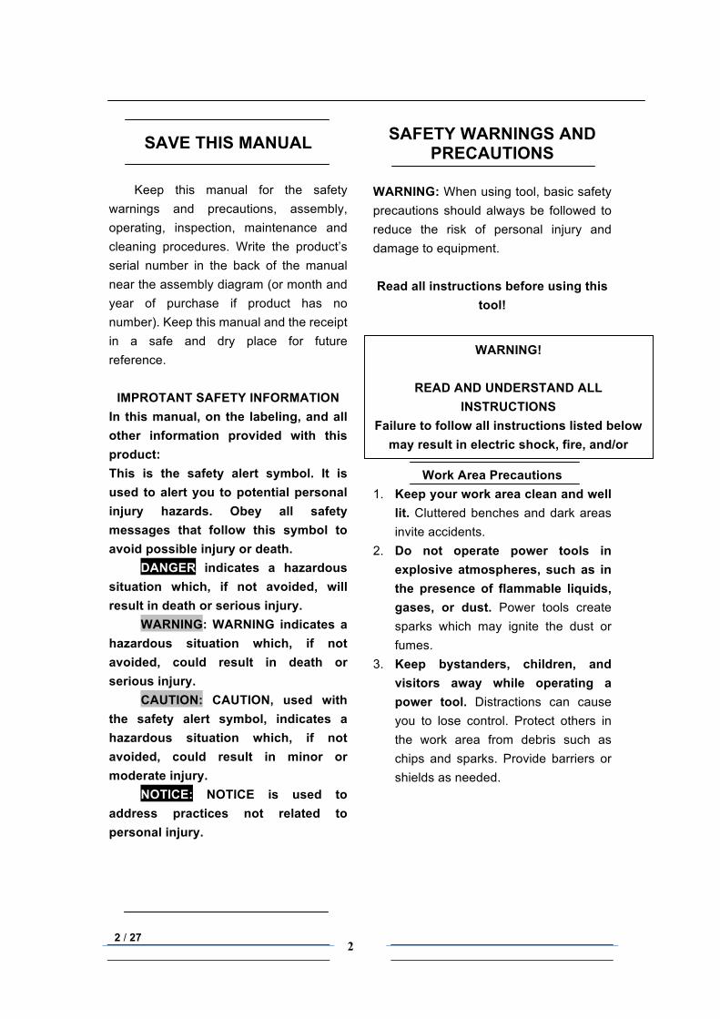
SAVE THIS MANUAL
Keep this manual for the safety warnings and precautions, assembly, operating, inspection, maintenance and cleaning procedures. Write the product’s serial number in the back of the manual near the assembly diagram (or month and year of purchase if product has no number). Keep this manual and the receipt in a safe and dry place for future reference.
IMPROTANT SAFETY INFORMATION In this manual, on the labeling, and all other information provided with this product: This is the safety alert symbol. It is used to alert you to potential personal injury hazards. Obey all safety messages that follow this symbol to avoid possible injury or death. DANGER indicates a hazardous situation which, if not avoided, will result in death or serious injury. WARNING: WARNING indicates a hazardous situation which, if not avoided, could result in death or serious injury. CAUTION: CAUTION, used with the safety alert symbol, indicates a hazardous situation which, if not avoided, could result in minor or moderate injury. NOTICE: NOTICE is used to address practices not related to personal injury.
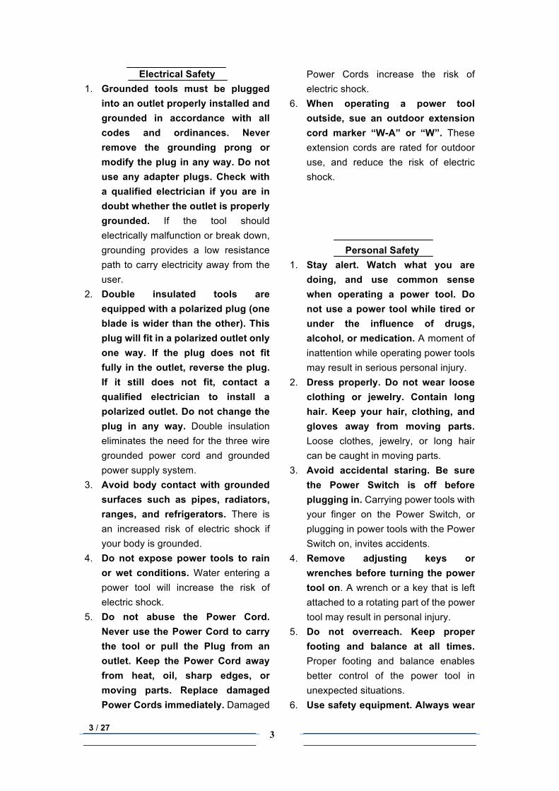
SAFETY WARNINGS AND PRECAUTIONS
WARNING: When using tool, basic safety precautions should always be followed to reduce the risk of personal injury and damage to equipment. Read all instructions before using this
tool!
Work Area Precautions 1. Keep your work area clean and well
lit. Cluttered benches and dark areas invite accidents.
2. Do not operate power tools in explosive atmospheres, such as in the presence of flammable liquids, gases, or dust. Power tools create sparks which may ignite the dust or fumes.
3. Keep bystanders, children, and visitors away while operating a power tool. Distractions can cause you to lose control. Protect others in the work area from debris such as chips and sparks. Provide barriers or shields as needed.
WARNING!
READ AND UNDERSTAND ALL INSTRUCTIONS
Failure to follow all instructions listed below may result in electric shock, fire, and/or
serious injury. SAVE THESE INSTRUCTIONS
3 / 27
3
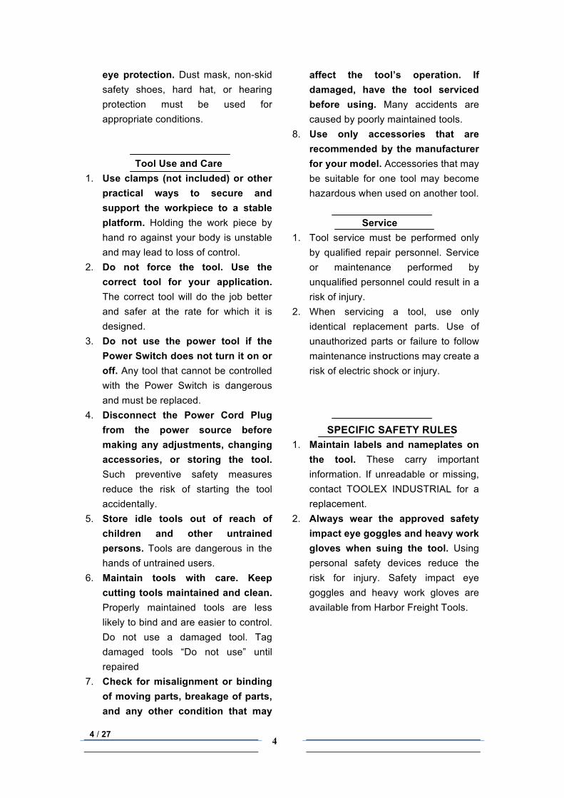
Electrical Safety 1. Grounded tools must be plugged
into an outlet properly installed and grounded in accordance with all codes and ordinances. Never remove the grounding prong or modify the plug in any way. Do not use any adapter plugs. Check with a qualified electrician if you are in doubt whether the outlet is properly grounded. If the tool should electrically malfunction or break down, grounding provides a low resistance path to carry electricity away from the user.
2. Double insulated tools are equipped with a polarized plug (one blade is wider than the other). This plug will fit in a polarized outlet only one way. If the plug does not fit fully in the outlet, reverse the plug. If it still does not fit, contact a qualified electrician to install a polarized outlet. Do not change the plug in any way. Double insulation eliminates the need for the three wire grounded power cord and grounded power supply system.
3. Avoid body contact with grounded surfaces such as pipes, radiators, ranges, and refrigerators. There is an increased risk of electric shock if your body is grounded.
4. Do not expose power tools to rain or wet conditions. Water entering a power tool will increase the risk of electric shock.
5. Do not abuse the Power Cord. Never use the Power Cord to carry the tool or pull the Plug from an outlet. Keep the Power Cord away from heat, oil, sharp edges, or moving parts. Replace damaged Power Cords immediately. Damaged
Power Cords increase the risk of electric shock.
6. When operating a power tool outside, sue an outdoor extension cord marker “W-A” or “W”. These extension cords are rated for outdoor use, and reduce the risk of electric shock.
Personal Safety
1. Stay alert. Watch what you are doing, and use common sense when operating a power tool. Do not use a power tool while tired or under the influence of drugs, alcohol, or medication. A moment of inattention while operating power tools may result in serious personal injury.
2. Dress properly. Do not wear loose clothing or jewelry. Contain long hair. Keep your hair, clothing, and gloves away from moving parts. Loose clothes, jewelry, or long hair can be caught in moving parts.
3. Avoid accidental staring. Be sure the Power Switch is off before plugging in. Carrying power tools with your finger on the Power Switch, or plugging in power tools with the Power Switch on, invites accidents.
4. Remove adjusting keys or wrenches before turning the power tool on. A wrench or a key that is left attached to a rotating part of the power tool may result in personal injury.
5. Do not overreach. Keep proper footing and balance at all times. Proper footing and balance enables better control of the power tool in unexpected situations.
6. Use safety equipment. Always wear
4 / 27
4
eye protection. Dust mask, non-skid safety shoes, hard hat, or hearing protection must be used for appropriate conditions.
Tool Use and Care 1. Use clamps (not included) or other
practical ways to secure and support the workpiece to a stable platform. Holding the work piece by hand ro against your body is unstable and may lead to loss of control.
2. Do not force the tool. Use the correct tool for your application. The correct tool will do the job better and safer at the rate for which it is designed.
3. Do not use the power tool if the Power Switch does not turn it on or off. Any tool that cannot be controlled with the Power Switch is dangerous and must be replaced.
4. Disconnect the Power Cord Plug from the power source before making any adjustments, changing accessories, or storing the tool. Such preventive safety measures reduce the risk of starting the tool accidentally.
5. Store idle tools out of reach of children and other untrained persons. Tools are dangerous in the hands of untrained users.
6. Maintain tools with care. Keep cutting tools maintained and clean. Properly maintained tools are less likely to bind and are easier to control. Do not use a damaged tool. Tag damaged tools “Do not use” until repaired
7. Check for misalignment or binding of moving parts, breakage of parts, and any other condition that may
affect the tool’s operation. If damaged, have the tool serviced before using. Many accidents are caused by poorly maintained tools.
8. Use only accessories that are recommended by the manufacturer for your model. Accessories that may be suitable for one tool may become hazardous when used on another tool.
Service 1. Tool service must be performed only
by qualified repair personnel. Service or maintenance performed by unqualified personnel could result in a risk of injury.
2. When servicing a tool, use only identical replacement parts. Use of unauthorized parts or failure to follow maintenance instructions may create a risk of electric shock or injury.
SPECIFIC SAFETY RULES 1. Maintain labels and nameplates on
the tool. These carry important information. If unreadable or missing, contact TOOLEX INDUSTRIAL for a replacement.
2. Always wear the approved safety impact eye goggles and heavy work gloves when suing the tool. Using personal safety devices reduce the risk for injury. Safety impact eye goggles and heavy work gloves are available from Harbor Freight Tools.
5 / 27
5
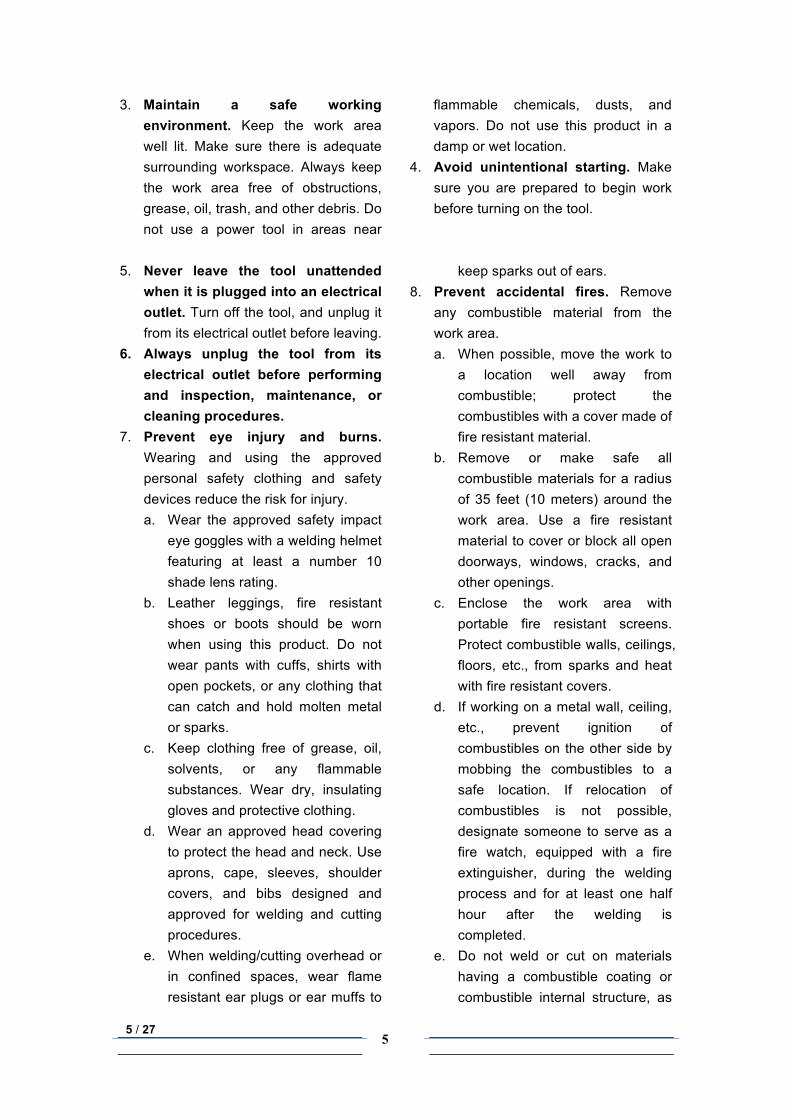
3. Maintain a safe working environment. Keep the work area well lit. Make sure there is adequate surrounding workspace. Always keep the work area free of obstructions, grease, oil, trash, and other debris. Do not use a power tool in areas near
flammable chemicals, dusts, and vapors. Do not use this product in a damp or wet location.
4. Avoid unintentional starting. Make sure you are prepared to begin work before turning on the tool.
5. Never leave the tool unattended when it is plugged into an electrical outlet. Turn off the tool, and unplug it from its electrical outlet before leaving.
6. Always unplug the tool from its electrical outlet before performing and inspection, maintenance, or cleaning procedures.
7. Prevent eye injury and burns. Wearing and using the approved personal safety clothing and safety devices reduce the risk for injury. a. Wear the approved safety impact
eye goggles with a welding helmet featuring at least a number 10 shade lens rating.
b. Leather leggings, fire resistant shoes or boots should be worn when using this product. Do not wear pants with cuffs, shirts with open pockets, or any clothing that can catch and hold molten metal or sparks.
c. Keep clothing free of grease, oil, solvents, or any flammable substances. Wear dry, insulating gloves and protective clothing.
d. Wear an approved head covering to protect the head and neck. Use aprons, cape, sleeves, shoulder covers, and bibs designed and approved for welding and cutting procedures.
e. When welding/cutting overhead or in confined spaces, wear flame resistant ear plugs or ear muffs to
keep sparks out of ears. 8. Prevent accidental fires. Remove
any combustible material from the work area. a. When possible, move the work to
a location well away from combustible; protect the combustibles with a cover made of fire resistant material.
b. Remove or make safe all combustible materials for a radius of 35 feet (10 meters) around the work area. Use a fire resistant material to cover or block all open doorways, windows, cracks, and other openings.
c. Enclose the work area with portable fire resistant screens. Protect combustible walls, ceilings, floors, etc., from sparks and heat with fire resistant covers.
d. If working on a metal wall, ceiling, etc., prevent ignition of combustibles on the other side by mobbing the combustibles to a safe location. If relocation of combustibles is not possible, designate someone to serve as a fire watch, equipped with a fire extinguisher, during the welding process and for at least one half hour after the welding is completed.
e. Do not weld or cut on materials having a combustible coating or combustible internal structure, as
6 / 27
6
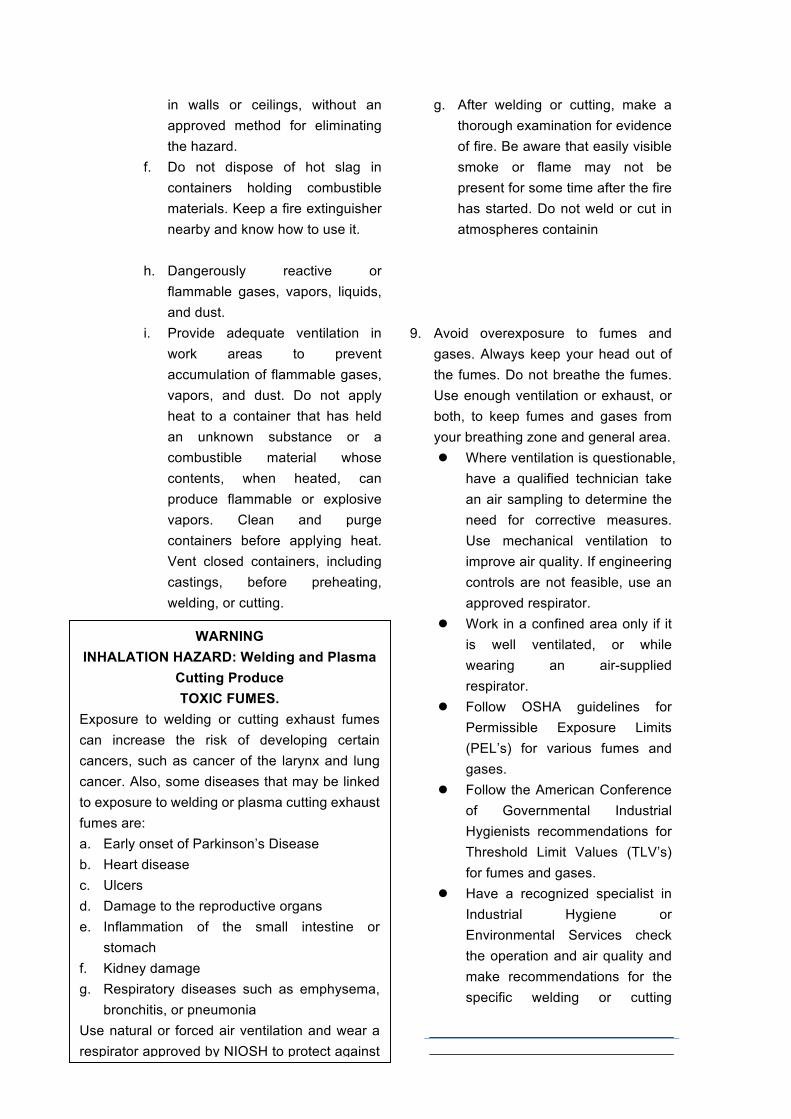
in walls or ceilings, without an approved method for eliminating the hazard.
f. Do not dispose of hot slag in containers holding combustible materials. Keep a fire extinguisher nearby and know how to use it.
g. After welding or cutting, make a thorough examination for evidence of fire. Be aware that easily visible smoke or flame may not be present for some time after the fire has started. Do not weld or cut in atmospheres containin
h. Dangerously reactive or flammable gases, vapors, liquids, and dust.
i. Provide adequate ventilation in work areas to prevent accumulation of flammable gases, vapors, and dust. Do not apply heat to a container that has held an unknown substance or a combustible material whose contents, when heated, can produce flammable or explosive vapors. Clean and purge containers before applying heat. Vent closed containers, including castings, before preheating, welding, or cutting.
9. Avoid overexposure to fumes and
gases. Always keep your head out of the fumes. Do not breathe the fumes. Use enough ventilation or exhaust, or both, to keep fumes and gases from your breathing zone and general area. ! Where ventilation is questionable,
have a qualified technician take an air sampling to determine the need for corrective measures. Use mechanical ventilation to improve air quality. If engineering controls are not feasible, use an approved respirator.
! Work in a confined area only if it is well ventilated, or while wearing an air-supplied respirator.
! Follow OSHA guidelines for Permissible Exposure Limits (PEL’s) for various fumes and gases.
! Follow the American Conference of Governmental Industrial Hygienists recommendations for Threshold Limit Values (TLV’s) for fumes and gases.
! Have a recognized specialist in Industrial Hygiene or Environmental Services check the operation and air quality and make recommendations for the specific welding or cutting
WARNING INHALATION HAZARD: Welding and Plasma
Cutting Produce TOXIC FUMES.
Exposure to welding or cutting exhaust fumes can increase the risk of developing certain cancers, such as cancer of the larynx and lung cancer. Also, some diseases that may be linked to exposure to welding or plasma cutting exhaust fumes are: a. Early onset of Parkinson’s Disease b. Heart disease c. Ulcers d. Damage to the reproductive organs e. Inflammation of the small intestine or
stomach f. Kidney damage g. Respiratory diseases such as emphysema,
bronchitis, or pneumonia Use natural or forced air ventilation and wear a respirator approved by NIOSH to protect against the fumes produced to reduce the risk of developing the above illnesses.
7 / 27
7
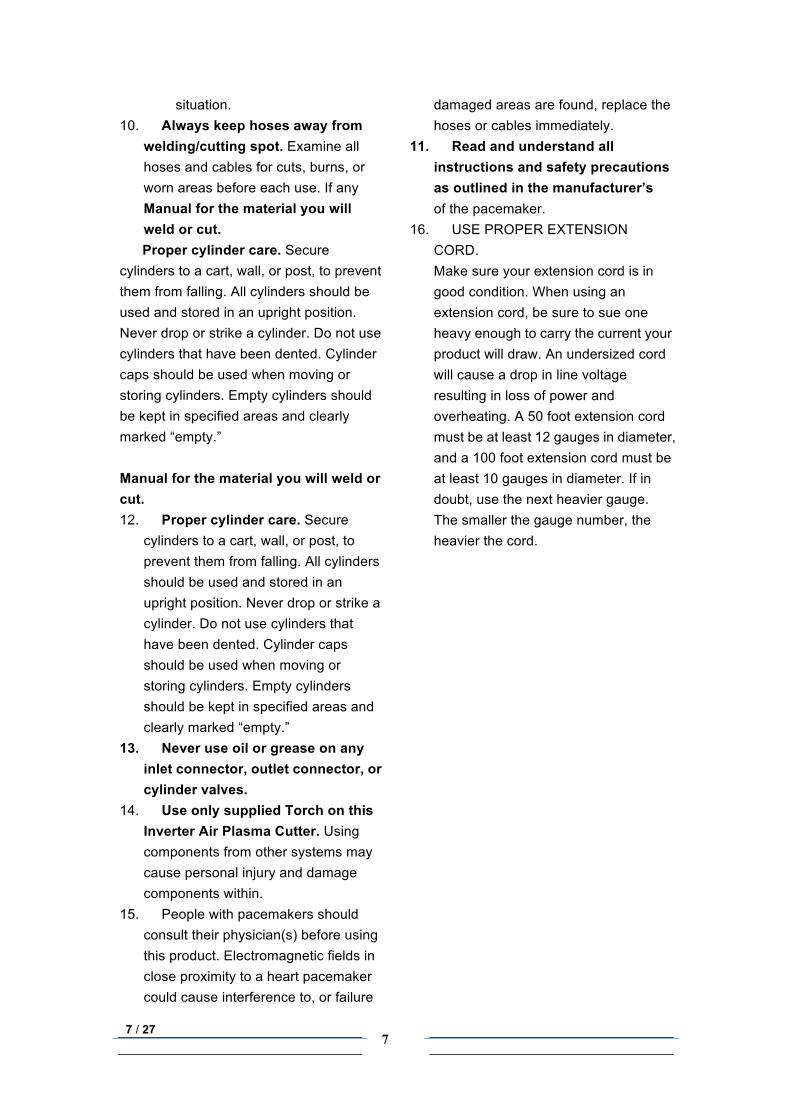
situation. 10. Always keep hoses away from
welding/cutting spot. Examine all hoses and cables for cuts, burns, or worn areas before each use. If any
damaged areas are found, replace the hoses or cables immediately.
11. Read and understand all instructions and safety precautions as outlined in the manufacturer’s
Manual for the material you will weld or cut. Proper cylinder care. Secure
cylinders to a cart, wall, or post, to prevent them from falling. All cylinders should be used and stored in an upright position. Never drop or strike a cylinder. Do not use cylinders that have been dented. Cylinder caps should be used when moving or storing cylinders. Empty cylinders should be kept in specified areas and clearly marked “empty.” Manual for the material you will weld or cut. 12. Proper cylinder care. Secure
cylinders to a cart, wall, or post, to prevent them from falling. All cylinders should be used and stored in an upright position. Never drop or strike a cylinder. Do not use cylinders that have been dented. Cylinder caps should be used when moving or storing cylinders. Empty cylinders should be kept in specified areas and clearly marked “empty.”
13. Never use oil or grease on any inlet connector, outlet connector, or cylinder valves.
14. Use only supplied Torch on this Inverter Air Plasma Cutter. Using components from other systems may cause personal injury and damage components within.
15. People with pacemakers should consult their physician(s) before using this product. Electromagnetic fields in close proximity to a heart pacemaker could cause interference to, or failure
of the pacemaker. 16. USE PROPER EXTENSION
CORD. Make sure your extension cord is in good condition. When using an extension cord, be sure to sue one heavy enough to carry the current your product will draw. An undersized cord will cause a drop in line voltage resulting in loss of power and overheating. A 50 foot extension cord must be at least 12 gauges in diameter, and a 100 foot extension cord must be at least 10 gauges in diameter. If in doubt, use the next heavier gauge. The smaller the gauge number, the heavier the cord.
8 / 27
8
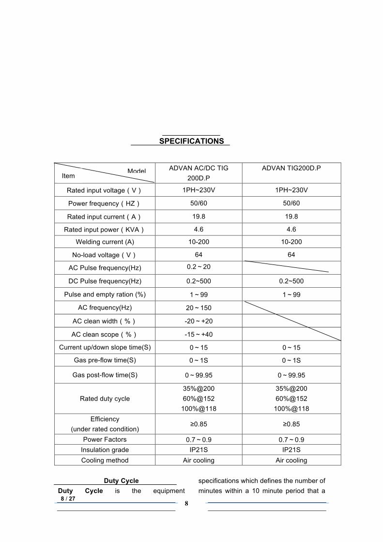
SPECIFICATIONS
Duty Cycle
Duty Cycle is the equipment specifications which defines the number of minutes within a 10 minute period that a
ADVAN AC/DC TIG 200D.P
ADVAN TIG200D.P
Rated input voltage(V) 1PH~230V 1PH~230V
Power frequency(HZ) 50/60 50/60
Rated input current(A) 19.8 19.8
Rated input power(KVA) 4.6 4.6
Welding current (A) 10-200 10-200
No-load voltage(V) 64 64
AC Pulse frequency(Hz) 0.2~20
DC Pulse frequency(Hz) 0.2~500 0.2~500
Pulse and empty ration (%) 1~99 1~99
AC frequency(Hz) 20~150
AC clean width(%) -20~+20
AC clean scope(%) -15~+40
Current up/down slope time(S) 0~15 0~15
Gas pre-flow time(S) 0~1S 0~1S
Gas post-flow time(S) 0~99.95 0~99.95
Rated duty cycle 35%@200 60%@152
100%@118
35%@200 60%@152
100%@118 Efficiency
(under rated condition) ≥0.85 ≥0.85
Power Factors 0.7~0.9 0.7~0.9 Insulation grade IP21S IP21S Cooling method Air cooling Air cooling
Model Item
9 / 27
9
piece of equipment can safely operate. This ADVAN WELDER has a 35% duty cycle at maximum welding output, which means that it continuously operates for 3.5 minutes at maximum output during
a 10 minute period. CAUTION: Failure to observe the duty cycle limitations of this Plasma Cutter can easily damage this equipment, and will void warranty.
UNPACKING When unpacking, checks to make sure the following parts are included.
Inverter welding machine with TIG torch with Power Cord Ground Cable with Clamp
Back-up Accessories for torch Warranty Card
If any parts are missing or broken, please call ………..at the number on the cover of this manual. Please keep these two cards (Especially the serial number on them) well for your after-sales service.
Preparing Your Work Area
1. You must have a sturdy work table that is open below the area you are cutting. Molten slag will be blown through the work metal, and must be able to fall away freely
2. Your work table must allow the work metal to be firmly clamped to prevent it accidentally falling or moving.
3. The floor and surrounding area of your work site must not be flammable. A clean cement floor is recommended. The cutting process will eject molten metal slag onto the floor, and it will scatter for 8-10 feet or more in any direction. Have an adequate fire extinguisher available if needed.
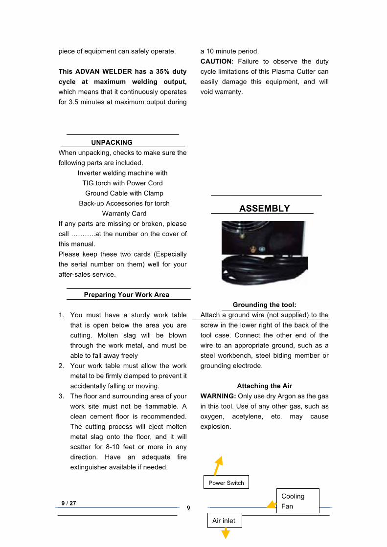
ASSEMBLY
Grounding the tool: Attach a ground wire (not supplied) to the screw in the lower right of the back of the tool case. Connect the other end of the wire to an appropriate ground, such as a steel workbench, steel biding member or grounding electrode.
Attaching the Air WARNING: Only use dry Argon as the gas in this tool. Use of any other gas, such as oxygen, acetylene, etc. may cause explosion.
Power Switch
Cooling Fan
Air inlet
10 / 27 10
Connect the gas air inlet (3) to your supply Argon by one air hose (not supplied). And remember to fasten it with coupling.
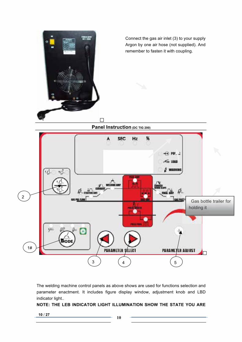
Panel Instruction (DC TIG 200)
The welding machine control panels as above shows are used for functions selection and parameter enactment. It includes figure display window, adjustment knob and LBD indicator light.. NOTE: THE LEB INDICATOR LIGHT ILLUMINATION SHOW THE STATE YOU ARE
Gas bottle trailer for holding it
2#
1#
3#
5#
4#
11 / 27
11
CHOOSING AT THAT MOMENT. NAME EXPLANATION:
1. GAS PRE-FLOW——Time of ahead gas sending as you prepare to welding.
2. STARTING AMP.——starting current. 3. CURRENT UP SLOPE——time slot
for welding current increasing 4. WELDING AMP.——Welding current
in the constant current output estate. 5. PEAK AMP.——the peak value
current when pulse outputting. 6. PULSE WIDTN——Time proportion of
peak value current when pulse outputting, which controls the welding line deep and realize entire position welding and sheet welding.
7. PULSE FREQ——Working frequency when pulse outputting.
8. CLEAN WIDTN——the time proportion of minus direction current within one AC welding cycle.
9. CLEAN SCOPE——the percentage of minus direction current scope adding when AC welding.
10. BASE AMP.——the maintaining arc current when pulse outputting.
11. CURRENT DOWN SLOPE——time slot for welding current decreasing.
12. FINAL AMP.——the welding current before finishing welding
13. GAS POST-FLOW——Gas extending time after welding is finished. It can protect the welding line and the
14. 1#: MODE Selector button: Press this button some times as needed
to choose the
four functions above : MMA, Pulse TIG, TIG, AUTO( from left to right in order).the indicator on position stands for current estate. AUTO means automatic welding and nothing can be
adjusted except current; MMA means: MMA welding; PULSE TIG means TIG welding with pulse function; TIG means the common TIG welding.
15. 2#: “4T/2T” selection button :Selecting “4T/2T” procedure functions, TIG welding divides into “2T” action(non-self lock)and “4T” action(self lock),both AC(PULSE TIG/TIG) and DC(PULSE TIG/TIG) can realize “4T/2T” selection. “2T” means to start welding when press the torch switch and stop welding when the torch switch is released.
“4T” action style means output ARC striking current when press torch switch for the first time, current up to standard welding current while releasing the torch switch. Press the torch switch again after welding is finished, at this time the welding current begin down to end-ARC current and retain it. The welding machine stops outputting current after releasing torch switch for the second time.
16. 3#: Parameter Select (towards the left):
You can choose any procedure function among “GAS PRE-FLOW/GAS POST-FLOW, STARTING AMP./FINAL AMP. ,CURRENT UP SLOPE/CURRENT DOWN SLOPE,TIG, AC/PULSE FREQUENCY, BASE AMP./PEAK AMP.,CLEAN WIDTH/CLEAN SCOPE /PULSE WIDTH” by press this button . The illumination indicator stands for the current status you are choosing. The indicator will illuminate from the right to left in
12 / 27
12
order while you press. Also when it is MMA welding, the button can adjust (just decrease) ARC force.
17. 4#: Parameter Select (towards the right):
You can choose any procedure function among “GAS PRE-FLOW/GAS POST-FLOW, STARTING AMP./FINAL AMP. ,CURRENT UP SLOPE/CURRENT DOWN SLOPE,TIG, AC/PULSE FREQUENCY, BASE AMP./PEAK AMP.,CLEAN WIDTH/CLEAN SCOPE /PULSE WIDTH” by press this button . The illumination indicator stands for the current status you are choosing. The indicator will illuminate from the left to right in order while you press. Also when it is MMA welding, the button can adjust (just increase) ARC force.
18. 5#: “Parameter Adjustment Knob”: After choosing the procedure function (refer to item 4 and 5), the current status are set, then you can turn this knob to adjust its parameter value. For example: GAS PRE-FLOW indicator on, adjust “ADJUSTMENT PAR.” 6# button to set “GAS PRE-FLOW/ GAS POST-FLOW” time(3~0s/99.9-0s); When the “STARTING AMP.” indicator on, adjust “ADJUSTMENT PAR 6#.”
button to set STARTING AMP. /FINAL AMP. Current(315/270/250~/15A); and using the same way to adjust beforehand for the followings: “CURRENT UP SLOPE/CURRENT DOWN SLOPE” time(15~0S)、 “TIG”( 315/270/250~15A ) 、 “BASE AMP./PEAK AMP.” current( 315/270/250~/15A ) /“PULSE WIDTH ” ( 99%~1% ) 、 “AC”( 100~20HZ ) /“PULSE FREQ.”(500~0.2HZ(DC), 20~0.2HZ(AC)) ; “CLEAN WIDTH ( +40~ -40%)”/“CLEAN SCOPE(30~ -15%)”。Long time pressing this button can realize speediness adjustment. This button just can adjust these parameters from high to low. Also it can used for adjusting welding current (from low to high) when the STICK is used. This welding machine can auto-save data when it is power off, which could be used directly of next time. NOTE: Protection Code (May showed on the digital display)
1. DISPLY 804: Machine auto-self protection when it is over-heated
2. Display 805: Short circuit of the TIG torch
Panel Instruction (AC/DC TIG 200)
13 / 27
13
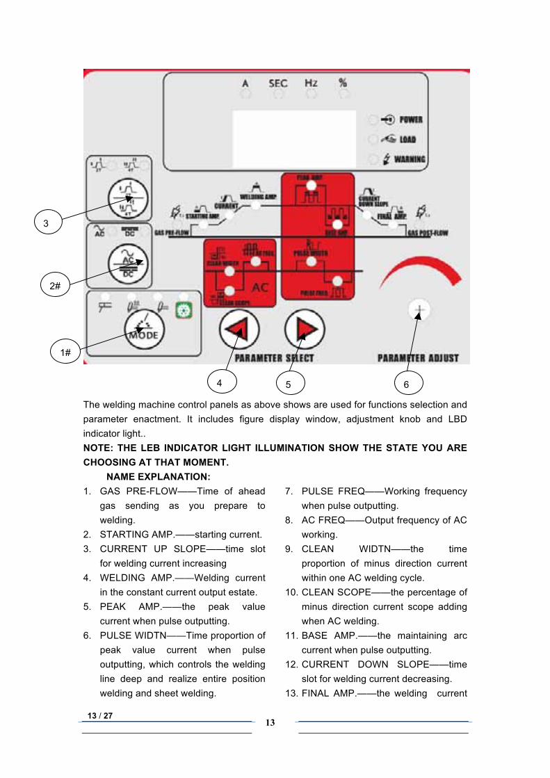
The welding machine control panels as above shows are used for functions selection and parameter enactment. It includes figure display window, adjustment knob and LBD indicator light.. NOTE: THE LEB INDICATOR LIGHT ILLUMINATION SHOW THE STATE YOU ARE CHOOSING AT THAT MOMENT.
NAME EXPLANATION: 1. GAS PRE-FLOW——Time of ahead
gas sending as you prepare to welding.
2. STARTING AMP.——starting current. 3. CURRENT UP SLOPE——time slot
for welding current increasing 4. WELDING AMP.——Welding current
in the constant current output estate. 5. PEAK AMP.——the peak value
current when pulse outputting. 6. PULSE WIDTN——Time proportion of
peak value current when pulse outputting, which controls the welding line deep and realize entire position welding and sheet welding.
7. PULSE FREQ——Working frequency when pulse outputting.
8. AC FREQ——Output frequency of AC working.
9. CLEAN WIDTN——the time proportion of minus direction current within one AC welding cycle.
10. CLEAN SCOPE——the percentage of minus direction current scope adding when AC welding.
11. BASE AMP.——the maintaining arc current when pulse outputting.
12. CURRENT DOWN SLOPE——time slot for welding current decreasing.
13. FINAL AMP.——the welding current
3#
1#
2#
4#
6#
5#
14 / 27
14
before finishing welding 14. GAS POST-FLOW——Gas extending
time after welding is finished. It can protect the welding line and the
15. 1#: MODE Selector button: Press this button some times as needed
to choose the
four functions above : MMA, Pulse TIG, TIG, AUTO( from left to right in order).the indicator on position stands for current estate. AUTO means automatic welding and nothing can be adjusted except current; MMA means: MMA welding; PULSE TIG means TIG welding with pulse function; TIG means the common TIG welding.
16. 2#: “AC/DC” selection button :selecting “AC/DC” functions, TIG welding divides into AC welding and DC welding,the indicator on position stands for current status.
17. 3#: “4T/2T” selection button :Selecting “4T/2T” procedure functions, TIG welding divides into “2T” action(non-self lock)and “4T” action(self lock),both AC(PULSE TIG/TIG) and DC(PULSE TIG/TIG) can realize “4T/2T” selection. “2T” means to start welding when press the torch switch and stop welding when the torch switch is released.
“4T” action style means output ARC striking current when press torch switch for the first time, current up to standard welding current while releasing the torch switch. Press the torch switch again after welding is finished, at this time the welding current begin down to end-ARC current and retain it. The welding machine stops outputting current after releasing torch switch for the
second time. 18. 4#: parameter adjustment(towards
the left): You can choose any procedure function among “GAS PRE-FLOW/GAS POST-FLOW, STARTING AMP./FINAL AMP. ,CURRENT UP SLOPE/CURRENT DOWN SLOPE,TIG, AC/PULSE FREQUENCY, BASE AMP./PEAK AMP.,CLEAN WIDTH/CLEAN SCOPE /PULSE WIDTH” by press this button . The illumination indicator stands for the current status you are choosing. The indicator will illuminate from the right to left in order while you press. Also when it is MMA welding, the button can adjust (just decrease) ARC force.
19. 5#:parameter adjustment(towards the right):
You can choose any procedure function among “GAS PRE-FLOW/GAS POST-FLOW, STARTING AMP./FINAL AMP. ,CURRENT UP SLOPE/CURRENT DOWN SLOPE,TIG, AC/PULSE FREQUENCY, BASE AMP./PEAK AMP.,CLEAN WIDTH/CLEAN SCOPE /PULSE WIDTH” by press this button . The illumination indicator stands for the current status you are choosing. The indicator will illuminate from the left to right in order while you press. Also when it is MMA welding, the button can adjust (just increase) ARC force.
20. 6#: “Parameter Adjustment Knob”: After choosing the procedure function (refer to item 18 and 19), the current status are set, then you can turn this knob to adjust its parameter value. For
15 / 27
15
example: GAS PRE-FLOW indicator on, adjust “ADJUSTMENT PAR.” 6# button to set “GAS PRE-FLOW/ GAS POST-FLOW” time( 3~0s/99.9-0s ) ; When the “STARTING AMP.” indicator on, adjust “ADJUSTMENT PAR 6#.” button to set STARTING AMP. /FINAL AMP. Current ( 315/270/250~/15A ) ; and using the same way to adjust beforehand for the followings: “CURRENT UP SLOPE/CURRENT DOWN SLOPE” time(15~0S)、 “TIG”( 315/270/250~15A ) 、 “BASE AMP./PEAK AMP.” current( 315/270/250~/15A ) /“PULSE WIDTH ” ( 99%~1% ) 、 “AC”( 100~20HZ ) /“PULSE FREQ.”(500~0.2HZ(DC), 20~0.2HZ(AC)) ; “CLEAN WIDTH ( +40~ -40%)”/“CLEAN SCOPE(30~ -15%)”。Long time pressing this button can realize speediness adjustment. This button just can adjust these parameters from high to low. Also it can used for adjusting welding current (from low to high) when the STICK is used. This welding machine can auto-save data when it is power off, which could be used directly of next time. NOTE: Protection Code (May showed on the digital display)
DISPLY 804: Machine auto-self protection when it is over-heated Display 805: Short circuit of the TIG torch
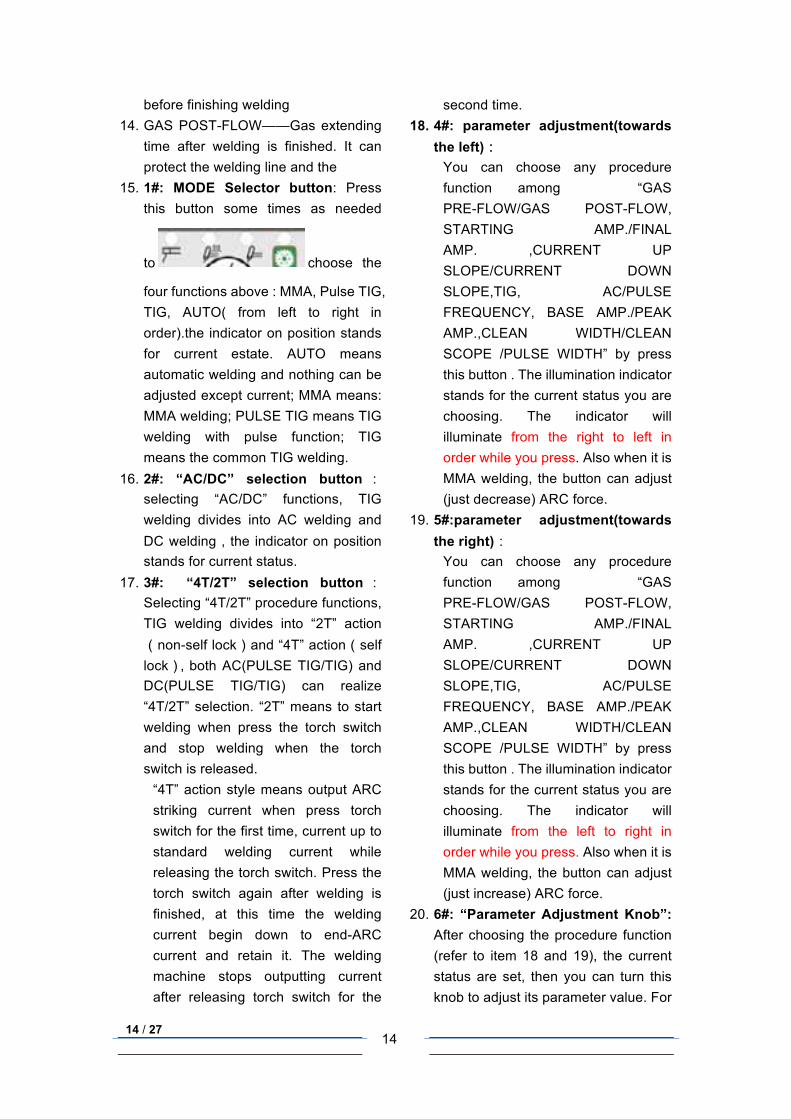
TIG Torch Welding Connect
DC TIG 200 welding
1. Ground Cable Connector; 2. Gas Connector of the torch; 3. TIG Control cable connector; 4. TIG Cable connector.
1 2 3 4
5 6 7
16 / 27
16
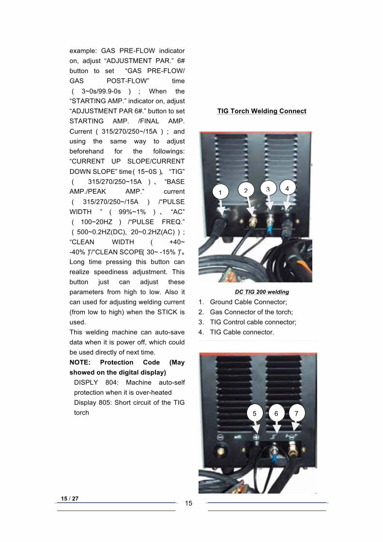
AC/DC TIG 200 DC Welding
5. DC Ground Cable Connector; 6. TIG Control cable connector; 7. TIG Cable connector.
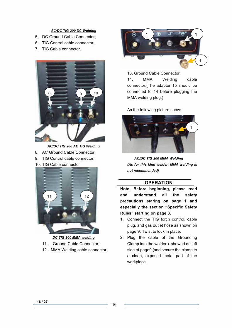
AC/DC TIG 200 AC TIG Welding
8. AC Ground Cable Connector; 9. TIG Control cable connector; 10. TIG Cable connector
DC TIG 200 MMA welding
11. Ground Cable Connector; 12.MMA Welding cable connector.
13. Ground Cable Connector; 14. MMA Welding cable connector.(The adaptor 15 should be connected to 14 before plugging the MMA welding plug.) As the following picture show:
AC/DC TIG 200 MMA Welding
(As for this kind welder, MMA welding is
not recommended)
OPERATION Note: Before beginning, please read and understand all the safety precautions staring on page 1 and especially the section “Specific Safety Rules” starting on page 3. 1. Connect the TIG torch control, cable
plug, and gas outlet hose as shown on page 9. Twist to lock in place.
2. Plug the cable of the Grounding Clamp into the welder (showed on left side of page9)and secure the clamp to a clean, exposed metal part of the workpiece.
8 9 10
11 12
13
14
15
15
17 / 27
17
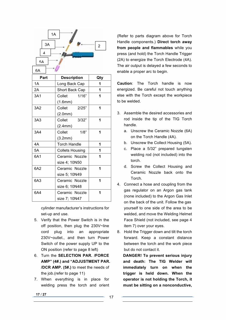
Part Description Qty
1A Long Back Cap 1 2A Short Back Cap 1 3A1 Collet 1/16”
(1.6mm) 1
3A2 Collet 2/25” (2.0mm)
1
3A3 Collet 3/32” (2.4mm)
1
3A4 Collet 1/8” (3.2mm)
1
4A Torch Handle 1 5A Collets Housing 1 6A1 Ceramic Nozzle
size 4; 10N50 1
6A2 Ceramic Nozzle size 5; 10N49
1
6A3 Ceramic Nozzle size 6; 10N48
1
6A4 Ceramic Nozzle size 7; 10N47
1
(Refer to parts diagram above for Torch Handle components.) Direct torch away from people and flammables while you press (and hold) the Torch Handle Trigger (2A) to energize the Torch Electrode (4A). The air output is delayed a few seconds to enable a proper arc to begin. Caution: The Torch handle is now energized. Be careful not touch anything else with the Torch except the workpiece to be welded.
3. Assemble the desired accessories and
rod inside the tip of the TIG Torch handle. a. Unscrew the Ceramic Nozzle (6A)
on the Torch Handle (4A). b. Unscrew the Collect Housing (5A). c. Place a 5/32” prepared tungsten
welding rod (not included) into the torch.
d. Screw the Collect Housing and Ceramic Nozzle back onto the Torch.
4. Connect a hose and coupling from the gas regulator on an Argon gas tank (none included) to the Argon Gas Inlet on the back of the unit. Follow the gas
cylinder manufacturer’s instructions for set-up and use.
5. Verify that the Power Switch is in the off position, then plug the 230V~line cord plug into an appropriate 230V~outlet., and then turn Power Switch of the power supply UP to the ON position (refer to page 8 left)
6. Turn the SELECTION PAR. /FORCE AMP” (4#.) and “ADJUSTMENT PAR. /DCR AMP. (5#.) to meet the needs of the job.(refer to page 11)
7. When everything is in place for welding press the torch and orient
yourself to one side of the area to be welded, and move the Welding Helmet Face Shield (not included, see page 4 item 7) over your eyes.
8. Hold the Trigger down and tilt the torch forward. Keep a constant distance between the torch and the work piece but do not contact it. DANGER! To prevent serious injury and death: The TIG Welder will immediately turn on when the trigger is held down. When the operator is not holding the Torch, it must be sitting on a nonconductive,
1A
2A
3A
4A
5A
6A
18 / 27
18
nonflammable surface. 9. If too much current is drawn from the
welder; the Thermal Overload protector will activate, the Overload indicator will light, and the welder will turn off until it cools down. It will automatically reset.
Arc (stick) Connection 1. Connect the Electrode Clamp and
Cable to the torch control connector (as 7 shown on page 9 and twist to lock in place.
2. Plug the cable of the Grounding Clamp into the DC ground connector and secure the clamp to a clean, exposed metal part of the workpiece.
3. Place the metal portion of the welding rod inside the jaws of the Electrode Clamp. Welding rod types vary for welding different metal DANGER! To prevent serious injury and death: If the operator is not holding the Torch, it must be sitting on a nonconductive, nonflammable surface. The Stick Welder will immediately turn on when the
power button is turned on. Stroke the work piece lightly to ignite the arc. Do not strike like a match? Never tap the electrode wire to ignite the arc; it will damage the electrode.
4. When the arc ignites, tilt the electrode forward and hold it near the work piece.
5. If too much current is drawn from the welder; the Thermal Overload protector will activate, the Warning indicator will light, and the code 804 will be showed on the digital display, at the same time, the welder will turn off until it cools down. It will automatically reset.
When finished welding a. Release the Torch handle trigger
and lift the Torch handle from the work piece,
b. Press the Power Switch to the Off (O) position.
c. Set the Torch handle down on the metal workbench,
d. Turn the air supply off, Unplug the line cord from the electrical outlet
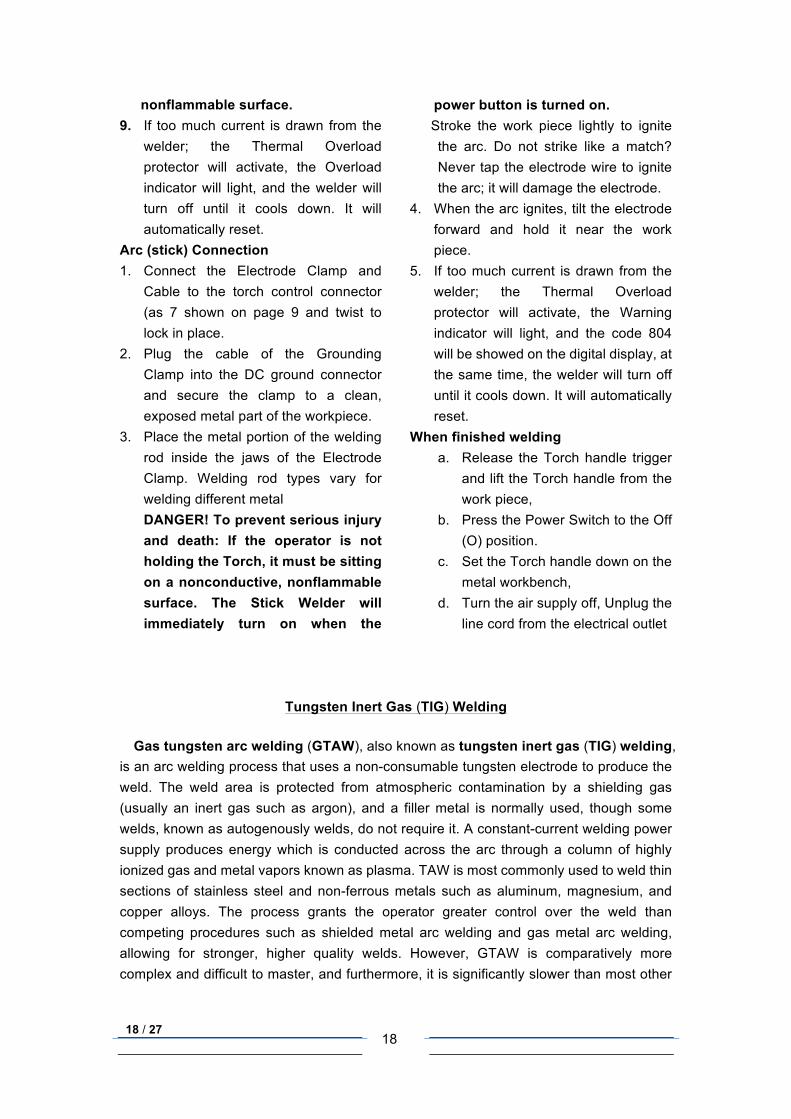
Tungsten Inert Gas (TIG) Welding
Gas tungsten arc welding (GTAW), also known as tungsten inert gas (TIG) welding, is an arc welding process that uses a non-consumable tungsten electrode to produce the weld. The weld area is protected from atmospheric contamination by a shielding gas (usually an inert gas such as argon), and a filler metal is normally used, though some welds, known as autogenously welds, do not require it. A constant-current welding power supply produces energy which is conducted across the arc through a column of highly ionized gas and metal vapors known as plasma. TAW is most commonly used to weld thin sections of stainless steel and non-ferrous metals such as aluminum, magnesium, and copper alloys. The process grants the operator greater control over the weld than competing procedures such as shielded metal arc welding and gas metal arc welding, allowing for stronger, higher quality welds. However, GTAW is comparatively more complex and difficult to master, and furthermore, it is significantly slower than most other
19 / 27
19
welding techniques. A related process, plasma arc welding, uses a slightly different welding torch to create a more focused welding arc and as a result is often automated.
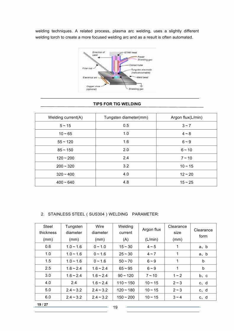
TIPS FOR TIG WELDING
Welding current(A) Tungsten diameter(mm) Argon flux(L/min)
5~15 0.5 3~7
10~65 1.0 4~8
55~120 1.6 6~9
85~150 2.0 6~10
120~200 2.4 7~10
200~320 3.2 10~15
320~400 4.0 12~20
400~640 4.8 15~25
2. STAINLESS STEEL(SUS304)WELDING PARAMETER:
Steel thickness
Tungsten diameter
Wire diameter
Welding current
Argon flux Clearance
size Clearance form
(mm) (mm) (mm) (A) (L/min) (mm)
0.6 1.0~1.6 0~1.0 15~30 4~5 1 a、b
1.0 1.0~1.6 0~1.6 25~30 4~7 1 a、b
1.5 1.0~1.6 0~1.6 50~70 6~9 1 b
2.5 1.6~2.4 1.6~2.4 65~95 6~9 1 b
3.0 1.6~2.4 1.6~2.4 90~120 7~10 1~2 b、c
4.0 2.4 1.6~2.4 110~150 10~15 2~3 c、d
5.0 2.4~3.2 2.4~3.2 120~180 10~15 2~3 c、d
6.0 2.4~3.2 2.4~3.2 150~200 10~15 3~4 c、d
20 / 27
20
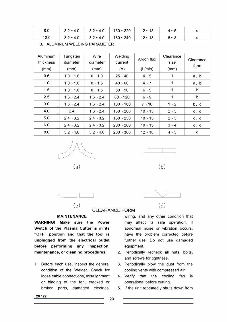
8.0 3.2~4.0 3.2~4.0 160~220 12~18 4~5 d
12.0 3.2~4.0 3.2~4.0 180~240 12~18 6~8 d
3. ALUMINUM WELDING PARAMETER
Aluminum thickness
Tungsten diameter
Wire diameter
Welding current
Argon flux Clearance
size Clearance form
(mm) (mm) (mm) (A) (L/min) (mm)
0.6 1.0~1.6 0~1.0 25~40 4~5 1 a、b
1.0 1.0~1.6 0~1.6 40~60 4~7 1 a、b
1.5 1.0~1.6 0~1.6 60~90 6~9 1 b
2.5 1.6~2.4 1.6~2.4 80~120 6~9 1 b
3.0 1.6~2.4 1.6~2.4 100~160 7~10 1~2 b、c
4.0 2.4 1.6~2.4 130~200 10~15 2~3 c、d
5.0 2.4~3.2 2.4~3.2 150~250 10~15 2~3 c、d
6.0 2.4~3.2 2.4~3.2 200~280 10~15 3~4 c、d
8.0 3.2~4.0 3.2~4.0 200~300 12~18 4~5 d
CLEARANCE FORMMAINTENANCE
WARNING! Make sure the Power Switch of the Plasma Cutter is in its “OFF” position and that the tool is unplugged from the electrical outlet before performing any inspection, maintenance, or cleaning procedures. 1. Before each use, inspect the general
condition of the Welder. Check for loose cable connections, misalignment or binding of the fan, cracked or broken parts, damaged electrical
wiring, and any other condition that may affect its safe operation. If abnormal noise or vibration occurs, have the problem corrected before further use. Do not use damaged equipment.
2. Periodically recheck all nuts, bolts, and screws for tightness.
3. Periodically blow the dust from the cooling vents with compressed air.
4. Verify that the cooling fan is operational before cutting.
5. If the unit repeatedly shuts down from
(c) (d)
(a) (b)
21 / 27
21
thermal overload, stop all use. Have the welder inspected and repaired by a qualified service technician.
6. Store the welder and accessories in a clean and dry location.
7. Periodically disassemble and clean the Torch Head components with steel wool. Replace burnt, cracked, distorted, or coated components, Refer to the assembly drawing on page 11.
8. To gain access to the internal components of the unit, remove screws from Main Body Cover. The home user is strongly advised not to remove the tool covers and not to attempt any electronic repairs. Any repairs must be completed by a qualified technician. Opening the tool will void any warranties, and may result in damage to equipment or possible personal injury. Don’t do it.
9. On a daily basis check for any of the following problems: If any are found, take the tool to a qualified repair technician. a. Abnormal vibration, sound or
smell. b. Abnormal heating at any cable
connection.
c. Then fan does not work properly. d. Any switch or control does not
work properly. e. Any damage to cables.
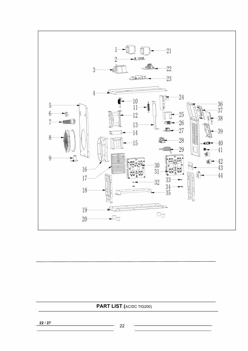
ASSEMBLY DIAGRAM
The structure of AC/DC TIG200 (reference only):
22 / 27
22
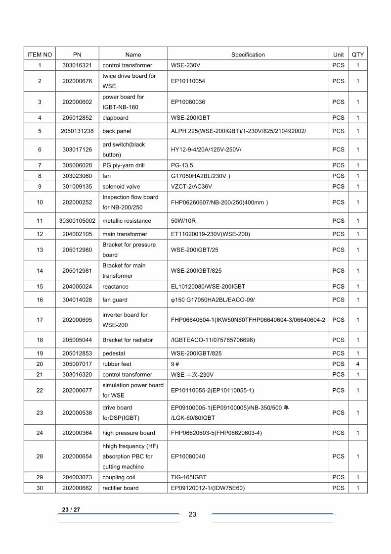
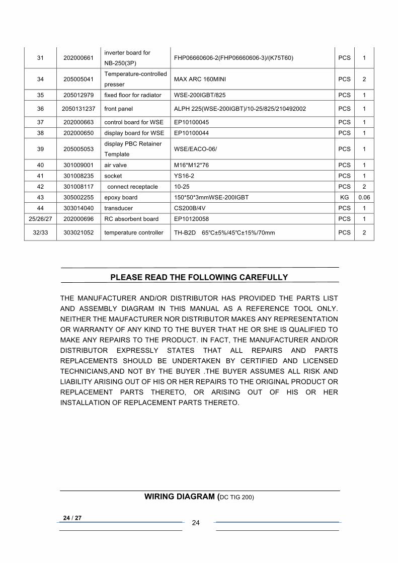
PART LIST (AC/DC TIG200)
23 / 27
23
ITEM NO PN Name Specification Unit QTY
1 303016321 control transformer WSE-230V PCS 1
2 202000676 twice drive board for
WSE EP10110054 PCS 1
3 202000602 power board for
IGBT-NB-160 EP10080036 PCS 1
4 205012852 clapboard WSE-200IGBT PCS 1
5 2050131238 back panel ALPH 225(WSE-200IGBT)/1-230V/825/210492002/ PCS 1
6 303017126 ard switch(black
button) HY12-9-4/20A/125V-250V/ PCS 1
7 305006028 PG ply-yarn drill PG-13.5 PCS 1
8 303023060 fan G17050HA2BL/230V) PCS 1
9 301009135 solenoid valve VZCT-2/AC36V PCS 1
10 202000252 Inspection flow board
for NB-200/250 FHP06260607/NB-200/250(400mm) PCS 1
11 30300105002 metallic resistance 50W/10R PCS 1
12 204002105 main transformer ET11020019-230V(WSE-200) PCS 1
13 205012980 Bracket for pressure
board WSE-200IGBT/25 PCS 1
14 205012981 Bracket for main
transformer WSE-200IGBT/825 PCS 1
15 204005024 reactance EL10120080/WSE-200IGBT PCS 1
16 304014028 fan guard φ150 G17050HA2BL/EACO-09/ PCS 1
17 202000695 inverter board for
WSE-200 FHP06640604-1(IKW50N60TFHP06640604-3/06640604-2 PCS 1
18 205005044 Bracket for radiator /IGBTEACO-11/075785706698) PCS 1
19 205012853 pedestal WSE-200IGBT/825 PCS 1
20 305007017 rubber feet 9# PCS 4
21 303016320 control transformer WSE 二次-230V PCS 1
22 202000677 simulation power board
for WSE EP10110055-2(EP10110055-1) PCS 1
23 202000538 drive board
forDSP(IGBT)
EP09100005-1(EP09100005)/NB-350/500 单/LGK-60/80IGBT
PCS 1
24 202000364 high pressure board FHP06620603-5(FHP06620603-4) PCS 1
28 202000654
hhigh frequency (HF)
absorption PBC for
cutting machine
EP10080040 PCS 1
29 204003073 coupling coil TIG-165IGBT PCS 1
30 202000662 rectifier board EP09120012-1/(IDW75E60) PCS 1
24 / 27
24
31 202000661 inverter board for
NB-250(3P) FHP06660606-2(FHP06660606-3)/(K75T60) PCS 1
34 205005041 Temperature-controlled
presser MAX ARC 160MINI PCS 2
35 205012979 fixed floor for radiator WSE-200IGBT/825 PCS 1
36 2050131237 front panel ALPH 225(WSE-200IGBT)/10-25/825/210492002 PCS 1
37 202000663 control board for WSE EP10100045 PCS 1
38 202000650 display board for WSE EP10100044 PCS 1
39 205005053 display PBC Retainer
Template WSE/EACO-06/ PCS 1
40 301009001 air valve M16*M12*76 PCS 1
41 301008235 socket YS16-2 PCS 1
42 301008117 connect receptacle 10-25 PCS 2
43 305002255 epoxy board 150*50*3mmWSE-200IGBT KG 0.06
44 303014040 transducer CS200B/4V PCS 1
25/26/27 202000696 RC absorbent board EP10120058 PCS 1
32/33 303021052 temperature controller TH-B2D 65℃±5%/45℃±15%/70mm PCS 2
PLEASE READ THE FOLLOWING CAREFULLY
THE MANUFACTURER AND/OR DISTRIBUTOR HAS PROVIDED THE PARTS LIST AND ASSEMBLY DIAGRAM IN THIS MANUAL AS A REFERENCE TOOL ONLY. NEITHER THE MAUFACTURER NOR DISTRIBUTOR MAKES ANY REPRESENTATION OR WARRANTY OF ANY KIND TO THE BUYER THAT HE OR SHE IS QUALIFIED TO MAKE ANY REPAIRS TO THE PRODUCT. IN FACT, THE MANUFACTURER AND/OR DISTRIBUTOR EXPRESSLY STATES THAT ALL REPAIRS AND PARTS REPLACEMENTS SHOULD BE UNDERTAKEN BY CERTIFIED AND LICENSED TECHNICIANS,AND NOT BY THE BUYER .THE BUYER ASSUMES ALL RISK AND LIABILITY ARISING OUT OF HIS OR HER REPAIRS TO THE ORIGINAL PRODUCT OR REPLACEMENT PARTS THERETO, OR ARISING OUT OF HIS OR HER INSTALLATION OF REPLACEMENT PARTS THERETO.
WIRING DIAGRAM (DC TIG 200)
25 / 27
25
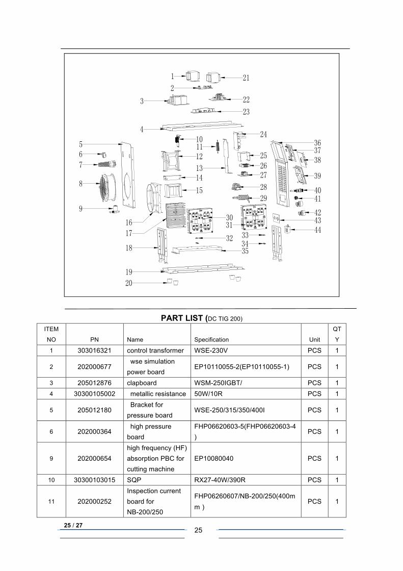
PART LIST (DC TIG 200)
ITEM
NO PN Name Specification Unit
QT
Y
1 303016321 control transformer WSE-230V PCS 1
2 202000677 wse simulation power board
EP10110055-2(EP10110055-1) PCS 1
3 205012876 clapboard WSM-250IGBT/ PCS 1 4 30300105002 metallic resistance 50W/10R PCS 1
5 205012180 Bracket for pressure board
WSE-250/315/350/400I PCS 1
6 202000364 high pressure board
FHP06620603-5(FHP06620603-4)
PCS 1
9 202000654 high frequency (HF) absorption PBC for cutting machine
EP10080040 PCS 1
10 30300103015 SQP RX27-40W/390R PCS 1
11 202000252 Inspection current board for NB-200/250
FHP06260607/NB-200/250(400mm)
PCS 1
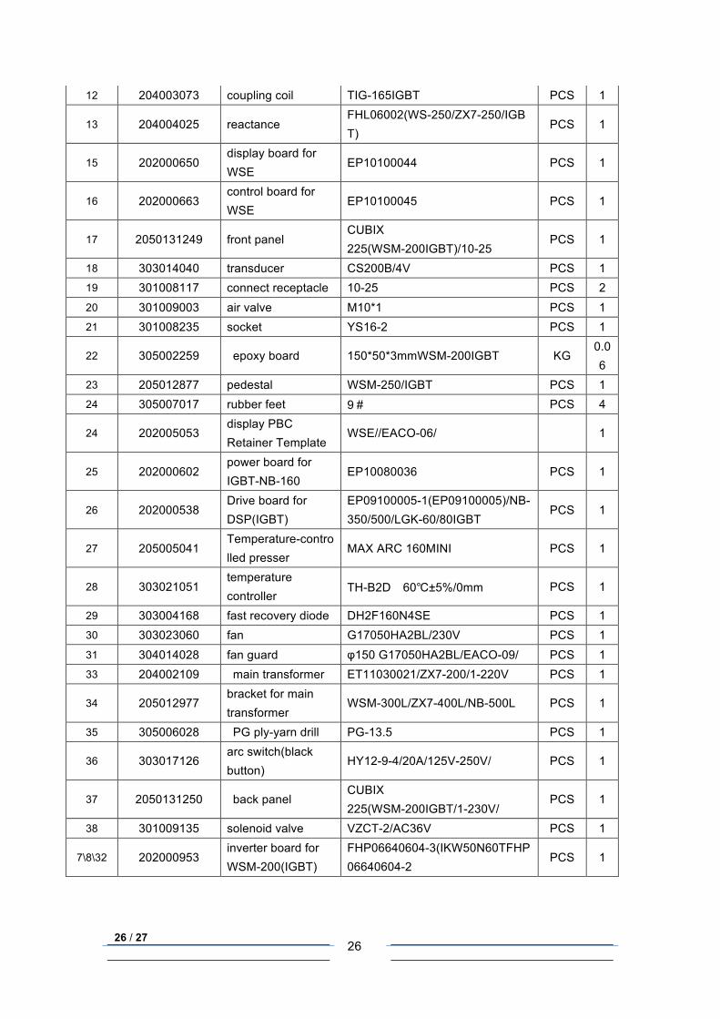
26 / 27
26
12 204003073 coupling coil TIG-165IGBT PCS 1
13 204004025 reactance FHL06002(WS-250/ZX7-250/IGBT)
PCS 1
15 202000650 display board for WSE
EP10100044 PCS 1
16 202000663 control board for WSE
EP10100045 PCS 1
17 2050131249 front panel CUBIX 225(WSM-200IGBT)/10-25
PCS 1
18 303014040 transducer CS200B/4V PCS 1 19 301008117 connect receptacle 10-25 PCS 2 20 301009003 air valve M10*1 PCS 1 21 301008235 socket YS16-2 PCS 1
22 305002259 epoxy board 150*50*3mmWSM-200IGBT KG 0.06
23 205012877 pedestal WSM-250/IGBT PCS 1 24 305007017 rubber feet 9# PCS 4
24 202005053 display PBC Retainer Template
WSE//EACO-06/ 1
25 202000602 power board for IGBT-NB-160
EP10080036 PCS 1
26 202000538 Drive board for DSP(IGBT)
EP09100005-1(EP09100005)/NB-350/500/LGK-60/80IGBT
PCS 1
27 205005041 Temperature-controlled presser
MAX ARC 160MINI PCS 1
28 303021051 temperature controller
TH-B2D 60℃±5%/0mm PCS 1
29 303004168 fast recovery diode DH2F160N4SE PCS 1 30 303023060 fan G17050HA2BL/230V PCS 1 31 304014028 fan guard φ150 G17050HA2BL/EACO-09/ PCS 1 33 204002109 main transformer ET11030021/ZX7-200/1-220V PCS 1
34 205012977 bracket for main transformer
WSM-300L/ZX7-400L/NB-500L PCS 1
35 305006028 PG ply-yarn drill PG-13.5 PCS 1
36 303017126 arc switch(black button)
HY12-9-4/20A/125V-250V/ PCS 1
37 2050131250 back panel CUBIX 225(WSM-200IGBT/1-230V/
PCS 1
38 301009135 solenoid valve VZCT-2/AC36V PCS 1
7\8\32 202000953 inverter board for WSM-200(IGBT)
FHP06640604-3(IKW50N60TFHP06640604-2
PCS 1
27 / 27
27
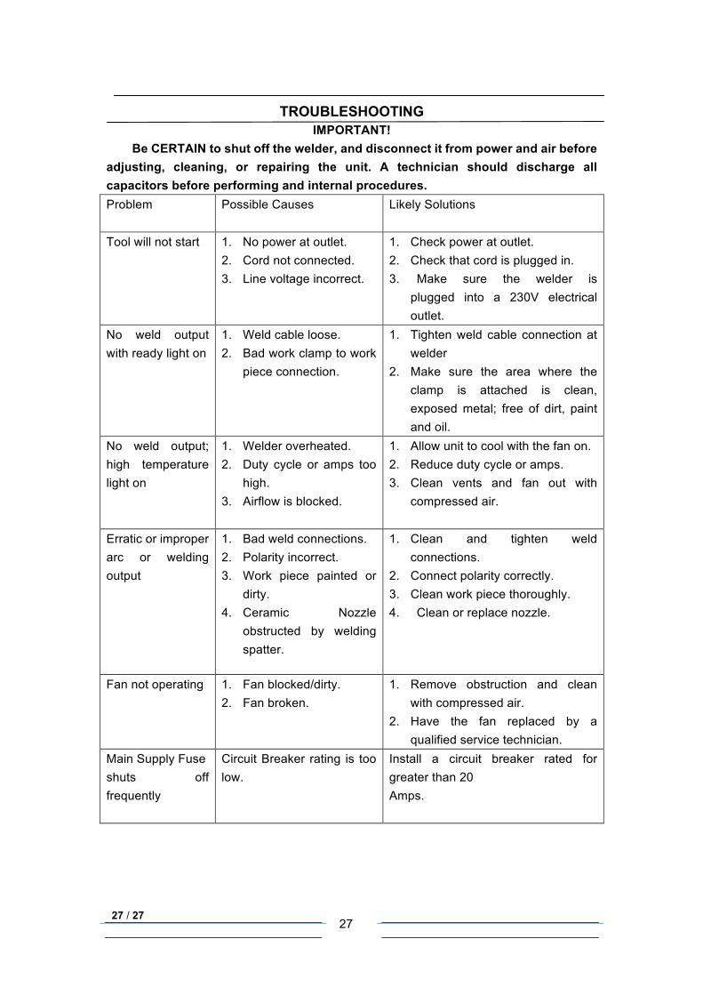
TROUBLESHOOTING
IMPORTANT! Be CERTAIN to shut off the welder, and disconnect it from power and air before
adjusting, cleaning, or repairing the unit. A technician should discharge all capacitors before performing and internal procedures. Problem
Possible Causes
Likely Solutions
Tool will not start
1. No power at outlet. 2. Cord not connected. 3. Line voltage incorrect.
1. Check power at outlet. 2. Check that cord is plugged in. 3. Make sure the welder is
plugged into a 230V electrical outlet.
No weld output with ready light on
1. Weld cable loose. 2. Bad work clamp to work
piece connection.
1. Tighten weld cable connection at welder
2. Make sure the area where the clamp is attached is clean, exposed metal; free of dirt, paint and oil.
No weld output; high temperature light on
1. Welder overheated. 2. Duty cycle or amps too
high. 3. Airflow is blocked.
1. Allow unit to cool with the fan on. 2. Reduce duty cycle or amps. 3. Clean vents and fan out with
compressed air.
Erratic or improper arc or welding output
1. Bad weld connections. 2. Polarity incorrect. 3. Work piece painted or
dirty. 4. Ceramic Nozzle
obstructed by welding spatter.
1. Clean and tighten weld connections.
2. Connect polarity correctly. 3. Clean work piece thoroughly. 4. Clean or replace nozzle.
Fan not operating
1. Fan blocked/dirty. 2. Fan broken.
1. Remove obstruction and clean with compressed air.
2. Have the fan replaced by a qualified service technician.
Main Supply Fuse shuts off frequently
Circuit Breaker rating is too low.
Install a circuit breaker rated for greater than 20 Amps.
Related Documents