SAFETY, SECURITY ASSESSMENT & OPERATIONAL PLANNING FOR LNG FUELED FERRIES LNG Operations Manual Washington State Ferries Report No.: PP061307-3, Rev. 3 Document No.: 167NWYK-12 Date: 2014-10-22

Welcome message from author
This document is posted to help you gain knowledge. Please leave a comment to let me know what you think about it! Share it to your friends and learn new things together.
Transcript

SAFETY, SECURITY ASSESSMENT & OPERATIONAL PLANNING FOR LNG FUELED FERRIES
LNG Operations Manual Washington State Ferries
Report No.: PP061307-3, Rev. 3 Document No.: 167NWYK-12 Date: 2014-10-22


EXECUTIVE SUMMARY This LNG Operations Manual serves as the procedural description of operations and bunkering of LNG according to the 33 CFR 127.305 and Ref. /2/. Ref /1/ has also been an important source to this Manual on concept, operations and design.
A risk assessment workshop was completed in the Washington State Ferries headquarters in Seattle February 14th 2013. The main focus of the workshops was safety principles of concepts and operations of the current design. Complete design and concepts has not been finalized at the date of this Manual.
The Operations manual was developed for the Issaquah class vessels and is a part of the LNG conversion project headed by Washington State Ferries. Proposed risk mitigating actions to systems and supporting management control as well as safety, emergency response, environmental and security management to accommodate LNG operations was identified.
A detailed description of the LNG transfer system and the related equipment has been provided with a focus on the gas fuel system, the bunkering station and related equipment, alarms and detectors, fire protection and suppression and mooring areas. The design and system details in this manual are based on the available preliminary documentation.
The duty, competence and qualification requirements are also described. The DNV standard for certification found in “Competence Requirements Related to the Use of LNG as Fuel on board Vessels” is included in Appendix I. The standard provides a detailed overview of the competence which is required for the crew on board an LNG fueled vessel. These are the minimum requirements which need to be in place for generic designs and layouts.
The procedures for transfer operations including gauging, cool down, operations start-up and shutdown, pumping, venting and communications have been included in this manual. The transfer procedures are given according to the following sub-processes:
[1] Conditions and requirements
[2] Safety during bunkering
[3] Personnel education and training
[4] Communication systems
[5] Pre-bunkering operations
[6] Operations during bunkering
[7] Operations post bunkering
The procedures related to the safety and the support safety systems are given as part of the procedures for transfer operations.
DNV GL – Report No. PP061307-3, Rev. 3 – www.dnvgl.com Page ii

Abbreviations CE Chief Engineer CH4 Methane CO2 Carbon Dioxide DNV Det Norske Veritas ERC Emergency Release Coupling ESD Emergency Shutdown EX Explosion Hazard GVU Gas Vaporizing Unit HC Hydro Carbons HFO Heavy Fuel Oil HP High Pressure IAS Integrated Automation System IGF International Code of Safety for ships using gas or other low flash-point fuels IMO International Maritime Organization ISO International Standards Organization LFL Lower Flammability Level LNG Liquefied Natural Gas LPG Liquefied Petrol Gas MBR Minimum Bending Radius MDO Marine Diesel Oil MGO Marine Gas Oil MIE Minimum Ignition Energy NG Natural Gas NOX Nitrogen Oxide PBU Pressure Building Unit PIC Person in charge PPE Personal Protection Equipment RPT Rapid Phase Transition SMS Safety Management System SOX Sulphur Oxide SSDG Ship’s Service Generators STCW Standards of Training, Certification and Watchkeeping UFL Upper Flammability Level UHF Ultra High Frequency USCG The United States Coast Guard VHF Very High Frequency WSF Washington State Ferries
DNV GL – Report No. PP061307-3, Rev. 3 – www.dnvgl.com Page iii

Table of contents
1 INTRODUCTION ........................................................................................................................... 1
1.1 The Manual .............................................................................................................................. 1
1.2 Environmental impact ............................................................................................................... 1
1.3 LNG Hazards ............................................................................................................................ 2
1.3.1 Chemical and physical properties ......................................................................................... 2
1.3.2 Description of physical phenomena ...................................................................................... 3
1.4 M/V Issaquah 130 car class auto/passenger ferry ......................................................................... 6
1.5 Regulatory framework of LNG as fuel .......................................................................................... 6
1.5.1 International regulations and standards ................................................................................ 6
1.5.2 Local regulations and standards ........................................................................................... 9
2 LNG TRANSFER SYSTEM AND EQUIPMENT DESCRIPTION ................................................................ 10
2.1 Proposed changes to systems and supporting management controls ............................................. 10
2.2 Changes in safety, emergency response, environmental and security management to accommodate LNG operations ................................................................................................................................ 11
2.3 Transfer system description ..................................................................................................... 11
2.3.1 Gas Fuel System .............................................................................................................. 11
2.3.2 The LNG bunker station .................................................................................................... 12
2.3.3 Bunker hoses .................................................................................................................. 14
2.3.4 Hose connections ............................................................................................................. 14
2.3.5 Bunker hose connection point ............................................................................................ 15
2.3.6 Hose inspection and testing ............................................................................................... 15
2.3.7 Marking .......................................................................................................................... 15
2.3.8 Differential pressure measuring ......................................................................................... 15
2.3.9 Lighting .......................................................................................................................... 15
2.3.10 Gas detectors .................................................................................................................. 15
2.3.11 Vent Mast ....................................................................................................................... 15
2.3.12 Nitrogen system .............................................................................................................. 16
2.3.13 Alarm, monitoring and control ........................................................................................... 16
2.3.14 Fire protection and suppression ......................................................................................... 16
2.3.15 Mooring areas.................................................................................................................. 17
DNV GL – Report No. PP061307-3, Rev. 3 – www.dnvgl.com Page iv

2.3.16 Fuel quality measuring ..................................................................................................... 18
3 DUTY, COMPETENCE AND QUALIFICATIONS REQUIREMENTS .......................................................... 19
3.1 General ................................................................................................................................. 19
3.2 Training and competence requirements ..................................................................................... 20
3.3 Assigned duties for the crew on board the Issaquah class vessels ................................................. 20
3.3.1 Control of operations ........................................................................................................ 20
3.3.2 Responsible of operations ................................................................................................. 21
3.3.3 Other areas of responsibility .............................................................................................. 21
3.3.4 Contact information .......................................................................................................... 21
4 MAINTENANCE........................................................................................................................... 22
5 LNG OPERATIONAL TRANSFER PROCEDURES ................................................................................ 23
5.1 General principles ................................................................................................................... 23
5.1.1 Scope ............................................................................................................................. 23
5.2 Conditions and requirements .................................................................................................... 24
5.2.1 Approval ......................................................................................................................... 24
5.2.2 Ship and supplier compatibility .......................................................................................... 24
5.2.3 Transfer Area .................................................................................................................. 24
5.2.4 Weather Conditions .......................................................................................................... 25
5.2.5 Light Conditions ............................................................................................................... 25
5.3 Safety ................................................................................................................................... 25
5.3.1 General .......................................................................................................................... 25
5.3.2 EX-Zone and hazardous zone ............................................................................................ 25
5.3.3 Security zone .................................................................................................................. 26
5.3.4 ESD-System .................................................................................................................... 26
5.3.5 Check-Lists ..................................................................................................................... 26
5.3.6 Instructions (Routines) ..................................................................................................... 26
5.3.7 Warning Signs ................................................................................................................. 27
5.4 Safety during Bunkering .......................................................................................................... 27
5.4.1 Smoking and Open Flame ................................................................................................. 27
5.4.2 Grounding on Switchboard ................................................................................................ 27
DNV GL – Report No. PP061307-3, Rev. 3 – www.dnvgl.com Page v

5.4.3 Electrical Currents ............................................................................................................ 27
5.4.3.1 Electrical current and Electrostatic Charge in Bunker Hose ............................................. 27
5.4.3.2 Electrical Arcing ........................................................................................................ 27
5.4.4 Radio and Communication Equipment ................................................................................. 28
5.4.5 Radar ............................................................................................................................. 28
5.4.6 Electrical storms .............................................................................................................. 28
5.4.7 Fire-Fighting Equipment .................................................................................................... 28
5.4.8 Accommodation Openings ................................................................................................. 28
5.4.9 Safety Zone .................................................................................................................... 28
5.4.10 Gas Accumulation ............................................................................................................ 29
5.4.11 Maintenance .................................................................................................................... 29
5.4.12 Redundancy .................................................................................................................... 29
5.5 Personal Protection Equipment (PPE) ......................................................................................... 29
5.6 Sharp edges ........................................................................................................................... 29
5.7 Communications ..................................................................................................................... 30
5.7.1 Language ........................................................................................................................ 30
5.7.2 Communication between Ship and Shore ............................................................................ 30
5.7.3 Procedure for Communication Failure ................................................................................. 30
5.8 Pre-bunkering operations ......................................................................................................... 30
5.8.1 Preparations .................................................................................................................... 30
5.8.2 LNG Tank System Check ................................................................................................... 31
5.8.3 Mooring Equipment Check ................................................................................................. 31
5.8.4 Bunker Hose Check .......................................................................................................... 31
5.8.5 Check-List for “operations before bunkering” ....................................................................... 31
5.8.6 Call ................................................................................................................................ 31
5.8.7 Arrangement Plan ............................................................................................................ 31
5.8.8 Mooring Operation ........................................................................................................... 31
5.8.9 Mooring Lines Supervision ................................................................................................. 32
5.8.10 Connection of Communication Link ..................................................................................... 32
5.8.11 Connection of Hoses ......................................................................................................... 32
5.8.12 Bunker Hoses .................................................................................................................. 32
DNV GL – Report No. PP061307-3, Rev. 3 – www.dnvgl.com Page vi

5.8.12.1 LNG Bunker Hose and Vapor Return Hose .................................................................... 32
5.8.12.2 Oil Bunker Hose ........................................................................................................ 33
5.8.12.3 Pre-Transfer Bunker Declaration of Inspection .............................................................. 33
5.9 OPERATIONS DURING BUNKERING ........................................................................................... 33
5.9.1 Return of Documents ........................................................................................................ 33
5.9.1.1 Signed Declaration of Inspection ................................................................................. 33
5.9.1.2 Signed document with Agreed Amount and Transfer Rate ............................................... 33
5.9.2 Inerting the Transfer Lines ................................................................................................ 33
5.9.3 Purging the Liquid Filling Line ............................................................................................ 33
5.9.4 Open Manual Bunker Valves .............................................................................................. 34
5.9.5 Ready Signal ................................................................................................................... 34
5.9.6 Pump Start Sequence ....................................................................................................... 34
5.9.7 Bunkering ....................................................................................................................... 35
5.9.8 Pump Stop Sequence ....................................................................................................... 35
5.10 OPERATIONS AFTER BUNKERING .............................................................................................. 36
5.10.1 Stripping of the transfer lines ............................................................................................ 36
5.10.2 Close Manual and Remote controlled valves ........................................................................ 36
5.10.3 Purging of the transfer lines .............................................................................................. 36
5.10.4 Disconnection of Hoses ..................................................................................................... 36
5.10.5 Disconnection Communication Link .................................................................................... 36
5.10.6 Delivery Bunker Document ................................................................................................ 37
5.10.7 Inerting of Bunker Lines ................................................................................................... 37
5.10.8 Check-list After Bunker ..................................................................................................... 37
6 SECURITY SYSTEMS ................................................................................................................... 38
7 REFERENCES ............................................................................................................................. 39
Appendix I Competence Related to the Onboard Use of LNG as Fuel
DNV GL – Report No. PP061307-3, Rev. 3 – www.dnvgl.com Page vii

1 INTRODUCTION 1.1 The Manual This manual describes the design and operation of the Issaquah class vessels in terms of conversion from diesel to LNG as the propulsion fuel. The Manual is developed in accordance with 33 CFR 127.305 and LNG ship to ship bunkering procedure developed by the Swedish Marine Technology Forum, Linde Cryo AB, FKAB Marine Design, Det Norske Veritas AS, LNG GOT and White Smoke AS as required by the U.S. Coast Guard Captain of the Port, Puget Sound.
A risk assessment workshop was completed at the Washington State Ferries headquarters in Seattle February 14th 2013. The workshop focused on the safety principles of the concept and operation of the current design. DNV recommends reviewing and updating the risk assessment upon any changes to the design, layout, processes or arrangements. The generics of this Operations Manual reflect the safety profile which was addressed in the workshop. The results of the workshop are described in the PP061307 Task 1 report.
The transfer guideline in Chapter 5 is based on the preliminary design and layout which is available at this stage of the project. The guideline should be updated and tailored to the design once it has been finalized and concluded.
1.2 Environmental impact One of the main reasons for building vessels fueled with LNG is their environmentally friendly profile both under normal operations and in the event of an accident. Using LNG instead of diesel is more environmentally friendly for the following reasons:
• Burning LNG as a fuel instead of diesel reduces the greenhouse gas emissions (CO2 and HC) due to the higher hydrogen ratio in LNG compared to diesel or HFO. The release of NOX, SOX and particles are reduced significantly (82-84 %, 100% and 67 %, respectively). The reductions are dependent on engine size and type.
• Methane gas might be released through the vent mast due to different reasons, such as pressure build up in the LNG tank. Methane is a more severe greenhouse gas than CO2 (greenhouse gas potential 20 to 25 times greater than CO2) and therefore methane releases should be kept to emergencies only. Running the engines or boiler on gas to lower the pressure in the LNG tank is better for the environment then lowering the pressure by releasing methane. The most likely source of methane releases will be due to purging of the gas pipes to ensure that no gas is trapped. This will be done when shutting down the engines or switching to diesel fuel. The amount of methane gas released in these scenarios will most likely be minor as well as the frequency thereof. Currently there are no state or federal regulations that regulate methane releases from ship traffic.
• Accidental spills of LNG to the marine environment would result in a relatively small and thin film, which is so volatile it would only affect the immediate surroundings. The majority of the fuel would evaporate immediately and be removed from the sea. Comparatively, a diesel oil release of the same magnitude (same mass of fuel) would result in an oil slick about 1000 times larger, more persistent and much more detrimental to sea-mammals, birds, and aquatic wildlife.
DNV GL – Report No. PP061307-3, Rev. 3 – www.dnvgl.com Page 1

• Releases of sub-surface LNG (a worst-case scenario for releases to the aquatic environment during e.g. capsizing) would result in a gaseous flow to the surface of methane and ethane, which could saturate the surrounding waters with these gases. The concentrations are not, however, considered sufficiently high to cause long-term effects on the affected environment.
• The components that may be liquid at deeper waters (butanes and pentanes) have such a low density that these too are expected to flow rapidly to the surface if released after e.g. capsizing or sinking of the vessel. Rapid dilution of these components, to concentrations well below acute and chronic effect levels, ensures that negligible environmental effects are expected from such a spill.
1.3 LNG Hazards In order to understand the behavior of natural gas correctly, a basic knowledge of its chemical and physical properties is needed. How natural gas behaves is determined by its properties and it also largely affects how the risks involved are assessed with respect to accidental releases of natural gas. Furthermore, differentiating between its properties in liquid- and gas phase is needed.
1.3.1 Chemical and physical properties
Liquefied natural gas (LNG) is natural gas, predominantly methane (CH4) with some Ethane, Propane, Butane, Pentane and other heavier components that have been liquefied for ease of storage or transportation. The reason why it is made liquid is that methane requires 600 times more volume in gas phase than in liquid phase, hence, it is much more efficient to transport it in liquid phase.
Methane is a colorless, odorless and low toxic gas. Some properties of methane are provided below:
• Molecular weight: 16.0425 g/mol
• Density: 6.67151E-4 g/cm3 (at 20 °C / 68 °F)
• Boiling point: -248 °F (-161.48 °C / -248 °F)
• Vapor density: 0.55 (relative to air)
Further fire hazard properties of LNG as well as Diesel and Gasoline are summarized in Table 1.
DNV GL – Report No. PP061307-3, Rev. 3 – www.dnvgl.com Page 2

Table 1: Fire hazard related properties of methane (LNG) and other light hydrocarbon fuels
Particulars Gasoline (100 Octane)
Diesel (fuel)
LNG Propane (LPG)
Flash point (°C) < -40 >62 -187 (Flammable gas)
-104 (Flammable gas)
Flammability limits (% in air)
LFL 1.4 0.6 5 2.1
UFL 7.6 7.5 15 9.5
Auto ignition temperature (°C) 246-280 250-300 537 480
Minimum Ignition Energy (MIE) in air (mJ)
- 20 0.27 -
Data sources: Hess Material Datasheet, Murphy, Michael J (1994) and Pitblado et al., 2006
- Flash point: The minimum temperature at which a liquid gives off vapor in sufficient concentration to form an ignitable mixture with air near the surface of a liquid, as specified by test
- Flammability limits: The lowest (LFL) and highest (UFL) concentrations of a combustible hydrocarbon gas in air at which the mixture is flammable.
- Auto ignition temperature: Temperature at which a flammable mixture will spontaneously ignite
- Minimum Ignition Energy: The minimum energy required to ignite a flammable mixture. A spark with an energy level of 0.25 (mJ) is barely visible to the eye
1.3.2 Description of physical phenomena
Due to its properties, LNG will represent other types of hazards, if spilled and in contact with personnel or materials compared to other fuels. The major hazards that are particular for LNG are presented below.
Flash Fire
A flash fire occurs when a cloud of gas burns without generating any significant overpressure. The cloud of methane (and the mix of ethane and propane) can only be ignited where the concentration is above the Lower Flammable Limit (LFL) and below Upper Flammable Limit (UFL). The flammable range for methane is 5% to 15% in mixture with air. Below 5% mix (methane/air) it will be too lean to ignite, and above 15% it will too rich to ignite.
The gas clouds can only be ignited at the edge as they disperse and meet an ignition source (e.g. open flame, internal combustion engine, sparks). An ignited cloud will “flash back” across all its flammable mass (i.e. that part within the flammable range – between the UFL and LFL). It will then burn at the UFL boundary until the entire hydrocarbon is consumed. The duration of the flash fire is relatively short, but it may stabilize as a continuing jet fire or pool fire from the leak origin.
DNV GL – Report No. PP061307-3, Rev. 3 – www.dnvgl.com Page 3

The following safety instructions are to be undertaken in order to avoid fire:
• All sources of ignition in the safety zone are to be strictly prohibited
• Organize and train all personnel for fire fighting
• Advise where smoking and naked fires are NOT allowed
• Fire and gas leakage safety barriers are to be established
• Full firefighting procedures and instructions are to be established for the ship
Pool Fire
For large spills, air cannot transfer enough heat to vaporize much LNG so a part of the spill is likely to end up in a liquid pool. A pool fire may result after a flash fire. A LNG pool fire generates significant thermal radiation with the surface emission power around 200kW/m2 (a person in protective clothing will typically withstand 12kW/m2 for a short time). Once combustion is added to evaporation, the pool will shrink significantly in size to a sustainable pool fire diameter.
Jet fire
Jet fires are burning jets of gas or atomized liquid whose shape is dominated by the momentum of the release. Jet fires typically result from gas or condensate releases from high-pressure equipment, e.g. a high-pressure pump, high pressure piping etc. Jet fires may also result from releases of high-pressure liquid containing dissolved gas, due to the gas flashing off and turning the liquid into a spray of small droplets. Typical conditions for this are at a pressure over 2 barg.
Explosion
A vapor cloud explosion can occur when a large flammable mass of hydrocarbon vapor is ignited in a confined space (e.g. an enclosed box). In an open space, outdoors situation, there is no confinement and the experimental evidence is that methane gas will burn relatively slowly with all the expansion resulting in a vertical rise of gas. Within methane clouds, flame propagation is slow. Sufficient flame acceleration to create explosion overpressure will not occur if there is not enough congestion or confinement.
Asphyxia
Methane, or natural gas, is not toxic. However, in the case of a release of natural gas in an enclosed or semi-enclosed area it can result in asphyxiation due to the lack of oxygen caused by decrease of the partial pressure of oxygen in the inhaled air, which is established when mixing methane and air. Concentrations of 50% by volume (methane in air) will cause obvious suffocation symptoms like difficulties in breathing and rapid breathing at the same time as the ability to respond deteriorates and muscle coordination weakens.
Rapid Phase Transformation (RPT)
This is a very rapid physical phase transformation of LNG to vapor mainly due to submersion in water. It can cause a small but serious local physical explosion effect, which at greater distances can cause low overpressures. The risk of RPT is limited to the LNG/water mixing zones. DNV believes that the intensity of explosion will be much less than a detonation (supersonic velocities) and more equivalent to a pressure wave limited to sonic velocity or less. This is unlikely to damage large structural elements of a ship or jetty. No specific modeling is undertaken for RPT as it is unlikely to increase the hazard range of a major spill that has already occurred. Rapid phase changes have not resulted in any known major incidents involving LNG.
DNV GL – Report No. PP061307-3, Rev. 3 – www.dnvgl.com Page 4

Brittle fracture and cryogenic burns
The cryogenic properties are particular for LNG and it thus require special attention. In order to get the methane into liquid phase it needs to be cooled down below its boiling temperature of -161.48 °C (-248 °F) thus representing thermal hazards to personnel (e.g. in contact with the liquid). However, the extremely low temperatures are not only hazardous to people. While stainless steel and aluminum will remain ductile, carbon steel and low alloy steel will become brittle and fractures are likely if exposed to such low temperatures. Standard ship steel must therefore be protected and insulated from any possible exposure to LNG, Ref. /4/.
Trapped LNG
If LNG is trapped in the piping or somewhere along the transfer line, a phase transition will cause a local pressure build up. The expansion can potentially cause a pipe burst leading to a significant release of natural gas or LNG depending on the size of the burst and operating conditions.
All pipe sections and tanks shall therefore be secured with thermal relief valves. Always take necessary precautions when encompassing system modification or maintenance, as the case of trapped liquid between two valves can lead to fatal consequences (tube cracking).
DNV GL – Report No. PP061307-3, Rev. 3 – www.dnvgl.com Page 5

1.4 M/V Issaquah 130 car class auto/passenger ferry WSF currently operates five Issaquah 130 class ferries: M/V Issaquah, M/V Kittitas, M/V
Chelan, M/V Kitsap, M/V Cathlamet and one Issaquah class ferry, M/V Sealth. These vessels were built and commissioned in the early 1980s.
The Issaquah class main particulars and conversion details are given in Table 2.
Figure 1: M/V Issaquah class ferry
Table 2: Issaquah class particulars
Class: Issaquah 130 Type: Auto/Passenger Ferry
Length: 328’ Speed in Knots: 16
Beam: 78’ 8” Propulsion: LNG
Draft: 16’ 6” Max Vehicles: 130
Max Passengers: 1200 Gross Tonnage: 2477
Tall Deck Space: 26 City Built: Seattle
Auto Deck Clearance: 15’6” Year Built/Re-built: 1979 - 1983
1.5 Regulatory framework of LNG as fuel
1.5.1 International regulations and standards
The world first rules for LNG fuelled ships were issued by DNV in 2000, along with the construction of the world’s first LNG fuelled ferry, Gultra. LNG has been transported as cargo for many years, and several regulations for these large-scale LNG facilities exist. Currently, there are no formalized standards or operational procedures for LNG bunkering operations and LNG bunker stations in place. Local regulations may be present, but there is a need to not only develop but to harmonize regulations on an international basis. This situation is, however, about to improve.
LNG bunkering should not be considered in the same context as large scale, commercial transfer of cargo between ocean-going LNG carriers. These large transfer types are regulated by separate standards which
DNV GL – Report No. PP061307-3, Rev. 3 – www.dnvgl.com Page 6

are not qualified for the small dimensions referred to in this report. The IGF Code, once ratified, is expected to come into force in 2014 for gaseous fuel use on LNG fuelled vessels. Chapter 9 of the IGF Code governs the ship side of the bunkering process.
Currently, the introduction of utilizing LNG as fuel and the development of its accompanying processes and operations have been risk and experience based because of lack of standards for small scale LNG operations. As the LNG fuel fleet grows and is being introduced in various different geographic areas, the need for a set of standards with best practice guidelines to ensure compatibility and safe operations is increasing.
The International Organization for Standardization (ISO) through a working group ISO TC67/WG10 PT1 “Guidelines for systems and installations for supply of LNG as fuel to Ships” is, working together with a chair of different countries’ representatives from the gas industry, guidelines / minimum requirements on safety, operational and control procedures, component and equipment requirements, maintenance procedures, training and emergency operations to ensure safe, practical and efficient LNG bunkering operations of gas fuelled ships from; bunkering vessels and barges and onshore installations either from fixed storage tanks or LNG trucks. The ISO guideline is expected to be issued before the third quarter of 2013.
The following illustrates a non-exhaustive list of international regulations and standards including DNV Class Rules on LNG fuelled ships and ships transporting cargo and production, storage and transfer of LNG.
• IMO International Code for the Construction and Equipment of Ships Carrying Liquefied Gases in Bulk (IGC code)
• IMO International Code for Safety for Ships using Gases of other Low Flashpoint Fuels (IGF code). The code is currently under development and is expected to enter into force as early as 2016
• IMO Resolution MSC. 285 (86) “Interim Guidelines on Safety for Natural Gas-Fuelled Engine Installations in Ships. Until the IGF code enters into force IMO recommends to use the interim guideline
• An ISO-standard is under development under ISO/TC 67/WG 10 PT1 “Guidelines for Systems and Installations for Supply of LNG as Fuel to Ships”
• DNV classification rules, such as Rules for classification of ships Part 6 Chapter 13 “Gas Fuelled Ship Installations”
• ISO/FDIS 28460 “Petroleum and natural gas industries – Installation and equipment for liquefied natural gas – Ship-to-shore interface and port operations”
Table 3 illustrates a non-exhaustive list of applicable standards to components of a LNG bunkering transfer system for truck to ship bunkering operations.
DNV GL – Report No. PP061307-3, Rev. 3 – www.dnvgl.com Page 7

Table 3: Applicable standards to components of LNG bunkering transfer system related to onshore
installations
Component Function Design Qualification test Tests
Coupling Connection to ship's manifold EN 1474-1, Clause 6 EN 1474-1, 8.2.3 EN 1474-1, 8.4.4
Hoses Transfer of LNG and NG
Offshore standards can be used for guidance(EN1474 – 2 )
Ref. Note
Ref. Note EN 12434
BS 4089
Swivel joints Product line articulation EN 1474-1, 4.3 New design qualification EN 1474-1, 8.4.1
Bearing Articulation of support structure
ISO 28460 – EN 1474-1, 4.4 ISO 28460 – EN 1474-1 EN 1474-1, 8.4.2
ERS Emergency disconnector
ISO 28460 – EN 1474-1, 5.5.2
ISO 28460 – EN 1474-1, 8.2.2 EN 1474-1, 8.4.3
Breakaway coupling
Emergency disconnector EN 1474-1, 5.5.2 EN 1474-1, 8.2.2 EN 1474-1, 8.4.3
Loading arms Loading system
ISO 28460 – EN 1474-1, Clause 4 N/A ISO 28460 – EN 1474-1,
8.4.7
Transfer system
LNG bunkering loading solution
ISO 28460
EN 1474-3 ISO 28460 – EN 1474-1
EN 1160
EN1474-1
OCIMF Mooring Equipment Guidelines
IEC 60079
IGF Code
NFPA 70
NFPA 58
NFPA 59A
EN 13465
API 2003
ISO/TS 16901
Note: For hoses intended to be used in multiple LNG transfer configurations, due to the variety of the receiving ships for
example, the criteria applied for their qualification according to EN 1474-2 shall be determined on the base of an agreed
envelope to be defined between the manufacturer, the owner and the qualification body. These criteria shall be defined
prior to the official qualification testing campaign is started and the qualification will be valid for the configurations
covered by the agreed envelope only.
DNV GL – Report No. PP061307-3, Rev. 3 – www.dnvgl.com Page 8

1.5.2 Local regulations and standards
During bunkering there are certain local regulations to consider in addition to the international regulatory framework as described in Chapter 1.5.1. Local authorities and the responsible port need to permit LNG bunkering at the chosen location. There are several national rules and guideline that may be applicable:
• Port Regulations for the Port of Seattle
• National Fire Protection Association, NFPA-57
• Code 2002 Edition Rules for the truck
• USCG 33 CFR Part 127 Waterfront facilities handling liquefied natural gas and liquefied hazardous gas
• Navigation and Vessel Inspection Circular no. 11-02 (NVIC 11-02)
• CG521 Policy Letter Equivalency Determination - Design Criteria for Natural Gas Fuel Systems
• CG-OES Policy Letter No. 01-14 Guidelines for Liquefied Natural Gas Fuel Transfer Operations and Training of Personnel on Vessels Using Natural Gas as Fuel
• CG-OES Policy Letter No. 02-14 Guidance Related to Vessels and Waterfront Facilities Conducting Liquefied Natural Gas (LNG) Marine Fuel Transfer (Bunkering) Operations
DNV GL – Report No. PP061307-3, Rev. 3 – www.dnvgl.com Page 9
2 LNG TRANSFER SYSTEM AND EQUIPMENT DESCRIPTION A description of the transfer system equipment including mooring areas, transfer connections, control rooms, and diagrams of the piping and electrical systems is provided in this Chapter. The conversion of the Issaquah Class vessels from diesel to LNG fuelled propulsion implies significant changes to the total fuel system on board. A description of the technical changes on board is given below.
The design and system details in the following chapters are based on the available preliminary documentation from WSF at the date of this manual.
2.1 Proposed changes to systems and supporting management controls
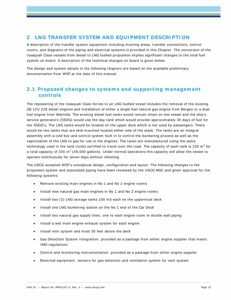
The repowering of the Issaquah Class ferries to an LNG fuelled vessel includes the removal of the existing GE 12V-228 diesel engines and installation of either a single fuel natural gas engine from Bergen or a dual fuel engine from Wärtsilä. The existing diesel fuel tanks would remain intact on the vessel and the ship’s service generators (SSDG) would use the day tank which would provide approximately 30 days of fuel for the SSDG’s. The LNG tanks would be located on the upper deck which is not used by passengers. There would be two tanks that are skid mounted located either side of the stack. The tanks are an integral assembly with a cold box and control system built in to control the bunkering process as well as the vaporization of the LNG to gas for use in the engines. The tanks are manufactured using the same technology used in the tank trucks certified to travel over the road. The capacity of each tank is 100 m3 for a total capacity of 200 m3 (48,000 gallons). Under normal operations this capacity will allow the vessel to operate continuously for seven days without refueling.
The USCG accepted WSF's conceptual design, configuration and layout. The following changes to the propulsion system and associated piping have been reviewed by the USCG MSC and given approval for the following systems:
• Remove existing main engines in No 1 and No 2 engine rooms
• Install new natural gas main engines in No 1 and No 2 engine rooms
• Install two (2) LNG storage tanks 100 m3 each on the uppermost deck
• Install one LNG bunkering station on the No 1 end of the Car Deck
• Install two natural gas supply lines: one to each engine room in double wall piping
• Install a wet main engine exhaust system for each engine
• Install vent system and mast 30 feet above the deck
• Gas Detection System Integration: provided as a package from either engine supplier that meets IMO regulations
• Control and monitoring instrumentation: provided as a package from either engine supplier
• Electrical equipment: sensors for gas detection and ventilation system for vent system
DNV GL – Report No. PP061307-3, Rev. 3 – www.dnvgl.com Page 10

• Fire suppression systems: deluge system for each pilothouse and dry chemical system for bunkering station
2.2 Changes in safety, emergency response, environmental and security management to accommodate LNG operations
Changes for LNG operations shall be integrated into WSF’s existing Safety Management System (SMS). It is important to understand that WSF will incorporate LNG operations into its wide-ranging and integrated approach to safety, emergency response, environmental and security management for the entire Washington State Ferries system. The foundation for this approach is WSF’s detailed and extensive SMS.
All policies and procedures regarding the use of LNG as a fuel will be integrated into the SMS. The goal of WSF’s SMS is to ensure that policies and procedures are clearly defined, that these documented policies and procedures meet or exceed regulatory requirements, and that the opportunity for continuous improvement is available to all WSF employees. WSF’s intent with their SMS is to provide “best practice” safety, emergency response, environmental and security guidelines for all WSF employees in a standardized approach, covering routine, critical, and emergent activities. SMS policies and procedures provide a structure within which managers and employees are expected to use sound judgment in the performance of their duties which is an important part of WSF’s Safety Management.
2.3 Transfer system description The LNG system design is not finalized at the date of this Operations Manual. However, a preliminary description of the LNG system transfer arrangements and layout is given below. The technical information is according to /3/.
2.3.1 Gas Fuel System
Engine selection has not been agreed yet, but the alternatives that are being looked into are the Rolls Royce Bergen C26:33 L9PG and the Wärtsilä 6L34DF.
The gas fuel system includes the LNG storage tanks, gas vaporization equipment, gas distribution system, and bunkering system. The general gas system arrangement is shown in Figure 2. Certain aspects of the gas fuel system arrangement vary slightly, depending on whether gas only or dual fuel engines will be used. Where there are differences, both configurations will be addressed specifically.
Figure 2: Gas system arrangement
DNV GL – Report No. PP061307-3, Rev. 3 – www.dnvgl.com Page 11

The LNG storage tanks proposed are two 100m3 (26417 gal) custom tanks. Both tanks are of sufficient size to provide 7 days endurance on the Seattle – Bremerton route which is the current LNG filling interval target.
The LNG storage tanks will be placed transversely on either side of the exhaust casing. Reinforcement of the deck and supporting structure will be required to support the tanks but major changes to the vessel’s structure are not required. The tanks will be double shell vacuum-insulated pressure vessels, with a design pressure of 7.5 barg (109 psig) and an operating pressure of 5 to 6 barg (73 to 87 psig). A gastight tank room will be integral to one end of each of the tanks, and will contain all the gasification process equipment. Each tank room will contain a pressure building unit (PBU), a LNG Vaporizer (GVU), and a Natural Gas (NG) Heater, as well as gas delivery piping and valves. All of the gas piping and equipment that processes liquefied gas will be located inside of the tank room. This does not include the bunkering pipes which also carry liquefied gas, and are located outside of the tank rooms.
The tanks will be equipped with pressure relief valves to prevent over pressurization of the tank. The relief valves will vent the tank to the gas vent. The storage tanks arrangement is illustrated in Figure 3.
DNV will recommend sufficient safeguards to be in place for this particular tank location and arrangement. The tank location on the top of the ship above passenger areas will require means of leakage prevention from tanks or transfer lines which are open to air. A leakage could potentially cause LNG to spill down and along the side of the ship, evaporating and potentially entering the passenger or crew areas. The final design for the LNG fuel installation will include protection against LNG leaks and the impoundment of potential LNG spillage.
Figure 3: Storage tank arrangement
2.3.2 The LNG bunker station
The vessel will have a bunkering station located at the No 1 end of the Car Deck (see Figure 4). This location is open to air and will have good natural ventilation. The vehicle space is open in both ends and has large openings in the sides. Nevertheless, DNV recommends considering this as a confined space. A gas leakage could create a gas cloud that could potentially be trapped between the openings on the car deck.
DNV GL – Report No. PP061307-3, Rev. 3 – www.dnvgl.com Page 12

Any ignition of the trapped gas cloud could lead to a fire escalation. Sufficient safeguards like gas detectors, ESD and fire safety systems should therefore be integrated into the design.
The bunker station will consist of a shore connection, a pressure gauge, a manual stop valve, and a remotely operated stop valve. Insulated stainless steel trays will be provided below the LNG and vapor return manifolds, to prevent damage to the steel hull in case of leakage. Each tray should have an outlet overboard which can be a temporary fitted pipe or hose to lead possible spill to the water without contact to the hull. The deck and hull penetrations will be sleeved and the drain pipe will be thermally isolated from the vessel’s structure. The overboard will be installed such that any liquid discharged from the drain is directed away from the vessel’s hull. The bunkering station will be shielded from all accommodations spaces by A-60 boundaries.
The bunker piping will be routed from the bunker station up to the overhead of the vehicle space, where it will be run to the exhaust casing at approximately amidships. The piping run from the bunkering station to the casing will include a protection guard around the associated piping. During normal operations there will be no liquid or gas contained within this section of piping (it will be gas free). Inside the casing, the piping will be routed up to the tanks alongside the gas supply piping inside a ventilated duct. The bunker piping inside the casing will be double wall vacuum jacketed pipe. Because the vehicle space is an open space, piping in the vehicle space will be single walled pipe.
The bunkering station module and the bunker piping that runs up the side shell of the vehicle space will be located closer than 760 mm (29.9 in) from the ship side. This is in apparent conflict with the applicable DNV rules for LNG Fuelled Ship Installations /5/ and shall be given special attention upon approval. Once the bunker pipe reaches the overhead of the vehicle space, it will immediately run inboard to where it will be more than 760 mm (29.9 in) from the ships side. Bunkering will only occur while the vessel is at the dock. While the vessel is underway, the bunker pipe will be inerted with nitrogen and gas free in accordance with the rules.
DNV GL – Report No. PP061307-3, Rev. 3 – www.dnvgl.com Page 13
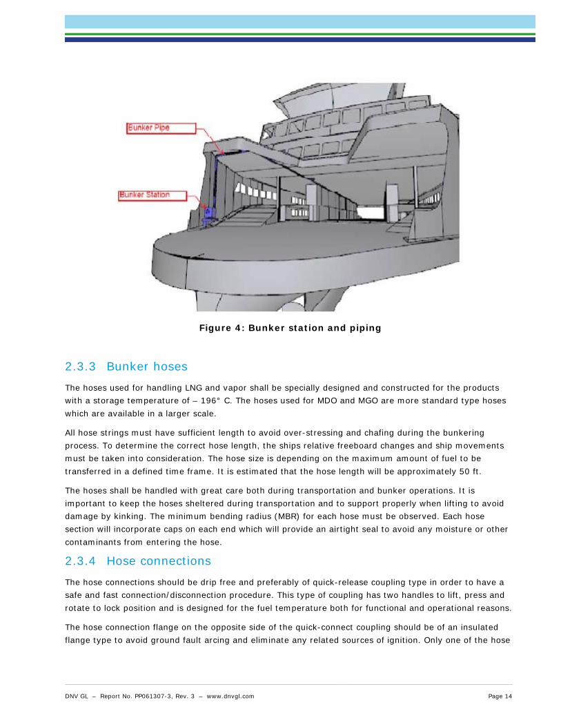
Figure 4: Bunker station and piping
2.3.3 Bunker hoses
The hoses used for handling LNG and vapor shall be specially designed and constructed for the products with a storage temperature of – 196° C. The hoses used for MDO and MGO are more standard type hoses which are available in a larger scale.
All hose strings must have sufficient length to avoid over-stressing and chafing during the bunkering process. To determine the correct hose length, the ships relative freeboard changes and ship movements must be taken into consideration. The hose size is depending on the maximum amount of fuel to be transferred in a defined time frame. It is estimated that the hose length will be approximately 50 ft.
The hoses shall be handled with great care both during transportation and bunker operations. It is important to keep the hoses sheltered during transportation and to support properly when lifting to avoid damage by kinking. The minimum bending radius (MBR) for each hose must be observed. Each hose section will incorporate caps on each end which will provide an airtight seal to avoid any moisture or other contaminants from entering the hose.
2.3.4 Hose connections
The hose connections should be drip free and preferably of quick-release coupling type in order to have a safe and fast connection/disconnection procedure. This type of coupling has two handles to lift, press and rotate to lock position and is designed for the fuel temperature both for functional and operational reasons.
The hose connection flange on the opposite side of the quick-connect coupling should be of an insulated flange type to avoid ground fault arcing and eliminate any related sources of ignition. Only one of the hose
DNV GL – Report No. PP061307-3, Rev. 3 – www.dnvgl.com Page 14

end flanges should be insulated as insulation of both ends can cause an electrical differential potential build-up between the two insulated points which can represent a potential source of ignition.
2.3.5 Bunker hose connection point
There shall be a break-away (dry-break) coupling (Emergency Release Coupling, ERC) on each LNG hose, placed on the receiving ship’s manifold to ensure that hoses do not break in case of extreme movement or emergency. The function of this coupling is to be the weakest part of the chain and to break off if forces exceed the limits. Inside the coupling, there are two quick-closing shut-off valves, which immediately close and prohibit leakage.
2.3.6 Hose inspection and testing
All hoses shall be part of a specified test program where each hose is to follow a predetermined schedule of inspection, pressure testing and finally replacement. The hoses shall be pressure tested in consultation with the hose manufacturer. This schedule is to be strictly maintained and all information is to be documented and saved on board. The hoses must also be visually inspected before each transfer to detect possible damages during handling. It is very important to monitor the hoses during start-up of the transfer, to verify that there is no leakage which can increase and cause spillage.
2.3.7 Marking
Each hose is to be marked according to a specific system. The marking should contain the following information: For which fuel the hose is designed for, manufacturer, maximum allowable working pressure, month and year of manufacture, minimum bending radius and certification number to identify the specific hose in inspection and testing program.
2.3.8 Differential pressure measuring
Each LNG bunker hose shall have a differential pressure measuring system connected to the control system. The pressure will drop quickly in case of a hose leakage which will be detected and the control system will automatically activate the safe shut-down procedure (ESD) which will close down necessary valves and cargo pump and give audio and visible signals on the bunker ship bridge.
2.3.9 Lighting
Ferry and terminal lighting shall be sufficient in terms of ability for continuous monitoring during the total bunkering operation. Note that all lights around the bunker area are to be intrinsically safe.
2.3.10 Gas detectors
There shall be gas detectors installed in enclosed or semi-enclosed spaces around the bunker area. The detectors are to be connected to the control system and give both visible and audio signals at the actual location in case of a detected leakage. The bunker operation shall be terminated in case of gas detection and not be resumed until it is safe to proceed.
2.3.11 Vent Mast
Because of the hazardous nature of vented gas, all gas vents are connected to a gas vent mast. The international standard for the gas vent mast requires it to be located 10 m (33 ft.) away from ventilation intakes or accommodation access doors. In the current design the gas vent mast will be located on the
DNV GL – Report No. PP061307-3, Rev. 3 – www.dnvgl.com Page 15

centerline at amidships and will extend 12.2 m (40 feet) above the outlet of the exhaust. Because the vent mast is so tall, it will likely need to be guyed to the vessel’s structure.
The structural details of the mast and its location will need to be developed during the detailed design.
2.3.12 Nitrogen system
Nitrogen is used to purge and inert the bunker pipes and gas supply pipes. To supply the nitrogen, a nitrogen system would need to be installed on the vessel. The nitrogen system would use compressed nitrogen cylinders located in the fixed firefighting room. This space was selected because it is a well-ventilated space that already contains compressed gas cylinders. A pressure regulator would be installed at the nitrogen tank, and nitrogen supply piping would be led to the GSU enclosures, the tank rooms, and the bunker stations. The nitrogen distribution piping would have a maximum working pressure of 10 barg (150 psig).
2.3.13 Alarm, monitoring and control
An alarm, monitoring, and control system will be provided by the engine and gas system supplier and will be integrated into the vessel’s overall alarms, monitoring and control system.
The system will provide operational monitoring and controls as well as monitoring and alarms for faults and failures, and control of valves required for automatic shutdown.
In order to comply with class rules /5/, a number of specific detectors and sensors are required for gas fuelled vessels. Detectors and sensors as described in Table 4 will be fitted.
Table 4: Detectors and sensors to be fitted for securing safe operation of the LNG system
Location Qty Type
Tank
1 Pressure sensor
1 Level indicator
1 High level alarm
Ventilation duct 3 Gas detector
Engine room
2 Gas detector
1 Smoke detector
1 Heat detector
GSU enclosure 1 Gas detector
2.3.14 Fire protection and suppression
In addition to the typical fire protection and suppression systems required for a diesel fuelled passenger vessel, there are several specific fire detection and suppression systems required for gas fuelled vessels.
DNV GL – Report No. PP061307-3, Rev. 3 – www.dnvgl.com Page 16

These systems include a water spray system to protect the storage tanks, fixed fire systems to protect the bunkering stations, and additional structural fire protection.
A new branch off the sprinkler system will need to be installed to serve the water spray system for the storage tanks. The sprinkler pump in the existing design is of sufficient size to meet the required sprinkler service. Some sprinkler system valves may need to be replaced with remotely operated valves so that the LNG storage tank water spray system can be automatically started.
The locations of the on board fire stations will require evaluation to ensure there is adequate stations and isolation near the LNG storage tank.
Changes to WSF’s SMS to address ignition source control and firefighting shore side will include the following:
• WSF will supply a sufficient number of fire extinguishers (approved by an independent laboratory) throughout the facility and maintained in a ready condition.
• WSF will ensure that the location of each hydrant, standpipe, hose station, fire extinguisher, and fire alarm box is conspicuously marked and readily accessible.
• WSF will ensure that temporary signs indicating that smoking is prohibited are posted in areas where smoking is not permitted. WSF will ensure that welding or hot work is prohibited during transfer of LNG.
• The vessels will be equipped with fixed sensors which will have audio and visual alarms in the control room and audio alarms nearby. The fixed sensors will continuously monitor for NG vapor, flame, and heat.
• WSF will purchase and incorporate in to their procedures portable gas detectors. WSF will ensure that at least two portable gas detectors capable of measuring 0-100% of the lower flammable limit of methane will be available at each transfer of LNG.
2.3.15 Mooring areas
The vessel will have adequate means of mooring with respect to current, tide and weather conditions during bunkering. Good quality mooring lines well placed and sufficiently strong fairleads and bollards will be provided.
Mooring lines and necessary means of propulsion are used to maintain a steady position relative to the bridge on the pier during the bunkering operations. Mooring area minimums will be determined by and will include weather, traffic, construction or other specific considerations.
DNV GL – Report No. PP061307-3, Rev. 3 – www.dnvgl.com Page 17

Figure 5: Vessel lay-up and mooring during bunkering
2.3.16 Fuel quality measuring
There may be a need for measuring and documenting the quality and quantity of the LNG bunkered, especially in the case of serving several different customers. The quality could be measured by a Gas Chromatograph, where a small sample is taken and analyzed for its energy value and content. The quantity could be measured by a mass flow meter which continuously monitors the amount being bunkered.
DNV GL – Report No. PP061307-3, Rev. 3 – www.dnvgl.com Page 18

3 DUTY, COMPETENCE AND QUALIFICATIONS REQUIREMENTS 3.1 General The requirement for pre-training and qualification before working on an LNG fuelled vessel shall ensure that the seafarer is fully aware of the characteristics, and potential risks associated with handling LNG.
Training requirements for personnel involved in gas handling processes are regulated according to the CG-OES Policy Letter No. 01-14, CG-OES Policy Letter No. 02-14, IMO MSC.285(86), STCW, and the ISO interim bunkering guidelines, ISO/TC 67/WG 10 PT1.
Training standards for personnel on board vessels that use LNG as a fuel are to be in line with those requirements laid out in IMO document MSC.285(86) section 8.2, as a minimum, and full records kept on board of related training carried out for all personnel.
For safety and security reasons, gas zones, indicated on drawings supplied by a yard, have to be considered when natural gas is stored on board the vessel. The gas hazardous zones for bunkering activities set requirements for training of the personnel involved.
According to the ISO/TC 67/WG 10 PT1, depth of training should be commensurate on the roles and responsibilities of the personnel and the complexity of the operation and facilities.
Competence of the bunkering personnel should include the following topics:
[1] Generics:
• Basics of LNG Handling
• LNG metering (Mass/volume/calorific value/composition)
• Hazards and properties of LNG and Natural gas, and inerting gases
• Use of PPE equipment
• Safety and fire fighting
[2] Use of Equipment:
• Hoses
• Connectors
• Valves
• Pumps
• ESD
• Instrumentation controls
• Safety devices
• Handling equipment
DNV GL – Report No. PP061307-3, Rev. 3 – www.dnvgl.com Page 19

[3] Port specific operations:
• Operations
• Organization/communication
• Emergency preparedness
The qualification requirements for the ship crew will be set in agreement with the IGF code and aligned with STCW. This implies that all crew should have basic safety training. Deck-officers and engineers which are directly involved in the bunkering should have dedicated training.
3.2 Training and competence requirements All personnel working with LNG bunkering are to be educated, trained and authorized for working with liquefied gases. Non-educated and trained persons are to be classified as unauthorized and are therefore not allowed to be inside the bunker area during operation. Education and training records of all personnel are to be kept on board and be available if requested by US Coast Guard or port authorities.
DNV, in co-operation with industry stakeholders, has issued a standard for training and competence requirements for crew on LNG fuelled vessels. The “Competence Requirements related to use of LNG as fuel on board vessels, No.3.325” is given in Appendix I.
The standard includes a detailed overview of requirements for competence related to the different types of operation. In accordance with IMO, there are defined different levels of competence classified for the crew’s different work descriptions. The competence requirements for the different roles and duties on board are outlined in the standard.
3.3 Assigned duties for the crew on board the Issaquah class vessels
3.3.1 Control of operations
The Chief Engineer (CE) is the person in control of the total bunkering operation and shall be on watch and available by sufficient means of communication channels at all times. The CE is to have sufficient education, training and authorization to safely perform the LNG bunkering.
The CE shall ensure that all bunkering personnel are adequately rested. All check-lists are to be controlled pre-bunkering and upon completion and bunker delivery note is to be crosschecked for fuel quality and amount to be delivered.
The CE shall also control that all hazardous areas are clear according to the defined hazardous zones. All bunkering staff (including terminal staff and truck drivers) which is operating in hazardous areas are to be checked for only wearing/carrying intrinsically safe tools and equipment. The Chief Engineer shall evaluate environmental concerns such as wind, weather and other aspects such as security before initiating the LNG transfer operation
Transfer equipment and lines are to be confirmed safe and ready to use prior to the transfer operations.
DNV GL – Report No. PP061307-3, Rev. 3 – www.dnvgl.com Page 20

3.3.2 Responsible of operations
Each Master is responsible for his own ship, personnel and bunker regarding all safety and other issues for the complete operation. If another person is appointed responsible for the bunkering operations, it is required that the person has navigational competence for maneuvering of the vessel in the port in case of an emergency and that the person has completed the training for bridge personnel onboard LNG fuelled vessels (Appendix I). The Master (or other person appointed responsible) is also responsible for mooring, maneuvering and evacuation upon an emergency situation.
The Master (or other person appointed responsible) is to have sufficient education, training and authorization to safely be part of the LNG bunkering.
3.3.3 Other areas of responsibility
There shall be min. two persons (engineer, able seaman or similar) designated at the bunker station throughout the operations. Equipment handling, connection of bunker and vapor return line and monitoring of the bunker lines and station during filling (for leakage, etc.) are the main areas of responsibility. Instructions from the CE via radio shall be followed during the total operations.
The engineer, able seaman or similar is to have sufficient education, training and authorization to safely perform work on deck for the LNG bunkering.
3.3.4 Contact information
The facility telephone numbers for key personnel responsible for the different areas and zones of concern are given in the table below.
Table 5: Facility telephone numbers for key operating, safety and security personnel Name of facility/person in charge: Telephone number:
Coast Guard Advanced Notification Center
Local Fire Department
Facility Supervisors
Master of the vessel
Chief Engineer of the vessel
LNG Supplier
Head LNG Truck Operator
Key personnel on watch in the marine transfer area
Security personnel
WSF Operations Center VHF/Telephone
The aforementioned table will be populated with appropriate information when details exist.
DNV GL – Report No. PP061307-3, Rev. 3 – www.dnvgl.com Page 21

4 MAINTENANCE Proper maintenance of system and equipment is of major importance in order to minimize the risk of possible accidents due to component wear. Component repair is most suitably done on notified location for the type of work concerned. Replacements should be done on site only if reasonable and possible. All new components introduced by the new LNG system onboard will be implemented in the existing WSF Life Cycle Cost Model.
The following shall be observed and in line with the maintenance procedures for the Ferry concerned:
• Acts of interference have been done in a correct manner also from safety point of view
• All operational functions have been checked:
• System state mode
• Pressure
• Temperature
• Flow
• Electrical status, current, voltage, intrinsically components
• Gas detection
• Structural integrity
• Check of safety information
• Check of equipment/plant surroundings
DNV GL – Report No. PP061307-3, Rev. 3 – www.dnvgl.com Page 22

5 LNG OPERATIONAL TRANSFER PROCEDURES 5.1 General principles
5.1.1 Scope
This bunkering procedure aims at establishing a safe and time efficient truck to ship bunkering procedure for LNG, encompassing the entire bunkering operation, both the operational bunkering process and the technical solutions needed.
The following procedure has been developed based on the project to develop a ship to ship bunkering procedure that was initiated by the Svenskt Marintekniskt Forum and carried out together with FKAB Marine Design, Linde Cryo AB, Det Norske Veritas AS (DNV), LNG GOT and White Smoke AB. This is also in line with USCG’s most recent policy letter regarding requirements for LNG bunkering procedures /2/. The CONOPS /1/ study provided by Washington State Ferries is also a central source in the development of this procedure.
The Washington State Ferry Issaquah Class vessels operate in Puget Sound carrying passengers and vehicles across the sound and bays including routes from Seattle to Bremerton, Vashon to Fauntleroy, Clinton to Mukilteo, Southworth, Anacortes and Inter-Island routes and Point Defiance to Tahlequah. The short routes are all well suited to use LNG as a main fuel. The Issaquah Class ferry operating between Seattle and Bremerton is used as the reference vessel throughout this procedure.
It is assumed that the bunkering will take place in Bremerton, Southworth, Clinton and Anacortes. All are ports within urban/industrial areas. The bunkering will take approximately one hour and be accomplished during their night tie-up. This means that the requirements on the ship and truck are strict both for bunkering speed as well as for safety aspects. The typical trailer is a LNG Tanker Model T289. The trailer is owned by the Gas Company and the truck and operator are contracted.
The Ferry will need both LNG and diesel oil. Even if the engine is a “Gas-Only” engine, the Ferry will still use the existing ship’s service diesel generators for vital and hotel loads. At the present time the WSF fleet burns ultra-low Sulphur diesel fuel with a blend of five per cent biodiesel for both power generation and main propulsion engines. The Ferry will need both diesel fuel and LNG delivered to the vessel by truck. It is assumed the diesel fuel delivery will not be done during any sequence of the LNG bunkering operation.
The amount of LNG bunker fuel delivered by truck is 10,000 gallons (38 cubic meters). The maximum bunkering time per truck is set to 50 minutes. All the Issaquah Class vessels are currently fuelled by truck. The frequency of the delivery will be dependent on the route, but the range is from once per week to twice per week on the routes presently served by the Issaquah Class vessels.
This manual presents a bunkering scenario which includes the use of a vapor return hose, as suggested by WSF. In general, vapor return hoses are applied in large scale ship transfers. Normal practice for truck to ship bunkering (with the associated capacities) is to only have one transfer hose. The transfer is controlled by a cargo pump operated by the LNG supplier and the pressure in the ship receiving LNG tank by sequential tank filling/spray (see Chapter 5.9.7). DNV recommends to assess the transfer operation scenario once the LNG supplier is selected, the truck and related transfer equipment is finalized (LNG vapor receiving capacities on the truck needs to be estimated) and the bunker station design and associated arrangements and layout are finalized.
DNV GL – Report No. PP061307-3, Rev. 3 – www.dnvgl.com Page 23

WSF bunkers their vessels at night while they are tied up at the dock, between the last run of the day and first run of the next day. There are no passengers or vehicles on the vessel during bunkering. No other simultaneous operations will take place during the total bunkering operation.
A typical LNG truckload will consist of two truckloads delivered every seven days.
5.2 Conditions and requirements
5.2.1 Approval
Before commencing any bunker operations it is necessary to have the US Coast Guard’s approval for LNG bunkering.
5.2.2 Ship and supplier compatibility
It must be clarified that mooring and bunker equipment are compatible in design so that the bunker operation can be conducted in a safe way before commencing any operations.
The following points are to be confirmed by communication:
• Possibility for safe and effective mooring/immobilizing of the trucks
• The relative freeboard difference
• Type and size of hose connections and manifold flanges
• Connection order of the manifolds
• Compatibility of ESD and communication systems
• Operational envelope (motions, weather, visibility)
• Ex-zone, hazardous zoning and ventilation
• Spill protection systems; drip tray arrangements and water sprays for ships with different draft
• Compatibility of safety management systems
5.2.3 Transfer Area
The transfer area is determined and approved by the US Coast Guard. Points to be considered are:
• Safety zone
• Waves, current, swell and weather conditions
• Tidal conditions
• Maneuvering space
• Simultaneous operations during LNG bunkering
DNV GL – Report No. PP061307-3, Rev. 3 – www.dnvgl.com Page 24

5.2.4 Weather Conditions
Weather and current forecast for the area are to be studied before commencing a bunkering operation. While there are too many variables to set specific criteria for operating in heavy weather, the following shall be considered by the Chief Engineer in assessing and determining the best course of action:
• The strength, direction, and duration of both the wind and the current.
• The sea-keeping characteristics of the particular vessel, including stability or trim conditions (freeboard, inherent or unusual lists, fuel and ballast status, etc.).
• The general condition of the equipment and machinery or any structural problems that may affect the vessel’s maneuverability.
• The location of topographical features that often generate tide rips and the larger or heavy seas associated with such anomalies.
• The proximity of cross traffic that may inhibit or prevent the Master from taking the best track for the conditions.
• Specific radio reports regarding operating conditions from other vessels that may have recently transited the area.
5.2.5 Light Conditions
The bunkering operation will be accomplished during the shutdown period overnight without passengers or vehicles on board the vessel. The shutdown occurs after dark, between 2200 and 0530. Intrinsically safe light is provided at each terminal where bunkering will occur. Sufficient light is required in all hazardous and safety zones on board and onshore as well as for all the open air transfer lines which requires monitoring during the filling operations.
5.3 Safety
5.3.1 General
The CE is at all times responsible for the bunkering operation and should not allow safety issues to be influenced by the actions of others. They are to ensure that correct procedures and check-lists are followed and that safety standards are maintained and that the ship system and procedures are according to approved rules and regulations.
5.3.2 EX-Zone and hazardous zone
The bunkering area is to be an EX-classified and restricted area during bunkering. Only authorized personnel are allowed in these areas during bunkering. The terminal must establish a prohibited zone with warning signs to secure the bunker operation area.
The size of the EX-zone shall be according to the IGF Code for Zone 1. Special attention must be given to existing equipment such as high voltage cables and their insulation and protection. The Zone 1 is within 3m (9,8 ft) of any bunker manifold valve, flange or gas tank outlet. Use of EX-proof tools is decreed while in the EX-zone. A hazardous area Zone 2 is an additional 2.5m (8,2 ft) beyond Zone 1. The electrical
DNV GL – Report No. PP061307-3, Rev. 3 – www.dnvgl.com Page 25

equipment in these areas is certified to IEC 60079-10. An exclusion Zone will extend 10 m (32,8 ft) horizontally on each side of the piping, transfer pump and bunkering station and vertically.
It should be clearly communicated that storage of combustible waste within the EX-Zone and hazardous zone is prohibited. There should be adequate means (marking of equipment, fences and EX signs) such that safety of the operation cannot be affected by unauthorized personnel. Inside these zones (including Zone 1, 2 and exclusion zone) all electrical equipment is required to be intrinsically safe. Vessel and terminal staff should not carry any lighters, cell phones or other portable electronic devices. Recommended protective equipment generally concerns face shield, hearing equipment, gloves, protective overall, protective footwear and other equipment (i.e. VHF) which are intrinsically safe.
5.3.3 Security zone
To guard against collision or interaction from passing vessels or other means of marine traffic when the ferry is alongside the berth, restricted areas for other marine traffic shall be defined by the US Coast Guard.
5.3.4 ESD-System
In the case that a hazardous situation (e.g. operation mal-function or security violations) occurs, appropriate safeguards shall be implemented in order to detect that a release has occurred, reduce immediate consequences and prevent escalation.
Each truck and ferry shall have an independent automatic Emergency Shut-Down system for a quick and safe shut-down of the transfer pump and all bunkering system valves in case of an emergency. The ESD system shall be appropriate for the size of and type of facility and shall be activated by some or all of the following:
• Gas detection
• Fire detection
• Manual activation from ship and facility
• Ship drift/movement of supply vehicle
• Power failure
• High level in receiving tank
• Abnormal pressure in transfer system
5.3.5 Check-Lists
Each ship is to have internal individual check-lists for before, during and after bunkering. For the bunkering operation there shall be a common check-list which is to be filled out and signed by responsible operators on the truck and the ferry before any operation is commenced.
5.3.6 Instructions (Routines)
There shall be written detailed instructions for the bunkering process with regards to responsibility and actions to be made in case of malfunction or emergency. The instructions are to be quickly available at all
DNV GL – Report No. PP061307-3, Rev. 3 – www.dnvgl.com Page 26

times and all personnel involved in bunkering operations are to be familiar with the content and location of the instructions. The instructions should cover the following areas:
• Loss of communication or control system (ESD)
• Loss of power
• Handling of cryogenic products including the use of personal protection equipment and EX-proof tools, ice formation and awareness of sharp edges.
• Waves and weather conditions
• Collision and impacts from ships or trucks
5.3.7 Warning Signs
There shall be warning and instruction signs posted around hazardous areas on the ferry. The signs are to be placed clearly visible and according to an accepted guideline for placement of warning signs. The warning signs are to cover the risks of handling cryogenic liquid, fire and safety issues and show restricted areas.
5.4 Safety during Bunkering
5.4.1 Smoking and Open Flame
The ferry and ferry terminal are both non-smoking facilities and shall have warning signs accordingly. The use of open flame shall be strictly enforced. Warning signs and notices shall be clearly posted.
5.4.2 Grounding on Switchboard
The truck trailer and transfer pump are to have transfer hoses with isolation flanges for continuity and grounding. The switchboard and bunkering control panel on the ferry shall have ground fault indicator lights to indicate faulty circuits. Any indications of faulty circuits are to be immediately traced and isolated to avoid arcing around bunker area. The bunkering operation is to be suspended in case of a ground fault indication during on-going transfer.
5.4.3 Electrical Currents 5.4.3.1 Electrical current and Electrostatic Charge in Bunker Hose
To prevent the occurrence of arcing between the truck and transfer pump manifold on the ship this to be grounded, all hoses are to be electrically continuous and each hose string shall be fitted with an insulating flange on the truck manifold. It is important that the insulating flange only is fitted to the truck; otherwise there may be an electrostatic build-up in the hose between the insulating flanges which can result in arcing.
5.4.3.2 Electrical Arcing
Other places (besides hose connections) where arcing can occur are:
• Mooring lines
• Ladders or gangways between the pier and ferry
• Bare wires and chains for fender support
DNV GL – Report No. PP061307-3, Rev. 3 – www.dnvgl.com Page 27

5.4.4 Radio and Communication Equipment
The ships main radio transmissions may cause electrical resonance in insulated parts of some ship fittings such as mast stays and this can cause arcing across deck fittings. Radio aerials should be grounded, but can induce arcing if insulators are coated with salt, dirt or water. The use of ships main radio equipment during transfer operations can potentially be a hazard and should be restricted during the process. The equipment is not to be used if there is possibility of flammable gas in the vicinity of the antennas.
Satellite communication equipment normally operates at low power levels and is considered to be a low ignition hazard. The equipment is not to be used if there is a possibility for flammable gas in the vicinity of the antenna.
VHF and UHF communications are low voltage operated and are considered to be safe to use. Hand-held VHF or UHF radios are to be intrinsically safe (EX-class).
Portable electronic devices such as mobile phones, cameras etc. using batteries are not allowed in hazardous areas unless they are EX-class. It is especially important for personnel working in or visiting such areas to be aware of this.
5.4.5 Radar
The radar equipment is not intrinsically safe and can create potentially hazardous power densities. The radar on the ferry shall be secured during all bunkering operations.
5.4.6 Electrical storms
No bunker operation should be commenced during electrical storms. In case of a sudden electrical storm appearance during on-going transfer, the operation is to be suspended and all systems secured until it is considered safe to resume operation.
5.4.7 Fire-Fighting Equipment
Firefighting equipment on both the trailer and ferry are to be ready for immediate action. A charged dry chemical portable extinguisher shall be available at the truck manifold, the transfer pump and the bunkering station. The ferry already has a sprinkler system that covers the car deck area and the bunkering station is fitted with a dry chemical system which provides 7.5 lb/sec for 45 seconds. In the case of a fire the bunker station fire system can be activated remotely.
Notification of the nearest fire department and Coast Guard advanced notification center will be commenced prior to any truck transfer.
5.4.8 Accommodation Openings
All accommodation openings on the ferry are to be closed during transfer. Personnel transit is not allowed during bunkering unless it is an emergency.
5.4.9 Safety Zone
The ferry shall have a safety zone above the bunker station during bunkering. The extent of the safety zone should be 10 meters (32,8 ft) on each side of the bunker station manifold. This safety zone shall be clearly marked and have the following restrictions:
DNV GL – Report No. PP061307-3, Rev. 3 – www.dnvgl.com Page 28

• No unauthorized persons to be able to access open deck areas directly above the bunker area
• Warning signs to be posted around the area
• Access doors to be locked and only to be opened by trained and authorized personnel • No overhead crane lifting in this area during bunkering
• No maintenance work in the area during bunkering
• No maneuvering of ship equipment in the area during bunkering
• Ventilation inlets in the area to be closed during bunkering
5.4.10 Gas Accumulation
Transfer operation shall be suspended if there is fuel vapor leaking around manifolds on the truck, transfer pump or bunkering station. Operation is not to be resumed until the leakage is identified and stopped and all gas has dispersed which is monitored by gas detectors at the bunker station.
5.4.11 Maintenance
Key components in both ships systems are to be identified with emphasis on safety to avoid leakage and ignition sources in and around the bunker areas. These components should have a maintenance and replacement schedule where inspections and actions are documented and stored on board.
5.4.12 Redundancy
Key components in the ship’s control and power systems are to be identified with emphasis on safety in case of failure. These components shall have redundancy back-up which can start up within a short period of time. All control and monitoring systems shall have a redundant power supply in the event of the loss of the primary power source a backup power source will take over without interruption.
5.5 Personal Protection Equipment (PPE) There shall be personal protection equipment, like gloves, eye protectors and protective clothing, for handling cryogenic products at bunkering areas and the personnel involved are to be well instructed where to find the equipment and how to use it. The personnel must wear the following personal protective gear:
• Nomex Coveralls
• Insulated Gloves (Leather)
• Helmet with face shield and leather neck protection
• Safety Boots
5.6 Sharp edges The bunkering area shall be designed not to have any sharp edges around the bunker stations due to the possibility of damage to the hoses during handling. Loose items with potentially sharp edges, like hand
DNV GL – Report No. PP061307-3, Rev. 3 – www.dnvgl.com Page 29

tools, are to be stored outside the direct hose handling area. The hoses shall be set into stainless steel troughs on the deck. The interior surface shall be fair and smooth between the chocks.
5.7 Communications
5.7.1 Language
The English language shall be used as a standard for communication between all parties during the total bunkering operation.
5.7.2 Communication between Ship and Shore
The communication methods used could be by VHF, hand-held radios, vocally or by a separate communication link depending on the phase of the operation and availability of equipment.
There shall be reliable means of communication at all times during bunkering, such as handheld VHF. No transfer operations are to begin before effective communication has been confirmed by all parties involved. Optionally there can be a cable link between the LNG trailers, transfer pump, bunkering station and storage tanks.
WSF will purchase communications systems for the marine transfer area for LNG that provides a ship-to-shore communications. The system will allow voice communication between the PIC for the ferry and the PIC in charge of shore side transfer operations, and personnel in the control room.
5.7.3 Procedure for Communication Failure
In the event of communication failure during bunker operation, the emergency signal shall be sounded and all operations in progress shall be suspended immediately. The operations shall not be resumed before communications has been re-established.
5.8 Pre-bunkering operations
5.8.1 Preparations
The following steps shall be made prior to start of the operation and noted on the Before Bunker
Check-list:
• The bunkering operators should ensure that the drip trays are not damaged and properly positioned
• Safety zone on ferry activated and checked
• EX-zone and hazardous zone is safe and clear
• Fire equipment on trailer and ship checked and ready for use
• Personal protection equipment on trailer and ship checked and prepared for use
• ESD system on the ship and trailer checked and ready for use
DNV GL – Report No. PP061307-3, Rev. 3 – www.dnvgl.com Page 30

• Where operations permit, it should be best practice not having the gas engines running at any time during bunkering of LNG.
• Lighting installations to be checked and cleared
5.8.2 LNG Tank System Check
Liquid level, temperature and pressure for the fuel tanks of the receiving vessel should be checked from the Integrated Automation System (IAS) in prior to bunkering and noted on the pre-transfer bunker checklist. If the temperature of the receiving tank is significantly higher than the bunker tank, there will be an initial vaporization when starting to transfer the LNG. This will increase the tank pressure and can trigger the pressure relief valve to open if the pressure exceeds the set limit. The pressure of both tanks must be reduced prior to the bunkering in case of a high receiving tank temperature. The trailer operator and CE are to confirm that both ship and trailer LNG tanks combined temperature and pressure range are within the safety limits before commencing transfer.
5.8.3 Mooring Equipment Check
Lines, fenders, winches and other mooring equipment are to be visually checked for wear or damages. Equipment should be replaced or the transfer aborted if there are any doubts about equipment quality and safety.
5.8.4 Bunker Hose Check
Bunker hoses are to be visually checked for wear or damages and that the hose markings are correct for the actual transfer operation. Bunker hoses should be replaced if there are any doubts about equipment quality and safety. Pressure testing of the transfer equipment should be commenced on reasonable regular intervals.
5.8.5 Check-List for “operations before bunkering”
Both the LNG truck and the Ferry are to have a checklist (declaration of inspection) which contains the steps to be made and documented specific for each ship before the bunkering process commences.
5.8.6 Call
The CE shall notify the port of the time schedule of the bunkering and location by the normal VHF contact channel. Also, the working channel for VHF communication, emergency signal, contingency plan and terms of the operational envelope is to be agreed upon.
5.8.7 Arrangement Plan
The ferry shall supply, if requested, a sketch with information about placement of the trailer and transfer pump in relation to the bunker station and storage tanks. The Arrangement Plan shall show the number of lines and dolphins and their locations with respect to the transfer span and location of the shore side approach.
5.8.8 Mooring Operation
The ferry shall be moored in a safe manner with respect to weather conditions such as wind, tide and current. The bunker station should be placed on the forward section of the curtain plate to ensure a good
DNV GL – Report No. PP061307-3, Rev. 3 – www.dnvgl.com Page 31

access on the No 1 End between the transfer span and the bow of the boat, additional lines should be ready for use if needed.
5.8.9 Mooring Lines Supervision
Mooring lines are to be under supervision during the total bunkering operation. Special attention is to be given when bunkering during heavy weather or when other vessels are in the area.
5.8.10 Connection of Communication Link
Optionally, there can be a separate communication link which is located at the bunkering station.
This panel would contain a wired communication system with the following:
• Have a direct line phone system
• View the level, temperature and pressure of the receiving tanks
• Monitor alarms.
• Include the emergency stop control instead of a separate box
5.8.11 Connection of Hoses
The hoses are to be supported over their entire length from the truck to the transfer pump and from the transfer pump to the bunkering station. All connections and handling of hoses shall be accomplished by trained personnel from the ferry, before operation commences.
Each manifold shall be equipped with an insulating flange near the coupling to prevent a possible ignition source due to electrostatic build-up. The hoses with couplings should not touch any un-grounded part before connection to avoid possible electrical arcing.
The bunker hose should be connected by emergency release couplings (ERC) or dry break away couplings Dry break away couplings will decrease the LNG spill in case of an emergency where a hose decoupling is required and also increase the safety profile of the vessel as the time for full retraction of the vessel decreases.
The hose connections can, if possible, be of different sizes for increased safety reason to eliminate the possibility of error in the connection point. Proper marking by color is also recommended to avoid mix-up.
5.8.12 Bunker Hoses 5.8.12.1 LNG Bunker Hose and Vapor Return Hose
The hoses shall lie in a tray made of stainless steel from the trailer to the transfer pump and from the transfer pump to the bunkering station. The trays are 8 meters in length with a clamp connection on the ends. The hose is supported by plastic chocks located every meter. The hoses shall not come in contact with the steel deck during transfer. The trays are designed to contain any small amount of leakage preventing the LNG from contacting the deck.
DNV GL – Report No. PP061307-3, Rev. 3 – www.dnvgl.com Page 32

5.8.12.2 Oil Bunker Hose
The oil bunker hoses are to be clearly color-marked so that there will be no risk of using an incorrect hose type. The hoses must be in good condition, have suitable length for the actual transfer and supported to avoid overstressing or chafing during transfer.
5.8.12.3 Pre-Transfer Bunker Declaration of Inspection
The pre-transfer checklist is a mutual document with steps to be made on the trailer and ferry, and signed by authorized persons to confirm that all points are addressed. The truck operator is responsible for the checklist to be properly filled in and signed before delivery to the receiving ship. The Chief Engineer will accept the checklist and issue the order to proceed after alerting the pilothouse that the bunkering is to commence.
5.9 OPERATIONS DURING BUNKERING
5.9.1 Return of Documents 5.9.1.1 Signed Declaration of Inspection
The declaration of inspection is to be filled out, signed by the CE on the ferry and returned to the trailer operator before starting any transfer. A copy of the signed declaration of inspection is to be kept on board the ferry for a minimum of one month (ref. 33 CFR 127.317(b)). No bunker operations are to begin until this declaration of inspection is signed by both parties.
5.9.1.2 Signed document with Agreed Amount and Transfer Rate
A document, clearly stating the quantities of fuel to be transferred, the transfer rate, start and topping up rate and maximum pressure at manifold, is to be filled out and signed by the CE and truck operator. This document can be combined with the pre-transfer checklist mentioned above. The signed document is to be kept on board the ferry for three months.
5.9.2 Inerting the Transfer Lines
Inerting with Nitrogen is performed in order to remove moisture and Oxygen in the piping and hoses. This is to reduce the risk of explosion and clogging of the lines by hydrate formation. Nitrogen is usually supplied from a bank on board the vessel.
The person responsible for the inerting sequence should note level and pressure of Nitrogen bottles in prior to inerting.
In general the inerting is stopped after a certain number of minutes controlled by the IAS and based on experience of when piping and hose conditions are satisfactory. The inerting sequence may also be controlled by visual condition monitoring of the bunker lines.
5.9.3 Purging the Liquid Filling Line
The pipelines are purged with NG after the inerting sequence due to engine specifications on Nitrogen tolerance. There are different handling designs and practices for the purged amount of NG from the vessel’s cold tank.
DNV GL – Report No. PP061307-3, Rev. 3 – www.dnvgl.com Page 33

Venting of the purged gas to the atmosphere will be restricted in future regulations and measures are taken to prevent gas emissions during bunkering. The IGF Code states that the bunkering system should be so arranged that no gas is discharged to air during filling of the storage tanks. Measures that are common for prevention of purging to the atmosphere are LNG system and design dependent.
5.9.4 Open Manual Bunker Valves
The trailer operator may close the road relief valve set at 30 psig. The main relief valve is set at 75 psig. Pressure is built in the trailer by allowing LNG from the bottom of the tank to flow and vaporize through a pressure build-up coil on the underside of the trailer. Once the pressure in the trailer and the receiving tanks are within 10 psig, the operator shall open the manual bunkering valves (line up the transfer path).
It is important to check that the remote controlled bunker valves are closed, by visually checking the valve indicator, prior to opening the manual valves. There shall be one engineer at the bunkering station and transfer pump and a second engineer at the storage tanks to monitor the tanks. The chief engineer shall oversee the operation and will monitor the situation at the communication panel at the bunkering station.
5.9.5 Ready Signal
When the manual valves are confirmed to be opened and the personnel are confirmed to be outside the safety zone, the operator and the ferries’ engineers confirm that they are ready to commence bunkering by giving a ready signal by VHF or optional communication link. The CE will initiate the bunkering.
5.9.6 Pump Start Sequence
After ready signals are given and personnel are out of the bunker area, the transfer pumps can be started and ramped up in a controlled manner until the agreed start transfer rate is achieved. This sequence is to be closely monitored on both ship and truck for possible leaks, hose and equipment behavior and system functions.
When the trailer and the storage tank are within 10 psig, open the vapor return line at the bunker control station and the trailer slowly to allow the pressure in the two tanks equalize. Once the pressure is equalized, open the fill line to the storage tank and crack open the tanker liquid withdrawal valve to begin the cool down of the liquid fill line.
Once the lines to the bunkering station are flooded, start the transfer pumps slowly to continue the cool down of the line to the storage tanks. Slowly open the supply valve and increase the speed of the pump. Maintain a tank pressure of 60 psig at both the storage tank and trailer by cooling the storage tank as required.
The party responsible for operation, control and monitoring of the pump shall be defined and clearly communicated in prior to instigating operations.
If any problems or suspicions of problems are detected, transfer is to be shut-down immediately and not started again until satisfactory checks and actions are performed. The start sequence transfer rate is to be upheld for an agreed time, giving time for monitoring and also cooling down of the system before the transfer rate is increased.
DNV GL – Report No. PP061307-3, Rev. 3 – www.dnvgl.com Page 34

5.9.7 Bunkering
When the pump start sequence is completed the transfer pumps can continue to ramp up in a controlled manner until the agreed rate is achieved under constant supervision and monitoring of the equipment and the system. This rate can be withheld during the transfer until the agreed amount is almost reached. The transfer is to be continuously monitored with regards to system pressure, tank volume and equipment behavior.
The actual working pressure relative to the maximum allowable working pressure, 130 psig, of the receiving vessel’s bunker tank is generally automatically controlled by sequential filling. Sequential filling is encountered by sequentially spraying of LNG in from the top of the tank and pumping of LNG into the bottom of the tank. Spraying on top gives a condensing of the accumulated vapor in the tank which results in a pressure decrease. Pumping in at the bottom of the tank increases the pressure. If the tank pressure exceeds the limit for maximum allowable working pressure, the filling will be aborted and the pressure relief valves will open to vent automatically. In any case of this event, the cargo pump should be stopped to avoid cavitation.
The delivery pressure should be controlled during bunkering. A too high delivery pressure will jeopardize personnel and equipment safety, whilst a too low delivery pressure can result in flow reversals. The system pressure is monitored in the IAS and visually by pressure gauges coupled to the system and filling lines at all times during the filling sequence. Pressure relief and venting is to be arranged for at all times in case of trapped liquid between two valves.
All loading control is with the receiving vessel. Tank pressure and liquid level is to be monitored and noted from the IAS for bunkering control. On shore personnel is to respond accordingly through the communication channels that are set up (i.e. VHS).
The filling sequence may be aborted at all times during the operation by three redundancy systems:
a) The IAS
b) The ESD system
c) Manual shut down procedures upon closing of the safety valves
Activating a stop or hold in the IAS or ESD will automatically give a reactive response to pneumatic valves. When a stop order has been given, the bunker hose is to be held open until the hose is manually confirmed empty.
The cargo pump shall have pressure gauges on suction and discharge that will quickly shut down the pump in case of leakage during transfer.
5.9.8 Pump Stop Sequence
The cargo pumps shall be ramped down to an agreed topping up rate when the total transfer amount is almost reached. The final filling requires special attention on the receiving ship to watch the tank level and pressure. The maximum level for filling the LNG tanks is 86% of total volume to allow for cooling the tank to accept the residual LNG in the line. The receiving ship operator is to signal, by VHF or optional
DNV GL – Report No. PP061307-3, Rev. 3 – www.dnvgl.com Page 35

communication link to the bunkering station when the required amount of fuel is reached. The engineer will then secure the transfer pumps.
The ESD system will automatically stop the bunkering sequence at a maximum liquid level in the fuel tanks.
5.10 OPERATIONS AFTER BUNKERING
5.10.1 Stripping of the transfer lines
The liquid that remains in the bunker hoses, after the pumps have stopped, must be drained before disconnection. Heated LNG-vapor from the trailer is to be blown through the hose in order to purge the hose. The valves at the transfer pump are to be closed when the purging is completed.
When the bunkering is complete, the vapor return line is closed as well as the liquid fill line at the truck. The remaining LNG will be pushed up the line by a build-up of pressure on the truck side with a simultaneous reduction of pressure in the storage tank. The maximum operating pressure of the trailer is 67 psig. The differential pressure required to purge the line of LNG is approximately 18 psi from the bunkering station to the storage tank. A temperature sensor should be clamped on the liquid filling line in the cold box to indicate and transmit an approximate liquid temperature. During stripping, the temperature can be monitored in the IAS for phase and state control.
Post stripping and draining, the hose and piping are saturated with natural gas.
5.10.2 Close Manual and Remote controlled valves
Once the line is purged of LNG, the valves at the storage tank are to be closed. First the remote controlled valves are to be closed and then the manual valves.
5.10.3 Purging of the transfer lines
The bunkering line purge valve is opened and the line is purged with nitrogen to remove any NG left in the transfer lines in prior to disconnecting. The vapor return line purge valve is opened and charged with nitrogen. The bunkering line can be purged with nitrogen from either the transfer pump trailer or from the bunkering station. The vent return line is purged from the bunkering station.
5.10.4 Disconnection of Hoses
The bunker lines and vapor return, on the LNG trailer, can be disconnected after the lines have been purged from NG and valves are closed.
The ERC couplings are to be disconnected with attention to possible dripping of fuel. If a second LNG trailer load will be delivered, the hoses between the transfer pump and trailer shall be purged with nitrogen before the first LNG trailer is moved. When the second trailer is in position, a second Pre-bunkering Checklist will be completed prior to the transfer of fuel. There should not be any sharp edges in the hose handling area.
5.10.5 Disconnection Communication Link
The communication link, if available, is to be disconnected and returned to the EOS.
DNV GL – Report No. PP061307-3, Rev. 3 – www.dnvgl.com Page 36

5.10.6 Delivery Bunker Document
The LNG trailer is to deliver a document, in 2 copies, clearly stating the quantity and quality of fuel transferred, signed by the responsible officer. Both copies are to be signed by the receiving ship personnel. One signed document is to be kept by the driver and the other document on board the ferry for three (3) months.
5.10.7 Inerting of Bunker Lines
The ferry must inert the bunker line and vapor return line before departure on board the vessel, which means that the inerting sequence is to start as soon as the hoses are disconnected from the manifold and run until the lines are gas free. The trailer does not need to inert before departure since the hoses are stored on the trailer and are ventilated. To avoid the risk of forgetting to inert the bunker hoses, there shall be an inerting section in the After Bunker Check-list to be checked out within 10 minutes after departure and an alarm signal on the main switchboard if inerting valve has not been activated within 60 minutes from stopping the cargo pumps.
5.10.8 Check-list After Bunker
Both the trailer and the receiving ship are to have a checklist which contains steps to be made in order to safely shut down the bunkering system. The checklist shall specifically document the ship and bunkering event after the bunkering process is completed.
DNV GL – Report No. PP061307-3, Rev. 3 – www.dnvgl.com Page 37

6 SECURITY SYSTEMS A description of the security systems for the marine transfer area for LNG and an assessment of scenarios and consequences of security violations are given in the Security Hazard Identification Assessment for LNG Fueled Ferries which is one of the other deliverables in this project prepared by DNV.
DNV GL – Report No. PP061307-3, Rev. 3 – www.dnvgl.com Page 38

7 REFERENCES /1/ Washington State Ferries, Concept of Operations (CONOPS), 2011/2012
/2/ Swedish Marine Technology Forum, Linde Cryo AB, FKAB Marine Design, Det Norske Veritas AS, LNG GOT and White Smoke AS, LNG ship to ship bunkering procedure, 03-06-2010
/3/ Washington State Ferries, 144-Car Ferry LNG Feasibility Design Report, File No.11030, 2011-07-01
/4/ DNV (2011). Safety Requirements for LNG ships. Found at www.dnv.com
/5/ DNV (January 2013) Rules for Gas Fuelled Ship Installations
DNV GL – Report No. PP061307-3, Rev. 3 – www.dnvgl.com Page 39

APPENDIX I COMPETENCE RELATED TO THE ONBOARD USE OF LNG AS FUEL
DNV GL – Report No. PP061307-3, Rev. 3 – www.dnvgl.com

T he electronic
STANDARD FOR CERTIFICATION
No. 3.325
Competence Related to the On Board Use of LNG as Fuel
APRIL 2013
DET NORSKE VERITAS AS
pdf version of this document found through http://ww w.dnv.com is the officially binding version

FOREWORD
DNV is a global provider of knowledge for managing risk. Today, safe and responsible business conduct is both a licenseto operate and a competitive advantage. Our core competence is to identify, assess, and advise on risk management. Fromour leading position in certification, classification, verification, and training, we develop and apply standards and bestpractices. This helps our customers safely and responsibly improve their business performance. DNV is an independentorganisation with dedicated risk professionals in more than 100 countries, with the purpose of safeguarding life, propertyand the environment.
Standards for Certification
Standards for Certification (previously Certification Notes) are publications that contain principles, acceptance criteriaand practical information related to the Society's consideration of objects, personnel, organisations, services andoperations. Standards for Certification also apply as the basis for the issue of certificates and/or declarations that may notnecessarily be related to classification.
© Det Norske Veritas AS April 2013
Any comments may be sent by e-mail to [email protected]
This service document has been prepared based on available knowledge, technology and/or information at the time of issuance of this document, and is believed to reflect the best ofcontemporary technology. The use of this document by others than DNV is at the user's sole risk. DNV does not accept any liability or responsibility for loss or damages resulting fromany use of this document.

Standard for Certification - No. 3.325, April 2013
Changes – Page 3
CHANGES
General
This is a new document.
DET NORSKE VERITAS AS

Standard for Certification - No. 3.325, April 2013
Contents – Page 4
CONTENTS
1. Introduction............................................................................................................................................ 51.1 Introduction...............................................................................................................................................51.2 Scope.........................................................................................................................................................51.3 Target groups ............................................................................................................................................51.4 Professional profile ...................................................................................................................................51.5 Required performance standard ................................................................................................................5
2. Taxonomy ............................................................................................................................................... 62.1 General......................................................................................................................................................62.2 Levels of Cognition...................................................................................................................................62.3 Professional behaviour verbs ....................................................................................................................6
3. Competence Table.................................................................................................................................. 7
4. Use of the Standard.............................................................................................................................. 16
5. References............................................................................................................................................. 16
DET NORSKE VERITAS AS

Standard for Certification - No. 3.325, April 2013
Sec.1 Introduction – Page 5
1 Introduction
1.1 Introduction
The standard aims to cover important aspects related to the use of Liquefied Natural Gas (LNG) as a fuel onboard vessels. Depending on the role or position on board the suggested competence level may differ. Specificdetails related to ship-specific arrangements / systems cannot be captured in a standard of a general nature.However the standard aims to provide guidance for establishing a competence foundation, both for vessels withpressure tanks and atmospheric tanks, to be supplemented by e.g. operational / supplier manuals. The standardaims to identify a base set of competencies for key personnel involved in LNG-related activities on board.
1.2 ScopeThe standard identifies a suggested minimum level of knowledge and skills for people in various roles on boarda vessel using LNG as fuel. This standard can be used in the following ways:
— As a reference to familiarise or assess people in their specific role in relation to LNG. — As a reference for global competence and defining training requirements. — As a guide to training providers, who are to develop courses according to the requirements of the standard
and needs of the industry.— As a reference document for e.g. certification of personnel.
Standard equipment is supposed to be covered by current competence. (e.g. engines, heating system,compressors). Detailed competence in relation to e.g. fire-fighting and first aid is not covered in this standard.
The standard does not contain competence requirements for LNG Cargo Operators for vessels involved intransporting LNG as cargo. These can be found in DNV competence standard 3.302 Competence of ShipboardLNG Cargo Operators.
1.3 Target groupsThe Target Groups below are based on the categories introduced in Resolution IMO MSC. 285(86).
The determining factor for selecting the required level of competence should always be the role, task orresponsibility assigned to a person. It is the responsibility of the ship-owner to ensure that the right peoplepossess the right competence.
The target group is considered to possess a thorough knowledge and understanding of regular equipment usedon vessels.
1.4 Professional profileThe crew on board an LNG-fuelled vessel must be able to recognise risks and be aware of specific points ofattention related to LNG and operate the systems related to this. In addition they must be able to perform LNG-bunkering operations (shipboard) in a safe and controlled manner, recognise potential problems and handleemergency situations related to LNG.
1.5 Required performance standard
The performance standard describes how well or to what level of detail the crew should perform their dutiesand tasks related to LNG. All performance criteria are aimed at risk reduction and a constant safety awarenessis considered a basic condition to work with or in the vicinity of LNG.
The crew will comply with all international, national and local regulations and requirements and the vessel andequipment shall be operated safely without damage to life, environment or property.
CATEGORY TARGET GROUP
Category A - BASIC Basic competence for ALL officers / crew, regardless of role or function
Category B - DECK Competence requirements for deck officers / operational deck crew
Category C - ENGINE Competence requirements for engine officers / operational engine crew
DET NORSKE VERITAS AS

Standard for Certification - No. 3.325, April 2013
Sec.2 Taxonomy – Page 6
2 Taxonomy
2.1 General
Taxonomy of behaviour specifies the level on which the person should be able to function on a professionallevel.
It is a hierarchical arrangement in four (4) levels of what a person has to master from simple to complexrequirements, based on instructional design principles.
For every next level, it is a prerequisite that the preceding level is mastered. The required professionalbehaviour is expressed by means of a verb.
2.2 Levels of CognitionEach competence requirement can be classed by the level of cognition required to meet the competencerequirement.
2.3 Professional behaviour verbsThe lists of verbs in the table below are not exhaustive and should be used as guidance only.
Level 1: Knowledge (K) To remember or to reproduce on basis of appropriate, previously learned information.
Level 2: Understanding (U)To give meaning to new situations and or new material by recollection and using necessary present information. To give evidence of insight in certain activities.
Level 3: Application (A)To use previously acquired information in new and concrete situations to solve problems that have single or best answers.
Level 4: Integration (I)
To separate information into their component parts, to examine such information to develop divergent conclusions by identifying motives or causes, making inferences, and or finding evidence to support generalizations. To creatively apply prior knowledge and skills to produce a new or original whole. To judge the value of material based on personal values or opinions, resulting in an end product, with a given purpose, without real right or wrong answers.
Level of cognition Relevant action verbs
Knowledge (K)
Choose, Cite, Describe, Distinguish, Find, Give example, Group, Identify, Indicate, Know, Label, List, Listen, Locate, Match, Memorise, Name, Outline, Quote, Read, Recall, Recognise, Record, Recite, Relate, Repeat, Reproduce, Retrieve, Review, Select, Show, Sort, State, Underline, Write
Understanding (U)
Account for, Annotate, Associate, Check, Classify, Compare, Define, Describe, Discuss, Estimate, Explain, Give examples, Give main idea, Identify, Infer, Interpret, Observe, Outline, Paraphrase, Recognise, Reorganise, Report, Restate, Retell, Research, Review, Summarise, Translate
Application (A)
Adapt, Apply, Arrange, Calculate, Carry out, Change, Collect, Compute, Conclude, Construct, Demonstrate, Dramatise, Draw, Exhibit, Execute, Extract, Illustrate, Implement, Include, Instruct, Interpret, Interview, Make, Manipulate, Obtain, Operate, Paint, Practice, Prepare, Sequence, Show, Sketch, Solve, Translate, Use
Integration (I)
Analyse, Appraise, Argue, Arrange, Assess, Attribute, Calculate, Categorise, Check, Choose, Combine, Compare, Contrast, Criticise, Critique, Debate, Decide, Deconstruct, Deduce, Defend, Design, Detect, Determine, Develop, Diagram, Differentiate, Discriminate, Dissect, Distinguish, Evaluate, Examine, Experiment, Find, Formulate, Group, Hypothesise, Infer, Investigate, Integrate, Interpret, Inspect, Inquire, Judge, Justify, Measure, Monitor, Order, Organise, Outline, Plan, Predict, Prioritise, Probe, Question, Rank, Rate, Recommend, Reject, Relate, Research, Revise, Score, Separate, Select, Sequence, Sift, Structure, Survey, Tell why, Test, Validate, Value, Verify
DET NORSKE VERITAS AS

Standard for Certification - No. 3.325, April 2013
Sec.3 Competence Table – Page 7
3 Competence Table
Each competence requirement indicates a level of knowledge or understanding regarding a certain topic or task.The competence requirements are stated in objective format to clearly define what is expected from a person.This also facilitates the derivation of learning objectives for training or familiarisation programs as well asassessment criteria to measure individual competencies.
The categorisation as described under 1.3 is captured in one integrated competence table, Table 3-1 below.
The table displays the competence requirements / competence statements indicated per category:
— Category A: Basic – All functions
— Category B: Deck officers / Operational Deck crew
— Category C: Supplement for Engine officers / Operational Engine crew
Each competence requirement is allocated a level of cognition that can be used to determine the type ofassessment required to measure competence.
Each competence requirement is then linked to the applicable categories.
The competence requirements for an officer or crewmember working on an LNG-fuelled vessel includetheoretical knowledge, intellectual skills and physical skills.
Table 3-1 Competence Requirements
Column 1 shows the ID for the competenceColumn 2 is the defining activity for the competence Column 3 defines the level of competence requiredColumn 4 indicates the applicability for Category A: Basic – All FunctionsColumn 5 indicates the applicability for Category B: Operational DeckColumn 6 indicates the applicability for Category C: Operational Engine
Co
gn
itiv
e le
vel
Ca
t. A
- B
asi
c
Ca
t. B
- D
eck
Ca
t. C
- E
ng
ine
1 2 3 4 5 6
1 GENERAL KNOWLEDGE AND UNDERSTANDING
1.1 Physics and Chemistry
1.1.1 Explain what LNG is U • • •
1.1.2 Explain how LNG differs from other marine fuels U • • •
1.1.3 Explain the relationship between pressure and temperature U • • •
1.1.4 State the storage-temperature of LNG K • • •
1.1.5 State the flashpoint, Lower Explosive Limit, Upper Explosive Limit and auto-ignition temperature of LNG
U • • •
1.1.6 Explain what happens when opening a valve used to contain LNG U • • •
1.1.7 Explain the term 'rapid phase transition' U • • •
1.1.8 Explain the term 'dew point' and ‘bubble point’ in relation to nitrogen and how this affects LNG
U • • •
1.1.9 Describe 'Boil Off Gas' U • • •
1.1.10 Describe the term 'vapour buoyancy' U • • •
1.1.11 State the applicable rules and regulations related to the use of LNG in the maritime sector K • • •
1.2 Risk awareness, Health and Safety
1.2.1 Interpret the Material Safety Data Sheet for LNG I • • •
1.2.2 Describe the hazards associated with handling LNG (e.g. asphyxia, low temperatures) U • • •
1.2.3 Explain the risk of expanding trapped liquid / BLEVE U • • •
1.2.4 Describe the hazardous areas / EX-zones on board in relation to LNG and operational limitations in those areas
U • • •
1.2.5 Explain the Joule-Thomson effect and the risks it presents (pressurized systems only) U • • •
1.2.6 Explain the term 'cryogenic' and the risks it presents for humans U • • •
1.2.7 Perform basic first aid in case of injuries / physical problems due to LNG exposure A • • •
1.2.8 Describe how the cryogenic properties of LNG affect standard steel components upon contact
U • • •
1.2.9 Demonstrate the use of appropriate personal protective aids when working with LNG A • • •
1.2.10 Demonstrate the use of available rescue and escape equipment A • • •
1.2.11 Describe the behaviour of LNG when discharged (into water / on ground) U • • •
DET NORSKE VERITAS AS

Standard for Certification - No. 3.325, April 2013
Sec.3 Competence Table – Page 8
1.2.12 Recognise the environmental impact of an operational release of LNG as compared to a release of a similar quantity of CO2
U • • •
1.2.13 Explain the risks of entering spaces containing nitrogen systems U • • •
1.2.14 Explain risks of entering spaces with high pressure cryogenic pumps U • • •
2 THE STORAGE SYSTEM
2.1 Bunker Tanks
2.1.1 Describe the different tanks used for LNG containment (e.g. membrane, independent types) U • •
2.1.2 Explain the layout and operation of the tank-system U • •
2.1.3 Describe indicators of leaks in the insulation system U • •
2.1.4 Describe pressure holding times of the bunker-tanks / system U • •
2.1.5 Explain the importance of monitoring hold space atmosphere U • •
2.1.6 Describe methods of cooling down tanks U • •
2.1.7 Perform inspections of the bunker support system A •
2.1.8 Perform inspections of the insulation system A •
2.1.9 Adjust valves not to exceed desired cooling down rate A •
2.1.10 Interpret process descriptions of special tank operations I •
2.1.11 Interpret readings from instruments / control system I •
2.1.12 Operate bunker tank valves A •
2.2 Bunker Transfer Arrangement
2.2.1 Explain the importance of drip-trays being kept free of (rain)water before commencing bunkering (if applicable)
U • • •
2.2.2 Verify drip-tray drains are closed prior to LNG service (if applicable) A • •
2.2.3 Describe the loading arrangement for bunkering LNG U • •
2.2.4 State the maximum loads / limitations of the loading arrangement (vessel-side) K • •
2.2.5 Estimate the required free space and trajectory for the loading arrangement A • •
2.2.6 Verify fendering does not interfere with the bunker transfer arrangement A • •
2.2.7 Recognise the movement limitations of the bunker transfer arrangement K • •
2.2.8 Explain the difference between high pressure and low pressure gas supply systems (pressurized / atmospheric)
U • •
2.2.9 Prepare the line-up for bunker transfer A •
2.2.10 Operate the manifold A •
2.2.11 Operate the strainers A •
2.2.12 Run cool down procedure (if applicable) A •
2.2.13 Adjust valves in a correct manner during the cool down procedure A •
2.2.14 Interpret bunkering transfer diagrams I •
2.3 Tank Connection Space
2.3.1 Describe the function of the tank connection space U • • •
2.3.2 Recognise the increased risk of gas leakage in the tank connection space K • • •
2.3.3 Describe the safe working procedure for working in the tank connection space U • • •
2.4 Pressure Control
2.4.1 Describe the equipment used for measuring pressure U • •
2.4.2 Interpret pressure readings (e.g. system components, nitrogen batteries) I • •
2.4.3 Perform inspections, tests and routine calibration on pressure-monitoring equipment A •
Table 3-1 Competence Requirements (Continued)
Column 1 shows the ID for the competenceColumn 2 is the defining activity for the competence Column 3 defines the level of competence requiredColumn 4 indicates the applicability for Category A: Basic – All FunctionsColumn 5 indicates the applicability for Category B: Operational DeckColumn 6 indicates the applicability for Category C: Operational Engine
Cog
nit
ive
level
Cat.
A -
Ba
sic
Cat.
B -
Dec
k
Cat.
C -
En
gin
e
1 2 3 4 5 6
DET NORSKE VERITAS AS

Standard for Certification - No. 3.325, April 2013
Sec.3 Competence Table – Page 9
2.4.4 Perform checks and maintenance on pressure controllers, pressure transmitters and pressure relief valves
A •
2.4.5 Explain the terms Operating pressure, Pressure Alarm High (PAH) and Pressure Alarm Low (PAL).
U •
2.5 Temperature Monitoring
2.5.1 Describe the equipment used for temperature monitoring U • •
2.5.2 Interpret readings from temperature monitoring equipment I • •
2.5.3 Perform inspections, tests and routine calibration of temperature monitoring equipment A •
2.6 Level Gauging Systems • •
2.6.1 Interpret readings from level gauging equipment I • •
2.6.2 Describe the equipment used for overfill protection U • •
2.6.3 Interpret readings from overfill protection equipment I • •
2.6.4 Explain principle and method of operation of various types of Level Gauging Systems U • •
2.6.5 Explain likely problems of the various Level Gauging Systems U • •
2.6.6 Perform inspections, tests and routine calibration on level gauging equipment A •
2.6.7 Perform inspections, tests and routine calibration on overfill protection equipment A •
3 THE GAS SUPPLY SYSTEM
3.1 Repairs and Exchanging parts
3.1.1 Explain the importance of using stainless steel in piping and equipment U • • •
3.1.2 Explain why improvised solutions using non-standard parts are dangerous U • • •
3.1.3 Verify if the vessel has proper equipment on board to repair stainless steel piping A • •
3.2 Cryogenic valves and pumps
3.2.1 Explain the design and construction of cryogenic valves U • •
3.2.2 Explain operation of cryogenic pumps in high pressure gas supply systems U • •
3.3 Gas isolation valves (Double block / bleed arrangement)
3.3.1 Perform routine-tests on gas isolation valves / double block and bleed arrangement A •
3.3.2 Interpret test results of gas isolation valves / double block and bleed arrangement I •
3.3.3 Recognise high differential pressure (High pressure control valve) K •
3.4 High Pressure Pumps
3.4.1 Operate a high pressure reciprocating plunger fuel injection pump A •
3.4.2 Monitor pump readings A •
3.4.3 Perform the cooling down procedure A •
3.4.4 Perform maintenance on a high pressure pump A •
3.5 In-tank Pumps (Atmospheric systems only- if applicable)
3.5.1 Explain the setup and operation of in-tank pumps U • •
3.5.2 Recognise the critical importance of maintaining gas tight cable penetration K • •
3.5.3 Start up the in-tank pumps A •
3.5.4 Interpret readings related to the operation of in-tank pumps I •
3.5.5 State the minimum flow required for cooling purposes K •
3.5.6 Recognise the critical importance of maintaining gas tight cable penetration K •
Table 3-1 Competence Requirements (Continued)
Column 1 shows the ID for the competenceColumn 2 is the defining activity for the competence Column 3 defines the level of competence requiredColumn 4 indicates the applicability for Category A: Basic – All FunctionsColumn 5 indicates the applicability for Category B: Operational DeckColumn 6 indicates the applicability for Category C: Operational Engine
Cog
nit
ive
level
Cat.
A -
Ba
sic
Cat.
B -
Dec
k
Cat.
C -
En
gin
e
1 2 3 4 5 6
DET NORSKE VERITAS AS

Standard for Certification - No. 3.325, April 2013
Sec.3 Competence Table – Page 10
3.6 Spray Pumps (Atmospheric systems only-if applicable)
3.6.1 Explain the purpose of spray pumps U • •
3.6.2 Operate the spray pump(s) A •
4 THE LNG MONITORING SYSTEM
4.1 Control and Alarm Board
4.1.1 Interpret readings from the process control system I •
4.1.2 Perform fault-finding related to the control and alarm board A •
4.1.3 Perform troubleshooting related to the control and alarm board A •
4.2 Vapour Control
4.2.1 Describe methods for handling vapours from cooling down U • •
4.2.2 Describe limitations for venting off vapours U • •
4.2.3 Explain where to return the vapours during gas-freeing and warming up U • •
4.2.4 Perform a manual emergency vapour release A •
5 VENTING AND VENTILATION
5.1 Importance of venting and ventilation
5.1.1 Explain the critical importance of a functioning ventilation system to ensure provision of LNG to the engine
U • • •
5.1.2 Explain the importance and the function of air locks U • • •
5.1.3 Explain the use of positive pressure and negative pressure at various places in the system U • •
5.1.4 Explain the importance of relative negative pressure in the gas dangerous areas U • •
5.1.5 Perform checks related to positive pressure and negative pressure conditions and equipment A •
5.1.6 Adjust differential pressure switches when needed A •
5.2 Double Walled Piping
5.2.1 Explain the importance and purpose of double-walled piping U • • •
5.2.2 Perform inspection and leak-tests on double-walled piping A •
5.2.3 Describe how to handle double-walled piping during dis-assembling and re-assembling U •
5.2.4 Perform maintenance on double-walled piping A •
5.3 Fuel Gas Venting System
5.3.1 Explain why vent outlets should be regarded as potentially hazardous zones K • • •
5.3.2 Describe actions in case of ignited vents U • • •
5.3.3 Recognise the importance of reporting safety vent releases to engine department U • • •
5.3.4 Monitor vent piping system for explosive atmosphere A •
5.3.5 Determine if trapped liquid releases consist of water or LNG A •
5.3.6 Describe the proper procedure if the trapped liquid consists of LNG U •
5.3.7 Describe the proper procedure if the trapped liquid consists of water U •
5.3.8 Interpret the level / temperature readings of liquid releases in the fuel gas venting system I •
6 COMPRESSORS
6.1 High Duty Compressors
Table 3-1 Competence Requirements (Continued)
Column 1 shows the ID for the competenceColumn 2 is the defining activity for the competence Column 3 defines the level of competence requiredColumn 4 indicates the applicability for Category A: Basic – All FunctionsColumn 5 indicates the applicability for Category B: Operational DeckColumn 6 indicates the applicability for Category C: Operational Engine
Cog
nit
ive
level
Cat.
A -
Ba
sic
Cat.
B -
Dec
k
Cat.
C -
En
gin
e
1 2 3 4 5 6
DET NORSKE VERITAS AS

Standard for Certification - No. 3.325, April 2013
Sec.3 Competence Table – Page 11
6.1.1 Explain the purpose and principles of operation of High Duty Compressors U • •
6.1.2 Operate a High Duty Compressor (Setting up, Starting, Automatic control, Shutdown) A •
6.1.3 Explain the presence of dissolved gas in lubrication oil used in the high duty gas compressor U • •
6.1.4 Describe the potential danger of dissolved gas in case of maintenance of the high duty gas compressor
U • •
6.1.5 List lubrication requirements of High Duty Compressors K •
7 SAFETY SYSTEMS AND COMPONENTS
7.1 Gas Detection System
7.1.1 Describe the gas detection system on board U • • •
7.1.2 Maintain an adequate inventory of spare-parts to ensure continuity of the gas detection system A • •
7.1.3 Explain the operation of the interlocks as part of the gas detection and gas control system U •
7.1.4 Calibrate the gas detection system A •
7.1.5 Perform maintenance on the gas detection system A •
7.2 Emergency Shutdown System
7.2.1 Describe the consequences of activating an ESD call-button U • • •
7.2.2 Explain the operation and triggers of the Emergency Shutdown System U • •
7.2.3 Explain the Emergency Shutdown Sequence U • •
7.2.4 Perform Emergency Shutdown tests A • •
7.2.5 Perform inspection and maintenance on ESD-valves A •
7.2.6 Explain the difference between the ER safety system principles ‘Emergency Shutdown’ and ‘Inherently safe'
U •
7.3 Safety Relief Valves
7.3.1 Explain the working principle of safety relief valves U • • •
7.3.2 Perform inspections and tests on safety relief valves (qualified people only) A •
7.3.3 Perform maintenance on safety relief valves (qualified people only) A •
7.3.4 Perform the emergency closing procedure of safety relief valves A •
7.4 Fire Detection System
7.4.1 Describe the components of the fire detection system U • • •
7.5 Portable Gas Detection Equipment
7.5.1 Explain purpose and principles of operation of different portable gas detection instruments U • •
7.5.2 Calibrate and use portable gas detection equipment (oxygen, methane) A • •
7.5.3 Calibrate and use a dew-point meter A •
7.6 EX-certified Equipment
7.6.1 Describe locations where EX-proof lighting and equipment is required U • • •
7.6.2 Perform inspection, maintenance and repair of EX-certified equipment (certified people only) A •
7.6.3 Explain the specific maintenance requirements for EX-proof fans U •
7.6.4 Interpret a wiring diagram of an EX-certified instrument I •
7.6.5 Connect a motor in EX-mode A •
7.6.6 Replace EX-barriers in I/O modules A •
7.6.7 Maintain inventory of EX-certified spare parts, based on the criticality in relation to LNG-related components
A •
Table 3-1 Competence Requirements (Continued)
Column 1 shows the ID for the competenceColumn 2 is the defining activity for the competence Column 3 defines the level of competence requiredColumn 4 indicates the applicability for Category A: Basic – All FunctionsColumn 5 indicates the applicability for Category B: Operational DeckColumn 6 indicates the applicability for Category C: Operational Engine
Cog
nit
ive
level
Cat.
A -
Ba
sic
Cat.
B -
Dec
k
Cat.
C -
En
gin
e
1 2 3 4 5 6
DET NORSKE VERITAS AS

Standard for Certification - No. 3.325, April 2013
Sec.3 Competence Table – Page 12
8 AUXILIARY SYSTEMS
8.1 Inert Gas Generator (If applicable)
8.1.1 Define principles of operation of an Inert Gas Generator U • •
8.1.2 Define 'Inert Gas' and its requirements U • •
8.1.3 Operate an inert gas generator to supply dry air of appropriate quality A •
8.2 Nitrogen Generation and Distribution (If applicable)
8.2.1 Define principles of operation of a nitrogen generator U • •
8.2.2 Explain how the nitrogen injection and purging arrangement works U • •
8.2.3 Explain when the nitrogen injection and purging arrangement should be operational U • •
8.2.4 State the maximum allowable percentage of oxygen in the mix K • •
8.2.5 Describe nitrogen outlet requirements U • •
8.2.6 Operate the nitrogen generator A •
8.2.7 Perform maintenance on the nitrogen generator A •
8.2.8 Operate the air compressor used for nitrogen generation and distribution A •
8.2.9 Perform maintenance on the air compressor used for nitrogen generation and distribution A •
8.2.10 Operate the booster compressor A •
8.2.11 Perform maintenance on the booster compressor A •
8.2.12 Take appropriate action in case of nitrogen quality problems A •
8.3 Air and Inert Gas Dryers (If applicable)
8.3.1 Explain the purpose and operating principles of Air and Inert Gas Dryers U • •
8.3.2 Describe the tank conditioning method 'drying' and its importance U • •
8.3.3 Describe the tank conditioning method 'inerting' and its importance U • •
8.3.4 Operate the Air and Inert Gas Dryer A •
8.3.5 Perform maintenance on the Air and Inert Gas Dryer A •
8.4 Gas Heaters
8.4.1 Define principles of operation and purpose of Gas Heaters U • •
8.4.2 Operate Gas Heaters (Setting up, Starting, Shutdown) A •
8.4.3 Adjust the flow of a gas heater A •
8.4.4 Monitor the outlet temperature of a gas heater A •
8.5 Vaporisers
8.5.1 Explain the purpose of a Forcing Vaporiser U • •
8.5.2 Explain the purpose of a LNG Vaporiser U • •
8.5.3 Operate a Forcing Vaporiser (Setting up, Starting, Monitoring, Shutdown) A •
8.5.4 Operate a LNG Vaporiser (Setting up, Starting, Monitoring, Shutdown) A •
8.5.5 Describe how vaporizers are protected from freezing U •
8.5.6 Adjust system settings if required to protect vaporisers from freezing A •
8.6 Water Curtain (if applicable)
8.6.1 Explain purpose and operation of a Water Curtain U • •
8.6.2 Perform maintenance on the water curtain system A •
8.7 Control Air
8.7.1 State important checks in determining the quality of control air K • •
Table 3-1 Competence Requirements (Continued)
Column 1 shows the ID for the competenceColumn 2 is the defining activity for the competence Column 3 defines the level of competence requiredColumn 4 indicates the applicability for Category A: Basic – All FunctionsColumn 5 indicates the applicability for Category B: Operational DeckColumn 6 indicates the applicability for Category C: Operational Engine
Cog
nit
ive
level
Cat.
A -
Ba
sic
Cat.
B -
Dec
k
Cat.
C -
En
gin
e
1 2 3 4 5 6
DET NORSKE VERITAS AS

Standard for Certification - No. 3.325, April 2013
Sec.3 Competence Table – Page 13
9 BUNKERING
9.1 Bunkering Preparations
9.1.1 Describe the tasks and responsibilities of both crew and bunkering personnel during preparation and bunkering operation
U • •
9.1.2 Determine the condition of the bunker-tanks A • •
9.1.3 Agree pre-bunkering formalities and operational alignment between ship and bunker operator in line with port regulations (pre-bunkering/compatibility checklist, communication lines)
A •
9.1.4 Agree emergency actions in combination with shore in case of emergencies A •
9.1.5 Determine the vapour-handling capacities of bunker provider and own vessel A • •
9.1.6 Determine the pressure levels of the nitrogen batteries to ensure adequate supply for the bunkering operation
A • •
9.1.7 State the acceptable pump-rates during the bunker-transfer K • •
9.1.8 State the determining factors for using the vapour return system (if applicable) K • •
9.1.9 Determine tank sequence for bunkering A • •
9.1.10 Discuss the need for using insulation flanges as opposed to bonding wires U • •
9.1.11 Explain the importance of earthing / grounding U • •
9.1.12 Describe measures taken on board to ensure proper grounding and static discharge during operations / bunkering
U • •
9.1.13 Determine the need for inerting of the filling lines in prior to the bunker transfer A • •
9.1.14 Determine the need for purging of the filling lines in prior to the bunker transfer A • •
9.2 Bunker Transfer
9.2.1 Describe the physical properties of bunkers U • •
9.2.2 Explain 'flash gas' U • •
9.2.3 Interpret signals from the bunker control system I •
9.2.4 Recognise the occurrence of 'flash gas' K •
9.2.5 Demonstrate correct and clear communication during bunkering process A • •
9.2.6 Perform bunkering in failure mode A •
9.2.7 Describe the process sequences for bunkering operations U •
9.2.8 Explain the functionality of the control system (IAS) for the bunkering operations U •
9.2.9 Explain start- and stop sequences during bunker transfer U •
9.2.10 Explain the different processes following a ‘blow-out’ situation (overpressure relief) during bunkering
U •
9.3 Bunker Calculations
9.3.1 Explain the difficulty of calculating quantity and quality of LNG bunkers U • •
9.3.2 Explain the procedure for bunker quantity and quality calculations as defined by the company
U • •
9.3.3 Verify bunker quantity received A • •
9.4 Shore Connections / Emergency Release
9.4.1 Explain the potential risk in connection with Emergency Release Couplings, immediately after release
U • • •
9.4.2 Explain type and construction of shore connection arms (if applicable) U • •
9.4.3 Interpret mooring requirements for a loading point •
9.4.4 Moor the vessel anticipating emergency release A •
9.4.5 Explain the importance of emergency release or dry break couplings U • •
9.4.6 Explain the use of flexible hoses U • •
Table 3-1 Competence Requirements (Continued)
Column 1 shows the ID for the competenceColumn 2 is the defining activity for the competence Column 3 defines the level of competence requiredColumn 4 indicates the applicability for Category A: Basic – All FunctionsColumn 5 indicates the applicability for Category B: Operational DeckColumn 6 indicates the applicability for Category C: Operational Engine
Cog
nit
ive
level
Cat.
A -
Ba
sic
Cat.
B -
Dec
k
Cat.
C -
En
gin
e
1 2 3 4 5 6
DET NORSKE VERITAS AS

Standard for Certification - No. 3.325, April 2013
Sec.3 Competence Table – Page 14
9.4.7 Explain Emergency Shutdown procedure between ship and shore • •
9.4.8 Explain emergency breakout operation of shore connection arms (if applicable) U • •
9.4.9 Explain emergency breakout operation of flexible hoses U • •
10 TANK CONDITIONING
10.1 Warming Up
10.1.1 Describe the resources, infrastructure and local conditions required for warming up U • •
10.1.2 Calculate the approximate duration of warming up A • •
10.1.3 Perform warming up procedure, keeping the tank atmosphere in a non-explosive range at all times
A •
10.2 Gas Freeing
10.2.1 Describe principles and physics involved in the changing of tank atmospheres U • •
10.2.2 Describe the resources, infrastructure and local conditions required for gas-freeing U • •
10.2.3 Explain likely behaviour of vapour pressure during gas freeing U • •
10.2.4 Calculate the approximate duration of gas-freeing A •
10.2.5 Perform gas-freeing, keeping the tank atmosphere in a non-explosive range at all times A •
10.3 Inerting
10.3.1 Describe the principle of inerting U • • •
10.3.2 Explain possible problems related to inerting and causes, such as condensate formation U • •
10.3.3 Describe dangers associated with incorrect inerting procedure U • •
10.3.4 Make a plan for inerting tanks, pipelines and equipment I •
10.3.5 Determine when the inerting operation is completed based on parameters A •
10.3.6 Determine oxygen-content A •
10.3.7 Determine dew point A •
10.3.8 Perform a controlled change in tank atmosphere through inerting A •
10.4 Purging
10.4.1 Explain principles of air purging U • •
10.4.2 Demonstrate line up and procedures to purge tanks and pipelines A •
10.4.3 Perform air purging A •
10.4.4 Perform Nitrogen Purging A •
10.4.5 Determine when Nitrogen Purging operation is completed, based on parameters A •
11 WARM UP / HEATING
11.1 Water Glycol Intermediate Circuit
11.1.1 Describe the water glycol intermediate circuit U • •
11.1.2 Explain the alarms, interlocks and readings related to water glycol intermediate circuit U •
11.1.3 Set temperature control points of the water glycol intermediate circuit A •
11.1.4 Set flow distribution of the water glycol intermediate circuit A •
11.2 Heating System
11.2.1 Recognise the link of the heating system with the engine cooling system K • •
11.2.2 Describe 'overpressure protection' in relation to the heating sytem U •
Table 3-1 Competence Requirements (Continued)
Column 1 shows the ID for the competenceColumn 2 is the defining activity for the competence Column 3 defines the level of competence requiredColumn 4 indicates the applicability for Category A: Basic – All FunctionsColumn 5 indicates the applicability for Category B: Operational DeckColumn 6 indicates the applicability for Category C: Operational Engine
Cog
nit
ive
level
Cat.
A -
Ba
sic
Cat.
B -
Dec
k
Cat.
C -
En
gin
e
1 2 3 4 5 6
DET NORSKE VERITAS AS

Standard for Certification - No. 3.325, April 2013
Sec.3 Competence Table – Page 15
12 CONTINGENCIES
12.1 General
12.1.1 Act in accordance with applicable contingency plan in case of an emergency A • • •
12.1.2 Determine a safe position on board in case of an LNG release, emergency discharge or spill A • • •
12.1.3 Determine the most suitable vessel position / vessel orientation considering environmental conditions in case of an LNG release or spill
I •
12.2 LNG Spills
12.2.1 Explain the danger of cloud formation when LNG comes into contact with outside air and hot surfaces
U • • •
12.2.2 Describe the actions required to mitigate spills U • • •
12.2.3 Demonstrate the proper way to handle an LNG-spill A • • •
12.2.4 Demonstrate directing a gas-cloud using the effect of waterspray A • • •
12.3 LNG Leaks
12.3.1 Recognise indications of a gas leak K • • •
12.3.2 Take appropriate action in case of a detected gas leak A • • •
12.3.3 Demonstrate the various methods to locate a gas leak A •
12.4 LNG Fire
12.4.1 Explain the potential danger of trying to extinguish a fire prior to stopping a leak U • • •
12.4.2 Recognise the heat intensity of burning LNG U • • •
12.4.3 State the extinguishing agents to be used on LNG U • • •
12.4.4 Demonstrate the proper way to control an LNG fire (flash, jet and poolfire) A • • •
12.5 Emergency Shutdown
12.5.1 Perform an emergency shutdown A • •
12.6 Emergency Unloading/ Transfer of LNG
12.6.1 Describe the possibilities for emergency unloading or transfer of LNG U • •
12.6.2 Perform the procedure for transferring LNG to another vessel in case of an emergency A • •
12.7 Emergency Discharge / Release
12.7.1 List principles of emergency discharge K • •
12.7.2 Explain the procedure and points of attention related to an emergency release of LNG U • •
12.7.3 Outweigh the consequences of igniting LNG or LNG release I • •
12.8 Emergency Separation
12.8.1 Describe criteria / situations which would trigger emergency separation U • •
12.8.2 Find the local port requirements on emergency separation A • •
12.8.3 Explain the steps involved in emergency separation during bunkering U • •
Table 3-1 Competence Requirements (Continued)
Column 1 shows the ID for the competenceColumn 2 is the defining activity for the competence Column 3 defines the level of competence requiredColumn 4 indicates the applicability for Category A: Basic – All FunctionsColumn 5 indicates the applicability for Category B: Operational DeckColumn 6 indicates the applicability for Category C: Operational Engine
Cog
nit
ive
level
Cat.
A -
Ba
sic
Cat.
B -
Dec
k
Cat.
C -
En
gin
e
1 2 3 4 5 6
DET NORSKE VERITAS AS

Standard for Certification - No. 3.325, April 2013
Sec.4 Use of the Standard – Page 16
4 Use of the Standard
This standard can be used in the following ways:
— As a reference to familiarise crew or assess crew— As a reference for global competence and training requirements — As a guide to training providers, who are to develop courses according to the requirements of the standard
and needs of the industry.— As a reference document for e.g. certification of personnel
The standard follows the category-structure of the Interim Guidelines on Safety for Natural Gas-Fuelled EngineInstallations in Ships. This category structure has been the basis for current training programs.
5 References
— LNG Shipping Suggested Competency Standards (SIGGTO)— DNV Standard for Certification No. 3.302 – Competence of Shipboard LNG Cargo Operators— Resolution MSC. 285(86) - Interim Guidelines on Safety for Natural Gas-fuelled engine installations in
ships— Various sources and technical documentation
- o0o -
DET NORSKE VERITAS AS

ABOUT DNV GL Driven by our purpose of safeguarding life, property and the environment, DNV GL enables organizations to advance the safety and sustainability of their business. We provide classification and technical assurance along with software and independent expert advisory services to the maritime, oil and gas, and energy industries. We also provide certification services to customers across a wide range of industries. Operating in more than 100 countries, our 16,000 professionals are dedicated to helping our customers make the world safer, smarter and greener.
Related Documents