SAFETY PROVISIONS FOR SUPPORT STRUCTURES L. Y; ON OVERHEAD SIGN BRIDGES r L., { A Cooperative Research Study Sponsored by the Highway Departments of Alabama Arkansas Connecticut District of Columbia Florida Georgia Hawaii Kentucky Louisiana Maryland Michigan Mississippi Montan.a Nebraska New Hampshire In Cooperation with the New Mexico Rhode Island South Dakota Tennessee Texas West Virginia Wyoming U. S. Department of Transportation, Federal Highway Administration Contract No. FH-11-7032 June, 1971 Station,

Welcome message from author
This document is posted to help you gain knowledge. Please leave a comment to let me know what you think about it! Share it to your friends and learn new things together.
Transcript

SAFETY PROVISIONS FOR SUPPORT STRUCTURES L. Y; ON OVERHEAD SIGN BRIDGES r L., {
A Cooperative Research Study Sponsored by the Highway Departments of
Alabama Arkansas Connecticut District of Columbia Florida Georgia Hawaii
Kentucky Louisiana Maryland Michigan Mississippi Montan.a Nebraska New Hampshire
In Cooperation with the
New Mexico Rhode Island South Dakota Tennessee Texas West Virginia Wyoming
U. S. Department of Transportation, Federal Highway Administration
Contract No. FH-11-7032
June, 1971
Station,

Overhead Sign Bridge Research Project HPR-2(107)
Project Policy Committee OFFICERS
W. Henneberger, Chairman
T. Hicks, Vice Chairman
M. D. Shelby, Secretary (ex officio)
MEMBERS
J F. Tribble, Chief, Research and Development Bureau, Alabama State Highway Department.
A. E. )ohnsor., Jr., Engineer of Planning and Research, Arkansas Stale Highway Department.
R. M. Williston, Director of Traffic, Connecticut Department of Transportation, Bureau of Highways.
L. Martin, Department of Highways and Traffic, District of Columbia
A. j Haywood, Structural Design Engif'eer, Florida Stale Department of Transportaliof'.
H. L. Tyner, Chief, Research and Development Branch, State Highway Department of Georgia.
P. T. Yamashita, Bridge Design Engineer, Hawaii Department of Transportation.
W. G. Galloway, Director, Division of Traffic, Kef' lucky Department of Highways.
V. Adam, Research & Development Engineer, Louisiana Department of Highways.
T. Hicks, Deputy Chief Engineer, Planning & Safety, Maryland State Roads Commission.
H. H. Cooper, Traffic Engineer, Michigan Department of State Highways.
B. D. Verell, Bridge Engineer, Mississippi State Highway Department.
E. C. Miller, Preconslruction Engineer, Montana Stale Highway Commission.
j C. Porter, Bridge Engineer, Nebraska Department of Roads.
R. A. Brune!, Design Engineer, New Hampshire Department of Public Works & Highways.
W. J. Noakes, Chief Traffic Engineer, New Mexico State Highway Department.
S. A. Engdahl, Supervising Civil Engineer (Bridge), Rhode Island Depart-ment of Public Works.
C. Gregory, South Dakota Department of Highways.
W. H. Bentley, Road Designer, Tennessee Department of Highways.
W. Henneberger, Bridge Engineer, Texas Highway Department.
K. Kobetsky, Assistant Traffic Engineer, The State Road Commission of West Virginia.
). H. Milan, Wyoming Highway Department.

ALTERNATE MEMBERS
F. L. Holman, Assistant Research and Development Engineer, Alabama State Highway Department.
J W. Chapman, Assistant Planning & Research Engineer, Arkansas State Highway Department.
N. A. Bashkiroff, Highway Associate Engineer, Connecticut Department of Transportation, Bureau of Highways.
Hoi Hsiang Liu, Research Civil Engineer, Department of Highways and Traffic, District of Columbia.
C W. Campbell, Florida State Road Department.
F. L. Breen, )r., Highway Bridge Engineer, State Highway Department of Georgia.
). T. Okamoto, Principal Bridge Design Engineer, Hawaii Department ol Transportation.
W. J Lynch, Design Engineer, Kentucky Department of Highways.
W. T. Taylor, Jr., Special Assistant to the Director, Louisiana Department of Highways.
G. Straub, Maryland State Roads Commission.
D. Orne, Traffic Research Engineer, Michigan Department of State Highways.
S Q. Kidd, Traffic Control & Safety Engineer, Mississippi State Highway Department.
A. C Scheer, Associate Professor of Civil Engineering, Montana State University.
K. ). Gottula, Roadway Design Engineer, Nebraska Department of Roads.
E. W. Huckins, Assistant Desiqn Engineer, New Hampsh1re Department of Public Works and Highways.
J A. Kennedy, Traffic Services Engineer, New Mexico State Highway Department.
F. A. Hesketh, Principal Civil Engineer, Rhode Island Department of Public Works.
G. Sherrill, Traffic Engineer, South Dakota Department of Highways
L. Hinds, Tennessee Department of Highways.
D. L. Hawkins, Engineer of Maintenance, Texas Highway Department.
C C Wallace, The State Road Commission of West Virginia
A. F. Bastron, Planning and Research Engineer, Wyoming Highway Department.
3

Foreword
This summary rey::;ort contains a brief description of information developed under Research Project HPR-2(107), entitled "Safety Provisions for Support Structures on Overhead Sign Bridges," which was sponsored jointly by twenty-two highway departments and the U. S Department of Transportation, Federal Highway Administration.
TECHNICAL MEMORANDUM
NUMBER
605-l
(Volume l of 6)
605-2
(Volume 2 of 6)
605-3
(Volume 3 of 6)
605-4
(Volume 4 of 6)
605-5 (Volume 5 of 6)
605-6
(Volume 6 of 6)
AUTHOR(S)
E. R. Post C. P. Garner, Jr. R. M. Olson
J E. Martinez j J Jumper F. Y Baskurt
R. H. Gunderson A. Cetiner
D. L. Ivey c. E. Buth R M. Olson T ). Hirsch
A. ). Stocker
R. M. Olson D. L. Ivey J E. Martinez E. R. Post R. H. Gunderson
TITLE
DESIGN, ANALYSIS AND CONSTRUCTION
MATHEMATICAL SIMULATION AND CORRELATION
A STUDY OF BUCK!...ING STRESS FORMULAS
TESTING PROGRAM
FABRICATION AND CONSTRUCTION
SUPPLEMENTARY STUDIES
In the following paragraphs each of these Technical Memoranda have been briefly described and the reader of this summary report is referred to the Final Report on the project for more specific information.
4

Acknowledgements
The research, development, and evaluation studies presented in this report were sponsored by the highway departments of Alabama, Arkansas, Connecticut, Florida, Georgia, Hawaii, Kentucky, Louisiana, Maryland, Michigan, Mississippi, Montana, Nebraska, New Hampshire, New Mexico, Rhode Island, South Dakota, Tennessee, Texas, West Virginia, Wyoming, and the District of Columbia. The contract was administered by the Deportment of Transportation, Federal Highway Administration, under Contract No FH-ll-7032. Representatives of each of these agencies met as a Project Policy Committee and consulted with and advised the researchers during the course of this study. The Project Policy Committee appointed a Technical Subcommittee which provided guidance on structural and testing details.
At an early meeting, the deliberations of these engineers, administrators and the research engineers led to the decision to conduct the testing program on the basis of increasingly severe conditions of impact; thus permitting interim evaluation of successive tests. As a result, damage to impacting vehicles, and to ports of the prototype structure could be observed and evaluated. Certain changes to the original design details became apparent and were incorporated during the testing progra!'l.
The authors ore deeply mdebted for the patience and counsel of the members of the Project Policy Coml'littee and f1e Technical Subcommittee and to the Contract Manager; a:1d further, thank them and their agencies for making this reccrt possible
The opinions, findings, and conclusions expressed he:-ein are those of the authors and not necessarily those of the Fede:ol Highway Administration and or those of the highvray ments.
5

Introduction
High-speed highways require the placement of roadside and overhead directional signs for efficient control of traffic. Fixed supports of sign structures constitute a hazardous condition to the occupants of an errant vehicle. Accident information compiled by the California Division of Highways' Traffic Department during the years of 1965-7 indicated that approximately 7 percent of 640 single vehicle fixed-object freeway fatal accidents involved steel sign supports. 1 * Eliminating fixed sign supports from gore areas has proven effective in reducing accident frequency and severity. Operational experience has further shown that, wherever practical, signs should be mounted on overcrossing bridge structures or that the supports of signs should be: (a) located 20 to 30 feet from the roadway shoulder, or (b) placed behind guardrail, or (c) provided with break-away devices.
The field performance of break-away roadside sign supports, conceived and designed by Hawkins~ and developed and tested by the Texas Transportation Institute,'{ n is summed up in the following two paragraphs presented in the publication Texas Highways.~
"The first breakaway signs were installed on Texas highways in 1965 and in less than 31/z years, 171 accidents were documented with only one reported injury and one fatality. The Bureau of Public Roads made the breakaway design mandatory for all signs on federal aid highway construction throughout the nation after the design proved successful in Texas.
As research continues on the breakaway overhead sign bridge, some 80,000 breakaway signs already are in place along the 69,000 miles of state-maintained highways in Texas. More are being added daily with some hall-million signs due for conversion to breakaways."
In 1965, and subsequent to the promising results obtained from tests on prototype break-away roadside s1gn supports, Hawkins~' began an investigation to extend the breakaway concept to the larger supports of OVERHEAD SIGN BRIDGE STRUCTURES (OSB) A preliminary design by Hawkins of an OSB with four break-away supports showed that the concept warranted further consideration. The safety characteristics of the OSB break-away concept was the primary objective of this research study.
·s~perscript numbers refer to items listed under Re;ereroces.
6

Design, Analysis, and Construction Technical Memorandum 605- 1
by
E. R. Post, C. P. Garner. Jr .. and R. M. Olson
General Design Considerations
The PROTOTYPE OSB with four break-away support columns, on which full scale head-on and ang le tests were conducted, is shown in Figure l. Except for minor modifications, the PROTOTYPE OSB was essentially the same as the preliminary design of Hawkins.J
The PROTOTYPE STRUCTURE was designed to represent a very large OSB structure which might be constructed on the Interstate Highway System. The PROTOTYPE OSB has an overall length of 140 feet. The truss is 6 fee t in width and depth. The l 00 foot middle section of the truss is of sufficient leng th to span a four-lane divided highway. The OSB is structurally adequate to resist dead loads and a l 00 mph wind load with all four columns in place; whereas, when one of the four columns is temporarily displaced by a colliding vehicle, the OSB is structurally adequate to resist dead loads and a wind load of 50 mph. The study conducted by Hawkins·j has shown that the sign area of 325 sq. ft. located above the lanes of travel in each direction on the PROTOTYPE OSB would exceed the sign area of 95 percent of the installations on Texas highways, thus 650 sq. ft. represents a reasonable maximum sign installation. To satisfy these design conditions, massive break-away columns,
Figure l. Prototype OSB with four break-away supports.
7

each weighing approximately 1,500 pounds , were needed, a nd four I% inch high strength bolts were used at the break-away base connection . The OSB truss was designed stiffer than would actually be needed under fie ld conditions.
The PROTOTYPE OSB break-away columns, shown in Figure I , have an over-all height of approximately 261jz feet above the slip base. To reduce the mass and inertial effects of the break-away columns during a collision incident, and hence, minimize the vehicle damage and decelerations, the columns were : (a) fabrica ted from a 100,000 psi Heat-Treated Constructional Alloy Steel (ASTM 514) , and (b ) tapered in both the flanges and web. The wedge tapered columns are also p leasing in appearance. Each break-away column was designed to clear a colliding vehicle as it rotates about a 1-7/ 16 inch diameter stainless steel pin connection, subsequent to the release of the break-away base connection and the fracturing of four liz inch A307 bolts in the upper connection. A close-up view of the column connections is shown in the photographs of Figure 2.
The PROTOTYPE OSB was designed in accordance with 1968 AASHO Specifications for the Design and Construction of Structural Supports for Highway Signs6 with the exceptions of: (a) the break-away column devices, and (b) the lateral buckling requirements of sections 6:a(3) and 6:a( 7). The lateral buckling requirements of AASHO are applicable to that portion of a beam or column subjected to pure bending. Sign supports
Upper Connection
Pin Connection
Slip Base
Figure 2. OSB column connections.
8

are essentially cantilevers and in this project, the columns were analyzed as such. The tapered break-away wedge columns were designed on the basis of information from research studies performed at Columbia University by Krefeld.'
In addition to being strong enough to withstand static loading conditions, the OSB columns under dynamic loading conditions must: (a) have break-away connections weak enough to produce tolerable decelerations on the colliding errant vehicle, and (b) have a strong enough pin connection to assure that the break-away connections will actuate and the column will rotate clear of the vehicle.
Three other important design features, which became apparent during this study deserve mention. Steel pipe sections were fastened to the lower chord members of the truss to distribute the impact forces and minimize damage as a column, following a collision incident, strikes the truss. Secondly, two horizontal angles were fastened at approximately mid-depth of the truss and on each side of the column, to guide the column during an angle collision so that the column will not snag on and damage the vertical truss members. Finally, a thin sheet metal "keeper plate" was placed between the slip base plates of the column and the stub post, as shown in Figure 2, to eliminate the possibility of the breakaway columns walking off their foundation stub posts under vibrations set up by wind and traffic.
Possible Locations of OSB Having Two or More Break-Away Column Supports
It is necessary to insure that an OSB will not collapse onto the roadway when an out-of-control vehicle collides with one break-away support. Therefore, to prevent the collapse of an
A
I 1 I I
~• J I
A ~~~:j i 0 0~ 0
0
I I
ELEVATION
PLAN
EXIT 4 l m11e
BARRIER~
A
ELEVATION
~ ~J
H I I
'I I
~ 8. "' Jl c
~ :J 0 \;: 0
~ I
I
... ~
PLAN
Figure 3. Structures with one fixed and two break-away supports.
9

OSB, a minimum of three column supports must be provided. At present it is recommended that in such installations one support be fixed.
Figure 3 shows examples of structures with two break-away supports and one fixed support. These sketches illustrate a condition which exists on many freeways which have a traffic barrier separating opposing traffic lanes of traffic.
Another example condition exists where the fixed support would be constructed on a right of way line, and the breakaway supports would be located near the shoulders of a divided highway having a wide median. Michie' indicates that median barriers are not warranted when the distance between pavement edges of opposing lanes of travel exceeds 40 feet.
These examples can be extended to a structure having four supports, one of which may be fixed because of roadway conditions. This discussion illustrates the point that the stability of a structure having break-away supports can be enhanced if one or more supports are fixed.
Mathematical Simulation and Correlation Technical Memorandum 605-2
by
J. E. Martinez, J. J. Jumper, and F. Y. Baskurt
Mathematical Model
The Prototype OSB shown in Figure l is comprised of approximately 400 members. The solution for the response of this structure subjected to some loading conditions requires solving a large number of simultaneous equations; and, even with the facilities of an IBM 360. 65 computer having a core capacity of lOOK words, it is usually necessary to employ outside storage facilities in order to perform the static analysis of the structure. An elastic dynamic analysis considering the entire OSB not only adds to the information storage difficulties, but makes the computer cost to solve the problem prohibitive. The reason for this is that the solution must be carried out numerically and the response must be followed for a considerable length of time. Consequently, in this study it was decided to employ a rigid body model to describe the dynamic behavior of the break-away column support.
This model assumed the supporting column to be a rigid body having only an angular degree of freedom and being hinged at the truss connection and idealized the colliding vehicle as a single-degree-of-freedom spring-mass system This idealized system along with the forces that are taken to act on it is shown in Figure 4.
10

CONNECTION RESISTANCE
HINGE AT TRUSS CONNECTION
SUPPORT
(VEHICLE)
-FF- BASE RESISTANCE
Figure 4. Vehicle and support idealization.
The forces F1, and FT in Figure 4 represent shear resistances offered by the base connection and the upper connection to t~e truss, respectively, whereas the force F ~ represents the vehicular impact force.
Correlation with Test Results In order to validate the mathematical model of the break
away column and vehicle, the results obtained from the model simulation were compared with the results obtained from seven full-scale crash tests as shown in Table l. As evident in Table l, a reasonably good agreement exists between the results of the mathematical model simulation and crash tests. Such a comparison is remarkable when one considers the simplicity of the model and the difficulties involved in acquiring and reducing data obtained from crash tests. One of the difficulties in data reduction was estimating from the high-speed film the time at which contact was lost between the break-away column and colliding test vehicle. For the angle collisions, a portion of the difference between the model and test data could be due to the fact that the model was developed for head-on impacts only.
11

..... N
TahlP I
COMPARlSON OF MODEL SIMULATION AND Cl{ASH TEST DATA
Test Conditions Comparison of Results
Time Average Changp Column Long.
Year, in & Veh. Vehicle Vehicle Were in Decel-Make Veloeity Contact eration and Type Vehicle lmpaet lmpaet (mph) (sec) (G's) Test of Weight Ang-le Velocity
:lumber Vehiele (lbs) (deg) (mph) Test Model Test Model Test Model
co:,-A 1!Hi:l Ford :l!JflO 0 2f>.7 G.4 G.!J 0.091 0.082 2.9 2.!l CO!i-B 1%!1 Simea 2100 0 44.0 14.7 lli.2 0.080* 0.1:~!) 8.!1 5.:~
no:,-C l!Hi:1 Ford 40!10 0 41i.G 8.!l !J.:l 0.080 o.mHl 5.5 4.3 liOG-D 1!lli2 Cadillac 4880 0 G4.0 !l.O !l.1 0.080 0.087 4.2 4.7 liOG-E 1!16:1 Ford :!920 15 28.(i 7.2 7.0 0.08G O.O!JG 4.1 :!.4 liO!l-F 1!lii!l Borgwood 2:!.')0 Hi ii2.0 14.:1 l(i)l 0.062 0.074 10.7 10.1 liOG-G 19()2 Ford :l!J!JO Hi fi0.1 10.2 10.4 0.05!) 0.098 7.9 fi.l liOG-H* * 1961 Cadillac 51 GO 0 7G.:~ ll.G 11.7 O.Oiifi 0.08:3 8.1 ().4 liOG-1"''' l!JG2 Cadillac iil70 Iii 72.0 11.2 11.2 O.OG8 o.os:~ 7.7 G.2
Maxi-mum
Column Pene-
tration (in)
Test Model
12 12 21 26 15 20 18 1!l 10 14 20 18 19 21 25 27 :!2 2(i
Kinetic Energy
Imparted To Truss and Pipe Distrib. (kip-ft) Model
:n l!l.1 :~8.G
li2.!J:!: G.G
:not 48.9t
142.1 t 128.2
*Time during which break-away components were activated. Vehicle snagged lower end of support post, was lifted and pulled to a stop, wedged between support post and the ground.
**Tests H and I reported in TM liO!i-li; "Supplemental Studies." ·;·Tests on exterim· support. Bolts in uppPr connection of adjacent interior support fractured. :t:It was predicted from a film anal~·~is that the kinetic energy imparted to truss and pipe distrihntors was approximately
4!1.8 kip-ft.

The model simulation should be of value to engineers who desire to analyze other proposed OSB structures with break-away supports.
A parameter study was conducted using the mathematical model to determine the dynamic response of a vehicle and break-away support for a variety of conditions. The general conclusions obtained from the parameter study and observations of full-scale crash tests are summarized as follows:
l. The application of the break-away concept to the supports of an overhead sign bridge is feasible.
2. The prototype truss is structurally adequate to withstand the torsional loads imparted to it by the rotating break-away support, and the OSB structure as a whole remained stable under the impact forces.
3. Vehicle velocity changes and deceleration increase as the break-away base and upper shear connection resistances increase.
4. Vehicle velocity changes, deceleration, and damage increase as the column support weight increases.
5. Small size passenger vehicles are subjected to higher velocity changes, deceleration, and damage than that for larger size passenger vehicles.
Buckling Stress Formulas for Overhead Sign Bridge Supports
Technical Memorandum 605-3 by
R. H. Gunderson, A. Cetiner, and R. M. Olson
The supports of overhead sign bridges are essentially cantilever beams. The l 968 AASHO Specifications0 require, however, that the critical lateral buckling stress be limited by formulas based on theoretical and experimental investigations of a simple beam subjected to loads which produce pure bending. This portion of the study examined the AASHO formula to determine its applicability to overhead sign bridge supports.
Rigorous adherence to the present AASHO buckling requirement results in uneconomical open sections for overhead sign bridge supports which are fixed at the base, elastically restrained by the truss at the top, and are subjected to wind and dead loads which produce lateral, transverse, axial, and moment forces. The same conditions exist on roadside signs with two or more supports.
A suitable alternate to the AASHO Specifications for critical buckling stress has been developed in Technical Memorandum 605-3 and shown to agree with available test results of Krefeld.'
13

~,F=======;:i» [ L ------11 I I
a. THEORETICAL SUPPORT CONDITIONS- AASHC.~ISC
I ~LATERAL BRACE
]:====1 b. ;EST MODEL SUPPORT CONDITIONS (4) ~My
:jt~.- '~"' '"' ll Fy +Fy __L t
~~ 7,~.-· I Mx
I L ------!
c. OVERHEAD SIGN BRIDGE SUPPORT CONDITIONS (TYPICAL)
Figure 5. Support conditions and loadings. Theoretical critical buckling stress formulas have been de
rived by deVries1 " and Winter11 for cases of lateral buckling of simple beams loaded by end moments, and by Timoshenko1~ for buckling of cantilever beams loaded by transverse end forces and straight slender columns under concentric and eccentric axial forces. An overhead sign bridge support is subjected to a combination of the above loads, and the end conditions do not correspond to any of the above cases as shown in Figure 5.
PROPOSED ALLOW ABLE CRITICAL BUCKLING STRESS FORMULA
~- \
1
EI,GK ~ F, ~ /s L~ ( ¥) ( {;)' ( 1 - 2~ v' ~~ u 14
(l)

Where, R, is a stress reduction factor for tapered columns delined by Krefeld7, and, K, is the torsional rigidity. The effects of end support conditions are included in the effective length factors, K, and K;. (K/ is a simplification of K;.Kz).
As required in Section 6(a) (4) of AASHO';, overhead sign bridge supports shall be proportioned in accordance with the following interaction formula.
fa + fh Fa Fh
+ 1.0 (2)
where, the actual bending stress, f1, is determined for bending about the two principal axes of the support cross section.
The allowable unit compression stress, Fh, in WF and I supports subject to lateral buckling can be determined by use of the proposed formula, Equation (I), or one of its simplified versions presented in Technical Memorandum 605-3.
Comparison of Critical Lateral Buckling Stress Formulas A comparison of several forms of critical lateral buckling
stress formulas are shown in Figure 6. In each case, it is assumed that the column section is prismatic and the bending stress is below the yield point. The test results of Krefeld' are for relatively light sections with high moment of inertia ratios of t Iy and the tension flange of the cantilever beam was lateral·· ly restrained at the point of application of the transverse load as shown in Figure 5b. The tests of Krefeld' closely approxi mate the end condition existing for a typical overhead sigll
00
"' .><
(/) 75 en w a:: 1-en ..J 50 <l: ~ 1-i'E u
25
0 250 500 750
Lcljbt
Figure 6. Comparison of critical lateral buckling stresses vs. Ld/bt from various theoretical formulas and test results (pris-matic supports ... R = 1).
15
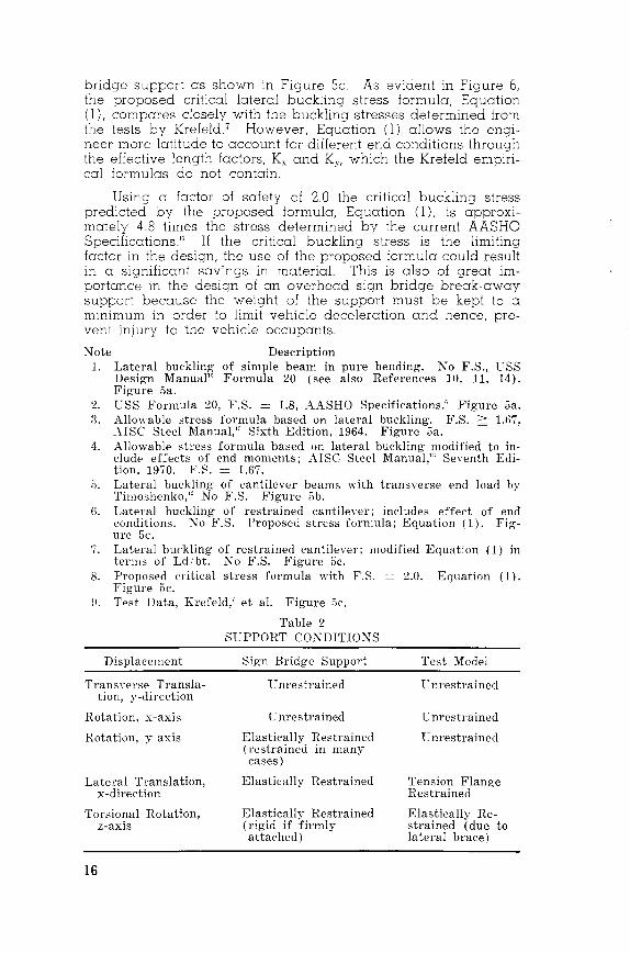
bridge support as shown in Figure Sc. As evident in Figure 6, the proposed critical lateral buckling stress formula, Equation (l), compares closely with the buckling stresses determined from the tests by Krefeld 7 However, Equation (l) allows the engineer more latitude to account for different end conditions through the effective length factors, Kx and K,., which the Krefeld empiri-cal formulas do not contain. ·
Using a factor of safety of 2.0 the critical buckling stress predicted by the proposed formula, Equation (l), is appro ximately 4.8 times the stress determined by the current AASHO Specifications" If the critical buckling stress is the limiting factor in the design, the use of the proposed formula could result in a significant savings in material. This is also of great importance in the design of an overhead sign bridge break-away support because the weight of the support must be kept to a minimum in order to limit vehicle deceleration and hence, prevent injury to the vehicle occupants.
Note Description l. Lateral buckling of simple beam in pure bending. No F.S., USS
Design Manual15 Formula 20 (see also References 10, 11, 14). Figure 5a.
2. l:SS Formula 20, F.S. = 1.8, AASHO Specifications.' Figure 5a. :i. Allowable stress formula based on lateral buckling. F.S. 2 1.67.
AISC Steel Manual," Sixth Edition, 1964. Figure 5a. 4. Allowable stress formula based on lateral buckling modified to in
clude effects of end moments; AISC Steel Manual,"' Seventh Edition, 1970. F.S. = 1.67.
5. Lateral buckling of cantilever beams with transnrse end load by Timoshenko," No F.S. Figure 5b.
G. Lateral buckling of restrained cantilever; includes effect of end conditions. ~ o F.S. Proposed stress formula; Equation ( 1). Figure 5c.
7. Lateral buckling of restrained cantilever; modified Equation ( 1) in terms of Ldibt. No F.S. Figure 5c.
8. Proposed critical stress formula with F.S. = 2.0. Equation (1). Figure 5c.
H. Test Data, Krefeld,' et a!. Figure 5c.
Displacement
Trans\-el·se Translation, y-direction
Rotation, x-axis
Rotation, y-axis
Lateral Translation, x-direction
Torsional Rotation, z-axis
16
Table 2 Sl.:PPORT CONDITIONS
Sign Bridge Support
L nrestrained
Unrestrained
Elastically Restrained (restrained in many cases)
Elastically Restrained
Elastically Restrained (rigid if firmly attached)
Test Model
enrestrained
'C nrestrained
l.:nrestrained
Tension Flange Restrained
Elastically Restrained (due to lateral brace)

In comparing the end conditions for a typical overhead sign bridge support (Figure 5c) and the test model (Figure 5b) as shown in Table 2, it is apparent that the test model restraints are much less rigid. Therefore, it appears that the proposed ~ormula, which was developed for the test model, will have a factor of safety larger than 2.0 when applied to an actual design.
Testing Program
Technical Memorandum 605-4 by
D. L. lvey. C. E. Buth. R. M. Olson. and T. J. Hirsch
A testing program, consisting of several laboratory static tests and eight full scale crash tests, was conducted to determme: (a) the feasibility of a Prototype OSB with break-away supports from a viewpoint of safety and structural integrity, and (b) the validity of a mathematical model simulation technique.
The first laboratory test was performed to obtain some insight on how the break-away support connections would function under a static load simulating a head-on vehicle collision. In addition to showing that the break-away connections would function satisfactorily, this laboratory test provided information on the energy expended by: (a) the slip base friction due to an applied bolt torque of 50 lb-ft and controlled column axial load (theoretically estimated to be 8 kips in each of the four supports), (b) the 20 ga. sheet metal keeper plate, (c) the four fractured bolts in the upper break-away connection, and (d) the rotational and translational displacements of the support and truss. Other laboratory tests were conducted later in the program to study in greater depth the parameters which affect the frictional resistance of the lovrer break-away support connection. Data obtained from these laboratory tests are used as input into the mathematical model.
The dynamic behavior of the Prototype OSB break-away support and truss during a head-on 54 mph passenger vehicle collision is shown in Figure 7 As clearly visible, the rotation of the truss was negligible until the rotatmg support struck and crushed two of the four pir::e load distributors mounted on the lower chord members of the truss. In addition to distributing the load and expending a portion of the rotational kinetic energy of the support the pipes are effective in preventing severe damage of the truss. The horizontal anales located at mid-depth of the trus3, as visible in Figure 7, ~ere shown in a later 15 degree angle collision to be effective in preventing severe damage to the truss as the rotating support, twisting about its pin connection, was guided through the truss-it is conceivable that the support would have snagged on the top of the colliding vehicle had the horizontal angles not been used and the support
17

0.010 sec 0.109 sec
t = 0.453 sec t = 0.453 sec
Figure 7. Dynamic behavior of the prototype structure (test 605-D).
snagged on the truss; therefore , the horizontal angles serve, like the pipe distributors, a multiple purpose .
A comparison of the results obtained from a high-speed film analysis with the results obtained from a mathematical model simulation was presented earlier in Table l. The good comparison clearly indicates that the mathematical model can be used with a high degree of confidence to analyze other proposed OSB structures with break-away supports .
A preliminary low-speed 21 mph full scale crash test not shown in Table l was conducted following the first laboratory test to primarily confirm that the upper break-away connection would perform satisfactorily under dynamic loading conditions.
During the preliminary crash test the break-away support did not contact the truss ; however, during subsequent tests conducted at speeds exceeding 21 mph the support did strike the truss. The amount of rotational kinetic energy imparted to the truss shown in Table l was predicted b y the mathematical model. Static tests were run on an exterior support to evaluate the torsional stiffness characteristics of the truss and remaining supports, and to evaluate the performance of the pipe distributors (discussed earlier) . These tests showed that the bolts in
18
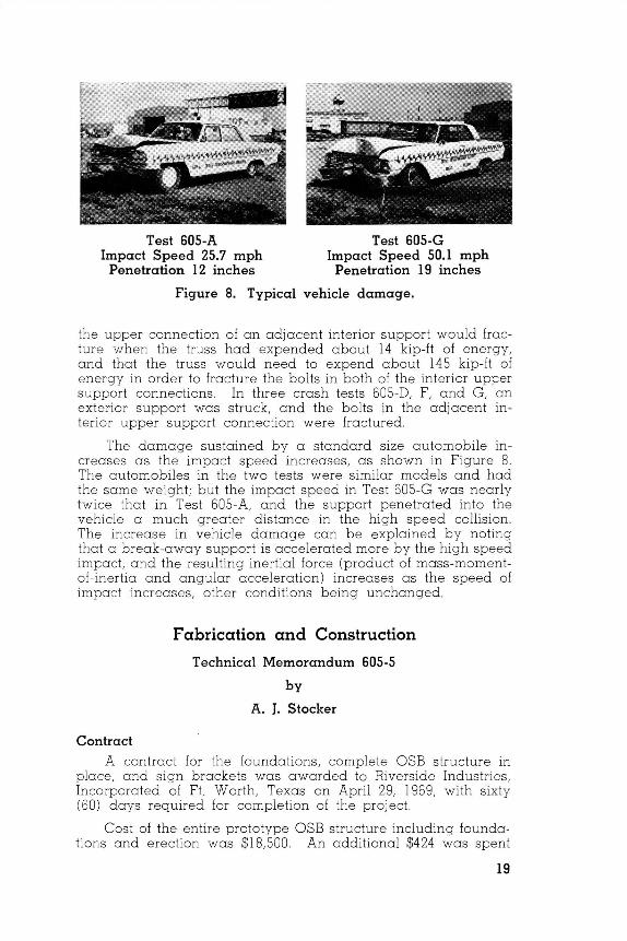
Test 605-A Impact Speed 25.7 mph
Penetration 12 inches
Test 605-G Impact Speed 50.1 mph
Penetration 19 inches
Figure 8. Typical vehicle damage.
the upper connection of an adjacent interior support would fracture when the truss had expended about 14 kip-ft of energy, and that the truss would need to expend about 145 kip-ft of energy in order to fracture the bolts in both of the interior upper support connections. In three crash tests 605-D, F, and G, an exterior support was struck, and the bolts in the adjacent interior upper support connection were fractured.
The damage sustained by a standard size automobile increases as the impact speed increases, as shown in Figure 8. The automobiles in the two tests were similar models and had the same weight; but the impact speed in Test 605-G was nearly twice that in Test 605-A, and the support penetrated into the vehicle a much greater distance in the high speed collision. The increase in vehicle damage can be explained by noting that a break-away support is accelerated more by the high speed impact, and the resulting inertial force (product of mass-momentof-inertia and angular acceleration) increases as the speed of impact increases, other conditions being unchanged.
Fabrication and Construction Technical Memorandum 605-5
by
A. J. Stocker
Contract A contract for the foundations, complete OSB structure in
place, and sign brackets was awarded to Riverside Industries , Incorporated of Ft. Worth, Texas on April 29, 1969, with sixty (60) days required for completion of the project.
Cost of the entire prototype OSB structure including foundations and erection was $18,500 . An additional $424 was spent
19

:or sign brackets and $1,300 for fabrication and erection of the two information signs; the total cost was $20,224.
Fabrication
Only minor changes and substitutions were made relative to the original working plans and specifications. The fabricator initially chose to galvanize the complete OSB structure but because of the development of a warping problem in the first break-away support during welding, it was requested that painting of the supports be allowed. This request was granted because maximum interpass temperature was 300oF for welding the supports and galvanizing is done at 850'F. The possibility of additional warpage during galvanizing was the reason for the request.
The original intention was to use ASTM A-514 Type F steel for the break-away supports and the welding procedure was written on this basis. When it was found that Type F plate had a 60-day delivery, the fabricator's request to use Type A was granted and the welding procedure rewritten and approved.
It was found that the established procedure for alternating welding beads was not followed in the shop on the first support. Adherence to this procedure on the remaining three supports eliminated the camber problem Camber in the first support fabricated was removed satisfactorily by using a 200-ton jack
Slower welding speeds and two passes instead of one v'rere required in welding the A-514 steel, as compared with A-36. The fabricator felt that only their most qualified craftsmen should do the job. Both of these factors mcreased the cost. Table 3 shows a comparison between the welding of A-514 and A-36 steels. The table is included since the prototype overhead sign bridge was fabricated from high strength steel while mony con-temporary bridges are fabricated from A-36 steel.
Table :i
CCHI!'AR!SO~ OF WELDl~G I'IWCETJL'lU:S FOI1 A-014 AXIl A-:Hi STEELS
\Velding Speed Ampel'es Hod Deposited Rod Size :-;umber of Passes
A-014
1:)" -1?)" /min 2~0 m?;ps . :2 to .) / mm 1 '8" :2
A-!:lfi
18" -:2:2" /min 400 amps :r to 4' /min :i 'l(j"
1
Foundations The four identical foundations consisted of two 30-inch
drilled concrete shafts with 60-in. bells joined by a 36-in. by 26-in. beam. The drilled concrete shafts were 9 feet deep.
20

The foundations have two bolt patterns instead of one required for the single break-away column support in this program. Since many existing overhead sign bridge structures have twocolumn supports, it was decided to construct the foundations so that a two-column support could be tested at some future date, if desired.
Erection The 140-ft. truss was delivered to the job site in three sec
tions; the two end sections were 60 feet and the middle section was 20 feet in length. The truss was assembled on the ground and the four break-away supports installed while the truss was on its side. The total OSB assembly was raised into position with two 35-ton truck cranes.
Supplementary Studies Technical Memorandum 605-6
by
R. M. Olson, D. L. lvey, J. E. Martinez,
E. R. Post, and R. H. Gunderson
Additional work was requested by the sponsors after completion of the original contract: (a) additional full-scale crash tests, (b) static laboratory tests on break-away bases and other structural components, (c) parameter studies by mathematical simulation and (d) alternate concepts for support columns.
Two additional full-scale crash tests were conducted; the first car (5,150 lbs) struck an outside support head-on at 75.3 mph and the second car (5, 170 lbs) struck an inside support at 72.0 mph at a 15 degree angle These tests were labeled Hand I, respectively, and results are included in Table l. Comparisons between test results and the computer model were good. A summary of the crash test results on the entire project is given.
During Test H, the rotating support struck the truss with sufficient force to shear off the upper bolts and the truss rotated about the upper pin connections as shown in Figure 9. The structure was not visibly damaged during this test and the truss was repositioned for the next test.
Nine additional laboratory tests were conducted using a column stub and base. It was concluded that variables associated with bolts, nuts and washers caused as much as 100'/r variation in the peak force required to slip the base and the angle at which the load is applied has very little influence on the value of the peak base force. A crane was used to apply a torque to the truss after Test H and it was found that the truss was less stiff than in a previous torsion test, presumably due to
21

0 sec 0.030 sec
0.211 sec 1.001 sec
1.441 sec 2.043 sec
3.014 sec
Figure 9. Sequential photographs of test H.
22

bolt slip and member deformations in the truss which occurred during the testing program.
Additional parameter studies were conducted to determine (a) behavior of selected vehicles; (b) structural response when support conditions (such as bose shear force) and vehicle parameters (vehicle spring constant) were varied, and (c) effect of varying support weight The study indicated that lighter supports produced lower vehicle velocity and momentum changes, lower overage decelerations, and caused less energy to be imported to the truss by the support as it swings following impact. Also, varying the bose connection resistance up to 20 kips does not significantly affect vehicle behavior nor support response.
The mathematical san ulo!Jon correlated very sollsfoctorily with test results and provided reliable in:orrnation to fill the gaps in the test results.
Alternative concepts for the support colurnnr; \Vcre sw1uested by various individuals durinq the course' cf thrs studv. These concepts are discussed in th~ cppendix to TM LirJ:1 Ci ' Some' of these demonstrate a good knowledcw of tlJr~ rTobJr:m ond present ingenious methods of rmprovmu tire prototype' column support.
The authors are oroteful for tlw rnterest :ol1c n in this project by many of the high~oy cmd for tire.· con:otrllclive com-ments of the reviewers.
23

References
l. OLSON, R. M, POST, E. R., and McFARLAND, W F, "Tentative Service Requirements for Bridge Rail Systems," NCHRP 86, 1970, p. 6.
2. ROW AN, N. J , OLSON, R. M., EDWARDS, T. C., GADDIS, A. M., WILLIAMS, T. G, and HAWKINS, D. L. "Impact Behavior of Sign Supports-II," A Staff Report by Texas Transportation Institute, College Station, Texas, 1965, 115 pp.
3. EDWARDS, T. C., "Break-Away Roadside Sign Support Structures," Summary Report on Project HPR-2(104), Texas Transportation Institute, College Station, Texas, 1967, 12 pp.
4. "A Swinging Success," an article in Texas Highways, Volume 16, Number 12, December, 1969
5. HAWKINS, D. L, "Preliminary Design Calculations for a Prototype Overhead Sign Bridge with Break-Away Supports." Dated October, 1965, forwarded to the Texas Transportation Institute for consideration.
6. AASHO, "Specifications for the Design and Construction of Structural Supports for Highway Signs " Adopted by the American Association of State Highway Officials, 1968, 26 pages.
7. KREFELD, W. J, BUTLER, D. J, and ANDERSON, G. B., "Welded Cantilever Wedge Beams." Supplement to the Welding Journal, March, 1959, pages 97s-ll2s
8. MICHIE, J D, and CALCOTE, L R., "Location, Selection, and Maintenance of Highway Guardrails and Median Barriers," NCHRP 54, 1968, p. 5.
9. EDWARDS, T C, HIRSCH, T J , and OLSON, R. M., "BreakAway Sign Support Structures," Volume I, Final Report on Highway Sign Support Structures, Project HPR-2(104), Texas Transportation Institute, Texas A&M University, College Station, Texas, July, 1967.
10. DEVRIES, KARL, "Strength of Beams as Determined by Lateral Buckling," ASCI Transactions, VoL 112, 194 7, pps. 1245-1320.
11. WINTER, GEORGE, "Winter on Lateral Buckling," Discussion in ASCI Transactions, VoL 112, 1947, pps. 1272-1276.
12. TIMOSHENKO, S P, and GERE, J M, "Theory of Elastic Stability," Second Edition, McGraw Hill Book Company, New York, 1961.
13. AISC Steel Construction Manual-"Specifications for Design, Fabrication and Erection of Structural Steel for Buildings." American Institute of Steel Construction, Sixth Edition, 1964; Seventh Edition, 1970.
14. WINTER, GEORGE, "Strength of Slender Beams," ASCI Transactions, VoL 109, 1944, pps. 1321-1358.
15. PRIEST, H. M., and GILLIGAN, J A., "Design Manual for High-Strength Steels," United States Steel Corporation, 1954.
24
Related Documents


