— MAIN CATALOG Safety Products ABB Jokab Safety

Welcome message from author
This document is posted to help you gain knowledge. Please leave a comment to let me know what you think about it! Share it to your friends and learn new things together.
Transcript

— MAIN C ATALOG
Safety ProductsABB Jokab Safety
—ABB AB Jokab SafetyVarlabergsvägen 11SE-434 39 KungsbackaTel. +46 (0) 21-32 50 00www.abb.com/jokabsafety
Copyright© 2018 ABBAll rights reserved 2T
LC0
100
01C
020
2
— MAIN C ATALOG
Safety ProductsABB Jokab Safety
—ABB AB Jokab SafetyVarlabergsvägen 11SE-434 39 KungsbackaTel. +46 (0) 21-32 50 00www.abb.com/jokabsafety
Copyright© 2018 ABBAll rights reserved 2T
LC0
100
01C
020
2


26
37
94
85
INTRODUCTION
CONTROL DEVICES
SAFETY CONTROLLERS
EMERGENCY STOPS AND PILOT DEVICES
OPTICAL SAFETY DEVICES
PRESSURE SENSITIVE DEVICES
FENCING SYSTEMS
SENSORS AND LOCKS
CONTACTORS AND MOTOR STARTERS
—Safety products catalogABB Jokab Safety
1

1
S A F E T Y PRO D U C T S C ATA LO G A B B J O K A B S A FE T Y

—Introduction
1–2 Introduction
1–6 Standards and regulations
1
I NTR O D U C TI O N 1– 1

—Introduction Company overview
ABB Jokab Safety has been helping machine builders to create production-friendly and safe work environments for operators since 1988.
We develop products and solutions for machine safetyWe make it simple to build safety systems. Developing products and solutions for machine safety has been our business idea since the company Jokab Safety, now a part of ABB, was founded in Sweden in 1988.
Many industries around the world have discovered how much easier it has become to build protection and safety systems with our components and guidance. Our extensive program of products, safety solutions and our long experience in ma-chine safety makes us a safe partner.
Together we create a safe world!
1
1– 2 S A F E T Y PRO D U C T S C ATA LO G A B B J O K A B S A FE T Y
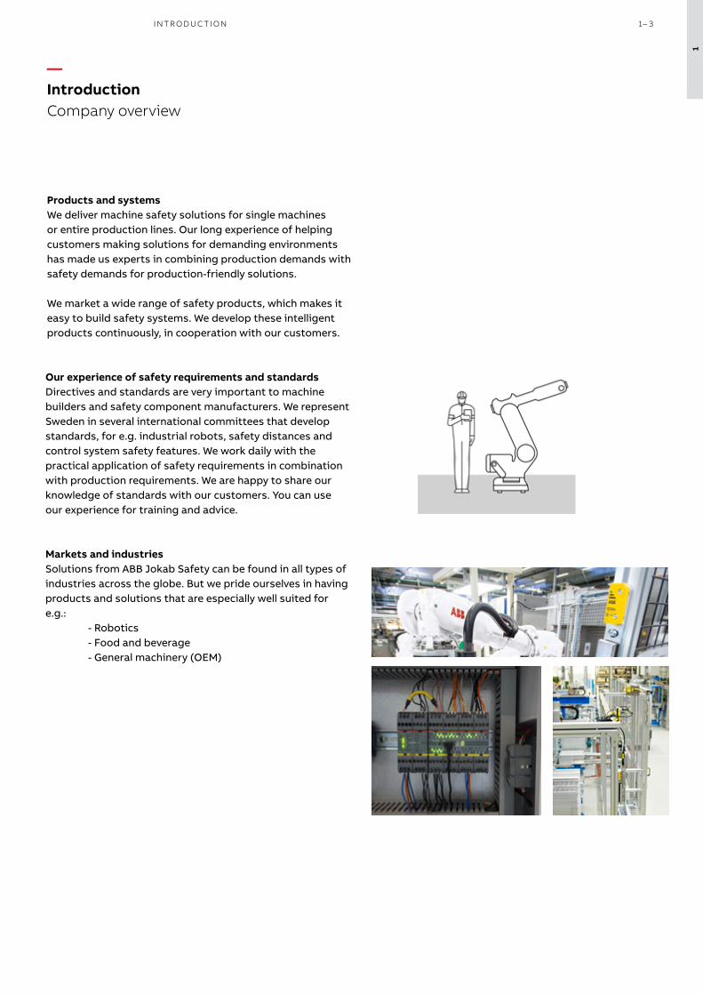
Products and systemsWe deliver machine safety solutions for single machines or entire production lines. Our long experience of helping customers making solutions for demanding environments has made us experts in combining production demands with safety demands for production-friendly solutions.
We market a wide range of safety products, which makes it easy to build safety systems. We develop these intelligent products continuously, in cooperation with our customers.
Markets and industriesSolutions from ABB Jokab Safety can be found in all types of industries across the globe. But we pride ourselves in having products and solutions that are especially well suited for e.g.: - Robotics - Food and beverage - General machinery (OEM)
—Introduction Company overview
Our experience of safety requirements and standardsDirectives and standards are very important to machine builders and safety component manufacturers. We represent Sweden in several international committees that develop standards, for e.g. industrial robots, safety distances and control system safety features. We work daily with the practical application of safety requirements in combination with production requirements. We are happy to share our knowledge of standards with our customers. You can use our experience for training and advice.
1
I NTR O D U C TI O N 1– 3

Magne magnetic lockto keep doors and hatches locked during a process
Smile emergency stop buttonto safely stop machinery in hazardous situations
Safeball control device for an ergonomic and safe two-hand control
Quick-Guard fencing system
to prevent unauthorised access
JSHD4 three-position device for safe and ergonomic inspection and troubleshooting
GKey safety lockfor safe locking of doors
MKey9 key switchfor safe locking of hatches and doors
Inca emergency stop buttonfor compact panel mounting
Orion light guardsfor a production friendly safety detection
Eden sensorfor reliable non-contact monitoring of doors and hatches
Pluto programmable safety controller,Vital safety controller and Sentry safety relaysfor flexible monitoring of safety devices
LineStrong pull wire emergency stop switch for easy access of emergency stop function
Operators and signalling devicesfor control and indication
Mats, rails and bumpersto detect the presence of people
Contactors and electroniccompacts starters to control power and motors
—Our range of safety products
ABB is the only supplier that can deliver complete safety solutions (including
output devices such as contactors and frequency converters) together with
automation solutions such as robotics, motors, drives and PLCs.
1
1– 4 S A F E T Y PRO D U C T S C ATA LO G A B B J O K A B S A FE T Y

Magne magnetic lockto keep doors and hatches locked during a process
Smile emergency stop buttonto safely stop machinery in hazardous situations
Safeball control device for an ergonomic and safe two-hand control
Quick-Guard fencing system
to prevent unauthorised access
JSHD4 three-position device for safe and ergonomic inspection and troubleshooting
GKey safety lockfor safe locking of doors
MKey9 key switchfor safe locking of hatches and doors
Inca emergency stop buttonfor compact panel mounting
Orion light guardsfor a production friendly safety detection
Eden sensorfor reliable non-contact monitoring of doors and hatches
Pluto programmable safety controller,Vital safety controller and Sentry safety relaysfor flexible monitoring of safety devices
LineStrong pull wire emergency stop switch for easy access of emergency stop function
Operators and signalling devicesfor control and indication
Mats, rails and bumpersto detect the presence of people
Contactors and electroniccompacts starters to control power and motors
1
I NTR O D U C TI O N 1– 5

Harmonised standardsHarmonised standards give support on how to fulfill the requirements of the Machinery Directive. The relationship between the Machinery Directive and the harmonised stan-dards is illustrated by the diagram below.
Within ISO (The International Organization for Standardiza-tion) work is also going on in order to harmonise the safety standards globally in parallel with the European standardi-sation work.
ABB Jokab Safety takes an active part in the working groups both for the ISO and EN standards.
Directives and standards are of great importance for manufacturers of machines and safety components. In the Europe-an Union, the EU Directives gives requirements for the minimum level of health and safety, and these are mandatory for manufacturers to fulfill. In every member country the Directives are implemented in national legislation.
Machines which have been placed on the market since 2010, must comply with the new Machinery Directive2006/42/EC. Before that, the old Machinery Directive 98/37/EC was valid.
Although the requirements in the Directives are specific for Europe, they also apply to machines that are imported to Eu-rope. And the Directives are supported by standards, of which many also are valid internationally.
—European Directives and Standards
The objectives of the Machinery Directive, 2006/42/EC, are to maintain, increase and equalise the safety level of machines within the members of the European Community. Based on this, the free movement of machines/products between the countries in this market can be achieved. The Machinery Directive is developed according to “The New Ap-proach” which is based on the following principles:
– The directives give the basic health and safety require-ments, which are mandatory.
– Detailed solutions and technical specifications are found in harmonised standards.
– Standards are voluntary to apply, but products designed according to the harmonised standards will fulfill the basic safety requirements in the Machinery Directive.
Giving basic concepts, principles for design, and general aspects that can be applied to all machinery
B1: Standards on particular safety aspects (e.g. safety distances, surface temperature, noise)B2: Standards on safeguards (e.g. two-hand controls, interlocking devices, pressure sensi-tive devices, guards)
Dealing with detailed safety requirements for a particular machine or group of machines
Examples of standards
A-standards
B1-standards
B2-standards
C-standards
EN ISO 1200
EN ISO 13857EN 349EN ISO 13849-1 EN ISO 13855
EN ISO 13850EN ISO 14119EN 60204-1
EN ISO 10218-1EN 692EN 693
The Machinery Directive2006/42/EC
1
1– 6 S A F E T Y PRO D U C T S C ATA LO G A B B J O K A B S A FE T Y
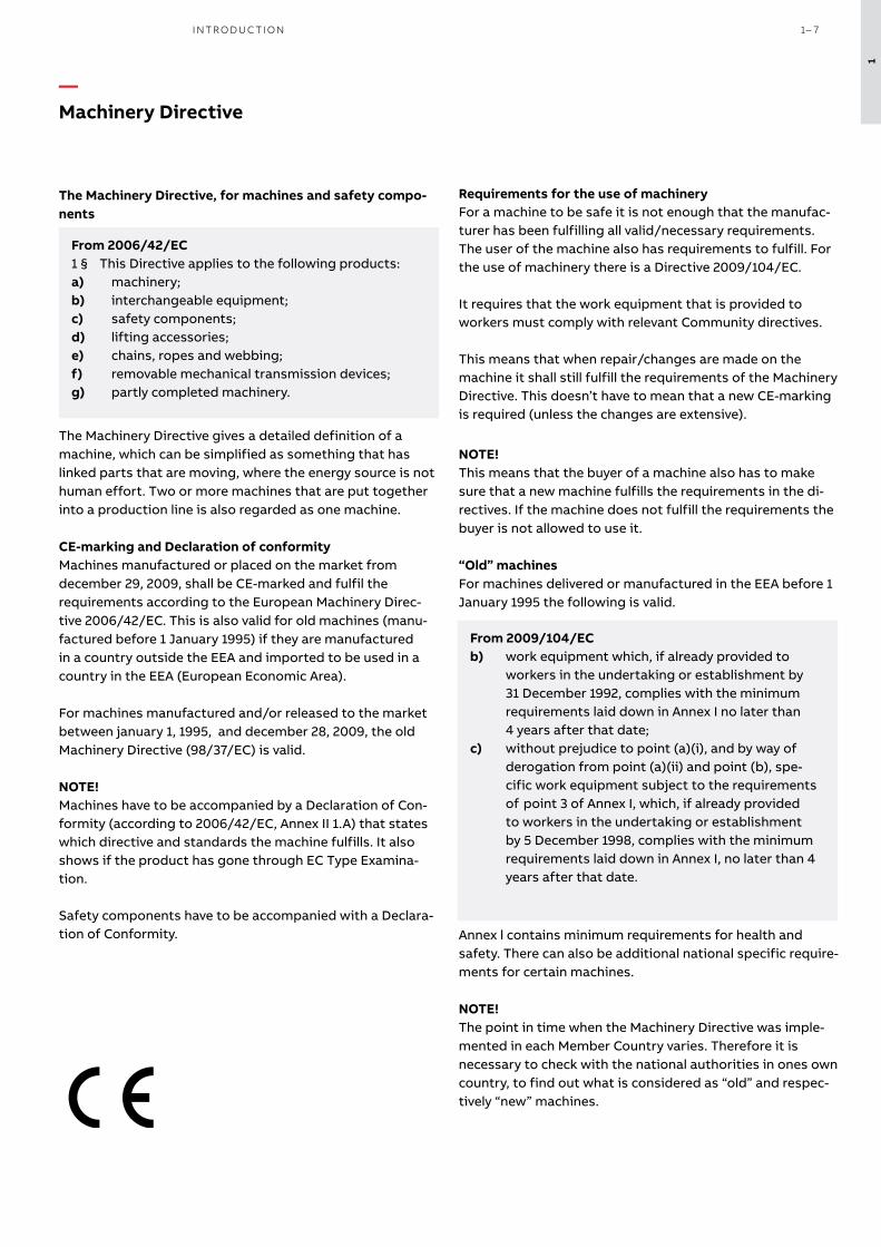
The Machinery Directive, for machines and safety compo-nents
From 2006/42/EC1 § This Directive applies to the following products:a) machinery;b) interchangeable equipment;c) safety components;d) lifting accessories;e) chains, ropes and webbing;f) removable mechanical transmission devices;g) partly completed machinery.
The Machinery Directive gives a detailed definition of a machine, which can be simplified as something that has linked parts that are moving, where the energy source is not human effort. Two or more machines that are put together into a production line is also regarded as one machine.
CE-marking and Declaration of conformityMachines manufactured or placed on the market from december 29, 2009, shall be CE-marked and fulfil the requirements according to the European Machinery Direc-tive 2006/42/EC. This is also valid for old machines (manu-factured before 1 January 1995) if they are manufactured in a country outside the EEA and imported to be used in a country in the EEA (European Economic Area).
For machines manufactured and/or released to the market between january 1, 1995, and december 28, 2009, the old Machinery Directive (98/37/EC) is valid.
NOTE! Machines have to be accompanied by a Declaration of Con-formity (according to 2006/42/EC, Annex II 1.A) that states which directive and standards the machine fulfills. It also shows if the product has gone through EC Type Examina-tion.
Safety components have to be accompanied with a Declara-tion of Conformity.
Requirements for the use of machineryFor a machine to be safe it is not enough that the manufac-turer has been fulfilling all valid/necessary requirements. The user of the machine also has requirements to fulfill. For the use of machinery there is a Directive 2009/104/EC.
It requires that the work equipment that is provided to workers must comply with relevant Community directives.
This means that when repair/changes are made on the machine it shall still fulfill the requirements of the Machinery Directive. This doesn’t have to mean that a new CE-marking is required (unless the changes are extensive).
NOTE! This means that the buyer of a machine also has to make sure that a new machine fulfills the requirements in the di-rectives. If the machine does not fulfill the requirements the buyer is not allowed to use it.
“Old” machinesFor machines delivered or manufactured in the EEA before 1 January 1995 the following is valid.
From 2009/104/EC(b) work equipment which, if already provided to workers in the undertaking or establishment by 31 December 1992, complies with the minimum requirements laid down in Annex I no later than 4 years after that date;
(c) without prejudice to point (a)(i), and by way of derogation from point (a)(ii) and point (b), spe-cific work equipment subject to the requirements of point 3 of Annex I, which, if already provided to workers in the undertaking or establishment by 5 December 1998, complies with the minimum requirements laid down in Annex I, no later than 4 years after that date.
Annex l contains minimum requirements for health and safety. There can also be additional national specific require-ments for certain machines.
NOTE! The point in time when the Machinery Directive was imple-mented in each Member Country varies. Therefore it is necessary to check with the national authorities in ones own country, to find out what is considered as “old” and respec-tively “new” machines.
—Machinery Directive
From 2006/42/EC1 § This Directive applies to the following products:a) machinery;b) interchangeable equipment;c) safety components;d) lifting accessories;e) chains, ropes and webbing;f) removable mechanical transmission devices;g) partly completed machinery.
From 2009/104/ECb) work equipment which, if already provided to workers in the undertaking or establishment by 31 December 1992, complies with the minimum requirements laid down in Annex I no later than 4 years after that date;c) without prejudice to point (a)(i), and by way of derogation from point (a)(ii) and point (b), spe- cific work equipment subject to the requirements of point 3 of Annex I, which, if already provided to workers in the undertaking or establishment by 5 December 1998, complies with the minimum requirements laid down in Annex I, no later than 4 years after that date.
1
I NTR O D U C TI O N 1– 7

Machinery that is placed on the market or put into service before 1995 in the EEA.
—Risk assessment an important tool both when constructing a new machine and when assessing risks on older machines
"New" machines1. Machinery that is placed on the market or put into
service from 1995 in the EEA.2. All machinery that are imported to the EEA irre-
spective of date of origin.
Use of work equipment2009/104/ECNote! Not Annex 1 - instead use applicable directives.
The Machinery Directive98/37/EC (1995 - 2009)2006/42/EC (from 2010)
Possible moredirectives
EMC Directive2014/30/EU
CE-marking +Declaration ofconformity
Low Voltage Directive2014/35/EU
"Old" machines
Use of work equipment2009/104/EC
Possible national legislation on specific machines
Risk assessmentA well thought-out risk assessment supports manufactur-ers/users of machines to develop production friendly safety solutions. One result of this is that the safety components will not be a hindrance. This minimizes the risk of the safety system being defeated.
New machinesThe following requirement is given by the Machinery Direc-tive
From 2006/42/ECThe manufacturer of machinery or his authorised repre-sentative must ensure that a risk assessment is carried out in order to determine the health and safety require-ments which apply to the machinery. The machinery must then be designed and constructed taking into account the results of the risk assessment.
The standard EN ISO 12100 gives guidance on the informa-tion required to allow risk assessment to be carried out.The standard does not point out a specific method to be used. It is the responsibility of the manufacturer to select a suitable method.
Machines in use A risk assessment must have been carried out on all ma-chines that are in use; CE-marked as well as not CE-marked. A risk assessment must also be performed when making changes on a machine, to determine if the safety measures needs to be adapted.
Documentation of risk assessmentThe risk assessment shall be documented. The risk assess-ment should take into consideration the severity of the potential injuries as well as the probability that they occur.
1
1– 8 S A F E T Y PRO D U C T S C ATA LO G A B B J O K A B S A FE T Y

Example on prioritizing according to the 5-step-method
Protection or warning?How is it possible to choose safety measures that are production friendly and in every way well balanced? The Machinery Directive gives an order of priority for the choice of appropriate methods to remove the risks. Here it is further developed in a five step method.
Prioritize safety measures according to the 5-step-method1. Eliminate or reduce risks by design and construction2. Move the work tasks outside the risk area 3. Use guards/safety devices4. Develop safe working routines/information/education5. Use warnings as pictograms, light, sound etc.
Combine the 5-step-method with production friendly thinking. This can give you e.g.
– fast and easy restart of machines after a safety stop – enough space to safely program a robot – places outside the risk area to observe the production – electrically interlocked doors, instead of guards attached
with screws, to be able to take the necessary measures for removing production disturbances
– a safety system that is practical for all types of work tasks, even when removing production disturbances
Priority Example of hazard and safety measure taken
1. Make machine safe by design and construction
Hazard:Safety measure:
Cuts and wounds from sharp edges and corners on machineryRound off sharp edges and corners.
2. Move the work tasks out-side the risk area
Hazard: Crushing of fingers from machine movements during inspection of the production inside the risk area
Safety measure: Installation of a camera.
3. Use guard/safety devices
Hazard: Crushing injuries because of unintended start during loading of work pieces in a mechanical press
Safety measure: Install a light curtain to detect operator and provide safe stop of the machinery.
4. Safe working routines/information
Hazard: Crushing injuries because the machine can tip during installation and normal use.
Safety measure: Make instructions on how the machine is to be installed to avoid the risks. This can include requirements on the type of fastening, ground, screw retention etc.
5. Warning Hazard: Burns because of hot surfaces in reachSafety measure: Warning signs
The likelihood that the safety solution will be well made, well received and suitable for the application increases if each risk is handled according to the 5-step-method.
The further away from the center of the circle, the greater responsibility for the safety is placed onto the user of the machine. If full protection is not effectively achieved in one step, one has to go to the next step and find complementary
measures. What is possible is dependant on the need for accessibility, the severity of the risk, appropiate safety measures etc.
1
I NTR O D U C TI O N 1– 9

EN ISO 12100 Safety of machinery - General principles for design - Risk assessment and risk reduction
The primary purpose of this standard is to provide designers with an overall frame-work and guidance for decisions during the development of machinery to enable them to design machines that are safe for their intended use.
EN ISO 13857 Safety of machinery - Safety distances to prevent hazard zones being reached by up-per and lower limbs
This standard establishes values for safety distances to prevent danger zones being reached by the upper and lower limbs. The distances apply when adequate safety can be achieved by distances alone.
EN ISO 13854 Safety of machinery – Minimum gaps to avoid crushing of parts of the human body
The object of this standard is to enable the user (e.g. standard makers, designers of machinery) to avoid hazards from crushing zones. It specifies minimum gaps relative to parts of the human body and is applicable when adequate safety can be achieved by this method.
EN ISO 13850 Safety of machinery – Emergency stop – Principles for design
This standard specifies design principles for emergency stop equipment for machin-ery. No account is taken of the nature of the energy source.
ISO 13851 Safety of machinery – Two-hand control devices – Principles for design and selection
This standard specifies the safety requirements of a two-hand control device and its logic unit. The standard describes the main characteristics of two-hand control devices for the achievement of safety and sets out combinations of functional charac-teristics for three types.
EN ISO 14120 Safety of machinery – Guards – General re-quirements for the design and construction of fixed and movable guards
This standard specifies general requirements for the design and construction of guards provided primarily to protect persons from mechanical hazards.
EN ISO 13849-1 Safety of machinery – Safety-related parts of control systems – Part 1: General prin-ciples for design
This standard provides safety requirements and guidance on the principles for the design of safety-related parts of control systems. For these parts it specifies categories and describes the characteristics of their safety functions. This includes programmable systems for all machinery and for related protective devices. It applies to all safety-related parts of control systems, regardless of the type of energy used, e.g. electrical, hydraulic, pneumatic, mechanical. It does not specify which safety functions and which categories shall be used in a particular case.
EN ISO 13849-2 Safety of machinery - Safety-related parts of control systems - Part 2: Validation
This standard specifies the procedures and conditions to be followed for the valida-tion by analysis and testing of:• the safety functions provided, and• the category achieved of the safety-related parts of the control system in compli-ance with EN 954-1 (ISO 13849-1), using the design rationale provided by the designer.
EN 62061 Safety of machinery - Functional safety of safety-related electrical, electronic and pro-grammable electronic control systems
The standard defines the safety requirements and guiding principles for the design of safety-related electrical/electronic/programmable parts of a control system.
EN ISO 13855 Safety of machinery - Positioning of safeguards with respect to the approach speeds of parts of the human body
This standard provides parameters based on values for hand/arm and approach speeds and the methodology to determine the minimum distances from specific sens-ing or actuating devices of protective equipment to a danger zone.
EN ISO 14119 Safety of machinery - Interlocking devices associated with guards - Principles for de-sign and selection
This standard specifies principles for the design and selection — independent of the nature of the energy source — of interlocking devices associated with guards.The standard provides measures to minimize defeat of interlocking devices in a reasonably foreseeable manner.
EN 60204-1 Safety of machinery - Electrical equipment of machines - Part 1: General requirements
This part of IEC 60204 provides requirements and recommendations relating to the electrical equipment of machines so as to promote:– safety of persons and property;– consistency of control response;– ease of maintenance.
—Examples of regularly used EN/ISO standards
1
1– 10 S A F E T Y PRO D U C T S C ATA LO G A B B J O K A B S A FE T Y

—Standards for safety in control systems
Building a protection system that works in practice and provides sufficient safety requires expertise in several areas. The design of the safety functions in the protection system in order to ensure they provide sufficient reliability is a key ingredient. As help for this there is, for example, the EN ISO 13849-1 standard. The purpose of this text is to provide an introduction to the standard and its application in conjunction with our products. Please note that outside of the European Union there are often other standards that are used in place of EN ISO 13849.
Introducing the standardThe generation change for standards on safety in control systems introduced new concepts and calculations for machine builders and machine users. The EN 954-1 standard has been phased out and is replaced by EN ISO 13849-1 (PL, Performance Level) and EN 62061 (SIL, Safety Integrity Level).
PL or SIL? What should I use?The standard you should use depends on the choice of tech-nology, experience and customer requirements.
Choice of technology– PL (Performance Level) is a technology-neutral concept that can be used for electrical, mechanical, pneumatic and hydraulic safety solutions. – SIL (Safety Integrity Level) can, however, only be used for electrical, electronic or programmable safety solutions.
ExperienceEN ISO 13849-1 uses categories from EN 954-1 for defin-ing the system structure, and therefore the step to the new calculations is not so big if you have previous experience of the categories. EN 62061 defines the structures slightly differently.
Customer requirements If you or your end customer comes from an industry that is accustomed to using SIL (e.g. the process industry), require-ments can also include safety functions for machine safety being SIL rated.
We notice that most of our customers prefer PL as it is tech-nology-neutral and that they can use their previous knowl-edge in the categories. In this text we show some examples of how to build safety solutions in accordance with EN ISO 13849-1 and calculate the reliability of the safety functions to be used for a particular machine. The examples in this text are simplified in order to provide an understanding of the principles. The values used in the examples can change.
What is PL (Performance Level)?PL is a measure of the reliability of a safety function. PL is divided into five levels (a-e). PL e gives the best reliability and is equivalent to that required at the highest level of risk.
To calculate which PL level the system achieves you need to know the following:– The system’s structure (categories B, 1-4)– The Mean Time To dangerous Failure of the component (MTTFd)– The system’s Diagnostic Coverage (DC)
You will also need to:– protect the system against simultaneous failure of both channels (CCF)– protect the system from systematic errors built into the design– follow certain rules to ensure software can be developed and validated in the right way
The five PL-levels (a-e) correspond to certain ranges of PFHD-values (probability of dangerous failure per hour). These indicate how likely it is that a dangerous failure could occur over a period of one hour. In the calculation, it is ben-eficial to use PFHD-values directly as the PL is a simplifica-tion that does not provide equally accurate results.
What is the easiest way of complying with the standard?1. Use pre-calculated components.As far as it is possible, use components with pre-calculated PL and PFHD-values. You then minimise the number of calcu-lations to be performed. All ABB Jokab Safety products have pre-calculated PFHD-values.
2. Use a calculation tool.With the calculation softwares FSDT or SISTEMA you avoid making calculations by hand. You also get help to structure your safety solutions and provide the necessary documenta-tion.
3. Use Pluto or Vital Use the Pluto programmable safety controller or Vital safety controller. Not only is it easier to make calculations and changes in the future, but above all it is easier to ensure a higher level of safety.
1
I NTR O D U C TI O N 1– 11
Step 1
Has the risk been adequately reduced?
Step 3
Reduce the risk (redesign, use protection, information)
Step 2
Risk
ass
essm
ent
START
Are new risks generated?
Is the measure dependent on the control system?
Determine the system’s scope (space, usage, time, environment)
Identify risk sources (all work operations during the life cycle)
Estimate the risk (determine PLr with S, F and P)
Evaluate the risk (is action required?)Yes
Yes
No
No
Yes
No
Are
all
safe
ty f
unct
ions
exe
cute
d?
Determine PLr
Identify the safety functions
Design and implement the solution for the safety function
Verify that PL ≥ PLr
Calculate PL
ValidateHave other require ments been met?
Yes
Yes
No
No
END
Risk
ana
lysi
s
1
1– 12 S A F E T Y PRO D U C T S C ATA LO G A B B J O K A B S A FE T Y
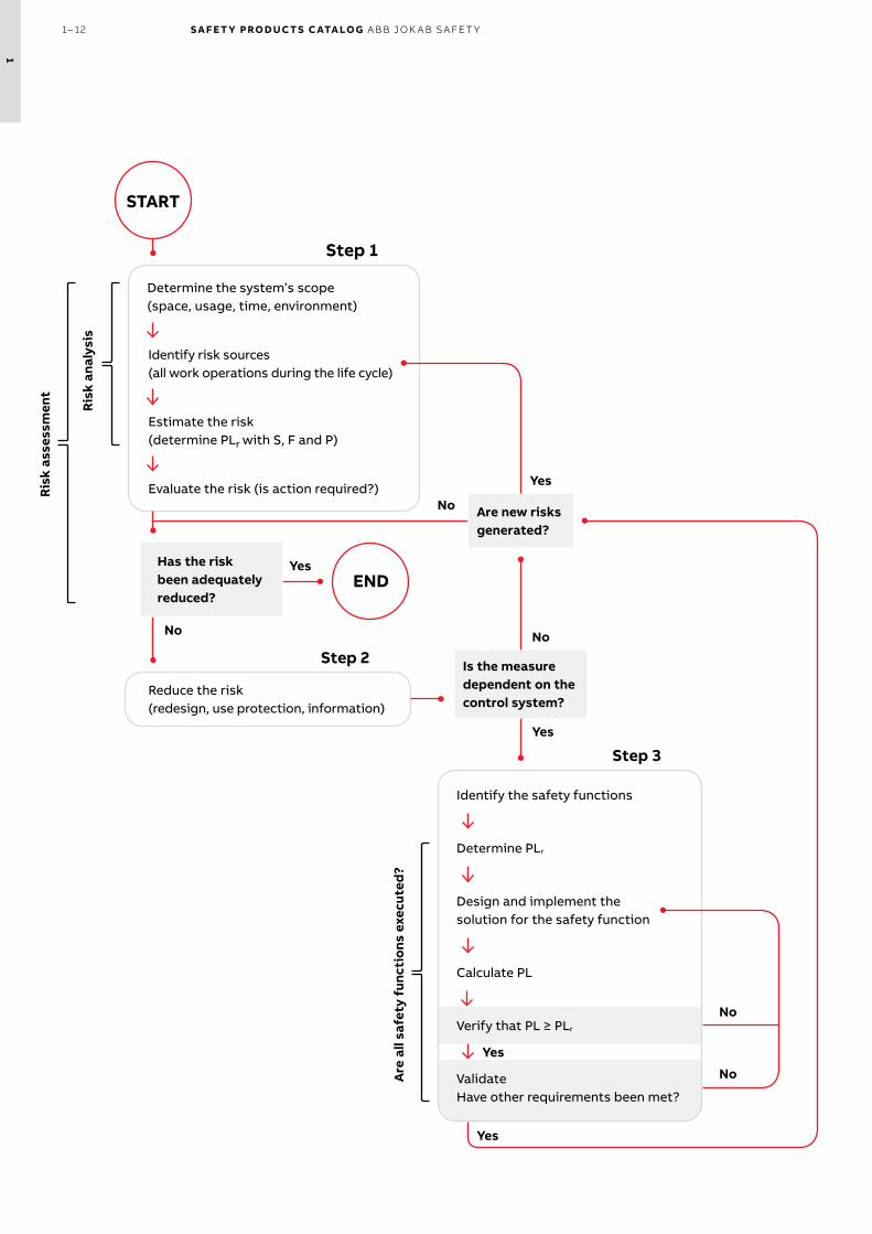
Risk assessment and risk minimisationAccording to the Machinery Directive, the machine builder (anyone who builds or modifies a machine) is required to perform a risk assessment for the machine design and also include an assessment of all the work operations that need to be performed. EN ISO 12100 stipulates the requirements for a risk assessment. It is this that EN ISO 13849-1 is based on, and a completed risk assessment is a prerequisite for being able to work with the standard.
Step 1 – Risk assessmentA risk assessment begins with determining the scope of the machine. This includes the space that the machine and its operators need for all of its intended applications, and all operational stages throughout the machine’s life cycle.All risk sources must then be identified for all work opera-tions throughout the machine’s life cycle.A risk estimation is made for each risk source, i.e. indication of the degree of risk. According to EN ISO 13849-1 the risk is estimated using three factors: injury severity (S), frequency of exposure to the hazard (F) and the possibility you have of avoiding or limiting the injury (P). For each factor two options are given. Where the boundary between the two op-tions lies is not specified in the standard, but the following are common interpretations and our recommendations:S1 bruises, abrasions, puncture wounds and minor
crushing injuriesS2 skeletal injuries, amputations and deathF1 less frequent than once a weekF2 once a week or more oftenP1 slow machine movements, plenty of space, low
powerP2 quick machine movements, crowded, high powerBy selecting S, F and P for the risk, you will get the PLr that is necessary for the risk source.Finally, the risk assessment includes a risk evaluation where you determine if the risk needs to be reduced or if sufficient safety is ensured.
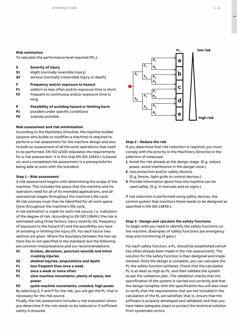
Risk estimationTo calculate the performance level required (PLr).
S Severity of injuryS1 slight (normally reversible injury)S2 serious (normally irreversible injury or death)
F Frequency and/or exposure to hazardF1 seldom to less often and/or exposure time is shortF2 frequent to continuous and/or exposure time is long
P Possibility of avoiding hazard or limiting harmP1 possible under specific conditionsP2 scarcely possible
Step 3 - Design and calculate the safety functionsTo begin with you need to identify the safety functions on the machine. (Examples of safety functions are emergency stop and monitoring of gate.)
For each safety function, a PLr should be established (which has often already been made in the risk assessment). The solution for the safety function is then designed and imple-mented. Once the design is complete, you can calculate the PL the safety function achieves. Check that the calculated PL is at least as high as PLr and then validate the system as per the validation plan. The validation checks that the specification of the system is carried out correctly and that the design complies with the specification.You will also need to verify that the requirements that are not included in the calculation of the PL are satisfied, that is, ensure that the software is properly developed and validated, and that you have taken adequate steps to protect the technical solution from systematic errors.
Step 2 – Reduce the riskIf you determine that risk reduction is required, you must comply with the priority in the Machinery Directive in the selection of measures: 1. Avoid the risk already at the design stage. (E.g. reduce
power, avoid interference in the danger zone.)2. Use protection and/or safety devices.
(E.g. fences, light grids or control devices.)3. Provide information about how the machine can be
used safely. (E.g. in manuals and on signs.)
If risk reduction is performed using safety devices, the control system that monitors these needs to be designed as specified in EN ISO 13849-1.
a
b
c
d
e
PLr
P1
P2
P1
P2
P1
P2
P1
P2
F1
F2
F1
F2S1
S2
low risk
high risk
1
I NTR O D U C TI O N 1– 13

PL calculation in Step 3 When you calculate the PL for a safety function, it is easi-est to split it into separate, well defined blocks (also called subsystems). It is often logical to make the breakdown according to input, logic and output (e.g. switch - safety relay - contactors), but there may be more or fewer than three blocks depending on the connection and the number of components used (an expansion relay could for example create an additional logic block) .
For each block, you calculate a PL or PFHD-value. It is easiest if you obtain these values from the component manufac-turer, so you do not have to calculate yourself. The manu-facturer of switches, sensors and logic devices often have
PL and PFHD-values for their components, but for mechani-cal devices (such as key switches or contactors) a PL-value cannot be supplied since it depends on how often the component will be used. You then need to calculate yourself according to EN ISO 13849-1 or use default values from the standard, if provided.
To calculate PL or PFHD for a block, you need to know its category, DC and MTTFd. In addition, you need to protect the system against systematic errors and ensure that an error does not knock out both channels, and generate and vali-date any software used correctly. The following text gives a brief explanation of what to do.
Safety function (SF)
+ + PFHD, Input
Input
PL/PFHD
PFHD, Logic
Logic
PL/PFHD
PFHD, Output
Output
PL/PFHD
PFHD, Total =
The relationship between categories, the DCavg, MTTFd for each channel and PL. The table also shows the PFHD-range that corresponds to each PL.
PFHD PL
10 -4
a
10 -5
b
3x10 -6
c
10 -6
d
10 -7
e
10 -8
DC none
DC none
DC low
DC medium
DC low
DC medium
DC high
Cat. B Cat. 1 Cat. 2Cat. 2 Cat. 3Cat. 3 Cat. 4
MTTFdlow
MTTFdmedium
MTTFdhigh
1
1– 14 S A F E T Y PRO D U C T S C ATA LO G A B B J O K A B S A FE T Y
Category The structure for the component(s) in the block is assessed to determine the category (B, 1-4) it corresponds to. For category 4, for example, individual failures do not result in any loss of the safety function. In order to achieve category 4 with contactors, you need to have two channels - i.e., two contactors - that can cut the power to the machine individually. The contactors need to be monitored by connecting opening contacts to a test input on, for example a safety relay. For monitoring of this type to work, the contactors need to have positive-guided contacts.
Diagnostic Coverage (DC)A simple method to determine DC is explained in Appendix E in EN ISO 13849-1. It lists various measures and what they correspond to in terms of DC. For example, DC=99 % (which corresponds to DC high) is achieved for a pair of contactors by monitoring the contactors with the logic device.
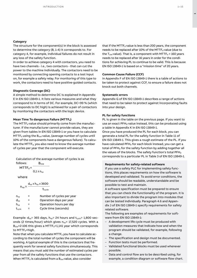
Mean Time To dangerous Failure (MTTFd)The MTTFd-value should primarily come from the manufac-turer. If the manufacturer cannot provide values, they are given from tables in EN ISO 13849-1 or you have to calculate MTTFd using the B10d-value, (average number of cycles until 10% of the components have a dangerous failure). To calcu-late the MTTFd, you also need to know the average number of cycles per year that the component will execute.
Calculation of the average number of cycles is as follows:
dop x hop x 3600
tcyclenop =
B10d
0,1 x nop
MTTFd =
where
nop = Number of cycles per yeardop = Operation days per year hop = Operation hours per daytcycle = Cycle time (seconds)
Example: dop= 365 days, hop= 24 hours and tcycle= 1,800 sec-onds (2 times/hour) which gives nop= 17,520 cycles. With a B10d=2·106 this gives a MTTFd=1,141 year which corresponds to MTTFd=high. Note that when you calculate MTTFd you have to calculate ac-cording to the total number of cycles the component will be working. A typical example of this is the contactors that fre-quently work for several safety functions simultaneously. This means that you must add the number of estimated cycles per year from all the safety functions that use the contactors.When MTTFd is calculated from a B10d-value, also consider
that if the MTTFd-value is less than 200 years, the component needs to be replaced after 10% of the MTTFd-value (due to the T10d-value). That is, a component with MTTFd = 160 years needs to be replaced after 16 years in order for the condi-tions for achieving PL to continue to be valid. This is because EN ISO 13849-1 is based on a “mission time” of 20 years.
Common Cause Failure (CCF)In Appendix F of EN ISO 13849-1 there is a table of actions to be taken to protect against CCF, to ensure a failure does not knock out both channels.
Systematic errorsAppendix G of EN ISO 13849-1 describes a range of actions that need to be taken to protect against incorporating faults into your design.
PL for safety functionsPL is given in the table on the previous page. If you want to use an exact PFHD-value instead, this can be produced using a table in Appendix K in EN ISO 13849-1.Once you have produced the PL for each block, you can generate a total PL for the safety function in Table 11 of EN ISO 13849-1. This gives a rough estimate of the PL. If you have calculated PFHD for each block instead, you can get a total of PFHD for the safety function by adding together all the values of the blocks. The safety function’s total PFHD corresponds to a particular PL in Table 3 of EN ISO 13849-1.
Requirements for safety-related softwareIf you use a safety PLC for implementing safety func-tions, this places requirements on how the software is developed and validated. To avoid error conditions, the software should be readable, understandable and be possible to test and maintain.A software specification must be prepared to ensure that you can check the functionality of the program. It is also important to divide the program into modules that can be tested individually. Paragraph 4.6 and Appen-dix J of EN ISO 13849-1 specify requirements for safety related software.The following are examples of requirements for soft-ware from EN ISO 13849-1:
– A development life cycle must be produced with validation measures that indicate how and when the program should be validated, for example, following a change.
– The specification and design must be documented. – Function tests must be performed. – Validated functional blocks must be used whenever
possible. – Data and control flow are to be described using, for
example, a condition diagram or software flow chart.
1
I NTR O D U C TI O N 1– 15

Step 1 – Risk assessmentFood to be packaged is loaded into the cell manually through the rear door. A batch is prepared for the packing conveyor in the infeed hopper. The cell is reset and restart-ed. The packaging machine with conveyor belt only oper-ates when both doors are closed and when the protection system has been reset.
In the risk assessment it was established that the machine is to be operated in three shifts (8 hours per shift) 365 days a year. The total access to the danger zone is estimated to be two times per hour (F2), including manual packaging and tending operational disturbances. Unexpected start-ups are not considered to cause serious injury but rather minor heal-able injuries (S1). The operator is considered not to have the possibility of avoiding injury as the machine moves quickly (P2).
The number of cycles for the safety function = 365 days/year x (3x8) hours/day x 2 cycles/hour = 17,520 cycles/yearThe assessment for the safety function required for access to the machine is PLr= c (S1, F2, P2). In addition to this safety function, an emergency stop function is needed. This is also assessed as PLr=c.
Determination of the PLr necessary for the safety function with interlocked door for this example.
NOTE! The assessment needs to be made for each safety function.
Key switch MKey5Monitors that the door is closed.
Safety relay SentryMonitors safety compo-nents.
Emergency stop buttonTo stop the machine in case of danger.
Step 2 – Reduce the riskAs protection, an interlocked door is selected with the key switch MKey5. Stopping time is short enough for the dan-gerous movement to have ceased before the operator can access it. The emergency stop is placed within easy reach, on both sides of the cell near the doors.
—Case study 1 - Safety relay SentryProtection layout for a packaging machine with low risks
a
b
c
d
e
PLr
P1
P2
P1
P2
P1
P2
P1
P2
F1
F2
F1
F2S1
S2
low risk
high risk
1
1– 16 S A F E T Y PRO D U C T S C ATA LO G A B B J O K A B S A FE T Y

PFHD, E-stop + PFHD, Sentry + PFHD, Contactors = 4.3x10⁻⁸ + 4.9x10⁻⁹ + 4.9x10⁻⁹ + 2.47x10-8 = 7.75x10⁻⁸ PL e
PLr=c
Input OutputSafety function 3
PLr=c
Safety function 1
B1 MKey5 (PL c)
S1 E-stop (PL e)
Input Logic
PFHD, MKey5 + PFHD, Sentry + PFHD, Contactors = 1.14x10⁻⁶ + 4.9x10⁻⁹ + 2.47x10-8 = 1.17x10⁻⁶ PL c
K2Sentry (PL e)
Q1/Q2 Contactors (PL e)
Q1/Q2 Contactors (PL e)
Output
The reason for not achieving more than PL c with Safety function 1 is that only one key switch is used per door, and a key switch is mechanically a Category 1 device. For e-stop devices though, a fault exclusion for the mechanical parts is allowed according to EN ISO 13849-2 if a maximum number of operations is considered. For this solution to reach a higher PL, EN ISO 14119 and ISO/TR 24119 need to be consulted.
Step 3 - Calculate the safety functionsThe output subsystem that is composed of double moni-tored contactors has been calculated at 2.47x10⁻⁸. The safety functions are represented by block diagrams.Safety functions 1 and 2 are identical. Therefore, only safety function 1 is shown.Safety functions 3 and 4 are identical. Therefore, only safety function 3 is shown.
* Monitoring of contactors with K2
How safe is a mechanical switch? Mechanical switches have a tendency to break if misused.Manufacturer instructions must be followed, e.g. no excessive force or dirty environment. For interlocking switches in general EN ISO 14119 must be considered. It handles e.g. the possibility to defeat a switch and require-ments on key switches. Connecting key switches in series gives a significant risk of masking errors, as stated in the technical report ISO/TR 24119, which limits the maximum achievable DC depending on the number of frequently used doors connected in series.
S1 E-stop
K1Sentry SSR10
S2 E-stop
B2 Key switch
Q1Contactor
B1 Key switch
K2Sentry SSR10
K1
Q2Contactor
Result
Result
PL c
PL e
*
Logic
K1Sentry (PL e)
Logic
K2Sentry (PL e)
1
I NTR O D U C TI O N 1– 17

Step 1 – Risk assessmentThe workpieces are transported into the robot cell where the robot places them in a test cabinet. Approved work-pieces leave the cell on the conveyor belt, while workpieces that fail the tests are placed on the table for manual adjust-ments. The work that needs to be done in the robot cell is to correct operational disturbances for the test equipment and the conveyor belt (about once an hour), unloading from the manual station (about once an hour), program adjustments (once/week) and cleaning (once/week) (F2). Unexpected start-ups of the robot are considered to cause potentially serious injury (S2). The operator is considered not to have the possibility of avoiding injury as the robot moves quickly (P2). The risk estimation gives PLr=e (S2, F2, P2) for the safety functions required for access to the machine.
The standard for robot systems/cells (EN ISO 10218-2) speci-fies that safety functions shall comply with at least PL d, un-less the risk assessment determines otherwise. In this case the risk assessment gives us PLr= e.
Step 2 – Reduce the riskAs protection, the door and hatch are interlocked with Eden non-contact sensors. To protect against entering the cell the wrong way, transport of materials in and out is protected with light cur-tains and provided with muting to distinguish between material and people. The emergency stop function is also a safety function
that is required. The energy to all hazardous machine functions shall be re-moved by all safety functions.
The solution with Vital makes it possible to implement a robot application with only one safety controller, which does not need to be configured or programmed. Vital makes it possible to connect up to 30 safety functions in a single DYNlink loop, with PL e in accordance with EN ISO 13849-1.
NOTE! The assessment needs to be made for each safety function.
Emergency stop button, Smile TinaTo stop the machine in case of danger.
Emergency stop button INCA TinaTo stop the machine in case of danger.Light curtain, Orion
Monitors the passages.
Safety controller, VitalMonitors safety components in series.
Non-contact sensor, EdenMonitors that the doors and hatches are closed.
—Case study 2 - Safety controller VitalProtection layout for a robot cell with high risks
Determination of PLr for the safety function with interlocked door.
a
b
c
d
e
PLr
P1
P2
P1
P2
P1
P2
P1
P2
F1
F2
F1
F2S1
S2
low risk
high risk
1
1– 18 S A F E T Y PRO D U C T S C ATA LO G A B B J O K A B S A FE T Y

Step 3 - Calculate the safety functionsThe PFHD-value of the robot’s safety stop input is 5.79x10⁻⁸ (the value applies to ABB industrial robots with IRC5 control-ler). The safety functions are represented by block diagrams.
These safety functions with Vital meet PL e in accordance with EN ISO 13849-1. Note that the above functions are only selected examples of the safety functions in the robot cell.
PFHD, Eden + PFHD, Vital + PFHD, Robot = 4.5x10⁻⁹ + 2.74x10⁻⁸ + 5.79x10-8 = 8.98x10⁻⁸ PL e
PLr=eB1Eden (PL e)
Input
K1Vital (PL e)
Logic
Q1Robot (PL e)
OutputResult
Safety function 1
PL e
PFHD, Smile Tina+ PFHD, Vital + PFHD, Robot = 4.66x10⁻⁹ + 2.74x10⁻⁸ + 5.79x10-8 = 9.0x10⁻⁸ PL e
Safety function 2
PLr=eS2Smile Tina (PL e)
Input
K1Vital (PL e)
Logic
Q1Robot (PL e)
Output Result
PL e
PFHD, Orion + PFHD, Tina 10 + PFHD, Vital + PFHD, Robot = 2.64x10⁻⁹ + 4.5x10⁻⁹ + 2.74x10⁻⁸ + 5.79x10-8 = 9.24x10⁻⁸ PL e
PLr=e
Safety function 3
B3Orion with muting (PL e)
Input
K1Vital (PL e)
Logic
Q1Robot (PL e)
OutputResult
Tina 10B(PL e)
PL e
Safety function 3 - muting of light guardsIf the logic of the muting function is included in the light guard, the PFHD-value of the light guard should include the PFHD-values for the muting components. If the logic is external (i.e. safety PLC) the muting sensors should be added as separate blocks in the safety function.
B5 Eden
K1 Vital
S1Inca Tina
S2 Smile Tina
B2 Eden
B4 Orion 2E with OMC1, MuteR2 and Tina 10B
B3Orion 2E with OMC1, MuteR2 and Tina 10B
Q1Machine stop input for robot, redundant
1
I NTR O D U C TI O N 1– 19

—Case study 3 - Programmable safety controller PlutoProtection layout for a production cell with high risks
Step 1 – Risk assessmentThe workpieces are fed into the cell through a conveyor belt and positioned by the operator in the pneumatic machining tool in station 1. The operator starts station 1 manually. The operator then places the workpiece on the conveyor belt for transfer to station 2. A light curtain prevents the operator from entering station 2 unnoticed. The robot in station 2 places the workpiece in the hydraulic press. The workpiece leaves the cell by transport out onto the conveyor.
The work that needs to be done in station 2 is, e.g. to ad-dress operational disturbances in the press and the robot a few times a week (F2). Unexpected start-ups of the robot are considered to cause serious injury (S2). The operator is considered not to have the possibility of avoiding injury as the robot moves quickly (P2). The risk estimation for the safety function required for access to station 2 is PLr=e (S2, F2, P2). This estimation would still be the same for the press. For the safety function for the risks associated with the con-veyor belt, the estimation S1, F2, P1 is made giving PLr= b.
Step 2 – Reduce the riskAs protection, interlocked doors are selected with the Eden non-contact sensor. Station 1 with the pneumatic machining tool is operated by a two-hand device. When the two-hand device is released, the dangerous movement will be stopped safely. Station 2 can be in automatic mode, when a light curtain (Orion) and a non-contact sensor at door 4 (Eden) protects the entry. If the door is opened or the light curtain
is interrupted, energy to the hazardous functions in station 2 is removed. By opening doors 2 and 3 (also monitored by Eden sensors) the conveyor belt and the pneumatic machin-ing tool will stop safely. Manual reset must always be done after actuation of any safety device.
When the protection system requires a number of safety devices and that multiple machines must be stopped, Pluto programmable safety controller is the most effective solu-tion. If the protection system also has to work by zones and in different modes of operation, this is another good reason to use Pluto. With Pluto, PL e can be achieved regardless of the number of connected safety devices.
PLr= e for the robot and hydraulic press. PLr=b for the conveyor belt.
Programmable safety controller Pluto Monitors safety components.
Station 2
Station 1
Door 4
Door 3Door 2
Door 1
Robot Conveyor belt
a
b
c
d
e
PLr
P1
P2
P1
P2
P1
P2
P1
P2
F1
F2
F1
F2S1
S2
low risk
high risk
a
b
c
d
e
PLr
P1
P2
P1
P2
P1
P2
P1
P2
F1
F2
F1
F2S1
S2
low risk
high risk
1
1– 20 S A F E T Y PRO D U C T S C ATA LO G A B B J O K A B S A FE T Y

Step 3 - Calculate the safety functions for the robot cellThe PFHD-value for the robot’s safety stop input is 5.79x10⁻⁸
(the value applies to ABB industrial robots with IRC5 control-ler).
Only safety functions to help remove energy to the industrial robot are shown below. This is only a subset of the safety functions. When energy is removed to multiple machines in a cell, the safety functions can be defined in different ways depending on the risk assessment. The safety functions are represented by block diagrams.
These safety functions with Pluto meet PL e in accordance with EN ISO 13849-1. Note that the above functions are only selected examples of the safety functions in the robot cell.
PFHD, Eden + PFHD, Pluto + PFHD, Robot = 4.5x10⁻⁹ + 2x10⁻⁹ + 5.79x10-8 = 6.44x10⁻⁸ PL e
PLr=e
Safety function 1
B1 Eden (PL e)
Input
K1Pluto, relay outputs (PL e)
Logic
Q1Robot (PL e)
Output
PL e
Result
PFHD, Smile Tina + PFHD, Pluto+ PFHD, Robot = 4.66x10⁻⁹ + 2x10⁻⁹ + 5.79x10-8= 6.46x10⁻⁸ PL e
PLr=e S2 Smile Tina (PL e)
Input
Q1Robot (PL e)
Output
PL e
ResultSafety function 2
K1 Pluto, relay outputs (PL e)
Logic
PFHD, Orion + PFHD, Tina 10 + PFHD, Pluto + PFHD, Robot = 2.5x10⁻⁹ + 4.5x10⁻⁹ + 2x10⁻⁹ + 5.79x10-8 = 6.69x10⁻⁸ PL e
PLr=e B5 Orion (PL e)
Input
Q1Robot (PL e)
Output
PL e
Result
K1Pluto, relay outputs (PL e)
Logic
Tina 10A(PL e)
Safety function 3
S1Two-hand device, Safeball
S2–S4Emergency stop, Smile Tina
B1–B3Non-contact sen-sor Eden
B4–B5Non-contact sensor Eden/Light curtain Orion with Tina 10A
Q3Pneumatic machining tool
Q2Hydraulic press
Q1 Machine stop input for robot, redundant
1
I NTR O D U C TI O N 1– 21
SF1
SF3
SF2 K1Logic unit
S1E-stop button
F1Light curtain
Q1Machine
B1Interlocked switch
S1E-stop button
Q3Machine 3
B1Interlocked switch
F1Light curtain
Q1Machine 1
Q2Machine 2
K1Logic unit
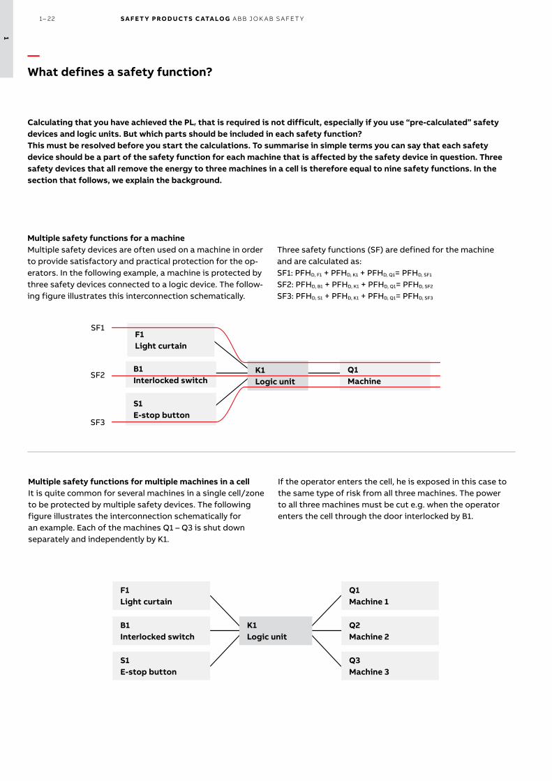
Multiple safety functions for a machine Multiple safety devices are often used on a machine in order to provide satisfactory and practical protection for the op-erators. In the following example, a machine is protected by three safety devices connected to a logic device. The follow-ing figure illustrates this interconnection schematically.
Calculating that you have achieved the PLr that is required is not difficult, especially if you use “pre-calculated” safety devices and logic units. But which parts should be included in each safety function?This must be resolved before you start the calculations. To summarise in simple terms you can say that each safety device should be a part of the safety function for each machine that is affected by the safety device in question. Three safety devices that all remove the energy to three machines in a cell is therefore equal to nine safety functions. In the section that follows, we explain the background.
Three safety functions (SF) are defined for the machine and are calculated as:SF1: PFHD, F1 + PFHD, K1 + PFHD, Q1= PFHD, SF1
SF2: PFHD, B1 + PFHD, K1 + PFHD, Q1= PFHD, SF2
SF3: PFHD, S1 + PFHD, K1 + PFHD, Q1= PFHD, SF3
Multiple safety functions for multiple machines in a cell It is quite common for several machines in a single cell/zone to be protected by multiple safety devices. The following figure illustrates the interconnection schematically for an example. Each of the machines Q1 – Q3 is shut down separately and independently by K1.
If the operator enters the cell, he is exposed in this case to the same type of risk from all three machines. The power to all three machines must be cut e.g. when the operator enters the cell through the door interlocked by B1.
—What defines a safety function?
1
1– 22 S A F E T Y PRO D U C T S C ATA LO G A B B J O K A B S A FE T Y

Conclusions – Use the practical approach for multiple machines. – Use safety devices/logic units with high reliability (low
PFHD) to make it easy to achieve the PLr required. – With Vital or Pluto, it is easier to achieve the PLr re-
quired.
Sources:http://www.dguv.de/medien/ifa/en/pra/en13849/safe-ty_functions.pdf
Theoretical approach for multiple machinesThe theoretical approach to calculate the safety function is as follows:
Q3Machine 3
B1 Interlocked switch
Q1Machine 1
Q2Machine 2
K1Logic unit
For the full safety function to be performed you require all the components to be working. Note that if B1 or K1 has a dangerous malfunction, the entire safety function is dis-abled. However, if for example machine Q1 has a dangerous malfunction, and is not shut down, machines Q2 and Q3 will still be shut down. One disadvantage in considering the safe-ty function in this way is that you may have trouble achieving the PLr required. But if you achieve the PLr required, you can use the theoretical approach.
Practical approach for multiple machinesA more practical approach is to divide the safety func-tion into three parts, one for each of the three machines.
B1Interlocked switch
Q2Machine 2
K1Logic unit
B1Interlocked switch
Q3Machine 3
K1Logic unit
B1Interlocked switch
Q1Machine 1
K1Logic unit
This is an approach that can provide a more accurate way of looking at the safety functions, especially where a different PLr is required for the safety functions above. If machine Q1 is a robot and machine Q2 is a conveyor which is de-signed to have negligible risks, the different PLr required to protect against risks from Q1 and Q2 will also be different. This practical approach is therefore the one recommended. The interpretation is based on information provided by IFA (Institut für Arbeitsschutz der Deutschen Gesetzlichen Unfallversicherung). For more information on this and other issues, see Sources.
Practical approach If you use the practical approach the safety functions are as follows:Robot:PFHD, B1 + PFHD, K1 + PFHD, Q1 = 4.5x10⁻⁹ + 2•10-9 + 5.79x10-8 = 6.44x10⁻⁸ PL eHydraulic press:PFHD, B1 + PFHD, K1 + PFHD, Q2 = 4.5x10⁻⁹ + 2•10-9 + 8x10-8 = 8.65x10⁻⁸ PL ePneumatic machining tool:PFHD, B1 + PFHD, K1 + PFHD, Q3 = 4.5x10⁻⁹ + 2x10⁻⁹ + 2x10-7 = 2.07x10⁻⁷ PL dThis is to be done in a similar way with other safety functions for the cell. For each safety device, you define the machines it affects, and establish the various safety functions according to this.
Theoretical approach What would the result be using the theoretical approach? Would the safety function achieve PL e?All machines:PFHD, B1 + PFHD, K1 + PFHD, Q1 + PFHD, Q2 + PFHD, Q3 = 4.5x10⁻⁹ + 2x10⁻⁹ + 5.79x10⁻⁸ + 8x10⁻⁸ + 2x10-7 = 3.44x10⁻⁷ PL dIn this case, the safety function would not achieve a total PL e, which was required for the risks associated with the robot and hydraulic press.
Example of safety functions for multiple machines in a cell For a cell with three machines (one robot, one hydraulic press and one pneumatic machining tool) a risk assessment is made resulting in different PLr for the individual machines. The robot and the hydraulic press requires PLr = e, while the pneumatic machining tool requires PLr = d.One of the safety functions is that a non-contact sensor
(Eden) supervised by a safety PLC (Pluto) shall disconnect the energy to all three machines in the hazard zone:
– Eden B1 (PFHD, B1 = 4.5x10⁻⁹) – Pluto K1 (PFHD, K1 = 2x10⁻⁹) – Robot Q1 (PFHD, Q1 = 5.79x10⁻⁸) – Hydraulic press Q2 (PFHD, Q2 = 8x10⁻⁸) – Pneumatic machining tool Q3 (PFHD, Q3 = 2x10⁻⁷).
Please note that the examples on these pages are simplified in order to ex-plain the principles. Values of products can also change.
1
I NTR O D U C TI O N 1– 23

—FSDT and SISTEMATools for determining performance level (PL)
Tools to simplify the process of safety function designFSDT is an ABB software for determining PL and SIL of safety functions and generating technical documentation. The tool helps simplifying the process of safety function design, verification and documentation. It supports the compliance of the requirements of both EN ISO 13849-1 and IEC 62061 as well as the European Machinery Directive. FSDT is freeware and can be downloaded from the ABB website.
Another commonly used software tool for the calculation of PL according to EN ISO 13849-1 is SISTEMA, developed by IFA (The Institute for Occupational Safety and Health) in Ger-many. With SISTEMA it is possible to “build” safety functions, verify them and generate the technical documentation required. The tool is freeware and can be downloaded from the IFA website.
To simplify the use of FSDT and SISTEMA with our products we have created a library con-taining all of our safety products.
2TLC172300D0201
1
1– 24 S A F E T Y PRO D U C T S C ATA LO G A B B J O K A B S A FE T Y

Safety Integrity Level, SIL Probability of dangerous Failure per Hour (PFHD)
3 ≥10-8 to <10-7
2 ≥10-7 to <10-6
1 ≥10-6 to <10-5
There is a method in IEC/EN 62061 for assigning the Safety Integrity Level.
Severity (Se) Class (Cl)
3-4 5-7 8-10 11-13 14-15
4 SIL2 SIL2 SIL2 SIL3 SIL3
3 (OM) SIL1 SIL2 SIL3
2 (OM) SIL1 SIL2
1 (OM) SIL1
Cl=Fr+Pr+Av OM=Other Measures
The severity of injury that can occur is divided into four levels. Class is the addition of the values of frequency (Fr, stated as a value between 1 and 5, where 5 represents the highest frequency), probability that a dangerous event will occur (Pr, stated as a value between 1 and 5, where 5 repre-sents the highest proability) and the possibility of avoiding or limiting injury (Av, stated as a value of 1, 3 or 5, where 5 represents the least chance of avoiding or limiting an injury). The safety function that is to be designed must at least fulfill the SIL that has been assigned to it in the risk assess-ment. The safety function consists of a number of sub-elements. Example: a door is interlocked by a non-contact sensor which is in turn monitored by a Pluto safety PLC, with outputs that break the power to two supervised contac-tors. The sensor is sub-element 1, Pluto is sub-element 2 and the two supervised contactors are sub-element 3. If in the assessment it has been established that SIL2 shall be used, every individual sub-element in the safety function must fulfill the SIL2 requirements. And the safety function must in its entirety fulfill the SIL2 requirements.
If the SIL requirements are not fulfilled in any of the sub-elements or by the safety function in its entirety, a re-design must be made.
FinallyThis is just a brief introduction to the EN ISO 13849-1 and IEC/EN 62061 standards. You are welcome to contact us for more information and we are happy to guide you in how to apply the standards to our products.
The information given in this document is not intended to replace the standards - we strongly encourage you to pur-chase the standards if you are working with machine safety.
Definition of protective safety in accordance with IEC/EN 62061"Function of a machine whose failure can result in an immediate increase of the risk(s)"
If a safety function is designed in accordance with IEC/EN 62061, the level of reliability is expressed as the Safety Integrity Level, SIL. There are a total of 4 levels, but in the IEC/EN 62061 standard SIL 3 is the highest level. SIL is similar to PL (performance level) and uses the same PFHD (probability of dangerous failure per hour) to express the reliability of components and systems.
—Applying IEC/EN 62061
I NTR O D U C TI O N 1 – 2 5
1

S A F E T Y PRO D U C T S C ATA LO G A B B J O K A B S A FE T Y
2

—Safety controllers
2– 2 Introduction and overview
2– 6 Programmable safety controller
Pluto
2– 16 Safety controller
Vital
2– 22 Safety relay
Sentry
S A FE T Y CO NTR O L L ER S 2– 1
2

—Introduction and overviewSelection guide
The safety controllers from ABB can monitor anything from a single safety
function to complete manufacturing lines.
Pluto Vital Sentry
Image
Type Programmable safety controller Safety controller Safety relay
Description A cost-effective, powerful and compact programmable safety controller for all types of safety applications.
A configurable safety controller that can monitor all safety devices on smaller machines.
Powerful and easy-to-install safety relays suitable for all common types of safety devices.
Application(s) Monitoring of multiple safety de-vices and several safety functions, as well as control of machines and/or processes. Many I/Os and pro-grammable logic.
Monitoring multiple safety devices with all the advantages of the DYN-link system.
Monitoring safety devices with one safety function, as well as expan-sion of safety outputs, with or without time delay.
Compatible safety devices
All types of conventional safety devices and DYNlink devices
DYNlink devices All types of conventional safety devices
Advantages - Easy-to-use while still allowing advanced programming
- Free software- Easy system modification- Gateway communication with all
main fieldbuses
- Monitor up to 30 sensors in series maintaining Cat. 4/PL e
- No programming
- Easy to install- Universal models for all common
applications- Extensive status information- Advanced timer functions- Multireset of up to 10 safety relays
2– 2 S A F E T Y PRO D U C T S C ATA LO G A B B J O K A B S A FE T Y
2

Conventional safety devicesBy conventional safety devices, we mean safety devices with one or two channels with contacts (e.g. key switches and emergency stop buttons), devices with OSSD outputs (e.g. light guards and Eden OSSD), safety devices with solid state outputs (e.g. safety magnetic sensors) and pressure sensitive devices (e.g. safety mats, safety edges and bumpers).A safety controller compatible with conventional safety devices can be used with most safety devices on the market, independently of the brand.
The DYNlink solutionThe DYNlink solution is a unique ABB Jokab Safety feature allowing to connect safety de-vices in series and still reach category 4/PL e/SIL 3 with only one channel (instead of two with conventional safety devices). This saves cabling and hardware.For a small machine, the Vital safety controller can be a very cost effective solution since up to 30 DYNlink devices can be connected to one Vital and still reach category 4/PL e/SIL 3. With conventional safety devices this would require one safety relay per safety device.When Pluto programmable safety controller is used, only one safety input is necessary for each DYNlink circuit instead of two inputs for a traditional safety device, which means that less I/Os are necessary.Tina adapters allow to use conventional safety devices in a DYNlink solution and transform between DYNlink signals and conventional safety signals, while maintaining the highest level of safety. This means that most conventional safety devices can be used in a DYNlink solu-tion when used together with a suitable Tina adapter.
—OverviewSelection orientation
Programmable logicQuite often, there is a need for logic between the different safety functions. For instance: IF (“door A” AND “door B” are open) OR (“door C” is open) THEN “Action 1”. A logic like this can be hardwired without using programmable safety controllers, but the cabling becomes much more complicated, modifications are time consuming, errors happen more often and are difficult to find.With a programmable safety controller, the safety devices are simply connected to the safe inputs of the controller and the logic is made in the program of the safety controller. The logic is then easy to modify without changing anything in the cabling. The Pluto Manager programming software allows to test the logic and see on the screen if there are any prob-lems, which means much faster troubleshooting. Pluto also offers many functions that enables it to do much more than supervising safety functions. It can e.g. control the complete manufacturing process of a smaller machine, thus saving the cost of a standard (non-safety) PLC.
S A FE T Y CO NTR O L L ER S 2– 3
2

—Introduction and overviewStandards
StandardsSome of the more important safety standards to follow when designing safety solutions are:EN ISO 12100 - Risk assessmentEN ISO 13849 - Performance LevelEN ISO 62061 - SILISO/TR 23849 - Guidance on the use of the PL and SIL standardsEN 60204 - Electrical equipment
2– 4 S A F E T Y PRO D U C T S C ATA LO G A B B J O K A B S A FE T Y
2

S A FE T Y CO NTR O L L ER S 2– 5
2

Pluto is a cost effective, powerful and compact programmable safety controller used in a variety of applications: in large and small systems for process and functional safety.
Pluto can control most types of safety devices on the market, as well as ABB Jokab Safety DYNlink safety devices, analog sensors, encoders, con-tactors, valves and many more. Programming is done easily in the complimentary software, Pluto Manager.
The models with safety bus communication sim-plify the design of safety systems, thanks to our All-Master concept. A wide range of gateways al-lows communication with other networks and also remote monitoring of a Pluto system.
Continuous operation
Programming software free of chargePluto Manager is an easy to use PC based programming software provided free of charge.
Easy programmingReady-made TÜV approved function blocks for safety functions make it easy to reach PL e/SIL3. Ladder logic and text programming allow the de-sign of more advanced functions and the control of complete machines.
Communication with external net-worksPluto gateways provide a two-way communication between the Pluto safety bus and other field buses.
Optimum interface
Easy modificationEasy and quick replacement of units without any configuration.
Flexible monitoringOnline monitoring from any Pluto in the system and remote monitoring and control with an Ethernet gateway.
—Programmable safety controllerPluto
Great flexibilityUp to 32 Pluto units can exchangedata on the same safety bus, and theunique All-Master system allows simplescaling, splitting and modification.
Powerful yet compactUnexpected features for its size, likereal programming and speed monitor-ing, enables replacement of more com-plex PLC systems in some applications.
More sensors and less cablingThe DYNlink solution allows seriesconnection of up to 10 safetydevices on each input.StatusBus and light button featurealso reduces cabling to a minimum.
Speed up installation
2-6 S A F E T Y PRO D U C T S C ATA LO G A B B J O K A B S A FE T Y
2

DYNlink solutionThe DYNlink circuit is a unique solution that allows up to 10 DYNlink devices to be connected in series to a Pluto input while still reaching up to Cat. 4/PL e/SIL3. This saves inputs and cabling, since to reach the same level with standard two-channel safety devices, two inputs are necessary and series connection is not possible.The DYNlink solution checks the signal 200 times/second and a fault such as a short circuit will be detected before any safety device is used.Examples of DYNlink devices are Eden and Smile Tina. Most two-channel safety devices can be connected to the DYNlink solution using Tina adapters.
StatusBus functionalityThe StatusBus functionality is available with some DYNlink devices and allows to collect the status of each individual safety device, even when connected in series. A single input on Pluto can collect the status of up to 30 safety devices. The devices are connected using standard cable and M12-5 connectors. No specific bus cable or extra communication module is necessary. All Pluto models offer the StatusBus functionality.
—FeaturesPluto
Safety bus with All-Master functionThe unique All-Master system allows simple scaling, split-ting and modification of the safety system.
In a traditional safety PLC network, there is one Master and additional Slave units. But for Plutos connected to a safety bus, all units are Masters and make their own decisions, while still having the possibility to listen to what is hap-pening to the other Plutos on the safety bus. This enables great flexibility when it comes to modification of the safety system. It also enables very simple replacement of a broken Pluto, since all Plutos have a copy of the application soft-ware of all other Plutos on the safety bus stored locally. If the replacement Pluto is given the same ID as the broken Pluto (using IDFIX), the software is downloaded from the safety bus with a simple button on the front of Pluto.
Up to 32 Pluto units can be connected to the Pluto safety bus. The Pluto S20 and S46 are stand-alone models and can-not be connected to the Pluto safety bus. All other models have bus functionality. The Safety bus functionality is neces-sary in order to use a Pluto gateway.
I/OsFailsafe inputs (I) are used to connect the safety devices tobe monitored. Some of them can be used as analog inputsand counter inputs. The choice is made in the Pluto programwhen the I/Os are configured. Depending on the model, theanalog inputs can be low resolution 0-27 V or high resolution0-10 V/4-20 mA. The fast counter inputs can handle frequen-cies up to 14 kHz.
Failsafe inputs/non-failsafe outputs (IQ) are terminals thatcan be used as failsafe inputs or communication outputs(non-failsafe). The choice is made in the Pluto program whenthe I/Os are configured. A specific configuration is “light button” which means that both the contact and the LED in-dicator of an illuminated push-button are connected to only one IQ, thus saving one I/O.
Failsafe outputs (Q) are individually safe and independentlyprogrammable outputs. There are both relay and transistoroutputs. The transistor outputs deliver a negative voltage(-24 VDC) that facilitates the detection of a short circuit with other voltage potentials and increases safety. The tran-sistor outputs are primarily intended for electromechanical components such as contactors and valves.
StatusBus logotype
S A FE T Y CO NTR O L L ER S 2-7
2

Pluto ManagerPluto Manager is the programming software for Pluto, downloaded free of charge from our website http://new.abb.com/low-voltage/products/safety-products/program-mable-safety-controllers/plutoAn update function in Pluto Manager helps you to always have the latest version installed as long as you have an Inter-net connection. Pluto Manager is a user friendly PC software that allows a simple configuration of the Pluto I/Os and programming in ladder logic and with TÜV approved func-tion blocks.
Examples of what the available function blocks can handle: - Two-channel safety devices, with or without Reset and Monitoring. - Single channel functions with Reset. - Muting functions - Encoders and counters - Communication with Gateways and StatusBus Examples of ladder logic functions provided: - Boolean instructions, Edge/inverted edge detection, Latch function, Toggle - Timers - Addition, Subtraction, Multiplication, Division - Remanent memories - Registers: 16 and 32 bit - Sequence programming - Option handling - Online monitoring
In Pluto Manager there is a unique Option handling function suitable for series production of machines with different customer options. All versions of a machine type can have the same PLC program. To handle the different customer options, check boxes are used to set memories that activate the different functions of the code.
Current monitoringPluto A20 has a special current monitoring function. The function is mainly used to check if the connected muting lamps are working.
—FeaturesPluto
Remote monitoring and controlRemote monitoring allows the connection to a remote Plutosystem via the Internet and an Ethernet gateway. Pluto Man-ager is used for the monitoring.This function can be used for:- Support of local maintenance personnel during trouble-
shooting- Regular monitoring of the status of the machine or process- Follow-up of operational data like number of cycles/day or
runtime.
Pluto Manager also offers remote control of a Pluto system using the Internet and an Ethernet gateway.With the remote control function it is possible to:- Download a program from PC to the remote Pluto- Configure addressing of AS-i and StatusBus slaves, write
IDFIX codeThe security of the remote control function is guaranteed by use of the K-button on Pluto. A change in a remote Pluto sys-tem cannot be made without a person at the remote Pluto confirming the action by pressing the K-button.
Configuration of the gateway itself, e.g. switching remote control on/off, can only be made via the programming port on the gateway and not via the Ethernet port.
2-8 S A F E T Y PRO D U C T S C ATA LO G A B B J O K A B S A FE T Y
2

—AccessoriesPluto
Operator panelsAn operator panel can be connected to the programming port of Pluto with a specific cable and communicate with Pluto in MODBUS ASCII. We recommend the ABB CP600 series operator panels that offer the appropriate communi-cation driver.An operator panel can also communicate with Pluto via a GATE-MT gateway.
Pluto gatewaysPluto gateways provide two-way communication between the Pluto safety bus, i.e. all the Pluto units connected to it, and other field buses. Several models are available for the most common field buses.Ready-made function blocks in Pluto Manager facilitate the communication. A gateway can be located anywhere on the Pluto safety bus.
Pluto safe encodersRotary absolute encoders can be used for safe position determination. Our safe encoders are intended to be connected to the Pluto safety bus. They are available in single and multi-turn ver-sions, with shaft or hollow shaft. Up to 16 absolute encoders can be connected to a Pluto safety bus. In Pluto Manager, specific function blocks make it easy to read and evaluate the values of two encoders forming a PL e/SIL3 solution. Apart from position, the speed values are available which means that also zero speed and overspeed can be moni-tored.
Examples of applications are gantry robots, industrial ro-bots, and also eccentric shaft presses, where the encoders can replace existing cam mechanisms.
S A FE T Y CO NTR O L L ER S 2-9
2

2TLC
010
035V
020
1
Pluto S20 v2
—Ordering informationPluto
Safety bus Failsafe outputs a)
Failsafe inputs (max) b)
Analog inputs (max) b)
Fast counter inputs(max) b)
StatusBus inputs (max) b)
Non failsafe outputs(max) b)
Width
mm
Type Order code
No 4 16 1 c) - 4 8 45 Pluto S20 2TLA020070R4700
6 40 3 c) - 4 16 90 Pluto S46 2TLA020070R1800
Yes - 22 1 c) - 4 8 45 Pluto B22 e) 2TLA020070R4800
2 4 - - 2 2 45 Pluto O2 f) 2TLA020070R8500
4 16 1 c) - 4 8 45 Pluto A20 g) 2TLA020070R4500
Pluto B20 2TLA020070R4600
4 d) + 1 c) - 4 8 45 Pluto D20 2TLA020070R6400
6 40 3 c) - 4 16 90 Pluto B46 2TLA020070R1700
39 8 d) 4 4 15 90 Pluto D45 2TLA020070R6600a) Failsafe outputs
2 failsafe outputs: - 2 independent individually safe potential free relay outputs (Q0 and Q1) with 3 contacts each
4 failsafe outputs: - 2 independent individually safe potential free relay outputs (Q0 and Q1) - 2 independent individually safe transistor outputs (-24 VDC) (Q2 and Q3)
6 failsafe outputs: - 2 independent individually safe potential free relay outputs (Q0 and Q1)
- 2 independent individually safe potential free relay outputs with common supply (Q4 and Q5) - 2 independent individually safe transistor outputs (-24 VDC) (Q2 and Q3)
b)
-The number of failsafe inputs available decreases with the number of used non-failsafe outputs, analog inputs, fast counter inputs and StatusBus inputs. -The number of analogue inputs available decreases with the number of used fast counter inputs. -The number of non-failsafe outputs available decreases with the number of StatusBus inputs used. Check the Pluto hardware manual for more information.
c) 0-27 V analog inputsd) 0-10 V/4-20 mA (high resolution) analog inputse) Expansion model with failsafe inputs and no failsafe outputs.f) Expansion model with 2 failsafe outputs with 3 contacts each. Also possible to use as stand-alone unit.g) Model with current monitoring
Pluto A20 v2
2TLC
010
00
8V0
201
Pluto D45
2TLC
010
029
V0
201
Failsafe inputs / Outputs (not failsafe) / Dynamic outputs
IQ10 IQ11
supplyPower
+24V
IQ12 IQ13
Identifier IDFIX
IQ15IQ14 IQ16
I30
B
Inputs, individual failsafe
Q0
IQ17
I31 I32 I33 I34 I35 I36
Q2A
I37
Pluto B46, S46
Pluto bus
I45I40 I41 I42 I43 I44 I46 I47
Inputs, individual failsafe
I0 I1 I2 I3 I6I5I4 I7
IQ21IQ20 IQ25IQ24IQ23IQ22 IQ27IQ26
BA
AQ1 B
AQ4 B
Q5 A B
Q3BA
0V
0V
ID
CH
CL1)
AI AI AISR46SR45SR41
4L
1L
0L
Safety outputs
Digital/AnalogueInputs, individual failsafe
CLI0
CH
ID
Pluto O2
IQ10
Q1
B
IQ11
33
A
13 14+24V 0V
CSh
23 2434
B33 34 13 14 23 24
A
Q0
I1
250VAC, 5A24V, 1.5A
24V, 1.5A 250VAC, 5A
Power supply
Safety Output Module
Safe inputs
Non-safe outpDynamic outp
Safe inputs
Non-safe outpDynamic outp
—Pluto ordering tablePluto is available in different models depending on the needs of your application. Optional features includes bus communication, high resolution analog inputs, current monitoring and adaption for harsh environments.
2-10 S A F E T Y PRO D U C T S C ATA LO G A B B J O K A B S A FE T Y
2

IDFIX-PROG 10k
2TLC
1726
13F0
201
IDFIX-PROG 2k5
2TLC
1726
11F0
201
—Ordering informationPluto accessories
Description Type Order code
Pre-programmed unique identification number. IDFIX-R 2TLA020070R2000
Programmable identification number, i.e. the user can choose identification number. IDFIX-RW 2TLA020070R2100
Programmable identification number and storage of AS-i safety codes. IDFIX-DATA 2TLA020070R2300
Storage of the Pluto program, 2.5 Kbyte. Especially useful for stand-alone Pluto. IDFIX-PROG 2k5 2TLA020070R2400
Storage of the Pluto program, 10 Kbyte. Especially useful for stand-alone Pluto. IDFIX-PROG 10k 2TLA020070R2600
Description Type Order code
Pluto programming and on-line monitoring cable. For a PC serial port, 9-pole D-sub connector. Pluto cable serial 2TLA020070R5600
Pluto programming and on-line monitoring cable. For a PC USB port. Pluto cable USB 2TLA020070R5800
Cable for connecting a HMI-panel to the Pluto programming port. Connector on HMI-side: 15-pole D-sub. On Pluto side: 90 degrees angled Modbus contact.
Pluto cable HMI 2TLA020070R5700
Cable for connecting HMI-panel ABB CP400 to Pluto programming port. Connector on HMI-side: 9-pole D-sub.
Pluto cable CP400 2TLA020070R6700
Cable for connecting HMI-panel ABB CP600 to Pluto programming port. Connector on HMI-side: 9-pole D-sub.
Pluto cable CP600 2TLA020070R6900
Bus cable for Pluto safety bus, 2 x 0.75 mm2. Ordered by meter, cut to size. Minimum order length 10 m.
PCABLE-000 2TLA020070R6800
Bus cable for Pluto safety bus, 2 x 0.75 mm2. 50-meter ring. PCABLE-050 2TLA020070R6805
Bus cable for Pluto safety bus, 2 x 0.75 mm2. 100-meter ring. PCABLE-100 2TLA020070R6810
Bus cable for Pluto safety bus, 2 x 0.75 mm2. 500-meter drum. PCABLE-500 2TLA020070R6850
Bus cable for Pluto safety bus, 2 x 0.75 mm2. Halogen free. Ordered by meter, cut to size. Minimum order length 10 m.
PCABLE-000-HF 2TLA020070R8600
Bus cable for Pluto safety bus, 2 x 0.75 mm2. Halogen free. 50-meter ring. PCABLE-050-HF 2TLA020070R8605
Bus cable for Pluto safety bus, 2 x 0.75 mm2. Halogen free. 100-meter ring. PCABLE-100-HF 2TLA020070R8610
Bus cable for Pluto safety bus, 2 x 0.75 mm2. Halogen free. 500-meter drum. PCABLE-500-HF 2TLA020070R8650
Terminal block with capacitor, 12nF, for connection between 0 V of Pluto supply and earth in order to reduce problems with conducted disturbances.
Pluto capacitor 2TLA020070R3200
Description Type Order code
Set of function blocks for mechanical presses. Pluto press block 2TLA020070R4100
Smile reset button for light button function with M12-5 connector. Smile 11 RB 2TLA030053R0100
Handheld terminal for StatusBus. Used for e.g. addressing and test. Connection to PC via USB-micro cable
FIXA 2TLA020072R2000
Terminating resistor for Pluto safety bus. Necessary for each stand-alone Pluto and on the Pluto units at each end of the Pluto safety bus. Should be removed from the other Pluto units.
R120 Resistor 2TLA020070R2200
Description Type Order code
Contact block for safety relays and Pluto. 7 poles. Grey. Contact block 7 grey 2TLA081200R1500
IDFIX-R
2TLC
1726
09F
020
1
IDFIX-RW
2TLC
1727
65F0
201
IDFIX-DATA
2TLC
1726
07F0
201
R120 Resistor
2TLC
1726
24F0
201
FIXA
—Pluto cables and connection accessories
—IDFIX identifiersIDFIX is an identification circuit that is connected to Pluto. It must be used: • when several Pluto are connected to the Pluto Safety bus (IDFIX-R or IDFIX-RW) • to get the possibility to replace a stand-alone Pluto with a new one without the need of a PC (IDFIX-PROG stores the Pluto program)
—Other accessories
—Pluto spare parts (included when ordering a Pluto)
S A FE T Y CO NTR O L L ER S 2-11
2

Type of safety device
Type of connection to the DYNlink loop
Description Type Order code
Devices with posi-tively driven force-guided contacts like E-stop buttons and key switches
Via the device connection Mounted directly on the device enclosure to a M20 cable entry.
Tina 2A 2TLA020054R0100
Placed inside the safety device enclosure Tina 2B 2TLA020054R1100
M12-5 male connector Mounted directly on the device enclosure to a M20 cable entry.
Tina 3A 2TLA020054R0200
M12-5 male connector with extra conductor for the supply of the safety device
Two circuits and with supply voltage for the safety sensor. Connects to a M20 cable entry.
Tina 3Aps 2TLA020054R1400
Removable terminal blocks
Mounted on a DIN rail in the electrical cabi-net. Note that the connected safety device(s) must be mounted on the same cabinet.
Tina 7A 2TLA020054R0700
Devices with OSSD outputs like Orion light guards
M12-5 male connector Adaptation of OSSD to DYNlink. M12-8 con-nector for OSSD and M12-5 for DYNlink.
Tina 10A v2 2TLA020054R1210
Adaptation of OSSD to DYNlink with possibil-ity to connect a local reset button. M12-8 for OSSD and M12-5 for DYNlink and reset.
Tina 10B v2 2TLA020054R1310
Adaptation of OSSD to DYNlink with possibility to power the transmitter. M12-8 connector for OSSD and M12-5 for DYNlink and power.
Tina 10C v2 2TLA020054R1610
Safety mats, edges and bumpers with short-circuit detection
M12-5 male connector Short-circuit detection and adaptation to DYNlink.
Tina 6A 2TLA020054R0600
—Ordering informationDYNlink solution
Description Type Order code
Tina 1A is a blind plug connected to the unused M12 connectors of the connection blocks Tina 4A and Tina 8A.
Tina 1A 2TLA020054R0000
Description Type Order code
Connection block for serial connection of up to 4 DYNlink devices with M12-5 connectors Tina 4A 2TLA020054R0300
Connection block for serial connection of up to 8 DYNlink devices with M12-5 connectors Tina 8A 2TLA020054R0500
Connection block for serial connection of 2 DYNlink devices with M12-5 connectors Tina 11A 2TLA020054R1700
Connection block for serial connection of 2 DYNlink devices with M12-8 connectors, e.g. Magne. Tina 12A 2TLA020054R1800
2TLC
1724
75F0
201
Tina 10B
Tina 7A
2TLC
1724
69F0
201
Tina 10A
2TLC
1724
73F0
201
2TLC
1724
59F0
201
Tina 3A
2TLC
1724
67F0
201
Tina 6A
2TLC
1724
77F0
201
Tina 10C
2TLC
1724
57F0
201
Tina 2B
2TLC
1724
53F0
201
Tina 2A
—Tina adaptation units to DYNlink The Tina devices adapt the DYNlink signals from Pluto to safety components with mechanicalcontacts, such as E-stops, switches and light beams/curtains with dual outputs. Tina is available in several versions depending on the type of safety component that is connected to theDYNlink solution. Also available is connector blocks and a blind plug.
—Connection blocks for serial connection of DYNlink devices (or devices with Tina adapter)
—Blind plug to complete the serial connection on a connection block All M12 connectors on Tina 4A or Tina 8A must be connected to a safety device or a Tina 1A. For example, if only 6 devices are connected to a Tina 8A, two Tina 1A are necessary.
Description Type Order code
M12 Y-connector for series connection of DYNlink devices such as Eden, Smile, Inca and Tina. M12-3A 2TLA020055R0000
M12 Y-connector for parallel connection of 2 DYNlink devices. M12-3B 2TLA020055R0100
M12 Y-connector for the connection of 2 DYNlink devices or one DYNlink and one light button to Pluto safety PLC with only one cable.
M12-3E 2TLA020055R0200
M12 Y-connector for series connection of DYNlink devices with the StatusBus function. M12-3S 2TLA020055R0600
—M12 Y-connectors
2-12 S A F E T Y PRO D U C T S C ATA LO G A B B J O K A B S A FE T Y
2

Function Shaft Shaft diameter (mm)
Type of connection Type Order code
Single-turn Solid 10 Connector male 12 poles RSA 597 connector 2TLA020070R3600
6 1.5 m cable RSA 597 1.5 m cable 2TLA020070R3300
Hollow 12 2 m cable RHA 597 2 m cable 2TLA020070R3400
10 m cable RHA 597 10 m cable 2TLA020070R5900
Multi-turn Solid 6 M12 connector RSA 698 6 mm solid 2TLA020071R7800
10 M12 connector RSA 698 10 mm solid 2TLA020070R3700
Holow 12 M12 connector RHA 698 hollow 2TLA020071R7900
For more information, see the manual: Pluto safe encoders 2TLC172006M0206
—Ordering informationAccessories
Description Type Order code
Female 12 pole connector to be used with absolute encoder “RSA 597 connector”. Con-nector to be mounted on the cable.
Connector for abso-lute encoder
2TLA020070R3900
M12 plug with Pluto safety bus termination resistor. To be used when the encoder is at one end of the Pluto safety bus.
M12-CANend 2TLA020061R0300
Fieldbus Ethernet Type Order code
CANopen GATE-C2 2TLA020071R8100
DeviceNet GATE-D2 2TLA020071R8200
PROFIBUS-DP GATE-P2 2TLA020071R8000
EtherCAT x GATE-EC 2TLA020071R9100
Ethernet/IP x GATE-EIP 2TLA020071R9000
Modbus TCP x GATE-MT 2TLA020071R9400
PROFINET x GATE-PN 2TLA020071R9300
SERCOS III x GATE-S3 2TLA020071R9200
For more information, see the gateway manuals: Pluto gateways 2TLC172009M0210 Pluto Ethernet gateways 2TLC172285M0203
Description Type Order code
Operator panel, 4.3” touch screen, 480 x 272 pixels CP604 1SAP504100R0001
For more sizes and version, see: http://new.abb.com/plc/control-panels
GATE-C2
2TLC
1725
09F
020
1
GATE-EC
2TLC
1728
43F0
201
CP604
RSA 698
2TLC
1725
43F0
201
RSA 597
2TLC
1723
31F0
201
—Pluto gateways With the use of a gateway, Pluto can communicate with other control systems and form a part of a larger network. The gateway models GATE-D2 and C2 can also be used as an extension of the safety bus cable to extend the Pluto network.
—Pluto safe encoders The safe encoders can be used together with Pluto to safely determine the position of machine movements.
—Pluto safe encoders accessories
—Operator panels An operator panel (also called HMI) can be connected to the Pluto programming port (on the Pluto front) with a special cable and communicate with Pluto using MODBUS ASCII. We recommend the ABB CP600 series that offer the appropriate communication driver. An operator panel can also communicate with Pluto via a GATE-MT gateway.
S A FE T Y CO NTR O L L ER S 2-13
2

Technical data
Approvals
Conformity2006/42/EC - Machinery2014/30/EU - EMC 2011/65/EU - RoHSEN ISO 13849-1:2015, IEC 62061:2015+Corr.1:2015, EN 61496-1:2013(in extracts), EN 574:1996+A1:2008(in extracts), EN 692, EN 60204-1:2006+A1:2009+AC:2010, EN 50178:1997, EN 61000-6-2, EN 61000-6-4, EN 61000-4-1...6, IEC 61508:2010, IEC 61511-1, EN 50156-1, EN 50156-2:2015, ISO 13851:2002 (in extracts)
Functional safety data
PFHD Failsafe relay outputs PFHD Failsafe transistor outputs
EN 61508:2010 SIL3 2.00 × 10⁻⁹ 1.5 × 10⁻⁹
EN 62061:2005+A1:2013 SILCL3 2.00 × 10⁻⁹ 1.5 × 10⁻⁹
EN ISO 13849-1:2008 PL e/Cat.4 2.00 × 10⁻⁹ 1.5 × 10⁻⁹
Electrical data
Electrical insulation Category II in accordance with IEC 61010-1
Operating voltage +24 VDC ± 15%
Failsafe outputs Q Transistor, -24 VDC, 800 mA
Q2, Q3 Pluto O2 Pluto O2Q0, Q1, (Q4, Q5) Relay outputs
AC-12: 250 V / 1.5 AVAC-15: 250 V /1.5 A VDC-12: 50 V /1.5 A DC-13: 24 V / 1.5 A
Relay outputsAC-12: 250 V / 5 AAC-15: 250 V / 3 ADC-12: 60 V / 5 ADC-13: 24 V / 3 A
Relay outputs (33-34)AC-12: 24 V / 1.5 AAC-15: 24 V / 1.5 ADC-12: 24 V / 1.5 ADC-13: 24 V / 1.5 A
Installation 35 mm DIN rail
Ambient temperature –10 ˚C to +50 ˚C
Pluto safety busMax. number of Pluto units 32
Cable length Up to 600 m
More information For more information, e.g. the complete technical information, see product manual: Pluto hardware manual 2TLC172001M0211
Connection diagramsFor Pluto connection diagrams please see https://library.abb.com/
—Technical dataPluto
2-14 S A F E T Y PRO D U C T S C ATA LO G A B B J O K A B S A FE T Y
2

—Dimension drawingsPluto
Single size
All dimensions in mm
Double size
45 120
12090
84
84
S A FE T Y CO NTR O L L ER S 2-15
2

Vital is a configurable safety control-ler that does not require program-ming. It uses the DYNlink system, which allows up to 30 safety devices to be connected in series to the same circuit, while achieving PL e.
This enables a single Vital to super-vise all safety functions on many machines that otherwise would have required a programmable safety con-troller or multiple safety relays.
Vital is also commonly used to super-vise all emergency stops for larger machine lines.
Easy connectionReduced installation and engineer-ing time thanks to simple installa-tion with serial connection using M12 connectors.
No programming requiredThe use of only one safety module without any programming simpli-fies engineering, commissioning and replacement.
Less componentsSignificantly less components needed to achieve PL e/SIL 3.
Speed up your projects
Safety and protection
LED diagnosticsIntegrated LED diagnostics reduces down time when troubleshooting.
Detachable connection blocks Detachable connection blocks simplify replacement.
Exchange without configuration The configuration is made with jump-ers in the detachable connection blocks. In case of exchange, the new unit automatically gets the correct configuration.
Continuous operation
Easy to reach highest safety levelThe DYNlink solution makes it possible to maintain the highest level of safety with up to 30 sensors connected in series.
Extensive fault detectionThe DYNlink solution enables uniquefault detection features and prevents2-channel faults.
—Safety controllerVital
2–16 S A F E T Y PRO D U C T S C ATA LO G A B B J O K A B S A FE T Y
2

—Applications and featuresVital
DYNlink The DYNlink circuit is a unique solution that uses one single channel to achieve up to Cat. 4/PL e. Vital sends out a square wave signal that is inverted by each safety device. A connection between B1 and S1 sets if Vital should receive a non-inverted signal, i.e. an even number of devices are connected (no shunt indicates an odd number). Vital checks the returning signal 200 times/second and a fault such as a short circuit will be detected before any safety device is used.
Vital can only be used with DYNlink safety device, such as Eden DYN, and devices with a Tina adapter.
Features
Applications
Vital safety controller excels at supervising multiple safety devices on the same machine, since up to 30 safety devices can be connected in series to the same input while achieving up to PL e.Typical applications are machines with multiple doors/hatches or emergency stop buttons.
S A FE T Y CO NTR O L L ER S 2–17
2

—Ordering informationVital
2TLC
010
101V
020
1
Vital 1
DYNlink circuits Maximum DYNlink devices Safe outputs Type Order code
1 30 2 NO Vital 1 2TLA020052R1000
Type of safety device
Type of connection to the DYNlink loop
Description Type Order code
Devices with posi-tively driven force-guided contacts like E-stop buttons and key switches
Via the device connection Mounted directly on the device enclosure to a M20 cable entry.
Tina 2A 2TLA020054R0100
Placed inside the safety device enclosure Tina 2B 2TLA020054R1100
M12-5 male connector Mounted directly on the device enclosure to a M20 cable entry.
Tina 3A 2TLA020054R0200
M12-5 male connector with extra conductor for the supply of the safety device
Two circuits and with supply voltage for the safety sensor. Connects to a M20 cable entry.
Tina 3Aps 2TLA020054R1400
Removable terminal blocks
Mounted on a DIN rail in the electrical cabi-net. Note that the connected safety device(s) must be mounted on the same cabinet.
Tina 7A 2TLA020054R0700
Devices with OSSD outputs like Orion light guards
M12-5 male connector Adaptation of OSSD to DYNlink. One M12-5 and one M12-8 connector.
Tina 10A v2 2TLA020054R1210
Adaptation of OSSD to DYNlink with pos-sibility to connect a local reset button. M12-8 connector for OSSD. M12-5 connector for DYNlink and reset button.
Tina 10B v2 2TLA020054R1310
Adaptation of OSSD to DYNlink with possibility to power the transmitter. M12-8 connector for OSSD. M12-5 for DYNlink and power.
Tina 10C v2 2TLA020054R1610
Safety mats, edges and bumpers with short-circuit detection
M12-5 male connector Short-circuit detection and adaptation to DYNlink.
Tina 6A 2TLA020054R0600
2TLC
1724
75F0
201
Tina 10B
Tina 7A
2TLC
1724
69F0
201
Tina 10A
2TLC
1724
73F0
201
2TLC
1724
59F0
201
Tina 3A
2TLC
1724
67F0
201
Tina 6A
2TLC
1724
57F0
201
Tina 2B
2TLC
1724
53F0
201
Tina 2A
Description Type Order code
Blind plug connected to unused M12 connectors of the connection blocks Tina 4A and Tina 8A. Tina 1A 2TLA020054R0000
Description Type Order code
Connection block for serial connection of up to 4 DYNlink devices with M12-5 connectors Tina 4A 2TLA020054R0300
Connection block for serial connection of up to 8 DYNlink devices with M12-5 connectors Tina 8A 2TLA020054R0500
Connection block for serial connection of 2 DYNlink devices with M12-5 connectors Tina 11A 2TLA020054R1700
Connection block for serial connection of 2 DYNlink devices with M12-8 connectors, e.g. Magne. Tina 12A 2TLA020054R1800
—Description
—Tina adaptation units to DYNlinkThe Tina devices adapt the DYNlink signals from Pluto to safety components with mechanicalcontacts, such as E-stops, switches and light beams/curtains with dual outputs. Tina is available in several versions depending on the type of safety component that is connected to theDYNlink solution. Also available is connector blocks and a blind plug.
—Connection blocks for serial connection of DYNlink devices (or devices with Tina adapter)
—Blind plug to complete the serial connection on a connection blockAll M12 connectors on Tina 4A or Tina 8A must be connected to a safety device or a Tina 1A. For example, if only 6 devices are connected to a Tina 8A, two Tina 1A are necessary.
Description Type Order code
M12 Y-connector for series connection of DYNlink devices such as Eden, Smile, Inca and Tina. M12-3A 2TLA020055R0000
M12 Y-connector for parallel connection of 2 DYNlink devices. M12-3B 2TLA020055R0100
M12 Y-connector for the connection of 2 DYNlink devices with only one cable. M12-3E 2TLA020055R0200
M12 Y-connector for series connection of DYNlink devices with the StatusBus function. M12-3S 2TLA020055R0600
—M12 Y-connectors
2–18 S A F E T Y PRO D U C T S C ATA LO G A B B J O K A B S A FE T Y
2

Technical dataApprovals TÜV NORD
Conformity2006/42/EC - Machinery2014/30/EU - EMC2011/65/EU - RoHSEN ISO 12100:2010, EN ISO 13849-1:2015, EN 62061:2005+A1:2013, EN 60204-1:2006+A1:2009+Cor.:2010, EN 60664-1:2007, EN 61000-6-2:2016, EN 61000-6-4:2007, EN 61496-1:2013
Functional safety data
EN 61508:2010
EN 62061:2005+A1:2013
EN ISO 13849-1:2008
SIL3
SILCL3PL e, Cat. 4
PFHD Relay output 2.74 × 10⁻⁸
Electrical data
Power supply +24 VDC ± 15%
AC-1 250 VAC / 6 A / 1500 VA
AC-15 240 VAC / 2 A
DC-1 24 VDC / 6 A / 150 W
DC-13 24 VDC / 1 ANumber of sensors
Max. number of Eden DYN or Tina units per input 30
Total max. cable length (depending on the number of Eden/Tina units) 1000 m
Operating temperature -10 °C to +55 °C
—Technical dataVital
More informationFore more information, e.g. the complete technical information, see product manual for:
Vital 1: 2TLC172156M0201
Connection diagramsFor Vital connection diagrams please see https://library.abb.com/
S A FE T Y CO NTR O L L ER S 2–19
2

—Dimension drawingsVital
Vital 1
120
84
22.5
2–20 S A F E T Y PRO D U C T S C ATA LO G A B B J O K A B S A FE T Y
2

S A FE T Y CO NTR O L L ER S 2–21
2

The Sentry safety relays are powerful and easy to use safety relays, suitable for all common types of safety applications.
The Sentry series contains basic models for simple applications and easy output expansion, as well as highly flexible models with extremely accurate timer functions.
Sentry safety relays are used in both simple and more advanced safety solutions when safety devices need to be monitored according to the requirements of functional safety standards.
Universal modelsA single safety relay for all common safety applications reduces stock and saves warehouse space.
Multi-voltageMulti-voltage models offer more flex-ibility and less stock.
Compact sizeAll models are only 22.5 mm wide, even models with 2 NO + 2 NO outputs.
Optimized logistics
Detachable terminal blocksDetachable terminal blocks speed up connection and replacement.
Switch for reset selectionManual or automatic reset easily select-able by switch.
Powerful outputs Powerful outputs allow to drive larger contactors and simplify installation by saving the use of an intermediary contactor.
Easy to install
LEDs and displayLEDs in 3 colours allow for more status messages and simplify troubleshoot-ing. Models with display offer preset configurations and extensive fault information.
Advanced timer functionsTimer functions with an accuracy of ± 1% minimize unnecessary downtime.
Multi-reset The multi-reset function enables reset of up to 10 Sentry safety relays using just one reset button.
Continuous operation
—Safety relaySentry
2– 22 S A F E T Y PRO D U C T S C ATA LO G A B B J O K A B S A FE T Y
2
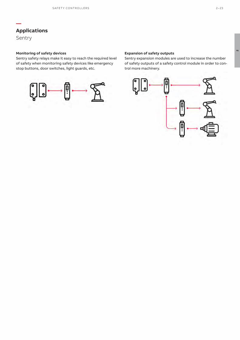
—ApplicationsSentry
Monitoring of safety devicesSentry safety relays make it easy to reach the required level of safety when monitoring safety devices like emergency stop buttons, door switches, light guards, etc.
Expansion of safety outputsSentry expansion modules are used to increase the number of safety outputs of a safety control module in order to con-trol more machinery.
S A FE T Y CO NTR O L L ER S 2– 23
2

—FeaturesSentry
Timer functions with an accuracy of ± 1%Several timer functions are available: On/Off-delay, time bypass and time reset.
On/Off-delay are used to postpone the activation/deactiva-tion of the safety outputs with a preset time delay. This is used in e.g. Category 1 stops.
Time bypass activates the safety outputs for a maximum predefined time when the safety inputs are closed. Inching is an example of application.
Time reset activates the safety outputs for a maximum pre-defined time when the safety inputs are opened. Pre-reset is an example of application.
An accuracy of ± 1% allows a very precise time to be set in order to increase safety and minimize unnecessary down-time.
Configurable models with displayThe models with display are configurable and the user can choose between preset configurations and a custom con-figuration that can be protected by password.
Faster troubleshooting with displayThe display minimizes troubleshooting by giving extensive information about internal faults, I/O faults, system faults, function faults and a log of the last 10 errors.
Switch for selection of the reset functionAll models can be used in automatic reset and some models allow to choose manual reset, either by switch or by con-figuration, which simplifies connection. In order to prevent mistakes, it is not possible to change reset function during operation by just flipping the switch.
Multi-resetThe multi-reset function enables reset of up to 10 Sentry safety relays using just one reset light-button. This simplifies connection, minimizes cabling and unneces-sary downtime. The multi-reset function is available for all +24 VDC Sentry models offering manual reset.
Light-button functionThe light-button function is used for the multi-reset func-tion, but can also be used for a standard reset button. The function of the LED in the light-button is the following: on - at least one input is not accepted flashing - all inputs are accepted, reset possible off - all inputs accepted, reset performed, outputs active
Note: if an input is accepted it means that the door is closed, the light curtain is not interrupted, etc.
Powerful outputsThe outputs have a switching capacity of up to 6A DC-13. This allows Sentry to drive larger contactors and saves the use of an intermediary contactor.
Delayed outputsSome Sentry models have delayed outputs in order to e.g. give a machine time to apply breaking force before power is disconnected. For models with 2 NO + 2 NO outputs, it is only the second pair of NO outputs that is delayed. For models with 3 NO + 1 NC, all outputs are delayed.
Single function or universal modelsSentry SSR models are single function safety relays de-signed for a specific application such as 1 and 2 channel devices, OSSD devices or two-hand devices. Sentry USR models are universal safety relays. They are ca-pable of handling most types of applications and safety de-vices, i.e. 1 and 2 channel devices, OSSD-devices, two-hand devices and contact mats/bumpers/edges. This means that only one type of relay is necessary as a spare, which reduces stock and saves warehouse space.
2– 24 S A F E T Y PRO D U C T S C ATA LO G A B B J O K A B S A FE T Y
2

—Ordering informationSentry
Expan-sion
Safety devices Test/Reset
Safety relay outputs
Timer function
Fea-ture
Power supply
Expa
nsio
n of
safe
ty co
ntro
ller o
utpu
ts
1 cha
nnel
2 cha
nnel
s with
equ
ival
ent c
onta
cts
2 cha
nnel
s with
ant
ival
ent c
onta
cts
OSSD
out
puts
/ P
NP o
utpu
ts
Cont
act m
ats,
bum
pers
and
safe
ty e
dges
c)
Two-
hand
dev
ices
Man
ual r
eset
(all m
odel
s hav
e au
to re
set)
Star
t/Te
st
3 NO
+ 1 N
C
4 NO
2 NO
+ 2 d
elay
ed/d
elay
able
NO
4 NO
+ 1
NC
Off-d
elay
0.5
s
Off-d
elay
1.5
s
Adva
nced
tim
er fu
nctio
ns 0
– 99
9 s d)
Conf
igur
albl
e w
ith d
ispl
ay
85-2
65 V
AC /
120-
375
VDC
+24
VDC
Type Order code
a) b) BSR10 2TLA010040R0000
a) b) BSR11 2TLA010040R0200
a) BSR23 e) 2TLA010041R0600
SSR10 2TLA010050R0000
SSR10M 2TLA010050R0100
SSR20 2TLA010051R0000
SSR20M 2TLA010051R0100SSR32 2TLA010052R0400
SSR42 2TLA010053R0400
TSR10 2TLA010060R0000
TSR20 2TLA010061R0000
TSR20M 2TLA010061R0100
USR10 2TLA010070R0000
USR22 2TLA010070R0400a) These models can also be used for expansion of Pluto safe transistor outputs (-24 VDC)b) No monitoring of two-channel fault, i.e. max Category 3 without fault exclusion.c) The safety relay detects a short-circuit, not a change in resistance.d) Off-delay, On-delay, Time bypass or Time reset.e) BSR23 must be monitored by another device in order to reach higher than Category 1/PL c according to EN ISO 13849-1, for example a safety relay, a safety PLC or an Orion light guard (EDM function).
BSR10
2TLC
1720
49V
020
12T
LC17
2079
V0
201
USR10
2TLC
1720
64V
020
1
SSR32
Description Type Order code
Terminal block for Sentry safety relays. One piece. S30A 2TLA010099R0000
Coding kit for terminal blocks. One kit for one Sentry relay. S30B 2TLA010099R0100
2TLC
010
019
F020
1
S30A
2TLC
010
020
F020
1
S30B
—Accessories
—Ordering details
S A FE T Y CO NTR O L L ER S 2– 25
2

Technical dataApprovals
Conformity 2006/42/EC - Machinery2014/30/EU - EMC2011/65/EU - RoHSEN ISO 12100:2010, EN ISO 13849-1:2015, EN 62061:2005+A2:2015, EN 60204-1:2006+A1:2009, EN 60664-1:2007, EN 61000-6-2:2005, EN 61000-6-4:2007, EN 61508:2010
Functional safety data BSR10 BSR11, BSR23 SSR10, SSR10M, SSR20, SSR20M, TSR10, TSR20, TSR20M, USR10
SSR32, SSR42, USR22
EN/IEC 61508:2010 SIL3, PFHD = 3.0 x 10⁻⁹
SIL3, PFHD = 4.1 x 10⁻⁹
SIL3, PFHD = 4.9 x 10⁻⁹
SIL3, PFHD = 9.3 x 10⁻⁹
EN/IEC 62061:2005+A1:2013 SILCL3, PFHD = 3.1 x 10⁻⁹
SILCL3, PFHD = 4.1 x 10⁻⁹
SILCL3, PFHD = 4.9 x 10⁻⁹
SILCL3, PFHD = 3.9 x 10⁻⁹
EN ISO 13849-1:2008 PL e, Cat. 4, PFHD = 3.1 x 10⁻⁹
PL e, Cat. 4, PFHD = 4.1 x 10⁻⁹
PL e, Cat. 4, PFHD = 4.9 x 10⁻⁹
PL e, Cat. 4, PFHD = 3.9 x 10⁻⁹
Note! The relays must be cycled at least once a year.
Electrical data
Operating voltage +24 VDC (19.2-27.6 VDC) PELV / SELVMains models: 85-265 VAC (50 / 60 Hz) or 120-375 VDC
Response time at deactivation 20 ms
Maximum switching capacity
DC13, DC1 Up to 6 A (except relays with 2 NO + 2 NO outputs that switch 3 A)
AC15, AC1 Up to 5 A (except relays with 2 NO + 2 NO outputs that switch 3 A)
Mechanical data
Operating temperature BSR10, BSR11, BSR23, SSR10M, SSR20M, TSR20M-10 °C to 55 °C SSR10, SSR20, SSR32, SSR42, TSR10, TSR20, USR10, USR22 -10 °C to 65 °C
Humidity range 25% … 90%
Protection class IP20 (enclosure/electrical cabinet must have at least an IP54)
Mounting 35 mm DIN rail (DIN 50022)
Minimum space between relays in the enclosure 0 mm (except for BSR23 which needs 5 mm distance)
—Technical data
Sentry
More informationFore more information, e.g. the complete technical information, see product manual:Sentry 2TLC010002M0201
Connection diagramsFor Sentry connection diagrams please see https://library.abb.com/
2– 26 S A F E T Y PRO D U C T S C ATA LO G A B B J O K A B S A FE T Y
2

All dimensions in mm
Dimension drawing
—Dimension drawing
Sentry
2
S A FE T Y CO NTR O L L ER S 2– 27
2

S A F E T Y PRO D U C T S C ATA LO G A B B J O K A B S A FE T Y
3

—Optical safety devices
O P TI C A L S A FE T Y D E V I CE S
3
3 – 1
3– 2 Introduction and overview
3– 8 Safety light curtain - Orion1 Base
3– 16 Safety light curtain - Orion1 Extended
3– 24 Safety light grid - Orion2 Base
3– 32 Safety light grid - Orion2 Extended
3– 40 Safety light grid - Orion3 Base
3– 48 Safety light grid - Orion3 Extended

Light curtains and light grids that cover most types of applications.
Orion1 Orion2 Orion3Function Light curtain, Transmitter + Receiver, Slim profile Function Light grid, Transmitter + Receiver,
Slim profileLight grid, Active + Passive units, Sturdy profile
Image
Image
Type Orion1 Base Orion1 Extended Type Orion2 Base Orion2Extended
Orion3 Base Orion3Extended
Type of detection
Finger Hand
Finger Hand
Type of detection
Body
Body
Resolution 14 mm 30 mm 14 mm 30 mm Resolution 2, 3 or 4 beams
Protected height 15-180 cm 15-180 cm 30-180 cm 30-180 cm Protected height 50-120 cm
Applications Manually serviced machines with short safety distances.
Manually serviced machines with short safety distances. With advanced features like muting, blanking and cascading.
Applications Perimeter guarding over long distances
Perimeter guarding over long distances with muting
Perimeter guarding with one-sided con-nection
Perimeter guarding with one-sided connection and muting
Functions Functions
Range 6 m 19 m 7 m 20 m Range 50 m 50 m Up to 8 m Up to 8 m
Auto/Manual reset Auto/Manual reset
EDM EDM
Muting Muting
Override Override
Integrated muting lamp
Integrated muting lamp
Blanking Blanking
No dead zone No dead zone
Coding Coding
Cascading Cascading
—Introduction and overviewSelection guide
3 – 2 S A F E T Y PRO D U C T S C ATA LO G A B B J O K A B S A FE T Y
3

Orion1 Orion2 Orion3Function Light curtain, Transmitter + Receiver, Slim profile Function Light grid, Transmitter + Receiver,
Slim profileLight grid, Active + Passive units, Sturdy profile
Image
Image
Type Orion1 Base Orion1 Extended Type Orion2 Base Orion2Extended
Orion3 Base Orion3Extended
Type of detection
Finger Hand
Finger Hand
Type of detection
Body
Body
Resolution 14 mm 30 mm 14 mm 30 mm Resolution 2, 3 or 4 beams
Protected height 15-180 cm 15-180 cm 30-180 cm 30-180 cm Protected height 50-120 cm
Applications Manually serviced machines with short safety distances.
Manually serviced machines with short safety distances. With advanced features like muting, blanking and cascading.
Applications Perimeter guarding over long distances
Perimeter guarding over long distances with muting
Perimeter guarding with one-sided con-nection
Perimeter guarding with one-sided connection and muting
Functions Functions
Range 6 m 19 m 7 m 20 m Range 50 m 50 m Up to 8 m Up to 8 m
Auto/Manual reset Auto/Manual reset
EDM EDM
Muting Muting
Override Override
Integrated muting lamp
Integrated muting lamp
Blanking Blanking
No dead zone No dead zone
Coding Coding
Cascading Cascading
O P TI C A L S A FE T Y D E V I CE S 3 – 3
3

Finger detectionLight curtains with 14 mm resolution are intended for finger detection when the light guard needs to be very close to the machine in order to give the operator a good view and easy accessibility to the machine.
Choose the right resolution for your application
Hand detectionLight curtains with 30 mm resolution are intended for hand detection and area protection and is often a good compro-mise between cost and accessibility to the machine. They offer a better sensing range than finger detection light curtains, but require a slightly greater safety distance.
—Introduction and overview Selection orientation
Body detectionLight grids have a resolution adapted for detection of the whole body and are intended for perimeter guarding where there is a requirement for high accessibility. They offer a very good sensing range, but require a much greater safety distance than light guards for finger and hand detection.
3 – 4 S A F E T Y PRO D U C T S C ATA LO G A B B J O K A B S A FE T Y
3

—Introduction and overview Standards
Resolution and safety distanceThe optical safety device must be installed so that no-one can reach the hazardous area without first passing through the detection zone of the light guard. The distance from the hazardous area to the detection zone of the optical safety device must be large enough in order for the machine to have time to stop before someone can reach the hazardous area. This distance is called the safety distance, and it shall be calculated using the formula from EN ISO 13855.
The safety distance is influenced by the distance between each beam in the light guard. The closer the beams are together, the smaller the safety distance can be, which is why light cur-tains for finger detection can be placed much closer to the hazardous area than light grids for body detection.
O P TI C A L S A FE T Y D E V I CE S 3 – 5
3

The distance ’S’ is the minimum distance between a light curtain and a hazardous area. This is calculated with the formula from EN ISO 13855 - Safety of machinery - Positioning of safeguards with respect to the approach speeds of parts of the human body.
S = minimum distance in mmH1 = the lower beam may not be situated higher than 300 mm above the groundH2 = the upper beam may not be situated lower than 900 mm above the ground
S = minimum distance in mmH = the light curtain detec-tion zone must be posi-tioned between 0 and 1000 mm above the floor
S = minimum distance in mmK = approach speed (of hand or body) in mm/sT = stopping time of the machine (including reaction time of safety devices) in secondsC = additional distance in mm based upon the body´s intrusion towards the hazardous area before the safety device has been actuated.
For S ≤ 500 mm the minimum distance for vertical installation is calculated with the following formula:
S = (2000 x T) + 8 x (d-14)
where d is the light curtain´s resolution in mm.
K = 2000 mm/s is used to represent the speed of the hand. The expression (8 x (d-14)) may never be less than 0. Mini-mum distance S may never be less than 100 mm.
If the minimum distance according to the formula above gets larger than 500 mm one can instead use:
S = (1600 x T) + 8 x (d-14)
K = 1600 mm/s is used to represent the speed of the body. Minimum distance according to this formula is 500 mm.
The minimum distance for horizontal installation is calculated with the following formula:
S = (1600 x T) + (1200 - 0.4 x H)
where H is the height of the detection zone above the refer-ence plane, e.g. the ground
(1200 – 0,4 x H) may not be less than 850 mm. Depending on the resolution, d, that the light curtain has, there is a mini-mum height where the detection zone may be placed. This is calculated with:H = 15 x (d – 50). H cannot be less than 0. With a resolution d =14 or 30 mm one can therefore install the light curtain from H = 0 and up. The higher it is situated, the shorter the minimum distance gets. The highest permissible height H of the detection zone is 1000 mm.
When you use a horizontal light curtain as perimeter protec-tion, the depth of the light curtain shall be at least 750 mm to prevent people from inadvertently stepping over it. The estimated minimum distance is measured from the ma-chine’s hazardous section to the outermost beam of the horizontal light curtain (seen from the machine).
Resolution for finger (≤14 mm) gives C = 0
NB If it is possible to reach the hazard zone by reaching over the light beam, an adjustment is made to the formula. In table 1 in EN ISO 13855 an alternative safety distance addi-tion (Cro) is given to the formula S = (K x T) + C. The greatest value out of C and Cro is to be used to prevent reaching the hazard zone by reaching over the light curtain/grid.
—Safety distance according to EN ISO 13855
S = (K x T) + C
Minimum distances for light curtains installed vertically and horizontally
according to EN ISO 13855
3 – 6 S A F E T Y PRO D U C T S C ATA LO G A B B J O K A B S A FE T Y
3

Minimum distance for light beams according to EN ISO 13855
Minimum distance for single beams according to EN ISO 13855
For light beams the minimum distance is calculated from the following:
S = (1600 x T) + 850 mm
NOTE! The additional distance will in most cases be more than 850 mm due to the possibility to reach over a light beam. (Cro) The formula applies to light guards with 2, 3 or 4 beams. It is the risk assessment that decides the number of beams that are to be chosen. The following possibilities must be considered.
– to crawl under the lowest beam; – to reach over the top beam; – to reach in between two beams; – that the body passes in between two beams.
To fulfill the requirements the beams shall be installed at the following heights:
A single beam as only protection is normally not suitable to prevent whole body access. Single beams are mostly used in combination with other safety devices or fixed guards.
The risk assessment should determine if a single beam is a suitable protection for the hazard in question.
The safety distance is calculated using:
S = (1600 x T) + 1200 mm
A height of 750 mm from the reference plane has been found suitable to prevent inadvertent access to the danger zone.
Number of beams Height over the reference plane, e.g. ground
4 300, 600, 900, 1200
3 300, 700, 1100
2 400, 900
O P TI C A L S A FE T Y D E V I CE S 3 – 7
3

Orion1 Base is an easy to use light curtain with compact dimensions and two resolutions for detection of fingers and hands.
Light curtains are usually used closed to the hazardous zone when repeated access to the machine is necessary, for example manually serviced machines.
Light curtains can also be used to limit work zones inside the hazardous area and be mounted horizontally for area protection.
Visible alignment levelSince the alignment level is displayed, the alignment can be improved before the occurrence of an unwanted stop.
Extensive error indicationExtensive error indication reduces troubleshooting time.
Protection against harsh environ-mentProtective tubes and lens shields protect the devices in harsh environ-ments.
Continuous operation
Easy to install
Easy to align Alignment help and a wide angle within the limits of a Type 4 device facilitate alignment. Rotation brackets also sim-plify alignment.
Easy to connectM12 connectors speed up cabling.
No more functions than neccessaryOrion1 Base comes with a minimum of advanced functionalities to save cost.
Minimized cablingA local reset button can be connected directly to the light curtain. In this way there is no need for a cable between the reset button and the electrical cabinet or for an extra control module.
External device monitoringEach light curtain can monitor the actuators without any extra control module (EDM function).
Cost effective solution
—Safety light curtainOrion1 Base
3 – 8 S A F E T Y PRO D U C T S C ATA LO G A B B J O K A B S A FE T Y
3
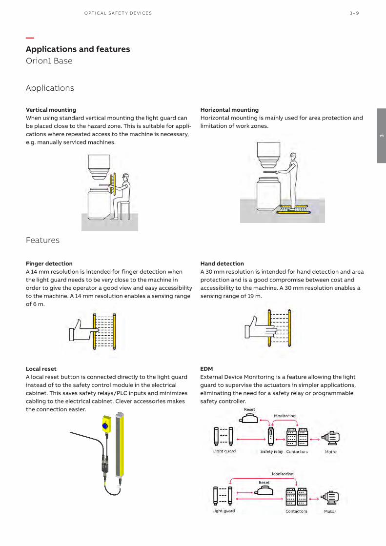
Vertical mountingWhen using standard vertical mounting the light guard can be placed close to the hazard zone. This is suitable for appli-cations where repeated access to the machine is necessary, e.g. manually serviced machines.
—Applications and featuresOrion1 Base
Applications
Horizontal mountingHorizontal mounting is mainly used for area protection and limitation of work zones.
Finger detectionA 14 mm resolution is intended for finger detection when the light guard needs to be very close to the machine in order to give the operator a good view and easy accessibility to the machine. A 14 mm resolution enables a sensing range of 6 m.
Hand detectionA 30 mm resolution is intended for hand detection and area protection and is a good compromise between cost and accessibility to the machine. A 30 mm resolution enables a sensing range of 19 m.
EDMExternal Device Monitoring is a feature allowing the light guard to supervise the actuators in simpler applications, eliminating the need for a safety relay or programmable safety controller.
Local resetA local reset button is connected directly to the light guard instead of to the safety control module in the electrical cabinet. This saves safety relays/PLC inputs and minimizes cabling to the electrical cabinet. Clever accessories makes the connection easier.
Features
O P TI C A L S A FE T Y D E V I CE S 3 – 9
3

—Safety light curtainOrion1 Base
Detection (Resolution mm)
Protected heightmm
Type (Transmitter + receiver)
Order code
Finger(14)
150 Orion1-4-14-015-B 2TLA022300R0000
300 Orion1-4-14-030-B 2TLA022300R0100
450 Orion1-4-14-045-B 2TLA022300R0200
600 Orion1-4-14-060-B 2TLA022300R0300
750 Orion1-4-14-075-B 2TLA022300R0400
900 Orion1-4-14-090-B 2TLA022300R0500
1050 Orion1-4-14-105-B 2TLA022300R0600
1200 Orion1-4-14-120-B 2TLA022300R0700
1350 Orion1-4-14-135-B 2TLA022300R0800
1500 Orion1-4-14-150-B 2TLA022300R0900
1650 Orion1-4-14-165-B 2TLA022300R1000
1800 Orion1-4-14-180-B 2TLA022300R1100
Hand(30)
150 Orion1-4-30-015-B 2TLA022302R0000
300 Orion1-4-30-030-B 2TLA022302R0100
450 Orion1-4-30-045-B 2TLA022302R0200
600 Orion1-4-30-060-B 2TLA022302R0300
750 Orion1-4-30-075-B 2TLA022302R0400
900 Orion1-4-30-090-B 2TLA022302R0500
1050 Orion1-4-30-105-B 2TLA022302R0600
1200 Orion1-4-30-120-B 2TLA022302R0700
1350 Orion1-4-30-135-B 2TLA022302R0800
1500 Orion1-4-30-150-B 2TLA022302R0900
1650 Orion1-4-30-165-B 2TLA022302R1000
1800 Orion1-4-30-180-B 2TLA022302R1100
Orion1 Base
2TLC
1727
87F0
201
Description Type Order code
4 standard brackets for Orion1 & Orion2 JSM Orion01 2TLA022310R0000
JSM Orion01
2TLC
1727
81F0
201
—Ordering Details
—Spare parts (included when ordering Orion)
3 – 10 S A F E T Y PRO D U C T S C ATA LO G A B B J O K A B S A FE T Y
3

Mounting accessories
Description Type Order code
Orion Test Piece 14 mm Orion TP-14 2TLA022310R5200
Orion Test Piece 30 mm Orion TP-30 2TLA022310R5300
Orion Laser pointer Orion Laser 2TLA022310R5000
JSM M5B special T-nut M5 to be used with M5x12 screw for mounting Orion on Quick-Guard T-nut JSM M5B 2TLA040035R0400
4 rotation brackets for Orion1 Base JSM Orion03 2TLA022310R0100
Kit for mounting of Orion1 & Orion2 in Stand (4 pieces for lengths shorter than 1200 mm) JSM Orion06 2TLA022310R0400
Kit for mounting of Orion1 & Orion2 in Stand (6 pieces for lengths of 1200 mm or more) JSM Orion07 2TLA022310R0500
Kit for mounting of Orion1 Mirror in Stand JSM Orion11 2TLA022310R0900
Orion Plate kit for adjustment of protective stand Orion Stand Plate 2TLA022312R5000
Deviating mirror to be mounted in Orion Stand with one kit JSM Orion11 Orion1 Mirror*
Protective stand Orion Stand*
Protective tube Orion WET*
Lens shield Orion Shield*
Connection accessories
Smile reset button with NO contact Smile 11 RA 2TLA030053R0000
Smile reset button with NO contact for Pluto Smile 11 RB 2TLA030053R0100
Smile reset button with NO contact for Orion1 Base Smile 11RO1 2TLA022316R3000
Y-connector for series connection of DYNlink devices with M12-5 connectors, e.g. Eden M12-3A 2TLA020055R0000
Y-connector for connection of a Smile reset button to Orion M12-3R 2TLA022316R0000
Y-connector for easy connection of a transmitter M12-3D 2TLA020055R0300
Adaptation of OSSD to DYNlink. M12-8 connector for OSSD and M12-5 for DYNlink. Tina 10A v2 2TLA020054R1210
Adaptation of OSSD to DYNlink with possibility to connect a local reset button. M12-8connector for OSSD and M12-5 for DYNlink and reset.
Tina 10B v2 2TLA020054R1310
Adaptation of OSSD to DYNlink with possibility to power the transmitter. M12-8 connector for OSSD and M12-5 for DYNlink and transmitter.
Tina 10C v2 2TLA020054R1610
*These accessories are available in different sizes. For more information see:Orion1 Mirror 2TLC172058L0201, Orion Stand 2TLC172059L0201, Orion WET 2TLC172061L0201, Orion Shield 2TLC172071L0201
For more information about the connection accessories, please see:Orion connection accessories 2TLC172101L0201
—AccessoriesOrion1 Base
2TLC
1720
12V
020
1
M12-3R
Smile 11 RB
2TLC
1723
67F0
201
Tina 10C
2TLC
1724
77F0
201
JSM Orion03
2TLC
1727
83F0
201
Local or global reset Adaption to DYNlink* Safety controle module Type Useful connection accessories
Local reset button con-nected to the light guard
(Orion in manual reset mode)
Yes Vital or Pluto Smile 11RO1 Tina 10B: OSSD to DYNlink + local reset button M12-3A: Serial connection of DYNlink
No Any safety control module compatible with light guard
Smile 11RO1 M12-3R: Easy connection of a local reset button
Global reset button connected to the control module
(Orion in automatic reset mode)
Yes Vital Smile 11 RA Tina 10A: OSSD to DYNlinkTina 10C: OSSD to DYNlink + supply to transmitter
Pluto Smile 11 RB Tina 10A: OSSD to DYNlink Tina 10C: OSSD to DYNlink + supply to transmitter
No Any safety control module compatible with light guard
Smile 11 RA**
-
* The ABB Jokab Safety DYNlink solution offers the following advantages:- Serial connection of safety devices while maintaining PLe/cat. 4, up to 25 Tina 10 per Vital and up to 5 Tina 10 per
Pluto input.- Only one safety input of the Pluto instead of two with the standard OSSD outputs.
** Smile 11 RA has one NO contact, which is the most common for reset buttons. Please check what is requested for the chosen safety control module.
Orion Laser pointer
2TLC
1728
16F0
201
—Accessories
—How to choose correct reset button
O P TI C A L S A FE T Y D E V I CE S 3 – 11
3
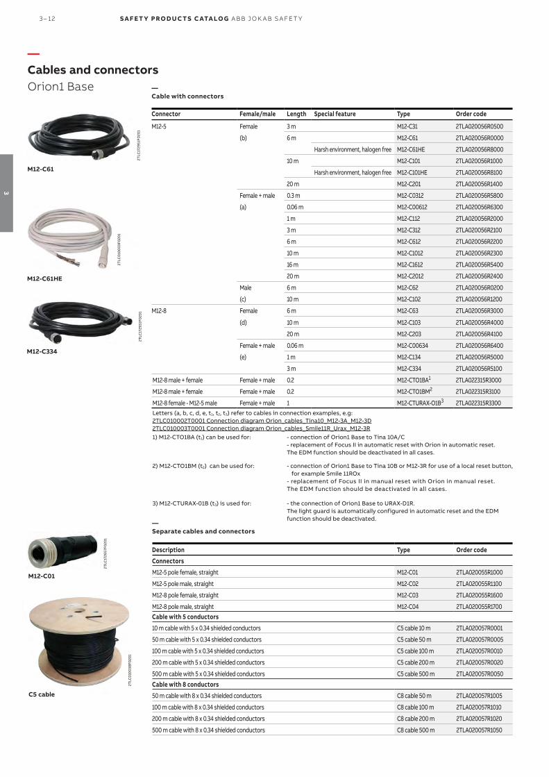
—Cables and connectorsOrion1 Base
Connector Female/male Length Special feature Type Order code
M12-5 Female 3 m M12-C31 2TLA020056R0500
(b) 6 m M12-C61 2TLA020056R0000
Harsh environment, halogen free M12-C61HE 2TLA020056R8000
10 m M12-C101 2TLA020056R1000
Harsh environment, halogen free M12-C101HE 2TLA020056R8100
20 m M12-C201 2TLA020056R1400
Female + male 0.3 m M12-C0312 2TLA020056R5800
(a) 0.06 m M12-C00612 2TLA020056R6300
1 m M12-C112 2TLA020056R2000
3 m M12-C312 2TLA020056R2100
6 m M12-C612 2TLA020056R2200
10 m M12-C1012 2TLA020056R2300
16 m M12-C1612 2TLA020056R5400
20 m M12-C2012 2TLA020056R2400
Male 6 m M12-C62 2TLA020056R0200
(c) 10 m M12-C102 2TLA020056R1200
M12-8 Female 6 m M12-C63 2TLA020056R3000
(d) 10 m M12-C103 2TLA020056R4000
20 m M12-C203 2TLA020056R4100
Female + male 0.06 m M12-C00634 2TLA020056R6400
(e) 1 m M12-C134 2TLA020056R5000
3 m M12-C334 2TLA020056R5100
M12-8 male + female Female + male 0.2 M12-CTO1BA1 2TLA022315R3000
M12-8 male + female Female + male 0.2 M12-CTO1BM2 2TLA022315R3100
M12-8 female - M12-5 male Female + male 1 M12-CTURAX-O1B3 2TLA022315R3300Letters (a, b, c, d, e, t1, t2, t3) refer to cables in connection examples, e.g:2TLC010002T0001 Connection diagram Orion_cables_Tina10_M12-3A_M12-3D2TLC010003T0001 Connection diagram Orion_cables_Smile11R_Urax_M12-3R1) M12-CTO1BA (t1) can be used for: - connection of Orion1 Base to Tina 10A/C
- replacement of Focus II in automatic reset with Orion in automatic reset. The EDM function should be deactivated in all cases.
2) M12-CTO1BM (t2) can be used for: - connection of Orion1 Base to Tina 10B or M12-3R for use of a local reset button, for example Smile 11ROx
- replacement of Focus II in manual reset with Orion in manual reset.The EDM function should be deactivated in all cases.
3) M12-CTURAX-01B (t3) is used for: - the connection of Orion1 Base to URAX-D1R.The light guard is automatically configured in automatic reset and the EDM function should be deactivated.
M12-C61
2TLC
1729
51F0
201
Description Type Order code
Connectors
M12-5 pole female, straight M12-C01 2TLA020055R1000
M12-5 pole male, straight M12-C02 2TLA020055R1100
M12-8 pole female, straight M12-C03 2TLA020055R1600
M12-8 pole male, straight M12-C04 2TLA020055R1700Cable with 5 conductors
10 m cable with 5 x 0.34 shielded conductors C5 cable 10 m 2TLA020057R0001
50 m cable with 5 x 0.34 shielded conductors C5 cable 50 m 2TLA020057R0005
100 m cable with 5 x 0.34 shielded conductors C5 cable 100 m 2TLA020057R0010
200 m cable with 5 x 0.34 shielded conductors C5 cable 200 m 2TLA020057R0020
500 m cable with 5 x 0.34 shielded conductors C5 cable 500 m 2TLA020057R0050 Cable with 8 conductors
50 m cable with 8 x 0.34 shielded conductors C8 cable 50 m 2TLA020057R1005
100 m cable with 8 x 0.34 shielded conductors C8 cable 100 m 2TLA020057R1010
200 m cable with 8 x 0.34 shielded conductors C8 cable 200 m 2TLA020057R1020
500 m cable with 8 x 0.34 shielded conductors C8 cable 500 m 2TLA020057R1050
M12-C334
2TLC
1729
31F0
201
M12-C61HE
2TLC
010
003
F020
1
C5 cable
2TLC
010
038F
020
1
M12-C01
2TLC
1726
57F0
201
—Cable with connectors
—Separate cables and connectors
3 – 12 S A F E T Y PRO D U C T S C ATA LO G A B B J O K A B S A FE T Y
3

—Connection examplesOrion1 Base
Orion receiver or active part
Smile reset(a)M12-3R
1. + 24 VDC 2. OSSD13. 0 V 4. OSSD2 5. -
M12 5-pole male
Reset to Orion with M12-3R
Connection of a local reset button via M12-3R.
With local reset button
(a)Orion receiver or active part
Tina 10B
Smile reset
1. + 24 VDC 2. In3. 0 V 4. Out5. Info
M12 5-pole male
Reset to Orion with Tina 10BOrion with Tina 10A/C
Orion receiver or active part
Tina 10A/C 1. + 24 VDC 2. In3. 0 V 4. Out5. Info
M12 5-pole male
Cable
Connection to the ABB Jokab Safety DYNlink signal via Tina 10 A/C. To be used with Vital safety control module or Pluto programmable safety controller.
Connection to the ABB Jokab Safety DYNlink signal via Tina 10B. To be used with Vital safety control module or Pluto programmable safety controller.
Without local reset button
(t1) (t2)
(t2)
Connection diagramsFor Orion1 Base connection diagrams please see https://library.abb.com/
O P TI C A L S A FE T Y D E V I CE S 3 – 13
3

—Technical dataOrion1 Base
Technical dataApprovals
Conformity
2006/42/EC - Machinery2004/108/EC - EMCEN ISO 13849-1:2008, EN 62061:2005/A1:2013, EN 61496-1:2013, EN 61496-2, EN 61508-1:2010, EN 61508-2:2010, EN 61508-3:2010, EN 61508-4:2010
Functional safety data
EN 61508:2010 SIL3, PFHD = 2.64 x 10⁻⁹
EN 62061:2005+A1:2013 SILCL3, PFHD = 2.64 x 10⁻⁹
EN ISO 13849-1:2008 PL e, Cat. 4, PFHD = 2.64 x 10⁻⁹
Electrical data
Power supply +24 VDC ± 20%
Power consumtion, transmitter 1.5 W max
Power consumption, receiver 4 W max (without load)
Outputs 2 PNP
Short-circuit protection 1.4 A max
Output current 0.5 A max / output
Output voltage – ON Vdd -1 V min
Output voltage – OFF 0.2 V max
Capacitive load 2.2 μF at +24 VDC max
Cable length (for power supply) 50 m max
Connectors M12-4 pole male on transmitter (compatible with M12-5 pole female)
M12-8 pole male on receiver
Optical data
Light emission (λ) Infrared, LED (950 nm)
Resolution 14 or 30 mm
Operating distance 0.2…19 m for 30 mm
0.2…6 m for 14 mm
Ambient light rejection According to IEC-61496-2:2013
Mechanical data
Operating temperature 0…+ 55 °C
Storage temperature - 25…+ 70 °C
Humidity range 15…95% (no condensation)
Protection class IP65 (EN 60529:2000)
Weight 1.3 kg / meter for each single unit
Housing material Painted aluminium (yellow RAL 1003)
Front glass material PMMA
Cap material PC MAKROLON
More informationFor more information, e.g. the complete technical information, please see product manual for:Orion1 Base 2TLC172287M0201
Connection diagramsFor Orion1 Base connection diagrams please see https://library.abb.com/
3 – 14 S A F E T Y PRO D U C T S C ATA LO G A B B J O K A B S A FE T Y
3

All dimensions in mm
38
50,514
L1
L2
12,5
M12
Ø16 Ø16
M2 n°3
36,9
32,3
x2
Orion1 Base
—Dimension drawingsOrion1 Base
Protected heightmm
L1mm
L2mm
Type
150 233.3 153.3 Orion1-4-xx-015-B
300 383.2 303.2 Orion1-4-xx-045-B
450 533.2 453.3 Orion1-4-xx-045-B
600 683.3 603.2 Orion1-4-xx-060-B
750 833.2 753.3 Orion1-4-xx-075-B
900 983.2 903.2 Orion1-4-xx-090-B
1050 1133.2 1053.2 Orion1-4-xx-105-B
1200 1283.2 1203.3 Orion1-4-xx-120-B
1350 1433.2 1353.2 Orion1-4-xx-135-B
1500 1583.3 1503.3 Orion1-4-xx-150-B
1650 1733.3 1653.3 Orion1-4-xx-165-B
1800 1883.3 1803.3 Orion1-4-xx-180-B
xx = Resolution
—Dimension
O P TI C A L S A FE T Y D E V I CE S 3 – 15
3
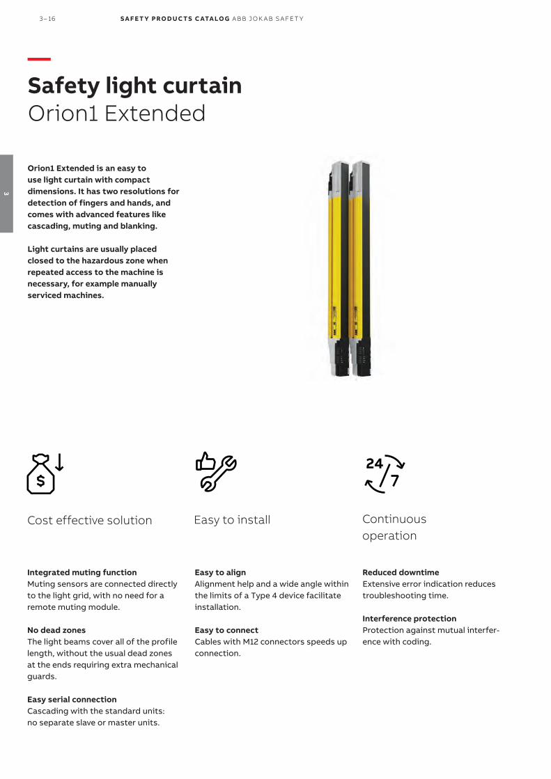
Reduced downtimeExtensive error indication reduces troubleshooting time.
Interference protectionProtection against mutual interfer-ence with coding.
Continuous operation
Orion1 Extended is an easy to use light curtain with compact dimensions. It has two resolutions for detection of fingers and hands, and comes with advanced features like cascading, muting and blanking.
Light curtains are usually placed closed to the hazardous zone when repeated access to the machine is necessary, for example manually serviced machines.
Easy to install
Easy to align Alignment help and a wide angle within the limits of a Type 4 device facilitate installation.
Easy to connectCables with M12 connectors speeds up connection.
Integrated muting functionMuting sensors are connected directly to the light grid, with no need for a remote muting module.
No dead zonesThe light beams cover all of the profile length, without the usual dead zones at the ends requiring extra mechanical guards.
Easy serial connectionCascading with the standard units:no separate slave or master units.
Cost effective solution
—Safety light curtainOrion1 Extended
3 – 16 S A F E T Y PRO D U C T S C ATA LO G A B B J O K A B S A FE T Y
3

—FeaturesOrion1 Extended
CascadingAll Orion1 Extended units can be connected in series (cas-caded) to easily create a suitable light curtain setup with no special units needed.
Hand detectionA 30 mm resolution is intended for hand detection and area protection and is a good compromise between cost and accessibility to the machine. A 30 mm resolution enables a sensing range of 20 m.
Finger detectionA 14 mm resolution is intended for finger detection when the light guard needs to be very close to the machine in order to give the operator a good view and easy accessibility to the machine. A 14 mm resolution enables a sensing range of 7 m.
No dead zonesA special feature of Orion1 Extended is that the light beams cover all of the profile length, without any dead zones. This enables to place it inside openings, instead of having a larg-er light guard in front of an opening.
BlankingThe blanking function allows to define a number of beams that can be constantly interrupted without stopping the machine. In this way a fixed material or a cable is allowed in the protected field, but a hand interrupting an extra beam would stop the machine. With floating blanking, the object, for ex. the cable, can move within the protected field.
EDMExternal Device Monitoring is a feature allowing the light guard to supervise the actuators in simpler applications, eliminating the need for a safety relay or programmable safety controller.
Local resetA local reset button is connected directly to the light guard instead of to the safety control module in the electrical cabinet. This saves safety relays/programmable inputs and minimizes cabling to the electrical cabinet.
MutingBy connecting muting sensors to the light guard, it can distinguish material from persons and allow the material to pass through an opening but not persons.
O P TI C A L S A FE T Y D E V I CE S 3 – 17
3

—Ordering informationOrion1 Extended
Resolution mm
Protected heightmm
Type (Transmitter + receiver)
Order code
Finger(14)
300 Orion1-4-14-030-E 2TLA022301R0100
450 Orion1-4-14-045-E 2TLA022301R0200
600 Orion1-4-14-060-E 2TLA022301R0300
750 Orion1-4-14-075-E 2TLA022301R0400
900 Orion1-4-14-090-E 2TLA022301R0500
1050 Orion1-4-14-105-E 2TLA022301R0600
1200 Orion1-4-14-120-E 2TLA022301R0700
1350 Orion1-4-14-135-E 2TLA022301R0800
1500 Orion1-4-14-150-E 2TLA022301R0900
1650 Orion1-4-14-165-E 2TLA022301R1000
1800 Orion1-4-14-180-E 2TLA022301R1100
Hand(30)
300 Orion1-4-30-030-E 2TLA022303R0100
450 Orion1-4-30-045-E 2TLA022303R0200
600 Orion1-4-30-060-E 2TLA022303R0300
750 Orion1-4-30-075-E 2TLA022303R0400
900 Orion1-4-30-090-E 2TLA022303R0500
1050 Orion1-4-30-105-E 2TLA022303R0600
1200 Orion1-4-30-120-E 2TLA022303R0700
1350 Orion1-4-30-135-E 2TLA022303R0800
1500 Orion1-4-30-150-E 2TLA022303R0900
1650 Orion1-4-30-165-E 2TLA022303R1000
1800 Orion1-4-30-180-E 2TLA022303R1100
Description Type Order code
4 standard brackets for Orion1 & Orion2 JSM Orion01 2TLA022310R0000
2TLC
1727
92F0
201
Orion1 Extended
JSM Orion01
2TLC
1727
81F0
201
—Ordering Details
—Spare parts (included when ordering Orion)
3 – 18 S A F E T Y PRO D U C T S C ATA LO G A B B J O K A B S A FE T Y
3
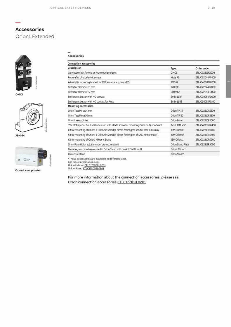
—AccessoriesOrion1 Extended
Connection accessoriesDescription Type Order codeConnection box for two or four muting sensors OMC1 2TLA022316R2000
Retroreflex photoelectric sensor Mute R2 2TLA022044R0500
Adjustable mounting bracket for M18 sensors (e.g. Mute R2). JSM 64 2TLA040007R0200
Reflector diameter 63 mm Reflect 1 2TLA022044R2000
Reflector diameter 82 mm Reflect 2 2TLA022044R3000
Smile reset button with NO contact Smile 11 RA 2TLA030053R0000
Smile reset button with NO contact for Pluto Smile 11 RB 2TLA030053R0100Mounting accessories
Orion Test Piece 14 mm Orion TP-14 2TLA022310R5200
Orion Test Piece 30 mm Orion TP-30 2TLA022310R5300
Orion Laser pointer Orion Laser 2TLA022310R5000
JSM M5B special T-nut M5 to be used with M5x12 screw for mounting Orion on Quick-Guard T-nut JSM M5B 2TLA040035R0400
Kit for mounting of Orion1 & Orion2 in Stand (4 pieces for lengths shorter than 1200 mm) JSM Orion06 2TLA022310R0400
Kit for mounting of Orion1 & Orion2 in Stand (6 pieces for lengths of 1200 mm or more) JSM Orion07 2TLA022310R0500
Kit for mounting of Orion1 Mirror in Stand JSM Orion11 2TLA022310R0900
Orion Plate kit for adjustment of protective stand Orion Stand Plate 2TLA022312R5000
Deviating mirror to be mounted in Orion Stand with one kit JSM Orion11 Orion1 Mirror*
Protective stand Orion Stand*
*These accessories are available in different sizes. For more information see:Orion1 Mirror 2TLC172058L0201Orion Stand 2TLC172059L0201
For more information about the connection accessories, please see:Orion connection accessories 2TLC172101L0201
OMC1
2TLC
1720
16V
020
1
Orion Laser pointer
2TLC
1728
16F0
201
JSM 64
2TLC
010
032F
020
11
—Accessories
O P TI C A L S A FE T Y D E V I CE S 3 – 19
3

—CablesOrion1 Extended
Muting to be used
Neccessary transmit-ter/receiver cable
Suitable cable between transmitter/receiver cable and el-cabinet
Length Special feature Type Order code
Yes Transmitter M12-C02PT2T M12-5 female single ended, to e.g. el-cabinet (b)
3 m M12-C31 2TLA020056R0500
6 m M12-C61 2TLA020056R0000
6 m Harsh environment, halogen free
M12-C61HE 2TLA020056R8000
10 m M12-C101HE 2TLA020056R8100
10 m M12-C101 2TLA020056R1000
20 m M12-C201 2TLA020056R1400
Receiver M12-C02PT62RM M12-5 male + female, to e.g. OMC1 (a)
0.06 m M12-C00612 2TLA020056R6300
0.3 M12-C0312 2TLA020056R5800
1 m M12-C112 2TLA020056R2000
3 m M12-C312 2TLA020056R2100
6 m M12-C612 2TLA020056R2200
10 m M12-C1012 2TLA020056R2300
16 m M12-C1612 2TLA020056R5400
20 m M12-C2012 2TLA020056R2400
M12-12 female single ended, to e.g. el-cabinet
6 m M12-C65 2TLA020056R7200
10 m M12-C105 2TLA020056R7300
20 m M12-C205 2TLA020056R7500
No Transmitter M12-C02PT2T M12-5 female single ended, to e.g. el-cabinet (b)
6 m M12-C61 2TLA020056R0000
6 m Harsh environment, halogen free
M12-C61HE 2TLA020056R8100
10 m M12-C101HE 2TLA020056R5400
10 m M12-C101 2TLA020056R1000
20 m M12-C201 2TLA020056R1400
Receiver M12-C02PT6RB M12-12 female single ended, to e.g. el-cabinet
6 m M12-C65 2TLA020056R7200
10 m M12-C105 2TLA020056R7300
20 m M12-C205 2TLA020056R7500
M12-C61
2TLC
1729
51F0
201
Description Type Order code
Connectors
M12-5 pole female, straight M12-C01 2TLA020055R1000
M12-5 pole male, straight M12-C02 2TLA020055R1100
Cable with 5 conductors
10 m cable with 5 x 0.34 shielded conductors C5 cable 10 m 2TLA020057R0001
50 m cable with 5 x 0.34 shielded conductors C5 cable 50 m 2TLA020057R0005
100 m cable with 5 x 0.34 shielded conductors C5 cable 100 m 2TLA020057R0010
200 m cable with 5 x 0.34 shielded conductors C5 cable 200 m 2TLA020057R0020
500 m cable with 5 x 0.34 shielded conductors C5 cable 500 m 2TLA020057R0050
M12-C61HE
2TLC
010
003
F020
1
C5 cable
2TLC
010
038F
020
1
M12-C01
2TLC
1726
57F0
201
Description Length Type Order code
Transmitter cable for Orion1 Extended. M12-5 male connector. 0.2 m M12-C02PT2T 2TLA022315R0100
Receiver cable for Orion1 Extended when no muting. M12-12 male connector. 0.2 m M12-C02PT6RB 2TLA022315R0200
Receiver cable for Orion1 Extended when muting. M12-5 male connector (for muting sensors) and M12-12 male connector.
0.2 m M12-C02PT62RM 2TLA022315R0300
Cascade cable for Orion1 Extended 1 m PT-C1PT 2TLA022315R1000
Cascade cable for Orion1 Extended 0.5 m PT-C05PT 2TLA022315R1100
Cascade cable for Orion1 Extended 0.05 m PT-C005PT 2TLA022315R1200M12-C02PT2T
M12-C2012
2TLC
1729
35F0
201
—Cables with connectors
—Separate cables and connectors
—Special cables for Orion1 Extended
3 – 20 S A F E T Y PRO D U C T S C ATA LO G A B B J O K A B S A FE T Y
3

—Connection exampleOrion1 Extended
NB: Cable with M12-5 male + female connectors shall be used between muting sensors and OMC1 inputs A1, B1, A2, B2.
Connection of the muting sensors with M12-C02PT62RM and OMC1
OM
C1
A2A1
B1 B2
Orio
n re
ceiv
er
M12-12 pole male
A1, B1, A2, B2
1. +24 VDC 2. — 3. 0 V 4. Muting input5. —
O P TI C A L S A FE T Y D E V I CE S 3 – 21
3

—Technical dataOrion1 Extended
Technical dataApprovals
Conformity
2006/42/EC - Machinery2004/108/EC - EMCEN ISO 13849-1:2008, EN 62061:2005/A1:2013, EN 61496-1:2013, EN 61496-2, EN 61508-1:2010, EN 61508-2:2010, EN 61508-3:2010, EN 61508-4:2010
Functional safety data
EN 61508:2010 SIL3, PFHD = 2.64 x 10⁻⁹
EN 62061:2005+A1:2013 SILCL3, PFHD = 2.64 x1 0-9
EN ISO 13849-1:2008 PL e, Cat. 4, PFHD = 2.64 x 10⁻⁹
Electrical data
Power supply +24 VDC ± 20%
Power consumtion, Transmitter 3 W max
Power consumption, Receiver 5 W max (without load)
Outputs 2 PNP
Short-circuit protection 1.4 A max
Output current 0.5 A max / output
Output voltage – ON Vdd -1 V min
Output voltage – OFF 0.2 V max
Capacitive load 2.2 μF at +24 VDC max
Current for external lamp 20 mA min; 200 mA max
Cable length (for power supply) 50 m max
Connectors M12-4 pole male on transmitter (compatible with M12-5 pole female)
M12-8 pole male on receiver
Optical data
Light emission (λ) Infrared, LED (950 nm)
Resolution 14 or 30 mm
Operating distance 0.2…20 m for 30 mm
0.2…7 m for 14 mm
Ambient light rejection According to IEC-61496-2:2013
Mechanical data
Operating temperature 0…+ 50 °C
Storage temperature - 25…+ 70 °C
Humidity range 15…95% (no condensation)
Protection class IP65 (EN 60529:2000)
Weight 1.35 kg / meter for each single unit
Housing material Painted aluminium (yellow RAL 1003)
Front glass material PMMA
Cap material PBT Valox 508
More informationFor more information, e.g. the complete technical information, see product manual for:Orion1 Extended 2TLC172290M0201
3 – 22 S A F E T Y PRO D U C T S C ATA LO G A B B J O K A B S A FE T Y
3

—Dimension drawingsOrion1 Extended
All dimensions in mm
Orion1 Extended
L1mm
L2mm
Type
300 306.3 Orion1-4-xx-030-E
450 456.3 Orion1-4-xx-045-E
600 606.3 Orion1-4-xx-060-E
750 756.3 Orion1-4-xx-075-E
900 906.3 Orion1-4-xx-090-E
1050 1056.3 Orion1-4-xx-105-E
1200 1206.3 Orion1-4-xx-120-E
1350 1356.3 Orion1-4-xx-135-E
1500 1506.3 Orion1-4-xx-150-E
1650 1656.3 Orion1-4-xx-165-E
1800 1806.3 Orion1-4-xx-180-E
xx = Resolution (14 or 30 mm)
—Dimension
O P TI C A L S A FE T Y D E V I CE S 3 – 23
3
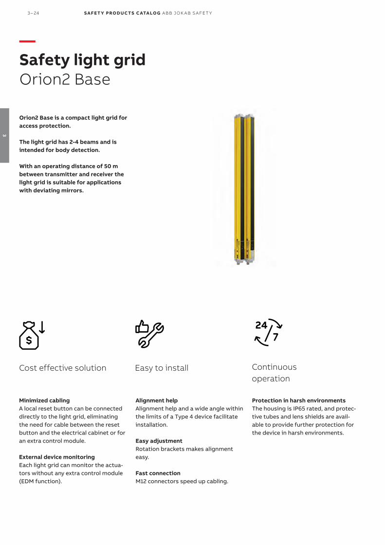
Easy to install
Alignment help Alignment help and a wide angle within the limits of a Type 4 device facilitate installation.
Easy adjustmentRotation brackets makes alignment easy.
Fast connectionM12 connectors speed up cabling.
Protection in harsh environmentsThe housing is IP65 rated, and protec-tive tubes and lens shields are avail-able to provide further protection for the device in harsh environments.
Continuous operation
Minimized cablingA local reset button can be connected directly to the light grid, eliminating the need for cable between the reset button and the electrical cabinet or for an extra control module.
External device monitoringEach light grid can monitor the actua-tors without any extra control module (EDM function).
Cost effective solution
Orion2 Base is a compact light grid for access protection.
The light grid has 2-4 beams and is intended for body detection.
With an operating distance of 50 m between transmitter and receiver the light grid is suitable for applications with deviating mirrors.
—Safety light gridOrion2 Base
3 – 24 S A F E T Y PRO D U C T S C ATA LO G A B B J O K A B S A FE T Y
3

Body detection over long distancesWith 2-4 beams and a maximum sensing range of 50 m be-tween transmitter and receiver, the light grid is intended for body detection and can be used with deviating mirrors to form a protective perimeter around a dangerous area.
—Applications and featuresOrion2 Base
Application
EDMExternal Device Monitoring is a feature allowing the light guard to supervise the actuators in simpler applications, eliminating the need for a safety relay or programmable safety controller.
Local resetA local reset button is connected directly to the light guard instead of to the safety control module in the electrical cabinet. This saves safety relays/programmable inputs and minimizes cabling to the electrical cabinet. Clever accesso-ries make the connection easier.
Features
O P TI C A L S A FE T Y D E V I CE S 3 – 25
3

—Ordering informationOrion2 Base
Detection Protected height
mmType (Transmitter + receiver)
Order code
Body 500 (2 beams) Orion2-4-K2-050-B 2TLA022304R0000
800 (3 beams) Orion2-4-K3-080-B 2TLA022304R0100
900 (4 beams) Orion2-4-K4-090-B 2TLA022304R0200
1200 (4 beams) Orion2-4-K4-120-B 2TLA022304R0300
Orion2 Base
2TLC
1727
98F0
201
Description Type Order code
4 standard brackets for Orion1 & Orion2 JSM Orion01 2TLA022310R0000
JSM Orion01
2TLC
1727
81F0
201
—Ordering details
—Spare parts (imcluded when ordering Orion)
3 – 26 S A F E T Y PRO D U C T S C ATA LO G A B B J O K A B S A FE T Y
3

Mounting accessories
Description Type Order code
Orion Test Piece 14 mm Orion TP-14 2TLA022310R5200
Orion Test Piece 30 mm Orion TP-30 2TLA022310R5300
Orion Laser pointer Orion Laser 2TLA022310R5000
JSM M5B special T-nut M5 to be used with M5x12 screw for mounting Orion on Quick-Guard T-nut JSM M5B 2TLA040035R0400 4 rotation brackets for Orion2 JSM Orion04 2TLA022310R0200
Kit for mounting of Orion1 & Orion2 in Stand (4 pieces for lengths shorter than 1200 mm) JSM Orion06 2TLA022310R0400
Kit for mounting of Orion1 & Orion2 in Stand (6 pieces for lengths of 1200 mm or more) JSM Orion07 2TLA022310R0500
Orion Plate kit for adjustment of protective stand Orion Stand Plate 2TLA022312R5000
Deviating mirror in stand for Orion 2 and 3 Orion Mirror*
Protective stand Orion Stand*
Protective tube Orion WET*
Lens shield Orion Shield*
Connection accessories
Smile reset button with NO contact Smile 11 RA 2TLA030053R0000
Smile reset button with NO contact for Pluto Smile 11 RB 2TLA030053R0100
Smile reset button with NO contact for Orion1 Base Smile 11RO1 2TLA022316R3000
Y-connector for series connection of DYNlink devices with M12-5 connectors, e.g. Eden M12-3A 2TLA020055R0000
Y-connector for connection of a Smile reset button to Orion M12-3R 2TLA022316R0000
Y-connector for easy connection of a transmitter M12-3D 2TLA020055R0300
Adaptation of OSSD to DYNlink. M12-8 connector for OSSD and M12-5 for DYNlink. Tina 10A v2 2TLA020054R1210
Adaptation of OSSD to DYNlink with possibility to connect a local reset button. M12-8connector for OSSD and M12-5 for DYNlink and reset button.
Tina 10B v2 2TLA020054R1310
Adaptation of OSSD to DYNlink with possibility to power the transmitter. M12-8 connector for OSSD and M12-5 for DYNlink and transmitter.
Tina 10C v2 2TLA020054R1610
*These accessories are available in different sizes. For more information see:Orion Mirror 2TLC172060L0201, Orion Stand 2TLC172059L0201, Orion WET 2TLC172061L0201, Orion Shield 2TLC172071L0201
For more information about the connection accessories, please see:Orion connection accessories 2TLC172101L0201
—AccessoriesOrion2 Base
Smile 11 RB
2TLC
1723
67F0
201
Tina 10 C
2TLC
1724
77F0
201
2TLC
1720
12V
020
1
M12-3R
Local or global reset Adaption to DYNlink* Safety controle module Type Useful connection accessories
Local reset button connected to the light guard
(Orion in manual reset mode)
Yes Vital or Pluto Smile 11RO2 Tina 10B: OSSD to DYNlink + local reset button M12-3A: Serial connection of the DYNlink
No Any safety control module compatible with light guard
Smile 11RO2 M12-3R: Easy connection of a local reset button
Global reset button connected to the control module
(Orion in automatic reset mode)
Yes Vital Smile 11 RA Tina 10A: OSSD to DYNlinkTina 10C: OSSD to DYNlink + supply to transmitter
Pluto Smile 11 RB Tina 10A: OSSD to DYNlinkTina 10C: OSSD to DYNlink + supply to transmitter
No Any safety control module compatible with light guard
Smile 11 RA**
-
* The ABB Jokab Safety DYNlink solution offers the following advantages:- Serial connection of safety devices while maintaining PLe/cat. 4, up to 25 Tina 10 per Vital and up to 5 Tina 10 per
Pluto input.- Only one safety input of the Pluto instead of two with the standard OSSD outputs.
** Smile 11RA has one NO contact, which is the most common for reset buttons. Please check what is requested for the chosen safety control module.
JSM Orion 04
2TLC
1727
76F0
201
—How to choose correct reset button
—Accessories
O P TI C A L S A FE T Y D E V I CE S 3 – 27
3

—CablesOrion2 Base
Connector Female/male Length Special feature Type Order code
M12-5 Female 3 m M12-C31 2TLA020056R0500
(b) 6 m M12-C61 2TLA020056R0000
Harsh environment, halogen free M12-C61HE 2TLA020056R8000
10 m M12-C101 2TLA020056R1000
Harsh environment, halogen free M12-C101HE 2TLA020056R8100
20 m M12-C201 2TLA020056R1400
Female + male 0.3 m M12-C0312 2TLA020056R5800
(a) 0.06 m M12-C00612 2TLA020056R6300
1 m M12-C112 2TLA020056R2000
3 m M12-C312 2TLA020056R2100
6 m M12-C612 2TLA020056R2200
10 m M12-C1012 2TLA020056R2300
16 m M12-C1612 2TLA020056R5400
20 m M12-C2012 2TLA020056R2400
Male 6 m M12-C62 2TLA020056R0200
(c) 10 m M12-C102 2TLA020056R1200
M12-8 Female 6 m M12-C63 2TLA020056R3000
(d) 10 m M12-C103 2TLA020056R4000
20 m M12-C203 2TLA020056R4100
Female + male 0.06 m M12-C006341 2TLA020056R6400
(e) 1 m M12-C1341 2TLA020056R5000
3 m M12-C3341 2TLA020056R5100
M12-8 female + M12-5 male Female + male 1 M12-CT1322 2TLA020060R0600
Letters (a, b, c, d, e, t3) refer to cables in connection examples, e.g:
2TLC010002T0001 Connection diagram Orion_cables_Tina10_M12-3A_M12-3D2TLC010003T0001 Connection diagram Orion_cables_Smile11R_Urax_M12-3R
1) Used for the connection to Tina 10, M12-3D and M12-3R. Tina 10 can be connected directly to the light guard without cable, but will form an angle (i.e. not be aligned) with the light guard, which might be a problem if the light guard is mounted close to a wall/aluminum profile.
2) M12-CT132 (t3) is used for the connection of Orion2 Base to URAX-D1R.
2TLC
1729
51F0
201
Description Type Order code
Connectors
M12-5 pole female, straight M12-C01 2TLA020055R1000
M12-5 pole male, straight M12-C02 2TLA020055R1100
M12-8 pole female, straight M12-C03 2TLA020055R1600
M12-8 pole male, straight M12-C04 2TLA020055R1700
Cable with 5 conductors
10 m cable with 5 x 0.34 shielded conductors C5 cable 10 m 2TLA020057R0001
50 m cable with 5 x 0.34 shielded conductors C5 cable 50 m 2TLA020057R0005
100 m cable with 5 x 0.34 shielded conductors C5 cable 100 m 2TLA020057R0010
200 m cable with 5 x 0.34 shielded conductors C5 cable 200 m 2TLA020057R0020
500 m cable with 5 x 0.34 shielded conductors C5 cable 500 m 2TLA020057R0050
Cable with 8 conductors
50 m cable with 8 x 0.34 shielded conductors C8 cable 50 m 2TLA020057R1005
100 m cable with 8 x 0.34 shielded conductors C8 cable 100 m 2TLA020057R1010
200 m cable with 8 x 0.34 shielded conductors C8 cable 200 m 2TLA020057R1020
500 m cable with 8 x 0.34 shielded conductors C8 cable 500 m 2TLA020057R1050
M12-C334
2TLC
1729
31F0
201
2TLC
010
003
F020
1
C5 cable
2TLC
010
038F
020
1
M12-C01
2TLC
1726
57F0
201
M12-C61HE
—Cable with connectors
—Separate Cables and connectors
M12-C61
3 – 28 S A F E T Y PRO D U C T S C ATA LO G A B B J O K A B S A FE T Y
3

Orion receiver or active part
Smile reset(a)M12-3R
1. + 24 VDC 2. OSSD13. 0 V 4. OSSD2 5. -
M12 5-pole male
Reset to Orion with M12-3R
Connection of a local reset button via M12-3R.
With local reset button
(a)Orion receiver or active part
Tina 10B
Smile reset
1. + 24 VDC 2. In3. 0 V 4. Out5. Info
M12 5-pole male
Reset to Orion with Tina 10BOrion with Tina 10A/C
Orion receiver or active part
Tina 10A/C 1. + 24 VDC 2. In3. 0 V 4. Out5. Info
M12 5-pole male
Cable
Connection to the ABB Jokab Safety DYNlink signal via Tina 10 A/C. To be used with Vital safety control module or Pluto programmable safety controller.
Connection to the ABB Jokab Safety DYNlink signal via Tina 10B. To be used with Vital safety control module or Pluto programmable safety controller.
Without local reset button
(e) (e)
(e)
—Connection examplesOrion2 Base
Connection diagrams For Orion2 Base connection diagrams please see https://library.abb.com/
O P TI C A L S A FE T Y D E V I CE S 3 – 29
3

—Technical dataOrion2 Base
Technical dataApprovals
Conformity
2006/42/EC - Machinery2004/108/EC - EMCEN ISO 13849-1:2008, EN 62061:2005/A1:2013, EN 61496-1:2013, EN 61496-2, EN 61508-1:2010, EN 61508-2:2010, EN 61508-3:2010, EN 61508-4:2010
Functional safety data
EN 61508:2010 SIL3, PFHD = 2.64 x 10⁻⁹
EN 62061:2005+A1:2013 SILCL3, PFHD = 2.64 x 10⁻⁹
EN ISO 13849-1:2008 PL e, Cat. 4, PFHD = 2.64 x 10⁻⁹
Electrical data
Power supply +24 VDC ± 20% (SELV/PELV)
Power consumtion, Transmitter 30 mA max. / 0.9 W
Power consumption, Receiver 75 mA max. (without load) / 2.2 W
Cable length (for power supply) 50 m max with 50 nF capacitive load and +24 VDC
Internal capacitance 23 nF (Transmitter) / 120 nF (Receiver)
Outputs 2 PNP
Short-circuit protection Max 1.4 A at 55 °C, min. 1.1 A at -10 °C
Output current 0.5 A max / output
Leakage current < 1 mA
Capacitive load (pure) 65 nF max at 25 °C
Resitive load (pure) 56 Ω min at +24 VDC
Current for external lamp 20 mA min, 250 mA max
Connectors M12-4 pole male on transmitter (compatible with M12-5 pole female)
M12-8 pole male on receiver
Optical data
Light emission (λ) Infrared, LED (880 nm)
Resolution 315 - 515 mm
Operating distance 0.5…50 m
Ambient light rejection According to IEC-61496-2:2013
Mechanical data
Operating temperature 10…+ 55 °C
Storage temperature - 25…+ 70 °C
Humidity range 15…95% (no condensation)
Protection class IP65 (EN 60529:2000)
Weight 1.2 kg max / meter for each single unit
Housing material Painted aluminium (yellow RAL 1003)
Front glass material PMMA
Cap material PC Lexan 943A
More information For more information, e.g. the complete technical information, see product manual for: Orion2 Base 2TLC172288M0201 Connection diagrams For Orion2 Base connection diagrams please see https://library.abb.com/
3 – 30 S A F E T Y PRO D U C T S C ATA LO G A B B J O K A B S A FE T Y
3

All dimensions in mm
Orion2 Base
—Dimension drawingsOrion2 Base
Lr mm
L1mm
L2mm
Type
617 664 538.4 Orion2-4-K2-050-B
917 964 838.4 Orion2-4-K3-080-B
1017 1064 938.4 Orion2-4-K4-090-B
1317 1364 1238.4 Orion2-4-K4-120-B
xx = Resolution
—Dimension
O P TI C A L S A FE T Y D E V I CE S 3 – 31
3

Protection in harsh environmentsThe housing is IP65 rated, and protec-tive tubes and lens shields are avail-able to provide further protection for the device in harsh environments.
Continuous operation
Orion2 Extended is a compact light grid for access protection in muting applications.
The light grid has 2-4 beams and is intended for body detection.
Easy to install
Alignment helpAlignment help and a wide angle within the limits of a Type 4 device facilitate installation.
Easy adjustmentRotation brackets makes alignment easy.
Fast connectionM12 connectors speed up cabling.
Integrated muting functionMuting sensors are connected directly to the light grid, with no need for a remote muting module.
Minimized cablingA local reset button can be connected directly to the light grid, eliminating the need for cable between the reset button and the electrical cabinet.
External device monitoring (EDM)Each light grid can monitor the actua-tors without any extra control module.
Cost effective solution
—Safety light gridOrion2 Extended
3 – 32 S A F E T Y PRO D U C T S C ATA LO G A B B J O K A B S A FE T Y
3
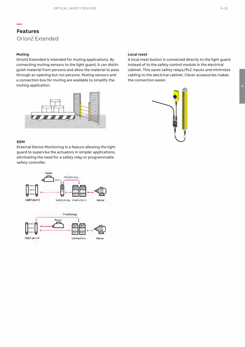
—FeaturesOrion2 Extended
EDMExternal Device Monitoring is a feature allowing the light guard to supervise the actuators in simpler applications, eliminating the need for a safety relay or programmable safety controller.
Local resetA local reset button is connected directly to the light guard instead of to the safety control module in the electrical cabinet. This saves safety relays/PLC inputs and minimizes cabling to the electrical cabinet. Clever accessories makes the connection easier.
MutingOrion2 Extended is intended for muting applications. By connecting muting sensors to the light guard, it can distin-guish material from persons and allow the material to pass through an opening but not persons. Muting sensors and a connection box for muting are available to simplify the muting application.
O P TI C A L S A FE T Y D E V I CE S 3 – 33
3
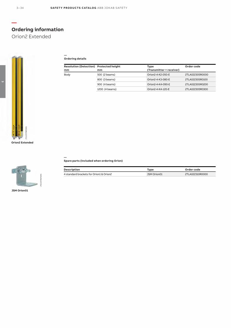
—Ordering informationOrion2 Extended
—Ordering details
Resolution (Detection)mm
Protected heightmm
Type (Transmitter + receiver)
Order code
Body 500 (2 beams) Orion2-4-K2-050-E 2TLA022305R0000
800 (3 beams) Orion2-4-K3-080-E 2TLA022305R0100
900 (4 beams) Orion2-4-K4-090-E 2TLA022305R0200
1200 (4 beams) Orion2-4-K4-120-E 2TLA022305R0300
—Spare parts (included when ordering Orion)
Description Type Order code
4 standard brackets for Orion1 & Orion2 JSM Orion01 2TLA022310R0000
2TLC
1727
98F0
201
Orion2 Extended
JSM Orion01
2TLC
1727
81F0
201
3 – 34 S A F E T Y PRO D U C T S C ATA LO G A B B J O K A B S A FE T Y
3
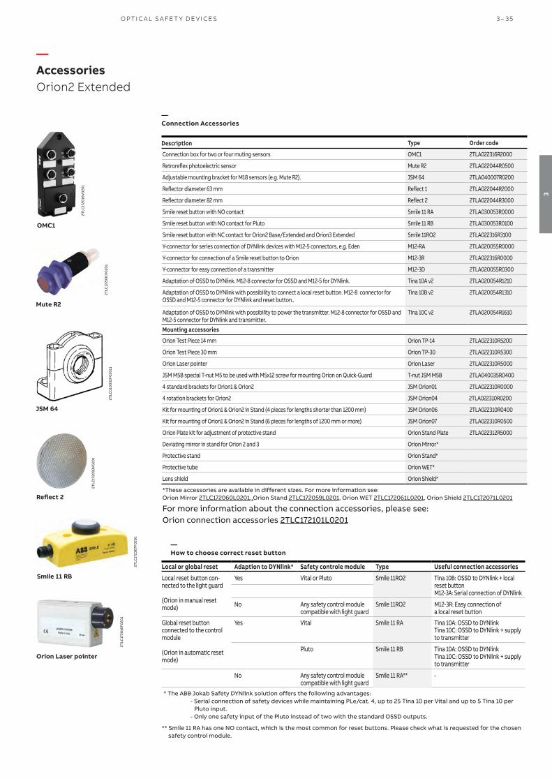
—AccessoriesOrion2 Extended
Description Type Order code
Connection box for two or four muting sensors OMC1 2TLA022316R2000
Retroreflex photoelectric sensor Mute R2 2TLA022044R0500
Adjustable mounting bracket for M18 sensors (e.g. Mute R2). JSM 64 2TLA040007R0200
Reflector diameter 63 mm Reflect 1 2TLA022044R2000
Reflector diameter 82 mm Reflect 2 2TLA022044R3000
Smile reset button with NO contact Smile 11 RA 2TLA030053R0000
Smile reset button with NO contact for Pluto Smile 11 RB 2TLA030053R0100
Smile reset button with NC contact for Orion2 Base/Extended and Orion3 Extended Smile 11RO2 2TLA022316R3100
Y-connector for series connection of DYNlink devices with M12-5 connectors, e.g. Eden M12-RA 2TLA020055R0000
Y-connector for connection of a Smile reset button to Orion M12-3R 2TLA022316R0000
Y-connector for easy connection of a transmitter M12-3D 2TLA020055R0300
Adaptation of OSSD to DYNlink. M12-8 connector for OSSD and M12-5 for DYNlink. Tina 10A v2 2TLA020054R1210
Adaptation of OSSD to DYNlink with possibility to connect a local reset button. M12-8 connector for OSSD and M12-5 connector for DYNlink and reset button..
Tina 10B v2 2TLA020054R1310
Adaptation of OSSD to DYNlink with possibility to power the transmitter. M12-8 connector for OSSD and M12-5 connector for DYNlink and transmitter.
Tina 10C v2 2TLA020054R1610
Mounting accessories
Orion Test Piece 14 mm Orion TP-14 2TLA022310R5200
Orion Test Piece 30 mm Orion TP-30 2TLA022310R5300
Orion Laser pointer Orion Laser 2TLA022310R5000
JSM M5B special T-nut M5 to be used with M5x12 screw for mounting Orion on Quick-Guard T-nut JSM M5B 2TLA040035R0400
4 standard brackets for Orion1 & Orion2 JSM Orion01 2TLA022310R0000
4 rotation brackets for Orion2 JSM Orion04 2TLA022310R0200
Kit for mounting of Orion1 & Orion2 in Stand (4 pieces for lengths shorter than 1200 mm) JSM Orion06 2TLA022310R0400
Kit for mounting of Orion1 & Orion2 in Stand (6 pieces for lengths of 1200 mm or more) JSM Orion07 2TLA022310R0500
Orion Plate kit for adjustment of protective stand Orion Stand Plate 2TLA022312R5000
Deviating mirror in stand for Orion 2 and 3 Orion Mirror*
Protective stand Orion Stand*
Protective tube Orion WET*
Lens shield Orion Shield*
*These accessories are available in different sizes. For more information see:Orion Mirror 2TLC172060L0201,,Orion Stand 2TLC172059L0201, Orion WET 2TLC172061L0201, Orion Shield 2TLC172071L0201
For more information about the connection accessories, please see: Orion connection accessories 2TLC172101L0201
OMC1
2TLC
1720
16V
020
1
JSM 64
2TLC
010
032F
020
11
Orion Laser pointer
2TLC
1728
16F0
201
Smile 11 RB
2TLC
1723
67F0
201
Mute R2
2TLC
1720
91V
020
1
Local or global reset Adaption to DYNlink* Safety controle module Type Useful connection accessories
Local reset button con-nected to the light guard
(Orion in manual reset mode)
Yes Vital or Pluto Smile 11RO2 Tina 10B: OSSD to DYNlink + local reset button M12-3A: Serial connection of DYNlink
No Any safety control module compatible with light guard
Smile 11RO2 M12-3R: Easy connection of a local reset button
Global reset button connected to the control module
(Orion in automatic reset mode)
Yes Vital Smile 11 RA Tina 10A: OSSD to DYNlinkTina 10C: OSSD to DYNlink + supply to transmitter
Pluto Smile 11 RB Tina 10A: OSSD to DYNlinkTina 10C: OSSD to DYNlink + supply to transmitter
No Any safety control module compatible with light guard
Smile 11 RA**
-
* The ABB Jokab Safety DYNlink solution offers the following advantages:- Serial connection of safety devices while maintaining PLe/cat. 4, up to 25 Tina 10 per Vital and up to 5 Tina 10 per
Pluto input.- Only one safety input of the Pluto instead of two with the standard OSSD outputs.
** Smile 11 RA has one NO contact, which is the most common for reset buttons. Please check what is requested for the chosen safety control module.
2TLC
1720
93V
020
1
Reflect 2
—Connection Accessories
—How to choose correct reset button
O P TI C A L S A FE T Y D E V I CE S 3 – 35
3

—CablesOrion2 Extended
Connector Female/male Length Special feature Type Order code
M12-5 Female 3 m M12-C31 2TLA020056R0500
(b) 6 m M12-C61 2TLA020056R0000
Harsh environment, halogen free M12-C61HE 2TLA020056R8000
10 m M12-C101 2TLA020056R1000
Harsh environment, halogen free M12-C101HE 2TLA020056R8100
20 m M12-C201 2TLA020056R1400
Female + male 0.3 m M12-C0312 2TLA020056R5800
(a) 0.06 m M12-C00612 2TLA020056R6300
1 m M12-C112 2TLA020056R2000
3 m M12-C312 2TLA020056R2100
6 m M12-C612 2TLA020056R2200
10 m M12-C1012 2TLA020056R2300
16 m M12-C1612 2TLA020056R5400
20 m M12-C2012 2TLA020056R2400
Male 6 m M12-C62 2TLA020056R0200
(c) 10 m M12-C102 2TLA020056R1200
M12-8 Female 6 m M12-C63 2TLA020056R3000
(d) 10 m M12-C103 2TLA020056R4000
20 m M12-C203 2TLA020056R4100
Female + male 0.06 m M12-C006341 2TLA020056R6400
(e) 1 m M12-C1341 2TLA020056R5000
3 m M12-C3341 2TLA020056R5100
M12-8 male + female Female + male 0.2 M12-CT1322 2TLA020060R0600
M12-8 female - M12-5 male Female + male 1 M12-CYMUTE3 2TLA022316R0100
Letters (a, b, c, d, e, t3) refer to cables in connection examples, e.g:
2TLC010002T0001 Connection diagram Orion_cables_Tina10_M12-3A_M12-3D2TLC010003T0001 Connection diagram Orion_cables_Smile11R_Urax_M12-3R
1) Used for the connection to Tina 10, M12 3D and M12-3R. Tina 10 can be connected directly to the light guard without cable, but will form an angle (i.e. not be aligned) with the light guard, which might be a problem if the light guard is mounted close to a wall/aluminum profile.
2) M12-CT132 (t3) is used for the connection of Orion2 Extended to URAX-D1R.
3) M12-CYMUTE is used to simplify the connection of 2 or 4 muting sensors with the help of the OMC1 connection box.
M12-C61
2TLC
1729
51F0
201
Description Type Order codeConnectors
M12-5 pole female, straight M12-C01 2TLA020055R1000
M12-5 pole male, straight M12-C02 2TLA020055R1100
M12-8 pole female, straight M12-C03 2TLA020055R1600
M12-8 pole male, straight M12-C04 2TLA020055R1700Cable with 5 conductors
10 m cable with 5 x 0.34 shielded conductors C5 cable 10 m 2TLA020057R0001
50 m cable with 5 x 0.34 shielded conductors C5 cable 50 m 2TLA020057R0005
100 m cable with 5 x 0.34 shielded conductors C5 cable 100 m 2TLA020057R0010
200 m cable with 5 x 0.34 shielded conductors C5 cable 200 m 2TLA020057R0020
500 m cable with 5 x 0.34 shielded conductors C5 cable 500 m 2TLA020057R0050 Cable with 8 conductors
50 m cable with 8 x 0.34 shielded conductors C8 cable 50 m 2TLA020057R1005
100 m cable with 8 x 0.34 shielded conductors C8 cable 100 m 2TLA020057R1010
200 m cable with 8 x 0.34 shielded conductors C8 cable 200 m 2TLA020057R1020
500 m cable with 8 x 0.34 shielded conductors C8 cable 500 m 2TLA020057R1050
M12-C334
2TLC
1729
31F0
201
M12-C61HE
2TLC
010
003
F020
1
C5 cable
2TLC
010
038F
020
1
M12-C01
2TLC
1726
57F0
201
—Cable with connectors
—Separate cables and connectors
3 – 36 S A F E T Y PRO D U C T S C ATA LO G A B B J O K A B S A FE T Y
3

—Separate cables and connectors
—Connection examplesOrion2 Extended
Orion receiver or active part
Smile reset(a)M12-3R
1. + 24 VDC 2. OSSD13. 0 V 4. OSSD2 5. -
M12 5-pole male
Reset to Orion with M12-3R
Connection of a local reset button via M12-3R.
With local reset button
(a)Orion receiver or active part
Tina 10B
Smile reset
1. + 24 VDC 2. In3. 0 V 4. Out5. Info
M12 5-pole male
Reset to Orion with Tina 10BOrion with Tina 10A/C
Orion receiver or active part
Tina 10A/C 1. + 24 VDC 2. In3. 0 V 4. Out5. Info
M12 5-pole male
Cable
Connection to the ABB Jokab Safety DYNlink signal via Tina 10 A/C. To be used with Vital safety control module or Pluto programmable safety controller.
Connection to the ABB Jokab Safety DYNlink signal via Tina 10B. To be used with Vital safety control module or Pluto programmable safety controller.
Without local reset button
NB: Cable with M12-5 male + female connectors shall be used between muting sensors and OMC1 inputs A1, B1, A2, B2.
M12-8 pole male Connection to: - Tina 10A/B/C - M12-3R - Electrical cabinet
Orio
n re
ceiv
er o
r act
ive
part
A1, B1, A2, B2:Muting sensors
OM
C1
A2A1
B1 B2
A1, B1, A2, B2
1. +24 VDC 2. — 3. 0 V 4. Muting input5. —
Connection of muting sensors with M12-CYMUTE and OMC1
(e) (e)
(e)
Connection diagrams For Orion2 Extended connection diagrams please see https://library.abb.com/
O P TI C A L S A FE T Y D E V I CE S 3 – 37
3

—Technical dataOrion2 Extended
Technical dataApprovals
Conformity
2006/42/EC - Machinery2004/108/EC - EMCEN ISO 13849-1:2008, EN 62061:2005/A1:2013, EN 61496-1:2013, EN 61496-2, EN 61508-1:2010, EN 61508-2:2010, EN 61508-3:2010, EN 61508-4:2010
Functional safety data
EN 61508:2010 SIL3, PFHD = 2.64 x 10⁻⁹
EN 62061:2005+A1:2013 SILCL3, PFHD = 2.64 x 10⁻⁹
EN ISO 13849-1:2008 PL e, Cat. 4, PFHD = 2.64 x 10⁻⁹
Electrical data
Internal capacitance 23 nF (Transmitter) / 120 nF (Receiver)
Power supply +24 VDC ± 20% (SELV/PELV)
Power consumtion, Transmitter 0.5 W during normal operation
Power consumption, Receiver 2 W during normal operation
Outputs 2 PNP
Short-circuit protection Max 1.4 A at 55 °C, min 1.1 A at -10 °C
Output current 0.5 A max / output
Leakage current < 1 mA
Capacitive load (pure) 65 nF max at 25 °C
Resistive load (pure) 56 Ω min at +24 VDC
Current for external lamp 20 mA min, 250 mA max
Response time 2 and 3 beams: 14 ms; 4 beams: 16 ms
Connectors M12-4 pole male on transmitter (compatible with M12-5 pole female)
M12-8 pole male on receiver
Optical data
Light emission (λ) Infrared (880 nm)
Resolution 315 - 515 mm
Operating distance 0.5…50 m
Ambient light rejection According to IEC-61496-2:2013
Mechanical data
Operating temperature - 10…+ 55 °C
Storage temperature - 25…+ 70 °C
Humidity range 15…95% (no condensation)
Protection class IP65 (EN 60529:2000)
Weight 1.2 kg max / meter for each single unit
Housing material PC Lexan 943A
Lens material PMMA
Cap material PC MAKROLON
More information For more information, e.g. the complete technical information, see manual for:Orion2 Extended 2TLC172291M0201 Connection diagrams For Orion2 Extended connection diagrams please see https://library.abb.com/
3 – 38 S A F E T Y PRO D U C T S C ATA LO G A B B J O K A B S A FE T Y
3

All dimensions in mm
Orion2 Extended
—Dimension drawingsOrion2 Extended
Lrmm
L1mm
L2mm
Type
617 664 538.4 Orion2-4-K2-050-E
917 964 838.4 Orion2-4-K3-080-E1017 1064 938.4 Orion2-4-K4-090-E
1317 1364 1238.4 Orion2-4-K4-120-E
—Dimension
O P TI C A L S A FE T Y D E V I CE S 3 – 39
3

Easy to install
Alignment help Alignment help and a wide angle within the limits of a Type 4 device facilitate installation.
Easy adjustmentRotation brackets makes alignment easy.
Fast connectionM12 connectors speed up cabling.
Less cablingOnly the active part needs connecting.
Orion3 Base is a light grid with a sturdy profile for access protection.
Only one of the parts needs power supply, since both transmitter and receiver are in the same active part. The other part is passive with mirrors to reflect the beams.
With 2-4 beams and an operating range of up to 8 m, it is intended for body detection.
Visible alignment levelSince the alignment level is displayed, the alignment can be improved before the occurrence of an unwanted stop.
Extensive error indicationExtensive error indication reduces troubleshooting time.
Continuous operation
Minimized cablingA local reset button can be connected directly to the light grid, eliminating the need for cable between the reset button and the electrical cabinet or for an extra control module.
External device monitoringEach light grid can monitor the actua-tors without any extra control module (EDM function).
Cost effective solution
—Safety light gridOrion3 Base
3 – 40 S A F E T Y PRO D U C T S C ATA LO G A B B J O K A B S A FE T Y
3

Sturdy profile for demanding applicationsWith its thicker and sturdier profile Orion3 is suitable for ap-plications with tougher requirements.
—FeaturesOrion3 Base
EDMExternal Device Monitoring is a feature allowing the light guard to supervise the actuators in simpler applications, eliminating the need for a safety relay or programmable safety controller.
Local resetA local reset button is connected directly to the light guard instead of to the safety control module in the electrical cabinet. This saves safety relays/PLC inputs and minimizes cabling to the electrical cabinet. Clever accessories makes the connection easier.
Features
Power on one sideBoth transmitter and receiver is in one active part, and the other part is passive containing mirrors. This simplifies installation and saves cables, making it easier to place in ap-plications where cables needs to be avoided.
O P TI C A L S A FE T Y D E V I CE S 3 – 41
3

—Ordering informationOrion3 Base
Detection Protected height
mmActive or passive part Type Order code
Body 500 (2 beams)
Active part Orion3-4-K1C-050-B 2TLA022306R0000
Passive part Orion3-4-M1C-050 2TLA022306R1000
800 (3 beams)
Active part Orion3-4-K2C-080-B 2TLA022306R0100
Passive part Orion3-4-M2C-080 2TLA022306R1100
900 (4 beams)
Active part Orion3-4-K2C-090-B 2TLA022306R0200
Passive part Orion3-4-M2C-090 2TLA022306R1300
1200 (4 beams)
Active part Orion3-4-K2C-120-B 2TLA022306R0300
Passive part Orion3-4-M2C-120 2TLA022306R1400
Orion3 Base
22TL
C17
280
4F0
201
Description Type Order code
4 standard brackets for Orion3 JSM Orion02 2TLA022310R1000
JSM Orion02
2TLC
1727
79F0
201
—Ordering details
—Spare parts (included when ordering Orion)
3 – 42 S A F E T Y PRO D U C T S C ATA LO G A B B J O K A B S A FE T Y
3

Mounting accessories
Description Type Order codeOrion Laser pointer Orion Laser 2TLA022310R5000JSM M5B special T-nut M5 to be used with M5x12 screw for mounting Orion on Quick-Guard T-nut JSM M5B 2TLA040035R04004 standard brackets for Orion3 JSM Orion05 2TLA022310R0300
Kit for mounting of Orion3 in Stand (4 pieces for lengths shorter than 1200 mm) JSM Orion08 2TLA022310R0600
Kit for mounting of Orion3 in Stand (6 pieces for lengths of 1200 mm or more) JSM Orion09 2TLA022310R0700
Orion Plate kit for adjustment of protective stand Orion Stand Plate 2TLA022312R5000
Deviating mirror in stand for Orion 2 and 3 Orion Mirror*
Protective stand Orion Stand*
Connection accessories
Smile reset button with NO contact Smile 11 RA 2TLA030053R0000
Smile reset button with NO contact for Pluto Smile 11 RB 2TLA030053R0100Smile reset button with NC contact for Orion3 Base Smile 11 RO3 2TLA022316R3200
Y-connector for series connection of DYNlink devices with M12-5 connectors, e.g. Eden M12-3A 2TLA020055R0000
Y-connector for connection of a Smile reset button to Orion M12-3R 2TLA022316R0000
Y-connector for easy connection of a transmitter M12-3D 2TLA020055R0300
Adaptation of OSSD to DYNlink. M12-8 connector for OSSD and M12-5 for DYNlink. Tina 10A v2 2TLA020054R1210
Adaptation of OSSD to DYNlink with possibility to connect a local reset button. M12-8connector for OSSD and M12-5 for DYNlink and reset button.
Tina 10B v2 2TLA020054R1310
Adaptation of OSSD to DYNlink with possibility to power the transmitter. M12-8 connector for OSSD and M12-5 connector for DYNlink and transmitter.
Tina 10C v2 2TLA020054R1610
*These accessories are available in different sizes. For more information see: Orion Mirror 2TLC172060L0201Orion Stand 2TLC172059L0201
For more information about the connection accessories, please see:Orion connection accessories 2TLC172101L0201
—AccessoriesOrion3 Base
2TLC
1720
12V
020
1
M12-3R
Smile 11 RB
2TLC
1723
67F0
201
Tina 10C
2TLC
1724
77F0
201
Local or global reset Adaption to DYNlink* Safety controle module Type Useful connection accessories
Local reset button con-nected to the light guard
(Orion in manual reset mode)
Yes Vital or Pluto Smile 11 RO3 Tina 10B: OSSD to DYNlink solution + local reset button M12-3A: Serial connection of the DYNlink solution
No Any safety control module compatible with light guard
Smile 11 RO3 M12-3R: Easy connection of a local reset button
Global reset button connected to the control module
(Orion in automatic reset mode)
Yes Vital Smile 11 RA Tina 10A: OSSD to DYNlink solution Tina 10C: OSSD to DYNlink solution + supply to transmitter/active part
Pluto Smile 11 RB Tina 10A: OSSD to DYNlink solution Tina 10C: OSSD to DYNlink solution + supply to transmitter/active part
No Any safety control module compatible with light guard
Smile 11 RA**
-
* The ABB Jokab Safety DYNlink solution offers the following advantages:- Serial connection of safety devices while maintaining PLe/cat. 4, up to 25 Tina 10 per Vital and up to 5 Tina 10 per
Pluto input.- Only one safety input of the Pluto instead of two with the standard OSSD outputs.
** Smile 11 RA has one NO contact, which is the most common for reset buttons. Please check what is requested for the chosen safety control module.
2TLC
1728
16F0
201
Orion Laser pointer
—Accessories
—How to choose correct reset button
O P TI C A L S A FE T Y D E V I CE S 3 – 43
3

—CablesOrion3 Base
Connector Female/male Length Special feature Type Order code
M12-5 Female 3 m M12-C31 2TLA020056R0500
(b) 6 m M12-C61 2TLA020056R0000
Harsh environment, halogen free M12-C61HE 2TLA020056R8000
10 m M12-C101 2TLA020056R1000
Harsh environment, halogen free M12-C101HE 2TLA020056R8100
20 m M12-C201 2TLA020056R1400
Female + male 0.3 m M12-C0312 2TLA020056R5800
(a) 0.06 m M12-C00612 2TLA020056R6300
1 m M12-C112 2TLA020056R2000
3 m M12-C312 2TLA020056R2100
6 m M12-C612 2TLA020056R2200
10 m M12-C1012 2TLA020056R2300
16 m M12-C1612 2TLA020056R5400
20 m M12-C2012 2TLA020056R2400
Male 6 m M12-C62 2TLA020056R0200
(c) 10 m M12-C102 2TLA020056R1200
M12-8 Female 6 m M12-C63 2TLA020056R3000
(d) 10 m M12-C103 2TLA020056R4000
20 m M12-C203 2TLA020056R4100
Female + male 0.06 m M12-C00634 2TLA020056R6400
1 m M12-C134 2TLA020056R5000
3 m M12-C334 2TLA020056R5100
0,2 m M12-CTO3B 1 2TLA022315R3200
M12-8 female + M12-5 male Female + male 1 m M12-CTURAX-O3B 2 2TLA022315R3400
Letters (a, b, c, d, t2, t3) refer to cables in connection examples, e.g:
2TLC010002T0002 Connection diagram Cables Orion3 to Tina10 2TLC010003T0002 Connection diagram Cables Orion3 to electrical cabinet URAX
1) M12-CTO3B (t2) can be used for: - connection of Orion3 Base to Tina 10A/B/C. - connection of Orion 3 Base to M12-3R.
The EDM function is deactivated in all cases
2) M12-CTURAX-03B (t3) is used for: - connection of Orion3 Base to URAX-D1R.
The light guard is automatically configured in automatic reset and the EDM function is deactivated.
M12-C61
2TLC
1729
51F0
201
Description Type Order code
Connectors
M12-5 pole female, straight M12-C01 2TLA020055R1000
M12-5 pole male, straight M12-C02 2TLA020055R1100
M12-8 pole female, straight M12-C03 2TLA020055R1600
M12-8 pole male, straight M12-C04 2TLA020055R1700
Cable with 5 conductors
10 m cable with 5 x 0.34 shielded conductors C5 cable 10 m 2TLA020057R0001
50 m cable with 5 x 0.34 shielded conductors C5 cable 50 m 2TLA020057R0005
100 m cable with 5 x 0.34 shielded conductors C5 cable 100 m 2TLA020057R0010
200 m cable with 5 x 0.34 shielded conductors C5 cable 200 m 2TLA020057R0020
500 m cable with 5 x 0.34 shielded conductors C5 cable 500 m 2TLA020057R0050 Cable with 8 conductors
50 m cable with 8 x 0.34 shielded conductors C8 cable 50 m 2TLA020057R1005
100 m cable with 8 x 0.34 shielded conductors C8 cable 100 m 2TLA020057R1010
200 m cable with 8 x 0.34 shielded conductors C8 cable 200 m 2TLA020057R1020
500 m cable with 8 x 0.34 shielded conductors C8 cable 500 m 2TLA020057R1050
M12-C334
2TLC
1729
31F0
201
2TLC
010
003
F020
1
C5 cable
2TLC
010
038F
020
1
M12-C01
2TLC
1726
57F0
201
M12-C61HE
—Cable with connectors
—Separate cables and connectors
3 – 44 S A F E T Y PRO D U C T S C ATA LO G A B B J O K A B S A FE T Y
3

—Connection examplesOrion3 Base
Orion receiver or active part
Smile reset(a)M12-3R
1. + 24 VDC 2. OSSD13. 0 V 4. OSSD2 5. -
M12 5-pole male
Reset to Orion with M12-3R
Connection of a local reset button via M12-3R.
With local reset button
(a)Orion receiver or active part
Tina 10B
Smile reset
1. + 24 VDC 2. In3. 0 V 4. Out5. Info
M12 5-pole male
Reset to Orion with Tina 10BOrion with Tina 10A/C
Orion receiver or active part
Tina 10A/C 1. + 24 VDC 2. In3. 0 V 4. Out5. Info
M12 5-pole male
Cable
Connection to the ABB Jokab Safety DYNlink signal via Tina 10 A/C. To be used with Vital safety control module or Pluto programmable safety controller.
Connection to the ABB Jokab Safety DYNlink signal via Tina 10B. To be used with Vital safety control module or Pluto programmable safety controller.
Without local reset button
(t2) (t2)
(t2)
Connection diagramsFor Orion3 Base connection diagrams please see https://library.abb.com/
O P TI C A L S A FE T Y D E V I CE S 3 – 45
3

—Technical dataOrion3 Base
Technical dataApprovals
Conformity
2006/42/EC - Machinery2004/108/EC - EMCEN ISO 13849-1:2008, EN 62061:2005/A1:2013, EN 61496-1:2013, EN 61496-2, EN 61508-1:2010, EN 61508-2:2010, EN 61508-3:2010, EN 61508-4:2010
Functional safety data
EN 61508:2010 SIL3, PFHD = 9.28 x 10⁻⁹
EN 62061:2005+A1:2013 SILCL3, PFHD = 9.28 x 10⁻⁹
EN ISO 13849-1:2008 PL e, Cat. 4, PFHD = 9.28 x 10⁻⁹
Electrical data
Power supply +24 VDC ±20 %
Power consumption, Active unit 6.5 W max (without load)
Cable length (for power supply) 70 m max
Outputs 2 PNP
Short-circuit protection 1.4 A max
Output current 0.5 A max / output
Output voltage – ON Power supply value less 1 V (min)
Output voltage – OFF 0.2 V max
Capacitive load 2.2 μF at +24 VDC max
Cable length (for power supply) 70 m max
Connectors M12-8 pole male on receiver
Optical data
Light emission (λ) Infrared, LED (950 nm)
Resolution 319.75 - 519.75 mm
Operating distance 0.5...8 m except K2C-090: 0.5...6.5 m
Ambient light rejection According to IEC-61496-2:2013
Mechanical data
Operating temperature 0…+ 55 °C
Storage temperature - 25…+ 70 °C
Humidity range 15…95% (no condensation)
Protection class IP65 (EN 60529:2000)
Weight
Orion3-4-K1C-050-B 1.3 kg
Orion3-4-K2C-080-B 1.8 kg
Orion3-4-K2C-090-B 2.1 kg
Orion3-4-K2C-120-B 2.6 kg
Orion3-4-M1C-050 (passive) 1.2 kg
Orion3-4-M2C-080 (passive) 1.7 kg
Orion3-4-M2C-090 (passive) 1.9 kg
Orion3-4-M2C-120 (passive) 2.5 kg
Housing material Painted aluminium (yellow RAL 1003)
Cap material PBT Valox 508
Lens material PMMA
More InformationFor more information about the connection accessories, see manual for:Orion3 Base 2TLC172289M0201
Connection diagramsFor Orion3 Base connection diagrams please see https://library.abb.com/
3 – 46 S A F E T Y PRO D U C T S C ATA LO G A B B J O K A B S A FE T Y
3

L1
Ø 42
52
56,9
10
36
L230 30
M4 TCEI inox
20
40
52
Ø 42
17
56,9
M4 TCEI inox
30
M12
L1
L2
10,85
30
15
36
10
Orion3 Base
—Dimension drawingsOrion3 Base
L1mm
L2mm
Type
606.4 520.5 Orion3-4-K1C-050-B (active part)
906.4 820.5 Orion3-4-K2C-080-B (active part)
1006.4 920.5 Orion3-4-K2C-090-B (active part)
1306.4 1220.5 Orion3-4-K2C-120-B (active part)
580.5 520.5 Orion3-4-M1C-050 (passive part)
880.5 820.5 Orion3-4-M2C-080 (passive part)
980.5 920.5 Orion3-4-M2C-090 (passive part)
1280.5 1220.5 Orion3-4-M2C-090 (passive part))
xx = Resolution
Passive part – All dimensions in mm
Active part – All dimensions in mm
—Dimensions
O P TI C A L S A FE T Y D E V I CE S 3 – 47
3

Visible alignment levelSince the alignment level is displayed, the alignment can be improved before the occurrence of an unwanted stop.
Extensive error indicationExtensive error indication reduces troubleshooting time.
Continuous operation
Orion3 Extended is a sturdy light grid for access protection in muting applications.
Only one of the parts needs power supply, since both transmitter and receiver are in the same active part. The other part is passive and contains mirrors to reflect the beams.
With 2-4 beams and an operating range of up to 8 m, it is intended for body detection.
Easy to install
Alignment helpAlignment help and a wide angle within the limits of a Type 4 device facilitate installation.
Easy adjustmentRotation brackets makes alignment easy.
Fast connectionM12 connectors speed up cabling.
Less cablingOnly the active part needs connecting.
Integrated muting functionMuting sensors are connected directly to the light grid, with no need for a remote muting module.
Minimized cablingA local reset button can be connected directly to the light grid, eliminating the need for cable between the reset button and the electrical cabinet.
External device monitoring (EDM)Each light grid can monitor the actua-tors without any extra control module.
Cost effective solution
—Safety light grid Orion3 Extended
3 – 48 S A F E T Y PRO D U C T S C ATA LO G A B B J O K A B S A FE T Y
3

Local resetA local reset button is connected directly to the light guard instead of to the safety control module in the electrical cabinet. This saves safety relays/PLC inputs and minimizes cabling to the electrical cabinet. Clever accessories make the connection easier.
—Applications and featuresOrion3 Extended
MutingOrion2 Extended is intended for muting applications. By connecting muting sensors to the light guard, it can distin-guish material from persons and allow the material to pass through an opening but not persons. Muting sensors and a connection box for muting are available to simplify the mut-ing application.
EDMExternal Device Monitoring is a feature allowing the light guard to supervise the actuators in simpler applications, eliminating the need for a safety relay or programmable safety controller.
Application
Features
Power on one sideBoth transmitter and receiver are in one active part, and the other part is passive and contains mirrors. This simplifies installation and saves cables, making it easier to place in ap-plications where cables need to be avoided.
Sturdy profile for demanding applicationsWith its thicker and sturdier profile Orion3 is suitable for ap-plications with tougher requirements.
O P TI C A L S A FE T Y D E V I CE S 3 – 49
3

—Ordering informationOrion3 Extended
Detection Protected height
mmActive or passive part Type Order code
Body 500 (2 beams) Active part Orion3-4-K1C-050-E 2TLA022307R0000
Passive part Orion3-4-M1C-050 2TLA022306R1000
800 (3 beams) Active part Orion3-4-K2C-080-E 2TLA022307R0100
Passive part Orion3-4-M2C-080 2TLA022306R1100
900 (4 beams) Active part Orion3-4-K2C-090-E 2TLA022307R0200
Passive part Orion3-4-M2C-090 2TLA022306R1300
1200 (4 beams) Active part Orion3-4-K2C-120-E 2TLA022307R0300
Passive part Orion3-4-M2C-120 2TLA022306R1400
Please note that active and passive parts are ordered separately and both are necessary for Orion3 Extended to function.
Description Type Order code
4 standard brackets for Orion3 JSM Orion02 2TLA022310R1000
2TLC
1728
04F
020
1
Orion3 Extended
JSM Orion02
2TLC
1727
79F0
201
—Ordering details
—Spare parts (included when ordering Orion
3 – 50 S A F E T Y PRO D U C T S C ATA LO G A B B J O K A B S A FE T Y
3

—AccessoriesOrion3 Extended
Connection accessories
Description Type Order code
Connection box for two or four muting sensors OMC1 2TLA022316R2000
Retroreflex photoelectric sensor Mute R2 2TLA022044R0500
Adjustable mounting bracket for M18 sensors (e.g. Mute R2). JSM 64 2TLA040007R0200
Reflector diameter 63 mm Reflect 1 2TLA022044R2000
Reflector diameter 82 mm Reflect 2 2TLA022044R3000
Smile reset button with NO contact Smile 11 RA 2TLA030053R0000
Smile reset button with NO contact for Pluto Smile 11 RB 2TLA030053R0100
Smile reset button with NC contact for Orion2 Base/Extended and Orion3 Extended Smile 11R02 2TLA022316R3100
Y-connector for series connection of DYNlink devices with M12-5 connectors, e.g. Eden M12-3A 2TLA020055R0000
Y-connector for connection of a Smile reset button to Orion M12-3R 2TLA022316R0000
Adaptation of OSSD to DYNlink. M12-8 connector for OSSD and M12-5 for DYNlink. Tina 10A v2 2TLA020054R1210
Adaptation of OSSD to DYNlink with possibility to connect a local reset button. M12-8connector for OSSD and M12-5 for DYNlink and reset button.
Tina 10B v2 2TLA020054R1310
Mounting accessories
Orion Laser pointer Orion Laser 2TLA022310R5000
JSM M5B Special T-nut M5 to be used with screw M5x12 screw for mounting Orion on QuickGuard T-nut JSM M5B 2TLA040035R0400
4 rotation brackets for Orion3 JSM Orion05 2TLA022310R0300
Kit for mounting of Orion3 in Stand (4 pieces)- For a pair Orion3 - 050 / 080 / 090 (active + passive units)
JSM Orion08 2TLA022310R0600
For a pair Orion3 - 120 (Orion3-4-K2C-120 + Orion3-4-M2C-120) JSM Orion09 2TLA022310R0700
Orion Plate kit for adjustment of protective stand Orion Stand Plate 2TLA022312R5000
Deviating mirror in stand for Orion 2 and 3 Orion Mirror*
Protective stand Orion Stand*
Protective tube Orion WET*
Lens shield Orion Shield*
*These accessories are available in different sizes. For more information see:Orion Mirror 2TLC172060L0201, Orion Stand 2TLC172059L0201, Orion WET 2TLC172061L0201, Orion Shield 2TLC172071L0201
For more information about the connection accessories, please see:Orion connection accessories 2TLC172101L0201
OMC1
2TLC
1720
16V
020
1
JSM 64
2TLC
010
032F
020
11
Orion Laser pointer
2TLC
1728
16F0
201
Smile 11 RB
2TLC
1723
67F0
201
Mute R2
2TLC
1720
91V
020
1
2TLC
1724
75F0
201
Tina 10B
Local or global reset Adaption to the DYNlink solution*
Safety controle module Type Suitable connection accessories
Local reset button connected to the light guard
(Orion in manual reset mode)
Yes Vital or Pluto Smile 11RO2 Tina 10B: OSSD to DYNlink + local reset buttonM12-3A: serial connection of DYNlink
No Any safety control module compatible with light guard
Smile 11RO2 M12-3R: Easy connection of a local reset button
Global reset button connected to the control module
(Orion in automatic reset mode)
Yes Vital Smile 11 RA Tina 10A: OSSD to DYNlink Tina 10C: OSSD to DYNlink + supply to transmitter
Pluto Smile 11 RB Tina 10A: OSSD to DYNlink Tina 10C: OSSD to DYNlink + supply to transmitter
No Any safety control module compatible with light guard
Smile 11 RA** -
* The ABB Jokab safety DYNlink solution offers the following advantages:
- Serial connection of safety devices while maintaining PLe/cat. 4, up to 25 Tina 10 per Vital and up to 5 Tina 10 per Pluto
input.
- Only one safety input of the Pluto instead of two with the standard OSSD outputs.
** Smile 11RA has one NO contact, which is the most common for reset buttons. Please check what is requested for the chosen safety
control module.
Reflect 2
2TLC
1720
93V
020
1
—Accessories
—How to choose correct reset button
O P TI C A L S A FE T Y D E V I CE S 3 – 51
3

—CablesOrion3 Extended
Connector Female/male Length Special feature Type Order code
M12-5 Female 3 m M12-C31 2TLA020056R0500
(b) 6 m M12-C61 2TLA020056R0000
Harsh environment, halogen free M12-C61HE 2TLA020056R8000
10 m M12-C101 2TLA020056R1000
Harsh environment, halogen free M12-C101HE 2TLA020056R8100
20 m M12-C201 2TLA020056R1400
Female + male 0.3 m M12-C0312 2TLA020056R5800
(a) 0.06 m M12-C00612 2TLA020056R6300
1 m M12-C112 2TLA020056R2000
3 m M12-C312 2TLA020056R2100
6 m M12-C612 2TLA020056R2200
10 m M12-C1012 2TLA020056R2300
16 m M12-C1612 2TLA020056R5400
20 m M12-C2012 2TLA020056R2400
Male 6 m M12-C62 2TLA020056R0200
(c) 10 m M12-C102 2TLA020056R1200
M12-8 Female 6 m M12-C63 2TLA020056R3000
(d) 10 m M12-C103 2TLA020056R4000
20 m M12-C203 2TLA020056R4100
Female + male 0.06 m M12-C006341 2TLA020056R6400
1 m M12-C1341 2TLA020056R5000
3 m M12-C3341 2TLA020056R5100
0.2 M12-CT1322 2TLA020060R0600
M12-8 female + M12-5 male Female + male 1 M12-CYMUTE3 2TLA022316R0100
Letters (a, b, c, d, t2, t3) refer to cables in connection examples, e.g:2TLC010002T0002 Connection diagram Cables Orion3 to Tina10 2TLC010003T0002 Connection diagram Cables Orion3 to electrical cabinet URAX
1) These cables (t2) are used for the connection to Tina 10, M12 3D and M12-3R. Tina 10 can be connected directly to the light guard without cable, but will form an angle (i.e. not be aligned) with the light guard, which might be a problem if the light guard is mounted close to a wall/aluminum profile.
2) M12-CT132 (t3) is used for the connection of Orion3 Extended to URAX-D1R.
3) M12-CYMUTE is used to simplify the connection of 2 or 4 muting sensors with the help of the OMC1 connection box.
M12-C61
2TLC
1729
51F0
201
Description Type Order code
Connectors
M12-5 pole female, straight M12-C01 2TLA020055R1000
M12-5 pole male, straight M12-C02 2TLA020055R1100
M12-8 pole female, straight M12-C03 2TLA020055R1600
M12-8 pole male, straight M12-C04 2TLA020055R1700
Cable with 5 conductors
10 m cable with 5 x 0.34 shielded conductors C5 cable 10 m 2TLA020057R0001
50 m cable with 5 x 0.34 shielded conductors C5 cable 50 m 2TLA020057R0005
100 m cable with 5 x 0.34 shielded conductors C5 cable 100 m 2TLA020057R0010
200 m cable with 5 x 0.34 shielded conductors C5 cable 200 m 2TLA020057R0020
500 m cable with 5 x 0.34 shielded conductors C5 cable 500 m 2TLA020057R0050
Cable with 8 conductors
50 m cable with 8 x 0.34 shielded conductors C8 cable 50 m 2TLA020057R1005
100 m cable with 8 x 0.34 shielded conductors C8 cable 100 m 2TLA020057R1010
200 m cable with 8 x 0.34 shielded conductors C8 cable 200 m 2TLA020057R1020
500 m cable with 8 x 0.34 shielded conductors C8 cable 500 m 2TLA020057R1050
M12-C334
2TLC
1729
31F0
201
M12-C61HE
2TLC
010
003
F020
1
C5 cable
2TLC
010
038F
020
1
M12-C01
2TLC
1726
57F0
201
—Cable with connectors
—Separate cables and connectors
3 – 52 S A F E T Y PRO D U C T S C ATA LO G A B B J O K A B S A FE T Y
3

—Connection examplesOrion3 Extended
Orion receiver or active part
Smile reset(a)M12-3R
1. + 24 VDC 2. OSSD13. 0 V 4. OSSD2 5. -
M12 5-pole male
Reset to Orion with M12-3R
Connection of a local reset button via M12-3R.
With local reset button
(a)Orion receiver or active part
Tina 10B
Smile reset
1. + 24 VDC 2. In3. 0 V 4. Out5. Info
M12 5-pole male
Reset to Orion with Tina 10BOrion with Tina 10A/C
Orion receiver or active part
Tina 10A/C 1. + 24 VDC 2. In3. 0 V 4. Out5. Info
M12 5-pole male
Cable
Connection to the ABB Jokab Safety DYNlink signal via Tina 10 A/C. To be used with Vital safety control module or Pluto programmable safety controller.
Connection to the ABB Jokab Safety DYNlink signal via Tina 10B. To be used with Vital safety control module or Pluto programmable safety controller.
Without local reset button
NB: Cable with M12-5 male + female connectors shall be used between muting sensors and OMC1 inputs A1, B1, A2, B2.
M12-8 pole male Connection to: - Tina 10A/B/C - M12-3R - Electrical cabinet
Orio
n re
ceiv
er o
r act
ive
part
A1, B1, A2, B2:Muting sensors
OM
C1
A2A1
B1 B2
A1, B1, A2, B2
1. +24 VDC 2. — 3. 0 V 4. Muting input5. —
Connection of muting sensors with M12-CYMUTE and OMC1
(t2) (t2)
(t2)
Connection diagramsFor Orion3 Extended connection diagrams please see https://library.abb.com/
O P TI C A L S A FE T Y D E V I CE S 3 – 53
3

—Technical dataOrion3 Extended
Technical data
Approvals
Conformity
2006/42/EC - Machinery2004/108/EC - EMCEN ISO 13849-1:2008, EN 62061:2005/A1:2013, EN 61496-1:2013, EN 61496-2, EN 61508-1:2010, EN 61508-2:2010, EN 61508-3:2010, EN 61508-4:2010
Functional safety data
EN 61508:2010 SIL3, PFHD = 8.57 x 10⁻⁹
EN 62061:2005+A1:2013 SILCL3, PFHD = 8.57 x 10⁻⁹
EN ISO 13849-1:2008 PL e, Cat. 4, PFHD = 8.57 x 10⁻⁹
Electrical data
Power supply +24 VDC ± 20%
Power consumtion, Active unit 2.5 W max (without load)
Cable length (for power supply) 70 m max
Outputs 2 PNP
Short-circuit protection 1.4 A at 55 °C
Output current 0.5 A max / output
Output voltage – ON Power supply value less 1 V (min)
Output voltage – OFF 0.2 V max
Capacitive load 2.2 μF at +24 VDC max
Current for external lamp 20 mA min, 250 mA max
Response time K1C-050: 11 ms, others: 12 ms
Connectors M12-4 pole male on transmitter (compatible with M12-5 pole female)
Optical data
Light emission (λ) Infrared (860 nm)
Resolution 319.75 - 519.75 mm
Operating distance 0.5...8 m except K2C-090: 0.5...6.5 m
Ambient light rejection According to IEC-61496-2:2013
Mechanical data
Operating temperature 0…+ 55 °C
Storage temperature - 25…+ 70 °C
Humidity range 15…95% (no condensation)
Protection class IP65 (EN 60529:2000)
Housing material Painted aluminium
Lens material PMMA
Cap material PBT Valox 508
Weight
Orion3-4-K1C-050-E 1.3 kg
Orion3-4-K2C-080-E 1.8 kg
Orion3-4-K2C-090-E 2.1 kg
Orion3-4-K2C-120-E 2.6 kg
Orion3-4-M1C-050 (passive) 1.2 kg
Orion3-4-M2C-080 (passive) 1.7 kg
Orion3-4-M2C-090 (passive) 1.9 kg
Orion3-4-M2C-120 (passive) 2.5 kg
More informationFor more information about the connection accessories, see manual for:Orion3 Extended 2TLC172292M0201
Connection diagramsFor Orion3 Extended connection diagrams please see https://library.abb.com/
3 – 54 S A F E T Y PRO D U C T S C ATA LO G A B B J O K A B S A FE T Y
3

Orion3 Extended
—Dimension drawingsOrion3 Extended
L1mm
L2mm
Type
606.4 520.5 Orion3-4-K1C-050-E (active part)
906.4 820.5 Orion3-4-K2C-080-E (active part)1006.4 920.5 Orion3-4-K2C-090-E (active part)
1306.4 1220.5 Orion3-4-K2C-120-E (active part)
580.5 520.5 Orion3-4-M1C-050 (passive part)
880.5 820.5 Orion3-4-M2C-080 (passive part)
980.5 920.5 Orion3-4-M2C-090 (passive part)
1280.5 1220.5 Orion3-4-M2C-090 (passive part)
20
40
52
Ø42
17
56,9
M4 TCEI inox
30
M12
L1
L2
10,85
30
15
36
10
Active part - All dimensions in mm
L1
Ø42
52
56,9
10
36
L230 30
M4 TCEI inox
L1
Ø42
52
56,9
10
36
L230 30
M4 TCEI inox
Passive part - All dimensions in mm
—Dimensions
O P TI C A L S A FE T Y D E V I CE S 3 – 55
3

S A F E T Y PRO D U C T S C ATA LO G A B B J O K A B S A FE T Y
4

—Sensors and locks
4– 2 Introduction and overview
4– 6 Non-contact safety sensor
Eden
4– 16 Safety magnetic switch
Sense
4– 20 Safety interlock switch
MKey
4– 28 Electromagnetic process lock
Magne
4– 34 Safety lock
GKey
SENSO R S A N D LO CK S 4 – 1
4

—Introduction and overviewSelection guide
ABB has a full range of switches for monitoring doors and hatches, both with and without locking function.
Eden Sense MKey Magne GKey
Image Image
Function Interlock Interlock Interlock and process/safety lock Function Interlock and process lock Interlock and safety lock
Type Non-contact switch Magnetic non-contact switch
Mechanical switch Type Electromagnetic lock Mechanical safety lock
Description The original non-contact sen-sor with unique fault-detec-tion capabilities.
Coded magnetic switch in stainless steel for harsh environments.
A classic and well-tried solution. Description A robust magnetic lock with strong holding force.
A robust safety lock with die cast housing.
Applications Monitoring doors and hatches. Ideal for use in harsh environments such as food and beverage. Also for moni-toring of end positions of e.g. an overhead crane.
Monitoring doors and hatches in applications where a stainless steel product is required.
Monitoring doors and hatches. Also available with safe locking.
Applications Locking doors and hatches to prevent inter-ruption of machines with short stopping time e.g. robotics applications.
Safe locking of hinged and sliding doors for ma-chines with a long stopping time.
Advantage - Flexible mounting - M12 connectors - IP69K for harsh environ-ments - One switch to reach Cat. 4 - Unique coding to prevent defeat - Local reset minimizes cabling - Non-contact eliminates wear
- Stainless steel- IP69K for harsh environ-ments- Extreme temperature range- Coded sensor- Non-contact eliminates wear
- Holds the door closed - Possible to lock
Advantage - Robust design- M12 connectors.
- Safe locking- Robust design- Room to integrate 22 mm pilot devices- Rear escape release- High level coding- Lockout function- Manual unlocking (auxiliary release)
4 – 2 S A F E T Y PRO D U C T S C ATA LO G A B B J O K A B S A FE T Y
4

Eden Sense MKey Magne GKey
Image Image
Function Interlock Interlock Interlock and process/safety lock Function Interlock and process lock Interlock and safety lock
Type Non-contact switch Magnetic non-contact switch
Mechanical switch Type Electromagnetic lock Mechanical safety lock
Description The original non-contact sen-sor with unique fault-detec-tion capabilities.
Coded magnetic switch in stainless steel for harsh environments.
A classic and well-tried solution. Description A robust magnetic lock with strong holding force.
A robust safety lock with die cast housing.
Applications Monitoring doors and hatches. Ideal for use in harsh environments such as food and beverage. Also for moni-toring of end positions of e.g. an overhead crane.
Monitoring doors and hatches in applications where a stainless steel product is required.
Monitoring doors and hatches. Also available with safe locking.
Applications Locking doors and hatches to prevent inter-ruption of machines with short stopping time e.g. robotics applications.
Safe locking of hinged and sliding doors for ma-chines with a long stopping time.
Advantage - Flexible mounting - M12 connectors - IP69K for harsh environ-ments - One switch to reach Cat. 4 - Unique coding to prevent defeat - Local reset minimizes cabling - Non-contact eliminates wear
- Stainless steel- IP69K for harsh environ-ments- Extreme temperature range- Coded sensor- Non-contact eliminates wear
- Holds the door closed - Possible to lock
Advantage - Robust design- M12 connectors.
- Safe locking- Robust design- Room to integrate 22 mm pilot devices- Rear escape release- High level coding- Lockout function- Manual unlocking (auxiliary release)
SENSO R S A N D LO CK S 4 – 3
4

The difference between locking and interlocking functions
Interlocking functionAn interlocking function indicates if a door is open or closed. When the door is open the interlocking function also prevents dangerous machine functions, but it does not prevent the door from being opened.
Locking functionA locking function prevents the door from being opened until an unlocking signal has been sent.
When to use interlocking and locking functionsAn interlocking function is required if the dangerous machine functions needs to be stopped when someone enters the dangerous area.
A locking function is required if a user can open a door/hatch and reach the dangerous machine parts before the dangerous machine functions have ceased. It is also required if the process needs to be protected from unwanted stops that would occur if a person could open a door in the middle of a critical stage of the process..
All locks of the ABB Jokab Safety range can be used as process locks but only GKey and the models of MKey that uses power to unlock can be used as safety locks. Here is why:
A process lock protects the process. One example of an application is a lock on a door giv-ing access to a machine with short stopping time, e.g. a welding machine. The door should not be unlocked before the end of the welding cycle. Should the door be unlocked before the end of the cycle (as a consequence of a fault in the installation like a loss of power or a short-circuit) the door could be opened, which would result in a process stop. It might take a long time to restart the process, but no person would have had time to come close to the danger or get injured. Since the lock only protects the process there is no need for a safe locking signal.
A safety lock protects people. One example of an application is a lock on a door giving ac-cess to a dangerous machine with a long stopping time, e.g. a circular saw. The door should never be unlocked before the dangerous movement has stopped, not even as a consequence of a fault in the installation like a loss of power or a short-circuit. Should the door be un-locked before the machine has stopped, a person could open the door and have time to get close to the dangerous movement and get injured. Since the lock is protecting the person, the unlocking signal should be safe.Since a loss of power should not unlock a safety lock, only locks that require power to unlock (e.g. +24 VDC) can be used as safety locks.
The difference between a process lock and a safety lock
—Introduction and overview Selection orientation
Interlocking function e.g. Eden
Locking function e.g. Magne
Process lock e.g. Magne
Safety lock e.g. GKey
4 – 4 S A F E T Y PRO D U C T S C ATA LO G A B B J O K A B S A FE T Y
4

Interlocking function e.g. Eden
Locking function e.g. Magne
Process lock e.g. Magne
Safety lock e.g. GKey
SENSO R S A N D LO CK S 4 – 5
4
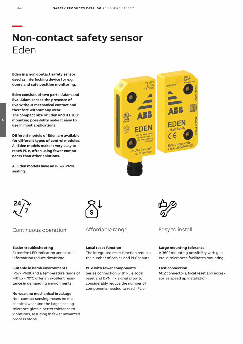
Eden is a non-contact safety sensorused as interlocking device for e.g. doors and safe position monitoring.
Eden consists of two parts: Adam and Eva. Adam senses the presence of Eva without mechanical contact and therefore without any wear. The compact size of Eden and its 360° mounting possibility make it easy to use in most applications.
Different models of Eden are available for different types of control modules. All Eden models make it very easy to reach PL e, often using fewer compo-nents than other solutions.
All Eden models have an IP67/IP69K sealing.
Local reset functionThe integrated reset function reduces the number of cables and PLC inputs.
PL e with fewer componentsSeries connection with PL e, local reset and DYNlink signal allow to considerably reduce the number of components needed to reach PL e.
Affordable range Easy to install
Large mounting toleranceA 360° mounting possibility with gen-erous tolerances facilitates mounting.
Fast connectionM12 connectors, local reset and acces-sories speed up installation.
Easier troubleshootingExtensive LED indication and status information reduce downtime.
Suitable in harsh environments IP67/IP69K and a temperature range of -40 to +70°C offer an excellent resis-tance in demanding environments.
No wear, no mechanical breakageNon-contact sensing means no me-chanical wear and the large sensing tolerance gives a better tolerance to vibrations, resulting in fewer unwanted process stops.
Continuous operation
—Non-contact safety sensor Eden
4 – 6 S A F E T Y PRO D U C T S C ATA LO G A B B J O K A B S A FE T Y
4
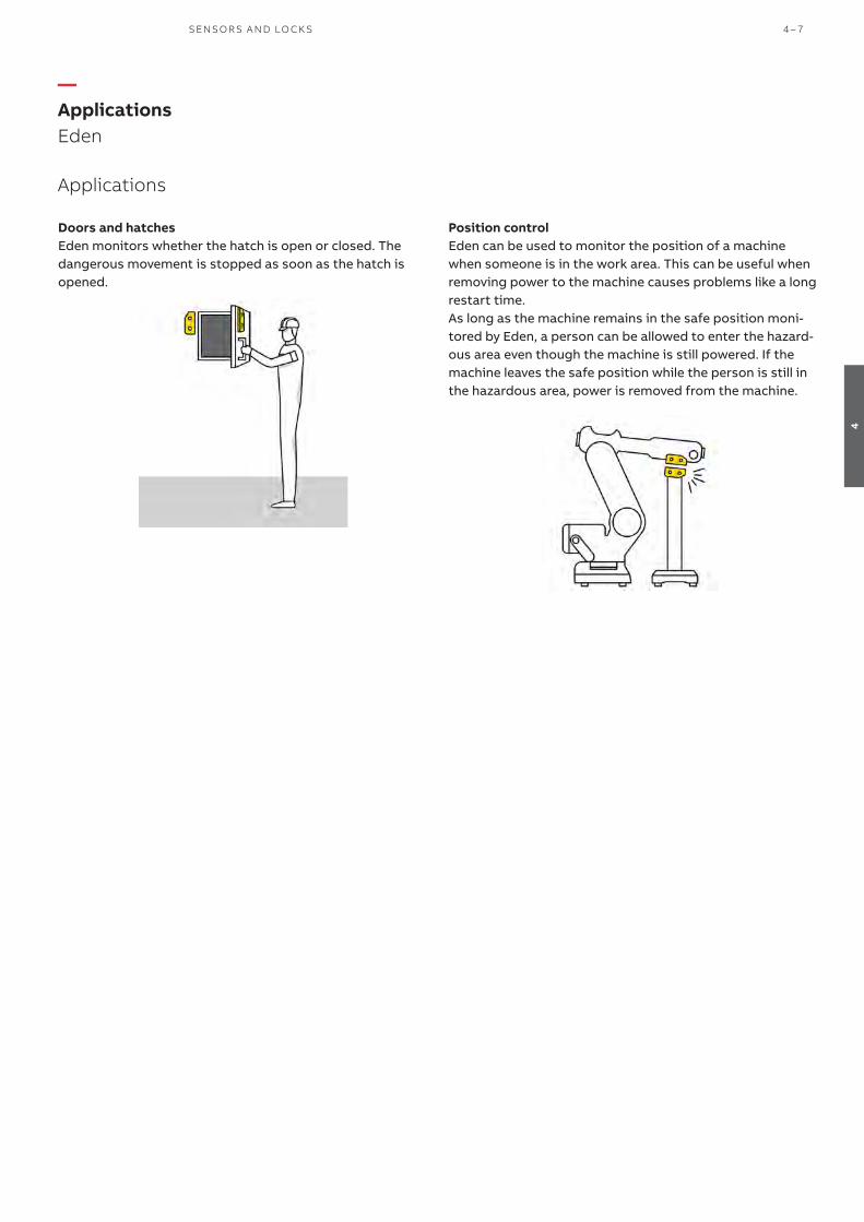
Doors and hatchesEden monitors whether the hatch is open or closed. The dangerous movement is stopped as soon as the hatch is opened.
—ApplicationsEden
Applications
Position controlEden can be used to monitor the position of a machine when someone is in the work area. This can be useful when removing power to the machine causes problems like a long restart time. As long as the machine remains in the safe position moni-tored by Eden, a person can be allowed to enter the hazard-ous area even though the machine is still powered. If the machine leaves the safe position while the person is still in the hazardous area, power is removed from the machine.
SENSO R S A N D LO CK S 4 – 7
4

—FeaturesEden
Easy PL e with Eden safety sensor- Eden sensors can be connected in series while maintaining
Cat. 4.- Only one Eden per guard is necessary to reach PL e (in-
stead of two key switches).- Eden reaches PL e without any need for periodic checks
(see ISO/TR 24119).
Features
Low or high level coded sensorEva is available with General code or Unique code. If a new Adam is paired with an Eva general code at start up, Adam will accept all Eva with general code as a valid actuator. Eden will then classify as a low level coded sensor. If a new Adam is paired with an Eva Unique code at startup, Adam will only accept this specific Eva as a valid actuator. In this case Eden is classified as a high level coded sensor. A high level coded sensor should be used when the motiva-tion to defeat a sensor cannot be eliminated (see EN ISO 14119:2013).
Simple status information with StatusBusStatusBus is a simple and cost effective way to collect the status information of safety sensors. The StatusBus func-tionality is available with some DYNlink devices and allows to collect the status of each individual safety device, even when connected in series. A single input on Pluto safety PLC can collect the status of up to 30 safety devices. The devices are connected using standard cable and M12-5 connectors. No specific bus cable or extra communication module is neces-sary.
Info signal and extensive indication facilitate troubleshootingAll Eden models offer extensive LED indication to help trou-bleshooting and localizing which doors/hatches are opened. The LED on Adam lights in green or red depending on status:
green - valid Eva within rangered - valid Eva out of rangeflashing red/green - valid Eva within range, but no valid safety signal received (loop broken “upstream”)
Local reset buttonA local reset button with integrated LED can be connected directly to Adam Reset instead of to the safety control mod-ule. In this way, each Eden can easily have its own reset but-ton, which saves cable length and safety relays/PLC inputs. Adam Reset monitors the reset function and manages the LED in the reset button in the following way:
on - Adam and Eva are not in contactflashing - Adam and Eva in contact, waiting for resetoff - Adam and Eva in contact and reset
360° mounting possibilityEden offers 360° mounting possibility with generous toler-ances.
4 – 8 S A F E T Y PRO D U C T S C ATA LO G A B B J O K A B S A FE T Y
4

Eden DYNEden DYN consists of an Adam DYN and an Eva (general or unique code).Adam DYN uses the ABB Jokab Safety DYNlink signal that al-lows to connect several safety products in series while main-taining PL e using only one channel. DYNlink signals must be used with Vital safety controller or Pluto safety PLC. Up to 30 Adam DYN can be connected in series to Vital and up to 10 Adam DYN can be connected in series to one input of Pluto.All products using the DYNlink signal can easily be connected in series and mixed in the same loop with a maintained PL e. Tina adapters allow to use other products in a DYNlink loop, and a wide range of connection accessories simplifies the cabling.
Eden OSSDEden OSSD consists of an Adam OSSD and an Eva (general or unique code). Adam OSSD can be used with all safety relays and safety PLCs compatible with OSSD signals (commonly used for light guards). Up to 30 Adam OSSD can be connected in se-ries, and since OSSD devices monitor their own outputs for short circuits, a Cat. 4/PL e can still be reached.
Models
—ModelsEden
Eden DYN Eden OSSD
SENSO R S A N D LO CK S 4 – 9
4

—Ordering informationEden
2TLC
010
045
V0
201
Adam DYN-Info M12-5
Type of safety controller
StatusBus Info signal Local reset Series connection
Connector male
Type Order code
Pluto x x 1) x M12-5 Adam DYN-Status M12-5 2TLA020051R5200
Pluto or Vital x x M12-5 Adam DYN-Info M12-5 2TLA020051R5100
x x M12-5 Adam DYN-Reset M12-5 2TLA020051R5300
OSSD compatible (incl. Pluto and Sentry)
x M12-5 Adam OSSD-Info M12-5 2TLA020051R5400
x x M12-8 Adam OSSD-Info M12-8 2TLA020051R5700
x M12-5 Adam OSSD-Reset M12-5 2TLA020051R5600
x x x M12-8 Adam OSSD-Reset M12-8 2TLA020051R5900 1) Pin 5 can be used as a standard info signal or StatusBus.
Code description Code level Type Order code
General code. (Eva is interchangeable) Low level Eva General code 2TLA020046R0800
Unique code. (Prevents defeat/fraud) High level Eva Unique code 2TLA020046R0900
Description Type Order code
Distance plate in yellow PBT (4 pcs). DA 1B 2TLA020053R0700
Black distance rings to be mounted in Adam and Eva mounting holes (4 pcs). DA 2B 2TLA020053R0300
Distance plate
2TLC
1727
27F0
201
Eva General code
2TLC
010
061
V0
201
Description Type Order code
Mounting plate for conventional door/hatch and folding door. Two pieces are needed for a complete set.
JSM D4H 2TLA040033R3600
Mounting plate for folding doors. Used together with one piece of JSM D4H. JSM D4J 2TLA042020R4000
Sliding lock for Eden on conventional doors. (Eden is not included.) JSM D20 2TLA020302R1000
Mounting converting plate from Eden E to Eden OSSD or Eden DYN DA 3A 2TLA020053R0600
Heat shrinking tubes for M12 connectors. Protects M12 connectors in harsh environments and provides extra protection against tampering.
M12 Safety seal 2TLA020053R0800
Wrench for tightening of M12 connectors according to specified torque: 0.6 Nm. M12 Torque wrench 2TLA020053R0900
Handheld terminal for addressing, configuration and testing of StatusBus devices, DYN-link devices and conventional PNP devices.
FIXA 2TLA020072R2000
JSM D20 Eden slide lock
2TLC
010
040
F020
1
FIXA
2TLC
010
040
F020
1
Description Type Order code
Reset button for Adam with 5 pins Smile 12RF 2TLA030053R2600
Reset button for Adam with 8 pins Smile 12RG 2TLA030053R2700
2TLC
1725
75F0
201
Smile 12RG Reset button
—Adam
—Eva
—Accessories
—Spare parts (included with main product on delivery)
—Reset buttons for local reset
4 – 10 S A F E T Y PRO D U C T S C ATA LO G A B B J O K A B S A FE T Y
4

—Cables and connectorsEden
Connector Female/male Length Special feature Type Order code
M12-5 Female 3 m M12-C31 2TLA020056R0500
6 m M12-C61 2TLA020056R0000
Harsh environment, halogen free M12-C61HE 2TLA020056R8000
10 m M12-C101 2TLA020056R1000
Harsh environment, halogen free M12-C101HE 2TLA020056R8100
20 m M12-C201 2TLA020056R1400
Female + male 0.3 m M12-C0312 2TLA020056R5800
0.06 m M12-C00612 2TLA020056R6300
1 m M12-C112 2TLA020056R2000
3 m M12-C312 2TLA020056R2100
6 m M12-C612 2TLA020056R2200
10 m M12-C1012 2TLA020056R2300
Angled female connector M12-C1012V2 2TLA020056R6700
16 m M12-C1612 2TLA020056R5400
20 m M12-C2012 2TLA020056R2400
Male 6 m M12-C62 2TLA020056R0200
10 m M12-C102 2TLA020056R1200
M12-8 Female 6 m M12-C63 2TLA020056R3000
10 m M12-C103 2TLA020056R4000
20 m M12-C203 2TLA020056R4100
Female + male 0.06 m M12-C00634 2TLA020056R6400
1 m M12-C134 2TLA020056R5000
3 m M12-C334 2TLA020056R5100
M12-C61
2TLC
1729
51F0
201
Description Type Order code
Connectors
M12-5 pole female, straight M12-C01 2TLA020055R1000
M12-5 pole male, straight M12-C02 2TLA020055R1100
M12-8 pole female, straight M12-C03 2TLA020055R1600
M12-8 pole male, straight M12-C04 2TLA020055R1700
Cable with 5 conductors
10 m cable with 5 x 0.34 shielded conductors C5 cable 10 m 2TLA020057R0001
50 m cable with 5 x 0.34 shielded conductors C5 cable 50 m 2TLA020057R0005
100 m cable with 5 x 0.34 shielded conductors C5 cable 100 m 2TLA020057R0010
200 m cable with 5 x 0.34 shielded conductors C5 cable 200 m 2TLA020057R0020
500 m cable with 5 x 0.34 shielded conductors C5 cable 500 m 2TLA020057R0050
Cable with 8 conductors
50 m cable with 8 x 0.34 shielded conductors C8 cable 50 m 2TLA020057R1005
100 m cable with 8 x 0.34 shielded conductors C8 cable 100 m 2TLA020057R1010
200 m cable with 8 x 0.34 shielded conductors C8 cable 200 m 2TLA020057R1020
500 m cable with 8 x 0.34 shielded conductors C8 cable 500 m 2TLA020057R1050
C5 cable
2TLC
010
038F
020
1
M12-C334
2TLC
1729
31F0
201
M12-C61HE
2TLC
010
003
F020
1
M12-C01
2TLC
1726
57F0
201
—Cable with connectors
—Separate cables and connectors
SENSO R S A N D LO CK S 4 – 11
4

Description Type Order code
Y-connector for series connection of DYNlink devices with M12-5 connectors, e.g. Eden. M12-3A 2TLA020055R0000
Y-connector for series connection of DYNlink devices with the StatusBus function. M12-3S 2TLA020055R0600
Y-connector for series connection of Adam OSSD M12-8 with M12-8 cables M12-3G 2TLA020055R0700
Y-connector for series connection of Adam OSSD M12-8 with M12-5 cables M12-3H 2TLA020055R0800
Termination plug M12-5. For Adam OSSD with M12-3H. Connects pin 1 with pin 2 and 4. JSOP-1 Terminator 2TLA020053R7000
Termination plug M12-8. For Adam OSSD with M12-3G. Connects pin 2 with pin 3 and 4. JSOP-2 Terminator 2TLA020053R7100
JSOP-2 Terminator
2TLC
010
00
8F0
201
—Connection accessories
—Connection AccessoriesEden
4 – 12 S A F E T Y PRO D U C T S C ATA LO G A B B J O K A B S A FE T Y
4

Eden DYN Eden OSSD
Approvals
Conformity 2006/42/EC - Machinery2014/30/EU - EMC2011/65/EU - RoHS
EN ISO 12100:2010, EN ISO 13849-1:2015,EN 62061:2005/A2:2015, EN 60204-1:2006+A1:2009, EN 60664-1:2007, EN 61000-6-2:2005, EN 61000-6-4:2007, EN 60947-5-3:2013, EN ISO 14119:2013, EN 61508:2010
EN ISO 12100:2010, EN ISO 13849-1:2015, EN 62061:2005/A2:2015, EN 60204-1:2006+A1:2009, EN 60664-1:2007, EN 61000-6-2:2005, EN 61000-6-4:2007, EN 60947-5-3:2013, EN ISO 14119:2013, EN 61508:2010
Functional safety data
EN/IEC 61508:2010 SIL3, PFHD = 4.5 x 10⁻⁹ SIL3, PFHD = 4.5 x 10⁻⁹
EN/IEC 62061:2005+A1:2013 SILCL3, PFHD = 4.5 x 10⁻⁹ SILCL3, PFHD = 4.5 x 10⁻⁹
EN ISO 13849-1:2008 PL e, Cat. 4, PFHD = 4.5 x 10⁻⁹ PL e, Cat. 4, PFHD = 4.5 x 10⁻⁹
Electrical data +24 VDC Tolerance: +14.4...+27.6 VDC
+24 VDC Tolerance: +14.4...+27.6 VDC
Mechanical data
Operating temperature -40 °C...+70 °C (storage/operation) -40°C...+70 °C (storage/operation)
Protection class IP67 and IP69K
Humidity range 35 to 85% (no icing, no condensation)
Material
Housing Polybutylene terephthalate (PBT)
Moulding Epoxy
Weight Eva: 70 g, Adam: 80 g
Assured release distance (Sar) 25 mm 25 mm
Assured operating distance (Sao) 10 mm 10 mmRated operating distance (Sn) 15 ± 2mm
Recommended distance between Adam and Eva
7 mm
Min distance between two Eden 100 mm
—Technical dataEden
More informationFor more information, e.g. the complete technical information, see product manual for:Eden DYN 2TLC172271M0201Eden OSSD 2TLC172272M0201
Connection diagramsFor Eden connection diagrams please see https://library.abb.com/
—Technical data
SENSO R S A N D LO CK S 4 – 13
4
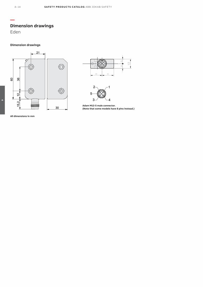
Dimension drawings
All dimensions in mm
Adam M12-5 male connector.(Note that some models have 8 pins instead.)
—Dimension drawingsEden
4 – 14 S A F E T Y PRO D U C T S C ATA LO G A B B J O K A B S A FE T Y
4

SENSO R S A N D LO CK S 4 – 15
4

Sense7 is a coded magnetic non-con-tact switch for interlocking gates and hatches.
Sense7 has a stainless steel housing that is designed for harsh environ-ments and extreme temperatures.
Sense7 offers and interlocking func-tion reaching PL e/SIL3 with low level coding.
High safety levelSense7 has two closing and one open-ing solid state contacts. Two of these needs to be monitored to achieve PL e/SIL3.
LED indication An integrated LED shows the status of the sensor.
Safety and protection Reliable in extreme conditions
Compact sizeSense7 is compact in size to make it easy to position and hide on gates and hatches.
Large sensing distanceWith a large sensing distance and a high tolerance for misalignment Sense7 is easy to install.
Easy to install
Stainless steelWith a stainless steel 316 body and a IP67/IP69K rating, Sense7 is resistant to harsh environments with both dirt and water.
Hygienic designSense7 has no dust collecting cav-ities, and the stainless steel has a mirror polished finish (Ra4) suitable for CIP cleaning - food splash zones acording to EHEDG guidelines.
High temperaturesSense7 can be used at temperatures from -25 °C up to 105 °C.
—Safety magnetic switchSense7
4-16 S A F E T Y PRO D U C T S C ATA LO G A B B J O K A B S A FE T Y
4

Sense7Z 2M
Sense7Z Key SS
—Ordering details
Description Connector Cable length (m) Contacts Type Order code
Safety magnetic switch M12-8 male 0,25 2NC+1NO Sense7Z M12 2TLA050056R2120
Safety magnetic switch - 2 2NC+1NO Sense7Z 2M 2TLA050056R4120
Safety magnetic switch - 5 2NC+1NO Sense7Z 5M 2TLA050056R5120
Safety magnetic switch - 10 2NC+1NO Sense7Z 10M 2TLA050056R6120
Sense7 is always delivered with both switch and actuator.
—Spare part Type of handle Type Order code
Actuator to safety magnetic switch Sense7Z, stainless steel. Sense7Z Key SS 2TLA050040R0212
—
Ordering detailsSense7
SENSO R S A N D LO CK S 4-17
4
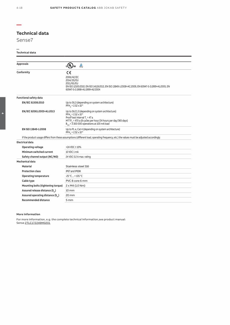
Approvals
Conformity
2006/42/EC2014/30/EU2011/65/EUEN ISO 12100:2010, EN ISO 14119:2013, EN ISO 13849-1:2008+AC:2009, EN 60947-5-3:1999+A1:2005, EN 60947-5-2:1998+A1:1999+A2:2004
Functional safety data
EN/IEC 61508:2010 Up to SIL3 (depending on system architecture)PFHD = 2.52 x 10⁻⁸
EN/IEC 62061:2005+A1:2013 Up to SILCL3 (depending on system architecture)PFHD = 2.52 x 10⁻⁸ Proof test interval T1 = 47 aMTTFd = 470 a (8 cycles per hour/24 hours per day/365 days)B10d = 3 300 000 operations at 100 mA load
EN ISO 13849-1:2008 Up to PL e, Cat 4 (depending on system architecture)PFHD = 2.52 x 10⁻⁸
If the product usage differs from these assumptions (different load, operating frequency, etc.) the values must be adjusted accordingly.
Electrical data
Operating voltage +24 VDC ± 10%
Minimum switched current 10 VDC 1 mA
Safety channel output (NC/NO) 24 VDC 0.2 A max. rating
Mechanical data
Material Stainless steel 316
Protection class IP67 and IP69K
Operating temperature -25 °C ... + 105 °C
Cable type PVC 8 core 6 mm
Mounting bolts (tightening torque) 2 x M4 (1.0 Nm)
Assured release distance (Sar) 10 mm
Assured operating distance (Sor) 20 mm
Recommended distance 5 mm
—Technical data
More information
For more information, e.g. the complete technical information,see product manual:Sense 2TLC172249M0201
—
Technical dataSense7
4-18 S A F E T Y PRO D U C T S C ATA LO G A B B J O K A B S A FE T Y
4

—Dimension drawingsSense7
Dimensions - Sense7Z
All dimensions in mm
SENSO R S A N D LO CK S 4-19
4

MKey are mechanical safety switch-es used for monitoring doors and hatches. The switch is mounted on the frame and the actuator key on the moving part of the guard.
All MKey models have a safe interlock-ing function. Some MKey models can be locked and depending on the lock-ing signal they can be used either as process locks or safety locks (with a safe unlocking function).
MKey switches are available in differ-ent material and sizes in order to meet the requirements of different applica-tions.
Easy to install
Easy mounting with rotating head The head of the switch can be mount-ed in up to 8 actuating positions to allow different mounting positions.
Flexible keysFlexible keys are available to minimize mechanical wear and allow a smaller movement radius and use in reduced spaces.
Safety and protection
Highest level of safetyPL e/SIL3 can be reached when using two switches on a door.
Safety lockModels that use power to unlock can be used as safety locks.
Emergency escape button Using MKey8ER with an integrated emergency escape button, it is always possible to open the door from inside the dangerous zone.
Strong holding forceA holding force of up to 2000 N pre-vents unwanted process stops.
Robust designModels are available with full stainless steel housing with IP69K, suitable for most applications in food processing and chemical industries.
Status informationAuxiliary contacts give status informa-tion.
Continous operation
—Safety interlock switchMKey
4 – 20 S A F E T Y PRO D U C T S C ATA LO G A B B J O K A B S A FE T Y
4

—Applications MKey
Doors and hatchesMKey is used to monitor the position of doors and hatches. The models with locking function are usually used for:– Processes which should not be interrupted, such as
welding.– Machinery with a long stopping procedure, such as paper
machinery that requires a long braking operation.– Prevention of unauthorized access to a particular area.
Please note that all safety key switches (including MKey) normally need two switches per door/hatch in order to reach PL e/SIL3. (See EN ISO 13849 and EN ISO 14119.)
Locking and interlockingAn interlocking function indicates if a door is open or closed and prevents movement when the door is open, but it does not prevent the door from being opened. A locking function makes sure the door is kept closed.
Process lock with safe interlockingAll MKey models offer a safe interlocking function that will stop the process if the door/hatch is opened. All lockable models of MKey can also be used as a process lock to pre-vent the process from being interrupted.An example of an application where a process lock could be used is a welding robot where the stopping time is short, but the welding should not be interrupted once it has started.
Safety lock with safe interlocking and safe unlockingThe MKey models that uses power to unlock can be used as safety locks. They have a safe unlocking function, which means that the loss of power for these locks will not result in the release of the locking element, and the door will re-main locked even during a power failure.An example of an application where a safety lock should be used is a circular saw that would have a long stopping time after a power failure.
SENSO R S A N D LO CK S 4 – 21
4

Different modelsMKey5 are simple mechanical interlocks while MKey8 and MKey9 also have locking functions.– MKey5: plastic body with plastic or stainless steel head,
or full stainless steel body and head.Holding force 12 N or 40 N.
– MKey8: robust design in die cast metal or stainless steel body and head. Holding force of 2000 N.
– MKey9: plastic body with stainless steel head. Holding force of 1800 N.
Power to lock or power to unlockTwo different types of locking function are available:– Spring lock (power to unlock) models are automatically
locked when closing the door. An active signal (+24 VDC) must be supplied to unlock the switch, which makes these models suitable as safe locks.
– Electro-magnetic lock (power to lock) models are locked when an active signal (+24 VDC) is supplied, which makes these models suitable only as process locks.
Rotatable headDepending on model, the head of MKey can be set in two or four directions with two entrance holes each, thus provid-ing four or eight different mounting positions. The leading edges of the actuator key are reinforced and beveled in order to guide it properly into the hole.
Different materials and protection classesThe housing and head of the key switches are available in different material in order to meet the requirements of different applications. Metal heads are more resistant to mechanical wear. The choice between plastic, die cast or stainless steel depends on the environment and the chemi-cals used. Models ending with -Z are completely made of stainless steel 316 and offers an IP69K protection class. They can be high pressure hosed with detergent at high tempera-ture and can be used in harsh applications, e.g. the food pro-cessing and chemical industries. All other models offer IP67.
Emergency escape buttonMKey8ER has a manual release button at the rear of the housing. It is used for emergency exit by a person locked inside the dangerous zone by mistake. It is a non-latching manual escape, and can be used when the risk assessment requires it. The switch must be mounted so that the release button is reachable from inside the dangerous zone, but not reachable from outside. Pressing and holding the button will release the locking mechanism allowing to open the door/guard.
Constructed for safetyAll MKey switches have double positively operated forced-guided contacts controlled by the actuator key. This means that the contacts that are closed when the actuator key is in the switch will be forced to open, and the ones that are opened will be forced to close, when the actuator key is re-moved. It also means that it is not possible to have, e.g. NO and NC contacts opened at the same time due to a fault like one welded contact.The actuator key is designed to prevent tampering with the safety switch using a tool, a magnet or any similar object.The lockable models also have forced-guided contacts con-trolled by the locking mechanism. MKey8 and MKey9 have auxiliary contacts giving status information (not MKey5, MKey8M or MKey9M).
Manual release button
—FeaturesMKey
4 – 22 S A F E T Y PRO D U C T S C ATA LO G A B B J O K A B S A FE T Y
4

Locking function
Material housing
Material head
Holding force
Special feature Type Order code
— Plastic Plastic 12 N MKey5 2TLA050003R0100
40 N MKey5+ 2TLA050003R0101
Stainless steel 12 N MKey5 SSH 2TLA050003R0110
40 N MKey5+ SSH 2TLA050003R0111
Stainless steel Stainless steel 12 N IP69K MKey5Z 2TLA050003R0120
40 N IP69K MKey5+Z 2TLA050003R0121
Process lock(power to lock)
Plastic Stainless steel 1800 N MKey9M 24VDC 2TLA050009R0112
Die cast Die cast 2000 N MKey8M 24VDC 2TLA050013R0132
Safety lock(power to unlock)
Plastic Stainless steel 1800 N MKey9 24VDC 2TLA050007R0112
No key supplied MKey9 24VDC, No Key 2TLA050007R0012
Die cast Die cast 2000 N MKey8 24VDC 2TLA050011R0132
With escape release button MKey8ER 24VDC 2TLA050015R0132
Stainless steel Stainless steel 2000 N IP69K MKey8Z 24VDC 2TLA050011R0122
—Ordering informationMKey
2TLC
1724
03F0
201
MKey5
2TLC
1724
21F0
201
MKey9
2TLC
1724
09F
020
1
MKey5 SSH
2TLC
1725
03F0
201
MKey5Z
2TLC
1724
17F0
201
MKey8ER
2TLC
1724
15F0
201
MKey8Z
—MKey ordering information
SENSO R S A N D LO CK S 4 – 23
4

—AccessoriesMKey
MKey Key 4
2TLC
1726
28F0
201
MKey Key 2
2TLC
1726
27F0
201
MKey Key 6
Type of key Compatible MKey models
Key housing Description Type Order code
Standard key MKey5MKey5+
None Standard key for MKey safety switches with plastic head. Stainless steel key.
MKey Key 1 2TLA050040R0201
MKey5 SSHMKey5+ SSHMKey5ZMKey5+ZAll MKey8All MKey9
None Standard key for MKey safety switches with metal head. Stainless steel key.
MKey Key 2 2TLA050040R0202
Flat key All Plastic shroud Flat key for MKey safety switches. Stain-less steel key with plastic shroud.
MKey Key 3 2TLA050040R0220
Flexible key All MKey5 Plastic Flexible key for MKey5 safety switches. Stainless steel key with plastic housing.
MKey Key 4 2TLA050040R0221
All Die cast Flexible key for MKey safety switches. Stainless steel key with black die cast metal housing.
MKey Key 5 2TLA050040R0203
All Stainless steel Flexible key for MKey safety switches. Stain-less steel key with stainless steel housing.
MKey Key 6 2TLA050040R0204
Description Type Order code
Bit for manual unlocking of MKey8Z. Stainless steel. MKey8Z Manual release 2TLA050040R0400
Maintenance lockout actuator key. Compatible with all MKey switches. MKey Lockout key 2TLA050040R0401
Slide Lock for MKey8 and MKey9, left. MKey slide lock left 2TLA050040R0500
Slide Lock for MKey8 and MKey9, right. MKey slide lock right 2TLA050040R0501
Fitting in stainless steel for mounting MKey5 on a Quick-Guard conventional door. JSM D29A 2TLA040033R6000
Fitting in stainless steel for mounting MKey5 on a Guick-Guard sliding door. JSM D29B 2TLA040033R6100
Fitting in stainless steel for mounting Mkey8 and Mkey9 on a Quick-Guard conventional door. JSM D29C 2TLA040033R6200
Fitting in stainless steel for mounting Mkey8 and MKey9 on a Quick-Guard sliding door. JSM D29D 2TLA040033R6300
Spacer in stainless steel for flexible keys. Required when using JSM D29A and JSM D29C. JSM D29E 2TLA040033R6400
Rear handle for sliding doors. RHS GKey MKey 2TLA050040R0510
Spring loaded catch for sliding doors. SCS GKey MKey 2TLA050040R0511
MKey Key 3
2TLC
1726
31F0
201
MKey slide lock left
MKey slide lock right
—Actuator keys All MKey safety switches are supplied with the appropriate standard key, except MKey9 24VDC, No key. Choose standard key or flat key depending on suitable mounting direction, e.g. standard door or sliding door. Flexible keys are suitable for doors/hatches with a smaller opening radius (i.e. 100-175 mm).
—Other accessories
4 – 24 S A F E T Y PRO D U C T S C ATA LO G A B B J O K A B S A FE T Y
4

MKey5 MKey8 MKey9
Approvals
Conformity 2006/42/EC - Machinery2014/30/EU - EMC2011/65/EU - RoHSEN ISO 12100:2010, EN ISO 14119:2013, EN 60204-1:2006:+A1:2009, EN 60947-1:2007:+A1:2011, EN 60947-5-1:2004:+A1:2009
Functional safety data
B10d 2,500,000 operations at 100 mA load
EN/IEC 62061 Up to SILCL3 (depending on system architecture) 1)
EN ISO 13849-1 Up to PL e (depending on system architecture) 1)
Electrical data
Contact block configuration with guard open and unlocked
For actuator key 2 NO + 1 NC MKey8, Mkey8Z, MKey8ER: 2 NO + 1 NC MKey8M: 1 NO + 1 NC
MKey9: 2 NO + 1 NC 2) 1 NO + 1 NC
For solenoid/locking - MKey8, Mkey8Z, MKey8ER: 2NO + 1NC MKey8M: 2 NO
MKey9: 2 NO + 1 NC 2) MKey9M: 2 NO
Solenoid voltage - +24 VDC ± 10% +24 VDC ± 10%
DC-13 +24 VDC / 3 A
AC-15 230 VAC / 3 A
Mechanical data
Travel for positive opening 6 mm 10 mm 10 mm
Actuator key entry minimum radius 175 mm Standard Key, 100 mm Flexible Key
Material Body: Polyester or stainless steel 316Head: Polyester or stainless steel 316
MKey8, MKey8M, MKey8ER: Die cast painted redMKey8Z: Stainless steel 316
Body: Glass filled polyester Head: Stainless steel 316
Conduit entries 3 x M20 x 1.5 3 x M20 x 1.5 1 x M20 x 1.5
Operating temperature -25...+80 °C -25...+40 °C -25...+40 °C
Protection class MKey5, MKey5+, MKey5 SSH, MKey5+ SSH: IP67MKey5Z, MKey5+Z: IP67, IP69K
MKey8, MKey8M, MKey8ER: IP67MKey8Z: IP67, IP69K
IP67
1) Please see EN/IEC 62061, EN ISO 13849, EN ISO 14119 and ISO/TR 24119 to see how fault exclusions and serial connection impacts the reliability of the safety related parts of control systems.
2) For MKey9, the pair of contacts for the actuator key and the pair of contacts for the locking cannot be used independently of each other. See the manual for moreinformation.
—Technical dataMKey
More informationFor more information, e.g. the complete technical information, see product manual:MKey5 2TLC172244M0201MKey8 2TLC172245M0201MKey9 2TLC172246M0201
Connection diagramsFor MKey connection diagrams please see https://library.abb.com/
—Technical data
SENSO R S A N D LO CK S 4 – 25
4

—Dimension drawingsMKey
All dimensions in mm
21
5
4046
9.50
30
32124
30
Fixing Holes for M5 Screws
FRONT ENTRY
41.5
0
176
47
16
23.50
28.5
0
70
67
21
9.50
5
25
END ENTRY
MKey5
MKey8 and MKey8M MKey8ER
MKey9 and MKey9M
MKey5Z
4 – 26 S A F E T Y PRO D U C T S C ATA LO G A B B J O K A B S A FE T Y
4

SENSO R S A N D LO CK S 4 – 27
4

Magne is an electromagnetic process lock intended for locking doors and hatches.
Magne is usually used to prevent unwanted process interruptions, e.g. during a welding operation.
Magne models with inte grated Adam safety sensor make it easy to achieve the highest safety level for the inter-locking function.
Sealed aluminium housingIP67 sealing gives Magne good protection.
Robust designThe electromagnetic lock without mechanical moving parts is a robust design with fewer parts that are sub-ject to wear.
Hygienic designFlat surfaces without cavities or screws sticking out minimize the risk of accumulating dirt on the surface.
Reliable in extreme conditions
Continuous operation
M12 connectorsQuick and easy cabling with M12 con-nectors.
Magnets simplify installationElectromagnets offer larger mounting tolerances than mechanical locks.
Easy to install
LED diagnosticsIntegrated LED diagnostics reduce down time when troubleshooting.
Strong holding forceA holding force of up to 1500 N pre-vents unwanted process stops.
—Electromagnetic process lockMagne
4 – 28 S A F E T Y PRO D U C T S C ATA LO G A B B J O K A B S A FE T Y
4

Locking and interlockingAn interlocking function indicates if a door is open or closed and prevents movement when the door is open. But it does not prevent the door from being opened. A locking function makes sure the door is kept closed.
—Applications and featuresMagne
PL e in a simple and cost effective wayMagne 4 has an integrated Adam sensor. Models are avail-able with either Adam DYN or Adam OSSD. Eva General code or Eva Unique code is ordered separately. The use of the Eden safety sensor makes it easy to reach PL e/SIL3 for the interlocking function, and enables serial connection of several Magne 4 locks to the Pluto safety PLC using only one input for Eden DYN and two for Eden OSSD. Tina 12A can be used for the serial connection of two Magne 4 locks in order to simplify connection, reduce cabling and risk of connec-tion errors.
Protect the processMagne 4 is a process lock, with a safe interlocking function. This means that the interlocking function reaches PL e/SIL3 but the unlocking signal is not a safe signal. A typical appli-cation is to prevent unintentional/unnecessary interruptions of a sensitive process when the dangerous movement has a very short stop time.
Magne 3 is a simple lock without any interlocking function/safety function.
Applications
Features
M12 connectorsSince the Adam sensor is integrated in Magne 4, the amount of cables is reduced so that only one cable is necessary for both the locking of Magne and the interlocking with Eden.The M12 connectors speed up connection and reduce therisk of connection errors.
Wet environmentsWith a hygienic enclosure in anodized aluminum and IP67 protection class, Magne is well protected in wet environ-ments.
Status indicationMost models offer an info signal indicating whether the Magne is locked or not, which simplifies troubleshooting and improves user friendliness.
Optional permanent magnetAnchor plates for Magne are ordered separately and are available with or without permanent magnet. A permanent magnet holds the door closed when Magne is unlocked, or if there is a power loss. Without the permanent magnet, Magne has no magnetic field when unlocked, which avoids the accumulation of metallic particles on the magnet.
SENSO R S A N D LO CK S 4 – 29
4

JSM D28
—Ordering informationMagne
Safe interlocking with integrated Adam Safety signal Extra function Connector Type Order code
No - - M12-5 male Magne 3X M12-5 2TLA042022R2700
Yes DYNlink - M12-5 male Magne 4X DYN M12-5
2TLA042022R3000
"Locked" and "Closed" information outputs
M12-8 male Magne 4 DYN-Info 2TLA042022R3400
OSSD "Locked" and "Closed" information outputs
M12-8 male Magne 4 OSSD-Info 2TLA042022R4600
Description Type Order code
Aluminium profile for door handle that completely covers a Magne unit when the door is closed. For conventional door (5–15 mm door gap)
JSM D28 2TLA042023R0100
Mounting kit for Magne. For conventional door (5 -15 mm door gap) * JSM D21B 2TLA042023R0500
Mounting kit for Magne. For sliding door * JSM D23 2TLA042023R0200
Mounting kit for Eva. For conventional door* JSM D24 2TLA042023R0300
Door handle for JSM D21B JSM D27 2TLA042023R1000
Connection block for serial connection of two Magne (M12-8) Tina 12A 2TLA020054R1800
Cellular rubber, 10 mm thick. Spare part for anchor plate. Cellular rubber 2TLA042023R3600
* All mounting kits include the bolts and nuts necessary to mount Magne on ABB Quick-Guard® fencing system
2TLC
1721
67F0
201
2TLC
010
070
V0
201
Magne 3
JSM D27 JSM D21B
JSM D24
2TLC
010
072V
020
1
Magne 4
2TLC
010
085
V0
201
Anchorplate
JSM D23
Tina 12A
2TLC
1724
83F0
201
Description Type Order code
Anchor plate with permanent magnet. Delivered with cellular rubber. Magne Anchor 32B 2TLA042023R0400
Anchor plate without permanent magnet. Delivered with cellular rubber. Magne Anchor 32A 2TLA042023R1300
Compatible Adam Code description Code level Type Order code
Adam DYN and OSSD General code. (Eva is interchangeable) Low level Eva General code 2TLA020046R0800
Unique code. (Prevents defeat/fraud) High level Eva Unique code 2TLA020046R0900
4 – 30 S A F E T Y PRO D U C T S C ATA LO G A B B J O K A B S A FE T Y
4
—Ordering details For a complete Magne lock both door part and frame parts are necessary. Magne 4 also requires a separate Eva sensor.
—Accessories
—Door part
—Eva sensor for Magne 4 models

—Cables and connectorsMagne
Description Type Order code
Connectors
M12-5 pole female, straight M12-C01 2TLA020055R1000
M12-5 pole male, straight M12-C02 2TLA020055R1100
M12-8 pole female, straight M12-C03 2TLA020055R1600
M12-8 pole male, straight M12-C04 2TLA020055R1700
Cable with 5 conductors
10 m cable with 5 x 0.34 shielded conductors C5 cable 10 m 2TLA020057R0001
50 m cable with 5 x 0.34 shielded conductors C5 cable 50 m 2TLA020057R0005
100 m cable with 5 x 0.34 shielded conductors C5 cable 100 m 2TLA020057R0010
200 m cable with 5 x 0.34 shielded conductors C5 cable 200 m 2TLA020057R0020
500 m cable with 5 x 0.34 shielded conductors C5 cable 500 m 2TLA020057R0050
Cable with 8 conductors
50 m cable with 8 x 0.34 shielded conductors C8 cable 50 m 2TLA020057R1005
100 m cable with 8 x 0.34 shielded conductors C8 cable 100 m 2TLA020057R1010
200 m cable with 8 x 0.34 shielded conductors C8 cable 200 m 2TLA020057R1020
500 m cable with 8 x 0.34 shielded conductors C8 cable 500 m 2TLA020057R1050
C5 cable
2TLC
010
038F
020
1
M12-C334
2TLC
1729
31F0
201
M12-C61HE
2TLC
010
003
F020
1
M12-C01
2TLC
1726
57F0
201
Connector Female/male Length Special feature Type Order code
M12-5 Female 3 m M12-C31 2TLA020056R0500
6 m M12-C61 2TLA020056R0000
Harsh environment, halogen free M12-C61HE 2TLA020056R8000
10 m M12-C101 2TLA020056R1000
Harsh environment, halogen free M12-C101HE 2TLA020056R8100
20 m M12-C201 2TLA020056R1400
Female + male 0.3 m M12-C0312 2TLA020056R5800
0.06 m M12-C00612 2TLA020056R6300
1 m M12-C112 2TLA020056R2000
3 m M12-C312 2TLA020056R2100
6 m M12-C612 2TLA020056R2200
10 m M12-C1012 2TLA020056R2300
Angled female connector M12-C1012V2 2TLA020056R6700
16 m M12-C1612 2TLA020056R5400
20 m M12-C2012 2TLA020056R2400
Male 6 m M12-C62 2TLA020056R0200
10 m M12-C102 2TLA020056R1200
M12-8 Female 6 m M12-C63 2TLA020056R3000
10 m M12-C103 2TLA020056R4000
20 m M12-C203 2TLA020056R4100
Female + male 0.06 m M12-C00634 2TLA020056R6400
1 m M12-C134 2TLA020056R5000
3 m M12-C334 2TLA020056R5100
M12-C61
2TLC
1729
51F0
201
SENSO R S A N D LO CK S 4 – 31
4
—Cable with connectors
—Separate cables and connectors

Magne 3 Magne 4
Approvals
Conformity 2014/35/EU - Low voltage2011/65/EU - RoHS EN 60204-1:2006+A1:2009, EN 60664-1:2007, EN 61000-6-2:2005, EN 61000-6-4:2007+A1:2011
2006/42/EC - Machinery2014/30/EU - EMC2011/65/EU - RoHSEN ISO 12100:2010, EN ISO 13849-1:2015, EN 62061:2005/A2:2015, EN 60204-1:2006+A1:2009, EN 60664-1:2007, EN 61000-6-2:2005, EN 61000-6-4:2007+A1:2011, EN 60947-5-3:2013, EN ISO 14119:2013, EN 61508:2010
Functional safety data
EN 61508:2010 Interlocking function: SIL3, PFHD = 4.50 x 10⁻⁹
EN 62061:2005 Interlocking function: SILCL3, PFHD = 4.50 x 10⁻⁹
EN ISO 13849-1:2008 Interlocking function: PL e, Cat. 4, PFHD= 4.50 x 10⁻⁹
Electrical data
Operating voltage +24 VDC ± 15%
Holding force
+24 VDC Min 1500 N
0 V, Anchor plate 32A 0 N
0 V, Anchor plate 32B 30 N
Mechanical data
Mechanical life >107 switch operations
Operating temperature -20…+50 °C
Humidity range 35 to 85% (with no icing or condensation)
Protection class IP67
Weight
610 g 700 g
Anchor plate 32A/B 290 g
Material
Anchor plate Iron with nickel coating
Electromagnet Iron with zinc-nickel coating
Housing Anodized aluminum with parts in polycarbonate
Potting PUR, epoxy
—Technical dataMagne
More informationFor more information, e.g. the complete technical information, see product manual for:Magne 2TLC172315M0201
4 – 32 S A F E T Y PRO D U C T S C ATA LO G A B B J O K A B S A FE T Y
4
—Technical data

158
260
123
6,6(2x)11 DEEP 7(2x)
91 18,5
11,
75
35
20,75
21,65
Magne
All dimensions in mm
—Dimension drawingsMagne
130100 ±0,20
M8(2x)
AA
14
SECTION A-A
±0,1
09,
105,
50
4,10
0+0,1
0
32
Permanent magnet
Permanent magnet
Anchor plate 32A
Anchor plate 32B
SENSO R S A N D LO CK S 4 – 33
4

GKey is a robust safety lock with a die cast housing for hinged and sliding doors.
GKey offers an interlocking function reaching PL e/SIL 3 with high level coding. Power is needed to unlock GKey which makes GKey a safety lock.
GKey is fitted with a rear escape release button and manual unlocking (auxiliary release).
GKey offers four positions for 22 mm pilot devices.
Escape releaseThe door can always be opened from inside the danger zone using the escape release button.
High level coding A standard mechanical interlock com-bined with RFID coding offers high level coding.
Lockout functionGKey can be padlocked off for safe working.
Safety and protection Reliable in extreme conditions
Integrated buttonsThere are four positions in the key housing that can be used for inte-grating push buttons, switches or pilot lights.
Easy to install
Robust designMade of die cast aluminum alloy with a robust construction, GKey is ideal for use in mechanically demanding environments.
—Safety lockGKey
4-34 S A F E T Y PRO D U C T S C ATA LO G A B B J O K A B S A FE T Y
4

—Ordering Details
GKey4 RU
RHS GKey MKey
SCS GKey MKey
FHS GKey4
CE3P-10R-02
C2SS1-10B-20
CP1-11C-10
MA1-8130
KA1-8120
Material (body) Positions for pilot devices Manual unlock Type Order code
Die cast 4 Yes GKey4 RU 2TLA050304R0002
—Switches
For a complete safety lock, a switch and a mounting plate with front handle must be ordered separately. Rear handle, spring catch, pilot devices and blanking plugs for the unused positions are available and also ordered separately.
Description Contacts Illuminated Voltage Type Order code
Emergency stop button 2NC No 24 V AC/DC CE3P-10R-02 1SFA619501R1051
Selector switch 2NO No 24 V AC/DC C2SS1-10B-20 1SFA619200R1026
Push button Green 1NO Yes 24 V AC/DC CP1-11G-10 1SFA619100R1112
Push button Yellow 1NO Yes 24 V AC/DC CP1-11Y-10 1SFA619100R1113
Push button Blue 1NO Yes 24 V AC/DC CP1-11L-10 1SFA619100R1114
Push button White/Clear 1NO Yes 24 V AC/DC CP1-11C-10 1SFA619100R1118
Push button Black 1NO No 24 V AC/DC CP2-10B-10 1SFA619101R1016
Blanking plug Black MA1-8130 1SFA611920R8130Legend plate holder (without insert)
KA1-8120 1SFA616920R8120
—Accessories - Pilot devices
All models are fitted with an escape release button and delivered with a high level coded RFID actuator.
—Mounting plate with front handle
The handle can be mounted on hinged doors and sliding doors, on the left or on the right.Note that door and frame must be aligned when the door is closed.Each order code includes a mounting plate for the switch and a front handle. Type of handle Material (mounting plates and sliding bolt) Type Order code
Sliding Die cast FHS GKey4 2TLA050310R0032
—Accessories - Rear handle and spring loaded catch
The spring loaded catch prevents from closing the door by mistake. When the sliding handle is in open position, the catch must be pulled in order to be able to push back the handle to closed position. Type of handle Material Description Type Order code
Sliding Die cast Rear handle RHS GKey MKey 2TLA050040R0510
Spring catch SCS GKey MKey 2TLA050040R0511
More informationFor more optional pilot devices, pre-printed legend plate inserts and other accessories, please see the Compact range of ABB pilot devices: http://new.abb.com/low-voltage/products/pilot-devices
Pilot devices and blanking plugs must be ordered separately. Make sure that the total amount is 4, so that all holes in GKey4 are covered.
Description Type Order code
Cable gland M20 x 1.5 Gland M20x1.5 2TLA050040R0002
Conduit plug M20 x 1.5 Cond.Plug M20x1.5 2TLA050040R0004
—Accessories for cable holes
—
Ordering detailsGKey
SENSO R S A N D LO CK S 4-35
4

Approvals
Conformity
2006/42/EC – Machinery2014/53/EU – RED2011/65/EU – RoHS22015/863 – RoHS3EN ISO 12100:2010, EN ISO 14119:2013, EN ISO 13849-1:2015, IEC 62061:2005+A2:2015, IEC 60947-5-3:2013, IEC 60947-1:2014, EN 60204-1:2018, EN 301 489-1 V2.1.1, EN 301 489-3 V1.6.1
Functional safety data
EN 62061:2005+A1:2013 SIL3PFH = 4.77 x 10⁻¹⁰ (corresponds to 4.8% of SIL3),PFD = 4.18 x 10⁻⁵ (corresponds to 4.2% of SIL3)Proof test interval T1 = 20 a
EN ISO 13849-1:2008 PL e (if both channels are used in conjunction with a SIL3/PL e control device),Category 4, MTTFd = 1100 a, DC high
Assumptions dop = 365d, hop = 24h
If the product usage differs from these assumptions (different load, operating frequency, etc.) the values must be adjusted accordingly.
Electrical data
Operating voltage +24 VDC ± 10%
Holding force 3000 N
Mechanical data
Connection M20 (x3)
Operating temperature -25 °C ... +40 °C
Protection class IP65.
—Technical data
More informationFor more information, e.g. the complete technical information,see product manual:GKey 2TLC010048M0201
Connection diagramsFor GKey connection diagrams please see https://library.abb.com/
Actuator must be in place and RFID coding verified for the safety contacts to close.
Electrical connection
—
Technical dataGKey
4-36 S A F E T Y PRO D U C T S C ATA LO G A B B J O K A B S A FE T Y
4

—Dimension drawingsGKey
Dimensions - GKey4 switch and actuator
Dimensions - FHS GKey4 with rear handle and spring loaded catch
All dimensions in mm
SENSO R S A N D LO CK S 4-37
4

S A F E T Y PRO D U C T S C ATA LO G A B B J O K A B S A FE T Y
5

5– 2 Introduction and overview
5– 4 One- and two-hand devices
Safeball™
5– 10 Three-position device
JSHD4
CO NTR O L D E V I CE S 5 – 1
5
— Control devices

—Introduction and overviewSelection guide
ABB offers ergonomic control devices that allow operators to safely control dangerous machinery.
Safeball JSHD4
Image
Type One or two-hand control device Tree-position device
Description Ergonomic and unique machine control Ergonomic hold-to-run device with extra control buttons
Application Mainly used in pairs as a two-hand control in applications where it must be ensured that the operator has his hands outside the hazardous area, e.g. for starting a press cycle.
Used during e.g. troubleshooting, test running and programming, in order to allow the operator to be inside the hazardous area without stopping the machine, while ensuring limited move-ment and stop in case of danger.
Advantages - Ergonomic design- Several grip possibilities- Flexible mounting- Two opposing buttons minimize the
possibility to defeat
- Ergonomic shape and operation- Hand recognition prevents defeat- Easy connection with M12 connectors- Several models to suit multiple applica-
tions- Extra buttons for e.g. machine control
5 – 2 S A F E T Y PRO D U C T S C ATA LO G A B B J O K A B S A FE T Y
5
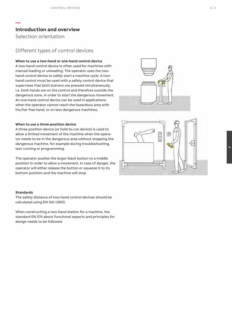
Different types of control devices
When to use a two-hand or one-hand control device A two-hand control device is often used for machines with manual loading or unloading. The operator uses the two-hand control device to safely start a machine cycle. A two-hand control must be used with a safety control device that supervises that both buttons are pressed simultaneously, i.e. both hands are on the control and therefore outside the dangerous zone, in order to start the dangerous movement. An one-hand control device can be used in applications when the operator cannot reach the hazardous area with his/her free hand, or on less dangerous machines.
When to use a three-position deviceA three-position device (or hold-to-run device) is used to allow a limited movement of the machine when the opera-tor needs to be in the dangerous area without stopping the dangerous machine, for example during troubleshooting, test running or programming.
The operator pushes the larger black button to a middle position in order to allow a movement. In case of danger, the operator will either release the button or squeeze it to its bottom position and the machine will stop.
StandardsThe safety distance of two-hand control devices should be calculated using EN ISO 13855.
When constructing a two-hand station for a machine, the standard EN 574 about functional aspects and principles for design needs to be followed.
—Introduction and overview Selection orientation
CO NTR O L D E V I CE S 5 – 3
5
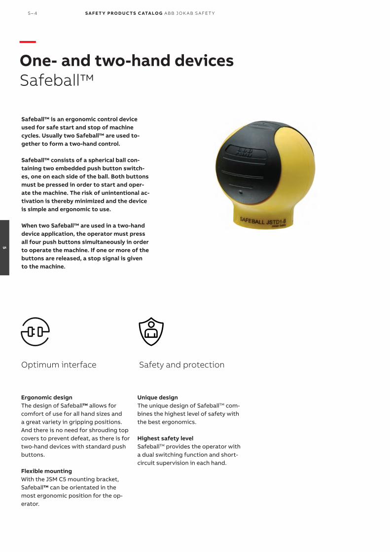
Safeball™ is an ergonomic control device used for safe start and stop of machine cycles. Usually two Safeball™ are used to-gether to form a two-hand control.
Safeball™ consists of a spherical ball con-taining two embedded push button switch-es, one on each side of the ball. Both buttons must be pressed in order to start and oper-ate the machine. The risk of unintentional ac-tivation is thereby minimized and the device is simple and ergonomic to use. When two Safeball™ are used in a two-hand device application, the operator must press all four push buttons simultaneously in order to operate the machine. If one or more of the buttons are released, a stop signal is given to the machine.
Unique designThe unique design of SafeballTM com-bines the highest level of safety with the best ergonomics.
Highest safety levelSafeballTM provides the operator with a dual switching function and short-circuit supervision in each hand.
Safety and protection
Ergonomic designThe design of Safeball™ allows for comfort of use for all hand sizes and a great variety in gripping positions. And there is no need for shrouding top covers to prevent defeat, as there is for two-hand devices with standard push buttons.
Flexible mountingWith the JSM C5 mounting bracket, Safeball™ can be orientated in the most ergonomic position for the op-erator.
Optimum interface
—One- and two-hand devicesSafeball™
5 – 4 S A F E T Y PRO D U C T S C ATA LO G A B B J O K A B S A FE T Y
5

One-hand control deviceOne Safeball™ can be used as an ergonomic “hold to run” button, i.e. the movement is allowed as long as both push buttons on Safeball™ are pressed, usually when the opera-tor cannot reach the hazardous area with his/her free hand, or on less dangerous machines. SafeballTM is a very practical one-hand control device since it is very easy to locate and activate.
—Applications and featuresSafeball™
Applications
Two-hand control deviceA two-hand control device is often used for machines withmanual loading or unloading. The operator uses the two-handcontrol device to safely start a machine cycle. A two-hand control must be used with a safety control device that makes sure that both buttons are pressed simultaneously, i.e. both hands are on the control and therefore outside the dangerous zone, in order to start the dangerous movement. Using two SafeballTM, it is easy to realize a custom two-hand device.
Features
Mounting methodsSafeball™ can be mounted in many different ways. It can be mounted on a table, on the machine, on a support or wherever suitable for ergonomic reasons. Safeball™ can be mounted in a fixed position or on a tilting and/or rotating support when used with a JSM C5. This flexibility in mount-ing enhances ergonomics and minimizes work-related mus-culoskeletal disorders.
When two Safeball™ are used as a two-hand device, no shrouding top cover is necessary to prevent defeat, as it is for two-hand devices with push buttons, since it is very dif-ficult to push all 4 push buttons of the two Safeball™ with e.g. a hand and an elbow.
Highest level of safetyWhen used as a two-hand control device, a safety control-ler for two-hand devices must be used, like an appropriate Sentry safety relay or a Pluto programmable safety control-ler. The safety controller monitors that all four push buttons (i.e. on each side of both Safeball™) are pressed within 0.5 second, in order to detect e.g. a short circuit or fraud, like a rubber band around one device. Safeball™ is certified to comply with type III C according to EN 574+A1:2008.
JSTD25The JSTD25 control stations are pre-built two-hand devices utilizing the good ergonomics of Safeball™. They can be used as fixed devices that are easy to install, or as mobile devices. All models are equipped with shields to protect the buttons from accidental operation, and also protect from damage if the device is dropped on the floor when used as mobile device. All versions meet EN 574 and EN ISO 13849-1.
CO NTR O L D E V I CE S 5 – 5
5

—Ordering informationSafeball™
2TLC
010
041
F020
1
Safeball™
Types of switches Cable length Type Order code
1 NO + 1 NC 2 m JSTD1-A 2TLA020007R3000
0.2 m JSTD1-B 2TLA020007R3100
10 m JSTD1-C 2TLA020007R3200
2 NO 0.2 m JSTD1-E 2TLA020007R3400
Extra feature Connector male Type Order code
None M12-5 JSTD25F 2TLA020007R6000
M12-8 JSTD25H 2TLA020007R6300
Pre-mounted Smile 10 EK emergency stop button M12-8 JSTD25K 2TLA020007R6900
JSMC5
2TLC
1721
94F0
201
JSMC7
2TLC
1721
95F0
201
JSTD25F
2TLC
1720
86F0
201
2TLC
1726
81F0
201
JSTD25K
Description Type Order code
Mounting bracket for JSTD1 with orientation possibility (ball joint) JSM C5 2TLA020007R0900
Suspension shelf for JSTD25F/H/K JSM C7 2TLA020007R1200
Protection coat for Safeball Safeball coat 2TLA020007R1900
—Safeball™ JSTD1
—Two-hand control devices JSTD25
—Accessories
5 – 6 S A F E T Y PRO D U C T S C ATA LO G A B B J O K A B S A FE T Y
5

—Cables and connectorsSafeball™
Connector Female/male Length Special feature Type Order code
M12-5 Female 3 m M12-C31 2TLA020056R0500
6 m M12-C61 2TLA020056R0000
Harsh environment, halogen free M12-C61HE 2TLA020056R8000
10 m M12-C101 2TLA020056R1000
Harsh environment, halogen free M12-C101HE 2TLA020056R8100
20 m M12-C201 2TLA020056R1400
Female + male 0.3 m M12-C0312 2TLA020056R5800
0.06 m M12-C00612 2TLA020056R6300
1 m M12-C112 2TLA020056R2000
3 m M12-C312 2TLA020056R2100
6 m M12-C612 2TLA020056R2200
10 m M12-C1012 2TLA020056R2300
Angled female connector M12-C1012V2 2TLA020056R6700
16 m M12-C1612 2TLA020056R5400
20 m M12-C2012 2TLA020056R2400
Male 6 m M12-C62 2TLA020056R0200
10 m M12-C102 2TLA020056R1200
M12-8 Female 6 m M12-C63 2TLA020056R3000
10 m M12-C103 2TLA020056R4000
20 m M12-C203 2TLA020056R4100
Female + male 0.06 m M12-C00634 2TLA020056R6400
1 m M12-C134 2TLA020056R5000
3 m M12-C334 2TLA020056R5100
M12-C61
2TLC
1729
51F0
201
Description Type Order code
Connectors
M12-5 pole female, straight M12-C01 2TLA020055R1000
M12-5 pole male, straight M12-C02 2TLA020055R1100
M12-8 pole female, straight M12-C03 2TLA020055R1600
M12-8 pole male, straight M12-C04 2TLA020055R1700
Cable with 5 conductors
10 m cable with 5 x 0.34 shielded conductors C5 cable 10 m 2TLA020057R0001
50 m cable with 5 x 0.34 shielded conductors C5 cable 50 m 2TLA020057R0005
100 m cable with 5 x 0.34 shielded conductors C5 cable 100 m 2TLA020057R0010
200 m cable with 5 x 0.34 shielded conductors C5 cable 200 m 2TLA020057R0020
500 m cable with 5 x 0.34 shielded conductors C5 cable 500 m 2TLA020057R0050
Cable with 8 conductors
50 m cable with 8 x 0.34 shielded conductors C8 cable 50 m 2TLA020057R1005
100 m cable with 8 x 0.34 shielded conductors C8 cable 100 m 2TLA020057R1010
200 m cable with 8 x 0.34 shielded conductors C8 cable 200 m 2TLA020057R1020
500 m cable with 8 x 0.34 shielded conductors C8 cable 500 m 2TLA020057R1050
C5 cable
2TLC
010
038F
020
1
M12-C334
2TLC
1729
31F0
201
M12-C61HE
2TLC
010
003
F020
1
M12-C01
2TLC
1726
57F0
201
—Cable with connectors
—Separate cables and connectors
CO NTR O L D E V I CE S 5 – 7
5

Technical dataApprovals
Conformity 2006/42/EC - MachineryEN ISO 12100:2010, EN 574+A1:2008
Functional safety data
EN/IEC 61508:2010 Up to SIL3, depending on system architecture
EN/IEC 62061:2005+A1:2013 Up to SILCL3, depending on system architecture
EN ISO 13849-1:2008 Up to Cat. 4, PL e, depending on systemMechanical data
Operating force Approx. 2N
Life, mechanical > 1 x 10⁶ operations at max 1 Hz
Connection cable
JSTD1-A PVC-cable, 4 x 0.75 mm2, L = 2 m
JSTD1-B, JSTD1-E Wires, 4 x 0.75 mm2, L = approx. 0.2 m
JSTD1-C PVC-cable, 4 x 0.75 mm2, L = 10 m
Protection class IP67. Not intended for use under water
Ambient temperature -25 °C to +50 °C (operating)
Material JSTD1 Polypropylene
Weight JSTD1
With 2 m cable 0.2 kg
With 10 m cable 0.7 kg
With 4 x 0.2 m wires 0.1 kg
—Technical dataSafeball™
More informationFore more information, e.g. the complete technical information, see product manual for:Safeball 2TLC172182M0201 Connection diagramsFor Safeball connection diagrams please see https://library.abb.com/
5 – 8 S A F E T Y PRO D U C T S C ATA LO G A B B J O K A B S A FE T Y
5

—Dimension drawingsSafeball™
Safeball™
JSTD25F
All dimensions in mm
CO NTR O L D E V I CE S 5 – 9
5

JSHD4 is a three-position device used to allow a limited movement of the machine when the operator is in the dangerous area, for example during troubleshooting, test running and programming.
The operator pushes the larger black button to a middle position in order to allow a movement. In case of danger, the operator will either release the button or squeeze it to its bottom position and the machine will stop.
JSHD4 is available with different types of connectors for an optimal adaptation to the application. Some models offer additional top and front button to control a non-safe signal, for ex. move forward and/or backward.
Cheat-safe hand recognitionAll JSHD4 models comply with PL e/Cat 4. Some models offer an “anti-tamper” function: an extra signal indicate if the JSHD4 is held in the middle position by a human hand. A machine movement will be authorized only in presence of this signal and not if the device is held in run position by any other (fraudulent) mean.
Safety and protection Continuous operation
Ergonomic shape and operation JSHD4 is ergonomic, both in respect of its shape, fitting to the hand, and the way the buttons are operated. JSHD4 is easy to operate using just the fingers (even with gloves), and the middle position provides a safe resting position.
Optimum interface
Safely inspect a running machineJSHD4 allows the operators to safely inspect the manufacturing process without completely stopping the ma-chine.
—Three-position device JSHD4
5 – 10 S A F E T Y PRO D U C T S C ATA LO G A B B J O K A B S A FE T Y
5

Safe troubleshooting, programming and testingIf the operator has to enter a risk area for troubleshooting or test running, it is extremely important that he/she is able to stop the machinery without having to rely on someone else pushing a stop button. In addition, no-one else should be able to start the machinery after it has been stopped by the operator. An operator who is under pressure must also be able to give a stop signal, whether in panic he/she pushes harder on the button or just releases it.
—Applications and featuresJSHD4
Applications
JSHD4 three-position control device can be used for trou-bleshooting, programming and test running in situations where no other protection is available or feasible. JSHD4 allows the operator to safely inspect the process without completely stopping the machine. The big black button has 3 distinct positions: released, pressed gently and pressed hard. The middle position allows the machine to run with limited speed or range, but when released or pressed hard the machine stops.
Hand recognition for protection against tamperingAn optional “anti-tamper” function sends an extra signal to indicate if the JSHD4 is held by a human hand or not. By us-ing this, the safety level is increased, and the risk of manipu-lation or bypass of the safety function is reduced. It is no longer possible to expose the operator to danger by trying to lock the three-position control device in run mode.
Ergonomic designJSHD4 is ergonomic, both in respect of its shape, fitting to the hand and the way the buttons are operated. It is easy to operate the device by using just the fingers (even with gloves), and the middle position provides a secure resting position.
Features
Additional top and front buttons for non-safe signals The two additional buttons can be used for e.g. start/stop, up/down or forward/ back. These buttons should not be used for safety related functions.
CO NTR O L D E V I CE S 5 – 11
5

—Ordering informationJSHD4
Top part Bottom part Anti-Buttons and LEDs Feature ID Connection tamper Type Order code
JSHD4-1 Use your own cable AA Cable gland and 5 screw connections
JSHD4-1-AA 2TLA019995R0000
No LEDs No buttons
Cost effective and quick connection AC M12-5 male JSHD4-1-AC 2TLA019995R0100
Holder for Eva (used with JSM54) AL Cable gland and 10 screw connections
JSHD4-1-AL Order separate parts
JSHD4-2 Cost effective and robust AB Cannon 12 male pins JSHD4-2-AB 2TLA019995R0200
LEDs Front button Top button
JSHD4-2-AB-A Order separate parts
Cost effective and quick connection AD M12-8 male JSHD4-2-AD 2TLA019995R0400
JSHD4-2-AD-A Order separate parts
Use your own cable, simplified connection
AH Cable gland and 10 screw connections
JSHD4-2-AH 2TLA019995R0800
JSHD4-2-AH-A Order separate parts
Use your own cable, full pin connection
AJ Cable gland and 16 screw connections
JSHD4-2-AJ Order separate parts
JSHD4-2-AJ-A Order separate parts
Replacement of old units* AK Cannon 12 male pins JSHD4-2-AK 2TLA019995R4800
Holder for Eva (used with JSM54) AL Cable gland and 10 screw connections
JSHD4-2-AL Order separate parts
JSHD4-2-AL-A Order separate parts
JSHD4-3 Cost effective and robust AB Cannon 12 male pins JSHD4-3-AB Order separate parts
LEDs No buttons
JSHD4-3-AB-A Order separate parts
Cost effective and quick connection AD M12-8 male JSHD4-3-AD Order separate parts
JSHD4-3-AD-A Order separate parts
E-stop AE M12-8 male JSHD4-3-AE Order separate parts
Use your own cable, simplified connection
AH Cable gland and 10 screw connections
JSHD4-3-AH 2TLA019995R2000
JSHD4-3-AH-A Order separate parts
Use your own cable, full pin connection
AJ Cable gland and 16 screw connections
JSHD4-3-AJ Order separate parts
JSHD4-3-AJ-A Order separate parts
Replacement of old units* AK Cannon 12 male pins JSHD4-3-AK Order separate parts
Holder for Eva (used with JSM54) AL Cable gland and 10 screw connections
JSHD4-3-AL Order separate parts
JSHD4-3-AL-A Order separate parts
JSHD4-4 Cost effective and robust AB Cannon 12 male pins JSHD4-4-AB Order separate parts
LEDs Front button
JSHD4-4-AB-A Order separate parts
Cost effective and quick connection AD M12-8 male JSHD4-4-AD Order separate parts
JSHD4-4-AD-A Order separate parts
Use your own cable, simplified connection
AH Cable gland and 10 screw connections
JSHD4-4-AH Order separate parts
JSHD4-4-AH-A Order separate parts
Use your own cable, full pin connection
AJ Cable gland and 16 screw connections
JSHD4-4-AJ Order separate parts
JSHD4-4-AJ-A Order separate parts
Replacement of old units* AK Cannon 12 male pins JSHD4-4-AK Order separate parts
Holder for Eva (used with JSM54) AL Cable gland and 10 screw connections
JSHD4-4-AL Order separate parts
JSHD4-4-AL-A Order separate parts
JSHD4-5 Cost effective and robust AB Cannon 12 male pins JSHD4-5-AB Order separate parts
LEDs Top button
JSHD4-5-AB-A Order separate parts
Cost effective and quick connection AD M12-8 male JSHD4-5-AD Order separate parts
JSHD4-5-AD-A Order separate parts
Use your own cable, simplified connection
AH Cable gland and 10 screw connections
JSHD4-5-AH Order separate parts
JSHD4-5-AH-A Order separate parts
Use your own cable, full pin connection
AJ Cable gland and 16 screw connections
JSHD4-5-AJ Order separate parts
JSHD4-5-AJ-A Order separate parts
Replacement of old units* AK Cannon 12 male pins JSHD4-5-AK Order separate parts
Holder for Eva (used with JSM54) AL Cable gland and 10 screw connections
JSHD4-5-AL Order separate parts
JSHD4-5-AL-A Order separate parts
* See document 2TLC010007L0201 for information about replacement
JSHD4-1-AC
2TLC
010
00
5V0
201
JSHD4-2-AB
2TLC
010
014
F020
1
JSHD4-2-AH
2TLC
010
013
F020
1
JSHD4-2-AD
2TLC
010
015
F020
1
Top part
Bottom part
—Complete list of JSHD4 modelsThis list shows the possible combination of features. Some combinations can be ordered pre-assembled with a single order code. Other combinations need to be ordered in separate parts (see next page).
5 – 12 S A F E T Y PRO D U C T S C ATA LO G A B B J O K A B S A FE T Y
5
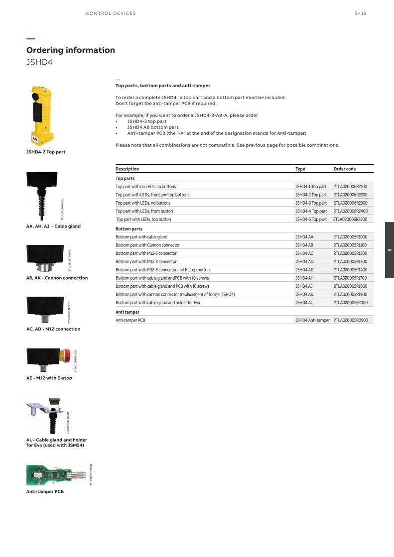
—Ordering informationJSHD4
Description Type Order code
Top parts
Top part with no LEDs, no buttons JSHD4-1 Top part 2TLA020006R2100
Top part with LEDs, front and top buttons JSHD4-2 Top part 2TLA020006R2200
Top part with LEDs, no buttons JSHD4-3 Top part 2TLA020006R2300
Top part with LEDs, front button JSHD4-4 Top part 2TLA020006R2400
Top part with LEDs, top button JSHD4-5 Top part 2TLA020006R2500
Bottom parts
Bottom part with cable gland JSHD4 AA 2TLA020005R1000
Bottom part with Cannon connector JSHD4 AB 2TLA020005R1100
Bottom part with M12-5 connector JSHD4 AC 2TLA020005R1200
Bottom part with M12-8 connector JSHD4 AD 2TLA020005R1300
Bottom part with M12-8 connector and E-stop button JSHD4 AE 2TLA020005R1400
Bottom part with cable gland andPCB with 10 screws JSHD4 AH 2TLA020005R1700
Bottom part with cable gland and PCB with 16 screws JSHD4 AJ 2TLA020005R1800
Bottom part with cannon connector (replacement of former JSHD4) JSHD4 AK 2TLA020005R1900
Bottom part with cable gland and holder for Eva JSHD4 AL 2TLA020005R2000
Anti tamper
Anti-tamper PCB JSHD4 Anti-tamper 2TLA020005R0900
—Top parts, bottom parts and anti-tamper
To order a complete JSHD4, a top part and a bottom part must be included. Don’t forget the anti-tamper PCB if required.
For example, if you want to order a JSHD4-3-AB-A, please order• JSHD4-3 top part• JSHD4 AB bottom part• Anti-tamper PCB (the “-A” at the end of the designation stands for Anti-tamper)
Please note that all combinations are not compatible. See previous page for possible combinations.
AA, AH, AJ - Cable gland
2TLC
1721
56F0
201
AB, AK - Cannon connection
2TLC
1721
57F0
201
AE - M12 with E-stop
2TLC
1721
59F0
202
AL - Cable gland and holder for Eva (used with JSM54)
2TLC
1720
47V
020
1
AC, AD - M12 connection
2TLC
1721
58F0
201
Anti-tamper PCB
2TLC
1721
61F0
201
JSHD4-2 Top part
CO NTR O L D E V I CE S 5 – 13
5

Description Type Order code
Connectors
M12-5 pole female, straight M12-C01 2TLA020055R1000
M12-5 pole male, straight M12-C02 2TLA020055R1100
M12-8 pole female, straight M12-C03 2TLA020055R1600
M12-8 pole male, straight M12-C04 2TLA020055R1700
12-pole female cannon connector for JSHD4 JSHK0 2TLA020003R0300
Cable with 5 conductors
10 m cable with 5 x 0.34 shielded conductors C5 cable 10 m 2TLA020057R0001
50 m cable with 5 x 0.34 shielded conductors C5 cable 50 m 2TLA020057R0005
100 m cable with 5 x 0.34 shielded conductors C5 cable 100 m 2TLA020057R0010
200 m cable with 5 x 0.34 shielded conductors C5 cable 200 m 2TLA020057R0020
500 m cable with 5 x 0.34 shielded conductors C5 cable 500 m 2TLA020057R0050
Cable with 8 conductors
50 m cable with 8 x 0.34 shielded conductors C8 cable 50 m 2TLA020057R1005
100 m cable with 8 x 0.34 shielded conductors C8 cable 100 m 2TLA020057R1010
200 m cable with 8 x 0.34 shielded conductors C8 cable 200 m 2TLA020057R1020
500 m cable with 8 x 0.34 shielded conductors C8 cable 500 m 2TLA020057R1050
C5 cable
M12-C01
—Separate cables and connectors
2TLC
010
038F
020
1
2TLC
1726
57F0
201
—Cables and connectorsJSHD4
Connector Female/male Length Special feature Type Order code
M12-5 Female 3 m M12-C31 2TLA020056R0500
6 m M12-C61 2TLA020056R0000
Harsh environment, halogen free M12-C61HE 2TLA020056R8000
10 m M12-C101 2TLA020056R1000
Harsh environment, halogen free M12-C101HE 2TLA020056R8100
20 m M12-C201 2TLA020056R1400
Female + male 0.3 m M12-C0312 2TLA020056R5800
0.06 m M12-C00612 2TLA020056R6300
1 m M12-C112 2TLA020056R2000
3 m M12-C312 2TLA020056R2100
6 m M12-C612 2TLA020056R2200
10 m M12-C1012 2TLA020056R2300
16 m M12-C1612 2TLA020056R5400
20 m M12-C2012 2TLA020056R2400
Male 6 m M12-C62 2TLA020056R0200
10 m M12-C102 2TLA020056R1200
M12-8 Female 6 m M12-C63 2TLA020056R3000
10 m M12-C103 2TLA020056R4000
20 m M12-C203 2TLA020056R4100
Female + male 0.06 m M12-C00634 2TLA020056R6400
1 m M12-C134 2TLA020056R5000
3 m M12-C334 2TLA020056R5100
Cannon Female 5 m HK5 2TLA020003R4700
10 m HK10 2TLA020003R4800
20 m HK20 2TLA020003R4900
1.6 m Spiral cable HK16S4 2TLA020003R5000
2 m Spiral cable HK20S4 2TLA020003R5100
3.2 m Spiral cable HK32S4 2TLA020003R5200
4 m Spiral cable HK40S4 2TLA020003R3500
6 m Spiral cable HK60S4 2TLA020003R3600
8 m Spiral cable HK80S4 2TLA020003R5300
M12-C61
2TLC
1729
51F0
201
M12-C334
2TLC
1729
31F0
201
M12-C61HE
HK20S4
—Cable with connectors
5 – 14 S A F E T Y PRO D U C T S C ATA LO G A B B J O K A B S A FE T Y
5

JSM 50G bracket for key switches and JSM 5B wall bracket for 2 pcs MKey5
JSM 50G
JSM 5B
—AccessoriesJSHD4
JSHD4 protection coat
JSM 54A wall bracket for Adam (and AL bottom part that has a holder for Eva)
JSM 54A
JSM 55
JSM 55 wall bracket and JSM 50H bracket for Eden
JSM 50H
Description Type Order code
Brackets and bottom plates
JSM 55 Wall bracket for three position device JSM 55 2TLA040005R0500
JSM 5B Wall bracket for 2 pcs MKey5 interlock switches JSM 5B 2TLA040005R0700
JSM 54A Wall bracket for Adam. Used with AL bottom part that has a holder for Eva JSM 54A 2TLA020205R2800
JSM 50G Bracket for key switches JSM 50G 2TLA020205R6300
JSM 50H Bracket for Eden sensor JSM 50H 2TLA020205R6400
Others
JSHD4 protection coat JSHD4 Coat 2TLA020200R4600
2TLC
1723
51F0
201
—Accessories
CO NTR O L D E V I CE S 5 – 15
5

—Electrical wiring diagramsExamples with JSHD4-1 and JSHD4-2 models
JSHD4-2-AD-A, M12-8
JSHD4-2-AK, Cannon 12 pins
JSHD4-2-AB-A, Cannon 12 pins
JSHD4-1-AA, cable gland and 5 screw connections on JSHD4-1
5 – 16 S A F E T Y PRO D U C T S C ATA LO G A B B J O K A B S A FE T Y
5

—Electrical wiring diagramsExamples with JSHD4-2 models
JSHD4-2-AJ-A, cable gland and 16 screw connection
JSHD4-2-AL-A, cable gland and 10 screw connection
JSHD4-2-AB-A, Cannon 12 pins
JSHD4-2-AH-A, cable gland and 10 screw connection
CO NTR O L D E V I CE S 5 – 17
5

—Technical data and dimension drawingsJSHD4
Technical dataApprovals
Conformity2006/42/EC - Machines2014/30/EU - EMC2011/65/EU - RoHSEN ISO 12100-1:2010, EN ISO 13849-1:2015, EN ISO 13849-2:2012, EN 60204-1:2006+A1:2009, EN 61000-6-2:2005, EN 61000-6-3:2007
Functional safety data
EN ISO 13849-1:2016 Up to PL e (depending on number of operations per year)B10d: 2 000 000 to middle position, 968 000 to bottom position
Electrical data
Current allowed, three-position button Per channel: Maximum +30 VDC, 20 mA, (Minimum +10 VDC, 8 mA)
Current allowed, extra button Maximum 500 mA
Operation force Approx. 15 N for three-position buttons (ON)
Approx. 45 N for three-position buttons (OFF)
Approx. 2.5 N for top/front push button
Mechanical data
Operating temperature - 10 …+50 °C
Protection class IP65
Mechanical life 1 000 000 cycles to middle position
Weight Approx. 0.2 kg without cable
Dimension drawings
All dimensions in mm
142
235
78
111
JSHD4-2-AD
JSHD4-2-AL
142
235
78
111
More informationFore more information, e.g. the complete technical information, see product manual for:JSHD4 2TLC172072M0201
5 – 18 S A F E T Y PRO D U C T S C ATA LO G A B B J O K A B S A FE T Y
5

CO NTR O L D E V I CE S 5 – 19
5

S A F E T Y PRO D U C T S C ATA LO G A B B J O K A B S A FE T Y
6

—Emergency stops and pilot devices
6– 2 Introduction and overview
6– 6 Emergency stop buttons
Smile, INCA, EStrong and Compact
6– 16 Safety stop buttons
Smile, INCA, and Compact
6– 24 Pull wire emergency stop switch
LineStrong
6– 34 Push-button box
Smile 41
6– 40 Reset button
Smile
6– 46 Pilot devices
Modular and Compact range
EM ER G EN C Y S TO P S A N D PI LOT D E V I CE S 6 – 1
6

—Introduction and overviewSelection guide
ABB offers a full range of buttons and pull wires for emergency stop functions, as well as pilot devices for e.g. reset functions.
Emergency stop buttons Safety stop buttons Reset buttons Pull wire emergency stop switches Push button boxes Pilot devices
Name Smile, Inca, EStrong, Compact Smile, Inca, Compact Smile Name LineStrong Smile 41 Modular range, compact rangeImage Image
Description Emergency stop buttons for external mounting and panel mounting in different sizes and material
Safety stop buttons for external mounting and panel mounting
Small and easy to install reset button
Description Emergency stop switches in robust enclosures for pull wires of various lengths.
Gathers up to four push but-tons, including emergency stop, in a single compact device
Push buttons, selector switch-es, pilot lights, joysticks and signal towers in a compact and robust design
Applications Safely stop dangerous machine functions
Safely stop a limited part of a dangerous machine
Pushbutton for resetting safety devices
Applications Emergency stop line to safely stop conveyor belts and long transporta-tion lines.
Emergency stop and pushbuttons in one device
For control and indication of ma-chines and processes
Advantages Models with:- Compact size- Robust enclosure for harsh environments- Quick installation with M12 connectors- LED indication
Models with:- Compact size- Robust enclosure for harsh environments- Quick installation with M12 connectors- LED indication
- Compact size- Quick installation- M12 connector- LED indication
Advantages - Up to 200 m wire with one switch- Reliable mechanical connection- Robust construction
- Compact size- Quick installation- M12 connector- LED indication- Highly adaptable with several
button colors
- Compact size- Up to IP69K- Long life-time thanks to self-cleaning contacts- Quick snap-on design for simple installation without tools
6 – 2 S A F E T Y PRO D U C T S C ATA LO G A B B J O K A B S A FE T Y
6

Emergency stop buttons Safety stop buttons Reset buttons Pull wire emergency stop switches Push button boxes Pilot devices
Name Smile, Inca, EStrong, Compact Smile, Inca, Compact Smile Name LineStrong Smile 41 Modular range, compact rangeImage Image
Description Emergency stop buttons for external mounting and panel mounting in different sizes and material
Safety stop buttons for external mounting and panel mounting
Small and easy to install reset button
Description Emergency stop switches in robust enclosures for pull wires of various lengths.
Gathers up to four push but-tons, including emergency stop, in a single compact device
Push buttons, selector switch-es, pilot lights, joysticks and signal towers in a compact and robust design
Applications Safely stop dangerous machine functions
Safely stop a limited part of a dangerous machine
Pushbutton for resetting safety devices
Applications Emergency stop line to safely stop conveyor belts and long transporta-tion lines.
Emergency stop and pushbuttons in one device
For control and indication of ma-chines and processes
Advantages Models with:- Compact size- Robust enclosure for harsh environments- Quick installation with M12 connectors- LED indication
Models with:- Compact size- Robust enclosure for harsh environments- Quick installation with M12 connectors- LED indication
- Compact size- Quick installation- M12 connector- LED indication
Advantages - Up to 200 m wire with one switch- Reliable mechanical connection- Robust construction
- Compact size- Quick installation- M12 connector- LED indication- Highly adaptable with several
button colors
- Compact size- Up to IP69K- Long life-time thanks to self-cleaning contacts- Quick snap-on design for simple installation without tools
EM ER G EN C Y S TO P S A N D PI LOT D E V I CE S 6 – 3
6

Why an emergency stop is necessaryIf a machine breaks down or if someone is in danger, anyone should be able to stop the ma-chine, regardless of their knowledge of the specific application.
When a safety stop could be usedA safety stop (also called machine stop) should be used to safely stop a part of the machine, e.g. as a stop for an individual hazardous motion. It should not be used as an emergency stop and stop the complete machine. Likewise, an emergency stop with red push button must not be used as a safety stop.
In order to separate the safety stop function from the emergency stop function, the safety stop buttons should be colored black.
When a pull wire emergency stop could be usedA pull wire emergency stop is easier to install than a system of several emergency stop buttons along a carriage path which makes it ideal for installations over long distances. LineStrong can handle wires up to 200 m on one single switch and the emergency command can be initiated from any point along the installed wire length.
—Introduction and overviewSelection orientation
6 – 4 S A F E T Y PRO D U C T S C ATA LO G A B B J O K A B S A FE T Y
6

—Introduction and overviewStandards
Text and symbolsNeither the emergency stop nor its background should be labelled with text or symbols. It has previously been common with white arrows indicating the direction of unlatching, but this is not allowed anymore.
Location and signsThe risk assessment should determine the locations of the emergency stop buttons, but they should in general be placed at operator stations, at locations where man/machine interaction is required and at entry/exit points. Signs to mark the location of emergency stops are not required, but if used they should be green with white markings.
Important standards to follow when implementing emergency stop functions are e.g. EN ISO 13850 and EN ISO 60204-1.
Stop categoriesThe following stop categories are defined in the standards:
Stop Category 0 stopping by immediate removal of power to the machine actuators
Stop Category 1 a controlled stop with power available to the machine actuators to achieve the stop and then removal of power when the stop is achieved
Stop Category 2 a controlled stop with power left available to the actuators
Note that these categories should not be confused with the categories used to describe the architecture when calculating PL in EN ISO 13849. The risk assessment should determine which stop category to use, but stop category 2 is normally considered not to be suitable for emergency stops.
EM ER G EN C Y S TO P S A N D PI LOT D E V I CE S 6 – 5
6

Easy to install
Compact sizeModels with a compact and appealing housing saves space and makes it easy to place.
Quick installationQuick and easy installation of models with features such as centered mount-ing holes, removable terminal blocks and M12 connectors.
Serial connectionTina models save cable length and in-stallation time with serial connection.
Emergency stop buttons are used to safely stop dangerous machine func-tions.
ABB offers a wide range of emergency stop buttons for external mounting or panel mounting, with plastic or metal housing and for different types of connections.
Highly adaptableSeveral models to choose between depending on position, installation and function.
Reliable in extreme conditionsRobust models and models in stainless steel for use in demanding environ-ments.
Optimum interface
LED diagnosticsModels with integrated LED diagnos-tics reduce downtime when trouble-shooting.
Continuous operation
—Emergency stop buttonsSmile, INCA, EStrong and Compact
6 – 6 S A F E T Y PRO D U C T S C ATA LO G A B B J O K A B S A FE T Y
6

—Models and applicationEmergency stop buttons
SmileSmile is a small and easy to install emergency stop button. Its size allows mounting in reduced spaces, and its cen-tered mounting holes makes it especially easy to mount on aluminum extrusions (e.g. Quick-Guard fencing system). Smile is available with M12 connectors or cable.Smile has an integrated LED in the button that shows the status and simplifies error tracking.The standard models of Smile have 2 contacts and can be used with safety controllers from all brands. Smile Tina models belong to the ABB DYNlink solution, with the ad-vantages of serial connection using only one channel and still reaching Cat. 4/PL e.
Models for external mounting
Emergency stop buttons are used to safely stop a danger-ous machine function in order to prevent an accident, or minimize the consequences of an accident. An emergency stop should be a complement to other safety devices, and not a replacement for them.
Application
EStrongEStrong is an emergency stop button designed to provide a robust unit in exposed and severe environments. The unit has a stainless steel enclosure with IP69K rating that with-stands high pressure and high temperature wash-down. It is therefore ideally suited for industries with special demands, such as food processing or chemical industry.
CompactCompact emergency stop buttons offer a robust enclosure with a high IP rating that fulfill the demands in severe and humid environments, such as food and beverage industry. Compact can be fitted with a Tina adapter for use in a DYN-link solution (Tina 2A, Tina 2B or Tina 3A).
Models for panel mounting
INCAINCA is an emergency stop button for panel mounting, designed for installation in 22.5 mm holes. Its removable terminal block facilitates connection and exchange. INCA has an integrated LED in the button that shows the status and simplifies error tracking. The standard model of INCA has 2 contacts and can be used with safety controllers from all brands. INCA Tina models belongs to the ABB DYNlink solution, with the advantages of serial connection using only one channel and still reaching Cat. 4/PL e.
Smile ReverseSmile Reverse is identical to the regular Smile emergency stop button besides from being reversed in order to be mounted on the back side of a panel. Smile Reverse has an IP65 housing that makes it suitable in panels where mois-ture and dust may occur. Smile Reverse has an integrated LED in the button that shows the status and simplifies error tracking. The standard model of Smile Reverse has 2 contacts and can be used with safety controllers from all brands. The Smile Reverse Tina model belongs to the ABB DYNlink solution, with the advantages of serial connection using only one channel and still reaching Cat. 4/PL e.
EM ER G EN C Y S TO P S A N D PI LOT D E V I CE S 6 – 7
6

—FeaturesEmergency stop buttons
DYNlinkEmergency stop buttons with Tina in their name belong to the DYNlink solution, which enables serial connection using only one channel and still reaching Cat. 4/PL e. DYNlink devices must be used with Vital safety controller or Pluto programmable safety controller. Up to 30 DYNlink devices can be connected in series to Vital and up to 10 can be con-nected to each input on Pluto.
Communication features
StatusBusStatusBus is a simple and cost effective way to collect the status information of emergency stops and safety sen-sors. The StatusBus functionality is available with some DYNlink devices and allows to collect the status of each individual safety device, even when connected in series. A Pluto programmable safety controller must be used to read the StatusBus information, and a single input on Pluto can collect the status of up to 30 safety devices. The devices are connected using standard cable and M12-5 connectors. No specific bus cable or extra communication module is necessary.
6 – 8 S A F E T Y PRO D U C T S C ATA LO G A B B J O K A B S A FE T Y
6

—Ordering informationEmergency stop buttons
2TLC
1728
63F0
201
Smile 10 EA Tina
2TLC
1728
57F0
201
Smile 11 EC Tina
2TLC
1721
87F0
201
Smile 12 EA
2TLC
1726
89F0
201
EStrongZ and EStrongZ LED
Description Type of safety signal Connection type Feature Type Order code
Compact sizePlastic housingIP65
DYNlink 1 m cable from bottom Status LED Smile 10 EA Tina 2TLA030050R0400
1 x M12-5 male Status LED Smile 11 EA Tina 2TLA030050R0000
1 x M12-5 male Status LED, StatusBus
Smile 11 EC Tina 2TLA030050R0900
2 x M12-5 male Status LED Smile 12 EA Tina 2TLA030050R0200
2 NC 1 m cable from bottom Status LED Smile 10 EA 2TLA030051R0400
1 m leads from bottom - Smile 10 EK 2TLA030051R0600
1 x M12-5 male Status LED Smile 11 EA 2TLA030051R0000
2 x M12-5 male Status LED Smile 12 EA 2TLA030051R0200
Plastic housingIP66, IP67 and IP69K
2 NC* 2 x M20 conduits - CEPY1-1002 (Compact) 1SFA619821R1002
With shroud CEPY1-2002 (Compact) 1SFA619821R2002
Metal housingIP67 and IP69K
2 NO + 2 NC 3 x M20 conduits Status LED EStrongZ LED 2TLA050220R0222
- EStrongZ 2TLA050220R0020
* Can be adapted to DYNlink with Tina
IP rating Depth Connection type Type of safety signal Feature Type Order code
IP65 26 mm 1 x M12-5 male DYNlink Status LED Smile 11 EAR Tina 2TLA030050R0100
2 NC Status LED Smile 11 EAR 2TLA030051R0100
Button IP65, connector IP20
53 mm Removable termi-nal block
DYNlink Status LED INCA 1 Tina 2TLA030054R0000
Status LED,StatusBus
INCA 1 EC Tina 2TLA030054R1400
2 NC Status LED INCA 1 2TLA030054R0100
2TLC
1728
61F0
201
Smile 11 EAR
2TLC
1723
63F0
201
INCA 1
ABB Compact emergency stop shroud
—External mounting
—Panel mounting
EM ER G EN C Y S TO P S A N D PI LOT D E V I CE S 6 – 9
6

—AccessoriesEmergency stop buttons
2TLC
1720
34V
020
1
M12-3S
2TLC
1724
71F0
201
Tina 8A
2TLC
1729
06F
020
1
E-sign 22.5
Description Type Order code
Connection accessories
M12 Y-connector for serial connection of device with StatusBus functionality. M12-3S 2TLA020055R0600
M12 Y-connector for serial connection of devices without StatusBus functionality. M12-3A 2TLA020055R0000
Connection block for the serial connection of up to 4 DYNlink devices with 12-5 connectors. Tina 4A 2TLA020054R0300
Connection block for the serial connection of up to 8 DYNlink devices with 12-5 connectors. Tina 8A 2TLA020054R0500
Adaptation unit for DYNlink solution with M20 fitting. For e.g. Compact. Tina 2A* 2TLA020054R0100
Adaptation unit for DYNlink solution, internal assembly. For e.g. Compact. Tina 2B* 2TLA020054R1100
Adaptation unit for DYNlink solution with M20 fitting and M12 connector. For e.g. con-necting Compact to Pluto/Vital.
Tina 3A* 2TLA020054R0200
Termination for Smile 12 JST2 2TLA030051R1300
Accessories
Emergency stop sign, yellow, no text, for INCA (22.5mm) E-Sign 22.5 2TLA030054R0900
Emergency stop sign, yellow, no text, for Smile (32.5mm) E-Sign 32.5 2TLA030054R1000
Yellow surround for Inca Surround for Inca 2TLA030054R0400
Yellow shroud for Compact CA1-8053 1SFA619920R8053
Stainless steel cable gland, for EStrong Gland M20x1.5 2TLA050040R0002
Stainless steel conduit plug, for EStrong Conduit Plug M20x1.5 2TLA050040R0004
LED Green/Red 230 VAC, for EStrong LED 230 2TLA050211R0003
* For more information about Tina adapter units, please see Pluto and Vital chapters.
Connector Female/male Length Special feature Type Order code
M12-5 Female 3 m M12-C31 2TLA020056R0500
6 m M12-C61 2TLA020056R0000
Harsh environment, halogen free M12-C61HE 2TLA020056R8000
10 m M12-C101 2TLA020056R1000
Harsh environment, halogen free M12-C101HE 2TLA020056R8100
20 m M12-C201 2TLA020056R1400
Female + male 0.3 m M12-C0312 2TLA020056R5800
0.06 m M12-C00612 2TLA020056R6300
1 m M12-C112 2TLA020056R2000
3 m M12-C312 2TLA020056R2100
6 m M12-C612 2TLA020056R2200
10 m M12-C1012 2TLA020056R2300
Angled female connector M12-C1012V2 2TLA020056R6700
16 m M12-C1612 2TLA020056R5400
20 m M12-C2012 2TLA020056R2400
Male 6 m M12-C62 2TLA020056R0200
10 m M12-C102 2TLA020056R1200
M12-C61
2TLC
1729
51F0
201
M12-C61HE
2TLC
010
003
F020
1
—Connection accessories
—Cable with connectors
6 – 10 S A F E T Y PRO D U C T S C ATA LO G A B B J O K A B S A FE T Y
6

Description Type Order code
Connectors
M12-5 pole female, straight M12-C01 2TLA020055R1000
M12-5 pole male, straight M12-C02 2TLA020055R1100
Cable with 5 conductors
10 m cable with 5 x 0.34 shielded conductors C5 cable 10 m 2TLA020057R0001
50 m cable with 5 x 0.34 shielded conductors C5 cable 50 m 2TLA020057R0005
100 m cable with 5 x 0.34 shielded conductors C5 cable 100 m 2TLA020057R0010
200 m cable with 5 x 0.34 shielded conductors C5 cable 200 m 2TLA020057R0020
500 m cable with 5 x 0.34 shielded conductors C5 cable 500 m 2TLA020057R0050 C5 cable
2TLC
010
038F
020
1
M12-C01
2TLC
1726
57F0
201
—Separate cables and connectors
EM ER G EN C Y S TO P S A N D PI LOT D E V I CE S 6 – 11
6

—Technical dataEmergency stop buttons
Technical data
Approvals
Smile, INCA
Smile Tina, INCA Tina TÜV NORD
EStrong
Compact
ConformitySmile, INCA
2006/42/EC – Machinery2011/65/EU - RoHSEN ISO 12100:2010, EN ISO 13849-1:2008/AC:2009, EN 60204-1:2006+A1:2008, EN ISO 13850:2008
Smile Tina, INCA Tina 2006/42/EC - Machinery2004/108/EC - EMCEN ISO 12100:2010, EN ISO 13849-1:2008, EN 62061:2005, EN 60204-1:2006+A1:2009, IEC 60664-1:2007, EN 61000-6-2:2005, EN 61000-6-4:2007, EN 60947-5-5:2005, EN ISO 13850:2006
EStrong2006/42/EG – Machinery2011/65/EU - RoHSEN ISO 12100:2010, EN ISO 13850:2015, EN 60204-1:2006:+A1:2009+AC:2010, EN 60947-5-5:1997:+A1:2017, EN 60947-5-1:2004:+A1:2009
Compact2006/42/EC - Machinery2014/30/EU - EMCEN 60947-1:2007/A1:2011/A2:2014, EN 60947-5-1:2004/A1:2009, EN 60947-5-5:1997/A1:2005/A11:2013, EN ISO 13850:2008
Functional safety dataEN 61508:2010 Up to SIL3, depending on system architecture
EN 62061:2005 Up to SILCL3, depending on system architecture
EN ISO 13849-1:2008 Up to Cat. 4, PL e, depending on system architecture
Smile, INCA B10d = 100 000
Smile Tina, INCA Tina PFHD = 4.66 x 10⁻⁹
EStrong B10d = 1 500 000
Compact B10d = 250 000
6 – 12 S A F E T Y PRO D U C T S C ATA LO G A B B J O K A B S A FE T Y
6

—Technical dataEmergency stop buttons
Technical data
Electrical data
Operating voltage
Smile, INCA 17-27 VDC ± 10%
Smile Tina, INCA Tina +24 VDC +15% -25%
EStrong 230 VAC / +24 VDC (the LED is +24 VDC originally, but can be replaced with a 230 VAC accessory)
Compact 230 VAC / +24 VDC
Mechanical data
Mechanical life >50 000 operations
Operating temperature
Smile, INCA -10…+55 °C
EStrong -25…+80 °C
Compact -25…+70 °C
Protection class
Smile, INCA IP65
EStrong IP67, IP69K
Compact IP66, IP67, IP69K
WeightSmile 65 g
INCA 45 g
EStrong 820 g
Compact 108 g, 124 g (with shroud)
Material
Smile Polyamide PA66, Macromelt, polybutylenterephthalate PBT, Polypropene PP, UL 94 V0
INCA Polyamide PA66, Macromelt, polybutylenterephthalate PBT, Polypropene PP, UL 94 V0
EStrong Stainless steel 316 housing
Compact Polycarbonate
More informationFore more information, e.g. the complete technical information, see product manual for:Smile 2TLC172097M0201INCA 2TLC172163M0201EStrong 2TLC172247M0201Compact 1SFC151005C0201
Connection diagramsFor connection diagrams of emergency stop buttons please see https://library.abb.com/
EM ER G EN C Y S TO P S A N D PI LOT D E V I CE S 6 – 13
6

Smile
—Dimension drawingsEmergency stop buttons
INCA
All dimensions in mm
EStrong Compact (housing only)
Type L1mm
L2mm
INCA 1 EC Tina 75.5 49.5 ± 0.5
INCA 1 80 54 ± 0.5
INCA 1 Tina 80 54 ± 0.5
6 – 14 S A F E T Y PRO D U C T S C ATA LO G A B B J O K A B S A FE T Y
6

EM ER G EN C Y S TO P S A N D PI LOT D E V I CE S 6 – 15
6

Easy to install
Compact sizeModels with a compact and appealing housing saves space and makes it easy to place.
Quick installationQuick and easy installation of models with features such as centered mount-ing holes, removable terminal blocks and M12 connectors.
Serial connectionTina models save cable length and in-stallation time with serial connection.
Safety stop buttons are used to safely stop a certain part of a dangerous machine.
ABB offers safety stop buttons to suit different needs of connection and communication. Models are available for e.g. external mounting or panel mounting, in compact size or robust design, adapted for the DYNlink solu-tion or with 2 NC contacts.
Highly adaptableSeveral models to choose between depending on position, installation and function.
Reliable in extreme conditionsRobust models for use in demanding environments.
Optimum interface
LED diagnosticsModels with integrated LED diagnos-tics reduce downtime when trouble-shooting.
Continuous operation
—Safety stop buttonsSmile, INCA and Compact
6 – 16 S A F E T Y PRO D U C T S C ATA LO G A B B J O K A B S A FE T Y
6

—Applications and featuresSafety stop buttons
Applications
A safety stop (also called machine stop) can be used to safely stop a part of the machine, e.g. as a stop for an individual hazardous machine function. It may not be used as an emer-gency stop and stop the complete machine or production line. Likewise, an emergency stop with red push button should not be used as a safety stop. In order to separate the safety stop function from the emergency stop function, the safety stop buttons should be colored black.
Features
DYNlinkSafety stop buttons with Tina in their name belong to the DYN-link solution, which enables serial connection using only one channel and still reaching Cat. 4/PL e. DYNlink devices must be used with Vital safety controller or Pluto programmable safety controller. Up to 30 DYNlink devices can be connected in series to Vital and up to 10 can be connected to each input on Pluto.
EM ER G EN C Y S TO P S A N D PI LOT D E V I CE S 6 – 17
6
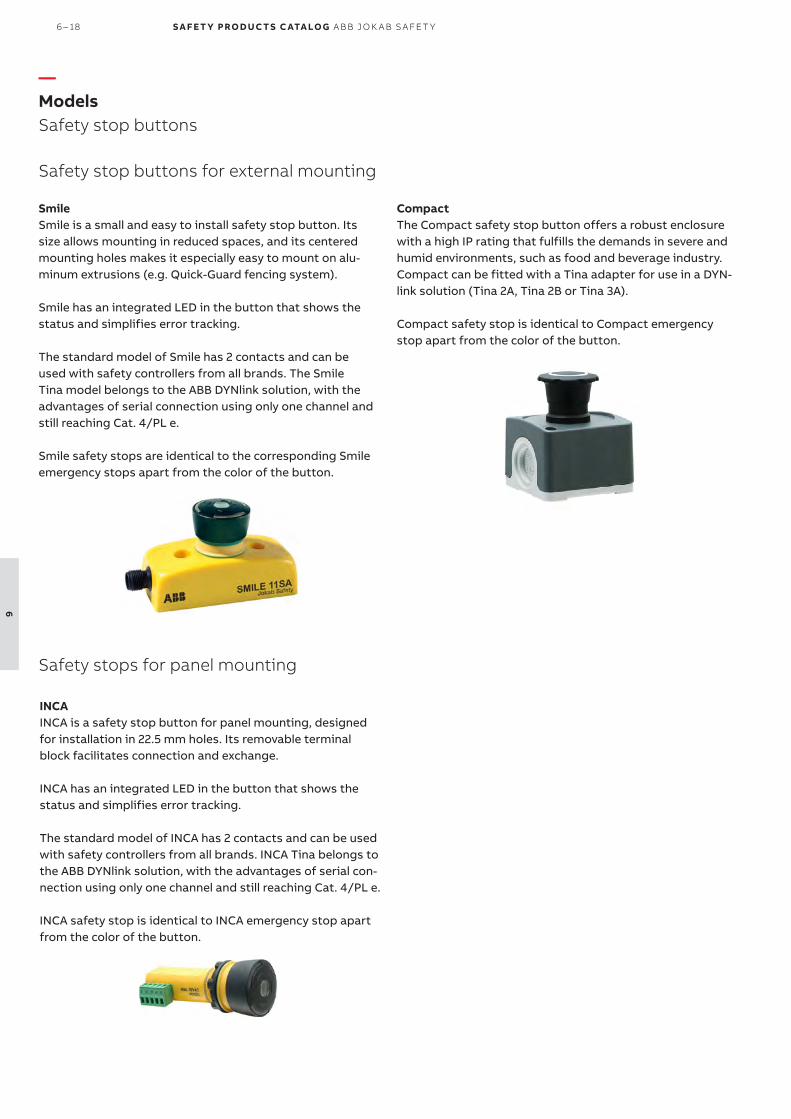
—Models Safety stop buttons
SmileSmile is a small and easy to install safety stop button. Its size allows mounting in reduced spaces, and its centered mounting holes makes it especially easy to mount on alu-minum extrusions (e.g. Quick-Guard fencing system).
Smile has an integrated LED in the button that shows the status and simplifies error tracking.
The standard model of Smile has 2 contacts and can be used with safety controllers from all brands. The Smile Tina model belongs to the ABB DYNlink solution, with the advantages of serial connection using only one channel and still reaching Cat. 4/PL e.
Smile safety stops are identical to the corresponding Smile emergency stops apart from the color of the button.
Safety stop buttons for external mounting
CompactThe Compact safety stop button offers a robust enclosure with a high IP rating that fulfills the demands in severe and humid environments, such as food and beverage industry. Compact can be fitted with a Tina adapter for use in a DYN-link solution (Tina 2A, Tina 2B or Tina 3A).
Compact safety stop is identical to Compact emergency stop apart from the color of the button.
INCAINCA is a safety stop button for panel mounting, designed for installation in 22.5 mm holes. Its removable terminal block facilitates connection and exchange.
INCA has an integrated LED in the button that shows the status and simplifies error tracking.
The standard model of INCA has 2 contacts and can be used with safety controllers from all brands. INCA Tina belongs to the ABB DYNlink solution, with the advantages of serial con-nection using only one channel and still reaching Cat. 4/PL e.
INCA safety stop is identical to INCA emergency stop apart from the color of the button.
Safety stops for panel mounting
6 – 18 S A F E T Y PRO D U C T S C ATA LO G A B B J O K A B S A FE T Y
6

—Ordering informationSafety stop buttons
2TLC
1721
98F0
201
Smile 11 SA Tina
CEP1-1002
2TLC
1723
65F0
201
INCA 1S
Mounting Type of safety signal Connection type Feature Type Order code
External DYNlink 1 m cable from bottom Status LED Smile 11 SA Tina 2TLA030050R0500
2 NC 1 x M12-5 Status LED Smile 11 SA 2TLA030051R0900
2 NC* 2 x M20 conduits - CEP1-1002 (Compact) 1SFA619811R1002
With shroud CEP1-2002 (Compact) 1SFA619811R2002
Panel DYNlink 5 pole terminal block Status LED INCA 1S Tina 2TLA030054R0200
2 NC 5 pole terminal block Status LED INCA 1S 2TLA030054R0300
* Can be adapted to DYNlink with Tina
Description Type Order code
M12 Y-connector for serial connection of devices without StatusBus functionality. M12-3A 2TLA020055R0000
Connection block for the serial connection of up to 4 DYNlink devices with 12-5 connectors. Tina 4A 2TLA020054R0300
Connection block for the serial connection of up to 8 DYNlink devices with 12-5 connectors. Tina 8A 2TLA020054R0500
Grey shroud for Compact CA1-8054 1SFA619920R8054
Adaptation unit for DYNlink solution with M20 fitting. For e.g. Compact. Tina 2A * 2TLA020054R0100
Adaptation unit for DYNlink solution, internal assembly. For e.g. Compact. Tina 2B * 2TLA020054R1100
Adaptation unit for DYNlink solution with M20 fitting and M12 connector. For e.g. connect-ing Compact to Pluto/Vital.
Tina 3A * 2TLA020054R0200
* For more information about Tina adapter units, please see Pluto and Vital chapters.
2TLC
1724
71F0
201
Tina 8A
—Accessories
—Safety stop buttons
EM ER G EN C Y S TO P S A N D PI LOT D E V I CE S 6 – 19
6

—Cable and connectorsSafety stop buttons
Connector Female/male Length Special feature Type Order code
M12-5 Female 3 m M12-C31 2TLA020056R0500
6 m M12-C61 2TLA020056R0000
Harsh environment, halogen free M12-C61HE 2TLA020056R8000
10 m M12-C101 2TLA020056R1000
Harsh environment, halogen free M12-C101HE 2TLA020056R8100
20 m M12-C201 2TLA020056R1400
Female + male 0.3 m M12-C0312 2TLA020056R5800
0.06 m M12-C00612 2TLA020056R6300
1 m M12-C112 2TLA020056R2000
3 m M12-C312 2TLA020056R2100
6 m M12-C612 2TLA020056R2200
10 m M12-C1012 2TLA020056R2300
Angled female connector M12-C1012V2 2TLA020056R6700
16 m M12-C1612 2TLA020056R5400
20 m M12-C2012 2TLA020056R2400
Male 6 m M12-C62 2TLA020056R0200
10 m M12-C102 2TLA020056R1200
M12-C61
2TLC
1729
51F0
201
Description Type Order code
Connectors
M12-5 pole female, straight M12-C01 2TLA020055R1000
M12-5 pole male, straight M12-C02 2TLA020055R1100
Cable with 5 conductors
10 m cable with 5 x 0.34 shielded conductors C5 cable 10 m 2TLA020057R0001
50 m cable with 5 x 0.34 shielded conductors C5 cable 50 m 2TLA020057R0005
100 m cable with 5 x 0.34 shielded conductors C5 cable 100 m 2TLA020057R0010
200 m cable with 5 x 0.34 shielded conductors C5 cable 200 m 2TLA020057R0020
500 m cable with 5 x 0.34 shielded conductors C5 cable 500 m 2TLA020057R0050
C5 cable
2TLC
010
038F
020
1
M12-C61HE
2TLC
010
003
F020
1
M12-C01
2TLC
1726
57F0
201
—Cable with connectors
—Separate cables and connectors
6 – 20 S A F E T Y PRO D U C T S C ATA LO G A B B J O K A B S A FE T Y
6

—Technical data Safety stop buttons
Technical dataApprovals
Smile, INCA
Smile Tina, INCA Tina TÜV NORD
Compact
Conformity
Smile, INCA2006/42/EC – Machinery2011/65/EU - RoHSEN ISO 12100:2010, EN ISO 13849-1:2008/AC:2009, EN 60204-1:2006+A1:2008, EN ISO 13850:2008
Smile Tina, INCA Tina2006/42/EC - Machinery2004/108/EC - EMCEN ISO 12100:2010, EN ISO 13849-1:2008, EN 62061:2005, EN 60204-1:2006+A1:2009, IEC 60664-1:2007, EN 61000-6-2:2005, EN 61000-6-4:2007, EN 60947-5-5:2005, EN ISO 13850:2006
Compact
2006/42/EC - Machinery2014/30/EU - EMCEN 60947-1:2007/A1:2011/A2:2014, EN 60947-5-1:2004/A1:2009, EN 60947-5-5:1997/A1:2005/A11:2013, EN ISO 13850:2008
Functional safety data
EN 61508:2010 Up to SIL3, depending on system architecture
EN 62061:2005 Up to SILCL3, depending on system architecture
EN ISO 13849-1:2008 Up to Cat. 4, PL e, depending on system architecture
Smile, INCA B10d = 100 000
Smile Tina, INCA Tina PFHD = 4.66 x 10⁻⁹
Compact B10d = 50 000
Electrical data
Operating voltage
Smile, INCA 17-27 VDC ± 10%
Smile Tina, INCA Tina +24 VDC +15% -25%
Compact 230 VAC / +24 VDC
Mechanical data
Mechanical life >50 000 operations
Operating temperature
Smile, INCA -10…+55 °C
Compact -25…+70 °C
Protection class
Smile, INCA IP65
Compact IP66, IP67, IP69K
Weight
Smile 65 g
INCA 45 g
Compact 108 g, 124 g (with shroud)
Material
Smile Polyamide PA66, Macromelt, polybutylenterephthalate PBT, Polypropene PP, UL 94 V0
INCA Polyamide PA66, Macromelt, polybutylenterephthalate PBT, Polypropene PP, UL 94 V0
Compact Polycarbonate
More informationFore more information, e.g. the complete technical information, see product manual for:Smile 2TLC172097M0201INCA 2TLC172163M0201Compact 1SFC151005C0201
EM ER G EN C Y S TO P S A N D PI LOT D E V I CE S 6 – 21
6
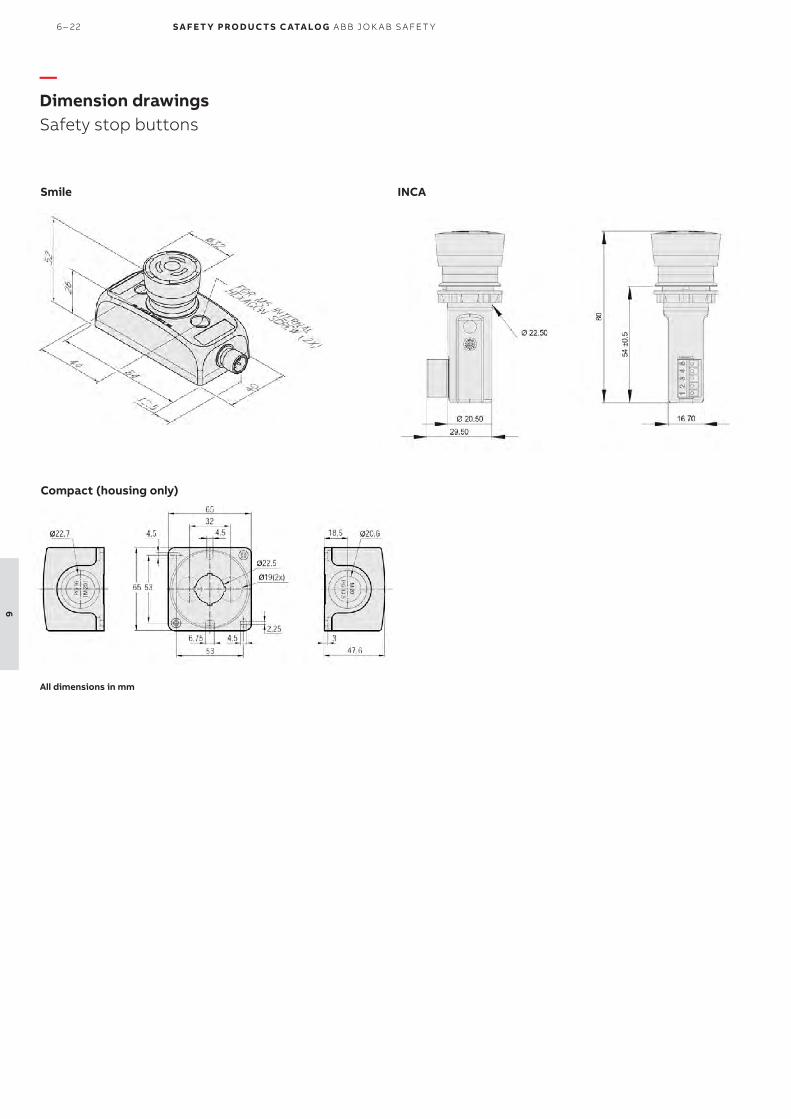
Smile
—Dimension drawings Safety stop buttons
INCA
All dimensions in mm
Compact (housing only)
6 – 22 S A F E T Y PRO D U C T S C ATA LO G A B B J O K A B S A FE T Y
6

EM ER G EN C Y S TO P S A N D PI LOT D E V I CE S 6 – 23
6

Easily accessibleEasy reach of the emergency stop function along machines, conveyors and processes.
High level of safetyThe positive forced disconnect con-tacts provide a high level of safety and are double switching, i.e. triggers emergency stop in both directions of the wire.
Safety and protectionEasy to install
Quick installationA pull wire emergency stop switch is easier to install than a system of sev-eral emergency stop buttons along a carriage path.
Highly adaptableSeveral models to choose between gives a variety of mounting possibili-ties and features.
Long wire lengthCan handle wires up to 200 m on a single switch.
LineStrong is a pull wire emergency stop switch, used for easy reach of the emergency stop function along machines and sections of conveyors.
A pull wire emergency stop switch allows to initiate the emergency stop command from any point along the in-stalled wire length by pulling the wire. It replaces a series of emergency stop buttons and is easier to install.
LineStrong is also available in differ-ent models for different lengths of wires, with different housing material as well as an explosion proof version.
Reliable in extreme conditionsRobust construction makes LineStrong ideal for use in demanding environ-ments.
LED diagnosticsIntegrated LED diagnostics ensures status can be seen easily from a dis-tance.
Continuous operation
—Pull wire emergency stop switchLineStrong
6 – 24 S A F E T Y PRO D U C T S C ATA LO G A B B J O K A B S A FE T Y
6

—ApplicationsLineStrong
Instead of multiple emergency stopsA pull wire emergency stop switch is often placed along conveyor belts or carriage paths where access to the stop function must be possible along the whole line. It is often easier to install a pull wire emergency stop switch than to place multiple emergency stop buttons if the distance is longer.
LineStrong can handle wires up to 200 m on one single switch and since the emergency stop command can be initiated from any point along the wire, this gives better ac-cess to the emergency stop function than using emergency stop buttons.
As protective device in low risk applicationsLineStrong can be used as protection, for example along conveyors with low risks where the wire can be installed at waist height in front of the conveyor, which provides an emergency stop if someone walks or falls towards the con-veyor, hence pulling the wire.
One, two or several switchesThe maximum length of the wire attached to LineStrong de-pends on if there is a LineStrong unit attached to both ends of the wire or if one end is attached to a wall/fixed object. In the image below LineStrong2 is used as an example.
Two units
One unit
Up to 80 m
Up to 60 m
EM ER G EN C Y S TO P S A N D PI LOT D E V I CE S 6 – 25
6

—FeaturesLineStrong
Wire breakage monitoringThe contacts are double switching which means that the emergency stop command is given both when someone pulls the wire and if the wire should break.
Indication of wire tensionAll models are equipped with an indicator of the tension of the wire which simplifies installation and adjustment.
Positive forced disconnected contactsThe contacts in LineStrong are positive force disconnected, which ensures that the contacts will not be held in a normal-ly closed position due to a failure of the spring mechanism or the welding/sticking of the contacts.
Reset buttonAll models of LineStrong have an integrated reset button that needs to be pressed in order to reset the emergency stop if the emergency stop function has been triggered.
Emergency stop buttonMost LineStrong models have an integrated emergency stop button on the housing of the switch. Since the first half me-ter of the wire is not intended to pull in order to trigger the emergency stop function, the integrated emergency stop button provides quick and simple access to the emergency stop function if you are standing right in front of LineStrong. The emergency stop button of LineStrong 2 can be moved to either side of LineStrong to enable best access depending on position and height of LineStrong.
Integrated LEDLineStrong2 and LineStrong3 have an integrated 2-color LED that shows if the emergency stop function has been trig-gered or not. The LED is also available as spare part.
MaterialLineStrong is available with a housing in yellow die cast aluminum alloy or with a housing in stainless steel 316 which is recommended for severe applications in e.g. the food pro-cessing and the chemical industries.
Left hand, right hand or both sidesLineStrong1 and LineStrong2 can be mounted in any direc-tion. Linestrong3 is available in different models depending on installation. L (left hand) should be used if the placement of the grab wire switch is to the left in the installation. R (right hand) should be used if the grab wire switch is to the right in the installation. D (double wire) has wire entries from both sides of the grab wire switch.
Left Double Double Right
Up to 125 m Up to 125 m
6 – 26 S A F E T Y PRO D U C T S C ATA LO G A B B J O K A B S A FE T Y
6

Easier installation with tensioner/gripper The tensioner/gripper accessory significantly reduces the installation time. Traditional grab wire systems normally need turnbuckle and clamps, which are difficult to tension and adjust, and normally require frequent re-tensioning. The tensioner gripper integrates an eyehook, a tensioner thimble and a wire strength gripper in one assembly which enables rapid connection to the switch eyebolts and fast and accurate tensioning of the wire.
Thanks to the switch tension indicator, it is easy to ad-just the system accurately and quickly. The double clamp mechanism prevents wire slippage and significantly reduces machine downtime which can occur which traditional turn-buckle systems.
For systems longer than 50 m, the tensioner/gripper is nec-essary on both sides.
—FeaturesLineStrong
2
1
3
2
Quick-link terminationA quick-link termination is available as an accessory in the wire pull kit, for easy connection to the safety spring or the switch eyebolt for systems up to 50 m.
Mounting accessories The wire pull kits contains the suitable accessories for the included wire length. - When using one switch, the wire must be anchored at the other end using a safety spring. - The first eyeball support must be placed no more than 500 mm from the switch eyebolt or safety spring.- The part of the wire from the wire end to the first eyebolt support shall not be used as part of the active protection cover-age. - Wire support eyebolts must be fitted at 2.5 - 3 meters intervals along the complete wire length.- The tensioner/gripper is used to adjust the correct tension
Tensioner / Gripper Pull Quick link Safety spring
Zone of protection Inactive zone (500mm)
Inactive zone (500mm)
Eyebolt
Wire
Corner pulleyA corner pulley can be used to navigate inside or outside corners without causing damage to the wire. They are in stainless steel and can be rigidly mounted.When using a safety spring, a maximum of one corner pulley may be used, to ensure that the complete length of the wire is visible from either the switch or the spring anchorage.
Machine
Machine
MachineOutside corners
MachineOutside cornersM
achi
neInside corners
Examples of using the corner pulley
1. Tension to mid position as indicated by the green arrows in the viwing window of each switch2. The tensioner thimble allows immediate accurate and final ten-sioning of the wire, whilst viewing the tension marker through the viewing window on the switch.3. Quick Link termination.
Corner pulley
EM ER G EN C Y S TO P S A N D PI LOT D E V I CE S 6 – 27
6
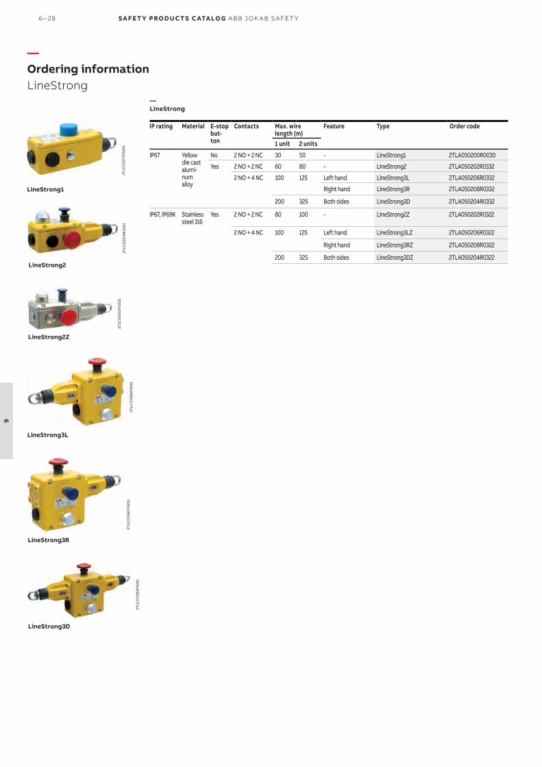
—Ordering informationLineStrong
2TLC
1723
77F0
201
LineStrong1
2TLC
1723
85F0
201
LineStrong3L
IP rating Material E-stop
but-ton
Contacts Max. wire length (m)
Feature Type Order code
1 unit 2 units
IP67 Yellow die cast alumi-num alloy
No 2 NO + 2 NC 30 50 - LineStrong1 2TLA050200R0030
Yes 2 NO + 2 NC 60 80 - LineStrong2 2TLA050202R0332
2 NO + 4 NC 100 125 Left hand LineStrong3L 2TLA050206R0332
Right hand LineStrong3R 2TLA050208R0332
200 325 Both sides LineStrong3D 2TLA050204R0332
IP67, IP69K Stainless steel 316
Yes 2 NO + 2 NC 80 100 - LineStrong2Z 2TLA050202R0322
2 NO + 4 NC 100 125 Left hand LineStrong3LZ 2TLA050206R0322
Right hand LineStrong3RZ 2TLA050208R0322
200 325 Both sides LineStrong3DZ 2TLA050204R0322
2TLC
1725
01F
020
1
LineStrong2Z
2TLC
1723
83F0
201
LineStrong3D
2TLC
1723
87F0
201
LineStrong3R
LineStrong2
2TLC
1723
79F0
201
—LineStrong
6 – 28 S A F E T Y PRO D U C T S C ATA LO G A B B J O K A B S A FE T Y
6

Description Material Length Type Order code
Wire pull kit including wire, eyebolts, tensioner/gripper, quick-link termination and Allen key in right quantity for the included wire length.
Galvanized 10 m wire 10 m wire kit, gal 2TLA050210R0130
20 m wire 20 m wire kit, gal 2TLA050210R0330
80 m wire 80 m wire kit, gal 2TLA050210R0630
100 m wire 100 m wire kit, gal 2TLA050210R0730
Stainless steel 50 m wire 50 m wire kit, SS 2TLA050210R0520
100 m wire 100 m wire kit, SS 2TLA050210R0720
Wire tensioner/gripper Galvanized Wire tensioner, gal 2TLA050210R4030
Stainless steel Wire tensioner, SS 2TLA050210R4020
Corner pulley Galvanized Corner pulley, gal 2TLA050210R6030
Stainless steel Corner pulley, SS 2TLA050210R6020
Eyebolt M8 x 1.258 pcs
Galvanized Eyebolt M8x1.25, gal 2TLA050210R8030
Stainless steel Eyebolt M8x1.25, SS 2TLA050210R8020
Safety spring, 220mm Stainless steel Spring 220 mm, SS 2TLA050211R0004
—AccessoriesLineStrong
Description Type Order code
LineStrong LED Green/Red +24 VDC LineStrong LED 24 2TLA050211R0001
LineStrong LED Green/Red 230 VAC LineStrong LED 230 2TLA050211R0003
LineStrong2 and LineStrong3 Emergency stop button. LineStrong E-Stop 2TLA050211R0005
Description Type Order code
Screwdriver, anti-tamper, Torx T20 Screwdriver T20 2TLA050211R0006
Gland M20 x 1.5 Gland M20x1.5 2TLA050040R0002
Conduit plug M20 x 1.5 Cond.Plug M20x1.5 2TLA050040R0004
2TLC
1725
77F0
201
Wire pull kit
2TLC
1722
15F0
201
LineStrong Screwdriver
LineStrong LED 230
2TLC
1729
02F
020
1
Wire tensioner
2TLC
1722
20F0
201
2TLC
1722
19F0
201
2TLC
1722
21F0
201
2TLC
1725
81F0
201
Corner pulley
Eyebolt
Safety spring
Gland
Conduit plug
2TLC
1722
17F0
201
2TLC
1722
18F0
201
LineStrong LED 230
—Mounting Accessories
—Other accessories
—Spare parts
EM ER G EN C Y S TO P S A N D PI LOT D E V I CE S 6 – 29
6

—CablesLineStrong
Description Type Order code
Connectors
M12-5 pole female, straight M12-C01 2TLA020055R1000
M12-5 pole male, straight M12-C02 2TLA020055R1100
M12-8 pole female, straight M12-C03 2TLA020055R1600
M12-8 pole male, straight M12-C04 2TLA020055R1700
Cable with 5 conductors
10 m cable with 5 x 0.34 shielded conductors C5 cable 10 m 2TLA020057R0001
50 m cable with 5 x 0.34 shielded conductors C5 cable 50 m 2TLA020057R0005
100 m cable with 5 x 0.34 shielded conductors C5 cable 100 m 2TLA020057R0010
200 m cable with 5 x 0.34 shielded conductors C5 cable 200 m 2TLA020057R0020
500 m cable with 5 x 0.34 shielded conductors C5 cable 500 m 2TLA020057R0050
Cable with 8 conductors
50 m cable with 8 x 0.34 shielded conductors C8 cable 50 m 2TLA020057R1005
100 m cable with 8 x 0.34 shielded conductors C8 cable 100 m 2TLA020057R1010
200 m cable with 8 x 0.34 shielded conductors C8 cable 200 m 2TLA020057R1020
500 m cable with 8 x 0.34 shielded conductors C8 cable 500 m 2TLA020057R1050
C5 cable
2TLC
010
038F
020
1
M12-C01
2TLC
1726
57F0
201
—LineStrong
6 – 30 S A F E T Y PRO D U C T S C ATA LO G A B B J O K A B S A FE T Y
6

—Technical dataLineStrong
Technical dataApprovals
LineStrong
Conformity
LineStrong 2006/42/EC - MachineryEN ISO 12100:2010, EN ISO 13850:2008, EN 60204-1:2006+A1:2009, EN 60947-1:2007+A1:2011, EN 60947-5-1:2004+A1:2009, EN 60947-5-5:1997+A1:2005
Functional safety data
EN ISO 13849-1:2008 Up to Cat. 4, PL e, depending on system architecture.
EN/IEC 62061:2005 Up to SILCL3, depending on system architecture.
IEC 61508 Up to SIL3, depending on system architecture.
B10d 1 500 000
Electrical data
Utilization category 240 VAC / 3 A
+24 VDC / 2.5 A
LED +24 VDC
Mechanical data
Operating temperature -25…+80 °C
Protection class
LineStrong1, LineStrong2, LineStrong3
IP67
LineStrong2Z, LineStrong3Z IP66, IP67, IP69K
Weight
LineStrong1 675 g
LineStrong2 880 g
LineStrong2Z 1635 g
LineStrong3L/R 1100 g
LineStrong3LZ/RZ 2000 g
LineStrong3D 1320 g
LineStrong3DZ 2200 g
Material
LineStrong1, LineStrong2, LineStrong3D/L/R
Die cast painted yellow
LineStrong2Z, LineStrong3LZ/RZ/DZ
Stainless steel 316
Wire type PVC sheath steel wire 4.0 mm outside diameter
Conduit entries
LineStrong1/2 3 x M20 x 1.5
LineStrong3 4 x M20 x 1.5
More informationFore more information, e.g. the complete technical information, see product manual for:LineStrong 2TLC172248M0201
EM ER G EN C Y S TO P S A N D PI LOT D E V I CE S 6 – 31
6

LineStrong1
—Dimension drawingsLineStrong
LineStrong2
All dimensions in mm
LIneStrong3L-R
6 – 32 S A F E T Y PRO D U C T S C ATA LO G A B B J O K A B S A FE T Y
6

EM ER G EN C Y S TO P S A N D PI LOT D E V I CE S 6 – 33
6
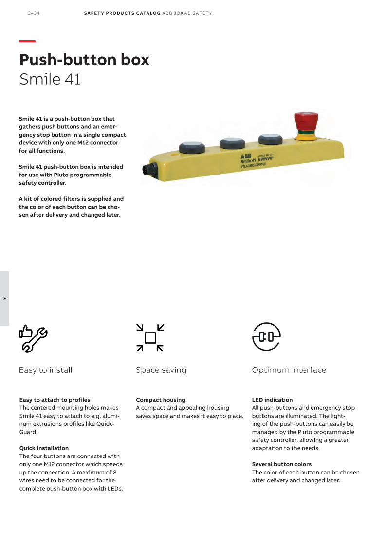
Smile 41 is a push-button box that gathers push buttons and an emer-gency stop button in a single compact device with only one M12 connector for all functions.
Smile 41 push-button box is intended for use with Pluto programmable safety controller.
A kit of colored filters is supplied and the color of each button can be cho-sen after delivery and changed later.
Compact housingA compact and appealing housing saves space and makes it easy to place.
Space savingEasy to install
Easy to attach to profilesThe centered mounting holes makes Smile 41 easy to attach to e.g. alumi-num extrusions profiles like Quick-Guard.
Quick installationThe four buttons are connected with only one M12 connector which speeds up the connection. A maximum of 8 wires need to be connected for the complete push-button box with LEDs.
LED indicationAll push-buttons and emergency stop buttons are illuminated. The light-ing of the push-buttons can easily be managed by the Pluto programmable safety controller, allowing a greater adaptation to the needs.
Several button colorsThe color of each button can be chosen after delivery and changed later.
Optimum interface
—Push-button box Smile 41
6 – 34 S A F E T Y PRO D U C T S C ATA LO G A B B J O K A B S A FE T Y
6

Smile 41 is a convenient way to gather several buttons at the same place while reducing cabling and installation. For example, an emergency stop button, a push button used to request the unlocking of the door, a push button used as reset button, and a push button used as start button.
—Applications and features Smile 41
Applications
Kit of colored filtersA kit of colored filters is supplied with all models and the color of each push button can be chosen after delivery and changed later.
Centered mounting holesCentered mounting holes facilitate the mounting of Smile 41 on aluminum profiles like Quick-Guard.
With Pluto programmable safety controller Smile 41 has been developed for use with Pluto programma-ble safety controller and allow to get all the advantages of the Pluto “light-button function”: only one I/O (IQ) is neces-sary for both a push-button and its LEDs and the lighting of the reset buttons can be handled by Pluto without any extra programming.
The emergency stop button satisfies the highest level of safety, and although only one cable is used for the signals of the four buttons, a possible short-circuit can be detected by Pluto and the highest level of safety can be reached.
Features
EM ER G EN C Y S TO P S A N D PI LOT D E V I CE S 6 – 35
6

—Ordering informationSmile 41
Smile 41 push-button box is delivered with a kit of filters
Safety controller Emergency stop button
Other buttons Connector Type Order code
Pluto programmable safety controller 1 3 push-buttons M12-8 male Smile 41 EWWWP 2TLA030057R0100
Description Type Order code
Kit of colored filters Colored filters 2TLA030059R2600
Smile 41 EWWWP
2TLC
1727
17F0
201
6 – 36 S A F E T Y PRO D U C T S C ATA LO G A B B J O K A B S A FE T Y
6
—Smile 41 push button box
—Spare parts

—Cables and connectorsSmile 41
Connector Female/male Length Type Order code
M12-8 Female 6 m M12-C63 2TLA020056R3000
10 m M12-C103 2TLA020056R4000
20 m M12-C203 2TLA020056R4100
Female + male 0.06 m M12-C00634 2TLA020056R6400
1 m M12-C134 2TLA020056R5000
3 m M12-C334 2TLA020056R5100
M12-C63
2TLC
1729
51F0
201
Description Type Order codeM12-8 connectors
M12-8 pole female, straight M12-C03 2TLA020055R1600
M12-8 pole male, straight M12-C04 2TLA020055R1700
Cable with 8 conductors
50 m cable with 8 x 0.34 shielded conductors C8 cable 50 m 2TLA020057R1005
100 m cable with 8 x 0.34 shielded conductors C8 cable 100 m 2TLA020057R1010
200 m cable with 8 x 0.34 shielded conductors C8 cable 200 m 2TLA020057R1020
500 m cable with 8 x 0.34 shielded conductors C8 cable 500 m 2TLA020057R1050
C8 cable
2TLC
010
038F
020
1
M12-C334
2TLC
1729
31F0
201
M12-C03
2TLC
1726
59F0
201
—Cable with connectors
—Separate cables and connectors
EM ER G EN C Y S TO P S A N D PI LOT D E V I CE S 6 – 37
6

Technical dataSmile 41
Approvals TÜV NORD
Conformity 2006/42/EC - Machinery2014/30/EU - EMC2011/65/EU - RoHSEN ISO 12100:2010, EN ISO 13849-1:2008/AC:200962061:2005+A2:2015, EN 60204-1:2006+A1:2009, IEC 60664-1:2007,EN 61000-6-2:2005, EN 61000-6-4:2011, EN ISO 13850:2015
Functional safety data
IEC 61508:2010 Up to SIL3, depending on system architecture
EN/IEC 62061:2005 Up to SILCL3, depending on system architecture
EN ISO 13849-1:2008 Up to Cat. 4/PL e, depending on system architecture
B10d 65 000
Electrical data
Operating voltage +24 VDC ± 15%
Mechanical data
Mechanical life
Emergency stop button > 50 000 operations
Illuminated push button 1 000 000 operations
Operating temperature -25… +50 °C
Protection class IP65
Weight 190 g
—Technical dataSmile 41
More informationFore more information, e.g. the complete technical information, see product manual for:Smile 41 2TLC172280M0201
6 – 38 S A F E T Y PRO D U C T S C ATA LO G A B B J O K A B S A FE T Y
6

Smile 41
—Dimension drawingsSmile 41
All dimensions in mm
EM ER G EN C Y S TO P S A N D PI LOT D E V I CE S 6 – 39
6

Smile reset buttons have compact housings with M12 connectors for easy connection.
The reset button contains an integrated white LED, and all buttons are delivered with a kit of colored filters to snap on the top of the button. In this way the color of the button can be chosen after delivery and is also possible to changed later.
The different models also allow a choice of: - local reset connected directly to the sensor, or - global reset connected to the safety control module.
Compact housingA compact and appealing housing saves space and makes it easy to place.
Space savingEasy to install
Easy to attach to profilesThe centered mounting holes make Smile easy to attach to e.g. aluminum extrusions profiles.
Speed up installationn The housing requires no assembly and the M12 connectors speed up installa-tion and reduce the risk of connection error.
Local resetLocal reset allows to have the reset button close to the safety device while reducing cabling.
Several button colorsAll reset buttons are illuminated with a white LED and the color of each but-ton can be chosen after delivery and changed later using colored snap-on filters.
Optimum interface
—Reset buttonSmile
6 – 40 S A F E T Y PRO D U C T S C ATA LO G A B B J O K A B S A FE T Y
6

—Ordering information Smile reset buttons
Type of contact Intended use Connectors Type Order code
1 NO Most reset applications M12-5 male Smile 11 RA 2TLA030053R0000
1 NO Pluto Safety PLC light button function* M12-5 male Smile 11 RB 2TLA030053R01001 NO Local reset of Orion1 Base M12-5 male Smile 11RO1 2TLA022316R3000
1 NC Local reset of Orion2 Base and Extended, and Orion3 Extended M12-5 male Smile 11RO2 2TLA022316R3100
1 NC Local reset of Orion3 Base M12-5 male Smile 11RO3 2TLA022316R3200
1 NO Local reset of Eden DYN-Reset M12-5 and Eden OSSD-Reset M12-5 M12-5 male + female Smile 12 RF 2TLA030053R2600
1 NO Local reset of Eden OSSD-Reset M12-8 M12-8 male + female Smile 12 RG 2TLA030053R2700
* See Pluto hardware manual for more information about the light button function
Description Type Order codeY-connector for series connection of DYNlink devices with M12-5 connectors, e.g. Eden. M12-3A 2TLA020055R0000
Y-connector for series connection of Adam OSSD M12-8 with M12-5 cables M12-3H 2TLA020055R0800
Y-connector for series connection of Adam OSSD M12-8 with M12-8 cables M12-3G 2TLA020055R0700
Y-connector for connection of Smile reset button to Orion. M12-3R 2TLA022316R0000
Adaptation unit of OSSD outputs to DYNlink signals for use with Vital control module or Pluto Safety PLC. Tina 10B has an extra M12 connector for connection of a reset button.
Tina 10B v2 2TLA020054R1310
Tina 10B
M12-3x
2TLC
1726
23F0
201
2TLC
1724
75F0
201
Smile 11 RO1
2TLC
1720
18V
020
1
Description Type Order codeKit of colored filters (yellow, green, white, blue, red) Colored filters 2TLA030059R2600
2TLC
1727
25F0
201
Colored filters
—Ordering details
—Accessories
—Spare parts
EM ER G EN C Y S TO P S A N D PI LOT D E V I CE S 6 – 41
6

Eden
Res
et M
12-5
to
Smile
12 R
F
Smile
12 R
F to
M12
-3A
M12
-3A
to M
12 3A
El-c
abin
et to
M12
-3A
M12
-3A
to el
-cab
inet
Description Female/male Length Type Order code
M12-5 Female 6 m M12-C61 2TLA020056R0000
10 m M12-C101 2TLA020056R1000
20 m M12-C201 2TLA020056R1400
Female + male 1 m M12-C112 2TLA020056R2000
3 m M12-C312 2TLA020056R2100
6 m M12-C612 2TLA020056R2200
10 m M12-C1012 2TLA020056R2300
20 m M12-C2012 2TLA020056R2400
Male 6 m M12-C62 2TLA020056R0200
10 m M12-C102 2TLA020056R1200
—Cables Smile reset buttons
Eden
Res
et M
12-8
to
Smile
12 R
G
Smile
12 R
G to
M12
-3G
or
M12
-3H
M12
-3G
to M
12-3
G
El-c
abin
et to
M12
-3G
M12
-3G
to el
-cab
inet
M12
-3H
to M
12-3
H
El-c
abin
et to
M12
-3H
M12
-3H
to el
-cab
inet
Connector Female/male Length Type Order code
M12-5 Female 6 m M12-C61 2TLA020056R0000
10 m M12-C101 2TLA020056R1000
20 m M12-C201 2TLA020056R1400
Female + male 1 m M12-C112 2TLA020056R2000
3 m M12-C312 2TLA020056R2100
6 m M12-C612 2TLA020056R2200
10 m M12-C1012 2TLA020056R2300
20 m M12-C2012 2TLA020056R2400
Male 6 m M12-C62 2TLA020056R0200
10 m M12-C102 2TLA020056R1200
M12-8 Female 6 m M12-C63 2TLA020056R3000
10 m M12-C103 2TLA020056R4000
20 m M12-C203 2TLA020056R4100
Female + male 1 m M12-C134 2TLA020056R5000
3 m M12-C334 2TLA020056R5100
Male By meter M12-C04 2TLA020055R1700
Smile
11 R
x to
anot
her
M12
Smile
11 R
x to
el-ca
bine
t
Smile
11 R
Ox to
Tin
a 10B
Tina
10B
to el
-cab
inet
Smile
11 R
Ox to
M12
-3R
M12
-3R
to el
-cab
inet
Tina
10B
to M
12-3
A
M12
-3A
to M
12 3A
El-c
abin
et to
M12
-3A
M12
-3A
to el
-cab
inet
Connector Female/male Length Type Order code
M12-5 Female 6 m M12-C61 2TLA020056R0000
10 m M12-C101 2TLA020056R1000
20 m M12-C201 2TLA020056R1400 Female + male 1 m M12-C112 2TLA020056R2000
3 m M12-C312 2TLA020056R2100
6 m M12-C612 2TLA020056R2200
10 m M12-C1012 2TLA020056R2300
20 m M12-C2012 2TLA020056R2400
Male 6 m M12-C62 2TLA020056R0200
10 m M12-C102 2TLA020056R1200
—Cables for Smile 12 RF (with Eden DYN/OSSD Reset M12-5)
—Cables for Smile 12 RG (with Eden DYN/OSSD Reset M12-8)
—Cables for Smile 11 RX and ROx
6 – 42 S A F E T Y PRO D U C T S C ATA LO G A B B J O K A B S A FE T Y
6

—Connection examplesSmile reset buttons
Orion receiver or active part
Smile reset(a)M12-3R
1. + 24 VDC 2. OSSD13. 0 V 4. OSSD2 5. -
M12 5-pole male
(a)Orion receiver or active part
Tina 10B
Smile reset
1. + 24 VDC 2. In3. 0 V 4. Out5. Info
M12 5-pole male
Local reset to Orion with Tina 10A/C Local reset to Orion with Tina 10B
Local reset to Eden
Connection of Smile 11 ROx to Orion through M12-3R. For connection to any control module compatible with OSSD outputs.
Serial connection of Eden with local Smile reset buttons:- Adam OSSD-Reset M12-8 with Smile 12 RG and M12-3G or M12-3H- Adam DYN-Reset with Smile 12 RF and M12-3A
Connection of Smile 11 ROx to Orion through Tina 10B.For connection to Vital control module or Pluto Safety PLC.
Global vs local resetA global reset is connected directly to the control cabinet with separate cables. The safety controller in the control cabinet supervises the reset and decides the function and actions.
A local reset is connected directly to the safety device, and requires no communication with the control cabinet. The safety device supervises the reset and decides the actions. A local reset simplifies installation and minimizes cabling.
EM ER G EN C Y S TO P S A N D PI LOT D E V I CE S 6 – 43
6

—Technical dataSmile reset buttons
Approvals
Power supplyLED operating voltage +24 VDC (maximum +33 VDC)LED current consumption 20 mA at +24 VDC, 30 mA at +33 VDCPush button operating voltage Min: +5 V, max: +35 VPush button current Min: 1 mA, max: 100 mAPush button rated power Max: 250 mW
Mechanical dataColor - Enclosure YellowColor - Push button WhiteMaterial - Housing Polyprobylene PPMaterial - Contact AuWeight Approx. 60 g
Protection class IP65Mechanical life 1 000 000 operations at 10 mA / +24 VDCSwitching reliability 10 x 10
-6
at 5 mA / +24 VDCEnvironmental data
Ambient temperature -25...+55 °CHumidity range 35 to 85% (with no icing or condensation)
More informationFore more information, e.g. the complete technical information, see product manual for:Smile reset buttons 2TLC172097M0201
6 – 44 S A F E T Y PRO D U C T S C ATA LO G A B B J O K A B S A FE T Y
6

—Dimension drawingsSmile reset buttons
Smile 11 R Smile 12 R
All dimensions in mm
EM ER G EN C Y S TO P S A N D PI LOT D E V I CE S 6 – 45
6

—Pilot devicesReliable products, easy to select and install
ABB pilot devices are engineered for total reliability. Our products are tested to extremes and proven in the toughest environments. Their innovative designs simplify the entire process, from selection to installation. Enclosures, signal towers and signal beacons complete the portfolio.
Continuous operation Global availability Easy to install
Engineered for tough environmentsABB pilot devices are designed with protection degree of up to IP69K and 4X, guaranteeing reliability in extreme environments – making ABB pilot devices ideal for use in demanding industries such as construction and food and beverage. An innovative de-sign that automatically cleans contacts ensures high reliability for all products.
Simple selection and stock managementABB’s core offering includes the pilot devices most in demand, so product selection is easier, stock management is simpler and product availability is higher. Support for exporters is world-class, thanks to ABB’s standardized global range, certified to comply with all ma-jor international standards.
Save time and spaceThe unique design of ABB’s modular range enables tool-free installation that is quick and simple. It provides high flexibility for last-minute changes. With its all-in-one construction, the compact range reduces installation space and saves time.
6 – 46 S A F E T Y PRO D U C T S C ATA LO G A B B J O K A B S A FE T Y
6

JoysticksSelectorswitches
Key-operated selector switches
Toggle switches
Pilot lightsPotentiometers
A versatile selection of operators with high levels of flexibility
and a broad choice of electrical ratings. Find the perfect
solution for almost every application.
More flexibility:Last-minute changes made easyUp to 6 contact blocks, NO and NC
Save up to 30% installation time with unique tool-free snap on components
Choice of 3- and 5-position holders
Simple solutions nuts require no tools
Every requirement covered with a wide choice of operators and bezels
High AC-15 electrical ratings 6 A at 230 V.
The flexible solution that simplifies
your stock management.
Emergency stop pushbuttons
Machine stop pushbuttons
Heavy duty pushbuttons
Pushbuttons Double pushbuttons
Reset pushbuttons
Mushroom pushbuttons
—Modular plastic rangeFlexible configuration
EM ER G EN C Y S TO P S A N D PI LOT D E V I CE S 6 – 47
6
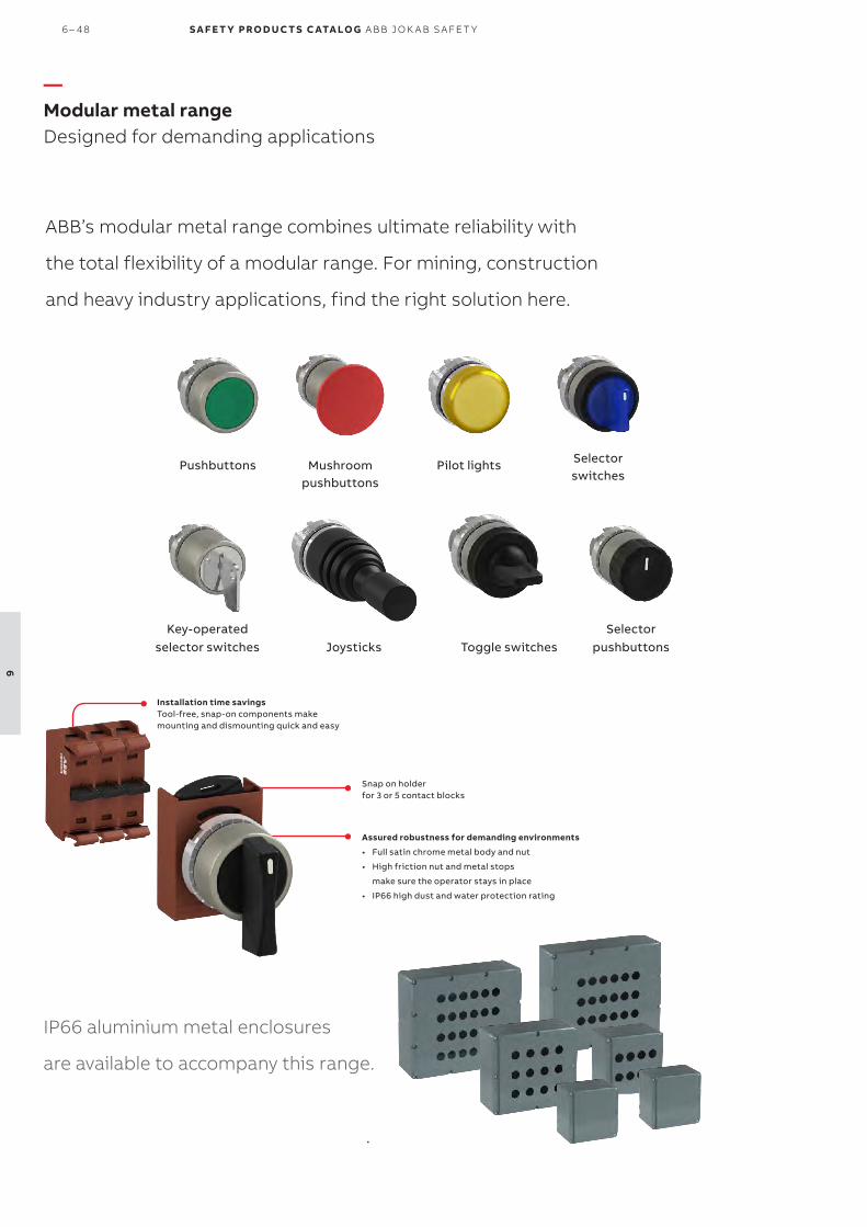
ABB’s modular metal range combines ultimate reliability with
the total flexibility of a modular range. For mining, construction
and heavy industry applications, find the right solution here.
Installation time savingsTool-free, snap-on components make mounting and dismounting quick and easy
Snap on holder for 3 or 5 contact blocks
Assured robustness for demanding environments
• Full satin chrome metal body and nut
• High friction nut and metal stops
make sure the operator stays in place
• IP66 high dust and water protection rating
Pushbuttons Mushroom pushbuttons
Selector switches
Selectorpushbuttons
Key-operated selector switches Toggle switchesJoysticks
Pilot lights
IP66 aluminium metal enclosures
are available to accompany this range.
—Modular metal rangeDesigned for demanding applications
6 – 48 S A F E T Y PRO D U C T S C ATA LO G A B B J O K A B S A FE T Y
6

Compact:Just 42 mm built in depth
Improve reliability: Higher protection levels with IP66, IP67 and IP69K classification and 4X (NEMA)
Fewer order codes make selection easy
and save time.
All-in-one design makes installation fast.
The most efficient solution available, reducing installation time
and cost. The compact range have the highest level of dust and water
resistance on the market.
Buzzers
Emergency stop pushbuttons
Machine stop pushbuttons
Pushbuttons
Pilot lights
Heavy duty pushbuttons
Selector switches
Mushroom pushbuttons
http://new.abb.com/low-voltage/products/pilot-devices
For more models, ordering information and tech-nical data, please see web:
—Compact rangeAll-in-one solution
EM ER G EN C Y S TO P S A N D PI LOT D E V I CE S 6 – 49
6

S A F E T Y PRO D U C T S C ATA LO G A B B J O K A B S A FE T Y
77
PR E SSU R E SENSIT I V E D E V I CE S 7-1
7
— Pressure sensitive devices
7– 2 Introduction and overview
7– 4 Safety edges
7– 8 Safety bumpers
7– 12 Safety mats

—Introduction and overviewSelection guide
ABB has different types of pressure sensitive devices to cover the needs in
various applications.
Safety edges Safety bumpers Safety matsImage
Type Pressure sensitive safety edge Pressure sensitive safety bumper Pressure sensitive safety mat
Overtravel distance
15-22.7 mm 60-240 mm -
Application(s) Sliding doors, gates, roller doors and moving platforms.
Larger sliding doors/hangar doors and automated guided vehicles.
Personal protection within the dangerous area.
Advantages - Preassembled- Easy to install- Compact- Up to 25 m long
- Preassembled- Easy to install
- Very durable- Easy to install- Custom measurements
7-2 S A F E T Y PRO D U C T S C ATA LO G A B B J O K A B S A FE T Y
7
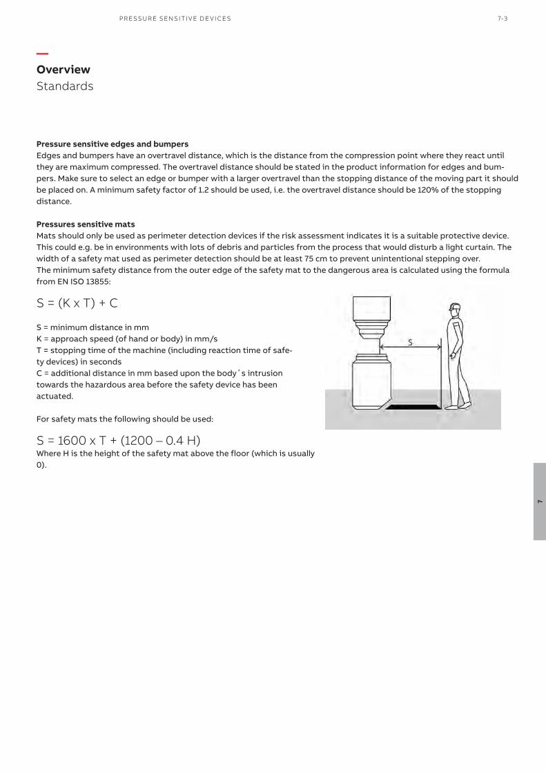
S = minimum distance in mmK = approach speed (of hand or body) in mm/sT = stopping time of the machine (including reaction time of safe-ty devices) in secondsC = additional distance in mm based upon the body´s intrusion towards the hazardous area before the safety device has been actuated.
Pressure sensitive edges and bumpersEdges and bumpers have an overtravel distance, which is the distance from the compression point where they react until they are maximum compressed. The overtravel distance should be stated in the product information for edges and bum-pers. Make sure to select an edge or bumper with a larger overtravel than the stopping distance of the moving part it should be placed on. A minimum safety factor of 1.2 should be used, i.e. the overtravel distance should be 120% of the stopping distance.
Pressures sensitive matsMats should only be used as perimeter detection devices if the risk assessment indicates it is a suitable protective device. This could e.g. be in environments with lots of debris and particles from the process that would disturb a light curtain. The width of a safety mat used as perimeter detection should be at least 75 cm to prevent unintentional stepping over.The minimum safety distance from the outer edge of the safety mat to the dangerous area is calculated using the formula from EN ISO 13855:
—Overview Standards
Where H is the height of the safety mat above the floor (which is usually 0).
S = (K x T) + C
S = 1600 x T + (1200 – 0.4 H)
For safety mats the following should be used:
PR E SSU R E SENSIT I V E D E V I CE S 7-3
7

Safety edges are pressure sensitive devices that are used on leading edges of doors or moving machine parts to prevent crushing injuries.
The contact edges from ABB are avail-able in two sizes and custom lengths. They are supplied together with an aluminum profile for simple mounting
Continuous operation
MaterialThe contact edges are made in TPE that has a good resistance to ozone, weather and especially against chemi-cals.
—Safety edgesTT
Easy to install
Preassembled Ordered in custom lengths, preassem-bled - no gluing required, supplied with matching aluminum support profile.
Serial connectionThe twin cable connection makes it easy to connect several safety edges in series.
7-4 S A F E T Y PRO D U C T S C ATA LO G A B B J O K A B S A FE T Y
7

—
Applications and featuresSafety edges
Sliding doorsSafety edges are placed on the leading edge of sliding doors, gates and roller doors. When the door hits a person or an object, the safety edge sends a signal to the safety controller to stop the motion. The soft parts of the edge should be big enough to allow compression until the motion has ceased.
Safety controllersThe safety edge must be connected to a suitable two-input-channel safety controller that provides all necessary monitoring of the contact edges activation and detection of cable faults. Suitable ABB controllers are Sentry USR safety relays, Pluto programmable safety controllers or Vital safety controllers. When using Vital, a Tina 6 must also be used for short circuit detection.
Moving machine partsSafety edges can also be placed on moving machine parts, such as the edges of horizontally moving tables and the underside of a scissor lift table.
Internal contactsInside the safety edge there is a cast-in contact strip that consists of two conductive alternating surfaces on the inside and a highly-effective insulating shell. There are two conductive wires in the contact surfaces that allow for low ohm measurements even when the contact edge has an extended length. When pressure is applied the two contact surfaces are short circuited, resulting in a stopping signal. The cast-in contact strip is protected against damage by the surrounding chamber. The cast end plugs ensure a perma-nent contact from the conductive surfaces in the contact strip.
Applications
Features
PR E SSU R E SENSIT I V E D E V I CE S 7-5
7

Ordering detailsWhen ordering a safety edge there are two parts that need to be ordered. One order code for production cost and cables, and one order code for the length of the safety edge. Length should be specified in meters.
Example:One piece of 45 mm high safety edge (plus 14 mm high aluminum rail), 0.73 m long with a 5 meter cable in each end =- 0.73 m of 2TLA076025R4510- 1 pcs of 2TLA076010R0500
Overtravela)
mmDescription Material Type Order code
15 30 mm high safety edge with 25-14 aluminum rail. Length in m needs to be specified on order.
TPE Safety edge TT 25-30 TPE 2TLA076025R3010
22.7 45 mm high safety edge with 25-14 aluminum rail. Length in m needs to be specified on order.
TPE Safety edge TT 25-45 TPE 2TLA076025R4510
a) At 100 mm/s to 400 N
Length of cablesm
Description Type Order code
2.5 Production cost with a 2,5 m cable in each end. Safety edge production cost 2,5m cable
2TLA076010R0100
5 Production cost with a 5 m cable in each end. Safety edge production cost 5,0m cable
2TLA076010R0500
10 Production cost with a 10 m cable in each end. Safety edge production cost 10,0m cable
2TLA076010R1000
2TLC
010
120
V0
201
Safety edge TT 35-30 TPE
—
Ordering informationSafety edges
Safety edge TT 25-45 TPE
2TLC
010
00
8V0
201
—Production cost and cables
—Safety edge TT
7-6 S A F E T Y PRO D U C T S C ATA LO G A B B J O K A B S A FE T Y
7

Technical dataApprovals
Conformity2006/42/EC - Machinery2014/30/EU - EMC2011/65/EU - RoHSEN ISO 12100:2010, EN ISO 13856-2:2013, EN ISO 13849-1:2015, EN 62061:2005+A2:2015, EN 60204-1:2006+A1:2009, EN 60664-1:2007, EN 61000-6-2:2005, EN 61000-6-4:2007, EN 61508:2010
Functional safety data 62061:2005+A1:2013 EN ISO 13849-1:2015
SILCL2PL d/Cat 4 (According to EN ISO 13849-2:2012, Table D.8, a fault exclusion for that the contacts in a pressure sensitive device will not close, can be made. This fault exclusion is limited up to PL d.)
Electrical data
Electrical capacity 24 V, 10 mA
Mechanical data
Switching cycles 10 000Protection class IP65Operating temperature -10 °C to 50 °C Weight TT 25-45 TT 25-30
0.34 kg/m0.44 kg/m
MaterialRubber TPESupportive profile Aluminium
Max Delivery length 25 mInactive end region 30 mmConnection cables LIY11Y 2 x 0.34 mmCable material PUR flat black
More information For more information, e.g. the complete technical information, see product manual for:Safety Edges 2TLC010046M0201.
Connection diagramsFor safety edge connection diagrams please see https://library.abb.com/
Dimension drawings
—
Technical dataSafety edges
TÜV NORD
All dimensions in mm
PR E SSU R E SENSIT I V E D E V I CE S 7-7
7

Safety bumpers are pressure sensi-tive devices used to prevent crushing injuries. They are mounted on lead-ing edges of large doors or moving machinery such as automated guided vehicles.
The bumpers are available in four different sizes, and the internal foam construction allows for long deforma-tion zones to provide optimum pro-tection for individuals and material.
—Safety bumperASB
Continuous operation
MaterialThe outer material of the safety bum-pers is an artificial leather that pro-vides excellent resistance against most liquids, oils and chemicals.
Easy to install
Preassembled Ordered in custom lengths and preas-sembled to a carrier profile.
Serial connectionThe twin cable connection makes it easy to connect several safety bum-pers in series.
7– 8 S A F E T Y PRO D U C T S C ATA LO G A B B J O K A B S A FE T Y
7

—Applications and featuresSafety bumper
Large sliding doorsSafety bumpers are placed on the leading edge of large sliding doors, gates and vertical roller doors. When the door hits a person or an object, the safety bumper sends a signal to the safety controller to stop the motion. The soft parts of the bumper should be big enough to allow compression until the motion has ceased.
Safety controllersThe safety bumper must be connected to a suitable two-input-channel safety controller that provides all necessary monitoring of the activation of the safety bumpers and detection of cable faults. Suitable ABB controllers are Sentry USR safety relays and Pluto programmable safety control-lers.
Moving vehiclesSafety bumpers can also be placed on moving vehicles, such as AGVs (automated guided vehicles) or high reach fork lifts to detect when a person or an object is hit.
Internal contact stripInside the safety bumper there is a cast-in contact strip that consists of two conductive alternating surfaces on the inside and a highly-effective insulating shell. When pressure is applied the large foam cushion presses the two contact surfaces against each other so that they are short circuited, which the safety controller will detect.
Applications
Features
PR E SSU R E SENSIT I V E D E V I CE S 7– 9
7

—Ordering informationSafety bumper
2TLC
010
122V
020
1
ASB
7– 10 S A F E T Y PRO D U C T S C ATA LO G A B B J O K A B S A FE T Y
7
Ordering detailsWhen ordering a safety bumper there are two parts that need to be ordered. One order code for production cost and cables, and one order code for the type of bumper and length. Length should be specified in meters. Minimum length is 0.15 m and maximum length is 3 m.
Bumpers are delivered with two 0,2 m cables with M8 connectors attached. Two 5 m cables with M8 connectors are also included.
Example:One piece of 150x300 mm safety bumper (including aluminum rail), 2.1 m long =- 2.1 m of 2TLA076200R0700- 1 pcs of 2TLA076200R0000
Overtravela)
mm
Description Material Type Order code
60 60x100 mm bumper. Length in m needs to be speci-fied on order.
Imitation leather
Bumper ASB 60-100 black/yellow
2TLA076200R0500
120 100x200 mm bumper. Length in m needs to be speci-fied on order.
Imitation leather
Bumper ASB 100-200 black/yellow
2TLA076200R0600
180 150x300 mm bumper. Length in m needs to be speci-fied on order.
Imitation leather
Bumper ASB 150-300 black/yellow
2TLA076200R0700
240 200x400 mm bumper. Length in m needs to be specified on order.
Imitation leather
Bumper ASB 200-400 black/yellow
2TLA076200R0800
a) 60% of bumper height at 10 mm/s
Description Type Order code
Bumpers production cost, including aluminum rail and cables Bumper production cost 2TLA076200R0000
—Production cost and cables
—Safety bumper ASB

PR E SSU R E SENSIT I V E D E V I CE S 7– 11
7
Technical data
Approvals TÜV NORD
Conformity2006/42/EC - Machinery2014/30/EU - EMC2011/65/EU - RoHSEN ISO 12100:2010, EN ISO 13856-3:2013, EN ISO 13849-1:2015, EN 62061:2005+A2:2015, EN 60204-1:2006+A1:2009, EN 60664-1:2007, EN 61000-6-2:2005, EN 61000-6-4:2007, EN 61508:2010
Functional safety data 62061:2005+A1:2013 EN ISO 13849-1:2015
SILCL2PL d/Cat 4 (According to EN ISO 13849-2:2012, Table D.8, a fault exclusion for that the contacts in a pressure sensitive device will not close, can be made. This fault exclusion is limited up to PL d.)
Electrical data
Electrical capacity 24 V, 10 mA
Mechanical data
Actuating force < 150 N by test specimen Ø80 mm (according to EN ISO 13856-3) < 400 N by test specimen 45x400 mm (according to EN ISO 13856-3)
Inactive edge region 0 mmSwitching cycles > 10 000 Protection class IP54Temperature range 0 °C to + 50 °C Connection cable Pluggable 2 x 0.34 mm² (PUR black) with M8 connector 0.12mMaterial Artificial leatherChemical resistance Good chemical resistance, except for Ethyl acetate and Acetone.Dimensioning of bumper height Actuating distance Overtravel distance Maximum compression
15% of bumper height60% of bumper height75% of bumper height
More information For more information, e.g. the complete technical information, see product manual for:Safety Bumpers 2TLC010045M0201.
Connection diagramsFor safety bumpers connection diagrams please see https://library.abb.com/
Dimension drawings
—
Technical dataSafety bumpers
All dimensions in mm

Safety mats are pressure sensitive devices placed on the floor to detect if someone is standing on them. They are mostly used inside hazard zones around e.g. presses, robots and production lines to prevent the machine from running when someone is in the hazard zone.
—Safety matsASK
Continuous operation
MaterialThe surface material of the safety mat is a slip-free rubber with excellent re-sistance against oil, water and grease.
Easy to install
Preassembled Ordered in standard or custom sizes with molded ramp and preassembled with two cables (M8 male and female connector).
Serial connectionThe twin cable connection makes it easy to connect several safety mats in series. Extension cables exist to fur-ther simplify connection.
7– 12 S A F E T Y PRO D U C T S C ATA LO G A B B J O K A B S A FE T Y
7

—Applications and featuresSafety mats
Personal protection within hazard zonesSafety mats are mostly used inside hazard zones around e.g. presses, robots and production lines to prevent the machine from running when someone is in the hazard zone.
Safety controllersThe safety mat must be connected to a suitable two-input-channel safety controller that provides all necessary moni-toring of the activation of the safety map and detection of cable faults. Suitable ABB controllers are Sentry USR safety relays, Pluto programmable safety controllers or Vital safety controllers. When using Vital, a Tina 6 must also be used for short circuit detection.
Mat constructionThe safety mat is made of a sandwich construction. When stepped upon, two internal conducting plates connect and result in a short circuit that the safety controller detects.
Perimeter guardSafety mats can also be used as a perimeter guard e.g. to replace a light curtain in applications where there is a lot of debris or particles in the air that would trigger the light curtain.
Ramp railAt the edges of the safety mat there is a molded ramp rail. The ramp rail is 35 mm wide and is not included in the mea-surement of the ramp (i.e. the actual dimensions of a 1000 x 1000 mm safety mat is 1070 x 1070 mm). The purpose of the ramp rail is to minimize the tripping risk and for fastening of the safety mat, since screws can be drilled through the ramp rail. The ramp rail can be cut off using a knife if the safety mat is to be placed close to a wall or next to another safety mat.
Applications
Features
PR E SSU R E SENSIT I V E D E V I CE S 7– 13
7

Ordering detailsWhen ordering a safety mat you can either select one of the standard sizes or a custom size. For standard sizes only one order code is necessary. For custom sizes two parts need to be ordered. One order code for base price, and one order code for the size in m2. Width x length also needs to be specified in text on the order in mm. Maximum dimensions are 2350 x 1350 mm and minimum dimensions 100 x 100 mm.
Example:One piece of 450 x 1150 mm safety mat =- 1 pcs of 2TLA076301R0200- 0.5175 m2 of 2TLA076301R0600- Dimensions 450 x 1150 mm
Sizemm
Description Connectors Type Order code
750x1000 750x1000 safety mat with molded ramp rail and two 5 m cables
1x M8 male1x M8 female
Safety mat ASK T4 750x1000mm
2TLA076310R1000
1000x1000 1000x1000 safety mat with molded ramp rail and two 5 m cables
1x M8 male1x M8 female
Safety mat ASK T4 1000x1000mm
2TLA076310R1100
1000x1500 1000x1500 safety mat with molded ramp rail and two 5 m cables
1x M8 male1x M8 female
Safety mat ASK T4 1000x1500mm
2TLA076310R1200
Description Connectors Type Order code
Base price for custom made safety mat with molded ramp rail
- Safety mat ASK CM T4, base price
2TLA076301R0200
Order code for size (m2) and two 5 m cables. Specify dimensions (width x length in mm) in text.
1x M8 male1x M8 female
Safety mat ASK CM T4 2TLA076301R0600
Description Lengthm
Connectors Type Order code
Extension cable 2.5 1x M8 male1x M8 female
Safety mat extension cable 2.5 m
2TLA076900R3200
Extension cable 5.0 1x M8 male1x M8 female
Safety mat extension cable 5.0 m
2TLA076900R3300
2TLC
010
035V
020
1
ASK
—Ordering informationSafety mats
—Safety mat ASK – standard sizes
—Safety mat ASK – custom sizes
—Accessories
7– 14 S A F E T Y PRO D U C T S C ATA LO G A B B J O K A B S A FE T Y
7

Technical data
Approvals
Conformity2006/42/EC - Machinery2014/30/EU - EMC2011/65/EU - RoHSEN ISO 12100:2010, EN ISO 13856-1:2013, EN ISO 13849-1:2015, EN 62061:2005+A2:2015, EN 60204-1:2006+A1:2009, EN 60664-1:2007, EN 61000-6-2:2005, EN 61000-6-4:2007, EN 61508:2010
Functional safety data 62061:2005+A1:2013 EN ISO 13849-1:2015
SILCL2PL d/Cat 4B10D: 2 000 000(According to EN ISO 13849-2:2012, Table D.8, a fault exclusion for that the contacts in a pressure sensitive device will not close, can be made. This fault exclusion is limited up to PL d.)
Electrical data
Electrical capacity 24 V, 100 mA
Response time Including Sentry Including Pluto (single Pluto) Including Pluto incl. Pluto bus
With function block “BigMat”
< 20 ms< 30 msNormal condition: < 40 msAt fault condition: < 70 msAdd 30 ms
Mechanical data
Max. area Entire safety mat = 2350 x 1350 mm, 10 m2, (divided safety mat) Rec. relation max 3:1, Min 100 x 100 mm
Height 14 mmWeight 26 Kg/m2Material Black polyurethaneProtection class IP65Ambient air temperature 0° C to + 60° CCable 2 x 5 m; 2 x 0.34 mm2
PU sheathedMechanical life >1.0 x 10⁶ Load shifting
More information For more information, e.g. the complete technical information, see product manual for:Safety Mats 2TLC010047M0201.
Connection diagramsFor safety mats connection diagrams please see https://library.abb.com/
—
Technical dataSafety mats
PR E SSU R E SENSIT I V E D E V I CE S 7– 15
7

S A F E T Y PRO D U C T S C ATA LO G A B B J O K A B S A FE T Y
8

— Contactors and motor starters
8– 2 Introduction and overview
8– 4 Safety contactors
8– 10 Electronic compact starters
CO NTAC TO R S A N D M OTO R S TA RTER S 8 – 1
8

AFS HF
Image
Type Safety contactor Electronic compact starters
Description A simple and reliable unit for monitoring and controlling circuits.
A compact and space saving alternative to con-tactors, using a combination of semiconductor technology and electromechanical relays. Moni-toring and control of circuits with numerous additional features.
Applications Removing control power to dangerous ma-chinery up to 400 W/400 V.
Removing control power to dangerous ma-chinery up to 3 kW/400 V, as well as direct and reversed start of motors.
Advantage - Easy to use- Fast switching- High switching capacity
- Space saving up to 90% with only 22.5 mm in control cabinets- Extended equipment life time and decreased maintenance cost- Reduced wiring time- Safety variants comply with SIL3, PL e and are ATEX certified
ABB offers a wide range of output devices for safely removing power to
dangerous machinery. Apart from contactors and electronic compact starters,
we also have frequency converters with safe torque off (STO) and industrial
robots with safety stop inputs.
—Introduction and overviewSelection guide
8 – 2 S A F E T Y PRO D U C T S C ATA LO G A B B J O K A B S A FE T Y
8

CO NTAC TO R S A N D M OTO R S TA RTER S 8 – 3
8

Designed for machine safety applications, AFS contactors now complete ABB’s safety component portfolio.
With a range stretching from 9 A up to 750 A for motor starting applications and with a design complying with the latest safety standard, the AFS range of contactors is the given choice for any application that puts the users safety first.
Secure uptimeThe AFS contactor secures system uptime. Featuring ABB’s tested and proven AF technology, AFS contactors are reliable in any network. Direct control by safety PLCs or safety relays ensures the required safety performance.
Simplify designAFS design makes integration easier. With energy efficient coils smaller transformers can be used and panel space more efficiently used. Wide voltage range coils and easily available safety data simplifies product selection. In addition, all the safety data for the AFS contactors is available using common safety design tools.
Speed up your projects
Continuous operation
Safety in all things ABB’s AFS contactors can be easily integrated in machine manufacturer’s systems complying with main standards EN ISO 13849 and EN 62061 - guaranteeing the safe use of your machinery and equipment. An easily identifiable yellow low energy auxiliary contact block ensures the status feedback circuits required in machine safety applications.
Safety and protection
—AFS 3-pole contactorsDedicated for safety applications
8 – 4 S A F E T Y PRO D U C T S C ATA LO G A B B J O K A B S A FE T Y
8

—AFS 3-pole contactorsDedicated for safety applications
Simplify calculation of your installation safety levelAFS contactor safety data is available in safety design tools Sistema and FSDT, dedicated software for determining the Performance Level (PL) and Safety Integrity Level (SIL) of safety functions and generating technical documentations.
Prevent unexpected operationsFactory fitted auxiliary contact blocks that are permanently fixed protects devices against accidental operation and misuse. A factory-fitted transparent cover on contactors up to 96 A shields the contactor status indicator, providing additional protection from misuse.
Guaranteed contactor statusABB’s permanently fixed auxiliary contact blocks guarantee the correct contactor status at all times. Mechanically linked and mirror contacts provide the performance re-quired in feedback circuits. This prevents any unexpected state changes of auxiliary contact if main contacts become welded or stuck and ensures an accurate depiction of the safety system status displayed at all times. Mechanically linked and mirror contact symbols are marked on the yellow auxiliary block.
Fast response for increased safetyIn safety applications speed is essential to protect operators. AFS contactors feature fast opening times, down to 20 ms for certain PLC controlled contactors, en-suring that when a dangerous failure is detected the opera-tor is kept out of harms way.
CO NTAC TO R S A N D M OTO R S TA RTER S 8 – 5
8

—AFS 3-pole contactors Dedicated for safety applications
Easy safety chain identificationThe yellow housing of ABB’s AFS contactors makes identify-ing the safety product in your panel quicker. During routine maintenance work, ABB’s intuitive design saves valuable time.
Control by safety PLCs or safety relaysABB’s AFS contactors can be controlled directly by safety PLCs or safety relays, or by a power relay depending on size. AFS contactors is part of the ABB safety family, and se-lected sizes are tested together with ABB's Pluto safety PLC and the Sentry safety relay. For full coordination please ad-vise ABB. The auxiliary contacts only require a minimum switching capacity of 3 V / 1 mA. They guarantee system sta-tus feedback, making the system safe and reliable.
Panel size reductionUtilizing AF technology, AFS coils needs up to 60% less energy than conventional contactor coils. This allows for smaller transformers to be used for contactor control, which in turn allows for more efficient use of panel space. Using AFS contactors saves money and precious space.
Built-in surge suppressionUnlike conventional contactors, ABB's AFS contactors have built-in surge suppression, preventing surges from ever reaching the control circuit. With no need for the usual external surge suppressor add-ons, ABB’s solution means one less device to install and one less complication to man-age.
Sentry safety relay
Pluto safety PLC
8 – 6 S A F E T Y PRO D U C T S C ATA LO G A B B J O K A B S A FE T Y
8

—AFS 3-pole contactorsDedicated for safety applications
AFS16-30-22
1SB
C10
1536
V0
014
1SB
C10
1539
V0
014
IEC UL/CSA Rated control circuit voltage Uc min. ... Uc max.
Auxiliarycontactsfitted
Type Order code WeightRated operational 3-phase Generalpower Current
θ ≤ 40 °Cmotor rating
use rating
400 VAC-3 AC-1
480 V 600 V AC
kW A hp A V 50/60 Hz V DC kg4 25 5 25 - 24 2 2 AFS09Z-30-22-30 1SBL136082R3022 0.490
24...60 20...60 (1) 2 2 AFS09-30-22-11 1SBL137082R1122 0.320100…250 100..250 2 2 AFS09-30-22-13 1SBL137082R1322 0.320
5.5 28 7.5 28 - 24 2 2 AFS12Z-30-22-30 1SBL156082R3022 0.49024...60 20...60 (1) 2 2 AFS12-30-22-11 1SBL157082R1122 0.320100…250 100..250 2 2 AFS12-30-22-13 1SBL157082R1322 0.320
7.5 30 10 30 - 24 2 2 AFS16Z-30-22-30 1SBL176082R3022 0.49024...60 20...60 (1) 2 2 AFS16-30-22-11 1SBL177082R1122 0.320100…250 100..250 2 2 AFS16-30-22-13 1SBL177082R1322 0.320
11 45 15 45 - 24 2 2 AFS26Z-30-22-30 1SBL236082R3022 0.54024...60 20...60 (1) 2 2 AFS26-30-22-11 1SBL237082R1122 0.360100…250 100..250 2 2 AFS26-30-22-13 1SBL237082R1322 0.360
15 50 20 50 - 24 2 2 AFS30Z-30-22-30 1SBL276082R3022 0.54024...60 20...60 (1) 2 2 AFS30-30-22-11 1SBL277082R1122 0.360100…250 100..250 2 2 AFS30-30-22-13 1SBL277082R1322 0.360
18.5 50 20 50 - 24 2 2 AFS38Z-30-22-30 1SBL296082R3022 0.54024...60 20...60 (1) 2 2 AFS38-30-22-11 1SBL297082R1122 0.360100…250 100..250 2 2 AFS38-30-22-13 1SBL297082R1322 0.360
18.5 70 30 60 24…60 20…60 (1) 2 2 AFS40-30-22-11 1SBL347082R1122 1.020100…250 100..250 2 2 AFS40-30-22-13 1SBL347082R1322 1.000
22 100 40 80 24…60 20…60 (1) 2 2 AFS52-30-22-11 1SBL367082R1122 1.020100…250 100..250 2 2 AFS52-30-22-13 1SBL367082R1322 1.000
30 105 50 90 24…60 20…60 (1) 2 2 AFS65-30-22-11 1SBL387082R1122 1.020100…250 100..250 2 2 AFS65-30-22-13 1SBL387082R1322 1.000
37 125 60 105 24…60 20…60 (1) 2 2 AFS80-30-22-11 1SBL397082R1122 1.270100…250 100..250 2 2 AFS80-30-22-13 1SBL397082R1322 1.220
45 130 60 115 24…60 20…60 (1) 2 2 AFS96-30-22-11 1SBL407082R1122 1.270100…250 100..250 2 2 AFS96-30-22-13 1SBL407082R1322 1.220
For connection with built-in cable clamps55 160 75 160 24...60 20...60 1 2 AFS116-30-12-11 1SFL427081R1112 1.750
48...130 48...130 1 2 AFS116-30-12-12 1SFL427081R1212 1.750100...250 100...250 1 2 AFS116-30-12-13 1SFL427081R1312 1.750
1 2 AFS116-30-12-33 (2) 1SFL427081R3312 1.750250...500 250...500 1 2 AFS116-30-12-14 1SFL427081R1412 1.750
1 2 AFS116-30-12-34 (2) 1SFL427081R3412 1.75075 225 100 200 24...60 20...60 1 2 AFS146-30-12-11 1SFL467081R1112 1.750
48...130 48...130 1 2 AFS146-30-12-12 1SFL467081R1212 1.750100...250 100...250 1 2 AFS146-30-12-13 1SFL467081R1312 1.750
1 2 AFS146-30-12-33 (2) 1SFL467081R3312 1.750250...500 250...500 1 2 AFS146-30-12-14 1SFL467081R1412 1.750
1 2 AFS146-30-12-34 (2) 1SFL467081R3412 1.750
With bar connections55 160 75 160 24...60 20...60 1 2 AFS116-30-12B-11 1SFL427082R1112 1.500
48...130 48...130 1 2 AFS116-30-12B-12 1SFL427082R1212 1.500100...250 100...250 1 2 AFS116-30-12B-13 1SFL427082R1312 1.500
1 2 AFS116-30-12B-33 (2) 1SFL427082R3312 1.500250...500 250...500 1 2 AFS116-30-12B-14 1SFL427082R1412 1.500
1 2 AFS116-30-12B-34 (2) 1SFL427082R3412 1.50075 225 100 200 24...60 20...60 1 2 AFS146-30-12B-11 1SFL467082R1112 1.500
48...130 48...130 1 2 AFS146-30-12B-12 1SFL467082R1212 1.500100...250 100...250 1 2 AFS146-30-12B-13 1SFL467082R1312 1.500250...500 250...500 1 2 AFS146-30-12B-14 1SFL467082R1412 1.500
AFS65-30-22
1SB
C10
154
2V0
014
AFS96-30-22
1SB
C10
154
4V
00
14
AFS146-30-12
AFS146-30-12B
1SF
C10
124
6V
00
01
1SF
C10
124
4V
00
01
AFS38-30-22
CO NTAC TO R S A N D M OTO R S TA RTER S 8 – 7
8
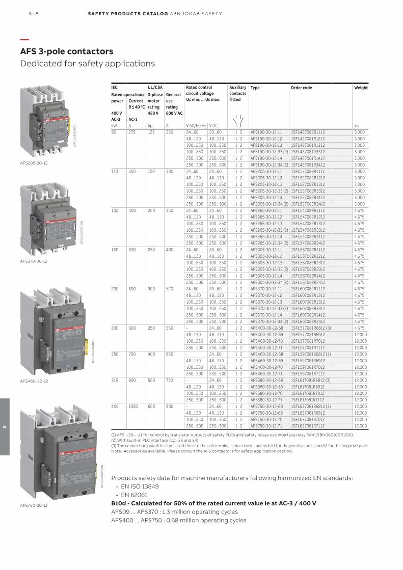
—AFS 3-pole contactorsDedicated for safety applications
IEC UL/CSA Rated control circuit voltage Uc min. ... Uc max.
Auxiliarycontactsfitted
Type Order code WeightRated operational 3-phase Generalpower Current
θ ≤ 40 °Cmotor rating
use rating
400 VAC-3 AC-1
480 V 600 V AC
kW A hp A V 50/60 Hz V DC kg90 275 125 250 24...60 20...60 1 2 AFS190-30-12-11 1SFL427082R1112 3.000
48...130 48...130 1 2 AFS190-30-12-12 1SFL427081R1212 3.000100...250 100...250 1 2 AFS190-30-12-13 1SFL427081R1312 3.000100...250 100...250 1 2 AFS190-30-12-33 (2) 1SFL427081R3312 3.000250...500 250...500 1 2 AFS190-30-12-14 1SFL427081R1412 3.000250...500 250...500 1 2 AFS190-30-12-34 (2) 1SFL427081R3412 3.000
110 350 150 300 24...60 20...60 1 2 AFS205-30-12-11 1SFL527082R1112 3.00048...130 48...130 1 2 AFS205-30-12-12 1SFL527082R1212 3.000100...250 100...250 1 2 AFS205-30-12-13 1SFL527082R1312 3.000100...250 100...250 1 2 AFS205-30-12-33 (2) 1SFL527082R3312 3.000250...500 250...500 1 2 AFS205-30-12-14 1SFL527082R1412 3.000250...500 250...500 1 2 AFS205-30-12-34 (2) 1SFL527082R3412 3.000
132 400 200 350 24...60 20...60 1 2 AFS265-30-12-11 1SFL547082R1112 4.67548...130 48...130 1 2 AFS265-30-12-12 1SFL547082R1212 4.675100...250 100...250 1 2 AFS265-30-12-13 1SFL547082R1312 4.675100...250 100...250 1 2 AFS265-30-12-33 (2) 1SFL547082R3312 4.675250...500 250...500 1 2 AFS265-30-12-14 1SFL547082R1412 4.675250...500 250...500 1 2 AFS265-30-12-34 (2) 1SFL547082R3412 4.675
160 500 250 400 24...60 20...60 1 2 AFS305-30-12-11 1SFL587082R1112 4.67548...130 48...130 1 2 AFS305-30-12-12 1SFL587082R1212 4.675100...250 100...250 1 2 AFS305-30-12-13 1SFL587082R1312 4.675100...250 100...250 1 2 AFS305-30-12-33 (2) 1SFL587082R3312 4.675250...500 250...500 1 2 AFS305-30-12-14 1SFL587082R1412 4.675250...500 250...500 1 2 AFS305-30-12-34 (2) 1SFL587082R3412 4.675
200 600 300 520 24...60 20...60 1 2 AFS370-30-12-11 1SFL607082R1112 4.67548...130 48...130 1 2 AFS370-30-12-12 1SFL607082R1212 4.675100...250 100...250 1 2 AFS370-30-12-13 1SFL607082R1312 4.675100...250 100...250 1 2 AFS370-30-12-33 (2) 1SFL607082R3312 4.675250...500 250...500 1 2 AFS370-30-12-14 1SFL607082R1412 4.675250...500 250...500 1 2 AFS370-30-12-34 (2) 1SFL607082R3412 4.675
200 600 350 550 - 24...60 1 2 AFS400-30-12-68 1SFL577081R6812 (3) 4.67548...130 48...130 1 2 AFS400-30-12-69 1SFL577081R6912 12.000100...250 100...250 1 2 AFS400-30-12-70 1SFL577081R7012 12.000250...500 250...500 1 2 AFS400-30-12-71 1SFL577081R7112 12.000
250 700 400 650 - 24...60 1 2 AFS460-30-12-68 1SFL597081R6812 (3) 12.00048...130 48...130 1 2 AFS460-30-12-69 1SFL597081R6912 12.000100...250 100...250 1 2 AFS460-30-12-70 1SFL597081R7012 12.000250...500 250...500 1 2 AFS460-30-12-71 1SFL597081R7112 12.000
315 800 500 750 - 24...60 1 2 AFS580-30-12-68 1SFL617081R6812 (3) 12.00048...130 48...130 1 2 AFS580-30-12-69 1SFL617081R6912 12.000100...250 100...250 1 2 AFS580-30-12-70 1SFL617081R7012 12.000250...500 250...500 1 2 AFS580-30-12-71 1SFL617081R7112 12.000
400 1050 600 900 - 24...60 1 2 AFS750-30-12-68 1SFL637081R6812 (3) 12.00048...130 48...130 1 2 AFS750-30-12-69 1SFL637081R6912 12.000100...250 100...250 1 2 AFS750-30-12-70 1SFL637081R7012 12.000250...500 250...500 1 2 AFS750-30-12-71 1SFL637081R7112 12.000
(1) AFS..-30-..-11 for control by transistor outputs of safety PLCs and safety relays use interface relay RA4 1SBN060100R1000.(2) With built-in PLC interface (coil 33 and 34)(3) The connection polarities indicated close to the coil terminals must be respected: A1 for the positive pole and A2 for the negative pole.Note : Accessories available. Please consult the AFS contactors for safety application catalog.
AFS205-30-12
AFS370-30-12
1SF
C10
1230
V0
00
1
1SF
C10
1233
V0
00
1
Products safety data for machine manufacturers following harmonized EN standards: - EN ISO 13849 - EN 62061
B10d - Calculated for 50% of the rated current value Ie at AC-3 / 400 VAFS09 ... AFS370 : 1.3 million operating cyclesAFS400 ... AFS750 : 0.68 million operating cycles
AFS460-30-12
AFS750-30-12
1SF
C10
1228
V0
00
1
1SF
C10
1226
V0
00
1
8 – 8 S A F E T Y PRO D U C T S C ATA LO G A B B J O K A B S A FE T Y
8

CO NTAC TO R S A N D M OTO R S TA RTER S 8 – 9
8

ABB’s electronic compact starter packs more functions into less space. The compact unit is just 22.5 mm wide and is suitable for three-phase motor loads up to 3 kW - 400 V AC. Direct-on-line and reversed starter with overload protection and emergency stop versions are available, making the range a perfect fit for high frequent and reliable long life switching of e.g. paper machines, conveyors, pumps, compressors and machine tools.
Up to 90% less space required ABB’s electronic compact starter saves cabinet space, and is especially effective for group mounting. The starter is just 22.5 mm wide and yet still provides motor starting functionalities with motor protection and safety embedded.
Integrated safety function Protect your personnel with emergency stop version complying with SIL3, PL e safety standards.
Extend equipment life time and decrease maintenance cost as our starters service life is 10 times higher than electromechanical solutions.
Up to 75% reduced time in wiring Wiring time during installation is cut to a minimum with motor protection, re-versing function and emergency stop already integrated in the product.
With just one component to install, the risk of wiring errors is lower. Separate overload protection is no longer need-ed.
Saving space Safety and protection Easy to install
—Electronic compact starters: HF rangeA compact solution with great functionality
8 – 10 S A F E T Y PRO D U C T S C ATA LO G A B B J O K A B S A FE T Y
8

Overload protectionABB offers three variants with wide setting ranges, using an electronic relay to protect the motor from overload. Pro-tection against phase asymmetry and phase failure is also integrated.
Emergency stopABB’s HF safety range supports safety applications comply-ing to SIL3 and PL e safety level in combination with modular safety relays such as ABB’s Sentry SSR10.
Direct-on-lineABB's direct-on-line starter comes with a function that runs the motor in a forward direction. An integrated electronic overload relay also helps protect the motor.
Reversing capabilityReversing functionality is already integrated in our hybrid starter. This results in avoiding wiring faults and additionally saving time and space.
Direct-on-line and reversing function in only one product
—Electronic compact startersAll-in-one: four functions in one starter
CO NTAC TO R S A N D M OTO R S TA RTER S 8 – 11
8

Space-savingUsing an HF electronic compact starter saves space – espe-cially when group-mounting units. With a width of just 22.5 mm and high function density, the unit fits any control cabi-net. Smaller footprints for more compact systems are also possible.
Less wiringThe control circuit is connected on the upper side of the device with the main circuit on the underside. The all-in-one functionality reduces wiring, saving time and money – and reducing faults.
Longer working lifeABB’s hybrid technology improves durability and reduces power losses. Semiconductors switch on and off the unit and the relays remain active while the motor is running. With a lifespan of 30 million cycles now achievable, maintenance costs are reduced.
Reset functionAfter the overload function has tripped, the electronic com-pact starter can be reset automatically, manually or remotely. The LEDs on the device are visualizing that an error has oc-curred. Additionally, a feedback relay will be activated.
22.5 mm
—Electronic compact startersFeatures and benefits
8 – 12 S A F E T Y PRO D U C T S C ATA LO G A B B J O K A B S A FE T Y
8

DescriptionThe HF-DOL-range is used for the direct-on-line start of motors and the switching of non-resistive loads. With contactor and overload relay functionalities integrated into one device, the results are faster wiring times and fewer faults. The range covers 0.6 A, 2.4 A and up to 9 A - for motors up to 3 kW – 500 V AC. The integrated electronic overload protection has a wide setting range that enables just three models to cover all requirements.
The control supply voltage is 24 V DC. For the control and main connection points ABB offers screw connections. ABB also offers a HF-DOLE safety range with emergency stop function. This offers Safety Integrity Level 3, in accordance with functional safety standard IEC 61508-1 and Performance Level 'e' in accordance with ISO 13849-1. The safety range is ATEX-certified.
Rated operational current AC-53a
Rated operational powerAC-53a
Rated op-erational current AC-51
Setting range
Full load amps motor use
Type Order code Weight(1 pce)
A kW A A A kg
Direct-on-line starter with overload protection0.6 0.18 (400V)0.6 0.075 … 0.6 0.6 HF0.6-DOL-24VDC 1SAT112000R1011 0.2052.4 0.75 (400V) 2.4 0.18 … 2.4 2.4 HF2.4-DOL-24VDC 1SAT122000R1011 0.2186.5 3.00
(400V)9.0 1.5 … 9.0 6.5 HF9-DOL-24VDC 1SAT142000R1011 0.206
Direct-on-line starter with overload protection and emergency stop0.6 0.18 (400V) 0.6 0.075 … 0.6 0.6 HF0.6-DOLE-24VDC 1SAT113000R1011 0.2052.4 0.75 (400V) 2.4 0.18 … 2.4 2.4 HF2.4-DOLE-24VDC 1SAT123000R1011 0.2186.5 3.00
(400V)9.0 1.5 … 9.0 6.5 HF9-DOLE-24VDC 1SAT143000R1011 0.206
2CD
C24
100
7V0
016
HF0.6-DOL-24VDC
2CD
C24
1010
V0
016
HF0.6-DOLE-24VDC
Main dimensions mm, inches
2CD
C24
200
3F0
017
HF0.6, HF2.4, HF9
—HF0.6, HF2.4, HF9 electronic compact startersDirect-on-line starter
—Ordering details
CO NTAC TO R S A N D M OTO R S TA RTER S 8 – 13
8

DescriptionThe HF-ROL-range is used for forward and reverse running motors, as well as for switching non resistive loads. With contactor and overload relay functionalities integrated into one device, the results are faster wiring times and fewer faults. The range covers 0.6 A, 2.4 A and up to 9 A - for motors up to 3 kW – 500 V AC. The integrated electronic overload protection has a wide setting range that enables just three models to cover all requirements.
The control supply voltage is 24 V DC. For the control and main connection points ABB offers screw connections. ABB also offers a HF-ROLE safety range with emergency stop function. This offers Safety Integrity Level 3, in accordance with functional safety standard IEC 61508-1 and Performance Level 'e' in accordance with ISO 13849-1. The safety range is ATEX-certified.
Rated operational current AC-53a
Rated operational powerAC-53a
Rated operational current AC-51
Setting range
Full load amps motor use
Type Order code Weight(1 pce)
A kW A A A kg
Reversing starter6.5 3.00
(400V)9.0 - 6.5 HF9-R-24VDC 1SAT144000R1011 0.174
Reversing starter with overload protection0.6 0.18 (400V) 0.6 0.075 … 0.6 0.6 HF0.6-ROL-24VDC 1SAT115000R1011 0.2172.4 0.75 (400V) 2.4 0.18 … 2.4 2.4 HF2.4-ROL-24VDC 1SAT125000R1011 0.2196.5 3.00
(400V)9.0 1.5 … 9.0 6.5 HF9-ROL-24VDC 1SAT145000R1011 0.218
Reversing starter with overload protection and emergency stop0.6 0.18 (400V) 0.6 0.075 … 0.6 0.6 HF0.6-ROLE-24VDC 1SAT116000R1011 0.2182.4 0.75 (400V) 2.4 0.18 … 2.4 2.4 HF2.4-ROLE-24VDC 1SAT126000R1011 0.2706.5 3.00 (400V) 9.0 1.5 … 9.0 6.5 HF9-ROLE-24VDC 1SAT146000R1011 0.289
Main dimensions mm, inches
2CD
C24
200
3F0
017
HF0.6, HF2.4, HF9
2CD
C24
100
4V
00
16
HF0.6-ROL-24VDC
2CD
C24
100
1V0
016
HF0.6-ROLE-24VDC
2CD
C24
1013
V0
016
HF9-R-24VDC
—HF0.6, HF2.4, HF9 electronic compact startersReversing starter
—Ordering details
8 – 14 S A F E T Y PRO D U C T S C ATA LO G A B B J O K A B S A FE T Y
8

—HF0.6, HF2.4, HF9 electronic compact startersTechnical data
Main circuit – Utilization characteristics according to IEC/ENType HF-DOL/ROL HF-DOLE/ROLE HF-RStandards IEC/EN 60947-1, IEC/EN 60947-4-2 IEC/EN 60947-1, IEC/EN 60947-4-2, IEC/
EN 61508, IS0 13849IEC/EN 60947-1, IEC/EN 60947-4-2
Rated operational voltage Ue 500 V ACOperational voltage
Minimum 42 V AC, Maximum 550 V AC
Setting range see ordering detailsRated frequency 50/60 HzTrip class 10ANumber of poles 3Number of protected poles 3Mechanical durability 10000 cyclesElectrical durability 30 Mio. cyclesRated impulse withstand voltage Uimp 6 kVRated insulation voltage Ui 500 VRated operational current Ie AC-51 see ordering detailsRated operational current Ie AC-53a see ordering detailsRated uninterrupted current Iu see ordering details, Rated operational current IeOvervoltage category IIIDelay time Off, minimum, switched off with pushbutton 1 s 1 s -
Off, maximum, switched off with pushbutton 3 s 3 s -Off, typical, switched off via control input voltage 30 ms 30 ms 30 msOff, maximum, switched off via control input voltage
- HF0.6, HF2.4: 60 msHF9: 80 ms
-
Off, typical, switched off via supply voltage 25 ms 25 ms 25 msOff, maximum, switched off via supply voltage - 500 ms -
Switch off time
By phase failure 1.8 s 1.8 s -By phase asymmetry at 33% 120 s 120 s -By phase asymmetry at 67% 1.8 s 1.8 s -
Overspeed tripping
Operating threshold HF9-DOL/ROL/DOLE/ROLE: >45 AResponse time HF9-DOL/ROL/DOLE/ROLE: 2 s
Power loss Minimum 1.1 WMaximum HF0.6: 1.5 W
HF2.4: 3.3 WHF9: 14.6 W
Switching frequency ≤ 2 Hz; 120 starts/min; 7200 starts/hOvervoltage category III
Short circuit protection with MO132 for single mounting, IEC Type 1, 500 V AC, 35 kA, 50 Hz, AC-53a, EN/IEC 60947-4-2Rated motor power Rated motor current Starter Type Protection type HF-Starter Current setting range
of HF-StarterMax. allowed setting current for AC-53a
kW A A A0.18 0.48 DOL, ROL, DOLE, ROLE (1) MO132-0.63 HF0.6 0.075 - 0.6 0.61.1 2.2 DOL, ROL, DOLE, ROLE (1) MO132-2.5 HF2.4 0.18 - 2.4 2.43.0 5.2 DOL, ROL, DOLE, ROLE, R (1) MO132-6.3 HF9 1.5 - 9 (1) 6.5
(1) HF9 is able to switch 9A in AC-51, 6.5A in AC-53a.
Short circuit protection with MO132 for single mounting, IEC Type 1, 415 V AC, 70 kA, 50 Hz, AC-53a, EN/IEC 60947-4-2Rated motor power Rated motor current Starter Type Protection type HF-Starter Current setting range
of HF-StarterMax. allowed setting current for AC-53a
kW A A A0.18 0.58 DOL, ROL, DOLE, ROLE (1) MO132-0.63 HF0.6 0.075 - 0.6 0.60.75 1.8 DOL, ROL, DOLE, ROLE (1) MO132-2.5 HF2.4 0.18 - 2.4 2.43.0 6.3 DOL, ROL, DOLE, ROLE, R (1) MO132-6.3 HF9 1.5 - 9 (1) 6.5
(1) HF9 is able to switch 9A in AC-51, 6.5A in AC-53a
CO NTAC TO R S A N D M OTO R S TA RTER S 8 – 15
8

—HF0.6, HF2.4, HF9 electronic compact startersTechnical data
Short circuit protection with MO132 for group mounting, IEC Type 1, 500 V AC, EN/IEC 60947-4-2Max. sum of current of HF-Starter in group Iq HF-Starter Type SCPD
kA A6.5 35 DOL, ROL, DOLE, ROLE, R (1) MO132-6.310 3 MO132-1012 3 MO132-1216 3 MO132-1620 3 MO132-2025 3 MO132-2532 3 MO132-32(1) HF9 is able to switch 9A in AC-51, 6.5A in AC-53a
Short circuit protection with MO132 for group mounting, IEC Type 1, 415 V AC, EN/IEC 60947-4-2Max. sum of current of HF-Starter in group Iq HF-Starter Type SCPD
kA A6.5 70 DOL, ROL, DOLE, ROLE, R (1) MO132-6.310 35 MO132-1012 3 MO132-1216 3 MO132-1620 3 MO132-2025 3 MO132-2532 3 MO132-32(1) HF9 is able to switch 9A in AC-51, 6.5A in AC-53a
Single mounting fused design, IEC Type 1, 500 V AC, 35 kA, 50 Hz, AC-53a, EN/IEC 60947-4-2Rated motor power Rated motor current Starter Type Protection type HF-Starter Current setting range
of HF-StarterMax. allowed setting current for AC-53a
kW A A A0.18 0.48 DOL, ROL, DOLE, ROLE (1) Fuse 25A gG HF0.6 0.075 - 0.6 0.61.1 2.2 DOL, ROL, DOLE, ROLE (1) Fuse 25A gG HF2.4 0.18 - 2.4 2.43.0 5.2 DOL, ROL, DOLE, ROLE, R (1) Fuse 25A gG HF9 1.5 - 91) 6.5
(1) HF9 variants can switch 6.5A in utilization category AC-53a and 9A in AC-51.
Single mounting fused design, IEC Type 1, 415 V AC, 50 kA, 50 Hz, AC-53a, EN/IEC 60947-4-2Rated motor power Rated motor current Starter Type Protection type HF-Starter Current setting range
of HF-StarterMax. allowed setting current for AC-53a
kW A A A0.18 0.58 DOL, ROL, DOLE, ROLE (1) Fuse 25A gG HF0.6 0.075 - 0.6 0.60.75 1.8 DOL, ROL, DOLE, ROLE (1) Fuse 25A gG HF2.4 0.18 - 2.4 2.43.0 6.3 DOL, ROL, DOLE, ROLE, R (1) Fuse 25A gG HF9 1.5 - 91) 6.5
(1) HF9 variants can switch 6.5A in utilization category AC-53a and 9A in AC-51.
Group mounting fused design, IEC Type 1, 500 V AC, 35 kA, 50 Hz, AC-53a, EN/IEC 60947-4-2Iq SCPD Max. sum of current of used devices HF-Starter
kA A35 Fuse 25A gG 25 HF0.635 Fuse 25A gG 25 HF2.435 Fuse 25A gG 25 HF9
Group mounting fused design, IEC Type 1, 415 V AC, 50 kA, 50 Hz, AC-53a, EN/IEC 60947-4-2Iq SCPD Max. sum of current of used devices HF-Starter
kA A50 Fuse 25A gG 25 HF0.650 Fuse 25A gG 25 HF2.450 Fuse 25A gG 25 HF9
8 – 16 S A F E T Y PRO D U C T S C ATA LO G A B B J O K A B S A FE T Y
8

—HF0.6, HF2.4, HF9 electronic compact startersTechnical data
Main circuit – Utilization characteristics according to UL/CSAType HFStandards UL 60947-1; UL 60947-4-2 Rated operational voltage 500 V ACOperational voltage Minimum 42 V AC
Maximum 550 V ACAmpere Rating UL/CSA see ordering details, Full load amps motor useHorse power rating Nominal switching performance full load
(power factor = 0.4)HF0.6: 0.4 hpHF2.4: 1.2 hpHF9: 3.0 hp
Nominal switching performance full load (power factor = 0.8)
HF0.6: 0.6 hpHF2.4: 2.2 hpHF9: 6.1 hp
Full loads Amps (FLA) see ordering detailsShort-circuit current rating (SCCR) (500 V AC, 30 A Class J or CC) 100 kA
General technical dataType HFUtilization category AC51, AC53aPollution degree 2Phase loss sensitive YesAmbient air temperature Operation -25 ... + 70 °C
Operation compensated -40 ... + 80 °CMounting position Position 1, load side bottomMounting in DIN Rail TH35-15 (35 x 15 mm Mounting Rail) acc. to IEC 60715,
TH35-7.5 (35 x 7.5 mm Mounting Rail) acc. to IEC 60715Degree of protection Housing IP20
Main circuit terminals IP20
Control circuitType HFRated control circuit voltage Uc 24 V DCInput voltage Uin Switching Threshold at Signal <0> -3 ... 9.6 V
Switching Threshold at Signal <1> 19.2 ... 30 VInput current Ic 3 mA
Supply circuitType HFRated control supply voltage Us 24 V DCControl supply voltage 19.2 ... 30 V DCRated control supply current Is 0.04 A
Single and group mounting HF-Starter, Type 1 coordination with fuse class J or CC according to UL60947-1/-4-1 HF-Starter FLA Iq SCPD Max. current Max. Voltage
A / V AC kA A V ACHF0.6 0.6 / 500 100 Fuse class J or CC 30 480HF2.4 2.4 / 500 100 Fuse class J or CC 30 480HF9 6.5 / 500 100 Fuse class J or CC 30 480
Single and group mounting HF-Starter, Type 1 coordination with fuse RK 5 according to UL60947-1/-4-1 HF-Starter FLA Iq SCPD Max. current Max. Voltage
A / V AC kA A V ACHF0.6 0.6 / 500 5 Fuse RK 5 20 480HF2.4 2.4 / 500 5 Fuse RK 5 20 480HF9 6.5 / 500 5 Fuse RK 5 20 480
CO NTAC TO R S A N D M OTO R S TA RTER S 8 – 17
8

Safety related dataType HF-DOLE/ROLEStandards IEC/EN 60947-1, IEC/EN 60947-4-2, IEC/EN 61508, IS0 13849 Safe shut down for ambient temperature 40°C … 60°C
Safety integrity level acc. to IEC 61508-1 SIL 3Performance level Up to eMean time to failure (MTTF) acc. to IEC60050-191-12-07 DOLE: 43 years
ROLE: 39.3 yearsMean time to dangerous failure, motor protection 447 yearsMean time to dangerous failure, safe shutdown DOLE: 518 years
ROLE: 517 yearsFailure in time Safe, detectabled λsd DOLE: 543 FIT
ROLE: 664 FITSafe, undetectable λsu DOLE: 852 FIT
ROLE: 968 FITDangerous, detectable λdd 218 FITDangerous, undetectable λdu DOLE: 2.4 FIT
ROLE: 2.67 FITSafe failure fraction (SFF) DOLE: 99.85%
ROLE: 99.86%Diagnostic coverage (DC) DOLE: 98.91%
ROLE: 98.79%Probability of dangerous failure per hour (PFH) DOLE: 2.4
ROLE: 2.67Motor overload protection for ambient temperature 40°C … 60°C
Safety integrity level acc. to IEC 61508-1 SIL 3Performance level Up to eMean time to failure (MTTF) acc. to IEC60050-191-12-07 DOLE: 43 years
ROLE: 39.3 yearsMean time to dangerous failure, safe shutdown DOLE: 518 years
ROLE: 517 yearsFailure in time Safe, detectabled DOLE: 517 FIT
ROLE: 637 FITSafe, undetectable DOLE: 809 FIT
ROLE: 870 FITDangerous, detectable 239 FITDangerous, undetectable 17 FIT
Safe failure fraction (SFF) DOLE: 98.92% ROLE: 99.03%
Diagnostic coverage DOLE: 98.91wROLE: 98.79%
—HF0.6, HF2.4, HF9 electronic compact startersTechnical data
8 – 18 S A F E T Y PRO D U C T S C ATA LO G A B B J O K A B S A FE T Y
8

—HF0.6, HF2.4, HF9 electronic compact startersTechnical data
Main circuitType HFConnecting capacity
Rigid 1 x 2 ... 2.5 mm²Flexible 1 x 2 ... 2.5 mm²Flexible with ferrule 1 x 2 ... 2.5 mm²
Connecting capacity acc. to UL/CSARigid 1 x 24 ... 14 AWGFlexible 1 x 24 ... 14 AWGFlexible with ferrule 1 x 24 ... 14 AWG
Stripping length 8 mmTightening torque 0.5 ... 0.6 N·mTightening torque UL/CSA 5 ... 7 in·lbTerminal type Screw terminalsRecommended screw driver M3
Control circuitType HFConnecting capacity
Rigid 1 x 2 ... 2.5 mm²Flexible 1 x 2 ... 2.5 mm²Flexible with ferrule 1 x 2 ... 2.5 mm²
Connecting capacity acc. to UL/CSARigid 1 x 24 ... 14 AWGFlexible 1 x 24 ... 14 AWGFlexible with ferrule 1 x 24 ... 14 AWG
Stripping length 8 mmTightening torque 0.5 ... 0.6 N·mTightening torque UL/CSA 5 ... 7 in·lbTerminal type Screw terminalsRecommended screw driver M3
—Connecting characteristics
CO NTAC TO R S A N D M OTO R S TA RTER S 8 – 19
8

—HF0.6, HF2.4, HF9 electronic compact startersTechnical diagrams
Derating curvePlease consider the derating curves for group mounting with and without ≥22.5 mm distance and the overload protection for tripping class 10A.
Side by side
With 22.5 mm distance
HF9
HF2.4
HF0.6
HF9
0
1
2
3
4
5
6
7
8
9
0 10 20 30 40 50 60 70
Load current (A)
Ambient temperature (°C)
Derating curve HF range - electronic compact starters
Tripping characteristics
Class10 AClass10 A +20 %Class10 A -20 %
0.10
1.00
10.00
100.00
1000.00
10000.00
1 2 3 4 5 6 7 8 9 10
Tripping time (s)
Overcurrent factor
Tripping characteristics class 10A HF range - electronic compact starters
8 – 20 S A F E T Y PRO D U C T S C ATA LO G A B B J O K A B S A FE T Y
8

CO NTAC TO R S A N D M OTO R S TA RTER S 8 – 21
8

S A F E T Y PRO D U C T S C ATA LO G A B B J O K A B S A FE T Y
9

FEN CIN G S YS TEMS 9 – 1
9
9– 2 Introduction and overview
9– 4 Fencing system
Quick-Guard
—Fence

—Introduction and overviewSelection guide
Quick-Guard is an ABB fencing solution with endless possibilities.
Quick-Guard Standard Quick-Guard Express
Image
Type Aluminum fencing system Aluminum fencing system
Description Custom made fence with endless possibilities
Fence with few components and quick installation
Application Fence designed and delivered according to drawing with mesh, solid or noise reduction panels
Fence sections with mesh and possibility to modify on site
Advantage - Custom design for each machine- Highly adaptable- Mounting brackets for Jokab Safety
sensors
- Fast installation- Minimum number of components- Cost effective- Can be cut and modified on site- Possible to adjust angles ± 45 degrees- Mounting brackets for Jokab Safety
sensors
9 – 2 S A F E T Y PRO D U C T S C ATA LO G A B B J O K A B S A FE T Y
9

The standard EN ISO 13857 gives guidance on the safety distances for fencing systems and other fixed protective structures.
FEN CIN G S YS TEMS 9 – 3
9
—Introduction and overviewStandards
The safety distance between a fence and the hazard zone depends on the height of the fence and the height of the hazard zone. Minimum distances can be found in tables in the standard and ranges from 0 to 1500 mm.
Minimum safety distances can also be determined by the size of openings in fences and between a fence and e.g. a wall. Here are some important points from the standard:
- A fence with a mesh using 40x40 mm openings gives a safety distance of 200 mm. If the fence needs to be placed closer to the hazard zone, solid panels need to be used.- If a slot-shaped opening is more than 20 mm wide, the safety distance is 850 mm.- Slot openings that are more than 180 mm are not permitted since some persons can slip through.

Quick-Guard is a very flexible fencingsystem used for machine enclosure or preventing access to a hazardous area.
It consists of a minimum of differ-ent components, such as aluminum profiles, patented assembly parts, net-locks, mesh, solid or noise reduc-tion panels.
Thanks to our patented screw-lock system, we can supply all brackets pre-mounted with fixing screws and nuts. No holes need to be drilled in the profiles and all cuts are made straight. This makes assembly and modifica-tion very easy.
Speed up your projects
Aluminum profilesLightweight aluminum profiles allow ergonomic assembly.
Patented screw-lock systemPre-mounted brackets with fixing screws and nuts simplifies assembly and modification.
Simple modificationIt is easy to modify an existing fence design since the aluminum profiles are easy to saw into different lengths.
Easy to install
Highly adaptable to various needsNumerous materials and components give endless possibilities.
Complete safety systemQuick-Guard has fittings and mount-ing brackets for all sensors, locks and switches from Jokab Safety.
—Fencing systemQuick-Guard
9 – 4 S A F E T Y PRO D U C T S C ATA LO G A B B J O K A B S A FE T Y
9

SafeCADSafeCAD is a plug-in program for AutoCAD that enables you to quickly and easily customize safety solutions with our fencing system Quick-Guard. A simple sketch of the guard-ing system is used as the program input. The positions of doors and hatches, choice of mesh, polycarbonate, alumi-num/steel sheet or noise reduction panels are typed in. The program automatically generates 3D drawings along with component and cutting lists. These drawings are also used as the basis for assembly/installation.
—Applications and featuresQuick-Guard
Patented assembly functionOur patented guide and locking method makes it simple to assemble and dismantle the fencing system. The nut has several advantages, it can easily be located into the profile and automatically positions itself when the screw is turned 90 degrees clockwise. When in this position the bracket be-ing fixed can be adjusted as required and locked by turning the screw further clockwise. To remove the bracket the fix-ing screw is turned counterclockwise until the nut is in line with the profile slot.
All of our sensors, light grids, emergency stops and control devices are easy to mount, adjust and dismount in theprofile’s T-slot thanks to our special nuts. Because we don’t have to drill in the profile, there are no marks if you want tomove a sensor or rebuild.
Simple fencing for on site adaptionQuick-Guard Express is installed quickly and cost effectively. You order sections consisting of a few components which make it easy for you to install the fencing system by yourself on site. A manual mesh clipping tool, for easy cutting of the mesh, can be ordered if needed.
Applications
Features
Advanced enclosure with endless possibilitiesWhen ordering a Quick-Guard standard fencing system, you give us a simple sketch or AutoCAD® file of how you want the fencing system to look. We put this information into our AutoCAD-based software SafeCAD and design the fence in 3D. Cutting, component lists and quotations are generated automatically from SafeCAD.
Quick-Guard fencing system is designed to be used in different types of applications and can be customized to suit specific needs. Quick-Guard can be supplied to be designed by you on site (Quick-Guard Express) or designed and cut according to drawing (Quick-Guard standard). These two fencing system can also be combined to achieve a complete system.
1. MagnePlace the magnetic lock with or without built-in safety sensor Eden in any position on the profile
2. Process lockFine adjust the process lock in the direction of the T-slot
3. EdenTighten the screws to fix the Eden sensor
4. Safety lockYou can easily move a safety lock later.
Door opening(inwards)
Door opening(outwards)
FEN CIN G S YS TEMS 9 – 5
9

—Ordering informationQuick-Guard Express
Description Material Profile
mmWidth (CC)mm
Type Order code
Express sections height 2000
Section with one profile Mesh 44 x 44 1100 JSM E11-N20X4 2TLA040101R0200
44 x 88 1100 JSM E11-N20X8 2TLA040101R0300
Section without profiles (incl. netlocks and edge protection)
Mesh - 1100 JSM E11-N20Z 2TLA040101R0400
Door section (incl. floorbrackets and netlocks)
Mesh 44 x 44 / 44 x 88 1100 JSM E11-N20G 2TLA040101R0500
Sliding door section (incl. suspension wheels, guiding components, floor brackets and netlocks
Mesh 44 x 44 / 44 x 88 1100 JSM E11-N20S 2TLA040101R0600
Express sections height 2200
Section with one profile Mesh 44 x 44 1100 JSM E11-N22X4 2TLA040102R0200
44 x 88 1100 JSM E11-N22X8 2TLA040102R0300
Section without profiles (incl. netlocks and edge protection)
Mesh - 1100 JSM E11-N22Z 2TLA040102R0400
Door section (incl. Floorbrackets and netlocks)
Mesh 44 x 44 / 44 x 88 1100 JSM E11-N22G 2TLA040102R0500
Sliding door section (incl. Suspension wheels, guiding components, floor brackets and netlocks
Mesh 44 x 44 / 44 x 88 1100 JSM E11-N22S 2TLA040102R0600
JSM E11-N20Z
2TLC
1723
16F0
201
JSM E11-N20G
2TLC
1723
12F0
201
JSM E11-N20X8
2TLC
1723
13F0
201
—Express sections
9 – 6 S A F E T Y PRO D U C T S C ATA LO G A B B J O K A B S A FE T Y
9

Description Height
mmProfilemm
Type Order code
Section profile incl. two floor brackets and one support screw
2000 44 x 44 JSM E11-20Y4 2TLA040103R2000
44 x 88 JSM E11-20Y8 2TLA040103R2100
2200 44 x 44 JSM E11-22Y4 2TLA040103R4000
44 x 88 JSM E11-22Y8 2TLA040103R4100Cable duct 44 × 25 mm with holes c-c = 500 mm diameter = 5. Natural anodized aluminum. Length 2000 mm.
JSM A25A 2TLA040037R1300
Cable duct 88 × 68 mm without holes. Natural anodized aluminum. Length 2000 mm.
JSM A88 2TLA040037R3300
Cable duct 44 × 60 mm with holes c-c = 500 mm diameter = 5. Natural anodized aluminum. Length 2000 mm.
JSM A60A 2TLA040037R1500
Door closer incl. mounting components, for conventional door/hatch.
JSM D3 2TLA040033R0200
Door closer incl. mounting components, for sliding door. JSM D19 2TLA042020R5600 Ball latch for conventional door/hatch. JSM D11B 2TLA040033R4100 Ball latch for sliding door. JSM D11C 2TLA040033R4200Door bolt with spring for catch above the door (included). Brackets in zinc-plated steel, rod in stainless steel. Total height 1130 mm.
JSM D10A 2TLA040033R2100
Door bolt with spring for hole in floor. Brackets in zinc-plated steel, rod in stainless steel. Total height 995 mm.
JSM D10B 2TLA040033R3800
Bracket for padlock hasp, zinc plated steel. Two pieces needed for one complete unit.
JSM D17 2TLA042020R2200
Special nut, M4 galvanized. JSM M4B 2TLA040035R0700 Special nut, M5 galvanized. JSM M5B 2TLA040035R0400Special nut, M6 galvanized. JSM M6B 2TLA040035R0500 Special nut, M8 galvanized. JSM M8B 2TLA040035R0600
—Ordering informationQuick-Guard Express
More informationFor components and ordering information for Quick-Guard standard please see the website http://new.abb.com/low-voltage/products/safety-products/fencing-sys-tems/quick-guard
JSM E11-20Y4
2TLC
1722
35F0
201
JSM A25
2TLC
1722
55F0
201
JSM D3
2TLC
1722
69F0
201
JSM D11B
2TLC
1722
67F0
201
JSM D10A
—Accessories
FEN CIN G S YS TEMS 9 – 7
9

The examples above are just a small selection of the available components. For a complete listing of all Quick-Guard components, please see the Product list 2TLC010019D0201
16.5x44 44x44 44x88 88x88
L-bracket T-bracket Angle fitting Floor fitting
Welding polycarbonate
X-reinforced steelTransparent polycarbonate
Mesh
All dimensions in mm
Aluminum posts of different sizes
Fixings with pre-assembled screws and nuts
Infill material for different purposes
A large selection of hatches and doors
—Main componentsQuick-Guard Standard
Quick-Guard Standard is a fencing system with endless possibilities. At its core are a few simple components that can be combined in an infinite number of ways in order to create a perfect solution for each machine.
9 – 8 S A F E T Y PRO D U C T S C ATA LO G A B B J O K A B S A FE T Y
9

More informationFor components and ordering information for Quick-Guard standard please see the website http://new.abb.com/low-voltage/products/safety-products/fencing-systems/quick-guard
—ExamplesQuick-Guard Standard
Quick-Guard Standard is a fencing system with endless possibilities. Contact us with a detailed CAD-drawing of your machine or a simple sketch of your imagined fence solution, and our experienced fence designers will help you realize the perfect fencing solution adapted to your machine and requirements.
Below are some examples of custom made fence solutions using Quick-Guard Standard.
FEN CIN G S YS TEMS 9 – 9
9

NoteWe reserve the right to make technical changes or modify the contents of this document without prior notice. With regard to purchase orders, the agreed particulars shall prevail. ABB does not accept any responsibility whatsoever for potential errors or possible lack of information in this document.
We reserve all rights in this document and in the subject matter and illustrations contained therein. Any reproduction, disclosure to third parties or utilization of its contents – in whole or in parts – is forbidden without prior written consent of ABB.


— MAIN C ATALOG
Safety ProductsABB Jokab Safety
—ABB AB Jokab SafetyVarlabergsvägen 11SE-434 39 KungsbackaTel. +46 (0) 21-32 50 00www.abb.com/jokabsafety
Copyright© 2020 ABB All rights reserved 2T
LC0
100
01C
020
2 re
vD April 2
020
— MAIN C ATALOG
Safety ProductsABB Jokab Safety
—ABB ABJokab SafetyVarlabergsvägen 11SE-434 39 KungsbackaTel. +46 (0) 21-32 50 00www.abb.com/jokabsafety
Copyright© 2020 ABBAll rights reserved 2T
LC0
100
01C
020
2 re
vE April 2
020
Related Documents