1 Safety Operating & Service Instructions Tracked Tree Stump Grinders Updated 2019 ENGLISH POWERFUL - COMPACT This manual relates to the operation and maintenance of the P28X, P28RX, P38X, P38RX

Welcome message from author
This document is posted to help you gain knowledge. Please leave a comment to let me know what you think about it! Share it to your friends and learn new things together.
Transcript

1
SafetyOperating & Service
InstructionsTracked Tree Stump Grinders
Updated 2019 ENGLISH
POWERFUL - COMPACT
This manual relates to the operation and maintenance of the P28X, P28RX, P38X, P38RX

2

3
INTRODUCTION.
Congratulations on the purchase of your new Predator Tree Stump Grinder. If you have anyquestions regarding the operation or service of the machine, please contact your supplyingdealer.
PURPOSE OF MACHINE.
The Predator tree stump grinder is designed to grind away tree stumps of any diameter fromabove ground level to below ground level.
By the nature of its function the cutter on this machine has been designed to tolerate a certainamount of contact with soil, vegetation and other natural material that may be found aroundthe base of a tree. It is not however designed specifically to cut through soil or materials otherthan timber. To ensure the maximum life of the cutters and to keep the cutters sharp, contactwith soil, rock, flint brick and other hard materials around the base of the tree stump should bekept to an absolute minimum.
Our tree stump grinders are designed to give safe and dependable service if operatedaccording to the instructions.
This manual contains important health and safety information and explains the machinecontrols.Read and understand this manual before operating the tree stump grinder. Take the time tofamiliarise yourself with the machine controls before attempting to operate it and slowly buildup to operating the machine at its full capability. Failure to do so could result in personal injury,death, equipment damage, damage to property, or injury to a member of the general public.
Ensure that all operators are adequately trained for operating this machine especially with safeworking practices.
This manual covers the operation and general maintenance of the machine. All information inthis manual is based on the latest product information available at time of publication.
NOTE - Also supplied with this manual is an engine manual and a separate CE Declaration ofConformity.
All the information you need to operate the machine safely and effectively is contained withinthis manual and the engine manual.
Predator’s policy of constantly improving their products may involve major or minor changesto the machine and therefore we reserve the right to make changes at any time without noticeandwithout incurring any obligation. This policy may result in minor discrepancies between theactual tree stump grinder and the text in this manual.
NOTETHIS MANUAL SHOULD BE CONSIDERED A PERMANENT PART OF THE MACHINE ANDSHOULD REMAIN WITH THE MACHINE IF RESOLD.

4
RUNNING IN and other important notes and recommendations for the machine.
To achieve long life from your new machine it is important to run it in properly.
During the first few hours of use there is a bedding in period of components. Check all fittings and hose connections regularly.
Clutch
It is standard that electro magnetic clutches need burnishing in and this is achieved by caus-ing it to slip momentarily several times for short periods without generating too much heat. With new machines this is undertaken in the factory. However, gentle use for the first 5 hours is recommended to prolong the life of the clutch
Belts
New belts will stretch within the first few hours so they will require some tightening or they will slip too much. Excessive slipping will wear the belts and the pulleys out prematurely. Please follow the ‘Belt Tightening’ procedures on page ?
Engine
The engine can be run in at full RPM. The first service should be at 25 - 50 hours.
Duty Cycle
The Predator 38 is designed for duty cycles of no more than two hours between breaks. Ex-tended periods could cause excessive heat to the hydraulic system and clutch. Breaks are required to allow the machine to cool down. The length of the break depends on the ambient temperature. Do not allow hydraulic oil temperature to increase above 65ºC ( 150ºF )
The guards and decals are an essential part of the machine. They must always be in place and in good condition. Replacements are available from your local dealer or from Predator.
The use of genuine parts is very important. Copy parts might be of the same basic specifica-tion but lack quality of function.

5
SPECIFICATIONS.
ENGINE -
P28X and RX - Lombardini 9LD 21kW, air cooled, 2 cyl, electric start, diesel.P38X and RX - Kohler CH980 26kW, air cooled, 2 cyl, electric start, petrol.
ENGINE OIL - Refer to Engine Manual
FUEL CAPACITY 20 Litres
HYDRAULIC CAPACITY approx. 40 litres = type AF45
CUTTER WHEEL RPM 1900
LENGTH 2350mm
WIDTH (D) 670mm
WIDTH (B) 1000mm
HEIGHT (A) 1300mm
WEIGHT gross 1000 Kg
CUTTING DEPTH 460mm
CUTTING HEIGHT 800mm
SLEW 1370mm
CUTTERS on cutting wheel 6 x 4
CUTTER WHEEL DIA. 500mm.
SERIAL NUMBERS.
Serial numbers relating to the Predator tree stump grinder can be found on the main chassison top of the machine.
Serial numbers relating to the engine can be found on the side of the engine.Under no circumstances should any of these numbers be removed or defaced in any way.
These numbers should be quoted in any correspondence with your supplying dealer.

6
NOTICES.
Whenever you see the symbols shown below, heed their instructions!Always follow safe operating and maintenance practices.
DANGER.This danger symbol indicates potential danger situations that canquite probably cause severe injury or death if the danger is notavoided and can also cause serious damage to machinery.
WARNING.This warning symbol identifies special instructions or procedureswhich, if not correctly followed, could result in severe personnelinjury.
CAUTION.This caution symbol identifies special instructions or procedureswhich, if not strictly observed, could result in damage to, ordestruction of, equipment.
IMPORTANT.This message is used in situations where failure to take duemeasures can shorten the working life of the machine.
NOTE.This note symbol indicates points of particular interest for moreefficient and convenient operation.
PUTTING INTO SERVICE.
All Predator machines have a full pre-delivery inspection before leaving the factory and areready to use. The teeth might show signs of use. This is part of pre delivery tests. Read andunderstand the instruction manual and become familiar with the stump grinder controls beforeattempting to operate the machine. Ensure that all operators are adequately trained foroperating this machine especially with safe working practices.

7
SAFETY INFORMATION.
FUEL.
Fuel can be injurious to the skin and highly flammable - wash off as soon as possible. If takeninternally seek immediate medical attention. Refer to your local fuel supplier for MSDS leafletand ensure you have carried out your own COSHH assesment.
Store fuel only in approved containers, in well ventilated, unoccupied buildings away fromnaked flames. Do not fill the fuel tank while the engine is running.
EXHAUST FUMES.
Engine exhaust gases contain poisonous carbon monoxide. Carbon monoxide is odourless,colourless and can cause death if inhaled.Avoid inhaling exhaust fumes and never run the engine in a closed building or confined area.
HOT PARTS.
Engine components can get extremely hot from operation. To prevent severe burns, do nottouch these areas while the engine is running - or immediately after it is turned off.Never operate the engine with heat shields or guards removed.
ELECTRICAL SHOCKS.
Never touch electrical wires or components while the engine is running - they can be sourcesof electrical shock.
ROTATING CUTTER.
When the engine is turned off the cutter wheel could continue to rotate for a short while.The teeth are sharp and could cause damage or injury even whilst not in motion.
BATTERIES.
Batteries contain Acid which is corrosive and poisonous.Handle battery with care - if splashed there is a risk of burns and / or serious damage to eyes.Wash affected area immediately with lots of clean water and seek medical advice.Read the battery MSDS sheets as supplied.
EXPLOSIVE GASES.
Explosive gases given off from battery, keep sparks and flames away.

8
PERSONAL SAFETY.
The following personal protective equipment (P.P.E.) must be worn by the person operatingthis machine and also all personnel within a 20 metre radius of the machine.
Forestry safety helmet to EN 397 fitted with steel mesh visor to EN 166 and full ear protectionto EN 352-3.
Heavy duty gloves to EN 388. And Safety Goggles
Close fitting heavy duty non snag clothing and steel toe protection boots to EN 345.
Dust mask if the ground is very dry.
NOISE.
Noise levels of 114 dB(A) have been recorded at the working position.
VIBRATION
As required by the supply of Machinery (Safety) Regulations 1992, this unit has been designedto reduce the risk from vibration (and noise) to the lowest level.
The nature /variation of working conditions makes definite rms acceleration valuesincalculable, but it is understood that the acceleration level over an 8 hour day (A(8)) is llessthan 2.5m/sec ²
In order to reduce the effects of vibration, the following points ought to be adhered to:
Keep hands warm.Exercise hands and fingers regularly during work.Minimise the grip strength on the controlsBreak up the working periods, if possibleMaintain the equipment – as instructed

9
SAFE OPERATION.
MANOEUVRING ON SOFT GROUND.
Avoid driving on very soft or unstable ground. The machine could sink, slide, slew or turn over.
INCLINED SURFACES.
Manoeuvring on inclined surfaces is dangerous. Expand the track base and reduce themanoeuvring speed in order to avoid the risk of tipping the machine over and skidding.
As far as possible avoid turning on inclined surfaces. When you have to turn on slopes, try todo it on solid, non slippery sections.
Avoid traversing along steep slopes, since there's always the danger of overturning themachine.
This machine is rated to climb slopes of up to 20°. Operating on slopes is undertaken at usersrisk.
Before trying to go up a slope, make sure that the engine and the hydraulic system hasreached normal operating temperature. This will help prevent stalling.
CLOTHING.
DO NOT wear rings, bracelets, watches, jewellery or any other items that could be caught inthe machine controls. Always wear full protective clothing.
SMOKING.
DO NOT smoke when refueling.
CHILDREN.
DO NOT allow children or anyone who has not received instruction to operate the machine.
CLIMBING.
DO NOT climb on the machine at any time.
SAFETY OF THE GENERAL PUBLIC.
The Stump Grinder Cutter can eject debris at high speed - always maintain a 20 metreexclusion zone for the general public. USE SUFFICIENT SCREENING TO PROTECTAGAINST FLYING DEBRIS

10
SAFE AREA.
Maintain the 20 metre exclusion zone as a safe working area around yourself and the stumpgrinder. Keep this area clear from debris build up. Mark the area out with hazard tape. Keepthe area clear of animals as well as people.
KEEP CLEAR.
All operatives must keep well away from the cutter when the engine is running.
STARTING.
Always start the engine in the open air and allow to warm before operating.Never operate the starter key for more than fifteen seconds at one time.Sync remote or open rear cabinet door for remote control machines to start.
EMERGENCY STOPPING.
Push the RED STOP button and turn the ignition key to the off position.
SAFE USE.
Prior to starting cutter ensure the front control panel is rotated and securely located into itsposition for cutter control. Ensure cutter guards are fitted, secure and intact.
With the engine switched off visually inspect the cutter wheel and ensure that there is noobvious damage to the cutting teeth, that all teeth retaining bolts are tight and that there is nodebris trapped in the cutting teeth. Under no circumstances must the engine be running or theignition key be in the ignition switch whilst you carry out this inspection.
ALWAYS ENSURE THAT THE CUTTER ARM IS IN THE UP POSITION AND CLEAR OFANY OBSTACLES BEFORE TRYING TO DRIVE THE MACHINE OR BEFORE SELECTINGTHE CUTTER.
HAZARDOUS BRASH.
Some species of trees and bushes are poisonous and can irritate the skin or give respiratoryproblems. DO NOT work in confined areas and if in doubt wear a respiratory mask in additionto the P.P.E already described. Seek professional advice if you are unsure what you aredealing with.
DUST
If the ground is very dry, a large amount of airborne dust might occur. In this situation arespiratory mask should be worn.
P.P.E.

11
STOPPING.
Always stop the engine and remove the ignition key before making any adjustments, refueling,or cleaning.
SAFE CUTTER.
Remove ignition key to avoid accidental starting. Ensure cutter wheel has stopped rotatingbefore undertaking any maintenance or adjustments to the machine.
SPEED.
When being driven, the stump grinder can move and turn with surprising speed.
Be aware of the size, shape and weight of the stump grinder when operating the track controllevers. This is particularly important to bear in mind if you are driving the unit in a public area.
Always operate the track controls carefully and gently.
Be aware that the stump grinder is a powerful machine and moves with considerable force.
LIGHTING
Operate only in daylight or with sufficient lighting
12
TRANSPORTING THE MACHINE.
The stump grinder can be transported to site either on a trailer, in a van or on a low bed truck.
MOVING MOUNTED ON A TRAILER.
When manoeuvring by hand always use the jockey wheel. Do not attempt to support the weightof the draw bar yourself.
If moving the trailer and stump grinder off of the vehicle draw-bar, ensure the hand brake is onand (if fitted) the rear jack stand is in the down position and the trailer wheels are chocked priorto attempting to move the stump grinder from the trailer.If working on a gradient always ensure trailer wheels are adequately chocked. Failure to do somay result in the over centre brakes de-activating and allowing the trailer to roll. Turn the trailerto an appropriate position and chock both wheels.Do not move the trailer with the stump grinder engine running.
LOADING THE MACHINE.
Always perform the machine loading and unloading operation with the low bed truck, van ortrailer parked on a solid and level surface.
Remember to use a purpose designed ramp or a loading platform for loading and unloadingthestump grinder. The ramp must be strong enough to support the weight of the machine. Makesure the slope of the ramp is less than 20°.
Before loading the machine be sure to thoroughly clean the ramp and the bed. Ramps or bedsthat are dirty with oil, mud or ice are slippery and dangerous.
SLOPES - under 20º
Avoid steering when going up or down the ramps since this can be extremely dangerous. If itis absolutely necessary to steer, first drive the machine back down to the ground and off theramps or back onto the vehicle / trailer bed and then change the direction of travel and startback up or down the ramp again.
Never operate any control levers except for the drive control levers when going up or down aramp. Actuating other levers can cause the machine to become unbalanced and tip over.The machine will pivot on its tracks with a see-saw type action as it is driven over the pointwhere the ramp meets the trailer / vehicle bed. Be careful when going over this point. Driveslowly on ramps.
Always ascend and desend steep slopes with cutter wheel up hill.It is not reccomended to work on slopes more than 20º
STRAPS & CHAINS
Fasten retention chains, straps or cables to the machine chassis. Do not put chains, straps orcables over or against hydraulic hoses. Make sure that chains , straps or cables do not causedamage to rubber tracks.Fasten each corner of the machine and fasten the front arm to the trailer / vehicle bed with achain / strap or a suitable anchor.

13
OPERATION INSTRUCTIONS.
BEFORE STARTING ENGINE.
Ensure that you have read and understood this manual.
Check engine oil level. Top up if necessary.
Check fuel level and ensure fuel is free of contaminents. Do not use fuel from metalcontainers unless adequatly filtered.
Check hydraulic oil level.
Visually check around the machine for fuel, oil, & hydraulic oil leaks.
Ensure the engine cover, cutter guard rubbers and rear access cover are in place andtightened securely.
Inspect the cutter wheel to ensure no foreign objects or dangerous matter are trapped in thecutters and that the cutter retention bolts are tight and that the cutters are in generally goodcondition.
Refer to Multi-Tip notes and ensure bolts are tightened to 55Nm
Ensure that the cutter wheel bolts are fitted and tight.
Ensure that cutter wheel is not touching or is obstructed by anything and that there are nooperators, personnel, members of the public or animals in close proximity to the machine.Ensure cutter wheel engage switch is in the ‘Off” position and that the safety cover is inplace.
Observe the condition of the terrain / surface under the machine and on which you (theoperator) are standing and make sure that you are confident that you are going to be able tomaintain full control of the machine on this terrain / surface.
STARTING THE ENGINE.
Ensure red emergency stop button is out. Ensure cutter wheel switch is off. Turn ignition keyone position clockwise.
In the case of radio control machines, depress the sync button until an audible click is heard.
Then turn key further to engage starter motor. Once the engine starts, let go of the key toallow it to spring back into its normal running position. See Engine Manual for furtherinformation.
14
USE OF RUBBER TRACKS
Avoid excessive manoeuvring on hard, stony and uneven surfaces such as rock, gravel, etc.Avoid keeping the rubber tracks in direct sunlight for more than 3 months.Avoid excessive steering manoeuvres on asphalt and concrete surfaces since these causeexcess pad wear. Avoid driving on asphalt surfaces when their temperature exceeds 60°Csince this causes both excess pad wear and damage to the asphalt surface.Manoeuvres with a loose track on an irregular surface can cause the pad to detach and /ordamage to the rubber track.
Rubber tracks are designed only for use on soft terrain, not for hard and abrasive surfacessuch as sand, stone, minerals, etc. Use of rubber tracks on these surfaces can causepremature wear and deformation hence reducing the useful life of the tracks.
Avoid contact between sharp concrete edges etc. and the rubber track.
Fuels or synthetic oils must never come in contact with the rubber track. If this does happenthen they must immediately be cleaned.
Avoid using rubber tracks in marine and seaside environments since saline air or salt ingeneral corrode adhesion between rubber and metal inner core.
OPERATING INSTRUCTIONS. (If radio control, refer to next section for controlsoperation)
Do not use or attempt to start the stump grinder without the cutter guards, engine covers andaccess covers securely in place. Failure to do so may result in personal injury or loss of life.
Start the stump grinder following the correct starting procedure. Check that the engine isrunning smoothly. If it is not stop and investigate. Once the engine is warm you are ready tostart tracking. Pull the cutter lift lever backwards to ensure that thecutter arm is at its highest position.
Use the track control levers at the rear of the machine to drive the stump grinder in thedesired direction.Pushing both track levers forwards at the same time drives the stump grinder forwards.Pulling both track levers backwards at the same time drives the stump grinder backwards.Pushing the right track lever only turns the machine to the left.Pulling the right track lever only turns the machine to the right.Pushing the left track lever only turns the machine to the right.Pulling the left track lever only turns the machine to the left.
With practice a combination of these lever movements can be used to gain accurateproportional driving and steering control.
Position the stump grinder directly in front of the stump with the cutter directly over the frontedge of the stump.
Before starting the stump grinding operation check the area around the base of the treestump is clear of any foreign objects such as cloth, string, plastic, glass, rubber, stones,bricks, metal, or any other materials that could be picked up and ejected by the cutter.
15
Use the variable width lever to fully expand the width of the tracks to their outermost position.Pushing the lever forwards will expand the track base.
TRACK WIDENING
Take care when widening or narrowing the tracks. Obstacles e.g. stumps, walls etc, couldcause unnecessary wear to the rubber tracks and its mechanism and could also cause atrack to come off. Also take care that no people or obstacles may be caught between thetracks and the machine or between the tracks and other obstacles.
Make sure the control panel is fully open and locked in position so the control panel cannotmove.
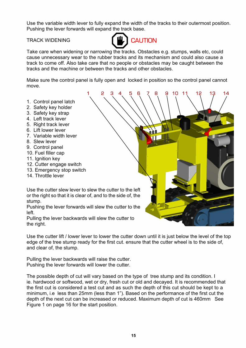
Use the cutter lift / lower lever to lower the cutter down until it is just below the level of the topedge of the tree stump ready for the first cut. ensure that the cutter wheel is to the side of,and clear of, the stump.
Pulling the lever backwards will raise the cutter.Pushing the lever forwards will lower the cutter.
The possible depth of cut will vary based on the type of tree stump and its condition. Iie. hardwood or softwood, wet or dry, fresh cut or old and decayed. It is recommended thatthe first cut is considered a test cut and as such the depth of this cut should be kept to aminimum, i.e less than 25mm (less than 1”). Based on the performance of the first cut thedepth of the next cut can be increased or reduced. Maximum depth of cut is 460mm SeeFigure 1 on page 16 for the start position.
1. Control panel latch2. Safety key holder3. Safety key strap4. Left track lever5. Right track lever6. Lift lower lever7. Variable width lever8. Slew lever9. Control panel10. Fuel filler cap11. Ignition key12. Cutter engage switch13. Emergency stop switch14. Throttle lever
Use the cutter slew lever to slew the cutter to the leftor the right so that it is clear of, and to the side of, thestump.Pushing the lever forwards will slew the cutter to theleft.Pulling the lever backwards will slew the cutter tothe right.
16
Make sure the control panel is locked in place. All guards and screens fitted to the machinemust be in place and intact. Further guards might be required to protect third party property.
Position yourself near the machine at the main control panel and atatch the safety strap asshown making sure the key is plugged into the holder. Safety helmet, visor and eardefenders must be worn along with steel toe cap boots, heavy full length trousers andgloves. When the cord is pulled out accidentally or deliberately the cutter wheel will stop.Use guards to protect property, vehicles and people from flying debris.Turn the cutter selection button clockwise one step. The cutter wheel will start rotating. Usethe manual lever to increase the engine revsUse the cutter slew lever to carefully and slowly slew the cutter across the front of the treestump taking the first cut. If the machine becomes excessively noisy or an excess of vibrationor obvious resistance to cutting is experienced stop cutting immediately and back the cutteraway from the tree stump. Turn off the engine and investigate the cause.The slew speed of the cutter can be adjusted by turning the slew speed control knob.Turning the knob clockwise will reduce slew speed.Turning the knob counter clockwise will increase slew speed.After completion of the first cut, i.e when the cutterhas passed completely across the tree stump and is clear of the opposite side of the stump,the arm can be lowered a little by pushing the lift/lower lever forward. The machine is nowready for the return cut in the opposite direction.
Repeat this until the desired depth is achieved. Then lift the arm to a height above the stump,inch forward using the track levers and start the whole process again.
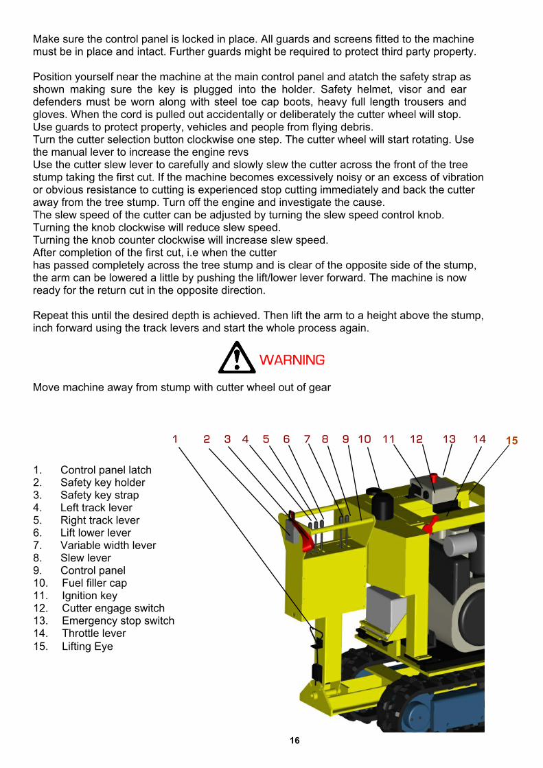
Move machine away from stump with cutter wheel out of gear
1. Control panel latch2. Safety key holder3. Safety key strap4. Left track lever5. Right track lever6. Lift lower lever7. Variable width lever8. Slew lever9. Control panel10. Fuel filler cap11. Ignition key12. Cutter engage switch13. Emergency stop switch14. Throttle lever15. Lifting Eye
15
17
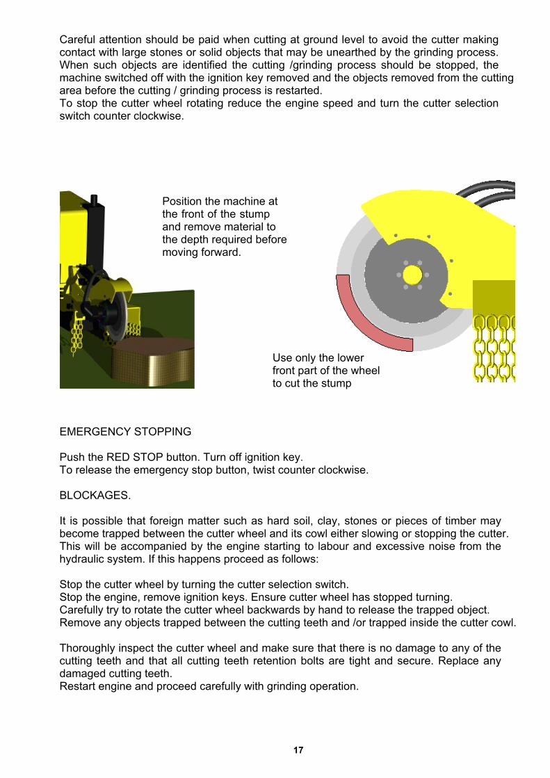
Careful attention should be paid when cutting at ground level to avoid the cutter makingcontact with large stones or solid objects that may be unearthed by the grinding process.When such objects are identified the cutting /grinding process should be stopped, themachine switched off with the ignition key removed and the objects removed from the cuttingarea before the cutting / grinding process is restarted.To stop the cutter wheel rotating reduce the engine speed and turn the cutter selectionswitch counter clockwise.
EMERGENCY STOPPING
Push the RED STOP button. Turn off ignition key.To release the emergency stop button, twist counter clockwise.
BLOCKAGES.
It is possible that foreign matter such as hard soil, clay, stones or pieces of timber maybecome trapped between the cutter wheel and its cowl either slowing or stopping the cutter.This will be accompanied by the engine starting to labour and excessive noise from thehydraulic system. If this happens proceed as follows:
Stop the cutter wheel by turning the cutter selection switch.Stop the engine, remove ignition keys. Ensure cutter wheel has stopped turning.Carefully try to rotate the cutter wheel backwards by hand to release the trapped object.Remove any objects trapped between the cutting teeth and /or trapped inside the cutter cowl.
Thoroughly inspect the cutter wheel and make sure that there is no damage to any of thecutting teeth and that all cutting teeth retention bolts are tight and secure. Replace anydamaged cutting teeth.Restart engine and proceed carefully with grinding operation.
Use only the lowerfront part of the wheelto cut the stump
Position the machine atthe front of the stumpand remove material tothe depth required beforemoving forward.

18
4. Cutter switch with safety cover5. Micro speed selection switch6. Green LED7. Emergency stop8. Red LED9. On/Signal/Freq shift Sync10. DANGER11. Arm lift / lower lever12. Left track forward / back14. Variable width15. Right track forward / back16. Slew left right
Levers (11, 12, 14, 15, 16) are all proportional and operate in the same way as described earlier inthe manual.
Radio Control (option)
Unauthorized tampering with the radio control system automatically invalidates warranty
The radio control unit is highly sophisticated and offers fine control to the movements of the machine.Fine tuning of the controls can be made only by a qualified technician or under his instruction.
The manoeuvre levers give fully proportional operation and are sprung loaded to return to zero posi-tion, i.e. "dead-man's-handle". When the manoeuvre levers are moved from zero position the respec-tive hydraulic function starts to operate slowly and increases in speed as the lever is moved furtherfrom zero position and vice versa as the lever is moved back towards zero position.
For safety reasons all manoeuvre levers must be in their zero/neutral positions for a start-up to bemade. If any lever is not in its zero/neutral position during start-up, the control unit will blink and beepthe same number of times as the number of the lever to indicate which manoeuvre lever is faulty. Thecontrol unit can be used but the faulty lever will be locked and disengaged. (eg. if it beeps and blinksfive times, it is the 5th lever from the LEFT which is faulty or giving the problem signal).
The micro speed button (5) slows down all the movements. This return sprung switch can be used toreduce the operating speed.With impulses from the sprung loaded toggle switch to the left, towards ON ( tortoise), reducesspeed. Movement of the switch to the right, towards OFF (hare), will produce 100% movement onceagain. Green LED : Flashing - speed reduction. Not flashing - normal speed .
The large red emergency stop button (7) turns off the radio control unit when pushed in. It also stopsthe cutter wheel. IT DOES NOT STOP THE ENGINE ON THE MACHINE. The main emergency stopswitch is located on the machine. Twist the switch (7) clockwise until it springs out, then push the Onbutton (9) to turn the unit on. The red LED light (8)will show that the unit is on.
Switch (4) is the cutter selection switch. Thismust be in the off position to start the machine.
19
OPERATING INSTRUCTIONS
Place a newly charged battery in the radio control unit.Start the grinder at the main ignition on the machine.Twist out the emergency stop switch on the radio control unit.Switch (4) is the cutter selection switch. This must be in the off position.Press ON/SIGNAL/FREQ.-SHIFT (9), and the red LED will light continuously.The grinder is now ready for operation.The operator must be aware of all manoeuvre lever and switch functions before operation is started.The emergency stop on the control unit stops all operations from the unit.The emergency stop on the machine is the main emergency stop switch which also stops the engine.The switch (2) on the control unit stops the engine but the control unit must be on and in signal.The emergency stop on the control unit should always be in the depressed position whenever the unitis not in use. This applies even for short stoppages, for example, if the operator wishes to move.
Stand at least 3 metres from the machine. With the cutter wheel of the machine is at position12 on a clock in plan view, the best position to stand is either 10 or 2.Make sure nobody else is within 20 metres of the machine.Wear all PPE as described earlier in the manual.Only engage wheel when it is safe to do so.Follow operating instruction set out earlier in this manual for grinding.When finished switch off cutter wheel with button (4) and then switch off engine with button (2). Then
Control CabinetOpen the control cabinet/cowl door to access the lever control, radio receiver and battery charger.On the right hand side of the receiver is a switch, plug socket and some LED lights.The switch should remain in the radio control position at all time, which is towards the door.The plug (2) is for attachment of the cable for operation if the radio controls fail. It is also used for set-ting up the controls for fine adjustment.The battery charger charges the spare battery whilst the machine is running.
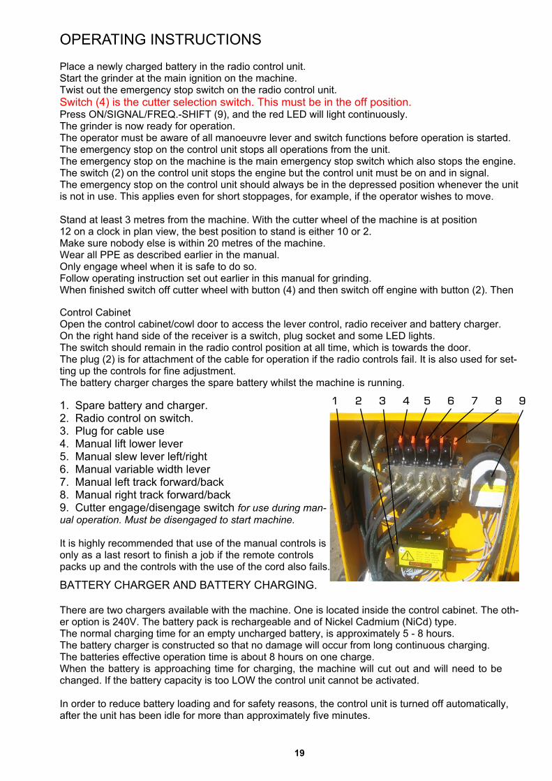
1. Spare battery and charger.2. Radio control on switch.3. Plug for cable use4. Manual lift lower lever5. Manual slew lever left/right6. Manual variable width lever7. Manual left track forward/back8. Manual right track forward/back9. Cutter engage/disengage switch for use during man-ual operation. Must be disengaged to start machine.
It is highly recommended that use of the manual controls isonly as a last resort to finish a job if the remote controlspacks up and the controls with the use of the cord also fails.
BATTERY CHARGER AND BATTERY CHARGING.
There are two chargers available with the machine. One is located inside the control cabinet. The oth-er option is 240V. The battery pack is rechargeable and of Nickel Cadmium (NiCd) type.The normal charging time for an empty uncharged battery, is approximately 5 - 8 hours.The battery charger is constructed so that no damage will occur from long continuous charging.The batteries effective operation time is about 8 hours on one charge.When the battery is approaching time for charging, the machine will cut out and will need to bechanged. If the battery capacity is too LOW the control unit cannot be activated.
In order to reduce battery loading and for safety reasons, the control unit is turned off automatically,after the unit has been idle for more than approximately five minutes.
20
MAINTENANCE.
Always immobilise engine, let engine cool down and remove ignition keys before undertakingany maintenance work on the machine.
VIBRATION
Stump grinders are machines that are subject to vibration. Be aware that vibration can worknuts and bolts loose. Check periodically all fixings for security.
PARTS
Only fit genuine MultiTip cutters and retaining bolts.Only fit genuine engine spares.Only fit genuine Predator stump grinder spares. Failure to do so will result in the invalidationof the warranty and may result in damage to the grinder, personal injury or even loss of life.
SAFETY
When maintaining your engine refer to the appropriate COSHH sheets from your suppliers.
GENERAL CLEANING.
Keep the stump grinder and engine clear from excessive dust, wood chippings and debrisbuild up especially around the fuel filler cap, hydraulic oil tank fillers, engine bay and batteryarea. Cleaning should be done with a stiff brush or cloth. DO NOT USE steam cleaners,
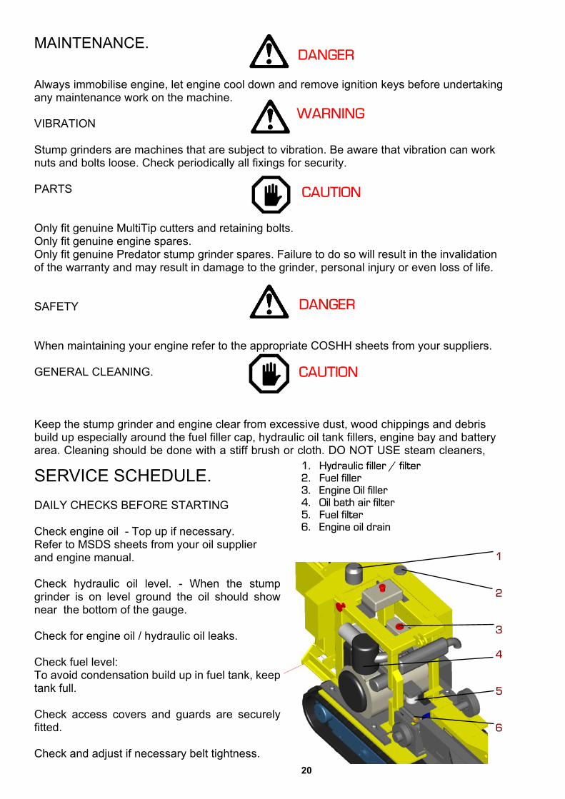
SERVICE SCHEDULE.DAILY CHECKS BEFORE STARTING
Check engine oil - Top up if necessary.Refer to MSDS sheets from your oil supplierand engine manual.
Check hydraulic oil level. - When the stumpgrinder is on level ground the oil should shownear the bottom of the gauge.
Check for engine oil / hydraulic oil leaks.
Check fuel level:To avoid condensation build up in fuel tank, keeptank full.
Check access covers and guards are securelyfitted.
Check and adjust if necessary belt tightness.

21
Belt Tightening.The Predator 28 and 38 are belt drive machines, so all the power from the engine istransferered through the belts. For this reason it is essential to keep the belts in good conditionand at the correct tension at all times. LOOSE BELTS WILL WEAR OUT THE BELTS ANDTHE PULLEYS
NOTE New belts will need tightening within the first 10 hours of use. We recommend the P38belts are checked at 5 hours and again at 10 hours. This is because of the extra torquetransfered from the powerful engine.
After the initial stretching period we recommend tightening the belts every 50 hours.
Tightening Engine to Layshaft Belts -
1) Remove the guard that is fitted to the engine, that covers the belts.
2) Slacken the 4 large nuts around the base plate that the engine sits on. A 30mm spanner isrequired.
3) Turn the jacking screw (24mm spanner) that is at the rear of the engine underneath thebattery. The engine will gradually pull backwards, tightening the belts.
4) When the belts are sufficiently tight, tighten the 4 30mm nuts up to secure the base plate.
Hydraulic Pump belts (for the P38X and P38RX) -
1) Slacken securing bolts
2) Tighten belts by turning the jacking screw
3) Tighten bolts on bracket to secure.
Lay shaft to Cutter wheel belts
1) Remove the bolts on the rubber skirt that attach to the belt guard
2) Remove the 4 bolts that hold the guard in place and remove the guard.
3) slacken the 4 bolts that secure the cutter head. Two of them are extender bolts that doubleup as spacers for the guard.
4) Slacken the jacking screw lock nut.
5) Turn the jacking screw clockwise to push the head away from the machine, tightening thebelts to the required tension.
6) Lock off the jacking screw with the lock nut.
7) Tighten the four bolts that secure the head. Then replace the guard and the rubber skirt. Donot over tighten the space bolts as they will bend due to the leverage action of the long boltheads. 45Nm is adequate.

22
Check tracks for correct tensioning and damage.
Check condition of cutters. Make sure that all cutter retaining bolts are tight and that there is no debris that may break loose when the cutter is started.
Make sure wheel is tight, there is no wobble and it turns freely.Check and clean air filter and remove any debris from within the engine covers .
Apply one pump of grease to the hub at the grease point at the centre of the wheel (per week of use)
25 HOUR FIRST SERVICE (To be repeated every 25 hours)Perform all the daily checks.Check pulley alignment.Check exhaust bolts are tightCheck engine mounts making sure nuts are tight.Check round machine make sure nothing is working loose.Check tracks for correct tensioning and damage.Refer to engine manual for cleaning of air cooling system.Check and adjust if necessary belt tightness from layshaft to cutter head.
50 HOUR FIRST SERVICE.
Repeat 25 hour service.Change engine oil and filterChange fuel filtersChange hydraulic oil and filterCheck fuel pipes and clamp bands.
100 HOUR FIRST SERVICE.
Repeat standard 50 hour service. (inc 25 hour service)Check battery electrolyte level-Refer to COSHH safe batteries – supplied.Change oil in track drive gearbox.Grease undercarriage widening pins and slides.
EVERY 100 HOUR STANDARD SERVICE. (To be repeated every 100 hours of use.)
50 Hour standard service. (inc 25 hour service).Check battery electrolyte level-Refer to COSHH safe batteries – supplied.Grease undercarriage widening pins and slides.
23
SERVICE & MAINTENANCE INSTRUCTIONS.
SPARES SUPPLY.
All spares required for the stump grinder can be purchased direct from the dealer from whomthe machine was purchased.
CHECKING FUEL LEVEL.
Do not smoke when refuelingKeep fuel away from naked heat sources.Wipe up any spillagesDiesel fuel can be injurious to the skin, wash thoroughly on completion of refueling.Refer to engine manufacturers instructions.
FILLING
The fuel tank should be kept as full as practicable to prevent water condensation and shouldnot be allowed to run dry. Take care to ensure water does not contaminate the fuel.Scrupulous cleanliness should be observed at all times. The fuel injection equipment is madeto very fine tolerances and even the smallest particle of dirt entering the system can causedamage.Add more fuel if required ensuring area around filler cap is clean.Refit fuel cap.
CHANGING FUEL FILTER.
Change inline fuel filter by loosening clips, removing and replacing new filter. Be sure toinsert the new filter with the arrow in the direction of the flowMain filter – see engine manual.Bleed fuel system - refer to engine manual.Close engine cover and redo engine cover retention clips.Run and test.
CHECKING ENGINE OIL.
See engine manualIn order for the engine to function properly, maintain the oil at the proper level and changethe oil and oil filter in accordance with the maintenance schedule. Not only do dirt and metalparticles collect in the oil, but the oil itself loses its lubrication quality if used for too long.
REVVING ENGINE
Revving the engine straight from a cold start before the oil has had chance to circulate toevery part of the engine can cause engine seizure. Allow the engine to run at no more thanfast idle speed until warm.
Over filling the engine with oil can cause serious damage.

24
CHANGING HYDRAULIC OIL FILTERS.
There are two hydraulic filters on this machine. One suction (90 micron) located within themain tank and a 25 micron return filter located in a housing on top of the hydraulic tank.The hydraulic oil filters must be changed on a yearly basis regardless of use or 10 hoursafter any kind of servicing to the hydraulic system.
OIL CHANGING - See engine manual
Undo oil drain plug located on the end of a hoseat point (9)Drain oil into large container.Replace oil drain plug and tighten.Refill through point (6).Use the dipstick (7)to check level.Do not overfill.
CHANGING ENGINE OIL FILTER - See enginemanual.
After draining oil, undo filter near batteryReplace filter with new and tighten.Refill with oil to level on dip stick.
CHANGING HYDRAULIC OIL
The hydraulic tank (14)
Place a clean dry container under the drainplug (11) and loosen until hydraulic fluidstarts to drain into the container. Thecontainer should be capable of holdingapproximately 40 litres.Thoroughly clean area around the filter cap(15) before unscrewing to avoid oilcontamination.
When fluid has stopped draining remove filterfrom housing (15) and replace with new.Replace cap.
Re-tighten plug and refill hydraulic system viafiller cap (15) to the middle of the level gau e.
10. Fuel tank11. Drain plugs12. Battery13. Oil filter14. Hydraulic tank15. Return filter

25
GREASING CUTTER WHEEL BEARING.
There is a grease nipple provided on the outside of the cutter wheel hub next to the hydraulicmotor. Apply two shots of grease from a standard grease gun.
BLUNT TEETH
Using the stump grinder with blunt cutters will over stress the cutter wheel and cause thecutter wheel bearings to fail prematurely.
The cutter wheel bearings are a serviceable part and should be replaced on a regular basis.It is recommend the bearings are changed yearly for optimum performance.
If the bearings start to make a rumbling noise or a high pitched whine expert advice shouldbe sought as this could be the first signs of bearing failure.
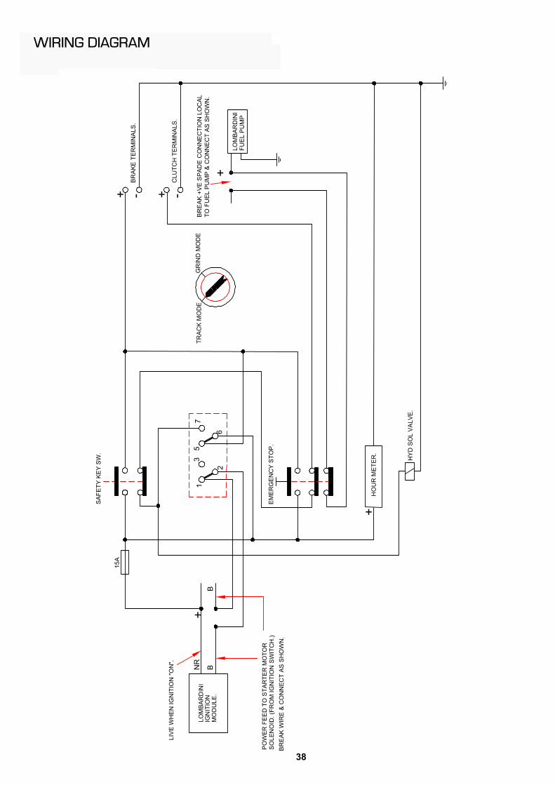
ELECTRICAL.
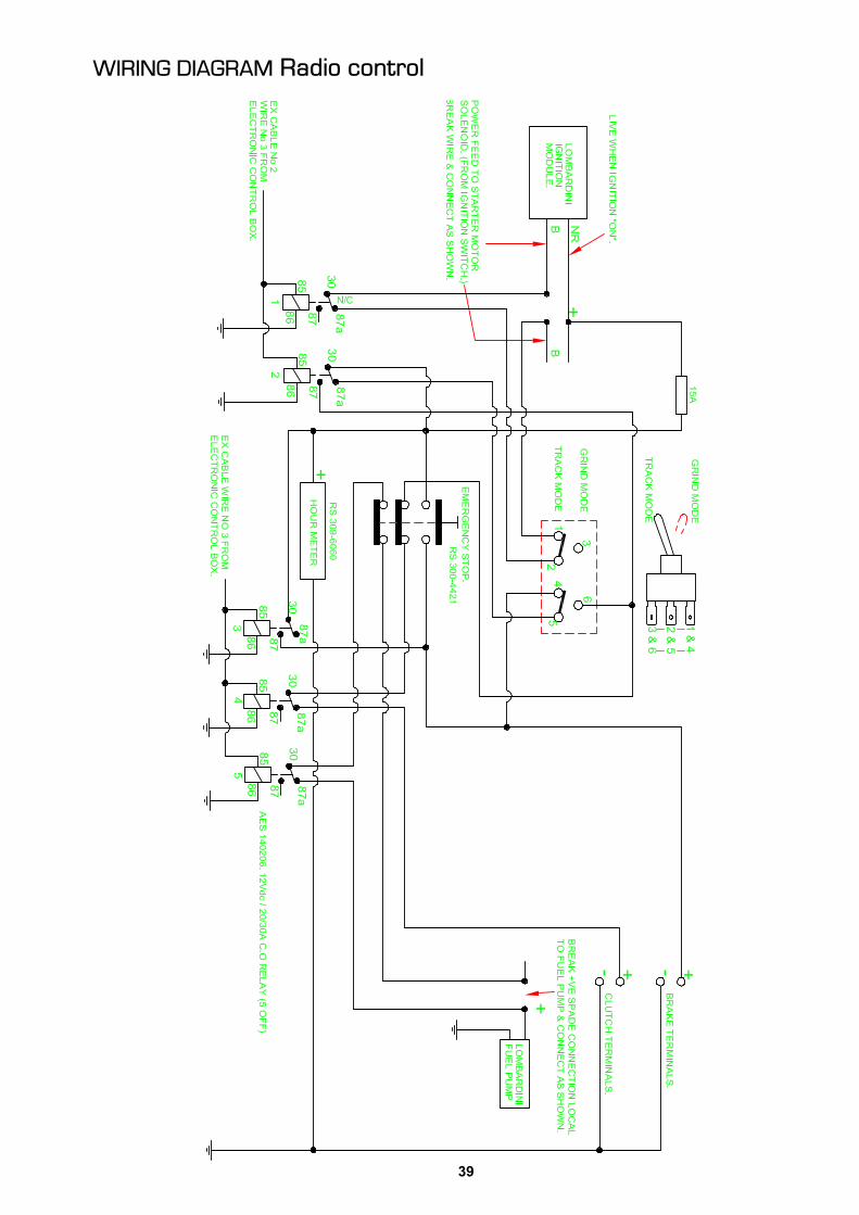
There is a main fuse located in the control box near the emergency stop button. Thiscontrols the main 12 V dc supply to the complete electrical system.
Failure of the fuse is indicative of a fault in the electrical system and the machine should bereturned to the dealer from whom the machine was purchased or to Predator so that thecause of the fault can be found and safely rectified. To simply replace the fuse withoutinvestigating the cause of failure and not carrying out the correct rectification work could bedangerous and detrimental to the safe operation of the stump grinder.
FURTHER INFORMATION
ANY FURTHER TECHNICAL INFORMATION CONCERNING REPAIRS, SERVICING ORMAINTENANCE CAN BE OBTAINED FROM YOUR SUPPLYING DEALER.
26
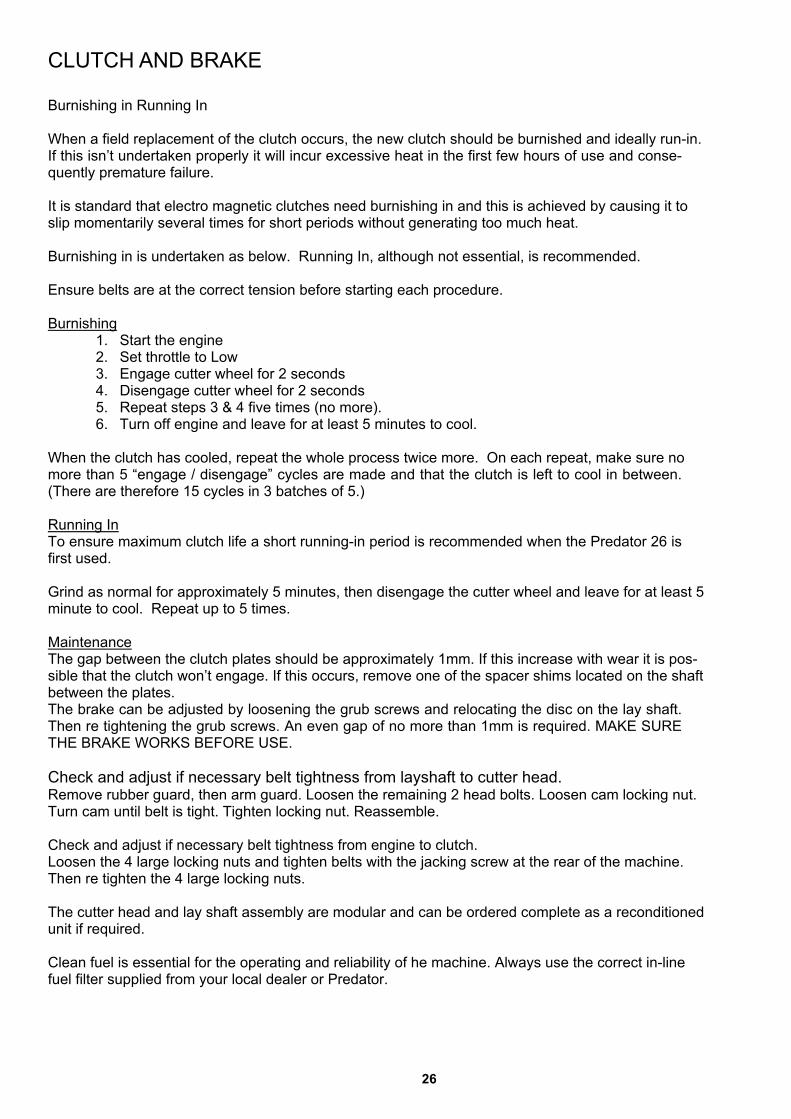
CLUTCH AND BRAKE
Burnishing in Running In
When a field replacement of the clutch occurs, the new clutch should be burnished and ideally run-in.If this isn’t undertaken properly it will incur excessive heat in the first few hours of use and conse-quently premature failure.
It is standard that electro magnetic clutches need burnishing in and this is achieved by causing it toslip momentarily several times for short periods without generating too much heat.
Burnishing in is undertaken as below. Running In, although not essential, is recommended.
Ensure belts are at the correct tension before starting each procedure.
Burnishing1. Start the engine2. Set throttle to Low3. Engage cutter wheel for 2 seconds4. Disengage cutter wheel for 2 seconds5. Repeat steps 3 & 4 five times (no more).6. Turn off engine and leave for at least 5 minutes to cool.
When the clutch has cooled, repeat the whole process twice more. On each repeat, make sure nomore than 5 “engage / disengage” cycles are made and that the clutch is left to cool in between.(There are therefore 15 cycles in 3 batches of 5.)
Running InTo ensure maximum clutch life a short running-in period is recommended when the Predator 26 isfirst used.
Grind as normal for approximately 5 minutes, then disengage the cutter wheel and leave for at least 5minute to cool. Repeat up to 5 times.
MaintenanceThe gap between the clutch plates should be approximately 1mm. If this increase with wear it is pos-sible that the clutch won’t engage. If this occurs, remove one of the spacer shims located on the shaftbetween the plates.The brake can be adjusted by loosening the grub screws and relocating the disc on the lay shaft.Then re tightening the grub screws. An even gap of no more than 1mm is required. MAKE SURETHE BRAKE WORKS BEFORE USE.
Check and adjust if necessary belt tightness from layshaft to cutter head.Remove rubber guard, then arm guard. Loosen the remaining 2 head bolts. Loosen cam locking nut.Turn cam until belt is tight. Tighten locking nut. Reassemble.
Check and adjust if necessary belt tightness from engine to clutch.Loosen the 4 large locking nuts and tighten belts with the jacking screw at the rear of the machine.Then re tighten the 4 large locking nuts.
The cutter head and lay shaft assembly are modular and can be ordered complete as a reconditionedunit if required.
Clean fuel is essential for the operating and reliability of he machine. Always use the correct in-linefuel filter supplied from your local dealer or Predator.

27
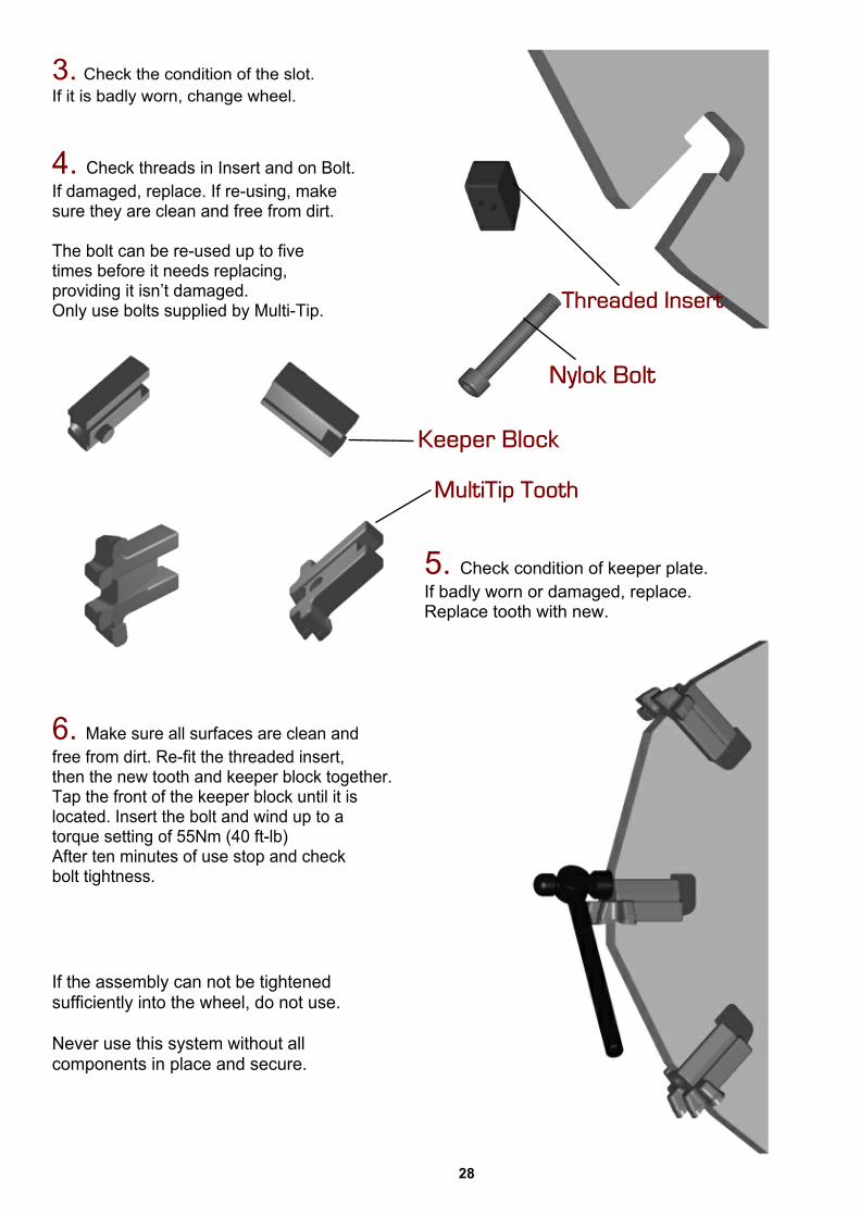
Maintenance Of Your Multi-Tip System
1. Remove bolt and tap behind toothwith a small hammer. Avoid hitting tips.Use safety goggles.
2. The keeper plate and tooth can beseparated once out of the slot.Check the groove in the top of thekeeper plate and the edgesunderneath that locate with thetooth. If these are damaged, replace.
Congratulations for purchasing yourMulti-Tip stump grinding cutting system.
Please look after this system as setout below to insure a long and trouble freelife span of the wheel and the components.
Safety is paramount. Please take note ofall the enclosed recommendations andsafety notes overleaf.
Tip - The leading teeth that are furthestfrom the centre of the wheel do most of thecutting.By changing these as soon as they become blunt,you can re-use them in non-leading positions.
28
3. Check the condition of the slot.If it is badly worn, change wheel.
4. Check threads in Insert and on Bolt.If damaged, replace. If re-using, makesure they are clean and free from dirt.
The bolt can be re-used up to fivetimes before it needs replacing,providing it isn’t damaged.Only use bolts supplied by Multi-Tip.
6. Make sure all surfaces are clean andfree from dirt. Re-fit the threaded insert,then the new tooth and keeper block together.Tap the front of the keeper block until it islocated. Insert the bolt and wind up to atorque setting of 55Nm (40 ft-lb)After ten minutes of use stop and checkbolt tightness.
If the assembly can not be tightenedsufficiently into the wheel, do not use.
Never use this system without allcomponents in place and secure.
5. Check condition of keeper plate.If badly worn or damaged, replace.Replace tooth with new.

29
MAINTENANCE OF TRACKED UNDERCARRIAGE
RUBBER TRACK TENSION
When the tracked undercarriage is lifted the rubber track must sag 10-15 mm.When tension decreases it must be re-tightened to prevent the track from coming off.Do not over tighten. If you continue to pump grease into the cylinder once the track is alreadytight, you will compress the cylinder spring and cause excessive damage.
CORRECT INSPECTION AND MAINTENANCE PROCEDURES.
Always perform maintenance on a solid and level surface.
Never grease or lubricate or perform maintenance on the machine while it is in motion.Solidly support the undercarriage if it needs to be lifted up for maintenance.Use great care when maintaining the hydraulic system since oil is very hot when the machinehas just finished working.
Circuits are under high pressures even when the machine is not working.Keep all components properly installed and in good condition.Immediately repair all damage and replace worn or broken parts.Remove any build-ups of grease, oil or debris.Check for oil leaks and /or damaged hydraulic hoses.Use recommended lubricants. Do not mix different brands of lubricants.Use only original spare parts.
Keep undercarriage widening cylinder and track-stretcher grease nipples clean.Intervals for periodic maintenance are indicated for normal work conditions. If the trackedundercarriage is used in severe work conditions then maintenance must be performed atshorter intervals.
Dispose of lubricants in an ecologically safe way. Thoughtless disposal of lubricants candamage the environment. Become familiar with local anti-pollution laws and regulations beforedisposing of lubricants.Use suitable containers when draining lubricants. Do not use beverage or food containers thatmight tempt someone to drink from them. Never pour lubricants on the ground or in a canal,pond or watercourse. Comply with current environmental protection regulations whendisposing of lubricants.
GEAR OIL
Avoid using oils with different characteristics and brands
CHOICE OF TYPE OF REDUCTION UNIT OILWe recommend, for reduction units, using gear oils with E.P. additives and viscosity classaccording to ISO VG 150 or SAE 80W/90.
When temperature variation ranges are very high we recommend using synthetic oils with E.P.properties and minimum 165 viscosity index and viscosity class VG
30
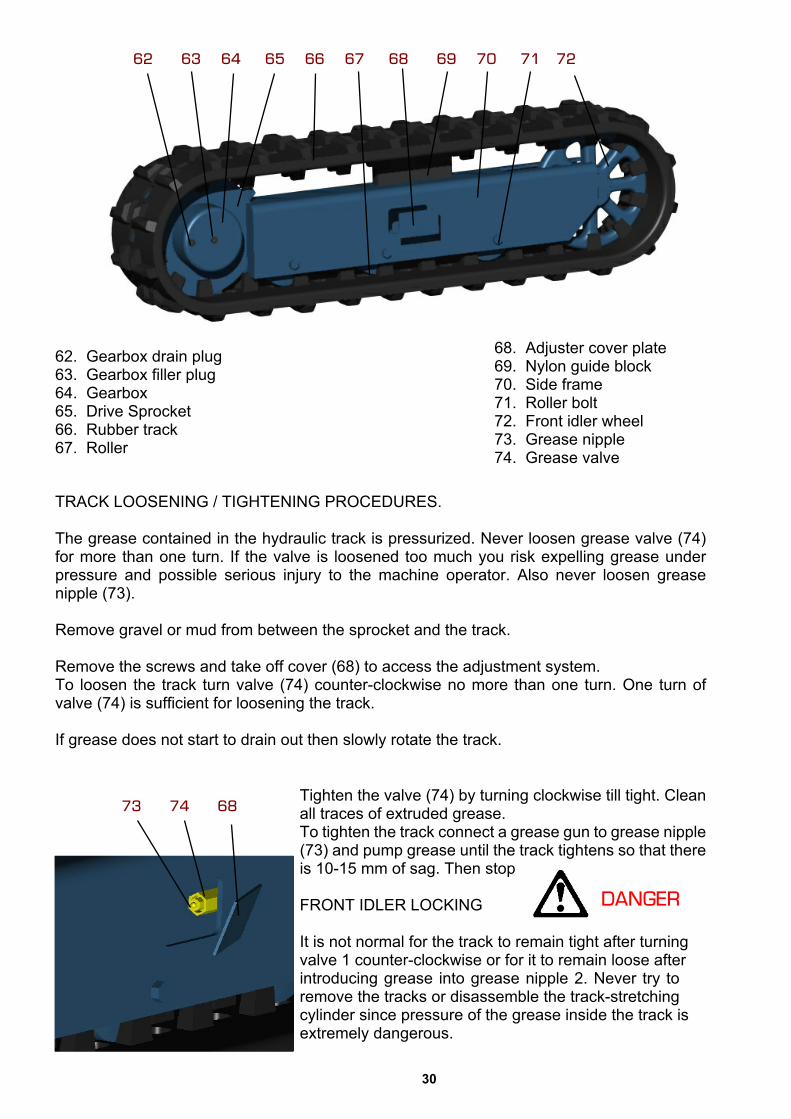
TRACK LOOSENING / TIGHTENING PROCEDURES.
The grease contained in the hydraulic track is pressurized. Never loosen grease valve (74)for more than one turn. If the valve is loosened too much you risk expelling grease underpressure and possible serious injury to the machine operator. Also never loosen greasenipple (73).
Remove gravel or mud from between the sprocket and the track.
Remove the screws and take off cover (68) to access the adjustment system.To loosen the track turn valve (74) counter-clockwise no more than one turn. One turn ofvalve (74) is sufficient for loosening the track.
If grease does not start to drain out then slowly rotate the track.
62. Gearbox drain plug63. Gearbox filler plug64. Gearbox65. Drive Sprocket66. Rubber track67. Roller
Tighten the valve (74) by turning clockwise till tight. Cleanall traces of extruded grease.To tighten the track connect a grease gun to grease nipple(73) and pump grease until the track tightens so that thereis 10-15 mm of sag. Then stop
FRONT IDLER LOCKING
It is not normal for the track to remain tight after turningvalve 1 counter-clockwise or for it to remain loose afterintroducing grease into grease nipple 2. Never try toremove the tracks or disassemble the track-stretchingcylinder since pressure of the grease inside the track isextremely dangerous.
68. Adjuster cover plate69. Nylon guide block70. Side frame71. Roller bolt72. Front idler wheel73. Grease nipple74. Grease valve

31
REMOVING THE RUBBER TRACK.
Stop your machine on a solid and level surface. Jack up side of machine under main frameand support it in safe condition.
Remove the cover plate (68) on side of track frame that gives access to the adjustment system.
To loosen a track slowly unscrew valve (74) counter-clockwise for no more than one turn. Oneturn of valve (74) is sufficient for loosening the track.If grease does not start to drain out then slowly rotate the track.
Insert 3 steel tubes in the space between the rollers and the tracks. Rotate the driving gearin reverse so that the steel tubes proceed with the track and contract the front idler wheel.Exercise force sideways to slide the track and lift it off the front idler wheel.
INSTALLING THE RUBBER TRACK.
Make sure that you are always in safe conditions with the machine lifted before performing thetrack installation operation.
Mesh the track links in the sprocket and place the other end of the track on the front idler wheel.Rotate the driving gear in reverse slowly and push the track soles into the framePosition the track using a steel tube and turn the driving gear again.Make sure the track links mesh correctly with the sprocket and with the front idler wheel.Adjust track tension as set out previously. Replace cover and lower back onto the ground.
UNDERCARRIAGE GREASE POINTS
Perform this maintenance procedure every 100 work hours, using lithium grease with EP2consistency.
Clean grease nipples before connecting them to the grease gun.Clean all grease that exits out after greasing.
Lubrication should be at more frequent intervals if the tracked undercarriage is used inparticularly severe operating conditions.
Grease points for the tracked undercarriage widening cylinder pins can be found when tracksare extended out. Grease more regularly if working in dusty or wet conditions.

32
The structure of the rubber track is shown above. The steel cables and metal core areembedded in the rubber. The carved profiles function gives stability on soft terrain. The wheelguides, located on the inside of the track, preventing the track from sliding off the guide rollers.
BREAKAGE OF STEEL CABLES.
Excess track tension can cause steel cables to break in the following conditions:When stones or foreign matter accumulate between the track and the undercarriage frame.When the track slips off its guide system.In case of great friction such as rapid changes in direction.
BREAKAGE OF METAL CORES.
Excess track tension can cause the metal cores to bend or break just like the steel cables asstated above.
Other causes include:Improper contact between track and sprocket.Rotation of internal rollers.Operation on sandy terrain.
MAINTENANCE OF DRIVE GEARED MOTORS.
CHECKING THE OIL LEVEL IN THE REDUCTION UNIT.
Stop the hydraulic geared motor with plugs (62 & 63) aligned horizontal. Remove the plugs andcheck that the oil level is up to their holes. Top up as necessary, filling through one of the holesand using the other to check the oil level.
REPLACEMENT OF OIL IN THE GEARBOX.
Replace the oil after the first 100 operating hours and then at subsequent 1000 hour Intervals. Proceed as follows to perform the replacement: - stop the reduction unit with theplugs(62 & 63) aligned vertically with (62) at the bottom - remove both plugs and drain out all theoil; -now position the plugs horizontally and fill the reduction unit through one hole, using the othertocheck the oil level.
METAL SPROCKET CURVED PROFILE
33
P26
CU
TTE
R H
UB
SU
B-A
SS
Y.
ITEM
DE
SCR
IPTI
ON
Q
TY P
AR
T-N
UM
BER
.1
STU
B S
HA
FT
1 P
-26-
CA
-002
.
S
TOC
K IT
EM
.2
NU
T 1
P-2
6-C
A-0
04.
STO
CK
ITE
M.
3
CLA
MP
ING
PLA
TE
1 P
-26-
CA
-003
.
S
TOC
K IT
EM
.4 5
1
2
3
11
8
SE
AL.
125
mm
x 1
50m
m x
12m
m.
1 P
-26-
SL-
001.
S
TOC
K IT
EM
.
6
9
GR
EA
SE
NIP
PLE
. 1/8
BSP
. 1
CU
TTE
R H
UB
1
P-2
6-C
A-0
01.
STO
CK
ITE
M.
RE
CTA
NG
ULA
R K
EY
STE
EL.
1 P
-26-
CA
-005
.
S
TOC
K IT
EM.
B-M
8/22
8.8
STO
CK
ITE
M.
4SO
C H
D C
AP
SCR
EW-M
8 x
22LG
.
6 7
DO
UB
LE R
OW
AN
G C
ON
BAL
L B
RG
1
P-2
6-B
E-0
04.
STO
CK
ITE
M.
11
14M
PU
LLE
Y. 1
42.6
PC
D. 3
2 TE
ETH
. 1
P-2
6-P
U-0
01.
STO
CK
ITE
M.
P-2
6-B
S-0
01.
STO
CK
ITEM
.1
TAP
ER
LO
CK
BU
SH
. Ø50
.
12 13
M6
x 16
LG
SO
C S
ET(G
RU
B) S
CR
EW
3 B-
M6/
16C
P 8
.8
S
TOC
K IT
EM.
4
(ITE
M 5
)U
SIN
G K
EY
STE
EL
CU
T A
ND
FIT
KEY
NO
TE.
789
1312
SE
E D
RA
WIN
G N
o. P
-26-
27.
FOR
TO
RQ
UE
SP
EC
IFIC
ATIO
NTH
RE
AD
S P
RIO
R T
O T
IGH
TEN
ING
.LO
CTI
TE 2
701
TO B
E A
PP
LIE
D T
O A
LLN
OTE
.
P-26
-27.
TO
RQ
UE
SPEC
IFIC
ATIO
NS.
P-2
6-G
A. G
EN
ER
AL
AR
RAN
GE
MEN
T.C
ON
JUN
CTI
ON
WIT
H D
RAW
ING
No'
STH
IS D
RAW
ING
TO
BE
REA
D IN
TIG
HTE
N N
UT
US
ING
PIN
SP
AN
NER
AN
DTH
EN
FIT
CO
NE
PO
INT
GR
UB
SC
RE
WS
TO
FIX
NU
T IN
PO
SIT
ION
.
10
P-2
6-S
L-00
2.
STO
CK
ITE
M.
1S
EA
L. 1
00m
m x
125
mm
x 1
2mm
.
10
P-2
6-G
N-0
01.
STO
CK
ITE
M.
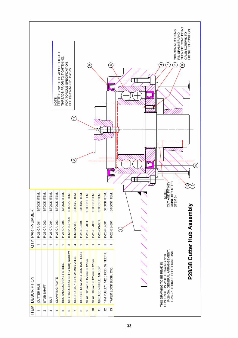
P28/
38 C
utte
r Hub
Ass
embl
y
34
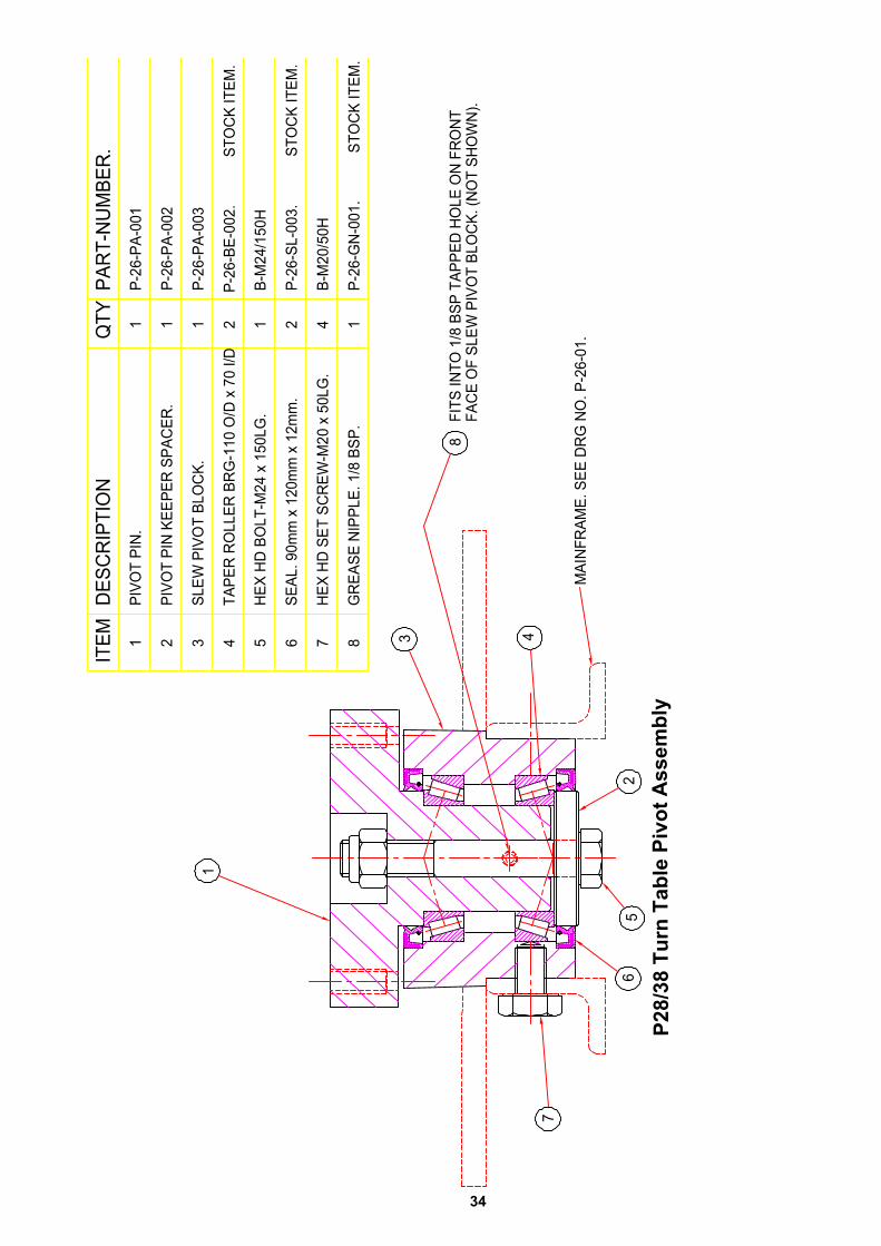
P28/
38 T
urn
Tabl
e Pi
vot A
ssem
bly
35
36

37
38
39
40
41

42

43
PREDATOR WARRANTY STATEMENT
IT IS NECESSARY TO RETURN THE ENCLOSED WARRANTY VALIDATION FORM TO PREDATOR HEAD OFFICE WITHIN FOURTEEN (14) DAYS FROM DELIVERY DATE TO VALIDATE THIS WARRANTY.
Predator Power, at its option will replace or repair, at a point they designate, parts which are defective in material or workmanship. This warranty is active for 24 months upon delivery of a new machine to the original retail purchaser, and is not transferable (Machinery sold before June 2019 carries a 12 month warranty). Please note that the engine is not warrantied by Predator or its dealers, but directly by the engine manufacturer for a period of 24 months from date of purchase. See engine manual for details.
Please be aware that parts failures may not be caused by defects in materials or workmanship - Parts will require replacement should usage or misuse exhaust the component’s life. This warranty is in place to guarantee your machine from defects in manufacture or assembly, it will not apply if the machine is subject to abuse, neglect, accident, has been improperly maintained or modified, or if parts failure is due to fuel or oil contamination.
*Items that are subject to normal expected wear such as cutter wheel, tyres, tracks, paintwork, belts, bolts, cables, pulleys, guards, clutch, teeth, bearings, filters and consumables etc are not covered under warranty*
Electric or hydraulic components such as batteries or pumps may have limited guarantees in place by their respective OEM, and are not covered under this warranty. Following correct maintenance and operating procedures, as instructed in your user manual, will promote longevity of all components.
Faulty parts need to be returned to the manufacturer for inspection prior to processing a warranty claim. It is the customer's responsibility to deliver the machine to a Predator dealer’s facility, unless other arrangements have been agreed between the dealer and the customer. The manufacturer does not recover machinery, reimburse travel costs or furnish loan/rental machines.
All arrangements for the service of the machine are to be made direct with an authorised Predator dealer or service point. Your closest dealer can be found at www.predator-mfg.com
The user manual contains important information on how to safely operate and maintain your Predator machine. The manufacturer is not responsible for part failures resulting from the neglect of this information. If you have any questions about troubleshooting, operation or maintenance, please contact your Predator dealer who will be happy to assist you.
The owner is responsible for all regular maintenance as explained in the operator’s manual. Neglect in regular maintenance or failure to replace normal wear items such as teeth, keeper blocks, bolts, lubrication oils, filters, belts, bearings, etc may void warranty.
The manufacturer may elect at its discretion, to reimburse reasonable labour costs & replacement parts when a machine is at an authorized Predator dealer for defect repairs. Prior approval should be obtained from the manufacturer before repairs take place. The hours claimed for repair will be determined by Predator.
Predator Power ltd reserve the right to alter, improve, revise or modify any parts or products. Design, specifications or parts prices may be changed without notice. The manufacturer is not responsible for updating or upgrading completed machines with design changes that are made after its production.
MACHINES USED FOR LEASE OR RENTAL - WARRANTY IS LIMITED TO 90 DAYS.
This warranty statement does not affect your Statutory Rights.

44
Kiln Lane, Binfield HeathNr. Henley-on-Thames,
Oxon. RG9 4EN.ENGLAND
Tel: +44 (0) 118 940 1740Fax: +44 (0) 118 940 4739
Related Documents