SAFETY MANUAL Vacuum Pump and Vacuum Systems

Welcome message from author
This document is posted to help you gain knowledge. Please leave a comment to let me know what you think about it! Share it to your friends and learn new things together.
Transcript

SAFETY MANUAL
Vacuum Pump andVacuum Systems
Global Contacts
Rev 01/2009Publication Number: P40040100, Issue D
© Edwards Limited 2009. All rights reserved.Edwards and the Edwards logo are trade marks of Edwards Limited.
Crawley Business Quarter, Manor Royal, Crawley, West Sussex RH10 9LW, UK
UNITED KINGDOM - HEAD OFFICECrawley Business Quarter, Manor Royal, Crawley, West Sussex RH10 9LWTel: Sales & Service +44 8459 212223 Office +441293528844Fax: Sales & Service +44 1293 534149
USAThree Highwood Drive, Suite 3-101E,HighwoodOfficePark,Tewksbury,MA01876Tel: Toll free (USA) +1 800 848 9800 +19786585410Fax: Office +18664845218
CANADA5860ChedworthWay,Mississauga,Ontario LR5 0A2Tel: Office +18003874076Fax: Office +19055011225
BRAZILRua Bernado Wrona, 22202710-060-SaoPaulo-SP,BrazilTel: Office +551139525000Fax: Office +551139652766
BELGIUMBergensesteenweg709BE-1600Sint-Pieters-LeewTel: Office +3223000730Fax: Office +3223000704
ITALYVia Vittore Carpaccio 3520090TrezzanosulNaviglio,MilanoTel: Office +3902484471Fax: Office +390248401638
GERMANYAmmerthalstrasse36,85551 Kirchheim, MunichTel: Sales&Service 08000001456Fax: Sales & Service +49 899 919 1888
FRANCE101 rue de la Bongarde,92238 Gennevilliers, CedexTel: Sales&Service +33141211256 Office +33147982401Fax: Sales & Service +33 1 4121 1238
ISRAEL5HabarzelBlvd.Gat2000IndustrialZone,POBox862,QiryatGat200901Tel: Sales +97286810633 Service +97276810633Fax: Office +97286810640
CHINA23 Fu Te Road (North)WaiGaoQiaoFreeTradeZone,Pudong, Shanghai 200131 PR ChinaTel: Sales +862158669618ext173 Service +862158669618ext152Fax: Office +862158682533 +862158669993
JAPAN1078-1Yoshihashi,Yachiyo-shi,Chiba276-8523,JapanTel: Sales +81474588831 Service +81474588851Fax: Sales +81474588835 Service +81474588048
SINGAPORE42 Loyang Drive, Loyang Industrial EstateSingapore508962Tel: Office +6565468408Fax: Office +6565468407
TAIWANNo. 434, Chung Hwa Road, Toufen Town,Miaoli County, Taiwan R.O.C.Tel: Office +88637611422Fax: Office +88637611401
KOREA5FHanwonBuilding,6-1Sunae-dong,Bundang-gu, Seongnam-si,Gyeonggi-do, KoreaTel: Office +82317167070Fax: Office +82317102222
INDIAT97/2,OppositeSaintGobainBhosariMIDC,Pune411026,IndiaTel: Sales +912040752222 Service +912040752207Fax: Sales +912040752212 Service +912027120548

This page intentionally blank.

© Edwards Limited 2008. All rights reserved. Page iEdwards and the Edwards logo are trademarks of Edwards Limited.
ContentsP400-40-100 Issue D
Contents
Section Page
1 Introduction ....................................................................................... 1
1.1 Scope of this publication ............................................................................................... 11.2 Explosion risks ............................................................................................................ 1
2 When hazards arise ............................................................................... 3
2.1 Design ...................................................................................................................... 32.2 Construction .............................................................................................................. 32.3 Operation ................................................................................................................. 32.4 Maintenance .............................................................................................................. 4
3 Chemical sources of hazards .................................................................... 5
3.1 Chemical reactions and explosions .................................................................................... 53.1.1 Homogeneous reactions ................................................................................................. 53.1.2 Heterogeneous reactions ............................................................................................... 53.2 Problems with abnormal reactions .................................................................................... 53.3 Explosion Hazards ........................................................................................................ 63.3.1 Oxidants ................................................................................................................... 63.3.2 Flammable materials .................................................................................................... 73.3.3 Pyrophoric materials .................................................................................................... 73.3.4 Unstable materials ....................................................................................................... 83.4 Toxic or Corrosive materials ........................................................................................... 83.4.1 Toxic materials ........................................................................................................... 83.4.2 Corrosive materials ...................................................................................................... 93.5 Summary - chemical sources of hazards ............................................................................10
4 Physical sources of hazards ................................................................... 11
4.1 Types of over-pressure hazard ........................................................................................114.2 Over-pressurised pump exhaust ......................................................................................114.2.1 Oil sealed rotary vane and piston pumps ...........................................................................114.2.2 Drystar pumps ...........................................................................................................124.2.3 Chemical Drystar pumping systems ..................................................................................124.2.4 Exhaust system design pressure ......................................................................................124.3 Protection against exhaust over-pressure ..........................................................................124.4 Inlet over-pressure .....................................................................................................134.4.1 Compressed gas supplies and back pressure ........................................................................134.4.2 Incorrect pump operation .............................................................................................134.5 Summary - physical sources of hazards ..............................................................................14
5 Hazard analysis .................................................................................. 15
6 System design ................................................................................... 17
6.1 Pressure ratings in a system ..........................................................................................176.1.1 Pressure rating of a system for use with flammable mixtures ...................................................176.2 Elimination of stagnant volumes .....................................................................................176.3 Exhaust extraction systems ...........................................................................................186.4 Sources of potentially explosive gas or vapour mixtures .........................................................186.5 Avoiding the flammable zone .........................................................................................196.6 Levels of system integrity .............................................................................................216.7 Use of flame arrestor protection systems ...........................................................................216.8 Sources of ignition ......................................................................................................22
Ipsi
tech
824
4-20
08

P400-40-100 Issue D
Page ii © Edwards Limited 2008. All rights reserved.Edwards and the Edwards logo are trademarks of Edwards Limited.
Contents
6.9 Summary - system design ..............................................................................................23
7 The correct choice of equipment ............................................................ 25
7.1 Oil-sealed rotary vane and piston pumps ...........................................................................267.2 Edwards Drystar and Chemical Drystar pumps .....................................................................267.3 Pipeline design ..........................................................................................................277.3.1 Bellows ...................................................................................................................277.3.2 Braided flexible pipelines .............................................................................................277.3.3 Flexible pipelines .......................................................................................................277.3.4 Anchor points ............................................................................................................277.3.5 Seals ......................................................................................................................277.4 Physical over-pressure protection ....................................................................................287.4.1 Pressure relief ...........................................................................................................287.4.2 Over pressure alarm/trip ..............................................................................................287.4.3 Pressure regulators .....................................................................................................287.4.4 Explosion pressure relief ..............................................................................................297.4.5 Flame arrestors .........................................................................................................297.5 Purge systems ...........................................................................................................297.6 Summary - the correct choice of equipment .......................................................................30
8 Operating procedures and training .......................................................... 31
9 Summary ......................................................................................... 33
Trademark credits
Drystar® is a registered trademark of Edwards.

© Edwards Limited 2008. All rights reserved. Page 1Edwards and the Edwards logo are trademarks of Edwards Limited.
IntroductionP400-40-100 Issue D
1 Introduction1.1 Scope of this publication
This document contains safety information associated with the specification, design, operation and maintenance of vacuum pumps and vacuum systems.
The document identifies the potential hazards which can arise and provides guidelines intended to help minimise the probability of safety hazards and to ensure that, if a hazard arises, it is suitably dealt with.
This document is intended to be read by anyone who specifies, designs, installs, operates or maintains vacuum pumps and vacuum systems. We recommend that this is read in conjunction with:
The Instruction Manuals supplied with your equipment.
Information provided by the suppliers of your process gases and chemicals.
Information supplied by your safety department.
If you require any further information on the suitability of Edwards products for your process application, or on safety aspects of your vacuum pumps or vacuum systems, please contact your supplier or Edwards.
1.2 Explosion risks
Note: The rupture and fragmentation of vacuum system components (including pumps) has been known to occur.
Explosions in the pump exhaust systems of Edwards vacuum pumps have occurred with low frequency throughout the world, especially - but not uniquely - in systems used on semiconductor processing applications. They are invariably caused by accidental misuse of equipment. Nevertheless, some of the incidents of explosions have been extremely violent and could have caused serious injury or death.
The most common causes of violent rupture of a vacuum system component are ignition of flammable materials, or the blockage or restriction of the pump exhaust. To avoid hazards, you should pay attention to the following to ensure the safe operation of your vacuum pumps and systems.
Ensure that the concentration of flammable materials in the vacuum system does not permit them to enter the flammable zone (potentially explosive atmosphere). During operation, there should be a suitable supply of inert gas to achieve dilution to a safe level under all foreseeable operating conditions and failure modes. See Section 3.3.2 (Flammable materials).
Ensure that exhaust blockages cannot occur during operation, either because of mechanical components (for example, valves or blanks) or because of process materials or by-products depositing in pipelines, filters, and other exhaust components.
Use only PFPE (perfluoropolyether) oils to lubricate pump mechanisms which are exposed to high concentrations of oxygen or other oxidants. Other types of oils sold as "non flammable" may only be suitable for use with concentrations of oxidants up to 30% vv.
Ensure that the accidental over pressure of a deliberately closed and isolated vacuum system cannot occur; for example, as a result of a fault in a pressure regulator or purge control system.
Where the pumped product can react violently with water, it is recommended that a cooling material other than water (for example, heat transfer fluid) be used in the cooling circuit. Please consult Edwards for advice.

P400-40-100 Issue D
Page 2 © Edwards Limited 2008. All rights reserved.Edwards and the Edwards logo are trademarks of Edwards Limited.
This page has been intentionally left blank.
© Edwards Limited 2008. All rights reserved. Page 3Edwards and the Edwards logo are trademarks of Edwards Limited.
When hazards arise
P400-40-100 Issue D
2 When hazards ariseHazards arise during all phases of a system's life. These phases are:
Design
Construction
Operation
Maintenance
The types of problem which arise in each phase are summarised below. In all cases, you must be aware that you can minimise the hazards in your system only when you have a thorough understanding of the equipment in the system. If you are in doubt, you must ask your suppliers for more information or advice.
2.1 Design
When you design your system, you must choose the correct type of equipment for your application. You must consider:
the technical specification of the equipment
the materials used in the construction of the equipment
the operating consumables used with the equipment (such as lubricants and operating fluids)
the process conditions and materials.
You must also think about the general suitability of the equipment for your application and ensure that it will always be used within its specified operating conditions.
You must establish design procedures to ensure that errors in the design are reduced to a minimum. Such procedures should include an independent check of design calculations, as well as consultation on design parameters.
Hazard analysis must always form part of your design review. You can eliminate many potential hazards by careful consideration of the use of equipment in your system.
2.2 Construction
Reduce the probability of the occurrence of a hazard during construction by the use of skilled personnel and quality assurance procedures. Skilled personnel are able to identify the correct components that are required during assembly and are also able to identify faulty or poorly manufactured components and equipment. Quality assurance procedures will help to identify and rectify poor workmanship and will ensure that the design specification is strictly followed.
Personnel must take special care and observe all safety precautions when installing new equipment in a system in which toxic, corrosive, flammable or pyrophoric substances have been pumped, produced or may still be present.
Electrical equipment must be installed by skilled personnel, in accordance with all appropriate local and national electrical codes.
2.3 Operation
Hazards can be caused during operation by equipment and component failure as a result of age, improper use or poor maintenance. Reduce the probability of such hazards by proper training in the use and maintenance of the equipment. Where necessary, refer to the information supplied by Edwards and your other suppliers in the form of Instruction Manuals, training and after sales service.

P400-40-100 Issue D
Page 4 © Edwards Limited 2008. All rights reserved.Edwards and the Edwards logo are trademarks of Edwards Limited.
When hazards arise
2.4 Maintenance
To prevent personnel coming into contact with dangerous substances, special care must be exercised and all safety precautions must be observed during maintenance of a system in which toxic, corrosive, flammable or pyrophoric substances have been pumped or produced.
Consideration should also be given to a planned maintenance programme, and to the safe disposal of components which may be contaminated with dangerous substances.

© Edwards Limited 2008. All rights reserved. Page 5Edwards and the Edwards logo are trademarks of Edwards Limited.
Chemical sources of hazards
P400-40-100 Issue D
3 Chemical sources of hazards3.1 Chemical reactions and explosions
You must carefully consider all possible chemical reactions which in normal use, misuse and failure conditions may occur at any point within your vacuum system. In particular, you must carefully consider reactions which involve gases and vapours which can lead to explosions and deflagration. Experience has shown that explosions have occurred in which there were materials involved which were not originally considered by the system designer, and in which the failure mode of such equipment had not been taken into account.
3.1.1 Homogeneous reactions
Homogeneous reactions occur in the gas phase between two or more types of gas molecules. Gas combustion reactions are usually of this form. For example, to our knowledge, the reaction between Silane (SiH4) and oxygen (O2) is always homogeneous. Therefore, if you have such reactions in a manufacturing process, you must carefully control the process pressure and reactant concentrations to prevent the occurrence of excessive reaction rates.
3.1.2 Heterogeneous reactions
Heterogeneous reactions require a solid surface to occur. Some gas molecules only react when they are adsorbed onto a surface, but do not react in the gas phase at low pressures. This type of reaction is ideal for certain processes since it minimises the effects of reactions which occur within the process chamber, reduces the amounts of particulate, and reduces the probability of contamination.
Most heterogeneous reactions become homogeneous at higher pressures, commonly well below atmospheric pressure. This means that the way the gases react in process chambers will not necessarily relate to the way that they react when compressed by a vacuum pump.
3.2 Problems with abnormal reactions
Abnormal reactions can occur when chemicals come into contact with gases or materials that the system designer does not anticipate. This can occur, for example, when there is a leak which allows either atmospheric gases to leak into the system, or toxic, flammable or explosive gases to leak out into the atmosphere.
To prevent the occurrence of these reactions, you should maintain a leak tightness of 1 x 10⁻³ mbar l s-1 (1 x 10⁻¹ Pa l s-1), or lower, in your system. High vacuum applications would typically maintain a leak tightness of 1 x 10⁻⁵ mbar l s-1 (1 x 10⁻³ Pa l s-1) or lower. You must also ensure that all valves in the system are leak tight across their seats.
Gases which do not normally come into contact with each other during the process cycle may be mixed in the pumping system and exhaust pipelines.
It is possible that water vapour or cleaning solutions may be present in the process chamber after routine maintenance procedures. This could occur after the process chamber has been washed and cleaned. Water vapour may also enter the system from exhaust ducts and exhaust scrubbers.
Where solvents are used to flush process deposits from the vacuum system, it is important to ensure that the selected solvent is compatible with all the process materials in the vacuum system.
P400-40-100 Issue D
Page 6 © Edwards Limited 2008. All rights reserved.Edwards and the Edwards logo are trademarks of Edwards Limited.
Chemical sources of hazards
3.3 Explosion Hazards
The source of explosion hazards generally falls into one of the following categories:
Oxidants
Flammable materials
Pyrophoric materials
Sodium azide
Note that, in European community countries, suppliers of process materials are required by law to publish physical and chemical data for materials which they sell (usually in the form of Material Safety Data Sheets). The data for a material must include, where applicable, information about the upper and lower explosive limits, the physical and thermodynamic properties of the material, and any health hazards associated with the use of the material. Refer to this information for guidance.
3.3.1 Oxidants
Oxidants such as oxygen (O2), ozone (O3), fluorine (F2), nitrogen trifluoride (NF3) and tungsten hexafluoride (WF6) are often pumped in vacuum systems. Oxidants react readily with a wide range of substances and materials and the reaction often produces heat and an increased gas volume. The potential resultant hazards are fire and over-pressure in the pump or exhaust system.
To pump these gases safely, you must follow the gas supplier's safety recommendations, together with the following recommendations:
Always use a PFPE (perfluoropolyether) lubricant in pumps which are used to pump oxygen in concentrations above 25% by volume in an inert gas.
Use PFPE lubricants in pumps which are used to pump gases in which the percentage of oxygen is normally below 25% by volume, but which could rise to above 25% under fault conditions.
PFPE lubricants are the preferred lubricants, but hydrocarbon type lubricants can be used if a suitable inert purge is used to guarantee that the oil is not exposed to unsafe levels of the oxidant.
Under normal circumstances, PFPE lubricants will not oxidise or break down in an oil-sealed rotary vane or piston pump oil box or gear box and so this reduces the probability of an explosion.
Note that thermal decomposition of PFPE lubricants may occur at or above a temperature of 290 °C in the presence of air and ferrous metals. However, the thermal decomposition temperature is lowered to 260 °C when titanium, magnesium, aluminium or their alloys are present.
If you do not want to use PFPE lubricants in oil-sealed rotary vane or piston vacuum pumps, you may dilute the oxidant to a safe concentration with an inert gas such as dry nitrogen. This approach is only feasible for low flow rates of oxidant gases.
You must install safety features in your system to ensure that the minimum flow of the dilution gas required to reduce the concentration of the oxidant to a safe level is always available, and to ensure that the flow of oxidant does not exceed the maximum allowed flow rate. You must design your system so that the flow of oxidant stops immediately if these conditions are not met.
We recommend that you use an Edwards Drystar® pump when you pump oxidants (see Section 7.2). Drystar pumps have no sealing fluids in the swept volume and so there is a greatly reduced probability of the occurrence of an explosion if you use a Drystar pump to process oxidants.
© Edwards Limited 2008. All rights reserved. Page 7Edwards and the Edwards logo are trademarks of Edwards Limited.
Chemical sources of hazards
P400-40-100 Issue D
3.3.2 Flammable materials
Many gases, such as hydrogen (H2), acetylene (C2H2) and propane (C3H8) are flammable and explosive in certain concentrations in air if an ignition source is provided. An ignition source may easily arise, for example, from a localised heat build-up. This is discussed in Section 6.8.
You may be able to reduce the explosion hazard by reducing the concentration of flammable gases and vapours with an inert gas; this can be introduced at several points in the pump or system. Further details are given in Section 6.5. However, in some systems, it may not be desirable to use an inert dilution gas; for example, if your application requires you to recover waste gas or vapour products, or to limit atmospheric emissions, or if your system uses a burn box to dispose of waste gas products.
Another method you can use to reduce the probability of explosion is to eliminate the ignition source. This method is commonly used in process industries to reduce fire and explosion hazards from flammable materials, and this approach forms the basis of much of the flameproof electrical codes. Further details are given in Section 6.8. It is, however, difficult to remove all ignition sources when you have a flow of flammable material inside a process system, because there is a possibility of static discharge or friction hot spots where rotating machinery is employed.
Where it is not possible in abnormal conditions to avoid the flammable zone, you must ensure that the equipment is designed to contain any resulting explosion without rupturing or transmitting a flame to the outside atmosphere. Flame arrestors are discussed in Section 6.7.
This approach is mandated in European law by the ATEX100 directive ("94/9/EC: The use of mechanical equipment in a hazardous environment"), with specific requirements detailed by European standard EN1127.
When pumping gases or vapours which could enter the flammable zone, Edwards Chemical dry pumps should be specified.
Where it is possible to avoid pumping potentially explosive atmospheres under all conditions, all types of Edwards Vacuum pumps may be used to pump flammable vapours or gases.
3.3.3 Pyrophoric materials
Under most conditions, pyrophoric gases such as silane (SiH4) and phosphine (PH3) are spontaneously flammable in air at atmospheric pressure, so combustion could occur when these gases come into contact with air anywhere in the vacuum system. This can happen if air leaks into the system, or if the system exhaust comes into contact with the atmosphere. In a confined space (such as an exhaust duct, a dust filter or an oil box of a mechanical pump), the combustion can cause an explosion.
If, in addition to pyrophoric materials, an oxidant is also present in the process, the probability of explosion at both atmospheric and process pressures increases greatly. If oxidants from other processes are vented through a common extraction system, combustion or an explosion could result. You must, therefore, use independent extraction systems when you pump pyrophoric materials.
The use of PFPE lubricants in the pump will not prevent the ignition and explosion of pyrophoric materials. It will, however, ensure that a subsequent oil fire will not occur.
PFPE lubricants can absorb process gases which, in the case of pyrophoric materials, can lead to local ignition when the lubricant is exposed to air. This hazard can become particularly apparent during servicing, or where an oxidant is pumped through the system after a pyrophoric gas. You can reduce the probability of an occurrence of this hazard if you use Edwards Drystar dry pumps which contain no lubricants in the swept volume.

P400-40-100 Issue D
Page 8 © Edwards Limited 2008. All rights reserved.Edwards and the Edwards logo are trademarks of Edwards Limited.
Chemical sources of hazards
3.3.4 Unstable materials
Sodium azide is occasionally used in the preparation of products for freeze drying and in other manufacturing processes. Sodium azide can produce hydrozoic acid. Hydrozoic acid vapours can react with heavy metals to form unstable metal azides. These azides may explode spontaneously.
The heavy metals include:
Brass, copper, cadmium, tin and zinc are commonly used in many components in vacuum pumps, accessories and pipes. If your process system uses or produces sodium azide, you must ensure that the gas path in your process system does not contain heavy metals.
Processes that use phosphorus can allow solid phosphorus to condense in the vacuum system or exhaust. In the presence of air, and subject to even slight mechanical agitation (for example, activation of a valve, or pump rotation caused by a pressure differential), phosphorus can spontaneously burn to release toxic gases. It is recommended that pumps are operated with an inert gas purge to remove phosphorus, before the pumps are vented or opened for maintenance
3.4 Toxic or Corrosive materials
Many vacuum applications involve the handling of toxic and corrosive materials and require special care.
3.4.1 Toxic materials
Toxic materials by their nature are hazardous to health. However, the nature of the hazard is specific to the material and its relative concentration. You should comply with correct handling procedures provided by the supplier of the material.
You should also consider the following points:
Gas dilution - Facilities exist to allow dilution of toxic process gases as they pass through the vacuum pump and into the exhaust. You may use this dilution to reduce the concentration below the toxic limit.
Leak detection - Edwards vacuum equipment is generally designed to be leak tight to a level of < 1 x 10⁻³ mbar l s-1 (< 1 x 10⁻¹ Pa l s-1). However, the leak tightness of the adjoining system cannot be ensured. You must use a suitable leak detection method (for example, helium mass spectrometry leak detection) to confirm the integrity of the vacuum and exhaust system.
Shaft sealing (Edwards dry pumps) - Edwards Dry vacuum pumps use a gas purge system to ensure process gases do not enter the gearbox and thereby potentially the atmosphere. You must ensure the integrity of this gas supply when handling toxic materials. Non-venting regulators must be used in combination with a non-return check valve, as discussed in Section 7.4.3.
Shaft sealing (other pumps) - Oil flooded shaft seal designs (for example, EH mechanical booster pumps and EM rotary vane pumps) minimise the risk of process gas leakage (or of the in-leakage of air), and can give a visual warning (oil leakage or oil level reduction) before a hazard arises. Other seal designs may not give adequate warning of failure.
Magnetic drives - Where total hermetic sealing is required, Edwards Chemical Drystar vacuum pumps can be supplied fitted with a magnetic drive employing a ceramic containment vessel which eliminates the need for shaft sealing on the motor input shaft.
Barium Cadmium Caesium
Calcium Copper Lead
Lithium Manganese Potassium
Rubidium Silver Sodium
Strontium Tin Zinc
Copper/zinc alloys (such as brass)
© Edwards Limited 2008. All rights reserved. Page 9Edwards and the Edwards logo are trademarks of Edwards Limited.
Chemical sources of hazards
P400-40-100 Issue D
If pressure relief valves or bursting disks are used to relieve excess pressure, ensure that they are safely vented into a suitable exhaust system, which prevents a toxic hazard.
When you return contaminated vacuum equipment to Edwards for service or maintenance, you must follow the specific procedures (Form HS1) and complete the declaration (Form HS2) given in the Instruction Manual supplied with the equipment.
3.4.2 Corrosive materials
Corrosive materials generally attack the material they are in contact with by the mechanism of ion exchange, a process which can only happen in the presence of a suitable liquid solvent (such as water). This mechanism cannot occur when the material is in the vapour phase, even if a suitable solvent is present. Edwards vacuum pumps are not designed to resist wet corrosive materials; therefore, the following points should be noted:
Anhydrous materials - The removal of the solvent necessary for ion exchange prevents corrosion. However, you must take special care to prevent the ingress of moist air from the exhaust of the vacuum pump, especially when the pump is stopped and air is sucked back into the pump. An inert purge should be used as part of the shut down procedure in order to flush corrosive vapours out of the system prior to shut down.
Dilution - Use a suitable dilution gas to prevent condensation of corrosive vapours and hence prevent the resulting corrosion.
Temperature - Increase the pump and exhaust line temperature to prevent condensation and therefore corrosion. Where the low temperature of the incoming gas flow could lead to condensation and corrosion, an inert gas purge should be used to avoid condensation.
Corrosion of safety equipment - Where safety critical equipment (such as flame arrestor elements, temperature sensors and so on) could be damaged by corrosive products in the process gas flow, their materials of construction must be selected in order to remove this hazard.
Phase changes - Unplanned phase changes can result in condensation and possible corrosion. Consideration of changes in temperature and pressure is required to avoid this hazard.
Unplanned reactions - Unplanned chemical reactions can lead to the generation of corrosive products. Careful consideration should be given to the possibility of cross contamination when equipment is used for more than one purpose.

P400-40-100 Issue D
Page 10 © Edwards Limited 2008. All rights reserved.Edwards and the Edwards logo are trademarks of Edwards Limited.
Chemical sources of hazards
3.5 Summary - chemical sources of hazards
Consider all possible chemical reactions within your system.
Make allowance for abnormal chemical reactions, including those which could occur under fault conditions.
Refer to Material Safety Data Sheets when you assess the potential hazards associated with your process materials.
Use dilution techniques to minimise reactions with oxidants and flammable materials.
Use Edwards Chemical Drystar pumps if flammable materials could enter the flammable zone under abnormal conditions.
Use the correct type of lubricant in your pump when you pump oxidants, and consider the use of a dry pump.
Do not use heavy metals in the gas path of your process system if your process uses or produces sodium azide.
Take specific care when handling toxic, corrosive or unstable materials.

© Edwards Limited 2008. All rights reserved. Page 11Edwards and the Edwards logo are trademarks of Edwards Limited.
Physical sources of hazardsP400-40-100 Issue D
4 Physical sources of hazards4.1 Types of over-pressure hazard
The over-pressure of components in the system can be as a result of any of the following:
the introduction of high pressure gas into the system.
the compression of gas by the system.
a sudden increase of temperature of volatile gas in the system.
a phase change leading to the deposition of solid product.
4.2 Over-pressurised pump exhaust
The most common cause of an over-pressurised exhaust is a blockage or restriction in the exhaust system.
All high vacuum pumps are compressors which are specifically designed to operate with high outlet-to-inlet compression ratios. They are also designed to exhaust to atmospheric pressure or to a pressure only slightly higher than atmospheric.
If the exhaust is restricted or blocked, many typical vacuum pumps can generate an exhaust pressure in excess of 7 bar gauge (8 x 10⁵ Pa). This can lead to failure of the pump or other components in the system.
In addition to the potential over-pressure caused by the operation of the pump, the introduction of a compressed gas (such as a purge or dilution gas) can also over-pressurise the system if the exhaust system is restricted or blocked.
Where a pump is fitted with flame arrestors on the exhaust side, it is essential that the exhaust back pressure does not exceed the maximum limit stated in the vacuum system Instruction Manual. A suitable maintenance programme should be employed to ensure that process deposits do not block the exhaust system and flame arrestor. If this is not practical, then a pressure sensor located between the pump and the flame arrestor should be used to detect blockage.
Sublimation or phase change can lead to blockage of process pipework and an over pressure hazard.
Read the Instruction Manual supplied with the vacuum pump for maximum and recommended continuous back-pressures. Design the exhaust system so that these limitations can be met, and comply with the recommendations in the following sections.
4.2.1 Oil sealed rotary vane and piston pumps
Oil sealed rotary vane and piston pumps are not designed to operate with the exhaust restricted or blocked. Operation of the pump in such a situation will cause rupture of the pump components.
You must therefore design the exhaust system so that the pump is never subjected to a back pressure greater than 1 bar gauge (2 x 10⁵ Pa). Under normal operating conditions, the pump should not be run continuously with a back pressure of more than 0.35 bar gauge (1.35 x 10⁵ Pa).
P400-40-100 Issue D
Page 12 © Edwards Limited 2008. All rights reserved.Edwards and the Edwards logo are trademarks of Edwards Limited.
Physical sources of hazards
4.2.2 Drystar pumps
Dry pumps also generate high exhaust pressures when the exhaust system is restricted or blocked, though the pressure rating of Drystar pumps (typically in excess of 7.0 bar gauge (8 x 10⁵ Pa) maximum static pressure; 10.0 bar gauge (1.1 x 10⁶ Pa) in the case of Edwards Chemical Drystar pumps) is considerably higher than the 1 bar gauge (2 x 10⁵ Pa) pressure rating of oil sealed rotary vane pumps. The exhaust system must be designed and maintained to eliminate the possibility of blockage and over pressure.
It is important that Edwards Chemical and GV Drystar pumps are not operated continuously with an exhaust pressure higher than 0.3 bar gauge (1.3 x 10⁵ Pa). If there is a risk of high exhaust pressures occurring, we recommend that your system incorporates an exhaust pressure trip switch to prevent this pressure being exceeded.
Note: To maintain reliability, some Edwards pumps may have a maximum exhaust pressure lower than the pressure specified above: refer to the Instruction Manuals supplied with your pumps.
4.2.3 Chemical Drystar pumping systems
Edwards Chemical Drystar pumps and flame arrestors have a static pressure rating of 10 bar gauge (1.1 x 10⁶ Pa). This pressure rating was selected to resist pressure build up as a result of an internal explosion.
4.2.4 Exhaust system design pressure
We recommend that you design your system so that the exhaust system can withstand an internal pressure of at least 1.3 bar gauge (2.3 x 10⁵ Pa), or at least 10 bar gauge (1.1 x 10⁶ Pa) in the case of a Chemical Drystar pumping system, unless over pressure relief is provided.
4.3 Protection against exhaust over-pressure
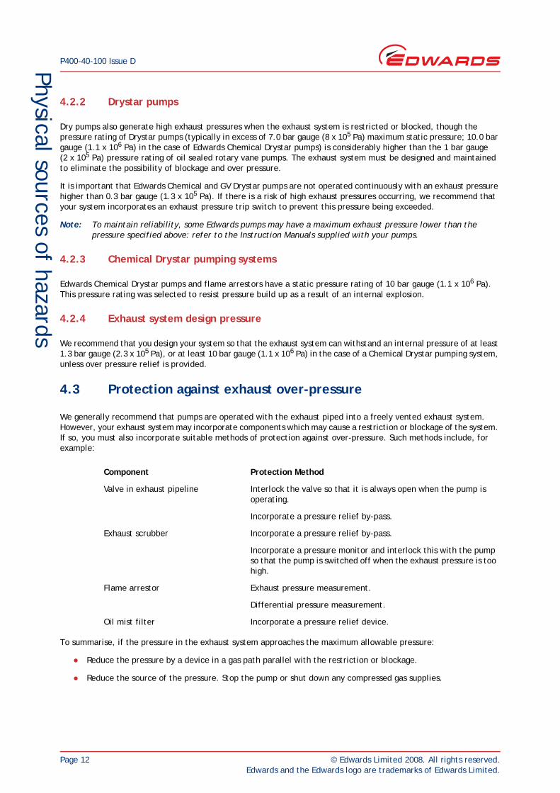
We generally recommend that pumps are operated with the exhaust piped into a freely vented exhaust system. However, your exhaust system may incorporate components which may cause a restriction or blockage of the system. If so, you must also incorporate suitable methods of protection against over-pressure. Such methods include, for example:
To summarise, if the pressure in the exhaust system approaches the maximum allowable pressure:
Reduce the pressure by a device in a gas path parallel with the restriction or blockage.
Reduce the source of the pressure. Stop the pump or shut down any compressed gas supplies.
Component Protection Method
Valve in exhaust pipeline Interlock the valve so that it is always open when the pump is operating.
Incorporate a pressure relief by-pass.
Exhaust scrubber Incorporate a pressure relief by-pass.
Incorporate a pressure monitor and interlock this with the pump so that the pump is switched off when the exhaust pressure is too high.
Flame arrestor Exhaust pressure measurement.
Differential pressure measurement.
Oil mist filter Incorporate a pressure relief device.
© Edwards Limited 2008. All rights reserved. Page 13Edwards and the Edwards logo are trademarks of Edwards Limited.
Physical sources of hazardsP400-40-100 Issue D
4.4 Inlet over-pressure
4.4.1 Compressed gas supplies and back pressure
It is common to underestimate the required pressure rating of the pipeline connecting the pump to the vacuum system, due to the belief that this pipeline will not be subjected to pressures above atmospheric pressure. In practice, this is only true under normal design operating conditions. You should estimate the required pressure rating to allow for higher pressures caused by abnormal or fault conditions.
The most common cause of over-pressure in pump inlet pipelines is the introduction of compressed gases (such as purge gases) when the pump is not operating. If components in the inlet pipeline are not suitable for the pressures which result, the pipeline will rupture and process gases will leak from the system. A back flow of gases from the system into a process chamber which is not capable of withstanding the pressure which results will also cause ruptures and leaks.
Take care before you connect compressed gas supplies to your system through pressure regulators which are designed to provide a low pressure flow, at a pressure within the rating of the system.
The non-venting pressure regulators most commonly used will cause the pressure within the system to rise to the pressure of the gas supply to the regulator, if operated under conditions where there is no process gas flow through the system. You must therefore use one of the following two methods to prevent over-pressurisation:
reduce the pressure, allow the gases to by-pass the pump and flow into a freely vented exhaust
monitor the pressure of the system and use a positive closure valve to shut off the supply of compressed gas at a preset pressure level.
4.4.2 Incorrect pump operation
Special precautions must be taken until it has been established that the pump is operating correctly.
If the direction of rotation of the pump is incorrect and the pump is operated with the inlet blocked or restricted, the pump will generate high pressure in the inlet pipeline. This could result in rupture of the pump, the pipeline or components in the pipeline.
Always use a blanking plate loosely secured by screws to the pump inlet until you have established that the direction of rotation of the pump is correct.
Operation at high rotational speeds could result in pump break up. Do not operate the pump at rotational speeds above the maximum designed speed of rotation; this is particularly important where frequency inverters are used for speed control.

P400-40-100 Issue D
Page 14 © Edwards Limited 2008. All rights reserved.Edwards and the Edwards logo are trademarks of Edwards Limited.
Physical sources of hazards
4.5 Summary - physical sources of hazards
When you perform safety calculations, ensure that the safe working pressures for all components in the system are taken into account.
Ensure that the pump exhaust cannot become blocked.
For Edwards GV Drystar pump systems, design the exhaust system for a maximum continuous operating pressure of 0.3 bar gauge (1.3 x 10⁵ Pa) and a maximum static pressure of 1.0 bar gauge (2 x 10⁵ Pa). If there is a risk of high exhaust pressures occurring, we recommend that your system incorporates an exhaust pressure trip switch to switch off the pump should the maximum continuous operating pressure be exceeded.
For Edwards Chemical Drystar pump systems, design the exhaust system for a maximum continuous operating pressure of 0.3 bar gauge (1.3 x 10⁵ Pa) and a maximum static pressure of 10 bar gauge (1.1 x 10⁶ Pa) (unless pressure relief is provided).
Take account of abnormal and fault conditions when you assess the required pressure rating of the pump inlet pipeline.
Ensure that you incorporate the correct type of pressure relief device and that it is suitably rated for your application.
Ensure that compressed gas supplies are properly regulated and monitored. Switch off the supplies if the pump is switched off.
Where possible, ensure the supply pressure to any regulated purges is lower than the maximum static pressure of the system. Alternatively, ensure that pressure relief is possible in the event of component failure.

© Edwards Limited 2008. All rights reserved. Page 15Edwards and the Edwards logo are trademarks of Edwards Limited.
Hazard analysis
P400-40-100 Issue D
5 Hazard analysisThe techniques of hazard analysis provide a structured approach to the identification and analysis of the hazards in a system in normal use, and the hazards which may arise under fault and failure conditions. Such techniques provide a route to hazard management; the use of these techniques may, in many circumstances, be a statutory requirement. To be fully effective, hazard analysis must begin during the initial design of a system and must continue through the installation and operation of the system.
A detailed study of hazard analysis techniques is beyond the scope of this publication. There are, however, many hazard analysis techniques described elsewhere. An example of a technique commonly used in the chemical processing industry is HAZOP (Hazard and Operability Study). This is a procedure for hazard analysis which is concerned with the identification of potential hazards and operating problems.
Typically, hazard analysis generates information about the type of hazards, the severity of these hazards, and the probability that the hazards will occur. You can use this information to decide on the best way to reduce the effects of the hazards to acceptable levels. Depending on the origin of the hazard, it may be possible either to eliminate the hazard, or to reduce the severity of the hazard, or to reduce the probability that the hazard will occur. It is, however, rare that hazards can be eliminated completely.
You must consider all possible effects of a hazard when you decide on the best way to manage the hazard. For example, a small hot surface may present a minor hazard for an operator as it could cause a burn. To reduce the probability of the occurrence of a burn, the system designer may provide a visible warning of the hot surface, or may put a guard around the hot surface. However, the hazard analysis of the system may also indicate that the same hot surface could provide a source of ignition for flammable vapours; this might lead to a major explosion or to the release of a toxic vapour cloud. To reduce the probability of ignition, the system designer must reduce the temperature of the hot surface, or ensure that the flammable vapours cannot contact the hot surface.

P400-40-100 Issue D
Page 16 © Edwards Limited 2008. All rights reserved.Edwards and the Edwards logo are trademarks of Edwards Limited.
This page has been intentionally left blank.

© Edwards Limited 2008. All rights reserved. Page 17Edwards and the Edwards logo are trademarks of Edwards Limited.
System design
P400-40-100 Issue D
6 System design6.1 Pressure ratings in a system
Vacuum system pipelines and components are designed to work with internal pressures below atmospheric pressure. In practice, however, it is usually necessary to design your system for use with internal pressures above atmospheric pressure as well. If necessary, you must incorporate pressure relief devices to prevent over-pressurisation.
It is important that you do not allow the inlet pipes and other inlet components to become the weakest part of the system, on the assumption that they will always operate under vacuum, even under fault conditions.
Exhaust systems must always be designed to offer the smallest possible back pressure to the pump during operation. It is important, however, that you design your exhaust system with an adequate pressure rating; it must be suitable for use with the pressures that can be generated by the pump and by the introduction into the system of a compressed gas, and be suitable for use with the over-pressure protection measures used.
When you perform your hazard analysis, you should always consider:
External inlets, such as inert gas connections
Isolation and constriction from all sources, especially in exhaust lines
Reactions between process gases.
6.1.1 Pressure rating of a system for use with flammable mixtures
Where the vacuum system is used to handle a vapour or gas mixture in the flammable zone and where there is a potential ignition source, the pump, pipework and vessels should have a minimum design pressure rating of 10 bar gauge (1.1 x 10⁶ Pa).
It should be noted that where a vessel contains a volatile liquid and can be isolated from the rest of the system, then the application of external heat (for example, from a fire) may result in internal pressures greater than the design pressure of the vessel. You must consider the need for suitable pressure relief in this case.
6.2 Elimination of stagnant volumes
A stagnant volume is any closed volume in a vacuum pipe or component which is not subjected to a through flow of gas. Examples are the gear box of a mechanical booster pump, or the gauge head of an instrument. Valved pipework and nitrogen gas inlet pipes can also become stagnant volumes when they are isolated
Stagnant volumes must be taken into account when you consider the mixture and reaction of process gases which are not normally present together in the process chamber. Pipes, pumps and process chambers generally transport gases linearly, with one gas or gas mixture followed by another. Gases transported in such linear flows are not normally mixed unless the velocity of the exhaust gas is reduced by a restriction or blockage. A stagnant volume is not purged and may be filled with process gases as the pressure in the system rises and falls. In this way, gases which pass through the system at one stage of the process can be retained. These may then react with gases from a subsequent phase of the process. Thorough evacuation of the chamber between the introduction of incompatible gases will guard against the risk of explosion.
You must take special care when you consider cross-contamination in stagnant volumes when the pressure is relatively high (close to atmospheric pressure) and the gases are potentially explosive. In particular, you should consider the hazard of build-up in filters and separators. Where appropriate, use high integrity, continuous flows of inert purge gas to reduce the probability of cross contamination.
When pumping flammables, it is possible for stagnant volumes to fill with potentially explosive gases or vapours that cannot be removed by normal purging. Where an ignition source could also be present, specific purging of the stagnant volume should be considered.
P400-40-100 Issue D
Page 18 © Edwards Limited 2008. All rights reserved.Edwards and the Edwards logo are trademarks of Edwards Limited.
System design
6.3 Exhaust extraction systems
It is important that you use the correct type of exhaust extraction system for your process. As previously stated, the extraction system must be designed to withstand the pressures of operation and, when hazardous materials are produced or processed, must be sufficiently leaktight to contain the process materials and their by-products and prevent hazardous releases to atmosphere.
6.4 Sources of potentially explosive gas or vapour mixtures
When a flammable gas or vapour is mixed with the correct concentration of oxygen or other suitable oxidant, it will form a potentially explosive mixture which will ignite in the presence of an ignition source.
While it is generally apparent if a pumped material is potentially explosive, there are, in the experience of Edwards, some conditions where a potentially explosive mixture is produced due to conditions which were not considered when designing the process. You must identify all possible sources of potentially explosive mixtures which could be generated by your equipment. Some examples from Edwards experience are listed below, but the list is by no means exhaustive:
Cross contamination - Where a vacuum pump is being used for a number of duties, it is possible that its use with individual materials is safe, but if the pump is not purged before use with another material, then cross contamination could occur with unexpected reactions.
Cleaning fluids - An application may be viewed as benign, but the use of flammable cleaning fluids and the subsequent drying by evacuation through the vacuum pump can create a potentially explosive mixture.
Unexpected materials - On 'house vacuum' duties where the vacuum pump is used to provide a distributed vacuum system, it is possible to pump flammable materials which were not considered during system design. These materials may have auto-ignition temperatures lower than the internal temperatures of the vacuum pump.
Dissolved vapours - Low auto-ignition temperature materials generally have high vapour pressures. Pumping these materials at pressures above the vapour pressure will generally result in internal dry pump stage temperature below the auto-ignition point. However, it is possible for these vapours to become absorbed in a liquid with a lower vapour pressure, and for them to be released as the pressure falls below the vapour pressure of the dissolved material. At this lower pressure, it is possible for the internal dry pump stage temperature to exceed the auto-ignition point.
Air leakage - The accidental ingress of air or oxidant into a system may change the concentration of a flammable gas or vapour and create a potentially explosive mixture.
Flammable sealing liquids - Where a flammable liquid is used as the sealing liquid in a liquid ring vacuum pump, the ingress of air will create a potentially explosive internal mixture.

© Edwards Limited 2008. All rights reserved. Page 19Edwards and the Edwards logo are trademarks of Edwards Limited.
System design
P400-40-100 Issue D
6.5 Avoiding the flammable zone
A flammable material will only create a potentially explosive atmosphere if it is combined with air or oxygen and its concentration lies between the Lower Flammability Limit - LFL (or Lower Explosion Limit - LEL) and the Upper Flammability Limit - UFL (or Upper Explosion Limit - UEL).
To be potentially explosive, it is also necessary for the concentration of oxygen to be above the Minimum Oxygen Concentration - MOC (or Lowest Oxygen Concentration - LOC). The MOC (LOC) for the majority of flammable gases is 5% vol. or greater. (Note: This does not apply to explosive or pyrophoric materials that require special precautions.)
There are a number of strategies that can be used to avoid operating with gas mixtures in the flammable zone. The choice of strategy will depend on the outcome of the risk assessment (hazard analysis) for the process and the pumping system:
Maintain the flammable gas concentration below the LFL (LEL)
This is the preferred mode of operation. To minimise the risk of the flammable gas accidentally entering the flammable zone, a safety margin for below-LFL (LEL) operation should be used, and the flammable concentration should always be maintained below 25% of the LFL (LEL).
The preferred method of maintaining the concentration below 25% of the LFL (LEL) is dilution with inert purge gas (for example, nitrogen), introduced into the pump inlet and/or purge connections. The required integrity of the dilution system and of any alarms or interlocks will depend on the hazardous zone which would result if the dilution system were to fail.
Maintain the oxygen concentration below the MOC (LOC)
This is an alternative mode of operation that requires the use of oxygen concentration monitoring of the pumped gases to ensure safe operation. To minimise the risk of the flammable gas accidentally entering the flammable zone, a safety margin for below-MOC (LOC) operation should be used. Best available practice where the oxygen concentration is continuously monitored, is to maintain the oxygen concentration at less than 2% vol. below the lowest published MOC (LOC) for the gas mixture. If monitoring is only undertaken in the form of routine oxygen level checks, the oxygen level should not be allowed to exceed 60% of the lowest published MOC (LOC).
The preferred method of maintaining the oxygen level below the lowest published MOC (LOC) is rigorous exclusion of air and oxygen from the process and pump system, together with dilution of the pumped gas with an inert purge gas (such as nitrogen), introduced into the pump inlet and/or purge connections, if needed. The required integrity of the air/oxygen exclusion measures and of any alarms and interlocks will depend on the hazardous zone that would result were the exclusion and dilution systems to fail.
Precautions typically required to rigorously exclude air from the process and pump system are given at the end of this section (see page 20).
Maintain the flammable gas concentration above the UFL (UEL)
Where flammable gas concentrations are very high, above-UFL (UEL) operation can be more suitable. To minimise the risk of any accidental incursion into the flammable zone, a safety margin for above-UFL (UEL) operation should be used. It is recommended that the residual oxygen level in the gas should be maintained at less than 60% of the absolute oxygen level normally present at the flammable gas UFL (UEL) concentration.
The preferred method of maintaining the oxygen level below this safety margin, is rigorous exclusion of air and oxygen from the process and pump system. Dilution of the pumped gas with an inert purge gas (such as nitrogen) or with additional flammable gas ('padding' gas), introduced into the pump inlet and/or purge connections, may also be needed. The required integrity of the air exclusion measures, of any purge gas introduction system, and of any alarms and interlocks will depend on the hazardous zone that would result were the exclusion and dilution systems to fail.

P400-40-100 Issue D
Page 20 © Edwards Limited 2008. All rights reserved.Edwards and the Edwards logo are trademarks of Edwards Limited.
System design
Precautions typically required to rigorously exclude air from the process and pump system are as follows:
Elimination of air leaks - Use a leak detector or conduct a pressure rise test. Before admitting flammable materials into the process chamber, it is possible to perform a test to establish that air (oxygen) leakage into the vacuum system is within allowable limits; this is known as a pressure rise test.
To perform a pressure rise test, the empty process chamber is evacuated to a pressure just below the normal operating pressure, and is then isolated from the vacuum pump. The pressure in the process chamber is then recorded over a fixed period of time. As the volume of the process chamber is known along with the maximum allowable air leakage, it is possible to calculate a maximum allowable pressure rise than can occur over the fixed period of time. If this maximum pressure limit is exceeded, action must be taken to seal the source of the air (oxygen) leakage into the process chamber; the test must then be successfully repeated before the admission of flammable materials into the process chamber is allowed.
In some cases, the ability of the vacuum system to achieve a good base pressure can be used to indicate system leak tightness.
Remove all air from the system before the start of the process - Before any flammable gas is admitted into the process, the system should be fully evacuated and/or purged with inert gas (such as nitrogen), to remove all air from the system. At the end of the process, repeat this procedure before the system is finally vented to air.
For dry vacuum pumps - Ensure that any shaft seal gas cannot be supplied with or contaminated with air under any circumstances, and ensure that any gas ballast port is either sealed, or only used to introduce inert gas.
For wet vacuum pumps (rotary piston or rotary vane pumps) - Maintain the shaft seals fully in accordance with the manufacturer's instructions, and use a pumped and pressurised oil lubrication system with an alarm indication for loss of oil pressure. This system may comprise an external accessory to provide filtered and pressurised lubricating oil, with a pressure switch. Ensure that any gas ballast port is either sealed, or only used to introduce inert gas. Provide an adequate purge of inert gas to the oil box, to remove air before the start of the process.
For roots vacuum booster pumps - Maintain the primary drive shaft seal fully in accordance with the manufacturer's instructions, and ensure that any purge or breather port connections can only be used to introduce inert gas. It is recommended that you use Edwards EH mechanical booster pumps. EH pumps have oil-flooded shaft seals and can be fitted with oil level monitors, to provide warning of seal problems before air leakage into the system occurs.
Reverse flow - Ensure that the system operating procedures and facilities protect the system from any reverse air flow which might result from a pump failure. Ensure that any pumped flammable gases are safely disposed of at the final vent from the pump exhaust. Ensure that flammable gas mixtures cannot arise in the exhaust pipeline, by the use of suitable inert purging of the pipeline before the start of - and after the end of - the flammable gas process, and by the use of adequate inert gas purging during operation, to prevent turbulent back-mixing of air down the exhaust.
Note: Where Edwards DPS or EDPS dry vacuum systems are fitted with flame arrestors, it is possible to pump potentially explosive atmospheres. Consult Edwards for advice.
© Edwards Limited 2008. All rights reserved. Page 21Edwards and the Edwards logo are trademarks of Edwards Limited.
System design
P400-40-100 Issue D
6.6 Levels of system integrity
Methods of protection using inert gas dilution have been covered briefly in earlier sections. The principle of the method is that you mix an inert gas (usually nitrogen) with your process gases to dilute them to a level where an explosion or reaction cannot occur. When you use gas dilution as a primary safety system to protect against possible explosion, you may require a high integrity alarm and interlock system to prevent the operation of the system when the gas dilution system is not operational. The integrity of the gas dilution system should be considered during the risk assessment (hazard analysis), and will depend on the internal zoning (i.e. level of risk) which would result were the dilution system to fail. Current best practice should always be applied to this risk assessment, to determine the required levels of system integrity.
For example, if a dilution system were used to maintain a flammable gas concentration outside the flammable zone and the result of dilution failure would be that the pumped gas would be inside the flammable zone continuously or frequently (typically for more than 1/8th of the time - i.e. a Zone 0 condition), then the dilution system must satisfy one of the following:
It must be failsafe even in the event of rare malfunction.
It must be safe with two faults present.
It must comprise two independent dilution supply systems.
Alternatively, if the result of dilution system failure would be that the pumped gas would be inside the flammable zone occasionally (typically for less than 1/8th of the time - i.e. a Zone 1 condition), then the dilution system must satisfy one of the following:
It must be failsafe even in the event of expected malfunction.
It must be safe with one fault present.
If the result of dilution system failure would be that the pumped gas would be unlikely to enter the flammable zone, but might do so only for brief periods (typically for less than 1/800th of the time - i.e. a Zone 2 condition), then the dilution system must be safe in normal operation.
6.7 Use of flame arrestor protection systems
Where Edwards Chemical Drystar vacuum pumps are used for pumping gases or vapours which could enter the flammable zone under abnormal conditions, you must use inlet and exhaust flame arrestors to contain the resulting flame front in the event of an ignition. Third party certification has been obtained for the use of specific flame arrestors with Chemical Drystar Dry vacuum pumps, demonstrating their ability to prevent flame transmission along the process pipework or into the surrounding atmosphere.
Where there is the possibility of continuous ignitions or burn within the Edwards Chemical Drystar vacuum pump, you must take special precautions. Such conditions could occur due to a continuous ignition source resulting from the accidental pumping of a gas or vapour with an auto-ignition temperature lower than the internal pump temperatures. In this case you must use a PT100 or equivalent temperature sensing device located on the pump side of each flame arrestor to detect a burn condition, and adopt a suitable flame suppression strategy to make the system safe in the event of a burn being detected.
This is application dependent but could include:
Stopping the supply of fuel - Closing a valve located on the inlet of the Edwards Chemical Drystar Vacuum pump will prevent the supply of fuel into the vacuum pump.
Stopping the source of the ignition - Stopping the vacuum pump by turning off the power to the motor will bring the pump to a halt in approximately 10 seconds.
Inerting the area of the burn - The rapid addition of inert gas into the area of burn (typically, but not always located in the exhaust manifold of the pump), will eliminate the flame. Note that it is possible for a flame to re-ignite if the source of ignition is not removed.
P400-40-100 Issue D
Page 22 © Edwards Limited 2008. All rights reserved.Edwards and the Edwards logo are trademarks of Edwards Limited.
System design
6.8 Sources of ignition
Where Edwards Chemical Drystar Vacuum pumps are used to handle a gas or vapour which may enter the flammable zone under abnormal conditions, you must consider all possible sources of ignition. Below are some areas of consideration which you can use as part of an overall review.
Note: Edwards Chemical pumps are certified by a third party to confirm that (if correctly applied) they will contain an internal explosion.
Mechanical contact - Two rubbing surfaces can create sufficient heat to provide the ignition for combustion. All pumping mechanisms and machines based on rotating or reciprocating designs have the potential under failure conditions to allow two surfaces to come into rubbing contact. It is possible to reduce the possibility of a failure but not totally to eliminate the possibility. All Edwards Chemical Drystar vacuum pumps are designed to minimise this potential, but accepting that it can occur, these pumps are designed and certified to contain an internal explosion.
Particle ingestion - All pumping mechanisms have the potential to ingest particles which have been created by the process, or which are a result of the system manufacturing process. Where these are rolled between a moving surface and a static one, it is possible to generate heat. Since this can occur in virtually all types of vacuum pumps, Edwards Chemical Drystar vacuum pumps are designed to minimise this potential, but accepting that it can occur, these pumps are designed and certified to contain an internal explosion.
Dust build up - The build up of fine compacted dust within internal clearances can occur where any pumping mechanism is placed on a dust generating process. Even with the use of inlet dust filters, it is still possible for particles less than 50 micrometers to enter the pump. With small dimensional changes due to thermal changes, compacted dust can touch a moving surface and create heat. Edwards Chemical Drystar vacuum pumps are designed to minimise this potential, but given that it can occur, are designed and certified to contain an internal explosion
Heat of compression (auto-ignition) - The internal heat of compression within any compressor must be considered in relation to the auto-ignition temperature of any gases or vapours which are pumped. Edwards Chemical Drystar vacuum pumps are designed to minimise internal gas temperatures and an extensive characterisation program has determined the effect which most pumping parameters have on internal temperature.
Hot surfaces - Where flammable gases or vapours are allowed to come into contact with a hot surface, they may ignite if the auto-ignition temperature is exceeded. Note: Edwards pumps and flame arrestors should not be thermally insulated if this could cause increased surface temperatures internally (and externally) leading to auto-ignition.
Externally applied heat - Externally applied heat can occur, for example, in the event of a fire in the immediate area of the vacuum equipment. Under this condition, it is possible to generate internal pressures in excess of the maximum static pressure of the system, and temperatures in excess of auto-ignition temperature. This should be considered as part of the system hazard analysis.
Hot process gas flow - High inlet gas temperatures can lead to internal (or external) surfaces exceeding the auto-ignition temperature of the materials being pumped. As low-pressure gases have a low density, it is possible for them to have high gas temperatures but not cause surrounding equipment to heat up. Therefore, consideration should be taken of the energy content of the gas and its possible effect on the temperature of surrounding equipment.
Catalytic reaction - The presence of certain metals can lead to catalytic ignition. All materials of construction in the vacuum system should be considered for their potential to act in this way with the pumped gases or vapours.
Pyrophoric reaction - The ingestion of air or oxygen will lead to the spontaneous ignition of a pyrophoric material. See Section 3.3.3.
Static electricity - Certain conditions can occur where static electricity can build up on insulated components before discharging to earth in the form of a spark. The potential for static build-up should be considered as part of the system design.
Lightning - Where located in an outdoor location, a lightning strike can provide ignition energy. The potential of this event occurring should be considered as part of the system design.
© Edwards Limited 2008. All rights reserved. Page 23Edwards and the Edwards logo are trademarks of Edwards Limited.
System design
P400-40-100 Issue D
6.9 Summary - system design
There are a number of key points which you must note when you design safe vacuum systems:
If you pump hazardous materials, you must design the system to fail to a safe condition.
Use PFPE (perfluoropolyether) lubricants in pumps when you pump oxidants.
You must ensure that flammable gas is diluted by an inert gas so that the concentration of flammable gas is below the Lower Flammability Limit (or Lower Explosion Limit) of the gas. Where this is safety critical, you must ensure the integrity of the inert gas supply.
Leak test systems and equipment before use.
Dilute pyrophoric gases to safe levels with an inert gas before the gases are exhausted to atmosphere or mixed with oxidant gases.
You must not allow contact between sodium azide and heavy metals anywhere in the gas path of your system.
You must not allow the maximum pressure of the system to exceed the individual safe level of any single part of the system.
You must always consult the safety information supplied for the substances which you intend to pump.
Consider the use of Drystar pumps in preference to oil sealed rotary vane or piston pumps where there are hazards associated with the oil in the swept volume.
Where Edwards Chemical Drystar vacuum pumps are used to handle gas or vapour mixtures which could enter the flammable zone, use approved flame arrestors to contain possible ignitions.
Where Edwards Chemical Drystar vacuum pumps are used to handle gas or vapour mixtures which could enter the flammable zone under abnormal conditions, you must consider all possible sources of ignitions.

P400-40-100 Issue D
Page 24 © Edwards Limited 2008. All rights reserved.Edwards and the Edwards logo are trademarks of Edwards Limited.
This page has been intentionally left blank.
© Edwards Limited 2008. All rights reserved. Page 25Edwards and the Edwards logo are trademarks of Edwards Limited.
The correct choice of equipment
P400-40-100 Issue D
7 The correct choice of equipmentTo ensure that you choose the correct equipment for your application, you must consider the limits within which you will require the system to operate. The technical data for Edwards equipment is given in our Product Catalog and in the equipment's Instruction Manual(s). In most instances, further information is available on request.
When you design your vacuum system, take into account the following mechanical pump parameters:
Maximum static pressure (inlet and exhaust)
Maximum operating inlet pressure
Maximum operating exhaust pressure
Conductance of the inlet and exhaust components
For oil-sealed rotary vane and piston pumps, you must also consider:
Gas ballast flow rate
Oil box purge flow rate
Gases and vapours trapped in the oil box
Gases and vapours absorbed into the oil in the oil box
For Drystar pumps you must also consider:
Pressure specification of other components fitted to the pump
Pressure monitoring in case the exhaust line becomes blocked
Gas purging
The maximum static pressure defines the maximum pressure to which an inlet or outlet connection of a pump can be exposed when the pump is not operational. The pressure is dependent on the mechanical design of the pump. For example, the maximum static pressure of Edwards oil-sealed rotary vane pumps is 1 bar gauge (2 x 10⁵ Pa).
Oil-sealed rotary vane and piston pumps are designed to operate with inlet pressures at or below atmospheric pressure and, even though the maximum static pressure rating may be above atmospheric pressure, the maximum inlet pressure of the pump when it operates must not be allowed to go above atmospheric pressure. Some manufacturers limit the continuous inlet pressure of their pumps to pressures below atmospheric pressure. The maximum inlet pressure with the pump in operation is referred to as the maximum operating pressure.
The reason that the maximum operating pressure is limited is not necessarily related to the mechanical integrity of the pump. The maximum pressure is usually proportional to the power rating of the pump at high inlet pressures, and is associated with the potential hazard of overheating the mechanical components of the pump or the electric motor.
For similar reasons, we recommend that you maintain the outlet pressure of your vacuum pump as low as possible (typically at or below 0.15 bar gauge, 1.15 x 10⁵ Pa, for continuous operation). Pumps are designed to operate with unrestricted exhausts and an outlet pressure of 0.15 bar gauge (1.15 x 10⁵ Pa) is usually high enough to drive exhaust gases through your exhaust extraction system and treatment equipment.

P400-40-100 Issue D
Page 26 © Edwards Limited 2008. All rights reserved.Edwards and the Edwards logo are trademarks of Edwards Limited.
The correct choice of equipment
7.1 Oil-sealed rotary vane and piston pumps
Edwards oil-sealed rotary pumps include the E1M, E2M and RV series rotary vane pumps, and the Microvac range of oil sealed piston pumps. Generally, all vacuum pumps are designed to operate with inlet pressures below atmospheric pressure and with the pump exhaust freely vented to atmosphere.
Oil boxes on oil-sealed pumps are not designed as pressure vessels, although tests have shown that rupture pressures are generally 3.5 bar gauge (4.5 x 10⁵ Pa) or more.
Oil-sealed rotary vane and piston pumps are positive displacement compressors and can generate very high exhaust pressures if the outlet is blocked or restricted. In these cases, the pressures can exceed the safe static pressure of the pump oil box and, in many instances, the safe static pressures of downstream components in the system (such as polypropylene scrubbers or vacuum 'O' ring joints).
The flow rate of gas ballast into the pump is limited by the gas ballast valve before the performance of the pump is affected. A typical gas ballast flow rate for an Edwards E2M40 or E2M80 pump is ≈ 25 l min-1. To achieve a safe level of dilution, the gas ballast can be augmented by an oil box purge (where this facility is available) connected to the oil box on the pump. An increase in the gas ballast and oil box purge flow rates increases the amount of oil carried over to the exhaust system.
All Edwards oil-sealed pumps have significant oil box volumes which can retain flammable and explosive gas mixtures. The oil in the oil box has a normal operating temperature of about 80 °C and can effectively absorb or condense vapour and gaseous by-products. The vapours and gases trapped in the oil may be pyrophoric or toxic. You must, therefore, have special handling procedures to ensure safety during maintenance.
7.2 Edwards Drystar and Chemical Drystar pumps
Edwards Drystar pumps have the same pressure specification as oil sealed rotary pumps even though the Drystar pump bodies have been tested to 18 bar gauge (1.9 x 10⁶ Pa). The maximum static pressure is limited not by the pump, but by the components attached to the inlet and outlet, such as bellows and gauges. However, we recommend that you use a maximum static pressure of 1 bar gauge (2 x 10⁵ Pa).
Edwards Chemical Drystar pump bodies have been tested up to 72 bar gauge (7.3 x 10⁶ Pa). The maximum static pressure rating of 10 bar gauge (1.1 x 10⁶ Pa) is not pressure limited by the pump, but by components attached to the inlet and outlet.
The maximum operating pressure is limited by the same factors that affect oil-sealed pumps (that is, the potential hazard of overheating the mechanical components of the pump or the electric motor).
Edwards Drystar pumps are positive displacement compressors and can generate high exhaust pressures. When the pumps are incorporated into a system where the process can result in solid by-products, (and so there is a possibility of a blockage in the exhaust line), you must fit a high integrity exhaust pressure monitor. Such monitors are fitted to a number of Edwards pumps, and incorporate a two-stage switching device: the first switch activates a high pressure alarm, and the second switch shuts down the pump. Consult the pump Instruction Manual for the operating pressures to which the switches should be set.
Edwards Drystar pumps have a high-throughput gas ballast capability. The addition of a dilution gas such a nitrogen can be made progressively through the pump mechanism to optimise reaction suppression. Total nitrogen flow rates can be up to 100 l min-1 (40 l min-1 is typical).
© Edwards Limited 2008. All rights reserved. Page 27Edwards and the Edwards logo are trademarks of Edwards Limited.
The correct choice of equipment
P400-40-100 Issue D
7.3 Pipeline design
7.3.1 Bellows
Bellows are short, thin walled components with deep convolutions. They are used to reduce the transfer of vibration from a pump to your vacuum system.
Always install bellows in a straight line with both ends rigidly constrained. When installed correctly, the bellows can withstand a small positive internal pressure (refer to the Instruction Manual supplied with your bellows for details). Do not use bellows on dry pump exhausts; use braided flexible pipelines (see Section 7.3.2).
Consider the possibility of bellows fatigue failure when used on frequent cycle applications.
7.3.2 Braided flexible pipelines
Braided flexible pipelines are bellows with an outer protective layer of woven stainless steel braid. They are suitable for use as exhaust pipelines on Edwards dry pumps and other applications where there is significant gas pulsation or the possibility of high gas pressures.
Braided flexible pipelines are intended for installation in static systems. They are not suitable for repeated flexing which could cause fatigue failure.
When you install a braided flexible pipeline, you must observe the minimum bend radius given in the Instruction Manual supplied with the braided flexible pipeline.
7.3.3 Flexible pipelines
Flexible pipelines have a thicker wall section and shallower convolutions than bellows. Flexible pipelines provide a convenient method for the connection of vacuum system components and help to compensate for misalignment or small movements in rigid vacuum pipelines. Flexible pipelines can be formed into relatively sharp bends and will hold their position.
Flexible pipelines are intended for installation in static systems. They are not suitable for repeated flexing which could cause fatigue failure.
When you use a flexible pipeline, use the shortest possible length and avoid unnecessary bends. Do not use flexible pipelines on dry pump exhausts.
7.3.4 Anchor points
You must anchor pipelines and pipeline components correctly. For example, if you anchor bellows incorrectly, they will not reduce the vibration generated by the pump and this could lead to fatigue in the pipelines.
7.3.5 Seals
Where there is the possibility of positive pressures occurring in any part of the vacuum system (even under failure conditions), you must use trapped 'O' ring type seals which are capable of withstanding the expected vacuum and positive pressures.

P400-40-100 Issue D
Page 28 © Edwards Limited 2008. All rights reserved.Edwards and the Edwards logo are trademarks of Edwards Limited.
The correct choice of equipment
7.4 Physical over-pressure protection
Over-pressure can be caused by a restriction or blockage in your system or in one of its components. The over-pressure may occur as a result of compressed gas flow from the pump or from external compressed gas supplies (such as those for a dilution system). There are two main methods of system protection:
7.4.1 Pressure relief
You may use bursting disks or pressure relief valves to relieve an over-pressure. The operating pressure of the device must be below the design pressure rating of the system. You must connect these devices with suitable pipelines to an area in which it is safe to vent your process gases, and that does not have vent restrictions. If your process produces solid by-products, the pressure relief devices must be inspected regularly to ensure that they are not blocked or restricted. The design of such protection devices should take into account the effect of pressure pulsations on the fatigue life of the bursting disk or the life of the valve.
7.4.2 Over pressure alarm/trip
This method of protection is widely used by Edwards. This type of protection is recommended for any system, but is particularly suitable for systems which produce solid by-products.
Since the use of an alarm/trip system forms part of a primary safety device, it must incorporate a design of high integrity. You should not rely on a simple pressure switch or sensor attached to a flow line, as the condensation of solid particles or corrosion of the sensor can cause the device to fail without indication of the failure.
We recommend that you use a sensor which incorporates a nitrogen purge flow to the sensor attachment point. A purge flow keeps the attachment point relatively free from blockage and such a sensor is designed so that, if the sensor is blocked, the nitrogen supply pressure is high enough to operate the pressure alarm and trip. The normal pressure settings for such devices fitted to Edwards pumps are no greater than 0.3 bar gauge (1.3 x 10⁵ Pa) for alarm, and no greater than 0.4 bar gauge (1.4 x 10⁵ Pa) for trip.
You should design your control system so that both the pump and any gas inlets (which are capable of pressurising the system above its maximum operating pressure) are shut down when the trip level is reached
7.4.3 Pressure regulators
There are two main types of pressure regulators: venting and non-venting.
Venting regulators vent gas to atmosphere or to a separate vent line to maintain a constant outlet pressure under no-flow conditions. Venting regulators are generally used where pipeline integrity is of paramount importance.
Non-venting regulators can only maintain a constant outlet pressure under flow conditions. Non-venting regulators are generally used in industry.
Under no-flow conditions, the outlet pressure of some regulators can rise to the level of the supply pressure. The rate of rise is dependent on the characteristics of the regulator and the volume to which its outlet is connected. The rise can take from a few minutes to several months.
Pressure regulators are not designed to be shut-off valves and must be used in combination with a suitable isolator device (such as a solenoid valve) when isolation is required. Alternatively, you must take measures to safely vent excess pressures.
© Edwards Limited 2008. All rights reserved. Page 29Edwards and the Edwards logo are trademarks of Edwards Limited.
The correct choice of equipment
P400-40-100 Issue D
7.4.4 Explosion pressure relief
On certain process applications, you may consider a provision for explosion pressure relief. This method of protection is commonly used in the process industries.
The most common type of explosion pressure relief device is a bursting disk which vents the explosion by-products through a duct to a safe area. Pressure relief valves can also be used but can be less reliable. The rate of pressure rise, as well as the maximum explosion pressure, is important in the determination of the relationship between the system design pressure, the system volume, the relief pressure value and the vent volume.
In the semiconductor industry, the use of explosion pressure relief is not normally practical for the following reasons:
The large system area and the low operating pressure required of the relief device.
The low reliability and the high frequency of inspections that would be required of bursting disk or pressure relief valves in systems where solid by-products could exist or condense.
The problems of safely ducting away explosion products which may be highly toxic.
7.4.5 Flame arrestors
Deflagration flame arrestors are not explosion prevention devices. They are designed to prevent the propagation of a flame front along a pipe or duct. Flame arrestors offer a large surface area and small conductance gaps to the flame front, and so cause the flame to be quenched. Flame arrestors are generally only suitable for use in systems which are used for clean gases or vapours.
The explosive energy of gas mixtures increases with pressure. Most flame arrestors are designed to protect areas where the internal pressure does not exceed atmospheric pressure. You must ensure that the operating pressure in the exhaust extraction system leading up to the flame arrestor is not allowed to exceed atmospheric pressure. However in the case of arrestors certified for use with Edwards Chemical Drystar vacuum pumps, it is permissible for the pressure to rise up to 0.35 bar gauge (1.35 x 10⁵ Pa).
Where the vacuum pressure falls below 60 mbar absolute (6 x 10³ Pa), it is not possible for an ignition to be sustained.
Flame arrestors operate by removing the heat of combustion from the flame front, and therefore have a maximum safe operating temperature. You must not allow this temperature to be exceeded by trace heating, insulation or the temperature of the gas flow passing through them.
The ability of a flame arrestor to arrest a flame depends on the speed of the flame front, which in turn depends on its distance from the source of ignition. When used with Edwards Chemical vacuum pumps they should be closely coupled to the inlet and exhaust. The use of Elbows and Tee pieces between the pump and the arrestor is acceptable under certain conditions. Please consult Edwards for advice.
7.5 Purge systems
Inert gas purge systems can be fitted to equipment in order to remove process gas remaining in the system after the end of a process cycle.
The correct use of purge can ensure that corrosive products are removed, preventing them from damaging the pump and more importantly damaging protective systems such as flame arrestors. In addition, the removal of process gases ensures that undesired and potentially dangerous chemical reactions do not occur between materials used on different process cycles.

P400-40-100 Issue D
Page 30 © Edwards Limited 2008. All rights reserved.Edwards and the Edwards logo are trademarks of Edwards Limited.
The correct choice of equipment
7.6 Summary - the correct choice of equipment
Select the correct type of equipment for your application.
Incorporate all of the appropriate safety devices necessary to ensure safety in the event of a failure.
Eliminate stagnant volumes.
Ensure that the system is suitably controlled and regulated.
Where appropriate, incorporate pressure relief devices.
Use flame arrestors where appropriate.
Leak test systems and equipment before use.
© Edwards Limited 2008. All rights reserved. Page 31Edwards and the Edwards logo are trademarks of Edwards Limited.
Operating procedures and training
P400-40-100 Issue D
8 Operating procedures and trainingThe operating safety of equipment is enhanced by proper training, clear concise instructions and regular maintenance. It is important that all personnel who use vacuum equipment are properly trained and, where necessary, supervised.
If you are unsure about any detail of operation or safety which relates to Edwards equipment, please contact us for advice.

P400-40-100 Issue D
Page 32 © Edwards Limited 2008. All rights reserved.Edwards and the Edwards logo are trademarks of Edwards Limited.
This page has been intentionally left blank.

© Edwards Limited 2008. All rights reserved. Page 33Edwards and the Edwards logo are trademarks of Edwards Limited.
Summ
aryP400-40-100 Issue D
9 SummaryConsider all possible chemical reactions within your system. Make allowance for abnormal chemical reactions, including those which could occur under fault conditions.
Refer to material data sheets/Material Safety Data Sheets when you assess the potential hazards associated with your process materials, for example, auto-ignition.
Use dilution techniques to minimise reactions with oxidants and flammable materials.
Use the correct type of lubricant in your pump when you pump oxidants and pyrophoric materials.
Do not use heavy metals in the gas path of your pumping system if your process produces or uses sodium azide.
When you perform safety calculations, ensure that the safe working pressures for all components in the system are taken into account. Ensure that you also take account of abnormal and fault conditions.
Ensure that you incorporate the correct type of pressure relief devices and that they are suitably rated for your application.
Ensure that exhaust blockages cannot occur.
Ensure that dilution gases are properly regulated and monitored.
If you pump hazardous materials, you must design the system to fail to a safe condition.
Use PFPE (perfluoropolyether) oil when you pump oxidants.
Use an inert gas to dilute flammable and pyrophoric gas to safe levels.
You must not allow the maximum pressure of the system to exceed the maximum pressure rating of any single part of the system.
Consider the use of Drystar pumps in preference to oil sealed pumps where hazards associated with oil in the swept volume exist.
Eliminate stagnant volumes.
Ensure that the system is suitably controlled and regulated.
Use flame arrestors where appropriate.
Leak test systems and equipment before use.
P400-40-100 Issue D
Page 34 © Edwards Limited 2008. All rights reserved.Edwards and the Edwards logo are trademarks of Edwards Limited.
This page has been intentionally left blank.

This page intentionally blank.

SAFETY MANUAL
Vacuum Pump andVacuum Systems
Global Contacts
Rev 01/2009Publication Number: P40040100, Issue D
© Edwards Limited 2009. All rights reserved.Edwards and the Edwards logo are trade marks of Edwards Limited.
Crawley Business Quarter, Manor Royal, Crawley, West Sussex RH10 9LW, UK
UNITED KINGDOM - HEAD OFFICECrawley Business Quarter, Manor Royal, Crawley, West Sussex RH10 9LWTel: Sales & Service +44 8459 212223 Office +441293528844Fax: Sales & Service +44 1293 534149
USAThree Highwood Drive, Suite 3-101E,HighwoodOfficePark,Tewksbury,MA01876Tel: Toll free (USA) +1 800 848 9800 +19786585410Fax: Office +18664845218
CANADA5860ChedworthWay,Mississauga,Ontario LR5 0A2Tel: Office +18003874076Fax: Office +19055011225
BRAZILRua Bernado Wrona, 22202710-060-SaoPaulo-SP,BrazilTel: Office +551139525000Fax: Office +551139652766
BELGIUMBergensesteenweg709BE-1600Sint-Pieters-LeewTel: Office +3223000730Fax: Office +3223000704
ITALYVia Vittore Carpaccio 3520090TrezzanosulNaviglio,MilanoTel: Office +3902484471Fax: Office +390248401638
GERMANYAmmerthalstrasse36,85551 Kirchheim, MunichTel: Sales&Service 08000001456Fax: Sales & Service +49 899 919 1888
FRANCE101 rue de la Bongarde,92238 Gennevilliers, CedexTel: Sales&Service +33141211256 Office +33147982401Fax: Sales & Service +33 1 4121 1238
ISRAEL5HabarzelBlvd.Gat2000IndustrialZone,POBox862,QiryatGat200901Tel: Sales +97286810633 Service +97276810633Fax: Office +97286810640
CHINA23 Fu Te Road (North)WaiGaoQiaoFreeTradeZone,Pudong, Shanghai 200131 PR ChinaTel: Sales +862158669618ext173 Service +862158669618ext152Fax: Office +862158682533 +862158669993
JAPAN1078-1Yoshihashi,Yachiyo-shi,Chiba276-8523,JapanTel: Sales +81474588831 Service +81474588851Fax: Sales +81474588835 Service +81474588048
SINGAPORE42 Loyang Drive, Loyang Industrial EstateSingapore508962Tel: Office +6565468408Fax: Office +6565468407
TAIWANNo. 434, Chung Hwa Road, Toufen Town,Miaoli County, Taiwan R.O.C.Tel: Office +88637611422Fax: Office +88637611401
KOREA5FHanwonBuilding,6-1Sunae-dong,Bundang-gu, Seongnam-si,Gyeonggi-do, KoreaTel: Office +82317167070Fax: Office +82317102222
INDIAT97/2,OppositeSaintGobainBhosariMIDC,Pune411026,IndiaTel: Sales +912040752222 Service +912040752207Fax: Sales +912040752212 Service +912027120548
Related Documents