Safety Limit Switch D4N B-5 D4N Safety Limit Switches Safety Limit Switch D4N Upgraded Safety Limit Switches Based on the Popular D4D, Providing a Full Lineup Conforming to International Standards • Lineup includes three contact models with 2NC/1NO and 3NC contact forms in addition to the previous contact forms 1NC/ 1NO, and 2NC. Models with MBB contacts are also available. • M12-connector models are available, saving on labor and simplifying replacement. • Standardized gold-clad contacts provide high contact reliability. Can be used with both standard loads and microloads. • Free of lead, cadmium, and hexavalent chrome, reducing the burden on the environment. • Conforms to EN115 and EN81-1. • Lineup includes both slow-action and snap-action models with Zb contacts. • Approved standards: UL, EN (TÜV), and CCC Note: Be sure to read the “Safety Precautions” on page B-23. Note: Contact your sales representative for details on models with safety standard certification. Model Number Structure ■ Model Number Legend 1. Conduit/Connector size 1: Pg13.5 (1-conduit) 2: G1/2 (1-conduit) 3: 1/2-14NPT (1-conduit) 4: M20 (1-conduit) 5: Pg13.5 (2-conduit) 6: G1/2 (2-conduit) 7: 1/2-14NPT (2-conduit) 8: M20 (2-conduit) 9: M12 connector (1-conduit) 2. Built-in Switch 1: 1NC/1NO (snap-action) 2: 2NC (snap-action) A: 1NC/1NO (slow-action) B: 2NC (slow-action) C: 2NC/1NO (slow-action) D: 3NC (slow-action) E: 1NC/1NO (MBB contact) (slow-action) F: 2NC/1NO (MBB contact) (slow-action) 3. Head and Actuator 20: Roller lever (resin lever, resin roller) 22: Roller lever (metal lever, resin roller) 25: Roller lever (metal lever, metal roller) 26: Roller lever (metal lever, bearing roller) 2G:Adjustable roller lever, form lock (metal lever, resin roller) 2H: Adjustable roller lever, form lock (metal lever, rubber roller) 31: Top plunger 32: Top roller plunger 62: One-way roller arm lever (horizontal) 72: One-way roller arm lever (vertical) 80: Cat whisker 87: Plastic rod RE:Fork lever lock (right operation) LE: Fork lever lock (left operation) 1 2 3 D4N-@@@@

Welcome message from author
This document is posted to help you gain knowledge. Please leave a comment to let me know what you think about it! Share it to your friends and learn new things together.
Transcript
Safety Limit Switch D4N B-5
D4N
Safety L
imit
Sw
itches
Safety Limit Switch
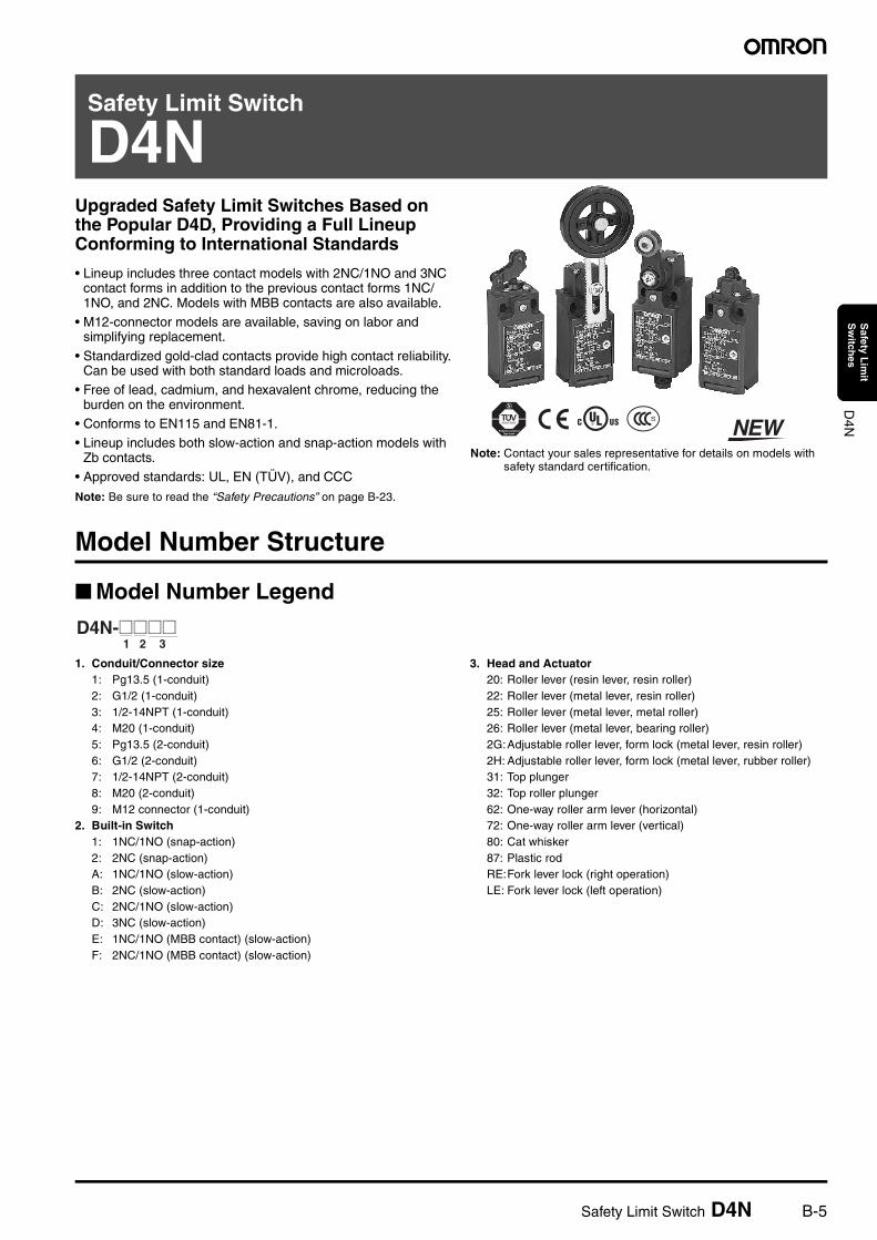
D4NUpgraded Safety Limit Switches Based on the Popular D4D, Providing a Full Lineup Conforming to International Standards
• Lineup includes three contact models with 2NC/1NO and 3NC contact forms in addition to the previous contact forms 1NC/1NO, and 2NC. Models with MBB contacts are also available.
• M12-connector models are available, saving on labor and simplifying replacement.
• Standardized gold-clad contacts provide high contact reliability.Can be used with both standard loads and microloads.
• Free of lead, cadmium, and hexavalent chrome, reducing the burden on the environment.
• Conforms to EN115 and EN81-1.• Lineup includes both slow-action and snap-action models with
Zb contacts.• Approved standards: UL, EN (TÜV), and CCC
Note: Be sure to read the “Safety Precautions” on page B-23.
Note: Contact your sales representative for details on models with safety standard certification.
Model Number Structure
Model Number Legend
1. Conduit/Connector size1: Pg13.5 (1-conduit)2: G1/2 (1-conduit)3: 1/2-14NPT (1-conduit)4: M20 (1-conduit)5: Pg13.5 (2-conduit)6: G1/2 (2-conduit)7: 1/2-14NPT (2-conduit)8: M20 (2-conduit)9: M12 connector (1-conduit)
2. Built-in Switch1: 1NC/1NO (snap-action)2: 2NC (snap-action)A: 1NC/1NO (slow-action)B: 2NC (slow-action)C: 2NC/1NO (slow-action)D: 3NC (slow-action)E: 1NC/1NO (MBB contact) (slow-action)F: 2NC/1NO (MBB contact) (slow-action)
3. Head and Actuator20: Roller lever (resin lever, resin roller)22: Roller lever (metal lever, resin roller)25: Roller lever (metal lever, metal roller)26: Roller lever (metal lever, bearing roller)2G:Adjustable roller lever, form lock (metal lever, resin roller)2H: Adjustable roller lever, form lock (metal lever, rubber roller)31: Top plunger32: Top roller plunger62: One-way roller arm lever (horizontal)72: One-way roller arm lever (vertical)80: Cat whisker87: Plastic rodRE:Fork lever lock (right operation)LE: Fork lever lock (left operation)
1 2 3 D4N-@@@@
B-6 Safety Limit Switch D4N
D4N
Safety L
imit
Sw
itches
Ordering Information
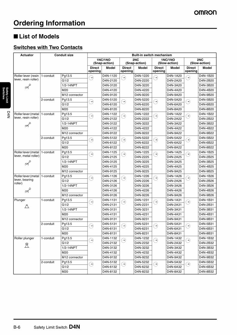
List of Models
Switches with Two ContactsActuator Conduit size Built-in switch mechanism
1NC/1NO (Snap-action)
2NC (Snap-action)
1NC/1NO (Slow-action)
2NC (Slow-action)
Direct opening
Model Direct opening
Model Direct opening
Model Direct opening
Model
Roller lever (resin lever, resin roller)
1-conduit Pg13.5 D4N-1120 D4N-1220 D4N-1A20 D4N-1B20
G1/2 D4N-2120 D4N-2220 D4N-2A20 D4N-2B20
1/2-14NPT D4N-3120 D4N-3220 D4N-3A20 D4N-3B20
M20 D4N-4120 D4N-4220 D4N-4A20 D4N-4B20
M12 connector D4N-9120 D4N-9220 D4N-9A20 D4N-9B20
2-conduit Pg13.5 D4N-5120 D4N-5220 D4N-5A20 D4N-5B20
G1/2 D4N-6120 D4N-6220 D4N-6A20 D4N-6B20
M20 D4N-8120 D4N-8220 D4N-8A20 D4N-8B20
Roller lever (metal lever, resin roller)
1-conduit Pg13.5 D4N-1122 D4N-1222 D4N-1A22 D4N-1B22
G1/2 D4N-2122 D4N-2222 D4N-2A22 D4N-2B22
1/2-14NPT D4N-3122 D4N-3222 D4N-3A22 D4N-3B22
M20 D4N-4122 D4N-4222 D4N-4A22 D4N-4B22
M12 connector D4N-9122 D4N-9222 D4N-9A22 D4N-9B22
2-conduit Pg13.5 D4N-5122 D4N-5222 D4N-5A22 D4N-5B22
G1/2 D4N-6122 D4N-6222 D4N-6A22 D4N-6B22
M20 D4N-8122 D4N-8222 D4N-8A22 D4N-8B22
Roller lever (metal lever, metal roller)
1-conduit Pg13.5 D4N-1125 D4N-1225 D4N-1A25 D4N-1B25
G1/2 D4N-2125 D4N-2225 D4N-2A25 D4N-2B25
1/2-14NPT D4N-3125 D4N-3225 D4N-3A25 D4N-3B25
M20 D4N-4125 D4N-4225 D4N-4A25 D4N-4B25
M12 connector D4N-9125 D4N-9225 D4N-9A25 D4N-9B25
Roller lever (metal lever, bearing roller)
1-conduit Pg13.5 D4N-1126 D4N-1226 D4N-1A26 D4N-1B26
G1/2 D4N-2126 D4N-2226 D4N-2A26 D4N-2B26
1/2-14NPT D4N-3126 D4N-3226 D4N-3A26 D4N-3B26
M20 D4N-4126 D4N-4226 D4N-4A26 D4N-4B26
M12 connector D4N-9126 D4N-9226 D4N-9A26 D4N-9B26
Plunger 1-conduit Pg13.5 D4N-1131 D4N-1231 D4N-1A31 D4N-1B31
G1/2 D4N-2131 D4N-2231 D4N-2A31 D4N-2B31
1/2-14NPT D4N-3131 D4N-3231 D4N-3A31 D4N-3B31
M20 D4N-4131 D4N-4231 D4N-4A31 D4N-4B31
M12 connector D4N-9131 D4N-9231 D4N-9A31 D4N-9B31
2-conduit Pg13.5 D4N-5131 D4N-5231 D4N-5A31 D4N-5B31
G1/2 D4N-6131 D4N-6231 D4N-6A31 D4N-6B31
M20 D4N-8131 D4N-8231 D4N-8A31 D4N-8B31
Roller plunger 1-conduit Pg13.5 D4N-1132 D4N-1232 D4N-1A32 D4N-1B32
G1/2 D4N-2132 D4N-2232 D4N-2A32 D4N-2B32
1/2-14NPT D4N-3132 D4N-3232 D4N-3A32 D4N-3B32
M20 D4N-4132 D4N-4232 D4N-4A32 D4N-4B32
M12 connector D4N-9132 D4N-9232 D4N-9A32 D4N-9B32
2-conduit Pg13.5 D4N-5132 D4N-5232 D4N-5A32 D4N-5B32
G1/2 D4N-6132 D4N-6232 D4N-6A32 D4N-6B32
M20 D4N-8132 D4N-8232 D4N-8A32 D4N-8B32
Safety Limit Switch D4N B-7
D4N
Safety L
imit
Sw
itches
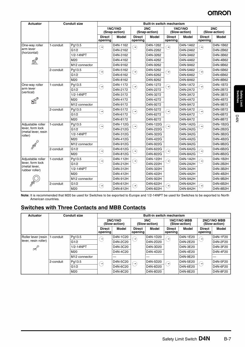
Note: It is recommended that M20 be used for Switches to be exported to Europe and 1/2-14NPT be used for Switches to be exported to North American countries.
Switches with Three Contacts and MBB Contacts
One-way roller arm lever (horizontal)
1-conduit Pg13.5 D4N-1162 D4N-1262 D4N-1A62 D4N-1B62
G1/2 D4N-2162 D4N-2262 D4N-2A62 D4N-2B62
1/2-14NPT D4N-3162 D4N-3262 D4N-3A62 D4N-3B62
M20 D4N-4162 D4N-4262 D4N-4A62 D4N-4B62
M12 connector D4N-9162 D4N-9262 D4N-9A62 D4N-9B62
2-conduit Pg13.5 D4N-5162 D4N-5262 D4N-5A62 D4N-5B62
G1/2 D4N-6162 D4N-6262 D4N-6A62 D4N-6B62
M20 D4N-8162 D4N-8262 D4N-8A62 D4N-8B62
One-way roller arm lever (vertical)
1-conduit Pg13.5 D4N-1172 D4N-1272 D4N-1A72 D4N-1B72
G1/2 D4N-2172 D4N-2272 D4N-2A72 D4N-2B72
1/2-14NPT D4N-3172 D4N-3272 D4N-3A72 D4N-3B72
M20 D4N-4172 D4N-4272 D4N-4A72 D4N-4B72
M12 connector D4N-9172 D4N-9272 D4N-9A72 D4N-9B72
2-conduit Pg13.5 D4N-5172 D4N-5272 D4N-5A72 D4N-5B72
G1/2 D4N-6172 D4N-6272 D4N-6A72 D4N-6B72
M20 D4N-8172 D4N-8272 D4N-8A72 D4N-8B72
Adjustable roller lever, form lock (metal lever, resin roller)
1-conduit Pg13.5 D4N-112G D4N-122G D4N-1A2G D4N-1B2G
G1/2 D4N-212G D4N-222G D4N-2A2G D4N-2B2G
1/2-14NPT D4N-312G D4N-322G D4N-3A2G D4N-3B2G
M20 D4N-412G D4N-422G D4N-4A2G D4N-4B2G
M12 connector D4N-912G D4N-922G D4N-9A2G D4N-9B2G
2-conduit G1/2 D4N-612G D4N-622G D4N-6A2G D4N-6B2G
M20 D4N-812G D4N-822G D4N-8A2G D4N-8B2G
Adjustable roller lever, form lock (metal lever, rubber roller)
1-conduit Pg13.5 D4N-112H D4N-122H D4N-1A2H D4N-1B2H
G1/2 D4N-212H D4N-222H D4N-2A2H D4N-2B2H
1/2-14NPT D4N-312H D4N-322H D4N-3A2H D4N-3B2H
M20 D4N-412H D4N-422H D4N-4A2H D4N-4B2H
M12 connector D4N-912H D4N-922H D4N-9A2H D4N-9B2H
2-conduit G1/2 D4N-612H D4N-622H D4N-6A2H D4N-6B2H
M20 D4N-812H D4N-822H D4N-8A2H D4N-8B2H
Actuator Conduit size Built-in switch mechanism
2NC/1NO (Slow-action)
3NC (Slow-action)
1NC/1NO MBB (Slow-action)
2NC/1NO MBB (Slow-action)
Direct opening
Model Direct opening
Model Direct opening
Model Direct opening
Model
Roller lever (resin lever, resin roller)
1-conduit Pg13.5 D4N-1C20 D4N-1D20 D4N-1E20 D4N-1F20
G1/2 D4N-2C20 D4N-2D20 D4N-2E20 D4N-2F20
1/2-14NPT D4N-3C20 D4N-3D20 D4N-3E20 D4N-3F20
M20 D4N-4C20 D4N-4D20 D4N-4E20 D4N-4F20
M12 connector --- --- D4N-9E20 ---
2-conduit Pg13.5 D4N-5C20 D4N-5D20 D4N-5E20 D4N-5F20
G1/2 D4N-6C20 D4N-6D20 D4N-6E20 D4N-6F20
M20 D4N-8C20 D4N-8D20 D4N-8E20 D4N-8F20
Actuator Conduit size Built-in switch mechanism
1NC/1NO (Snap-action)
2NC (Snap-action)
1NC/1NO (Slow-action)
2NC (Slow-action)
Direct opening
Model Direct opening
Model Direct opening
Model Direct opening
Model
B-8 Safety Limit Switch D4N
D4N
Safety L
imit
Sw
itches
Roller lever (metal lever, resin roller)
1-conduit Pg13.5 D4N-1C22 D4N-1D22 D4N-1E22 D4N-1F22
G1/2 D4N-2C22 D4N-2D22 D4N-2E22 D4N-2F22
1/2-14NPT D4N-3C22 D4N-3D22 D4N-3E22 D4N-3F22
M20 D4N-4C22 D4N-4D22 D4N-4E22 D4N-4F22
M12 connector --- --- D4N-9E22 ---
2-conduit Pg13.5 D4N-5C22 D4N-5D22 D4N-5E22 D4N-5F22
G1/2 D4N-6C22 D4N-6D22 D4N-6E22 D4N-6F22
M20 D4N-8C22 D4N-8D22 D4N-8E22 D4N-8F22
Roller lever (metal lever, metal roller)
1-conduit Pg13.5 D4N-1C25 D4N-1D25 D4N-1E25 D4N-1F25
G1/2 D4N-2C25 D4N-2D25 D4N-2E25 D4N-2F25
1/2-14NPT D4N-3C25 D4N-3D25 D4N-3E25 D4N-3F25
M20 D4N-4C25 D4N-4D25 D4N-4E25 D4N-4F25
M12 connector --- --- D4N-9E25 ---
Roller lever (metal lever, bearing roller)
1-conduit Pg13.5 D4N-1C26 D4N-1D26 D4N-1E26 D4N-1F26
G1/2 D4N-2C26 D4N-2D26 D4N-2E26 D4N-2F26
1/2-14NPT D4N-3C26 D4N-3D26 D4N-3E26 D4N-3F26
M20 D4N-4C26 D4N-4D26 D4N-4E26 D4N-4F26
M12 connector --- --- D4N-9E26 ---
Plunger 1-conduit Pg13.5 D4N-1C31 D4N-1D31 D4N-1E31 D4N-1F31
G1/2 D4N-2C31 D4N-2D31 D4N-2E31 D4N-2F31
1/2-14NPT D4N-3C31 D4N-3D31 D4N-3E31 D4N-3F31
M20 D4N-4C31 D4N-4D31 D4N-4E31 D4N-4F31
M12 connector --- --- D4N-9E31 ---
2-conduit Pg13.5 D4N-5C31 D4N-5D31 D4N-5E31 D4N-5F31
G1/2 D4N-6C31 D4N-6D31 D4N-6E31 D4N-6F31
M20 D4N-8C31 D4N-8D31 D4N-8E31 D4N-8F31
Roller plunger 1-conduit Pg13.5 D4N-1C32 D4N-1D32 D4N-1E32 D4N-1F32
G1/2 D4N-2C32 D4N-2D32 D4N-2E32 D4N-2F32
1/2-14NPT D4N-3C32 D4N-3D32 D4N-3E32 D4N-3F32
M20 D4N-4C32 D4N-4D32 D4N-4E32 D4N-4F32
M12 connector --- --- D4N-9E32 ---
2-conduit Pg13.5 D4N-5C32 D4N-5D32 D4N-5E32 D4N-5F32
G1/2 D4N-6C32 D4N-6D32 D4N-6E32 D4N-6F32
M20 D4N-8C32 D4N-8D32 D4N-8E32 D4N-8F32
One-way roller arm lever (horizontal)
1-conduit Pg13.5 D4N-1C62 D4N-1D62 D4N-1E62 D4N-1F62
G1/2 D4N-2C62 D4N-2D62 D4N-2E62 D4N-2F62
1/2-14NPT D4N-3C62 D4N-3D62 D4N-3E62 D4N-3F62
M20 D4N-4C62 D4N-4D62 D4N-4E62 D4N-4F62
M12 connector --- --- D4N-9E62 ----
2-conduit Pg13.5 D4N-5C62 D4N-5D62 D4N-5E62 D4N-5F62
G1/2 D4N-6C62 D4N-6D62 D4N-6E62 D4N-6F62
M20 D4N-8C62 D4N-8D62 D4N-8E62 D4N-8F62
One-way roller arm lever (vertical)
1-conduit Pg13.5 D4N-1C72 D4N-1D72 D4N-1E72 D4N-1F72
G1/2 D4N-2C72 D4N-2D72 D4N-2E72 D4N-2F72
1/2-14NPT D4N-3C72 D4N-3D72 D4N-3E72 D4N-3F72
M20 D4N-4C72 D4N-4D72 D4N-4E72 D4N-4F72
M12 connector --- --- D4N-9E72 ---
2-conduit Pg13.5 D4N-5C72 D4N-5D72 D4N-5E72 D4N-5F72
G1/2 D4N-6C72 D4N-6D72 D4N-6E72 D4N-6F72
M20 D4N-8C72 D4N-8D72 D4N-8E72 D4N-8F72
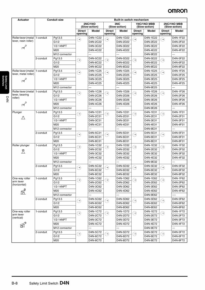
Actuator Conduit size Built-in switch mechanism
2NC/1NO (Slow-action)
3NC (Slow-action)
1NC/1NO MBB (Slow-action)
2NC/1NO MBB (Slow-action)
Direct opening
Model Direct opening
Model Direct opening
Model Direct opening
Model
Safety Limit Switch D4N B-9
D4N
Safety L
imit
Sw
itches
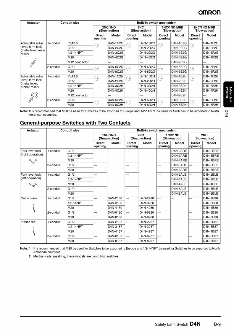
Note: It is recommended that M20 be used for Switches to be exported to Europe and 1/2-14NPT be used for Switches to be exported to North American countries.
General-purpose Switches with Two Contacts
Note: 1. It is recommended that M20 be used for Switches to be exported to Europe and 1/2-14NPT be used for Switches to be exported to North American countries.
2. Mechanically speaking, these models are basic limit switches.
Adjustable roller lever, form lock (metal lever, resin roller)
1-conduit Pg13.5 D4N-1C2G D4N-1D2G D4N-1E2G D4N-1F2G
G1/2 D4N-2C2G D4N-2D2G D4N-2E2G D4N-2F2G
1/2-14NPT D4N-3C2G D4N-3D2G D4N-3E2G D4N-3F2G
M20 D4N-4C2G D4N-4D2G D4N-4E2G D4N-4F2G
M12 connector --- --- D4N-9E2G ---
2-conduit G1/2 D4N-6C2G D4N-6D2G D4N-6E2G D4N-6F2G
M20 D4N-8C2G D4N-8D2G D4N-8E2G D4N-8F2G
Adjustable roller lever, form lock (metal lever, rubber roller)
1-conduit Pg13.5 D4N-1C2H D4N-1D2H D4N-1E2H D4N-1F2H
G1/2 D4N-2C2H D4N-2D2H D4N-2E2H D4N-2F2H
1/2-14NPT D4N-3C2H D4N-3D2H D4N-3E2H D4N-3F2H
M20 D4N-4C2H D4N-4D2H D4N-4E2H D4N-4F2H
M12 connector --- --- D4N-9E2H ---
2-conduit G1/2 D4N-6C2H D4N-6D2H D4N-6E2H D4N-6F2H
M20 D4N-8C2H D4N-8D2H D4N-8E2H D4N-8F2H
Actuator Conduit size Built-in switch mechanism
1NC/1NO (Snap-action)
2NC (Snap-action)
1NC/1NO (Slow-action)
2NC (Slow-action)
Direct opening
Model Direct opening
Model Direct opening
Model Direct opening
Model
Fork lever lock (right operation)
1-conduit G1/2 --- --- --- --- --- D4N-2ARE --- D4N-2BRE
1/2-14NPT D4N-3ARE D4N-3BRE
M20 D4N-4ARE D4N-4BRE
2-conduit G1/2 --- --- --- D4N-6ARE --- D4N-6BRE
M20 D4N-8ARE D4N-8BRE
Fork lever lock (left operation)
1-conduit G1/2 --- --- --- D4N-2ALE --- D4N-2BLE
1/2-14NPT D4N-3ALE D4N-3BLE
M20 D4N-4ALE D4N-4BLE
2-conduit G1/2 --- --- --- D4N-6ALE --- D4N-6BLE
M20 D4N-8ALE D4N-8BLE
Cat whisker 1-conduit G1/2 --- D4N-2180 --- D4N-2280 --- --- --- D4N-2B80
1/2-14NPT D4N-3180 D4N-3280 D4N-3B80
M20 D4N-4180 D4N-4280 D4N-4B80
2-conduit G1/2 --- D4N-6180 --- D4N-6280 --- --- D4N-6B80
M20 D4N-8180 D4N-8280 D4N-8B80
Plastic rod 1-conduit G1/2 --- D4N-2187 --- D4N-2287 --- --- D4N-2B87
1/2-14NPT D4N-3187 D4N-3287 D4N-3B87
M20 D4N-4187 D4N-4287 D4N-4B87
2-conduit G1/2 --- D4N-6187 --- D4N-6287 --- --- D4N-6B87
M20 D4N-8187 D4N-8287 D4N-8B87
Actuator Conduit size Built-in switch mechanism
2NC/1NO (Slow-action)
3NC (Slow-action)
1NC/1NO MBB (Slow-action)
2NC/1NO MBB (Slow-action)
Direct opening
Model Direct opening
Model Direct opening
Model Direct opening
Model
B-10 Safety Limit Switch D4N
D4N
Safety L
imit
Sw
itches
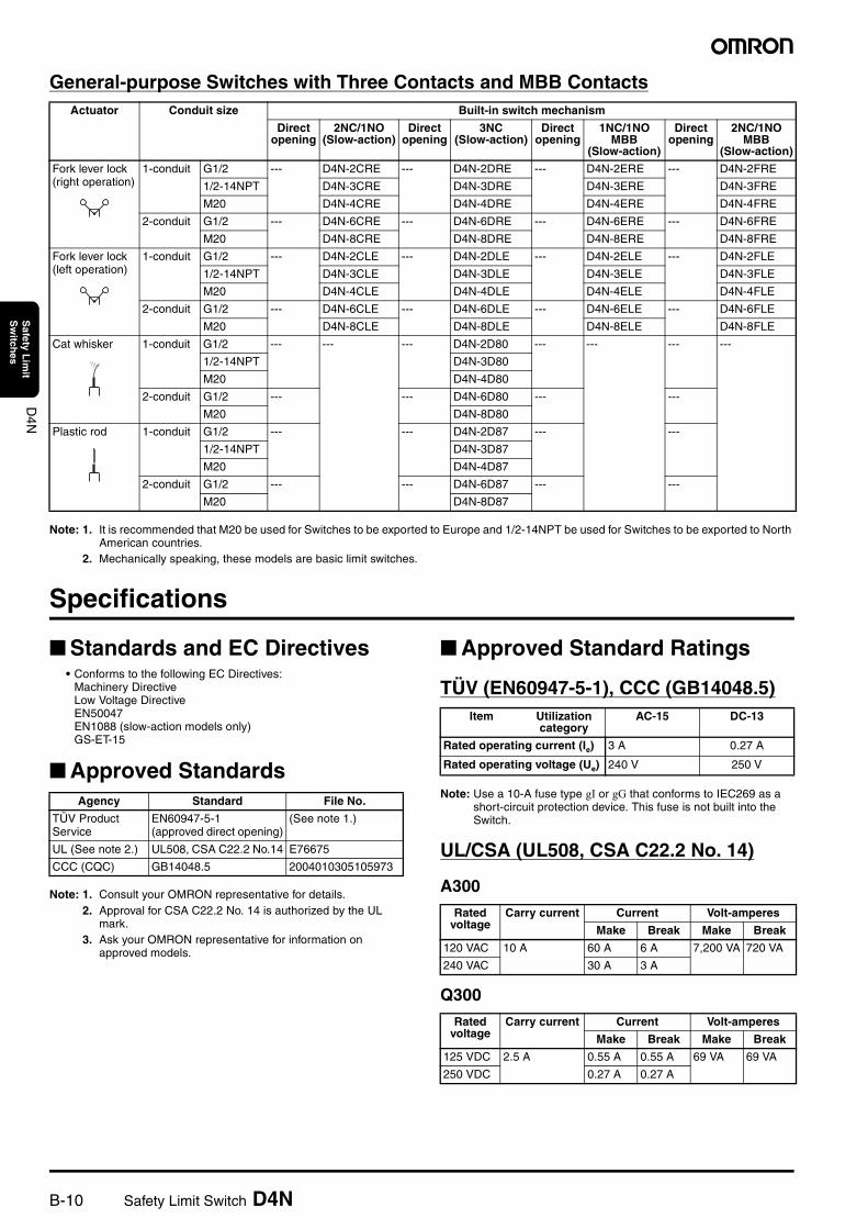
General-purpose Switches with Three Contacts and MBB Contacts
Note: 1. It is recommended that M20 be used for Switches to be exported to Europe and 1/2-14NPT be used for Switches to be exported to North American countries.
2. Mechanically speaking, these models are basic limit switches.
Specifications
Standards and EC Directives• Conforms to the following EC Directives:
Machinery DirectiveLow Voltage DirectiveEN50047EN1088 (slow-action models only)GS-ET-15
Approved Standards
Note: 1. Consult your OMRON representative for details.2. Approval for CSA C22.2 No. 14 is authorized by the UL
mark.3. Ask your OMRON representative for information on
approved models.
Approved Standard Ratings
TÜV (EN60947-5-1), CCC (GB14048.5)
Note: Use a 10-A fuse type gI or gG that conforms to IEC269 as a short-circuit protection device. This fuse is not built into the Switch.
UL/CSA (UL508, CSA C22.2 No. 14)
A300
Q300
Actuator Conduit size Built-in switch mechanism
Direct opening
2NC/1NO (Slow-action)
Direct opening
3NC (Slow-action)
Direct opening
1NC/1NO MBB
(Slow-action)
Direct opening
2NC/1NO MBB
(Slow-action)
Fork lever lock (right operation)
1-conduit G1/2 --- D4N-2CRE --- D4N-2DRE --- D4N-2ERE --- D4N-2FRE
1/2-14NPT D4N-3CRE D4N-3DRE D4N-3ERE D4N-3FRE
M20 D4N-4CRE D4N-4DRE D4N-4ERE D4N-4FRE
2-conduit G1/2 --- D4N-6CRE --- D4N-6DRE --- D4N-6ERE --- D4N-6FRE
M20 D4N-8CRE D4N-8DRE D4N-8ERE D4N-8FRE
Fork lever lock (left operation)
1-conduit G1/2 --- D4N-2CLE --- D4N-2DLE --- D4N-2ELE --- D4N-2FLE
1/2-14NPT D4N-3CLE D4N-3DLE D4N-3ELE D4N-3FLE
M20 D4N-4CLE D4N-4DLE D4N-4ELE D4N-4FLE
2-conduit G1/2 --- D4N-6CLE --- D4N-6DLE --- D4N-6ELE --- D4N-6FLE
M20 D4N-8CLE D4N-8DLE D4N-8ELE D4N-8FLE
Cat whisker 1-conduit G1/2 --- --- --- D4N-2D80 --- --- --- ---
1/2-14NPT D4N-3D80
M20 D4N-4D80
2-conduit G1/2 --- --- D4N-6D80 --- ---
M20 D4N-8D80
Plastic rod 1-conduit G1/2 --- --- D4N-2D87 --- ---
1/2-14NPT D4N-3D87
M20 D4N-4D87
2-conduit G1/2 --- --- D4N-6D87 --- ---
M20 D4N-8D87
Agency Standard File No.
TÜV Product Service
EN60947-5-1 (approved direct opening)
(See note 1.)
UL (See note 2.) UL508, CSA C22.2 No.14 E76675
CCC (CQC) GB14048.5 2004010305105973
Item Utilization category
AC-15 DC-13
Rated operating current (Ie) 3 A 0.27 A
Rated operating voltage (Ue) 240 V 250 V
Rated voltage
Carry current Current Volt-amperes
Make Break Make Break
120 VAC 10 A 60 A 6 A 7,200 VA 720 VA
240 VAC 30 A 3 A
Rated voltage
Carry current Current Volt-amperes
Make Break Make Break
125 VDC 2.5 A 0.55 A 0.55 A 69 VA 69 VA
250 VDC 0.27 A 0.27 A
Safety Limit Switch D4N B-11
D4N
Safety L
imit
Sw
itches
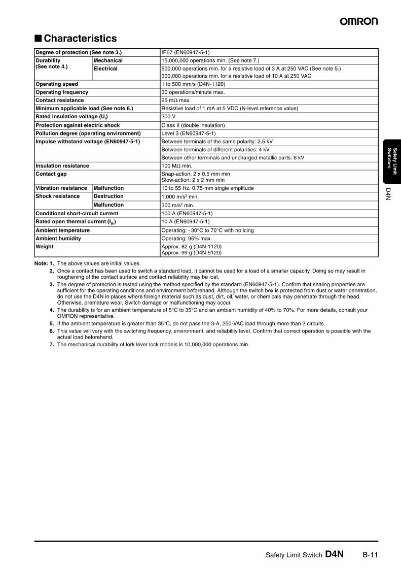
Characteristics
Note: 1. The above values are initial values.2. Once a contact has been used to switch a standard load, it cannot be used for a load of a smaller capacity. Doing so may result in
roughening of the contact surface and contact reliability may be lost.3. The degree of protection is tested using the method specified by the standard (EN60947-5-1). Confirm that sealing properties are
sufficient for the operating conditions and environment beforehand. Although the switch box is protected from dust or water penetration, do not use the D4N in places where foreign material such as dust, dirt, oil, water, or chemicals may penetrate through the head. Otherwise, premature wear, Switch damage or malfunctioning may occur.
4. The durability is for an ambient temperature of 5°C to 35°C and an ambient humidity of 40% to 70%. For more details, consult your OMRON representative.
5. If the ambient temperature is greater than 35°C, do not pass the 3-A, 250-VAC load through more than 2 circuits.6. This value will vary with the switching frequency, environment, and reliability level. Confirm that correct operation is possible with the
actual load beforehand.7. The mechanical durability of fork lever lock models is 10,000,000 operations min.
Degree of protection (See note 3.) IP67 (EN60947-5-1)
Durability (See note 4.)
Mechanical 15,000,000 operations min. (See note 7.)
Electrical 500,000 operations min. for a resistive load of 3 A at 250 VAC (See note 5.)300,000 operations min. for a resistive load of 10 A at 250 VAC
Operating speed 1 to 500 mm/s (D4N-1120)
Operating frequency 30 operations/minute max.
Contact resistance 25 mΩ max.
Minimum applicable load (See note 6.) Resistive load of 1 mA at 5 VDC (N-level reference value)
Rated insulation voltage (Ui) 300 V
Protection against electric shock Class II (double insulation)
Pollution degree (operating environment) Level 3 (EN60947-5-1)
Impulse withstand voltage (EN60947-5-1) Between terminals of the same polarity: 2.5 kV
Between terminals of different polarities: 4 kV
Between other terminals and uncharged metallic parts: 6 kV
Insulation resistance 100 MΩ min.
Contact gap Snap-action: 2 x 0.5 mm minSlow-action: 2 x 2 mm min
Vibration resistance Malfunction 10 to 55 Hz, 0.75-mm single amplitude
Shock resistance Destruction 1,000 m/s2 min.
Malfunction 300 m/s2 min.
Conditional short-circuit current 100 A (EN60947-5-1)
Rated open thermal current (Ith) 10 A (EN60947-5-1)
Ambient temperature Operating: −30°C to 70°C with no icing
Ambient humidity Operating: 95% max.
Weight Approx. 82 g (D4N-1120)Approx. 99 g (D4N-5120)
B-12 Safety Limit Switch D4N
D4N
Safety L
imit
Sw
itches
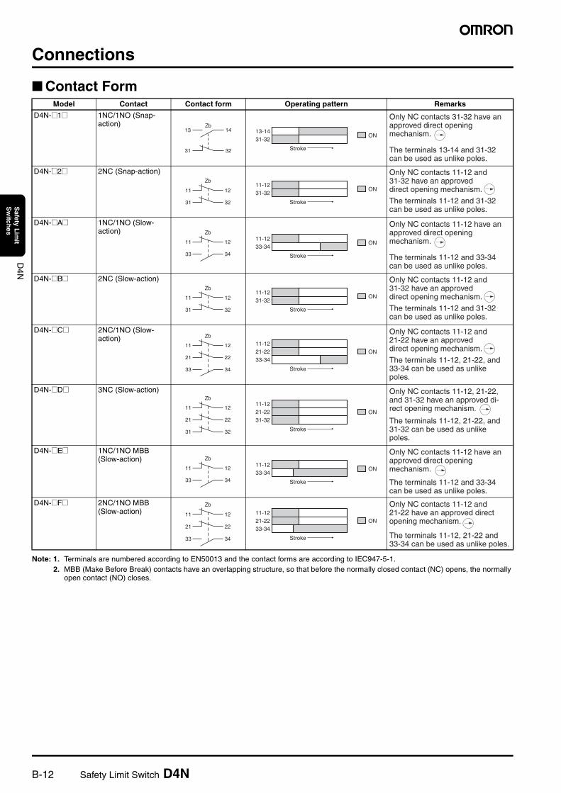
Connections
Contact Form
Note: 1. Terminals are numbered according to EN50013 and the contact forms are according to IEC947-5-1.2. MBB (Make Before Break) contacts have an overlapping structure, so that before the normally closed contact (NC) opens, the normally
open contact (NO) closes.
Model Contact Contact form Operating pattern Remarks
D4N-@1@ 1NC/1NO (Snap-action)
D4N-@2@ 2NC (Snap-action)
D4N-@A@ 1NC/1NO (Slow-action)
D4N-@B@ 2NC (Slow-action)
D4N-@C@ 2NC/1NO (Slow-action)
D4N-@D@ 3NC (Slow-action)
D4N-@E@ 1NC/1NO MBB (Slow-action)
D4N-@F@ 2NC/1NO MBB (Slow-action)
14
32
13
31
Zb
ON
Stroke
13-1431-32
Only NC contacts 31-32 have an approved direct opening mechanism.
The terminals 13-14 and 31-32 can be used as unlike poles.
11
31
12
32
Zb
ON
Stroke
11-1231-32
Only NC contacts 11-12 and 31-32 have an approved direct opening mechanism.
The terminals 11-12 and 31-32 can be used as unlike poles.
11
33
12
34
Zb
ON
Stroke
11-1233-34
Only NC contacts 11-12 have an approved direct opening mechanism.
The terminals 11-12 and 33-34 can be used as unlike poles.
11
31
12
32
Zb
ON
Stroke
11-1231-32
Only NC contacts 11-12 and 31-32 have an approved direct opening mechanism.
The terminals 11-12 and 31-32 can be used as unlike poles.
33 34
11
21
12
22
Zb
ON
Stroke
21-2233-34
11-12
Only NC contacts 11-12 and 21-22 have an approved direct opening mechanism.
The terminals 11-12, 21-22, and 33-34 can be used as unlike poles.
11
21
12
22
31 32
Zb
ON
Stroke
11-1221-2231-32
Only NC contacts 11-12, 21-22, and 31-32 have an approved di-rect opening mechanism.
The terminals 11-12, 21-22, and 31-32 can be used as unlike poles.
11
33
12
34
Zb
ON
Stroke
11-1233-34
Only NC contacts 11-12 have an approved direct opening mechanism.
The terminals 11-12 and 33-34 can be used as unlike poles.
33 34
11
21
12
22
Zb
ON
Stroke
11-1221-2233-34
Only NC contacts 11-12 and 21-22 have an approved direct opening mechanism.
The terminals 11-12, 21-22 and 33-34 can be used as unlike poles.
Safety Limit Switch D4N B-13
D4N
Safety L
imit
Sw
itches
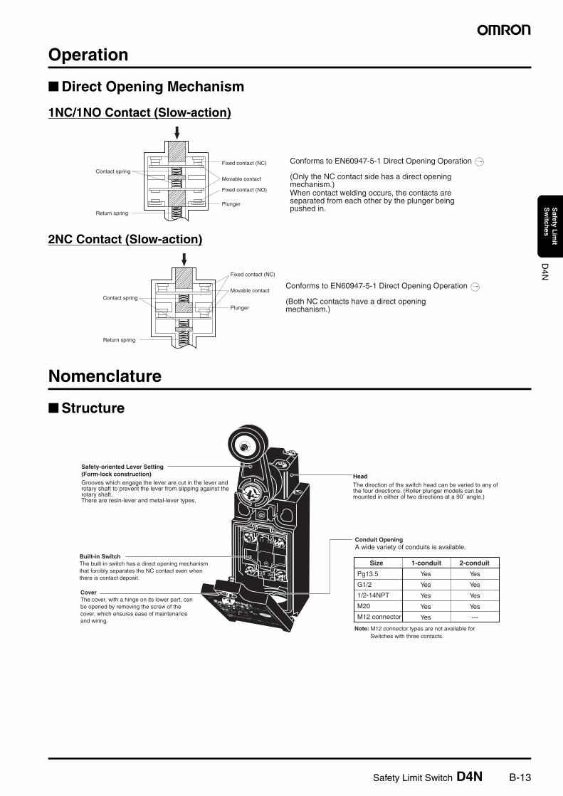
Operation
Direct Opening Mechanism
1NC/1NO Contact (Slow-action)
2NC Contact (Slow-action)
Nomenclature
Structure
Contact spring
Return spring
Fixed contact (NC)
Fixed contact (NO)
Plunger
Movable contact
Conforms to EN60947-5-1 Direct Opening Operation
(Only the NC contact side has a direct opening mechanism.)When contact welding occurs, the contacts are separated from each other by the plunger being pushed in.
Contact spring
Fixed contact (NC)
Plunger
Movable contact
Return spring
Conforms to EN60947-5-1 Direct Opening Operation
(Both NC contacts have a direct opening mechanism.)
Pg13.5
G1/2
1/2-14NPT
M20
M12 connector
Note: M12 connector types are not available for Switches with three contacts.
HeadThe direction of the switch head can be varied to any of the four directions. (Roller plunger models can be mounted in either of two directions at a 90˚ angle.)
Conduit OpeningA wide variety of conduits is available.
Built-in SwitchThe built-in switch has a direct opening mechanism that forcibly separates the NC contact even when there is contact deposit.
Safety-oriented Lever Setting (Form-lock construction)Grooves which engage the lever are cut in the lever and rotary shaft to prevent the lever from slipping against the rotary shaft. There are resin-lever and metal-lever types.
CoverThe cover, with a hinge on its lower part, can be opened by removing the screw of the cover, which ensures ease of maintenance and wiring.
Size 1-conduit 2-conduit
Yes
Yes
Yes
Yes
Yes
Yes
Yes
Yes
Yes
---
B-14 Safety Limit Switch D4N
D4N
Safety L
imit
Sw
itches
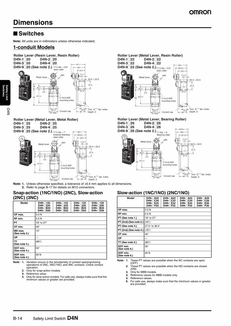
Dimensions
SwitchesNote: All units are in millimeters unless otherwise indicated.
1-conduit Models
Note: 1. Unless otherwise specified, a tolerance of ±0.4 mm applies to all dimensions.2. Refer to page B-17 for details on M12 connectors.
Snap-action (1NC/1NO) (2NC), Slow-action (2NC) (3NC)
Note: 1. Variation occurs in the simultaneity of contact opening/closing operations of 2NC, 2NC/1NO, and 3NC contacts. Check contact operation.
2. Only for snap-action models.3. Reference value.4. Only for slow-action models. For safe use, always make sure that the
minimum values or greater are provided.
Slow-action (1NC/1NO) (2NC/1NO)
Note: 1. These PT values are possible when the NC contacts are open (OFF).
2. These PT values are possible when the NO contacts are closed (ON).
3. Only for MBB models.4. Reference values for MBB models only.5. Reference values.6. For safe use, always make sure that the minimum values or greater
are provided.
Roller Lever (Resin Lever, Resin Roller)D4N-1@20 D4N-2@20 D4N-3@20 D4N-4@20D4N-9@20 (See note 2.) 17.5 dia. × 6.8
resin roller
Two, 4+0.15 dia. holesDepth: 5
0
30
27.5
11±0.2
47±1
40±1
(27)
21.5
22±0.2
31 max.
55 47±0.2
2.5
9±0.2
26R
18
20±0.1
22±0.1
14.2
Resin lever
2.15±0.05R mounting holes
Conduit cap
20.5 × 20.5
Roller Lever (Metal Lever, Resin Roller)D4N-1@22 D4N-2@22 D4N-3@22 D4N-4@22D4N-9@22 (See note 2.)17.5 dia. × 6.8
resin roller
Two, 4+0.15 dia. holesDepth: 5
0
30
27.5
11±0.2
45±1
39.5±1
(31)
21.5
22±0.2
31 max.
55 47±0.2
2.5
9±0.2
26R
18
20±0.1
22±0.1
14.2
Metal lever
2.15±0.05R mounting holes
Conduit cap
20.5 × 20.5
Roller Lever (Metal Lever, Metal Roller)D4N-1@25 D4N-2@25 D4N-3@25 D4N-4@25D4N-9@25 (See note 2.) 17.5 dia. × 7
sintered stainless steel roller
Two, 4+0.15 dia. holesDepth: 5
0
30
27.5
11±0.2
45±1
39.5±1
(31)
21.5
22±0.2
31 max.
55 47±0.2
2.5
9±0.2
26R
18
20±0.1
22±0.1
14.2
Metal lever20.5 × 20.5
2.15±0.05R mounting holes
Conduit cap
Roller Lever (Metal Lever, Bearing Roller)D4N-1@26 D4N-2@26 D4N-3@26 D4N-4@26D4N-9@26 (See note 2.) 17 dia. × 6
Bearing roller
Two, 4+0.15 dia. holesDepth: 5
0
Metal lever20.5 × 20.5
2.15±0.05R mounting holes
Conduit cap 30
27.5
11±0.2
43.6±1
39±1
(31.5)
21.5
22±0.2
31 max.
55 47±0.2
2.5
9±0.2
26R
18
20±0.1
22±0.1
14.2
Model D4N-@120D4N-@220D4N-@B20D4N-@D20
D4N-@122D4N-@222D4N-@B22D4N-@D22
D4N-@125D4N-@225D4N-@B25D4N-@D25
D4N-@126D4N-@226D4N-@B26D4N-@D26
OF max. 5.0 N
RF min. 0.5 N
PT 18° to 27°
OT min. 40°MD max. (See note 2.)
14°
OP ---
TT(See note 3.)
(80°)
DOT min.(See note 4.)
50°
DOF min. (See note 4.)
20 N
Model D4N-@A20D4N-@C20D4N-@E20D4N-@F20
D4N-@A22D4N-@C22D4N-@E22D4N-@F22
D4N-@A25D4N-@C25D4N-@E25D4N-@F25
D4N-@A26D4N-@C26D4N-@E26D4N-@F26
OF max. 5.0 N
RF min. 0.5 N
PT (See note 1.) 18° to 27°
PT (2nd) (See note 2.) (44°)PT (See note 3.) 27.5° to 36.5°
PT (2nd) (See note 4.) (18°)OT min. 40°
OP ---
TT (See note 5.) (80°)
DOT min. (See note 6.)
50°
DOF min. (See note 6.)
20 N
Safety Limit Switch D4N B-15
D4N
Safety L
imit
Sw
itches
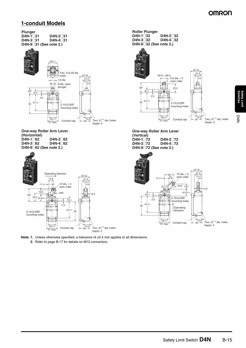
1-conduit Models
Note: 1. Unless otherwise specified, a tolerance of ±0.4 mm applies to all dimensions.2. Refer to page B-17 for details on M12 connectors.
PlungerD4N-1@31 D4N-2@31 D4N-3@31 D4N-4@31 D4N-9@31 (See note 2.)
Two, 3±0.05 dia. holes
6-dia. resin plunger
Two, 4+0.15 dia. holesDepth: 5
030
(31.5)
21.5
25±0.1
11±0.2
22±0.2
31 max.
55 47±0.2
2.5
9±0.2OP
20±0.1
22±0.1
14.2
12 dia.
2.15±0.05R mounting holes
Conduit cap
Roller PlungerD4N-1@32 D4N-2@32 D4N-3@32 D4N-4@32 D4N-9@32 (See note 2.)
9.5 dia. × 5 resin roller
Two, 4+0.15 dia. holesDepth: 5
030
25.2
11±0.2
22±0.2
31 max.
55 47±0.2
2.5
9±0.2
OP
20±0.1
22±0.1
14.2
(31.5)
21.520.5 × 20.5
2.15±0.05R mounting holes
Conduit cap
Two, 4+0.15 dia. holesDepth: 5
0
One-way Roller Arm Lever (Horizontal)D4N-1@62 D4N-2@62 D4N-3@62 D4N-4@62 D4N-9@62 (See note 2.)
Operating direction
12 dia. × 5 resin roller
30
14.8
23.3
13.5
19.5±0.2
11±0.211±0.2
20R 10.2
22±0.2
31 max.
47±0.2
2.5
9±0.2
OP
20±0.1
22±0.1
14.2
55
(31.5)
21.5
2.15±0.05R mounting holes
Conduit cap
Two, 4+0.15 dia. holesDepth: 5
0
One-way Roller Arm Lever (Vertical)D4N-1@72 D4N-2@72 D4N-3@72 D4N-4@72 D4N-9@72 (See note 2.)
Operating direction
12 dia. × 5 resin roller
30
OP
14.7R19
19.5±0.2
11±0.211±0.2
12
10.2
22±0.2
31 max.
47±0.2
2.5
9±0.2
20±0.1
22±0.1
14.2
(31.5)
55
21.5
2.15±0.05R mounting holes
Conduit cap
B-16 Safety Limit Switch D4N
D4N
Safety L
imit
Sw
itches
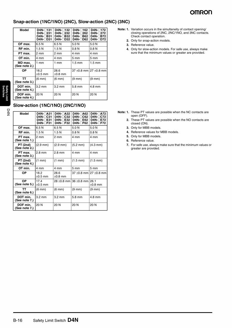
Snap-action (1NC/1NO) (2NC), Slow-action (2NC) (3NC)
Note: 1. Variation occurs in the simultaneity of contact opening/closing operations of 2NC, 2NC/1NO, and 3NC contacts. Check contact operation.
2. Only for snap-action models.3. Reference value.4. Only for slow-action models. For safe use, always make
sure that the minimum values or greater are provided.
Slow-action (1NC/1NO) (2NC/1NO)Note: 1. These PT values are possible when the NC contacts are
open (OFF).2. These PT values are possible when the NO contacts are
closed (ON).3. Only for MBB models.4. Reference values for MBB models.5. Only for MBB models.6. Reference value.7. For safe use, always make sure that the minimum values or
greater are provided.
Model D4N-@131D4N-@231D4N-@B31D4N-@D31
D4N-@132D4N-@232D4N-@B32D4N-@D32
D4N-@162D4N-@262D4N-@B62D4N-@D62
D4N-@172D4N-@272D4N-@B72D4N-@D72
OF max. 6.5 N 6.5 N 5.0 N 5.0 N
RF min. 1.5 N 1.5 N 0.8 N 0.8 N
PT max. 2 mm 2 mm 4 mm 4 mm
OT min. 4 mm 4 mm 5 mm 5 mm
MD max. (See note 2.)
1 mm 1 mm 1.5 mm 1.5 mm
OP 18.2 ±0.5 mm
28.6 ±0.8 mm
37 ±0.8 mm 27 ±0.8 mm
TT(See note 3.)
(6 mm) (6 mm) (9 mm) (9 mm)
DOT min.(See note 4.)
3.2 mm 3.2 mm 5.8 mm 4.8 mm
DOF min. (See note 4.)
20 N 20 N 20 N 20 N
Model D4N-@A31D4N-@C31D4N-@E31D4N-@F31
D4N-@A32D4N-@C32D4N-@E32D4N-@F32
D4N-@A62D4N-@C62D4N-@E62D4N-@F62
D4N-@A72D4N-@C72D4N-@E72D4N-@F72
OF max. 6.5 N 6.5 N 5.0 N 5.0 N
RF min. 1.5 N 1.5 N 0.8 N 0.8 N
PT max.(See note 1.)
2 mm 2 mm 4 mm 4 mm
PT (2nd)(See note 2.)
(2.9 mm) (2.9 mm) (5.2 mm) (4.3 mm)
PT max.(See note 3.)
2.8 mm 2.8 mm 4 mm 4 mm
PT (2nd)(See note 4.)
(1 mm) (1 mm) (1.5 mm) (1.5 mm)
OT min. 4 mm 4 mm 5 mm 5 mm
OP 18.2 ±0.5 mm
28.6 ±0.8 mm
37 ±0.8 mm 27 ±0.8 mm
OP (See note 5.)
17.4 ±0.5 mm
28 ±0.8 mm 36 ±0.8 mm 26.1 ±0.8 mm
TT(See note 6.)
(6 mm) (6 mm) (9 mm) (9 mm)
DOT min.(See note 7.)
3.2 mm 3.2 mm 5.8 mm 4.8 mm
DOF min. (See note 7.)
20 N 20 N 20 N 20 N
Safety Limit Switch D4N B-17
D4N
Safety L
imit
Sw
itches
1-conduit Models
Note: 1. Unless otherwise specified, a tolerance of ±0.4 mm applies to all dimensions.2. Refer to following diagrams for details on M12 connectors.
Snap-action (1NC/1NO) (2NC), Slow-action (2NC) (3NC)Note: 1. Variation occurs in the simultaneity of contact opening/
closing operations of 2NC, 2NC/1NO, and 3NC contacts. Check contact operation.
2. The operating characteristics of these Switches were measured with the roller lever set at 32 mm.
3. Only for snap-action models.4. Reference value.5. Only for slow-action models. For safe use, always make
sure that the minimum values or greater are provided.
Slow-action (1NC/1NO) (2NC/1NO)Note: 1. The operating characteristics of these Switches were
measured with the roller lever set at 32 mm.2. This PT value is possible when the NC contacts are open
(OFF).3. This PT value is possible when the NO contacts are closed
(ON).4. Only for MBB models.5. Reference value for MBB models only.6. Reference value.7. For safe use, always make sure that the minimum values or
greater are provided.
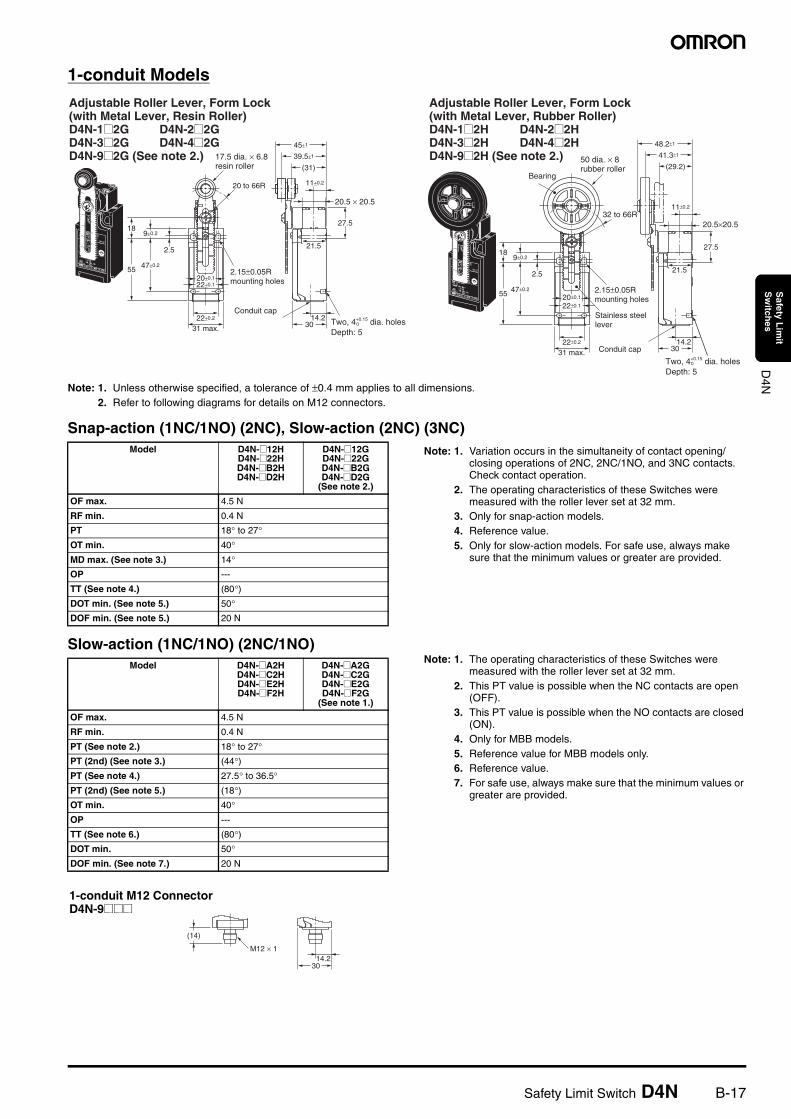
Adjustable Roller Lever, Form Lock (with Metal Lever, Resin Roller)D4N-1@2G D4N-2@2G D4N-3@2G D4N-4@2G D4N-9@2G (See note 2.) 17.5 dia. × 6.8
resin roller
Two, 4+0.15 dia. holesDepth: 5
0
2.15±0.05R mounting holes
Conduit cap
20.5 × 20.5
30
27.5
11±0.2
21.5
22±0.2
31 max.
55 47±0.2
2.5
9±0.2
20 to 66R
18
20±0.1
22±0.1
14.2
45±1
39.5±1
(31)
Adjustable Roller Lever, Form Lock (with Metal Lever, Rubber Roller)D4N-1@2H D4N-2@2H D4N-3@2H D4N-4@2H D4N-9@2H (See note 2.) 50 dia. × 8
rubber rollerBearing
Stainless steel lever
Two, 4+0.15 dia. holesDepth: 5
0
20.5×20.5
30
27.5
11±0.2
21.5
22±0.2
31 max.
55 47±0.2
2.5
9±0.218
20±0.1
22±0.1
14.2
48.2±1
41.3±1
(29.2)
32 to 66R
2.15±0.05R mounting holes
Conduit cap
Model D4N-@12HD4N-@22HD4N-@B2HD4N-@D2H
D4N-@12GD4N-@22GD4N-@B2GD4N-@D2G
(See note 2.)
OF max. 4.5 N
RF min. 0.4 N
PT 18° to 27°OT min. 40°MD max. (See note 3.) 14°OP ---
TT (See note 4.) (80°)DOT min. (See note 5.) 50°DOF min. (See note 5.) 20 N
Model D4N-@A2HD4N-@C2HD4N-@E2HD4N-@F2H
D4N-@A2GD4N-@C2GD4N-@E2GD4N-@F2G
(See note 1.)
OF max. 4.5 N
RF min. 0.4 N
PT (See note 2.) 18° to 27°PT (2nd) (See note 3.) (44°)PT (See note 4.) 27.5° to 36.5°PT (2nd) (See note 5.) (18°)OT min. 40°OP ---
TT (See note 6.) (80°)DOT min. 50°DOF min. (See note 7.) 20 N
1-conduit M12 ConnectorD4N-9@@@
(14)
M12 × 114.2
30
B-18 Safety Limit Switch D4N
D4N
Safety L
imit
Sw
itches
1-conduit Models
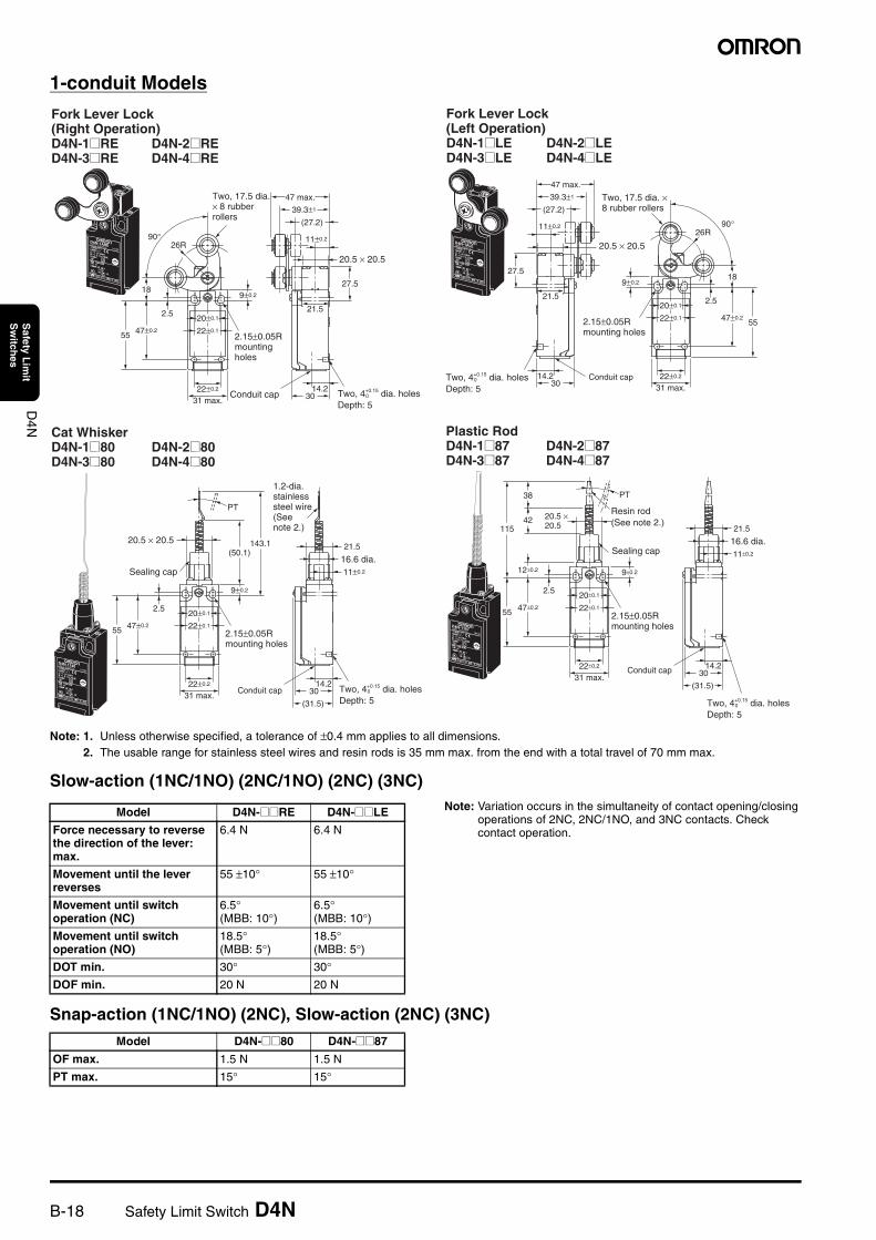
Note: 1. Unless otherwise specified, a tolerance of ±0.4 mm applies to all dimensions.2. The usable range for stainless steel wires and resin rods is 35 mm max. from the end with a total travel of 70 mm max.
Slow-action (1NC/1NO) (2NC/1NO) (2NC) (3NC)Note: Variation occurs in the simultaneity of contact opening/closing
operations of 2NC, 2NC/1NO, and 3NC contacts. Check contact operation.
Snap-action (1NC/1NO) (2NC), Slow-action (2NC) (3NC)
20.5 × 20.5
Two, 4+0.15 dia. holesDepth: 5
0
Fork Lever Lock (Right Operation)D4N-1@RE D4N-2@RED4N-3@RE D4N-4@RE
2.15±0.05R mounting holes
30
27.5
11±0.2
47 max.
39.3±1
(27.2)
21.5
22±0.2
31 max.
55 47±0.2
2.5
9±0.2
26R90°
18
20±0.1
22±0.1
14.2
Two, 17.5 dia. × 8 rubber rollers
Conduit cap
Two, 4+0.15 dia. holesDepth: 5
0
Fork Lever Lock (Left Operation)D4N-1@LE D4N-2@LED4N-3@LE D4N-4@LE
2.15±0.05R mounting holes
Two, 17.5 dia. × 8 rubber rollers
30
27.5
11±0.2
39.3±1
(27.2)
21.5
22±0.2
31 max.
5547±0.2
2.5
9±0.2
26R90°
18
20±0.1
22±0.1
14.2
47 max.
20.5 × 20.5
Conduit cap
Two, 4+0.15 dia. holesDepth: 5
0
Cat WhiskerD4N-1@80 D4N-2@80D4N-3@80 D4N-4@80
1.2-dia. stainless steel wire(See note 2.)
2.15±0.05R mounting holes
30
(31.5)
11±0.2
21.5
22±0.2
31 max.
55 47±0.2
2.5
9±0.2
(50.1)
PT
143.1
20±0.1
22±0.1
14.2
20.5 × 20.5
Sealing cap16.6 dia.
Conduit cap
Two, 4+0.15 dia. holesDepth: 5
0
Plastic RodD4N-1@87 D4N-2@87D4N-3@87 D4N-4@87
2.15±0.05R mounting holes
30
(31.5)
11±0.2
22±0.2
31 max.
55
115
38
42
12±0.2
47±0.2
2.5
PT
20±0.1
22±0.1
14.2
21.5
9±0.2
Resin rod(See note 2.)
20.5 × 20.5
Sealing cap16.6 dia.
Conduit cap
Model D4N-@@RE D4N-@@LE
Force necessary to reverse the direction of the lever: max.
6.4 N 6.4 N
Movement until the lever reverses
55 ±10° 55 ±10°
Movement until switch operation (NC)
6.5° (MBB: 10°)
6.5°(MBB: 10°)
Movement until switch operation (NO)
18.5°(MBB: 5°)
18.5°(MBB: 5°)
DOT min. 30° 30°DOF min. 20 N 20 N
Model D4N-@@80 D4N-@@87
OF max. 1.5 N 1.5 N
PT max. 15° 15°
Safety Limit Switch D4N B-19
D4N
Safety L
imit
Sw
itches
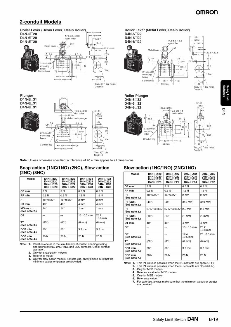
2-conduit Models
Note: Unless otherwise specified, a tolerance of ±0.4 mm applies to all dimensions.
Snap-action (1NC/1NO) (2NC), Slow-action (2NC) (3NC)
Note: 1. Variation occurs in the simultaneity of contact opening/closing operations of 2NC, 2NC/1NO, and 3NC contacts. Check contact operation.
2. Only for snap-action models.3. Reference value.4. Only for slow-action models. For safe use, always make sure that the
minimum values or greater are provided.
Slow-action (1NC/1NO) (2NC/1NO)
Note: 1. This PT value is possible when the NC contacts are open (OFF).2. This PT value is possible when the NO contacts are closed (ON).3. Only for MBB models.4. Reference value for MBB models.5. Only for MBB models.6. Reference value.7. For safe use, always make sure that the minimum values or greater
are provided.
Roller Lever (Resin Lever, Resin Roller)D4N-5@20 D4N-6@20 D4N-8@20
17.5 dia. × 6.8 resin roller
Two, 4+0.15 dia. holesDepth: 5
0
30
Cap
27.5
20.5
20.5 × 20.5
11±0.2
47±1
40±1
(27)
21.5
42±0.2 (3)
56 max.
47
39±0.2
25 dia.
2.55.49±0.2
26R
18
20±0.1
40±0.1
42±0.1
22±0.1
14.2
Resin lever
2.15±0.05R mounting holes
Conduit cap
Roller Lever (Metal Lever, Resin Roller)D4N-5@22 D4N-6@22 D4N-8@22 17.5 dia. × 6.8
resin roller
Two, 4+0.15 dia. holesDepth: 5
0
30
Cap
27.5
20.5
11±0.2
21.5
42±0.2 (3)
56 max.
4725 dia.
2.55.49±0.2
18
20±0.1
40±0.1
42±0.1
22±0.1
14.2
26R
45±1
39.5±1
(31)
39±0.2
Metal lever20.5 × 20.5
2.15±0.05R mounting holes
Conduit cap
PlungerD4N-5@31 D4N-6@31 D4N-8@31
Two, 3±0.05 dia. holes
Two, 4+0.15 dia.Depth: 5
0
30
Cap
20.
42±0.2 (3)
56 max.
4725 dia.
2.55.49±0.2
OP
20±0.1
40±0.1
42±0.1
22±0.1
14.2
(31.5)21.511±0.2
25±0.1
12 dia.
39±0.2
6-dia. resin plunger
2.15±0.05R mounting holes
Conduit cap
Roller PlungerD4N-5@32 D4N-6@32 D4N-8@32
9.5 dia. × 5 resin roller
Two, 4+0.15 dia. holesDepth: 5
0
30
Cap
20.5
42±0.2 (3)
56 max.
4725 dia.
2.5
5.4
9±0.2
OP 25.2
20±0.1
40±0.1
42±0.1
22±0.1
14.2
11±0.2
(31.5)21.5
39±0.2
20.5 × 20.5
2.15±0.05R mounting holes
Conduit cap
Model D4N-@120D4N-@220D4N-@B20D4N-@D20
D4N-@122D4N-@222D4N-@B22D4N-@D22
D4N-@131D4N-@231D4N-@B31D4N-@D31
D4N-@132D4N-@232D4N-@B32D4N-@D32
OF max. 5 N 5 N 6.5 N 6.5 N
RF min. 0.5 N 0.5 N 1.5 N 1.5 N
PT 18° to 27° 18° to 27° 2 mm 2 mm
OT min. 40° 40° 4 mm 4 mm
MD max. (See note 2.)
14° 14° 1 mm 1 mm
OP --- --- 18 ±0.5 mm 28.2 ±0.8 mm
TT(See note 3.)
(80°) (80°) (6 mm) (6 mm)
DOT min.(See note 4.)
50° 50° 3.2 mm 3.2 mm
DOF min. (See note 4.)
20 N 20 N 20 N 20 N
Model D4N-@A20D4N-@C20D4N-@E20D4N-@F20
D4N-@A22D4N-@C22D4N-@E22D4N-@F22
D4N-@A31D4N-@C31D4N-@E31D4N-@F31
D4N-@A32D4N-@C32D4N-@E32D4N-@F32
OF max. 5 N 5 N 6.5 N 6.5 N
RF min. 0.5 N 0.5 N 1.5 N 1.5 N
PT (See note 1.)
18° to 27° 18° to 27° 2 mm 2 mm
PT (2nd)(See note 2.)
(44°) (44°) (2.9 mm) (2.9 mm)
PT(See note 3.)
27.5° to 36.5° 27.5° to 36.5° 2.8 mm 2.8 mm
PT (2nd)(See note 4.)
(18°) (18°) (1 mm) (1 mm)
OT min. 40° 40° 4 mm 4 mm
OP --- --- 18 ±0.5 mm 28.2 ±0.8 mm
OP (See note 5.)
--- --- 17.4 ±0.5 mm
28 ±0.8 mm
TT(See note 6.)
(80°) (80°) (6 mm) (6 mm)
DOT min.(See note 7.)
50° 50° 3.2 mm 3.2 mm
DOF min. (See note 7.)
20 N 20 N 20 N 20 N
B-20 Safety Limit Switch D4N
D4N
Safety L
imit
Sw
itches
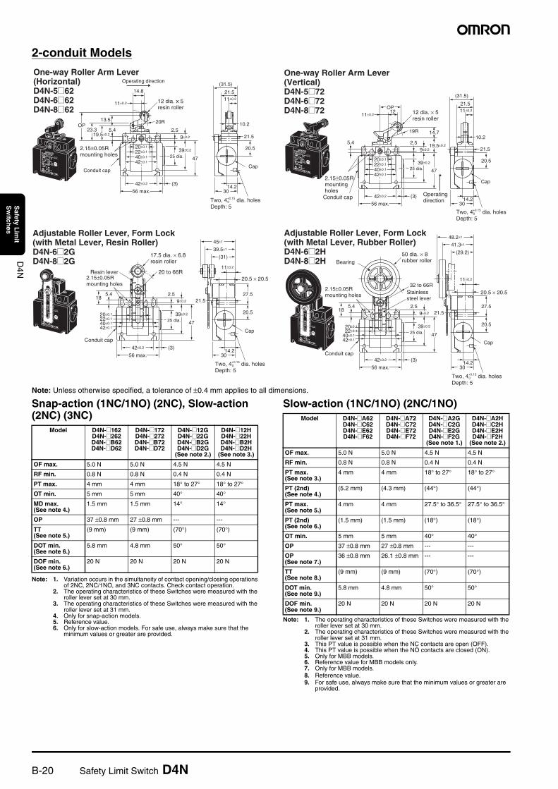
2-conduit Models
Note: Unless otherwise specified, a tolerance of ±0.4 mm applies to all dimensions.
Snap-action (1NC/1NO) (2NC), Slow-action (2NC) (3NC)
Note: 1. Variation occurs in the simultaneity of contact opening/closing operations of 2NC, 2NC/1NO, and 3NC contacts. Check contact operation.
2. The operating characteristics of these Switches were measured with the roller lever set at 30 mm.
3. The operating characteristics of these Switches were measured with the roller lever set at 31 mm.
4. Only for snap-action models.5. Reference value.6. Only for slow-action models. For safe use, always make sure that the
minimum values or greater are provided.
Slow-action (1NC/1NO) (2NC/1NO)
Note: 1. The operating characteristics of these Switches were measured with the roller lever set at 30 mm.
2. The operating characteristics of these Switches were measured with the roller lever set at 31 mm.
3. This PT value is possible when the NC contacts are open (OFF).4. This PT value is possible when the NO contacts are closed (ON).5. Only for MBB models.6. Reference value for MBB models only.7. Only for MBB models.8. Reference value.9. For safe use, always make sure that the minimum values or greater are
provided.
Two, 4+0.15 dia. holes Depth: 5
0
One-way Roller Arm Lever (Horizontal)D4N-5@62 D4N-6@62 D4N-8@62
12 dia. x 5 resin roller
2.15±0.05R mounting holes
30
Cap
20.5
21.5
42±0.2 (3)
56 max.
4725 dia.
2.55.49±0.2
20±0.1
40±0.1
42±0.1
22±0.1
14.2
11±0.2
10.2
(31.5)14.8
Operating direction
23.3
13.5
11±0.2
19.5±0.2
20ROP
21.5
39±0.2
Conduit cap
Two, 4+0.15 dia. holesDepth: 5
0
One-way Roller Arm Lever (Vertical)D4N-5@72 D4N-6@72 D4N-8@72
Operating direction
12 dia. × 5 resin roller
30
Cap
20.5
21.5
42±0.2 (3)
56 max.
4725 dia.
2.55.49±0.2
20±0.1
40±0.1
42±0.1
22±0.1
14.2
OP
14.719R
19.5±0.2
11±0.212 11±0.2
10.2
(31.5)
21.5
39±0.2
2.15±0.05R mounting holes
Conduit cap
Adjustable Roller Lever, Form Lock (with Metal Lever, Resin Roller)D4N-6@2G D4N-8@2G
17.5 dia. × 6.8 resin roller
Two, 4+0.15 dia. holesDepth: 5
0
30
Cap
27.5
20.5
11±0.2
21.5
42±0.2 (3)
56 max.
4725 dia.
2.55.49±0.2
18
20±0.1
40±0.1
42±0.1
22±0.1
14.2
45±1
39.5±1
(31)
39±0.2
20 to 66RResin lever2.15±0.05R mounting holes
Conduit cap
20.5 × 20.5
Adjustable Roller Lever, Form Lock (with Metal Lever, Rubber Roller)D4N-6@2H D4N-8@2H
50 dia. × 8 rubber rollerBearing
Stainless steel lever
Two, 4+0.15 dia. holesDepth: 5
0
20.5 × 20.5
30
Cap
27.5
20.5
11±0.2
21.5
42±0.2 (3)
56 max.
4725 dia.
2.55.49±0.2
18
20±0.1
40±0.1
42±0.1
22±0.1
14.2
48.2±1
41.3±1
(29.2)
39±0.2
32 to 66R2.15±0.05R mounting holes
Conduit cap
Model D4N-@162D4N-@262D4N-@B62D4N-@D62
D4N-@172D4N-@272D4N-@B72D4N-@D72
D4N-@12GD4N-@22GD4N-@B2GD4N-@D2G
(See note 2.)
D4N-@12HD4N-@22HD4N-@B2HD4N-@D2H
(See note 3.)
OF max. 5.0 N 5.0 N 4.5 N 4.5 N
RF min. 0.8 N 0.8 N 0.4 N 0.4 N
PT max. 4 mm 4 mm 18° to 27° 18° to 27°OT min. 5 mm 5 mm 40° 40°
MD max. (See note 4.)
1.5 mm 1.5 mm 14° 14°
OP 37 ±0.8 mm 27 ±0.8 mm --- ---
TT(See note 5.)
(9 mm) (9 mm) (70°) (70°)
DOT min.(See note 6.)
5.8 mm 4.8 mm 50° 50°
DOF min. (See note 6.)
20 N 20 N 20 N 20 N
Model D4N-@A62D4N-@C62D4N-@E62D4N-@F62
D4N-@A72D4N-@C72D4N-@E72D4N-@F72
D4N-@A2GD4N-@C2GD4N-@E2GD4N-@F2G
(See note 1.)
D4N-@A2HD4N-@C2HD4N-@E2HD4N-@F2H
(See note 2.)
OF max. 5.0 N 5.0 N 4.5 N 4.5 N
RF min. 0.8 N 0.8 N 0.4 N 0.4 N
PT max.(See note 3.)
4 mm 4 mm 18° to 27° 18° to 27°
PT (2nd)(See note 4.)
(5.2 mm) (4.3 mm) (44°) (44°)
PT max.(See note 5.)
4 mm 4 mm 27.5° to 36.5° 27.5° to 36.5°
PT (2nd)(See note 6.)
(1.5 mm) (1.5 mm) (18°) (18°)
OT min. 5 mm 5 mm 40° 40°
OP 37 ±0.8 mm 27 ±0.8 mm --- ---
OP(See note 7.)
36 ±0.8 mm 26.1 ±0.8 mm --- ---
TT(See note 8.)
(9 mm) (9 mm) (70°) (70°)
DOT min.(See note 9.)
5.8 mm 4.8 mm 50° 50°
DOF min. (See note 9.)
20 N 20 N 20 N 20 N
Safety Limit Switch D4N B-21
D4N
Safety L
imit
Sw
itches
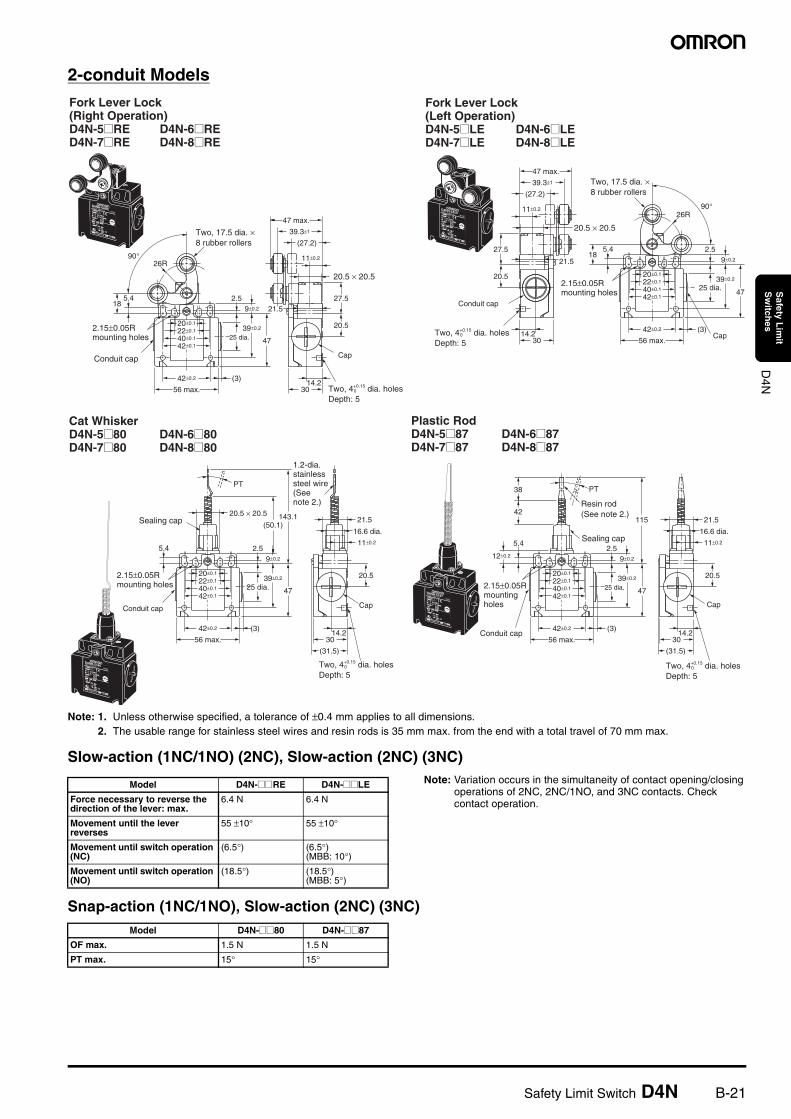
2-conduit Models
Note: 1. Unless otherwise specified, a tolerance of ±0.4 mm applies to all dimensions.2. The usable range for stainless steel wires and resin rods is 35 mm max. from the end with a total travel of 70 mm max.
Slow-action (1NC/1NO) (2NC), Slow-action (2NC) (3NC)Note: Variation occurs in the simultaneity of contact opening/closing
operations of 2NC, 2NC/1NO, and 3NC contacts. Check contact operation.
Snap-action (1NC/1NO), Slow-action (2NC) (3NC)
Two, 4+0.15 dia. holesDepth: 5
0
Fork Lever Lock (Right Operation)D4N-5@RE D4N-6@RED4N-7@RE D4N-8@RE
2.15±0.05R mounting holes
30
Cap
27.5
20.5
11±0.2
21.5
42±0.2 (3)
56 max.
4725 dia.
2.55.49±0.2
18
20±0.1
40±0.1
42±0.1
22±0.1
14.2
39.3±1
(27.2)
26R90°
47 max.
39±0.2
Two, 17.5 dia. × 8 rubber rollers
Conduit cap
20.5 × 20.5
Two, 4+0.15 dia. holesDepth: 5
0
Fork Lever Lock (Left Operation)D4N-5@LE D4N-6@LED4N-7@LE D4N-8@LE
2.15±0.05R mounting holes
Cap
Two, 17.5 dia. × 8 rubber rollers
20.5 × 20.5
30
27.5
20.5
11±0.2
21.5
14.2
39.3±1
(27.2)
42±0.2 (3)
56 max.
4725 dia.
2.55.49±0.2
18
20±0.1
40±0.1
42±0.1
22±0.1
90°26R
47 max.
39±0.2
Conduit cap
Two, 4+0.15 dia. holesDepth: 5
0
Cat WhiskerD4N-5@80 D4N-6@80D4N-7@80 D4N-8@80
1.2-dia. stainless steel wire(See note 2.)
2.15±0.05R mounting holes
30
Cap
20.5
11±0.2
16.6 dia.
42±0.2 (3)
56 max.
4725 dia.
2.5
20.5 × 20.5
5.49±0.2
20±0.1
40±0.1
42±0.1
22±0.1
14.2
(50.1)
PT
143.1 21.5
(31.5)
39±0.2
Sealing cap
Conduit cap
Two, 4+0.15 dia. holesDepth: 5
0
Plastic RodD4N-5@87 D4N-6@87D4N-7@87 D4N-8@87
2.15±0.05R mounting holes
30
Cap
20.5
11±0.2
16.6 dia.
42±0.2 (3)
56 max.
4725 dia.
2.55.4
9±0.212±0.2
20±0.1
40±0.1
42±0.1
22±0.1
14.2
115
38
42
PT
(31.5)
21.5
39±0.2
Resin rod(See note 2.)
Sealing cap
Conduit cap
Model D4N-@@RE D4N-@@LE
Force necessary to reverse the direction of the lever: max.
6.4 N 6.4 N
Movement until the lever reverses
55 ±10° 55 ±10°
Movement until switch operation (NC)
(6.5°) (6.5°)(MBB: 10°)
Movement until switch operation (NO)
(18.5°) (18.5°)(MBB: 5°)
Model D4N-@@80 D4N-@@87
OF max. 1.5 N 1.5 N
PT max. 15° 15°
B-22 Safety Limit Switch D4N
D4N
Safety L
imit
Sw
itches
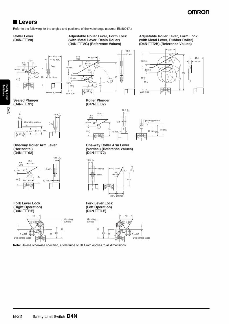
LeversRefer to the following for the angles and positions of the watchdogs (source: EN50047.)
Note: Unless otherwise specified, a tolerance of ±0.4 mm applies to all dimensions.
Roller Lever(D4N-@@20)
Adjustable Roller Lever, Form Lock (with Metal Lever, Resin Roller)(D4N-@@2G) (Reference Values)
Adjustable Roller Lever, Form Lock (with Metal Lever, Rubber Roller)(D4N-@@2H) (Reference Values)
40±2
15±3
40+1 0
55
50
30°20 min.
Dog
10 min.
Dog
5 min.
40±2
45
29±7
5±2
30°
30°
55+1 0
35+1 0
65R 20R
90
40 min.
Dog
15 min.
10 min.
42±2
110
75
30±7
11±3
30°
70+1 0
55+1 0
65R 31R
45 min.
25 min.
10 min.
Sealed Plunger(D4N-@@31)
Roller Plunger(D4N-@@32)
12.5 0
−2.5
18±0.5
Dog
15 min. 21 min.
DogOperating position
25+1 0
3528±1
10±1.5
2.530°
12.5 0
−2.5
Dog
20 min.
10 min.
Operating position
25 min.31 min.
One-way Roller Arm Lever (Horizontal)(D4N-@@62)
One-way Roller Arm Lever (Vertical) (Reference Values)(D4N-@@72)
30 max.
Dog
20 min.
31+1 0
10±2
40
5 min.
10 min.
30°
12.5 0
−2.5
30°
20 min.
31
41±2
22+1 0
5 min.
10 min.
12.5 0
−2.5
Dog
Fork Lever Lock (Right Operation)(D4N-@@RE)
Fork Lever Lock (Left Operation)(D4N-@@LE)
60
36
55° to 60°
5 to 9R
Dog setting range
40
28
60
36
55° to 60°
5 to 9R
Dog setting range
40
28
Mounting surface
Mounting surface
Safety Limit Switch D4N B-23
D4N
Safety L
imit
Sw
itches
Safety PrecautionsRefer to the “Precautions for All Switches” on page I-2 and “Precautions for All Safety Limit Switches” on page B-2.
!CAUTION
Precautions for Safe Use• Do not drop the Switch. Doing so may result in the Switch not
performing to its full capacity.• Do not attempt to disassemble or modify the Switch. Doing so may
cause the Switch to malfunction.• Do not use the Switch where explosive gas or flammable gas may
be present.• Do not use the Switch submerged in oil or water, or in locations
continuously subject to splashes of oil or water. Doing so may result in oil or water entering the Switch interior. (The IP67 degree of protection specification for the Switch refers to water penetration while the Switch is submersed in water for a specified period of time.)
• Protect the head from foreign material. Subjecting the head to foreign material may result in premature wear or damage to the Switch. Although the switch body is protected from penetration by dust or water, the head is not protected from penetration by minute particles or water.
• Turn the power OFF before wiring. Not doing so may result in electric shock.
• Install the cover after wiring. Not doing so may result in electric shock.
• Connect a fuse to the Switch in series to protect the Switch from short-circuit damage. Use a fuse with a breaking current 1.5 to 2 times larger than the rated current. To conform to EN ratings, use an IEC60269-compliant 10-A fuse type gI or gG.
• Do not switch circuits for two or more standard loads (250 VAC, 3 A) at the same time. Doing so may adversely affect insulation performance.
• The durability of the Switch is greatly affected by operating conditions. Evaluate the Switch under actual working conditions before permanent installation and use within a number of switching operations that will not adversely affect the Switch’s performance.
• Be sure to indicate in the machine manufacturer’s instruction manual that the user must not attempt to repair or maintain the Switch and must contact the machine manufacturer for any repairs or maintenance.
• Check the Switches before use and inspect regularly, replacing them when necessary. If a Switch is kept pressed for an extended period of time, the components may deteriorate quickly, and the Switch may not release.
Precautions for Correct Use
Environment• The Switch is intended for indoor use only.• Do not use the Switch outdoors. Doing so may cause the Switch to
malfunction.• Do not use the Switch where corrosive gases (e.g., H2S, SO2, NH3,
HNO3, CI2) are present or in locations subject to high temperature and humidity. Doing so may result in damage to the Switch caused by contact failure or corrosion.
• Do not use the Switches in the following locations.• Locations subject to severe temperature changes
• Locations subject to high temperatures or condensation
• Locations subject to severe vibration
• Locations where the interior of the Protective Door may come into direct contact with cutting chips, metal filings, oil, or chemicals
• Locations where the Switch may come into contact with thinner or detergents
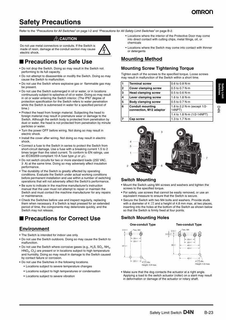
Mounting Method
Mounting Screw Tightening TorqueTighten each of the screws to the specified torque. Loose screws may result in malfunction of the Switch within a short time.
Switch Mounting• Mount the Switch using M4 screws and washers and tighten the
screws to the specified torque.• For safety, use screws that cannot be easily removed, or use an
equivalent measure to ensure that the Switch is secure.• Secure the Switch with two M4 bolts and washers. Provide studs
with a diameter of 4 and a height of 4.8 mm max. at two places, inserting into the holes at the bottom of the Switch as shown below so that the Switch is firmly fixed at four points.
Switch Mounting Holes
• Make sure that the dog contacts the actuator at a right angle. Applying a load to the switch actuator (roller) on a slant may result in deformation or damage of the actuator or rotary shaft.
Do not use metal connectors or conduits. If the Switch is made of resin, damage at the conduit section may cause electric shock.
1 Terminal screw 0.6 to 0.8 N·m
2 Cover clamping screw 0.5 to 0.7 N·m
3 Head clamping screw 0.5 to 0.6 N·m
4 Lever clamping screw 1.6 to 1.8 N·m
5 Body clamping screw 0.5 to 0.7 N·m
6 Conduit mounting connection, M12 adaptor
1.8 to 2.2 N·m (except 1/2-14NPT)
1.4 to 1.8 N·m (1/2-14NPT)
7 Cap screw 1.3 to 1.7 N·m
One-conduit Type Two-conduit Type
7
6
3
4
5
1
2
−0.05−0.15
2.5±0.1
22±0.1
47±0.1
20±0.1
22±0.1
Two, M4
−0.154−0.05 dia. Height: 4.8 max.
42±0.1
39±0.1
20±0.1
22±0.1
40±0.1
42±0.1
2.5±0.1
5.35±0.1
Two, M4
−0.154−0.05 dia. Height: 4.8 max.
B-24 Safety Limit Switch D4N
D4N
Safety L
imit
Sw
itches
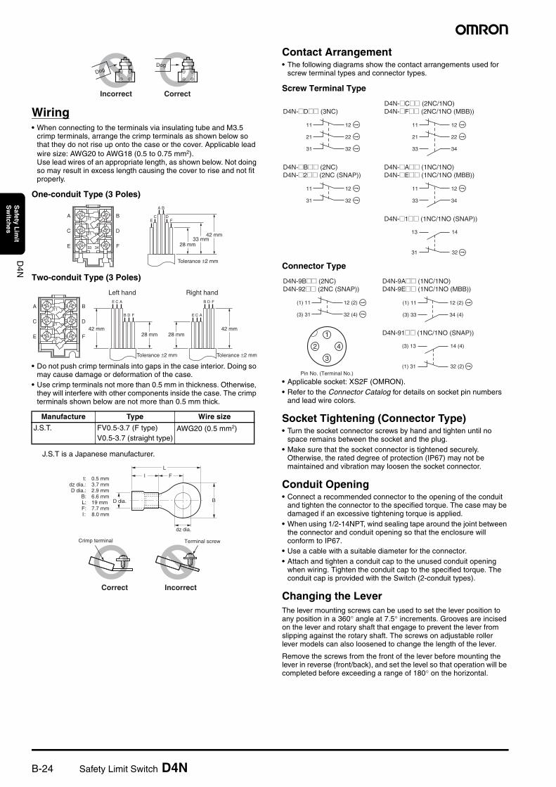
Wiring• When connecting to the terminals via insulating tube and M3.5
crimp terminals, arrange the crimp terminals as shown below so that they do not rise up onto the case or the cover. Applicable lead wire size: AWG20 to AWG18 (0.5 to 0.75 mm2).Use lead wires of an appropriate length, as shown below. Not doing so may result in excess length causing the cover to rise and not fit properly.
One-conduit Type (3 Poles)
Two-conduit Type (3 Poles)
• Do not push crimp terminals into gaps in the case interior. Doing so may cause damage or deformation of the case.
• Use crimp terminals not more than 0.5 mm in thickness. Otherwise, they will interfere with other components inside the case. The crimp terminals shown below are not more than 0.5 mm thick.
J.S.T is a Japanese manufacturer.
Contact Arrangement• The following diagrams show the contact arrangements used for
screw terminal types and connector types.
Screw Terminal Type
Connector Type
• Applicable socket: XS2F (OMRON).• Refer to the Connector Catalog for details on socket pin numbers
and lead wire colors.
Socket Tightening (Connector Type)• Turn the socket connector screws by hand and tighten until no
space remains between the socket and the plug.• Make sure that the socket connector is tightened securely.
Otherwise, the rated degree of protection (IP67) may not be maintained and vibration may loosen the socket connector.
Conduit Opening• Connect a recommended connector to the opening of the conduit
and tighten the connector to the specified torque. The case may be damaged if an excessive tightening torque is applied.
• When using 1/2-14NPT, wind sealing tape around the joint between the connector and conduit opening so that the enclosure will conform to IP67.
• Use a cable with a suitable diameter for the connector. • Attach and tighten a conduit cap to the unused conduit opening
when wiring. Tighten the conduit cap to the specified torque. The conduit cap is provided with the Switch (2-conduit types).
Changing the LeverThe lever mounting screws can be used to set the lever position to any position in a 360° angle at 7.5° increments. Grooves are incised on the lever and rotary shaft that engage to prevent the lever from slipping against the rotary shaft. The screws on adjustable roller lever models can also loosened to change the length of the lever.
Remove the screws from the front of the lever before mounting the lever in reverse (front/back), and set the level so that operation will be completed before exceeding a range of 180° on the horizontal.
Manufacture Type Wire size
J.S.T. FV0.5-3.7 (F type)V0.5-3.7 (straight type)
AWG20 (0.5 mm2)
DogDog
CorrectIncorrect
2221
3433
1211A
A
CE
B
DF
C
E
B
D
F 28 mm
Tolerance ±2 mm
33 mm42 mm
2221
3433
1211A
C
E
B
D
F
ACE
B D F
28 mm
Tolerance ±2 mm
Left hand
42 mm
ACE
B D F
28 mm
Tolerance ±2 mm
Right hand
42 mm
L
l F
BD dia.
dz dia.
Correct Incorrect
Terminal screwCrimp terminal
t: 0.5 mmdz dia.: 3.7 mmD dia.: 2.9 mm
B: 6.6 mmL: 19 mmF: 7.7 mmI: 8.0 mm
14
32
13
31
D4N-@D@@ (3NC)
11
21
12
22
31 32
D4N-@B@@ (2NC)D4N-@2@@ (2NC (SNAP))
11
31
12
32
D4N-@C@@ (2NC/1NO)D4N-@F@@ (2NC/1NO (MBB))
D4N-@A@@ (1NC/1NO)D4N-@E@@ (1NC/1NO (MBB))
33 34
11
21
12
22
11
33
12
34
D4N-@1@@ (1NC/1NO (SNAP))
14 (4)
32 (2)
(3) 13
(1) 31
1
3
2 4
Pin No. (Terminal No.)
D4N-9B@@ (2NC)D4N-92@@ (2NC (SNAP))
D4N-9A@@ (1NC/1NO)D4N-9E@@ (1NC/1NO (MBB))
(1) 11
(3) 31
12 (2)
32 (4)
(1) 11
(3) 33
12 (2)
34 (4)
D4N-91@@ (1NC/1NO (SNAP))
Safety Limit Switch D4N B-25
D4N
Safety L
imit
Sw
itches
Recommended ConnectorsUse connectors with screws not exceeding 9 mm, otherwise the screws will protrude into the case interior, interfering with other components in the case. The connectors listed in the following table have connectors with thread sections not exceeding 9 mm. Use the recommended connectors to ensure conformance to IP67.
Use LAPP connectors together with seal packing (JPK-16, GP-13.5, GPM20, or GPM12), and tighten to the specified tightening torque. Seal packing is sold separately.
LAPP is a German manufacturer.
Before using an M12 type, attaching the provided changing adaptor to the Switch and then connect the recommended connector.
Before using a 2-conduit 1/2-14NPT type, attach the provided changing adaptor to the Switch and then connect the recommended connector.
StorageDo not store the Switch in locations where corrosive gases (e.g., H2S, SO2, NH3, HNO3, Cl2) or dust is present, or in locations subject to high temperatures and humidity.
Others• Do not allow the load current to exceed the rated value. • Confirm that the seal rubber has no defects before use.
If the seal rubber is displaced or raised, or has foreign particles adhered to it, the sealing capability of the seal rubber will be adversely affected.
• Use the correct cover mounting screws only, or the sealing capability of the seal rubber will deteriorate.
• Inspect the Switch regularly.• Make sure that foreign particles do not enter the head when
removing the screws from the four corners to change the head position in any of the four directions.
• Use the following recommended countermeasures to prevent telegraphing when using adjustable or long levers.
1. Make the rear edge of the dog smooth with an angle of 15° to 30° or make it in the shape of a quadratic curve.
2. Design the circuit so that no error signal will be generated.3. Use or set a Switch that is operated in one direction only.
Production DiscontinuationFollowing the release of the D4N, production of the D4D-N will be discontinued.
Date of Production DiscontinuationProduction of the D4D-N Series will be discontinued as of the end of March 2006.
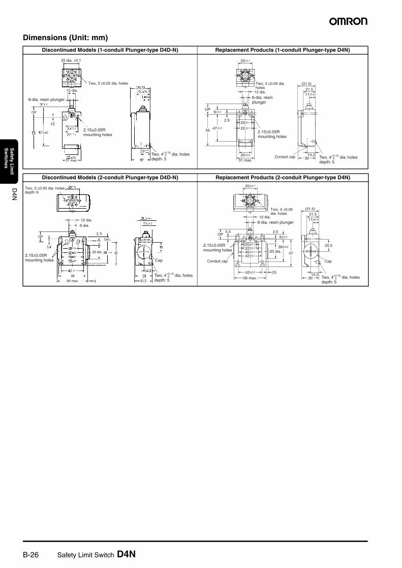
Product Replacement1. Dimensions
The D4D-N and D4N use the same mounting method, and mounting hole. The multi-contact structure and the extra 4 mm in length, however, are different.
2. Terminal NumbersFor the 2-contact slow-action model, the terminals 21, 22, 23, and 24 on the D4D-N are 31, 32, 33, and 34 on the D4N.
3. Recommended TerminalsIf the recommended terminals are not used, the Switch may not be compatible. Make sure that the Switch is compatible with the terminals.
Comparison of the D4D-N and Substitute Products
Size Manufacturer Model Applicable cable diameter
G1/2 LAPP ST-PF1/25380-1002
6.0 to 12.0 mm
Pg13.5 LAPP ST-13.55301-5030
6.0 to 12.0 mm
M20 LAPP ST-M20 × 1.55311-1020
7.0 to 13.0 mm
1/2-14NPT LAPP ST-NPT1/25301-6030
6.0 to 12.0 mm
M12 LAPP ST-M12 × 1.55311-1000
3.5 to 7.0 mm
Model D4N
Switch color Very similar
Dimensions Very similar
Wiring/connection Significantly different
Mounting method Completely compatible
Ratings/performance Very similar
Operating characteristics Very similar
Operating method Completely compatible
B-26 Safety Limit Switch D4N
D4N
Safety L
imit
Sw
itches
Dimensions (Unit: mm)
Discontinued Models (1-conduit Plunger-type D4D-N) Replacement Products (1-conduit Plunger-type D4N)
Discontinued Models (2-conduit Plunger-type D4D-N) Replacement Products (2-conduit Plunger-type D4N)
25 dia. ±0.1
Two, 3 ±0.05 dia. holes
12 dia.
6-dia. resin plunger
0Two, 4+0.15 dia. holes depth: 5
2.15±0.05R mounting holes
31 max.
OP
30
(31.5)
21.5
25±0.1
12 dia.11±0.2
22±0.2
31 max.
55 47±0.2
2.5
9±0.2OP
20±0.1
22±0.1
14.2
2.15±0.05R mounting holes
0Two, 4+0.15 dia. holes depth: 5
Two, 3 ±0.05 dia. holes
6-dia. resin plunger
Conduit cap
Two, 3 ±0.05 dia. holes depth: 6
12 dia.6 dia.
2.15±0.05R mounting holes
56 max.
25 dia.
Cap
0Two, 4+0.15 dia. holes depth: 5
OP
30
Cap
20.5
42±0.2 (3)
56 max.
4725 dia.
2.55.49±0.2
OP
20±0.1
40±0.1
42±0.1
22±0.1
14.2
(31.5)21.511±0.2
25±0.1
12 dia.
39±0.22.15±0.05R mounting holes
0Two, 4+0.15 dia. holes depth: 5
Two, 3 ±0.05 dia. holes
6-dia. resin plunger
Conduit cap
Safety Limit Switch D4N B-27
D4N
Safety L
imit
Sw
itches
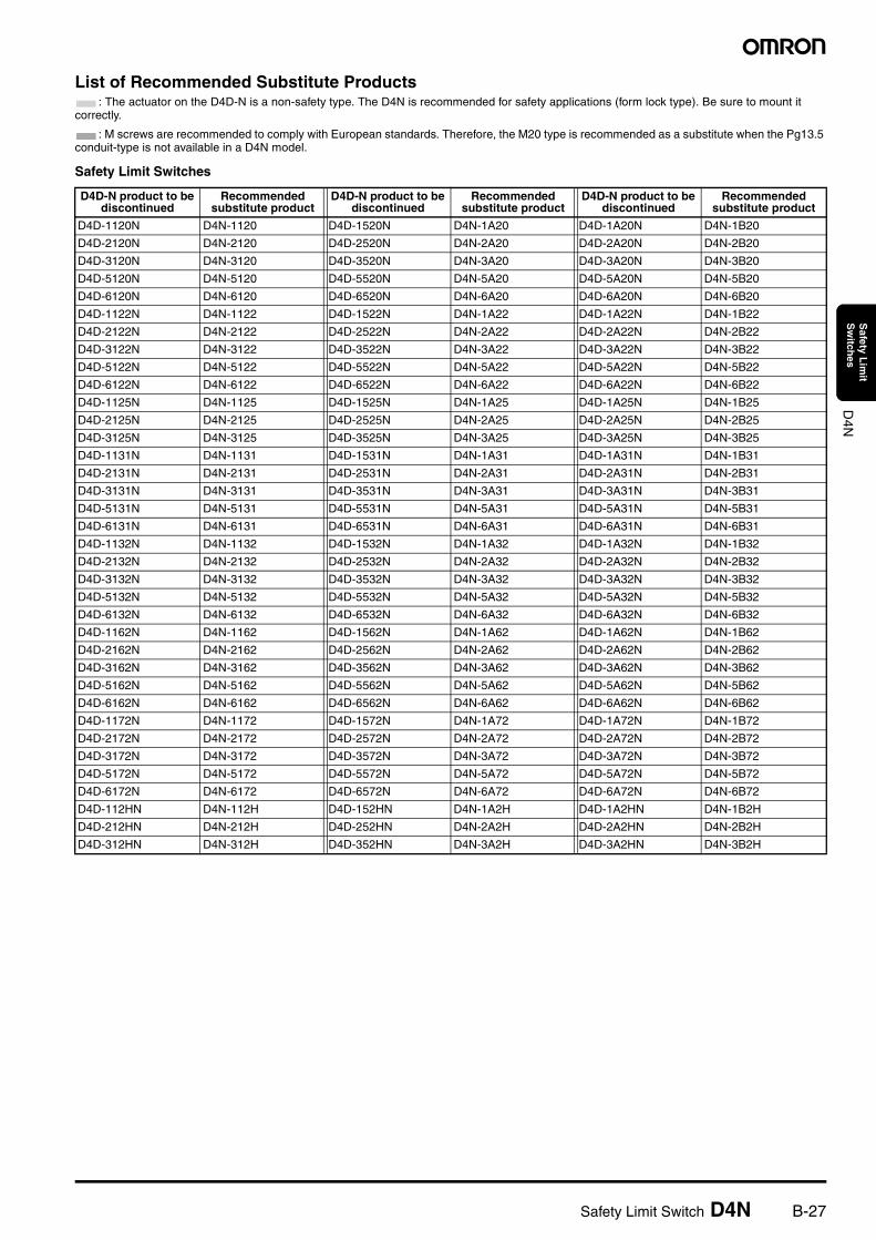
List of Recommended Substitute Products: The actuator on the D4D-N is a non-safety type. The D4N is recommended for safety applications (form lock type). Be sure to mount it
correctly.
: M screws are recommended to comply with European standards. Therefore, the M20 type is recommended as a substitute when the Pg13.5 conduit-type is not available in a D4N model.
Safety Limit Switches
D4D-N product to be discontinued
Recommended substitute product
D4D-N product to be discontinued
Recommended substitute product
D4D-N product to be discontinued
Recommended substitute product
D4D-1120N D4N-1120 D4D-1520N D4N-1A20 D4D-1A20N D4N-1B20
D4D-2120N D4N-2120 D4D-2520N D4N-2A20 D4D-2A20N D4N-2B20
D4D-3120N D4N-3120 D4D-3520N D4N-3A20 D4D-3A20N D4N-3B20
D4D-5120N D4N-5120 D4D-5520N D4N-5A20 D4D-5A20N D4N-5B20
D4D-6120N D4N-6120 D4D-6520N D4N-6A20 D4D-6A20N D4N-6B20
D4D-1122N D4N-1122 D4D-1522N D4N-1A22 D4D-1A22N D4N-1B22
D4D-2122N D4N-2122 D4D-2522N D4N-2A22 D4D-2A22N D4N-2B22
D4D-3122N D4N-3122 D4D-3522N D4N-3A22 D4D-3A22N D4N-3B22
D4D-5122N D4N-5122 D4D-5522N D4N-5A22 D4D-5A22N D4N-5B22
D4D-6122N D4N-6122 D4D-6522N D4N-6A22 D4D-6A22N D4N-6B22
D4D-1125N D4N-1125 D4D-1525N D4N-1A25 D4D-1A25N D4N-1B25
D4D-2125N D4N-2125 D4D-2525N D4N-2A25 D4D-2A25N D4N-2B25
D4D-3125N D4N-3125 D4D-3525N D4N-3A25 D4D-3A25N D4N-3B25
D4D-1131N D4N-1131 D4D-1531N D4N-1A31 D4D-1A31N D4N-1B31
D4D-2131N D4N-2131 D4D-2531N D4N-2A31 D4D-2A31N D4N-2B31
D4D-3131N D4N-3131 D4D-3531N D4N-3A31 D4D-3A31N D4N-3B31
D4D-5131N D4N-5131 D4D-5531N D4N-5A31 D4D-5A31N D4N-5B31
D4D-6131N D4N-6131 D4D-6531N D4N-6A31 D4D-6A31N D4N-6B31
D4D-1132N D4N-1132 D4D-1532N D4N-1A32 D4D-1A32N D4N-1B32
D4D-2132N D4N-2132 D4D-2532N D4N-2A32 D4D-2A32N D4N-2B32
D4D-3132N D4N-3132 D4D-3532N D4N-3A32 D4D-3A32N D4N-3B32
D4D-5132N D4N-5132 D4D-5532N D4N-5A32 D4D-5A32N D4N-5B32
D4D-6132N D4N-6132 D4D-6532N D4N-6A32 D4D-6A32N D4N-6B32
D4D-1162N D4N-1162 D4D-1562N D4N-1A62 D4D-1A62N D4N-1B62
D4D-2162N D4N-2162 D4D-2562N D4N-2A62 D4D-2A62N D4N-2B62
D4D-3162N D4N-3162 D4D-3562N D4N-3A62 D4D-3A62N D4N-3B62
D4D-5162N D4N-5162 D4D-5562N D4N-5A62 D4D-5A62N D4N-5B62
D4D-6162N D4N-6162 D4D-6562N D4N-6A62 D4D-6A62N D4N-6B62
D4D-1172N D4N-1172 D4D-1572N D4N-1A72 D4D-1A72N D4N-1B72
D4D-2172N D4N-2172 D4D-2572N D4N-2A72 D4D-2A72N D4N-2B72
D4D-3172N D4N-3172 D4D-3572N D4N-3A72 D4D-3A72N D4N-3B72
D4D-5172N D4N-5172 D4D-5572N D4N-5A72 D4D-5A72N D4N-5B72
D4D-6172N D4N-6172 D4D-6572N D4N-6A72 D4D-6A72N D4N-6B72
D4D-112HN D4N-112H D4D-152HN D4N-1A2H D4D-1A2HN D4N-1B2H
D4D-212HN D4N-212H D4D-252HN D4N-2A2H D4D-2A2HN D4N-2B2H
D4D-312HN D4N-312H D4D-352HN D4N-3A2H D4D-3A2HN D4N-3B2H
B-28 Safety Limit Switch D4N
D4N
Safety L
imit
Sw
itches
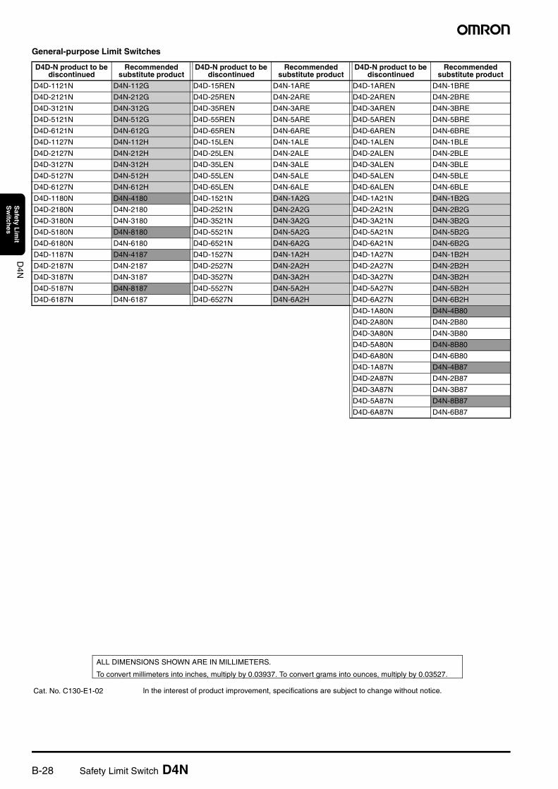
General-purpose Limit Switches
D4D-N product to be discontinued
Recommended substitute product
D4D-N product to be discontinued
Recommended substitute product
D4D-N product to be discontinued
Recommended substitute product
D4D-1121N D4N-112G D4D-15REN D4N-1ARE D4D-1AREN D4N-1BRE
D4D-2121N D4N-212G D4D-25REN D4N-2ARE D4D-2AREN D4N-2BRE
D4D-3121N D4N-312G D4D-35REN D4N-3ARE D4D-3AREN D4N-3BRE
D4D-5121N D4N-512G D4D-55REN D4N-5ARE D4D-5AREN D4N-5BRE
D4D-6121N D4N-612G D4D-65REN D4N-6ARE D4D-6AREN D4N-6BRE
D4D-1127N D4N-112H D4D-15LEN D4N-1ALE D4D-1ALEN D4N-1BLE
D4D-2127N D4N-212H D4D-25LEN D4N-2ALE D4D-2ALEN D4N-2BLE
D4D-3127N D4N-312H D4D-35LEN D4N-3ALE D4D-3ALEN D4N-3BLE
D4D-5127N D4N-512H D4D-55LEN D4N-5ALE D4D-5ALEN D4N-5BLE
D4D-6127N D4N-612H D4D-65LEN D4N-6ALE D4D-6ALEN D4N-6BLE
D4D-1180N D4N-4180 D4D-1521N D4N-1A2G D4D-1A21N D4N-1B2G
D4D-2180N D4N-2180 D4D-2521N D4N-2A2G D4D-2A21N D4N-2B2G
D4D-3180N D4N-3180 D4D-3521N D4N-3A2G D4D-3A21N D4N-3B2G
D4D-5180N D4N-8180 D4D-5521N D4N-5A2G D4D-5A21N D4N-5B2G
D4D-6180N D4N-6180 D4D-6521N D4N-6A2G D4D-6A21N D4N-6B2G
D4D-1187N D4N-4187 D4D-1527N D4N-1A2H D4D-1A27N D4N-1B2H
D4D-2187N D4N-2187 D4D-2527N D4N-2A2H D4D-2A27N D4N-2B2H
D4D-3187N D4N-3187 D4D-3527N D4N-3A2H D4D-3A27N D4N-3B2H
D4D-5187N D4N-8187 D4D-5527N D4N-5A2H D4D-5A27N D4N-5B2H
D4D-6187N D4N-6187 D4D-6527N D4N-6A2H D4D-6A27N D4N-6B2H
D4D-1A80N D4N-4B80
D4D-2A80N D4N-2B80
D4D-3A80N D4N-3B80
D4D-5A80N D4N-8B80
D4D-6A80N D4N-6B80
D4D-1A87N D4N-4B87
D4D-2A87N D4N-2B87
D4D-3A87N D4N-3B87
D4D-5A87N D4N-8B87
D4D-6A87N D4N-6B87
In the interest of product improvement, specifications are subject to change without notice.
ALL DIMENSIONS SHOWN ARE IN MILLIMETERS.
To convert millimeters into inches, multiply by 0.03937. To convert grams into ounces, multiply by 0.03527.
Cat. No. C130-E1-02
Terms and Conditions of Sale1. Offer; Acceptance. These terms and conditions (these "Terms") are deemed
part of all quotes, agreements, purchase orders, acknowledgments, price lists,catalogs, manuals, brochures and other documents, whether electronic or inwriting, relating to the sale of products or services (collectively, the "Products")by Omron Electronics LLC and its subsidiary companies (“Omron”). Omronobjects to any terms or conditions proposed in Buyer’s purchase order or otherdocuments which are inconsistent with, or in addition to, these Terms.
2. Prices; Payment Terms. All prices stated are current, subject to change with-out notice by Omron. Omron reserves the right to increase or decrease priceson any unshipped portions of outstanding orders. Payments for Products aredue net 30 days unless otherwise stated in the invoice.
3. Discounts. Cash discounts, if any, will apply only on the net amount of invoicessent to Buyer after deducting transportation charges, taxes and duties, and willbe allowed only if (i) the invoice is paid according to Omron’s payment termsand (ii) Buyer has no past due amounts.
4. Interest. Omron, at its option, may charge Buyer 1-1/2% interest per month orthe maximum legal rate, whichever is less, on any balance not paid within thestated terms.
5. Orders. Omron will accept no order less than $200 net billing. 6. Governmental Approvals. Buyer shall be responsible for, and shall bear all
costs involved in, obtaining any government approvals required for the impor-tation or sale of the Products.
7. Taxes. All taxes, duties and other governmental charges (other than generalreal property and income taxes), including any interest or penalties thereon,imposed directly or indirectly on Omron or required to be collected directly orindirectly by Omron for the manufacture, production, sale, delivery, importa-tion, consumption or use of the Products sold hereunder (including customsduties and sales, excise, use, turnover and license taxes) shall be charged toand remitted by Buyer to Omron.
8. Financial. If the financial position of Buyer at any time becomes unsatisfactoryto Omron, Omron reserves the right to stop shipments or require satisfactorysecurity or payment in advance. If Buyer fails to make payment or otherwisecomply with these Terms or any related agreement, Omron may (without liabil-ity and in addition to other remedies) cancel any unshipped portion of Prod-ucts sold hereunder and stop any Products in transit until Buyer pays allamounts, including amounts payable hereunder, whether or not then due,which are owing to it by Buyer. Buyer shall in any event remain liable for allunpaid accounts.
9. Cancellation; Etc. Orders are not subject to rescheduling or cancellationunless Buyer indemnifies Omron against all related costs or expenses.
10. Force Majeure. Omron shall not be liable for any delay or failure in deliveryresulting from causes beyond its control, including earthquakes, fires, floods,strikes or other labor disputes, shortage of labor or materials, accidents tomachinery, acts of sabotage, riots, delay in or lack of transportation or therequirements of any government authority.
11. Shipping; Delivery. Unless otherwise expressly agreed in writing by Omron:a. Shipments shall be by a carrier selected by Omron; Omron will not drop ship
except in “break down” situations.b. Such carrier shall act as the agent of Buyer and delivery to such carrier shall
constitute delivery to Buyer;c. All sales and shipments of Products shall be FOB shipping point (unless oth-
erwise stated in writing by Omron), at which point title and risk of loss shallpass from Omron to Buyer; provided that Omron shall retain a security inter-est in the Products until the full purchase price is paid;
d. Delivery and shipping dates are estimates only; ande. Omron will package Products as it deems proper for protection against nor-
mal handling and extra charges apply to special conditions.12. Claims. Any claim by Buyer against Omron for shortage or damage to the
Products occurring before delivery to the carrier must be presented in writingto Omron within 30 days of receipt of shipment and include the original trans-portation bill signed by the carrier noting that the carrier received the Productsfrom Omron in the condition claimed.
13. Warranties. (a) Exclusive Warranty. Omron’s exclusive warranty is that theProducts will be free from defects in materials and workmanship for a period oftwelve months from the date of sale by Omron (or such other period expressedin writing by Omron). Omron disclaims all other warranties, express or implied.(b) Limitations. OMRON MAKES NO WARRANTY OR REPRESENTATION,EXPRESS OR IMPLIED, ABOUT NON-INFRINGEMENT, MERCHANTABIL-
ITY OR FITNESS FOR A PARTICULAR PURPOSE OF THE PRODUCTS.BUYER ACKNOWLEDGES THAT IT ALONE HAS DETERMINED THAT THEPRODUCTS WILL SUITABLY MEET THE REQUIREMENTS OF THEIRINTENDED USE. Omron further disclaims all warranties and responsibility ofany type for claims or expenses based on infringement by the Products or oth-erwise of any intellectual property right. (c) Buyer Remedy. Omron’s sole obli-gation hereunder shall be, at Omron’s election, to (i) replace (in the formoriginally shipped with Buyer responsible for labor charges for removal orreplacement thereof) the non-complying Product, (ii) repair the non-complyingProduct, or (iii) repay or credit Buyer an amount equal to the purchase price ofthe non-complying Product; provided that in no event shall Omron be responsi-ble for warranty, repair, indemnity or any other claims or expenses regardingthe Products unless Omron’s analysis confirms that the Products were prop-erly handled, stored, installed and maintained and not subject to contamina-tion, abuse, misuse or inappropriate modification. Return of any Products byBuyer must be approved in writing by Omron before shipment. Omron Compa-nies shall not be liable for the suitability or unsuitability or the results from theuse of Products in combination with any electrical or electronic components,circuits, system assemblies or any other materials or substances or environ-ments. Any advice, recommendations or information given orally or in writing,are not to be construed as an amendment or addition to the above warranty.See http://oeweb.omron.com or contact your Omron representative for pub-lished information.
14. Limitation on Liability; Etc. OMRON COMPANIES SHALL NOT BE LIABLEFOR SPECIAL, INDIRECT, INCIDENTAL, OR CONSEQUENTIAL DAMAGES,LOSS OF PROFITS OR PRODUCTION OR COMMERCIAL LOSS IN ANYWAY CONNECTED WITH THE PRODUCTS, WHETHER SUCH CLAIM ISBASED IN CONTRACT, WARRANTY, NEGLIGENCE OR STRICT LIABILITY.Further, in no event shall liability of Omron Companies exceed the individualprice of the Product on which liability is asserted.
15. Indemnities. Buyer shall indemnify and hold harmless Omron Companies andtheir employees from and against all liabilities, losses, claims, costs andexpenses (including attorney's fees and expenses) related to any claim, inves-tigation, litigation or proceeding (whether or not Omron is a party) which arisesor is alleged to arise from Buyer's acts or omissions under these Terms or inany way with respect to the Products. Without limiting the foregoing, Buyer (atits own expense) shall indemnify and hold harmless Omron and defend or set-tle any action brought against such Companies to the extent based on a claimthat any Product made to Buyer specifications infringed intellectual propertyrights of another party.
16. Property; Confidentiality. Any intellectual property in the Products is the exclu-sive property of Omron Companies and Buyer shall not attempt to duplicate itin any way without the written permission of Omron. Notwithstanding anycharges to Buyer for engineering or tooling, all engineering and tooling shallremain the exclusive property of Omron. All information and materials suppliedby Omron to Buyer relating to the Products are confidential and proprietary,and Buyer shall limit distribution thereof to its trusted employees and strictlyprevent disclosure to any third party.
17. Export Controls. Buyer shall comply with all applicable laws, regulations andlicenses regarding (i) export of products or information; (iii) sale of products to“forbidden” or other proscribed persons; and (ii) disclosure to non-citizens ofregulated technology or information.
18. Miscellaneous. (a) Waiver. No failure or delay by Omron in exercising any rightand no course of dealing between Buyer and Omron shall operate as a waiverof rights by Omron. (b) Assignment. Buyer may not assign its rights hereunderwithout Omron's written consent. (c) Law. These Terms are governed by thelaw of the jurisdiction of the home office of the Omron company from whichBuyer is purchasing the Products (without regard to conflict of law princi-ples). (d) Amendment. These Terms constitute the entire agreement betweenBuyer and Omron relating to the Products, and no provision may be changedor waived unless in writing signed by the parties. (e) Severability. If any provi-sion hereof is rendered ineffective or invalid, such provision shall not invalidateany other provision. (f) Setoff. Buyer shall have no right to set off any amountsagainst the amount owing in respect of this invoice. (g) Definitions. As usedherein, “including” means “including without limitation”; and “Omron Compa-nies” (or similar words) mean Omron Corporation and any direct or indirectsubsidiary or affiliate thereof.
Certain Precautions on Specifications and Use1. Suitability of Use. Omron Companies shall not be responsible for conformity
with any standards, codes or regulations which apply to the combination of theProduct in the Buyer’s application or use of the Product. At Buyer’s request,Omron will provide applicable third party certification documents identifyingratings and limitations of use which apply to the Product. This information byitself is not sufficient for a complete determination of the suitability of the Prod-uct in combination with the end product, machine, system, or other applicationor use. Buyer shall be solely responsible for determining appropriateness ofthe particular Product with respect to Buyer’s application, product or system.Buyer shall take application responsibility in all cases but the following is anon-exhaustive list of applications for which particular attention must be given:(i) Outdoor use, uses involving potential chemical contamination or electricalinterference, or conditions or uses not described in this document.(ii) Use in consumer products or any use in significant quantities. (iii) Energy control systems, combustion systems, railroad systems, aviationsystems, medical equipment, amusement machines, vehicles, safety equip-ment, and installations subject to separate industry or government regulations. (iv) Systems, machines and equipment that could present a risk to life or prop-erty. Please know and observe all prohibitions of use applicable to this Prod-uct. NEVER USE THE PRODUCT FOR AN APPLICATION INVOLVING SERIOUSRISK TO LIFE OR PROPERTY OR IN LARGE QUANTITIES WITHOUTENSURING THAT THE SYSTEM AS A WHOLE HAS BEEN DESIGNED TO
ADDRESS THE RISKS, AND THAT THE OMRON’S PRODUCT IS PROP-ERLY RATED AND INSTALLED FOR THE INTENDED USE WITHIN THEOVERALL EQUIPMENT OR SYSTEM.
2. Programmable Products. Omron Companies shall not be responsible for theuser’s programming of a programmable Product, or any consequence thereof.
3. Performance Data. Data presented in Omron Company websites, catalogsand other materials is provided as a guide for the user in determining suitabil-ity and does not constitute a warranty. It may represent the result of Omron’stest conditions, and the user must correlate it to actual application require-ments. Actual performance is subject to the Omron’s Warranty and Limitationsof Liability.
4. Change in Specifications. Product specifications and accessories may bechanged at any time based on improvements and other reasons. It is our prac-tice to change part numbers when published ratings or features are changed,or when significant construction changes are made. However, some specifica-tions of the Product may be changed without any notice. When in doubt, spe-cial part numbers may be assigned to fix or establish key specifications foryour application. Please consult with your Omron’s representative at any timeto confirm actual specifications of purchased Product.
5. Errors and Omissions. Information presented by Omron Companies has beenchecked and is believed to be accurate; however, no responsibility is assumedfor clerical, typographical or proofreading errors or omissions.
$%"=GG<"=GGG ("=GG
Cat. No. GC SAFETY-3 07/05 Specifications subject to change without notice Printed in USA
! "#992; # !;*2F9
$%&'&&$&(
( -# %!7'415,
$)$*)+,,6< 3 =
,,((&&)&&
- ./ 012
111# # 3H/- 2.2"/4#
!56 ## !%11,:,5# !%11,25
Related Documents


