Safety Light Curtain F3SG-R Series Advanced, Robust, and Easy types Advanced type Easy type Robust type NEW More Rugged

Welcome message from author
This document is posted to help you gain knowledge. Please leave a comment to let me know what you think about it! Share it to your friends and learn new things together.
Transcript

Safety Light CurtainF3SG-R Series
Advanced, Robust, and Easy types
Advanced type
Easy type
Robust typeNEW
More Rugged
2 | Safety Light Curtain F3SG-R Series
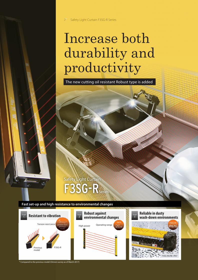
Resistant to vibrationTough
1
Torsion resistance5 times *
greater than previous
model
Robust against environmental changes
Tough
2
Operating rangeHigh power
Up to
20 m
Reliable in dusty wash-down environments
Tough
3
Safety Light Curtain
F3SG-RSeries
e o e ta c a gesUp to
Operating rangeHi h
p
20Operating rangeHigh power 20 m20 m
5 *n
5ti s*sans
5timesshausel
ancetime
thoude
ance greater io
od
ance greateprev
mo
Resistant to vib
stastastasississisesesesrererennnnnn oonoonoonTorrssiooorrssiooiooToorrssiToorrssi
F3SG-RPrevious model
F3SG-RR
IP67G
The new cutting oil resistant Robust type is added
Fast set-up and high resistance to environmental changes
* Compared to the previous model (Omron survey as of March 2017)
Increase bothdurability and productivity
F3SG-RA/RE:IP67
| 3
STI is a trademark or registered trademark of OMRON Corporation in Japan and other countries.
Microsoft product screen shot(s) reprinted with permission from Microsoft Corporation.
The Bluetooth® word mark and logos are registered trademarks owned by Bluetooth SIG, Inc. Any use of such marks by Omron is under license.
Other company names and product names in this document are the trademarks or registered trademarks of their respective companies.
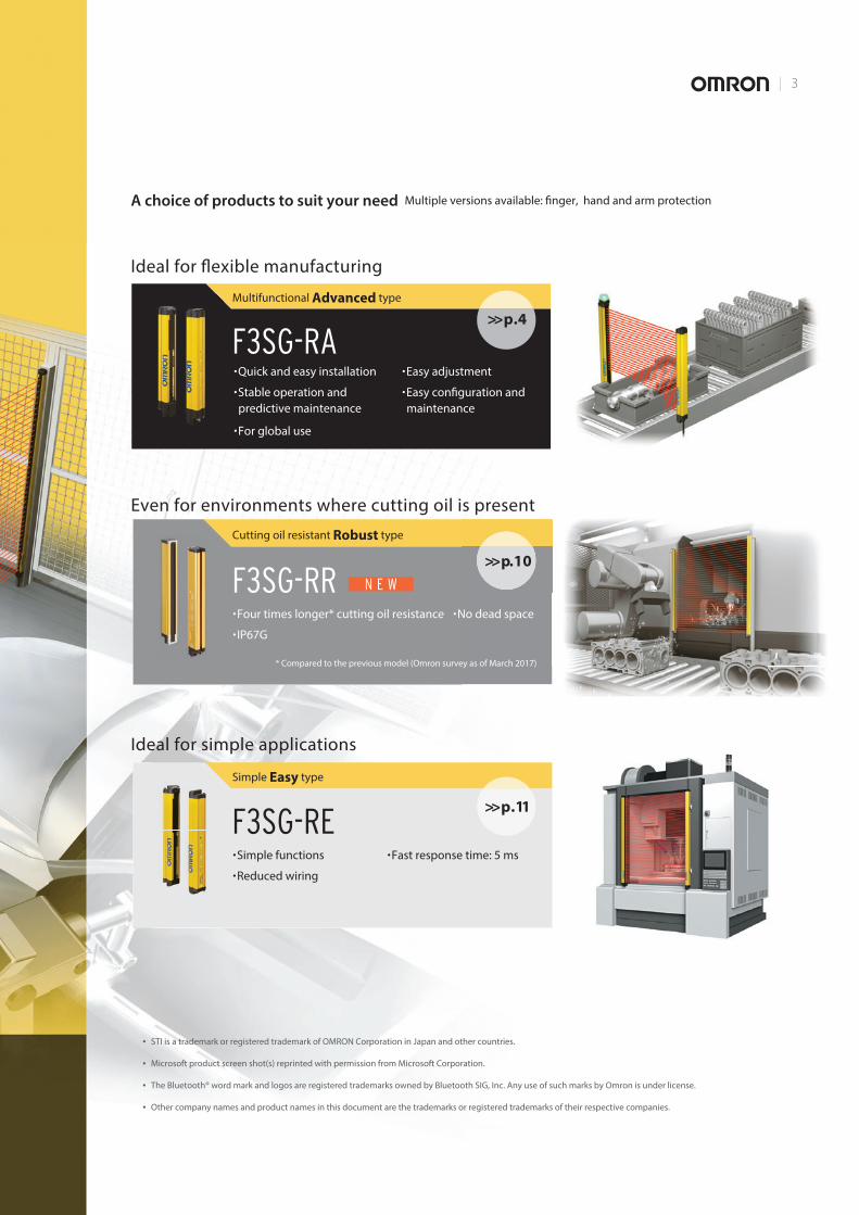
A choice of products to suit your need Multiple versions available: finger, hand and arm protection
Ideal for flexible manufacturing
F3SG-RAQuick and easy installation
Stable operation and
predictive maintenance
For global use
Easy adjustment
Easy configuration and
maintenance
>>p.4Multifunctional Advanced type
Ideal for simple applications
F3SG-RESimple functions
Reduced wiring
Fast response time: 5 ms
>>p.11
Simple Easy type
Even for environments where cutting oil is present
F3SG-RRFour times longer* cutting oil resistance No dead space
IP67G
>>p.10
Cutting oil resistant Robust type
N E W
* Compared to the previous model (Omron survey as of March 2017)
4 | Safety Light Curtain F3SG-R Series
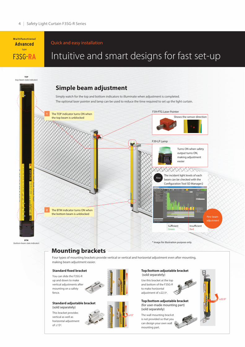
Simple beam adjustmentSimply watch for the top and bottom indicators to illuminate when adjustment is completed.
The optional laser pointer and lamp can be used to reduce the time required to set up the light curtain.
TOP
(top-beam-state indicator)
BTM
(bottom-beam-state indicator)
F39-PTG Laser Pointer
Shows the sensor direction
Turns ON when safety
output turns ON,
making adjustment
easier
F39-LP Lamp
The incident light levels of each
beam can be checked with the
Configuration Tool SD Manager2
Sufficient
Green
Insufficient
Red
Fine beam
adjustment
ShSh
Tu
ou
ma
ea
F39-LP Lamp
Intuitive and smart designs for fast set-upQuick and easy installation
Also
The TOP indicator turns ON when
the top beam is unblocked
1
The BTM indicator turns ON when
the bottom beam is unblocked
2
Mounting bracketsFour types of mounting brackets provide vertical or vertical and horizontal adjustment even after mounting,
making beam adjustment easier.
Standard fixed bracket
You can slide the F3SG-R
up and down to make
vertical adjustments after
mounting on a safety
fence.
Standard adjustable bracket
(sold separately)
This bracket provides
vertical as well as
horizontal adjustment
of ±15º.
Top/bottom adjustable bracket
(sold separately)
Use this bracket at the top
and bottom of the F3SG-R
to make horizontal
adjustment of ±22.5º.
Top/bottom adjustable bracket
(for user-made mounting part) (sold separately)
The wall mounting bracket
is not provided so that you
can design your own wall
mounting part.
r
p
R
p
R
k
o
l
ket
ou
l
±15°
±22.5°
F3SG-RA
M u l t i f u n c t i o n a l
Advancedtype
* Image for illustration purpose only.
| 5
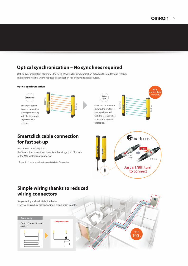
Optical synchronization – No sync lines requiredOptical synchronization eliminates the need of wiring for synchronization between the emitter and receiver.
The resulting flexible wiring reduces disconnection risk and avoids noise sources.
Smartclick cable connection for fast set-upNo torque-control required:
the Smartclick connectors connect cables with just a 1/8th turn
of the M12 waterproof connector.
Simple wiring thanks to reduced wiring connectors
* Smartclick is a registered trademark of OMRON Corporation.
Optical synchronization
Start-up
Re
ceiv
er
Em
itte
r
Em
itte
rThe top or bottom
beam of the emitter
starts synchronizing
with the correspond-
ing beam of the
receiver.
Aftersync
Re
ceiv
er
Once synchronization
is done, the emitter is
kept synchronized
with the receiver while
at least one beam is
unblocked.
Insertfully
1/8th turn
Click!
Just a 1/8th turn to connect
Cables of the emitter and
receiver
Previously
Only one cable
up to
100m
High ambient light
immunity
Simple wiring makes installation faster.
Fewer cables reduce disconnection risk and noise trouble.
*
6 | Safety Light Curtain F3SG-R Series
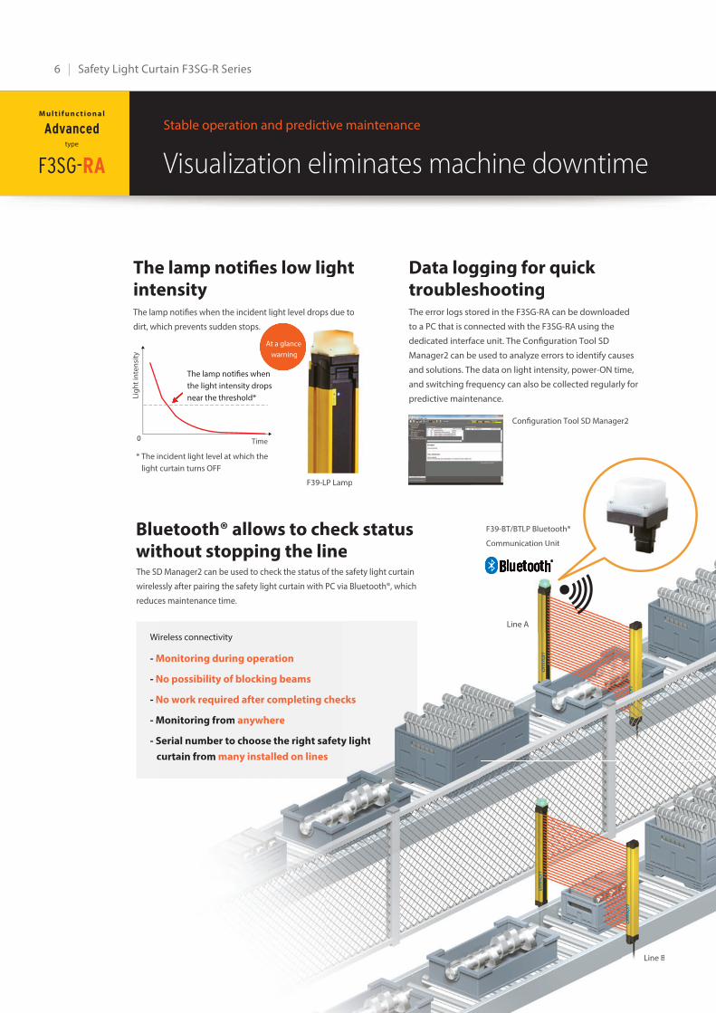
Visualization eliminates machine downtimeStable operation and predictive maintenance
The lamp notifies low light intensity The lamp notifies when the incident light level drops due to
dirt, which prevents sudden stops.
Bluetooth® allows to check status without stopping the line
Data logging for quick troubleshootingThe error logs stored in the F3SG-RA can be downloaded
to a PC that is connected with the F3SG-RA using the
dedicated interface unit. The Configuration Tool SD
Manager2 can be used to analyze errors to identify causes
and solutions. The data on light intensity, power-ON time,
and switching frequency can also be collected regularly for
predictive maintenance.
The SD Manager2 can be used to check the status of the safety light curtain
wirelessly after pairing the safety light curtain with PC via Bluetooth®, which
reduces maintenance time.
Wireless connectivity
- Monitoring during operation
- No possibility of blocking beams
- No work required after completing checks
- Monitoring from anywhere
- Serial number to choose the right safety light
curtain from many installed on lines
F39-LP Lamp
* The incident light level at which the
light curtain turns OFF
Configuration Tool SD Manager2
Line A
Line B
The lamp notifies when
the light intensity drops
near the threshold*
At a glance
warning
F39-BT/BTLP Bluetooth®
Communication Unit
F3SG-RA
M u l t i f u n c t i o n a l
Advancedtype
e lamp notifies low light ensity mp notifies when the incident light level drops due to
hich prevents sudden stops.
uetooth® allows to check status thout stopping the line
Data logging for quick troubleshootingThe error logs stored in the F3SG-RA can be downloaded
to a PC that is connected with the F3SG-RA using the
dedicated interface unit. The Configuration Tool SD
Manager2 can be used to analyze errors to identify causes
and solutions. The data on light intensity, power-ON time,
and switching frequency can also be collected regularly for
predictive maintenance.
D Manager2 can be used to check the status of the safety light curtain
essly after pairing the safety light curtain with PC via Bluetooth®, which
es maintenance time.
Wireless connectivity
Monitoring during operation
No possibility of blocking beams
No work required after completing checks
Monitoring from anywhere
Serial number to choose the right safety light
curtain from many installed on lines
F39-LP Lamp
incident light level at which the
t curtain turns OFF
Configuration Tool SD Manager2
Line A
Line B
The lamp notifies when
the light intensity drops
near the threshold*
At a glance
warning
F39-BT/BTLP Bluetooth®
Communication Unit
Lig
ht
inte
nsi
ty
Time0

| 7
Easy to deploy around the worldFor global use
PNP/NPN selectionThe F3SG-RA is designed to be used in a variety of
environments around the world, conforming to international
standards.
Troubleshooting in eight languages*
Global production and delivery
You can find causes and solutions of errors that occur during
operation on the troubleshooting webpage in eight languages.
Operators across the world can check the error details in their local
languages, which will help them minimize time to troubleshoot.
* English, Chinese, Italian, Korean, French, German, Spanish, and Japanese
Just 15
seconds to
connect!
PNP or NPN can be selected
with the DIP switch. The same
cables are used
The F3SG-R conforms to major
international standards including
Chinese GB standards
NPN PNP
GB
ISOIEC
PNP/NPN selectionThe F3SG-RA is designed to be used in a variety of
Troubleshlanguages
Global pro
You can find causes a
operation on the trou
Operators across the
languages, which will
* English, Chinese, Italia
Just 15
seconds to
connect!
environments around the world
standards.
d, co
PNP or NPN can be selected
with the DIP switch. The same
cables are used
rT
ding nternational standards includin
Chinese GB standardsC
NPN PNPGlGlGlG oobobo allall Intetetettetetett rnrnrnnatataa ioioioioonnnnanaann lSSSSSttStSSS ananndaad rdrdrdddddrd
GB
ISOIEC
Line
BLine
A
Easy
trouble
shooting
Select the status
of the indicator
Omron enhanced the global production bases and local services
in Japan, China, United States, and Europe to deliver Omron
products quickly and reliably. Our sales network of approximately
150 offices in 40 countries and regions supports our customers.
Scan the QR code and go directly
to the troubleshooting webpage
8 | Safety Light Curtain F3SG-R Series
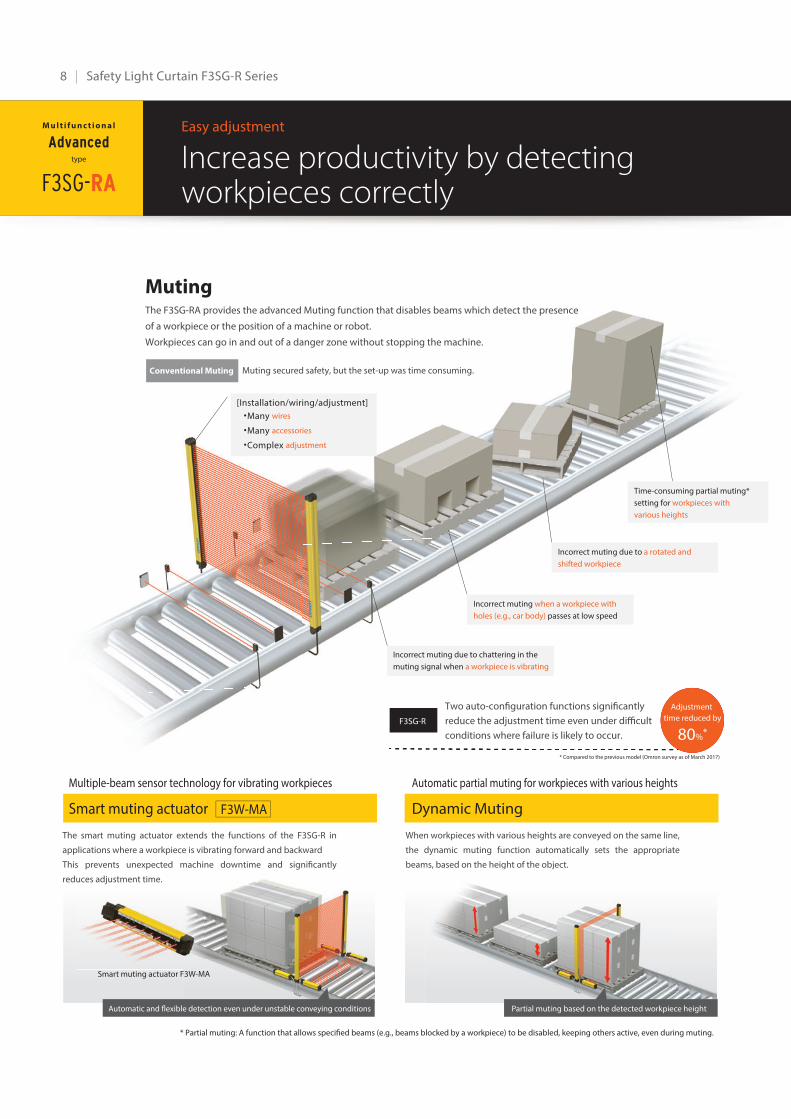
MutingThe F3SG-RA provides the advanced Muting function that disables beams which detect the presence
of a workpiece or the position of a machine or robot.
Workpieces can go in and out of a danger zone without stopping the machine.
Muting secured safety, but the set-up was time consuming.
Increase productivity by detecting workpieces correctly
Easy adjustment
Adjustment
time reduced by
80%*
Multiple-beam sensor technology for vibrating workpieces
Smart muting actuator
The smart muting actuator extends the functions of the F3SG-R in
applications where a workpiece is vibrating forward and backward
This prevents unexpected machine downtime and significantly
reduces adjustment time.
Automatic partial muting for workpieces with various heights
Dynamic Muting
When workpieces with various heights are conveyed on the same line,
the dynamic muting function automatically sets the appropriate
beams, based on the height of the object.
* Partial muting: A function that allows specified beams (e.g., beams blocked by a workpiece) to be disabled, keeping others active, even during muting.
Automatic and flexible detection even under unstable conveying conditions
Smart muting actuator F3W-MA
Conventional Muting
Two auto-configuration functions significantly
reduce the adjustment time even under difficult
conditions where failure is likely to occur.
F3SG-R
OK, but big difference
between assumed and
setting ranges
ms, based on the height of the object.
Partial muting based on the detected workpiece height
Incorrect muting due to chattering in the
muting signal when a workpiece is vibrating
[Installation/wiring/adjustment]
.Many wires
.Many accessories
.Complex adjustment
Incorrect muting when a workpiece with
holes (e.g., car body) passes at low speed
Incorrect muting due to a rotated and
shifted workpiece
Time-consuming partial muting*
setting for workpieces with
various heights
F3SG-RA
M u l t i f u n c t i o n a l
Advancedtype
* Compared to the previous model (Omron survey as of March 2017)
F3W-MA
| 9
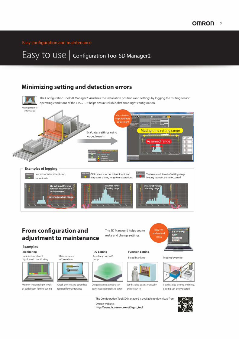
Minimizing setting and detection errors
The Configuration Tool SD Manager2 visualizes the installation positions and settings by logging the muting sensor
operating conditions of the F3SG-R. It helps ensure reliable, first-time-right configuration.
From configuration and adjustment to maintenance
The SD Manager2 helps you to
make and change settings.
Evaluates settings using
logged results
Examples of logging
Easy to use | Configuration Tool SD Manager2
Easy configuration and maintenance
Muting statistics
information
Easy- to-
understand
icons
The Configuration Tool SD Manager2 is available to download from
Omron website:
http://www.ia.omron.com/f3sg-r_tool
Eval
logg
u g a
information
safer operation range
OK, but big difference OK, but big difference
between assumed and between assumed and
setting rangessetting ranges
OK, but big difference
between assumed and
setting ranges
Assumed range Assumed range
> Setting range> Setting range
Assumed range
> Setting range Measured valuesMeasured values
> Setting range> Setting range
Measured values
> Setting range
Low risk of intermittent stop,
but not safe
OK in a test run, but intermittent stop
may occur during long-term operations
Test run result is out of setting range.
Muting sequence error occurred
I/O Setting Function Setting
Maintenance information
Auxiliary output/lamp
Fixed blanking Muting/override
Examples
Monitoring
Incident/ambient light level monitoring
Monitor incident light levels
of each beam for fine tuning
Check error log and other data
required for maintenance
Change the settings assigned to each
output including lamp color and pattern
Set disabled beams manually
or by teach-in
Set disabled beams and time.
Setting can be evaluated
Muting time setting range
Assumed range
Visualization
helps facilitate
adjustment
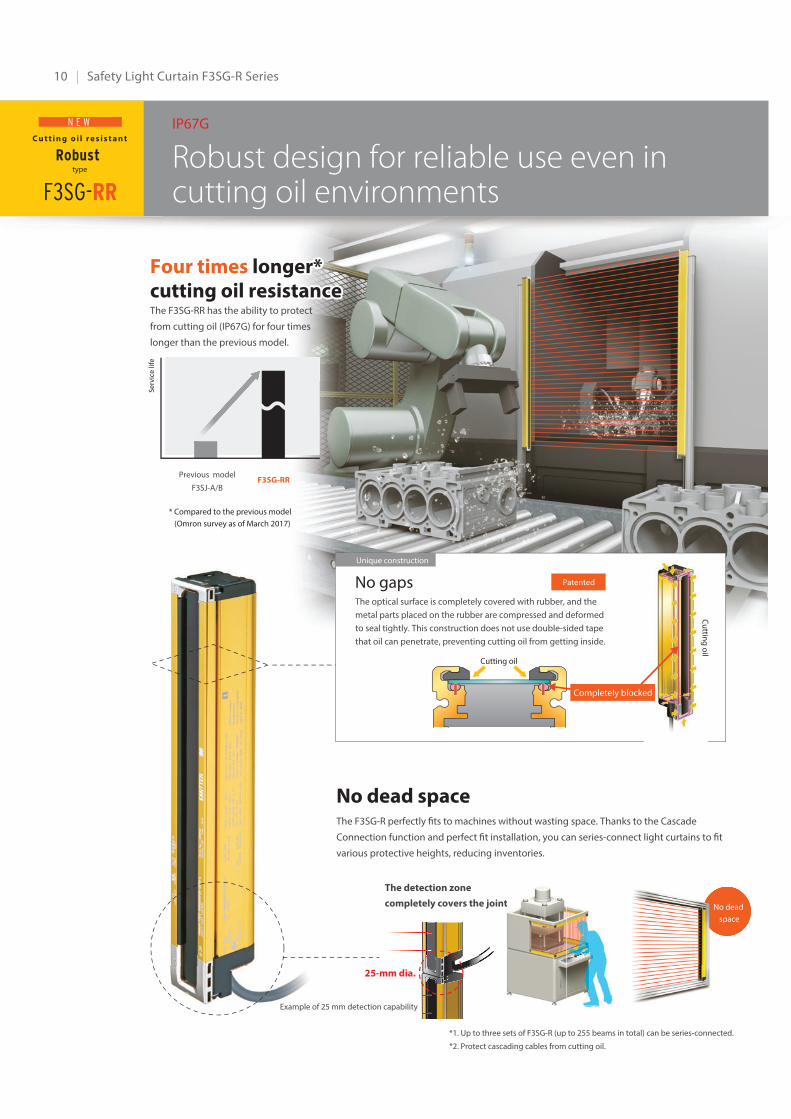
10 | Safety Light Curtain F3SG-R Series
Robust design for reliable use even in cutting oil environments
IP67G
No dead spaceThe F3SG-R perfectly fits to machines without wasting space. Thanks to the Cascade
Connection function and perfect fit installation, you can series-connect light curtains to fit
various protective heights, reducing inventories.
F3SG-RR
Previous model
F3SJ-A/BF3SG-RR
*1. Up to three sets of F3SG-R (up to 255 beams in total) can be series-connected.
*2. Protect cascading cables from cutting oil.
Example of 25 mm detection capabilityExample of 25 m
The detection zone
completely covers the joint
25-mm dia.
Se
rvic
e li
fe
C u t t i n g o i l r e s i s t a n t
Robust type
N E W
No dead
space
Four timesFour times longer* longer*cutting oil resistancecutting oil resistanceFour times longer*cutting oil resistanceThe F3SG-RR has the ability to protect
from cutting oil (IP67G) for four times
longer than the previous model.
No gaps Patented
Cutting oil
Cu
tting
oil
Unique construction
* Compared to the previous model
(Omron survey as of March 2017)
The optical surface is completely covered with rubber, and the
metal parts placed on the rubber are compressed and deformed
to seal tightly. This construction does not use double-sided tape
that oil can penetrate, preventing cutting oil from getting inside.
Completely blocked
e joint No dead
space
| 11
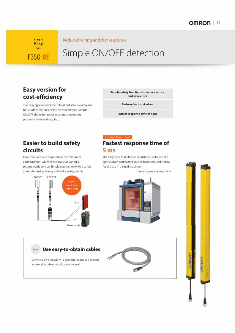
Simple ON/OFF detectionReduced wiring and fast response
Easy version for cost-efficiency
Fastest response time of 5 msThe Easy type that allows the distance between the
light curtain and hazard source to be reduced is ideal
for the use in a small machine.
Easier to build safety circuitsOnly four wires are required for the minimum
configuration, which is as simple as wiring a
photoelectric sensor. Simple connection with a safety
controller makes it easy to build a safety circuit.
F3SG-RE
Use easy-to-obtain cables
Commercially available M12 connector cables can be used
as extension cables to build a safety circuit.
Emitter
G9SE
Power supply
Receiver
Industry's fastest class*
Simple safety functions to reduce errors
and save costs
Reduced to just 4 wires
Fastest response time of 5 ms
Also
S i m p l e
Easytype
Four times longer*cutting oil resistance
Y-Joint
connector
with 4 wires
* Omron survey as of March 2017
The Easy type inherits the robust but slim housing and
basic safety features of the Advanced type. Simple
ON/OFF detection reduces errors, preventing
productivity from dropping.
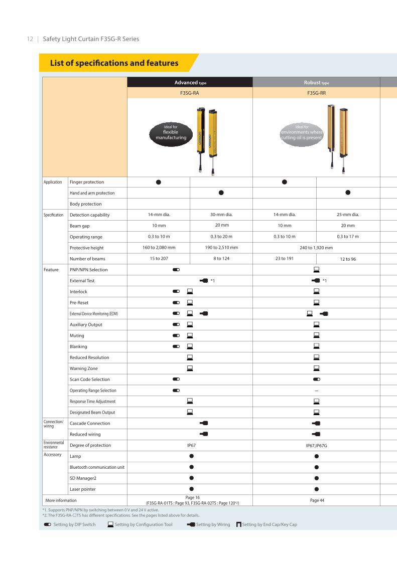
List of specifications and features
F3SG-RA F3SG-RR
Advanced type Robust type
Ideal for
flexible manufacturing
Ideal for
environments where cutting oil is present
12 | Safety Light Curtain F3SG-R Series
14-mm dia.
10 mm
0.3 to 10 m
160 to 2,080 mm
15 to 207
30-mm dia.
0.3 to 20 m
190 to 2,510 mm
8 to 124
14-mm dia.
10 mm
0.3 to 10 m
23 to 191
25-mm dia.
20 mm
0.3 to 17 m
12 to 96
IP67
••••
• •• •
-
IP67,IP67G
••••
240 to 1,920 mm
20 mm
Finger protection
Hand and arm protection
Body protection
Detection capability
Beam gap
Operating range
Protective height
Number of beams
PNP/NPN Selection
External Test
Interlock
Pre-Reset
External Device Monitoring (EDM)
Auxiliary Output
Muting
Blanking
Reduced Resolution
Warning Zone
Scan Code Selection
Operating Range Selection
Response Time Adjustment
Designated Beam Output
Cascade Connection
Reduced wiring
Degree of protection
Lamp
Bluetooth communication unit
SD Manager2
Laser pointer
Application
Specification
Feature
Connection/wiring
Environmental resistance
Accessory
*1 *1
Setting by DIP Switch Setting by Wiring Setting by End Cap/Key CapSetting by Configuration Tool
*1. Supports PNP/NPN by switching between 0 V and 24 V active.
*2. The F3SG-RA-□TS has different specifications. See the pages listed above for details.
More informationPage 16
(F3SG-RA-01TS : Page 93, F3SG-RA-02TS : Page 120*2)Page 44
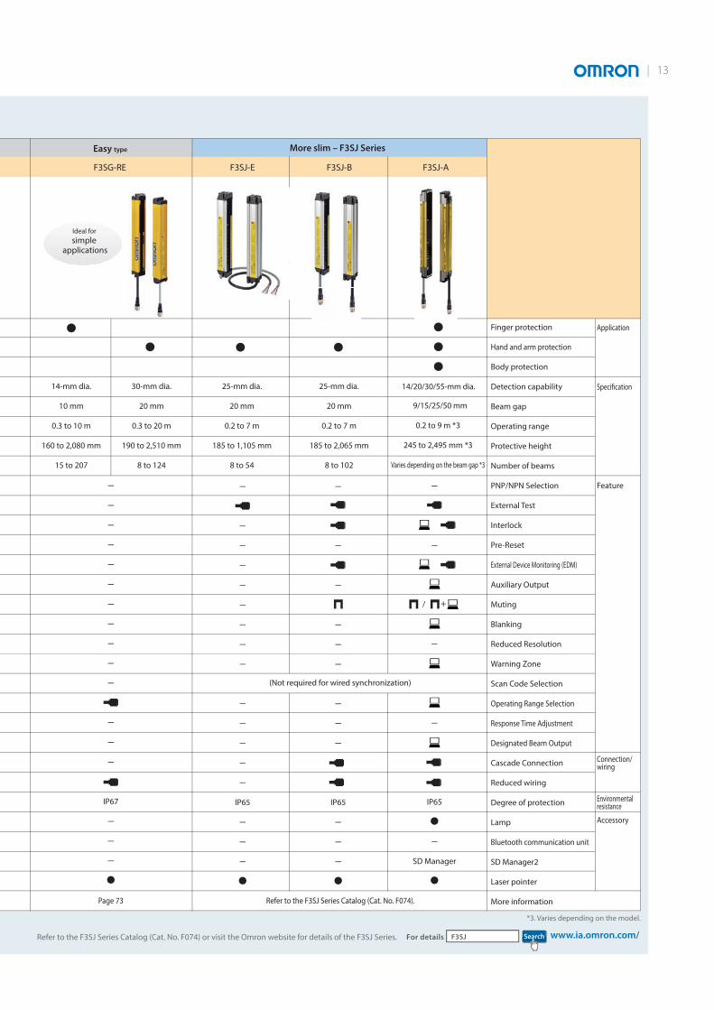
Easy type
F3SG-RE
Ideal for
simple applications
F3SJ-BF3SJ-E F3SJ-A
More slim – F3SJ Series
| 13
14-mm dia.
10 mm
0.3 to 10 m
160 to 2,080 mm
15 to 207
30-mm dia.
20 mm
0.3 to 20 m
190 to 2,510 mm
8 to 124
25-mm dia.
20 mm
0.2 to 7 m
185 to 1,105 mm
8 to 54
25-mm dia.
20 mm
0.2 to 7 m
185 to 2,065 mm
8 to 102
0.2 to 9 m *3
245 to 2,495 mm *3
Varies depending on the beam gap *3
-
-
-
-
IP65
•-
SD Manager
•
-
-
-
-
-
-
-
-
-
-
-
-
-
-
IP65
-
-
-
•
-
-
-
-
-
-
-
-
-
IP65
-
-
-
•
-
-
-
-
-
-
-
-
-
-
-
-
-
-
IP67
-
-
-
•
•••••
• •
(Not required for wired synchronization)
+/
14/20/30/55-mm dia.
9/15/25/50 mm
Finger protection
Hand and arm protection
Body protection
Detection capability
Beam gap
Operating range
Protective height
Number of beams
PNP/NPN Selection
External Test
Interlock
Pre-Reset
External Device Monitoring (EDM)
Auxiliary Output
Muting
Blanking
Reduced Resolution
Warning Zone
Scan Code Selection
Operating Range Selection
Response Time Adjustment
Designated Beam Output
Cascade Connection
Reduced wiring
Degree of protection
Lamp
Bluetooth communication unit
SD Manager2
Laser pointer
More information
Application
Specification
Feature
Connection/wiring
Environmental resistance
Accessory
*3. Varies depending on the model.
Refer to the F3SJ Series Catalog (Cat. No. F074) or visit the Omron website for details of the F3SJ Series. SearchF3SJFor details www.ia.omron.com/
Page 73 Refer to the F3SJ Series Catalog (Cat. No. F074).
YES
YES
NO
NO
NOYES
YESYES
NO
High power required for stable
NO
NO
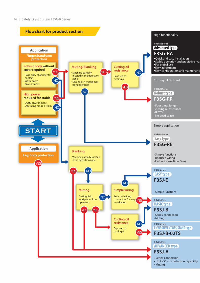
・Quick and easy installation ・Stable operation and predictive mai・For global use ・Easy adjustment・Easy configuration and maintenance
• Four times longer cutting oil resistance • IP67G• No dead space
• Simple functions• Reduced wiring• Fast response time: 5 ms
• Simple functions
START
• Series-connection• Muting
Finger/hand/armprotection
YES
YES
NO
YES
NO
YES
YES
Robust body without cover required• Possibility of accidental contact• Wash-down environment
Muting/Blanking
• Machine partially located in the detection zone• Distinguish workpieces from operators
Blanking
Machine partially located in the detection zone
Cutting oilresistance
Exposed to cutting oil
Simple wiring
Reduced wiring connectors for easy installation
Cutting oilresistance
Exposed to cutting oil
Muting
Distinguish workpieces from operators
• Dusty environment• Operating range ≥ 10 m
Application
Application
Flowchart for product sectionHigh functionality
Cutting oil resistant
Simple application
• Series-connection• Up to 55 mm detection capability• Muting
F3SG-R Series
Advanced typeF3SG-RA
F3SG-R Series
Robust typeF3SG-RR
F3SG-R Series
Easy typeF3SG-RE
F3SJ Series
EASY typeF3SJ-E
F3SJ Series
BASIC typeF3SJ-B
F3SJ Series
ADVANCED typeF3SJ-A
F3SJ Series
ENVIRONMENT RESISTANT typeF3SJ-B-02TS
START
Leg/body protection
14 | Safety Light Curtain F3SG-R Series
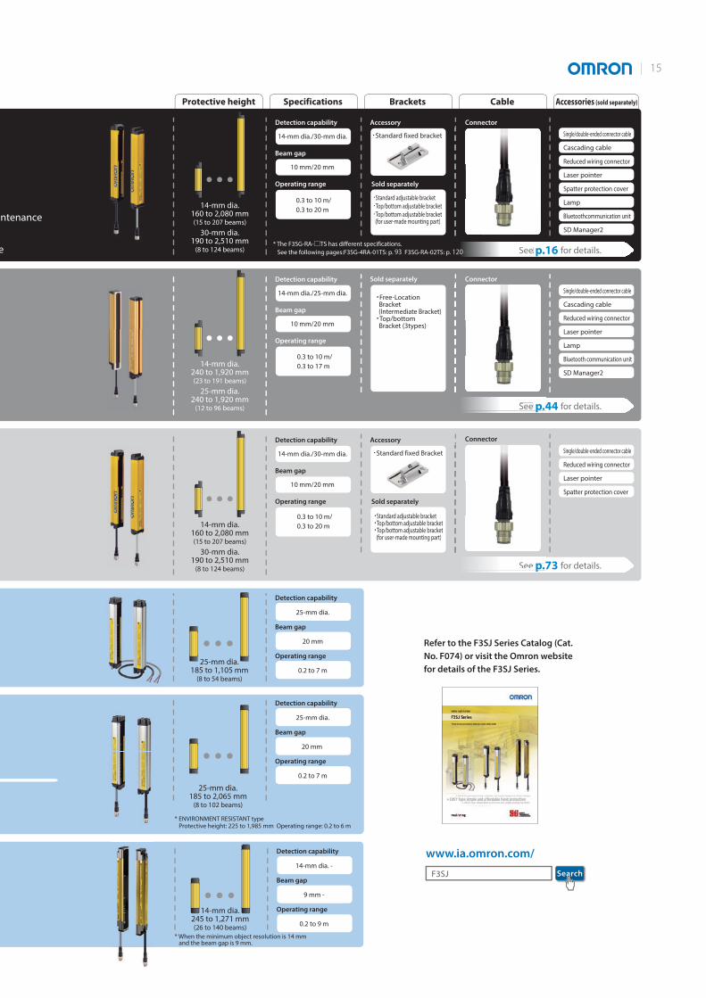
ntenance
e
Protective height Specifications
Detection capability
14-mm dia.160 to 2,080 mm(15 to 207 beams)
30-mm dia.190 to 2,510 mm
(8 to 124 beams) See p.16 for details.
See p.44 for details.
See p.73 for details.
14-mm dia./30-mm dia.
Accessory
Sold separately
・Standard fixed bracket
・Standard adjustable bracket・Top/bottom adjustable bracket・Top/bottom adjustable bracket (for user-made mounting part)
Connector
Beam gap
10 mm/20 mm
Operating range
0.3 to 10 m/
0.3 to 20 m
Brackets Cable Accessories (sold separately)
Sold separately Connector
Connector
Detection capability
25-mm dia.
Beam gap
20 mm
Operating range
0.2 to 7 m
www.ia.omron.com/
25-mm dia.185 to 1,105 mm
(8 to 54 beams)
14-mm dia.240 to 1,920 mm(23 to 191 beams)
25-mm dia.240 to 1,920 mm
(12 to 96 beams)
14-mm dia.160 to 2,080 mm(15 to 207 beams)
30-mm dia.190 to 2,510 mm
(8 to 124 beams)
Single/double-ended connector cable
Cascading cable
Reduced wiring connector
Laser pointer
Spatter protection cover
Lamp
Bluetoothcommunication unit
SD Manager2
Single/double-ended connector cable
Cascading cable
Reduced wiring connector
Laser pointer
Lamp
Bluetooth communication unit
SD Manager2
Single/double-ended connector cable
Reduced wiring connector
Laser pointer
Spatter protection cover
Detection capability
25-mm dia.
Beam gap
20 mm
Operating range
0.2 to 7 m
25-mm dia.185 to 2,065 mm
(8 to 102 beams)
Detection capability
14-mm dia. -
Beam gap
9 mm -
Operating range
0.2 to 9 m
14-mm dia.245 to 1,271 mm(26 to 140 beams)
Detection capability
14-mm dia./25-mm dia.
Beam gap
10 mm/20 mm
Operating range
0.3 to 10 m/
0.3 to 17 m
Detection capability
14-mm dia./30-mm dia.
Accessory
Sold separately
・Standard fixed Bracket
・Standard adjustable bracket・Top/bottom adjustable bracket・Top/bottom adjustable bracket (for user-made mounting part)
Beam gap
10 mm/20 mm
Operating range
0.3 to 10 m/
0.3 to 20 m
* ENVIRONMENT RESISTANT type Protective height: 225 to 1,985 mm Operating range: 0.2 to 6 m
* When the minimum object resolution is 14 mm and the beam gap is 9 mm.
Refer to the F3SJ Series Catalog (Cat. No. F074) or visit the Omron website for details of the F3SJ Series.
SearchF3SJ
andard fixed brac
See p.4
See p.1
See p.7
・Free-Location Bracket (Intermediate Bracket)・Top/bottom Bracket (3types)
* The F3SG-RA-□TS has different specifications.
See the following pages:F3SG-4RA-01TS: p. 93 F3SG-RA-02TS: p. 120
| 15

16
Safety Light Curtain Advanced type
F3SG-RAOffers Both Durability and Reliability• Rugged and compact• New muting function to increase both productivity and
safety• All models designed for global use. PNP/NPN selection by
DIP switch• Conforming to major international standards including
Chinese standard GB/T 4584
System Configuration
IF-U
PC
F39-LGFStandard Fixed Bracket (included as standard)
F39-LGAStandard Adjustable
Bracket
F39-LGTBF39-LGTB-1
Top/Bottom Adjustable Bracket
F39-LPLamp
F39-BTLPLamp and Bluetooth Communication Unit
F39-BTBluetooth
Communication Unit
F39-HGA@@@@Spatter Protection Cover
(for F3SG-RA)
F39-PTGLaser Pointer
NX/NE1A-seriesSafety Network Controller
G9SP-seriesSafety Controller
G9SE/G9SA-seriesSafety Relay Unit
G9SX-seriesFlexible Safety Unit
G7SA/G7S-ERelays with Forcibly
Guided Contacts
Mounting bracket Accessory Accessory
Emitter Receiver
Emitter Receiver
F39-JGR2WCascading Cable
F39-JG@BDouble-Ended Cable
Up to three sets
F39-JG@BDouble-Ended CableF39-JG@ASingle-Ended Cable or
F39-GCNY2F39-JG@B-LF39-JG@A-DReduced wiring connector system
F3W-MA0100PF3W-MA0300PSmart Muting Actuator
Note: See p.147 for details.
F39-GIFInterface Unit
Configuration ToolSD Manager 2
Recommended safety controller *
Accessory
Accessory
* The recommended safety controller is required to build a safety circuit using emergency stop switches and door switches.
T
F3SG-RA
17
F3S
G-R
A
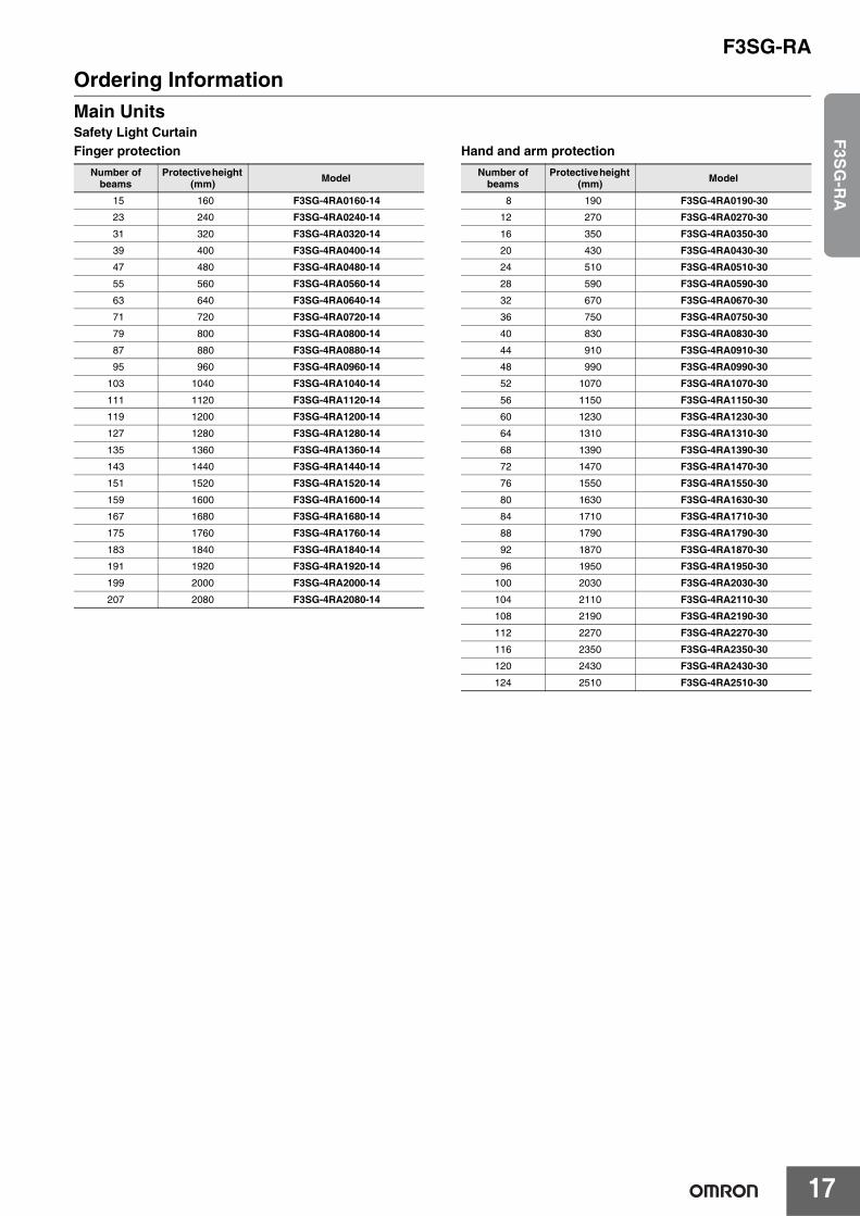
Ordering InformationMain UnitsSafety Light CurtainFinger protection Hand and arm protection
Number of beams
Protective height (mm) Model
15 160 F3SG-4RA0160-1423 240 F3SG-4RA0240-14
31 320 F3SG-4RA0320-14
39 400 F3SG-4RA0400-1447 480 F3SG-4RA0480-14
55 560 F3SG-4RA0560-14
63 640 F3SG-4RA0640-1471 720 F3SG-4RA0720-14
79 800 F3SG-4RA0800-14
87 880 F3SG-4RA0880-1495 960 F3SG-4RA0960-14
103 1040 F3SG-4RA1040-14
111 1120 F3SG-4RA1120-14119 1200 F3SG-4RA1200-14
127 1280 F3SG-4RA1280-14
135 1360 F3SG-4RA1360-14143 1440 F3SG-4RA1440-14
151 1520 F3SG-4RA1520-14
159 1600 F3SG-4RA1600-14167 1680 F3SG-4RA1680-14
175 1760 F3SG-4RA1760-14
183 1840 F3SG-4RA1840-14191 1920 F3SG-4RA1920-14
199 2000 F3SG-4RA2000-14
207 2080 F3SG-4RA2080-14
Number of beams
Protective height (mm) Model
8 190 F3SG-4RA0190-3012 270 F3SG-4RA0270-30
16 350 F3SG-4RA0350-30
20 430 F3SG-4RA0430-3024 510 F3SG-4RA0510-30
28 590 F3SG-4RA0590-30
32 670 F3SG-4RA0670-3036 750 F3SG-4RA0750-30
40 830 F3SG-4RA0830-30
44 910 F3SG-4RA0910-3048 990 F3SG-4RA0990-30
52 1070 F3SG-4RA1070-30
56 1150 F3SG-4RA1150-3060 1230 F3SG-4RA1230-30
64 1310 F3SG-4RA1310-30
68 1390 F3SG-4RA1390-3072 1470 F3SG-4RA1470-30
76 1550 F3SG-4RA1550-30
80 1630 F3SG-4RA1630-3084 1710 F3SG-4RA1710-30
88 1790 F3SG-4RA1790-30
92 1870 F3SG-4RA1870-3096 1950 F3SG-4RA1950-30
100 2030 F3SG-4RA2030-30
104 2110 F3SG-4RA2110-30108 2190 F3SG-4RA2190-30
112 2270 F3SG-4RA2270-30
116 2350 F3SG-4RA2350-30120 2430 F3SG-4RA2430-30
124 2510 F3SG-4RA2510-30
F3SG-RA
18
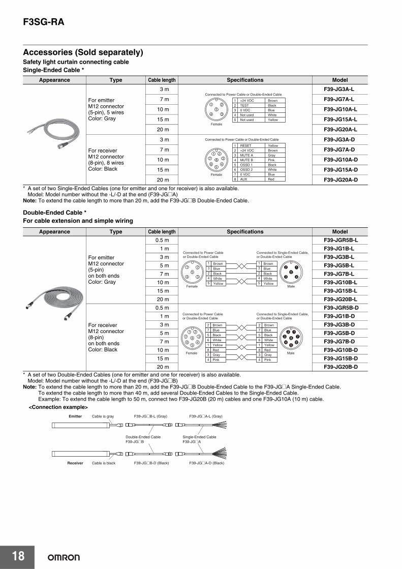
Accessories (Sold separately)Safety light curtain connecting cableSingle-Ended Cable *
* A set of two Single-Ended Cables (one for emitter and one for receiver) is also available.Model: Model number without the -L/-D at the end (F39-JG@A)
Note: To extend the cable length to more than 20 m, add the F39-JG@B Double-Ended Cable.
Double-Ended Cable *For cable extension and simple wiring
* A set of two Double-Ended Cables (one for emitter and one for receiver) is also available.Model: Model number without the -L/-D at the end (F39-JG@B)
Note: To extend the cable length to more than 20 m, add the F39-JG@B Double-Ended Cable to the F39-JG@A Single-Ended Cable. To extend the cable length to more than 40 m, add several Double-Ended Cables to the Single-Ended Cable. Example: To extend the cable length to 50 m, connect two F39-JG20B (20 m) cables and one F39-JG10A (10 m) cable.
Appearance Type Cable length Specifications Model
For emitterM12 connector (5-pin), 5 wiresColor: Gray
3 m F39-JG3A-L
7 m F39-JG7A-L
10 m F39-JG10A-L
15 m F39-JG15A-L
20 m F39-JG20A-L
For receiverM12 connector (8-pin), 8 wiresColor: Black
3 m F39-JG3A-D
7 m F39-JG7A-D
10 m F39-JG10A-D
15 m F39-JG15A-D
20 m F39-JG20A-D
Appearance Type Cable length Specifications Model
For emitterM12 connector (5-pin) on both endsColor: Gray
0.5 m F39-JGR5B-L1 m F39-JG1B-L3 m F39-JG3B-L5 m F39-JG5B-L7 m F39-JG7B-L
10 m F39-JG10B-L15 m F39-JG15B-L20 m F39-JG20B-L
For receiverM12 connector (8-pin) on both endsColor: Black
0.5 m F39-JGR5B-D1 m F39-JG1B-D3 m F39-JG3B-D5 m F39-JG5B-D7 m F39-JG7B-D
10 m F39-JG10B-D15 m F39-JG15B-D20 m F39-JG20B-D
53
21
4
Female
12345
+24 VDCTEST0 VDCNot usedNot used
BrownBlackBlueWhiteYellow
Connected to Power Cable or Double-Ended Cable
5
84
3
21
7
6
Female
2
7
56
1+24 VDC
0 VDC
OSSD 1OSSD 2
RESET Brown
Blue
BlackWhite
Yellow
8 AUX Red
3 MUTE A Gray4 MUTE B Pink
Connected to Power Cable or Double-Ended Cable
BrownBlueBlackWhiteYellow
13245
53
21
4
BrownBlueBlackWhiteYellow
13245
Female
54
12
3
Male
Connected to Power Cable or Double-Ended Cable
Connected to Single-Ended Cable, or Double-Ended Cable
BrownBlueBlackWhiteYellowRedGrayPink
BlueBlackWhiteYellowRedGrayPink
27561834
Brown
5
84
321
7
65
86
712
3
4
27561834
Connected to Power Cable or Double-Ended Cable
Connected to Single-Ended Cable, or Double-Ended Cable
Female Male
Emitter Cable is gray F39-JG@B-L (Gray) F39-JG@A-L (Gray)
Receiver Cable is black F39-JG@B-D (Black)
Double-Ended CableF39-JG@B
Single-Ended CableF39-JG@A
F39-JG@A-D (Black)
<Connection example>
F3SG-RA
19
F3S
G-R
A
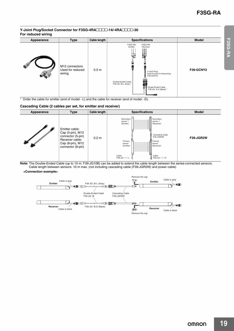
Y-Joint Plug/Socket Connector for F3SG-4RA@@@@-14/-4RA@@@@-30For reduced wiring
* Order the cable for emitter (end of model: -L) and the cable for receiver (end of model: -D).
Cascading Cable (2 cables per set, for emitter and receiver)
Note: The Double-Ended Cable (up to 10 m: F39-JG10B) can be added to extend the cable length between the series-connected sensors.Cable length between sensors: 10 m max. (not including cascading cable (F39-JGR2W) and power cable)
Appearance Type Cable length Specifications Model
M12 connectors.Used for reducedwiring.
0.5 m F39-GCNY2
Appearance Type Cable length Specifications Model
Emitter cable:Cap (5-pin), M12 connector (5-pin)Receiver cable:Cap (8-pin), M12 connector (8-pin)
0.2 m F39-JGR2W
F3SG-RAEmitter
Double-Ended CableF39-JG@B-L (Gray) *
Single-Ended CableF39-JG@A-D (Black) *
Y-Joint Plug/Socket Connector for Advanced typeF39-GCNY2
F3SG-RAReceiver
Secondary sensor 1 (Emitter)
Secondary sensor 1 (Receiver)
Primary sensor (Emitter)
Primary sensor (Receiver)
Cascading CableF39-JGR2W
CableF39-JG@@@-D
CableF39-JG@@@-L
Emitter
Receiver
Cable is grayF39-JG@B-L (Gray)
Double-Ended CableF39-JG@B
Cable is blackF39-JG@B-D (Black)
Cascading CableF39-JGR2W
Emitter
Receiver
Cable is gray
Cable is blackRemove the cap
Remove the cap
<Connection example>
F3SG-RA
20
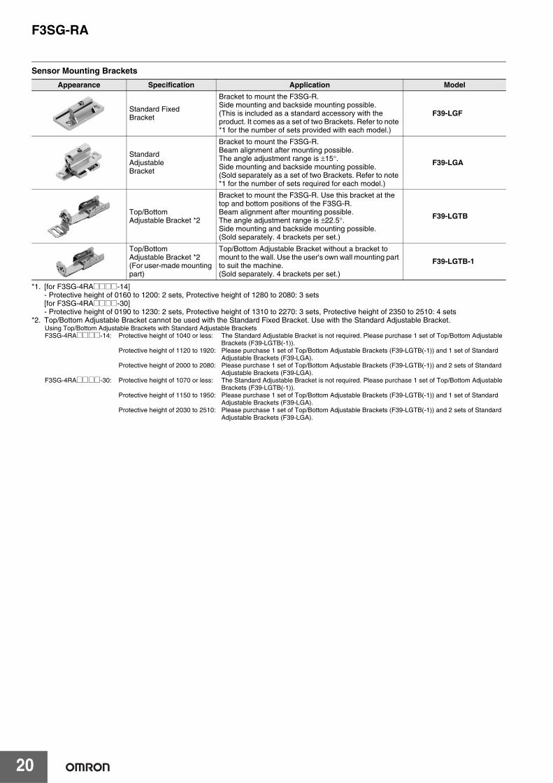
Sensor Mounting Brackets
*1. [for F3SG-4RA@@@@-14]- Protective height of 0160 to 1200: 2 sets, Protective height of 1280 to 2080: 3 sets[for F3SG-4RA@@@@-30]- Protective height of 0190 to 1230: 2 sets, Protective height of 1310 to 2270: 3 sets, Protective height of 2350 to 2510: 4 sets
*2. Top/Bottom Adjustable Bracket cannot be used with the Standard Fixed Bracket. Use with the Standard Adjustable Bracket. Using Top/Bottom Adjustable Brackets with Standard Adjustable BracketsF3SG-4RA@@@@-14: Protective height of 1040 or less: The Standard Adjustable Bracket is not required. Please purchase 1 set of Top/Bottom Adjustable
Brackets (F39-LGTB(-1)).Protective height of 1120 to 1920: Please purchase 1 set of Top/Bottom Adjustable Brackets (F39-LGTB(-1)) and 1 set of Standard
Adjustable Brackets (F39-LGA).Protective height of 2000 to 2080: Please purchase 1 set of Top/Bottom Adjustable Brackets (F39-LGTB(-1)) and 2 sets of Standard
Adjustable Brackets (F39-LGA).F3SG-4RA@@@@-30: Protective height of 1070 or less: The Standard Adjustable Bracket is not required. Please purchase 1 set of Top/Bottom Adjustable
Brackets (F39-LGTB(-1)).Protective height of 1150 to 1950: Please purchase 1 set of Top/Bottom Adjustable Brackets (F39-LGTB(-1)) and 1 set of Standard
Adjustable Brackets (F39-LGA).Protective height of 2030 to 2510: Please purchase 1 set of Top/Bottom Adjustable Brackets (F39-LGTB(-1)) and 2 sets of Standard
Adjustable Brackets (F39-LGA).
Appearance Specification Application Model
Standard Fixed Bracket
Bracket to mount the F3SG-R.Side mounting and backside mounting possible.(This is included as a standard accessory with the product. It comes as a set of two Brackets. Refer to note *1 for the number of sets provided with each model.)
F39-LGF
Standard Adjustable Bracket
Bracket to mount the F3SG-R.Beam alignment after mounting possible.The angle adjustment range is ±15°.Side mounting and backside mounting possible.(Sold separately as a set of two Brackets. Refer to note *1 for the number of sets required for each model.)
F39-LGA
Top/Bottom Adjustable Bracket *2
Bracket to mount the F3SG-R. Use this bracket at the top and bottom positions of the F3SG-R. Beam alignment after mounting possible. The angle adjustment range is ±22.5°.Side mounting and backside mounting possible.(Sold separately. 4 brackets per set.)
F39-LGTB
Top/Bottom Adjustable Bracket *2(For user-made mounting part)
Top/Bottom Adjustable Bracket without a bracket to mount to the wall. Use the user's own wall mounting part to suit the machine.(Sold separately. 4 brackets per set.)
F39-LGTB-1
F3SG-RA
21
F3S
G-R
A
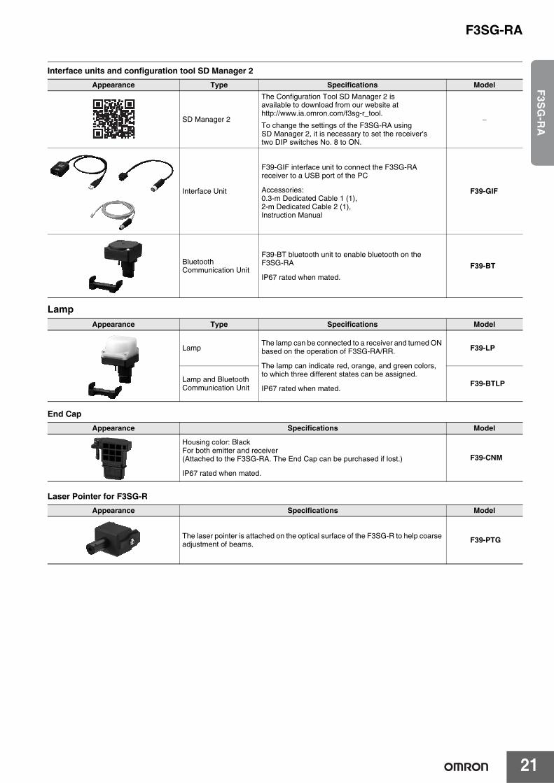
Interface units and configuration tool SD Manager 2
Lamp
End Cap
Laser Pointer for F3SG-R
Appearance Type Specifications Model
SD Manager 2
The Configuration Tool SD Manager 2 is available to download from our website at http://www.ia.omron.com/f3sg-r_tool.
To change the settings of the F3SG-RA using SD Manager 2, it is necessary to set the receiver's two DIP switches No. 8 to ON.
−
Interface Unit
F39-GIF interface unit to connect the F3SG-RA receiver to a USB port of the PC
Accessories:0.3-m Dedicated Cable 1 (1),2-m Dedicated Cable 2 (1),Instruction Manual
F39-GIF
Bluetooth Communication Unit
F39-BT bluetooth unit to enable bluetooth on the F3SG-RA
IP67 rated when mated.
F39-BT
Appearance Type Specifications Model
LampThe lamp can be connected to a receiver and turned ON based on the operation of F3SG-RA/RR.
The lamp can indicate red, orange, and green colors, to which three different states can be assigned.
IP67 rated when mated.
F39-LP
Lamp and Bluetooth Communication Unit F39-BTLP
Appearance Specifications Model
Housing color: BlackFor both emitter and receiver(Attached to the F3SG-RA. The End Cap can be purchased if lost.)
IP67 rated when mated.
F39-CNM
Appearance Specifications Model
The laser pointer is attached on the optical surface of the F3SG-R to help coarse adjustment of beams. F39-PTG
F3SG-RA
22
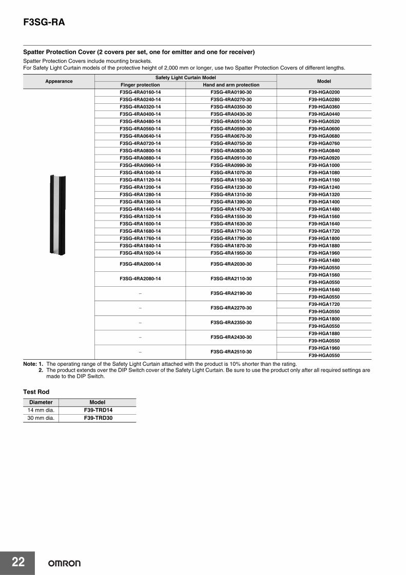
Spatter Protection Cover (2 covers per set, one for emitter and one for receiver)Spatter Protection Covers include mounting brackets. For Safety Light Curtain models of the protective height of 2,000 mm or longer, use two Spatter Protection Covers of different lengths.
Note: 1. The operating range of the Safety Light Curtain attached with the product is 10% shorter than the rating.2. The product extends over the DIP Switch cover of the Safety Light Curtain. Be sure to use the product only after all required settings are
made to the DIP Switch.
Test Rod
AppearanceSafety Light Curtain Model
ModelFinger protection Hand and arm protectionF3SG-4RA0160-14 F3SG-4RA0190-30 F39-HGA0200F3SG-4RA0240-14 F3SG-4RA0270-30 F39-HGA0280F3SG-4RA0320-14 F3SG-4RA0350-30 F39-HGA0360F3SG-4RA0400-14 F3SG-4RA0430-30 F39-HGA0440F3SG-4RA0480-14 F3SG-4RA0510-30 F39-HGA0520F3SG-4RA0560-14 F3SG-4RA0590-30 F39-HGA0600F3SG-4RA0640-14 F3SG-4RA0670-30 F39-HGA0680F3SG-4RA0720-14 F3SG-4RA0750-30 F39-HGA0760F3SG-4RA0800-14 F3SG-4RA0830-30 F39-HGA0840F3SG-4RA0880-14 F3SG-4RA0910-30 F39-HGA0920F3SG-4RA0960-14 F3SG-4RA0990-30 F39-HGA1000F3SG-4RA1040-14 F3SG-4RA1070-30 F39-HGA1080F3SG-4RA1120-14 F3SG-4RA1150-30 F39-HGA1160F3SG-4RA1200-14 F3SG-4RA1230-30 F39-HGA1240F3SG-4RA1280-14 F3SG-4RA1310-30 F39-HGA1320F3SG-4RA1360-14 F3SG-4RA1390-30 F39-HGA1400F3SG-4RA1440-14 F3SG-4RA1470-30 F39-HGA1480F3SG-4RA1520-14 F3SG-4RA1550-30 F39-HGA1560F3SG-4RA1600-14 F3SG-4RA1630-30 F39-HGA1640F3SG-4RA1680-14 F3SG-4RA1710-30 F39-HGA1720F3SG-4RA1760-14 F3SG-4RA1790-30 F39-HGA1800F3SG-4RA1840-14 F3SG-4RA1870-30 F39-HGA1880F3SG-4RA1920-14 F3SG-4RA1950-30 F39-HGA1960
F3SG-4RA2000-14 F3SG-4RA2030-30F39-HGA1480F39-HGA0550
F3SG-4RA2080-14 F3SG-4RA2110-30F39-HGA1560F39-HGA0550
− F3SG-4RA2190-30F39-HGA1640F39-HGA0550
− F3SG-4RA2270-30F39-HGA1720F39-HGA0550
− F3SG-4RA2350-30F39-HGA1800F39-HGA0550
− F3SG-4RA2430-30F39-HGA1880F39-HGA0550
− F3SG-4RA2510-30F39-HGA1960F39-HGA0550
Diameter Model14 mm dia. F39-TRD1430 mm dia. F39-TRD30
F3SG-RA
23
F3S
G-R
A
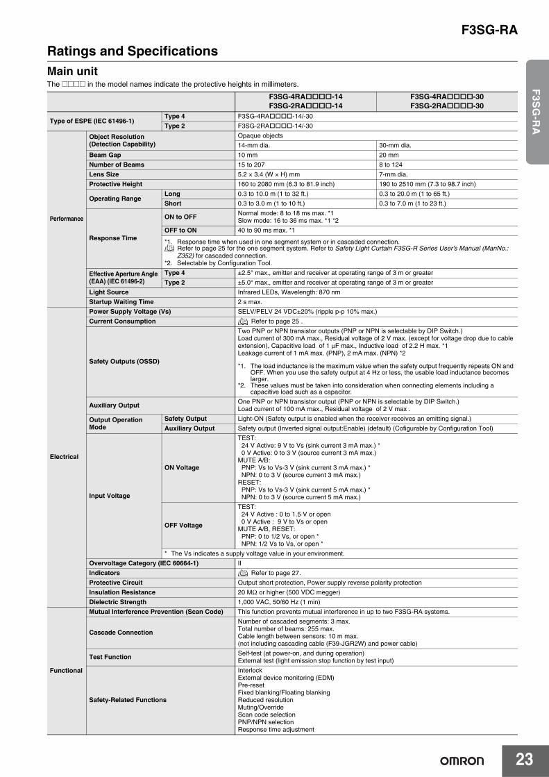
Ratings and SpecificationsMain unitThe @@@@ in the model names indicate the protective heights in millimeters.
F3SG-4RA-14F3SG-2RA-14
F3SG-4RA-30F3SG-2RA-30
Type of ESPE (IEC 61496-1)Type 4 F3SG-4RA-14/-30
Type 2 F3SG-2RA-14/-30
Performance
Object Resolution(Detection Capability)
Opaque objects
14-mm dia. 30-mm dia.
Beam Gap 10 mm 20 mm
Number of Beams 15 to 207 8 to 124
Lens Size 5.2 × 3.4 (W × H) mm 7-mm dia.
Protective Height 160 to 2080 mm (6.3 to 81.9 inch) 190 to 2510 mm (7.3 to 98.7 inch)
Operating RangeLong 0.3 to 10.0 m (1 to 32 ft.) 0.3 to 20.0 m (1 to 65 ft.)
Short 0.3 to 3.0 m (1 to 10 ft.) 0.3 to 7.0 m (1 to 23 ft.)
Response Time
ON to OFF Normal mode: 8 to 18 ms max. *1Slow mode: 16 to 36 ms max. *1 *2
OFF to ON 40 to 90 ms max. *1
*1. Response time when used in one segment system or in cascaded connection. Refer to page 25 for the one segment system. Refer to Safety Light Curtain F3SG-R Series User's Manual (ManNo.: Z352) for cascaded connection.
*2. Selectable by Configuration Tool.
Effective Aperture Angle (EAA) (IEC 61496-2)
Type 4 ±2.5° max., emitter and receiver at operating range of 3 m or greater
Type 2 ±5.0° max., emitter and receiver at operating range of 3 m or greater
Light Source Infrared LEDs, Wavelength: 870 nm
Startup Waiting Time 2 s max.
Electrical
Power Supply Voltage (Vs) SELV/PELV 24 VDC±20% (ripple p-p 10% max.)
Current Consumption Refer to page 25 .
Safety Outputs (OSSD)
Two PNP or NPN transistor outputs (PNP or NPN is selectable by DIP Switch.)Load current of 300 mA max., Residual voltage of 2 V max. (except for voltage drop due to cable extension), Capacitive load of 1 μF max., Inductive load of 2.2 H max. *1Leakage current of 1 mA max. (PNP), 2 mA max. (NPN) *2
*1. The load inductance is the maximum value when the safety output frequently repeats ON and OFF. When you use the safety output at 4 Hz or less, the usable load inductance becomes larger.
*2. These values must be taken into consideration when connecting elements including a capacitive load such as a capacitor.
Auxiliary Output One PNP or NPN transistor output (PNP or NPN is selectable by DIP Switch.)Load current of 100 mA max., Residual voltage of 2 V max .
Output Operation Mode
Safety Output Light-ON (Safety output is enabled when the receiver receives an emitting signal.)
Auxiliary Output Safety output (Inverted signal output:Enable) (default) (Cofigurable by Configuration Tool)
Input Voltage
ON Voltage
TEST: 24 V Active: 9 V to Vs (sink current 3 mA max.) *0 V Active: 0 to 3 V (source current 3 mA max.)
MUTE A/B:PNP: Vs to Vs-3 V (sink current 3 mA max.) *NPN: 0 to 3 V (source current 3 mA max.)
RESET:PNP: Vs to Vs-3 V (sink current 5 mA max.) *NPN: 0 to 3 V (source current 5 mA max.)
OFF Voltage
TEST: 24 V Active : 0 to 1.5 V or open0 V Active : 9 V to Vs or open
MUTE A/B, RESET:PNP: 0 to 1/2 Vs, or open *NPN: 1/2 Vs to Vs, or open *
* The Vs indicates a supply voltage value in your environment.
Overvoltage Category (IEC 60664-1) II
Indicators Refer to page 27.
Protective Circuit Output short protection, Power supply reverse polarity protection
Insulation Resistance 20 MΩ or higher (500 VDC megger)
Dielectric Strength 1,000 VAC, 50/60 Hz (1 min)
Functional
Mutual Interference Prevention (Scan Code) This function prevents mutual interference in up to two F3SG-RA systems.
Cascade Connection
Number of cascaded segments: 3 max.Total number of beams: 255 max.Cable length between sensors: 10 m max. (not including cascading cable (F39-JGR2W) and power cable)
Test Function Self-test (at power-on, and during operation)External test (light emission stop function by test input)
Safety-Related Functions
InterlockExternal device monitoring (EDM)Pre-resetFixed blanking/Floating blankingReduced resolutionMuting/OverrideScan code selectionPNP/NPN selectionResponse time adjustment
F3SG-RA
24
Bluetooth Communication Unit
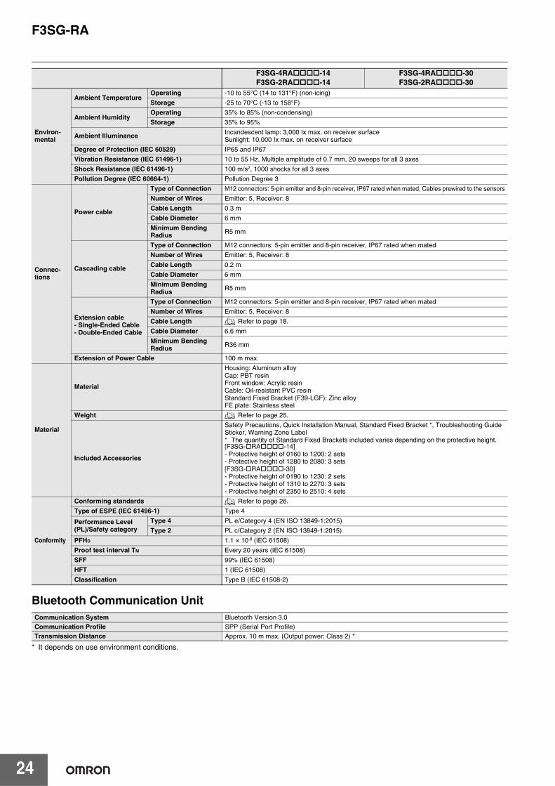
* It depends on use environment conditions.
Environ-mental
Ambient TemperatureOperating -10 to 55°C (14 to 131°F) (non-icing)
Storage -25 to 70°C (-13 to 158°F)
Ambient HumidityOperating 35% to 85% (non-condensing)
Storage 35% to 95%
Ambient Illuminance Incandescent lamp: 3,000 Ix max. on receiver surfaceSunlight: 10,000 Ix max. on receiver surface
Degree of Protection (IEC 60529) IP65 and IP67
Vibration Resistance (IEC 61496-1) 10 to 55 Hz, Multiple amplitude of 0.7 mm, 20 sweeps for all 3 axes
Shock Resistance (IEC 61496-1) 100 m/s2, 1000 shocks for all 3 axes
Pollution Degree (IEC 60664-1) Pollution Degree 3
Connec-tions
Power cable
Type of Connection M12 connectors: 5-pin emitter and 8-pin receiver, IP67 rated when mated, Cables prewired to the sensors
Number of Wires Emitter: 5, Receiver: 8
Cable Length 0.3 m
Cable Diameter 6 mm
Minimum Bending Radius R5 mm
Cascading cable
Type of Connection M12 connectors: 5-pin emitter and 8-pin receiver, IP67 rated when mated
Number of Wires Emitter: 5, Receiver: 8
Cable Length 0.2 m
Cable Diameter 6 mm
Minimum Bending Radius R5 mm
Extension cable- Single-Ended Cable- Double-Ended Cable
Type of Connection M12 connectors: 5-pin emitter and 8-pin receiver, IP67 rated when mated
Number of Wires Emitter: 5, Receiver: 8
Cable Length Refer to page 18.
Cable Diameter 6.6 mm
Minimum Bending Radius R36 mm
Extension of Power Cable 100 m max.
Material
Material
Housing: Aluminum alloyCap: PBT resinFront window: Acrylic resinCable: Oil-resistant PVC resinStandard Fixed Bracket (F39-LGF): Zinc alloyFE plate: Stainless steel
Weight Refer to page 25.
Included Accessories
Safety Precautions, Quick Installation Manual, Standard Fixed Bracket *, Troubleshooting Guide Sticker, Warning Zone Label* The quantity of Standard Fixed Brackets included varies depending on the protective height.[F3SG-RA-14]- Protective height of 0160 to 1200: 2 sets- Protective height of 1280 to 2080: 3 sets[F3SG-RA-30]- Protective height of 0190 to 1230: 2 sets- Protective height of 1310 to 2270: 3 sets- Protective height of 2350 to 2510: 4 sets
Conformity
Conforming standards Refer to page 26.
Type of ESPE (IEC 61496-1) Type 4
Performance Level (PL)/Safety category
Type 4 PL e/Category 4 (EN ISO 13849-1:2015)
Type 2 PL c/Category 2 (EN ISO 13849-1:2015)
PFHD 1.1 × 10⁻⁸ (IEC 61508)
Proof test interval TM Every 20 years (IEC 61508)
SFF 99% (IEC 61508)
HFT 1 (IEC 61508)
Classification Type B (IEC 61508-2)
Communication System Bluetooth Version 3.0Communication Profile SPP (Serial Port Profile)Transmission Distance Approx. 10 m max. (Output power: Class 2) *
F3SG-4RA-14F3SG-2RA-14
F3SG-4RA-30F3SG-2RA-30
F3SG-RA
25
F3S
G-R
A
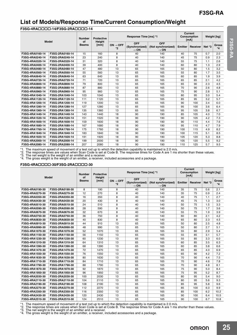
List of Models/Response Time/Current Consumption/WeightF3SG-4RA-14/F3SG-2RA-14
*1. The maximum speed of movement of a test rod up to which the detection capability is maintained is 2.0 m/s.*2. The response times are values when Scan Code is set at Code B. The response times for Code A are 1 ms shorter than these values.*3. The net weight is the weight of an emitter and a receiver.*4. The gross weight is the weight of an emitter, a receiver, included accessories and a package.
F3SG-4RA-30/F3SG-2RA-30
*1. The maximum speed of movement of a test rod up to which the detection capability is maintained is 2.0 m/s.*2. The response times are values when Scan Code is set at Code B. The response times for Code A are 1 ms shorter than these values.*3. The net weight is the weight of an emitter and a receiver.*4. The gross weight is the weight of an emitter, a receiver, included accessories and a package.
ModelNumber
of Beams
Protective Height[mm]
Response Time [ms] *1Current
Consumption [mA]
Weight [kg]
ON → OFF *2
OFF(Synchronized)
→ ON
OFF (Not synchronized)
→ ONEmitter Receiver Net *3 Gross
*4
F3SG-4RA0160-14 F3SG-2RA0160-14 15 160 8 40 140 40 75 0.7 2.0F3SG-4RA0240-14 F3SG-2RA0240-14 23 240 8 40 140 45 75 0.9 2.3F3SG-4RA0320-14 F3SG-2RA0320-14 31 320 8 40 140 55 75 1.1 2.6F3SG-4RA0400-14 F3SG-2RA0400-14 39 400 8 40 140 60 80 1.3 2.9F3SG-4RA0480-14 F3SG-2RA0480-14 47 480 13 65 165 50 80 1.5 3.2F3SG-4RA0560-14 F3SG-2RA0560-14 55 560 13 65 165 55 80 1.7 3.5F3SG-4RA0640-14 F3SG-2RA0640-14 63 640 13 65 165 60 85 1.9 3.9F3SG-4RA0720-14 F3SG-2RA0720-14 71 720 13 65 165 65 85 2.1 4.2F3SG-4RA0800-14 F3SG-2RA0800-14 79 800 13 65 165 65 90 2.3 4.5F3SG-4RA0880-14 F3SG-2RA0880-14 87 880 13 65 165 70 90 2.6 4.8F3SG-4RA0960-14 F3SG-2RA0960-14 95 960 13 65 165 75 90 2.8 5.1F3SG-4RA1040-14 F3SG-2RA1040-14 103 1040 13 65 165 80 95 3.0 5.4F3SG-4RA1120-14 F3SG-2RA1120-14 111 1120 13 65 165 85 95 3.2 5.7F3SG-4RA1200-14 F3SG-2RA1200-14 119 1200 13 65 165 90 100 3.4 6.0F3SG-4RA1280-14 F3SG-2RA1280-14 127 1280 13 65 165 95 100 3.6 6.4F3SG-4RA1360-14 F3SG-2RA1360-14 135 1360 13 65 165 95 105 3.8 6.7F3SG-4RA1440-14 F3SG-2RA1440-14 143 1440 18 90 190 85 105 4.0 7.0F3SG-4RA1520-14 F3SG-2RA1520-14 151 1520 18 90 190 90 105 4.2 7.3F3SG-4RA1600-14 F3SG-2RA1600-14 159 1600 18 90 190 90 110 4.4 7.6F3SG-4RA1680-14 F3SG-2RA1680-14 167 1680 18 90 190 95 110 4.7 7.9F3SG-4RA1760-14 F3SG-2RA1760-14 175 1760 18 90 190 100 115 4.9 8.2F3SG-4RA1840-14 F3SG-2RA1840-14 183 1840 18 90 190 100 115 5.1 8.5F3SG-4RA1920-14 F3SG-2RA1920-14 191 1920 18 90 190 105 120 5.3 8.8F3SG-4RA2000-14 F3SG-2RA2000-14 199 2000 18 90 190 105 120 5.5 9.2F3SG-4RA2080-14 F3SG-2RA2080-14 207 2080 18 90 190 110 125 5.7 9.5
ModelNumber
of Beams
Protective Height[mm]
Response Time [ms] *1Current
Consumption [mA]
Weight [kg]
ON → OFF *2
OFF (Synchronized)
→ ON
OFF (Not synchronized)
→ ONEmitter Receiver Net *3 Gross
*4
F3SG-4RA0190-30 F3SG-2RA0190-30 8 190 8 40 140 35 75 0.6 2.1F3SG-4RA0270-30 F3SG-2RA0270-30 12 270 8 40 140 35 75 0.9 2.4F3SG-4RA0350-30 F3SG-2RA0350-30 16 350 8 40 140 40 75 1.1 2.7F3SG-4RA0430-30 F3SG-2RA0430-30 20 430 8 40 140 45 75 1.3 3.0F3SG-4RA0510-30 F3SG-2RA0510-30 24 510 8 40 140 50 75 1.5 3.3F3SG-4RA0590-30 F3SG-2RA0590-30 28 590 8 40 140 50 75 1.7 3.6F3SG-4RA0670-30 F3SG-2RA0670-30 32 670 8 40 140 55 75 1.9 3.9F3SG-4RA0750-30 F3SG-2RA0750-30 36 750 8 40 140 60 80 2.1 4.2F3SG-4RA0830-30 F3SG-2RA0830-30 40 830 8 40 140 65 80 2.3 4.5F3SG-4RA0910-30 F3SG-2RA0910-30 44 910 13 65 165 50 80 2.5 4.8F3SG-4RA0990-30 F3SG-2RA0990-30 48 990 13 65 165 50 80 2.7 5.1F3SG-4RA1070-30 F3SG-2RA1070-30 52 1070 13 65 165 55 80 2.9 5.4F3SG-4RA1150-30 F3SG-2RA1150-30 56 1150 13 65 165 55 85 3.1 5.7F3SG-4RA1230-30 F3SG-2RA1230-30 60 1230 13 65 165 55 85 3.3 6.0F3SG-4RA1310-30 F3SG-2RA1310-30 64 1310 13 65 165 60 85 3.5 6.3F3SG-4RA1390-30 F3SG-2RA1390-30 68 1390 13 65 165 60 85 3.8 6.6F3SG-4RA1470-30 F3SG-2RA1470-30 72 1470 13 65 165 65 85 4.0 6.9F3SG-4RA1550-30 F3SG-2RA1550-30 76 1550 13 65 165 65 90 4.2 7.2F3SG-4RA1630-30 F3SG-2RA1630-30 80 1630 13 65 165 70 90 4.4 7.5F3SG-4RA1710-30 F3SG-2RA1710-30 84 1710 13 65 165 70 90 4.6 7.8F3SG-4RA1790-30 F3SG-2RA1790-30 88 1790 13 65 165 70 90 4.8 8.1F3SG-4RA1870-30 F3SG-2RA1870-30 92 1870 13 65 165 75 90 5.0 8.4F3SG-4RA1950-30 F3SG-2RA1950-30 96 1950 13 65 165 75 95 5.2 8.7F3SG-4RA2030-30 F3SG-2RA2030-30 100 2030 13 65 165 80 95 5.4 9.0F3SG-4RA2110-30 F3SG-2RA2110-30 104 2110 13 65 165 80 95 5.6 9.3F3SG-4RA2190-30 F3SG-2RA2190-30 108 2190 13 65 165 85 95 5.8 9.6F3SG-4RA2270-30 F3SG-2RA2270-30 112 2270 13 65 165 85 100 6.0 9.9F3SG-4RA2350-30 F3SG-2RA2350-30 116 2350 13 65 165 85 100 6.2 10.2F3SG-4RA2430-30 F3SG-2RA2430-30 120 2430 13 65 165 90 100 6.4 10.5F3SG-4RA2510-30 F3SG-2RA2510-30 124 2510 13 65 165 90 100 6.7 10.8
F3SG-RA
26
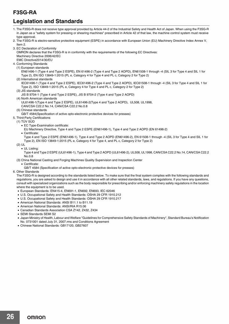
Legislation and Standards1. The F3SG-R does not receive type approval provided by Article 44-2 of the Industrial Safety and Health Act of Japan. When using the F3SG-R
in Japan as a "safety system for pressing or shearing machines" prescribed in Article 42 of that law, the machine control system must receive type approval.
2. The F3SG-R is electro-sensitive protective equipment (ESPE) in accordance with European Union (EU) Machinery Directive Index Annex V, Item 2.
3. EC Declaration of Conformity OMRON declares that the F3SG-R is in conformity with the requirements of the following EC Directives:Machinery Directive 2006/42/EC EMC Directive2014/30/EU
4. Conforming Standards(1) European standards
EN61496-1 (Type 4 and Type 2 ESPE), EN 61496-2 (Type 4 and Type 2 AOPD), EN61508-1 through -4 (SIL 3 for Type 4 and SIL 1 for Type 2), EN ISO 13849-1:2015 (PL e, Category 4 for Type 4 and PL c, Category 2 for Type 2)
(2) International standardsIEC61496-1 (Type 4 and Type 2 ESPE), IEC61496-2 (Type 4 and Type 2 AOPD), IEC61508-1 through -4 (SIL 3 for Type 4 and SIL 1 for Type 2), ISO 13849-1:2015 (PL e, Category 4 for Type 4 and PL c, Category 2 for Type 2)
(3) JIS standardsJIS B 9704-1 (Type 4 and Type 2 ESPE), JIS B 9704-2 (Type 4 and Type 2 AOPD)
(4) North American standardsUL61496-1(Type 4 and Type 2 ESPE), UL61496-2(Type 4 and Type 2 AOPD), UL508, UL1998, CAN/CSA C22.2 No.14, CAN/CSA C22.2 No.0.8
(5) Chinese standardsGB/T 4584(Specification of active opto-electronic protective devices for presses)
5. Third-Party Certifications(1) TÜV SÜD
• EC Type-Examination certificate:EU Machinery Directive, Type 4 and Type 2 ESPE (EN61496-1), Type 4 and Type 2 AOPD (EN 61496-2)
• Certificate:Type 4 and Type 2 ESPE (EN61496-1), Type 4 and Type 2 AOPD (EN61496-2), EN 61508-1 through -4 (SIL 3 for Type 4 and SIL 1 for Type 2), EN ISO 13849-1:2015 (PL e, Category 4 for Type 4, and PL c, Category 2 for Type 2)
(2) UL• UL Listing:
Type 4 and Type 2 ESPE (UL61496-1), Type 4 and Type 2 AOPD (UL61496-2), UL508, UL1998, CAN/CSA C22.2 No.14, CAN/CSA C22.2 No.0.8
(3) China National Casting and Forging Machines Quality Supervision and Inspection Center• Certificate:
GB/T 4584 (Specification of active opto-electronic protective devices for presses)6. Other Standards
The F3SG-R is designed according to the standards listed below. To make sure that the final system complies with the following standards and regulations, you are asked to design and use it in accordance with all other related standards, laws, and regulations. If you have any questions, consult with specialized organizations such as the body responsible for prescribing and/or enforcing machinery safety regulations in the location where the equipment is to be used. • European Standards: EN415-4, EN691-1, EN692, EN693, IEC 62046• U.S. Occupational Safety and Health Standards: OSHA 29 CFR 1910.212• U.S. Occupational Safety and Health Standards: OSHA 29 CFR 1910.217• American National Standards: ANSI B11.1 to B11.19• American National Standards: ANSI/RIA R15.06• Canadian Standards Association CSA Z142, Z432, Z434• SEMI Standards SEMI S2• Japan Ministry of Health, Labour and Welfare "Guidelines for Comprehensive Safety Standards of Machinery", Standard Bureau's Notification
No. 0731001 dated July 31, 2007.rms and Conditions Agreement• Chinese National Standards: GB17120, GB27607
F3SG-RA
27
F3S
G-R
A
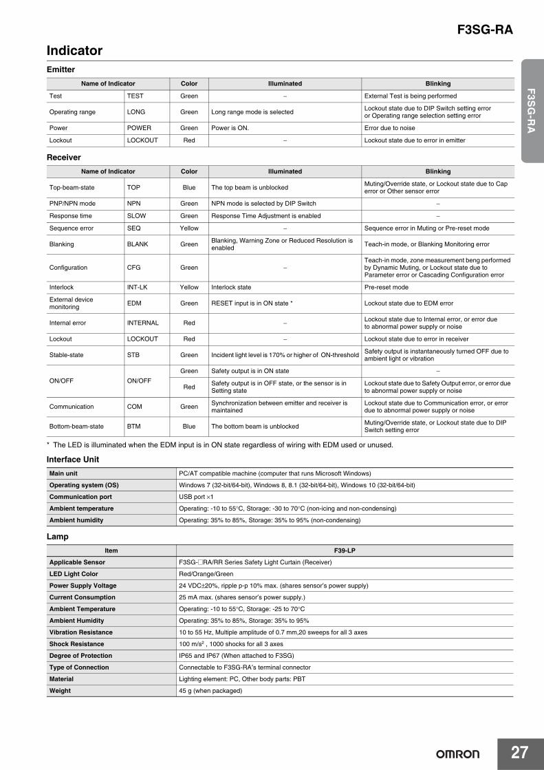
IndicatorEmitter
Receiver
* The LED is illuminated when the EDM input is in ON state regardless of wiring with EDM used or unused.
Interface Unit
Lamp
Name of Indicator Color Illuminated Blinking
Test TEST Green − External Test is being performed
Operating range LONG Green Long range mode is selected Lockout state due to DIP Switch setting erroror Operating range selection setting error
Power POWER Green Power is ON. Error due to noise
Lockout LOCKOUT Red − Lockout state due to error in emitter
Name of Indicator Color Illuminated Blinking
Top-beam-state TOP Blue The top beam is unblockedMuting/Override state, or Lockout state due to Cap error or Other sensor error
PNP/NPN mode NPN Green NPN mode is selected by DIP Switch −
Response time SLOW Green Response Time Adjustment is enabled −
Sequence error SEQ Yellow − Sequence error in Muting or Pre-reset mode
Blanking BLANK Green Blanking, Warning Zone or Reduced Resolution is enabled Teach-in mode, or Blanking Monitoring error
Configuration CFG Green −Teach-in mode, zone measurement beng performed by Dynamic Muting, or Lockout state due to Parameter error or Cascading Configuration error
Interlock INT-LK Yellow Interlock state Pre-reset mode
External device monitoring EDM Green RESET input is in ON state * Lockout state due to EDM error
Internal error INTERNAL Red − Lockout state due to Internal error, or error dueto abnormal power supply or noise
Lockout LOCKOUT Red − Lockout state due to error in receiver
Stable-state STB Green Incident light level is 170% or higher of ON-threshold Safety output is instantaneously turned OFF due to ambient light or vibration
ON/OFF ON/OFF
Green Safety output is in ON state −
Red Safety output is in OFF state, or the sensor is in Setting state
Lockout state due to Safety Output error, or error due to abnormal power supply or noise
Communication COM Green Synchronization between emitter and receiver is maintained
Lockout state due to Communication error, or error due to abnormal power supply or noise
Bottom-beam-state BTM Blue The bottom beam is unblocked Muting/Override state, or Lockout state due to DIP Switch setting error
Main unit PC/AT compatible machine (computer that runs Microsoft Windows)
Operating system (OS) Windows 7 (32-bit/64-bit), Windows 8, 8.1 (32-bit/64-bit), Windows 10 (32-bit/64-bit)
Communication port USB port ×1
Ambient temperature Operating: -10 to 55°C, Storage: -30 to 70°C (non-icing and non-condensing)
Ambient humidity Operating: 35% to 85%, Storage: 35% to 95% (non-condensing)
Item F39-LP
Applicable Sensor F3SG-@RA/RR Series Safety Light Curtain (Receiver)
LED Light Color Red/Orange/Green
Power Supply Voltage 24 VDC±20%, ripple p-p 10% max. (shares sensor′s power supply)
Current Consumption 25 mA max. (shares sensor′s power supply.)
Ambient Temperature Operating: -10 to 55°C, Storage: -25 to 70°C
Ambient Humidity Operating: 35% to 85%, Storage: 35% to 95%
Vibration Resistance 10 to 55 Hz, Multiple amplitude of 0.7 mm,20 sweeps for all 3 axes
Shock Resistance 100 m/s2 , 1000 shocks for all 3 axes
Degree of Protection IP65 and IP67 (When attached to F3SG)
Type of Connection Connectable to F3SG-RA′s terminal connector
Material Lighting element: PC, Other body parts: PBT
Weight 45 g (when packaged)
F3SG-RA
28
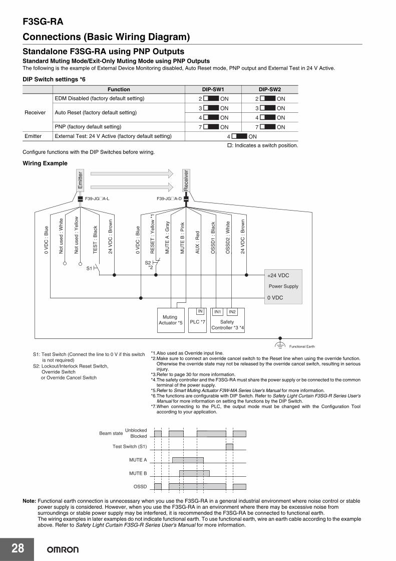
Connections (Basic Wiring Diagram)Standalone F3SG-RA using PNP OutputsStandard Muting Mode/Exit-Only Muting Mode using PNP OutputsThe following is the example of External Device Monitoring disabled, Auto Reset mode, PNP output and External Test in 24 V Active.
DIP Switch settings *6
: Indicates a switch position.Configure functions with the DIP Switches before wiring.
Wiring Example
Note: Functional earth connection is unnecessary when you use the F3SG-RA in a general industrial environment where noise control or stablepower supply is considered. However, when you use the F3SG-RA in an environment where there may be excessive noise from surroundings or stable power supply may be interfered, it is recommended the F3SG-RA be connected to functional earth.The wiring examples in later examples do not indicate functional earth. To use functional earth, wire an earth cable according to the example above. Refer to Safety Light Curtain F3SG-R Series User's Manual for more information.
Function DIP-SW1 DIP-SW2
Receiver
EDM Disabled (factory default setting)
Auto Reset (factory default setting)
PNP (factory default setting)
Emitter External Test: 24 V Active (factory default setting)
2 ON 2 ON
3 ON 3 ON
4 ON 4 ON
7 ON 7 ON
4 ON
OS
SD
1 : B
lack
OS
SD
2 : W
hite
24 V
DC
: B
row
n
Not
use
d : Y
ello
w
TE
ST
: B
lack
Not
use
d : W
hite
24 V
DC
: B
row
n
0 V
DC
: B
lue
0 V
DC
: B
lue
AU
X :
Red
MU
TE
B :
Pin
k
MU
TE
A :
Gra
y
RE
SE
T :
Yel
low
*1
S1: Test Switch (Connect the line to 0 V if this switch is not required)S2: Lockout/Interlock Reset Switch,
Override Switch or Override Cancel Switch
S2*2S1
Power Supply
+24 VDC
0 VDC
Safety Controller *3 *4
Muting Actuator *5
IN1 IN2
UnblockedBlocked
MUTE A
MUTE B
OSSD
Test Switch (S1)
Beam state
PLC *7
IN
Rec
eive
r
Em
itter
F39-JG@A-L F39-JG@A-D
Functional Earth
*1.Also used as Override input line.*2.Make sure to connect an override cancel switch to the Reset line when using the override function.
Otherwise the override state may not be released by the override cancel switch, resulting in seriousinjury.
*3.Refer to page 30 for more information.*4.The safety controller and the F3SG-RA must share the power supply or be connected to the common
terminal of the power supply.*5.Refer to Smart Muting Actuator F3W-MA Series User's Manual for more information. *6.The functions are configurable with DIP Switch. Refer to Safety Light Curtain F3SG-R Series User's
Manual for more information on setting the functions by the DIP Switch.*7.When connecting to the PLC, the output mode must be changed with the Configuration Tool
according to your application.
F3SG-RA
29
F3S
G-R
A
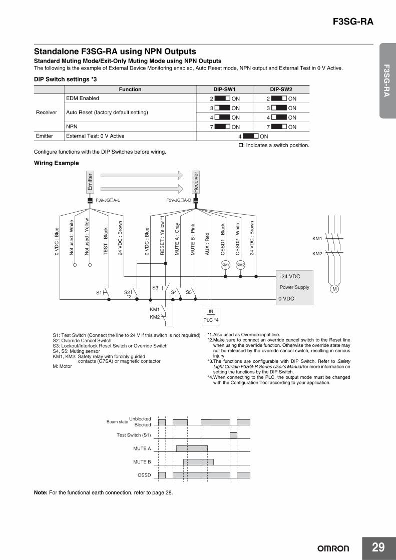
Standalone F3SG-RA using NPN OutputsStandard Muting Mode/Exit-Only Muting Mode using NPN OutputsThe following is the example of External Device Monitoring enabled, Auto Reset mode, NPN output and External Test in 0 V Active.
DIP Switch settings *3
: Indicates a switch position.Configure functions with the DIP Switches before wiring.
Wiring Example
Note: For the functional earth connection, refer to page 28.
Function DIP-SW1 DIP-SW2
Receiver
EDM Enabled
Auto Reset (factory default setting)
NPN
Emitter External Test: 0 V Active
2 ON 2 ON
3 ON 3 ON
4 ON 4 ON
7 ON 7 ON
4 ON
OS
SD
1 : B
lack
OS
SD
2 : W
hite
24 V
DC
: B
row
n
Not
use
d : Y
ello
w
TE
ST
: B
lack
Not
use
d : W
hite
24 V
DC
: B
row
n
0 V
DC
: B
lue
0 V
DC
: B
lue
AU
X :
Red
MU
TE
B :
Pin
k
MU
TE
A :
Gra
y
RE
SE
T :
Yel
low
*1
S1: Test Switch (Connect the line to 24 V if this switch is not required)S2: Override Cancel SwitchS3: Lockout/Interlock Reset Switch or Override SwitchS4, S5: Muting sensorKM1, KM2: Safety relay with forcibly guided contacts (G7SA) or magnetic contactorM: Motor
S1S3 Power Supply
+24 VDC
0 VDCS5S2
*2S4
KM1 KM2
KM1
KM2
KM1
KM2
M
UnblockedBlocked
MUTE A
MUTE B
OSSD
Test Switch (S1)
Beam state
PLC *4
IN
Rec
eive
r
Em
itter
F39-JG@A-L F39-JG@A-D
*1.Also used as Override input line.*2.Make sure to connect an override cancel switch to the Reset line
when using the override function. Otherwise the override state maynot be released by the override cancel switch, resulting in seriousinjury.
*3.The functions are configurable with DIP Switch. Refer to SafetyLight Curtain F3SG-R Series User's Manual for more information onsetting the functions by the DIP Switch.
*4.When connecting to the PLC, the output mode must be changedwith the Configuration Tool according to your application.
F3SG-RA
30
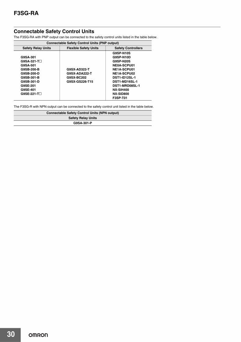
Connectable Safety Control UnitsThe F3SG-RA with PNP output can be connected to the safety control units listed in the table below.
The F3SG-R with NPN output can be connected to the safety control unit listed in the table below.
Connectable Safety Control Units (PNP output)Safety Relay Units Flexible Safety Units Safety Controllers
G9SA-301G9SA-321-T@G9SA-501G9SB-200-BG9SB-200-DG9SB-301-BG9SB-301-DG9SE-201G9SE-401G9SE-221-T@
G9SX-AD322-TG9SX-ADA222-TG9SX-BC202G9SX-GS226-T15
G9SP-N10SG9SP-N10DG9SP-N20SNE0A-SCPU01NE1A-SCPU01NE1A-SCPU02DST1-ID12SL-1DST1-MD16SL-1DST1-MRD08SL-1NX-SIH400NX-SID800F3SP-T01
Connectable Safety Control Units (NPN output)Safety Relay Units
G9SA-301-P
F3SG-RA
31
F3S
G-R
A
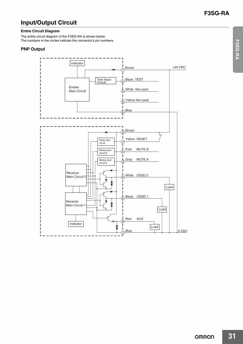
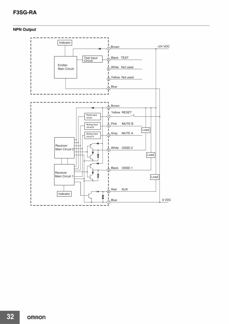
Input/Output CircuitEntire Circuit DiagramThe entire circuit diagram of the F3SG-RA is shown below.The numbers in the circles indicate the connector's pin numbers.
PNP Output
2
1
5
8
7
6
+24 VDC1
2
4
Brown
Black TEST
White Not used
Blue
Brown
White OSSD 2
Pink MUTE B
Gray MUTE A
Black OSSD 1
Red AUX
Blue
3
Reset input circuit
4Muting input circuit B
3Muting input circuit A
Yellow RESET
0 VDC
5Yellow Not used
Load
Indicator
EmitterMain Circuit
Test Input Circuit
ReceiverMain Circuit 2
ReceiverMain Circuit 1
IndicatorLoad
Load
F3SG-RA
32
NPN Output
2
1
5
8
7
6
+24 VDC1
2
4
Brown
Black TEST
White Not used
Blue
Brown
Yellow
White OSSD 2
Pink MUTE B
Gray MUTE A
Black OSSD 1
Red AUX
Blue
3
Reset input circuit
4Muting input circuit B
3Muting input circuit A
RESET
0 VDC
5Yellow Not used
Indicator
EmitterMain Circuit
Test Input Circuit
ReceiverMain Circuit 2
ReceiverMain Circuit 1
Indicator
Load
Load
Load
F3SG-RA
33
F3S
G-R
A
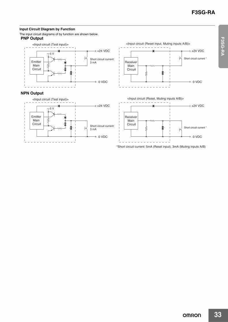
Input Circuit Diagram by FunctionThe input circuit diagrams of by function are shown below.
PNP Output
NPN Output
Emitter Main Circuit
+24 VDC
0 VDC
5 V
Short circuit current:3 mA
<Input circuit (Test input)>
Receiver Main Circuit
+24 VDC
0 VDC
Short circuit current *
<Input circuit (Reset input, Muting inputs A/B)>
Receiver Main Circuit
+24 VDC
0 VDC
Short circuit current *
<Input circuit (Reset, Muting inputs A/B)>
Emitter Main Circuit
+24 VDC
0 VDC
5 V
Short circuit current:3 mA
<Input circuit (Test input)>
*Short circuit current: 5mA (Reset input), 3mA (Muting inputs A/B)
F3SG-RA
34
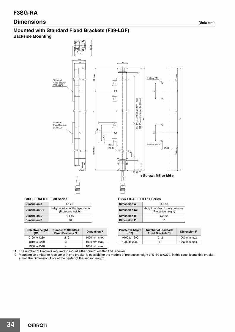
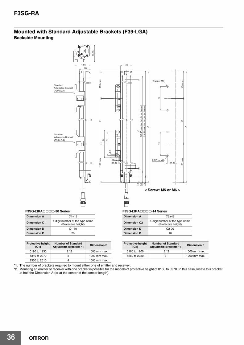
Dimensions (Unit: mm)
Mounted with Standard Fixed Brackets (F39-LGF)Backside Mounting
*1. The number of brackets required to mount either one of emitter and receiver.*2. Mounting an emitter or receiver with one bracket is possible for the models of protective height of 0160 to 0270. In this case, locate this bracket
at half the Dimension A (or at the center of the sensor length).
2-M5 or M6
2-M5 or M6
A
6.4
5151
35
9.2
66
StandardFixed Bracket(F39-LGF)
StandardFixed Bracket(F39-LGF)
35
40
50.3
5
D
P
24.85
51
150
max
F
150
max
C2
(Pro
tect
ive
heig
ht fo
r 14
mm
)
C1
(Pro
tect
ive
heig
ht fo
r 30
mm
)
33 1843
F
24.85
A
150
max
150
max
< Screw: M5 or M6 >
F3SG-RA-30 Series Dimension A C1+18
Dimension C1 4-digit number of the type name(Protective height)
Dimension D C1-50
Dimension P 20
Protective height(C1)
Number of Standard Fixed Brackets *1 Dimension F
0190 to 1230 2 *2 1000 mm max.
1310 to 2270 3 1000 mm max.
2350 to 2510 4 1000 mm max.
F3SG-RA-14 Series Dimension A C2+48
Dimension C2 4-digit number of the type name(Protective height)
Dimension D C2-20
Dimension P 10
Protective height(C2)
Number of Standard Fixed Brackets *1 Dimension F
0160 to 1200 2 *2 1000 mm max.
1280 to 2080 3 1000 mm max.
F3SG-RA
35
F3S
G-R
A
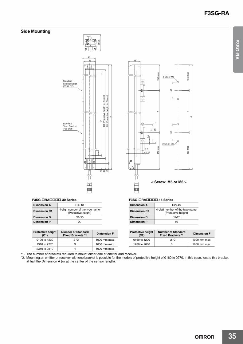
Side Mounting
*1. The number of brackets required to mount either one of emitter and receiver.*2. Mounting an emitter or receiver with one bracket is possible for the models of protective height of 0160 to 0270. In this case, locate this bracket
at half the Dimension A (or at the center of the sensor length).
StandardFixed Bracket(F39-LGF)
StandardFixed Bracket(F39-LGF)
A
35
40
2-M5 or M6
2-M5 or M6
51
9.2
51
35
6.4
66
50.3
5
51
150
max
150
max
F
42.35
A
150
max
150
max
F
P
D
C1
(Pro
tect
ive
heig
ht fo
r 30
mm
)
33 1843
C2
(Pro
tect
ive
heig
ht fo
r 14
mm
)
< Screw: M5 or M6 >
F3SG-RA-30 Series Dimension A C1+18
Dimension C1 4-digit number of the type name(Protective height)
Dimension D C1-50
Dimension P 20
Protective height(C1)
Number of Standard Fixed Brackets *1 Dimension F
0190 to 1230 2 *2 1000 mm max.
1310 to 2270 3 1000 mm max.
2350 to 2510 4 1000 mm max.
F3SG-RA-14 Series Dimension A C2+48
Dimension C2 4-digit number of the type name(Protective height)
Dimension D C2-20
Dimension P 10
Protective height(C2)
Number of Standard Fixed Brackets *1 Dimension F
0160 to 1200 2 *2 1000 mm max.
1280 to 2080 3 1000 mm max.
F3SG-RA
36
Mounted with Standard Adjustable Brackets (F39-LGA)Backside Mounting
*1. The number of brackets required to mount either one of emitter and receiver.*2. Mounting an emitter or receiver with one bracket is possible for the models of protective height of 0160 to 0270. In this case, locate this bracket
at half the Dimension A (or at the center of the sensor length).
StandardAdjustable Bracket(F39-LGA)
StandardAdjustable Bracket(F39-LGA)
35
48.6
50.3
5
2-M5 or M6
2-M5 or M6
35
A
729.2
72
6.4
84
P
72
24.85
150
max
150
max
F
D
C2
(Pro
tect
ive
heig
ht fo
r 14
mm
)
C1
(Pro
tect
ive
heig
ht fo
r 30
mm
)
33 1843
F
A
24.85
150
max
150
max
< Screw: M5 or M6 >
F3SG-RA-30 Series Dimension A C1+18
Dimension C1 4-digit number of the type name(Protective height)
Dimension D C1-50
Dimension P 20
Protective height(C1)
Number of Standard Adjustable Brackets *1 Dimension F
0190 to 1230 2 *2 1000 mm max.
1310 to 2270 3 1000 mm max.
2350 to 2510 4 1000 mm max.
F3SG-RA-14 Series Dimension A C2+48
Dimension C2 4-digit number of the type name(Protective height)
Dimension D C2-20
Dimension P 10
Protective height(C2)
Number of Standard Adjustable Brackets *1 Dimension F
0160 to 1200 2 *2 1000 mm max.
1280 to 2080 3 1000 mm max.
F3SG-RA
37
F3S
G-R
A
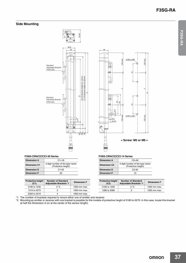
Side Mounting
*1. The number of brackets required to mount either one of emitter and receiver.*2. Mounting an emitter or receiver with one bracket is possible for the models of protective height of 0160 to 0270. In this case, locate this bracket
at half the Dimension A (or at the center of the sensor length).
50.3
5
StandardAdjustable Bracket(F39-LGA)
StandardAdjustable Bracket(F39-LGA)
35
A
48.6
2-M5 or M6
2-M5 or M6
7272
35
6.4
9.28472
150
max
150
max
F42.35
A
150
max
150
max
F
P
D
C2
(Pro
tect
ive
heig
ht fo
r 14
mm
)
C1
(Pro
tect
ive
heig
ht fo
r 30
mm
)
33 1843
< Screw: M5 or M6 >
F3SG-RA-30 Series Dimension A C1+18
Dimension C1 4-digit number of the type name(Protective height)
Dimension D C1-50
Dimension P 20
Protective height(C1)
Number of Standard Adjustable Brackets *1 Dimension F
0190 to 1230 2 *2 1000 mm max.
1310 to 2270 3 1000 mm max.
2350 to 2510 4 1000 mm max.
F3SG-RA-14 Series Dimension A C2+48
Dimension C2 4-digit number of the type name(Protective height)
Dimension D C2-20
Dimension P 10
Protective height(C2)
Number of Standard Adjustable Brackets *1 Dimension F
0160 to 1200 2 *2 1000 mm max.
1280 to 2080 3 1000 mm max.
F3SG-RA
38
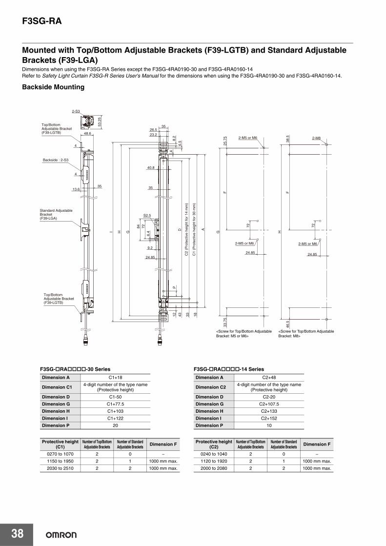
Mounted with Top/Bottom Adjustable Brackets (F39-LGTB) and Standard Adjustable Brackets (F39-LGA)Dimensions when using the F3SG-RA Series except the F3SG-4RA0190-30 and F3SG-4RA0160-14Refer to Safety Light Curtain F3SG-R Series User's Manual for the dimensions when using the F3SG-4RA0190-30 and F3SG-4RA0160-14.
Backside Mounting
<Screw for Top/Bottom Adjustable Bracket: M5 or M6>
<Screw for Top/Bottom Adjustable Bracket: M8>
Standard Adjustable Bracket(F39-LGA)
Top/Bottom Adjustable Bracket(F39-LGTB)
Top/Bottom Adjustable Bracket(F39-LGTB)
Backside : 2-S3
2-M5 or M6
2-M5 or M6
2-M5 or M6
C1
(Pro
tect
ive
heig
ht fo
r 30
mm
)
C2
(Pro
tect
ive
heig
ht fo
r 14
mm
)
2-M8
S2.5
12
35
40.8
G
H
I
26.5
35
23.2
8.2
A
9.2
72
6.4
84
6.5
4
2-S3
53.
25
48.6
35 13.6
4
4
18
33
43
D
P
F
F
25.
75
24.85
46.
5
H
38.
5
G
33.
75
24.85 7
2
24.85
72
F3SG-RA-30 Series Dimension A C1+18
Dimension C1 4-digit number of the type name(Protective height)
Dimension D C1-50
Dimension G C1+77.5
Dimension H C1+103
Dimension I C1+122
Dimension P 20
Protective height(C1)
Number of Top/BottomAdjustable Brackets
Number of Standard Adjustable Brackets Dimension F
0270 to 1070 2 0 −1150 to 1950 2 1 1000 mm max.
2030 to 2510 2 2 1000 mm max.
F3SG-RA-14 Series Dimension A C2+48
Dimension C2 4-digit number of the type name(Protective height)
Dimension D C2-20
Dimension G C2+107.5
Dimension H C2+133
Dimension I C2+152
Dimension P 10
Protective height(C2)
Number of Top/BottomAdjustable Brackets
Number of Standard Adjustable Brackets Dimension F
0240 to 1040 2 0 −1120 to 1920 2 1 1000 mm max.
2000 to 2080 2 2 1000 mm max.
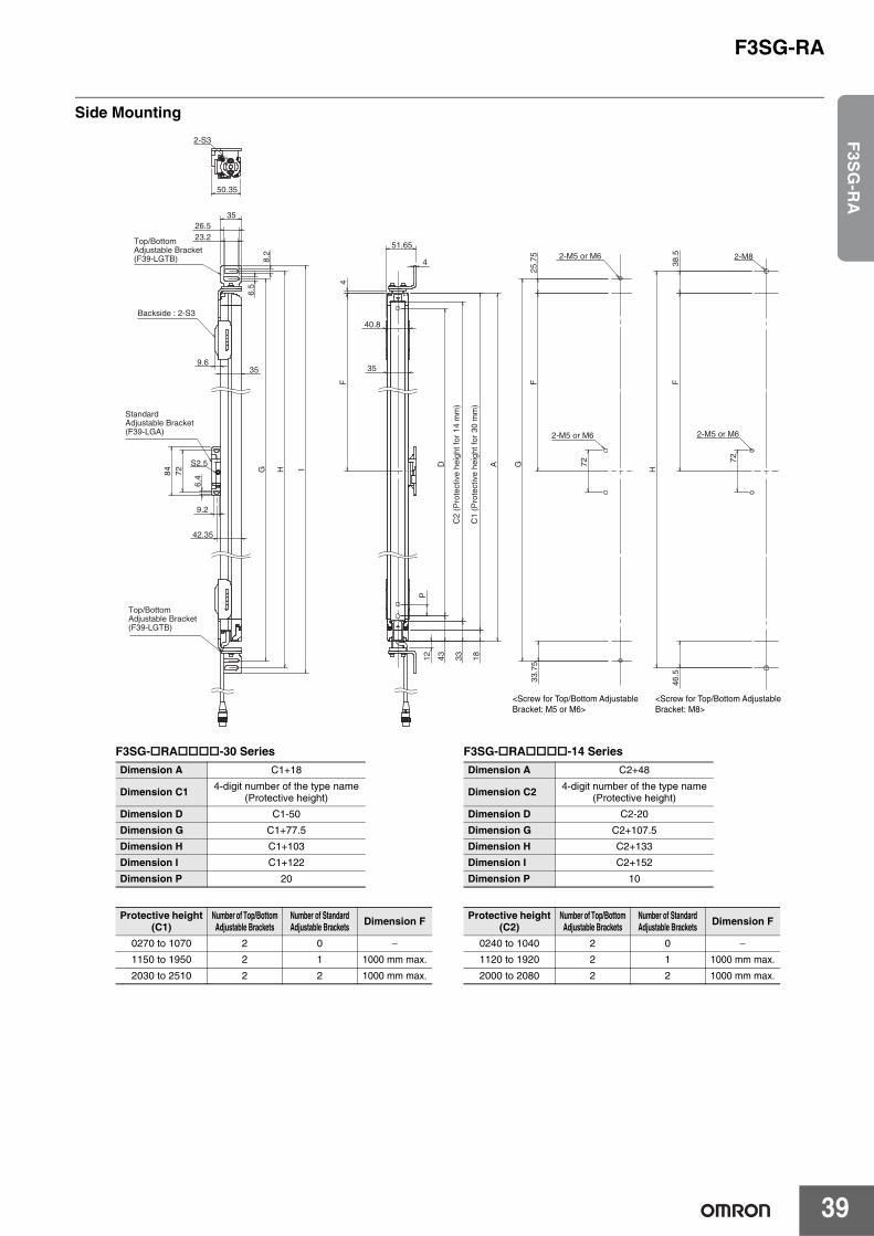
F3SG-RA
39
F3S
G-R
A
Side Mounting
Top/Bottom Adjustable Bracket(F39-LGTB)
Top/Bottom Adjustable Bracket(F39-LGTB)
Standard Adjustable Bracket(F39-LGA)
Backside : 2-S3
2-M5 or M6
2-M5 or M6
2-M5 or M6
C1
(Pro
tect
ive
heig
ht fo
r 30
mm
)
C2
(Pro
tect
ive
heig
ht fo
r 14
mm
)
<Screw for Top/Bottom Adjustable Bracket: M5 or M6>
<Screw for Top/Bottom Adjustable Bracket: M8>
2-M8
40.8
35
A
4
51.65
4
12
S2.5
35
23.2 26.5
35
6.5
8.2
H
I
84
9.2
6.4
72 G
9.6
2-S3
50.35
42.35
18
33
43
D
P
F
F
F
H
38.
5 4
6.5
33.
75
25.
75
G
72 72
F3SG-RA-30 Series Dimension A C1+18
Dimension C1 4-digit number of the type name(Protective height)
Dimension D C1-50
Dimension G C1+77.5
Dimension H C1+103
Dimension I C1+122
Dimension P 20
Protective height(C1)
Number of Top/BottomAdjustable Brackets
Number of Standard Adjustable Brackets Dimension F
0270 to 1070 2 0 −1150 to 1950 2 1 1000 mm max.
2030 to 2510 2 2 1000 mm max.
F3SG-RA-14 Series Dimension A C2+48
Dimension C2 4-digit number of the type name(Protective height)
Dimension D C2-20
Dimension G C2+107.5
Dimension H C2+133
Dimension I C2+152
Dimension P 10
Protective height(C2)
Number of Top/BottomAdjustable Brackets
Number of Standard Adjustable Brackets Dimension F
0240 to 1040 2 0 −1120 to 1920 2 1 1000 mm max.
2000 to 2080 2 2 1000 mm max.
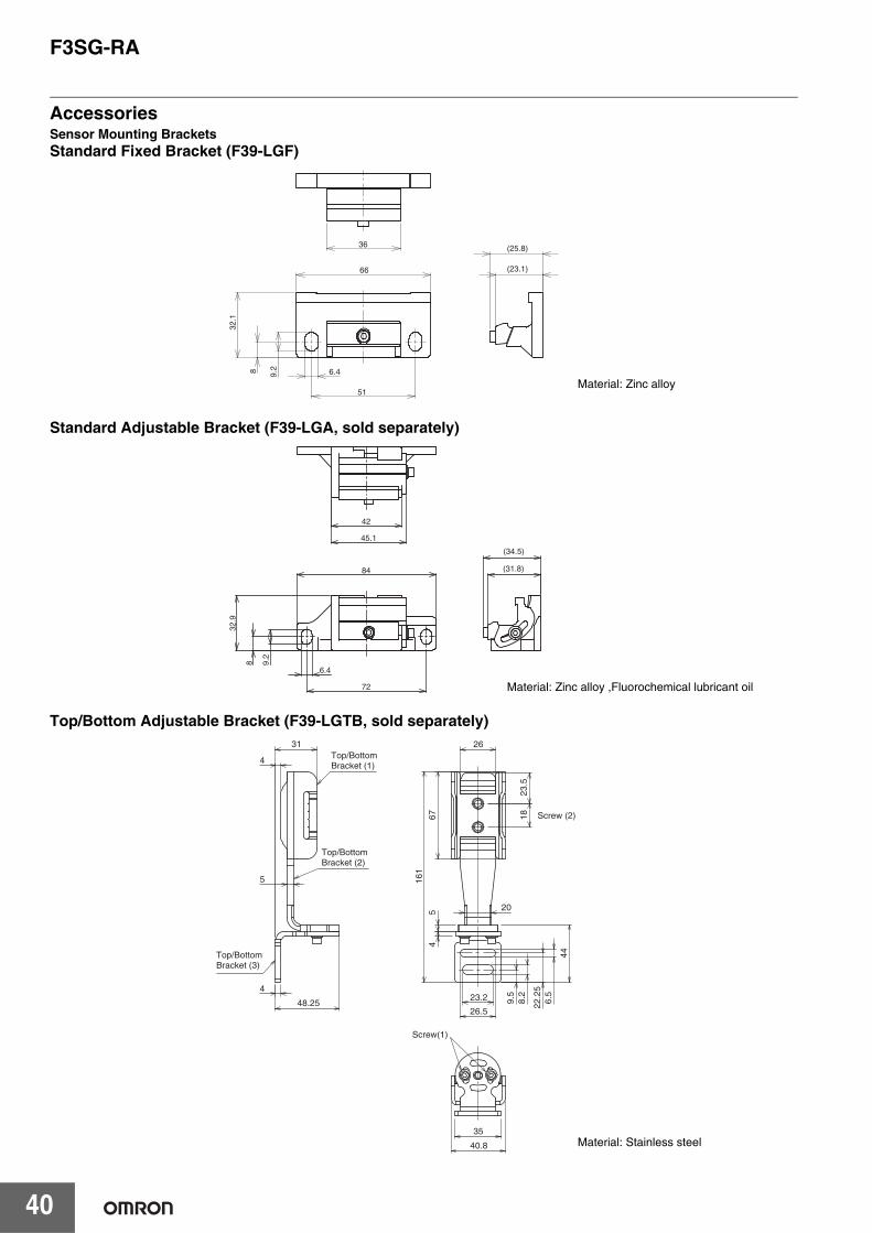
F3SG-RA
40
AccessoriesSensor Mounting BracketsStandard Fixed Bracket (F39-LGF)
Standard Adjustable Bracket (F39-LGA, sold separately)
Top/Bottom Adjustable Bracket (F39-LGTB, sold separately)
51
8
(23.1)
(25.8)
9.2
66
6.4
32.1
36
Material: Zinc alloy
8
72
42
45.1
84
9.2
6.4
32.9
(31.8)
(34.5)
Material: Zinc alloy ,Fluorochemical lubricant oil
4
31
4
48.25
5
26.5
23.2 8.2
6.5
9.5
22.2
5
44
45
1867
23.5
26
20
161
35
40.8
Top/Bottom Bracket (1)
Top/Bottom Bracket (2)
Top/Bottom Bracket (3)
Screw (2)
Screw(1)
Material: Stainless steel
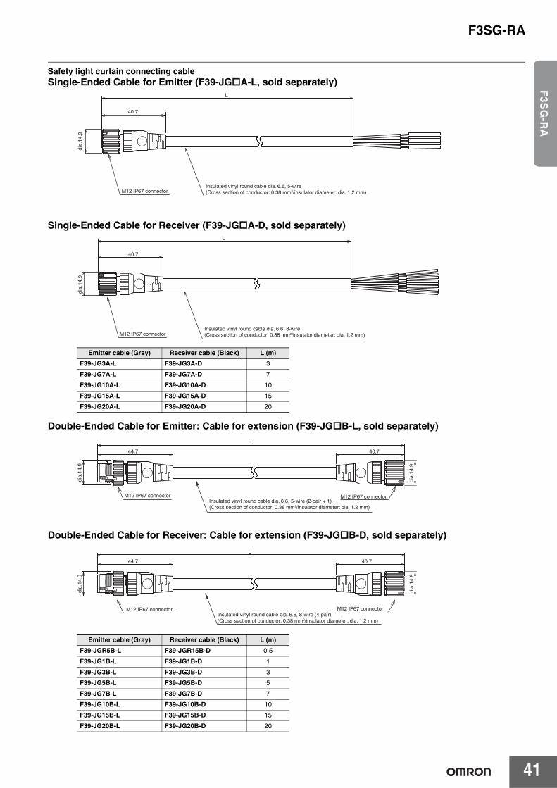
F3SG-RA
41
F3S
G-R
A
Safety light curtain connecting cableSingle-Ended Cable for Emitter (F39-JGA-L, sold separately)
Single-Ended Cable for Receiver (F39-JGA-D, sold separately)
Double-Ended Cable for Emitter: Cable for extension (F39-JGB-L, sold separately)
Double-Ended Cable for Receiver: Cable for extension (F39-JGB-D, sold separately)
Emitter cable (Gray) Receiver cable (Black) L (m)F39-JG3A-L F39-JG3A-D 3
F39-JG7A-L F39-JG7A-D 7
F39-JG10A-L F39-JG10A-D 10
F39-JG15A-L F39-JG15A-D 15
F39-JG20A-L F39-JG20A-D 20
Emitter cable (Gray) Receiver cable (Black) L (m)F39-JGR5B-L F39-JGR15B-D 0.5
F39-JG1B-L F39-JG1B-D 1
F39-JG3B-L F39-JG3B-D 3
F39-JG5B-L F39-JG5B-D 5
F39-JG7B-L F39-JG7B-D 7
F39-JG10B-L F39-JG10B-D 10
F39-JG15B-L F39-JG15B-D 15
F39-JG20B-L F39-JG20B-D 20
40.7
L
Insulated vinyl round cable dia. 6.6, 5-wire (Cross section of conductor: 0.38 mm2/insulator diameter: dia. 1.2 mm)
dia.
14.9
M12 IP67 connector
Insulated vinyl round cable dia. 6.6, 8-wire (Cross section of conductor: 0.38 mm2/insulator diameter: dia. 1.2 mm)
dia.
14.9
M12 IP67 connector
L
40.7
M12 IP67 connectorInsulated vinyl round cable dia. 6.6, 5-wire (2-pair + 1)(Cross section of conductor: 0.38 mm2/insulator diameter: dia. 1.2 mm)
M12 IP67 connector
40.7
L
44.7
dia.
14.9
dia.
14.9
M12 IP67 connectorInsulated vinyl round cable dia. 6.6, 8-wire (4-pair) (Cross section of conductor: 0.38 mm2/insulator diameter: dia. 1.2 mm)
M12 IP67 connector
40.7
L
44.7
dia.
14.9
dia.
14.9
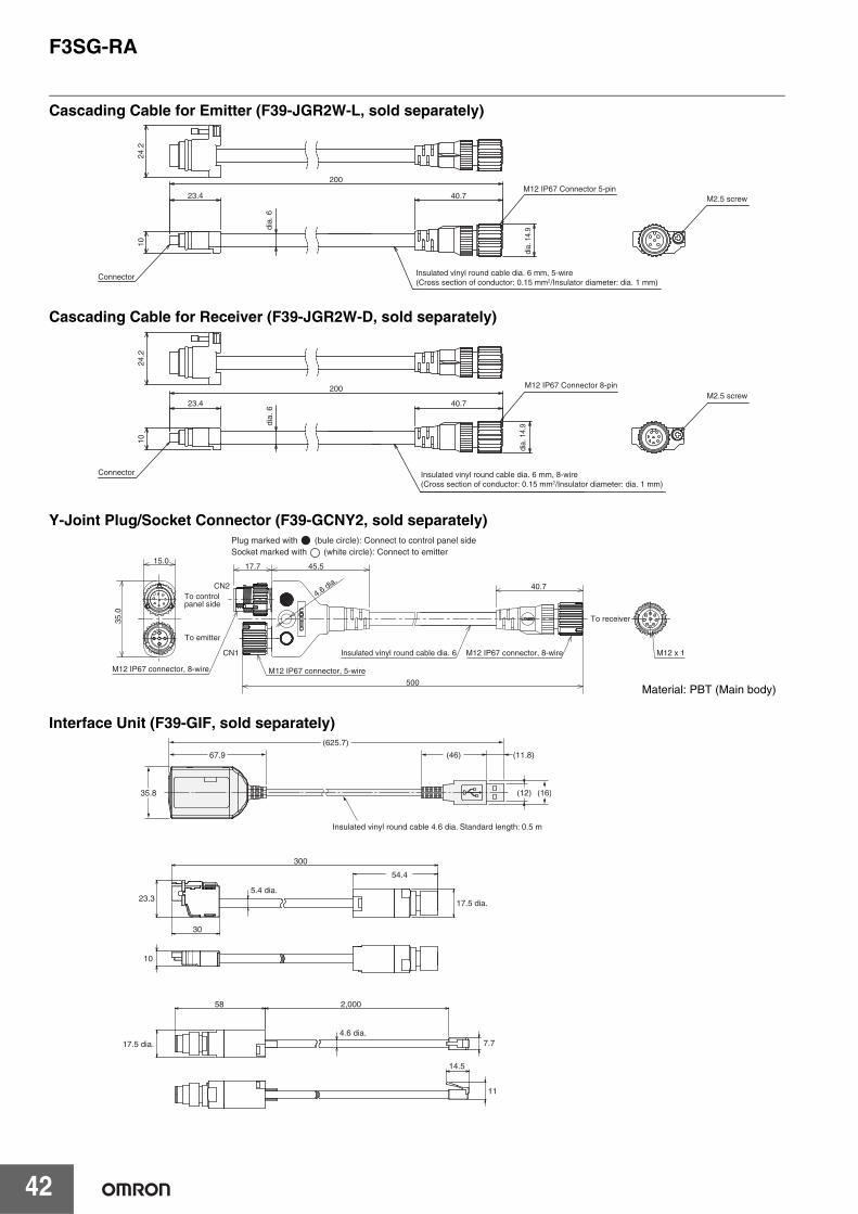
F3SG-RA
42
Cascading Cable for Emitter (F39-JGR2W-L, sold separately)
Cascading Cable for Receiver (F39-JGR2W-D, sold separately)
Y-Joint Plug/Socket Connector (F39-GCNY2, sold separately)
Interface Unit (F39-GIF, sold separately)
200
dia.
14.
9
40.7
dia.
6
23.4
10
Insulated vinyl round cable dia. 6 mm, 5-wire(Cross section of conductor: 0.15 mm2/Insulator diameter: dia. 1 mm)
Connector
M12 IP67 Connector 5-pin
24.2
M2.5 screw
dia.
6
200
dia.
14.
9
40.723.4
Insulated vinyl round cable dia. 6 mm, 8-wire (Cross section of conductor: 0.15 mm2/Insulator diameter: dia. 1 mm)
Connector
M12 IP67 Connector 8-pinM2.5 screw
1024
.2
Plug marked with (bule circle): Connect to control panel sideSocket marked with (white circle): Connect to emitter
CN1
CN2
17.7 45.5
500
40.7
15.0
35.0
M12 x 1
4.6 dia.
To controlpanel side
To emitter
M12 IP67 connector, 8-wire M12 IP67 connector, 5-wire
M12 IP67 connector, 8-wireInsulated vinyl round cable dia. 6
To receiver
Material: PBT (Main body)
67.9
35.8 (16)(12)
(625.7)
(46)
Insulated vinyl round cable 4.6 dia. Standard length: 0.5 m
(11.8)
300
30
54.4
58
23.3
10
17.5 dia.4.6 dia.
5.4 dia.
2,000
14.5
17.5 dia.
7.7
11
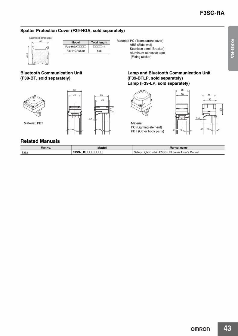
F3SG-RA
43
F3S
G-R
A
Spatter Protection Cover (F39-HGA, sold separately)
Bluetooth Communication Unit (F39-BT, sold separately)
Lamp and Bluetooth Communication Unit (F39-BTLP, sold separately)Lamp (F39-LP, sold separately)
Related Manuals
40
41.8
Assembled dimensions
Model Total lengthF39-HGA@@@@ @@@@+4
F39-HGA0550 558
Material: PC (Transparent cover)ABS (Side wall)Stainless steel (Bracket)Aluminum adhesive tape (Fixing sticker)
16.
5
35
30
35
35
2.4
Material: PBT
35
30
28
35
35
2.4
Material: PC (Lighting element)PBT (Other body parts)
ManNo. Model Manual name
Z352 F3SG-@R@@@@@@@@ Safety Light Curtain F3SG-@R Series User's Manual

44
Safety Light Curtain Robust type
F3SG-RREnhanced Cutting Oil Resistance• Mechanical seal structure prevents cutting oil
from getting inside• Special materials and cables significantly enhanced
cutting oil resistance• Rugged and compact housing. Perfect fit installation• IP67G (JIS C 0920 Annex 1) rated
System Configuration
IF-U
PC
F39-LGRAFree-Location Bracket(Intermediate Bracket)
F39-LGRTBF39-LGRTB-2F39-LGRTB-3
Top/Bottom Bracket
F39-LPLamp
F39-BTLPLamp and Bluetooth Communication Unit
F39-BTBluetooth
Communication Unit
NX/NE1A-seriesSafety Network Controller
G9SP-seriesSafety Controller
G9SE/G9SA-seriesSafety Relay Unit
G9SX-seriesFlexible Safety Unit
G7SA/G7S-ERelays with Forcibly
Guided Contacts
Emitter Receiver
F39-JGR2WCascading Cable *1
F39-JD@BDouble-Ended Cable *1F39-JD@RA-LF39-JD@RA-DSingle-Ended Cable (Oil-Resistant Cable)F39-JD@ASingle-Ended Cable *1 or
F39-CN5F39-JD@BAReduced wiring connector system *1
Recommended safety controller *2
Accessory
Accessory *1
F39-PTGLaser Pointer *1
Accessory Mounting bracket Accessory *1
Emitter Receiver
F39-JD@BDouble-Ended Cable *1
Up to three sets
F39-GIF-1Interface Unit *1
Configuration ToolSD Manager 2
*1. When the accessory is used, protect it from cutting oil.
*2. The recommended safety controller is required to build a safety circuit using emergency stop switches and door switches.
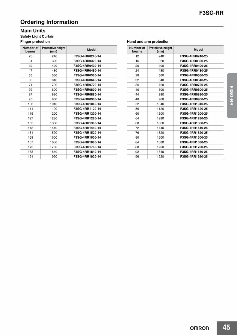
F3SG-RR
45
F3S
G-R
R
Ordering InformationMain UnitsSafety Light CurtainFinger protection Hand and arm protection
Number of beams
Protective height(mm) Model
23 240 F3SG-4RR0240-1431 320 F3SG-4RR0320-1439 400 F3SG-4RR0400-1447 480 F3SG-4RR0480-1455 560 F3SG-4RR0560-1463 640 F3SG-4RR0640-1471 720 F3SG-4RR0720-1479 800 F3SG-4RR0800-1487 880 F3SG-4RR0880-1495 960 F3SG-4RR0960-14
103 1040 F3SG-4RR1040-14111 1120 F3SG-4RR1120-14119 1200 F3SG-4RR1200-14127 1280 F3SG-4RR1280-14135 1360 F3SG-4RR1360-14143 1440 F3SG-4RR1440-14151 1520 F3SG-4RR1520-14159 1600 F3SG-4RR1600-14167 1680 F3SG-4RR1680-14175 1760 F3SG-4RR1760-14183 1840 F3SG-4RR1840-14191 1920 F3SG-4RR1920-14
Number of beams
Protective height(mm) Model
12 240 F3SG-4RR0240-2516 320 F3SG-4RR0320-2520 400 F3SG-4RR0400-2524 480 F3SG-4RR0480-2528 560 F3SG-4RR0560-2532 640 F3SG-4RR0640-2536 720 F3SG-4RR0720-2540 800 F3SG-4RR0800-2544 880 F3SG-4RR0880-2548 960 F3SG-4RR0960-2552 1040 F3SG-4RR1040-2556 1120 F3SG-4RR1120-2560 1200 F3SG-4RR1200-2564 1280 F3SG-4RR1280-2568 1360 F3SG-4RR1360-2572 1440 F3SG-4RR1440-2576 1520 F3SG-4RR1520-2580 1600 F3SG-4RR1600-2584 1680 F3SG-4RR1680-2588 1760 F3SG-4RR1760-2592 1840 F3SG-4RR1840-2596 1920 F3SG-4RR1920-25
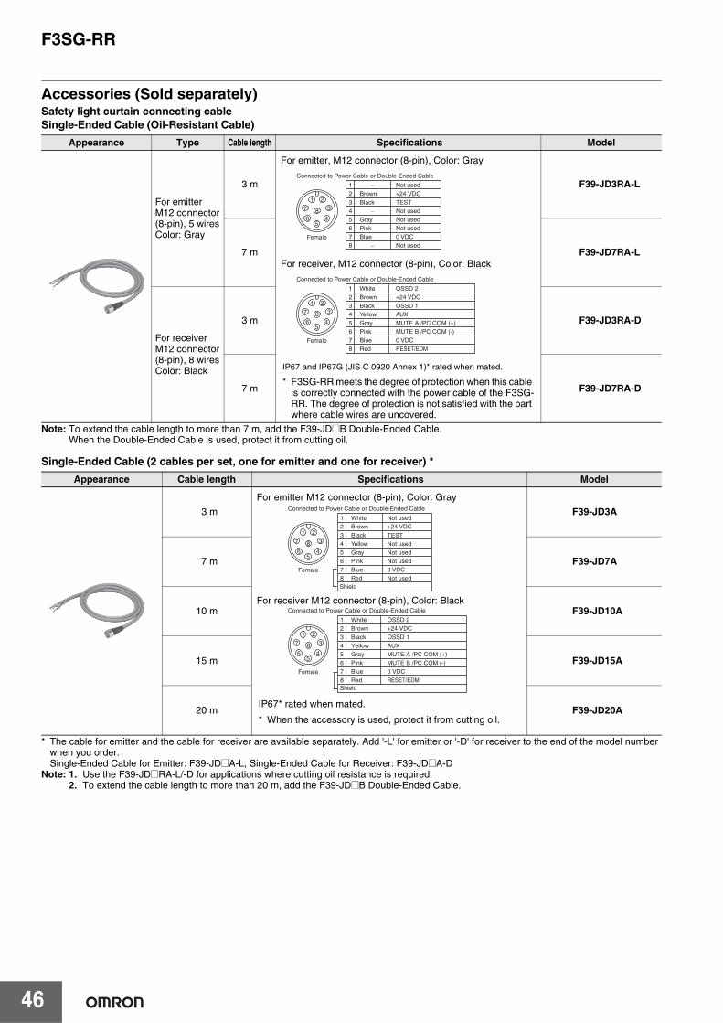
F3SG-RR
46
Accessories (Sold separately)Safety light curtain connecting cableSingle-Ended Cable (Oil-Resistant Cable)
Note: To extend the cable length to more than 7 m, add the F39-JD@B Double-Ended Cable.When the Double-Ended Cable is used, protect it from cutting oil.
Single-Ended Cable (2 cables per set, one for emitter and one for receiver) *
* The cable for emitter and the cable for receiver are available separately. Add '-L' for emitter or '-D' for receiver to the end of the model number when you order.Single-Ended Cable for Emitter: F39-JD@A-L, Single-Ended Cable for Receiver: F39-JD@A-D
Note: 1. Use the F39-JD@RA-L/-D for applications where cutting oil resistance is required.2. To extend the cable length to more than 20 m, add the F39-JD@B Double-Ended Cable.
Appearance Type Cable length Specifications Model
For emitterM12 connector(8-pin), 5 wiresColor: Gray
3 m F39-JD3RA-L
7 m F39-JD7RA-L
For receiverM12 connector(8-pin), 8 wiresColor: Black
3 m F39-JD3RA-D
7 m F39-JD7RA-D
Appearance Cable length Specifications Model
3 m F39-JD3A
7 m F39-JD7A
10 m F39-JD10A
15 m F39-JD15A
20 m F39-JD20A
5
84
3
21
7
6
Female
2
7
56
1+24 VDC
0 VDC
Not usedNot used
Not used
Connected to Power Cable or Double-Ended Cable
Brown
Blue
GrayPink
−
8 Not used−
3 TESTBlack4 Not used−
5
84
3
21
7
6
Female
2
7
56
1+24 VDC
0 VDC
MUTE A /PC COM (+)MUTE B /PC COM (-)
OSSD 2
Connected to Power Cable or Double-Ended Cable
Brown
Blue
GrayPink
White
8 RESET/EDMRed
3 OSSD 1Black4 AUXYellow
For emitter, M12 connector (8-pin), Color: Gray
For receiver, M12 connector (8-pin), Color: Black
IP67 and IP67G (JIS C 0920 Annex 1)* rated when mated.
* F3SG-RR meets the degree of protection when this cable is correctly connected with the power cable of the F3SG-RR. The degree of protection is not satisfied with the part where cable wires are uncovered.
5
84
3
21
7
6
Female
2
7
56
1+24 VDC
0 VDC
Not usedNot used
Not used
Connected to Power Cable or Double-Ended Cable
Brown
Blue
GrayPink
White
8 Not usedRed
3 TESTBlack4 Not usedYellow
Shield
5
84
3
21
7
6
Female
2
7
56
1+24 VDC
0 VDC
MUTE A /PC COM (+)MUTE B /PC COM (-)
OSSD 2
Connected to Power Cable or Double-Ended Cable
Brown
Blue
GrayPink
White
8 RESET/EDMRed
3 OSSD 1Black4 AUXYellow
Shield
For emitter M12 connector (8-pin), Color: Gray
For receiver M12 connector (8-pin), Color: Black
IP67* rated when mated.
* When the accessory is used, protect it from cutting oil.
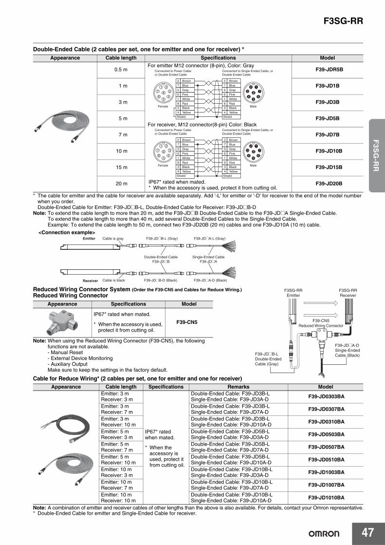
F3SG-RR
47
F3S
G-R
R
Double-Ended Cable (2 cables per set, one for emitter and one for receiver) *
* The cable for emitter and the cable for receiver are available separately. Add '-L' for emitter or '-D' for receiver to the end of the model number when you order.Double-Ended Cable for Emitter: F39-JD@B-L, Double-Ended Cable for Receiver: F39-JD@B-D
Note: To extend the cable length to more than 20 m, add the F39-JD@B Double-Ended Cable to the F39-JD@A Single-Ended Cable.To extend the cable length to more than 40 m, add several Double-Ended Cables to the Single-Ended Cable.Example: To extend the cable length to 50 m, connect two F39-JD20B (20 m) cables and one F39-JD10A (10 m) cable.
Reduced Wiring Connector System (Order the F39-CN5 and Cables for Reduce Wiring.) Reduced Wiring Connector
Note: When using the Reduced Wiring Connector (F39-CN5), the following functions are not available.- Manual Reset- External Device Monitoring- Auxiliary OutputMake sure to keep the settings in the factory default.
Cable for Reduce Wiring* (2 cables per set, one for emitter and one for receiver)
Note: A combination of emitter and receiver cables of other lengths than the above is also available. For details, contact your Omron representative.* Double-Ended Cable for emitter and Single-Ended Cable for receiver.
Appearance Cable length Specifications Model
0.5 m F39-JDR5B
1 m F39-JD1B
3 m F39-JD3B
5 m F39-JD5B
7 m F39-JD7B
10 m F39-JD10B
15 m F39-JD15B
20 m F39-JD20B
Appearance Specifications Model
IP67* rated when mated.
* When the accessory is used, protect it from cutting oil.
F39-CN5
Appearance Cable length Specifications Remarks ModelEmitter: 3 mReceiver: 3 m
IP67* rated when mated.
* When the accessory is used, protect it from cutting oil.
Double-Ended Cable: F39-JD3B-LSingle-Ended Cable: F39-JD3A-D F39-JD0303BA
Emitter: 3 mReceiver: 7 m
Double-Ended Cable: F39-JD3B-LSingle-Ended Cable: F39-JD7A-D F39-JD0307BA
Emitter: 3 mReceiver: 10 m
Double-Ended Cable: F39-JD3B-LSingle-Ended Cable: F39-JD10A-D F39-JD0310BA
Emitter: 5 mReceiver: 3 m
Double-Ended Cable: F39-JD5B-LSingle-Ended Cable: F39-JD3A-D F39-JD0503BA
Emitter: 5 mReceiver: 7 m
Double-Ended Cable: F39-JD5B-LSingle-Ended Cable: F39-JD7A-D F39-JD0507BA
Emitter: 5 mReceiver: 10 m
Double-Ended Cable: F39-JD5B-LSingle-Ended Cable: F39-JD10A-D F39-JD0510BA
Emitter: 10 mReceiver: 3 m
Double-Ended Cable: F39-JD10B-LSingle-Ended Cable: F39-JD3A-D F39-JD1003BA
Emitter: 10 mReceiver: 7 m
Double-Ended Cable: F39-JD10B-LSingle-Ended Cable: F39-JD7A-D F39-JD1007BA
Emitter: 10 mReceiver: 10 m
Double-Ended Cable: F39-JD10B-LSingle-Ended Cable: F39-JD10A-D F39-JD1010BA
Brown
Blue
Gray
Pink
White
RedBlack
Yellow
Blue
Gray
Pink
White
RedBlack
Yellow
2
7
5
6
1
83
4
Brown
5
84
3
21
7
65
86
7
12
3
4
2
7
5
6
1
83
4
Female Male
Connected to Power Cable or Double-Ended Cable
Connected to Single-Ended Cable, or Double-Ended Cable
Shield Shield
Connected to Power Cable or Double-Ended Cable
Connected to Single-Ended Cable, or Double-Ended Cable
Brown
Blue
Gray
Pink
White
RedBlack
Yellow
Blue
Gray
Pink
White
RedBlack
Yellow
27561834
Brown
5
84
321
7
65
86
712
3
4
27561834
Female Male
Shield Shield
For emitter M12 connector (8-pin), Color: Gray
For receiver, M12 connector(8-pin) Color: Black
IP67* rated when mated.* When the accessory is used, protect it from cutting oil.
Emitter
Receiver
Cable is gray F39-JD@B-L (Gray) F39-JD@A-L (Gray)
Double-Ended CableF39-JD@B
Single-Ended CableF39-JD@A
Cable is black F39-JD@B-D (Black) F39-JD@A-D (Black)
<Connection example>
F3SG-RREmitter
F3SG-RRReceiver
F39-CN5Reduced Wiring Connector
F39-JD@A-DSingle-Ended Cable (Black)F39-JD@B-L
Double-Ended Cable (Gray)
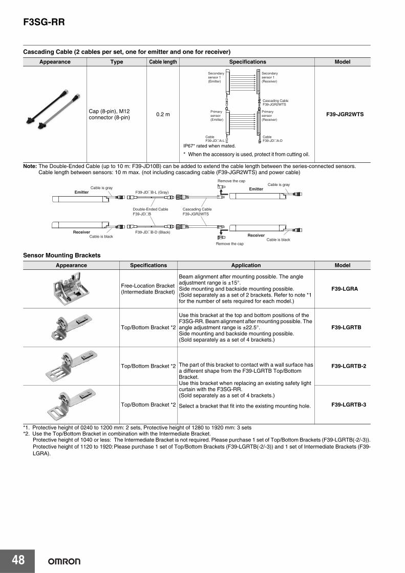
F3SG-RR
48
Cascading Cable (2 cables per set, one for emitter and one for receiver)
Note: The Double-Ended Cable (up to 10 m: F39-JD10B) can be added to extend the cable length between the series-connected sensors.Cable length between sensors: 10 m max. (not including cascading cable (F39-JGR2WTS) and power cable)
Sensor Mounting Brackets
*1. Protective height of 0240 to 1200 mm: 2 sets, Protective height of 1280 to 1920 mm: 3 sets*2. Use the Top/Bottom Bracket in combination with the Intermediate Bracket.
Protective height of 1040 or less: The Intermediate Bracket is not required. Please purchase 1 set of Top/Bottom Brackets (F39-LGRTB(-2/-3)).Protective height of 1120 to 1920:Please purchase 1 set of Top/Bottom Brackets (F39-LGRTB(-2/-3)) and 1 set of Intermediate Brackets (F39-LGRA).
Appearance Type Cable length Specifications Model
Cap (8-pin), M12connector (8-pin) 0.2 m F39-JGR2WTS
Appearance Specifications Application Model
Free-Location Bracket(Intermediate Bracket)
Beam alignment after mounting possible. The angle adjustment range is ±15°. Side mounting and backside mounting possible.(Sold separately as a set of 2 brackets. Refer to note *1 for the number of sets required for each model.)
F39-LGRA
Top/Bottom Bracket *2
Use this bracket at the top and bottom positions of the F3SG-RR. Beam alignment after mounting possible. The angle adjustment range is ±22.5°. Side mounting and backside mounting possible.(Sold separately as a set of 4 brackets.)
F39-LGRTB
Top/Bottom Bracket *2 The part of this bracket to contact with a wall surface hasa different shape from the F39-LGRTB Top/BottomBracket.Use this bracket when replacing an existing safety lightcurtain with the F3SG-RR.(Sold separately as a set of 4 brackets.)
Select a bracket that fit into the existing mounting hole.
F39-LGRTB-2
Top/Bottom Bracket *2 F39-LGRTB-3
IP67* rated when mated.
* When the accessory is used, protect it from cutting oil.
Secondary sensor 1 (Emitter)
Secondary sensor 1 (Receiver)
Primary sensor (Emitter)
Primary sensor (Receiver)
Cascading CableF39-JGR2WTS
CableF39-JD@A-D
CableF39-JD@A-L
Cable is blackF39-JD@B-D (Black)
Cable is blackRemove the cap
Double-Ended CableF39-JD@B
Cascading CableF39-JGR2WTS
Cable is grayF39-JD@B-L (Gray)
Cable is grayRemove the cap
Emitter
Receiver
Emitter
Receiver
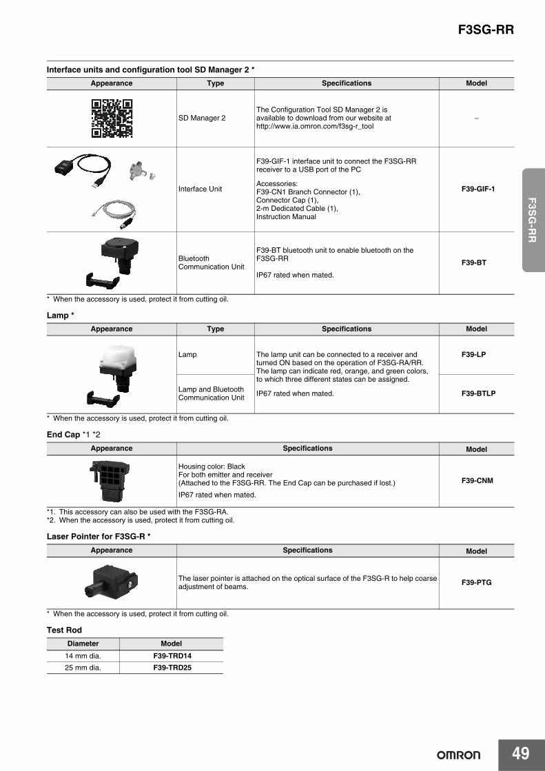
F3SG-RR
49
F3S
G-R
R
Interface units and configuration tool SD Manager 2 *
* When the accessory is used, protect it from cutting oil.
Lamp *
* When the accessory is used, protect it from cutting oil.
End Cap *1 *2
*1. This accessory can also be used with the F3SG-RA.*2. When the accessory is used, protect it from cutting oil.
Laser Pointer for F3SG-R *
* When the accessory is used, protect it from cutting oil.
Test Rod
Appearance Type Specifications Model
SD Manager 2The Configuration Tool SD Manager 2 isavailable to download from our website athttp://www.ia.omron.com/f3sg-r_tool
−
Interface Unit
F39-GIF-1 interface unit to connect the F3SG-RR receiver to a USB port of the PC
Accessories:F39-CN1 Branch Connector (1),Connector Cap (1),2-m Dedicated Cable (1),Instruction Manual
F39-GIF-1
BluetoothCommunication Unit
F39-BT bluetooth unit to enable bluetooth on theF3SG-RR
IP67 rated when mated.
F39-BT
Appearance Type Specifications Model
Lamp The lamp unit can be connected to a receiver andturned ON based on the operation of F3SG-RA/RR.The lamp can indicate red, orange, and green colors,to which three different states can be assigned.
IP67 rated when mated.
F39-LP
Lamp and BluetoothCommunication Unit F39-BTLP
Appearance Specifications Model
Housing color: BlackFor both emitter and receiver(Attached to the F3SG-RR. The End Cap can be purchased if lost.)
IP67 rated when mated.
F39-CNM
Appearance Specifications Model
The laser pointer is attached on the optical surface of the F3SG-R to help coarseadjustment of beams. F39-PTG
Diameter Model
14 mm dia. F39-TRD1425 mm dia. F39-TRD25
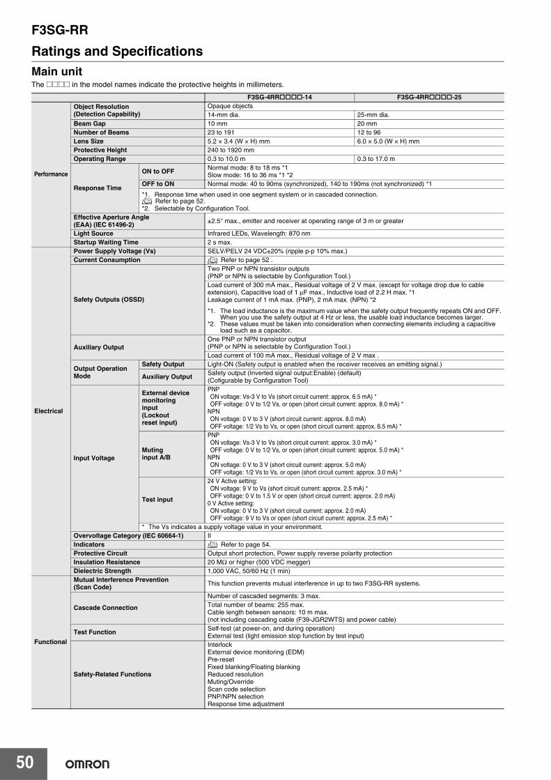
F3SG-RR
50
Ratings and SpecificationsMain unitThe @@@@ in the model names indicate the protective heights in millimeters.
F3SG-4RR-14 F3SG-4RR-25
Performance
Object Resolution(Detection Capability)
Opaque objects14-mm dia. 25-mm dia.
Beam Gap 10 mm 20 mmNumber of Beams 23 to 191 12 to 96Lens Size 5.2 × 3.4 (W × H) mm 6.0 × 5.0 (W × H) mm Protective Height 240 to 1920 mmOperating Range 0.3 to 10.0 m 0.3 to 17.0 m
Response Time
ON to OFF Normal mode: 8 to 18 ms *1Slow mode: 16 to 36 ms *1 *2
OFF to ON Normal mode: 40 to 90ms (synchronized), 140 to 190ms (not synchronized) *1
*1. Response time when used in one segment system or in cascaded connection. Refer to page 52.
*2. Selectable by Configuration Tool.Effective Aperture Angle (EAA) (IEC 61496-2) ±2.5° max., emitter and receiver at operating range of 3 m or greater
Light Source Infrared LEDs, Wavelength: 870 nmStartup Waiting Time 2 s max.
Electrical
Power Supply Voltage (Vs) SELV/PELV 24 VDC±20% (ripple p-p 10% max.)Current Consumption Refer to page 52 .
Safety Outputs (OSSD)
Two PNP or NPN transistor outputs (PNP or NPN is selectable by Configuration Tool.)Load current of 300 mA max., Residual voltage of 2 V max. (except for voltage drop due to cableextension), Capacitive load of 1 μF max., Inductive load of 2.2 H max. *1Leakage current of 1 mA max. (PNP), 2 mA max. (NPN) *2
*1. The load inductance is the maximum value when the safety output frequently repeats ON and OFF.When you use the safety output at 4 Hz or less, the usable load inductance becomes larger.
*2. These values must be taken into consideration when connecting elements including a capacitiveload such as a capacitor.
Auxiliary OutputOne PNP or NPN transistor output (PNP or NPN is selectable by Configuration Tool.)Load current of 100 mA max., Residual voltage of 2 V max .
Output Operation Mode
Safety Output Light-ON (Safety output is enabled when the receiver receives an emitting signal.)
Auxiliary Output Safety output (Inverted signal output:Enable) (default) (Cofigurable by Configuration Tool)
Input Voltage
External devicemonitoringinput(Lockoutreset input)
PNPON voltage: Vs-3 V to Vs (short circuit current: approx. 6.5 mA) *OFF voltage: 0 V to 1/2 Vs, or open (short circuit current: approx. 8.0 mA) *
NPNON voltage: 0 V to 3 V (short circuit current: approx. 8.0 mA)OFF voltage: 1/2 Vs to Vs, or open (short circuit current: approx. 6.5 mA) *
Mutinginput A/B
PNPON voltage: Vs-3 V to Vs (short circuit current: approx. 3.0 mA) *OFF voltage: 0 V to 1/2 Vs, or open (short circuit current: approx. 5.0 mA) *
NPNON voltage: 0 V to 3 V (short circuit current: approx. 5.0 mA)OFF voltage: 1/2 Vs to Vs, or open (short circuit current: approx. 3.0 mA) *
Test input
24 V Active setting:ON voltage: 9 V to Vs (short circuit current: approx. 2.5 mA) *OFF voltage: 0 V to 1.5 V or open (short circuit current: approx. 2.0 mA)
0 V Active setting:ON voltage: 0 V to 3 V (short circuit current: approx. 2.0 mA)OFF voltage: 9 V to Vs or open (short circuit current: approx. 2.5 mA) *
* The Vs indicates a supply voltage value in your environment.Overvoltage Category (IEC 60664-1) IIIndicators Refer to page 54.Protective Circuit Output short protection, Power supply reverse polarity protectionInsulation Resistance 20 MΩ or higher (500 VDC megger)Dielectric Strength 1,000 VAC, 50/60 Hz (1 min)
Functional
Mutual Interference Prevention (Scan Code) This function prevents mutual interference in up to two F3SG-RR systems.
Cascade Connection
Number of cascaded segments: 3 max.Total number of beams: 255 max.Cable length between sensors: 10 m max. (not including cascading cable (F39-JGR2WTS) and power cable)
Test Function Self-test (at power-on, and during operation)External test (light emission stop function by test input)
Safety-Related Functions
InterlockExternal device monitoring (EDM)Pre-resetFixed blanking/Floating blankingReduced resolutionMuting/OverrideScan code selectionPNP/NPN selectionResponse time adjustment
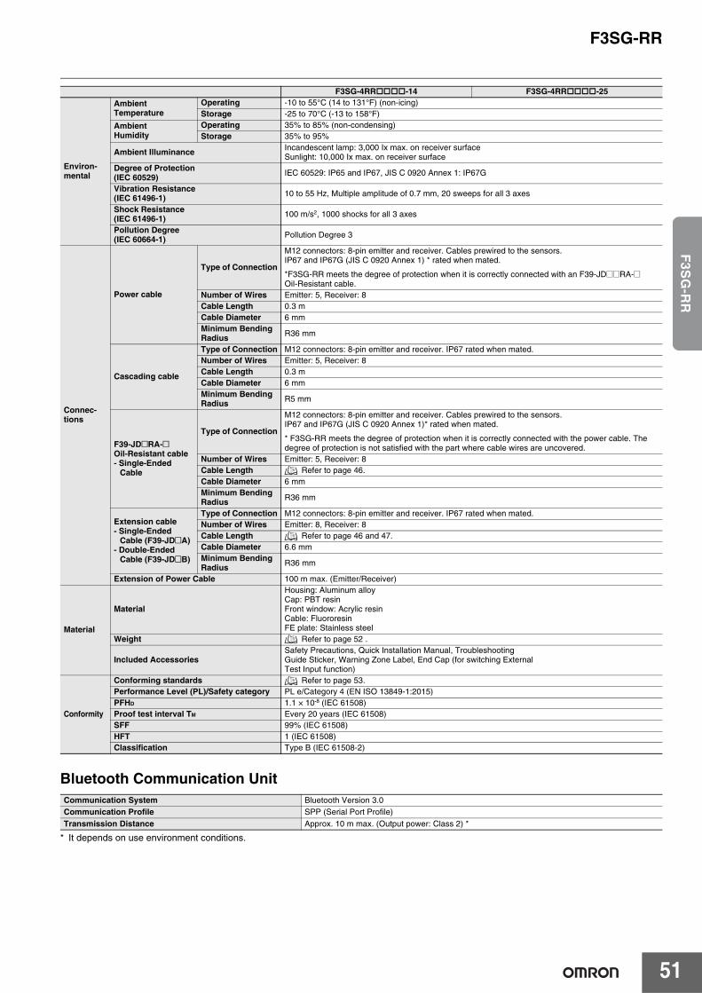
F3SG-RR
51
F3S
G-R
R
Bluetooth Communication Unit
* It depends on use environment conditions.
Environ-mental
AmbientTemperature
Operating -10 to 55°C (14 to 131°F) (non-icing)Storage -25 to 70°C (-13 to 158°F)
AmbientHumidity
Operating 35% to 85% (non-condensing)Storage 35% to 95%
Ambient Illuminance Incandescent lamp: 3,000 Ix max. on receiver surfaceSunlight: 10,000 Ix max. on receiver surface
Degree of Protection(IEC 60529) IEC 60529: IP65 and IP67, JIS C 0920 Annex 1: IP67G
Vibration Resistance(IEC 61496-1) 10 to 55 Hz, Multiple amplitude of 0.7 mm, 20 sweeps for all 3 axes
Shock Resistance(IEC 61496-1) 100 m/s2, 1000 shocks for all 3 axes
Pollution Degree(IEC 60664-1) Pollution Degree 3
Connec-tions
Power cable
Type of Connection
M12 connectors: 8-pin emitter and receiver. Cables prewired to the sensors.IP67 and IP67G (JIS C 0920 Annex 1) * rated when mated.
*F3SG-RR meets the degree of protection when it is correctly connected with an F39-JD@@RA-@ Oil-Resistant cable.
Number of Wires Emitter: 5, Receiver: 8Cable Length 0.3 mCable Diameter 6 mmMinimum Bending Radius R36 mm
Cascading cable
Type of Connection M12 connectors: 8-pin emitter and receiver. IP67 rated when mated.Number of Wires Emitter: 5, Receiver: 8Cable Length 0.3 mCable Diameter 6 mmMinimum Bending Radius R5 mm
F39-JD@RA-@Oil-Resistant cable- Single-Ended
Cable
Type of Connection
M12 connectors: 8-pin emitter and receiver. Cables prewired to the sensors.IP67 and IP67G (JIS C 0920 Annex 1)* rated when mated.
* F3SG-RR meets the degree of protection when it is correctly connected with the power cable. Thedegree of protection is not satisfied with the part where cable wires are uncovered.
Number of Wires Emitter: 5, Receiver: 8Cable Length Refer to page 46.Cable Diameter 6 mmMinimum Bending Radius R36 mm
Extension cable- Single-Ended
Cable (F39-JD@A)- Double-Ended
Cable (F39-JD@B)
Type of Connection M12 connectors: 8-pin emitter and receiver. IP67 rated when mated.Number of Wires Emitter: 8, Receiver: 8Cable Length Refer to page 46 and 47.Cable Diameter 6.6 mmMinimum BendingRadius R36 mm
Extension of Power Cable 100 m max. (Emitter/Receiver)
Material
Material
Housing: Aluminum alloyCap: PBT resinFront window: Acrylic resinCable: FluororesinFE plate: Stainless steel
Weight Refer to page 52 .
Included AccessoriesSafety Precautions, Quick Installation Manual, TroubleshootingGuide Sticker, Warning Zone Label, End Cap (for switching ExternalTest Input function)
Conformity
Conforming standards Refer to page 53.Performance Level (PL)/Safety category PL e/Category 4 (EN ISO 13849-1:2015)PFHD 1.1 × 10⁻⁸ (IEC 61508) Proof test interval TM Every 20 years (IEC 61508)SFF 99% (IEC 61508)HFT 1 (IEC 61508)Classification Type B (IEC 61508-2)
Communication System Bluetooth Version 3.0Communication Profile SPP (Serial Port Profile)Transmission Distance Approx. 10 m max. (Output power: Class 2) *
F3SG-4RR-14 F3SG-4RR-25

F3SG-RR
52
List of Models/Response Time/Current Consumption/WeightF3SG-4RR@@@@-14
*1. The maximum speed of movement of a test rod up to which the detection capability is maintained is 2.0 m/s.*2. The response times are values when Scan Code is set at Code B. The response times for Code A are 1 ms shorter than these values.*3. The net weight is the weight of an emitter and a receiver.*4. The gross weight is the weight of an emitter, a receiver, included accessories and a package.
F3SG-4RR@@@@-25
*1. The maximum speed of movement of a test rod up to which the detection capability is maintained is 2.0 m/s.*2. The response times are values when Scan Code is set at Code B. The response times for Code A are 1 ms shorter than these values.*3. The net weight is the weight of an emitter and a receiver.*4. The gross weight is the weight of an emitter, a receiver, included accessories and a package.
Model Numberof Beams
ProtectiveHeight[mm]
(Overalllength)
Response Time [ms] *1 Current Consumption [mA] Weight [kg]
ON → OFF *2OFF
(Synchronized)→ ON
OFF (Not synchronized)
→ ONEmitter Receiver Net *3 Gross
*4
F3SG-4RR0240-14 23 240 8 40 140 45 75 0.7 1.5
F3SG-4RR0320-14 31 320 8 40 140 55 75 0.9 1.7
F3SG-4RR0400-14 39 400 8 40 140 60 80 1.1 2.0
F3SG-4RR0480-14 47 480 13 65 165 50 80 1.3 2.3
F3SG-4RR0560-14 55 560 13 65 165 55 80 1.5 2.5
F3SG-4RR0640-14 63 640 13 65 165 60 85 1.7 2.8
F3SG-4RR0720-14 71 720 13 65 165 65 85 1.9 3.1
F3SG-4RR0800-14 79 800 13 65 165 65 90 2.1 3.4
F3SG-4RR0880-14 87 880 13 65 165 70 90 2.4 3.6
F3SG-4RR0960-14 95 960 13 65 165 75 90 2.6 3.9
F3SG-4RR1040-14 103 1040 13 65 165 80 95 2.8 4.2
F3SG-4RR1120-14 111 1120 13 65 165 85 95 3.0 4.4
F3SG-4RR1200-14 119 1200 13 65 165 90 100 3.2 4.7
F3SG-4RR1280-14 127 1280 13 65 165 95 100 3.4 5.0
F3SG-4RR1360-14 135 1360 13 65 165 95 105 3.6 5.3
F3SG-4RR1440-14 143 1440 18 90 190 85 105 3.8 5.5
F3SG-4RR1520-14 151 1520 18 90 190 90 105 4.0 5.8
F3SG-4RR1600-14 159 1600 18 90 190 90 110 4.2 6.1
F3SG-4RR1680-14 167 1680 18 90 190 95 110 4.4 6.3
F3SG-4RR1760-14 175 1760 18 90 190 100 115 4.6 6.6
F3SG-4RR1840-14 183 1840 18 90 190 100 115 4.8 6.9
F3SG-4RR1920-14 191 1920 18 90 190 105 120 5.0 7.2
Model Numberof Beams
ProtectiveHeight[mm]
(Overalllength)
Response Time [ms] *1 Current Consumption [mA] Weight [kg]
ON → OFF *2OFF
(Synchronized)→ ON
OFF (Not synchronized)
→ ONEmitter Receiver Net *3 Gross
*4
F3SG-4RR0240-25 12 240 8 40 140 35 75 0.7 1.6
F3SG-4RR0320-25 16 320 8 40 140 40 75 0.9 1.9
F3SG-4RR0400-25 20 400 8 40 140 45 75 1.1 2.1
F3SG-4RR0480-25 24 480 8 40 140 50 75 1.3 2.4
F3SG-4RR0560-25 28 560 8 40 140 50 75 1.5 2.7
F3SG-4RR0640-25 32 640 8 40 140 55 75 1.7 3.0
F3SG-4RR0720-25 36 720 8 40 140 60 80 1.9 3.2
F3SG-4RR0800-25 40 800 8 40 140 65 80 2.1 3.5
F3SG-4RR0880-25 44 880 13 65 165 50 80 2.3 3.8
F3SG-4RR0960-25 48 960 13 65 165 50 80 2.5 4.0
F3SG-4RR1040-25 52 1040 13 65 165 55 80 2.7 4.3
F3SG-4RR1120-25 56 1120 13 65 165 55 85 2.9 4.6
F3SG-4RR1200-25 60 1200 13 65 165 55 85 3.1 4.9
F3SG-4RR1280-25 64 1280 13 65 165 60 85 3.3 5.1
F3SG-4RR1360-25 68 1360 13 65 165 60 85 3.5 5.4
F3SG-4RR1440-25 72 1440 13 65 165 65 85 3.7 5.7
F3SG-4RR1520-25 76 1520 13 65 165 65 90 3.9 5.9
F3SG-4RR1600-25 80 1600 13 65 165 70 90 4.1 6.2
F3SG-4RR1680-25 84 1680 13 65 165 70 90 4.3 6.5
F3SG-4RR1760-25 88 1760 13 65 165 70 90 4.5 6.7
F3SG-4RR1840-25 92 1840 13 65 165 75 90 4.7 7.0
F3SG-4RR1920-25 96 1920 13 65 165 75 95 4.9 7.3
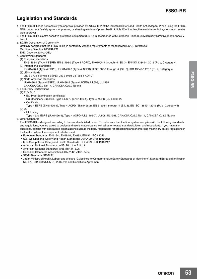
F3SG-RR
53
F3S
G-R
R
Legislation and Standards1. The F3SG-RR does not receive type approval provided by Article 44-2 of the Industrial Safety and Health Act of Japan. When using the F3SG-
RR in Japan as a "safety system for pressing or shearing machines" prescribed in Article 42 of that law, the machine control system must receive type approval.
2. The F3SG-RR is electro-sensitive protective equipment (ESPE) in accordance with European Union (EU) Machinery Directive Index Annex V, Item 2.
3. EC/EU Declaration of ConformityOMRON declares that the F3SG-RR is in conformity with the requirements of the following EC/EU Directives: Machinery Directive 2006/42/ECEMC Directive 2014/30/EU
4. Conforming Standards(1) European standards
EN61496-1 (Type 4 ESPE), EN 61496-2 (Type 4 AOPD), EN61508-1 through -4 (SIL 3), EN ISO 13849-1:2015 (PL e, Category 4)(2) International standards
IEC61496-1 (Type 4 ESPE), IEC61496-2 (Type 4 AOPD), IEC61508-1 through -4 (SIL 3), ISO 13849-1:2015 (PL e, Category 4)(3) JIS standards
JIS B 9704-1 (Type 4 ESPE), JIS B 9704-2 (Type 4 AOPD)(4) North American standards
UL61496-1 (Type 4 ESPE), UL61496-2 (Type 4 AOPD), UL508, UL1998,CAN/CSA C22.2 No.14, CAN/CSA C22.2 No.0.8
5. Third-Party Certifications(1) TÜV SÜD
• EC Type-Examination certificate:EU Machinery Directive, Type 4 ESPE (EN61496-1), Type 4 AOPD (EN 61496-2)
• Certificate:Type 4 ESPE (EN61496-1), Type 4 AOPD (EN61496-2), EN 61508-1 through -4 (SIL 3), EN ISO 13849-1:2015 (PL e, Category 4)
(2) UL• UL Listing:
Type 4 and ESPE (UL61496-1), Type 4 AOPD (UL61496-2), UL508, UL1998, CAN/CSA C22.2 No.14, CAN/CSA C22.2 No.0.86. Other Standards
The F3SG-RR is designed according to the standards listed below. To make sure that the final system complies with the following standards and regulations, you are asked to design and use it in accordance with all other related standards, laws, and regulations. If you have any questions, consult with specialized organizations such as the body responsible for prescribing and/or enforcing machinery safety regulations in the location where the equipment is to be used.• European Standards: EN415-4, EN691-1, EN692, EN693, IEC 62046• U.S. Occupational Safety and Health Standards: OSHA 29 CFR 1910.212• U.S. Occupational Safety and Health Standards: OSHA 29 CFR 1910.217• American National Standards: ANSI B11.1 to B11.19• American National Standards: ANSI/RIA R15.06• Canadian Standards Association CSA Z142, Z432, Z434• SEMI Standards SEMI S2• Japan Ministry of Health, Labour and Welfare "Guidelines for Comprehensive Safety Standards of Machinery", Standard Bureau's Notification
No. 0731001 dated July 31, 2007.rms and Conditions Agreement
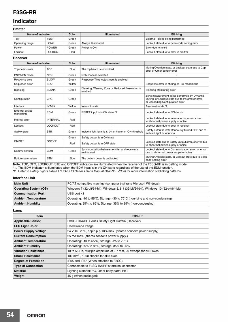
F3SG-RR
54
IndicatorEmitter
Receiver
Note: TOP, CFG, LOCKOUT, STB and ON/OFF indicators are illuminated when the receiver of the F3SG-RR is in Setting mode.*1. The EDM indicator is illuminated when the EDM input is in the ON state regardless of the use of the EDM function.*2. Refer to Safety Light Curtain F3SG-@RR Series User's Manual (ManNo.: Z383) for more information of blinking patterns.
Interface Unit
Lamp
Name of Indicator Color Illuminated BlinkingTest TEST Green − External Test is being performed
Operating range LONG Green Always illuminated Lockout state due to Scan code setting error
Power POWER Green Power is ON. Error due to noise
Lockout LOCKOUT Red − Lockout state due to error in emitter
Name of Indicator Color Illuminated Blinking
Top-beam-state TOP Blue The top beam is unblockedMuting/Override state, or Lockout state due to Cap error or Other sensor error
PNP/NPN mode NPN Green NPN mode is selected −
Response time SLOW Green Response Time Adjustment is enabled −
Sequence error SEQ Yellow − Sequence error in Muting or Pre-reset mode
Blanking BLANK GreenBlanking, Warning Zone or Reduced Resolution is enabled Blanking Monitoring error
Configuration CFG Green −Zone measurement being performed by Dynamic Muting, or Lockout state due to Parameter erroror Cascading Configuration error
Interlock INT-LK Yellow Interlock state Pre-reset mode *2
External device monitoring EDM Green RESET input is in ON state *1 Lockout state due to EDM error
Internal error INTERNAL Red − Lockout state due to Internal error, or error dueto abnormal power supply or noise
Lockout LOCKOUT Red − Lockout state due to error in receiver
Stable-state STB Green Incident light level is 170% or higher of ON-threshold Safety output is instantaneously turned OFF due to ambient light or vibration
ON/OFF ON/OFFGreen Safety output is in ON state −
Red Safety output is in OFF state Lockout state due to Safety Output error, or error due to abnormal power supply or noise
Communication COM Green Synchronization between emitter and receiver is maintained
Lockout state due to Communication error, or error due to abnormal power supply or noise
Bottom-beam-state BTM Blue The bottom beam is unblocked Muting/Override state, or Lockout state due to Scan code setting error
Main Unit PC/AT compatible machine (computer that runs Microsoft Windows)
Operating System (OS) Windows 7 (32-bit/64-bit), Windows 8, 8.1 (32-bit/64-bit), Windows 10 (32-bit/64-bit)
Communication Port USB port ×1
Ambient Temperature Operating: -10 to 55°C, Storage: -30 to 70°C (non-icing and non-condensing)
Ambient Humidity Operating: 35% to 85%, Storage: 35% to 95% (non-condensing)
Item F39-LPApplicable Sensor F3SG-@RA/RR Series Safety Light Curtain (Receiver)
LED Light Color Red/Green/Orange
Power Supply Voltage 24 VDC±20%, ripple p-p 10% max. (shares sensor’s power supply)
Current Consumption 25 mA max. (shares sensor’s power supply.)
Ambient Temperature Operating: -10 to 55°C, Storage: -25 to 70°C
Ambient Humidity Operating: 35% to 85%, Storage: 35% to 95%
Vibration Resistance 10 to 55 Hz, Multiple amplitude of 0.7 mm, 20 sweeps for all 3 axes
Shock Resistance 100 m/s2 , 1000 shocks for all 3 axes
Degree of Protection IP65 and IP67 (When attached to F3SG)
Type of Connection Connectable to F3SG-RA/RR’s terminal connector
Material Lighting element: PC, Other body parts: PBT
Weight 45 g (when packaged)
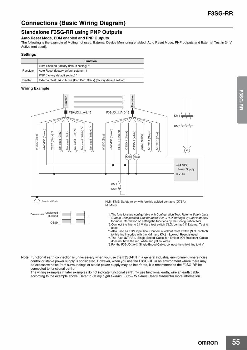
F3SG-RR
55
F3S
G-R
R
Connections (Basic Wiring Diagram)Standalone F3SG-RR using PNP OutputsAuto Reset Mode, EDM enabled and PNP OutputsThe following is the example of Muting not used, External Device Monitoring enabled, Auto Reset Mode, PNP outputs and External Test in 24 V Active (not used).
Settings
Wiring Example
Note: Functional earth connection is unnecessary when you use the F3SG-RR in a general industrial environment where noisecontrol or stable power supply is considered. However, when you use the F3SG-RR in an environment where there maybe excessive noise from surroundings or stable power supply may be interfered, it is recommended the F3SG-RR beconnected to functional earth.The wiring examples in later examples do not indicate functional earth. To use functional earth, wire an earth cable according to the example above. Refer to Safety Light Curtain F3SG-RR Series User's Manual for more information.
Function
Receiver
EDM Enabled (factory default setting) *1
Auto Reset (factory default setting) *1
PNP (factory default setting) *1
Emitter External Test: 24 V Active (End Cap: Black) (factory default setting)
UnblockedBlocked
Beam state
OSSD
KM1, KM2: Safety relay with forcibly guided contacts (G7SA) M: Motor
+24
VD
C (
Bro
wn)
Not
use
d (Y
ello
w)
*4
TE
ST
(B
lack
) *2
Not
use
d (W
hite
) *4
Not
use
d (R
ed)
*4
Not
use
d (P
ink)
Not
use
d (G
ray)
0 V
DC
(B
lue)
OS
SD
1 (
Bla
ck)
OS
SD
2 (
Whi
te)
+24
VD
C (
Bro
wn)
0 V
DC
(B
lue)
AU
X (
Yel
low
)
MU
TE
B (
Pin
k)
MU
TE
A (
Gra
y)
RE
SE
T (
Red
) *3
Functional Earth
F39-JD@@A-L *5 F39-JD@@A-D *5KM1
KM2
M
KM1 KM2
KM1
KM2
Power Supply+24 VDC
0 VDC
Rec
eive
r
Em
itter
*1.The functions are configurable with Configuration Tool. Refer to Safety LightCurtain Configuration Tool for Model F3SG (SD Manager 2) User’s Manualfor more information on setting the functions by the Configuration Tool.
*2.Connect the line to 24 V via a test switch (N.O. contact) if External Test isused.
*3.Also used as EDM input line. Connect a lockout reset switch (N.C. contact)to this line in series with the KM1 and KM2 if Lockout Reset is used.
*4.The F39-JD@RA-L Single-Ended Cable for Emitter (Oil-Resistant Cable)does not have the red, white and yellow wires.
*5.For the F39-JD@A-@ Single-Ended Cable, connect the shield line to 0 V.
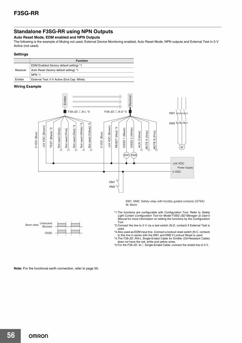
F3SG-RR
56
Standalone F3SG-RR using NPN OutputsAuto Reset Mode, EDM enabled and NPN OutputsThe following is the example of Muting not used, External Device Monitoring enabled, Auto Reset Mode, NPN outputs and External Test in 0 V Active (not used).
Settings
Wiring Example
Note: For the functional earth connection, refer to page 55.
Function
Receiver
EDM Enabled (factory default setting) *1
Auto Reset (factory default setting) *1
NPN *1
Emitter External Test: 0 V Active (End Cap: White)
UnblockedBlocked
Beam state
OSSD
KM1, KM2: Safety relay with forcibly guided contacts (G7SA) M: Motor
Not
use
d (P
ink)
Not
use
d (R
ed)
*4
Not
use
d (W
hite
) *4
Not
use
d (Y
ello
w)
*4
TE
ST
(B
lack
) *2
Not
use
d (G
ray)
+24
VD
C (
Bro
wn)
+24
VD
C (
Bro
wn)
RE
SE
T (
Red
) *3
OS
SD
1 (
Bla
ck)
OS
SD
2 (
Whi
te)
AU
X (
Yel
low
)
MU
TE
A (
Gra
y)
MU
TE
B (
Pin
k)
0 V
DC
(B
lue)
0 V
DC
(B
lue)
F39-JD@@A-L *5 F39-JD@@A-D *5 KM1
KM2
M
KM1 KM2
KM1
KM2
+24 VDCPower Supply
0 VDC
Em
itter
Rec
eive
r
*1.The functions are configurable with Configuration Tool. Refer to SafetyLight Curtain Configuration Tool for Model F3SG (SD Manager 2) User’sManual for more information on setting the functions by the ConfigurationTool.
*2.Connect the line to 0 V via a test switch (N.O. contact) if External Test isused.
*3.Also used as EDM input line. Connect a lockout reset switch (N.C. contact)to this line in series with the KM1 and KM2 if Lockout Reset is used.
*4.The F39-JD@RA-L Single-Ended Cable for Emitter (Oil-Resistant Cable)does not have the red, white and yellow wires.
*5.For the F39-JD@A-@ Single-Ended Cable, connect the shield line to 0 V.
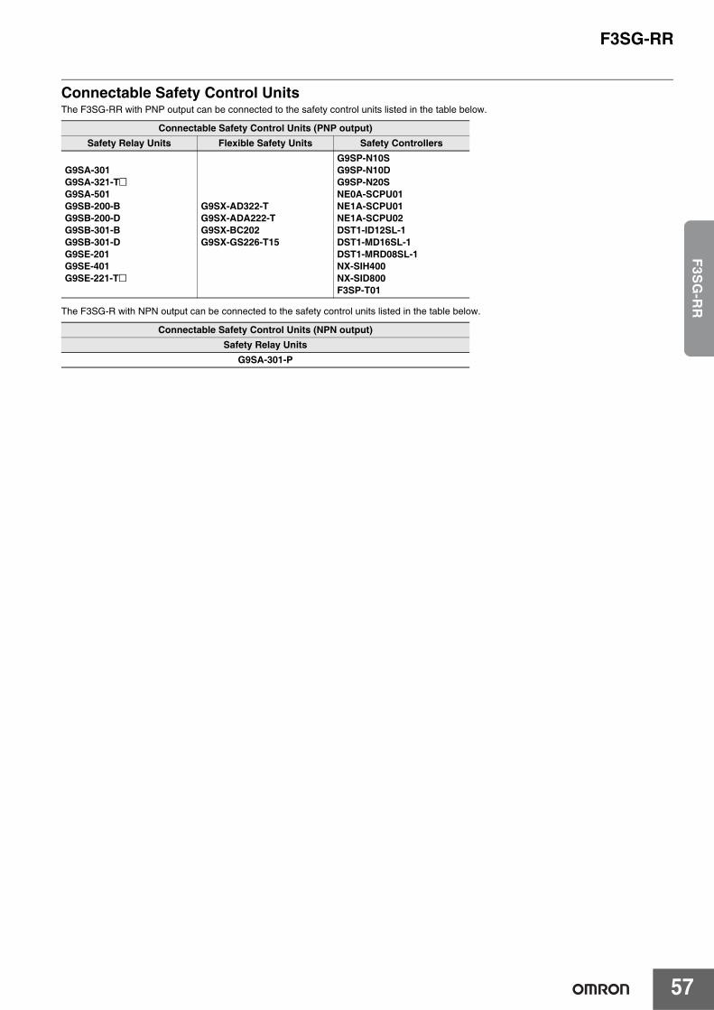
F3SG-RR
57
F3S
G-R
R
Connectable Safety Control UnitsThe F3SG-RR with PNP output can be connected to the safety control units listed in the table below.
The F3SG-R with NPN output can be connected to the safety control units listed in the table below.
Connectable Safety Control Units (PNP output)Safety Relay Units Flexible Safety Units Safety Controllers
G9SA-301G9SA-321-T@G9SA-501G9SB-200-BG9SB-200-DG9SB-301-BG9SB-301-DG9SE-201G9SE-401G9SE-221-T@
G9SX-AD322-TG9SX-ADA222-TG9SX-BC202G9SX-GS226-T15
G9SP-N10SG9SP-N10DG9SP-N20SNE0A-SCPU01NE1A-SCPU01NE1A-SCPU02DST1-ID12SL-1DST1-MD16SL-1DST1-MRD08SL-1NX-SIH400NX-SID800F3SP-T01
Connectable Safety Control Units (NPN output)Safety Relay Units
G9SA-301-P
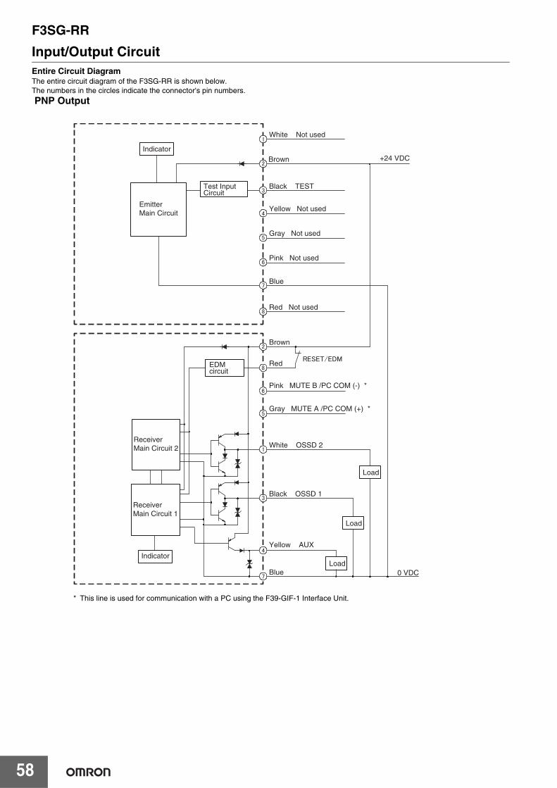
F3SG-RR
58
Input/Output CircuitEntire Circuit DiagramThe entire circuit diagram of the F3SG-RR is shown below.The numbers in the circles indicate the connector's pin numbers.
PNP Output
+24 VDCBrown
Black TEST
Yellow Not used
White Not used
Blue
Brown
Red
White OSSD 2
Pink MUTE B /PC COM (-) *
Gray MUTE A /PC COM (+) *
Black OSSD 1
Yellow AUX
Blue
EDMcircuit
0 VDC
Gray Not used
Pink Not used
Red Not used
Load
Indicator
EmitterMain Circuit
Test Input Circuit
ReceiverMain Circuit 2
ReceiverMain Circuit 1
IndicatorLoad
Load
* This line is used for communication with a PC using the F39-GIF-1 Interface Unit.
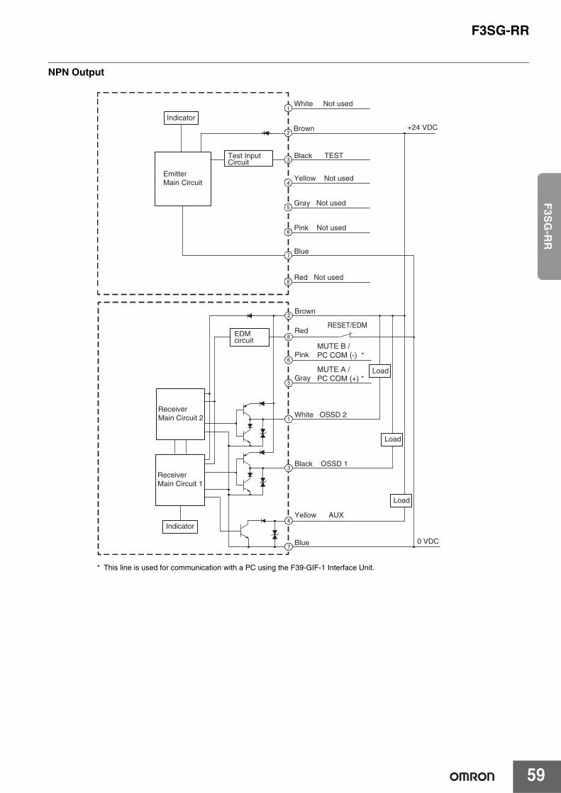
F3SG-RR
59
F3S
G-R
R
NPN Output
Brown
Red
White OSSD 2
Pink
Gray
Black OSSD 1
Yellow AUX
Blue
EDMcircuit
RESET/EDM
MUTE B /PC COM (-) *
MUTE A /PC COM (+) *
0 VDC
ReceiverMain Circuit 2
ReceiverMain Circuit 1
Indicator
Load
Load
Load
+24 VDCBrown
Black TEST
Yellow Not used
White Not used
Blue
Gray Not used
Pink Not used
Red Not used
Indicator
EmitterMain Circuit
Test Input Circuit
* This line is used for communication with a PC using the F39-GIF-1 Interface Unit.
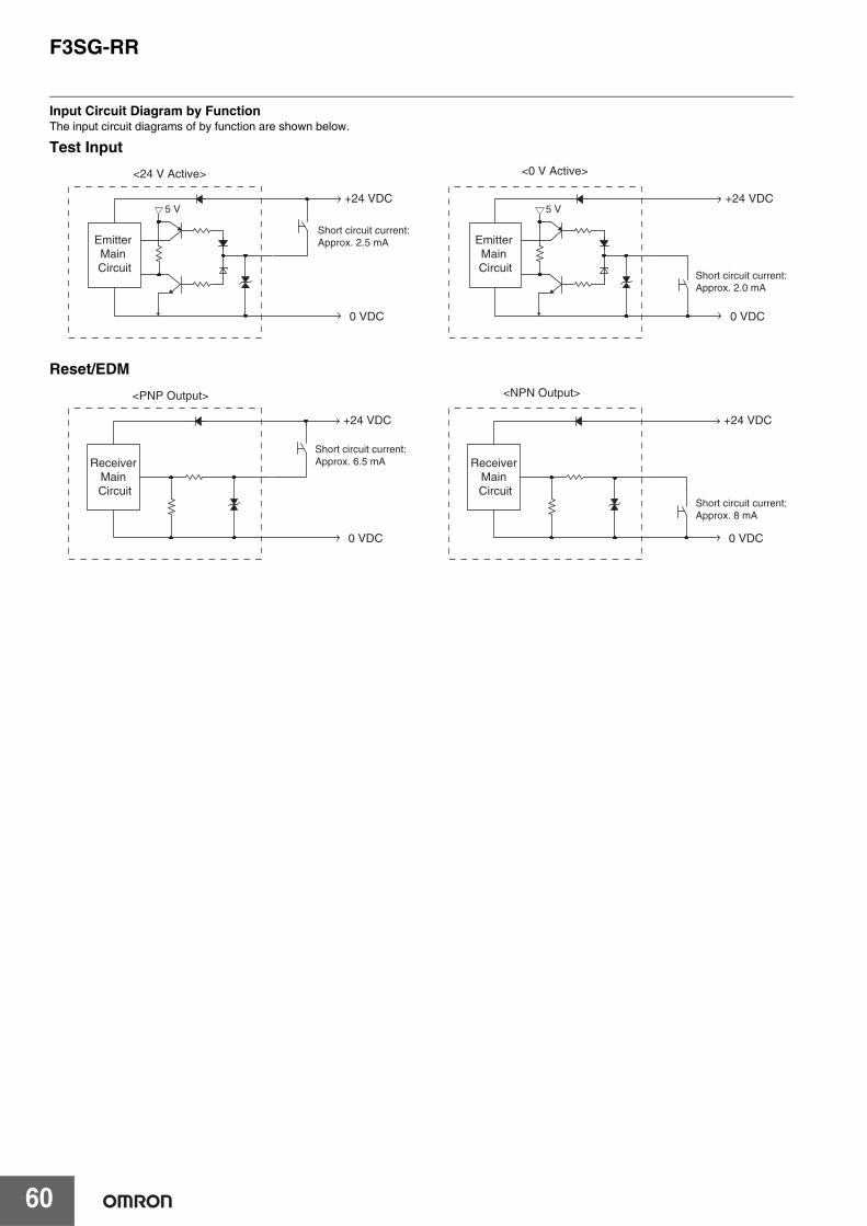
F3SG-RR
60
Input Circuit Diagram by FunctionThe input circuit diagrams of by function are shown below.
Emitter Main Circuit
+24 VDC
0 VDC
5 V
Short circuit current:Approx. 2.5 mA
<24 V Active> <0 V Active>
Emitter Main Circuit
+24 VDC
0 VDC
5 V
Short circuit current:Approx. 2.0 mA
Test Input
Receiver Main Circuit
+24 VDC
0 VDC
Short circuit current:Approx. 8 mA
<NPN Output><PNP Output>
Receiver Main Circuit
+24 VDC
0 VDC
Short circuit current:Approx. 6.5 mA
Reset/EDM
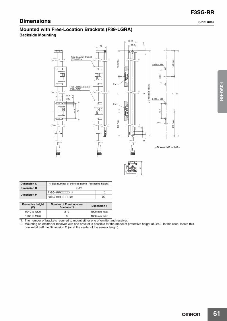
F3SG-RR
61
F3S
G-R
R
Dimensions (Unit: mm)
Mounted with Free-Location Brackets (F39-LGRA)Backside Mounting
*1. The number of brackets required to mount either one of emitter and receiver.*2. Mounting an emitter or receiver with one bracket is possible for the model of protective height of 0240. In this case, locate this
bracket at half the Dimension C (or at the center of the sensor length).
Dimension C 4-digit number of the type name (Protective height)
Dimension D C-20
Dimension PF3SG-4RR@@@@-14 10
F3SG-4RR@@@@-25 20
Protective height (C)
Number of Free-Location Brackets *1 Dimension F
0240 to 1200 2 *2 1000 mm max.
1280 to 1920 3 1000 mm max.
31.4
46.35
(10)
10
P
D
C (
Pro
tect
ive
heig
ht)
150
max
.15
0 m
ax.
F
56.5
56.5
150
max
.F
150
max
.
C
3.95
2-M4
2-M4
2-M5 or M6
<Screw: M5 or M6>
2-M5 or M6
38
Free-Location Bracket(F39-LGRA)
Free-Location Bracket(F39-LGRA)
26.3
73
6.3
3.95
56.5
50
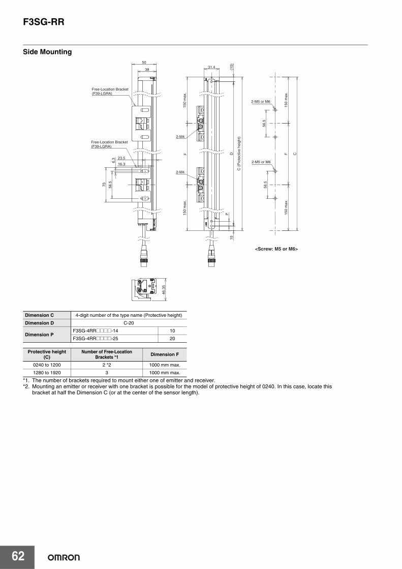
F3SG-RR
62
Side Mounting
*1. The number of brackets required to mount either one of emitter and receiver.*2. Mounting an emitter or receiver with one bracket is possible for the model of protective height of 0240. In this case, locate this
bracket at half the Dimension C (or at the center of the sensor length).
Dimension C 4-digit number of the type name (Protective height)
Dimension D C-20
Dimension PF3SG-4RR@@@@-14 10
F3SG-4RR@@@@-25 20
Protective height (C)
Number of Free-Location Brackets *1 Dimension F
0240 to 1200 2 *2 1000 mm max.
1280 to 1920 3 1000 mm max.
31.4 (10)
10P
DF
2-M4
2-M4
38
50
16.3
73
6.3 23.5
56.5
(F39-LGRA)
(F39-LGRA)
46.3
5
C (
Pro
tect
ive
heig
ht)
150
max
.15
0 m
ax.
2-M5 or M6
2-M5 or M6
Free-Location Bracket
Free-Location Bracket
56.5
56.5
150
max
.F
150
max
.
C
<Screw: M5 or M6>
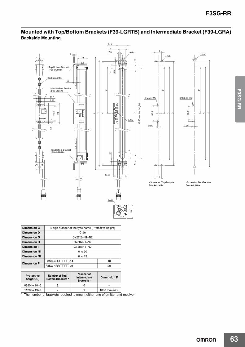
F3SG-RR
63
F3S
G-R
R
Mounted with Top/Bottom Brackets (F39-LGRTB) and Intermediate Bracket (F39-LGRA)Backside Mounting
* The number of brackets required to mount either one of emitter and receiver.
Dimension C 4-digit number of the type name (Protective height)
Dimension D C-20
Dimension G C+27.2+N1+N2
Dimension H C+38+N1+N2
Dimension I C+58+N1+N2
Dimension N1 0 to 30
Dimension N2 0 to 13
Dimension PF3SG-4RR@@@@-14 10
F3SG-4RR@@@@-25 20
Protective height (C)
Number of Top/Bottom Brackets *
Number of Intermediate Brackets *
Dimension F
0240 to 1040 2 0 −
1120 to 1920 2 1 1000 mm max.
31.4
(10)
1
0
P
D
N1
7.5
N2
46.35
HI
56.5 C
3.95
FF
19
5.5
G
19
19
G 56.5
C
3.95
F
H
2-M4
9 dia.
<Screw for Top/Bottom Bracket: M5>
<Screw for Top/Bottom Bracket: M8>
4-M52-M8
50
2-M4
12
3
38
Intermediate Bracket(F39-LGRA)
Top/Bottom Bracket(F39-LGRTB)
Top/Bottom Bracket(F39-LGRTB)
26.3
73
6.3
3.95
56.5
Backside:2-M4
C (
Pro
tect
ive
heig
ht)
2-M5 or M6 2-M5 or M6
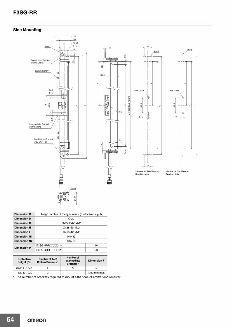
F3SG-RR
64
Side Mounting
* The number of brackets required to mount either one of emitter and receiver.
Dimension C 4-digit number of the type name (Protective height)
Dimension D C-20
Dimension G C+27.2+N1+N2
Dimension H C+38+N1+N2
Dimension I C+58+N1+N2
Dimension N1 0 to 30
Dimension N2 0 to 13
Dimension PF3SG-4RR@@@@-14 10
F3SG-4RR@@@@-25 20
Protective height (C)
Number of Top/Bottom Brackets *
Number of Intermediate Brackets *
Dimension F
0240 to 1040 2 0 −
1120 to 1920 2 1 1000 mm max.
(10)
10
P
D
N1
N2
31.4
3
56.5
C
F F
19
19
G
56.5 C
F
H
4.15 4.15
2-M4
4-M52-M8
16.3
73
6.3
31.4
38
50
I
5.5
4.15
56.5
19
19.35
G H
(F39-LGRA)
(F39-LGRTB)
(F39-LGRTB)
9 dia.
46.3
5
2-M4
<Screw for Top/Bottom Bracket: M5>
<Screw for Top/Bottom Bracket: M8>
Intermediate Bracket
Top/Bottom Bracket
Top/Bottom Bracket
Backside:2-M4
C (
Pro
tect
ive
heig
ht)
2-M5 or M6 2-M5 or M6

F3SG-RR
65
F3S
G-R
R
Mounted with Top/Bottom Brackets (F39-LGRTB-2) and Intermediate Bracket (F39-LGRA)Backside Mounting
* The number of brackets required to mount either one of emitter and receiver.
Dimension C 4-digit number of the type name (Protective height)
Dimension D C-20
Dimension G C+51+N1+N2
Dimension H C+54+N1+N2
Dimension I C+88+N1+N2
Dimension J C+106+N1+N2
Dimension N1 0 to 30
Dimension N2 0 to 13
Dimension PF3SG-4RR@@@@-14 10
F3SG-4RR@@@@-25 20
Protective height (C)
Number of Top/Bottom Brackets *
Number of Intermediate Brackets *
Dimension F
0240 to 1040 2 0 −
1120 to 1920 2 1 1000 mm max.
(10)
10
P
D
N1
N2
46.35
IJ
23.5
24.5
32
31.4
5.5
6.5
56.5
C
3.95
FF
20
20
H 56.5
C
3.95
F
IGH
20
G
2-M4
9 dia.
4-M5
2-M8
2-M6
50
2-M4
38
3
12
(F39-LGRTB-2)
(F39-LGRA)
(F39-LGRTB-2)
26.3
73
6.3
3.95
56.5
<Screw for Top/Bottom Bracket: M5>
<Screw for Top/Bottom Bracket: M6 or M8>
Intermediate Bracket
Top/Bottom Bracket
Top/Bottom Bracket
Backside:2-M4
C(P
rote
ctiv
e he
ight
)
2-M5 or M6 2-M5 or M6
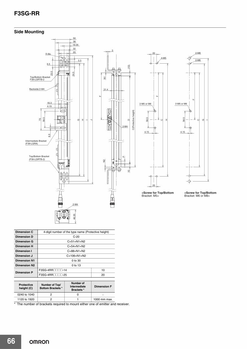
F3SG-RR
66
Side Mounting
* The number of brackets required to mount either one of emitter and receiver.
Dimension C 4-digit number of the type name (Protective height)
Dimension D C-20
Dimension G C+51+N1+N2
Dimension H C+54+N1+N2
Dimension I C+88+N1+N2
Dimension J C+106+N1+N2
Dimension N1 0 to 30
Dimension N2 0 to 13
Dimension PF3SG-4RR@@@@-14 10
F3SG-4RR@@@@-25 20
Protective height (C)
Number of Top/Bottom Brackets *
Number of Intermediate Brackets *
Dimension F
0240 to 1040 2 0 −
1120 to 1920 2 1 1000 mm max.
31.4
(10)
10
P
D
N1
N2
56.5
C
FF
20
20
H 56.5
C
F
IG
3
4.15 4.15
2-M4
4-M5
2-M8
2-M6
16.3
73
6.3
I J
24.5
23.5
32
38
5.5
6.5
4.15
56.5
G H
20
19.35
F39-LGRTB-2
(F39-LGRA)
(F39-LGRTB-2)
9 dia.
46.3
5
2-M4
<Screw for Top/Bottom Bracket: M5>
<Screw for Top/Bottom Bracket: M6 or M8>
Intermediate Bracket
Top/Bottom Bracket
Top/Bottom Bracket
Backside:2-M4
C(P
rote
ctiv
e he
ight
)
2-M5 or M6 2-M5 or M6
50
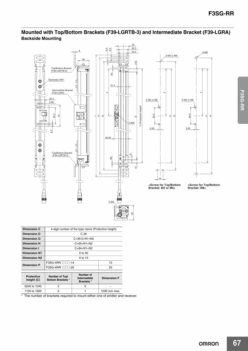
F3SG-RR
67
F3S
G-R
R
Mounted with Top/Bottom Brackets (F39-LGRTB-3) and Intermediate Bracket (F39-LGRA)Backside Mounting
* The number of brackets required to mount either one of emitter and receiver.
Dimension C 4-digit number of the type name (Protective height)
Dimension D C-20
Dimension G C+39.5+N1+N2
Dimension H C+65+N1+N2
Dimension I C+84+N1+N2
Dimension N1 0 to 30
Dimension N2 0 to 13
Dimension PF3SG-4RR@@@@-14 10
F3SG-4RR@@@@-25 20
Protective height (C)
Number of Top/Bottom Brackets *
Number of Intermediate Brackets *
Dimension F
0240 to 1040 2 0 −
1120 to 1920 2 1 1000 mm max.
31.4
(10)
10
P
D
N1
N2
46.35
I
35
23.2
26.5
6.5
8.2
56.5 C
3.95
FF
G
19
G
56.5 C
3.95
F
HH
2-M4
2-M8
50
2-M4
38
4
(F39-LGRA)
(F39-LGRTB-3)
(F39-LGRTB-3)
26.3
73
6.3
3.95
56.5
<Screw for Top/Bottom Bracket: M5 or M6>
<Screw for Top/Bottom Bracket: M8>
Intermediate Bracket
Top/Bottom Bracket
Top/Bottom Bracket
Backside:2-M4
C (
Pro
tect
ive
heig
ht)
2-M5 or M6 2-M5 or M6
2-M5 or M6

F3SG-RR
68
Side Mounting
* The number of brackets required to mount either one of emitter and receiver.
Dimension C 4-digit number of the type name (Protective height)
Dimension D C-20
Dimension G C+39.5+N1+N2
Dimension H C+65+N1+N2
Dimension I C+84+N1+N2
Dimension N1 0 to 30
Dimension N2 0 to 13
Dimension PF3SG-4RR@@@@-14 10
F3SG-4RR@@@@-25 20
Protective height (C)
Number of Top/Bottom Brackets *
Number of Intermediate Brackets *
Dimension F
0240 to 1040 2 0 −
1120 to 1920 2 1 1000 mm max.
(10)
10
P
D
N1
N2
31.4
4
56.5 C
FF
G
56.5 C
F
H
4.15 4.15
2-M4
2-M8
16.3
73
6.3
38 50
I
26.5
23.2
35
8.2
6.5
4.15
56.5
19.35
G H
(F39-LGRA)
(F39-LGRTB-3)
(F39-LGRTB-3)
46.9
5
2-M4
<Screw for Top/Bottom Bracket: M5 or M6>
<Screw for Top/Bottom Bracket: M8>
Intermediate Bracket
Top/Bottom Bracket
Top/Bottom Bracket
Backside:2-M4
C (
Pro
tect
ive
heig
ht)
2-M5 or M6
2-M5 or M6
2-M5 or M6
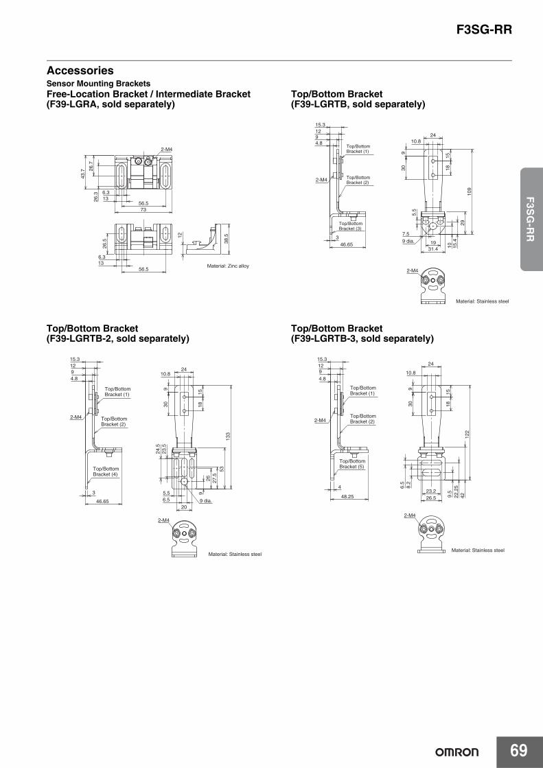
F3SG-RR
69
F3S
G-R
R
AccessoriesSensor Mounting BracketsFree-Location Bracket / Intermediate Bracket (F39-LGRA, sold separately)
Top/Bottom Bracket (F39-LGRTB, sold separately)
Top/Bottom Bracket (F39-LGRTB-2, sold separately)
Top/Bottom Bracket (F39-LGRTB-3, sold separately)
56.5
26.7
73
43.7
6.31326
.3
2-M4
26.5
56.5136.3
38.512
Material: Zinc alloy
Material: Stainless steel
19
15.4
2410.8
930 18
15
109
29
1031.4
5.5
7.59 dia.
2-M4
46.653
15.31294.8
2-M4
Top/Bottom Bracket (1)
Top/Bottom Bracket (2)
Top/BottomBracket (3)
27.5
26
20
309
2410.8
1518
133
53
9
23.5
24.5
5.56.5 9 dia.
2-M4
Material: Stainless steel
3
46.65
4.8
129
15.3
2-M4
Top/Bottom Bracket (1)
Top/Bottom Bracket (2)
Top/Bottom Bracket (4)
22.2
59.
5
24
309
10.8
1518
122
42
8.2
6.5
23.226.5
2-M4
Material: Stainless steel
48.25
4
4.891215.3
2-M4
Top/Bottom Bracket (1)
Top/Bottom Bracket (2)
Top/Bottom Bracket (5)
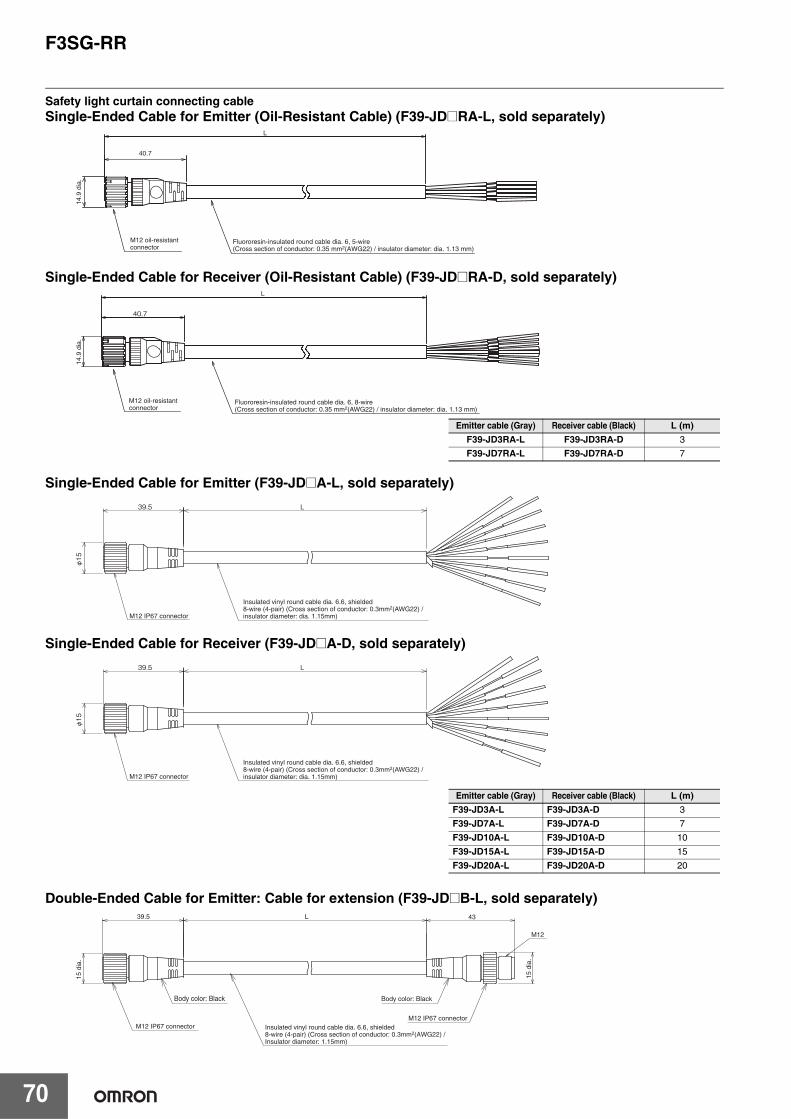
F3SG-RR
70
Safety light curtain connecting cableSingle-Ended Cable for Emitter (Oil-Resistant Cable) (F39-JD@RA-L, sold separately)
Single-Ended Cable for Receiver (Oil-Resistant Cable) (F39-JD@RA-D, sold separately)
Single-Ended Cable for Emitter (F39-JD@A-L, sold separately)
Single-Ended Cable for Receiver (F39-JD@A-D, sold separately)
Double-Ended Cable for Emitter: Cable for extension (F39-JD@B-L, sold separately)
Fluororesin-insulated round cable dia. 6, 5-wire (Cross section of conductor: 0.35 mm2(AWG22) / insulator diameter: dia. 1.13 mm)
M12 oil-resistant connector
40.7
L
14.9
dia
.
L
40.7
Fluororesin-insulated round cable dia. 6, 8-wire (Cross section of conductor: 0.35 mm2(AWG22) / insulator diameter: dia. 1.13 mm)
M12 oil-resistant connector
14.9
dia
.
Emitter cable (Gray) Receiver cable (Black) L (m)F39-JD3RA-L F39-JD3RA-D 3
F39-JD7RA-L F39-JD7RA-D 7
39.5 L
φ15
M12 IP67 connector
Insulated vinyl round cable dia. 6.6, shielded8-wire (4-pair) (Cross section of conductor: 0.3mm2(AWG22) / insulator diameter: dia. 1.15mm)
39.5 L
φ15
M12 IP67 connector
Insulated vinyl round cable dia. 6.6, shielded8-wire (4-pair) (Cross section of conductor: 0.3mm2(AWG22) / insulator diameter: dia. 1.15mm)
Emitter cable (Gray) Receiver cable (Black) L (m)F39-JD3A-L F39-JD3A-D 3
F39-JD7A-L F39-JD7A-D 7
F39-JD10A-L F39-JD10A-D 10
F39-JD15A-L F39-JD15A-D 15
F39-JD20A-L F39-JD20A-D 20
39.5 L 43
M12
15 d
ia.
M12 IP67 connector
Body color: BlackBody color: Black
M12 IP67 connector Insulated vinyl round cable dia. 6.6, shielded8-wire (4-pair) (Cross section of conductor: 0.3mm2(AWG22) / Insulator diameter: 1.15mm)
15 d
ia.

F3SG-RR
71
F3S
G-R
R
Double-Ended Cable for Receiver: Cable for extension (F39-JD@B-D, sold separately)
Cascading Cable for Emitter (F39-JGR2WTS-L, sold separately)
Cascading Cable for Receiver (F39-JGR2WTS-D, sold separately)
Emitter cable (Gray) Receiver cable (Black) L (m)F39-JDR5B-L F39-JDR5B-D 0.5
F39-JD1B-L F39-JD1B-D 1
F39-JD3B-L F39-JD3B-D 3
F39-JD5B-L F39-JD5B-D 5
F39-JD7B-L F39-JD7B-D 7
F39-JD10B-L F39-JD10B-D 10
F39-JD15B-L F39-JD15B-D 15
F39-JD20B-L F39-JD20B-D 20
Set model name Emitter cable (Gray) Receiver cable (Black) L (m)
F39-JGR2WTS F39-JGR2WTS-L F39-JGR2WTS-D 0.2
39.5 L 43
M12
15 d
ia.
Body color: BlackBody color: Black
M12 IP67 connectorM12 IP67 connector
Insulated vinyl round cable dia. 6.6, shielded8-wire (4-pair) (Cross section of conductor: 0.3mm2(AWG22) / Insulator diameter: 1.15mm)
15 d
ia.
24.712
13.6 13.6 8 dia. (SPOT FACING 2)4.5 dia.
(52)
32.110
17.7
18
Reduced Wiring Connector (F39-CN5, sold separately)
20040.7
6 di
a.
23.4
10
Insulated vinyl round cable dia. 6 mm, 5-wire(Cross section of conductor: 0.15 mm2 (AWG26) / Insulator diameter: dia. 1 mm)
M12 IP67 connector
24.2
M2.5 screw
Connector
14.9
dia
.
200
14.9
dia
.
40.7
6 di
a.
23.4
10
Insulated vinyl round cable dia. 6 mm, 8-wire(Cross section of conductor: 0.15 mm2 (AWG26) / Insulator diameter: dia. 1 mm)
Connector
M12 IP67 connector
24.2
M2.5 screw
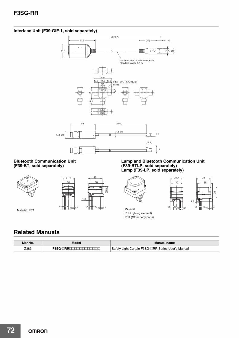
F3SG-RR
72
Interface Unit (F39-GIF-1, sold separately)
Bluetooth Communication Unit (F39-BT, sold separately)
Lamp and Bluetooth Communication Unit (F39-BTLP, sold separately)Lamp (F39-LP, sold separately)
Related Manuals
67.9
35.8 (16)(12)
(625.7)
(46)
Insulated vinyl round cable 4.6 dia. Standard length: 0.5 m
(11.8)
58
17.5 dia.4.6 dia.
2,000
14.5
7.7
11
24.712
13.6 13.6 8 dia. (SPOT FACING 2)4.5 dia.
(52)
32.110
17.7
18
16.
5
31.4
30 38
35
1.8
Material: PBT
31.4
30 38
35
28
1.8
Material:PC (Lighting element)PBT (Other body parts)
ManNo. Model Manual name
Z383 F3SG-@RR@@@@@@@@@@@@ Safety Light Curtain F3SG-@RR Series User's Manual
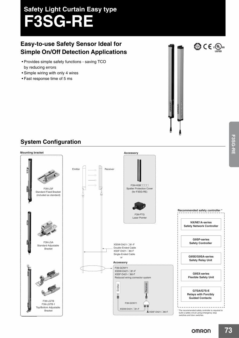
73
F3S
G-R
ESafety Light Curtain Easy type
F3SG-REEasy-to-use Safety Sensor Ideal for Simple On/Off Detection Applications• Provides simple safety functions - saving TCO
by reducing errors• Simple wiring with only 4 wires• Fast response time of 5 ms
System Configuration
F39-HGB@@@@Spatter Protection Cover
(for F3SG-RE)
F39-PTGLaser Pointer
Accessory
Emitter Receiver
XS5W-D421-@81-FDouble-Ended CableXS5F-D421-@80-FSingle-Ended Cable or
F39-LGFStandard Fixed Bracket (included as standard)
F39-LGAStandard Adjustable
Bracket
F39-LGTBF39-LGTB-1
Top/Bottom Adjustable Bracket
Mounting bracket
F39-GCNY1XS5W-D421-@81-FXS5F-D421-@80-FReduced wiring connector system
NX/NE1A-seriesSafety Network Controller
G9SP-seriesSafety Controller
G9SE/G9SA-seriesSafety Relay Unit
G9SX-seriesFlexible Safety Unit
G7SA/G7S-ERelays with Forcibly
Guided Contacts
Recommended safety controller *
* The recommended safety controller is required to build a safety circuit using emergency stop switches and door switches.
Accessory
T
F39-GCNY1
Rec
eive
r
Em
itter
XS5W-D421-@81-FXS5F-D421-@80-F
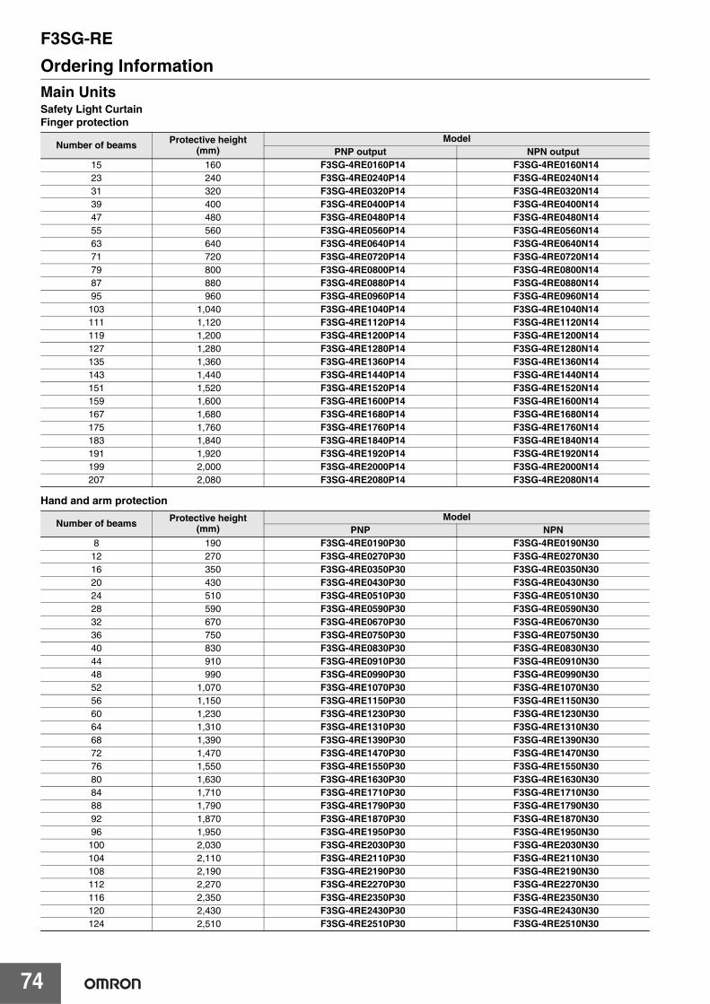
F3SG-RE
74
Ordering InformationMain UnitsSafety Light CurtainFinger protection
Hand and arm protection
Number of beams Protective height(mm)
ModelPNP output NPN output
15 160 F3SG-4RE0160P14 F3SG-4RE0160N1423 240 F3SG-4RE0240P14 F3SG-4RE0240N1431 320 F3SG-4RE0320P14 F3SG-4RE0320N1439 400 F3SG-4RE0400P14 F3SG-4RE0400N1447 480 F3SG-4RE0480P14 F3SG-4RE0480N1455 560 F3SG-4RE0560P14 F3SG-4RE0560N1463 640 F3SG-4RE0640P14 F3SG-4RE0640N1471 720 F3SG-4RE0720P14 F3SG-4RE0720N1479 800 F3SG-4RE0800P14 F3SG-4RE0800N1487 880 F3SG-4RE0880P14 F3SG-4RE0880N1495 960 F3SG-4RE0960P14 F3SG-4RE0960N14
103 1,040 F3SG-4RE1040P14 F3SG-4RE1040N14111 1,120 F3SG-4RE1120P14 F3SG-4RE1120N14119 1,200 F3SG-4RE1200P14 F3SG-4RE1200N14127 1,280 F3SG-4RE1280P14 F3SG-4RE1280N14135 1,360 F3SG-4RE1360P14 F3SG-4RE1360N14143 1,440 F3SG-4RE1440P14 F3SG-4RE1440N14151 1,520 F3SG-4RE1520P14 F3SG-4RE1520N14159 1,600 F3SG-4RE1600P14 F3SG-4RE1600N14167 1,680 F3SG-4RE1680P14 F3SG-4RE1680N14175 1,760 F3SG-4RE1760P14 F3SG-4RE1760N14183 1,840 F3SG-4RE1840P14 F3SG-4RE1840N14191 1,920 F3SG-4RE1920P14 F3SG-4RE1920N14199 2,000 F3SG-4RE2000P14 F3SG-4RE2000N14207 2,080 F3SG-4RE2080P14 F3SG-4RE2080N14
Number of beams Protective height(mm)
ModelPNP NPN
8 190 F3SG-4RE0190P30 F3SG-4RE0190N3012 270 F3SG-4RE0270P30 F3SG-4RE0270N3016 350 F3SG-4RE0350P30 F3SG-4RE0350N3020 430 F3SG-4RE0430P30 F3SG-4RE0430N3024 510 F3SG-4RE0510P30 F3SG-4RE0510N3028 590 F3SG-4RE0590P30 F3SG-4RE0590N3032 670 F3SG-4RE0670P30 F3SG-4RE0670N3036 750 F3SG-4RE0750P30 F3SG-4RE0750N3040 830 F3SG-4RE0830P30 F3SG-4RE0830N3044 910 F3SG-4RE0910P30 F3SG-4RE0910N3048 990 F3SG-4RE0990P30 F3SG-4RE0990N3052 1,070 F3SG-4RE1070P30 F3SG-4RE1070N3056 1,150 F3SG-4RE1150P30 F3SG-4RE1150N3060 1,230 F3SG-4RE1230P30 F3SG-4RE1230N3064 1,310 F3SG-4RE1310P30 F3SG-4RE1310N3068 1,390 F3SG-4RE1390P30 F3SG-4RE1390N3072 1,470 F3SG-4RE1470P30 F3SG-4RE1470N3076 1,550 F3SG-4RE1550P30 F3SG-4RE1550N3080 1,630 F3SG-4RE1630P30 F3SG-4RE1630N3084 1,710 F3SG-4RE1710P30 F3SG-4RE1710N3088 1,790 F3SG-4RE1790P30 F3SG-4RE1790N3092 1,870 F3SG-4RE1870P30 F3SG-4RE1870N3096 1,950 F3SG-4RE1950P30 F3SG-4RE1950N30
100 2,030 F3SG-4RE2030P30 F3SG-4RE2030N30104 2,110 F3SG-4RE2110P30 F3SG-4RE2110N30108 2,190 F3SG-4RE2190P30 F3SG-4RE2190N30112 2,270 F3SG-4RE2270P30 F3SG-4RE2270N30116 2,350 F3SG-4RE2350P30 F3SG-4RE2350N30120 2,430 F3SG-4RE2430P30 F3SG-4RE2430N30124 2,510 F3SG-4RE2510P30 F3SG-4RE2510N30
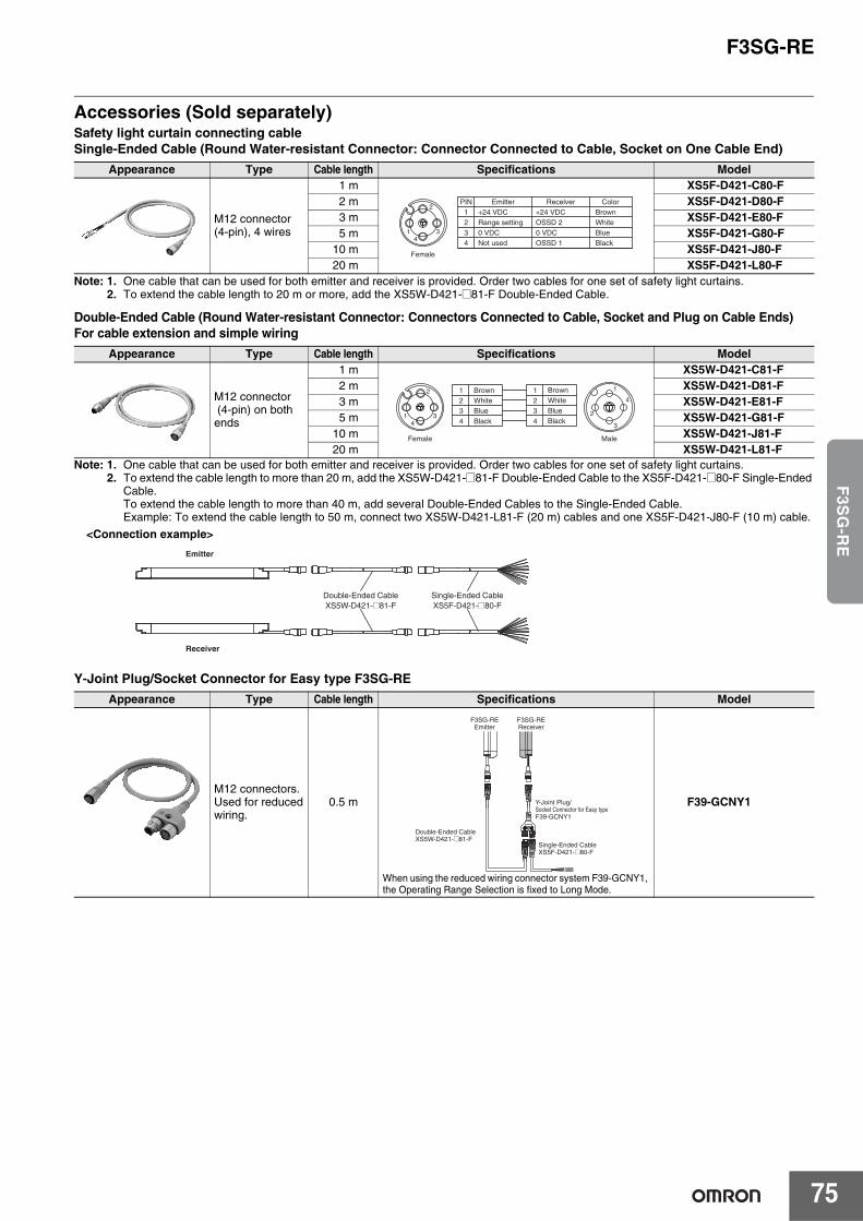
F3SG-RE
75
F3S
G-R
E
Accessories (Sold separately)Safety light curtain connecting cableSingle-Ended Cable (Round Water-resistant Connector: Connector Connected to Cable, Socket on One Cable End)
Note: 1. One cable that can be used for both emitter and receiver is provided. Order two cables for one set of safety light curtains. 2. To extend the cable length to 20 m or more, add the XS5W-D421-@81-F Double-Ended Cable.
Double-Ended Cable (Round Water-resistant Connector: Connectors Connected to Cable, Socket and Plug on Cable Ends)For cable extension and simple wiring
Note: 1. One cable that can be used for both emitter and receiver is provided. Order two cables for one set of safety light curtains.2. To extend the cable length to more than 20 m, add the XS5W-D421-@81-F Double-Ended Cable to the XS5F-D421-@80-F Single-Ended
Cable.To extend the cable length to more than 40 m, add several Double-Ended Cables to the Single-Ended Cable.Example: To extend the cable length to 50 m, connect two XS5W-D421-L81-F (20 m) cables and one XS5F-D421-J80-F (10 m) cable.
Y-Joint Plug/Socket Connector for Easy type F3SG-RE
Appearance Type Cable length Specifications Model
M12 connector (4-pin), 4 wires
1 m XS5F-D421-C80-F2 m XS5F-D421-D80-F3 m XS5F-D421-E80-F5 m XS5F-D421-G80-F
10 m XS5F-D421-J80-F20 m XS5F-D421-L80-F
Appearance Type Cable length Specifications Model
M12 connector (4-pin) on bothends
1 m XS5W-D421-C81-F2 m XS5W-D421-D81-F3 m XS5W-D421-E81-F5 m XS5W-D421-G81-F
10 m XS5W-D421-J81-F20 m XS5W-D421-L81-F
Appearance Type Cable length Specifications Model
M12 connectors.Used for reducedwiring.
0.5 m
When using the reduced wiring connector system F39-GCNY1, the Operating Range Selection is fixed to Long Mode.
F39-GCNY1
2
14
3
Female
1234
+24 VDCRange setting0 VDCNot used
+24 VDCOSSD 20 VDCOSSD 1
BrownPIN Emitter Recelver Color
WhiteBlueBlack
1
2
3
42
14
3
Female Male
1234
BrownWhiteBlueBlack
1234
BrownWhiteBlueBlack
Emitter
Receiver
Double-Ended CableXS5W-D421-@81-F
Single-Ended CableXS5F-D421-@80-F
<Connection example>
Single-Ended CableXS5F-D421-@80-F
Double-Ended CableXS5W-D421-@81-F
Y-Joint Plug/Socket Connector for Easy typeF39-GCNY1
F3SG-REEmitter
F3SG-REReceiver
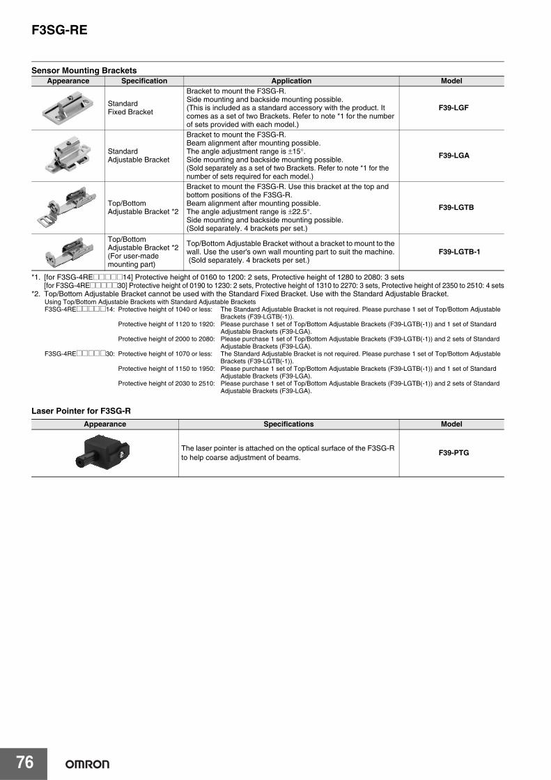
F3SG-RE
76
Sensor Mounting Brackets
*1. [for F3SG-4RE@@@@@14] Protective height of 0160 to 1200: 2 sets, Protective height of 1280 to 2080: 3 sets[for F3SG-4RE@@@@@30] Protective height of 0190 to 1230: 2 sets, Protective height of 1310 to 2270: 3 sets, Protective height of 2350 to 2510: 4 sets
*2. Top/Bottom Adjustable Bracket cannot be used with the Standard Fixed Bracket. Use with the Standard Adjustable Bracket. Using Top/Bottom Adjustable Brackets with Standard Adjustable BracketsF3SG-4RE@@@@@14: Protective height of 1040 or less: The Standard Adjustable Bracket is not required. Please purchase 1 set of Top/Bottom Adjustable
Brackets (F39-LGTB(-1)).Protective height of 1120 to 1920: Please purchase 1 set of Top/Bottom Adjustable Brackets (F39-LGTB(-1)) and 1 set of Standard
Adjustable Brackets (F39-LGA).Protective height of 2000 to 2080: Please purchase 1 set of Top/Bottom Adjustable Brackets (F39-LGTB(-1)) and 2 sets of Standard
Adjustable Brackets (F39-LGA).F3SG-4RE@@@@@30: Protective height of 1070 or less: The Standard Adjustable Bracket is not required. Please purchase 1 set of Top/Bottom Adjustable
Brackets (F39-LGTB(-1)).Protective height of 1150 to 1950: Please purchase 1 set of Top/Bottom Adjustable Brackets (F39-LGTB(-1)) and 1 set of Standard
Adjustable Brackets (F39-LGA).Protective height of 2030 to 2510: Please purchase 1 set of Top/Bottom Adjustable Brackets (F39-LGTB(-1)) and 2 sets of Standard
Adjustable Brackets (F39-LGA).
Laser Pointer for F3SG-R
Appearance Specification Application Model
Standard Fixed Bracket
Bracket to mount the F3SG-R.Side mounting and backside mounting possible.(This is included as a standard accessory with the product. It comes as a set of two Brackets. Refer to note *1 for the number of sets provided with each model.)
F39-LGF
Standard Adjustable Bracket
Bracket to mount the F3SG-R.Beam alignment after mounting possible.The angle adjustment range is ±15°.Side mounting and backside mounting possible.(Sold separately as a set of two Brackets. Refer to note *1 for the number of sets required for each model.)
F39-LGA
Top/Bottom Adjustable Bracket *2
Bracket to mount the F3SG-R. Use this bracket at the top and bottom positions of the F3SG-R. Beam alignment after mounting possible. The angle adjustment range is ±22.5°.Side mounting and backside mounting possible.(Sold separately. 4 brackets per set.)
F39-LGTB
Top/Bottom Adjustable Bracket *2(For user-made mounting part)
Top/Bottom Adjustable Bracket without a bracket to mount to the wall. Use the user's own wall mounting part to suit the machine. (Sold separately. 4 brackets per set.)
F39-LGTB-1
Appearance Specifications Model
The laser pointer is attached on the optical surface of the F3SG-R to help coarse adjustment of beams.
F39-PTG
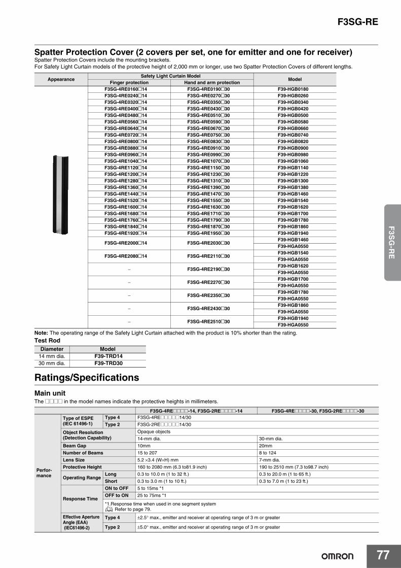
F3SG-RE
77
F3S
G-R
E
Spatter Protection Cover (2 covers per set, one for emitter and one for receiver)Spatter Protection Covers include the mounting brackets. For Safety Light Curtain models of the protective height of 2,000 mm or longer, use two Spatter Protection Covers of different lengths.
Note: The operating range of the Safety Light Curtain attached with the product is 10% shorter than the rating.
Test Rod
Ratings/SpecificationsMain unitThe @@@@ in the model names indicate the protective heights in millimeters.
AppearanceSafety Light Curtain Model
ModelFinger protection Hand and arm protection
F3SG-4RE0160@14 F3SG-4RE0190@30 F39-HGB0180F3SG-4RE0240@14 F3SG-4RE0270@30 F39-HGB0260F3SG-4RE0320@14 F3SG-4RE0350@30 F39-HGB0340F3SG-4RE0400@14 F3SG-4RE0430@30 F39-HGB0420F3SG-4RE0480@14 F3SG-4RE0510@30 F39-HGB0500F3SG-4RE0560@14 F3SG-4RE0590@30 F39-HGB0580F3SG-4RE0640@14 F3SG-4RE0670@30 F39-HGB0660F3SG-4RE0720@14 F3SG-4RE0750@30 F39-HGB0740F3SG-4RE0800@14 F3SG-4RE0830@30 F39-HGB0820F3SG-4RE0880@14 F3SG-4RE0910@30 F39-HGB0900F3SG-4RE0960@14 F3SG-4RE0990@30 F39-HGB0980F3SG-4RE1040@14 F3SG-4RE1070@30 F39-HGB1060F3SG-4RE1120@14 F3SG-4RE1150@30 F39-HGB1140F3SG-4RE1200@14 F3SG-4RE1230@30 F39-HGB1220F3SG-4RE1280@14 F3SG-4RE1310@30 F39-HGB1300F3SG-4RE1360@14 F3SG-4RE1390@30 F39-HGB1380F3SG-4RE1440@14 F3SG-4RE1470@30 F39-HGB1460F3SG-4RE1520@14 F3SG-4RE1550@30 F39-HGB1540F3SG-4RE1600@14 F3SG-4RE1630@30 F39-HGB1620F3SG-4RE1680@14 F3SG-4RE1710@30 F39-HGB1700F3SG-4RE1760@14 F3SG-4RE1790@30 F39-HGB1780F3SG-4RE1840@14 F3SG-4RE1870@30 F39-HGB1860F3SG-4RE1920@14 F3SG-4RE1950@30 F39-HGB1940
F3SG-4RE2000@14 F3SG-4RE2030@30F39-HGB1460F39-HGA0550
F3SG-4RE2080@14 F3SG-4RE2110@30F39-HGB1540F39-HGA0550
− F3SG-4RE2190@30F39-HGB1620F39-HGA0550
− F3SG-4RE2270@30F39-HGB1700F39-HGA0550
− F3SG-4RE2350@30F39-HGB1780F39-HGA0550
− F3SG-4RE2430@30F39-HGB1860F39-HGA0550
− F3SG-4RE2510@30F39-HGB1940F39-HGA0550
Diameter Model14 mm dia. F39-TRD1430 mm dia. F39-TRD30
F3SG-4RE@@@@-14, F3SG-2RE@@@@-14 F3SG-4RE@@@@-30, F3SG-2RE@@@@-30
Perfor-mance
Type of ESPE(IEC 61496-1)
Type 4 F3SG-4RE@@@@@14/30
Type 2 F3SG-2RE@@@@@14/30
Object Resolution(Detection Capability)
Opaque objects
14-mm dia. 30-mm dia.
Beam Gap 10mm 20mm
Number of Beams 15 to 207 8 to 124
Lens Size 5.2 ×3.4 (W×H) mm 7-mm dia.
Protective Height 160 to 2080 mm (6.3 to81.9 inch) 190 to 2510 mm (7.3 to98.7 inch)
Operating RangeLong 0.3 to 10.0 m (1 to 32 ft.) 0.3 to 20.0 m (1 to 65 ft.)
Short 0.3 to 3.0 m (1 to 10 ft.) 0.3 to 7.0 m (1 to 23 ft.)
Response Time
ON to OFF 5 to 15ms *1
OFF to ON 25 to 75ms *1
*1.Response time when used in one segment system Refer to page 79.
Effective ApertureAngle (EAA) (IEC61496-2)
Type 4 ±2.5° max., emitter and receiver at operating range of 3 m or greater
Type 2 ±5.0° max., emitter and receiver at operating range of 3 m or greater
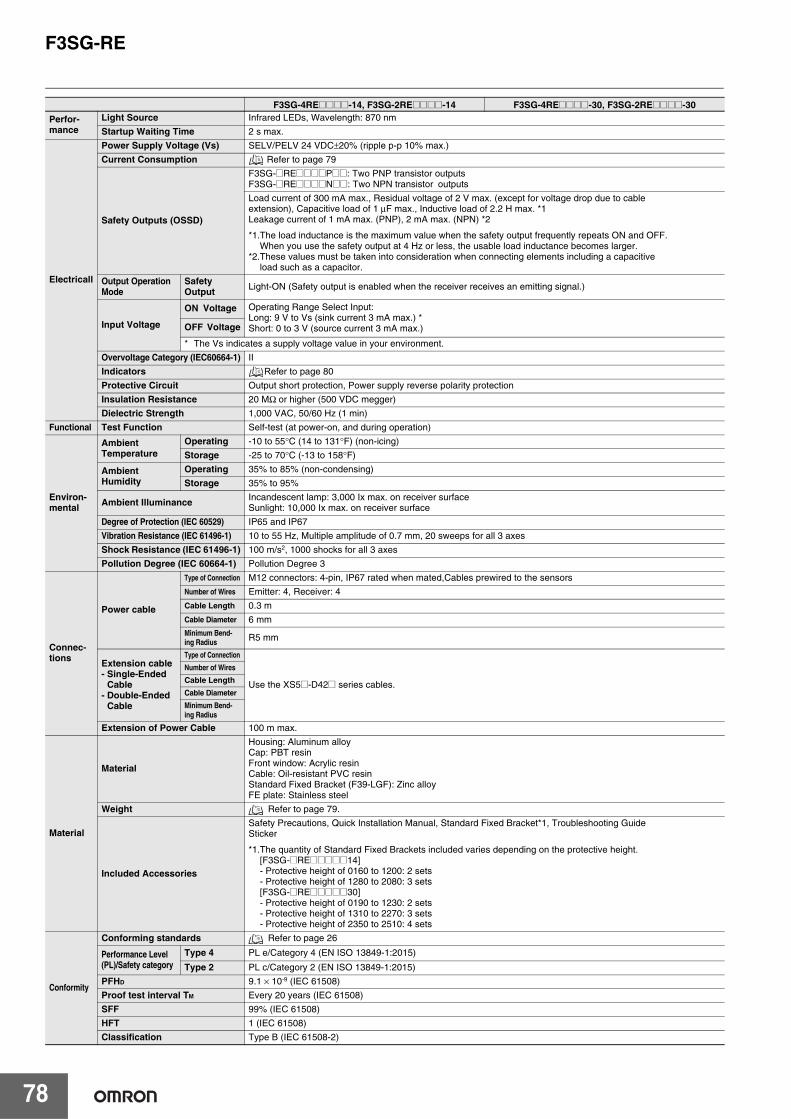
F3SG-RE
78
Perfor-mance
Light Source Infrared LEDs, Wavelength: 870 nm
Startup Waiting Time 2 s max.
Electricall
Power Supply Voltage (Vs) SELV/PELV 24 VDC±20% (ripple p-p 10% max.)
Current Consumption Refer to page 79
Safety Outputs (OSSD)
F3SG-@RE@@@@P@@: Two PNP transistor outputsF3SG-@RE@@@@N@@: Two NPN transistor outputs
Load current of 300 mA max., Residual voltage of 2 V max. (except for voltage drop due to cableextension), Capacitive load of 1 μF max., Inductive load of 2.2 H max. *1Leakage current of 1 mA max. (PNP), 2 mA max. (NPN) *2
*1.The load inductance is the maximum value when the safety output frequently repeats ON and OFF.When you use the safety output at 4 Hz or less, the usable load inductance becomes larger.
*2.These values must be taken into consideration when connecting elements including a capacitiveload such as a capacitor.
Output OperationMode
SafetyOutput Light-ON (Safety output is enabled when the receiver receives an emitting signal.)
Input Voltage
ON Voltage Operating Range Select Input:Long: 9 V to Vs (sink current 3 mA max.) *Short: 0 to 3 V (source current 3 mA max.)OFF Voltage
* The Vs indicates a supply voltage value in your environment.
Overvoltage Category (IEC60664-1) II
Indicators Refer to page 80
Protective Circuit Output short protection, Power supply reverse polarity protection
Insulation Resistance 20 MΩ or higher (500 VDC megger)
Dielectric Strength 1,000 VAC, 50/60 Hz (1 min)
Functional Test Function Self-test (at power-on, and during operation)
Environ-mental
AmbientTemperature
Operating -10 to 55°C (14 to 131°F) (non-icing)
Storage -25 to 70°C (-13 to 158°F)
AmbientHumidity
Operating 35% to 85% (non-condensing)
Storage 35% to 95%
Ambient Illuminance Incandescent lamp: 3,000 Ix max. on receiver surfaceSunlight: 10,000 Ix max. on receiver surface
Degree of Protection (IEC 60529) IP65 and IP67
Vibration Resistance (IEC 61496-1) 10 to 55 Hz, Multiple amplitude of 0.7 mm, 20 sweeps for all 3 axes
Shock Resistance (IEC 61496-1) 100 m/s2, 1000 shocks for all 3 axes
Pollution Degree (IEC 60664-1) Pollution Degree 3
Connec-tions
Power cable
Type of Connection M12 connectors: 4-pin, IP67 rated when mated,Cables prewired to the sensors
Number of Wires Emitter: 4, Receiver: 4
Cable Length 0.3 m
Cable Diameter 6 mmMinimum Bend-ing Radius R5 mm
Extension cable- Single-Ended
Cable- Double-Ended
Cable
Type of Connection
Use the XS5@-D42@ series cables.
Number of WiresCable LengthCable DiameterMinimum Bend-ing Radius
Extension of Power Cable 100 m max.
Material
Material
Housing: Aluminum alloyCap: PBT resinFront window: Acrylic resinCable: Oil-resistant PVC resinStandard Fixed Bracket (F39-LGF): Zinc alloyFE plate: Stainless steel
Weight Refer to page 79.
Included Accessories
Safety Precautions, Quick Installation Manual, Standard Fixed Bracket*1, Troubleshooting GuideSticker
*1.The quantity of Standard Fixed Brackets included varies depending on the protective height.[F3SG-@RE@@@@@14]- Protective height of 0160 to 1200: 2 sets- Protective height of 1280 to 2080: 3 sets[F3SG-@RE@@@@@30]- Protective height of 0190 to 1230: 2 sets- Protective height of 1310 to 2270: 3 sets- Protective height of 2350 to 2510: 4 sets
Conformity
Conforming standards Refer to page 26
Performance Level(PL)/Safety category
Type 4 PL e/Category 4 (EN ISO 13849-1:2015)
Type 2 PL c/Category 2 (EN ISO 13849-1:2015)
PFHD 9.1 × 10⁻⁹ (IEC 61508)
Proof test interval TM Every 20 years (IEC 61508)
SFF 99% (IEC 61508)
HFT 1 (IEC 61508)
Classification Type B (IEC 61508-2)
F3SG-4RE@@@@-14, F3SG-2RE@@@@-14 F3SG-4RE@@@@-30, F3SG-2RE@@@@-30
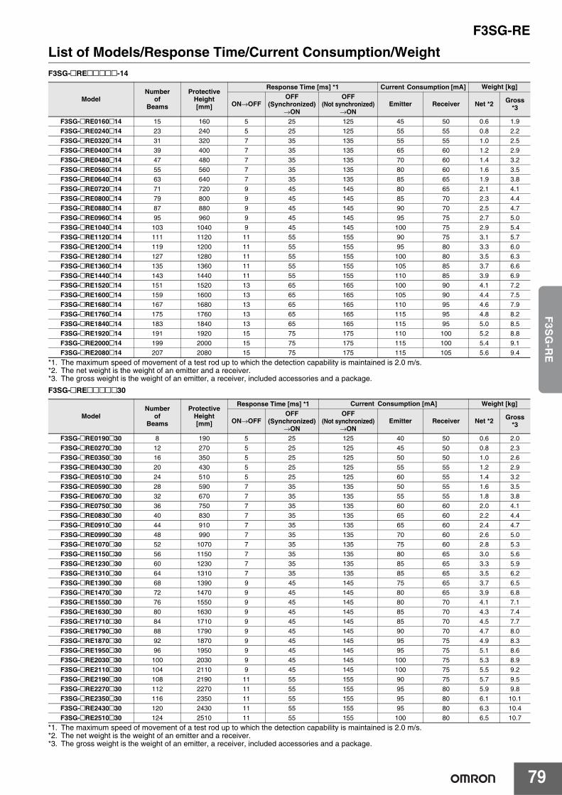
F3SG-RE
79
F3S
G-R
E
List of Models/Response Time/Current Consumption/WeightF3SG-@RE@@@@@-14
*1. The maximum speed of movement of a test rod up to which the detection capability is maintained is 2.0 m/s.*2. The net weight is the weight of an emitter and a receiver.*3. The gross weight is the weight of an emitter, a receiver, included accessories and a package.
F3SG-@RE@@@@@30
*1. The maximum speed of movement of a test rod up to which the detection capability is maintained is 2.0 m/s.*2. The net weight is the weight of an emitter and a receiver.*3. The gross weight is the weight of an emitter, a receiver, included accessories and a package.
ModelNumber
ofBeams
ProtectiveHeight[mm]
Response Time [ms] *1 Current Consumption [mA] Weight [kg]
ON→OFFOFF
(Synchronized)→ON
OFF (Not synchronized)
→ONEmitter Receiver Net *2 Gross
*3
F3SG-@RE0160@14 15 160 5 25 125 45 50 0.6 1.9
F3SG-@RE0240@14 23 240 5 25 125 55 55 0.8 2.2
F3SG-@RE0320@14 31 320 7 35 135 55 55 1.0 2.5
F3SG-@RE0400@14 39 400 7 35 135 65 60 1.2 2.9
F3SG-@RE0480@14 47 480 7 35 135 70 60 1.4 3.2
F3SG-@RE0560@14 55 560 7 35 135 80 60 1.6 3.5
F3SG-@RE0640@14 63 640 7 35 135 85 65 1.9 3.8
F3SG-@RE0720@14 71 720 9 45 145 80 65 2.1 4.1
F3SG-@RE0800@14 79 800 9 45 145 85 70 2.3 4.4
F3SG-@RE0880@14 87 880 9 45 145 90 70 2.5 4.7
F3SG-@RE0960@14 95 960 9 45 145 95 75 2.7 5.0
F3SG-@RE1040@14 103 1040 9 45 145 100 75 2.9 5.4
F3SG-@RE1120@14 111 1120 11 55 155 90 75 3.1 5.7
F3SG-@RE1200@14 119 1200 11 55 155 95 80 3.3 6.0
F3SG-@RE1280@14 127 1280 11 55 155 100 80 3.5 6.3
F3SG-@RE1360@14 135 1360 11 55 155 105 85 3.7 6.6
F3SG-@RE1440@14 143 1440 11 55 155 110 85 3.9 6.9
F3SG-@RE1520@14 151 1520 13 65 165 100 90 4.1 7.2
F3SG-@RE1600@14 159 1600 13 65 165 105 90 4.4 7.5
F3SG-@RE1680@14 167 1680 13 65 165 110 95 4.6 7.9
F3SG-@RE1760@14 175 1760 13 65 165 115 95 4.8 8.2
F3SG-@RE1840@14 183 1840 13 65 165 115 95 5.0 8.5
F3SG-@RE1920@14 191 1920 15 75 175 110 100 5.2 8.8
F3SG-@RE2000@14 199 2000 15 75 175 115 100 5.4 9.1
F3SG-@RE2080@14 207 2080 15 75 175 115 105 5.6 9.4
ModelNumber
ofBeams
ProtectiveHeight[mm]
Response Time [ms] *1 Current Consumption [mA] Weight [kg]
ON→OFFOFF
(Synchronized)→ON
OFF (Not synchronized)
→ONEmitter Receiver Net *2 Gross
*3
F3SG-@RE0190@30 8 190 5 25 125 40 50 0.6 2.0
F3SG-@RE0270@30 12 270 5 25 125 45 50 0.8 2.3
F3SG-@RE0350@30 16 350 5 25 125 50 50 1.0 2.6
F3SG-@RE0430@30 20 430 5 25 125 55 55 1.2 2.9
F3SG-@RE0510@30 24 510 5 25 125 60 55 1.4 3.2
F3SG-@RE0590@30 28 590 7 35 135 50 55 1.6 3.5
F3SG-@RE0670@30 32 670 7 35 135 55 55 1.8 3.8
F3SG-@RE0750@30 36 750 7 35 135 60 60 2.0 4.1
F3SG-@RE0830@30 40 830 7 35 135 65 60 2.2 4.4
F3SG-@RE0910@30 44 910 7 35 135 65 60 2.4 4.7
F3SG-@RE0990@30 48 990 7 35 135 70 60 2.6 5.0
F3SG-@RE1070@30 52 1070 7 35 135 75 60 2.8 5.3
F3SG-@RE1150@30 56 1150 7 35 135 80 65 3.0 5.6
F3SG-@RE1230@30 60 1230 7 35 135 85 65 3.3 5.9
F3SG-@RE1310@30 64 1310 7 35 135 85 65 3.5 6.2
F3SG-@RE1390@30 68 1390 9 45 145 75 65 3.7 6.5
F3SG-@RE1470@30 72 1470 9 45 145 80 65 3.9 6.8
F3SG-@RE1550@30 76 1550 9 45 145 80 70 4.1 7.1
F3SG-@RE1630@30 80 1630 9 45 145 85 70 4.3 7.4
F3SG-@RE1710@30 84 1710 9 45 145 85 70 4.5 7.7
F3SG-@RE1790@30 88 1790 9 45 145 90 70 4.7 8.0
F3SG-@RE1870@30 92 1870 9 45 145 95 75 4.9 8.3
F3SG-@RE1950@30 96 1950 9 45 145 95 75 5.1 8.6
F3SG-@RE2030@30 100 2030 9 45 145 100 75 5.3 8.9
F3SG-@RE2110@30 104 2110 9 45 145 100 75 5.5 9.2
F3SG-@RE2190@30 108 2190 11 55 155 90 75 5.7 9.5
F3SG-@RE2270@30 112 2270 11 55 155 95 80 5.9 9.8
F3SG-@RE2350@30 116 2350 11 55 155 95 80 6.1 10.1
F3SG-@RE2430@30 120 2430 11 55 155 95 80 6.3 10.4
F3SG-@RE2510@30 124 2510 11 55 155 100 80 6.5 10.7
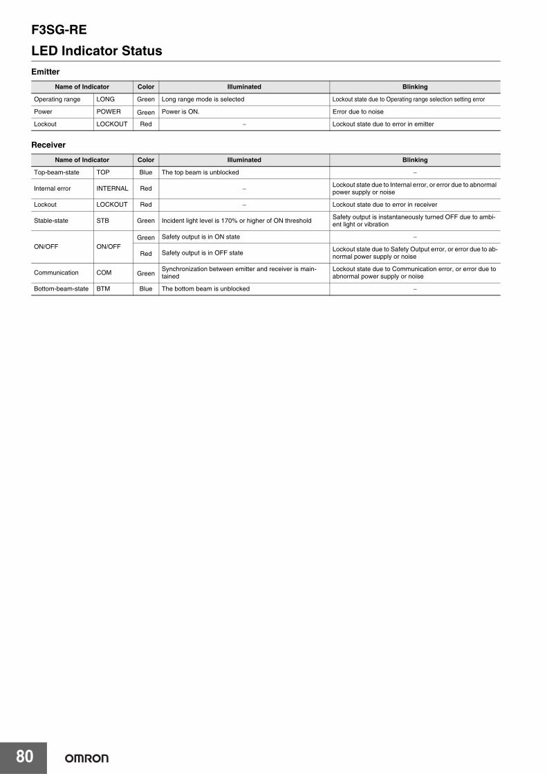
F3SG-RE
80
LED Indicator StatusEmitter
Receiver
Name of Indicator Color Illuminated Blinking
Operating range LONG Green Long range mode is selected Lockout state due to Operating range selection setting error
Power POWER Green Power is ON. Error due to noise
Lockout LOCKOUT Red − Lockout state due to error in emitter
Name of Indicator Color Illuminated Blinking
Top-beam-state TOP Blue The top beam is unblocked −
Internal error INTERNAL Red − Lockout state due to Internal error, or error due to abnormal power supply or noise
Lockout LOCKOUT Red − Lockout state due to error in receiver
Stable-state STB Green Incident light level is 170% or higher of ON thresholdSafety output is instantaneously turned OFF due to ambi-ent light or vibration
ON/OFF ON/OFFGreen Safety output is in ON state −
Red Safety output is in OFF state Lockout state due to Safety Output error, or error due to ab-normal power supply or noise
Communication COM GreenSynchronization between emitter and receiver is main-tained
Lockout state due to Communication error, or error due to abnormal power supply or noise
Bottom-beam-state BTM Blue The bottom beam is unblocked −
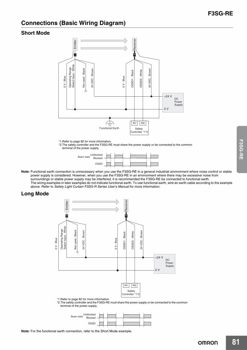
F3SG-RE
81
F3S
G-R
E
Connections (Basic Wiring Diagram)Short Mode
Note: Functional earth connection is unnecessary when you use the F3SG-RE in a general industrial environment where noise control or stable power supply is considered. However, when you use the F3SG-RE in an environment where there may be excessive noise from surroundings or stable power supply may be interfered, it is recommended the F3SG-RE be connected to functional earth.The wiring examples in later examples do not indicate functional earth. To use functional earth, wire an earth cable according to the example above. Refer to Safety Light Curtain F3SG-R Series User's Manual for more information.
Long Mode
Note: For the functional earth connection, refer to the Short Mode example.
+24 V
0 V
OS
SD
1 : B
lack
OS
SD
2 : W
hite
Ope
ratin
g R
ange
Sel
ect I
nput
: W
hite
24 V
DC
: B
row
n
Not
use
d : B
lack
24 V
DC
: B
row
n
0 V
: B
lue
Rec
eive
r
Em
itter
0 V
: B
lue
DCPower Supply
Safety Controller *1*2
IN1 IN2
UnblockedBlocked
OSSD
Functional Earth
Beam state
*1.Refer to page 82 for more information.*2.The safety controller and the F3SG-RE must share the power supply or be connected to the common
terminal of the power supply.
IN1 IN2
+24 V
0 V
OS
SD
1 : B
lack
OS
SD
2 : W
hite
Ope
ratin
g R
ange
Sel
ect I
nput
: W
hite
24 V
DC
: B
row
n
Not
use
d : B
lack
24 V
DC
: B
row
n
0 V
: B
lue
Rec
eive
r
Em
itter
0 V
: B
lue
DCPower Supply
Safety Controller *1*2
UnblockedBlocked
OSSD
Beam state
*1.Refer to page 82 for more information.*2.The safety controller and the F3SG-RE must share the power supply or be connected to the common
terminal of the power supply.
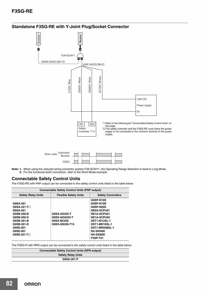
F3SG-RE
82
Standalone F3SG-RE with Y-Joint Plug/Socket Connector
Note: 1. When using the reduced wiring connector system F39-GCNY1, the Operating Range Selection is fixed to Long Mode.2. For the functional earth connection, refer to the Short Mode example.
Connectable Safety Control UnitsThe F3SG-RE with PNP output can be connected to the safety control units listed in the table below.
The F3SG-R with NPN output can be connected to the safety control units listed in the table below.
Connectable Safety Control Units (PNP output)
Safety Relay Units Flexible Safety Units Safety Controllers
G9SA-301G9SA-321-T@G9SA-501G9SB-200-BG9SB-200-DG9SB-301-BG9SB-301-DG9SE-201G9SE-401G9SE-221-T@
G9SX-AD322-TG9SX-ADA222-TG9SX-BC202G9SX-GS226-T15
G9SP-N10SG9SP-N10DG9SP-N20SNE0A-SCPU01NE1A-SCPU01NE1A-SCPU02DST1-ID12SL-1DST1-MD16SL-1DST1-MRD08SL-1NX-SIH400NX-SID800F3SP-T01
Connectable Safety Control Units (NPN output)Safety Relay Units
G9SA-301-P
0 VD
C: B
lue
OS
SD
1: B
lack
OS
SD
2: W
hite
24 V
DC
: Bro
wn
+24V DC
0V
XS5W-D42�-�81-�
F39-GCNY1
XS5F-D42�-�80-�
IN1 IN2
Safety Controller *1*2
Power supply
UnblockedBlocked
OSSD
Beam state
*1.Refer to the following list "Connectable Safety Control Units" onthis page.
*2.The safety controller and the F3SG-RE must share the powersupply or be connected to the common terminal of the powersupply.
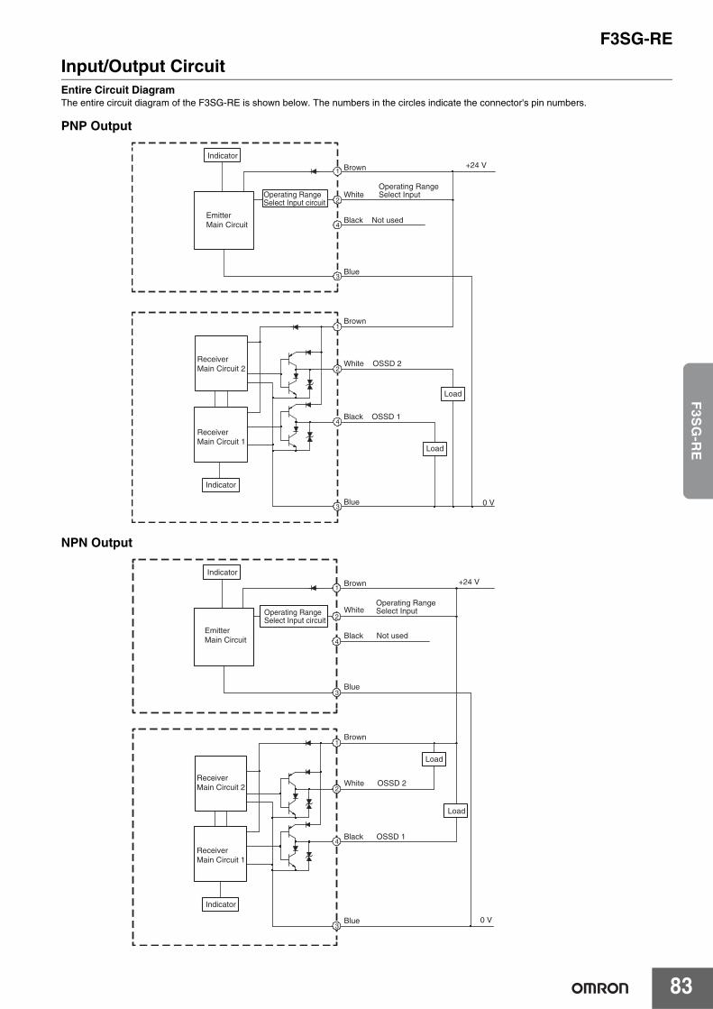
F3SG-RE
83
F3S
G-R
E
Input/Output CircuitEntire Circuit DiagramThe entire circuit diagram of the F3SG-RE is shown below. The numbers in the circles indicate the connector's pin numbers.
PNP Output
NPN Output
1
4
3
2
+24 V1
2
4
3
0 V
Operating Range Select Input circuit
Brown
Black Not used
White
Blue
Brown
White OSSD 2
Black OSSD 1
Blue
Indicator
EmitterMain Circuit
ReceiverMain Circuit 2
ReceiverMain Circuit 1
Indicator
Load
Load
Operating Range Select Input
1
4
3
2
+24 V1
2
4
3
0 V
Brown
Black Not used
White
Blue
Brown
White OSSD 2
Black OSSD 1
Blue
Indicator
EmitterMain Circuit
ReceiverMain Circuit 2
ReceiverMain Circuit 1
Indicator
Load
Load
Operating Range Select Input circuit
Operating Range Select Input
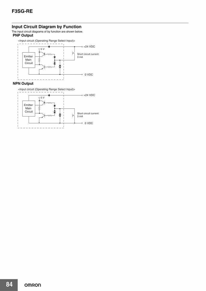
F3SG-RE
84
Input Circuit Diagram by FunctionThe input circuit diagrams of by function are shown below.
PNP Output
NPN Output
Emitter Main Circuit
+24 VDC
0 VDC
5 V
Short circuit current:3 mA
<Input circuit (Operating Range Select Input)>
Emitter Main Circuit
+24 VDC
0 VDC
5 V
Short circuit current:3 mA
<Input circuit (Operating Range Select Input)>
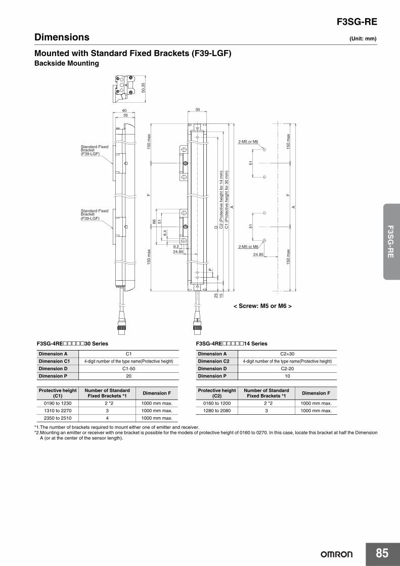
F3SG-RE
85
F3S
G-R
E
Dimensions (Unit: mm)
Mounted with Standard Fixed Brackets (F39-LGF)Backside Mounting
*1.The number of brackets required to mount either one of emitter and receiver.*2.Mounting an emitter or receiver with one bracket is possible for the models of protective height of 0160 to 0270. In this case, locate this bracket at half the Dimension
A (or at the center of the sensor length).
F3SG-4RE@@@@@30 Series
Dimension A C1
Dimension C1 4-digit number of the type name(Protective height)
Dimension D C1-50
Dimension P 20
Protective height(C1)
Number of Standard Fixed Brackets *1 Dimension F
0190 to 1230 2 *2 1000 mm max.
1310 to 2270 3 1000 mm max.
2350 to 2510 4 1000 mm max.
F3SG-4RE@@@@@14 Series
Dimension A C2+30
Dimension C2 4-digit number of the type name(Protective height)
Dimension D C2-20
Dimension P 10
Protective height(C2)
Number of Standard Fixed Brackets *1 Dimension F
0160 to 1200 2 *2 1000 mm max.
1280 to 2080 3 1000 mm max.
P
51
24.85
F
D C2
(Pro
tect
ive
heig
ht fo
r 14
mm
)
FA
150
max
150
max
150
max
150
max
25 15
24.85
6.4
9.251
66
35
C1
(Pro
tect
ive
heig
ht fo
r 30
mm
)A
512-M5 or M6
2-M5 or M6
3540
Standard Fixed Bracket
Standard Fixed Bracket
(F39-LGF)
(F39-LGF)
50.3
5
< Screw: M5 or M6 >
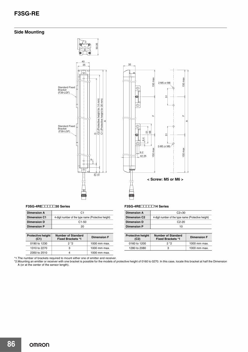
F3SG-RE
86
Side Mounting
*1.The number of brackets required to mount either one of emitter and receiver.*2.Mounting an emitter or receiver with one bracket is possible for the models of protective height of 0160 to 0270. In this case, locate this bracket at half the Dimension
A (or at the center of the sensor length).
F3SG-4RE@@@@@30 Series
Dimension A C1
Dimension C1 4-digit number of the type name (Protective height)
Dimension D C1-50
Dimension P 20
Protective height(C1)
Number of Standard Fixed Brackets *1 Dimension F
0190 to 1230 2 *2 1000 mm max.
1310 to 2270 3 1000 mm max.
2350 to 2510 4 1000 mm max.
F3SG-4RE@@@@@14 Series
Dimension A C2+30
Dimension C2 4-digit number of the type name (Protective height)
Dimension D C2-20
Dimension P 10
Protective height(C2)
Number of Standard Fixed Brackets *1 Dimension F
0160 to 1200 2 *2 1000 mm max.1280 to 2080 3 1000 mm max.
P
D
C2
(Pro
tect
ive
heig
ht fo
r 14
mm
)25 15
3540
C1
(Pro
tect
ive
heig
ht fo
r 30
mm
)A
Standard Fixed Bracket
Standard Fixed Bracket
(F39-LGF)
(F39-LGF)
50.3
5
51
F42.35
A15
0 m
ax15
0 m
axF
150
max
150
max
5151
9.2
6.4
66
35
2-M5 or M6
2-M5 or M6
< Screw: M5 or M6 >
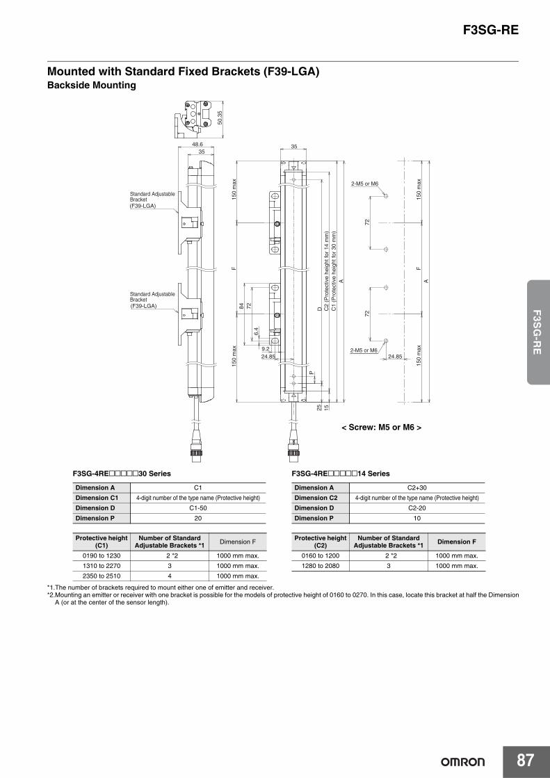
F3SG-RE
87
F3S
G-R
E
Mounted with Standard Fixed Brackets (F39-LGA)Backside Mounting
*1.The number of brackets required to mount either one of emitter and receiver.*2.Mounting an emitter or receiver with one bracket is possible for the models of protective height of 0160 to 0270. In this case, locate this bracket at half the Dimension
A (or at the center of the sensor length).
F3SG-4RE@@@@@30 Series
Dimension A C1
Dimension C1 4-digit number of the type name (Protective height)
Dimension D C1-50
Dimension P 20
Protective height(C1)
Number of Standard Adjustable Brackets *1 Dimension F
0190 to 1230 2 *2 1000 mm max.
1310 to 2270 3 1000 mm max.
2350 to 2510 4 1000 mm max.
F3SG-4RE@@@@@14 Series
Dimension A C2+30
Dimension C2 4-digit number of the type name (Protective height)
Dimension D C2-20
Dimension P 10
Protective height(C2)
Number of Standard Adjustable Brackets *1 Dimension F
0160 to 1200 2 *2 1000 mm max.
1280 to 2080 3 1000 mm max.
P
72
24.85
F
D
C2
(Pro
tect
ive
heig
ht fo
r 14
mm
)
FA
150
max
150
max
150
max
150
max
25 15
24.859.2
6.4
72
84
35
C1
(Pro
tect
ive
heig
ht fo
r 30
mm
)A
72
2-M5 or M6
2-M5 or M6
3548.6
Standard AdjustableBracket
Standard AdjustableBracket
(F39-LGA)
(F39-LGA)
50.3
5
< Screw: M5 or M6 >
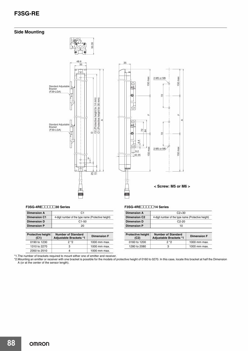
F3SG-RE
88
Side Mounting
*1.The number of brackets required to mount either one of emitter and receiver.*2.Mounting an emitter or receiver with one bracket is possible for the models of protective height of 0160 to 0270. In this case, locate this bracket at half the Dimension
A (or at the center of the sensor length).
F3SG-4RE@@@@@30 Series
Dimension A C1
Dimension C1 4-digit number of the type name (Protective height)
Dimension D C1-50
Dimension P 20
Protective height(C1)
Number of Standard Adjustable Brackets *1 Dimension F
0190 to 1230 2 *2 1000 mm max.
1310 to 2270 3 1000 mm max.
2350 to 2510 4 1000 mm max.
F3SG-4RE@@@@@14 Series
Dimension A C2+30
Dimension C2 4-digit number of the type name (Protective height)
Dimension D C2-20
Dimension P 10
Protective height(C2)
Number of Standard Adjustable Brackets *1 Dimension F
0160 to 1200 2 *2 1000 mm max.
1280 to 2080 3 1000 mm max.
PD C
2 (P
rote
ctiv
e he
ight
for
14 m
m)
25 15
3548.6
C1
(Pro
tect
ive
heig
ht fo
r 30
mm
)A
Standard Adjustable Bracket
Standard Adjustable Bracket
(F39-LGA)
(F39-LGA)
50.3
5
72
F
42.35
A
150
max
150
max
F
150
max
150
max
6.4
9.2
7272
84
35
2-M5 or M6
2-M5 or M6
< Screw: M5 or M6 >
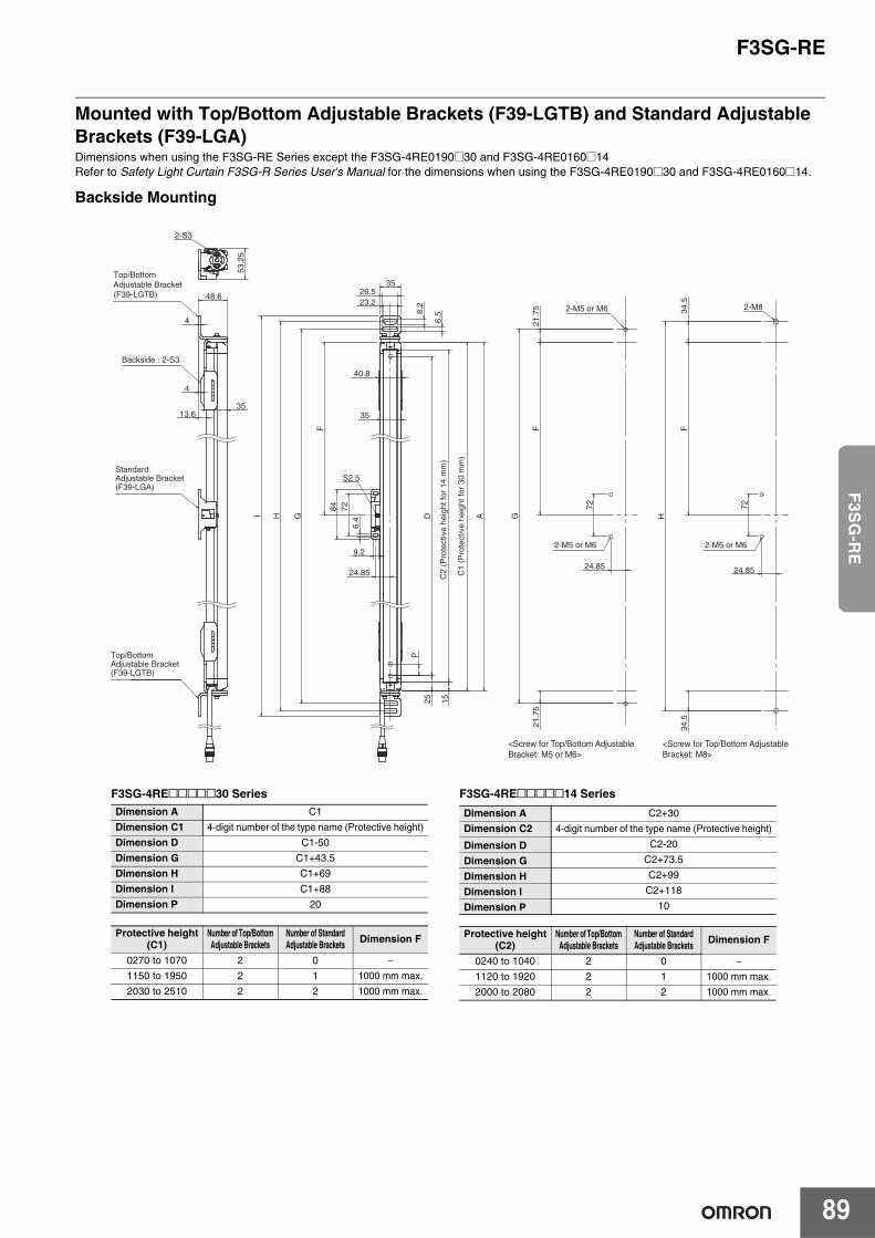
F3SG-RE
89
F3S
G-R
E
Mounted with Top/Bottom Adjustable Brackets (F39-LGTB) and Standard Adjustable Brackets (F39-LGA)Dimensions when using the F3SG-RE Series except the F3SG-4RE0190@30 and F3SG-4RE0160@14Refer to Safety Light Curtain F3SG-R Series User's Manual for the dimensions when using the F3SG-4RE0190@30 and F3SG-4RE0160@14.
Backside Mounting
Standard Adjustable Bracket(F39-LGA)
Top/Bottom Adjustable Bracket(F39-LGTB)
Top/Bottom Adjustable Bracket(F39-LGTB)
Backside : 2-S3
2-M5 or M6
2-M5 or M6
2-M5 or M6
C1
(Pro
tect
ive
heig
ht fo
r 30
mm
)
C2
(Pro
tect
ive
heig
ht fo
r 14
mm
)
<Screw for Top/Bottom Adjustable Bracket: M5 or M6>
<Screw for Top/Bottom Adjustable Bracket: M8>
48.6
35 13.6
4
4
2-S3 5
3.25
2-M8
S2.5
84
G
35
40.8
A
H
I
26.5
35
23.2
6.5
8.2
9.2
72
6.4
G
P
15
25
F
21.
75
F
F
H
34.
5 3
4.5
21.
75
D
24.85
72
24.85
72
24.85
F3SG-4RE@@@@@30 Series Dimension A C1
Dimension C1 4-digit number of the type name (Protective height)
Dimension D C1-50
Dimension G C1+43.5
Dimension H C1+69
Dimension I C1+88
Dimension P 20
Protective height(C1)
Number of Top/BottomAdjustable Brackets
Number of Standard Adjustable Brackets Dimension F
0270 to 1070 2 0 −1150 to 1950 2 1 1000 mm max.
2030 to 2510 2 2 1000 mm max.
F3SG-4RE@@@@@14 SeriesDimension A C2+30
Dimension C2 4-digit number of the type name (Protective height)
Dimension D C2-20
Dimension G C2+73.5
Dimension H C2+99
Dimension I C2+118
Dimension P 10
Protective height(C2)
Number of Top/BottomAdjustable Brackets
Number of Standard Adjustable Brackets Dimension F
0240 to 1040 2 0 −1120 to 1920 2 1 1000 mm max.
2000 to 2080 2 2 1000 mm max.
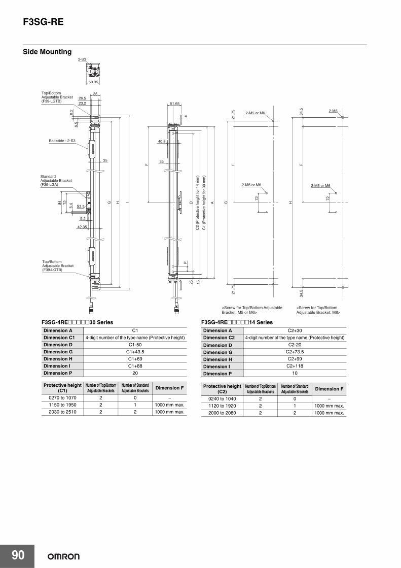
F3SG-RE
90
Side Mounting
<Screw for Top/Bottom Adjustable Bracket: M5 or M6>
<Screw for Top/Bottom Adjustable Bracket: M8>
Top/Bottom Adjustable Bracket(F39-LGTB)
Top/Bottom Adjustable Bracket(F39-LGTB)
Standard Adjustable Bracket(F39-LGA)
Backside : 2-S3
2-M5 or M6
2-M5 or M6
2-M5 or M6
C1
(Pro
tect
ive
heig
ht fo
r 30
mm
)
C2
(Pro
tect
ive
heig
ht fo
r 14
mm
)
S2.5
35
23.2 26.5
35
6.5
8
.2
G
H
I 84
72
6.4
9.2
2-S3
50.35
2-M8
40.8
35
4
51.65
A
D
P
F
F
F
15
25
H
34.
5 3
4.5
21.
75
21.
75
G 7
2
72
42.35
F3SG-4RE@@@@@30 Series Dimension A C1
Dimension C1 4-digit number of the type name (Protective height)
Dimension D C1-50
Dimension G C1+43.5
Dimension H C1+69
Dimension I C1+88
Dimension P 20
Protective height(C1)
Number of Top/BottomAdjustable Brackets
Number of Standard Adjustable Brackets Dimension F
0270 to 1070 2 0 −1150 to 1950 2 1 1000 mm max.
2030 to 2510 2 2 1000 mm max.
F3SG-4RE@@@@@14 Series Dimension A C2+30
Dimension C2 4-digit number of the type name (Protective height)
Dimension D C2-20
Dimension G C2+73.5
Dimension H C2+99
Dimension I C2+118
Dimension P 10
Protective height(C2)
Number of Top/BottomAdjustable Brackets
Number of Standard Adjustable Brackets Dimension F
0240 to 1040 2 0 −1120 to 1920 2 1 1000 mm max.
2000 to 2080 2 2 1000 mm max.
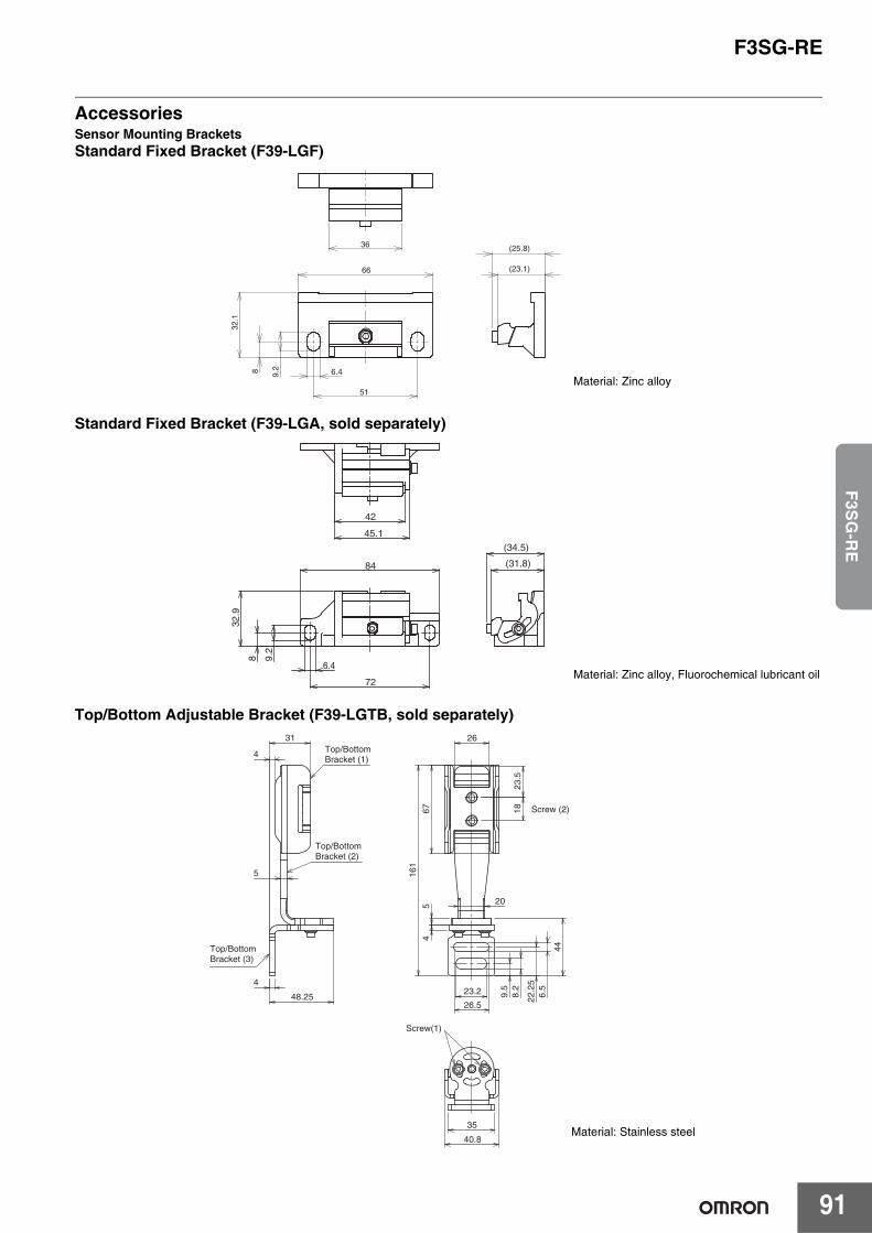
F3SG-RE
91
F3S
G-R
E
AccessoriesSensor Mounting BracketsStandard Fixed Bracket (F39-LGF)
Standard Fixed Bracket (F39-LGA, sold separately)
Top/Bottom Adjustable Bracket (F39-LGTB, sold separately)
51
8
(23.1)
(25.8)
9.2
66
6.4
32.1
36
Material: Zinc alloy
8
72
42
45.1
84
9.2
6.4
32.9
(31.8)
(34.5)
Material: Zinc alloy, Fluorochemical lubricant oil
Material: Stainless steel
4
31
4
48.25
5
26.5
23.2 8.2
6.5
9.5
22.2
5
44
45
1867
23.5
26
20
161
35
40.8
Top/Bottom Bracket (1)
Top/Bottom Bracket (2)
Top/Bottom Bracket (3)
Screw (2)
Screw(1)
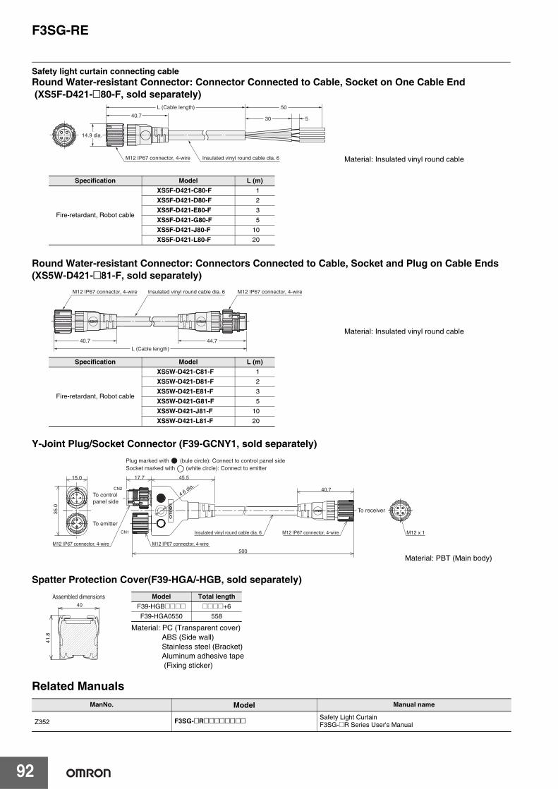
F3SG-RE
92
Safety light curtain connecting cableRound Water-resistant Connector: Connector Connected to Cable, Socket on One Cable End (XS5F-D421-@80-F, sold separately)
Round Water-resistant Connector: Connectors Connected to Cable, Socket and Plug on Cable Ends (XS5W-D421-@81-F, sold separately)
Y-Joint Plug/Socket Connector (F39-GCNY1, sold separately)
Spatter Protection Cover(F39-HGA/-HGB, sold separately)
Related ManualsManNo. Model Manual name
Z352 F3SG-@R@@@@@@@@ Safety Light CurtainF3SG-@R Series User's Manual
Specification Model L (m)
Fire-retardant, Robot cable
XS5F-D421-C80-F 1
XS5F-D421-D80-F 2
XS5F-D421-E80-F 3
XS5F-D421-G80-F 5
XS5F-D421-J80-F 10
XS5F-D421-L80-F 20
40.7
L (Cable length)
M12 IP67 connector, 4-wire Insulated vinyl round cable dia. 6
50
30 5
14.9 dia.
Material: Insulated vinyl round cable
Specification Model L (m)
Fire-retardant, Robot cable
XS5W-D421-C81-F 1
XS5W-D421-D81-F 2
XS5W-D421-E81-F 3
XS5W-D421-G81-F 5
XS5W-D421-J81-F 10
XS5W-D421-L81-F 20
40.7
L (Cable length)
M12 IP67 connector, 4-wire Insulated vinyl round cable dia. 6 M12 IP67 connector, 4-wire
44.7
Material: Insulated vinyl round cable
Plug marked with (bule circle): Connect to control panel sideSocket marked with (white circle): Connect to emitter
CN1
CN2
4.6 dia.
17.7 45.5
M12 x 1
40.7
35.0
15.0
500
To receiver
To control panel side
To emitter
M12 IP67 connector, 4-wire M12 IP67 connector, 4-wire
Insulated vinyl round cable dia. 6 M12 IP67 connector, 4-wire
Material: PBT (Main body)
40
41.8
Assembled dimensions
Material: PC (Transparent cover)ABS (Side wall)Stainless steel (Bracket)Aluminum adhesive tape (Fixing sticker)
Model Total lengthF39-HGB@@@@ @@@@+6
F39-HGA0550 558
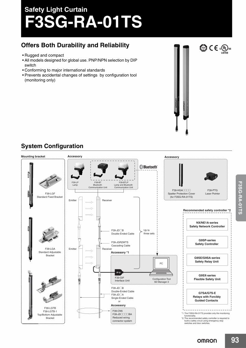
93
F3S
G-R
A-01T
SSafety Light Curtain
F3SG-RA-01TSOffers Both Durability and Reliability• Rugged and compact• All models designed for global use. PNP/NPN selection by DIP
switch• Conforming to major international standards• Prevents accidental changes of settings by configuration tool
(monitoring only)
System Configuration
IF-U
PC
F39-LGFStandard Fixed Bracket
F39-LGAStandard Adjustable
Bracket
F39-LGTBF39-LGTB-1
Top/Bottom Adjustable Bracket
F39-LPLamp
F39-BTLPLamp and Bluetooth Communication Unit
F39-BTBluetooth
Communication Unit
F39-HGA@@@@Spatter Protection Cover
(for F3SG-RA-01TS)
F39-PTGLaser Pointer
NX/NE1A-seriesSafety Network Controller
G9SP-seriesSafety Controller
G9SE/G9SA-seriesSafety Relay Unit
G9SX-seriesFlexible Safety Unit
G7SA/G7S-ERelays with Forcibly
Guided Contacts
Mounting bracket Accessory Accessory
Emitter Receiver
Emitter Receiver
F39-JGR2WTSCascading Cable
F39-JD□BDouble-Ended Cable
Up to three sets
F39-JD□BDouble-Ended CableF39-JD□ASingle-Ended Cable or
F39-CN5F39-JD@@@@BAReduced wiring connector system
F39-GIFInterface Unit
Configuration ToolSD Manager 2
Recommended safety controller *2
Accessory
Accessory *1
*1. The F3SG-RA-01TS provides only the monitoring functionality.
*2. The recommended safety controller is required to build a safety circuit using emergency stop switches and door switches.
T
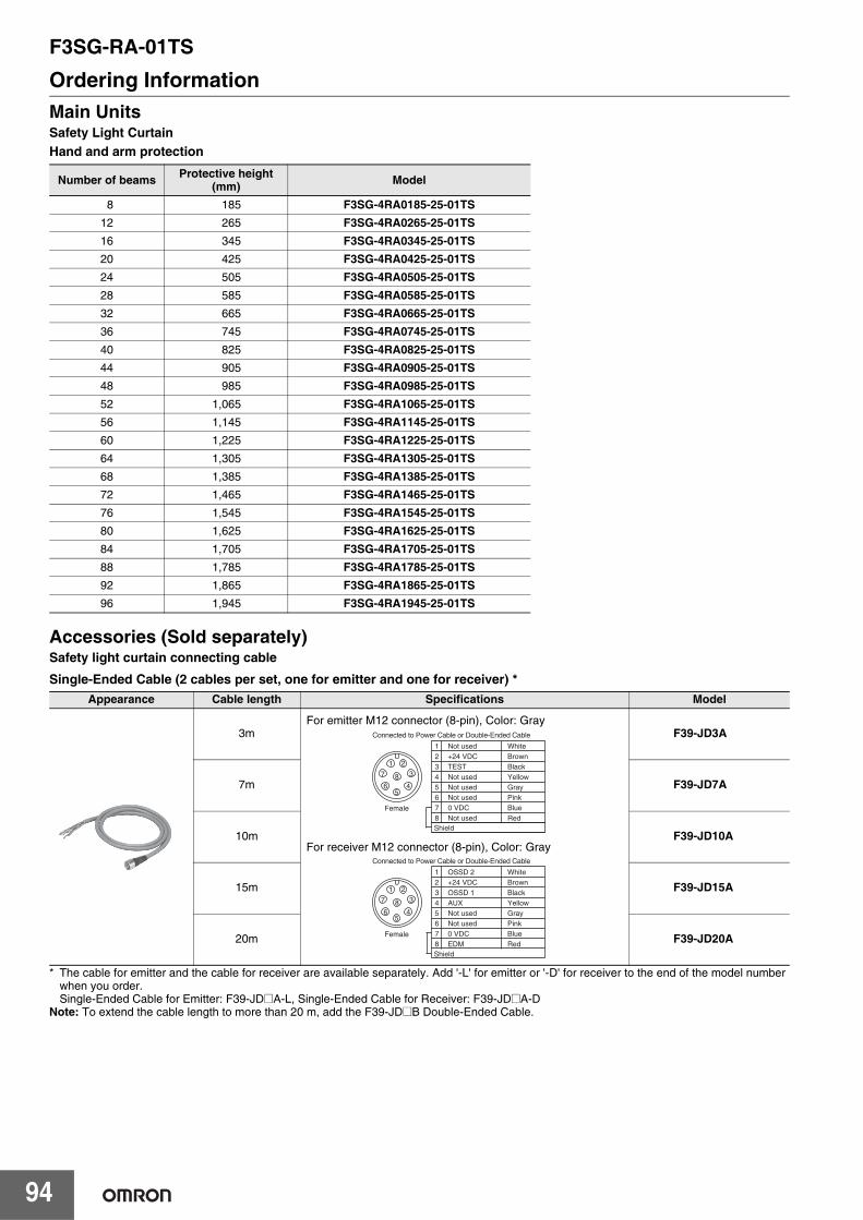
F3SG-RA-01TS
94
Ordering InformationMain UnitsSafety Light CurtainHand and arm protection
Accessories (Sold separately)Safety light curtain connecting cable
Single-Ended Cable (2 cables per set, one for emitter and one for receiver) *
* The cable for emitter and the cable for receiver are available separately. Add '-L' for emitter or '-D' for receiver to the end of the model number when you order.Single-Ended Cable for Emitter: F39-JD@A-L, Single-Ended Cable for Receiver: F39-JD@A-D
Note: To extend the cable length to more than 20 m, add the F39-JD@B Double-Ended Cable.
Number of beams Protective height (mm) Model
8 185 F3SG-4RA0185-25-01TS12 265 F3SG-4RA0265-25-01TS16 345 F3SG-4RA0345-25-01TS20 425 F3SG-4RA0425-25-01TS24 505 F3SG-4RA0505-25-01TS28 585 F3SG-4RA0585-25-01TS32 665 F3SG-4RA0665-25-01TS36 745 F3SG-4RA0745-25-01TS40 825 F3SG-4RA0825-25-01TS44 905 F3SG-4RA0905-25-01TS48 985 F3SG-4RA0985-25-01TS52 1,065 F3SG-4RA1065-25-01TS56 1,145 F3SG-4RA1145-25-01TS60 1,225 F3SG-4RA1225-25-01TS64 1,305 F3SG-4RA1305-25-01TS68 1,385 F3SG-4RA1385-25-01TS72 1,465 F3SG-4RA1465-25-01TS76 1,545 F3SG-4RA1545-25-01TS80 1,625 F3SG-4RA1625-25-01TS84 1,705 F3SG-4RA1705-25-01TS88 1,785 F3SG-4RA1785-25-01TS92 1,865 F3SG-4RA1865-25-01TS96 1,945 F3SG-4RA1945-25-01TS
Appearance Cable length Specifications Model
3m F39-JD3A
7m F39-JD7A
10m F39-JD10A
15m F39-JD15A
20m F39-JD20A
Connected to Power Cable or Double-Ended Cable
5
84
3
21
7
6
Female
2
7
56
1+24 VDC
0 VDC
Not usedNot used
Not usedBrown
Blue
GrayPink
White
8 Not used Red
3 TEST Black4 Not used Yellow
Shield
Connected to Power Cable or Double-Ended Cable
5
84
3
21
7
6
Female
2
7
56
1+24 VDC
0 VDC
Not usedNot used
OSSD 2Brown
Blue
GrayPink
White
8 EDM Red
3 OSSD 1 Black4 AUX Yellow
Shield
For emitter M12 connector (8-pin), Color: Gray
For receiver M12 connector (8-pin), Color: Gray
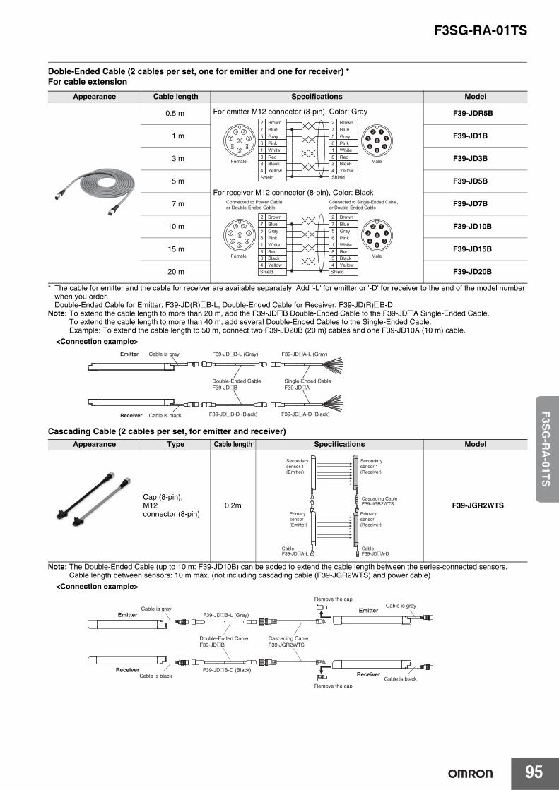
F3SG-RA-01TS
95
F3S
G-R
A-01T
S
Doble-Ended Cable (2 cables per set, one for emitter and one for receiver) *For cable extension
* The cable for emitter and the cable for receiver are available separately. Add '-L' for emitter or '-D' for receiver to the end of the model number when you order.Double-Ended Cable for Emitter: F39-JD(R)@B-L, Double-Ended Cable for Receiver: F39-JD(R)@B-D
Note: To extend the cable length to more than 20 m, add the F39-JD@B Double-Ended Cable to the F39-JD@A Single-Ended Cable.To extend the cable length to more than 40 m, add several Double-Ended Cables to the Single-Ended Cable.Example: To extend the cable length to 50 m, connect two F39-JD20B (20 m) cables and one F39-JD10A (10 m) cable.
Cascading Cable (2 cables per set, for emitter and receiver)
Note: The Double-Ended Cable (up to 10 m: F39-JD10B) can be added to extend the cable length between the series-connected sensors.Cable length between sensors: 10 m max. (not including cascading cable (F39-JGR2WTS) and power cable)
Appearance Cable length Specifications Model
0.5 m F39-JDR5B
1 m F39-JD1B
3 m F39-JD3B
5 m F39-JD5B
7 m F39-JD7B
10 m F39-JD10B
15 m F39-JD15B
20 m F39-JD20B
Appearance Type Cable length Specifications Model
Cap (8-pin), M12 connector (8-pin)
0.2m F39-JGR2WTS
BrownBlueGrayPinkWhiteRedBlackYellow
BlueGrayPinkWhiteRedBlackYellow
27561834
Brown
5
84
321
7
65
86
712
3
4
27561834
Female Male
Shield Shield
BrownBlueGrayPinkWhiteRedBlackYellow
BlueGrayPinkWhiteRedBlackYellow
27561834
Brown
5
84
321
7
65
86
712
3
4
27561834
Connected to Power Cable or Double-Ended Cable
Connected to Single-Ended Cable, or Double-Ended Cable
Female Male
Shield Shield
For emitter M12 connector (8-pin), Color: Gray
For receiver M12 connector (8-pin), Color: Black
<Connection example>Emitter
Receiver
Cable is gray F39-JD@B-L (Gray) F39-JD@A-L (Gray)
Double-Ended CableF39-JD@B
Single-Ended CableF39-JD@A
Cable is black F39-JD@B-D (Black) F39-JD@A-D (Black)
Secondary sensor 1 (Emitter)
Secondary sensor 1 (Receiver)
Primary sensor (Emitter)
Primary sensor (Receiver)
Cascading CableF39-JGR2WTS
CableF39-JD@A-D
CableF39-JD@A-L
Emitter
Receiver
Cable is grayF39-JD@B-L (Gray)
Double-Ended CableF39-JD@B
Cable is blackF39-JD@B-D (Black)
Cascading CableF39-JGR2WTS
Emitter
Receiver
Cable is gray
Cable is blackRemove the cap
Remove the cap
<Connection example>
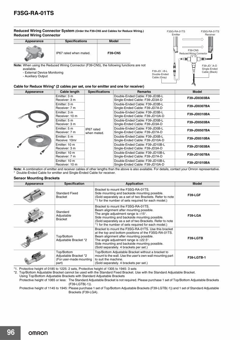
F3SG-RA-01TS
96
Reduced Wiring Connector System (Order the F39-CN5 and Cables for Reduce Wiring.) Reduced Wiring Connector
Note: When using the Reduced Wiring Connector (F39-CN5), the following functions are not available.- External Device Monitoring- Auxiliary Output
Cable for Reduce Wiring* (2 cables per set, one for emitter and one for receiver)
Note: A combination of emitter and receiver cables of other lengths than the above is also available. For details, contact your Omron representative.* Double-Ended Cable for emitter and Single-Ended Cable for receiver.
Sensor Mounting Brackets
*1. Protective height of 0185 to 1225: 2 sets, Protective height of 1305 to 1945: 3 sets*2. Top/Bottom Adjustable Bracket cannot be used with the Standard Fixed Bracket. Use with the Standard Adjustable Bracket.
Using Top/Bottom Adjustable Brackets with Standard Adjustable BracketsProtective height of 1065 or less: The Standard Adjustable Bracket is not required. Please purchase 1 set of Top/Bottom Adjustable Brackets
(F39-LGTB(-1)).Protective height of 1145 to 1945: Please purchase 1 set of Top/Bottom Adjustable Brackets (F39-LGTB(-1)) and 1 set of Standard Adjustable
Brackets (F39-LGA).
Appearance Specifications Model
IP67 rated when mated. F39-CN5
Appearance Cable length Specifications Remarks ModelEmitter: 3 mReceiver: 3 m
IP67 rated when mated.
Double-Ended Cable: F39-JD3B-LSingle-Ended Cable: F39-JD3A-D F39-JD0303BA
Emitter: 3 mReceiver: 7 m
Double-Ended Cable: F39-JD3B-LSingle-Ended Cable: F39-JD7A-D F39-JD0307BA
Emitter: 3 mReceiver: 10 m
Double-Ended Cable: F39-JD3B-LSingle-Ended Cable: F39-JD10A-D F39-JD0310BA
Emitter: 5 mReceiver: 3 m
Double-Ended Cable: F39-JD5B-LSingle-Ended Cable: F39-JD3A-D F39-JD0503BA
Emitter: 5 mReceiver: 7 m
Double-Ended Cable: F39-JD5B-LSingle-Ended Cable: F39-JD7A-D F39-JD0507BA
Emitter: 5 mReceive: 10mr
Double-Ended Cable: F39-JD5B-LSingle-Ended Cable: F39-JD10A-D F39-JD0510BA
Emitter: 10 mReceiver: 3 m
Double-Ended Cable: F39-JD10B-LSingle-Ended Cable: F39-JD3A-D F39-JD1003BA
Emitter: 10 mReceiver: 7 m
Double-Ended Cable: F39-JD10B-LSingle-Ended Cable: F39-JD7A-D F39-JD1007BA
Emitter: 10 mReceiver: 10 m
Double-Ended Cable: F39-JD10B-LSingle-Ended Cable: F39-JD10A-D F39-JD1010BA
Appearance Specification Application Model
Standard Fixed Bracket
Bracket to mount the F3SG-RA-01TS.Side mounting and backside mounting possible.(Sold separately as a set of two Brackets. Refer to note*1 for the number of sets required for each model.)
F39-LGF
Standard Adjustable Bracket
Bracket to mount the F3SG-RA-01TS.Beam alignment after mounting possible.The angle adjustment range is ±15°.Side mounting and backside mounting possible.(Sold separately as a set of two Brackets. Refer to note *1 for the number of sets required for each model.)
F39-LGA
Top/Bottom Adjustable Bracket *2
Bracket to mount the F3SG-RA-01TS. Use this bracket at the top and bottom positions of the F3SG-RA-01TS. Beam alignment after mounting possible. The angle adjustment range is ±22.5°.Side mounting and backside mounting possible.(Sold separately. 4 brackets per set.)
F39-LGTB
Top/Bottom Adjustable Bracket *2(For user-made mounting part)
Top/Bottom Adjustable Bracket without a bracket to mount to the wall. Use the user's own wall mounting part to suit the machine.(Sold separately. 4 brackets per set.)
F39-LGTB-1
F3SG-RA-01TSEmitter
F3SG-RA-01TSReceiver
F39-CN5Reduced Wiring Connector
F39-JD@A-DSingle-Ended Cable (Black)F39-JD@-B-L
Double-Ended Cable (Gray)
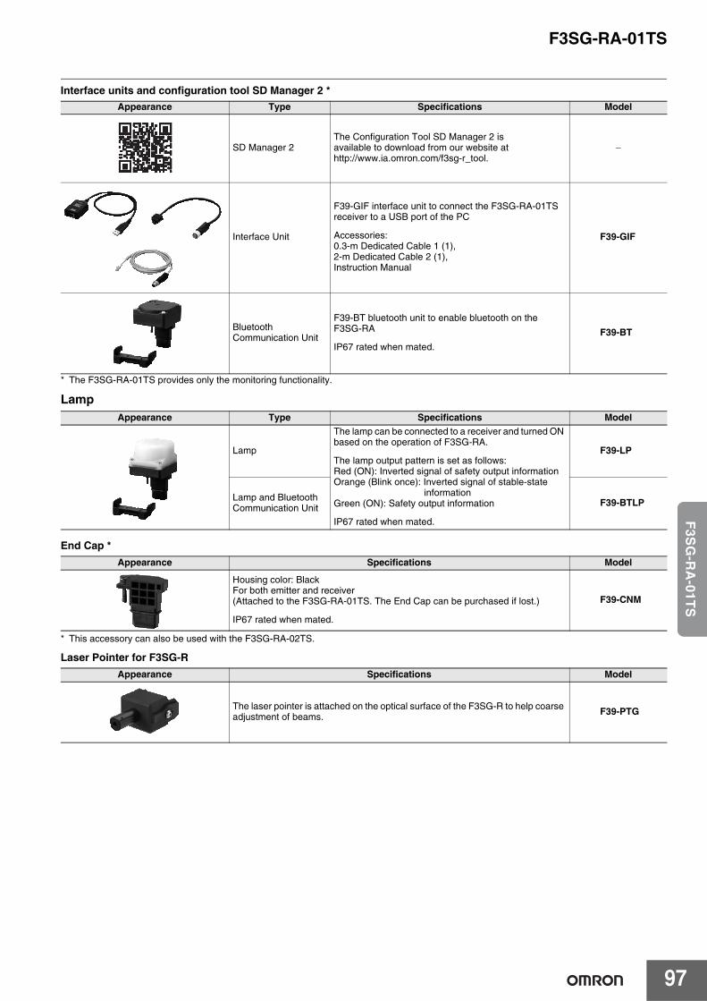
F3SG-RA-01TS
97
F3S
G-R
A-01T
S
Interface units and configuration tool SD Manager 2 *
* The F3SG-RA-01TS provides only the monitoring functionality.
Lamp
End Cap *
* This accessory can also be used with the F3SG-RA-02TS.
Laser Pointer for F3SG-R
Appearance Type Specifications Model
SD Manager 2The Configuration Tool SD Manager 2 is available to download from our website at http://www.ia.omron.com/f3sg-r_tool.
−
Interface Unit
F39-GIF interface unit to connect the F3SG-RA-01TS receiver to a USB port of the PC
Accessories:0.3-m Dedicated Cable 1 (1),2-m Dedicated Cable 2 (1),Instruction Manual
F39-GIF
Bluetooth Communication Unit
F39-BT bluetooth unit to enable bluetooth on the F3SG-RA
IP67 rated when mated.
F39-BT
Appearance Type Specifications Model
Lamp
The lamp can be connected to a receiver and turned ON based on the operation of F3SG-RA.
The lamp output pattern is set as follows:Red (ON): Inverted signal of safety output informationOrange (Blink once): Inverted signal of stable-state
informationGreen (ON): Safety output information
IP67 rated when mated.
F39-LP
Lamp and Bluetooth Communication Unit F39-BTLP
Appearance Specifications Model
Housing color: BlackFor both emitter and receiver(Attached to the F3SG-RA-01TS. The End Cap can be purchased if lost.)
IP67 rated when mated.
F39-CNM
Appearance Specifications Model
The laser pointer is attached on the optical surface of the F3SG-R to help coarse adjustment of beams. F39-PTG
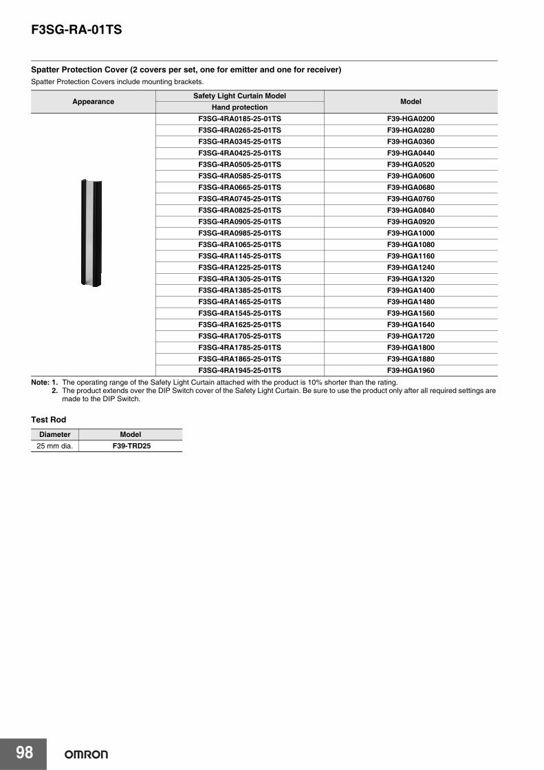
F3SG-RA-01TS
98
Spatter Protection Cover (2 covers per set, one for emitter and one for receiver)Spatter Protection Covers include mounting brackets.
Note: 1. The operating range of the Safety Light Curtain attached with the product is 10% shorter than the rating.2. The product extends over the DIP Switch cover of the Safety Light Curtain. Be sure to use the product only after all required settings are
made to the DIP Switch.
Test Rod
AppearanceSafety Light Curtain Model
ModelHand protection
F3SG-4RA0185-25-01TS F39-HGA0200F3SG-4RA0265-25-01TS F39-HGA0280F3SG-4RA0345-25-01TS F39-HGA0360F3SG-4RA0425-25-01TS F39-HGA0440F3SG-4RA0505-25-01TS F39-HGA0520F3SG-4RA0585-25-01TS F39-HGA0600F3SG-4RA0665-25-01TS F39-HGA0680F3SG-4RA0745-25-01TS F39-HGA0760F3SG-4RA0825-25-01TS F39-HGA0840F3SG-4RA0905-25-01TS F39-HGA0920F3SG-4RA0985-25-01TS F39-HGA1000F3SG-4RA1065-25-01TS F39-HGA1080F3SG-4RA1145-25-01TS F39-HGA1160F3SG-4RA1225-25-01TS F39-HGA1240F3SG-4RA1305-25-01TS F39-HGA1320F3SG-4RA1385-25-01TS F39-HGA1400F3SG-4RA1465-25-01TS F39-HGA1480F3SG-4RA1545-25-01TS F39-HGA1560F3SG-4RA1625-25-01TS F39-HGA1640F3SG-4RA1705-25-01TS F39-HGA1720F3SG-4RA1785-25-01TS F39-HGA1800F3SG-4RA1865-25-01TS F39-HGA1880F3SG-4RA1945-25-01TS F39-HGA1960
Diameter Model25 mm dia. F39-TRD25
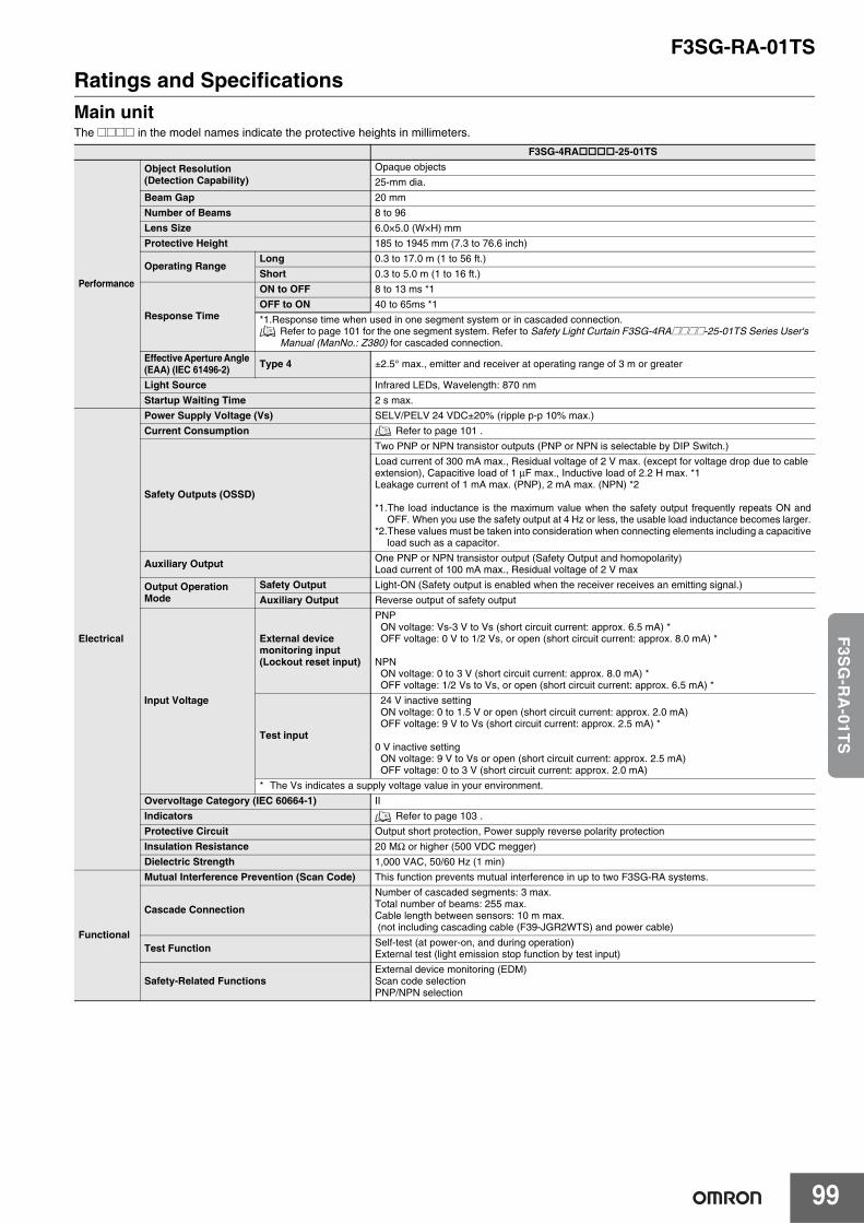
F3SG-RA-01TS
99
F3S
G-R
A-01T
S
Ratings and SpecificationsMain unitThe @@@@ in the model names indicate the protective heights in millimeters.
F3SG-4RA-25-01TS
Performance
Object Resolution(Detection Capability)
Opaque objects
25-mm dia.
Beam Gap 20 mm
Number of Beams 8 to 96
Lens Size 6.0×5.0 (W×H) mm
Protective Height 185 to 1945 mm (7.3 to 76.6 inch)
Operating RangeLong 0.3 to 17.0 m (1 to 56 ft.)
Short 0.3 to 5.0 m (1 to 16 ft.)
Response Time
ON to OFF 8 to 13 ms *1
OFF to ON 40 to 65ms *1
*1.Response time when used in one segment system or in cascaded connection. Refer to page 101 for the one segment system. Refer to Safety Light Curtain F3SG-4RA@@@@-25-01TS Series User's Manual (ManNo.: Z380) for cascaded connection.
Effective Aperture Angle (EAA) (IEC 61496-2) Type 4 ±2.5° max., emitter and receiver at operating range of 3 m or greater
Light Source Infrared LEDs, Wavelength: 870 nm
Startup Waiting Time 2 s max.
Electrical
Power Supply Voltage (Vs) SELV/PELV 24 VDC±20% (ripple p-p 10% max.)
Current Consumption Refer to page 101 .
Safety Outputs (OSSD)
Two PNP or NPN transistor outputs (PNP or NPN is selectable by DIP Switch.)
Load current of 300 mA max., Residual voltage of 2 V max. (except for voltage drop due to cable extension), Capacitive load of 1 μF max., Inductive load of 2.2 H max. *1Leakage current of 1 mA max. (PNP), 2 mA max. (NPN) *2
*1.The load inductance is the maximum value when the safety output frequently repeats ON andOFF. When you use the safety output at 4 Hz or less, the usable load inductance becomes larger.
*2.These values must be taken into consideration when connecting elements including a capacitiveload such as a capacitor.
Auxiliary Output One PNP or NPN transistor output (Safety Output and homopolarity)Load current of 100 mA max., Residual voltage of 2 V max
Output Operation Mode
Safety Output Light-ON (Safety output is enabled when the receiver receives an emitting signal.)
Auxiliary Output Reverse output of safety output
Input Voltage
External device monitoring input (Lockout reset input)
PNPON voltage: Vs-3 V to Vs (short circuit current: approx. 6.5 mA) * OFF voltage: 0 V to 1/2 Vs, or open (short circuit current: approx. 8.0 mA) *
NPNON voltage: 0 to 3 V (short circuit current: approx. 8.0 mA) *OFF voltage: 1/2 Vs to Vs, or open (short circuit current: approx. 6.5 mA) *
Test input
24 V inactive settingON voltage: 0 to 1.5 V or open (short circuit current: approx. 2.0 mA)OFF voltage: 9 V to Vs (short circuit current: approx. 2.5 mA) *
0 V inactive settingON voltage: 9 V to Vs or open (short circuit current: approx. 2.5 mA)OFF voltage: 0 to 3 V (short circuit current: approx. 2.0 mA)
* The Vs indicates a supply voltage value in your environment.
Overvoltage Category (IEC 60664-1) II
Indicators Refer to page 103 .
Protective Circuit Output short protection, Power supply reverse polarity protection
Insulation Resistance 20 MΩ or higher (500 VDC megger)
Dielectric Strength 1,000 VAC, 50/60 Hz (1 min)
Functional
Mutual Interference Prevention (Scan Code) This function prevents mutual interference in up to two F3SG-RA systems.
Cascade Connection
Number of cascaded segments: 3 max.Total number of beams: 255 max.Cable length between sensors: 10 m max. (not including cascading cable (F39-JGR2WTS) and power cable)
Test Function Self-test (at power-on, and during operation)External test (light emission stop function by test input)
Safety-Related Functions External device monitoring (EDM)Scan code selectionPNP/NPN selection
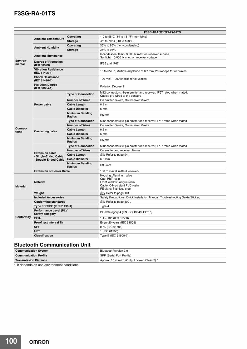
F3SG-RA-01TS
100
Bluetooth Communication Unit
* It depends on use environment conditions.
Environ-mental
Ambient TemperatureOperating -10 to 55°C (14 to 131°F) (non-icing)
Storage -25 to 70°C (-13 to 158°F)
Ambient HumidityOperating 35% to 85% (non-condensing)
Storage 35% to 95%
Ambient Illuminance Incandescent lamp: 3,000 Ix max. on receiver surfaceSunlight: 10,000 Ix max. on receiver surface
Degree of Protection(IEC 60529) IP65 and IP67
Vibration Resistance(IEC 61496-1) 10 to 55 Hz, Multiple amplitude of 0.7 mm, 20 sweeps for all 3 axes
Shock Resistance(IEC 61496-1) 100 m/s2, 1000 shocks for all 3 axes
Pollution Degree(IEC 60664-1) Pollution Degree 3
Connec-tions
Power cable
Type of Connection M12 connectors: 8-pin emitter and receiver, IP67 rated when mated,Cables pre-wired to the sensors
Number of Wires On emitter: 5-wire, On receiver: 8-wire
Cable Length 0.3 m
Cable Diameter 6 mm
Minimum Bending Radius R5 mm
Cascading cable
Type of Connection M12 connectors: 8-pin emitter and receiver, IP67 rated when mated
Number of Wires On emitter: 5-wire, On receiver: 8-wire
Cable Length 0.2 m
Cable Diameter 6 mm
Minimum Bending Radius R5 mm
Extension cable- Single-Ended Cable- Double-Ended Cable
Type of Connection M12 connectors: 8-pin emitter and receiver, IP67 rated when mated
Number of Wires On emitter and receiver: 8-wire
Cable Length Refer to page 94.
Cable Diameter 6.6 mm
Minimum Bending Radius R36 mm
Extension of Power Cable 100 m max.(Emitter/Receiver)
MaterialMaterial
Housing: Aluminum alloyCap: PBT resinFront window: Acrylic resinCable: Oil-resistant PVC resinFE plate: Stainless steel
Weight Refer to page 101 .
Included Accessories Safety Precautions, Quick Installation Manual, Troubleshooting Guide Sticker,
Conformity
Conforming standards Refer to page 102 .
Type of ESPE (IEC 61496-1) Type 4
Performance Level (PL)/Safety category PL e/Category 4 (EN ISO 13849-1:2015)
PFHD 1.1 × 10⁻⁸ (IEC 61508)
Proof test interval TM Every 20 years (IEC 61508)
SFF 99% (IEC 61508)
HFT 1 (IEC 61508)
Classification Type B (IEC 61508-2)
Communication System Bluetooth Version 3.0
Communication Profile SPP (Serial Port Profile)
Transmission Distance Approx. 10 m max. (Output power: Class 2) *
F3SG-4RA-25-01TS
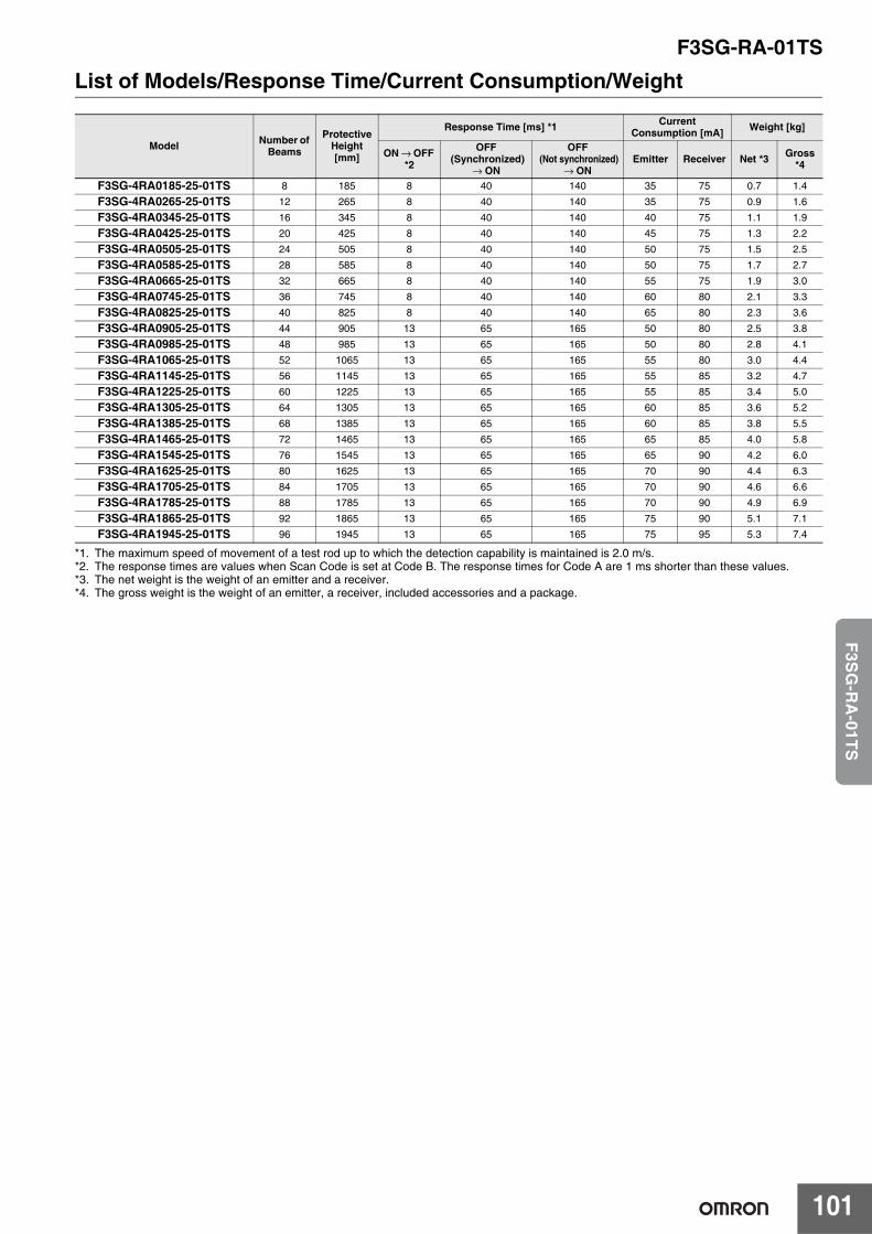
F3SG-RA-01TS
101
F3S
G-R
A-01T
S
List of Models/Response Time/Current Consumption/Weight
*1. The maximum speed of movement of a test rod up to which the detection capability is maintained is 2.0 m/s.*2. The response times are values when Scan Code is set at Code B. The response times for Code A are 1 ms shorter than these values.*3. The net weight is the weight of an emitter and a receiver.*4. The gross weight is the weight of an emitter, a receiver, included accessories and a package.
Model Number of Beams
Protective Height[mm]
Response Time [ms] *1 Current Consumption [mA] Weight [kg]
ON → OFF *2
OFF (Synchronized)
→ ON
OFF (Not synchronized)
→ ONEmitter Receiver Net *3 Gross
*4
F3SG-4RA0185-25-01TS 8 185 8 40 140 35 75 0.7 1.4
F3SG-4RA0265-25-01TS 12 265 8 40 140 35 75 0.9 1.6
F3SG-4RA0345-25-01TS 16 345 8 40 140 40 75 1.1 1.9
F3SG-4RA0425-25-01TS 20 425 8 40 140 45 75 1.3 2.2
F3SG-4RA0505-25-01TS 24 505 8 40 140 50 75 1.5 2.5
F3SG-4RA0585-25-01TS 28 585 8 40 140 50 75 1.7 2.7
F3SG-4RA0665-25-01TS 32 665 8 40 140 55 75 1.9 3.0
F3SG-4RA0745-25-01TS 36 745 8 40 140 60 80 2.1 3.3
F3SG-4RA0825-25-01TS 40 825 8 40 140 65 80 2.3 3.6
F3SG-4RA0905-25-01TS 44 905 13 65 165 50 80 2.5 3.8
F3SG-4RA0985-25-01TS 48 985 13 65 165 50 80 2.8 4.1
F3SG-4RA1065-25-01TS 52 1065 13 65 165 55 80 3.0 4.4
F3SG-4RA1145-25-01TS 56 1145 13 65 165 55 85 3.2 4.7
F3SG-4RA1225-25-01TS 60 1225 13 65 165 55 85 3.4 5.0
F3SG-4RA1305-25-01TS 64 1305 13 65 165 60 85 3.6 5.2
F3SG-4RA1385-25-01TS 68 1385 13 65 165 60 85 3.8 5.5
F3SG-4RA1465-25-01TS 72 1465 13 65 165 65 85 4.0 5.8
F3SG-4RA1545-25-01TS 76 1545 13 65 165 65 90 4.2 6.0
F3SG-4RA1625-25-01TS 80 1625 13 65 165 70 90 4.4 6.3
F3SG-4RA1705-25-01TS 84 1705 13 65 165 70 90 4.6 6.6
F3SG-4RA1785-25-01TS 88 1785 13 65 165 70 90 4.9 6.9
F3SG-4RA1865-25-01TS 92 1865 13 65 165 75 90 5.1 7.1
F3SG-4RA1945-25-01TS 96 1945 13 65 165 75 95 5.3 7.4
F3SG-RA-01TS
102
Legislation and Standards1. The F3SG-RA-01TS does not receive type approval provided by Article 44-2 of the Industrial Safety and Health Act of Japan. When using the
F3SG-RA-01TS in Japan as a "safety system for pressing or shearing machines" prescribed in Article 42 of that law, the machine control system must receive type approval.
2. The F3SG-RA-01TS is electro-sensitive protective equipment (ESPE) in accordance with European Union (EU) Machinery Directive Index Annex V, Item 2.
3. EC Declaration of Conformity OMRON declares that the F3SG-RA-01TS is in conformity with the requirements of the following EC Directives:Machinery Directive 2006/42/EC EMC Directive2014/30/EU
4. Conforming Standards(1) European standards
EN61496-1 (Type 4 and Type 2 ESPE), EN 61496-2 (Type 4 and Type 2 AOPD), EN61508-1 through -4 (SIL 3 for Type 4 and SIL 1 for Type 2), EN ISO 13849-1:2015 (PL e, Category 4 for Type 4 and PL c, Category 2 for Type 2)
(2) International standardsIEC61496-1 (Type 4 and Type 2 ESPE), IEC61496-2 (Type 4 and Type 2 AOPD), IEC61508-1 through -4 (SIL 3 for Type 4 and SIL 1 for Type 2), ISO 13849-1:2015 (PL e, Category 4 for Type 4 and PL c, Category 2 for Type 2)
(3) JIS standardsJIS B 9704-1 (Type 4 and Type 2 ESPE), JIS B 9704-2 (Type 4 and Type 2 AOPD)
(4) North American standardsUL61496-1(Type 4 and Type 2 ESPE), UL61496-2(Type 4 and Type 2 AOPD), UL508, UL1998, CAN/CSA C22.2 No.14, CAN/CSA C22.2 No.0.8
5. Third-Party Certifications(1) TÜV SÜD
• EC Type-Examination certificate:EU Machinery Directive, Type 4 and Type 2 ESPE (EN61496-1), Type 4 and Type 2 AOPD (EN 61496-2)
• Certificate:Type 4 and Type 2 ESPE (EN61496-1), Type 4 and Type 2 AOPD (EN61496-2), EN 61508-1 through -4 (SIL 3 for Type 4 and SIL 1 for Type 2), EN ISO 13849-1:2015 (PL e, Category 4 for Type 4, and PL c, Category 2 for Type 2)
(2) UL• UL Listing:
Type 4 and Type 2 ESPE (UL61496-1), Type 4 and Type 2 AOPD (UL61496-2), UL508, UL1998, CAN/CSA C22.2 No.14, CAN/CSA C22.2 No.0.8
6. Other Standards The F3SG-RA-01TS is designed according to the standards listed below. To make sure that the final system complies with the following standards and regulations, you are asked to design and use it in accordance with all other related standards, laws, and regulations. If you have any questions, consult with specialized organizations such as the body responsible for prescribing and/or enforcing machinery safety regulations in the location where the equipment is to be used. • European Standards: EN415-4, EN691-1, EN692, EN693, IEC 62046• U.S. Occupational Safety and Health Standards: OSHA 29 CFR 1910.212• U.S. Occupational Safety and Health Standards: OSHA 29 CFR 1910.217• American National Standards: ANSI B11.1 to B11.19• American National Standards: ANSI/RIA R15.06• Canadian Standards Association CSA Z142, Z432, Z434• SEMI Standards SEMI S2• Japan Ministry of Health, Labour and Welfare "Guidelines for Comprehensive Safety Standards of Machinery", Standard Bureau's Notification
No. 0731001 dated July 31, 2007.rms and Conditions Agreement
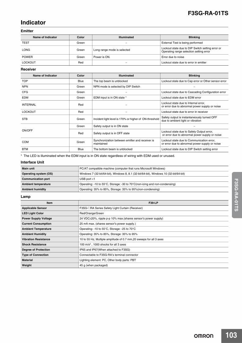
F3SG-RA-01TS
103
F3S
G-R
A-01T
S
IndicatorEmitter
Receiver
* The LED is illuminated when the EDM input is in ON state regardless of wiring with EDM used or unused.
Interface Unit
Lamp
Name of Indicator Color Illuminated Blinking
TEST Green − External Test is being performed
LONG Green Long range mode is selected Lockout state due to DIP Switch setting error or Operating range selection setting error
POWER Green Power is ON. Error due to noise
LOCKOUT Red − Lockout state due to error in emitter
Name of Indicator Color Illuminated Blinking
TOP Blue The top beam is unblocked Lockout state due to Cap error or Other sensor error
NPN Green NPN mode is selected by DIP Switch −
CFG Green − Lockout state due to Cascading Configuration error
EDM Green EDM input is in ON state * Lockout state due to EDM error
INTERNAL Red − Lockout state due to Internal error, or error due to abnormal power supply or noise
LOCKOUT Red − Lockout state due to error in receiver
STB Green Incident light level is 170% or higher of ON-threshold Safety output is instantaneously turned OFF due to ambient light or vibration
ON/OFF
Green Safety output is in ON state −
Red Safety output is in OFF state Lockout state due to Safety Output error, or error due to abnormal power supply or noise
COM Green Synchronization between emitter and receiver is maintained
Lockout state due to Communication error, or error due to abnormal power supply or noise
BTM Blue The bottom beam is unblocked Lockout state due to DIP Switch setting error
Main unit PC/AT compatible machine (computer that runs Microsoft Windows)
Operating system (OS) Windows 7 (32-bit/64-bit), Windows 8, 8.1 (32-bit/64-bit), Windows 10 (32-bit/64-bit)
Communication port USB port ×1
Ambient temperature Operating: -10 to 55°C, Storage: -30 to 70°C(non-icing and non-condensing)
Ambient humidity Operating: 35% to 85%, Storage: 35% to 95%(non-condensing)
Item F39-LP
Applicable Sensor F3SG-@RA Series Safety Light Curtain (Receiver)
LED Light Color Red/Orange/Green
Power Supply Voltage 24 VDC±20%, ripple p-p 10% max.(shares sensor′s power supply)
Current Consumption 25 mA max. (shares sensor′s power supply.)
Ambient Temperature Operating: -10 to 55°C, Storage: -25 to 70°C
Ambient Humidity Operating: 35% to 85%, Storage: 35% to 95%
Vibration Resistance 10 to 55 Hz, Multiple amplitude of 0.7 mm,20 sweeps for all 3 axes
Shock Resistance 100 m/s2 , 1000 shocks for all 3 axes
Degree of Protection IP65 and IP67(When attached to F3SG)
Type of Connection Connectable to F3SG-RA′s terminal connector
Material Lighting element: PC, Other body parts: PBT
Weight 45 g (when packaged)
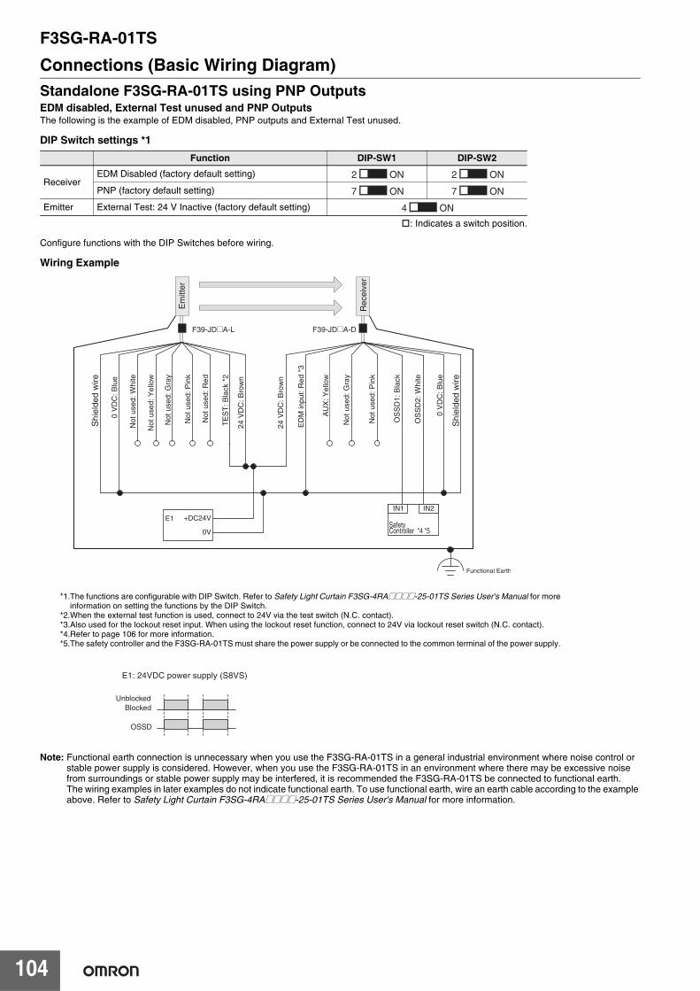
F3SG-RA-01TS
104
Connections (Basic Wiring Diagram)Standalone F3SG-RA-01TS using PNP OutputsEDM disabled, External Test unused and PNP OutputsThe following is the example of EDM disabled, PNP outputs and External Test unused.
DIP Switch settings *1
: Indicates a switch position.
Configure functions with the DIP Switches before wiring.
Wiring Example
Note: Functional earth connection is unnecessary when you use the F3SG-RA-01TS in a general industrial environment where noise control or stable power supply is considered. However, when you use the F3SG-RA-01TS in an environment where there may be excessive noise from surroundings or stable power supply may be interfered, it is recommended the F3SG-RA-01TS be connected to functional earth.The wiring examples in later examples do not indicate functional earth. To use functional earth, wire an earth cable according to the example above. Refer to Safety Light Curtain F3SG-4RA@@@@-25-01TS Series User's Manual for more information.
Function DIP-SW1 DIP-SW2
ReceiverEDM Disabled (factory default setting)
PNP (factory default setting)
Emitter External Test: 24 V Inactive (factory default setting)
2 ON 2 ON
7 ON 7 ON
4 ON
E1: 24VDC power supply (S8VS)
Shi
elde
d w
ire
Shi
elde
d w
ire
IN1 IN2E1 +DC24V
0VSafetyController *4 *5
24 V
DC
: Bro
wn
24 V
DC
: Bro
wn
TE
ST
: Bla
ck *
2
0 V
DC
: Blu
e
OS
SD
1: B
lack
OS
SD
2: W
hite
0 V
DC
: Blu
e
ED
M in
put:
Red
*3
Not
use
d: P
ink
Not
use
d: G
ray
Not
use
d: R
ed
Not
use
d: P
ink
Not
use
d: G
ray
Not
use
d: Y
ello
w
Not
use
d: W
hite
AU
X: Y
ello
w
Em
itter
Rec
eive
r
F39-JD@A-L F39-JD@A-D
OSSD
UnblockedBlocked
Functional Earth
*1.The functions are configurable with DIP Switch. Refer to Safety Light Curtain F3SG-4RA@@@@-25-01TS Series User's Manual for moreinformation on setting the functions by the DIP Switch.
*2.When the external test function is used, connect to 24V via the test switch (N.C. contact).*3.Also used for the lockout reset input. When using the lockout reset function, connect to 24V via lockout reset switch (N.C. contact). *4.Refer to page 106 for more information.*5.The safety controller and the F3SG-RA-01TS must share the power supply or be connected to the common terminal of the power supply.
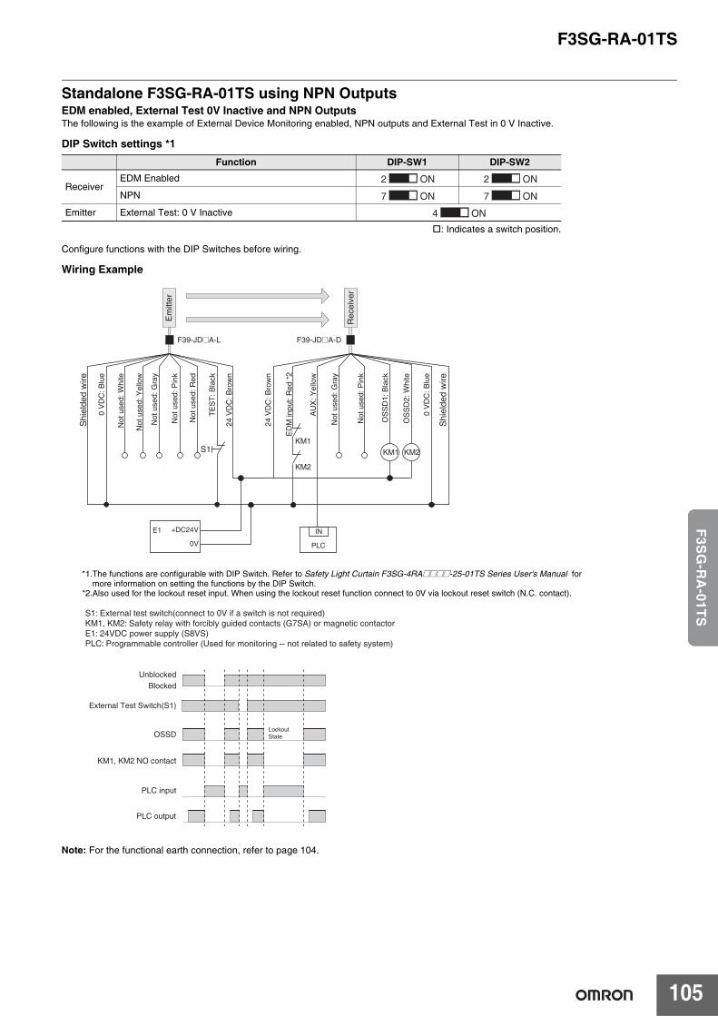
F3SG-RA-01TS
105
F3S
G-R
A-01T
S
Standalone F3SG-RA-01TS using NPN OutputsEDM enabled, External Test 0V Inactive and NPN OutputsThe following is the example of External Device Monitoring enabled, NPN outputs and External Test in 0 V Inactive.
DIP Switch settings *1
: Indicates a switch position.
Configure functions with the DIP Switches before wiring.
Wiring Example
Note: For the functional earth connection, refer to page 104.
Function DIP-SW1 DIP-SW2
ReceiverEDM Enabled
NPN
Emitter External Test: 0 V Inactive
2 ON 2 ON
7 ON 7 ON
4 ON
KM1 KM2
PLC
INE1 +DC24V
0V
S1KM1
KM2
PLC input
UnblockedBlocked
External Test Switch(S1)
OSSD
KM1, KM2 NO contact
PLC output
LockoutState
S1: External test switch(connect to 0V if a switch is not required)KM1, KM2: Safety relay with forcibly guided contacts (G7SA) or magnetic contactorE1: 24VDC power supply (S8VS)PLC: Programmable controller (Used for monitoring -- not related to safety system)
Not
use
d: Y
ello
w
Not
use
d: W
hite
Rec
eive
r
Em
itter
0 V
DC
: Blu
e
F39-JD@A-L F39-JD@A-D
Shi
elde
d w
ire
Shi
elde
d w
ire
24 V
DC
: Bro
wn
24 V
DC
: Bro
wn
TE
ST
: Bla
ck
OS
SD
1: B
lack
OS
SD
2: W
hite
0 V
DC
: Blu
e
ED
M in
put:
Red
*2
Not
use
d: P
ink
Not
use
d: G
ray
Not
use
d: R
ed
Not
use
d: P
ink
Not
use
d: G
ray
AU
X: Y
ello
w
*1.The functions are configurable with DIP Switch. Refer to Safety Light Curtain F3SG-4RA@@@@-25-01TS Series User's Manual formore information on setting the functions by the DIP Switch.
*2.Also used for the lockout reset input. When using the lockout reset function connect to 0V via lockout reset switch (N.C. contact).
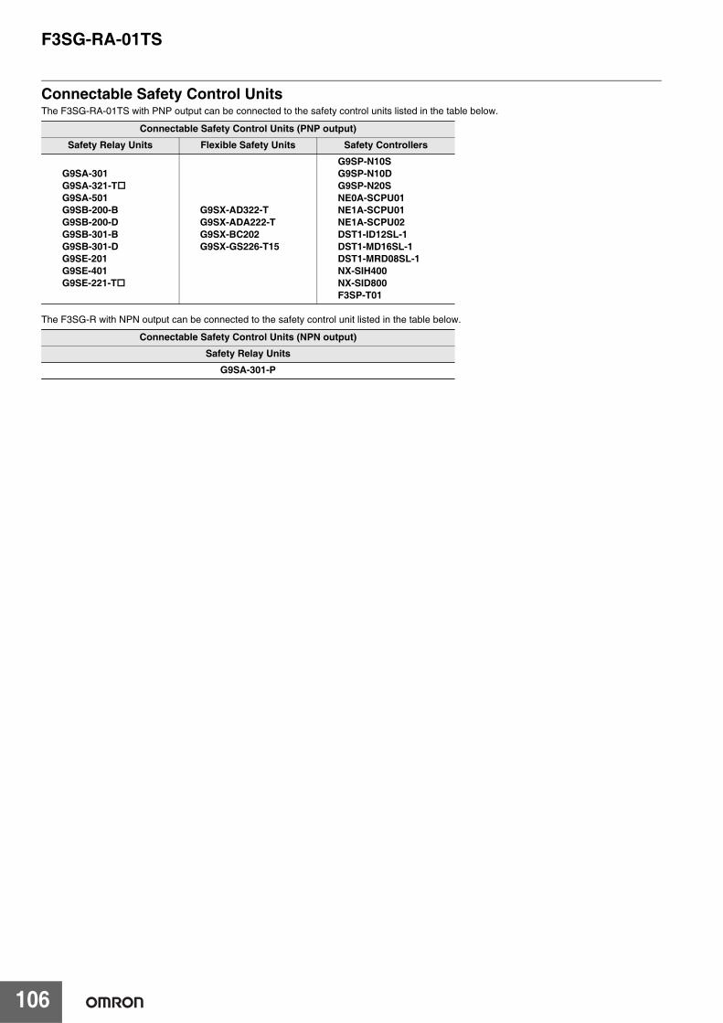
F3SG-RA-01TS
106
Connectable Safety Control UnitsThe F3SG-RA-01TS with PNP output can be connected to the safety control units listed in the table below.
The F3SG-R with NPN output can be connected to the safety control unit listed in the table below.
Connectable Safety Control Units (PNP output)
Safety Relay Units Flexible Safety Units Safety Controllers
G9SA-301G9SA-321-TG9SA-501G9SB-200-BG9SB-200-DG9SB-301-BG9SB-301-DG9SE-201G9SE-401G9SE-221-T
G9SX-AD322-TG9SX-ADA222-TG9SX-BC202G9SX-GS226-T15
G9SP-N10SG9SP-N10DG9SP-N20SNE0A-SCPU01NE1A-SCPU01NE1A-SCPU02DST1-ID12SL-1DST1-MD16SL-1DST1-MRD08SL-1NX-SIH400NX-SID800F3SP-T01
Connectable Safety Control Units (NPN output)
Safety Relay Units
G9SA-301-P
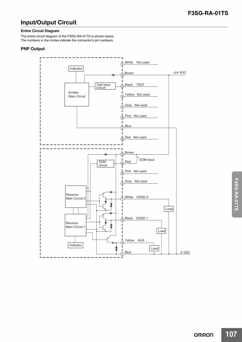
F3SG-RA-01TS
107
F3S
G-R
A-01T
S
Input/Output CircuitEntire Circuit DiagramThe entire circuit diagram of the F3SG-RA-01TS is shown below.The numbers in the circles indicate the connector's pin numbers.
PNP Output
2
8
3
4
7
1
+24 VDC2
3
4
Brown
Black TEST
Yellow Not used
1White Not used
Blue
Brown
Red
White OSSD 2
Pink Not used
Gray Not used
Black OSSD 1
Yellow AUX
Blue
7
EDMcircuit
6
5
EDM input
0 VDC
5Gray Not used
6Pink Not used
8Red Not used
Load
Indicator
EmitterMain Circuit
Test Input Circuit
ReceiverMain Circuit 2
ReceiverMain Circuit 1
IndicatorLoad
Load
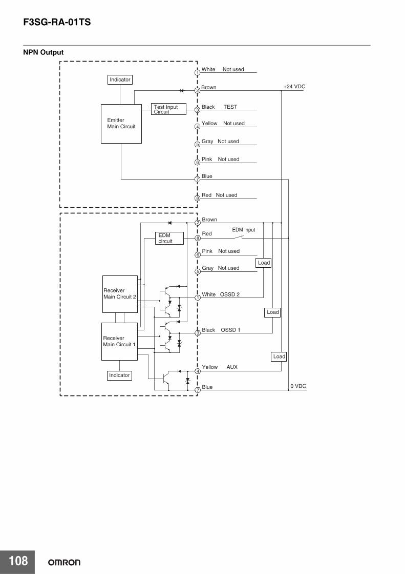
F3SG-RA-01TS
108
NPN Output
2
8
3
4
7
1
Brown
Red
White OSSD 2
Pink Not used
Gray Not used
Black OSSD 1
Yellow AUX
Blue
6
5
EDM input
0 VDC
ReceiverMain Circuit 2
ReceiverMain Circuit 1
Indicator
Load
Load
Load
+24 VDC2
3
4
Brown
Black TEST
Yellow Not used
1White Not used
Blue7
5Gray Not used
6Pink Not used
8Red Not used
Indicator
EmitterMain Circuit
Test Input Circuit
EDMcircuit
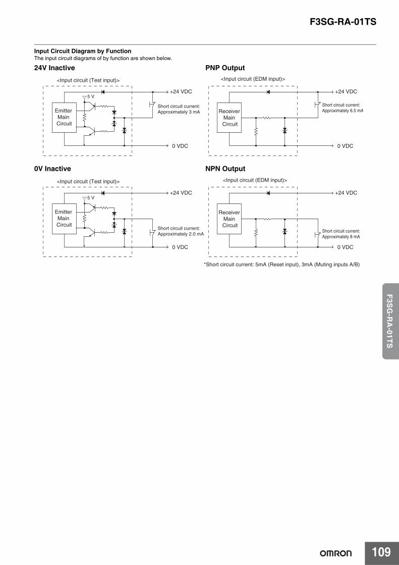
F3SG-RA-01TS
109
F3S
G-R
A-01T
S
Input Circuit Diagram by FunctionThe input circuit diagrams of by function are shown below.
Emitter Main Circuit
+24 VDC
0 VDC
5 V
Short circuit current:Approximately 3 mA
<Input circuit (Test input)>
Receiver Main Circuit
+24 VDC
0 VDC
Short circuit current:Approximately 6.5 mA
<Input circuit (EDM input)>
24V Inactive PNP Output
Receiver Main Circuit
+24 VDC
0 VDC
Short circuit current:Approximately 8 mA
<Input circuit (EDM input)>
Emitter Main Circuit
+24 VDC
0 VDC
5 V
Short circuit current:Approximately 2.0 mA
<Input circuit (Test input)>
*Short circuit current: 5mA (Reset input), 3mA (Muting inputs A/B)
0V Inactive NPN Output
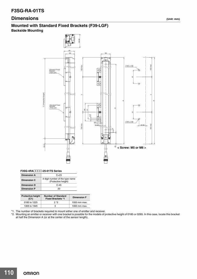
F3SG-RA-01TS
110
Dimensions (Unit: mm)
Mounted with Standard Fixed Brackets (F39-LGF)Backside Mounting
*1. The number of brackets required to mount either one of emitter and receiver.*2. Mounting an emitter or receiver with one bracket is possible for the models of protective height of 0185 or 0265. In this case, locate this bracket
at half the Dimension A (or at the center of the sensor length).
A
6.4
5151
35
9.2
66
35
40
50.3
5
D
P
24.85
51
F
43
F
24.85
A
20.5
2-M5 or M6
2-M5 or M6
Standard Fixed Bracket
Standard Fixed Bracket
(F39-LGF)
(F39-LGF)
150
max
150
max
C (
Pro
tect
ive
heig
ht)
150
max
150
max
< Screw: M5 or M6 >
F3SG-4RA@@@@-25-01TS Series Dimension A C+23
Dimension C 4-digit number of the type name(Protective height)
Dimension D C-45
Dimension P 20
Protective height(C1)
Number of Standard Fixed Brackets *1 Dimension F
0185 to 1225 2 *2 1000 mm max.
1305 to 1945 3 1000 mm max.
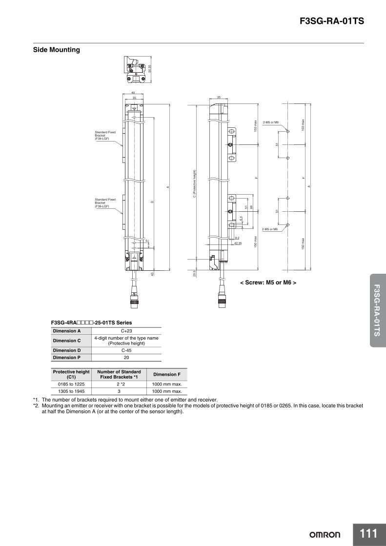
F3SG-RA-01TS
111
F3S
G-R
A-01T
S
Side Mounting
*1. The number of brackets required to mount either one of emitter and receiver.*2. Mounting an emitter or receiver with one bracket is possible for the models of protective height of 0185 or 0265. In this case, locate this bracket
at half the Dimension A (or at the center of the sensor length).
A
35
40
51
9.2
51
35
6.4
66
50.3
5
51
F
42.35
A
F
P
D
43 20.5
Standard Fixed Bracket
Standard Fixed Bracket
(F39-LGF)
(F39-LGF)
2-M5 or M6
2-M5 or M6
150
max
150
max
150
max
150
max
C (
Pro
tect
ive
heig
ht)
< Screw: M5 or M6 >
F3SG-4RA@@@@-25-01TS Series Dimension A C+23
Dimension C 4-digit number of the type name(Protective height)
Dimension D C-45
Dimension P 20
Protective height(C1)
Number of Standard Fixed Brackets *1 Dimension F
0185 to 1225 2 *2 1000 mm max.
1305 to 1945 3 1000 mm max.
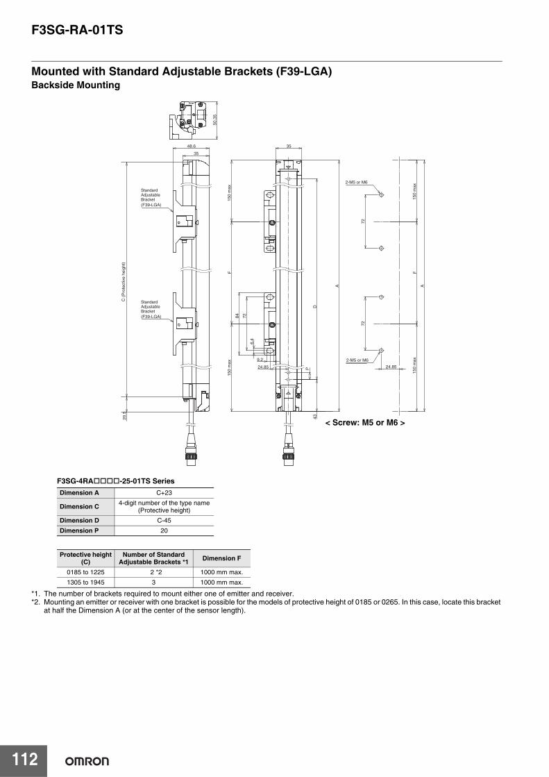
F3SG-RA-01TS
112
Mounted with Standard Adjustable Brackets (F39-LGA)Backside Mounting
*1. The number of brackets required to mount either one of emitter and receiver.*2. Mounting an emitter or receiver with one bracket is possible for the models of protective height of 0185 or 0265. In this case, locate this bracket
at half the Dimension A (or at the center of the sensor length).
35
48.6
50.3
5
35
A
729.2
72
6.4
84
P
72
24.85
F
D
43
F
A
24.85
20.5
Standard Adjustable Bracket(F39-LGA)
Standard Adjustable Bracket(F39-LGA)
2-M5 or M6
2-M5 or M6
150
max
150
max
C (
Pro
tect
ive
heig
ht)
150
max
150
max
< Screw: M5 or M6 >
F3SG-4RA-25-01TS Series Dimension A C+23
Dimension C 4-digit number of the type name(Protective height)
Dimension D C-45
Dimension P 20
Protective height(C)
Number of Standard Adjustable Brackets *1 Dimension F
0185 to 1225 2 *2 1000 mm max.
1305 to 1945 3 1000 mm max.

F3SG-RA-01TS
113
F3S
G-R
A-01T
S
Side Mounting
*1. The number of brackets required to mount either one of emitter and receiver.*2. Mounting an emitter or receiver with one bracket is possible for the models of protective height of 0185 or 0265. In this case, locate this bracket
at half the Dimension A (or at the center of the sensor length).
50.3
5
35
A
48.6
7272
35
6.4
9.28472
F42.35
A
F
P
D
43 20.5
Standard Adjustable Bracket(F39-LGA)
Standard Adjustable Bracket(F39-LGA)
150
max
150
max
150
max
150
max
C (P
rote
ctiv
e he
ight
)
2-M5 or M6
2-M5 or M6
< Screw: M5 or M6 >
F3SG-4RA-25-01TS Series Dimension A C+23
Dimension C 4-digit number of the type name(Protective height)
Dimension D C-45
Dimension P 20
Protective height(C)
Number of Standard Adjustable Brackets *1 Dimension F
0185 to 1225 2 *2 1000 mm max.
1305 to 1945 3 1000 mm max.
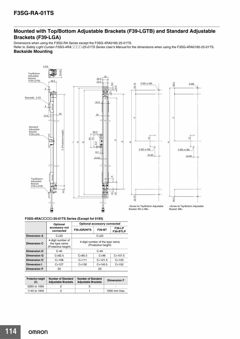
F3SG-RA-01TS
114
Mounted with Top/Bottom Adjustable Brackets (F39-LGTB) and Standard Adjustable Brackets (F39-LGA)Dimensions when using the F3SG-RA Series except the F3SG-4RA0185-25-01TS.Refer to Safety Light Curtain F3SG-4RA@@@@-25-01TS Series User's Manual for the dimensions when using the F3SG-4RA0185-25-01TS.
Backside Mounting
2-M8
S2.5
12
35
40.8
G
H
I
26.5
35
23.2
8.2
A
9.2
72
6.4
84
6.5
4
2-S3
53.
25
48.6
35 13.6
4
4
43
D
P
F
F
25.
75
24.85
46.
5
H
38.
5
G
33.
75
24.85
72
24.85
72
20.5
<Screw for Top/Bottom Adjustable Bracket: M5 or M6>
<Screw for Top/Bottom Adjustable Bracket: M8>
Standard Adjustable Bracket(F39-LGA)
Top/Bottom Adjustable Bracket(F39-LGTB)
Top/Bottom Adjustable Bracket(F39-LGTB)
Backside : 2-S3
2-M5 or M6
2-M5 or M6
2-M5 or M6C (
Pro
tect
ive
heig
ht)
F3SG-4RA-25-01TS Series (Except fot 0185)
Optional accessory not
connected
Optional accessory connected
F39-JGR2WTS F39-BT F39-LPF39-BTLP
Dimension A C+23 C+23
Dimension C4-digit number of
the type name(Protective height)
4-digit number of the type name(Protective height)
Dimension D C-45 C-45
Dimension G C+82.5 C+85.5 C+96 C+107.5
Dimension H C+108 C+111 C+121.5 C+133
Dimension I C+127 C+130 C+140.5 C+152
Dimension P 20 20
Protective height(C)
Number of Standard Adjustable Brackets
Number of Standard Adjustable Brackets Dimension F
0265 to 1065 2 0 -
1145 to 1945 2 1 1000 mm max.
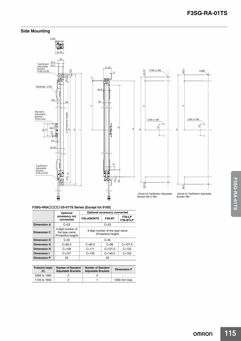
F3SG-RA-01TS
115
F3S
G-R
A-01T
S
Side Mounting
2-M8
40.8
35
A
4
51.65
4
12
S2.5
35
23.2 26.5
35
6.5
8.2
H
I
84
9.2
6.4
72 G
9.6
2-S3
50.35
42.35
43
D
P
F
F
F
H
38.
5 4
6.5
33.
75
25.
75
G 72 72
20.5
Top/Bottom Adjustable Bracket(F39-LGTB)
Top/Bottom Adjustable Bracket(F39-LGTB)
Standard Adjustable Bracket(F39-LGA)
Backside : 2-S3
2-M5 or M6
2-M5 or M6
2-M5 or M6
C (
Pro
tect
ive
heig
ht)
<Screw for Top/Bottom Adjustable Bracket: M5 or M6>
<Screw for Top/Bottom Adjustable Bracket: M8>
F3SG-4RA-25-01TS Series (Except fot 0185)
Optional accessory not
connected
Optional accessory connected
F39-JGR2WTS F39-BT F39-LPF39-BTLP
Dimension A C+23 C+23
Dimension C4-digit number of
the type name(Protective height)
4-digit number of the type name(Protective height)
Dimension D C-45 C-45
Dimension G C+82.5 C+85.5 C+96 C+107.5
Dimension H C+108 C+111 C+121.5 C+133
Dimension I C+127 C+130 C+140.5 C+152
Dimension P 20 20
Protective height(C)
Number of Standard Adjustable Brackets
Number of Standard Adjustable Brackets Dimension F
0265 to 1065 2 0 -
1145 to 1945 2 1 1000 mm max.
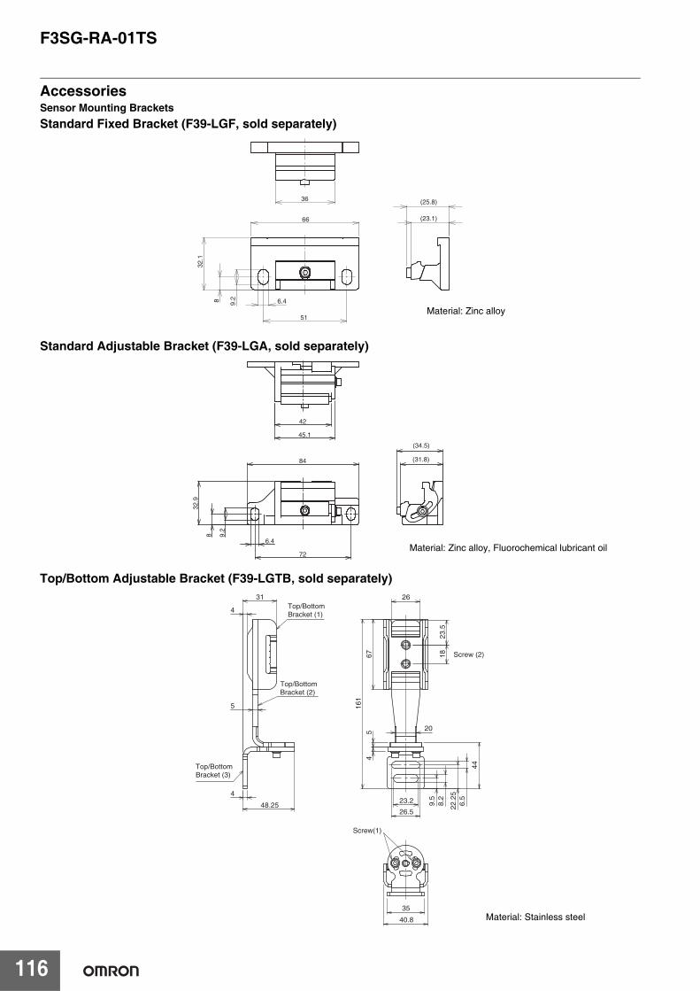
F3SG-RA-01TS
116
AccessoriesSensor Mounting BracketsStandard Fixed Bracket (F39-LGF, sold separately)
Standard Adjustable Bracket (F39-LGA, sold separately)
Top/Bottom Adjustable Bracket (F39-LGTB, sold separately)
51
8(23.1)
(25.8)
9.2
66
6.4
32.1
36
Material: Zinc alloy
8
72
42
45.1
84
9.2
6.4
32.9
(31.8)
(34.5)
Material: Zinc alloy, Fluorochemical lubricant oil
4
31
4
48.25
5
26.5
23.2 8.2
6.5
9.5
22.2
5
44
45
1867
23.5
26
20
161
35
40.8
Top/Bottom Bracket (1)
Top/Bottom Bracket (2)
Top/Bottom Bracket (3)
Screw (2)
Screw(1)
Material: Stainless steel
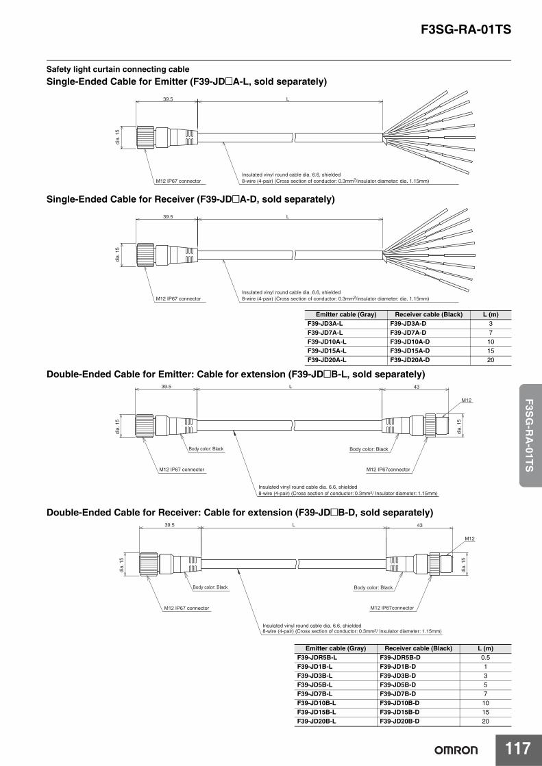
F3SG-RA-01TS
117
F3S
G-R
A-01T
S
Safety light curtain connecting cableSingle-Ended Cable for Emitter (F39-JD@A-L, sold separately)
Single-Ended Cable for Receiver (F39-JD@A-D, sold separately)
Double-Ended Cable for Emitter: Cable for extension (F39-JD@B-L, sold separately)
Double-Ended Cable for Receiver: Cable for extension (F39-JD@B-D, sold separately)
Emitter cable (Gray) Receiver cable (Black) L (m)F39-JD3A-L F39-JD3A-D 3F39-JD7A-L F39-JD7A-D 7F39-JD10A-L F39-JD10A-D 10F39-JD15A-L F39-JD15A-D 15F39-JD20A-L F39-JD20A-D 20
Emitter cable (Gray) Receiver cable (Black) L (m)F39-JDR5B-L F39-JDR5B-D 0.5F39-JD1B-L F39-JD1B-D 1F39-JD3B-L F39-JD3B-D 3F39-JD5B-L F39-JD5B-D 5F39-JD7B-L F39-JD7B-D 7F39-JD10B-L F39-JD10B-D 10F39-JD15B-L F39-JD15B-D 15F39-JD20B-L F39-JD20B-D 20
39.5 L
dia
. 15
Insulated vinyl round cable dia. 6.6, shielded8-wire (4-pair) (Cross section of conductor: 0.3mm2/insulator diameter: dia. 1.15mm) M12 IP67 connector
39.5 L
dia
. 15
Insulated vinyl round cable dia. 6.6, shielded8-wire (4-pair) (Cross section of conductor: 0.3mm2/insulator diameter: dia. 1.15mm) M12 IP67 connector
39.5 L 43
M12
M12 IP67connector
Body color: BlackBody color: Black
M12 IP67 connector
Insulated vinyl round cable dia. 6.6, shielded8-wire (4-pair) (Cross section of conductor: 0.3mm2/ Insulator diameter: 1.15mm)
dia.
15
dia.
15
39.5 L 43
M12
M12 IP67connector
Body color: BlackBody color: Black
M12 IP67 connector
Insulated vinyl round cable dia. 6.6, shielded8-wire (4-pair) (Cross section of conductor: 0.3mm2/ Insulator diameter: 1.15mm)
dia.
15
dia.
15
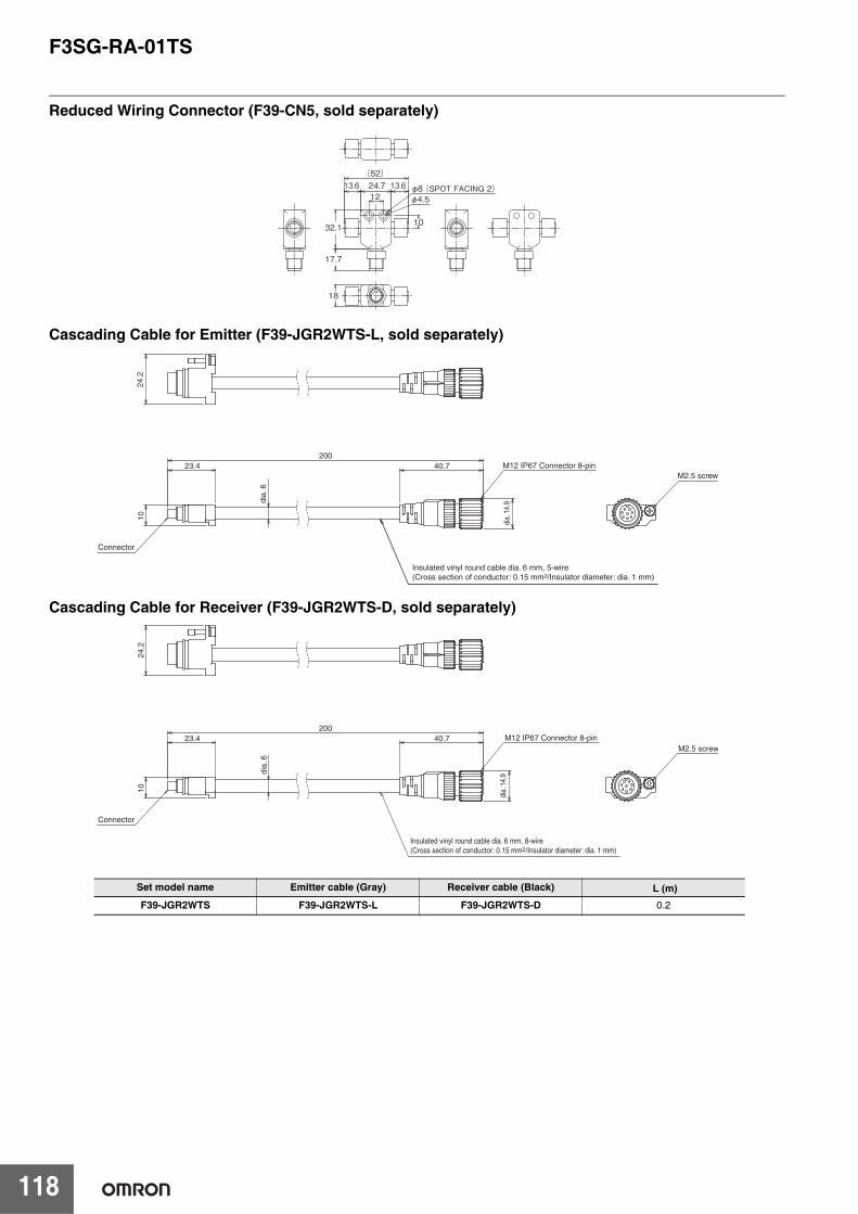
F3SG-RA-01TS
118
Reduced Wiring Connector (F39-CN5, sold separately)
Cascading Cable for Emitter (F39-JGR2WTS-L, sold separately)
Cascading Cable for Receiver (F39-JGR2WTS-D, sold separately)
Set model name Emitter cable (Gray) Receiver cable (Black) L (m)
F39-JGR2WTS F39-JGR2WTS-L F39-JGR2WTS-D 0.2
24.712
13.6 13.6 φ8 (SPOT FACING 2)φ4.5
(52)
32.1 10
17.7
18
20040.7
dia.
6
23.4
10
Insulated vinyl round cable dia. 6 mm, 5-wire(Cross section of conductor: 0.15 mm2/Insulator diameter: dia. 1 mm)
Connector
M12 IP67 Connector 8-pin
24.2
M2.5 screw
dia.
14.
9
200
dia.
14.
9
40.7
dia.
6
23.4
10
Insulated vinyl round cable dia. 6 mm, 8-wire(Cross section of conductor: 0.15 mm2/Insulator diameter: dia. 1 mm)
M12 IP67 Connector 8-pin
24.2
M2.5 screw
Connector
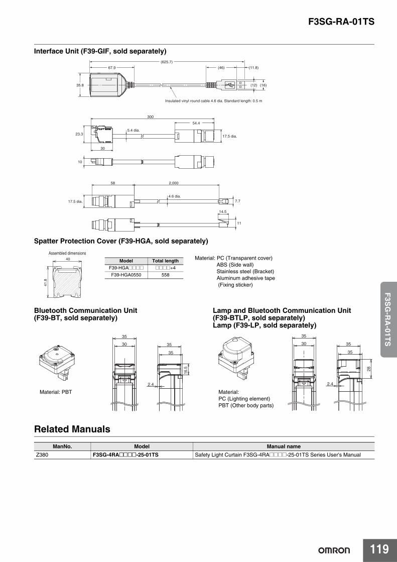
F3SG-RA-01TS
119
F3S
G-R
A-01T
S
Interface Unit (F39-GIF, sold separately)
Spatter Protection Cover (F39-HGA, sold separately)
Bluetooth Communication Unit (F39-BT, sold separately)
Lamp and Bluetooth Communication Unit (F39-BTLP, sold separately)Lamp (F39-LP, sold separately)
Related Manuals
67.9
35.8 (16)(12)
(625.7)
(46)
Insulated vinyl round cable 4.6 dia. Standard length: 0.5 m
(11.8)
300
30
54.4
58
23.3
10
17.5 dia.4.6 dia.
5.4 dia.
2,000
14.5
17.5 dia.
7.7
11
40
41.8
Assembled dimensions
Model Total lengthF39-HGA@@@@ @@@@+4
F39-HGA0550 558
Material: PC (Transparent cover)ABS (Side wall)Stainless steel (Bracket)Aluminum adhesive tape (Fixing sticker)
16.
5
35
30
35
35
2.4
Material: PBT
35
30
28
35
35
2.4
Material: PC (Lighting element)PBT (Other body parts)
ManNo. Model Manual nameZ380 F3SG-4RA@@@@-25-01TS Safety Light Curtain F3SG-4RA@@@@-25-01TS Series User's Manual
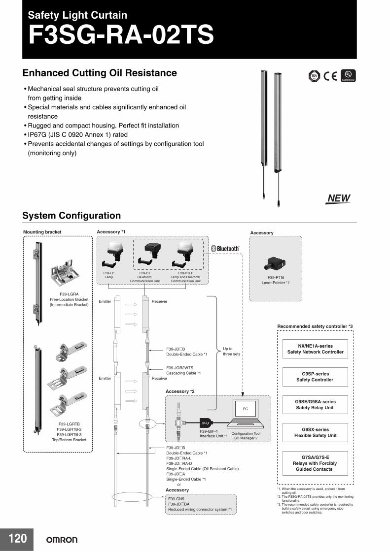
120
Safety Light Curtain
F3SG-RA-02TSEnhanced Cutting Oil Resistance• Mechanical seal structure prevents cutting oil
from getting inside• Special materials and cables significantly enhanced oil
resistance• Rugged and compact housing. Perfect fit installation• IP67G (JIS C 0920 Annex 1) rated• Prevents accidental changes of settings by configuration tool
(monitoring only)
System Configuration
IF-U
PC
F39-LGRAFree-Location Bracket(Intermediate Bracket)
F39-LGRTBF39-LGRTB-2F39-LGRTB-3
Top/Bottom Bracket
F39-LPLamp
F39-BTLPLamp and Bluetooth Communication Unit
F39-BTBluetooth
Communication Unit
NX/NE1A-seriesSafety Network Controller
G9SP-seriesSafety Controller
G9SE/G9SA-seriesSafety Relay Unit
G9SX-seriesFlexible Safety Unit
G7SA/G7S-ERelays with Forcibly
Guided Contacts
Emitter Receiver
F39-JGR2WTSCascading Cable *1
F39-JD@BDouble-Ended Cable *1F39-JD@RA-LF39-JD@RA-DSingle-Ended Cable (Oil-Resistant Cable)F39-JD@ASingle-Ended Cable *1 or
F39-CN5F39-JD@BAReduced wiring connector system *1
Recommended safety controller *3
Accessory
Accessory *2
F39-PTGLaser Pointer *1
Accessory Mounting bracket Accessory *1
Emitter Receiver
F39-JD@BDouble-Ended Cable *1
Up to three sets
F39-GIF-1Interface Unit *1
Configuration ToolSD Manager 2
*1. When the accessory is used, protect it from cutting oil.
*2. The F3SG-RA-02TS provides only the monitoring functionality.
*3. The recommended safety controller is required to build a safety circuit using emergency stop switches and door switches.
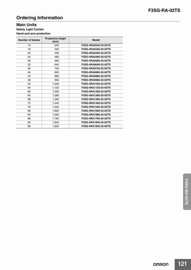
F3SG-RA-02TS
121
F3S
G-R
A-02T
S
Ordering InformationMain UnitsSafety Light CurtainHand and arm protection
Number of beams Protective height(mm) Model
12 240 F3SG-4RA0240-25-02TS16 320 F3SG-4RA0320-25-02TS20 400 F3SG-4RA0400-25-02TS24 480 F3SG-4RA0480-25-02TS28 560 F3SG-4RA0560-25-02TS32 640 F3SG-4RA0640-25-02TS36 720 F3SG-4RA0720-25-02TS40 800 F3SG-4RA0800-25-02TS44 880 F3SG-4RA0880-25-02TS48 960 F3SG-4RA0960-25-02TS52 1,040 F3SG-4RA1040-25-02TS56 1,120 F3SG-4RA1120-25-02TS60 1,200 F3SG-4RA1200-25-02TS64 1,280 F3SG-4RA1280-25-02TS68 1,360 F3SG-4RA1360-25-02TS72 1,440 F3SG-4RA1440-25-02TS76 1,520 F3SG-4RA1520-25-02TS80 1,600 F3SG-4RA1600-25-02TS84 1,680 F3SG-4RA1680-25-02TS88 1,760 F3SG-4RA1760-25-02TS92 1,840 F3SG-4RA1840-25-02TS96 1,920 F3SG-4RA1920-25-02TS
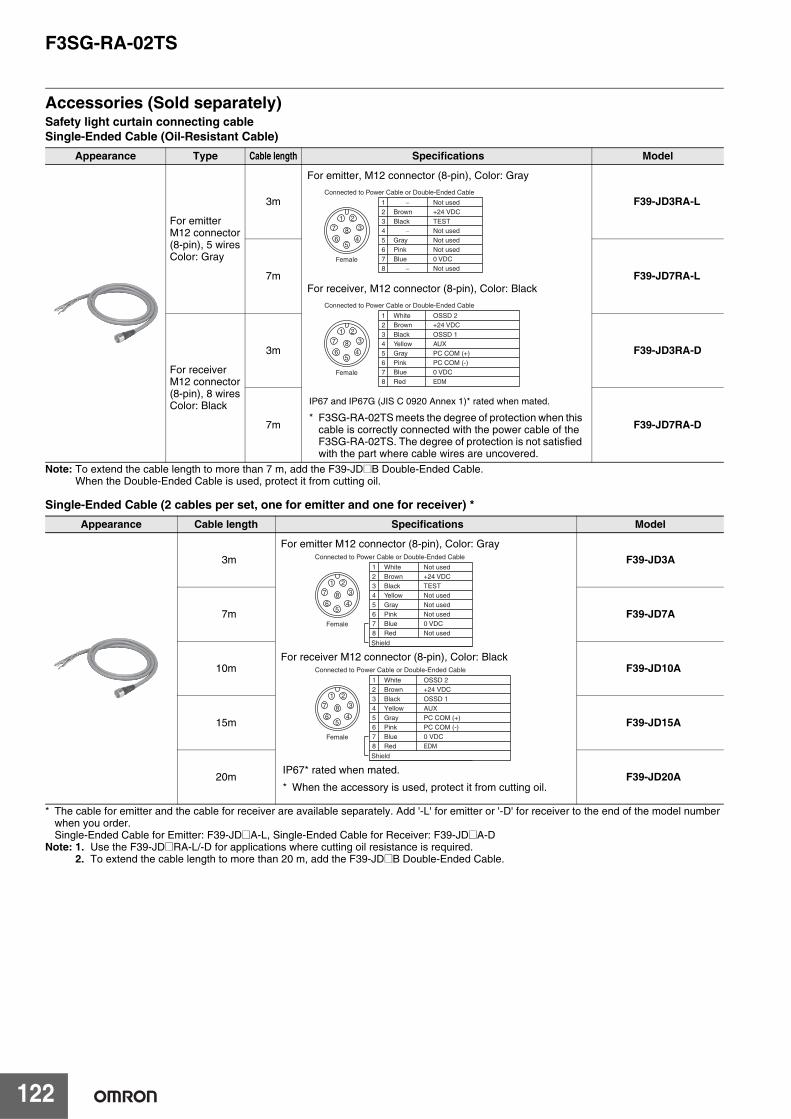
F3SG-RA-02TS
122
Accessories (Sold separately)Safety light curtain connecting cableSingle-Ended Cable (Oil-Resistant Cable)
Note: To extend the cable length to more than 7 m, add the F39-JD@B Double-Ended Cable.When the Double-Ended Cable is used, protect it from cutting oil.
Single-Ended Cable (2 cables per set, one for emitter and one for receiver) *
* The cable for emitter and the cable for receiver are available separately. Add '-L' for emitter or '-D' for receiver to the end of the model number when you order.Single-Ended Cable for Emitter: F39-JD@A-L, Single-Ended Cable for Receiver: F39-JD@A-D
Note: 1. Use the F39-JD@RA-L/-D for applications where cutting oil resistance is required.2. To extend the cable length to more than 20 m, add the F39-JD@B Double-Ended Cable.
Appearance Type Cable length Specifications Model
For emitterM12 connector(8-pin), 5 wiresColor: Gray
3m F39-JD3RA-L
7m F39-JD7RA-L
For receiverM12 connector(8-pin), 8 wiresColor: Black
3m F39-JD3RA-D
7m F39-JD7RA-D
Appearance Cable length Specifications Model
3m F39-JD3A
7m F39-JD7A
10m F39-JD10A
15m F39-JD15A
20m F39-JD20A
5
84
3
21
7
6
Female
2
7
56
1+24 VDC
0 VDC
Not usedNot used
Not used
Connected to Power Cable or Double-Ended Cable
Brown
Blue
GrayPink
−
8 Not used−
3 TESTBlack4 Not used−
5
84
3
21
7
6
Female
2
7
56
1+24 VDC
0 VDC
PC COM (+) PC COM (-)
OSSD 2
Connected to Power Cable or Double-Ended Cable
Brown
Blue
GrayPink
White
8 EDMRed
3 OSSD 1Black4 AUXYellow
For emitter, M12 connector (8-pin), Color: Gray
For receiver, M12 connector (8-pin), Color: Black
IP67 and IP67G (JIS C 0920 Annex 1)* rated when mated.
* F3SG-RA-02TS meets the degree of protection when this cable is correctly connected with the power cable of the F3SG-RA-02TS. The degree of protection is not satisfied with the part where cable wires are uncovered.
5
84
3
21
7
6
Female
2
7
56
1+24 VDC
0 VDC
Not usedNot used
Not used
Connected to Power Cable or Double-Ended Cable
Brown
Blue
GrayPink
White
8 Not usedRed
3 TESTBlack4 Not usedYellow
Shield
5
84
3
21
7
6
Female
2
7
56
1+24 VDC
0 VDC
PC COM (+) PC COM (-)
OSSD 2
Connected to Power Cable or Double-Ended Cable
Brown
Blue
GrayPink
White
8 EDMRed
3 OSSD 1Black4 AUXYellow
Shield
For emitter M12 connector (8-pin), Color: Gray
For receiver M12 connector (8-pin), Color: Black
IP67* rated when mated.
* When the accessory is used, protect it from cutting oil.
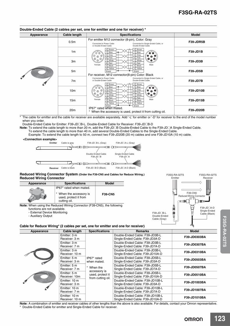
F3SG-RA-02TS
123
F3S
G-R
A-02T
S
Double-Ended Cable (2 cables per set, one for emitter and one for receiver) *
* The cable for emitter and the cable for receiver are available separately. Add '-L' for emitter or '-D' for receiver to the end of the model number when you order.Double-Ended Cable for Emitter: F39-JD@B-L, Double-Ended Cable for Receiver: F39-JD@B-D
Note: To extend the cable length to more than 20 m, add the F39-JD@B Double-Ended Cable to the F39-JD@A Single-Ended Cable.To extend the cable length to more than 40 m, add several Double-Ended Cables to the Single-Ended Cable.Example: To extend the cable length to 50 m, connect two F39-JD20B (20 m) cables and one F39-JD10A (10 m) cable.
Reduced Wiring Connector System (Order the F39-CN5 and Cables for Reduce Wiring.) Reduced Wiring Connector
Note: When using the Reduced Wiring Connector (F39-CN5), the following functions are not available.- External Device Monitoring- Auxiliary Output
Cable for Reduce Wiring* (2 cables per set, one for emitter and one for receiver)
Note: A combination of emitter and receiver cables of other lengths than the above is also available. For details, contact your Omron representative.* Double-Ended Cable for emitter and Single-Ended Cable for receiver.
Appearance Cable length Specifications Model
0.5m F39-JDR5B
1m F39-JD1B
3m F39-JD3B
5m F39-JD5B
7m F39-JD7B
10m F39-JD10B
15m F39-JD15B
20m F39-JD20B
Appearance Specifications ModelIP67* rated when mated.
* When the accessory is used, protect it from cutting oil.
F39-CN5
Appearance Cable length Specifications Remarks ModelEmitter: 3 mReceiver: 3 m
IP67* rated when mated.
* When the accessory is used, protect it from cutting oil.
Double-Ended Cable: F39-JD3B-LSingle-Ended Cable: F39-JD3A-D F39-JD0303BA
Emitter: 3 mReceiver: 7 m
Double-Ended Cable: F39-JD3B-LSingle-Ended Cable: F39-JD7A-D F39-JD0307BA
Emitter: 3 mReceiver: 10 m
Double-Ended Cable: F39-JD3B-LSingle-Ended Cable: F39-JD10A-D F39-JD0310BA
Emitter: 5 mReceiver: 3 m
Double-Ended Cable: F39-JD5B-LSingle-Ended Cable: F39-JD3A-D F39-JD0503BA
Emitter: 5 mReceiver: 7 m
Double-Ended Cable: F39-JD5B-LSingle-Ended Cable: F39-JD7A-D F39-JD0507BA
Emitter: 5 mReceiver: 10m
Double-Ended Cable: F39-JD5B-LSingle-Ended Cable: F39-JD10A-D F39-JD0510BA
Emitter: 10 mReceiver: 3 m
Double-Ended Cable: F39-JD10B-LSingle-Ended Cable: F39-JD3A-D F39-JD1003BA
Emitter: 10 mReceiver: 7 m
Double-Ended Cable: F39-JD10B-LSingle-Ended Cable: F39-JD7A-D F39-JD1007BA
Emitter: 10 mReceiver: 10 m
Double-Ended Cable: F39-JD10B-LSingle-Ended Cable: F39-JD10A-D F39-JD1010BA
Brown
Blue
Gray
Pink
White
RedBlack
Yellow
Blue
Gray
Pink
White
RedBlack
Yellow
2
7
5
6
1
83
4
Brown
5
84
3
21
7
65
86
7
12
3
4
2
7
5
6
1
83
4
Female Male
Connected to Power Cable or Double-Ended Cable
Connected to Single-Ended Cable, or Double-Ended Cable
Shield Shield
Connected to Power Cable or Double-Ended Cable
Connected to Single-Ended Cable, or Double-Ended Cable
Brown
Blue
Gray
Pink
White
RedBlack
Yellow
Blue
Gray
Pink
White
RedBlack
Yellow
27561834
Brown
5
84
321
7
65
86
712
3
4
27561834
Female Male
Shield Shield
For emitter M12 connector (8-pin), Color: Gray
For receiver, M12 connector(8-pin) Color: Black
IP67* rated when mated.* When the accessory is used, protect it from cutting oil.
Emitter
Receiver
Cable is gray F39-JD@B-L (Gray) F39-JD@A-L (Gray)
Double-Ended CableF39-JD@B
Single-Ended CableF39-JD@A
Cable is black F39-JD@B-D (Black) F39-JD@A-D (Black)
<Connection example>
F3SG-RA-02TSEmitter
F3SG-RA-02TSReceiver
F39-CN5Reduced Wiring Connector
F39-JD@A-DSingle-Ended Cable (Black)F39-JD@B-L
Double-Ended Cable (Gray)
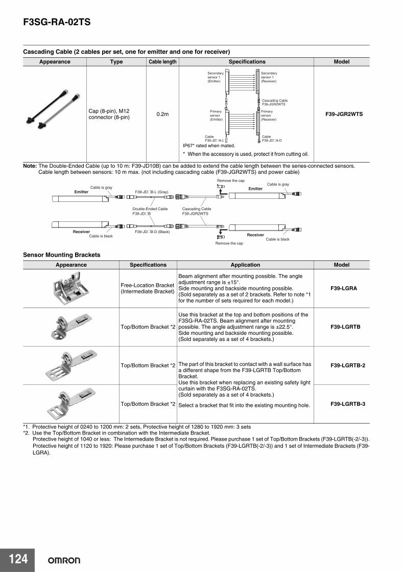
F3SG-RA-02TS
124
Cascading Cable (2 cables per set, one for emitter and one for receiver)
Note: The Double-Ended Cable (up to 10 m: F39-JD10B) can be added to extend the cable length between the series-connected sensors.Cable length between sensors: 10 m max. (not including cascading cable (F39-JGR2WTS) and power cable)
Sensor Mounting Brackets
*1. Protective height of 0240 to 1200 mm: 2 sets, Protective height of 1280 to 1920 mm: 3 sets*2. Use the Top/Bottom Bracket in combination with the Intermediate Bracket.
Protective height of 1040 or less: The Intermediate Bracket is not required. Please purchase 1 set of Top/Bottom Brackets (F39-LGRTB(-2/-3)).Protective height of 1120 to 1920: Please purchase 1 set of Top/Bottom Brackets (F39-LGRTB(-2/-3)) and 1 set of Intermediate Brackets (F39-LGRA).
Appearance Type Cable length Specifications Model
Cap (8-pin), M12connector (8-pin) 0.2m F39-JGR2WTS
Appearance Specifications Application Model
Free-Location Bracket(Intermediate Bracket)
Beam alignment after mounting possible. The angle adjustment range is ±15°. Side mounting and backside mounting possible.(Sold separately as a set of 2 brackets. Refer to note *1 for the number of sets required for each model.)
F39-LGRA
Top/Bottom Bracket *2
Use this bracket at the top and bottom positions of the F3SG-RA-02TS. Beam alignment after mounting possible. The angle adjustment range is ±22.5°. Side mounting and backside mounting possible.(Sold separately as a set of 4 brackets.)
F39-LGRTB
Top/Bottom Bracket *2 The part of this bracket to contact with a wall surface has a different shape from the F39-LGRTB Top/Bottom Bracket.Use this bracket when replacing an existing safety light curtain with the F3SG-RA-02TS.(Sold separately as a set of 4 brackets.)
Select a bracket that fit into the existing mounting hole.
F39-LGRTB-2
Top/Bottom Bracket *2 F39-LGRTB-3
IP67* rated when mated.
* When the accessory is used, protect it from cutting oil.
Secondary sensor 1 (Emitter)
Secondary sensor 1 (Receiver)
Primary sensor (Emitter)
Primary sensor (Receiver)
Cascading CableF39-JGR2WTS
CableF39-JD@A-D
CableF39-JD@A-L
Cable is blackF39-JD@B-D (Black)
Cable is blackRemove the cap
Double-Ended CableF39-JD@B
Cascading CableF39-JGR2WTS
Cable is grayF39-JD@B-L (Gray)
Cable is grayRemove the cap
Emitter
Receiver
Emitter
Receiver
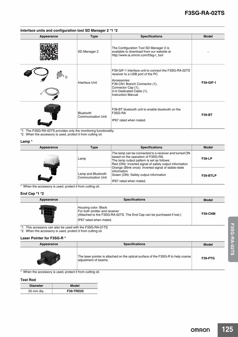
F3SG-RA-02TS
125
F3S
G-R
A-02T
S
Interface units and configuration tool SD Manager 2 *1 *2
*1. The F3SG-RA-02TS provides only the monitoring functionality.*2. When the accessory is used, protect it from cutting oil.
Lamp *
* When the accessory is used, protect it from cutting oil.
End Cap *1 *2
*1. This accessory can also be used with the F3SG-RA-01TS.*2. When the accessory is used, protect it from cutting oil.
Laser Pointer for F3SG-R *
* When the accessory is used, protect it from cutting oil.
Test Rod
Appearance Type Specifications Model
SD Manager 2The Configuration Tool SD Manager 2 isavailable to download from our website athttp://www.ia.omron.com/f3sg-r_tool
−
Interface Unit
F39-GIF-1 interface unit to connect the F3SG-RA-02TS receiver to a USB port of the PC
Accessories:F39-CN1 Branch Connector (1),Connector Cap (1),2-m Dedicated Cable (1),Instruction Manual
F39-GIF-1
BluetoothCommunication Unit
F39-BT bluetooth unit to enable bluetooth on theF3SG-RA
IP67 rated when mated.
F39-BT
Appearance Type Specifications Model
Lamp
The lamp can be connected to a receiver and turned ON based on the operation of F3SG-RA.The lamp output pattern is set as follows:Red (ON): Inverted signal of safety output informationOrange (Blink once): Inverted signal of stable-stateinformationGreen (ON): Safety output information
IP67 rated when mated.
F39-LP
Lamp and BluetoothCommunication Unit F39-BTLP
Appearance Specifications Model
Housing color: BlackFor both emitter and receiver(Attached to the F3SG-RA-02TS. The End Cap can be purchased if lost.)
IP67 rated when mated.
F39-CNM
Appearance Specifications Model
The laser pointer is attached on the optical surface of the F3SG-R to help coarseadjustment of beams. F39-PTG
Diameter Model
25 mm dia. F39-TRD25
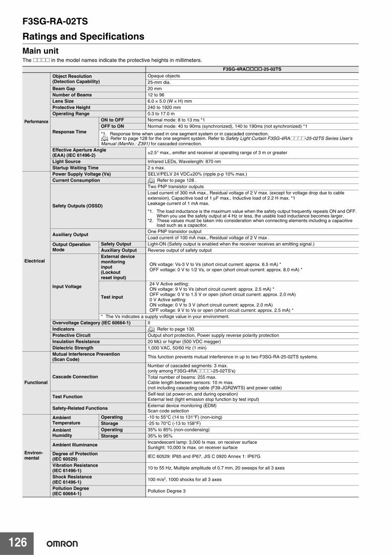
F3SG-RA-02TS
126
Ratings and SpecificationsMain unitThe @@@@ in the model names indicate the protective heights in millimeters.
F3SG-4RA-25-02TS
Performance
Object Resolution(Detection Capability)
Opaque objects25-mm dia.
Beam Gap 20 mmNumber of Beams 12 to 96Lens Size 6.0 × 5.0 (W × H) mm Protective Height 240 to 1920 mmOperating Range 0.3 to 17.0 m
Response Time
ON to OFF Normal mode: 8 to 13 ms *1OFF to ON Normal mode: 40 to 90ms (synchronized), 140 to 190ms (not synchronized) *1
*1. Response time when used in one segment system or in cascaded connection. Refer to page 128 for the one segment system. Refer to Safety Light Curtain F3SG-4RA@@@@-25-02TS Series User's
Manual (ManNo.: Z391) for cascaded connection.Effective Aperture Angle (EAA) (IEC 61496-2) ±2.5° max., emitter and receiver at operating range of 3 m or greater
Light Source Infrared LEDs, Wavelength: 870 nmStartup Waiting Time 2 s max.
Electrical
Power Supply Voltage (Vs) SELV/PELV 24 VDC±20% (ripple p-p 10% max.)Current Consumption Refer to page 128 .
Safety Outputs (OSSD)
Two PNP transistor outputsLoad current of 300 mA max., Residual voltage of 2 V max. (except for voltage drop due to cableextension), Capacitive load of 1 μF max., Inductive load of 2.2 H max. *1Leakage current of 1 mA max.
*1. The load inductance is the maximum value when the safety output frequently repeats ON and OFF.When you use the safety output at 4 Hz or less, the usable load inductance becomes larger.
*2. These values must be taken into consideration when connecting elements including a capacitiveload such as a capacitor.
Auxiliary OutputOne PNP transistor outputLoad current of 100 mA max., Residual voltage of 2 V max .
Output Operation Mode
Safety Output Light-ON (Safety output is enabled when the receiver receives an emitting signal.)Auxiliary Output Reverse output of safety output
Input Voltage
External devicemonitoringinput(Lockoutreset input)
ON voltage: Vs-3 V to Vs (short circuit current: approx. 6.5 mA) *OFF voltage: 0 V to 1/2 Vs, or open (short circuit current: approx. 8.0 mA) *
Test input
24 V Active setting:ON voltage: 9 V to Vs (short circuit current: approx. 2.5 mA) *OFF voltage: 0 V to 1.5 V or open (short circuit current: approx. 2.0 mA)0 V Active setting:ON voltage: 0 V to 3 V (short circuit current: approx. 2.0 mA)OFF voltage: 9 V to Vs or open (short circuit current: approx. 2.5 mA) *
* The Vs indicates a supply voltage value in your environment.Overvoltage Category (IEC 60664-1) IIIndicators Refer to page 130.Protective Circuit Output short protection, Power supply reverse polarity protectionInsulation Resistance 20 MΩ or higher (500 VDC megger)Dielectric Strength 1,000 VAC, 50/60 Hz (1 min)
Functional
Mutual Interference Prevention (Scan Code) This function prevents mutual interference in up to two F3SG-RA-25-02TS systems.
Cascade Connection
Number of cascaded segments: 3 max.(only among F3SG-4RA@@@@-25-02TS's)Total number of beams: 255 max.Cable length between sensors: 10 m max. (not including cascading cable (F39-JGR2WTS) and power cable)
Test Function Self-test (at power-on, and during operation)External test (light emission stop function by test input)
Safety-Related Functions External device monitoring (EDM)Scan code selection
Environ-mental
AmbientTemperature
Operating -10 to 55°C (14 to 131°F) (non-icing)Storage -25 to 70°C (-13 to 158°F)
AmbientHumidity
Operating 35% to 85% (non-condensing)Storage 35% to 95%
Ambient Illuminance Incandescent lamp: 3,000 Ix max. on receiver surfaceSunlight: 10,000 Ix max. on receiver surface
Degree of Protection(IEC 60529) IEC 60529: IP65 and IP67, JIS C 0920 Annex 1: IP67G
Vibration Resistance(IEC 61496-1) 10 to 55 Hz, Multiple amplitude of 0.7 mm, 20 sweeps for all 3 axes
Shock Resistance(IEC 61496-1) 100 m/s2, 1000 shocks for all 3 axes
Pollution Degree(IEC 60664-1) Pollution Degree 3
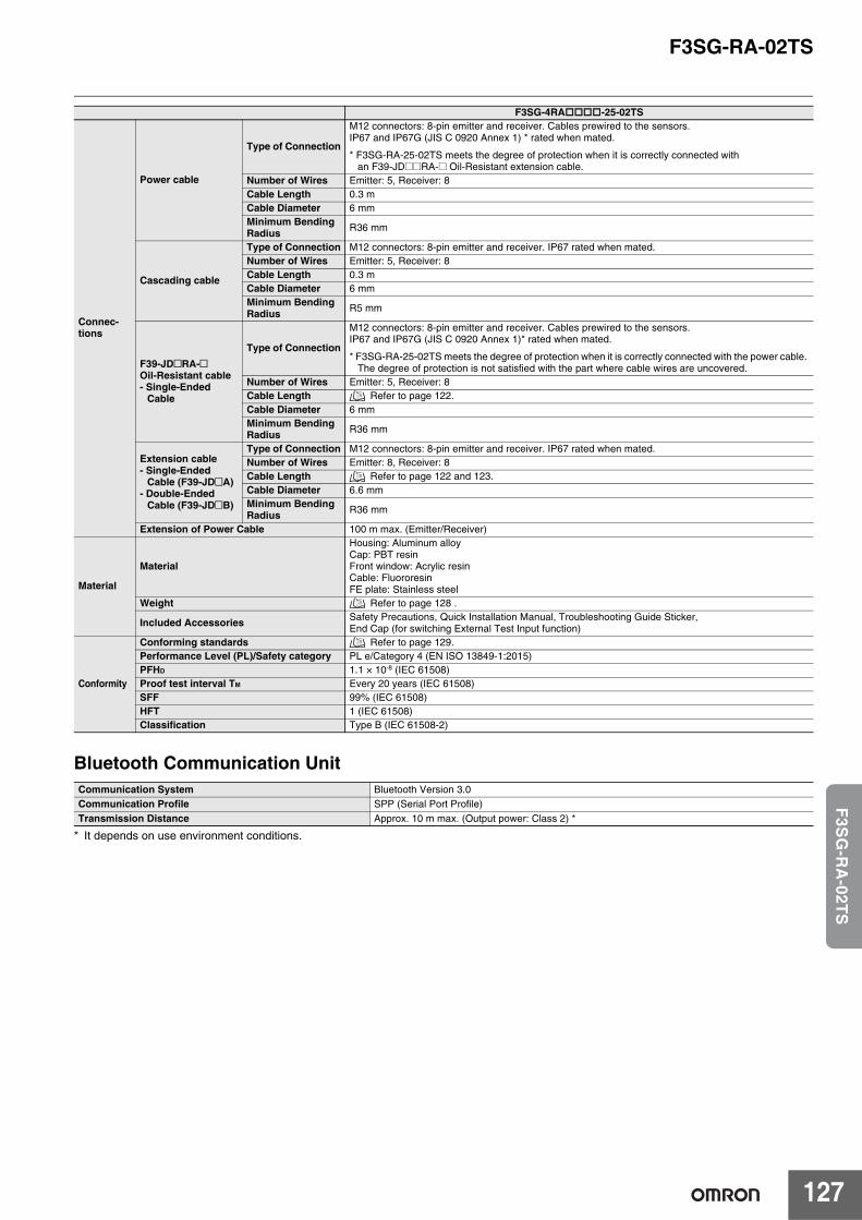
F3SG-RA-02TS
127
F3S
G-R
A-02T
S
Bluetooth Communication Unit
* It depends on use environment conditions.
Connec-tions
Power cable
Type of Connection
M12 connectors: 8-pin emitter and receiver. Cables prewired to the sensors.IP67 and IP67G (JIS C 0920 Annex 1) * rated when mated.
* F3SG-RA-25-02TS meets the degree of protection when it is correctly connected with an F39-JD@@RA-@ Oil-Resistant extension cable.
Number of Wires Emitter: 5, Receiver: 8Cable Length 0.3 mCable Diameter 6 mmMinimum Bending Radius R36 mm
Cascading cable
Type of Connection M12 connectors: 8-pin emitter and receiver. IP67 rated when mated.Number of Wires Emitter: 5, Receiver: 8Cable Length 0.3 mCable Diameter 6 mmMinimum Bending Radius R5 mm
F39-JD@RA-@Oil-Resistant cable- Single-Ended
Cable
Type of Connection
M12 connectors: 8-pin emitter and receiver. Cables prewired to the sensors.IP67 and IP67G (JIS C 0920 Annex 1)* rated when mated.
* F3SG-RA-25-02TS meets the degree of protection when it is correctly connected with the power cable. The degree of protection is not satisfied with the part where cable wires are uncovered.
Number of Wires Emitter: 5, Receiver: 8Cable Length Refer to page 122.Cable Diameter 6 mmMinimum Bending Radius R36 mm
Extension cable- Single-Ended
Cable (F39-JD@A)- Double-Ended
Cable (F39-JD@B)
Type of Connection M12 connectors: 8-pin emitter and receiver. IP67 rated when mated.Number of Wires Emitter: 8, Receiver: 8Cable Length Refer to page 122 and 123.Cable Diameter 6.6 mmMinimum BendingRadius R36 mm
Extension of Power Cable 100 m max. (Emitter/Receiver)
Material
Material
Housing: Aluminum alloyCap: PBT resinFront window: Acrylic resinCable: FluororesinFE plate: Stainless steel
Weight Refer to page 128 .
Included Accessories Safety Precautions, Quick Installation Manual, Troubleshooting Guide Sticker, End Cap (for switching External Test Input function)
Conformity
Conforming standards Refer to page 129.Performance Level (PL)/Safety category PL e/Category 4 (EN ISO 13849-1:2015)PFHD 1.1 × 10⁻⁸ (IEC 61508) Proof test interval TM Every 20 years (IEC 61508)SFF 99% (IEC 61508)HFT 1 (IEC 61508)Classification Type B (IEC 61508-2)
Communication System Bluetooth Version 3.0Communication Profile SPP (Serial Port Profile)Transmission Distance Approx. 10 m max. (Output power: Class 2) *
F3SG-4RA-25-02TS
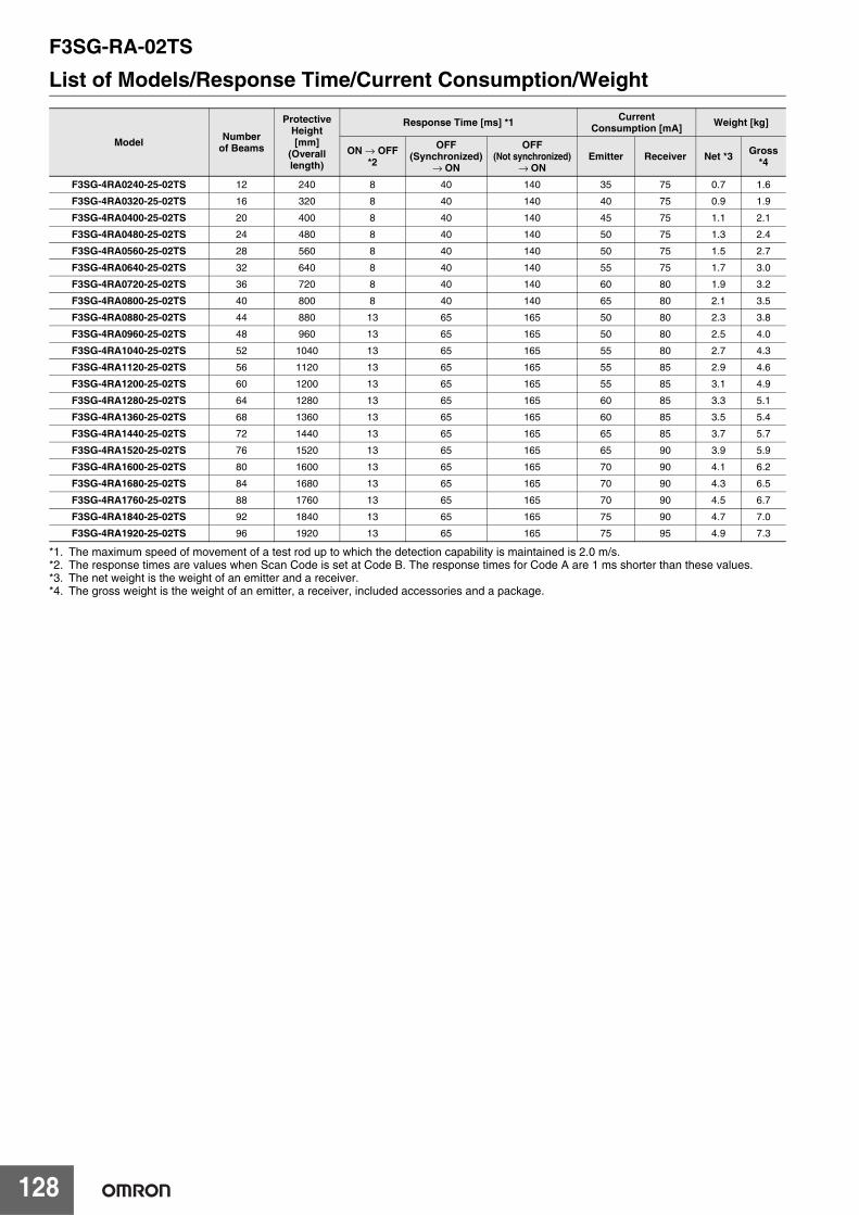
F3SG-RA-02TS
128
List of Models/Response Time/Current Consumption/Weight
*1. The maximum speed of movement of a test rod up to which the detection capability is maintained is 2.0 m/s.*2. The response times are values when Scan Code is set at Code B. The response times for Code A are 1 ms shorter than these values.*3. The net weight is the weight of an emitter and a receiver.*4. The gross weight is the weight of an emitter, a receiver, included accessories and a package.
Model Numberof Beams
ProtectiveHeight[mm]
(Overalllength)
Response Time [ms] *1 Current Consumption [mA] Weight [kg]
ON → OFF *2
OFF(Synchronized)
→ ON
OFF (Not synchronized)
→ ONEmitter Receiver Net *3 Gross
*4
F3SG-4RA0240-25-02TS 12 240 8 40 140 35 75 0.7 1.6
F3SG-4RA0320-25-02TS 16 320 8 40 140 40 75 0.9 1.9
F3SG-4RA0400-25-02TS 20 400 8 40 140 45 75 1.1 2.1
F3SG-4RA0480-25-02TS 24 480 8 40 140 50 75 1.3 2.4
F3SG-4RA0560-25-02TS 28 560 8 40 140 50 75 1.5 2.7
F3SG-4RA0640-25-02TS 32 640 8 40 140 55 75 1.7 3.0
F3SG-4RA0720-25-02TS 36 720 8 40 140 60 80 1.9 3.2
F3SG-4RA0800-25-02TS 40 800 8 40 140 65 80 2.1 3.5
F3SG-4RA0880-25-02TS 44 880 13 65 165 50 80 2.3 3.8
F3SG-4RA0960-25-02TS 48 960 13 65 165 50 80 2.5 4.0
F3SG-4RA1040-25-02TS 52 1040 13 65 165 55 80 2.7 4.3
F3SG-4RA1120-25-02TS 56 1120 13 65 165 55 85 2.9 4.6
F3SG-4RA1200-25-02TS 60 1200 13 65 165 55 85 3.1 4.9
F3SG-4RA1280-25-02TS 64 1280 13 65 165 60 85 3.3 5.1
F3SG-4RA1360-25-02TS 68 1360 13 65 165 60 85 3.5 5.4
F3SG-4RA1440-25-02TS 72 1440 13 65 165 65 85 3.7 5.7
F3SG-4RA1520-25-02TS 76 1520 13 65 165 65 90 3.9 5.9
F3SG-4RA1600-25-02TS 80 1600 13 65 165 70 90 4.1 6.2
F3SG-4RA1680-25-02TS 84 1680 13 65 165 70 90 4.3 6.5
F3SG-4RA1760-25-02TS 88 1760 13 65 165 70 90 4.5 6.7
F3SG-4RA1840-25-02TS 92 1840 13 65 165 75 90 4.7 7.0
F3SG-4RA1920-25-02TS 96 1920 13 65 165 75 95 4.9 7.3
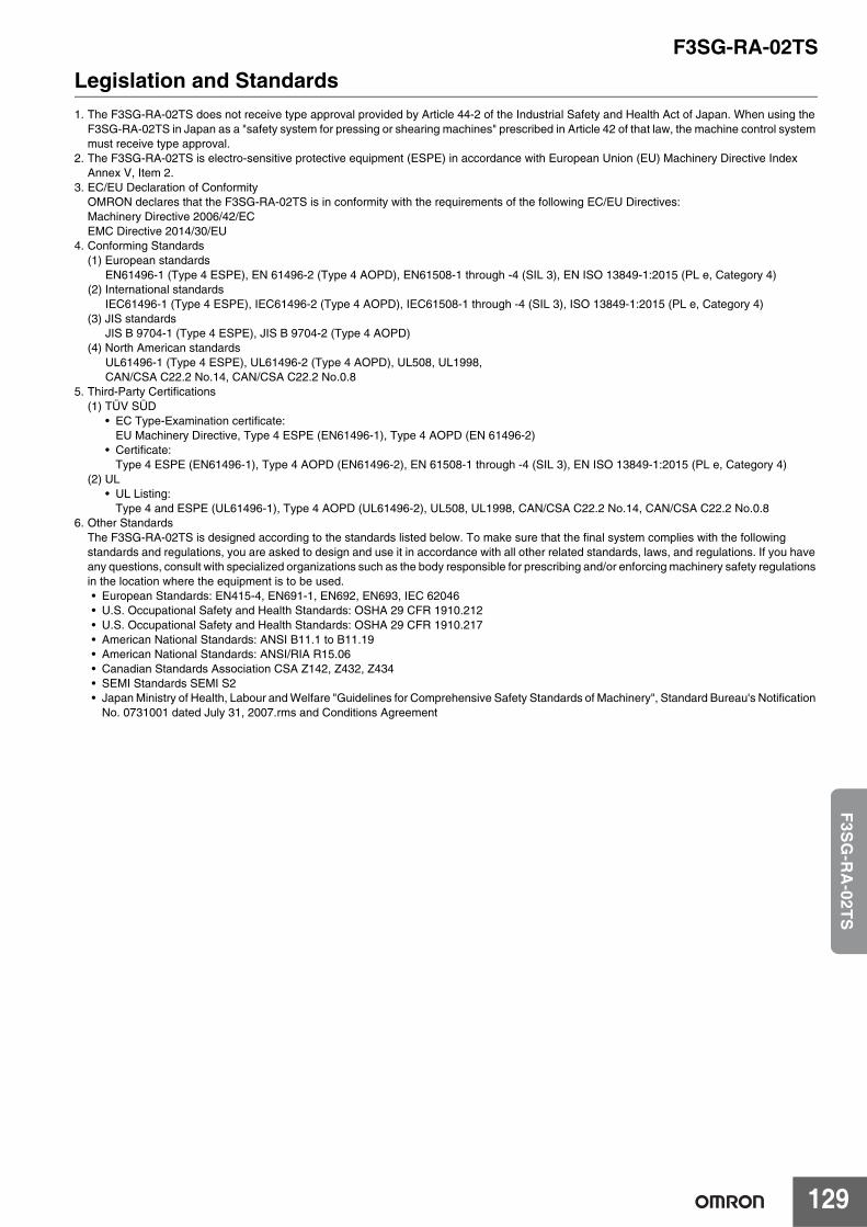
F3SG-RA-02TS
129
F3S
G-R
A-02T
S
Legislation and Standards1. The F3SG-RA-02TS does not receive type approval provided by Article 44-2 of the Industrial Safety and Health Act of Japan. When using the
F3SG-RA-02TS in Japan as a "safety system for pressing or shearing machines" prescribed in Article 42 of that law, the machine control system must receive type approval.
2. The F3SG-RA-02TS is electro-sensitive protective equipment (ESPE) in accordance with European Union (EU) Machinery Directive Index Annex V, Item 2.
3. EC/EU Declaration of ConformityOMRON declares that the F3SG-RA-02TS is in conformity with the requirements of the following EC/EU Directives: Machinery Directive 2006/42/ECEMC Directive 2014/30/EU
4. Conforming Standards(1) European standards
EN61496-1 (Type 4 ESPE), EN 61496-2 (Type 4 AOPD), EN61508-1 through -4 (SIL 3), EN ISO 13849-1:2015 (PL e, Category 4)(2) International standards
IEC61496-1 (Type 4 ESPE), IEC61496-2 (Type 4 AOPD), IEC61508-1 through -4 (SIL 3), ISO 13849-1:2015 (PL e, Category 4)(3) JIS standards
JIS B 9704-1 (Type 4 ESPE), JIS B 9704-2 (Type 4 AOPD)(4) North American standards
UL61496-1 (Type 4 ESPE), UL61496-2 (Type 4 AOPD), UL508, UL1998,CAN/CSA C22.2 No.14, CAN/CSA C22.2 No.0.8
5. Third-Party Certifications(1) TÜV SÜD
• EC Type-Examination certificate:EU Machinery Directive, Type 4 ESPE (EN61496-1), Type 4 AOPD (EN 61496-2)
• Certificate:Type 4 ESPE (EN61496-1), Type 4 AOPD (EN61496-2), EN 61508-1 through -4 (SIL 3), EN ISO 13849-1:2015 (PL e, Category 4)
(2) UL• UL Listing:
Type 4 and ESPE (UL61496-1), Type 4 AOPD (UL61496-2), UL508, UL1998, CAN/CSA C22.2 No.14, CAN/CSA C22.2 No.0.86. Other Standards
The F3SG-RA-02TS is designed according to the standards listed below. To make sure that the final system complies with the following standards and regulations, you are asked to design and use it in accordance with all other related standards, laws, and regulations. If you have any questions, consult with specialized organizations such as the body responsible for prescribing and/or enforcing machinery safety regulations in the location where the equipment is to be used.• European Standards: EN415-4, EN691-1, EN692, EN693, IEC 62046• U.S. Occupational Safety and Health Standards: OSHA 29 CFR 1910.212• U.S. Occupational Safety and Health Standards: OSHA 29 CFR 1910.217• American National Standards: ANSI B11.1 to B11.19• American National Standards: ANSI/RIA R15.06• Canadian Standards Association CSA Z142, Z432, Z434• SEMI Standards SEMI S2• Japan Ministry of Health, Labour and Welfare "Guidelines for Comprehensive Safety Standards of Machinery", Standard Bureau's Notification
No. 0731001 dated July 31, 2007.rms and Conditions Agreement
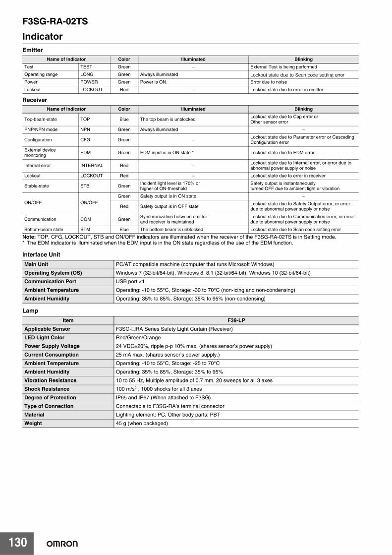
F3SG-RA-02TS
130
IndicatorEmitter
Receiver
Note: TOP, CFG, LOCKOUT, STB and ON/OFF indicators are illuminated when the receiver of the F3SG-RA-02TS is in Setting mode.* The EDM indicator is illuminated when the EDM input is in the ON state regardless of the use of the EDM function.
Interface Unit
Lamp
Name of Indicator Color Illuminated BlinkingTest TEST Green − External Test is being performed
Operating range LONG Green Always illuminated Lockout state due to Scan code setting errorPower POWER Green Power is ON. Error due to noise
Lockout LOCKOUT Red − Lockout state due to error in emitter
Name of Indicator Color Illuminated Blinking
Top-beam-state TOP Blue The top beam is unblockedLockout state due to Cap error orOther sensor error
PNP/NPN mode NPN Green Always illuminated −
Configuration CFG Green − Lockout state due to Parameter error or Cascading Configuration error
External devicemonitoring
EDM Green EDM input is in ON state * Lockout state due to EDM error
Internal error INTERNAL Red − Lockout state due to Internal error, or error due to abnormal power supply or noise
Lockout LOCKOUT Red − Lockout state due to error in receiver
Stable-state STB Green Incident light level is 170% orhigher of ON-threshold
Safety output is instantaneouslyturned OFF due to ambient light or vibration
ON/OFF ON/OFFGreen Safety output is in ON state −
Red Safety output is in OFF state Lockout state due to Safety Output error, or error due to abnormal power supply or noise
Communication COM Green Synchronization between emitterand receiver is maintained
Lockout state due to Communication error, or error due to abnormal power supply or noise
Bottom-beam state BTM Blue The bottom beam is unblocked Lockout state due to Scan code setting error
Main Unit PC/AT compatible machine (computer that runs Microsoft Windows)
Operating System (OS) Windows 7 (32-bit/64-bit), Windows 8, 8.1 (32-bit/64-bit), Windows 10 (32-bit/64-bit)
Communication Port USB port ×1
Ambient Temperature Operating: -10 to 55°C, Storage: -30 to 70°C (non-icing and non-condensing)
Ambient Humidity Operating: 35% to 85%, Storage: 35% to 95% (non-condensing)
Item F39-LPApplicable Sensor F3SG-@RA Series Safety Light Curtain (Receiver)
LED Light Color Red/Green/Orange
Power Supply Voltage 24 VDC±20%, ripple p-p 10% max. (shares sensor’s power supply)
Current Consumption 25 mA max. (shares sensor’s power supply.)
Ambient Temperature Operating: -10 to 55°C, Storage: -25 to 70°C
Ambient Humidity Operating: 35% to 85%, Storage: 35% to 95%
Vibration Resistance 10 to 55 Hz, Multiple amplitude of 0.7 mm, 20 sweeps for all 3 axes
Shock Resistance 100 m/s2 , 1000 shocks for all 3 axes
Degree of Protection IP65 and IP67 (When attached to F3SG)
Type of Connection Connectable to F3SG-RA’s terminal connector
Material Lighting element: PC, Other body parts: PBT
Weight 45 g (when packaged)
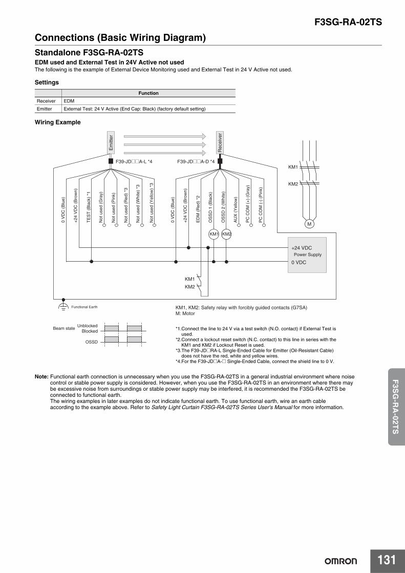
F3SG-RA-02TS
131
F3S
G-R
A-02T
S
Connections (Basic Wiring Diagram)Standalone F3SG-RA-02TSEDM used and External Test in 24V Active not usedThe following is the example of External Device Monitoring used and External Test in 24 V Active not used.
Settings
Wiring Example
Note: Functional earth connection is unnecessary when you use the F3SG-RA-02TS in a general industrial environment where noisecontrol or stable power supply is considered. However, when you use the F3SG-RA-02TS in an environment where there maybe excessive noise from surroundings or stable power supply may be interfered, it is recommended the F3SG-RA-02TS beconnected to functional earth.The wiring examples in later examples do not indicate functional earth. To use functional earth, wire an earth cable according to the example above. Refer to Safety Light Curtain F3SG-RA-02TS Series User's Manual for more information.
Function
Receiver EDM
Emitter External Test: 24 V Active (End Cap: Black) (factory default setting)
UnblockedBlocked
Beam state
OSSD
KM1, KM2: Safety relay with forcibly guided contacts (G7SA) M: Motor
+24
VD
C (
Bro
wn)
Not
use
d (Y
ello
w)
*3
TE
ST
(B
lack
) *1
Not
use
d (W
hite
) *3
Not
use
d (R
ed)
*3
Not
use
d (P
ink)
Not
use
d (G
ray)
0 V
DC
(B
lue)
OS
SD
1 (
Bla
ck)
OS
SD
2 (
Whi
te)
+24
VD
C (
Bro
wn)
0 V
DC
(B
lue)
AU
X (
Yel
low
)
PC
CO
M (
-) (
Pin
k)
PC
CO
M (
+)
(Gra
y)
ED
M (
Red
) *2
Functional Earth
F39-JD@@A-L *4 F39-JD@@A-D *4KM1
KM2
M
KM1 KM2
KM1
KM2
Power Supply+24 VDC
0 VDC
Rec
eive
r
Em
itter
*1.Connect the line to 24 V via a test switch (N.O. contact) if External Test isused.
*2.Connect a lockout reset switch (N.C. contact) to this line in series with the KM1 and KM2 if Lockout Reset is used.
*3.The F39-JD@RA-L Single-Ended Cable for Emitter (Oil-Resistant Cable) does not have the red, white and yellow wires.
*4.For the F39-JD@A-@ Single-Ended Cable, connect the shield line to 0 V.
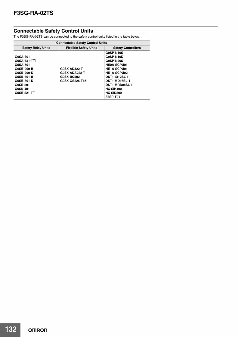
F3SG-RA-02TS
132
Connectable Safety Control UnitsThe F3SG-RA-02TS can be connected to the safety control units listed in the table below.
Connectable Safety Control UnitsSafety Relay Units Flexible Safety Units Safety Controllers
G9SA-301G9SA-321-T@G9SA-501G9SB-200-BG9SB-200-DG9SB-301-BG9SB-301-DG9SE-201G9SE-401G9SE-221-T@
G9SX-AD322-TG9SX-ADA222-TG9SX-BC202G9SX-GS226-T15
G9SP-N10SG9SP-N10DG9SP-N20SNE0A-SCPU01NE1A-SCPU01NE1A-SCPU02DST1-ID12SL-1DST1-MD16SL-1DST1-MRD08SL-1NX-SIH400NX-SID800F3SP-T01
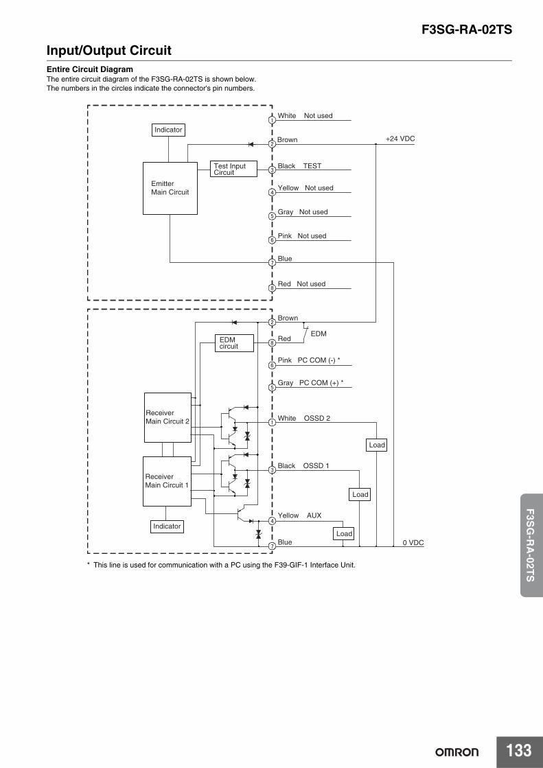
F3SG-RA-02TS
133
F3S
G-R
A-02T
S
Input/Output CircuitEntire Circuit DiagramThe entire circuit diagram of the F3SG-RA-02TS is shown below.The numbers in the circles indicate the connector's pin numbers.
+24 VDCBrown
Black TEST
Yellow Not used
White Not used
Blue
Brown
RedEDM
White OSSD 2
Pink PC COM (-) *
Gray PC COM (+) *
Black OSSD 1
Yellow AUX
Blue
EDMcircuit
0 VDC
Gray Not used
Pink Not used
Red Not used
Load
Indicator
EmitterMain Circuit
Test Input Circuit
ReceiverMain Circuit 2
ReceiverMain Circuit 1
IndicatorLoad
Load
* This line is used for communication with a PC using the F39-GIF-1 Interface Unit.
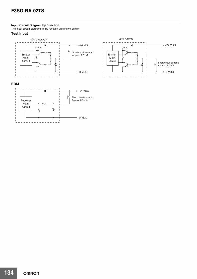
F3SG-RA-02TS
134
Input Circuit Diagram by FunctionThe input circuit diagrams of by function are shown below.
Emitter Main Circuit
+24 VDC
0 VDC
5 V
Short circuit current:Approx. 2.5 mA
<24 V Active> <0 V Active>
Emitter Main Circuit
+24 VDC
0 VDC
5 V
Short circuit current:Approx. 2.0 mA
Test Input
Receiver Main Circuit
+24 VDC
0 VDC
Short circuit current:Approx. 6.5 mA
EDM
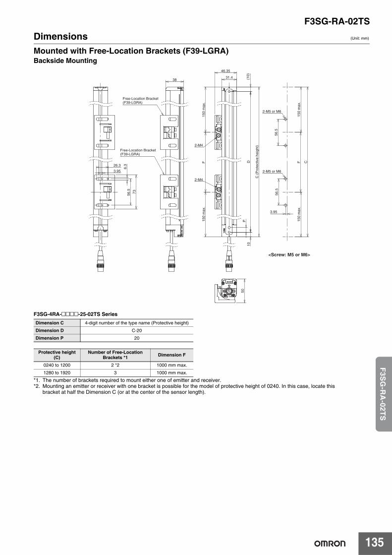
F3SG-RA-02TS
135
F3S
G-R
A-02T
S
Dimensions (Unit: mm)
Mounted with Free-Location Brackets (F39-LGRA)Backside Mounting
F3SG-4RA-@@@@-25-02TS Series
*1. The number of brackets required to mount either one of emitter and receiver.*2. Mounting an emitter or receiver with one bracket is possible for the model of protective height of 0240. In this case, locate this
bracket at half the Dimension C (or at the center of the sensor length).
Dimension C 4-digit number of the type name (Protective height)
Dimension D C-20
Dimension P 20
Protective height (C)
Number of Free-Location Brackets *1 Dimension F
0240 to 1200 2 *2 1000 mm max.
1280 to 1920 3 1000 mm max.
31.4
46.35
(10)
10
P
D
C (
Pro
tect
ive
heig
ht)
150
max
.15
0 m
ax.
F
56.5
56.5
150
max
.F
150
max
.
C
3.95
2-M4
2-M4
2-M5 or M6
<Screw: M5 or M6>
2-M5 or M6
38
Free-Location Bracket(F39-LGRA)
Free-Location Bracket(F39-LGRA)
26.3
73
6.3
3.95
56.5
50
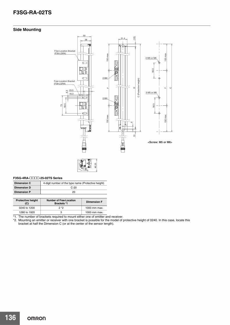
F3SG-RA-02TS
136
Side Mounting
F3SG-4RA-@@@@-25-02TS Series
*1. The number of brackets required to mount either one of emitter and receiver.*2. Mounting an emitter or receiver with one bracket is possible for the model of protective height of 0240. In this case, locate this
bracket at half the Dimension C (or at the center of the sensor length).
Dimension C 4-digit number of the type name (Protective height)
Dimension D C-20
Dimension P 20
Protective height (C)
Number of Free-Location Brackets *1 Dimension F
0240 to 1200 2 *2 1000 mm max.
1280 to 1920 3 1000 mm max.
31.4 (10)
10P
DF
2-M4
2-M4
38
50
16.3
73
6.3 23.5
56.5
(F39-LGRA)
(F39-LGRA)
46.3
5
C (
Pro
tect
ive
heig
ht)
150
max
.15
0 m
ax.
2-M5 or M6
2-M5 or M6
Free-Location Bracket
Free-Location Bracket
56.5
56.5
150
max
.F
150
max
.
C
<Screw: M5 or M6>
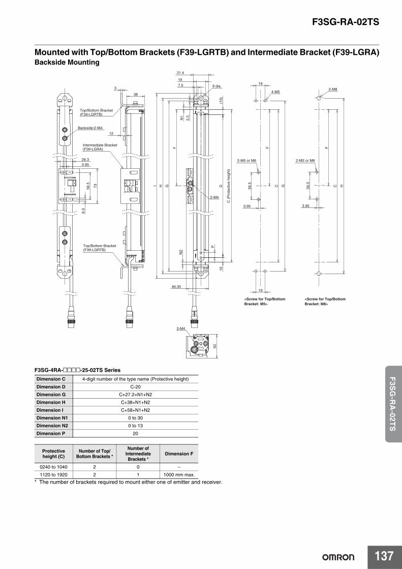
F3SG-RA-02TS
137
F3S
G-R
A-02T
S
Mounted with Top/Bottom Brackets (F39-LGRTB) and Intermediate Bracket (F39-LGRA)Backside Mounting
F3SG-4RA-@@@@-25-02TS Series
* The number of brackets required to mount either one of emitter and receiver.
Dimension C 4-digit number of the type name (Protective height)
Dimension D C-20
Dimension G C+27.2+N1+N2
Dimension H C+38+N1+N2
Dimension I C+58+N1+N2
Dimension N1 0 to 30
Dimension N2 0 to 13
Dimension P 20
Protective height (C)
Number of Top/Bottom Brackets *
Number of Intermediate Brackets *
Dimension F
0240 to 1040 2 0 −
1120 to 1920 2 1 1000 mm max.
31.4
(10)
1
0
P
D
N1
7.5
N2
46.35
HI
56.5 C
3.95
FF
19
5.5
G
19
19
G 56.5
C
3.95
F
H
2-M4
9 dia.
<Screw for Top/Bottom Bracket: M5>
<Screw for Top/Bottom Bracket: M8>
4-M52-M8
50
2-M4
12
3
38
Intermediate Bracket(F39-LGRA)
Top/Bottom Bracket(F39-LGRTB)
Top/Bottom Bracket(F39-LGRTB)
26.3
73
6.3
3.95
56.5
Backside:2-M4
C (
Pro
tect
ive
heig
ht)
2-M5 or M6 2-M5 or M6

F3SG-RA-02TS
138
Side Mounting
F3SG-4RA-@@@@-25-02TS Series
* The number of brackets required to mount either one of emitter and receiver.
Dimension C 4-digit number of the type name (Protective height)
Dimension D C-20
Dimension G C+27.2+N1+N2
Dimension H C+38+N1+N2
Dimension I C+58+N1+N2
Dimension N1 0 to 30
Dimension N2 0 to 13
Dimension P 20
Protective height (C)
Number of Top/Bottom Brackets *
Number of Intermediate Brackets *
Dimension F
0240 to 1040 2 0 −
1120 to 1920 2 1 1000 mm max.
(10)
10
P
D
N1
N2
31.4
3
56.5
C
F F
19
19
G
56.5 C
F
H
4.15 4.15
2-M4
4-M52-M8
16.3
73
6.3
31.4
38
50
I
5.5
4.15
56.5
19
19.35
G H
(F39-LGRA)
(F39-LGRTB)
(F39-LGRTB)
9 dia.
46.3
5
2-M4
<Screw for Top/Bottom Bracket: M5>
<Screw for Top/Bottom Bracket: M8>
Intermediate Bracket
Top/Bottom Bracket
Top/Bottom Bracket
Backside:2-M4
C (
Pro
tect
ive
heig
ht)
2-M5 or M6 2-M5 or M6
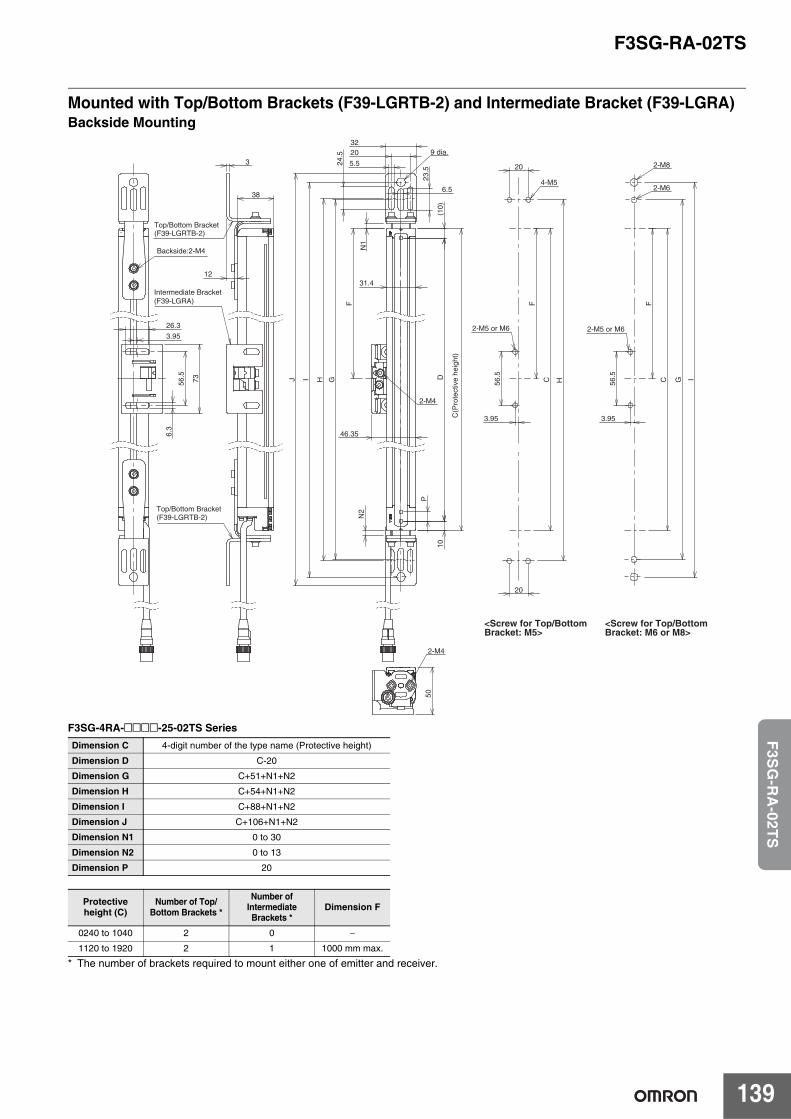
F3SG-RA-02TS
139
F3S
G-R
A-02T
S
Mounted with Top/Bottom Brackets (F39-LGRTB-2) and Intermediate Bracket (F39-LGRA)Backside Mounting
F3SG-4RA-@@@@-25-02TS Series
* The number of brackets required to mount either one of emitter and receiver.
Dimension C 4-digit number of the type name (Protective height)
Dimension D C-20
Dimension G C+51+N1+N2
Dimension H C+54+N1+N2
Dimension I C+88+N1+N2
Dimension J C+106+N1+N2
Dimension N1 0 to 30
Dimension N2 0 to 13
Dimension P 20
Protective height (C)
Number of Top/Bottom Brackets *
Number of Intermediate Brackets *
Dimension F
0240 to 1040 2 0 −
1120 to 1920 2 1 1000 mm max.
(10)
10
P
D
N1
N2
46.35
IJ
23.5
24.5
32
31.4
5.5
6.5
56.5
C
3.95
FF
20
20
H 56.5
C
3.95
F
IGH
20
G
2-M4
9 dia.
4-M5
2-M8
2-M6
50
2-M4
38
3
12
(F39-LGRTB-2)
(F39-LGRA)
(F39-LGRTB-2)
26.3
73
6.3
3.95
56.5
<Screw for Top/Bottom Bracket: M5>
<Screw for Top/Bottom Bracket: M6 or M8>
Intermediate Bracket
Top/Bottom Bracket
Top/Bottom Bracket
Backside:2-M4
C(P
rote
ctiv
e he
ight
)
2-M5 or M6 2-M5 or M6
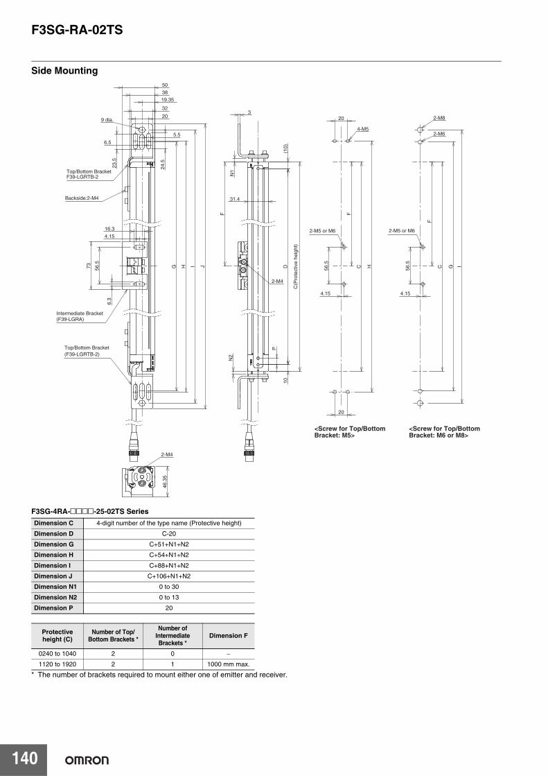
F3SG-RA-02TS
140
Side Mounting
F3SG-4RA-@@@@-25-02TS Series
* The number of brackets required to mount either one of emitter and receiver.
Dimension C 4-digit number of the type name (Protective height)
Dimension D C-20
Dimension G C+51+N1+N2
Dimension H C+54+N1+N2
Dimension I C+88+N1+N2
Dimension J C+106+N1+N2
Dimension N1 0 to 30
Dimension N2 0 to 13
Dimension P 20
Protective height (C)
Number of Top/Bottom Brackets *
Number of Intermediate Brackets *
Dimension F
0240 to 1040 2 0 −
1120 to 1920 2 1 1000 mm max.
31.4
(10)
10
P
D
N1
N2
56.5
C
FF
20
20
H 56.5
C
F
IG
3
4.15 4.15
2-M4
4-M5
2-M8
2-M6
16.3
73
6.3
I J
24.5
23.5
32
38
5.5
6.5
4.15
56.5
G H
20
19.35
F39-LGRTB-2
(F39-LGRA)
(F39-LGRTB-2)
9 dia.
46.3
5
2-M4
<Screw for Top/Bottom Bracket: M5>
<Screw for Top/Bottom Bracket: M6 or M8>
Intermediate Bracket
Top/Bottom Bracket
Top/Bottom Bracket
Backside:2-M4
C(P
rote
ctiv
e he
ight
)
2-M5 or M6 2-M5 or M6
50
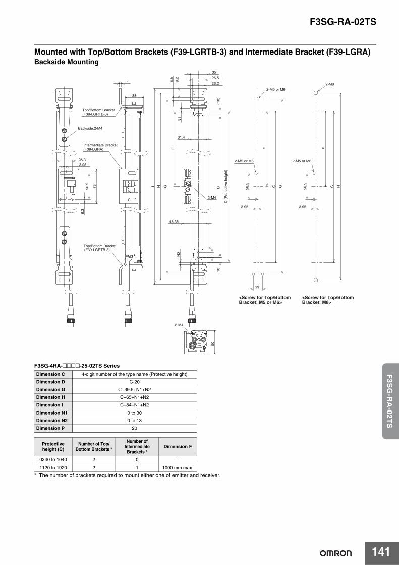
F3SG-RA-02TS
141
F3S
G-R
A-02T
S
Mounted with Top/Bottom Brackets (F39-LGRTB-3) and Intermediate Bracket (F39-LGRA)Backside Mounting
F3SG-4RA-@@@@-25-02TS Series
* The number of brackets required to mount either one of emitter and receiver.
Dimension C 4-digit number of the type name (Protective height)
Dimension D C-20
Dimension G C+39.5+N1+N2
Dimension H C+65+N1+N2
Dimension I C+84+N1+N2
Dimension N1 0 to 30
Dimension N2 0 to 13
Dimension P 20
Protective height (C)
Number of Top/Bottom Brackets *
Number of Intermediate Brackets *
Dimension F
0240 to 1040 2 0 −
1120 to 1920 2 1 1000 mm max.
31.4
(10)
10
P
D
N1
N2
46.35
I
35
23.2
26.5
6.5
8.2
56.5 C
3.95
FF
G
19
G
56.5 C
3.95
F
HH
2-M4
2-M8
50
2-M4
38
4
(F39-LGRA)
(F39-LGRTB-3)
(F39-LGRTB-3)
26.3
73
6.3
3.95
56.5
<Screw for Top/Bottom Bracket: M5 or M6>
<Screw for Top/Bottom Bracket: M8>
Intermediate Bracket
Top/Bottom Bracket
Top/Bottom Bracket
Backside:2-M4
C (
Pro
tect
ive
heig
ht)
2-M5 or M6 2-M5 or M6
2-M5 or M6
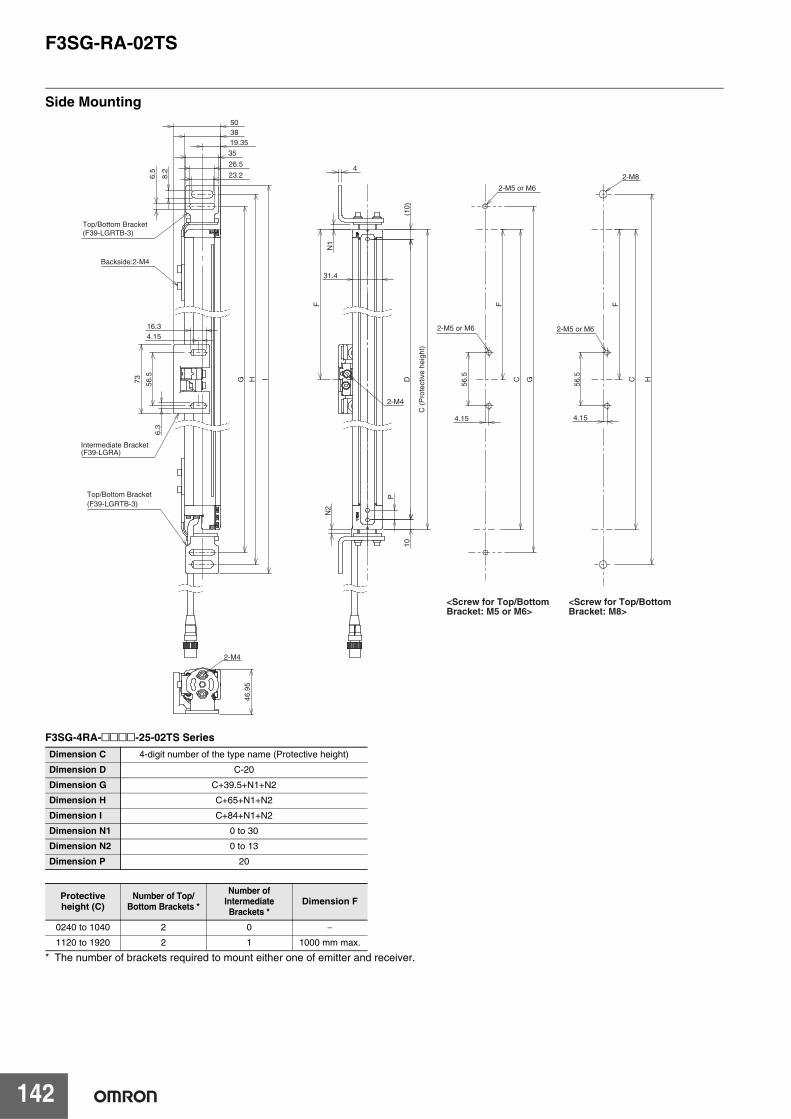
F3SG-RA-02TS
142
Side Mounting
F3SG-4RA-@@@@-25-02TS Series
* The number of brackets required to mount either one of emitter and receiver.
Dimension C 4-digit number of the type name (Protective height)
Dimension D C-20
Dimension G C+39.5+N1+N2
Dimension H C+65+N1+N2
Dimension I C+84+N1+N2
Dimension N1 0 to 30
Dimension N2 0 to 13
Dimension P 20
Protective height (C)
Number of Top/Bottom Brackets *
Number of Intermediate Brackets *
Dimension F
0240 to 1040 2 0 −
1120 to 1920 2 1 1000 mm max.
(10)
10
P
D
N1
N2
31.4
4
56.5 C
FF
G
56.5 C
F
H
4.15 4.15
2-M4
2-M8
16.3
73
6.3
38 50
I
26.5
23.2
35
8.2
6.5
4.15
56.5
19.35
G H
(F39-LGRA)
(F39-LGRTB-3)
(F39-LGRTB-3)
46.9
5
2-M4
<Screw for Top/Bottom Bracket: M5 or M6>
<Screw for Top/Bottom Bracket: M8>
Intermediate Bracket
Top/Bottom Bracket
Top/Bottom Bracket
Backside:2-M4
C (
Pro
tect
ive
heig
ht)
2-M5 or M6
2-M5 or M6
2-M5 or M6
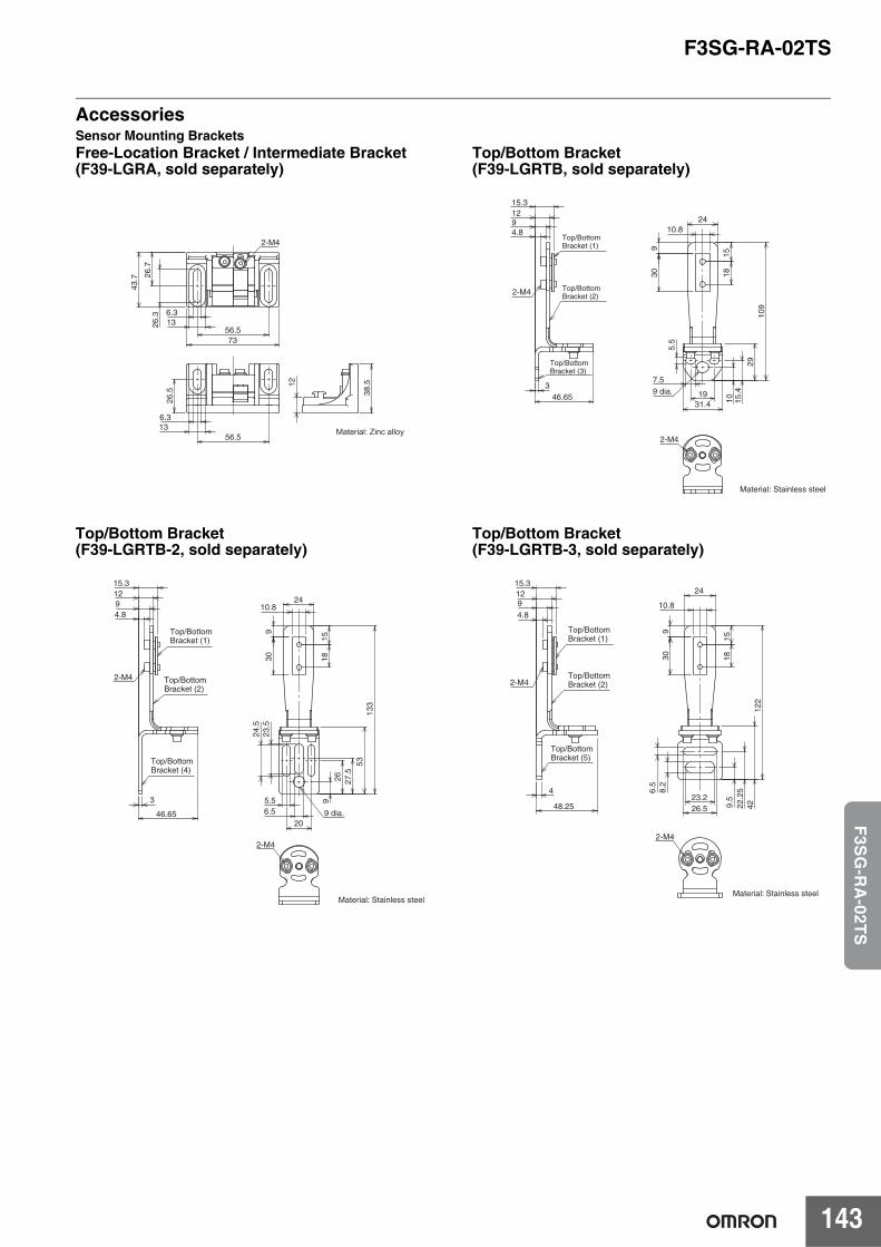
F3SG-RA-02TS
143
F3S
G-R
A-02T
S
AccessoriesSensor Mounting BracketsFree-Location Bracket / Intermediate Bracket (F39-LGRA, sold separately)
Top/Bottom Bracket (F39-LGRTB, sold separately)
Top/Bottom Bracket (F39-LGRTB-2, sold separately)
Top/Bottom Bracket (F39-LGRTB-3, sold separately)
56.5
26.7
73
43.7
6.31326
.3
2-M4
26.5
56.5136.3
38.512
Material: Zinc alloy
Material: Stainless steel
19
15.4
2410.8
930 18
15
109
29
1031.4
5.5
7.59 dia.
2-M4
46.653
15.31294.8
2-M4
Top/Bottom Bracket (1)
Top/Bottom Bracket (2)
Top/BottomBracket (3)
27.5
26
20
309
2410.8
1518
133
53
9
23.5
24.5
5.56.5 9 dia.
2-M4
Material: Stainless steel
3
46.65
4.8
129
15.3
2-M4
Top/Bottom Bracket (1)
Top/Bottom Bracket (2)
Top/Bottom Bracket (4)
22.2
59.
5
24
309
10.8
1518
122
42
8.2
6.5
23.226.5
2-M4
Material: Stainless steel
48.25
4
4.891215.3
2-M4
Top/Bottom Bracket (1)
Top/Bottom Bracket (2)
Top/Bottom Bracket (5)
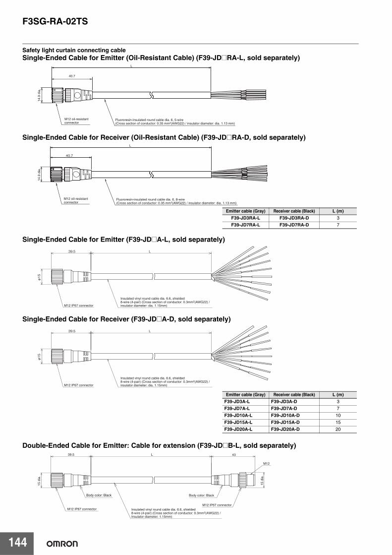
F3SG-RA-02TS
144
Safety light curtain connecting cableSingle-Ended Cable for Emitter (Oil-Resistant Cable) (F39-JD@RA-L, sold separately)
Single-Ended Cable for Receiver (Oil-Resistant Cable) (F39-JD@RA-D, sold separately)
Single-Ended Cable for Emitter (F39-JD@A-L, sold separately)
Single-Ended Cable for Receiver (F39-JD@A-D, sold separately)
Double-Ended Cable for Emitter: Cable for extension (F39-JD@B-L, sold separately)
Fluororesin-insulated round cable dia. 6, 5-wire (Cross section of conductor: 0.35 mm2(AWG22) / insulator diameter: dia. 1.13 mm)
M12 oil-resistant connector
40.7
L
14.9
dia
.
L
40.7
Fluororesin-insulated round cable dia. 6, 8-wire (Cross section of conductor: 0.35 mm2(AWG22) / insulator diameter: dia. 1.13 mm)
M12 oil-resistant connector
14.9
dia
.
Emitter cable (Gray) Receiver cable (Black) L (m)F39-JD3RA-L F39-JD3RA-D 3
F39-JD7RA-L F39-JD7RA-D 7
39.5 L
φ15
M12 IP67 connector
Insulated vinyl round cable dia. 6.6, shielded8-wire (4-pair) (Cross section of conductor: 0.3mm2(AWG22) / insulator diameter: dia. 1.15mm)
39.5 L
φ15
M12 IP67 connector
Insulated vinyl round cable dia. 6.6, shielded8-wire (4-pair) (Cross section of conductor: 0.3mm2(AWG22) / insulator diameter: dia. 1.15mm)
Emitter cable (Gray) Receiver cable (Black) L (m)F39-JD3A-L F39-JD3A-D 3
F39-JD7A-L F39-JD7A-D 7
F39-JD10A-L F39-JD10A-D 10
F39-JD15A-L F39-JD15A-D 15
F39-JD20A-L F39-JD20A-D 20
39.5 L 43
M12
15 d
ia.
M12 IP67 connector
Body color: BlackBody color: Black
M12 IP67 connector Insulated vinyl round cable dia. 6.6, shielded8-wire (4-pair) (Cross section of conductor: 0.3mm2(AWG22) / Insulator diameter: 1.15mm)
15 d
ia.
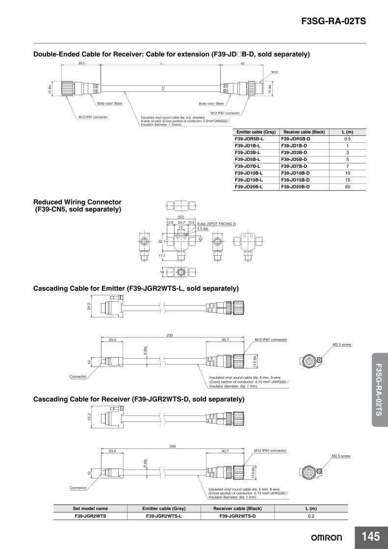
F3SG-RA-02TS
145
F3S
G-R
A-02T
S
Double-Ended Cable for Receiver: Cable for extension (F39-JD@B-D, sold separately)
Cascading Cable for Emitter (F39-JGR2WTS-L, sold separately)
Cascading Cable for Receiver (F39-JGR2WTS-D, sold separately)
Emitter cable (Gray) Receiver cable (Black) L (m)F39-JDR5B-L F39-JDR5B-D 0.5
F39-JD1B-L F39-JD1B-D 1
F39-JD3B-L F39-JD3B-D 3
F39-JD5B-L F39-JD5B-D 5
F39-JD7B-L F39-JD7B-D 7
F39-JD10B-L F39-JD10B-D 10
F39-JD15B-L F39-JD15B-D 15
F39-JD20B-L F39-JD20B-D 20
Set model name Emitter cable (Gray) Receiver cable (Black) L (m)
F39-JGR2WTS F39-JGR2WTS-L F39-JGR2WTS-D 0.2
39.5 L 43
M12
15 d
ia.
Body color: BlackBody color: Black
M12 IP67 connectorM12 IP67 connector
Insulated vinyl round cable dia. 6.6, shielded8-wire (4-pair) (Cross section of conductor: 0.3mm2(AWG22) / Insulator diameter: 1.15mm)
15 d
ia.
24.712
13.6 13.6 8 dia. (SPOT FACING 2)4.5 dia.
(52)
32.110
17.7
18
Reduced Wiring Connector (F39-CN5, sold separately)
20040.7
6 di
a.
23.4
10
Insulated vinyl round cable dia. 6 mm, 5-wire(Cross section of conductor: 0.15 mm2 (AWG26) / Insulator diameter: dia. 1 mm)
M12 IP67 connector
24.2
M2.5 screw
Connector
14.9
dia
.
200
14.9
dia
.
40.7
6 di
a.
23.4
10
Insulated vinyl round cable dia. 6 mm, 8-wire(Cross section of conductor: 0.15 mm2 (AWG26) / Insulator diameter: dia. 1 mm)
Connector
M12 IP67 connector
24.2
M2.5 screw
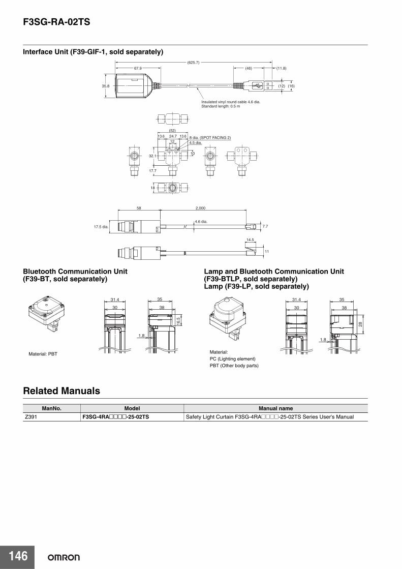
F3SG-RA-02TS
146
Interface Unit (F39-GIF-1, sold separately)
Bluetooth Communication Unit (F39-BT, sold separately)
Lamp and Bluetooth Communication Unit (F39-BTLP, sold separately)Lamp (F39-LP, sold separately)
Related Manuals
67.9
35.8 (16)(12)
(625.7)
(46)
Insulated vinyl round cable 4.6 dia. Standard length: 0.5 m
(11.8)
58
17.5 dia.4.6 dia.
2,000
14.5
7.7
11
24.712
13.6 13.6 8 dia. (SPOT FACING 2)4.5 dia.
(52)
32.110
17.7
18
16.
5
31.4
30 38
35
1.8
Material: PBT
31.4
30 38
35
28
1.8
Material:PC (Lighting element)PBT (Other body parts)
ManNo. Model Manual nameZ391 F3SG-4RA@@@@-25-02TS Safety Light Curtain F3SG-4RA@@@@-25-02TS Series User's Manual
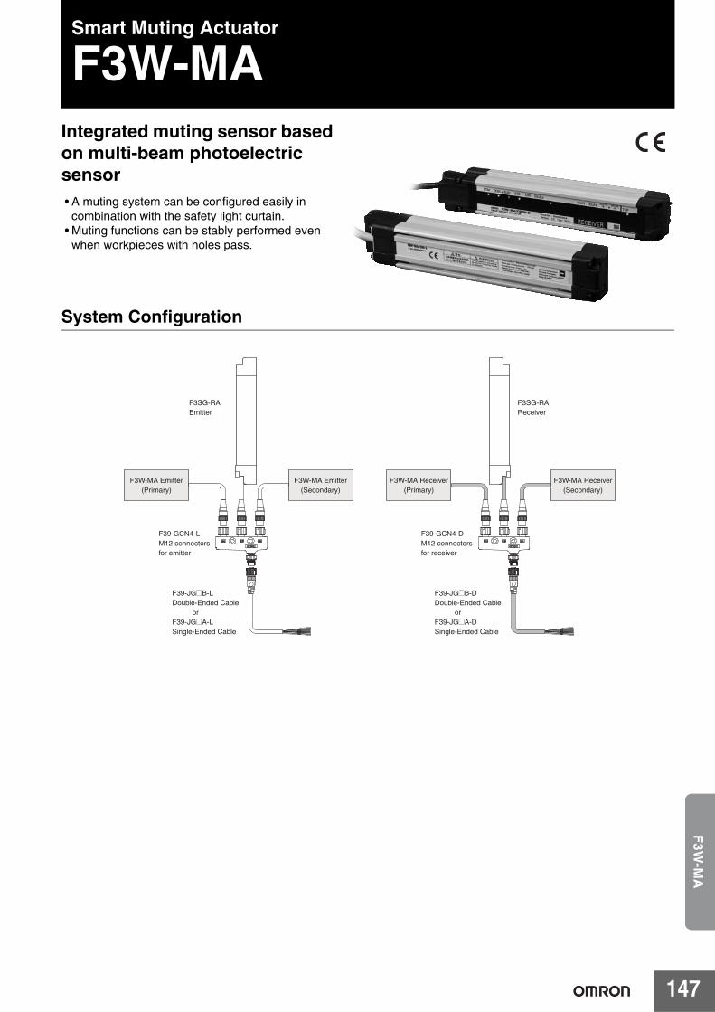
147
F3W
-MA
Smart Muting Actuator
F3W-MAIntegrated muting sensor based on multi-beam photoelectric sensor• A muting system can be configured easily in
combination with the safety light curtain.• Muting functions can be stably performed even
when workpieces with holes pass.
System Configuration
F39-JG@B-DDouble-Ended Cable orF39-JG@A-DSingle-Ended Cable
F39-GCN4-DM12 connectors for receiver
F3SG-RAReceiver
F3W-MA Receiver(Secondary)
F3W-MA Receiver(Primary)
F39-JG@B-LDouble-Ended Cable orF39-JG@A-LSingle-Ended Cable
F39-GCN4-LM12 connectors for emitter
F3SG-RAEmitter
F3W-MA Emitter(Secondary)
F3W-MA Emitter(Primary)
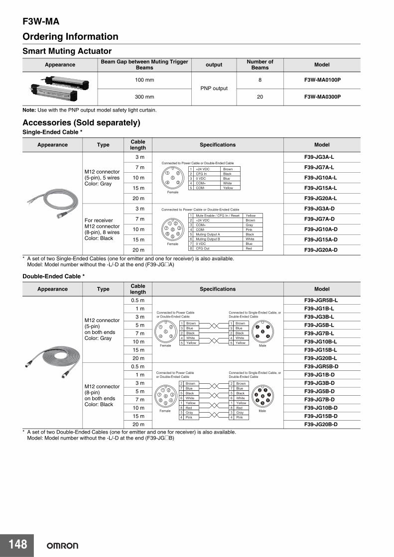
F3W-MA
148
Ordering InformationSmart Muting Actuator
Note: Use with the PNP output model safety light curtain.
Accessories (Sold separately)Single-Ended Cable *
* A set of two Single-Ended Cables (one for emitter and one for receiver) is also available.Model: Model number without the -L/-D at the end (F39-JG@A)
Double-Ended Cable *
* A set of two Double-Ended Cables (one for emitter and one for receiver) is also available.Model: Model number without the -L/-D at the end (F39-JG@B)
Appearance Beam Gap between Muting Trigger Beams output Number of
Beams Model
100 mm
PNP output
8 F3W-MA0100P
300 mm 20 F3W-MA0300P
Appearance Type Cable length Specifications Model
M12 connector (5-pin), 5 wiresColor: Gray
3 m F39-JG3A-L
7 m F39-JG7A-L
10 m F39-JG10A-L
15 m F39-JG15A-L
20 m F39-JG20A-L
For receiverM12 connector (8-pin), 8 wiresColor: Black
3 m F39-JG3A-D
7 m F39-JG7A-D
10 m F39-JG10A-D
15 m F39-JG15A-D
20 m F39-JG20A-D
Appearance Type Cable length Specifications Model
M12 connector (5-pin) on both endsColor: Gray
0.5 m F39-JGR5B-L1 m F39-JG1B-L3 m F39-JG3B-L5 m F39-JG5B-L7 m F39-JG7B-L
10 m F39-JG10B-L15 m F39-JG15B-L20 m F39-JG20B-L
M12 connector (8-pin) on both endsColor: Black
0.5 m F39-JGR5B-D1 m F39-JG1B-D3 m F39-JG3B-D5 m F39-JG5B-D7 m F39-JG7B-D
10 m F39-JG10B-D15 m F39-JG15B-D20 m F39-JG20B-D
53
21
4
Female
12345
+24 VDCCFG In0 VDCCOM+COM-
BrownBlackBlueWhiteYellow
Connected to Power Cable or Double-Ended Cable
Connected to Power Cable or Double-Ended Cable
5
843
2176
Female
2
7
56
1+24 VDC
0 VDC
Muting Output AMuting Output B
Mute Enable / CFG In / ResetBrown
Blue
BlackWhite
Yellow
8 CFG Out Red
3 COM+ Gray4 COM- Pink
BrownBlueBlackWhiteYellow
1
3
2
4
5
5
3
21
4
BrownBlueBlackWhiteYellow
1
3
2
4
5Female
5
4
12
3
Male
Connected to Power Cable or Double-Ended Cable
Connected to Single-Ended Cable, orDouble-Ended Cable
BrownBlueBlackWhiteYellowRedGrayPink
BlueBlackWhiteYellowRedGrayPink
27561834
Brown
5
84
321
7
65
86
712
3
4
27561834
Connected to Power Cable or Double-Ended Cable
Connected to Single-Ended Cable, orDouble-Ended Cable
Female Male
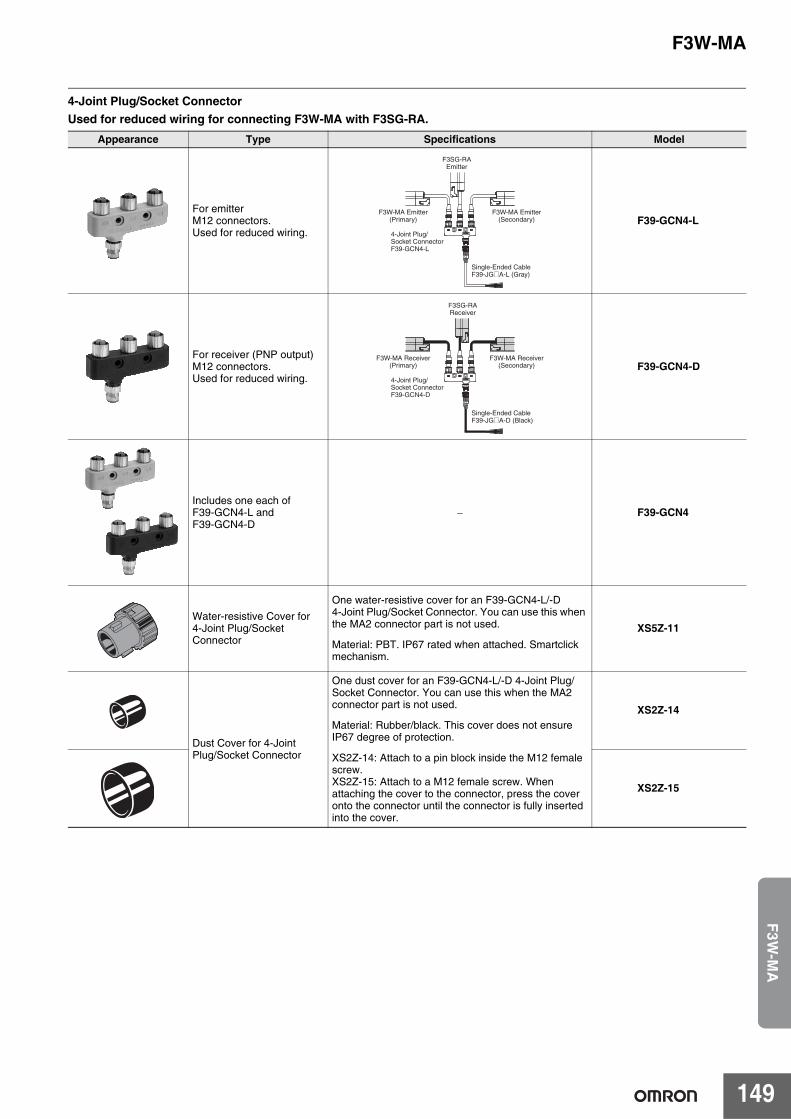
F3W-MA
149
F3W
-MA
4-Joint Plug/Socket ConnectorUsed for reduced wiring for connecting F3W-MA with F3SG-RA.
Appearance Type Specifications Model
For emitterM12 connectors.Used for reduced wiring.
F39-GCN4-L
For receiver (PNP output)M12 connectors.Used for reduced wiring.
F39-GCN4-D
Includes one each of F39-GCN4-L and F39-GCN4-D
− F39-GCN4
Water-resistive Cover for 4-Joint Plug/Socket Connector
One water-resistive cover for an F39-GCN4-L/-D4-Joint Plug/Socket Connector. You can use this when the MA2 connector part is not used.
Material: PBT. IP67 rated when attached. Smartclick mechanism.
XS5Z-11
Dust Cover for 4-Joint Plug/Socket Connector
One dust cover for an F39-GCN4-L/-D 4-Joint Plug/Socket Connector. You can use this when the MA2 connector part is not used.
Material: Rubber/black. This cover does not ensure IP67 degree of protection.
XS2Z-14: Attach to a pin block inside the M12 female screw.XS2Z-15: Attach to a M12 female screw. When attaching the cover to the connector, press the cover onto the connector until the connector is fully inserted into the cover.
XS2Z-14
XS2Z-15
Single-Ended CableF39-JG@A-L (Gray)
4-Joint Plug/Socket ConnectorF39-GCN4-L
F3SG-RAEmitter
F3W-MA Emitter(Secondary)
F3W-MA Emitter(Primary)
Single-Ended CableF39-JG@A-D (Black)
4-Joint Plug/Socket ConnectorF39-GCN4-D
F3W-MA Receiver(Secondary)
F3W-MA Receiver(Primary)
F3SG-RAReceiver
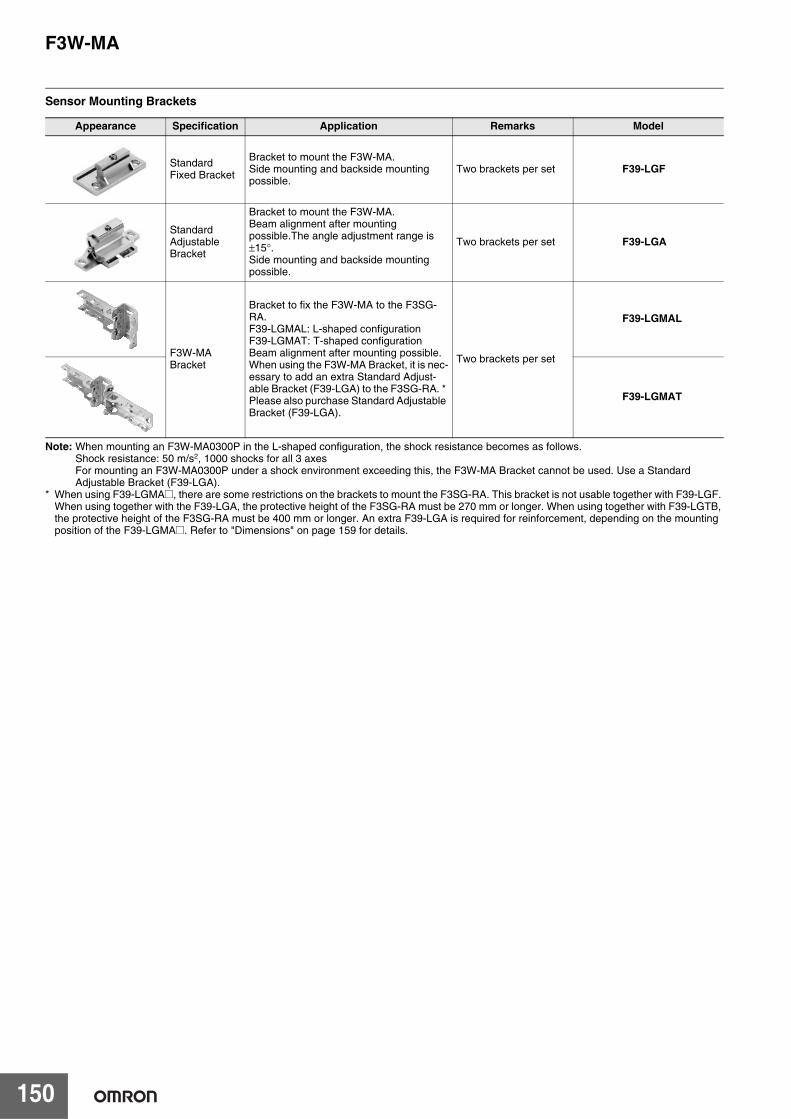
F3W-MA
150
Sensor Mounting Brackets
Note: When mounting an F3W-MA0300P in the L-shaped configuration, the shock resistance becomes as follows.Shock resistance: 50 m/s2, 1000 shocks for all 3 axesFor mounting an F3W-MA0300P under a shock environment exceeding this, the F3W-MA Bracket cannot be used. Use a Standard Adjustable Bracket (F39-LGA).
* When using F39-LGMA@, there are some restrictions on the brackets to mount the F3SG-RA. This bracket is not usable together with F39-LGF. When using together with the F39-LGA, the protective height of the F3SG-RA must be 270 mm or longer. When using together with F39-LGTB, the protective height of the F3SG-RA must be 400 mm or longer. An extra F39-LGA is required for reinforcement, depending on the mounting position of the F39-LGMA@. Refer to "Dimensions" on page 159 for details.
Appearance Specification Application Remarks Model
Standard Fixed Bracket
Bracket to mount the F3W-MA.Side mounting and backside mounting possible.
Two brackets per set F39-LGF
Standard Adjustable Bracket
Bracket to mount the F3W-MA.Beam alignment after mounting possible.The angle adjustment range is ±15°.Side mounting and backside mounting possible.
Two brackets per set F39-LGA
F3W-MA Bracket
Bracket to fix the F3W-MA to the F3SG-RA.F39-LGMAL: L-shaped configurationF39-LGMAT: T-shaped configurationBeam alignment after mounting possible.When using the F3W-MA Bracket, it is nec-essary to add an extra Standard Adjust-able Bracket (F39-LGA) to the F3SG-RA. * Please also purchase Standard Adjustable Bracket (F39-LGA).
Two brackets per set
F39-LGMAL
F39-LGMAT
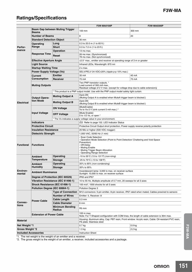
F3W-MA
151
F3W
-MA
Ratings/Specifications
*1. The net weight is the weight of an emitter and a receiver.*2. The gross weight is the weight of an emitter, a receiver, included accessories and a package.
F3W-MA0100P F3W-MA0300P
Perfor-mance
Beam Gap between Muting Trigger Beams 100 mm 300 mm
Number of Beams 8 20
Standard Detection Object 30 mm
Operating Range
Long 0.3 to 20.0 m (1 to 65 ft.)
Short 0.3 to 7.0 m (1 to 23 ft.)
Response TimeOperation 13 ms max.
Reset 26 ms max. (Synchronized)78 ms max. (Not synchronized)
Effective Aperture Angle ±2.5° max., emitter and receiver at operating range of 3 m or greater
Light Source Infrared LEDs, Wavelength: 870 nm
Startup Waiting Time 2 s max.
Electrical
Power Supply Voltage (Vs) SELV/PELV 24 VDC±20% (ripple p-p 10% max.)
CurrentConsumption
Emitter 35 mA 45 mA
Receiver 75 mA 75 mA
Muting OutputsTwo PNP transistor outputs. *Load current of 300 mA max.,Residual voltage of 2 V max. (except for voltage drop due to cable extension)j
* This product is a PNP output model. Use with the PNP output model safety light curtain.
Output Opera-tion Mode
Muting Output A Dark-ON(Muting Output A is enabled when MuteA trigger beam is blocked.)
Muting Output B Dark-ON(Muting Output B is enabled when MuteB trigger beam is blocked.)
Input Voltage
ON Voltage [MuteEnable]Vs to Vs-3 V (sink current 5 mA max.) *
OFF Voltage [Mute Enable]0 to 1/2 Vs, or open *
* The Vs indicates a supply voltage value in your environment.
Indicators Refer to page 152. LED Indicator Status
Protective Circuit Protective Circuit Output short protection, Power supply reverse polarity protection
Insulation Resistance 20 MΩ or higher (500 VDC megger)
Dielectric Strength 1,000 VAC, 50/60 Hz (1 min)
Functional Functions
- Scan Code Selection- Operation Mode Selection (Point to Point Detection/ Chattering and Void SpacePrevention)- Off-Delay- Muting Enable- Muting Trigger Beam Allocation- Operating Range Selection
Environ-mental
AmbientTemperature
Operating -10 to 55°C (13 to 131°F) (non-icing)
Storage -25 to 70°C (-13 to 158°F)
AmbientHumidity
Operating 35% to 85% (non-condensing)
Storage 35% to 95%
Ambient Illuminance Incandescent lamp: 3,000 Ix max. on receiver surfaceSunlight: 10,000 Ix max. on receiver surface
Degree of Protection (IEC 60529) IP65 and IP67
Vibration Resistance (IEC 61496-1) 10 to 55 Hz, Multiple amplitude of 0.7 mm, 20 sweeps for all 3 axes
Shock Resistance (IEC 61496-1) 100 m/s2, 1000 shocks for all 3 axes
Pollution Degree (IEC 60664-1) Pollution Degree 3
Connec-tions
Power Cable
Type of Connection M12 connectors: 5-pin emitter, 8-pin receiver, IP67 rated when mated, Cables prewired to sensors
Number of Wires Emitter: 5, Receiver: 8
Cable Length 0.3 mm
Cable Diameter 6 mm
Minimum Bending Radius R5 mm
Extension of Power Cable 100 m max.Note: For T-Shaped configuration with COM lines, the length of cable extension is 30m max.
Material Housing: Aluminum alloy, Cap: PBT resin, Front window: Acrylic resin, Cable: Oil-resistant PVC resin, FE plate: Stainless steel
Net Weight *1 0.7 kg 0.9 kg
Gross Weight *2 1.3 kg 2.2 kg
Included Accessories Instruction Sheet
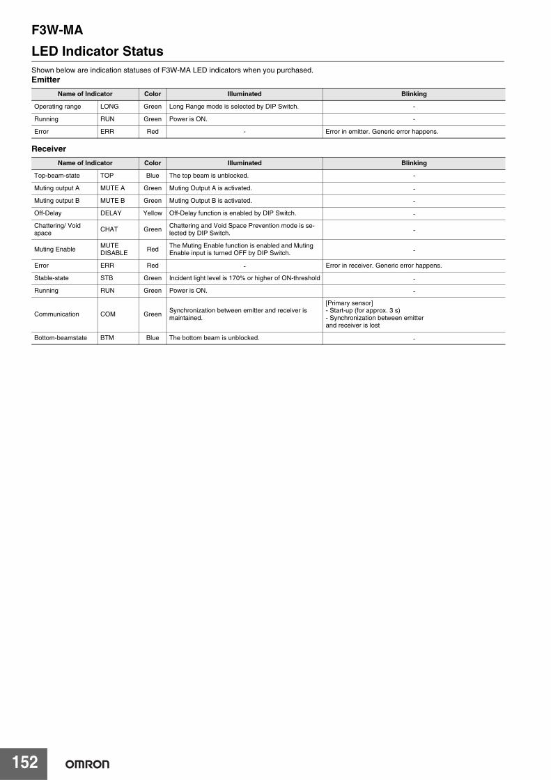
F3W-MA
152
LED Indicator StatusShown below are indication statuses of F3W-MA LED indicators when you purchased.Emitter
Receiver
Name of Indicator Color Illuminated Blinking
Operating range LONG Green Long Range mode is selected by DIP Switch. -
Running RUN Green Power is ON. -
Error ERR Red - Error in emitter. Generic error happens.
Name of Indicator Color Illuminated Blinking
Top-beam-state TOP Blue The top beam is unblocked. -
Muting output A MUTE A Green Muting Output A is activated. -
Muting output B MUTE B Green Muting Output B is activated. -
Off-Delay DELAY Yellow Off-Delay function is enabled by DIP Switch. -
Chattering/ Voidspace
CHAT GreenChattering and Void Space Prevention mode is se-lected by DIP Switch. -
Muting Enable MUTEDISABLE Red The Muting Enable function is enabled and Muting
Enable input is turned OFF by DIP Switch. -
Error ERR Red - Error in receiver. Generic error happens.
Stable-state STB Green Incident light level is 170% or higher of ON-threshold -
Running RUN Green Power is ON. -
Communication COM Green Synchronization between emitter and receiver is maintained.
[Primary sensor]- Start-up (for approx. 3 s)- Synchronization between emitterand receiver is lost
Bottom-beamstate BTM Blue The bottom beam is unblocked. -
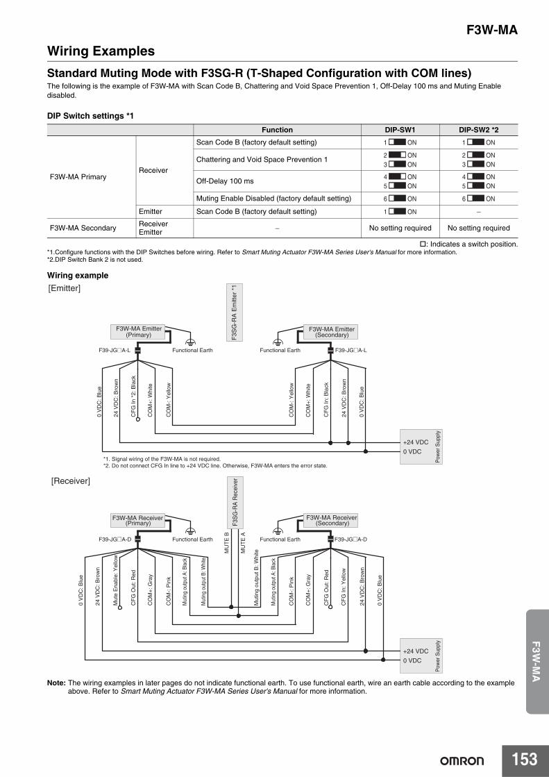
F3W-MA
153
F3W
-MA
Wiring ExamplesStandard Muting Mode with F3SG-R (T-Shaped Configuration with COM lines)The following is the example of F3W-MA with Scan Code B, Chattering and Void Space Prevention 1, Off-Delay 100 ms and Muting Enable disabled.
DIP Switch settings *1
: Indicates a switch position.*1.Configure functions with the DIP Switches before wiring. Refer to Smart Muting Actuator F3W-MA Series User's Manual for more information.*2.DIP Switch Bank 2 is not used.
Wiring example
Note: The wiring examples in later pages do not indicate functional earth. To use functional earth, wire an earth cable according to the example above. Refer to Smart Muting Actuator F3W-MA Series User's Manual for more information.
Function DIP-SW1 DIP-SW2 *2
F3W-MA PrimaryReceiver
Scan Code B (factory default setting)
Chattering and Void Space Prevention 1
Off-Delay 100 ms
Muting Enable Disabled (factory default setting)
Emitter Scan Code B (factory default setting) −
F3W-MA Secondary ReceiverEmitter − No setting required No setting required
1 ON 1 ON
2 ON3 ON
2 ON3 ON
4 ON5 ON
4 ON5 ON
6 ON 6 ON
1 ON
Mut
ing
outp
ut A
: Bla
ck
Mut
ing
outp
ut B
: Whi
te
24 V
DC
: Bro
wn
0 V
DC
: Blu
e
F3W-MA Receiver(Primary)
CF
G O
ut: R
ed
CO
M-:
Pin
k
CO
M+
: Gra
y
Mut
e E
nabl
e: Y
ello
w
F3W-MA Receiver(Secondary)
Mut
ing
outp
ut A
: Bla
ck
Mut
ing
outp
ut B
: Whi
te
CO
M-:
Pin
k
CO
M+
: Gra
y
CF
G O
ut: R
ed
CF
G In
: Yel
low
0 V
DC
: Blu
e
24 V
DC
: Bro
wn
F39-JG@A-D F39-JG@A-DFunctional Earth Functional Earth
24 V
DC
: Bro
wn
0 V
DC
: Blu
e
F3W-MA Emitter(Primary)
CF
G In
*2:
Bla
ck
CO
M-:
Yel
low
CO
M+
: Whi
te
F3W-MA Emitter(Secondary)
CO
M-:
Yel
low
CO
M+
: Whi
te
0 V
DC
: Blu
e
24 V
DC
: Bro
wn
F39-JG@A-L F39-JG@A-LFunctional Earth Functional Earth
F3S
G-R
A E
mitt
er *
1
CF
G In
: Bla
ck
Pow
er S
uppl
y+24 VDC
0 VDC
Pow
er S
uppl
y
+24 VDC
0 VDC
*1. Signal wiring of the F3W-MA is not required.*2. Do not connect CFG In line to +24 VDC line. Otherwise, F3W-MA enters the error state.
[Emitter]
[Receiver]
F3S
G-R
A R
ecei
ver
MU
TE
B
MU
TE
A
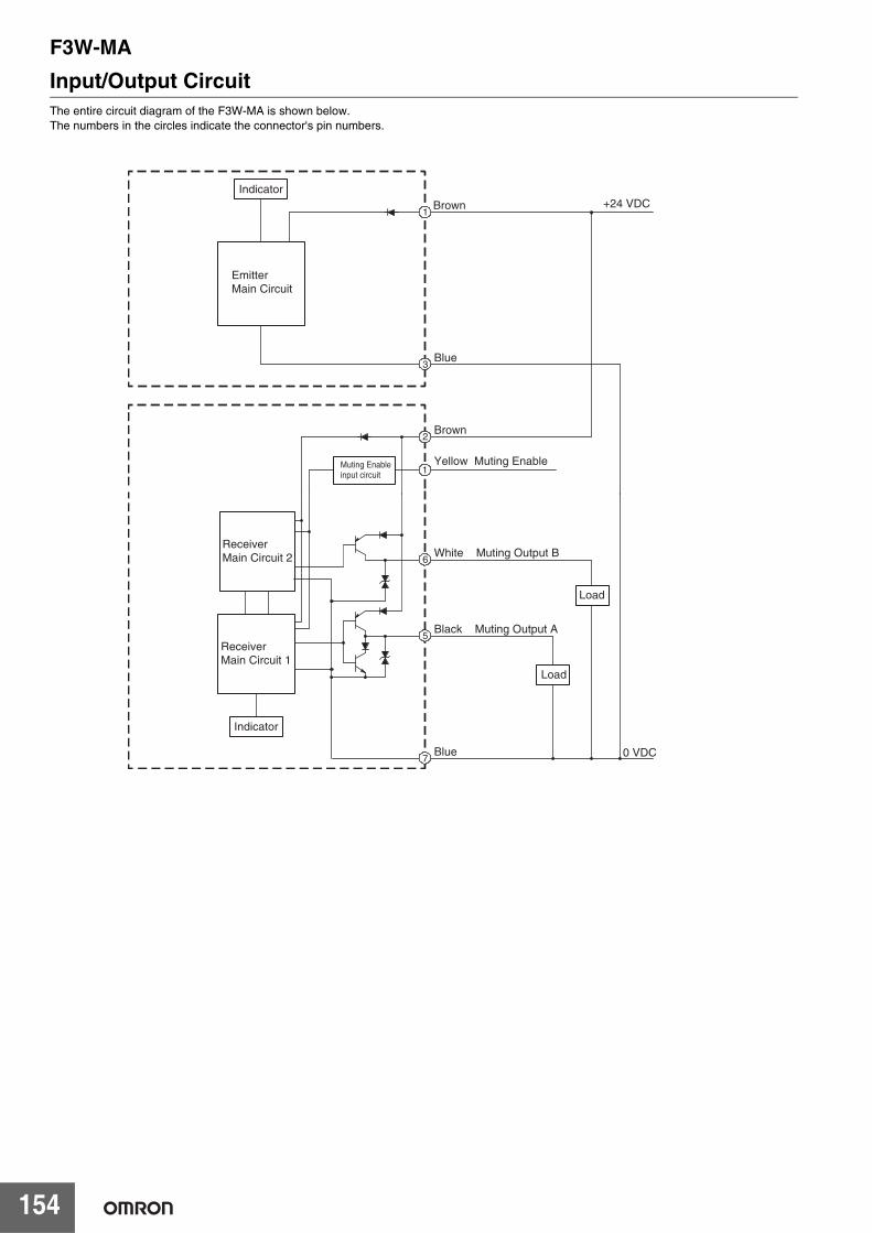
F3W-MA
154
Input/Output CircuitThe entire circuit diagram of the F3W-MA is shown below.The numbers in the circles indicate the connector's pin numbers.
2
1
5
7
6
+24 VDC1
Brown
Blue
Brown
White Muting Output B
Black Muting Output A
Blue
3
Muting Enableinput circuit
Yellow Muting Enable
0 VDC
Indicator
EmitterMain Circuit
ReceiverMain Circuit 2
ReceiverMain Circuit 1
Indicator
Load
Load
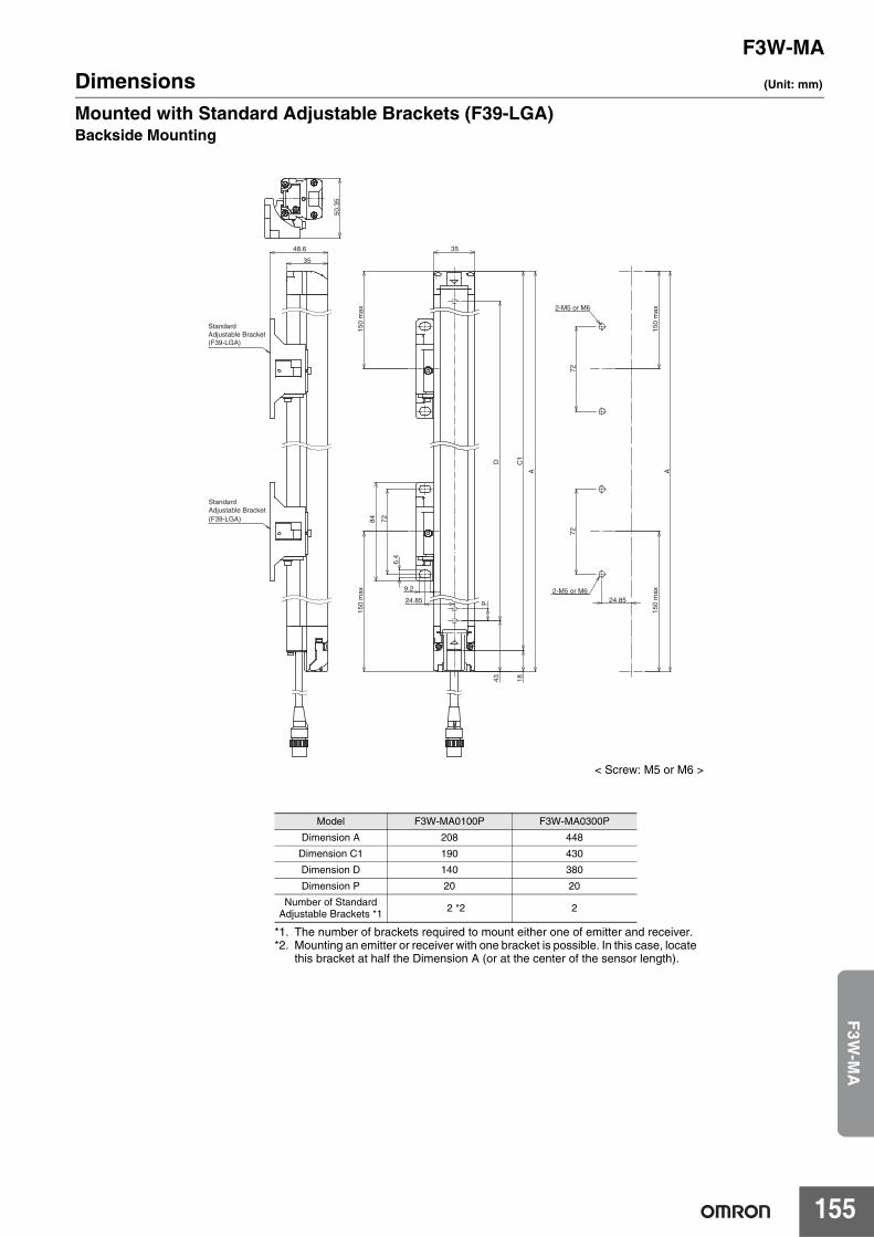
F3W-MA
155
F3W
-MA
Dimensions (Unit: mm)
Mounted with Standard Adjustable Brackets (F39-LGA)Backside Mounting
< Screw: M5 or M6 >
*1. The number of brackets required to mount either one of emitter and receiver.*2. Mounting an emitter or receiver with one bracket is possible. In this case, locate
this bracket at half the Dimension A (or at the center of the sensor length).
Model F3W-MA0100P F3W-MA0300P
Dimension A 208 448
Dimension C1 190 430
Dimension D 140 380
Dimension P 20 20
Number of Standard Adjustable Brackets *1 2 *2 2
StandardAdjustable Bracket(F39-LGA)
StandardAdjustable Bracket(F39-LGA)
35
48.6
50.3
5
2-M5 or M6
2-M5 or M6
35
A
72
9.2
72
6.4
84
P
72
24.85
150
max
150
max
D
C1
1843
A
24.85
150
max
150
max
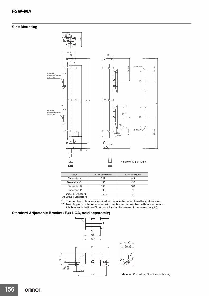
F3W-MA
156
Side Mounting
Standard Adjustable Bracket (F39-LGA, sold separately)
50.3
5
StandardAdjustable Bracket(F39-LGA)
StandardAdjustable Bracket(F39-LGA)
35
A
48.6
2-M5 or M6
2-M5 or M6
7272
35
6.4
9.2
8472
150
max
150
max
42.35
A
150
max
150
max
P
D
C1
1843
< Screw: M5 or M6 >
*1. The number of brackets required to mount either one of emitter and receiver.*2. Mounting an emitter or receiver with one bracket is possible. In this case, locate
this bracket at half the Dimension A (or at the center of the sensor length).
Model F3W-MA0100P F3W-MA0300P
Dimension A 208 448
Dimension C1 190 430
Dimension D 140 380
Dimension P 20 20
Number of Standard Adjustable Brackets *1 2 *2 2
8
72
42
45.1
84
9.2
6.4
32.9
31.8
34.5
Material: Zinc alloy, Fluorine-containing
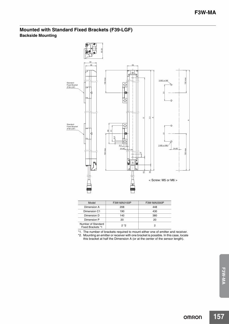
F3W-MA
157
F3W
-MA
Mounted with Standard Fixed Brackets (F39-LGF)Backside Mounting
2-M5 or M6
2-M5 or M6
A
6.4
5151
35
9.2
66
StandardFixed Bracket(F39-LGF)
StandardFixed Bracket(F39-LGF)
35
40
50.3
5
D
P
24.85
51
150
max
150
max
C1
1843
24.85
A
150
max
150
max
< Screw: M5 or M6 >
*1. The number of brackets required to mount either one of emitter and receiver.*2. Mounting an emitter or receiver with one bracket is possible. In this case, locate
this bracket at half the Dimension A (or at the center of the sensor length).
Model F3W-MA0100P F3W-MA0300P
Dimension A 208 448
Dimension C1 190 430
Dimension D 140 380
Dimension P 20 20
Number of StandardFixed Brackets *1 2 *2 2
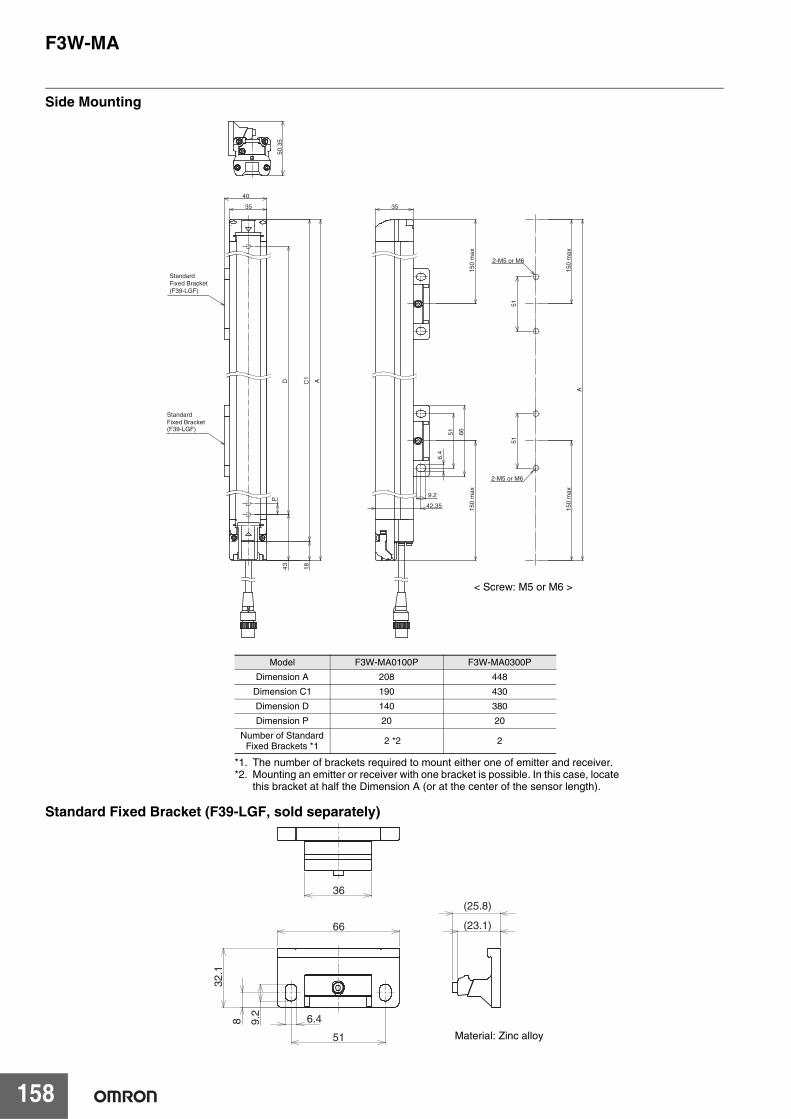
F3W-MA
158
Side Mounting
Standard Fixed Bracket (F39-LGF, sold separately)
StandardFixed Bracket(F39-LGF)
StandardFixed Bracket(F39-LGF)
A
35
40
2-M5 or M6
2-M5 or M6
51
9.2
51
35
6.4
66
50.3
5
51
150
max
150
max
42.35
A
150
max
150
max
P
D
C1
1843
< Screw: M5 or M6 >
*1. The number of brackets required to mount either one of emitter and receiver.*2. Mounting an emitter or receiver with one bracket is possible. In this case, locate
this bracket at half the Dimension A (or at the center of the sensor length).
Model F3W-MA0100P F3W-MA0300P
Dimension A 208 448
Dimension C1 190 430
Dimension D 140 380
Dimension P 20 20
Number of Standard Fixed Brackets *1 2 *2 2
51
8
(23.1)
(25.8)
9.2
66
6.4
32.1
36
Material: Zinc alloy
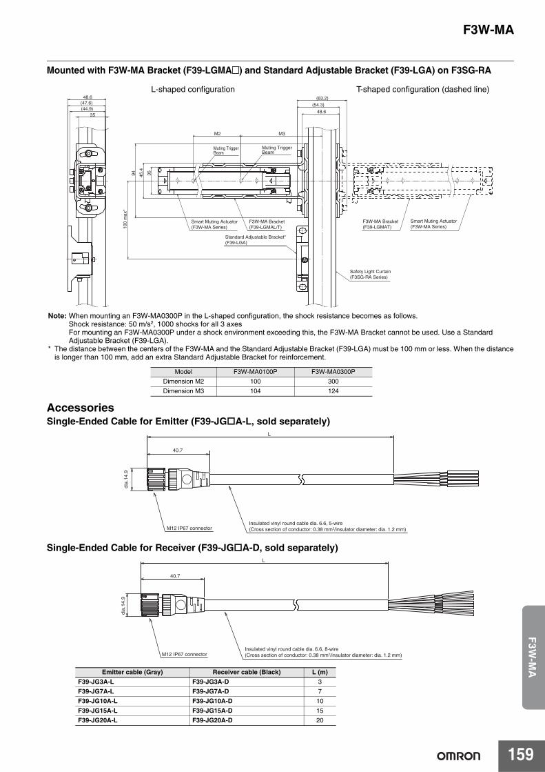
F3W-MA
159
F3W
-MA
Mounted with F3W-MA Bracket (F39-LGMA@) and Standard Adjustable Bracket (F39-LGA) on F3SG-RA
AccessoriesSingle-Ended Cable for Emitter (F39-JGA-L, sold separately)
Single-Ended Cable for Receiver (F39-JGA-D, sold separately)
Emitter cable (Gray) Receiver cable (Black) L (m)F39-JG3A-L F39-JG3A-D 3
F39-JG7A-L F39-JG7A-D 7
F39-JG10A-L F39-JG10A-D 10
F39-JG15A-L F39-JG15A-D 15
F39-JG20A-L F39-JG20A-D 20
Standard Adjustable Bracket*(F39-LGA)
Smart Muting Actuator(F3W-MA Series)
Smart Muting Actuator(F3W-MA Series)
Safety Light Curtain(F3SG-RA Series)
F3W-MA Bracket(F39-LGMAT)
F3W-MA Bracket(F39-LGMAL/T)
L-shaped configuration T-shaped configuration (dashed line)
Muting Trigger Beam
Muting Trigger Beam
94
(54.3)
100
max
*
35
(63.2)
45.4
48.6
48.6
35
M3M2
(47.6)(44.9)
Note: When mounting an F3W-MA0300P in the L-shaped configuration, the shock resistance becomes as follows.Shock resistance: 50 m/s2, 1000 shocks for all 3 axesFor mounting an F3W-MA0300P under a shock environment exceeding this, the F3W-MA Bracket cannot be used. Use a Standard Adjustable Bracket (F39-LGA).
* The distance between the centers of the F3W-MA and the Standard Adjustable Bracket (F39-LGA) must be 100 mm or less. When the distance is longer than 100 mm, add an extra Standard Adjustable Bracket for reinforcement.
Model F3W-MA0100P F3W-MA0300P
Dimension M2 100 300
Dimension M3 104 124
40.7
L
Insulated vinyl round cable dia. 6.6, 5-wire (Cross section of conductor: 0.38 mm2/insulator diameter: dia. 1.2 mm)
dia.
14.9
M12 IP67 connector
Insulated vinyl round cable dia. 6.6, 8-wire (Cross section of conductor: 0.38 mm2/insulator diameter: dia. 1.2 mm)
dia.
14.9
M12 IP67 connector
L
40.7
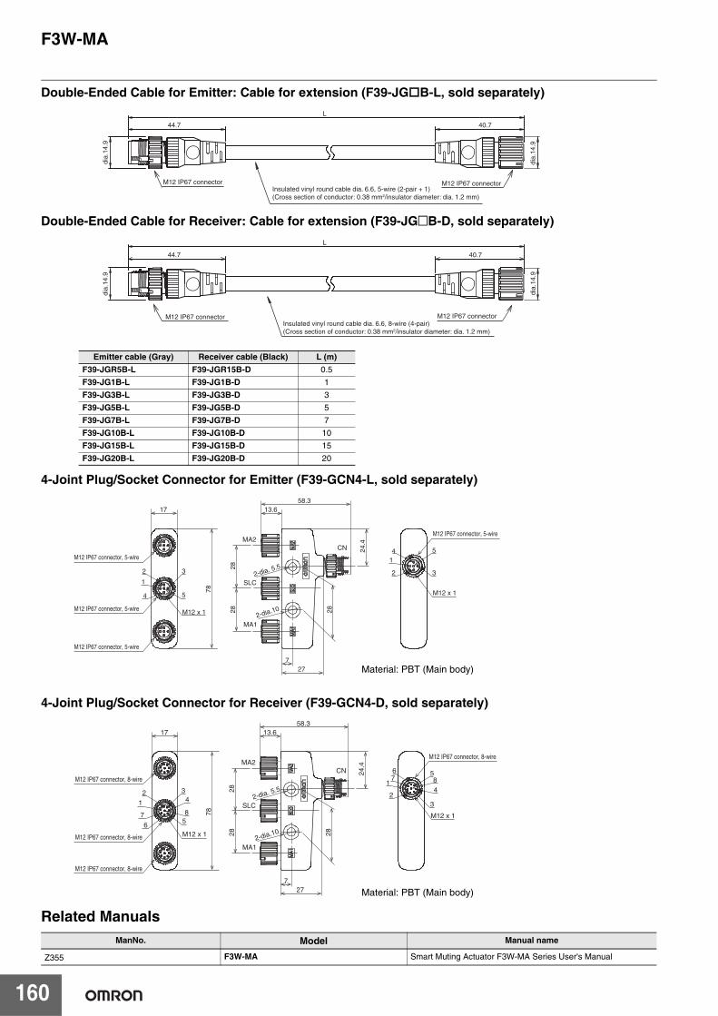
F3W-MA
160
Double-Ended Cable for Emitter: Cable for extension (F39-JGB-L, sold separately)
Double-Ended Cable for Receiver: Cable for extension (F39-JG@B-D, sold separately)
4-Joint Plug/Socket Connector for Emitter (F39-GCN4-L, sold separately)
4-Joint Plug/Socket Connector for Receiver (F39-GCN4-D, sold separately)
Related Manuals
Emitter cable (Gray) Receiver cable (Black) L (m)F39-JGR5B-L F39-JGR15B-D 0.5
F39-JG1B-L F39-JG1B-D 1
F39-JG3B-L F39-JG3B-D 3
F39-JG5B-L F39-JG5B-D 5
F39-JG7B-L F39-JG7B-D 7
F39-JG10B-L F39-JG10B-D 10
F39-JG15B-L F39-JG15B-D 15
F39-JG20B-L F39-JG20B-D 20
ManNo. Model Manual name
Z355 F3W-MA Smart Muting Actuator F3W-MA Series User's Manual
M12 IP67 connectorInsulated vinyl round cable dia. 6.6, 5-wire (2-pair + 1)(Cross section of conductor: 0.38 mm2/insulator diameter: dia. 1.2 mm)
M12 IP67 connector
40.7
L
44.7
dia.
14.9
dia.
14.9
M12 IP67 connectorInsulated vinyl round cable dia. 6.6, 8-wire (4-pair) (Cross section of conductor: 0.38 mm2/insulator diameter: dia. 1.2 mm)
M12 IP67 connector
40.7
L
44.7
dia.
14.9
dia.
14.9
17
78
3
5
2
1
4
M12 x 1
M12 IP67 connector, 5-wire
M12 IP67 connector, 5-wire
M12 IP67 connector, 5-wire
M12 IP67 connector, 5-wire
541
2 3
M12 x 1
727
58.313.6
MA2
SLC
MA1
CN
282828
24.4
2-dia. 5.5
2-dia.10
Material: PBT (Main body)
17
78
3
5
2
1
6M12 x 1
587
23
M12 x 1
727
58.313.6
MA2
SLC
MA1
CN
282828
24.4
2-dia. 5.5
2-dia.10
4
7 8
6
14
M12 IP67 connector, 8-wire
M12 IP67 connector, 8-wire
M12 IP67 connector, 8-wire
M12 IP67 connector, 8-wire
Material: PBT (Main body)

161
MEMO

MEMO
162

Terms and Conditions AgreementRead and understand this catalog.
Please read and understand this catalog before purchasing the products. Please consult your OMRON representative if you have any questions or comments.
Warranties.(a) Exclusive Warranty. Omron’s exclusive warranty is that the Products will be free from defects in materials and workmanship
for a period of twelve months from the date of sale by Omron (or such other period expressed in writing by Omron). Omron disclaims all other warranties, express or implied.
(b) Limitations. OMRON MAKES NO WARRANTY OR REPRESENTATION, EXPRESS OR IMPLIED, ABOUT NON-INFRINGEMENT, MERCHANTABILITY OR FITNESS FOR A PARTICULAR PURPOSE OF THE PRODUCTS. BUYER ACKNOWLEDGES THAT IT ALONE HAS DETERMINED THAT THE PRODUCTS WILL SUITABLY MEET THE REQUIREMENTS OF THEIR INTENDED USE.
Omron further disclaims all warranties and responsibility of any type for claims or expenses based on infringement by the Products or otherwise of any intellectual property right. (c) Buyer Remedy. Omron’s sole obligation hereunder shall be, at Omron’s election, to (i) replace (in the form originally shipped with Buyer responsible for labor charges for removal or replacement thereof) the non-complying Product, (ii) repair the non-complying Product, or (iii) repay or credit Buyer an amount equal to the purchase price of the non-complying Product; provided that in no event shall Omron be responsible for warranty, repair, indemnity or any other claims or expenses regarding the Products unless Omron’s analysis confirms that the Products were properly handled, stored, installed and maintained and not subject to contamination, abuse, misuse or inappropriate modification. Return of any Products by Buyer must be approved in writing by Omron before shipment. Omron Companies shall not be liable for the suitability or unsuitability or the results from the use of Products in combination with any electrical or electronic components, circuits, system assemblies or any other materials or substances or environments. Any advice, recommendations or information given orally or in writing, are not to be construed as an amendment or addition to the above warranty.
See http://www.omron.com/global/ or contact your Omron representative for published information.
Limitation on Liability; Etc.OMRON COMPANIES SHALL NOT BE LIABLE FOR SPECIAL, INDIRECT, INCIDENTAL, OR CONSEQUENTIAL DAMAGES, LOSS OF PROFITS OR PRODUCTION OR COMMERCIAL LOSS IN ANY WAY CONNECTED WITH THE PRODUCTS, WHETHER SUCH CLAIM IS BASED IN CONTRACT, WARRANTY, NEGLIGENCE OR STRICT LIABILITY.
Further, in no event shall liability of Omron Companies exceed the individual price of the Product on which liability is asserted.
Suitability of Use.Omron Companies shall not be responsible for conformity with any standards, codes or regulations which apply to the combination of the Product in the Buyer’s application or use of the Product. At Buyer’s request, Omron will provide applicable third party certification documents identifying ratings and limitations of use which apply to the Product. This information by itself is not sufficient for a complete determination of the suitability of the Product in combination with the end product, machine, system, or other application or use. Buyer shall be solely responsible for determining appropriateness of the particular Product with respect to Buyer’s application, product or system. Buyer shall take application responsibility in all cases.
NEVER USE THE PRODUCT FOR AN APPLICATION INVOLVING SERIOUS RISK TO LIFE OR PROPERTY OR IN LARGE QUANTITIES WITHOUT ENSURING THAT THE SYSTEM AS A WHOLE HAS BEEN DESIGNED TO ADDRESS THE RISKS, AND THAT THE OMRON PRODUCT(S) IS PROPERLY RATED AND INSTALLED FOR THE INTENDED USE WITHIN THE OVERALL EQUIPMENT OR SYSTEM.
Programmable Products.Omron Companies shall not be responsible for the user’s programming of a programmable Product, or any consequence thereof.
Performance Data.Data presented in Omron Company websites, catalogs and other materials is provided as a guide for the user in determining suitability and does not constitute a warranty. It may represent the result of Omron’s test conditions, and the user must correlate it to actual application requirements. Actual performance is subject to the Omron’s Warranty and Limitations of Liability.
Change in Specifications.Product specifications and accessories may be changed at any time based on improvements and other reasons. It is our practice to change part numbers when published ratings or features are changed, or when significant construction changes are made. However, some specifications of the Product may be changed without any notice. When in doubt, special part numbers may be assigned to fix or establish key specifications for your application. Please consult with your Omron’s representative at any time to confirm actual specifications of purchased Product.
Errors and Omissions.Information presented by Omron Companies has been checked and is believed to be accurate; however, no responsibility is assumed for clerical, typographical or proofreading errors or omissions.

Authorized Distributor:
In the interest of product improvement, specifications are subject to change without notice.
Cat. No. F094-E1-10
0118(1214)
© OMRON Corporation 2014-2018 All Rights Reserved.
OMRON Corporation Industrial Automation Company
OMRON ELECTRONICS LLC2895 Greenspoint Parkway, Suite 200 Hoffman Estates, IL 60169 U.S.A.Tel: (1) 847-843-7900/Fax: (1) 847-843-7787
Regional HeadquartersOMRON EUROPE B.V.Wegalaan 67-69, 2132 JD HoofddorpThe NetherlandsTel: (31)2356-81-300/Fax: (31)2356-81-388
Contact: www.ia.omron.comKyoto, JAPAN
OMRON ASIA PACIFIC PTE. LTD.No. 438A Alexandra Road # 05-05/08 (Lobby 2), Alexandra Technopark, Singapore 119967Tel: (65) 6835-3011/Fax: (65) 6835-2711
OMRON (CHINA) CO., LTD.Room 2211, Bank of China Tower, 200 Yin Cheng Zhong Road, PuDong New Area, Shanghai, 200120, ChinaTel: (86) 21-5037-2222/Fax: (86) 21-5037-2200
Note: Do not use this document to operate the Unit.
CSM_12_4_1018
Related Documents