Safety Guidelines Thank you for purchasing MELIPC MI5000 Series. Prior to use, please read this and relevant manuals thoroughly to fully understand the product. 2018 MITSUBISHI ELECTRIC CORPORATION MODEL MELIPC-MI5000-U-HW MODEL CODE 13J2F1 IB(NA)-0800605-C(2007)MEE

Welcome message from author
This document is posted to help you gain knowledge. Please leave a comment to let me know what you think about it! Share it to your friends and learn new things together.
Transcript
Safety Guidelines
Thank you for purchasing MELIPC MI5000 Series.Prior to use, please read this and relevant manuals thoroughly to fully understand the product.
2018 MITSUBISHI ELECTRIC CORPORATION
MODEL MELIPC-MI5000-U-HWMODEL CODE 13J2F1IB(NA)-0800605-C(2007)MEE

1
SAFETY PRECAUTIONS(Read these precautions before using this product.)Before using this product, please read this manual and the relevant manuals carefully and pay full attention to safety to handle the product correctly.In this manual, the safety precautions are classified into two levels: " WARNING" and " CAUTION".
Under some circumstances, failure to observe the precautions given under " CAUTION" may lead to serious consequences.Observe the precautions of both levels because they are important for personal and system safety.Make sure that the end users read this manual and then keep the manual in a safe place for future reference.
[Design Precautions]
WARNING● Configure safety circuits external to the product to ensure that the entire system operates
safely even when a fault occurs in the external power supply or the product. Failure to do so may result in an accident due to an incorrect output or malfunction.(1) Emergency stop circuits, protection circuits, and protective interlock circuits for
conflicting operations (such as forward/reverse rotations or upper/lower limit positioning) must be configured external to the product.
(2) When the product detects an abnormal condition, it stops the operation and all outputs are: • Turned off if the overcurrent or overvoltage protection of the power supply module is
activated. • Held or turned off according to the parameter setting if the self-diagnostic function of
the product detects an error such as a watchdog timer error.● Configure a circuit so that the product is turned on first and then the external power supply.
If the external power supply is turned on first, an accident may occur due to an incorrect output or malfunction.
● For the operating status of each station after a communication failure, refer to manuals relevant to the network. Incorrect output or malfunction due to a communication failure may result in an accident.
● Before performing operations for the product from the peripheral connected, read the relevant manuals carefully and ensure the safety.
Indicates that incorrect handling may cause hazardous conditions, resulting in death or severe injury.
Indicates that incorrect handling may cause hazardous conditions, resulting in minor or moderate injury or property damage.CAUTION
WARNING

2
[Design Precautions]
[Security Precautions]
CAUTION● Do not install the control lines or communication cables together with the main circuit lines
or power cables. Keep a distance of 100mm or more between them. Failure to do so may result in malfunction due to noise.
● When selecting fuses and breakers for external circuits, consider the specification values of fusing/detection characteristics and inrush current.
● When using an uninterruptible power supply (UPS), do not use the one that outputs square waves.
WARNING● To maintain the security (confidentiality, integrity, and availability) the product and the
system against unauthorized access, denial-of-service (DoS) attacks, computer viruses, and other cyberattacks from external devices via the network, take appropriate measures such as firewalls, virtual private networks (VPNs), and antivirus solutions.

3
[Installation Precautions]
CAUTION● Use the product in an environment that meets Page 19 General Specifications in this
manual. Failure to do so may result in electric shock, fire, malfunction, or damage to or deterioration of the product.
● To mount a power supply module, place the concave parts located at the bottom onto the guides of the main module, and push in the power supply module until the hooks located at the top snaps into place. Incorrect interconnection may cause malfunction, failure, or drop of the module.
● When using the product in an environment of frequent vibrations, fix the power supply module with a screw.
● Tighten the screws within the specified torque range. Undertightening can cause drop of the screw, short circuit, or malfunction. Overtightening can damage the screw and/or module, resulting in drop, short circuit, or malfunction.
● To connect a fan module, set the fan module at the correct position of the main module, and push in the fan module until the fan module fixing hook snaps into place. Check that the fan module fixing hook is fixed to the main module securely. If the fan module is not connected properly, the fan may not rotate or it may cause malfunction due to rise in temperature of the main module.
● To disconnect a fan module, securely press the fan module fixing hook with your finger. Then, pull the module forward while pressing the hook.
● Do not touch the exposed heatsink after removing the fan module. The heatsink is very hot immediately after the power is switched off and may cause burns. Additionally, touching the heat sink may deform it and decrease cooling efficiency.
● Do not apply shock such as falling and dropping to the fan module during transportation. Doing so may result in damage to the product or deterioration in performance.
● When using a CFast card, fully insert it into the CFast card slot. Check that it is inserted completely. Poor contact may cause malfunction.
● Place hands to hold a CFast card when removing it from the slot because the card may be jumped out. If not placing hands, the card may fall, resulting in damage or failure.
● Do not directly touch any conductive parts and electronic components of the module or CFast card. Doing so can cause malfunction or failure of the module.
● Do not remove the protecting sheets attached to the plate of the base part. For this plate, it may raise to high temperature cause combined with heat-sink. Do not remove or touch this sheets when module is operating and turning off the power supply to prevent a burn.
4
[Wiring Precautions]
[Wiring Precautions]
WARNING● Shut off the external power supply (all phases) used in the system before installation and
wiring. Failure to do so may result in electric shock or cause the module to fail or malfunction.
● After installation and wiring, attach the included terminal cover to the product before turning it on for operation. Failure to do so may result in electric shock.
CAUTION● Individually ground the FG and LG terminals of the product with a ground resistance of 100
ohms or less. Failure to do so may result in electric shock or malfunction.● Use applicable solderless terminals and tighten them within the specified torque range. If
any spade solderless terminal is used, it may be disconnected when the terminal screw comes loose, resulting in failure.
● Check the rated voltage and signal layout before wiring to the power supply module, and connect the cables correctly. Connecting a power supply with a different voltage rating or incorrect wiring may cause fire or failure.
● Solderless terminals must be crimped with the tool specified by the manufacturer. Incomplete crimping may cause short circuit, fire, or malfunction.
● Securely connect the connector of an external device to the product. Poor contact may cause malfunction.
● Do not install the control lines or communication cables together with the main circuit lines or power cables. Keep a distance of 100mm or more between them. Failure to do so may result in malfunction due to noise.
● Place the cables in a duct or clamp them. (Cable ties made of nylon can be used as well.) If not, dangling cable may swing or inadvertently be pulled, resulting in damage to the module or cables or malfunction due to poor contact.
● Check the interface type and correctly connect the cable. Incorrect wiring (connecting the cable to an incorrect interface) may cause failure of the module and external device.
● Tighten the terminal screws or connector screws within the specified torque range. Undertightening can cause drop of the screw, short circuit, fire, or malfunction. Overtightening can damage the screw and/or module, resulting in drop, short circuit, fire, or malfunction.
● Prevent foreign matter such as dust or wire chips from entering the product. Such foreign matter can cause a fire, failure, or malfunction.

5
[Wiring Precautions]
[Startup and Maintenance Precautions]
CAUTION● A protective film is attached to the top of the module to prevent foreign matter, such as
wire chips, from entering the product during wiring. Do not remove the film during wiring. Remove it for heat dissipation before system operation.
● When disconnecting the cable from the product, do not pull the cable by the cable part. For the cable with connector, hold the connector part of the cable. For the cable connected to the terminal block, loosen the terminal screw. Pulling the cable connected to the module may result in malfunction or damage to the module or cable.
● The product must be installed in control panels. Connect the main power supply to the power supply module in the control panel through a relay terminal block. Wiring and replacement of a power supply module must be performed by qualified maintenance personnel with knowledge of protection against electric shock. For wiring, refer to the MELIPC MI5000 Series User's Manual (Startup).
WARNING● Do not touch any terminal while power is on. Doing so will cause electric shock or
malfunction.● Correctly connect the battery connector. Do not charge, disassemble, heat, short-circuit,
solder, or throw the battery into the fire. Also, do not expose it to liquid or strong shock. Doing so will cause the battery to produce heat, explode, ignite, or leak, resulting in injury and fire.
● Shut off the external power supply (all phases) used in the system before cleaning the module or retightening the terminal screws, connector screws, or module fixing screws. Failure to do so may result in electric shock.
● Tighten the screws within the specified torque range. Undertightening can cause drop of the screw, short circuit, or malfunction. Overtightening can damage the screw and/or module, resulting in drop, short circuit, or malfunction.

6
[Startup and Maintenance Precautions]
CAUTION● Do not disassemble or modify the product. Doing so may cause failure, malfunction, injury,
or a fire.● Use any radio communication device such as a cellular phone or PHS (Personal Handy-
phone System) more than 25cm away in all directions from the product. Failure to do so may cause malfunction.
● Shut off the external power supply (all phases) used in the system before mounting or removing the product. Failure to do so may cause the product to fail or malfunction.
● Do not touch any part of your body or contact any object to the rotating fan. Doing so may result in injury or failure of the fan module.
● After the first use of the product, do not connect/disconnect the power supply module or fan module to/from the main module more than 50 times. Exceeding the limit may cause malfunction.
● After the first use of the product, do not insert/remove a CFast card to/from the product more than 10000 times. Exceeding the limit may cause malfunction.
● Place hands to hold a CFast card when removing it from the slot because the card may be jumped out. If not placing hands, the card may fall, resulting in damage or failure.
● Do not drop or apply shock to the battery to be installed in the product. When removing the battery, hold the connector part so that the battery cable is not damaged.
● Before handling the product, touch a conducting object such as a grounded metal to discharge the static electricity from the human body. Failure to do so may cause the product to fail or malfunction.
● Do not remove the protecting sheets attached to the plate of the base part. For this plate, it may raise to high temperature cause combined with heat-sink. Do not remove or touch this sheets when module is operating and turning off the power supply to prevent a burn.
● If a fan module is used under a high temperature with high humidity environment, it will be discolored; however, this does not affect the performance of the fan module.
● Do not turn off or reset this product, or disconnect a USB device while accessing the USB device. It may result in data corruption or failure of the USB device. Stop accessing first, then disconnect the USB device.

7
[Power-on Precautions]
[Transportation Precautions]
[Disposal Precautions]
CAUTION● If input power is supplied again immediately after power supply shutdown of the product,
an inrush current that exceeds the specification value may flow.● To avoid this, wait for five seconds or more after power supply shutdown of the product.
Then, supply input power again.
CAUTION● When transporting lithium batteries, follow the transportation regulations. For details on the
regulated models, refer to Page 31 Precautions for Battery Transportation in this manual.
CAUTION● When disposing of this product, treat it as industrial waste.● When disposing of batteries, separate them from other wastes according to the local
regulations. For details on battery regulations in EU member states, refer to Page 32 Batteries and Devices with Built-In Batteries in EU Member States in this manual.

8
SAFETY PRECAUTIONS(Lire ces précautions avant toute utilisation du produit.)Avant d'utiliser ce produit, lire attentivement ce manuel ainsi que les manuels auxquels il renvoie, et toujours considérer la sécurité comme de la plus haute importance en manipulant le produit correctement.Dans ce manuel, les précautions de sécurité sont classées en deux niveaux, à savoir : " AVERTISSEMENT" and " ATTENTION".
Dans certaines circonstances, le non-respect d'une précaution de sécurité introduite sous le titre "ATTENTION"peut avoir des conséquences graves.Les précautions de ces deux niveaux doivent être observées dans leur intégralité car elles ont trait à la sécurité des personnes et aussi du système.Veiller à ce que les utilisateurs finaux lisent ce manuel qui doit être conservé soigneusement à portée de main pour s'y référer autant que de besoin.
Attire l'attention sur le fait qu'une négligence peut créer une situation de danger avec risque de mort ou de blessures graves.
Attire l'attention sur le fait qu'une négligence peut créer une situation de danger avec risque de blessures légères ou de gravité moyennes ou risque de dégâts matériels.
ATTENTION
AVERTISSEMENT

9
[Précautions lors de la conception]
[Précautions lors de la conception]
[Précautions de sécurité]
AVERTISSEMENT● Configurer des circuits de sécurité extérieurs au produit pour garantir la sécurité du
système dans son ensemble en cas de défaut dans l'alimentation externe comme dans le produit. Ne pas le faire pourrait conduire à un accident du fait d'une valeur de sortie incorrecte ou d'un défaut de fonctionnement.(1) Les circuits d'arrêt d'urgence, les circuits de protection et les circuits de verrouillage de
sécurité pour les opérations contradictoires du genre rotation avant/arrière ou positionnement en limite haute/basse doivent être configurés à l'extérieur du produit.
(2) Quand le produit détecte un état anormal, il arrête le fonctionnement et toutes les sorties sont : • Désactivées si la protection du module d'alimentation contre les surtensions ou
surintensités a déclenché. • Maintenues ou désactivées selon le paramétrage, quand la fonction
d'autodiagnostic du produit détecte une erreur telle qu'une erreur d'horloge de surveillance.
● Configurer un circuit de façon à allumer d'abord le produit avant l'alimentation externe. Si l'alimentation externe est allumée d'abord, un accident est possible suite à des valeurs de sortie incorrectes ou à un défaut de fonctionnement.
● Quant à l'état opérationnel de chacun des stations après un problème de communication, se reporter aux manuels concernant le réseau. Une sortie erronée ou un dysfonctionnement suite à une erreur de communication peuvent être à l'origine d'un accident.
● Avant d'effecteur des opérations pour le produit depuis le périphérique connecté, lire attentivement les manuels correspondants pour assurer la sécurité.
ATTENTION● Ne pas entremêler les lignes de commandes ou câbles de communication avec les lignes
des circuits principaux ou les câbles d'alimentation. Les installer en maintenant entre eux une distance minimum de 100 mm. Faute de quoi, il y a risque de dysfonctionnement par un bruit.
● Pour sélectionner des fusibles et des disjoncteurs pour les circuits externes, prendre en compte les valeurs de spécification des caractéristiques de fusion/détection ainsi que le courant d'appel.
● En cas d'utilisation d'un onduleur (UPS), ne pas utiliser un appareil fournissant en sortie un signal carré.
AVERTISSEMENT● Pour maintenir la sécurité (confidentialité, intégrité et disponibilité) de produit et du
système contre les accès non autorisés, les attaques par déni de service (DoS), les virus informatiques et autres cyberattaques d'appareils externes via le réseau, prendre les mesures appropriées telles que la configuration d'un pare-feu ou d'un réseau privé virtuel (VPN), ou l'installation d'un logiciel antivirus sur l'ordinateur.

10
[Précautions d'installation]
ATTENTION● Utiliser le produit dans un environnement conforme aux Page 19 General Specifications
que présentent ce manuel. Ne pas le faire peut provoquer un choc électrique, un incendie, un défaut de fonctionnement, des dommages ou une détérioration du produit.
● Pour monter un module d'alimentation, placer les pièces concaves situées sur le fond sur les guides du module principal, et pousser le module d'alimentation jusqu'à l'encliquetage des crochets du haut. Une interconnexion incorrecte peut provoquer un défaut de fonctionnement, une panne ou une chute du module.
● Pour utiliser le produit dans un environnement à vibrations fréquentes, fixer le module d'alimentation par une vis.
● Serrer les vis dans les limites du couple serrage prescrit. Une vis insuffisamment serrée peut produire un court-circuit en tombant, ou être à l'origine de dysfonctionnements. Un serrage excessif peut endommager les vis et/ou le module, avec aussi un risque de chute, de court-circuits et de dysfonctionnements.
● Pour connecter un module de ventilateur, le positionner correctement sur le module principal et pousser sur le module de ventilateur jusqu'à l'encliquetage de son crochet de fixation. Vérifier que le crochet de fixation du module de ventilateur est bien fixé sur le module principal. Si le module de ventilateur n'est pas connecté correctement, le ventilateur peut ne pas tourner ou causer une panne suite à la montée en température du module principal.
● Pour débrancher un module de ventilateur, appuyer à fond avec le doigt sur le crochet de fixation du module de ventilateur. Tirer ensuite le module vers l'avant en appuyant sur le crochet.
● Ne pas toucher le dissipateur thermique apparent après dépose du module de ventilateur. Le dissipateur thermique est très chaud juste après la coupure de l'alimentation et peut causer des brûlures. De plus, vous pouvez déformer le dissipateur thermique en le touchant et réduire l'efficacité du refroidissement.
● Ne pas soumettre le module de ventilateur à des chocs pendant le transport, par exemple par des chutes. Cela pourrait causer des dommages au produit ou une détérioration des performances.
● Pour utiliser une carte CFast, l'insérer à fond dans le logement de carte CFast. Vérifier que la carte a été poussée bien à fond dans le logement. Un mauvais contact peut provoquer un défaut de fonctionnement.
● Placer la main pour retenir la carte CFast lors de sa sortie du logement parce qu'elle peut en être éjectée. S'il n'y a pas de main pour la retenir, la carte peut tomber et conduire à des dommages ou à une panne.
● Ne pas toucher directement les parties conductrices et les composants électroniques du module ou de la carte CFast. Cela pourrait causer un défaut de fonctionnement ou une panne du module.
● Ne pas déposer les feuilles de protection fixées à la plaque du socle. Cette plaque peut monter à haute température parce qu'elle est combinée avec le dissipateur thermique. Ne pas déposer ni toucher ces feuilles quand le module est en fonctionnement et en coupant l'alimentation, pour éviter toute brûlure.
11
[Précautions de câblage]
[Précautions de câblage]
AVERTISSEMENT● Couper l'alimentation externe du système (sur toutes les phases) avant l'installation et le
câblage. Faute de quoi, il y a risque d'électrocution et d'endommagement du produit.● Après installation et câblage, mettre en place les couvre-bornes fournis avec le produit
avant la mise sous tension et la mise en service. Ne pas le faire pourrait causer un choc électrique.
ATTENTION● Mettre à la terre individuellement les bornes FG et LG du produit avec une résistance de
terre inférieure à 100 Ω. Ne pas le faire pourrait causer un choc électrique ou un défaut de fonctionnement.
● Utiliser des bornes sans soudure de type approprié et serrer au couple de serrage prescrit. Si on utilise des bornes sans soudure de type embrochable, il y a risque de déconnexion et de panne au cas où une vis de borne se desserrerait.
● Vérifier la tension nominale et l'affectation des signaux avant le câblage sur le module d'alimentation, et raccorder les câbles correctement. Le raccordement d'une alimentation de tension nominale différente ou une erreur de câblage peuvent causer un incendie ou une panne.
● Les bornes sans soudure doivent être serties avec l'outil préconisé par le fabricant. Un sertissage incomplet peut causer un court-circuit, un incendie ou un défaut de fonctionnement.
● Brancher fermement le connecteur d'un appareil externe au produit. Un mauvais contact peut provoquer un défaut de fonctionnement.
● Ne pas entremêler les lignes de commandes ou câbles de communication avec les lignes des circuits principaux ou les câbles d'alimentation. Les installer en maintenant entre eux une distance minimum de 100 mm. Faute de quoi, il y a risque de dysfonctionnement par un bruit.
● Placer les câbles dans une gaine ou les brider. (Des colliers à câble en nylon peuvent être aussi être utilisés.) Sinon, le câble qui pend peut se balancer ou être tiré par inadvertance, conduisant à des dommages au module, aux câbles ou à un défaut de fonctionnement dû à un mauvais contact.
● Vérifier le type d'interface et raccorder les câbles correctement. Un câblage incorrect (avec raccordement d'un câble à une interface incorrect) peut entraîner une panne du module ou du dispositif externe.
● Serrer les vis des bornes et les vis des connecteurs dans les limites du couple de serrage prescrit. Un serrage insuffisant peut entraîner la chute de la vis avec risque de court-circuit, de départ de feu ou de dysfonctionnement. Un serrage excessif peut endommager les vis et/ou le module, avec aussi un risque de chute, de court-circuits et de dysfonctionnements.

12
[Précautions de câblage]
[Précautions de mise en service et de maintenance]
ATTENTION● Veiller à ne pas laisser la poussière, les copeaux métalliques ou d'autres corps étrangers
pénétrer dans le produit. Ces corps étrangers peuvent causer un incendie, une panne ou un défaut de fonctionnement.
● Le haut du module est recouvert d'un film protecteur pour éviter toute pénétration de corps étrangers comme des morceaux de fils pendant le câblage du produit. Ne pas retirer le film protecteur avant de terminer le câblage. Il doit cependant être retiré avant la mise en service du système pour une meilleure dissipation de la chaleur.
● Pour débrancher le câble du produit, ne pas tirer sur le câble lui-même. Pour les câbles avec connecteur, saisir le câble par le connecteur. Pour le câble raccordé sur un bornier, desserrer la vis de la borne. Tirer sur un câble raccordé au module peut endommager le câble ou le module et être à l'origine de dysfonctionnements.
● Le produit doit être installé en tableaux de commande. Raccorder l'alimentation principale au module d'alimentation dans le tableau de commande sur une plaque à bornes avec relais. Le câblage et le remplacement d'un module d'alimentation doivent être effectués par un personnel de maintenance qualifié et formé à la protection contre les risques d'électrocution. Pour le câblage, consulter le manuel d'utilisation MELIPC série MI5000 (démarrage).
AVERTISSEMENT● Ne toucher à aucun des bornes quand le système est sous tension. Faute de quoi, il y a
risque d'électrocutions et de dysfonctionnements.● Raccorder correctement le connecteur des piles. Les piles ne doivent pas être rechargées,
démontées, court-circuitées ou soudées. Elles ne doivent pas non plus être jetées au feu. De plus, ne pas les exposer à des liquides ou à des chocs violents. Cela pourrait entraîner une surchauffe ou un éclatement de la pile qui pourrait s'enflammer et être à l'origine de blessures ou d'un départ de feu.
● Couper l'alimentation externe utilisée pour le système (sur toutes les phases) avant de procéder au nettoyage du module ou au resserrage des vis de bornes des vis de connecteur ou des vis de fixation du module. Faute de quoi, il y a risque d'électrocution et le module risque de tomber en panne ou de mal fonctionner.
● Serrer les vis dans les limites du couple serrage prescrit. Une vis insuffisamment serrée peut produire un court-circuit en tombant, ou être à l'origine de dysfonctionnements. Un serrage excessif peut endommager les vis et/ou le module, avec aussi un risque de chute, de court-circuits et de dysfonctionnements.

13
[Précautions de mise en service et de maintenance]
ATTENTION● Ne pas démonter ni modifier le produit. Cela pourrait causer une panne, un défaut de
fonctionnement, un blessure ou un incendie.● Tout type d'appareil de communication radio, y compris les téléphones portables et les
appareils PHS (Personal handy-phone system), doit être tenus éloignés de plus de 25 cm de l'automate programmable, dans tous les sens. Le non-respect de cette précaution expose à des dysfonctionnements.
● Avant de mettre en place ou de retirer le produit, couper l'alimentation externe utilisée par le système (couper toutes les phases). Ne pas le faire peut causer une panne ou un défaut de fonctionnement du produit.
● Ne pas toucher ni laisser une partie du corps ou un objet entrer en contact avec le ventilateur tournant. Cela pourrait causer une blessure ou une panne du module de ventilateur.
● Après la première utilisation du produit, ne pas brancher/débrancher le module d'alimentation ni le module de ventilateur sur le module principal plus de 50 fois. Le dépassement de cette limite peut causer un défaut de fonctionnement.
● Après la première utilisation du produit, ne pas insérer/retirer une carte CFast du produit plus de 10 000 fois. Le dépassement de cette limite peut causer un défaut de fonctionnement.
● Placer la main pour retenir la carte CFast lors de sa sortie du logement parce qu'elle peut en être éjectée. S'il n'y a pas de main pour la retenir, la carte peut tomber et conduire à des dommages ou à une panne.
● Ne pas faire tomber ou soumettre à de forts chocs la batterie à installer dans le produit. Pour déposer la batterie, la tenir par le connecteur pour éviter d'endommager le câble.
● Avant de manipuler le produit, se débarrasser de la charge électrostatique qu'accumule le corps humain en touchant un objet conducteur approprié. Ne pas le faire peut causer une panne ou un défaut de fonctionnement du produit.
● Ne pas déposer les feuilles de protection fixées à la plaque du socle. Cette plaque peut monter à haute température parce qu'elle est combinée avec le dissipateur thermique. Ne pas déposer ni toucher ces feuilles quand le module est en fonctionnement et en coupant l'alimentation, pour éviter toute brûlure.
● En cas d'utilisation d'un module de ventilateur dans un environnement à haute température et haute humidité, il peut se décolorer ; ceci n'affecte pas les performances du module de ventilateur.
● Ne pas éteindre ou réinitialiser ce produit ni débrancher un périphérique USB pendant l'accès au périphérique USB. Cela peut conduire à une dégradation des données ou à une panne du périphérique USB. Arrêter l'accès avant de débrancher le périphérique USB.

14
[Précautions de mise sous tension]
[Précautions de transport]
[Précautions de mise au rebut]
ATTENTION● Si l'alimentation est rétablie juste après une coupure d'alimentation du produit, un courant
d'appel pouvant dépasser la valeur de spécification peut circuler.● Pour l'éviter, attendre cinq secondes au moins après une coupure d'alimentation du
produit. Rétablir ensuite l'alimentation.
ATTENTION● Pour le transport des piles au lithium, respecter la réglementation afférente à ce transport.
Pour le détail des modèles soumis à une réglementation, voir le Page 31 Precautions for Battery Transportation que présentent ce manuel.
ATTENTION● Lors de sa mise au rebut, ce produit doit être traité comme un déchet industriel.● Les piles ou batteries doivent être mises au rebut séparément des autres déchets et
conformément à la réglementation locale. Pour le détail des règlements sur les piles et batteries dans les pays membres de l'Union Européenne, voir le Page 32 Batteries and Devices with Built-In Batteries in EU Member States que présentent ce manuel.

15
CONDITIONS OF USE FOR THE PRODUCT
(1) Mitsubishi Electric Industrial Computer module ("the PRODUCT") shall be used in conditions;i) where any problem, fault or failure occurring in the PRODUCT, if any, shall not lead to any major or serious accident; and ii) where the backup and fail-safe function are systematically or automatically provided outside of the PRODUCT for the case of any problem, fault or failure occurring in the PRODUCT.
(2) The PRODUCT has been designed and manufactured for the purpose of being used in general industries.MITSUBISHI SHALL HAVE NO RESPONSIBILITY OR LIABILITY (INCLUDING, BUT NOT LIMITED TO ANY AND ALL RESPONSIBILITY OR LIABILITY BASED ON CONTRACT, WARRANTY, TORT, PRODUCT LIABILITY) FOR ANY INJURY OR DEATH TO PERSONS OR LOSS OR DAMAGE TO PROPERTY CAUSED BY the PRODUCT THAT ARE OPERATED OR USED IN APPLICATION NOT INTENDED OR EXCLUDED BY INSTRUCTIONS, PRECAUTIONS, OR WARNING CONTAINED IN MITSUBISHI'S USER, INSTRUCTION AND/OR SAFETY MANUALS, TECHNICAL BULLETINS AND GUIDELINES FOR the PRODUCT.("Prohibited Application")Prohibited Applications include, but not limited to, the use of the PRODUCT in;
Nuclear Power Plants and any other power plants operated by Power companies, and/or any other cases in which the public could be affected if any problem or fault occurs in the PRODUCT.Railway companies or Public service purposes, and/or any other cases in which establishment of a special quality assurance system is required by the Purchaser or End User.Aircraft or Aerospace, Medical applications, Train equipment, transport equipment such as Elevator and Escalator, Incineration and Fuel devices, Vehicles, Manned transportation, Equipment for Recreation and Amusement, and Safety devices, handling of Nuclear or Hazardous Materials or Chemicals, Mining and Drilling, and/or other applications where there is a significant risk of injury to the public or property.
Notwithstanding the above, restrictions Mitsubishi may in its sole discretion, authorize use of the PRODUCT in one or more of the Prohibited Applications, provided that the usage of the PRODUCT is limited only for the specific applications agreed to by Mitsubishi and provided further that no special quality assurance or fail-safe, redundant or other safety features which exceed the general specifications of the PRODUCTs are required. For details, please contact the Mitsubishi representative in your region.
(3) Mitsubishi shall have no responsibility or liability for any problems involving of the PRODUCT and system trouble caused by DoS attacks, unauthorized access, computer viruses, and other cyberattacks.

16
CONTENTSSAFETY PRECAUTIONS . . . . . . . . . . . . . . . . . . . . . . . . . . . . . . . . . . . . . . . . . . . . . . . . . . . . . 1CONDITIONS OF USE FOR THE PRODUCT . . . . . . . . . . . . . . . . . . . . . . . . . . . . . . . . . . . . 15RELEVANT MANUALS . . . . . . . . . . . . . . . . . . . . . . . . . . . . . . . . . . . . . . . . . . . . . . . . . . . . . . 17
1 Overview 181.1 Checking the included items . . . . . . . . . . . . . . . . . . . . . . . . . . . . . . . . . . . . . . . . . . . . . 18
2 General Specifications 19
3 EMC and Low Voltage Directives 203.1 Measures to comply with the EMC Directive . . . . . . . . . . . . . . . . . . . . . . . . . . . . . . . . . 203.2 Measures to comply with the Low Voltage Directive . . . . . . . . . . . . . . . . . . . . . . . . . . . 27
4 Wiring 294.1 Power supply module . . . . . . . . . . . . . . . . . . . . . . . . . . . . . . . . . . . . . . . . . . . . . . . . . . 29
5 Precautions for Battery Transportation 315.1 Precautions when transporting to or through with California, USA . . . . . . . . . . . . . . . . 31
6 Batteries and Devices with Built-In Batteries in EU Member States 32
7 MOUNTING MODULES 33REVISIONS . . . . . . . . . . . . . . . . . . . . . . . . . . . . . . . . . . . . . . . . . . . . . . . . . . . . . . . . . . . . . . . 35WARRANTY . . . . . . . . . . . . . . . . . . . . . . . . . . . . . . . . . . . . . . . . . . . . . . . . . . . . . . . . . . . . . . 36TRADEMARKS . . . . . . . . . . . . . . . . . . . . . . . . . . . . . . . . . . . . . . . . . . . . . . . . . . . . . . . . . . . . 37

17
RELEVANT MANUALSThe manuals related to this product are listed below.For the following manual, please consult your local Mitsubishi representative.Relevant manualManual name Manual number
MELIPC MI5000 Series User's Manual (Startup) SH-081930ENG
MELIPC MI5000 Series User's Manual (Application) SH-081932ENG

18
1 OverviewThis manual describes safety precautions for using the product.For details on the product, refer to the following. Please develop familiarity with the functions and performance of the product to handle it correctly.MELIPC MI5000 Series User's Manual (Startup)
1.1 Checking the included itemsThe following items are included in the package of this product. Before using the product, check that all items are included.Product name Quantity
MI5122-VW Main module MI5122 1
Power supply module MI5A1P 1
Fan module MI5FAN 1
Module mounting screw (M414) 4
License Certificate (for SLMP Data Collector) 1
END-USER SOFTWARE LICENSE AGREEMENT (for SLMP Data Collector) 1
License Certificate of Edgecross Basic Software for Windows 1
This manual 1

19
2 General SpecificationsThis chapter describes the general specifications of the modules used.
*1 The storage ambient temperature of the fan module is -25 to 70, and the storage ambient humidity is 20 to 85% RH.
*2 Do not use or store under pressure higher than the atmospheric pressure of altitude 0 m. Doing so may cause malfunction. When using the programmable controller under pressure, consult your local Mitsubishi representative.
*3 When the programmable controller is used at altitude above 2000 m, the withstand voltage performance and the upper limit of the operating ambient temperature decrease. Consult your local Mitsubishi representative.
*4 When installing a ventilation fan in the control panel, situate in order that this does not interfere with the exhaust flow from a fan module of the product.
*5 This indicates the section of the power supply to which the equipment is assumed to be connected between the public electrical power distribution network and the machinery within premises. Category applies to equipment for which electrical power is supplied from fixed facilities. The surge voltage withstand level for up to the rated voltage of 300 V is 2500 V.
*6 This index indicates the degree to which conductive material is generated in terms of the environment in which the equipment is used. Pollution degree 2 is when only non-conductive pollution occurs. A temporary conductivity caused by condensing must be expected occasionally.
Check the usage conditions of peripheral devices before installing or connecting them.
Item Specifications
Operating ambient temperatureTempérature ambiante de fonctionnement
0 to 550 à 55
Storage ambient temperature*1
-25 to 75
Operating ambient humidity 5 to 95% RH, non-condensing
Storage ambient humidity*1
Vibration resistance Compliant with JIS B 3502 and IEC 61131-2
Frequency range
Constant acceleration
Half amplitude
Sweep count
Under intermittent vibration
5 to 8.4 Hz 3.5 mm 10 times each in X, Y, and Z directions
8.4 to 150 Hz 9.8 m/
Under continuous vibration
5 to 8.4 Hz 1.75 mm
8.4 to 150 Hz 4.9 m/
Shock resistance Compliant with JIS B 3502 and IEC 61131-2 (147 m/, 3 times each in X, Y, and Z bidirections)
Operating atmosphere No corrosive gases, flammable gases, less conductive dust
Operating altitude*2 0 to 2000 m*3
Installation location Inside a control panel*4
Overvoltage category*5 or less
Pollution degree*6 2 or less
Equipment class Class
20
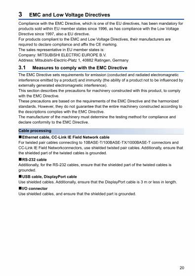
3 EMC and Low Voltage DirectivesCompliance with the EMC Directive, which is one of the EU directives, has been mandatory for products sold within EU member states since 1996, as has compliance with the Low Voltage Directive since 1997, also a EU directive.For products compliant to the EMC and Low Voltage Directives, their manufacturers are required to declare compliance and affix the CE marking.The sales representative in EU member states is:Company: MITSUBISHI ELECTRIC EUROPE B.V.Address: Mitsubishi-Electric-Platz 1, 40882 Ratingen, Germany
3.1 Measures to comply with the EMC DirectiveThe EMC Directive sets requirements for emission (conducted and radiated electromagnetic interference emitted by a product) and immunity (the ability of a product not to be influenced by externally generated electromagnetic interference).This section describes the precautions for machinery constructed with this product, to comply with the EMC Directive.These precautions are based on the requirements of the EMC Directive and the harmonized standards. However, they do not guarantee that the entire machinery constructed according to the descriptions complies with the EMC Directive.The manufacturer of the machinery must determine the testing method for compliance and declare conformity to the EMC Directive.
Cable processingEthernet cable, CC-Link IE Field Network cableFor twisted pair cables connecting to 10BASE-T/100BASE-TX/1000BASE-T connectors and CC-Link IE Field Networkconnectors, use shielded twisted pair cables. Additionally, ensure that the shielded part of the twisted cables is grounded.RS-232 cableAdditionally, for the RS-232 cables, ensure that the shielded part of the twisted cables is grounded.USB cable, DisplayPort cableUse shielded cables. Additionally, ensure that the DisplayPort cable is 3 m or less in length.I/O connectorUse shielded cables, and ensure that the shielded part is grounded.

21
EMC Directive related standardsEmission requirementsStandard: EN61131-2:2007
*1 This product is an open-type device and must be placed in a conductive control panel or similar type of enclosure. The tests were conducted with the product installed in a control panel. applying the maximum rated input voltage of the power supply module.
*2 QP: Quasi-Peak value, Mean: Average value
Immunity requirementsStandard: EN61131-2:2007
*1 This product is an open-type device and must be placed in a conductive control panel or similar type of enclosure. The tests were conducted with the product installed in a control panel.
Test item Test description Value specified in standard
CISPR16-2-3Radiated emission*1
The electromagnetic wave emitted by the product to the external space is measured.
• 30 M to 230 MHz, QP: 40 dBV/m (measured at 10 m distance)*2
• 230 M to 1000 MHz, QP: 47 dBV/m((measured at 10 m distance)
CISPR16-2-1, CISPR16-1-2Conducted emission*1
The noise level which the product emits to the power line is measured.
• 150 k to 500 kHz, QP: 79 dB, Mean: 66 dB*2
• 500 k to 30 MHz, QP: 73 dB, Mean: 60 dB
Test item Test description Value specified in standard
EN61000-4-2Electrostatic discharge immunity*1
Immunity testing in which an electrostatic discharge is applied to the enclosure of the equipment.
• 8 kV: Air discharge• 4 kV: Contact discharge
EN61000-4-3Radiated, radio-frequency, electromagnetic field immunity*1
Immunity testing in which an electric field is radiated to the product.
80% AM modulation @1 kHz• 80 to 1000 MHz: 10 V/m• 1.4 to 2.0 GHz: 3 V/m• 2.0 to 2.7 GHz: 1 V/m
EN61000-4-4Fast transient/burst immunity*1
Immunity testing in which burst noise is applied to power lines and signal lines.
• AC/DC power, I/O power, and AC I/O (unshielded) lines: 2 kV
• DC I/O, analog, and communication lines: 1 kV
EN61000-4-5Surge immunity*1
Immunity testing in which lightning surge is applied to power lines and signal lines.
• AC power, AC I/O power, and AC I/O (unshielded) lines: 2 kV CM, 1 kV DM
• DC power and DC I/O power lines: 0.5 kV CM, DM
• DC I/O, AC I/O (shielded), analog, and communication lines: 1 kV CM
EN61000-4-6Conducted RF immunity*1
Immunity testing in which high-frequency noise is applied to power lines and signal lines.
0.15 M to 80 MHz, 80%AM modulation@1 kHz, 10 Vrms
EN61000-4-8Power-frequency magnetic field immunity*1
Immunity testing in which the product is immersed in the magnetic field of an induction coil.
50/60 Hz, 30 A/m
EN61000-4-11Voltage dips and interruptions immunity*1
Immunity testing in which supply power voltage is momentarily interrupted.
• 0%, 0.5 periods, starting at zerocrossing
• 0%, 250/300 periods (50/60 Hz)• 40%, 10/12 periods (50/60 Hz)• 70%, 25/30 periods (50/60 Hz)
22
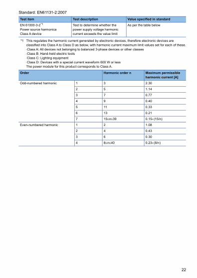
Standard: EN61131-2:2007
*1 This regulates the harmonic current generated by electronic devices, therefore electronic devices are classified into Class A to Class D as below, with harmonic current maximum limit values set for each of these.Class A: All devices not belonging to balanced 3-phase devices or other classesClass B: Hand-held electric toolsClass C: Lighting equipmentClass D: Devices with a special current waveform 600 W or lessThe power module for this product corresponds to Class A.
Test item Test description Value specified in standard
EN 61000-3-2*1
Power source harmonicaClass A device
Test to determine whether the power supply voltage harmonic current exceeds the value limit
As per the table below
Order Harmonic order n Maximum permissible harmonic current [A]
Odd-numbered harmonic 1 3 2.30
2 5 1.14
3 7 0.77
4 9 0.40
5 11 0.33
6 13 0.21
7 15n39 0.15(15/n)
Even-numbered harmonic 1 2 1.08
2 4 0.43
3 6 0.30
4 8n40 0.23(8/n)

23
Installation in a control panelThis product is an open-type device intended to be placed in a conductive control panel or similar type of enclosure.Remote modules on each network must be also installed inside the control panel. Waterproof type remote modules can be installed outside the control panel.Placing the product inside a conductive control panel ensures safety as well as effective shielding of electromagnetic noise emitted from the product.Control panel • Use a conductive control panel. • Mask off an area used for grounding in advance. • To ensure electrical contact between inner plates and the control panel, mask off the bolt
installation areas of each inner plate so that conductivity can be ensured in the largest area. • Ground the control panel with a thick ground cable so that low impedance can be ensured
even at high frequencies. • Keep the diameter of the holes on the control panel to 10 cm or less. If the diameter is larger
than 10 cm, electromagnetic wave may leak. In addition, because electromagnetic wave leaks through a clearance between the control panel and its door, reduce the clearance as much as possible. Use of EMI gaskets (sealing the clearance) can suppress undesired radiated emissions.
The tests were conducted by Mitsubishi Electric Corporation using a control panel having damping characteristics of 37 dB (maximum) and 30 dB (average) (measured at 3 m distance, 30 to 300 MHz).Power cable and ground cable • Provide a ground point to the control panel near the power supply module. Ground the LG
and FG terminals of the power supply module to the ground point with the thickest and shortest ground cable possible (2 or less, a length of 30 cm or shorter). The role of the LG and FG terminals is to send to ground noise generated by the product, therefore it is necessary to use a ground wire with as low an impedance as possible. Additionally, the ground cable removes noise, but can carry noise itself, therefore using a short wire prevents this from acting as an antenna.
• Twist the ground cable extended from the ground point together with the power cable. Twisting this together with the power cable sends the largest amount of noise generated form the power cable to the ground. Note that if a noise filter is attached to the power cable, twisting may not be required.

24
DIN railsAluminum DIN rails may have insulation films. If there is not any electrical contact between the DIN rail and the product, ensure conductivity to the extent possible. Methods to obtain conductivity are shown below. • Screw this product to the control panel. (Do not use the DIN rail) • Use iron DIN rails, such as TH35-7.5Fe and TH35-15Fe.Noise filter (power supply line filter)A noise filter is effective for reducing conducted noise in the 10MHz or less frequency band. (Use of a noise filter can suppress noise.)The following are the installation precautions. • Do not bundle the cables on the input side and output side of the noise filter. If bundled, the
noise on the output side is induced into the filtered cable on the input side.
• Ground the ground terminal of the noise filter to the ground point of the control panel with the shortest cable possible (approximately 10 cm).
• Problematic exampleNoise is induced when the input and output cables are bundled.
• Modification exampleInstall the input and output cables separately.
FilterInduction
Input side (power supply side)
Output side(device side)
Filter
Input side (power supply side)
Output side(device side)

25
Cables extended out of the control panelUse a shielded cable for a cable extended out of the control panel such as an I/O signal line (including a common line) and cable for communications.If a shielded cable is not used or not grounded properly, the noise immunity will not meet the requirement.Grounding a shielded cable • Ground the shield of a shielded cable as close to the module as possible so that the grounded
cable will not be affected by electromagnetic induction from ungrounded cables. • Ground the exposed shield to a large area on the control panel. A clamp can be used as
shown below. In this case, mask off the inner wall surface of the control panel, which comes in contact with the clamp.
Do not use the tip of a PVC wire soldered onto a shield of the shielded cable for grounding. Doing so will raise the high-frequency impedance, resulting in loss of the shielding effect.
(1) Paint mask(2) Clamp
(2)(1)
PVC wireSolderless terminal
Shielded cable
26
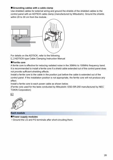
Grounding cables with a cable clampUse shielded cables for external wiring and ground the shields of the shielded cables to the control panel with an AD75CK cable clamp (manufactured by Mitsubishi). Ground the shields within 20 to 30 cm from the module.
For details on the AD75CK, refer to the following. AD75CK-type Cable Clamping Instruction ManualFerrite coreA ferrite core is effective for reducing radiated noise in the 30MHz to 100MHz frequency band.It is recommended to install a ferrite core if a shield cable extended out of the control panel does not provide sufficient shielding effects.Install a ferrite core to the cable in the position just before the cable is extended out of the control panel. If the installation position is not appropriate, the ferrite core will not produce any effect.Install a ferrite core to each power cable as shown below.(Ferrite core used for the tests conducted by Mitsubishi: ESD-SR-250 manufactured by NEC TOKIN Corporation)
Ex.
Each modulePower supply modules • Ground the LG and FG terminals after short-circuiting them.
AD75CK20 to 30 cm

27
3.2 Measures to comply with the Low Voltage DirectiveThe Low Voltage Directive requires electrical equipment that is designed or adapted for use between 50 to 1000 VAC or 75 to 1500 VDC to satisfy the safety requirements.This section describes the precautions for use of the product to comply with the Low Voltage Directive.These precautions are based on the requirements of the Low Voltage Directive and the harmonized standards. However, they do not guarantee that the entire machinery constructed according to the descriptions complies with the Low Voltage Directive. The manufacturer of the machinery must determine the testing method for compliance and declare conformity to the Low Voltage Directive.
Regulations applicable to this product • EN61131-2 "Safety requirements for electrical equipment for measurement, control and
laboratory use"This product and those that operate at 50 VAC/75 VDC or higher rated input voltage have also been developed in accordance with EN61131-2.
Range of application of productPower supply modulesPower supply modules for the AC power supply have hazardous voltage (peak voltage higher than or equal to 42.4 V) internally. Therefore, insulation between the primary and secondary circuits is reinforced for CE-marked power supply modules.Main module, fan moduleThese products are not targeted for the Low Voltage Directive compliance because the circuits in the products operate at the 24 VDC or less rated voltage.
Power supplyPower supply modules are designed to meet the overvoltage category .Confirm that the power supply to the product meets the overvoltage category .
Control panelProtection against electric shockHandle the control panel as necessary to protect a person who does not have adequate knowledge of electrical installation from an electric shock. This shows example handling. • Lock the control panel so that only a person who is trained and has acquired enough
knowledge of electrical installation can open the panel. • Design the control panel so that the power supply is automatically shut off when the panel is
opened. (In this product, the OS is shut down.) • Use a control panel with a protection degree of IP20 or higher.Protection from dust and waterThe control panel needs to be dustproof and waterproof.Insufficient dustproof and waterproof lower the dielectric withstand of the control panel, possibly causing dielectric breakdown.The product is designed to be used in an environment of pollution degree 2. Use them in an environment of pollution degree 2 or below. The environment of pollution degree 2 can be achieved when the programmable controller is installed inside the control panel with a protection degree of IP54 or equivalent.

28
GroundingUse with the following ground terminals connected.
External wiringExternal devicesFor external devices connected to a this product, use the one of which insulation between the interface circuit section to this product and the hazardous voltage circuit section is reinforced (if the device internally has a hazardous voltage circuit section).Reinforced insulationReinforced insulation means an insulation having the following withstand voltage.
(Overvoltage category , source: IEC 664)
Terminal name Application
Protective grounding Guarantees product safety, and increases immunity to noise.
Functional grounding Increases immunity to noise.
Rated voltage of hazardous voltage Surge withstand voltage (1.2/50 s)
150 VAC or less 2500 V
300 VAC or less 4000 V

29
4 WiringThis section describes the precautions for wiring this product.
4.1 Power supply module
Wiring diagrams
Schémas de câblage
The table below shows applicable solderless terminals connected to the terminal block. When wiring, use applicable wires and an appropriate tightening torque. Use UL listed solderless terminals and, for processing, use a tool recommended by their manufacturer.
*1 It can be used for ERR terminals.
Terminal screw size
Solderless terminal Wire
Model Tightening torque
Diameter Type Material Temperature rating
M4 RAV1.25-4*1, RAV2-4
1.02 to 1.38Nm
18 to 14AWG Stranded Copper 75 or more
ERR+ERR-FGLGINPUTAC100/240
INPUTAC

30
Le tableau ci-dessous indique quelles bornes sans soudure on doit utiliser pour les raccordements sur la plaque à bornes. Pour le câblage, utiliser les fils et couples de serrage prescrits. Utiliser les bornes sans soudure répertoriées par UL et, pour le montage, utiliser l'outil recommandé par le fabricant de ces bornes.
*1 It can be used for ERR terminals.
Taille des vis de borne
Borne sans soudure Fil
Modèle Couple de serrage
Diamètre Type Matériau Gamme de température
M4 RAV1.25-4*1, RAV2-4
1,02 à 1,38Nm
18 à 14 AWG Torsadé Cuivre 75 ou plus

31
5 Precautions for Battery TransportationWhen transporting lithium batteries, follow the transportation regulations.For details, refer to the following technical bulletin.Precautions for transport recommendations on lithium batteries (FA-A-0259)
Regulated modelsThe batteries for this product are classified as shown below.
Transport guidelinesProducts are packed in compliance with the transportation regulations prior to shipment. When repacking any of the unpacked products for transportation, make sure to observe the IATA Dangerous Goods Regulations, IMDG (International Maritime Dangerous Goods) Code, and other local transportation regulations.For details, consult the shipping carrier used.
5.1 Precautions when transporting to or through with California, USASince December 31, 2006, in California it is obligatory to include the following warning text on packaging of products incorporating or containing lithium primary cells that have a perchlorate composition of 6 ppb. • Perchlorate Material - special handling may apply, See
www.dtsc.ca.gov/hazardouswaste/perchlorateThis product incorporates the lithium primary cells detailed above, therefore when transporting this product to or through California, ensure that the warning text above is included on the packaging.
Model name Supply status Transport guidelines
FX3U-32BL Lithium battery Non-dangerous goods

32
6 Batteries and Devices with Built-In Batteries in EU Member States
This section describes the precautions for disposing of waste batteries in EU member states and exporting batteries and/or devices with built-in batteries to EU member states.
Disposal precautionsIn EU member states, there is a separate collection system for waste batteries. Dispose of batteries properly at the local community waste collection/recycling center.The following symbol mark is printed on the batteries and packaging of devices with built-in batteries. The symbol mark indicates that batteries need to be disposed of separately from other wastes.
This symbol mark is for EU member states only.The symbol mark is specified in the new EU Battery Directive (2006/66/EC) Article 20 "Information for end-users" and Annex.
Exportation precautionsThe new EU Battery Directive (2006/66/EC) requires the following when marketing or exporting batteries and/or devices with built-in batteries to EU member states. • To print the symbol mark on batteries, devices, or their packaging • To explain the symbol mark in the manuals of the productsLabelingTo market or export batteries and/or devices with built-in batteries, which have no symbol mark, to EU member states, print the symbol mark shown in the following on the batteries, devices, or their packaging.Page 32 Disposal precautionsExplaining the symbol in the manualsTo export devices incorporating this product to EU member states, provide the latest manuals that include the explanation of the symbol mark.If manuals are not provided, separately attach an explanatory note regarding the symbol mark to each manual of the devices.
The requirements apply to batteries and/or devices with built-in batteries manufactured before the enforcement date of the new EU Battery Directive (2006/66/EC).

33
7 MOUNTING MODULESWhen installing the product in a control panel, fully consider its operability, maintainability, and environmental resistance.Securely mount the power supply module and the fan module of the product to the main module.For details on the mounting method, refer to the MELIPC MI5000 Series User's Manual (Startup).
7 MONTAGE DES MODULESPour installer le produit dans un tableau de commande, prendre en compte tous les aspects de facilité d'utilisation, de maintenance et de résistance à l'environnement.Fixer solidement le module d'alimentation et le module de ventilateur au module principal du produit.Pour plus de détails sur la méthode de fixation, consulter le manuel d'utilisation MELIPC série MI5000 (démarrage).

34
MEMO

35
REVISIONS*The manual number is given on the bottom left of the front cover.
© 2018 MITSUBISHI ELECTRIC CORPORATION
Revision date *Manual number Description
May 2018 IB(NA)-0800605-A First edition
May 2018 IB(NA)-0800605-B Partial correction
July 2020 IB(NA)-0800605-C Added or modified partsSAFETY PRECAUTIONS, CONDITIONS OF USE FOR THE PRODUCT
This manual confers no industrial property rights of any other kind, nor does it confer any patent licenses. Mitsubishi Electric Corporation cannot be held responsible for any problems involving industrial property rights which may occur as a result of using the contents noted in this manual.

36
WARRANTY
Please confirm the following product warranty details before using this product.
1. Gratis Warranty Term and Gratis Warranty RangeIf any faults or defects (hereinafter "Failure") found to be the responsibility of Mitsubishi occurs during use of the product within the gratis warranty term, the product shall be repaired at no cost via the sales representative or Mitsubishi Service Company.However, if repairs are required onsite at domestic or overseas location, expenses to send an engineer will be solely at the customer's discretion. Mitsubishi shall not be held responsible for any re-commissioning, maintenance, or testing on-site that involves replacement of the failed module.[Gratis Warranty Term]The gratis warranty term of the product shall be for one year after the date of purchase or delivery to a designated place.Note that after manufacture and shipment from Mitsubishi, the maximum distribution period shall be six (6) months, and the longest gratis warranty term after manufacturing shall be eighteen (18) months. The gratis warranty term of repair parts shall not exceed the gratis warranty term before repairs.[Gratis Warranty Range](1) The range shall be limited to normal use within the usage state, usage methods and usage environment,
etc., which follow the conditions and precautions, etc., given in the instruction manual, user's manual and caution labels on the product.
(2) Even within the gratis warranty term, repairs shall be charged for in the following cases.1. Failure occurring from inappropriate storage or handling, carelessness or negligence by the user.
Failure caused by the user's hardware or software design.2. Failure caused by unapproved modifications, etc., to the product by the user.3. When the Mitsubishi product is assembled into a user's device, Failure that could have been avoided if
functions or structures, judged as necessary in the legal safety measures the user's device is subject to or as necessary by industry standards, had been provided.
4. Failure that could have been avoided if consumable parts (battery, backlight, fuse, etc.) designated in the instruction manual had been correctly serviced or replaced.
5. Failure caused by external irresistible forces such as fires or abnormal voltages, and Failure caused by force majeure such as earthquakes, lightning, wind and water damage.
6. Failure caused by reasons unpredictable by scientific technology standards at time of shipment from Mitsubishi.
7. Any other failure found not to be the responsibility of Mitsubishi or that admitted not to be so by the user.
2. Onerous repair term after discontinuation of production(1) Mitsubishi shall accept onerous product repairs for seven (7) years after production of the product is
discontinued. Discontinuation of production shall be notified with Mitsubishi Technical Bulletins, etc.(2) Product supply (including repair parts) is not available after production is discontinued.
3. Overseas serviceOverseas, repairs shall be accepted by Mitsubishi's local overseas FA Center. Note that the repair conditions at each FA Center may differ.
4. Exclusion of loss in opportunity and secondary loss from warranty liabilityRegardless of the gratis warranty term, Mitsubishi shall not be liable for compensation to:(1) Damages caused by any cause found not to be the responsibility of Mitsubishi.(2) Loss in opportunity, lost profits incurred to the user by Failures of Mitsubishi products.(3) Special damages and secondary damages whether foreseeable or not, compensation for accidents, and
compensation for damages to products other than Mitsubishi products.(4) Replacement by the user, maintenance of on-site equipment, start-up test run and other tasks.
5. Changes in product specificationsThe specifications given in the catalogs, manuals or technical documents are subject to change without prior notice.

37
TRADEMARKSThe company names, system names and product names mentioned in this manual are either registered trademarks or trademarks of their respective companies.In some cases, trademark symbols such as '' or '' are not specified in this manual.


Specifications subject to change without notice.
HEAD OFFICE : TOKYO BUILDING, 2-7-3 MARUNOUCHI, CHIYODA-KU, TOKYO 100-8310, JAPANNAGOYA WORKS : 1-14, YADA-MINAMI 5-CHOME, HIGASHI-KU, NAGOYA, JAPAN
When exported from Japan, this manual does not require application to the Ministry of Economy, Trade and Industry for service transaction permission.
MITSUBISHI ELECTRIC TURKEY A.Ş Ümraniye Branch Serifali Mahallesi Nutuk Sokak No:5, TR-34775 Umraniye/Istanbul, TurkeyTel : +90-216-526-3990MITSUBISHI ELECTRIC EUROPE B.V. Dubai Branch Dubai Silicon Oasis, P.O.BOX 341241, Dubai, U.A.E.Tel : +971-4-3724716ADROIT TECHNOLOGIES 20 Waterford Office Park, 189 Witkoppen Road, Fourways, South AfricaTel : +27-11-658-8100
MITSUBISHI ELECTRIC AUTOMATION (CHINA) LTD. No.1386 Hongqiao Road, Mitsubishi Electric Automation Center, Shanghai, ChinaTel : +86-21-2322-3030SETSUYO ENTERPRISE CO., LTD. 6F, No.105, Wugong 3rd Road, Wugu District, New Taipei City 24889, TaiwanTel : +886-2-2299-2499MITSUBISHI ELECTRIC AUTOMATION KOREA CO., LTD. 7F-9F, Gangseo Hangang Xi-tower A, 401, Yangcheon-ro, Gangseo-Gu, Seoul 07528, KoreaTel : +82-2-3660-9530MITSUBISHI ELECTRIC ASIA PTE. LTD. 307, Alexandra Road, Mitsubishi Electric Building, Singapore 159943Tel : +65-6473-2308
MITSUBISHI ELECTRIC FACTORY AUTOMATION (THAILAND) CO., LTD. 12th Floor, SV.City Building, Office Tower 1, No. 896/19 and 20 Rama 3 Road, Kwaeng Bangpongpang, Khet Yannawa, Bangkok 10120, ThailandTel : +66-2682-6522MITSUBISHI ELECTRIC VIETNAM COMPANY LIMITED Hanoi Branch 6th Floor, Detech Tower, 8 Ton That Thuyet Street, My Dinh 2 Ward, Nam Tu Liem District, Hanoi, VietnamTel : +84-4-3937-8075PT. MITSUBISHI ELECTRIC INDONESIAGedung Jaya 11th Floor, JL. MH. Thamrin No.12, Jakarta Pusat 10340, IndonesiaTel : +62-21-3192-6461
MITSUBISHI ELECTRIC INDIA PVT. LTD. Pune Branch Emerald House, EL-3, J Block, M.I.D.C., Bhosari, Pune-411026, Maharashtra, IndiaTel : +91-20-2710-2000
USA MITSUBISHI ELECTRIC AUTOMATION, INC. 500 Corporate Woods Parkway, Vernon Hills, IL 60061, U.S.A.Tel : +1-847-478-2100
Turkey
Sales office/Tel
Country/Region
Sales office/Tel
Country/Region
Mexico MITSUBISHI ELECTRIC AUTOMATION, INC. Mexico Branch Mariano Escobedo #69, Col. Zona Industrial, Tlalnepantla Edo. Mexico, C.P.54030Tel : +52-55-3067-7500
UAE
Brazil MITSUBISHI ELECTRIC DO BRASIL COMÉRCIO E SERVIÇOS LTDA. Avenida Adelino Cardana, 293, 21 andar, Bethaville, Barueri SP, BrazilTel : +55-11-4689-3000
South Africa
Germany MITSUBISHI ELECTRIC EUROPE B.V. German Branch Mitsubishi-Electric-Platz 1, 40882 Ratingen, GermanyTel : +49-2102-486-0
China
UK MITSUBISHI ELECTRIC EUROPE B.V. UK Branch Travellers Lane, Hatfield, Hertfordshire, AL10 8XB, U.K.Tel : +44-1707-28-8780
Taiwan
Ireland MITSUBISHI ELECTRIC EUROPE B.V. Irish Branch Westgate Business Park, Ballymount, Dublin 24, IrelandTel : +353-1-4198800
Korea
Italy MITSUBISHI ELECTRIC EUROPE B.V. Italian Branch Centro Direzionale Colleoni-Palazzo Sirio Viale Colleoni 7, 20864 Agrate Brianza(Milano) ItalyTel : +39-039-60531
Singapore
Spain MITSUBISHI ELECTRIC EUROPE, B.V. Spanish Branch Carretera de Rubí, 76-80-Apdo. 420, 08190 Sant Cugat del Vallés (Barcelona), SpainTel : +34-935-65-3131
Thailand
France MITSUBISHI ELECTRIC EUROPE B.V. French Branch 25, Boulevard des Bouvets, 92741 Nanterre Cedex, FranceTel : +33-1-55-68-55-68
Vietnam
Czech Republic
MITSUBISHI ELECTRIC EUROPE B.V. Czech Branch Avenir Business Park, Radlicka 751/113e, 158 00 Praha5, Czech RepublicTel : +420-251-551-470
Indonesia
Poland MITSUBISHI ELECTRIC EUROPE B.V. Polish Branch ul. Krakowska 50, 32-083 Balice, PolandTel : +48-12-347-65-00
India
Sweden MITSUBISHI ELECTRIC EUROPE B.V. (Scandinavia) Fjelievägen 8, SE-22736 Lund, SwedenTel : +46-8-625-10-00
Russia MITSUBISHI ELECTRIC (RUSSIA) LLC St. Petersburg Branch Piskarevsky pr. 2, bld 2, lit “Sch”, BC “Benua”, office 720; 195027 St. Petersburg, RussiaTel : +7-812-633-3497
Australia MITSUBISHI ELECTRIC AUSTRALIA PTY. LTD.348 Victoria Road, P.O. Box 11, Rydalmere, N.S.W 2116, AustraliaTel : +61-2-9684-7777
Related Documents