Safety Controller Setting and Monitoring Tool Operating Manual -WS0-CPU0 -WS0-CPU1 -WS0-CPU3 -SW1DNN-WS0ADR-B

Welcome message from author
This document is posted to help you gain knowledge. Please leave a comment to let me know what you think about it! Share it to your friends and learn new things together.
Transcript

Safety Controller Setting and Monitoring ToolOperating Manual
-WS0-CPU0-WS0-CPU1-WS0-CPU3-SW1DNN-WS0ADR-B


This document is protected by the law of copyright, whereby all rights established
therein remain with the company Mitsubishi Electric Corporation. Reproduction of this
document or parts of this document is only permissible within the limits of the legal
determination of Copyright Law. Alteration or abridgement of the document is not
permitted without the explicit written approval of the company Mitsubishi Electric
Corporation.
Precautions regarding warranty and specifications
MELSEC-WS series products are jointly developed and manufactured by Mitsubishi
and SICK AG, Industrial Safety Systems, in Germany.
Note that there are some precautions regarding warranty and specifications of
MELSEC-WS series products.
<Warranty>
The gratis warranty term of the product shall be for one (1) year after the date of
delivery or for eighteen (18) months after manufacturing, whichever is less.
The onerous repair term after discontinuation of production shall be for four (4)
years.
Mitsubishi shall mainly replace the product that needs a repair.
It may take some time to respond to the problem or repair the product depending on
the condition and timing.
<Specifications>
General specifications of the products differ.
MELSEC-WS MELSEC-Q MELSEC-QS
Operating ambient temperature -25 to 55°C*1 0 to 55°C 0 to 55°C
Operating ambient humidity 10 to 95%RH 5 to 95%RH 5 to 95%RH
Storage ambient temperature -25 to 70°C -25 to 75°C -40 to 75°C
Storage ambient humidity 10 to 95%RH 5 to 95%RH 5 to 95%RH
*1 When the WS0-GCC100202 is included in the system, operating ambient temperature will
be 0 to 55 °C. EMC standards that are applicable to the products differ.
MELSEC-WS MELSEC-Q, MELSEC-QS
EMC standards EN61000-6-2, EN55011 EN61131-2

1
SAFETY PRECAUTIONS (Read these precautions before using this product.)
Before using this product, please read this manual and the relevant manuals carefully and pay full
attention to safety to handle the product correctly.
In this manual, the safety precautions are classified into two levels: " WARNING" and " CAUTION".
Under some circumstances, failure to observe the precautions given under " CAUTION" may lead to
serious consequences.
Observe the precautions of both levels because they are important for personal and system safety.
Make sure that the end users read this manual and then keep the manual in a safe place for future
reference.
[Design Precautions]
WARNING
When the MELSEC-WS safety controller detects a fault in the external power supply or itself, it
turns off the outputs. Configure an external circuit so that the connected devices are powered off
according to the output status (off) of the MELSEC-WS safety controller. Incorrect configuration
may result in an accident.
When a load current exceeding the rated current or an overcurrent caused by a load short-circuit
flows for a long time, it may cause smoke and fire. To prevent this, configure an external safety
circuit, such as a fuse.
For safety relays, configure an external circuit using a device such as a fuse or breaker to protect a
short-circuit current.
When changing data and operating status, and modifying program of the running MELSEC-WS
safety controller from the PC, configure a safety circuit in the sequence program or external to the
MELSEC-WS safety controller to ensure that the entire system operates safely.
Before operating the MELSEC-WS safety controller, read the relevant manuals carefully and
determine the operating procedure so that the safety can be ensured.
Furthermore, before performing online operations for the MELSEC-WS safety controller from the
PC, determine corrective actions to be taken for communication errors caused by failure such as a
poor contact.
Create an interlock program using a reset button to prevent the MELSEC-WS safety controller from
restarting automatically after the safety function is activated and the safety controller turns off the
outputs.

2
CAUTION
Ensure that an entire system using the MELSEC-WS safety controller meets the requirements for
the corresponding safety category.
The life of safety relays in the safety relay output module depends on the switching condition
and/or load. Configure a system satisfying the number of switching times of the safety relays in
the module.
Do not install the communication cables together with the main circuit lines or power cables. Keep
a distance of 100 mm or more between them.
Failure to do so may result in malfunction due to noise.
If a mechanical switch such as a relay is connected to an input terminal of a safety I/O module,
consider contact bounce.
Observe the protective notes and measures.
Observe the following items in order to ensure proper use of the MELSEC-WS safety controller.
When mounting, installing and using the MELSEC-WS safety controller, observe the standards
and directives applicable in your country.
The national/international rules and regulations apply to the installation, use and periodic
technical inspection of the MELSEC-WS safety controller, in particular.
Machinery Directive 2006/42/EC
EMC Directive 2004/108/EC
Provision and Use of Work Equipment Directive 89/655/EC
Low-Voltage Directive 2006/95/EC
The work safety regulations/safety rules
Manufacturers and owners of the machine on which a MELSEC-WS safety controller is used
are responsible for obtaining and observing all applicable safety regulations and rules.
The notices, in particular the test notices of this manual (e.g. on use, mounting, installation or
integration into the existing machine controller), must be observed.
The test must be carried out by specialised personnel or specially qualified and authorized
personnel and must be recorded and documented and retraced at any time by third parties.
The external voltage supply of the device must be capable of buffering brief mains voltage
failures of 20 ms as specified in EN 60204.
The modules of the MELSEC-WS safety controller conform to Class A, Group 1, in accordance
with EN 55011. Group 1 encompasses all the ISM devices in which intentionally generated
and/or used conductor-bound RF energy that is required for the inner function of the device
itself occurs.
The MELSEC-WS safety controller fulfils the requirements of Class A (industrial
applications) in accordance with the “Interference emission” basic specifications.
The MELSEC-WS safety controller is therefore only suitable for use in an industrial environment
and not for private use.

3
[Installation Precautions]
WARNING
Do not use the MELSEC-WS safety controller in flammable gas atmosphere or explosive gas
atmosphere. Doing so may result in a fire or explosion due to such as an arc caused by switching
the relays.
CAUTION
Use the MELSEC-WS safety controller in an environment that meets the general specifications in
this manual. Failure to do so may result in electric shock, fire, malfunction, or damage to or
deterioration of the product.
Latch the module onto the DIN mounting rail. Incorrect mounting may cause malfunction, failure or
drop of the module.
To ensure full electromagnetic compatibility (EMC), the DIN mounting rail has to be connected to
functional earth (FE).
Ensure that the earthling contact is positioned correctly. The earthling spring contact of the
module must contact the DIN mounting rail securely to allow electrical conductivity.
Shut off the external power supply for the system in all phases before mounting or removing the
module.
Failure to do so may result in damage to the product.
Do not directly touch any conductive part of the module.
Doing so can cause malfunction or failure of the module.
The MELSEC-WS safety controller is only suitable for mounting in a control cabinet with at least
IP 54 degree of protection.
Failure to meet the installation method may cause the module to fail or malfunction due to the
deposition of dust or the adhesion of water.

4
[Wiring Precautions]
WARNING
Shut off the external power supply for the system in all phases before wiring.
Failure to do so may result in electric shock or damage to the product.
The system could start up unexpectedly while you are connecting the devices.
CAUTION
Individually ground the GND wires of the MELSEC-WS safety controller with a ground resistance
of 100 Ω or less.
Failure to do so may result in electric shock or malfunction.
Check the rated voltage and terminal layout before wiring to the module, and connect the cables
correctly.
Connecting a power supply with a different voltage rating or incorrect wiring may cause a fire or
failure.
Tighten the terminal screw within the specified torque range.
Undertightening can cause short circuit, fire, or malfunction. Overtightening can damage the
screw and/or module, resulting in drop, short circuit, or malfunction.
Prevent foreign matter such as dust or wire chips from entering the module.
Such foreign matter can cause a fire, failure, or malfunction.
Mitsubishi MELSEC-WS safety controllers must be installed in control cabinets. Connect the main
power supply to the MELSEC-WS safety controller through a relay terminal block.
Wiring and replacement of an external power supply must be performed by maintenance
personnel who is familiar with protection against electric shock. (For wiring methods, refer to
Chapter 7.)
Place the cables in a duct or clamp them.
If not, dangling cable may swing or inadvertently be pulled, resulting in damage to the module or
cables or malfunction due to poor contact.

5
[Startup and Maintenance Precautions]
WARNING
Do not touch any terminal while power is on.
Doing so will cause electric shock.
Shut off the external power supply for the system in all phases before cleaning the module or
retightening the terminal screws. Failure to do so may result in electric shock.
Tighten the terminal screw within the specified torque range. Undertightening can cause short
circuit, fire, or malfunction.
Overtightening can damage the screw and/or module, resulting in drop, short circuit, or
malfunction.
Safety-oriented devices must be suitable for safety related signals.
A function interruption of safety outputs results in a loss of the safety functions so that the risk of
serious injury exists.
Do not connect any loads that exceed the rated values of the safety outputs.
Wire the MELSEC-WS safety controller so that 24 V DC signals cannot unintentionally contact
safety outputs.
Connect the GND wires of the power supply to earth so that the devices do not switch on when
the safety output line is applied to frame potential.
Use suitable components or devices that fulfill all the applicable regulations and standards.
Actuators at the outputs can be wired single-channeled. In order to maintain the respective Safety
Integrity Level the lines have to be routed in such a manner that cross circuits to other live signals
can be excluded, for example by routing them within protected areas such as in a control cabinet
or in separate sheathed cables.

6
CAUTION
Before performing online operations (Force mode) for the running MELSEC-WS safety controller
from the PC, read the relevant manuals carefully and ensure the safety.
The online operations must be performed by qualified personnel, following the operating
procedure determined at designing.
Fully understand the precautions described in the Safety Controller Setting and Monitoring Tool
Operating Manual before use.
Do not disassemble or modify the modules.
Doing so may cause failure, malfunction, injury, or a fire.
Mitsubishi does not warrant any products repaired or modified by persons other than Mitsubishi or
FA Center authorized by Mitsubishi.
Shut off the external power supply for the MELSEC-WS safety controller in all phases before
mounting or removing the module.
Failure to do so may cause the module to fail or malfunction.
After the first use of the product, do not mount/remove the module from/to the DIN mounting rail,
and the terminal block to/from the module more than 50 times (IEC 61131-2 compliant)
respectively.
Exceeding the limit of 50 times may cause malfunction.
Before handling the module, touch a grounded metal object to discharge the static electricity from
the human body.
Failure to do so may cause the module to fail or malfunction.
[Disposal Precautions]
CAUTION
When disposing of this product, treat it as industrial waste.
Disposal of the product should always occur in accordance with the applicable country-specific
waste-disposal regulations (e.g. European Waste Code 16 02 14).

7
CONDITIONS OF USE FOR THE PRODUCT
(1) Although MELCO has obtained the certification for Product's compliance to the international safety
standards IEC61508, ISO13849-1 from TUV Rheinland, this fact does not guarantee that Product will
be free from any malfunction or failure. The user of this Product shall comply with any and all
applicable safety standard, regulation or law and take appropriate safety measures for the system in
which the Product is installed or used and shall take the second or third safety measures other than
the Product. MELCO is not liable for damages that could have been prevented by compliance with
any applicable safety standard, regulation or law.
(2) MELCO prohibits the use of Products with or in any application involving, and MELCO shall not be
liable for a default, a liability for defect warranty, a quality assurance, negligence or other tort and a
product liability in these applications.
1) power plants,
2) trains, railway systems, airplanes, airline operations, other transportation systems,
3) hospitals, medical care, dialysis and life support facilities or equipment,
4) amusement equipments,
5) incineration and fuel devices,
6) handling of nuclear or hazardous materials or chemicals,
7) mining and drilling,
8) and other applications where the level of risk to human life, health or property are elevated.

8
*The manual number is given on the bottom left of the back cover.
Print date *Manual number Revision September, 2009 SH(NA)-080856ENG-A First edition
March, 2010 SH(NA)-080856ENG-B A new module, CC-Link interface module, was added.
July, 2011 SH(NA)-080856ENG-C Description on Flexi Link system was added.
August, 2012 SH(NA)-080856ENG-D Setting and Monitoring Tool was upgraded.
August, 2014 SH(NA)-080856ENG-E A new module, WS0-CPU3 module, was added.
Description on Flexi Line system was added.
Setting and Monitoring Tool was upgraded.
August, 2016 SH(NA)-080856ENG-F Description on the corporate logo was changed.
November, 2018 SH(NA)-080856ENG-G Errors in writing are corrected.
September, 2019 SH(NA)-080856ENG-H Additions to the notes for transferring the system configuration
ware made.
January, 2020 SH(NA)-080856ENG-I Setting and Monitoring Tool was upgraded.
Japanese manual version SH-080853-J This manual confers no industrial property rights or any rights of any other kind, nor does it confer any patent licenses. Mitsubishi Electric Corporation cannot be held responsible for any problems involving industrial property rights which may occur as a result of using the contents noted in this manual.
2009 MITSUBISHI ELECTRIC CORPORATION
REVISIONS

9
SAFETY PRECAUTIONS ........................................................................................... 1 CONDITIONS OF USE FOR THE PRODUCT ........................................................... 7
REVISIONS ................................................................................................................ 8
CONTENTS ................................................................................................................ 9 GENERIC TERMS AND ABBREVIATIONS .............................................................. 15
1. About this document ............................................................................................. 16
1.1 Function of this document ............................................................................... 16 1.2 Target group .................................................................................................... 17
1.3 Function and structure of this manual ............................................................. 18
1.3.1 Recommendations for familiarising yourself with Setting and Monitoring Tool .......................................................................................................... 18
1.3.2 Recommendations for experienced users ................................................ 18
1.4 Scope and version .......................................................................................... 18 1.5 Abbreviations used .......................................................................................... 19
1.6 Symbols and notations used ........................................................................... 19
2. On safety .............................................................................................................. 20 2.1 Qualified safety personnel .............................................................................. 20
2.2 Correct use ...................................................................................................... 20
2.3 General protective notes and protective measures ........................................ 21 3. Version, compatibility and features ....................................................................... 22
4. Installation and removal ........................................................................................ 24
4.1 System requirements ...................................................................................... 24 4.2 Installation and Update ................................................................................... 24
4.3 Removal .......................................................................................................... 25
4.4 Troubleshooting............................................................................................... 25 5. The graphical user interface ................................................................................. 26
5.1 Start view ........................................................................................................ 26
5.2 Setting the desired language .......................................................................... 26 5.3 Standard views................................................................................................ 27
5.4 Positioning windows ........................................................................................ 28
5.5 Hardware configuration view ........................................................................... 29 5.5.1 Exercise for configuring the MELSEC-WS modules ................................ 31
5.5.2 Module status bits in the Hardware configuration view ............................ 33
5.5.3 Exercise for configuring the connected devices ....................................... 35 5.5.4 Safe and non-safe elements in the hardware configuration ..................... 36
5.5.5 Expanding elements ................................................................................. 36
5.5.6 Parameterization of connected elements ................................................. 37 5.5.7 Customized elements ............................................................................... 39
CONTENTS

10
5.5.8 Connection of SICK EFI-compatible devices ........................................... 42 5.5.9 Export and import of a partial application ................................................. 44
5.5.10 RS-232 routing ....................................................................................... 47
5.6 Logic editor view ............................................................................................. 52 5.6.1 Exercise for using the logic editor ............................................................ 53
5.6.2 Logic access levels ................................................................................... 54
5.6.3 Validation of the configuration .................................................................. 56 5.6.4 Inputs and diagnostics bits of the main module in the logic editor ........... 57
5.6.5 EFI I/O error status bits in the logic editor ................................................ 58
5.6.6 Module input and output status bits in the logic editor ............................. 59 5.6.7 CPU markers ............................................................................................ 60
5.6.8 Jump addresses ....................................................................................... 61
5.6.9 I/O matrix .................................................................................................. 62 5.6.10 Tag name editor ...................................................................................... 64
5.6.11 Import and export tag names .................................................................. 65
5.7 Report view ..................................................................................................... 66 5.8 Diagnostics view ............................................................................................. 67
5.9 Data recorder view .......................................................................................... 69
6. Connecting to the MELSEC-WS safety controller ................................................ 71 6.1 First steps for establishing a connection ......................................................... 71
6.1.1 Connecting the PC to the MELSEC-WS safety controller via RS-232 ..... 71
6.1.2 Online status and background color ......................................................... 72 6.2 Editing the communication settings ................................................................ 73
6.3 Establishing a connection with the MELSEC-WS safety controller ................ 79
6.4 User levels in the Setting and Monitoring Tool ............................................... 80 6.5 Identify project ................................................................................................. 81
7. Flexi Link ............................................................................................................... 82
7.1 Flexi Link overview .......................................................................................... 82 7.1.1 System requirements and restrictions for Flexi Link ................................ 82
7.2 Function principle ............................................................................................ 83
7.2.1 Flexi Link address ..................................................................................... 83 7.2.2 Flexi Link ID .............................................................................................. 83
7.3 Getting started................................................................................................. 85
7.3.1 Connecting to an existing Flexi Link system ............................................ 85 7.3.2 Setting up a Flexi Link project in the Setting and Monitoring Tool............ 88
7.3.3 Flexi Link configuration ............................................................................. 89
7.3.4 Transferring and verifying the Flexi Link configuration ............................. 93 7.4 Flexi Link functions ......................................................................................... 96
7.4.1 Flexi Link system: System overview ......................................................... 97
7.4.2 Flexi Link system: Process image ............................................................ 99 7.4.3 Flexi Link system: Network settings ....................................................... 100

11
7.4.4 Flexi Link stations: Flexi Link data in the logic editor ............................. 101 7.4.5 Flexi Link stations: Station X view and process image .......................... 103
7.4.6 Flexi Link stations: Teach function .......................................................... 105
7.4.7 Flexi Link teaching status and diagnostics ............................................. 107 7.5 Flexi Link troubleshooting ............................................................................. 109
7.5.1 Flexi Link ID mismatch ........................................................................... 109
8. Flexi Line ............................................................................................................. 110 8.1 Flexi Line overview ........................................................................................ 110
8.1.1 System requirements and restrictions for Flexi Line ............................... 110
8.2 Principle of operation Flexi Line ..................................................................... 111 8.2.1 Topology .................................................................................................. 111
8.2.2 Flexi Line configuration ............................................................................ 111
8.2.3 Flexi Line checksum (CRC) ..................................................................... 114 8.2.4 Flexi Line data in the logic editor ............................................................. 115
8.2.5 Teach function.......................................................................................... 116
8.2.6 Status and diagnostics ............................................................................ 118 8.3 Getting started................................................................................................ 119
8.3.1 Configuration and commissioning of a Flexi Line system ....................... 119
8.3.2 Conversion of a Flexi Line system ......................................................... 120 8.3.3 Configuration of the Flexi Line logic ....................................................... 121
9. Logic programming – Function blocks ............................................................... 123 9.1 General description ....................................................................................... 123 9.2 Safety notes for the logic programming ........................................................ 123
9.3 Function block Overview ............................................................................... 125
9.4 Function block properties .............................................................................. 126 9.5 Input and output signal connections of function blocks ................................ 127
9.5.1 Function block input connections ........................................................... 127
9.5.2 Inversion of input connections ................................................................ 127 9.5.3 Function block output connections ......................................................... 128
9.5.4 Fault present output ................................................................................ 129
9.6 Timer values and logic execution time .......................................................... 130 9.7 Logic function blocks ..................................................................................... 130
9.7.1 NOT ........................................................................................................ 130
9.7.2 AND ........................................................................................................ 131 9.7.3 OR .......................................................................................................... 132
9.7.4 XOR (exclusive OR) ............................................................................... 133
9.7.5 XNOR (exclusive NOR) .......................................................................... 134 9.7.6 Multiple release ...................................................................................... 134
9.7.7 RS Flip-Flop ............................................................................................ 135
9.7.8 JK Flip-Flop ............................................................................................ 136 9.7.9 Multiple memory ..................................................................................... 137

12
9.7.10 Clock generator .................................................................................... 138 9.7.11 Event counter (Up, Down and Up and down) ....................................... 139
9.7.12 Fast shut off and Fast shut off with bypass .......................................... 142
9.7.13 Edge detection ...................................................................................... 147 9.7.14 Binary encoder ..................................................................................... 148
9.7.15 Binary decoder ..................................................................................... 151
9.7.16 Log generator ....................................................................................... 154 9.7.17 Routing 1:N ........................................................................................... 156
9.7.18 Routing N:N .......................................................................................... 157
9.8 Application-specific function blocks............................................................... 158 9.8.1 Reset ...................................................................................................... 158
9.8.2 Restart .................................................................................................... 159
9.8.3 Off-delay timer ........................................................................................ 161 9.8.4 Adjustable off-delay timer ....................................................................... 162
9.8.5 On-delay timer ........................................................................................ 163
9.8.6 Adjustable on-delay timer ....................................................................... 164 9.8.7 EDM (External device monitoring) .......................................................... 165
9.8.8 Valve monitoring ..................................................................................... 166
9.8.9 User mode switch ................................................................................... 170 9.8.10 Switch synchronization ......................................................................... 172
9.8.11 Error output combination ...................................................................... 175
9.8.12 Ramp down detection ........................................................................... 176 9.8.13 Frequency monitor ................................................................................ 181
9.8.14 Start warning ........................................................................................ 185
9.9 Function blocks for dual channel evaluation ................................................. 190 9.9.1 Single-channel evaluation ...................................................................... 190
9.9.2 Dual-channel evaluation (1 pair) and discrepancy time ......................... 191
9.9.3 Double dual-channel evaluation (2 pair synchronization evaluation) and synchronization time .............................................................................. 193
9.9.4 Emergency stop ...................................................................................... 195
9.9.5 Magnetic switch ...................................................................................... 196 9.9.6 Light curtain monitoring .......................................................................... 197
9.9.7 Safety gate monitoring ............................................................................ 198
9.9.8 Tolerant dual channel monitor ................................................................ 200 9.9.9 Two-hand control type IIIA ...................................................................... 205
9.9.10 Two-hand control type IIIC.................................................................... 205
9.9.11 Multi operator (multiple two-hand control) ............................................ 207 9.10 Function blocks for Parallel muting, Sequential muting and Cross muting
.................................................................................................................... 209
9.10.1 Overview and general description ........................................................ 209 9.10.2 Parameters of the function blocks ........................................................ 212

13
9.10.3 Information on wiring ............................................................................ 219 9.10.4 State transition from Stop to Run ......................................................... 220
9.10.5 Error states and information on resetting ............................................. 220
9.10.6 Parallel muting ...................................................................................... 221 9.10.7 Sequential muting ................................................................................. 223
9.10.8 Cross muting – direction of movement only forwards or backwards .... 225
9.10.9 Cross muting – material transport in both directions ............................ 227 9.11 Function blocks for press contact monitoring .............................................. 229
9.11.1 Overview and general description ........................................................ 229
9.11.2 Eccentric press contact ......................................................................... 229 9.11.3 Universal press contact ........................................................................ 235
9.12 Function blocks for press cycle control ....................................................... 243
9.12.1 Press setup ........................................................................................... 243 9.12.2 Press single stroke ............................................................................... 246
9.12.3 Press automatic .................................................................................... 250
9.12.4 N-break (press with N-PSDI mode) ...................................................... 253 9.13 User defined function blocks ....................................................................... 261
9.13.1 Grouped function block......................................................................... 261
9.13.2 Customized function block ................................................................... 265 9.14 Simulation of the configuration .................................................................... 268
9.15 Force mode ................................................................................................. 270
10. I/O modules ...................................................................................................... 274 10.1 Dual channel evaluation and discrepancy time monitoring ........................ 274
10.2 ON-OFF filter and OFF-ON filter ................................................................. 276
10.3 Disabling the test pulses of WS0-XTIO outputs .......................................... 276 11. Transferring the system configuration ............................................................... 277
11.1 Transferring project data to the safety controller ......................................... 277
11.2 Compatibility check ..................................................................................... 277 11.3 Verification of the configuration ................................................................... 278
11.4 Activating the write protection of the configuration in the
safety controller .......................................................................................... 281 11.5 Configuration checksums ............................................................................ 281
11.6 Deletion of the configuration in the safety controller ................................... 281
12. Device states of the MELSEC-WS safety controller ......................................... 282 12.1 Changing the device state .......................................................................... 283
12.2 Behaviour on startup ................................................................................... 283
12.3 Software reset of the CPU module ............................................................. 283 13. Technical commissioning .................................................................................. 284
13.1 Wiring and voltage supply ........................................................................... 284
13.2 Transferring the configuration ..................................................................... 284 13.3 Technical test and commissioning .............................................................. 285

14
14. Troubleshooting ................................................................................................ 286 15. Annex ................................................................................................................ 287
15.1 Example application reports ........................................................................ 287
15.1.1 Example application Newspaper palletizer........................................... 287 15.1.2 Example application Wood scanner ..................................................... 302
15.1.3 Example application Ramp down detection ......................................... 313
15.2 List of function block status in simulation mode .......................................... 323 15.3 Precautions ................................................................................................. 323
15.4 SICK contact ............................................................................................... 324

15
Generic
term/abbreviation Description
WS0-MPL0 The abbreviation for the WS0-MPL000201 MELSEC-WS safety controller memory plug
WS0-MPL1 The abbreviation for the WS0-MPL100201 MELSEC-WS safety controller memory plug
WS0-CPU0 The abbreviation for the WS0-CPU000200 MELSEC-WS safety controller CPU module
WS0-CPU1 The abbreviation for the WS0-CPU130202 MELSEC-WS safety controller CPU module
WS0-CPU3 The abbreviation for the WS0-CPU 320202 MELSEC-WS safety controller CPU module
WS0-XTIO The abbreviation for the WS0-XTIO84202 MELSEC-WS safety controller safety I/O combined module
WS0-XTDI The abbreviation for the WS0-XTDI80202 MELSEC-WS safety controller safety input module
WS0-4RO The abbreviation for the WS0-4RO4002 MELSEC-WS safety controller safety relay output module
WS0-GETH The abbreviation for the WS0-GETH00200 MELSEC-WS safety controller Ethernet interface module
WS0-GCC1 The abbreviation for the WS0-GCC100202 MELSEC-WS safety controller CC-Link interface module
CPU module A generic term for the WS0-CPU0, WS0-CPU1 and WS0-CPU3
Safety I/O module A generic term for the WS0-XTIO and WS0-XTDI
Network module A generic term for the WS0-GETH and WS0-GCC1
GENERIC TERMS AND ABBREVIATIONS

Chapter 1
16
About this document
1 About this document
Please read this chapter carefully before working with this manual and the MELSEC-WS safety controller.
1.1 Function of this document For the MELSEC-WS safety controller there are sets of manuals with clearly defined applications as well as user’s manuals (hardware) for each module.
All MELSEC-WS modules and their functions are described in detail in “MELSEC-WS series Safety Controller User's manual”. Use the Safety Controller User's manual in particular for the planning of MELSEC-WS safety controllers. The Safety Controller User's manual is designed to address the technical personnel of the machine manufacturer or the machine operator in regards to safe mounting, electrical installation, commissioning, operation and maintenance of the MELSEC-WS safety controller. The Safety Controller User's manual does not provide instructions for operating machines on which the safety controller is, or will be, integrated. Information on this is to be found in the operating instructions of the machine.
The software-based configuration and setting the parameters for the MELSEC-WS safety controller are described in “MELSEC-WS series Safety Controller Setting and Monitoring Tool Operating Manual". The operating manual also contain a description of the diagnostic functions most important for operation and detailed information on the identification and rectification of errors. Use the operating manual in particular for the configuration, commissioning and operation of MELSEC-WS safety controllers.
MELSEC-WS network interface modules and their functions are described in detail in the user's manuals for each network interface module. The network interface module interface manuals are designed to address the technical personnel of the machine manufacturer or the machine operator in regards to safe mounting, electrical installation, commissioning as well as on maintenance of the MELSEC-WS network interface modules. The network interface module user's manuals also contain important information on the configuration of the network interface module using the software Setting and Monitoring Tool, on the exchange of data with networks as well as information on the status, the planning and the related mapping.
The user’s manuals (hardware) are included with each MELSEC-WS module. They provide basic technical specifications on the modules and contain simple mounting instructions. Use the user’s manuals (hardware) when mounting the MELSEC-WS safety controller.

Chapter 1
17
About this document
The following shows the relevant manuals.
Title Number
Safety Controller User’s Manual WS-CPU-U-E (13JZ32)
Safety Controller Ethernet Interface Module User’s Manual WS-ET-U-E (13JZ33)
Safety Controller CC-Link Interface Module User’s Manual WS-CC-U-E (13JZ45)
Safety Controller Setting and Monitoring Tool Operating Manual
SW1DNN-WS0ADR-B-O-E (13JU67)
Safety Controller CPU Module User's Manual (Hardware) WS-CPU-U-HW-E
(13JZ91)
Safety Controller Safety I/O Module User's Manual (Hardware)
WS-IO-U-HW-E (13JZ92)
Safety Controller Safety Relay Output Module User's Manual (Hardware)
WS-SR-U-HW-E (13JZ93)
Safety Controller Ethernet Interface Module User's Manual (Hardware)
WS-ET-U-HW-E (13JZ95)
Safety Controller CC-Link Interface Module User's Manual (Hardware)
WS-CC-U-HW (13J209)
1.2 Target group These user's manuals are addressed to the planning engineers, designers and operators of systems which are to be protected by a MELSEC-WS safety controller. They also are addressed to people who integrate the MELSEC-WS safety controller into a machine, commission it initially or who are in charge of servicing and maintaining the unit. These user's manuals do not provide instructions for operating the machine or system in which a MELSEC-WS safety controller is integrated. Information of this kind will be found in the operating instructions for the machine or system.
Table 1: Overview of the MELSEC-WS manuals

Chapter 1
18
About this document
1.3 Function and structure of this manual This manual instructs the technical personnel of the machine manufacturer or machine operator in the software configuration, operation and diagnostics of a MELSEC-WS safety controller using the Setting and Monitoring Tool. It only applies in combination with the Safety Controller User’s Manual. Planning and using SICK protective devices also require specific technical skills which are not detailed in this documentation. Chapter 2 contains fundamental safety instructions. These instructions must be read. When operating the MELSEC-WS modular safety controller, the national, local and statutory rules and regulations must be observed. For the acquisition of Setting and Monitoring Tool, please contact your local Mitsubishi representative. The SICK EFI-compatible devices and SICK configuration and diagnostics software CDS are the products of SICK. For details of the SICK products, please contact your local SICK representative (see Section 15.4). www.sick.com
1.3.1 Recommendations for familiarising yourself with Setting and Monitoring Tool
We recommend the following procedure for users who want to familiarize themselves with Setting and Monitoring Tool for the first time: Read Chapter 5 to familiarize yourself with the graphical user interface and do the
exercises for the configuration of example applications.
1.3.2 Recommendations for experienced users
We recommend the following procedure for experienced users who have already worked with Setting and Monitoring Tool: Familiarize yourself with the most recent version of the software by reading
Section 1.4. The table of contents lists all functions provided by the Setting and Monitoring
Tool. Use the table of contents to obtain information about the basic functions.
1.4 Scope and version These user's manuals are original manuals. These user's manuals apply for the Setting and Monitoring Tool software version V1.2.0 or higher, CPU0 and CPU1 with firmware version V1.11 or higher, and CPU3 with firmware version V3.02 or higher. This version of the user's manuals describes version V1.9.1 of the Setting and Monitoring Tool software.
Note

Chapter 1
19
About this document
1.5 Abbreviations used External device monitoring Enhanced function interface Electro-sensitive protective equipment (e.g. C4000) Output signal switching device Revolutions (1 Rev = 360°)
1.6 Symbols and notations used Recommendations are designed to give you some assistance in your decision-making process with respect to a certain function or a technical measure. Note provides special information on a device or a software function. Instructions for taking action are shown by an arrow. Read carefully and follow the instructions for action.
ATTENTION! An “ATTENTION” indicates concrete or potential dangers. It is intended to protect you from harm and help avoid damage to devices and systems. Read warnings carefully and follow them! Otherwise the safety function may be impaired and a dangerous state may occur.
The names of software menus, submenus, options and commands, selection boxes and windows are highlighted in bold. Example: Click Edit in the File menu. The term “dangerous state” The dangerous state (standard term) of the machine is always shown in the drawings and diagrams of this document as the movement of a machine part. In practical operation, there may be a number of different dangerous states: machine movements electrical conductors visible or invisible radiation a combination of several risks and hazards
Keys are shown in uppercase. Keys to be pressed sequentially are hyphenated with “-”. Example: “CTRL+ALT+DEL” indicates to press these keys simultaneously. “F12-2” indicates to press these keys sequentially. The key names are based on the standard keyboard. Some users may use a keyboard with a different language layout such as German.
EDM EFI
ESPE OSSD
Rev
Recommendation
Note Action
ATTENTION
Menus and commands
Key

Chapter 2
20
On safety
2 On safety
This chapter deals with your own safety and the safety of the equipment operators.
Please read this chapter carefully before working with a MELSEC-WS safety controller.
2.1 Qualified safety personnel The MELSEC-WS safety controller must be installed, configured, commissioned and serviced only by qualified safety personnel. Qualified safety personnel are defined as persons who
have undergone the appropriate technical training
and
have been instructed by the responsible machine operator in the operation of the
machine and the current valid safety guidelines
and
are sufficiently familiar with the applicable official health and work safety regulations,
directives and generally recognized engineering practice (e.g. DIN standards, VDE
stipulations, engineering regulations from other EC member states) that they can
assess the work safety aspects of the power-driven equipment
and
have access to the MELSEC-WS manuals and have and read and familiarised
themselves with them
and
have access to the operating instructions for the protective devices (e.g. C4000)
connected to the safety controller and have read and familiarised themselves with
them.
2.2 Correct use The Setting and Monitoring Tool is used to configure a MELSEC-WS safety controller consisting of modules of the safety controller.
The MELSEC-WS safety controller may only be used by qualified safety personnel and only at the machine at which it was mounted and initially commissioned by qualified safety personnel in accordance with the MELSEC-WS manuals.
Mitsubishi Electric Corporation accepts no claims for liability if the software or the devices are used in any other way or if modifications are made to the software or the devices - even in the context of mounting and installation.
Observe the safety instructions and protective measures of the Safety Controller
User’s Manual and this manual!
When implementing a safety-relevant functional logic, ensure that the regulations
of the national and international rules and standards are observed, in particular
the controlling strategies and the measures for risk minimisation that are
mandatory for your application.
ATTENTION

Chapter 2
21
On safety
2.3 General protective notes and protective measures
Observe the protective notes and measures!
Please observe the following items in order to ensure proper use of the MELSEC-WS safety controller.
When mounting, installing and using the MELSEC-WS safety controller, observe
the standards and directives applicable in your country.
The national and international rules and regulations apply to the installation and use
as well as commissioning and periodic technical inspection of the MELSEC-WS
safety controller, in particular:
– Machinery Directive 2006/42/EC,
– EMC Directive 2004/108/EC,
– Provision and Use of Work Equipment Directive 2009/104/EC and the
supplementary Directive 35/63/EC,
– Low-Voltage Directive 2006/95/EC,
– Work safety regulations and safety rules.
Manufacturers and owners of the machine on which a MELSEC-WS safety
controller is used are responsible for obtaining and observing all applicable safety
regulations and rules.
Note

Chapter 3
22
Version, compatibility and features
3 Version, compatibility and features
For the MELSEC-WS series several firmware versions and function packages exist that allow different functions. This chapter gives an overview which firmware version, which function package and/or which version of the Setting and Monitoring Tool is required to use a certain function or device.
Minimum required version
Feature WS0-CPU WS0-XTIO/
WS0-XTDI
Setting and Monitoring Tool
Logic offline simulation –*1 – V1.2.0
Logic import/export – – V1.3.0
Online edit – – V1.3.0
Automatic wiring diagrams – – V1.3.0
Central tag name editor – – V1.3.0
Flexi Link (only with WS0-CPU1/WS0-CPU3)
V2.01 (Revision 2.xx)
– V1.3.0
Flexi Line (only with WS0-CPU3) V3.02
(Revision 3.xx) – V1.7.0
Function block documentation within the Setting and Monitoring Tool
– – V1.3.0
Input/output relation matrix – – V1.3.0
Invertable inputs for the AND, OR, RS Flip-Flop and Routing N:N function blocks
V2.01 (Revision 2.xx)
– V1.3.0
Ramp down detection function block
V1.11 (Revision 1.xx)
– V1.3.0
Adjustable on-delay timer and
adjustable off-delay timer function blocks
V2.01 (Revision 2.xx)
– V1.3.0
Fast Shut Off with Bypass function block (only with WS0-XTI0)
V2.01 (Revision 2.xx)
V2.00 (Revision 2.xx)
V1.7.0
Deactivation of test pulses on Q1–Q4 on the WS0-XTIO possible
– V2.00
(Revision 2.xx) V1.3.0
Verification without identical hardware possible
V2.01 (Revision 2.xx)
– V1.3.0
Status input data and Status output data in logic
V2.01 (Revision 2.xx)
V2.00 (Revision 2.xx)
V1.3.0
Data recorder V2.01
(Revision 2.xx) – V1.7.0
Extended cross-circuit detection time for switching loads with high capacitance
– V3.10
(Revision 3.xx) V1.7.0
Adjustable filter time for ON-OFF filter and OFF-ON filter on the inputs I1 to I8 of the WS0-XTIO/WS0-XTDI
– V3.10
(Revision 3.xx) V1.7.0
Table 2: Required firmware and software versions

Chapter 3
23
Version, compatibility and features
Device WS0-CPU WS0-XTIO/
WS0-XTDI
Setting and Monitoring Tool
Ethernet interface module V1.11 (Revision 1.xx)
– V1.2.0
CC-Link interface module V1.11 (Revision 1.xx)
– V1.2.1
ROHS conformity WS0-XTIO – V1.01*2 –
*1 “–” means “any” or “not applicable”.
*2 All other modules from product launch onwards.
You can find the firmware version on the type label of the MELSEC-WS modules in
the field Firmware version.
In order to use modules with a newer firmware version, a new Setting and
Monitoring Tool version is required. For CPU0/1 ≥ V2.01 and XTIO/XTDI ≥ V2.00
Setting and Monitoring Tool V1.3.0 or higher is required. This has to be considered
when devices are to be replaced in existing systems.
You will find the firmware version of the MELSEC-WS modules in the hardware
configuration view of the Setting and Monitoring Tool when the system is online or
in the report if the system has been online before.
The version of the Setting and Monitoring Tool can be found in About in the Help
menu.
For the acquisition of the newest version of the Setting and Monitoring Tool, please
contact your local Mitsubishi representative.
The function package (Revision 1.xx or Revision 2.xx) must be selected in the
Setting and Monitoring Tool hardware configuration. Function package Revision
2.xx is available with Setting and Monitoring Tool 1.3.0 and higher.
In order to use function package Revision 2.xx, the respective module must have at
least firmware version V2.00.0. Otherwise you will receive an error message when
you try to upload a configuration using Revision 2.xx to a module with a lower
firmware version.
Newer modules are downward compatible so that any module can be replaced by a
module with a higher firmware version.
The same firmware version and function package revision as those of the module
used must be set to the new project after a project stored in the memory plug is
modified.
You will find the device’s date of manufacture at the bottom of the type label in the
format yywwnnnn (yy = year, ww = calendar week, nnnn = continuos serial number
in the calendar week).
Note

Chapter 4
24
Installation and removal
4 Installation and removal
4.1 System requirements Recommended system configuration: Windows XP (32 Bit/64 Bit) (only with Setting and Monitoring Tool V1.7.0 or earlier
version), Windows Vista (32 Bit/64 Bit), Windows 7 (32 Bit/64 Bit), or Windows 10 (32 Bit/64 Bit) (only with Setting and Monitoring Tool V1.9.1 or later version)
Microsoft .NET Framework 3.5
1 GHz processor 1 GB RAM
1024 × 768 pixel screen resolution
300 MB free hard disk memory Setting and Monitoring Tool is a .NET Framework application. It requires .NET Framework Version 3.5 or higher.
Information on the current .NET Framework versions, supported operating systems, and Regional and Language Options settings is available on the Internet at
www.microsoft.com
Microsoft .NET Framework Version 3.5 or higher and any other components that may be needed can also be downloaded from www.microsoft.com/downloads.
Use a standard user account or higher in Windows Vista, Windows 7, or Windows 10. To display text of Setting and Monitoring Tool in Chinese, use Chinese version of Windows operating systems.
To display text of Setting and Monitoring Tool in Japanese or Chinese in Windows XP (English version), add the language in the Regional and Language Options dialog box. (The dialog box can be accessed from Control Panel.)
4.2 Installation and Update For the acquisition of Setting and Monitoring Tool (including information for installation), please contact your local Mitsubishi representative.
Start the installation by running the setup.exe file and then follow the further instruction.
New software versions may contain new functions and support new MELSEC-WS modules. The version of the Setting and Monitoring Tool can be found in About in the Help menu. Remove the old software version before installing a new one. The working directory in which the project data are stored is not overwritten during the new installation and is retained. When an RS232-USB converter (WS0-UC-232A) is used, install a driver from the CD ROM provided with the converter.
When an RS232-USB configuration cable (WS0-C20M8U) is used, please contact your local Mitsubishi representative for a driver of the cable.
Note
Note

Chapter 4
25
Installation and removal
4.3 Removal The Setting and Monitoring Tool can be removed as follows:
In the Windows Start menu, start Uninstall Setting and Monitoring Tool in the Setting and Monitoring Tool program folder.
4.4 Troubleshooting Error/Error message Cause Rectification
When Setting and Monitoring Tool is started, the following or a similar error message is displayed: “DLL not found – the Dynamic Link Library mscoree.dll was not found in the specified path. Specify the registration key HKLM\Software\Microsoft\ NETFramework\InstallRoot so that it refers to the installation location of the .NET Framework.”
Microsoft .NET Framework is not installed on the PC.
Install a suitable version of Microsoft .NET Framework. Ask your system administrator if appropriate. .NET Framework is available for downloading on the internet pages of Microsoft. Note: Install .NET Framework 3.5
Table 3: Errors and error elimination

Chapter 5
26
The graphical user interface
5 The graphical user interface
This chapter familiarizes you with the basic elements of the graphical user interface as an introduction. This chapter does not give any information on the configuration of MELSEC-WS modules nor any instructions for logic programming. This chapter is only intended to explain the fundamental functioning of the Setting and Monitoring Tool on the basis of a small section of the functions. Experienced users of Setting and Monitoring Tool can skip this chapter.
5.1 Start view After the Setting and Monitoring Tool has been started, the start view is displayed. The user can specify here with which of the following actions he wants to start: Open existing project file
Connect to physical device
Create new project Create new Flexi Link project
Edit com. Interface settings
5.2 Setting the desired language Click the flag icon in the menu bar at the far right and select the desired language
version.
Note
Figure 1: Start view with selection of the action

Chapter 5
27
The graphical user interface
5.3 Standard views The Setting and Monitoring Tool has the following views that can be accessed via buttons below the menu bar.
The structure of a MELSEC-WS safety controller consisting of various hardware modules as well as the configuration of the inputs and outputs and the connected elements are specified in the Hardware configuration view.
The function logic can be configured by means of logic function blocks and application-specific function blocks in the Logic editor view. This view is not available unless a CPU module has been selected beforehand in the hardware configuration.
If the project contains at least one network module or if RS-232 communication is enabled, the Network module [13] view is available. Here you can configure the network module and the data that are transferred to and from the network.
Do not save the project data while Setting and Monitoring Tool is connected to the MELSEC-WS safety controller. Before saving the project data, disconnect the PC from the MELSEC-WS safety controller. Complete information on the currently loaded project and all settings including the
logic programming and wiring diagrams is available in the Report view. Furthermore, additional information on the project can be entered here. All information can be saved in standard file formats and printed out. The scope of the report can be compiled individually depending on the selection.
The stored error messages are displayed as a history of a connected MELSEC-WS safety controller in the Diagnostics view.
Input and output signals from a MELSEC-WS safety controller can be recorded and displayed inthe Data recorder view.
Figure 2: The view can be selected below the menu bar
Note

Chapter 5
28
The graphical user interface
5.4 Positioning windows Every view consists of several sub-windows that can be positioned freely. You can
change the height, width and position of each sub-window by using the mouse to move the frame or title bar of the sub-window,
convert a sub-window into a flyout window by clicking the “Hide” button (drawing pin symbol) on the right in the title bar. The flyout is then positioned on the left-hand margin of the Setting and Monitoring Tool window,
move flyout windows back to their normal position by clicking the drawing pin icon in the flyout window again.
Figure 3: Sub-windows can be converted to flyout menus

Chapter 5
29
The graphical user interface
5.5 Hardware configuration view The Hardware configuration window consists of the following sub-windows:
Tabs for switching between the Hardware configuration, Logic editor, Network modules (if the project contains at least one network interface module), Report, Diagnostics and Data Recoder view.
Menu bar with the menus Project, Device, Extras Toolbar with icons for rapid access to menus that are often used
Elements selection window: All devices (e.g. sensors, actuators etc.) that can be connected to a MELSEC-WS safety controller are listed here. The devices can be parameterized and renamed. In addition, user-defined devices can be created and stored. In addition to the elements, EFI elements can also be connected. They are dragged to the two EFI interfaces of the CPU module, provided that the CPU module provides EFI interfaces.
Partial applications selection window (see section 5.5.9).
Parking area: The user can compile a selection of devices for a concrete application and store them temporarily here.
Modules selection window: All MELSEC-WS modules that can be combined into a MELSEC-WS safety controller are listed here. The modules that cannot be selected at the current configuration are grayed out. Modules that can be added to the current configuration are identified by a green “+” symbol. The number of inputs, outputs and EFI connections is displayed for each module. From a drop down list under the module, the Revision (or function package) for the respective module can be selected. The function package chosen defines the minimum firmware version that must be used: Revision 2.XX requires at least firmware version 2.00. See also Chapter 3.
Configuration area: The entire hardware configuration of the MELSEC-WS safety controller and of the connected devices is created here and represented graphically. The individual modules and connected devices can be named, have a tag name assigned and can be parameterized using the context menu of the devices. Additionally, it is possible to export or import a configuration (hardware configuration and logic) and – if the Setting and Monitoring Tool is connected to the system – to change the password or to perform a software reset of the system via the context menu of the CPU module.
Icons for the following functions are located on the left next to the positioned modules. From top: Switch view, Settings and Edit tag names. When a connection to a Flexi Link station is established, further functions are also available: Log in (change the user group), Verify (read in and compare the configuration) and Run or Stop the CPU module.

Chapter 5
30
The graphical user interface
A double click on the CPU module in the configuration area will open the logic editor.
A double click on any network module in the configuration area will open the network module configuration view for the respective network module.
Switch view
The Switch view button toggles between an enlarged and a reduced view of the configuration area.
Settings
The Settings button opens a dialog where you can adjust the settings for your project. Here you can … create your own tag name format,
enable or disable customized elements (see Section 5.5.6),
enable or disable the import of customized function blocks, enable or disable RS-232 routing for the CPU,
enable additional XT modules (see Section 5.5.1),
save the current view and/or activate a saved view. change the path for the folders where user defined elements are saved,
export the module status bits as a CSV file, e.g. for use in a Programmable controller.
Figure 4: The “Hardware configuration” view
Note
Figure 5: Switch view button
Figure 6: Settings button

Chapter 5
31
The graphical user interface
Edit tag names
The Edit tag names button opens the central Tag name editor (see Section 5.6.10).
Online edit mode button If you need to change the configuration while the Setting and Monitoring Tool is connected to the system, you can use the Online edit mode button in the upper right corner of the screen over the configuration area to switch into the edit mode. This way it is possible to edit the configuration without disconnecting from the system first.
5.5.1 Exercise for configuring the MELSEC-WS modules
Create a new standalone project using the New Project button. All available MELSEC-WS modules are displayed in the Modules selection window. All modules are grayed out with the exception of the CPU modules.
Select the function package from the dropdown list under the desired CPU module (WS0-CPU0, WS0-CPU1 or WS0-CPU3). Function package Revision V 2.xx requires CPU firmware version 2.01 or higher (see Chapter 3).
Use the mouse to drag the CPU module into the Configuration area. The CPU module is displayed magnified there. The inputs/outputs and terminals are visible. The CPU modules are now grayed out and the other modules (network modules, I/O modules) can be selected in the Modules selection window.
Move further safety I/O modules in the Configuration area. Green arrows indicate where the new module will be positioned. Grey arrows indicate possible other positions. The CPU module is always located at the left. Up to two network modules follow directly to the right of the CPU module. Then the safety I/O modules follow. The safety relay output modules have to be positioned at the far right.
Right-click the individual modules and select Edit... in the context menu. Enter a new tag name (module name) for the respective module and close the window by clicking OK.
Change the positions of the modules subsequently by using the mouse to drag them to a different position.
Remove modules from the configuration area by right-clicking the module and choosing the Remove module… command in the context menu. Alternatively, you can use the mouse to drag the module to the trashcan at the bottom left of the Configuration area.
Figure 7: Edit tag names button
Figure 8: Online edit mode button in the hardware view
Exercise

Chapter 5
32
The graphical user interface
A MELSEC-WS safety controller can contain maximally two network interface modules.
A MELSEC-WS safety controller can contain maximally twelve I/O modules. Enable configurations with more than twelve I/O modules Using Setting and Monitoring Tool version V1.7.0 or higher you can enable
configurations with up to 22 I/O modules. This feature makes it possible for you to prepare a common maximum configuration for several similar systems and then to adapt this configuration to the related system by simply deleting modules that are not required.
For configurations containing more than twelve I/O modules, the following restrictions apply:
– You can not connect to a system and the configuration can not be transferred to the MELSEC-WS safety controller.
– Simulation is not possible. A MELSEC-WS safety controller can only ever contain a maximum of two network
interface modules. How to enable configurations with more than twelve I/O modules: In the Hardware configuration view, click on the Settings icon at the left of the
Configuration area to open the Settings dialog. On the General file card, activate the Enable additional XT modules option.
Click OK.
Note

Chapter 5
33
The graphical user interface
5.5.2 Module status bits in the Hardware configuration view
When the MELSEC-WS safety controller is online (i.e. the Setting and Monitoring Tool is connected to the system), you can display the status bits of each module and their current values. Right click on any module (CPU module, network module or safety I/O module) and
select Edit... in the context menu. If the system is online, the dialog window for the selected module opens with the additional Diagnostics file card where all available status bits for the selected module and their values are displayed.
Click on the Refresh button to update the values of the module status bits.
Figure 9: CPU status bits in the Hardware configuration view
Figure 10: Network module status bits in the Hardware configuration view

Chapter 5
34
The graphical user interface
How to export the module status bits: In the Hardware configuration view, click on the Settings icon at the left of the
Configuration area to open the Settings dialog.
On the Export module status file card, click on the Export button. A file selection dialog opens.
Navigate to the folder where you want to save the export file, enter a file name for the export and click on Save. The module status bits are saved as a CSV file.
Figure 11: WS0-XTIO module status bits in the Hardware configuration view
Figure 12: WS0-XTDI module status bits in the Hardware configuration view

Chapter 5
35
The graphical user interface
5.5.3 Exercise for configuring the connected devices
The selection tree in the Elements selection window can be expanded and collapsed by means of a mouse click. Optional: Right-click a device and select Edit current element in the context menu. Assign a user-defined Internal item number if you want to. This Internal item number is stored for this device.
Select some devices from the list and drag them into the Parking area.
The Parking area serves to increase clarity. You can compile all required devices here so that you do not forget any of them during the configuration. Alternatively, you can drag the devices directly from the Elements selection window into the Configuration area. Then drag a device from the Parking area into the Configuration area. If the Configuration area does not contain a module with suitable free
inputs/outputs, the device cannot be placed there. In this case, place at least one hardware module with inputs or outputs, e.g. WS0-XTIO or WS0-XTDI, in the Configuration area.
When the device is moved over suitable free inputs or outputs, they light up green. The Setting and Monitoring Tool automatically considers the required number of inputs or outputs. Drop the device on a suitable position. The device icon is now displayed in the view at this point.
Certain elements can not be connected to all modules: Dual channel elements can only be connected to safe modules.
Pure safety elements can only be connected to safe modules. Drag the device to other suitable inputs or outputs or back into the Parking area. Delete the device by right-clicking the device icon and clicking Remove in the
context menu. Alternatively, you can use the mouse to drag the device to the trashcan at the bottom left of the Configuration area.
A device can be parameterized when it is located in the Parking area or in the Configuration area. Right-click a device in the Parking area or Configuration area and select Edit... from the context menu or double-click a device. The Element settings window is opened. Depending on the type of device you can: – assign a tag name (identifying name for the element) – set evaluation parameters for the element, for example the discrepancy time,
ON-OFF filter or OFF-ON filter, connection to a test output, test pulses enabled/disabled, etc. (See also Section 5.5.6).
Close the Element settings window by clicking OK.
Exercise
Note
Note

Chapter 5
36
The graphical user interface
5.5.4 Safe and non-safe elements in the hardware configuration
Safe and non-safe elements are shown in the hardware configuration using different colors: Safe elements are marked yellow.
Non-safe elements are marked gray. The majority of elements are only marked as safe or non-safe when they are dragged to a corresponding input or output: Safe elements that are dragged to a safe input or output are marked yellow. If an element marked gray is dragged to a safe input or output, it remains marked
gray but can be marked yellow by editing. How to mark an element as a safety element: Double-click a gray or red marked element or click it using the right mouse button
and select Edit... on the context menu. The Element settings window opens. Activate the Safety element checkbox. Click on OK to close the Element settings window. The element is now marked
yellow.
5.5.5 Expanding elements
Some elements consist of a group of two or more sub-elements, such as an interlock that consists of a safety switch as input element and an interlock with locking as output element. Normally these elements must be connected to one module (e.g. WS0-XTIO), but some of these elements can be expanded so that the individual sub-elements can be connected to different modules. How to expand an element: Place the element (e.g. an interlock) in the Parking area. Right click the element to open the context menu. Select the Expand command. The element in the Parking area is replaced by its
sub-elements which can be treated like individual elements.

Chapter 5
37
The graphical user interface
5.5.6 Parameterization of connected elements
Input and output elements can be parameterized when they are located in the Parking area or in the Configuration area. Depending on the type of element you can:
– assign a tag name (identifying name for the element) – set evaluation parameters for the element, for example the discrepancy time,
ON-OFF or OFF-ON filter, connection to a test output, test pulses enabled/disabled, etc.
How to parameterize a connected element: Double click on the element or right click an element in the Parking area or in the
Configuration area and select Edit... from the context menu. The Element settings window is opened.
Tag name Enter a Tag name for the element, if desired. Otherwise the default tag name is
used. Nr. of devices Adjust the Nr. of devices, if necessary. E.g. if you have connected a cascade of
several SICK L21 testable type 2 sensors to one input, you can use this function to adjust the number of devices that will appear on the bill of material in the project report to match the actual number of devices used.
Figure 13: Element settings window for an ES21 emergency stop button

Chapter 5
38
The graphical user interface
Element is connected to test outputs By activating or deactivating the option Element is connected to test outputs you can determine whether the respective element shall be tested or not. By connecting an element to the test outputs … short circuits to 24 V in the sensor wiring which could inhibit the switch-off condition
can be detected,
electronic sensors with test inputs (e.g. SICK L21) can be tested. To activate or deactivate the connection to the test outputs either click on the
checkbox or on the 3D buttons on the right side. One WS0-XTDI has 2 test sources only, even if it has 8 test output terminals.
Protect single channel inputs against short circuits and cross circuits! If a stuck-at-high error occurs on a single channel input with test pulses that was previously Low, the logic may see a pulse for this signal. The stuck-at-high first causes the signal to become High and then after the error detection time back to Low again. Due to the error detection a pulse may be generated. Therefore single channel signals with test pulses need special attention: If the stuck-at-high occurs on a single channel signal input with test pulses that was
previously High, the logic will see a delayed falling edge (High to Low transition).
If a single channel input is used and an unexpected pulse or a delayed falling edge (High to Low) at this input may lead to a dangerous situation, the following measures have to be taken: – Protected cabling of the related signal (to exclude cross circuits to other signals) – No cross circuit detection, i.e. no connection to test output. This needs especially to be considered for the following inputs: – Reset input on the Reset function block – Restart input on the Restart function block – Restart input on the Press function blocks (Eccentric Press Contact, Universal
Press Contact, N-break, Press Setup, Press Single Stroke, Press Automatic) – Override input on a Muting function block – Reset input on a Valve function block – Reset to zero input and Reload input on a Counter function block
Note
ATTENTION

Chapter 5
39
The graphical user interface
5.5.7 Customized elements
In addition to the standard input and output elements that are installed with the Setting and Monitoring Tool, it is possible to create, configure, import and export customized elements. This function allows you to create element templates with preset configuration options (e.g. single-channel or dual-channel evaluation, discrepancy time, on-off filtering, connection to test outputs etc.) that are adapted to your specific equipment needs. How to enable customized elements: In the Hardware configuration view, click on the Settings icon at the left of the
Configuration area to open the Settings dialog. In the General tab, activate the Enable customized elements option. Click on OK. How to create a customized element: In the Hardware configuration view, right click on any element (in the Elements
window, in the Configuration area or in the Parking area). It is recommended to choose an element that is as similar as possible to the customized element you want to create.
From the context menu select the command Save as customized element.... The Create custom element template window opens.
Rename and configure the element as needed (see below for details). Click on Save to save the new element and close the window.
You have to enter a new name for the template in order to save it. Make sure that all settings are complete and correct before you save the new
template. It is not possible to change an existing element template within the Setting and Monitoring Tool, no matter whether it is a standard or a customized template.
Figure 14: Create custom element template window
Note

Chapter 5
40
The graphical user interface
How to configure a customized element: Select the new customized element in the element tree and use the sub-element
buttons under the element tree to add additional inputs or outputs. You can choose between single-channel and various dual-channel input and output types. If you add sub-elements, these will appear in the element tree one level below the customized element.
Select the new element in the element tree and enter a new name for it in the General file card. It is not possible to save an element with a name that is already used by another element. However, it is not necessary to enter the new element name in all languages shown. You only have to change the element name in the language that is currently set in the Setting and Monitoring Tool on your PC.
Use the Browse... button at the bottom of the screen to assign a custom image to any element or sub-element.
If an element contains two or more sub-elements, the Extractable? option is available. Elements based on a template that has been configured with this option active can be expanded or “split” into their sub-elements which can then be treated as individual elements (see Section 5.5.5).
If the option Single test output is activated, all sub-elements of the element must be connected to the same test output. Examples for this are the tested user mode switches which must use either inputs I1/I3/I5/I7 if test output X1 is used or inputs I2/I4/I6/I8 with test output X2.
Enter the desired BOM (“bill of material”) information in the BOM info file card for the used elements and sub-elements. This information will be used in the Setting and Monitoring Tool report in the material list.
Figure 15: Add or delete sub-elements for a customized element
Figure 16: Entering the BOM info for a customized element

Chapter 5
41
The graphical user interface
Select the customized element (or the sub-element) that you want to configure and click on the Settings file card to edit the configuration settings.
Adjust the settings (e.g. Discrepancy time, ON-OFF filter, OFF-ON filter etc.) as described in Section 5.5.5. In addition to editing the configuration options, you can also activate or deactivate them completely and enter maximum, minimum and preset values.
Check the Mandatory checkbox for a function, if elements based on this template must be used on modules supporting this function (e.g. to create an element that requires connection to a module with test outputs).
Check the Element configuration editable checkbox, if Elements based on this new template shall be editable within the limits that are preset on the Settings file card.
If only selected individual configuration options shall not be editable, uncheck the Visible checkbox for these options.
How to transfer a customized element to another PC: Save the project file and open it on the other PC. Customized elements contained
in the project will be imported automatically. Importing customized elements requires Setting and Monitoring Tool version 1.3.0 or higher. How to delete a customized element: In the Elements window in the Hardware configuration view, right click on the
customized element you want to delete. From the context menu select the command Delete template.... You will be asked
for confirmation. Click OK. It is not possible to delete a standard element template.
Figure 17: Editing the configuration settings of a customized element
Note
Note

Chapter 5
42
The graphical user interface
How to export customized elements as XML files: In the Elements window, right click on the customized element you want to export
and choose the Export... command from the context menu. A folder selection dialog opens.
Select or create the folder where you want to save the customized element and click on OK. The customized element is then saved as an XML file.
How to import customized elements as XML files: In the Elements window, right click on any element or element group and choose
the Import... command from the context menu. A file selection dialog opens. Select the XML file for the customized element that you want to import and click on
Open. The customized element will be imported.
5.5.8 Connection of SICK EFI-compatible devices
You can connect SICK EFI-compatible devices to your CPU module if your project contains a WS0-CPU1 or WS0-CPU3. Drag and drop the desired SICK EFI-compatible device (e.g. a C4000 safety light
curtain) from the Elements selection window to the EFI connection of the CPU module. The Device selection wizard will open where you can select the exact device variant or enter its type code directly.
Click Finish to confirm your selection and to connect the selected SICK EFI-compatible device. The EFI bits for the connected SICK EFI-compatible device are now available in the logic editor as inputs and outputs for the CPU.
Double-click an SICK EFI-compatible device to open its configuration dialog. The configuration of an SICK EFI-compatible device must be uploaded or
transferred separately in the configuration dialog of the SICK EFI-compatible device. To do this, you have to connect the Setting and Monitoring Tool with the MELSEC-WS safety controller first.
For details of the SICK products, please contact your local SICK representative (see Section 15.4). www.sens-control.com
Depending on the devices already connected there may be restrictions which devices can be connected on the other EFI connection.
Switching of the EFI address In some combinations of SICK EFI-compatible devices it is mandatory that the MELSEC-WS safety controller has the EFI address 13, because EFI address 14 is already occupied by another SICK EFI-compatible device (e.g. EFI network module, UE403). To switch between EFI address 13 and 14, right click on the WS0-CPU1 or WS0-
CPU3 and choose Address 13 or Address 14 from the context menu. After switching of the EFI address, the MELSEC-WS safety controller carries out a reset, i.e. all outputs are switched off.
Note
Note

Chapter 5
43
The graphical user interface
EFI system integrity test The WS0-CPU1 or WS0-CPU3 can test the SICK EFI-compatible devices connected to the EFI interfaces at every voltage reset. The following parameters can be compared with the parameters saved the last time the CPU module was configured: Type code: A device with the same type code is expected. Serial number: A device with the same serial number is expected. Configuration data: A device with the same configuration data is expected. If the parameters of the connected device do not match, the WS0-CPU1 or WS0-CPU3 will use 0 for the input and output data of this EFI device and the corresponding EFI LED (EFI1 or EFI2) will start flashing Red (1 Hz).
If the configuration data is used for the EFI system integrity test, then it is imperative to transfer the configuration of the connected SICK EFI-compatible devices before the configuration of the CPU module is transferred. If the configuration does not match the devices actually physically present a question mark is displayed in the hardware configuration in Setting and Monitoring Tool at the related EFI connection. An EFI-compatible device is physically present on this EFI connection but not in the
configuration of the CPU module. If you now upload the configuration using the Transfer project command, this device will be added to the configuration of the CPU module. Exception: If the configuration in the CPU module is verified, the sensor is not corrected. In this case the configuration in the CPU module remains unchanged.
An EFI-compatible device is configured on this EFI connection, but is not present physically. In this case the icon for the device is displayed with a question mark. If you now upload the configuration using the Transfer project command, this device will be removed from the configuration of the CPU module. Exception: If the configuration in the CPU module is verified, the sensor is not corrected. In this case the configuration remains unchanged.
How to configure the EFI system integrity test: If the Setting and Monitoring Tool is connected to the WS0-CPU1 or WS0-CPU3,
click on Disconnect or change to the Edit mode. Right click on the CPU module and select the Edit... command from the context
menu. In the following dialog, click on the EFI button on the left side.
Check all parameters that shall be used for the EFI system integrity test. Click OK to accept the settings and to close the dialog.
Note
Figure 18: Configuration of the EFI integrity test

Chapter 5
44
The graphical user interface
5.5.9 Export and import of a partial application
You can export or import a partial application. All modules with their associated inputs and outputs and logic are exported except for the WS0-CPU0/WS0-CPU1/WS0-CPU3. If you are exporting a project containing SICK EFI-compatible devices have to be reconfigured when you import the configuration into another project. When you import a partial application into an existing project, the stored modules, elements and logic are added to the project while the rest of the project remains unchanged. This is especially useful if you need to replace a CPU in an existing project without re-configuring the entire hardware and logic. Tag names of CPU markers, logic results, EFI1/EFI2, and RS-232 I/O cannot be exported. (For example, when an exported CPU marker with a tag name is imported to another project, the tag name is not reflected. A tag name configured in the import-target project is displayed. If no tag name is configured in the import-target project, no name is displayed.) Among the outputs in the logic editor, CPU output markers, logic results, and EFI1/EFI2 are imported only when they are not used in the import-target project. How to export a partial application: In the Partial applications selection window, click on Save as new partial
application.
Or: Right click on the CPU module and select the Export configuration... command
from the context menu. The following dialog opens.
You can add a description of the partial application in the Description field. Click on the button on the right of the Export file field. A file selection dialog opens.
Navigate to the folder where you want to save the export file, enter a file name for the export and click on Save to close the file selection dialog again.
Click OK to export the partial application.
Note
Figure 19: Export configuration dialog

Chapter 5
45
The graphical user interface
How to import a partial application In the Partial applications selection window, click on Load partial application. Or: Right click on the CPU module and select the Import configuration... command
from the context menu. The following dialog opens.
Click on the button on the right of the Import file field. A file selection dialog opens. Select any fsi file and click OPEN to display the contained partial application and
description in the panel. Click OK to import the selected partial application. The hardware in the import file
will be added to your projects hardware configuration while the imported logic will be inserted as one or several new separate pages in the Logic editor. Example: A project contains a WS0-CPU1 and an WS0-XTIO module, a C4000, an emergency stop button, a robot and one page with the necessary logic in the logic editor. The partial application to be imported contains another WS0-XTIO module with a two hand control and a motor plus one logic editor page with the logic for controlling these devices. After the import has been completed, the project will contain both WS0-XTIO modules with the respective devices connected and both logic programs on two separate pages.
How to exchange a CPU module in a project: Using the export and import function, it is possible to exchange a CPU module (e.g. WS0-CPU0 to WS0-CPU1 or another firmware version (from Ver.1 to Ver.1.xx or later)) in an existing project without having to re-configure the project (hardware configuration, logic). Load the project with the CPU module you want to exchange. Export the partial application as described above. In the Project menu, select the command New, Standalone station project. In the Hardware configuration view, add the desired new CPU module to the new
project. Right click on the new CPU module and reimport the partial application.
Figure 20: Import configuration dialog

Chapter 5
46
The graphical user interface
The configuration of any connected SICK EFI-compatible devices is not included in the exported partial application. Therefore these devices have to be reconfigured. How to exchange a safety I/O module in a project: Load the project with the safety I/O module you want to exchange. Add the desired new safety I/O module to the hardware configuration. Move the connected elements from the old module to the new module. This way the
logic connections will be preserved. Delete the old module. This method does not work for elements that are used in combination with a Fast
shut off function block, because these elements can not be moved to another module anymore.
This method does not work either for grouped elements like e.g. operating mode selector switches and switches with interlock.
Note
Note

Chapter 5
47
The graphical user interface
5.5.10 RS-232 routing
You can access the input and output data on the MELSEC-WS safety controller via the RS-232 interface on the CPU. This feature makes possible, e.g., communication between the MELSEC-WS safety controller and a Programmable controller connected without using a network interface module or the connection of an HMI.
Do not use the RS-232 interface for safety-related applications! The communication protocol used for the RS-232 interface does not support any safety mechanisms necessary for communication in a safety network. For this reason the data exchanged via the RS-232 interface are not allowed to be used for safetyrelated functions.
How to activate the RS-232 routing: In the hardware configuration, click the Settings button in the left of the
configuration area. On the General tab, select the Enable RS-232 routing for the CPU option.
Click OK. The RS-232 routing is then activated. On the Interfaces menu you can now open the configuration window for the data to be transferred.
You can read up to 100 bytes from the MELSEC-WS safety controller and write up to 4 bytes to the MELSEC-WS safety controller.
ATTENTION
Figure 21: Activating RS-232 routing

Chapter 5
48
The graphical user interface
Configuration of the input data for the RS-232 routing On the Interfaces menu, click RS-232 [0] to open the dialog box for the RS-232
configuration. Click the MELSEC-WS to RS-232 button on the left to display the routing
configuration for the input data.
Basically this dialog is divided into three areas: Available data 1), RS-232 data 2) and Tag names 3). The upper left corner of the dialog holds the toolbar 4). The toolbar
The toolbar contains buttons for the following actions (from left to right): The Load user configuration and Save user configuration buttons allow you to
load and/or save a configuration in XML format, including the used tag names. If you load a configuration, all previously made changes that have not been saved will be lost. You can not undo this action.
Using the Import and Export buttons you can import and export the tag names used as a CSV file (comma separated values). This allows you to import and use the assigned tag names in a Programmable controller program.
The Import button is only available for the RS-232 to MELSEC-WS routing configuration.
Figure 22: Configuration of the operating data transferred via RS-232 to the network
Figure 23: Toolbar for the routing configuration
Note

Chapter 5
49
The graphical user interface
Reset to default restores the default routing configuration. You will be asked for confirmation. If you click Yes, all previously made changes that have not been saved will be lost. You can not undo this action.
Clear all clears the configuration, i.e. deletes all assigned bytes in the RS-232 data area. You will be asked for confirmation.
Delete routing deletes the currently selected byte in the RS-232 data area. The Undo and Redo buttons allow you to undo or redo changes you made to your
configuration. Available data This area offers all sources from which data may be routed into the network. It is divided in two views holding the available input and output data. You can switch between these views using the file cards at the bottom. The Input view contains the input values for the connected MELSEC-WS modules
and EFI devices as well as the module status data. If your MELSEC-WS safety controller contains network interface modules, the input data on the network interface modules (i.e. the data the network interface modules receive from the network) are also available here.
The Output view offers the output values for the connected MELSEC-WS modules and EFI devices as well as the Logic results from the logic editor.
All sources supported by the current configuration are displayed in black: connected MELSEC-WS modules connected EFI devices configured logic results*1 gateway input data and gateway output data Sources currently not configured will be displayed in grey. Activating the Show only available data checkbox in the upper left corner hides the unused sources from the view. Sources that are used in the logic program are marked with a small symbol beside the text. *1 In the default configuration, only the first logic result byte (Logic Result 0) is active and available. You
can activate more output bits for logic results in the logic editor.
How to add a data byte to the routing table: Drag and drop an element (i.e. byte) from the Available data area to a free slot in
the Gateway data set to network area. If the desired position is not free, you will have to clear it first by deleting or moving the byte currently assigned to it. It is possible to use the same byte several times in the routing table.
RS-232 data area This area contains the routing table. It shows the actual contents of the data sent via the RS-232 interface. Bytes and bits highlighted in blue contain “live” system data if the hardware configuration supports the source. Bytes highlighted grey actually do not have data associated with them since the hardware configuration does not support the sources.

Chapter 5
50
The graphical user interface
How to delete a data byte from the routing table: Drag and drop the byte you want to delete to the trashcan icon in the bottom left
corner of the RS-232 data area.
Or: Select the byte you want to delete by clicking it with the left mouse button. Then,
click on the Delete routing button in the toolbar.
Or: Call up the context menu by clicking the respective byte with the right mouse
button. In the context menu, select the Delete routing command.
How to move a data byte to another place in the routing table: Drag and drop the byte you want to move to the desired position. If the desired
position is not free, you will have to clear it first by deleting or moving the byte currently assigned to it.
Tag names area This area shows the tag names for all bits in the byte currently selected in the Available data area or in the RS-232 data area. You can edit the tag names in the tag name editor and also to some extent in the logic editor and in the hardware configuration dialog box (e.g. for expansion modules). In the Tag names area of the MELSEC-WS to RS-232 configuration dialog, it is not possible to edit the tag names. Configuration of the output data (RS-232 to MELSEC-WS) Click the RS-232 to MELSEC-WS button on the left. The following dialog will be
displayed.
Basically this dialog is divided into two areas: RS-232 data 1) and Tag names 2): The RS-232 data area shows the current configuration of the output data.
Figure 24: RS-232 to MELSEC-WS dialog

Chapter 5
51
The graphical user interface
The Tag names area shows the tag names associated to the byte selected in the RS-232 data area. Choose a byte in the RS-232 data area. For each bit of the selected byte that you wish to use, enter a tag name. Each bit to which you assign a tag name here is then available as an RS-232 input in the logic editor.
Saving and loading a configuration Using the buttons Load user configuration and Save user configuration you can save or load a configuration in XML format. If you load a configuration, all previously made changes that have not been saved will be lost. You can not undo this action. Importing and exporting a configuration Using the Import and Export buttons you can import and export a configuration including the tag names used as a CSV file (comma separated values). This allows you to import and use tag names you have assigned in the MELSEC-WS project in the Programmable controller program and vice versa. If you import a configuration, all previously made changes that have not been saved will be lost. You can not undo this action. The Import button is only available for the RS-232 to MELSEC-WS routing configuration.
Figure 25: Tag names for the RS-232 output data in the logic editor
Note

Chapter 5
52
The graphical user interface
5.6 Logic editor view The Setting and Monitoring Tool includes a graphical Logic editor. The function logic is program-med by using logic and application-specific function blocks. The inputs, function blocks and outputs are positioned on a worksheet and are connected correspondingly. As soon as a MELSEC-WS CPU module is located in the Configuration area, the Logic editor can be accessed via the tab of the same name.
The Logic editor window consists of the following sub-windows: Menu bar with the menus Project, Device, Extras Toolbar with icons for rapid access to menus that are often used Tabs for switching between the Hardware configuration, Logic editor, Network
module [13] (if the project contains at least one network module), Report, Diagnostics and Data Recorder view.
Specific toolbar for the logic editor with the following functions: Add/Delete/Rename page, Print current page, Zoom, Copy/Cut/Paste/Delete elements, Undo/Redo last action, Open dialog to edit logic result markers, Show/Hide grid, Show grid of lines/dots, Show function block I/O description, Search function block, Start simulation mode and Start forcing mode
Selection windows for Function block, Inputs, Outputs and Diagnostic inputs FB preview window on the bottom left for displaying the important system
resources such as the number of used/available function blocks or the current logic execution time (cycle time of the logic). When the cursor is moved over a function block in the worksheet, additional information on this function block is displayed in the FB preview window.
Worksheets (Pages) for creating the logic, I/O summary page and I/O matrix that can be selected alternatively by using tabs
Figure 26: The logic editor

Chapter 5
53
The graphical user interface
5.6.1 Exercise for using the logic editor
In the Hardware configuration view combine a CPU module, at least one WS0-XTIO module and one element.
Switch to the Logic editor by clicking the tab of the same name. In the selection window for Inputs, Function block and Outputs, click Inputs and
drag an input from the list onto the worksheet. You can mark several inputs if you click them while holding down the Ctrl key or if you click the first and last in a series while holding down the Shift key. Then you can drag all marked inputs to the worksheet simultaneously.
In the selection window for Inputs, Function block and Outputs, click Function block and drag an application-specific or logic function block from the list onto the worksheet. The function block will be displayed orange while not all of its inputs have been connected.
In the selection window for Inputs, Function block and Outputs click Outputs and drag an output from the list onto the worksheet.
The inputs and outputs are marked in color in the logic editor depending on their function:
– gray: non-safe – yellow: safe – blue: diagnostics
Connect the node of the input with an input field of the function block (node) and an output (node) of the function block with the node of the output. To do so, click one node with the left mouse button, hold the left mouse button pressed and drag the cursor to the node with which the first node is to be connected. Once all inputs of the function block have been connected, the function block is displayed yellow.
Alternatively it is possible to place and connect inputs or outputs in one step. Drag an input or output while keeping the left mouse button pressed to the desired function block input or output node. If the mouse pointer hovers over the node it will be highlighted. Then drag the input or output to the place on the worksheet where it shall be positioned and release the left mouse button.
While holding down the Ctrl key you can drag and drop the end of an already existing connection line from one node to another. This is useful to reassign a connection without having to delete it first.
Mark the input, function block, output and the connections by clicking them or by dragging with the left mouse button pressed and then position as desired.
In the selection window for Inputs, Function block and Outputs, click FB preview. A preview of the respective element or the details of a function block are displayed in the FB preview window when you move the cursor over it.
To replace one function block with another function block, drag the required function block from the selection list over a function block already positioned until the existing function block is highlighted green, and then release the left mouse button. You are prompted as to whether you want to replace the function block positioned previously with the new function block.
Using the right mouse button, click an input or output element in the logic editor to show the logic pages on which the element clicked is used.
In order to delete an element from the worksheet, right-click it and select the Delete command from the context menu.
Exercise
Note

Chapter 5
54
The graphical user interface
5.6.2 Logic access levels
The logic access levels function allows you to protect individual pages in the logic editor using a password. You can prevent changes to the logic page by unauthorized persons. There are the following logic access levels:
Access level Right to
Not logged in Edit and view unprotected pages
View pages that are access protected but whose visibility has not been protected
Logic access level 1 Edit and view unprotected pages
Edit and view pages that have been access protected and/or whose visibility has been protected with access level 1
View protected pages that have been access protected with access level 2 and whose visibility has been protected up to access level 1
Set up the access or visibility protection for unprotected pages (access level 1 only)
Remove the access or visibility protection from protected pages (access level 1 only)
Logic access level 2 Edit and view all protected and unprotected pages
Set up the access or visibility protection at all levels
Remove the access or visibility protection at all levels
Disable page protection
How to activate page protection: In the hardware configuration, right click on the CPU module and select the
Change in access for Logic pages command from the context menu. Activate the Enable password protection for Logic pages option. Enter passwords for the logic access levels 1 and 2. Click OK. How to log in to a logic access level: In the hardware configuration, right click on the CPU module and select the
Change in access for Logic pages command from the context menu. In the Current User Level area, click on Log in. In the Log-in dialog box select the logic access level for which you want to log in,
type the password and click Log in. Click OK. How to log off from a logic access level: In the hardware configuration, right click on the CPU module and select the
Change in access for Logic pages command from the context menu. In the Current User Level area, click on Log off. Click OK.
Table 4: Access levels in the logic editor

Chapter 5
55
The graphical user interface
How to protect a logic page: Open the page to protect in the logic editor. Using the right mouse button, click the page and, on the context menu, select the
required logic access level on the Set up access protection for Logic page submenu.
If you are not logged in, you will now also be prompted to enter the password for the required logic access level. Enter the password and click on Log in.
The logic access level for a protected page is displayed at the top left of the page in a light-gray font. How to remove the page protection from a logic page: In the logic editor open the page on which you want to remove the protection. Right-click on the page, and in the context menu of the page, select the Remove
access protection for Logic page command. If you are not logged in, you will now also be prompted to enter the password for the required logic access level. Enter the password and click on Log in. How to apply the visibility protection: Open the desired page in the logic editor. Right-click on the page and select the Protect page visibility submenu in the
context menu of the page. If necessary, enter the password for the required logic access level and click on
Log in. If the current user is logged into the same logic access level or a higher one, the visibility restriction for a protected page will be displayed on the top left-hand side in light gray font. If not, the contents of the page will remain hidden and the required logic access level will be displayed in red font.
Unverified projects that contain logic pages with visibility protection cannot be transferred to Setting and Monitoring Tool and cannot be verified. When partial applications are exported, the logic access levels and passwords are not exported at the same time. Therefore, you may have to set up password protection again after importing a partial application. Applications containing protected logic pages can only be exported after logging into the relevant logic access level.
ATTENTION

Chapter 5
56
The graphical user interface
How to remove the visibility protection from a logic page: Open the desired page in the logic editor. Right-click on the page and select the Remove page visibility command in the
context menu of the page. If necessary, enter the password for the required logic access level and click on
Log in.
5.6.3 Validation of the configuration
The Setting and Monitoring Tool performs an automatical check of the logic program. If an error is detected, the configuration is marked as invalid and a warning icon appears in the upper right corner of the screen. Additionally, a warning icon marks the erroneous page of the logic program and the function block that is not connected correctly (e.g. one or more inputs are not connected) is displayed orange.
As long as the configuration is invalid, it is not possible to start the simulation mode or to transfer the configuration to the MELSEC-WS safety controller. How to correct an invalid configuration: Connect all unconnected function block inputs. As soon as all function blocks are
connected correctly, they will be displayed yellow and the invalid warnings will disappear.
Check your application thoroughly for correctness! The Setting and Monitoring Tool checks only for connection errors in your logic program. You are responsible to check whether your application conforms to your risk analysis and avoidance strategy and also fulfils all applicable standards and regulations. Otherwise the operator of the machine will be in danger.
Figure 27: Invalid configuration warnings
ATTENTION

Chapter 5
57
The graphical user interface
5.6.4 Inputs and diagnostics bits of the main module in the logic editor
On the Inputs and Diagnostics tabs in the logic editor, the main module provides the following inputs and diagnostic bits: Logical 0 and Logical 1 The Logical 0 input can be used to set a function block input permanently to 0 (Low). Respectively the Logical 1 input can be used to set a function block input permanently to 1 (High). This may be necessary to achieve a valid logic configuration if there are function block inputs that are not used but can not be disabled. Configuration is valid This diagnostics bit is high if the configuration on the main module is valid. Module power supply is OK This diagnostic bit is high if there is no error on the supply voltage for the main module. Flexi Line Teaching required This diagnostics bit is high if it is necessary to teach a Flexi Line system. Verify status This input is High if the configuration is verified (CV LED of the CPU module is static yellow on). First logic cycle This input is High for the very first logic cycle after every transition from the Stop state to the Run state. For all following logic cycles it remains Low. This input can be useful to trigger initialization functions in the logic program. Simulation bit The following table shows compatible combinations of CPU modules and Setting and Monitoring Tool when the simulation bit is used.
Setting and Monitoring Tool software version
Compatible revision number of the CPU module
Compatible firmware version of the CPU module
V1.7.0*1 Revision 3.xx V3.02 or later
V1.9.1 or later No restrictions
*1 The simulation bit cannot be used with Setting and Monitoring Tool with the software version earlier than
V1.7.0.
Table 4-1: Compatible CPU module and Setting and Monitoring Tool

Chapter 5
58
The graphical user interface
Flexi Link status bits In a Flexi Link system additional CPU status bits are available. For a description of these status bits see Section 7.4.7. Status EFI1 and Status EFI2 These inputs are available only with CPU modules with an EFI interface, e.g. WS0-CPU1 or WS0-CPU3. You will find Status EFI1 and Status EFI2 as well as the equivalent EFI1 is OK and EFI2 is OK on the Diagnostics tab under the main module. The inputs are set to Low as default. The input is set to High if … EFI input and output process data exchange to all EFI devices that are expected
according to the configuration for the EFI interfaces (EFI1, EFI2) is started and faultless, or
no EFI devices are expected according to the configuration. The input is set to Low again if an error is detected at the EFI input/output process data exchange to any of the EFI devices (e.g. communication interruption). With AOPD senders there is no EFI process data exchange. Therefore a communication error will not occur with these devices, i.e. a communication interruption can not be detected.
5.6.5 EFI I/O error status bits in the logic editor
An I/O error status bit for each connected SICK EFI-compatible device or Flexi Link station is available in the Inputs tab of the Logic editor under the respective SICK EFI-compatible device or Flexi Link station and can be used as input for the logic programming. The I/O error status bit is High if the data or process image of the connected SICK EFI-compatible device or Flexi Link station is set to Low. This may be the case e.g. if an error has been detected or if the Flexi Link station is in the Stop state or being reconfigured.
Status bit Value Meaning
I/O error Low The corresponding SICK EFI-compatible device or Flexi Link station is error-free (e.g. in the Run state).
High The process image of the corresponding SICK EFI-compatible device or Flexi Link station is set to Low due to one of the following reasons:
Error detected on the SICK EFI-compatible device
The Flexi Link station is not in the Run state.
Suspended Flexi Link station has been found.
Flexi Link station with different Flexi Link ID found
See also Section 7.4.7.
Note
Note
Table 5: Meaning of the EFI I/O error status bits

Chapter 5
59
The graphical user interface
5.6.6 Module input and output status bits in the logic editor
The input and output status of the connected network modules and safety I/O modules is available in the Diagnostics tab of the logic editor and can be used as input for the logic programming. In some applications an evaluation of this status information can be important in order to specify the behaviour of the logic functions of the safety controller. The input status specifies whether the data transferred from the input device to the CPU module are:
Low, because this is the output value at the input device or Low, because there is a fault at the input device.
Status bit Value Meaning
Status input data
Low One or more input bits of the corresponding module are set to Low due to an detected error (e.g. cross-circuit detected or communication failure detected), meaning that the input bits may have different values as in error-free operation.
High The inputs of the corresponding module are error-free.
Status output data
Low For one or more outputs of the corresponding module an error has been detected (e.g. overload detected, short circuit detected or communication failure detected), meaning that the outputs may have different values as in error-free operation.
High The outputs of the corresponding module are error-free.
Table 6: Meaning of the module status bits

Chapter 5
60
The graphical user interface
The input and output status for the WS0-XTIO and WS0-XTDI modules is available only with firmware version V2.00 and higher.
5.6.7 CPU markers
CPU markers are available as inputs and outputs in the Logic editor. They can be used e.g. for the creation of logic loop backs or to connect an output of a function block that is placed on one page of the logic editor to an input of a function block on another page of the logic editor. A CPU marker consists of an output marker and an input marker. The input marker always takes the same value (High or Low) as the corresponding output marker with a delay of one logic execution time.
Take the delay caused by CPU markers into account! CPU markers always cause a delay of one logic execution time, because the input marker always uses the value of the output marker in the previous logic cycle. The resulting delay must be considered for the response time calculation and for the functionality.
How to use a CPU marker: Connect a CPU output marker (e.g. Marker 0.0) from the Outputs tab of the logic
editor to the function block output that you want to use. Each CPU output marker can be used only once in a project.
Connect the corresponding CPU input marker (e.g. Marker 0.0) from the Inputs tab of the logic editor to the function block input where you want to use the signal from the first function block as shown in the following screenshot. CPU input markers can be used several times in a project.
Note
ATTENTION
Figure 28: Example for the usage of a CPU marker

Chapter 5
61
The graphical user interface
5.6.8 Jump addresses
Jump addresses can be used basically in the same way as CPU markers. They consist of a source jump address and a destination jump address. The destination jump address takes the same value (High or Low) as the corresponding source jump address without delay – provided that it is not a loop back. In this way, jump addresses differ from CPU markers. A maximum of 256 jump addresses can be used in a project.
Take logic loop backs into account! A logic loop back is created if a function block input is connected to a destination jump address and the related source jump address is connected to an output of the same function block or to an output of another function block that has a higher function block index (the function block index is displayed at the top of each function block and shows the function block’s position in the logic execution sequence). In this case, the logic result from the current logic cycle is only available at the destination jump address in the following logic cycle, i.e. with a delay of the logic execution time. If a jump address causes a loop back, this is indicated automatically by an additional clock symbol shown on the destination jump address icon. The resulting delay is equal to the execution time and must be considered for the response time calculation and for the functionality.
How to use a jump address: First add a source jump address per drag & drop to your project. A dialog opens
where you must enter a label for the new source jump address. Each source jump address label must be unique and can be used only once in a project. Typically, a source jump address is connected to any function block output.
Then add one or several destination jump addresses per drag & drop. A dialog opens, where you can select the correspondent source jump address for the new destination jump address from the list of existing source jump address labels. A source jump address can have several destination jump addresses in a project. Typically, a destination jump address is connected to any function block input.
ATTENTION
Figure 29: Example of jump addresses with and without loop back

Chapter 5
62
The graphical user interface
5.6.9 I/O matrix
The logic editor’s I/O matrix file card displays which inputs have an effect on which outputs. This can be useful to check whether your logic program is complete. A green field indicates that the respective input has an effect on the respective output; a white field indicates that there is no relation between this input and output.
In the I/O matrix window, all inputs and outputs are listed. By checking or unchecking the checkboxes you can select which inputs and outputs shall be displayed in the I/O matrix. This can be useful in complex projects with many inputs and outputs to condense the displayed information to the most important aspects.
I/O matrix in simulation mode In simulation mode (see Section 9.14), the I/O matrix displays the values of the used inputs and outputs. High inputs and outputs are displayed green. By clicking on an input you can toggle its value between High and Low and monitor the effect on the output values.
Figure 30: I/O matrix in offline mode
Figure 31: I/O matrix in simulation mode

Chapter 5
63
The graphical user interface
Exporting the I/O matrix to a CSV file The I/O matrix for all pages set in the logic editor can be exported to a CSV file (UTF-8 encoding). Click the Export I/O matrix as CSV file icon ( ) to open the save file dialog, and
specify a location to save the file. A CSV file encoded in UTF-8 is generated.
Figure 31-1 Export I/O matrix in CSV format

Chapter 5
64
The graphical user interface
5.6.10 Tag name editor
The Tag name editor is the central place where you can edit all tag names in your project. To open the tag name editor either click on the Edit tag names button in the Hardware configuration view or click on the Open dialog to edit logic result markers button in the Logic editor toolbar.
The different types of tag names in the name editor – Logic results and markers: Tag names in the logic editor (CPU module) – Local I/O: Input and output element tag names in the hardware view (safety I/O
modules) – Network module at address 13/14: Input and output data set tag names
(network modules) – EFI1/EFI2: Input and output tag names for devices on EFI interface 1 and 2 – RS232 HMI: RS-232 I/O tag names The tag names of the selected type are listed in a tree view on the right side of the screen. If a device type is not available in your project (e.g. no SICK EFI-compatible device connected), then the corresponding section is displayed grey, i.e. inactive.
How to edit the tag names: Click on one of the active sections on the left side to choose the device type whose
tag names you want to edit: Navigate through the tree view on the right side to select the bit whose tag name
you want to edit and enter the desired name in the input field.
Figure 32: Tag name editor

Chapter 5
65
The graphical user interface
5.6.11 Import and export tag names
With the aid of the Import tag names and Export tag names buttons at the top left of this window you can save the tag names as a text file in the CSV format (comma separated values) or import tag names from a CSV file or Excel file.
Symbol Meaning
Import tag names
Export tag names
Table 7: Buttons for exporting and importing tag names

Chapter 5
66
The graphical user interface
5.7 Report view In the Report view, a comprehensive report on the current project and all configuration settings including the logic program and detailed wiring information is available. You can individually configure the contents of the report.
The information to be summarized in the report can be selected individually from an expandable selection list on the left-hand side. The selection is made by activating or deactivating the check boxes. The toolbar in the Report view contains the following commands: Save: Stores the report in PDF format on a data medium. Print: Open the report in PDF format. To this purpose, a PDF viewer (e.g. Acrobat
Reader Ver.10.0 or later) must be installed on your computer. Refresh report: Updates the report after changing the report structure. Change report structure: Switches between a hardware oriented and a function
oriented report structure. Detailed information on using the wiring information at the end of the report is available in the Safety Controller User's Manual. You will find example application reports in the annex of this manual (see Section 15.1). Exercise for the Report view Open the Report view by clicking on the Report button. Use the Change report structure button to choose one of the two different report
structures (hardware- or function-oriented). Activate or deactivate the check boxes for the components that shall be included in
the report in the selection list on the left-hand side. After you have completed your selection, click Refresh report. The report is now
assembled and displayed in the right-hand window section. How to save or print a report: The report can be printed or saved as PDF. To save the report as PDF, click on the Save button. To print the report, click on the Print button. A PDF preview of the report will be
created that you can subsequently print.
Figure 33: Report view
Note

Chapter 5
67
The graphical user interface
5.8 Diagnostics view Once you have completed your project and connected to your MELSEC-WS safety controller, you can perform a diagnostics on your system. In the Diagnostics view, a complete history of all messages, information, warnings and error messages of a connected MELSEC-WS safety controller is available in the upper part of the window. If you click on one of the entries in the list, details on the selected message are displayed in the lower part of the window.
Keyword Description
Code Hexadecimal error code
Description Error description
Time stamp Total CPU module operation time at the time of error (days:hours:min:sec)
Local time Time when error occurred (PC system time). This value is not displayed for historical errors.
Cycle power Total number of times the CPU module has been switched on
Type Error type (e.g. information, warning, recoverable error, critical error)
Source Module that detected the error
Category Part of the module that detected the error
Information Internal information about the error
Occurrence counter
Number of times this error has occurred. If an error occurs several times in a row, only the last occurrence will be recorded and the occurrence counter is increased.
Power on hour Total time since the last power-on of the CPU module. This value is reset at every restart.
Operating hours Total power-on time of the CPU module
Block Diagnostics memory area in the CPU module. 8 = RAM (volatile, error occurred within the current power-on cycle) 88 = EEPROM (non-volatile, error occured in a previous power-on cycle)
Register Index in the diagnostics memory area
CPU channel Internal hardware channel (A or B) of the module that detected the error
For a list of the most important error codes, possible causes and potential rectification measures please see the Safety Controller User's Manual.
Figure 34: Diagnostics view
Table 8: Meaning of the diagnostics information
Note

Chapter 5
68
The graphical user interface
How to perform diagnostics: Click on the Diagnostics button in the menu bar to open the Diagnostics view. In
the toolbar, the following commands are available:
Click on Refresh to read the current message list from the system. Using the Clear button you can delete all messages stored in the system. You must
be logged in as Administrator. Under Settings you can configure an automatic refresh of the diagnostics and the
time interval. In the Diagnostic Settings dialog, activate the Automatic Refresh checkbox and enter the desired refresh interval in seconds.
Using the Show history button, you can display or hide older messages still stored in the MELSEC-WS safety controller.
The Filter pull-down menu enables you to display or hide different types of messages. In the menu, click on the different message types to activate or deactivate them.
To save or print the diagnostic messages you can use the Report function (see Section 5.7). Change the safety controller to the Stop state before clearing the diagnostic results.
Figure 35: Toolbar in the diagnostics view
Figure 36: Filtering the diagnostics messages
Note
Note

Chapter 5
69
The graphical user interface
5.9 Data recorder view Once you have completed your project and established a connection to your MELSEC-WS safety controller, you can record input and output signals. Various selection windows area available in the Data recorder view for this purpose.
The Data recorder view contains the following windows and elements: Selection windows for the Inputs or Outputs on which the signals are to be
recorded. For this purpose drag the required inputs and outputs from the selection window to the data display window.
Trigger trace config selection window: You can record data either continuously or only once a specific trigger condition is met.
Status/control selection window: Is used to start and stop the recording. In addition, the data recorder configuration can be read from the device or transferred to the device here.
Data display window 1) where the signals recorded on the inputs and outputs are displayed.
Toolbar with icons to import, export and delete the data recorded, to increase or reduce the size of the view, or to reset it to its original size. In addition, you can show and hide markers using the toolbar. You can use the markers, e.g. to determine the intervals between signal changes.
Recording data To record data the data recorder configuration in the device and in Setting and Monitoring Tool must match. With the aid of the buttons in the Status/control selection window you can transfer the data recorder configuration either from Setting and Monitoring Tool to the device or read it from the device.
Figure 37: Data recorder view

Chapter 5
70
The graphical user interface
If you have loaded the configuration from the device into Setting and Monitoring Tool, you can then start the recording using the Start recording button in the Status/control selection window. For this purpose Setting and Monitoring Tool must be connected to the device. You can also prepare a dedicated data recorder configuration that can then be transferred to the device. For this purpose drag the inputs and outputs with the signals to be recorded from the Inputs/Outputs selection window to the data display window. You can then define in the Trigger trace config selection window when the data recording is to start: Continuous: The recording starts immediately after you click the Start recording
button. Trigger: After you have clicked the Start recording button the recording only
starts once the trigger condition you have defined is met. For this purpose select one of the inputs or outputs used from the list as a Trigger channel and define the trigger condition, i.e. whether the recording is to start when the selected trigger channel has the value 0 or the value 1. In the Recording time setting, specify a duration for recording changes in the signal. (Setting and Monitoring Tool with the version V1.9.1 or later supports this setting.) The duration is selectable from Long, Medium, and Short. A specific duration cannot be specified because it varies depending on the following: The number of changes in the signal that occur during the period from the
occurrence of a trigger event to the end of recording The duration of time from the start to the end of recording The number of changes in the signal that occur during the period from the start
of recording to the occurrence of a trigger event In Setting and Monitoring Tool with the version V1.7.0 or earlier, the signals are not recorded continuously but only on a change in signal when the Only record new values save option is enabled. For this reason, signals can be recorded for a long duration. In Setting and Monitoring Tool with the version V1.9.1 or later, however, the signals are recorded continuously. When a long-duration recording is necessary, select Long in the Recording time setting.

Chapter 6
71
Connecting to the MELSEC-WS safety controller
6 Connecting to the MELSEC-WS safety controller
6.1 First steps for establishing a connection
This chapter describes how to establish a connection between the MELSEC-WS safety controller and a PC or notebook.
6.1.1 Connecting the PC to the MELSEC-WS safety controller via RS-232
Connect a PC or notebook to the RS-232 interface of the CPU module.
Power on the MELSEC-WS safety controller.
Open the Setting and Monitoring Tool installed on the PC.
Click on Com settings to ensure the correct communication interface has been selected. The following dialog appears:
To edit the settings click on the pencil icon to the right. The following dialog appears:
Modify the settings if required.
Click OK. The Connection settings dialog closes.
Click on Connect The Setting and Monitoring Tool will search for connected MELSEC-WS modules and load the hardware configuration into the hardware configuration dialog. Once all modules have been identified, the Setting and Monitoring Tool will ask whether the configuration shall be uploaded.
Click Yes to upload the configuration.
Figure 38: Connection settings dialog
Figure 39: Modify profile dialog

Chapter 6
72
Connecting to the MELSEC-WS safety controller
As an example, the following hardware configuration may appear:
Click Disconnect to go into the offline mode if you want to change the configuration of the MELSEC-WS modules. Alternatively, you can click on the Online edit mode button to make minor changes without having to disconnect each time.
Configuration and verification of devices that are connected to the MELSEC-WS safety controller is generally not carried out using the Setting and Monitoring Tool, even if they can be addressed via the RS-232 interface of a MELSEC-WS module. These devices have their own mechanisms for configuration and verification.
An exception is SICK EFI-compatible devices connected to the WS0-CPU1 or WS0-CPU3 module (EFI elements from the elements window). These devices can be configured directly in the Setting and Monitoring Tool by double-clicking the icon, or alternatively configured and verified locally at the device via the RS-232 interface. For this purpose, the SICK configuration and diagnostics software CDS is used. The SICK configuration and diagnostics software CDS included in Setting and Monitoring Tool is the product of SICK. For CDS, please contact your local SICK representative (see Annex, Section 15.4).
www.sens-control.com
Before removing the RS-232 USB converter (WS0-UC-232A), disconnect the PC from the MELSEC-WS safety controller.
6.1.2 Online status and background color
The background color displayed in the Setting and Monitoring Tool indicates the current online or offline status of the MELSEC-WS safety controller as shown in the following table:
Background color Status Configuration status in the Setting and
Monitoring Tool
Light yellow Offline Any
Blue Online Invalid and/or different to the device configuration
Grey Online Valid and equal to the device configuration
Figure 40: Hardware configuration dialog (example)
Note
Note
Table 9: Meaning of the background color

Chapter 6
73
Connecting to the MELSEC-WS safety controller
6.2 Editing the communication settings
Using the COM settings command, you can create, edit and delete connection profiles.
To edit the connection profiles, the Setting and Monitoring Tool must be in offline mode.
If you are in online mode, click on the Disconnect button to change into offline mode.
Click on COM settings. The dialog for editing the connection profiles is opened:
All existing connection profiles are displayed here. The currently activated profile is marked light green and with bold typeface; the profile selected for editing is marked blue.
At the bottom of the dialog an overview of the current settings is displayed.
The symbols for editing the profiles have the following meaning:
Symbol Meaning
Save profile with the current project
Activate profile
Edit profile
Remove profile
Check connection
Figure 41: Connection settings dialog
Table 10: Symbols for editing the connection profiles in the Connection settings dialog

Chapter 6
74
Connecting to the MELSEC-WS safety controller
How to add a COM profile (serial port):
Click on the Add COM profile button. The Create new profile dialog is opened.
Enter a name for the new profile.
Select the serial port for the new profile or activate the COM auto detection checkbox.
Select a fixed baudrate or activate the Auto scan checkbox.
Click OK. The dialog is closed and the new profile is displayed in the list.
To activate the new profile, select it using the left mouse button and click on the green arrow symbol on the right. From now on, the Setting and Monitoring Tool will use this profile.
Figure 42: Create new profile dialog (serial port)

Chapter 6
75
Connecting to the MELSEC-WS safety controller
How to add a USB profile:
Click on the Add USB profile button. The Create new profile dialog is opened.
Enter a name for the new profile
Select a CPU module to be conneted in "Connected Devices"
Click OK. The dialog is closed and the new profile is displayed in the list.
To activate the new profile, select it using the left mouse button and click on the green arrow symbol on the right. From now on, the Setting and Monitoring Tool will use this profile.
Figure 43: Create new profile dialog (USB)

Chapter 6
76
Connecting to the MELSEC-WS safety controller
How to add a TCP/IP profile:
To create a TCP/IP profile it is necessary that your MELSEC-WS safety controller contains an Ethernet interface module (WS0-GETH) which must be configured with a valid IP address for your network. For detailed instructions on the Ethernet interface module configuration please see the Safety Controller Ethernet Interface Module User's Manual.
Click on the Add TCP/IP profile button. The Create new connection profile dialog is opened.
Note
Figure 44: Create new profile dialog (TCP/IP)

Chapter 6
77
Connecting to the MELSEC-WS safety controller
Click on the Scan button. Your network is scanned for connected network modules and the network modules found are displayed in the list.
Click on the desired network module. The IP address of the device is displayed in the IP address field.
Enter a name for the new profile.
If necessary, set TCP/IP configuration port.
Click OK. The dialog is closed and the new profile is displayed in the list.
To activate the new profile, select it using the left mouse button and click on the green arrow symbol at the right. From now on, the Setting and Monitoring Tool will use this profile.
How to check a profile:
Click on the green tick on the right side of the profile to be checked.
To check all profiles, click on the Check all profiles button.
The Setting and Monitoring Tool checks the connection settings and marks faulty profiles.
Profile type Profile not checked Profile OK Profile faulty
Serial (COM)
USB
TCP/IP
Figure 45: List of network modules found
Table 11: Status symbols for connection profiles

Chapter 6
78
Connecting to the MELSEC-WS safety controller
How to change the network settings of a network module:
Click on the Network settings button. The Network scan dialog is opened.
If necessary, select the correct network adapter from the dropdown list at the bottom of the dialog.
Click on the Scan button. Your network is scanned for connected network modules and the network modules found are displayed in the list.
Click on the network module you want to edit.
Enter the new settings in the Edit IP address area.
Click on the Set device config button to transfer the new settings to the device.
Figure 46: List of network modules found

Chapter 6
79
Connecting to the MELSEC-WS safety controller
6.3 Establishing a connection with the MELSEC-WS safety controller
Do not connect to the MELSEC-WS safety controller via the RS-232, the Ethernet interface and the USB at the same time!
The MELSEC-WS safety controller can only communicate with one instance of the Setting and Monitoring Tool at one time. Connecting to the safety controller using multiple instances of the Setting and Monitoring Tool, either on a single PC or multiple PCs, may result in inconsistencies of the configuration and the diagnostics as well as in operational errors.
Click on the Connect button. The Setting and Monitoring Tool will try to connect to your MELSEC-WS safety controller using the currently activated connection profile.
If a connection is established successfully, the Setting and Monitoring Tool goes into online mode and you can perform the following activities depending on your user level:
Log in (see Section 6.4).
Transfer the configuration to the device, upload it from the device or verify the
configuration (see Chapter 11).
Run or stop the CPU module (see Section 12.1).
Start the force mode (see Section 9.14).
ATTENTION

Chapter 6
80
Connecting to the MELSEC-WS safety controller
6.4 User levels in the Setting and Monitoring Tool If the Setting and Monitoring Tool is connected to the devices in a project (i.e. is in online mode), you can switch to the user levels of the Setting and Monitoring Tool. These user levels have different authorisations for the transfer of configurations to the devices:
User level Password Authorisation
Operator None May create and edit configurations offline.
Cannot connect to the system.(diagnostics only) Cannot transfer any configuration. Cannot verify a configuration.
Maintenance Default: None (i.e. no login possible) Can be changed by Administrator.
May create and edit configurations offline. Can transfer verified configuration. Can connect to the system (transfer, diagnostics).
Cannot verify a configuration.
Administrator Default: MELSECWS
Can be changed by Administrator.
May create and edit configurations offline.
Can transfer verified and non-verified configuration. Can connect to the system (transfer, diagnostics).
Can use Force mode. Can verify a configuration.
Switch to the user group Operator!
If you leave the PC connected to devices without personal attendance or supervision, you must log off from the user levels Maintenance or Administrator and switch to the user level Operator to make sure that no unauthorized person can transfer configurations to the devices!
The password protection relates to the configuration of the current devices. The password is saved in the memory plug. This means that the password will remain the same even if the CPU module is replaced.
How to change the user level:
In the Hardware configuration view, click on the Log in symbol on the left side of the Configuration area while you are online. The Change user group dialog will open.
Select the desired user level, enter the password and click on Log On.
How to assign or to change the password for a user level:
Go into online mode.
Open the Hardware configuration view.
With the right mouse button, click on the CPU module.
From the context menu, select the Change password... command. If you are not logged in as Administrator, you will be prompted to log in now.
In the Change password dialog, select the user level for which you want to change the password, enter the new password twice and confirm with OK.
Table 12: User level authorisations
ATTENTION
Note

Chapter 6
81
Connecting to the MELSEC-WS safety controller
The password may consist of 8 characters maximally.
6.5 Identify project
The Identify project command is equivalent to the Connect to physical device command that can be executed upon program start of the Setting and Monitoring Tool.
In the Device menu, choose the Identify project command. The current project will be closed.
The Setting and Monitoring Tool will search for connected MELSEC-WS modules and load the hardware configuration into the Hardware configuration dialog. Once all modules have been identified, the Setting and Monitoring Tool will ask whether the configuration shall be uploaded.
Click Yes if you want to upload the configuration.
Note
Figure 47: Change password dialog

Chapter 7
82
Flexi Link
7 Flexi Link
7.1 Flexi Link overview
Flexi Link allows you to combine up to four Flexi Link stations via EFI for safe data communication. Only WS0-CPU1 and WS0-CPU3 modules can be used in a Flexi Link system, the connection of WS0-CPU0 modules is not possible. The process data of each station (inputs and outputs, logic results etc.) can be made available to all other stations in the Flexi Link system. The Teach function allows to temporarily deactivate single stations without impairing the function of the overall system.
Features
Safe connection of up to four Flexi Link stations via EFI
Connection via EFI1 or EFI1 and EFI2
Transfer/receive up to 52 bit of information per station (26 bit per EFI channel)
Each bit can be assigned a global tag name.
Teaching simulates the presence of temporarily suspended (switched off) stations.
Any station can be used as access point to address and configure the entire system
with the Setting and Monitoring Tool.
The configuration of the entire Flexi Link system is stored in a single project file.
7.1.1 System requirements and restrictions for Flexi Link
The minimum system requirements for Flexi Link are as follows:
System component Minimum version
Hardware WS0-CPU1 or WS0-CPU3 with firmware version V2.00 or higher
Software Setting and Monitoring Tool version 1.3.0 or higher
The Flexi Link system can be connected using only EFI1 or using both EFI1 and EFI2. The overall number of status bits per station that can be made available to the other stations in the Flexi Link system depends on the connection method:
Connection method Available status bits per station
EFI1 26
EFI1+2 52
You can not use Flexi Link and EFI communication at the same time, i.e. it is not
possible to connect other SICK EFI-compatible devices on the EFI2 connection
while EFI1 is used for Flexi Link.
The process data sent by any station are received almost simultaneously by all
other stations. The processing (logic) in the individual stations is, however, not
necessarily simultaneous, as the stations are not synchronized.
The data on EFI1 and on EFI2 are consistent. The data on EFI1 and EFI2 can,
however, be inconsistent for a short time, as they are transferred separately.
Table 13: Minimum system requirements for Flexi Link
Table 14: Available status bits depending on the connection method
Note

Chapter 7
83
Flexi Link
7.2 Function principle
The configuration of a Flexi Link project requires two steps.
The first step is the configuration of the network settings and the Flexi Link address.
Wiring errors or the presence of devices that are not suitable for Flexi Link projects
are detected in this step automatically by the system.
The second step is the configuration of the individual stations in the system: CPU
module, safety I/O modules, connected elements, network modules, logic and the
process image for the Flexi Link network.
7.2.1 Flexi Link address
The Flexi Link address is required by the Setting and Monitoring Tool to uniquely identify each of the up to 4 stations in a Flexi Link system. This is the first important setting in order to configure a Flexi Link system.
The Flexi Link address ranges from A to D and is freely configurable. For detailed information on how to assign Flexi Link addresses to connected stations please see Section 7.4.3.
7.2.2 Flexi Link ID
The Flexi Link ID is necessary for the stations in a Flexi Link network to communicate with each other. All stations in a Flexi Link system must have an identical Flexi Link ID in order to exchange their process image information. This ensures that only stations that belong to the same Flexi Link system can communicate with each other. If a differing Flexi Link ID is detected in a Flexi Link system, all connected stations will change into “Invalid configuration” mode (MS LED flashing red at 1 Hz).
The Flexi Link IDs are numeric values that are calculated from the default values for the process image. This means that a change of the default values for the process image of any station will change the Flexi Link ID of all stations. Adding or deleting a station will also change the Flexi Link ID of the system.
If a change is made to any station’s process image, you must transfer the new configuration to all stations (e.g. Transfer all in the Flexi Link network settings view). This will set all Flexi Link IDs simultaneously to the same value. Not doing so will lead to a Flexi Link ID mismatch in the system and thus interrupt the safety communication between the stations.
The Flexi Link IDs are a part of the configuration and are transferred and saved with the configuration in the memory plug of each connected WS0-CPU1 or WS0-CPU3 module.
The Flexi Link IDs for the current configuration in the Setting and Monitoring Tool are always displayed in the Flexi Link menu bar. The Flexi Link IDs that are currently stored in the individual stations are displayed in the Flexi Link System overview and compared to the Flexi Link ID of the project on the PC, while the station is connected. If the Setting and Monitoring Tool detects a Flexi Link ID mismatch, a warning sign is displayed. On the right side of the screen a recommendation is given how to proceed:
Note

Chapter 7
84
Flexi Link
The Flexi Link IDs are also displayed in the Flexi Link Network settings view.
If the configuration of any station in the Flexi Link system is changed in a way that affects the process image of the system (e.g. if a station is added to the system or if the default value for one of the transmitted bits is changed), then the Setting and Monitoring Tool calculates a new Flexi Link ID based on the changed process image. In this case you have to transmit the configuration to all stations in the system, not only to the station whose configuration you have changed. Otherwise the new Flexi Link IDs will be transferred only to this station while the other stations will keep the old Flexi Link IDs. The resulting Flexi Link ID mismatch between the stations will disrupt the process image communication in the system. If a differing Flexi Link ID is detected, no process image transfer between the stations is possible and all CPU modules (WS0-CPU1) in the system will show a recoverable error (MS LED flashing Red at 1 Hz and EFI1 and EFI2 LEDs will light up Red). Only configuration and diagnostics of the stations is still possible then.
For more information on how to correct a Flexi Link ID mismatch please see Section 7.5.
Figure 48: Flexi Link IDs display in the Flexi Link System overview

Chapter 7
85
Flexi Link
7.3 Getting started This section describes how to set up a new Flexi Link system. In order to do this, you need to configure the hardware for your project first. You have two possibilities:
You can first set up and wire the hardware, then connect your PC to the system and read in the hardware setup using the Setting and Monitoring Tool.
If the required hardware is not available yet, you can set up the hardware configuration for your Flexi Link project in the Setting and Monitoring Tool and transfer the configuration later when you have assembled the hardware.
Either way, once the hardware configuration for your Flexi Link project is complete, you can proceed with the software configuration. The last step is to transfer the finished configuration to the stations, to verify the configuration of the stations and to run the system.
7.3.1 Connecting to an existing Flexi Link system
Step 1: Assemble and wire the hardware
Set up the hardware for your Flexi Link system (WS0-CPU1 or WS0-CPU3 modules, safety I/O modules and connected devices such as sensors, switches, actuators etc.).
For information on wiring please see the Safety Controller User’s Manual.
Step 2: Establish a connection to your Flexi Link system
Connect a PC or notebook to the RS-232 interface of any CPU module in the system.
Power on the Flexi Link system.
Open the Setting and Monitoring Tool installed on the PC.
If necessary, edit the communication settings (see Section 6.2).
Click on Connect or choose the Identify project command from the Device menu. The Setting and Monitoring Tool will then scan the network for connected devices.
If the error message “No valid Flexi Link network found” appears, check whether each of your WS0-CPU1 or WS0-CPU3 in the system has at least the firmware version V2.00. The firmware version can be found on the type label of the module in the field Firmware version.
Only if the connected CPU modules have been configured for Flexi Link before, they will have valid Flexi Link addresses. Otherwise, the Setting and Monitoring Tool will now open the Flexi Link Network settings view and list the stations found:
Note
Note

Chapter 7
86
Flexi Link
Use the up and down arrow buttons or drag and drop the stations into the rows for Station A to D so that no two stations occupy the same address.
There are two possibilities to identify each station:
– Click on the Start identify button of one of the displayed stations. The corresponding station’s MS and EFI1 LEDs will start flashing alternating with the EFI2 LED (2 Hz). You will need the password for Administrator. The default password is “MELSECWS”. To stop the LED flashing, click the button again (it is now labeled Stop identify).
– Check the serial number on the memory plug and compare it with the serial number shown in the Setting and Monitoring Tool.
Click on the Apply settings button in the upper left hand corner of the screen. The Flexi Link addresses of the stations will be changed.
Figure 49: Flexi Link Network settings without valid address assignment
Figure 50: Apply settings button
Figure 51: Flexi Link Network settings with valid address assignment

Chapter 7
87
Flexi Link
Step 3: Read in the hardware settings
Click on the System overview tab. The following view opens:
Click on the Upload button. The Setting and Monitoring Tool will read in the hardware and configuration settings of all devices on this station.
When the hardware configuration is complete, click Disconnect. You can now configure your project as described in Section 7.3.3.
The Disconnect command in the System overview will disconnect all Flexi Link stations simultaneously. The buttons for Transfer and Upload react the same way as well. If you switch to the view for an individual station, these buttons will affect only that station.
Figure 52: Flexi Link System overview
Note

Chapter 7
88
Flexi Link
7.3.2 Setting up a Flexi Link project in the Setting and Monitoring Tool
If the required hardware is not available yet, you can set up the hardware configuration for your Flexi Link project in the Setting and Monitoring Tool.
Open the Setting and Monitoring Tool on your PC or laptop.
In the startup dialog, click on Create new Flexi Link project or choose from the Project menu the command New > Flexi Link system project. The Flexi Link System overview screen opens.
Choose whether your Flexi Link system will be wired using only EFI1 or both EFI connections. EFI1 allows to exchange up to 26 bits per station, using both EFI1 and EFI2 each station can share up to 52 bits with the other stations.
You can change this setting any time later.
Now add the first station to your project. Click one of the buttons for adding a new station on the left side of the screen. This will open the view for this individual station. Alternatively you can also switch to the view for an individual station using the Station buttons in the toolbar at the top of the screen.
In the view for the individual station, add the desired hardware for this station as described in Section 5.5.1 and in Section 5.5.3.
When the hardware configuration for the selected station is complete, use the Flexi Link system overview button in the toolbar to switch back to the Flexi Link system view.
Then add the other required station(s) to your Flexi Link project as described above.
When the hardware configuration of your Flexi Link system is complete, you can configure your project as described in the following section.
Figure 53: Flexi Link System overview
Note
Figure 54: Flexi Link system overview and station buttons

Chapter 7
89
Flexi Link
7.3.3 Flexi Link configuration
This section shows in detail how data can be shared between the single stations in a Flexi Link system.
Example: Simple Flexi Link project with two stations. An emergency stop button and a restart button on Station A will control two robots connected to Station A and Station B.
Setting up the hardware
Create a new Flexi Link project (see Section 7.3.2).
In the Flexi Link System overview, set the connection method to EFI1+2 (setting it to EFI1 will make no difference for this example project). Then click on the Add a new station button for Station A. The Hardware configuration view for Station A opens.
Add a CPU1 or CPU3 and then an WS0-XTIO module for Station A.
Connect a single channel emergency stop button to input I1 and a single channel reset button to input I2 of the Station A WS0-XTIO module.
Connect a single channel robot to output Q1 and a lamp to output Q2 of the Station A WS0-XTIO module.
Now click on the button for Station B in the toolbar. The Hardware configuration view for Station B opens.
Add a CPU1 or CPU3 and then an WS0-XTIO module for Station B.
Connect a single channel robot to output Q1 and a lamp to output Q2 of the Station B WS0-XTIO module.
Configuring the logic for Station A
Click on the button for Station A in the toolbar. Then switch to the Logic editor view for Station A.
Using the connected input and output elements on the WS0-XTIO module and a Restart function block, create the following logic configuration:
Figure 55: Logic configuration example (Station A)

Chapter 7
90
Flexi Link
Configuring the Flexi Link routing for Station A
In the Logic editor for Station A, add an additional Routing N:N function block, configure it for two inputs and outputs and connect its inputs to the WS0-XTIO inputs for the reset button and the emergency stop button.
Drag two outputs of the Station A CPU module on the logic editor worksheet. You will find the outputs in the output selection window under CPU1 or CPU3.
A square with the letter A-D within it denotes a bit within the Flexi Link process
image.
Each output can be used only once. Used outputs are displayed green.
Connect the outputs of the Routing N:N function block to the two CPU1[A] outputs (e.g. Info 0.3.CPU1[A].EFI1 and Info 0.4.CPU1[A].EFI1) as shown in Figure 57.
Note which input is being routed to which output.
In more complex projects, configure the routing connections on a separate page in the logic editor. Otherwise the logic design could get confusing.
Figure 56: CPU outputs in the output selection window
Note
Figure 57: Flexi Link routing logic example
Recommendation

Chapter 7
91
Flexi Link
Assigning tag names for the Flexi Link routing
Still in the Station A view, switch to the Flexi Link routing table using the Flexi Link station A button in the toolbar (if your project contains also one or two network modules, you will find this entry in the submenu under Network modules).
Click on Byte 0 in the EFI1 area to display the tag names for Byte 0 and its bits in the lower half of the window.
Now replace the default tag names (e.g. Safe 0.3 and Safe 0.4) with more expressive tag names (e.g. Global Reset and Global E-stop). The assigned tag names will be displayed in the logic editor from now on.
It does not make a difference for the routing whether you use the default tag names or change them, but assigning clear tag names will help you to keep track of things in your projects.
Figure 58: Flexi Link routing table and tag names
Figure 59: Assigned Flexi Link tag names in the routing configuration and in the logic editor
Note

Chapter 7
92
Flexi Link
Configuring the logic for Station B
Click on the button for Station B in the toolbar. Then switch to the Logic editor view for Station B.
In the inputs selection window, find the two inputs from the Station A CPU module that are routed via Flexi Link. You can recognize them by their tag names:
Using these inputs, the output elements on the Station B WS0-XTIO module and a Restart function block, create the following logic configuration:
With this step the example project is finished. The input from the emergency stop button and from the reset button connected to Station A is routed to Station B via Flexi Link so that the robots connected to both stations can be controlled simultaneously.
Figure 60: Routed inputs from Station A in the Station B logic editor
Figure 61: Logic configuration example (Station B)

Chapter 7
93
Flexi Link
7.3.4 Transferring and verifying the Flexi Link configuration
To start your Flexi Link system, connect the PC with the system, transfer and verify the configurations and switch the stations into the Run state. This requires that you have finished the configuration as described in the previous section and that you have set up and connected the required MELSEC-WS modules and other hardware.
Establish a connection to your Flexi Link system
Connect a PC or notebook to the RS-232 interface of any CPU module in the system.
Power on the Flexi Link system.
Open the Setting and Monitoring Tool installed on the PC and load the project file with your configuration.
If necessary, adjust the communication settings (see Section 6.2).
Switch to the Flexi Link system overview. The configured stations in your project will be displayed with a light yellow background.
Click on Connect. You will be prompted to select the stations you want to connect to. Activate all stations, then click OK.
If the CPU modules of the connected stations have not been configured for Flexi Link before, the Setting and Monitoring Tool will now open the Flexi Link Network settings view and list the found stations. In this case you will have to assign a unique Flexi Link address from A to D to the individual stations as described in Section 7.3.1.
Figure 62: Flexi Link system overview, system not connected
Figure 63: Connect dialog

Chapter 7
94
Flexi Link
The Setting and Monitoring Tool will connect to the Flexi Link system, compare the existing hardware and software configuration with the configuration in the Designer and display the results. If the configuration in the Setting and Monitoring Tool is not identical to the configuration in the connected stations, these will be displayed with a blue background.
Transfer the configuration
Now transfer the configuration to the stations by clicking on Transfer. Again you will be prompted to select which station(s) you want to transfer the configuration to.
Select all stations and click on OK. The Setting and Monitoring Tool will now transfer the configuration to each station. You will need the password for Administrator; the default password is “MELSECWS”.
Once a valid configuration has been transferred to a station successfully, the Setting and Monitoring Tool will ask you whether you want to set this station into the Run state. Click either Yes or No. The station will be displayed in the Flexi Link system overview with a grey background.
You can run or stop each station also in the Hardware configuration view for the respective station.
Figure 64: Flexi Link system overview, system connected, differing configurations
Figure 65: Flexi Link system overview, system connected, configuration identical but not verified
Note

Chapter 7
95
Flexi Link
Verify the configuration
Switch to the Hardware configuration view for any station in your project. If the device configuration is valid and equal with the configuration in the Setting and Monitoring Tool, but not yet verified, the CV LED on the CPU module will flash as well as the Upload and verify configuration button on the left side of the configuration area.
Click the Upload and verify configuration button. The Setting and Monitoring Tool will upload the configuration from the module and compare it to the configuration in the Setting and Monitoring Tool. If both configurations match, the result will be displayed as a report and you will be asked whether you want to set the device to Verified. Read the report carefully.
You can print the report or save it in PDF format.
If you have checked the report and want to set the device to Verified, click Yes. The device will be set to Verified. If it is currently not in the Run state you will now be asked whether you want to start it.
Repeat this for all stations in your Flexi Link system.
For more detailed information on transferring and verifying a configuration please see Chapter 10.
Note

Chapter 7
96
Flexi Link
7.4 Flexi Link functions
This section gives a comprehensive overview over the Flexi Link functions in the Setting and Monitoring Tool. These functions are divided into Flexi Link system functions and functions that are related to the single stations in a Flexi Link system. You can switch between the view for the Flexi Link system and the individual station views using the additional buttons that appear in the toolbar of the Setting and Monitoring Tool if a Flexi Link project is open.
Flexi Link system functions
In the Flexi Link system view, you can switch between the different Flexi Link system functions using the buttons that are displayed under the menu bar:
The Flexi Link System overview provides information on the configured/connected
stations and their status. See Section 7.4.1.
The Flexi Link process image allows you to monitor the information that is
exchanged between the connected Flexi Link stations. See Section 7.4.2.
In the Flexi Link Network settings view you can scan the Flexi Link network for
connected stations, view and assign the Flexi Link address to the connected
stations and distribute the stations to their individual positions (A to D) in the Flexi
Link network. See Section 7.4.3.
The EFI1/2 and EFI1 radio buttons are used to choose the connection method, i.e.
whether one or two EFI strings are used.
On the right side the Flexi Link IDs for the current configuration in the Setting and
Monitoring Tool are displayed.
Flexi Link station functions
The Flexi Link functions for an individual station can be reached if the view for this station is active:
Most of these functions as the Hardware configuration, Report or Diagnostics
are working in the same way as in a standalone project. In this section only the
additional functions that are relevant for Flexi Link will be described.
Figure 66: Flexi Link system and station buttons
Figure 67: Flexi Link system menu bar
Figure 68: Flexi Link station menu bar

Chapter 7
97
Flexi Link
The Logic editor is used to configure which information each station will send to
the other stations via the Flexi Link network. This is also where the information
provided by the other Flexi Link stations in the network is available and can be used
as input for logic applications. See Section 7.4.4.
The Flexi Link station X view is where you can assign tag names to the source
information that the station sends to the Flexi Link network and change the process
image default values (High or Low). These values will be used in case the Teach
function is used to simulate the presence of this station. See Section 7.4.5 and
Section 7.4.6.
If a network module is connected to the station, the Flexi Link Station X button is integrated in the Network modules menu:
7.4.1 Flexi Link system: System overview
The Flexi Link System overview provides information on the configured/connected stations and their status. To open the system overview, first click on the Flexi Link system button in the toolbar and then on the System overview button.
In this view each station is displayed with its current hardware configuration, information on the connected CPU, online status, configuration status and Flexi Link IDs. The background color of each station also indicates its online status and configuration status as shown in Figure 70.
In the example above, Station A is offline (light yellow background), while station B is online with a valid configuration (grey background), station C is online with an invalid configuration (blue background) and no station D has been configured (light yellow background).
Figure 69: Flexi Link station menu bar with network module
Figure 70: Flexi Link system overview

Chapter 7
98
Flexi Link
To the left of each station you will find the following tool icons:
Icon Function Description
Add Adds a new station in the current slot (A to D) and switches to
the view for the new station. This function is only available if no
station has been configured for this slot yet.
Edit Switches to the view for this station. There you can edit its
properties including the station name, configure the connected
hardware, program the logic, verify and lock the configuration
etc.
Recognize Connects to this station, uploads its hardware configuration,
then prompts you whether the software configuration shall be
uploaded from this station.
Delete Deletes this station from the current configuration.
Note: You will not be asked to confirm this command and there
is no Undo function. Unsaved changes will be lost.
Connect Connects to this station so that you can upload, transfer or verify
the configuration, run or stop the application etc.
Disconnect Disconnects from this station so that you can e.g. edit the
configuration.
If a function is not available, the corresponding icon is displayed grey.
Instead of clicking the Add or Edit button, you can also switch to the view for an
individual station by clicking the corresponding button for Station A to D or by
double clicking on that station’s graphical representation.
The Connect or Disconnect buttons next to each station perform their function
only for this station while the Connect or Disconnect button in the menu bar for the
Flexi Link system overview will connect to or disconnect from the entire Flexi Link
system (when you click Connect there you will be asked which stations you want to
connect to).
It is not possible to set all stations into the Run state or to stop them all
simultaneously in the Flexi Link system overview. You need to switch to the station
view for each station and to log in individually to each station as Administrator with
the password for this station in order to run it or to verify the configuration.
Table 15: Flexi Link system overview tools
Note

Chapter 7
99
Flexi Link
7.4.2 Flexi Link system: Process image
The Flexi Link process image allows you to monitor the information that is exchanged between the Flexi Link stations. In the left area of the screen the hardware configuration for each station is displayed, on the right side the bits for EFI1 and EFI2 (if used) are displayed with their tag names. Bits that are currently High in the process image are highlighted green.
If a station is not in the Run state, its process image will be set to Low and its I/O
error status bits will be set to High (see Section 5.6.5).
Double clicking on the hardware symbol for a station will open the routing view for
this station where you can edit the tag names for the bits and bytes sent from this
station (see Section 7.4.4).
Figure 71: Flexi Link process image
Note

Chapter 7
100
Flexi Link
7.4.3 Flexi Link system: Network settings
The Network settings view is where you can assign the Flexi Link address (A, B, C or D) to the individual stations in the Flexi Link network. This is a prerequisite for the configuration because it enables the Flexi Link Designer to address each station and to identify the bits in the Flexi Link process image, e.g. Station A, EFI1, Byte 0, Bit 0.
The Network settings view is opened automatically if you connect to a Flexi Link system and the Setting and Monitoring Tool detects an erroneous address assignment, e.g. if two or more connected stations have the same Flexi Link address. This will be the case if you have created a Flexi Link system with new CPU modules or if you have replaced one or more CPU modules in an existing system.
If at least one station of a Flexi Link system is online, all connected stations are shown with their current address assignment (address A to D). Additionally the memory plug serial number and the current Flexi Link IDs for EFI1 and EFI2 of each station are displayed here. You can update this information using the Scan button at the top left of the window. Error messages and warnings regarding the current system status are displayed as a pop-up message for each station.
You have two possibilities to identify a station:
– Click on the Start identify button of one of the displayed stations. The corresponding station’s MS and EFI1 LEDs will start flashing alternating with the EFI2 LED (2 Hz). You will need the password for Administrator. The default password is “MELSECWS”. To stop the LED blinking, click the button again (it is now labeled Stop identify).
– Check the serial number on the memory plug and compare it with the serial number shown in the Setting and Monitoring Tool. The serial number displayed in the Network settings view is the serial number of the memory plug, not the serial number of the CPU module.
Figure 72: Flexi Link Network settings view
Note

Chapter 7
101
Flexi Link
How to change the assigned Flexi Link address (A to D):
To change the address of a station, click on the up and down arrow buttons to move it up or down to the desired position in the window. Alternatively, you can drag and drop the station to the desired position.
Click on the Apply settings button in the upper left hand corner of the screen. The Flexi Link addresses of the stations will be changed.
The Apply settings button has no effect on the Flexi Link IDs in the stations. The
Flexi Link IDs are transferred to the stations as a part of the configuration. That
means that if you have made changes to the configuration of any station that have
resulted in a change of the Flexi Link IDs, then you have to transfer the
configuration again to all stations in order to apply the new Flexi Link IDs.
It does not matter which Flexi Link address is assigned to which station. One
recommended possibility is to follow the mounting order in the switching cabinet
from left to right for better orientation.
If you change the address assignment of a Flexi Link system, you may have to
reconfigure the process image and the parts of the logic programming that use
input bits from the Flexi Link process image because the Flexi Link address is part
of the bit assignment in the process image.
7.4.4 Flexi Link stations: Flexi Link data in the logic editor
The logic editor is the central place where the available information in the Flexi Link network is processed. Flexi Link stations are handled like EFI sensors:
Each station can use the information of the other stations as input data
Each station can provide its own data as outputs
Ensure that all signals are present long enough!
Very short signals may not be recognized and transferred to other Flexi Link stations, especially if the logic cycle time of the source is much shorter than the Flexi Link system’s logic execution time. Take appropriate measures to ensure that all signals are present long enough to be recognized in the Flexi Link system (e.g. by using a delay function block in the logic).
Figure 73: Apply settings button
Note
ATTENTION

Chapter 7
102
Flexi Link
Routing of data into the Flexi Link network
In order to write data into the Flexi Link network so that it can be used by other stations you need to define which bit in the Flexi Link process image shall be set. You will find the bits that can be defined for each station in the Outputs panel in the logic editor under the symbol for the used CPU:
A square with the letter A-D within it denotes a bit within the Flexi Link process
image.
Each output bit can be used once. Outputs that are already in use are displayed
green.
You can edit the tag names of the output bits in the Flexi Link station X view (see
Section 7.4.5).
How to send information into the Flexi Link network:
Drag the bit you want to define on the worksheet and connect it to the output of a function block.
To have the value of an input available directly for all stations in the Flexi Link network, use a Routing 1:N or a Routing N:N function block as shown in Figure 75:
Figure 74: Flexi Link output bits for Station A in the logic editor
Note
Figure 75: Routing an input into the Flexi Link network

Chapter 7
103
Flexi Link
Using data from the Flexi Link network
You will find all available information from the other stations in the Flexi Link network in the Inputs tab of the logic editor under the symbol of the respective station’s CPU module:
You can use these inputs just as any other input.
Inputs can be used several times.
Inputs that are already used at least once in this station’s logic are displayed green.
The Flexi Link inputs are displayed with their respective tag names. You can edit
the tag names in the Flexi Link station X view of the originating station (see
Section 7.4.5).
7.4.5 Flexi Link stations: Station X view and process image
In the Flexi Link station X view you can do the following:
Edit the tag names for the bits and bytes that this station sends to the Flexi Link
network.
Set the default values for this station’s process image bits to Low or High (see also
Section 7.4.6).
To open the Flexi Link station X view press the corresponding button in the toolbar. If the station contains also a network module, this button can be found in the Network module menu.
Figure 76: Flexi Link input bits from Station A in the logic editor of another station
Note

Chapter 7
104
Flexi Link
The toolbar
The toolbar contains icons for the following actions (from left to right):
Reset to default: Sets the tag names and configured default settings for all bits and
bytes to the default values.
Clear selected byte: Deletes all tag names for the selected byte and its bits and sets
the default value for all bits of this byte to Low.
Undo the last action
Redo the last action
How to edit the tag names:
Click on a byte in the EFI1 or EFI2 area to display its bits in the lower half of the window.
Change the displayed tag names as desired. The bits will appear in the logic editor in the Outputs tab with their new tag names.
Some bits are reserved and can not be used or edited. These bits are displayed
grey in the upper half of the window.
You can also delete tag names. Bits that have no tag name can not be used. They
will be displayed grey in the upper half of the window and they are not displayed in
the Flexi Link process image (see also Section 7.4.2).
How to set the default values:
Click on a byte in the EFI1 or EFI2 area to display its content in the lower half of the window.
Now click once on the icon to the right of the tag name field of any bit to toggle this bit’s default value between 0 (Low) and 1 (High).
The set default value will be used in the Flexi Link system’s process image if the corresponding station has been suspended (see Section 7.4.6).
Figure 77: Flexi Link station A view
Note

Chapter 7
105
Flexi Link
Changing the default value of any bit changes the process image of the configuration and in consequence the Flexi Link ID for the EFI string the changed bit belongs to. You will be warned that you have to transfer the changed configuration to all stations in order to apply the new Flexi Link ID. Otherwise the communication in the Flexi Link network will be disrupted due to a Flexi Link ID mismatch (see also Section 7.2.2 and Section 7.5).
7.4.6 Flexi Link stations: Teach function
The Teach function allows you to keep a Flexi Link system operable and running even if one or more stations in the system are missing (i.e. switched off). “Teaching” the missing station or stations will suspend them such that the other stations will simulate their existence. Each suspended station will be treated as if it were online and running. The Flexi Link process image will contain the values that have been configured as default values for this station (see Section 7.4.5). This can be useful e.g. while setting up a system or for maintenance purposes.
If the Teach function is active on any station and this station is connected to the system and in the Run state, it will trigger the complete system to perform a network scan and to treat all missing stations as suspended. I.e. the system will function as if these stations were still online and use their default process images.
Before you use the Teach function, check whether a dangerous state can occur!
If the Teach function is used, the safety outputs on any of the still active stations may
be High.
Analyze your application and check whether additional safety measures have to be implemented if the Teach function is enabled.
Consider how to handle the disconnected machine modules. Point out that the control parts and sensors have no effect to the previously connected machine modules (e.g. install “out of order” signs at E-stops).
The teach function must be considered as a configuration process. Therefore the teach function needs to be secured according to the respective safety requirements, e.g. by using a key operated switch that is wired to the logic teach input and a restart function block in the logic to check the timing condition.
Only authorized and especially trained personnel are allowed to activate the Teach function.
Before using the Teach function, make sure that nobody is in the hazardous area or has access to the hazardous area while the Teach function is active.
Figure 78: Default values for Flexi Link input bits
Note
ATTENTION

Chapter 7
106
Flexi Link
A station is considered as “missing” and can be suspended if its power supply is
switched off or if its EFI connection to the Flexi Link system has been interrupted
completely. It is not possible to suspend a station if it is still connected and e.g. one
of the following conditions applies:
– The station is not in the Run state.
– The station has generated an EFI error, e.g. due to a Flexi Link ID mismatch.
Teaching always affects all powered stations in the Flexi Link system, not a single
station. Therefore it may be sufficient to activate the Teach function just on one of
the connected stations. However, if only one station in the system is equipped with
a teach button and configured for teaching, then only the other stations in the
system can be suspended since this particular station is needed for activating the
Teach function.
Each CPU in a Flexi Link system signals the current system status via status bits
that can be used as inputs in the logic editor (see Section 7.4.7).
How to configure the Teach function:
Connect a Teach button to the inputs of each station in the Flexi Link system that shall be able to activate the Teach function. The Teach button can be e.g. a dual channel key operated switch.
In the logic editor for these stations, use a Restart function block to connect the Teach button input to this station’s Teaching output as shown in Figure 79.
If the Teach button is pressed, the Teaching output will become High for one logic cycle. The rising edge (Low to High) on the Teaching output triggers the Teach function.
Ensure that the transitions of the signals for Teaching fulfill the requirements!
In case of a short-circuit to High (to 24 V DC) at a physical input, the evaluated signal can have a pulse when the signal is reset due to the short-circuit detection. If such a pulse can result in a dangerous state in the machine, the following points have to be observed:
Ensure protected cable laying for the signal line (due to cross-circuiting to other signal lines).
No short-circuit detection, i.e. do not reference to test outputs.
How to use the Teach function:
In a running Flexi Link system, switch off the power supply of one or more stations (e.g. Station C). The system will detect that these stations are missing and set their process image to failsafe values (zeros). The remaining stations will show an EFI error (EFI LEDs flashing red) and their EFI status bits for the switched off station(s) (e.g. Station C missing) will become High and Station missing will become High as well.
Note
Figure 79: Configuration of the Teach function in the logic editor
ATTENTION

Chapter 7
107
Flexi Link
Now press the Teach button on any of the remaining stations. The system will now continue to operate as if the missing stations were still present. Their “real” process image will however be replaced with the static default values that you have configured before (see Section 7.4.5). The EFI status bits of the remaining stations will now show which stations have been suspended (e.g. Station C missing and Station missing will become Low again and Station C taught becomes High).
To bring a missing and consequently suspended station back into operation, reconnect its power supply. As soon as the station has finished powering up, the other stations will detect its presence and show an EFI error. The EFI status bit Station C taught remains High while the system status bit Teach required becomes High.
Now press the Teach button again. The system will reintegrate the suspended station and continue operation. The Teach required system status bit will become Low as well as the respective EFI status bits (e.g. Station C missing remains Low and Station C taught also becomes Low).
If a station is missing not because its power supply has been switched off but due to an interruption of its EFI connection, it will most likely have gone into an error state. In this case you will have to reset this station by interrupting its power supply for at least 3 s before it can be reintegrated into the system.
7.4.7 Flexi Link teaching status and diagnostics
Each CPU in a Flexi Link system signals via status bits whether Teaching is required and which station is missing or is suspended (= has been taught). These status bits are available as inputs of the respective CPU in the logic editor.
Note
Figure 80: Flexi Link system status information in the logic editor

Chapter 7
108
Flexi Link
CPU status bit Meaning
Teach required A station that has been suspended before, has reappeared in the
system. In this case the process image of the all Flexi Link station is set
to Low and the EFI I/O error bit is set to High. To continue operation,
Teaching is required. Teaching will reset the error bit, even if the found
station has been already suspended again.
Station missing At least one station in the system is missing. To continue operation,
Teaching is required.
This means that at least one of the Station X missing status bits (see
below) is High as well.
Station X missing The station with the Flexi Link address X (= A, B, C or D) is missing. In
this case the process image of the corresponding Flexi Link station is
set to Low and the EFI I/O error bit is set to High.
This means that the Station missing status bit (see above) is High as
well.
Station X taught The station with the Flexi Link address X (= A, B, C or D) is suspended.
In this case the default process image of the corresponding Flexi Link
station is used.
Using these status bits you can set up your own diagnostic system, e.g. by connecting these status bits to a Log generator function block or by switching on a warning lamp if Teaching is required or active.
After the transition from the Stop state to the Run state, a station is considered as missing it it has not been found within 3 minutes.
For a description of the other CPU status bits see Section 5.6.4.
Table 16: Meaning of the Teaching status bits
Note
Chapter 7
109
Flexi Link
7.5 Flexi Link troubleshooting
This section deals with some common causes for malfunctions of the Flexi Link network and how to diagnose and correct them.
For an overview of the LED error displays please refer to the Safety Controller User’s Manual.
7.5.1 Flexi Link ID mismatch
Error description
If no process image transfer is possible between the stations in your system and all CPU modules show a recoverable error (MS LED flashing Red at 1 Hz and EFI1 and EFI2 LEDs light up Red), this could be due to a Flexi Link ID mismatch. This means that at least one of the stations in the system has one or two Flexi Link IDs that differ from the other stations’ Flexi Link IDs.
Diagnostics
Switch to the Flexi Link System overview.
If the Setting and Monitoring Tool is not connected to the system, connect to all stations.
Check the status messages of the stations for indication of a Flexi Link ID mismatch.
Correction of the error
If different Flexi Link IDs exist in the system, the current configuration must be transferred to all stations again.
Check whether the configuration in the Setting and Monitoring Tool is correct.
Connect to all stations.
Transfer the configuration to all stations.
Switch to the view for each station and verify the configuration if necessary.

Chapter 8
110
Flexi Line
8 Flexi Line
8.1 Flexi Line overview
Flexi Line enables you to reliably network up to 32 MELSEC-WS safety controller.
Only WS0-CPU3 modules can be used in a Flexi Line system. It is not possible to
connect any other CPU modules (WS0-CPU0, WS0-CPU1).
A uniform process image is defined for the entire Flexi Line system. Each byte of this
process image is either global, i.e. in the entire system, or local, i.e. only for the related
station and its neighboring stations. Each Flexi Line station communicates with its
neighboring stations via this process image. The topology permits communication
without addressing.
Features
Reliable connection of up to 32 MELSEC-WS stations via the Flexi Line interface.
Topology without addressing: In case of a change in the order of the stations, it is sufficient to confirm the new arrangement using a Teach pushbutton.
The EFI interface remains available without limitation:
– It is possible to connect EFI-compatible sensors.
– It is possible to connect a Flexi Link system.
A global process image is defined for all stations.
Within the process image, global or local bytes can be defined.
The process image can contain up to 12 bytes or 96 bits.
The maximum cable length between 2 stations is 1000 meters. The possible total
length of a system with 32 stations is therefore 31 kilometers.
8.1.1 System requirements and restrictions for Flexi Line
For Flexi Line the following system requirements must be met as a minimum:
System component Version
Hardware WS0-CPU3
Software Setting and Monitoring Tool version V1.7.0 or higher
You can also use Flexi Link or EFI communication at the same time as Flexi Line, i.e. it is possible to connect either EFI-compatible devices or Flexi Link stations.
The process image is transferred from station to station with a fixed update rate. The processing (logic) on the individual stations is, however, not necessarily simultaneous, as the stations are not synchronized with each other.
The update rate of the Flexi Line system is dependent on the maximum length of cable between two stations and the size of the process image.
Max. cable length 32 bits 64 bits 96 bits
125 m 2 ms 2 ms 4 ms
250 m 2 ms 4 ms 8 ms
500 m 4 ms 8 ms 12 ms
1000 m 8 ms 12 ms 20 ms
Table 17: System requirements for Flexi Line
Notes
Table 18: Update rate for a Flexi Line system as a function of the maximum length of cable and the size of the process image

Chapter 8
111
Flexi Line
8.2 Principle of operation Flexi Line
8.2.1 Topology
The individual stations within a Flexi Line system are not identified using addresses. Instead, each station is connected to its immediate neighbors. Communication is with the previous station and the next station.
The arrangement of the stations in the Flexi Line system must be confirmed during commissioning by means of a teach process and subsequently monitored. If a station is disconnected from the system, replaced or added, then the arrangement of the stations must be confirmed again (see section 8.2.5).
8.2.2 Flexi Line configuration
The heart of the Flexi Line system is the process image. This process image defines how many and which items of data are communicated from station to station, at which update rate, with which range (routing) and with which default value (high or low). The routing and the default value can be defined separately for each byte.
The process image is normally defined during the configuration of the first station in the Flexi Line system and then transferred to the rest of the stations.
You can open the Flexi Line view at any time using the Network modules button on the menu bar. The view is also opened automatically if you add a Flexi Line element to an WS0-CPU3.
The Flexi Line view comprises the following elements:
menu bar with the Project, Device, Extras menus
toolbar with icons for quick access to frequently used menus
tabs for changing to the Hardware configuration, Logic editor, Network modules, Report, Diagnostics and Data recorder views
toolbar for Flexi Line configuration with the Import Flexi Line definition, Export Flexi Line definition, Teach, Reset and Configuration lock functions
navigation bar for changing the view between General settings and Byte configuration
configuration areas for the two views mentioned above: General Flexi Line information and Specification for the view General settings, Byte configuration and Details and bit configuration for the view Byte configuration
drop-down information area
The configuration view for Flexi Line is split into two.
You can set the defaults in General settings. These settings are primarily the required combination of the size of the process image, segment length and update rate as well as the name of the process image and its revision number.
You can define the data for the process image in Byte configuration. Each byte is given a range, a default value and a name. All bits used can also be given a tag name. By deactivating unused bits these bits can be hidden in the logic and the diagnostics.

Chapter 8
112
Flexi Line
Flexi Line toolbar
The Flexi Line toolbar contains buttons for the following functions:
importing a Flexi Line definition saved previously
exporting a Flexi Line definition
Teach function: confirmation of the topology of the Flexi Line system during commissioning as well as on changes to the topology
Reset: restarts the entire Flexi Line system
Configuration lock: Using the slider you can lock the Flexi Line configuration to prevent unintentional changes.
General settings
In the left of this view you can enter for your process image a name, a comment as well as a revision number, consisting of a major revision number and a minor revision number. The checksum for the process image (CRC) is also displayed here (see section 8.2.3).
On the right you can define the size of the process image and the update rate. The possible values are dependent on the maximum segment length in the complete Flexi Line system (see Table 18).
If a cell in the table is displayed in red, the related combination of segment length and data size is not possible with the update rate set. To be able to select this combination, you must first set a higher value for the update rate.
The update rate is identical for all stations and therefore not synchronous with the logic cycle, which can vary from station to station.
Figure 81: Flexi Line, General settings view
Note

Chapter 8
113
Flexi Line
Byte configuration
On the left of the view you will find an overview of the bytes in the Flexi Line process image. If you select a byte, you can edit the following settings for this byte on the right:
name of the byte
routing: The data for a byte can be either shared globally in the entire system or only locally with one or two neighboring stations.
default value High or Low
tag names of the individual bits
activation or deactivation of the individual bits
Routing
A byte can be either local, i.e. only valid for one or both immediately neighboring stations, or global in the entire Flexi Line system.
A byte that is valid globally is communicated to the entire Flexi Line system. All stations can read and change each bit of this byte. If a station changes a bit, this change will be effective on all other stations.
A byte that is valid locally is shared with either one or both immediately neighboring stations. A station that receives a local byte from a neighboring station evaluates the information from this byte and in turn prepares its own local byte that it sends to one or both its neighboring stations. The data received and the data sent are independent of each other during this process.
Figure 82: Flexi Line, Byte configuration view

Chapter 8
114
Flexi Line
Default value
The default value defines how a bit is affected by a station:
A bit with the default value High is set to 1 (logic status high) if all stations signal a 1 for this bit (logical AND). As soon as only one station sets the bit to the logic status low, the bit is set to 0.
A bit with the default value Low is set to 0 (logic status low) if all stations signal a 0 for this bit (logical OR). As soon as only one station sets the bit to the logic status high, the bit is set to 1.
Activation and deactivation of individual bits
You can deactivate bits that are not required by not assigning a name to these bits. Deactivated bits are no longer available or shown in the logic editor or in the diagnostics. However, the size of the process image is not affected by this change.
8.2.3 Flexi Line checksum (CRC)
The checksum is required so that the stations in a Flexi Line system can communicate with each other. All stations in a Flexi Line system must have an identical checksum. This ensures that only stations that belong to the same Flexi Line system can communicate with each other. If a different checksum is detected in a Flexi Line system, then all connected stations will change to the “Error on the Flexi Line bus” mode (Line LED flashes Red/green at 2 Hz).
The checksum is calculated from the following settings:
size of the process image and maximum cable length
update rate
range of each byte
default value of each byte
first part of the revision number
The minor revision number as well as the names you have assigned to bits, bytes and the process image itself do not affect the checksum.
If the process image is changed on any station such that the checksum changes, then you must transfer this new image to all other stations. In this way you will set the checksum in all stations to the same value.
Otherwise there will be different checksums in the Flexi Line system such that the safety communication between the stations cannot be established.
The checksum is part of the configuration that is saved in the memory plug for each CPU3 module connected.
Note

Chapter 8
115
Flexi Line
8.2.4 Flexi Line data in the logic editor
Each Flexi Line station automatically prepares a local instance of the process image from the data received from its neighboring stations. If local information on the related station affects global bits, these values are also immediately taken into account in the local instance of the process image.
The output process image is prepared with the aid of Routing function blocks. Here the signals on the local inputs must each be routed to a Flexi Line output.
Then the values on these local inputs are available in the entire Flexi Line system as Flexi Line inputs via the Flexi Line process image.
In the context of the logic programming, the Flexi Line inputs do not differ from other types of safety inputs.
Figure 83: Routing of local signals to the Flexi Line process image
Figure 84: Usage of signals from the Flexi Line process image in the logic

Chapter 8
116
Flexi Line
8.2.5 Teach function
The topology of the Flexi Line system must be confirmed to activate the function. It can be executed using the Setting and Monitoring Tool. If it is to be possible to change the topology of the system later, an integrated Teach function is also available in the logic.
Any change in the topology of a Flexi Line system immediately stops the Flexi Line communication. Communication is only re-initialized and restarted after the Teach function is run.
Before you use the Teach function, check whether a dangerous state can
occur!
If the Teach function is used, the safety outputs on any of the still active stations
may be High.
Analyze your application and check whether additional safety measures have to be implemented if the Teach function is enabled.
Consider how to handle the disconnected machine modules. Point out that the control parts and sensors have no effect to the previously connected machine modules (e.g. install “out of order” signs at E-stops).
The teach function must be considered as a configuration process. Therefore the Teach function needs to be secured according to the respective safety requirements, e.g. by using a key operated switch that is wired to the logic teach input and a restart function block in the logic to check the timing condition.
Only authorized and especially trained personnel are allowed to activate the Teach function.
Before using the Teach function, make sure that nobody is in the hazardous area or has access to the hazardous area while the Teach function is active.
After using the Teach function, check the safety function of the entire Flexi Line system.
Note
ATTENTION

Chapter 8
117
Flexi Line
Teaching using Setting and Monitoring Tool
In the Flexi Line view in Setting and Monitoring Tool there is a Teach button on the toolbar.
Click the Teach button during commissioning when all stations are switched on and in the Teach required state. The topology of the system is then checked and confirmed and the Flexi Line system is started.
Teaching using a pushbutton
If it is necessary to be able to remove, add or replace individual stations during operation, then you can also run the Teach function using a pushbutton.
How to configure the Teach function using a pushbutton:
Connect a Teach button to the inputs of the station in the Flexi Line system that shall be able to activate the Teach function. The Teach button can be e.g. a dual channel key operated switch.
In the logic editor for this station, use a Restart function block to connect the Teach button input to this station’s Teaching output as shown in Figure 85.
If the Teach button is pressed, the Teaching output will become High for one logic cycle. The rising edge (Low to High) on the Teaching output triggers the Teach function.
Figure 85: Configuration of the Teach function in the logic editor

Chapter 8
118
Flexi Line
8.2.6 Status and diagnostics
The Diagnostics view shows which data have been received, used and forwarded.
The bytes in the process image for the actual station are shown in the Byte overview area on the left. If you select one of the bytes, the related bits are shown underneath together with their tag names.
The processing of the selected bits is shown in the Detail overview area on the right:
On the left you can see the input bits that are received from the two neighboring stations as well as the status of the local inputs.
On the right you can see the output bits that are sent to the two neighboring stations, as well as the status of the local outputs.
If the Flexi Line system is online, active bits are shown in color and inactive bits in gray.
In the area on the left you can select the individual bits in the byte currently shown. The processing of these bits is shown in detail on the right:
Figure 86: Flexi Line diagnostics

Chapter 8
119
Flexi Line
In the example in Figure 87 bit 0 from byte 2 with the tag name Reset has been selected. This bit is low in the process images that are received from the neighboring stations, but high at the local input (marked in green). For this reason this bit is also high in all process images sent by this station.
8.3 Getting started
8.3.1 Configuration and commissioning of a Flexi Line system
This section describes how you can setup a new Flexi Line system and place it in operation.
A Flexi Line system is configured in 2 steps:
In the first step the first station is configured and the process image defined.
The second step comprises the configuration of the other stations. During this step the process image must be transferred to these stations.
Each station in a Flexi Line system must be configured in Setting and Monitoring Tool as an individual station and placed in operation.
Configuration of the first station in the Setting and Monitoring Tool
Open the Setting and Monitoring Tool software on your PC or notebook.
In the startup dialog, click on Create new Flexi Link project or choose from the Project menu the command New, Standalone station project. The Hardware configuration window is opened.
First add a new WS0-CPU3.
Then add the required hardware, as described in section 5.5.1 and in section 5.5.3.
Once the hardware configuration for the selected station is complete, drag the Flexi Line element from the list box for the elements to the CPU module. A pop-up window opens.
In the pop-up window click New Flexi Line definition. The Flexi Line view opens.
Figure 87: Flexi Line diagnostics
Note

Chapter 8
120
Flexi Line
Configure the Flexi Line process image as described in section 8.2.2. Plan the Flexi Line process image carefully. If you change the process image subsequently, then you must transfer it again to each of the individual stations in the Flexi Line system.
On the Flexi Line toolbar click the Export Flexi Line definition button and export the Flexi Line definition.
Configure the logic for the station as described in section 5.6 and in section 8.3.2.
Setting-up the other stations in Setting and Monitoring Tool
Configure the hardware for the remaining Flexi Line stations in the same way as for the first station.
Once the hardware configuration for a station is complete, drag the Flexi Line element from the list box for the elements to the CPU module. A pop-up window opens.
In this window click the name of the file with the Flexi Line definition saved pre-viously to import it.
Or:
Click on Use existing Flexi Line definition. A file selection dialog opens. Select the desired file and click on Open.
Then configure the logic for the station.
Commissioning of the Flexi Line system
Connect the individual Flexi Line stations as described in the user’s manuals (hardware).
Place in operation each individual station as a standalone system. The stations change to the Teach required status and the LINE LED flashes Green at 2 Hz.
Once all stations are in the Teach required status, change to the Flexi Line view while Setting and Monitoring Tool is connected to any station.
Click the Teach button on the toolbar to place Flexi Line in operation. The topology of the system is then checked and confirmed and the Flexi Line system is started.
8.3.2 Conversion of a Flexi Line system
New stations can be added to an existing Flexi Line system if these systems have a Flexi Line definition that matches the existing system. This action is also possible while the existing system is in operation. As soon as the stations in the system detect the addition, they change to the Teaching required status and the LINE LED flashes Green at 2 Hz.
If one or more stations are removed from a correctly configure Flexi Line system while it is switched off, after it is switched on again this system changes to the Teaching required status and the LINE LED flashes Green at 2 Hz.
If one or more stations are removed from a Flexi Line system while it is in operation, then the neighboring stations signal a Flexi Line error state, i.e. the LINE LED flashes Red at 1 Hz. The error state can be reset in this case with a teaching process.
If a station that is no longer required is bypassed while the system is in operation, this action will result in a Flexi Line error. In this case the system cannot be reset by teaching, instead it must be switched off and on again. After switching on the system changes to the Teaching required status and the LINE LED flashes Green at 2 Hz.
Recommendation

Chapter 8
121
Flexi Line
8.3.3 Configuration of the Flexi Line logic
The logic for a Flexi Line station is programmed in 2 steps:
Integration of the local data for the station into the Flexi Line process image: All local information of relevance for the Flexi Line process image must be integrated into the process image with the aid of a Routing function block.
Creation of the local logic with the aid of the process image data.
Example of simple Flexi Line logic
The following example shows a station with an emergency stop pushbutton and a reset pushbutton. This station switches a machine via a single-channel safety output. The following figure shows the hardware configuration:
The station is connected via Flexi Line to identical or similarly configured stations on which the states of the two buttons should also be available. For this purpose two bits are used in the process image:
Bit 1: global byte, default value: high, name: E-stop This bit collects all emergency stop commands from all stations: If an emergency stop pushbutton is actuated on any station, this bit is set to low (logical AND).
Bit 9: global bit, default value: low, name: Reset This bit collects all the reset commands from all stations: If a reset pushbutton is actuated on any station, this bit is set to high (logical OR).
The signals from the two pushbuttons connected are now routed to the Flexi Line process image:
Figure 88: Example hardware configuration for a Flexi Line system
Figure 89: Routing of local signals to the Flexi Line process image

Chapter 8
122
Flexi Line
Then these signals can be evaluated in the logic on any station in this Flexi Line system in the following manner:
Figure 90: Usage of signals from the Flexi Line process image in the logic

Chapter 9
123
Logic programming – Function blocks
9 Logic programming – Function blocks
9.1 General description
The function logic of the MELSEC-WS safety controller is programmed by using
function blocks. These function blocks are certified for use in safety-relevant functions
if all safety standards are observed during implementation. The following sections
provide information on important aspects of using function blocks in the MELSEC-WS
safety controller.
9.2 Safety notes for the logic programming
Observe the relevant safety standards and regulations!
All safety related parts of the installation (cabling, connected sensors and actuators,
configuration settings) must be according to the relevant safety standards (e.g. IEC
62061 or EN/ISO 13849-1) and regulations. Only safety-relevant signals may be used
in safety-relevant logic. Ensure that the application fulfills all applicable standards and
regulations!
You are responsible for checking that the right signal sources are used for these
function blocks and that the entire implementation of the safety logic fulfills the
applicable standards and regulations. Always check the mode of operation of the
MELSEC-WS module and of the logic program in order to ensure that these behave in
accordance with your risk avoidance strategy.
Take additional safety measures if the safe value may lead to a dangerous condition!
The safe value of process data and outputs is Low, which is applied if an error is detected. If the safe value (signal = Low) may lead to a dangerous condition in the application, additional measures must be taken, e.g. evaluation of the status of the process data and switching off the related output signals if the status evaluation detects an error. This needs especially to be considered for inputs with edge detections.
Take unexpected rising or falling edges into account!
Special attention is required for applications where an unexpected rising or falling
edge at an input with edge detection may lead to a dangerous situation. An error on
an input can generate such edges (e.g. network or EFI communication interruption,
cable interruption at digital input, short circuit at digital input connected to test output).
The safe value is applied until the error reset condition is fulfilled. Due to this the
related signal can behave as follows:
It changes temporarily to High, instead of remaining Low (rising edge and falling
edge, i.e. transition from Low to High to Low),
or
it changes temporarily to Low, instead of remaining High as under faultless
condition (falling edge and rising edge, i.e. transition from High to Low to High),
or
it remains Low, instead of changing to High as under faultless condition.
ATTENTION

Chapter 9
124
Logic programming – Function blocks
Take delays into account that are caused by CPU markers and jump addresses with logic loop backs!
A loop back signal is an input signal that is connected to an output of a function block
with the same or higher function block index (the function block index is displayed at
the top of each function block). Therefore the input uses the output value of the
previous logic cycle. This must be considered for the functionality and especially for
the response time calculation.
To connect a loop back signal a jump address or a CPU marker must be used. A CPU
marker generally causes a delay of one logic cycle.
A jump address causes a delay of one logic cycle if it constitutes a loop back. If this is
the case, the input of the jump address is displayed with a clock symbol (with Setting
and Monitoring Tool V1.3.0 or higher).
Figure 91: CPU marker
Figure 92: Jump address with loop back

Chapter 9
125
Logic programming – Function blocks
9.3 Function block overview
The MELSEC-WS safety controller uses function blocks to define the safety-oriented
logic. There are logic function blocks and application-specific function blocks. The
following table lists all function blocks available in the CPU modules:
Logic
NOT
AND
OR
XOR (exclusive OR)
XNOR (exclusive NOR)
Multiple release
RS Flip-Flop
JK Flip-Flop
Multiple memory
Binary decoder
Binary encoder
Routing 1:N (signal duplication)
Routing N:N (N inputs to N outputs parallel)
Start/Edge
Reset
Restart
Start warning
Edge detection
Delays
On-delay timer
Off-delay timer
Adjustable on-delay timer
Adjustable off-delay timer
Counter and cycle
Event counter (up, down, up and down)
Clock generator
Ramp down detection
Frequency monitor
Log generator
EDM/Output blocks
EDM
Valve monitoring
Fast shut off with bypass
Fast shut off
Muting/Press
Sequential muting
Parallel muting
Cross muting
Universal press contact
Press single stroke
Press setup
Press automatic
N-break (PSDI - Press with N-PSDI mode)
Eccentric press contact
Other
User mode switch
Emergency stop
Safety gate monitoring
Magnetic switch
Light curtain monitoring
Tolerant dual channel monitor
Two hand control type IIIA
Two hand control type IIIC
Multi operator
Switch synchronization
Error output combination
User defined function blocks
Grouped function block Customized function block
Table 19: Overview of the CPU module function blocks

Chapter 9
126
Logic programming – Function blocks
A configuration can encompass a maximum of 255 function blocks. The logic
execution time is a multiple of 4 ms and depends on the number and type of function
blocks used. Therefore, the number and type of function blocks in your application
should be kept as low as possible.
9.4 Function block properties
Function blocks offer a number of different properties that you can use. The
configurable parameters differ depending on the function block. You can double-click
the function block to access the configurable parameters and select the tab with the
desired properties. The following example shows the Safety gate monitoring function
block:
In addition to the type of input (e.g. single-channel, dual-channel equivalent, etc.), function blocks can have further parameters that are defined on the properties page of the function block shown above.
On the Parameter tab and on the I/O settings tab you will find the configurable parameters depending on the function block. The I/O comment tab allows you to replace the standard I/O descriptions of the function block with your own names and to add a name or a descriptive text to the function block that will be displayed under the function block in the logic editor. Under Info you will find a description of the function block and its parameters.
The number 1) to 3) for the time configuration parameters (of function block such as Safety Gate Monitoring and Valve Monitoring) indicate:
1) input range: an allowable range of an input value
2) input field: a field where a value is input within the input range
3) set parameter: a configured value. The value calculated as follows is displayed: (Configured value) = (Value input to the input field) × (10 ms)
Figure 93: Configurable parameters of function blocks
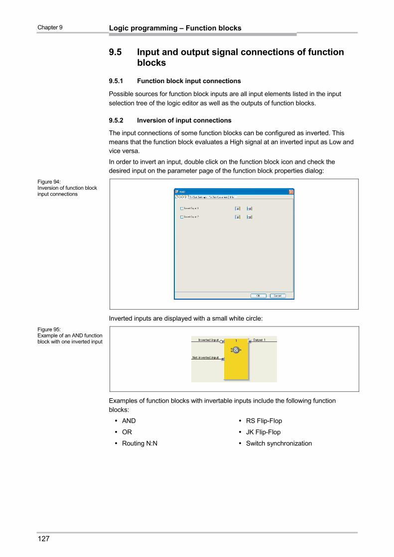
Chapter 9
127
Logic programming – Function blocks
9.5 Input and output signal connections of function blocks
9.5.1 Function block input connections
Possible sources for function block inputs are all input elements listed in the input
selection tree of the logic editor as well as the outputs of function blocks.
9.5.2 Inversion of input connections
The input connections of some function blocks can be configured as inverted. This means that the function block evaluates a High signal at an inverted input as Low and vice versa.
In order to invert an input, double click on the function block icon and check the desired input on the parameter page of the function block properties dialog:
Inverted inputs are displayed with a small white circle:
Examples of function blocks with invertable inputs include the following function blocks:
AND
OR
Routing N:N
RS Flip-Flop
JK Flip-Flop
Switch synchronization
Figure 94: Inversion of function block input connections
Figure 95: Example of an AND function block with one inverted input

Chapter 9
128
Logic programming – Function blocks
9.5.3 Function block output connections
Function blocks provide various output signal connections for connecting to physical outputs or to other function blocks.
The output of a function block can be connected to several subordinate function
blocks, but not to several output elements (physical outputs or EFI outputs). If you
want to control several physical outputs with a single function block, use the Routing
1:N function block. The behaviour of the outputs is explained at the description of the
individual function blocks.
You can choose whether error and diagnostics outputs are displayed. In the
configuration basic setting of the function blocks only the Enable output and some
further outputs are selected (e.g. Reset required). In order to display error and
diagnostics outputs increase the number of outputs on the I/O settings tab of the
function block properties.
Figure 96: In/Out configuration of the Safety gate monitoring function block

Chapter 9
129
Logic programming – Function blocks
9.5.4 Fault present output
Various function blocks dispose of the Fault present diagnostics output. In order to use it, activate the Use fault present checkbox on the I/O settings tab of the function block properties. The additional output “Fault present” is now displayed in the function block.
The Fault present output changes to High when an error has been detected on the basis of the configured function block parameters (e.g. discrepancy time error, function test error, synchronization error, etc.). When the Fault present output is High, the main output (e.g. the Enable output) changes to Low.
The Fault present output is set to Low if all errors are reset. The conditions to reset an error are described in the section of the respective function block.
Figure 97: Activating the Fault present output
Figure 98: Fault present output

Chapter 9
130
Logic programming – Function blocks
9.6 Timer values and logic execution time
The following has to be observed when selecting time monitoring functions for the
discrepancy time, synchronization time, pulse duration, muting time, etc.: The times
have to be greater than the logic execution time,
have a precision of +/– 10 ms in the evaluation in addition to the logic execution time.
The logic execution time depends on the number and type of the function blocks used.
It is a multiple of 4 ms. If the used logic execution time exceeds 100 %, then the logic
execution time is increased by 4 ms. The logic execution time is displayed in the logic
editor in the FB preview window. It has a precision of +/– 100 ppm (parts per million).
Effect of tested sensors
During a test signal the signal (bit) is “frozen”, i.e. the value that was present prior to
the test gap is retained for the duration of the test signal (and possibly also the max.
off-on delay). As a result a signal change can be delayed by this time, i.e. a pulse can
be longer or shorter.
9.7 Logic function blocks
9.7.1 NOT
Function block diagram
General description
The inverted input value applies at the output. If, for example, the input is High, the output is Low.
Truth table
The following applies for the truth table in this section:
“0” means logic Low.
“1” means logic High.
Truth table for NOT
Input Output
0 1
1 0
Note
Figure 99: Function block diagram for the NOT function block
Table 20: Truth table for the NOT function block

Chapter 9
131
Logic programming – Function blocks
9.7.2 AND
Function block diagram
General description
The output is High if all evaluated inputs are High. Up to eight inputs are evaluated.
Example: If eight emergency stop buttons are attached to the inputs of the function
block, the output would become Low as soon as one of the emergency stop buttons is
pressed.
Parameters of the function block
Parameter Possible values
Number of inputs 2 to 8
Invert input x Each input of this function block can be inverted (see Section 9.5.2).
Truth table
The following applies for the truth tables in this section:
“0” means logic Low.
“1” means logic High.
“x” means “any” = “0” or “1”.
Truth table for AND evaluation with one input
Input 1 Output 1
0 0
1 1
Truth table for AND evaluation with two inputs
Input 1 Input 2 Output 1
0 x 0
x 0 0
1 1 1
Figure 100: Function block diagram for the AND function block
Table 21: Parameters of the AND function block
Table 22: Truth table for AND evaluation with one input
Table 23: Truth table for AND evaluation with two inputs

Chapter 9
132
Logic programming – Function blocks
Truth table for AND evaluation with eight inputs
Input 1 Input 2 Input 3 Input 4 Input 5 Input 6 Input 7 Input 8 Output 1
0 x x x x x x x 0
x 0 x x x x x x 0
x x 0 x x x x x 0
x x x 0 x x x x 0
x x x x 0 x x x 0
x x x x x 0 x x 0
x x x x x x 0 x 0
x x x x x x x 0 0
1 1 1 1 1 1 1 1 1
9.7.3 OR
Function block diagram
General description
The output is High if any one of the evaluated inputs is High. Up to eight inputs are
evaluated.
Example: If eight light curtains are attached to the inputs of the function block, the
output would become High as soon as at least one of the light curtains is free.
Parameters of the function block
Parameter Possible values
Number of inputs 2 to 8
Invert input x Each input of this function block can be inverted (see Section 9.5.2).
Truth table
The following applies for the truth tables in this section:
“0” means logic Low.
“1” means logic High.
“x” means “any” = “0” or “1”.
Truth table for OR evaluation with one input
Input 1 Output 1
0 0
1 1
Table 24: Truth table for AND evaluation with eight inputs
Figure 101: Function block diagram for the OR function block
Table 25: Parameters of the OR function block
Table 26: Truth table for OR evaluation with one input

Chapter 9
133
Logic programming – Function blocks
Truth table for OR evaluation with two inputs
Input 1 Input 2 Output 1
0 0 0
1 x 1
x 1 1
Truth table for OR evaluation with eight inputs
Input 1 Input 2 Input 3 Input 4 Input 5 Input 6 Input 7 Input 8 Output 1
0 0 0 0 0 0 0 0 0
1 x x x x x x x 1
x 1 x x x x x x 1
x x 1 x x x x x 1
x x x 1 x x x x 1
x x x x 1 x x x 1
x x x x x 1 x x 1
x x x x x x 1 x 1
x x x x x x x 1 1
9.7.4 XOR (exclusive OR)
Function block diagram
General description
The output is High only if both inputs are complementary (i.e. with contrary values: one
input High and one input Low).
Truth table
The following applies for the truth table in this section:
“0” means logic Low.
“1” means logic High.
Truth table for XOR evaluation
Input 1 Input 2 Output 1
0 0 0
0 1 1
1 0 1
1 1 0
Table 27: Truth table for OR evaluation with two inputs
Table 28: Truth table for OR evaluation with eight inputs
Figure 102: Function block diagram for the Exclusive OR (XOR) function block
Table 29: Truth table for XOR evaluation

Chapter 9
134
Logic programming – Function blocks
9.7.5 XNOR (exclusive NOR)
Function block diagram
General description
The output is High only if both inputs are equivalent (have the same value: both inputs
High or both inputs Low).
Truth table
The following applies for the truth table in this section:
“0” means logic Low.
“1” means logic High.
Truth table for XNOR evaluation
Input 1 Input 2 Output 1
0 0 1
0 1 0
1 0 0
1 1 1
9.7.6 Multiple release
Function block diagram
General description
Using the multiple release function block an AND operator can be applied to up to 7
inputs along with the Release input (7-times AND).
Figure 103: Function block diagram for the Exclusive NOR (XNOR) function block
Table 30: Truth table for XNOR evaluation
Figure 104: Logic connections for the multiple release function block

Chapter 9
135
Logic programming – Function blocks
Function block parameters
Parameter Possible values
Number of inputs
(without Release input) 1 to 7
Invert input x Each input of this function block can be inverted (see section
9.5.2) Invert Release
Truth table
For the truth table identified in this section, the following applies:
“0” means logic low.
“1” means logic high.
Release Output X
0 0
1 Input x
9.7.7 RS Flip-Flop
Function block diagram
General description
The RS Flip-Flop function block stores the last value of the inputs Set or Reset. It is
used as a simple storage cell. The Reset signal has a higher priority than the Set
signal. If Set was High last, output Q is High and output /Q (Q inverted) is Low. If the
Reset input was High last, output Q is Low and output /Q is High.
Parameters of the function block
Parameter Possible values
Invert Set Each input of this function block can be inverted (see Section 9.5.2).
Invert Reset
Table 31: Parameters for the multiple release function block
Table 32: Truth table for the multiple release function block
Figure 105: Function block diagram for the RS Flip-Flop function block
Table 33: Parameters of the RS Flip-Flop function block

Chapter 9
136
Logic programming – Function blocks
Truth table for the RS Flip-Flop function block
The following applies for the truth table in this section:
“0” means logic Low.
“1” means logic High.
“n–1” references the preceding value.
“n” references the current value.
“x” means “any” = “0” or “1”.
Set Reset Output Q n–1 Output Q n Output /Q n
0 0 0 0 1
0 0 1 1 0
0 1 x 0 1
1 0 x 1 0
1 1 x 0 1
9.7.8 JK Flip-Flop
Function block diagram
General description
The JK Flip-Flop function block has three inputs. The J input and K input have only
an effect on the outputs when a rising edge is detected at the Clock input. In this
case …
If J input is High and K input is Low, the Q output will be High and the /Q (= Q inverted) output will be Low.
If J input is Low and K input is High, the Q output will be Low and the /Q output will be High.
If both inputs are Low, the last values of outputs Q and /Q will be held.
If both inputs are High, the outputs will toggle, i.e. their last values will be inverted.
Parameters of the function block
Parameter Possible values
Number of outputs 1 (Q)
2 (Q and /Q)
Invert J input Each input of this function block can be inverted (see Section 9.5.2). Invert Clock input
Invert K input
Table 34: Truth table for the RS Flip-Flop function block
Figure 106: Function block diagram for the JK Flip-Flop function block
Table 35: Parameters of the JK Flip-Flop function block

Chapter 9
137
Logic programming – Function blocks
Truth table for the JK Flip-Flop function block
The following applies for the truth table in this section:
“0” means logic Low.
“1” means logic High.
“↑” means that a rising edge has been detected at the input.
“↓” means that a falling edge has been detected at the input.
“n–1” references the preceding value.
“n” references the current value.
“x” means “any” = “0” or “1”.
The following truth table is valid for a configuration of the JK Flip-Flop function block with no input inverted.
J input K input Clock input Output Q n–1 Output Q n Output /Q n
x x 0, 1 or ↓ 0 0 1
x x 0, 1 or ↓ 1 1 0
0 0 ↑ 0 0 1
0 0 ↑ 1 1 0
0 1 ↑ 0 0 1
0 1 ↑ 1 0 1
1 0 ↑ 0 1 0
1 0 ↑ 1 1 0
1 1 ↑ 0 1 0
1 1 ↑ 1 0 1
9.7.9 Multiple memory
Function block diagram
General description
Using the multiple memory function block the state of up to 7 inputs can either be
forwarded unchanged or saved depending on the Latch input.
If the Latch input is low, the state of inputs 1 to 7 is forwarded unchanged to the
outputs 1 to 7.
If the Latch input changes from low to high, then the current state of inputs 1 to 7 is
saved and output on outputs 1 to 7 as long as the Latch input is high.
The Latch output corresponds to the Latch input.
Note
Table 36: Truth table for the JK Flip-Flop function block
Figure 107: Logic connections for the multiple memory function block

Chapter 9
138
Logic programming – Function blocks
Function block parameters
Parameter Possible values
Number of inputs
(without Latch input) 1 to 7
Invert input x Each input of this function block can be inverted (see
section9.5.2). Invert Save
Truth table
For the truth table identified in this section, the following applies:
“0” means logic low.
“1” means logic high.
"↑" means that a rising edge has been detected on the input.
"n-1" refers to the previous value.
"n" refers to the current value.
Latch input Latch output Output Xn
0 0 Input x
↑ ↑ Input x
1 1 Output xn–1
9.7.10 Clock generator
Function block diagram
General description
The Clock generator function block is used to generate a pulsed signal. When the
Enable input is High, the Clock output pulses from Low to High and back to Low in
accordance with the parameter settings of the function block. When the Enable input
is Low the Clock output becomes Low.
Table 37: Parameters for the multiple memory function block
Table 38: Truth table for the multiple memory function block
Figure 108: Function block diagram for the Clock generator function block
Figure 109: Parameter diagram for the Clock generator function block

Chapter 9
139
Logic programming – Function blocks
Parameters of the function block Parameter Possible values
Stopping mode Immediately
After last clock
Clock period (cycle duration) 2 to 65535 Duration = Parameter value × Logic execution time
Pulse time 1 to 65534 Duration = Parameter value × Logic execution time The pulse time has to be lower than the clock period.
If the logic execution time of the configuration changes (e.g. through addition or subtraction of function blocks), the clock period and the pulse time will change.
Sequence/timing diagram
9.7.11 Event counter (Up, Down and Up and down)
Function block diagram
General description
The Event counter function blocks allow to count events, either upward and/or downward. When a pre-defined overflow value is reached, this will be indicated on the Overflow output or, when zero is reached, this will be indicated on the Underflow output. Depending on the required counting direction there are the function blocks Event counter (Up), Event counter (Down) and Event counter (Up and down).
Parameters of the function block Parameter Possible values
Counter reset Manual
Automatic
Counter reload Manual
Automatic
Overflow limit Integer between 1 and 65,535. The overflow value limit has to be higher than or equal to the reload value.
Reload value Integer between 1 and 65,535
Min. restart pulse time 100 ms
350 ms
Min. reload pulse time 100 ms
350 ms
Table 39: Parameters of the Clock generator function block
Note
Figure 110: Timing diagram for the Clock generator function block
Figure 111: Function block diagram for the Event counter (Up and down) function block
Table 40: Parameter for the Event counter function blocks

Chapter 9
140
Logic programming – Function blocks
Inputs Up and Down
A rising edge (Low to High) at the Up input increases the value of the internal counter by “1”.
A rising edge (Low to High) at the Down input decreases the value of the internal counter by “1”.
If a rising edge (Low to High) occurs at the Up input as well as at the Down input (applies only to the Up and down event counter function block), the value of the internal counter remains unchanged.
Reset to zero
A valid pulse sequence with a Low-High-Low transition at the Reset to zero input sets the internal counter to “0”. This happens irrespective of whether the Overflow value has been reached or not and also irrespective of whether Reset to zero after overflow has been configured to Manual or Automatic.
The Min. restart pulse time defines the minimum required duration of the pulse at the Reset to zero input. Valid values are 100 ms and 350 ms. If the pulse duration is shorter than the configured minimum pulse time or longer than 30 s, the pulse is ignored.
Reload
A valid pulse sequence with a Low-High-Low transition at the Reload input sets the internal counter to the configured value of the Reload value parameter. This happens irrespective of whether Counter reload has been configured to Manual or Automatic.
The Min. reload pulse time defines the minimum required duration of the pulse at the Reload input. Valid values are 100 ms and 350 ms. If the pulse duration is shorter than the configured minimum pulse time or longer than 30 s, the pulse is ignored.
Ensure that the transitions of the signals for resetting or reloading value fulfill
the requirements!
In case of a short-circuit to High (to 24 V DC) at a physical input, the evaluated signal
can have a pulse when the signal is reset due to the short-circuit detection. If such a
pulse can result in a dangerous state in the machine, the following points have to be
observed:
Ensure protected cable laying for the signal line (due to cross-circuiting to other
signal lines).
No short-circuit detection, i.e. do not reference to test outputs.
Overflow limit and Counter reset
The Counter reset parameter determines what happens when the counter value
reaches the Overflow limit. If this parameter is configured to Automatic, and the
internal counter equals the Overflow limit, the Overflow output becomes High for the
duration of the logic execution time. The value of the internal counter is subsequently
reset to zero.
If the Counter reset parameter is configured to Manual and the Overflow limit has
been reached, the Overflow output is set to High and remains High until the counter
value changes again, either by counting downward, by a valid Reset to zero pulse
sequence or by a valid pulse sequence at the Reload input, if the start value is smaller
than the overflow value. Until then, all further “Up” counting pulses are ignored.
ATTENTION

Chapter 9
141
Logic programming – Function blocks
Reload value and Counter reload
The Counter reload parameter determines what happens when the counter value
reaches “0”. If this parameter is configured to Automatic and the internal counter
equals “0”, the Underflow output becomes High for the duration of the logic execution
time. The value of the internal counter is subsequently set to the configured Reload
value.
If the Counter reload parameter is configured to Manual and the lower limit, i.e. “0”, has been reached, the Underflow output is set to High and remains High until the counter value changes again, either by counting upward or by a valid pulse sequence at the Reload input. Until then, all further “Down” counting pulses are ignored.
Truth table for the Event counter function blocks (Up, Down and Up and down)
The following applies for the truth table in this section:
“0” means logic Low
“1” means logic High
“↑” means that a rising edge has been detected at the input
“↓” means that a falling edge has been detected at the input
“n–1” references the preceding value
“n” references the current value
“Y” references the value of the internal counter
“X” means “any”. E.g. the Reset to zero input and the Reload input have priority
over the Up input and the Down input.
Up Down Reset to zero
Reload Counter valuen–1
Counter valuen
Overflow n Underflow n
↑ 0, 1 or ↓
0 0 Y Y+1 0 0
↑ 0, 1 or ↓
0 0 Y Y+1 =
Overflow value
1 0
↑ 0, 1 or ↓
0 0 Y =
Overflow value
Y = Overflow
value 1 0
0, 1 or ↓
↑ 0 0 Y Y–1 0 0
0, 1 or ↓
↑ 0 0 Y Y–1 = 0 0 1
0, 1 or ↓
↑ 0 0 Y = 0 Y = 0 0 1
↑ ↑ 0 0 Y Y 0 0
X X 1 0 Y Reset to
zero 0 0
X X 0 1 Y Reload 0 0
X X 1 1 Y Reset to
zero 0 0
Table 41: Truth table for the Event counter function blocks (Up, Down and Up/Down)

Chapter 9
142
Logic programming – Function blocks
9.7.12 Fast shut off and Fast shut off with bypass
Function block diagram
General description
The Fast shut off and Fast shut off with bypass function block is used to minimize the response time of a safety switching path within the MELSEC-WS safety controller. To use this block, both the input and output for the switching path must be connected to the same safety I/O module (i.e. WS0-XTIO). This is necessary because the Fast shut off function block generates a direct switch off at the safety I/O module resulting in a shorter switch off time which is independent of the logic execution time.
For the Fast shut off function block, the consequence of this is that logic between the Fast shut off input and the Fast shut off output cannot hinder a switch off when the Fast shut off is activated.
The Fast shut off with bypass function block however allows to temporarily bypass the Fast shut off function using the bypass input.
The Fast shut off with bypass function block is only available with WS0-XTIO with firmware version V2.00 or higher.
Example: In the following logic example, the C4000 will switch off the Q2 motor.
Simple logic such as this can be accomplished within the Fast shut off function block itself (see how to configure below).
The signal path from the output of the Fast shut off function block to the physical output that is selected in the Fast shut off function block must be configured in such a way that switching off of the output of the Fast shut off function block always results in a direct switching off of the physical output as well. Typically the AND, Restart or EDM function blocks can be used in the signal chain for this. An OR function block however does not comply to this rule.
Figure 112: Function block diagram for the Fast shut off and Fast shut off with bypass function blocks
Note
Figure 113: Fast shut off example
Note

Chapter 9
143
Logic programming – Function blocks
Always consider the total response time of the entire safety function!
The response time of the Fast shut off function block is not the same as the total response time of the entire safety function. The total response time includes multiple parameters outside of this function block. For a description of how to calculate the total response time of the MELSEC-WS safety controller please see the Safety Controller User’s Manual.
Parameters of the function block
Parameter Possible values
Number of inputs Fast shut off: 1 to 8
Fast shut off with bypass: 1 to 7
Select output for fast shut
off
All outputs of the safety I/O module whose inputs are connected
to the function block, if the output is not already used for Fast
shut off.
How to configure the Fast shut off function block:
The following example shows the function with three light curtains attached to a Fast shut off function block.
To configure the Fast shut off function block perform the following steps:
Connect input elements to the function block. Double click the function block to open the configuration dialog and click the I/O Settings tab.
ATTENTION
Table 42: Parameters of the Fast shut off function block
Figure 114: Configuration example for Fast shut off with three light curtains
Figure 115: I/O settings dialog for the Fast shut off function block

Chapter 9
144
Logic programming – Function blocks
Choose the number of inputs which you would like to attach to the function block.
Then click the Parameter tab and choose the zone by checking the boxes.
If only AND logic is needed, leave the Zone 2 AND function block inputs unchecked. If additional OR logic is required in the application, the inputs can be combined using the Zone 1 and Zone 2 AND function blocks and subsequently connecting to the internal OR function block.
Finally select the output for Fast shut off.
Figure 116: Parameter settings dialog for the Fast shut off function block
Note
Figure 117: Output selection for Fast shut off

Chapter 9
145
Logic programming – Function blocks
At this point, the selected inputs and outputs are linked to each other such that the output cannot be moved to another position and the inputs must stay on the WS0-XTIO module in the hardware configuration. The elements which are linked are shown in the hardware configuration in orange.
These links are broken when the Fast shut off function block is edited or deleted.
Fast shut off with bypass
In some applications it may be necessary to bypass the Fast shut off. This could be, e.g. in a safe machine setup mode, in which the machine can be operated only in jog mode. To this purpose, the Fast shut off with bypass function block is available. It is used and configured in the same way as the Fast shut off function block. The only difference is that one of the inputs of the Fast shut off with bypass function block is used for the Bypass function. If the Bypass input is High, the Fast shut off with bypass function block is bypassed.
Ensure the system or machine is in a safe condition when using the bypass
function! As long as the bypass function is active, any stopping condition, e.g. the infringement of a protective field will not lead to a shut-off of the machine. You must ensure that other protective measures are forcibly activated during the bypass, e.g. the safe machine setup mode, so that the machine cannot endanger persons or parts of the system during the bypass function.
Take the prolonged response time into account when the Bypass is
deactivated! If the Bypass input is being deactivated while a switching-off condition exists, the outputs will switch off only with the normal response time of the application. The minimized response time for Fast shut off does not apply for the Bypass input. Consider this for your risk analysis and avoidance strategy. Otherwise the operator of the machine will be in danger.
Figure 118: Hardware configuration view of inputs and outputs linked to Fast shut off
ATTENTION

Chapter 9
146
Logic programming – Function blocks
Unlike the other inputs and outputs of this function block, the Bypass input can be
connected to an output of another function block as well as to any other input
element which may also be moved to another module in the hardware
configuration.
The Bypass input has an on-delay of 3 logic cycles to compensate delays due to
logic processing time and transmission time of the FLEXBUS+. The delay ensures
that the I/O module has received the bypass signal before it is used for the further
logic processing in the Fast shut off function block. As a result of the delay, the
Bypass input must be High 3 logic cycles in advance to successfully inhibit the fast
shut off. If this condition is fulfilled, then the Fast shut off output of the function block
and the physical output at the I/O module will both remain High.
The Fast shut off directly switches off the connected output of the WS0-XTIO while
subsequent logic will be ignored. Therefore it is not possible to implement further
bypass conditions in the logic editor between the output of the Fast shut off function
block and the connected WS0-XTIO.
Be aware that in the logic online monitor the value of the connected WS0-XTIO
output may differ from the effective value at the physical output of the WS0-XTIO.
For example the connected output can be Low as a result of the subsequent logic
while the output of the Fast shut off function block and the physical output of the
WS0-XTIO High because the Bypass input is High.
If your application requires that the output of the WS0-XTIO module can be
switched off independently of an existing bypass condition (e.g. emergency stop),
then the underlying logic must be realised in a way that the respective shut-down
signal (e.g. emergency stop) switches off the bypass signal for the function block as
well, as shown in the following example:
Notes
Figure 119: Example for Fast shut off with bypass with more than one bypass conditions

Chapter 9
147
Logic programming – Function blocks
9.7.13 Edge detection
one bypass conditionsFunction block diagram
General description
The Edge detection function block is used to detect a positive (rising) or negative
(falling) edge of the input signal. The function block can be configured to detect a
positive edge, a negative edge or both. If an edge corresponding to the parameter
settings is detected, the Edge Detected output changes to High for the duration of the
logic execution time.
Parameters of the function block
Parameter Possible values
Edge detection Positive
Negative
Positive and negative
Sequence/timing diagram
Figure 120: Function block diagram for the Edge detection function block
Table 43: Parameters of the Edge detection function block
Figure 121: Timing diagram for the Edge detection function block

Chapter 9
148
Logic programming – Function blocks
9.7.14 Binary encoder
Function block diagram
General description
The Binary encoder function block encodes depending on the current configuration a one-out-of-N (one-hot) or a priority code to a binary code (Output A = 20, Output B = 21, Output C = 22). 2 to 8 inputs can be configured. The number of outputs depends on the number of inputs. An optional Fault present output is available.
Parameters of the function block
Parameter Possible values
Number of inputs 2 to 8
Encoder mode One out of N
Priority
Priority-to-binary (Input 1 dominant)
Use fault present With
Without
One out of N
In One out of N mode, only one input may be High at the same time. The outputs are set dependent on the index (input 1 = 1, input 2 = 2, …) of the High input. If all inputs are Low or if more than one input is High at the same time, all outputs are set to Low and Fault present becomes High.
Priority
In Priority mode, more than one input may be High at a time. The outputs are set dependent on the High input with the highest index (input 1 = 1, input 2 = 2, …). If all inputs are Low at the same time, all outputs are set to Low and Fault present becomes High.
Figure 122: Function block diagram for the Binary encoder function block
Table 44: Parameters of the Binary encoder function block

Chapter 9
149
Logic programming – Function blocks
Priority-to-binary (input 1 dominant)
In this mode, all outputs are set to Low, if input 1 is High, regardless of the other inputs. If input 1 is Low, the function block behaves as in Priority mode. If all inputs are Low at the same time, all outputs are set to Low and Fault present becomes High.
Truth tables for the Binary encoder function block
The following applies for the truth tables in this section:
“0” means logic Low.
“1” means logic High.
“x” means “any” = “0” or “1”.
Input 2 Input 1 Output A Fault
present
0 0 0 1
0 1 0 0
1 0 1 0
1 1 0 1
Input 8 Input 7 Input 6 Input 5 Input 4 Input 3 Input 2 Input 1 Output
C Output
B Output
A Fault
present
0 0 0 0 0 0 0 0 0 0 0 1
0 0 0 0 0 0 0 1 0 0 0 0
0 0 0 0 0 0 1 0 0 0 1 0
0 0 0 0 0 1 0 0 0 1 0 0
0 0 0 0 1 0 0 0 0 1 1 0
0 0 0 1 0 0 0 0 1 0 0 0
0 0 1 0 0 0 0 0 1 0 1 0
0 1 0 0 0 0 0 0 1 1 0 0
1 0 0 0 0 0 0 0 1 1 1 0
More than one input = 1 0 0 0 1 Table 46: Truth table for the Binary encoder function block with 8 inputs in One out of N mode
Input 2 Input 1 Output A Fault
present
0 0 0 1
0 1 0 0
1 x 1 0
Table 45: Truth table for the Binary encoder function block with 2 inputs in One out of N mode
Table 47: Truth table for the Binary encoder function block with 2 inputs in Priority mode

Chapter 9
150
Logic programming – Function blocks
Input 8 Input 7 Input 6 Input 5 Input 4 Input 3 Input 2 Input 1 Output
C Output
B Output
A Fault
present
0 0 0 0 0 0 0 0 0 0 0 1
0 0 0 0 0 0 0 1 0 0 0 0
0 0 0 0 0 0 1 x 0 0 1 0
0 0 0 0 0 1 x x 0 1 0 0
0 0 0 0 1 x x x 0 1 1 0
0 0 0 1 x x x x 1 0 0 0
0 0 1 x x x x x 1 0 1 0
0 1 x x x x x x 1 1 0 0
1 x x x x x x x 1 1 1 0 Table 48: Truth table for the Binary encoder function block with 8 inputs in Priority mode
Input 2 Input 1 Output A Fault
present
0 0 0 1
x 1 0 0
1 0 1 0
Input 8 Input 7 Input 6 Input 5 Input 4 Input 3 Input 2 Input 1 Output
C Output
B Output
A Fault
present
0 0 0 0 0 0 0 0 0 0 0 1
x x x x x x x 1 0 0 0 0
0 0 0 0 0 0 1 0 0 0 1 0
0 0 0 0 0 1 x 0 0 1 0 0
0 0 0 0 1 x x 0 0 1 1 0
0 0 0 1 x x x 0 1 0 0 0
0 0 1 x x x x 0 1 0 1 0
0 1 x x x x x 0 1 1 0 0
1 x x x x x x 0 1 1 1 0 Table 50: Truth table for the Binary encoder function block with 8 inputs in Priority mode with dominant input 1
Evaluate Fault present if the Binary encoder function block is used for safety purposes!
If you use the Binary encoder function block for safety relevant logic, you may have to evaluate the Fault present output depending on your application. This is the only way to distinguish whether only input 1 is High or if an invalid input state exists. In both cases, all outputs will be Low.
Table 49: Truth table for the Binary encoder function block with 2 inputs in Priority mode with dominant input 1
ATTENTION
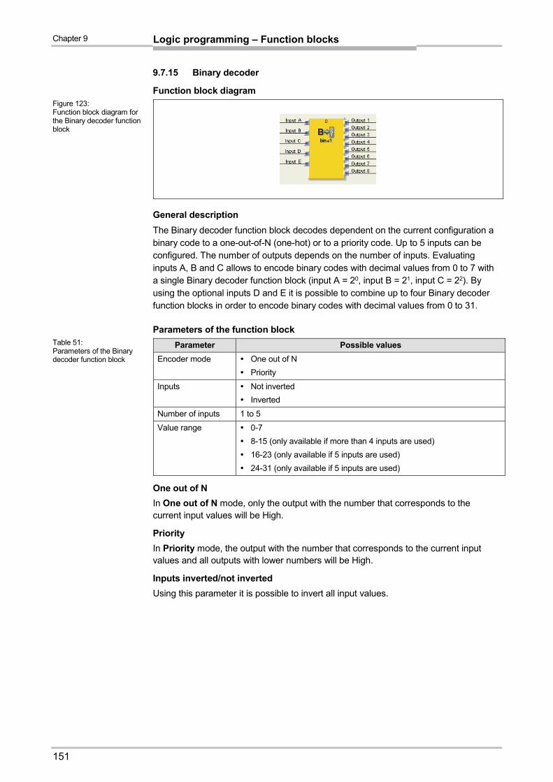
Chapter 9
151
Logic programming – Function blocks
9.7.15 Binary decoder
Function block diagram
General description
The Binary decoder function block decodes dependent on the current configuration a binary code to a one-out-of-N (one-hot) or to a priority code. Up to 5 inputs can be configured. The number of outputs depends on the number of inputs. Evaluating inputs A, B and C allows to encode binary codes with decimal values from 0 to 7 with a single Binary decoder function block (input A = 20, input B = 21, input C = 22). By using the optional inputs D and E it is possible to combine up to four Binary decoder function blocks in order to encode binary codes with decimal values from 0 to 31.
Parameters of the function block
Parameter Possible values
Encoder mode One out of N
Priority
Inputs Not inverted
Inverted
Number of inputs 1 to 5
Value range 0-7
8-15 (only available if more than 4 inputs are used)
16-23 (only available if 5 inputs are used)
24-31 (only available if 5 inputs are used)
One out of N
In One out of N mode, only the output with the number that corresponds to the current input values will be High.
Priority
In Priority mode, the output with the number that corresponds to the current input values and all outputs with lower numbers will be High.
Inputs inverted/not inverted
Using this parameter it is possible to invert all input values.
Figure 123: Function block diagram for the Binary decoder function block
Table 51: Parameters of the Binary decoder function block

Chapter 9
152
Logic programming – Function blocks
Truth tables for the Binary decoder function block
The following applies for the truth table in this section:
“0” means logic Low.
“1” means logic High.
Input A Output 2 Output 1
0 0 1
1 1 0
Input B Input A Output 4 Output 3 Output 2 Output 1
0 0 0 0 0 1
0 1 0 0 1 0
1 0 0 1 0 0
1 1 1 0 0 0
Input C Input B Input A Output 8 Output 7 Output 6 Output 5 Output 4 Output 3 Output 2 Output 1
0 0 0 0 0 0 0 0 0 0 1
0 0 1 0 0 0 0 0 0 1 0
0 1 0 0 0 0 0 0 1 0 0
0 1 1 0 0 0 0 1 0 0 0
1 0 0 0 0 0 1 0 0 0 0
1 0 1 0 0 1 0 0 0 0 0
1 1 0 0 1 0 0 0 0 0 0
1 1 1 1 0 0 0 0 0 0 0
Table 54: Truth table for the Binary decoder with 3 inputs in One out of N mode
Input A Output 2 Output 1
0 0 1
1 1 1
Input B Input A Output 4 Output 3 Output 2 Output 1
0 0 0 0 0 1
0 1 0 0 1 1
1 0 0 1 1 1
1 1 1 1 1 1
Input C Input B Input A Output 8 Output 7 Output 6 Output 5 Output 4 Output 3 Output 2 Output 1
0 0 0 0 0 0 0 0 0 0 1
0 0 1 0 0 0 0 0 0 1 1
0 1 0 0 0 0 0 0 1 1 1
0 1 1 0 0 0 0 1 1 1 1
1 0 0 0 0 0 1 1 1 1 1
1 0 1 0 0 1 1 1 1 1 1
1 1 0 0 1 1 1 1 1 1 1
1 1 1 1 1 1 1 1 1 1 1
Table 57: Truth table for the Binary decoder with 3 inputs in Priority mode
Table 52: Truth table for the Binary decoder with 1 input in One out of N mode
Table 53: Truth table for the Binary decoder with 2 inputs in One out of N mode
Table 55: Truth table for the Binary decoder with 1 input in Priority mode
Table 56: Truth table for the Binary decoder with 2 inputs in Priority mode

Chapter 9
153
Logic programming – Function blocks
Evaluation of more than three inputs
If 4 or 5 inputs are used, up to four Binary decoder function blocks can be combined in order to encode binary codes with values from 0 to 31.
When using multiple Binary decoder function blocks in combination you have to configure the Value range option of each function block for the value range it shall cover. This range depends on the values of inputs D and E.
Input D Outputs
0 0-7
1 8-15
Input E Input D Outputs
0 0 1-7
0 1 8-15
1 0 16-23
1 1 24-31
If Input D and Input E are set to the same value as the Value range parameter
(e.g. if Input E = 1, Input D = 0 and Value range is set to 16-23), the function block
will behave as shown in the truth tables above, depending on the values of inputs
A, B and C and the configured Encoder mode (One out of N or Priority).
If Input D and Input E are set to a lower value than the Value range parameter
(e.g. Input E = 0, Input D = 1 and Value range = 16-23) all outputs are Low
independent of the configured Encoder mode (One out of N or Priority).
If Input D and Input E are set to a higher value than the Value range parameter
(e.g. Input E = 1, Input D = 1 and Value range = 16-23) …
– in One out of N mode, all outputs are set to Low,
– in Priority mode, all outputs are set to High.
Figure 124: Combination of four Binary decoder function blocks
Table 58: Value range of the Binary decoder function block depending on input D
Table 59: Value range of the Binary decoder function block depending on inputs D and E

Chapter 9
154
Logic programming – Function blocks
9.7.16 Log generator
Function block diagram
General description
The Log generator function block monitors up to eight inputs. If at one of these inputs an edge is detected according to the configuration, the function block sets the corresponding output to High for the duration of the logic execution time and adds a user defined text message to the diagnostics history. This can be read out in online mode using the Setting and Monitoring Tool diagnostic function (see Section 5.8).
These messages will be deleted when the voltage supply for the MELSEC-WS safety controller is interrupted.
Parameters of the function block
Parameter Possible values
Number of inputs 1 to 8
Messages Up to 64 user defined messages per project.
Message assignment Rising edge
Falling edge
Rising or falling edge
How to configure the Log generator function block:
The following example shows the Log generator function block with two emergency stop buttons and a safety switch attached.
Figure 125: Function block diagram for the Log generator function block
Note
Table 60: Parameters of the Log generator function block
Figure 126: Configuration example for Log generator with two emergency stop buttons and a safety switch

Chapter 9
155
Logic programming – Function blocks
To configure the Log generator function block, proceed as follows:
Connect input elements to the function block. Double click on the function block to open the configuration dialog and click then on the I/O settings tab.
Choose the number of inputs that you wish to attach to the function block.
Then click the Messages tab and enter the messages that shall be output in the diagnostics.
– The messages entered are valid globally for all Log generator function blocks used in a project.
– In a single project, you can enter up to 64 different messages with a length of up to 32767 characters each.
– Using the Import from CSV and Export to CSV buttons at the top left of the window, you can save the messages to a text file in CSV (comma separated values) format or import messages from a CSV file.
Figure 127: I/O settings for the Log generator function block
Figure 128: Messages of the Log generator function block
Note

Chapter 9
156
Logic programming – Function blocks
Then click the Message assignment tab. Assign the desired message to each used input and choose the input condition that must be fulfilled for the related message to be sent (rising edge, falling edge or rising and falling edge).
The message assignment can not be exported or imported.
Message priority
If more than one conditions are fulfilled at the same time, the following priorities apply:
On a single Log generator function block, the input with the lower number is prioritized, i.e. the message triggered by this input will be logged first.
If several Log generator function blocks are used, the function block with the lower function block index is prioritized, i.e. the messages generated by this function block will be logged first.
9.7.17 Routing 1:N
Function block diagram
General description
The Routing 1:N function block passes an input signal from a preceding function block
to up to eight output signals. This function block makes it possible to connect an
output of a function block or an input element with several output elements (e.g.
outputs of a WS0-XTIO module, CPU marker). It is not needed, however, for the
connection to several function block inputs, because this can be done directly.
Parameters of the function block
Parameter Possible values
Number of outputs 1 to 8
Note Figure 129: Message assignment for the Log generator function block
Figure 130: Function block diagram for the Routing 1:N function block
Table 61: Parameters of the Routing 1:N function block

Chapter 9
157
Logic programming – Function blocks
9.7.18 Routing N:N
Function block diagram
General description
The Routing N:N function block passes up to eight input signals parallel to up to eight
outputs. The input signal can originate from a preceding function block or directly from
a physical input.
Parameters of the function block
Parameter Possible values
Number of inputs 1 to 8
Invert input x Each input of this function block can be inverted (see Section 9.5.2).
Figure 131: Function block diagram for the Routing N:N function block
Table 62: Parameters of the Routing N: N function block

Chapter 9
158
Logic programming – Function blocks
9.8 Application-specific function blocks
9.8.1 Reset
Function block diagram
General description
The Reset function block can be used to fulfill the normative requirements for safety
applications on acknowledging a manual safety stop and the subsequent request to
restart the application. Typically, each safety logic system of a MELSEC-WS safety
controller contains a Reset function block.
Parameters of the function block
Parameter Possible values
Min. reset pulse time 100 ms
350 ms
Number of inputs 2 to 8 (= 1 to 7 Release inputs activated)
Release condition fulfilled output
The Release condition fulfilled output displays the result of an AND combination of all activated Release inputs. It is High if all activated Release inputs are High.
Reset required output
The Reset required output shows by pulsing at 1 Hz that the function block expects a valid reset pulse at the Reset input so that the Enable output can become High. This is the case if the Release condition fulfilled output is High, i.e. all activated Release inputs are High, but the Enable output is still Low. Typically this output is used to control a signal lamp.
Enable output
The Enable output becomes High, if the Release condition fulfilled output is High and a valid reset pulse has been detected at the Reset input, provided that all activated Release inputs remain High.
The Min. reset pulse time defines the minimum required duration of the pulse at the Reset input. Valid values are 100 ms and 350 ms. If the pulse duration is shorter than the configured minimum pulse time or longer than 30 s, the pulse is ignored.
The Enable output becomes Low, if one or more Release inputs become Low.
Figure 132: Function block diagram for the Reset function block
Table 63: Parameters of the Reset function block

Chapter 9
159
Logic programming – Function blocks
Ensure that the transitions of the signals for resetting fulfill the requirements!
In case of a short-circuit to High (to 24 V DC) at a physical input, the evaluated signal
can have a pulse when the signal is reset due to the short-circuit detection. If such a
pulse can result in a dangerous state in the machine, the following points have to be
observed:
Ensure protected cable laying for the signal line (due to cross-circuiting to other signal lines).
No short-circuit detection, i.e. do not reference to test outputs.
Sequence/timing diagram
9.8.2 Restart
Function block diagram
General description
The internal logic of the Restart function block has the same functionality as the Reset
function block. The Restart function block allows graphic differentiation between the
function blocks with regard to the observation of application standards for
acknowledging a manual restart request.
Parameters of the function block
Parameter Possible values
Min. restart pulse time 100 ms
350 ms
Number of inputs 2 to 8 (= 1 to 7 Release inputs activated)
Release condition fulfilled output
The Release condition fulfilled output displays the result of an AND combination of all activated Release inputs. It is High if all activated Release inputs are High.
ATTENTION
Figure 133: Sequence/timing diagram for the Reset function block
Figure 134: Function block diagram for the Restart function block
Table 64: Parameters of the Restart function block

Chapter 9
160
Logic programming – Function blocks
Restart required output
The Restart required output shows by pulsing at 1 Hz that the function block expects a valid restart pulse at the Restart input so that the Enable output can become High. This is the case if the Release condition fulfilled output is High, i.e. all activated Release inputs are High, but the Enable output is still Low. Typically this output is used to control a signal lamp.
Enable output
The Enable output becomes High, if the Release condition fulfilled output is High and a valid restart pulse has been detected at the Restart input, provided that all activated Release inputs remain High.
The Min. restart pulse time defines the minimum required duration of the pulse at the Restart input. Valid values are 100 ms and 350 ms. If the pulse duration is shorter than the configured minimum pulse time or longer than 30 s, the pulse is ignored.
The Enable output becomes Low, if one or more Release inputs become Low.
Ensure that the transitions of the signals for restarting fulfill the requirements!
In case of a short-circuit to High (to 24 V DC) at a physical input, the evaluated signal
can have a pulse when the signal is reset due to the short-circuit detection. If such a
pulse can result in a dangerous state in the machine, the following points have to be
observed:
Ensure protected cable laying for the signal line (due to cross-circuiting to other signal lines).
No short-circuit detection, i.e. do not reference to test outputs.
Sequence/timing diagram
ATTENTION
Figure 135: Sequence/timing diagram for the Restart function block

Chapter 9
161
Logic programming – Function blocks
9.8.3 Off-delay timer
Function block diagram
General description
The Off-delay timer function block delays the switching-off of the output signal by a
configurable duration.
Parameters of the function block
Parameter Possible values
Delay time 0 = disabled.
0 to 300 seconds in steps of 10 ms.
If the value is not 0, it has to be greater than the logic execution time.
The timer begins with the delay sequence when a falling edge (High to Low) on the
input occurs. If the timer has expired after the configured delay period, the Enable
output changes also to Low, provided the input remains Low. If the input changes to
High, the Enable output is set to High immediately and the delay timer is reset.
Sequence/timing diagram
Figure 136: Function block diagram for the Off-delay timer function block
Table 65: Parameters of the Off-delay timer function block
Figure 137: Sequence/timing diagram for the Off-delay timer function block

Chapter 9
162
Logic programming – Function blocks
9.8.4 Adjustable off-delay timer
Function block diagram
General description
The Adjustable off-delay timer function block delays the switching-off of the Enable output by an adjustable duration. Four individual delay times can be configured, each of which can be activated via a related Delay input. The overall delay is the sum of all activated delay times.
Parameters of the function block
Parameter Possible values
Off delay time 1 0 = disabled.
0 to 600 seconds in steps of 10 ms.
If the value is not 0, the related input is activated. In this case, the value has to be greater than the logic execution time.
The overall delay (sum of all delay times) is limited to 600 seconds.
Off delay time 2
Off delay time 3
Off delay time 4
The timer begins with the delay sequence when a falling edge (High to Low) occurs at the Control input. If the timer has expired after the selected overall delay period, the Enable output changes also to Low, provided the Control input remains Low. If the Control input changes to High, the Enable output is set to High immediately and the delay timer is reset.
If during a running delay sequence any Delay input changes its value, the Time changed output changes to High and remains High until the Control input becomes High again.
The effective overall delay time depends on the Delay inputs that were High at the moment when the falling edge at the Control input has occurred. This means that a change on the Delay inputs during a delay sequence has no effect on the current delay sequence.
If the Control input is Low in the first logic cycle after transition from the Stop state to the Run state, the Enable output remains Low as well.
Sequence/timing diagram
Figure 138: Function block diagram for the Adjustable off-delay timer function block
Table 66: Parameters of the Adjustable off-delay timer function block
Figure 139: Sequence/timing diagram for the Adjustable off-delay timer function block with Off delay time 1 and Off delay time 2

Chapter 9
163
Logic programming – Function blocks
9.8.5 On-delay timer
Function block diagram
General description
The On-delay timer function block delays the switching-on of the output signal by a
specified duration.
Parameters of the function block
Parameter Possible values
Delay time 0 = disabled.
0 to 300 seconds in steps of 10 ms.
If the value is not 0, it has to be greater than the logic execution time.
The timer begins with the delay sequence when a rising edge (Low to High) on the
input occurs. If the timer has expired after the configured delay period, the Enable
output changes also to High, provided the input remains High. If the input changes to
Low, the Enable output is set to Low immediately and the delay timer is reset.
Sequence/timing diagram
Figure 140: Function block diagram for the On-delay timer function block
Table 67: Parameters of the On-delay timer function block
Figure 141: Sequence/timing diagram for the On-delay timer function block

Chapter 9
164
Logic programming – Function blocks
9.8.6 Adjustable on-delay timer
Function block diagram
General description
The Adjustable on-delay timer function block delays the switching-on of the Enable output by an adjustable duration. Four individual delay times can be configured, each of which can be activated via a related Delay input. The overall delay is the sum of all activated delay times.
Parameters of the function block
Parameter Possible values
On delay time 1 0 = disabled.
0 to 600 seconds in steps of 10 ms.
If the value is not 0, the related input is activated. In this case, the value has to be greater than the logic execution time.
The overall delay (sum of all delay times) is limited to 600 seconds.
On delay time 2
On delay time 3
On delay time 4
The timer begins with the delay sequence when a rising edge (Low to High) occurs at the Control input. If the timer has expired after the selected overall delay period, the Enable output changes also to High, provided the Control input remains High. If the Control input changes to Low, the Enable output is set to Low immediately and the delay timer is reset.
If during a running delay sequence any Delay input changes its value, the Time changed output changes to High and remains High until the Control input becomes Low again.
The effective overall delay time depends on the Delay inputs that were High at the moment when the rising edge at the Control input has occurred. This means that a change on the Delay inputs during a delay sequence has no effect on the current delay sequence.
If the Control input is High in the first logic cycle after transition from the Stop state to the Run state, the Enable output becomes High immediately without delay.
Sequence/timing diagram
Figure 142: Function block diagram for the Adjustable on-delay timer function block
Table 68: Parameters of the Adjustable on-delay timer function block
Figure 143: Sequence/timing diagram for the Adjustable on-delay timer function block with On delay time 1 and On delay time 2

Chapter 9
165
Logic programming – Function blocks
9.8.7 EDM (External device monitoring)
Function block diagram
General description
The EDM (External device monitoring) function block allows to control an external device (e.g. a contactor) and to check on the basis of its feedback signal whether it has switched as expected. To this purpose the external device is connected to Output 1 and/or Output 2. The feedback signal is connected to the EDM feedback input. The Monitored input is connected to the logic signal that represents the desired state for the external device, e.g. the Enable output of a Reset function block.
Parameters of the function block
Parameter Possible values
Max. feedback delay 10 to 1,000 ms in 10 ms steps. The value has to be greater than the logic execution time.
Use fault present With
Without Use Error reset
Output 1 and Output 2
Both outputs have always the same value. This way, two outputs are available to connect two output elements directly.
Output 1 and Output 2 become High, if the EDM feedback is High and the Monitored input changes from Low to High subsequently.
Output 1 and Output 2 become Low, if the Monitored input is Low or if an EDM error is present (EDM error output is High).
EDM error and Fault present
Generally it is expected that the EDM feedback input always takes the inverted value of the Monitored input before the configured Max. feedback delay (TEDM) has expired.
The EDM error and Fault present outputs become High, if …
the Monitored input changes from Low to High and the EDM feedback input is Low (irrespective of TEDM), or
the Monitored input changes from Low to High and the EDM feedback input does not change from High to Low before TEDM has expired, or
the Monitored input changes from High to Low and the EDM feedback input does not change from Low to High before TEDM has expired, or
the Monitored input is Low and the EDM feedback input changes to Low for longer than TEDM, or
the Monitored input is High and the EDM feedback input changes to High for longer than TEDM.
Figure 144: Function block diagram for the EDM function block
Table 69: Parameters of the EDM function block

Chapter 9
166
Logic programming – Function blocks
The EDM error and Fault present outputs become Low, if a signal sequence is detected that sets Output 1 and Output 2 to High.
Alternatively an error can also be reset with the aid of the Error reset input (from firmware V3.02). The EDM error and Fault present outputs change to low if the Error reset input changes from low to high and one of the two following conditions is met:
The Control input is low and the EDM feedback is high.
Or:
The Control input is high and the EDM feedback is low.
Only if the second of these two possible conditions is met are the outputs Output 1 and Output 2 also high.
If you require a delay of the Output 1 and Output 2 signals, then you have to realize the output delay with another function block before the EDM function block and not after it. Otherwise this can result in an EDM error.
Sequence/timing diagram
9.8.8 Valve monitoring
Function block diagram
General description
The Valve monitoring function block allows to control valves and to check on the basis
of their feedback signals whether they have switched as expected.
To this purpose the valves are connected with Output 1a to Output 2b. The feedback
signals are connected to the Feedback 1 and Feedback 2 inputs. The Control 1 and
Control 2 inputs are connected to the logic signal that represents the desired state for
the valve, e.g. the Enable output of a Reset function block. Depending on the valve
type, some of the signals are not used.
Three different valve types are available: Single valves, double valves and directional
valves.
Note
Figure 145: Sequence/timing diagram for the External device monitoring (EDM) function block
Figure 146: Function block diagram for the Valve monitoring function block, configured for a directional valve

Chapter 9
167
Logic programming – Function blocks
Parameters of the function block
Parameter Possible values
Reset condition Manual reset
Auto reset
Continuous monitoring when valve is active
No
Yes
Valve mode Single (Control 1, Output 1a, Output 1b, Feedback 1 activated)
Double (Control 1, Output 1a, Output 1b, Feedback 1, Output 2a, Output 2b, Feedback 2 activated)
Directional (Control 1, Output 1a, Output 1b, Feedback 1, Control 2, Output 2a, Output 2b, Feedback 2, Directional error activated)
Max. switch-on feedback delay time
50 ms to 10 s in steps of 10 ms (0 = disabled, only with CPU firmware V2.00.0 or higher).
If this parameter is disabled, then the option Continuous monitoring when valve is active has to be deactivated as well.
If this parameter is enabled, the value has to be greater than the logic execution time.
Max. switch-off feedback delay time
50 ms to 10 s in steps of 10 ms (0 = disabled, only with CPU firmware V2.00.0 or higher).
If enabled, the value has to be greater than the logic execution time.
Min. reset pulse time 100 ms
350 ms
Use fault present With
Without
Connect the feedback signals correctly!
The signals for Feedback 1 and Feedback 2 have to be protected against short-
circuits to the signals for outputs (e.g. Output 1a, 1b, 2a and 2b) as well as against
each other (e.g. by means of protected wiring or wiring of these signals solely within
the control cabinet).
Output 1a to Output 2b
Both outputs of a pair (Output 1a and Output 1b or Output 2a and Output 2b) have always the same value. This way, two outputs per valve are available to connect two output elements directly.
Output 1a/1b or Output 2a/2b become High, if the related Feedback 1 or Feedback 2 input is High and the related Control input changes from Low to High subsequently.
Output 1a/1b or Output 2a/2b become Low, if the related Control input is Low or if a fault is present (Feedback error output is High or Directional error output is High).
The related control input for Output 1a/1b is always Control 1.
The related control input for Output 2a/2b depends on the configured valve type:
For Double valve: Control 1
For Directional valve: Control 2
Table 70: Parameters of the Valve monitoring function block
ATTENTION

Chapter 9
168
Logic programming – Function blocks
Feedback error, Directional error and Fault present
Generally it is expected that the Feedback 1/2 input always takes the inverted value of the related Control input before the configured Max. switch-on feedback delay (TON) or Max. switch-off feedback delay (TOFF) has expired.
The Feedback error output becomes High, if …
the Control input changes from Low to High and the related Feedback input is Low (irrespective of TON and TOFF),
Or
TON is greater than zero and the Control input changes from Low to High and the related Feedback input does not change from High to Low before TON has expired,
Or
TOFF is greater than zero and the Control input changes from High to Low and the related Feedback input does not change from Low to High before TOFF has expired,
Or
Continuous monitoring when valve is active is active and the Control input is High and the related Feedback input changes to High.
The Directional error output becomes High, if the Valve type parameter is = Directional and the Control 1 and Control 2 inputs are High at the same time.
The Fault present output becomes High, if Feedback error and/or Directional error is High.
The Feedback error, Directional error and Fault present outputs become Low, if all activated Control inputs are Low and all activated Feedback inputs are High. If the Reset condition is configured as Manual reset, a valid reset pulse must be applied at the Reset input additionally.
The Min. reset pulse time defines the minimum required duration of the pulse at the
Reset input. Valid values are 100 ms and 350 ms. If the pulse duration is shorter than
the configured minimum pulse time or longer than 30 s, the pulse is ignored.
Ensure that the transitions of the signals for resetting fulfill the requirements of
the safety standards and regulations!
In case of a short-circuit to High (to 24 V DC) at a physical input, the evaluated signal
can have a pulse when the signal is reset due to the short-circuit detection. If such a
pulse can result in a dangerous state in the machine, the following points have to be
observed:
Ensure protected cable laying for the signal line (due to cross-circuiting to other signal lines).
No short-circuit detection, i.e. do not reference to test outputs.
ATTENTION

Chapter 9
169
Logic programming – Function blocks
Sequence/timing diagrams
Figure 147: Sequence/timing diagram for single valve in manual reset mode
Figure 148: Sequence/timing diagram for double valve in manual reset mode
Figure 149: Sequence/timing diagram for directional valve

Chapter 9
170
Logic programming – Function blocks
9.8.9 User mode switch
Function block diagram
General description
The User mode switch function block selects an output depending on an input value.
Output x is High if Input x is High.
The function block supports 2 to 8 inputs and the corresponding outputs.
Only one input may be High at any time (1 out of n). If no input or more than one input
is High, the output that was High last is kept High for the configured discrepancy time.
After expiration of the discrepancy time, the Fault present output changes to High
and all outputs change to the value defined in the error output combination.
If in the first logic cycle after the transition from the Stop state to the Run state there is
no valid input combination, the configured error output combination is applied to the
outputs and the Fault present output changes to High immediately.
Parameters of the function block
Parameter Possible values
Discrepancy time 0 to 10 seconds in steps of 10 ms
Error output combination Checked outputs will be High and not checked outputs will be Low when Fault present is High.
Number of inputs or Number of outputs 2 to 8
Use fault present With
Without
Figure 150: Function block diagram for the User mode switch function block
Table 71: Parameters of the User mode switch function block

Chapter 9
171
Logic programming – Function blocks
Truth table for the User mode switch function block
The truth table uses the following designations:
“0” means logic Low.
“1” means logic High.
Inputs Outputs
1 2 3 4 5 6 7 8 Fault present 1 2 3 4 5 6 7 8
1 0 0 0 0 0 0 0 0 1 0 0 0 0 0 0 0
0 1 0 0 0 0 0 0 0 0 1 0 0 0 0 0 0
0 0 1 0 0 0 0 0 0 0 0 1 0 0 0 0 0
0 0 0 1 0 0 0 0 0 0 0 0 1 0 0 0 0
0 0 0 0 1 0 0 0 0 0 0 0 0 1 0 0 0
0 0 0 0 0 1 0 0 0 0 0 0 0 0 1 0 0
0 0 0 0 0 0 1 0 0 0 0 0 0 0 0 1 0
0 0 0 0 0 0 0 1 0 0 0 0 0 0 0 0 1
More than one input High or no input High for shorter than the set discrepancy time
0 = Last output combination
More than one input High or no input High for equal or longer than the set discrepancy time
1 = Error output combination
Sequence/timing diagram
If the inputs of the function block are connected to inputs of an safety I/O module which are connected to test outputs, and the faulty input combination is the result of a test pulse error (stuck-at-high) which leads to a Low input value, the test pulse error needs to be reset first, e.g. by briefly interrupting the corresponding input line or test output line.
If the inputs of the function block are connected to inputs of an safety I/O module which are connected to test outputs, then a cross circuit between the used inputs is detected only if a user mode is selected that activates one of these inputs.
Table 72: Truth table for the User mode switch function block
Figure 151: Sequence/timing diagram for the User mode switch function block
Note

Chapter 9
172
Logic programming – Function blocks
9.8.10 Switch synchronization
Function block diagram
General description
The Switch synchronization function block was designed to improve the integration of
SICK safety scanners (e.g. S3000). It monitors the input signals for changes. If a
change of any input signal has been detected, the function block “freezes” the values
of its outputs until the configurable Hold time for outputs has expired.
Parameters of the function block
Parameter Possible values
Cascade input With
Without
Antivalence check With
Without
If this function is active, the optional Antivalence error output can be used.
Hold time for outputs 10 ms to 10 s in steps of 10 ms. The value has to be greater than the logic execution time.
Invert input 1A … Invert input 3B
Each input of this function block can be inverted (see Section 9.5.2).
Number of inputs or Number of outputs
1 to 6
Use fault present With
Without
An inverted input will invert the corresponding output signal as well. E.g. if input 1A is High, but configured as inverted, it will be evaluated as Low and output 1A will be set to Low.
Hold time for outputs
The Hold time for outputs defines the time delay between the first change of any input signal and the latching of the input signals, i.e. the reaction of the outputs. This can be used to compensate delays e.g. between the different contacts of mechanical switches.
Non cascading mode – without cascade input
If the Switch synchronization function block is configured without the Cascade input, it supports the evaluation of up to three input pairs. A change of any input signal starts the timer. The outputs 1A to 3B keep their values during the configured Hold time for outputs. When the timer has elapsed, the values of the inputs 1A to 3B at this point of time are applied to output 1A to 3B, irrespective of the result of the antivalence check. The outputs keep these values until the next synchronization process occurs.
Figure 152: Function block diagram for the Switch synchronization function block
Table 73: Parameters of the Switch synchronization function block
Note

Chapter 9
173
Logic programming – Function blocks
Cascading mode – with cascade input
Several Switch synchronization function blocks can be combined to a cascade so that
all outputs will be switched at precisely the same time.
By cascading multiple Switch synchronization function blocks it is possible to synchronize more than six inputs. If the function block is configured with Cascade input, the Cascade output is present additionally.
All cascaded function blocks must be configured with the same Hold time for outputs.
All Cascade output signals must be connected back to the Cascade inputs of all used Switch synchronization function blocks via an OR function block and a CPU marker (see also Figure 153).
Do not use a jump address for the back routing of the cascade signal but a CPU marker. This ensures that all related Switch synchronization function blocks will process the signal at the same logic cycle.
The timer is increased by the necessary value to compensate the delay resulting from the connection of the Cascade input via the CPU marker.
A rising edge on the Cascade input starts the timer (timer start value is the system time from the last logic execution cycle). When the timer has elapsed, the values of the inputs 1A to 3B at this point of time are applied to output 1A to 3B, irrespective of the result of the antivalence check. The outputs keep these values until the next synchronization process occurs.
Antivalence check
If this function is enabled, an antivalence check is performed every time when the Hold time for outputs has elapsed (i.e. every time when the outputs take the current input values). If any of the used input pairs Input 1A/Input 1B to Input 3A/Input 3B does not have antivalent values (i.e. one input of each pair must be Low and the other input must be High), then the Antivalence error output changes to High. It becomes Low again when another synchronization process has been finished without an antivalence error. The behaviour of the outputs 1A to 3B however is independent of the result of the antivalence check.
In order to obtain a defined output value combination in case of an antivalence error, the Error output combination function block can be used (see Chapter 9.8.11).
Behaviour on startup
On transition from the Stop state to the Run state, the outputs will be set immediately according to the input values and the antivalence check will be executed, if configured. In this case the function block does not wait for the Hold time for outputs to expire.
Note
Figure 153: Logic example for two cascaded Switch synchronization function blocks
Notes
Note

Chapter 9
174
Logic programming – Function blocks
Sequence/timing diagrams
Figure 154: Sequence/timing diagram for the Switch synchronization function block without cascading
Figure 155: Sequence/timing diagram for the Switch synchronization function block with cascading

Chapter 9
175
Logic programming – Function blocks
9.8.11 Error output combination
Function block diagram
General description
The Error output combination function block was designed to improve the integration
of SICK safety scanners (e.g. S3000). It can be used to set the outputs to predefined
values under certain conditions, e.g. in order to output a dedicated error output
combination in case of an antivalence error of the Switch synchronization function
block.
Parameters of the function block
Parameter Possible values
Number of error inputs 1 error input
2 error inputs
Number of inputs or Number of outputs 1 to 6
Error output combination For each output individually:
High
Low
Truth table
The following applies for the truth table in this section:
“0” means logic Low.
“1” means logic High.
“x” means “any” = “0” or “1”.
Error input 1
Error input 2
Output 1A
Output 1B
Output 2A
Output 2B
Output 3A
Output 3B
1 x Error output combination
x 1 Error output combination
0 0 Input 1A Input 1B Input 2A Input 2B Input 3A Input 3B
Figure 156: Function block diagram for the Error output combination function block
Table 74: Parameters of the Error output combination function block
Figure 157: Logic example for the Error output combination function block
Table 75: Truth table for Error output combination

Chapter 9
176
Logic programming – Function blocks
9.8.12 Ramp down detection
Function block diagram
General description
The Ramp down detection function block checks whether a connected drive has been
stopped, meaning that for a configurable time no pulses have been detected from the
encoder system (e.g. from a HTL encoder or proximity switches). Depending on the
result of this check e.g. a safety door lock can be unlatched.
The ramp down detection is started by a falling edge of the Drive released input
signal. A stop of the drive is detected when no signal change (falling or rising edge) at
any Incremental input has occurred for at least the configured Min. time between
signal changes. In this case the Ramp down ended output will change to High. If the
Drive released input signal becomes High, this will immediately set the Ramp down
ended output to Low and will also cancel a currently running ramp down detection.
During the running state (i.e. while the Drive released input is High) and during the
stop detected state (Ramp down ended output is High) the Incremental inputs are
not monitored for signal changes (see Figure 163).
The function block allows an optional plausibility check of the Incremental inputs to
detect cable interruptions, provided that the encoder provides appropriate signals, e.g.
complementary outputs or proximity switches and a tooth-wheel with 270° tooth width
and 180° phase shift. If the plausibility check is enabled, at least one signal within a
signal pair must be High at any time. The Plausibility error incremental output is set
to High, if this condition is not fulfilled for two consecutive logic cycles. This means that
both inputs of a pair may be Low for the duration of the logic execution time without
causing an error (see also Figure 164).
The Plausibility error incremental output is reset to Low if at least one signal within
a signal pair is High and the Drive released input is Low.
The Fault present output is set to High if any Plausibility error incremental output is
High. The Fault present output is set to Low, if all error outputs are Low.
Figure 158: Function block diagram for the Ramp down detection function block

Chapter 9
177
Logic programming – Function blocks
Parameters of the function block
Parameter Possible values
Number of incremental inputs 1 single encoder input
1 pair of encoder inputs
2 pairs of encoder inputs
Input plausibility checks Disabled
Enabled
If enabled, then the number of incremental inputs must be either 1 pair or 2 pairs.
Min. time between signal changes
100 ms to 10 s in steps of 10 ms. The value has to be greater than the logic execution time.
Use fault present With
Without
Ensure that your application fulfils the following requirements!
Encoder pulses must have a minimum duration of the logic execution time (see step 1 below).
Connect the signal that controls the physical output for the drive to the Drive released input. It must be ensured that if this input is Low, the torque of the drive is switched off in any case.
Encoders must be connected locally to a WS0-XTIO or WS0-XTDI module on the same Flexi Link station (not via network or Flexi Link etc.)
Configuration steps
Check the minimum duration of the encoder pulses (see step 1 below).
Determine the time between signal changes for the speed limit (see step 2 below).
Step 1: Check the maximum signal frequency for incremental signals
The encoder pulses thigh and tlow must both have a minimum duration of the logic execution time. This limits the allowed signal frequency and encoder speed depending on the encoder type. The following figures show typical signal patterns for different encoder types:
Table 76: Parameters of the Ramp down detection function block
ATTENTION
Figure 159: Signal pattern for A/B 90° phase shift encoders
Figure 160: Signal pattern for 1/3 gap 180° phase shift encoders

Chapter 9
178
Logic programming – Function blocks
It must be ensured by the design of your system that the minimum duration of the encoder pulses thigh and tlow must both be always higher than the logic execution time. Take all possible tolerances into account, e.g. switching tolerances, tooth wheel tolerances etc. The following table shows typical values for different encoder types.
Encoder type Max. allowed encoder signal frequency (Hz) for logic execution time
4 ms 8 ms 12 ms 16 ms 20 ms 24 ms 28 ms 32 ms 36 ms 40 ms
A/B, 90° phase shift 125.0 62.5 41.7 31.3 25.0 20.8 17.9 15.6 13.9 12.5
1/3 gap*1 83.3 41.7 27.8 20.8 16.7 13.9 11.9 10.4 9.3 8.3
1/4 gap*1 62.5 31.3 20.8 15.6 12.5 10.4 8.9 7.8 6.9 6.3
Pulse 180° 125.0 62.5 41.7 31.3 25.0 20.8 17.9 15.6 13.9 12.5
Table 77:
Maximum allowed encoder signal frequency and speed (rpm) depending on the encoder type and the logic
execution time
*1 180° phase shift, 1 signal min. always High.
Step 2: Determine the time between signal changes for the speed limit
Define the speed at which the Ramp down ended output shall be activated, e.g. to unlock a safety door.
Define the maximum time that can pass between two signal changes at this speed (highest values of t1 to t4). Take all possible tolerances into account, e.g. switching tolerances, tooth wheel tolerances etc.
Min. time between signal changes = highest values of t1 to t4 + 10 ms
In any case the Min. time between signal changes must be greater than the logic execution time and must be rounded up to a multiple of 10 ms.
Take increased logic execution times into account!
Every time the logic program is changed, the logic execution time may increase. In this case it may be necessary to check the maximum signal frequency for incremental signals again. Otherwise the operator of the machine will be in danger.
Example 1: A/B 90° phase shift
4 teeth per revolution
Switching tolerances +/–5° teeth 175° to 185° (corresponds to tlow, thigh); signal change 85° to 95° (corresponds to t1 to t4)
Maximum shaft speed = 750 rpm = 12.5 Hz
Shaft speed for release = 15 rpm = 0.25 Hz
Logic execution time = 8 ms
Check the maximum signal frequency for incremental signals:
Max. signal frequency = 12.5 Hz × 4 teeth/revolution = 50 Hz
Smallest tlow = 1/50 Hz × 175°/360° = 9.7 ms
greater than the logic execution time
Smallest thigh = 1/50 Hz × 175°/360° = 9.7 ms
greater than the logic execution time
Figure 161: Signal pattern for zero pulse encoders
ATTENTION

Chapter 9
179
Logic programming – Function blocks
Determine the time between signal changes for the speed limit:
Signal frequency for release = 0.25 Hz × 4 teeth/revolution = 1 Hz
Max. input pattern period = 1/1 Hz × 185°/360° = 514 ms
Time between signal changes = 514 ms + 10 ms = 524 ms
Min. time between signal changes = 530 ms (rounded up to multiples of 10 ms)
Example 2: 1/3 gap 180° phase shift
8 teeth per revolution
Switching tolerances +/–2° teeth 118° to 122° (corresponds to tlow, thigh); signal change 118° to 122° (corresponds to t1to t4)
Maximum shaft speed = 120 rpm = 2 Hz
Shaft speed for release = 12 rpm = 0.2 Hz
Logic execution time = 16 ms
Check the maximum signal frequency for incremental signals:
Max. signal frequency = 2 Hz × 8 teeth/revolution = 16 Hz
Smallest tlow = 1/16 Hz × 118°/360° = 20.5 ms
greater than the logic execution time
Smallest thigh = 1/16 Hz × 238°/360° = 41.3 ms
greater than the logic execution time
Determine the time between signal changes for the speed limit:
Signal frequency for release = 0.2 Hz × 8 teeth/revolution = 1.6 Hz
Max. input pattern period = 1/1.6 Hz × 122°/360° = 212 ms
Time between signal changes = 212 ms + 10 ms = 222 ms
Min. time between signal changes = 230 ms (rounded up to multiples of 10 ms)
Example 3: Zero pulse 10°
1 tooth per revolution
Switching tolerances +/–1° teeth 9° to 11° (corresponds to tlow, thigh); signal change 349° to 351° (corresponds to t1 to t4)
Maximum shaft speed = 300 rpm = 5 Hz
Shaft speed for release = 3 rpm = 0.05 Hz
Logic execution time = 4 ms
Check the maximum signal frequency for incremental signals:
Max. signal frequency = 5 Hz × 1 tooth/revolution = 5 Hz
Smallest tlow = 1/5 Hz × 9°/360° = 5 ms
greater than the logic execution time
Smallest thigh = 1/5 Hz × 351°/360° = 195 ms
greater than the logic execution time
Determine the time between signal changes for the speed limit:
Signal frequency for release = 0.05 Hz × 1 tooth/revolution = 0.05 Hz
Max. input pattern period = 1/0.05 Hz × 11°/360° = 611 ms
Time between signal changes = 611 ms + 10 ms = 621 ms
Min. time between signal changes = 630 ms (rounded up to multiples of 10 ms)

Chapter 9
180
Logic programming – Function blocks
Logic example
Sequence/timing diagrams
Figure 162: Logic example for the Ramp down detection function block
Figure 163: Sequence/timing diagram for the Ramp down detection function block
Figure 164: Sequence/timing diagram for the Ramp down detection function block with plausibility check

Chapter 9
181
Logic programming – Function blocks
9.8.13 Frequency monitor
Function block diagram
General description
Using the frequency monitor function block the frequency or the period duration of up to two signals can be monitored separately. Optionally it is also possible to monitor the pulse duration (thigh). This feature can be used, for instance, to evaluate signal sources that output a pulsed signal at a specific frequency as an enable signal.
Function block parameters
Parameters Possible values, each for frequency 1 and frequency 2
Min. period duration 20 ms to 2.54 s in 10 ms increments.
The value must be greater than the logic execution time.
Max. period duration 30 ms to 2.55 s in 10 ms increments.
The value must be greater than the min. period duration +
the logic execution time.
Average value of the
pulse duration (thigh)
0 = inactive, 10 ms to 2.53 s in 10 ms increments.
With 0 = inactive the pulse duration is not evaluated. The
pulse duration is then always valid for the evaluation.
If the value is not 0, it must meet the following conditions:
> 2 x Logic execution time
and
< (Min. period duration – Tolerance of the pulse duration)
Tolerance of the pulse
duration (thigh)
10 ms to 310 ms in 10 ms increments.
The value must be greater than the logic execution time.
Error message if period
duration too short
With
Without
Use Fault present With
Without
This parameter applies to the function block and therefore
to both Frequency 1 and Frequency 2.
Figure 165: Logic connections for the frequency monitor function block
Table 78: Parameters for the frequency monitor function block

Chapter 9
182
Logic programming – Function blocks
Pay attention to the accuracy of the monitoring!
The minimum duration for the pulse duration thigh and the minimum duration of the space between pulses tlow on the pulse generator signals must be greater than the logic execution time. Otherwise there is a risk that an increased frequency (shorter period duration) will not be detected, because all signal changes are not measured.
Limits for reliably valid signal
The limits for the average period duration that a signal must meet to be evaluated as a valid signal are tighter than the limits selected with the parameters. The effective tighter limits are always the next multiple of the logic execution time. The average period duration means here that although the individual periods of the signal may have outliers (jitter), these outliers must be compensated over several periods.
Limits for reliably invalid signal
The limit for the average period duration that a signal must exceed to be evaluated as an invalid signal corresponds to the tolerance for the related parameters. On this subject see chapter 9.6.
Essentially, this means that a static low or high is detected as an invalid signal at the latest after max. period duration + logic execution time + 10 ms. The response time of the signal path used is increased by this amount.
If the average period duration of the signal is greater than the limit for a reliably valid signal, but lower than the limit for an reliably invalid signal, then it can take several periods until the deviation has accumulated adequately such that an invalid signal is then evaluated:
Number of periods = (logic execution time + 10 ms) / (real averaged period duration– effective limit for reliably valid signal).
Logic
execution
time
Set parameters Effective limit
Min. period
duration
Max. period
duration
Min. period
duration
Max. period
duration
4 ms 120 ms 160 ms 120 ms 160 ms
12 ms 120 ms 160 ms 120 ms 156 ms
32 ms 120 ms 160 ms 128 ms 160 ms
In the following description the “x” in the signal names signifies either 1 or 2, i.e. the index for one of the two separate monitoring functions in the function block. The function block can detect the following invalid signals:
(1) The period duration measured is too short: The time between the rising edges or between the falling edges on the Frequency x input is less than Min. period duration. This monitoring starts with the first rising edge after the transition from the Stop state to the Run state.
(2) The period duration measured is too long: The time between the rising edges or between the falling edges on the Frequency x input is greater than Max. period duration. This monitoring starts with the first rising edge after the transition from the Stop state to the Run state.
ATTENTION
Table 79: Examples for effective limits for the period duration
Note

Chapter 9
183
Logic programming – Function blocks
(3) The pulse duration measured is too short: The pulse duration monitoring is activated (Average value of the pulse duration is not 0) and the time between the last rising edge and the last falling edge on the Frequency x input is less than Average value of the pulse duration — Tolerance of the pulse duration. This monitoring starts with the first rising edge after the transition from the Stop state to the Run state.
(4) The pulse duration measured is too long: The pulse duration monitoring is activated (Average value of the pulse duration is not 0) and the time since the last rising edge on the Frequency x input is greater than Average value of the pulse duration + Tolerance of the pulse duration. A falling edge has therefore not been detected in the expected time. This monitoring starts with the first rising edge after the transition from the Stop state to the Run state.
(5) Input Frequency x is constantly high: The Frequency x input has been high for longer than Max. period duration. This monitoring starts immediately after the transition from the Stop state to the Run state.
The Enable x output changes to high if two periods with a valid period duration and a valid pulse duration are detected on the Frequency x input. If the pulse duration monitoring is inactive, the pulse duration is always valid for the evaluation.
The Enable x output changes to low if an invalid signal has been measured on the Freqency x input, i.e. if…
(1) the period duration measured is too short or
(2) the period duration measured is too long or
(3) the pulse duration measured is too short and the pulse duration monitoring is activated or
(4) the pulse duration measured is too long and the pulse duration monitoring is activated.
The Frequency x error output becomes high, if…
(1) the period duration measured is too short and the error signal is activated (Error signal if period duration too short = With) or
(2) the period duration measured is too long or
(3) the pulse duration measured is too short and the pulse duration monitoring is activated or
(4) the pulse duration measured is too long and the pulse duration monitoring is activated or
(5) the Frequency x input is constantly high.
The Frequency x constant high output becomes high, if…
(5) the Frequency x input is constantly high.
The Fault present output becomes high, if…
Frequency x
Enable x output
(3) + (4)
(1) + (2)
Figure 166: Sequence/timing diagram for the frequency monitor function block, release activation

Chapter 9
184
Logic programming – Function blocks
the Frequency 1 error output is high or
the Frequency 2 error output is high or
the Frequency 1 constant high output is high or
the Frequency 2 constant high output is high.
The Frequency x error, Frequency x constant high and Fault present outputs change to low again if the Enable x output changes to high, i.e. two periods with a valid period duration and a valid pulse duration have been detected on the Frequency x input.
After the transition from the Stop state to the Run state all outputs are low.
Sequence/timing diagrams
Figure 167: Sequence/timing diagram for the frequency monitor function block, period duration too long
Figure 168: Sequence/timing diagram for the frequency monitor function block, period duration too short
Figure 169: Sequence/timing diagram for the frequency monitor function block, frequencyx constant high

Chapter 9
185
Logic programming – Function blocks
9.8.14 Start warning
Function block diagram
General description
Many machines must be equipped with a start warning mechanism, e.g. if the
machine operator can not see all dangerous areas from one location because of the
size of the machine.
After a start button has been pressed, the waiting time starts and a warning signal is
initiated. After expiration of the waiting time the release time starts and a second
warning signal is initiated. During the release time it is possible to start the machine by
pressing the start button a second time.
The start warning is required for automatic run mode as well as for the safe inch mode of the machine.
Start sequence
1. On startup the function block is in Inactive mode. The Startup active output is High while all other outputs are Low.
2. If the Control input becomes Low and the Lock and Stop inputs are High, the start sequence is enabled and the function block goes into Waiting for start mode.
3. A rising edge on the Inch forward or on the Inch backward input will trigger the start sequence:
– The Startup active output changes to Low, the waiting time and the signal time start and the Waiting time active output as well as the Warning output change to High for the duration of the signal time.
– After expiration of the Waiting time the Release time and the Impulse time start. The Waiting time active output changes back to Low, the Release time active output changes to High and the Warning output changes to High again for the duration of the impulse time.
4. If during the release time a second rising edge of Inch forward occurs, the function block will transit to inch mode (Forward) and the Enable and Forward active outputs will change to High. Respectively, if during the release time an additional rising edge of Inch backward occurs, the function block will transit to inch mode (Backward), and the Enable and the Backward active outputs will change to High.
Figure 170: Function block diagram for the Start warning function block
Note

Chapter 9
186
Logic programming – Function blocks
For restrictions to this rule that apply in forward/backward locked mode see below.
5. If the release time has expired and no transition to inch mode has occurred, the function block will transit back to Waiting for start mode and a complete start sequence is required again.
6. The duration of the inch mode is not limited. It will be stopped if the High input (Inch forward or Inch backward) becomes Low again. In this case the Enable output and the Forward active or the Backward active output will become Low again. The inch mode will also be stopped if both inputs (Inch forward and Inch backward) become High at the same time. After the inch mode has been stopped, the release time starts again. This means that another rising edge on the Inch forward or on the Inch backward input will restart the inch mode immediately without a new start sequence. If the release time has expired and no transition to inch mode has occurred, the function block will transit back to Waiting for start mode and a complete start sequence is required again.
7. The inch mode will also be stopped by a falling edge on the Reset input or on the Stop input. In this case, the function block will transit back to Waiting for start mode and a complete start sequence is necessary again.
Parameters of the function block
Parameter Possible values
Direction switching Locked
Not locked
Waiting time 1000 to 60000 ms in steps of 10 ms. The value has to be greater than the logic execution time.
Release time 1000 to 600000 ms in steps of 10 ms. The value has to be greater than the logic execution time.
Signal time 0 to 60000 ms in steps of 10 ms. If the value is not 0, it has to be greater than the logic execution time, but smaller than the Waiting time.
Impulse time 0 to 600000 ms in steps of 10 ms. If the value is not 0, it has to be greater than the logic execution time, but smaller than the Release time.
Direction switching
This parameter determines if it is possible to switch between the forward and backward direction with or without execution of the complete start sequence. If the setting Not locked is configured it is possible to initiate the start sequence with one of the inputs (e.g. Inch forward) and confirm the start sequence with the other input (e.g. Inch backward). In Not locked mode, it is also possible to switch the direction of the inch mode without the execution of the complete start sequence.
The setting Locked means that the start sequence must be confirmed (during the release time) with the same input (Inch forward or Inch backward) that has triggered the start sequence. A rising edge on the other input will restart the Waiting time instead. It is also not possible to switch between directions in inch mode. If the direction shall be changed a complete start sequence must be executed (see also Figure 173).
Note
Table 80: Parameters of the Start warning function block

Chapter 9
187
Logic programming – Function blocks
Waiting time
The Waiting time parameter defines the time between the first rising edge of the Inch forward or Inch backward input and the start of the Release time.
Release time
After the Waiting time has expired, the Release time begins. During the Release time a rising edge on one of the Inch forward/Inch backward inputs will start the machine (depending on the setting of the Direction switching parameter).
Signal time
The Signal time starts at the same time as the Waiting time. During the Signal time the Warning output becomes High, indicating that a start sequence has been initiated.
Impulse time
The Impulse time starts at the same time as the Release time. During the impulse time the Warning output becomes High again, indicating that the inch mode can now be started. If during the Impulse time the inch mode is started this has no effect on the Impulse time, i.e. the Warning output will remain High until the configured Impulse time has expired.
The second warning signal is not mandatory and may be disabled by setting the impulse time to 0 s.
Control input
A start sequence can only be initiated if the Control input is Low. If the Control input changes to High during a start sequence, the start sequence is aborted and another start sequence can only be initiated after the Control input has changed to Low again.
Lock input
A start sequence can only be initiated if the Lock input is High. If the Lock input changes to Low during a start sequence, the start sequence is aborted and another start sequence can only be initiated after the Lock input has changed to High again. This input can be used for safety stops.
If inch mode is active, a falling edge at the Lock input will stop inch mode and set the function block back into Waiting for start mode.
Stop input
A start sequence can only be initiated if the Stop input is High. If the Stop input changes to Low during a start sequence, the start sequence is aborted and another start sequence can only be initiated after the Stop input has changed to High again. This input can be used for safety stops.
If inch mode is active, a falling edge at the Stop input will stop inch mode and set the function block back into Waiting for start mode.
Inch forward/Inch backward
If a rising edge (transition from Low to High) is detected on the Inch forward or on the Inch backward input while the other input remains Low, the start sequence will begin.
A rising edge on both inputs or a rising edge on one of these inputs while the other input is High is considered an invalid input state. If this occurs during a start sequence (waiting time or release time running), these rising edges have no effect. If this occurs during inch mode, the inch mode will be stopped and the release time starts again.
Note
Note

Chapter 9
188
Logic programming – Function blocks
Reset
A falling edge on the Reset input restarts the start sequence. An active inch mode is stopped and the function block back goes into Waiting for start mode. The Enable output as well as the Forward active and the Backward active output will become Low while the Startup active output will become High.
Startup active output
The Startup active output is Low during the start sequence (waiting or release time is running) or if inch mode is active (the Enable output is High). The Startup active output can be used to lock other parallel Start warning function block instances. To this purpose, connect the Startup active output via a CPU marker to the Lock input of the other function block instance (see Figure 171).
Waiting time active output and Release time active output
These outputs indicate whether the waiting time or the release time is active.
Figure 171: Logic example for a combination of two Start warning function blocks

Chapter 9
189
Logic programming – Function blocks
Sequence/timing diagrams
The start sequence is started by a rising edge of the Inch forward input.
A rising edge at the Inch backward input causes a restart of the waiting time during the start sequence.
A rising edge at the Inch backward input causes a stop of the inch mode if the Inch forward input is High.
Figure 172: Sequence/timing diagram for the Start warning function block in Not locked mode
Figure 173: Sequence/timing diagram for the Start warning function block in Locked mode
Note

Chapter 9
190
Logic programming – Function blocks
9.9 Function blocks for dual channel evaluation
The MELSEC-WS safety controller supports applications up to SIL3 (in accordance with IEC 62061) and Performance Level (PL) e (in accordance with EN/ISO 13849-1). Possible sources for function block inputs are one or two safety signals connected locally to the MELSEC-WS safety controller. You can choose between the following input evaluations (depending on the function block):
Single-channel
Dual-channel:
– Dual-channel equivalent (1 pair)
– Dual-channel complementary (1 pair)
– Dual-channel equivalent (2 pairs)
– Dual-channel complementary (2 pairs)
The following truth tables summarize the internal evaluation for the individual types of
input signal evaluations of the MELSEC-WS safety controller.
Truth tables
The following applies for the truth tables in this section:
“0” means logic Low.
“1” means logic High.
“x” means “any” = “0” or “1”.
The Fault present output is High when the logic processing of the MELSEC-WS safety
controller detects an error in the combination or in the sequence of the input signals.
9.9.1 Single-channel evaluation
The following relates to the Safety gate monitoring and Emergency stop function blocks.
This evaluation type has no functional use since the Enable output always has the same value as Input 1A and the Fault present output is always Low. Therefore this option may be useful only for the graphic arrangement of the logic program. Regardless of that, the related input element can be used directly in the logic instead of connecting it to Input 1A.
Note
Figure 174: Example for single-channel evaluation
Note

Chapter 9
191
Logic programming – Function blocks
9.9.2 Dual-channel evaluation (1 pair) and discrepancy time
This section relates to the Safety gate monitoring, Emergency stop, Light curtain monitoring, Magnetic switch, Two hand control type IIIA and Two hand control type IIIC function blocks.
It does not relate to the Tolerant dual channel monitor function block.
Note that the safety I/O modules, e.g. WS0-XTIO or WS0-XTDI, can carry out a dual-channel evaluation when predefined input elements from the Elements window (e.g. RE27, C4000, …) are connected to them. If such an input element is selected, you do not need a separate function block for dual-channel evaluation (e.g. light curtain monitoring, safety gate monitoring or magnetic switch). For detailed information on discrepancy monitoring on the safety I/O modules see Section 10.1.
Alternatively, you can connect non pre-evaluated input signals to both input channels
of a function block with a dual-channel input configuration. In this case the dual-
channel evaluation takes place in the function block.
The disadvantage of this alternative is that it requires one function block more in the
logic which can lead to a higher logic execution time. The advantage is that a
discrepancy time error is made available via the output of the function block and can
be evaluated in the logic.
The following function blocks generate the same output value for a dual-channel input
signal that was pre-evaluated by the I/O device.
The dual-channel evaluation evaluates the correct sequence of the two input signals. It is expected that if one of the two signals has caused a switching off, the other signal will follow accordingly. Which values the two signals must have depends on the type of the dual-channel evaluation. There are two possibilities:
equivalent evaluation
complementary evaluation
An optional discrepancy time can be configured. The discrepancy time defines for how long the two inputs may have discrepant values after one of the both input signals has changed without this being considered as an error.
Note
Figure 175: Dual-channel evaluation with safety I/O module or with function block

Chapter 9
192
Logic programming – Function blocks
The following truth table describes the discrepancy conditions for the dual-channel equivalent and the dual-channel complementary input evaluation:
Evaluation
type
Input
1A
Input
1B
Discrepancy
timer*1
Evaluation
status
Enable output Discrepancy
error output
Equivalent 0 0 0 Inactive 0 Unchanged*2
0 1 < Discrepancy
time Discrepant 0 Unchanged*2
1 0 < Discrepancy
time Discrepant 0 Unchanged*2
1 1 0 Active*3 1 0
x x ≥ Discrepancy
time (timeout) Error 0 1
Complementary 0 1 0 Inactive 0 Unchanged*2
0 0 < Discrepancy
time Discrepant 0 Unchanged*2
1 1 < Discrepancy
time Discrepant 0 Unchanged*2
1 0 0 Active*3 1 0
x x ≥ Discrepancy
time (timeout) Error 0 1
*1 If the discrepancy time is active (> 0), the discrepancy timer is restarted on the first signal change
resulting in a discrepant status. If the discrepancy time is inactive (= 0), the discrepancy timer does
not start, i.e. a timeout will never occur.
*2 Unchanged = Last status is preserved.
*3 If the correct sequence has been observed.
For the change between the different states of the dual-channel evaluation the following rules apply:
A dual-channel evaluation can only change to Active (Enable output changes from Low to High), if …
since the last Active status at least once the status was Inactive, i.e. it is not possible to switch from Active to Discrepant and back to Active, and
the discrepancy time has not elapsed or the discrepancy time is deactivated, and
A discrepancy error (timeout) is reset, if the Active status has been reached, i.e. the Enable output changes to High.
When defining values for the discrepancy time the following must be observed: The discrepancy time …
must be greater than the logic execution time,
has a tolerance of +/- 10 ms in addition to the logic execution time. The logic execution time depends on the number and type of function blocks used and is shown in the Setting and Monitoring Tool in the logic editor on the FB info tab and also in the report.
Table 81: Dual-channel evaluation
Note

Chapter 9
193
Logic programming – Function blocks
If signals from tested sensors are connected to WS0-XTDI or WS0-XTIO modules, the discrepancy time should be at least the set Test gap (ms) plus the Max. off-on delay (ms), because a signal change at the module input can be delayed for this time. Both values are displayed in the Setting and Monitoring Tool report for the used test output.
If both inputs of a pair are connected to the same input signal, the evaluation corresponds to the single-channel evaluation, i.e. no equivalence check or antivalence check and no discrepancy time monitoring is carried out.
Sequence/timing diagram
9.9.3 Double dual-channel evaluation (2 pair synchronization evaluation)
and synchronization time
This section relates to the Safety gate monitoring and Two hand control type IIIC function blocks.
The double dual-channel evaluation (synchronization evaluation) evaluates the correct sequence of the two input signals for each of the two input pairs as described in Section 9.9.2. Additionally the correct sequence of the two dual-channel evaluations in relation to each other is monitored. It is expected that if one of the two dual-channel evaluations has caused a switching off, the other dual-channel evaluation will follow accordingly.
An optional synchronization time can be defined. The synchronization time defines for how long the two dual-channel evaluations may have not synchronous states without this being considered as an error.
The synchronization time differs from the discrepancy time: It evaluates the relation between the two dual-channel evaluations while the discrepancy time applies to an input pair of one dual-channel evaluation.
Figure 176: Sequence/timing diagram for the Emergency stop function block
Note
Figure 177: Double dual-channel evaluation with the Safety gate monitoring function block

Chapter 9
194
Logic programming – Function blocks
The following truth table describes the synchronization conditions for double dual-channel evaluations (2 pairs):
Status of the dual-channel
evaluation pair 1
Status of the dual-channel
evaluation pair 1
Synchronization timer*1
Synchronization status
Enable output
Synchronization error output
Inactive or discrepant
Inactive or discrepant
0 Inactive 0 Unchanged*2
Inactive or discrepant
Active <
Synchronization time
Discrepant 0 Unchanged
Active Inactive or discrepant
< Synchronization
time Discrepant 0 Unchanged
Active Active 0 Active*3 1 0
x x ≥
Synchronization time (timeout)
Error 0 1
*1 If the discrepancy time is active (> 0), the discrepancy timer is restarted on the first signal change
resulting in a discrepant status. If the discrepancy time is inactive (= 0), the discrepancy timer does
not start, i.e. a timeout will never occur.
*2 Unchanged = Last status is preserved.
*3 If the correct sequence has been observed.
For the change between the different states of the double dual-channel evaluation (synchronization evaluation) the following rules apply:
The synchronization evaluation can only change to Active (Enable output changes from Low to High), if …
since the last Active synchronization status at least once the status was Inactive. For the Two hand control type IIIC function block both dual-channel evaluations must be Inactive at the same time, for the Safety gate monitoring function block this can occur at different times as well. It is not possible to switch from Active to Discrepant and back to Active.
the synchronization time has not elapsed or the synchronization time is deactivated, and
after the state change of the MELSEC-WS safety controller from the Stop state to the Run state the synchronization status has been at least once Inactive. So if at the time of the transit to the Run state the inputs already stand for the Active status, the Enable output remains Low nevertheless.
A synchronization error (timeout) is reset, if the Active synchronization status has been reached, i.e. the Enable output changes to High.
When defining values for the synchronization time the following must be observed: The synchronization time …
must be greater than the logic execution time,
has a tolerance of +/- 10 ms in addition to the logic execution time. The logic execution time depends on the number and type of function blocks used and is shown in the Setting and Monitoring Tool in the logic editor on the FB info tab and also in the report.
If signals from tested sensors are connected to WS0-XTDI or WS0-XTIO modules, the synchronization time should be at least the set Test gap (ms) plus the Max. off-on delay (ms), because a signal change at the module input can be delayed for this time. Both values are displayed in the Setting and Monitoring Tool report for the used test output.
Table 82: Double dual-channel evaluation (synchronization evaluation)
Note

Chapter 9
195
Logic programming – Function blocks
9.9.4 Emergency stop
Function block diagram
General description
The Emergency stop function block allows the implementation of an emergency stop function with an emergency stop pushbutton.
If a corresponding dual-channel input element is configured in the hardware configuration of the Setting and Monitoring Tool, this function block is no longer required in the logic since the pre-evaluation is then carried out directly on the safety I/O module (e.g. WS0-XTDI or WS0-XTIO module). But if the Fault present output is required for further processing, the function block can be used. To this purpose the two input signals have to be configured as single-channel signals and applied to the inputs of the function block.
In the case of emergency stop pushbuttons, a Reset and/or Restart function block has to take over the processing of the reset/restart conditions for the safety chain when the Enable output is set to Low. This can also be necessary for emergency stop pushbuttons with a combined push-/pull-to-unlatch mechanism.
Figure 178: Sequence/timing diagram for the Safety gate monitoring function block, Category 4, dual-channel equivalent (2 pairs) without function test
Figure 179: Function block diagram for the Emergency stop function block

Chapter 9
196
Logic programming – Function blocks
Parameters of the function block
Parameter Possible values
Inputs Single-channel
Dual-channel equivalent
Dual-channel complementary
Discrepancy time 0 = disabled, 10 to 30,000 ms in 10 ms steps. If enabled, the value
has to be greater than the logic execution time.
Number of outputs 1 (Enable output)
2 (Enable output and Discrepancy error output)
Use fault present With
Without
For further information on the behaviour of this function block please refer to Section 9.9.2.
9.9.5 Magnetic switch
Function block diagram
General description
The internal logic of the Magnetic switch function block corresponds to the functionality
of the Emergency stop function block, only with a limited parameter selection. The
function block allows graphic differentiation in accordance with the application.
The Magnetic switch function block is a predefined function block for reed switches or
other sensors for which discrepancy time monitoring is required. When the evaluation
of the complementary inputs is High, the Enable output is High (see Section 9.9.2).
Parameters of the function block
Parameter Possible values
Inputs Dual-channel equivalent
Dual-channel complementary
Discrepancy time 10 to 3000 ms in 10 ms steps. The value has to be greater than the logic execution time.
Number of outputs 1 (Enable output)
2 (Enable output and Discrepancy error output)
Use fault present With
Without
Table 83: Parameters of the Emergency stop function block
Figure 180: Function block diagram for the Magnetic switch function block
Table 84: Parameters of the Magnetic switch function block

Chapter 9
197
Logic programming – Function blocks
9.9.6 Light curtain monitoring
Function block diagram
General description
The Light curtain monitoring function block allows the implementation of a
semiconductor protective device functionality with ESPE.
The internal logic of the Light curtain monitoring function block corresponds to the functionality of the Emergency stop function block, however with a limited parameter selection. The single-channel input type cannot be selected in the Light curtain monitoring function block. When the evaluation of the complementary inputs is High, the Enable output is High (see Section 9.9.2).
If a corresponding dual-channel input element is configured in the hardware configuration of the Setting and Monitoring Tool, this function block is no longer required in the logic since the pre-evaluation is then carried out directly on the safety I/O module (e.g. WS0-XTDI or WS0-XTIO module). But if the Fault present output is required for further processing, the function block can be used to this purpose. To this purpose the two input signals have to be configured as single-channel signals and applied to the inputs of the function block.
Parameters of the function block
Parameter Possible values
Inputs Dual-channel equivalent
Discrepancy time 0 = disabled, 10 to 500 ms in 10 ms steps. If enabled, the value has to be greater than the logic execution time.
Number of outputs 1 (Enable output)
2 (Enable output and Discrepancy error output)
Use fault present With
Without
Figure 181: Function block diagram for the Light curtain monitoring function block
Note
Table 85: Parameters of the Light curtain monitoring function block

Chapter 9
198
Logic programming – Function blocks
9.9.7 Safety gate monitoring
Function block diagram
General description
The function block can be used for the evaluation of dual-channel switches. 1 pair or 2
pairs can be selected. For the behaviour of the dual-channel evaluation see Section
9.9.2 and Section 9.9.3.
Additionally the function block allows an optional function test monitoring.
Parameters of the function block
Parameter Possible values
Inputs Single-channel
Dual-channel equivalent (1 pair)
Dual-channel complementary (1 pair)
Dual-channel equivalent (2 pairs)
Dual-channel complementary (2 pairs)
Function test No function test
Function test required
Discrepancy time pair 1
Discrepancy time pair 2
Can be set separately for the inputs 1A/1B and 2A/2B.
Values: 0 = disabled, 10 to 30,000 ms in 10 ms steps.
If enabled, the value has to be greater than the logic execution time.
Synchronization time 0 = disabled, 10 to 30,000 ms in 10 ms steps. If enabled, the value has to be greater than the logic execution time.
Number of outputs 1 to 6
Use fault present With
Without
Figure 182: Function block diagram for the Safety gate monitoring function block
Table 86: Parameters of the Safety gate monitoring function block

Chapter 9
199
Logic programming – Function blocks
Function test
In some applications, safeguarding devices require cyclic physical testing in order to verify that the device continues to operate properly.
If the Safety gate monitoring function block is configured with the Function test required parameter, the input signal(s) must change once per machine cycle in a way that no enable condition exists anymore and back (e.g. as a result of opening and closing of a safety gate).
Typically the Function test request input is connected to the machine cycle contact.
If according to the configuration a function test is required, this has to be performed under the following conditions:
after the MELSEC-WS safety controller has changed from the Stop state to the Run state, and
after each rising edge (Low to High) at the Function test request input.
This is indicated by a High signal at the Function test required output. The Function test required output changes back to Low, if a signal sequence occurs at the inputs that causes the Enable output to change from Low to High, before the next rising edge at the Function test request input occurs.
The Function test error output becomes High and the Enable output becomes Low, if the next machine cycle starts before a function test has been performed, i.e. if the Function test required output is still High and another rising edge (Low to High) at the Function test request input occurs.
The Function test error output changes back to Low, if a signal sequence occurs at the inputs that causes the Enable output to change from Low to High.
Sequence/timing diagrams
Figure 183: Sequence/timing diagram for the Safety gate monitoring function block, Category 2, single-channel with function test
Figure 184: Sequence/timing diagram for the Safety gate monitoring function block, Category 4, dual-channel equivalent (1 pair) without function test

Chapter 9
200
Logic programming – Function blocks
9.9.8 Tolerant dual channel monitor
Function block diagram
General description
The Tolerant dual channel monitor function block can be used to evaluate
switches and sensors. It offers dual channel monitoring that is less restrictive than
the normal dual channel monitor on the input/output I/O modules, e.g. WS0-XTIO or
WS0-XTDI or the function blocks Switch evaluation, Emergency stop, Light grid
evaluation, Magnetic switch, Two-hand type IIIA and Two-hand type IIIC (see
section 9.9.2).
In the case of tolerant dual channel monitor the correct sequence of the two input
signals is evaluated. During this process it is expected, if one of the two signals has
caused the switch off, that the other signal will follow.
The tolerant dual channel monitor differs from the normal dual channel monitor in
the following points:
The switch off condition is allowed to be met on the two inputs with a delay. It is not imperative for the switch off condition to be met simultaneously on both inputs at least at one point in time.
Optionally an AND mode can be activated to make the evaluation even more tolerant in certain circumstances. In this case even switching off only one input is accepted as a correct sequence without the need for the other input to follow. This situation may be acceptable if the hazardous machine parts (actuator) are safety shut down at this point in time. For this purpose the optional Actuator released input is connected to the signal in the logic that controls the output for the safety-related actuator release. If necessary the duration of the AND mode can be limited.
Optionally, a brief switch off on one or both inputs can be ignored with the aid of the off-delay. If necessary the off-delay can be enabled using the Off-delay timer input.
The discrepancy time monitoring can be activated separately for switching on and for switching off.
Figure 185: Logic connections for the tolerant dual channel monitor function block

Chapter 9
201
Logic programming – Function blocks
Function block parameters
Parameters Possible values
Input mode Equivalent
Complementary
Evaluation mode Dual channel
Dual channel/AND mode
Max. time for AND
mode
0 = infinite, 1 to 60000 s
Discrepancy time on
switching on
Without
With
Discrepancy time on
switching off
Without
With
Discrepancy time 0 = infinite, 10 ms to 60 s in 10 ms increments.
If the value is not 0, the value must be greater than the logic
execution time
Off-delay timer input Without
With
Off-delay 0 to 10 s in 10 ms increments.
If the value is not 0, the value must be greater than the logic
execution time.
Use outputs Status
input A and Status input
B
Without
With
Use Fault present Without
With
Dual channel monitor
The value necessary on the two signals to achieve the required state depends on the Input mode selected. There are two possibilities:
equivalent evaluation
complementary sampling
Input mode Input A Input B State of the tolerant dual channel monitor
Equivalent 0 0 Inactive
0 1 Discrepant, Input A switched off
1 0 Discrepant, Input B switched off
1 1 Active, if correct sequence has been followed
Complementary 0 1 Inactive
0 0 Discrepant, Input A switched off
1 1 Discrepant, Input B switched off
1 0 Active, if correct sequence has been followed
Table 87: Parameters for the tolerant dual channel monitor function block
Table 88: State of the tolerant dual channel monitor as a function of the input mode

Chapter 9
202
Logic programming – Function blocks
Discrepancy time
An optional discrepancy time can be defined. The discrepancy time defines how long the two inputs are allowed to have discrepant values after a change in one of the two inputs without this situation resulting in an error. The Discrepancy error input A and Discrepancy error input B outputs indicate which input has not followed in the expected time.
A discrepancy error (time-out) is reset once the active state has been achieved, i.e. a correct sequence has been followed and as a result the Release output changes to high.
Sequence/timing diagrams
For the change between the individual states of the tolerant dual channel monitor the following rules apply:
The tolerant dual channel monitor can only transfer to active (Release output changes from low to high) if the following criteria are met:
both inputs have each switched off once since the last active state
and
the discrepancy time has not elapsed or the discrepancy time monitoring for switching on is deactivated.
This means that it is not possible to change from active to discrepant and back again
if only one input has switched off.
The sequence/timing diagrams shown in this section relate to the equivalent input mode. For the complementary input mode, input B is to be considered inverted.
Inactive ActiveActiveDiscrepant DiscrepantStatus
Enable output
Figure 186: State diagram for the tolerant dual channel monitor function block
Note
Figure 187: Sequence/timing diagram for the tolerant dual channel monitor function block — change to active

Chapter 9
203
Logic programming – Function blocks
Fault present and resetting errors
The Fault present output is a combined error output and changes to high if one of the following cases occurs:
The discrepancy time on switching on is activated and has elapsed or
The discrepancy time on switching off is activated and has elapsed.
All error states and error outputs (Discrepancy error input A, Discrepancy error input B, Fault present) are reset on a successful change to the active state (Release output changes from low to high). In addition, both inputs must have previously switched off simultaneously.
AND mode
If, for the Evaluation mode, the Dual channel/AND mode option has been selected, then the two inputs are monitored based either on the tolerant dual channel rules or only as a logic AND, depending on the Actuator released input.
If the AND mode is active, then it is possible to change back to the active state by switching off and switching back on only one input, without the need for the other input to switch as well. If one or both of the inputs switches off, in all cases the Release output is also switched off. The value for switching off due to Input B is also dependent on the input mode in the AND mode.
The AND mode is activated if a falling edge (transition from high to low) occurs on the Actuator released input and the Release output is high. If the Release output is high at this point in time, then this means that the switch off has been triggered by a different signal path that is also acting on the actuator.
The AND mode is deactivated again if the Actuator released input is high or if the Max. time for AND mode has elapsed. When the Max. time for AND mode elapses it has no effect on the Fault present output.
In AND-mode the discrepancy time is not monitored.
Discrepancy error input A
Discrepancy error input B
Status
Enable output
Active ActiveDiscrepant
Figure 188: Sequence/timing diagram for the tolerant dual channel monitor function block — resetting errors

Chapter 9
204
Logic programming – Function blocks
Off-delay
Using the off-delay, briefly switching off one or both inputs can be ignored and the Release output remains high. If one or both of the inputs is/are still switched off after the off-delay has elapsed, then the Release output changes to low.
If the optional Off-delay timer input is used, then the off-delay is only effective if this input is high. If the Off-delay timer input is low, then switching off one or both inputs has an immediate effect.
The off-delay is effective in both the dual channel mode and also in the AND mode.
Status input A/B
The two Status input A and Status input B outputs indicate the internal value on the two inputs A and B. The outputs correspond to the value on the Input A and Input B inputs with the following exceptions:
The status output indicates the value for “Switched off”, even though the related input is switched on (with input mode = equivalent: low instead of high), as the other input must first switch off before it is possible to switch on again (Release output changes to high).
The status output indicates the value for “Switched on”, even though the related input is switched off (with input mode = equivalent: high instead of low), as the off-delay is active and switching off is currently prevented internally.
Input A
Input B
Off-delay timer Input
Off-delay timer
Off-delay
Enable output
Figure 189: Sequence/timing diagram for the tolerant dual channel monitor function block — AND mode
Figure 190: Sequence/timing diagram for the tolerant dual channel monitor function block — off-delay

Chapter 9
205
Logic programming – Function blocks
9.9.9 Two-hand control type IIIA
Function block diagram
General description
The Two-hand control type IIIA function block is a predefined function block for two-hand control sensors for which discrepancy time monitoring on equivalent inputs is required. The discrepancy time monitoring is used to monitor the synchronous actuation of two-hand circuits of type IIIA in the context of EN 574.
The internal logic of the Two-hand control type IIIA function block corresponds to the functionality of the Emergency stop function block, only with a limited parameter selection. The function block allows graphic differentiation in accordance with the application.
Input A and Input B form a dual-channel evaluation and must be equivalent. When the evaluation of the inputs is High, the Enable output is High (see Section 9.9.2).
The discrepancy time is set to 500 ms (the discrepancy time is fixed and cannot be changed).
Parameters of the function block
Parameter Possible values
Inputs Fixed value: Dual channel equivalent
Discrepancy time Fixed value: 500 ms
(equivalent to the discrepancy time according to EN 574)
Number of outputs 1 (Enable output)
2 (Enable output and Discrepancy error output)
Use fault present With
Without
9.9.10 Two-hand control type IIIC
Function block diagram
General description
The Two-hand control type IIIC function block provides the logic for monitoring the inputs of a two-hand control in accordance with EN 574/ISO 13851.
Use the Two-hand control type IIIC function block only in combination with a WS0-XTIO or a WS0-XTDI module!
The Two-hand control type IIIC function block requires the usage of a WS0-XTIO or a WS0-XTDI module. Otherwise the requirements of EN 574/ISO 13851 are not fulfilled.
Figure 191: Function block diagram for the Two-hand control type IIIA function block
Table 89: Parameters of the Two-hand control type IIIA function block
Figure 192: Function block diagram for the Two-hand control type IIIC function block
ATTENTION

Chapter 9
206
Logic programming – Function blocks
In the hardware configuration the used inputs must be configured as single channel signals, i.e. no dual channel input evaluation on the safety I/O module.
Parameters of the function block
Parameter Possible values
Discrepancy time pair 1 0 = disabled, 10 to 500 ms in 10 ms steps. If enabled, the value has to be greater than the logic execution time.
Discrepancy time pair 2 0 = disabled, 10 to 500 ms in 10 ms steps. If enabled, the value has to be greater than the logic execution time.
Number of outputs 1 (Enable output)
2 (Enable output and Discrepancy error pair 1 output)
3 (Enable output, Discrepancy error pair 1 output and Discrepancy error pair 2 output)
Use fault present With
Without
The function block evaluates its input signals in pairs. Input 1A and Input 1B form a dual-channel evaluation and have to be complementary. Input 2A and Input 2B form a dual-channel evaluation and also have to be complementary. A discrepancy time can be specified for each of both input pairs.
The synchronization time is the time during which the input pairs may have different values. As specified in the standards and regulations, the synchronization time for a two-hand switch evaluation may not exceed 500 ms (the synchronization time is preset and cannot be changed).
For the behaviour of the double dual-channel evaluation see Section 9.9.2 and Section 9.9.3.
The synchronization evaluation for the Two hand control type IIIC function block differs from the Safety gate monitoring function block with regard to the condition for the Inactive synchronization status. For the Two hand control type IIIC function block, both dual-channel evaluations must be Inactive, i.e. the inputs A/B of both input pairs must be Low/High at the same time.
Furthermore the Two hand control type IIIC function block has no Synchronization error output, because with a two hand control it is not regarded as an error if not both manual switches are actuated within the specified 500 ms. However this synchronization time may not be exceeded, because otherwise the Enable output will not change to High.
Sequence/timing diagram
Table 90: Parameters of the Two-hand control type IIIC function block
Figure 193: Sequence/timing diagram for the Two hand control type IIIC function block
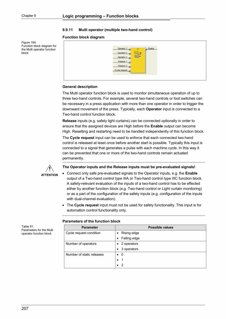
Chapter 9
207
Logic programming – Function blocks
9.9.11 Multi operator (multiple two-hand control)
Function block diagram
General description
The Multi operator function block is used to monitor simultaneous operation of up to
three two-hand controls. For example, several two-hand controls or foot switches can
be necessary in a press application with more than one operator in order to trigger the
downward movement of the press. Typically, each Operator input is connected to a
Two-hand control function block.
Release inputs (e.g. safety light curtains) can be connected optionally in order to
ensure that the assigned devices are High before the Enable output can become
High. Resetting and restarting need to be handled independently of this function block.
The Cycle request input can be used to enforce that each connected two-hand control is released at least once before another start is possible. Typically this input is connected to a signal that generates a pulse with each machine cycle. In this way it can be prevented that one or more of the two-hand controls remain actuated permanently.
The Operator inputs and the Release inputs must be pre-evaluated signals!
Connect only safe pre-evaluated signals to the Operator inputs, e.g. the Enable output of a Two-hand control type IIIA or Two-hand control type IIIC function block. A safety-relevant evaluation of the inputs of a two-hand control has to be effected either by another function block (e.g. Two-hand control or Light curtain monitoring) or as a part of the configuration of the safety inputs (e.g. configuration of the inputs with dual-channel evaluation).
The Cycle request input must not be used for safety functionality. This input is for automation control functionality only.
Parameters of the function block
Parameter Possible values
Cycle request condition Rising edge
Falling edge
Number of operators 2 operators
3 operators
Number of static releases 0
1
2
Figure 194: Function block diagram for the Multi operator function block
ATTENTION
Table 91: Parameters for the Multi operator function block

Chapter 9
208
Logic programming – Function blocks
The Enable output changes to High, if …
all Release inputs are High and stay High, and
each activated Operator input has changed to Low at least once (this may occur at different times as well) after the MELSEC-WS safety controller has changed from the Stop state to the Run state or after a rising or a falling edge (depending on the configuration) has been detected at the Cycle request input, and
all activated Operator inputs have changed to High subsequently.
The Enable output changes to Low, if …
one or more of the Release inputs is Low, or
one or more of the Operator inputs is Low, or
a rising or a falling edge (depending on the configuration) has been detected at the Cycle request input.
Sequence/timing diagram
Figure 195: Sequence/timing diagram for the Multi operator function block

Chapter 9
209
Logic programming – Function blocks
9.10 Function blocks for Parallel muting, Sequential muting and Cross muting
9.10.1 Overview and general description
Muting is the automatic temporary suppression of safety-oriented area monitoring using electro-sensitive protective equipment (ESPE) while certain objects, e.g. pallets with material, are moved into the hazardous area.
Muting sensors monitor the presence of the material while it is being transported. Careful selection of the type and layout of the sensors makes it possible to differentiate between objects and persons.
In combination with the muting sensors and the ESPE the transported object generates an exactly defined signal sequence while it is moved through the hazardous area. The muting sensors have to ensure that all dangers are excluded when a person enters an area protected by the ESPE (i.e. any dangerous state has to be terminated immediately). It has to be impossible for a person to generate the same signal sequence as a transported object.
The placement of the muting sensors is determined by the form of the object to be
detected. To this purpose the following options are, amongst others, available with
differing numbers of sensor input signals:
two sensors
two sensors and an additional signal C1
four sensors (two sensor pairs)
four sensors (two sensor pairs) and an additional signal C1
Muting sensor signals can be generated by the following external sensors:
optical sensors
inductive sensors
mechanical switches
signals from the control system
If you use optical sensors for muting applications, use sensors with a background
suppression in order to ensure that only the transported material fulfills the muting
condition. These sensors detect material only up to a specific distance. Objects that
are further away can therefore not fulfill the input conditions of the muting sensors.
Three different function blocks are available for muting:
Parallel muting (muting with two parallel sensor pairs)
Sequential muting (muting with two sequential sensor pairs)
Cross muting (muting with one crossed sensor pair)
The muting cycle is the specified sequence of all processes that are executed during muting.
The muting cycle begins when the first muting sensor is activated. The muting cycle ends depending on the configuration in the function block for the muting end condition. It is not possible to activate muting again until the preceding muting cycle has been terminated.
Material can be transported several times within one muting cycle if the muting conditions are maintained permanently in the process, meaning that at least one pair of sensors remain activated permanently.
Since muting bypasses the safety functions of a protective device, several
requirements have to be fulfilled, as shown below, in order to ensure the safety of the
application.
Note

Chapter 9
210
Logic programming – Function blocks
The general safety regulations and protective measures have to be observed!
If you use muting, be sure to observe the following information about the correct use of
muting:
Access to the hazardous area has to be detected reliably by the ESPE or be excluded through other measures. It has to be impossible for a person to pass by, pass over, pass under or cross the ESPE without being detected. Observe the manual of the ESPE for the correct installation and use of the device.
Always observe the valid applicable local, regional and national regulations and standards applying to your application. Ensure that your application conforms to an appropriate risk analysis and avoidance strategy.
Muting may never be used to transport a person into the hazardous area.
Mount the control devices for resetting and overriding outside the hazardous area so that they cannot be actuated by a person located in the hazardous area. Furthermore, when operating a control device, the operator must have full visual command of the hazardous area.
The muting sensors have to be located in such a way that the hazardous area can only then be accessed after an intervention in the protective field, if the dangerous state has been terminated before. One condition here is that the required safety distances defined in EN/ISO 13855 are observed. At least two muting signals that are independent of each other are required.
Muting may only be activated for the period in which the object that triggered the muting condition blocks access to the hazardous area.
The area between the ESPE and the muting sensors must be protected against standing behind:
– For Parallel muting between ESPE and sensors A1/A2 and between ESPE and sensors B1/B2 (see Figure 200).
– For Sequential muting between ESPE and sensor A2 and between ESPE and sensor B1 (see Figure 203).
– For Cross muting between ESPE and sensor A1 and between ESPE and sensor A2 (see Figure 206)
Muting has to be carried out automatically, but may not depend on a single electrical signal.
The material to be transported has to be detected along the entire length, meaning that an interruption of the output signals may not occur (see Suppression of sensor signal gaps).
Muting must be triggered by at least two independently wired signals (e.g. by muting sensors) and may not depend completely on software signals (e.g. from a programmable controller).
The muting condition has to be terminated immediately after the passage of the object so that the protective device returns to its normal state that was bypassed by muting (i.e. so that it comes back into force).
The muting sensors have to be positioned in such a way that muting cannot be triggered unintentionally by anyone (see Figure 196).
ATTENTION

Chapter 9
211
Logic programming – Function blocks
Always position the muting sensors in such a way that only the material is detected and not the conveyance means (pallet or vehicle).
Always position muting sensors in such a way that the material can pass unimpeded, but persons are detected reliably.
Always position the muting sensors in such a way that a minimum distance to the detection area of the ESPE (e.g. to the light beams of a light curtain) is observed while the material is being detected.
It has to be ensured that no persons are within the hazardous area before and during the activation of an override.
Before you activate the override ensure that the equipment is in a perfect condition, in particular the muting sensors (visual inspection).
When it has been necessary to activate an override, subsequently check whether the equipment functions properly and the layout of the muting sensors.
During long muting cycles (i.e. longer than 24 hours) or during longer machine downtimes check that the muting sensors function correctly.
A muting and/or override lamp has to be used in order to signal that the muting or override function is active. It is possible to use an external muting/override lamp or one that is integrated in the protective device (ESPE).
It may be necessary to monitor the muting/override lamp depending on your local, regional and national regulations and standards. If this is the case, this has to be realized by additional means. WS0-XTIO and WS0-XTDI modules do not support lamp monitoring.
Always position the muting or override lamp so that it can be seen well! It must be possible to see the muting or override lamp from all positions around the hazardous area and for the system operator.
If safety-relevant information (i.e. distributed safety input values and/or safety output values) is transferred via a safety field bus network, always take the corresponding delays into account. These delays can influence both the system behaviour as well as the requirements for the minimum safety distances that are connected to the response times.
Figure 196: Safety when mounting the muting sensors
Figure 197: Detection of material during muting

Chapter 9
212
Logic programming – Function blocks
When an override input is configured, test pulse outputs may not be used for the configuration of the safety inputs.
Separate lines have to be used for the sensor signals A1 and A2 (B1 and B2).
A line that is independent of other input signals has to be used for the signals for Reset and Reset required in order to exclude unintentional resetting of the system. The line must furthermore be laid protected.
The total muting time cannot be set to indefinite (inactive) without additional precautions being taken. If the total muting time is set to indefinite, additional measures have to be taken to ensure that no one can access the hazardous area while muting is activated.
9.10.2 Parameters of the function blocks
The following table lists the possible configuration parameters of the muting function
blocks.
Parameter Possible values
Direction detection Disabled
Only with Parallel muting and Sequential muting:
Forward (A1/A2 first)
Backward (B1/B2 first)
Sequence monitoring Not selectable. Defined by selection of the muting function block:
Enabled: With Sequential muting
Disabled: With Parallel muting or Cross muting
Condition of other sensor pair for muting start
Both inputs are clear
Only with Parallel muting and Sequential muting:
If last muting sensor is active
Muting end condition With muting sensor pair
With ESPE
Muting total time 0 = disabled, 5 s to 3600 s, resolution 1 s
Add. muting time when ESPE is clear
0 ms, 200 ms, 500 ms, 1000 ms
Sensor signal gap monitoring
0 = disabled, 10 to 1000 ms, resolution 10 ms. If enabled, the value has to be greater than the logic execution time.
Concurrency monitoring time
0 = disabled, 10 to 3000 ms, resolution 10 ms. If enabled, the value has to be greater than the logic execution time.
C1 input With
Without
Conveyor input With
Without
Override input With
Without
Min. override pulse time 100 ms
350 ms
Table 92: Parameters of the muting function blocks

Chapter 9
213
Logic programming – Function blocks
Direction detection
Direction detection is used when the transported material has to be moved in a
specific direction. The direction depends on the sequence in which the muting sensors
are activated.
If direction detection is disabled, the material to be transported can be moved in both
directions in order to fulfill the muting conditions. In this case it is not relevant which
sensor pair is activated first.
If Forward (A1/A2 first) was selected as the direction, the muting sensor pairs have
to be activated in the sequence (A1/A2) before (B1/B2). Muting is not possible in the
opposite direction. Muting is terminated by a transition from four active sensors to an
inactive sensor pair “B” (no sensor or one sensor active).
If Backward (B1/B2 first) was selected as the direction, the muting sensor pairs have
to be activated in the sequence (B1/B2) before (A1/A2). Muting is not possible in the
forward direction. Muting is terminated by a transition from four active sensors to an
inactive sensor pair “A” (no sensor or one sensor active).
Condition of other sensor pair for muting start
The Condition of other sensor pair for muting start parameter determines when a
valid muting sequence can begin. The Condition of other sensor pair for muting
start can be defined for one of the following conditions:
Both inputs are clear: All muting sensors have changed to Low together or individually and the OSSDs of the protective device (e.g. safety light curtain) are High (i.e. the protective field is clear),
or
If last muting sensor is active: All muting sensors except the last muting sensor are Low and the OSSDs of the protective device (e.g. safety light curtain) are High (i.e. the protective field is clear).
If a higher throughput is required, it can be advantageous to allow the beginning of the
next muting sequence as soon as the transported material has passed the protective
device as well as all muting sensors with the exception of the last one (i.e. If last
muting sensor is active).
Muting end condition
In contrast to the Condition of other sensor pair for muting start, the Muting end
condition determines when a valid muting state ends. You can choose when the
Muting end condition occurs:
With muting sensor pair: When a muting sensor of the last muting sensor pair changes to Low (sensor clear),
or
With ESPE: When the OSSDs of the protective device (e.g. safety light curtain) indicate that the protective field is no longer violated, i.e., the protective field is clear, and the OSSDs return to High.
If after the muting end the OSSD input of the ESPE becomes Low (e.g. by a violation
of the protective field of the ESPE) before the next valid muting sequence has begun,
the Enable output of the function block becomes Low. The next muting cycle cannot
begin until the Muting end condition has been fulfilled.

Chapter 9
214
Logic programming – Function blocks
Muting total time
The Muting total time is used in order to limit the maximum duration of the muting
sequence. If the set value for the Muting total time is exceeded, the Muting error
and Fault present outputs change to High and the Enable output changes to Low.
The timer for the Muting total time begins when the muting function is activated,
indicated by the transition of the Muting status output to High. The timer for the
Muting total time is stopped and reset to zero when the muting function changes to
Low. If the optional Conveyor input is used, the timer for the Muting total time pauses
when the Conveyor input remains High, indicating that the conveyor belt has stopped.
Add. muting time when ESPE is clear
The Add. muting time when ESPE is clear parameter is used when the Muting end
condition has been configured as With ESPE. If the ESPE does not always detect
the muting end exactly because of irregularities in the material or the transport means,
you can increase the availability of the machine by configuring an additional muting
time of up to 1000 ms. Only in this case does the Add. muting time when ESPE is
clear parameter determine the additional muting time after the OSSDs of the ESPE
have returned to High, i.e. that the safety light curtain is no longer interrupted.
Concurrency monitoring time
The Concurrency monitoring time is used to check whether the muting sensors are
activated simultaneously. This value specifies the maximum duration for which each of
the two dual-channel evaluated muting sensor inputs may have different values
without this being evaluated as an error. This means that input pair A1 and A2 or input
pair B1 and B2 must have equivalent values before the Concurrency monitoring
time has expired.
Concurrency monitoring begins with the first change of an input value of a muting
sensor. If the Concurrency monitoring time has expired and the two inputs of an
input pair still have different values, an error occurs.
If the concurrency monitoring determines an error for at least one input pair, the
function block indicates this error by setting the Muting error output to High.
Sensor signal gap monitoring
Occasionally faults occur in the output signals of muting sensors that may not be
relevant for muting. The Sensor signal gap monitoring function allows to filter out
brief faults without muting being interrupted.
When Sensor signal gap monitoring is enabled, a Low signal from a muting sensor
input is ignored for the duration of the set value for Sensor signal gap monitoring.
The function block continues to interpret this signal as an uninterrupted High as long
as only one sensor per pair A1/A2 or B1/B2 has a signal gap. If a signal gap has been
detected at a sensor, the simultaneous occurrence of a further signal gap at the other
sensor of the sensor pair results in the termination of muting.

Chapter 9
215
Logic programming – Function blocks
Sequence monitoring
Sequence monitoring is used to define a special mandatory sequence in which the
muting sensors have to be High. Table 93 shows the valid sequence for muting
sensor input signals. This parameter is only available for configurations with four
muting sensors, for example for parallel muting or sequential muting.
Direction detection Requirement for the muting sensor signal inputs for
sequence monitoring:
Disabled A1 before A2 before B1 before B2 or B2 before B1 before A2 before A1
Forward A1 before A2 before B1 before B2
Backward B2 before B1 before A2 before A1
This parameter depends on the function block. Deviations from the sequence shown
above result in a muting error, indicated by the Muting error output. In order to avoid
machine downtime the configured time for the Sensor signal gap monitoring should
furthermore be shorter than the time span that the transported object requires to pass
a muting sensor pair (e.g. A1/A2 or B1/B2).
C1 input
The C1 input is used as an additional measure to avoid manipulations. If C1 is used, a
transition from Low to High has to take place before the first muting sensor pair
becomes High. Input C1 must then remain High until both sensors of the muting
sensor pair are High so that a valid muting condition can arise. If this condition is not
fulfilled, this results in a muting error, indicated by the Muting error output. The C1
input subsequently has to return to Low again before the next muting cycle is
permitted.
Override input
An Override input signal is used to remove transported objects that have remained in
the protective field of the protective device (e.g. safety light curtain) after power
failures, triggering of an emergency stop, muting errors or similar circumstances.
The Override status output (available from firmware V3.02) changes to high and the
Override required output pulses at 2 Hz, if the following conditions are met:
Muting is currently inactive (i.e. Muting status is Low).
At least one muting sensor is High.
The OSSDs of the ESPE are Low (e.g. safety light curtain is interrupted).
The Enable output is Low.
If the conditions for the Override required output are fulfilled and a valid override
pulse sequence with a Low-High-Low transition (minimum 100 ms or 350 ms and
maximum 3 s; longer or shorter pulses are ignored) has occurred at the Override
input, the Enable output becomes High, as if the muting conditions were fulfilled.
When all muting sensors have returned to Low and the OSSD input of the ESPE is
High (e.g. indicating that the protective field of a safety light curtain is now clear), the
next valid muting cycle is expected. If the next object does not fulfill the conditions for
a muting cycle, but the conditions for the Override required output, a further override
cycle can be used in order to remove the transported material. The number of override
cycles is limited (see Table 95).
Table 93: Requirements for sequence monitoring

Chapter 9
216
Logic programming – Function blocks
A reset button can also be suitable for the override function. Check the requirements
of your application in order to ensure that the safety-relevant logic fulfils the
requirements of the local, regional, national and international regulations.
Table 94 provides information about the Override required output and when Override
is possible under the shown conditions and when not.
Muting status
At least one muting sensor
is High
OSSDs of the ESPE are High
Override required output
Override possible
0 No 0 No No
0 No 1 No No
0 Yes 0 Pulses at 2 Hz
Yes, if the maximum permissible number of override cycles is not
exceeded.
0 Yes 1 No No
1 No 0 No No
1 No 1 No No
1 Yes 0 No No
1 Yes 1 No No
Figure 198 shows an example sequence for Override and Override required.
thigh has to be equal to or greater than the minimum override pulse time (100 ms or
350 ms), but less than or equal to 3 s. If thigh is shorter than the minimum override
pulse time or greater than 3 s, the Override input is ignored.
If you use Override, check whether the system is in a safe state!
The Override function is used to activate the safety output (i.e. the Enable output) of
the muting function block although the safety device (e.g. a safety light curtain) signals
that a dangerous state may exist. The Override input should only be used when the
hazardous area has been checked visually and nobody is in the hazardous area or
has access to the hazardous area while the Override input is being used.
Ensure that the transitions of the signals for Override fulfill the requirements of the safety standards and regulations!
In case of a short-circuit to High (to 24 V DC) at a physical input, the evaluated signal
can have a pulse when the signal is reset due to the short-circuit detection. If such a
pulse can result in a dangerous state in the machine, the following points have to be
observed:
Ensure protected cable laying for the signal line (due to cross-circuiting to other signal lines).
No short-circuit detection, i.e. do not reference to test outputs.
Note
Table 94: Conditions for Override required and Override possible
Figure 198: Logic diagram for Override and Override required
Note
ATTENTION

Chapter 9
217
Logic programming – Function blocks
During an override cycle, the Enable output is set to High as during a valid muting
sequence. The number of permissible override cycles is limited in order to prevent
excessive use of the override function. The number of permissible override cycles
depends on the value for the total muting time. Table 95 summarizes the number of
permissible override cycles:
Total muting time Number of permissible
override cycles Remarks
5 s 360 Maximum number of override cycles = 360 10 s 360
20 s 180
= 60 min/total muting time 30 s 120
1 min 60
5 min 12
15 min 5
Minimum number of override cycles = 5
30 min 5
60 min 5
Disabled (unlimited) 5
The number of override cycles is stored in the function block. The value is
incremented each time the Override required output starts pulsing or the Override
status output changes to high. The value is reset to “0”, after a valid muting cycle has
occurred, after a system reset (e.g. using the Setting and Monitoring Tool) or after a
transition from the Stop state to the Run state.
After the Override required output has started pulsing at 2 Hz and a subsequent
Override signal has become High, Muting begins again and the Enable output
becomes High.
If the muting cycle is stopped because of a faulty input signal of a muting sensor,
Override required changes to High for the duration of the logic execution time,
provided that the remaining conditions for Override required are fulfilled. If the faulty
input of the muting sensor returns to High and subsequently to Low, the muting cycle
is stopped again and Override required becomes High, provided that the remaining
conditions for Override required are fulfilled.
During a valid override state, the direction detection, sequence monitoring (depending
on the function block) and concurrency monitoring are not carried out for the duration
of an override cycle.
Conveyor input
If the movement of the transported material is stopped during the muting cycle, the total muting time and other parameters that can result in a muting error may be exceeded. This can be avoided by using the Conveyor input. This input is used to stop time-related functions connected with muting when the material to be transported does not move further.
The Conveyor input has to fulfill EN 61131/IEC 61131 and has the following properties:
0 V DC = conveyor belt stopped, e.g. Low
24 V DC = conveyor belt running, e.g. High
Table 95: Number of permissible override cycles
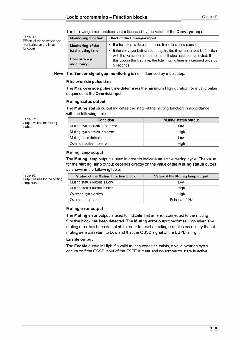
Chapter 9
218
Logic programming – Function blocks
The following timer functions are influenced by the value of the Conveyor input:
Monitoring function Effect of the Conveyor input
Monitoring of the total muting time
If a belt stop is detected, these timer functions pause.
If the conveyor belt starts up again, the timer continues its function with the value stored before the belt stop has been detected. If this occurs the first time, the total muting time is increased once by 5 seconds.
Concurrency monitoring
The Sensor signal gap monitoring is not influenced by a belt stop.
Min. override pulse time
The Min. override pulse time determines the minimum High duration for a valid pulse sequence at the Override input.
Muting status output
The Muting status output indicates the state of the muting function in accordance with the following table:
Condition Muting status output
Muting cycle inactive, no error Low
Muting cycle active, no error High
Muting error detected Low
Override active, no error High
Muting lamp output
The Muting lamp output is used in order to indicate an active muting cycle. The value for the Muting lamp output depends directly on the value of the Muting status output as shown in the following table:
Status of the Muting function block Value of the Muting lamp output
Muting status output is Low Low
Muting status output is High High
Override cycle active High
Override required Pulses at 2 Hz
Muting error output
The Muting error output is used to indicate that an error connected to the muting
function block has been detected. The Muting error output becomes High when any
muting error has been detected. In order to reset a muting error it is necessary that all
muting sensors return to Low and that the OSSD signal of the ESPE is High.
Enable output
The Enable output is High if a valid muting condition exists, a valid override cycle occurs or if the OSSD input of the ESPE is clear and no error/error state is active.
Table 96: Effects of the conveyor belt monitoring on the timer functions
Note
Table 97: Output values for muting status
Table 98: Output values for the Muting lamp output

Chapter 9
219
Logic programming – Function blocks
9.10.3 Information on wiring
If muting functions are to be implemented, possible errors in the wiring have to be
taken into consideration. If certain signal combinations are to be transferred in a
common wire, additional precautions have to be taken in order to ensure that the
respective signals are correct. Suitable measures have to be taken (e.g. protected
wiring) in order to ensure that errors cannot arise through this wiring.
Signal description A
1
A2
B1
B2
C1
Co
nve
yor
ES
PE
Ove
rrid
e in
pu
t
En
able
ou
tpu
t
Mu
tin
g la
mp
Mu
tin
g s
tatu
s
Ove
rrid
e re
qu
ired
A1 – A B B A A A A A A A C
A2 A – B B A A A A A A A C
B1 B B – A A A A A A A A C
B2 B B A – A A A A A A A C
C1 A A A A – A A A A C C C
Conveyor A A A A A – C A A C C C
ESPE A A A A A C – C A C C C
Override input A A A A A A C – A A C A
A The specified signals may not be installed in a common wire unless protected wiring is used.
B The specified signals may not be installed in a common wire unless protected wiring or sequence monitoring is used.
C The specified signals may be installed in a common wire.
– Not applicable
Table 99: Wiring combinations for muting and prerequisites

Chapter 9
220
Logic programming – Function blocks
9.10.4 State transition from Stop to Run
If the MELSEC-WS safety controller changes from the Stop state to the Run state, the
following behavioural patterns can be realized, depending on the state of the muting
sensors and of the OSSDs of the sensors (e.g. safety outputs of a safety light curtain).
Table 100 shows details of the system behaviour during the transition from Stop to
Run.
State after the change from the Stop state to the
Run state System behaviour
Input ESPE State of the muting sensors Run Next action
High
(e.g., no object in
the protective
field)
All muting sensors are Low A normal muting
sequence is
possible.
Muting is possible after correct
activation/sequence of the
muting sensors.
The muting condition is
partially fulfilled.
All muting sensors have to
return to Low, before the
OSSDs of the sensor become
Low. If the OSSDs of the
sensors become Low before all
muting sensors have become
Low, Override has to be used.
The muting condition is
fulfilled.
Low
(e.g., object
detected)
All muting sensors are Low Muting is blocked. The sensor OSSDs have to
become High before muting
can take place.
The muting condition is
partially fulfilled.
Override is
required, if
configured.
Either transition to normal
behaviour (in case of a
cyclically correct sequence of
sensor states) or the total
override time is exceeded.
The muting condition is
fulfilled.
9.10.5 Error states and information on resetting
Diagnostic outputs Resetting the error state Remarks
Muting error:
Error in the concurrency monitoring function
Error in the total muting time monitoring
Error in the direction detection
Sequence error detected
Error in the sensor gap monitoring
A complete valid muting cycle has to occur before any muting error can be reset. To this purpose either Override has to be used or all muting sensors and OSSDs of the ESPE have to be clear and a subsequent valid muting sequence has to be applied.
If one of these two conditions is fulfilled, the Muting error output returns to Low, provided that no other error exists.
The Enable output changes to Low and Fault present changes to High, if the Muting error output is High.
Table 100: Stop-to-Run transition behaviour for muting functions
Table 101: Error states and information on resetting for Muting function blocks

Chapter 9
221
Logic programming – Function blocks
9.10.6 Parallel muting
Function block diagram
Representation of the application
Figure 200 shows an example of the placement of sensors for Parallel muting.
In this example the material moves from the left to the right. As soon as the first
muting sensor pair A1 & A2 is activated, the protective effect of the protective device
(ESPE) is muted. The protective effect remains muted until the muting sensor pair B1
& B2 is clear again.
Input conditions for muting sensors
Condition Description
A1 & A2 (or B1 & B2)
Starts the muting cycle. The first sensor pair is activated depending on the direction of transportation of the material.
A1 & A2 & B1 & B2 Condition for transferring the muting function to the second sensor pair.
B1 & B2 (or A1 & A2)
Muting applies as long as this condition is fulfilled. The second sensor pair is activated depending on the direction of transportation of the material.
Equations and prerequisites for calculating the distance:
L1 v × 2 × TIN Muting sensor
v × t > L1 + L3
L1 < L3
TIN Light curtain < TIN Muting sensor
Figure 199: Function block diagram for the Parallel muting function block
Figure 200: Muting with two parallel sensor pairs
Table 102: Conditions for Parallel muting

Chapter 9
222
Logic programming – Function blocks
Where …
L1 = Distance between the sensors (layout symmetrical to the detection area of
the ESPE)
L3 = Length of material in conveyor direction
v = Velocity of the material (e.g. of the conveyor belt)
t = Set total muting time [s]
TIN Light curtain, TIN Muting sensor = Response time of the light curtain or the muting sensors in the MELSEC-WS safety controller (See the Safety Controller User’s Manual.)
The material can be moved in both directions or a fixed direction of transportation can be defined for it as follows:
– With the optional input C1. If used, the C1 input always has to be activated
before both muting sensors of the first sensor pair (e.g. A1 and A2) become
High.
– By means of the Direction detection configuration parameter
In parallel layout, the position of the muting sensors also determines the width of the permissible object. The objects always have to pass the muting sensors with an identical width.
Optical probes and all types of non-optical sensors can be used for this application. Use sensors and probes with background suppression.
Avoid mutual interference of the sensors.
Increase the protection against manipulation and the safety level by using the following configurable functions:
– concurrency monitoring
– monitoring of the total muting time
– muting end via ESPE
Information on wiring can be found in Section 9.10.3.
The function block requires that a valid muting sequence takes place. Figure 201 shows an example of a valid muting sequence based on the basic parameter setting for this function block.
Sequence/timing diagram
Note
Figure 201: Valid muting sequence using the configuration basic setting (C1 input: without, Override input: without, Conveyor input: without)

Chapter 9
223
Logic programming – Function blocks
9.10.7 Sequential muting
Function block diagram
Representation of the application
Figure 203 shows an example of the placement of sensors using the Sequential
muting function block.
In the example, the material moves from the left to the right. As soon as the muting
sensors A1 & A2 are activated, the protective effect of the protective device (ESPE) is
muted. The protective effect remains muted until a sensor of the muting sensor pair
B1 & B2 becomes clear again.
Input conditions for muting sensors
Condition Description
A1 & A2 (or B1 & B2)
Starts the muting cycle. The first sensor pair is activated depending on the direction of transportation of the material.
A1 & A2 & B2 & B1 Condition for transferring the muting function to the second sensor pair.
B1 & B2 (or A1 & A2)
Muting applies as long as this condition is fulfilled. The second sensor pair is activated depending on the direction of transportation of the material.
Figure 202: Function block diagram for the Sequential muting function block
Figure 203: Example of the sequential layout of muting sensors
Table 103: Conditions for Sequential muting with four sensors

Chapter 9
224
Logic programming – Function blocks
Equations and prerequisites for calculating the distance:
L1 v × 2 × TIN Muting sensor
v × t > L1 + L3
L2 < L3
TIN Light curtain < TIN Muting sensor
Where …
L1 = Distance between the inner sensors (layout symmetrical to the detection area of the ESPE)
L2 = Distance between the outer sensors (layout symmetrical to the detection area of the ESPE)
L3 = Length of the material in conveyor direction
v = Velocity of the material (e.g. of the conveyor belt)
t = Set total muting time [s]
TIN Light curtain, TIN Muting sensor = Response time of the light curtain or the muting sensors in the MELSEC-WS safety controller (See the Safety Controller User’s Manual.)
In this example the material can either be moved in both directions or a fixed direction of transportation can be defined as follows:
– With the optional input C1. If used, the C1 input always has to be activated
before both muting sensors of the first sensor pair (e.g. A1 and A2) become
High.
– By means of the Direction detection configuration parameter
The sensor layout shown in this example is suitable for all types of sensors.
Avoid mutual interference of the sensors.
Increase the protection against manipulation and the safety level by using the following configurable functions:
– concurrency monitoring
– monitoring of the total muting time
– muting end via ESPE
– sequence monitoring
Information on wiring can be found in Section 9.10.3.
Sequence/timing diagram
The function block requires that a valid muting sequence takes place. Figure 204
shows an example of a valid muting sequence based on the basic parameter setting
for this function block.
Note
Figure 204: Valid muting sequence using the basic configuration setting (C1 input: without, Override input: without, Conveyor input: without)

Chapter 9
225
Logic programming – Function blocks
9.10.8 Cross muting – direction of movement only forwards or backwards
Function block diagram
Representation of the application
Figure 206 shows an example of the sensor layout for the Cross muting function
block. The optional input C1 is used as an additional protection for the muting system
against manipulation.
The protective effect of the protective device is muted when the muting sensors are
operated in a defined sequence. The optional input C1 always has to be activated
before both muting sensors of the first sensor pair (e.g. A1 and A2) become High.
Input conditions for muting sensors
Condition Description
C1 & A1 & A2 Input C1 always has to be activated before both muting sensors of the first sensor pair (e.g. A1 and A2) become High.
A1 & A2 Muting applies as long as this condition is fulfilled and the requirement mentioned above existed.
Equations and prerequisites for calculating the distance:
L1 v × TIN Muting sensor
v × t > L2 + L3
L3 > L4
TIN Light curtain < TIN Muting sensor
Figure 205: Function block diagram for the Cross muting function block with optional input C1
Figure 206: Example of Cross muting with optional input C1
Table 104: Conditions for Cross muting with optional input C1

Chapter 9
226
Logic programming – Function blocks
Where …
L1 = Minimum distance between the detection line of the ESPE and the detection
by A1, A2
L2 = Distance between the two detection lines of the sensors (sensors
activated/sensors clear)
L3 = Length of material in conveyor direction
L4 = Maximum distance between C1 and the detection line of A1, A2
v = Velocity of the material (e.g. of the conveyor belt)
t = Set total muting time [s]
TIN Light curtain, TIN Muting sensor = Response time of the light curtain or the muting sensors in the MELSEC-WS safety controller (See the Safety Controller User’s Manual.)
Material flow is only possible in one direction in this example.
In order to move material in both directions (i.e. bidirectionally), place the intersection directly in the light beams of the ESPE (See also Section 9.10.9).
The sensor layout shown in this example is suitable for both through-beam photoelectric switches and photoelectric reflex switches.
Avoid mutual interference of the sensors.
Increase the protection against manipulation and the safety level by using the following configurable functions:
– concurrency monitoring
– monitoring of the total muting time
– muting end via ESPE
Information on wiring can be found in Section 9.10.3.
Sequence/timing diagram
The function block requires that a valid muting sequence takes place. Figure 207
shows an example of a valid muting sequence based on the basic parameter setting
for this function block. The optional input C1 is not contained in the sequence shown
below.
Note
Figure 207: Valid muting sequence using the configuration basic setting (C1 input: without, Override input: without, Conveyor input: without)

Chapter 9
227
Logic programming – Function blocks
9.10.9 Cross muting – material transport in both directions
Function block diagram
Representation of the application
The sensors can be located as follows in the case of muting applications with one
crossed sensor pair where the material has to be moved in both directions. The
optional signal C1 is not used in this application example.
Ensure that the muting sensors detect only the moved material!
Ensure that the muting sensors are positioned in such a manner that no one can enter
the hazardous area by fulfilling the muting conditions (meaning that they activate both
muting sensors and thus create the required conditions for muting).
Input conditions for muting sensors
Condition Description
A1 & A2 Muting applies as long as this condition is fulfilled and, furthermore, the requirements mentioned above existed.
Equations and prerequisites for calculating the distance:
L1 v × TIN Muting sensor
v × t > L2 + L3
TIN Light curtain < TIN Muting sensor
Figure 208: Function block diagram for the Cross muting function block
ATTENTION
Figure 209: Cross muting for bidirectional movement of material
Table 105: Conditions for Cross muting without optional input C1

Chapter 9
228
Logic programming – Function blocks
Where …
L1 = Minimum distance between the detection line of the ESPE and the detection
by A1, A2
L2 = Distance between the two detection lines of the sensors (sensors
activated/sensors clear)
L3 = Length of material in conveyor direction
v = Velocity of the material (e.g. of the conveyor belt)
t = Set total muting time [s]
TIN Light curtain, TIN Muting sensor = Response time of the light curtain or the muting sensors in the MELSEC-WS safety controller (See the Safety Controller User’s Manual.)
Material flow is possible in both directions in this example.
In order for material to be moved in both directions, place the intersection of the muting sensors exactly in the course of the light beams of the ESPE.
In order to move material in one direction only, place the intersection, with regard to the direction of the transport, behind the light beams of the ESPE (see Section 9.10.8).
The sensor layout shown in this example is suitable for both through-beam photoelectric switches and photoelectric reflex switches.
Avoid mutual interference of the sensors.
Increase the protection against manipulation and the safety level by using the following configurable functions:
– concurrency monitoring
– monitoring of the total muting time
– muting end via ESPE
Information on wiring can be found in Section 9.10.3.
Sequence/timing diagram
The function block requires that a valid muting sequence takes place. Figure 210
shows an example of a valid muting sequence based on the basic parameter setting
for this function block.
Note
Figure 210: Valid muting sequence using the basic configuration setting (C1 input: without, Override input: without, Conveyor input: without)

Chapter 9
229
Logic programming – Function blocks
9.11 Function blocks for press contact monitoring
9.11.1 Overview and general description
For press applications there are two complementary types of function blocks offered. This section describes the contact monitoring function blocks, which provide signals for the press cycle control function blocks.
There are two different function blocks for press contact monitoring which can be used to monitor the correct cam signal sequence and the correct stopping (overrun) of the press. The outputs of these function blocks indicate the current press cycle phase in which the press is operating (e.g. upstroke or top). Typically the Enable output, Top output and Upstroke output of a contact monitoring function block are connected to the corresponding inputs of one or more press cycle control function blocks.
Eccentric press Universal press
Typical press types Eccentric press Eccentric press
Hydraulic press
Press travelling directions
Forward Forward and backward
Cams Overrun cam
Upstroke cam
Dynamic cam
Top dead center (TDC)
Bottom dead center (BDC)
Overrun cam
Top position condition
When Overrun cam = High When TDC = Low
Upstroke condition When Upstroke cam = High When BDC = High
Overrun monitoring Optional Optional
Disable monitoring Optional Optional
9.11.2 Eccentric press contact
Function block diagram
General description
The Eccentric press contact function block can be used for specific types of eccentric
presses (i.e. mechanical presses). The minimum configuration requires an Overrun
cam and the Upstroke cam. Optionally a Dynamic cam can also be connected.
Table 106: Overview of the press contact monitoring function blocks
Figure 211: Function block diagram for the Eccentric press contact function block

Chapter 9
230
Logic programming – Function blocks
Parameters of the function block
Parameter Possible values
Dynamic cam input With
Without
Min. reset pulse time 100 ms
350 ms
Reset input With
Without
Disable monitoring input With
Without
Use fault present With
Without
Enable output
The Enable output is used to stop the press and is connected to another complementary press function block, e.g. Press setup or Press single stroke. If no error was detected, the Enable output is High.
If any error in the contact signal sequence is detected, the Enable output changes to Low, the corresponding error output changes to High and the Reset required output changes to High. A valid reset sequence at the Reset input is then required.
The Enable output also changes to Low if Monitoring gets disabled.
Reset input
A valid reset sequence at the Reset input is a Low-High-Low transition with a minimum pulse duration of 100 ms or 350 ms and maximum 30 s. Shorter and longer pulses are ignored.
Ensure that the transitions of the signals for resetting fulfill the requirements of
the safety standards and regulations!
In case of a short-circuit to High (to 24 V DC) at a physical input, the evaluated signal
can have a pulse when the signal is reset due to the short-circuit detection. If such a
pulse can result in a dangerous state in the machine, the following points have to be
observed:
Ensure protected cable laying for the signal line (due to cross-circuiting to other signal lines).
No short-circuit detection, i.e. do not reference to test outputs.
Safety-relevant signals have to conform to standards and regulations to be applied!
Always take the valid national, regional and local regulations and standards into consideration for your application. Type C standards such as EN 692 and EN 693 contain requirements how safety-relevant signals have to be used. For example, the restart signal may have to be protected by suitable means in case of overrun errors (e.g. by a key switch or in a closed control cabinet).
If the Reset input is disabled, an error can be reset only by stopping the logic execution, e.g. by a power cycle or by changing the system state from the Run state to the Stop state and back to the Run state with the Setting and Monitoring Tool.
Table 107: Parameters of the Eccentric press contact function block
ATTENTION

Chapter 9
231
Logic programming – Function blocks
Top output and Upstroke output
The Top output is typically used to stop the press and is connected to another complementary press function block, e.g. Press setup or Press single stroke.
The Upstroke output is typically connected to another complementary press function block, e.g. Press single stroke or Press Setup. Additionally it can be used to initiate upstroke muting.
This function block sets the Upstroke output and the Top output based on value changes of the cam inputs. If the function block detects an error, both outputs are set to Low.
Without Dynamic cam
The Upstroke output is set to High with a rising edge (transition from Low to High) of the Upstroke cam input and is set to Low with a rising edge of the Overrun cam input.
The Top output is set to High if the Overrun cam input is High.
With Dynamic cam
If this function block is configured with Dynamic cam, the start of the Top phase can be brought forward with a falling edge (transition from High to Low) of the Dynamic cam input.
The Upstroke output is set to High with a rising edge (transition from Low to High) of the Upstroke cam input. It is set to Low either with a rising edge of the Overrun cam input or with a falling edge of the Dynamic cam input, whichever occurs first.
The Top output is set to High with a rising edge of the Overrun cam or with a falling edge of the Dynamic cam input, whichever occurs first. The Top output is set to Low with a falling edge of the Overrun cam input.
Figure 212: Press cycle for the Eccentric press contact function block without Dynamic cam

Chapter 9
232
Logic programming – Function blocks
If there is a falling edge of the Dynamic cam input when the Upstroke cam input is Low, i.e. in the Run-down phase of the press cycle, the Top output will be set to High until a rising edge of the Upstroke cam input is detected. The Upstroke output will remain Low for the rest of the press cycle.
If the Upstroke cam input is already High when the monitoring of the cam inputs begins (e.g. in the first logic cycle, after resetting an error or after enabling monitoring with Disable monitoring input), the Upstroke output will remain Low until the first actual transition from Low to High has been detected at the Upstroke cam input.
Figure 213: Press cycle for the Eccentric press contact function block with Dynamic cam on upstroke
Figure 214: Press cycle for the Eccentric press contact function block with Dynamic cam on upstroke and downstroke
Note

Chapter 9
233
Logic programming – Function blocks
Contact monitoring
The input signals for the Overrun cam input, Upstroke cam input and the Drive released input have to accord with Figure 215 and the following rules.
(1) The overrun must begin during the upstroke phase: The rising edge at the Overrun cam input (Low-High transition) must occur while the Upstroke cam input is High.
(2) The overrun must end after the end of the upstroke phase: The falling edge at the Overrun cam input (High-Low transition) must occur when the Upstroke cam input is Low.
(3) The upstroke phase must begin after the overrun has ended: The rising edge at the Upstroke cam input (Low-High transition) must occur while the Overrun cam input is Low.
(4) The upstroke phase must end during the overrun: The falling edge at the Upstroke cam input (High-Low transition) must occur while the Overrun cam input is High.
If at least one of these conditions is not fulfilled during operation, the Enable output becomes Low and the Contact error output becomes High.
A valid sequence to fulfill the conditions is as follows:
0) Start condition: Overrun cam input = High, Upstroke cam input = Low
1) Overrun cam input: High Low
2) Upstroke cam input: Low High
3) Overrun cam input: Low High
4) Upstroke cam input: High Low
Observe the relevant safety standards and regulations!
All safety related parts of the installation (cabling, connected sensors and actuators, configuration settings) must be according to the relevant safety standards (e.g. IEC 62061 or EN/ISO 13849-1 or Type C standards such as EN 692 and EN 693) and regulations. Only safety-relevant signals may be used in safety-relevant logic. Ensure that the application fulfills all applicable standards and regulations!
This needs to be considered especially for the Upstroke cam, if the Upstroke output is used for upstroke muting, e.g. in combination with a press cycle control function block.
Figure 215: Contact monitoring with the Eccentric press contact function block
ATTENTION

Chapter 9
234
Logic programming – Function blocks
In order to fulfill the safety standards it may be necessary to use tested switches for the cam input signals, each with different test sources. To use different test sources for the cam signals, the Overrun cam, Upstroke cam and Dynamic cam need to be connected to different WS0-XTDI or WS0-XTIO modules.
One WS0-XTDI has two test sources only, even if it has eight test output terminals.
Overrun monitoring
The Eccentric press contact function block monitors the overrunning of the press. If the Overrun cam is left although the press is supposed to have stopped, then the function block detects an Overrun error.
The Drive released input signal must then accord to Figure 216 and the following rule.
At the Drive released input there has to be either a Low to High transition while the Top output is High or the Drive released input has to be High at the end of the Overrun cam (High-Low transition). If none of these two conditions is fulfilled, the Enable output becomes Low and the Overrun error output becomes High.
The Drive released input must be connected to the signal that controls the physical output of the press drive, so that the function block can determine whether the press is currently supposed to be running or has been stopped. Typically this is the Enable output of a subsequent Press setup or Press single stroke function block.
Do not connect any physical input signals to the Drive released input. Connect the signal that controls the physical output for the press drive using a jump address or a CPU marker.
If a jump address is used, make sure that this signal is a loop-back. This is indicated by a clock icon on the destination tag of the jump address. To this purpose, connect the outputs of this function block to the following function blocks before you connect the jump address to the Drive released input. This applies especially if all connections to the following function blocks are also realized using jump addresses.
If a CPU marker is used, then a Routing function block must be used to split the signal to the physical output for the press drive and to the CPU marker output.
Note
Figure 216: Overrun monitoring with the Eccentric press contact function block
Note

Chapter 9
235
Logic programming – Function blocks
Disable monitoring
Using this optional input it is possible to deactivate the monitoring functionality under certain conditions in order to prevent the function block to go into an error state. This can be useful for certain operating modes, e.g. during the setup of the machine or when the press moves backwards.
If the Disable monitoring input is High, the Enable output of the Eccentric press contact function block is Low and the monitoring of the cam signal sequence and overrun is inhibited, provided there is no error pending. The error output states are not affected by this.
If the Disable monitoring input is High and an error is pending, a reset of the error is possible.
When the Disable monitoring input changes from High to Low, the function block behaves in the same way as after a change from the Stop state to the Run state, i.e. the Enable output will become High again.
9.11.3 Universal press contact
Function block diagram
General description
The Universal press contact function block can be used for different press types (e.g.
hydraulic presses and eccentric presses (i.e. mechanical presses)). The minimum
configuration requires only TDC (Top dead center). Optionally, the BDC (Bottom dead
center) and Overrun cam inputs can be connected.
The Upstroke output is available only if the BDC input is enabled.
Overrun monitoring is possible only if the Overrun cam input is enabled.
If BDC and Overrun cam are not used, a plausibility check is not possible for the function block. In this case, a check for overrunning cannot be carried out. The only remaining function in this case is the provision of the Top output signal.
Do not use this function block for safety purposes without BDC and Overrun cam!
If this function block is used without the BDC and Overrun cam inputs, then it must be used for automation control only, i.e. not for safety functionality. Otherwise the operator of the press will be in danger.
Figure 217: Function block diagram for the Universal press contact function block
ATTENTION

Chapter 9
236
Logic programming – Function blocks
Parameters of the function block
Parameter Possible values
Overrun cam input With
Without
BDC input With
Without
Number of BDC signals per cycle 1 (e.g. eccentric press)
0-2 (e.g. hydraulic press)
Min. reset pulse time 100 ms
350 ms
Reset input With
Without
Disable monitoring input With
Without
Use fault present With
Without
Enable output
The Enable output is used to stop the press and is connected to another complementary press function block, e.g. Press setup or Press single stroke. If no error was detected, the Enable output is High.
If any error in the contact signal sequence is detected, the Enable output changes to Low, the corresponding error output changes to High and the Reset required output changes to High. A valid reset sequence at the Reset input is then required.
The Enable output also changes to Low if Monitoring gets disabled.
Reset input
A valid reset sequence at the Reset input is a Low-High-Low transition with a minimum pulse duration of 100 ms or 350 ms and maximum 30 s. Shorter and longer pulses are ignored.
Ensure that the transitions of the signals for resetting fulfill the requirements of
the safety standards and regulations!
In case of a short-circuit to High (to 24 V DC) at a physical input, the evaluated signal
can have a pulse when the signal is reset due to the short-circuit detection. If such a
pulse can result in a dangerous state in the machine, the following points have to be
observed:
Ensure protected cable laying for the signal line (due to cross-circuiting to other signal lines).
No short-circuit detection, i.e. do not reference to test outputs.
Safety-relevant signals have to conform to standards and regulations to be applied!
Always take the valid national, regional and local regulations and standards into consideration for your application. Type C standards such as EN 692 and EN 693 contain requirements how safety-relevant signals have to be used. For example, the restart signal may have to be protected by suitable means in case of overrun errors (e.g. by a key switch or in a closed control cabinet).
Table 108: Parameters of the Universal press contact function block
ATTENTION

Chapter 9
237
Logic programming – Function blocks
If the Reset input is disabled, an error can be reset only by stopping the logic execution, e.g. by a power cycle or by changing the system state from the Run state to the Stop state and back to the Run state with the Setting and Monitoring Tool.
Top output and Upstroke output
The Top output is typically used to stop the press and is connected to another complementary press function block, e.g. Press setup or Press single stroke.
The Upstroke output is typically connected to another complementary press function block, e.g. Press single stroke or Press Setup. Additionally it can be used to initiate upstroke muting.
This function block sets the Upstroke output and the Top output based on value changes of the cam inputs. If the function block detects an error, both outputs are set to Low.
The Top output is set to High if the TDC input is Low. The Upstroke output is set to High with a rising edge (transition from Low to High) of the BDC input. It is set to Low either with a falling edge of the TDC input, or with a falling edge of the BDC input, whichever occurs first.
If the function blocks starts (power up, disable enable) with the BDC input High, the Upstroke output will remain Low for the first press cycle.
Figure 218: Press cycle for the Universal press contact function block with falling edge of TDC before BDC

Chapter 9
238
Logic programming – Function blocks
A second rising edge of the BDC input does not restart the upstroke phase. This is the case if Number of BDC signals per cycle is 0-2 (e.g. hydraulic press), and the press moves back and forth in the bottom section.
If in this setting no BDC pulse at all occurs during the cycle, the Upstroke output will remain Low for the complete cycle.
If the BDC input is already High when the monitoring of the contact inputs begins (e.g. in the first logic cycle, after resetting an error or after enabling monitoring with Disable monitoring input), the Upstroke output will remain Low during the first cycle. The next BDC transition from Low to High is only accepted after a transition from High to Low has occurred at the Top output.
Figure 219: Press cycle for the Universal press contact function block with falling edge of BDC before TDC
Figure 220: Press cycle for the Universal press contact function block with 2 BDC transitions
Note

Chapter 9
239
Logic programming – Function blocks
TDC monitoring
There must be exactly one TDC pulse per cycle. A violation of this rule can be detected only if the Overrun cam input is enabled and/or the BDC input is enabled and the parameter Number of BDC signals per cycle is set to 1 (e.g eccentric press).
Overrun cam monitoring
If Overrun cam is enabled, the Overrun cam input signals must accord with Figure 221 and the following rules:
There must be exactly one Overrun cam pulse per cycle. The rising edge of the Overrun cam input (Low-High transition) must occur before the falling edge of the TDC input. The falling edge of the Overrun cam input (High-Low transition) must occur after the rising edge of the TDC input. This means that at any time at least one of both inputs must be High.
BDC monitoring
If BDC is enabled and Overrun cam is disabled, the BDC input signals must accord with Figure 222 and the following rules.
(1) The beginning of the BDC (Low-High transition) must be close to 180° and has to occur while the TDC input is High.
(2) The end of the BDC (High-Low transition) has to occur before the rising edge (Low-High transition) of the TDC input. In other words, BDC must be Low when a Low-High transition at the TDC input occurs.
Figure 221: Contact monitoring with the Universal press contact function block with Overrun cam enabled
Figure 222: Contact monitoring with the Universal press contact function block with BDC enabled

Chapter 9
240
Logic programming – Function blocks
BDC and Overrun cam monitoring
If BDC and Overrun cam are enabled, the BDC input signals must accord with Figure 223 and the following rules.
(1) The beginning of the BDC (Low-High transition) must be close to 180° and has to occur while the TDC input is High and after the falling edge (High-Low transition) of the Overrun cam input (the Overrun cam input may have changed back to High already).
(2) The end of the BDC (High-Low transition) has to occur before the falling edge (High-Low transition) of the Overrun cam input. In other words, BDC must be Low when a High-Low transition at the Overrun cam input occurs.
A valid sequence that fulfills the conditions for BDC and Overrun cam is:
1. Start condition: TDC = Low, BDC = Low, Overrun cam = High
2. TDC: Low High
3. Drive released = High (this is to fulfill the condition for overrun monitoring)
4. Overrun cam: High Low
5. BDC: Low High
6. Overrun cam: Low High
7. TDC: High Low and BDC: High Low (sequence does not matter)
Depending on the type of press (e.g. hydraulic press), it may occur that the beginning of the BDC (step 5 above) occurs not once but twice or even not at all. To avoid that this leads to a contact error, the parameter Number of BDC signals per cycle must be set to the value 0-2 (e.g. hydraulic press). With this setting, the conditions for the BDC still apply for every BDC pulse with the exception of the falling edge of the Overrun cam input (step 4 above).
Figure 223: Contact monitoring with the Universal press contact function block with BDC enabled

Chapter 9
241
Logic programming – Function blocks
Additionally, the number of BDC signals (Low-High-Low) must be according to the configured value, i.e. either exactly one or any value between 0 and 2.
0 BDC signals per cycle 1 BDC signal per cycle 2 BDC signals per cycle
Figure 224: Timing diagrams for 0, 1 and 2 BDC signals per cycle
If one or more of the conditions mentioned above is not fulfilled during operation, the Enable output becomes Low and the Contact error output becomes High.
Observe the relevant safety standards and regulations!
All safety related parts of the installation (cabling, connected sensors and actuators, configuration settings) must be according to the relevant safety standards (e.g. IEC 62061 or EN/ISO 13849-1 or Type C standards such as EN 692 and EN 693) and regulations. Only safety-relevant signals may be used in safety-relevant logic. Ensure that the application fulfills all applicable standards and regulations!
This needs to be considered especially for the BDC, if the Upstroke output is used for upstroke muting, e.g. in combination with a press cycle control function block.
If the Number of BDC signals per cycle is configured to 0-2 (e.g. hydraulic press), the function block’s error detection is reduced and not all input errors can be detected (e.g. stuck-at-low at the BDC input).
In order to fulfill the safety standards it may be necessary to use tested switches for the cam input signals, each with different test sources. To use different test sources for the cam signals, the TDC, BDC and Overrun cam inputs need to be connected to different WS0-XTDI or WS0-XTIO modules.
One WS0-XTDI has 2 test sources only, even if it has eight test output terminals.
ATTENTION
Note

Chapter 9
242
Logic programming – Function blocks
Overrun monitoring
If the Overrun cam input is enabled, the Universal press contact function block monitors the overrunning of the press, i.e. it checks whether the Overrun cam cam is left although the press is expected to have stopped.
The Drive released input signal must then accord with Figure 225 and the following rule.
At the Drive released input there has to be either a Low to High transition between the Low-High transition of the Top output and the end of Overrun cam (High-Low transition), or the Drive released input has to be High at the end of the Overrun cam (High-Low transition). If none of these two conditions is fulfilled, the Enable output becomes Low and the Overrun error output becomes High.
The Drive released input must be connected to the signal that controls the physical output of the press drive, so that the function block can determine whether the press is currently supposed to be running or has been stopped. Typically this is the Enable output of a subsequent Press setup or Press single stroke function block.
Do not connect any physical input signals to the Drive released input. Connect the signal that controls the physical output for the press drive using a jump address or a CPU marker. If a jump address is used, make sure that this signal is a loop-back. This is
indicated by a clock icon on the destination tag of the jump address. To this purpose, connect the outputs of this function block to the following function blocks before you connect the jump address to the Drive released input. This applies especially if all connections to the following function blocks are also realized using jump addresses.
If a CPU marker is used, then a Routing function block must be used to split the signal to the physical output for the press drive and to the CPU marker output.
Disable monitoring
Using this optional input it is possible to deactivate the monitoring functionality under certain conditions in order to prevent the function block to go into an error state. This can be useful for certain operating modes, e.g. during the setup of the machine or when the press moves backwards.
If the Disable monitoring input is High, the Enable output of the Universal press contact function block is Low and the monitoring of the cam signal sequence and overrun is inhibited, provided there is no error pending. The error output states are not affected by this.
If the Disable monitoring input is High and an error is pending, a reset of the error is possible.
When the Disable monitoring input changes from High to Low, the function block behaves in the same way as after a change from the Stop state to the Run state, i.e. the Enable output will become High again.
Figure 225: Overrun monitoring with the Universal press contact function block
Note

Chapter 9
243
Logic programming – Function blocks
9.12 Function blocks for press cycle control
9.12.1 Press setup
Function block diagram
General description
The Press setup function block is generally used together with the Universal press
contact or the Eccentric press contact function block in order to set up the press and in
order to provide the information of the Top output as input for this function block. The
Top output is required for single-stroke operation. Control of the press can, for
example, be effected by means of a two-hand control.
Parameters of the function block
Parameter Possible values
Restart interlock Without
When Release 1 or Start/Release is Low
When Release 1 is Low or Top changes to High
Always
Release 2 (start) input With
Without
Single stroke protection With
Without
Min. restart pulse time 100 ms
350 ms
Ensure that the transitions of the signals for restarting fulfill the requirements of
the safety standards and regulations!
In case of a short-circuit to High (to 24 V DC) at a physical input, the evaluated signal
can have a pulse when the signal is reset due to the short-circuit detection. If such a
pulse can result in a dangerous state in the machine, the following points have to be
observed:
Ensure protected cable laying for the signal line (due to cross-circuiting to other signal lines).
No short-circuit detection, i.e. do not reference to test outputs.
Figure 226: Function block diagram for the Press setup function block
Table 109: Parameters of the Press Setup function block
ATTENTION

Chapter 9
244
Logic programming – Function blocks
Input signals of the function block
The Press setup function block supports the following input signals:
Start/Release
The Start/Release input signal is used to indicate the beginning and the end of the
press movement. A rising edge (Low to High) at the Start/Release input signals a
start of the press. A Low Start/Release input signals a stop of the press. If Restart
interlock is set to When Release 1 or Start/Release is Low, a valid restart sequence
is required after a stop that was caused by a Low Start/Release input signal.
Release 1 (static)
The input signal Release 1 (static) is mandatory. The Enable output always changes
immediately to Low, if Release 1 (static) is Low.
If this function block is used together with a press contact function block (e.g.
Eccentric press contact or Universal press contact), the Enable output of this press
contact function block must be connected with the Release 1 (static) input of the
Press setup function block.
Release 2 (start)
The input signal Release 2 (start) is optional. If Release 2 (start) is configured, the
Enable output can only change to High (e.g. during switching on), if Release 2 (start)
is High. If the Enable output is High, Release 2 (start) is no longer monitored.
Do not use the Release 2 (start) input for safety purposes!
Do not use the Release 2 (start) input for initiating safety stops, because this input is evaluated temporarily during the start sequence only. Otherwise the operator of the press will be in danger.
Top
The Top input signal is used in order to determine the end of the press cycle (i.e. the
press has reached the top dead center). This signal is available at the function blocks
Eccentric press contact or Universal press contact. The Top input signal is used for
single-stroke protection. When the Single stroke protection configuration parameter
is set to With, the Enable output changes to Low when the Top input changes from
Low to High.
Do not use the Top input for safety purposes!
Connect the Top input only with the Top output of an Eccentric press contact or Universal press contact function block or to an equivalent signal source. Do not use the Top input for initiating safety stops. Otherwise the operator of the press will be in danger.
ATTENTION
ATTENTION

Chapter 9
245
Logic programming – Function blocks
Restart input
If the Restart interlock parameter has been set to Without, a Restart signal is not
required in order to restart the press after any kind of stop. The Restart interlock
parameter can also be set to the following values:
When Release 1 or Start/Release is Low
When Release 1 is Low or Top changes to High
Always
This parameter determines when a Restart signal is expected as input signal for the
function block.
If the Enable output changes to Low because of the above-mentioned settings of the
configuration parameters for Restart interlock, the Enable output can only be reset
after a valid restart sequence with a Low-High-Low transition (minimum 100 ms or 350
ms; shorter pulses and pulses longer than 30 s will be ignored) has been carried out.
Output signals of the function block
Restart required
The Restart required output is High, when a valid restart sequence is expected at the
Restart input.
Enable
The Enable output is High, when Restart required is Low (i.e. a restart is not
required) and the following conditions are fulfilled:
When Single stroke protection is set to Without, Release 1 (static) is High, Release 2 (start) (if configured) is High and a rising edge (Low to High) is detected at the Start/Release input, or
if Single stroke protection is set to With, Start/Release changes from Low to High, Release 1 (static) is High and Release 2 (start) (if configured) is High. In this case the Enable output changes to Low when the Top input changes from Low to High.
Release 1 (static) inverted
The Release 1 (static) inverted output signals whether an enable signal for the Press setup function block is present. If Release 1 (static) is High, Release 1 (static) inverted is Low and vice versa.
Figure 227: Sequence/timing diagram for the Press setup function block

Chapter 9
246
Logic programming – Function blocks
9.12.2 Press single stroke
Function block diagram
General description
The Press single stroke function block is generally used together with the Universal
press contact or the Eccentric press contact function block in order to provide the
information of the Top and Upstroke outputs as input for this function block. The Top
output is required for single-stroke operation. Controlling of the press can, for
example, be implemented by means of a Two-hand control or an N-break function
block in connection with a safety light curtain.
Single-stroke protection is always active and cannot be configured. This means: When
the signal of the Top input changes to High, the Enable output is always set to Low.
The requirements for a restart depend of the configuration of the parameter for
Restart interlock.
Parameters of the function block
Parameter Possible values
Restart interlock Without
When Release 1 or Release 3 or Start/Release is Low
When Release 1 or Release 3 is Low, or Top changes to High
Always
When Release 1 or Release 3 is Low
Release 2 (start) input With
Without
Release 3 (safety) input With
Without
Mode for Start/Release input Stepping
Start only
Mode for upstroke muting Inactive
For Release 3
For Release 3 and Start/Release
Max. Up-Stroke muting time 0 = disabled, 1 to 7200 s. The Upstroke input is available only if the value is not set to 0.
Min. restart pulse time 100 ms
350 ms
Ignore Release 3 (safety) for Restart interlock in top position
Yes
No
Figure 228: Function block diagram for the Press single stroke function block
Table 110: Parameters of the Press single stroke function block

Chapter 9
247
Logic programming – Function blocks
Ensure that the transitions of the signals for restarting fulfill the requirements of
the safety standards and regulations!
In case of a short-circuit to High (to 24 V DC) at a physical input, the evaluated signal can have a pulse when the signal is reset due to the short-circuit detection. If such a pulse can result in a dangerous state in the machine, the following points have to be observed:
Ensure protected cable laying for the signal line (due to cross-circuiting to other signal lines).
No short-circuit detection, i.e. do not reference to test outputs.
Input parameters and input signals of the function block
The Press single stroke function block supports the following input signals:
Start/Release
The Start/Release input signal is used to indicate the beginning and the end of the press movement. A rising edge (Low to High) at the Start/Release input signals a start of the press. A Low Start/Release input signals a stop of the press. If the Mode for Start/Release input parameter is set to Start only, the press cannot be stopped by the Start/Release input signal.
Use additional safety measures when Start/Release is set to Start only!
If the Mode for Start/Release input parameter is set to Start only, you must use additional safety measures (e.g. hazardous point protection with a light curtain). Otherwise the operator of the press will be in danger.
If the Mode for Start/Release input parameter is set to Stepping and Restart interlock is set to When Release 1 or Release 3 or Start/Release is Low or Always, a valid restart sequence is required after a stop that was caused by a Low Start/Release input signal.
The Enable output of a Two-hand control or of an N-break function block is particularly suitable for connection to the Start/Release input.
Release 1 (static)
The Release 1 (static) input signal is mandatory. The Enable output always changes
immediately to Low, if Release 1 (static) is Low.
If this function block is used together with a press contact function block (e.g.
Eccentric press contact or Universal press contact), its Enable output must be
connected with the Release 1 (static) input of this function block.
Release 2 (start)
The input signal Release 2 (start) is optional. If Release 2 (start) is configured, the
Enable output can only change to High (e.g. during switching on), if Release 2 (start)
is High. If the Enable output is High, Release 2 (start) is no longer monitored.
Do not use the Release 2 (start) input for safety purposes!
Do not use the Release 2 (start) input for initiating safety stops, because this input is evaluated temporarily during the start sequence only. Otherwise the operator of the press will be in danger.
ATTENTION
ATTENTION
ATTENTION

Chapter 9
248
Logic programming – Function blocks
Release 3 (safety)
The Release 3 (safety) input signal is an optional signal. The Enable output can only
change from Low to High if Release 3 (safety) is High. If Release 3 (safety) is Low
and Upstroke is Low, the Enable output is set to Low and a restart sequence has to
occur in accordance with the settings.
If Release 1 (static) and Upstroke are High and the maximum upstroke muting time
is configured to a value higher than 0, the Release 3 (safety) signal is muted.
Top
The Top input signal is used in order to determine the end of the press cycle (i.e. the
press has reached the top dead center). This signal is available at the function blocks
Eccentric press contact or Universal press contact. The Top input signal is used for
single-stroke protection. The Enable output changes to Low when the Top input
signal changes from Low to High.
Do not use the Top input for safety purposes!
Connect the Top input only with the Top output of an Eccentric press contact or Universal press contact function block or to an equivalent signal source. Do not use the Top input for initiating safety stops. Otherwise the operator of the press will be in danger.
Mode for upstroke muting
If the Max. Up-Stroke muting time is not set to 0, the Upstroke input has to be
connected.
Connect the Upstroke input only with the Upstroke output of an Eccentric press
contact or a Universal press contact function block.
In this case, the Release 3 (safety) and Start/Release input signals are muted
(muting of the Start/Release input depends on the parameter settings) when the
Enable output is High and the Upstroke input is High. This function block does not
carry out a plausibility check of the Upstroke input signal. If the Upstroke input is
High several times during a single press cycle, it is possible to mute the corresponding
input of the function block several times. If a signal shall not be muted, it should be
connected to the Release 1 (static) input by means of an AND function block together
with other signals that have to be connected to the Release 1 (static) input.
Exclude any danger during the upstroke movement of the press!
If you use upstroke muting, you must ensure that during the upstroke period no hazards are present, e.g. by the up movement itself.
Max. Up-Stroke muting time
The Max. Up-Stroke muting time can be configured. This time begins with the rising
edge (Low to High) of the signal at the Upstroke input. If the timer reaches the
configured Max. Up-Stroke muting time before a falling edge (High to Low) occurs at
the Upstroke input, the function block terminates the muting of the Release 3 (safety)
and Start/Release inputs. If from this moment on one of these two inputs becomes
Low, the Enable output is also set to Low.
ATTENTION
Note
ATTENTION

Chapter 9
249
Logic programming – Function blocks
Restart input
If the Restart interlock parameter has been set to Without, a Restart signal is not required in order to restart the press after any kind of stop. The Restart interlock parameter can also be set to the following values:
When Release 1 or Release 3 or Start/Release is Low
When Release 1 or Release 3 is Low or Top changes to High
Always
When Release 1 or Release 3 is Low
This parameter determines when a Restart signal is expected as input signal for the function block.
If the Enable output changes to Low because of the above-mentioned settings of the configuration parameters for the Restart interlock, the Enable output can only be reset after a valid restart sequence with a Low-High-Low transition (minimum 100 ms or 350 ms; shorter pulses and pulses longer than 30 s will be ignored) has been carried out.
Disable Restart Interlock (for EN3) on Top
The Disable Restart Interlock (for EN3) on Top parameter prevents the restart interlock being activated if the Release 3 (safety) input changes to Low during a regular stop of the press. This means that if the Disable Restart Interlock (for EN3) on Top parameter is configured as Yes and the Enable output changes to Low as a result of the Top input changing to High, then the Restart required output will not change to High if the Release 3 (safety) input changes to Low as long as the press has not been restarted.
Output signals of the function block
Restart required
The Restart required output is High, when a valid restart sequence is expected at the Restart input.
Sequence/timing diagrams
Figure 229: Sequence/timing diagram for the Press single stroke function block when Start/Release is configured in stepping mode
Figure 230: Sequence/timing diagram for the Press single stroke function block when Start/Release is configured in start only mode
Figure 231: Sequence/timing diagram for the Press single stroke function block with upstroke muting of Start/Release and Release 3 (safety)

Chapter 9
250
Logic programming – Function blocks
9.12.3 Press automatic
Function block diagram
General description
The Press automatic function block is used in connection with press applications in
which the workpieces are moved automatically to and from the press, but where
occasionally access to the press is required, for example to change a tool.
To this purpose the function block can generate a stop signal for the press (i.e. the
Enable output changes to Low) in a position in which the tool can be changed easily
(e.g. in the top position), when a stop has been requested before.
Parameters of the function block
Parameter Possible values
Restart interlock after stop condition With
Without
Stop request When Start/Release input is Low
When Stop input is High
Upstroke input With
Without
Release 2 (start) input With
Without
Min. restart pulse time 100 ms
350 ms
Ensure that the transitions of the signals for restarting fulfill the requirements of
the safety standards and regulations!
In case of a short-circuit to High (to 24 V DC) at a physical input, the evaluated signal
can have a pulse when the signal is reset due to the short-circuit detection. If such a
pulse can result in a dangerous state in the machine, the following points have to be
observed:
Ensure protected cable laying for the signal line (due to cross-circuiting to other signal lines).
No short-circuit detection, i.e. do not reference to test outputs.
Figure 232: Function block diagram for the Press automatic function block
Table 111: Parameters of the Press automatic function block
ATTENTION

Chapter 9
251
Logic programming – Function blocks
Input parameters and input signals of the function block
Stop request
The Stop request parameter determines the Stop state of the Press automatic function block. If this parameter is configured as When Start/Release input is Low, the Start/Release input signal is used to control the Enable output directly. If configured to When Stop input is High, the Enable output changes to Low, when the Stop request input is High.
In both cases the Enable output changes to High, when the following conditions are fulfilled:
A transition from Low to High occurs at the Start/Release input; and
the Stop request input is Low, if it is connected; and
no other reason is present that would normally trigger a stop signal, e.g. Release 1 (static) is Low.
Do not use the Start/Release and Stop inputs for safety stops!
Independent of the configured stop request mode, the inputs Start/Release and Stop request must not be used for initiating safety stops. These inputs can only be used for setting automation control stop requests. Signals initiating safety stops (e.g. safety stop) must be connected to the Release 1 (static) input of the function block.
Upstroke input
If the Upstroke input parameter is configured as With, a High signal at the Upstroke
input allows the press to stop both during the downstroke and in the top position. If this
parameter is set to Without, regular stops are only possible in the top position.
Connect the Upstroke input only to the Upstroke output of an Eccentric press contact
or a Universal press contact function block.
Start/Release
The Start/Release input signal is used to provide signals for the beginning and end of the press movement. If a rising edge (Low to High) is detected at the Start/Release input, the Enable output becomes High, provided that the Stop request input is Low and no other reason is present that would normally trigger a stop signal, e.g. Release 1 (static) is Low. A valid restart sequence can be required before a signal transition of Start/Release if the Restart interlock after stop condition parameter is set to With. If you connect a command device (e.g. a two-hand control) to the Start/Release input, you must ensure that unintentional restarting is not possible.
Stop request
If the Stop request parameter is set to When Stop input is High, the Stop request
input is used to signal a stop to the press. When the Stop request input is High, the
Enable output is set to Low.
This input should only be used if the Stop request parameter has been set to When
Stop input is High. The Stop request input is not used when the Stop request
parameter has been set to When Start/Release input is Low. A valid restart
sequence can be required before a signal transition of Start/Release when the
Restart interlock after stop condition parameter is set to With. The Stop request
input is designed for the connection of signals that are not safety-relevant (e.g. from a
programmable controller). Safety-relevant signals may only be connected to the
Release 1 (static) input, not to the Stop request input.
ATTENTION
Note

Chapter 9
252
Logic programming – Function blocks
Release 1 (static)
The input signal Release 1 (static) is mandatory. The Enable output always changes immediately to Low, if Release 1 (static) is Low.
If this function block is used together with a press contact function block (e.g. Eccentric press contact or Universal press contact), its enable signal must be connected with the Release 1 (static) input of this function block.
Release 2 (start)
The input signal Release 2 (start) is optional. When Release 2 (start) is configured, the Enable output can only change to High (e.g. during switching on), when Release 2 (start) is High. When the Enable output is High, Release 2 (start) is no longer monitored.
Do not use the Release 2 (start) input for safety purposes!
Do not use the Release 2 (start) input for initiating safety stops, because this input is evaluated temporarily during the start sequence only. Otherwise the operator of the press will be in danger.
Top
The Top input signal is used in order to determine the end of the press cycle (i.e. the press has reached the top dead center). This signal is available at the function blocks Eccentric press contact or Universal press contact.
Do not use the Top input for safety purposes!
Connect the Top input only with the Top output of an Eccentric press contact or Universal press contact function block or to an equivalent signal source. Do not use the Top input for initiating safety stops. Otherwise the operator of the press will be in danger.
Restart input
If the Restart interlock after stop condition parameter has been set to Without, a Restart signal is not required in order to restart the press after any kind of stop.
If the Restart interlock after stop condition parameter has been set to With and the Enable output changes to Low, the Enable output can only be reset after a valid restart sequence with a Low-High-Low transition (minimum 100 ms or 350 ms; shorter pulses and pulses longer than 30 s will be ignored) has been carried out.
Output signals of the function block
Restart required
The Restart required output is High, when a valid restart sequence is expected at the Restart input.
Sequence/timing diagram
ATTENTION
ATTENTION
Figure 233: Sequence/timing diagram for the Press automatic function block using the Stop request and Upstroke inputs

Chapter 9
253
Logic programming – Function blocks
9.12.4 N-break (press with N-PSDI mode)
Function block diagram
General description
The N-break function block is used for press applications with Presence-Sensing
Device Initiation (PSDI) mode.
Conform to the safety regulations for PSDI mode!
The requirements for PSDI mode are specified in local, regional, national and international standards. Always implement PSDI applications in conformity with these standards and regulations as well as in conformity with your risk analysis and avoidance strategy.
If more than one mode is set up in which the ESPE (e.g. safety light curtain) is not used, the ESPE has to be deactivated in this mode so that it is clear that the ESPE is currently not active in protective operation.
If more than one ESPE (e.g. safety light curtain) is used in an application that uses the N-PSDI functions, only one of the ESPEs may be used to fulfill the requirements for N-PSDI mode.
In conformity with EN 692 and EN 693 for press applications the number of breaks is limited to 1 or 2. Other applications depend on the applicable standards.
Prevent access to hazardous movements!
Press systems with a configuration that would allow a person to enter, to cross through and to leave the protective field of an ESPE are not permitted for PSDI mode.
This function block defines a specific sequence of events that trigger a press cycle.
“Breaks” are defined as the transition from High to Low to High of the PSDI input
signal. In PSDI mode of a press an indirect manual triggering of a press cycle is
carried out based on a predefined number of “breaks” in the ESPE. If the ESPE (e.g.
safety light curtain) detects that the operating movements of the operator related to the
insertion or removal of parts have ended and that the operator has withdrawn all body
parts from the protective field of the ESPE, the press may trigger automatically.
The N-break function block can be used in connection with the Universal press contact
or Press single stroke function blocks and an input for a safety light curtain. The
Enable signal of this function block controls, for example, the Start/Release input of a
Press single stroke function block.
The N-break function block checks whether the start sequence is valid and when the
break counter or the function block have to be reset.
Figure 234: Function block diagram for the N-break function block
ATTENTION

Chapter 9
254
Logic programming – Function blocks
Parameters of the function block
Parameter Possible values
Number of breaks 1 to 8
Mode Standard
Sweden
Max. Up-Stroke muting time 0 = disabled, 1 to 7200 s. The Upstroke input is available only if the value is not set to 0.
PSDI time monitoring 0 = disabled, 1 to 500 s
Condition for Release 2 (start) input
Without
Necessary for first start
Necessary for every start
Start of first PSDI pulse (PSDI input Low→High)
After Top has been reached
After the start of upstroke
Restart interlock Always
Deactivation on upstroke (only for PSDI)
Without
Min. restart pulse time 100 ms
350 ms
Start position Everywhere
Only on top
Min. break pulse time 100 ms
350 ms
Use fault present With
Without
Ensure that the transitions of the signals for restarting fulfill the requirements!
In case of a short-circuit to High (to 24 V DC) at a physical input, the evaluated signal
can have a pulse when the signal is reset due to the short-circuit detection. If such a
pulse can result in a dangerous state in the machine, the following points have to be
observed:
Ensure protected cable laying for the signal line (due to cross-circuiting to other signal lines).
No short-circuit detection, i.e. do not reference to test outputs.
Input parameters and input signals of the function block
Standard or Sweden mode
The Mode parameter specifies the complete start sequence for the N-break function
block. Standard mode requires that the configured number of breaks is carried out,
followed by a valid restart sequence.
Sweden mode first requires a valid restart sequence, followed by the configured
number of breaks.
Table 112: Parameters of the N-break function block
ATTENTION

Chapter 9
255
Logic programming – Function blocks
Requirements for the start sequence
If the Enable output changes to Low because of one of the following conditions, a
complete start sequence can be necessary:
Release 1 (static) is Low,
the Unexpected PSDI output is High, while Cycle = 0 and there is no active upstroke muting and no stop at the top dead center,
in case of a PSDI timeout,
after the Control of drive has been switched on
If the Unexpected PSDI output is High and the Enable output is Low and the PSDI
input is also Low and Restart interlock is set to Without, a restart is possible without
a complete restart sequence. This can also apply during the press upstroke if Restart
interlock is set to Always.
The minimum break time at the PSDI input is 100 ms or 350 ms. Shorter breaks are
not evaluated as valid, i.e. they are ignored. If the Condition for Release 2 (start)
input is configured as Necessary for first start or as Necessary for every start, the
Release 2 (start) input also must be High if a complete start sequence is required.
After the initial complete start sequence has been executed and the press has
completed a press cycle, the Top input must indicate that the press has currently
reached the top dead center. This is indicated by a rising edge (Low to High) of the
Top input. When this happens, the internal break counter is reset.
A cycle start sequence is required in order to trigger a subsequent cycle. In this case,
the Enable output is set to High when the configured number of breaks has occurred
and the remaining configured conditions have been fulfilled (e.g., Condition for
Release 2 (start) input can be configured as Necessary for every start).
Figure 235: Sequence/timing diagram for a complete start sequence in Standard mode in two-cycle mode
Figure 236: Sequence/timing diagram for a complete start sequence in Sweden mode in two-cycle mode

Chapter 9
256
Logic programming – Function blocks
PSDI time monitoring
The PSDI time monitoring parameter specifies the required time both for a complete
start sequence and for a cycle start sequence. If the PSDI time monitoring is
exceeded, the PSDI timeout output changes to High. In this case, a complete start
sequence is necessary so that the Enable output can return to High (e.g. in order to
start the press). The PSDI timer starts when the press is stopped at the top dead
center (i.e. the Top input changes from Low to High) and after all other stop conditions
have been fulfilled.
The basic setting for the PSDI time monitoring is 30 s in accordance with the
maximum PSDI time allowed for eccentric presses (defined in EN 692). If the PSDI
time monitoring is set to 0, PSDI time monitoring is disabled.
Start of first PSDI pulse (PSDI input Low→High)
The Start of first PSDI pulse (PSDI input Low→High) parameter determines under which circumstances a break is regarded as valid.
If the Start of first PSDI pulse (PSDI input Low→High) parameter is set to After the start of upstroke, a break is valid if the beginning of the break (i.e. falling edge (High to Low) at the PSDI input) occurs after the rising edge at the Upstroke input, no matter whether the Top input has changed to High already.
If the Start of first PSDI pulse (PSDI input Low→High) parameter is set to After Top has been reached, a break is only valid if the beginning of the break (i.e. falling edge (High to Low) at the PSDI input) occurs after the rising edge at the Top input.
In both cases, the end of the break (i.e. rising edge (Low to High) at the PSDI input)
must occur after the rising edge at the Top input, no matter whether the Top input is
still High or has changed back to Low already.
If the Start of first PSDI pulse (PSDI input Low→High) parameter is set to After the start of upstroke, upstroke muting must be enabled. Otherwise the Enable output changes to Low as soon as the PSDI input changes to Low (i.e. at the beginning of the break).
Upstroke muting and Max. Up-Stroke muting time
Upstroke muting allows bypassing of the PSDI input (e.g. the OSSDs of a safety light
curtain) during the upstroke of the press cycle. Upstroke muting is activated when the
Max. Up-Stroke muting time parameter is set to a value higher than 0. Upstroke
muting is inactive when the Max. Up-Stroke muting time parameter is set to 0.
When upstroke muting is activated …
it is imperative that the Upstroke input is connected to a suitable signal. This can be the Upstroke output e.g. of the Eccentric press contact or of the Universal press contact function block.
the PSDI input of the function block is bypassed if the Upstroke input is High and the Top input remains Low.
The function block does not check the Upstroke input for plausibility. This means that it is possible to bypass the PSDI input several times if the Upstroke input is activated several times during a single press cycle.
Figure 237: Valid breaks when the Start of first PSDI pulse (PSDI input Low→High) parameter is set to After the start of upstroke
Note

Chapter 9
257
Logic programming – Function blocks
Exclude any danger during the upstroke movement of the press!
If you use upstroke muting, you must ensure that during the upstroke period no hazards are present, e.g. by the up movement itself.
The Max. Up-Stroke muting time can be configured. The upstroke muting timer starts with a rising edge (Low to High) at the Upstroke input. If the timer reaches the configured Max. Up-Stroke muting time before another rising edge occurs at the Upstroke input, upstroke muting is interrupted and, if the PSDI input is Low, the Enable output is set to Low. When a second rising edge occurs at the Upstroke input, upstroke muting begins again.
Start position
If the Start position parameter is set to Only on top, a start of the press is possible only in the top position. In any other position a start is inhibited. If the press has been stopped e.g. by interruption of the light curtain during a downstroke, you must change to another press operating mode (e.g. in combination with the press setup function block) to move the press back to the top position, because the N-break function block inhibits a restart with this parameter setting.
If the Start position parameter is set to Only on top, the optional Control of drive input must be connected in order to monitor whether the press is currently running or has been stopped. This must be the signal which directly controls the press. Typically the Control of drive input will be connected via a jump address or a CPU marker to the logic editor signal which is connected to the physical output for the press.
Do not connect any physical input signals to the Control of drive input. Connect the signal that controls the physical output for the press drive using a jump address or a CPU marker.
If a jump address is used, make sure that this signal is a loop-back. This is indicated by a clock icon on the destination tag of the jump address. To this purpose, connect the outputs of this function block to the following function blocks before you connect the jump address to the Control of drive input. This applies especially if all connections to the following function blocks are also realized using jump addresses.
If a CPU marker is used, then a Routing function block must be used to split the signal to the physical output for the press drive and to the CPU marker output.
If the Enable output changes to Low as a result of either the Release 1 (static) input or the PSDI input has changed to Low, the diagnostic output Top required changes to High. A restart of the press is prevented until the Top input has changed back to High and no restart in another operating mode has occurred.
ATTENTION
Figure 238: Sequence/timing diagram for Upstroke muting in Standard mode in two-cycle mode
Note

Chapter 9
258
Logic programming – Function blocks
Release 1 (static)
The input signal Release 1 (static) is mandatory. The Enable output always changes
immediately to Low, if Release 1 (static) is Low.
If this function block is used together with a press contact function block (e.g.
Eccentric press contact or Universal press contact), its Enable output must be
connected with the Release 1 (static) input of this function block.
Release 2 (start)
The input signal Release 2 (start) is optional. If Release 2 (start) is configured, the
Enable output can only change to High (e.g. during switching on), when Release 2
(start) is High. When the Enable output is High, Release 2 (start) is no longer
monitored.
Do not use the Release 2 (start) input for safety purposes!
Do not use the Release 2 (start) input for initiating safety stops, because this input is evaluated temporarily during the start sequence only. Otherwise the operator of the press will be in danger.
Top
The Top input signal is used in order to determine the end of the press cycle (i.e. the
press has reached the top dead center). This signal is available at the function blocks
Eccentric press contact or Universal press contact.
Do not use the Top input for safety purposes!
Connect the Top input only with the Top output of an Eccentric press contact or Universal press contact function block or to an equivalent signal source. Do not use the Top input for initiating safety stops. Otherwise the operator of the press will be in danger.
Upstroke input
If upstroke muting is enabled (i.e. if the Max. Up-Stroke muting time is greater than 0), the PSDI input of the function block is bypassed if the Upstroke input is High and the Top input remains Low.
Connect the Upstroke input only with the Upstroke output of an Eccentric press
contact or a Universal press contact function block.
Restart input
If Restart interlock has been set to Without, a Restart signal is not required in order
to restart the press after the Enable output has changed to Low.
If Restart interlock has been set to Always and the Enable output changes to Low,
the Enable output can only be reset after a valid restart sequence with a Low-High-
Low transition (minimum 100 ms or 350 ms; shorter pulses and pulses longer than 30
s will be ignored) has been carried out. The only exception to this rule is formed by the
cycle beginning. In this case the Restart interlock parameter does not have any
effect on the function block.
If Restart interlock has been set to Always and the Max. Up-Stroke muting time
has been configured to 0 s, a Low signal at the PSDI input during the runup sets the
Enable output immediately to Low.
ATTENTION
ATTENTION
Note

Chapter 9
259
Logic programming – Function blocks
If Restart interlock has been set to Always and upstroke muting is active, the
Enable output remains High until the Top input becomes High, thus indicating that the
press cycle has been completed. In this case, a complete restart sequence is
required.
If Restart interlock has been set to Deactivation on upstroke (only for PSDI) and
the Upstroke input is High, the Enable output remains High until Top becomes High,
thus indicating that the press cycle has been completed. In this case, a cycle start
sequence is required.
If the PSDI input changes after the Max. Up-Stroke muting time has elapsed from
High to Low and back to High, the Enable output also changes from High to Low
and back to High. The setting for this parameter does not have any effect when the
Restart and Upstroke input signals remain unconnected.
Output signals of the function block
Restart required output
The Restart required output is High when a valid restart sequence is expected at the
Restart input.
PSDI required output
The PSDI required output is High when a break is expected at the PSDI input.
Figure 239: Sequence/timing diagram, when the PSDI input is Low, Upstroke muting is inactive and Restart interlock is set to “Always”
Figure 240: Sequence/timing diagram when the PSDI input is Low, Max. Up-Stroke muting time > 0 and Restart interlock is set to “Deactivation on upstroke (only for PSDI)”

Chapter 9
260
Logic programming – Function blocks
Unexpected PSDI
The Unexpected PSDI output is High when a valid start sequence has been carried
out and the PSDI input changes from High to Low while no muting is active and no
break is expected. If Unexpected PSDI is High, a valid restart sequence generally has
to be carried out before the Enable output can be set to High.
If the Unexpected PSDI output is High and the Enable output is Low and the PSDI
input is also Low and Restart interlock is set to Without, a restart is possible without
a complete restart sequence. This can also apply during the press upstroke if Restart
interlock is set to Deactivation on upstroke (only for PSDI).
Error states and information on resetting
Diagnostics outputs
Resetting the error state Remarks
Unexpected PSDI
If an interruption of the protective field occurs, the PSDI input generally has to return to High, followed by a valid restart sequence, in order to reset the error.
If the Unexpected PSDI output is High and the Enable output is Low and the PSDI input is also Low and Restart interlock is set to Without or Deactivation on upstroke (only for PSDI), a restart is possible without a complete restart sequence.
For PSDI timeout the error is reset by a valid restart sequence.
The Enable output changes to Low and Fault present changes to High, if Unexpected PSDI or PSDI timeout is High.
PSDI timeout
Table 113: Error states and information on resetting for the N-break function block

Chapter 9
261
Logic programming – Function blocks
9.13 User defined function blocks
9.13.1 Grouped function block
Function block diagram
You can select groups of function blocks in order to create a single grouped function block. The typical purpose of a grouped function block is to simplify the re-use of groups of logic and to reduce the number of function blocks on a page.
A grouped function block has the following characteristics:
It can have a maximum of 8 inputs and 8 outputs.
It cannot contain the Fast Shut-off function block nor another grouped or customized function block.
The icon representing the grouped function block is chosen from a fixed library within the Setting and Monitoring Tool.
It is created within the logic editor, but is not listed in the function block list.
It is saved with the project file. Upon re-opening the project file on another PC, the grouped function block will be displayed.
It can be saved as a customized function block.
When determining the total number of function blocks within a project, the grouped function block is not counted as a single function block, but rather the total number of blocks used within it.
How to create a grouped function block:
Select the function blocks which are to be grouped.
Right click on one of the selected function blocks to call up the context menu.
Figure 241: Function block diagram for the Grouped function block
Note
Figure 242: Creating a grouped function block

Chapter 9
262
Logic programming – Function blocks
Click on Group. The Edit Function Block Details dialog opens.
Enter a name for the new grouped function block.
Do not enter the same name used in any existing grouped function block for the new grouped function block.
If you want to assign another icon to the new grouped function block, click on Select... to open the Select Icon dialog. You can choose the icon from a fixed library.
Select the desired icon and click OK.
Back in the Edit Function Block Details dialog, click OK to confirm your changes and to leave the dialog. The selected function blocks will be reduced to a single grouped function block on the worksheet for the main program.
Figure 243: Edit Function Block Details dialog for the Grouped function block
Note
Figure 244: Select Icon dialog for the Grouped function block
Figure 245: New grouped function block on the worksheet

Chapter 9
263
Logic programming – Function blocks
The content of the new grouped function block is stored on a new page. In the example, the name of the new grouped function block is Machine 1. The worksheet for the grouped function block is displayed orange.
The name and the icon associated with a grouped function block can be edited here by clicking on the function block’s icon in the FB Group Info view.
By clicking on the associated tab (here: Machine 1), you can edit the grouped function block.
How to add inputs and outputs to a grouped function block:
Click on the tab for the grouped function block.
Switch to the FB Group Info view on the left side of the screen.
Drag and drop inputs or outputs onto the function block worksheet and attach them within the logic as needed. (Automatic wiring is not supported.)
Double click on an input or output to edit its tag name.
Figure 246: New logic editor page for the new grouped function block
Note
Figure 247: Adding inputs and outputs to a grouped function block

Chapter 9
264
Logic programming – Function blocks
The inputs and outputs that have been added to the grouped function block will appear on the function block itself in the main program and devices can be attached to them. Once a device is attached, it will be displayed in the logic of the grouped function block when the view is switched to external view.
To switch between the internal tag names of the grouped function block (internal view) and the external I/O descriptions (external view), click on Switch View in the toolbar.
The internal view shows the grouped function block’s tag names for its inputs and outputs.
The external view shows what is connected to the grouped function block.
How to transfer a grouped function block to another PC:
Save the project file and open it on the other PC. Grouped function blocks contained in the project will be imported automatically.
The import of function blocks must be enabled in the Hardware configuration view (Settings, General tab, disable the option Don’t ask to import customized function blocks). You will be asked to confirm the import, when you open the project file.
Figure 248: Grouped function block with devices attached
Figure 249: Switching between internal and external view
Note

Chapter 9
265
Logic programming – Function blocks
9.13.2 Customized function block
Once a grouped function block is created, it is possible to lock and import it into the function block selection field for use in future project files. The resulting function block is called a Customized function block.
Function block diagram
A customized function block has the following characteristics:
It can have a maximum of 8 inputs and 8 outputs.
It cannot contain the Fast Shut-off function block nor another grouped or customized function block.
The icon representing the customized function block may either be user defined or chosen from a fixed library within the Setting and Monitoring Tool.
It is created within the logic editor, will be listed with the other function blocks in the function block list and will be available in all new projects on the same PC.
Upon opening a project file containing customized function blocks on another PC, you have the following options:
– You can import the customized function blocks into the function block listing on the new PC for further use in new projects.
– Or you can import the customized function blocks for this project only. In this case, they will not be listed in the function block list.
When determining the total number of function blocks within a project, the customized function block is not counted as a single function block, but rather the total number of blocks used within it.
How to create a customized function block:
In order to create a customized function block, you must have already created it as a grouped function block (see Section 9.13.1).
Open the grouped function block view by clicking on its tab.
Click on Save as CFB... in the toolbar. The Edit Function Block Details dialog opens.
Enter a name for the new customized function block.
Do not enter the same name used in any function block for the new customized function block.
Figure 250: Function block diagram for the customized function block
Note
Figure 251: Edit Function Block Details dialog for the customized function block
Note

Chapter 9
266
Logic programming – Function blocks
If you want to assign another icon to your new customized function block, you have two possibilities:
– Click on Browse... to choose a user defined icon.
– Or click on Select... to open the Select Icon dialog. You can choose the icon from a fixed library.
Select the desired icon and click OK.
Back in the Edit function block details dialog, click OK to confirm your changes. The selected grouped function block will appear in the function block list as a customized function block and will be available in all new projects on the same PC.
Once a customized function block has been placed on the worksheet, its content is displayed on a new page. In the example, the name of the customized function block is Machine 1. The worksheet for the customized function block is displayed orange. The customized function block can not be edited.
A grouped function block contains a small pencil icon in the upper right corner indicating that it can be edited. The customized function block contains a padlock indicating that it is locked against modification.
Figure 252: Select Icon dialog for the customized function block
Figure 253: New customized function block in the function block list
Note
Figure 254: Icons for the grouped function block and for the customized function block

Chapter 9
267
Logic programming – Function blocks
How to edit a customized function block:
Open the customized function block’s page by clicking on its tab,
Click on Edit... in the toolbar. You will be prompted for confirmation. If you click on Yes, the customized function block will be transformed to a grouped function block which can be edited (see Section 9.13.1).
In order to make the modified function block available for re-use in the function block list, save it again as a customized function block by clicking Save as CFB... in the toolbar.
How to transfer customized function blocks to another computer:
Adding Customized Function Blocks to the function block list
– Drag and drop the desired Customized Function Blocks into the logic editor and save the project file.
– Open the project file on another computer. You will be prompted to accept an import of all Customized Function Blocks used in the project file.
– Click on Yes to import the Customized Function Blocks. They will be listed in the function block list and will be available in all new projects on the same PC.
Not adding Customized Function Blocks to the function block list
– Click on No to import the Customized Function Blocks as grouped function blocks only. In this case, they will not be listed in the function block list and will be available for the current project only.
If a customized function block to be imported has the same name as another customized function block saved in the PC, the imported customized function block will be added under the same name.
How to delete a customized function block permanently from your PC:
Delete all instances of the customized function block from your project or transform each of them to a grouped function block by clicking Edit... in the toolbar.
In the function block list, right click on the customized function block you want to delete. The context menu opens.
Choose Delete Custom Function Block....
You cannot undo this action.
Other projects containing customized function blocks that have been deleted can still be used. When opening an older project that contains customized function blocks that have been deleted from your PC, it will be treated like a project that has been transferred from another PC. You will be prompted whether you want to import the customized function blocks contained in the project permanently as customized function blocks or as grouped function blocks for use in the current project only.
Note
Note

Chapter 9
268
Logic programming – Function blocks
9.14 Simulation of the configuration
Within the logic editor, it is possible to simulate the programmed logic offline. Inputs can be set to High or Low and the resulting switching of the outputs can be monitored. Additionally the timer and counter values of the used function blocks are displayed on the function blocks while the simulation is running.
Click on the Start simulation mode icon ( ) in the toolbar to activate the simulation mode. The background of the logic editor will change to green and the simulation toolbar will appear.
To start a simulation of the logic, click the green Play button (1)) for simulation at full speed (near to real time). The timer (2)) keeps track of the elapsed time. The timer can be reset using the blue Reset button (3)). To stop a simulation, click the red Stop button (5)).
Time control of the simulation
For logic processes which are too fast to see at normal speed there are two possibilities:
Use the sliding bar (4)) to slow the simulated passage of time.
It is possible to execute a simulation in time increments. To do so, stop the simulation by clicking on the red Stop button and click on one of the time increment buttons to the right of the sliding bar (6)). The following time periods are available by default: +4 ms, +20 ms, +40 ms, +200 ms and +400 ms. These values will be adapted automatically respective to the size of the programmed logic since they represent multiples of the logic execution time. By clicking on one of these time buttons, the simulation jumps forward by the specified time increment. Additionally, the input field on the right (7)) allows you to enter a user specific time period in ms, by which the simulation will jump forward when the yellow button (8)) beside the input field is pressed. By entering a large number such as 40000 (40 s) into this field, you can jump forward in order to avoid waiting for timers to complete their cycle, for example.
The entered time will be rounded to the nearest possible cycle time.
Figure 255: Simulation toolbar
Note

Chapter 9
269
Logic programming – Function blocks
While the simulation is running you can set an input to High by clicking on it. High inputs will be displayed green with a blue frame. Another click will set the input back to Low again.
When the simulation is stopped, it is possible to select inputs to switch at the next possible moment. When clicking on an input in stopped mode, a blue box will appear around it denoting that it is ready to switch at the next cycle of the simulation. This makes it possible to switch one or more elements at the same time and see their direct effect on the logic.
After activation of the desired inputs, the simulation must be continued either by pressing the green Start button or by using one of the time increment buttons in order for the logic and outputs to switch accordingly.
If the EDM or the Valve monitoring function block is being used, it is recommended to remove them from the logic before simulating. These function blocks expect a high signal on their feedback input within 300 ms of their associated output being activated. This can only be simulated by using small increments and not in real time.
Figure 256: Simulation mode started, simulation off
Figure 257: Simulation mode started, simulation running
Note

Chapter 9
270
Logic programming – Function blocks
9.15 Force mode
In force mode you can set the inputs in the MELSEC-WS logic program to High or Low via Setting and Monitoring Tool independently of the values of the actual physical inputs while the MELSEC-WS safety controller is in the Run state. The MELSEC-WS safety controller and the programmed logic will react exactly in the same way as if the physical inputs had actually the respective values.
This enables you e.g. during commissioning or maintenance to test the wiring of your system and the function of your programmed logic in online operation.
You can force only the logic inputs of a safety controller directly, but not outputs or logic results such as function blocks or jump addresses.
Forcing effects only function block inputs. Therefore it is not possible to influence signals that do not depend on the outputs of a function block, such as inputs of safety I/O modules that are routed directly to a programmable controller via a network module.
Exclude any danger for persons or equipment!
In force mode you can freely influence the status of the safety inputs. As a result thereof, the safety function of your safety equipment can be impaired and a dangerous state may occur.
Ensure that no person is present in the dangerous area of your machine or system before activating force mode.
Ensure that no person can intrude into the dangerous area of the machine or system while force mode is active.
Additional safety measures may be required if forcing is used.
Do not use force mode from several PCs simultaneously!
When using force mode, ensure that no person activates the force mode from a second PC. Otherwise, a dangerous state may occur.
How to activate the force mode:
The following requirements must be met in order to use the force mode:
You must be logged in to the system as Administrator.
The configuration of your safety controller project may not be verified (CV LED Yellow flashing with 1 Hz).
It is recommended to connect your PC to the MELSEC-WS safety controller via the communication interface of the CPU module (RS-232, USB), if you want to use the force mode.
If you try to activate the force mode although the configuration has been already verified (CPU module CV LED Yellow on), a dialog appears that allows you to reset the status to Not verified.
Click on Connect to establish a connection to your MELSEC-WS safety controller.
In the Hardware configuration view, click on the Run application button. If you have not yet logged in as Administrator, you will be prompted now to do so.
Note
ATTENTION
Note

Chapter 9
271
Logic programming – Function blocks
Go to the Logic editor view and click on the Start force mode button. A dialog is opened where you can enter the time after which the force mode will be automatically left if no actions are taken.
Choose the desired time span from the drop box list and click OK. Force mode will be activated and the background colour of the logic editor changes to orange.
While force mode is active, it is not possible to logout, to upload and compare a configuration or to stop the safety controller.
Figure 258: Dialog window when starting force mode
Figure 259: Logic editor with force mode activated
Note

Chapter 9
272
Logic programming – Function blocks
How to force an input:
Click on an input with the left mouse button. A context menu with the following options will appear:
– Force low...: The MELSEC-WS safety controller will evaluate the input independently of its actual physical value as Low.
– Force high...: The safety controller will evaluate the input independently of its actual physical value as High.
– Remove force...: The safety controller will evaluate the input with its actual physical value.
Forced inputs are marked with a dark blue frame. High inputs are displayed green, Low inputs are displayed white. Inputs whose forced value differs from their physical value are displayed light blue.
While an input is forced in the logic, the actual value on the physical input is not displayed in the logic editor but only in the Hardware configuration view.
Forcing affects only the inputs in the logic program, but not the physical inputs of safety I/O modules. Examples:
– Forcing has no effect on the inputs of a WS0-XTIO module that are used for Fast shut off. Therefore the hardware output may remain Low although the inputs are forced High in the logic because the Fast shut off on the WS0-XTIO is controlled directly via the physical inputs.
– Forcing has no effect on inputs whose values are not being controlled by the logic program but are transferred directly to a programmable controller via a network module.
Force mode always applies to the complete project. This means for logic programs using more than one page in the logic editor, that a forced input will be set to the same value on each page of the logic editor where it is used, not only on the currently displayed page.
If forcing an input in a logic program causes more than 16 outputs to switch at the same time, then some of these outputs will be switched with a delay of one or more logic cycles due to the limited transmission capacity of the RS-232 or USB interface. The logic execution time depends on the size of your logic program. It is calculated automatically in the logic editor and is displayed in the top right corner of the FB preview window.
Unlike the simulation mode, the force mode allows you to use the EDM or Valve monitoring, if corresponding devices are connected that will send the required feedback signal when the outputs are activated.
When using a network module, please note that the process image of the network modules always reflects the actual physical value of the inputs and outputs of the connected devices and not the (virtual) forced value of an input in the logic program. If by forcing of an input in the logic program (e.g. from High to Low) the value of an output is changed (e.g. from High to Low), the actually changed value of the output (in the example Low) will be transferred to the programmable controller in the process image, but not the forced Low value of the input in the logic program. Instead still the actual physical value of the input on the device (in the example High) will be transferred. Take this into account when you evaluate the transferred data in the programmable controller.
Figure 260: Forced and not forced inputs
Note

Chapter 9
273
Logic programming – Function blocks
Termination of the force mode
The force mode can be terminated in the following ways:
manually through the user
automatically after the defined time delay
automatically after 30 seconds if the MELSEC-WS safety controller detects an error (e.g. if the connection to the PC is interrupted)
When the force mode is terminated, the safety controller switches all outputs to Low and the active application is stopped.
Ensure that no dangerous situation can occur when the force mode is terminated!
Ensure that your machine or system is transferred to a safe state and can not be damaged when the force mode is terminated.
While the force mode has been active, the actual value of an input may have changed (e.g. button pressed, safety door opened etc.). Ensure that this can not cause any dangerous situation before restarting your machine or system.
Click on the Stop force mode button. A safety message will appear. Click on Yes to confirm and terminate the force mode or click on No to keep the force mode active.
If no force action (e.g. forcing of an input) has occurred for the time defined when the force mode was started, the force mode will be automatically terminated. During force mode, a timer in the top right corner shows the time remaining until the force mode is automatically terminated. Each action resets this timer. You can also reset the timer using the Trigger force mode button on its left. 15 seconds before the timer expires, a dialog is displayed that reminds you of the imminent termination of the force mode.
If you ignore this dialog, the force mode will be terminated after the defined time delay has expired.
Or:
Click on Cancel. The dialog will close and the force mode will be terminated after the defined time delay has expired.
Or:
Click OK in order to close the dialog, reset the timer and keep the force mode active.
ATTENTION
Figure 261: Dialog before auto-matic termination of the force mode

Chapter 10
274
I/O modules
10 I/O modules
10.1 Dual channel evaluation and discrepancy time monitoring
Dual channel evaluation
The safety I/O modules, e.g. WS0-XTIO or WS0-XTDI, can carry out a dual-channel evaluation when predefined input elements from the Elements window (e.g. RE27, C4000, …) are connected to them. If such an input element is selected, you do not need a separate function block for dual-channel evaluation (e.g. light curtain monitoring, safety gate monitoring or magnetic switch).
The dual-channel evaluation evaluates the correct sequence of the two input signals. It is expected that if one of the two signals has caused a switching off, the other signal will follow accordingly. Which values the two signals must have depends on the type of the dual-channel evaluation. There are two possibilities:
Equivalent evaluation
Complementary evaluation
Discrepancy time
Dual channel elements can be evaluated with or without a Discrepancy time. The discrepancy time defines for how long the two inputs may have discrepant values after one of the both input signals has changed without this being considered as an error.
To activate or to deactivate the Discrepancy time either click on the checkbox or on the 3D buttons on the right side of the element settings dialog.
For elements connected to WS0-XTDI and WS0-XTIO modules the following restrictions apply:
The Value for the discrepancy time can be set to 0 = inactive or to a value from 4 ms to 30 s. It will be rounded automatically to the next greater multiple of 4 ms due to the internal sampling frequency of the modules.
If signals of tested sensors are connected to WS0-XTDI and WS0-XTIO modules,
the discrepancy time has to be greater than the test gap + the max. Off-on delay of
the used test output. You can find these values in the project report under
Configuration, I/O module, Test pulse parameter.
If you try to set a lower discrepancy time than allowed, the minimum value will be
shown in the dialog window.

Chapter 10
275
I/O modules
The following truth table describes the discrepancy conditions for the dual-channel equivalent and the dual-channel complementary input evaluation:
Evaluation
type
Input A
(I1, I3, I5, I7)
Input B
(I2, I4, I6, I8)
Discrepancy
timer*1
Status of the
dual-channel
evaluation
Safety I/O
module input in
the logic editor
Discrepancy
error
Equivalent 0 0 0 Inactive 0 0
0 1 < Discrepancy
time Discrepant 0 Unchanged*2
1 0 < Discrepancy
time Discrepant 0 Unchanged*2
1 1 0 Active*3 1 0
x x ≥ Discrepancy
time (timeout) Error 0 1
Comple-
mentary
0 1 0 Inactive 0 0
0 0 < Discrepancy
time Discrepant 0 Unchanged*2
1 1 < Discrepancy
time Discrepant 0 Unchanged*2
1 0 0 Active*3 1 0
x x ≥ Discrepancy
time (timeout) Error 0 1
*1 If the discrepancy time is active (> 0), the discrepancy timer is restarted on the first signal change resulting in a discrepant status. If the discrepancy time is inactive (= 0), the discrepancy timer does not start, i.e. a timeout will never occur.
*2 Unchanged = Last status is preserved. *3 If the correct sequence has been observed.
For the change between the different states of the dual-channel evaluation the following rules apply:
A dual-channel evaluation can only change to Active (the input of the safety I/O module in the logic editor changes from Low to High), if …
since the last Active status at least once the status was Inactive, i.e. it is not possible to switch from Active to Discrepant and back to Active, and
the discrepancy time has not elapsed or the discrepancy time is deactivated.
If the correct sequence to reach the Active status has not been observed (i.e. if the status has changed from Active to Discrepant to Active), WS0-XTIO and WS0-XTDI modules with firmware V2.00.0 and higher will display this sequence error after 100 ms at the latest, if the discrepancy time has not elapsed earlier (i.e. if the discrepancy time is set to 0 or to a value > 100 ms). Older modules will not display the sequence error, although their input in the logic editor remains Low as well.
In case of a discrepancy error or sequence error the module will behave as follows:
The MS LED of the affected module will start flashing with firmware V1.xx.0: Red (1 Hz)
with firmware ≥ V2.00.0: Red/Green (1 Hz)
the LEDs of the affected inputs will start flashing Green (1 Hz),
the module’s Status input data in the logic editor will be Low.
Resetting the error:
A discrepancy error (timeout) or sequence error is reset, if the Inactive status has been reached.
Table 114: Dual-channel evaluation
Note

Chapter 10
276
I/O modules
10.2 ON-OFF filter and OFF-ON filter
Several unintentional brief signal changes occur when opening or closing a component fitted with contacts as the result of the bouncing of the contacts. As this may influence the evaluation of the input, you can use the ON-OFF filter for falling edges (i.e. transitions from High to Low) and the OFF-ON filter for rising edges (i.e. transitions from Low to High) to eliminate this effect.
To activate or deactivate the ON-OFF filter or the OFF-ON filter either click on the checkbox or on the 3D buttons on the right side.
If the ON-OFF filter or the OFF-ON filter is active, a signal change will be recognized only if it is confirmed by three consecutive identical samples of the input with a sample rate of 4 ms, meaning constant signal for at least the duration of the filter time chosen. For this purpose the state of the input is evaluated at an interval of 4ms.
On WS0-XTIO and WS0-XTDI with firmware version ≤ 2.xx the filter time is not adjustable, but is fixed at 8 ms.
Consider extended reaction times when using the input filters!
• Due to the modules’ internal sampling rate of 4 ms, the ON-OFF filter and the OFF-ON filter extend the reaction time by at least 8 ms.
• If the signal is alternating within these initial 8 ms, the signal change can be delayed for much longer, i.e. until a constant signal of at least 8 ms has been detected.
For dual-channel elements with complementary evaluation the respective filter (ON-OFF or OFF-ON) is always related to the leading channel. Filtering of the complementary channel is active automatically.
10.3 Disabling the test pulses of WS0-XTIO outputs
It is possible to disable the test pulses on one or several outputs of WS0-XTIO modules with firmware version V2.00.0 and higher.
Disabling the test pulses of any output reduces the safety parameters of all outputs!
Disabling the test pulses of one or more outputs of a WS0-XTIO module will reduce the safety parameters for all outputs Q1…Q4 of this module. Consider this to ensure that your application conforms to an appropriate risk analysis and avoidance strategy!
For detailed information on the safety parameters see the user’s manuals (hardware).
How to disable the test pulses of a WS0-XTIO output:
Connect an output element to the WS0-XTIO module.
Right click the output element and select Edit... from the context menu.
Deactivate the option Enable test pulses of this output. The test pulses of this output are switched off. A notice will be displayed in the hardware configuration area under the respective WS0-XTIO module.
ATTENTION
Note
ATTENTION

Chapter 11
277
Transferring the system configuration
11 Transferring the system configuration
Initially, the configuration of the MELSEC-WS safety controller only exists as a
project, meaning as a MELSEC-WS configuration file. The configuration has to be
transferred to the memory plug via the CPU.
The memory plug and the CPU module communicate via an internal interface. Direct
connection of a PC to the memory plug is not possible. Data can only be loaded to
the memory plug or read from it via a compatible CPU module.
The configuration data are checked for compatibility during transfer to the memory
plug and can subsequently be verified (through reading and comparing) and
optionally have a write protection assigned to it.
If an error is detected in a module during transfer, data may not be written correctly
to the memory plug. (A memory plug error may be detected after the voltage supply
has been switched off and on.)
Eliminate the error cause, and retry transfer.
With the memory plug the project data can be transferred without further processing
using the Setting and Monitoring Tool to any number of MELSEC-WS safety
controllers. The configuration data are copied exactly in the process, including the
verification and any write-protection information that were set during the
configuration of the first safety controller with these data.
Before using standby, hibernation, or sleep mode of PC, disconnect the PC from the MELSEC-WS safety controller.
Before removing the RS-232 USB converter (WS0-UC-232A), disconnect the PC from the MELSEC-WS safety controller.
11.1 Transferring project data to the safety controller
After the transfer, the configuration data are read back from the memory plug if the
verification has been activated in the Setting and Monitoring Tool (see Section 11.3).
The reading back of the configuration data from the memory plug requires some
time. The memory plug may not be removed during this time. The Setting and
Monitoring Tool displays a corresponding warning as long as the process takes.
11.2 Compatibility check
The configuration data contain an electronic type code and a version code for each
module that is to be configured. During the transfer each module checks whether it
is compatible with the configuration data. The compatibility check only applies to the
functional part of the respective module, not to the hardware variant, the
implementation of the terminals, for example, remains unconsidered.
If the compatibility check is negative, a corresponding error message is generated in
the respective module and in the CPU module.
In Setting and Monitoring Tool different version numbers are assigned to some
modules so that a compatible module can be selected from a list below the module.
Note
Note
Note
Note
Note
Note

Chapter 11
278
Transferring the system configuration
11.3 Verification of the configuration
After the configuration has been downloaded to the safety controller, the MELSEC-
WS safety controller can be verified. To this purpose, the downloaded configuration
data are read back from the safety controller and compared with the project data. If
they match, the data are displayed in a report. If the user confirms that they are
correct, the safety controller, is considered to be verified.
If the configuration is verified, the MELSEC-WS safety controller will change into the
Run state automatically after the voltage supply has been switched on. If the
configuration is not verified, the system must be set into the Run state manually
using the Setting and Monitoring Tool (see Section 12.1).
How to verify the configuration:
Click the Upload and verify configuration button.
Note
Figure 262: Upload and verify configuration

Chapter 11
279
Transferring the system configuration
The Upload and verify result window is opened. Click Yes below at the question
Set device to verified? if the displayed configuration is the expected
configuration. The system is then considered to be verified.
The configuration of the connected elements, for example EFI sensors, is not
included in the process. Their verification is carried out in the same way as the
configuration and verification via the serial interfaces of the devices.
If differences between the project data and the read-back configuration data are detected, a corresponding message including information about possible actions is displayed. Verification of the configuration is not possible then. Observe the information in the error message for the further procedure. Terminate the dialog box by clicking Close.
Figure 263: Setting a device to verified.
Note
Figure 264: Upload and verify failed

Chapter 11
280
Transferring the system configuration
If the verification is completed successfully, a project report is created subsequently that you can print and save.
The query whether the device is to be marked as verified is displayed in the lower part of the report window. You must be logged in as an Administrator to mark the device as “verified”. The status verified/not verified is indicated in the lower right-hand corner of the Setting and Monitoring Tool and by the CV LED at the CPU module lighting up.
The verification flag is included in copying when the data are read back into the memory plug and are also transferred automatically to each safety controller to which the configuration data are duplicated.
The safety controller is also ready to use when the configuration is only validated and not verified or does not have a write protection. However the automatic transition of the MELSEC-WS safety controller into the Run state after the voltage supply has been switched on is not possible then.
The dialog box for verification is only displayed after a request by the user in order to ensure that the verification process does not have to be passed through every time the configuration is changed or new project data uploaded.
In order to validate the MELSEC-WS safety controller, the safety functions at the machine or system have to be checked completely and have to function perfectly. With regard to its content, the validation is identical to the technical test taking place when the safety controller is commissioned.
Figure 265: Verification successful
Note

Chapter 11
281
Transferring the system configuration
11.4 Activating the write protection of the configuration in the safety controller
A verified configuration can be protected against accidental changes by activating the write protection. The write protection can be set and deactivated in the Setting and Monitoring Tool by using the lock symbol in the Hardware configuration to the left of the CPU module.
The write protection is included in copying when the data are transferred to the memory plug and are also transferred automatically to each safety controller to which the configuration data are duplicated.
11.5 Configuration checksums
Configuration checksums are displayed in Setting and Monitoring Tool in the report and on the information page for the hardware configuration. The checksums have the following meaning:
Total checksum:
Same value as the WSFlexi Soft checksum
WS checksum:
This checksum covers the configuration of the WS system, i.e. for all Modules. The configuration of EFI devices connected is not included in the WS checksum.
Each checksum is four bytes long.
11.6 Deletion of the configuration in the safety controller
A configuration in a memory plug can be deleted (A CPU module with firmware version V2.01 and higher, and the Setting and Monitoring Tool version V1.7.0 or higher is necessary.) A configuration can be deleted in the Setting and Monitoring Tool by right-clicking on a CPU module in the Hardware configuration and selecting Delete memory plug.

Chapter 12
282
Device states of the MELSEC-WS safety controller
12 Device states of the MELSEC-WS safety controller
The MELSEC-WS safety controller knows different device states during operation. Some device states require a user intervention, e.g. the state transition from Stop to Run or vice versa using the Setting and Monitoring Tool. Other states are based on the internal self-test of the safety controller, e.g. Internal error. The following table summarizes the device states of the safety controller.
MS LED Meaning Notes
Supply voltage is outside range
Switch on the supply voltage and check it at the terminals A1 and A2.
Red/Green (1 Hz)
A self test is being carried out or the system is being initialized
Please wait …
Green (1 Hz) System is in Stop state Start the application in the Setting and Monitoring Tool.
Green (2 Hz) Identify (e.g. for Flexi Link) –
Green System is in Run state –
Red (1 Hz) Invalid configuration Check the module type and version of the CPU module and safety I/O modules whose MS LED flashes Red/Green.
If appropriate, adapt the configuration using the Setting and Monitoring Tool.
For detailed diagnostics information refer to the Setting and Monitoring Tool.
Red (2 Hz) Critical error in the system, possibly in this module. Application is stopped. All outputs are switched off.
Switch the supply voltage off and on again. If the error is not eliminated after multiple repetition, replace this module.
For detailed diagnostics information refer to the Setting and Monitoring Tool.
Red Critical error in the system, possibly in another module. Application is stopped. All outputs are switched off.
Switch the supply voltage off and on again. If the error is not eliminated after multiple repetition, replace the module which displays Red (2 Hz). If this is not the case, use the diagnostic functions of the Setting and Monitoring Tool to narrow down the respective module.
CV LED Meaning Notes
Configuration in progress Please wait …
Yellow (2 Hz) Storing of configuration data in the memory plug (non-volatile memory)
Supply voltage may not be interrupted until the storage process has been completed.
Yellow (1 Hz) Unverified configuration Verify configuration with the Setting and Monitoring Tool.
Yellow Verified configuration –
Symbol description: : LED off, : LED lights up, : LED flashes
Table 115: Device status and LED displays on the CPU module

Chapter 12
283
Device states of the MELSEC-WS safety controller
12.1 Changing the device state
Specific state changes in the MELSEC-WS safety controller are carried out manually
in the Setting and Monitoring Tool. These changes in the device state are:
change from Stop to Run
change from Run to Stop
In order to change the device state, click on the Stop application or Run application
button next to the representation of the modules in the hardware configuration.
Icon Function Description
Run Sets the system into the Run state.
Stop Sets the system into the Stop state.
If the configuration is verified, the MELSEC-WS safety controller will go into the Run state automatically after the voltage supply has been switched on. If the configuration is not verified, the system must be set into the Run state manually using the Setting and Monitoring Tool.
12.2 Behaviour on startup
When the MELSEC-WS safety controller changes from the Stop state to the Run state:
The First logic cycle status bit of the CPU module is High for the logic execution
time. This status bit is available as a CPU input element in the logic editor.
All timers and states including the error states of the function blocks are reset.
12.3 Software reset of the CPU module
It is possible to reset the CPU module via software (i.e. without interrupting the voltage supply), if the Setting and Monitoring Tool is connected with the CPU module.
How to perform a software reset:
In the Hardware configuration view, right click on the CPU module in the Configuration area and select the Software reset command from the context menu.
If you are not logged in as Administrator, you will be prompted to log in now.
A safety message will appear. Click on Yes to reset the CPU module.
Before you reset the CPU module, check whether the system is in a safe state!
If you reset the CPU module, the outputs (e.g. the Enable output) could change their status. The Software reset command should only be used when the hazardous area has been checked visually and nobody is in the hazardous area or has access to the hazardous area while the CPU module is being reset.
If the configuration is verified, the CPU module will change back into the Run state automatically after the reset. If the configuration is not verified, you will have to start the CPU module manually using the Setting and Monitoring Tool.
Table 116: Run button and Stop button
Note
ATTENTION
Note

Chapter 13
284
Technical commissioning
13 Technical commissioning
The configuration of the MELSEC-WS safety controller has to be completed before
you begin with the technical commissioning.
13.1 Wiring and voltage supply
When connecting the MELSEC-WS safety controller, observe the technical
data in the Safety Controller User’s Manual!
Connect the individual field devices to the corresponding signal connections and
check for each safety input, test/signal output and safety output whether these
behave as required for the application. Diagnostics information from the
MELSEC-WS module’s LEDs support you in validating the individual field signals.
Check whether the external circuit, the realisation of the wiring, the choice of the
pick-ups and their location at the machine fulfill the required safety level.
Eliminate any faults (e.g. incorrect wiring or crossed signals) at each safety input,
test/signal output or safety output before you continue with the next step.
Switch on the voltage supply. As soon as the supply voltage is applied to the
connections A1 and A2 of the CPU modules or the WS0-XTIO modules, the
MELSEC-WS safety controller automatically carries out the following steps:
– internal self-test
– loading of the saved configuration
– testing of the loaded configuration for validity
The system does not start up if the steps described above could not be carried out
successfully. If there is an error, this is indicated correspondingly by the LEDs (see
the Safety Controller User’s Manual) and the safety controller only transfers Low
values.
13.2 Transferring the configuration
After you have configured the hardware and the logic in the MELSEC-WS safety
controller and have checked whether they are correct, transfer the configuration to
the safety controller via the Setting and Monitoring Tool.
ATTENTION

Chapter 13
285
Technical commissioning
13.3 Technical test and commissioning
The machine or system that is protected by a MELSEC-WS safety controller may
only be started up after a successful technical check of all safety functions. The
technical test may only be performed by qualified safety personnel.
The technical test includes the following test items:
Uniquely mark all connection cables and connectors at the safety controller in order to avoid confusion. Since the MELSEC-WS safety controller has several connections of the same design, you must ensure that loosened connection cables are not connected back to the wrong connection.
Verify the configuration of the MELSEC-WS safety controller.
Check the signal paths and the correct inclusion in higher-level controllers.
Check the correct data transfer from and to the MELSEC-WS safety controller.
Check the logic program of the safety controller.
Completely document the configuration of the entire system, of the individual devices and the results of the safety check.
Check the safety functions of the machine or system completely and ensure that the safety functions function perfectly.
In order to prevent unintentional overwriting of the configuration, activate the write protection of the configuration parameters of the MELSEC-WS safety controller. Modifications are now no longer possible unless the write protection has been deactivated.

Chapter 14
286
Troubleshooting
14 Troubleshooting
In case of an error please refer to the Safety Controller User’s Manual. There you
will find a list of LED error displays, error codes, error causes and rectification
measures.
Error codes and error messages can also be displayed in the Diagnostics view if
you are connected to the MELSEC-WS safety controller. For more information on
how to perform diagnostics, see Section 5.8.

Chapter 15
287
Annex
15 Annex
15.1 Example application reports
15.1.1 Example application Newspaper palletizer

Chapter 15
288
Annex

Chapter 15
289
Annex

Chapter 15
290
Annex

Chapter 15
291
Annex

Chapter 15
292
Annex

Chapter 15
293
Annex

Chapter 15
294
Annex

Chapter 15
295
Annex

Chapter 15
296
Annex

Chapter 15
297
Annex

Chapter 15
298
Annex

Chapter 15
299
Annex

Chapter 15
300
Annex

Chapter 15
301
Annex
Chapter 15
302
Annex
15.1.2 Example application Wood scanner

Chapter 15
303
Annex

Chapter 15
304
Annex

Chapter 15
305
Annex

Chapter 15
306
Annex

Chapter 15
307
Annex

Chapter 15
308
Annex

Chapter 15
309
Annex

Chapter 15
310
Annex

Chapter 15
311
Annex

Chapter 15
312
Annex

Chapter 15
313
Annex
15.1.3 Example application Ramp down detection

Chapter 15
314
Annex

Chapter 15
315
Annex

Chapter 15
316
Annex

Chapter 15
317
Annex

Chapter 15
318
Annex

Chapter 15
319
Annex

Chapter 15
320
Annex

Chapter 15
321
Annex

Chapter 15
322
Annex

Chapter 15
323
Annex
15.2 List of function block status in simulation mode
Table 117 lists the function block status displayed in the FB Preview window.
Function block status
Bottom dead center (BDC) left first time
Bottom dead center (BDC) reached first time
Bottom dead center (BDC) left second time
Bottom dead center (BDC) reached second time
Active
Discrepancy error
Edge detected
Error
Wait for function test
Inactive
Monitoring disabled
Muting active
No edge detected
Off delay
On delay
OK
Upper counter limit reached
Overrun Cam left
Overrun Cam reached
Override Required
Wait for reset/restart pulse
Output Enable is active
Wait for all monitored inputs becoming active
Drive is enabled
Run-up Cam reached
Drive stopped
Top dead center (TDC) left
Top dead center (TDC) reached
User mode is changing
User mode is valid
Lower counter limit reached
Valve 1 is active
Valve 2 is active
Wait for feedback
Drive is coasting
15.3 Precautions (1) Edit a CSV file exported from Setting and Monitoring tool in a text editor.
Table 117: List of function block status in simulation mode

Chapter 15
324
Annex
15.4 SICK contact
More representatives and agencies in all major industrialnations at www.sick.com
Australia Phone +61 3 9497 4100 1800 33 48 02 – tollfree E-Mail [email protected]
Belgium/Luxembourg Phone +32 (0)2 466 55 66 E-Mail [email protected]
Brasil Phone +55 11 3215-4900 E-Mail [email protected]
CeskáRepublika Phone +420 2 57 91 18 50 E-Mail [email protected]
China Phone +852-2763 6966 E-Mail [email protected]
Danmark Phone +45 45 82 64 00 E-Mail [email protected]
Deutschland Phone +49 211 5301-260 E-Mail [email protected]
España Phone +34 93 480 31 00 E-Mail [email protected]
France Phone +33 1 64 62 35 00 E-Mail [email protected]
GreatBritain Phone +44 (0)1727 831121 E-Mail [email protected]
India Phone +91-22-4033 8333 E-Mail [email protected]
Israel Phone +972-4-9990590 E-Mail [email protected]
Italia Phone +39 02 27 43 41 E-Mail [email protected]
Japan Phone +81 (0)3 3358 1341 E-Mail [email protected]
Nederlands Phone +31 (0)30 229 25 44 E-Mail [email protected]
Norge Phone +47 67 81 50 00 E-Mail [email protected]
Österreich Phone +43 (0)22 36 62 28 8-0 E-Mail [email protected]
Polska Phone +48 22 837 40 50 E-Mail [email protected]
Republic of Korea Phone +82-2 786 6321/4 E-Mail [email protected]
Republika Slovenija Phone +386 (0)1-47 69 990 E-Mail [email protected]
Romania Phone +40356171120 E-Mail [email protected]
Russia Phone +7-495-775-05-34 E-Mail [email protected]
Schweiz Phone +41 41 619 29 39 E-Mail [email protected]
Singapore Phone +65 6744 3732 E-Mail [email protected]
Suomi Phone +358-9-25 15 800 E-Mail [email protected]
Sverige Phone +46 10 110 10 00 E-Mail [email protected]
Taiwan Phone +886 2 2375 -6288
E-Mail [email protected]
Türkiye Phone +90 216 587 74 00
E-Mail [email protected]
United Arab Emirates Phone + 971 4 8865 878
E-Mail [email protected]
USA/Canada/México Phone +1(952) 941- 6780 1800-325-7425 – tollfree E-Mail [email protected]

WARRANTY 1. Limited Warranty and Product Support.
a. Mitsubishi Electric Company ("MELCO") warrants that for a period of eighteen (18) months after date of delivery from the point of manufacture or one year from date of Customer's purchase, whichever is less, Mitsubishi Safety Controller (the "Products") will be free from defects in material and workmanship.
b. At MELCO's option, for those Products MELCO determines are not as warranted, MELCO shall either repair or replace them or issue a credit or return the purchase price paid for them.
c. For this warranty to apply: (1) Customer shall give MELCO (i) notice of a warranty
claim to MELCO and the authorized dealer or distributor from whom the Products were purchased, (ii) the notice shall describe in reasonable details the warranty problem, (iii) the notice shall be provided promptly and in no event later than thirty (30) days after the Customer knows or has reason to believe that Products are not as warranted, and (iv) in any event, the notice must given within the warranty period;
(2) Customer shall cooperate with MELCO and MELCO's representatives in MELCO's investigation of the warranty claim, including preserving evidence of the claim and its causes, meaningfully responding to MELCO's questions and investigation of the problem, grant MELCO access to witnesses, personnel, documents, physical evidence and records concerning the warranty problem, and allow MELCO to examine and test the Products in question offsite or at the premises where they are installed or used; and
(3) If MELCO requests, Customer shall remove Products it claims are defective and ship them to MELCO or MELCO's authorized representative for examination and, if found defective, for repair or replacement. The costs of removal, shipment to and from MELCO's designated examination point, and reinstallation of repaired or replaced Products shall be at Customer's expense.
(4) If Customer requests and MELCO agrees to effect repairs onsite at any domestic or overseas location, the Customer will pay for the costs of sending repair personnel and shipping parts. MELCO is not responsible for any re-commissioning, maintenance, or testing on-site that involves repairs or replacing of the Products.
d. Repairs of Products located outside of Japan are accepted by MELCO's local authorized service facility centers ("FA Centers"). Terms and conditions on which each FA Center offers repair services for Products that are out of warranty or not covered by MELCO's limited warranty may vary.
e. Subject to availability of spare parts, MELCO will offer Product repair services for (4) years after each Product model or line is discontinued, at MELCO's or its FA Centers' rates and charges and standard terms in effect at the time of repair. MELCO usually produces and retains sufficient spare parts for repairs of its Products for a period of four (4) years after production is discontinued.
f. MELCO generally announces discontinuation of Products through MELCO's Technical Bulletins. Products discontinued and repair parts for them may not be available after their production is discontinued.
2. Limits of Warranties. a. MELCO does not warrant or guarantee the design,
specify, manufacture, construction or installation of the materials, construction criteria, functionality, use, properties or other characteristics of the equipment, systems, or production lines into which the Products may be incorporated, including any safety, fail-safe and shut down systems using the Products.
b. MELCO is not responsible for determining the suitability of the Products for their intended purpose and use, including determining if the Products provide appropriate safety margins and redundancies for the applications, equipment or systems into which they are incorporated.
c. Customer acknowledges that qualified and experienced personnel are required to determine the suitability, application, design, construction and proper installation and integration of the Products. MELCO does not supply such personnel.
d. MELCO is not responsible for designing and conducting tests to determine that the Product functions appropriately and meets application standards and requirements as installed or incorporated into the end-user's equipment, production lines or systems.
e. MELCO does not warrant any Product: (1) repaired or altered by persons other than MELCO
or its authorized engineers or FA Centers; (2) subjected to negligence, carelessness, accident,
misuse, or damage; (3) improperly stored, handled, installed or maintained; (4) integrated or used in connection with improperly
designed, incompatible or defective hardware or software;
(5) that fails because consumable parts such as relay, batteries, backlights, or fuses were not tested, serviced or replaced;
(6) operated or used with equipment, production lines or systems that do not meet applicable and commensurate legal, safety and industry-accepted standards;
(7) operated or used in abnormal applications; (8) installed, operated or used in contravention of
instructions, precautions or warnings contained in MELCO's user, instruction and/or safety manuals, technical bulletins and guidelines for the Products;
(9) used with obsolete technologies or technologies not fully tested and widely accepted and in use at the time of the Product's manufacture;
(10) subjected to excessive heat or moisture, abnormal voltages, shock, excessive vibration, physical damage or other improper environment; or
(11) damaged or malfunctioning due to Acts of God, fires, acts of vandals, criminals or terrorists, communication or power failures, or any other cause or failure that results from circumstances beyond MELCO's control.
f. All Product information and specifications contained on MELCO's website and in catalogs, manuals, or technical information materials provided by MELCO are subject to change without prior notice.
g. The Product information and statements contained on MELCO's website and in catalogs, manuals, technical bulletins or other materials provided by MELCO are provided as a guide for Customer's use. They do not constitute warranties and are not incorporated in the contract of sale for the Products.

h. These terms and conditions constitute the entire agreement between Customer and MELCO with respect to warranties, remedies and damages and supersede any other understandings, whether written or oral, between the parties. Customer expressly acknowledges that any representations or statements made by MELCO or others concerning the Products outside these terms are not part of the basis of the bargain between the parties and are not factored into the pricing of the Products.
i. THE WARRANTIES AND REMEDIES SET FORTH IN THESE TERMS ARE THE EXCLUSIVE AND ONLY WARRANTIES AND REMEDIES THAT APPLY TO THE PRODUCTS.
j. MELCO DISCLAIMS THE IMPLIED WARRANTIES OF MERCHANTABILITY AND FITNESS FOR A PARTICULAR PURPOSE.
3. Limits on Damages. a. MELCO'S MAXIMUM CUMULATIVE LIABILITY
BASED ON ANY CLAIMS FOR BREACH OF WARRANTY OR CONTRACT, NEGLIGENCE, STRICT TORT LIABILITY OR OTHER THEORIES OF RECOVERY REGARDING THE SALE, REPAIR, REPLACEMENT, DELIVERY, PERFORMANCE, CONDITION, SUITABILITY, COMPLIANCE, OR OTHER ASPECTS OF THE PRODUCTS OR THEIR SALE, INSTALLATION OR USE SHALL BE LIMITED TO THE PRICE PAID FOR PRODUCTS NOT AS WARRANTED.
b. Although MELCO has obtained the certification for Product's compliance to the international safety standards IEC61508 and ISO13849-1 from TUV Rheinland, this fact does not guarantee that Product will be free from any malfunction or failure. The user of this Product shall comply with any and all applicable safety standard, regulation or law and take appropriate safety measures for the system in which the Product is installed or used and shall take the second or third safety measures other than the Product. MELCO is not liable for damages that could have been prevented by compliance with any applicable safety standard, regulation or law.
c. MELCO prohibits the use of Products with or in any application involving power plants, trains, railway systems, airplanes, airline operations, other transportation systems, amusement equipments, hospitals, medical care, dialysis and life support facilities or equipment, incineration and fuel devices, handling of nuclear or hazardous materials or chemicals, mining and drilling, and other applications where the level of risk to human life, health or property are elevated.
d. MELCO SHALL NOT BE LIABLE FOR SPECIAL, INCIDENTAL, CONSEQUENTIAL, INDIRECT OR PUNITIVE DAMAGES, FOR LOSS OF PROFITS, SALES, OR REVENUE, FOR INCREASED LABOR OR OVERHEAD COSTS, FOR DOWNTIME OR LOSS OF PRODUCTION, FOR COST OVERRUNS, OR FOR ENVIRONMENTAL OR POLLUTION DAMAGES OR CLEAN-UP COSTS, WHETHER THE LOSS IS BASED ON CLAIMS FOR BREACH OF CONTRACT OR WARRANTY, VIOLATION OF STATUTE, NEGLIGENCE OR OTHER TORT, STRICT LIABILITY OR OTHERWISE.
e. In the event that any damages which are asserted against MELCO arising out of or relating to the Products or defects in them, consist of personal injury, wrongful death and/or physical property
damages as well as damages of a pecuniary nature, the disclaimers and limitations contained in these terms shall apply to all three types of damages to the fullest extent permitted by law. If, however, the personal injury, wrongful death and/or physical property damages cannot be disclaimed or limited by law or public policy to the extent provided by these terms, then in any such event the disclaimer of and limitations on pecuniary or economic consequential and incidental damages shall nevertheless be enforceable to the fullest extent allowed by law.
f. In no event shall any cause of action arising out of breach of warranty or otherwise concerning the Products be brought by Customer more than one year after the cause of action accrues.
g. Each of the limitations on remedies and damages set forth in these terms is separate and independently enforceable, notwithstanding the unenforceability or failure of essential purpose of any warranty, undertaking, damage limitation, other provision of these terms or other terms comprising the contract of sale between Customer and MELCO.
4. Delivery/Force Majeure. a. Any delivery date for the Products acknowledged by
MELCO is an estimated and not a promised date. MELCO will make all reasonable efforts to meet the delivery schedule set forth in Customer's order or the purchase contract but shall not be liable for failure to do so.
b. Products stored at the request of Customer or because Customer refuses or delays shipment shall be at the risk and expense of Customer.
c. MELCO shall not be liable for any damage to or loss of the Products or any delay in or failure to deliver, service, repair or replace the Products arising from shortage of raw materials, failure of suppliers to make timely delivery, labor difficulties of any kind, earthquake, fire, windstorm, flood, theft, criminal or terrorist acts, war, embargoes, governmental acts or rulings, loss or damage or delays in carriage, acts of God, vandals or any other circumstances reasonably beyond MELCO's control.
5. Choice of Law/Jurisdiction. These terms and any agreement or contract between Customer and MELCO shall be governed by the laws of the State of New York without regard to conflicts of laws. To the extent any action or dispute is not arbitrated, the parties consent to the exclusive jurisdiction and venue of the federal and state courts located in the Southern District of the State of New York. Any judgment there obtained may be enforced in any court of competent jurisdiction.
6. Arbitration. Any controversy or claim arising out of, or relating to or in connection with the Products, their sale or use or these terms, shall be settled by arbitration conducted in accordance with the Center for Public Resources (CPR) Rules for Non-Administered Arbitration of International Disputes, by a sole arbitrator chosen from the CPR's panels of distinguished neutrals. Judgment upon the award rendered by the Arbitrator shall be final and binding and may be entered by any court having jurisdiction thereof. The place of the arbitration shall be New York City, New York. The language of the arbitration shall be English. The neutral organization designated to perform the functions specified in Rule 6 and Rules 7.7(b), 7.8 and 7.9 shall be the CPR.

TRADEMARKS
Microsoft, Excel, Windows, Windows Vista, and Windows XP are either registered trademarks or trademarks of
Microsoft Corporation in the United States and/or other countries.
The company names, system names and product names mentioned in this manual are either registered trademarks or
trademarks of their respective companies.
In some cases, trademark symbols such as '' or '' are not specified in this manual.
SH(NA)-080856ENG-I


SH(NA)-080856ENG-I(2001)MEEMODEL: SW1DNN-WS0ADR-B-O-E MODEL CODE: 13JU67
SICK AG www.sick.com
Specifications subject to change without notice.
When exported from Japan, this manual does not require application to theMinistry of Economy, Trade and Industry for service transaction permission.
HEAD OFFICE : TOKYO BUILDING, 2-7-3 MARUNOUCHI, CHIYODA-KU, TOKYO 100-8310, JAPANNAGOYA WORKS : 1-14 , YADA-MINAMI 5-CHOME , HIGASHI-KU, NAGOYA , JAPAN
Related Documents