» Flexible range suits any system » Reconfigure to every need » Simple set-up and clear diagnosis Safety Controller G9SP Software-based standalone controller family

Welcome message from author
This document is posted to help you gain knowledge. Please leave a comment to let me know what you think about it! Share it to your friends and learn new things together.
Transcript

» F l ex i b l e ra n g e s u i t s a n y sy s t e m» R e c o n f i g u re t o e v e r y n e e d
» S i m p l e s e t - u p a n d c l e a r d i a g n o s i s
Safety Controller G9SP S o f t w a r e - b a s e d s t a n d a l o n e c o n t r o l l e r f a m i l y
2
Modular safety control
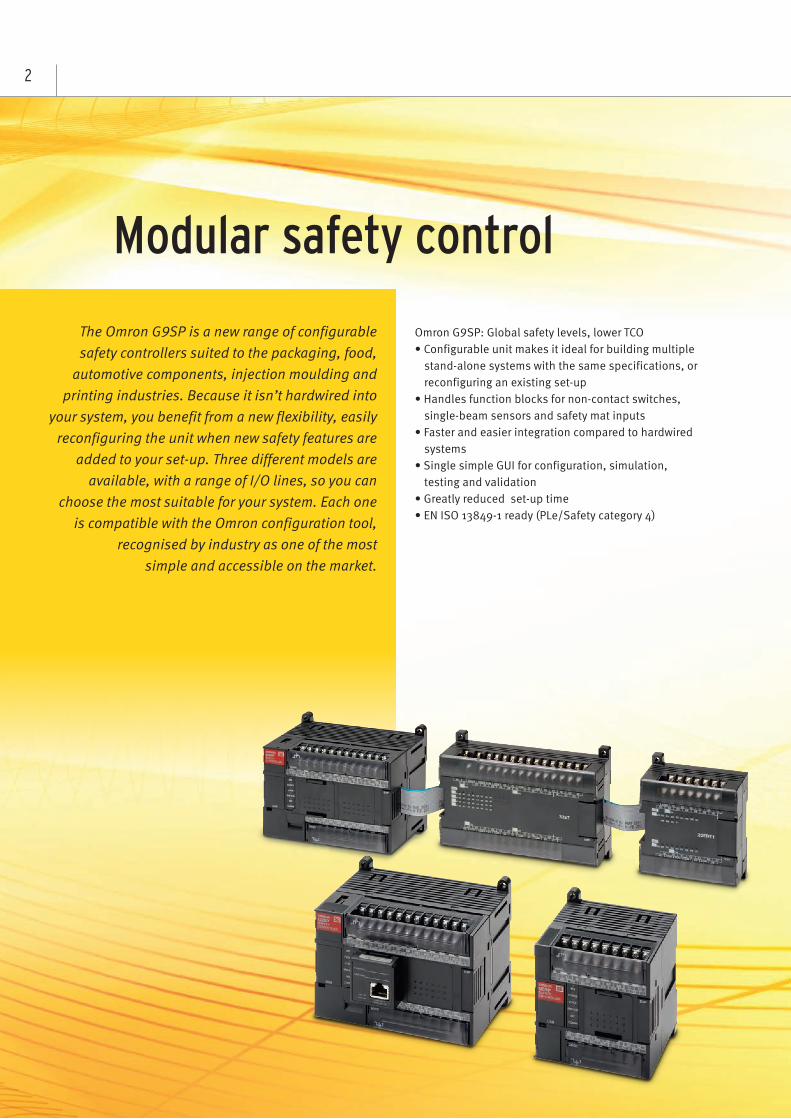
The Omron G9SP is a new range of configurable safety controllers suited to the packaging, food,
automotive components, injection moulding and printing industries. Because it isn’t hardwired into
your system, you benefit from a new flexibility, easily reconfiguring the unit when new safety features are
added to your set-up. Three different models are available, with a range of I/O lines, so you can
choose the most suitable for your system. Each one is compatible with the Omron configuration tool,
recognised by industry as one of the most simple and accessible on the market.
Omron G9SP: Global safety levels, lower TCO• Configurable unit makes it ideal for building multiple
stand-alone systems with the same specifications, or reconfiguring an existing set-up
• Handles function blocks for non-contact switches, single-beam sensors and safety mat inputs
• Faster and easier integration compared to hardwired systems
• Single simple GUI for configuration, simulation, testing and validation
• Greatly reduced set-up time• EN ISO 13849-1 ready (PLe/Safety category 4)
3
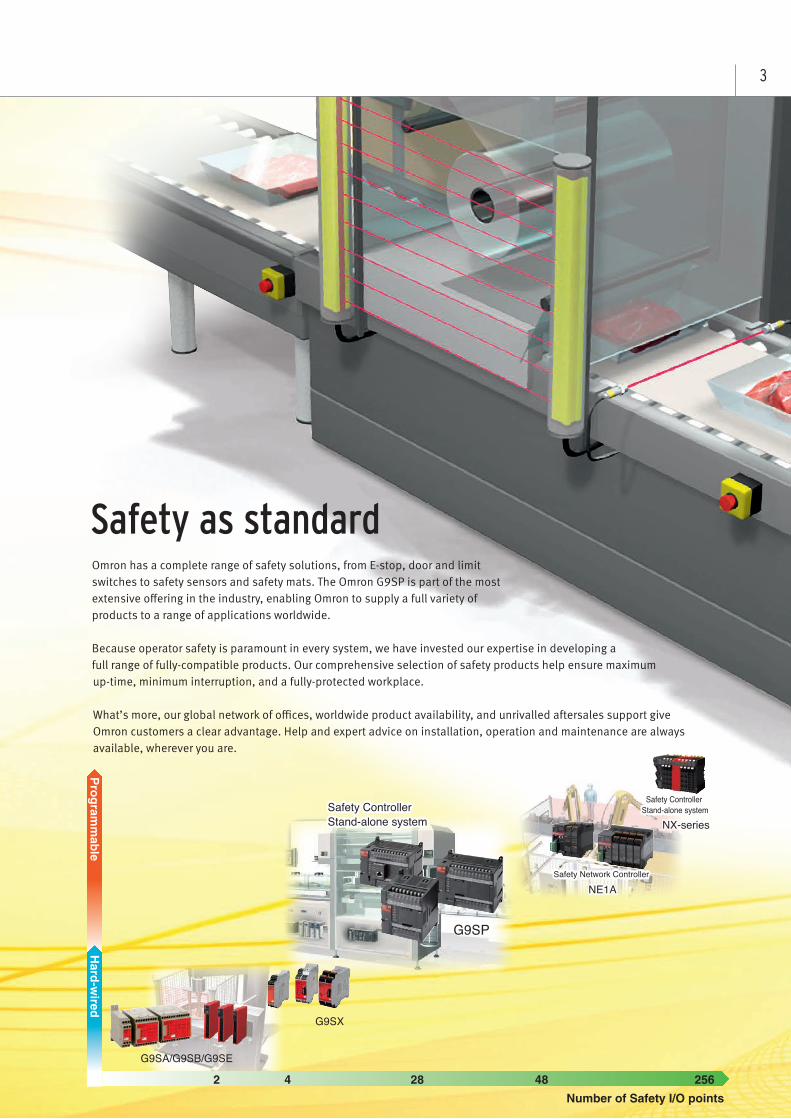
Omron has a complete range of safety solutions, from E-stop, door and limit switches to safety sensors and safety mats. The Omron G9SP is part of the most extensive offering in the industry, enabling Omron to supply a full variety of products to a range of applications worldwide.
Because operator safety is paramount in every system, we have invested our expertise in developing a full range of fully-compatible products. Our comprehensive selection of safety products help ensure maximum up-time, minimum interruption, and a fully-protected workplace.
What’s more, our global network of offices, worldwide product availability, and unrivalled aftersales support give Omron customers a clear advantage. Help and expert advice on installation, operation and maintenance are always available, wherever you are.
Safety as standard
Safety Controller Stand-alone system
G9SA/G9SB/G9SE
G9SX
Safety Controller Stand-alone systemSafety Controller Stand-alone system
2 4 48 25628Number of Safety I/O points
Program
mable
Hard-w
ired
Safety Network Controller Safety Network Controller
Safety Controller Stand-alone system
G9SP
NE1ANE1A
NX-seriesNX-series
4
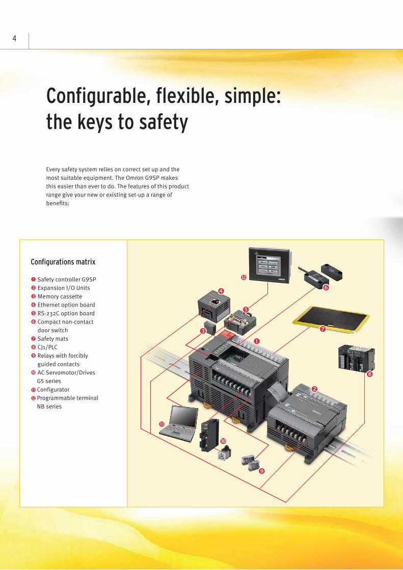
Every safety system relies on correct set up and the most suitable equipment. The Omron G9SP makes this easier than ever to do. The features of this product range give your new or existing set-up a range of benefits:
Configurable, flexible, simple: the keys to safety
Configurations matrix
Safety controller G9SP Expansion I/O Units Memory cassette Ethernet option board RS-232C option board Compact non-contact
door switch Safety mats CJ1/PLC Relays with forcibly
guided contacts AC Servomotor/Drives
G5 series Configurator Programmable terminal NB series
5
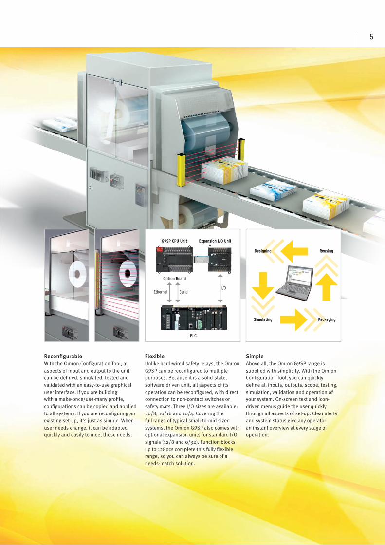
ReconfigurableWith the Omron Configuration Tool, all aspects of input and output to the unit can be defined, simulated, tested and validated with an easy-to-use graphical user interface. If you are building with a make-once/use-many profile, configurations can be copied and applied to all systems. If you are reconfiguring an existing set-up, it’s just as simple. When user needs change, it can be adapted quickly and easily to meet those needs.
FlexibleUnlike hard-wired safety relays, the Omron G9SP can be reconfigured to multiple purposes. Because it is a solid-state, software-driven unit, all aspects of its operation can be reconfigured, with direct connection to non-contact switches or safety mats. Three I/O sizes are available: 20/8, 10/16 and 10/4. Covering the full range of typical small-to-mid sized systems, the Omron G9SP also comes with optional expansion units for standard I/O signals (12/8 and 0/32). Function blocks up to 128pcs complete this fully flexible range, so you can always be sure of a needs-match solution.
SimpleAbove all, the Omron G9SP range is supplied with simplicity. With the Omron Configuration Tool, you can quickly define all inputs, outputs, scope, testing, simulation, validation and operation of your system. On-screen text and icon-driven menus guide the user quickly through all aspects of set-up. Clear alerts and system status give any operator an instant overview at every stage of operation.
PackagingSimulating
ReusingDesigning
Option Board
I/OEthernet Serial
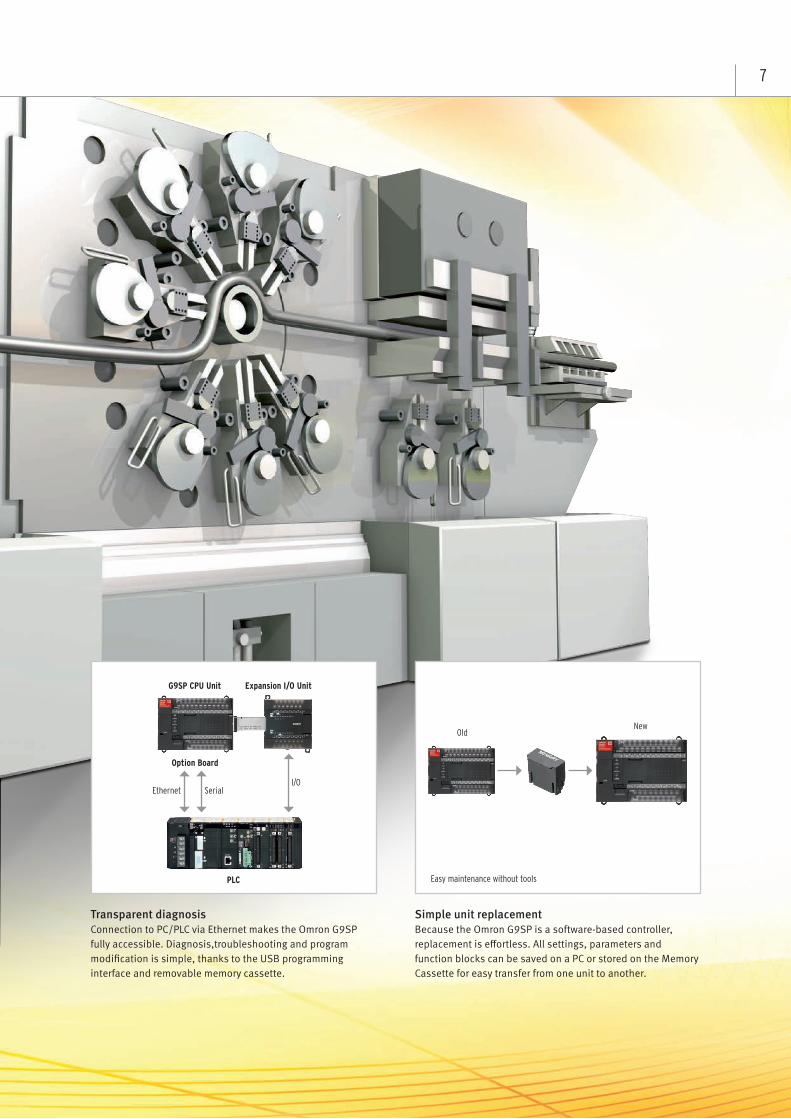
G9SP CPU Unit Expansion I/O Unit
PLC
6
Modern production and automotive parts production lines must be flexible to cater to changing customer needs. This often means being able to change machine set-up at short notice, for custom jobs or additional requirements. With the Omron G9SP, it couldn’t be easier. Function blocks can be redesigned and replaced using the simple GUI, swiftly incorporating any application changes or additions.
Even the most complex controls can be configured easily. Clear programming guidance is provided for new users, and modification and maintenance have been simplified too. Settings can be saved to Memory Cassette for off-line diagnostics, and any programming changes can be restored instantly into the Omron G9SP from the same memory cassette.
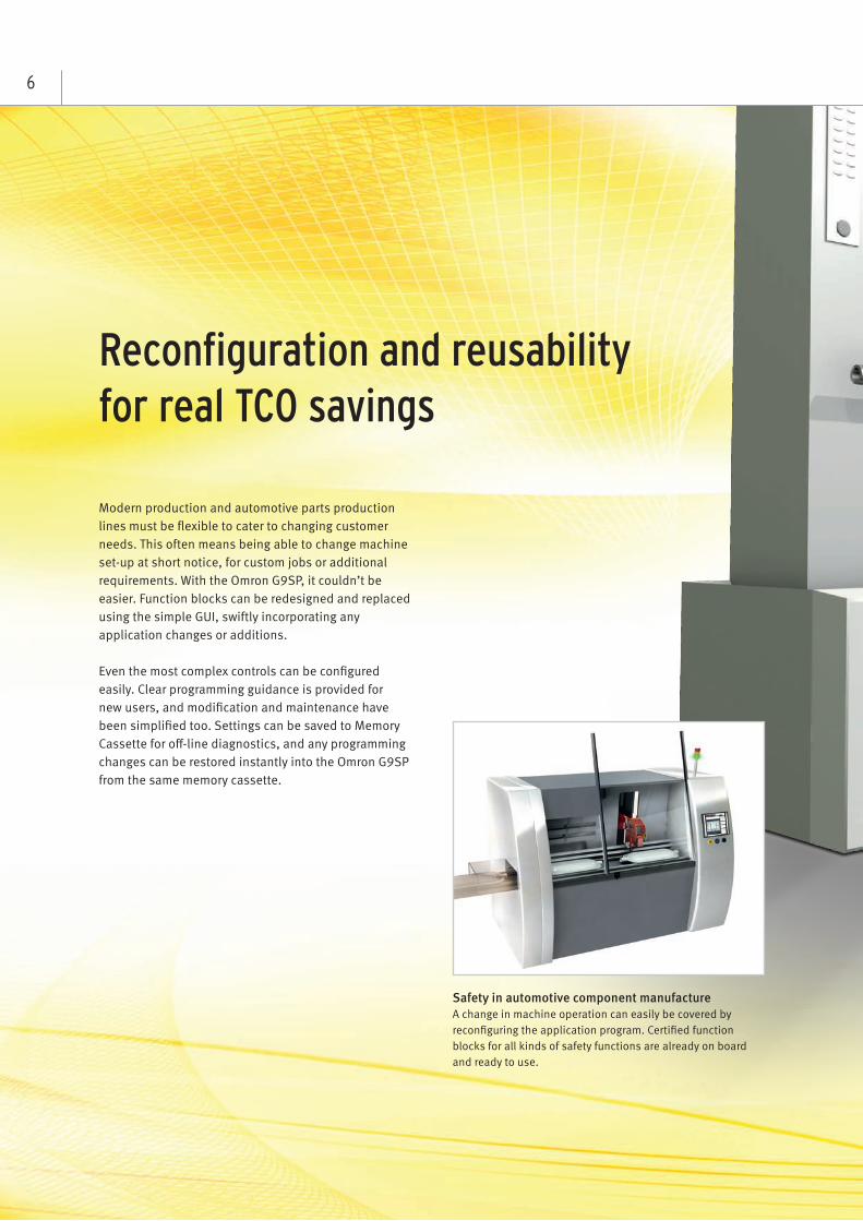
Safety in automotive component manufacture A change in machine operation can easily be covered by reconfiguring the application program. Certified function blocks for all kinds of safety functions are already on board and ready to use.
Reconfiguration and reusability for real TCO savings
7
Transparent diagnosisConnection to PC/PLC via Ethernet makes the Omron G9SP fully accessible. Diagnosis,troubleshooting and program modification is simple, thanks to the USB programming interface and removable memory cassette.
Simple unit replacementBecause the Omron G9SP is a software-based controller, replacement is effortless. All settings, parameters and function blocks can be saved on a PC or stored on the Memory Cassette for easy transfer from one unit to another.
Easy maintenance without tools
OldNew
Option Board
I/OEthernet Serial
G9SP CPU Unit Expansion I/O Unit
PLC
8
Modern packaging machines must be flexible to exactly match changing customer needs. With the Omron G9SP, application flexibility is built in. Choose from three standalone safety controller CPU types, then combine with any communication interface or 2 additional standard I/O signals. All G9SP units support direct connections of all kinds of safety sensors, including safety mats, non-contact door monitoring systems and single-beam sensors.
The Omron G9SP can be monitored and configured from a standard control console via Ethernet, serial board or standard I/O lines. For multiple applications of a single configuration, the Omron G9SP memory cassette usage. Which means that systems designers now only need to program the unit once, and use the memory cassette to install settings into each identical system.
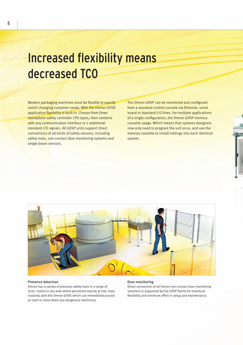
Door monitoringDirect connection of all Omron non-contact door monitoring solutions is supported by the G9SP family for maximum flexibility and minimum effort in setup and maintenance.
Presence detectionOmron has a variety of pressure safety mats in a range of sizes. Useful in any area where personnel may be at risk, mats instantly alert the Omron G9SP, which can immediately sound an alert or close down any dangerous machinery.
Increased flexibility means decreased TCO
+
9
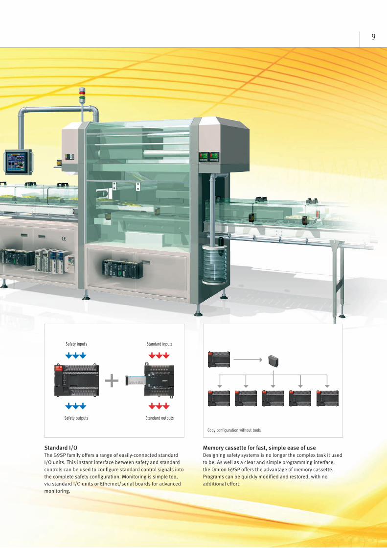
Standard I/OThe G9SP family offers a range of easily-connected standard I/O units. This instant interface between safety and standard controls can be used to configure standard control signals into the complete safety configuration. Monitoring is simple too, via standard I/O units or Ethernet/serial boards for advanced monitoring.
Memory cassette for fast, simple ease of useDesigning safety systems is no longer the complex task it used to be. As well as a clear and simple programming interface, the Omron G9SP offers the advantage of memory cassette. Programs can be quickly modified and restored, with no additional effort.
Safety inputs
Safety outputs
Standard inputs
Standard outputs
Copy configuration without tools
10
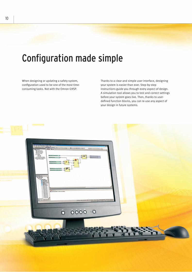
When designing or updating a safety system, configuration used to be one of the most time-consuming tasks. Not with the Omron G9SP.
Thanks to a clear and simple user interface, designing your system is easier than ever. Step-by-step instructions guide you through every aspect of design. A simulation tool allows you to test and correct settings before your system goes live. Then, thanks to user-defined function blocks, you can re-use any aspect of your design in future systems.
Configuration made simple
11
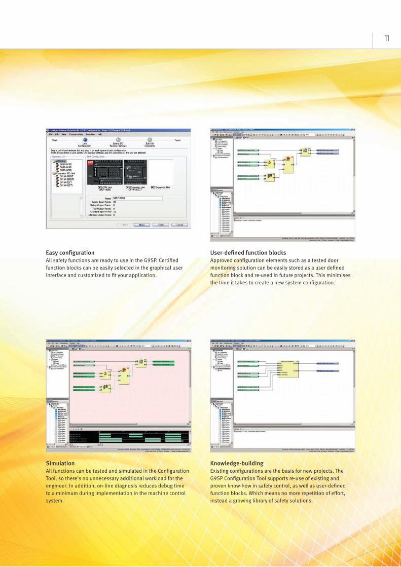
Easy configurationAll safety functions are ready to use in the G9SP. Certified function blocks can be easily selected in the graphical user interface and customized to fit your application.
User-defined function blocksApproved configuration elements such as a tested door monitoring solution can be easily stored as a user defined function block and re-used in future projects. This minimises the time it takes to create a new system configuration.
SimulationAll functions can be tested and simulated in the Configuration Tool, so there’s no unnecessary additional workload for the engineer. In addition, on-line diagnosis reduces debug time to a minimum during implementation in the machine control system.
Knowledge-buildingExisting configurations are the basis for new projects. The G9SP Configuration Tool supports re-use of existing and proven know-how in safety control, as well as user-defined function blocks. Which means no more repetition of effort, instead a growing library of safety solutions.
12
Safety Controller
G9SPEasy programming for complex safety control
• Stand-alone Safety Controller for small and mid-sized machinery• Three types of CPU with different I/O size to suit the application• Four types of Expansion I/O Units for hard-wired diagnosis or
standard signals• Clear diagnosis and monitoring via Ethernet or Serial connection• Various kinds of safety devices directly connectable like non-
contact switches and safety mats• Easy design, verification, standardization and reusage of safety
control by unique programming software• ISO 13849-1 (PLe/Category 4), IEC61508 (SIL3) certified
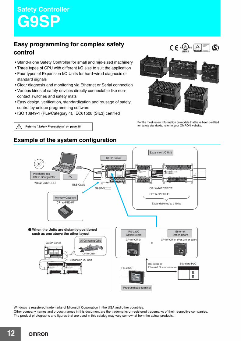
Example of the system configuration
Windows is registered trademarks of Microsoft Corporation in the USA and other countries.Other company names and product names in this document are the trademarks or registered trademarks of their respective companies.The product photographs and figures that are used in this catalog may vary somewhat from the actual products.
Refer to "Safety Precautions" on page 25.
For the most recent information on models that have been certified for safety standards, refer to your OMRON website.
Programmable terminal
Expansion I/O Unit
G9SP Series
PC Peripheral Tool G9SP Configurator WS02-G9SP@@@
USB Cable
Memory Cassette
CP1W-ME05M
G9SP-N@@@ CP1W-20EDT/EDT1 CP1W-32ET/ET1
Expandable up to 2 Units
CP1W-CN811
G9SP Series
Expansion I/O Unit
RS-232C Option Board
CP1W-CIF01 or
RS-232C
RS-232C or Ethernet Communication
Standard PLC
CP1W-CIF41 (Ver. 2.0 or later)
Ethernet Option Board
I/O Connecting Cable
When the Units are distantly-positioned such as one above the other layout
G9SP
13
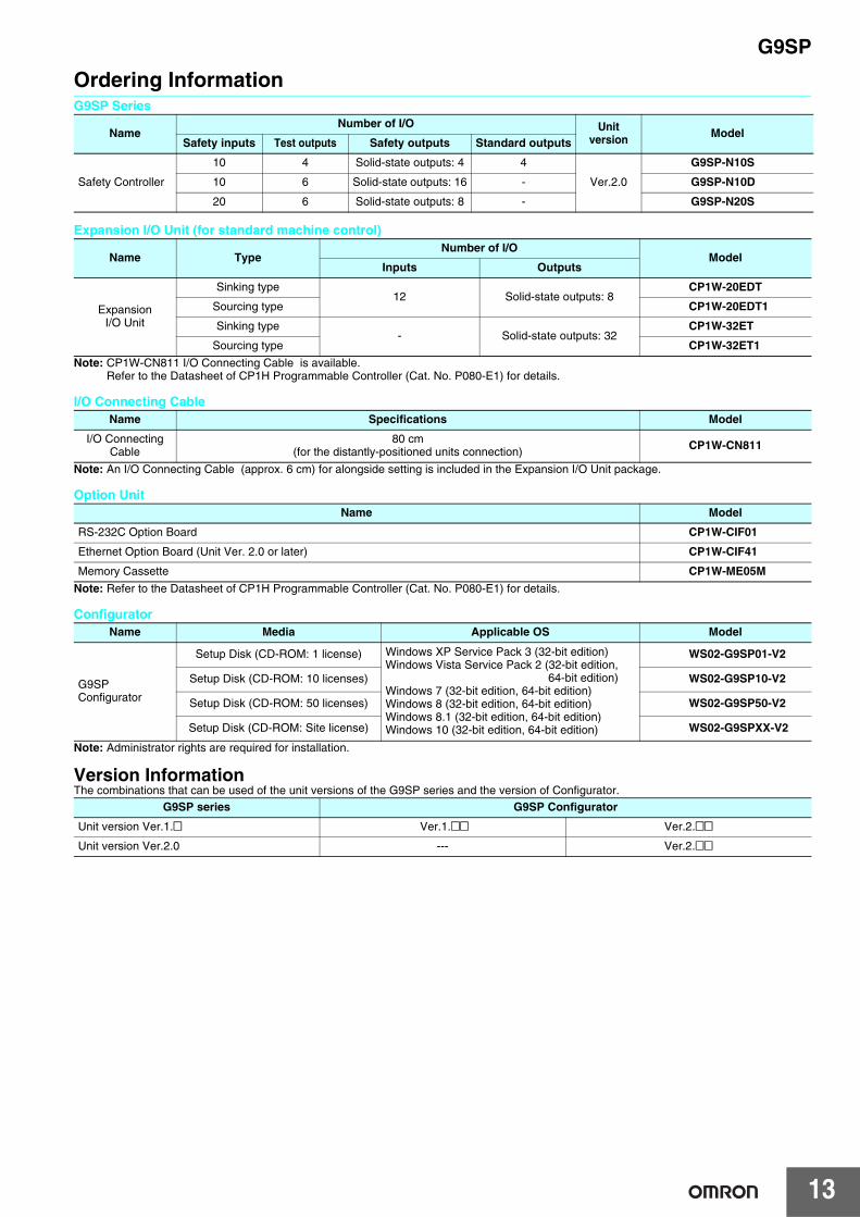
Ordering InformationG9SP Series
Expansion I/O Unit (for standard machine control)
Note: CP1W-CN811 I/O Connecting Cable is available.Refer to the Datasheet of CP1H Programmable Controller (Cat. No. P080-E1) for details.
I/O Connecting Cable
Note: An I/O Connecting Cable (approx. 6 cm) for alongside setting is included in the Expansion I/O Unit package.
Option Unit
Note: Refer to the Datasheet of CP1H Programmable Controller (Cat. No. P080-E1) for details.
Configurator
Note: Administrator rights are required for installation.
Version InformationThe combinations that can be used of the unit versions of the G9SP series and the version of Configurator.
NameNumber of I/O Unit
version ModelSafety inputs Test outputs Safety outputs Standard outputs
Safety Controller
10 4 Solid-state outputs: 4 4
Ver.2.0
G9SP-N10S
10 6 Solid-state outputs: 16 - G9SP-N10D
20 6 Solid-state outputs: 8 - G9SP-N20S
Name TypeNumber of I/O
ModelInputs Outputs
Expansion I/O Unit
Sinking type12 Solid-state outputs: 8
CP1W-20EDT
Sourcing type CP1W-20EDT1
Sinking type- Solid-state outputs: 32
CP1W-32ET
Sourcing type CP1W-32ET1
Name Specifications Model
I/O Connecting Cable
80 cm(for the distantly-positioned units connection) CP1W-CN811
Name Model
RS-232C Option Board CP1W-CIF01
Ethernet Option Board (Unit Ver. 2.0 or later) CP1W-CIF41
Memory Cassette CP1W-ME05M
Name Media Applicable OS Model
G9SP Configurator
Setup Disk (CD-ROM: 1 license) Windows XP Service Pack 3 (32-bit edition)Windows Vista Service Pack 2 (32-bit edition,
64-bit edition)Windows 7 (32-bit edition, 64-bit edition)Windows 8 (32-bit edition, 64-bit edition)Windows 8.1 (32-bit edition, 64-bit edition)Windows 10 (32-bit edition, 64-bit edition)
WS02-G9SP01-V2
Setup Disk (CD-ROM: 10 licenses) WS02-G9SP10-V2
Setup Disk (CD-ROM: 50 licenses) WS02-G9SP50-V2
Setup Disk (CD-ROM: Site license) WS02-G9SPXX-V2
G9SP series G9SP Configurator
Unit version Ver.1.@ Ver.1.@@ Ver.2.@@
Unit version Ver.2.0 --- Ver.2.@@
G9SP
14
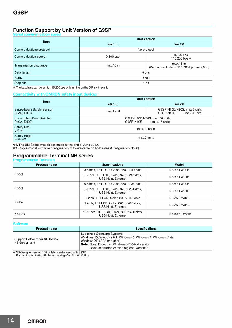
Function Support by Unit Version of G9SPSerial communication speed
* The baud rate can be set to 115,200 bps with turning on the DIP swith pin 3.
Connectivity with OMRON safety input devices
*1. The UM Series was discontinued at the end of June 2019.*2. Only a model with wire configuration of 2-wire cable on both sides (Configuration No. 0)
Programmable Terminal NB series Programmable Terminals
Software
* NB-Designer version 1.32 or later can be used with G9SP.For detail, refer to the NB Series catalog (Cat. No. V412-E1).
ItemUnit Version
Ver.1.@ Ver.2.0
Communications protocol No-protocol
Communication speed 9,600 bps 9,600 bps115,200 bps *
Transmission disutance max.15 m max.15 m(With a baud rate of 115,200 bps: max.3 m)
Data length 8 bits
Parity Even
Stop bits 1 bit
ItemUnit Version
Ver.1.@ Ver.2.0
Single-beam Safety SensorE3ZS, E3FS max.1 unit G9SP-N10D/N20S: max.6 units
G9SP-N10S : max.4 units
Non-contact Door SwitcheD40A, D40Z
G9SP-N10D/N20S: max.30 unitsG9SP-N10S : max.15 units
Safety MatUM *1 max.12 units
Safety EdgeSGE *2 max.5 units
Product name Specifications Model
NB3Q3.5 inch, TFT LCD, Color, 320 × 240 dots NB3Q-TW00B
3.5 inch, TFT LCD, Color, 320 × 240 dots, USB Host, Ethernet NB3Q-TW01B
NB5Q5.6 inch, TFT LCD, Color, 320 × 234 dots NB5Q-TW00B
5.6 inch, TFT LCD, Color, 320 × 234 dots, USB Host, Ethernet NB5Q-TW01B
NB7W7 inch, TFT LCD, Color, 800 × 480 dots NB7W-TW00B
7 inch, TFT LCD, Color, 800 × 480 dots, USB Host, Ethernet NB7W-TW01B
NB10W 10.1 inch, TFT LCD, Color, 800 × 480 dots, USB Host, Ethernet NB10W-TW01B
Product name Specifications
Support Software for NB SeriesNB-Designer *
Supported Operating Systems:Windows 10, Windows 8.1, Windows 8, Windows 7, Windows Vista , Windows XP (SP3 or higher).Note: Note: Except for Windows XP 64-bit version
Download from Omron's regional websites.
G9SP
15
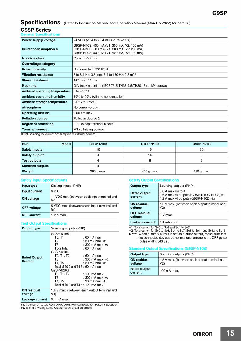
Specifications (Refer to Instruction Manual and Operation Manual (Man.No.Z922) for details.)
G9SP SeriesGeneral Specifications
* Not including the current consumption of external devices.
Safety Input Specifications
Test Output Specifications
*1. Connection to OMRON D40A/D40Z Non-contact Door Switch is possible.*2. With the Muting Lamp Output (open circuit detection)
Safety Output Specifications
*1. Total current for So0 to So3 and So4 to So7*2. Total current for So0 to So3, So4 to So7, So8 to So11 and So12 to So15Note: When a safety output is set as a pulse output, make sure that
the connected devices do not malfunction due to the OFF pulse (pulse width: 640 μs).
Standard Output Specifications (G9SP-N10S)
Power supply voltage 24 VDC (20.4 to 26.4 VDC -15% +10%)
Current consumption *G9SP-N10S: 400 mA (V1: 300 mA, V2: 100 mA)G9SP-N10D: 500 mA (V1: 300 mA, V2: 200 mA)G9SP-N20S: 500 mA (V1: 400 mA, V2: 100 mA)
Isolation class Class III (SELV)
Overvoltage category II
Noise immunity Conforms to IEC61131-2
Vibration resistance 5 to 8.4 Hz: 3.5 mm, 8.4 to 150 Hz: 9.8 m/s2
Shock resistance 147 m/s2: 11 ms
Mounting DIN track mounting (IEC60715 TH35-7.5/TH35-15) or M4 screws
Ambient operating temperature 0 to +55°C
Ambient operating humidity 10% to 90% (with no condensation)
Ambient storage temperature -20°C to +75°C
Atmosphere No corrosive gas
Operating altitude 2,000 m max.
Pollution degree Pollution degree 2
Degree of protection IP20 except terminal blocks
Terminal screws M3 self-rising screws
Item Model G9SP-N10S G9SP-N10D G9SP-N20S
Safety inputs 10 10 20
Safety outputs 4 16 8
Test outputs 4 6 6
Standard outputs 4 - -
Weight 290 g max. 440 g max. 430 g max.
Input type Sinking inputs (PNP)
Input current 6 mA
ON voltage 11 VDC min. (between each input terminal and G1)
OFF voltage 5 VDC max. (between each input terminal and G1)
OFF current 1 mA max.
Output type Sourcing outputs (PNP)
Rated Output Current
G9SP-N10ST0, T1 : 60 mA max.T2 : 30 mA max. *1T3 : 300 mA max. *2T0-2 total : 60 mA max.
G9SP-N10DT0, T1, T2 : 60 mA max.T3 : 300 mA max. *2T4, T5 : 30 mA max. *1Total of T0-2 and T4-5 : 60 mA max.
G9SP-N20ST0, T1, T2 : 100 mA max.T3 : 300 mA max. *2T4, T5 : 30 mA max. *1Total of T0-2 and T4-5 : 120 mA max.
ON residual voltage
1.8 V max. (between each output terminal and V1)
Leakage current 0.1 mA max.
Output type Sourcing outputs (PNP)
Rated output current
0.8 A max./output1.6 A max./4 outputs (G9SP-N10S/-N20S) *11.2 A max./4 outputs (G9SP-N10D) *2
ON residual voltage
1.2 V max. (between each output terminal and V2)
OFF residual voltage 2 V max.
Leakage current 0.1 mA max.
Output type Sourcing outputs (PNP)
ON residual voltage
1.5 V max. (between each output terminal and V2)
Rated output current 100 mA max.
G9SP
16
ConfiguratorSystem RequirementsThe following system is required to operate the G9SP Configurator WS02-G9SP@@@. Make sure your system provides the following conditions and has the necessary components.
Certified Standards
* The G9SP-series Controller (version 1.1 or later) and the Expansion I/O Units have been certified for the KOSHA S Mark.
Item Description
CD-ROM or DVDROM drive One or more
Supported operating systems
Windows XP Service Pack 3 (32-bit edition)Windows Vista Service Pack 2 (32-bit edition, 64-bit edition)Windows 7 (32-bit edition, 64-bit edition)Windows 8 (32-bit edition, 64-bit edition)Windows 8.1 (32-bit edition, 64-bit edition)Windows 10 (32-bit edition, 64-bit edition)Note: Administrator rights are required for installation.
CPU Computer with a processor that is recommended by Microsoft Corporation.
RAM Memory capacity that is recommended by Microsoft Corporation
Required hard disk space 200 MB min.
Display High-luminance display of SVGA (800 × 600) min. With 256 colors min.
Connection port to Controller USB port
Certifying body Standard
TÜVRheinland
EN ISO 13849-1EN ISO 13849-2IEC 61508 parts 1-7EN 62061IEC 61131-2EN ISO 13850EN 60204-1EN 61000-6-2EN 61000-6-4NFPA 79ANSI RIA R15.06ANSI B11.19ANSI/UL 1998
UL UL508CSA22.2 No.142
KOSHA S Mark *
G9SP
17
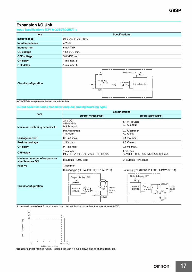
Expansion I/O UnitInput Specifications (CP1W-20EDT/20EDT1)
*ON/OFF delay represents the hardware delay time.
Output Specifications (Transistor outputs: sinking/sourcing type)
*1. A maximum of 0.9 A per common can be switched at an ambient temperature of 50°C.
*2. User cannot replace fuses. Replace the unit if a fuse blows due to short circuit, etc.
Item Specifications
Input voltage 24 VDC, +10%, -15%
Input impedance 4.7 kΩ
Input current 5 mA TYP
ON voltage 14.4 VDC min.
OFF voltage 5.0 VDC max.
ON delay 1 ms max. *
OFF delay 1 ms max. *
Circuit configuration
ItemSpecifications
CP1W-20EDT/EDT1 CP1W-32ET/32ET1
Maximum switching capacity *1
24 VDC+10%, -5%0.3 A/output
4.5 to 30 VDC 0.3 A/output
0.9 A/common1.8 A/unit
0.9 A/common7.2 A/unit
Leakage current 0.1 mA max. 0.1 mA max.
Residual voltage 1.5 V max. 1.5 V max.
ON delay 0.1 ms max. 0.1 ms max.
OFF delay 1 ms max.24 VDC, +10%, -5%, when 5 to 300 mA
1 ms max.24 VDC, +10%, -5%, when 5 to 300 mA
Maximum number of outputs for simultaneous ON 8 outputs (100% load) 24 outputs (75% load)
Fuse *2 1/common
Circuit configuration
Sinking type (CP1W-20EDT, CP1W-32ET) Sourcing type (CP1W-20EDT1, CP1W-32ET1)
IN
IN
COM
4.7 k
Input display LED
Internal circuits750
OUTL
LOUT
COM(-)
24 VDC/4.5 to 30 VDC
Output display LED
Internalcircuits
COM (+)
OUT
OUT
L
L
24 VDC/4.5 to 30 VDC
Output display LED
Internalcircuits
0.9
0.8
50 55
Ambient temperature
(A)
(°C)
Com
mon total current
0
G9SP
18
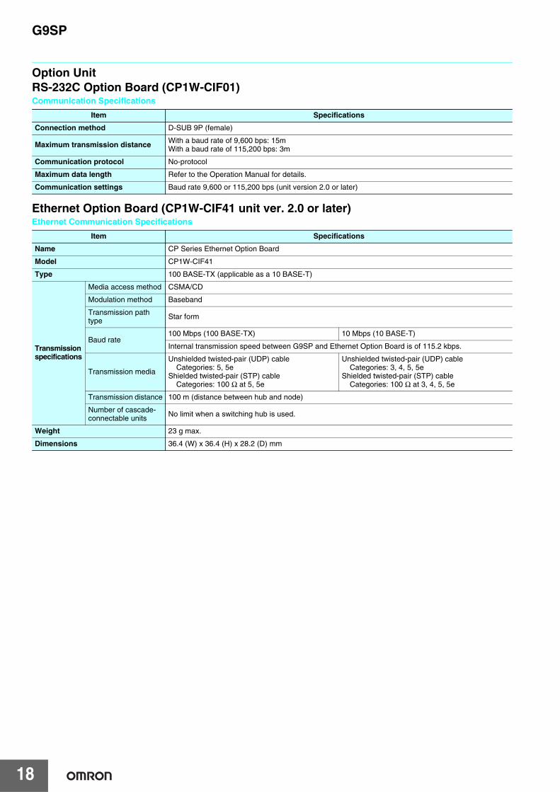
Option UnitRS-232C Option Board (CP1W-CIF01)Communication Specifications
Ethernet Option Board (CP1W-CIF41 unit ver. 2.0 or later)Ethernet Communication Specifications
Item Specifications
Connection method D-SUB 9P (female)
Maximum transmission distance With a baud rate of 9,600 bps: 15mWith a baud rate of 115,200 bps: 3m
Communication protocol No-protocol
Maximum data length Refer to the Operation Manual for details.
Communication settings Baud rate 9,600 or 115,200 bps (unit version 2.0 or later)
Item Specifications
Name CP Series Ethernet Option Board
Model CP1W-CIF41
Type 100 BASE-TX (applicable as a 10 BASE-T)
Transmission specifications
Media access method CSMA/CD
Modulation method Baseband
Transmission path type Star form
Baud rate100 Mbps (100 BASE-TX) 10 Mbps (10 BASE-T)
Internal transmission speed between G9SP and Ethernet Option Board is of 115.2 kbps.
Transmission media
Unshielded twisted-pair (UDP) cableCategories: 5, 5e
Shielded twisted-pair (STP) cable Categories: 100 Ω at 5, 5e
Unshielded twisted-pair (UDP) cableCategories: 3, 4, 5, 5e
Shielded twisted-pair (STP) cableCategories: 100 Ω at 3, 4, 5, 5e
Transmission distance 100 m (distance between hub and node)
Number of cascade-connectable units No limit when a switching hub is used.
Weight 23 g max.
Dimensions 36.4 (W) x 36.4 (H) x 28.2 (D) mm
G9SP
19
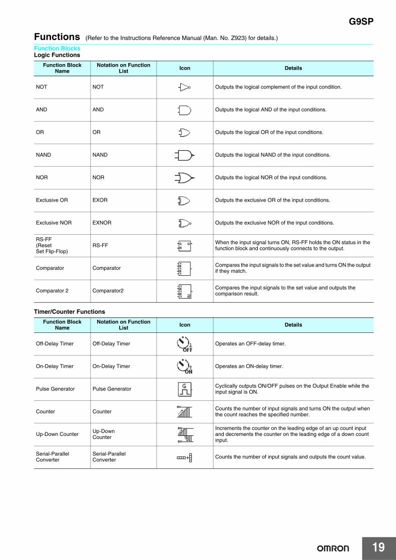
Functions (Refer to the Instructions Reference Manual (Man. No. Z923) for details.)
Function BlocksLogic Functions
Timer/Counter Functions
Function Block Name
Notation on Function List Icon Details
NOT NOT Outputs the logical complement of the input condition.
AND AND Outputs the logical AND of the input conditions.
OR OR Outputs the logical OR of the input conditions.
NAND NAND Outputs the logical NAND of the input conditions.
NOR NOR Outputs the logical NOR of the input conditions.
Exclusive OR EXOR Outputs the exclusive OR of the input conditions.
Exclusive NOR EXNOR Outputs the exclusive NOR of the input conditions.
RS-FF(Reset Set Flip-Flop)
RS-FF When the input signal turns ON, RS-FF holds the ON status in the function block and continuously connects to the output.
Comparator Comparator Compares the input signals to the set value and turns ON the output if they match.
Comparator 2 Comparator2 Compares the input signals to the set value and outputs the comparison result.
Function Block Name
Notation on Function List Icon Details
Off-Delay Timer Off-Delay Timer Operates an OFF-delay timer.
On-Delay Timer On-Delay Timer Operates an ON-delay timer.
Pulse Generator Pulse Generator Cyclically outputs ON/OFF pulses on the Output Enable while the input signal is ON.
Counter Counter Counts the number of input signals and turns ON the output when the count reaches the specified number.
Up-Down Counter Up-DownCounter
Increments the counter on the leading edge of an up count input and decrements the counter on the leading edge of a down count input.
Serial-Parallel Converter
Serial-ParallelConverter Counts the number of input signals and outputs the count value.
G9SP
20
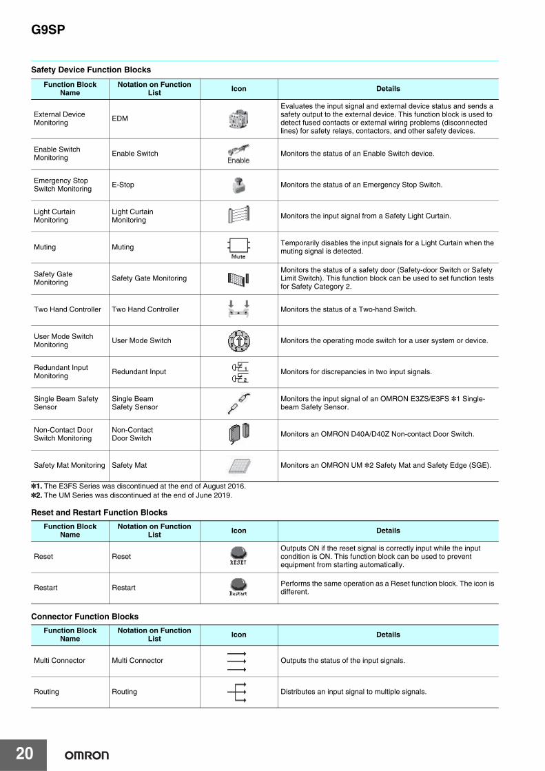
Safety Device Function Blocks
*1. The E3FS Series was discontinued at the end of August 2016.*2. The UM Series was discontinued at the end of June 2019.
Reset and Restart Function Blocks
Connector Function Blocks
Function Block Name
Notation on Function List Icon Details
External Device Monitoring EDM
Evaluates the input signal and external device status and sends a safety output to the external device. This function block is used to detect fused contacts or external wiring problems (disconnected lines) for safety relays, contactors, and other safety devices.
Enable Switch Monitoring Enable Switch Monitors the status of an Enable Switch device.
Emergency Stop Switch Monitoring E-Stop Monitors the status of an Emergency Stop Switch.
Light Curtain Monitoring
Light Curtain Monitoring Monitors the input signal from a Safety Light Curtain.
Muting Muting Temporarily disables the input signals for a Light Curtain when the muting signal is detected.
Safety Gate Monitoring Safety Gate Monitoring
Monitors the status of a safety door (Safety-door Switch or Safety Limit Switch). This function block can be used to set function tests for Safety Category 2.
Two Hand Controller Two Hand Controller Monitors the status of a Two-hand Switch.
User Mode Switch Monitoring User Mode Switch Monitors the operating mode switch for a user system or device.
Redundant Input Monitoring Redundant Input Monitors for discrepancies in two input signals.
Single Beam Safety Sensor
Single BeamSafety Sensor
Monitors the input signal of an OMRON E3ZS/E3FS *1 Single-beam Safety Sensor.
Non-Contact Door Switch Monitoring
Non-ContactDoor Switch Monitors an OMRON D40A/D40Z Non-contact Door Switch.
Safety Mat Monitoring Safety Mat Monitors an OMRON UM *2 Safety Mat and Safety Edge (SGE).
Function Block Name
Notation on Function List Icon Details
Reset ResetOutputs ON if the reset signal is correctly input while the input condition is ON. This function block can be used to prevent equipment from starting automatically.
Restart Restart Performs the same operation as a Reset function block. The icon is different.
Function Block Name
Notation on Function List Icon Details
Multi Connector Multi Connector Outputs the status of the input signals.
Routing Routing Distributes an input signal to multiple signals.
G9SP
21
WiringTerminal Arrangement
G9SP-N10S
G9SP-N10D
G9SP-N20S
Internal Circuits and Wiring Example
I/O Wiring Example: Emergency Stop (Dual Channel) with Manual Reset
NC
NC NC
Si0Si1
O0
Si2Si3
Si4Si5
Si6Si7
Si8Si9
V2
V1 G1
So1So2
So3
T0T1 T3Top
(17 pin)
Bottom(14 pin) G2
So0NC
NCO1
O2O3
T2
Top(24 pin)
Bottom(19 pin)
NC NCSi0
So8
Si1
So9
Si2
So10
Si3
So11
Si4
So12
Si5
So13
Si6
So14
Si7
So15
Si8Si9
V2
V1 G1
So1So2
So3
NCNC
T0
So7So4
So5So6
T1
G2So0NC
NCNC
T2T3
T4T5
Top(24 pin)
Bottom(19 pin)
NC
NC
NCSi0Si1
Si2Si3
Si4Si5
Si6Si7
Si8Si9
Si10Si11
Si12Si13
Si14Si15
Si16Si17
Si18
V2
V1 G1
T0T1
T2
Si19
So0G2 So1
So2So3
So4So5
So6So7
NCNC T3
T4T5
Terminals Function
V1/G1 Power supply terminals for Internal/Input circuits (24 VDC)
V2/G2 Power supply terminals for output circuits (24 VDC)
NC Not used (Do not connect.)
Si0 - Si19 Safety input terminals
T0 - T5 Test output terminals
So0 - So15 Safety output terminals
O0 - O3 Standard output terminals
D+
D -
USB
Internalcircuits
24 VDCV1
G1
Si0
Si19
T0
T5
V2
G2
So0
So7
O0
O3
L
L
L
L
Testoutputcircuit
Safetyinputcircuit
Standardoutputcircuit
Safetyoutputcircuit
DC24V
V1
V2
G1
G2
Si0
So0
Si1
So1 T1 T2 T3
Si2 Si3
Reset
Estop
G9SP
T0 M
KM1
KM2
KM1 KM2
KM1
KM2
G9SP
22
Dimensions (Unit: mm)
Safety ControllerG9SP-N10S
8
81
85
86
76
90100110
2-4.5 dia.
8
81
85
130
120
90100110
4-4.5 dia.
Safety ControllerG9SP-N10DG9SP-N20S
G9SP
23
Application Examples
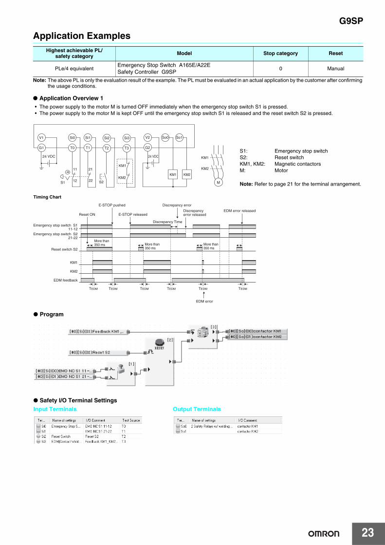
Note: The above PL is only the evaluation result of the example. The PL must be evaluated in an actual application by the customer after confirming the usage conditions.
● Application Overview 1• The power supply to the motor M is turned OFF immediately when the emergency stop switch S1 is pressed.• The power supply to the motor M is kept OFF until the emergency stop switch S1 is released and the reset switch S2 is pressed.
Highest achievable PL/safety category Model Stop category Reset
PLe/4 equivalentEmergency Stop Switch A165E/A22ESafety Controller G9SP
0 Manual
11
12
21
22S1 S2
24 VDC24 VDC
KM1
KM2
Si2 Si3V1 Si0 Si1 V2 So0
T0 T1 T2 T3 G2
KM1 KM2
G1
So1
M
KM1
KM2
S1: Emergency stop switchS2: Reset switchKM1, KM2: Magnetic contactorsM: Motor
Note: Refer to page 21 for the terminal arrangement.
Timing Chart
E-STOP pushed
More than 350 ms More than
350 msMore than 350 ms
Discrepancy error
EDM error releasedDiscrepancyerror released
TEDM TEDM TEDM TEDM TEDM TEDM
Emergency stop switch S111-12
Reset switch S2
KM1
KM2
EDM feedback
Emergency stop switch S221-22
Discrepancy Time
E-STOP releasedReset ON
EDM error
● Program
● Safety I/O Terminal Settings
Input Terminals Output Terminals
G9SP
24
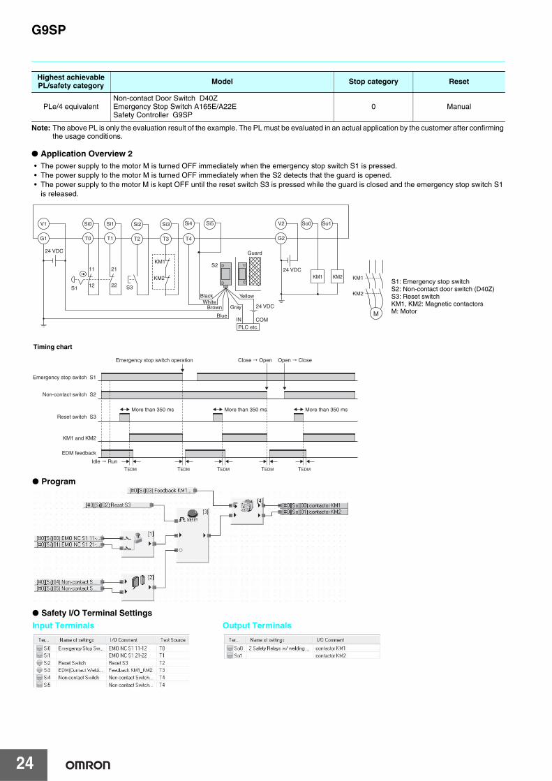
Note: The above PL is only the evaluation result of the example. The PL must be evaluated in an actual application by the customer after confirming the usage conditions.
● Application Overview 2• The power supply to the motor M is turned OFF immediately when the emergency stop switch S1 is pressed.• The power supply to the motor M is turned OFF immediately when the S2 detects that the guard is opened.• The power supply to the motor M is kept OFF until the reset switch S3 is pressed while the guard is closed and the emergency stop switch S1
is released.
Highest achievable PL/safety category Model Stop category Reset
PLe/4 equivalentNon-contact Door Switch D40ZEmergency Stop Switch A165E/A22ESafety Controller G9SP
0 Manual
S1: Emergency stop switchS2: Non-contact door switch (D40Z)S3: Reset switchKM1, KM2: Magnetic contactorsM: Motor
24 VDC11
12
21
22
24 VDC
S2
PLC etc.
Guard
COMIN
24 VDC
S1 S3
M
KM1
KM1
KM2
KM2
Si2 Si3V1 Si0 Si1 Si4 Si5 V2 So0
T0 T1 T2 T3 G2
KM1 KM2
T4G1
So1
BlackWhite
Brown
Blue
Yellow
Gray
Emergency stop switch operation
Emergency stop switch S1
Reset switch S3
KM1 and KM2
EDM feedback
Non-contact switch S2
More than 350 ms More than 350 ms
TEDM
More than 350 ms
Close � Open
Idle � Run
Open � Close
TEDM TEDM TEDMTEDM
Timing chart
● Safety I/O Terminal Settings
Input Terminals Output Terminals
● Program
G9SP
25
Safety PrecautionsBe sure to read the Common Precautions for Safety Warning at the following URL: http://www.ia.omron.com/.
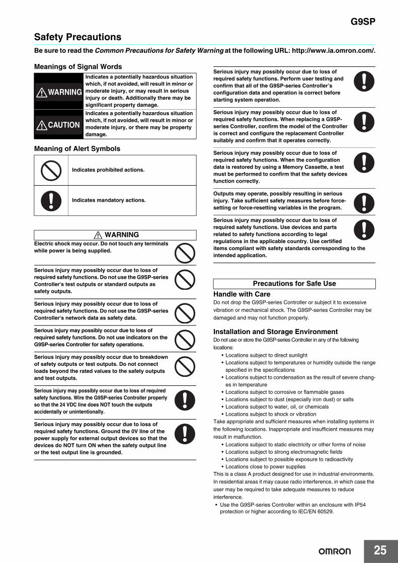
Meanings of Signal Words
Meaning of Alert Symbols
Electric shock may occur. Do not touch any terminals while power is being supplied.
Serious injury may possibly occur due to loss of required safety functions. Do not use the G9SP-series Controller's test outputs or standard outputs as safety outputs.
Serious injury may possibly occur due to loss of required safety functions. Do not use the G9SP-series Controller's network data as safety data.
Serious injury may possibly occur due to loss of required safety functions. Do not use indicators on the G9SP-series Controller for safety operations.
Serious injury may possibly occur due to breakdown of safety outputs or test outputs. Do not connect loads beyond the rated values to the safety outputs and test outputs.
Serious injury may possibly occur due to loss of required safety functions. Wire the G9SP-series Controller properly so that the 24 VDC line does NOT touch the outputs accidentally or unintentionally.
Serious injury may possibly occur due to loss of required safety functions. Ground the 0V line of the power supply for external output devices so that the devices do NOT turn ON when the safety output line or the test output line is grounded.
Serious injury may possibly occur due to loss of required safety functions. Perform user testing and confirm that all of the G9SP-series Controller’s configuration data and operation is correct before starting system operation.
Serious injury may possibly occur due to loss of required safety functions. When replacing a G9SP-series Controller, confirm the model of the Controller is correct and configure the replacement Controller suitably and confirm that it operates correctly.
Serious injury may possibly occur due to loss of required safety functions. When the configuration data is restored by using a Memory Cassette, a test must be performed to confirm that the safety devices function correctly.
Outputs may operate, possibly resulting in serious injury. Take sufficient safety measures before force-setting or force-resetting variables in the program.
Serious injury may possibly occur due to loss of required safety functions. Use devices and parts related to safety functions according to legal regulations in the applicable country. Use certified items compliant with safety standards corresponding to the intended application.
Handle with CareDo not drop the G9SP-series Controller or subject it to excessive vibration or mechanical shock. The G9SP-series Controller may be damaged and may not function properly.
Installation and Storage EnvironmentDo not use or store the G9SP-series Controller in any of the following locations:
• Locations subject to direct sunlight• Locations subject to temperatures or humidity outside the range
specified in the specifications• Locations subject to condensation as the result of severe chang-
es in temperature• Locations subject to corrosive or flammable gases• Locations subject to dust (especially iron dust) or salts• Locations subject to water, oil, or chemicals• Locations subject to shock or vibration
Take appropriate and sufficient measures when installing systems in the following locations. Inappropriate and insufficient measures may result in malfunction.
• Locations subject to static electricity or other forms of noise• Locations subject to strong electromagnetic fields• Locations subject to possible exposure to radioactivity• Locations close to power supplies
This is a class A product designed for use in industrial environments. In residential areas it may cause radio interference, in which case the user may be required to take adequate measures to reduce interference.• Use the G9SP-series Controller within an enclosure with IP54
protection or higher according to IEC/EN 60529.
Indicates a potentially hazardous situation which, if not avoided, will result in minor or moderate injury, or may result in serious injury or death. Additionally there may be significant property damage.
Indicates a potentially hazardous situation which, if not avoided, will result in minor or moderate injury, or there may be property damage.
Indicates prohibited actions.
Indicates mandatory actions.
WARNING
WARNING
CAUTION
Precautions for Safe Use
G9SP
26
• Use DIN Track (TH35-7.5/TH35-15 according to IEC 60715) or M4 screws with a tightening torque of 1.2 N·m (10.5 lb·in) to install the G9SP-series Controller into the control panel.
• Mount the G9SP-series Controller to the DIN Track using PFP-M End Plates (not included with the G9SP-series Controller) to prevent it from falling off the DIN Track because of vibration. Correctly mount all Units to DIN Track.
• Install the G9SP-series Controller in the vertical direction shown below to ensure adequate cooling.
• Space must be provided around the G9SP-series Controller, at least 20 mm from its side surfaces and at least 50 mm from its top and bottom surfaces, for ventilation and wiring.
• Be sure to lock all locking mechanisms, such as those on I/O terminal blocks and connectors, before attempting to use the Controller.
Turn OFF the power supply before performing any of the following.• Connecting or disconnecting Expansion I/O Units, Option Boards,
or any other Units• Assembling the Controller• Connecting cables or wiring• Connecting or removing terminal blocks
Installation and Wiring• Use the following to wire external I/O devices to the G9SP-series
Controller.
*When wiring two wires to one terminal. Use two wires of the same type and thickness.
• Tighten the terminal block screws to a torque of 0.5 N·m.• Disconnect the G9SP-series Controller from the power supply
before starting wiring. Devices connected to the G9SP-series Controller may operate unexpectedly.
• Properly apply the specified voltage to the G9SP-series Controller inputs. Applying an inappropriate DC voltage or any AC voltage will cause the G9SP-series Controller to fail.
• Be sure to separate the communications cables and I/O cables from high-voltage/high-current lines.
• Be cautious not to get your fingers caught when attaching connectors to the plugs on the G9SP-series Controller.
• Incorrect wiring may lead to loss of safety functions. Wire conductors correctly and verify the operation of the G9SP-series Controller before using the system in which the G9SP-series Controller is incorporated.
• Lock the connectors on Option Units or Expansion I/O Unit before using the Units.
• After wiring is completed, be sure to remove the label for wire clip entry prevention from the G9SP-series Controller to enable heat to escape for proper cooling.
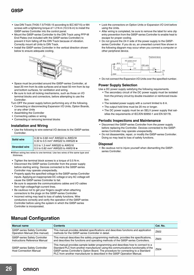
• Do not ground the 24-V side of the power supply to the G9SP-series Controller. If you do so, an unwanted current flow shown in the following diagram may occur when you connect a computer or other peripheral device.
• Do not connect the Expansion I/O Units over the specified number.
Power Supply SelectionUse a DC power supply satisfying the following requirements.
• The secondary circuit of the DC power supply must be isolatedfrom the primary circuit by double insulation or reinforced insula-tion.
• The isolated power supply with a current limited to 8 A.• The output hold time must be 20 ms or longer.• The DC power supply must be an SELV power supply that sat-
isfies the requirements of IEC/EN 60950-1 and EN 50178.
Periodic Inspections and Maintenance• Disconnect the G9SP-series Controller from the power supply
before replacing the Controller. Devices connected to the G9SP-series Controller may operate unexpectedly.
• Do not disassemble, repair, or modify the G9SP-series Controller. Doing so may lead to loss of safety functions.
Disposal• Be cautious not to injure yourself when dismantling the G9SP-
series Controller.
Manual Configuration
Solid wire 0.32 to 0.82 mm2 AWG22 to AWG180.32 to 0.5 mm2 AWG22 to AWG20 *
Stranded wire 0.5 to 1.3 mm2 AWG20 to AWG160.5 to 0.82 mm2 AWG20 to AWG18 *
DC power circuit
24 V
0 V 0 V 0 V
G9SP Peripheral device
GND
USB cable
FG
Manual name Contents Cat. No.
G9SP-series Safety Controller Operation Manual (this manual)
This manual provides detailed specifications and describes functions and application methods for the G9SP-series Controller in detail. Z922
G9SP-series Safety Controller Instructions Reference Manual
This manual describes the safety programming methods, provides the specifications, and describes the functions and operating methods of the G9SP-series Controllers. Z923
G9SP-series Safety Controller Host Connection Manual
This manual provides sample ladder programming and describes how to connect to a Standard PLC from another manufacturer using the communications functionality of the G9SP-series Controller's Option Board. The procedure for connecting to a Standard PLC from another manufacturer is described in the G9SP Operation Manual.
Z924

Terms and Conditions AgreementRead and understand this catalog.
Please read and understand this catalog before purchasing the products. Please consult your OMRON representative if you have any questions or comments.
Warranties.(a) Exclusive Warranty. Omron’s exclusive warranty is that the Products will be free from defects in materials and workmanship
for a period of twelve months from the date of sale by Omron (or such other period expressed in writing by Omron). Omron disclaims all other warranties, express or implied.
(b) Limitations. OMRON MAKES NO WARRANTY OR REPRESENTATION, EXPRESS OR IMPLIED, ABOUT NON-INFRINGEMENT, MERCHANTABILITY OR FITNESS FOR A PARTICULAR PURPOSE OF THE PRODUCTS. BUYER ACKNOWLEDGES THAT IT ALONE HAS DETERMINED THAT THE PRODUCTS WILL SUITABLY MEET THE REQUIREMENTS OF THEIR INTENDED USE.
Omron further disclaims all warranties and responsibility of any type for claims or expenses based on infringement by the Products or otherwise of any intellectual property right. (c) Buyer Remedy. Omron’s sole obligation hereunder shall be, at Omron’s election, to (i) replace (in the form originally shipped with Buyer responsible for labor charges for removal or replacement thereof) the non-complying Product, (ii) repair the non-complying Product, or (iii) repay or credit Buyer an amount equal to the purchase price of the non-complying Product; provided that in no event shall Omron be responsible for warranty, repair, indemnity or any other claims or expenses regarding the Products unless Omron’s analysis confirms that the Products were properly handled, stored, installed and maintained and not subject to contamination, abuse, misuse or inappropriate modification. Return of any Products by Buyer must be approved in writing by Omron before shipment. Omron Companies shall not be liable for the suitability or unsuitability or the results from the use of Products in combination with any electrical or electronic components, circuits, system assemblies or any other materials or substances or environments. Any advice, recommendations or information given orally or in writing, are not to be construed as an amendment or addition to the above warranty.
See http://www.omron.com/global/ or contact your Omron representative for published information.
Limitation on Liability; Etc.OMRON COMPANIES SHALL NOT BE LIABLE FOR SPECIAL, INDIRECT, INCIDENTAL, OR CONSEQUENTIAL DAMAGES, LOSS OF PROFITS OR PRODUCTION OR COMMERCIAL LOSS IN ANY WAY CONNECTED WITH THE PRODUCTS, WHETHER SUCH CLAIM IS BASED IN CONTRACT, WARRANTY, NEGLIGENCE OR STRICT LIABILITY.
Further, in no event shall liability of Omron Companies exceed the individual price of the Product on which liability is asserted.
Suitability of Use.Omron Companies shall not be responsible for conformity with any standards, codes or regulations which apply to the combination of the Product in the Buyer’s application or use of the Product. At Buyer’s request, Omron will provide applicable third party certification documents identifying ratings and limitations of use which apply to the Product. This information by itself is not sufficient for a complete determination of the suitability of the Product in combination with the end product, machine, system, or other application or use. Buyer shall be solely responsible for determining appropriateness of the particular Product with respect to Buyer’s application, product or system. Buyer shall take application responsibility in all cases.
NEVER USE THE PRODUCT FOR AN APPLICATION INVOLVING SERIOUS RISK TO LIFE OR PROPERTY OR IN LARGE QUANTITIES WITHOUT ENSURING THAT THE SYSTEM AS A WHOLE HAS BEEN DESIGNED TO ADDRESS THE RISKS, AND THAT THE OMRON PRODUCT(S) IS PROPERLY RATED AND INSTALLED FOR THE INTENDED USE WITHIN THE OVERALL EQUIPMENT OR SYSTEM.
Programmable Products.Omron Companies shall not be responsible for the user’s programming of a programmable Product, or any consequence thereof.
Performance Data.Data presented in Omron Company websites, catalogs and other materials is provided as a guide for the user in determining suitability and does not constitute a warranty. It may represent the result of Omron’s test conditions, and the user must correlate it to actual application requirements. Actual performance is subject to the Omron’s Warranty and Limitations of Liability.
Change in Specifications.Product specifications and accessories may be changed at any time based on improvements and other reasons. It is our practice to change part numbers when published ratings or features are changed, or when significant construction changes are made. However, some specifications of the Product may be changed without any notice. When in doubt, special part numbers may be assigned to fix or establish key specifications for your application. Please consult with your Omron’s representative at any time to confirm actual specifications of purchased Product.
Errors and Omissions.Information presented by Omron Companies has been checked and is believed to be accurate; however, no responsibility is assumed for clerical, typographical or proofreading errors or omissions.

Authorized Distributor:
In the interest of product improvement, specifications are subject to change without notice.
Cat. No. F090-E1-05 0720(0610)
© OMRON Corporation 2010-2020 All Rights Reserved.
OMRON Corporation Industrial Automation Company
OMRON ELECTRONICS LLC2895 Greenspoint Parkway, Suite 200 Hoffman Estates, IL 60169 U.S.A.Tel: (1) 847-843-7900/Fax: (1) 847-843-7787
Regional HeadquartersOMRON EUROPE B.V.Wegalaan 67-69, 2132 JD HoofddorpThe NetherlandsTel: (31)2356-81-300/Fax: (31)2356-81-388
STI is a trademark or registered trademark of OMRON Corporation in Japan and other countries.Windows is registered trademarks of Microsoft Corporation in the USA and other countries.Other company names and product names in this document are the trademarks or registered trademarks of their respective companies.Microsoft product screen shot(s) reprinted with permission from Microsoft Corporation.
Contact: www.ia.omron.comKyoto, JAPAN
OMRON ASIA PACIFIC PTE. LTD.No. 438A Alexandra Road # 05-05/08 (Lobby 2), Alexandra Technopark, Singapore 119967Tel: (65) 6835-3011/Fax: (65) 6835-2711
OMRON (CHINA) CO., LTD.Room 2211, Bank of China Tower, 200 Yin Cheng Zhong Road, PuDong New Area, Shanghai, 200120, ChinaTel: (86) 21-5037-2222/Fax: (86) 21-5037-2200
CSM_12_4
Related Documents