California State Lands Commission Safety and Oil Spill Prevention Audit Platform Holly Venoco, Inc. December, 2012

Welcome message from author
This document is posted to help you gain knowledge. Please leave a comment to let me know what you think about it! Share it to your friends and learn new things together.
Transcript

California State Lands Commission
Safety and Oil Spill Prevention Audit
Platform Holly
Venoco, Inc.
December, 2012

TABLE OF CONTENTS
EXECUTIVE SUMMARY
1.0 INTRODUCTION
1.1 Safety Audit Background 1.2 Facility History 1.3 Facility Descriptions
2.0 FACILITY CONDITION AUDIT
2.1 Goals and Methodology 2.2 General Facility Conditions
2.2.1 Workplace Housekeeping 2.2.2 Stairs, Walkways, Gratings and Ladders 2.2.3 Escape / Emergency Egress / Exits 2.2.4 Labeling, Color Coding and Signs 2.2.5 Security 2.2.6 Hazardous Material Handling and Storage
2.3 Field Verification of Plans 2.3.1 Process Flow Diagrams (PFD) 2.3.2 Piping & Instrumentation Diagrams (P&ID) 2.3.3 Fire Protection Drawings
2.4 Condition and Integrity of Major Systems 2.4.1 Piping 2.4.2 Tanks 2.4.3 Pressure Vessels 2.4.4 Relief System 2.4.5 Fire Detection Systems 2.4.6 Fire Fighting Equipment 2.4.7 Combustible Gas and H2S Detection 2.4.8 Emergency Shutdown System (ESD) 2.4.9 Safety and Personal Protective Equipment (PPE) 2.4.10 Lighting 2.4.11 Instrumentation, Alarm and Paging 2.4.12 Auxiliary Generator Prime Mover 2.4.13 Spill Containment 2.4.14 Spill Response 2.4.15 Cranes
2.5 Preventive Maintenance and Mechanical Reliability 3.0 ELECTRICAL SYSTEM AUDIT
3.1 Goals and Methodology
3.2 Hazardous Area Electrical Classification Drawings 3.3 Electrical Power Distribution System, Normal Power
3.3.1 System Configuration

3.3.2 Electrical Single Line 3.3.3 Equipment and Component Ratings 3.3.4 System Electrical Design Safety 3.3.5 Grounding System and Equipment
3.4 Electrical Power Equipment Condition and Functionality 3.4.1 Wiring Methods and Enclosures 3.4.2 Safety Procedures
3.5 Emergency and Standby Power 3.5.1 System Configuration 3.5.2 Equipment and Component Ratings
3.6 Electric Fire Pumps 3.7 Process Instrumentation Wiring Methods, Materials and Installation 3.8 Standby Lighting 3.9 Special Systems Wiring Methods, Materials and Installation
3.9.1 Safety Control Systems 3.9.2 Gas Detection Systems 3.9.3 Fire Detection Systems 3.9.4 Aids to Navigation 3.9.5 Communication 3.9.6 General Alarms 3.9.7 Cathodic Protection
4.0 SAFETY MANAGEMENT PROGRAMS
4.1 Goals and Methodology 4.2 Operations Manual 4.3 Spill Response Plan 4.4 Applicable Documents & Records 4.5 Training, Drills & Applications
5.0 HUMAN FACTORS AUDIT
5.1 Goals of the Human Factors Audit 5.2 Human Factors Audit Methodology
6.0 APPENDICES
A.1 Team Members A.2 Acronyms A.3 References
EXECUTIVE SUMMARY
Mineral Resources Management Division Venoco Platform Holly Safety & Oil Spill Prevention Audit December, 2012
California State Lands Commission i
Executive Summary
Safety Audit of Platform Holly A safety audit of Platform Holly was conducted by the California State Lands Commission with the objective of ensuring that each oil and gas production facility on State leases, is operated in a safe and environmentally sound manner. The audit followed the established procedures that have been used by CSLC for many years. The safety audit team performed field work at the platform in the fall of 2011. The electrical portion of the audit that is performed by an electrical engineering contractor for the state, Power Engineering Services, was delayed until the beginning of the next fiscal year in July of 2012. Electrical field work occurred sporadically over several months and the final report was completed in December of 2012. Background Venoco Inc. (Venoco), with corporate headquarters in Denver, CO and regional offices in Carpentaria, CA and Houston, TX is an independent oil and gas company engaged in developing and producing domestic oil and gas properties primarily in California and Texas. Venoco’s California core operations are located in and around the Santa Barbara Channel and in the Sacramento Basin. Platform Holly is an offshore oil and gas production platform located in the Santa Barbara Channel. It is located in 211 feet of water approximately 2 miles offshore from Goleta, California. The facility produces from State Oil and Gas Leases PRC 3120 and PRC 3242, which are part of the South Ellwood Oil Field. Holly is currently producing approximately 4,100 barrels of oil per day (bopd) with daily gas sales of over two million cubic feet per day (2.7 MMCFD or 2,700 MCFD). A majority of the producing wells are still on gas lift although four wells have been converted to electric submersible pump (ESP). Platform Holly’s production is sent to the Ellwood Offshore Facility (EOF), located in Goleta, CA, which processes oil and sour gas before sales shipment through Venoco’s new 8-1/2 mile oil pipeline from EOF to the Plains All American Pipeline at Las Flores Canyon. Platform operations are 24 hours per day, 365 days per year. Day shifts are manned by 2 to 3 operators and 2 roustabouts while night shifts are manned by a minimum of 2 operators. Visitors and contract personnel vary depending on platform operations, drilling, and maintenance activities. Safety Audit Results The safety audit identified a total of 156 action items, with none being considered level one, the most significant priority. There were 50 action items that were priority two items posing a moderate risk, and the majority, 106, were priority three action items that have a low risk potential for injury, oil spill, adverse environmental impacts, or property damage. Priority two items generally involve physical equipment or conditions that require attention whereas priority three items often represent concerns with drawings,

Mineral Resources Management Division Venoco Platform Holly Safety & Oil Spill Prevention Audit December, 2012
California State Lands Commission ii
plans, and procedures that document or support platform operations or are administrative in nature. The following chart displays the number of action items from the 2000 and 2005 safety audits versus the number of action items identified on their 2011 audit. There has been a continued decrease in the overall number of action items from the previous audits with no priority one items identified at the two most recent audits. Qualitative observations by the audit team confirm this trend which is indicative of Venoco’s continued commitment to safety and risk prevention through their mature safety management programs.
Conclusion Platform Holly is a clean, well maintained, and professionally operated oil and gas platform that continues to operate safely through consistent and conscientious attention to both the safety of personnel as well as safety of the facility and processes. Although the platform was installed in 1966, its physical condition and equipment is well maintained, and the safety and control systems have been regularly updated to provide highly reliable and safe operations. The design and operating parameters are based on sound engineering principles and accepted industry practices. A comprehensive mechanical integrity program is established and equipment is being operated, inspected, and maintained following accepted practices. A high level of pride and ownership is evident from Venoco employees that enhances reliability, performance, and team work. These personnel are knowledgeable, demonstrate responsibility for the environment, and were very happy to assist the audit team with this effort.
0
50
100
150
200
250
2000 Audit 2005 Audit 2011 Audit
Priority 3
Priority 2
Priority 1

Introduction
Mineral Resources Management Division Venoco Platform Holly Safety & Oil Spill Prevention Audit December, 2012
California State Lands Commission 1
1.0 INTRODUCTION:
1.1 Safety Audit Background:
The California State Lands Commission (CSLC) Mineral Resources Management Division (MRMD) staff conducts detailed safety audits of all state lease oil and gas operating companies. The objective of these safety audits is to ensure that all oil and gas production facilities on State leases are operated in a safe and environmentally sound manner and comply with Federal, State, and local codes/permits, as well as industry standards and practices. The MRMD staff is tasked with providing for the prevention and elimination of any contamination or pollution of the ocean and tidelands, for the prevention of waste, for the conservation of natural resources, and for the protection of human health, safety and property by sections 6103, 6108, 6216, 6301, and 6873(d) of the Public Resources Code (PRC). These PRC sections provide authority for MRMD regulations as well as for existing inspection programs and the safety audit program.
The Safety Audit Program was developed in response to PRC 8757(a), which originated from the Lempert, Keene, and Seastrand Oil Spill Prevention Act. In this Act, existing oil spill prevention programs were considered insufficient to reduce the risk of significant discharges of petroleum into marine waters. Marine facilities were specifically required to employ best achievable technology and protection. The CSLC was required to regularly inspect all marine facilities, monitor their operations, and their effects on public health, safety, and the environment. The Safety Audit Program was established, as a result, to augment the existing inspection program, further preventing oil spills and other accidents. The Safety Audit Program augments prevention efforts by way of a thorough review of design, maintenance, human factors, and other safe management practices.
The MRMD uses five teams, each with specific focus, to conduct the safety audit. The five teams systematically evaluate the facilities, operations, personnel, and management from many different perspectives. The five teams and their areas of emphasis include:
1) Equipment Functionality and Integrity (EFI) 2) Electrical (ELC) 3) Technical (TEC) 4) Safety Management Programs (SMP) 5) Human Factors (HF) Appropriate company contacts and resources are identified for each team. Progress
and inspection action item reports are communicated periodically throughout the audit evaluations. Each team records findings on an “action item matrix” for its area with recommended corrective actions and a priority ranking for the specified corrective action. Any overlap or duplication of action items identified by more than one team is addressed by the team with primary responsibility or technical expertise for the item and is thereby consolidated in the report and the included final action item list.
The audit report highlights the most significant action items and gives a general
overview of items commonly identified by each team. The report refers to the action item numbers used for identification in the complete matrix of action items. Draft copies of the audit
Mineral Resources Management Division Venoco Platform Holly Safety & Oil Spill Prevention Audit December, 2012
California State Lands Commission 2
report and the matrix of action items are provided to the company periodically throughout the audit. The final audit report is provided to company management and the team is available to discuss the findings and the corrective actions proposed. The MRMD continues to assist the operator in resolving action items and tracks progress of the proposed corrective actions. Adjustments to the MRMD inspection program can be made based on Safety Audits.
The success of this program is enhanced through the cooperation and support of the
operating company. It is designed to benefit both the company and the State by reducing the risk of personnel or environmental accidents, damage, and in particular, oil spills. Previous experience shows that the safety assessments help increase operating effectiveness and efficiency and lower cost. History has shown that improving safety and reducing accidents makes good business sense. 1.2 Facility History:
Platform Holly, owned and operated by Venoco, Inc. is an offshore oil and gas production platform located in the Santa Barbara Channel. It is located in 211 feet of water approximately 2 miles offshore from Goleta, California. The facility produces from State Oil and Gas Leases PRC 3120 and PRC 3242, which are part of the South Ellwood Oil Field. The platform was installed by ARCO and Mobil in 1966. Mobil took control in 1993, and Venoco subsequently acquired the facility and has operated it since 1997.
Venoco, Inc. is an independent energy company primarily engaged in the acquisition,
exploitation and development of oil and natural gas. Venoco has corporate offices in Denver, Colorado with regional offices in Carpinteria and Bakersfield, California. Venoco also operates two other offshore platforms in the Santa Barbara Channel as well as other onshore properties in Southern California. Venoco also operates or has a financial interest in over 100 wells in the Sacramento Basin of California.
Platform Holly is currently producing approximately 4,100 barrels of oil per day (bopd) with daily gas sales of over two million cubic feet per day (2.7 MMCFD or 2,700 MCFD). A majority of the producing wells are still on gas lift although four wells have been converted to electric submersible pump (ESP). There are currently 27 production wells.
Platform operations are 24 hours per day, 365 days per year. Day shifts are manned by 2 to 3 operators and 2 roustabouts while night shifts are manned by a minimum of 2 operators. Visitors and contract personnel vary with platform operations and maintenance. 1.3 Facility Description: The primary purpose of Platform Holly is to recover crude oil and natural gas which is then transported by two subsea pipelines to the Elwood Onshore Facility (EOF). The onshore facility separates the crude oil from produced water and processes the gas for sale to the Southern California Gas Company. Through 2011 and during the initial part of the safety audit, crude oil was transported via pipeline from EOF to the Ellwood Marine Terminal (EMT) for storage before being loaded onto an ocean going barge for shipment to refining facilities. In early 2012 Venoco completed their new 8-1/2 mile oil pipeline from EOF that will tie-in to
Mineral Resources Management Division Venoco Platform Holly Safety & Oil Spill Prevention Audit December, 2012
California State Lands Commission 3
Plains All American Pipeline at Las Flores Canyon and eliminated the marine transportation of oil by barge from the Ellwood Marine Terminal (EMT).
Platform Holly is a tubular steel jacket structure consisting of eight main legs and two primary upper decks. The lower deck includes the well bay and production area, which are separated by a firewall, along with the office/control room and switchgear room. The upper deck accommodates the gas compressors and drilling rig with the heliport positioned atop the compressors.
The majority of the wells on Holly utilize a gas lift system to produce. High-pressure gas
is injected down the production casing annulus and enters the tubing through gas lift valves to lift the column of fluid to the surface. This is accomplished because the gas will displace an equivalent volume of heavier oil or water and reduce the composite weight of the fluid column allowing the gas and oil water emulsion to flow up the tubing to surface. A few wells flow naturally, and four wells are produced by electric submersible pump.
Platform Holly produces from both the Monterey and Rincon formations with production
flowing to one of two gross oil separators. The separators each have a 119 barrel capacity and operate between 65-80 psi at approximately 100° F. Gas is drawn off the top of the gross oil separators. Separator operating pressures are sufficient to push the effluent to the oil and water surge drums. The surge drums have a 100 barrel capacity and operate at 3–5 psi and approximately 100° F. Shipping pump P-200 takes suction from the oil surge drum and pumps the emulsion to EOF via the 6” crude oil pipeline.
The wet gas from the gross oil separators flows to the suction of the Ingersoll Rand
compressors at 64-80 psi. The gas is compressed in the two-stage unit to approximately 180 psi before flowing to the Glycol Unit for partial dehydration before being transported to EOF for further processing via a 6” gas pipeline.
The White-Superior compressor is a three-stage compressor that takes a portion of the
dry gas from the Glycol Unit outlet at 175 psi and compresses it to 900-1200 psi providing the gas injection for the gas lift system.
Two Vapor Recovery Units (VRUs) compress all of the gases vented or drawn off
various low-pressure production vessels to prevent fugitive emissions to the atmosphere. Gas compressed by the VRU’s is routed to the Ingersoll Rand compressor suction to re-enter the production gas stream.
Platform Holly also has fire protection systems, fire and gas detection systems, safety
shutdown systems, auxiliary electrical systems, and deck drain systems common to other platforms operating in state waters.
Facility Condition Audit

Mineral Resources Management Division Venoco Platform Holly Safety & Oil Spill Prevention Audit December, 2012
California State Lands Commission 4
2.0 FACILITY CONDITION AUDIT
2.1 Goals and Methodology The primary goal of this Safety and Oil Spill Prevention Audit is to evaluate the design, condition, and maintenance of Platform Holly and its associated process equipment. A series of system and equipment inspections, field verifications of facility drawings/plans, and technical design reviews were employed to accomplish this goal. The layout of this report reflects this methodology. 2.2 General Facility Conditions 2.2.1 Workplace Housekeeping: Platform Holly appears clean and well maintained, even though it is a forty-five year old offshore facility with limited space and a high activity levels. The Platform Holly Audit began in 2011 and was completed with the electrical team examining the platform in mid-2012. During the audit, a Kenai Drilling crew was on the platform for well workover operations. Contract galley personnel were utilized to prepare meals as well as to maintain sleeping quarters and restrooms. Restrooms located in the Drilling Quarters on the upper deck were found to be in satisfactory condition with no obvious health or sanitation concerns. The restroom located on the production deck was found to be well maintained with soap, hot water and paper towels. Both refuse containers and scrap metal bins were found to be in use. No noticeable debris was observed on the platform. 2.2.2 Stairs, Walkways, Gratings and Ladders: The stairs, landings, walkways, gratings, and ladders on the platform appeared to be in acceptable condition. Contract welders completed replacement of the east staircase from the production deck to the drill deck during the audit. Access to equipment for operation and maintenance as well as for safety appeared to be satisfactory. Marine environment corrosion issues are a constant issue on offshore platforms. During the course of the audit, Thomas & Beers, structural engineering consultants from Ventura, conducted a topside inspection of the platform that addressed these issues. Companies typically use topside inspections as the basis for replacement of grating, stairs and handrails as well as other maintenance issues. 2.2.3 Escape / Emergency Egress / Exits: Platform operating personnel brief first time visitors to Platform Holly on the location of safe briefing areas and emergency escape routes in addition to providing a demonstration of the audible alarms. When an emergency alarm sounds, personnel should move quickly upwind and away from any point involving the release of H2S, report to one of the safe briefing areas, obtain an SCBA, and await further instructions. Operating personnel take headcounts to ensure that all personnel are accounted for. If evacuation is required, operating personnel will direct others to the upwind escape route. The Station Bill for the platform accurately depicts all of the emergency and evacuation alarms. Windsocks are strategically located to indicate wind direction; however, the new crane on the drill deck is one of the most prominent and highly visible locations and lacks a windsock. An action item was issued to install a windsock on the crane. (EFI - 2.2.3.01) Emergency lighting is functional in the control room, galley and motor control centers. 2.2.4 Labeling, Color Coding and Signs: Placards and signs are present and legible throughout Platform Holly with minor exceptions. One action item identified was due to the
Mineral Resources Management Division Venoco Platform Holly Safety & Oil Spill Prevention Audit December, 2012
California State Lands Commission 5
lack of pressure vessel labeling and another action item was developed to address an instance where the labeling was inconsistent with design plans. (EFI - 2.2.4.01 & .02) Both items involved pressure vessels located on the drill deck.
The National Fire Protection Association (NFPA) identification diamond is a nationally
recognized method of indicating the presence of a hazardous material and gives the general hazards and the degree of severity of the product. Tanks and vessels appeared to be properly labeled with NFPA diamonds as well as confined space labeling. All confined spaces require an entry permit. Some ESD stations lacked proper labeling, and some lacked visibility. An action item was created to provide proper signs and contrasting paint schemes for quick and easy recognition. (EFI - 2.2.4.03) Some of the firefighting hose stations on the platform were not properly labeled for identification. An action item was created to address the proper labeling of the hose stations. (EFI - 2.2.4.04) 2.2.5 Security: Security measures are in place to prevent unauthorized entry to Venoco property as well as to Platform Holly. The onshore pier and the employee parking lot is gated at Hollister Avenue. All personnel are required to contact the security guard on duty at the pier via intercom. After proper identification is given, the guard can remotely open the electric gate to allow entrance. All personnel must show a photo I.D. and sign in at the guard shack before gaining access to the pier and the crewboat. Platform Holly is manned twenty-four hours a day, seven days a week with a minimum of 2 operators at all times. Limited routes of access upward from the boat landing on the platform inhibit entry by unauthorized personnel. Platform operating personnel are in contact with the crew boat regarding passenger count before passengers can disembark. A sign-in and sign-out logbook for personnel is maintained on the platform. 2.2.6 Hazardous Material Handling and Storage: Flammable and combustible liquids were found properly stored in safety cans and drums in accordance with CAL-OSHA and NFPA 30 regulations. A paint locker is located against the firewall separating the production area from the well bay. Bulk chemical totes appeared to be properly labeled, properly grounded and adequate containment in the event of a leak. No combustible material was observed within the containment areas. Compressed gas cylinders appeared to be properly stored and properly identified. Caps were in place on those cylinders not in use. Cylinders seemed to be stored in out of the way areas where accidental damage would be minimal. Material Safety Data Sheets (MSDS) containing information on all chemicals used in the workplace were located in the Control Room and readily accessible to personnel.

Mineral Resources Management Division Venoco Platform Holly Safety & Oil Spill Prevention Audit December, 2012
California State Lands Commission 6
2.3 Field Verification of Plans 2.3.1 Process Flow Diagrams (PFD): A simplified PFD is available and in good order but requires updating of the current process variables (pressure, temperature and rates) due to significant change in daily production. (EFI - 2.3.2.01) Venoco has reported that this item has already been completed. 2.3.2 Piping and Instrumentation Diagrams (P&ID): Field verification of the P&ID’s were performed on Platform Holly and found to be accurate with only ten minor corrections required on the entire set of P&IDs. (EFI - 2.3.2.01 thru 2.3.2.10) At Venoco’s request, this information was made available to them upon completion of the field verification so that they could update their P&ID’s immediately. 2.3.3 Fire Protection Drawings: Venoco’s FPD include the fire pumps, deluge system and hose stations. Additional information including location and number of sprinkler heads was requested. (EFI - 2.3.3.01) Because the hose stations on the platform were not labeled as previously mentioned and different lines on the FPD were shown running to the same station, the FPD needs to be updated after the stations are properly identified and labeled. (EFI - 2.3.3.02) 2.4 Condition and Integrity of Major Systems 2.4.1 Piping: A piping system assessment was used to evaluate the current mechanical integrity of piping systems and compliance of the installed piping with design standards. The piping assessment included:
• Reviewing company piping maintenance and inspection information • Evaluating the results of piping and corrosion monitoring • Visual external inspections to identify piping systems in need of repair
The condition and maintenance of process piping throughout Platform Holly was judged to be in typically good condition based on external examination, ultrasonic testing reports, and internal inspection reports on file. Venoco’s selection of piping materials appears compatible with the process, operating variables and the environment. Because a significant proportion of the corrosion problems experienced relate to piping systems, a proactive approach to corrosion control using ultrasonic thickness testing and other methods has been adopted. Several different approaches are being used to sustain the life of piping systems, including:
• Epoxy and Tape Coatings • Pipeline Pigs • Cathodic Protection • Chemical Treatment
Venoco uses a combination of on-going routine and condition based piping inspections
to achieve a desired level of quality assurance, facility safety, environmental protection, and unscheduled downtime. The established inspection frequencies are based on API RP 570 piping classifications (I, II and III) with DOT pipeline inspections occurring more frequently than
Mineral Resources Management Division Venoco Platform Holly Safety & Oil Spill Prevention Audit December, 2012
California State Lands Commission 7
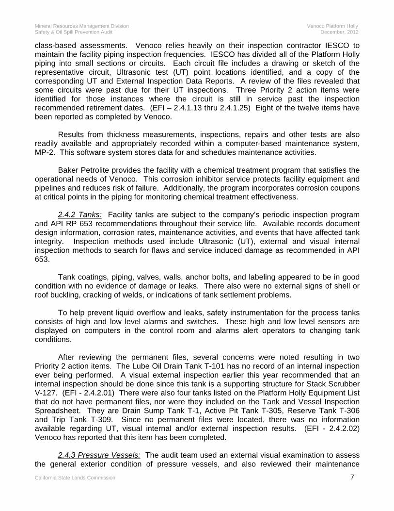
class-based assessments. Venoco relies heavily on their inspection contractor IESCO to maintain the facility piping inspection frequencies. IESCO has divided all of the Platform Holly piping into small sections or circuits. Each circuit file includes a drawing or sketch of the representative circuit, Ultrasonic test (UT) point locations identified, and a copy of the corresponding UT and External Inspection Data Reports. A review of the files revealed that some circuits were past due for their UT inspections. Three Priority 2 action items were identified for those instances where the circuit is still in service past the inspection recommended retirement dates. (EFI – 2.4.1.13 thru 2.4.1.25) Eight of the twelve items have been reported as completed by Venoco.
Results from thickness measurements, inspections, repairs and other tests are also readily available and appropriately recorded within a computer-based maintenance system, MP-2. This software system stores data for and schedules maintenance activities. Baker Petrolite provides the facility with a chemical treatment program that satisfies the operational needs of Venoco. This corrosion inhibitor service protects facility equipment and pipelines and reduces risk of failure. Additionally, the program incorporates corrosion coupons at critical points in the piping for monitoring chemical treatment effectiveness. 2.4.2 Tanks: Facility tanks are subject to the company’s periodic inspection program and API RP 653 recommendations throughout their service life. Available records document design information, corrosion rates, maintenance activities, and events that have affected tank integrity. Inspection methods used include Ultrasonic (UT), external and visual internal inspection methods to search for flaws and service induced damage as recommended in API 653. Tank coatings, piping, valves, walls, anchor bolts, and labeling appeared to be in good condition with no evidence of damage or leaks. There also were no external signs of shell or roof buckling, cracking of welds, or indications of tank settlement problems. To help prevent liquid overflow and leaks, safety instrumentation for the process tanks consists of high and low level alarms and switches. These high and low level sensors are displayed on computers in the control room and alarms alert operators to changing tank conditions. After reviewing the permanent files, several concerns were noted resulting in two Priority 2 action items. The Lube Oil Drain Tank T-101 has no record of an internal inspection ever being performed. A visual external inspection earlier this year recommended that an internal inspection should be done since this tank is a supporting structure for Stack Scrubber V-127. (EFI - 2.4.2.01) There were also four tanks listed on the Platform Holly Equipment List that do not have permanent files, nor were they included on the Tank and Vessel Inspection Spreadsheet. They are Drain Sump Tank T-1, Active Pit Tank T-305, Reserve Tank T-306 and Trip Tank T-309. Since no permanent files were located, there was no information available regarding UT, visual internal and/or external inspection results. (EFI - 2.4.2.02) Venoco has reported that this item has been completed. 2.4.3 Pressure Vessels: The audit team used an external visual examination to assess the general exterior condition of pressure vessels, and also reviewed their maintenance

Mineral Resources Management Division Venoco Platform Holly Safety & Oil Spill Prevention Audit December, 2012
California State Lands Commission 8
history. This method detects specific problems such as external coating failure, corrosion, leaks, labeling, inadequate anchoring or foundations, lack of internal inspections and required instrumentation. The assessment also included a review of Venoco’s permanent files, which contained inspection history as well as any alterations or repairs made. The records typically contained the results of external and/or internal inspections and the documentation of non-destructive examination techniques. A review of these inspection records, construction and maintenance logs, found them to be well organized with minimal exceptions. The pressure vessels and control systems were designed with sufficient safety devices and redundancy to prevent and/or isolate any unintentional release of flammable gas or liquid. Two levels of protection are provided against potential hazards and the system is designed to be “failsafe”. This integrated detection and protection system senses and activates appropriate shutdown devices as a first level. The second level of protection is provided by pressure relief valves. Addition spill protection is provided by containment and operator intervention as a means of responding to an undesirable event. This safety control scheme is considered sufficient and adequate for the safe operation of the platform. This evaluation is based on the hazards analysis studies that have been conducted for Platform Holly. There were three Priority 2 action items generated regarding pressure vessels. These typically had to do with the number of remaining years life expected based on rates of corrosion. One discrepancy was identified with Cuno Filter F-101, where file information showed an A- B-Scan inspection from 2007 that was showing the vessel was at or below the minimum allowable thickness in at least one location. However, another Ultrasonic (UT) test in 2010 showed the vessel had 6 years of life remaining. Because of this discrepancy, Venoco should evaluate and document in the file that the vessel has adequate integrity to may remain in service. (EFI – 2.4.3.09) The second Priority 2 action item addresses internal inspection report data that was missing for Reflux Column V-124 and Reboiler V-125. There was no inspection or thickness data available in the permanent file and the Tank and Vessel Spreadsheet that tracks the periodic inspection data was also blank. (EFI – 2.4.3.10) The third and final Priority 2 action item pertained to an inspection information discrepancy and missing inspection data for the White Superior 1st Stage Compressor Discharge Bottle, V-142. V-142 had a UT inspection done in 2004 that indicated the vessel had only 6 years of life remaining at that time. According to the Tank and Vessel Inspection Spreadsheet, a subsequent UT inspection, recorded in 2007, apparently found the vessel in acceptable condition, but with the estimated life (in years) left blank. There was no record in the permanent file to document the 2007 UT. (EFI – 2.4.3.11) There were a total of eleven less serious Priority 3 action items identified that address maintenance and inspections that were due for the pressure vessels. Analysis of the file information and visual external examination concludes that some interval based inspection requirements in API RP 510 were not met. Venoco worked with the contract inspection company IESCO to complete the overdue inspections and regain schedule. Venoco reports they have completed five of the eleven items. Conflicting and other missing inspection information made up the remainder of the Priority 3 items that applied to pressure vessels.

Mineral Resources Management Division Venoco Platform Holly Safety & Oil Spill Prevention Audit December, 2012
California State Lands Commission 9
Venoco’s management viewed issues that arose during our vessel review as an opportunity for improvement. Through their application of Good Management Practices and the use of sound technical expertise, Venoco has successfully implemented a comprehensive mechanical integrity program. 2.4.4 Relief System: The relief system on Platform Holly consists of the pressure relief valves designed to protect vessels and piping from overpressure and/or burst and the flare systems designed for the safe incineration of all gases relieved into the system. The flare systems consist of Low Pressure Flare H-101 tied to low pressure relief valves on the Glycol Unit and Flare H-100 that serves the rest of the platform. A 4-inch pipeline from shore supplies clean fuel gas to the platform, and this clean fuel gas is used for the pilot gas to the flare. Flare Igniters are deemed critical safety equipment and, as such, are tied into the Uninterruptable Power Supply (UPS) as well as the auxiliary generator.
On Flare H-100, the pressure relief valves are hard piped into larger diameter piping called headers, which terminate at Stack Scrubber V-127. Any entrained liquids drop out in the scrubber while the dry gas flows on to the flare for incineration. Liquids in V-127 are pumped to Oil Surge Drum V-110. During the audit, it was noted that Venoco had purchased a 2” pneumatic pump to replace the 1” pneumatic pump that was in service. Installation was pending receipt of complementary parts. The larger pump will allow faster pump down of any liquid level in V-127. This system is designed with minimum valves and with minimum backpressure so that any vented gas has unrestricted passage to the flare. Pressure relief valves are typically configured with isolation valves upstream and downstream so that maintenance and/or testing is possible while the platform is operating. Isolation valves are car sealed open as a safety precaution. A car seal log is maintained and is checked quarterly. One Priority 2 action item was issued after the PSV on the discharge of Glycol Pump 106-A was found to be blocked-in. (EFI - 2.4.4.01) Venoco reported this item was completed in February of 2012. The maintenance and servicing intervals, as well as record keeping within the preventive maintenance system for all pressure safety valves (PSVs) on the pressure vessels, complied with applicable regulations and recommended standards. MRMD regulations require that relief valves be tested every six months. Venoco utilizes Ventura Valve Service for the PSV testing on Platform Holly. Service records were in order with only one exception when no record was found for testing the PSV’s found on Air Receivers V-160 and V-161. (EFI - 2.4.4.02) Venoco reported this item was completed in February of 2012. 2.4.5 Fire Detection Systems: The fire detection systems utilized on platforms are designed to detect fires in their earliest stages and alert personnel to the existence of a fire on the platform. The fire detection system on Platform Holly utilizes UV/IR flame detectors, which detect fires by monitoring in both the ultraviolet (UV) and infrared (IR) spectral ranges. Thirty of these detectors are strategically located for optimal coverage. Triggering any of the fire detectors will activate the deluge system and result in a shutdown of the platform. The fire detection system is set up with bypasses to allow testing. The flame detectors are tested monthly utilizing a test lamp and witnessed by a MRMD inspector. Seventeen smoke detectors are in use in electrical rooms, sleeping quarters, offices and the galley. The smoke detectors are tested monthly using canned smoke and witnessed by an MRMD inspector. Facility personnel who observe a fire can activate one of Platform Holly’s eight fire alarms

Mineral Resources Management Division Venoco Platform Holly Safety & Oil Spill Prevention Audit December, 2012
California State Lands Commission 10
and/or manually initiate fire suppression before automatic sensing devices activate the deluge system. No discrepancies were noted. The electrical team also examined this system in section 3.9.3 and found no problems with the installation or code requirements.
2.4.6 Fire Fighting Equipment: Platform Holly’s firefighting equipment consists of a deluge type sprinkler system for the well bay and process equipment, in addition to hose stations located at critical points and two stationary monitors located on the upper deck. Portable fire extinguishers strategically located throughout the platform supplement this firefighting equipment. Joy Equipment Protection, Inc. of Carpinteria services and maintains this equipment. The equipment appeared to be in good condition and in compliance with recommended inspection frequencies.
Platform Holly’s two firewater pumps are vertical shaft turbine-type pumps driven by 60 Horsepower (HP) electric motors and capable of being powered by the auxiliary generator in the event of a power failure. The electrical audit team evaluated the fire pump motors and electrical power supply as part of the electrical audit in section 3.6. The electrical team found no items of concern with those items.
Venoco’s Firewater System drawing lists Firewater Pump P-150A as a 12” suction x 6”
discharge with no GPM rating shown. Firewater Pump P-150B is listed as a 12” suction x 4” discharge and rated at 250 GPM. A review of Platform Holly’s old firewater pump records shows that Johnston Pump Company rated the 12” x 6” pump at 350 GPM and the 12” x 4” pump at 250 GPM. MRMD regulations state that a firefighting system shall be installed and maintained in accordance with the applicable standards of the National Fire Protection Association (NFPA). NFPA 20 states that vertical shaft turbine-type pumps shall furnish not less than 150% of rated capacity at a total head of not less than 65 percent of the total rated head. On that basis a 350 GPM pump should be expected to furnish not less than 525 GPM. Operating personnel advise that when P-150A failed, the old pump was sent to Surface Pumps, Inc. with instructions to build a like for like replacement pump. From the pump data information, it appears that Surface Pumps, Inc. apparently tried to build a 250 GPM pump rather than a 350 GPM pump. In addition, the replacement pump apparently has a performance problem. When Joy Equipment Protection, Inc. flow tested the firewater pumps on February 21, 2011, P-150A only tested at 235 GPM. By comparison, P-150B, rated at 250 GPM, tested at 505 GPM. No fire-protection study or related information was found to show the historical basis for firewater pump sizing on Platform Holly or why two different size firewater pumps were utilized. Absent any new information, staff is of the opinion that Venoco must adhere to the original sizing basis of 350 GPM for Firewater Pump P-150A. A Priority 2 action item addressed the proper sizing for Firewater Pump P-150A. (EFI - 2.4.6.05) Venoco replaced the pump in March of 2012 and the pump has been performing satisfactorily at the CSLC monthly MRMD witnessed testing of the deluge sprinkler system. Venoco tests the firewater pumps weekly as part of their normal operating procedures. 2.4.7 Combustible Gas and H2S Detection Systems: Both a combustible gas detection system and a hydrogen sulfide (H2S) gas detection system are required on platform Holly by MRMD regulations. Platform Holly is currently equipped with a modern system of twenty-nine (29) fixed combustible gas Lower Explosive Limit (LEL) detectors, and a modern H2S system with thirty-five (35) H2S detectors. The LEL and H2S detection sensors are strategically located to provide the required area coverage protection. MRMD regulations also require that

Mineral Resources Management Division Venoco Platform Holly Safety & Oil Spill Prevention Audit December, 2012
California State Lands Commission 11
a diagram of the gas detection systems, showing the location of the sensors, be posted on the production facility. An action item was identified to post such a diagram, (EFI - 2.4.7.01) and Venoco completed the item by May of 2012. For the gas detection system, MRMD regulations require the audible alarm at a point not higher than 60% of the LEL and shut-in at a point not higher than 80% of the LEL. Venoco has elected to set their LEL detectors at 25% and 50% respectively to provide an additional margin of safety. At the time the safety audit began in 2011, ten of the LEL detectors were tied into an old modular style panel with each unit having a digital readout. Four of the ten units were observed to have indicator lights that appeared faulty. An outdated list was taped to the control room wall that cross referenced old monitor/detector numbers with the computer screen number so that the location could be found, causing some opportunity for confusion. Five LEL detectors had previously been upgraded to a modern system that graphically displayed their status using Wonderware software on one of the control room computer screens. Because the two LEL detection systems display differently and intermix detectors between two systems in the control room, there appeared to be significant potential for confusion during an emergency. This issue had previously been identified as a human factors issue at the 2005 safety audit. Condition, lack of parts, and questionable reliability called for final resolution of the situation. An action item was issued to upgrade all remaining modules and detectors on the old system to the new system that displays on the control room Wonderware display. (EFI - 2.4.7.02) Venoco completed the remaining upgrade that now provides twenty-nine (29) LEL sensors on the modern system with graphic status display. All wiring and installation to proper code was verified by the electrical team in late 2012 as reported in section 3.9.2 of this report. There were no electrical team issues identified in 3.9.3. The safety audit conducted in 1999-2000 found that Platform Holly did not have enough H2S monitors to provide adequate coverage. To meet the increased coverage requirement, additional sensors were added using a new system with graphic display similar to the new LEL system. Thirteen of the original H2S sensors that used the old modular control panels remained in service after 2000. At the 2005 safety audit, State Lands recommended that Venoco complete the upgrade, and they worked on a time permitting basis. In 2011, there were still nine of the old style alarms in service. Because of the reliability and human factors issues similar to the LEL system, an action item was issued to complete the H2S system upgrade. (EFI - 2.4.7.03) Venoco completed the upgrade resulting in a total of thirty-five (35) modern H2S detectors on the system in 2012. The wiring and installation of this system was examined by the electrical team in late 2012 with no issues reported in section 3.9.2. Both the LEL and H2S detection systems are tested with test gas while in bypass as part of the regular monthly testing. The monthly testing is witnessed and results recorded by an MRMD inspector.
2.4.8 Emergency Shutdown System (ESD): Platform Holly is equipped with ten manual Emergency Shutdown (ESD) stations that will cause shut-in of all wells and pipelines as well as the complete shutdown of the production facility in the event of fire, pipeline failure or other catastrophe. MRMD regulations specify that ESD shutdowns be located on the helicopter deck and on all exit stairway landings leading to the helicopter deck and to all boat landings. These locations are included. The fact that some of these manual ESD stations require better signs and marking was previously discussed.

Mineral Resources Management Division Venoco Platform Holly Safety & Oil Spill Prevention Audit December, 2012
California State Lands Commission 12
Additional operational safeguards include shutdowns based on pressure or level parameters. Process shutdowns protect against overpressure, under pressure, and abnormal levels. Process shutdowns also activate the ESD system to shut down the platform. In addition to process shutdowns and manual ESD stations, activation of the following devices will also trigger the ESD system based on the API RP 14C SAFE Chart for platform Holly:
• Fire Detection System • H2S Detection System • Combustible Gas Detection System • White Superior Compressor Shutdown • Ingersoll Rand Compressor Shutdown • Vapor Recovery Compressor A & B Shutdown • Loss of Air Pressure • High or Low Pressure Shutdown on the Oil Pipeline • High or Low Pressure Shutdown on the Gas Pipeline
The individual process shutdowns as well as the devices listed above are tested
monthly to verify calibration and proper operation. An MRMD inspector witnesses all tests. MRMD regulations require a complete testing of the safety-control system to the satisfaction of Staff every six months and may be witnessed and approved by the Staff. The ESD system was evaluated to verify compliance with API RP 14C with no problems noted. The electrical team also examined this system in section 3.9.1 and found no problems.
2.4.9 Safety and Personal Protective Equipment (PPE): Venoco’s safety programs are set out in the Venoco Safety Plans, Volume 1 and 2. These written plans identify policies, procedures, and practices that are used to create and maintain a safe and healthy working environment.
All first time visitors to Platform Holly must complete Venoco’s Visitor Orientation Training that includes answering a written quiz and satisfactorily demonstrating their swing rope capability before travel to Platform Holly is authorized. Venoco’s Personal Protective Equipment (PPE) Requirements are outlined in the training. First-time platform visitors receive a site-specific briefing upon arrival. PPE requirements are also listed in work permits and further communicated in morning safety meetings. Venoco conducts yearly training to cover Cal OSHA and federal requirements including CPR, First Aid, AED training, HAZWOPER update, lockout/tagout, emergency response, and fire extinguisher training. Although operating personnel and contractors were observed to be using proper PPE and following generally accepted safety practices, deficiencies in Platform Holly’s Hydrogen Sulfide (H2S) Contingency Plan were uncovered that need to be addressed. Two Priority 2 and six Priority 3 deficiencies were issued after the plan was compared against actual practice. Resuscitators are required under MRMD regulations for any facility known to handle H2S. (EFI - 2.4.9.01) Venoco quickly got this equipment on the platform. Although emergency oxygen with a fixed flow regulator was available on the platform, operating personnel were not trained in its use. (EFI - 2.4.9.02) Venoco got this item
Mineral Resources Management Division Venoco Platform Holly Safety & Oil Spill Prevention Audit December, 2012
California State Lands Commission 13
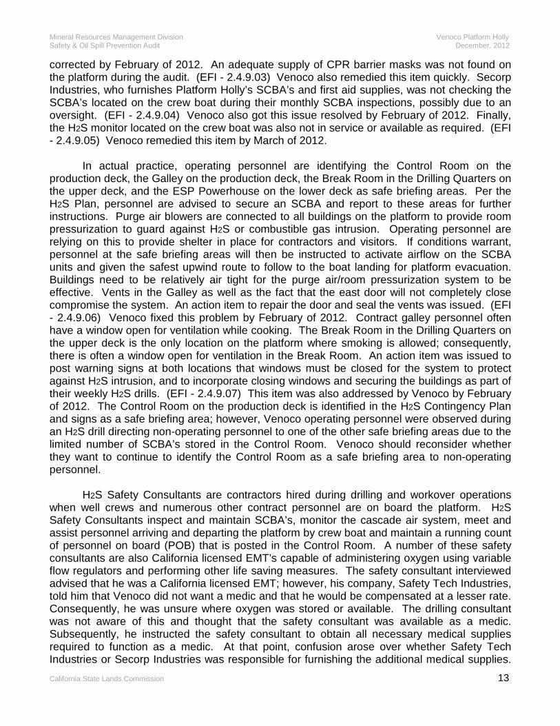
corrected by February of 2012. An adequate supply of CPR barrier masks was not found on the platform during the audit. (EFI - 2.4.9.03) Venoco also remedied this item quickly. Secorp Industries, who furnishes Platform Holly’s SCBA’s and first aid supplies, was not checking the SCBA’s located on the crew boat during their monthly SCBA inspections, possibly due to an oversight. (EFI - 2.4.9.04) Venoco also got this issue resolved by February of 2012. Finally, the H2S monitor located on the crew boat was also not in service or available as required. (EFI - 2.4.9.05) Venoco remedied this item by March of 2012. In actual practice, operating personnel are identifying the Control Room on the production deck, the Galley on the production deck, the Break Room in the Drilling Quarters on the upper deck, and the ESP Powerhouse on the lower deck as safe briefing areas. Per the H2S Plan, personnel are advised to secure an SCBA and report to these areas for further instructions. Purge air blowers are connected to all buildings on the platform to provide room pressurization to guard against H2S or combustible gas intrusion. Operating personnel are relying on this to provide shelter in place for contractors and visitors. If conditions warrant, personnel at the safe briefing areas will then be instructed to activate airflow on the SCBA units and given the safest upwind route to follow to the boat landing for platform evacuation. Buildings need to be relatively air tight for the purge air/room pressurization system to be effective. Vents in the Galley as well as the fact that the east door will not completely close compromise the system. An action item to repair the door and seal the vents was issued. (EFI - 2.4.9.06) Venoco fixed this problem by February of 2012. Contract galley personnel often have a window open for ventilation while cooking. The Break Room in the Drilling Quarters on the upper deck is the only location on the platform where smoking is allowed; consequently, there is often a window open for ventilation in the Break Room. An action item was issued to post warning signs at both locations that windows must be closed for the system to protect against H2S intrusion, and to incorporate closing windows and securing the buildings as part of their weekly H2S drills. (EFI - 2.4.9.07) This item was also addressed by Venoco by February of 2012. The Control Room on the production deck is identified in the H2S Contingency Plan and signs as a safe briefing area; however, Venoco operating personnel were observed during an H2S drill directing non-operating personnel to one of the other safe briefing areas due to the limited number of SCBA’s stored in the Control Room. Venoco should reconsider whether they want to continue to identify the Control Room as a safe briefing area to non-operating personnel. H2S Safety Consultants are contractors hired during drilling and workover operations when well crews and numerous other contract personnel are on board the platform. H2S Safety Consultants inspect and maintain SCBA’s, monitor the cascade air system, meet and assist personnel arriving and departing the platform by crew boat and maintain a running count of personnel on board (POB) that is posted in the Control Room. A number of these safety consultants are also California licensed EMT’s capable of administering oxygen using variable flow regulators and performing other life saving measures. The safety consultant interviewed advised that he was a California licensed EMT; however, his company, Safety Tech Industries, told him that Venoco did not want a medic and that he would be compensated at a lesser rate. Consequently, he was unsure where oxygen was stored or available. The drilling consultant was not aware of this and thought that the safety consultant was available as a medic. Subsequently, he instructed the safety consultant to obtain all necessary medical supplies required to function as a medic. At that point, confusion arose over whether Safety Tech Industries or Secorp Industries was responsible for furnishing the additional medical supplies.
Mineral Resources Management Division Venoco Platform Holly Safety & Oil Spill Prevention Audit December, 2012
California State Lands Commission 14
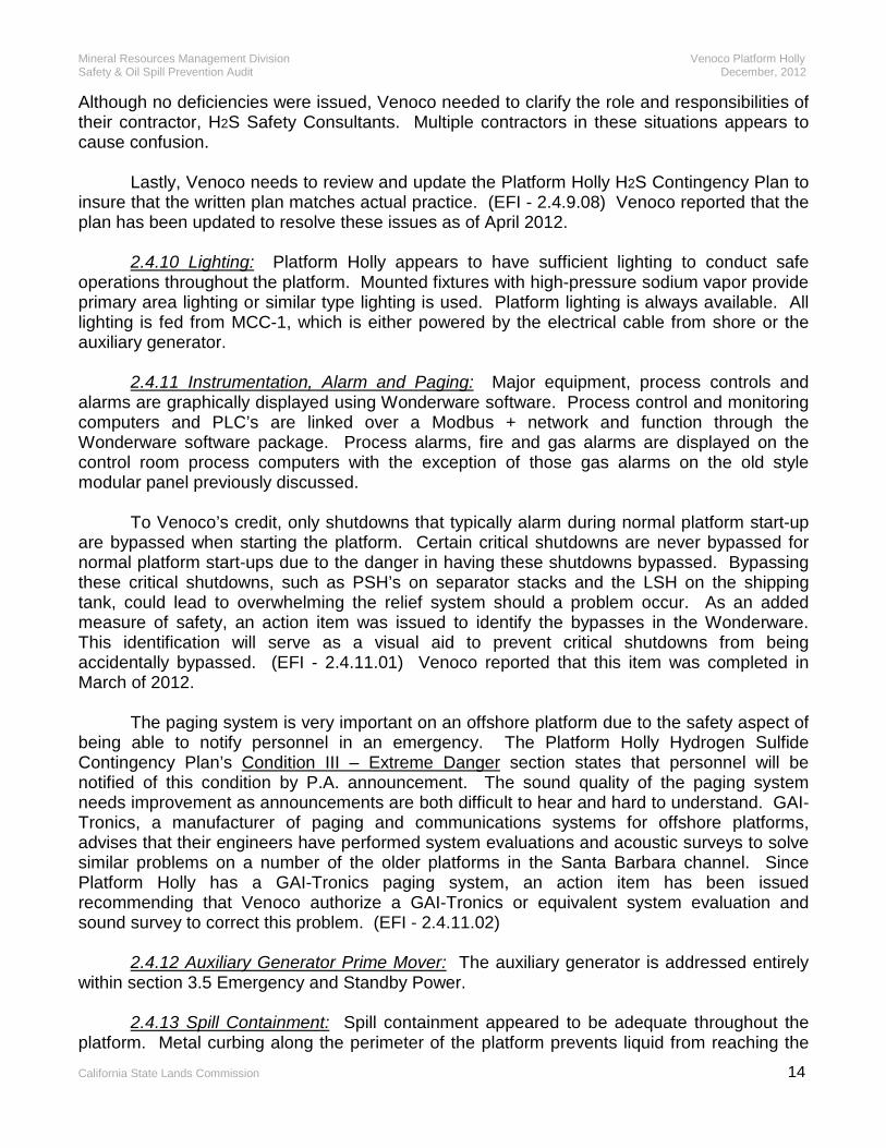
Although no deficiencies were issued, Venoco needed to clarify the role and responsibilities of their contractor, H2S Safety Consultants. Multiple contractors in these situations appears to cause confusion. Lastly, Venoco needs to review and update the Platform Holly H2S Contingency Plan to insure that the written plan matches actual practice. (EFI - 2.4.9.08) Venoco reported that the plan has been updated to resolve these issues as of April 2012. 2.4.10 Lighting: Platform Holly appears to have sufficient lighting to conduct safe operations throughout the platform. Mounted fixtures with high-pressure sodium vapor provide primary area lighting or similar type lighting is used. Platform lighting is always available. All lighting is fed from MCC-1, which is either powered by the electrical cable from shore or the auxiliary generator. 2.4.11 Instrumentation, Alarm and Paging: Major equipment, process controls and alarms are graphically displayed using Wonderware software. Process control and monitoring computers and PLC’s are linked over a Modbus + network and function through the Wonderware software package. Process alarms, fire and gas alarms are displayed on the control room process computers with the exception of those gas alarms on the old style modular panel previously discussed. To Venoco’s credit, only shutdowns that typically alarm during normal platform start-up are bypassed when starting the platform. Certain critical shutdowns are never bypassed for normal platform start-ups due to the danger in having these shutdowns bypassed. Bypassing these critical shutdowns, such as PSH’s on separator stacks and the LSH on the shipping tank, could lead to overwhelming the relief system should a problem occur. As an added measure of safety, an action item was issued to identify the bypasses in the Wonderware. This identification will serve as a visual aid to prevent critical shutdowns from being accidentally bypassed. (EFI - 2.4.11.01) Venoco reported that this item was completed in March of 2012. The paging system is very important on an offshore platform due to the safety aspect of being able to notify personnel in an emergency. The Platform Holly Hydrogen Sulfide Contingency Plan’s Condition III – Extreme Danger section states that personnel will be notified of this condition by P.A. announcement. The sound quality of the paging system needs improvement as announcements are both difficult to hear and hard to understand. GAI-Tronics, a manufacturer of paging and communications systems for offshore platforms, advises that their engineers have performed system evaluations and acoustic surveys to solve similar problems on a number of the older platforms in the Santa Barbara channel. Since Platform Holly has a GAI-Tronics paging system, an action item has been issued recommending that Venoco authorize a GAI-Tronics or equivalent system evaluation and sound survey to correct this problem. (EFI - 2.4.11.02) 2.4.12 Auxiliary Generator Prime Mover: The auxiliary generator is addressed entirely within section 3.5 Emergency and Standby Power. 2.4.13 Spill Containment: Spill containment appeared to be adequate throughout the platform. Metal curbing along the perimeter of the platform prevents liquid from reaching the

Mineral Resources Management Division Venoco Platform Holly Safety & Oil Spill Prevention Audit December, 2012
California State Lands Commission 15
ocean. Curbing and gutters direct rainwater as well as any spills or process leaks to area deck drains located on each level. These deck drains flow to Drain Sump Tank T-1 and then flow into Overflow Sump Tank T-4. Both tanks have high-level alarms. Fluid from the sump tanks is pumped to Oil Surge Drum V-110. Operating personnel inspect the sump system each shift to insure that liquid levels are kept at minimum. 2.4.14 Spill Response: The oil spill response for Platform Holly is outlined in the Oil Spill Contingency Plan South Ellwood Field. The plan was written to satisfy both federal and state regulations and will be discussed in more detail in the Administrative Audit. Response equipment located on the platform includes 1,700 feet of 43” Expandi boom, a 22 Foot Boston Whaler support boat with a 225 HP outboard motor and 10 bales of absorbent pads as well as both marine and company radios for communication. The equipment appeared to be in good order and is inventoried as part of the MRMD monthly safety inspection. Venoco is a member of Clean Seas headquartered in Carpinteria. Clean Seas is a cooperative of oil producers and transporters that maintains a fleet of oil spill response vessels and clean up equipment. Clean Seas will respond to any oil spill reaching the water at Venoco’s request. In the event that oil reached the water, operating personnel on Platform Holly would deploy their boom to contain the spill until Clean Seas arrived to assume control of the spill and clean up. Boom deployment drills are conducted with Clean Seas semi-annually and may be witnessed by various participating agencies. Operating personnel advise that the semi-annual drills consist of viewing an instructional video followed by the boom deployment. Staff is of the opinion that Venoco should consider substituting at least one of the semi-annual drills with an unannounced spill drill. In an unannounced spill drill, operating personnel would be given a scenario to respond to. Response actions including boom deployment would be logged to develop a time line. After completion of the drill, observers and responders would be free to analyze and critique the drill to find opportunities for improvement. Unannounced spill drills on other platforms in state waters have proven beneficial. 2.4.15 Cranes: Platform Holly’s main platform crane is a National Model 8000 rated at 60,000 pounds. Venoco completed installation in November 2008. A review of the crane records showed that crane operators perform daily safety checks while company mechanics performed monthly and quarterly crane inspections. Preferred Aerial & Crane Technology of Long Beach successfully performed the annual inspection on June 6, 2011 at which time a quadrennial load test, mandated by Cal OSHA regulations, was also performed. The proof load was a water bag weighing 66,000 pounds used on the main line. A proof load of 15,400 pounds was used on the whip line rated at 14,000 pounds. No discrepancies were noted. 2.5 Preventive Maintenance and Mechanical Reliability Enhanced safety, stability of operation and certainty of environmental compliance are three benefits that companies receive from preventive maintenance and mechanical integrity. Venoco utilizes a computer based maintenance program for scheduling preventive maintenance as well as corrective maintenance. Preventive maintenance scheduling is based upon manufacturer’s recommendations, operating history, and good engineering practices. Weekly status meetings allow for prioritizing activities as well as reviewing completed work. The maintenance program allows management the opportunity to review expenses charged to
Mineral Resources Management Division Venoco Platform Holly Safety & Oil Spill Prevention Audit December, 2012
California State Lands Commission 16
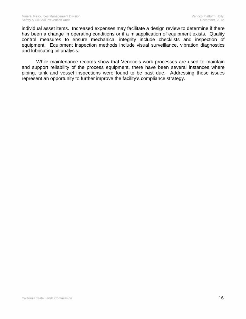
individual asset items. Increased expenses may facilitate a design review to determine if there has been a change in operating conditions or if a misapplication of equipment exists. Quality control measures to ensure mechanical integrity include checklists and inspection of equipment. Equipment inspection methods include visual surveillance, vibration diagnostics and lubricating oil analysis. While maintenance records show that Venoco’s work processes are used to maintain and support reliability of the process equipment, there have been several instances where piping, tank and vessel inspections were found to be past due. Addressing these issues represent an opportunity to further improve the facility’s compliance strategy.
Electrical System Audit

Mineral Resources Management Division Venoco Platform Holly Safety & Oil Spill Prevention Audit December, 2012
California State Lands Commission 17
3.0 ELECTRICAL SYSTEM AUDIT
3.1 Goals and Methodology
The primary goal of the ELC Team was to evaluate the electrical systems, operations, and maintenance of Platform Holly. Equipment inspections, field verifications of electrical system plans and diagrams, and technical design review of systems were employed to accomplish this goal.
References used in review of facilities include documents published by the American Petroleum Institute (API), National Fire Prevention Association (NFPA), the State of California Electric Code (CEC) and California State Lands Commission Regulations (CSLC). The ELC Team review comments are primarily based on API RP 14F, API RP 500, API RP 540, and the CEC. The drawings used in support of the audit were Electrical Single-lines and Area Classification Drawings for Platform Holly. 3.2 Hazardous Area Electrical Classification Drawings
The API recommended practices and CEC requirements provide specific guidelines for the electrical classification of hazardous areas and installation practices for electrical equipment and materials within classified areas. The ELC Team review comments for all hazardous areas are based on API RP 500, API RP 14F and CEC documents.
The purpose of an Electrical Area Classification Drawing is to define the locations of boundaries and areas where specific electrical installation practices are required to manage the explosive properties of flammable liquids, vapors and other volatile materials. Installation and maintenance of electrical systems requires attention to the type of hazard and the level of the hazard in order to insure compliance with the CEC. Electrical Area Classification Drawings are required to contain the information necessary for a qualified electrician to perform work in and around classified areas.
The addition, relocation or change in process equipment, lines and valves requires that classified areas be re-assessed and that classified boundaries be redrawn if necessary. If the Area Classification drawings in some cases, do not show the present conditions, all new electrical equipment purchased for installation should meet the most stringent requirements and be rated explosion-proof in accordance with the Code. Drawing E-1 requires revision to show the existing equipment and area classification extents. (ELC - 3.2.01) Chemical storage totes that contain flammable liquids, and that are continuously in service, should be added to the area classification plan. (ELC - 3.2.06)
Several general-purpose electrical control and PLC panels are located in classified areas. The enclosures that house PLC-2 have been provided with a Type Z air purge system to make them suitable for the area classification. However, purging on some panels was ineffective. (ELC - 3.2.02) Purge on these panels should be tested and maintained on a regular basis and schedule. (ELC - 3.2.09) The Main Electric Room 1 magnehelic pressure differential sensor is not functional and requires repair. (ELC - 3.2.04) In all cases, the loss of purge alarm should be continuously monitored by the Control Room.

Mineral Resources Management Division Venoco Platform Holly Safety & Oil Spill Prevention Audit December, 2012
California State Lands Commission 18
Conduit seals are required at classification boundaries but are not provided or are missing in some locations. (ELC - 3.2.03) Locations where conduits originate outside of classified areas and travel through classified areas without use of a box, fitting or coupling may cross boundaries of Division 2 areas without a seal. 3.3 Electrical Power Distribution System, Normal Power
3.3.1 System Configuration: Electric power for normal platform operations, excluding drilling operations, is supplied from the Venoco Onshore Facilities at the South Ellwood Field, Santa Barbara County, at 34.5 kV via submarine cable.
The service location is at the Ellwood 12.5kV main substation switchgear lineup. A 15kV, 1200-Amp breaker feeds a 5000kVA, 12.5kV–16.3kV step-up transformer and 34.5kV submersible cable approximately three miles to platform Holly.
The submarine cable to platform Holly supplies 16.3kV electrical power to a 25kV rated G&W five (5) position SF6 gas filled disconnect switch position. One disconnect switch position feeds a 3750kVA 16.3kV-2.4kV transformer to supply power to the two Gas Compressors. A second switch position is connected to a 2000kVA, 16.3kV-480V; delta-delta transformer supplying 480V, 3-phase, 3-wire power to MCC-1, MCC-2, and Glycol Dehydrator. A third switch supplies the Drill Deck, 4000kVA, 16.3kV – 600V, transformer TX-DR1. A fourth switch supplies the ESP switchboard via a 3000kVA, 16.3kV – 480Y/277V, transformer.
Standby power on the platform is limited to one 250kW (312kVA) auxiliary/emergency generator supplying MCC-1 through an Automatic transfer switch (ATS). Various small battery and UPS systems are provided to supply alarms and controls. These auxiliary/emergency power systems are discussed in Section 3.5.
Drilling operations are powered from three (3) 600V generators feeding the drilling equipment. Key interlocked breakers allow selected drilling equipment and the drilling emergency panel E1 to be supplied from either operations power or the drilling generators. Two (2) generators are rated 774kVA and one (1) generator is rated 932kVA.
There are several modes of power system configuration and operation for power distribution on Platform Holly as follows:
1) Normal Power – Shore Power Only: Power is supplied from the Ellwood 16.5kV subsea cable only to all platform loads. There is no drilling activity for this mode of operation.
2) Normal Power – Shore Power and Drilling Generator Power: Power is supplied to the platform load from the subsea cable. Power is supplied to the drilling rig by the drilling generators.
3) Emergency/Standby Power – No Shore Power: In the event of loss of shore power, the drilling generators can be used to supply power to the entire platform by use of breaker interlock scheme. The shore power is isolated by opening the “A” switch position on the subsea cable feed and closing the 3000A, 480V breaker on the drilling deck. The drilling generators are

Mineral Resources Management Division Venoco Platform Holly Safety & Oil Spill Prevention Audit December, 2012
California State Lands Commission 19
energized and supply power to the platform. The total load must be limited to the capacity of the generators. The platform operations are limited in this mode of operation.
4) Emergency Power – No Shore Power or Drilling Power: In the event of loss of shore power and drilling rig power, the 480V, 250kW emergency generator will supply power to MCC-1 via an automatic transfer switch. The generator will only supply power to the MCC-1 loads, which include the essential power system loads such as UPS for control and communications, fire pump, lighting, purge fans, breathing air compressor, and hoist. No other platform loads will be energized.
3.3.2 Electrical Single-Line: The electrical single-line drawings used for review of
facilities were dated 2006. The drawings are generally representative of the electrical power system. However, changes to the electrical system after the issue date have not been incorporated into the drawings. The audit focused on power distribution systems 480 V and above and excluded the lower voltage systems. Copies of the latest single-line drawings were requested from the Venoco. Discrepancies observed between the installed equipment and the single-line diagrams have been provided to Venoco and are listed in the matrix. (ELC - 3.3.1.01 thru 3.3.1.14)
3.3.3 Equipment and Component Ratings: The normal power system capacity appears
adequate for the present loads based on present usage but could not be confirmed due to lack of meter data including peak demand. Shore feeder power meter readings were requested from Venoco to confirm capacity. (ELC - 3.3.2.01)
Except as noted below and in the matrix, overcurrent protection and wire sizes were
found to be appropriate. The application of overcurrent devices with respect to equipment ratings is generally satisfactory. As part of the activity necessary to update the single-line diagrams, it will also be necessary to confirm the overcurrent device rating is appropriate for the connected equipment.
3.3.4 System Electrical Design Safety: The power system installation, in general,
appears to be adequately maintained and labeled for safe operation except as noted. (ELC - 3.4.1) Equipment was not properly labeled for arc-flash hazard levels and PPE. (ELC - 3.3.3.01) The Arc Flash Hazard study needs to be updated every five (5) years per NFPA 70E.
3.3.5 Grounding System and Equipment: CEC Article 250 and 501 provide the rules for
power system grounding and bonding. The requirements for grounding are established to prevent or reduce the possibility of personnel injury due to shock hazards resulting from elevated touch potential as a result of improper grounding. The rules of grounding also contribute to reduction of equipment damage. Three specific types of grounding are required at the facilities; power system grounding, safety or equipment grounding, and static grounding. Transformers of separately derived systems for 480-208Y/120V are solidly grounded and satisfy Code requirements for power system grounding.
Article 501-16, Bonding in Class I areas, states that all non-current carrying metal parts
and enclosures associated with electrical components shall be connected together, bonded, and be continuous between the Class I area equipment and the supply system ground. Bonding shall provide reliable grounding continuity from the load back to the power transformer
Mineral Resources Management Division Venoco Platform Holly Safety & Oil Spill Prevention Audit December, 2012
California State Lands Commission 20
grounding. The best way to achieve this is to include properly sized equipment grounding conductors with each set of power conductors from the source of power to each of the equipment grounding points and include bonding jumpers at points of discontinuity along the route. Equipment grounding conductors are not installed on all circuits and bonding is achieved through continuity of raceways and fittings. Equipment bonding conductors to major equipment; transformers, switchgear and the like, were installed and appeared adequate.
Static grounding conductors to the portable storage containers (some containing hazardous liquids) were found to be missing or not connected and are required. (ELC - 3.5.1.01)
CEC 501-16(b) requires that all liquidtight conduit used in a hazardous area be supplemented with either an internal or external ground bonding jumper. These required bonding conductors are missing or disconnected in some cases and are require. (ELC - 3.5.1.02)
3.4 Electrical Power Equipment Condition and Functionally
3.4.1 Wiring Methods and Enclosures: Given the harsh environmental conditions of the open sea, the overall condition of electrical equipment can be rated as good except as noted in the matrix where corrosion of enclosures and raceways was unacceptable. (ELC - 3.4.7) Broken and missing enclosure covers, broken supports, rusted enclosures, deteriorated weatherproof gaskets and missing bolts occur to a small extent on the platform.
3.4.2 Safety Procedures: Safety Standards (procedures) in the operations manual on the platform cover the lockout / tagout / blockout program. The scope, responsibility and procedures outlined in the document appear to be adequate and complete. A Venoco “Equipment Isolation List” form including lockouts/tagouts is filled out prior to maintenance work performed on the platform.
Planned maintenance is scheduled and controlled through the MP2 program. Maintenance work tasks are input into the MP2 database and identified by task, equipment tags, responsible individual, due date, priority (1 to 4), etc. Reports and work orders are published two weeks prior to the due date and distributed to the responsible party. Tasks are tracked and flagged is they have not been cleared fourteen days after due date. Work orders include a list of the activities required for each task.
The safety standards in the operations manual include a section on arc-flash protection. However, the arc-flash labeling present on the electrical gear is missing arc flash hazard level and PPE information. New labels are required. The safety standards manual needs to be updated and new arc-flash labels applied to electrical equipment. (ELC - 3.3.3.01)
In some locations, equipment and control stations were not properly identified. (ELC - 3.4.1 thru 3.4.4)

Mineral Resources Management Division Venoco Platform Holly Safety & Oil Spill Prevention Audit December, 2012
California State Lands Commission 21
3.5 Emergency and Standby Power
3.5.1 System Configuration: The auxiliary power on Platform Holly is supplied by a 250 KW, 480 Volt, three phase Caterpillar Generator Set with a Caterpillar Model D343 6 cylinder diesel engine rated at 373 HP @ 1800 RPM. This generator set is located in the main Switchgear room on the Production Deck. The auxiliary electrical generator is connected via 800-amp auto-transfer switch to emergency panel MCC-1. MCC-1 supplies power to safety equipment including deck floodlighting, fire water pumps, building pressurizing fans, and several transformers for other critical loads. These critical loads include uninterruptable power supplies (UPS), alarms, safety shutdowns, fire water pumps, C-110B air compressor, sump tank, and chemical pump skid, primary and standby purge air blowers, breathing air compressor, Holly crane controls, cellar hoist and freshwater pump. The transformers include a 75kV, 480-208Y/120V transformer to supply Panel A and Panel B, and a 45kVA, 480-208Y/120V transformer to supply Panel C. There is also a second 45kVA, 480-208Y/120V transformer in the MCC-3 building that supplies power to the 7kVA UPS unit located in MCC-3. If power from shore is lost, an uninterruptable power supply (UPS) system located in a cabinet adjacent to the MCC-3 panel in the ESP Powerhouse building on the lower deck will supply power for certain critical safety equipment loads until the auxiliary generator automatically starts. Once the auxiliary generator is running, an automatic transfer switch (ATS) automatically switches the load to the generator and the UPS senses power is again available and shifts from battery supply to the auxiliary generator. In the event that the auxiliary generator does not start, the UPS system will supply power to critical safety equipment for a minimum of one hour to allow time to safely shut-in the platform. The UPS system supplies power to the PLC’s, the combustible gas and H2S monitors, the flare igniters, the compressor panels and emergency lighting. The auxiliary generator driver (diesel engine) is test run as part of the monthly safety inspection and witnessed by an MRMD inspector. 3.5.2 Equipment and Component Ratings: MRMD regulation 2132(g)(7) requires “an auxiliary electrical power supply shall be installed to provide sufficient emergency power for all the equipment required to maintain safety of operation in the event the primary electric power fails”. The generator is tested for 30 minutes under no load on a monthly basis. However, it is required to run the generator with load and to take load recordings during the monthly load test. (ELC - 3.3.2.02) The monthly generator test procedure requires the generator to be run with the load connected.
UPS power is provided from one (1) UPS unit located in MCC-3. The UPS supplies the following loads:
• PLC-1 Cabinet
• VRU-A Control Panel
• VRU-B Control Panel
• RS 485 Modicon

Mineral Resources Management Division Venoco Platform Holly Safety & Oil Spill Prevention Audit December, 2012
California State Lands Commission 22
• PLC 1/0 Remote (ET150, V110, V109)
• G&W Meter Panel
• TB-B UPS Distribution Panel
• TB-A UPS Distribution Panel
• Microwave Circuit
• Phone System
• PLC-2 cabinet (remote I/O and hot standby)
• I-R Compressor Control Panel
• White Compressor Control Panel
• Instrumentation Control Junction Box #7 3.6 Electric Fire Pumps
Two 60hp electric fire pumps are located on the platform production deck. One at the well bay and a second near the laboratory, both are and controlled through the firewater controller panel located in the switchgear building. The electric fire pumps are fed from MCC-1 and, as such, are also supplied by the standby generator. A diesel driven fire pump is also available in the event of a complete loss of power from both the electrical system and standby generator. 3.7 Process Instrumentation Wiring Methods, Materials and Installation
The process control system uses a combination of pneumatic, hydraulic and electrical instruments and DDC controls. It includes the use of computers, PLC’s and relay logic to control and interface with valves, solenoids and pump controllers. Alarms are produced by level, temperature, pressure and flow sensors advising operators of process conditions.
Process monitoring and control is provided via two Modicon PLCs, one located in the I&E
office and the other located in a purged cabinet above the control room. The PLC monitors and controls the process main alarms and shutdowns. PLCs are interconnected over an Ethernet Data Highway and Microwave data link to Ellwood onshore facility. The Ellwood facility monitors process status only and has no control capability for platform operations.
PCs in the control room monitor the process and alarms. A separate PC in the I&E office
on the platform is used for programming changes to the system. Major programming changes are backed up to the main offsite server located at Venoco offices in Carpinteria, CA.
A KOYO 250 PLC is used to monitor and record emissions as required by the AQMD.

Mineral Resources Management Division Venoco Platform Holly Safety & Oil Spill Prevention Audit December, 2012
California State Lands Commission 23
3.8 Standby Lighting
All platform lighting is kept on all the time. Lighting is fed from MCC-1, which is powered by normal shore power or the standby generator.
Fixtures are installed in conformance with the CEC and appear to be located to provide
adequate lighting levels for the tasks performed. Fixtures are appropriate types and designs for the environmental and hazardous area conditions. Venoco needs to perform a lighting level survey to assess existing conditions and verify compliance with egress illumination requirements. (ELC - 3.9.1.01)
During the inspection, several lamps were not functioning and need relamping or
replacement. (ELC - 3.4.17) 3.9 Special Systems Wiring Methods, Materials and Installation
Special system requirements for off shore production facilities are described in API RP 14F. The ELC Team review comments for special systems are based on API RP 14F, API RP 540 and CEC documents.
3.9.1 Safety Control Systems: Safety control systems are required to be a combination
of devices arranged to safely affect platform shutdown. Electrical safety control systems are normally operated energized and fail-safe. Failure of external power to a safety control circuit requires an audible or visual alarm to be initiated or operation of equipment in a fail-safe condition.
Ten (1) Manual Emergency Shutdown Stations, (ESDs) are located on the platform. The
stations appeared to be in good working order. The stations include; ESD-1- Production Deck – East Stairway, ESD-2 – North door between Production Deck and Well Bay, ESD-3 – Well Bay – West Stairway, ESD-4 – Production Deck South Stairway, ESD-5 – Production Deck SE Corner, ESD-6 – Compressor deck – East stairway, ESD-7 – Drill deck – West stairway, ESD-8 North boat landing – NE corner, ESD-9 – Operator’s Control Room and ESD-10 – Heliport stairway. Stations are hard wired to the control panel in the control room. Fail safe relays in the control panel located in the office initiate shutdown of the platform and signal to the general alarms cabinet.
Eight Fire, Abandon Platform, and Man Overboard Alarm Stations (EA-1 through EA-8)
are located about the platform. The stations include EA-1 Production deck – East stairway, EA-2 Well bay – West stairway, EA-3 Production deck – South stairway, EA-4 Compressor deck – East stairway, EA-5 Drill deck – South stairway, EA-6 Drill deck – West stairway, EA-7 Cellar deck-catwalk to mechanic’s shed and EA-8 North boat landing. All stations appeared to be in good working order. All stations have been painted red. ESD and EA stations are tested monthly and records are maintained.
3.9.2 Gas Detection Systems: Combustible gas detection systems, LEL and H2S, are
usually employed to detect combustible gas leaks in equipment and piping, to warn personnel of explosive and toxic concentrations and to initiate remedial action. Thirty-five H2S sensors and
Mineral Resources Management Division Venoco Platform Holly Safety & Oil Spill Prevention Audit December, 2012
California State Lands Commission 24
twenty-nine LEL sensors are located about the platform. Signals from the gas detectors are hard wired to the system modules in the control room panel CP-1. There were no issues identified with these systems. The gas monitor detector systems are tested monthly and records are maintained.
3.9.3 Fire Detection Systems: Fire detection and smoke detection is usually employed to
detect and warn personnel of fire and smoke conditions and to initiate remedial action. General Monitor Model FL3000 (IR/UV) and Model FL3001 (UV) flame detectors protect the Well Bays, production deck and drill deck. Signals are returned to the General Monitor Fire Detection Module in the control room panel CP-1. Fire detectors are tested monthly and records are maintained.
3.9.4 Aids to Navigation: The US Coast Guard no longer requires aids to navigation in
offshore facilities close to the shore. The work and area lights on the platform are illuminated continuously and provide adequate warning to vessels. A foghorn located on the Cellar deck provides an audible signal when visibility is reduced due to fog. Equipment is inspected monthly and records are maintained. The helipad lights are illuminated continuously. The crane and drill derrick also have warning lights that are illuminated continuously.
3.9.5 Communication: Communications systems are established to provide for normal
and emergency operations. Systems used for emergency communication have UPS battery-operated supplies good for at least four hours continuous operation as required by API RP 14F. The UPS located in MCC-3 is installed to provide power for the communications system. The primary communication link to shore is a microwave antenna. The receiver is located in the electrical room.
Intercom communications are provided by Gaitronics phones located throughout the
platform.
3.9.6 General Alarms: General Alarms shall be audible in all parts of the facility to notify personnel to abandon the facility or respond to an emergency. Red lights can be used in conjunction with the audible alarms. All General Alarm sounding devices shall be identified by a sign at each device in red letters at least one inch high describing required personnel response.
There are two (2) signs observed that define the audible alarms. They are located in the
Control Room and on a wall outside the Control Room. A label above each pushbutton station identifies its alarm function. There are six (6) tones for the general alarms; process alarm is a steady tone, fire alarm is a siren, HS2 above 10ppm is warble, man-over-board is a steady beep-beep, abandon platform is a fast beep, and HS2 above 20ppm is a constant alarm.
It is recommended the central paging system be used to supplement instructions of a
general alarm. Alarms are tested monthly and found to demonstrate adequate performance in the outdoor areas. In indoor areas, including the switchgear room, galley, and MCC room, audible general alarms were difficult to hear. It is recommended that supplemental speakers be placed in these rooms.
Mineral Resources Management Division Venoco Platform Holly Safety & Oil Spill Prevention Audit December, 2012
California State Lands Commission 25
3.9.7 Cathodic Protection: The impressed current cathodic protection system consists of four cathodic protection rectifiers located in the switchgear room and anode locations.around the platform. Units appear to be in good working order.

Safety Management Programs
Mineral Resources Management Division Venoco Platform Holly Safety & Oil Spill Prevention Audit December, 2012
California State Lands Commission 26
4.0 SAFETY MANAGEMENT PROGRAMS AUDIT
4.1 Goals and Methodology The goal of the safety management programs audit (SMP) team was to verify the availability of and review the manuals, programs, procedures, and records required by Federal, State and local authorities as well as adherence to applicable industry standards for safety management programs. The Holly Operations Manual and the South Ellwood Field Oil Spill Contingency Plan, which includes platform Holly, were carefully reviewed for adherence to these requirements and standards as detailed below. A hardcopy version of the Holly Operations Manual dated August 2011 was reviewed in the MRMD office in Long Beach and a hard copy version of the South Ellwood Field Oil Spill Contingency Plan was reviewed on site in Goleta. The Spill Prevention, Control & Countermeasure (SPCC) Plan along with other required plans, manuals, policies, and documents needed for safe and proper operation of the facility were also reviewed on site. Observations were made of the application of the policies and procedures from these documents at the facility. 4.2 Operations Manual The Holly Operations Manual was reviewed for this audit to determine whether it met the content requirements for an operations manual as outlined in MRMD Regulation 2175. Venoco’s manual followed recommended MRMD format. It was arranged in a logical order with clearly defined tabs for quick reference, a comprehensive table of contents and numbered pages. Basic requirements for an operations manual include location, ownership and responsibility, and purpose. In addition to the basic requirements, personnel requirements include a listing of operating staff positions showing the chain of command and the responsibility of each position. Description of operations requirements include identifying major components and associated equipment as well as recommended preventive maintenance. Personnel safety requirements include personal protective equipment (PPE) required for employees, safety responsibility by position, training and drills. Systems safety requirements include information concerning safety equipment, training, and inspection and testing. Automatic control systems requirements include normal process and operation, normal shut-down, safety shut-down and emergency shut-down.
The Holly Operations Manual in conjunction with the Holly Operating Procedures Manual, referenced plans, and attached appendices appear to fulfill the requirements of MRMD Regulation 2175. No action items were identified. Copies of the manual were determined to be easily accessible by operating personnel. 4.3 Spill Response Plan
Venoco’s Oil Spill Contingency Plan (OSCP) South Ellwood Field is an extensive plan that includes EOF, Ellwood Marine Terminal, Ellwood Onshore Oil Transfer Pipeline, Ellwood Pier, Platform Holly including the subsea pipelines and Beachfront Lease (PRC 421).

Mineral Resources Management Division Venoco Platform Holly Safety & Oil Spill Prevention Audit December, 2012
California State Lands Commission 27
Venoco’s OSCP was developed to fulfill the requirements for an Oil Spill Contingency Plan required by California State regulations and for a Facility Response Plan required by federal regulations.
An Oil Spill Contingency Plan is a written document that includes a current copy of the
California Certificate of Financial Responsibility (COFR) and provides for an incident command system, provides procedures for reporting oil spills, describes communication plans, describes protection strategies, identifies an oil spill responder (OSRO), identifies a qualified individual (QI), identifies an agent for service of process, and is certified by the plan holder’s management for authority to implement the plan as well as to the plan’s accuracy, feasibility, and executability as required by California Department of Fish and Game, Office of Spill Prevention and Response (OSPR) regulations, CCR Title 14, Regulation 817.02.
A Facility Response Plan is required of any non-transportation related facility that,
because of its location, could reasonably be expected to cause substantial harm to the environment by discharging oil into or on the navigable waters or adjoining shorelines per Title 40 CFR Section 112. The Facility Response Plan is coordinated with the Federal Spill Prevention, Control, and Countermeasure (SPCC) Plan. The SPCC Plan will be addressed in Section 3.4.
Venoco’s OSCP, which was found to meet the above referenced state and federal
requirements, has been approved for many years. The OSCP remains comprehensive and in a clear format. The plan contains the following required content:
• Facility description • Hazards Evaluation Study and potential worst case spill scenario evaluation • On-water containment and recovery procedures • Shoreline protection and clean-up • Response procedures
The plan was found to adequately address the policies and procedures to prevent,
evaluate, contain, mitigate, and review the effects of unauthorized discharges. The procedures outlined within the manual included:
• On-water Containment and Recovery of Oil Spills • Notification, Spill Response and Cleanup • Shoreline Protection and Cleanup • Waste Management Procedures • Wildlife Care and Rehabilitation Procedures • Hazardous Materials Communications and Training Program
It was noted that the Office of Spill Prevention and Response (OSPR) had reviewed the plan in April, 2008 and the plan was approved through March, 2013.

Mineral Resources Management Division Venoco Platform Holly Safety & Oil Spill Prevention Audit December, 2012
California State Lands Commission 28
4.4 Applicable Documents and Records
Regulatory agency required documents are available at the EOF office. These include the Spill Prevention, Control & Countermeasure (SPCC) Plan, the Hazardous Materials Business Plan, the Emergency Action Plan and the Illness & Injury Prevention Plan.
The SPCC Plan is an Environmental Protection Agency requirement. The current
SPCC Plan was dated September 24, 2010 and was professionally prepared by SCS Tracer Environmental. The SPCC Plan was reviewed on site. The SPCC Plan is required to be prepared in accordance with good engineering practices and clearly address operating procedures that prevent spills, control measures installed to prevent a spill from reaching navigable waters, and countermeasures to contain, clean up, and mitigate the effects of an oil spill that reaches navigable waters. The SPCC Plan must also include a demonstration of management’s approval and must be certified by a licensed professional engineer. All of these requirements were fulfilled. Additionally, Venoco’s SPCC Plan included a compliance matrix found in the table of contents that matched each required element found in the regulations with a corresponding page number of their plan.
4.5 Training, Drills and Applications Venoco conducts annual training in hazard communication, incipient firefighting, personal protective equipment (PPE), lockout/tagout, confined spaces, hot work, respiratory protection, hydrogen sulfide, and first aid/CPR to satisfy Cal OSHA safety and health training requirements. Venoco utilizes an operational chain of command. Within this command structure the #2 operator has been assigned to train #3 operators to perform the duties of a #2 operator. Spill response team members receive training to perform the tasks required of them based upon their job description and responsibility. Training levels have been developed to provide a curriculum for each job description. Venoco has a multi-faceted program consisting of classroom instruction, field briefings, exercises, tabletop drills and equipment deployment drills. These drills are used to gauge functionality, maintain readiness and make modifications where necessary.
The Health, Environmental and Safety Coordinator (HES) maintains a training matrix to document that individual employees are up-to-date in the training required for their job description. Training and drill records are maintained for three years and are made available to regulatory agencies upon request. Venoco training programs appear to meet all requirements for safety management systems and spill response. No action items were identified.
Human Factors Audit

Mineral Resources Management Division Venoco Platform Holly Safety & Oil Spill Prevention Audit December, 2012
California State Lands Commission 29
5.0 HUMAN FACTORS AUDIT
5.1 Goals of the Human Factors Audit The primary goal of the Human Factors Team is to evaluate the operating company’s human and organizational factors by using the Safety Assessment of Management Systems (SAMS) interview process. The SAMS is planned to be conducted following audits of the Venoco state lease facilities. Results of this team’s work will be considered confidential between CSLC, and Venoco and will be contained in a separate report. SAMS was developed under the sponsorship of government agencies and oil companies from the United States, Canada, and the United Kingdom to assess organizational factors, enabling companies to reduce organizational errors, reduce the risk of environmental accidents, and increase safety. The assessment was divided into nine major categories to examine the following areas (The number of sub-categories or areas of assessment for each category are included in parentheses.):
• Management and Organizational Issues (9), • Hazards Analysis (9), • Management of Change (8), • Operating Procedures (7), • Safe Work Practices (5), • Training and Selection (14), • Mechanical Integrity (12), • Emergency Response (8), and • Investigation and Audit (9).
Assessment of each of the sub-categories is derived from one main question with a number of associated and detailed questions to help better define the issues. The SAMS process is not intended to generate a list of action items. Its purpose is to provide the company with a confidential assessment of where it stands in developing and implementing its safety culture and a benchmark for future assessments. 5.2 Human Factors Audit Methodology
The CSLC Mineral Resources Management Division will schedule the SAMS interviews with Venoco staff and sub-contractors after completion of the safety and oil spill prevention audit. The assessors will evaluate the responses based on SAMS guidelines and develop a separate confidential report. The MRMD staff will provide the confidential report accompanied by a formal presentation that summarizes the report to Venoco management.

Appendices

Mineral Resources Management Division Venoco Platform Holly Safety & Oil Spill Prevention Audit December, 2012
California State Lands Commission A.1
TEAM MEMBERS
EQUIPMENT FUNCTIONALITY AND INTEGRITY TEAM CSLC – MRMD Mark Steinhilber Dave Rodriguez P.W. Lowry Steve Staker Daryl Hutchins VENOCO Jeff MacDonald Robert Van Nostrand Walt McCarty Robert Williams
TECHNICAL TEAM CSLC – MRMD Mark Steinhilber Dave Rodriguez P.W. Lowry Steve Staker VENOCO Jeff MacDonald Robert Van Nostrand Peter Spangelo
ELECTRICAL TEAM CSLC – MRMD Mark Steinhilber PES (Contractor) Doug Effenberger Tom Hill Frank McBride VENOCO Jeff MacDonald Mike Hjelm
SAFETY MANAGEMENT PROGRAMS TEAM CSLC – MRMD Mark Steinhilber David Rodriguez P.W. Lowry Steve Staker Daryl Hutchins VENOCO Jeff MacDonald Robert Van Nostrand Walt McCarty

Mineral Resources Management Division Venoco Platform Holly Safety & Oil Spill Prevention Audit December, 2012
California State Lands Commission A.2
ACRONYMS
ADM Administration ANSI American National Standards Institute API American Petroleum Institute BAT Best Achievable Technology CEC California Electrical Code CFC California Fire Code CSLC California State Lands Commission EFI Equipment Functionality and Integrity ELC Electrical ESD Emergency Shutdown ESP Electric Submersible Pump FSL Flow Safety Low FSV Flow Safety Valve HF Human Factor H2S Hydrogen Sulfide kVA KiloVolt Amperes kW Kilowatts LACT Lease Automatic Custody Transfer MOC Management of Change MRMD Mineral Resources Management Division NEC National Electrical Code NFPA National Fire Protection Association OSHA California Occupational Safety & Health Administration OSPR Office of Spill Prevention and Response P&ID Piping and Instrumentation Diagrams PHA Process Hazard Analysis PM Preventative Maintenance PPE Personal Protective Equipment PRC Public Resources Code PSH Pressure Safety High PSHL Pressure Safety High-Low PSI Pounds per Square Inch PSL Pressure Safety Low PSM Process Safety Management PSV Pressure Safety Valve RP Recommended Practice SAFE Safety Analysis Function Evaluation SAC Safety Analysis Checklist SAMS Safety Assessment of Management Systems SCADA Supervisory Control and Data Acquisition SCBA Self Contained Breathing Apparatus SCE Southern California Edison SSV Surface Safety Valve TEC Technical UBC Uniform Building Code UFC Uniform Fire Code VSD Variable Speed Drive
Mineral Resources Management Division Venoco Platform Holly Safety & Oil Spill Prevention Audit December, 2012
California State Lands Commission A.3
REFERENCES GOVERNMENT CODES, RULES, AND REGULATIONS Cal OSHA California Occupational Health and Safety 3215 Means of Egress 3222 Arrangement and Distance to Exits 3225 Maintenance and Access to Exits 3308 Hot Pipes and Hot Surfaces 3340 Accident Prevention Signs
5189 Process Safety Management of Acutely Hazardous Materials 6533 Pipe Lines, Fittings, and Valves 6551 Vessels, Boilers and Pressure Relief Devices
6556 Identification of Wells and Equipment CCR California Code of Regulations 1722.1.1 Well and Operator Identification 1774 Oil Field Facilities and Equipment Maintenance 1900-2954 California State Lands Commission, Mineral Resources Management Division
Regulations CFR Code of Federal Regulations 29 CFR Part 1910.119 Process Safety management of Highly Hazardous Chemicals 30 CFR Part 250 Oil and Gas Sulphur Regulations in the Outer Continental Shelf 33 CFR Chapter I, Subchapter N Artificial Islands and Fixed Structures on the Outer
Continental Shelf 40 CFR Part 112, Chapter I, Subchapter D Oil Pollution Prevention 49 CFR Part 192, Transportation of Natural and Other Gas by Pipeline: Minimum Federal
Safety Standard 49 CFR Part 195, Transportation of Liquids by Pipeline
INDUSTRY CODES, STANDARDS, AND RECOMMENDED PRACTICES ANSI American National Standards Institute
B31.3 Petroleum Refinery Piping B31.4 Liquid petroleum Transportation Piping Systems B31.8 Gas Transmission and Distribution Piping Systems Y32.11 Graphical Symbols for Process Flow Diagrams API American Petroleum Institute
RP 14B Design, Installation and Operation of Sub-Surface Safety Valve Systems RP 14C Analysis, Design, Installation, and Testing of Basic Surface Safety Systems for
Offshore Production Platforms RP 14E Design and Installation of Offshore Production Platform Piping Systems RP 14F Design and Installation of Electrical Systems for Offshore Production Platforms RP 14G Fire Prevention and Control on Open Type Offshore Production Platforms RP 14H Use of Surface Safety Valves and Underwater Safety Valves Offshore

Mineral Resources Management Division Venoco Platform Holly Safety & Oil Spill Prevention Audit December, 2012
California State Lands Commission A.3
RP 14J Design and Hazards Analysis for Offshore Production Facilities RP 51 Onshore Oil and Gas Production Practices for Protection of the Environment RP 55 Oil and Gas Producing and Gas Processing Plant Operations Involving Hydrogen
Sulfide RP 500 Classification of Locations for Electrical Installations at Petroleum Facilities RP 505 Classification of Locations for Electrical Installations at Petroleum Facilities
Classified as Class I, Zone 0, Zone 1, and Zone 2 API 510 Pressure Vessel Inspection Code: Maintenance Inspection, Rating, Repair, and
Alteration RP 520 Design and Installation of Pressure Relieving Systems in Refineries, Part I and II RP 521 Guide for Pressure-Relieving and Depressuring Systems RP 540 Electrical Installations in Petroleum Processing Plants RP 550 Manual on Installation of Refinery Instruments and Control Systems RP 570 Piping Inspection Code RP 651 Cathodic Protection of Aboveground Petroleum Storage Tanks Spec 6A Wellhead Equipment Spec 6D Pipeline Valves, End Closures, Connectors, and Swivels Spec 12B Specification for Bolted Tanks for Storage of Production Liquids Spec 12J Specification for Oil and Gas Separators Spec 12R1 Recommended Practice for Setting, Maintenance, Inspection, Operation, and
Repair of Tanks in Production Service Spec 14A Subsurface Safety Valve Equipment ASME American Society of Mechanical Engineers Boiler and Pressure Vessel Code, Section VIII, “Pressure Vessels,” Div. 1 and 2 ISA Instrument Society of America 55.1 Instrument Symbols and Identification 102-198X Standard for Gas Detector Tube Units – Short Term Type for Toxic Gases and
Vapors in Working Environments S12.15 Part I, Performance Requirements, Hydrogen Sulfide Gas Detectors S12.15 Part II, Installation, Operation, and maintenance of Hydrogen Sulfide Gas
Detection Instruments S12.13 Part I, Performance Requirements, Combustible Gas Detectors S12.13 Part II, Installation, Operation, and Maintenance of Combustible Gas Detection
Instruments NACE National Association of Corrosion Engineers RPO169 Control of External Corrosion on Underground or Submerged Metallic Piping
Systems NFPA National Fire Protection Agency 20 Stationary Pumps for Fire Detection 25 Inspection, Testing, and Maintenance of Water-Based Fire Protection Systems 70 National Electric Code 704 Identification of the Hazards of Materials for Emergency Response CEC California Electric Code
Related Documents