Safe storage and effective monitoring of CO 2 in depleted gas fields Charles R. Jenkins a,b,1 , Peter J. Cook a , Jonathan Ennis-King a,c , James Undershultz a,d , Chris Boreham a,e , Tess Dance a,d , Patrice de Caritat a,e , David M. Etheridge a,f , Barry M. Freifeld a,g , Allison Hortle a,d , Dirk Kirste a,h , Lincoln Paterson a,c , Roman Pevzner a,i , Ulrike Schacht a,j , Sandeep Sharma a,k , Linda Stalker a,d , and Milovan Urosevic a,i a Cooperative Research Center for Greenhouse Gas Technologies (CO2CRC), National Farmers’ Federation House, 14-16 Brisbane Avenue, Canberra 2600, Australia; b Earth Science and Resource Engineering, Commonwealth Scientific and Industrial Research Organization, Black Mountain, Canberra 2601, Australia; c Earth Science and Resource Engineering, Commonwealth Scientific and Industrial Research Organization, Ian Wark Laboratory, Bayview Avenue, Clayton, Victoria 3168, Australia; d Earth Science and Resource Engineering, Commonwealth Scientific and Industrial Research Organization, 26 Dick Perry Avenue, Technology Park, Kensington, Perth 6151, Australia; e Geoscience Australia, GPO Box 378, Canberra 2601, Australia; f Marine and Atmospheric Research, Commonwealth Scientific and Industrial Research Organization , 107-121 Station Street, Aspendale, Victoria 3195, Australia; g Lawrence Berkeley National Laboratory, MS 90-1116, One Cyclotron Road, Berkeley, CA 94720; h Earth Sciences, Simon Fraser University, Burnaby, BC, Canada V5A 1S6; i Department of Exploration Geophysics, Curtin University, 26 Dick Perry Avenue, Technology Park, Kensington, Perth 6151, Australia; j Australian School of Petroleum, University of Adelaide, Adelaide 5005, Australia; and k Schlumberger Carbon Services, 256 St. Georges Terrace, Perth 6000, Australia Edited by E. Ronald Oxburgh, University of Cambridge, United Kingdom, and approved October 25, 2011 (received for review May 19, 2011) Carbon capture and storage (CCS) is vital to reduce CO 2 emissions to the atmosphere, potentially providing 20% of the needed reduc- tions in global emissions. Research and demonstration projects are important to increase scientific understanding of CCS, and mak- ing processes and results widely available helps to reduce public concerns, which may otherwise block this technology. The Otway Project has provided verification of the underlying science of CO 2 storage in a depleted gas field, and shows that the support of all stakeholders can be earned and retained. Quantitative verification of long-term storage has been demonstrated. A direct measure- ment of storage efficiency has been made, confirming that CO 2 storage in depleted gas fields can be safe and effective, and that these structures could store globally significant amounts of CO 2 . carbon storage ∣ geosequestration ∣ carbon dioxide ∣ climate change ∣ energy policy I ncreasing atmospheric CO 2 , and the resulting climate risk, is a critical issue. Fossil fuels will continue to be burned for decades (1), thus capture and geological storage are vital to reduce the current approximately 30 Gt y −1 of CO 2 emitted to atmosphere (2, 3). Many aspects of carbon capture and storage (CCS) are well-understood in chemical engineering and the oil and gas in- dustries. Globally, there appears to be sufficient storage volume for decades to come (2) with depleted oil and gas reservoirs being obvious early targets for CCS projects. CO 2 has been injected into oil reservoirs for decades to en- hance recovery (4). Large United States operations of this type at Weyburn (5), Cranfield (6), and Rangely (7) are monitored as CCS case studies. The Sleipner (8), Snøvit (9), and In Salah (10) projects store 1–3 Mt CO 2 each year from gas processing, and the similar Gorgon project in northwest Australia is under con- struction (11). Smaller research and development (RD) storage projects have been completed or are in progress (12–15) (www. netl.doe.gov/technologies/carbon_seq/partnerships/validation. html). Subsurface storage of natural gas has a long and successful history (16). Hazardous waste, in large volumes (currently 30 Mt y −1 in the United States) is injected into deep saline aqui- fers (17), and in Canada approximately 5 Mt of acid gas (CO 2 and H 2 S) has been safely stored, in several cases into depleted gas reservoirs (18). Despite a successful record, CCS remains controversial. Tech- nical concerns are long-term leakage, global capacity, engineer- ing feasibility, and the scale of deployment. Public opposition focuses on perceived risks from leakage. Development of some onshore sites for commercial CCS has been blocked. Pathfinding projects in the Netherlands (Shell, Barendrecht) and Germany (Vattenfell, Altmark), which aimed to use onshore depleted gas fields for storage, have foundered on political opposition at many levels. The higher costs of offshore storage, or transport to remote areas, may mean that an issue with the viability of CCS is emerging. However, smaller demonstration projects in Germany (European Union-funded, Ketzin, 15) and France [Total, Lacq, (19)], the latter in a depleted gas field, are progressing. Depleted gas fields are an important target for RD because they could store many years of emissions from the some of world’s largest point sources (2, 20–22). Depleted gas fields thus may represent a globally significant storage resource, but there have been few direct measurements to date to support this conclusion. In this environment, noncommercial storage demonstration projects are important in building public confidence, confirming and extending our scientific understanding, and building techni- cal capacity. The CO2CRC Otway Project, located in southeast Australia, is a midscale demonstration utilizing a depleted gas field for storage. Being in a populated area, a key objective was to set an example of working successfully with all stakeholders, with an open approach to communication at all levels and exten- sive monitoring to provide the fullest assurance that risks are low, well-understood and manageable. The monitoring is also used to test models and develop robust measurement procedures. There have been 65,445 t stored at Otway, with no safety issues arising and monitoring results showing that there is sound under- standing of the storage process. Good relationships have been built and maintained with all stakeholders. Direct measurements of storage capacity have provided an early confirmation of impor- tant estimates of large global capacity in depleted gas fields. The Project Site The CO2CRC (www.co2crc.com.au) began searching in 2004 for a CO 2 source close to geological storage. A site was located in a mature hydrocarbon province, the Otway Basin of Victoria (23, Fig. 1). Two adjacent petroleum tenements were purchased. Author contributions: P.J.C., D.M.E., B.M.F., S.S., and M.U. designed research; C.R.J., J.E.-K., J.U., C.B., T.D., P.d.C., D.M.E., B.M.F., A.H., D.K., L.P., R.P., U.S., S.S., L.S., and M.U. performed research; J.E.-K., J.U., C.B., T.D., P.d.C., D.M.E., B.M.F., A.H., D.K., L.P., R.P., U.S., L.S., and M.U. analyzed data; and C.R.J. wrote the paper. The authors declare no conflict of interest. This article is a PNAS Direct Submission. Freely available online through the PNAS open access option. 1 To whom correspondence should be addressed. E-mail: [email protected]. See Author Summary on page 353. This article contains supporting information online at www.pnas.org/lookup/suppl/ doi:10.1073/pnas.1107255108/-/DCSupplemental. www.pnas.org/cgi/doi/10.1073/pnas.1107255108 PNAS ∣ January 10, 2012 ∣ vol. 109 ∣ no. 2 ∣ E35–E41 SUSTAINABILITY SCIENCE PNAS PLUS

Welcome message from author
This document is posted to help you gain knowledge. Please leave a comment to let me know what you think about it! Share it to your friends and learn new things together.
Transcript
Safe storage and effective monitoringof CO2 in depleted gas fieldsCharles R. Jenkinsa,b,1, Peter J. Cooka, Jonathan Ennis-Kinga,c, James Undershultza,d, Chris Borehama,e, Tess Dancea,d,Patrice de Caritata,e, David M. Etheridgea,f, Barry M. Freifelda,g, Allison Hortlea,d, Dirk Kirstea,h, Lincoln Patersona,c,Roman Pevznera,i, Ulrike Schachta,j, Sandeep Sharmaa,k, Linda Stalkera,d, and Milovan Urosevica,i
aCooperative Research Center for Greenhouse Gas Technologies (CO2CRC), National Farmers’ Federation House, 14-16 Brisbane Avenue, Canberra 2600,Australia; bEarth Science and Resource Engineering, Commonwealth Scientific and Industrial Research Organization, Black Mountain, Canberra 2601,Australia; cEarth Science and Resource Engineering, Commonwealth Scientific and Industrial Research Organization, Ian Wark Laboratory, BayviewAvenue, Clayton, Victoria 3168, Australia; dEarth Science and Resource Engineering, Commonwealth Scientific and Industrial Research Organization, 26Dick Perry Avenue, Technology Park, Kensington, Perth 6151, Australia; eGeoscience Australia, GPO Box 378, Canberra 2601, Australia; fMarine andAtmospheric Research, Commonwealth Scientific and Industrial Research Organization , 107-121 Station Street, Aspendale, Victoria 3195, Australia;gLawrence Berkeley National Laboratory, MS 90-1116, One Cyclotron Road, Berkeley, CA 94720; hEarth Sciences, Simon Fraser University, Burnaby, BC,Canada V5A 1S6; iDepartment of Exploration Geophysics, Curtin University, 26 Dick Perry Avenue, Technology Park, Kensington, Perth 6151, Australia;jAustralian School of Petroleum, University of Adelaide, Adelaide 5005, Australia; and kSchlumberger Carbon Services, 256 St. Georges Terrace, Perth6000, Australia
Edited by E. Ronald Oxburgh, University of Cambridge, United Kingdom, and approved October 25, 2011 (received for review May 19, 2011)
Carbon capture and storage (CCS) is vital to reduce CO2 emissionsto the atmosphere, potentially providing 20% of the needed reduc-tions in global emissions. Research and demonstration projectsare important to increase scientific understanding of CCS, andmak-ing processes and results widely available helps to reduce publicconcerns, which may otherwise block this technology. The OtwayProject has provided verification of the underlying science of CO2
storage in a depleted gas field, and shows that the support of allstakeholders can be earned and retained. Quantitative verificationof long-term storage has been demonstrated. A direct measure-ment of storage efficiency has been made, confirming that CO2
storage in depleted gas fields can be safe and effective, and thatthese structures could store globally significant amounts of CO2.
carbon storage ∣ geosequestration ∣ carbon dioxide ∣climate change ∣ energy policy
Increasing atmospheric CO2, and the resulting climate risk, is acritical issue. Fossil fuels will continue to be burned for decades
(1), thus capture and geological storage are vital to reduce thecurrent approximately 30 Gt y−1 of CO2 emitted to atmosphere(2, 3). Many aspects of carbon capture and storage (CCS) arewell-understood in chemical engineering and the oil and gas in-dustries. Globally, there appears to be sufficient storage volumefor decades to come (2) with depleted oil and gas reservoirs beingobvious early targets for CCS projects.
CO2 has been injected into oil reservoirs for decades to en-hance recovery (4). Large United States operations of this typeat Weyburn (5), Cranfield (6), and Rangely (7) are monitored asCCS case studies. The Sleipner (8), Snøvit (9), and In Salah (10)projects store 1–3 Mt CO2 each year from gas processing, andthe similar Gorgon project in northwest Australia is under con-struction (11). Smaller research and development (RD) storageprojects have been completed or are in progress (12–15) (www.netl.doe.gov/technologies/carbon_seq/partnerships/validation.html). Subsurface storage of natural gas has a long and successfulhistory (16). Hazardous waste, in large volumes (currently30 Mt y−1 in the United States) is injected into deep saline aqui-fers (17), and in Canada approximately 5 Mt of acid gas (CO2 andH2S) has been safely stored, in several cases into depleted gasreservoirs (18).
Despite a successful record, CCS remains controversial. Tech-nical concerns are long-term leakage, global capacity, engineer-ing feasibility, and the scale of deployment. Public oppositionfocuses on perceived risks from leakage. Development of someonshore sites for commercial CCS has been blocked. Pathfindingprojects in the Netherlands (Shell, Barendrecht) and Germany
(Vattenfell, Altmark), which aimed to use onshore depletedgas fields for storage, have foundered on political opposition atmany levels. The higher costs of offshore storage, or transport toremote areas, may mean that an issue with the viability of CCS isemerging. However, smaller demonstration projects in Germany(European Union-funded, Ketzin, 15) and France [Total, Lacq,(19)], the latter in a depleted gas field, are progressing.
Depleted gas fields are an important target for RD becausethey could store many years of emissions from the some of world’slargest point sources (2, 20–22). Depleted gas fields thus mayrepresent a globally significant storage resource, but there havebeen few direct measurements to date to support this conclusion.
In this environment, noncommercial storage demonstrationprojects are important in building public confidence, confirmingand extending our scientific understanding, and building techni-cal capacity. The CO2CRC Otway Project, located in southeastAustralia, is a midscale demonstration utilizing a depleted gasfield for storage. Being in a populated area, a key objective wasto set an example of working successfully with all stakeholders,with an open approach to communication at all levels and exten-sive monitoring to provide the fullest assurance that risks are low,well-understood and manageable. The monitoring is also used totest models and develop robust measurement procedures.
There have been 65,445 t stored at Otway, with no safety issuesarising and monitoring results showing that there is sound under-standing of the storage process. Good relationships have beenbuilt and maintained with all stakeholders. Direct measurementsof storage capacity have provided an early confirmation of impor-tant estimates of large global capacity in depleted gas fields.
The Project SiteThe CO2CRC (www.co2crc.com.au) began searching in 2004for a CO2 source close to geological storage. A site was locatedin a mature hydrocarbon province, the Otway Basin of Victoria(23, Fig. 1). Two adjacent petroleum tenements were purchased.
Author contributions: P.J.C., D.M.E., B.M.F., S.S., and M.U. designed research; C.R.J., J.E.-K.,J.U., C.B., T.D., P.d.C., D.M.E., B.M.F., A.H., D.K., L.P., R.P., U.S., S.S., L.S., and M.U. performedresearch; J.E.-K., J.U., C.B., T.D., P.d.C., D.M.E., B.M.F., A.H., D.K., L.P., R.P., U.S., L.S., andM.U.analyzed data; and C.R.J. wrote the paper.
The authors declare no conflict of interest.
This article is a PNAS Direct Submission.
Freely available online through the PNAS open access option.1To whom correspondence should be addressed. E-mail: [email protected].
See Author Summary on page 353.
This article contains supporting information online at www.pnas.org/lookup/suppl/doi:10.1073/pnas.1107255108/-/DCSupplemental.
www.pnas.org/cgi/doi/10.1073/pnas.1107255108 PNAS ∣ January 10, 2012 ∣ vol. 109 ∣ no. 2 ∣ E35–E41
SUSTAINABILITY
SCIENCE
PNASPL
US
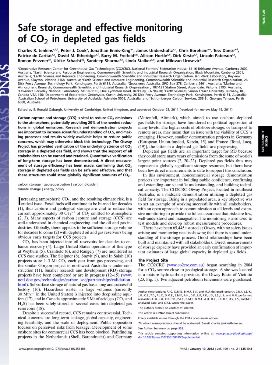
One contained the Buttress well, source of the CO2-rich gas forinjection (SI Appendix). The other contained the production wellNaylor-1, located near the crest of the depleted reservoir struc-ture and suitable for conversion for monitoring. A new well,CRC-1, was planned for injection.
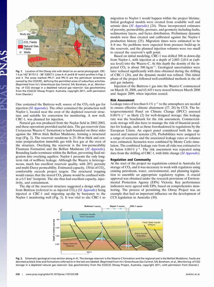
Natural gas was produced from the Naylor field in 2002-2003,and these operations provided useful data. The gas reservoir (lateCretaceous Waarre-C formation) is fault-bounded on three sidesagainst the 300-m thick Belfast Mudstone, forming a structuraltrap (Fig. 2). The reservoir sandstone is 25–30-m thick and con-tains postproduction immobile gas with free gas at the crest ofthe structure. Overlying the reservoir is the low-permeabilityFlaxmans Formation and the Belfast Mudstone (SI Appendix).Bounding faults terminate within the Belfast, preventing fluid mi-gration into overlying aquifers. Naylor-1 presents the only long-term risk of wellbore leakage. Although the Waarre is heteroge-neous, much has excellent reservoir quality, with 20% porosityand multi-Darcy permeability. Estimated capacity, 150 kt of CO2,comfortably exceeds project targets. The structural trappingwould ensure that the stored CO2 plume would be confined with-in a 0.5 km2 footprint. The site thus had excellent capacity, injec-tivity, and containment.
The dip of the reservoir structure suggested a design with gasfrom Buttress (referred to as injected CO2) (SI Appendix) beinginjected at CRC-1 and migrating up-dip by buoyancy to theNaylor-1 monitoring well (Fig. 3). It was vital to site CRC-1 so
migration to Naylor-1 would happen within the project lifetime.Initial geological models were created from available well andseismic data (SI Appendix) (24). These incorporated estimatesof porosity, permeability, pressure, and geometry including faults,sedimentary layers, and facies distribution. Preliminary dynamicmodels were then created and calibrated against the Naylor-1production history (25). Migration times were estimated to be4–8 mo. No problems were expected from pressure build-up inthe reservoir, and the planned injection volumes were too smallto exceed the reservoir’s spill point.
Based on initial modeling, CRC-1 was drilled 308 m down-dipfrom Naylor-1, with injection at a depth of 2,003–2,014 m (sub-sea level) into the Waarre-C. At this depth the density of the in-jected CO2 is about 500 kgm−3. Geological uncertainties werelater reduced significantly with data obtained during the drillingof CRC-1 (26), and the dynamic model was refined. This initialphase of the project followed well-established methods in the oiland gas industry.
Injection of the Buttress-1 gas into the Waarre-C commencedonMarch 18, 2008, and 65,445 t were stored between March 2008and August 2009, when injection ceased.
Risk AssessmentLeakage rates of less than 0.1% y−1 to the atmosphere are neededto ensure effective climate abatement (27, 28) by CCS. The In-tergovernmental Panel on Climate Change (IPCC) assessed0.001% y−1 as likely (2) for well-designed storage; this leakagerate was the benchmark for the risk assessment. Commercial-scale storage will also have to manage the risk of financial penal-ties for leakage, such as those foreshadowed in regulations by theEuropean Union. An expert panel considered both the engi-neered and natural systems (29). Probabilities were assigned toa range of scenarios and the associated leakage rates or volumeswere estimated. Scenarios were combined by Monte Carlo simu-lation. The combined leakage rate from all risks was estimated tobe below 0.001% y−1. The risk assessment was repeated usingdata from the drilling of CRC-1, with little change (SI Appendix).
Regulation and CommunityAt the start of the project no regulations existed in Australia forstorage of CO2 and it was necessary to work with regulators usingexisting petroleum, water, environmental, and planning legisla-tion to assemble an appropriate regulatory regime. A crucialapproval was obtained under the research provisions of Environ-mental Protection Agency (EPA) Victoria. Key performanceindicators were agreed with EPA, based on comprehensive mon-itoring. The process of permitting the Otway Project was anexample that had an important influence on the development ofCCS legislation in Australia (30).
Fig. 1. Location of the Otway site with detail on an aerial photograph. CRC-1 is at 142°.81151 E −38°.53057 S. Lines A–A’ and B–B’match profiles in Figs. 2and 3. The areas marked PPL11 and PPL13 are the petroleum tenementsowned by the CO2CRC, defining the permitted areas of subsurface activities.(Reprinted from Int J Greenhouse Gas Control, 5/4, Boreham, et al., Monitor-ing of CO2 storage in a depleted natural gas reservoir: Gas geochemistryfrom the CO2C2C Otway Project, Australia, copyright 2011, with permissionfrom Elsevier.)
Fig. 2. Schematic geological cross-section along A–A’. The storage reservoir is theWaarre-C formation and the regional seal is the Belfast Mudstone. Faults aredenoted as black lines and formations referred to in the text are labeled. (Reprinted from Int J Greenhouse Gas Control, 5/4, Boreham, et al., Monitoring of CO2storage in a depleted natural gas reservoir: Gas geochemistry from the CO2C2C Otway Project, Australia, copyright 2011, with permission from Elsevier.)
E36 ∣ www.pnas.org/cgi/doi/10.1073/pnas.1107255108 Jenkins et al.
Securing and maintaining the consent of the community wasvital. The CO2CRC developed a communications strategy, basedon market research of the area, and was proactive in engagingwith communities and decision makers, both face to face andalso through leafleting, media releases, and a comprehensiveweb site (31). Key principles were a willingness to listen to thepublic, to be open about all aspects of the project, and to ensureno surprises—any news about the project was communicated firstby the CO2CRC directly to those affected. This outreach effortwas aided by familiarity in the area with oil and gas operations.Evaluation shows a generally positive attitude has persisted in thelocal community, and wider media coverage has been generallybalanced and positive over the period where the CO2CRC hasbeen active (31).
Monitoring DesignA wide range of monitoring was carried out in the Otway Projectas part of its research objectives: A commercial project might relyon a smaller number of well-developed techniques. Measure-ments were necessary to confirm containment of injected CO2 inthe reservoir and provide assurance that groundwater, soil, andair are unaffected (32). These measurements were often techni-cally challenging, and complicated by access to farmers’ land re-quiring frequent negotiation and compromise.
The assurance measurements compare pre- and postinjectionproperties, and began well before CO2 injection commenced.Seismic measurements investigate an overlying aquifer, whereasgroundwater, soil, gas, and atmospheric monitoring provideassurance at increasing distances from the reservoir. These mea-surements will only show changes if leakage out of the reservoiroccurs. Leakage is very unlikely and it is impractical to character-ize the approximately 2 km of overburden and model hypotheti-cal leak pathways through it. Interpretation of results is thereforebased on conditional sensitivities—if CO2 were to enter this zone,then the following effects are predicted. Simple leakages, usuallypoint sources, are modeled to understand the sensitivity of theassurance measurements. Even if the sensitivity is ill-defined, animportant public assurance objective may be achieved if nochanges are detected in important assets such as ground water.Anomalies in an assurance measurement would not be decisivein isolation, but would initiate a cascade of investigations by suc-cessively more precise and expensive techniques (SI Appendix).
It was vital to the community to confirm that potable aquiferswere unaffected by CO2. The composition and chemistry of waterin deep and shallow water wells was measured twice a year (33).
Samples were collected from 24 existing wells, mostly within a5 km radius of CRC-1. Vadose zone soil-gas composition was alsomeasured annually during summer (34). Typically 150 sampleswere collected on a 4 × 3 km grid over the expected location ofthe subsurface plume, the area in which major faults terminateclose to surface, and natural CO2 accumulates (SI Appendix).
Atmospheric concentrations and fluxes of CO2, isotopic com-position (δ13C CO2), and tracers of injected gas (SF6, CH4) orof combustion (CO) were monitored 700 m northeast of the in-jection well (35) and compared to the undisturbed backgroundmeasured at the long-established Cape Grim site (Tasmania).CO2 atmospheric analyzers were also located near the injectionsite to monitor for larger anomalies and deep soil fluxes (36).
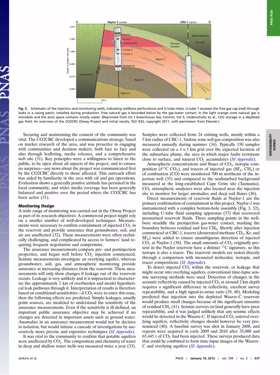
Direct measurements of reservoir fluids at Naylor-1 are theprimary confirmation of containment in this project. Naylor-1 wasinstrumented with a complex bottom-hole assembly (Fig. 3, 32),including U-tube fluid sampling apparatus (37) that recoveredpressurized reservoir fluids. Three sampling points in the well-bore straddle the preinjection gas-water contact, marking theboundary between residual and free CH4. Shortly after injectioncommenced at CRC-1, tracers (deuterated methane CD4, Kr, andSF6) were added to ensure unambiguous detection of injectedCO2 at Naylor-1 (38). The small amounts of CO2 originally pre-sent in the Naylor reservoir have a distinct 13C signature, so thisisotope is also a tracer. The reservoir models are tested directlythrough a comparison with measured molecular, isotopic, andtracer compositions (SI Appendix).
To detect injected CO2 within the reservoir, or leakage thatmight occur into overlying aquifers, conventional time-lapse seis-mic surveying methods were used. Detection of changes in theacoustic reflectivity caused by injected CO2 at around 2 km depthrequires a significant difference in reflectivity, excellent surveyrepeatability, and a high signal-to-noise ratio (39, 40). Modelingpredicted that injection into the depleted Waarre-C reservoirwould produce small changes because of the significant amountsof residual CH4 (41). Seismic surveys on land generally have poorrepeatability, and it was judged unlikely that any seismic effectswould be detected in the Waarre-C. If injected CO2 entered over-lying aquifers, reflectivity changes should however be very pro-nounced (40). A baseline survey was shot in January 2008, andrepeats were acquired in early 2009 and 2010 after 35,000 and65,445 t of CO2 had been injected. These surveys produced datathat could be combined to form time-lapse images of the Waarre-C and overlying aquifers (SI Appendix).
Fig. 3. Schematic of the injection and monitoring wells, indicating wellbore perforations and U-tube inlets. U-tube 1 accesses the free gas cap (red) throughleaks in a casing patch, installed during production. Free natural gas is bounded below by the gas-water contact. In the light orange zone natural gas isimmobile and the pore space contains mostly water. (Reprinted from Int J Greenhouse Gas Control, Vol 5, Underschultz et al., CO2 storage in a depletedgas field: An overview of the CO2CRC Otway Project and initial results, 922–932, copyright 2011, with permission from Elsevier.)
Jenkins et al. PNAS ∣ January 10, 2012 ∣ vol. 109 ∣ no. 2 ∣ E37
SUSTAINABILITY
SCIENCE
PNASPL
US

Reservoir ModelingThe core and wire-line logs obtained from CRC-1 (26) showedthat the Waarre-C reservoir comprised stacked sandstone bodiesof varying grain sizes, with thin shale baffles and streaks depositedin near-shore, tidally influenced channel settings. Four revisedgeological models were created stochastically, representing short-and long-range correlations in the shale baffles. Hysteric andnonhysteretic relative permeability curves were estimated fromlaboratory core tests (42) to give a total of eight models. Thesemodels are equiprobable, and capture the likely ranges in geolo-gical structure and rock properties. A set of dynamical fluid-flowmodels for the reservoir was then computed (SI Appendix). Com-parison with these models is the metric for evaluating predictedstorage performance. The relevant data are the seismic responseand details of arrival of injected CO2 and tracer at Naylor-1. Themodels predict that the injected CO2 will remain above the pre-production gas-water contact, which is presumed to be the spillpoint for the reservoir. Thus assurance measurements are not ex-pected to show injected CO2. Fig. 4 shows vertical cross-sectionsof the reservoir model. The high saturation region is the remain-ing gas cap, with the injected CO2 accumulating below. The in-jected gas is cooler than the reservoir as it leaves CRC-1, causinga region of localized cooling. Tracers are most concentrated be-neath the gas cap.
Monitoring ResultsAggregated groundwater data from the widely-used shallow lime-stone aquifer show no statistically significant pre-to-post-injec-tion changes in bicarbonate or electrical conductivity, with asmall (but statistically significant) increase (0.05 units, p < 0.01)in median pH. These small changes demonstrate that overallwater quality is unaffected by injection to within natural variabil-ity (SI Appendix). Aggregated soil-gas data show a consistentcorrelation between δ13C and CO2 concentration. Data were ob-tained for three summers before injection and two after, andall follow this correlation, which results from decomposition of
organic matter (SI Appendix) (34). Most δ13CO2 values are alsolower than those of the injected CO2, so there is no indication ofchanges that could be attributed to injection.
The groundwater and soil-gas results provide assurance byshowing that water and soils are practically unaffected; this assur-ance was the objective of this monitoring. Considerably moredata-gathering and modeling would be needed to bound quanti-tatively the amounts of CO2 that could have entered these zonesof investigation and yet remain undetected. For example, model-ing shows that leakage of CO2 might only affect small volumes ofthe aquifer and so is unlikely to reach the monitoring wells (SIAppendix). More detailed interpretation of soil-gas data is diffi-cult because of the very variable permeability of the vadose zone.Attempting to characterize the sensitivity of soil-gas and ground-water monitoring may not be cost effective.
The atmospheric concentrations and fluxes of CO2 show largediurnal and seasonal variations, reflecting the effects of plant re-spiration, photosynthesis, and atmospheric dispersion. Much ofthis variability can be modeled (SI Appendix) (43). By day, inwindy conditions, the CO2 concentrations often settle at a steadybaseline. In these favorable conditions small emissions of CO2
(equivalent to about 2 kt y−1) from the diesel engines used whiledrilling of CRC-1 were identified, confirmed by tracers and quan-tified with dispersion modeling (Fig. 5). Other nearby industrialsources have also been detected. These measurements confirmuseful sensitivity to spatially small emitters.
Injected gas at reservoir level was detected in the 2008–2009seismic survey (40) but not confirmed in 2010. Modeling predictsthat changes would be below the noise level on the time-lapseseismic images (SI Appendix). From an assurance perspective,simulations for the immediately overlying Paaratte aquifer showthat 5 kt of injected CO2 in a small accumulation would have beendetectable (40) but no changes were observed (Fig. 6).
None of the assurance-monitoring techniques have detectedany anomalies that would indicate the presence of injected CO2
outside the storage reservoir. The sensitivity of some assurance
Fig. 4. Modeled gas saturation (A), temperature (B), tracer mass fraction (C), and CO2 mass fraction (D) simulated for theWaarre-C, as a vertical cross-section inthe plane of Naylor-1 and CRC-1 (vertical black lines). The vertical exaggeration is 5∶1. Naylor-1 (Left) and CRC-1 (Right). The quantities shown (and the range incolor) include: gas saturation (0–0.8), temperature °C (75–85), tracer mass fraction in the gas phase (0–3 × 10⁻⁵), and total CO2 mass fraction (in gas and waterphases) (0–0.3). The model corresponds to the stage at which 35,000 t of CO2-rich gas had been injected, January 2009.
E38 ∣ www.pnas.org/cgi/doi/10.1073/pnas.1107255108 Jenkins et al.

techniques to leakage has been estimated, conditional upon therebeing a leakage route to aquifer or atmosphere, where effects ofCO2 become apparent. For the seismic and atmospheric monitor-ing, such conditional sensitivities to CO2 of a few kilotonnes, orkilotonnes y−1, have been demonstrated for point sources. Suchsources might result from a small fault acting as a conduit intoan aquifer, or an unmapped wellbore transferring CO2 to thesurface.
Reservoir fluid samples were collected weekly to fortnightlyat the Naylor-1 monitoring well. Pressurized fluids were broughtto surface by U-tube by reservoir pressure within the gas cap or
initially by using N2 pressure for formation water (Fig. 3) from U-tubes 2 and 3. Pressure assistance was initially required for watersamples because of the depressurization of the reservoir duringearlier commercial natural gas production. The arrival of injectedCO2 caused a transition to self-lift, as the composition changed tolighter injected fluid, which flowed to surface under reservoirpressure during sampling. The upper sampling point (U-tube 1,in the remnant gas cap) always returned gas. The lower samplingpoints (U-tube 2 and U-tube 3) initially returned reservoir waterlater transitioning to a CO2∕CH4 mixture with very little water.Chemical analysis was done after controlled depressurization.Fluid samples were analyzed for concentrations of CO2, hydro-carbons, tracers, and carbon isotopic composition (SI Appendix)(37, 38, 44)
The arrival of injected CO2 at the monitoring well is a key in-dicator of the progress of the storage. Fig. 7 shows the measuredarrival of CO2 and tracers at U-tube 2, where both show a rapidbreakthrough and then a plateau in concentrations. Comparisonwith the range of predictions (SI Appendix), with uncertainty dic-tated by uncertain geology and rock physics, shows a broadly sa-tisfactory agreement although breakthrough is slightly earlierthan predicted. Data and predictions from U-tube 3 are similar,with breakthrough slightly early but not significantly. The timingdiscrepancies, multiplied by the injection rate, correspond touncertainty of only 5–10 kt in the implied amount of injectedCO2 that is needed to match models to data. These small discre-pancies in timing, and the steady CO2 concentrations at latertimes are consistent with containment in the reservoir.
Water samples from U-tube 2 and U-tube 3 were collectedfrom preinjection to self-lift. The pH decreased sharply withincreasing CO2 content and changes in the water composition areconsistent with minor dissolution of carbonate and silicate miner-als. However, the dominant process affecting the water composi-tion was determined to be mixing within the reservoir andwellbore. There was no evidence for significant mobilization oftrace metal species.
The geochemical results show that the behavior of CO2 in thesubsurface is understood so that the storage model is realistic.The range of uncertainty from reservoir heterogeneity was ade-quately characterized and the main additional uncertainties arefrom poorly known relative permeabilities. These could have beenmore constrained with core analysis techniques better adapted tothe highly permeable samples fromCRC-1. Containment is demon-strated by the consistency of the geochemical data with forwardmodels at CO2 mass levels close to those that were actually in-jected. The clear absence of CO2 in the overlying aquifer (shownby repeat seismic) adds credibility to this conclusion. Because of thesimple geometry of the reservoir, lateral and vertical movement ofthe CO2 plume are predicted to be very limited.
Direct confirmation of containment is difficult because theamount of CO2 stored is relatively small. A minimalist climateabatement target (24, 25) of 0.1% y−1 leakage to atmosphereis 65 t y−1 for the amount we have stored. This leakage rate iscomparable to the nighttime respiration rate for 1 km2 of nearbypasture. However, the sensitivity of our seismic or atmospherictechniques would remain the same for industrial scale storageand so correspond to much smaller fractional sensitivity. Thesensitivity of our fluid sampling method (injection rate × timinguncertainty) would scale with storage size. An industrial sitemight store 100× more CO2 than Otway. A point leakage rate of6;500 t y−1 (0.1% y−1) from such a site would be detectable by theatmospheric and seismic methods we have tried. However theIPCC estimates (2) of likely leakage rates (1% in 1,000 y) wouldbe very hard to confirm, amounting again to only 65 t y−1.
Reservoir Storage EfficiencyThere is uncertainty regarding the extent to which the pore spacepreviously occupied by gas (primarily CH4, accumulated over
Fig. 6. Modeling of a hypothetical CO2 leak into the overlying Paaratte for-mation. (A) Seismic image of Paaratte acquired in 2008; (B) simulated time-lapse seismic image of a 5,000-t CO2 leak, noise level matched to the realdata; (C and D) actual time-lapse seismic images of the same region for2008–2009 and 2009–2010. The two-way travel times of the acoustic signal(vertical axis) correspond to depths of about 1,600 m. [Reprinted from EnergyProcedia, 4, Urosevic, et al., Seismic monitoring of CO2 injection into a de-pleted gas reservoir-Otway Basin Pilot Project, Australia, copyright 2011, withpermission from Elsevier. (Available at: http://www.elsevier.com/wps/find/journaldescription.cws_home/718157/description).]
Fig. 5. Atmospheric monitoring of emissions from the drilling of CRC-1. CO2
concentrations measured at the atmospheric station 700 m northeast of theemissions are color-filled down to the Cape Grim baseline with color indicat-ing wind direction (see bar), and opacity increasing with wind speed. Night-time maxima (resulting from vegetation emissions within a stable boundarylayer) are typically followed by daytime levels approaching baseline, but onMarch 15 freshening wind, erratically from the direction of the rig activities(about 200°), coincides with CO2 elevated and variable above baseline.Analysis of flask samples (CO and δ13CO2) confirms the origin in combustion(diesel engines). Emissions (estimated from fuel consumption) were about 6 tCO2 day−1 (SI Appendix).
Jenkins et al. PNAS ∣ January 10, 2012 ∣ vol. 109 ∣ no. 2 ∣ E39
SUSTAINABILITY
SCIENCE
PNASPL
US

geological time) can be reoccupied by CO2 injected in only a fewyears. Global estimates of capacity depend on applying averageassumptions to a wide range of different circumstances and needto be checked by experience (22). The International EnergyAgency Greenhouse Gas RD Program estimated that 160 Gtof practical capacity in depleted gas fields, matched to pointsources, will be cumulatively available by 2050 (21). Emissionsfrom such sources are 11 Gt y−1, accumulating to 279 Gt by2050 at present growth rates (2.5% y−1). This potential capacityis globally significant.
With our sampling system we can measure the dynamic storagecapacity of the reservoir as it was refilled with injected CO2 (25).Self-lift occurs when our U-tube samples become mostly CO2 andCH4, and hence the contents of the U-tube are of sufficiently lowdensity to be forced to surface by reservoir pressure alone (SIAppendix). Detailed modeling of the sampling process verifiedthat the transition to self-lift reliably indicates the passage ofthe gas-water contact (GWC) (Fig. 2) (SI Appendix). The amountof injected CO2 that was stored between self-lift at U-Tube 2 andU-Tube 3 is then compared to the available pore space, which isestimated both from the geological model and from the produc-tion data of natural gas. Detailed calculations (SI Appendix) pre-dict that 56–84% of the space originally occupied by recoverableCH4 is reoccupied by CO2, taking account of uncertainties in thepore volume, postproduction residual CH4 saturation and thepossible range of movement of the GWC. Generic estimates usedto calculate global capacity in depleted gas fields (21, 22) haveassumed 75%.
The determination of storage efficiency is a unique measure-ment of this type in CO2 storage, and is consistent with extensiveexperience of natural gas storage (45). Although dependent ondetailed circumstances (SI Appendix), for example rock type ortiming of storage after production, our data adds weight to theconclusion that depleted gas fields have enough storage capacityto make a significant contribution to reducing global emissions(21).
ConclusionsThe CO2CRC Otway Project has demonstrated that the storageof CO2 in a depleted gas field can be designed and safelyachieved. Monitoring showed that there has been no measurableeffect of stored CO2 on soil, groundwater, or atmosphere. Goodrelations with the local community, and decision makers atvarious levels of government, were established and maintained.Seismic imagery and fluid sampling confirmed dynamic and geo-chemical models. Sensitivity of monitoring techniques to surfaceleakage rates at the few kilotons y−1 level, or subsurface accumu-lations at the kilotons level, was demonstrated. Achieving thissensitivity shows that commercial-scale storage programs couldbe effectively monitored to ensure climate abatement was beingachieved.
Overall the project shows that our level of knowledge of sub-surface processes involving CO2, and our ability to forecast itsbehavior, is adequate to proceed with large-scale geologicalstorage of CO2 in depleted gas fields, and the capacity of thesestructures could be of global significance for carbon capture andstorage.
Materials and MethodsThe design, execution, and interpretation of this project followed provenmethods developed for oil and gas extraction, and environmental monitor-ing. Key aspects of adapting these methods for CO2 storage are discussedin the main text. Details of standard modeling of the subsurface, and thecollection of data both from the surface and subsurface are given in SIAppendix.
ACKNOWLEDGMENTS. The Otway Project was supported by the AustralianGovernment through the Cooperative Research Center program, by theVictorian Department of Primary Industry, the US Department of Energyand by the industrial and institutional partners in the CO2CRC. The conclu-sions reported here depend on work, published and unpublished, by manyparticipants in the CO2CRC.
0 100 200 300 400 5000
1
2
3
4
5
6
Con
cent
ratio
n/pp
mv
SF6
0 100 200 300 400 5000.0
0.2
0.4
0.6
0.8
1.0
Days after start of injection
Days after start of injection
Con
cent
ratio
n/m
ole
frac
tion
CO2
Fig. 7. Measured arrival and accumulation of injected CO2 at the Naylor monitoring well’s U-tube 2 (orange points) for SF6 (parts per million) and CO2 (molefraction). The background color coding superimposes predictions of eight reservoir models, each blurred by the experimental error levels. Lighter shadesindicate higher probability of a reservoir model occupying a point in the concentration, time plane. The scatter in SF6 around day 400 appears to be real,but is unexplained.
E40 ∣ www.pnas.org/cgi/doi/10.1073/pnas.1107255108 Jenkins et al.

1. Pacala S, Socolow R (2004) Stabilization wedges: Solving the climate problem for thenext 50 years with current technologies. Science 305:968–972.
2. Benson S, Cook PJ (2005) Carbon Dioxide Capture and Storage, eds B Metz et al. (Cam-bridge University Press, Cambridge, UK).
3. Schrag DP (2007) Preparing to capture carbon. Science 315:812–813.4. Grigg RB (2005) Carbon Dioxide Capture for Storage in Deep Geologic Formations, eds
SM Benson, C Oldenburg, M Hoverstein, and S Imbus (Elsevier, Amsterdam).5. Whittaker S, White D, Law D, Chalaturnyk R (2004) IEAGHG Weyburn CO2 monitoring
and storage project summary report 2000–2004. (Petroleum Technology ResearchCenter, Regina, SK, Canada), Available at: http://www.ptrc.ca/weyburn_first.php.
6. Meckel TA, Hovorka SD (2009) Results from continuous downhole monitoring (PDG)at a field-scale CO2 sequestration demonstration project, Cranfield, MS. SPE Interna-tional Conference on CO2 Capture, Storage, and Utilization (Society of PetroleumEngineers, Richardson, TX), 10.2118/127087-MS.
7. Klusman RW (2003) Rate measurements and detection of gas microseepage to theatmosphere from an enhanced oil recovery/sequestration project, Rangely, CO. AppGeochem 18:1839–1852.
8. Zweigel P, Arts R, Lothe AE, Lindeberg EBG (2004) Geological Storage of Carbon Di-oxide, eds SJ Baines and RH Worden (Geological Society, London), 233, pp 165–180.
9. Maldal T, Tappel MI (2004) CO2 underground storage for Snøhvit gas field develop-ment. Energy 29:1403–1411.
10. Mathieson A, Midgely J, Wright I, Saoula N, Ringrose P (2011) In Salah CO2 Storage JIP:CO2 sequestration monitoring and verification technologies applied at Krechba,Algeria. Energy Procedia 4:3596–3603.
11. Flett M, et al. (2009) Subsurface development of CO2 disposal for the Gorgon Project.Energy Procedia 1:3031–3038.
12. van der Meer LGH, Kreft E, Geel C, Hartman J (2005) K12-B a test site for CO2 storageand enhanced gas recovery. Sixty Seventh EAGE Conference and Exhibition (Society ofPetroleum Engineers, Richardson, TX), (SPE94128), 10.2118/94128-MS.
13. Kikuta K, Hongo S, Tanase D, Ohsumi T (2005) Field test of CO2 injection in Nagaoka,Japan. Proceedings of the Seventh International Conference on Greenhouse GasControl Technologies, eds ES Rubin, DW Keith, and CF Gilboy (Elsevier, Amsterdam),pp 1367–1372.
14. Hovorka SD, et al. (2006) Measuring permanence of CO2 storage in saline formations:The Frio experiment. Environ Geosci 13:105–121.
15. Schilling F, et al. (2009) Status report on the first European on-shore CO2 storage site atKetzin. Energy Procedia 1:2029–2035.
16. Perry KF (2005) Carbon Dioxide Capture for Storage in Deep Geologic Formations, edsSM Benson, C Oldenburg, M Hoverstein, and S Imbus (Elsevier, Amsterdam).
17. Apps JA (2005) Carbon Dioxide Capture for Storage in Deep Geologic Formations, edsSM Benson, C Oldenburg, M Hoverstein, and S Imbus (Elsevier, Amsterdam).
18. Bachu S, Haug K (2005) Carbon Dioxide Capture for Storage in Deep Geologic Forma-tions, eds SM Benson, C Oldenburg, M Hoverstein, and S Imbus (Elsevier, Amsterdam),pp 867–876.
19. Aimard N, Lescanne M, Mouronval G, Prebende C (2007) The CO2 pilot at Lacq:An integrated oxycombustion CO2 capture and geological storage project in theSouth West of France. International Petroleum Technology Conference 2007 (Societyof Petroleum Engineers, Richardson, TX), pp 1717–1724.
20. Loizzo M, Lecampion B, Berard T, Harichandran A, Jammes L (2009) Reusing O and Gdepleted reservoirs for CO2 storage: Pros and cons. SPE Offshore Europe Oil and GasConference, Aberdeen (Society of Petroleum Engineers, Richardson, TX), 10.2118/124317-MS.
21. IEA Greenhouse Gas R & D Program, Report 2009/01 (2009) CO2 storage in depletedgas fields., Available at: www.ieaghg.org.
22. Bachu S, et al. (2007) CO2 storage capacity estimation: Methodology and gaps. Int JGreenhouse Gas Control 1:430–443.
23. Sharma S, Cook PJ, Berly T, Anderson C (2007) Australia’s first geosequestrationdemonstration project—the CO2CRC Otway Basin Pilot Project. APPEA J 47:257–268.
24. Spencer L, La Pedalina F (2006) Otway Basin Pilot Project Naylor Field, WaarreFormation Unit C; Reservoir static models. CO2CRC Internal Report RPT05-0123(CO2CRC, Canberra, Australia), 10.5341/RPT05-0123.
25. Underschultz J, et al. (2011) CO2 storage in a depleted gas field: An overview ofthe CO2CRC Otway Project and initial results. Int J Greenhouse Gas Control 5:922–932.
26. Dance T, Spencer L, Xu Q (2009) Geological characterization of the Otway pilot site:What a difference a well makes. Energy Procedia 1:2871–2878.
27. Enting IG, Etheridge DM, Fielding MJ (2008) A perturbation analysis of the climatebenefit from geosequestration of carbon dioxide. Int J Greenhouse Gas Control2:289–296.
28. Haugan PM, Joos F (2004) Metrics to assess the mitigation of global warming bycarbon capture and storage in the ocean and in geological reservoirs. Geophys ResLett 31:L18202.
29. Bowden A, Rigg AJ (2004) Assessing risk in CO2 storage projects. APPEA J 44:677–701.30. Ranasinghe N (2008) Regulating carbon dioxide capture and storage in Australia.
Masters thesis (Griffith University, Nathan, Queensland, Australia).31. Ashworth P, Rodriguez S, Miller A (2010) Case study of the CO2CRC Otway Project.
(CSIRO, Pullenvale, Australia), 10.5341/RPT10-2362 EP 103388.32. Dodds K, et al. (2009) Developing a monitoring and verification plan with reference to
the Australian Otway CO2 pilot project. The Leading Edge 28:812–818.33. de Caritat P, Kirste D, Hortle A (2009) Composition and levels of groundwater in
the CO2CRC Otway Project area, Victoria, Australia: Establishing a pre-injection base-line. Proceedings of the Twenty Fourth International Applied Geochemistry Sympo-sium, eds DR Lentz, KG Thorne, and K-L Beal (Association of Applied Geochemists,Nepean, ON, Canada), pp 667–670.
34. Schacht U, Boreham CJ, Watson MN (2010) Soil Gas Baseline Characterization Study—Methodology and Summary (CO2CRC, Canberra, Australia), 10.5341/RPT09-1714CO2CRC Internal Report RPT09-1714.
35. Leuning R, Etheridge DM, Luhar AK, Dunse BL (2008) Atmospheric monitoring andverification technologies for CO2 geosequestration. Int J Greenhouse Gas Control2:401–414.
36. Bernardo C, de Vries DF (2010) Permanent shallow subsoil CO2 flux chambers formonitoring of onshore CO2 geological storage sites. Int J Greenhouse Gas Control,10.1016/j.ijggc.2010.05.011.
37. Freifeld BM, et al. (2005) The U-Tube: A novel system for acquiring borehole fluid sam-ples from a deep geologic CO2 sequestration experiment. J Geophys Res 110:B10203.
38. Stalker L, et al. (2009) Geochemical monitoring at the CO2CRC Otway Project: Tracerinjection and reservoir fluid acquisition. Energy Procedia 1:2119–2125.
39. Pevzner R, Shulakova V, Kepic A, Urosevic M (2010) Repeatability analysis of land time-lapse seismic data: CO2CRCOtway pilot project case study.Geophys Prospect 59:66–77.
40. Urosevic M, et al. (2011) Time-lapse seismic monitoring of CO2 injection into adepleted gas reservoir: Naylor Field, Australia. The Leading Edge 29:164–169.
41. Li R, Dodds K, Siggins AF, Urosevic M (2006) A rock physics simulator and its applicationfor CO2 sequestration process. Explor Geophys 37:67–72.
42. Perrin J-C, Benson S (2010) An experimental study on the influence of sub-core scaleheterogeneity on CO2 distribution in reservoir rocks. Transp Porous Media 82:93–109.
43. Luhar AK, et al. (2009) Modeling carbon dioxide fluxes and concentrations aroundthe CO2CRC Otway geological storage site. Nineteenth International Clean Air andEnvironment Conference (Clean Air Society of Australia and New Zealand, Olinda,Victoria, Australia), Available at: www.casanz.org.au.
44. BorehamC, et al. (2011) Monitoring of CO2 storage in a depleted natural gas reservoir:Gas geochemistry from the CO2CRC Otway Project, Australia. Int J Greenhouse GasControl 5:1039–1054, Available at: http://www.journals.elsevier.com/international-journal-of-greenhouse-gas-control/.
45. Katz DL, Lee RL (1990) Natural Gas Engineering, Production, and Storage (McGraw-Hill, New York).
Jenkins et al. PNAS ∣ January 10, 2012 ∣ vol. 109 ∣ no. 2 ∣ E41
SUSTAINABILITY
SCIENCE
PNASPL
US
Related Documents