Answers To Reviewers The answers are in RED Reviewer #: 88632 Interesting paper, and methodology, though the gain obtained by the proposed system is limited. Hereafter some comments and needed clarifications : End of P1 : add a space between bythis . DONE Fig 2 : Axis legend and values too small . All figures have been re sized. P2, right col parag 3 'as a function of '?? Corrected Fig 4 : Text too small and should be defined All figures have been re sized. P4 eq (8) V_prin should be defined Mistake corrected => V_main Fig 7 bottom : Texh should be Tech ? Corrected Tabl 1 : Left column difficult to read (black vs dark blue) All Tables have been changed accordingly to reviewer remark K_34 should be Forced Conv. (conv. missing ?) Corrected P5, right col parag 4 'as a function of ' ?? Corrected Tabl 2 : Id Tabl1 for colors All Tables have been changed accordingly to reviewer remark Tabl 3 : The ICE is capable of 100 kW for 1.2 L, that's quite impressive for a passenger car ? Sorry for the mistake : 70 kW P7, right col parag 4 'a Heated Intermediate…' ? (2 times) Corrected Table 6 : Conv consumption is 4,67 L/100, exactly the same value for NEDC and WLTP ? Then an other cycle could have been chosen ? WLTP has been chosen because it will become the new reference cycle in replacement to NEDC. Effectively there is no significant difference in consumption, but the WLTP has a higher demand in energy. Could you precise if the engine is cold or hot for all the start of the simulations (NEDC and WLTP). The simulations has been conducted with data maps established from ‘hot’ steady state experimental conditions .

SAE2013 IntermediateHeatedTank Corrected (06!07!2013 10-02-48)
Oct 23, 2015
Welcome message from author
This document is posted to help you gain knowledge. Please leave a comment to let me know what you think about it! Share it to your friends and learn new things together.
Transcript
Answers To Reviewers
The answers are in RED
Reviewer #: 88632
Interesting paper, and methodology, though the gain obtained by the proposed
system is limited. Hereafter some comments and needed clarifications :
End of P1 : add a space between bythis . DONE
Fig 2 : Axis legend and values too small . All figures have been re sized.
P2, right col parag 3 'as a function of '?? Corrected
Fig 4 : Text too small and should be defined All figures have been re sized.
P4 eq (8) V_prin should be defined Mistake corrected => V_main
Fig 7 bottom : Texh should be Tech ? Corrected
Tabl 1 : Left column difficult to read (black vs dark blue) All Tables have been
changed accordingly to reviewer remark
K_34 should be Forced Conv. (conv. missing ?) Corrected
P5, right col parag 4 'as a function of ' ?? Corrected
Tabl 2 : Id Tabl1 for colors All Tables have been changed accordingly to reviewer
remark
Tabl 3 : The ICE is capable of 100 kW for 1.2 L, that's quite impressive for a
passenger car ? Sorry for the mistake : 70 kW
P7, right col parag 4 'a Heated Intermediate…' ? (2 times) Corrected
Table 6 : Conv consumption is 4,67 L/100, exactly the same value for NEDC and WLTP ? Then an other cycle could have been chosen ? WLTP has been chosen because it will become the new reference cycle in replacement to NEDC. Effectively there is no significant difference in consumption, but the WLTP has a
higher demand in energy.
Could you precise if the engine is cold or hot for all the start of the simulations (NEDC and WLTP). The simulations has been conducted with data maps
established from ‘hot’ steady state experimental conditions .
Fig 11 to 16 : Difficult to exploit, text is too small and grid too visible Figures have
been re sized
P11 : 2nd
paragraph, it should be fig 17 ? Corrected
In conclusion : The effect of the proposed device seem to be small on fuel consumption gain, but validation of the simulations on a test bench would be
interesting.
Reviewer #: 88632
Overall, very well written paper. Clearly explained concept, backed by a good theoretical model and simulation results. Nice contribution
n. Would like to see it verified with Experimental Results. That will be interesting.The comments below are mostly editorial in nature.
1. Page one, “bythis” should be written as by this” Corrected
2. Page 2, after first equation. “Tank” should be “tank” corrected
3. Figure 2 shows clearly the benefits of heating the tank. Nice introduction and problem set up discussion. Thank you
4. Page 3 “Once the engine switch to the …” should be “Once the engine switches to the …” Corrected
5. Page 6 “For confidential reason…” should read “For confidentiality reasons…”Corrected
W What is the WLTP drive cycle ?Worldwide harmonized Light vehicles Test Procedures . Every acronyms have been correctly defined before use.
Graphs are not possible to read in black and white. Consider enlarging the key graphs and making them more understandable. . All figures have been re sized.
Reviewer #: 89166
The paper presents analysis of improving the efficiency of pneumatic hybrid engine with addition of an intermediate heated tank. The proposed idea involves placing an intermediate tank between engine combustion chamber and main tank. The intermediate tank is heated using exhaust gases. Additionally, a bypass valve is added to prevent cooling of intermediate tank when the engine is running in
pneumatic motor mode.

Authors should address following concerns:
1. The citations in the paper are not ordered in the order of their appearance. Please reorder citations appropriately. Corrected
2. From practical standpoint, having an bypass valve would be prone to fouling and sticking. Authors should comment how they plan to address that? Exactly as it is done with a EGR Valve … Reviewer is right, problems will occurs, exactly as those encountered with an EGR Valve.
3. 4. What is m in equation 2? ‘M’, ‘Cp’, ‘Cv’ and ‘r’ have been clearly definedin
the text 5. In thermodynamic modeling section, none of the equation variables are
described and not all variables are part of figure. Like Cp, Cv, r, Vprin? Vprin was a mistake (V main) . Corrected.
6. For simulation results, what kind of fidelity of models was used? What reviewer means ?
7. What is a WLTP cycle? Please use full name first time before
abbreviation.Worldwide harmonized Light vehicles Test Procedures . Every acronyms have been correctly defined before use.
8. In terms of fuel economy, there isn’t much difference between single mainisothermal tank and intermediate tank for both cycles, 0.01l/km? Effectively there is no significant difference…
9. The “hot” simulations don’t make any sense. What was the thinking behind such an experiment, as it doesn’t represent any real world scenario? This experiment unfavorably adds additional energy in the intermediate
tank. Reviewer is right. The thinking was to show that the hotter is the initial state of the tank, the higher are the efficiencies. Effectively those conditions would not be encountered on a Test Procedure, but could be encountered in real life..
10. Did simulations comparing intermediate tank and single main isothermal
tank considered additional weight for the intermediate tank? Also what is the size of main tank used in simulation? Did authors adjust the size of main tank for simulation with no intermediate tank to account for additional storage? The total volume for the pressurized air has been maintained constant : if intermediate tank grows up , main tank decreases.
11. 12. There are few grammatical mistakes like on Page 5, first line, “A thermal
resistance model, as depicted in fig7 is used” for what? Please proof read final draft. We have done the best as we can..
Page 1 of 12
Type Paper Number Here
Improving the Overall Efficiency of a Pneumatic-Combustion Hybrid
Engine by adding an intermediate Heated Tank
Pascal BREJAUD(*), Pascal HIGELIN, Alain CHARLET, Kristan
GILLET, Julien LEMAIRE (Do NOT enter this information. It will
be pulled from participant tab in MyTechZone)
Affiliation (Do NOT enter this information. It will be pulled from participant tab in MyTechZone)
Copyright © 2012 SAE International
ABSTRACT
Several works have previously shown that the concept of
pneumatic-combustion hybrid engine is an interesting alternative to the Electric Hybrid Vehicle, by leading to
equivalent fuel savings for a probable lower cost. However,
these studies have shown that the thermal insulation of the
tank is a problem. Indeed, due to its size and its location, the
adiabaticity of the pneumatic tank cannot be guaranteed.
During a regenerative braking (pneumatic pump mode) the hot
and pressurized air that is send to the tank cools, pressure
drops and density increases. When reusing the air in
pneumatic motor mode, the mass necessary to fill the cylinder
is greater than the one that would have been necessary if the
air was not cool at its stay in the tank. This phenomenon is the major cause to the quite low regenerative efficiency that has
been observed on a prototype engine. This paper proposes and
evaluates a solution to this problem by using an intermediate
air tank heated by the exhaust gases while the engine operates
in the conventional combustion mode. The proposed concept
is developed in detail and 0D thermal and thermodynamic
modeling is proposed. The fuel savings, for the NEDC and
WLTP driving cycles under several thermal initial states of the
intermediate tank, are estimated by numerical simulations.
Finally, the influence of the intermediate heated tank size is
investigated.
INTRODUCTION
Pneumatic Hybrid Engine
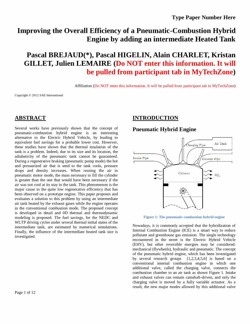
Figure 1: The pneumatic-combustion hybrid engine
Nowadays, it is commonly accepted that the hybridization of
Internal Combustion Engine (ICE) is a smart way to reduce
pollutant and greenhouse gas emission. The single technology
encountered in the street is the Electric Hybrid Vehicle
(EHV), but other reversible energies may be considered:
mechanical (flywheels), hydraulic and pneumatic. The concept
of the pneumatic hybrid engine, which has been investigated
by several research groups [1,2,3,4,5,6] is based on a
conventional internal combustion engine in which one additional valve, called the charging valve, connects the
combustion chamber to an air tank as shown Figure 1. Intake
and exhaust valves can remain camshaft-driven, and only the
charging valve is moved by a fully variable actuator. As a
result, the new major modes allowed by this additional valve

Page 2 of 12
(pneumatic pump, pneumatic motor and supercharged)
remains 4-Strokes cycles [7].
Pneumatic Pump: During a regenerative braking, this mode
transforms vehicle kinetic energy into a re-usable pneumatic
energy. The cycle begins with a conventional intake stroke.
The charging valve opens during the compression stroke as soon as the in-cylinder pressure reaches that of the charging
port. The valve closes shortly after TDC, and the cycle
finishes with conventional expansion and exhaust strokes.
Pneumatic Motor: This mode is used to recover mechanical
work from the pneumatic energy, without any combustion.
The cycle begins with classical intake and compression
strokes. The charging valve opens when approaching TDC,
and remains open during part of the expansion stroke in order
to maintain pressure at a high level and generate the desired
indicated work. The cycle finishes with a conventional exhaust
stroke.
Pneumatic Supercharged mode: This mode is used to compensate for the "turbo lag" effect, while temporarily boost
the engine during a strong acceleration transient. The charging
valve opens shortly after intake valve closure, and closes when
the desired additional air mass has flowed into the in-cylinder.
The end of the cycle remains the same as a conventional four
stroke one.
Several previous publications [3, 7, 8, 9] have shown that the
concept of pneumatic hybrid engine could provide benefits in
terms of fuel consumption and greenhouse gas emissions that
are comparable with those of an electric hybrid vehicle [10]
but with lower weight and presumably lower cost.
Thermal Insulation of the Air Tank
One major drawback encountered on the pneumatic hybrid engine concept is due to the non-adiabaticity of the Air Tank.
Indeed, while using the pneumatic pump mode during a
regenerative braking, the pressurized air sent to the tank is also
at high temperature level. Assuming an homentropic
compression from the ambient (Pext, T ext ) the air temperature
level can be estimated:
1
,homair
air entropic ext
ext
PT T
P
(1)
Ideally, if both the tank and the charging pipe were perfectly
adiabatic, the air temperature level could be maintained over
time. In practice, this is not the case. Due to its volume
(around 30liters) the air tank cannot be localized near the
engine, and a quite long charging pipe is needed. Even with a
thermal insulation of both air tank and charging pipe, the heat
transfer remains significant and the pressurized air quickly
cools to reach the ambient temperature. This phenomenon has
been experimentally observed on real pneumatic hybrid engine
by Trajkovic[11],Brejaud [12] and Donitz [3] . These authors
show that, without any additional heating system, the air tank
has to be considered isothermal.
Figure 2: Relative air mass consumed In pneumatic Motor Mode
As Function As Temperature [Wi=310 J/cycle- Ptank=12 bar-1200 RPM]
Finally, when reusing the air in pneumatic motor mode, the
mass necessary to fill the cylinder is greater than the one that
would have been necessary if the air was not cool at its stay in
the tank.
Figure 2 gives the calculated relative air mass needed in
pneumatic motor mode as a function of the incoming air
temperature, in order to produce an indicated work of 120
J/cycle, 1200 RPM, for an air tank pressure level of 12 bars.
This figure clearly shows that a great benefit exists in using
heated air instead of "cold" one coming from an isotherm air
tank.
Single Main Heated Tank
Figure 3: Single Main Air Tank Concept heated with exhaust gases. Source: [5]
293 393 493 593 693 7930
20
40
60
80
100
Relative air mass consumed in pneumatic motor mode [%]
Air Temperature [K]

Page 3 of 12
This observation has leaded several authors to propose to heat
the air tank with the exhaust gases produced while the engine
is used in conventional mode. Tai and al. [5] was the first
research team to propose the concept of a single Air Tank
heated with the exhaust gases in a technical paper [5].The
proposed concept is also described in a US Patent [13]. See Figure 3.
Figure 4: Energy Domains
This proposal for heating the air tank allows a new pathway in
the management of energy domains, as depicted in dashed line
by Figure 4. It is then possible, due to the heat exchanger
created by the double-walled air tank, to recover and to
transfer a part of the exhaust gas heat to the compressed air.
Proposed Concept
Figure 5: Schematic representation of the proposed concept
From the authors’ point of view, the idea for heating the air
tank is a smart way to improve the overall efficiency of the
hybrid engine, but its implementation by a single tank is unrealistic. As mentioned before and due to its volume, it is
not possible to embed the air tank near the exhaust pipe of the
engine. Consequently two large length air circuits are needed
for both exhaust gas and the pressurized air circuits. The heat
transfer phenomenon along these pipes finally leads to an
important reduction of the energy efficiency of the concept.
First, while the engine operates in conventional mode, a
significant part of the exhaust gas heat is dissipated along the pipe. Second, while the engine operates in pneumatic motor
mode, the hot pressurized air issued by the air tank is cooled
before entering into the cylinder.
For these reasons, authors propose an alternative charging air
path. See Figure 5. The proposed system consists of three
main components connected by various pipes: an intermediate
tank, a main tank and a optional three-way valve called "By-
pass valve". The main tank is a reservoir of compressed air
that presents a large capacity, up to 50 liters. The latter is
single-walled and has no special thermal insulation, so it has
to be considered as isothermal. The intermediate tank is
double-walled, low-capacity, and acts as a heat exchanger between the pressurized air issued from the main tank and the
exhaust gas of the engine.
The main and the intermediate tank may be respectively
considered as a mass and enthalpy reservoir. The main
function for the intermediate tank is to guarantee the
availability of a sufficient volume of “hot” and pressurized air
that will be typically consumed during a vehicle start from a
null speed while using the pneumatic motor mode. Once the
engine switches to the conventional combustion mode, the
new function for the intermediate tank is then to warm-up the
cold air that has came from the main tank in previous state. Next, when the engine is stopped, the double-wall acts as
insulation and limits the heat losses for the hot pressurized air.
The three-way “By-pass” valve is used to derive the flow of
exhaust gas when it is not desired that it passes through the
intermediate tank. Its presence is motivated by two reasons:
1. In pneumatic motor mode, because of the expansion
performed in the engine cylinder, the air discharged from
the exhaust valve reaches extremely low temperatures.
Thus, in order not to cool the intermediate tank, the
addition of a three way "By-Pass" valve is desirable. The
presence of the latter is not mandatory, but is
recommended in order to maximize the energy potential of the concept.
2. The heat transfer process while the exhaust gas crosses
the intermediate tank lowers the temperature of the latter.
As a consequence, the efficiency of the catalytic converter
could be negatively impacted. The presence of the three-
way "By-Pass" valve allows, if desired, not to cool the
exhaust and get a rapid rise in temperature of the catalytic
converter.
Moreover, it is appropriate that the pipe connecting the
charging valve to the intermediate tank is the most thermally insulated as possible. It is important to minimize the heat
Page 4 of 12
losses of the air between the outlet of the intermediate tank
and its entry into the engine cylinder.
Proposed Study
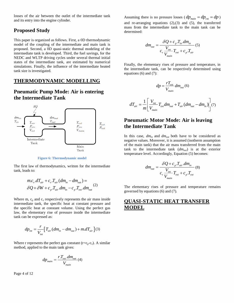
This paper is organized as follows. First, a 0D thermodynamic
model of the coupling of the intermediate and main tank is
proposed. Second, a 0D quasi-static thermal modeling of the
intermediate tank is developed. Third, the fuel savings, for the
NEDC and WLTP driving cycles under several thermal initial states of the intermediate tank, are estimated by numerical
simulations. Finally, the influence of the intermediate heated
tank size is investigated.
THERMODYNAMIC MODELLING
Pneumatic Pump Mode: Air is entering
the Intermediate Tank
Figure 6: Thermodynamic model
The first law of thermodynamics, written for the intermediate
tank, leads to:
. . . ( )
. . . .
v air v air in out
p air in p ext out
m c dT c T dm dm
Q W c T dm c T dm
(2)
Where m, cp and cv respectively represents the air mass inside
intermediate tank, the specific heat at constant pressure and
the specific heat at constant volume. Using the perfect gas
law, the elementary rise of pressure inside the intermediate tank can be expressed as:
( ) .int air in out air
int
rdp T dm dm m dT
V (3)
Where r represents the perfect gas constant (r=cp-cv). A similar
method, applied to the main tank gives:
. .ext outmain
main
r T dmdp
V (4)
Assuming there is no pressure losses ( ntmain idp dp dp )
and re-arranging equations (2),(3) and (5), the transferred
mass from the intermediate tank to the main tank can be
determined:
. .
.
p in
outint
v ext p
ma
n
in
i
air
Q c T dmdm
Vc T c T
V
(5)
Finally, the elementary rises of pressure and temperature, in
the intermediate tank, can be respectively determined using
equations (6) and (7):
extout
main
rTdp dm
V (6)
1( )int
air ext out air out in
main
VdT T dm T dm dm
m V
(7)
Pneumatic Motor Mode: Air is leaving
the Intermediate Tank
In this case, dmin and dmout both have to be considered as
negative values. Moreover, it is assumed (isotherm assumption
of the main tank) that the air mass transferred from the main
tank to the intermediate tank (dmout) is at the exterior
temperature level. Accordingly, Equation (5) becomes:
. .
.
p in
outint
v
air
ext
m
ext p
ain
Q c T dmdm
Vc T c T
V
(8)
The elementary rises of pressure and temperature remains
governed by equations (6) and (7).
QUASI-STATIC HEAT TRANSFER
MODEL
Page 5 of 12
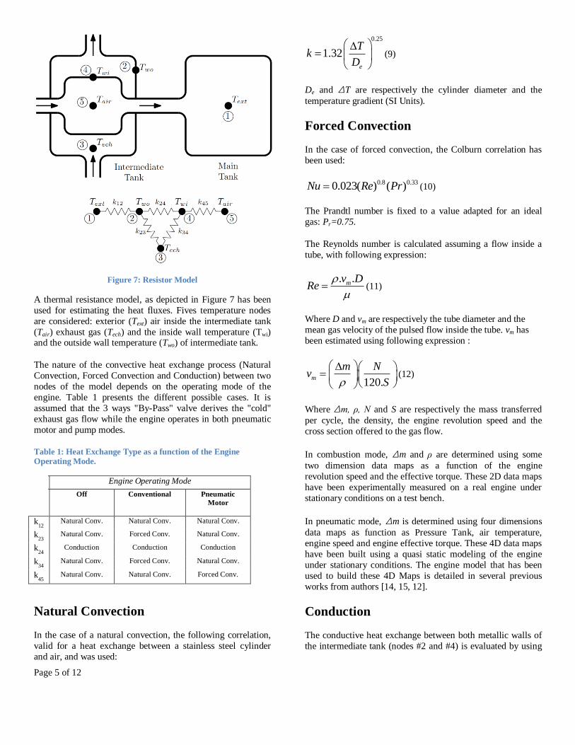
Figure 7: Resistor Model
A thermal resistance model, as depicted in Figure 7 has been
used for estimating the heat fluxes. Fives temperature nodes
are considered: exterior (Text) air inside the intermediate tank
(Tair) exhaust gas (Tech) and the inside wall temperature (Twi) and the outside wall temperature (Two) of intermediate tank.
The nature of the convective heat exchange process (Natural
Convection, Forced Convection and Conduction) between two
nodes of the model depends on the operating mode of the
engine. Table 1 presents the different possible cases. It is
assumed that the 3 ways "By-Pass" valve derives the "cold"
exhaust gas flow while the engine operates in both pneumatic
motor and pump modes.
Table 1: Heat Exchange Type as a function of the Engine Operating Mode.
Engine Operating Mode Off Conventional Pneumatic
Motor
k12
Natural Conv. Natural Conv. Natural Conv.
k23
Natural Conv. Forced Conv. Natural Conv.
k24
Conduction Conduction Conduction
k34
Natural Conv. Forced Conv. Natural Conv.
k45
Natural Conv. Natural Conv. Forced Conv.
Natural Convection
In the case of a natural convection, the following correlation,
valid for a heat exchange between a stainless steel cylinder
and air, and was used:
0.25
1.32e
Tk
D
(9)
De and ΔT are respectively the cylinder diameter and the
temperature gradient (SI Units).
Forced Convection
In the case of forced convection, the Colburn correlation has
been used:
0.8 0.330.023( ) ( )Nu Re Pr (10)
The Prandtl number is fixed to a value adapted for an ideal
gas: Pr=0.75.
The Reynolds number is calculated assuming a flow inside a
tube, with following expression:
. .mv DRe
(11)
Where D and vm are respectively the tube diameter and the
mean gas velocity of the pulsed flow inside the tube. vm has
been estimated using following expression :
120.m
m Nv
S
(12)
Where Δm, ρ, N and S are respectively the mass transferred
per cycle, the density, the engine revolution speed and the
cross section offered to the gas flow.
In combustion mode, Δm and ρ are determined using some
two dimension data maps as a function of the engine
revolution speed and the effective torque. These 2D data maps
have been experimentally measured on a real engine under
stationary conditions on a test bench.
In pneumatic mode, Δm is determined using four dimensions
data maps as function as Pressure Tank, air temperature,
engine speed and engine effective torque. These 4D data maps
have been built using a quasi static modeling of the engine
under stationary conditions. The engine model that has been
used to build these 4D Maps is detailed in several previous
works from authors [14, 15, 12].
Conduction
The conductive heat exchange between both metallic walls of
the intermediate tank (nodes #2 and #4) is evaluated by using
Page 6 of 12
the Fourier’s Law, assuming a steady state Conduction
Phenomena.
SIMULATION BACKGROUND:
Intermediate Heated Tank
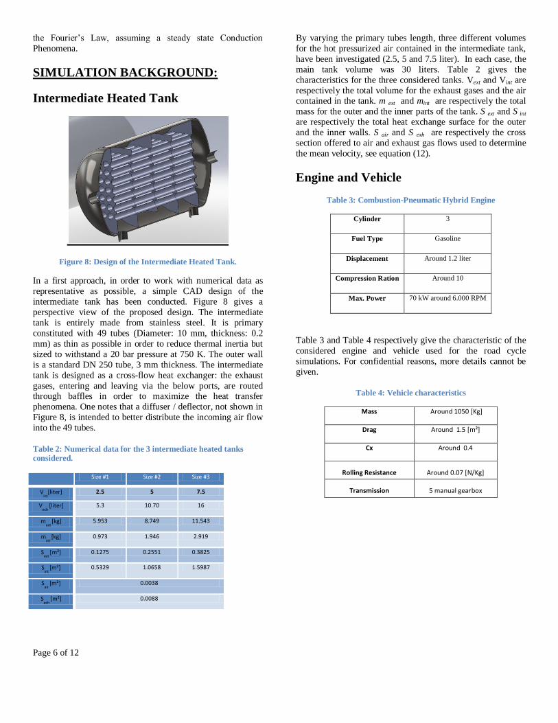
Figure 8: Design of the Intermediate Heated Tank.
In a first approach, in order to work with numerical data as
representative as possible, a simple CAD design of the
intermediate tank has been conducted. Figure 8 gives a
perspective view of the proposed design. The intermediate
tank is entirely made from stainless steel. It is primary
constituted with 49 tubes (Diameter: 10 mm, thickness: 0.2
mm) as thin as possible in order to reduce thermal inertia but
sized to withstand a 20 bar pressure at 750 K. The outer wall
is a standard DN 250 tube, 3 mm thickness. The intermediate
tank is designed as a cross-flow heat exchanger: the exhaust
gases, entering and leaving via the below ports, are routed through baffles in order to maximize the heat transfer
phenomena. One notes that a diffuser / deflector, not shown in
Figure 8, is intended to better distribute the incoming air flow
into the 49 tubes.
Table 2: Numerical data for the 3 intermediate heated tanks considered.
Size #1 Size #2 Size #3
Vint
[liter] 2.5 5 7.5
Vech
[liter] 5.3 10.70 16
mext
[kg] 5.953 8.749 11.543
mint
[kg] 0.973 1.946 2.919
Sext
[m²] 0.1275 0.2551 0.3825
Sint
[m²] 0.5329 1.0658 1.5987
Sair
[m²] 0.0038
Sech
[m²] 0.0088
By varying the primary tubes length, three different volumes
for the hot pressurized air contained in the intermediate tank,
have been investigated (2.5, 5 and 7.5 liter). In each case, the
main tank volume was 30 liters. Table 2 gives the
characteristics for the three considered tanks. Vext and Vint are
respectively the total volume for the exhaust gases and the air contained in the tank. m ext and mint are respectively the total
mass for the outer and the inner parts of the tank. S ext and S int
are respectively the total heat exchange surface for the outer
and the inner walls. S air and S exh are respectively the cross
section offered to air and exhaust gas flows used to determine
the mean velocity, see equation (12).
Engine and Vehicle
Table 3: Combustion-Pneumatic Hybrid Engine
Cylinder 3
Fuel Type Gasoline
Displacement Around 1.2 liter
Compression Ration Around 10
Max. Power 70 kW around 6.000 RPM
Table 3 and Table 4 respectively give the characteristic of the
considered engine and vehicle used for the road cycle
simulations. For confidential reasons, more details cannot be
given.
Table 4: Vehicle characteristics
Mass Around 1050 [Kg]
Drag Around 1.5 [m²]
Cx Around 0.4
Rolling Resistance Around 0.07 [N/Kg]
Transmission 5 manual gearbox

Page 7 of 12
Energy Management Strategy
Figure 9: Causal strategy
The energy management retained for present work is a causal
strategy, which is based on the engineer’s experience
(heuristics) and consequent intuition about how to operate the
energy source in the most efficient regions. Figure 9 depicts
the organization chart for engine mode choice. This energy
management strategy has been selected because it leads to an
effective fuel savings close to the optimum obtained by a
dynamic programming [16, 17], but with a very significant
reduction of computational time. Moreover, the aim for authors is not to determine this optimum fuel savings but to
establish if a benefit exists in the use of an intermediate heated
tank compared to a single isotherm main tank.
Efficiency Indicators
In order to precisely quantify, during a entire road cycle
simulation, the efficiencies over the entire energetic chain,
several indicators have been defined. See Figure 10.
Figure 10: Efficiency Chain
For a given engine cycle performed (index j), ,j regenW is
defined as the negative work per cycle recoverable at
crankshaft in order to produce the needed deceleration of the
vehicle assuming there is no use of the braking system.
,j pumpW represents the effective work per cycle recovered
when the pneumatic pump mode is used. Because the
regenerative pneumatic pump mode is often unable to
consume all the recoverable energy that is available, a first
efficiency can be defined as the Pump Usage Efficiency. This
indicator has been evaluated over the entire road cycle as:
,
,
Pump_Usage_Efficiency
j pump
j regen
j regen
j regen
W
W
Next, assuming a homentropic compression of the pumped air
mass (Δmin), a Coefficient of Performance for the pneumatic
pump mode can be defined as:
,hom ,hom
_
, ,
. .j entropic p air entropic
j regen j regen
pneu pump
j regen j regen
in
j pump j pump
H m c T
COPW W
Because, the main tank has to be considered in practice as
isothermal, a significant part of the Enthalpy transferred by the
Pump mode is lost by heat transfer process. Δmin and Δmout
are respectively defined as the mass of pressurized air that
inflows and outflows from the intermediate tank. The
Coefficient of Performance of the isotherm tank is then
defined as:
,
_ tan
,hom ,hom
. .
.
j isotherm out p ext
j regen j regen
isotherm k
j entropic in p air entropic
j regen j regen
H m c T
COPH m c T
When this pressurized cold air is re-used while the engine
operates in pneumatic motor mode, the latter is warmed while
its stay in the intermediate heated tank. ,air outT , Δmin and
Δmout are respectively defined as temperature of the warmed
air out-flowing from the exchanger, the mass of warmed air
out-flowing from the exchanger and the mass of cold air that
out-flowing the main tank . The coefficient of Performance of
the exchanger can then be defined as:
, ,
,
. .
. .
j exchanger in p air out
j motor j motor
exchanger
j isotherm out p ext
j motor j motor
H m c T
COPH m c T
Next, the coefficient of performance for pneumatic motor is
defined as:
, ,
_
,,. .
j motor j motor
j motor j motor
pneu motor
p air out
j motorj motor
inj exchanger
W W
COPC TmH
It then possible to define an Overall Regenerative Efficiency
over the entire road cycle as:
Page 8 of 12
,
,
Overall_Regenerative_Efficiency
j motor
j motor
j regen
j regen
W
W
SIMULATION RESULTS:
Cycles and Initial Thermal State Study
Two road cycles were considered: the New European Driving
Cycle (NEDC) cycle and a probable but still unconfirmed
Worldwide harmonized Light vehicles Test Procedures
(WLTP) cycle. For both cycles, four different simulations
were performed:
1. A reference simulation in pure combustion mode, with no hybridization and no Start & Stop effect.
2. A single main isotherm tank simulation for a 20 °C
exterior temperature level.
3. A 5 liters intermediate heated tank with an initial “cold”
thermal state, defined as the exterior temperature level.
4. A 5 liters intermediate heated tank simulation with an
initial “hot” thermal state, defined as the intermediate
heated tank final thermal state obtained for simulation #3.
Tables 5 and 6 respectively give the numerical results obtained
for the NEDC and WLTP cycles.
Figure 11, Figure 12, Figure 13, Figure 15 respectively display the simulation results as function as time for the
Combustion Mode, Single Main Isothermal Tank, Cold Start
and Warm Start with an Heated Intermediate Tank.
Figure 14 and Figure 16 respectively give the temperature as
function as time of the 5 nodes of thermal resistance model,
for the Cold Start and the Warm Start with an Heated
Intermediate Tank.
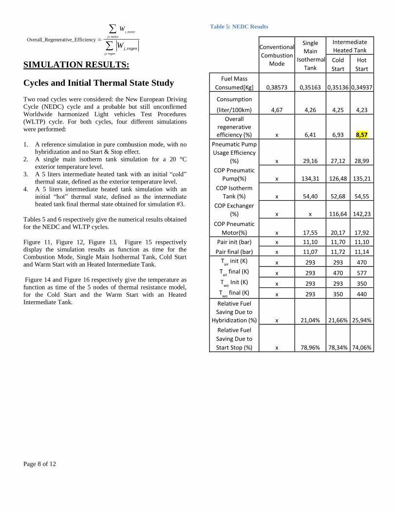
Table 5: NEDC Results
Conventional
Combustion
Mode
Single
Main
Isothermal
Tank
Intermediate
Heated Tank
Cold
Start
Hot
Start
Fuel Mass
Consumed[Kg] 0,38573 0,35163 0,35136 0,34937
Consumption
(liter/100km) 4,67 4,26 4,25 4,23
Overall regenerative efficiency (%) x 6,41 6,93 8,57
Pneumatic Pump
Usage Efficiency
(%) x 29,16 27,12 28,99
COP Pneumatic
Pump(%) x 134,31 126,48 135,21
COP Isotherm
Tank (%) x 54,40 52,68 54,55
COP Exchanger
(%) x x 116,64 142,23
COP Pneumatic
Motor(%) x 17,55 20,17 17,92
Pair init (bar) x 11,10 11,70 11,10
Pair final (bar) x 11,07 11,72 11,14
Tair
init (K) x 293 293 470
Tair
final (K) x 293 470 577
Two
Init (K) x 293 293 350
Two
final (K) x 293 350 440
Relative Fuel
Saving Due to
Hybridization (%) x 21,04% 21,66% 25,94%
Relative Fuel
Saving Due to
Start Stop (%) x 78,96% 78,34% 74,06%

Page 9 of 12
Table 6: WLTP Results
Conventional
Combustion
Mode
Single Main
Isothermal
Tank
Intermediate
Heated Tank
Cold
Start
Hot
Start
Fuel Mass
Consumed[Kg] 0,79515 0,76289 0,76048 0,75393
Consumption
(liter/100km) 4,67 4,48 4,46 4,42
Overall regenerative efficiency (%) X 4,88 5,80 8,10
Pneumatic Pump
Usage Efficiency
(%) X 33,03 32,37 31,67
COP Pneumatic
Pump(%) X 153,77 148,07 153,07
COP Isotherm
Tank (%) X 53,84 53,12 53,74
COP Exchanger
(%) X x 120,20 167,76
COP Pneumatic
Motor(%) X 15,08 16,71 18,70
Pair init (bar) X 10,00 10,50 10,80
Pair final (bar) X 9,89 10,68 10,85
Tair
init (K) X 293 293 609
Tair
final (K) X 293 609 695
Two
Init (K) X 293 293 481
Two
final (K) X 293 481 594
Relative Fuel
Saving Due to
Hybridization (%) X 31,85% 36,60% 46,66%
Relative Fuel
Saving Due to
Start Stop (%) X 68,15% 63,40% 53,33%
Figure 11: WLTP Conventional Combustion Mode
Figure 12: WLTP Single Main Isothermal Tank
Figure 13:WLTP Cold Start with Heated Intermediate Tank
0 500 1000 1500 2000-20
0
20
40
60
80
100
120
140
Time[s]
CycleSpeed [km/h]
EngineSpeed [rpm]/100
WorkDemand [J]/100
Tank Pressure [bar]
Engine mode [10=Motor 20=Pump 30=Conv]
Cumulative comsumption [liter]*100
GivenWork [J]/100
0 500 1000 1500 2000-20
0
20
40
60
80
100
120
140
Time[s]
CycleSpeed [km/h]
EngineSpeed [rpm]/100
WorkDemand [J]/100
Tank Pressure [bar]
Engine mode [10=Motor 20=Pump 30=Conv]
Cumulative comsumption [liter]*100
GivenWork [J]/100
0 500 1000 1500 2000-20
0
20
40
60
80
100
120
140
Time[s]
CycleSpeed [km/h]
EngineSpeed [rpm]/100
WorkDemand [J]/100
Tank Pressure [bar]
Engine mode [10=Motor 20=Pump 30=Conv]
Cumulative comsumption [liter]*100
GivenWork [J]/100

Page 10 of 12
Figure 14: Temperature Evolution-WLTP- Cold Start with Intermediate Heated Tank. [K]
Figure 15: WARM Start with Heated Intermediate Tank
Figure 16: Temperature Evolution-WLTP-WARM Start With Heated Intermediate Tank.
Discussion
NEDC Cycle
The Single Main Isothermal Tank simulation leads to a value
of -8.78% for the relative fuel consumption in reference to the
combustion. Table 5 shows that this fuel saving is due, at first
order (78.96%) to the suppression of the engine idling (Start &
Stop Effect) and at second order (21.04%) in the use of the
pneumatic motor mode to drive the vehicle instead of the conventional mode (Hybridization).
The use of an intermediate heated tank slightly improves the
relative fuel consumption in reference to combustion mode:
respectively -8.91 % and -9.43% for the “cold” and “hot”
initial thermal state. This rather low benefit is due to the low
level of engine load required by this cycle, which does not
allow an efficient heating of the intermediate tank.
However, a significant improvement of the overall
regenerative efficiency is observed: a value of 8.57% is
obtained for the intermediate tank (warm start) in comparison
to a value of 6.41% obtained for isothermal tank. An analysis
of Table 5 clearly establishes that this overall efficiency improvement is due to the COP exchanger that reaches a value
up to 135.21%.
WLTP Cycle
First, one notes that the WLTP cycle is different than the
NEDC because of its higher energy demand and less idling
phases. In one hand, this cycle is unfavorable to every hybridization technology and, in other hand, is favorable to the
intermediate heated tank concept.
Consequently, the single main isothermal tank simulation
leads to a poor value of -4.06% for the relative fuel
consumption in reference to the pure combustion mode. The
heated intermediate tank concept slightly ameliorates the
situation and leads to relative fuel consumption values of -
4.36% and -5.18% for the “cold” and “hot” initial state. This
improvement is one more time due to COP exchanger which
reaches a value up to 167.76% for the “hot” initial state
simulation. This undeniable heating of the air finally extends
the frequency of use of pneumatic motor mode, as it is shown by Relative Fuel Saving Due to Hybridization that
respectively evolutes, for the Single Isothermal Main Tank
and for the “hot” Initial State of Intermediate Tank, from
31.85% to 46.66%. One notes that, with the use of an
intermediate heated tank, a balance is almost reached between
the contribution of the Hybridization and that of the Start &
Stop.
0 500 1000 1500 2000250
300
350
400
450
500
550
600
650
Time[s]
Two [K]
Twi [K]
Tair [K]
T ech [K]
0 500 1000 1500 2000-20
0
20
40
60
80
100
120
140
Time[s]
CycleSpeed [km/h]
EngineSpeed [rpm]/100
WorkDemand [J]/100
Tank Pressure [bar]
Engine mode [10=Motor 20=Pump 30=Conv]
Cumulative comsumption [liter]*100
GivenWork [J]/100
0 500 1000 1500 2000450
500
550
600
650
700
750
Time[s]
Two [K]
Twi [K]
Tair [K]
T ech [K]
Page 11 of 12
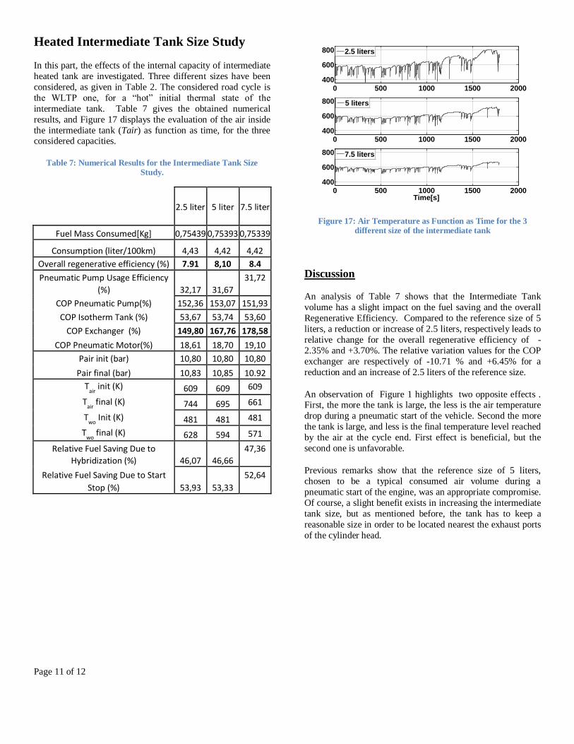
Heated Intermediate Tank Size Study
In this part, the effects of the internal capacity of intermediate
heated tank are investigated. Three different sizes have been
considered, as given in Table 2. The considered road cycle is
the WLTP one, for a “hot” initial thermal state of the
intermediate tank. Table 7 gives the obtained numerical
results, and Figure 17 displays the evaluation of the air inside
the intermediate tank (Tair) as function as time, for the three considered capacities.
Table 7: Numerical Results for the Intermediate Tank Size Study.
2.5 liter 5 liter 7.5 liter
Fuel Mass Consumed[Kg] 0,75439 0,75393 0,75339
Consumption (liter/100km) 4,43 4,42 4,42
Overall regenerative efficiency (%) 7.91 8,10 8.4
Pneumatic Pump Usage Efficiency
(%) 32,17 31,67
31,72
COP Pneumatic Pump(%) 152,36 153,07 151,93
COP Isotherm Tank (%) 53,67 53,74 53,60
COP Exchanger (%) 149,80 167,76 178,58
COP Pneumatic Motor(%) 18,61 18,70 19,10
Pair init (bar) 10,80 10,80 10,80
Pair final (bar) 10,83 10,85 10.92
Tair
init (K) 609 609 609
Tair
final (K) 744 695 661
Two
Init (K) 481 481 481
Two
final (K) 628 594 571
Relative Fuel Saving Due to
Hybridization (%) 46,07 46,66
47,36
Relative Fuel Saving Due to Start
Stop (%) 53,93 53,33
52,64
Figure 17: Air Temperature as Function as Time for the 3 different size of the intermediate tank
Discussion
An analysis of Table 7 shows that the Intermediate Tank
volume has a slight impact on the fuel saving and the overall
Regenerative Efficiency. Compared to the reference size of 5
liters, a reduction or increase of 2.5 liters, respectively leads to
relative change for the overall regenerative efficiency of -
2.35% and +3.70%. The relative variation values for the COP
exchanger are respectively of -10.71 % and +6.45% for a
reduction and an increase of 2.5 liters of the reference size.
An observation of Figure 1 highlights two opposite effects . First, the more the tank is large, the less is the air temperature
drop during a pneumatic start of the vehicle. Second the more
the tank is large, and less is the final temperature level reached
by the air at the cycle end. First effect is beneficial, but the
second one is unfavorable.
Previous remarks show that the reference size of 5 liters,
chosen to be a typical consumed air volume during a
pneumatic start of the engine, was an appropriate compromise.
Of course, a slight benefit exists in increasing the intermediate
tank size, but as mentioned before, the tank has to keep a
reasonable size in order to be located nearest the exhaust ports
of the cylinder head.
0 500 1000 1500 2000400
600
800
0 500 1000 1500 2000400
600
800
0 500 1000 1500 2000400
600
800
Time[s]
2.5 liters
5 liters
7.5 liters

Page 12 of 12
SUMMARY/CONCLUSIONS
In this paper, an alternative to the single main heated tank
concept, that authors judge unrealistic, has been proposed.
Both thermodynamic and steady state heat exchange models
have been proposed. The use of the numerical model, for road
cycle simulations, has shown that the proposed concept leads
to a slight but undeniable increase of the overall regenerative
efficiency. The reason for this improvement is the COP exchanger that reaches values up to +167% for a “hot” initial
state of the intermediate tank. It has been shown that the
Internal Tank volume has an impact on the fuel saving and
other efficiency indicators, but that a volume around 5 liters is
sufficient and probably makes possible its implantation nearest
the exhaust ports of the engine.
Future works have to experimentally validate the theoretical
benefits highlighted. A validation of the heat exchange
correlations that have been used is needed. An intermediate
heated tank prototype has to be built and implemented on a
real engine on a test bench in order to validate the thermal
model for engine operating mode switches.
REFERENCES
[1] M. SCHECHTER. New cycles for automobile
engines. SAE Technical Paper, 1999-01-0623, 1999.
[2] P. HIGELIN and A. CHARLET. Thermodynamic
cycles for a new hybrid pneumatic-combustion engine
concept. SAE Paper, 2001-09-23, 2001.
[3] C. DONITZ, I. VASILE, C. ONDER, and
L. GUZZELLA. Realizing a concept for high efficiency and
excellent drivability: The downsized and supercharged hybrid
pneumatic engine. SAE paper, 2009-01-1326, 2009.
[4] M. ANDERSSON, B. JOHANSSON, and
A. HULTQVIST. An air hybrid for high power absorption and
discharge. SAE Paper, 2005-01-2137, 2005. [5] C. TAI, T.TSAO, M.B. LEVIN, and
M. SCHECHTER. Using camless valvetrain for air hybrid
optimization. SAE Paper, 2003-01-0038, 2003.
[6] S. TRAJKOVIC, P. TUNESTAL, and
B. JOHANSSON. Investigation of different valve geometries
and valve timing strategies and their effect on regenerative
efficiency for a pneumatic hybrid with variable valve
actuation. SAE Paper, 2008-01-1715, 2008.
[7] C. DONITZ, I. VASILE, C. ONDER, and
L. GUZZELLA. Modeling and optimizing two- and four-
stroke hybrid pneumatic engines. IMechE Part D - Journal of
Automobile Engineering, Vol. 223, No. 2, pp. 255-280, 2009. [8] A. IVANCO. Evaluation of energy management
strategies for a hybrid pneumatic engine. PhD thesis,
Université d’Orléans, 2009.
[9] S. TRAJKOVIC, P. TUNESTAL, and
B. JOHANSON. Vehicle driving cycle simulation of a
pneumatic hybrid bus based on experimental engine
measurements. SAE Technical paper, 2010-01-0825(2010-01-
0825), 2010.
[10] A. ELGOWAINY, A. BURNHAM, M. WANG,
J. MOLBURG, and A. ROUSSEAU. Well-to-wheels use and
greenhouse gas emissions of plug-in-hybrid electric vehicles.
SAE paper, 2009-01-1309, 2009. [11] S. TRAJKOVIC. The Pneumatic Hybrid Vehicle. A
new Concept For Fuel Consumption Reduction. PhD thesis,
Lund University, 2010.
[12] P. BREJAUD. Etude théorique et expérimentale d’un
nouveau concept de moteur hybride thermique pneumatique.
PhD thesis, Université d’Orléans., 2011.
[13] SCHECHTER. Operating an air-hybrid vehicle with
two-stages compression and expansion. us patent us 7,543,668
bi, 2009.
[14] P. BREJAUD, A. CHARLET .,
Y. CHAMAILLARD, A. IVANCO, and P. HIGELIN. Pneumatic-combustion hybrid engine: A study of the effect of
the valve train sophistication on pneumatic modes. Oil and
Gas Science and Technology-Rev. IFP, DOI:
10.2516/ogst/2009054, 2009.
[15] P. BREJAUD, P. HIGELIN, A. CHARLET, and
Y. CHAMAILLARD. One dimensional modeling and
experimental validation of single cylinder pneumatic
combustion hybrid engine. SAE paper, 2011-24-0074, 2011.
[16] A. IVANCO, A. CHARLET, Y. CHAMAILLARD,
and P. HIGELIN. Energy management strategies for hybrid-
pneumatic engine studied on an Markov chain type generated
driving cycle. SAE Paper, 09PFL-1130, 2009. [17] C. DONITZ, I. VASILE, C. ONDER, and
L. GUZZELA. Dynamic programming for hybrid pneumatic
vehicles. In Proceeding ACC’09 proceedings of the 2009
conference on American control conference, 2009.
Related Documents