Creating customer confidence Sabroe Products 2022

Welcome message from author
This document is posted to help you gain knowledge. Please leave a comment to let me know what you think about it! Share it to your friends and learn new things together.
Transcript
Creating customer confidence
Sabroe Products 2022

Sabroe products - smart, safe and sustainable
2 3
ContentSabroe - creating customer confidence for a better world 04
125 years of new ideas and better technology 05
Business with global goals 08
Sabroe or Sabroe – what’s the difference? 10
Reducing emissions, recovering heat 11
Sabroe products – engineered to perfection 12
CompressorsSabroe reciprocating compressors 14
Sabroe screw compressors 24
Chillers Sabroe chillers 32
Sabroe low-temperature chillers 46
Heat pumpsSabroe heat pumps 50
ControlsSabroe controls 62
Heat exchangersSabroe heat exchangers and vessels 84
CustomisedSabroe customised solutions 112
AfterMarketAfterMarket solutions 116
Sabroe End-of-Line test centre 128
2 3

Our customers are our community We work every day to keep their trust and support their environments so they succeed Our rigorous engineering and testing enables consistently safe, reliable, and high-performing solutions When our customers are confident, we are successful
With a long history of product innovation, we always move forward with a focus on leading our customers to greener, safer, and more profitable solutions We deliver the “heart” of our customers’ processes and we take our role seriously – from the support of the world’s healthy food supply to the energy that fuels our world
We drive positive changes in the industries we serve as the world champions in green cooling and heating solutions, offering supreme flexibility and relentless quality
Part of Johnson Controls
The Sabroe product brand is owned by Johnson Controls, a pure play buildings leader serving customers in more than 150 countries
This means we can provide Sabroe customers with a comprehensive range of products, systems, and services for meeting heating, ventilating, air conditioning, and refrigeration needs in industrial, commercial, and residential buildings of all kinds
Sabroe is a registered trademark of Johnson Controls in the United States of America and other countries
Other trademarks:
ChillPAC, UniSAB
Sabroe - creating customer confidence for a better world
4
2022
2022
2022
2021
2020
2019
2018
2018
2017
2017
2017
2016
2015
2015
2013
2011
2011
2010
2007
2006
2006
2005
2004
2002
1995
1995
1994
1991
1989
1989
1988
1985
1985
1982
1967
1965
1955
1929
1897
1897
1897
ChillPAC Air
Chiller and Heat Pump Plant Control (CHPPC)
Heat exchangers and vessels
Heat pump 273, 63 bar
SAB 193 & 233 40 bar
TSMC, HPC Mk 5
SMC Mk 5
HPC 112-116
DualPAC
NS heat pump 40 bar
Chiller Plant Controller (CPC)
ComPAC
HeatPAC HPX
ChillPAC Mk 3
SABflex
SABlight
iRIS
HeatPAC
UniSAB lll
SABcube
CAFP
SABscrew redesign
ChillPAC
Variable-speed drive
Unisab II
PAC
SAB 202
SAB 110
Unisab l
HPO, HPC
Prosab II
µProsab
SAB 163
SAB 128
First heat pump
CMO
SMC
SA
First CO2 compressor
Introduction of natural refrigerants
Sabroe founded
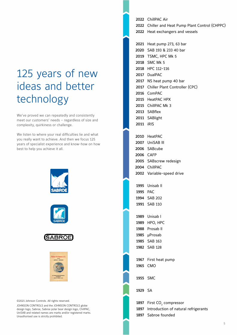
We’ve proved we can repeatedly and consistently meet our customers’ needs – regardless of size and complexity, quirkiness or challenge
We listen to where your real difficulties lie and what you really want to achieve And then we focus 125 years of specialist experience and know-how on how best to help you achieve it all
125 years of new ideas and better technology
©2021 Johnson Controls All rights reserved
JOHNSON CONTROLS and the JOHNSON CONTROLS globe design logo, Sabroe, Sabroe polar bear design logo, ChillPAC, UniSAB and related names are marks and/or registered marks Unauthorised use is strictly prohibited
5

George Oliver, Chairman and CEO, Johnson Controls:
“The recent IPCC* report spelled out in no uncertain terms that the climate crisis is here and needs urgent action now COP26 is the perfect opportunity for governments to set out the policies that can help the private sector to better support that effort
Technologies exist today that will enable us to bend the carbon emissions curve to reach net-zero by 2050 At Johnson Controls, we have been lowering the global carbon footprint of our customers, our supply chain, as well as our own operations through the use of technologies such as OpenBlue, which is playing a key role in decarbonising buildings
Buildings are a major component of global emissions – as much as 40 percent of global CO2 emissions are from the building sector ”
*Intergovernmental Panel on Climate Change
Achieve your green commitments with Sabroe solutions
Sabroe refrigeration and heating systems - such as chillers, heat pumps and other customised products - put companies in a better position to achieve their green commitments to the coming generations
With Sabroe systems using natural refrigerants like ammonia and carbon dioxide, our industrial cooling and heating customers will obtain energy savings with the most energy-efficient products designed for virtually all types of industrial applications and projects
6
Healthy Places
2002
Sin
ce
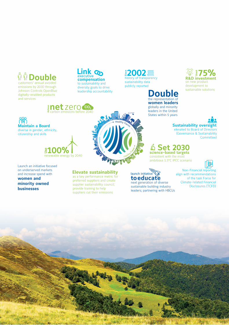
Double
Maintain a Board
executive
compensation
women leaders
Elevate sustainability
100% Use Set 2030
net zero
Ach
ieve
R&D investment
Dire
ct
Double
launch initiative
to educate
customers’ annual avoided emissions by 2030 through Johnson Controls OpenBlue digitally-enabled products and services
75%
on new product development to sustainable solutions
as a key performance metric for preferred suppliers and create supplier sustainability council; provide training to help suppliers cut their emissions
consistent with the most ambitious 1.5°C IPCC scenario
carbon emissions before 2040
renewable energy by 2040
to sustainability and diversity goals to drive leadership accountability
diverse in gender, ethnicity, citizenship and skills
Non-Financial reporting align with recommendations
of the task Force for Climate-related Financial
Disclosures (TCFD)
Sustainability oversight elevated to Board of Directors
(Governance & Sustainability Committee)
history of transparency sustainability data publicly reported
the representation of
globally and minority leaders in the United States within 5 years
next generation of diverse sustainable building industry leaders; partnering with HBCUs
Launch an initiative focused on underserved markets and increase spend withwomen and minority owned businesses
science-based targets
7

Determined to do something
The seventeen UNDP Sustainable Development Goals (SDGs) came into effect in January 2016 as part of a worldwide push to implement real measures to help end poverty, protect the planet, and ensure peace and prosperity for everyone
As a world leader in the commercial application of innovative thinking and sustainable technology, Johnson Controls – and its Sabroe business unit – strongly support, endorse, and encourage the implementation of the UNDP SDGs to ensure good business with a minimum of environmental impact But we are only going to achieve these global goals if we all actively support and comply with them and pass on the message about their importance
Johnson Controls believes in doing well by doing good
We will design and deliver increasingly sustainable products, services and solutions that help our customers improve their energy efficiency, reduce their carbon footprint and achieve their environmental goals.
Leading by example, we will improve our own environmental performance and that of our supply chain. We will protect our environment through recycling and reducing greenhouse gases, energy, water, and waste.
Business with global goals - Johnson Controls keeps its cool
8
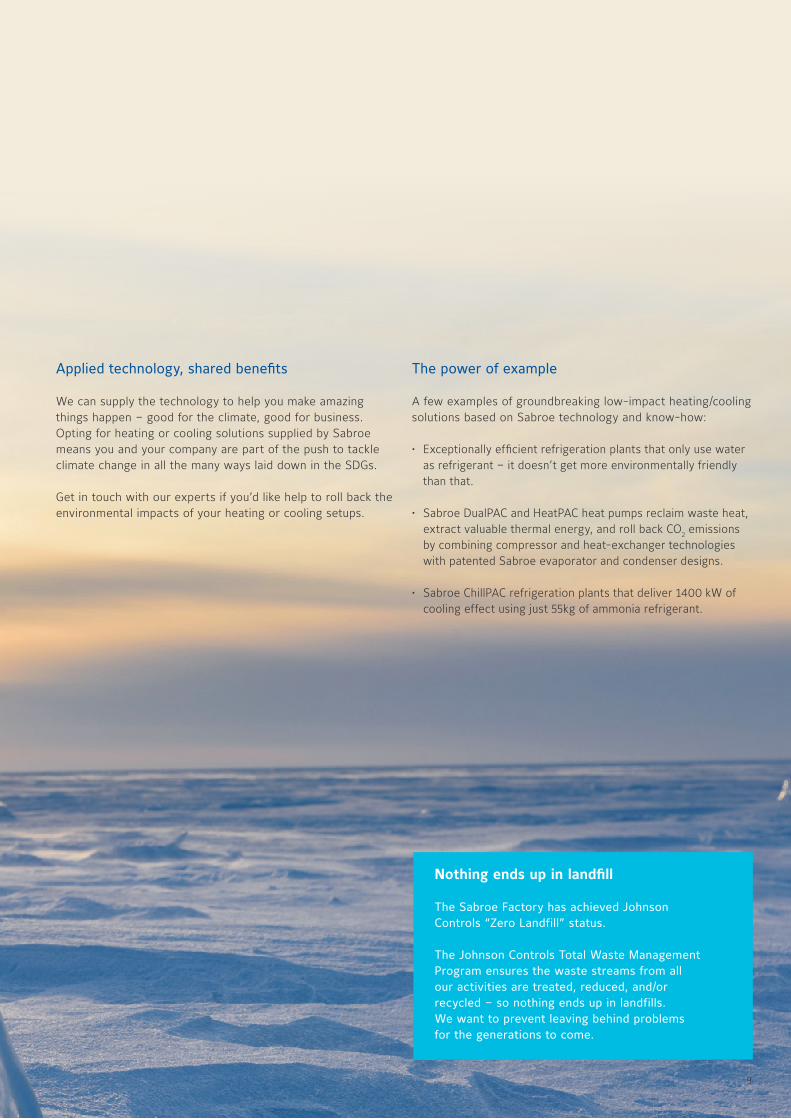
Applied technology, shared benefits
We can supply the technology to help you make amazing things happen – good for the climate, good for business Opting for heating or cooling solutions supplied by Sabroe means you and your company are part of the push to tackle climate change in all the many ways laid down in the SDGs
Get in touch with our experts if you’d like help to roll back the environmental impacts of your heating or cooling setups
The power of example
A few examples of groundbreaking low-impact heating/cooling solutions based on Sabroe technology and know-how:
• Exceptionally efficient refrigeration plants that only use water as refrigerant – it doesn’t get more environmentally friendly than that
• Sabroe DualPAC and HeatPAC heat pumps reclaim waste heat, extract valuable thermal energy, and roll back CO2 emissions by combining compressor and heat-exchanger technologies with patented Sabroe evaporator and condenser designs
• Sabroe ChillPAC refrigeration plants that deliver 1400 kW of cooling effect using just 55kg of ammonia refrigerant
Nothing ends up in landfill
The Sabroe Factory has achieved Johnson Controls “Zero Landfill” status.
The Johnson Controls Total Waste Management Program ensures the waste streams from all our activities are treated, reduced, and/or recycled – so nothing ends up in landfills. We want to prevent leaving behind problems for the generations to come.
9
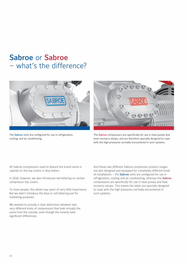
Sabroe or Sabroe – what’s the difference?
All Sabroe compressors used to feature the brand name in capitals on the top covers in blue letters In 2018, however, we also introduced red lettering on certain compressor top covers
To most people, this detail may seem of very little importance But we didn’t introduce the blue or red lettering just for marketing purposes
We wanted to provide a clear distinction between two very different kinds of compressors that look virtually the same from the outside, even though the innards have significant differences
The Sabroe units are configured for use in refrigeration, cooling, and air conditioning.
The Sabroe compressors are specifically for use in heat pumps and heat-recovery setups, and are therefore specially designed to cope with the high pressures normally encountered in such systems.
And these two different Sabroe compressor product ranges are also designed and equipped for completely different kinds of installations – the Sabroe units are configured for use in refrigeration, cooling and air conditioning, whereas the Sabroe compressors are specifically for use in heat pumps and heat recovery setups This means the latter are specially designed to cope with the high pressures normally encountered in such systems
10
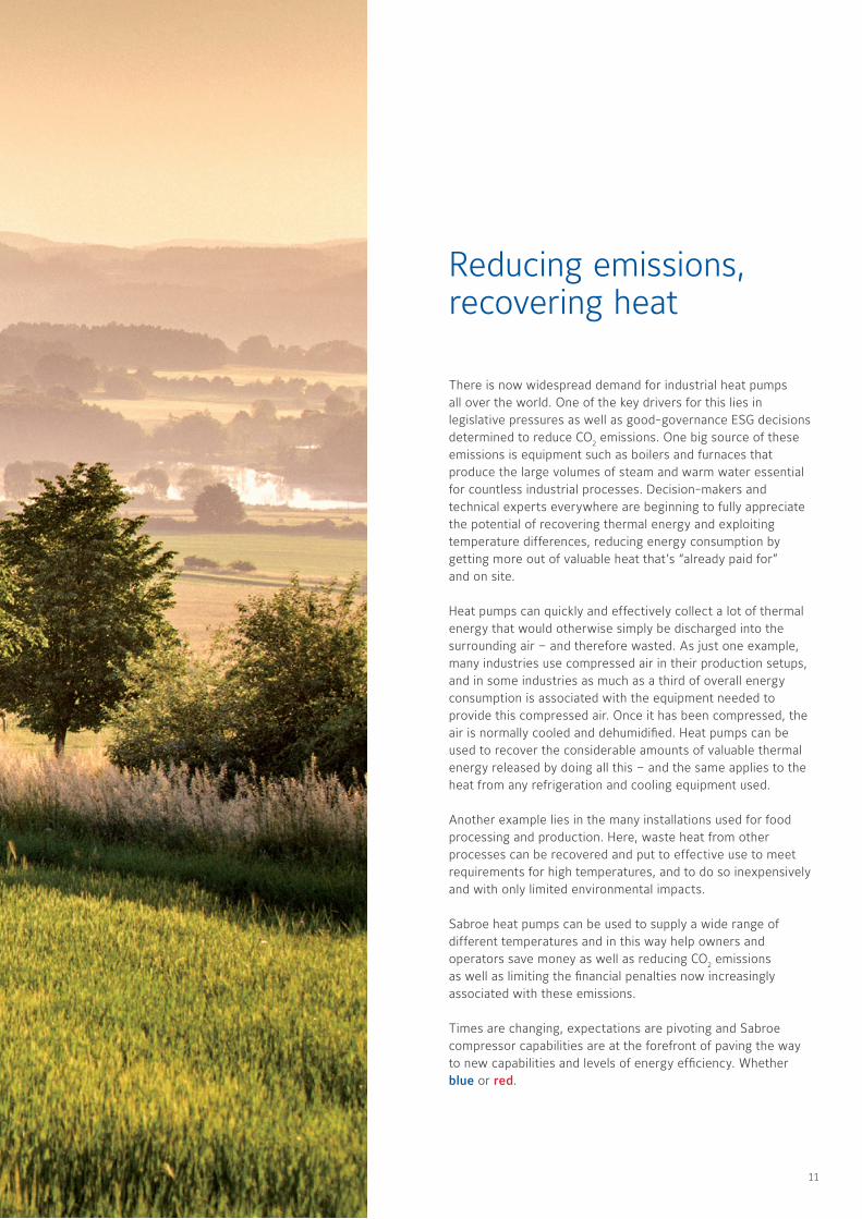
Reducing emissions, recovering heat
There is now widespread demand for industrial heat pumps all over the world One of the key drivers for this lies in legislative pressures as well as good-governance ESG decisions determined to reduce CO2 emissions One big source of these emissions is equipment such as boilers and furnaces that produce the large volumes of steam and warm water essential for countless industrial processes Decision-makers and technical experts everywhere are beginning to fully appreciate the potential of recovering thermal energy and exploiting temperature differences, reducing energy consumption by getting more out of valuable heat that’s “already paid for” and on site
Heat pumps can quickly and effectively collect a lot of thermal energy that would otherwise simply be discharged into the surrounding air – and therefore wasted As just one example, many industries use compressed air in their production setups, and in some industries as much as a third of overall energy consumption is associated with the equipment needed to provide this compressed air Once it has been compressed, the air is normally cooled and dehumidified Heat pumps can be used to recover the considerable amounts of valuable thermal energy released by doing all this – and the same applies to the heat from any refrigeration and cooling equipment used
Another example lies in the many installations used for food processing and production Here, waste heat from other processes can be recovered and put to effective use to meet requirements for high temperatures, and to do so inexpensively and with only limited environmental impacts
Sabroe heat pumps can be used to supply a wide range of different temperatures and in this way help owners and operators save money as well as reducing CO2 emissions as well as limiting the financial penalties now increasingly associated with these emissions
Times are changing, expectations are pivoting and Sabroe compressor capabilities are at the forefront of paving the way to new capabilities and levels of energy efficiency Whether blue or red
11
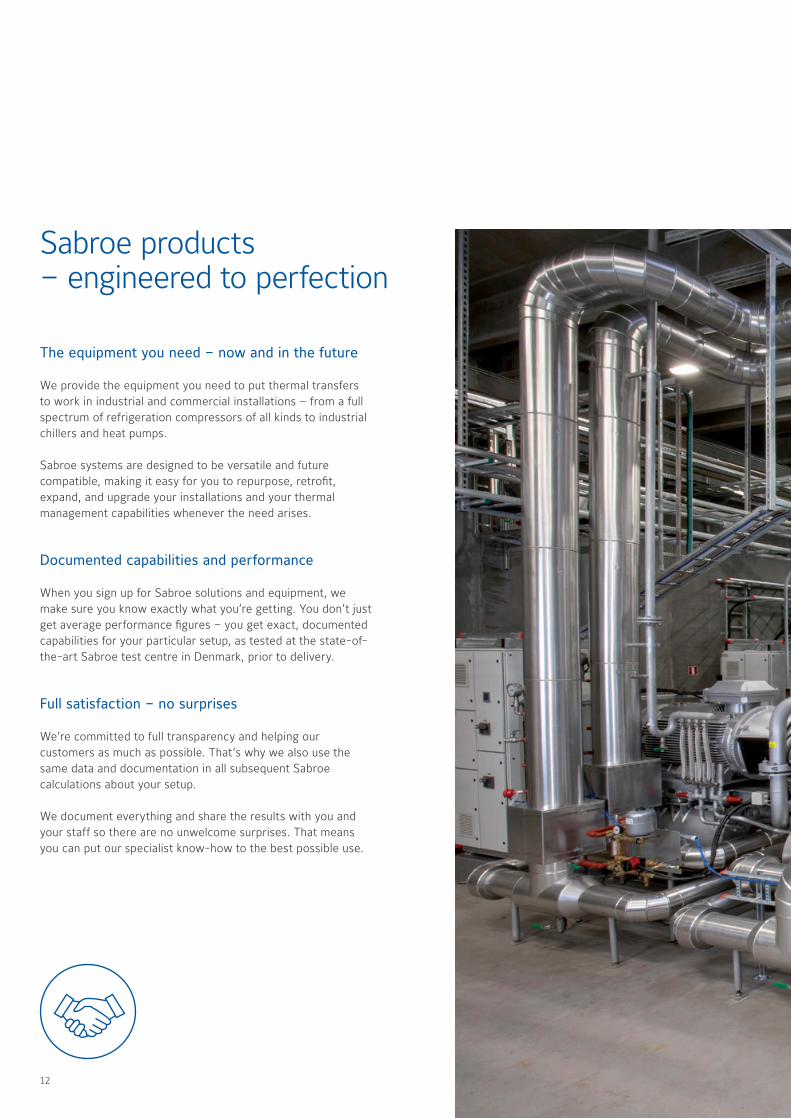
Sabroe products – engineered to perfection
The equipment you need – now and in the future
We provide the equipment you need to put thermal transfers to work in industrial and commercial installations – from a full spectrum of refrigeration compressors of all kinds to industrial chillers and heat pumps
Sabroe systems are designed to be versatile and future compatible, making it easy for you to repurpose, retrofit, expand, and upgrade your installations and your thermal management capabilities whenever the need arises
Documented capabilities and performance
When you sign up for Sabroe solutions and equipment, we make sure you know exactly what you’re getting You don’t just get average performance figures – you get exact, documented capabilities for your particular setup, as tested at the state-of-the-art Sabroe test centre in Denmark, prior to delivery
Full satisfaction – no surprises
We’re committed to full transparency and helping our customers as much as possible That’s why we also use the same data and documentation in all subsequent Sabroe calculations about your setup
We document everything and share the results with you and your staff so there are no unwelcome surprises That means you can put our specialist know-how to the best possible use
12

Reap the full potential of your equipment purchases
In the world of industrial refrigeration, the equipment you buy – whether standardised or individually customised – is just part of the overall picture
You only reap the full potential of your equipment purchases when they are effectively integrated into your existing setup and when all the operating parameters are fine-tuned to ensure maximum cost-effectiveness
Prevention is better than cure
With more than a century of heavyweight practical experience in everything even remotely related to industrial refrigeration compressors, Sabroe experts know pretty much all the on-site pitfalls, glitches, and bottlenecks likely to occur
This means that when you specify Sabroe equipment, you get more than you’d normally expect
Our unique combination of market-leader expertise and first-mover technology capabilities means that we know how to help prevent difficulties and downtime rather than spending time and money dealing with them once they’ve cropped up
Knowledge steers you away from risk
13


Compressors
15
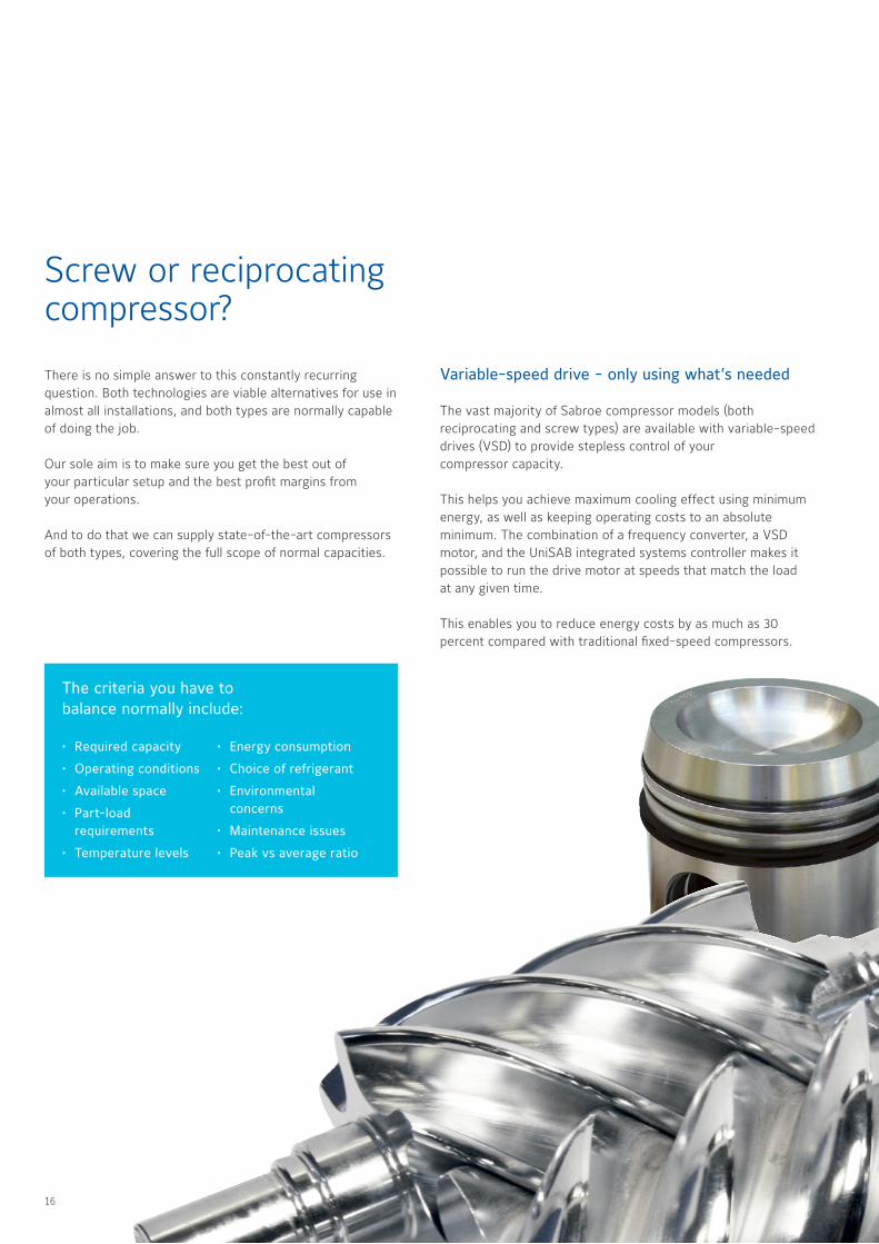
Screw or reciprocating compressor?
There is no simple answer to this constantly recurring question Both technologies are viable alternatives for use in almost all installations, and both types are normally capable of doing the job
Our sole aim is to make sure you get the best out of your particular setup and the best profit margins from your operations
And to do that we can supply state-of-the-art compressors of both types, covering the full scope of normal capacities
• Required capacity
• Operating conditions
• Available space
• Part-load requirements
• Temperature levels
• Energy consumption
• Choice of refrigerant
• Environmental concerns
• Maintenance issues
• Peak vs average ratio
The criteria you have to balance normally include:
Variable-speed drive - only using what’s needed
The vast majority of Sabroe compressor models (both reciprocating and screw types) are available with variable-speed drives (VSD) to provide stepless control of your compressor capacity
This helps you achieve maximum cooling effect using minimum energy, as well as keeping operating costs to an absolute minimum The combination of a frequency converter, a VSD motor, and the UniSAB integrated systems controller makes it possible to run the drive motor at speeds that match the load at any given time
This enables you to reduce energy costs by as much as 30 percent compared with traditional fixed-speed compressors
16 17

Swept volume m3/h in maximum speed(Reciprocating compressors at 50/60 Hz Screw compressors at 50/60/70/100 Hz)
Sabroe compressor programme
SAB 355 S, L, E, X
SAB 283 S, L, E, X
SAB 233 S, L, E
SAB 193 S, L
SAB 151 S, M, L, E
SAB 120 S, M, L, E
HPO 24, 26, 28
TSMC 116 S, L, E
TSMC 108 S, L, E
TCMO 28, 38
SMC 116 S, L, E
SMC 112 S, L, E
SMC 108 S, L, E
SMC 106 S, L, E
SMC 104 S, L, E
CMO 34, 36, 38
CMO 24, 26, 28
SAB 193, 233, 283 HP
HPC 104, 106, 108, 112, 116 S
HPX 704, 706, 708, 712, 716
100 200 50030 50 1,000 2,000 5,000 10,000
Swept volume m3/h in maximum speed(Reciprocating compressors at 50/60 Hz. Screw compressors at 50/60/70/100 Hz)
30 50 100 200 500 1,000 2,000 5,000 10,000
Com
pressorsChillers
Heat pum
psControls
Heat exchangers
Customised
AfterM
arket
16 17
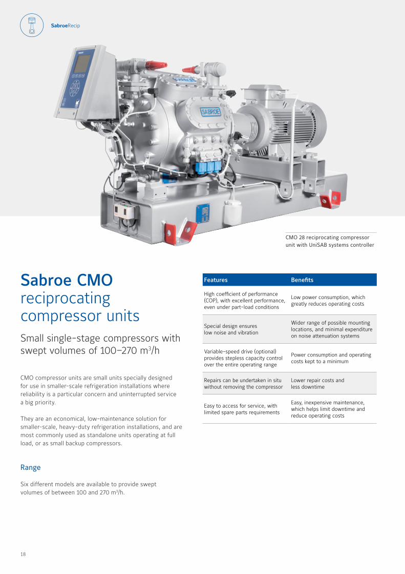
CMO compressor units are small units specially designed for use in smaller-scale refrigeration installations where reliability is a particular concern and uninterrupted service a big priority
They are an economical, low-maintenance solution for smaller-scale, heavy-duty refrigeration installations, and are most commonly used as standalone units operating at full load, or as small backup compressors
Range
Six different models are available to provide swept volumes of between 100 and 270 m3/h
Features Benefits
High coefficient of performance (COP), with excellent performance, even under part-load conditions
Low power consumption, which greatly reduces operating costs
Special design ensures low noise and vibration
Wider range of possible mounting locations, and minimal expenditure on noise attenuation systems
Variable-speed drive (optional) provides stepless capacity control over the entire operating range
Power consumption and operating costs kept to a minimum
Repairs can be undertaken in situ without removing the compressor
Lower repair costs and less downtime
Easy to access for service, with limited spare parts requirements
Easy, inexpensive maintenance, which helps limit downtime and reduce operating costs
Sabroe CMO reciprocating compressor unitsSmall single-stage compressors with swept volumes of 100–270 m3/h
CMO 28 reciprocating compressor unit with UniSAB systems controller
18 19
* Nominal capacities are based on:
1500 rpm at 50 Hz 1800 rpm at 60 Hz or VSD
Refrigerant: R717 Other refrigerants available on request
For R7172 K liquid subcooling and 0 5 K non-usable suction superheat
Design pressure, HP side: 28 barDesign pressure, LP side: 21 barDifferential pressure: 21 bar
Sound pressure levels measured in free field, over reflecting plane and one metre distance from the compressor block
Options
• UniSAB systems controller
• Variable-speed drive line (UniSAB always included)
• Gauges, thermometers and temperature/pressure control switches
• Extended cylinder capacity control
• Oil level regulator (for use in parallel systems)
• ATEX-compliant configuration
• Oil separators with coalescing element
• Special vibration dampening
All information is subject to change without notice
Dimensions, weight and sound pressure levels are guidelines only
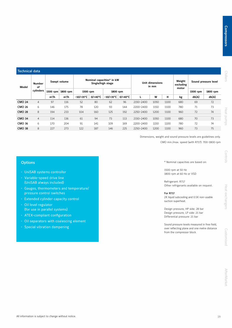
CMO min /max speed (with R717): 700-1800 rpm
Technical data
ModelNumber
of cylinders
Swept volume Nominal capacities* in kWSingle/high stage Unit dimensions
in mm
Weight excluding
motor
Sound pressure level
1500 rpm 1800 rpm 1500 rpm 1800 rpm 1500 rpm 1800 rpm
m3/h m3/h -10/+35°C 0/+40°C -10/+35°C 0/+40°C L W H kg db(A) db(A)
CMO 24 4 97 116 52 80 62 96 2150-2400 1050 1100 680 69 72
CMO 26 6 146 175 78 120 93 144 2200-2400 1150 1100 780 71 73
CMO 28 8 194 233 104 160 125 192 2250-2400 1200 1100 960 72 74
CMO 34 4 114 136 61 94 73 113 2150-2400 1050 1100 680 70 73
CMO 36 6 170 204 91 141 109 169 2200-2400 1150 1100 780 72 74
CMO 38 8 227 273 122 187 146 225 2250-2400 1200 1100 960 73 75
Com
pressorsChillers
Heat pum
psControls
Heat exchangers
Customised
AfterM
arket
18 19
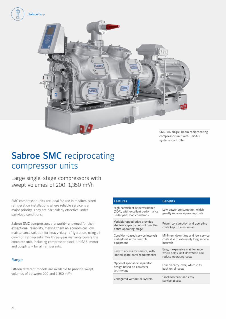
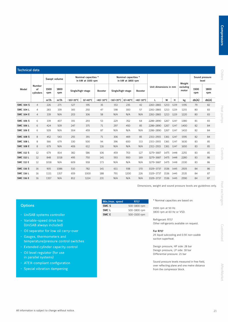
SMC compressor units are ideal for use in medium-sized refrigeration installations where reliable service is a major priority They are particularly effective under part-load conditions
Sabroe SMC compressors are world-renowned for their exceptional reliability, making them an economical, low-maintenance solution for heavy-duty refrigeration, using all common refrigerants Our three-year warranty covers the complete unit, including compressor block, UniSAB, motor and coupling - for all refrigerants
Range
Fifteen different models are available to provide swept volumes of between 200 and 1,350 m3/h
SMC 116 single-beam reciprocating compressor unit with UniSAB systems controller
Features Benefits
High coefficient of performance (COP), with excellent performance under part-load conditions
Low power consumption, which greatly reduces operating costs
Variable-speed drive provides stepless capacity control over the entire operating range
Power consumption and operating costs kept to a minimum
Condition-based service intervals embedded in the controls equipment
Minimum downtime and low service costs due to extremely long service intervals
Easy to access for service, with limited spare parts requirements
Easy, inexpensive maintenance, which helps limit downtime and reduce operating costs
Optional special oil separator design based on coalescer technology
Low oil carry-over, which cuts back on oil costs
Configured without oil systemSmall footprint and easy service access
Sabroe SMC reciprocating compressor unitsLarge single-stage compressors with swept volumes of 200–1,350 m3/h
20 21
Options
• UniSAB systems controller
• Variable-speed drive line (UniSAB always included)
• Oil separator for low oil carry-over
• Gauges, thermometers and temperature/pressure control switches
• Extended cylinder capacity control
• Oil level regulator (for use in parallel systems)
• ATEX-compliant configuration
• Special vibration dampening
* Nominal capacities are based on:
1500 rpm at 50 Hz 1800 rpm at 60 Hz or VSD
Refrigerant: R717Other refrigerants available on request
For R7172 K liquid subcooling and 0 5 K non-usable suction superheat
Design pressure, HP side: 28 barDesign pressure, LP side: 18 barDifferential pressure: 21 bar
Sound pressure levels measured in free field, over reflecting plane and one metre distance from the compressor block
Technical data
ModelNumber
of cylinders
Swept volumeNominal capacities * in kW at 1500 rpm
Nominal capacities *in kW at 1800 rpm
Unit dimensions in mmWeight
excluding motor
Sound pressure level
1500 rpm
1800 rpm
Single/high-stage Booster Single/high-stage Booster1500 rpm
1800 rpm
m3/h m3/h -10/+35°C 0/+40°C -40/-10°C -10/+35°C 0/+40°C -40/-10°C L W H kg db(A) db(A)
SMC 104 S 4 226 271 127 195 35 153 235 42 2261-2865 1213 1229 1195 79 82
SMC 104 L 4 283 339 165 250 47 198 300 57 2261-2865 1213 1229 1215 80 83
SMC 104 E 4 339 N/A 203 306 58 N/A N/A N/A 2261-2865 1213 1229 1220 80 83
SMC 106 S 6 339 407 191 293 53 229 352 64 2286-2890 1267 1247 1380 81 83
SMC 106 L 6 424 509 247 375 71 297 450 85 2286-2890 1267 1247 1400 82 84
SMC 106 E 6 509 N/A 304 459 87 N/A N/A N/A 2286-2890 1267 1247 1410 82 84
SMC 108 S 8 452 543 255 391 71 306 469 85 2311-2915 1361 1247 1595 82 84
SMC 108 L 8 566 679 330 500 94 396 600 113 2311-2915 1361 1247 1630 83 85
SMC 108 E 8 679 N/A 406 612 116 N/A N/A N/A 2311-2915 1361 1247 1650 83 85
SMC 112 S 12 679 814 382 586 106 459 703 127 3279-3687 1475 1448 2255 83 85
SMC 112 L 12 848 1018 495 750 141 593 900 169 3279-3687 1475 1448 2280 83 86
SMC 112 E 12 1018 N/A 609 918 173 N/A N/A N/A 3279-3687 1475 1448 2330 83 86
SMC 116 S 16 905 1086 510 782 141 611 938 170 3329–3737 1536 1445 2505 84 86
SMC 116 L 16 1131 1357 659 1000 188 791 1200 226 3329–3737 1536 1445 2535 84 87
SMC 116 E 16 1357 N/A 812 1224 231 N/A N/A N/A 3329–3737 1536 1445 2590 84 87
Min./max. speedMin./max. speed R717R717
SMC SSMC S 500-1800 rpm500-1800 rpm
SMC LSMC L 500-1800 rpm500-1800 rpm
SMC ESMC E 500-1500 rpm500-1500 rpm
All information is subject to change without notice
Dimensions, weight and sound pressure levels are guidelines only
Com
pressorsChillers
Heat pum
psControls
Heat exchangers
Customised
AfterM
arket
20 21
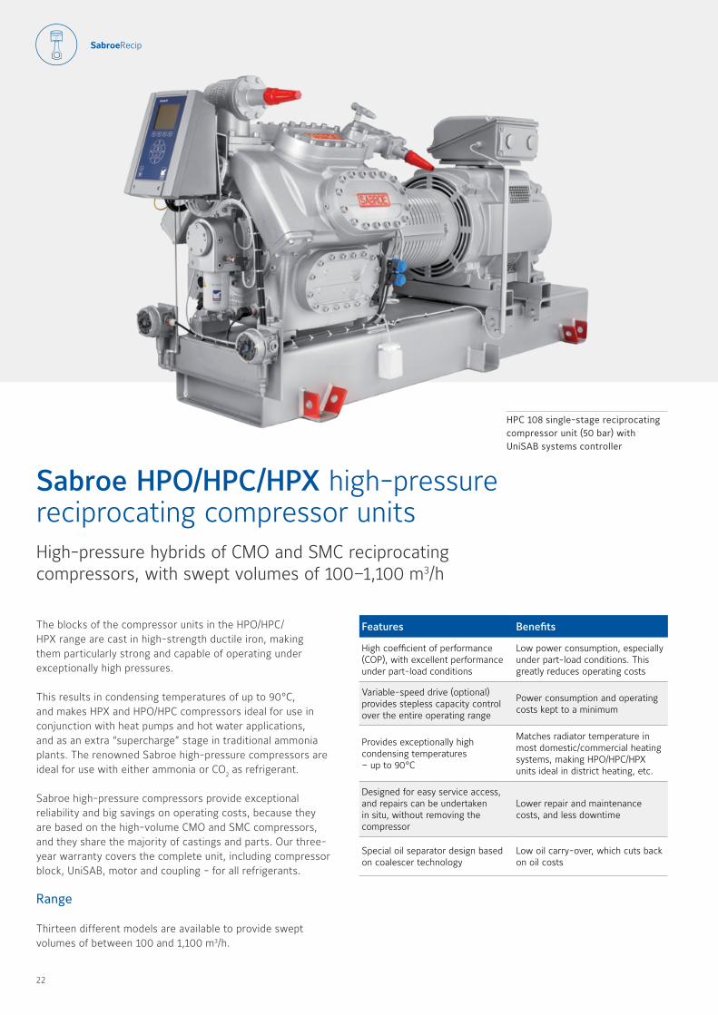
The blocks of the compressor units in the HPO/HPC/HPX range are cast in high-strength ductile iron, making them particularly strong and capable of operating under exceptionally high pressures
This results in condensing temperatures of up to 90 °C, and makes HPX and HPO/HPC compressors ideal for use in conjunction with heat pumps and hot water applications, and as an extra “supercharge” stage in trad itional ammonia plants The renowned Sabroe high-pressure compressors are ideal for use with either ammonia or CO2 as refrigerant
Sabroe high-pressure compressors provide exceptional reliability and big savings on operating costs, because they are based on the high-volume CMO and SMC compressors, and they share the majority of castings and parts Our three-year warranty covers the complete unit, including compressor block, UniSAB, motor and coupling - for all refrigerants
Range
Thirteen different models are available to provide swept volumes of between 100 and 1,100 m3/h
Sabroe HPO/HPC/HPX high-pressure reciprocating compressor unitsHigh-pressure hybrids of CMO and SMC reciprocating compressors, with swept volumes of 100–1,100 m3/h
HPC 108 single-stage reciprocating compressor unit (50 bar) with UniSAB systems controller
Features Benefits
High coefficient of performance (COP), with excellent performance under part-load conditions
Low power consumption, especially under part-load conditions This greatly reduces operating costs
Variable-speed drive (optional) provides stepless capacity control over the entire operating range
Power consumption and operating costs kept to a minimum
Provides exceptionally high condensing temperatures – up to 90 °C
Matches radiator temperature in most domestic/commercial heating systems, making HPO/HPC/HPX units ideal in district heating, etc
Designed for easy service access, and repairs can be undertaken in situ, without removing the compressor
Lower repair and maintenance costs, and less downtime
Special oil separator design based on coalescer technology
Low oil carry-over, which cuts back on oil costs
22 23
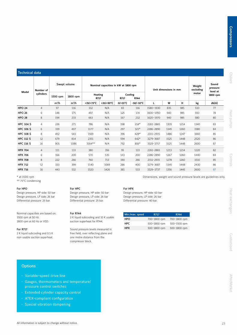
Technical data
ModelNumber of cylinders
Swept volume Nominal capacities in kW at 1800 rpm
Unit dimensions in mmWeight
excluding motor
Sound pressure level at
1800 rpm1500 rpm 1800 rpmHeating
R717Cooling
R717 R744
m3/h m3/h +35/+73°C +35/+90°C 0/+55°C -50/-10°C L W H kg db(A)
HPO 24 4 97 116 332 N/A 83 116 1580–1930 835 985 510 77
HPO 26 6 146 175 497 N/A 125 174 1600–1950 940 985 550 78
HPO 28 8 194 233 663 N/A 167 232 1620–1970 940 985 580 80
HPC 104 S 4 226 271 786 N/A 198 214* 2261-2865 1305 1214 1340 83
HPC 106 S 6 339 407 1177 N/A 297 321* 2286-2890 1345 1260 1580 84
HPC 108 S 8 452 543 1569 N/A 396 428* 2311-2915 1486 1247 1660 85
HPC 112 S 12 679 814 2351 N/A 594 642* 3279-3687 1525 1448 2520 86
HPC 116 S 16 905 1086 3164** N/A 792 856* 3329-3757 1525 1448 2600 87
HPX 704 4 111 133 380 356 95 133 2261-2865 1213 1214 1220 82
HPX 706 6 166 200 570 535 143 200 2286-2890 1267 1260 1440 84
HPX 708 8 222 266 760 713 190 266 2311-2915 1278 1260 1510 85
HPX 712 12 333 399 1140 1069 286 400 3279-3687 1345 1448 2430 86
HPX 716 16 443 532 1520 1426 381 533 3329–3737 1356 1445 2600 87
For HPO Design pressure, HP side: 50 barDesign pressure, LP side: 26 bar Differential pressure: 25 bar
For HPC Design pressure, HP side: 50 barDesign pressure, LP side: 26 bar Differential pressure: 25 bar
For HPXDesign pressure, HP side: 60 barDesign pressure, LP side: 26 barDifferential pressure: 40 bar
* at 1500 rpm** 71°C condensing
Options
• Variable-speed drive line
• Gauges, thermometers and temperature/pressure control switches
• Extended cylinder capacity control
• ATEX-compliant configuration
• Special vibration dampening
Min./max. speed R717 R744
HPO 700-1800 rpm 700-1800 rpm
HPC 500-1800 rpm 500-1500 rpm
HPX 500-1800 rpm 500-1800 rpm
Nominal capacities are based on:1500 rpm at 50 Hz 1800 rpm at 60 Hz or VSD
For R7172 K liquid subcooling and 0 5 K non-usable suction superheat
For R7442 K liquid subcooling and 10 K usable suction superheat for R744
Sound pressure levels measured in free field, over reflecting plane and one metre distance from the compressor block
All information is subject to change without notice
Dimensions, weight and sound pressure levels are guidelines only
Com
pressorsChillers
Heat pum
psControls
Heat exchangers
Customised
AfterM
arket
22 23
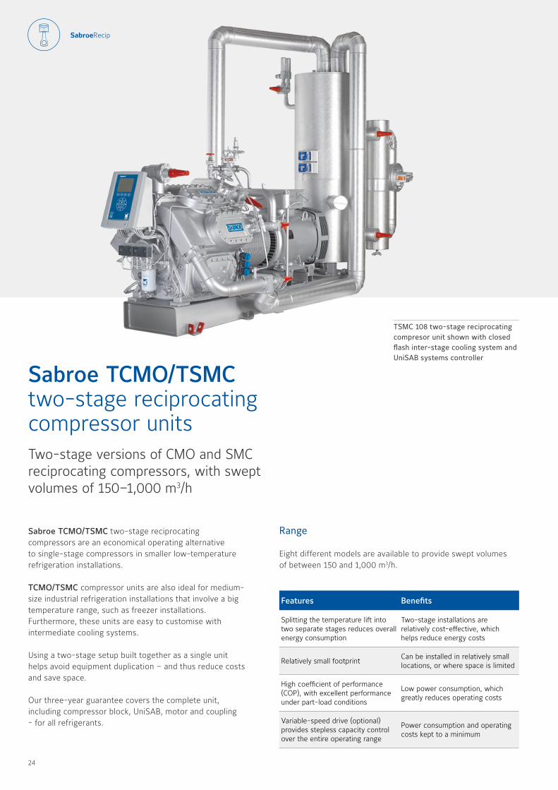
Sabroe TCMO/TSMC two-stage reciprocating compressors are an economical operating alternative to single-stage compressors in smaller low-temperature refrigeration installations
TCMO/TSMC compressor units are also ideal for medium-size industrial refrigeration installations that involve a big temperature range, such as freezer installations Furthermore, these units are easy to customise with intermediate cooling systems
Using a two-stage setup built together as a single unit helps avoid equipment duplication – and thus reduce costs and save space
Our three-year guarantee covers the complete unit, including compressor block, UniSAB, motor and coupling - for all refrigerants
TSMC 108 two-stage reciprocating compresor unit shown with closed flash inter-stage cooling system and UniSAB systems controller
Sabroe TCMO/TSMC two-stage reciprocating compressor unitsTwo-stage versions of CMO and SMC reciprocating compressors, with swept volumes of 150–1,000 m3/h
Features Benefits
Splitting the temperature lift into two separate stages reduces overall energy consumption
Two-stage installations are relatively cost-effective, which helps reduce energy costs
Relatively small footprintCan be installed in relatively small locations, or where space is limited
High coefficient of performance (COP), with excellent performance under part-load conditions
Low power consumption, which greatly reduces operating costs
Variable-speed drive (optional) provides stepless capacity control over the entire operating range
Power consumption and operating costs kept to a minimum
Range
Eight different models are available to provide swept volumes of between 150 and 1,000 m3/h
24 25

Options
• UniSAB systems controller
• Gauges, thermometers and temperature/pressure control switches
• Oil level regulator (for use in parallel systems)
• ATEX-compliant configuration
• Special vibration dampening
• Intermediate cooling systems
Min./max. speed R717
TCMO 700-1800 rpm
TSMC S 700-1800 rpm
TSMC L 700-1800 rpm
TSMC E 700-1500 rpm
Technical data
Model
Number of cylinders low/high-pressure
side
Swept volume Nominal capacities* in kW
-40/+35°CUnit dimensions in mm
Weight excluding
motor
Sound pressure level
1500 rpm 1800 rpm 1500 rpm 1800 rpm
m3/h m3/h 1500 rpm 1800 rpm L W H kg db(A) db(A)
TCMO 28 6 / 2 146 175 20 24 1400–1750 700 1000 500 68 70
TCMO 38 6 / 2 170 205 23 28 1400–1750 700 1000 500 69 71
TSMC 108 S 6 / 2 339 407 50 60 2311-2915 1052 1247 1746 80 82
TSMC 108 L 6 / 2 424 509 66 79 2311-2915 1052 1247 1781 81 83
TSMC 108 E 6 / 2 509 N/A 81 N/A 2311-2915 1052 1247 1796 81 83
TSMC 116 S 12 / 4 679 814 100 121 3329–3737 1327 1445 2791 81 83
TSMC 116 L 12 / 4 848 1018 133 159 3329–3737 1327 1445 2841 82 84
TSMC 116 E 12 / 4 1018 N/A 163 N/A 3329–3737 1327 1445 2891 83 84
* Nominal capacities are based on:
1500 rpm at 50 Hz 1800 rpm at 60 Hz or VSD
Refrigerant: R717Other refrigerants available on request
For R7172 K liquid subcooling, 0 5 K non-usable suction superheat and liquid subcooling in intermediate cooler to 10 K above intermediate temperature
For TCMODesign pressure, HP side: 28 barDesign pressure, LP side: 18 barDifferential pressure: 25 bar
For TSMCDesign pressure, HP side: 28 barDesign pressure, LP side: 18 barDifferential pressure: 25 bar
Sound pressure levels measured in free field, over reflecting plane and one metre distance from the compressor block
All information is subject to change without notice
Dimensions, weight and sound pressure levels are guidelines only
Com
pressorsChillers
Heat pum
psControls
Heat exchangers
Customised
AfterM
arket
24 25
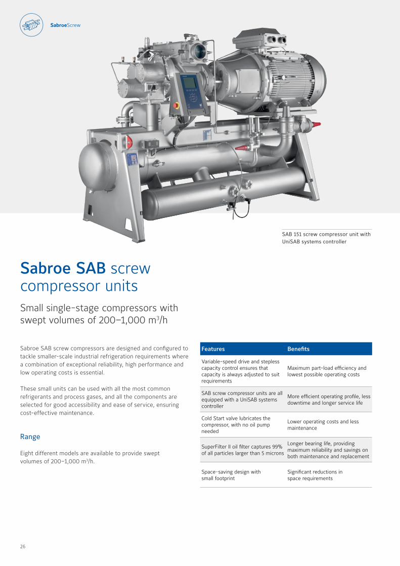
Sabroe SAB screw compressors are designed and configured to tackle smaller-scale industrial refrigeration requirements where a combination of exceptional reliability, high performance and low operating costs is essential
These small units can be used with all the most common refrigerants and process gases, and all the components are selected for good accessibility and ease of service, ensuring cost-effective maintenance
Range
Eight different models are available to provide swept volumes of 200–1,000 m3/h
Sabroe SAB screw compressor unitsSmall single-stage compressors with swept volumes of 200–1,000 m3/h
SAB 151 screw compressor unit with UniSAB systems controller
Features Benefits
Variable-speed drive and stepless capacity control ensures that capacity is always adjusted to suit requirements
Maximum part-load efficiency and lowest possible operating costs
SAB screw compressor units are all equipped with a UniSAB systems controller
More efficient operating profile, less downtime and longer service life
Cold Start valve lubricates the compressor, with no oil pump needed
Lower operating costs and less maintenance
SuperFilter II oil filter captures 99 % of all particles larger than 5 microns
Longer bearing life, providing maximum reliability and savings on both maintenance and replacement
Space-saving design with small footprint
Significant reductions in space requirements
26 27

Options
• Variable-speed drive
• Thermosyphon and water-cooled oil coolers, with 3-way oil temperature control valve
• Liquid injection oil cooling (EZ Cool)
• Dual SuperFilter II oil filters (on SAB 151 models only)
• Complete economiser systems
• Demand oil pump – controlled by UniSAB systems controller
• Sensors and transmitters for control by external PLC systems
Technical data
Model
Swept volume Nominal capacities in kW at 3600 rpm
R717Unit dimensions
in mm
Weight excluding motor/
oil
Sound pressure level
at 3000 rpm* at 3600 rpm* High-stage Booster With economiser 3000 rpm 3600 rpm
m3/h m3/h -10/+35°C -40/-10°C -40/+35 °C L x W x H kg db(A) db(A)
SAB 120 S* 204 245 145 44 44 2200 x 1300 x 1500 1200 85 87
SAB 120 M 255 306 191 58 58 2200 x 1300 x 1500 1200 86 88
SAB 120 L 316 379 243 73 73 2200 x 1300 x 1500 1300 88 90
SAB 120 E 413 496 325 98 99 2200 x 1300 x 1500 1300 89 91
SAB 151 S 484 581 373 116 106 3000 x 1450 x 1800 2050 90 92
SAB 151 M 571 685 448 139 127 3000 x 1450 x 1800 2050 91 93
SAB 151 L 708 850 565 175 160 3000 x 1450 x 1800 2050 91 93
SAB 151 E 847 1016 680 211 193 3000 x 1450 x 1800 2050 92 94
2-pole motor:3000 rpm at 50 Hz 3600 rpm at 60 Hz or VSD
* 4-pole motor (for SAB 120 S):1500 rpm at 50 Hz 1800 rpm at 60 Hz or VSD
Sound pressure levels measured in free field, over reflecting plane and one metre distance from the unit
For R717:2 K liquid subcooling and 0 5 K non-usable suction superheat
28 bar design pressure:SAB 120 and SAB 151
Min./max. speed R717
SAB 120 S 1000-1800 rpm
SAB 120 M-L-E 1000-3600 rpm
SAB 151 S-M-L-E 1000-3600 rpm
All information is subject to change without notice
Dimensions, weight and sound pressure levels are guidelines only
Com
pressorsChillers
Heat pum
psControls
Heat exchangers
Customised
AfterM
arket
26 27
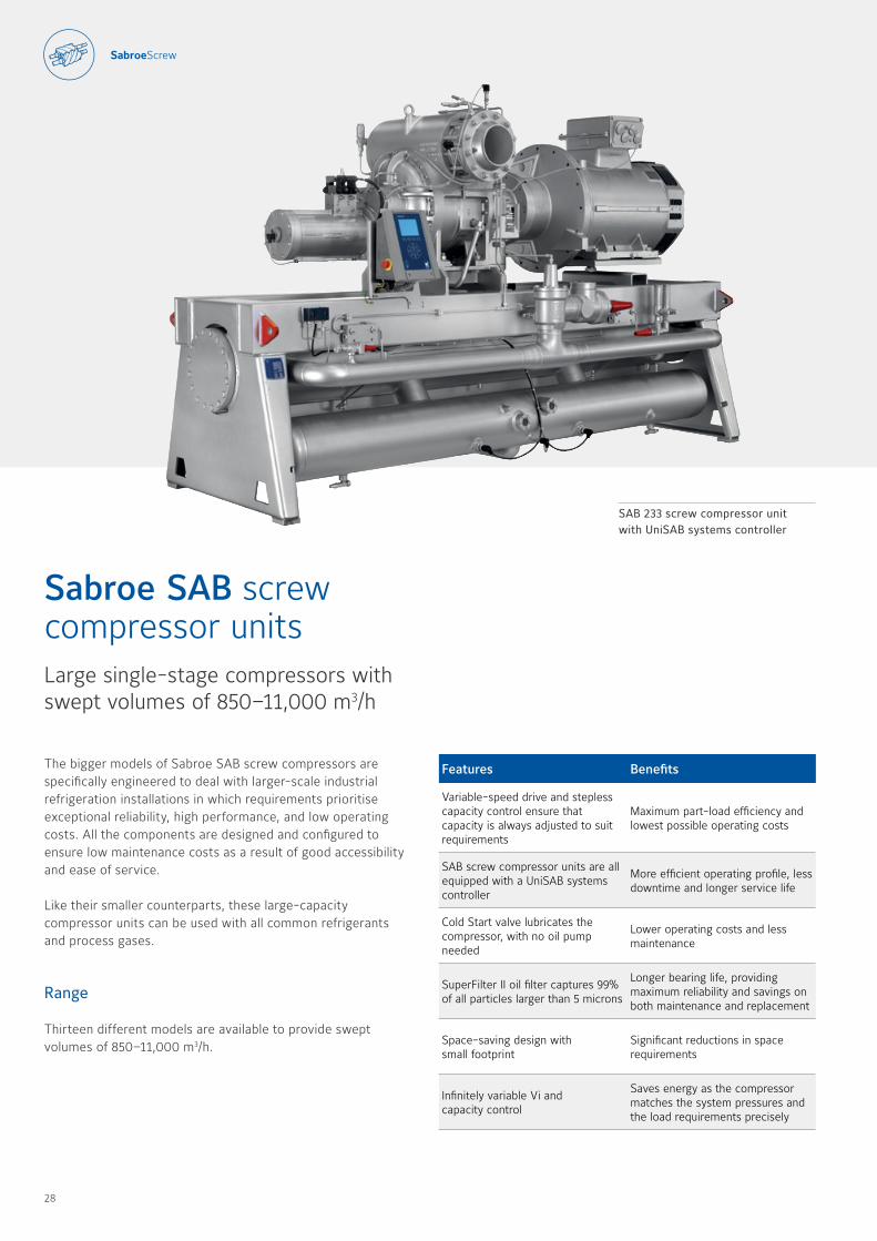
The bigger models of Sabroe SAB screw compressors are specifically engineered to deal with larger-scale industrial refrigeration installations in which requirements prioritise exceptional reliability, high performance, and low operating costs All the components are designed and configured to ensure low maintenance costs as a result of good accessibility and ease of service
Like their smaller counterparts, these large-capacity compressor units can be used with all common refrigerants and process gases
Range
Thirteen different models are available to provide swept volumes of 850–11,000 m3/h
Sabroe SAB screw compressor unitsLarge single-stage compressors with swept volumes of 850–11,000 m3/h
SAB 233 screw compressor unitwith UniSAB systems controller
Features Benefits
Variable-speed drive and stepless capacity control ensure that capacity is always adjusted to suit requirements
Maximum part-load efficiency and lowest possible operating costs
SAB screw compressor units are all equipped with a UniSAB systems controller
More efficient operating profile, less downtime and longer service life
Cold Start valve lubricates the compressor, with no oil pump needed
Lower operating costs and less maintenance
SuperFilter II oil filter captures 99% of all particles larger than 5 microns
Longer bearing life, providing maximum reliability and savings on both maintenance and replacement
Space-saving design with small footprint
Significant reductions in space requirements
Infinitely variable Vi and capacity control
Saves energy as the compressor matches the system pressures and the load requirements precisely
28 29
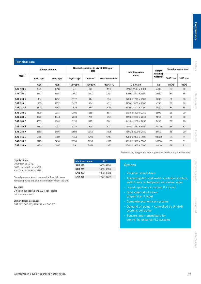
All information is subject to change without notice
2-pole motor:3000 rpm at 50 Hz 3600 rpm at 60 Hz or VSD 4200 rpm at 70 Hz or VSD
Sound pressure levels measured in free field, over reflecting plane and one metre distance from the unit
For R717:2 K liquid subcooling and 0 5 K non-usable suction superheat
28 bar design pressure:SAB 193, SAB 233, SAB 283 and SAB 355
Technical data
Model
Swept volume Nominal capacities in kW at 3600 rpm
R717 Unit dimensions in mm
Weight excluding motor/oil
Sound pressure level
3000 rpm 3600 rpm3000 rpm 3600 rpm High-stage Booster With economiser
m3/h m3/h -10/+35°C -40/-10°C -40/+35 °C L x W x H kg db(A) db(A)
SAB 193 S 848 1018 653 194 193 3150 x 1500 x 1800 2700 84 86
SAB 193 L 1131 1358 872 260 258 3250 x 1500 x 1900 2800 84 86
SAB 233 S 1494 1792 1172 344 334 3700 x 1700 x 2100 4600 86 88
SAB 233 L 1880 2257 1477 484 421 3700 x 1800 x 2200 4750 86 88
SAB 233 E 2323 2788 1826 537 520 3700 x 1800 x 2200 4800 86 88
SAB 283 S 2676 3211 2096 616 597 3700 x 1800 x 2250 5500 88 90
SAB 283 L 3370 4044 2638 776 752 4150 x 1900 x 2650 5850 88 90
SAB 283 E 4055 4865 3159 929 901 4450 x 2100 x 2850 7650 88 90
SAB 355 S 4192 5031 3236 963 917 4550 x 2350 x 3500 10000 89 91
SAB 283 X 4580 5496 3592 1056 1025 4600 x 2100 x 2850 8950 88 90
SAB 355 L 5716 6860 4369 1299 1240 4700 x 2350 x 3500 10000 89 91
SAB 355 E 7275 8730 5550 1630 1576 4850 x 2350 x 3500 10200 89 91
SAB 355 X 9180 11016 NA 2053 1966 5000 x 2350 x 3500 10400 89 91
Min./max. speed R717
SAB 193 1000-4200
SAB 233 1000-3800
SAB 283 1000-3600
SAB 355 1000-3600
Options
• Variable-speed drive
• Thermosyphon and water-cooled oil coolers, with 3-way oil temperature control valve
• Liquid injection oil cooling (EZ Cool)
• Dual external oil filters (SuperFilter II type)
• Complete economiser systems
• Demand oil pump – controlled by UniSAB systems controller
• Sensors and transmitters for control by external PLC systems
Dimensions, weight and sound pressure levels are guidelines only
Com
pressorsChillers
Heat pum
psControls
Heat exchangers
Customised
AfterM
arket
28 29
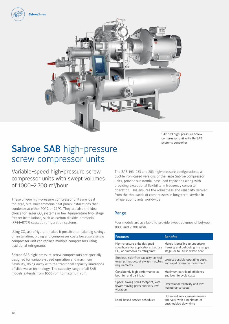
These unique high-pressure compressor units are ideal for large, site-built ammonia heat pump installations that condense at either 90 °C or 72 °C They are also the ideal choice for larger CO2 systems or low-temperature two-stage freezer installations, such as carbon dioxide–ammonia (R744–R717) cascade refrigeration systems
Using CO2 as refrigerant makes it possible to make big savings on installation, piping and compressor costs because a single compressor unit can replace multiple compressors using traditional refrigerants
Sabroe SAB high-pressure screw compressors are specially designed for variable-speed operation and maximum flexibility, doing away with the traditional capacity limitations of slide-valve technology The capacity range of all SAB models extends from 1000 rpm to maximum rpm
Sabroe SAB high-pressure screw compressor unitsVariable-speed high-pressure screw compressor units with swept volumes of 1000–2,700 m3/hour
Features Benefits
High-pressure units designed specifically for applications that use CO2 or ammonia as refrigerant
Makes it possible to undertake freezing and defrosting in a single stage, or to utilise waste heat
Stepless, skip-free capacity control ensures that output always matches requirements
Lowest possible operating costs and rapid return on investment
Consistently high performance at both full and part load
Maximum part-load efficiency and low life cycle costs
Space-saving small footprint, with fewer moving parts and very low vibration
Exceptional reliability and low maintenance costs
Load-based service schedulesOptimised service/maintenance intervals, with a minimum of unscheduled downtime
SAB 193 high-pressure screw compressor unit with UniSAB systems controller
The SAB 193, 233 and 283 high-pressure configurations, all ductile iron-cased versions of the large Sabroe compressor units, provide substantial base load capacities along with providing exceptional flexibility in frequency converter operation This ensures the robustness and reliability derived from the thousands of compressors in long-term service in refrigeration plants worldwide
Range
Four models are available to provide swept volumes of between 1000 and 2,700 m3/h
30 31
Options
• Variable-speed drive
• Thermosyphon and water-cooled oil coolers, with 3-way oil temperature control valve
• Liquid injection oil cooling (EZ Cool)
• Dual external oil filters (SuperFilter II type)
• Complete economiser systems
• Demand oil pump – controlled by UniSAB systems controller
• Sensors and transmitters for control by external PLC systems
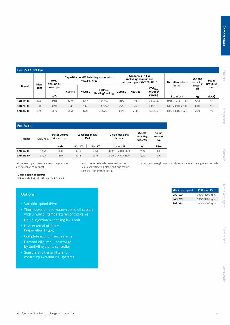
For R717, 40 bar
Model Max. rpm
Swept volume at max. rpm
Capacities in kW including economiser+4/72°C R717
Capacities in kW including economiser
at max. rpm +32/72 °C, R717 Unit dimensions in mm
Weight excluding motor/
oil
Sound pressure
level
Cooling Heating COPlineHeating/cooling Cooling Heating
COPlineHeating/coolingm3/h L x W x H kg db(A)
SAB 193 HP 4200 1188 1270 1797 3 41/2 41 2822 3399 5 90/4 90 3150 x 1500 x 1800 2700 90
SAB 233 HP 3800 1890 2040 2866 3 47/2 47 4576 5466 6 15/5 51 3700 x 1700 x 2100 4600 90
SAB 283 HP 3000 2676 2853 4025 3 35/2 37 6475 7735 6 01/5 03 3700 x 1800 x 2250 5500 92
For R744
Model Max. rpm
Swept volume at max. rpm
Capacities in kW R744
Unit dimensions in mm
Weight excluding motor/oil
Sound pressure
level
m3/h -40/-5°C -50/-5°C L x W x H kg db(A)
SAB 193 HP 4200 1188 1711 1159 3150 x 1500 x 1800 2700 88
SAB 233 HP 3800 1890 2773 1875 3700 x 1700 x 2100 4600 88
All Sabroe high-pressure screw compressors are available on request
40 bar design pressure:SAB 193 HP, SAB 233 HP and SAB 283 HP
All information is subject to change without notice
Sound pressure levels measured in free field, over reflecting plane and one metre from the compressor block
Dimensions, weight and sound pressure levels are guidelines only
Min./max. speed R717 and R744
SAB 193 1000-4200 rpm
SAB 233 1000-3800 rpm
SAB 283 1000-3000 rpm
Com
pressorsChillers
Heat pum
psControls
Heat exchangers
Customised
AfterM
arket
30 31

Chillers
33
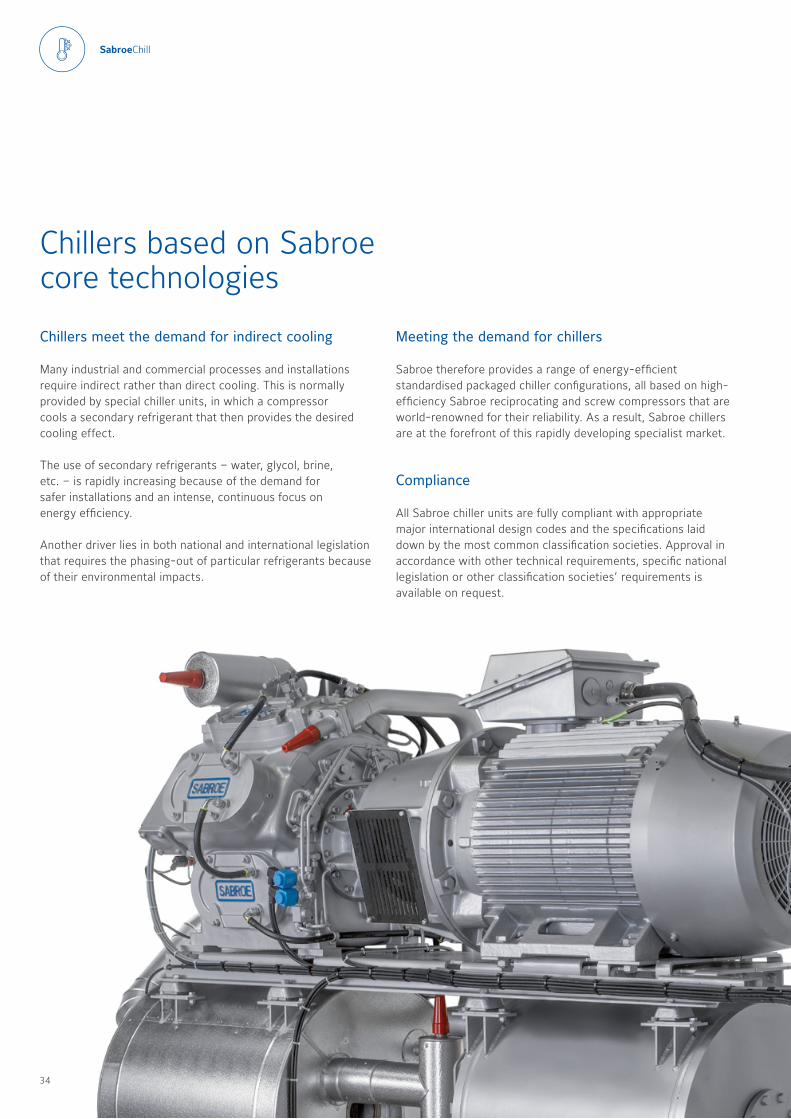
Chillers based on Sabroe core technologies
Chillers meet the demand for indirect cooling
Many industrial and commercial processes and installations require indirect rather than direct cooling This is normally provided by special chiller units, in which a compressor cools a secondary refrigerant that then provides the desired cooling effect
The use of secondary refrigerants – water, glycol, brine, etc – is rapidly increasing because of the demand for safer installations and an intense, continuous focus on energy efficiency
Another driver lies in both national and international legislation that requires the phasing-out of particular refrigerants because of their environmental impacts
Meeting the demand for chillers
Sabroe therefore provides a range of energy-efficient standardised packaged chiller configurations, all based on high-efficiency Sabroe reciprocating and screw compressors that are world-renowned for their reliability As a result, Sabroe chillers are at the forefront of this rapidly developing specialist market
Compliance
All Sabroe chiller units are fully compliant with appropriate major international design codes and the specifications laid down by the most common classification societies Approval in accordance with other technical requirements, specific national legislation or other classification societies’ requirements is available on request
34 35
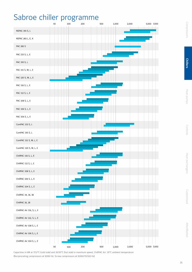
NSPAC 355 S, L
NSPAC 283 L, E, X
PAC 283 S
PAC 233 S, L, E
PAC 193 S, L
PAC 151 S, M, L, E
PAC 120 S, M, L, E
PAC 116 S, L, E
PAC 112 S, L, E
PAC 108 S, L, E
PAC 106 S, L, E
PAC 104 S, L, E
ComPAC 233 S, L
ComPAC 193 S, L
ComPAC 151 S, M, L, E
ComPAC 120 S, M, L, E
ChillPAC 116 S, L, E
ChillPAC 112 S, L, E
ChillPAC 108 S, L, E
ChillPAC 106 S, L, E
ChillPAC 104 S, L, E
ChillPAC 34, 36, 38
ChillPAC 26, 28
ChillPAC Air 116, S, L, E
ChillPAC Air 112, S, L, E
ChillPAC Air 108 S, L, E
ChillPAC Air 106 S, L, E
ChillPAC Air 104 S, L, E
50 500200 2,000100 1,000 5,000 7,000
100 1,00050 500200 2,000 7,0005,000
Sabroe chiller programme
Capacities in kW at 7/12°C (cold side) and 30/35°C (hot side) in maximum speed, ChillPAC Air: 35°C ambient temperature
(Reciprocating compressors at 50/60 Hz Screw compressors at 50/60/70/100 Hz)
Compressors
Chillers
Heat pum
psControls
Heat exchangers
Customised
AfterM
arket
34 35
Features Benefits
Factory-assembled, pre-tested packaged units based on Sabroe reciprocating compressors world-renowned for their reliability
Easy pre-commissioning makes installation and running-in both faster and cheaper Factory acceptance test (FAT) available (optional)
Exceptionally compact design and fully integrated configuration result in less than half the footprint of bespoke chiller designs
Major savings on both weight and space, resulting in lower installation costs Much less need for expensive separate machinery rooms
Indirect cooling and uncomplicated flooded evaporating system, using ammonia (R717) only
Greater safety and outstanding reliability
Exceptional COP and outstanding part-load performance
Greater cooling effect from a smaller refrigerant charge, and optimum load structure over the entire capacity range
Refrigerant charge 50% smaller than conventional chillers, because of special condenser/evaporator design
Higher output per unit kW/kg refrigerant, lower unit cost and lower installation costs
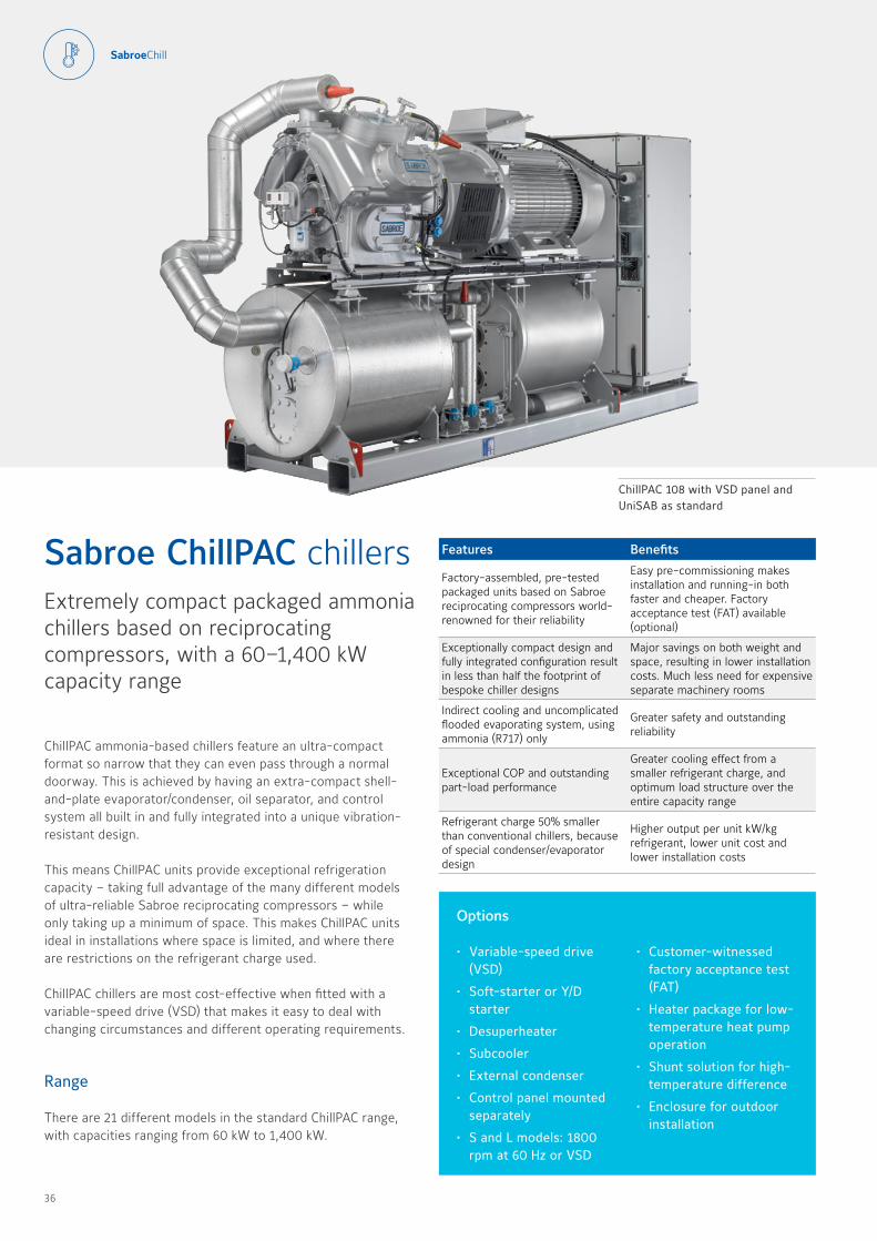
ChillPAC ammonia-based chillers feature an ultra-compact format so narrow that they can even pass through a normal doorway This is achieved by having an extra-compact shell-and-plate evaporator/condenser, oil separator, and control system all built in and fully integrated into a unique vibration-resistant design
This means ChillPAC units provide exceptional refrigeration capacity – taking full advantage of the many different models of ultra-reliable Sabroe reciprocating compressors – while only taking up a minimum of space This makes ChillPAC units ideal in installations where space is limited, and where there are restrictions on the refrigerant charge used
ChillPAC chillers are most cost-effective when fitted with a variable-speed drive (VSD) that makes it easy to deal with changing circumstances and different operating requirements
Range
There are 21 different models in the standard ChillPAC range, with capacities ranging from 60 kW to 1,400 kW
Sabroe ChillPAC chillersExtremely compact packaged ammonia chillers based on reciprocating compressors, with a 60–1,400 kW capacity range
ChillPAC 108 with VSD panel and UniSAB as standard
Options
• Variable-speed drive (VSD)
• Soft-starter or Y/D starter
• Desuperheater
• Subcooler
• External condenser
• Control panel mounted separately
• S and L models: 1800 rpm at 60 Hz or VSD
• Customer-witnessed factory acceptance test (FAT)
• Heater package for low-temperature heat pump operation
• Shunt solution for high-temperature difference
• Enclosure for outdoor installation
36 37
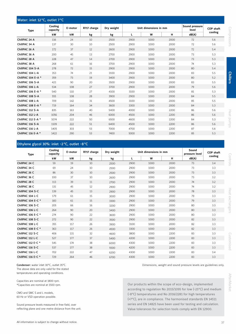
Condenser: water inlet 30 °C, outlet 35 °C The above data are only valid for the stated temperatures and operating conditions
Capacities are nominal at 1800 rpm *Capacities are nominal at 1500 rpm
CMO and SMC S and L models, 60 Hz or VSD operation possible
Sound pressure levels measured in free field, over reflecting plane and one metre distance from the unit
Water: inlet 12 °C, outlet 7 °C
TypeCooling capacity
E-motor R717 charge Dry weight Unit dimensions in mmSound pressure
level COP shaft cooling
kW kW kg kg L W H dB(A)
ChillPAC 24 A 116 24 10 2500 2900 1000 2000 72 5 6
ChillPAC 34 A 137 30 10 2500 2900 1000 2000 72 5 6
ChillPAC 26 A 172 37 12 2600 2900 1000 2000 72 5 4
ChillPAC 36 A 200 45 13 2700 2900 1000 2000 73 5 3
ChillPAC 28 A 228 47 14 2700 2900 1000 2000 73 5 3
ChillPAC 38 A 268 61 16 3700 2900 1000 2000 74 5 3
ChillPAC 104 S-A 278 72 15 2900 2900 1000 2000 80 5 4
ChillPAC 104 L-A 353 74 21 3100 2900 1000 2000 83 5 5
ChillPAC 104 E-A * 359 73 19 3400 2900 1000 2000 80 5 2
ChillPAC 106 S-A 421 90 20 3500 2900 1000 2000 83 5 5
ChillPAC 106 L-A 534 108 27 3700 2900 1000 2000 79 5 6
ChillPAC 106 E-A * 540 110 27 4100 3100 1000 2000 81 5 3
ChillPAC 108 S-A 555 108 28 3900 2900 1000 2000 84 5 5
ChillPAC 108 L-A 709 142 31 4500 3100 1000 2000 85 5 5
ChillPAC 108 E-A * 719 164 34 3600 3300 1000 2000 84 5 3
ChillPAC 112 S-A 835 163 40 5400 4000 1000 2200 86 5 6
ChillPAC 112 L-A 1056 204 46 6000 4500 1000 2200 86 5 6
ChillPAC 112 E-A * 1074 222 50 6500 4600 1000 2200 84 5 3
ChillPAC 116 S-A 1109 222 51 6400 4500 1000 2200 86 5 6
ChillPAC 116 L-A 1405 303 53 7000 4700 1000 2200 87 5 6
ChillPAC 116 E-A * 1422 290 53 7400 5000 1000 2200 85 5 3
Ethylene glycol 30%: inlet -2 °C, outlet -8 °C
TypeCooling capacity
E-motor R717 charge Dry weight Unit dimensions in mmSound
pressure level COP shaft cooling
kW kW kg kg L W H dB(A)
ChillPAC 24 C 59 19 10 2500 2900 1000 2000 73 3 4
ChillPAC 34 C 69 24 10 2500 2900 1000 2000 73 3 3
ChillPAC 26 C 86 30 10 2500 2900 1000 2000 73 3 3
ChillPAC 36 C 100 37 10 2600 2900 1000 2000 73 3 2
ChillPAC 28 C 113 39 11 2700 2900 1000 2000 74 3 2
ChillPAC 38 C 131 45 12 2900 2900 1000 2000 74 3 2
ChillPAC 104 S-C 139 45 13 2900 2900 1000 2000 78 3 3
ChillPAC 104 L-C 179 61 15 3000 2900 1000 2000 79 3 3
ChillPAC 104 E-C * 183 61 15 3300 2900 1000 2000 79 3 3
ChillPAC 106 S-C 205 66 16 3200 2900 1000 2000 80 3 3
ChillPAC 106 L-C 264 90 20 3400 2900 1000 2000 80 3 3
ChillPAC 106 E-C * 274 90 22 3600 2900 1000 2000 80 3 3
ChillPAC 108 S-C 272 90 22 3500 2900 1000 2000 82 3 3
ChillPAC 108 L-C 355 117 26 3900 3100 1000 2000 82 3 3
ChillPAC 108 E-C * 363 117 26 4500 3300 1000 2000 82 3 3
ChillPAC 112 S-C 406 131 32 4600 3800 1000 2200 83 3 3
ChillPAC 112 L-C 527 177 37 5400 4200 1000 2200 83 3 3
ChillPAC 112 E-C * 545 174 38 6000 4300 1000 2200 83 3 3
ChillPAC 116 S-C 537 177 38 5500 4200 1000 2200 83 3 3
ChillPAC 116 L-C 702 222 47 6200 4300 1000 2200 83 3 4
ChillPAC 116 E-C * 729 264 46 6700 4300 1000 2200 83 3 3
Our products within the scope of eco-design, implemented
according to regulation No 2015/1095 for low (-25°C) and medium
(-8°C) temperatures and No 2016/2281 for high temperatures
(+7°C), are in compliance. The harmonised standards EN 14511
series and EN 14825 have been used for testing and calculation.
Value tolerances for selection tools comply with EN 12900.
All information is subject to change without notice
Dimensions, weight and sound pressure levels are guidelines only
Compressors
Chillers
Heat pum
psControls
Heat exchangers
Customised
AfterM
arket
36 37
Features Benefits
Factory-assembled, pre-tested packaged units based on renowned Sabroe screw compressors
Easy pre-commissioning makes installation and running-in both faster and cheaper Factory acceptance test (FAT) available (optional)
Compact design with a very small footprint compared with bespoke chiller designs
Lower unit cost and lower installation costs
Indirect cooling and uncomplicated flooded evaporating system, using natural ammonia (R717) only
Major savings on both weight and space Much less need for expensive separate machinery rooms
Exceptional COP and outstanding part-load performance
Greater safety and outstanding reliability
Small refrigerant charge, smaller than conventional chiller charges because of special condenser/evaporator design
Greater cooling effect from a smaller refrigerant charge, and optimum load structure over the entire capacity range
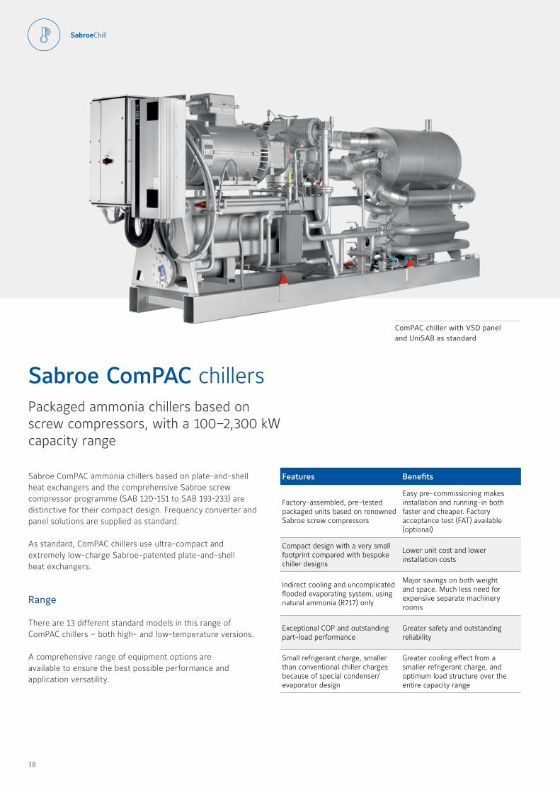
Sabroe ComPAC ammonia chillers based on plate-and-shell heat exchangers and the comprehensive Sabroe screw compressor programme (SAB 120-151 to SAB 193-233) are distinctive for their compact design Frequency converter and panel solutions are supplied as standard
As standard, ComPAC chillers use ultra-compact and extremely low-charge Sabroe-patented plate-and-shell heat exchangers
Range
There are 13 different standard models in this range of ComPAC chillers – both high- and low-temperature versions
A comprehensive range of equipment options are available to ensure the best possible performance and application versatility
Sabroe ComPAC chillersPackaged ammonia chillers based on screw compressors, with a 100–2,300 kW capacity range
ComPAC chiller with VSD panel and UniSAB as standard
38 39
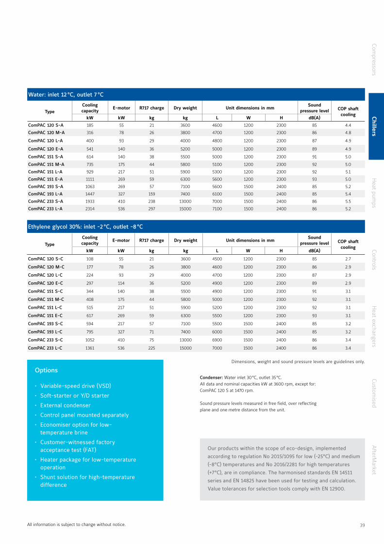
Options
• Variable-speed drive (VSD)
• Soft-starter or Y/D starter
• External condenser
• Control panel mounted separately
• Economiser option for low-temperature brine
• Customer-witnessed factory acceptance test (FAT)
• Heater package for low-temperature operation
• Shunt solution for high-temperature difference
Condenser: Water inlet 30 °C, outlet 35 °C All data and nominal capacities kW at 3600 rpm, except for: ComPAC 120 S at 1470 rpm
Sound pressure levels measured in free field, over reflecting plane and one metre distance from the unit
Water: inlet 12 °C, outlet 7 °C
TypeCooling capacity
E-motor R717 charge Dry weight Unit dimensions in mmSound
pressure level COP shaft cooling
kW kW kg kg L W H dB(A)
ComPAC 120 S-A 185 55 21 3600 4600 1200 2300 85 4 4
ComPAC 120 M-A 316 78 26 3800 4700 1200 2300 86 4 8
ComPAC 120 L-A 400 93 29 4000 4800 1200 2300 87 4 9
ComPAC 120 E-A 541 140 36 5200 5000 1200 2300 89 4 9
ComPAC 151 S-A 614 140 38 5500 5000 1200 2300 91 5 0
ComPAC 151 M-A 735 175 44 5800 5100 1200 2300 92 5 0
ComPAC 151 L-A 929 217 51 5900 5300 1200 2300 92 5 1
ComPAC 151 E-A 1111 269 59 6300 5600 1200 2300 93 5 0
ComPAC 193 S-A 1063 269 57 7100 5600 1500 2400 85 5 2
ComPAC 193 L-A 1447 327 159 7400 6100 1500 2400 85 5 4
ComPAC 233 S-A 1933 410 238 13000 7000 1500 2400 86 5 5
ComPAC 233 L-A 2314 536 297 15000 7100 1500 2400 86 5 2
Ethylene glycol 30%: inlet -2 °C, outlet -8 °C
TypeCooling capacity
E-motor R717 charge Dry weight Unit dimensions in mmSound
pressure level COP shaft cooling
kW kW kg kg L W H dB(A)
ComPAC 120 S-C 108 55 21 3600 4500 1200 2300 85 2 7
ComPAC 120 M-C 177 78 26 3800 4600 1200 2300 86 2 9
ComPAC 120 L-C 224 93 29 4000 4700 1200 2300 87 2 9
ComPAC 120 E-C 297 114 36 5200 4900 1200 2300 89 2 9
ComPAC 151 S-C 344 140 38 5500 4900 1200 2300 91 3 1
ComPAC 151 M-C 408 175 44 5800 5000 1200 2300 92 3 1
ComPAC 151 L-C 515 217 51 5900 5200 1200 2300 92 3 1
ComPAC 151 E-C 617 269 59 6300 5500 1200 2300 93 3 1
ComPAC 193 S-C 594 217 57 7100 5500 1500 2400 85 3 2
ComPAC 193 L-C 795 327 71 7400 6000 1500 2400 85 3 2
ComPAC 233 S-C 1052 410 75 13000 6900 1500 2400 86 3 4
ComPAC 233 L-C 1361 536 225 15000 7000 1500 2400 86 3 4
All information is subject to change without notice
Our products within the scope of eco-design, implemented
according to regulation No 2015/1095 for low (-25°C) and medium
(-8°C) temperatures and No 2016/2281 for high temperatures
(+7°C), are in compliance. The harmonised standards EN 14511
series and EN 14825 have been used for testing and calculation.
Value tolerances for selection tools comply with EN 12900.
Dimensions, weight and sound pressure levels are guidelines only
Compressors
Chillers
Heat pum
psControls
Heat exchangers
Customised
AfterM
arket
38 39
Features Benefits
Factory-assembled, pre-tested packaged units
Easy pre-commissioning makes installation and running-in both faster and cheaper Factory acceptance test (FAT) available as an option
Comprehensive selection of compressor capacities, making it easier to match particular requirements
Avoid paying for greater capacity than needed
Very easy access for serviceImproves safety, ensures maximum reliability and global sourcing of parts
Indirect cooling and uncomplicated flooded evaporating system, using ammonia (R717) only
Greater safety and outstanding reliability
Plate evaporator/condenser are easy to open and service
Routine checks/service can be carried out by operator’s own staff
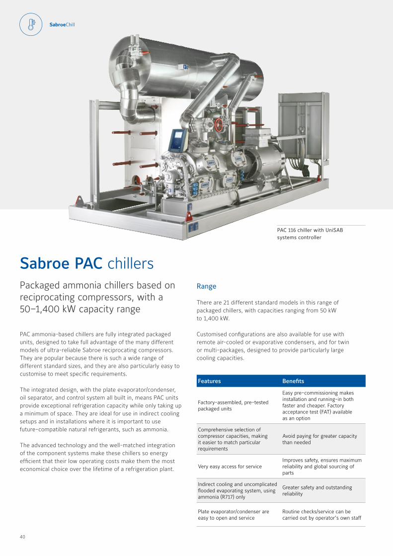
PAC ammonia-based chillers are fully integrated packaged units, designed to take full advantage of the many different models of ultra-reliable Sabroe reciprocating compressors They are popular because there is such a wide range of different standard sizes, and they are also particularly easy to customise to meet specific requirements
The integrated design, with the plate evaporator/condenser, oil separator, and control system all built in, means PAC units provide exceptional refrigeration capacity while only taking up a minimum of space They are ideal for use in indirect cooling setups and in installations where it is important to use future-compatible natural refrigerants, such as ammonia
The advanced technology and the well-matched integration of the component systems make these chillers so energy efficient that their low operating costs make them the most economical choice over the lifetime of a refrigeration plant
Sabroe PAC chillersPackaged ammonia chillers based on reciprocating compressors, with a 50–1,400 kW capacity range
PAC 116 chiller with UniSAB systems controller
Range
There are 21 different standard models in this range of packaged chillers, with capacities ranging from 50 kW to 1,400 kW
Customised configurations are also available for use with remote air-cooled or evaporative condensers, and for twin or multi-packages, designed to provide particularly large cooling capacities
40 41
Options
• Variable-speed drive (VSD)
• Soft-starter or Y/D starter
• Desuperheater
• Subcooler
• External condenser
• Control panel mounted separately
• Customer-witnessed factory acceptance test (FAT)
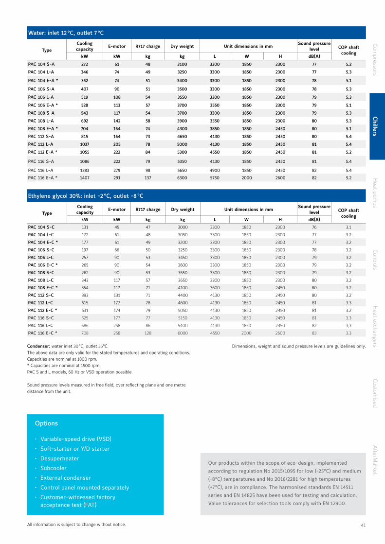
Condenser: water inlet 30 °C, outlet 35 °C The above data are only valid for the stated temperatures and operating conditions Capacities are nominal at 1800 rpm * Capacities are nominal at 1500 rpm PAC S and L models, 60 Hz or VSD operation possible
Sound pressure levels measured in free field, over reflecting plane and one metre distance from the unit
Water: inlet 12 °C, outlet 7 °C
TypeCooling capacity
E-motor R717 charge Dry weight Unit dimensions in mmSound pressure
level COP shaft cooling
kW kW kg kg L W H dB(A)
PAC 104 S-A 272 61 48 3100 3300 1850 2300 77 5.2
PAC 104 L-A 346 74 49 3250 3300 1850 2300 77 5.3
PAC 104 E-A * 352 74 51 3400 3300 1850 2300 78 5.1
PAC 106 S-A 407 90 51 3500 3300 1850 2300 78 5.3
PAC 106 L-A 519 108 54 3550 3300 1850 2300 79 5.3
PAC 106 E-A * 528 113 57 3700 3550 1850 2300 79 5.1
PAC 108 S-A 543 117 54 3700 3300 1850 2300 79 5.3
PAC 108 L-A 692 142 58 3900 3550 1850 2300 80 5.3
PAC 108 E-A * 704 164 74 4300 3850 1850 2450 80 5.1
PAC 112 S-A 815 164 73 4650 4130 1850 2450 80 5.4
PAC 112 L-A 1037 205 78 5000 4130 1850 2450 81 5.4
PAC 112 E-A * 1055 222 84 5300 4550 1850 2450 81 5.2
PAC 116 S-A 1086 222 79 5350 4130 1850 2450 81 5.4
PAC 116 L-A 1383 279 98 5650 4900 1850 2450 82 5.4
PAC 116 E-A * 1407 291 137 6300 5750 2000 2600 82 5.2
Ethylene glycol 30%: inlet -2 °C, outlet -8 °C
TypeCooling capacity
E-motor R717 charge Dry weight Unit dimensions in mmSound pressure
level COP shaft cooling
kW kW kg kg L W H dB(A)
PAC 104 S-C 131 45 47 3000 3300 1850 2300 76 3 1
PAC 104 L-C 172 61 48 3050 3300 1850 2300 77 3 2
PAC 104 E-C * 177 61 49 3200 3300 1850 2300 77 3 2
PAC 106 S-C 197 66 50 3250 3300 1850 2300 78 3 2
PAC 106 L-C 257 90 53 3450 3300 1850 2300 79 3 2
PAC 106 E-C * 265 90 54 3600 3300 1850 2300 79 3 2
PAC 108 S-C 262 90 53 3550 3300 1850 2300 79 3 2
PAC 108 L-C 343 117 57 3650 3300 1850 2300 80 3 2
PAC 108 E-C * 354 117 71 4100 3600 1850 2450 80 3 2
PAC 112 S-C 393 131 71 4400 4130 1850 2450 80 3 2
PAC 112 L-C 515 177 78 4600 4130 1850 2450 81 3 3
PAC 112 E-C * 531 174 79 5050 4130 1850 2450 81 3 2
PAC 116 S-C 525 177 77 5150 4130 1850 2450 81 3 3
PAC 116 L-C 686 258 86 5400 4130 1850 2450 82 3,3
PAC 116 E-C * 708 258 128 6000 4550 2000 2600 83 3 3
All information is subject to change without notice
Our products within the scope of eco-design, implemented
according to regulation No 2015/1095 for low (-25°C) and medium
(-8°C) temperatures and No 2016/2281 for high temperatures
(+7°C), are in compliance. The harmonised standards EN 14511
series and EN 14825 have been used for testing and calculation.
Value tolerances for selection tools comply with EN 12900.
Dimensions, weight and sound pressure levels are guidelines only
Compressors
Chillers
Heat pum
psControls
Heat exchangers
Customised
AfterM
arket
40 41

Features Benefits
Factory-assembled, pre-tested packaged units
Easy pre-commissioning makes installation and running-in both faster and cheaper Factory acceptance test (FAT) available as an option
Comprehensive selection of compressor capacities, making it easier to match particular requirements
Avoid paying for greater capacity than needed
Very easy access for serviceImproves safety, ensures maximum reliability and global sourcing of parts
Indirect cooling and uncomplicated flooded evaporating system, using ammonia (R717) only
Greater safety and outstanding reliability
Plate evaporator/condenser are easy to open and service
Routine checks/service can be carried out by operator’s own staff
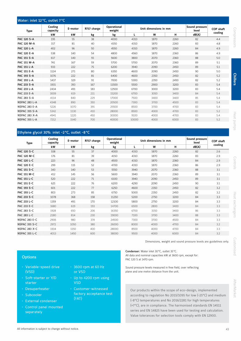
PAC ammonia-based chillers are fully integrated packaged units, designed to take full advantage of the many different models of ultra-reliable Sabroe screw compressors They are popular because there is such a wide range of different standard sizes They are also particularly easy to customise to meet specific requirements
The integrated design, with the plate evaporator/condenser, oil separator, and control system all built in, means PAC units provide exceptional refrigeration capacity while only taking up a minimum of space They are ideal for use in indirect cooling setups and in installations where it is important to use future-compatible natural refrigerants, such as ammonia
The advanced technology and the well-matched integration of the component systems make these chillers so energy efficient that their low operating costs make them the most economical choice over the lifetime of a refrigeration plant
Range
There are 19 different standard models in this range of packaged chillers, with capacities ranging from approx 100 kW to 7,200 kW
Sabroe PAC chillersPackaged ammonia chillers based on screw compressors, with a 100–7,200 kW capacity range
PAC 233 chiller with UniSAB systems controller
Customised configurations are also available for use with remote air-cooled or evaporative condensers, and for twin- or multi-packages, designed to provide particularly large cooling capacities
42 43
Options
• Variable-speed drive (VSD)
• Soft-starter or Y/D starter
• Desuperheater
• Subcooler
• External condenser
• Control panel mounted separately
• 3600 rpm at 60 Hz or VSD
• Up to 4200 rpm using VSD
• Customer-witnessed factory acceptance test (FAT)
Condenser: Water inlet 30 °C, outlet 35 °C All data and nominal capacities kW at 3600 rpm, except for: PAC 120 S at 1470 rpm
Sound pressure levels measured in free field, over reflecting plane and one metre distance from the unit
Water: inlet 12 °C, outlet 7 °C
TypeCooling capacity
E-motor R717 chargeOperational
weightUnit dimensions in mm
Sound pressure level COP shaft
coolingkW kW kg kg L W H dB(A)
PAC 120 S-A 195 55 38 4000 4310 1870 2260 82 4 4
PAC 120 M-A 317 81 40 4150 4310 1870 2260 83 4.8PAC 120 L-A 402 96 50 4550 4310 1870 2260 84 4 9
PAC 120 E-A 538 140 54 4800 4560 1870 2360 86 4 9
PAC 151 S-A 617 140 55 5600 3800 2070 2360 88 5 0
PAC 151 M-A 741 167 59 5700 5700 2070 2360 89 5 1
PAC 151 L-A 933 222 75 6200 3940 2090 2450 89 5 1
PAC 151 E-A 1124 271 80 6350 4600 2090 2450 90 5 0
PAC 193 S-A 1076 222 81 6400 4600 2350 2450 82 5 2
PAC 193 L-A 1437 329 91 7000 5300 2350 2450 82 5 2
PAC 233 S-A 1931 393 167 11500 5500 2900 3200 83 5 4
PAC 233 L-A 2434 491 183 12500 6700 3000 3200 83 5 4
PAC 233 E-A 3009 619 211 15200 6700 3050 3400 84 5 4
PAC 283 S-A 4114 840 229 17000 7500 3400 3400 85 5 4
NSPAC 283 L-A 4348 890 350 20500 7300 3700 4500 83 5 4
NSPAC 283 E-A 5226 1070 391 25500 8500 3700 4700 83 5 4
NSPAC 355 S-A 5342 1130 410 28000 8500 4000 4700 83 5 2NSPAC 283 X-A 4941 1220 450 30000 9100 4000 4700 83 5 4NSPAC 355 L-A 7212 1540 700 40000 10000 4000 6000 83 5 2
Ethylene glycol 30%: inlet -2 °C, outlet -8 °C
TypeCooling capacity
E-motor R717 chargeOperational
weightUnit dimensions in mm
Sound pressure level COP shaft
coolingkW kW kg kg L W H dB(A)
PAC 120 S-C 108 55 37 4000 4310 1870 2260 82 2 6
PAC 120 M-C 176 81 39 4150 4310 1870 2260 83 2 9
PAC 120 L-C 223 96 48 4500 4310 1870 2360 84 2 9
PAC 120 E-C 299 115 52 4700 4310 1870 2360 86 2 9
PAC 151 S-C 343 140 53 5550 3940 2070 2360 88 3 1
PAC 151 M-C 412 145 56 5600 3940 2070 2360 89 3 1
PAC 151 L-C 520 222 71 6100 3940 2090 2450 89 3 1
PAC 151 E-C 625 222 76 6200 4290 2090 2450 90 3 1
PAC 193 S-C 601 222 77 6250 4600 2350 2450 82 3 2
PAC 193 L-C 803 273 85 6750 5000 2350 2450 82 3 2
PAC 233 S-C 1078 368 158 11250 5200 2750 3200 84 3 3
PAC 233 L-C 1359 491 170 12100 5800 2750 3200 84 3 3
PAC 233 E-C 1680 619 193 14700 6500 2800 3400 84 3 3
PAC 283 S-C 1928 650 206 16350 6700 3150 3400 86 3 3
PAC 283 L-C 2180 814 230 19000 7100 3700 3400 88 3 3
NSPAC 283 E-C 2906 980 374 24500 7300 3700 4500 84 3 3
NSPAC 355 S-C 2972 1050 380 26000 8000 4000 4700 84 3 2
NSPAC 283 X-C 3304 1150 400 28000 8500 4000 4700 84 3 3
NSPAC 355 L-C 4013 1450 600 38000 9500 4000 6000 84 3 2
All information is subject to change without notice
Our products within the scope of eco-design, implemented
according to regulation No 2015/1095 for low (-25°C) and medium
(-8°C) temperatures and No 2016/2281 for high temperatures
(+7°C), are in compliance. The harmonised standards EN 14511
series and EN 14825 have been used for testing and calculation.
Value tolerances for selection tools comply with EN 12900.
Dimensions, weight and sound pressure levels are guidelines only
Compressors
Chillers
Heat pum
psControls
Heat exchangers
Customised
AfterM
arket
42 43

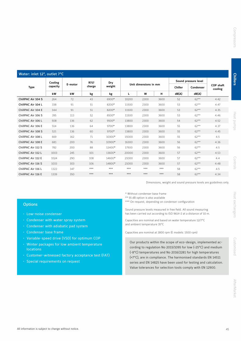
Sabroe ChillPAC Air uses ammonia as refrigerant and is a series of air-cooled chillers based on ultra-reliable Sabroe reciprocating compressors It is a factory-assembled system for outdoor installation
The chiller is made in a compact design, which is achieved by having an extra-compact shell-and-plate evaporator, an SMC compressor and double V-coil condensers to reduce the overall footprint With the lowest possible refrigerant charge and superior efficiency, the chiller provides the customer with an attractive, economic and environmentally responsible air-cooled chiller product
ChillPAC Air offers flexible and simple on-site installation for remote or local cooling needs, without any supplementary water-cooling assembly required
ChillPAC Air is based on the popular, proven and well-known ChillPAC family philosophy, and it shares many components and benefits with the Sabroe ChillPAC chillers
Sabroe ChillPAC Air chillers Air-cooled chillers for outdoor installation based on reciprocating compressors, with a capacity range between 300 and 1400 kW
Features Benefits
Factory-assembled, pre-tested packaged units based on Sabroe reciprocating compressors world-renowned for their reliability
Easy pre-commissioning makes installation and running-in both faster and cheaper Factory acceptance test (FAT) available (optional)
Outdoor installation in weatherproof enclosure
Cooling capacity can be added without needing to build/rebuild a machine room
Easy to mount, install and connect Low installation costs and rapid commissioning
Natural refrigerant R717Future-safe refrigerant supporting sustainability and ensuring high efficiency
Exceptional COP and outstanding part-load performance
Greater cooling effect from a smaller refrigerant charge, and optimum load structure over the entire capacity range
ChillPAC Air - air-cooled ammonia chiller
Range
There are 15 different standard models in this range of air-cooled chillers, with capacities ranging from 300 to 1400 kW.
44 45
All information is subject to change without notice
Options
• Low-noise condenser
• Condenser with water spray system
• Condenser with adiabatic pad system
• Condenser base frame
• Variable-speed drive (VSD) for optimum COP
• Winter packages for low ambient temperature locations
• Customer-witnessed factory acceptance test (FAT)
• Special requirements on request
Our products within the scope of eco-design, implemented ac-
cording to regulation No 2015/1095 for low (-25°C) and medium
(-8°C) temperatures and No 2016/2281 for high temperatures
(+7°C), are in compliance. The harmonised standards EN 14511
series and EN 14825 have been used for testing and calculation.
Value tolerances for selection tools comply with EN 12900.
Water: inlet 12°, outlet 7°C
Type
Cooling capacity
E-motorR717
chargeDry
weight Unit dimensions in mm
Sound pressure levelCOP shaft
coolingChiller Condenser
kW kW kg kg L W H dB(A) dB(A)
ChillPAC Air 104 S 264 72 43 6900* 10200 2300 3600 52 62** 4 42
ChillPAC Air 104 L 338 91 51 8200* 11500 2300 3600 53 62** 4 47
ChillPAC Air 104 E 344 91 51 8200* 11500 2300 3600 53 62** 4 35
ChillPAC Air 106 S 395 113 52 8500* 11500 2300 3600 53 62** 4 46
ChillPAC Air 106 L 508 136 62 9500* 13800 2300 3600 54 62** 4 52
ChillPAC Air 106 E 514 136 64 9700* 13800 2300 3600 55 62** 4 37
ChillPAC Air 108 S 521 136 60 9700* 13800 2300 3600 55 62** 4 45
ChillPAC Air 108 L 669 162 71 10300* 15000 2300 3600 55 62** 4 5
ChillPAC Air 108 E 681 200 76 10900* 16300 2300 3600 56 62** 4 36
ChillPAC Air 112 S 782 200 88 12400* 17500 2300 3600 56 62** 4 5
ChillPAC Air 112 L 1003 245 101 13600* 20000 2300 3600 57 62** 4 53
ChillPAC Air 112 E 1024 290 108 14600* 21000 2300 3600 57 62** 4 4
ChillPAC Air 116 S 1033 303 106 14800* 21000 2300 3600 57 62** 4 48
ChillPAC Air 116 L 1322 347 *** *** *** *** *** 58 62** 4 5
ChillPAC Air 116 E 1339 350 *** *** *** *** *** 58 62** 4 34
Dimensions, weight and sound pressure levels are guidelines only
Capacities are nominal and based on water temperature 12/7°C and ambient temperature 35°C
Capacities are nominal at 1800 rpm (E models: 1500 rpm)
* Without condenser base frame ** 55 dB option is also available*** On request, depending on condenser configuration
Sound pressure levels measured in free field All sound measuring has been carried out according to ISO 9614-2 at a distance of 10 m
Compressors
Chillers
Heat pum
psControls
Heat exchangers
Customised
AfterM
arket
44 45
Features Benefits
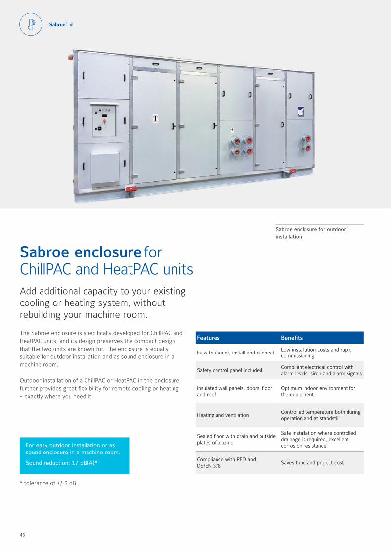
Easy to mount, install and connect Low installation costs and rapid commissioning
Safety control panel includedCompliant electrical control with alarm levels, siren and alarm signals
Insulated wall panels, doors, floor and roof
Optimum indoor environment for the equipment
Heating and ventilationControlled temperature both during operation and at standstill
Sealed floor with drain and outside plates of aluzinc
Safe installation where controlled drainage is required, excellent corrosion resistance
Compliance with PED and DS/EN 378
Saves time and project cost
The Sabroe enclosure is specifically developed for ChillPAC and HeatPAC units, and its design preserves the compact design that the two units are known for The enclosure is equally suitable for outdoor installation and as sound enclosure in a machine room
Outdoor installation of a ChillPAC or HeatPAC in the enclosure further provides great flexibility for remote cooling or heating - exactly where you need it
Sabroe enclosure for ChillPAC and HeatPAC unitsAdd additional capacity to your existing cooling or heating system, without rebuilding your machine room
Sabroe enclosure for outdoor installation
For easy outdoor installation or as sound enclosure in a machine room.
Sound reduction: 17 dB(A)*
* tolerance of +/-3 dB
46 47

Note:The enclosure is not defined as a machine room, because a person cannot stay inside it with the doors closed Nevertheless, it fulfills machine room requirements for gas detection, ventilation and ATEX
* See the drawing above
Ambient temperature: -15°C to +40°C.
ModelDimensions in mm Weight
L W H1/H2 Kg
Low
4023 1370* 2661/2778* 1210
5011 1370* 2661/2778* 1360
6000 1370* 2661/2778* 1510
6988 1370* 2661/2778* 1760
High
4023 1370* 2916/3033* 1250
5011 1370* 2916/3033* 1400
6000 1370* 2916/3033* 1550
6988 1370* 2916/3033* 1800
All information is subject to change without notice
= "" I
r
\\ I
'
�I
r,
"n III
r" III
•Il
D-t
-..
{ li
B i9
0
0
0
I I
I 0
0
0
�
.. -
' Il
li
�
I
/�
H1H2
W
Compressors
Chillers
Heat pum
psControls
Heat exchangers
Customised
AfterM
arket
46 47

The highly customisable Sabroe CAFP freezer systems are using CO2 on the low-temperature side and NH3 (ammonia) on the high-temperature side, giving you the best of both worlds
CO2 has its strength at low temperatures, and NH3 at high temperatures A combination of both provides the user with a system, which is working on natural refrigerants and at the same time ensuring high efficiency and safety The ammonia charge has been reduced to an absolute minimum and, instead of ammonia, CO2 is distributed to the user production area CO2 has a high volumetric cooling capacity and this goes hand in hand with high efficiency
These packaged systems are built around Sabroe reciprocating compressors that use CO2 as refrigerant, which gives them eight times greater cooling capacity than corresponding compressors using ammonia This in turn makes the low-temperature compressor much smaller, and the whole package considerably more compact than traditional two-stage ammonia-based freezer systems The compact design means the CAFP package can be installed even when space is limited
Compared with other solutions for low temperatures, a CAFP unit uses significantly less power in the temperature range down to –54°C
Sabroe CAFP CO2/NH3 low-temperature chillerCompact packaged freezer systems using reciprocating or screw compressors, with a 100–2,500 kW capacity range
Features Benefits
Compact design and technology that require small footprint
Big savings on installation costs
High COP and extremely low power consumption, even at part load
Low operating costs
Use of CO2 as low-temperature refrigerant reduces piping complexity
Reduces installation costs
Very small ammonia charge, located on the unit itself
No risk of ammonia leaks in production areas, cold stores and working areas
CO2 is a simple, inexpensive natural refrigerant
Low operating costs
This results in energy savings of as much as 15 percent compared with traditional two-stage ammonia systems, and up to 45 percent compared with single-stage setups Alternatively, the higher capacity can be used for a higher throughput on the freezer equipment
Range
There are six standard models in this range of freezer systems, with capacities ranging from 100 kW to 800 kW On request, we offer units up to 2,500 kW All CAFP units are operationally tested with refrigerant before dispatch Factory acceptance test (FAT) available
CAFP unit controlled and monitored by UniSAB systems controller
48 49

Condenser: water inlet 25 °C, outlet 30 °C Capacities are nominal, 1500 rpm at 50 Hz Power consumption applies to compressors only Refrigerant charge depends on application
Sound pressure levels measured in free field, over reflecting plane and one metre distance from the unit
Standard equipment
• Double control panel including UniSAB systems controller• CO2 pump separator including two pumps (one standby)• Shell-and-tube cascade cooler with double-tube sheet
to minimise any risk of CO2 and ammonia mixing• Standstill cooling unit, with separate control panel
and power supply to limit CO2 pressure• Automatic oil recovery system in both circuits• Water-cooled condenser (plate heat exchanger type)
on ammonia side• Insulation of all cold parts
Options
• Variable-speed drive• Titanium plates in condenser• Oversized CO2 pump separator for high CO2
evaporator volume• Oversized CO2 pumps for higher
circulation rate• Oversized ammonia condenser
for higher cooling water temperature• Fully welded shell-and-tube cascade cooler• External interstage load, including a brine
cooler on the R717 side of the cascade cooler• Special version for use with remote
condenser• Configurations for use with HFC refrigerants
instead of ammonia on high-pressure side
Technical data
ModelEvaporationtemperature
Coolingcapacity
Power consumption Compressors
R744/R717
MinimumNH3 charge (approx.)
MinimumCO2 charge (approx.)
Unit dimensionsin mm
WeightSound
pressure level
COPshaft
cooling°C kW kW kg l L x W x H kg dB(A)
CAFP 80 -50 84 64 HPO 24 / SMC 104 S
120 300 5500 x 2400 x 3000 7000
78 1 3
CAFP 80 -45 108 74 HPO 24 / SMC 104 L 80 1 5
CAFP 80 -40 138 84 HPO 24 / SMC 104 E 79 1 7
CAFP 80 -35 159 87 HPO 24 / SMC 106 S 79 1 8
CAFP 120 -50 125 95 HPO 26 / SMC 106 S
120 350 5700 x 3200 x 3300 10000
80 1 3
CAFP 120 -45 162 110 HPO 26 / SMC 106 L 80 1 5
CAFP 120 -40 203 126 HPO 26 / SMC 106 E 80 1 6
CAFP 120 -35 246 134 HPO 26 / SMC 108 L 82 1 8
CAFP 160 -50 166 127 HPO 28 / SMC 108 S
120 350 5900 x 2900 x 3300 11000
80 1 3
CAFP 160 -45 214 147 HPO 28 / SMC 108 L 82 1 5
CAFP 160 -40 271 167 HPO 28 / SMC 108 E 82 1 6
CAFP 160 -35 337 183 HPO 28 / SMC 112 L 83 1 9
CAFP 200 -50 196 150 HPC 104 / SMC 106 E
180 350 5900 x 3100 x 3800 14000
80 1 3
CAFP 200 -45 255 174 HPC 104 / SMC 108 E 82 1 5
CAFP 200 -40 321 193 HPC 104 / SMC 112 L 82 1 7
CAFP 200 -35 379 206 HPC 104 / SMC 112 L 83 1 8
CAFP 300 -50 300 222 HPC 106 / SMC 112 L
300 800 6300 x 3200 x 3900 16000
82 1 4
CAFP 300 -45 381 258 HPC 106 / SMC 112 E 82 1 5
CAFP 300 -40 468 279 HPC 106 / SMC 116 L 83 1 7
CAFP 300 -35 553 299 HPC 106 / SMC 116 L 83 1 9
CAFP 400 -50 392 293 HPC 108 / SMC 112 E
400 800 6500 x 3700 x 4000 19000
82 1 3
CAFP 400 -45 484 324 HPC 108 / SMC 116 L 83 1 5
CAFP 400 -40 616 370 HPC 108 / SMC 116 E 83 1 7
CAFP 400 -35 729 395 HPC 108 / SMC 116 E 83 1 9
All information is subject to change without notice
Dimensions, weight and sound pressure levels are guidelines only
Compressors
Chillers
Heat pum
psControls
Heat exchangers
Customised
AfterM
arket
48 49

Heat pumps
51

Heat pumps based on Sabroe core technologies
Sabroe heat pumps for commercial and industrial use are the result of intensive pioneer work on the idea of reaping energy benefits from using heat pumps in industry – long before heat pumps became fashionably greentech
Sabroe heat pumps are the ideal solution for effectively exploiting low-temperature waste heat and turning it into hot water (up to 95 °C) using only a minimum of electrical energy
Ammonia as refrigerant
Sabroe industrial heat pumps use ammonia (R717) as refrigerant Each unit is customised for the specific use and the particular installation, making sure that a minimum of thermal energy is used to provide maximum effect
Customised single-stage heat pump with compressor
Compliance
All Sabroe heat pumps are fully compliant with appropriate major international design codes and the specifications laid down by the most common classification societies Approval in accordance with other technical requirements, specific national legislation or other classification societies’ requirements is available on request
52 53
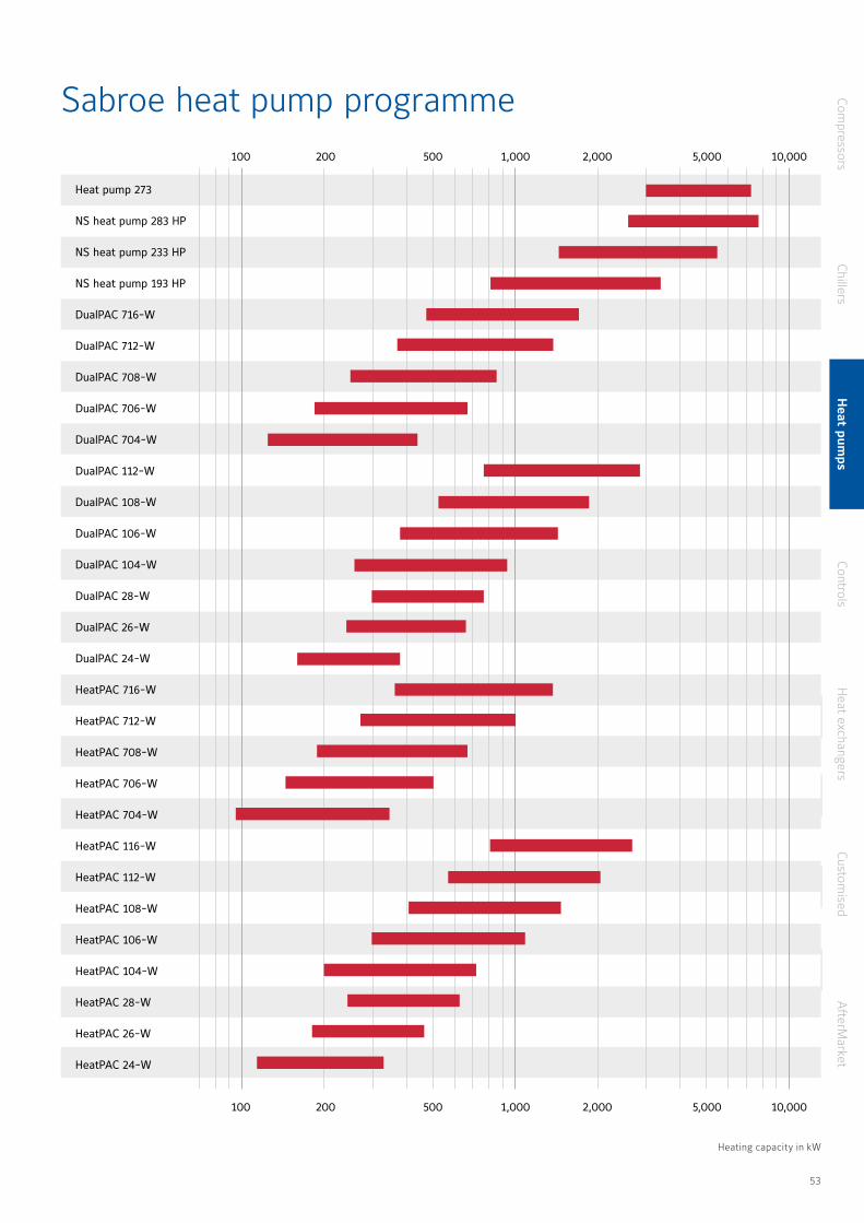
Sabroe heat pump programme
Heat pump 273
NS heat pump 283 HP
NS heat pump 233 HP
NS heat pump 193 HP
DualPAC 716-W
DualPAC 712-W
DualPAC 708-W
DualPAC 706-W
DualPAC 704-W
DualPAC 112-W
DualPAC 108-W
DualPAC 106-W
DualPAC 104-W
DualPAC 28-W
DualPAC 26-W
DualPAC 24-W
HeatPAC 716-W
HeatPAC 712-W
HeatPAC 708-W
HeatPAC 706-W
HeatPAC 704-W
HeatPAC 116-W
HeatPAC 112-W
HeatPAC 108-W
HeatPAC 106-W
HeatPAC 104-W
HeatPAC 28-W
HeatPAC 26-W
HeatPAC 24-W
Heating capacity in kW
100 1,000 10,000
100
200
200
500
500 1,000
2,000
2,000
5,000
5,000 10,000
Heating capacity in kW
Compressors
ChillersH
eat pumps
ControlsH
eat exchangersCustom
isedA
fterMarket
52 53
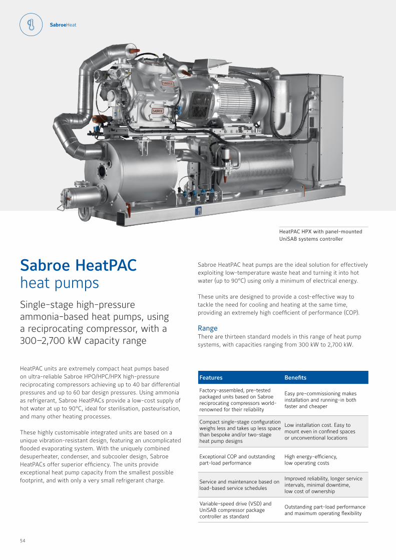
HeatPAC units are extremely compact heat pumps based on ultra-reliable Sabroe HPO/HPC/HPX high-pressure reciprocating compressors achieving up to 40 bar differential pressures and up to 60 bar design pressures Using ammonia as refrigerant, Sabroe HeatPACs provide a low-cost supply of hot water at up to 90°C, ideal for sterilisation, pasteurisation, and many other heating processes
These highly customisable integrated units are based on a unique vibration-resistant design, featuring an uncomplicated flooded evaporating system With the uniquely combined desuperheater, condenser, and subcooler design, Sabroe HeatPACs offer superior efficiency The units provide exceptional heat pump capacity from the smallest possible footprint, and with only a very small refrigerant charge
Sabroe HeatPAC heat pumpsSingle-stage high-pressure ammonia-based heat pumps, using a reciprocating compressor, with a 300–2,700 kW capacity range
Features Benefits
Factory-assembled, pre-tested packaged units based on Sabroe reciprocating compressors world-renowned for their reliability
Easy pre-commissioning makes installation and running-in both faster and cheaper
Compact single-stage configuration weighs less and takes up less space than bespoke and/or two-stage heat pump designs
Low installation cost Easy to mount even in confined spaces or unconventional locations
Exceptional COP and outstanding part-load performance
High energy-efficiency, low operating costs
Service and maintenance based on load-based service schedules
Improved reliability, longer service intervals, minimal downtime, low cost of ownership
Variable-speed drive (VSD) and UniSAB compressor package controller as standard
Outstanding part-load performance and maximum operating flexibility
HeatPAC HPX with panel-mounted UniSAB systems controller
Sabroe HeatPAC heat pumps are the ideal solution for effectively exploiting low-temperature waste heat and turning it into hot water (up to 90°C) using only a minimum of electrical energy These units are designed to provide a cost-effective way to tackle the need for cooling and heating at the same time, providing an extremely high coefficient of performance (COP)
RangeThere are thirteen standard models in this range of heat pump systems, with capacities ranging from 300 kW to 2,700 kW
54 55
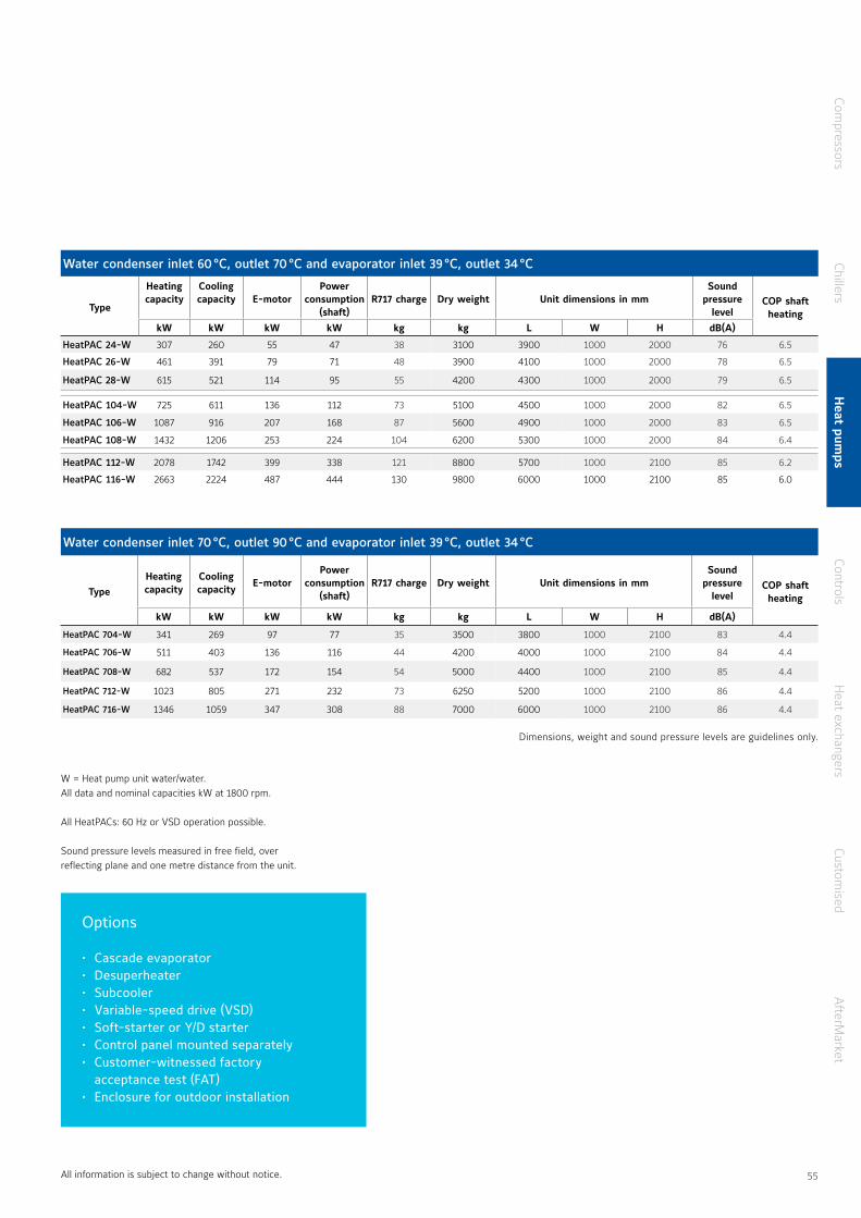
W = Heat pump unit water/water All data and nominal capacities kW at 1800 rpm
All HeatPACs: 60 Hz or VSD operation possible Sound pressure levels measured in free field, over reflecting plane and one metre distance from the unit
Water condenser inlet 60 °C, outlet 70 °C and evaporator inlet 39 °C, outlet 34 °C
Type
Heatingcapacity
Coolingcapacity E-motor
Power consumption
(shaft)R717 charge Dry weight Unit dimensions in mm
Sound pressure
levelCOP shaft heating
kW kW kW kW kg kg L W H dB(A)
HeatPAC 24-W 307 260 55 47 38 3100 3900 1000 2000 76 6 5
HeatPAC 26-W 461 391 79 71 48 3900 4100 1000 2000 78 6 5
HeatPAC 28-W 615 521 114 95 55 4200 4300 1000 2000 79 6 5
HeatPAC 104-W 725 611 136 112 73 5100 4500 1000 2000 82 6 5
HeatPAC 106-W 1087 916 207 168 87 5600 4900 1000 2000 83 6 5
HeatPAC 108-W 1432 1206 253 224 104 6200 5300 1000 2000 84 6 4
HeatPAC 112-W 2078 1742 399 338 121 8800 5700 1000 2100 85 6 2
HeatPAC 116-W 2663 2224 487 444 130 9800 6000 1000 2100 85 6 0
Water condenser inlet 70 °C, outlet 90 °C and evaporator inlet 39 °C, outlet 34 °C
TypeHeatingcapacity
Coolingcapacity
E-motorPower
consumption(shaft)
R717 charge Dry weight Unit dimensions in mmSound
pressure level
COP shaft heating
kW kW kW kW kg kg L W H dB(A)
HeatPAC 704-W 341 269 97 77 35 3500 3800 1000 2100 83 4 4
HeatPAC 706-W 511 403 136 116 44 4200 4000 1000 2100 84 4 4
HeatPAC 708-W 682 537 172 154 54 5000 4400 1000 2100 85 4 4
HeatPAC 712-W 1023 805 271 232 73 6250 5200 1000 2100 86 4 4
HeatPAC 716-W 1346 1059 347 308 88 7000 6000 1000 2100 86 4 4
All information is subject to change without notice
Options
• Cascade evaporator • Desuperheater • Subcooler • Variable-speed drive (VSD) • Soft-starter or Y/D starter • Control panel mounted separately • Customer-witnessed factory
acceptance test (FAT)• Enclosure for outdoor installation
Dimensions, weight and sound pressure levels are guidelines only
Compressors
ChillersH
eat pumps
ControlsH
eat exchangersCustom
isedA
fterMarket
54 55

Sabroe DualPAC heat pumps combine ChillPAC and HeatPAC units into one single heat pump, using an ingenious modular system that makes it possible to achieve high temperature lifts, with the advantages of compact design and attractive operating economics The DualPAC configuration is optimised for use in district heating and ground-source cooling
The DualPAC is a two-stage high-temperature heat pump configuration that uses ammonia as refrigerant It is designed with the aim of providing the best possible performance and versatile operating conditions This unique setup ensures maximum flexibility in both configuration and capabilities, because all standard ChillPAC and HeatPAC models can be used
DualPAC is an exceptional heat pump for utilising low source temperatures and supplying high temperatures at high capacity The unique heat exchangers and vessels ensure minimum refrigerant charge as well as the highest possible efficiency
Sabroe DualPAC heat pumpsTwo-stage ammonia-based heat pumps with capacities of up to 3,000 kW
Features Benefits
Stepless, skip-free capacity control ensures that output always matches requirements
Lowest possible operating costs and maximum return on investment
Consistently high performance at both full and part load
Maximum part-load efficiency and low life cycle costs
Unique two-stage solution featuring patented purpose-designed open inter-stage cooler
Ultra-low refrigerant charge and small footprint
Space-saving footprint, with fewer moving parts and very low vibration
Exceptional reliability and low maintenance costs
Service and maintenance based on load-based service schedules
Improved reliability, longer service intervals, minimal downtime, low cost of ownership
DualPAC heat pump unit with panel-mounted UniSAB systems controllers
Range
There are seventeen different models in the range of DualPAC heat pumps, with capacities ranging from 400 kW to 3,000 kW
56 57
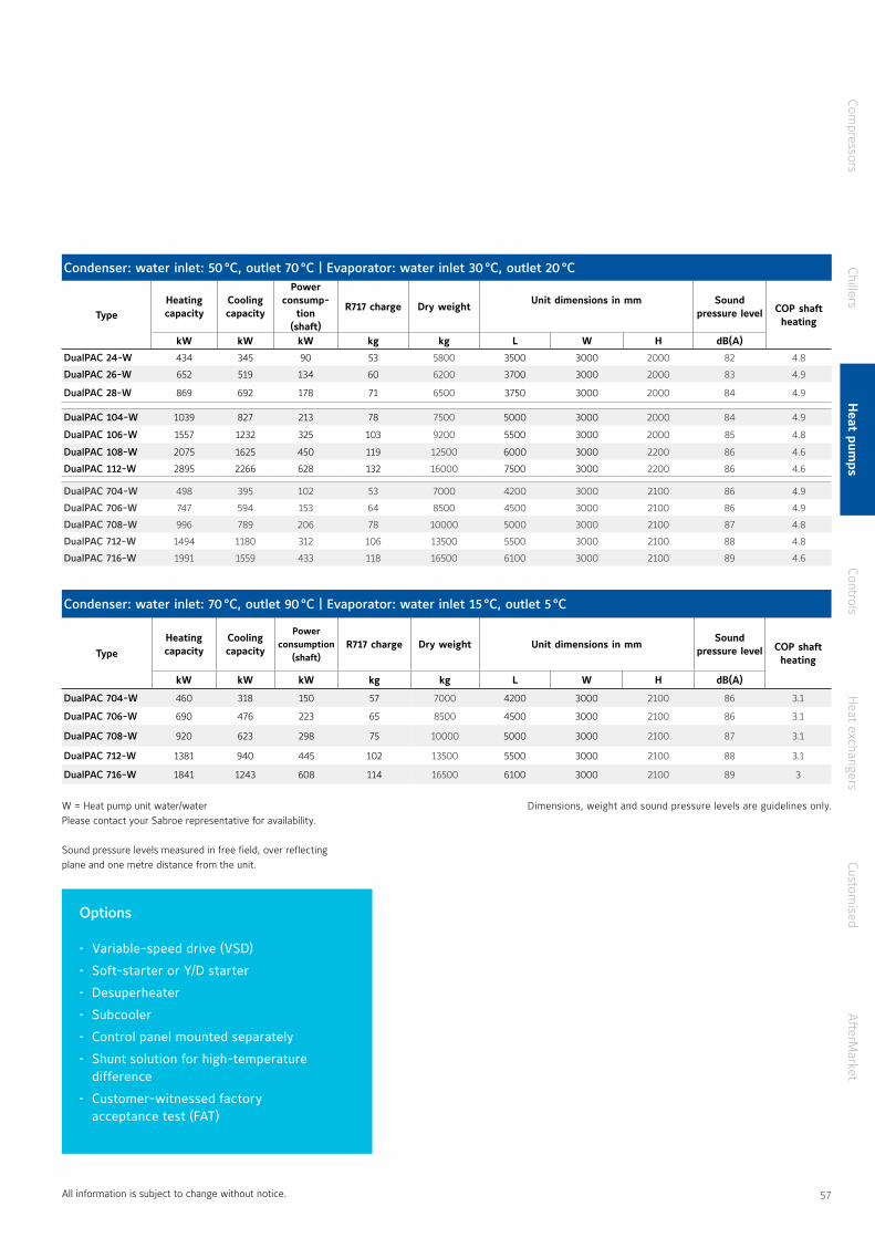
Options
• Variable-speed drive (VSD)
• Soft-starter or Y/D starter
• Desuperheater
• Subcooler
• Control panel mounted separately
• Shunt solution for high-temperature difference
• Customer-witnessed factory acceptance test (FAT)
W = Heat pump unit water/water Please contact your Sabroe representative for availability
Sound pressure levels measured in free field, over reflecting plane and one metre distance from the unit
Condenser: water inlet: 50 °C, outlet 70 °C | Evaporator: water inlet 30 °C, outlet 20 °C
TypeHeatingcapacity
Coolingcapacity
Power consump-
tion(shaft)
R717 charge Dry weightUnit dimensions in mm Sound
pressure level COP shaft heating
kW kW kW kg kg L W H dB(A)
DualPAC 24-W 434 345 90 53 5800 3500 3000 2000 82 4 8
DualPAC 26-W 652 519 134 60 6200 3700 3000 2000 83 4 9
DualPAC 28-W 869 692 178 71 6500 3750 3000 2000 84 4 9
DualPAC 104-W 1039 827 213 78 7500 5000 3000 2000 84 4 9
DualPAC 106-W 1557 1232 325 103 9200 5500 3000 2000 85 4 8
DualPAC 108-W 2075 1625 450 119 12500 6000 3000 2200 86 4 6
DualPAC 112-W 2895 2266 628 132 16000 7500 3000 2200 86 4 6
DualPAC 704-W 498 395 102 53 7000 4200 3000 2100 86 4 9
DualPAC 706-W 747 594 153 64 8500 4500 3000 2100 86 4 9
DualPAC 708-W 996 789 206 78 10000 5000 3000 2100 87 4 8
DualPAC 712-W 1494 1180 312 106 13500 5500 3000 2100 88 4 8
DualPAC 716-W 1991 1559 433 118 16500 6100 3000 2100 89 4 6
Condenser: water inlet: 70 °C, outlet 90 °C | Evaporator: water inlet 15 °C, outlet 5 °C
TypeHeatingcapacity
Coolingcapacity
Power consumption
(shaft)R717 charge Dry weight Unit dimensions in mm
Sound pressure level COP shaft
heating
kW kW kW kg kg L W H dB(A)
DualPAC 704-W 460 318 150 57 7000 4200 3000 2100 86 3 1
DualPAC 706-W 690 476 223 65 8500 4500 3000 2100 86 3 1
DualPAC 708-W 920 623 298 75 10000 5000 3000 2100 87 3 1
DualPAC 712-W 1381 940 445 102 13500 5500 3000 2100 88 3 1
DualPAC 716-W 1841 1243 608 114 16500 6100 3000 2100 89 3
All information is subject to change without notice
Dimensions, weight and sound pressure levels are guidelines only
Compressors
ChillersH
eat pumps
ControlsH
eat exchangersCustom
isedA
fterMarket
56 57
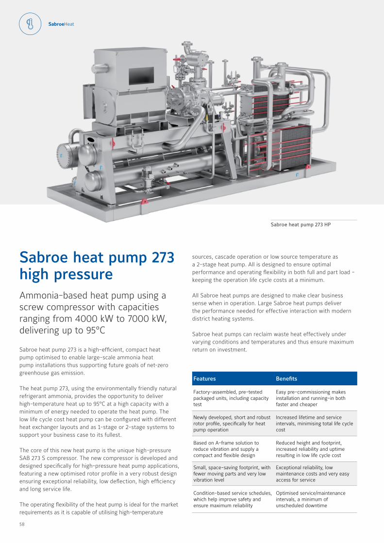
Sabroe heat pump 273 is a high-efficient, compact heat pump optimised to enable large-scale ammonia heat pump installations thus supporting future goals of net-zero greenhouse gas emission
The heat pump 273, using the environmentally friendly natural refrigerant ammonia, provides the opportunity to deliver high-temperature heat up to 95°C at a high capacity with a minimum of energy needed to operate the heat pump The low life cycle cost heat pump can be configured with different heat exchanger layouts and as 1-stage or 2-stage systems to support your business case to its fullest
The core of this new heat pump is the unique high-pressure SAB 273 S compressor The new compressor is developed and designed specifically for high-pressure heat pump applications, featuring a new optimised rotor profile in a very robust design ensuring exceptional reliability, low deflection, high efficiency and long service life
The operating flexibility of the heat pump is ideal for the market requirements as it is capable of utilising high-temperature
Sabroe heat pump 273 high pressure Ammonia-based heat pump using a screw compressor with capacities ranging from 4000 kW to 7000 kW, delivering up to 95°C
Features Benefits
Factory-assembled, pre-tested packaged units, including capacity test
Easy pre-commissioning makes installation and running-in both faster and cheaper
Newly developed, short and robust rotor profile, specifically for heat pump operation
Increased lifetime and service intervals, minimising total life cycle cost
Based on A-frame solution to reduce vibration and supply a compact and flexible design
Reduced height and footprint, increased reliability and uptime resulting in low life cycle cost
Small, space-saving footprint, with fewer moving parts and very low vibration level
Exceptional reliability, low maintenance costs and very easy access for service
Condition-based service schedules, which help improve safety and ensure maximum reliability
Optimised service/maintenance intervals, a minimum of unscheduled downtime
Sabroe heat pump 273 HP
sources, cascade operation or low source temperature as a 2-stage heat pump All is designed to ensure optimal performance and operating flexibility in both full and part load - keeping the operation life cycle costs at a minimum
All Sabroe heat pumps are designed to make clear business sense when in operation Large Sabroe heat pumps deliver the performance needed for effective interaction with modern district heating systems
Sabroe heat pumps can reclaim waste heat effectively under varying conditions and temperatures and thus ensure maximum return on investment
58 59
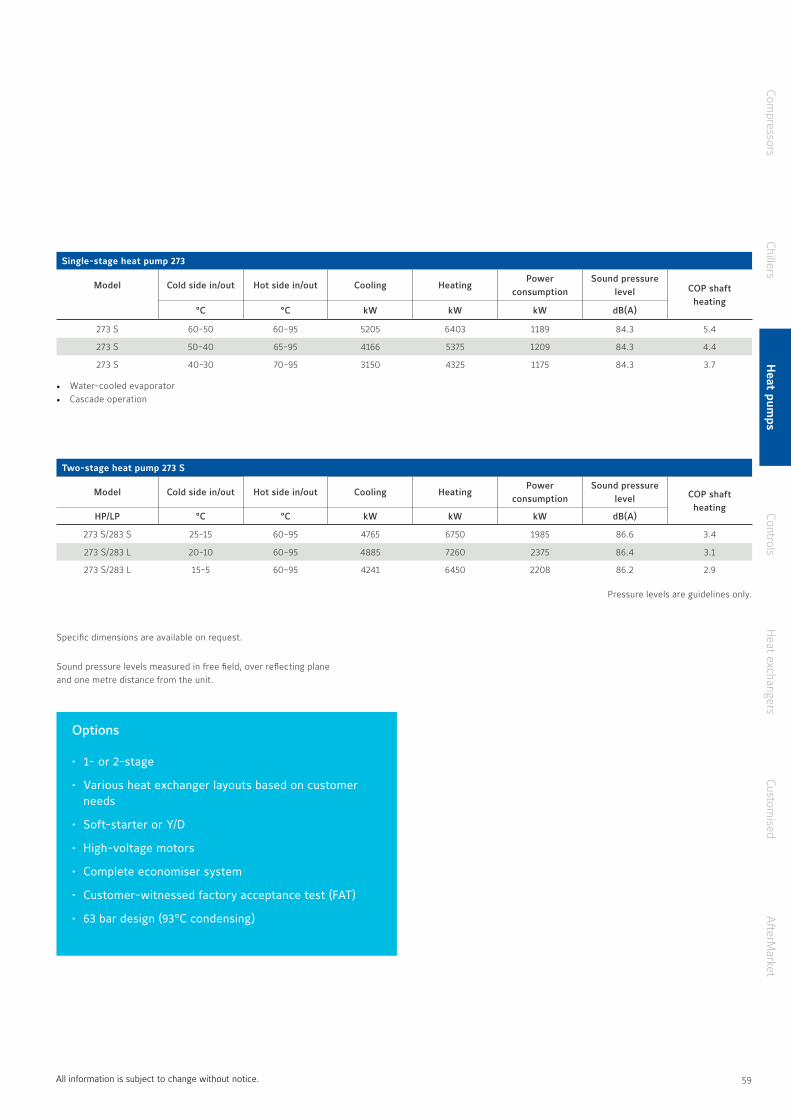
All information is subject to change without notice
Options
• 1- or 2-stage
• Various heat exchanger layouts based on customer needs
• Soft-starter or Y/D
• High-voltage motors
• Complete economiser system
• Customer-witnessed factory acceptance test (FAT)
• 63 bar design (93°C condensing)
Pressure levels are guidelines only
• Water-cooled evaporator• Cascade operation
Specific dimensions are available on request
Sound pressure levels measured in free field, over reflecting plane and one metre distance from the unit
Single-stage heat pump 273
Model Cold side in/out Hot side in/out Cooling HeatingPower
consumptionSound pressure
level COP shaft heating
°C °C kW kW kW dB(A)
273 S 60-50 60-95 5205 6403 1189 84 3 5 4
273 S 50-40 65-95 4166 5375 1209 84 3 4 4
273 S 40-30 70-95 3150 4325 1175 84 3 3 7
Two-stage heat pump 273 S
Model Cold side in/out Hot side in/out Cooling HeatingPower
consumptionSound pressure
level COP shaft heating
HP/LP °C °C kW kW kW dB(A)
273 S/283 S 25-15 60-95 4765 6750 1985 86 6 3 4
273 S/283 L 20-10 60-95 4885 7260 2375 86 4 3 1
273 S/283 L 15-5 60-95 4241 6450 2208 86 2 2 9
Compressors
ChillersH
eat pumps
ControlsH
eat exchangersCustom
isedA
fterMarket
58 59
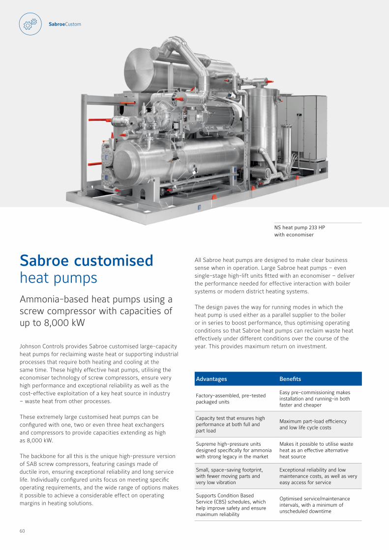
Johnson Controls provides Sabroe customised large-capacity heat pumps for reclaiming waste heat or supporting industrial processes that require both heating and cooling at the same time These highly effective heat pumps, utilising the economiser technology of screw compressors, ensure very high performance and exceptional reliability as well as the cost-effective exploitation of a key heat source in industry – waste heat from other processes
These extremely large customised heat pumps can be configured with one, two or even three heat exchangers and compressors to provide capacities extending as high as 8,000 kW
The backbone for all this is the unique high-pressure version of SAB screw compressors, featuring casings made of ductile iron, ensuring exceptional reliability and long service life Individually configured units focus on meeting specific operating requirements, and the wide range of options makes it possible to achieve a considerable effect on operating margins in heating solutions
Sabroe customised heat pumpsAmmonia-based heat pumps using a screw compressor with capacities of up to 8,000 kW
Advantages Benefits
Factory-assembled, pre-tested packaged units
Easy pre-commissioning makes installation and running-in both faster and cheaper
Capacity test that ensures high performance at both full and part load
Maximum part-load efficiency and low life cycle costs
Supreme high-pressure units designed specifically for ammonia with strong legacy in the market
Makes it possible to utilise waste heat as an effective alternative heat source
Small, space-saving footprint, with fewer moving parts and very low vibration
Exceptional reliability and low maintenance costs, as well as very easy access for service
Supports Condition Based Service (CBS) schedules, which help improve safety and ensure maximum reliability
Optimised service/maintenance intervals, with a minimum of unscheduled downtime
NS heat pump 233 HP with economiser
All Sabroe heat pumps are designed to make clear business sense when in operation Large Sabroe heat pumps – even single-stage high-lift units fitted with an economiser – deliver the performance needed for effective interaction with boiler systems or modern district heating systems
The design paves the way for running modes in which the heat pump is used either as a parallel supplier to the boiler or in series to boost performance, thus optimising operating conditions so that Sabroe heat pumps can reclaim waste heat effectively under different conditions over the course of the year This provides maximum return on investment
60 61

Condenser water inlet +60 °C, outlet +70 °C | 40 bar design pressure, R717 refrigerant
ModelMax. rpm
Cold side temp.In/out °C
Cooling HeatingPower
consumptionSound
pressure level COP shaft heating
kW kW kW db(A)
NS heat pump 193 HP4200 10/6 1270 1797 527 84 3 4
4200 40/34 2822 3399 577 84 5 9
NS heat pump 233 HP3800 10/6 2040 2866 826 86 3 5
3800 40/34 4576 5466 890 86 6 2
NS heat pump 283 HP3000 10/6 2895 4063 1168 88 3 5
3000 40/34 6492 7744 1252 88 6 2
40 bar design pressureSAB 193 HP, SAB 233 HP and SAB 283 HP All capacities include economiser operation
Dimensions on request
Non-standard Sabroe heat pumps are available on request
All information is subject to change without notice
Options
• Modular design for easy transport and rapid on-site assembly
• Shell–and–plate heat exchangers
• Shell–and–tube heat exchangers
• Parallel heat exchanger operation
• Variable-speed drive
• Soft-starter or Y/D starter
• High-voltage motors
• Complete economiser systems
• Customer-witnessed factory acceptance test (FAT)
Sound pressure levels measured in free field, over reflecting plane and one metre distance from the unit
Sound pressure levels are guidelines only
Compressors
ChillersH
eat pumps
ControlsH
eat exchangersCustom
isedA
fterMarket
60 61

Sabroe controls
63
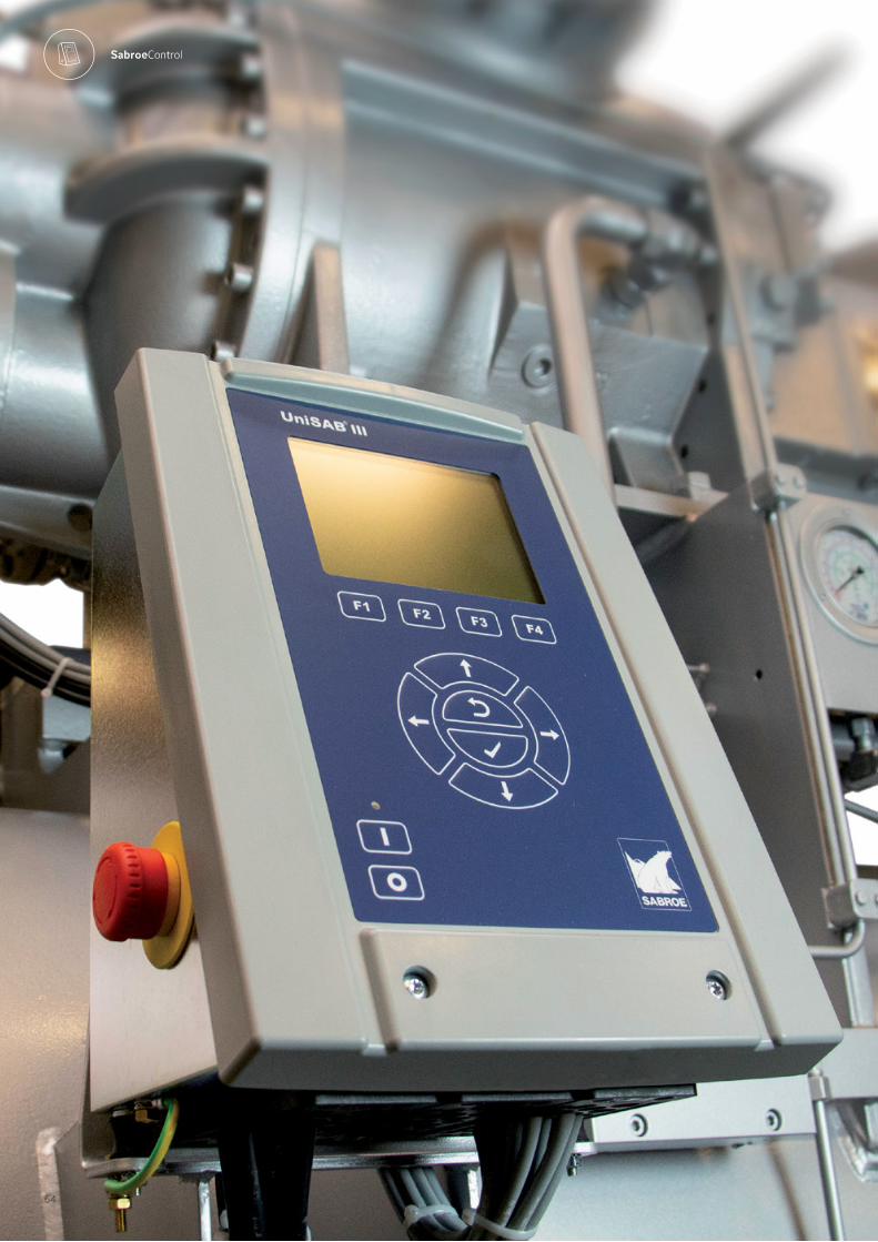
64 65
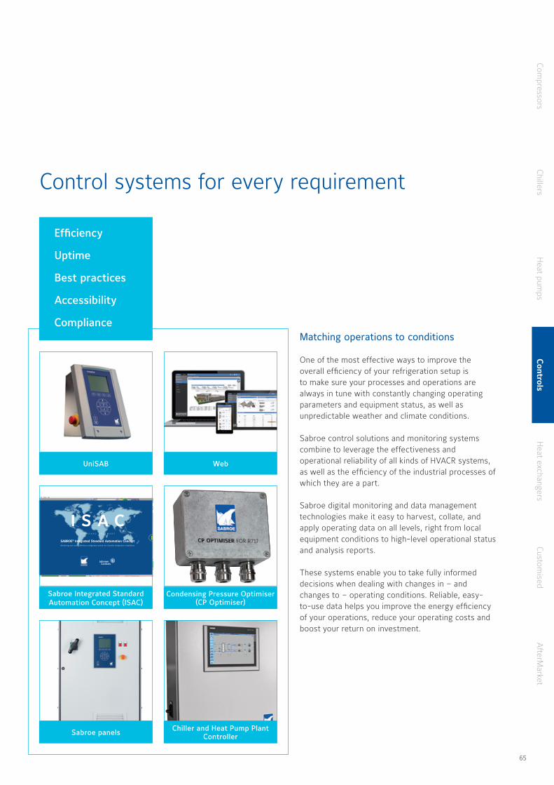
Control systems for every requirement
Matching operations to conditions
One of the most effective ways to improve the overall efficiency of your refrigeration setup is to make sure your processes and operations are always in tune with constantly changing operating parameters and equipment status, as well as unpredictable weather and climate conditions
Sabroe control solutions and monitoring systems combine to leverage the effectiveness and operational reliability of all kinds of HVACR systems, as well as the efficiency of the industrial processes of which they are a part
Sabroe digital monitoring and data management technologies make it easy to harvest, collate, and apply operating data on all levels, right from local equipment conditions to high-level operational status and analysis reports
These systems enable you to take fully informed decisions when dealing with changes in – and changes to – operating conditions Reliable, easy-to-use data helps you improve the energy efficiency of your operations, reduce your operating costs and boost your return on investment
Web
Condensing Pressure Optimiser (CP Optimiser)
Chiller and Heat Pump Plant ControllerSabroe panels
S T A N D A R D S O F T W A R E
SABROE® Integrated Standard Automation ConceptMonitoring and control interface configuration system for industrial refrigeration installations
I S A Cu
Sabroe Integrated StandardAutomation Concept (ISAC)
Efficiency
Uptime
Best practices
Accessibility
Compliance
Compressors
ChillersH
eat pumps
Controls
Heat exchangers
Customised
AfterM
arket
UniSAB
64 65
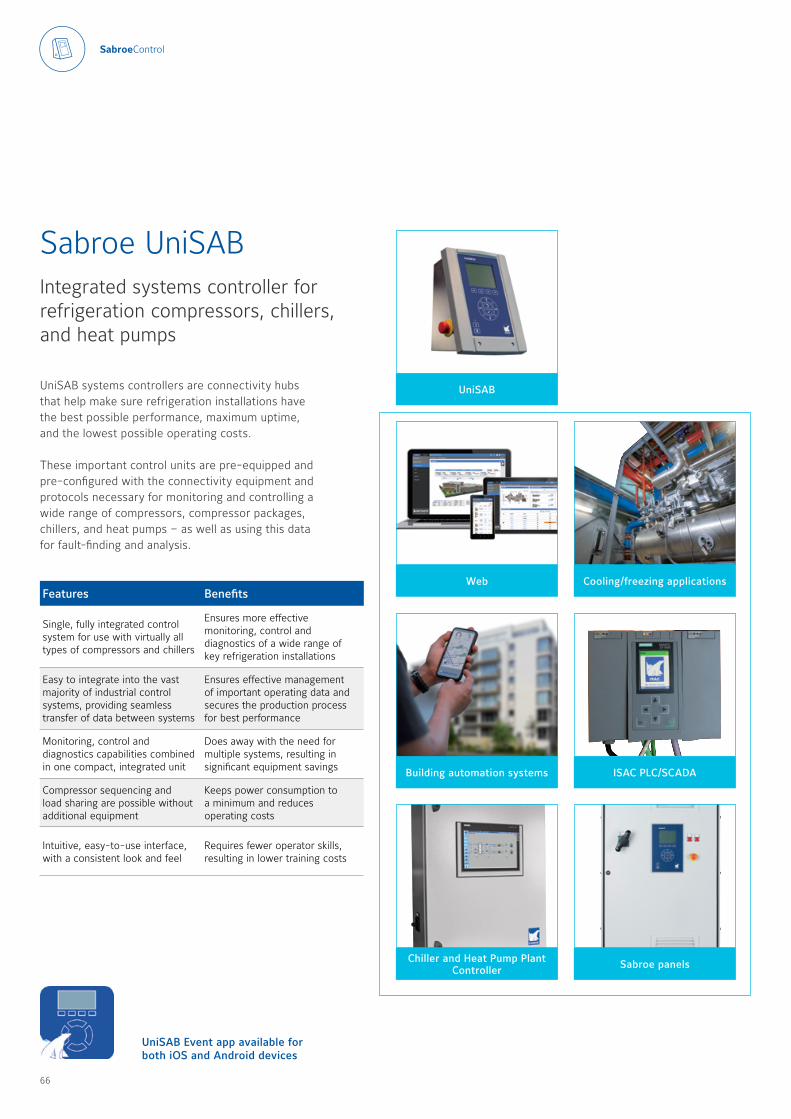
UniSAB systems controllers are connectivity hubs that help make sure refrigeration installations have the best possible performance, maximum uptime, and the lowest possible operating costs
These important control units are pre-equipped and pre-configured with the connectivity equipment and protocols necessary for monitoring and controlling a wide range of compressors, compressor packages, chillers, and heat pumps – as well as using this data for fault-finding and analysis
Sabroe UniSABIntegrated systems controller for refrigeration compressors, chillers, and heat pumps
Features Benefits
Single, fully integrated control system for use with virtually all types of compressors and chillers
Ensures more effective monitoring, control and diagnostics of a wide range of key refrigeration installations
Easy to integrate into the vast majority of industrial control systems, providing seamless transfer of data between systems
Ensures effective management of important operating data and secures the production process for best performance
Monitoring, control and diagnostics capabilities combined in one compact, integrated unit
Does away with the need for multiple systems, resulting in significant equipment savings
Compressor sequencing and load sharing are possible without additional equipment
Keeps power consumption to a minimum and reduces operating costs
Intuitive, easy-to-use interface, with a consistent look and feel
Requires fewer operator skills, resulting in lower training costs
UniSAB Event app available for both iOS and Android devices
Web
Building automation systems
Chiller and Heat Pump Plant Controller Sabroe panels
ISAC PLC/SCADA
Cooling/freezing applications
UniSAB
66 67

Technical data
ConnectivityMultiple communication ports, including Modbus TCP, Profibus DP and Sequence Bus, as standard
Smartphone app Available for both iOS and Android devices
SequencingAs many as 14 refrigeration compressors (per temperature or pressure system), chillers, and heat pumps of different makes and types can be linked in sequence to ensure effective load sharing and capacity optimisation
Diagnostics Detailed operating data documenting 30 shutdown situations
Refrigerants Pre-loaded with the requisite data about all refrigerants normally used
Operating languages Multiple languages available as standard, with additional languages as options
Enclosure IP54
Ambient temperature 0–55 °C
Power supply 85–250 volt AC, 50–60 HzDimensions (H x W x D) 380 x 300 x 210 mmWeight 6 5 kg
Connectivity
The UniSAB systems controller has normal industry-standard communication ports fitted as standard, and therefore does not require additional communication gateways
Data can then be made available via any kind of network, where virtually any computer can be used to monitor and operate the UniSAB systems controller
Functionality
• Service on-demand schedule• UniSAB app for smartphone • Configurable for both screw
compressors and reciprocating compressors, with or without variable-speed drive (VSD), and using any refrigerant
• Built-in regulation of suction pressure, water temperature, discharge pressure, etc
• Limitations on suction pressure, discharge pressure, motor current, etc
• Logging of operating history and profiles for effective fault-finding and diagnosis
• Email dispatch in case of alarm or shutdown
Retrofit
A wide range of UniSAB retrofit kits are available to provide all the advantages of upgrading a wide range of existing compressors to a modern controls standard for improved performance and control system integration
Retrofit kits are available for the full legacy of Sabroe, Frick, and Stal compressors - and most competitor compressors
Complete retrofit kit
All information is subject to change without notice
Compressors
ChillersH
eat pumps
Controls
Heat exchangers
Customised
AfterM
arket
66 67
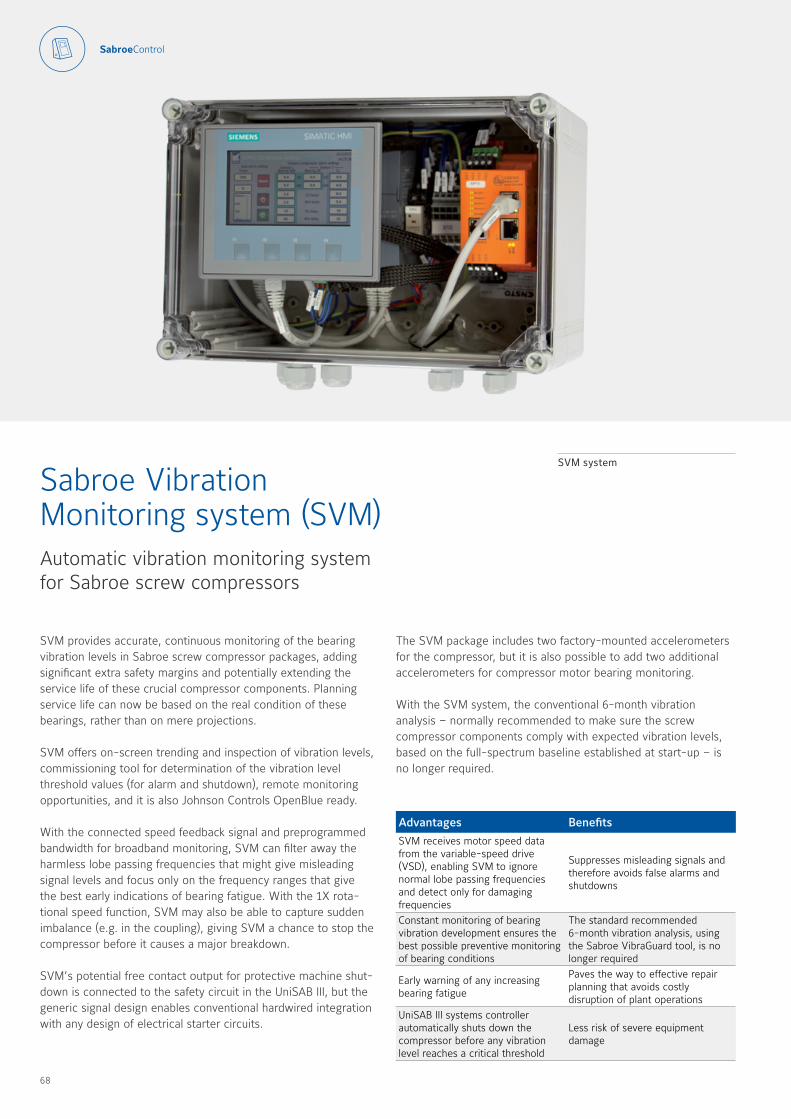
SVM provides accurate, continuous monitoring of the bearing vibration levels in Sabroe screw compressor packages, adding significant extra safety margins and potentially extending the service life of these crucial compressor components Planning service life can now be based on the real condition of these bearings, rather than on mere projections
SVM offers on-screen trending and inspection of vibration levels, commissioning tool for determination of the vibration level threshold values (for alarm and shutdown), remote monitoring opportunities, and it is also Johnson Controls OpenBlue ready
With the connected speed feedback signal and preprogrammed bandwidth for broadband monitoring, SVM can filter away the harmless lobe passing frequencies that might give misleading signal levels and focus only on the frequency ranges that give the best early indications of bearing fatigue With the 1X rota-tional speed function, SVM may also be able to capture sudden imbalance (e g in the coupling), giving SVM a chance to stop the compressor before it causes a major breakdown
SVM’s potential free contact output for protective machine shut-down is connected to the safety circuit in the UniSAB III, but the generic signal design enables conventional hardwired integration with any design of electrical starter circuits
Sabroe Vibration Monitoring system (SVM)Automatic vibration monitoring system for Sabroe screw compressors
SVM system
The SVM package includes two factory-mounted accelerometers for the compressor, but it is also possible to add two additional accelerometers for compressor motor bearing monitoring
With the SVM system, the conventional 6-month vibration analysis – normally recommended to make sure the screw compressor components comply with expected vibration levels, based on the full-spectrum baseline established at start-up – is no longer required
Advantages BenefitsSVM receives motor speed data from the variable-speed drive (VSD), enabling SVM to ignore normal lobe passing frequencies and detect only for damaging frequencies
Suppresses misleading signals and therefore avoids false alarms and shutdowns
Constant monitoring of bearing vibration development ensures the best possible preventive monitoring of bearing conditions
The standard recommended 6-month vibration analysis, using the Sabroe VibraGuard tool, is no longer required
Early warning of any increasing bearing fatigue
Paves the way to effective repair planning that avoids costly disruption of plant operations
UniSAB III systems controller automatically shuts down the compressor before any vibration level reaches a critical threshold
Less risk of severe equipment damage
68 69
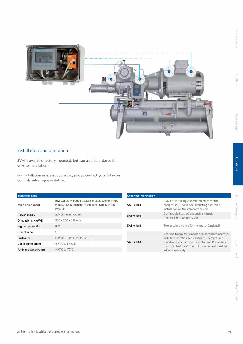
Technical data
Main component IFM VSE153 vibration analysis module Siemens PLC type S7-1200 Siemens touch panel type KTP400 Basic 4”
Power supply 24V DC, min 800mA
Dimensions HxWxD 300 x 200 x 186 mm
Ingress protection IP55
Compliance CE
Enclosure Plastic – Ensto OABP302018T
Cable connections 4 x M16, 3 x M20
Ambient temperature -40°C to 70°C
All information is subject to change without notice
Ordering information
SAB-Vib01SVM kit, including 2 accelerometers for the compressor, 1 SVM box, mounting and cable installation on the compressor unit
SAB-Vib02Danfoss MCB101 I/O expansion module (required for Danfoss VSD)
SAB-Vib03 Two accelerometers for the motor (optional)
SAB-Vib04
Addition to box for support of a second compressor, including vibration sensors for the compressor Vibration sensors for no 2 motor and I/O module for no 2 Danfoss VSD is not included and must be added separately
Installation and operation
SVM is available factory mounted, but can also be ordered for on-site installation For installation in hazardous areas, please contact your Johnson Controls sales representative
Compressors
ChillersH
eat pumps
Controls
Heat exchangers
Customised
AfterM
arket
68 69
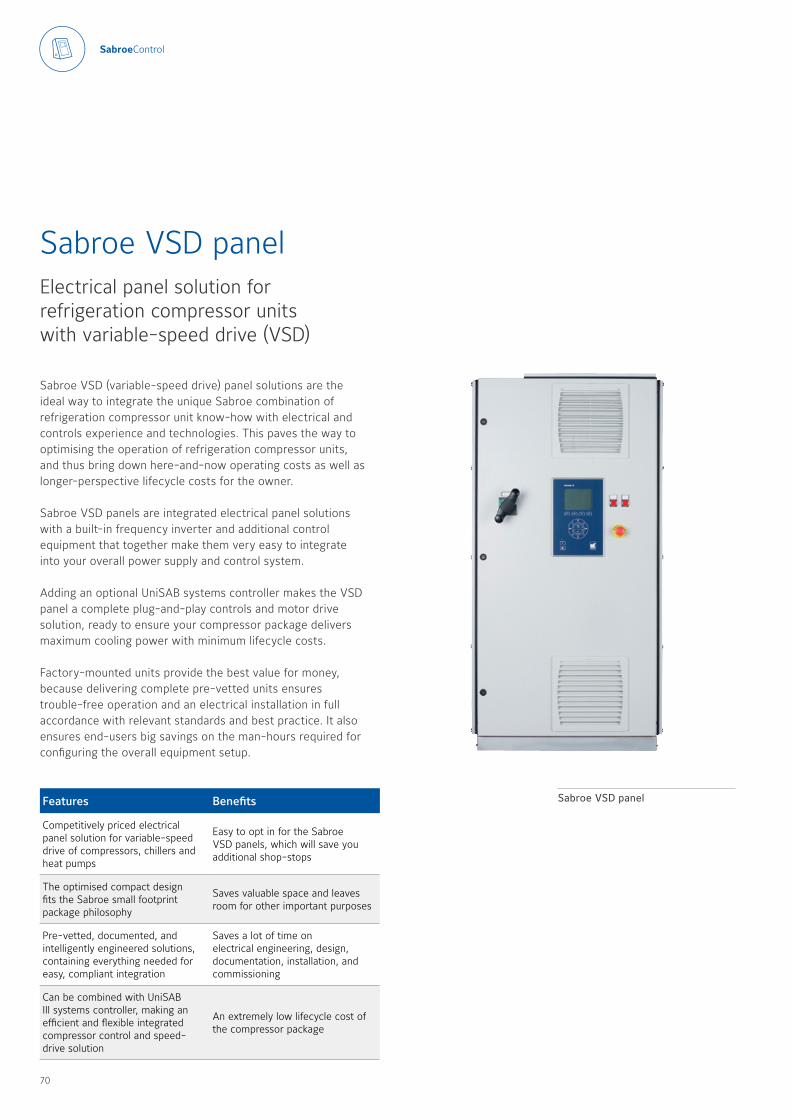
Sabroe VSD (variable-speed drive) panel solutions are the ideal way to integrate the unique Sabroe combination of refrigeration compressor unit know-how with electrical and controls experience and technologies This paves the way to optimising the operation of refrigeration compressor units, and thus bring down here-and-now operating costs as well as longer-perspective lifecycle costs for the owner
Sabroe VSD panels are integrated electrical panel solutions with a built-in frequency inverter and additional control equipment that together make them very easy to integrate into your overall power supply and control system
Adding an optional UniSAB systems controller makes the VSD panel a complete plug-and-play controls and motor drive solution, ready to ensure your compressor package delivers maximum cooling power with minimum lifecycle costs
Factory-mounted units provide the best value for money, because delivering complete pre-vetted units ensures trouble-free operation and an electrical installation in full accordance with relevant standards and best practice It also ensures end-users big savings on the man-hours required for configuring the overall equipment setup
Sabroe VSD panelElectrical panel solution for refrigeration compressor units with variable-speed drive (VSD)
Features Benefits
Competitively priced electrical panel solution for variable-speed drive of compressors, chillers and heat pumps
Easy to opt in for the Sabroe VSD panels, which will save you additional shop-stops
The optimised compact design fits the Sabroe small footprint package philosophy
Saves valuable space and leaves room for other important purposes
Pre-vetted, documented, and intelligently engineered solutions, containing everything needed for easy, compliant integration
Saves a lot of time on electrical engineering, design, documentation, installation, and commissioning
Can be combined with UniSAB III systems controller, making an efficient and flexible integrated compressor control and speed-drive solution
An extremely low lifecycle cost of the compressor package
Sabroe VSD panel
70 71

Technical data
Power supply:3x400 V, 50/60 Hz, +/-10 %
Earthing/supply system: TN-S
Partitioning: Form 1
Colour: Light grey
Ingress protection class: IP54
Compliance: CE
The VSD panels are available for the Sabroe compressor, chiller and heat pump units specified below These panels are available as standard for power configurations up to 450 kW Configurations up to 1000 kW are available on request
Factory-mounted
• ChillPAC chillers• PAC chillers• HeatPAC heat pumps
Separate delivery for site mounting
• ChillPAC chillers• PAC chillers• HeatPAC heat pumps• Screw compressors (all VSD-enabled)• Reciprocating compressors (all VSD-enabled)
Technical data
Nominal output
Dimensions in mm
kW/amp W H D
22/44 816 1434 624
30/61 816 1434 624
37/73 816 1434 624
45/90 816 1434 624
55/106 816 1434 624
75/147 816 1434 624
90/177 816 1434 624
110/212 816 1626 624 132/260 816 1626 624 160/315 816 1818 624
200/395 816 1818 624
250/480 816 1818 624
315/600 816 1818 624
355/658 1200 2202 816
400/745 1200 2202 816
450/800 1200 2202 816
All information is subject to change without notice
Retrofit
Sabroe VSD panels are also ideal for retrofit of the existing electrical starter systems Sabroe VSD panels are mounted in a standardised painted-steel cabinet, and include the following equipment:
• Electrical engineering, documentation and parameter settings list for the frequency inverter
• Danfoss FC102 frequency inverter, including RFI filter
• High-frequency common mode filter for bearing current suppression
• UniSAB controller for panel mounting (optional – must be selected separately)
• Main circuit breaker• Control voltage transformer• Emergency stop and emergency stop safety relay• Motor protection• Current feedback signal to UniSAB• Relays for signals to UniSAB• Hour counter• Terminals for interlock with pumps, etc • MCB for control voltage to panel• MCB for control voltage to UniSAB• MCB for power to immersion heater in oil separator• Cable inlet/outlet in panel bottom
Compressors
ChillersH
eat pumps
Controls
Heat exchangers
Customised
AfterM
arket
70 71
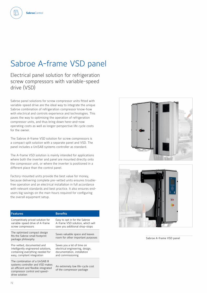
Sabroe panel solutions for screw compressor units fitted with variable-speed drive are the ideal way to integrate the unique Sabroe combination of refrigeration compressor know-how with electrical and controls experience and technologies This paves the way to optimising the operation of refrigeration compressor units, and thus bring down here-and-now operating costs as well as longer-perspective life cycle costs for the owner
The Sabroe A-frame VSD solution for screw compressors is a compact split solution with a separate panel and VSD The panel includes a UniSAB systems controller as standard
The A-frame VSD solution is mainly intended for applications where both the inverter and panel are mounted directly onto the compressor unit, or where the inverter is positioned in a different place than the control panel
Factory-mounted units provide the best value for money, because delivering complete pre-vetted units ensures trouble-free operation and an electrical installation in full accordance with relevant standards and best practice It also ensures end-users big savings on the man-hours required for configuring the overall equipment setup
Sabroe A-frame VSD panelElectrical panel solution for refrigeration screw compressors with variable-speed drive (VSD)
Features Benefits
Competitively priced solution for variable-speed drive of A-frame screw compressors
Easy to opt in for the Sabroe A-frame VSD solution, which will save you additional shop-stops
The optimised compact design fits the Sabroe small footprint package philosophy
Saves valuable space and leaves room for other important purposes
Pre-vetted, documented and intelligently engineered solutions, containing everything needed for easy, compliant integration
Saves you a lot of time on electrical engineering, design, documentation, installation and commissioning
The combination of a UniSAB III systems controller and VSD makes an efficient and flexible integrated compressor control and speed-drive solution
An extremely low life-cycle cost of the compressor package
Sabroe A-frame VSD panel
72 73
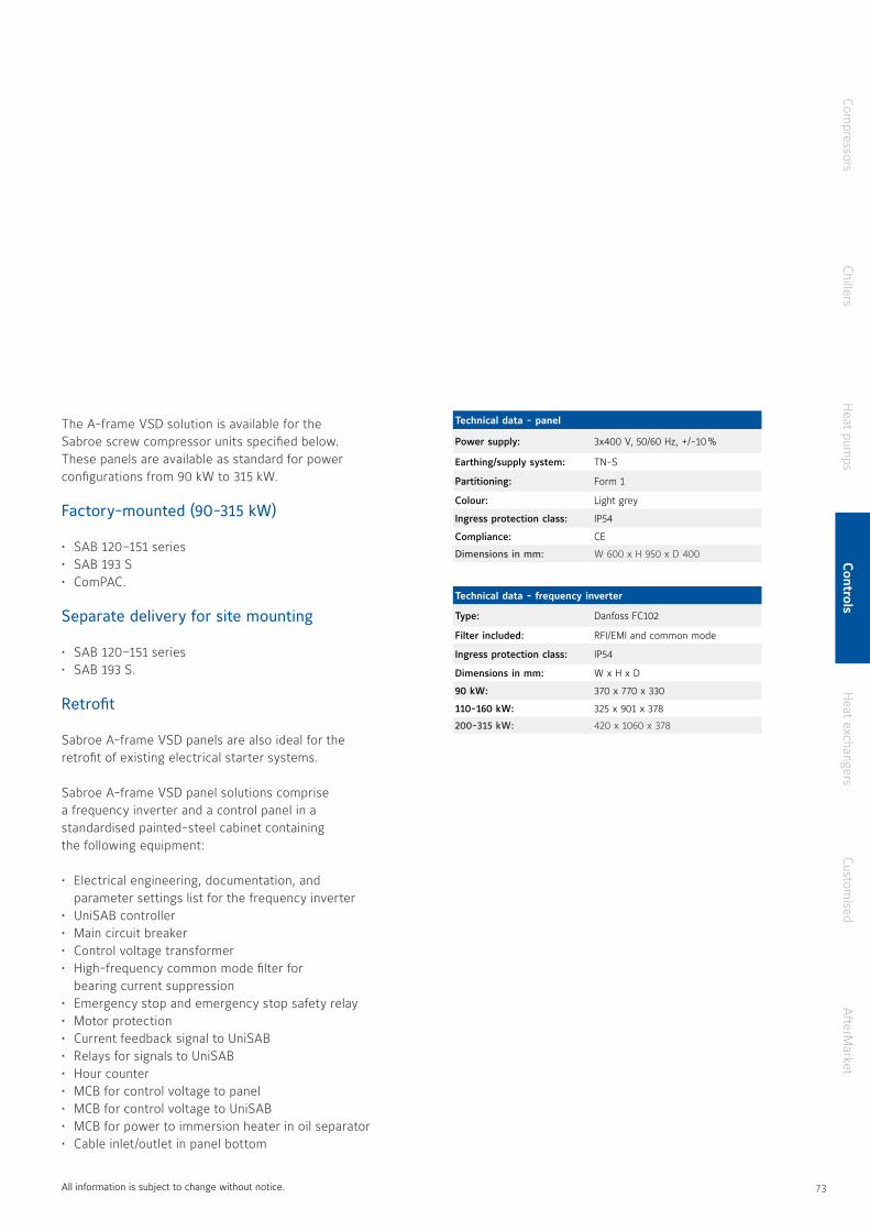
Technical data - panel
Power supply: 3x400 V, 50/60 Hz, +/-10 %
Earthing/supply system: TN-S
Partitioning: Form 1
Colour: Light grey
Ingress protection class: IP54
Compliance: CE
Dimensions in mm: W 600 x H 950 x D 400
The A-frame VSD solution is available for the Sabroe screw compressor units specified below These panels are available as standard for power configurations from 90 kW to 315 kW
Factory-mounted (90-315 kW)
• SAB 120–151 series• SAB 193 S• ComPAC
Separate delivery for site mounting
• SAB 120–151 series• SAB 193 S
Retrofit
Sabroe A-frame VSD panels are also ideal for the retrofit of existing electrical starter systems
Sabroe A-frame VSD panel solutions comprise a frequency inverter and a control panel in a standardised painted-steel cabinet containing the following equipment:
• Electrical engineering, documentation, and parameter settings list for the frequency inverter
• UniSAB controller• Main circuit breaker• Control voltage transformer• High-frequency common mode filter for
bearing current suppression• Emergency stop and emergency stop safety relay• Motor protection• Current feedback signal to UniSAB • Relays for signals to UniSAB• Hour counter• MCB for control voltage to panel• MCB for control voltage to UniSAB• MCB for power to immersion heater in oil separator• Cable inlet/outlet in panel bottom
Technical data - frequency inverter
Type: Danfoss FC102
Filter included: RFI/EMI and common mode
Ingress protection class: IP54
Dimensions in mm: W x H x D
90 kW: 370 x 770 x 330
110-160 kW: 325 x 901 x 378
200-315 kW: 420 x 1060 x 378
All information is subject to change without notice
Compressors
ChillersH
eat pumps
Controls
Heat exchangers
Customised
AfterM
arket
72 73

Factory-mounted units provide the best value by ensuring trouble-free operation and an electrical installation in full accordance with relevant standards and best practice It also ensures end-users big savings on the man-hours required for configuring the overall equipment setup
Sabroe panel solutions for compressor units fitted with fixed-speed motors are the ideal way to integrate the unique Sabroe combination of refrigeration compressor know-how with electrical and controls experience and technologies This paves the way to optimising the operation of fixed-speed refrigeration compressor units, and bring down here-and-now operating costs as well as longer-perspective lifecycle costs for the owner
Sabroe softstarter FSD panels are integrated electrical panel solutions with a built-in softstarter and additional control equipment that together make them very easy to integrate into your overall power supply and control system
Adding an optional UniSAB systems controller makes the softstarter FSD panel a complete plug-and-play controls and motor starter solution, ready to supply the motor and ensure that the fixed-speed compressor unit delivers maximum cooling power at a minimum life cycle cost
Sabroe softstarter FSD panels are an advanced electronic alternative to conventional Y/D starters, enabling a smoother start and (in some setups) making it possible to reduce the starting current better than a Y/D starter
Sabroe softstarter FSD panelElectrical panel solution for refrigeration compressor units with fixed-speed drive (FSD)
Features Benefits
Competitively priced electrical panel solution for fixed-speed drive of compressors, chillers and heat pumps
Easy to opt for the Sabroe softstarter FSD panels, which will save you additional shop stops
The optimised compact design fits the Sabroe small footprint package philosophy
Saves valuable space and leaves room for other important purposes
Pre-vetted, documented and intelligently engineered solutions, containing everything needed for easy, compliant integration
Saves you a lot of time on electrical engineering, design, documentation, installation, and commissioning
Can be combined with UniSAB III systems controller, making an efficient and flexible integrated compressor control and motor start solution
A very low lifecycle cost of the compressor package
Sabroe softstarter FSD panel
74 75
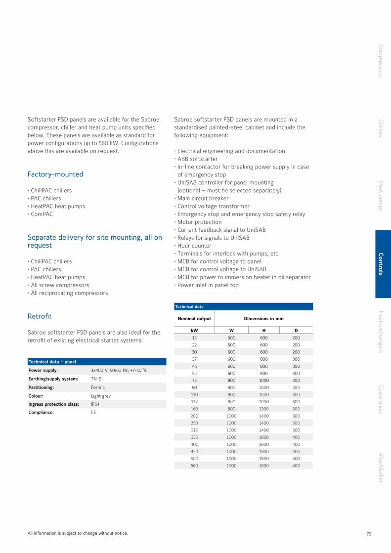
Sabroe softstarter FSD panels are mounted in a standardised painted-steel cabinet and include the following equipment:
• Electrical engineering and documentation • ABB softstarter• In-line contactor for breaking power supply in case
of emergency stop• UniSAB controller for panel mounting
(optional – must be selected separately)• Main circuit breaker• Control voltage transformer• Emergency stop and emergency stop safety relay• Motor protection• Current feedback signal to UniSAB• Relays for signals to UniSAB• Hour counter• Terminals for interlock with pumps, etc • MCB for control voltage to panel• MCB for control voltage to UniSAB• MCB for power to immersion heater in oil separator• Power inlet in panel top
Technical data - panel
Power supply: 3x400 V, 50/60 Hz, +/-10 %
Earthing/supply system: TN-S
Partitioning: Form 1
Colour: Light grey
Ingress protection class: IP54
Compliance: CE
Softstarter FSD panels are available for the Sabroe compressor, chiller and heat pump units specified below These panels are available as standard for power configurations up to 560 kW Configurations above this are available on request
Factory-mounted
• ChillPAC chillers• PAC chillers• HeatPAC heat pumps• ComPAC
Separate delivery for site mounting, all on request
• ChillPAC chillers• PAC chillers• HeatPAC heat pumps• All screw compressors• All reciprocating compressors
Retrofit
Sabroe softstarter FSD panels are also ideal for the retrofit of existing electrical starter systems
All information is subject to change without notice
Technical data
Nominal outputNominal output Dimensions in mmDimensions in mm
kWkW WW HH DD
15 600 600 200
22 600 600 200
30 600 600 200
37 600 800 300
45 600 800 300
55 600 800 300
75 800 1000 300
90 800 1000 300
110 800 1000 300
132 800 1000 300
160 800 1200 300
200 1000 1400 300
250 1000 1400 300
315 1000 1400 300
355 1000 1800 400
400 1000 1800 400
450 1000 1800 400
500 1000 1800 400
560 1000 1800 400
Compressors
ChillersH
eat pumps
Controls
Heat exchangers
Customised
AfterM
arket
74 75
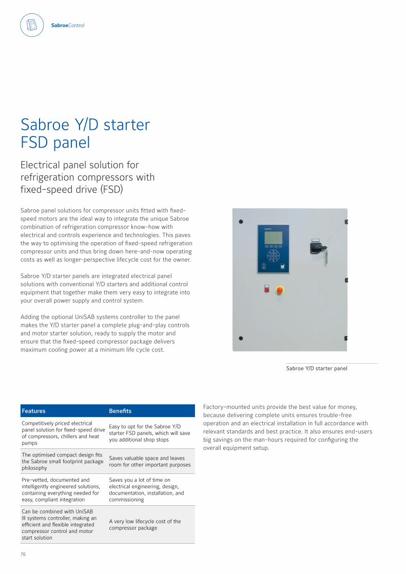
Sabroe panel solutions for compressor units fitted with fixed-speed motors are the ideal way to integrate the unique Sabroe combination of refrigeration compressor know-how with electrical and controls experience and technologies This paves the way to optimising the operation of fixed-speed refrigeration compressor units and thus bring down here-and-now operating costs as well as longer-perspective lifecycle cost for the owner
Sabroe Y/D starter panels are integrated electrical panel solutions with conventional Y/D starters and additional control equipment that together make them very easy to integrate into your overall power supply and control system
Adding the optional UniSAB systems controller to the panel makes the Y/D starter panel a complete plug-and-play controls and motor starter solution, ready to supply the motor and ensure that the fixed-speed compressor package delivers maximum cooling power at a minimum life cycle cost
Sabroe Y/D starter FSD panelElectrical panel solution for refrigeration compressors with fixed-speed drive (FSD)
Features Benefits
Competitively priced electrical panel solution for fixed-speed drive of compressors, chillers and heat pumps
Easy to opt for the Sabroe Y/D starter FSD panels, which will save you additional shop stops
The optimised compact design fits the Sabroe small footprint package philosophy
Saves valuable space and leaves room for other important purposes
Pre-vetted, documented and intelligently engineered solutions, containing everything needed for easy, compliant integration
Saves you a lot of time on electrical engineering, design, documentation, installation, and commissioning
Can be combined with UniSAB III systems controller, making an efficient and flexible integrated compressor control and motor start solution
A very low lifecycle cost of the compressor package
Factory-mounted units provide the best value for money, because delivering complete units ensures trouble-free operation and an electrical installation in full accordance with relevant standards and best practice It also ensures end-users big savings on the man-hours required for configuring the overall equipment setup
Sabroe Y/D starter panel
76 77
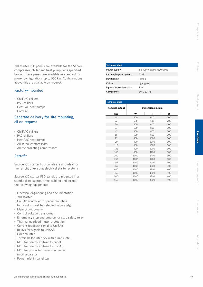
Y/D starter FSD panels are available for the Sabroe compressor, chiller and heat pump units specified below These panels are available as standard for power configurations up to 560 kW Configurations above this are available on request
Factory-mounted
• ChillPAC chillers• PAC chillers• HeatPAC heat pumps• ComPAC
Separate delivery for site mounting, all on request
• ChillPAC chillers• PAC chillers• HeatPAC heat pumps• All screw compressors• All reciprocating compressors
Retrofit
Sabroe Y/D starter FSD panels are also ideal for the retrofit of existing electrical starter systems
Sabroe Y/D starter FSD panels are mounted in a standardised painted-steel cabinet and include the following equipment:
• Electrical engineering and documentation • Y/D starter• UniSAB controller for panel mounting
(optional – must be selected separately)• Main circuit breaker• Control voltage transformer• Emergency stop and emergency stop safety relay• Thermal overload motor protection• Current feedback signal to UniSAB • Relays for signals to UniSAB• Hour counter• Terminals for interlock with pumps, etc • MCB for control voltage to panel• MCB for control voltage to UniSAB• MCB for power to immersion heater
in oil separator• Power inlet in panel top
Technical data
Power supply: 3 x 400 V, 50/60 Hz,+/-10 %
Earthing/supply system: TN-S
Partitioning: Form 1
Colour: Light grey
Ingress protection class: IP54
Compliance: EN60 204-1
Technical data
Nominal outputNominal output Dimensions in mmDimensions in mm
kWkW WW HH DD15 600 600 20022 600 600 20030 600 600 20037 600 800 30045 600 800 30055 600 800 30075 800 1000 30090 800 1000 300110 800 1000 300132 800 1000 300160 800 1200 300200 1000 1400 300250 1000 1400 300315 1000 1400 300355 1000 1800 400400 1000 1800 400450 1000 1800 400500 1000 1800 400560 1000 1800 400
All information is subject to change without notice
Compressors
ChillersH
eat pumps
Controls
Heat exchangers
Customised
AfterM
arket
76 77
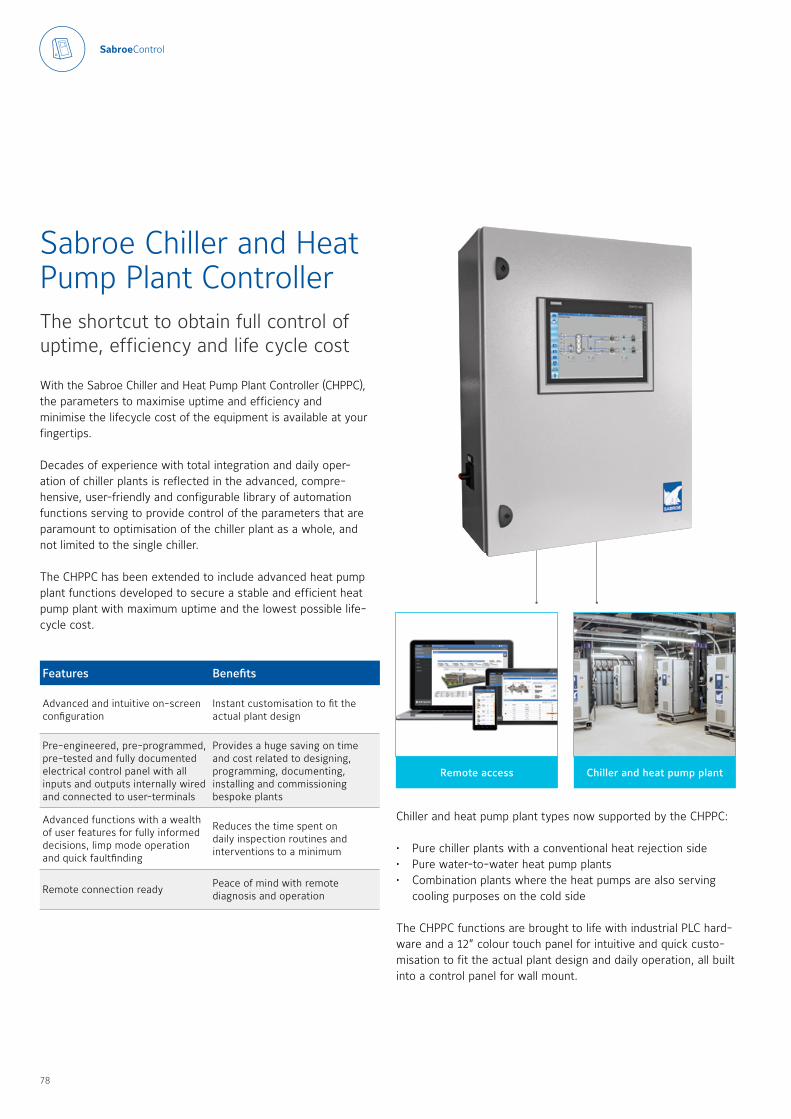
Chiller and heat pump plantRemote access
Sabroe Chiller and Heat Pump Plant ControllerThe shortcut to obtain full control of uptime, efficiency and life cycle cost
With the Sabroe Chiller and Heat Pump Plant Controller (CHPPC), the parameters to maximise uptime and efficiency and minimise the lifecycle cost of the equipment is available at your fingertips
Decades of experience with total integration and daily oper-ation of chiller plants is reflected in the advanced, compre-hensive, user-friendly and configurable library of automation functions serving to provide control of the parameters that are paramount to optimisation of the chiller plant as a whole, and not limited to the single chiller
The CHPPC has been extended to include advanced heat pump plant functions developed to secure a stable and efficient heat pump plant with maximum uptime and the lowest possible life-cycle cost
Features Benefits
Advanced and intuitive on-screen configuration
Instant customisation to fit the actual plant design
Pre-engineered, pre-programmed, pre-tested and fully documented electrical control panel with all inputs and outputs internally wired and connected to user-terminals
Provides a huge saving on time and cost related to designing, programming, documenting, installing and commissioning bespoke plants
Advanced functions with a wealth of user features for fully informed decisions, limp mode operation and quick faultfinding
Reduces the time spent on daily inspection routines and interventions to a minimum
Remote connection readyPeace of mind with remote diagnosis and operation
Chiller and heat pump plant types now supported by the CHPPC: • Pure chiller plants with a conventional heat rejection side• Pure water-to-water heat pump plants • Combination plants where the heat pumps are also serving
cooling purposes on the cold side
The CHPPC functions are brought to life with industrial PLC hard-ware and a 12” colour touch panel for intuitive and quick custo-misation to fit the actual plant design and daily operation, all built into a control panel for wall mount
78 79

Chillers and heat pumps are controlled by UniSAB
Control panel specifications
Cabinet1200 x 800 x 300 mm (HxWxD) painted steel plate, IP44
Connectivity
Touch panel: Ethernet interface for remote monitoring and operationPLC: Ethernet/Profinet interface for software service and connectivity to VSDs
Main components Main switch, 24V DC power supply, relays and terminals, Siemens S7-1500SP PLC, and 12-inch Siemens Comfort touch panel
All information is subject to change without notice
Cold side The chiller and heat pump units Hot side
Distribution pumps (up to three) incl. diff. pressure control
Remote monitoring of UniSAB IIIs on up to four compressors, distributed in four 1-stage or two 2-stage chillers/heat pumps
Fan speed and pump control for air-cooled and evaporative condensers and for dry coolers and cooling towers
Evaporator pumps and shut-off valve (up to four) Any mix of screw and reciprocating compressors Shut-off valves in glycol systems
Monitoring of temperatures and pressures in water system
Control signals from CHPPC to UniSABs Condensing pressure optimisation
Monitoring of temperatures and level switch in buffer tank
Historical data, trends and event analysis of UniSAB III data on central touch panel
Noise reduction with week calendar (fan speed reduction)
Remote start/stop of chillers from buffer tank temperature
Bearing vibration monitoring Rapid mixing of make-up water during standstill
Monitoring of the functioning of switches, motors and valves
Motor winding and bearing temperature monitoring
Monitoring of the functioning of switches, motors and valves
Leak detection signal from glycol sensor Leak detection signal from NH3 gas detector Low-temperature protection of condenser circuit
Special for heat pumps
Temperature and flow stabilisation with shunt pumps, shunt valves, in-line pumps or recycle pumps
COP optimisation through dynamic intermediate pressure in 2-stage heat pumps
Temperature control with shunt pumps, shunt valves or in-line pumps
Cooling power calculation Superheat control Heating power calculation
Common utilities
Remote connection ready (Internet, LAN). Can be delivered with wireless internet modem on request.
Profinet, Modbus TCP and OPC-UA protocols supported as standard. Others on request.
Rich data monitoring of VSD pumps with external VSD through Profinet communication (Danfoss and ABB VSDs with Profinet interface supported).
Compressors
ChillersH
eat pumps
Controls
Heat exchangers
Customised
AfterM
arket
78 79
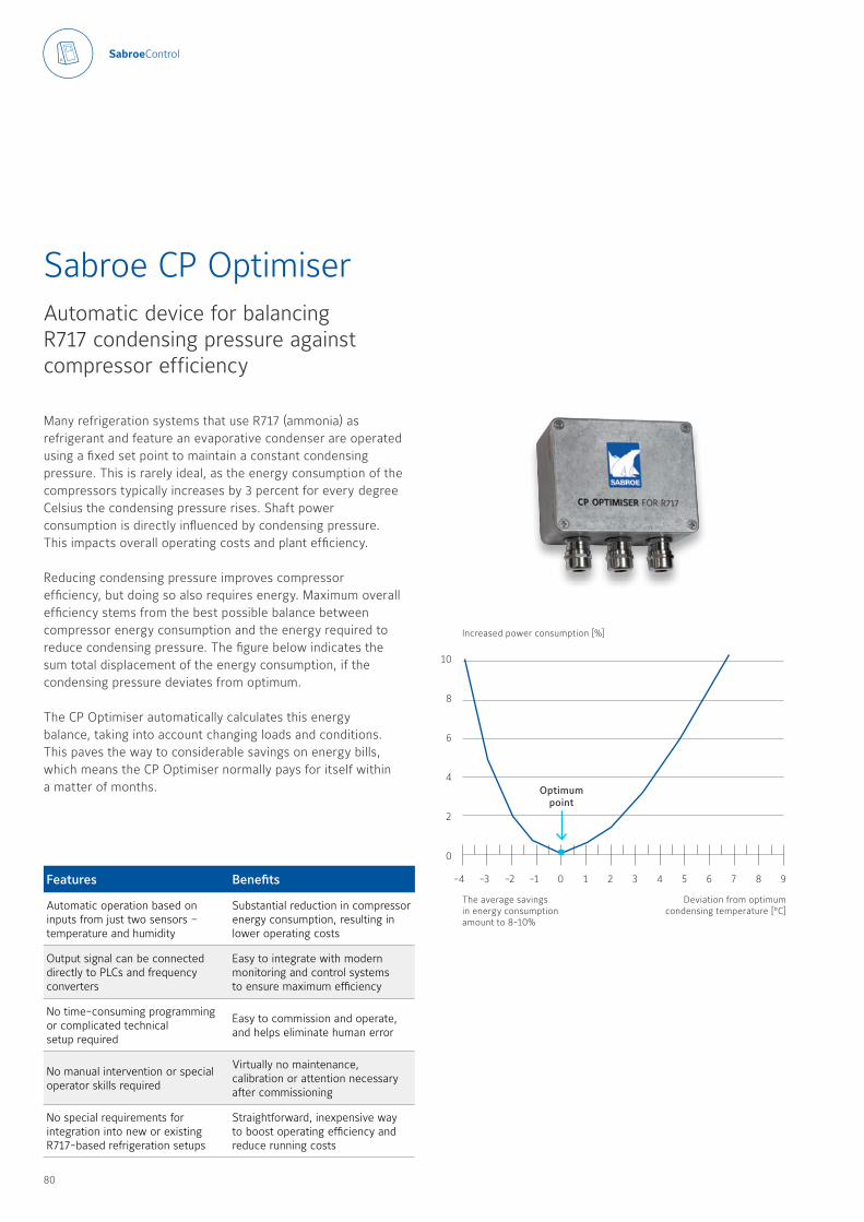
Many refrigeration systems that use R717 (ammonia) as refrigerant and feature an evaporative condenser are operated using a fixed set point to maintain a constant condensing pressure This is rarely ideal, as the energy consumption of the compressors typically increases by 3 percent for every degree Celsius the condensing pressure rises Shaft power consumption is directly influenced by condensing pressure This impacts overall operating costs and plant efficiency
Reducing condensing pressure improves compressor efficiency, but doing so also requires energy Maximum overall efficiency stems from the best possible balance between compressor energy consumption and the energy required to reduce condensing pressure The figure below indicates the sum total displacement of the energy consumption, if the condensing pressure deviates from optimum
The CP Optimiser automatically calculates this energy balance, taking into account changing loads and conditions This paves the way to considerable savings on energy bills, which means the CP Optimiser normally pays for itself within a matter of months
Sabroe CP OptimiserAutomatic device for balancing R717 condensing pressure against compressor efficiency
Features Benefits
Automatic operation based on inputs from just two sensors – temperature and humidity
Substantial reduction in compressor energy consumption, resulting in lower operating costs
Output signal can be connected directly to PLCs and frequency converters
Easy to integrate with modern monitoring and control systems to ensure maximum efficiency
No time-consuming programming or complicated technical setup required
Easy to commission and operate, and helps eliminate human error
No manual intervention or special operator skills required
Virtually no maintenance, calibration or attention necessary after commissioning
No special requirements for integration into new or existing R717-based refrigeration setups
Straightforward, inexpensive way to boost operating efficiency and reduce running costs
10
8
6
4
2
0
-4 -3 -2 -1 0 1 2 3 4 5 6 7 8 9
Optimum point
Deviation from optimum condensing temperature [°C]
Increased power consumption [%]
The average savings in energy consumption amount to 8-10%
80 81
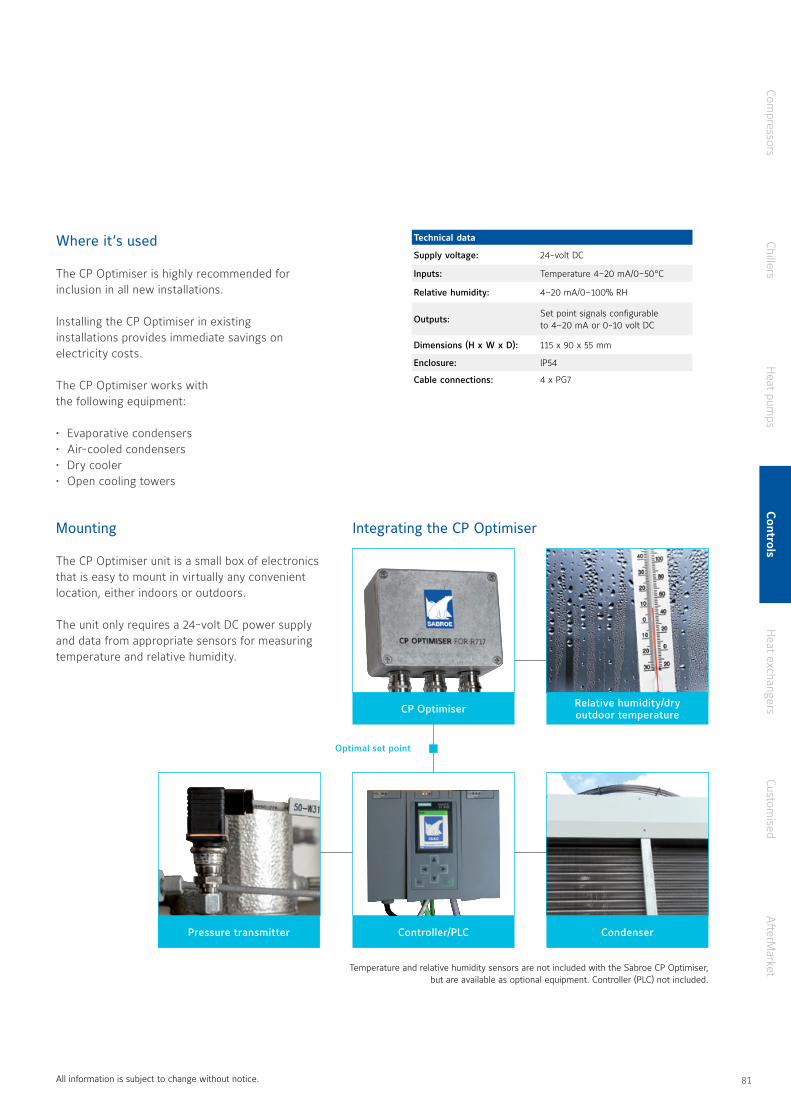
Where it’s used
The CP Optimiser is highly recommended for inclusion in all new installations
Installing the CP Optimiser in existing installations provides immediate savings on electricity costs
The CP Optimiser works with the following equipment:
• Evaporative condensers• Air-cooled condensers• Dry cooler• Open cooling towers
Mounting
The CP Optimiser unit is a small box of electronics that is easy to mount in virtually any convenient location, either indoors or outdoors
The unit only requires a 24-volt DC power supply and data from appropriate sensors for measuring temperature and relative humidity
Temperature and relative humidity sensors are not included with the Sabroe CP Optimiser, but are available as optional equipment Controller (PLC) not included
Integrating the CP Optimiser
All information is subject to change without notice
Relative humidity/dry outdoor temperature
Controller/PLCPressure transmitter Condenser
CP Optimiser
Optimal set point
Technical data
Supply voltage: 24-volt DC
Inputs: Temperature 4–20 mA/0–50 °C
Relative humidity: 4–20 mA/0–100% RH
Outputs:Set point signals configurable to 4–20 mA or 0-10 volt DC
Dimensions (H x W x D): 115 x 90 x 55 mm
Enclosure: IP54
Cable connections: 4 x PG7
Compressors
ChillersH
eat pumps
Controls
Heat exchangers
Customised
AfterM
arket
80 81
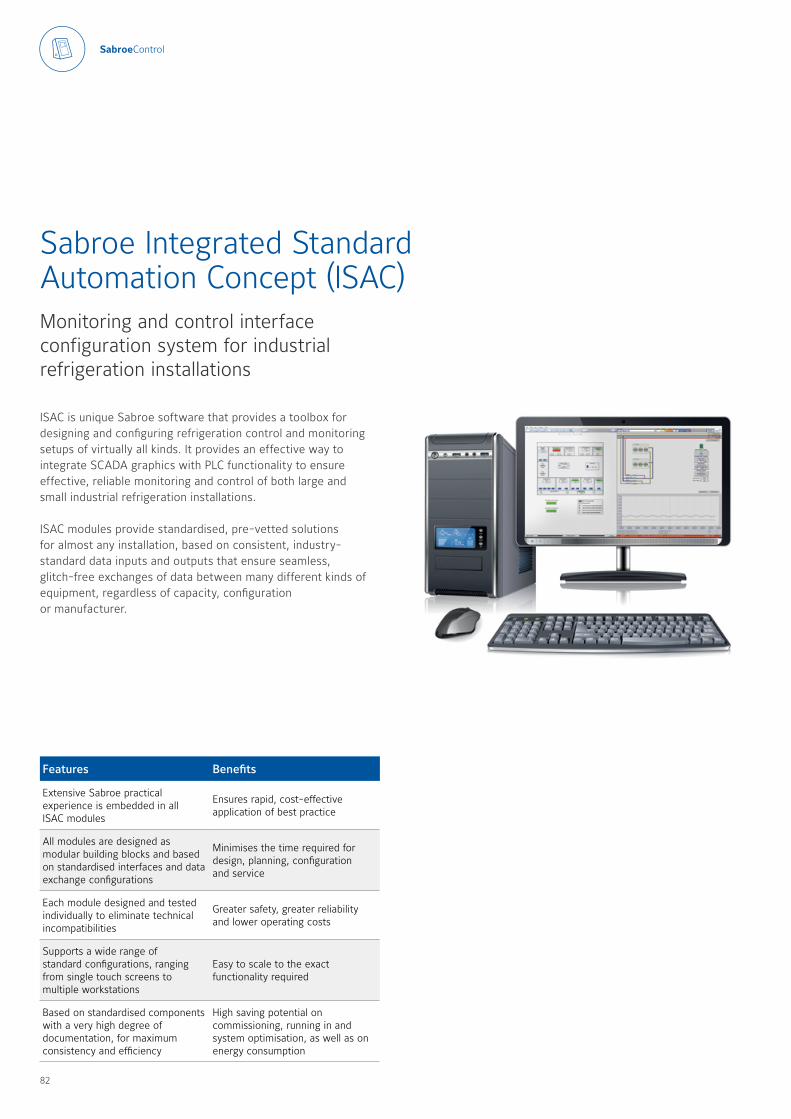
ISAC is unique Sabroe software that provides a toolbox for designing and configuring refrigeration control and monitoring setups of virtually all kinds It provides an effective way to integrate SCADA graphics with PLC functionality to ensure effective, reliable monitoring and control of both large and small industrial refrigeration installations
ISAC modules provide standardised, pre-vetted solutions for almost any installation, based on consistent, industry-standard data inputs and outputs that ensure seamless, glitch-free exchanges of data between many different kinds of equipment, regardless of capacity, configuration or manufacturer
Sabroe Integrated Standard Automation Concept (ISAC)Monitoring and control interface configuration system for industrial refrigeration installations
Features Benefits
Extensive Sabroe practical experience is embedded in all ISAC modules
Ensures rapid, cost-effective application of best practice
All modules are designed as modular building blocks and based on standardised interfaces and data exchange configurations
Minimises the time required for design, planning, configuration and service
Each module designed and tested individually to eliminate technical incompatibilities
Greater safety, greater reliability and lower operating costs
Supports a wide range of standard configurations, ranging from single touch screens to multiple workstations
Easy to scale to the exact functionality required
Based on standardised components with a very high degree of documentation, for maximum consistency and efficiency
High saving potential on commissioning, running in and system optimisation, as well as on energy consumption
82 83
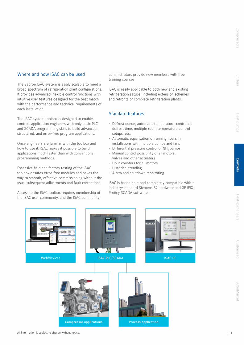
Where and how ISAC can be used
The Sabroe ISAC system is easily scalable to meet a broad spectrum of refrigeration plant configurations It provides advanced, flexible control functions with intuitive user features designed for the best match with the performance and technical requirements of each installation
The ISAC system toolbox is designed to enable controls application engineers with only basic PLC and SCADA programming skills to build advanced, structured, and error-free program applications
Once engineers are familiar with the toolbox and how to use it, ISAC makes it possible to build applications much faster than with conventional programming methods
Extensive field and factory testing of the ISAC toolbox ensures error-free modules and paves the way to smooth, effective commissioning without the usual subsequent adjustments and fault corrections
Access to the ISAC toolbox requires membership of the ISAC user community, and the ISAC community
administrators provide new members with free training courses
ISAC is easily applicable to both new and existing refrigeration setups, including extension schemes and retrofits of complete refrigeration plants
Standard features
• Defrost queue, automatic temperature-controlled defrost time, multiple room temperature control setups, etc
• Automatic equalisation of running hours in installations with multiple pumps and fans
• Differential pressure control of NH3 pumps• Manual control possibility of all motors,
valves and other actuators• Hour counters for all motors• Historical trending• Alarm and shutdown monitoring
ISAC is based on – and completely compatible with – industry-standard Siemens S7 hardware and GE IFIX Proficy SCADA software
All information is subject to change without notice
ISAC PCWeb/devices ISAC PLC/SCADA
Process applicationCompressor applications
Compressors
ChillersH
eat pumps
Controls
Heat exchangers
Customised
AfterM
arket
82 83

84 85
Heat exchangers and vessels
84 85
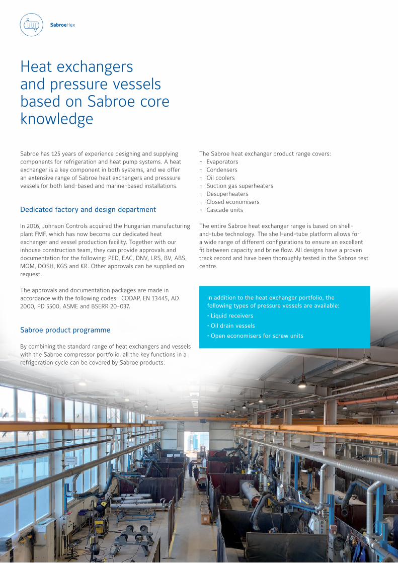
Heat exchangers and pressure vessels based on Sabroe core knowledge
The Sabroe heat exchanger product range covers:- Evaporators- Condensers - Oil coolers - Suction gas superheaters - Desuperheaters - Closed economisers - Cascade units
The entire Sabroe heat exchanger range is based on shell-and-tube technology The shell-and-tube platform allows for a wide range of different configurations to ensure an excellent fit between capacity and brine flow All designs have a proven track record and have been thoroughly tested in the Sabroe test centre
Sabroe has 125 years of experience designing and supplying components for refrigeration and heat pump systems A heat exchanger is a key component in both systems, and we offer an extensive range of Sabroe heat exchangers and presssure vessels for both land-based and marine-based installations
Dedicated factory and design department
In 2016, Johnson Controls acquired the Hungarian manufacturing plant FMF, which has now become our dedicated heat exchanger and vessel production facility Together with our inhouse construction team, they can provide approvals and documentation for the following: PED, EAC, DNV, LRS, BV, ABS, MOM, DOSH, KGS and KR Other approvals can be supplied on request The approvals and documentation packages are made in accordance with the following codes: CODAP, EN 13445, AD 2000, PD 5500, ASME and BSERR 20-037
Sabroe product programme
By combining the standard range of heat exchangers and vessels with the Sabroe compressor portfolio, all the key functions in a refrigeration cycle can be covered by Sabroe products
In addition to the heat exchanger portfolio, the following types of pressure vessels are available:
• Liquid receivers
• Oil drain vessels
• Open economisers for screw units
86 87
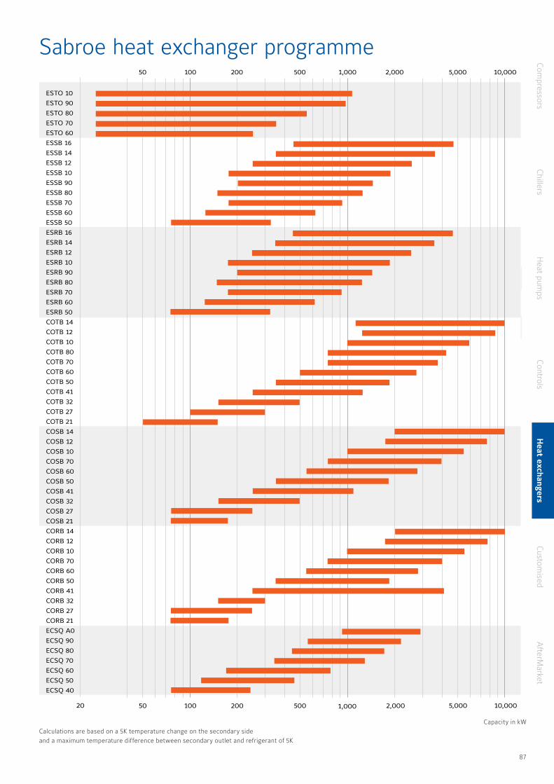
Compressors
ChillersH
eat pumps
ControlsH
eat exchangersCustom
isedA
fterMarket
Capacity in kWCalculations are based on a 5K temperature change on the secondary side and a maximum temperature difference between secondary outlet and refrigerant of 5K
Sabroe heat exchanger programme
ESTO 10
ESTO 90
ESTO 80
ESTO 70
ESTO 60
ESSB 16
ESSB 14
ESSB 12
ESSB 10
ESSB 90
ESSB 80
ESSB 70
ESSB 60
ESSB 50
ESRB 16
ESRB 14
ESRB 12
ESRB 10
ESRB 90
ESRB 80
ESRB 70
ESRB 60
ESRB 50
COTB 14
COTB 12
COTB 10
COTB 80
COTB 70
COTB 60
COTB 50
COTB 41
COTB 32
COTB 27
COTB 21
COSB 14
COSB 12
COSB 10
COSB 70
COSB 60
COSB 50
COSB 41
COSB 32
COSB 27
COSB 21
CORB 14
CORB 12
CORB 10
CORB 70
CORB 60
CORB 50
CORB 41
CORB 32
CORB 27
CORB 21
ECSQ A0
ECSQ 90
ECSQ 80
ECSQ 70
ECSQ 60
ECSQ 50
ECSQ 40
50 500200 2,000100 1,000 5,000
100 1,0005020 500200 2,000 10,0005,000
10,000
86 87
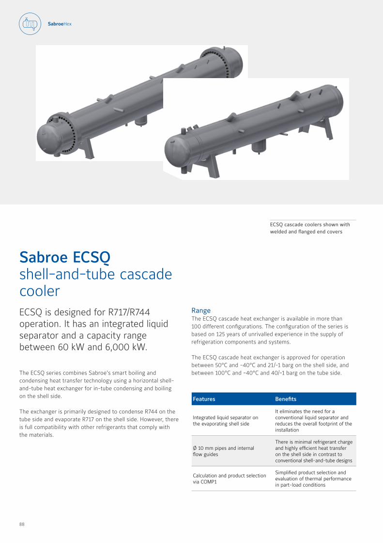
The ECSQ series combines Sabroe’s smart boiling and condensing heat transfer technology using a horizontal shell-and-tube heat exchanger for in-tube condensing and boiling on the shell side
The exchanger is primarily designed to condense R744 on the tube side and evaporate R717 on the shell side However, there is full compatibility with other refrigerants that comply with the materials
Sabroe ECSQ shell-and-tube cascade coolerECSQ is designed for R717/R744 operation It has an integrated liquid separator and a capacity range between 60 kW and 6,000 kW
Features Benefits
Integrated liquid separator on the evaporating shell side
It eliminates the need for a conventional liquid separator and reduces the overall footprint of the installation
Ø 10 mm pipes and internal flow guides
There is minimal refrigerant charge and highly efficient heat transfer on the shell side in contrast to conventional shell-and-tube designs
Calculation and product selection via COMP1
Simplified product selection and evaluation of thermal performance in part-load conditions
ECSQ cascade coolers shown with welded and flanged end covers
RangeThe ECSQ cascade heat exchanger is available in more than 100 different configurations The configuration of the series is based on 125 years of unrivalled experience in the supply of refrigeration components and systems
The ECSQ cascade heat exchanger is approved for operation between 50°C and -40°C and 21/-1 barg on the shell side, and between 100°C and -40°C and 40/-1 barg on the tube side
88 89
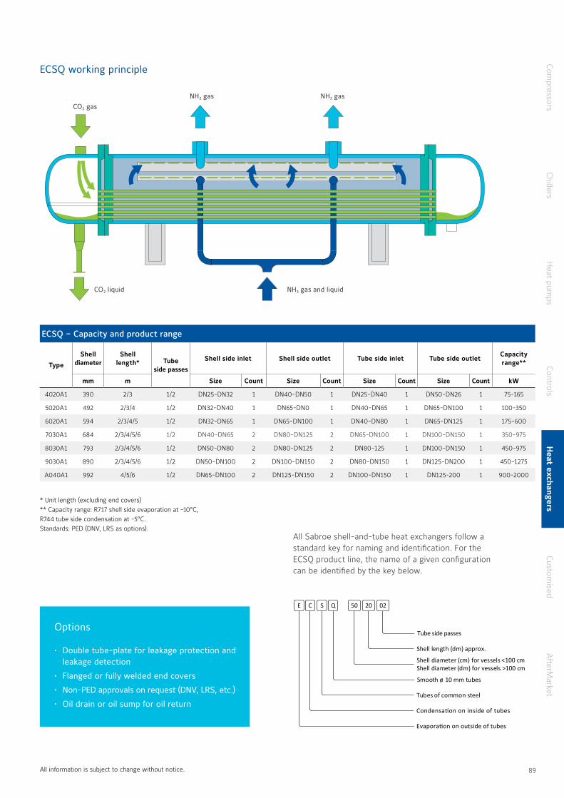
* Unit length (excluding end covers)** Capacity range: R717 shell side evaporation at -10°C, R744 tube side condensation at -5°C Standards: PED (DNV, LRS as options)
All information is subject to change without notice
Options
• Double tube-plate for leakage protection and leakage detection
• Flanged or fully welded end covers
• Non-PED approvals on request (DNV, LRS, etc.)
• Oil drain or oil sump for oil return
CO2 Gas
CO2 Liquid
NH3 Gas
NH3 Gas + liquid
NH3 Gas
ECSQ working principle
CO2 gas
CO2 liquid NH3 gas and liquid
NH3 gas NH3 gas
E C S Q
Tube side passes
50 20 02
Shell length (dm) approx.
Shell diameter (cm) for vessels <100 cmShell diameter (dm) for vessels >100 cm
Smooth ø 10 mm tubes
Tubes of common steel
Condensation on inside of tubes
Evaporation on outside of tubes
All Sabroe shell-and-tube heat exchangers follow a standard key for naming and identification For the ECSQ product line, the name of a given configuration can be identified by the key below
ECSQ – Capacity and product range
Type
Shell diameter
Shell length* Tube
side passes
Shell side inlet Shell side outlet Tube side inlet Tube side outletCapacity range**
mm m Size Count Size Count Size Count Size Count kW
4020A1 390 2/3 1/2 DN25-DN32 1 DN40-DN50 1 DN25-DN40 1 DN50-DN26 1 75-165
5020A1 492 2/3/4 1/2 DN32-DN40 1 DN65-DN0 1 DN40-DN65 1 DN65-DN100 1 100-350
6020A1 594 2/3/4/5 1/2 DN32-DN65 1 DN65-DN100 1 DN40-DN80 1 DN65-DN125 1 175-600
7030A1 684 2/3/4/5/6 1/2 DN40-DN65 2 DN80-DN125 2 DN65-DN100 1 DN100-DN150 1 350-975
8030A1 793 2/3/4/5/6 1/2 DN50-DN80 2 DN80-DN125 2 DN80-125 1 DN100-DN150 1 450-975
9030A1 890 2/3/4/5/6 1/2 DN50-DN100 2 DN100-DN150 2 DN80-DN150 1 DN125-DN200 1 450-1275
A040A1 992 4/5/6 1/2 DN65-DN100 2 DN125-DN150 2 DN100-DN150 1 DN125-200 1 900-2000
Compressors
ChillersH
eat pumps
ControlsH
eat exchangersCustom
isedA
fterMarket
88 89
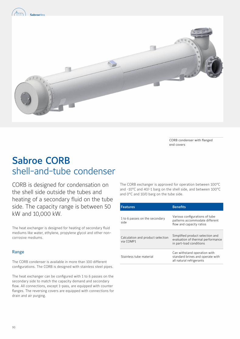
CORB is designed for condensation on the shell side outside the tubes and heating of a secondary fluid on the tube side The capacity range is between 50 kW and 10,000 kW
The heat exchanger is designed for heating of secondary fluid mediums like water, ethylene, propylene glycol and other non-corrosive mediums
Range
The CORB condenser is available in more than 100 different configurations The CORB is designed with stainless steel pipes
The heat exchanger can be configured with 1 to 6 passes on the secondary side to match the capacity demand and secondary flow All connections, except 1-pass, are equipped with counter flanges The reversing covers are equipped with connections for drain and air purging
Sabroe CORB shell-and-tube condenser
Features Benefits
1 to 6 passes on the secondary side
Various configurations of tube patterns accommodate different flow and capacity ratios
Calculation and product selection via COMP1
Simplified product selection and evaluation of thermal performance in part-load conditions
Stainless tube materialCan withstand operation with standard brines and operate with all natural refrigerants
CORB condenser with flanged end covers
The CORB exchanger is approved for operation between 100°C and -10°C and 40/-1 barg on the shell side, and between 100°C and 0°C and 10/0 barg on the tube side
90 91

Options
• Single or double connections on the refrigerant/shell side
• Single or double connections on the brine/tube side
• Brine connections from DN80 to DN300
CORB – Capacity and product range
Type
Shell diameter
Shell length Tube
side passes
Shell side inlet Shell side outlet Tube side inlet Tube side outletCapacity range*
mm m Size Count Size Count Size Count Size Count kW
21XXYY 207 1 5/2/2 5 1/2/4 DN40 1/2 DN32 1/2 DN80/DN125 1 DN80/DN125 1 75-100
27XXYY 260 2/2 5/3 1/2/4 DN40/DN50 1/2 DN32/DN40 1/2 DN100-DN150 1 DN100-DN150 1 75-175
32XXYY 311 2/2 5/3/4 1/2/4 DN50/DN65 1/2 DN40/DN50 1/2 DN125-DN200 1 DN125-DN200 1 150-350
41XXYY 403 2/2 5/3/4/5 1/2/4 DN65-DN80 1/2 DN50-DN80 1/2 DN150-DN250 1 DN150-DN250 1 250-850
50XXYY 492 2 5/3/4/5/6 1/2/4 DN80-DN100 1/2 DN 65-DN100 1/2 DN200-DN300 1 DN200-DN300 1 350-1500
60XXYY 594 2 5/3/4/5/6 1/2/4 DN100-DN125 1/2 DN80-DN100 1/2 DN250-DN400 1 DN250-DN400 1 550-2250
70XXYY 684 3/4/5/6 1/2/4 DN125-DN150 1/2 DN100-DN125 1/2 DN300-DN500 1 DN300-DN500 1 750-3250
10XXYY 992 3/4/5/6 1/2/4/6 DN150-DN200 1/2 DN100-DN150 2 DN500-DN700 1 DN500-DN700 1 1000-4500
12XXYY 1190 4/5/6 1/2/4/6 DN200-DN250 2 DN150-DN200 2 DN600-DN800 1 DN600-DN800 1 1750-6000
14XXYY 1384 4/5/6 1/2/4/6 DN250-DN300 2 DN200 2 DN700-DN900 1 DN700-DN900 1 2000-10000
Type designation for CORB
All Sabroe shell-and-tube heat exchangers follow a standard key for naming and identification For the CORB product line, the name of a given configuration can be identified by the key below
C O R B 41 20 04
Brine side passes
Shell length (dm) approx.
Shell diameter (cm) for vessels <100 cmShell diameter (dm) for vessels >100 cm
Smooth ø 10 mm tubes
Tubes of stainless steel
(Condensation on) outside of tubes
Condenser
* Calculations are based on a 5K temperature change on the secondary side and a maximum temperature difference between secondary outlet and refrigerant of 5K
All information is subject to change without notice
Compressors
ChillersH
eat pumps
ControlsH
eat exchangersCustom
isedA
fterMarket
90 91

COSB is designed for condensation on the shell side outside the tubes and heating of a secondary fluid on the tube side The capacity range is between 50 kW and 10,000 kW
The heat exchanger is designed for heating of secondary fluid mediums like water, ethylene, propylene glycol and other non-corrosive mediums
Range
The COSB condenser is available in more than 100 different configurations The COSB is configured with common steel pipes and is a cost-optimal alternative to the CORB condenser
The unit can be configured with 1 to 6 passes on the secondary side to match the capacity and secondary flow All connections, except 1-pass, are equipped with counter flanges The reversing covers are equipped with connections for draining and air purging
Sabroe COSB shell-and-tube condenser
Features Benefits
1 to 6 passes on the secondary side Various configurations of tube patterns accommodate different flow and capacity ratios
Calculation and product selection via COMP1
Simplified product selection and evaluation of thermal performance in part-load conditions
Common steel tube materialCost-effective option for systems without corrosive elements in the brine
COSB condenser with flanged end covers
The COSB exchanger is approved for operation between 150°C and -10°C and 40/-1 barg on the shell side, and between 80°C and 0°C and 10/0 barg on the tube side
92 93

Options
• Single or double connections on the refrigerant/shell side
• Single or double connections on the brine/tube side
• Large range of brine connection sizes
COSB – Capacity and product range
Type
Shell diameter
Shell length Tube
side passes
Shell side inlet Shell side outlet Tube side inlet Tube side outletCapacity range*
mm m Size Count Size Count Size Count Size Count kW
21XXYY 207 1 5/2/2 5 1/2/4 DN40 1/2 DN32 1/2 DN80/DN125 1 DN80/DN125 1 75-100
27XXYY 260 2/2 5/3 1/2/4 DN40/DN50 1/2 DN32/DN40 1/2 DN100-DN150 1 DN100-DN150 1 75-175
32XXYY 311 2/2 5/3/4 1/2/4 DN50/DN65 1/2 DN40/DN50 1/2 DN125-DN200 1 DN125-DN200 1 150-350
41XXYY 403 2/2 5/3/4/5 1/2/4 DN65-DN80 1/2 DN50-DN80 1/2 DN150-DN250 1 DN150-DN250 1 250-850
50XXYY 492 2 5/3/4/5/6 1/2/4 DN80-DN100 1/2 DN 65-DN100 1/2 DN200-DN300 1 DN200-DN300 1 350-1500
60XXYY 594 2 5/3/4/5/6 1/2/4 DN100-DN125 1/2 DN80-DN100 1/2 DN250-DN400 1 DN250-DN400 1 550-2250
70XXYY 684 3/4/5/6 1/2/4 DN125-DN150 1/2 DN100-DN125 1/2 DN300-DN500 1 DN300-DN500 1 750-3250
10XXYY 992 3/4/5/6 1/2/4/6 DN150-DN200 1/2 DN100-DN150 2 DN500-DN700 1 DN500-DN700 1 1000-4500
12XXYY 1190 4/5/6 1/2/4/6 DN200-DN250 2 DN150-DN200 2 DN600-DN800 1 DN600-DN800 1 1750-6000
14XXYY 1384 4/5/6 1/2/4/6 DN250-DN300 2 DN200 2 DN700-DN900 1 DN700-DN900 1 2000-10000
Type designation for COSB
All Sabroe shell-and-tube heat exchangers follow a standard key for naming and identification For the COSB product line, the name of a given configuration can be identified by the key below
C O S B 60 60 06
Brine side passes
Shell length (dm) approx.
Shell diameter (cm) for vessels <100 cmShell diameter (dm) for vessels >100 cm
Smooth ø 10 mm tubes
Tubes of common steel
(Condensation on) outside of tubes
Condenser
* Calculations are based on a 5K temperature change on the
secondary side and a maximum temperature difference between
secondary outlet and refrigerant of 5K
All information is subject to change without notice
Compressors
ChillersH
eat pumps
ControlsH
eat exchangersCustom
isedA
fterMarket
92 93
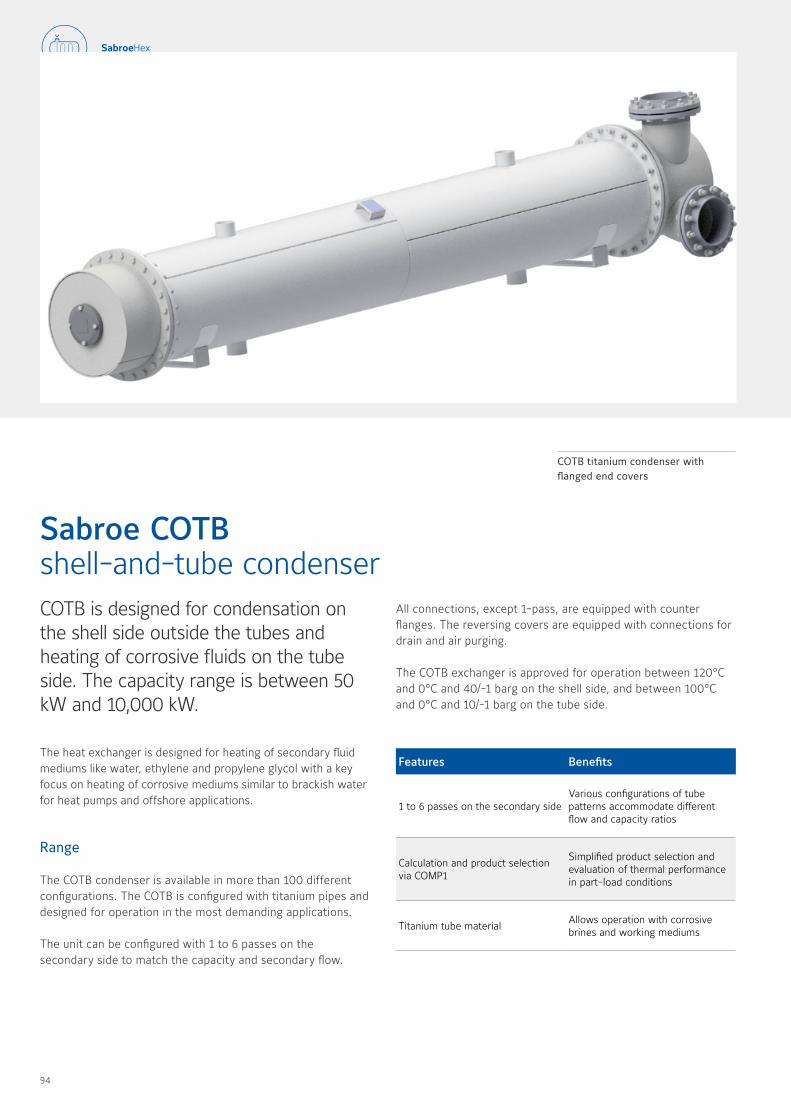
COTB is designed for condensation on the shell side outside the tubes and heating of corrosive fluids on the tube side The capacity range is between 50 kW and 10,000 kW
The heat exchanger is designed for heating of secondary fluid mediums like water, ethylene and propylene glycol with a key focus on heating of corrosive mediums similar to brackish water for heat pumps and offshore applications
Range
The COTB condenser is available in more than 100 different configurations The COTB is configured with titanium pipes and designed for operation in the most demanding applications
The unit can be configured with 1 to 6 passes on the secondary side to match the capacity and secondary flow
Sabroe COTB shell-and-tube condenser
Features Benefits
1 to 6 passes on the secondary side Various configurations of tube patterns accommodate different flow and capacity ratios
Calculation and product selection via COMP1
Simplified product selection and evaluation of thermal performance in part-load conditions
Titanium tube materialAllows operation with corrosive brines and working mediums
COTB titanium condenser with flanged end covers
All connections, except 1-pass, are equipped with counter flanges The reversing covers are equipped with connections for drain and air purging
The COTB exchanger is approved for operation between 120°C and 0°C and 40/-1 barg on the shell side, and between 100°C and 0°C and 10/-1 barg on the tube side
94 95

Type designation for COTB
All Sabroe shell-and-tube heat exchangers follow a standard key for naming and identification For the COTB product line, the name of a given configuration can be identified by the key below
Options
• Single or double connections on the refrigerant/shell side
• Single or double connections on the brine/tube side
• Brine connections from DN100 to DN350
COTB – Capacity and product range
Type
Shell diameter
Shell length Tube
side passes
Shell side inlet Shell side outlet Tube side inlet Tube side outletCapacity range*
mm m Size Count Size Count Size Count Size Count kW
21XXYY 207 1 5/2/2 5/3/3 5 1/2/4 DN50 1 DN40 1 DN80/DN125 1 DN80/DN125 1 50-100
27XXYY 260 2/2 5/3/3 5 1/2/4 DN32/DN40 1 DN 25/DN32 2 DN100-DN150 1 DN100-DN150 1 100-200
32XXYY 312 2/2 5/3/3 5 1/2/4 DN50 1 DN32/DN40 2 DN125/DN200 1 DN125/DN200 1 150-350
41XXYY 403 2/2 5,3,4/5 1/2/4 DN65 1 DN32/DN40/DN50 2 DN150/DN250 1 DN150/DN250 1 250-1000
50XXYY 493 2/2 5/3/4/5/6 1/2/4 DN65/DN80 1 D50-DN80 2 DN200-DN300 1 DN200-DN300 1 350-1500
60XXYY 594 2/2 5/3/4/5/6 1/2/4 DN80-DN100 1 DN65-DN80 2 DN250-DN400 1 DN250-DN400 1 500-2250
70XXYY 684 3/4/5/6 1/2/4 DN100-DN125 1 DN80-DN100 2 DN200-DN350 1 DN200-DN350 1 750-3000
80XXYY 793 3/4/5/6 1/2/4 DN125-DN150 1 DN100 2 DN200-DN350 1 DN200-DN350 1 750-3500
10XXYY 992 3/4/5/6 1/2/4 DN150 1 DN100-DN150 2 DN200-DN350 1 DN200-DN350 1 1000-5000
12XXYY 1190 4/5/6 1/2/4/6 DN200 1 DN150 2 DN200-DN350 1 DN200-DN350 1 1250-7500
14XXYY 1384 4/5/6 1/2/4/6 DN200 1 DN200 2 DN200-DN350 1 DN200-DN350 1 1750-10000
C O T B 32 20 02
Brine side passes
Shell length (dm) approx.
Shell diameter (cm) for vessels <100 cmShell diameter (dm) for vessels >100 cm
Smooth ø 10 mm tubes
Tubes of titanium
(Condensation on) outside of tubes
Condenser
* Calculations are based on a 5K temperature change on the
secondary side and a maximum temperature difference between
secondary outlet and refrigerant of 5K
All information is subject to change without notice
Compressors
ChillersH
eat pumps
ControlsH
eat exchangersCustom
isedA
fterMarket
94 95

The ESRB evaporator is designed for flooded evaporation of refrigerant outside the tubes and cooling of a secondary fluid on the tube side The capacity range is between 100 kW and 6500 kW
The heat exchanger is designed for cooling of secondary fluid mediums like water, ethylene, propylene glycol and other non-corrosive mediums
The integrated liquid separator reduces the overall footprint of the installation and ensures a high heat transfer coefficient while protecting the compressor from any liquid slugging
Range
The ESRB evaporator is available in more than 100 different configurations The ESRB is configured with stainless steel pipes
Sabroe ESRB shell-and-tube evaporator
Features Benefits
Integrated liquid separatorAn external liquid separator is not needed, and the overall footprint of the installation is reduced
Four different tube patterns Various configurations of tube patterns accommodate different system designs
Calculation and product selection via COMP1
Simplified product selection and evaluation of thermal performance in part-load conditions
Stainless tube materialCan withstand operation with standard brines and operate with all natural refrigerants
ESRB evaporator shown with oil collection pot
The unit can be configured with four different tube patterns depending on sensitivity in case of overcharging A-models have the lowest tube count, and D-models have the highest number of tubes per diameter
The ESRB exchanger is approved for operation between 50°C and -40°C and 29/-1 barg on the shell side, and between 50°C and -30°C and 10/0 barg on the tube side
96 97
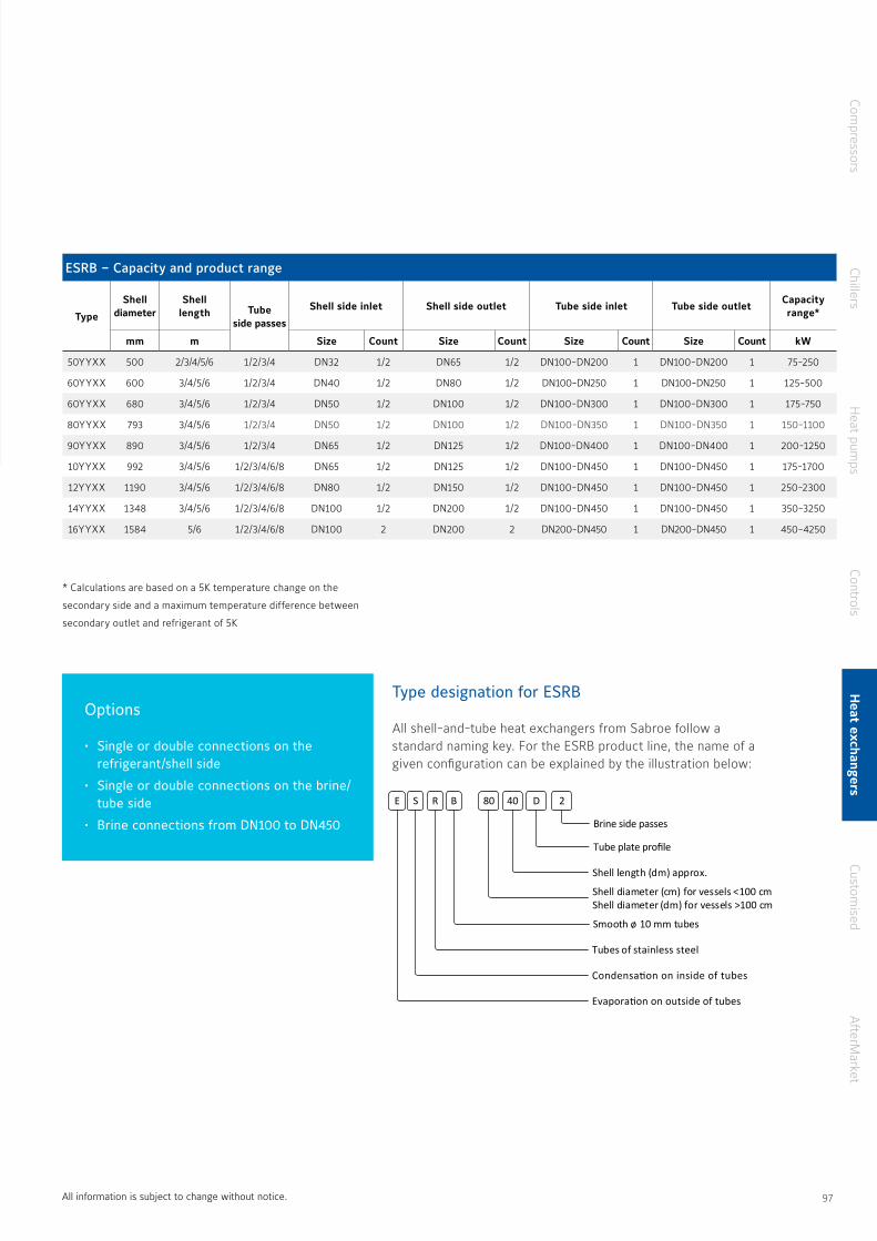
Options
• Single or double connections on the refrigerant/shell side
• Single or double connections on the brine/tube side
• Brine connections from DN100 to DN450
Type designation for ESRB
All shell-and-tube heat exchangers from Sabroe follow a standard naming key For the ESRB product line, the name of a given configuration can be explained by the illustration below:
E S R B 80 40 D 2
Tube plate profile
Brine side passes
Shell length (dm) approx.
Shell diameter (cm) for vessels <100 cmShell diameter (dm) for vessels >100 cm
Smooth ø 10 mm tubes
Tubes of stainless steel
Condensation on inside of tubes
Evaporation on outside of tubes
ESRB – Capacity and product range
Type
Shell diameter
Shell length Tube
side passes
Shell side inlet Shell side outlet Tube side inlet Tube side outletCapacity range*
mm m Size Count Size Count Size Count Size Count kW
50YYXX 500 2/3/4/5/6 1/2/3/4 DN32 1/2 DN65 1/2 DN100-DN200 1 DN100-DN200 1 75-250
60YYXX 600 3/4/5/6 1/2/3/4 DN40 1/2 DN80 1/2 DN100-DN250 1 DN100-DN250 1 125-500
60YYXX 680 3/4/5/6 1/2/3/4 DN50 1/2 DN100 1/2 DN100-DN300 1 DN100-DN300 1 175-750
80YYXX 793 3/4/5/6 1/2/3/4 DN50 1/2 DN100 1/2 DN100-DN350 1 DN100-DN350 1 150-1100
90YYXX 890 3/4/5/6 1/2/3/4 DN65 1/2 DN125 1/2 DN100-DN400 1 DN100-DN400 1 200-1250
10YYXX 992 3/4/5/6 1/2/3/4/6/8 DN65 1/2 DN125 1/2 DN100-DN450 1 DN100-DN450 1 175-1700
12YYXX 1190 3/4/5/6 1/2/3/4/6/8 DN80 1/2 DN150 1/2 DN100-DN450 1 DN100-DN450 1 250-2300
14YYXX 1348 3/4/5/6 1/2/3/4/6/8 DN100 1/2 DN200 1/2 DN100-DN450 1 DN100-DN450 1 350-3250
16YYXX 1584 5/6 1/2/3/4/6/8 DN100 2 DN200 2 DN200-DN450 1 DN200-DN450 1 450-4250
* Calculations are based on a 5K temperature change on the
secondary side and a maximum temperature difference between
secondary outlet and refrigerant of 5K
All information is subject to change without notice
Compressors
ChillersH
eat pumps
ControlsH
eat exchangersCustom
isedA
fterMarket
96 97
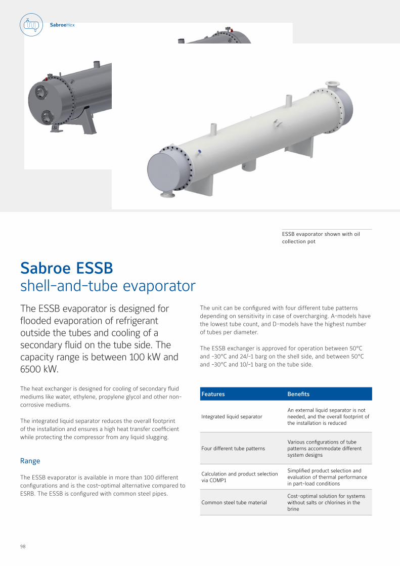
The ESSB evaporator is designed for flooded evaporation of refrigerant outside the tubes and cooling of a secondary fluid on the tube side The capacity range is between 100 kW and 6500 kW
The heat exchanger is designed for cooling of secondary fluid mediums like water, ethylene, propylene glycol and other non-corrosive mediums
The integrated liquid separator reduces the overall footprint of the installation and ensures a high heat transfer coefficient while protecting the compressor from any liquid slugging
Range
The ESSB evaporator is available in more than 100 different configurations and is the cost-optimal alternative compared to ESRB The ESSB is configured with common steel pipes
Sabroe ESSB shell-and-tube evaporator
Features Benefits
Integrated liquid separatorAn external liquid separator is not needed, and the overall footprint of the installation is reduced
Four different tube patterns Various configurations of tube patterns accommodate different system designs
Calculation and product selection via COMP1
Simplified product selection and evaluation of thermal performance in part-load conditions
Common steel tube materialCost-optimal solution for systems without salts or chlorines in the brine
ESSB evaporator shown with oil collection pot
The unit can be configured with four different tube patterns depending on sensitivity in case of overcharging A-models have the lowest tube count, and D-models have the highest number of tubes per diameter
The ESSB exchanger is approved for operation between 50°C and -30°C and 24/-1 barg on the shell side, and between 50°C and -30°C and 10/-1 barg on the tube side
98 99

Options
• Single or double connections on the refrigerant/shell side
• Single or double connections on the brine/tube side
• Brine connections from DN100 to DN450
Type designation for ESSB
All Sabroe shell-and-tube heat exchangers follow a standard key for naming and identification For the ESSB product line, the name of a given configuration can be identified by the key below
E S S B
Tube plate profile
50 20 D
Brine side passes
2
Lorem ipsumShell length (dm) approx.
Shell diameter (cm) for vessels <100 cmShell diameter (dm) for vessels >100 cm
Smooth ø 10 mm tubes
Tubes of common steel
Condensation on inside of tubes
Evaporation on outside of tubes
ESSB – Capacity and product range
Type
Shell diameter
Shell length Tube
side passes
Shell side inlet Shell side outlet Tube side inlet Tube side outletCapacity range*
mm m Size Count Size Count Size Count Size Count kW
50YYXX 500 2/3/4/5/6 1/2/3/4 DN32 1/2 DN65 1/2 DN100-DN200 1 DN100-DN200 1 75-250
60YYXX 600 3/4/5/6 1/2/3/4 DN40 1/2 DN80 1/2 DN100-DN250 1 DN100-DN250 1 125-500
60YYXX 680 3/4/5/6 1/2/3/4 DN50 1/2 DN100 1/2 DN100-DN300 1 DN100-DN300 1 175-750
80YYXX 793 3/4/5/6 1/2/3/4 DN50 1/2 DN100 1/2 DN100-DN350 1 DN100-DN350 1 150-1100
90YYXX 890 3/4/5/6 1/2/3/4 DN65 1/2 DN125 1/2 DN100-DN400 1 DN100-DN400 1 200-1250
10YYXX 992 3/4/5/6 1/2/3/4/6/8 DN65 1/2 DN125 1/2 DN100-DN450 1 DN100-DN450 1 175-1700
12YYXX 1190 3/4/5/6 1/2/3/4/6/8 DN80 1/2 DN150 1/2 DN100-DN450 1 DN100-DN450 1 250-2300
14YYXX 1348 3/4/5/6 1/2/3/4/6/8 DN100 1/2 DN200 1/2 DN100-DN450 1 DN100-DN450 1 350-3250
16YYXX 1584 5/6 1/2/3/4/6/8 DN100 2 DN200 2 DN200-DN450 1 DN200-DN450 1 450-4250
* Calculations are based on a 5K temperature change on the
secondary side and a maximum temperature difference between
secondary outlet and refrigerant of 5K
All information is subject to change without notice
Compressors
ChillersH
eat pumps
ControlsH
eat exchangersCustom
isedA
fterMarket
98 99
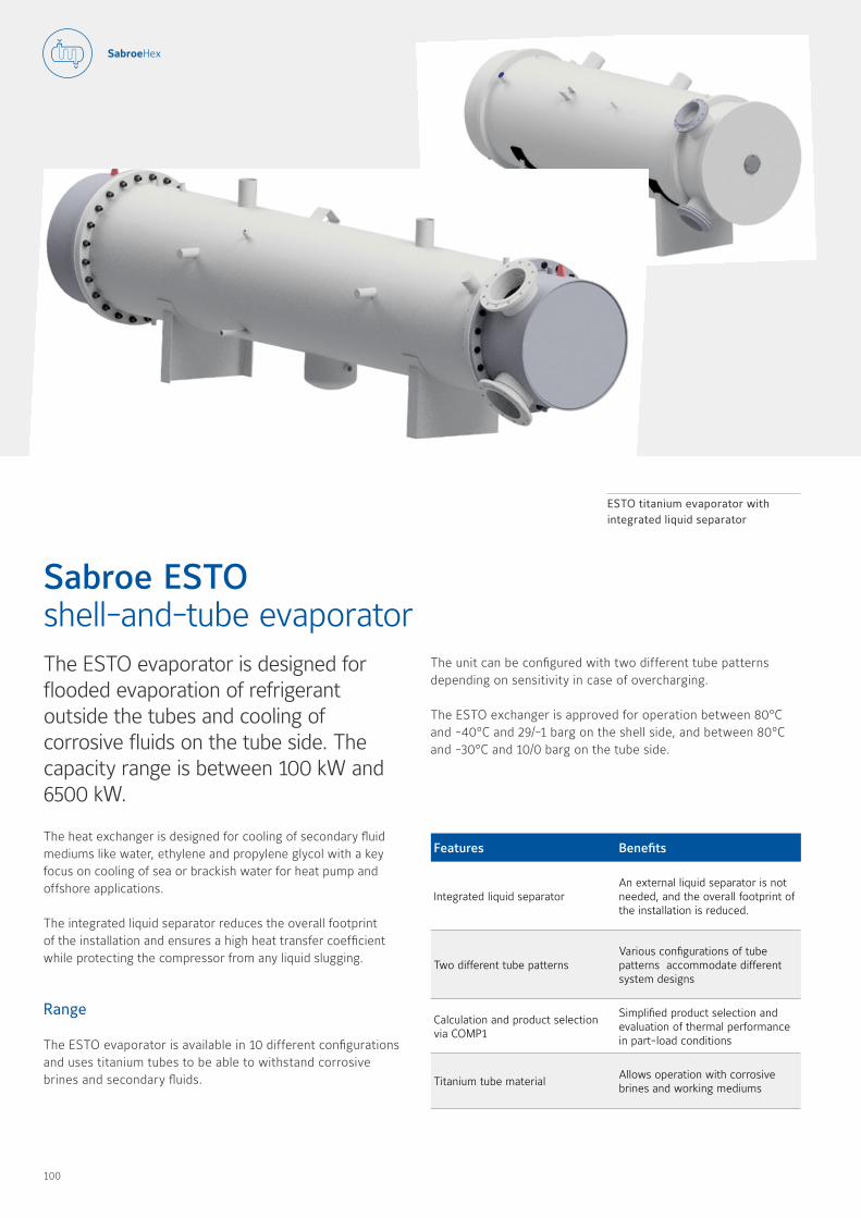
The ESTO evaporator is designed for flooded evaporation of refrigerant outside the tubes and cooling of corrosive fluids on the tube side The capacity range is between 100 kW and 6500 kW
The heat exchanger is designed for cooling of secondary fluid mediums like water, ethylene and propylene glycol with a key focus on cooling of sea or brackish water for heat pump and offshore applications
The integrated liquid separator reduces the overall footprint of the installation and ensures a high heat transfer coefficient while protecting the compressor from any liquid slugging
Range
The ESTO evaporator is available in 10 different configurations and uses titanium tubes to be able to withstand corrosive brines and secondary fluids
Sabroe ESTO shell-and-tube evaporator
Features Benefits
Integrated liquid separatorAn external liquid separator is not needed, and the overall footprint of the installation is reduced
Two different tube patterns Various configurations of tube patterns accommodate different system designs
Calculation and product selection via COMP1
Simplified product selection and evaluation of thermal performance in part-load conditions
Titanium tube materialAllows operation with corrosive brines and working mediums
ESTO titanium evaporator with integrated liquid separator
The unit can be configured with two different tube patterns depending on sensitivity in case of overcharging
The ESTO exchanger is approved for operation between 80°C and -40°C and 29/-1 barg on the shell side, and between 80°C and -30°C and 10/0 barg on the tube side
100 101
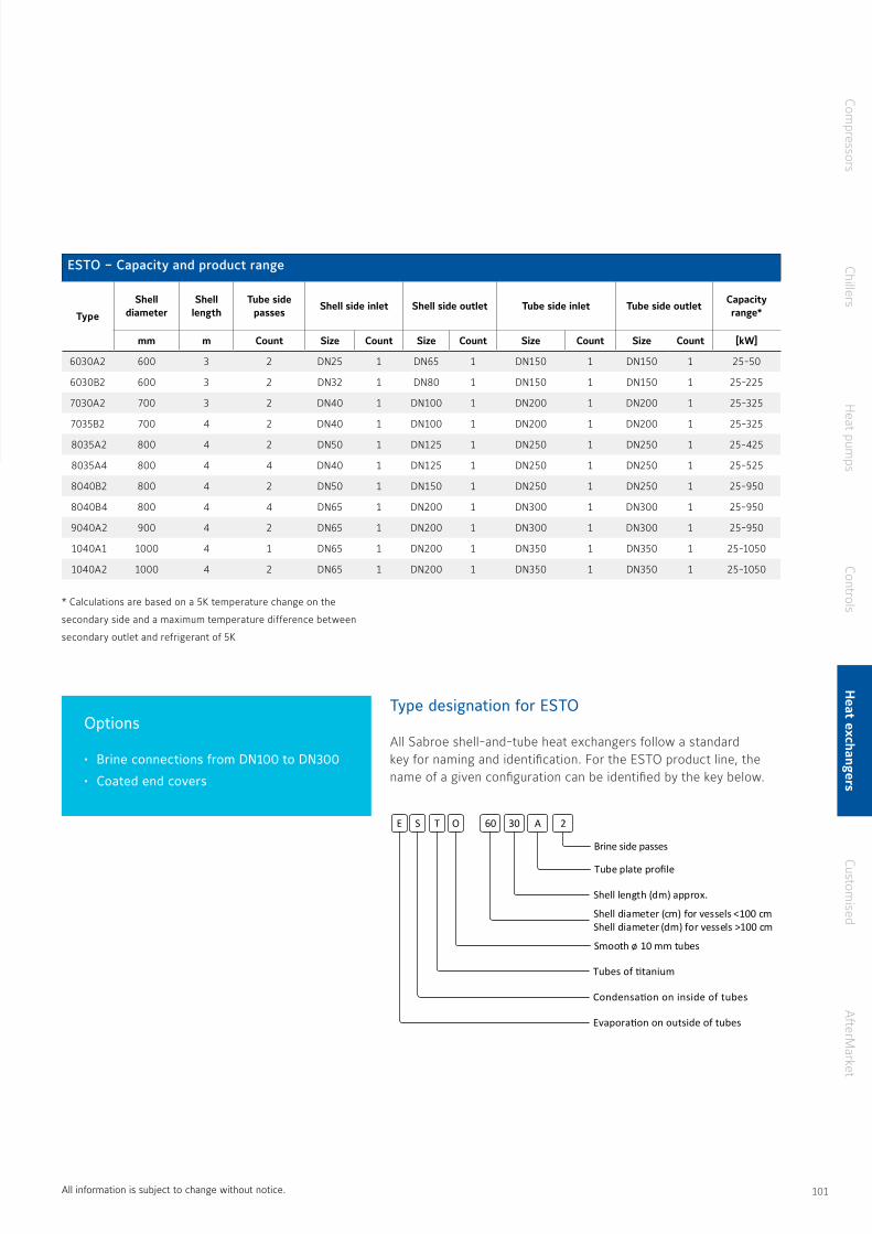
Options
• Brine connections from DN100 to DN300
• Coated end covers
ESTO – Capacity and product range
Type
Shell diameter
Shell length
Tube side passes
Shell side inlet Shell side outlet Tube side inlet Tube side outletCapacity range*
mm m Count Size Count Size Count Size Count Size Count [kW]
6030A2 600 3 2 DN25 1 DN65 1 DN150 1 DN150 1 25-50
6030B2 600 3 2 DN32 1 DN80 1 DN150 1 DN150 1 25-225
7030A2 700 3 2 DN40 1 DN100 1 DN200 1 DN200 1 25-325
7035B2 700 4 2 DN40 1 DN100 1 DN200 1 DN200 1 25-325
8035A2 800 4 2 DN50 1 DN125 1 DN250 1 DN250 1 25-425
8035A4 800 4 4 DN40 1 DN125 1 DN250 1 DN250 1 25-525
8040B2 800 4 2 DN50 1 DN150 1 DN250 1 DN250 1 25-950
8040B4 800 4 4 DN65 1 DN200 1 DN300 1 DN300 1 25-950
9040A2 900 4 2 DN65 1 DN200 1 DN300 1 DN300 1 25-950
1040A1 1000 4 1 DN65 1 DN200 1 DN350 1 DN350 1 25-1050
1040A2 1000 4 2 DN65 1 DN200 1 DN350 1 DN350 1 25-1050
E S T O 60 30 A 2
Tube plate profile
Brine side passes
Shell length (dm) approx.
Shell diameter (cm) for vessels <100 cmShell diameter (dm) for vessels >100 cm
Smooth ø 10 mm tubes
Tubes of titanium
Condensation on inside of tubes
Evaporation on outside of tubes
Type designation for ESTO
All Sabroe shell-and-tube heat exchangers follow a standard key for naming and identification For the ESTO product line, the name of a given configuration can be identified by the key below
* Calculations are based on a 5K temperature change on the
secondary side and a maximum temperature difference between
secondary outlet and refrigerant of 5K
All information is subject to change without notice
Compressors
ChillersH
eat pumps
ControlsH
eat exchangersCustom
isedA
fterMarket
100 101
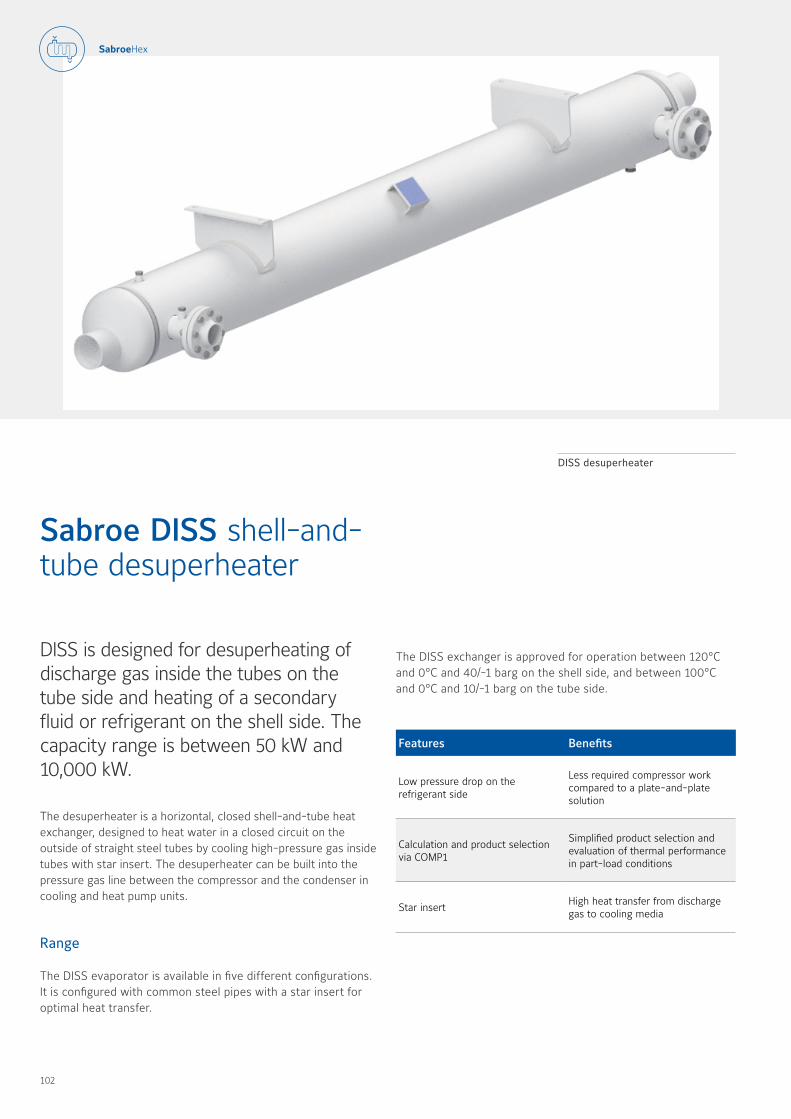
DISS is designed for desuperheating of discharge gas inside the tubes on the tube side and heating of a secondary fluid or refrigerant on the shell side The capacity range is between 50 kW and 10,000 kW
The desuperheater is a horizontal, closed shell-and-tube heat exchanger, designed to heat water in a closed circuit on the outside of straight steel tubes by cooling high-pressure gas inside tubes with star insert The desuperheater can be built into the pressure gas line between the compressor and the condenser in cooling and heat pump units
Range
The DISS evaporator is available in five different configurations It is configured with common steel pipes with a star insert for optimal heat transfer
Sabroe DISS shell-and- tube desuperheater
Features Benefits
Low pressure drop on the refrigerant side
Less required compressor work compared to a plate-and-plate solution
Calculation and product selection via COMP1
Simplified product selection and evaluation of thermal performance in part-load conditions
Star insert High heat transfer from discharge gas to cooling media
DISS desuperheater
The DISS exchanger is approved for operation between 120°C and 0°C and 40/-1 barg on the shell side, and between 100°C and 0°C and 10/-1 barg on the tube side
102 103
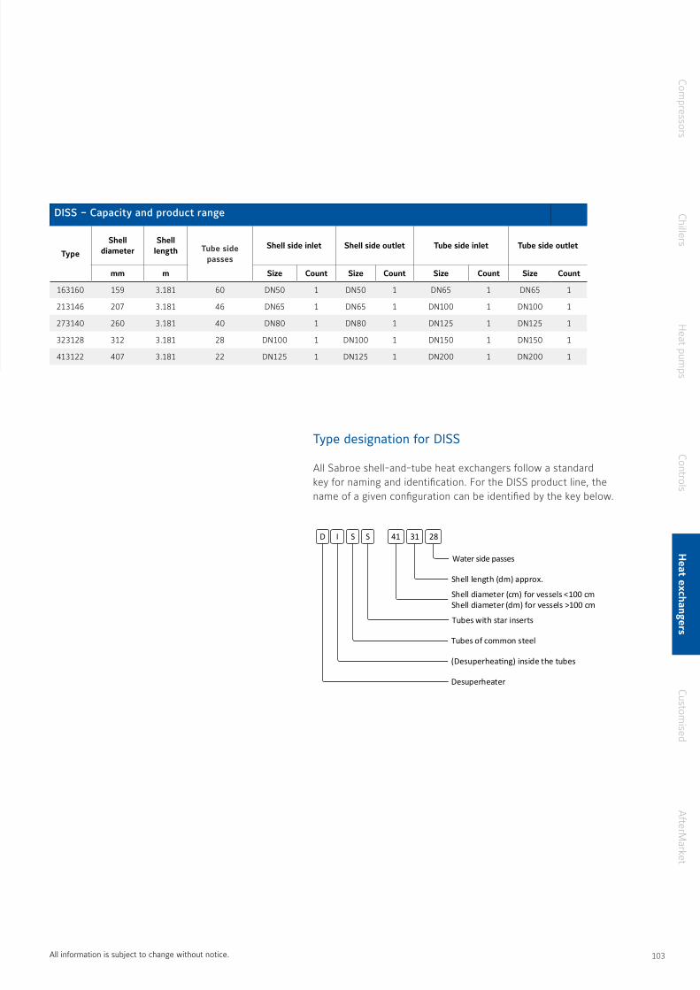
DISS – Capacity and product range
Type
Shell diameter
Shell length Tube side
passes
Shell side inlet Shell side outlet Tube side inlet Tube side outlet
mm m Size Count Size Count Size Count Size Count
163160 159 3.181 60 DN50 1 DN50 1 DN65 1 DN65 1
213146 207 3.181 46 DN65 1 DN65 1 DN100 1 DN100 1
273140 260 3.181 40 DN80 1 DN80 1 DN125 1 DN125 1
323128 312 3.181 28 DN100 1 DN100 1 DN150 1 DN150 1
413122 407 3.181 22 DN125 1 DN125 1 DN200 1 DN200 1
Type designation for DISS
All Sabroe shell-and-tube heat exchangers follow a standard key for naming and identification For the DISS product line, the name of a given configuration can be identified by the key below
D I S S
Water side passes
41 31 28
Shell length (dm) approx.
Shell diameter (cm) for vessels <100 cmShell diameter (dm) for vessels >100 cm
Tubes with star inserts
Tubes of common steel
(Desuperheating) inside the tubes
Desuperheater
All information is subject to change without notice
Compressors
ChillersH
eat pumps
ControlsH
eat exchangersCustom
isedA
fterMarket
102 103
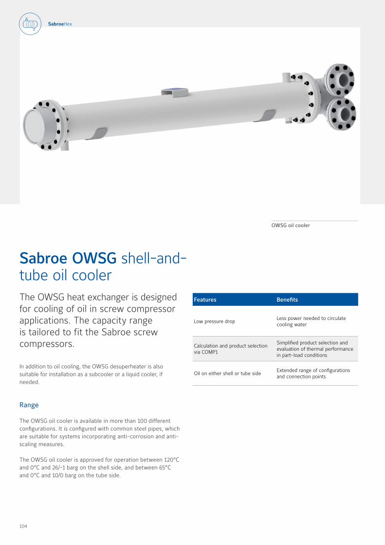
The OWSG heat exchanger is designed for cooling of oil in screw compressor applications The capacity range is tailored to fit the Sabroe screw compressors
In addition to oil cooling, the OWSG desuperheater is also suitable for installation as a subcooler or a liquid cooler, if needed
Range
The OWSG oil cooler is available in more than 100 different configurations It is configured with common steel pipes, which are suitable for systems incorporating anti-corrosion and anti-scaling measures
The OWSG oil cooler is approved for operation between 120°C and 0°C and 26/-1 barg on the shell side, and between 65°C and 0°C and 10/0 barg on the tube side
Sabroe OWSG shell-and- tube oil cooler
Features Benefits
Low pressure drop Less power needed to circulate cooling water
Calculation and product selection via COMP1
Simplified product selection and evaluation of thermal performance in part-load conditions
Oil on either shell or tube side Extended range of configurations and connection points
OWSG oil cooler
104 105
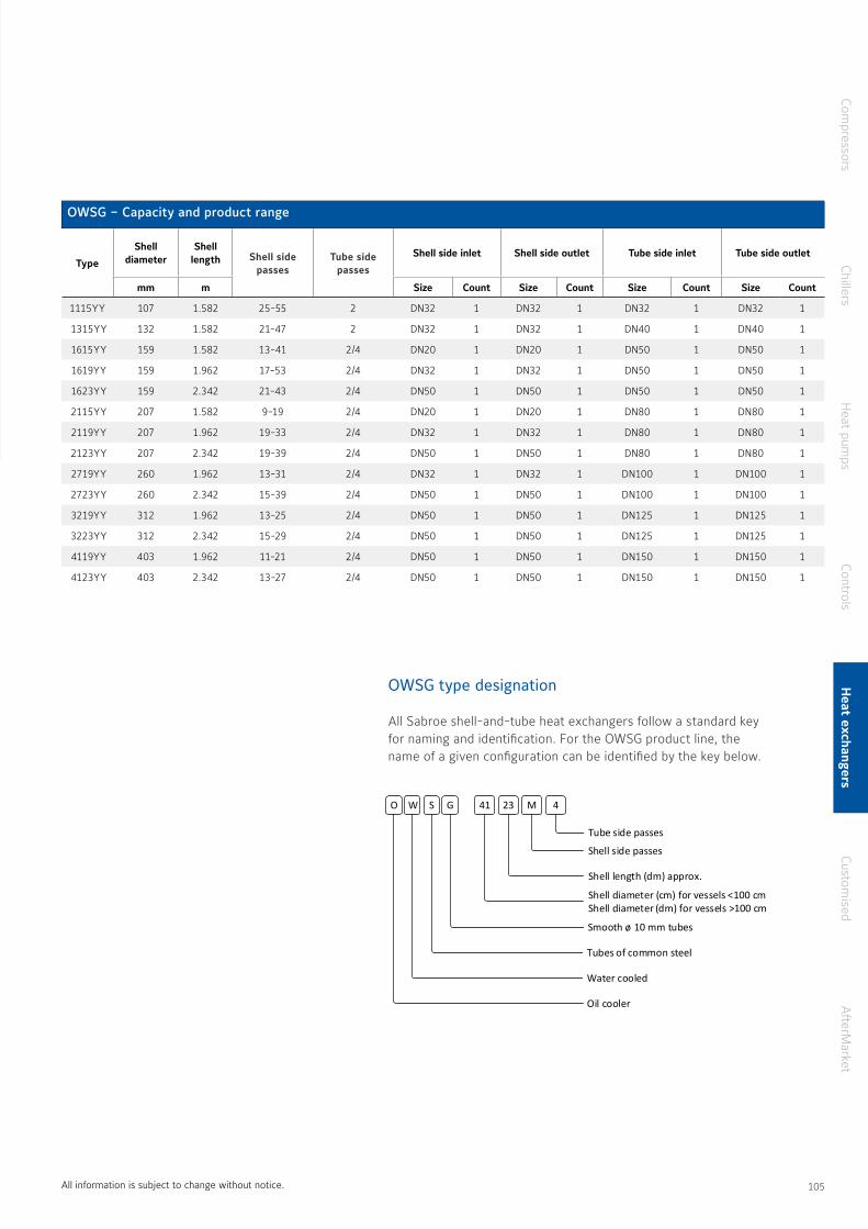
OWSG – Capacity and product range
Type
Shell diameter
Shell length Shell side
passesTube side
passes
Shell side inlet Shell side outlet Tube side inlet Tube side outlet
mm m Size Count Size Count Size Count Size Count
1115YY 107 1.582 25-55 2 DN32 1 DN32 1 DN32 1 DN32 1
1315YY 132 1.582 21-47 2 DN32 1 DN32 1 DN40 1 DN40 1
1615YY 159 1.582 13-41 2/4 DN20 1 DN20 1 DN50 1 DN50 1
1619YY 159 1.962 17-53 2/4 DN32 1 DN32 1 DN50 1 DN50 1
1623YY 159 2.342 21-43 2/4 DN50 1 DN50 1 DN50 1 DN50 1
2115YY 207 1.582 9-19 2/4 DN20 1 DN20 1 DN80 1 DN80 1
2119YY 207 1.962 19-33 2/4 DN32 1 DN32 1 DN80 1 DN80 1
2123YY 207 2.342 19-39 2/4 DN50 1 DN50 1 DN80 1 DN80 1
2719YY 260 1.962 13-31 2/4 DN32 1 DN32 1 DN100 1 DN100 1
2723YY 260 2.342 15-39 2/4 DN50 1 DN50 1 DN100 1 DN100 1
3219YY 312 1.962 13-25 2/4 DN50 1 DN50 1 DN125 1 DN125 1
3223YY 312 2.342 15-29 2/4 DN50 1 DN50 1 DN125 1 DN125 1
4119YY 403 1.962 11-21 2/4 DN50 1 DN50 1 DN150 1 DN150 1
4123YY 403 2.342 13-27 2/4 DN50 1 DN50 1 DN150 1 DN150 1
OWSG type designation
All Sabroe shell-and-tube heat exchangers follow a standard key for naming and identification For the OWSG product line, the name of a given configuration can be identified by the key below
O W S G
Shell side passes
41 23 M
Smooth ø 10 mm tubes
Tubes of common steel
Water cooled
Oil cooler
4
Tube side passes
Shell length (dm) approx.
Shell diameter (cm) for vessels <100 cmShell diameter (dm) for vessels >100 cm
All information is subject to change without notice
Compressors
ChillersH
eat pumps
ControlsH
eat exchangersCustom
isedA
fterMarket
104 105

EOSE is a closed flash economiser with an integrated separator, designed for operation with ammonia The capacity range is tailored to fit the Sabroe screw compressor range
The economiser is a horizontal, closed shell-and-spiral heat exchanger, which subcools the liquid from the condenser before expansion, and thus improves the overall system efficiency
Range
The EOSE closed flash economiser is available in five different configurations The five standard configurations are designed to match the Sabroe screw compressor product range
The EOSE unit is approved for operation between 50°C and -40°C and 26/-1 barg on the shell side, and between 50°C and -40°C and 26/-1 barg in the cooling spiral
Sabroe EOSE spiral flash economiser
Features Benefits
Subcooling of condenser liquid Increased cooling capacity with the same amount of compressor work
Calculation and product selection via COMP1
Simplified product selection and evaluation of thermal performance in part-load conditions
Integrated liquid separator As an external liquid separator is not needed, the overall footprint of the installation is reduced
EOSE economiser shown with feet for easy on site installation
EOSE type designation
All Sabroe shell-and-tube heat exchangers follow a standard key for naming and identification For the EOSE product line, the name of a given configuration can be identified by the key below
E O S E
Passes in the coil
50 20 02
Coil
Tubes of common steel
(Evaporation on) outside of tubes
Evaporator
Shell length (dm) approx.
Shell diameter (cm) for vessels <100 cmShell diameter (dm) for vessels >100 cm
106 107
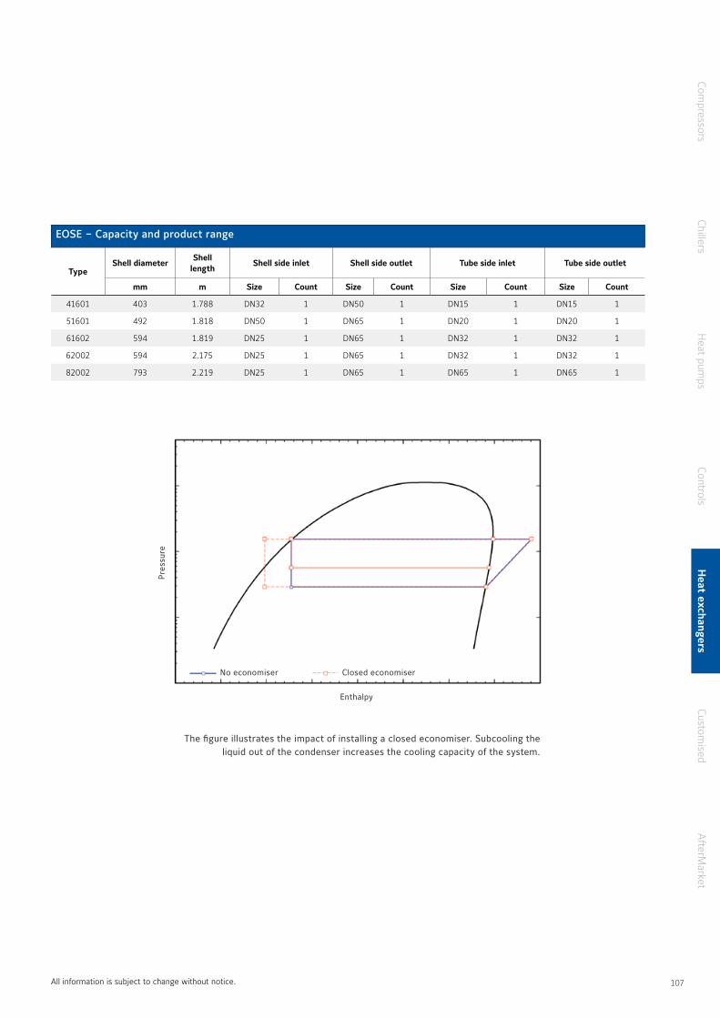
EOSE – Capacity and product range
TypeShell diameter
Shell length
Shell side inlet Shell side outlet Tube side inlet Tube side outlet
mm m Size Count Size Count Size Count Size Count
41601 403 1.788 DN32 1 DN50 1 DN15 1 DN15 1
51601 492 1.818 DN50 1 DN65 1 DN20 1 DN20 1
61602 594 1.819 DN25 1 DN65 1 DN32 1 DN32 1
62002 594 2.175 DN25 1 DN65 1 DN32 1 DN32 1
82002 793 2.219 DN25 1 DN65 1 DN65 1 DN65 1
E O S E
Passes in the coil
50 20 02
Coil
Tubes of common steel
(Evaporation on) outside of tubes
Evaporator
Shell length (dm) approx.
Shell diameter (cm) for vessels <100 cmShell diameter (dm) for vessels >100 cm
The figure illustrates the impact of installing a closed economiser. Subcooling the liquid out of the condenser increases the cooling capacity of the system.
Pres
sure
Enthalpy
No economiser Closed economiser
All information is subject to change without notice
Compressors
ChillersH
eat pumps
ControlsH
eat exchangersCustom
isedA
fterMarket
106 107
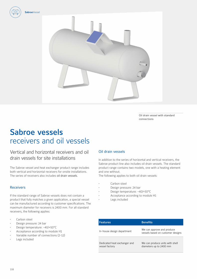
Vertical and horizontal receivers and oil drain vessels for site installations
The Sabroe vessel and heat exchanger product range includes both vertical and horizontal receivers for onsite installations The series of receivers also includes oil drain vessels
Receivers
If the standard range of Sabroe vessels does not contain a product that fully matches a given application, a special vessel can be manufactured according to customer specifications The maximum diameter for receivers is 2400 mm For all standard receivers, the following applies:
• Carbon steel• Design pressure: 24 bar• Design temperature: -40/+50°C • Acceptance according to module H1• Variable number of connections (2-12)• Legs included
Sabroe vessels receivers and oil vessels
Oil drain vessel with standard connections
Oil drain vessels
In addition to the series of horizontal and vertical receivers, the Sabroe product line also includes oil drain vessels The standard product range contains two models, one with a heating element and one without The following applies to both oil drain vessels:
• Carbon steel• Design pressure: 24 bar• Design temperature: -40/+50°C • Acceptance according to module H1• Legs included
Features Benefits
In-house design departmentWe can approve and produce vessels based on customer designs
Dedicated heat exchanger and vessel factory
We can produce units with shell diameters up to 2400 mm
108 109

Type designation
Like all Sabroe vessels and heat exhangers, the receivers follow a standard key for naming and identification Oil drain vessels can be identified by the keys below
O B 06 10
Vessel length (dm) approx.
Shell diameter (cm) for vessels <100 cmShell diameter (dm) for vessels >100 cm
Vessel
Oil
R H 06 10
Vessel length (dm) approx.
Shell diameter (cm) for vessels <100 cmShell diameter (dm) for vessels >100 cm
H: horizontal, V: vertical
Receiver
All information is subject to change without notice
Compressors
ChillersH
eat pumps
ControlsH
eat exchangersCustom
isedA
fterMarket
108 109
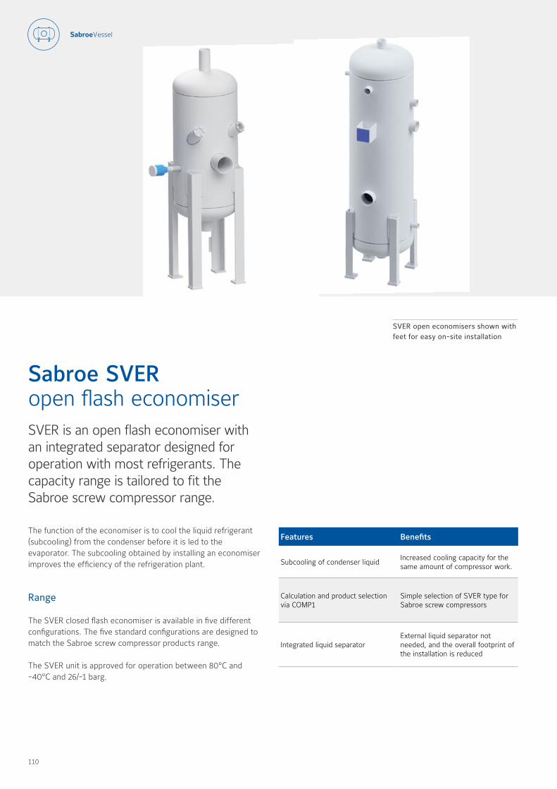
SVER is an open flash economiser with an integrated separator designed for operation with most refrigerants The capacity range is tailored to fit the Sabroe screw compressor range
The function of the economiser is to cool the liquid refrigerant (subcooling) from the condenser before it is led to the evaporator The subcooling obtained by installing an economiser improves the efficiency of the refrigeration plant
Range
The SVER closed flash economiser is available in five different configurations The five standard configurations are designed to match the Sabroe screw compressor products range
The SVER unit is approved for operation between 80°C and -40°C and 26/-1 barg
Sabroe SVER open flash economiser
SVER open economisers shown with feet for easy on-site installation
Features Benefits
Subcooling of condenser liquid Increased cooling capacity for the same amount of compressor work
Calculation and product selection via COMP1
Simple selection of SVER type for Sabroe screw compressors
Integrated liquid separator External liquid separator not needed, and the overall footprint of the installation is reduced
110 111

SVER type designation
All Sabroe vessels follow a standard key for naming and identification For the SVER product line, the name of a given configuration can be identified by the key below
S V E R 06 10
Vessel length (dm) approx.
Shell diameter (cm) for vessels <100 cmShell diameter (dm) for vessels >100 cm
All refrigerants
Single part
Vertical
Separator
The figure illustrates the impact of installing an open economiser. By separating the liquid and gas in the open flash economiser, the condenser liquid is subcooled and the
cooling capacity of the system is increased.
SVER - Capacity and product range
TypeShell diameter Unit height Flash inlet Liquid outlet Eco port
mm mm Size [mm] Count Size [mm] Count Size [mm] Count
0307 309 1455 73.7 1 54.5 1 54.5 1
0408 403 1175 107.1 1 70.3 1 70.3 1
0509 496 1580 120.6 1 82.5 1 82.5 1
0610 597.6 2095 146 1 107.1 1 107.1 1
0814 800 2610 270 1 130 1 130 1
All information is subject to change without notice
Pres
sure
Enthalpy
No economiser Open economiser
Compressors
ChillersH
eat pumps
ControlsH
eat exchangersCustom
isedA
fterMarket
110 111


Sabroe customised solutions
113
114 115
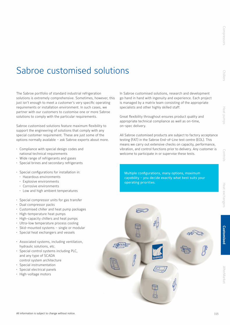
Sabroe customised solutions
The Sabroe portfolio of standard industrial refrigeration solutions is extremely comprehensive Sometimes, however, this just isn’t enough to meet a customer’s very specific operating requirements or installation environment In such cases, we partner with our customers to customise one or more Sabroe solutions to comply with the particular requirements
Sabroe customised solutions feature maximum flexibility to support the engineering of solutions that comply with any special customer requirement These are just some of the options normally available – ask Sabroe experts about more
• Compliance with special design codes and national technical requirements
• Wide range of refrigerants and gases• Special brines and secondary refrigerants
• Special configurations for installation in:• Hazardous environments• Explosive environments• Corrosive environments• Low and high ambient temperatures
• Special compressor units for gas transfer• Dual compressor packs• Customised chiller and heat pump packages• High-temperature heat pumps• High-capacity chillers and heat pumps• Ultra-low temperature process cooling• Skid-mounted systems – single or modular• Special heat exchangers and vessels
• Associated systems, including ventilation, hydraulic solutions, etc
• Special control systems including PLC, and any type of SCADA control system architecture
• Special instrumentation• Special electrical panels• High-voltage motors
In Sabroe customised solutions, research and development go hand in hand with ingenuity and experience Each project is managed by a matrix team consisting of the appropriate specialists and other highly skilled staff
Great flexibility throughout ensures product quality and appropriate technical compliance as well as on-time, on-spec delivery
All Sabroe customised products are subject to factory acceptance testing (FAT) in the Sabroe End-of-Line test centre (EOL) This means we carry out extensive checks on capacity, performance, vibration, and control functions prior to delivery Any customer is welcome to participate in or supervise these tests
All information is subject to change without notice
Compressors
ChillersH
eat pumps
ControlsH
eat exchangersCustom
isedA
fterMarket
Multiple configurations, many options, maximum capability - you decide exactly what best suits your operating priorities.
114 115


AfterMarket solutions
117

118 119
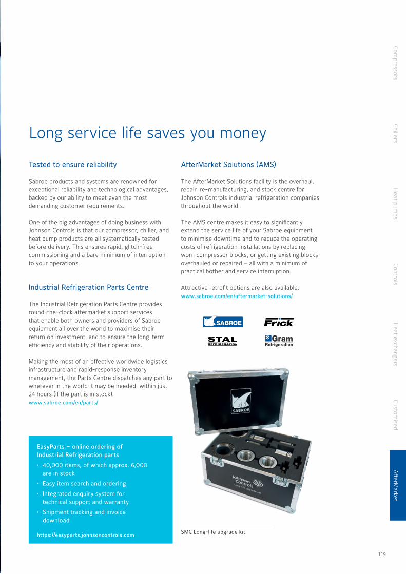
Long service life saves you money
Tested to ensure reliability
Sabroe products and systems are renowned for exceptional reliability and technological advantages, backed by our ability to meet even the most demanding customer requirements
One of the big advantages of doing business with Johnson Controls is that our compressor, chiller, and heat pump products are all systematically tested before delivery This ensures rapid, glitch-free commissioning and a bare minimum of interruption to your operations
Industrial Refrigeration Parts Centre
The Industrial Refrigeration Parts Centre provides round-the-clock aftermarket support services that enable both owners and providers of Sabroe equipment all over the world to maximise their return on investment, and to ensure the long-term efficiency and stability of their operations
Making the most of an effective worldwide logistics infrastructure and rapid-response inventory management, the Parts Centre dispatches any part to wherever in the world it may be needed, within just 24 hours (if the part is in stock) www.sabroe.com/en/parts/
AfterMarket Solutions (AMS)
The AfterMarket Solutions facility is the overhaul, repair, re-manufacturing, and stock centre for Johnson Controls industrial refrigeration companies throughout the world
The AMS centre makes it easy to significantly extend the service life of your Sabroe equipment to minimise downtime and to reduce the operating costs of refrigeration installations by replacing worn compressor blocks, or getting existing blocks overhauled or repaired – all with a minimum of practical bother and service interruption
Attractive retrofit options are also available www.sabroe.com/en/aftermarket-solutions/
EasyParts – online ordering of Industrial Refrigeration parts
• 40,000 items, of which approx. 6,000 are in stock
• Easy item search and ordering
• Integrated enquiry system for technical support and warranty
• Shipment tracking and invoice download
https://easyparts.johnsoncontrols.com SMC Long-life upgrade kit
Compressors
ChillersH
eat pumps
ControlsH
eat exchangersCustom
isedA
fterMarket
118 119
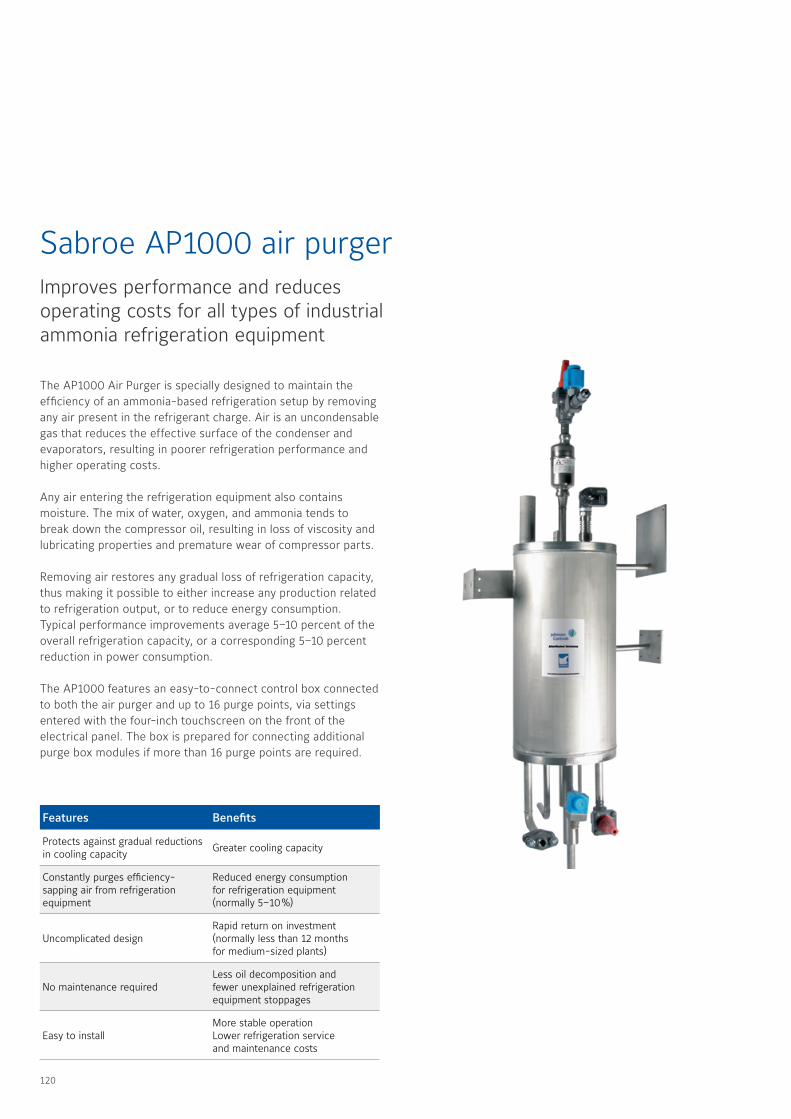
The AP1000 Air Purger is specially designed to maintain the efficiency of an ammonia-based refrigeration setup by removing any air present in the refrigerant charge Air is an uncondensable gas that reduces the effective surface of the condenser and evaporators, resulting in poorer refrigeration performance and higher operating costs
Any air entering the refrigeration equipment also contains moisture The mix of water, oxygen, and ammonia tends to break down the compressor oil, resulting in loss of viscosity and lubricating properties and premature wear of compressor parts
Removing air restores any gradual loss of refrigeration capacity, thus making it possible to either increase any production related to refrigeration output, or to reduce energy consumption Typical performance improvements average 5–10 percent of the overall refrigeration capacity, or a corresponding 5–10 percent reduction in power consumption
The AP1000 features an easy-to-connect control box connected to both the air purger and up to 16 purge points, via settings entered with the four-inch touchscreen on the front of the electrical panel The box is prepared for connecting additional purge box modules if more than 16 purge points are required
Sabroe AP1000 air purgerImproves performance and reduces operating costs for all types of industrial ammonia refrigeration equipment
Features Benefits
Protects against gradual reductions in cooling capacity
Greater cooling capacity
Constantly purges efficiency-sapping air from refrigeration equipment
Reduced energy consumption for refrigeration equipment (normally 5–10 %)
Uncomplicated designRapid return on investment (normally less than 12 months for medium-sized plants)
No maintenance requiredLess oil decomposition and fewer unexplained refrigeration equipment stoppages
Easy to installMore stable operation Lower refrigeration service and maintenance costs
120 121
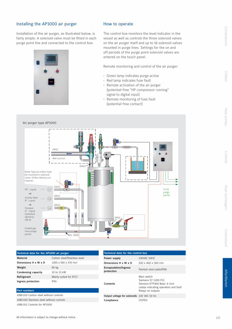
Installing the AP1000 air purger
Installation of the air purger, as illustrated below, is fairly simple A solenoid valve must be fitted in each purge point line and connected to the control box
Technical data for the AP1000 air purger
Material Carbon steel/Stainless steel
Dimensions H x W x D 1300 x 550 x 370 mm
Weight 80 kg
Condensing capacity 10 to 13 kW
Refrigerant Mainly suited for R717
Ingress protection IP65
Part numbers
4385 010 Carbon steel without controls
4385 020 Stainless steel without controls
4385 031 Controls for AP1000
Technical data for the control box
Power supply 230VAC 50HZ
Dimensions H x W x D 500 x 400 x 300 mm
Encapsulation/Ingress protection
Painted-steel plate/IP66
Contents
Main switchSiemens S7-1200 PLCSiemens KTP400 Basic 4-inchLamps indicating operation and faultRelays on outputs
Output voltage for solenoids 230 VAC 50 Hz
Compliance CE/PED
All information is subject to change without notice
How to operate
The control box monitors the level indicator in the vessel as well as controls the three solenoid valves on the air purger itself and up to 16 solenoid valves mounted in purge lines Settings for the on and off periods of the purge point solenoid valves are entered on the touch panel
Remote monitoring and control of the air purger:
• Green lamp indicates purge active• Red lamp indicates fuse fault• Remote activation of the air purger
(potential-free “HP compressor running” signal to digital input)
• Remote monitoring of fuse fault (potential-free contact)
Air purger type AP1000
HP . Liquid
Note! Special orifice must be mounted in solenoid valve. Orifice delivery on request.
Min. DN15
Wet suction
DN32
DN32
DN15
DN15OR
OR
Gravity feed lP . Liquid
Pumped lP . Liquid (standard delivery) DN 25
Fouled gas from purge points
1.C
1 B
1 A
To 16 purge points
DN15
DN15
Compressors
ChillersH
eat pumps
ControlsH
eat exchangersCustom
isedA
fterMarket
120 121
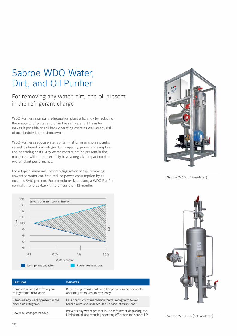
WDO Purifiers maintain refrigeration plant efficiency by reducing the amounts of water and oil in the refrigerant This in turn makes it possible to roll back operating costs as well as any risk of unscheduled plant shutdowns
WDO Purifiers reduce water contamination in ammonia plants, as well as benefiting refrigeration capacity, power consumption and operating costs Any water contamination present in the refrigerant will almost certainly have a negative impact on the overall plant performance
For a typical ammonia-based refrigeration setup, removing unwanted water can help reduce power consumption by as much as 5–10 percent For a medium-sized plant, a WDO Purifier normally has a payback time of less than 12 months
Sabroe WDO Water, Dirt, and Oil PurifierFor removing any water, dirt, and oil present in the refrigerant charge
Features Benefits
Removes oil and dirt from your refrigeration installation
Reduces operating costs and keeps system components operating at maximum efficiency
Removes any water present in the ammonia refrigerant
Less corrosion of mechanical parts, along with fewer breakdowns and unscheduled service interruptions
Fewer oil changes neededPrevents any water present in the refrigerant degrading the lubricating oil and reducing operating efficiency and service life
Power consumptionRefrigerant capacity
Inde
x
Loss
0% 0.5% 1% 1.5%
104
103
102
101
100
99
98
97
96
Water content
Effects of water contamination
Sabroe WDO-HE (insulated)
Sabroe WDO-HG (not insulated)
122 123
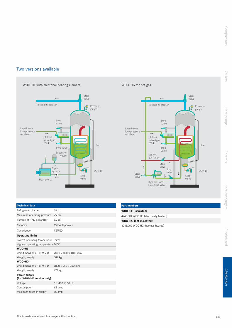
Two versions available
Technical data
Refrigerant charge 35 kg
Maximum operating pressure 25 bar
Surface of R717 separator 1 2 m²
Capacity 15 kW (approx )
Compliance CE/PED
Operating limits
Lowest operating temperature -50 °C
Highest operating temperature 50 °C
WDO-HE
Unit dimensions H x W x D 2000 x 800 x 1100 mm
Weight, empty 389 kg
WDO-HG
Unit dimensions H x W x D 1800 x 750 x 700 mm
Weight, empty 221 kg
Power supply (for WDO-HE version only)
Voltage 3 x 400 V, 50 Hz
Consumption 6 5 amp
Maximum fuses in supply 16 amp
All information is subject to change without notice
WDO-HE with electrical heating element WDO-HG for hot gas
To liquid separator
Liquid from low-pressure receiver
Glycol system
Heat source
Expansion vessel
Pressure gauge
Ice
QDV 15
Stop valve
Stop valve
Stop valve
Stop valve
LP float valve type SV 4
Stop valve
Stop valve
Stop valve
High pressure drain float valve
Hot gas line - inlet
To liquid separator
Liquid from low-pressure receiver
Pressure gauge
Ice
QDV 15
Stop valve
Stop valve
Stop valve
Stop valve
LP float valve type SV 4
Part numbers
WDO-HE (insulated)
4245 001 WDO HE (electrically heated)
WDO-HG (not insulated)
4245 002 WDO HG (hot-gas heated)
Compressors
ChillersH
eat pumps
ControlsH
eat exchangersCustom
isedA
fterMarket
122 123

The very powerful AP1200 + WDO1200 is a combined air and water purging system that can handle all sizes of industrial refrigeration systems that use ammonia (R717) as refrigerant and ensure no air, water and other impurities are left in the system
The AP1200 + WDO1200 purging system uses excess thermal energy from the air purger to remove any water, dirt or oil (WDO) that might be present in an ammonia refrigerant charge
This enables you to tackle multiple refrigerant contamination problems at once at relatively low cost
By installing an AP1200 + WDO1200 purging system, you reap the full benefits of clean ammonia with consistent specifications, for use at the heart of your refrigeration system
This whole purging system is easy and cheap to install, operate,and service
It is also ideal as a low-cost, energy-effective way to boost operating efficiency as well as to avoid and prevent unpleasant surprises, service interruptions, and possible breakdowns in your key processes
Sabroe AP1200 + WDO1200purging systemNew feature: Controller with signal of water content and purged air timer
Removes any air, water and other impuritiesthat are present in an ammonia refrigerant charge
Features Benefits
The amount of purged air can be determined from controller with purge timer and capacity table
Normally reduces refrigeration equipment energy consumption by as much as 5-10%
Relation between air and water content in system becomes visible
Reduces operating costs and keeps the refrigeration system and its components operating at maximum efficiency
Helps prevent undesirable chemical reactions in all systems in a refrigeration installation
More stable operation as well as lower service and maintenance costs
Warning signals when ready for pump down and water drainage from controller
Fewer oil changes needed, improved operating efficiency and longer service life for equipment and installations
Low installation costs as AP1200 + WDO1200 can use the same connections
Easy and cheap to install, operate and service
Sabroe AP1200 + WDO1200 purging system
124 125
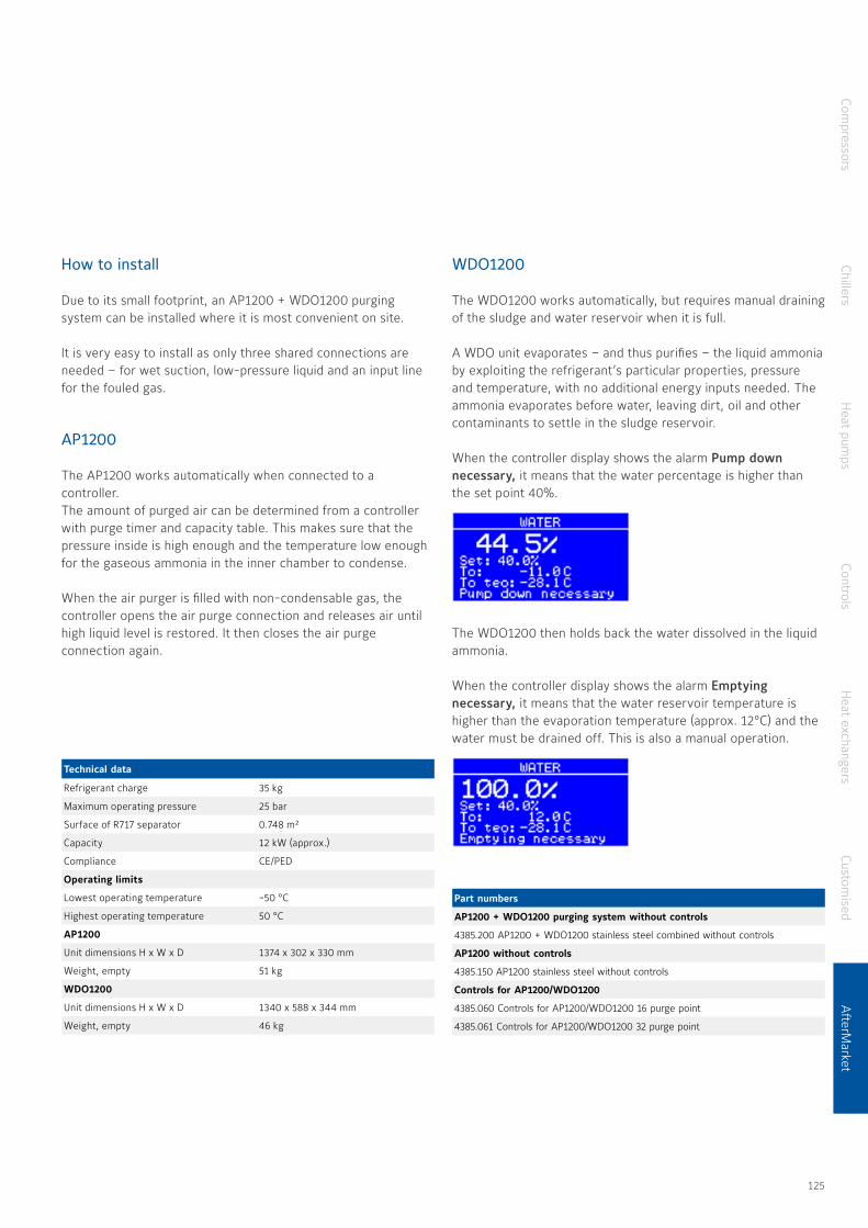
How to install
Due to its small footprint, an AP1200 + WDO1200 purging system can be installed where it is most convenient on site
It is very easy to install as only three shared connections are needed – for wet suction, low-pressure liquid and an input line for the fouled gas
AP1200
The AP1200 works automatically when connected to a controller The amount of purged air can be determined from a controller with purge timer and capacity table This makes sure that the pressure inside is high enough and the temperature low enough for the gaseous ammonia in the inner chamber to condense
When the air purger is filled with non-condensable gas, the controller opens the air purge connection and releases air until high liquid level is restored It then closes the air purgeconnection again
WDO1200
The WDO1200 works automatically, but requires manual draining of the sludge and water reservoir when it is full
A WDO unit evaporates – and thus purifies – the liquid ammonia by exploiting the refrigerant’s particular properties, pressure and temperature, with no additional energy inputs needed The ammonia evaporates before water, leaving dirt, oil and other contaminants to settle in the sludge reservoir
When the controller display shows the alarm Pump down necessary, it means that the water percentage is higher than the set point 40%
The WDO1200 then holds back the water dissolved in the liquid ammonia
When the controller display shows the alarm Emptying necessary, it means that the water reservoir temperature is higher than the evaporation temperature (approx 12°C) and the water must be drained off This is also a manual operation
Technical data
Refrigerant charge 35 kg
Maximum operating pressure 25 bar
Surface of R717 separator 0 748 m²
Capacity 12 kW (approx )
Compliance CE/PED
Operating limits
Lowest operating temperature -50 °C
Highest operating temperature 50 °C
AP1200
Unit dimensions H x W x D 1374 x 302 x 330 mm
Weight, empty 51 kg
WDO1200
Unit dimensions H x W x D 1340 x 588 x 344 mm
Weight, empty 46 kg
Part numbers
AP1200 + WDO1200 purging system without controls
4385 200 AP1200 + WDO1200 stainless steel combined without controls
AP1200 without controls
4385 150 AP1200 stainless steel without controls
Controls for AP1200/WDO1200
4385 060 Controls for AP1200/WDO1200 16 purge point
4385 061 Controls for AP1200/WDO1200 32 purge point
Compressors
ChillersH
eat pumps
ControlsH
eat exchangersCustom
isedA
fterMarket
124 125

The AP100 + Mini WDO is a combined air and water purger specially designed for use in small industrial refrigeration systems and industrial chiller units – of all sizes – that use ammonia (R717) as refrigerant
AP100 + Mini WDO units use excess thermal energy from the air purger to remove any water, dirt or oil (WDO) that might be present in an ammonia refrigerant charge This enables you to tackle multiple refrigerant contamination problems at once at relatively low cost Installing an AP100 + Mini WDO unit means you reap the full benefits of clean ammonia with consistent specifications, for use at the heart of your refrigeration systems
This whole purging system is easy and cheap to install, operate, and service It is also ideal as a low-cost, energy-effective way to boost operating efficiency as well as to avoid and prevent unpleasant surprises, service interruptions, and possible follow-on breakdowns in your key processes
Sabroe AP100 + Mini WDO combined air and water purgerRemoves any air and water present in an ammonia refrigerant charge
Features Benefits
Uses energy often wasted in an air purger to provide additional water purging capabilities
Normally reduces refrigeration equipment energy consumption by as much as 5–10%
Constantly purges efficiency-sapping air and water from your refrigeration system
Reduces operating costs and keeps the refrigeration system and its components operating at maximum efficiency
Helps prevent undesirable chemical reactions in all systems in a refrigeration installation
More stable operation as well as lower service and maintenance costs
Prevents any water present in the refrigerant from degrading the lubricant oil
Fewer oil changes needed, improved operating efficiency and longer service life for equipment and installations
Only three connections needed – wet suction, low-pressure liquid, and fouled gas line
Easy and cheap to install, operate and service
The mounting stand shown above is an optional extra
The mounting plate shown above is standard equipment
126 127
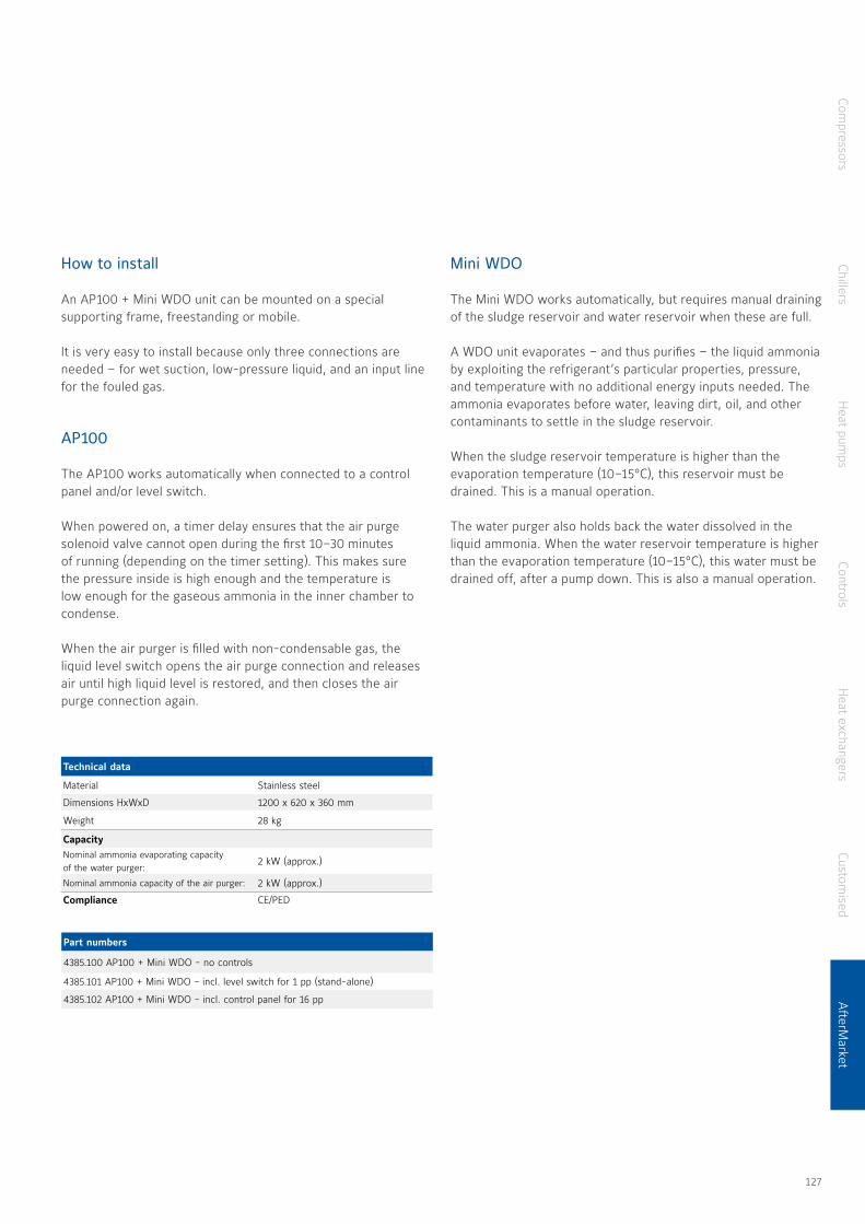
How to install
An AP100 + Mini WDO unit can be mounted on a special supporting frame, freestanding or mobile
It is very easy to install because only three connections are needed – for wet suction, low-pressure liquid, and an input line for the fouled gas
AP100
The AP100 works automatically when connected to a control panel and/or level switch
When powered on, a timer delay ensures that the air purge solenoid valve cannot open during the first 10–30 minutes of running (depending on the timer setting) This makes sure the pressure inside is high enough and the temperature is low enough for the gaseous ammonia in the inner chamber to condense
When the air purger is filled with non-condensable gas, the liquid level switch opens the air purge connection and releases air until high liquid level is restored, and then closes the air purge connection again
Mini WDO
The Mini WDO works automatically, but requires manual draining of the sludge reservoir and water reservoir when these are full
A WDO unit evaporates – and thus purifies – the liquid ammonia by exploiting the refrigerant’s particular properties, pressure, and temperature with no additional energy inputs needed The ammonia evaporates before water, leaving dirt, oil, and other contaminants to settle in the sludge reservoir
When the sludge reservoir temperature is higher than the evaporation temperature (10–15°C), this reservoir must be drained This is a manual operation
The water purger also holds back the water dissolved in the liquid ammonia When the water reservoir temperature is higher than the evaporation temperature (10–15°C), this water must be drained off, after a pump down This is also a manual operation
Technical data
Material Stainless steel
Dimensions HxWxD 1200 x 620 x 360 mm
Weight 28 kg
CapacityNominal ammonia evaporating capacity of the water purger:
2 kW (approx )
Nominal ammonia capacity of the air purger: 2 kW (approx )
Compliance CE/PED
Part numbers
4385 100 AP100 + Mini WDO - no controls
4385 101 AP100 + Mini WDO - incl level switch for 1 pp (stand-alone)
4385 102 AP100 + Mini WDO - incl control panel for 16 pp
Compressors
ChillersH
eat pumps
ControlsH
eat exchangersCustom
isedA
fterMarket
126 127

Sabroe End-of-Line test centre
Full satisfaction – no surprises
Not only are Sabroe systems at the forefront of industrial refrigeration technology, they’re also backed by state-of-the-art facilities for pre-delivery, pre-commissioning testing
We rigorously test the performance of every chiller and heat pump unit before it leaves the factory, so you can be 100 percent sure it lives up to your expectations in full when it arrives You’re entitled to expect full transparency – and we make sure Sabroe systems deliver
Testing in the factory – not on site
The unique Sabroe End-of-Line (EOL) test centre, located in Denmark, is a purpose-built facility comprehensively equipped with state-of-the-art monitoring and testing equipment
We can conduct a comprehensive range of tests, ranging from a full-blown Factory Acceptance Test (FAT) to any specific test package you may prefer You and your staff are, of course, welcome to witness every stage of tests and trial runs to make sure everything performs as intended, with no unwelcome surprises
All Sabroe chiller and heat pump units are tested before dispatch
128 129

Solid, dependable documentation helps you and your technical staff
Documented capabilities
Rigorous pre-commissioning testing gives you comprehensive, reliable documentation of the performance and capabilities of the exact equipment you’ll be receiving – not just generic approximations
Solid, dependable documentation helps you and your technical staff plan effective implementation and integration with other equipment And all the pre-delivery tests help save you time, money, and hassle with commissioning and running-in With Sabroe product deliveries, you get what you ordered – and it works as you expected
128 129

High-performing and reliable equipment that lasts
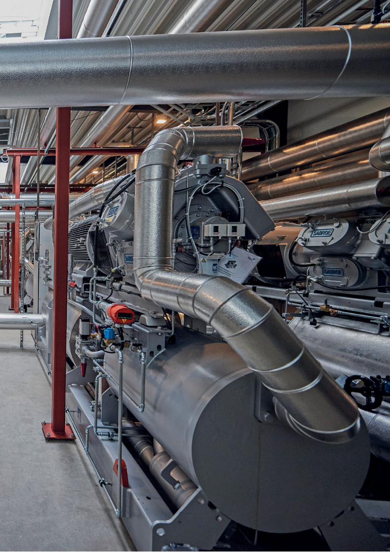
© 2021 Johnson Controls All rights reserved
About Johnson ControlsAt Johnson Controls, we transform the environments where people live, work, learn and play. From optimizing building performance to improving safety and enhancing comfort, we drive the outcomes that matter most. We deliver our promise in industries such as healthcare, education, data centers and manufacturing. With a global team of 105,000 experts in more than 150 countries and over 130 years of innovation, we are the power behind our customers’ mission. Our leading portfolio of building technology and solutions includes some of the most trusted names in the industry, such as Tyco®, YORK®, Metasys®, Ruskin®, Titus®, Frick®, PENN®, Sabroe®, Simplex®, Ansul® and Grinnell®.
For more information, visit www.johnsoncontrols.com or follow us @johnsoncontrols on Twitter.
Johnson Controls Denmark Sabroe Factory Christian X’s Vej 2018270 HoejbjergDenmarkPhone +45 87 36 70 00 www sabroe com
Your local representative
Related Documents


