OPERATION MANUAL SA1422 TWO CHANNEL DSP INFRARED TRANSMITTER SOUND ASSOCIATES, INC. 424 West 45th Street, New York, NY 10036 Tel: (212) 757-5679 Fax: (212) 265-1250 Toll free: (888) 772-7686 Home Page: www.soundassociates.com

Welcome message from author
This document is posted to help you gain knowledge. Please leave a comment to let me know what you think about it! Share it to your friends and learn new things together.
Transcript
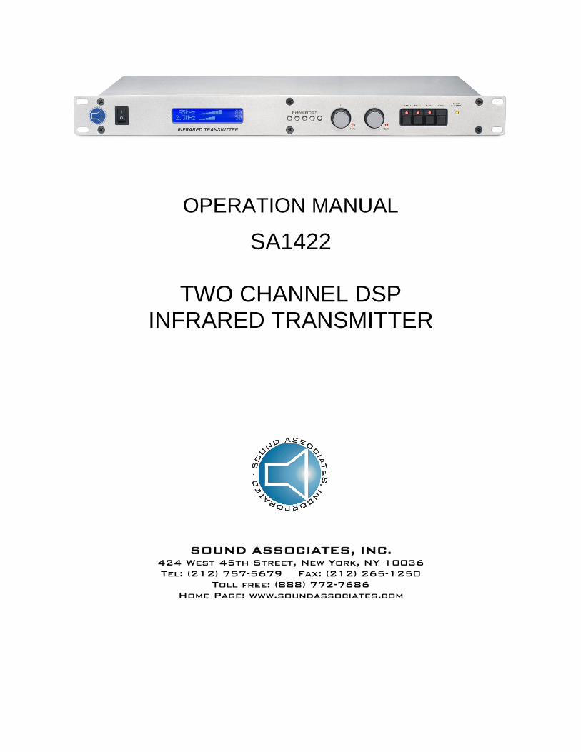
OPERATION MANUAL
SA1422
TWO CHANNEL DSP INFRARED TRANSMITTER
SOUND ASSOCIATES, INC. 424 West 45th Street, New York, NY 10036 Tel: (212) 757-5679 Fax: (212) 265-1250
Toll free: (888) 772-7686 Home Page: www.soundassociates.com
TABLE OF CONTENTS
IMPORTANT SAFETY INFORMATION........................................................................................2 INTRODUCTION...........................................................................................................................3 INFRARED LISTENING SYSTEM FEATURES............................................................................3 UNPACKING UNIT .......................................................................................................................4 RACK MOUNTING........................................................................................................................4 FRONT PANEL CONTROLS........................................................................................................4 REAR PANEL CONTROLS ..........................................................................................................5 POWER CONNECTION ...............................................................................................................6 AUDIO/CHASSIS GROUND LINK................................................................................................6 INPUT CONNECTION ..................................................................................................................6 OUTPUT CONNECTION ..............................................................................................................7 THEORY OF OPERATION...........................................................................................................8 BASIC MENU OPERATION..........................................................................................................9 MAIN MENU SCREEN................................................................................................................10 LEVEL CONTROL………………………………………………………………………........... ……..11 CHANNEL OR FREQUENCY MENU……………………………………............................. ……..12
CHANNEL SELECTION TABLE…………………… .................................................. ……..12 PROCESSING MENU………............................................................................................ ……..12
EXAMPLE CHANGE COMPRESSOR SETTINGS….................................................. ……..13 EXAMPLE CHANGE EQ SETTINGS…..................................................................... ……..14
MENU………..................................................................................................................... ……..14 VERSION… ........................................................................................................... ……..15 TEST TONES… ..................................................................................................... ……..15 BACKLIGHT… ....................................................................................................... ……..15 OUTPUT VOLTAGE… ............................................................................................ ……..15
TROUBLESHOOTING............................................................................................ ...................15 SERVICE OR REPAIRS......................................................................................... ....................16 TECHNICAL SPECIFICATIONS.................................................................................................16 ACCESSORIES ..........................................................................................................................17 WARRANTY................................................................................................................................18 TYPICAL SYSTEM SCHEMATIC ...............................................................................................19

- 2 -
IMPORTANT SAFETY INFORMATION
CAUTION: TO REDUCE THE RISK OF ELECTRIC SHOCK,
DO NOT REMOVE COVER (OR BACK). NO USER-SERVICEABLE PARTS INSIDE.
REFER SERVICING TO QUALIFIED SERVICE PERSONNEL. DO NOT EXPOSE TO RAIN OR MOISTURE.
The lightning flash with arrowhead symbol within an equilateral triangle is intended to alert the user to the presence of uninsulated "dangerous voltage" within the product's enclosure. It may be of sufficient magnitude to constitute a risk of electric shock to persons. The exclamation point within an equilateral triangle is intended to alert the user to the presence of important operating and maintenance (servicing) instructions in the literature accompanying the product.
Warnings • Connect this unit’s power cord only to an AC outlet of the type stated in this Owner’s Manual or as
marked on the unit. Failure to do so is a fire and electrical shock hazard. • Do not allow water to enter this unit or allow the unit to become wet. Fire or electrical shock may
result. • Do not place a container with liquid or small metal objects on top of this unit. Liquid or metal objects
inside this unit are a fire and electrical shock hazard. • Do not remove the unit’s cover. You could receive an electrical shock. If you think internal inspection,
maintenance, or repair is necessary, contact your dealer. • Do not modify the unit. Doing so is a fire and electrical shock hazard. • If the power cord is damaged (i.e., cut or a bare wire is exposed), ask your dealer for a replacement.
Using the unit with a damaged power cord is a fire and electrical shock hazard. • If you notice any abnormality, such as smoke, odor, or noise, or if a foreign object or liquid gets inside
the unit, turn it off immediately. Remove the power cord from the AC outlet. Consult your dealer for repair. Using the unit in this condition is a fire and electrical shock hazard.
Cautions • Keep this unit away from the following locations: Locations exposed to oil splashes or steam. Unstable surfaces, such as a wobbly table or slope. Do not install near any heat sources such as radiators, heat registers, stoves, or other apparatus
(including amplifiers) that produce large quantities of heat. Locations subject to excessive humidity or dust accumulation. • Hold the power cord plug when disconnecting it from an AC outlet. Never pull the cord. A damaged
power cord is a potential fire and electrical shock hazard. • Do not touch the power plug with wet hands. Doing so is a potential electrical shock hazard. • This unit is equipped with a dedicated ground connection to prevent electrical shock. Before
connecting the power plug to an AC outlet, be sure to ground the unit. • To relocate the unit, turn the power switch off, remove the power plug from the AC outlet, and remove
all connecting cables. Damaged cables may cause fire or electrical shock.
- 3 -
INTRODUCTION Thank you for choosing a Sound Associates, Inc. manufactured product. All Sound Associates, Inc. products are carefully designed and engineered for cutting edge performance and world class reliability. Our Infrared Listening System is a wireless assistive listening system which can be used as either an aid for the hard of hearing, audio description, or simultaneous translation. As an assistive listening device, the Sound Associate products meet the Americans with Disabilities Act standards to aid the hearing impaired. Also, infrared technology meets international standards for wireless interpretation equipment. These systems consist of three major components: the transmitter, the emitter, and the receiver. The transmitter modulates an audio signal that is converted into infrared light by the emitters. This light carries the modulated audio “on its back”, fills the room, and is converted back into audio by the receiver. The infrared light is amplitude modulated with a 95 kHz, 250 kHz, 2.3 MHz, 2.8 MHz, 3.3 MHz, or 3.8 MHz frequency-modulated sub-carrier. 95 kHz, 250 kHz, 2.3 MHz, and 2.8 MHz are industry standard frequency carriers, therefore other manufacturer’s receivers can be used with our system and our receivers used with other home or large area systems. To ensure proper set up and operation, the following instructions should be read completely before attempting to install any equipment. We continue to make improvements to our product line and look to our customers for future design changes. If you have any comments or suggestions, please feel free to contact us at [email protected] or call Monday – Friday 10:00 am - 5:30 pm EST at (888) 772-SOUND (7686). We look forward to hearing from you. INFRARED LISTENING SYSTEM FEATURES Infrared Technology Feature Advantage Wireless Receivers
No pre-registered seating No “deaf section” Easy distribution
Wireless signal transmission by Infrared light as compared to RF transmission
Confidentiality; signal will not pass through walls or curtains No interference from common radio signals Superior audio quality
Audio signal is frequency modulated at 95 kHz, 250 kHz, 2.3 MHz, 2.8 MHz, 3.3 MHz, or 3.8 MHz
Industry standards Headsets are interchangeable with other home and large area systems
SA1422 DSP Transmitter Feature Advantage DSP Design 3-Band parametric equalizer on each input.
6 user-selectable channels per input (95 kHz, 250 kHz, 2.3 MHz, 2.8 MHz, 3.3MHz, and 3.8 MHz). 2 audio inputs with ability to output 2 modulated channels or combine both signals into one output. Two balanced line or microphone inputs with phantom power. Input peak indicator on front panel. Pre-amp gain control on back panel. Bright, 20-character display showing true audio modulation and compression. Built-in test tone generator.
Phantom Power Can be used in conjunction with condenser microphone without need of an external mixer.
Infrared test diodes on front panel Ability to monitor the output using a receiver at the transmitter. Neutrik NCJ series audio input connector Excepts both 3-pole XLR (microphone level signal) or ¼” phone
connectors (line level signal)
- 4 -
Feature Advantage BNC modulated audio output Can drive Sound Associates and other manufactured emitters
UNPACKING UNIT As soon as the shipment is received, inspect the unit and all components for damage incurred by shipping. Also, check to see if all components are enclosed. Equipment enclosed: 1 SA1422F Infrared transmitter/base station 1 AC power cord
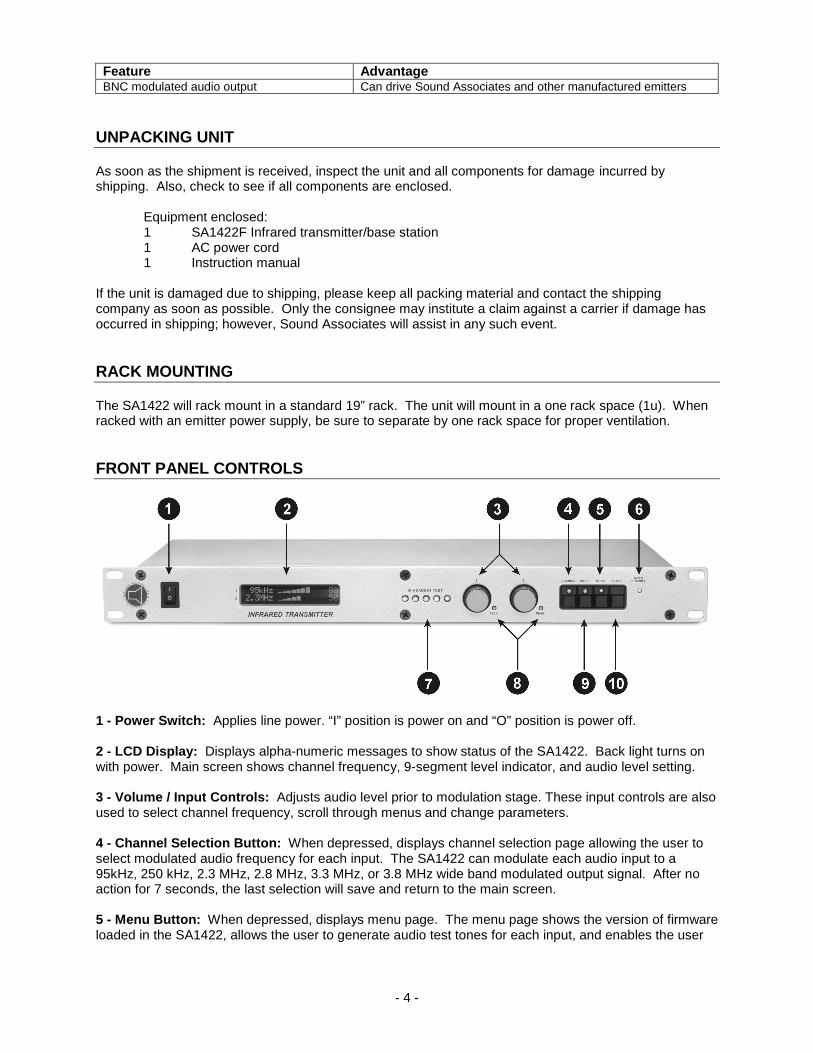
1 Instruction manual If the unit is damaged due to shipping, please keep all packing material and contact the shipping company as soon as possible. Only the consignee may institute a claim against a carrier if damage has occurred in shipping; however, Sound Associates will assist in any such event. RACK MOUNTING The SA1422 will rack mount in a standard 19” rack. The unit will mount in a one rack space (1u). When racked with an emitter power supply, be sure to separate by one rack space for proper ventilation. FRONT PANEL CONTROLS
1 - Power Switch: Applies line power. “I” position is power on and “O” position is power off. 2 - LCD Display: Displays alpha-numeric messages to show status of the SA1422. Back light turns on with power. Main screen shows channel frequency, 9-segment level indicator, and audio level setting. 3 - Volume / Input Controls: Adjusts audio level prior to modulation stage. These input controls are also used to select channel frequency, scroll through menus and change parameters. 4 - Channel Selection Button: When depressed, displays channel selection page allowing the user to select modulated audio frequency for each input. The SA1422 can modulate each audio input to a 95kHz, 250 kHz, 2.3 MHz, 2.8 MHz, 3.3 MHz, or 3.8 MHz wide band modulated output signal. After no action for 7 seconds, the last selection will save and return to the main screen. 5 - Menu Button: When depressed, displays menu page. The menu page shows the version of firmware loaded in the SA1422, allows the user to generate audio test tones for each input, and enables the user
- 5 -
to adjust the backlight of the LCD screen. After no action for 7 seconds, the last selection will save and return to the main screen. 6 - Multi-Channel Indicator: Indicates when multiple channels are being transmitter. Since emitter coverage reduces by the number channels of modulation, this light will indicate that the emitter output is reduced. 7 - Infrared Test Diodes: Infrared diodes that emit modulated infrared signal. Using a receiver, operator or installer can monitor the infrared output at the transmitter without being in the seating area. 8 - Peak Level Indicators: Indicators light up when the input signal level is 6 dB below clipping. Adjust the pre-amp input GAIN control so that the indicator rarely lights up at signal peaks. 9 - Processing Button: When depressed, displays the processing main page that includes Compression and Equalization for each input. After no action for 7 seconds, the last selection will save and return to the main screen. 10 – Enter Button: Used to select an action on the screen or save a setting before the screen is timed out and parameters are auto saved. REAR PANEL CONTROLS
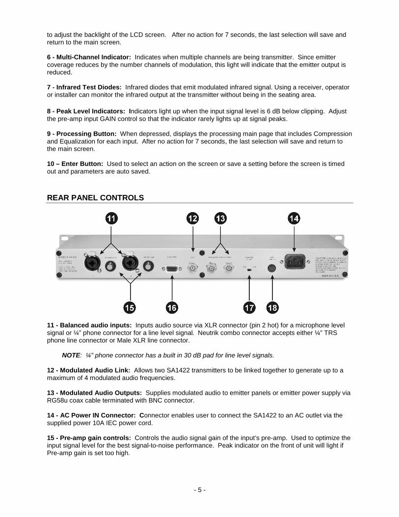
11 - Balanced audio inputs: Inputs audio source via XLR connector (pin 2 hot) for a microphone level signal or ¼” phone connector for a line level signal. Neutrik combo connector accepts either ¼” TRS phone line connector or Male XLR line connector. NOTE: ¼” phone connector has a built in 30 dB pad for line level signals. 12 - Modulated Audio Link: Allows two SA1422 transmitters to be linked together to generate up to a maximum of 4 modulated audio frequencies. 13 - Modulated Audio Outputs: Supplies modulated audio to emitter panels or emitter power supply via RG58u coax cable terminated with BNC connector. 14 - AC Power IN Connector: Connector enables user to connect the SA1422 to an AC outlet via the supplied power 10A IEC power cord. 15 - Pre-amp gain controls: Controls the audio signal gain of the input’s pre-amp. Used to optimize the input signal level for the best signal-to-noise performance. Peak indicator on the front of unit will light if Pre-amp gain is set too high.
- 6 -
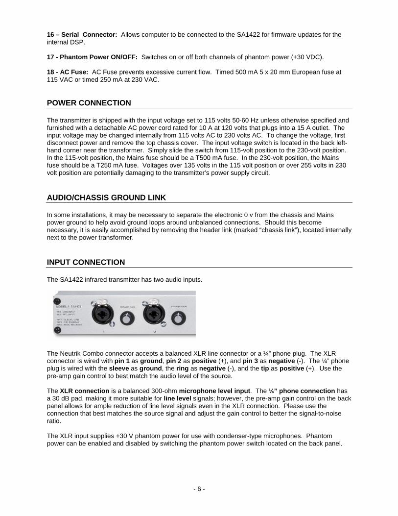
16 – Serial Connector: Allows computer to be connected to the SA1422 for firmware updates for the internal DSP. 17 - Phantom Power ON/OFF: Switches on or off both channels of phantom power (+30 VDC). 18 - AC Fuse: AC Fuse prevents excessive current flow. Timed 500 mA 5 x 20 mm European fuse at 115 VAC or timed 250 mA at 230 VAC. POWER CONNECTION The transmitter is shipped with the input voltage set to 115 volts 50-60 Hz unless otherwise specified and furnished with a detachable AC power cord rated for 10 A at 120 volts that plugs into a 15 A outlet. The input voltage may be changed internally from 115 volts AC to 230 volts AC. To change the voltage, first disconnect power and remove the top chassis cover. The input voltage switch is located in the back left-hand corner near the transformer. Simply slide the switch from 115-volt position to the 230-volt position. In the 115-volt position, the Mains fuse should be a T500 mA fuse. In the 230-volt position, the Mains fuse should be a T250 mA fuse. Voltages over 135 volts in the 115 volt position or over 255 volts in 230 volt position are potentially damaging to the transmitter’s power supply circuit. AUDIO/CHASSIS GROUND LINK In some installations, it may be necessary to separate the electronic 0 v from the chassis and Mains power ground to help avoid ground loops around unbalanced connections. Should this become necessary, it is easily accomplished by removing the header link (marked “chassis link”), located internally next to the power transformer. INPUT CONNECTION The SA1422 infrared transmitter has two audio inputs.
The Neutrik Combo connector accepts a balanced XLR line connector or a ¼” phone plug. The XLR connector is wired with pin 1 as ground, pin 2 as positive (+), and pin 3 as negative (-). The ¼” phone plug is wired with the sleeve as ground, the ring as negative (-), and the tip as positive (+). Use the pre-amp gain control to best match the audio level of the source. The XLR connection is a balanced 300-ohm microphone level input. The ¼” phone connection has a 30 dB pad, making it more suitable for line level signals; however, the pre-amp gain control on the back panel allows for ample reduction of line level signals even in the XLR connection. Please use the connection that best matches the source signal and adjust the gain control to better the signal-to-noise ratio. The XLR input supplies +30 V phantom power for use with condenser-type microphones. Phantom power can be enabled and disabled by switching the phantom power switch located on the back panel.

- 7 -
The input is balanced electronically with differential amplifiers. Due to the electronic balancing, the input may be used with a balanced or unbalanced source.
NOTE: A balanced line is defined as two conductor shielded cable with each of the two center conductors carrying the signal, but of opposite polarity and equal but opposite potential difference from ground. An unbalanced line is a single conductor shielded cable with the center conductor carrying the signal and the shield at ground potential.
OUTPUT CONNECTION The SA1422 has two modulated outputs which connect to an emitter panel or to an emitter power supply via RG58u coaxial cable (RG59u for short cable runs) terminated with a BNC connector. The SA1422 transmitter is designed to work in conjunction with Sound Associates’ SA611, SA612, and SA613 emitter panels as well as other manufactured emitter panels. The signal voltage is factory adjustable from 2-8 V P-P; therefore, it can be adjusted to drive most other manufacturer’s emitters at considerable distances. Please check the manufacturer’s instruction manual to be sure that the emitter will function properly at this signal voltage.
The link connection on the back of the SA1422 allows 2 transmitters to be linked together to utilize up to four channels of transmission. The unit which utilizes 2 channels should be the first in line. The second can utilize 1 or 2 channels. The emitter power supply or emitter panels must be connected to the second or last transmitter in the string. This will allow for proper output voltage to the emitters. See example diagram on the following page:

- 8 -
THEORY OF OPERATION The SA1422 transmitter is a frequency modulator that modulates an audio signal at 95 kHz, 250 kHz, 2.3 MHz, 2.8 MHz, 3.3 MHz or 3.8 MHz to the emitter panel’s infrared diodes. It is then demodulated back to audio by any infrared receiver set to the same transmission frequency. The transmitter performs gain control, equalization, compression, pre-emphasis, and modulation in a digital state. Refer to the block diagram for signal flow.
Preamp: The pre-amp circuit is designed around an SSM analog low-noise pre-amp integrated circuit. The circuit consists of a 30 dB pad for the line level signal on the ¼” phone connector and an external potentiometer for pre-amp gain control. The pad is active only in the TRS ¼” phone connection. The pre-amp gain control is located on the back panel near the audio input connection (see rear panel controls, page 5). The sensitivity of the input may be increased or decreased by this control if the input signal is too low or too “hot”. Peak Level Indicator: The PEAK LEVEL INDICATOR is located in the digital domain and will light up when the audio source is 6 db below distorting the digital signal. The PEAK LEVEL INDICATOR may light up on occasion but cannot stay light for long lengths of time. Gain Control: The GAIN control stage increases or decreases audio input prior to the modulation stage in the digital domain. The gain setting is displayed in 2 digit form on the MAIN screen. Each input can be adjusted from 0 (muted) to 99 (full volume) by rotating the front panel input control. EQ Stage: Each input has a 3-band parametric equalizer built into the signal flow. Low (250 Hz), Mid (1 kHz) and High (4 kHz) can be adjusted from the EQ screen of the processing menu. Compressor / Limiter: This dynamics processor can be used as compressor or limiter. The COMPRESSOR is post EQ and gain control and limits the audio signal prior to the modulation stage. The COMPRESSOR circuit restricts peak modulation swings to <50 kHz as well as prevents distortion in the modulation stage. The limiter may be taken out of the circuit if so desired by setting the
- 9 -
COMPRESSOR for the desired input to off. However, if the limit circuit is removed, we suggest that an external limiter/compressor be utilized. Pre-Emphasis: Prior to the modulation stage a pre-emphasis is applied to the signal to improve audio quality during transmission. This audio pre-emphasis is de-emphasized in the receiver to give a higher signal to noise ratio. The same pre-emphasis is utilized by other manufacturers so that their receiver can be used with the Sound Associates SA1422 and Sound Associates receivers with other manufacturer’s modulators. Modulation: The modulation section frequency modulates the audio signal to 95 kHz, 250 kHz, 2.3 MHz, 2.8 MHz, 3.3 MHz, or 3.8 MHz depending on the setting on the CHANNEL screen of the menu. Each input can be assigned a different channel or set to the same channel and mixed together.
NOTE: When more than one channel is in use the MULTI-CHANNEL indicator lights up showing that the output signal from the emitters has been diminished by the numbers of channels being transmitter. For example: two transmission frequencies will cause the emitter to be half of its specified output coverage; three transmission frequencies will cause the emitter to be one-third of its specified output coverage.
Output: The output consists of a push-pull driver circuit that has the ability to drive long cable runs without signal loss. Also, the output voltage can be adjusted from 2 V P-P to 8 V P-P. This adjustment allows other manufactured emitters to work with the SA1422. In addition, the ability to increase output voltage allows the SA1422 to drive longer cable runs on twisted cable.
NOTE: Since increasing the output voltage, especially for higher frequencies, can cause problems or damage to the emitter panel we suggest that you please contact Sound Associates, Inc. (888-772-7686) before changing the output voltage.
BASIC MENU OPERATION The following are system-wide front panel controls for the SA1422 menu. • The ENTER button is used to make a menu selection, save a configuration, or return to the main
screen. • The front panel rotary INPUT controls are used for audio level adjustment in the main screen and
scrolling through selections on any other menu. In all sub-menus such as PROCESSING, CHANNEL and MENU either knob will scroll through the list. In select menus the left encoder (1) moves the cursor while the right encoder (2) adjusts settings.
• All menus will time out and save after 7 seconds of no use. After time out, the SA1422 will always return to the main page.
• The top LCD row of the main menu shows input 1: channel and level; bottom row shows input 2: channel and level.
• “t” on the main page before the volume level settings; indicates that a test tone is set to ON for that channel.
• “m” on the main page before the volume level settings; indicates that the inputs are mixed together on the same frequency.
- 10 -
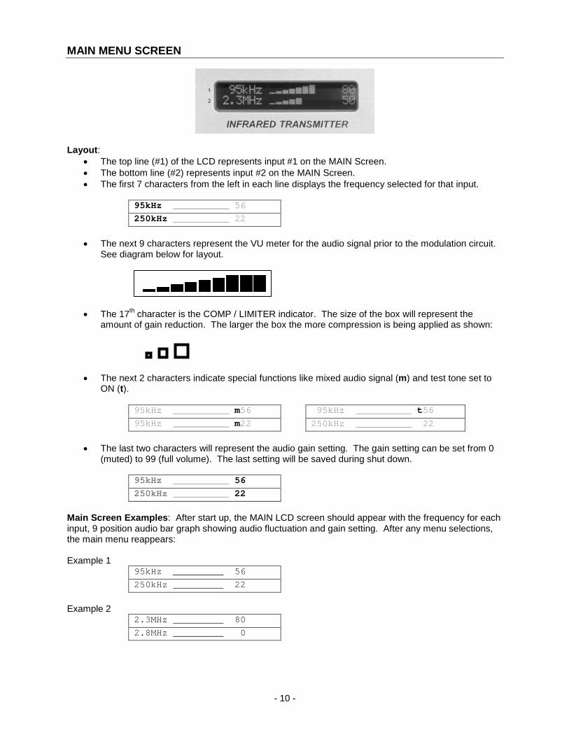
MAIN MENU SCREEN
Layout:
• The top line (#1) of the LCD represents input #1 on the MAIN Screen. • The bottom line (#2) represents input #2 on the MAIN Screen. • The first 7 characters from the left in each line displays the frequency selected for that input.
95kHz __________ 56 250kHz __________ 22
• The next 9 characters represent the VU meter for the audio signal prior to the modulation circuit.
See diagram below for layout.
• The 17th character is the COMP / LIMITER indicator. The size of the box will represent the amount of gain reduction. The larger the box the more compression is being applied as shown:
• The next 2 characters indicate special functions like mixed audio signal (m) and test tone set to ON (t).
95kHz __________ m56 95kHz __________ t56 95kHz __________ m22 250kHz __________ 22
• The last two characters will represent the audio gain setting. The gain setting can be set from 0
(muted) to 99 (full volume). The last setting will be saved during shut down.
95kHz __________ 56 250kHz __________ 22
Main Screen Examples: After start up, the MAIN LCD screen should appear with the frequency for each input, 9 position audio bar graph showing audio fluctuation and gain setting. After any menu selections, the main menu reappears: Example 1
95kHz _________ 56 250kHz _________ 22
Example 2
2.3MHz _________ 80 2.8MHz _________ 0
- 11 -
Example 3 95kHz _________ 50 OFF
Example 4
2.3MHz _________ m80 2.3MHz _________ m44
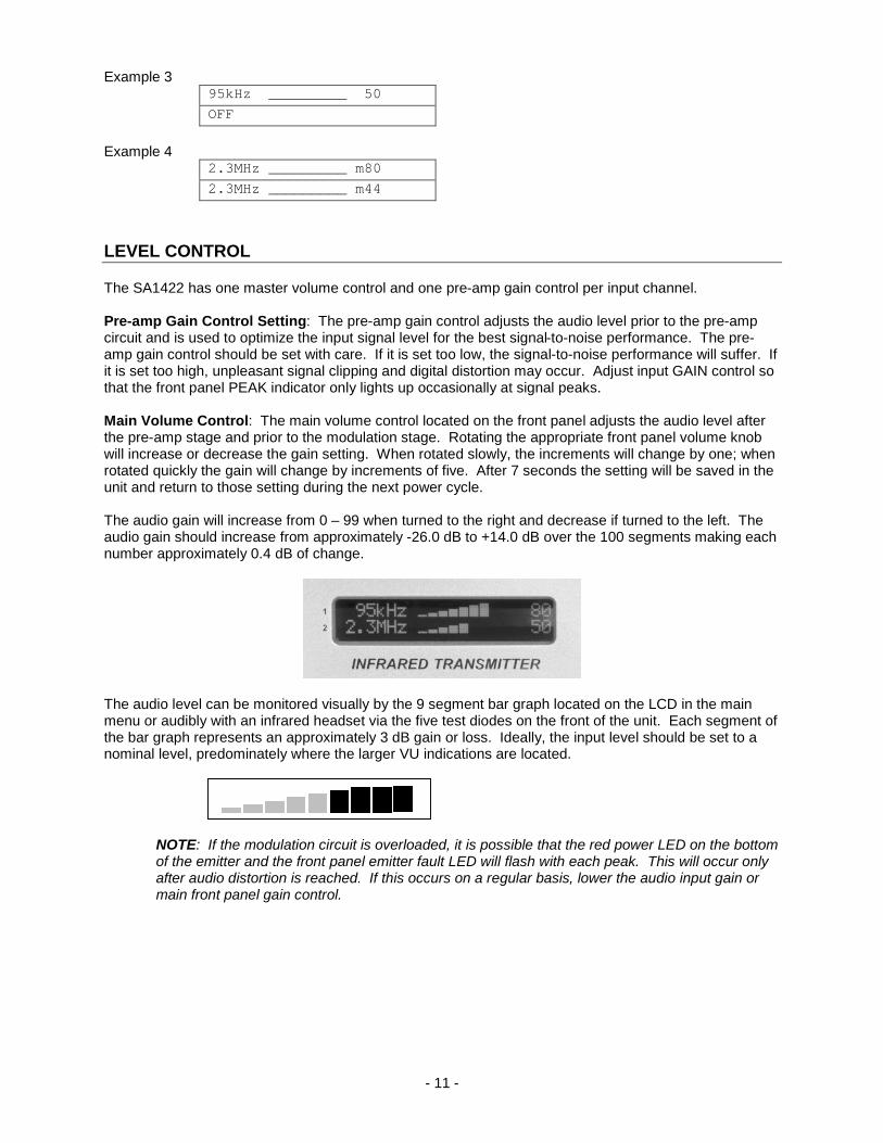
LEVEL CONTROL The SA1422 has one master volume control and one pre-amp gain control per input channel. Pre-amp Gain Control Setting: The pre-amp gain control adjusts the audio level prior to the pre-amp circuit and is used to optimize the input signal level for the best signal-to-noise performance. The pre-amp gain control should be set with care. If it is set too low, the signal-to-noise performance will suffer. If it is set too high, unpleasant signal clipping and digital distortion may occur. Adjust input GAIN control so that the front panel PEAK indicator only lights up occasionally at signal peaks. Main Volume Control: The main volume control located on the front panel adjusts the audio level after the pre-amp stage and prior to the modulation stage. Rotating the appropriate front panel volume knob will increase or decrease the gain setting. When rotated slowly, the increments will change by one; when rotated quickly the gain will change by increments of five. After 7 seconds the setting will be saved in the unit and return to those setting during the next power cycle. The audio gain will increase from 0 – 99 when turned to the right and decrease if turned to the left. The audio gain should increase from approximately -26.0 dB to +14.0 dB over the 100 segments making each number approximately 0.4 dB of change.
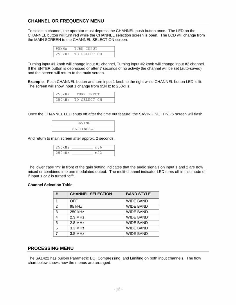
The audio level can be monitored visually by the 9 segment bar graph located on the LCD in the main menu or audibly with an infrared headset via the five test diodes on the front of the unit. Each segment of the bar graph represents an approximately 3 dB gain or loss. Ideally, the input level should be set to a nominal level, predominately where the larger VU indications are located.
NOTE: If the modulation circuit is overloaded, it is possible that the red power LED on the bottom of the emitter and the front panel emitter fault LED will flash with each peak. This will occur only after audio distortion is reached. If this occurs on a regular basis, lower the audio input gain or main front panel gain control.
- 12 -
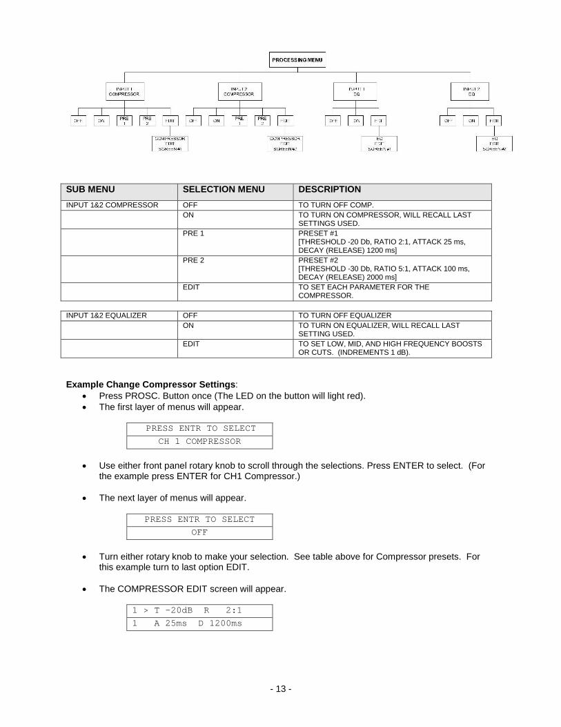
CHANNEL OR FREQUENCY MENU To select a channel, the operator must depress the CHANNEL push button once. The LED on the CHANNEL button will turn red while the CHANNEL selection screen is open. The LCD will change from the MAIN SCREEN to the CHANNEL SELECTION screen.
95kHz TURN INPUT 250kHz TO SELECT CH
Turning input #1 knob will change input #1 channel, Turning input #2 knob will change input #2 channel. If the ENTER button is depressed or after 7 seconds of no activity the channel will be set (auto-saved) and the screen will return to the main screen. Example: Push CHANNEL button and turn input 1 knob to the right while CHANNEL button LED is lit. The screen will show input 1 change from 95kHz to 250kHz.
250kHz TURN INPUT 250kHz TO SELECT CH
Once the CHANNEL LED shuts off after the time out feature; the SAVING SETTINGS screen will flash.
SAVING SETTINGS…
And return to main screen after approx. 2 seconds.
250kHz _________ m56 250kHz _________ m22
The lower case “m” in front of the gain setting indicates that the audio signals on input 1 and 2 are now mixed or combined into one modulated output. The mulit-channel indicator LED turns off in this mode or if input 1 or 2 is turned “off”. Channel Selection Table:
# CHANNEL SELECTION BAND STYLE
1 OFF WIDE BAND 2 95 kHz WIDE BAND 3 250 kHz WIDE BAND 4 2.3 MHz WIDE BAND 5 2.8 MHz WIDE BAND 6 3.3 MHz WIDE BAND 7 3.8 MHz WIDE BAND
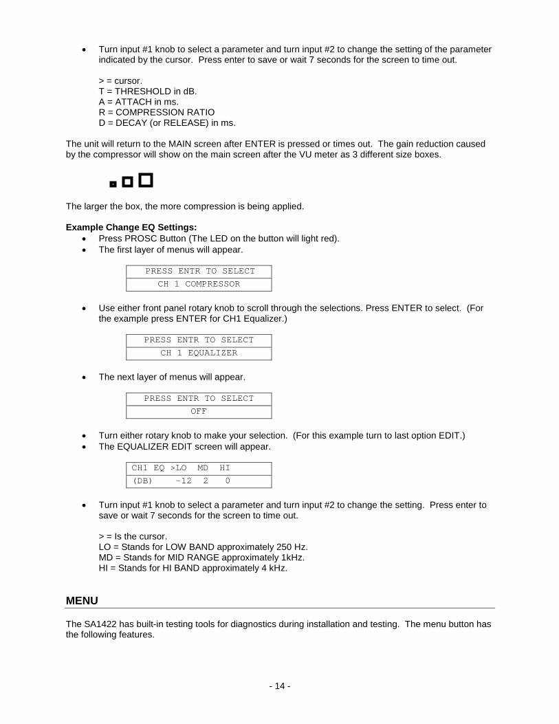
PROCESSING MENU The SA1422 has built-in Parametric EQ, Compressing, and Limiting on both input channels. The flow chart below shows how the menus are arranged.
- 13 -
SUB MENU SELECTION MENU DESCRIPTION INPUT 1&2 COMPRESSOR OFF TO TURN OFF COMP. ON TO TURN ON COMPRESSOR, WILL RECALL LAST
SETTINGS USED. PRE 1 PRESET #1
[THRESHOLD -20 Db, RATIO 2:1, ATTACK 25 ms, DECAY (RELEASE) 1200 ms]
PRE 2 PRESET #2 [THRESHOLD -30 Db, RATIO 5:1, ATTACK 100 ms, DECAY (RELEASE) 2000 ms]
EDIT TO SET EACH PARAMETER FOR THE COMPRESSOR.
INPUT 1&2 EQUALIZER OFF TO TURN OFF EQUALIZER ON TO TURN ON EQUALIZER, WILL RECALL LAST
SETTING USED. EDIT TO SET LOW, MID, AND HIGH FREQUENCY BOOSTS
OR CUTS. (INDREMENTS 1 dB). Example Change Compressor Settings:
• Press PROSC. Button once (The LED on the button will light red). • The first layer of menus will appear.
PRESS ENTR TO SELECT CH 1 COMPRESSOR
• Use either front panel rotary knob to scroll through the selections. Press ENTER to select. (For
the example press ENTER for CH1 Compressor.) • The next layer of menus will appear.
PRESS ENTR TO SELECT OFF
• Turn either rotary knob to make your selection. See table above for Compressor presets. For
this example turn to last option EDIT. • The COMPRESSOR EDIT screen will appear.
1 > T -20dB R 2:1 1 A 25ms D 1200ms
- 14 -
• Turn input #1 knob to select a parameter and turn input #2 to change the setting of the parameter indicated by the cursor. Press enter to save or wait 7 seconds for the screen to time out.
> = cursor. T = THRESHOLD in dB. A = ATTACH in ms. R = COMPRESSION RATIO D = DECAY (or RELEASE) in ms.
The unit will return to the MAIN screen after ENTER is pressed or times out. The gain reduction caused by the compressor will show on the main screen after the VU meter as 3 different size boxes.
The larger the box, the more compression is being applied. Example Change EQ Settings:
• Press PROSC Button (The LED on the button will light red). • The first layer of menus will appear.
PRESS ENTR TO SELECT
CH 1 COMPRESSOR • Use either front panel rotary knob to scroll through the selections. Press ENTER to select. (For
the example press ENTER for CH1 Equalizer.)
PRESS ENTR TO SELECT CH 1 EQUALIZER
• The next layer of menus will appear.
PRESS ENTR TO SELECT
OFF
• Turn either rotary knob to make your selection. (For this example turn to last option EDIT.) • The EQUALIZER EDIT screen will appear.
CH1 EQ >LO MD HI (DB) -12 2 0
• Turn input #1 knob to select a parameter and turn input #2 to change the setting. Press enter to
save or wait 7 seconds for the screen to time out.
> = Is the cursor. LO = Stands for LOW BAND approximately 250 Hz. MD = Stands for MID RANGE approximately 1kHz. HI = Stands for HI BAND approximately 4 kHz.
MENU The SA1422 has built-in testing tools for diagnostics during installation and testing. The menu button has the following features.
- 15 -
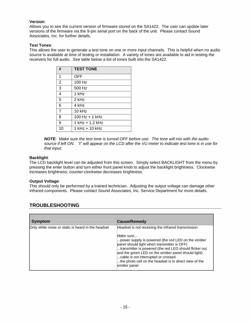
Version: Allows you to see the current version of firmware stored on the SA1422. The user can update later versions of the firmware via the 9-pin serial port on the back of the unit. Please contact Sound Associates, Inc. for further details. Test Tones: This allows the user to generate a test tone on one or more input channels. This is helpful when no audio source is available at time of testing or installation. A variety of tones are available to aid in testing the receivers for full audio. See table below a list of tones built into the SA1422.
# TEST TONE
1 OFF 2 100 Hz 3 500 Hz 4 1 kHz 5 2 kHz 6 4 kHz 7 10 kHz 8 100 Hz + 1 kHz 9 1 kHz + 1.2 kHz 10 1 kHz + 10 kHz
NOTE: Make sure the test tone is turned OFF before use. The tone will mix with the audio source if left ON. “t” will appear on the LCD after the VU meter to indicate test tone is in use for that input.
Backlight: The LCD backlight level can be adjusted from this screen. Simply select BACKLIGHT from the menu by pressing the enter button and turn either front panel knob to adjust the backlight brightness. Clockwise increases brightness; counter-clockwise decreases brightness. Output Voltage: This should only be performed by a trained technician. Adjusting the output voltage can damage other infrared components. Please contact Sound Associates, Inc. Service Department for more details. TROUBLESHOOTING Symptom Cause/Remedy
Only white noise or static is heard in the headset Headset is not receiving the infrared transmission Make sure... ...power supply is powered (the red LED on the emitter panel should light when transmitter is OFF) ...transmitter is powered (the red LED should flicker out and the green LED on the emitter panel should light) ...cable is not interrupted or crossed ...the photo cell on the headset is in direct view of the emitter panel

- 16 -
Symptom Cause/Remedy
No static and no audio in the headset The headset is not powered or the infrared light is being received with no audio signal “on its back” Make sure... ...the audio input is plugged into the transmitter and functioning properly ...the volume on the transmitter is turned up ...the volume on the headset is turned up ...the headset battery is charged and secured firmly in the receiver
Signal is received but with some static in the headset The infrared signal is too weak or high levels of infrared light are interfering with the transmission Make sure... ...all emitters are connected and being powered ...emitters are in direct sight and not blocked ...emitter fault indicator light is not on ...intense light is not shining on the photo cell of the receiver ...energy efficient fluorescent lights are not in use
SERVICE OR REPAIRS For technical support or to obtain an Repair Authorization (RA) number, please contact Sound Associates’ Customer Service Department Monday – Friday 10:00 am - 5:30 pm EST at (888) 772-SOUND (7686). Please note, equipment cannot be accepted without an RA number. TECHNICAL SPECIFICATIONS
Transmitting frequency 95 kHz, 250 kHz, 2.3 MHz, 2.8 MHz, 3.3 MHz, or 3.8 MHz
Modulation FM Modulation Nominal Swing + 35 kHz nominal + 50 kHz peak Pre-emphasis 50 ms Internal Signal Processing Speed 100 MHz 24 bit processing Sample Frequency 48 kHz Signal Delay <.5mS input to output Inputs Audio Connector Microphone - Female XLR / Line - 1/4” phone Number of Inputs 2 Wiring 1, sleeve - ground; 2, tip - positive; 3, ring - negative Phantom Power + 40 V switchable Sensitivity at 1kHz 50 mV to 2 V adjustable Input Impedance Balanced >50 k ohms / >2k ohms AF Frequency Response (-3dB) 20 Hz to 20 kHz Maximum input level 20 dBm (7.75V) Data Port Connector 9-Pin Sub-D – Serial Port Baud Rate

- 17 -
Output Connector BNC Number of Outputs 2 Outputs, 1 Summing to link units together RF Output Voltage approx. 750 mV rms Impedance approx. 50 ohms Power Power 120 / 240 ACV internally switchable Power Consumption > 25 W Fuse T500 mA (5 x 20 mm) @ 120V; T250 mA @ 230V Mechanical Mechanical Dimensions 19” x 1.75” x 9” deep (1 rack space) Weight 6 lb. Finish / Material Silver powder coat aluminum ACCESSORIES
To order accessories or equipment related to the SA1422 Infrared Transmitter, please contact Sound Associates’ Customer Service Department Monday – Friday 10:00 am - 5:30 pm EST at (888) 772-SOUND (7686). For your convenience, we have included the following part numbers for easy reference: Accessories: • BNC003 – RG59u BNC to BNC cable (3ft.) Related Equipment: • PS24 Emitter power supply • SA611, SA612, SA613 Emitter Panels • SA650H, SA652H, SA652P, and SA1502P Headsets and Recievers

- 18 -
SOUND ASSOCIATES
FULL THREE YEAR WARRANTY We, Sound Associates, Inc., warrant to you the original owner or any subsequent owner of each new Sound Associates infrared transmitter, emitter power supply, or emitter panel, that the unit is free of defects in workmanship and materials for a period of three years from date of original purchase. If the infrared product fails due to defects in materials or workmanship, or does not meet specifications enclosed with the product, Sound Associates will repair or replace the unit, whichever Sound Associates chooses, free of charge. All repairs will be conducted by trained personnel at Sound Associates’ facility in reasonable time. All expenses on remedying the defect, including return shipping will be borne by Sound Associates. All shipping fees, taxes, duties, and other customs fees incurred by products being shipped between foreign countries will be borne by the purchaser. Sound Associates is not responsible for malfunctions due to misuse, accident, or neglect. This warranty does not cover damage to other products resulting from Sound Associates product failure. It does not cover defects or damage caused by unauthorized modifications or service. Sound Associates reserves the right to change the design of any product without notice and with no obligation to make corresponding changes in products previously manufactured.

- 19 -
TYPICAL SYSTEM SCHEMATIC
Related Documents


