CBE2027 Structural Analysis I Chapter 7 – Mohr’s Circle HD in Civil Engineering Page 7 -1 MOHR’S CIRCLE A force is easily resolved to components in another coordinate system by a simple trigonometric calculation. Transformation of stress to another coordinate system is also a purely mathematical process but is more involved than the transformation of force. Stress not only has a magnitude and a direction, but is also associated with an area over it acts. A transformation of coordinates for stress will change the area of the orientation plane. This must be taken into account in stress transformation. Sometimes we are interested in the state of stress at a particular inclined plane, e.g. finding the normal and shearing stresses in an inclined glued splice. More often, we are interested in the maximum intensities of the normal and shear stresses at a point in the member. For this more general case, we also need to determine the orientation of the planes where the maximum normal and shear stresses occur. These are problems to be addressed in stress transformation.

Welcome message from author
This document is posted to help you gain knowledge. Please leave a comment to let me know what you think about it! Share it to your friends and learn new things together.
Transcript

CBE2027 Structural Analysis I Chapter 7 – Mohr’s Circle
HD in Civil Engineering Page 7 -1
MOHR’S CIRCLE
A force is easily resolved to components in another coordinate system by a
simple trigonometric calculation. Transformation of stress to another
coordinate system is also a purely mathematical process but is more
involved than the transformation of force.
Stress not only has a magnitude and a direction, but is also associated with
an area over it acts. A transformation of coordinates for stress will change
the area of the orientation plane. This must be taken into account in stress
transformation.
Sometimes we are interested in the state of stress at a particular inclined
plane, e.g. finding the normal and shearing stresses in an inclined glued
splice. More often, we are interested in the maximum intensities of the
normal and shear stresses at a point in the member. For this more general
case, we also need to determine the orientation of the planes where the
maximum normal and shear stresses occur. These are problems to be
addressed in stress transformation.

CBE2027 Structural Analysis I Chapter 7 – Mohr’s Circle
HD in Civil Engineering Page 7 -2
N = P cos θθθθ V = P sin θθθθ
The normal force N produces positive normal stresses σθ and the shear force
V produces negative shear stress τθ. These stresses can be evaluated by
dividing the forces by the area over which they act. The area A1 of the
inclined section is A/cos θ, in which A is the cross-sectional area.
σθ= N/A1 = (P/A)* cos2 θ = σx cos2 θ
τθ= -V/A1 = -(P/A) sin θ cos θ = -σx sin θ cos θ
in which σx = P/A is the normal stress on a cross-section.

CBE2027 Structural Analysis I Chapter 7 – Mohr’s Circle
HD in Civil Engineering Page 7 -3
STRESS TRANSORMATION EQUATIONS
An element is subject to the following stresses. We are interested in the
maximum intensities of the normal and shear stresses in the element. For
this case, we need to determine the orientation of the planes where the
maximum normal and shear stresses occur.
Let the thickness of this element ( in the z-direction) be equal to unity.
∑Fn=0
σθds - σx dy cos θ - σy dx sin θ + τx dy sin θ + τy dx cos θ = 0
Given that: dy = ds cos θ, dx = ds sin θ
cos2 θ = (1 + cos 2θ)/2, sin2 θ = (1 - cos 2θ)/2
2 sin θ cos θ = sin 2θ
σθ - σx cos2 θ - σy sin2 θ + 2 τx sin θ cos θ = 0 (Note: τx = τy )
Therefore,
σσσσθθθθ = (σσσσx+ σσσσy)/2 +[(σσσσx - σσσσy)/2] cos 2θθθθ - ττττx sin 2θθθθ (1)
∑Ft = 0
σθ = ?
τθ = ?
n- direction
σy
θ
τy
σx
τx
dy
dx
t- direction
CBE2027 Structural Analysis I Chapter 7 – Mohr’s Circle
HD in Civil Engineering Page 7 -4
τθds - σx dy sin θ + σy dx cos θ - τx dy cos θ + τy dx sin θ = 0
τθ - σx sin θ cos θ + σy sin θ cos θ - τx cos2 θ + τy sin2 θ = 0
Given that : cos2 θ - sin2 θ = cos 2θ
Therefore,
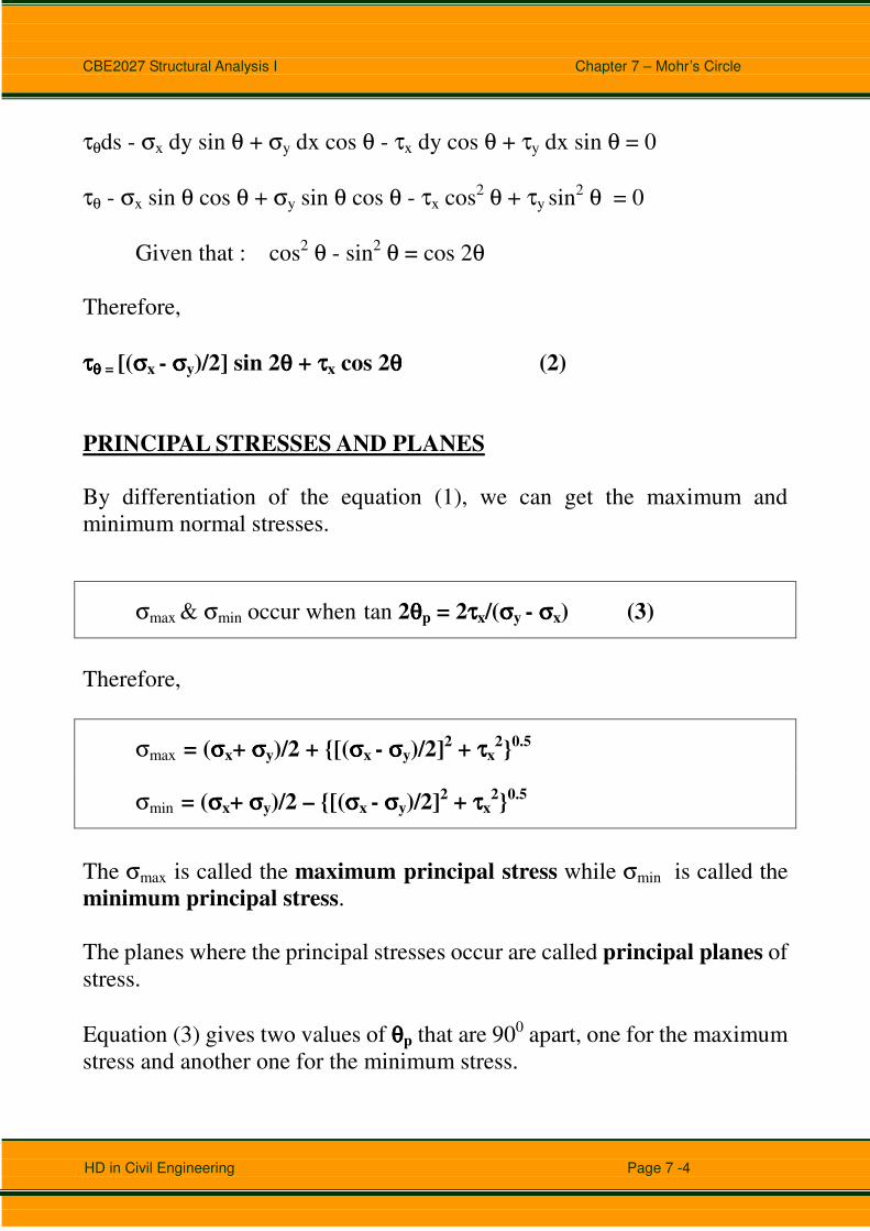
ττττθθθθ = [(σσσσx - σσσσy)/2] sin 2θθθθ + ττττx cos 2θθθθ (2)
PRINCIPAL STRESSES AND PLANES
By differentiation of the equation (1), we can get the maximum and
minimum normal stresses.
σmax & σmin occur when tan 2θθθθp = 2ττττx/(σσσσy - σσσσx) (3)
Therefore,
σmax = (σσσσx+ σσσσy)/2 + {[(σσσσx - σσσσy)/2]2 + ττττx2}0.5
σmin = (σσσσx+ σσσσy)/2 – {[(σσσσx - σσσσy)/2]2 + ττττx2}0.5
The σmax is called the maximum principal stress while σmin is called the
minimum principal stress.
The planes where the principal stresses occur are called principal planes of
stress.
Equation (3) gives two values of θθθθp that are 900 apart, one for the maximum
stress and another one for the minimum stress.

CBE2027 Structural Analysis I Chapter 7 – Mohr’s Circle
HD in Civil Engineering Page 7 -5
MAXIMUM SHEAR STRESSES
By differentiation of the equation (2), we can get the maximum and
minimum shear stresses.
The maximum shear stress is equal to
ττττmax = {[(σσσσx - σσσσy)/2]2 + ττττx2}0.5
ττττmin = -{[(σσσσx - σσσσy)/2]2 + ττττx2}0.5
Obviously, the calculations for finding σmax,σmin,τmax and τmin are very
complicate.
By the use of a graphical method (Mohr’s Circle), these values can be
determined very easily.

CBE2027 Structural Analysis I Chapter 7 – Mohr’s Circle
HD in Civil Engineering Page 7 -6
STRESS ELEMENTS
The following figures show how to draw stress elements for analysis.

CBE2027 Structural Analysis I Chapter 7 – Mohr’s Circle
HD in Civil Engineering Page 7 -7

CBE2027 Structural Analysis I Chapter 7 – Mohr’s Circle
HD in Civil Engineering Page 7 -8

CBE2027 Structural Analysis I Chapter 7 – Mohr’s Circle
HD in Civil Engineering Page 7 -9
MOHR’S CIRCLE
The Mohr’s circle gives a complete visual picture of the state of stress (or
strain) at a point in a structure and is often easier to use and interpret than a
set of equations.
The symbols for the stresses
The symbols for the stresses have the following meanings:
• A normal stress σσσσ has a subscript that identifies the face on which it acts.
For example, σσσσx acts on the x face of the element.
• A shear stress ττττ has two subscripts: the first indicate the face on which
stress acts, and the second gives the direction of the stress.
For example, ττττxy acts on the x face in the direction of the y axis;
ττττyx acts on the y face in the direction of the x axis.
From consideration of static equilibrium, we note that ττττyx = ττττxy

CBE2027 Structural Analysis I Chapter 7 – Mohr’s Circle
HD in Civil Engineering Page 7 -10
Sign conventions of Mohr’s Circle
Normal stress σσσσ: Tensile stresses are considered Positive,
Compressive stresses are considered Negative.
Shear Stress ττττ: Positive when it tend to rotate the element Clockwise,
Negative when it tend to rotate the element
Counter-clockwise)
Inclination Angle θ: Positive when measured Counter-clockwise.
CBE2027 Structural Analysis I Chapter 7 – Mohr’s Circle
HD in Civil Engineering Page 7 -11
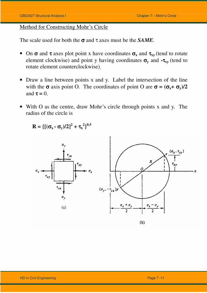
Method for Constructing Mohr’s Circle
The scale used for both the σσσσ and τ axes must be the SAME.
• On σσσσ and ττττ axes plot point x have coordinates σσσσx and ττττxy (tend to rotate
element clockwise) and point y having coordinates σσσσy and -ττττxy (tend to
rotate element counterclockwise).
• Draw a line between points x and y. Label the intersection of the line
with the σσσσ axis point O. The coordinates of point O are σσσσ = (σσσσx+ σσσσy)/2
and ττττ = 0.
• With O as the centre, draw Mohr’s circle through points x and y. The
radius of the circle is
R = {[(σσσσx - σσσσy)/2]2 + ττττx2}0.5

CBE2027 Structural Analysis I Chapter 7 – Mohr’s Circle
HD in Civil Engineering Page 7 -12
Method for Finding Stresses on an Inclined Plane
The method for finding stresses on planes of the element that form angles θ
of with respect to the x and y axes are as follow:
• Rotate the diameter xOy by an angle of 2θ in the SAME DIRECTION as
for the element.
• Locate the points n and t on the circle.
• The coordinates of the point n give the stresses σσσσn and ττττnt.
• The coordinates of the point t give the stresses σσσσt and -ττττtn.
• The values of as the coordinates (σσσσn , ττττnt) and (σσσσt , -ττττtn) may be measured
from the diagram or calculated using geometric relationships.
The important concept to remember is that:
Angles used in Mohr’s circle are double the true angles

CBE2027 Structural Analysis I Chapter 7 – Mohr’s Circle
HD in Civil Engineering Page 7 -13

CBE2027 Structural Analysis I Chapter 7 – Mohr’s Circle
HD in Civil Engineering Page 7 -14
Example 1
A stress element is subject to the following stresses.
σσσσx = 0 MPa; σσσσy = 0 MPa ; ττττxy= 40 MPa
1. Draw the initial stress element.
2. Draw the complete Mohr’s circle, labeling critical points.
3. Draw the complete principal stress element.
4. Draw the complete shear stress element.
Solution
The coordinates of point x are σx = 0 MPa and τxy= 40 MPa. The
coordinates of point y are σy = 0 MPa ; τyx= -40 MPa
Center of O of the circle is at:
σ = (σx+ σy)/2 = 0
The radius of the circle:
R = {[(σx - σy)/2]2 + τx2}0.5 = 40 MPa

CBE2027 Structural Analysis I Chapter 7 – Mohr’s Circle
HD in Civil Engineering Page 7 -15
It is noted that on the principal planes the shear stress is zero.

CBE2027 Structural Analysis I Chapter 7 – Mohr’s Circle
HD in Civil Engineering Page 7 -16
Example 2
A stress element is subject to the following stresses.
σσσσx = -30 MPa; σσσσy = 20 MPa ; ττττxy= 40 MPa
5. Draw the initial stress element.
6. Draw the complete Mohr’s circle, labeling critical points.
7. Draw the complete principal stress element.
8. Draw the complete shear stress element.
Solution
The coordinates of point x are σx = -30 MPa and τxy= 40 MPa. The
coordinates of point y are σy = 20 MPa ; τyx= -40 MPa
Center of O of the circle is at:
σ = (σx+ σy)/2 = (-30 + 20)/2 = -5 MPa
The radius of the circle:
R = {[(σx - σy)/2]2 + τx2}0.5
= {[(-30 - 20)/2]2 + 402}0.5
= 47.17 MPa

CBE2027 Structural Analysis I Chapter 7 – Mohr’s Circle
HD in Civil Engineering Page 7 -17

CBE2027 Structural Analysis I Chapter 7 – Mohr’s Circle
HD in Civil Engineering Page 7 -18
IMPORTANT NOTES
From the Mohr’s Circle, we can note that:
• On the principal planes the shear stress is zero.
• The maximum shear stress occurs where the diameter of the circle is in a
vertical position.
• The magnitude of the maximum shear stress is equal to the radius of the
circle.
• The normal stress σσσσ’ associated with the maximum shear stress is equal
to the average normal stress σσσσave,
σσσσ’ = (σσσσx+ σσσσy)/2
• The planes of maximum shear stress form angles of 450 with the principal
planes.

CBE2027 Structural Analysis I Chapter 7 – Mohr’s Circle
HD in Civil Engineering Page 7 -19

CBE2027 Structural Analysis I Chapter 7 – Mohr’s Circle
HD in Civil Engineering Page 7 -20
Example 3
At a certain point in a stressed body, the principal stresses are σx = 80 MPa
and σy = -40 MPa. Determine σ and τ on the planes whose normals are at
=300 and +1200 with the x-axis. Show your results on a sketch of a
differential element.
Solution
The coordinates of point x are σx = 80 MPa and τxy= 0 MPa. The
coordinates of point y are σy = -40 MPa ; τyx= 0 MPa
Center of O of the circle is at:
σ = (σx+ σy)/2 = (80 + -40)/2 = 20 MPa
The radius of the circle:
R = {[(σx - σy)/2]2 + τx2}0.5
= {[(80 + 40)/2]2 + 02}0.5
= 60 MPa

CBE2027 Structural Analysis I Chapter 7 – Mohr’s Circle
HD in Civil Engineering Page 7 -21
on the 300 face, i.e. at point D
σ = 50 MPa
τ = 52 MPa
on the 1200 face, i.e. at point E
σ’ = -10 MPa
τ’ = -52 MPa

CBE2027 Structural Analysis I Chapter 7 – Mohr’s Circle
HD in Civil Engineering Page 7 -22
Example 4
A material is subject to two mutually perpendicular direct stresses of +80
MPa and -50 MPa together with a shear stress of 30MPa as shown in the
following figure.
Find
1. the magnitude and nature of the principal stresses;
2. the magnitude of the maximum shear stresses in the plane of the given
stress system;
3. the direction of the planes on which the principal stresses act.
Obtain your answer by means of a Mohr’s circle diagram, and from the
diagram determine the magnitude of the normal stress on a plane inclined at
200 counterclockwise to the plane on which the 50 MPa stress acts.
Solution
The coordinates of point x are σx = -50 MPa and τxy= -30 MPa. The
coordinates of point y are σy = 80 MPa ; τyx= 30 MPa
Center of O of the circle is at:
σ = (σx+ σy)/2 = (80 + -50)/2 = 15 MPa
The radius of the circle:
R = {[(σx - σy)/2]2 + τx2}0.5
= {[(-50 - 80)/2]2 + 302}0.5
= 72 MPa
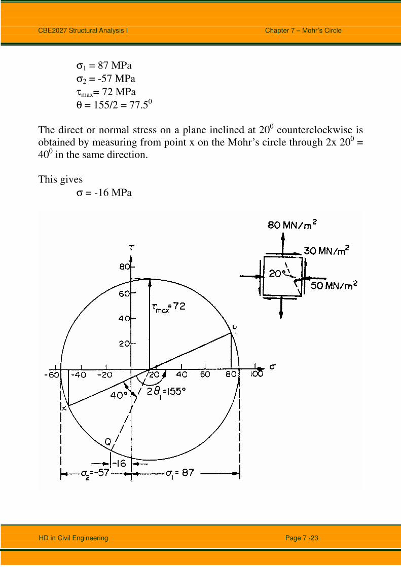
By measurement from the Mohr’s circle,
CBE2027 Structural Analysis I Chapter 7 – Mohr’s Circle
HD in Civil Engineering Page 7 -23
σ1 = 87 MPa
σ2 = -57 MPa
τmax= 72 MPa
θ = 155/2 = 77.50
The direct or normal stress on a plane inclined at 200 counterclockwise is
obtained by measuring from point x on the Mohr’s circle through 2x 200 =
400 in the same direction.
This gives
σ = -16 MPa

CBE2027 Structural Analysis I Chapter 7 – Mohr’s Circle
HD in Civil Engineering Page 7 -24
PRINCIPAL STRSSES AND MAXIMUM SHEAR STRESSES IN BEAM
The normal and shear stresses acting at any point in the cross section of
beam can be obtained from the flexure and shear formulas (σ=My/I and
τ=SAY/It). The normal stress is a maximum at the outer edges of the beam
and equals zero at the neutral axis, whereas the shear stress is zero at the
outer edges and usually is a maximum at the neutral axis.

CBE2027 Structural Analysis I Chapter 7 – Mohr’s Circle
HD in Civil Engineering Page 7 -25
Example 5
Determine the principal stresses and maximum shear stresses at point C by a
Mohr’s circle construction for the I-section beam as shown in the following
figure.
200 mm
20 mm
20 mm
20 mm
100 mm
C
Solution
The reaction at support A is 40 kN and hence at the required cross-section of
the beam:
M = 40 x 1 = 40 kNm;
V = 40 kN;
I = 100(240)3/12 – 2 x 40 x 2003/12
= 6.19 x 107mm4
CBE2027 Structural Analysis I Chapter 7 – Mohr’s Circle
HD in Civil Engineering Page 7 -26
The bending stress at point C ,
σc = (40 x 106 x 100)/6.19 x 107
= 64.6 N/mm2
= 64.6 MPa
The shear stress at point C,
τc = [40 x 103 x (100 x 20) x (100+10)] / (I x 20)
= 7.11 N/mm2
= 7.11 MPa
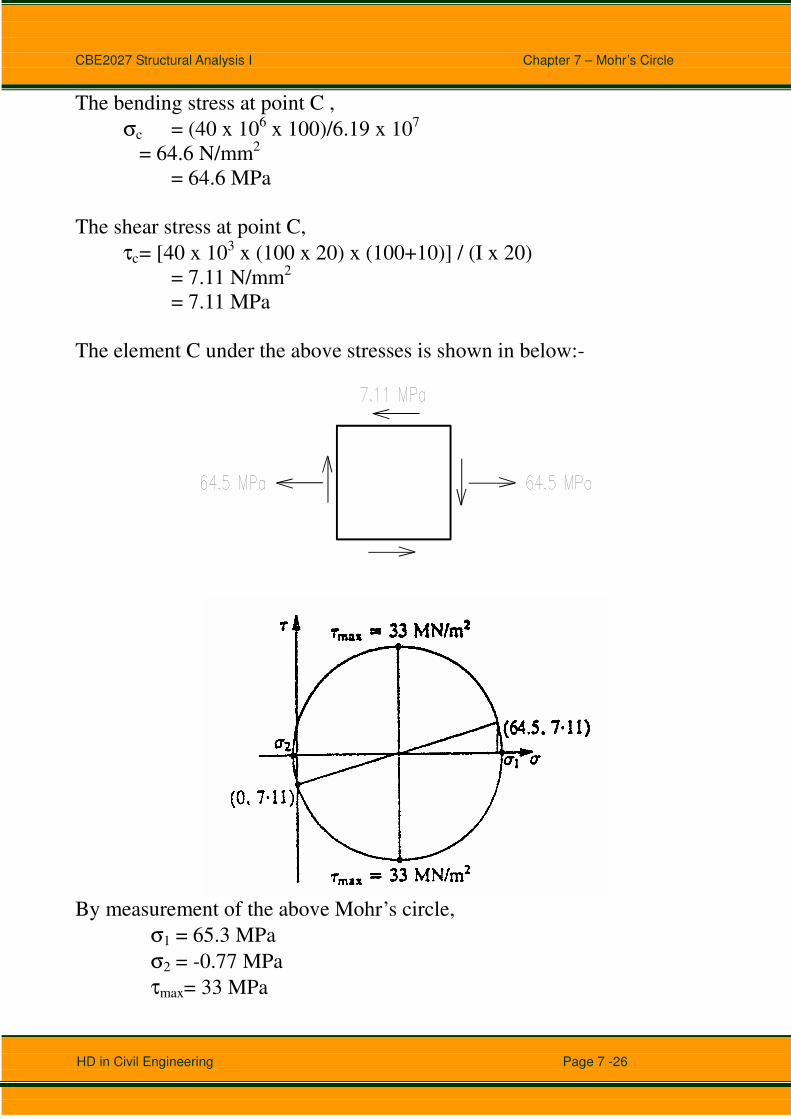
The element C under the above stresses is shown in below:-
By measurement of the above Mohr’s circle,
σ1 = 65.3 MPa
σ2 = -0.77 MPa
τmax= 33 MPa

CBE2027 Structural Analysis I Chapter 7 – Mohr’s Circle
HD in Civil Engineering Page 7 -27
Problems

CBE2027 Structural Analysis I Chapter 7 – Mohr’s Circle
HD in Civil Engineering Page 7 -28
Problems
Related Documents