Contents General � � � � � � � � � � � � � � � � � � � � � � � � � � � � � � � � � � � � 1 Safety Information � � � � � � � � � � � � � � � � � � � � � � � � � � � 2 Product Information 3 Installation Procedures 3 Preparation of Concentric Neutral Cable � � � � � � 3 Cable Housing and Fuse Assembly 6 Elbow Housing and Probe Assembly 8 Operating Instructions � � � � � � � � � � � � � � � � � � � � � � � 10 Loadmake Operation 10 Fault Close 10 Loadbreak Operation 10 Voltage Test Operation 11 PRODUCT INFORMATION Introduction The 15, 25, and 28 kV Class Fused Loadbreak Elbow Connectors from Cooper Power Systems combines a fully-shielded and insulated plug-in termination with full- range current-limiting fuse protection� The Fused Loadbreak Elbow Connector provides a convenient and cost effective means to adding fused protection to underground distribution systems, for connecting underground cables to transformers, switching cabinets and junctions equipped with 200 A, 15, 25, and 28 kV Class loadbreak bushings, manufactured to IEEE Std 386™ standard� Read This Manual First Read and understand the contents of this manual and follow all locally approved procedures and safety practices before installing or operating this equipment� Loadbreak Apparatus Connectors Fused Loadbreak Elbow Connector Installation Instructions S500-110-1 Service Information 0712 • Supersedes 0311 1 Figure 1 Line illustration of 25 kV Class Fused Elbow ARC FOLLOWER LOADBREAK PROBE PULLING EYE COPPERTOP CONNECTOR DRAIN WIRE TAB SEMI-CONDUCTIVE INSERT LOADBREAK BAND EPDM INSULATION SEMI-CONDUCTING SHIELD WARNING: All associated apparatus must be de-energized during any hands-on installation or maintenance Failure to comply could result in death, severe personal injury and equipment damage ! WARNING: Capacitive Test Point Operating Instructions: Use only voltage indicating instruments specifically designed for test points Use of conventional volt- age sensing devices may provide false “No Voltage” indications The test point must be dry and free of contaminants when checking for voltage After indication is taken: clean, dry, and lubricate the test point cap with silicone grease and assemble to the test point Always consider the termination to be energized until the test point “No Voltage” indication is confirmed by other means Failure to comply could result in death or severe personal injury ! DRAIN WIRE TAB CURRENT- LIMITING FUSE PROBE ADAPTER ! TEST POINTS

Welcome message from author
This document is posted to help you gain knowledge. Please leave a comment to let me know what you think about it! Share it to your friends and learn new things together.
Transcript

ContentsGeneral � � � � � � � � � � � � � � � � � � � � � � � � � � � � � � � � � � � � 1Safety Information � � � � � � � � � � � � � � � � � � � � � � � � � � � 2Product Information . . . . . . . . . . . . . . . . . . . . . . . . . . 3Installation Procedures . . . . . . . . . . . . . . . . . . . . . . . 3 Preparation of Concentric Neutral Cable � � � � � � 3 Cable Housing and Fuse Assembly . . . . . . . . . . 6 Elbow Housing and Probe Assembly . . . . . . . . . 8Operating Instructions � � � � � � � � � � � � � � � � � � � � � � � 10 Loadmake Operation . . . . . . . . . . . . . . . . . . . . . 10 Fault Close . . . . . . . . . . . . . . . . . . . . . . . . . . . . . 10 Loadbreak Operation . . . . . . . . . . . . . . . . . . . . . 10 Voltage Test Operation . . . . . . . . . . . . . . . . . . . 11
produCt informationintroductionThe 15, 25, and 28 kV Class Fused Loadbreak Elbow Connectors from Cooper Power Systems combines a fully-shielded and insulated plug-in termination with full-range current-limiting fuse protection� The Fused Loadbreak Elbow Connector provides a convenient and cost effective means to adding fused protection to underground distribution systems, for connecting underground cables to transformers, switching cabinets and junctions equipped with 200 A, 15, 25, and 28 kV Class loadbreak bushings, manufactured to IEEE Std 386™ standard�
read this manual firstRead and understand the contents of this manual and follow all locally approved procedures and safety practices before installing or operating this equipment�
Loadbreak apparatus Connectors
fused Loadbreak Elbow Connector installation instructions S500-110-1
Service information
0712 • Supersedes 0311 1
Figure 1 .Line illustration of 25 kV Class Fused Elbow .
ARC FOLLOWER
LOADBREAK PROBE
PULLING EYE
COPPERTOP CONNECTOR
DRAIN WIRE TAB
SEMI-CONDUCTIVE INSERT
LOADBREAK BAND
EPDM INSULATION
SEMI-CONDUCTING SHIELD
WarninG: All associated apparatus must be de-energized during any hands-on installation or maintenance . Failure to comply could result in death, severe personal injury and equipment damage .
!
WarninG: Capacitive Test Point Operating Instructions: Use only volt age in di cat ing in struments spe cif i cal ly de signed for test points . Use of convention al volt-age sensing devices may provide false “No Voltage” indications .
The test point must be dry and free of con tam i nants when checking for voltage . After indication is taken: clean, dry, and lubricate the test point cap with silicone grease and assemble to the test point .
Always consider the termination to be energized until the test point “No Voltage” indication is confirmed by other means . Failure to comply could result in death or severe personal injury .
! DRAIN WIRE TAB
CURRENT-LIMITING FUSE
PROBE ADAPTER
!
TEST POINTS

Fused Loadbreak Elbow Connector Installation Instructions
2
The instructions in this manual are not intended as a sub stitute for proper training or adequate experience in the safe operation of the equipment described� Only competent technicians, who are familiar with this equipment should install, operate and service it�
A competent technician has these qualifications:n Is thoroughly familiar with these instructions.n Is trained in industry-accepted high- and low-voltage
safe operating practices and procedures.n Is trained and authorized to energize, de-energize, clear,
and ground power distribution equipment.n Is trained in the care and use of protective equipment
such as flash clothing, safety glasses, face shield, hard hat, rubber gloves, clampstick, hotstick, etc.
Following is important safety information� For safe installation and operation of this equipment, be sure to read and understand all cautions and warnings�
Safety instructions
Following are general caution and warning statements that apply to this equipment� Additional statements, related to specific tasks and procedures, are located throughout the manual�
danGEr: Hazardous voltage . Contact with high voltage will cause death or severe personal injury . Follow all locally approved safety procedures when working around high- and low-voltage lines and equipment .
!
WarninG: Before installing, operating, maintaining, or testing this equipment, carefully read and understand the contents of this manual . Improper operation, handling or maintenance can result in death, severe personal injury, and equipment damage .
!
WarninG: This equipment is not intended to protect human life . Follow all locally approved procedures and safety practices when installing or operating this equipment . Failure to comply may result in death, severe personal injury and equipment damage .
!
WarninG: Power distribution and transmission equipment must be properly selected for the intended application . It must be installed and serviced by competent personnel who have been trained and understand proper safety procedures . These instructions are written for such personnel and are not a substitute for adequate training and experience in safety procedures . Failure to properly select, install or maintain power distribution and transmission equipment can result in death, severe personal injury, and equipment damage .
!
SafEtY for LifECooper Power Systems products meet or exceed all applicable industry standards relating to product safety� We actively promote safe practices in the use and maintenance of our products through our service literature, instructional training programs, and the continuous efforts of all Cooper Power Systems employees involved in product design, manufacture, marketing and service�
We strongly urge that you always follow all locally approved safety procedures and safety instructions when working around high-voltage lines and equipment and support our “Safety For Life” mission�
!SAFETYFOR LIFE
!SAFETYFOR LIFE
SafEtY information
This manual may contain four types of hazard statements:
danGEr: Indicates a hazardous situation which, if not avoided, will result in death or serious injury .
WarninG: Indicates a hazardous situation which, if not avoided, could result In death or serious injury .
Caution: Indicates a hazardous situation which, if not avoided, could result in minor or moderate injury .
Caution: Indicates a hazardous situation which, if not avoided, could result in equipment damage only .
Hazard Statement definitions
!
!
!
S500-110-1
3
!SAFETYFOR LIFE
additional informationThese instructions cannot cover all details or variations in the equipment, procedures, or process described nor provide directions for meeting every possible contingency during installation, operation, or maintenance� When additional information is desired to satisfy a problem not covered sufficiently for the user's purpose, please contact your Cooper Power Systems sales representative�
acceptance and initial inspectionEach Fused Loadbreak Elbow Connector is completely inspected and tested at the factory� It is in good condition when accepted by the carrier for shipment� Upon receipt of a Loadbreak Elbow Connector Kit, inspect the connector thoroughly for damage and loss of parts incurred during shipment� If damage or loss is discovered, file a claim with the carrier immediately�
Cable stripping and scoring tools, available from various tool manufacturers, are recommended for use when installing fused loadbreak elbows� After preparing the cable, the fused loadbreak elbow housing is pushed onto the cable� The current-limiting fuse is threaded into the coppertop connector and the loadbreak probe is installed into the probe adapter using tools provided� Use a clampstick to perform loadmake and loadbreak operations� (See page 10 for Operating Procedures.)
Complete elbow kit includes:n Fused Loadbreak Elbow Bodyn Current-Limiting Fuse Sold Separately n Coppertop Compression Connectorn Probe Adapter n Loadbreak Probe n Probe Installation Tooln 1/8" Hex Wrenchn 3/16" Hex Wrench Supplied with Fuse Sold Separately n Silicone Lubricantn Installation Instruction Sheet
Tools/Accessories needed:n Tape Measure n Wire Brush n Knife n Cable Stripping Tool n Crimping Tool and Dies n Cable Cleaner n Cable Cutters n Emery Cloth n Clampstick n Personal Protection Equipment n Vinyl Tape
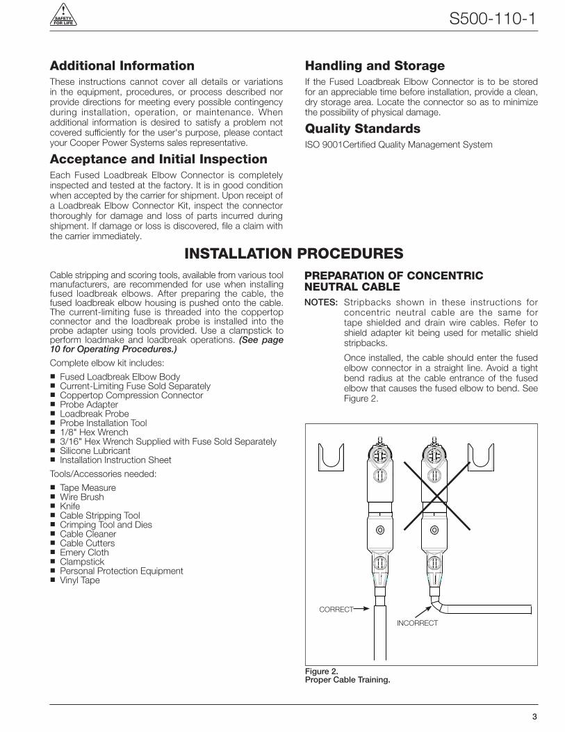
prEparation of ConCEntriC nEutraL CabLENOTES: Stripbacks shown in these instructions for
concentric neutral cable are the same for tape shielded and drain wire cables� Refer to shield adapter kit being used for metallic shield stripbacks�
Once installed, the cable should enter the fused elbow connector in a straight line� Avoid a tight bend radius at the cable entrance of the fused elbow that causes the fused elbow to bend� See Figure 2�
inStaLLation proCEdurES
Handling and StorageIf the Fused Loadbreak Elbow Connector is to be stored for an appreciable time before installation, provide a clean, dry storage area� Locate the connector so as to minimize the possibility of physical damage�
Quality StandardsISO 9001Certified Quality Management System
Figure 2 .Proper Cable Training .
CORRECT
INCORRECT
Fused Loadbreak Elbow Connector Installation Instructions
4
Step 1 Step 2
INSULATION SHIELD
CABLE JACKET
BEND NEUTRAL
WIRES DOWNAND OUT OF
THE WAY
MARK CENTERLINE OF BUSHING
Step 3
SQUARE CUT
ALLOW ExCESS CABLE
LOADBREAK BUSHING INSERT
ExCESS CABLE
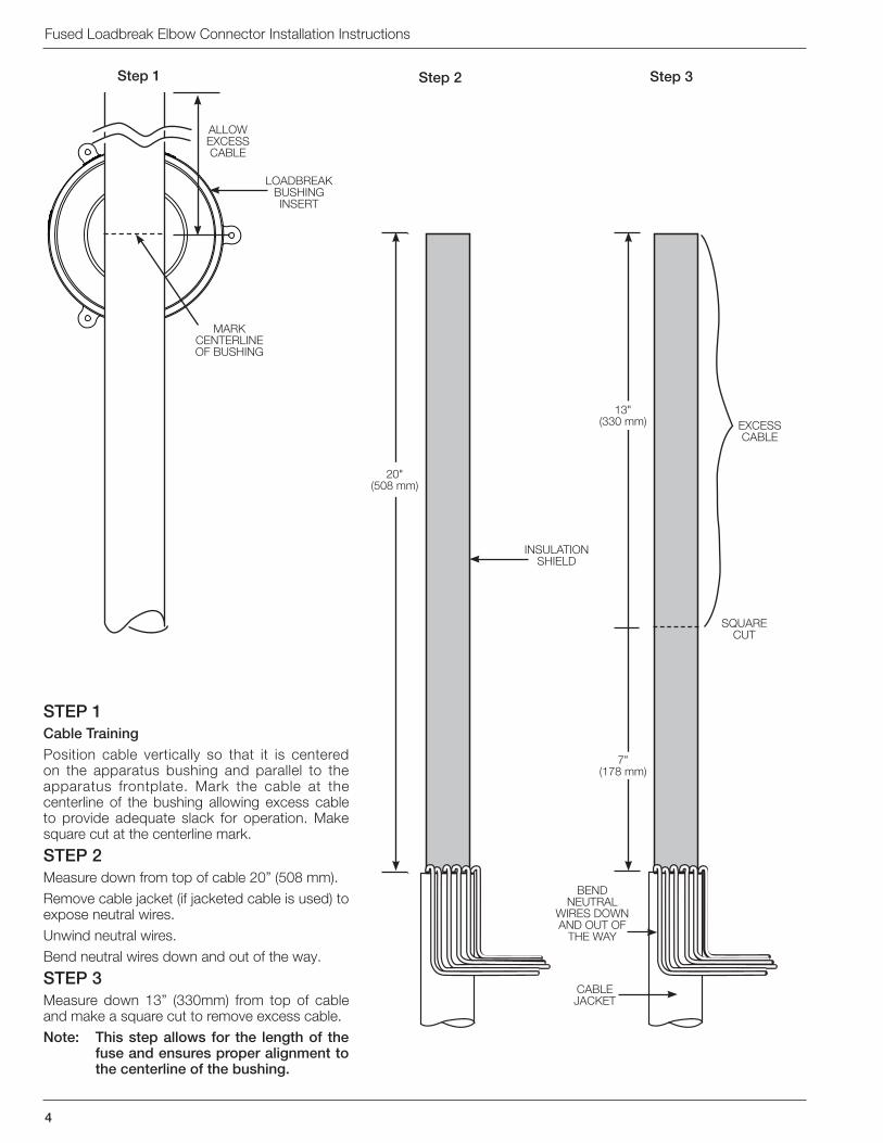
STEP 1Cable TrainingPosition cable vertically so that it is centered on the apparatus bushing and parallel to the apparatus frontplate� Mark the cable at the centerline of the bushing allowing excess cable to provide adequate slack for operation� Make square cut at the centerline mark�
STEP 2Measure down from top of cable 20” (508 mm)�Remove cable jacket (if jacketed cable is used) to expose neutral wires�Unwind neutral wires�Bend neutral wires down and out of the way�
STEP 3Measure down 13” (330mm) from top of cable and make a square cut to remove excess cable�Note: This step allows for the length of the
fuse and ensures proper alignment to the centerline of the bushing .
20" (508 mm)
13" (330 mm)
7" (178 mm)
S500-110-1
5
!SAFETYFOR LIFE
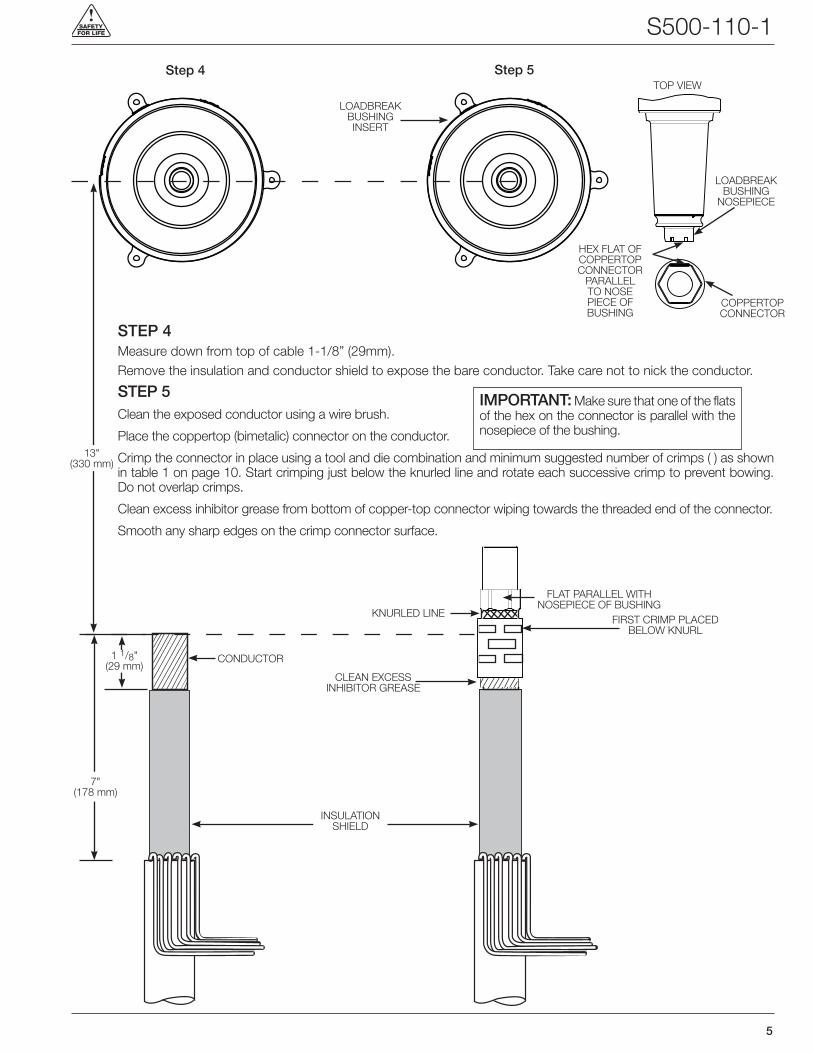
STEP 4Measure down from top of cable 1-1/8” (29mm)�Remove the insulation and conductor shield to expose the bare conductor� Take care not to nick the conductor�
STEP 5Clean the exposed conductor using a wire brush�
Place the coppertop (bimetalic) connector on the conductor�
Crimp the connector in place using a tool and die combination and minimum suggested number of crimps ( ) as shown in table 1 on page 10� Start crimping just below the knurled line and rotate each successive crimp to prevent bowing� Do not overlap crimps�
Clean excess inhibitor grease from bottom of copper-top connector wiping towards the threaded end of the connector�
Smooth any sharp edges on the crimp connector surface�
Step 5Step 4
CONDUCTOR
CLEAN ExCESS INHIBITOR GREASE
1 1/8" (29 mm)
TOP VIEW
HEx FLAT OF COPPERTOP CONNECTOR
PARALLEL TO NOSE PIECE OF BUSHING
IMPORTANT: Make sure that one of the flats of the hex on the connector is parallel with the nosepiece of the bushing�
LOADBREAK BUSHING INSERT
LOADBREAK BUSHING
NOSEPIECE
COPPERTOP CONNECTOR
13" (330 mm)
INSULATION SHIELD
FLAT PARALLEL WITH NOSEPIECE OF BUSHING
KNURLED LINEFIRST CRIMP PLACED
BELOW KNURL
7" (178 mm)
Fused Loadbreak Elbow Connector Installation Instructions
6
Step 6
1/8"(3 mm) BEVEL
5 1/2" (140 mm)
Step 7
TEST POINT FACING OUTWARD
ALIGN HOUSING WITH TOP OF TAPE MARKERTAPE
MARKER
5 7/8"(149 mm)
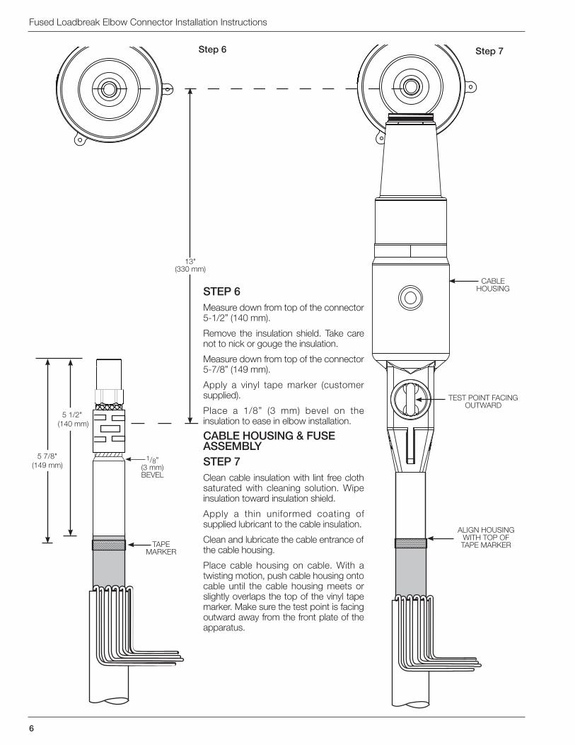
STEP 6Measure down from top of the connector 5-1/2” (140 mm)�
Remove the insulation shield� Take care not to nick or gouge the insulation�
Measure down from top of the connector 5-7/8” (149 mm)�
Apply a vinyl tape marker (customer supplied)�
Place a 1/8” (3 mm) bevel on the insulation to ease in elbow installation�
CABLE HOUSING & FUSE ASSEMBLY STEP 7Clean cable insulation with lint free cloth saturated with cleaning solution� Wipe insulation toward insulation shield�
Apply a thin uniformed coating of supplied lubricant to the cable insulation�
Clean and lubricate the cable entrance of the cable housing�
Place cable housing on cable� With a twisting motion, push cable housing onto cable until the cable housing meets or slightly overlaps the top of the vinyl tape marker� Make sure the test point is facing outward away from the front plate of the apparatus�
CABLE HOUSING
13" (330 mm)
!SAFETYFOR LIFE S500-110-1
7
Step 8 Step 9
INSERT FUSE
THREADED END
CHECK DIMENSIONUse the Hex
wrench notch to measure proper
depth�
3/16" HEx WRENCH
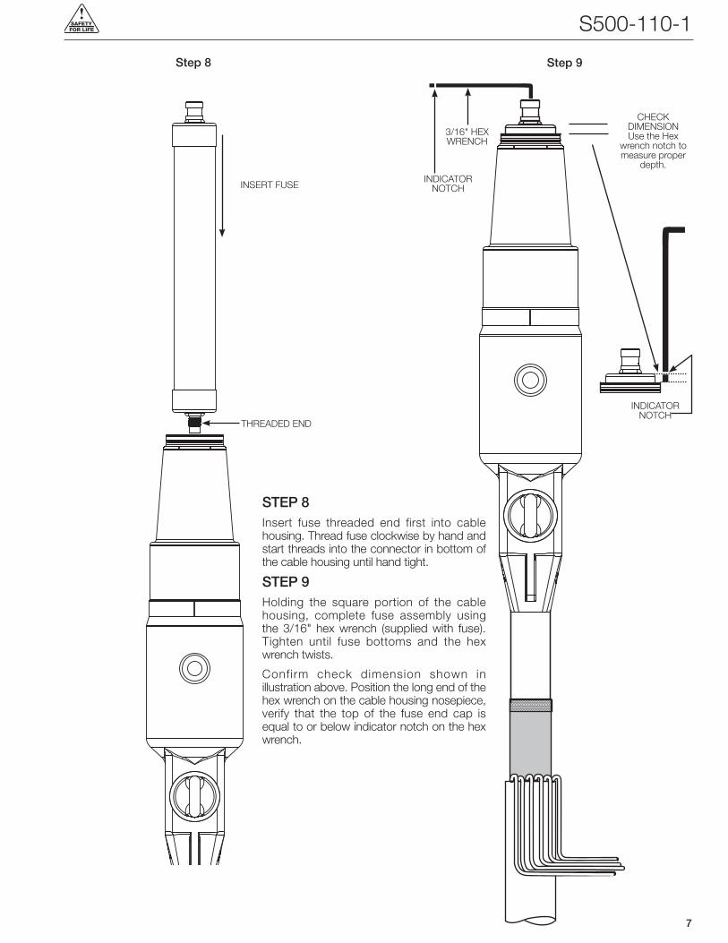
STEP 8Insert fuse threaded end first into cable housing� Thread fuse clockwise by hand and start threads into the connector in bottom of the cable housing until hand tight�
STEP 9Holding the square portion of the cable housing, complete fuse assembly using the 3/16" hex wrench (supplied with fuse)� Tighten until fuse bottoms and the hex wrench twists�
Confirm check dimension shown in illustration above� Position the long end of the hex wrench on the cable housing nosepiece, verify that the top of the fuse end cap is equal to or below indicator notch on the hex wrench�
INDICATOR NOTCH
INDICATOR NOTCH
Fused Loadbreak Elbow Connector Installation Instructions
8
Step 10 Step 11
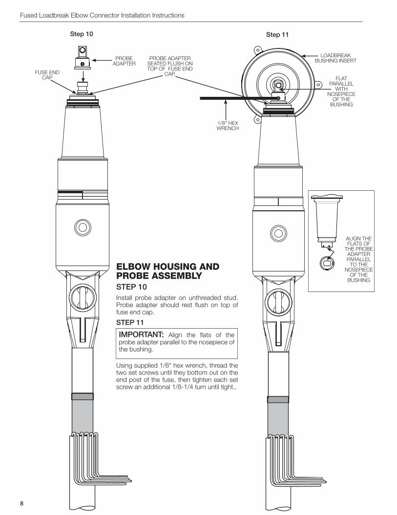
ELboW HouSinG and probE aSSEmbLYSTEP 10Install probe adapter on unthreaded stud� Probe adapter should rest flush on top of fuse end cap�
STEP 11
Using supplied 1/8" hex wrench, thread the two set screws until they bottom out on the end post of the fuse, then tighten each set screw an additional 1/8-1/4 turn until tight��
PROBE ADAPTER
1/8" HEx WRENCH
PROBE ADAPTER SEATED FLUSH ON TOP OF FUSE END
CAP�FUSE END CAP
20.305
5.272
4.547
1.747
3.857
15KV
ALIGN THE FLATS OF
THE PROBE ADAPTER PARALLEL
TO THE NOSEPIECE
OF THE BUSHING
FLAT PARALLEL
WITH NOSEPIECE
OF THE BUSHING
IMPORTANT: Align the flats of the probe adapter parallel to the nosepiece of the bushing�
LOADBREAK BUSHING INSERT

S500-110-1
9
!SAFETYFOR LIFE
Step 12 Step 13
ASSEMBLE LOADBREAK
PROBE
DRAIN WIRES
FACING OUTWARD
INSERT ELBOW
STEP 12
Assemble elbow housing onto the cable housing� Make sure the test point is facing outward away from the front plate of the apparatus�
STEP 13
Push down and twist elbow housing to align the probe adapter� The threaded hole in the probe adapter should be centered with respect to the hole in the elbow housing and perpendicular to the probe axis� By hand, insert loadbreak probe into the elbow housing along the center axis of the interface and thread the probe into the probe adapter� A thin layer of silicone lubricant applied to the last ¼” (6 mm) of the probe body (not on the threads) can aid in installation�
After at least three turns or when the probe is seated (5-1/2 turns) onto the probe adapter, use provided installation tool to properly torque the loadbreak probe� Proper torque is applied when the tool twists at least 180° (1/2 turn)�
NOTE: If a different installation tool is used it must apply a torque of 100 to 120 lbf-in (11�0 – 13�5 N-m)�
Clean and lubricate bushing and elbow housing interfaces areas with a thin uniformed coating of the silicone provided�
Attach drain wire leads to the drain wire eyes of the cable and elbow housings�
LUBRICATE INTERFACES
WITH SUPPLIED
LUBRICANT
CLEAN AND LUBRICATE INTERFACE

Fused Loadbreak Elbow Connector Installation Instructions
10
Do not connect two different phases of a multiple-phase system� Before closing a single-phase loop, make certain both ends of the loop are the same phase�
Loadmake operationn Area must be clear of obstructions or contaminations
that would interfere with the operation of the fused loadbreak elbow�
n Securely fasten a clampstick to the pulling eye of the fused loadbreak elbow�
n Place the fused loadbreak elbow over the bushing, inserting the white arc follower of the probe into the bushing approximately 2 1/2” (65 mm) until a slight resistance is felt� This will align and stabilize the fused loadbreak elbow�
n Turn your back to the bushing and grasp the clampstick securely and obtain good footing� Slam the fused loadbreak elbow onto the bushing with one quick and continuous motion�
n Turn around and apply a force to the clampstick to push the fused loadbreak elbow onto the bushing� A popping or snapping sound is often heard when this operation is
performed�
n To check that the fused loadbreak elbow is properly latched apply a gentle pull force to the clampstick� When latched properly the fused loadbreak elbow will not slide back off of the bushing�
n As a last operation, push on the clampstick to seat the fused loadbreak elbow all the way onto the bushing again� This insures that the fused loadbreak elbow is latched and was not dislodged during the latching check in previous step above�
fault Close1� It is not recommended that operations be made on
known faults�
2� If a fault is experienced, the fused loadbreak elbow connector, probe, and the bushing must be replaced�
Loadbreak operationn Area must be clear of obstructions or contaminants that
would interfere with this operation�
n Use clampstick to secure standoff insulator or portable feedthru in bracket� Ground devices to system ground per appropriate Installation Instructions� All associated apparatus must also be grounded�
n Secure fused loadbreak elbow eye firmly onto clampstick and lock�
n Twist clampstick clockwise until the fused loadbreak elbow rotates slightly on bushing — about 1/4” (6 mm)� This action will break any surface friction between outer surface of bushing and inner surface of fused loadbreak elbow�
n Withdraw fused loadbreak elbow from bushing with a fast, firm, straight motion� Minimum amount of travel of fused loadbreak elbow to break load is 9” (230 mm)�
n Use clampstick to place fused loadbreak elbow on lubricated standoff insulator or portable feedthru� (Follow loadmake instructions�)
TABLE 1Crimp Chart
WarninG: The operator should always use personal protective equipment (insulated gloves, clampstick and eye protection) whenever operating the fused loadbreak elbow . The operator should always be in the best possible operating position, providing firm footing and enabling a secure grasp of the clampstick, while maintaining positive control of the elbow before, during and immediately after operation . If there is any question regarding the operator’s operating position, de-energize the elbow before operation . The operator should not be looking directly at the connector during the moment of circuit interruption or connection . Failure to comply could result in death or serious injury .
!
CONNECTOR 5/8” DIAMETER 3/4” DIAMETER
CONDUCTOR SIZE NO� 4 THRU 2/0 STRANDED 3/0 - 4/0 STRANDED
BURNDY®
TOOL Y34 Y35 OR Y39 MD6 Y34 Y35 OR Y39 MD6
DIE
A243(2)
U243(1)
UBG(2)
W243(3)
WBG(1)
U247(2)
U247(2)
U467(2)
W247(5)
A25AR(2)
U25ART(2)
U687(2)
BG (3)NOSE
W687(2)
A27AR(2)
U27ART(1)
Thomas and Betts®
TOOL UT-3 UT-5 UT-15 UT-5 UT-15
DIE 5/8” (4) TV (4) 54 H (2) TV (4) 66 (2)
Kearney™TOOL O WH2, WH3, BH4, WH4,
PH2, PH13 O WH2, WH3, BH4, WH4, PH2, PH13
DIE5/8”
NOSE (3) 9/16” (3) 9/16” (2) 572 (1) 737 (3) 747 (2) 737 (2) 747 (1)
( ) Minimum suggested number of crimps .
opEratinG proCEdurES

S500-110-1
11
!SAFETYFOR LIFE
n Place an insulated protective cap with ground wire attached to system ground on any exposed energized bushing using clampstick� Follow the same operating procedures as for the fused loadbreak elbow as outlined above under Loadmake Operation�
Voltage test operationThe fused loadbreak elbow connector is equipped with two integral capacitance test points that can be used to establish whether or not the fuse has interrupted the circuit� The test point on the feed side of an open fuse will indicate a voltage while the test point on the load side will indicate no voltage� Both test points will indicate voltage if the fuse has not opened
Replacing a cleared fuse .See Service Section S240-97-1 included with replacement fuse�
WarninG: Capacitive Test Point Operating Instructions: Use only volt age in di cat ing in struments spe cif i cal ly de signed for test points . Use of convention al volt-age sensing devices may provide false “No Voltage” indications .
The test point must be dry and free of con tam i nants when checking for voltage . After indication is taken: clean, dry, and lubricate the test point cap with silicone grease and assemble to the test point .
Always consider the termination to be energized until the test point “No Voltage” indication is confirmed by other means . Failure to comply could result in death or severe personal injury .
!

Fused Loadbreak Elbow Connector Installation Instructions
12
2300 Badger Drive Waukesha, WI 53188 USA
©2012 Cooper Industries� All Rights Reserved� Cooper Power Systems and Kearney are valuable trademarks of Cooper Industries in the U�S� and other countries� You are not permitted to use the Cooper Trademarks without the prior written consent of Cooper Industries�IEEE Std 386™ standard is a trademark of the Institute of Electrical and Electronics Engineers, Inc�, (IEEE)� This publication/product is not endorsed or approved by the IEEE�BURNDY® is a registered trademark of Hubbell Power SystemsThomas and Betts® is a registered trademark of Thomas & Betts Corporation
One Cooper | www�cooperpower�com | Online
S5001101 Rev 4 Replaces S5001101 Rev 3
1 1 /
8"
(55
mm
)5
1 /2
(175
mm
)
!SAFETYFOR LIFE
Related Documents