S2928 Hardware Installation Manual

Welcome message from author
This document is posted to help you gain knowledge. Please leave a comment to let me know what you think about it! Share it to your friends and learn new things together.
Transcript

S2928 Hardware Installation Manual
Table of Contents
- I -
Table of Contents
Table of Contents................................................................................................................................ I
Chapter 1 S2928 Introduction ........................................................................................................... 1
1.1 Appearance Description for Standard Configuration............................................................ 1
1.2 S2928 Systematic Characteristic Parameters ..................................................................... 3
1.3 ROHS Description................................................................................................................ 4
Chapter 2 Installation Preparation..................................................................................................... 5
2.1 Caution of Usage ................................................................................................................. 5
2.2 Safety Advice........................................................................................................................ 5
2.2.1 Safety Principles ........................................................................................................ 5
2.2.2 Safety Notices............................................................................................................ 5
2.2.3 Safety Principles for Live Working ............................................................................. 6
2.2.4 Electrostatic Discharge Damage Prevention ............................................................. 7
2.3 Requirements for Common Locations.................................................................................. 7
2.3.1 Environment............................................................................................................... 7
2.3.2 Location Configuration Prevention............................................................................. 7
2.3.3 Cabinet Configuration ................................................................................................ 7
2.3.4 Power Requirements ................................................................................................. 8
2.4 Installation Tools and Device................................................................................................ 8
Chapter 3 Installing the S2928 Switch .............................................................................................. 9
3.1 Installation Flow of S2928 .................................................................................................... 9
3.2 Installing the Machine Box of the Switch ............................................................................. 9
3.2.1 Installing the Machine Box on the Desk................................................................... 10
3.2.2 Installing the Machine Box on the Cabinet .............................................................. 10
3.3 Connecting the Port ........................................................................................................... 10
3.3.1 Connecting the Console Port................................................................................... 10
3.3.2 Connecting Gigabit Ethernet SFP+ Port.................................................................. 12

Table of Contents
- II -
3.3.3 Connecting Gigabit Ethernet TX Port ...................................................................... 12
3.3.4 Connecting Gigabit Ethernet SFP Port .................................................................... 14
3.4 Checking After Installation.................................................................................................. 14
Chapter 4 Maintaining Switch.......................................................................................................... 15
4.1 Opening the Machine Box.................................................................................................. 15
4.2 Closing the Machine Box ................................................................................................... 16
Chapter 5 Hardware Fault Analysis................................................................................................. 17
5.1 Fault Separation................................................................................................................. 17
5.1.1 Faults Relative with Power and Cooling System ..................................................... 17
5.1.2 Faults Relative with Port, Cable and Connection .................................................... 17
5.2 Indicator Description .......................................................................................................... 17
S2928 Hardware Installation Manual
- 1 -
Chapter 1 S2928 Introduction
The section describes the characteristics and parameters of S2928 and gives an overview of S2928.
1.1 Appearance Description for Standard Configuration
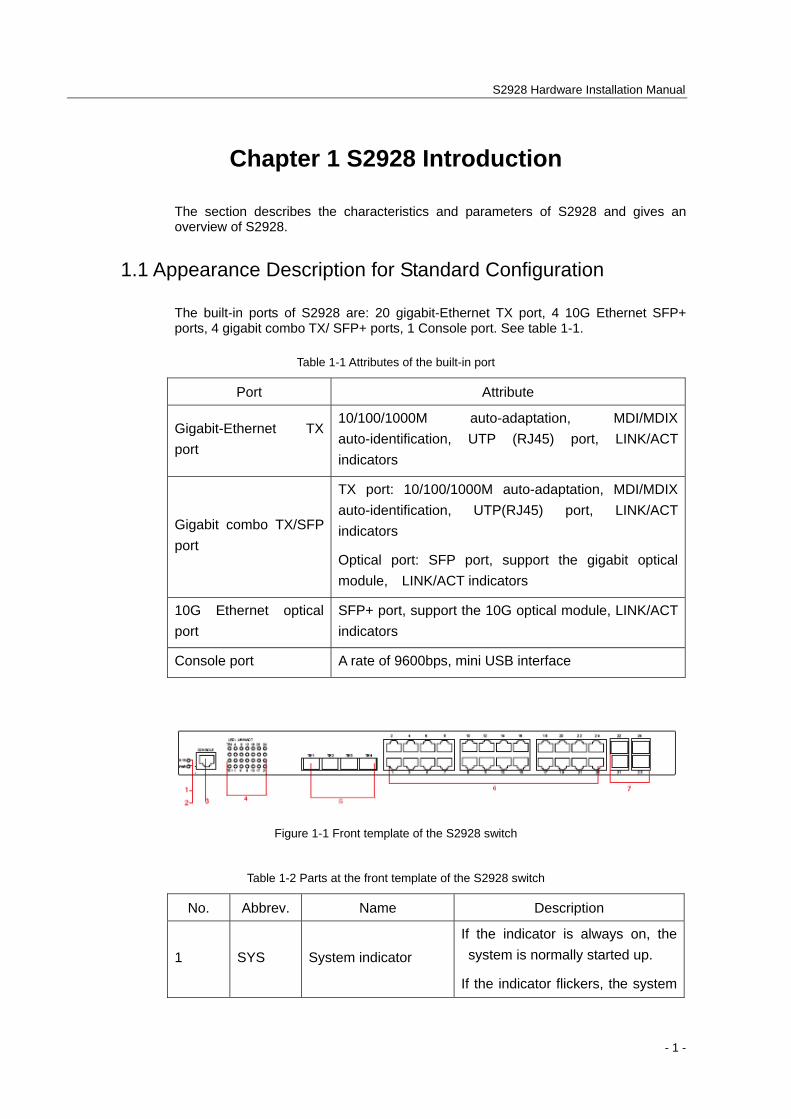
The built-in ports of S2928 are: 20 gigabit-Ethernet TX port, 4 10G Ethernet SFP+ ports, 4 gigabit combo TX/ SFP+ ports, 1 Console port. See table 1-1.
Table 1-1 Attributes of the built-in port
Port Attribute
Gigabit-Ethernet TX port
10/100/1000M auto-adaptation, MDI/MDIX auto-identification, UTP (RJ45) port, LINK/ACT indicators
Gigabit combo TX/SFP port
TX port: 10/100/1000M auto-adaptation, MDI/MDIX auto-identification, UTP(RJ45) port, LINK/ACT indicators
Optical port: SFP port, support the gigabit optical module, LINK/ACT indicators
10G Ethernet optical port
SFP+ port, support the 10G optical module, LINK/ACT indicators
Console port A rate of 9600bps, mini USB interface
Figure 1-1 Front template of the S2928 switch
Table 1-2 Parts at the front template of the S2928 switch
No. Abbrev. Name Description
1 SYS System indicator
If the indicator is always on, the system is normally started up.
If the indicator flickers, the system
S2928 Hardware Installation Manual
- 2 -
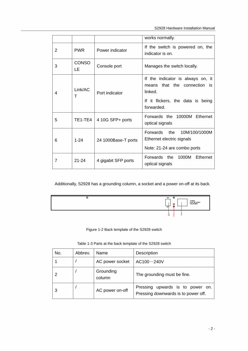
works normally.
2 PWR Power indicator If the switch is powered on, the indicator is on.
3 CONSOLE
Console port Manages the switch locally.
4 Link/ACT
Port indicator
If the indicator is always on, it means that the connection is linked.
If it flickers, the data is being forwarded.
5 TE1-TE4 4 10G SFP+ ports Forwards the 10000M Ethernet optical signals
6 1-24 24 1000Base-T ports
Forwards the 10M/100/1000M Ethernet electric signals
Note: 21-24 are combo ports
7 21-24 4 gigabit SFP ports Forwards the 1000M Ethernet optical signals
Additionally, S2928 has a grounding column, a socket and a power on-off at its back.
Figure 1-2 Back template of the S2928 switch
Table 1-3 Parts at the back template of the S2928 switch
No. Abbrev. Name Description
1 / AC power socket AC100~240V
2 / Grounding
column The grounding must be fine.
3 /
AC power on-off Pressing upwards is to power on. Pressing downwards is to power off.
S2928 Hardware Installation Manual
- 3 -
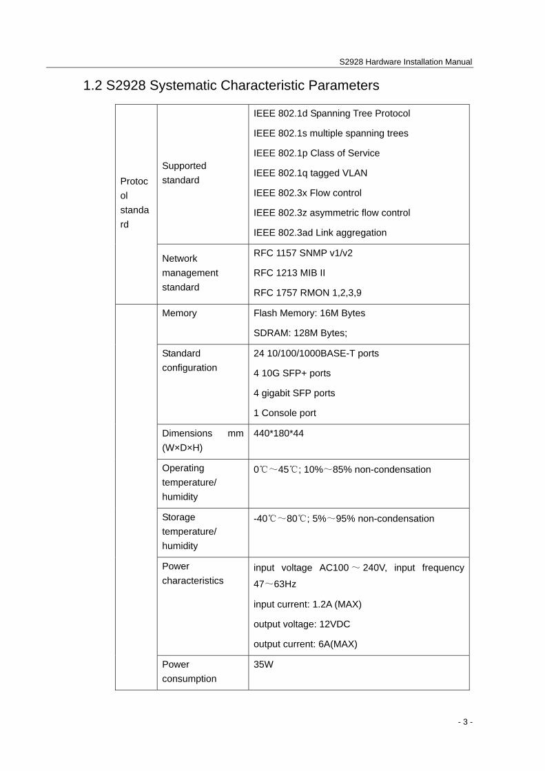
1.2 S2928 Systematic Characteristic Parameters
Supported standard
IEEE 802.1d Spanning Tree Protocol
IEEE 802.1s multiple spanning trees
IEEE 802.1p Class of Service
IEEE 802.1q tagged VLAN
IEEE 802.3x Flow control
IEEE 802.3z asymmetric flow control
IEEE 802.3ad Link aggregation
Protocol standard
Network management standard
RFC 1157 SNMP v1/v2
RFC 1213 MIB II
RFC 1757 RMON 1,2,3,9
Memory Flash Memory: 16M Bytes
SDRAM: 128M Bytes;
Standard configuration
24 10/100/1000BASE-T ports
4 10G SFP+ ports
4 gigabit SFP ports
1 Console port
Dimensions mm (W×D×H)
440*180*44
Operating temperature/ humidity
0℃~45℃; 10%~85% non-condensation
Storage temperature/ humidity
-40℃~80℃; 5%~95% non-condensation
Power characteristics
input voltage AC100 ~ 240V, input frequency
47~63Hz
input current: 1.2A (MAX)
output voltage: 12VDC
output current: 6A(MAX)
Power consumption
35W
S2928 Hardware Installation Manual
- 4 -
Net weight 2.5KG
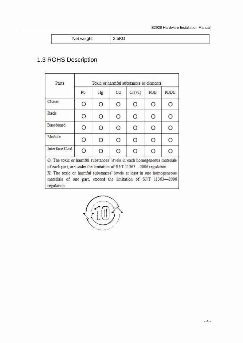
1.3 ROHS Description
S2928 Hardware Installation Manual
- 5 -
Chapter 2 Installation Preparation
2.1 Caution of Usage
Similar to other electronic products, the semiconductor chip easily gets damaged if you power on or off abruptly and frequently. To restart up the switch of S2928, you have to open the power on-off after the power is cut down for three to five seconds.
Avoid severe collision or falling down from the height to protect the parts in the switch.
Do not insert the Ethernet plug into the console port (RJ45 8-line socket). Similarly, do not insert the console cable into the console port (RJ45 8-line socket).
Note:
1) When you plug or dial the power line, keep the power line horizontal with the power socket.
2) When the lifetime of our products ends, handle them according to national laws and regulations, or send these products to our company for collective processing.
2.2 Safety Advice
2.2.1 Safety Principles
Keep dustless and clean during or after the installation.
Put the cover at the safe place.
Put tools at the right place where they are not easily falling down.
Put on relatively tight clothes fasten the tie or scarf well and roll up the sleeve, avoiding stumbling the machine box.
Put on the protective glasses if the environment may cause damage to your eyes.
Avoid incorrect operations that may cause damage to human or devices.
2.2.2 Safety Notices
The safety notices mentioned here means that improper operation may lead to body damage.
Read the installation guide carefully before you operate the system.
Only professionals are allowed to install or replace the switch.

S2928 Hardware Installation Manual
- 6 -
Pull out the AC power socket and close the direct-current power before operating on the machine box or working beside the power source.
The final configuration of products must comply with relative national laws and regulations.
2.2.3 Safety Principles for Live Working
When you work under electricity, following the following principles:
Put off ornaments, such as ring, necklace, watch and bracelet, before you operate under live working. When metal articles connect the power to the ground, short circuit happens and components may be damaged.
Pull out the AC power socket and close the direct-current power before operating on the machine box or working beside the power source.
When the power is on, do not touch the power.
Correctly connect the device and the power socket.
Only professionals are allowed to operate and maintain the device.
Read the installation guide carefully before the system is powered on.
Note:
1) Check potential dangers, such as the humid floor, ungrounded extensible power line and tatty power line.
2) Install the emergent on-off at the working room for turning off the power when trouble happens.
3) Turn off the power on-off of the switch and plug off the power line before installing or uninstalling the machine box or working beside the power.
4) Do not work alone if potential dangers exist.
5) Cut off the power before checkout.
6) If trouble happens, take the following measures:
A. Cut off the system's power.
B. Alarm.
C. Take proper measures to help persons who are hit by the disaster. Artificial respiration is needed if necessary.
D. Seek for medical help, or judge the loss and seek for available help.
S2928 Hardware Installation Manual
- 7 -
2.2.4 Electrostatic Discharge Damage Prevention
Electrostatic discharge may damage devices and circuits. Improper treatment may cause the switch to malfunction completely or discontinuously.
Move or locate the devices according to the measures of electrostatic discharge prevention, ensuring the machine box connects the ground. Another measure is to wear the static-proof hand ring. If there is no hand ring, use the metal clip with the metal cable to clip the unpainted metal part of the machine box. In this case, the static is discharged to the ground through the metal cable of the clip. You can also discharge the static to the ground through your body.
2.3 Requirements for Common Locations
This part describes the requirements for the installation locations.
2.3.1 Environment
The switch can be installed on the desk or the cabinet. The location of the machine box, cabinet planning and indoor cabling are very important for normal system’s function. Short distance between devices, bad ventilation and untouchable control plate will cause maintenance problems, systematic faulty and breakdown.
For location planning and device locating, refer to section 2.3.2 “Location Configuration Prevention”.
2.3.2 Location Configuration Prevention
The following preventive measures assist you to design the proper environment for the switch.
Make sure that the workshop is well-ventilated, the heat of electrical devices is well-discharged and sufficient air circulation is provided for device cooling.
Avoid to damage devices by following the electrostatic discharge prevention procedure.
Put the machine box at the place where cool air can blow off the heat inside the machine box. Make sure the machine box is sealed because the opened machine box will reverse the cool air flow.
2.3.3 Cabinet Configuration
The following content assists you to make a proper cabinet configuration:
Each device on the cabinet gives off heat when it runs. Therefore, the sealed cabinet must have the heat-discharge outlet and the cooling fan. Do not put the devices too close, avoiding bad ventilation.
S2928 Hardware Installation Manual
- 8 -
When you install the machine box at the open cabinet, prevent the frame of the cabinet from blocking the airway of the machine box.
Ensure that nice ventilation is provided for the devices installed at the bottom of the cabinet.
The clapboard separates exhaust gas and inflow air, and boost cool air to flow in the machine box. The best location of the clapboard is decided by the air flow mode in the machine box, which can be obtained through different location tests.
2.3.4 Power Requirements
Make sure that the power supply has nice grounding and the power at the input side of the switch is reliable. The voltage control can be installed if necessary. At least a 240 V, 10A fuse or a breaker is provided in the phase line if you prepare the short-circuit prevention measures for a building.
Caution:
If the power supply system does not have good grounding, or the input power disturbs too much and excessive pulses exist, the error code rate of communication devices increases and even the hardware system will be damaged.
2.4 Installation Tools and Device
The tools and devices to install the S2928 switch are not provided by the S2928 switch. You yourself need to prepare them. The following are the tools and devices needed for the typical installation of the S2928 switch:
Screwdriver
Static armguard
Bolt
Ethernet cable
Other Ethernet terminal devices
Control terminal
S2928 Hardware Installation Manual
- 9 -
Chapter 3 Installing the S2928 Switch
Caution:
Only professionals are allowed to install or replace the devices.
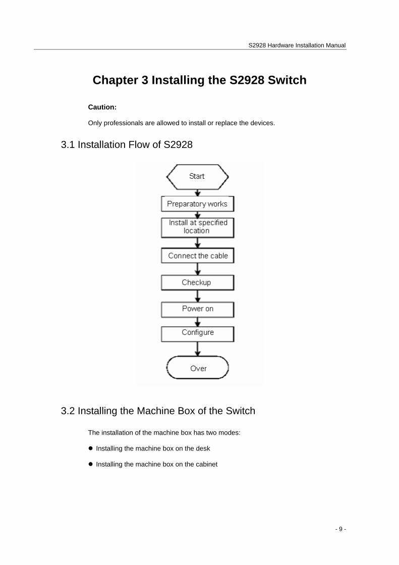
3.1 Installation Flow of S2928
3.2 Installing the Machine Box of the Switch
The installation of the machine box has two modes:
Installing the machine box on the desk
Installing the machine box on the cabinet
S2928 Hardware Installation Manual
- 10 -
3.2.1 Installing the Machine Box on the Desk
The S2928 switch can be directly put on the smooth and safe desk.
Note:
Do not put things weighing 4.5 kg or over 4.5 kg on the top of the switch.
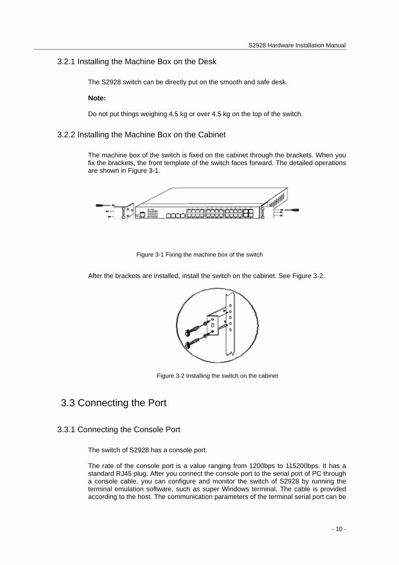
3.2.2 Installing the Machine Box on the Cabinet
The machine box of the switch is fixed on the cabinet through the brackets. When you fix the brackets, the front template of the switch faces forward. The detailed operations are shown in Figure 3-1.
Figure 3-1 Fixing the machine box of the switch
After the brackets are installed, install the switch on the cabinet. See Figure 3-2.
Figure 3-2 Installing the switch on the cabinet
3.3 Connecting the Port
3.3.1 Connecting the Console Port
The switch of S2928 has a console port.
The rate of the console port is a value ranging from 1200bps to 115200bps. It has a standard RJ45 plug. After you connect the console port to the serial port of PC through a console cable, you can configure and monitor the switch of S2928 by running the terminal emulation software, such as super Windows terminal. The cable is provided according to the host. The communication parameters of the terminal serial port can be
S2928 Hardware Installation Manual
- 11 -
set to a rate of 9600bps, eight data bits, one stop bit, no sum check bit and traffic control.
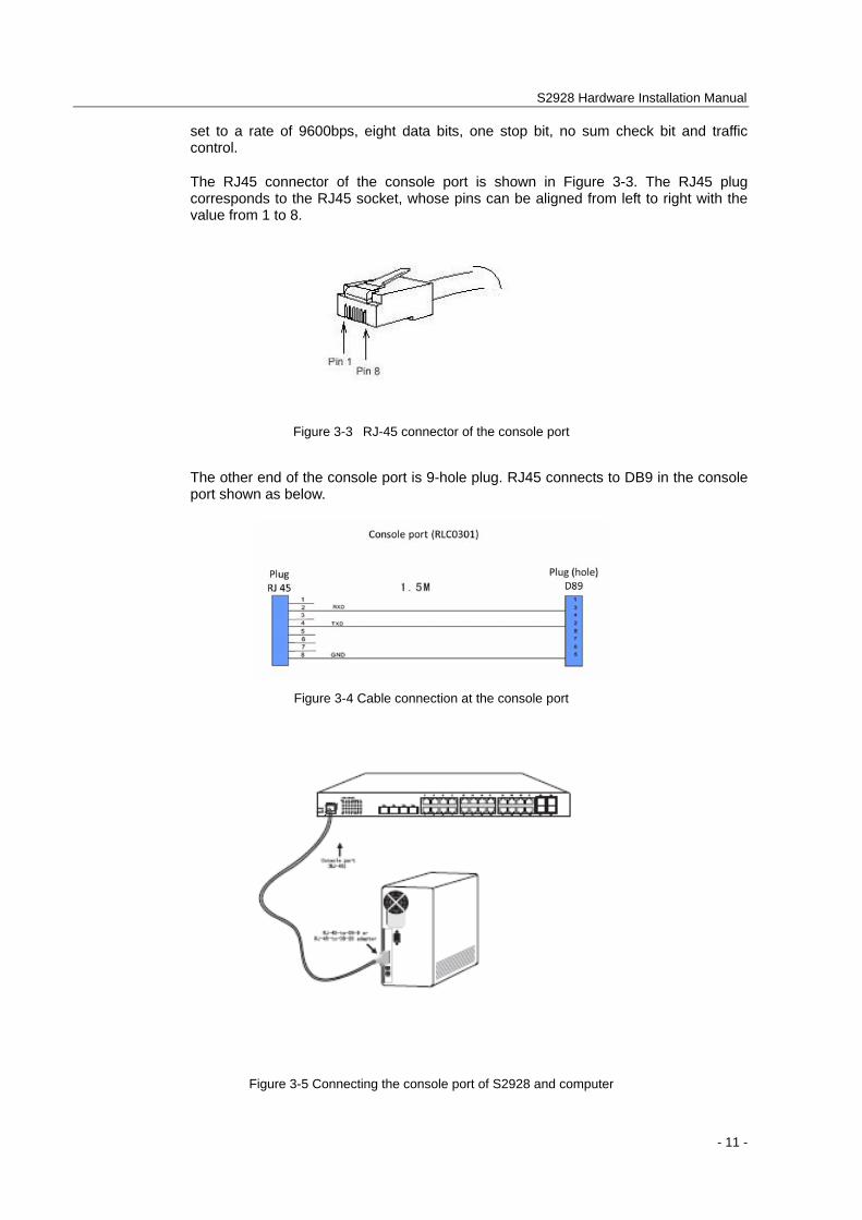
The RJ45 connector of the console port is shown in Figure 3-3. The RJ45 plug corresponds to the RJ45 socket, whose pins can be aligned from left to right with the value from 1 to 8.
Figure 3-3 RJ-45 connector of the console port
The other end of the console port is 9-hole plug. RJ45 connects to DB9 in the console port shown as below.
Figure 3-4 Cable connection at the console port
Figure 3-5 Connecting the console port of S2928 and computer
S2928 Hardware Installation Manual
- 12 -
Table 3-1 Pins of the console port
NO. Name Remarks
1 CD No connect
2 RXD Input
3 DSR No connect
4 TXD Output
5 RTS No connect
6 CTS No connect
7 DTR No connect
8 SG GND
Note:
The console port of S2928 does not support traffic control. Therefore, you must set the option data traffic control to none when you configure the switch with the super terminal. Otherwise, the single-pass problem will arise on the super terminal.
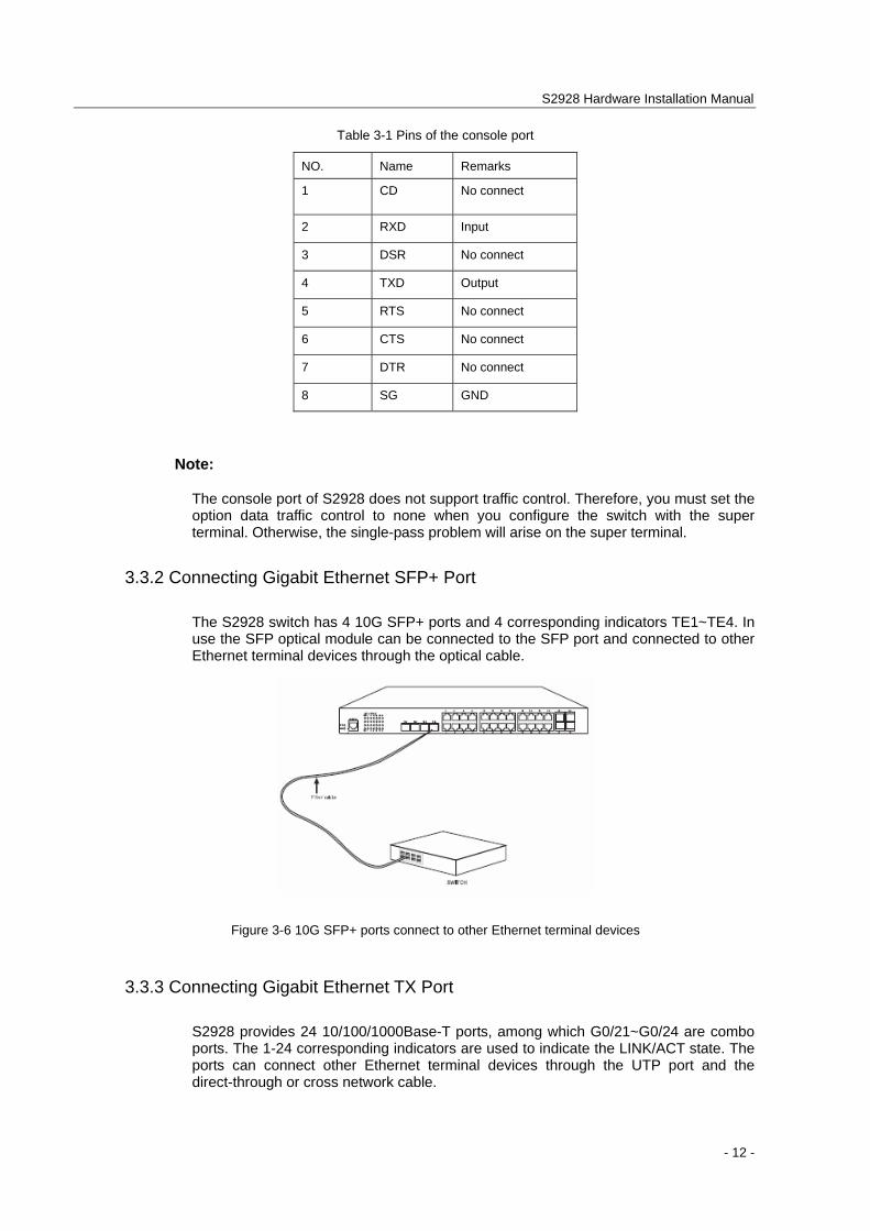
3.3.2 Connecting Gigabit Ethernet SFP+ Port
The S2928 switch has 4 10G SFP+ ports and 4 corresponding indicators TE1~TE4. In use the SFP optical module can be connected to the SFP port and connected to other Ethernet terminal devices through the optical cable.
Figure 3-6 10G SFP+ ports connect to other Ethernet terminal devices
3.3.3 Connecting Gigabit Ethernet TX Port
S2928 provides 24 10/100/1000Base-T ports, among which G0/21~G0/24 are combo ports. The 1-24 corresponding indicators are used to indicate the LINK/ACT state. The ports can connect other Ethernet terminal devices through the UTP port and the direct-through or cross network cable.
S2928 Hardware Installation Manual
- 13 -
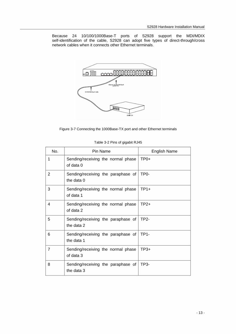
Because 24 10/100/1000Base-T ports of S2928 support the MDI/MDIX self-identification of the cable, S2928 can adopt five types of direct-through/cross network cables when it connects other Ethernet terminals.
Figure 3-7 Connecting the 1000Base-TX port and other Ethernet terminals
Table 3-2 Pins of gigabit RJ45
No. Pin Name English Name
1 Sending/receiving the normal phase of data 0
TP0+
2 Sending/receiving the paraphase of the data 0
TP0-
3 Sending/receiving the normal phase of data 1
TP1+
4 Sending/receiving the normal phase of data 2
TP2+
5 Sending/receiving the paraphase of the data 2
TP2-
6 Sending/receiving the paraphase of the data 1
TP1-
7 Sending/receiving the normal phase of data 3
TP3+
8 Sending/receiving the paraphase of the data 3
TP3-
S2928 Hardware Installation Manual
- 14 -
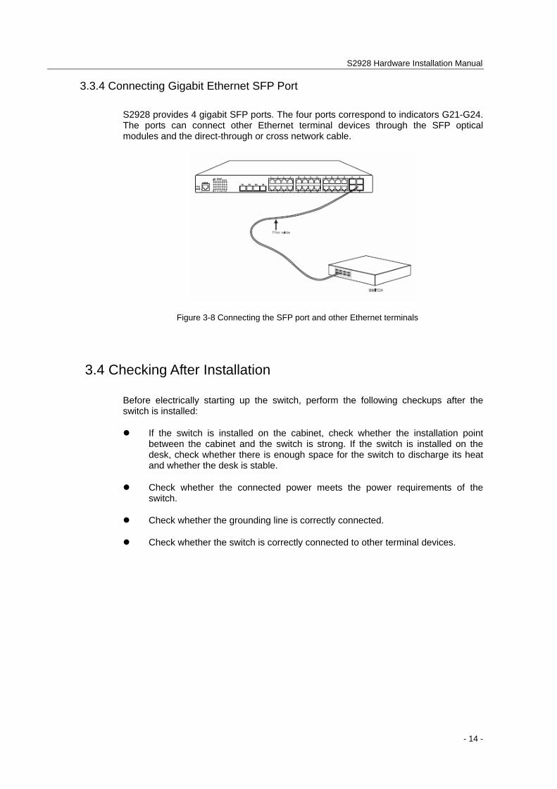
3.3.4 Connecting Gigabit Ethernet SFP Port
S2928 provides 4 gigabit SFP ports. The four ports correspond to indicators G21-G24. The ports can connect other Ethernet terminal devices through the SFP optical modules and the direct-through or cross network cable.
Figure 3-8 Connecting the SFP port and other Ethernet terminals
3.4 Checking After Installation
Before electrically starting up the switch, perform the following checkups after the switch is installed:
If the switch is installed on the cabinet, check whether the installation point between the cabinet and the switch is strong. If the switch is installed on the desk, check whether there is enough space for the switch to discharge its heat and whether the desk is stable.
Check whether the connected power meets the power requirements of the switch.
Check whether the grounding line is correctly connected.
Check whether the switch is correctly connected to other terminal devices.
S2928 Hardware Installation Manual
- 15 -
Chapter 4 Maintaining Switch
Caution:
1) Before opening the machine box, make sure that you have released the static you carried and then turn off the power on-off of the switch. Before operating any step in Appendix B, read the section “Safety Advice”.
2) Before performing operations beside the power source or on the machine box, turn off the power on-off and plug out the power cable.
4.1 Opening the Machine Box
This section describes how to open the cover of the switch, required tools and operation methods.
Caution:
When the power cable still connects the power source, do not touch it.
When you open the cover the switch, you may use the following tools:
Crossed screwdriver
Static armguard
Perform the following steps to open the cover of the switch:
(1) Turn off the power on-off of the switch.
(2) Plug out all cables connected the back of the switch.
(3) Take out the bolt from the machine box with the screwdriver.
Note:
The machine box comprises of two parts: cover and bottom.
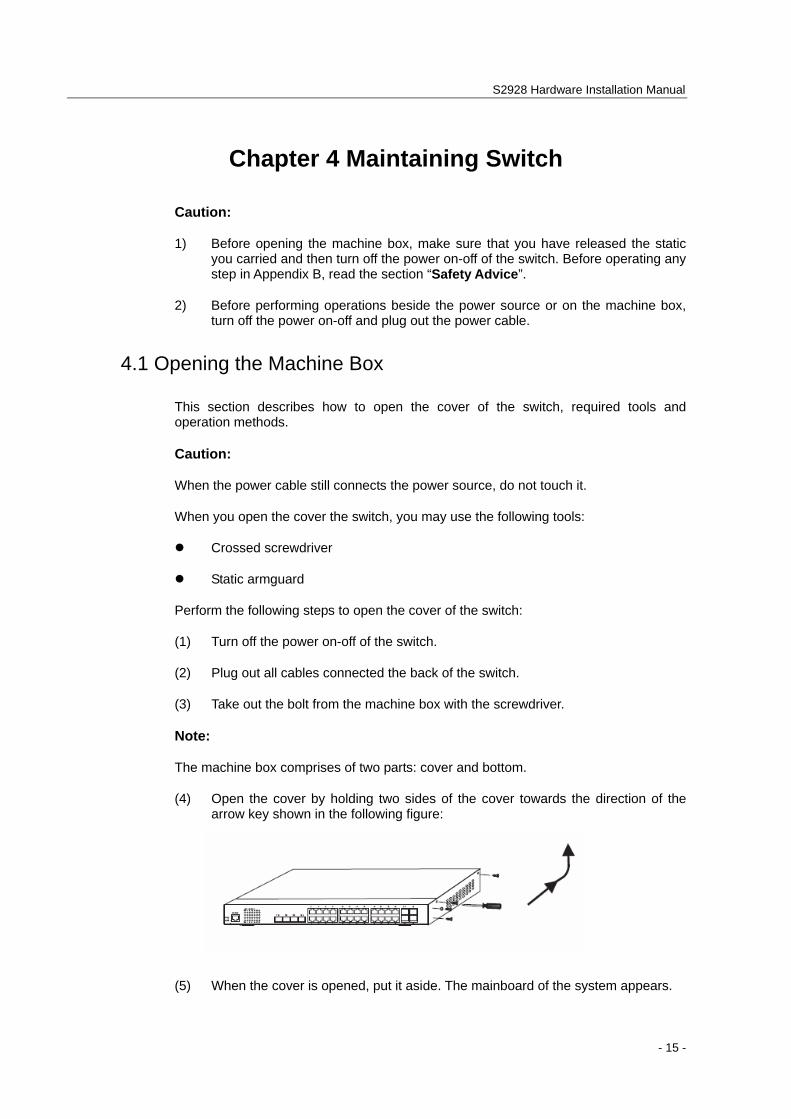
(4) Open the cover by holding two sides of the cover towards the direction of the arrow key shown in the following figure:
(5) When the cover is opened, put it aside. The mainboard of the system appears.
S2928 Hardware Installation Manual
- 16 -
Note:
After taking off the cover, put it horizontally and avoid it to be crushed or collided. Otherwise, the machine box is hard to install.
4.2 Closing the Machine Box
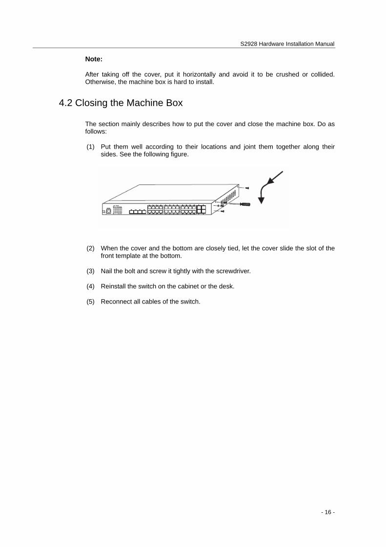
The section mainly describes how to put the cover and close the machine box. Do as follows:
(1) Put them well according to their locations and joint them together along their sides. See the following figure.
(2) When the cover and the bottom are closely tied, let the cover slide the slot of the front template at the bottom.
(3) Nail the bolt and screw it tightly with the screwdriver.
(4) Reinstall the switch on the cabinet or the desk.
(5) Reconnect all cables of the switch.

S2928 Hardware Installation Manual
- 17 -
Chapter 5 Hardware Fault Analysis
The part describes how to remove the fault from the switch.
5.1 Fault Separation
The key for resolving the systematic faults is to separate the fault from the system. You can compare what the system is doing with what the system should do to detect the fault. You need to check the following subsystems:
Power and cooling systems—power and fan
Port, cable and connection—ports on the front template of the switch and the cables connecting these ports
5.1.1 Faults Relative with Power and Cooling System
Do the following checkups to help remove the fault:
When the power on-off is at the “ON” location, check whether the fan works normally. If the fan does not work well, check the fan.
The working temperature of the switch is from 0 to 40 Celsius degrees. If the switch is too hot, check whether the air outlet and air inlet are clean and then do relative operations in section 2.3 “Requirements for Common Locations”.
If the switch cannot be started and the PWR indicator is off, check the power.
5.1.2 Faults Relative with Port, Cable and Connection
Do the following checkups to help remove the fault:
If the port of the switch cannot be linked, check whether the cable is correctly connected and whether the peer connection is normal.
If the power on-off is at the “ON” location, check the power source and the power cable.
If the console port does not work after the system is started up, check whether the console port is set to a baud rate of 9600 bps, eight data bits, no sum check bit, one stop bit and no traffic control.
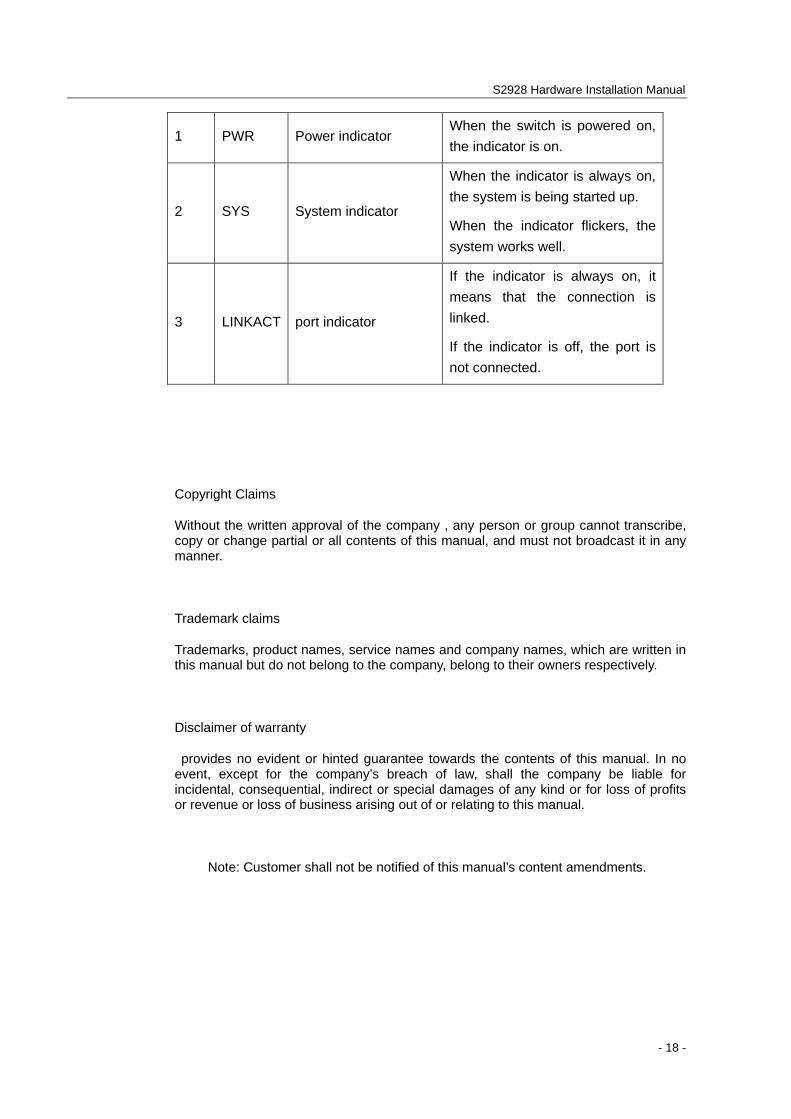
5.2 Indicator Description
The following table shows the indicators of the S2928 switch and their description:
No. Abbrev. Name Description
S2928 Hardware Installation Manual
- 18 -
1 PWR Power indicator When the switch is powered on, the indicator is on.
2 SYS System indicator
When the indicator is always on, the system is being started up.
When the indicator flickers, the system works well.
3 LINKACT port indicator
If the indicator is always on, it means that the connection is linked.
If the indicator is off, the port is not connected.
Copyright Claims
Without the written approval of the company , any person or group cannot transcribe, copy or change partial or all contents of this manual, and must not broadcast it in any manner.
Trademark claims
Trademarks, product names, service names and company names, which are written in this manual but do not belong to the company, belong to their owners respectively.
Disclaimer of warranty
provides no evident or hinted guarantee towards the contents of this manual. In no event, except for the company’s breach of law, shall the company be liable for incidental, consequential, indirect or special damages of any kind or for loss of profits or revenue or loss of business arising out of or relating to this manual.
Note: Customer shall not be notified of this manual’s content amendments.
Related Documents