1 European Congress on Computational Methods in Applied Sciences and Engineering ECCOMAS 2000 Barcelona, 11-14 September 2000 ECCOMAS THE PHYSICS OF SHOCK WAVE/BOUNDARY LAYER INTERACTION CONTROL: LAST LESSONS LEARNED Jean M. Délery and Reynald S. Bur Fundamental/Experimental Aerodynamics Department Onera - 92190 MEUDON, France Email: [email protected] , Webpage: http://www.onera.fr/dafe/ Key words : shock wave, boundary layer, turbulent flow, flow control, separation Abstract . In high speed flow, the existence of shock waves most often entails either drag increase or efficiency losses. A major cause of performance degradation is the interaction of the shock with a boundary layer. Then complex phenomena occur which contributes to increase friction losses, especially if the shock is strong enough to separate the boundary layer. To a separated flow are associated typical wave patterns resulting from the shocks induced by the separation and reattachment processes and which play a major role in the production of entropy by the flow. Since shocks cannot be avoided in most situations, control techniques have been proposed to limit their negative effects. The mode of operation of these techniques can be well understood by a clear identification of shock wave/boundary layer interaction properties. The control actions can be performed by a proper manipulation of the boundary layer upstream of the interaction domain in order to increase its resistance to the shock action (by blowing or lowering the wall temperature, or using vortex generators) or by a local action in the shock foot region. Then active, passive or hybrid control which combines the two previous actions can be applied. Other methods can be envisaged, like the installation of a bump in the shock foot region to adapt the surface contour in order to weaken the shock. None of these techniques brings the ideal answer to the problem of shock wave/boundary layer interaction control. Thus, the definition of a solution closely depends on the objective of the control. In addition, the appropriateness of implementing a control device highly depends on economical issues in terms of weight penalty, manufacturing and maintenance cost and energy consumption.

S BL Interaction
Dec 06, 2015
Shock Boundary layer interaction mechanism
Welcome message from author
This document is posted to help you gain knowledge. Please leave a comment to let me know what you think about it! Share it to your friends and learn new things together.
Transcript
1
European Congress on Computational Methods in Applied Sciences and EngineeringECCOMAS 2000
Barcelona, 11-14 September 2000 ECCOMAS
THE PHYSICS OF SHOCK WAVE/BOUNDARY LAYERINTERACTION CONTROL: LAST LESSONS LEARNED
Jean M. Délery and Reynald S. Bur
Fundamental/Experimental Aerodynamics DepartmentOnera - 92190 MEUDON, France
Email: [email protected], Webpage: http://www.onera.fr/dafe/
Key words : shock wave, boundary layer, turbulent flow, flow control, separation
Abstract. In high speed flow, the existence of shock waves most often entails either dragincrease or efficiency losses. A major cause of performance degradation is the interaction ofthe shock with a boundary layer. Then complex phenomena occur which contributes toincrease friction losses, especially if the shock is strong enough to separate the boundarylayer. To a separated flow are associated typical wave patterns resulting from the shocksinduced by the separation and reattachment processes and which play a major role in theproduction of entropy by the flow. Since shocks cannot be avoided in most situations, controltechniques have been proposed to limit their negative effects. The mode of operation of thesetechniques can be well understood by a clear identification of shock wave/boundary layerinteraction properties. The control actions can be performed by a proper manipulation of theboundary layer upstream of the interaction domain in order to increase its resistance to theshock action (by blowing or lowering the wall temperature, or using vortex generators) or bya local action in the shock foot region. Then active, passive or hybrid control which combinesthe two previous actions can be applied. Other methods can be envisaged, like the installationof a bump in the shock foot region to adapt the surface contour in order to weaken the shock.None of these techniques brings the ideal answer to the problem of shock wave/boundarylayer interaction control. Thus, the definition of a solution closely depends on the objective ofthe control. In addition, the appropriateness of implementing a control device highly dependson economical issues in terms of weight penalty, manufacturing and maintenance cost andenergy consumption.
Jean M. Délery and Reynald S. Bur
2
1 INTRODUCTION
Shock waves almost inevitably occur when a flow becomes supersonic or transonic. Theyare provoked by a change in the flow direction, as at the compression ramps of a supersonicair intake or at a control surface, an increase of the downstream pressure as on a transonicwing, a pressure jump as in an overexpanded propulsive nozzle, a brutal deceleration as infront of the nose of a re-entry vehicle.
The presence of shock waves entails the existence of discontinuities and regions of highgradients which are the shocks themselves and the shear layers resulting from the interactionwith the boundary layers developing on the vehicle surface. These gradients "activate" theviscous terms producing entropy, which makes shock waves an important source of drag:
(1) directly by entropy generation in the thickness of the shock: this contribution is thewave drag ;(2) indirectly, be enhancing dissipation in the boundary layers: hence an amplificationof the viscous drag.
In addition, strong interactions with the boundary layers may lead to catastrophicseparation with possible occurrence of large scale unsteadiness (wing buffeting, air intakebuzz). Shock waves play a dramatic role at hypersonic velocities because of their intensitywhich leads to spectacular shock-shock interferences with specific and complex wave patternsand strong interactions with the boundary layers1. In addition, the temperature rise at thecrossing of the shocks most often affects the gas thermodynamics properties (the so-calledreal gas effects) and is at the origin of high heat transfer levels at the vehicle surface2.
The idea to control shock wave/boundary layer interaction in order to avoid, or minimise,its detrimental effects is nearly contemporaneous with the advent of studies on high-speedflows. Thus, as early as 1941, Regenscheit3 studied the effect of suction through a slit at thesurface of an airfoil tested at transonic velocity. The same arrangement was considered byFage and Sargent4 in 1943. Since that time, a great deal of research has been devoted to thisimportant practical problem5. In fact, the problem of shock wave/boundary layer interactioncontrol is multiple in the sense that according to the objective looked for antagonisticmechanisms can be at work. As it will be seen, the reduction of a profile drag can be obtainedby a smearing of the shock entailing a reduction of the wave drag, but at the price of athickening of the boundary layer and an increase of the friction drag. On the other hand,separation suppression or shock stabilisation most often entails an intensification of the shock,hence an increase of the losses through the shock. Thus, the target of shock wave/boundarylayer control must be clearly identified.
The purpose of this paper is to focus on the physical phenomena involved in shockwave/boundary layer interactions first without, then with control action. The results presentedand discussed here are mostly based on a recent thorough investigation of various controlactions applied to transonic interactions executed within the framework of the Europeanprojects Euroshock I and II. In particular, detailed flow descriptions allowed a clearidentification of the flow processes at work in different kinds of control devices giving a goodstatus of the art on control techniques in transonic flows6,7.
Jean M. Délery and Reynald S. Bur
3
2 BASIC PROPERTIES OF SHOCK INDUCED PHENOMENA
The consideration which follow essentially apply to turbulent flows which are morecommon in usual aeronautical applications than laminar flows. When a boundary layer issubmitted to the strong retardation imparted by a shock wave, complex phenomena occurwithin its structure which is basically a parallel rotational flow with the Mach number varyingfrom the outer supersonic value to zero at the wall. The process has been analysed byLighthill in the framework of its famous triple-deck theory8.
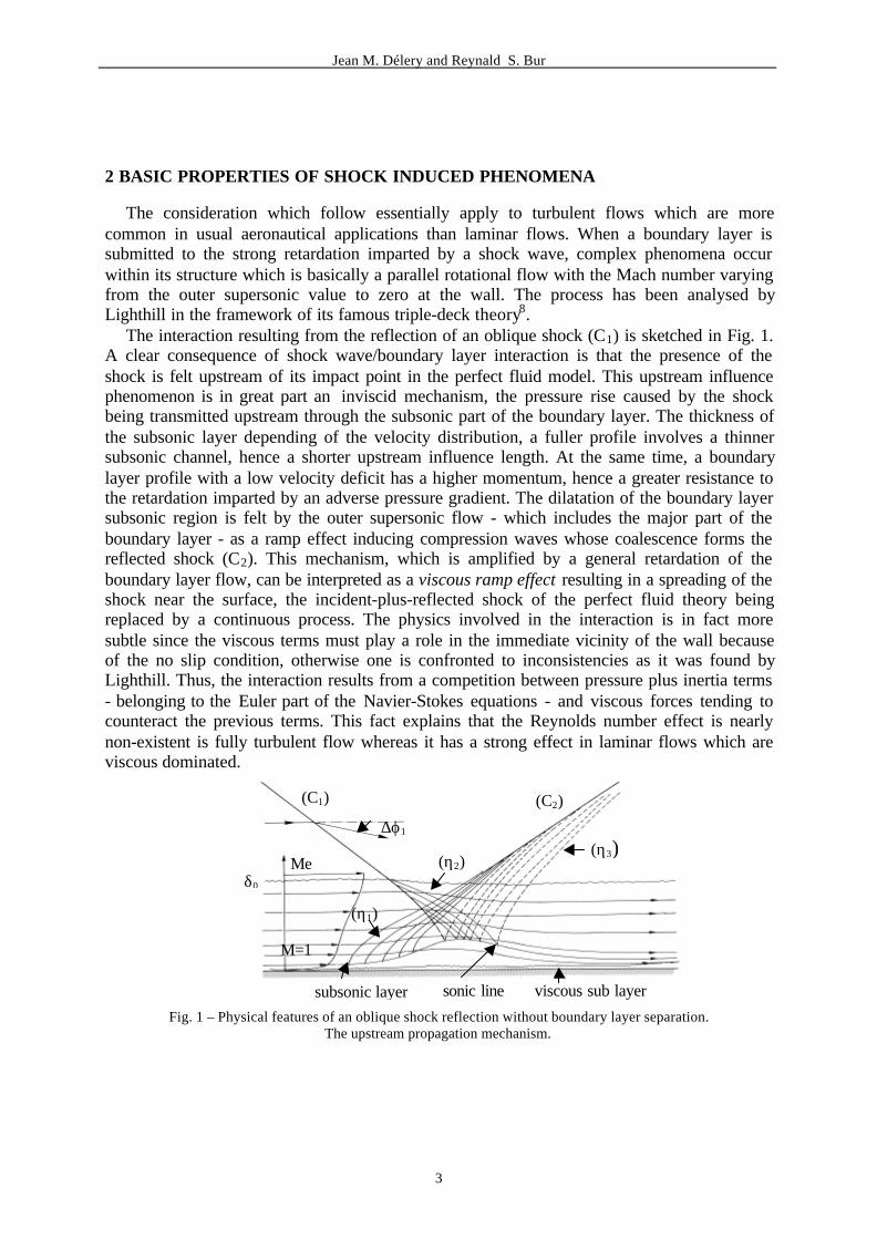
The interaction resulting from the reflection of an oblique shock (C1) is sketched in Fig. 1.A clear consequence of shock wave/boundary layer interaction is that the presence of theshock is felt upstream of its impact point in the perfect fluid model. This upstream influencephenomenon is in great part an inviscid mechanism, the pressure rise caused by the shockbeing transmitted upstream through the subsonic part of the boundary layer. The thickness ofthe subsonic layer depending of the velocity distribution, a fuller profile involves a thinnersubsonic channel, hence a shorter upstream influence length. At the same time, a boundarylayer profile with a low velocity deficit has a higher momentum, hence a greater resistance tothe retardation imparted by an adverse pressure gradient. The dilatation of the boundary layersubsonic region is felt by the outer supersonic flow - which includes the major part of theboundary layer - as a ramp effect inducing compression waves whose coalescence forms thereflected shock (C2). This mechanism, which is amplified by a general retardation of theboundary layer flow, can be interpreted as a viscous ramp effect resulting in a spreading of theshock near the surface, the incident-plus-reflected shock of the perfect fluid theory beingreplaced by a continuous process. The physics involved in the interaction is in fact moresubtle since the viscous terms must play a role in the immediate vicinity of the wall becauseof the no slip condition, otherwise one is confronted to inconsistencies as it was found byLighthill. Thus, the interaction results from a competition between pressure plus inertia terms- belonging to the Euler part of the Navier-Stokes equations - and viscous forces tending tocounteract the previous terms. This fact explains that the Reynolds number effect is nearlynon-existent is fully turbulent flow whereas it has a strong effect in laminar flows which areviscous dominated.
Fig. 1 – Physical features of an oblique shock reflection without boundary layer separation.The upstream propagation mechanism.
∆ϕ1
(C1) (C2)
(η3)(η2)Me
δ0
(η1)
M=1
subsonic layer sonic line viscous sub layer
Jean M. Délery and Reynald S. Bur
4
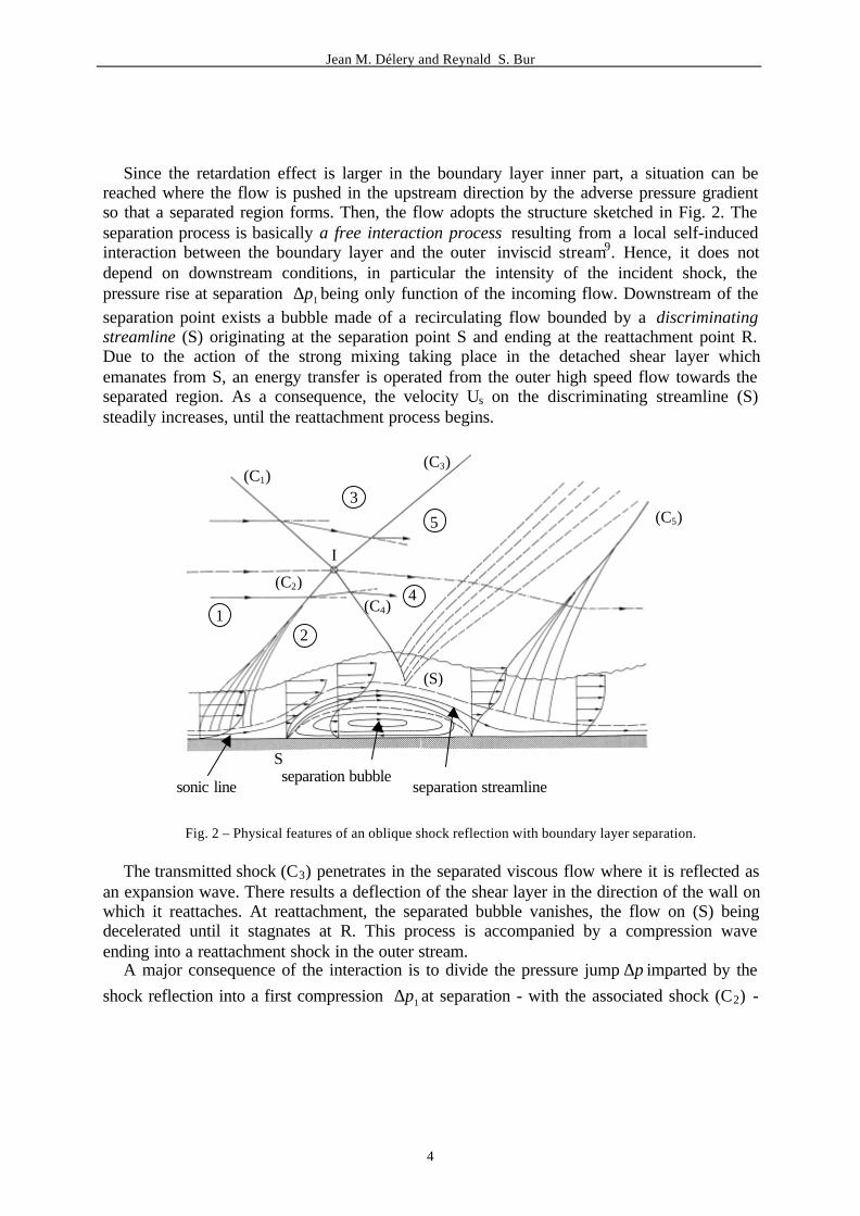
Since the retardation effect is larger in the boundary layer inner part, a situation can bereached where the flow is pushed in the upstream direction by the adverse pressure gradientso that a separated region forms. Then, the flow adopts the structure sketched in Fig. 2. Theseparation process is basically a free interaction process resulting from a local self-inducedinteraction between the boundary layer and the outer inviscid stream9. Hence, it does notdepend on downstream conditions, in particular the intensity of the incident shock, thepressure rise at separation 1p∆ being only function of the incoming flow. Downstream of theseparation point exists a bubble made of a recirculating flow bounded by a discriminatingstreamline (S) originating at the separation point S and ending at the reattachment point R.Due to the action of the strong mixing taking place in the detached shear layer whichemanates from S, an energy transfer is operated from the outer high speed flow towards theseparated region. As a consequence, the velocity Us on the discriminating streamline (S)steadily increases, until the reattachment process begins.
Fig. 2 – Physical features of an oblique shock reflection with boundary layer separation.
The transmitted shock (C3) penetrates in the separated viscous flow where it is reflected asan expansion wave. There results a deflection of the shear layer in the direction of the wall onwhich it reattaches. At reattachment, the separated bubble vanishes, the flow on (S) beingdecelerated until it stagnates at R. This process is accompanied by a compression waveending into a reattachment shock in the outer stream.
A major consequence of the interaction is to divide the pressure jump p∆ imparted by the
shock reflection into a first compression 1p∆ at separation - with the associated shock (C2) -
(C1)(C3)
(C5)3
5
14
2
(C4)
(S)
S
sonic lineseparation bubble
separation streamline
(C2)
I
Jean M. Délery and Reynald S. Bur
5
and a second compression 2p∆ at reattachment, the overall pressure rise being such that
21 ppp ∆+∆=∆ . The extent of the separated region is dictated by the ability of the shear layerissuing from the separation point S to overcome the pressure rise at reattachment. This abilityis function of the momentum available on (S) – or maximum velocity (US)max - at the startingof the reattachment process. Since the pressure rise to separation does not depend ondownstream conditions, an increase of the overall pressure rise imparted to the boundary layer- or incident shock strength - entails a higher pressure rise at reattachment. This can only beachieved by an increase of the maximum velocity (US)max reached on the discriminatingstreamline, hence an increase of the shear layer length allowing a greater transfer ofmomentum from the outer flow. Thus the length of the separated region will grow inproportion to the pressure rise at reattachment.
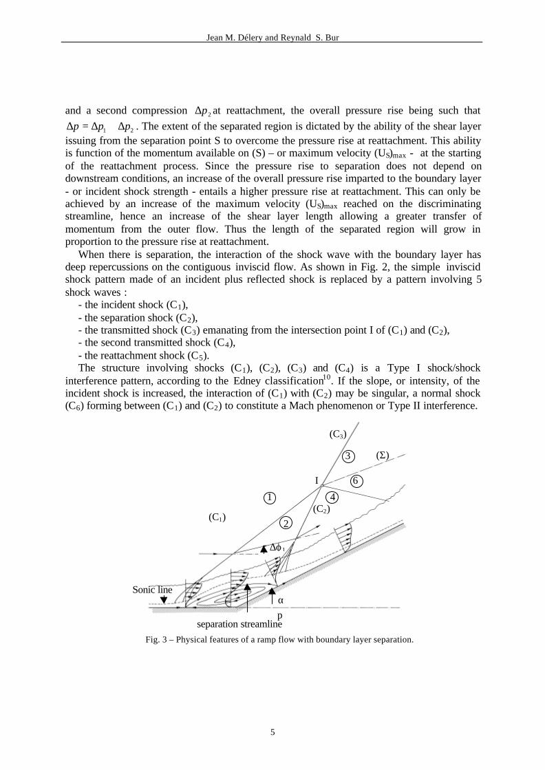
When there is separation, the interaction of the shock wave with the boundary layer hasdeep repercussions on the contiguous inviscid flow. As shown in Fig. 2, the simple inviscidshock pattern made of an incident plus reflected shock is replaced by a pattern involving 5shock waves :
- the incident shock (C1),- the separation shock (C2),- the transmitted shock (C3) emanating from the intersection point I of (C1) and (C2),- the second transmitted shock (C4),- the reattachment shock (C5).The structure involving shocks (C1), (C2), (C3) and (C4) is a Type I shock/shock
interference pattern, according to the Edney classification10. If the slope, or intensity, of theincident shock is increased, the interaction of (C1) with (C2) may be singular, a normal shock(C6) forming between (C1) and (C2) to constitute a Mach phenomenon or Type II interference.
Fig. 3 – Physical features of a ramp flow with boundary layer separation.
(C3)
(Σ)3
I
1
2(C1)
∆ϕ1
Sonic line
separation streamline
6
4
αp
(C2)
Jean M. Délery and Reynald S. Bur
6
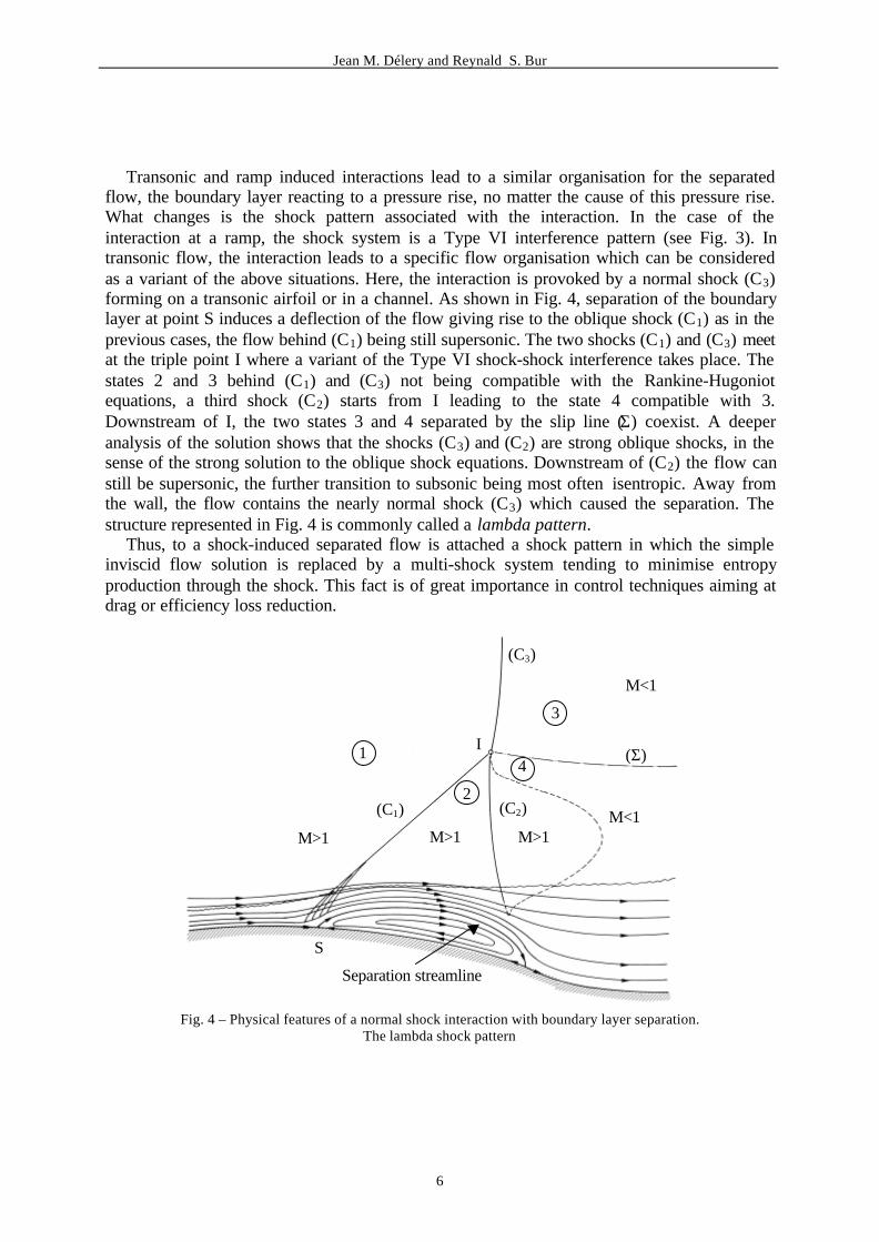
Transonic and ramp induced interactions lead to a similar organisation for the separatedflow, the boundary layer reacting to a pressure rise, no matter the cause of this pressure rise.What changes is the shock pattern associated with the interaction. In the case of theinteraction at a ramp, the shock system is a Type VI interference pattern (see Fig. 3). Intransonic flow, the interaction leads to a specific flow organisation which can be consideredas a variant of the above situations. Here, the interaction is provoked by a normal shock (C3)forming on a transonic airfoil or in a channel. As shown in Fig. 4, separation of the boundarylayer at point S induces a deflection of the flow giving rise to the oblique shock (C1) as in theprevious cases, the flow behind (C1) being still supersonic. The two shocks (C1) and (C3) meetat the triple point I where a variant of the Type VI shock-shock interference takes place. Thestates 2 and 3 behind (C1) and (C3) not being compatible with the Rankine-Hugoniotequations, a third shock (C2) starts from I leading to the state 4 compatible with 3.Downstream of I, the two states 3 and 4 separated by the slip line (Σ) coexist. A deeperanalysis of the solution shows that the shocks (C3) and (C2) are strong oblique shocks, in thesense of the strong solution to the oblique shock equations. Downstream of (C2) the flow canstill be supersonic, the further transition to subsonic being most often isentropic. Away fromthe wall, the flow contains the nearly normal shock (C3) which caused the separation. Thestructure represented in Fig. 4 is commonly called a lambda pattern.
Thus, to a shock-induced separated flow is attached a shock pattern in which the simpleinviscid flow solution is replaced by a multi-shock system tending to minimise entropyproduction through the shock. This fact is of great importance in control techniques aiming atdrag or efficiency loss reduction.
Fig. 4 – Physical features of a normal shock interaction with boundary layer separation.The lambda shock pattern
R
(C3)
M<1
(Σ)
3
4
M>1
(C2)
M>1
2
1
(C1)
M>1
S
Separation streamline
M<1
I
Jean M. Délery and Reynald S. Bur
7
3 MECHANISMS FOR CONTROL ACTION
The above physical description of typical shock wave/boundary layer interactions bringsout the most salient phenomena involved in an interaction, thus providing indications on themeans which can be considered to modify - or control - the interaction.
The upstream influence of the shock and the resistance of a turbulent boundary layerdepending mainly of its momentum, a means to restrict the effect of the shock is to increasethe boundary layer momentum prior to its interaction with the shock. This can be done byproper boundary layer manipulation :
- One can perform an injection through one or several slots located upstream of the shockorigin, this technique being called boundary layer blowing.
- A distributed suction applied over a certain boundary layer run before the interactionreduces its shape parameter, thus producing a fuller velocity profile. On the contrary,distributed injection - or transpiration - increases the shape parameter, which renders theboundary layer more sensible to the shock. Vortex generators can be classified in thiscategory of control actions, since the vortical structures that they create operate a momentumtransfer from the outer high speed flow at the benefit of the boundary layer.
- It is also possible to eliminate the low speed part of the boundary layer by making astrong suction through a slot located at a well chosen location upstream of the interaction.
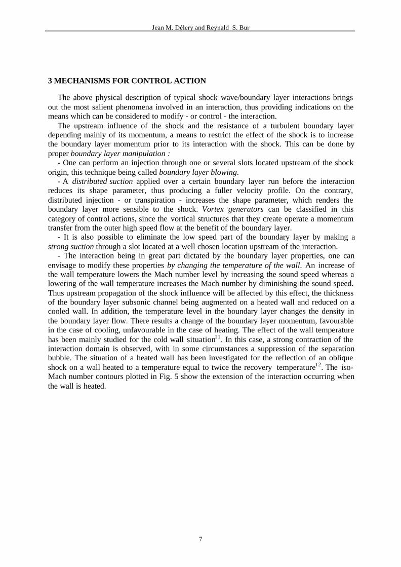
- The interaction being in great part dictated by the boundary layer properties, one canenvisage to modify these properties by changing the temperature of the wall. An increase ofthe wall temperature lowers the Mach number level by increasing the sound speed whereas alowering of the wall temperature increases the Mach number by diminishing the sound speed.Thus upstream propagation of the shock influence will be affected by this effect, the thicknessof the boundary layer subsonic channel being augmented on a heated wall and reduced on acooled wall. In addition, the temperature level in the boundary layer changes the density inthe boundary layer flow. There results a change of the boundary layer momentum, favourablein the case of cooling, unfavourable in the case of heating. The effect of the wall temperaturehas been mainly studied for the cold wall situation11. In this case, a strong contraction of theinteraction domain is observed, with in some circumstances a suppression of the separationbubble. The situation of a heated wall has been investigated for the reflection of an obliqueshock on a wall heated to a temperature equal to twice the recovery temperature12. The iso-Mach number contours plotted in Fig. 5 show the extension of the interaction occurring whenthe wall is heated.
Jean M. Délery and Reynald S. Bur
8
Fig. 5 – Wall temperature effect on an oblique shock reflection at Mach number 2.4. Mach number contours.
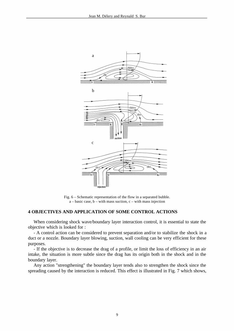
The interaction properties can also be affected by performing an action in the interactionregion itself. A key role being played by the velocity - or momentum - level which must bereached on the discriminating streamline to allow shear layer reattachment, any actionmodifying this level will influence the interaction. Thus, if some fluid is sucked through thewall, topological considerations lead to the flow structure sketched in Fig. 6b. The streamline(S2) stagnating at the reattachment point R comes from upstream "infinity" and is locatedabove (S1), the sucked-off fluid flowing between (S1) and (S2). Provided the extracted massflow be moderate enough so as not to entail a total alteration of the general flow structure, thevelocity profile through the shear layer is nearly the same as in the basic case of Fig. 6a. Asstreamline (S2) is located at a greater distance from the wall, the velocity (US)max on (S2) isgreater than in the basic case: hence, an increase of the ability of the flow to withstand a moreimportant compression and a subsequent contraction of the interaction domain. The case of afluid injection at low velocity is sketched in Fig. 6c. Now, the velocity on (S2) is smaller,since (S2) is located at a lower altitude on the velocity profile. The resulting effect is alengthening of the separation bubble. However, if the injected mass flow is increased, therewill be a reversal of the effect, since the velocities on the bottom part of the profile - and inparticular (US)max - will increase if the mass flow fed into the separated region goes beyond acertain limit. A similar mechanism is at work in base bleed aiming at the reduction of basedrag through an increase of the base pressure.
Jean M. Délery and Reynald S. Bur
9
Fig. 6 – Schematic representation of the flow in a separated bubble.a – basic case, b – with mass suction, c – with mass injection
4 OBJECTIVES AND APPLICATION OF SOME CONTROL ACTIONS
When considering shock wave/boundary layer interaction control, it is essential to state theobjective which is looked for :
- A control action can be considered to prevent separation and/or to stabilize the shock in aduct or a nozzle. Boundary layer blowing, suction, wall cooling can be very efficient for thesepurposes.
- If the objective is to decrease the drag of a profile, or limit the loss of efficiency in an airintake, the situation is more subtle since the drag has its origin both in the shock and in theboundary layer.
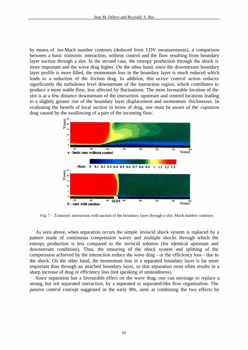
Any action "strengthening" the boundary layer tends also to strengthen the shock since thespreading caused by the interaction is reduced. This effect is illustrated in Fig. 7 which shows,
a
b
c
Jean M. Délery and Reynald S. Bur
10
by means of iso-Mach number contours (deduced from LDV measurements), a comparisonbetween a basic transonic interaction, without control and the flow resulting from boundarylayer suction through a slot. In the second case, the entropy production through the shock ismore important and the wave drag higher. On the other hand, since the downstream boundarylayer profile is more filled, the momentum loss in the boundary layer is much reduced whichleads to a reduction of the friction drag. In addition, this active control action reducessignificantly the turbulence level downstream of the interaction region, which contributes toproduce a more stable flow, less affected by fluctuations. The most favourable location of theslot is at a few distance downstream of the interaction, upstream and centred locations leadingto a slightly greater rise of the boundary layer displacement and momentum thicknesses. Inevaluating the benefit of local suction in terms of drag, one must be aware of the captationdrag caused by the swallowing of a part of the incoming flow.
Fig. 7 – Transonic interaction with suction of the boundary layer through a slot. Mach number contours.
As seen above, when separation occurs the simple inviscid shock system is replaced by apattern made of continuous compression waves and multiple shocks through which theentropy production is less compared to the inviscid solution (for identical upstream anddownstream conditions). Thus, the smearing of the shock system and splitting of thecompression achieved by the interaction reduce the wave drag - or the efficiency loss - due tothe shock. On the other hand, the momentum loss in a separated boundary layer is far moreimportant than through an attached boundary layer, so that separation most often results in asharp increase of drag or efficiency loss (not speaking of unsteadiness).
Since separation has a favourable effect on the wave drag, one can envisage to replace astrong, but not separated interaction, by a separated or separated-like flow organisation. Thepassive control concept suggested in the early 80s, aims at combining the two effects by
Jean M. Délery and Reynald S. Bur
11
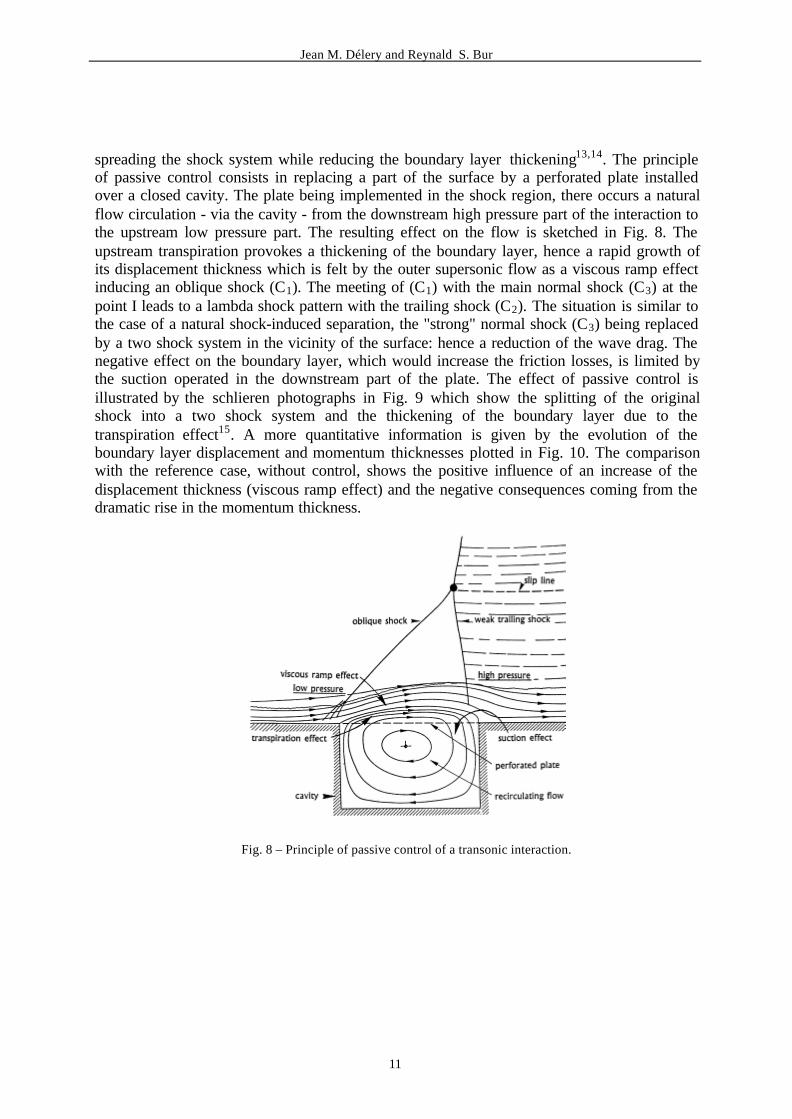
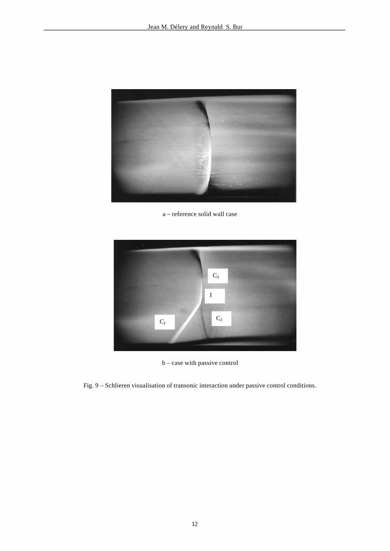
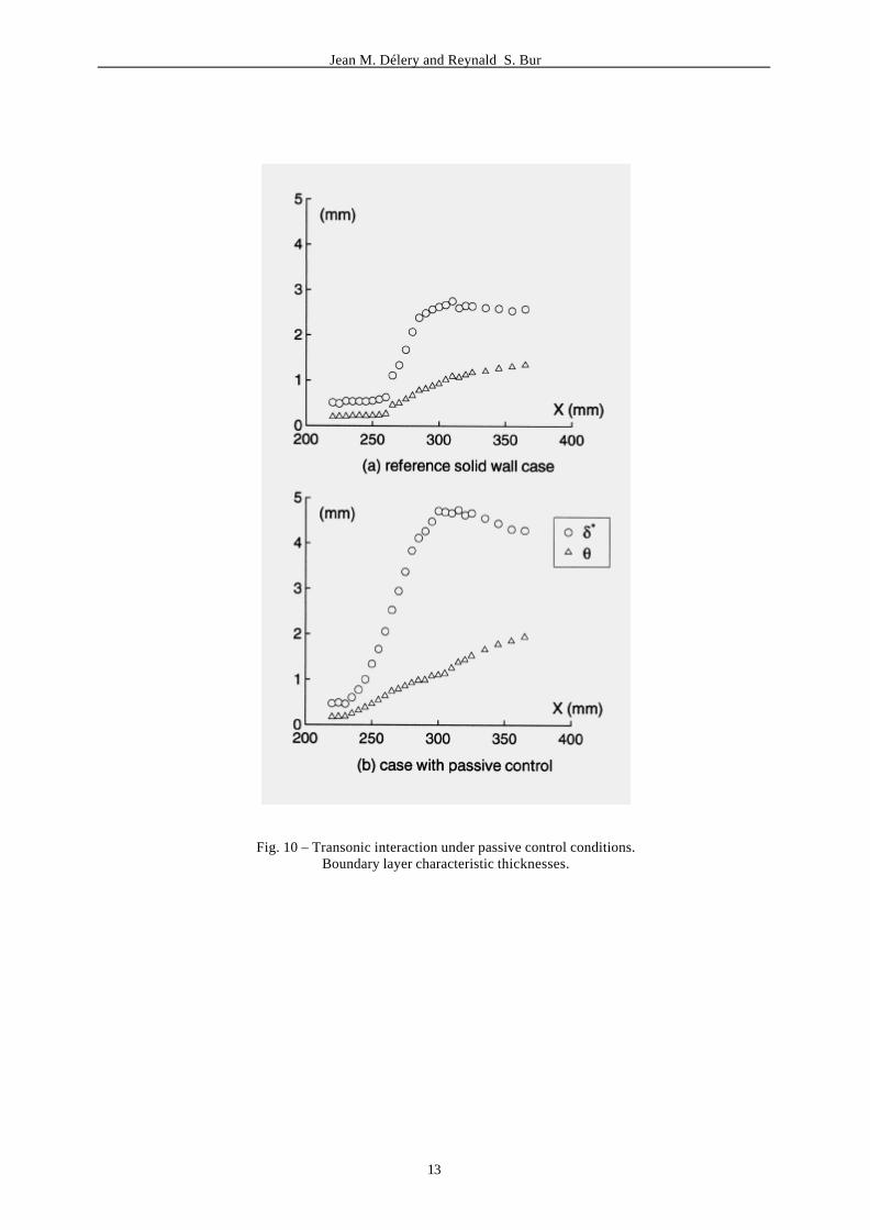
spreading the shock system while reducing the boundary layer thickening13,14. The principleof passive control consists in replacing a part of the surface by a perforated plate installedover a closed cavity. The plate being implemented in the shock region, there occurs a naturalflow circulation - via the cavity - from the downstream high pressure part of the interaction tothe upstream low pressure part. The resulting effect on the flow is sketched in Fig. 8. Theupstream transpiration provokes a thickening of the boundary layer, hence a rapid growth ofits displacement thickness which is felt by the outer supersonic flow as a viscous ramp effectinducing an oblique shock (C1). The meeting of (C1) with the main normal shock (C3) at thepoint I leads to a lambda shock pattern with the trailing shock (C2). The situation is similar tothe case of a natural shock-induced separation, the "strong" normal shock (C3) being replacedby a two shock system in the vicinity of the surface: hence a reduction of the wave drag. Thenegative effect on the boundary layer, which would increase the friction losses, is limited bythe suction operated in the downstream part of the plate. The effect of passive control isillustrated by the schlieren photographs in Fig. 9 which show the splitting of the originalshock into a two shock system and the thickening of the boundary layer due to thetranspiration effect15. A more quantitative information is given by the evolution of theboundary layer displacement and momentum thicknesses plotted in Fig. 10. The comparisonwith the reference case, without control, shows the positive influence of an increase of thedisplacement thickness (viscous ramp effect) and the negative consequences coming from thedramatic rise in the momentum thickness.
Fig. 8 – Principle of passive control of a transonic interaction.
Jean M. Délery and Reynald S. Bur
12
a – reference solid wall case
b – case with passive control
Fig. 9 – Schlieren visualisation of transonic interaction under passive control conditions.
I
C3
C2C1
Jean M. Délery and Reynald S. Bur
13
Fig. 10 – Transonic interaction under passive control conditions.Boundary layer characteristic thicknesses.
Jean M. Délery and Reynald S. Bur
14
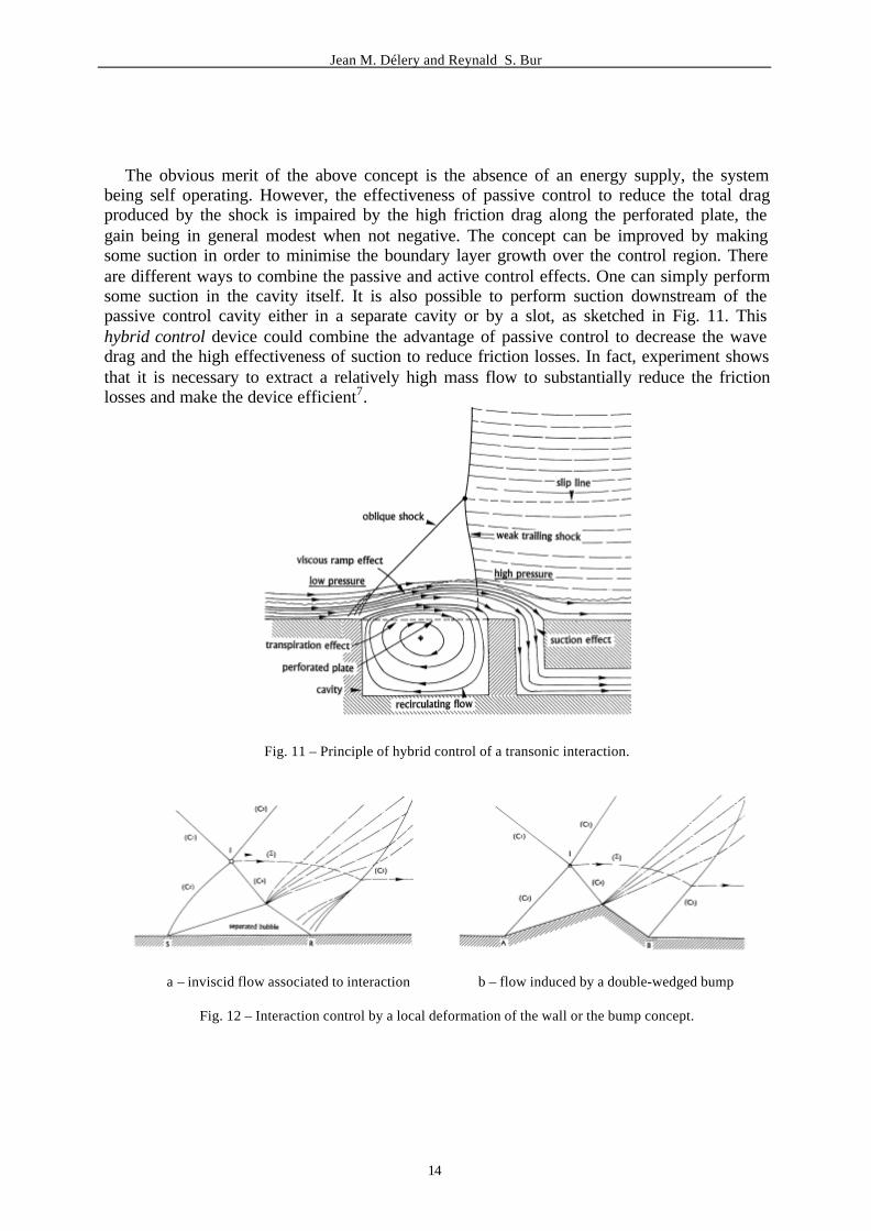
The obvious merit of the above concept is the absence of an energy supply, the systembeing self operating. However, the effectiveness of passive control to reduce the total dragproduced by the shock is impaired by the high friction drag along the perforated plate, thegain being in general modest when not negative. The concept can be improved by makingsome suction in order to minimise the boundary layer growth over the control region. Thereare different ways to combine the passive and active control effects. One can simply performsome suction in the cavity itself. It is also possible to perform suction downstream of thepassive control cavity either in a separate cavity or by a slot, as sketched in Fig. 11. Thishybrid control device could combine the advantage of passive control to decrease the wavedrag and the high effectiveness of suction to reduce friction losses. In fact, experiment showsthat it is necessary to extract a relatively high mass flow to substantially reduce the frictionlosses and make the device efficient7.
Fig. 11 – Principle of hybrid control of a transonic interaction.
a – inviscid flow associated to interaction b – flow induced by a double-wedged bump
Fig. 12 – Interaction control by a local deformation of the wall or the bump concept.
Jean M. Délery and Reynald S. Bur
15
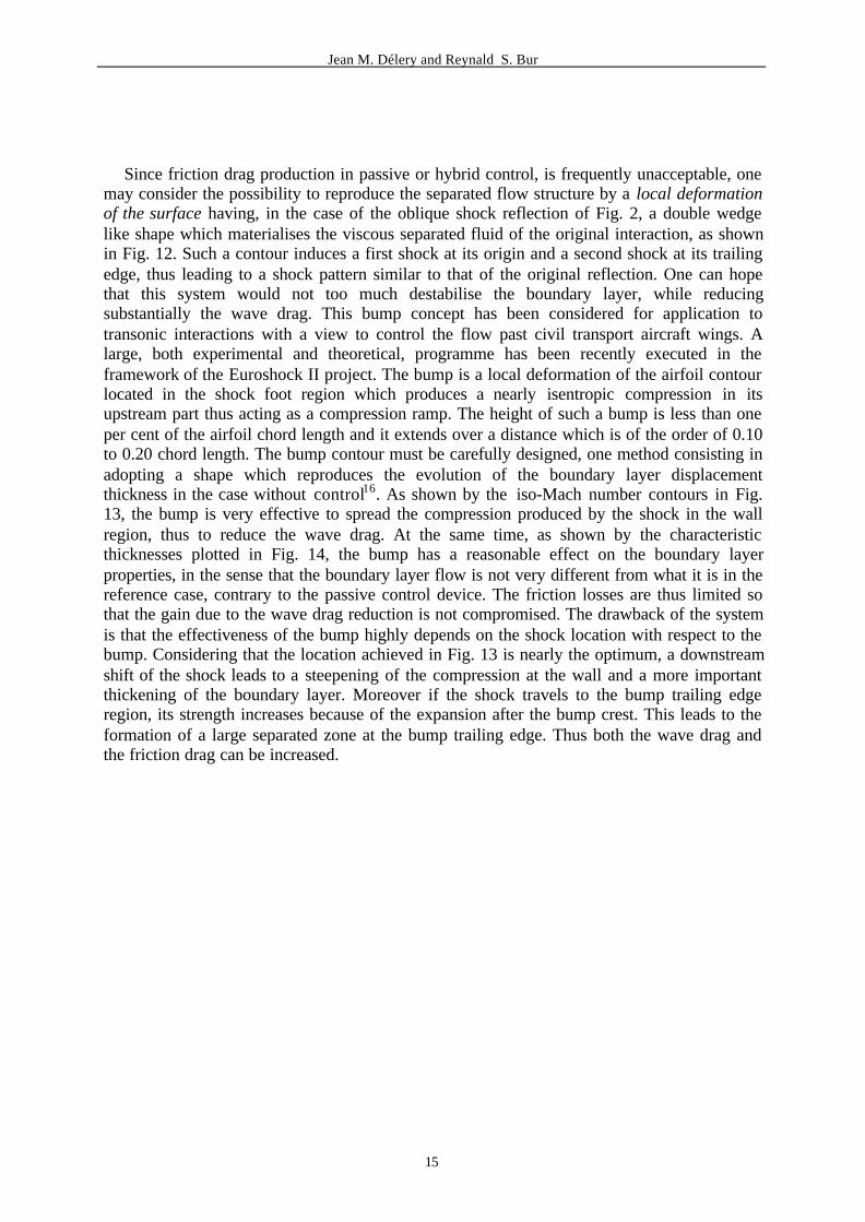
Since friction drag production in passive or hybrid control, is frequently unacceptable, onemay consider the possibility to reproduce the separated flow structure by a local deformationof the surface having, in the case of the oblique shock reflection of Fig. 2, a double wedgelike shape which materialises the viscous separated fluid of the original interaction, as shownin Fig. 12. Such a contour induces a first shock at its origin and a second shock at its trailingedge, thus leading to a shock pattern similar to that of the original reflection. One can hopethat this system would not too much destabilise the boundary layer, while reducingsubstantially the wave drag. This bump concept has been considered for application totransonic interactions with a view to control the flow past civil transport aircraft wings. Alarge, both experimental and theoretical, programme has been recently executed in theframework of the Euroshock II project. The bump is a local deformation of the airfoil contourlocated in the shock foot region which produces a nearly isentropic compression in itsupstream part thus acting as a compression ramp. The height of such a bump is less than oneper cent of the airfoil chord length and it extends over a distance which is of the order of 0.10to 0.20 chord length. The bump contour must be carefully designed, one method consisting inadopting a shape which reproduces the evolution of the boundary layer displacementthickness in the case without control16. As shown by the iso-Mach number contours in Fig.13, the bump is very effective to spread the compression produced by the shock in the wallregion, thus to reduce the wave drag. At the same time, as shown by the characteristicthicknesses plotted in Fig. 14, the bump has a reasonable effect on the boundary layerproperties, in the sense that the boundary layer flow is not very different from what it is in thereference case, contrary to the passive control device. The friction losses are thus limited sothat the gain due to the wave drag reduction is not compromised. The drawback of the systemis that the effectiveness of the bump highly depends on the shock location with respect to thebump. Considering that the location achieved in Fig. 13 is nearly the optimum, a downstreamshift of the shock leads to a steepening of the compression at the wall and a more importantthickening of the boundary layer. Moreover if the shock travels to the bump trailing edgeregion, its strength increases because of the expansion after the bump crest. This leads to theformation of a large separated zone at the bump trailing edge. Thus both the wave drag andthe friction drag can be increased.
Jean M. Délery and Reynald S. Bur
16
Fig. 13 – Transonic interaction control by a bump. Mach number contours.
a – displacement thickness b – momentum thickness
Fig. 14 – Transonic interaction control by a bump. Boundary layer characteristic thicknesses.
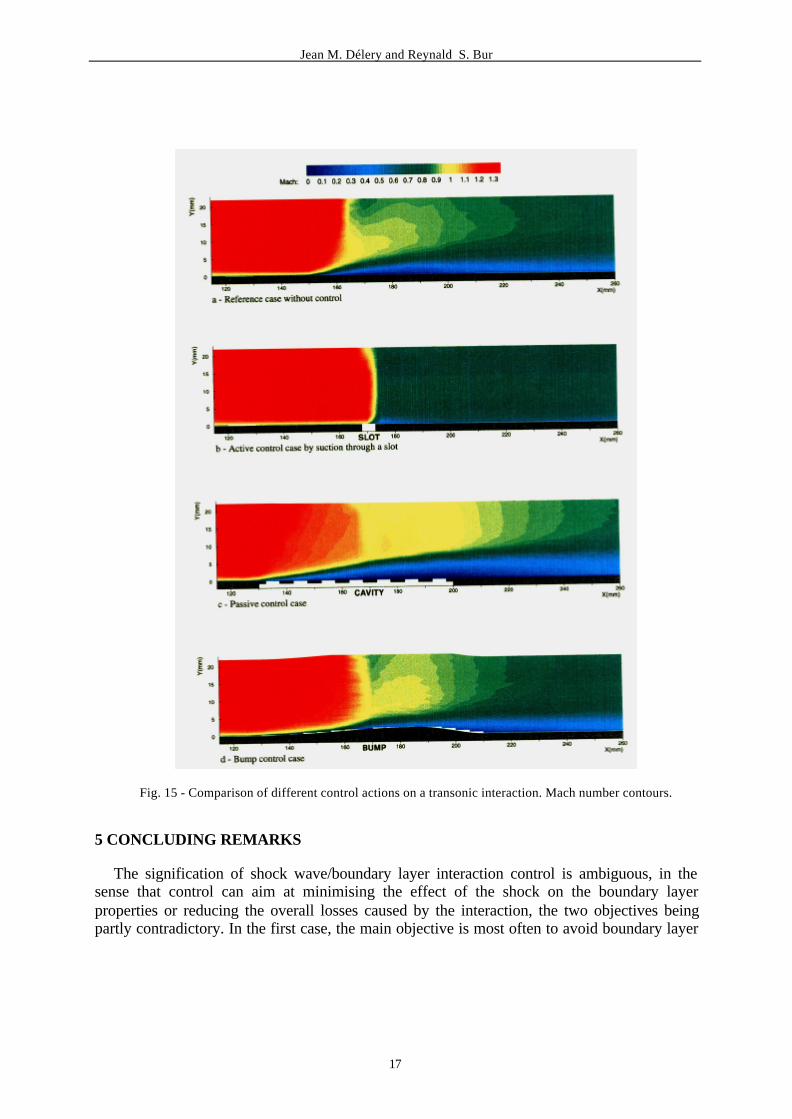
A comparison of the different tested methods is shown in Fig. 15 by plottings of the iso-Mach number contours deduced from LDV measurements. One sees the deep repercussion ofthe control actions both on the outer inviscid flow structure and on the boundary layerbehaviour.
Jean M. Délery and Reynald S. Bur
17
Fig. 15 - Comparison of different control actions on a transonic interaction. Mach number contours.
5 CONCLUDING REMARKS
The signification of shock wave/boundary layer interaction control is ambiguous, in thesense that control can aim at minimising the effect of the shock on the boundary layerproperties or reducing the overall losses caused by the interaction, the two objectives beingpartly contradictory. In the first case, the main objective is most often to avoid boundary layer
Jean M. Délery and Reynald S. Bur
18
separation which can be achieved either by manipulation of the boundary layer prior to itsinteraction with the shock (upstream blowing, suction through a slot, wall cooling) or bysuction or bleeding in the interaction region. In the second case, one has to reduce also thewave drag which is achieved by a splitting or spreading of the shock near the wall, which canbe done by creation of a separated-like flow structure by means of a passive control cavity ora bump.
The lessons learned at the issue of the two Euroshock projects could be that application ofthe above control systems to a wing is hasardous. The gain of passive control is questionable,active control requires extraction of important mass flow at low pressure, bump control is toomuch dependent on shock location. However, as far as external aerodynamics is concerned,local applications at a smaller scale can certainly be considered as, for example, to controlshock-induced separation on the pylon holding a propulsive nacelle.
Control techniques are more suited to internal aerodynamics applications interesting air-intakes, diffusers, nozzles because the size of the region to be controlled is far more reducedand because of the proximity of the energy supply; thus avoiding long redhibitory tubing.
The energetic and economic aspects of interaction control, as also the problem raised bythe installation of a control device in an airplane wing, have not been examined in this paper,although their consideration is essential. Neither we have discussed the problems raised by themodelling of an interaction under control conditions, considering the incidence of flowmanipulation on turbulence behaviour and the definition of a law to represent thesuction/transpiration velocities in the control region. The extensive experimental programmeexecuted within the Euroshock projects has allowed to constitute unprecedented data bankswhich already contributed to improve the physical models used in the prediction of shockwave/boundary layer interactions under control conditions17. This is also a lesson learned.
6 REFERENCES
[1] Délery, J., Shock phenomena in high speed aerodynamics: still a source of majorconcern. The Aeronautical Journal of the Royal Aeronautical Society, Jan. 1999, pp. 19-34
[2] Délery, J., Shock interaction phenomena in hypersonic flows. Part II: Physical featuresof shock wave/boundary layer interaction in hypersonic flows. In AGARD Conferenceon Future Aerospace Technology in the Service of the Alliance, 14-16 April 1997, EcolePolytechnique, Palaiseau, France
[3] Regenscheit, B., Versuche zur Widerstandsverringerung eines Flügels bei hoherMachscher - Zahl durch Absaugung der hinter dem Gebiet unstetiger Verdichtungabgelösten Grenzschicht. ZWB, Forschungsbericht N° 1424; 1941, English translation :NACA TM N° 1168
[4] Fage, A. and Sargent, R. F., Effect on aerofoil drag of boundary layer suction behind ashock wave, ARC R&M N° 1913, 1943
[5] Délery, J., Shock wave/turbulent boundary layer interaction and its control. Prog.Aerospace Sci., Vol. 22, 1985, pp. 209-280
Jean M. Délery and Reynald S. Bur
19
[6] Euroshock - Drag reduction by passive control. Results of the project Euroshock.AER2-CT92-0049 Supported by the European Union 1993-1995, Stanewsky, E.,Délery, J., Fulker, J. and Geissler, W. (Eds), Notes on Numerical Fluid Mechanics, 56,Vieweg, 1997
[7] Bur, R., Benay, R., Corbel, B., Soares-Morgadhino, R. and Soulevant, D., Study ofcontrol devices applied to a transonic shock wave/boundary layer interaction. Oneracontribution to Task 1 of the Euroshock II Project. Onera Technical Report N°126/7078DAFE/Y, July 1999
[8] Lighthill, M. J., On boundary-layer upstream influence. II Supersonic flows withoutseparation. Proc. R. Soc., A 217, 1953, pp. 478-507
[9] Chapman, D.R., Kuehn, D. M. and Larson, H.K., Investigation of separated flow insupersonic and subsonic streams with emphasis on the effect of transition. NACA TN3869, 1957
[10] Edney, B., Anomalous heat transfer and pressure distributions on blunt bodies athypersonic speeds in the presence of an impinging shock. Aeronautical ResearchInstitute of Sweeden, FFA Report N° 115, 1968
[11] Kilburg, R.F. and Kotansky, D.R., Experimental investigation of the interaction of aplane oblique incident-reflecting shock wave with a turbulent boundary layer on acooled surface. NACA CR-66-841, 1969
[12] Délery, J., Etude expérimentale de la réflexion d'une onde de choc sur une paroichauffée en présence d'une couche limite turbulente. La Recherche Aérospatiale, N°1992-1, 1992, pp. 1-23
[13] Savu, G., Trifu, O. and Dumitrescu, L. Z., Suppression of shocks on transonic airfoil.14th Int. Symp. On Shock Tubes and Waves, Sydney, Australia, 1983
[14] Bahi, L., Ross, J.M. and Nagamatsu, H.T., Passive shock wave/boundary layerinteraction control for transonic aerofoil drag reduction. AIAA Paper 83-0137, 1983
[15] Bur, R., Corbel, B., and Délery, J., Study of passive control in a transonic shockwave/boundary layer interaction. AIAA Journal, Vol. 36, N° 3, 1998, pp. 394-400
[16] Bur, R., Corbel, B., Délery, J. and Soulevant, D., Transonic shock wave/boundary layerinteraction control. Complementary experiments on suction slot and bump control.Onera contribution to Task 1 of the Euroshock II Project. Onera Technical Report N°131/7078DAFE/Y, Jan. 2000
[17] Bohning, R. and Doerffer, P., Passive control of shock wave/boundary layer interactionand porous plate transpiration flow. In Notes on Numerical Fluid Mechanics, 56,Vieweg, 1997
ACKNOWLEDGEMENT
The study of control methods applied to a transonic shock wave/boundary layer interactionhas been executed with the financial support of the European Union in the framework of theEuroshock I and II projects.
Related Documents


![Chapter 1 · [Runner: JUnit4] (0.159 s) verify zero interaction (0.12B s) verify nomore interaction (0022 s) Failure Trace org.mockito.exceptions.verification.NoInteractionsWanted:](https://static.cupdf.com/doc/110x72/5fb4153d74c7a364cd47a0e4/chapter-1-runner-junit4-0159-s-verify-zero-interaction-012b-s-verify-nomore.jpg)


![Fauchard, Pierre Diepgen, Paul [2] Bl., 12 S., [1] Bl ... · Tüshaus, Fritz ; Brend'amour, R Deutsche Sprichwörter nach Federzeichn. 13 Bl. ... Opiz, Philipp Maximilian Deutschlands](https://static.cupdf.com/doc/110x72/5b9f227d09d3f26e288c5be8/fauchard-pierre-diepgen-paul-2-bl-12-s-1-bl-tueshaus-fritz-.jpg)