Welcome message from author
This document is posted to help you gain knowledge. Please leave a comment to let me know what you think about it! Share it to your friends and learn new things together.
Transcript

Bob
Typewritten Text
Bob
Typewritten Text
RYCOM MODEL 2174
Bob
Typewritten Text
SELECTIVE VOLTMETER

MOD E L 2 1. 7 4
SELECTIVE VOLTMETER
Serial No. J"'·7
Ij
®
MODEL 2174
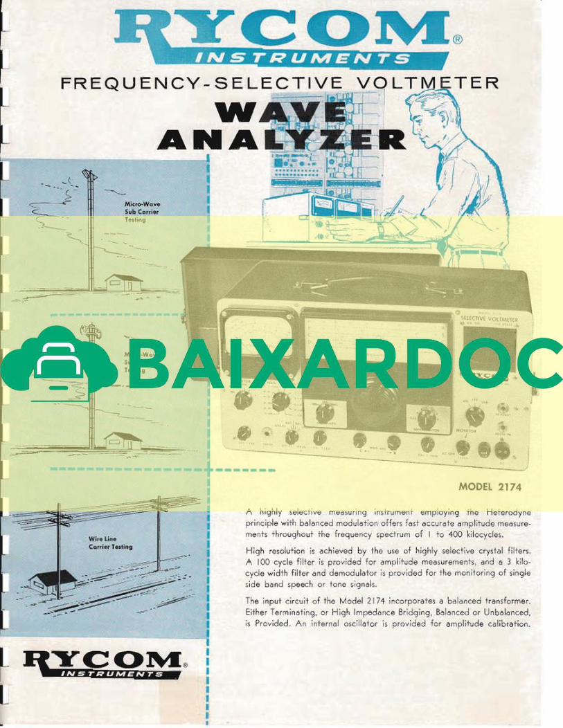
A highly selective measur'ing instrument employing the Heterodyne
principle with balar1ced modulation offers fast accurate amplitude measure
ments throughout the frequency spectrum of I to 400 kilocycles.
High resolution is achieved by the use of highly selective crystal filters.
A 100 cycle fiHer is provided for amplitude measurements, and a 3 kilo
cycle width filter and demodulator is provided for the monitoring of single
side band speech or tone signals.
The input circuit of the Model 2174 incorporates a balanced transformer.
Either Term inating, or High Impeda nce Bridg ing, Balanced or Unbalanced,
is Provided. An internal oscillator is provided for amplitude calibration.
~ . ......
Micro-WctveSub (:anierTltsling
Micro-WaveSub C:cmiltrTllstlllB
--- -
FREQUENCY - SELECTIVE
WANA
-
. ...(- --- ....(-?
---
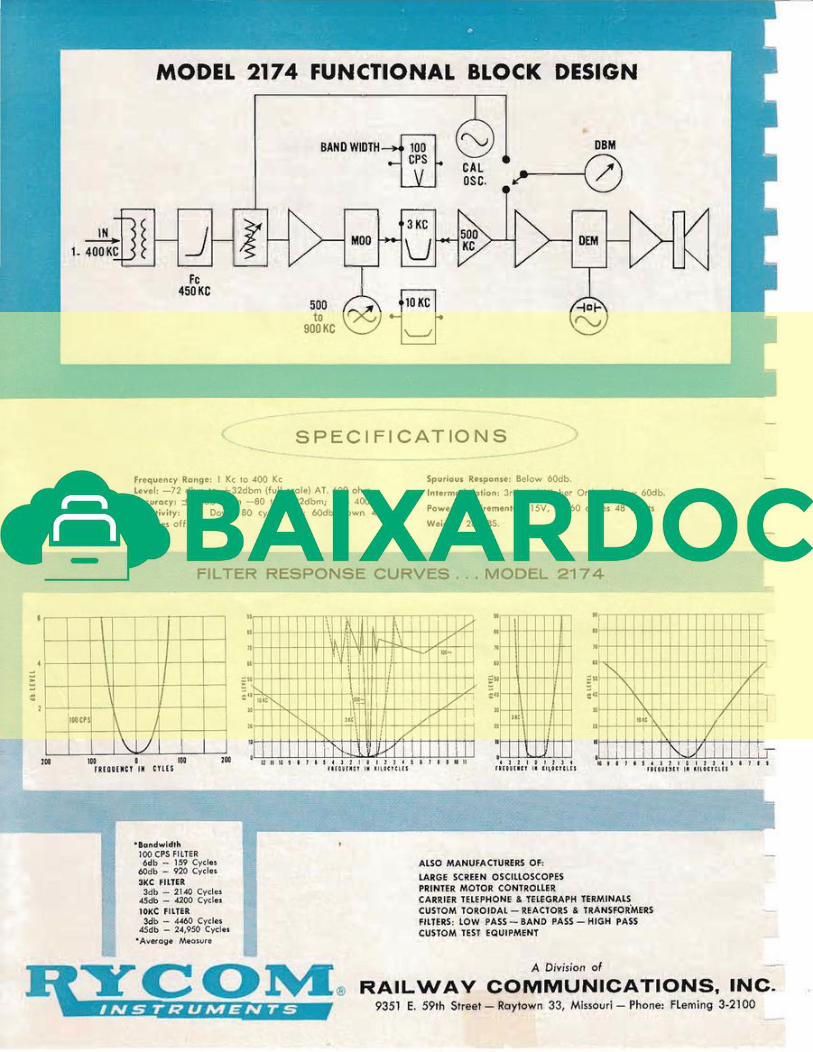
MODEL 2174 FUNCTIONAL BLOCK DESIGN
BAND WIDTHill DBMCPS
~I
IN
~ J 1(1 DEM-----+-1_ 400 KC 1
Fe450KC
500to
900KC
..---------- ......--- ------.. -.-
C. SPECIFICATIONS /... _~----- ----------
Frequency Range: I Kc 10 400 Kc
Level: -72 dbm to +32dbm (full scole) AT. 600 ohm.
Accuracy: ± .5db From -80 10 +32dbm; 1 to 400 Kc.
Selectivity: 6db Down 80 cycles off: 60db down 480
cycles off.
Spurious Response: Below 60db.
Intermodulation: 3rd ond Higher Orders Below 60db.
Power Requirements: 115V, 50/60 cycle$ 48 Wott$
Weight: 28 LBS.
F LTER RESPONSE CURVES ..• MODEL 2174
II\
V
i !IOOCPS1\ J
'I \ )I
Ie 9.1' 54 J 2 I a It] 4 S , } I ,rHlIUI~CY I_ IlILOCYClU
• 11 I I
0I I 1~
0
! II', I -(.
•,
! " \
YI 1\1 I I• 1\, I t-+.!/: i ; i• i
,1 i I~~C ~.: i I I,
1\.1 1 I/' I ! ."
•: i i N~i V ! i ! i "I
..
• I,•" I
,,Ii
:
, ,,l'
,ut, I
" !I
" !• -
11 II 10 ! I J • ~ ~ ) 2 1 g J 1 ] ~ ~ , I • 9 It 11FUQU[,lICT til ' ; 1 ~ G e l C l r s
• ,N Il'· I 'j--\ '\Of-+-
I 'Ii. ill\m 1:/- I L.-Y !, \0
,ill N·'1 \ I 1\ i I\'1~
1
•~ ! I
,II
I I0 T,· I I! !
•""!'- I
I
L.-: I IiI~~' ! I, I
! !'-I U1t\! I ! y' I !
I,N 1\1
-y i,1
,
"- " J t \:. i I: i " ~ I,
lOa100 a 100fRIOUUC! 'N CUES
200
'Bcsndwidth100 CPS FILTER6db - 159 Cycles
60db - 920 Cycle.
3KC FILTER3db - 2140 Cycle.
45db - 4200 Cycle.
10KC FIlTER3db - 4460 Cycle.
45db - 24,950 Cycle.
• Average Measure
ALSO MANUFACTURERS OF:
LARGE SCREEN OSCillOSCOPES
PRINTER MOTOR CONTROLLER
CARRIER TElEPHONE & TElEGRAPH lERMINALS
CUSTOM TOROIDAL - REACTORS & TRANSFORMERS
FILTERS: LOW PASS - BAND PASS - HIGH PASS
CUSTOM TEST EQUIPMENT
A Division of
RAILWAY COMMUNICATIONS, INC.935l E. 59th Street - Raytown 33, Missouri - Phone: Fleming 3-2100
. ,.. ' .~
INSPECTION
This instrument has been thoroughly tested and inspected beforeshipment.
The instrument should be inspected for damage as soon as it isreceived. If no damage is apparent, test for operation according tooperating instructions in this manual.
SUMMARY
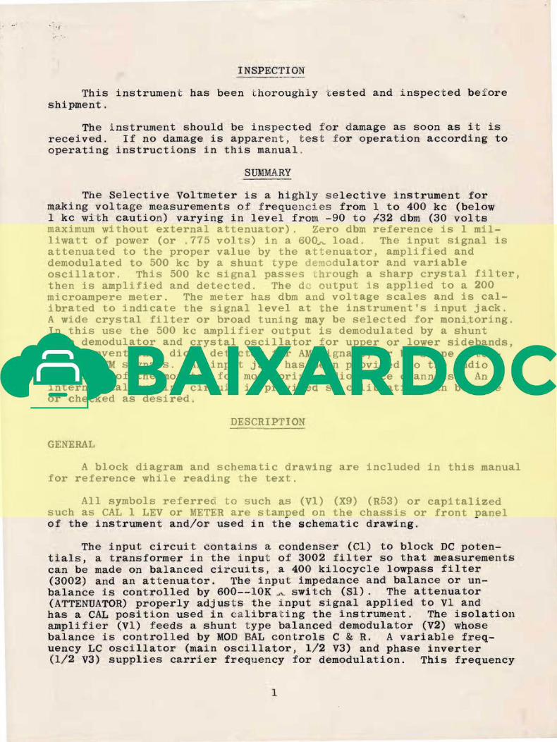
The Selective Voltmeter is a highly selective instrument formaking voltage measurements of frequenci.es from I to 400 kc (below1 kc with caution) varying in level from -90 to f32 dbm (30 voltsmaximum without external attenuator). Zero dbm reference is 1 milliwatt of power (or .775 volts) in a 600~ load. The input signal isattenuated to the proper value by the attenuator, amplified anddemodulated to 500 kc by a shunt type dem.odulator and variableoscillator. This 500 kc signal passes through a sharp crystal filter,then is amplified and detected. The de output is applied to a 200microampere meter. The meter has dbm and voltage scales and is calibrated to indicate the signal level at the instrument's input jack.A wide crystal filter or broad tuning may be selected for m o n i ~ o r i n g .
In this use the 500 kc amplifier output is demodulated by a shunttype demodulator and crystal oscillator for upper or lower sidebands,by a conventional diode detector for AM signals, or by slope detection of FM signals. An input jack has been provided to the audioamplifier of the monitor for monitoring audio voice channels. Aninternal calibrating circuit is provided so calibration can be madeor checked as desired.
DESCRIPTION
GENERAL
A block diagram and schematic drawing are included in this manualfor reference while reading the text.
All symbols referred to such as (VI) (X9) (R53) or capitalizedsuch as CAL 1 LEV or METER are stamped on the chassis or front panelof the instrument and/or used in the schematic drawing.
The input circuit contains a condenser (Cl) to block DC potentials, a transformer in the input of 3002 filter so that measurementscan be made on balanced circuits, a 400 kilocycle lowpass filter(3002) and an attenuator. The input impedance and balance or unbalance is controlled by 600--10K ~ ~ switch (Sl). The attenuator(ATTENUATOR) properly adjusts the input signal applied to VI andhas a CAL position used in calibrating the instrument. The isolationamplifier (VI) feeds a shunt type balanced demodulator (V2) whosebalance is controlled by MOD BAL controls C & R. A variable frequency LC oscillator (main oscillator, 1/2 V3) and phase inverter(1/2 V3) supplies carrier frequency for demodulation. This frequency
I

is controlled by the main tuning condenser (C36) , BAND SEL switch(S3) and a trimmer condenser (CB3) CAL 2 TRIM. The 100 cps or 3 kccrystal filter (Xl through 4 & Tl or X5 through 8 & T2) or 10 kcbroad coupling (C26 and 29) passes the lower sideband of modulation.The 500 kc IF amplifier (V4 & V5) feeds both the measure (V6, D3-4)and monitor (V8,9&10) sections of the instrument. The IF amplifiergain is adjusted by CAL 2 LEV (R37). The meter circuit amplifier(V6) feeds a series shunt type meter 1'6 : ~ . t i fier (D3 & D4) whose output indicates on a 200 microampere meter "alibrated in dbm and volts.The IF isolation amplifier (V8) feeds a ··B ..~ies type demodulator (Dl,D2) for monitoring lower sideband LSB or upper sideband USB signals(MONITOR switch on LSB or USB and SELECTIVITY switch on 3 kc).The carrier for this demodulator is supplied by a crystal controlledoscillator (1/2 V9). For monitoring amplitude modulated signalsor slope detection of FM signals, this oscillator is made inoperativeand diode D2 removed thus the circuit operates as a conventionaldiode detector (MONITOR switch on AM and SELECTIVITY switch on 10kc). The resulting audi0 signal passes through the RC filter (R40,C57,C58) and amplifier (1/2 V9,VIO), to the speaker or a headsetplugged into the HEADSET jack (J3). The audio output amplitude iscontrolled by the potentiometer MON LEV (R42).
An audio signal may be amplified by inserting it in the AUDIOIN jack just ahead of the audio amplifier (1/2 V9 & VIO).
A 30 kilocycle LC tuned oscillator (1/2 V7) coupled to acathode follower (1/2 V7) is used to furnish the calibration signal.The potentiometer CAL 1 LEV (R55) adjusts the calibrate oscillatoroutput. Plate power is supplied to the calibrate oscillator onlywhen the BAND SEL switch is in the CAL position, thus it is inoperation only during calibration.
Plate power is furnished by a bridge type full wave seleniumrectifier (SRl-SR4). A voltage regulator tube VII stabilizes theplate supply to all circuits except the monitor section.
The filaments are 50 volts DC above g ~ o u n d to prevent heaterto cathode leakage and to eliminate 60 cps modulation which mayoccur in VI and V2.
INPUT
The input impedance is 600 ohms ( 6 0 0 ~ ) or bridging (10K) asselected by the 600-l0K switch 81. The input circuit may beswitched from balanced (BAL) to unbalanced (UNBAL) as desired oneither input impedance. In the bridging position (10K) the inputimpedance remains high enough to cause negligible loading of lowimpedance circuits. The input impedance is approximately 10,000ohms from 1 to 30 KC, gradually falling to a.pproximately 5 0 0 0 ~
at 400 KC.
An external signal is connected to the input circuit by meansof a two conductor phone plug in INPUT jack. The sleeve of this

jack is insulated from the front panel, thus isolating it fromchassis ground during balanced measurements.
ATTENUATOR
The attenuato:!' provi.des 0 to 100 db of attenuation for measuring signals between -68 and ~ 3 2 dbm (full scale meter indication).The CAL position is connected to the voltage divider of the calibrateoscillator output for calibrating the isolation and IF amplifiers.
FREQUENCY
The main oscillator is varied from 501 to 900 kilocycles byBAND SEL switch and main tuning dial to measure frequencies of 1
to 400 kilocycles respectively as indicated on the frequency dial.For example, a signal of 17 kc is fed into the instrument. TheBAND SEL switch is set on A and frequency dial tuned to 17 kc.The main oscillator is now oscillating at 517 kc and the lowersideband of demodulation is 500 kc which is the center frequencyof the crystal filter. ~ J n i n g for calibration (BAND SEL On CAL)is separate from the main tuning dial and adjusted by the CAL 2TRIM control. This greatly simplifies meter calibration and calibration checks if desired while using the instrument. Since theCAL 2 TRIM control remains in the tank circuit on all bancls it canbe used as a frequency vernier when making measurements. This,however, temporarily disturbs the frequency calibration of theinstrument. When making an internal ca.libration of the instrumentthe main oscillator frequency is automatically recalibr"ated by theCAL 2 TRIM control at 30 kc.
The trimmers C40,42,44,46,48 & 88 are used to set the frequency of each band (A,B,C,D,E & F.) C38 is used to set thecalibrate frequency tuning. These calibrations are made withCAL 2 TRIM at mid range.
MODULATOR BALANCE
When measuring frequencies below 1 kc, the demodulator mustbe balanced to prevent erroneous readings due to main oscillatorfrequency passing through the crystal filter and being measuredalong with the desired signal.
The demodulator is balanced with the main oscillator at 500kc (frequency dial at zero) so the carrier (oscillator frequency)will pass through the crystal filter (100 cps bandwidth) andindicate on the meter. C & R are adjusted for minimum meterindication thus a minimum carrie:r frequency (carrier leak) at themodulator output.
The two controls C MOD HAL R control the balance of the maindemodulator. The C control (C80) balances the capacity componentand the R control (R24) balances the resistive component.
3
SELECTIVITY
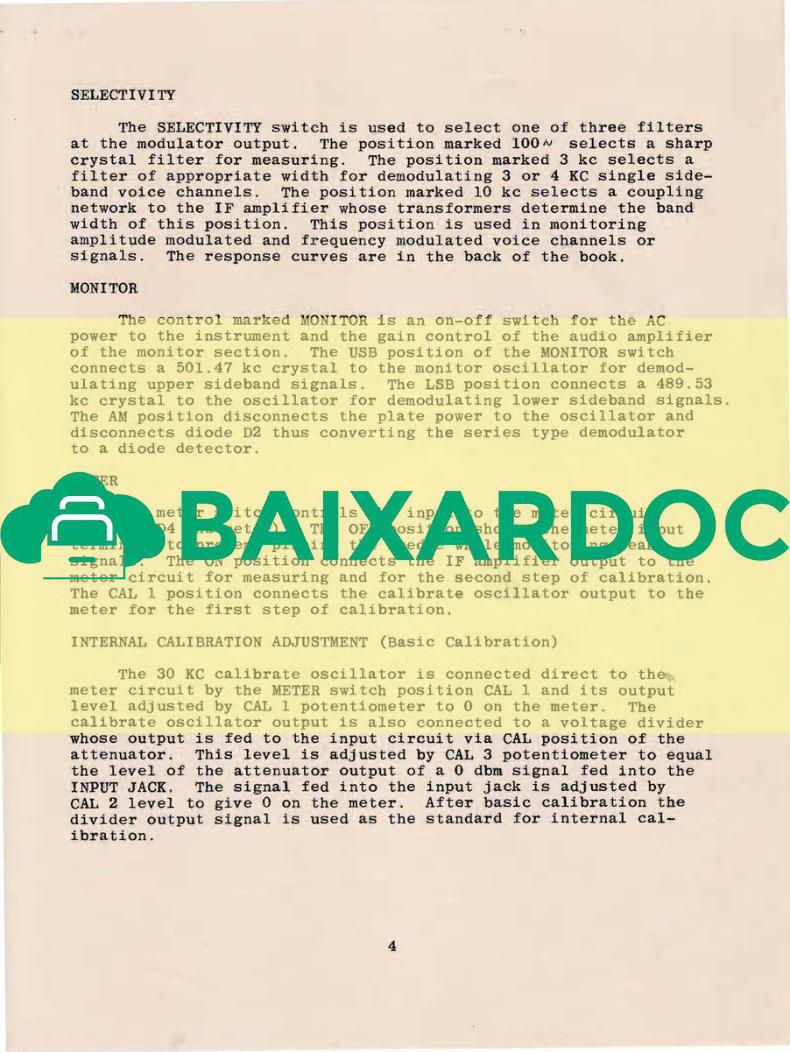
The SELECTIVITY switch is used to select one of three filtersat the modulator output. The position marked lOON selects a sharpcrystal filter for measuring. The position marked 3 kc selects afilter of appropriate width for demodulating 3 or 4 KC single sideband voice channels. The position marked 10 kc selects a couplingnetwork to the IF amplifier whose transformers determine the bandwidth of this position. This position is used in monitoringamplitude modulated and frequency modulated voice channels orsignals. The response curves are in the back of the book.
MONITOR
The control marked MONITOR is an on-off switch for the ACpower to the instrument and the gain control of the audio amplifierof the monitor section. The USB position of the MONITOR switchconnects a 501.47 kc crystal to the monitor oscillator for demodulating upper sideband signals. The LSB position connects a 489.53kc crystal to the oscillator for demodulating lower sideband signals.The AM position disconnects the plate power to the oscillator anddisconnects diode D2 thus converting the series type demodulatorto a diode detector.
METER
The meter switch controls the input to the meter circuit(V6,D3 & D4 and meter). The OFF position shorts the meter inputterminals to prevent pinning the needle while monitoring weaksignals. The ON position connects the IF amplifier output to themeter circuit for measuring and for the second step of calibration.The CAL 1 position connects the calibrate oscillator output to themeter for the first step of calibration.
INTERNAL CALIBRATION ADJUSTMENT (Basic Calibration)
The 30 KC calibrate oscillator is connected direct to themeter circuit by the METER switch position CAL 1 and its outputlevel adjusted by CAL 1 potentiometer to 0 on the meter. Thecalibrate oscillator output is also connected to a voltage dividerwhose output is fed to the input circuit via CAL position of theattenuator. This level is adjusted by CAL 3 potentiometer to equalthe level of the attenuator output of a 0 dbm signal fed into theINPUT JACK. The signal fed into the input jack is adjusted byCAL 2 level to give 0 on the meter. After basic calibration thedivider output signal is used as the standard for internal calibration.
4
OPERATING INSTRUCTIONS
GENERAL
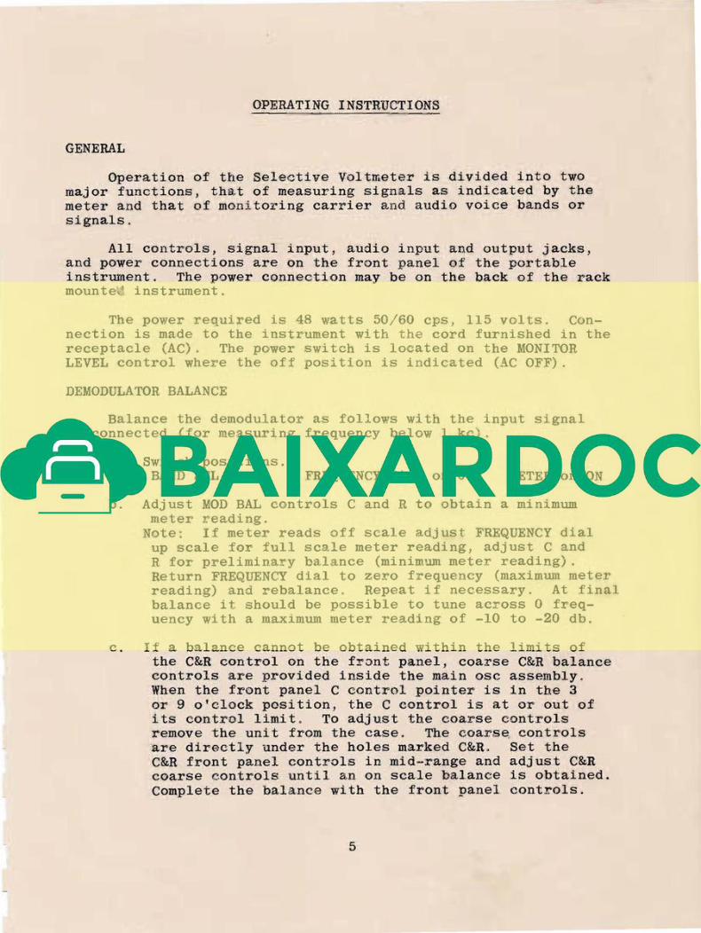
Operation of the Selective Voltmeter is divided into twomajor functions, tha.t of measuring signals as indicated by themeter and that of monitoring carrier and audio voice bands orsignals.
All controls, signal input, audio input and output jacks,and power connections are on the front panel of the portableinstrument. The power connection may be on the back of the rackm o u n t e ~ instrument.
The power required is 48 watts 50/60 cps, 115 volts. Connection is made to the instrument with the cord furnished in thereceptacle (AC). The power switch is located on the MONITORLEVEL control where the off position is indicated (AC OFF) .
DEMODULATOR BALANCE
Balance the demodulator as follows with the input signaldis.connected (for measuring frequency below 1 kc).
a. Switch positions.BAND SEL on A FREQUENCY dial on 0 METER on ON
b. Adjust MOD BAL controls C and R to obtain a minimummeter reading.
Note: If meter reads off scale adjust FREQUENCY dialup scale for full scale meter reading, adjust C andR for preliminary balance (minimum meter reading).Return FREQUENCY dial to zero frequency (maximum meterreading) and rebalance. Repeat if necessary. At finalbalance it should be possible to tune across 0 frequency wi.th a maximum meter reading of -10 to -20 db.
c. If a balance cannot be obtained within the limits ofthe C&R control on the f r ~ n t panel, coarse C&R balancecontrols are provided inside the main osc assembly.When the front panel C control pointer is in the 3or 9 o'clock position, the C eontrol is at or out ofits control limit. To adjust the coarse controlsremove the unit from the case. The coarSe controls-are directly under the holes marked C&R. Set theC&R front panel controls in mid-range and adjust C&Rcoarse controls until an on scale balance is obtained.Complete the balance with the front panel controls.
5

· balancs has cau ed
_..1'" d8c.;::.:::.~ 0'" balan e n .;::;ded j.G c13penCSl1t on the selactivity oft ~ rr73·~u~ ~il-~e~ a~d t~la freqLsncy Q3adured.
he l' C cp...,a Fe', C ! ~ ) a . . ~
rys ,- al f:l.1 ;;er is d O V J ~ 1 moro tf.lan 2(; 0.0 at 300 cps off~ ~ G G cps o f ~ , ~ ~ u s a J ~b ~a~a~ca will caUGe n e g l i ~ ~ ~ 0
asuring a 30D cps or h j . e ~ e r "tone.
A qci :< cLec.~ :i.s to 1:U e in t:-:8 d-8olred signal, reli10V8 ~ c : h e j.nput
and bsst' 8 1:: __ ffi'cte e ~ ... c1:~ i1e: (11;i8 · ~ o ~ ~ a . ~ ~ ~ ; " ' 8 1 ~ . 1 J: i -;.: :t~ less tb.an
a eE:-~~.nlat~~ J5· dD y ti1~3n t1Y 1 ~ 8 a c ~ ~ L J . ~ e a::::>\re -IS do v!:'Lil '08 aff.ccteclless - ; : ~ . " ' J O a . . . .],. r1b. l~TOT:~: vo 11Ct St~t tI-la ~ n e t e r zarc, o : ~ 0 ''tI0 .... t,n.
1 \ ~ J 2 nleC3I' Z ~ l . ~ O is usee] iOl'" ~ n e - c 2 1 4 'Ll"aC.l.\::?_11g at ..-lJ db.
A ' ~ low ~ a l a D c a , a double p e a ~ or erratic meter· fluctuations mayble l1C'"·-ed.. T..18Se do 110t 119ceccal":; 1;' i 1 1 d ~ ... cate ' ~ r G ' tb_,e :t:( t ~ 2 9
inst:i1 lw;,}n.t performs sat::"s:;-'actor:::':'y w;.:,Bn measur;~ne: a to e.
The tube used as VI is critical in date m i n ~ n g t ~ e degree i
l~nce ob~ainable princ~pa~ly dU8 to ~ e a t e r and c a ~ ~ o d 8 1 ga.US "=lo ~ ~"':::l. ~C'I'" '.:::Jo~" tZ~··.''',q -.... "11'"",~ r:r a· ~·~.f~l /r.:.~,:,.'"!,~ -Po 1" ~ " ) ~ ' \ •. r.Q"r_ ~---a;_~L·~.~e ..~ ..- ......,_ ~ u \.J ~ . l . . . , ' - . L ~ t . . . i _ U. ......'-' ,,~>- 'l..,;I'~_,_._''''' '_ . . . . . . - ~ _ ~ v ..., _ ......
Turn t;18 1l,10n::r'i.'OR-. ,EVEL down -to m : l . n : ~ m u m Wih'311 balancing.
Related Documents