DIVERSIFIED METAL FABRICATORS, INC. DMF 665 Pylant Street Atlanta, Georgia 30306 Parts (404) 607-1684 Parts Fax (404) 879-7888 [email protected] Service Department (404) 879-7882 [email protected] Phone (404) 875-1512 Fax (404) 875-4835 [email protected] http://www.dmfatlanta.com Parts & Service Manual RW-1019B January 2019 SERIAL NUMBER (FRONT) ________________________ SERIAL NUMBER (REAR) ________________________ NOTE: Please refer to the serial numbers when ordering parts or inquiring about warranty items.

Welcome message from author
This document is posted to help you gain knowledge. Please leave a comment to let me know what you think about it! Share it to your friends and learn new things together.
Transcript
DIVERSIFIED METAL FABRICATORS, INC.
DMF 665 Pylant Street Atlanta, Georgia 30306 Parts (404) 607-1684 Parts Fax (404) 879-7888 [email protected]
Service Department (404) 879-7882 [email protected] Phone (404) 875-1512 Fax (404) 875-4835 [email protected]
http://www.dmfatlanta.com
Parts & Service Manual RW-1019B
January 2019
SERIAL NUMBER (FRONT) ________________________
SERIAL NUMBER (REAR) ________________________
NOTE: Please refer to the serial numbers when ordering parts or
inquiring about warranty items.
DIVERSIFIED METAL FABRICATORS, INC. RW-1019B
© 2019 DMF, Inc. All Rights Reserved.
Message from DMF
No matter what your job function is, Operation, Installation, Maintenance, or Repair, it is your responsibility to familiarize yourself with the entire manual. Once you have read the entire manual, there are some specific sections that you will want to pay special attention to, depending on your role.
If you find anything missing, incorrect or unclear in this manual, please contact us. We are always trying to improve our manuals.
Manuals, service bulletins and general information are available on our website listed below.
We reserve the right to update our manuals without notice. You can download a current manual at our website (http://www.dmfatlanta.com).
Thank you for choosing DMF Railgear. We make every effort to provide quality, safe and rugged products for the railroad. We hope you'll find our gear to be satisfactory in every way. We take product support very seriously, so if you have any questions, please contact us.
Contact: Diversified Metal Fabricators 665 Pylant St. NE Atlanta, GA 30306 (404) 875-1512(404) 875-4835 Fax(404) 607-1684 Partshttp://[email protected]
Ship to: 668 Drewry St. NE Atlanta, GA 30306
DIVERSIFIED METAL FABRICATORS, INC. RW-1019B
© 2019 DMF, Inc. All Rights Reserved.
TABLE OF CONTENTS SECTION 1.0 GENERAL INFORMATION
1.1 General Description, Weights & Capacities .............. 1-2 1.2 Currently Approved Chassis ................................. 1-4 1.3 Front Railgear Key Components ........................... 1-5 1.4 Rear Railgear Key Components ............................ 1-6
SECTION 2.0 OPERATIONS 2.1 Before You Operate the Railgear ........................... 2-2 2.2 Anti-Lock Brake System (ABS), Traction Control ...... 2-2 2.3 Highway Operation .............................................. 2-3 2.4 Getting On the Rail.............................................. 2-3 2.5 Getting Off the Rail ............................................. 2-4
SECTION 3.0 ROUTINE MAINTENANCE 3.1 Inspection and Maintenance ................................. 3-2 3.2 Fluids and Lubrication .......................................... 3-3 3.3 Wheel Wear Gauge .............................................. 3-6 3.4 Troubleshooting .................................................. 3-8 3.5 Derailment ......................................................... 3-9
SECTION 4.0 RAILGEAR INSTALLATION 4.1 Pre-Install .......................................................... 4-3 4.2 Initial Instructions ............................................... 4-6 4.3 Installation of Rear Railgear ................................. 4-8 4.4 Exhaust Modification ............................................ 4-15 4.5 Installation of Front Railgear ................................. 4-19 4.6 Installation of Front Axle Lock ............................... 4-28 4.7 Hydraulic & Electrical Installation .......................... 4-35 4.8 Alignment, Weight Adjustment, & Rail Test ............. 4-36 4.9 Install Provided Accessories .................................. 4-41 4.10 Installation Review Checklist ............................... 4-46
SECTION 5.0 RAILGEAR OPTIONS 5.1 Rail Sweeps ....................................................... 5-2 5.2 Rail Brakes ........................................................ 5-5 5.3 Pin Offs ............................................................. 5-8
SECTION 6.0 HYDRAULIC SYSTEM 6.1 General Information ............................................ 6-2 6.2 Brake Line Routing .............................................. 6-6 6.3 Hydraulic and Electrical Schematics ....................... 6-7 6.4 Hydraulic and Electrical Component Drawings ......... 6-10
SECTION 7.0 REAR RAILGEAR PARTS 7.1 Before Ordering Parts .......................................... 7-2 7.2 Rear Core Assembly Diagrams .............................. 7-3 7.3 Mounting Kit Diagrams ........................................ 7-5 7.4 H-Bracket Kit Diagrams ....................................... 7-8 7.5 Rear Axle Diagrams ............................................. 7-10
SECTION 8.0 FRONT RAILGEAR PARTS 8.1 Before Ordering Parts .......................................... 8-2 8.2 Front Assembly Diagrams ..................................... 8-3 8.3 Front Axle Diagrams ............................................ 8-7 8.4 Axle Lock Kit Diagrams ........................................ 8-9
DIVERSIFIED METAL FABRICATORS, INC. RW-1019B
© 2019 DMF, Inc. All Rights Reserved.
LIST OF FIGURES/TABLES Figure 1.3.1 Front Railgear Components ..................................... 1-5 Figure 1.4.1 Rear Railgear Components ...................................... 1-6 Figure 4.2.3 Installation Rails .................................................... 4-7 Figure 4.3.2 Rear Railgear Components - Ford ............................. 4-9 Figure 4.4.2.A Exhaust Modifications – Ford ................................... 4-16 Figure 4.4.2.B Required Exhaust Clearances ................................... 4-16 Figure 4.4.2.C Required Hanger Relocation ..................................... 4-17 Figure 4.4.3.A Exhaust Modifications – Ram ................................... 4-18 Figure 4.4.3.B Required Exhaust Clearances ................................... 4-18 Figure 4.5.2.A Front Primary Components – Ford ............................ 4-19 Figure 4.5.2.B Crush Tube Location ............................................... 4-20 Figure 4.5.2.C Hardware Locations ................................................ 4-21 Figure 4.5.2.D Transmission Cooler Relocation ................................ 4-21 Figure 4.5.2.E Front Bumper Relocation ......................................... 4-22 Figure 4.5.2.F Sample Front Bumper Trim ..................................... 4-22 Figure 4.5.3.A Front Primary Components – Ford 2017+ .................. 4-23 Figure 4.5.3.B Crush Tube Location – Ford 2017+ ........................... 4-24 Figure 4.5.3.C Hardware Location – Ford 2017+ ............................. 4-25 Figure 4.5.4.A Front Primary Components – Ram ............................ 4-26 Figure 4.5.4.B Bumper Bracket Modification – Ram ......................... 4-26 Figure 4.5.4.C Front Railgear Installation – Ram ............................. 4-27 Figure 4.5.4.D Front Bumper Trimmed – Ram ................................. 4-27 Figure 4.6.6.A Front Brake Line Relocation – Ram ........................... 4-34 Figure 4.6.6.B Front Brake Line Relocation – Ram ........................... 4-34 Figure 4.8.1 Checking Rear Railgear for Square to Truck Axle ........ 4-36 Figure 4.9.1.A Steering Wheel Lock Installation .............................. 4-41 Figure 4.9.1.B Steering Wheel Lock Installed .................................. 4-41 Figure 5.1.1.A Rear Rail Sweeps ................................................... 5-2 Figure 5.1.1.B Front Rail Sweeps .................................................. 5-2 Figure 5.2.1 Rail Brake Adjustment ............................................ 5-5 Figure 5.3.1 Rear Pin Off Handle Routing .................................... 5-9 Figure 5.3.2 Typical Front Pin Off Cable Mounting ......................... 5-14
Table 3.4.1 Troubleshooting On-Track Problems .......................... 3-8 Table 4.1.5 Manufacturer Equivalent Welding Rod ....................... 4-5
DIVERSIFIED METAL FABRICATORS, INC. RW-1019B `
© 2019 DMF, Inc. All Rights Reserved. 1-1
SECTION 1.0 GENERAL INFORMATION 1.1 GENERAL DESCRIPTION, WEIGHTS & CAPACITIES ......................................... 1-2
1.1.1 Weights and Capacities .................................................................................. 1-2 1.1.2 Materials ..................................................................................................... 1-2 1.1.3 Installation .................................................................................................. 1-2 1.1.4 Options ....................................................................................................... 1-2 1.1.5 Brakes ........................................................................................................ 1-2
1.2 CURRENTLY APPROVED CHASSIS ................................................................... 1-4
1.2.1 Ram ............................................................................................................ 1-4 1.2.2 Ford ............................................................................................................ 1-4
1.3 FRONT RAILGEAR ........................................................................................... 1-5
1.3.1 Key Front Railgear Components ...................................................................... 1-5
1.4 REAR RAILGEAR ............................................................................................. 1-6
1.4.1 Key Rear Railgear Components ....................................................................... 1-6 1.4.2 Rear Railgear Body Clearances ........................................................................ 1-6
DIVERSIFIED METAL FABRICATORS, INC. RW-1019B
1-2 © 2019 DMF, Inc. All Rights Reserved.
1.1 GENERAL DESCRIPTION, WEIGHTS & CAPACITIES
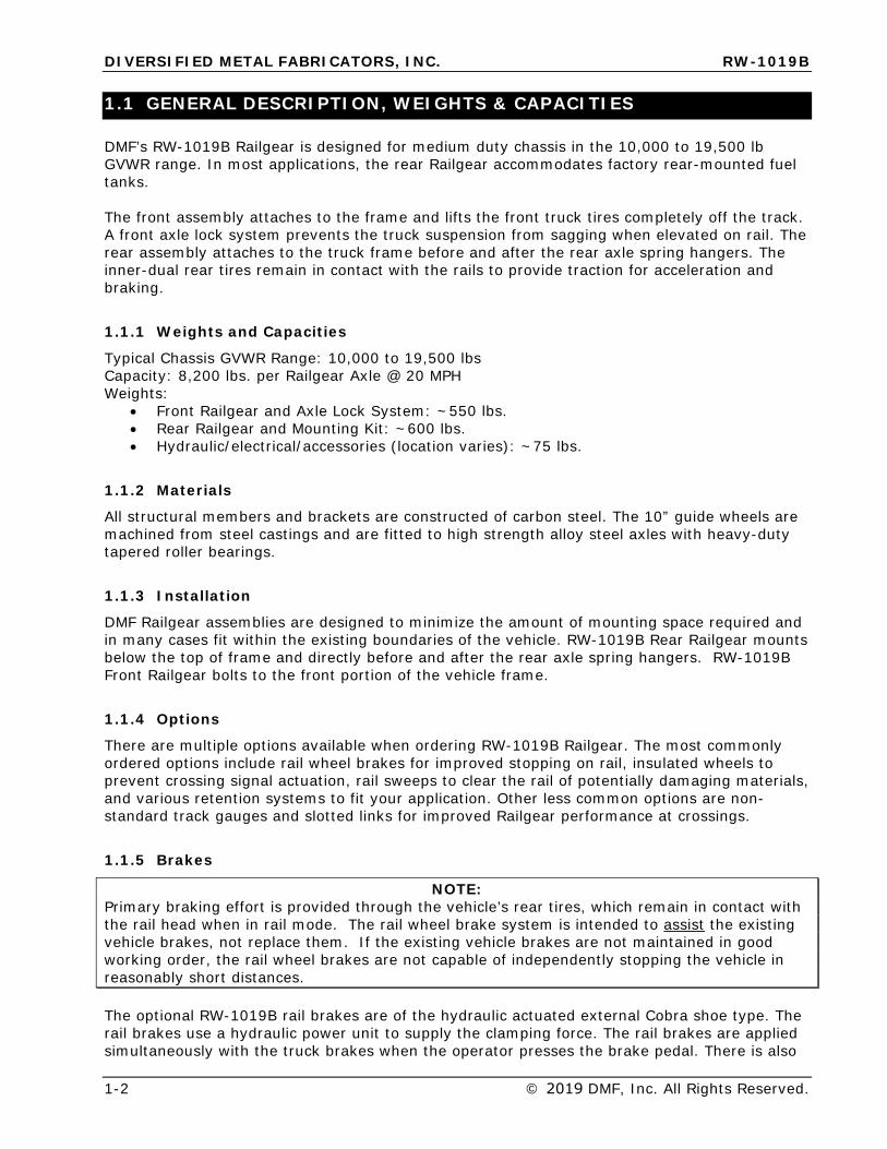
DMF’s RW-1019B Railgear is designed for medium duty chassis in the 10,000 to 19,500 lb GVWR range. In most applications, the rear Railgear accommodates factory rear-mounted fuel tanks.
The front assembly attaches to the frame and lifts the front truck tires completely off the track. A front axle lock system prevents the truck suspension from sagging when elevated on rail. The rear assembly attaches to the truck frame before and after the rear axle spring hangers. The inner-dual rear tires remain in contact with the rails to provide traction for acceleration and braking.
1.1.1 Weights and Capacities
Typical Chassis GVWR Range: 10,000 to 19,500 lbs Capacity: 8,200 lbs. per Railgear Axle @ 20 MPH Weights:
• Front Railgear and Axle Lock System: ~550 lbs.• Rear Railgear and Mounting Kit: ~600 lbs.• Hydraulic/electrical/accessories (location varies): ~75 lbs.
1.1.2 Materials
All structural members and brackets are constructed of carbon steel. The 10” guide wheels are machined from steel castings and are fitted to high strength alloy steel axles with heavy-duty tapered roller bearings.
1.1.3 Installation
DMF Railgear assemblies are designed to minimize the amount of mounting space required and in many cases fit within the existing boundaries of the vehicle. RW-1019B Rear Railgear mounts below the top of frame and directly before and after the rear axle spring hangers. RW-1019B Front Railgear bolts to the front portion of the vehicle frame.
1.1.4 Options
There are multiple options available when ordering RW-1019B Railgear. The most commonly ordered options include rail wheel brakes for improved stopping on rail, insulated wheels to prevent crossing signal actuation, rail sweeps to clear the rail of potentially damaging materials, and various retention systems to fit your application. Other less common options are non-standard track gauges and slotted links for improved Railgear performance at crossings.
1.1.5 Brakes
NOTE: Primary braking effort is provided through the vehicle’s rear tires, which remain in contact with the rail head when in rail mode. The rail wheel brake system is intended to assist the existing vehicle brakes, not replace them. If the existing vehicle brakes are not maintained in good working order, the rail wheel brakes are not capable of independently stopping the vehicle in reasonably short distances.
The optional RW-1019B rail brakes are of the hydraulic actuated external Cobra shoe type. The rail brakes use a hydraulic power unit to supply the clamping force. The rail brakes are applied simultaneously with the truck brakes when the operator presses the brake pedal. There is also
DIVERSIFIED METAL FABRICATORS, INC. RW-1019B `
© 2019 DMF, Inc. All Rights Reserved. 1-3
a dashboard-mounted switch that permits the operator to enable or disable the rail braking system.
DIVERSIFIED METAL FABRICATORS, INC. RW-1019B
1-4 © 2019 DMF, Inc. All Rights Reserved.
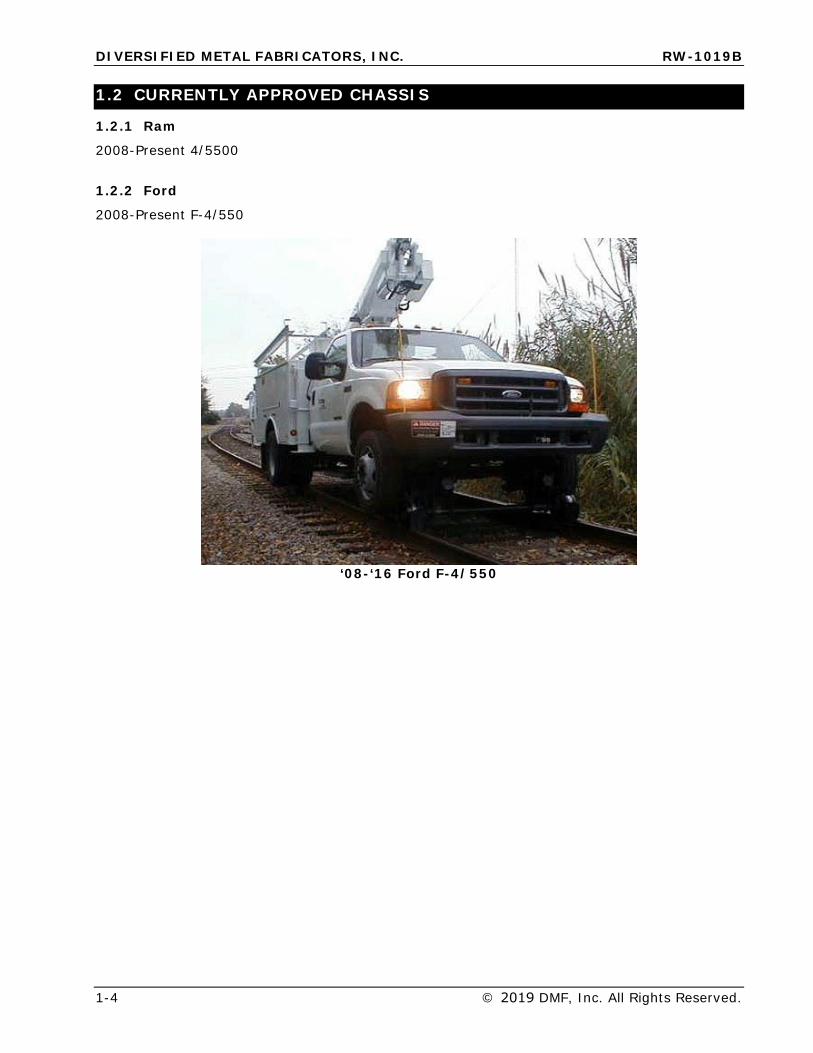
1.2 CURRENTLY APPROVED CHASSIS
1.2.1 Ram
2008-Present 4/5500
1.2.2 Ford
2008-Present F-4/550
‘08-‘16 Ford F-4/550
DIVERSIFIED METAL FABRICATORS, INC. RW-1019B `
© 2019 DMF, Inc. All Rights Reserved. 1-5
1.3 FRONT RAILGEAR
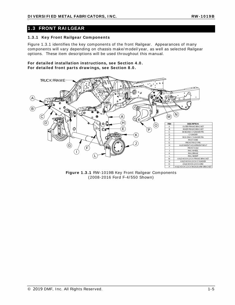
1.3.1 Key Front Railgear Components
Figure 1.3.1 identifies the key components of the front Railgear. Appearances of many components will vary depending on chassis make/model/year, as well as selected Railgear options. These item descriptions will be used throughout this manual.
For detailed installation instructions, see Section 4.0. For detailed front parts drawings, see Section 8.0.
N
O
M
A
A
B
CD
E
FG
H
I
J
K
L
P
TRUCK FRAME
ITEM DESCRIPTIONA OUTER FRAME BRACKETB INNER FRAME BRACKETC BASE END CYLINDER PIND CYLINDERE ROD END CYLINDER PINF PIVOT ARMG FRONT PIVOT PINH ALIGNMENT ADJUSTMENT BOLTI FRONT AXLEJ RAIL WHEELK RAIL BRAKEL RAIL SWEEPM AXLE HOOK LOCK FRAME BRACKETN AXLE HOOK LOCK CYLINDERO AXLE HOOK LOCK ARMP AXLE HOOK LOCK RADIUS ARM BRACKET
Figure 1.3.1 RW-1019B Key Front Railgear Components (2008-2016 Ford F-4/550 Shown)
DIVERSIFIED METAL FABRICATORS, INC. RW-1019B
1-6 © 2019 DMF, Inc. All Rights Reserved.
1.4 REAR RAILGEAR
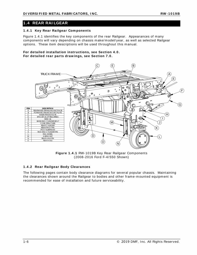
1.4.1 Key Rear Railgear Components
Figure 1.4.1 identifies the key components of the rear Railgear. Appearances of many components will vary depending on chassis make/model/year, as well as selected Railgear options. These item descriptions will be used throughout this manual.
For detailed installation instructions, see Section 4.0. For detailed rear parts drawings, see Section 7.0.
ITEM DESCRIPTIONA REARWARD FRAME MOUNT PLATEB FORWARD FRAME MOUNT PLATEC INNER FRAME PLATED SPACER (S) (IF REQUIRED)E SHIM (S)F BASE END CYLINDER BOLTG CORE STRUCTUREH REAR CYLINDERI REAR PIVOT PINJ PIVOT SUBFRAMEK ROD END CYLINDER PINL RAIL WHEELM H-BRACKETN REAR AXLE PINO REAR AXLE
M
N
A
BC
D
E
E
G
H
F
I
K
OL
J
TRUCK FRAME
Figure 1.4.1 RW-1019B Key Rear Railgear Components (2008-2016 Ford F-4/550 Shown)
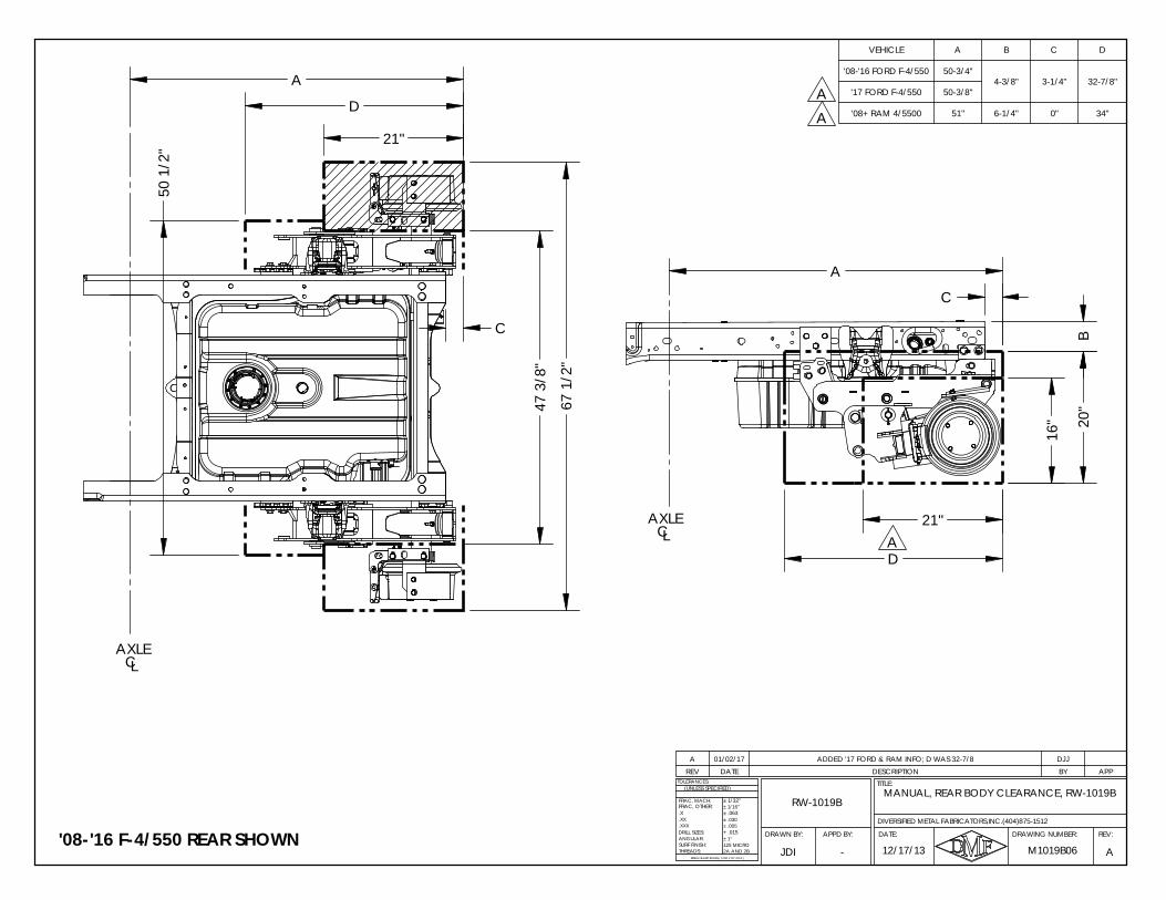
1.4.2 Rear Railgear Body Clearances
The following pages contain body clearance diagrams for several popular chassis. Maintaining the clearances shown around the Railgear to bodies and other frame-mounted equipment is recommended for ease of installation and future serviceability.
D
21"
67
1/2"
47
3/8"
50
1/2"
C
A
B
20"
D
16"
C
A
21"
AXLECL
AXLECL
MANUAL, REAR BODY CLEARANCE, RW-1019BRW-1019B
APPD BY:DRAWN BY:
M1019B06 A
.X
ANGULAR:
BREAK SHARP EDGES ( 0.030 X 45° MAX )
± 1/16"
± .005± .030
+ .015
± 1/32"
± .063
± 1°
2A AND 2B125 MICRO
DRILL SIZES:
SURF FINISH:THREADS:
.XXX
.XX
TOLERANCES:
FRAC, MACH:
(UNLESS SPECIFIED)
DIVERSIFIED METAL FABRICATORS,INC.(404)875-1512
FRAC, OTHER:
12/17/13JDI
REV:DRAWING NUMBER:
TITLE:
DATE:
-
REV DATE DESCRIPTION BY APPA 01/02/17 ADDED '17 FORD & RAM INFO; D WAS 32-7/8 DJJ
VEHICLE A B C D
'08-'16 FORD F-4/550 50-3/4"4-3/8" 3-1/4" 32-7/8"
'17 FORD F-4/550 50-3/8"
'08+ RAM 4/5500 51" 6-1/4" 0" 34"
'08-'16 F-4/550 REAR SHOWN
AA
A
DIVERSIFIED METAL FABRICATORS, INC. RW-1019B
© 2019 DMF, Inc. All Rights Reserved. 2-1
SECTION 2.0 OPERATIONS 2.1 BEFORE YOU OPERATE THE RAILGEAR ........................................................... 2-2
2.1.1 Familiarize Yourself with the Railgear ............................................................... 2-2 2.1.2 Daily Inspection ............................................................................................ 2-2
2.2 ANTI-LOCK BRAKE, TRACTION CONTROL, ELECTRONIC STABILITY CONTROL 2-2
2.2.1 Ford F4/550 ABS & Traction Control Electronic Stability Control Details ................. 2-2
2.3 HIGHWAY OPERATION ................................................................................... 2-3
2.4 GETTING ON THE RAIL ................................................................................... 2-3
2.4.1 Getting Onto the Tracks ................................................................................. 2-3 2.4.2 Engage Front Axle Lock System ...................................................................... 2-3 2.4.3 Lower Rear Guide Wheels............................................................................... 2-3 2.4.4 Lower Front Guide Wheels .............................................................................. 2-3 2.4.5 On the Tracks ............................................................................................... 2-4
2.5 GETTING OFF THE RAIL .................................................................................. 2-4
2.5.1 Removing Truck from Track ............................................................................ 2-4
DIVERSIFIED METAL FABRICATORS, INC. RW-1019B
2-2 © 2019 DMF, Inc. All Rights Reserved
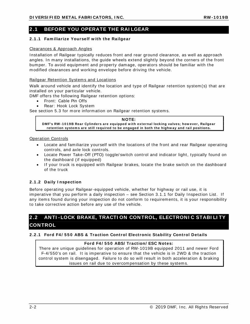
2.1 BEFORE YOU OPERATE THE RAILGEAR
2.1.1 Familiarize Yourself with the Railgear
Clearances & Approach Angles Installation of Railgear typically reduces front and rear ground clearance, as well as approach angles. In many installations, the guide wheels extend slightly beyond the corners of the front bumper. To avoid equipment and property damage, operators should be familiar with the modified clearances and working envelope before driving the vehicle.
Railgear Retention Systems and Locations Walk around vehicle and identify the location and type of Railgear retention system(s) that are installed on your particular vehicle. DMF offers the following Railgear retention options:
• Front: Cable Pin Offs• Rear: Hook Lock System
See section 5.3 for more information on Railgear retention systems.
NOTE: DMF’s RW-1019B Rear Cylinders are equipped with external locking valves; however, Railgear
retention systems are still required to be engaged in both the highway and rail positions.
Operation Controls • Locate and familiarize yourself with the locations of the front and rear Railgear operating
controls, and axle lock controls.• Locate Power Take-Off (PTO) toggle/switch control and indicator light, typically found on
the dashboard (if equipped)• If your truck is equipped with Railgear brakes, locate the brake switch on the dashboard
of the truck
2.1.2 Daily Inspection
Before operating your Railgear-equipped vehicle, whether for highway or rail use, it is imperative that you perform a daily inspection – see Section 3.1.1 for Daily Inspection List. If any items found during your inspection do not conform to requirements, it is your responsibility to take corrective action before any use of the vehicle.
2.2 ANTI-LOCK BRAKE, TRACTION CONTROL, ELECTRONIC STABILITY CONTROL
2.2.1 Ford F4/550 ABS & Traction Control Electronic Stability Control Details
Ford F4/550 ABS/Traction/ESC Notes: There are unique guidelines for operation of RW-1019B equipped 2011 and newer Ford F-4/550’s on rail. It is imperative to ensure that the vehicle is in 2WD & the traction
control system is disengaged. Failure to do so will result in both acceleration & braking issues on rail due to overcompensation by these systems.
DIVERSIFIED METAL FABRICATORS, INC. RW-1019B
© 2019 DMF, Inc. All Rights Reserved. 2-3
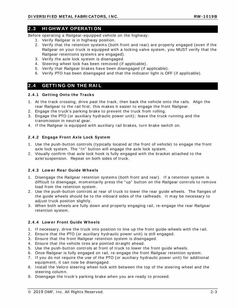
2.3 HIGHWAY OPERATION Before operating a Railgear-equipped vehicle on the highway:
1. Verify Railgear is in highway position.2. Verify that the retention systems (both front and rear) are properly engaged (even if the
Railgear on your truck is equipped with a locking valve system, you MUST verify that theRailgear retentions systems are engaged).
3. Verify the axle lock system is disengaged.4. Steering wheel lock has been removed (if applicable).5. Verify that Railgear brakes have been disengaged (if applicable).6. Verify PTO has been disengaged and that the indicator light is OFF (if applicable).
2.4 GETTING ON THE RAIL
2.4.1 Getting Onto the Tracks
1. At the track crossing, drive past the track, then back the vehicle onto the rails. Align therear Railgear to the rail first; this makes it easier to engage the front Railgear.
2. Engage the truck’s parking brake to prevent the truck from rolling.3. Engage the PTO (or auxiliary hydraulic power unit); leave the truck running and the
transmission in neutral gear.4. If the Railgear is equipped with auxiliary rail brakes, turn brake switch on.
2.4.2 Engage Front Axle Lock System
1. Use the push-button controls (typically located at the front of vehicle) to engage the frontaxle lock system. The “In” button will engage the axle lock system.
2. Visually confirm that axle lock hook is fully engaged with the bracket attached to theaxle/suspension. Repeat on both sides of truck.
2.4.3 Lower Rear Guide Wheels
1. Disengage the Railgear retention systems (both front and rear). If a retention system isdifficult to disengage, momentarily press the “up” button on the Railgear controls to removeload from the retention system.
2. Use the push-button controls at rear of truck to lower the rear guide wheels. The flanges ofthe guide wheels should be to the inboard sides of the railheads. It may be necessary toadjust truck position slightly.
3. When both wheels are fully down and properly engaging rail, re-engage the rear Railgearretention system.
2.4.4 Lower Front Guide Wheels
1. If necessary, drive the truck into position to line up the front guide-wheels with the rail.2. Ensure that the PTO (or auxiliary hydraulic power unit) is still engaged.3. Ensure that the front Railgear retention system is disengaged.4. Ensure that the vehicle tires are pointed straight ahead.5. Use the push-button controls at front of truck to lower the front guide wheels.6. Once Railgear is fully engaged on rail, re-engage the front Railgear retention system.7. If you do not require the use of the PTO (or auxiliary hydraulic power unit) for additional
equipment, it can now be disengaged.8. Install the Velcro steering wheel lock with between the top of the steering wheel and the
steering column.9. Disengage the truck’s parking brake when you are ready to proceed.
DIVERSIFIED METAL FABRICATORS, INC. RW-1019B
2-4 © 2019 DMF, Inc. All Rights Reserved
2.4.5 On the Tracks
• Do not exceed posted track speed limit, and at no time exceed 30 MPH while on the track.• Be aware that some Railgear is insulated, and will not operate the crossing gate circuits.
You are responsible for knowing if your Railgear equipped vehicle has insulated or non-insulated wheels. To assist in identifying insulated rail wheels, a grooved ring is machinedaround the inside of the front and rear driver’s side wheels.
• All railroad rules and safety guidelines should be observed.• Reduce speed while in reverse and/or at all crossings, curves, branch lines, switches and
frogs (no more than a slow walking pace is recommended).• Traction is reduced on the track, especially in wet conditions.• Braking distance is increased on the track, especially in wet conditions.• Do not slide tires or guide wheels on the tracks as this will cause premature wear.• Do not exceed the maximum rated capacity of the equipment.• On newer trucks with Anti-Lock braking systems, the amber ‘ABS’ dash light may remain on
with the front wheels elevated. This will not reduce rear truck braking or rail wheel braking.
2.5 GETTING OFF THE RAIL
2.5.1 Removing Truck from Track
1. Safely pull onto the track crossing, paying attention to traffic and other obstacles.2. Set the truck parking brakes and engage the PTO (if equipped).3. Leave the truck running and the transmission in neutral gear.4. Disengage both the front and rear Railgear safety retention systems.5. Lift both sets of Railgear (there is no preference for removal order).6. Re-engage ALL Railgear retention systems for safe travel in the highway position.7. Disengage the front axle lock system with the push button controls (typically @ front
bumper), by pressing the “out” button.8. Disengage the switch that controls the Railgear brakes (if applicable).9. Disengage the PTO (or auxiliary hydraulic power unit) and the parking brakes.10. Install the Velcro steering wheel lock with between the top of the steering wheel and the
steering column.11. Make sure surrounding area is free and clear of any obstacles and vehicles before pulling off
of the rail and onto the road.12. If the amber ABS dash light remains on during rail operation, the truck engine must be
turned off and restarted after returning to highway operation. This will clear the ABS lightafter a few seconds. If the amber light remains on during road operation, the truck’s brakesystem may have an active fault and should be checked out. Please refer to the truck’soperation manual.
DIVERSIFIED METAL FABRICATORS, INC. RW-1019B
© 2019 DMF, Inc. All Rights Reserved. 3-1
SECTION 3.0 ROUTINE MAINTENANCE 3.1 INSPECTION AND MAINTENANCE ................................................................... 3-2
3.1.1 Daily Maintenance ......................................................................................... 3-2 3.1.2 Weekly Maintenance ...................................................................................... 3-3 3.1.3 Bi-Annual Maintenance or as Required ............................................................. 3-3 3.1.4 Annual Maintenance or as Required ................................................................. 3-3
3.2 FLUIDS AND LUBRICATION ............................................................................ 3-3
3.3 WHEEL WEAR GAUGE ..................................................................................... 3-6
3.4 TROUBLESHOOTING ....................................................................................... 3-8
3.5 DERAILMENT .................................................................................................. 3-9
DIVERSIFIED METAL FABRICATORS, INC. RW-1019B
3-2 © 2019 DMF, Inc. All Rights Reserved.
3.1 INSPECTION AND MAINTENANCE
To assure safe and reliable operation, Diversified Metal Fabricators recommends the following inspection and maintenance guidelines detailed below.
Government or corporate regulations may require additional inspections not covered below. Please ensure that you are aware of any additional recurring inspections that pertain to your Railgear, and have them completed according to required regulations.
Vehicles operated in the following severe-duty conditions may need more frequent inspection and maintenance than suggested below: • Extreme hot or cold temperatures• Operation on steep grades• Extended exposure to road salt• High mileage use
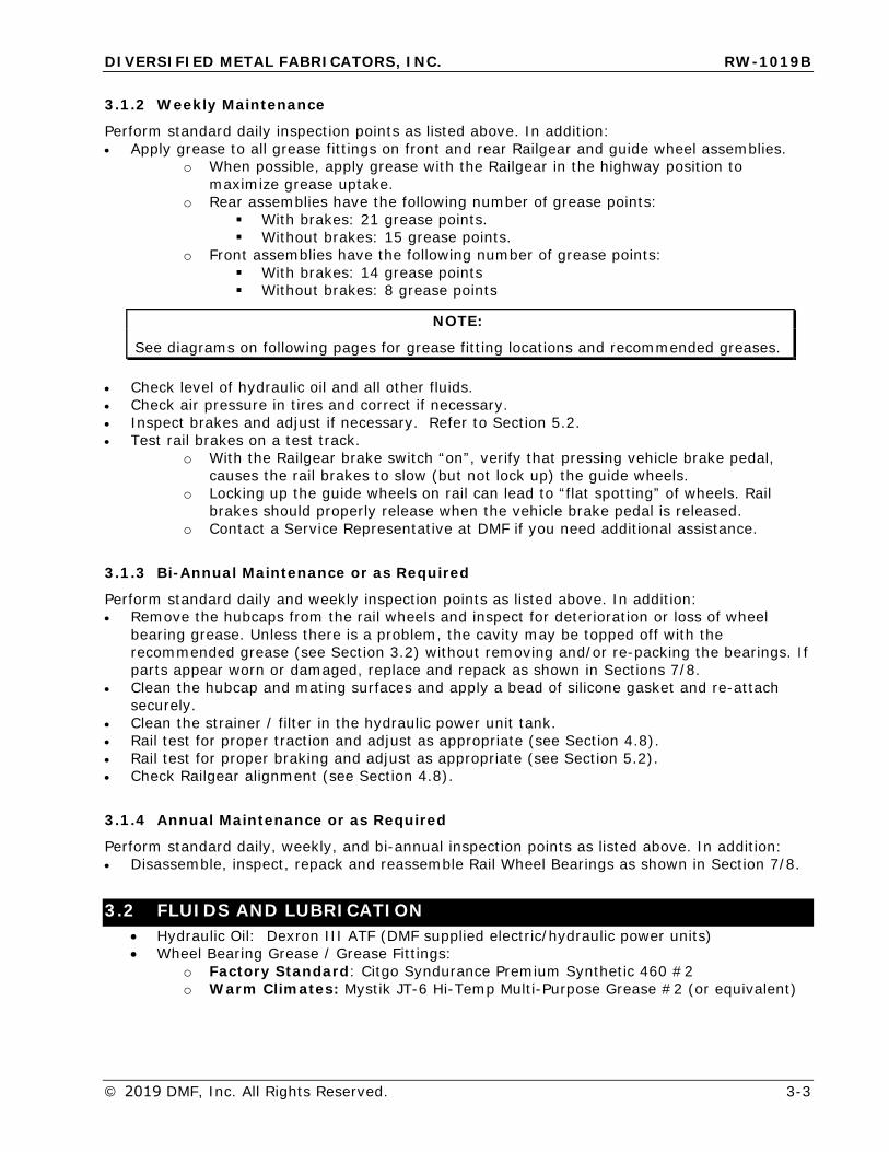
3.1.1 Daily Maintenance
• Visually inspect for hydraulic fluid leaks.• Check and make sure that all threaded fasteners are secured.• Visually inspect protective hose/wire wraps, and securing straps, near moving parts or
exhaust systems. Replace if cracked or worn.• Inspect wheel flanges for excessive wear, primarily noting differences in wear between
wheels on the same axle or diagonally. If an abnormal pattern is noted, check Railgearalignment (see alignment procedure in Section 4.8).
• Inspect wheel “end-play”: Placing one hand at the 9 o’clock position and your other hand atthe 3 o’clock position firmly grab the wheel and push and pull it a few times. There shouldbe no discernable movement in and out, and the wheel should rotate freely. If you feelthere is too much movement in and out, or if the wheel does not rotate freely, a detailedinspection should be performed. See Section 7 and 8 for appropriate axle assemblydrawings.
• Throughout the day, inspect wheel temperature. If extremely hot, this could indicatebearing adjustment is too tight. For adjustment information, see Sections 7 and 8 forappropriate axle assembly drawings.
DIVERSIFIED METAL FABRICATORS, INC. RW-1019B
© 2019 DMF, Inc. All Rights Reserved. 3-3
3.1.2 Weekly Maintenance
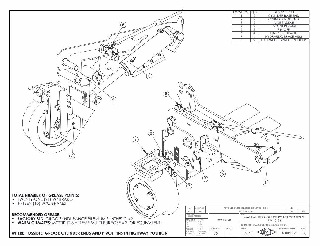
Perform standard daily inspection points as listed above. In addition: • Apply grease to all grease fittings on front and rear Railgear and guide wheel assemblies.
o When possible, apply grease with the Railgear in the highway position tomaximize grease uptake.
o Rear assemblies have the following number of grease points:With brakes: 21 grease points.Without brakes: 15 grease points.
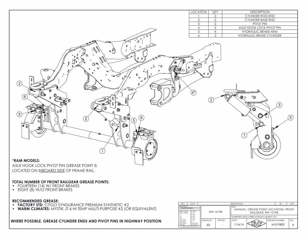
o Front assemblies have the following number of grease points:With brakes: 14 grease pointsWithout brakes: 8 grease points
NOTE:
See diagrams on following pages for grease fitting locations and recommended greases.
• Check level of hydraulic oil and all other fluids.• Check air pressure in tires and correct if necessary.• Inspect brakes and adjust if necessary. Refer to Section 5.2.• Test rail brakes on a test track.
o With the Railgear brake switch “on”, verify that pressing vehicle brake pedal,causes the rail brakes to slow (but not lock up) the guide wheels.
o Locking up the guide wheels on rail can lead to “flat spotting” of wheels. Railbrakes should properly release when the vehicle brake pedal is released.
o Contact a Service Representative at DMF if you need additional assistance.
3.1.3 Bi-Annual Maintenance or as Required
Perform standard daily and weekly inspection points as listed above. In addition: • Remove the hubcaps from the rail wheels and inspect for deterioration or loss of wheel
bearing grease. Unless there is a problem, the cavity may be topped off with therecommended grease (see Section 3.2) without removing and/or re-packing the bearings. Ifparts appear worn or damaged, replace and repack as shown in Sections 7/8.
• Clean the hubcap and mating surfaces and apply a bead of silicone gasket and re-attachsecurely.
• Clean the strainer / filter in the hydraulic power unit tank.• Rail test for proper traction and adjust as appropriate (see Section 4.8).• Rail test for proper braking and adjust as appropriate (see Section 5.2).• Check Railgear alignment (see Section 4.8).
3.1.4 Annual Maintenance or as Required
Perform standard daily, weekly, and bi-annual inspection points as listed above. In addition: • Disassemble, inspect, repack and reassemble Rail Wheel Bearings as shown in Section 7/8.
3.2 FLUIDS AND LUBRICATION • Hydraulic Oil: Dexron III ATF (DMF supplied electric/hydraulic power units)• Wheel Bearing Grease / Grease Fittings:
o Factory Standard: Citgo Syndurance Premium Synthetic 460 #2o Warm Climates: Mystik JT-6 Hi-Temp Multi-Purpose Grease #2 (or equivalent)
3
4
5
2
7
8
6
6
1
7
6
TOTAL NUMBER OF GREASE POINTS:TWENTY-ONE (21) W/ BRAKES•FIFTEEN (15) W/O BRAKES•
WHERE POSSIBLE, GREASE CYLINDER ENDS AND PIVOT PINS IN HIGHWAY POSITION
RECOMMENDED GREASE:FACTORY STD: CITGO SYNDURANCE PREMIUM SYNTHETIC #2 •WARM CLIMATES: MYSTIK JT-6 HI-TEMP MULTI-PURPOSE #2 (OR EQUIVALENT) •
REV DATE DESCRIPTION BY APPA 6/23/2014 REMOVED PASSENGER SIDE DEPLOYED HOOK JDI
LOCATION QTY DESCRIPTION1 2 CYLINDER BASE END2 2 CYLINDER ROD END3 2 AXLE SADDLE4 2 PIVOT SUBFRAME5 3 PIN-OFF6 4 PIN-OFF LINKAGE7 4 HYDRAULIC BRAKE ARM8 2 HYDRAULIC BRAKE CYLINDER
A
.X
ANGULAR:
BREAK SHARP EDGES ( 0.030 X 45° MAX )
± 1/16"
± .005± .030
+ .015
± 1/32"
± .063
± 1°
2A AND 2B125 MICRO
DRILL SIZES:
SURF FINISH:THREADS:
.XXX
.XX
TOLERANCES:
FRAC, MACH:
(UNLESS SPECIFIED)
FRAC, OTHER:
8/21/13 M1019B02JDI
REV:DRAWING NUMBER:
TITLE:
DATE:APPD BY:DRAWN BY:
DIVERSIFIED METAL FABRICATORS,INC.(404)875-1512
-
MANUAL, REAR GREASE POINT LOCATIONS, RW-1019BRW-1019B
1
2
4*
56
5
6
2
WHERE POSSIBLE, GREASE CYLINDER ENDS AND PIVOT PINS IN HIGHWAY POSITION
AA
3
1
2
5
RECOMMENDED GREASE:FACTORY STD: CITGO SYNDURANCE PREMIUM SYNTHETIC #2 •WARM CLIMATES: MYSTIK JT-6 HI-TEMP MULTI-PURPOSE #2 (OR EQUIVALENT) •
TOTAL NUMBER OF FRONT RAILGEAR GREASE POINTS:FOURTEEN (14) W/ FRONT BRAKES•EIGHT (8) W/O FRONT BRAKES•
*RAM MODELS:AXLE HOOK LOCK PIVOT PIN GREASE POINT IS LOCATED ON INBOARD SIDE OF FRAME RAIL.
REV DATE DESCRIPTION BY APP
LOCATION QTY DESCRIPTION1 2 CYLINDER ROD END2 2 CYLINDER BASE END3 2 PIVOT PIN4 2 AXLE HOOK LOCK PIVOT PIN5 4 HYDRAULIC BRAKE ARM6 2 HYDRAULIC BRAKE CYLINDER
#
.X
ANGULAR:
BREAK SHARP EDGES ( 0.030 X 45° MAX )
± 1/16"
± .005± .030
+ .015
± 1/32"
± .063
± 1°
2A AND 2B125 MICRO
DRILL SIZES:
SURF FINISH:THREADS:
.XXX
.XX
TOLERANCES:
FRAC, MACH:
(UNLESS SPECIFIED)
FRAC, OTHER:
11/4/14 M1019B09JDI
REV:DRAWING NUMBER:
TITLE:
DATE:APPD BY:DRAWN BY:
DIVERSIFIED METAL FABRICATORS,INC.(404)875-1512
-
MANUAL, GREASE POINT LOCATIONS, FRONT RAILGEAR, RW-1019BRW-1019B
DIVERSIFIED METAL FABRICATORS, INC. RW-1019B
3-6 © 2019 DMF, Inc. All Rights Reserved.
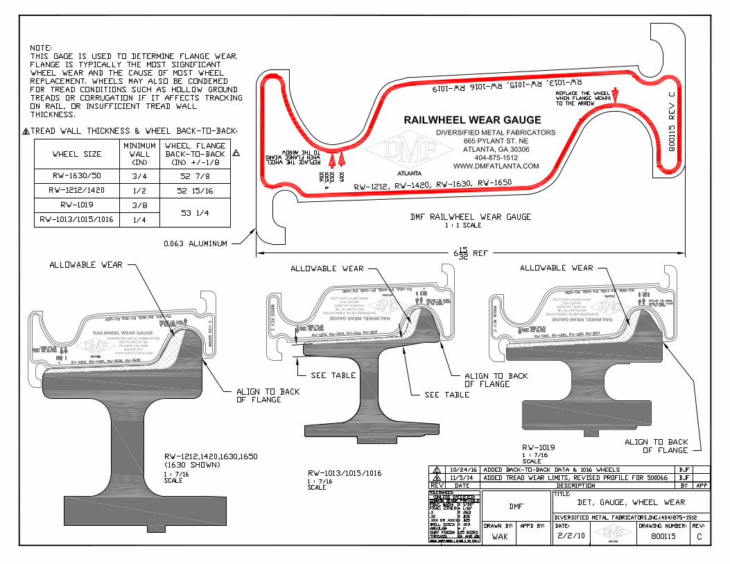
3.3 WHEEL WEAR GAUGE
A metal wheel wear gauge (DMF part number 800115) is available to aid in inspecting worn wheels. The drawing on the next page illustrates how to use the gauge and also lists specifications for minimum wall thickness on the wheel tread as well as tolerance on wheel back-to-back spacing.
DIVERSIFIED METAL FABRICATORS, INC. RW-1019B
3-8 © 2019 DMF, Inc. All Rights Reserved.
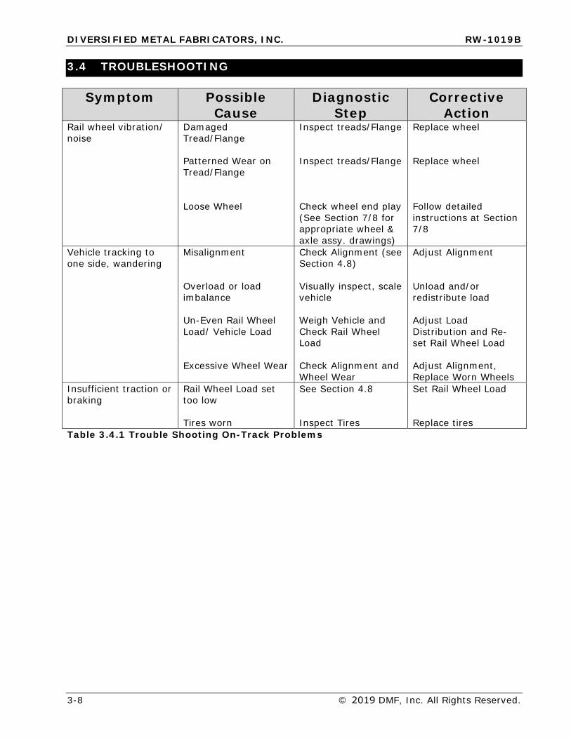
3.4 TROUBLESHOOTING
Symptom Possible Cause
Diagnostic Step
Corrective Action
Rail wheel vibration/ noise
Damaged Tread/Flange
Patterned Wear on Tread/Flange
Loose Wheel
Inspect treads/Flange
Inspect treads/Flange
Check wheel end play (See Section 7/8 for appropriate wheel & axle assy. drawings)
Replace wheel
Replace wheel
Follow detailed instructions at Section 7/8
Vehicle tracking to one side, wandering
Misalignment
Overload or load imbalance
Un-Even Rail Wheel Load/ Vehicle Load
Excessive Wheel Wear
Check Alignment (see Section 4.8)
Visually inspect, scale vehicle
Weigh Vehicle and Check Rail Wheel Load
Check Alignment and Wheel Wear
Adjust Alignment
Unload and/or redistribute load
Adjust Load Distribution and Re-set Rail Wheel Load
Adjust Alignment, Replace Worn Wheels
Insufficient traction or braking
Rail Wheel Load set too low
Tires worn
See Section 4.8
Inspect Tires
Set Rail Wheel Load
Replace tires Table 3.4.1 Trouble Shooting On-Track Problems
DIVERSIFIED METAL FABRICATORS, INC. RW-1019B
© 2019 DMF, Inc. All Rights Reserved. 3-9
3.5 DERAILMENT
The following are instructions for derailment inspection recommended by Diversified Metal Fabricators. In some circumstances, government or corporate regulations may require additional inspections to be performed. Please ensure that you are aware of any inspection requirements that pertain to your Railgear and that you abide by all local and national laws regarding Railgear maintenance and safety.
In the case of a minor derailment, the cause of the derailment should be determined and corrective steps taken. The vehicle should be inspected to determine if repairs or adjustments are required. This inspection should include, but should not be limited to, the following:
• Visually inspect Railgear for hydraulic leaks• Ensure all lines and hoses are still secured and out of the way of any moving parts• Ensure all hydraulic hose connections and fittings are securely in place and not broken• Verify that all threaded fasteners are secure, and that cotter pins are not broken• Visually inspect wheels to ensure that tread and flange are not severely damaged• Spin all 4 railwheels, noting any bearing noise, resistance, and end play
Any items noted should be repaired using Section 4.0, to ensure they are repaired to initial install standards.
In case of a major derailment, a complete inspection should be performed, including but not limited to the following:
• Perform all inspection items as listed above in the Minor Derailment section• Inspect all frame brackets, pivot arms, core structures, and pivot subframe to ensure
they are not bent, cracked, or broken• Inspect and test rail brake system (see Sections 4.8 and 5.2).• Ensure all welds are intact and show no signs of cracking or breaking• Ensure all mounting hardware and brackets are securely fastened, and are not bent,
cracked, or damaged in any way• A full alignment should be performed. See section 4.8.• Wheels should be removed and the bore, bearing, races, and insulation (if applicable)
should be inspected for any damage. For further wheel details, see sections 7/8 forappropriate wheel & axle assembly drawings.
• Ensure axle threads are not stripped or damagedAny items noted should be repaired using Section 4.0, to ensure they are repaired to initial install standards.
Please contact DMF for any assistance you may require.
DIVERSIFIED METAL FABRICATORS, INC. RW-1019B
© 2019 DMF, Inc. All Rights Reserved. 4-1
SECTION 4.0 RAILGEAR INSTALLATION 4.1 PRE-INSTALL .................................................................................................. 4-3
4.1.1 Safety Statements ........................................................................................ 4-3 4.1.2 Installation Order .......................................................................................... 4-3 4.1.3 Required Tools & Materials ............................................................................. 4-3 4.1.4 Fluids and Lubrication .................................................................................... 4-3 4.1.5 Bolt Torque Specifications .............................................................................. 4-3 4.1.6 Welding Information ...................................................................................... 4-5
4.2 INITIAL INSTRUCTIONS ................................................................................. 4-6
4.2.1 Work Area ................................................................................................... 4-6 4.2.2 Truck Condition ............................................................................................ 4-6 4.2.3 Front and Rear Installation Rails ..................................................................... 4-7
4.3 INSTALLATION OF REAR RAILGEAR ............................................................... 4-8
4.3.1 General Information ...................................................................................... 4-8 4.3.2 Diagram of Key Components .......................................................................... 4-9 4.3.3 Exhaust Removal .......................................................................................... 4-9 4.3.4 Install Rear Mounting Kit ................................................................................ 4-9 4.3.5 Install Rear Railgear .................................................................................... 4-14 4.3.6 Rear Railgear Alignment and Weight Settings .................................................. 4-14 4.3.1 Install Rear Railgear Pin Offs ........................................................................ 4-14
4.4 EXHAUST MODIFICATION ............................................................................. 4-15
4.4.1 General Information .................................................................................... 4-15 4.4.2 2011+ Ford F-4/550 w/ 6.7L Diesel Engine ..................................................... 4-15 4.4.3 2008+ Ram 4/5500 w/ 6.7L Diesel Engine ...................................................... 4-17
4.5 INSTALLATION OF FRONT RAILGEAR ........................................................... 4-19
4.5.1 General Information .................................................................................... 4-19 4.5.2 2008 - 2016 Ford F-4/550 Installation ........................................................... 4-19 4.5.3 2017+ Ford F-4/550 Installation ................................................................... 4-23 4.5.4 2008+ Ram 4/5500 Installation .................................................................... 4-25
4.6 INSTALLATION OF FRONT AXLE LOCK .......................................................... 4-28
4.6.1 General Information .................................................................................... 4-28 4.6.2 Front Axle Lock Cylinder Assembly ................................................................ 4-29 4.6.3 2008-2016 Ford F-4/550 Installation ............................................................. 4-30 4.6.4 2017+ Ford F-4/550 Installation ................................................................... 4-31 4.6.5 2008+ Ram 4/5500 Installation .................................................................... 4-32 4.6.6 Brake Line Relocation; 2008+ Ram 4/5500 ..................................................... 4-33
4.7 HYDRAULIC & ELECTRICAL SYSTEM INSTALLATION ..................................... 4-35
4.8 ALIGNMENT, WEIGHT ADJUSTMENT & RAIL TEST PROCEDURES .................. 4-36
4.8.1 Square Rear Railgear to Rear Truck Axle ........................................................ 4-36 4.8.2 Adjust Front Railgear ................................................................................... 4-36 4.8.3 Adjust Rear Weight Settings ......................................................................... 4-37 4.8.4 Rail Test and Final Weld-Out ......................................................................... 4-37
4.9 INSTALL PROVIDED ACCESSORIES ............................................................... 4-41
4.9.1 Velcro Steering Wheel Lock .......................................................................... 4-41 4.9.2 Install Operation and Safety Decals ............................................................... 4-42
DIVERSIFIED METAL FABRICATORS, INC. RW-1019B
4-2 © 2019 DMF, Inc. All Rights Reserved.
INSTALLATION REVIEW CHECKLIST ....................................................................... 4-46
DIVERSIFIED METAL FABRICATORS, INC. RW-1019B
© 2019 DMF, Inc. All Rights Reserved. 4-3
4.1 PRE-INSTALL
NOTE: The proper installation of this equipment is solely the responsibility of you, the installer.
When in doubt, contact DMF for assistance.
****WARNING**** Satisfactory adjustment of the Railgear alignment and weight settings are crucial to ensure safe and reliable operation. Do not attempt to use vehicle on rail until these
steps have been completed. See Section 4.8 for detailed instructions.
4.1.1 Safety Statements
• Always block up gear before getting underneath• Always use jack stands when jacking up vehicle• Use personal protective equipment and clothing
4.1.2 Installation Order
This manual presents the installation information in the order that we find to work best. Your shop, tools, personnel or other factors may dictate a different order. This is acceptable as long as the Overall Alignment, Rail Test, Road Test, and Final Inspection are performed at the end.
4.1.3 Required Tools & Materials
Aside from general shop tools and safety equipment the following tools may be required: • Arc or MIG Welder• Surge Protector (Protects ECM from damage during welding)• Cutting Torch• Hand Grinder• Frame Drill• Air Saw• Angle Finder• Test Rail – See Section 4.2.3• Spacers for weight setting (ASTM A36 3-1/2” x 4"L)
Additionally the following tools are recommended: • Transmission Jack, Motorcycle Lift, Pallet Jack or Forklift• Overhead Crane• Work Lights• Wheel Dolly
4.1.4 Fluids and Lubrication
• Hydraulic Oil: Dexron III ATF (DMF supplied electric/hydraulic power units)• Wheel Bearing Grease / Grease Fittings:
o Factory Standard: Citgo Syndurance Premium Synthetic 460 #2o Warm Climates: Mystik JT-6 Hi-Temp Multi-Purpose Grease #2 (or
equivalent)
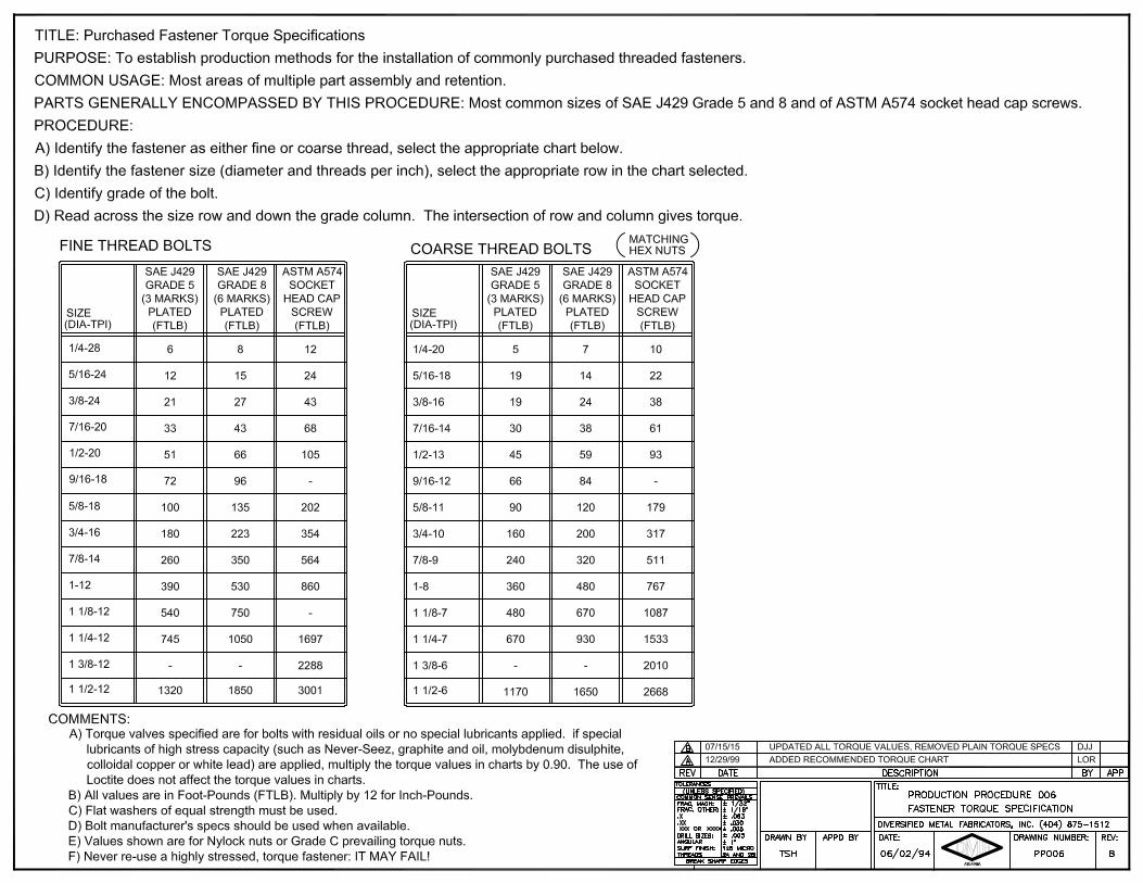
4.1.5 Bolt Torque Specifications
See following page for recommended torque specifications.
DIVERSIFIED METAL FABRICATORS, INC. RW-1019B
© 2019 DMF, Inc. All Rights Reserved. 4-5
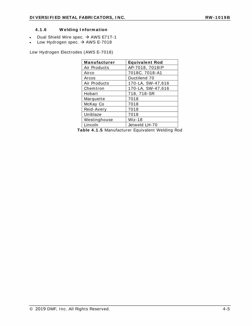
4.1.6 Welding Information
• Dual Shield Wire spec. AWS E71T-1• Low Hydrogen spec. AWS E-7018
Low Hydrogen Electrodes (AWS E-7018)
Manufacturer Equivalent Rod Air Products AP-7018, 7018IP Airco 7018C, 7018-A1Arcos Ductilend 70Air Products 170-LA, SW-47,616Chemtron 170-LA, SW-47,616Hobart 718, 718-SRMarquette 7018McKay Co 7018 Reid-Avery 7018Uniblaze 7018Westinghouse Wiz-18 Lincoln Jetweld LH-70
Table 4.1.5 Manufacturer Equivalent Welding Rod
DIVERSIFIED METAL FABRICATORS, INC. RW-1019B
4-6 © 2019 DMF, Inc. All Rights Reserved.
4.2 INITIAL INSTRUCTIONS
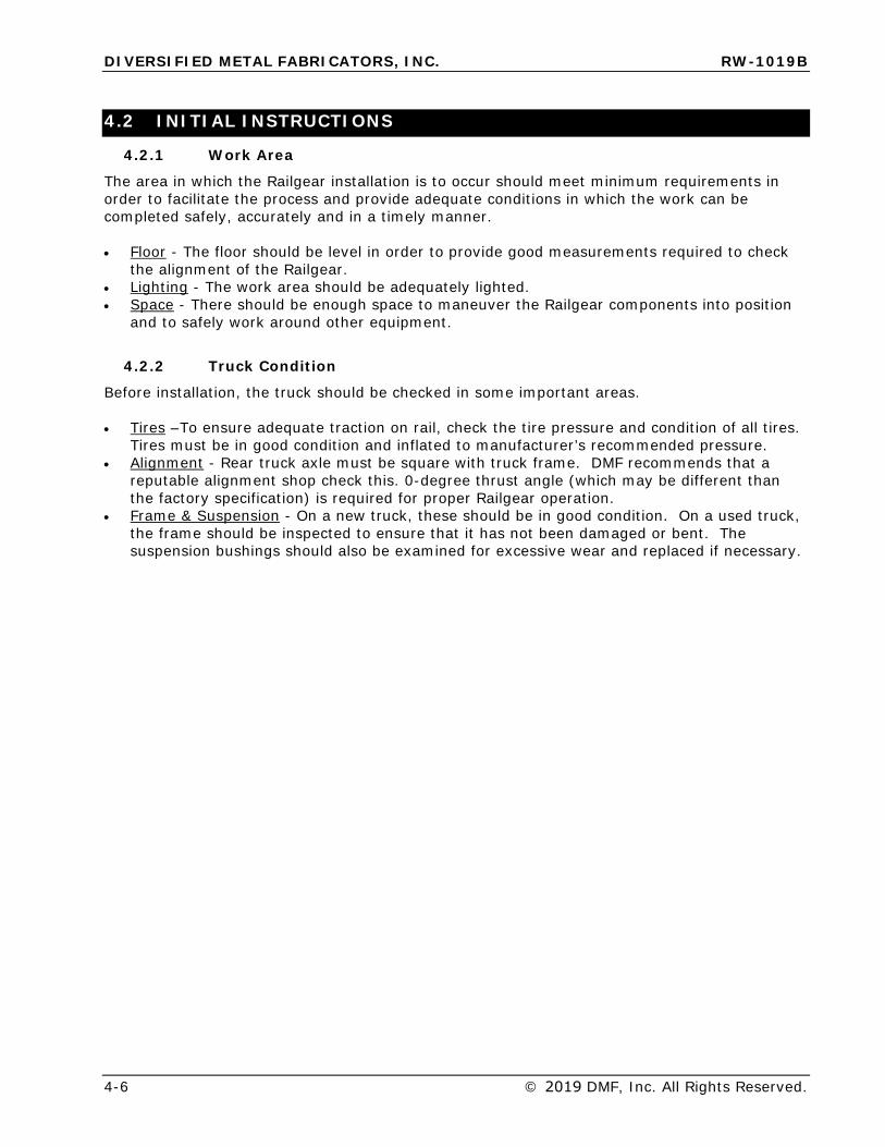
4.2.1 Work Area
The area in which the Railgear installation is to occur should meet minimum requirements in order to facilitate the process and provide adequate conditions in which the work can be completed safely, accurately and in a timely manner.
• Floor - The floor should be level in order to provide good measurements required to checkthe alignment of the Railgear.
• Lighting - The work area should be adequately lighted.• Space - There should be enough space to maneuver the Railgear components into position
and to safely work around other equipment.
4.2.2 Truck Condition
Before installation, the truck should be checked in some important areas.
• Tires –To ensure adequate traction on rail, check the tire pressure and condition of all tires.Tires must be in good condition and inflated to manufacturer’s recommended pressure.
• Alignment - Rear truck axle must be square with truck frame. DMF recommends that areputable alignment shop check this. 0-degree thrust angle (which may be different thanthe factory specification) is required for proper Railgear operation.
• Frame & Suspension - On a new truck, these should be in good condition. On a used truck,the frame should be inspected to ensure that it has not been damaged or bent. Thesuspension bushings should also be examined for excessive wear and replaced if necessary.
DIVERSIFIED METAL FABRICATORS, INC. RW-1019B
© 2019 DMF, Inc. All Rights Reserved. 4-7
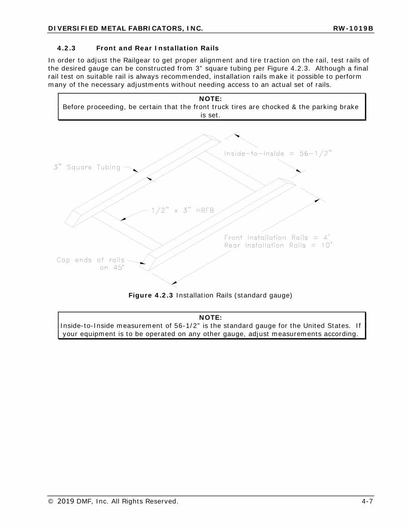
4.2.3 Front and Rear Installation Rails
In order to adjust the Railgear to get proper alignment and tire traction on the rail, test rails of the desired gauge can be constructed from 3” square tubing per Figure 4.2.3. Although a final rail test on suitable rail is always recommended, installation rails make it possible to perform many of the necessary adjustments without needing access to an actual set of rails.
NOTE: Before proceeding, be certain that the front truck tires are chocked & the parking brake
is set.
Figure 4.2.3 Installation Rails (standard gauge)
NOTE: Inside-to-Inside measurement of 56-1/2” is the standard gauge for the United States. If your equipment is to be operated on any other gauge, adjust measurements according.
DIVERSIFIED METAL FABRICATORS, INC. RW-1019B
4-8 © 2019 DMF, Inc. All Rights Reserved.
4.3 INSTALLATION OF REAR RAILGEAR
4.3.1 General Information
There are several items to note before you begin the installation of the rear Railgear:
• Due to limited access for tools and components, if vehicle is equipped with a rear-mounted fuel tank, DMF recommends installing the rear Railgear prior to mounting abody.
• Your Railgear includes parts designed for your particular chassis year/make/model andselected options. Exact appearances of some items may vary.
• Basic instructions for several popular applications are included below. Detailed assemblydrawings and additional information can be found in Section 7.
• It is important to note that there is a difference between “shims” and “spacers”:o RW-1019B Shims are typically included with your Railgear purchase, and are
installed between the rear mounting brackets and main rear Railgearassembly. Shims allow side-to-side adjustment to center the rear Railgearwith the truck rear axle.
o RW-1019B Spacers are not included with your Railgear purchase. Spacersare solid steel pieces varying in thickness, used between the pivot subframeand the H-bracket to achieve proper weight settings between the truck tiresand rail wheels while on rail.
• “Spacers” used in adjusting the height of Railgear must be solid steel pieces becausethey will experience the full structural load seen by the rear frame.
• When setting the height of the Railgear using “spacers” you must be within the range of½” minimum to 3” of spacers maximum. If you are outside of this range it may benecessary to move to the top mounting hole position on the core structure. Using aminimum of ½” of spacers on new vehicles allows for future adjustments to be made assprings and suspension components wear and settle.
• It is important that the truck tire pressure (especially the rear tires) be checked andbrought to the tire manufacturer’s intended pressure for a given load. Reference yourtire manufacturer’s load rating and inflation chart. (Inflating tires to their max side wallpressure may result in drastically reduced contact with the rail if under-loaded.
DIVERSIFIED METAL FABRICATORS, INC. RW-1019B
© 2019 DMF, Inc. All Rights Reserved. 4-9
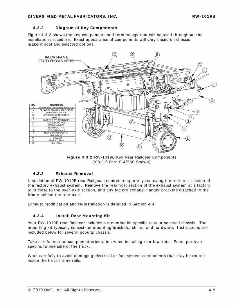
4.3.2 Diagram of Key Components
Figure 4.3.2 shows the key components and terminology that will be used throughout the installation procedure. Exact appearance of components will vary based on chassis make/model and selected options.
ITEM DESCRIPTIONA REARWARD FRAME MOUNT PLATEB FORWARD FRAME MOUNT PLATEC INNER FRAME PLATED SPACER (S) (IF REQUIRED)E SHIM (S)F BASE END CYLINDER BOLTG CORE STRUCTUREH REAR CYLINDERI REAR PIVOT PINJ PIVOT SUBFRAMEK ROD END CYLINDER PINL RAIL WHEELM H-BRACKETN REAR AXLE PINO REAR AXLE
M
L
A
BC
D
E
E
G
H
F
I
K
O N
(FORD SHOWN HERE)TRUCK FRAME
J
Figure 4.3.2 RW-1019B Key Rear Railgear Components (‘08-‘16 Ford F-4/550 Shown)
4.3.3 Exhaust Removal
Installation of RW-1019B rear Railgear requires temporarily removing the rearmost section of the factory exhaust system. Remove the rearmost section of the exhaust system at a factory joint close to the over-axle section, and any factory exhaust hanger brackets attached to the frame behind the rear axle.
Exhaust modification and re-installation is detailed in Section 4.4.
4.3.4 Install Rear Mounting Kit
Your RW-1019B rear Railgear includes a mounting kit specific to your selected chassis. The mounting kit typically consists of mounting brackets, shims, and hardware. Instructions are included below for several popular chassis.
Take careful note of component orientation when installing rear brackets. Some parts are specific to one side of the truck.
Work carefully to avoid damaging electrical or fuel system components that may be routed inside the truck frame rails.
DIVERSIFIED METAL FABRICATORS, INC. RW-1019B
4-10 © 2019 DMF, Inc. All Rights Reserved.
2008+ Ford F-4/550 1. See detailed drawing on following pages for diagrams and additional details.2. First install the rearward mounting brackets to the factory holes at the end of the frame.3. Locate and drill holes for the forward mounting brackets installed by measuring from the
rearward frame bracket edge.
2008+ Ram 4/5500 1. See detailed drawing on following pages for diagrams and additional details.2. First install the rearward mounting brackets to the factory holes at the end of the frame.3. The forward mounting brackets “sandwich” on top of the factory rear spring hanger
bracket and auxiliary pad bracket, and mount using existing frame holes.4. It may be necessary to elevate the back of the truck to gain tool access to some bolts.
F4/550FRAME MOUNT KIT, REAR, RW-1019B, '08 FORD
RW-1019B
DRAWN BY:
FRAC, OTHER:
B
.X
ANGULAR:
BREAK SHARP EDGES ( 0.030 X 45° MAX )
± 1/16"
± .005± .030
+ .015
± 1/32"
± .063
± 1°
2A AND 2B125 MICRO
DRILL SIZES:
SURF FINISH:THREADS:
.XXX
.XX
TOLERANCES:
FRAC, MACH:
(UNLESS SPECIFIED)
5/9/13 304052
DIVERSIFIED METAL FABRICATORS,INC.(404)875-1512
JDI
REV:DRAWING NUMBER:
TITLE:
DATE:APPD BY:
-
REV DATE DESCRIPTION BY APP
B 10/14/14 605006 WAS 605259, ITEM 3 CALLED OUT DJJ
A 7/2/2013 19-1/8" WAS 18-7/8", 605276 WAS 605258, ADDED 113014, 304024 WAS 304032 JDI
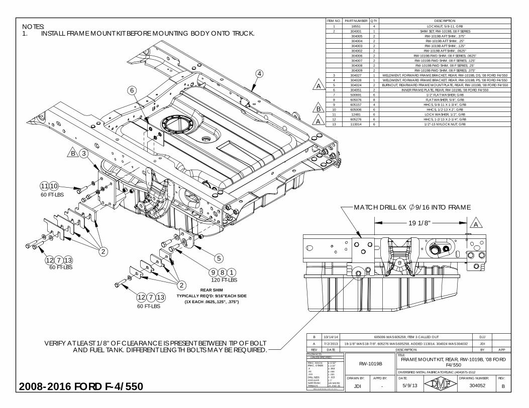
ITEM NO. PART NUMBER QTY. DESCRIPTION1 18551 4 LOCKNUT, 5/8-11, GR82 304001 1 SHIM SET; RW-1019B, 08 F SERIES
304005 2 RW-1019B AFT SHIM; .375" 304004 2 RW-1019B AFT SHIM; .25" 304003 2 RW-1019B AFT SHIM; .125" 304002 2 RW-1019B AFT SHIM; .0625" 304006 2 RW-1019B FWD SHIM; 08 F SERIES; .0625" 304007 2 RW-1019B FWD SHIM; 08 F SERIES; .125" 304008 2 RW-1019B FWD SHIM; 08 F SERIES; .25" 304009 2 RW-1019B FWD SHIM; 08 F SERIES; .375"
3 304027 1 WELDMENT, FORWARD FRAME BRACKET, REAR, RW-1019B, DS, '08 FORD F4/5504 304028 1 WELDMENT, FORWARD FRAME BRACKET, REAR, RW-1019B, PS, '08 FORD F4/5505 304024 2 BURNOUT, REARWARD FRAME MOUNT PLATE, REAR, RW-1019B, '08 FORD F4/5506 304051 2 INNER FRAME PLATE, REAR, RW-1019B, '08 FORD F4/5507 500691 6 1/2" FLAT WASHER; GR88 605076 8 FLAT WASHER, 5/8", GR89 605157 4 HHCS, 5/8-11 X 1-3/4", GR810 605006 6 HHCS, 1/2-13 X 2", GR811 12481 6 LOCK WASHER, 1/2", GR812 605276 6 HHCS, 1-2/13 X 2-1/4", GR813 113014 6 1/2"-13 NYLOCK NUT; GR8
NOTES:INSTALL FRAME MOUNT KIT BEFORE MOUNTING BODY ONTO TRUCK.1.
A
2008-2016 FORD F-4/550
8
9/16 INTO FRAMEMATCH DRILL 6X
VERIFY AT LEAST 1/8" OF CLEARANCE IS PRESENT BETWEEN TIP OF BOLT AND FUEL TANK. DIFFERENT LENGTH BOLTS MAY BE REQUIRED.
A 19 1/8"
5
11
12
10
A6
B
B
4
3
(1X EACH .0625,.125", .375")
60 FT-LBS
60 FT-LBS
60 FT-LBS
REAR SHIMTYPICALLY REQ'D: 9/16"EACH SIDE
120 FT-LBS9
7 13
1
7
2
13
12
2

REV DATE DESCRIPTION BY APP
ITEM NO. PART NUMBER QTY. DESCRIPTION
1 304141 1 DS FRAME SUPPORT, FWD MOUNT, WELDMENT, RW-1019B REAR, '17 F450/550
2 304142 1 PS FRAME SUPPORT, FWD MOUNT, WELDMENT, RW-1019B REAR, '17 F450/550
3 304150 2 INNER FRAME PLATE, REAR, '17 FORD F450/550
4 304024 2 BURNOUT, REARWARD FRAME MOUNT PLATE, REAR, RW-1019B, '08 FORD F4/550
5 304001 1 SHIM SET; RW-1019B, 08 F SERIES
304005 2 RW-1019B AFT SHIM, .375"
304004 2 RW-1019B AFT SHIM, .25"
304003 2 RW-1019B AFT SHIM, .125"
304002 2 RW-1019B AFT SHIM, .0625
304006 2 RW-1019B FWD SHIM, 08' SERIES, .0625"
304007 2 RW-1019B FWD SHIM, 08' SERIES, .0125"
304008 2 RW-1019B FWD SHIM, 08' SERIES, .25"
304009 2 RW-1019B FWD SHIM, 08' SERIES, .375"
6 605006 12 HHCS, 1/2-13 X 2", GR8
7 605157 4 HHCS, 5/8-11 X 1-3/4", GR8
8 12481 10 LOCK WASHER, 1/2", GR8
9 605076 8 FLAT WASHER, 5/8", GR8
10 500691 8 FLAT WASHER, 1/2", GR8
11 113014 2 1/2"-13 NYLOCK NUT; GR8
12 18551 4 5/8"-11 NYLOCK NUT; GR8
#BREAK SHARP EDGES .03 X 45° MAX2A AND 2B
304148REV:DRAWING NUMBER:
TITLE:
DATE:APPD BY:DRAWN BY:
FRAC, MACH:TOLERANCES (UNLESS SPECIFIED):
METAL FABRICATORS, INC (DMF). COPYRIGHT DMF, ALL RIGHTS RESERVED.
DJJ -
RW-1019B
11/11/16
FRAME MOUNT KIT, REAR, '17 FORD F450/550
THIS DRAWING CONTAINS CONFIDENTIAL PROPRIETARY INFORMATION OF DIVERSIFIED
FRAC, OTHER:.X.XX.XXXDRILL SIZES:ANGULAR:SURF FINISH:THREADS:
± 1/32"±1/16"± .063± .030± .005+ .015± 1°125 MICRO
DMF (404)875-15122017+ FORD F450/550
60 FT-LBS
8 1012
1
120 FT-LBS10
60 FT-LBS
7
4
3
611
9
6
6
5
2
8
60 FT-LBS
NOTE:FRAME MOUNT KIT SHOULD BE INSTALLED BEFORE MOUNTING BODY ONTO TRUCK
REAR SHIMTYPICALLY REQ'D: 9/16" EACH SIDE(1X EACH 0.0625", 0.125", 0.375")
FRAME SUPPORT IS POSITIONED AGAINST LEAF SPRING COMPONENT, MATCH DRILL 2X 9/16 INTO EACH SIDE OF FRAME
19.3 VERIFY AT LEAST 1/8" OF CLEARANCE IS PRESENT BETWEEN TIP OF BOLTS & FUEL TANK/FUEL COVER. A DIFFERENT LENGTH BOLT MAY BE REQUIRED

REV DATE DESCRIPTION BY APPA 06/09/15 605006 WAS 605281 (BOLT LENGTH REDUCED TO 2" FROM 2.25") TAM
FACTORY BOLTSLEFT IN PLACE
FACTORY BOLTSLEFT IN PLACE
NOTES:FACTORY FUEL TANK NOT SHOWN FOR CLARITY.1.DRIVERS SIDE SHOWN. REPEAT FOR PASSENGER SIDE.2.WHEN USING FACTORY REAR FUEL TANK, INSTALLATION OF 3.FRAME MOUNT KIT BEFORE BODY IS HIGHLY RECOMMENDED.VERIFY TIPS OF SHIM MOUNTING BOLTS CLEAR FUEL TANK BY4.1/8" MIN. DIFFERENT LENGTH BOLTS MAY BE REQUIRED BASEDON SHIM REQUIRED.
ITEM NO.
PART NUMBER QTY. DESCRIPTION
1 304118 1 WELDMENT, FORWARD FRAME BRACKET, RW-1019B REAR, 25" DS, '08 RAM 4/55002 304119 1 WELDMENT, FORWARD FRAME BRACKET, RW-1019B REAR, 25" PS, '08 RAM 4/55003 304113 2 BO, REARWARD FRAME MOUNT PLATE, 38", RW-1019B REAR, '08 RAM 4/55004 600318 2 SQAURE WASHER, 1/2"5 304001 1 SHIM SET; RW-1019B, 08 F SERIES
304005 2 RW-1019B AFT SHIM; .375" 304004 2 RW-1019B AFT SHIM; .25" 304003 2 RW-1019B AFT SHIM; .125" 304002 2 RW-1019B AFT SHIM; .0625" 304006 2 RW-1019B FWD SHIM; 08 F SERIES; .0625" 304007 2 RW-1019B FWD SHIM; 08 F SERIES; .125" 304008 2 RW-1019B FWD SHIM; 08 F SERIES; .25" 304009 2 RW-1019B FWD SHIM; 08 F SERIES; .375"
6 113016 12 HHCS, 1/2-13 X 2-1/2", GR87 500691 24 FLAT WASHER, 1/2", GR88 113014 12 1/2"-13 NYLOCK NUT; GR89 605076 8 FLAT WASHER, 5/8", GR8
10 605457 4 HHCS, 5/8-11 X 2-1/2", GR811 605075 4 5/8"-11 NYLOCK NUT; GR812 605006 4 HHCS, 1/2-13 X 2", GR813 12481 4 LOCK WASHER, 1/2", GR8
2008+ RAM 4/5500
A
TIRE, '08 RAM 4/5500FRAME MOUNT KIT, REAR, RW-1019B, 25" AFT OF
RW-1019B
304126 A
.X
ANGULAR:
BREAK SHARP EDGES ( 0.030 X 45° MAX )
± 1/16"
± .005± .030
+ .015
± 1/32"
± .063
± 1°
2A AND 2B125 MICRO
DRILL SIZES:
SURF FINISH:THREADS:
.XXX
.XX
TOLERANCES:
FRAC, MACH:
(UNLESS SPECIFIED)
DIVERSIFIED METAL FABRICATORS,INC.(404)875-1512
FRAC, OTHER:
01/29/15TAM
REV:DRAWING NUMBER:
TITLE:
DATE:APPD BY:DRAWN BY:
-
TOWARDS FRONTLOWER HOLE
6
1
3
8 4
8
911
10 9
6 7
1312 7
7
5
5
(1X EACH .0625, .25", .375")TYPICALLY REQ'D: 11/16"EACH SIDE
REAR SHIM
8 7
MAY BE REQUIRED BASED ON SHIM REQUIRED.FUEL TANK BY 1/8" MIN. DIFFERENT LENGTH BOLTS VERIFY TIPS OF SHIM MOUNTING BOLTS CLEAR
(1X EACH .0625, .25")TYPICALLY REQ'D: 5/16"EACH SIDE
REAR SHIM
RELOCATE AS NECESSARYTO FACTORY FUEL AND WIRING COMPONENTSCHECK CLEARANCES INSIDE FRAME RAILS
A
REPLACEDFACTORY BOLTS
DIVERSIFIED METAL FABRICATORS, INC. RW-1019B
4-14 © 2019 DMF, Inc. All Rights Reserved.
4.3.5 Install Rear Railgear
1. Carefully slide the Railgear assembly into place below the rear frame of the truck.2. Slowly lift the Railgear assembly into place. Check frequently for interference between
the Railgear and truck components.3. Use the shims provided between the Railgear assembly and the mounting brackets to
center the Railgear on the truck. The number and location of shims varies based onchassis configuration. See detailed drawings for your specific mounting kit on theprevious pages for recommended initial shim locations for your chassis. If noguidelines are provided, add or remove shims to achieve a gap of 1/16between the core Railgear structure and the mounting brackets.
4. The front “ear” of the rear Railgear assembly has two sets of mounting holes. Mostapplications will utilize the lower pair of mounting holes to bolt to the mountingbrackets. Very tall trucks may require using the upper pair of mounting holes.
5. Once installed, carefully inspect the Railgear and all mounting hardware for clearancesto the fuel tank. There should be 1/8” minimum between the mountinghardware and fuel tank. In some instances, shorter bolts may need to besubstituted to provide sufficient clearance to the fuel tank.
4.3.6 Rear Railgear Alignment and Weight Settings
Rear Railgear alignment and weight settings are typically performed after front Railgear is installed. The procedures for these final steps can be found in Section 4.8.
4.3.1 Install Rear Railgear Pin Offs
NOTE:
DMF Recommends final installation of the rear Railgear retention system AFTER body equipment, bumpers, and hitches have been installed.
Your rear RW-1019B Railgear is equipped with a pin off retention system to prevent unintended movement of the Railgear. See section 5.3.
DIVERSIFIED METAL FABRICATORS, INC. RW-1019B
© 2019 DMF, Inc. All Rights Reserved. 4-15
4.4 EXHAUST MODIFICATION
4.4.1 General Information
• Installation of RW-1019B rear Railgear typically requires modification of the rear sectionof the exhaust system.
• Guidelines for several popular chassis and engine configurations are included below.• General recommendations include:
o Modifying the exhaust system in accordance with body builder guidelinespublished by chassis manufacturer.
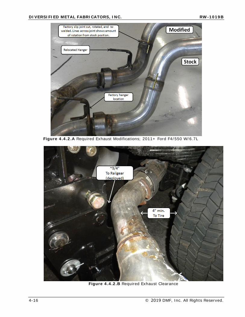
o Maintaining 4” minimum clearance between any portion of the exhaust systemand the rear vehicle tires.
o Maintaining 3/4” minimum clearance between any portion of the exhaustsystem and the rear Railgear when in the deployed position.
o Modifying and relocating hangers and brackets such that they do not restrictgrowth along the length of the exhaust system due to thermal expansion.
o Modifying or relocating mud flaps and brackets to provide adequate clearance tohot exhaust components.
o Any factory heat shields protecting vital components should be retained (modifyas necessary).
o Smooth transitions in pipe sections to avoid increasing exhaust backpressure.
4.4.2 2011+ Ford F-4/550 w/ 6.7L Diesel Engine
This section outlines best practices for exhaust modification on 2011 model year and newer F-450 and F-550 trucks with a 6.7L diesel engine for use with RW-1019B rear Railgear. Please see Ford SVE Bulletin Q-187 for all 2011-2016 and Q-253 for all 2017+ model year trucks. Reference these bulletins for additional information and for Ford’s recommendations regarding exhaust modifications, https://www.fleet.ford.com/truckbbas/topics/qvmp.html.
After installation of Railgear, DMF recommends following the basic exhaust modification steps below. Depending on body configuration, it may be necessary to raise the back end of the truck to gain sufficient clearance to remove and install exhaust.
1. If installed, remove over-axle portion of exhaust system from truck.2. Cut or grind through the factory weld (NOT THROUGH TUBING) at the slip joint as
shown in Figure 4.4.2.A, so that diffuser section can be freely rotated.3. Cut the rearmost factory exhaust hanger from the exhaust system, leaving enough of
the “legs” on the removed portion that it may be re-welded later (See Figure 4.4.2.A).4. Bolt over-axle portion of exhaust back in place on truck.5. Rotate exhaust at factory slip joint to achieve clearances shown in Figure 4.4.2.B. DMF
recommends temporarily placing a 4” spacer between the exhaust and tire to ensuresufficient tire clearance.
6. Tack weld exhaust at factory slip joint to fix new orientation.7. The rearmost factory exhaust hanger bracket is removed from the frame during Railgear
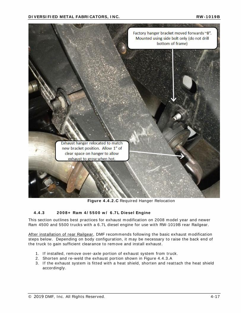
installation. It can be relocated ~8” farther forward, and mounted by drilling a new holein the side of the frame. Do not drill the bottom of the frame. See Figure 4.4.2.C.
8. Tack weld the removed hanger to the exhaust system to match new bracket position.9. Remove exhaust from truck and fully weld slip joint and exhaust hanger.10. After welding, install exhaust system on truck and verify clearances to tire and Railgear.
DIVERSIFIED METAL FABRICATORS, INC. RW-1019B
4-16 © 2019 DMF, Inc. All Rights Reserved.
Figure 4.4.2.A Required Exhaust Modifications; 2011+ Ford F4/550 W/6.7L
Figure 4.4.2.B Required Exhaust Clearance
DIVERSIFIED METAL FABRICATORS, INC. RW-1019B
© 2019 DMF, Inc. All Rights Reserved. 4-17
Figure 4.4.2.C Required Hanger Relocation
4.4.3 2008+ Ram 4/5500 w/ 6.7L Diesel Engine
This section outlines best practices for exhaust modification on 2008 model year and newer Ram 4500 and 5500 trucks with a 6.7L diesel engine for use with RW-1019B rear Railgear.
After installation of rear Railgear, DMF recommends following the basic exhaust modification steps below. Depending on body configuration, it may be necessary to raise the back end of the truck to gain sufficient clearance to remove and install exhaust.
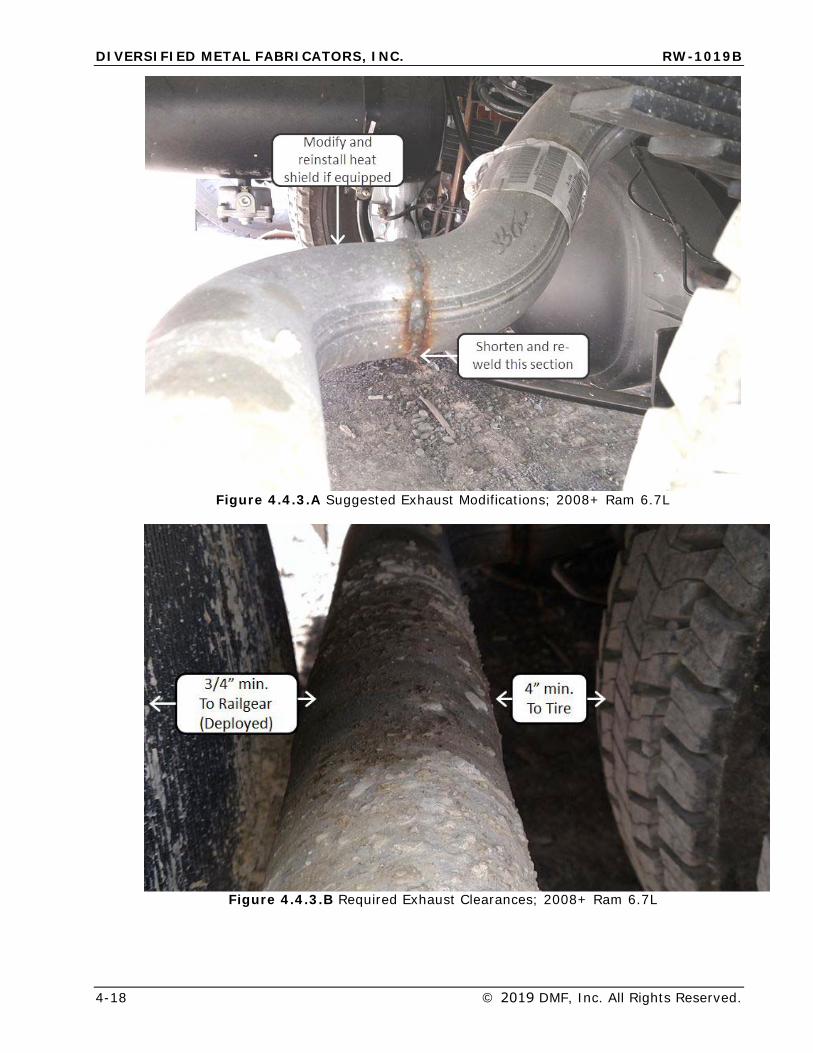
1. If installed, remove over-axle portion of exhaust system from truck.2. Shorten and re-weld the exhaust portion shown in Figure 4.4.3.A3. If the exhaust system is fitted with a heat shield, shorten and reattach the heat shield
accordingly.
DIVERSIFIED METAL FABRICATORS, INC. RW-1019B
4-18 © 2019 DMF, Inc. All Rights Reserved.
Figure 4.4.3.A Suggested Exhaust Modifications; 2008+ Ram 6.7L
Figure 4.4.3.B Required Exhaust Clearances; 2008+ Ram 6.7L
DIVERSIFIED METAL FABRICATORS, INC. RW-1019B
© 2019 DMF, Inc. All Rights Reserved. 4-19
4.5 INSTALLATION OF FRONT RAILGEAR
4.5.1 General Information
• Your Railgear includes parts designed for your particular chassis year/make/model andselected options. Exact appearances of some items may vary.
• Basic instructions for several popular applications are included below. Detailed assemblydrawings and additional information can be found in Section 8.
• Prior to beginning front installation, please locate and become familiar with the sectionspecific to your application.
• Check for sufficient clearances to prevent interference with Railgear and other parts ofthe truck (i.e. Frame, steering boxes, shocks, oil filters, etc.)
4.5.2 2008 - 2016 Ford F-4/550 Installation
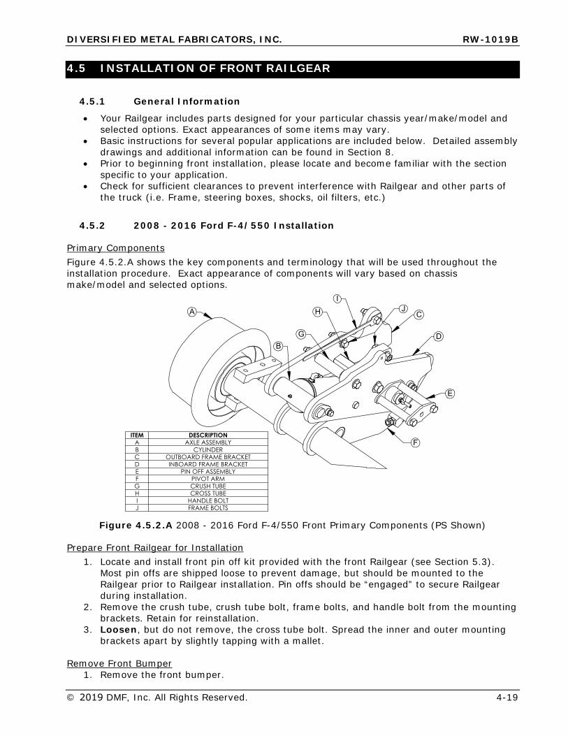
Primary Components Figure 4.5.2.A shows the key components and terminology that will be used throughout the installation procedure. Exact appearance of components will vary based on chassis make/model and selected options.
�
�
�
�
�
�
�
�
���� ���������� �������������� �� ��� ���������������������� ������������������� � �������������� ��������� ���������� ��������� �� ��������� �����������
Figure 4.5.2.A 2008 - 2016 Ford F-4/550 Front Primary Components (PS Shown)
Prepare Front Railgear for Installation 1. Locate and install front pin off kit provided with the front Railgear (see Section 5.3).
Most pin offs are shipped loose to prevent damage, but should be mounted to the Railgear prior to Railgear installation. Pin offs should be “engaged” to secure Railgear during installation.
2. Remove the crush tube, crush tube bolt, frame bolts, and handle bolt from the mountingbrackets. Retain for reinstallation.
3. Loosen, but do not remove, the cross tube bolt. Spread the inner and outer mountingbrackets apart by slightly tapping with a mallet.
Remove Front Bumper 1. Remove the front bumper.
DIVERSIFIED METAL FABRICATORS, INC. RW-1019B
4-20 © 2019 DMF, Inc. All Rights Reserved.
2. The tow hook/bumper brackets can be left in place.
Unbolt Factory Transmission Cooler 1. Most models are equipped with a transmission cooler bolted to the passenger side frame
rail that must be relocated for Railgear installation.2. Remove the two bolts securing the transmission cooler, and temporarily secure the
transmission cooler away from the frame rail with a zip tie.
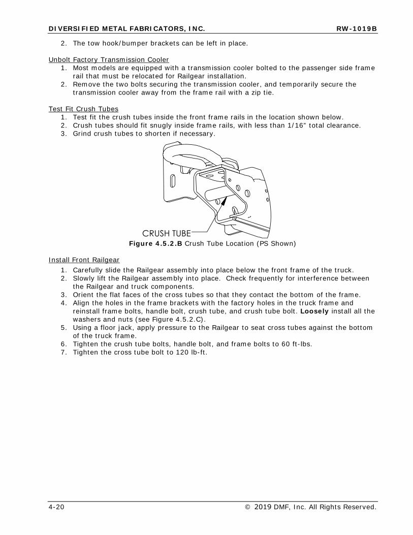
Test Fit Crush Tubes 1. Test fit the crush tubes inside the front frame rails in the location shown below.2. Crush tubes should fit snugly inside frame rails, with less than 1/16” total clearance.3. Grind crush tubes to shorten if necessary.
���������Figure 4.5.2.B Crush Tube Location (PS Shown)
Install Front Railgear 1. Carefully slide the Railgear assembly into place below the front frame of the truck.2. Slowly lift the Railgear assembly into place. Check frequently for interference between
the Railgear and truck components.3. Orient the flat faces of the cross tubes so that they contact the bottom of the frame.4. Align the holes in the frame brackets with the factory holes in the truck frame and
reinstall frame bolts, handle bolt, crush tube, and crush tube bolt. Loosely install all thewashers and nuts (see Figure 4.5.2.C).
5. Using a floor jack, apply pressure to the Railgear to seat cross tubes against the bottomof the truck frame.
6. Tighten the crush tube bolts, handle bolt, and frame bolts to 60 ft-lbs.7. Tighten the cross tube bolt to 120 lb-ft.
DIVERSIFIED METAL FABRICATORS, INC. RW-1019B
© 2019 DMF, Inc. All Rights Reserved. 4-21
���������������������� ��� �������
%*����-���
���-� ��������6
��������������'����-���
����������'����-���
���-������������6
�� ��������'����-���
����������'����-��� ��������������
'����-���
���������������������� ��� �������
%*����-���
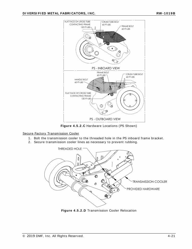
Figure 4.5.2.C Hardware Locations (PS Shown)
Secure Factory Transmission Cooler 1. Bolt the transmission cooler to the threaded hole in the PS inboard frame bracket.2. Secure transmission cooler lines as necessary to prevent rubbing.
��� ����� ������
��������������
������������6���
Figure 4.5.2.D Transmission Cooler Relocation
DIVERSIFIED METAL FABRICATORS, INC. RW-1019B
4-22 © 2019 DMF, Inc. All Rights Reserved.
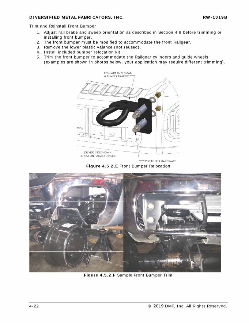
Trim and Reinstall Front Bumper 1. Adjust rail brake and sweep orientation as described in Section 4.8 before trimming or
installing front bumper.2. The front bumper must be modified to accommodate the front Railgear.3. Remove the lower plastic valance (not reused).4. Install included bumper relocation kit.5. Trim the front bumper to accommodate the Railgear cylinders and guide wheels
(examples are shown in photos below, your application may require different trimming).
���������6������9��������������
*(�������9�����6���
��������������6 �������� ������ �������
Figure 4.5.2.E Front Bumper Relocation
Figure 4.5.2.F Sample Front Bumper Trim
DIVERSIFIED METAL FABRICATORS, INC. RW-1019B
© 2019 DMF, Inc. All Rights Reserved. 4-23
4.5.3 2017+ Ford F-4/550 Installation
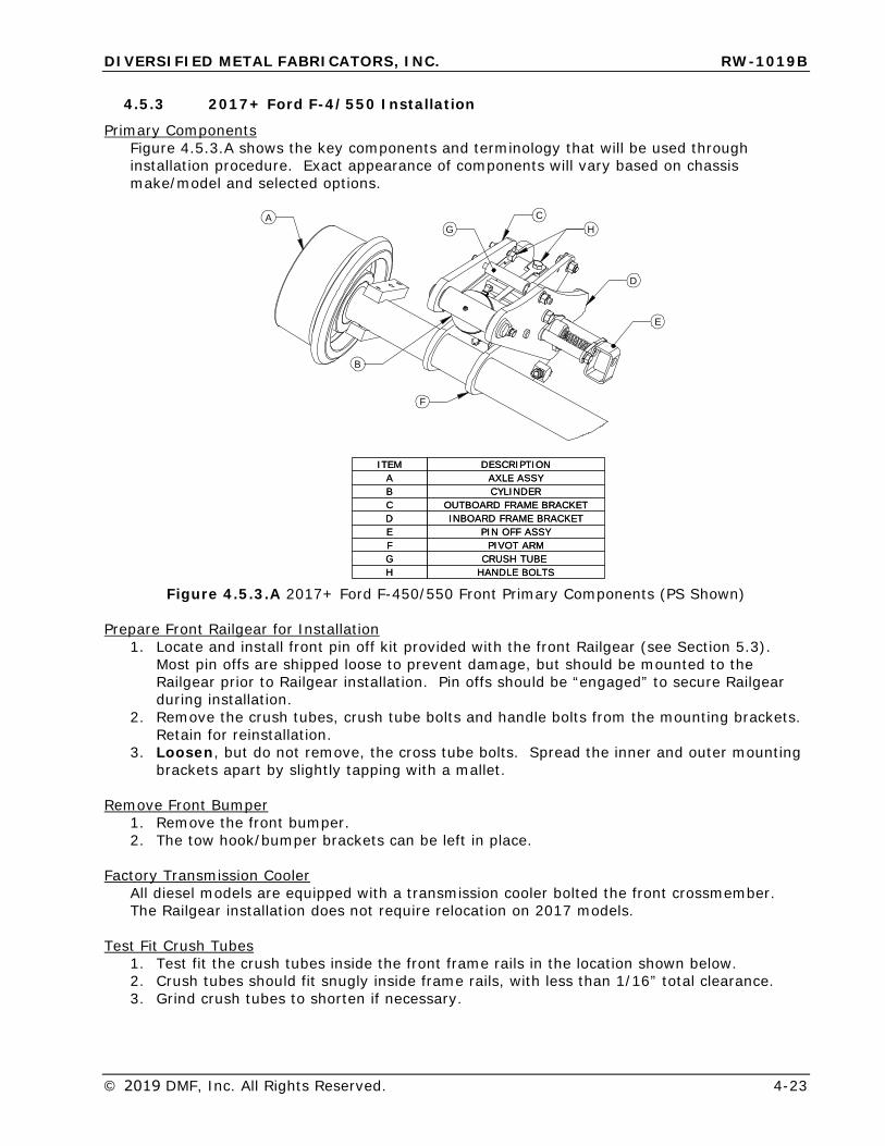
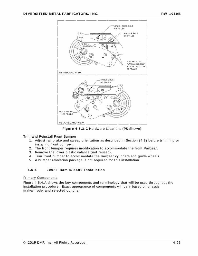
Primary Components Figure 4.5.3.A shows the key components and terminology that will be used through installation procedure. Exact appearance of components will vary based on chassis make/model and selected options.
DESCRIPTIONAXLE ASSYCYLINDER
OUTBOARD FRAME BRACKETINBOARD FRAME BRACKET
PIN OFF ASSYPIVOT ARM
CRUSH TUBE HANDLE BOLTS
ITEMABCDEFGH
ITEMABCDEFGH
DESCRIPTIONAXLE ASSYCYLINDER
OUTBOARD FRAME BRACKETINBOARD FRAME BRACKET
PIN OFF ASSYPIVOT ARM
CRUSH TUBE HANDLE BOLTS
D
E
F
AG
B
CH
Figure 4.5.3.A 2017+ Ford F-450/550 Front Primary Components (PS Shown)
Prepare Front Railgear for Installation 1. Locate and install front pin off kit provided with the front Railgear (see Section 5.3).
Most pin offs are shipped loose to prevent damage, but should be mounted to theRailgear prior to Railgear installation. Pin offs should be “engaged” to secure Railgearduring installation.
2. Remove the crush tubes, crush tube bolts and handle bolts from the mounting brackets.Retain for reinstallation.
3. Loosen, but do not remove, the cross tube bolts. Spread the inner and outer mountingbrackets apart by slightly tapping with a mallet.
Remove Front Bumper 1. Remove the front bumper.2. The tow hook/bumper brackets can be left in place.
Factory Transmission Cooler All diesel models are equipped with a transmission cooler bolted the front crossmember. The Railgear installation does not require relocation on 2017 models.
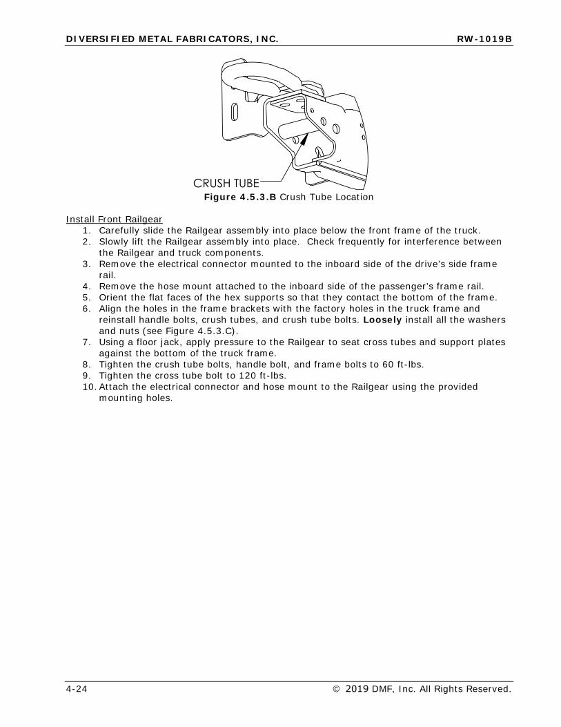
Test Fit Crush Tubes 1. Test fit the crush tubes inside the front frame rails in the location shown below.2. Crush tubes should fit snugly inside frame rails, with less than 1/16” total clearance.3. Grind crush tubes to shorten if necessary.
DIVERSIFIED METAL FABRICATORS, INC. RW-1019B
4-24 © 2019 DMF, Inc. All Rights Reserved.
��������Figure 4.5.3.B Crush Tube Location
Install Front Railgear 1. Carefully slide the Railgear assembly into place below the front frame of the truck.2. Slowly lift the Railgear assembly into place. Check frequently for interference between
the Railgear and truck components.3. Remove the electrical connector mounted to the inboard side of the drive’s side frame
rail.4. Remove the hose mount attached to the inboard side of the passenger’s frame rail.5. Orient the flat faces of the hex supports so that they contact the bottom of the frame.6. Align the holes in the frame brackets with the factory holes in the truck frame and
reinstall handle bolts, crush tubes, and crush tube bolts. Loosely install all the washersand nuts (see Figure 4.5.3.C).
7. Using a floor jack, apply pressure to the Railgear to seat cross tubes and support platesagainst the bottom of the truck frame.
8. Tighten the crush tube bolts, handle bolt, and frame bolts to 60 ft-lbs.9. Tighten the cross tube bolt to 120 ft-lbs.10. Attach the electrical connector and hose mount to the Railgear using the provided
mounting holes.
DIVERSIFIED METAL FABRICATORS, INC. RW-1019B
© 2019 DMF, Inc. All Rights Reserved. 4-25
CRUSH TUBE BOLT60 FT-LBS
AGAINST BOTTOM OF FRAME
FLAT FACE OF PLATE & HEX REST
HANDLE BOLT60 FT-LBS
HANDLE BOLT60 FT-LBS
PS OUTBOARD VIEW
PS INBOARD VIEW
HEX SUPPORT120 FT-LBS
Figure 4.5.3.C Hardware Locations (PS Shown)
Trim and Reinstall Front Bumper 1. Adjust rail brake and sweep orientation as described in Section (4.8) before trimming or
installing front bumper.2. The front bumper requires modification to accommodate the front Railgear.3. Remove the lower plastic valance (not reused).4. Trim front bumper to accommodate the Railgear cylinders and guide wheels.5. A bumper relocation package is not required for this installation.
4.5.4 2008+ Ram 4/5500 Installation
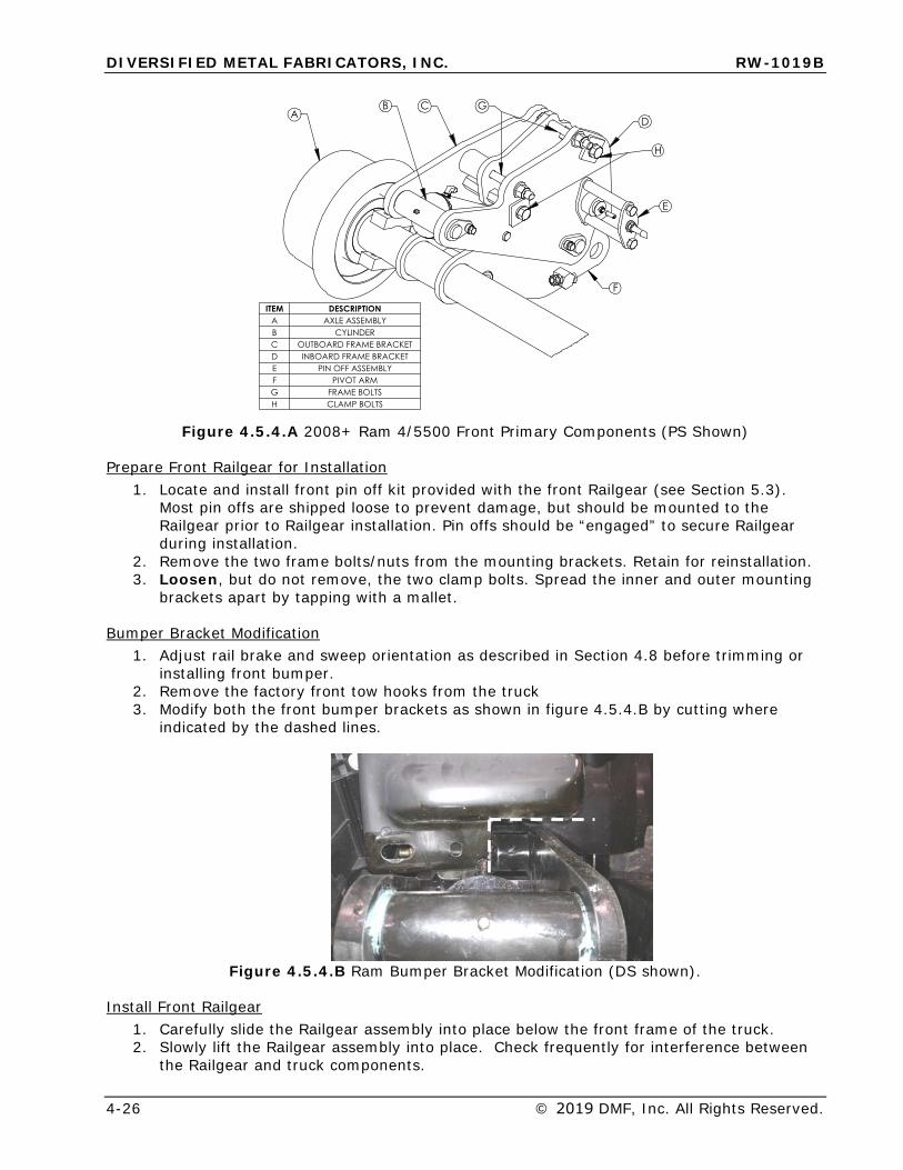
Primary Components Figure 4.5.4.A shows the key components and terminology that will be used throughout the installation procedure. Exact appearance of components will vary based on chassis make/model and selected options.
DIVERSIFIED METAL FABRICATORS, INC. RW-1019B
4-26 © 2019 DMF, Inc. All Rights Reserved.
��
�
�
��
�
���� ���������� �������������� �� ��� ���������������������� ������������������� � �������������� ��������� ������������ ����������
Figure 4.5.4.A 2008+ Ram 4/5500 Front Primary Components (PS Shown)
Prepare Front Railgear for Installation 1. Locate and install front pin off kit provided with the front Railgear (see Section 5.3).
Most pin offs are shipped loose to prevent damage, but should be mounted to theRailgear prior to Railgear installation. Pin offs should be “engaged” to secure Railgearduring installation.
2. Remove the two frame bolts/nuts from the mounting brackets. Retain for reinstallation.3. Loosen, but do not remove, the two clamp bolts. Spread the inner and outer mounting
brackets apart by tapping with a mallet.
Bumper Bracket Modification 1. Adjust rail brake and sweep orientation as described in Section 4.8 before trimming or
installing front bumper.2. Remove the factory front tow hooks from the truck3. Modify both the front bumper brackets as shown in figure 4.5.4.B by cutting where
indicated by the dashed lines.
Figure 4.5.4.B Ram Bumper Bracket Modification (DS shown).
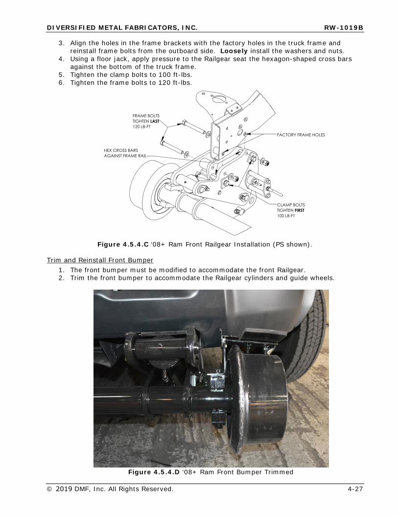
Install Front Railgear 1. Carefully slide the Railgear assembly into place below the front frame of the truck.2. Slowly lift the Railgear assembly into place. Check frequently for interference between
the Railgear and truck components.
DIVERSIFIED METAL FABRICATORS, INC. RW-1019B
© 2019 DMF, Inc. All Rights Reserved. 4-27
3. Align the holes in the frame brackets with the factory holes in the truck frame andreinstall frame bolts from the outboard side. Loosely install the washers and nuts.
4. Using a floor jack, apply pressure to the Railgear seat the hexagon-shaped cross barsagainst the bottom of the truck frame.
5. Tighten the clamp bolts to 100 ft-lbs.6. Tighten the frame bolts to 120 ft-lbs.
������������������
��������������� ����%�����-��
���������������� �����%*����-��
���������������� ������������
Figure 4.5.4.C ‘08+ Ram Front Railgear Installation (PS shown).
Trim and Reinstall Front Bumper 1. The front bumper must be modified to accommodate the front Railgear.2. Trim the front bumper to accommodate the Railgear cylinders and guide wheels.
Figure 4.5.4.D ‘08+ Ram Front Bumper Trimmed
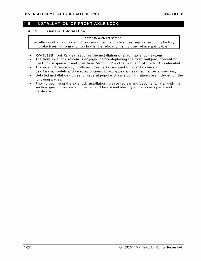
DIVERSIFIED METAL FABRICATORS, INC. RW-1019B
4-28 © 2019 DMF, Inc. All Rights Reserved.
4.6 INSTALLATION OF FRONT AXLE LOCK
4.6.1 General Information
****WARNING**** Installation of a front axle lock system on some models may require rerouting factory
brake lines. Information on brake line relocation is included where applicable.
• RW-1019B front Railgear requires the installation of a front axle lock system.• The front axle lock system is engaged before deploying the front Railgear, preventing
the truck suspension and tires from “drooping” as the front end of the truck is elevated.• The axle lock system typically includes parts designed for specific chassis
year/make/models and selected options. Exact appearances of some items may vary.• Detailed installation guides for several popular chassis configurations are included on the
following pages.• Prior to beginning the axle lock installation, please review and become familiar with the
section specific to your application, and locate and identify all necessary parts andhardware.
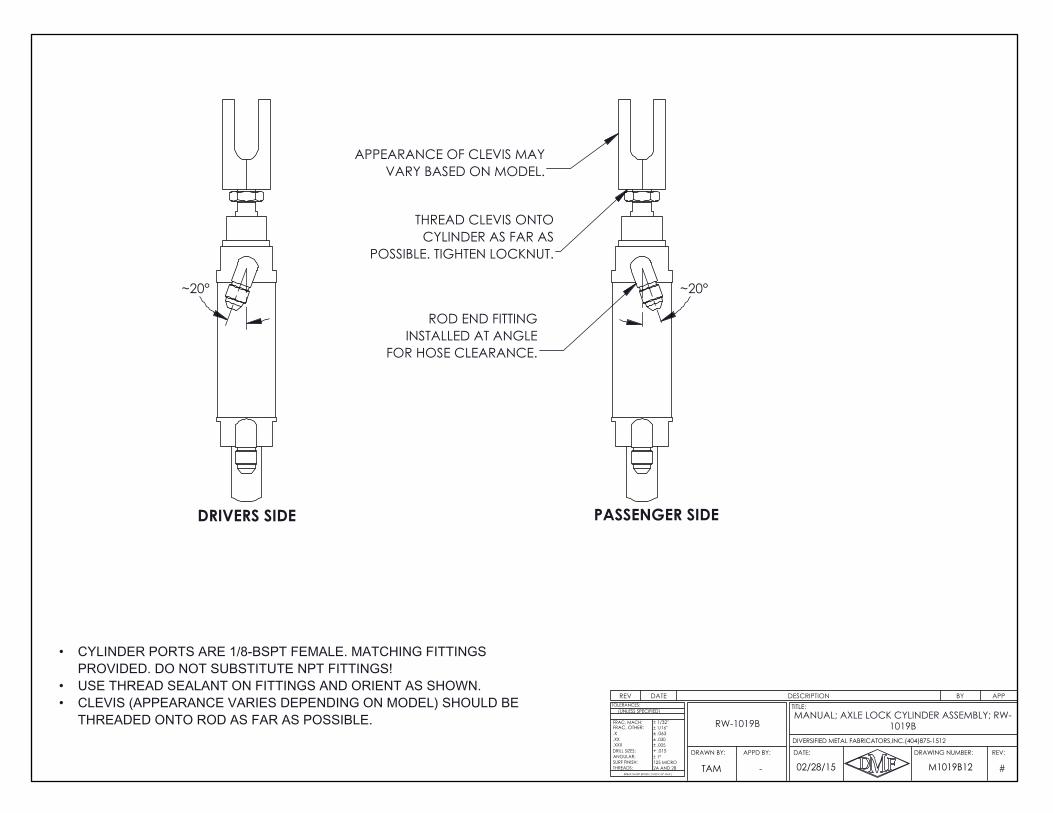
~20°
THREAD CLEVIS ONTO CYLINDER AS FAR AS
POSSIBLE. TIGHTEN LOCKNUT.
APPEARANCE OF CLEVIS MAY VARY BASED ON MODEL.
PASSENGER SIDE
ROD END FITTINGINSTALLED AT ANGLE
FOR HOSE CLEARANCE.
CYLINDER PORTS ARE 1/8-BSPT FEMALE. MATCHING FITTINGS •PROVIDED. DO NOT SUBSTITUTE NPT FITTINGS!USE THREAD SEALANT ON FITTINGS AND ORIENT AS SHOWN.•CLEVIS (APPEARANCE VARIES DEPENDING ON MODEL) SHOULD BE •THREADED ONTO ROD AS FAR AS POSSIBLE.
~20°
DRIVERS SIDE
REV DATE DESCRIPTION BY APP
#
.X
ANGULAR:
BREAK SHARP EDGES ( 0.030 X 45° MAX )
± 1/16"
± .005± .030
+ .015
± 1/32"
± .063
± 1°
2A AND 2B125 MICRO
DRILL SIZES:
SURF FINISH:THREADS:
.XXX
.XX
TOLERANCES:
FRAC, MACH:
(UNLESS SPECIFIED)
FRAC, OTHER:
02/28/15 M1019B12TAM
REV:DRAWING NUMBER:
TITLE:
DATE:APPD BY:DRAWN BY:
DIVERSIFIED METAL FABRICATORS,INC.(404)875-1512
-
MANUAL; AXLE LOCK CYLINDER ASSEMBLY; RW-1019BRW-1019B

10
9
2MATCH DRILL FRAME (2X 1/2")
12 INSERT THROUGH FRAME ACCESS HOLEREQUIRES CLEARANCE NOTCHFOR CYLINDER MOUNT
21 22
16 1715
18
1913
DRIVER SIDE BODY GUSSET
2021
3
9
ADJUST HOOK FOR 1/4" MIN.
FITTINGGREASE
CLEARANCE TO CATCH PIN
23
24
4
SHORTEN IF NECESSARY TO BRING FLUSH WITH INSIDE OF ARM
LOWER END OF SHOCK ABSORBER FOR CLEARANCE.INSTALL/TIGHTEN BOLTS ON ONE SIDE OF TRUCK BEFORE
9
ON UPPER BOLT
3
6
7
5 4
8
1
14x4 MODELS: REUSEFACTORY WELDED NUT
•LOOSENING/REMOVING BOLTS ON OPPOSITE SIDE.
TEMPORARILY DISCONNECT AND RELOCATE •
REV DATE DESCRIPTION BY APPA 10/28/2016 ADDED TIRE LIFT NOTE BJF
INSTALLATION NOTES:DRIVERS SIDE SHOWN. REPEAT FOR PASSENGER SIDE.•CLEARANCE NOTCH FOR CYLINDER REQUIRED IN DRIVERS SIDE BODY GUSSET.•LOWER HOOKS SHOULD CLEAR CATCH PINS BY 1/4" MINIMUM WHEN ENGAGED•ON LEVEL GROUND WITH TRUCK NEAR SERVICE WEIGHT.GREASE UPPER HOOK PIVOT POINTS AFTER INSTALLATION.•SEE DRAWING #301057/301058 FOR HYDRAULIC SCHEMATICS.•SEE DRAWING # 309003/309004 FOR ELECTRICAL SCHEMATICS.•CYLINDER PORTS ARE 1/8-BSPT FEMALE. MATCHING FITTINGS PROVIDED. APPLY •THREAD SEALANT DURING INSTALLATION. DO NOT SUBSTITUTE NPT FITTINGS.ROUTE HYDRAULIC LINES CLEAR OF EXHAUST AND PINCH/WEAR HAZARDS.•WITH AXLE LOCK ENGAGED AND RAILGEAR DEPLOYED, MINIMUM ACCEPTABLE •TIRE LIFT ABOVE RAIL IS 2"
ITEM NO.
PART NUMBER QTY. DESCRIPTION
1 307019 1 WELDMENT, RADIUS ARM BRACKET, DS, RW-1019B, '08 FORD F4/5502 307020 1 WELDMENT, RADIUS ARM BRACKET, PS, RW-1019B, '08 FORD F4/5503 605268 4 HHCS, M18-2.5 X 140MM, CLASS 10.94 605269 4 FLAT WASHER, M185 605270 4 LOCK NUT, M18-2.5, CLASS 106 605010 2 HEX HEAD CAP SCREW, 1/2-12 X 4-1/4", GR87 307030 2 RADIUS ARM CRUSH TUBE, RW-1019B, '08 FORD F4/5508 500691 2 1/2" FLAT WASHER; GR89 113014 10 1/2"-13 NYLOCK NUT; GR8
10 307025 1 WELDMENT, AXLE HOOK LOCK FRAME BRACKET, DS, RW-1019B, '08 FORD F4/55011 307026 1 WELDMENT, AXLE HOOK LOCK FRAME BRACKET, PS, RW-1019B, '08 FORD F4/55012 307035 2 WELDMENT; AXLE HOOK LOCK BOLT PLATE ; RW-1019B; '08 FORD F4/55013 307031 1 DS UPPER HOOK WELDMENT; RW-1019B, '08 FORD F4/55014 307032 1 PS UPPER HOOK WELDMENT; RW-1019B, '08 FORD F4/55015 605022 2 FENDER WASHER; 3/8"16 12566 2 LOCK WASHER, 3/8", GR817 605356 2 HHCS 3/8-16 X 3/4" GRADE 818 301054 2 AXLE HOOK LOCK CYLINDER; W/ CLEVIS; RW-1019B19 818456 2 COTTER PIN, 1/8" X 1-1/2"20 605082 2 HHCS, 3/8-16 X 1-3/4", GR821 818508 4 FLAT WASHER, 3/8", GR822 605077 2 3/8"-16 NYLOCK NUT; GR823 307029 2 LOWER HOOK LOCK, AXLE HOOK LOCK, RW-1019B, '08 FORD F4/55024 605259 4 HEX HEAD CAP SCREW, 1/2-13 X 1-3/4", GRADE 8
A
INSTALLATION NOTES:DRIVERS SIDE SHOWN. REPEAT FOR PASSENGER SIDE.•CLEARANCE NOTCH FOR CYLINDER REQUIRED IN DRIVERS SIDE BODY GUSSET.•LOWER HOOKS SHOULD CLEAR CATCH PINS BY 1/4" MINIMUM WHEN ENGAGED•ON LEVEL GROUND WITH TRUCK NEAR SERVICE WEIGHT.GREASE UPPER HOOK PIVOT POINTS AFTER INSTALLATION.•SEE DRAWING #301057/301058 FOR HYDRAULIC SCHEMATICS.•SEE DRAWING # 309003/309004 FOR ELECTRICAL SCHEMATICS.•CYLINDER PORTS ARE 1/8-BSPT FEMALE. MATCHING FITTINGS PROVIDED. APPLY •THREAD SEALANT DURING INSTALLATION. DO NOT SUBSTITUTE NPT FITTINGS.ROUTE HYDRAULIC LINES CLEAR OF EXHAUST AND PINCH/WEAR HAZARDS.•WITH AXLE LOCK ENGAGED AND RAILGEAR DEPLOYED, MINIMUM ACCEPTABLE •TIRE LIFT ABOVE RAIL IS 2"
RW-1019B
A
.X
ANGULAR:
BREAK SHARP EDGES ( 0.030 X 45° MAX )
± 1/16"
± .005± .030
+ .015
± 1/32"
± .063
± 1°
2A AND 2B125 MICRO
DRILL SIZES:
SURF FINISH:THREADS:
.XXX
.XX
TOLERANCES:
FRAC, MACH:
(UNLESS SPECIFIED)
8/11/14 307036
REV:DRAWING NUMBER:
TITLE:
DATE:APPD BY:DRAWN BY:
FRAC, OTHER:
DIVERSIFIED METAL FABRICATORS,INC.(404)875-1512
TAM -
AXLE HOOK LOCK KIT; RW-1019B; '08-'16 FORD F4/550
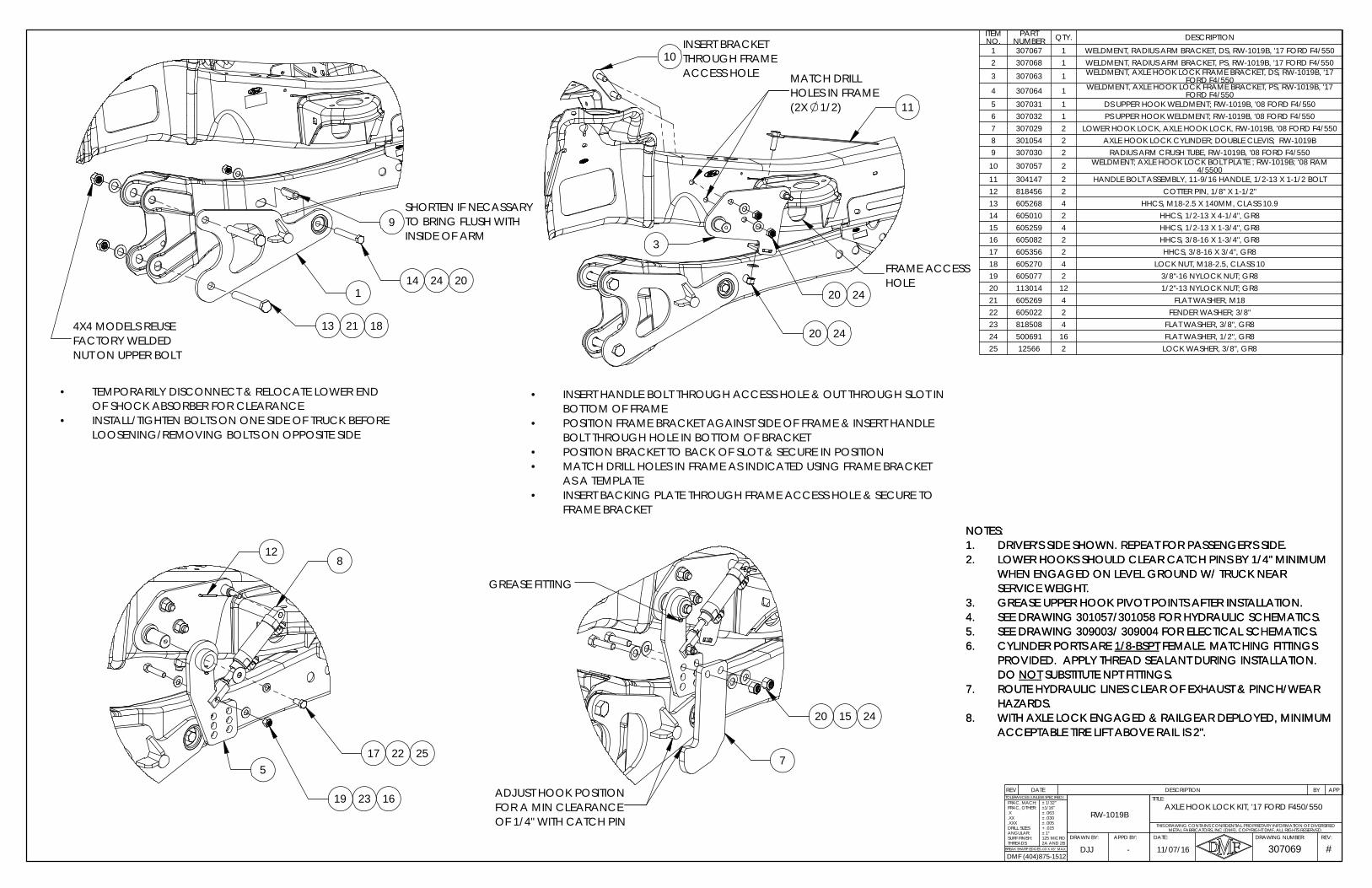
HOLE
ACCESS HOLETHROUGH FRAME INSERT BRACKET
FRAME ACCESS
11
3
2420
10
MATCH DRILL HOLES IN FRAME (2X 1/2)
20 24
INSERT HANDLE BOLT THROUGH ACCESS HOLE & OUT THROUGH SLOT IN •BOTTOM OF FRAMEPOSITION FRAME BRACKET AGAINST SIDE OF FRAME & INSERT HANDLE •BOLT THROUGH HOLE IN BOTTOM OF BRACKETPOSITION BRACKET TO BACK OF SLOT & SECURE IN POSITION•MATCH DRILL HOLES IN FRAME AS INDICATED USING FRAME BRACKET •AS A TEMPLATEINSERT BACKING PLATE THROUGH FRAME ACCESS HOLE & SECURE TO •FRAME BRACKET
8
2217
2319 16
12
255
7
20 2415
ADJUST HOOK POSITION FOR A MIN CLEARANCE OF 1/4" WITH CATCH PIN
GREASE FITTING
REV DATE DESCRIPTION BY APP
ITEM NO.
PART NUMBER QTY. DESCRIPTION
1 307067 1 WELDMENT, RADIUS ARM BRACKET, DS, RW-1019B, '17 FORD F4/5502 307068 1 WELDMENT, RADIUS ARM BRACKET, PS, RW-1019B, '17 FORD F4/550
3 307063 1 WELDMENT, AXLE HOOK LOCK FRAME BRACKET, DS, RW-1019B, '17 FORD F4/550
4 307064 1 WELDMENT, AXLE HOOK LOCK FRAME BRACKET, PS, RW-1019B, '17 FORD F4/550
5 307031 1 DS UPPER HOOK WELDMENT; RW-1019B, '08 FORD F4/5506 307032 1 PS UPPER HOOK WELDMENT; RW-1019B, '08 FORD F4/5507 307029 2 LOWER HOOK LOCK, AXLE HOOK LOCK, RW-1019B, '08 FORD F4/5508 301054 2 AXLE HOOK LOCK CYLINDER; DOUBLE CLEVIS; RW-1019B9 307030 2 RADIUS ARM CRUSH TUBE, RW-1019B, '08 FORD F4/550
10 307057 2 WELDMENT; AXLE HOOK LOCK BOLT PLATE ; RW-1019B; '08 RAM 4/5500
11 304147 2 HANDLE BOLT ASSEMBLY, 11-9/16 HANDLE, 1/2-13 X 1-1/2 BOLT12 818456 2 COTTER PIN, 1/8" X 1-1/2"13 605268 4 HHCS, M18-2.5 X 140MM, CLASS 10.914 605010 2 HHCS, 1/2-13 X 4-1/4", GR815 605259 4 HHCS, 1/2-13 X 1-3/4", GR816 605082 2 HHCS, 3/8-16 X 1-3/4", GR817 605356 2 HHCS, 3/8-16 X 3/4", GR818 605270 4 LOCK NUT, M18-2.5, CLASS 1019 605077 2 3/8"-16 NYLOCK NUT; GR820 113014 12 1/2"-13 NYLOCK NUT; GR821 605269 4 FLAT WASHER, M1822 605022 2 FENDER WASHER; 3/8"23 818508 4 FLAT WASHER, 3/8", GR824 500691 16 FLAT WASHER, 1/2", GR825 12566 2 LOCK WASHER, 3/8", GR8
NOTES:DRIVER'S SIDE SHOWN. REPEAT FOR PASSENGER'S SIDE.1.LOWER HOOKS SHOULD CLEAR CATCH PINS BY 1/4" MINIMUM 2.WHEN ENGAGED ON LEVEL GROUND W/ TRUCK NEAR SERVICE WEIGHT.GREASE UPPER HOOK PIVOT POINTS AFTER INSTALLATION.3.SEE DRAWING 301057/301058 FOR HYDRAULIC SCHEMATICS.4.SEE DRAWING 309003/ 309004 FOR ELECTICAL SCHEMATICS.5.CYLINDER PORTS ARE 1/8-BSPT FEMALE. MATCHING FITTINGS 6.PROVIDED. APPLY THREAD SEALANT DURING INSTALLATION. DO NOT SUBSTITUTE NPT FITTINGS.ROUTE HYDRAULIC LINES CLEAR OF EXHAUST & PINCH/WEAR 7.HAZARDS.WITH AXLE LOCK ENGAGED & RAILGEAR DEPLOYED, MINIMUM 8.ACCEPTABLE TIRE LIFT ABOVE RAIL IS 2".
NOTES:DRIVER'S SIDE SHOWN. REPEAT FOR PASSENGER'S SIDE.1.LOWER HOOKS SHOULD CLEAR CATCH PINS BY 1/4" MINIMUM 2.WHEN ENGAGED ON LEVEL GROUND W/ TRUCK NEAR SERVICE WEIGHT.GREASE UPPER HOOK PIVOT POINTS AFTER INSTALLATION.3.SEE DRAWING 301057/301058 FOR HYDRAULIC SCHEMATICS.4.SEE DRAWING 309003/ 309004 FOR ELECTICAL SCHEMATICS.5.CYLINDER PORTS ARE 1/8-BSPT FEMALE. MATCHING FITTINGS 6.PROVIDED. APPLY THREAD SEALANT DURING INSTALLATION. DO NOT SUBSTITUTE NPT FITTINGS.ROUTE HYDRAULIC LINES CLEAR OF EXHAUST & PINCH/WEAR 7.HAZARDS.WITH AXLE LOCK ENGAGED & RAILGEAR DEPLOYED, MINIMUM 8.ACCEPTABLE TIRE LIFT ABOVE RAIL IS 2".
13
1
NUT ON UPPER BOLT
4X4 MODELS REUSE
INSIDE OF ARM
SHORTEN IF NECASSARY
FACTORY WELDED
24 20
9
14
TO BRING FLUSH WITH
21 18
TEMPORARILY DISCONNECT & RELOCATE LOWER END •OF SHOCK ABSORBER FOR CLEARANCEINSTALL/TIGHTEN BOLTS ON ONE SIDE OF TRUCK BEFORE •LOOSENING/REMOVING BOLTS ON OPPOSITE SIDE
2A AND 2B
FRAC, MACH:
DJJBREAK SHARP EDGES .03 X 45° MAX
TOLERANCES (UNLESS SPECIFIED):
307069REV:DRAWING NUMBER:
TITLE:
DATE:
#
FRAC, OTHER:
RW-1019BTHIS DRAWING CONTAINS CONFIDENTIAL PROPRIETARY INFORMATION OF DIVERSIFIED
METAL FABRICATORS, INC (DMF). COPYRIGHT DMF, ALL RIGHTS RESERVED.
AXLE HOOK LOCK KIT, '17 FORD F450/550
- 11/07/16APPD BY:DRAWN BY:
.X
.XX
.XXXDRILL SIZES:ANGULAR:SURF FINISH:THREADS:
± 1/32"±1/16"± .063± .030± .005+ .015± 1°125 MICRO
DMF (404)875-1512
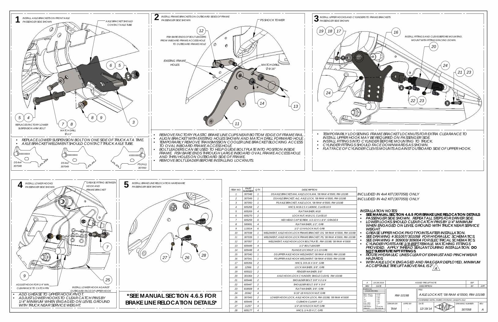
84
REPLACES FACTORY LOWER
PASSENGER SIDE SHOWN
1/2"
SUSPENSION ARM BOLT
8
INSTALL AXLE BRACKETS ON FRONT AXLE1
MATCH DRILL
7
6
35 9
5
AXLE BRACKET SHOULD CONTACT AXLE TUBE
TAM -
RW-1019B
12/19/14
.X
ANGULAR:
BREAK SHARP EDGES ( 0.030 X 45° MAX )
± 1/16"
± .005± .030
+ .015
± 1/32"
± .063
± 1°
2A AND 2B125 MICRO
DRILL SIZES:
SURF FINISH:THREADS:
.XXX
.XX DIVERSIFIED METAL FABRICATORS,INC.(404)875-1512
FRAC, MACH:
(UNLESS SPECIFIED)
FRAC, OTHER:
307058
REV:DRAWING NUMBER:
TITLE:TOLERANCES:
DATE:APPD BY:DRAWN BY:
A
REV DATE DESCRIPTION BY APPA 10/28/2016 ADDED TIRE LIFT NOTE BJF
ITEM NO. PART NUMBER QTY. DESCRIPTION
1 307048 1 DS AXLE BRACKET,4X4, AXLE LOCK,4X4, '08 RAM 4/5500, RW-1019B
2 307049 1 DS AXLE BRACKET, 4x2, AXLE LOCK, '08 RAM 4/5500, RW-1019B
3 307050 1 PS AXLE BRACKET, AXLE LOCK, '08 RAM 4/5500, RW-1019B
4 605268 2 HHCS, M18-2.5 X 140MM, CLASS 10.9
5 605269 4 FLAT WASHER, M18
6 605270 2 LOCK NUT, M18-2.5, CLASS 10
7 605259 6 HEX HEAD CAP SCREW, 1/2-13 X 1-3/4", GRADE 8
8 500691 4 FLAT WASHER, 1/2", GR8
9 113014 6 1/2"-13 NYLOCK NUT; GR8
10 307038 1 WELDMENT, AXLE HOOK LOCK FRAME BRACKET, DS, '08 RAM 4/5500, RW-1019B
11 307039 1 WELDMENT, AXLE HOOK LOCK FRAME BRACKET, PS, '08 RAM 4/5500, RW-1019B
12 307057 2 WELDMENT; AXLE HOOK LOCK BOLT PLATE ; RW-1019B; '08 RAM 4/5500
13 605449 4 1/2" BOLT LEADER
14 605448 4 FLANGE LOCKNUT; 1/2-13 GR8
15 307040 1 DS UPPER AXLE HOOK WELDMENT; '08 RAM 4/5500; RW-1019B
16 307041 1 PS UPPER AXLE HOOK WELDMENT; '08 RAM 4/5500; RW-1019B
17 605356 2 HHCS, 3/8-16 X 3/4", GR8
18 12566 2 LOCK WASHER, 3/8", GR8
19 605022 2 FENDER WASHER; 3/8"
20 301064 2 AXLE HOOK LOCK CYLINDER; SINGLE CLEVIS; RW-1019B
21 605446 2 SHOULDER BOLT; 3/8" X 2-1/4
22 605447 2 SHOULDER BOLT; 3/8" X 3/4"
23 818508 4 FLAT WASHER, 3/8", GR8
24 20342 4 5/16"-18 NYLOCK NUT; GR8
25 307043 2 LOWER HOOK LOCK, AXLE HOOK LOCK, RW-1019B, '08 RAM 4/5500
26 605445 4 CUSHION CLAMP; 1/2"
27 11257 4 1/4"-20 NYLOCK NUT; GR8
28 605177 4 HHCS, 1/4-20 X 1", GR5
FISH BARE ENDS OF BOLT LEADERSFROM INBOARD FRAME ACCESS HOLE
TO OUTBOARD FRAME HOLE
INSTALLATION NOTES:SEE MANUAL SECTION 4.6.5 FOR BRAKE LINE RELOCATION DETAILS•PASSENGER SIDE SHOWN. REPEAT ALL STEPS FOR DRIVER SIDE.•LOWER LOOKS SHOULD CLEAR CATCH PINS BY 1/4" MINIMUM •WHEN ENGAGED ON LEVEL GROUND WITH TRUCK NEAR SERVICE WEIGHT.GREASE UPPER HOOK PIVOT POINTS AFTER INSTALLATION.•SEE DRAWING #301057/301058 FOR HYDRAULIC SCHEMATICS.•SEE DRAWING # 309003/309004 FOR ELECTRICAL SCHEMATICS.•CYLINDER PORTS ARE 1/8-BSPT FEMALE. MATCHING FITTINGS •PROVIDED. APPLY THREAD SEALANT DURING INSTALLATION. DO NOT SUBSTITUTE NPT FITTINGS.ROUTE HYDRAULIC LINES CLEAR OF EXHAUST AND PINCH/WEAR •HAZARDS.WITH AXLE LOCK ENGAGED AND RAILGEAR DEPLOYED, MINIMUM •ACCEPTABLE TIRE LIFT ABOVE RAIL IS 2".
REPLACE LOWER SUSPENSION BOLT ON ONE SIDE OF TRUCK AT A TIME.•AXLE BRACKET WELDMENT SHOULD CONTACT TRUCK AXLE TUBE.•
INCLUDED IN 4x4 KIT (307058) ONLYINCLUDED IN 4x2 KIT (307059) ONLY
DS 4x4307048
AXLE LOCK KIT; '08 RAM 4/5500; RW-1019B
A
INSTALLATION NOTES:SEE MANUAL SECTION 4.6.5 FOR BRAKE LINE RELOCATION DETAILS•PASSENGER SIDE SHOWN. REPEAT ALL STEPS FOR DRIVER SIDE.•LOWER LOOKS SHOULD CLEAR CATCH PINS BY 1/4" MINIMUM •WHEN ENGAGED ON LEVEL GROUND WITH TRUCK NEAR SERVICE WEIGHT.GREASE UPPER HOOK PIVOT POINTS AFTER INSTALLATION.•SEE DRAWING #301057/301058 FOR HYDRAULIC SCHEMATICS.•SEE DRAWING # 309003/309004 FOR ELECTRICAL SCHEMATICS.•CYLINDER PORTS ARE 1/8-BSPT FEMALE. MATCHING FITTINGS •PROVIDED. APPLY THREAD SEALANT DURING INSTALLATION. DO NOT SUBSTITUTE NPT FITTINGS.ROUTE HYDRAULIC LINES CLEAR OF EXHAUST AND PINCH/WEAR •HAZARDS.WITH AXLE LOCK ENGAGED AND RAILGEAR DEPLOYED, MINIMUM •ACCEPTABLE TIRE LIFT ABOVE RAIL IS 2".
EXISTING FRAMEHOLES MATCH DRILL
12
•
9/16"
REMOVE BOLT LEADER BEFORE INSTALLING LOCKNUTS.
2
FRAME. FISH BARE ENDS THROUGH LARGE INBOARD OVAL FRAME ACCESS HOLE AND THRU HOLES ON OUTBOARD SIDE OF FRAME.
PASSENGER SIDE SHOWNINSTALL FRAME BRACKETS ON OUTBOARD SIDES OF FRAME
PS SHOCK TOWER
13
11
14
REMOVE FACTORY PLASTIC BRAKE LINE CLIPS NEAR BOTTOM EDGE OF FRAME RAIL.•ALIGN BRACKET WITH EXISTING HOLES SHOWN AND MATCH DRILL FORWARD HOLE.•TEMPORARILY REMOVE TRANSMISSION COOLER LINE BRACKET BLOCKING ACCESS •TO OVAL INBOARD FRAME ACCESS HOLE.BOLT LEADERS CAN BE USED TO HELP GUIDE BOLT PLATE INTO POSITION INSIDE •
23
22
INSTALL FITTINGS AND CLEVIS BEFORE MOUNTING.MOUNT WITH FITTINGS FACING DOWN.
FLAT FACE OF CYLINDER CLEVIS MOUNTS AGAINST OUTBOARD SIDE OF UPPER HOOK.•
3
24
INSTALL UPPER HOOKS AND CYLINDERS TO FRAME BRACKETSPASSENGER SIDE SHOWN
20
18
CYLINDER FITTINGS SHOULD FACE DOWNWARDS AS SHOWN.•
19 17
24
23
21
TEMPORARILY LOOSENING FRAME BRACKET LOCKNUTS FOR EXTRA CLEARANCE TO •INSTALL UPPER HOOK MAY BE REQUIRED ON PASSENGER SIDE.INSTALL FITTINGS INTO CYLINDER BEFORE MOUNTING TO TRUCK.•
16
ADJUST HOOK FOR 1/4" MIN.
HOOK AND
7
INSTALL LOWER HOOK AGAINSTCLEARANCE TO CATCH PIN
9
1/4" MINIMUM WHEN ENGAGED ON LEVEL GROUND
GREASE FITTING BETWEEN
•
FRAME BRACKET
ADJUST LOWER HOOKS TO CLEAR CATCH PINS BY
4 INSTALL LOWER HOOKS PASSENGER SIDE SHOWN
WITH TRUCK NEAR SERVICE WEIGHT.
25
OUTBOARD FACE OF UPPER HOOKADD GREASE TO UPPER HOOK PIVOT.•
5 INSTALL BRAKE LINE RELOCATION HARDWAREPASSENGER SIDE SHOWN
26 2827
*SEE MANUAL SECTION 4.6.5 FOR BRAKE LINE RELOCATION DETAILS*
DS 4x2307049
PS (ALL)307050
DIVERSIFIED METAL FABRICATORS, INC. RW-1019B
© 2019 DMF, Inc. All Rights Reserved. 4-33
4.6.6 Brake Line Relocation; 2008+ Ram 4/5500
• To ensure safe and reliable operation of the vehicle, the factory front brake lines andABS sensor wires need to be re-routed and secured to avoid chafing and damage.
• Route the factory brake lines and ABS sensor wires through the two included line clampsas shown in Figures 4.6.6.A and 4.6.6.B
• The rubber-lined portion of the line clamps should be installed towards the front of thevehicle.
• The upper line clamp should be installed on the brake line and ABS wire between the 1st
and 2nd factory clip/grommets on the brake lines.• The lower line clamp should be installed on the brake line and ABS wire between the 2nd
and 3rd factory clip/grommets on the brake lines.• Use cable ties to secure the upper portion of the factory brake lines in a location where
they will avoid chafing and damage.
****WARNING**** After relocating the brake lines, DMF recommends the following two tests be performed:
1) Turn the steering wheel lock-to-lock and have an assistant watch for rubbing orinterference of brake lines on both sides of the vehicle.
2) Jack the front of the vehicle up until both front tires are off the ground. Check thatthe front brake lines have slack remaining and are not being stressed.
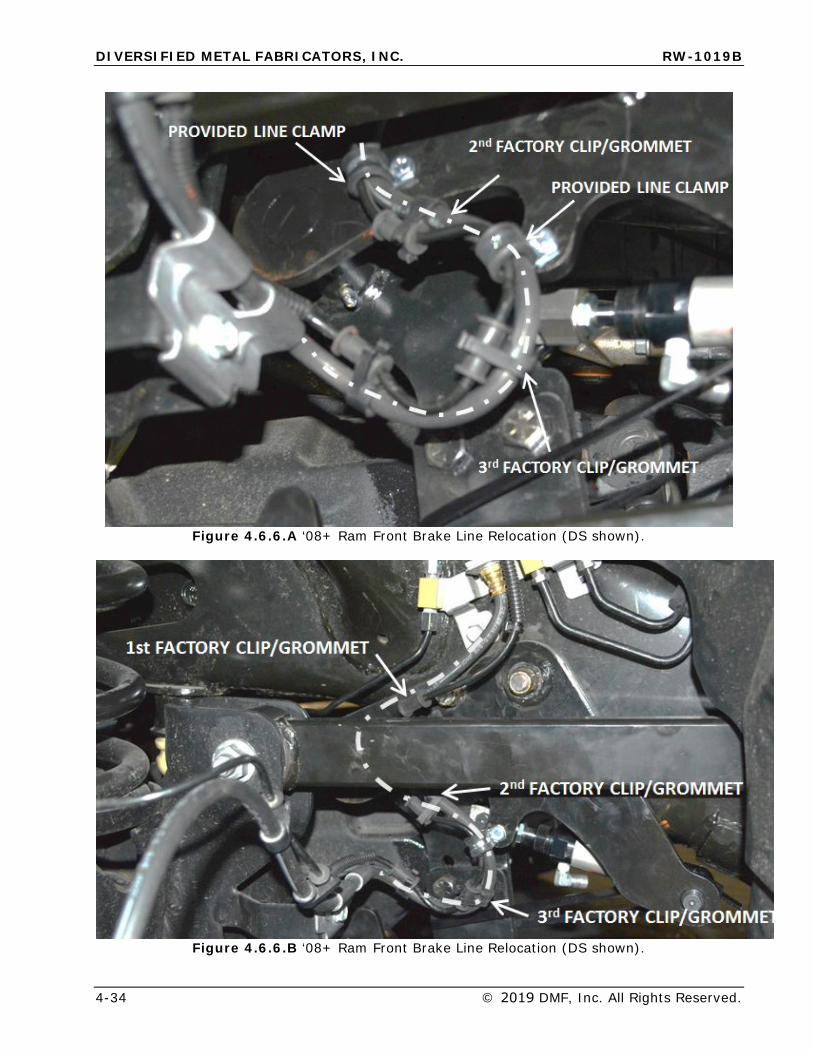
DIVERSIFIED METAL FABRICATORS, INC. RW-1019B
4-34 © 2019 DMF, Inc. All Rights Reserved.
Figure 4.6.6.A ‘08+ Ram Front Brake Line Relocation (DS shown).
Figure 4.6.6.B ‘08+ Ram Front Brake Line Relocation (DS shown).
DIVERSIFIED METAL FABRICATORS, INC. RW-1019B
© 2019 DMF, Inc. All Rights Reserved. 4-35
4.7 HYDRAULIC & ELECTRICAL SYSTEM INSTALLATION Please see Section 6 for hydraulic/electric system schematics and component diagrams. DMF recommends installing both the hydraulic and electrical systems before attempting to align or rail test the vehicle.
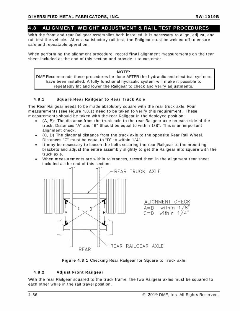
DIVERSIFIED METAL FABRICATORS, INC. RW-1019B
4-36 © 2019 DMF, Inc. All Rights Reserved.
4.8 ALIGNMENT, WEIGHT ADJUSTMENT & RAIL TEST PROCEDURES With the front and rear Railgear assemblies both installed, it is necessary to align, adjust, and rail test the vehicle. After a satisfactory rail test, the Railgear must be welded off to ensure safe and repeatable operation.
When performing the alignment procedure, record final alignment measurements on the tear sheet included at the end of this section and provide it to customer.
NOTE: DMF Recommends these procedures be done AFTER the hydraulic and electrical systems
have been installed. A fully functional hydraulic system will make it possible to repeatedly lift and lower the Railgear to check and verify adjustments.
4.8.1 Square Rear Railgear to Rear Truck Axle
The Rear Railgear needs to be made absolutely square with the rear truck axle. Four measurements (see Figure 4.8.1) need to be taken to verify this requirement. These measurements should be taken with the rear Railgear in the deployed position:
• (A, B): The distance from the truck axle to the rear Railgear axle on each side of thetruck. Distances “A” and “B” Should be equal to within 1/8”. This is an importantalignment check.
• (C, D) The diagonal distance from the truck axle to the opposite Rear Rail Wheel.Distances “C” must be equal to “D” to within 1/4”.
• It may be necessary to loosen the bolts securing the rear Railgear to the mountingbrackets and adjust the entire assembly slightly to get the Railgear into square with thetruck axle.
• When measurements are within tolerances, record them in the alignment tear sheetincluded at the end of this section.
Figure 4.8.1 Checking Rear Railgear for Square to Truck axle
4.8.2 Adjust Front Railgear
With the rear Railgear squared to the truck frame, the two Railgear axles must be squared to each other while in the rail travel position.
DIVERSIFIED METAL FABRICATORS, INC. RW-1019B
© 2019 DMF, Inc. All Rights Reserved. 4-37
First, center the front Railgear axle. Deploy the front Railgear and measure from the outboard wheel faces to the truck frame on each side of the truck. Raise the Railgear and slide axle side-to-side until measurements are equal on both sides of the truck. Re-check measurements in deployed position. Repeat as necessary to get equal measurements in deployed position.
Measure diagonally and linearly between convenient, repeatable points on the Railgear axles. Use the adjustment bolts on the front pivot arms to bring the diagonal measurements into tolerance. See drawings at the end of this section for additional information.
• All four adjustment bolt heads must contact the frame brackets.• Secure the locknuts against the hex stops when adjustment is complete.
Tack weld pivot arms to axle tubes in several places to hold alignment during rail testing.
4.8.3 Adjust Rear Weight Settings
With both sets of Railgear installed and aligned, it is necessary to adjust the rear weight setting of the rear Railgear to maintain a proper weight distribution between the guide wheels and vehicle tires. See the drawings at the end of this section for proper weight adjustment.
NOTE: ½” minimum of spacer should be installed during installation on a new vehicle. This will
allow for additional adjustment as suspension components wear and settle.
After adjusting the rear weight settings, re-check and correct the alignment as necessary.
4.8.4 Rail Test and Final Weld-Out
After aligning the Railgear and tacking components in place, put the vehicle on a segment of suitable test track and run the following tests:
• Run vehicle forwards and backwards on rail.• If available, run the vehicle through curves and switches.• Verify that the vehicle has sufficient traction to accelerate and brake smoothly and
within acceptable distances.• Verify alignment by observing the wear pattern on the wheel and the behavior of the
vehicle. If adjustment re-check alignment and weight settings.
After the Railgear has been aligned and tested satisfactorily on rail, it is necessary to perform final welding procedures to ensure the safe and repeatable operation.
Rear Weld-Out After final alignment and weight setting, the spacers need to be welded to the H-bracket. Ensure each spacer is evenly aligned with the inner edge of the H-bracket and weld spacer to the H-bracket. If multiple spacers are used, the spacers need to be welded together. See drawing M1019B04 on following pages for additional information.
Front Weld-Out Weld the pivot arms to the axle tubes, completely around, where indicated on drawing M1019B11.
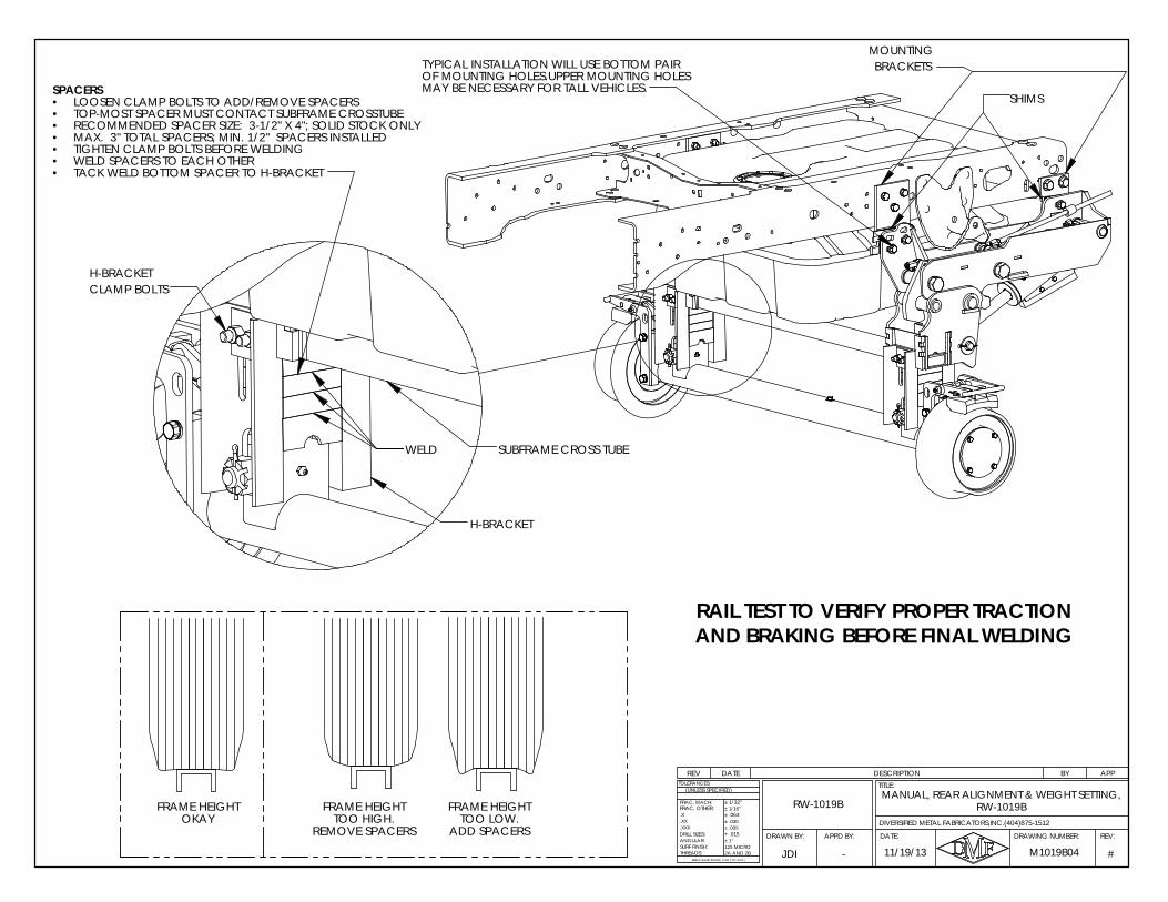
REV DATE DESCRIPTION BY APP
FRAME HEIGHT TOO LOW.
ADD SPACERS
FRAME HEIGHT TOO HIGH.
REMOVE SPACERS
FRAME HEIGHT OKAY
RAIL TEST TO VERIFY PROPER TRACTION AND BRAKING BEFORE FINAL WELDING
RW-1019BMANUAL, REAR ALIGNMENT & WEIGHT SETTING,
RW-1019B
APPD BY:DRAWN BY:
11/19/13 #
.X
ANGULAR:
BREAK SHARP EDGES ( 0.030 X 45° MAX )
± 1/16"
± .005± .030
+ .015
± 1/32"
± .063
± 1°
2A AND 2B125 MICRO
DRILL SIZES:
SURF FINISH:THREADS:
.XXX
.XX
TOLERANCES:
FRAC, MACH:
(UNLESS SPECIFIED)
DIVERSIFIED METAL FABRICATORS,INC.(404)875-1512
FRAC, OTHER:
M1019B04JDI
REV:DRAWING NUMBER:
TITLE:
DATE:
-
TYPICAL INSTALLATION WILL USE BOTTOM PAIR BRACKETS
SHIMS
MOUNTING
MAY BE NECESSARY FOR TALL VEHICLES.OF MOUNTING HOLES.UPPER MOUNTING HOLES
H-BRACKET
CLAMP BOLTS
WELD
H-BRACKET
SUBFRAME CROSS TUBE
SPACERSLOOSEN CLAMP BOLTS TO ADD/REMOVE SPACERS•TOP-MOST SPACER MUST CONTACT SUBFRAME CROSSTUBE•RECOMMENDED SPACER SIZE: 3-1/2" X 4"; SOLID STOCK ONLY•MAX. 3" TOTAL SPACERS; MIN. 1/2" SPACERS INSTALLED•TIGHTEN CLAMP BOLTS BEFORE WELDING•WELD SPACERS TO EACH OTHER•TACK WELD BOTTOM SPACER TO H-BRACKET •
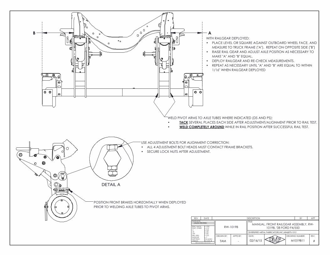
POSITION FRONT BRAKES HORIZONTALLY WHEN DEPLOYED PRIOR TO WELDING AXLE TUBES TO PIVOT ARMS.
A B
WELD PIVOT ARMS TO AXLE TUBES WHERE INDICATED (DS AND PS):TACK SEVERAL PLACES EACH SIDE AFTER ADJUSTMENT/ALIGNMENT PRIOR TO RAIL TEST.•WELD COMPLETELY AROUND WHILE IN RAIL POSITION AFTER SUCCESSFUL RAIL TEST.•
DETAIL A
USE ADJUSTMENT BOLTS FOR ALIGNMENT CORRECTION:ALL 4 ADJUSTMENT BOLT HEADS MUST CONTACT FRAME BRACKETS.•SECURE LOCK NUTS AFTER ADJUSTMENT.•
WITH RAILGEAR DEPLOYED:PLACE LEVEL OR SQUARE AGAINST OUTBOARD WHEEL FACE, AND •MEASURE TO TRUCK FRAME ("A"). REPEAT ON OPPOSITE SIDE ("B")RAISE RAIL GEAR AND ADJUST AXLE POSITION AS NECESSARY TO •MAKE "A" AND "B" EQUAL.DEPLOY RAILGEAR AND RE-CHECK MEASUREMENTS.•REPEAT AS NECESSARY UNTIL "A" AND "B" ARE EQUAL TO WITHIN •1/16" WHEN RAILGEAR DEPLOYED
REV DATE DESCRIPTION BY APP
#
.X
ANGULAR:
BREAK SHARP EDGES ( 0.030 X 45° MAX )
± 1/16"
± .005± .030
+ .015
± 1/32"
± .063
± 1°
2A AND 2B125 MICRO
DRILL SIZES:
SURF FINISH:THREADS:
.XXX
.XX
TOLERANCES:
FRAC, MACH:
(UNLESS SPECIFIED)
FRAC, OTHER:
02/16/15 M1019B11TAM
REV:DRAWING NUMBER:
TITLE:
DATE:APPD BY:DRAWN BY:
DIVERSIFIED METAL FABRICATORS,INC.(404)875-1512
-
MANUAL, FRONT RAILGEAR ASSEMBLY, RW-1019B, '08 FORD F4/550RW-1019B
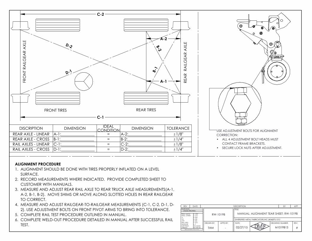
C-2
C-1
A-2
A-1
D-2
D-1
FRO
NT
RAIL
GEA
R A
XLE
REA
R R
AIL
GEA
R A
XLE
FRONT TIRES REAR TIRES
B-1
B-2
USE ADJUSTMENT BOLTS FOR ALIGNMENT CORRECTION:
ALL 4 ADJUSTMENT BOLT HEADS MUST •CONTACT FRAME BRACKETS.SECURE LOCK NUTS AFTER ADJUSTMENT.•
ALIGNMENT PROCEDUREALIGNMENT SHOULD BE DONE WITH TIRES PROPERLY INFLATED ON A LEVEL 1.SURFACE.RECORD MEASUREMENTS WHERE INDICATED. PROVIDE COMPLETED SHEET TO 2.CUSTOMER WITH MANUALS.MEASURE AND ADJUST REAR RAIL AXLE TO REAR TRUCK AXLE MEASUREMENTS(A-1, 3.A-2, B-1, B-2). MOVE SHIMS OR MOVE ALONG SLOTTED HOLES IN REAR RAILGEAR TO CORRECT.MEASURE AND ADJUST RAILGEAR-TO-RAILGEAR MEASUREMENTS (C-1, C-2, D-1, D-4.2). USE ADJUSTMENT BOLTS ON FRONT PIVOT ARMS TO BRING INTO TOLERANCE.COMPLETE RAIL TEST PROCEDURE OUTLINED IN MANUAL.5.COMPLETE WELD-OUT PROCEDURE DETAILED IN MANUAL AFTER SUCCESSFUL RAIL 6.TEST.
REV DATE DESCRIPTION BY APP
DISCRIPTION DIMENSION IDEAL CONDITION DIMENSION TOLERANCE
REAR AXLE - LINEAR A-1: = A-2: 1/8"REAR AXLE - CROSS B-1: = B-2: 1/4"RAIL AXLES - LINEAR C-1: = C-2: 1/8"RAIL AXLES - CROSS D-1: = D-2: 1/4"
#
.X
ANGULAR:
BREAK SHARP EDGES ( 0.030 X 45° MAX )
± 1/16"
± .005± .030
+ .015
± 1/32"
± .063
± 1°
2A AND 2B125 MICRO
DRILL SIZES:
SURF FINISH:THREADS:
.XXX
.XX
TOLERANCES:
FRAC, MACH:
(UNLESS SPECIFIED)
FRAC, OTHER:
02/27/15 M1019B13TAM
REV:DRAWING NUMBER:
TITLE:
DATE:APPD BY:DRAWN BY:
DIVERSIFIED METAL FABRICATORS,INC.(404)875-1512
-
MANUAL; ALIGNMENT TEAR SHEET; RW-1019BRW-1019B
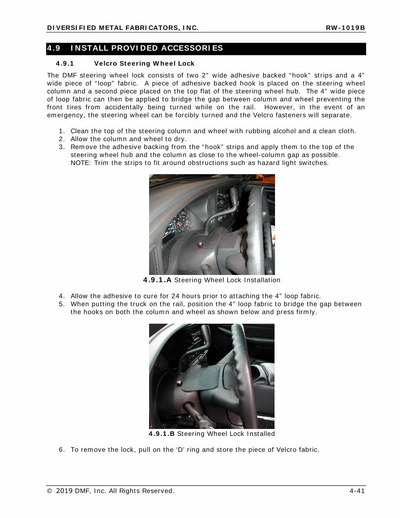
DIVERSIFIED METAL FABRICATORS, INC. RW-1019B
© 2019 DMF, Inc. All Rights Reserved. 4-41
4.9 INSTALL PROVIDED ACCESSORIES
4.9.1 Velcro Steering Wheel Lock
The DMF steering wheel lock consists of two 2” wide adhesive backed “hook” strips and a 4” wide piece of “loop” fabric. A piece of adhesive backed hook is placed on the steering wheel column and a second piece placed on the top flat of the steering wheel hub. The 4” wide piece of loop fabric can then be applied to bridge the gap between column and wheel preventing the front tires from accidentally being turned while on the rail. However, in the event of an emergency, the steering wheel can be forcibly turned and the Velcro fasteners will separate.
1. Clean the top of the steering column and wheel with rubbing alcohol and a clean cloth.2. Allow the column and wheel to dry.3. Remove the adhesive backing from the “hook” strips and apply them to the top of the
steering wheel hub and the column as close to the wheel-column gap as possible.NOTE: Trim the strips to fit around obstructions such as hazard light switches.
4.9.1.A Steering Wheel Lock Installation
4. Allow the adhesive to cure for 24 hours prior to attaching the 4” loop fabric.5. When putting the truck on the rail, position the 4” loop fabric to bridge the gap between
the hooks on both the column and wheel as shown below and press firmly.
4.9.1.B Steering Wheel Lock Installed
6. To remove the lock, pull on the ‘D’ ring and store the piece of Velcro fabric.
DIVERSIFIED METAL FABRICATORS, INC. RW-1019B
4-42 © 2019 DMF, Inc. All Rights Reserved.
4.9.2 Install Operation and Safety Decals
Install the provided operation and safety decals where shown on the following pages. Surfaces should be clean of oil and dirt before application.
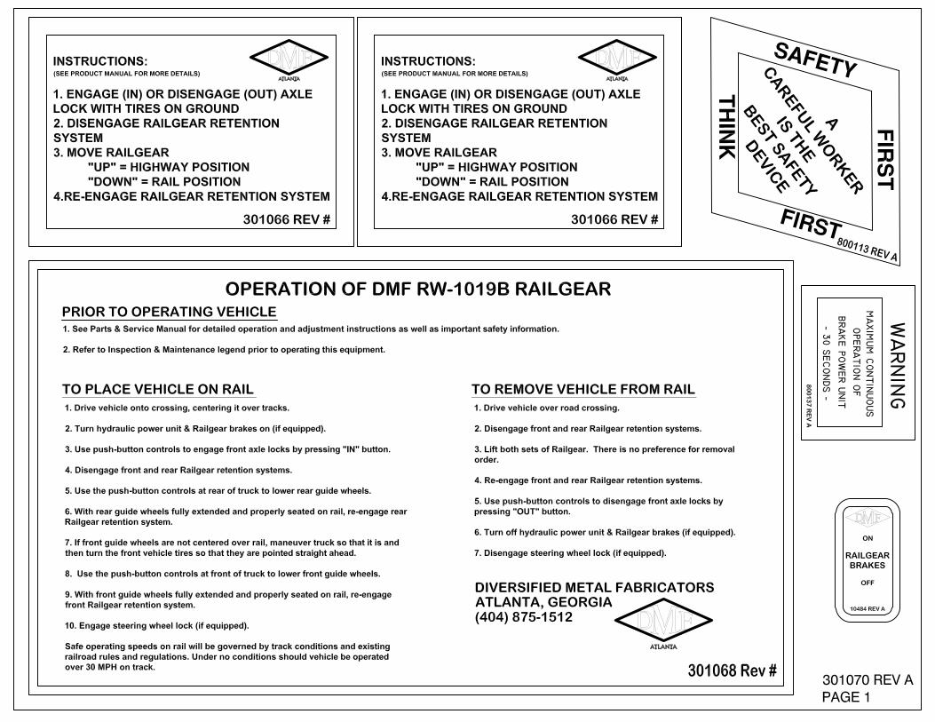
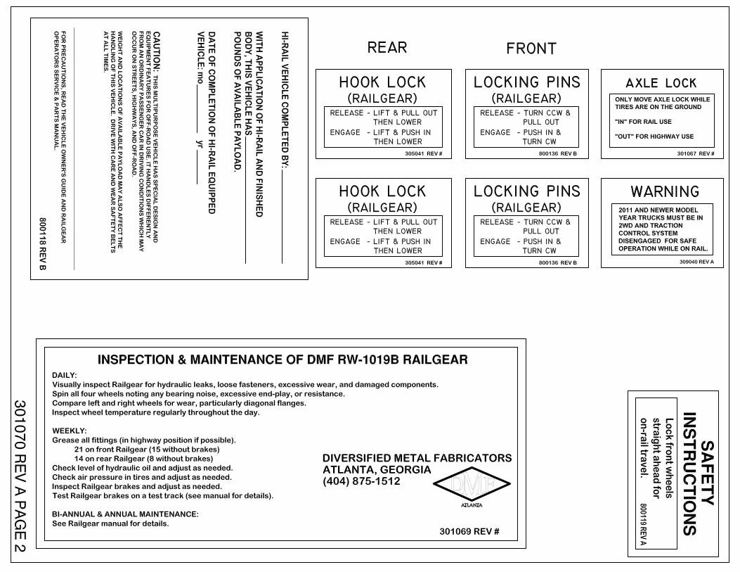
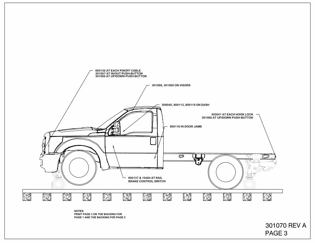
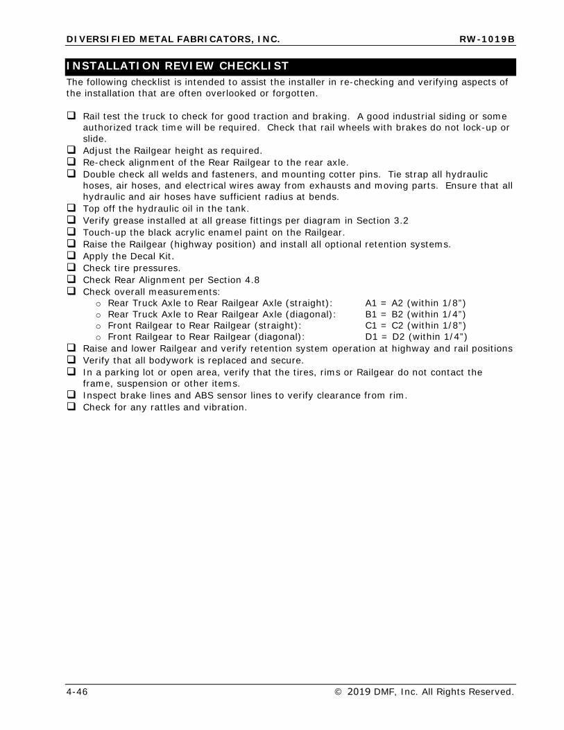
DIVERSIFIED METAL FABRICATORS, INC. RW-1019B
4-46 © 2019 DMF, Inc. All Rights Reserved.
INSTALLATION REVIEW CHECKLIST The following checklist is intended to assist the installer in re-checking and verifying aspects of the installation that are often overlooked or forgotten.
Rail test the truck to check for good traction and braking. A good industrial siding or someauthorized track time will be required. Check that rail wheels with brakes do not lock-up orslide.Adjust the Railgear height as required.Re-check alignment of the Rear Railgear to the rear axle.Double check all welds and fasteners, and mounting cotter pins. Tie strap all hydraulichoses, air hoses, and electrical wires away from exhausts and moving parts. Ensure that allhydraulic and air hoses have sufficient radius at bends.Top off the hydraulic oil in the tank.Verify grease installed at all grease fittings per diagram in Section 3.2Touch-up the black acrylic enamel paint on the Railgear.Raise the Railgear (highway position) and install all optional retention systems.Apply the Decal Kit.Check tire pressures.Check Rear Alignment per Section 4.8Check overall measurements:
o Rear Truck Axle to Rear Railgear Axle (straight): A1 = A2 (within 1/8”) o Rear Truck Axle to Rear Railgear Axle (diagonal): B1 = B2 (within 1/4”) o Front Railgear to Rear Railgear (straight): C1 = C2 (within 1/8”) o Front Railgear to Rear Railgear (diagonal): D1 = D2 (within 1/4”)
Raise and lower Railgear and verify retention system operation at highway and rail positionsVerify that all bodywork is replaced and secure.In a parking lot or open area, verify that the tires, rims or Railgear do not contact theframe, suspension or other items.Inspect brake lines and ABS sensor lines to verify clearance from rim.Check for any rattles and vibration.
DIVERSIFIED METAL FABRICATORS, INC. RW-1019B
© 2019 DMF, Inc. All Rights Reserved. 5-1
SECTION 5.0 RAILGEAR OPTIONS 5.1 RAIL SWEEPS ................................................................................................. 5-2
5.1.1 Rail Sweep Adjustment .................................................................................. 5-2 5.1.2 Rail Sweep Parts ........................................................................................... 5-2
5.2 RAIL BRAKES ................................................................................................. 5-5
5.2.1 Brake Adjustment ......................................................................................... 5-5 5.2.2 Brake Parts .................................................................................................. 5-5
5.3 PIN OFFS ........................................................................................................ 5-8
5.3.1 Rear Pin Offs ................................................................................................ 5-8 5.3.2 Front Pin Offs ............................................................................................. 5-14
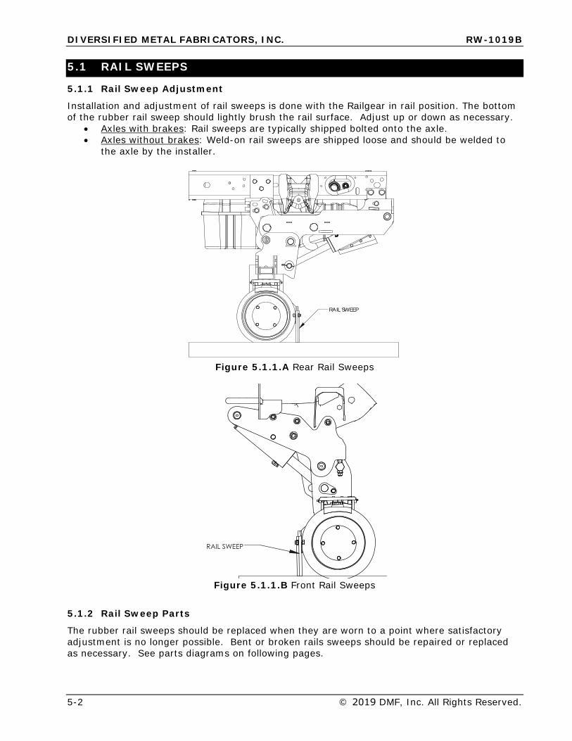
DIVERSIFIED METAL FABRICATORS, INC. RW-1019B
5-2 © 2019 DMF, Inc. All Rights Reserved.
5.1 RAIL SWEEPS
5.1.1 Rail Sweep Adjustment
Installation and adjustment of rail sweeps is done with the Railgear in rail position. The bottom of the rubber rail sweep should lightly brush the rail surface. Adjust up or down as necessary.
• Axles with brakes: Rail sweeps are typically shipped bolted onto the axle.• Axles without brakes: Weld-on rail sweeps are shipped loose and should be welded to
the axle by the installer.
RAIL SWEEP
Figure 5.1.1.A Rear Rail Sweeps
�������
Figure 5.1.1.B Front Rail Sweeps
5.1.2 Rail Sweep Parts
The rubber rail sweeps should be replaced when they are worn to a point where satisfactory adjustment is no longer possible. Bent or broken rails sweeps should be repaired or replaced as necessary. See parts diagrams on following pages.
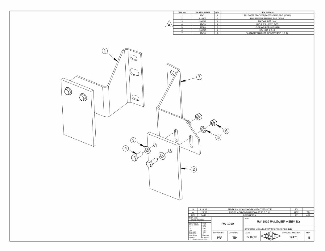
RW-1019 RAILSWEEP ASSEMBLYRW-1019
DRAWN BY:
FRAC, OTHER:
B
.X
ANGULAR:
BREAK SHARP EDGES ( 0.030 X 45° MAX )
± 1/16"
± .005± .030
+ .015
± 1/32"
± .063
± 1°
2A AND 2B125 MICRO
DRILL SIZES:
SURF FINISH:THREADS:
.XXX
.XX
TOLERANCES:
FRAC, MACH:
(UNLESS SPECIFIED)
DIVERSIFIED METAL FABRICATORS,INC.(404)875-1512
124763/16/95PRP
REV:DRAWING NUMBER:
TITLE:
DATE:APPD BY:
TSH
DESCRIPTION BY APP
B 5/13/13
REV
JDIA 1/25/96 ADDED MOUNTING HARDWARE TO B.O.M. MRV TSH
DATE
REDRAWN IN SOLIDWORKS, REMOVED NOTE
ITEM NO. PART NUMBER QTY. DESCRIPTION1 12471 1 RAILSWEEP BRACKET (PASSENGER'S SIDE) (10HD)2 818503 2 RAILSWEEP RUBBER BELTING DETAIL3 106241 4 FLAT WASHER, 3/8"4 12475 4 HHCS, 3/8-16 X 1", GR55 12566 4 LOCK WASHER, 3/8", GR86 106243 4 HEX NUT, 3/8-167 12470 1 RAILSWEEP BRACKET (DRIVER'S SIDE) (10HD)
2
4
5
7
1
6
3
A
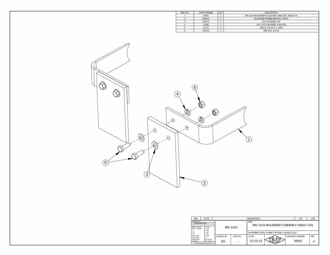
APPBYDESCRIPTIONDATEREV
ITEM NO. PART NUMBER QTY. DESCRIPTION1 10042 2 RW-1019 RAILSWEEP MOUNTING BRACKET, WELD ON2 818503 2 RAILSWEEP RUBBER BELTING DETAIL3 106241 4 FLAT WASHER, 3/8"4 12566 4 3/8" LOCK WASHER, GRADE 85 12475 4 HHCS, 3/8-16 X 1", GR56 106243 4 HEX NUT, 3/8-16
RW-1019 RAILSWEEP ASSEMBLY (WELD ON)RW-1019
DRAWN BY:
12/12/13 #
.X
ANGULAR:
BREAK SHARP EDGES ( 0.030 X 45° MAX )
± 1/16"
± .005± .030
+ .015
± 1/32"
± .063
± 1°
2A AND 2B125 MICRO
DRILL SIZES:
SURF FINISH:THREADS:
.XXX
.XX
TOLERANCES:
FRAC, MACH:
(UNLESS SPECIFIED)
10053
FRAC, OTHER:
DIVERSIFIED METAL FABRICATORS,INC.(404)875-1512
JDI
REV:DRAWING NUMBER:
TITLE:
DATE:APPD BY:
-
4
1
2
3
5
6
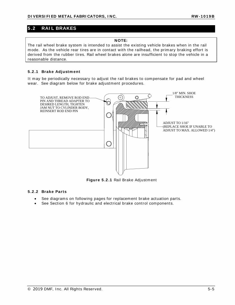
DIVERSIFIED METAL FABRICATORS, INC. RW-1019B
© 2019 DMF, Inc. All Rights Reserved. 5-5
5.2 RAIL BRAKES
NOTE: The rail wheel brake system is intended to assist the existing vehicle brakes when in the rail mode. As the vehicle rear tires are in contact with the railhead, the primary braking effort is derived from the rubber tires. Rail wheel brakes alone are insufficient to stop the vehicle in a reasonable distance.
5.2.1 Brake Adjustment
It may be periodically necessary to adjust the rail brakes to compensate for pad and wheel wear. See diagram below for brake adjustment procedures.
TO ADJUST, REMOVE ROD ENDPIN AND THREAD ADAPTER TO DESIRED LENGTH, TIGHTENJAM NUT TO CYLINDER BODY, REINSERT ROD END PIN
ADJUST TO MAX. ALLOWED 1/4")(REPLACE SHOE IF UNABLE TOADJUST TO 1/16"
1/8" MIN. SHOETHICKNESS
Figure 5.2.1 Rail Brake Adjustment
5.2.2 Brake Parts
• See diagrams on following pages for replacement brake actuation parts.• See Section 6 for hydraulic and electrical brake control components.
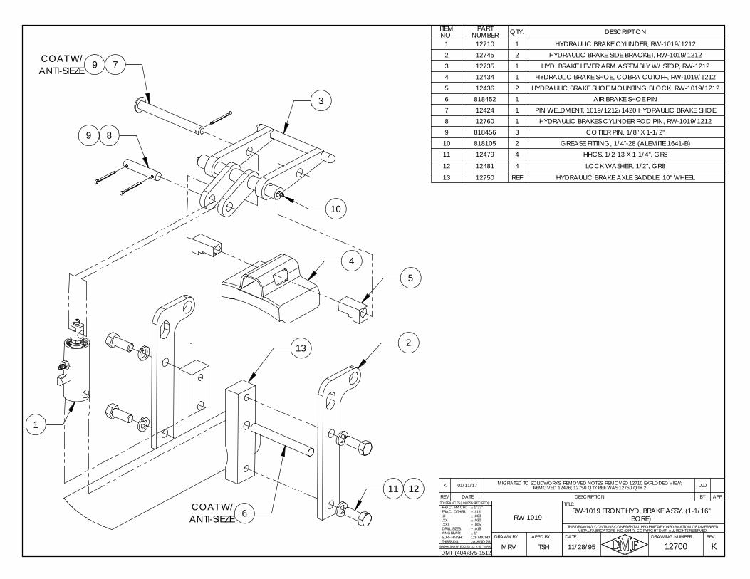
FRAC, OTHER:
BORE)
FRAC, MACH:
METAL FABRICATORS, INC (DMF). COPYRIGHT DMF, ALL RIGHTS RESERVED.
BREAK SHARP EDGES .03 X 45° MAX
THIS DRAWING CONTAINS CONFIDENTIAL PROPRIETARY INFORMATION OF DIVERSIFIED
12700REV:DRAWING NUMBER:
TITLE:
DRAWN BY:
11/28/95
RW-1019 FRONT HYD. BRAKE ASSY. (1-1/16"
KMRV
TOLERANCES (UNLESS SPECIFIED):
2A AND 2BDATE:APPD BY:
TSH
RW-1019.X.XX.XXXDRILL SIZES:ANGULAR:SURF FINISH:THREADS:
± 1/32"±1/16"± .063± .030± .005+ .015± 1°125 MICRO
DMF (404)875-1512
3
5
COAT W/ ANTI-SIEZE
2
8
9
10
9
7
11 12
6
1
4
13
COAT W/ ANTI-SIEZE
REV DATE DESCRIPTION BY APP
K 01/11/17 MIGRATED TO SOLIDWORKS; REMOVED NOTES; REMOVED 12710 EXPLODED VIEW; REMOVED 12476; 12750 QTY REF WAS 12750 QTY 2 DJJ
ITEM NO.
PART NUMBER QTY. DESCRIPTION
1 12710 1 HYDRAULIC BRAKE CYLINDER; RW-1019/12122 12745 2 HYDRAULIC BRAKE SIDE BRACKET, RW-1019/12123 12735 1 HYD. BRAKE LEVER ARM ASSEMBLY W/ STOP, RW-12124 12434 1 HYDRAULIC BRAKE SHOE, COBRA CUTOFF, RW-1019/12125 12436 2 HYDRAULIC BRAKE SHOE MOUNTING BLOCK, RW-1019/12126 818452 1 AIR BRAKE SHOE PIN7 12424 1 PIN WELDMENT, 1019/1212/1420 HYDRAULIC BRAKE SHOE8 12760 1 HYDRAULIC BRAKES CYLINDER ROD PIN, RW-1019/12129 818456 3 COTTER PIN, 1/8" X 1-1/2"10 818105 2 GREASE FITTING, 1/4"-28 (ALEMITE 1641-B)11 12479 4 HHCS, 1/2-13 X 1-1/4", GR8
12 12481 4 LOCK WASHER, 1/2", GR8
13 12750 REF HYDRAULIC BRAKE AXLE SADDLE, 10" WHEEL
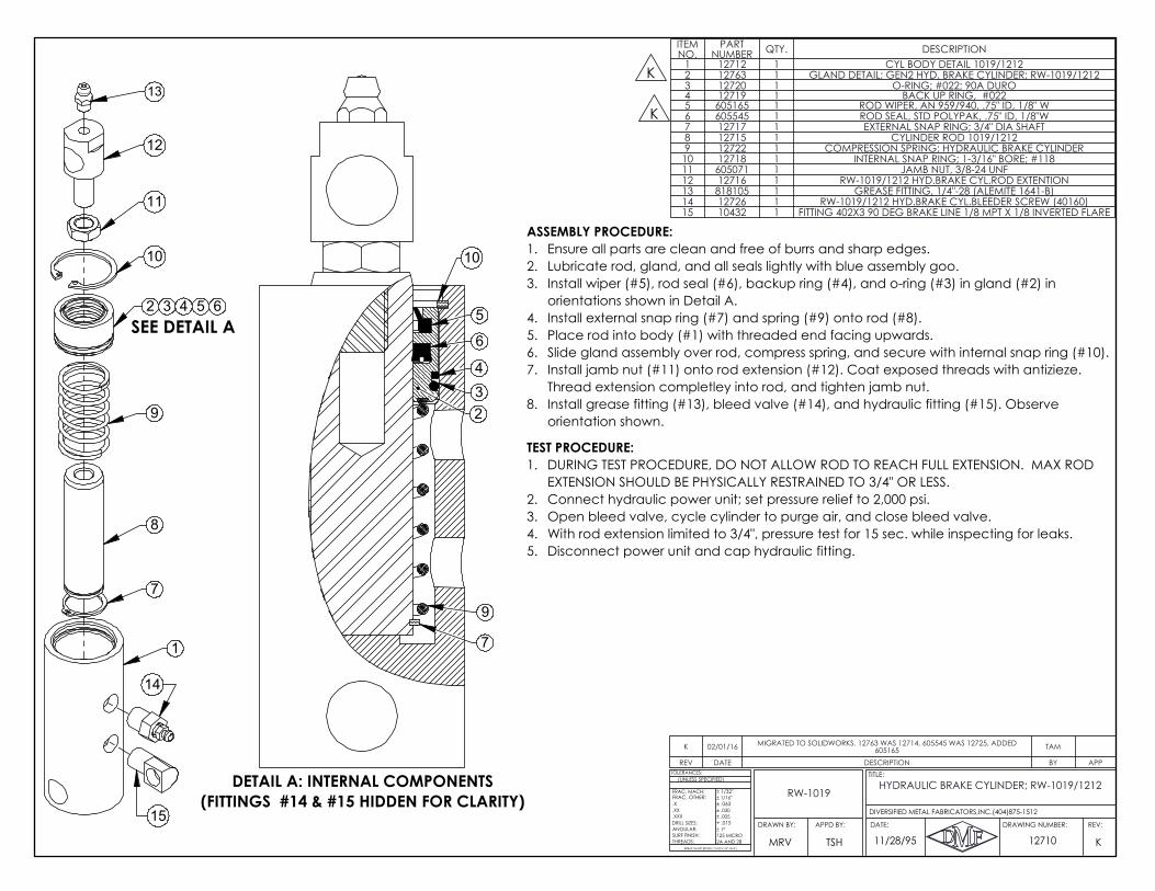
13
12
11
10
9
8
7
1
14
15
2 3 4 5 6SEE DETAIL A
5
6
43
10
2
7
9
DETAIL A: INTERNAL COMPONENTS(FITTINGS #14 & #15 HIDDEN FOR CLARITY)
ASSEMBLY PROCEDURE:Ensure all parts are clean and free of burrs and sharp edges.1.Lubricate rod, gland, and all seals lightly with blue assembly goo.2.Install wiper (#5), rod seal (#6), backup ring (#4), and o-ring (#3) in gland (#2) in 3.orientations shown in Detail A.Install external snap ring (#7) and spring (#9) onto rod (#8).4.Place rod into body (#1) with threaded end facing upwards.5.Slide gland assembly over rod, compress spring, and secure with internal snap ring (#10).6.Install jamb nut (#11) onto rod extension (#12). Coat exposed threads with antizieze. 7.Thread extension completley into rod, and tighten jamb nut.Install grease fitting (#13), bleed valve (#14), and hydraulic fitting (#15). Observe 8.orientation shown.
TEST PROCEDURE:DURING TEST PROCEDURE, DO NOT ALLOW ROD TO REACH FULL EXTENSION. MAX ROD 1.EXTENSION SHOULD BE PHYSICALLY RESTRAINED TO 3/4" OR LESS.Connect hydraulic power unit; set pressure relief to 2,000 psi.2.Open bleed valve, cycle cylinder to purge air, and close bleed valve.3.With rod extension limited to 3/4", pressure test for 15 sec. while inspecting for leaks.4.Disconnect power unit and cap hydraulic fitting.5.
K
K
REV DATE DESCRIPTION BY APP
K 02/01/16 MIGRATED TO SOLIDWORKS. 12763 WAS 12714, 605545 WAS 12725, ADDED 605165 TAM
ITEM NO.
PART NUMBER QTY. DESCRIPTION
1 12712 1 CYL BODY DETAIL 1019/12122 12763 1 GLAND DETAIL; GEN2 HYD. BRAKE CYLINDER; RW-1019/12123 12720 1 O-RING; #022; 90A DURO4 12719 1 BACK UP RING, #0225 605165 1 ROD WIPER, AN 959/940, .75" ID, 1/8" W6 605545 1 ROD SEAL, STD POLYPAK, .75" ID, 1/8"W7 12717 1 EXTERNAL SNAP RING; 3/4" DIA SHAFT8 12715 1 CYLINDER ROD 1019/12129 12722 1 COMPRESSION SPRING; HYDRAULIC BRAKE CYLINDER10 12718 1 INTERNAL SNAP RING; 1-3/16" BORE; #11811 605071 1 JAMB NUT, 3/8-24 UNF12 12716 1 RW-1019/1212 HYD.BRAKE CYL.ROD EXTENTION13 818105 1 GREASE FITTING, 1/4"-28 (ALEMITE 1641-B)14 12726 1 RW-1019/1212 HYD.BRAKE CYL.BLEEDER SCREW (40160)15 10432 1 FITTING 402X3 90 DEG BRAKE LINE 1/8 MPT X 1/8 INVERTED FLARE
K
.X
ANGULAR:
BREAK SHARP EDGES ( 0.030 X 45° MAX )
± 1/16"
± .005± .030
+ .015
± 1/32"
± .063
± 1°
2A AND 2B125 MICRO
DRILL SIZES:
SURF FINISH:THREADS:
.XXX
.XX
TOLERANCES:
FRAC, MACH:
(UNLESS SPECIFIED)
FRAC, OTHER:
11/28/95 12710MRV
REV:DRAWING NUMBER:
TITLE:
DATE:APPD BY:DRAWN BY:
DIVERSIFIED METAL FABRICATORS,INC.(404)875-1512
TSH
HYDRAULIC BRAKE CYLINDER; RW-1019/1212RW-1019
DIVERSIFIED METAL FABRICATORS, INC. RW-1019B
5-8 © 2019 DMF, Inc. All Rights Reserved.
5.3 PIN OFFS
NOTE:
DMF Recommends final installation of the front and rear pin off systems AFTER body equipment, bumpers, and hitches have been (re)installed. A functional Railgear
hydraulic system is necessary to test and adjust the pin offs.
5.3.1 Rear Pin Offs
In standard configurations, RW-1019B rear Railgear uses a hook lock retention system, referred to for simplicity as a pin off.
A rearward pair of hooks (one on each side of the truck) secures the Railgear when in the highway position. A single forward hook (driver’s side only) secures the Railgear when in the rail position. The Rear Pin Offs should always remain engaged except when the Railgear is being operated. After it has been deployed or stowed the Pin Offs must be re-engaged for safe operation of the vehicle.
Hook Lock Pin Offs – Spring Detent Cable
This Pin Off uses a spring to keep the hook locks engaged when the cable is extended. The cable itself is flexible allowing the handle to be routed to an easily accessible location at the rear of the truck. The handle locking feature should be used to temporarily disengage the hook locks while operating the Railgear.
After installation, as detailed by the following pages, the travel of each Pin Off must be evaluated and adjusted as necessary.
Hook Lock Pin Offs - Manual
This Pin Off provides a long threaded rod that may be cut and bent as necessary to run to an accessible location at the rear of the truck. The modified rod should be welded to the factory installed intermediate rod coupler. Keyhole plates and adjustable stops are provided to terminate the rods.
Pin Off component diagrams and adjustment instructions can be found in the following pages.
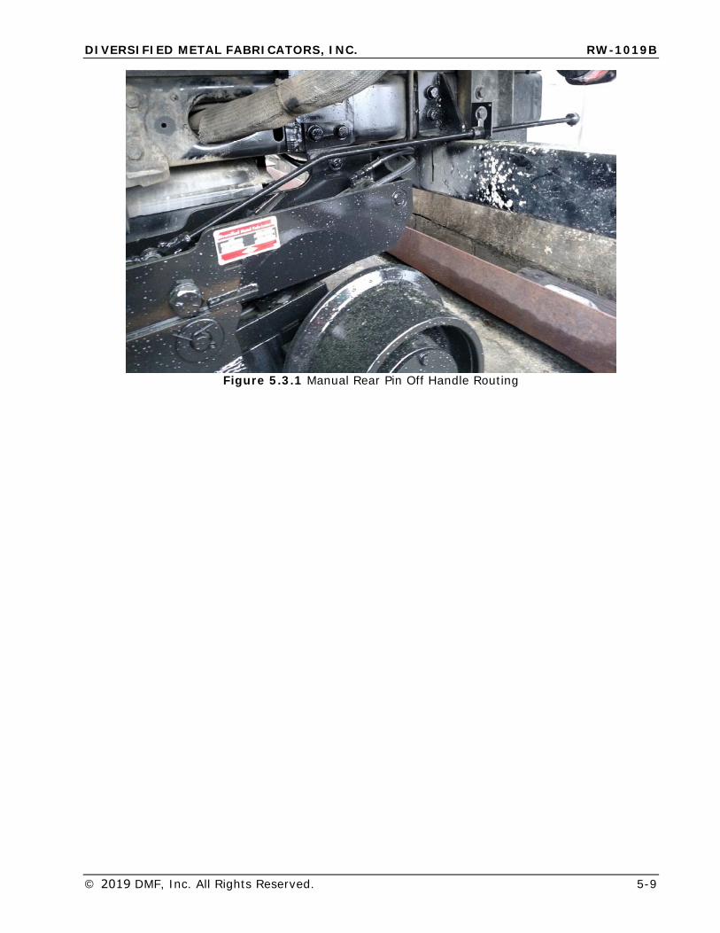
DIVERSIFIED METAL FABRICATORS, INC. RW-1019B
© 2019 DMF, Inc. All Rights Reserved. 5-9
Figure 5.3.1 Manual Rear Pin Off Handle Routing
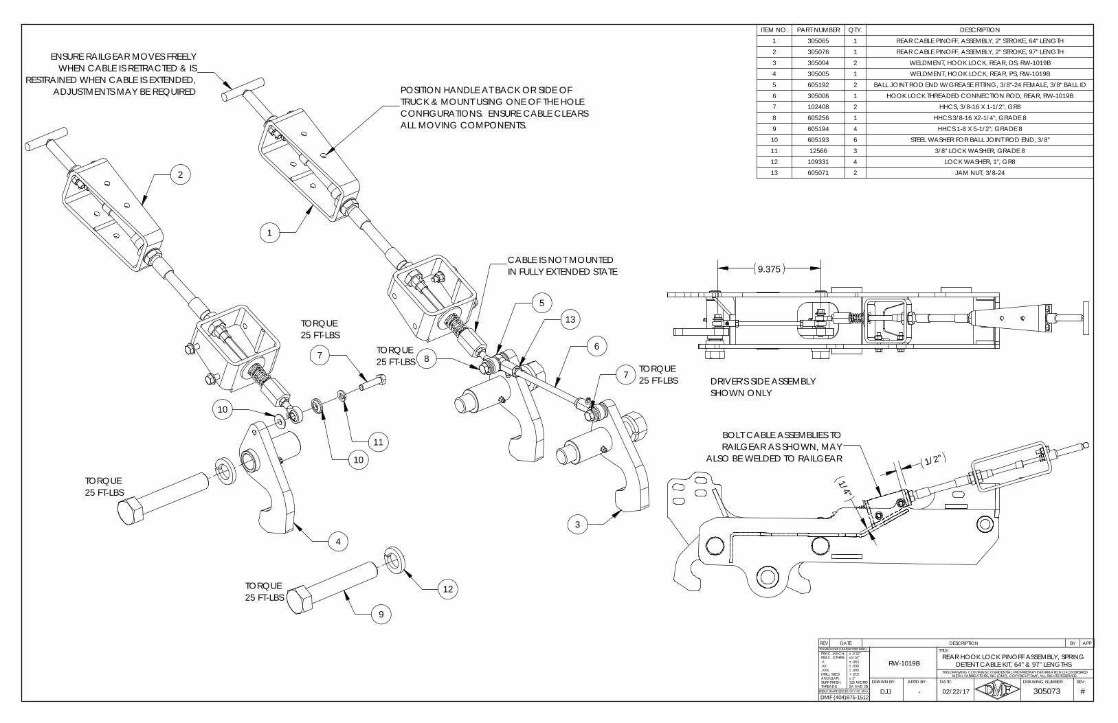
FRAC, MACH:
THIS DRAWING CONTAINS CONFIDENTIAL PROPRIETARY INFORMATION OF DIVERSIFIED
BREAK SHARP EDGES .03 X 45° MAX2A AND 2B
305073REV:DRAWING NUMBER:
TITLE:
DATE:APPD BY:
DETENT CABLE KIT, 64" & 97" LENGTHS
#
TOLERANCES (UNLESS SPECIFIED):
METAL FABRICATORS, INC (DMF). COPYRIGHT DMF, ALL RIGHTS RESERVED.
DJJ -
RW-1019B
DRAWN BY:
FRAC, OTHER:
02/22/17
REAR HOOK LOCK PINOFF ASSEMBLY, SPRING .X.XX.XXXDRILL SIZES:ANGULAR:SURF FINISH:THREADS:
± 1/32"±1/16"± .063± .030± .005+ .015± 1°125 MICRO
DMF (404)875-1512
REV DATE DESCRIPTION BY APP
ITEM NO. PART NUMBER QTY. DESCRIPTION
1 305065 1 REAR CABLE PINOFF, ASSEMBLY, 2" STROKE, 64" LENGTH
2 305076 1 REAR CABLE PINOFF, ASSEMBLY, 2" STROKE, 97" LENGTH
3 305004 2 WELDMENT, HOOK LOCK, REAR, DS, RW-1019B
4 305005 1 WELDMENT, HOOK LOCK, REAR, PS, RW-1019B
5 605192 2 BALL JOINT ROD END W/GREASE FITTING, 3/8"-24 FEMALE, 3/8" BALL ID
6 305006 1 HOOK LOCK THREADED CONNECTION ROD, REAR, RW-1019B
7 102408 2 HHCS, 3/8-16 X 1-1/2", GR8
8 605256 1 HHCS 3/8-16 X2-1/4", GRADE 8
9 605194 4 HHCS 1-8 X 5-1/2"; GRADE 8
10 605193 6 STEEL WASHER FOR BALL JOINT ROD END, 3/8"
11 12566 3 3/8" LOCK WASHER, GRADE 8
12 109331 4 LOCK WASHER, 1", GR8
13 605071 2 JAM NUT, 3/8-24
POSITION HANDLE AT BACK OR SIDE OF TRUCK & MOUNT USING ONE OF THE HOLE
25 FT-LBSTORQUE
25 FT-LBSTORQUE
CABLE IS NOT MOUNTED IN FULLY EXTENDED STATE
25 FT-LBSTORQUE
CONFIGURATIONS. ENSURE CABLE CLEARS ALL MOVING COMPONENTS.
3
4
9
12
2
10
10
11
76
13
5
8
7
RESTRAINED WHEN CABLE IS EXTENDED, ADJUSTMENTS MAY BE REQUIRED
TORQUE25 FT-LBS
25 FT-LBSTORQUE
ENSURE RAILGEAR MOVES FREELY WHEN CABLE IS RETRACTED & IS
1
DRIVER'S SIDE ASSEMBLY SHOWN ONLY
9.375
BOLT CABLE ASSEMBLIES TO RAILGEAR AS SHOWN, MAY
ALSO BE WELDED TO RAILGEAR 1/2"
1/4"
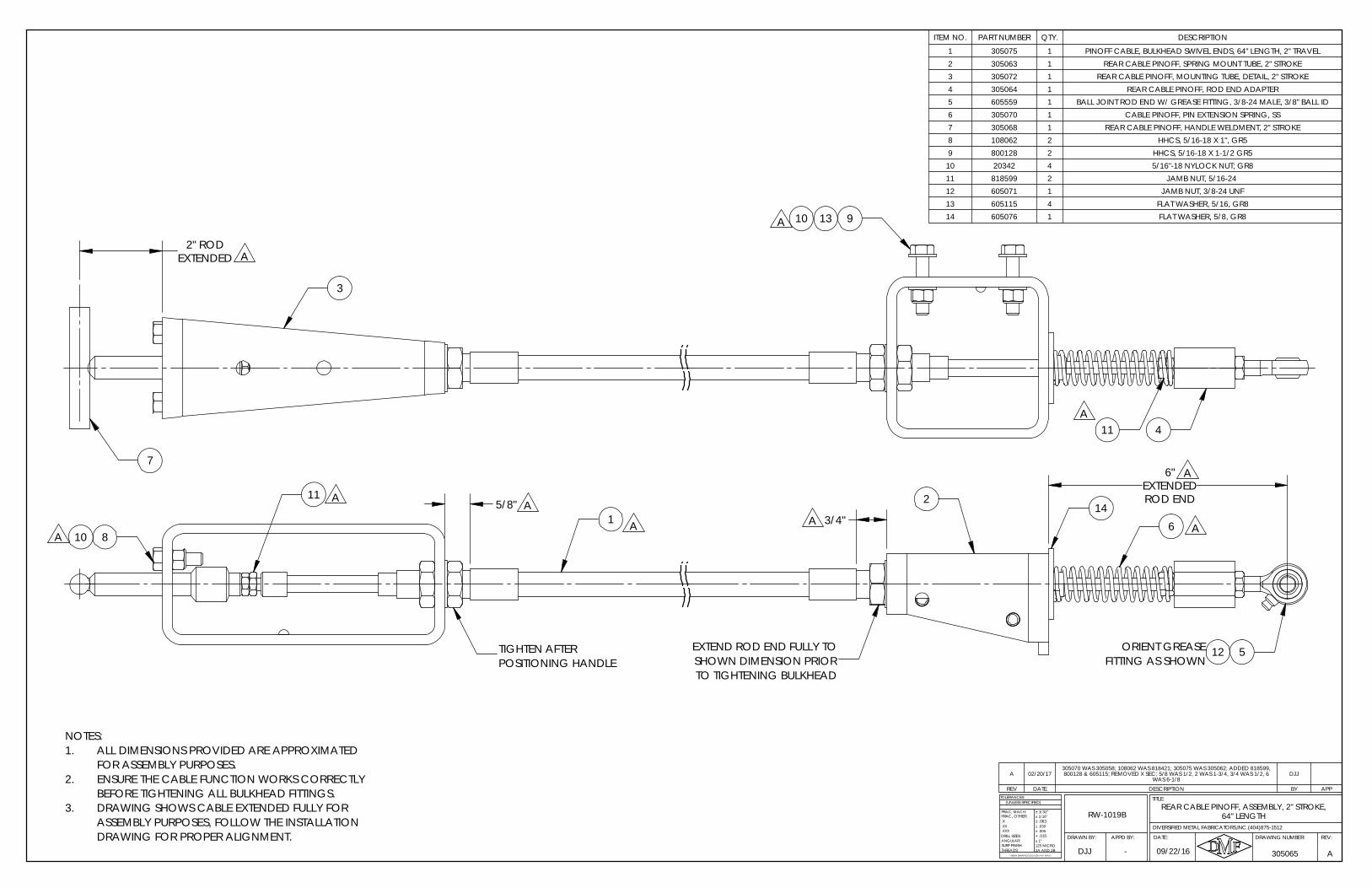
TIGHTEN AFTER POSITIONING HANDLE
81
A
EXTEND ROD END FULLY TO
6
A 214
5FITTING AS SHOWN
ORIENT GREASE
ASSEMBLY PURPOSES, FOLLOW THE INSTALLATION
A
A
12SHOWN DIMENSION PRIOR TO TIGHTENING BULKHEAD
AA
11
DRAWING FOR PROPER ALIGNMENT.
NOTES:ALL DIMENSIONS PROVIDED ARE APPROXIMATED 1.FOR ASSEMBLY PURPOSES.ENSURE THE CABLE FUNCTION WORKS CORRECTLY 2.BEFORE TIGHTENING ALL BULKHEAD FITTINGS.DRAWING SHOWS CABLE EXTENDED FULLY FOR 3.
10A 3/4"
5/8"
6"EXTENDEDROD END
REV DATE DESCRIPTION BY APP
A 02/20/17305070 WAS 305058; 108062 WAS 818421; 305075 WAS 305062; ADDED 818599, 800128 & 605115; REMOVED X SEC; 5/8 WAS 1/2, 2 WAS 1-3/4, 3/4 WAS 1/2, 6
WAS 6-1/8DJJ
ITEM NO. PART NUMBER QTY. DESCRIPTION
1 305075 1 PINOFF CABLE, BULKHEAD SWIVEL ENDS, 64" LENGTH, 2" TRAVEL2 305063 1 REAR CABLE PINOFF, SPRING MOUNT TUBE, 2" STROKE3 305072 1 REAR CABLE PINOFF, MOUNTING TUBE, DETAIL, 2" STROKE4 305064 1 REAR CABLE PINOFF, ROD END ADAPTER5 605559 1 BALL JOINT ROD END W/ GREASE FITTING, 3/8-24 MALE, 3/8" BALL ID6 305070 1 CABLE PINOFF, PIN EXTENSION SPRING, SS7 305068 1 REAR CABLE PINOFF, HANDLE WELDMENT, 2" STROKE8 108062 2 HHCS, 5/16-18 X 1", GR59 800128 2 HHCS, 5/16-18 X 1-1/2 GR5
10 20342 4 5/16"-18 NYLOCK NUT; GR811 818599 2 JAMB NUT, 5/16-24 12 605071 1 JAMB NUT, 3/8-24 UNF13 605115 4 FLAT WASHER, 5/16, GR814 605076 1 FLAT WASHER, 5/8, GR8
DJJ
RW-1019BFRAC, OTHER:.X
ANGULAR:
BREAK SHARP EDGES ( 0.030 X 45° MAX )
± 1/16"
± .005± .030
+ .015
± 1/32"
± .063
± 1°
2A AND 2B125 MICRO
DRILL SIZES:
SURF FINISH:THREADS:
.XXX
.XX
TOLERANCES:
FRAC, MACH:
(UNLESS SPECIFIED)
- 305065
REV:DRAWING NUMBER:
TITLE:
DATE:APPD BY:DRAWN BY:
A09/22/16
DIVERSIFIED METAL FABRICATORS,INC.(404)875-1512
REAR CABLE PINOFF, ASSEMBLY, 2" STROKE, 64" LENGTH
13
3
411A
7
A
910A
2" RODEXTENDED
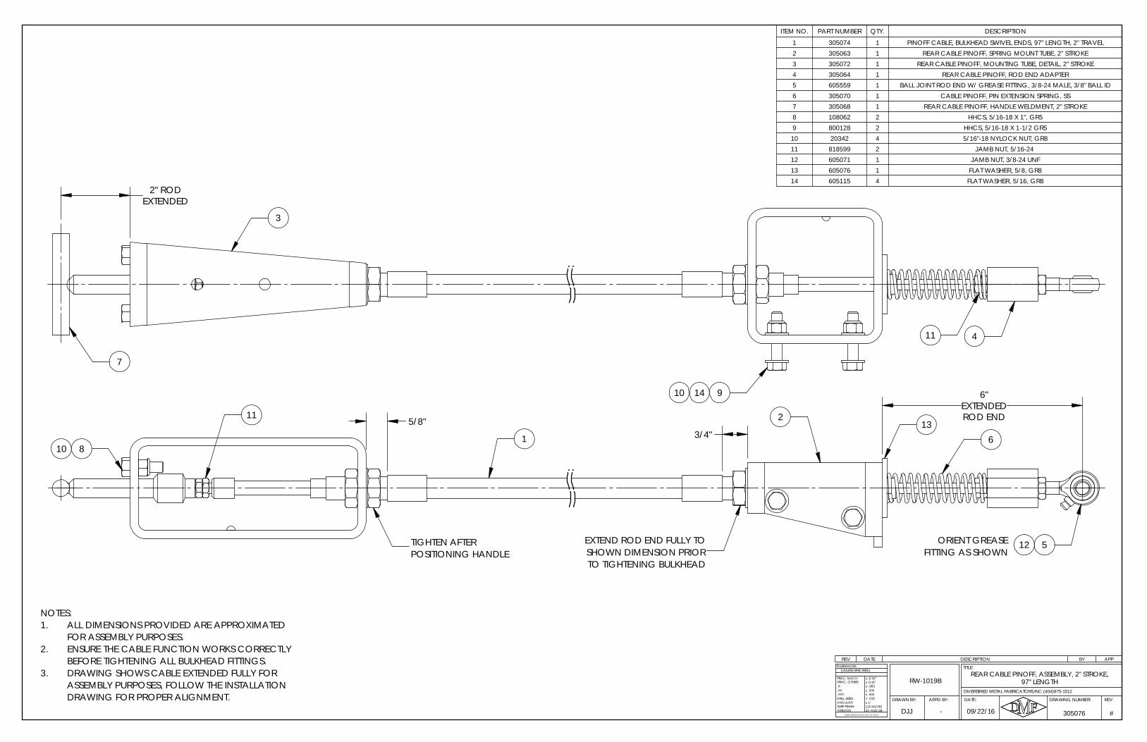
11
7
14
3
4
910
2" RODEXTENDED
DJJ -
RW-1019B
09/22/16 #
.X
ANGULAR:
BREAK SHARP EDGES ( 0.030 X 45° MAX )
± 1/16"
± .005± .030
+ .015
± 1/32"
± .063
± 1°
2A AND 2B125 MICRO
DRILL SIZES:
SURF FINISH:THREADS:
.XXX
.XX
TOLERANCES:
FRAC, MACH:
(UNLESS SPECIFIED)
FRAC, OTHER:
305076
REV:DRAWING NUMBER:
TITLE:
DATE:APPD BY:DRAWN BY:
DIVERSIFIED METAL FABRICATORS,INC.(404)875-1512
REAR CABLE PINOFF, ASSEMBLY, 2" STROKE, 97" LENGTH
REV DATE DESCRIPTION BY APP
ITEM NO. PART NUMBER QTY. DESCRIPTION
1 305074 1 PINOFF CABLE, BULKHEAD SWIVEL ENDS, 97" LENGTH, 2" TRAVEL2 305063 1 REAR CABLE PINOFF, SPRING MOUNT TUBE, 2" STROKE3 305072 1 REAR CABLE PINOFF, MOUNTING TUBE, DETAIL, 2" STROKE4 305064 1 REAR CABLE PINOFF, ROD END ADAPTER5 605559 1 BALL JOINT ROD END W/ GREASE FITTING, 3/8-24 MALE, 3/8" BALL ID6 305070 1 CABLE PINOFF, PIN EXTENSION SPRING, SS7 305068 1 REAR CABLE PINOFF, HANDLE WELDMENT, 2" STROKE8 108062 2 HHCS, 5/16-18 X 1", GR59 800128 2 HHCS, 5/16-18 X 1-1/2 GR5
10 20342 4 5/16"-18 NYLOCK NUT; GR811 818599 2 JAMB NUT, 5/16-24 12 605071 1 JAMB NUT, 3/8-24 UNF13 605076 1 FLAT WASHER, 5/8, GR814 605115 4 FLAT WASHER, 5/16, GR8
EXTEND ROD END FULLY TO
11
TIGHTEN AFTER 12
TO TIGHTENING BULKHEADSHOWN DIMENSION PRIOR
5
DRAWING FOR PROPER ALIGNMENT.ASSEMBLY PURPOSES, FOLLOW THE INSTALLATION
ORIENT GREASE POSITIONING HANDLE
81 6
213
FITTING AS SHOWN
NOTES:ALL DIMENSIONS PROVIDED ARE APPROXIMATED 1.FOR ASSEMBLY PURPOSES.ENSURE THE CABLE FUNCTION WORKS CORRECTLY 2.BEFORE TIGHTENING ALL BULKHEAD FITTINGS.DRAWING SHOWS CABLE EXTENDED FULLY FOR 3.
10 3/4"
5/8"
6"EXTENDEDROD END
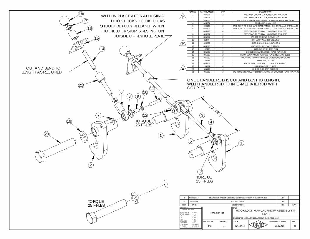
REARHOOK LOCK MANUAL PINOFF ASSEMBLY KIT,
RW-1019B
APPD BY:DRAWN BY:
DIVERSIFIED METAL FABRICATORS,INC.(404)875-1512
B
.X
ANGULAR:
BREAK SHARP EDGES ( 0.030 X 45° MAX )
± 1/16"
± .005± .030
+ .015
± 1/32"
± .063
± 1°
2A AND 2B125 MICRO
DRILL SIZES:
SURF FINISH:THREADS:
.XXX
.XX
TOLERANCES:
FRAC, MACH:
(UNLESS SPECIFIED)
3050085/13/13
FRAC, OTHER:
JDI
REV:DRAWING NUMBER:
TITLE:
DATE:
-
12
25 FT-LBSTORQUE
2
1
1
1110
8
7
16
15
14
17
WELD HANDLE ROD TO INTERMEDIATE ROD WITH
LENGTH AS REQUIRED
20
TORQUE25 FT-LBS
18
96
19
CUT AND BEND TO
ONCE HANDLE ROD IS CUT AND BENT TO LENGTH,
COUPLER21
A
5
3
4
13
B
B
25 FT-LBSTORQUE
WELD IN PLACE AFTER ADJUSTING HOOK LOCKS, HOOK LOCKS
SHOULD BE FULLY RELEASED WHEN HOOK LOCK STOP IS RESTING ON
OUTSIDE OF KEYHOLE PLATE
9 3/8"
REV DATE DESCRIPTION BY APP
B 6/19/2014 REMOVED PASSENGER SIDE DEPLOYED HOOK, ADDED 605082 JDI
A 12/12/13 ADDED 305020 JDI
ITEM NO. PART NUMBER QTY DESCRIPTION1 305004 2 WELDMENT, HOOK LOCK, REAR, DS, RW-1019B2 305005 1 WELDMENT, HOOK LOCK, REAR, PS, RW-1019B3 305006 1 HOOK LOCK THREADED CONNECTION ROD, REAR, RW-1019B4 605071 2 JAMB NUT, 3/8-24 UNF5 605192 2 BALL JOINT ROD END W/GREASE FITTING, 3/8"-24 FEMALE, 3/8" BALL ID6 605306 2 BALL JOINT ROD END W/GREASE FITTING, 1/2"-20 FEMALE, 1/2" BALL ID7 605193 4 STEEL WASHER FOR BALL JOINT ROD END, 3/8"8 605307 2 STEEL WASHER FOR BALL JOINT ROD END, 1/2"9 305017 2 PINOFF ROD END SLEEVE, 1/2"
10 12566 3 3/8" LOCK WASHER, GRADE 811 605082 1 HHCS 3/8-16 X 1-3/4", GRADE 812 605256 1 HHCS 3/8-16 X2-1/4", GRADE 813 102408 1 HHCS, 3/8-16 X 1-1/2", GR814 305007 2 HOOK LOCK HANDLE ROD, REAR, RW-1019B15 305009 2 HOOK LOCK PINOFF KEYHOLE PLATE, REAR, RW-1019B16 305010 2 HOOK LOCK PINOFF HANDLE STOP, REAR, RW-1019B17 106237 4 JAMB NUT, 1/2"-2018 605308 2 KNOB, BALL, 1-3/8" DIA, 1/2-20 X 5/8" THREAD19 109331 4 LOCK WASHER, 1", GR820 605194 4 HHCS 1-8 X 5-1/2"; GRADE 821 305020 2 HOOK LOCK HANDLE INTERMEDIATE ROD W/COUPLER, REAR, RW-1019B
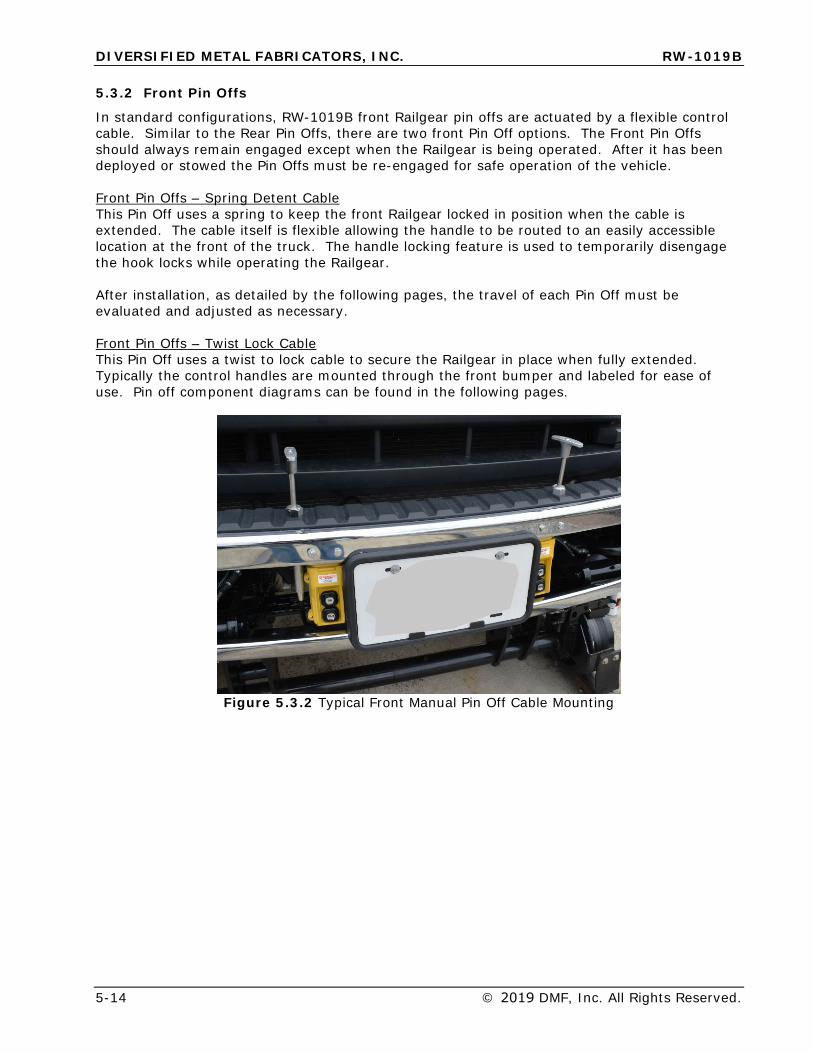
DIVERSIFIED METAL FABRICATORS, INC. RW-1019B
5-14 © 2019 DMF, Inc. All Rights Reserved.
5.3.2 Front Pin Offs
In standard configurations, RW-1019B front Railgear pin offs are actuated by a flexible control cable. Similar to the Rear Pin Offs, there are two front Pin Off options. The Front Pin Offs should always remain engaged except when the Railgear is being operated. After it has been deployed or stowed the Pin Offs must be re-engaged for safe operation of the vehicle.
Front Pin Offs – Spring Detent Cable This Pin Off uses a spring to keep the front Railgear locked in position when the cable is extended. The cable itself is flexible allowing the handle to be routed to an easily accessible location at the front of the truck. The handle locking feature is used to temporarily disengage the hook locks while operating the Railgear.
After installation, as detailed by the following pages, the travel of each Pin Off must be evaluated and adjusted as necessary.
Front Pin Offs – Twist Lock Cable This Pin Off uses a twist to lock cable to secure the Railgear in place when fully extended. Typically the control handles are mounted through the front bumper and labeled for ease of use. Pin off component diagrams can be found in the following pages.
Figure 5.3.2 Typical Front Manual Pin Off Cable Mounting
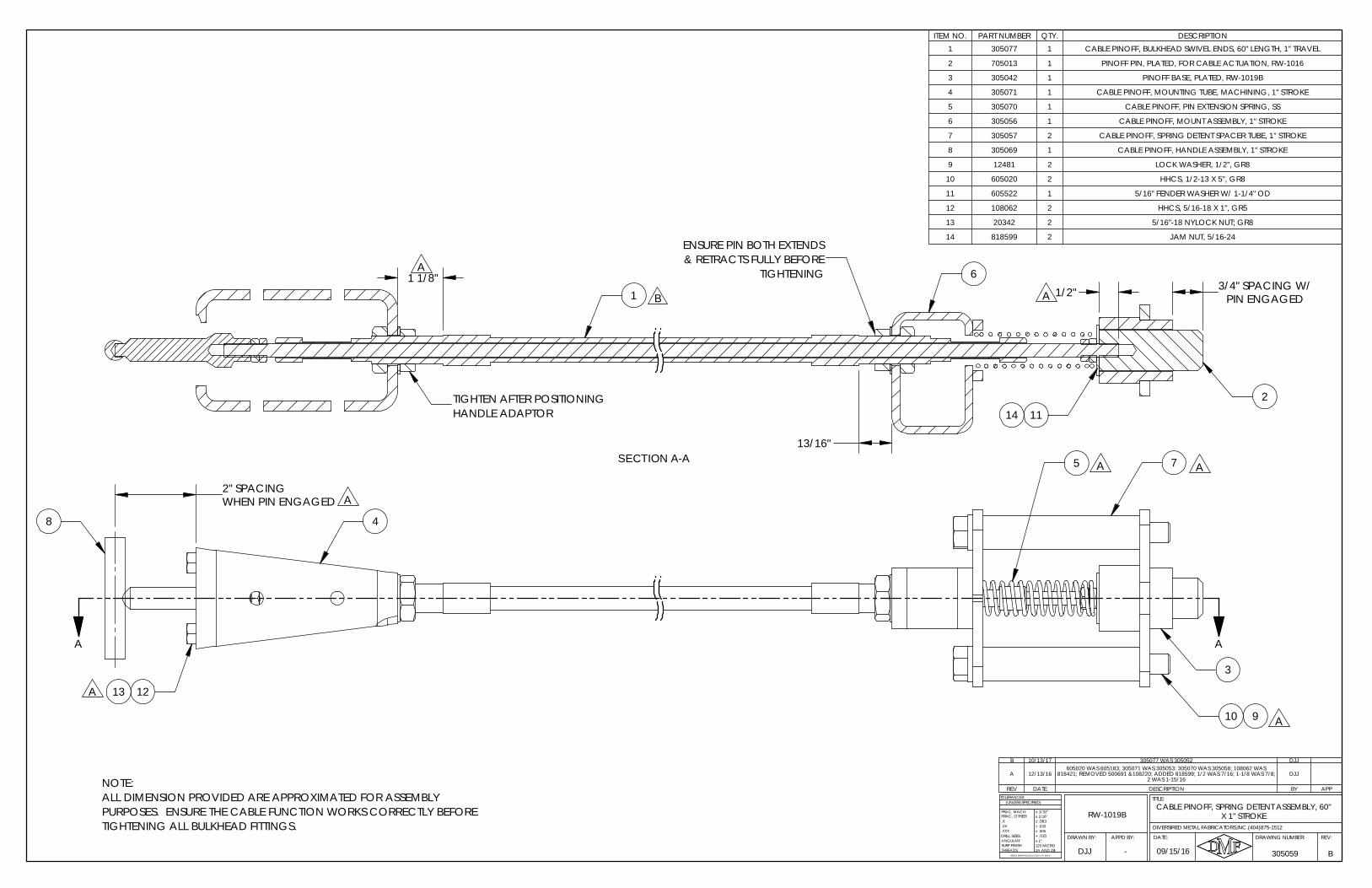
TIGHTENING& RETRACTS FULLY BEFORE
B1
6
14 11
A
SECTION A-A
TIGHTEN AFTER POSITIONING HANDLE ADAPTOR
A
ENSURE PIN BOTH EXTENDS
2
1 1/8"
13/16"
1/2" 3/4" SPACING W/PIN ENGAGED
-
RW-1019B
B
.X
ANGULAR:
BREAK SHARP EDGES ( 0.030 X 45° MAX )
± 1/16"
± .005± .030
+ .015
± 1/32"
± .063
± 1°
2A AND 2B125 MICRO
DRILL SIZES:
SURF FINISH:THREADS:
.XXX
.XX
TOLERANCES:
FRAC, MACH:
(UNLESS SPECIFIED)
09/15/16 305059
REV:DRAWING NUMBER:
TITLE:
DATE:APPD BY:DRAWN BY:
FRAC, OTHER:
DIVERSIFIED METAL FABRICATORS,INC.(404)875-1512
DJJ
CABLE PINOFF, SPRING DETENT ASSEMBLY, 60" X 1" STROKE
REV DATE DESCRIPTION BY APP
B 10/13/17 305077 WAS 305052 DJJ
A 12/13/16605020 WAS 605183; 305071 WAS 305053; 305070 WAS 305058; 108062 WAS
818421; REMOVED 500691 &108220; ADDED 818599; 1/2 WAS 7/16; 1-1/8 WAS 7/8; 2 WAS 1-15/16
DJJ
ITEM NO. PART NUMBER QTY. DESCRIPTION1 305077 1 CABLE PINOFF, BULKHEAD SWIVEL ENDS, 60" LENGTH, 1" TRAVEL
2 705013 1 PINOFF PIN, PLATED, FOR CABLE ACTUATION, RW-1016
3 305042 1 PINOFF BASE, PLATED, RW-1019B
4 305071 1 CABLE PINOFF, MOUNTING TUBE, MACHINING, 1" STROKE
5 305070 1 CABLE PINOFF, PIN EXTENSION SPRING, SS
6 305056 1 CABLE PINOFF, MOUNT ASSEMBLY, 1" STROKE
7 305057 2 CABLE PINOFF, SPRING DETENT SPACER TUBE, 1" STROKE
8 305069 1 CABLE PINOFF, HANDLE ASSEMBLY, 1" STROKE
9 12481 2 LOCK WASHER, 1/2", GR8
10 605020 2 HHCS, 1/2-13 X 5", GR8
11 605522 1 5/16" FENDER WASHER W/ 1-1/4" OD
12 108062 2 HHCS, 5/16-18 X 1", GR5
13 20342 2 5/16"-18 NYLOCK NUT; GR8
14 818599 2 JAM NUT, 5/16-24
A
A
1213
A
8
A
7
3
5
10 9
PURPOSES. ENSURE THE CABLE FUNCTION WORKS CORRECTLY BEFORE TIGHTENING ALL BULKHEAD FITTINGS.
NOTE:ALL DIMENSION PROVIDED ARE APPROXIMATED FOR ASSEMBLY
4
A2" SPACINGWHEN PIN ENGAGED
AA
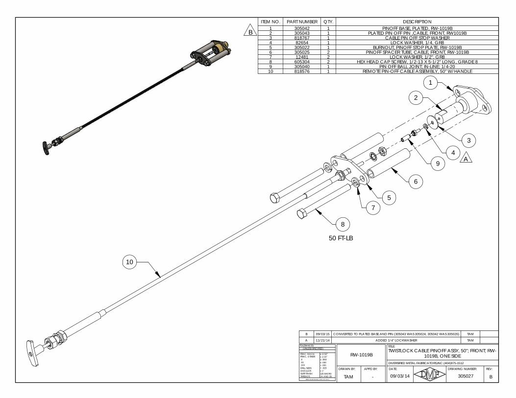
B
7
50 FT-LB
9
3
2
1
6
5
8
10
A4
A 11/21/14 ADDED 1/4" LOCKWASHER TAM
B 09/03/15 CONVERTED TO PLATED BASE AND PIN (305043 WAS 305024; 305042 WAS 305026) TAM
ITEM NO. PART NUMBER QTY. DESCRIPTION1 305042 1 PINOFF BASE, PLATED, RW-1019B2 305043 1 PLATED PIN OFF PIN ,CABLE, FRONT, RW1019B3 818767 1 CABLE PIN OFF STOP WASHER4 82654 1 LOCK WASHER, 1/4, GR85 305022 1 BURNOUT, PINOFF STOP PLATE, RW-1019B6 305025 2 PINOFF SPACER TUBE, CABLE, FRONT, RW-1019B7 12481 2 LOCK WASHER, 1/2", GR88 605304 2 HEX HEAD CAP SCREW, 1/2-13 X 5-1/2" LONG, GRADE 89 305040 1 PIN OFF BALL JOINT; IN-LINE; 1/4-20
10 818576 1 REMOTE PIN-OFF CABLE ASSEMBLY, 50" W/HANDLE
1019B, ONE SIDETWISTLOCK CABLE PINOFF ASSY, 50"; FRONT; RW-
RW-1019BFRAC, OTHER:
B
.X
ANGULAR:
BREAK SHARP EDGES ( 0.030 X 45° MAX )
± 1/16"
± .005± .030
+ .015
± 1/32"
± .063
± 1°
2A AND 2B125 MICRO
DRILL SIZES:
SURF FINISH:THREADS:
.XXX
.XX
TOLERANCES:
FRAC, MACH:
(UNLESS SPECIFIED)
09/03/14
DIVERSIFIED METAL FABRICATORS,INC.(404)875-1512
305027TAM
REV:DRAWING NUMBER:
TITLE:
DATE:APPD BY:DRAWN BY:
-
DIVERSIFIED METAL FABRICATORS, INC. RW-1019B
© 2019 DMF, Inc. All Rights Reserved. 6-1
SECTION 6.0 HYDRAULIC & ELECTRICALSYSTEMS
6.1 GENERAL INFORMATION ................................................................................ 6-2
6.1.1 System Pressures and Relief Settings .............................................................. 6-2 6.1.2 Using Hydraulic Power Unit Provided by DMF .................................................... 6-2 6.1.3 Hydraulic System for Multiple Uses (Railgear and other application(s)) ................. 6-2 6.1.4 Fitting Installation ......................................................................................... 6-3
6.2 BRAKE LINE ROUTING .................................................................................... 6-6
6.3 HYDRAULIC & ELECTRICAL SCHEMATICS ....................................................... 6-7
6.4 HYDRAULIC & ELECTRICAL COMPONENT DRAWINGS ................................... 6-11
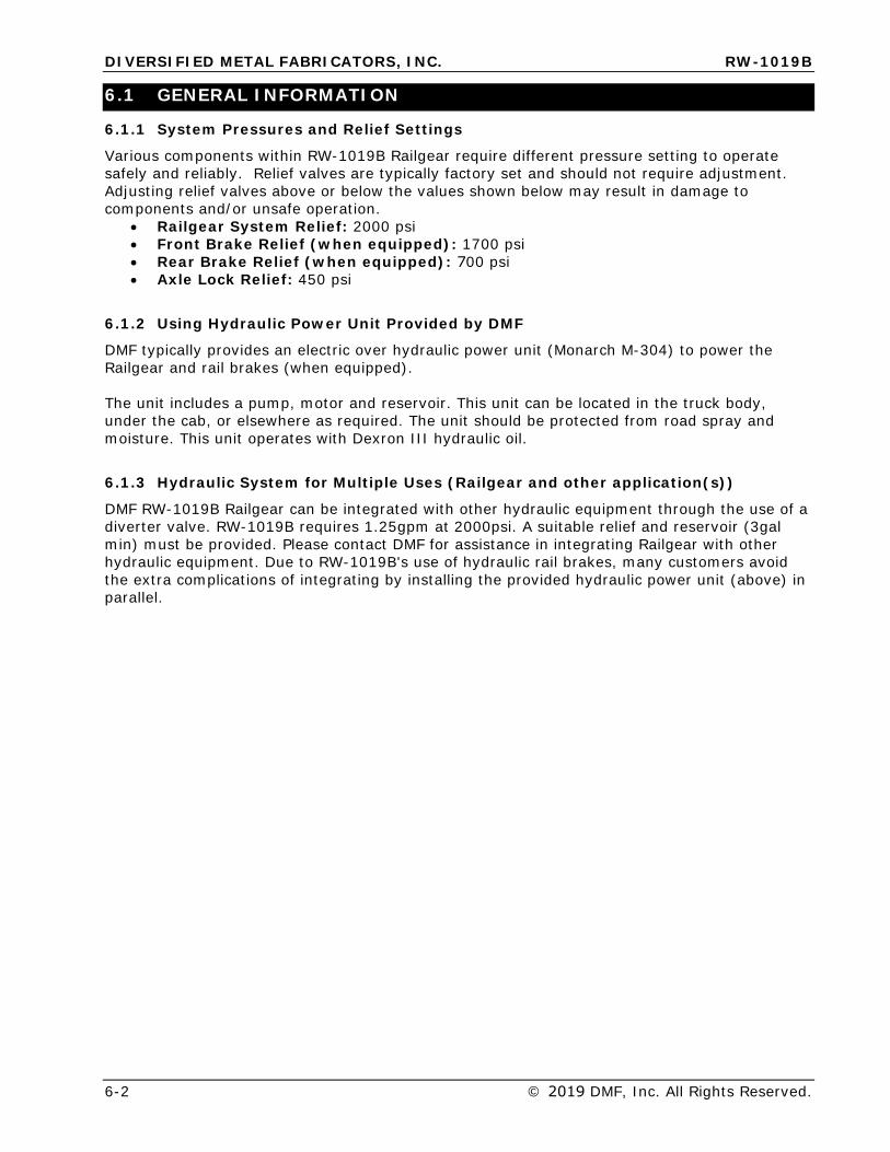
DIVERSIFIED METAL FABRICATORS, INC. RW-1019B
6-2 © 2019 DMF, Inc. All Rights Reserved.
6.1 GENERAL INFORMATION
6.1.1 System Pressures and Relief Settings
Various components within RW-1019B Railgear require different pressure setting to operate safely and reliably. Relief valves are typically factory set and should not require adjustment. Adjusting relief valves above or below the values shown below may result in damage to components and/or unsafe operation.
• Railgear System Relief: 2000 psi• Front Brake Relief (when equipped): 1700 psi• Rear Brake Relief (when equipped): 700 psi• Axle Lock Relief: 450 psi
6.1.2 Using Hydraulic Power Unit Provided by DMF
DMF typically provides an electric over hydraulic power unit (Monarch M-304) to power the Railgear and rail brakes (when equipped).
The unit includes a pump, motor and reservoir. This unit can be located in the truck body, under the cab, or elsewhere as required. The unit should be protected from road spray and moisture. This unit operates with Dexron III hydraulic oil.
6.1.3 Hydraulic System for Multiple Uses (Railgear and other application(s))
DMF RW-1019B Railgear can be integrated with other hydraulic equipment through the use of a diverter valve. RW-1019B requires 1.25gpm at 2000psi. A suitable relief and reservoir (3gal min) must be provided. Please contact DMF for assistance in integrating Railgear with other hydraulic equipment. Due to RW-1019B's use of hydraulic rail brakes, many customers avoid the extra complications of integrating by installing the provided hydraulic power unit (above) in parallel.
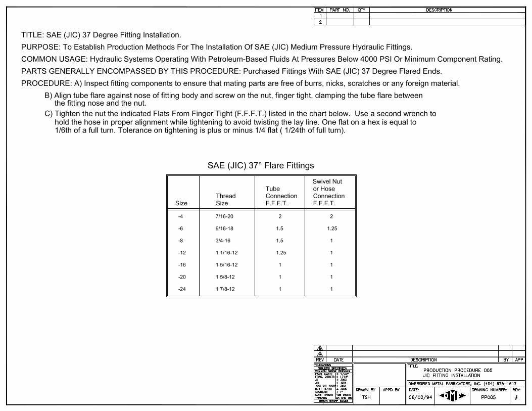
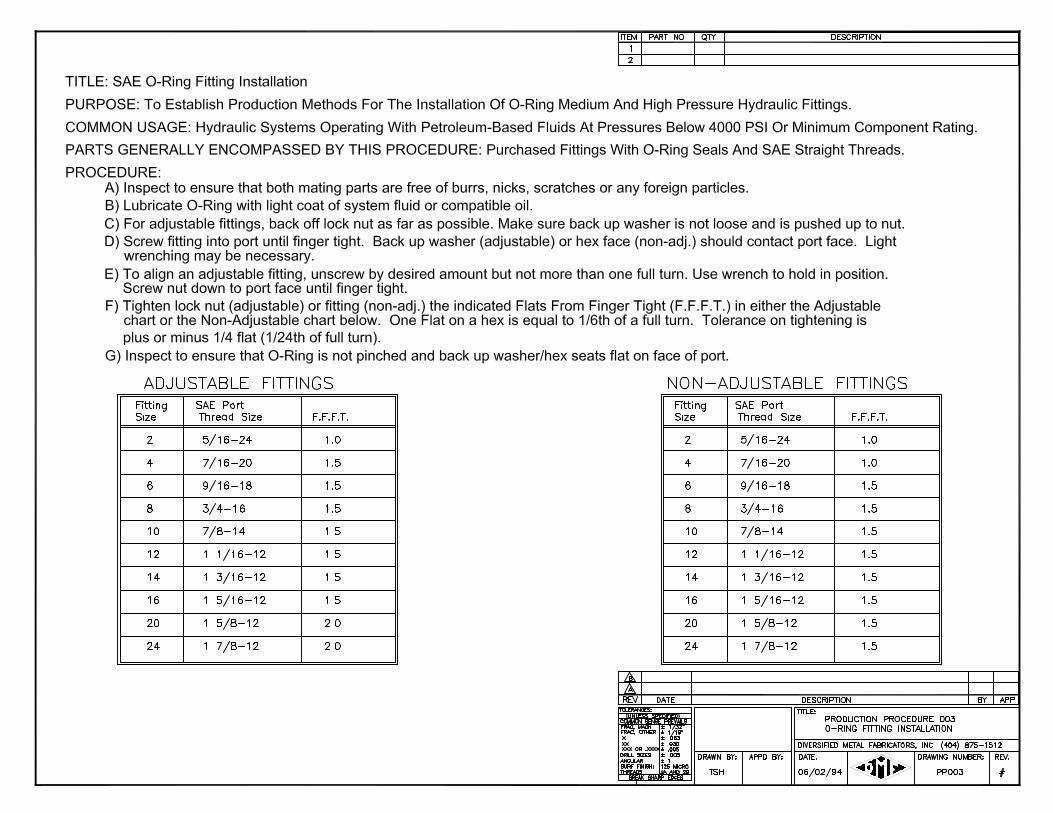
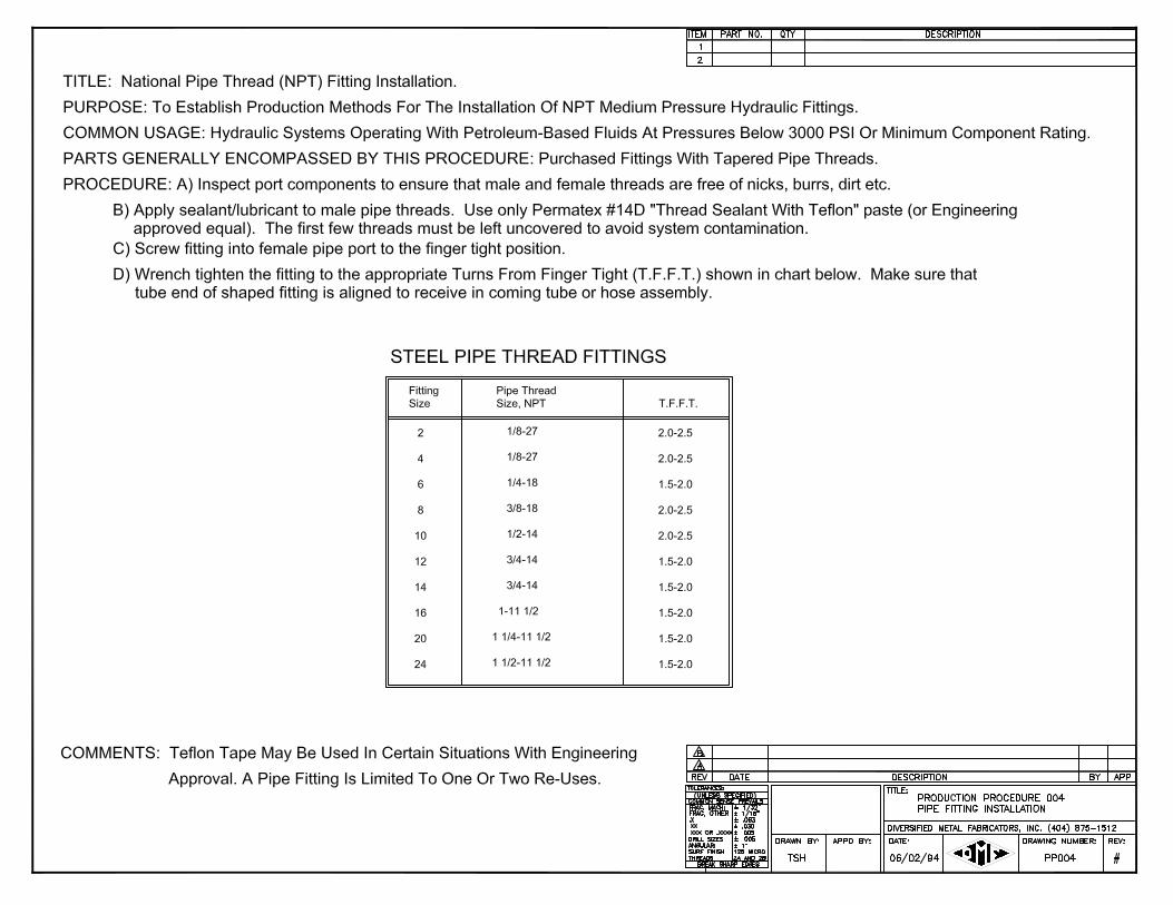
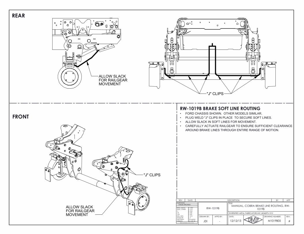
"J" CLIPS
ALLOW SLACKFOR RAILGEARMOVEMENT
"J" CLIPS
ALLOW SLACKFOR RAILGEARMOVEMENT
REAR
RW-1019B BRAKE SOFT LINE ROUTINGFORD CHASSIS SHOWN. OTHER MODELS SIMILAR.•PLUG WELD "J" CLIPS IN PLACE TO SECURE SOFT LINES.•ALLOW SLACK IN SOFT LINES FOR MOVEMENT.•CAREFULLY ACTUATE RAILGEAR TO ENSURE SUFFICIENT CLEARANCE •AROUND BRAKE LINES THROUGH ENTIRE RANGE OF MOTION.
FRONT
REV DATE DESCRIPTION BY APP
#
.X
ANGULAR:
BREAK SHARP EDGES ( 0.030 X 45° MAX )
± 1/16"
± .005± .030
+ .015
± 1/32"
± .063
± 1°
2A AND 2B125 MICRO
DRILL SIZES:
SURF FINISH:THREADS:
.XXX
.XX
TOLERANCES:
FRAC, MACH:
(UNLESS SPECIFIED)
FRAC, OTHER:
12/12/13 M1019B05JDI
REV:DRAWING NUMBER:
TITLE:
DATE:APPD BY:DRAWN BY:
DIVERSIFIED METAL FABRICATORS,INC.(404)875-1512
-
MANUAL, COBRA BRAKE LINE ROUTING, RW-1019BRW-1019B
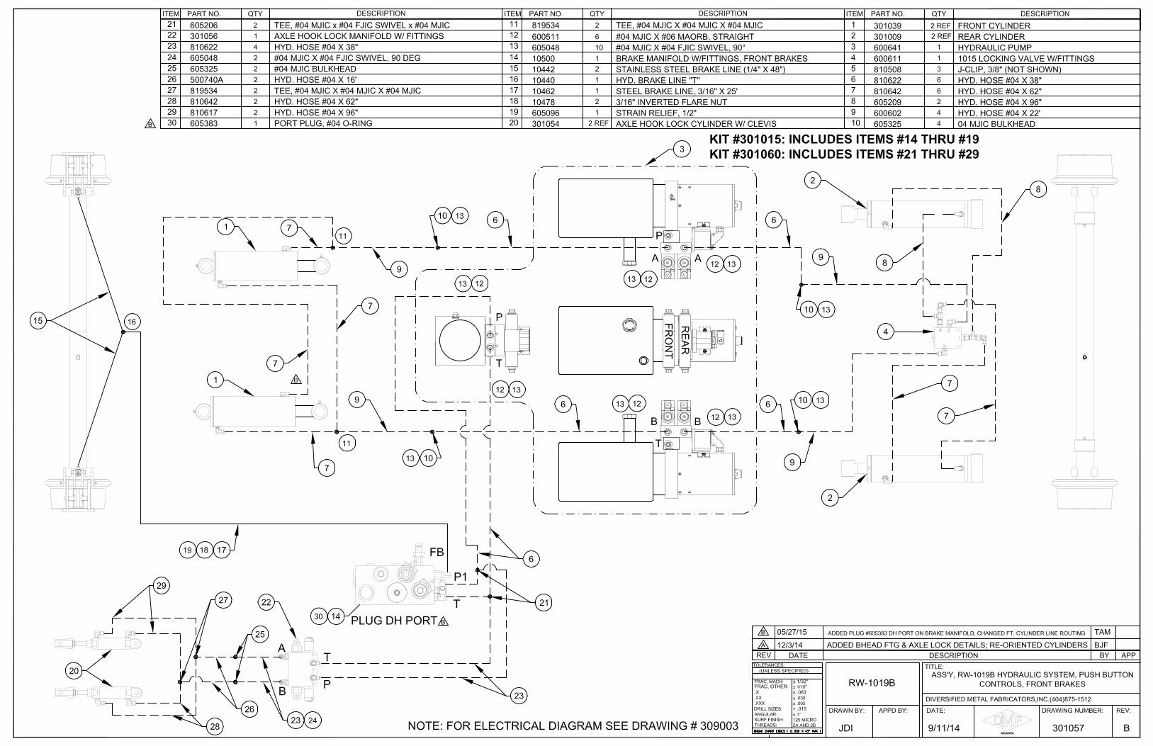
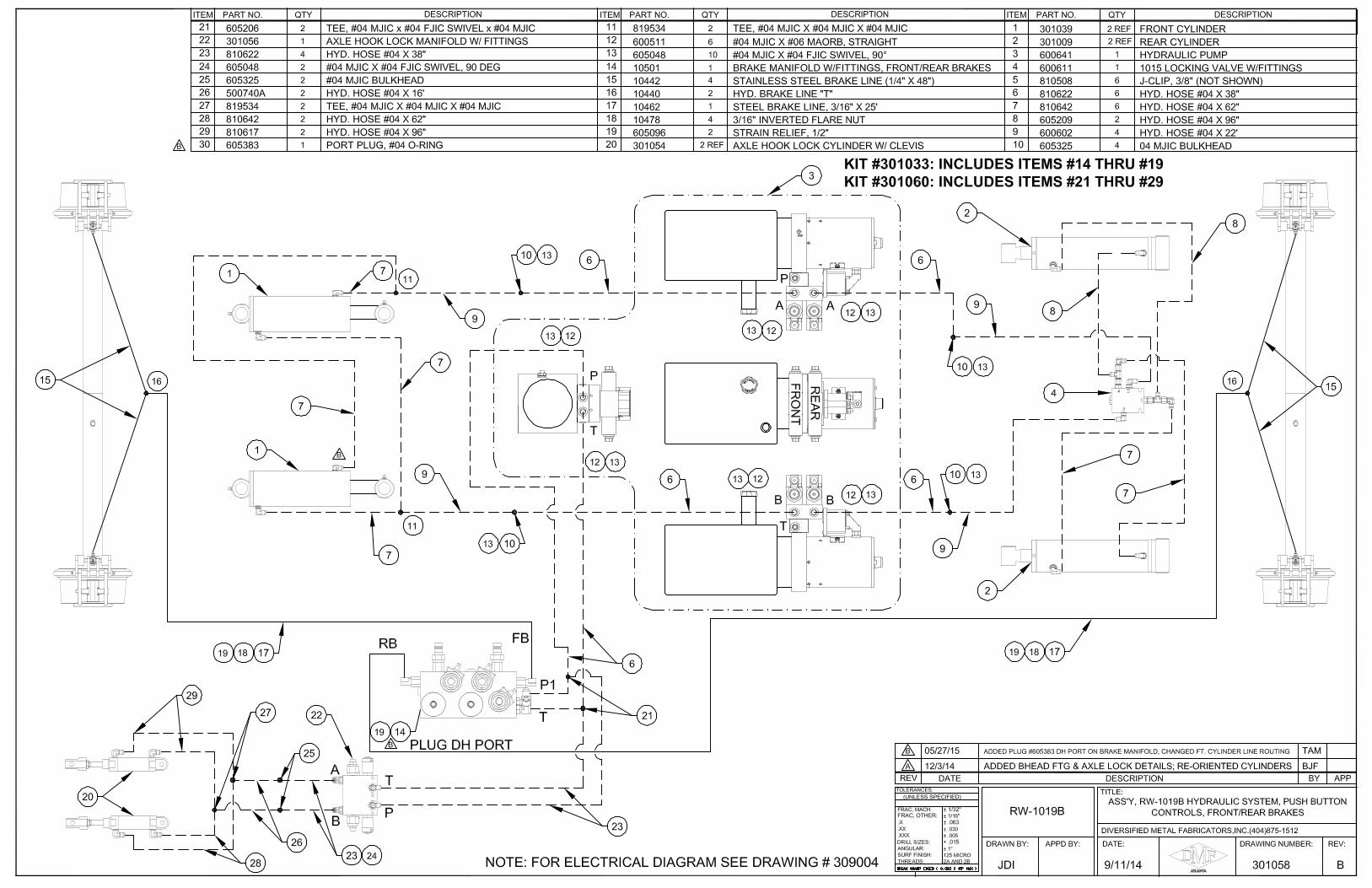
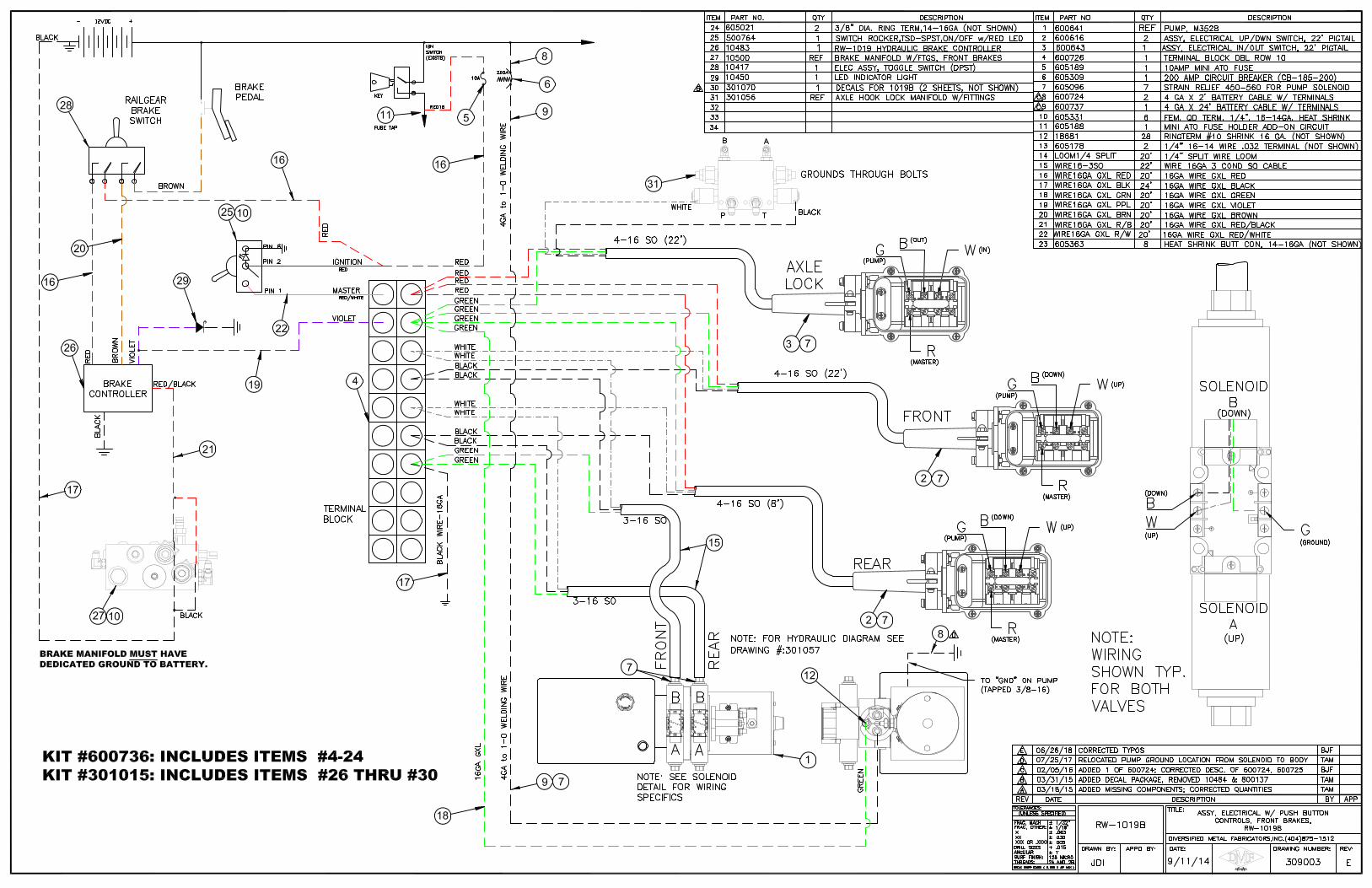
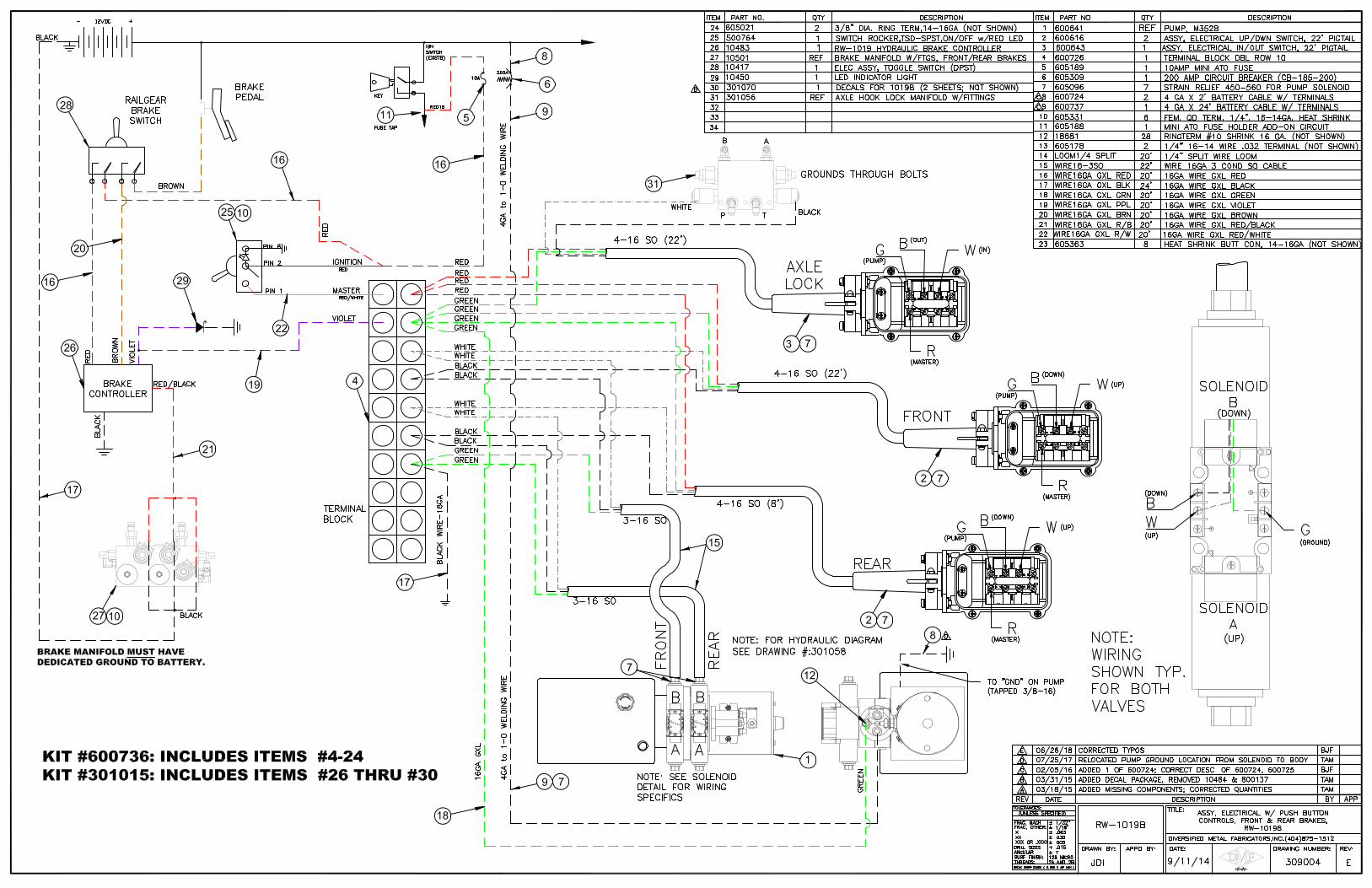
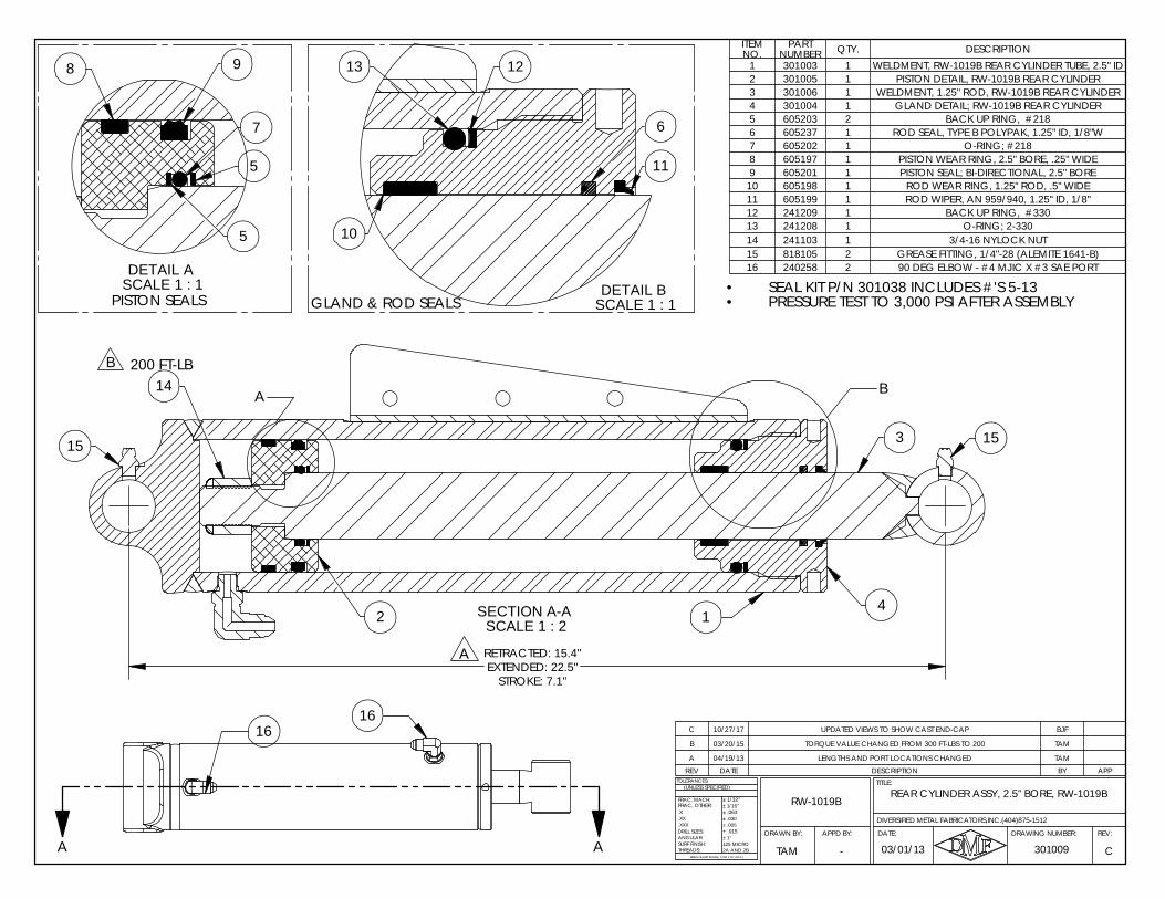
1SCALE 1 : 2SECTION A-A
3 1515
14200 FT-LB
42
A
A B
RETRACTED: 15.4"EXTENDED: 22.5"
STROKE: 7.1"
1616
A A
REAR CYLINDER ASSY, 2.5" BORE, RW-1019BRW-1019B
TITLE:
DATE:DRAWN BY:
DIVERSIFIED METAL FABRICATORS,INC.(404)875-1512
301009 C
.X
ANGULAR:
BREAK SHARP EDGES ( 0.030 X 45° MAX )
± 1/16"
± .005± .030
+ .015
± 1/32"
± .063
± 1°
2A AND 2B125 MICRO
DRILL SIZES:
SURF FINISH:THREADS:
.XXX
.XX
TOLERANCES:
APPD BY:
FRAC, MACH:FRAC, OTHER:
(UNLESS SPECIFIED)
03/01/13TAM
REV:DRAWING NUMBER:
-
PISTON SEALSSCALE 1 : 1DETAIL A
8 9
7
5
5
B
SCALE 1 : 1
13
GLAND & ROD SEALSDETAIL B
11
6
10
12
REV DATE DESCRIPTION BY APP
C 10/27/17 UPDATED VIEWS TO SHOW CAST END-CAP BJF
B 03/20/15 TORQUE VALUE CHANGED FROM 300 FT-LBS TO 200 TAM
A 04/19/13 LENGTHS AND PORT LOCATIONS CHANGED TAM
ITEM NO.
PART NUMBER QTY. DESCRIPTION
1 301003 1 WELDMENT, RW-1019B REAR CYLINDER TUBE, 2.5" ID2 301005 1 PISTON DETAIL, RW-1019B REAR CYLINDER3 301006 1 WELDMENT, 1.25" ROD, RW-1019B REAR CYLINDER4 301004 1 GLAND DETAIL; RW-1019B REAR CYLINDER5 605203 2 BACK UP RING, #2186 605237 1 ROD SEAL, TYPE B POLYPAK, 1.25" ID, 1/8"W7 605202 1 O-RING; #2188 605197 1 PISTON WEAR RING, 2.5" BORE, .25" WIDE9 605201 1 PISTON SEAL; BI-DIRECTIONAL, 2.5" BORE
10 605198 1 ROD WEAR RING, 1.25" ROD, .5" WIDE11 605199 1 ROD WIPER, AN 959/940, 1.25" ID, 1/8"12 241209 1 BACK UP RING, #33013 241208 1 O-RING; 2-33014 241103 1 3/4-16 NYLOCK NUT15 818105 2 GREASE FITTING, 1/4"-28 (ALEMITE 1641-B)16 240258 2 90 DEG ELBOW - #4 MJIC X #3 SAE PORT
SEAL KIT P/N 301038 INCLUDES #'S 5-13•PRESSURE TEST TO 3,000 PSI AFTER ASSEMBLY•
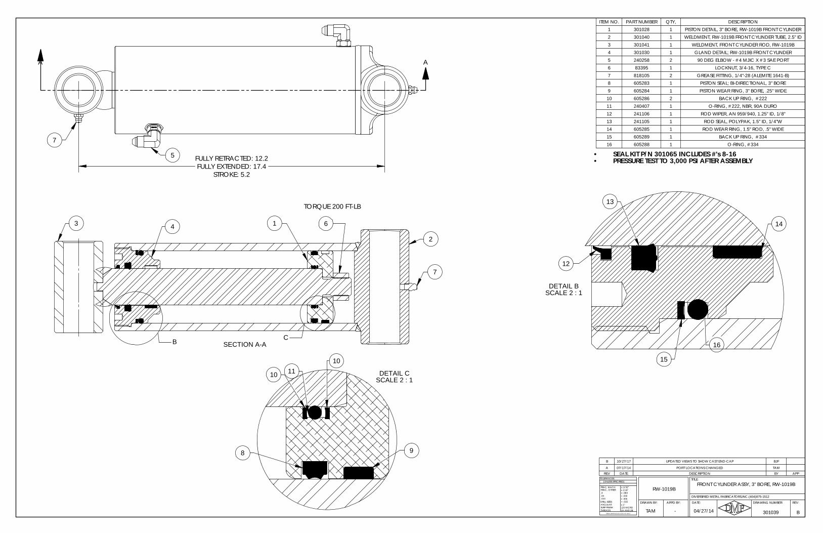
SEAL KIT P/N 301065 INCLUDES #'s 8-16PRESSURE TEST TO 3,000 PSI AFTER ASSEMBLY
•
7
•5 FULLY RETRACTED: 12.2
FULLY EXTENDED: 17.4STROKE: 5.2
AA
REV DATE DESCRIPTION BY APP
B 10/27/17 UPDATED VIEWS TO SHOW CAST END-CAP BJF
A 07/17/14 PORT LOCATIONS CHANGED TAM
ITEM NO. PART NUMBER QTY, DESCRIPTION1 301028 1 PISTON DETAIL, 3" BORE, RW-1019B FRONT CYLINDER2 301040 1 WELDMENT, RW-1019B FRONT CYLINDER TUBE, 2.5" ID3 301041 1 WELDMENT, FRONT CYLINDER ROD, RW-1019B4 301030 1 GLAND DETAIL; RW-1019B FRONT CYLINDER5 240258 2 90 DEG ELBOW - #4 MJIC X #3 SAE PORT6 83395 1 LOCKNUT, 3/4-16, TYPE C7 818105 2 GREASE FITTING, 1/4"-28 (ALEMITE 1641-B)8 605283 1 PISTON SEAL; BI-DIRECTIONAL, 3" BORE9 605284 1 PISTON WEAR RING, 3" BORE, .25" WIDE10 605286 2 BACK UP RING, #22211 240407 1 O-RING, #222, NBR, 90A DURO12 241106 1 ROD WIPER, AN 959/940, 1.25" ID, 1/8"13 241105 1 ROD SEAL, POLYPAK, 1.5" ID, 1/4"W14 605285 1 ROD WEAR RING, 1.5" ROD, .5" WIDE15 605289 1 BACK UP RING, #33416 605288 1 O-RING, #334
-
FRAC, OTHER:
B04/27/14
.X
ANGULAR:
BREAK SHARP EDGES ( 0.030 X 45° MAX )
± 1/16"
± .005± .030
+ .015
± 1/32"
± .063
± 1°
2A AND 2B125 MICRO
DRILL SIZES:
SURF FINISH:THREADS:
.XXX
.XX
TOLERANCES:
DRAWN BY:
(UNLESS SPECIFIED)
TAM 301039
REV:DRAWING NUMBER:
TITLE:
DATE:
DIVERSIFIED METAL FABRICATORS,INC.(404)875-1512
APPD BY:
FRAC, MACH: RW-1019BFRONT CYLINDER ASSY, 3" BORE, RW-1019B
12
13
14
16
DETAIL BSCALE 2 : 1
15
10
1011
9
DETAIL CSCALE 2 : 1
8
TORQUE 200 FT-LB
2
13
B SECTION A-A
4
7
6
C
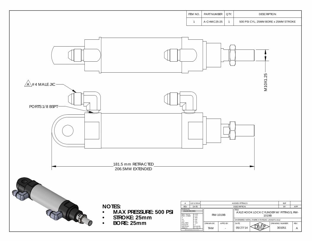
REV DATE DESCRIPTION BY APPA 12/1/2014 ADDED FITTINGS BJF
NOTES:MAX PRESSURE: 500 PSI•STROKE: 25mm•BORE: 25mm•
ITEM NO. PART NUMBER QTY. DESCRIPTION
1 A-CHMC25-25 1 500 PSI CYL; 25MM BORE x 25MM STROKE
M10
X1.2
5
PORTS 1/8 BSPT
#4 MALE JICA
181.5 mm RETRACTED206.5MM EXTENDED
1019BAXLE HOOK LOCK CYLINDER W/ FITTINGS, RW-
RW-1019B
05/27/14 A
.X
ANGULAR:
BREAK SHARP EDGES ( 0.030 X 45° MAX )
± 1/16"
± .005± .030
+ .015
± 1/32"
± .063
± 1°
2A AND 2B125 MICRO
DRILL SIZES:
SURF FINISH:THREADS:
.XXX
.XX
TOLERANCES:
FRAC, MACH:
(UNLESS SPECIFIED)
301051
DIVERSIFIED METAL FABRICATORS,INC.(404)875-1512
FRAC, OTHER:
TAM
REV:DRAWING NUMBER:
TITLE:
DATE:APPD BY:DRAWN BY:
-
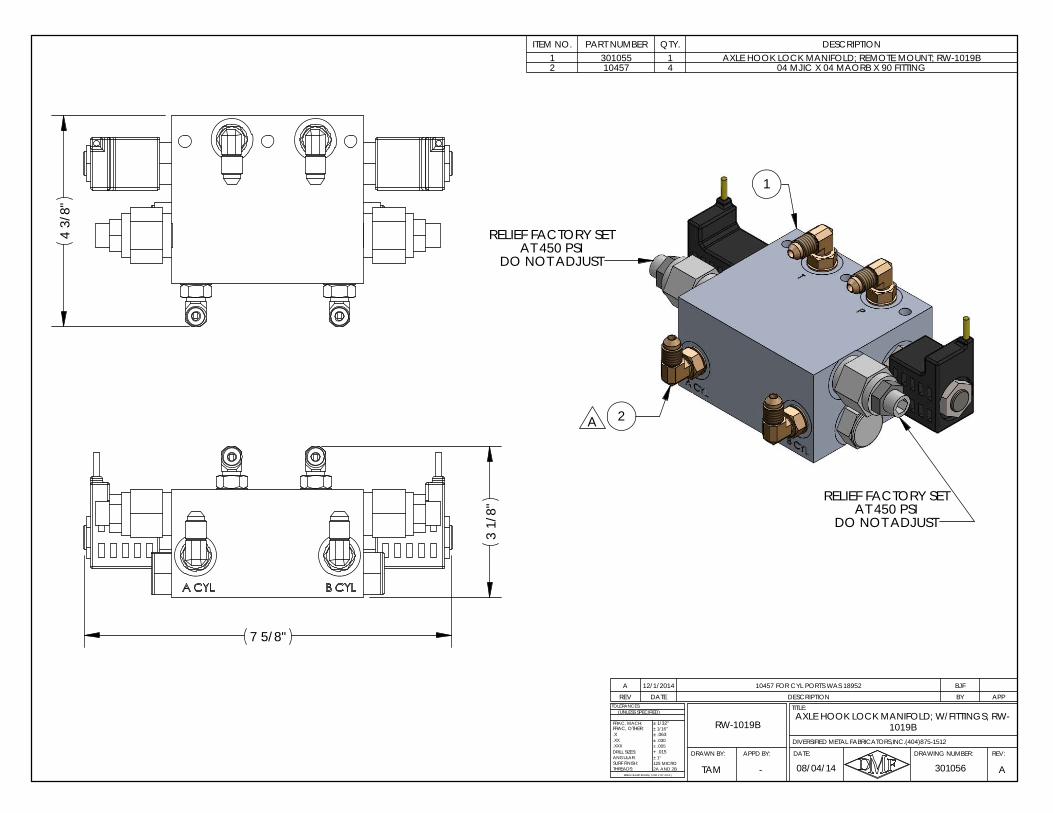
REV DATE DESCRIPTION BY APPA 12/1/2014 10457 FOR CYL PORTS WAS 18952 BJF
ITEM NO. PART NUMBER QTY. DESCRIPTION1 301055 1 AXLE HOOK LOCK MANIFOLD; REMOTE MOUNT; RW-1019B2 10457 4 04 MJIC X 04 MAORB X 90 FITTING
AT 450 PSIDO NOT ADJUST
RELIEF FACTORY SET
1
AT 450 PSIDO NOT ADJUST
RELIEF FACTORY SET
2A
1019BAXLE HOOK LOCK MANIFOLD; W/FITTINGS; RW-
RW-1019B
DATE:APPD BY:
FRAC, OTHER:
301056 A
.X
ANGULAR:
BREAK SHARP EDGES ( 0.030 X 45° MAX )
± 1/16"
± .005± .030
+ .015
± 1/32"
± .063
± 1°
2A AND 2B125 MICRO
DRILL SIZES:
SURF FINISH:THREADS:
.XXX
.XX
TOLERANCES:
FRAC, MACH:
DRAWN BY:
(UNLESS SPECIFIED)
DIVERSIFIED METAL FABRICATORS,INC.(404)875-1512
08/04/14TAM
REV:DRAWING NUMBER:
TITLE:
-
7 5/8"
3 1
/8"
4 3
/8"
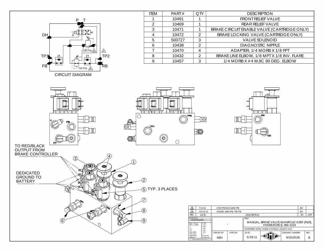
TO RED/BLACKOUTPUT FROMBRAKE CONTROLLER
2
9
13
7
8
4
6
5
T
CIRCUIT DIAGRAM
P
TP1 TP2
RBFB
DH
ITEM PART # QTY DESCRIPTION1 10491 1 FRONT RELIEF VALVE2 10469 1 REAR RELIEF VALVE3 10471 1 BRAKE CIRCUIT ENABLE VALVE (CARTRIDGE ONLY)4 10472 2 BRAKE LOCKING VALVE (CARTRIDGE ONLY)5 500727 3 VALVE SOLENOID6 10438 2 DIAGNOSTIC NIPPLE7 10470 4 ADAPTER, 1/4 MORB X 1/8 FPT8 10432 2 BRAKE LINE ELBOW, 1/8 MPT X 1/8 INV. FLARE9 10457 3 1/4 MORB X #4 MJIC 90 DEG. ELBOW
TYP. 3 PLACES
DEDICATEDGROUND TO BATTERY
1700 PSI
700 PSI A
A B
5/20/11
JDIADDED 1800 PSI, 700 PSI10/21/13
B
A
.X
ANGULAR:
BREAK SHARP EDGES ( 0.030 X 45° MAX )
± 1/16"
± .005± .030
+ .015
± 1/32"
± .063
± 1°
2A AND 2B125 MICRO
DRILL SIZES:
SURF FINISH:THREADS:
.XXX
.XX
TOLERANCES:
FRAC, MACH:
(UNLESS SPECIFIED)
FRAC, OTHER: -
7/2/14
HYDRAFORCE, RW-1019
1700 PSI WAS 1800 PSI
M1019135NEH
APPBY
REV:DRAWING NUMBER:
TITLE:
DATE:APPD BY:
DATE
DRAWN BY:
DIVERSIFIED METAL FABRICATORS,INC.(404)875-1512
DESCRIPTIONREV
B
MANUAL, BRAKE VALVE MANIFOLD ASSY (F&R),
JDI
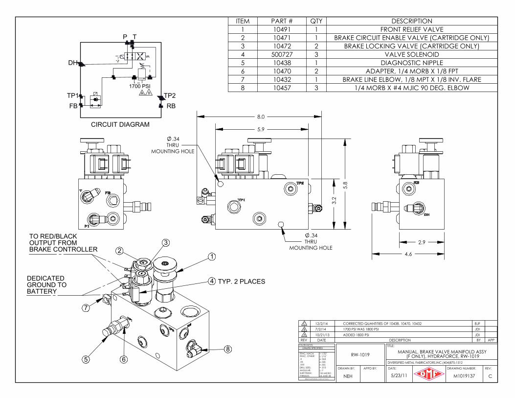
8.0
5.8
5.9
3.2
.34THRU
MOUNTING HOLE
.34THRU
MOUNTING HOLE
2.9
4.6 12
8
3
5
7
6
4
1700 PSIB
RBTP2
P
DH
TP1FB
CIRCUIT DIAGRAM
T
DEDICATEDGROUND TO BATTERY
TO RED/BLACKOUTPUT FROMBRAKE CONTROLLER
TYP. 2 PLACES
A
ITEM PART # QTY DESCRIPTION1 10491 1 FRONT RELIEF VALVE2 10471 1 BRAKE CIRCUIT ENABLE VALVE (CARTRIDGE ONLY)3 10472 2 BRAKE LOCKING VALVE (CARTRIDGE ONLY)4 500727 3 VALVE SOLENOID5 10438 1 DIAGNOSTIC NIPPLE6 10470 2 ADAPTER, 1/4 MORB X 1/8 FPT7 10432 1 BRAKE LINE ELBOW, 1/8 MPT X 1/8 INV. FLARE8 10457 3 1/4 MORB X #4 MJIC 90 DEG. ELBOW
JDIADDED 1800 PSI10/21/13
C
A
.X
ANGULAR:
BREAK SHARP EDGES ( 0.030 X 45° MAX )
± 1/16"
± .005± .030
+ .015
± 1/32"
± .063
± 1°
2A AND 2B125 MICRO
DRILL SIZES:
SURF FINISH:THREADS:
.XXX
.XX
TOLERANCES:
FRAC, MACH:
(UNLESS SPECIFIED)
FRAC, OTHER: RW-1019 MANUAL, BRAKE VALVE MANIFOLD ASSY (F ONLY), HYDRAFORCE, RW-1019
5/23/11 M1019137NEH
APPBY
REV:DRAWING NUMBER:
TITLE:
DATE:APPD BY:
DATE
DRAWN BY:
DIVERSIFIED METAL FABRICATORS,INC.(404)875-1512
DESCRIPTIONREV
B 7/2/14 1700 PSI WAS 1800 PSI JDIC BJF12/2/14 CORRECTED QUANTITIES OF 10438, 10470, 10432
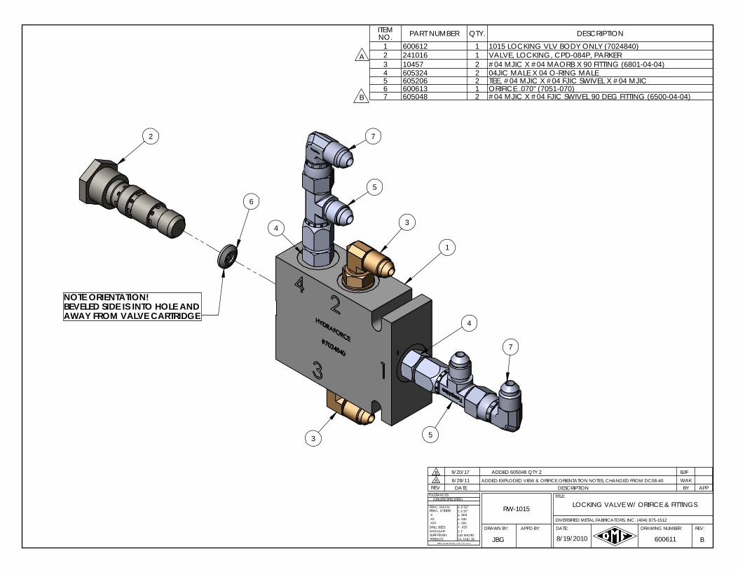
7
3
4
6
5
2
4
5
3
1
NOTE ORIENTATION!BEVELED SIDE IS INTO HOLE AND AWAY FROM VALVE CARTRIDGE
7
ITEM NO. PART NUMBER QTY. DESCRIPTION
1 600612 1 1015 LOCKING VLV BODY ONLY (7024840)2 241016 1 VALVE, LOCKING, CPD-084P, PARKER3 10457 2 #04 MJIC X #04 MAORB X 90 FITTING (6801-04-04)4 605324 2 04JIC MALE X 04 O-RING MALE5 605206 2 TEE, #04 MJIC X #04 FJIC SWIVEL X #04 MJIC6 600613 1 ORIFICE .070" (7051-070)7 605048 2 #04 MJIC X #04 FJIC SWIVEL 90 DEG FITTING (6500-04-04)
A
B
B 9/20/17
8/19/2010
WAKADDED EXPLODED VIEW & ORIFICE ORIENTATION NOTES, CHANGED FROM DC08-406/28/11
B
A
.X
ANGULAR:
BREAK SHARP EDGES ( 0.030 X 45° MAX )
± 1/16"
± .005± .030
+ .015
± 1/32"
± .063
± 1°
2A AND 2B125 MICRO
DRILL SIZES:
SURF FINISH:THREADS:
.XXX
.XX
TOLERANCES:
FRAC, MACH:
(UNLESS SPECIFIED)
FRAC, OTHER: RW-1015 LOCKING VALVE W/ ORIFICE & FITTINGS
BJF
600611JBG
APPBY
REV:DRAWING NUMBER:
TITLE:
DATE:APPD BY:
DATE
DRAWN BY:
DIVERSIFIED METAL FABRICATORS, INC. (404) 875-1512
DESCRIPTIONREV
ADDED 605048 QTY 2
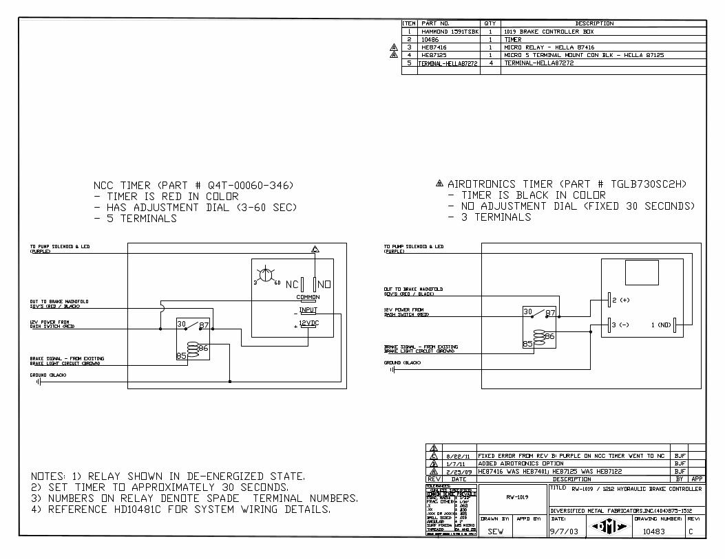
DIVERSIFIED METAL FABRICATORS, INC. RW-1019B
© 2019 DMF, Inc. All Rights Reserved. 7-1
SECTION 7.0 REAR RAILGEAR PARTS 7.1 BEFORE ORDERING PARTS ............................................................................. 7-2
7.2 REAR CORE ASSEMBLY DIAGRAMS ................................................................. 7-3
7.3 MOUNTING KIT DIAGRAMS ............................................................................ 7-5
7.4 H-BRACKET KIT DIAGRAMS ............................................................................ 7-8
7.5 REAR AXLE DIAGRAMS ................................................................................. 7-10
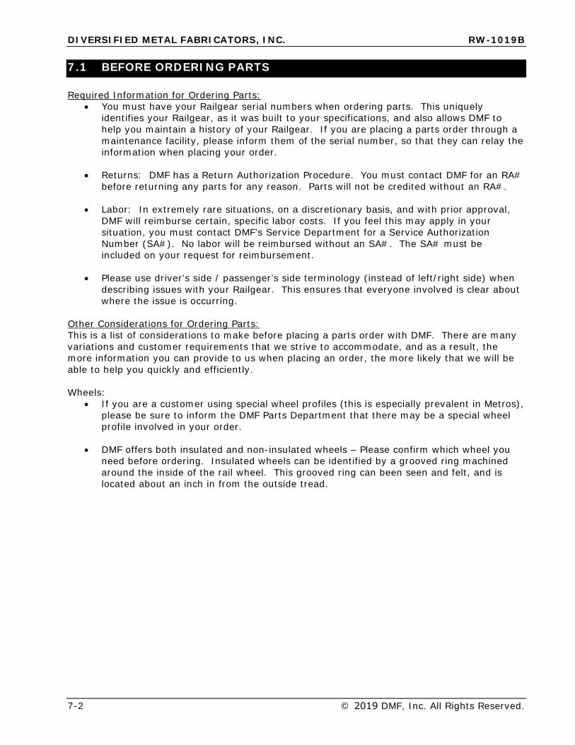
DIVERSIFIED METAL FABRICATORS, INC. RW-1019B
7-2 © 2019 DMF, Inc. All Rights Reserved.
7.1 BEFORE ORDERING PARTS
Required Information for Ordering Parts: • You must have your Railgear serial numbers when ordering parts. This uniquely
identifies your Railgear, as it was built to your specifications, and also allows DMF tohelp you maintain a history of your Railgear. If you are placing a parts order through amaintenance facility, please inform them of the serial number, so that they can relay theinformation when placing your order.
• Returns: DMF has a Return Authorization Procedure. You must contact DMF for an RA#before returning any parts for any reason. Parts will not be credited without an RA#.
• Labor: In extremely rare situations, on a discretionary basis, and with prior approval,DMF will reimburse certain, specific labor costs. If you feel this may apply in yoursituation, you must contact DMF’s Service Department for a Service AuthorizationNumber (SA#). No labor will be reimbursed without an SA#. The SA# must beincluded on your request for reimbursement.
• Please use driver’s side / passenger’s side terminology (instead of left/right side) whendescribing issues with your Railgear. This ensures that everyone involved is clear aboutwhere the issue is occurring.
Other Considerations for Ordering Parts: This is a list of considerations to make before placing a parts order with DMF. There are many variations and customer requirements that we strive to accommodate, and as a result, the more information you can provide to us when placing an order, the more likely that we will be able to help you quickly and efficiently.
Wheels: • If you are a customer using special wheel profiles (this is especially prevalent in Metros),
please be sure to inform the DMF Parts Department that there may be a special wheelprofile involved in your order.
• DMF offers both insulated and non-insulated wheels – Please confirm which wheel youneed before ordering. Insulated wheels can be identified by a grooved ring machinedaround the inside of the rail wheel. This grooved ring can been seen and felt, and islocated about an inch in from the outside tread.
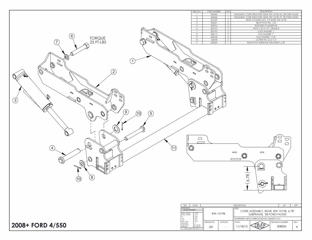
2
1
3
76
4
109 5
810
TORQUE25 FT-LBS
11
6.7
8
2008+ FORD 4/550
REV DATE DESCRIPTION BY APP
ITEM NO. PART NUMBER QTY DESCRIPTION1 304045 1 WELDMENT, CORE STRUCTURE, REAR, RW-1019B, DS, '08 FORD F4/5502 304046 1 WELDMENT, CORE STRUCTURE, REAR, RW-1019B, PS, '08 FORD F4/5503 301009 2 REAR CYLINDER ASSY, 2.5" BORE, RW-1019B4 303021 2 REAR PIVOT PIN, 1.25"5 303016 2 ROD END CYLINDER PIN6 605194 2 HHCS 1-8 X 5-1/2"; GRADE 87 605195 2 LOCK WASHER, 1"8 238112 2 FLAT WASHER, 1"9 500124 2 FLAT WASHER, 1-1/4"10 108078 4 COTTER PIN, 3/16" X 2"11 303039 1 REAR PIVOT SUBFRAME WELDMENT; 6.78"
#
.X
ANGULAR:
BREAK SHARP EDGES ( 0.030 X 45° MAX )
± 1/16"
± .005± .030
+ .015
± 1/32"
± .063
± 1°
2A AND 2B125 MICRO
DRILL SIZES:
SURF FINISH:THREADS:
.XXX
.XX
TOLERANCES:
FRAC, MACH:
(UNLESS SPECIFIED)
FRAC, OTHER:
11/18/13 308005JDI
REV:DRAWING NUMBER:
TITLE:
DATE:APPD BY:DRAWN BY:
DIVERSIFIED METAL FABRICATORS,INC.(404)875-1512
-
CORE ASSEMBLY, REAR, RW-1019B, 6.78" SUBFRAME, '08 FORD F4/550RW-1019B
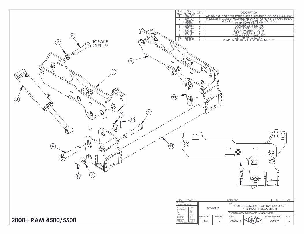
2
1
3
7
4
109
5
11
10
11
6
8
TORQUE25 FT-LBS
6.7
8
2008+ RAM 4500/5500
REV DATE DESCRIPTION BY APP
ITEM NO.
PART NUMBER QTY. DESCRIPTION
1 304122 1 WELDMENT, CORE STRUCTURE, REAR, RW-1019B, DS, '08 RAM 4/55002 304123 1 WELDMENT, CORE STRUCTURE, REAR, RW-1019B, PS, '08 RAM 4/55003 301009 2 REAR CYLINDER ASSY, 2.5" BORE, RW-1019B4 303021 2 REAR PIVOT PIN, 1.25"5 303016 2 ROD END CYLINDER PIN6 605194 2 HHCS, 1-8 X 5-1/2", GR87 109331 2 LOCK WASHER, 1", GR88 238112 2 FLAT WASHER, 1", GR59 818289 2 FLAT WASHER, 1-1/4", GR510 108078 4 COTTER PIN, 3/16" X 2"11 303039 1 REAR PIVOT SUBFRAME WELDMENT; 6.78"
#
.X
ANGULAR:
BREAK SHARP EDGES ( 0.030 X 45° MAX )
± 1/16"
± .005± .030
+ .015
± 1/32"
± .063
± 1°
2A AND 2B125 MICRO
DRILL SIZES:
SURF FINISH:THREADS:
.XXX
.XX
TOLERANCES:
FRAC, MACH:
(UNLESS SPECIFIED)
FRAC, OTHER:
02/02/15 308019TAM
REV:DRAWING NUMBER:
TITLE:
DATE:APPD BY:DRAWN BY:
DIVERSIFIED METAL FABRICATORS,INC.(404)875-1512
-
CORE ASSEMBLY; REAR; RW-1019B; 6.78" SUBFRAME, 08 RAM 4/5500RW-1019B

11
512
10
A
B
6
4
3
(1X EACH .0625,.125", .375")
60 FT-LBS
B
60 FT-LBS
60 FT-LBS
REAR SHIMTYPICALLY REQ'D: 9/16"EACH SIDE
120 FT-LBS
7 13
1
12
7
9
13
2
2
8
REV DATE DESCRIPTION BY APP
B 10/14/14 605006 WAS 605259, ITEM 3 CALLED OUT DJJ
A 7/2/2013 19-1/8" WAS 18-7/8", 605276 WAS 605258, ADDED 113014, 304024 WAS 304032 JDI
ITEM NO. PART NUMBER QTY. DESCRIPTION1 18551 4 LOCKNUT, 5/8-11, GR82 304001 1 SHIM SET; RW-1019B, 08 F SERIES
304005 2 RW-1019B AFT SHIM; .375" 304004 2 RW-1019B AFT SHIM; .25" 304003 2 RW-1019B AFT SHIM; .125" 304002 2 RW-1019B AFT SHIM; .0625" 304006 2 RW-1019B FWD SHIM; 08 F SERIES; .0625" 304007 2 RW-1019B FWD SHIM; 08 F SERIES; .125" 304008 2 RW-1019B FWD SHIM; 08 F SERIES; .25" 304009 2 RW-1019B FWD SHIM; 08 F SERIES; .375"
3 304027 1 WELDMENT, FORWARD FRAME BRACKET, REAR, RW-1019B, DS, '08 FORD F4/5504 304028 1 WELDMENT, FORWARD FRAME BRACKET, REAR, RW-1019B, PS, '08 FORD F4/5505 304024 2 BURNOUT, REARWARD FRAME MOUNT PLATE, REAR, RW-1019B, '08 FORD F4/5506 304051 2 INNER FRAME PLATE, REAR, RW-1019B, '08 FORD F4/5507 500691 6 1/2" FLAT WASHER; GR88 605076 8 FLAT WASHER, 5/8", GR89 605157 4 HHCS, 5/8-11 X 1-3/4", GR810 605006 6 HHCS, 1/2-13 X 2", GR811 12481 6 LOCK WASHER, 1/2", GR812 605276 6 HHCS, 1-2/13 X 2-1/4", GR813 113014 6 1/2"-13 NYLOCK NUT; GR8
NOTES:INSTALL FRAME MOUNT KIT BEFORE MOUNTING BODY ONTO TRUCK.1.
A
2008-2016 FORD F-4/550
FORD F-4/550FRAME MOUNT KIT, REAR, RW-1019B, '08-'16
RW-1019B
APPD BY:DRAWN BY:
304052 B
.X
ANGULAR:
BREAK SHARP EDGES ( 0.030 X 45° MAX )
± 1/16"
± .005± .030
+ .015
± 1/32"
± .063
± 1°
2A AND 2B125 MICRO
DRILL SIZES:
SURF FINISH:THREADS:
.XXX
.XX
TOLERANCES:
FRAC, MACH:
(UNLESS SPECIFIED)
5/9/13
DIVERSIFIED METAL FABRICATORS,INC.(404)875-1512
FRAC, OTHER:
JDI
REV:DRAWING NUMBER:
TITLE:
DATE:
-
9/16 INTO FRAMEMATCH DRILL 6X
VERIFY AT LEAST 1/8" OF CLEARANCE IS PRESENT BETWEEN TIP OF BOLT AND FUEL TANK. DIFFERENT LENGTH BOLTS MAY BE REQUIRED.
A 19 1/8"
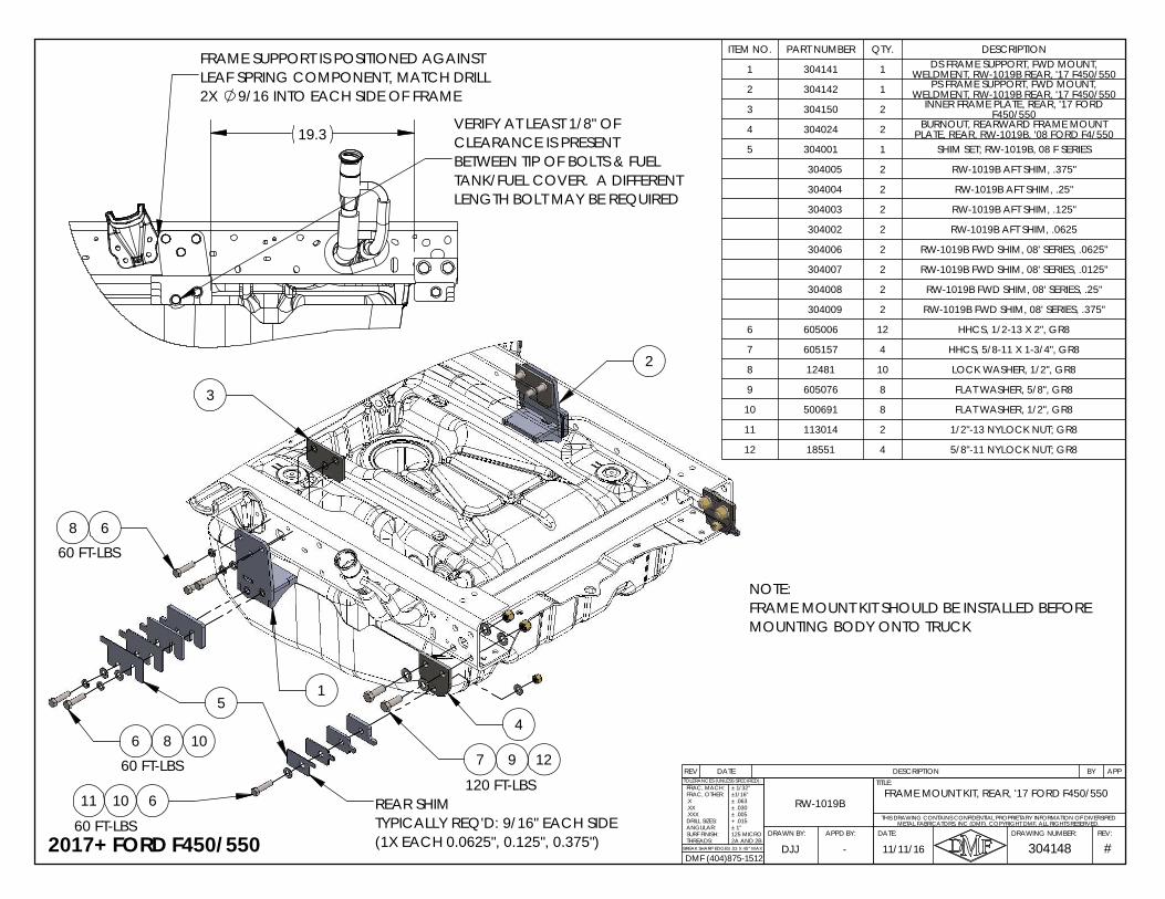
REV DATE DESCRIPTION BY APP
ITEM NO. PART NUMBER QTY. DESCRIPTION
1 304141 1 DS FRAME SUPPORT, FWD MOUNT, WELDMENT, RW-1019B REAR, '17 F450/550
2 304142 1 PS FRAME SUPPORT, FWD MOUNT, WELDMENT, RW-1019B REAR, '17 F450/550
3 304150 2 INNER FRAME PLATE, REAR, '17 FORD F450/550
4 304024 2 BURNOUT, REARWARD FRAME MOUNT PLATE, REAR, RW-1019B, '08 FORD F4/550
5 304001 1 SHIM SET; RW-1019B, 08 F SERIES
304005 2 RW-1019B AFT SHIM, .375"
304004 2 RW-1019B AFT SHIM, .25"
304003 2 RW-1019B AFT SHIM, .125"
304002 2 RW-1019B AFT SHIM, .0625
304006 2 RW-1019B FWD SHIM, 08' SERIES, .0625"
304007 2 RW-1019B FWD SHIM, 08' SERIES, .0125"
304008 2 RW-1019B FWD SHIM, 08' SERIES, .25"
304009 2 RW-1019B FWD SHIM, 08' SERIES, .375"
6 605006 12 HHCS, 1/2-13 X 2", GR8
7 605157 4 HHCS, 5/8-11 X 1-3/4", GR8
8 12481 10 LOCK WASHER, 1/2", GR8
9 605076 8 FLAT WASHER, 5/8", GR8
10 500691 8 FLAT WASHER, 1/2", GR8
11 113014 2 1/2"-13 NYLOCK NUT; GR8
12 18551 4 5/8"-11 NYLOCK NUT; GR8
#BREAK SHARP EDGES .03 X 45° MAX2A AND 2B
304148REV:DRAWING NUMBER:
TITLE:
DATE:APPD BY:DRAWN BY:
FRAC, MACH:TOLERANCES (UNLESS SPECIFIED):
METAL FABRICATORS, INC (DMF). COPYRIGHT DMF, ALL RIGHTS RESERVED.
DJJ -
RW-1019B
11/11/16
FRAME MOUNT KIT, REAR, '17 FORD F450/550
THIS DRAWING CONTAINS CONFIDENTIAL PROPRIETARY INFORMATION OF DIVERSIFIED
FRAC, OTHER:.X.XX.XXXDRILL SIZES:ANGULAR:SURF FINISH:THREADS:
± 1/32"±1/16"± .063± .030± .005+ .015± 1°125 MICRO
DMF (404)875-15122017+ FORD F450/550
60 FT-LBS
8 1012
1
120 FT-LBS10
60 FT-LBS
7
4
3
611
9
6
6
5
2
8
60 FT-LBS
NOTE:FRAME MOUNT KIT SHOULD BE INSTALLED BEFORE MOUNTING BODY ONTO TRUCK
REAR SHIMTYPICALLY REQ'D: 9/16" EACH SIDE(1X EACH 0.0625", 0.125", 0.375")
FRAME SUPPORT IS POSITIONED AGAINST LEAF SPRING COMPONENT, MATCH DRILL 2X 9/16 INTO EACH SIDE OF FRAME
19.3 VERIFY AT LEAST 1/8" OF CLEARANCE IS PRESENT BETWEEN TIP OF BOLTS & FUEL TANK/FUEL COVER. A DIFFERENT LENGTH BOLT MAY BE REQUIRED
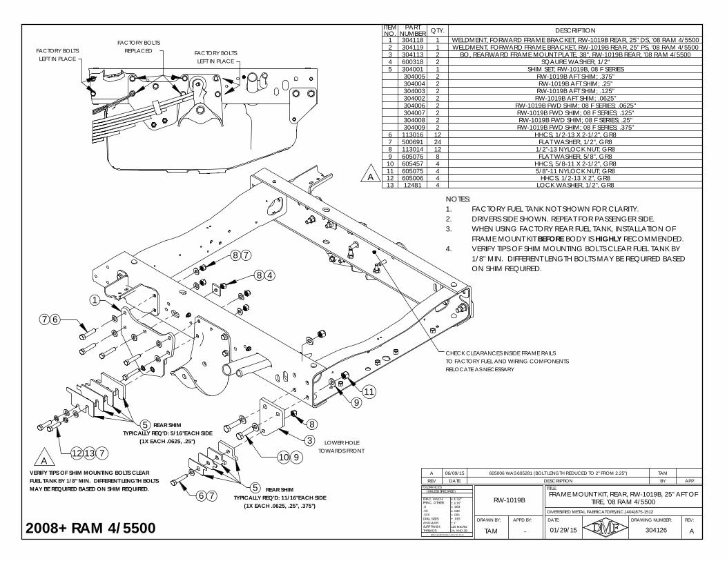
REV DATE DESCRIPTION BY APPA 06/09/15 605006 WAS 605281 (BOLT LENGTH REDUCED TO 2" FROM 2.25") TAM
FACTORY BOLTSLEFT IN PLACE
FACTORY BOLTSLEFT IN PLACE
NOTES:FACTORY FUEL TANK NOT SHOWN FOR CLARITY.1.DRIVERS SIDE SHOWN. REPEAT FOR PASSENGER SIDE.2.WHEN USING FACTORY REAR FUEL TANK, INSTALLATION OF 3.FRAME MOUNT KIT BEFORE BODY IS HIGHLY RECOMMENDED.VERIFY TIPS OF SHIM MOUNTING BOLTS CLEAR FUEL TANK BY4.1/8" MIN. DIFFERENT LENGTH BOLTS MAY BE REQUIRED BASEDON SHIM REQUIRED.
ITEM NO.
PART NUMBER QTY. DESCRIPTION
1 304118 1 WELDMENT, FORWARD FRAME BRACKET, RW-1019B REAR, 25" DS, '08 RAM 4/55002 304119 1 WELDMENT, FORWARD FRAME BRACKET, RW-1019B REAR, 25" PS, '08 RAM 4/55003 304113 2 BO, REARWARD FRAME MOUNT PLATE, 38", RW-1019B REAR, '08 RAM 4/55004 600318 2 SQAURE WASHER, 1/2"5 304001 1 SHIM SET; RW-1019B, 08 F SERIES
304005 2 RW-1019B AFT SHIM; .375" 304004 2 RW-1019B AFT SHIM; .25" 304003 2 RW-1019B AFT SHIM; .125" 304002 2 RW-1019B AFT SHIM; .0625" 304006 2 RW-1019B FWD SHIM; 08 F SERIES; .0625" 304007 2 RW-1019B FWD SHIM; 08 F SERIES; .125" 304008 2 RW-1019B FWD SHIM; 08 F SERIES; .25" 304009 2 RW-1019B FWD SHIM; 08 F SERIES; .375"
6 113016 12 HHCS, 1/2-13 X 2-1/2", GR87 500691 24 FLAT WASHER, 1/2", GR88 113014 12 1/2"-13 NYLOCK NUT; GR89 605076 8 FLAT WASHER, 5/8", GR8
10 605457 4 HHCS, 5/8-11 X 2-1/2", GR811 605075 4 5/8"-11 NYLOCK NUT; GR812 605006 4 HHCS, 1/2-13 X 2", GR813 12481 4 LOCK WASHER, 1/2", GR8
2008+ RAM 4/5500
A
TIRE, '08 RAM 4/5500FRAME MOUNT KIT, REAR, RW-1019B, 25" AFT OF
RW-1019B
304126 A
.X
ANGULAR:
BREAK SHARP EDGES ( 0.030 X 45° MAX )
± 1/16"
± .005± .030
+ .015
± 1/32"
± .063
± 1°
2A AND 2B125 MICRO
DRILL SIZES:
SURF FINISH:THREADS:
.XXX
.XX
TOLERANCES:
FRAC, MACH:
(UNLESS SPECIFIED)
DIVERSIFIED METAL FABRICATORS,INC.(404)875-1512
FRAC, OTHER:
01/29/15TAM
REV:DRAWING NUMBER:
TITLE:
DATE:APPD BY:DRAWN BY:
-
TOWARDS FRONTLOWER HOLE
6
1
3
8 4
8
911
10 9
6 7
1312 7
7
5
5
(1X EACH .0625, .25", .375")TYPICALLY REQ'D: 11/16"EACH SIDE
REAR SHIM
8 7
MAY BE REQUIRED BASED ON SHIM REQUIRED.FUEL TANK BY 1/8" MIN. DIFFERENT LENGTH BOLTS VERIFY TIPS OF SHIM MOUNTING BOLTS CLEAR
(1X EACH .0625, .25")TYPICALLY REQ'D: 5/16"EACH SIDE
REAR SHIM
RELOCATE AS NECESSARYTO FACTORY FUEL AND WIRING COMPONENTSCHECK CLEARANCES INSIDE FRAME RAILS
A
REPLACEDFACTORY BOLTS
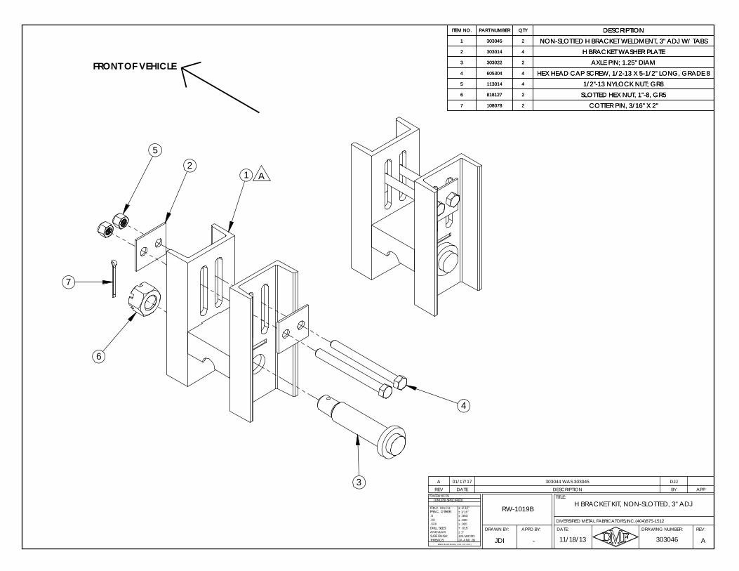
H BRACKET KIT, NON-SLOTTED, 3" ADJRW-1019B
APPD BY:DRAWN BY:
303046 A
.X
ANGULAR:
BREAK SHARP EDGES ( 0.030 X 45° MAX )
± 1/16"
± .005± .030
+ .015
± 1/32"
± .063
± 1°
2A AND 2B125 MICRO
DRILL SIZES:
SURF FINISH:THREADS:
.XXX
.XX
TOLERANCES:
FRAC, MACH:
(UNLESS SPECIFIED)
DIVERSIFIED METAL FABRICATORS,INC.(404)875-1512
11/18/13
FRAC, OTHER:
JDI
REV:DRAWING NUMBER:
TITLE:
DATE:
-
25
1
7
6
4
FRONT OF VEHICLE
3
A
REV DATE DESCRIPTION BY APPA 01/17/17 303044 WAS 303045 DJJ
ITEM NO. PART NUMBER QTY DESCRIPTION1 303045 2 NON-SLOTTED H BRACKET WELDMENT, 3" ADJ W/ TABS2 303014 4 H BRACKET WASHER PLATE3 303022 2 AXLE PIN; 1.25" DIAM4 605304 4 HEX HEAD CAP SCREW, 1/2-13 X 5-1/2" LONG, GRADE 85 113014 4 1/2"-13 NYLOCK NUT; GR86 818127 2 SLOTTED HEX NUT, 1"-8, GR57 108078 2 COTTER PIN, 3/16" X 2"
ITEM NO. PART NUMBER QTY DESCRIPTION1 303045 2 NON-SLOTTED H BRACKET WELDMENT, 3" ADJ W/ TABS2 303014 4 H BRACKET WASHER PLATE3 303022 2 AXLE PIN; 1.25" DIAM4 605304 4 HEX HEAD CAP SCREW, 1/2-13 X 5-1/2" LONG, GRADE 85 113014 4 1/2"-13 NYLOCK NUT; GR86 818127 2 SLOTTED HEX NUT, 1"-8, GR57 108078 2 COTTER PIN, 3/16" X 2"
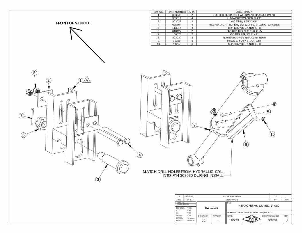
REV DATE DESCRIPTION BY APPA 01/17/17 303048 WAS 303015 DJJ
ITEM NO. PART NUMBER QTY. DESCRIPTION1 303048 2 SLOTTED H BRACKET WELDMENT; 3" ADJUSTMENT2 303014 4 H BRACKET WASHER PLATE3 303022 2 AXLE PIN; 1.25" DIAM4 605304 4 HEX HEAD CAP SCREW, 1/2-13 X 5-1/2" LONG, GRADE 85 113014 4 1/2"-13 NYLOCK NUT; GR86 818127 2 SLOTTED HEX NUT, 1"-8, GR57 108078 2 COTTER PIN, 3/16" X 2"8 303030 2 RUBBER BUMPER, RW-1019B, REAR9 10399 6 HHCS, 1/4-20 X 1-1/2", GR5
10 11257 6 1/4"-20 NYLOCK NUT; GR8
106
5
2
7
FRONT OF VEHICLE
1
3
4
9
8
MATCH DRILL HOLES FROM HYDRAULIC CYL.INTO P/N 303030 DURING INSTALL
A
H BRACKET KIT, SLOTTED, 3" ADJRW-1019B
DRAWN BY:
303031 A
.X
ANGULAR:
BREAK SHARP EDGES ( 0.030 X 45° MAX )
± 1/16"
± .005± .030
+ .015
± 1/32"
± .063
± 1°
2A AND 2B125 MICRO
DRILL SIZES:
SURF FINISH:THREADS:
.XXX
.XX
TOLERANCES:
FRAC, MACH:
(UNLESS SPECIFIED)
FRAC, OTHER:
11/5/13
DIVERSIFIED METAL FABRICATORS,INC.(404)875-1512
JDI
REV:DRAWING NUMBER:
TITLE:
DATE:APPD BY:
-
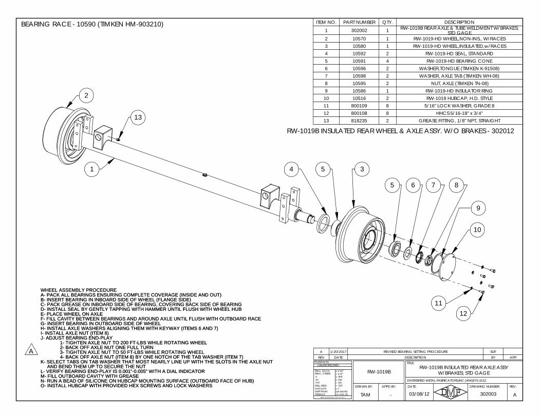
REV DATE DESCRIPTION BY APPA 1/20/2017 REVISED BEARING SETTING PROCEDURE BJF
ITEM NO. PART NUMBER QTY. DESCRIPTION
1 302002 1 RW-1019B REAR AXLE & TUBE WELDMENT W/BRAKES; STD GAGE
2 10570 1 RW-1019-HD WHEEL,NON-INS., W/RACES3 10580 1 RW-1019-HD WHEEL,INSULATED,w/RACES4 10592 2 RW-1019-HD SEAL, STANDARD5 10591 4 RW-1019-HD BEARING CONE6 10596 2 WASHER,TONGUE (TIMKEN K-91508)7 10598 2 WASHER, AXLE TAB (TIMKEN WH-08)8 10595 2 NUT, AXLE (TIMKEN TN-08)9 10586 1 RW-1019-HD INSULATOR RING
10 10516 2 RW-1019 HUBCAP, H.D. STYLE11 800109 8 5/16" LOCK WASHER, GRADE 812 800108 8 HHCS 5/16-18" x 3/4"13 818235 2 GREASE FITTING, 1/8" NPT, STRAIGHT
WHEEL ASSEMBLY PROCEDUREA- PACK ALL BEARINGS ENSURING COMPLETE COVERAGE (INSIDE AND OUT)B- INSERT BEARING IN INBOARD SIDE OF WHEEL (FLANGE SIDE)C- PACK GREASE ON INBOARD SIDE OF BEARING, COVERING BACK SIDE OF BEARINGD- INSTALL SEAL BY GENTLY TAPPING WITH HAMMER UNTIL FLUSH WITH WHEEL HUBE- PLACE WHEEL ON AXLEF- FILL CAVITY BETWEEN BEARINGS AND AROUND AXLE UNTIL FLUSH WITH OUTBOARD RACEG- INSERT BEARING IN OUTBOARD SIDE OF WHEELH- INSTALL AXLE WASHERS ALIGNING THEM WITH KEYWAY (ITEMS 6 AND 7)I- INSTALL AXLE NUT (ITEM 8)J- ADJUST BEARING END-PLAY
1- TIGHTEN AXLE NUT TO 200 FT-LBS WHILE ROTATING WHEEL2- BACK OFF AXLE NUT ONE FULL TURN3- TIGHTEN AXLE NUT TO 50 FT-LBS WHILE ROTATING WHEEL4- BACK OFF AXLE NUT (ITEM 8) BY ONE NOTCH OF THE TAB WASHER (ITEM 7)
K- SELECT TABS ON TAB WASHER THAT MOST NEARLY LINE UP WITH THE SLOTS IN THE AXLE NUTAND BEND THEM UP TO SECURE THE NUT
L- VERIFY BEARING END-PLAY IS 0.001”-0.005” WITH A DIAL INDICATORM- FILL OUTBOARD CAVITY WITH GREASEN- RUN A BEAD OF SILICONE ON HUBCAP MOUNTING SURFACE (OUTBOARD FACE OF HUB)O- INSTALL HUBCAP WITH PROVIDED HEX SCREWS AND LOCK WASHERS
BEARING RACE - 10590 (TIMKEN HM-903210)
WHEEL ASSEMBLY PROCEDUREA- PACK ALL BEARINGS ENSURING COMPLETE COVERAGE (INSIDE AND OUT)B- INSERT BEARING IN INBOARD SIDE OF WHEEL (FLANGE SIDE)C- PACK GREASE ON INBOARD SIDE OF BEARING, COVERING BACK SIDE OF BEARINGD- INSTALL SEAL BY GENTLY TAPPING WITH HAMMER UNTIL FLUSH WITH WHEEL HUBE- PLACE WHEEL ON AXLEF- FILL CAVITY BETWEEN BEARINGS AND AROUND AXLE UNTIL FLUSH WITH OUTBOARD RACEG- INSERT BEARING IN OUTBOARD SIDE OF WHEELH- INSTALL AXLE WASHERS ALIGNING THEM WITH KEYWAY (ITEMS 6 AND 7)I- INSTALL AXLE NUT (ITEM 8)J- ADJUST BEARING END-PLAY
1- TIGHTEN AXLE NUT TO 200 FT-LBS WHILE ROTATING WHEEL2- BACK OFF AXLE NUT ONE FULL TURN3- TIGHTEN AXLE NUT TO 50 FT-LBS WHILE ROTATING WHEEL4- BACK OFF AXLE NUT (ITEM 8) BY ONE NOTCH OF THE TAB WASHER (ITEM 7)
K- SELECT TABS ON TAB WASHER THAT MOST NEARLY LINE UP WITH THE SLOTS IN THE AXLE NUTAND BEND THEM UP TO SECURE THE NUT
L- VERIFY BEARING END-PLAY IS 0.001”-0.005” WITH A DIAL INDICATORM- FILL OUTBOARD CAVITY WITH GREASEN- RUN A BEAD OF SILICONE ON HUBCAP MOUNTING SURFACE (OUTBOARD FACE OF HUB)O- INSTALL HUBCAP WITH PROVIDED HEX SCREWS AND LOCK WASHERS
W/BRAKES; STD GAGERW-1019B INSULATED REAR AXLE ASSY
RW-1019B
DRAWN BY:
DIVERSIFIED METAL FABRICATORS,INC.(404)875-1512
A
.X
ANGULAR:
BREAK SHARP EDGES ( 0.030 X 45° MAX )
± 1/16"
± .005± .030
+ .015
± 1/32"
± .063
± 1°
2A AND 2B125 MICRO
DRILL SIZES:
SURF FINISH:THREADS:
.XXX
.XX
TOLERANCES:
FRAC, MACH:
(UNLESS SPECIFIED)
03/08/12 302003
FRAC, OTHER:
TAM
REV:DRAWING NUMBER:
TITLE:
DATE:APPD BY:
-
RW-1019B INSULATED REAR WHEEL & AXLE ASSY. W/O BRAKES - 302012
1
13
6
10
1112
87
354
2
5
9
A
DIVERSIFIED METAL FABRICATORS, INC. RW-1019B
© 2019 DMF, Inc. All Rights Reserved. 8-1
SECTION 8.0 FRONT RAILGEAR PARTS 8.1 BEFORE ORDERING PARTS ............................................................................. 8-2
8.2 FRONT ASSEMBLY DIAGRAMS ........................................................................ 8-3
8.3 FRONT AXLE DIAGRAMS ................................................................................. 8-7
8.4 AXLE LOCK KIT DIAGRAMS ............................................................................. 8-9
DIVERSIFIED METAL FABRICATORS, INC. RW-1019B
8-2 © 2019 DMF, Inc. All Rights Reserved.
8.1 BEFORE ORDERING PARTS
Required Information for Ordering Parts: • You must have your Railgear serial numbers when ordering parts. This uniquely
identifies your Railgear, as it was built to your specifications, and also allows DMF tohelp you maintain a history of your Railgear. If you are placing a parts order through amaintenance facility, please inform them of the serial number, so that they can relay theinformation when placing your order.
• Returns: DMF has a Return Authorization Procedure. You must contact DMF for an RA#before returning any parts for any reason. Parts will not be credited without an RA#.
• Labor: In extremely rare situations, on a discretionary basis, and with prior approval,DMF will reimburse certain, specific labor costs. If you feel this may apply in yoursituation, you must contact DMF’s Service Department for a Service AuthorizationNumber (SA#). No labor will be reimbursed without an SA#. The SA# must beincluded on your request for reimbursement.
• Please use driver’s side / passenger’s side terminology (instead of left/right side) whendescribing issues with your Railgear. This ensures that everyone involved is clear aboutwhere the issue is occurring.
Other Considerations for Ordering Parts: This is a list of considerations to make before placing a parts order with DMF. There are many variations and customer requirements that we strive to accommodate, and as a result, the more information you can provide to us when placing an order, the more likely that we will be able to help you quickly and efficiently.
Wheels: • If you are a customer using special wheel profiles (this is especially prevalent in Metros),
please be sure to inform the DMF Parts Department that there may be a special wheelprofile involved in your order.
• DMF offers both insulated and non-insulated wheels – Please confirm which wheel youneed before ordering. Insulated wheels can be identified by a grooved ring machinedaround the inside of the rail wheel. This grooved ring can been seen and felt, and islocated about an inch in from the outside tread.
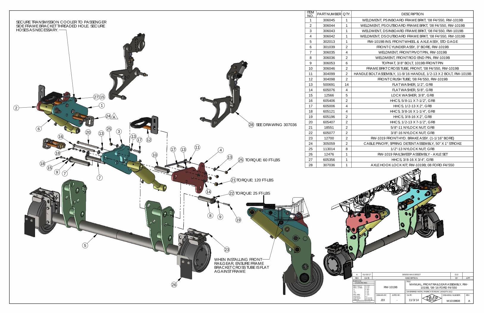
5
4
3
2 1
6
24
12
2513
1117 13
21
14
8 919
10
20 1316
18
1815
797
23
26
22
TORQUE: 120 FT-LBS
TORQUE: 60 FT-LBS
28
TORQUE: 25 FT-LBS
25
1713
SEE DRAWING 307036
HOSES AS NECESSARY.
SECURE TRANSMISSION COOLER TO PASSENGERSIDE FRAME BRACKET THREADED HOLE. SECURE
27 15
A
REV DATE DESCRIPTION BY APP
A 01/03/17 305059 WAS 305027 DJJ
ITEM NO. PART NUMBER QTY. DESCRIPTION
1 306045 1 WELDMENT, PS INBOARD FRAME BRKT, '08 F4/550, RW-1019B2 306044 1 WELDMENT, PS OUTBOARD FRAME BRKT, '08 F4/550, RW-1019B3 306043 1 WELDMENT, DS INBOARD FRAME BRKT, '08 F4/550, RW-1019B4 306042 1 WELDMENT, DS OUTBOARD FRAME BRKT, '08 F4/550, RW-1019B5 302013 1 RW-1019B INS. FRONT WHEEL & AXLE ASSY, STD GAGE6 301039 2 FRONT CYLINDER ASSY, 3" BORE, RW-1019B7 306035 4 WELDMENT, FRONT PIVOT PIN, RW-1019B8 306036 2 WELDMENT, FRONT ROD END PIN, RW-1019B9 306053 6 TOPHAT, 3/8" BOLT, 1019B FRONT PIN10 306046 2 FRAME BRKT CROSS TUBE, FRONT, '08 F4/550, RW-1019B11 304099 2 HANDLE BOLT ASSEMBLY, 11-9/16 HANDLE, 1/2-13 X 2 BOLT, RW-1019B12 304098 2 FRONT CRUSH TUBE; '08 F4/550, RW-1019B13 500691 14 FLAT WASHER, 1/2", GR814 605076 4 FLAT WASHER, 5/8", GR815 12566 5 LOCK WASHER, 3/8", GR816 605406 2 HHCS, 5/8-11 X 7-1/2", GR817 605006 4 HHCS, 1/2-13 X 2", GR818 605121 4 HHCS, 3/8-16 X 1-1/4", GR819 605196 2 HHCS, 3/8-16 X 2", GR820 605407 2 HHCS, 1/2-13 X 7-1/2", GR821 18551 2 5/8"-11 NYLOCK NUT; GR822 605077 2 3/8"-16 NYLOCK NUT; GR823 12700 2 RW-1019 FRONT HYD. BRAKE ASSY. (1-1/16" BORE)24 305059 2 CABLE PINOFF, SPRING DETENT ASSEMBLY, 50" X 1" STROKE25 113014 8 1/2"-13 NYLOCK NUT; GR826 12476 1 RW-1019 RAILSWEEP ASSEMBLY - AXLE SET27 605356 1 HHCS, 3/8-16 X 3/4", GR828 307036 1 AXLE HOOK LOCK KIT; RW-1019B; 08 FORD F4/550
A
.X
ANGULAR:
BREAK SHARP EDGES ( 0.030 X 45° MAX )
± 1/16"
± .005± .030
+ .015
± 1/32"
± .063
± 1°
2A AND 2B125 MICRO
DRILL SIZES:
SURF FINISH:THREADS:
.XXX
.XX
TOLERANCES:
FRAC, MACH:
(UNLESS SPECIFIED)
11/3/14 M1019B08
REV:DRAWING NUMBER:
TITLE:
DATE:APPD BY:DRAWN BY:
FRAC, OTHER:
DIVERSIFIED METAL FABRICATORS,INC.(404)875-1512
JDI -
RW-1019BMANUAL, FRONT RAILGEAR ASSEMBLY, RW-
1019B, '08-'16 FORD F4/550
WHEN INSTALLING FRONTRAILGEAR, ENSURE FRAMEBRACKET CROSS TUBE IS FLATAGAINST FRAME
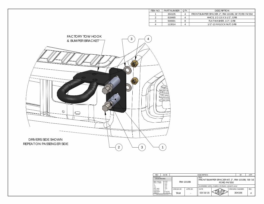
FORD F4/550FRONT BUMPER SPACER KIT, 2", RW-1019B, '08-'16
RW-1019B
APPD BY:DRAWN BY:
DIVERSIFIED METAL FABRICATORS,INC.(404)875-1512
#
.X
ANGULAR:
BREAK SHARP EDGES ( 0.030 X 45° MAX )
± 1/16"
± .005± .030
+ .015
± 1/32"
± .063
± 1°
2A AND 2B125 MICRO
DRILL SIZES:
SURF FINISH:THREADS:
.XXX
.XX
TOLERANCES:
FRAC, MACH:
(UNLESS SPECIFIED)
03/15/15 304106
FRAC, OTHER:
TAM
REV:DRAWING NUMBER:
TITLE:
DATE:
-
REV DATE DESCRIPTION BY APP
ITEM NO. PART NUMBER QTY. DESCRIPTION1 304105 4 FRONT BUMPER SPACER, 2", RW-1019B, 08' FORD F4/5502 818465 4 HHCS, 1/2-13 X 3-1/2", GR83 500691 8 FLAT WASHER, 1/2", GR84 113014 4 1/2"-13 NYLOCK NUT; GR8
3
3& BUMPER BRACKETFACTORY TOW HOOK
2 1
4
DRIVERS SIDE SHOWNREPEAT ON PASSENGER SIDE
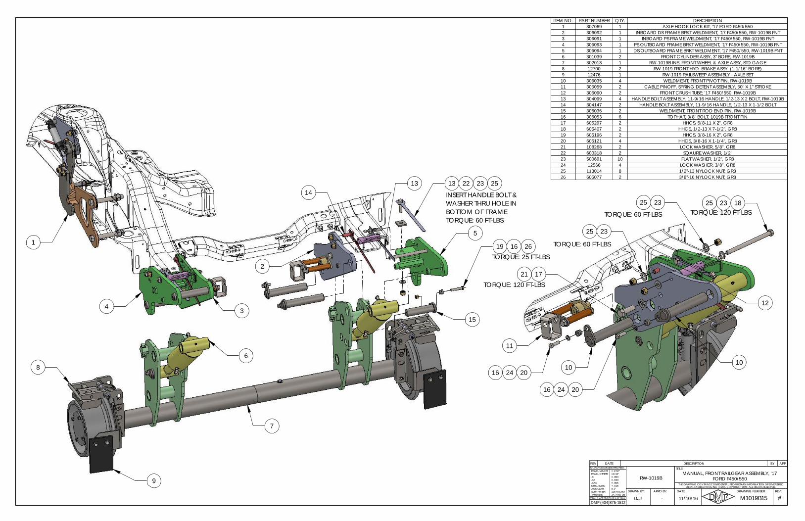
THIS DRAWING CONTAINS CONFIDENTIAL PROPRIETARY INFORMATION OF DIVERSIFIED
BREAK SHARP EDGES .03 X 45° MAX2A AND 2B
M1019B15REV:DRAWING NUMBER:
TITLE:
DATE:APPD BY:DRAWN BY:
#
TOLERANCES (UNLESS SPECIFIED):
METAL FABRICATORS, INC (DMF). COPYRIGHT DMF, ALL RIGHTS RESERVED.
DJJ -
RW-1019B
11/10/16
FRAC, MACH:
FORD F450/550MANUAL, FRONT RAILGEAR ASSEMBLY, '17 FRAC, OTHER:
.X
.XX
.XXXDRILL SIZES:ANGULAR:SURF FINISH:THREADS:
± 1/32"±1/16"± .063± .030± .005+ .015± 1°125 MICRO
DMF (404)875-1512
REV DATE DESCRIPTION BY APP
ITEM NO. PART NUMBER QTY. DESCRIPTION1 307069 1 AXLE HOOK LOCK KIT, '17 FORD F450/5502 306092 1 INBOARD DS FRAME BRKT WELDMENT, '17 F450/550, RW-1019B FNT3 306091 1 INBOARD PS FRAME WELDMENT, '17 F450/550, RW-1019B FNT4 306093 1 PS OUTBOARD FRAME BRKT WELDMENT, '17 F450/550, RW-1019B FNT5 306094 1 DS OUTBOARD FRAME BRKT WELDMENT, '17 F450/550, RW-1019B FNT6 301039 2 FRONT CYLINDER ASSY, 3" BORE, RW-1019B7 302013 1 RW-1019B INS. FRONT WHEEL & AXLE ASSY, STD GAGE8 12700 2 RW-1019 FRONT HYD. BRAKE ASSY. (1-1/16" BORE)9 12476 1 RW-1019 RAILSWEEP ASSEMBLY - AXLE SET
10 306035 4 WELDMENT, FRONT PIVOT PIN, RW-1019B11 305059 2 CABLE PINOFF, SPRING DETENT ASSEMBLY, 50" X 1" STROKE12 306090 2 FRONT CRUSH TUBE; '17 F450/550, RW-1019B13 304099 4 HANDLE BOLT ASSEMBLY, 11-9/16 HANDLE, 1/2-13 X 2 BOLT, RW-1019B14 304147 2 HANDLE BOLT ASSEMBLY, 11-9/16 HANDLE, 1/2-13 X 1-1/2 BOLT15 306036 2 WELDMENT, FRONT ROD END PIN, RW-1019B16 306053 6 TOPHAT, 3/8" BOLT, 1019B FRONT PIN17 605297 2 HHCS, 5/8-11 X 2". GR818 605407 2 HHCS, 1/2-13 X 7-1/2", GR819 605196 2 HHCS, 3/8-16 X 2", GR820 605121 4 HHCS, 3/8-16 X 1-1/4", GR821 108268 2 LOCK WASHER, 5/8", GR822 600318 2 SQAURE WASHER, 1/2"23 500691 10 FLAT WASHER, 1/2", GR824 12566 4 LOCK WASHER, 3/8", GR825 113014 8 1/2"-13 NYLOCK NUT; GR826 605077 2 3/8"-16 NYLOCK NUT; GR8
TORQUE: 60 FT-LBS
25 1823
12
25
102024
11
1610
24 2016
1721TORQUE: 120 FT-LBS
TORQUE: 60 FT-LBS TORQUE: 120 FT-LBS23
2325
14
7
9
8
6
1
4 3
22 2313 25
5
2
15
16 2619
TORQUE: 60 FT-LBS
INSERT HANDLE BOLT & WASHER THRU HOLE IN
TORQUE: 25 FT-LBS
BOTTOM OF FRAME
13
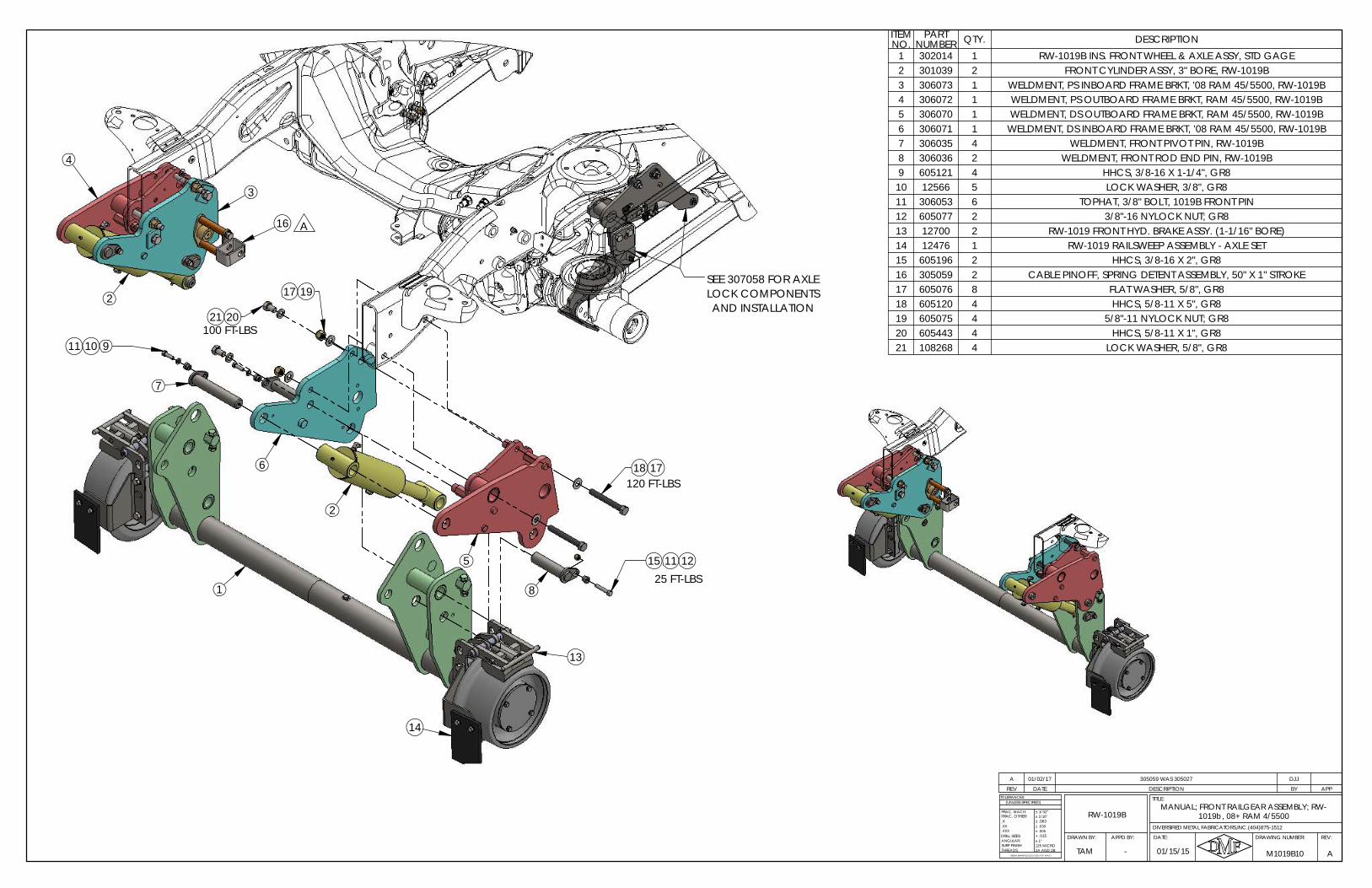
20
11
19
12
18
LOCK COMPONENTSSEE 307058 FOR AXLE
15
1
14
13
16
4
3
25 FT-LBS
2
100 FT-LBS
2
120 FT-LBS6
1011
A
5
21
17
9
17
8
7
AND INSTALLATION
REV DATE DESCRIPTION BY APP
A 01/02/17 305059 WAS 305027 DJJ
ITEM NO.
PART NUMBER QTY. DESCRIPTION
1 302014 1 RW-1019B INS. FRONT WHEEL & AXLE ASSY, STD GAGE2 301039 2 FRONT CYLINDER ASSY, 3" BORE, RW-1019B3 306073 1 WELDMENT, PS INBOARD FRAME BRKT, '08 RAM 45/5500, RW-1019B4 306072 1 WELDMENT, PS OUTBOARD FRAME BRKT, RAM 45/5500, RW-1019B5 306070 1 WELDMENT, DS OUTBOARD FRAME BRKT, RAM 45/5500, RW-1019B6 306071 1 WELDMENT, DS INBOARD FRAME BRKT, '08 RAM 45/5500, RW-1019B7 306035 4 WELDMENT, FRONT PIVOT PIN, RW-1019B8 306036 2 WELDMENT, FRONT ROD END PIN, RW-1019B9 605121 4 HHCS, 3/8-16 X 1-1/4", GR810 12566 5 LOCK WASHER, 3/8", GR811 306053 6 TOPHAT, 3/8" BOLT, 1019B FRONT PIN12 605077 2 3/8"-16 NYLOCK NUT; GR813 12700 2 RW-1019 FRONT HYD. BRAKE ASSY. (1-1/16" BORE)14 12476 1 RW-1019 RAILSWEEP ASSEMBLY - AXLE SET15 605196 2 HHCS, 3/8-16 X 2", GR816 305059 2 CABLE PINOFF, SPRING DETENT ASSEMBLY, 50" X 1" STROKE17 605076 8 FLAT WASHER, 5/8", GR818 605120 4 HHCS, 5/8-11 X 5", GR819 605075 4 5/8"-11 NYLOCK NUT; GR820 605443 4 HHCS, 5/8-11 X 1", GR821 108268 4 LOCK WASHER, 5/8", GR8
TAM
RW-1019B
01/15/15 A
.X
ANGULAR:
BREAK SHARP EDGES ( 0.030 X 45° MAX )
± 1/16"
± .005± .030
+ .015
± 1/32"
± .063
± 1°
2A AND 2B125 MICRO
DRILL SIZES:
SURF FINISH:THREADS:
.XXX
.XX
TOLERANCES:
-
(UNLESS SPECIFIED)
FRAC, OTHER:
M1019B10
REV:DRAWING NUMBER:
TITLE:
DATE:
FRAC, MACH:
APPD BY:DRAWN BY:
DIVERSIFIED METAL FABRICATORS,INC.(404)875-1512
MANUAL; FRONT RAILGEAR ASSEMBLY; RW-1019b, 08+ RAM 4/5500
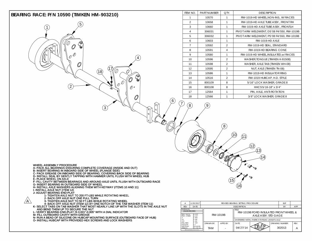
REV DATE DESCRIPTION BY APPA 1/20/2017 REVISED BEARING SETTING PROCEDURE BJF
WHEEL ASSEMBLY PROCEDUREA- PACK ALL BEARINGS ENSURING COMPLETE COVERAGE (INSIDE AND OUT)B- INSERT BEARING IN INBOARD SIDE OF WHEEL (FLANGE SIDE)C- PACK GREASE ON INBOARD SIDE OF BEARING, COVERING BACK SIDE OF BEARINGD- INSTALL SEAL BY GENTLY TAPPING WITH HAMMER UNTIL FLUSH WITH WHEEL HUBE- PLACE WHEEL ON AXLEF- FILL CAVITY BETWEEN BEARINGS AND AROUND AXLE UNTIL FLUSH WITH OUTBOARD RACEG- INSERT BEARING IN OUTBOARD SIDE OF WHEELH- INSTALL AXLE WASHERS ALIGNING THEM WITH KEYWAY (ITEMS 10 AND 11)I- INSTALL AXLE NUT (ITEM 12)J- ADJUST BEARING END-PLAY
1- TIGHTEN AXLE NUT TO 200 FT-LBS WHILE ROTATING WHEEL2- BACK OFF AXLE NUT ONE FULL TURN3- TIGHTEN AXLE NUT TO 50 FT-LBS WHILE ROTATING WHEEL4- BACK OFF AXLE NUT (ITEM 12) BY ONE NOTCH OF THE TAB WASHER (ITEM 11)
K- SELECT TABS ON TAB WASHER THAT MOST NEARLY LINE UP WITH THE SLOTS IN THE AXLE NUTAND BEND THEM UP TO SECURE THE NUT
L- VERIFY BEARING END-PLAY IS 0.001”-0.005” WITH A DIAL INDICATORM- FILL OUTBOARD CAVITY WITH GREASEN- RUN A BEAD OF SILICONE ON HUBCAP MOUNTING SURFACE (OUTBOARD FACE OF HUB)O- INSTALL HUBCAP WITH PROVIDED HEX SCREWS AND LOCK WASHERS
ITEM NO. PART NUMBER QTY. DESCRIPTION1 10570 1 RW-1019-HD WHEEL,NON-INS., W/RACES2 10658 1 RW-1019-HD AXLE TUBE ASSY., FRONT RH3 10660 1 RW-1019-HD AXLE TUBE ASSY., FRONTLH4 306031 1 PIVOT ARM WELDMENT, DS '08 F4/550, RW-1019B5 306032 1 PIVOT ARM WELDMENT, PS '08 F4/550, RW-1019B6 10603 1 RW-1019-HD AXLE7 10592 2 RW-1019-HD SEAL, STANDARD8 10591 4 RW-1019-HD BEARING CONE9 10580 1 RW-1019-HD WHEEL,INSULATED,w/RACES
10 10596 2 WASHER,TONGUE (TIMKEN K-91508)11 10598 2 WASHER, AXLE TAB (TIMKEN WH-08)12 10595 2 NUT, AXLE (TIMKEN TN-08)13 10586 1 RW-1019-HD INSULATOR RING14 10516 2 RW-1019 HUBCAP, H.D. STYLE15 800109 8 5/16" LOCK WASHER, GRADE 816 800108 8 HHCS 5/16-18" x 3/4"17 12564 1 PIN, AXLE, ANTI-ROTATION18 12566 1 3/8" LOCK WASHER, GRADE 8
BEARING RACE: P/N 10590 (TIMKEN HM-903210)
A
WHEEL ASSEMBLY PROCEDUREA- PACK ALL BEARINGS ENSURING COMPLETE COVERAGE (INSIDE AND OUT)B- INSERT BEARING IN INBOARD SIDE OF WHEEL (FLANGE SIDE)C- PACK GREASE ON INBOARD SIDE OF BEARING, COVERING BACK SIDE OF BEARINGD- INSTALL SEAL BY GENTLY TAPPING WITH HAMMER UNTIL FLUSH WITH WHEEL HUBE- PLACE WHEEL ON AXLEF- FILL CAVITY BETWEEN BEARINGS AND AROUND AXLE UNTIL FLUSH WITH OUTBOARD RACEG- INSERT BEARING IN OUTBOARD SIDE OF WHEELH- INSTALL AXLE WASHERS ALIGNING THEM WITH KEYWAY (ITEMS 10 AND 11)I- INSTALL AXLE NUT (ITEM 12)J- ADJUST BEARING END-PLAY
1- TIGHTEN AXLE NUT TO 200 FT-LBS WHILE ROTATING WHEEL2- BACK OFF AXLE NUT ONE FULL TURN3- TIGHTEN AXLE NUT TO 50 FT-LBS WHILE ROTATING WHEEL4- BACK OFF AXLE NUT (ITEM 12) BY ONE NOTCH OF THE TAB WASHER (ITEM 11)
K- SELECT TABS ON TAB WASHER THAT MOST NEARLY LINE UP WITH THE SLOTS IN THE AXLE NUTAND BEND THEM UP TO SECURE THE NUT
L- VERIFY BEARING END-PLAY IS 0.001”-0.005” WITH A DIAL INDICATORM- FILL OUTBOARD CAVITY WITH GREASEN- RUN A BEAD OF SILICONE ON HUBCAP MOUNTING SURFACE (OUTBOARD FACE OF HUB)O- INSTALL HUBCAP WITH PROVIDED HEX SCREWS AND LOCK WASHERS
AXLE ASSY; STD GAGERW-1019B FORD INSULATED FRONT WHEEL &
RW-1019B
DRAWN BY:
04/27/14 A
.X
ANGULAR:
BREAK SHARP EDGES ( 0.030 X 45° MAX )
± 1/16"
± .005± .030
+ .015
± 1/32"
± .063
± 1°
2A AND 2B125 MICRO
DRILL SIZES:
SURF FINISH:THREADS:
.XXX
.XX
TOLERANCES:
FRAC, MACH:
(UNLESS SPECIFIED)
FRAC, OTHER:
302013
DIVERSIFIED METAL FABRICATORS,INC.(404)875-1512
TAM
REV:DRAWING NUMBER:
TITLE:
DATE:APPD BY:
-
17
2
18
12
9
11
8
14
3
10
1
8
76
13
4
5
1615
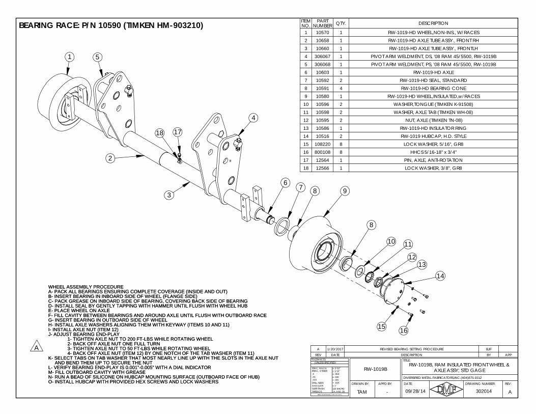
REV DATE DESCRIPTION BY APPA 1/20/2017 REVISED BEARING SETTING PROCEDURE BJF
WHEEL ASSEMBLY PROCEDUREA- PACK ALL BEARINGS ENSURING COMPLETE COVERAGE (INSIDE AND OUT)B- INSERT BEARING IN INBOARD SIDE OF WHEEL (FLANGE SIDE)C- PACK GREASE ON INBOARD SIDE OF BEARING, COVERING BACK SIDE OF BEARINGD- INSTALL SEAL BY GENTLY TAPPING WITH HAMMER UNTIL FLUSH WITH WHEEL HUBE- PLACE WHEEL ON AXLEF- FILL CAVITY BETWEEN BEARINGS AND AROUND AXLE UNTIL FLUSH WITH OUTBOARD RACEG- INSERT BEARING IN OUTBOARD SIDE OF WHEELH- INSTALL AXLE WASHERS ALIGNING THEM WITH KEYWAY (ITEMS 10 AND 11)I- INSTALL AXLE NUT (ITEM 12)J- ADJUST BEARING END-PLAY
1- TIGHTEN AXLE NUT TO 200 FT-LBS WHILE ROTATING WHEEL2- BACK OFF AXLE NUT ONE FULL TURN3- TIGHTEN AXLE NUT TO 50 FT-LBS WHILE ROTATING WHEEL4- BACK OFF AXLE NUT (ITEM 12) BY ONE NOTCH OF THE TAB WASHER (ITEM 11)
K- SELECT TABS ON TAB WASHER THAT MOST NEARLY LINE UP WITH THE SLOTS IN THE AXLE NUTAND BEND THEM UP TO SECURE THE NUT
L- VERIFY BEARING END-PLAY IS 0.001”-0.005” WITH A DIAL INDICATORM- FILL OUTBOARD CAVITY WITH GREASEN- RUN A BEAD OF SILICONE ON HUBCAP MOUNTING SURFACE (OUTBOARD FACE OF HUB)O- INSTALL HUBCAP WITH PROVIDED HEX SCREWS AND LOCK WASHERS
BEARING RACE: P/N 10590 (TIMKEN HM-903210) ITEM NO.
PART NUMBER QTY. DESCRIPTION
1 10570 1 RW-1019-HD WHEEL,NON-INS., W/RACES2 10658 1 RW-1019-HD AXLE TUBE ASSY., FRONT RH3 10660 1 RW-1019-HD AXLE TUBE ASSY., FRONTLH4 306067 1 PIVOT ARM WELDMENT, DS, '08 RAM 45/5500, RW-1019B5 306068 1 PIVOT ARM WELDMENT, PS, '08 RAM 45/5500, RW-1019B6 10603 1 RW-1019-HD AXLE7 10592 2 RW-1019-HD SEAL, STANDARD8 10591 4 RW-1019-HD BEARING CONE9 10580 1 RW-1019-HD WHEEL,INSULATED,w/RACES
10 10596 2 WASHER,TONGUE (TIMKEN K-91508)11 10598 2 WASHER, AXLE TAB (TIMKEN WH-08)12 10595 2 NUT, AXLE (TIMKEN TN-08)13 10586 1 RW-1019-HD INSULATOR RING14 10516 2 RW-1019 HUBCAP, H.D. STYLE15 108220 8 LOCK WASHER, 5/16", GR816 800108 8 HHCS 5/16-18" x 3/4"17 12564 1 PIN, AXLE, ANTI-ROTATION18 12566 1 LOCK WASHER, 3/8", GR8
A
WHEEL ASSEMBLY PROCEDUREA- PACK ALL BEARINGS ENSURING COMPLETE COVERAGE (INSIDE AND OUT)B- INSERT BEARING IN INBOARD SIDE OF WHEEL (FLANGE SIDE)C- PACK GREASE ON INBOARD SIDE OF BEARING, COVERING BACK SIDE OF BEARINGD- INSTALL SEAL BY GENTLY TAPPING WITH HAMMER UNTIL FLUSH WITH WHEEL HUBE- PLACE WHEEL ON AXLEF- FILL CAVITY BETWEEN BEARINGS AND AROUND AXLE UNTIL FLUSH WITH OUTBOARD RACEG- INSERT BEARING IN OUTBOARD SIDE OF WHEELH- INSTALL AXLE WASHERS ALIGNING THEM WITH KEYWAY (ITEMS 10 AND 11)I- INSTALL AXLE NUT (ITEM 12)J- ADJUST BEARING END-PLAY
1- TIGHTEN AXLE NUT TO 200 FT-LBS WHILE ROTATING WHEEL2- BACK OFF AXLE NUT ONE FULL TURN3- TIGHTEN AXLE NUT TO 50 FT-LBS WHILE ROTATING WHEEL4- BACK OFF AXLE NUT (ITEM 12) BY ONE NOTCH OF THE TAB WASHER (ITEM 11)
K- SELECT TABS ON TAB WASHER THAT MOST NEARLY LINE UP WITH THE SLOTS IN THE AXLE NUTAND BEND THEM UP TO SECURE THE NUT
L- VERIFY BEARING END-PLAY IS 0.001”-0.005” WITH A DIAL INDICATORM- FILL OUTBOARD CAVITY WITH GREASEN- RUN A BEAD OF SILICONE ON HUBCAP MOUNTING SURFACE (OUTBOARD FACE OF HUB)O- INSTALL HUBCAP WITH PROVIDED HEX SCREWS AND LOCK WASHERS
9
2
18 17
3
11
12
14
16
10
13
8
76
1 5
4
8
15
AXLE ASSY; STD GAGERW-1019B, RAM INSULATED FRONT WHEEL &
RW-1019B
DRAWN BY:
302014 A
.X
ANGULAR:
BREAK SHARP EDGES ( 0.030 X 45° MAX )
± 1/16"
± .005± .030
+ .015
± 1/32"
± .063
± 1°
2A AND 2B125 MICRO
DRILL SIZES:
SURF FINISH:THREADS:
.XXX
.XX
TOLERANCES:
FRAC, MACH:
(UNLESS SPECIFIED)
DIVERSIFIED METAL FABRICATORS,INC.(404)875-1512
FRAC, OTHER:
09/28/14TAM
REV:DRAWING NUMBER:
TITLE:
DATE:APPD BY:
-
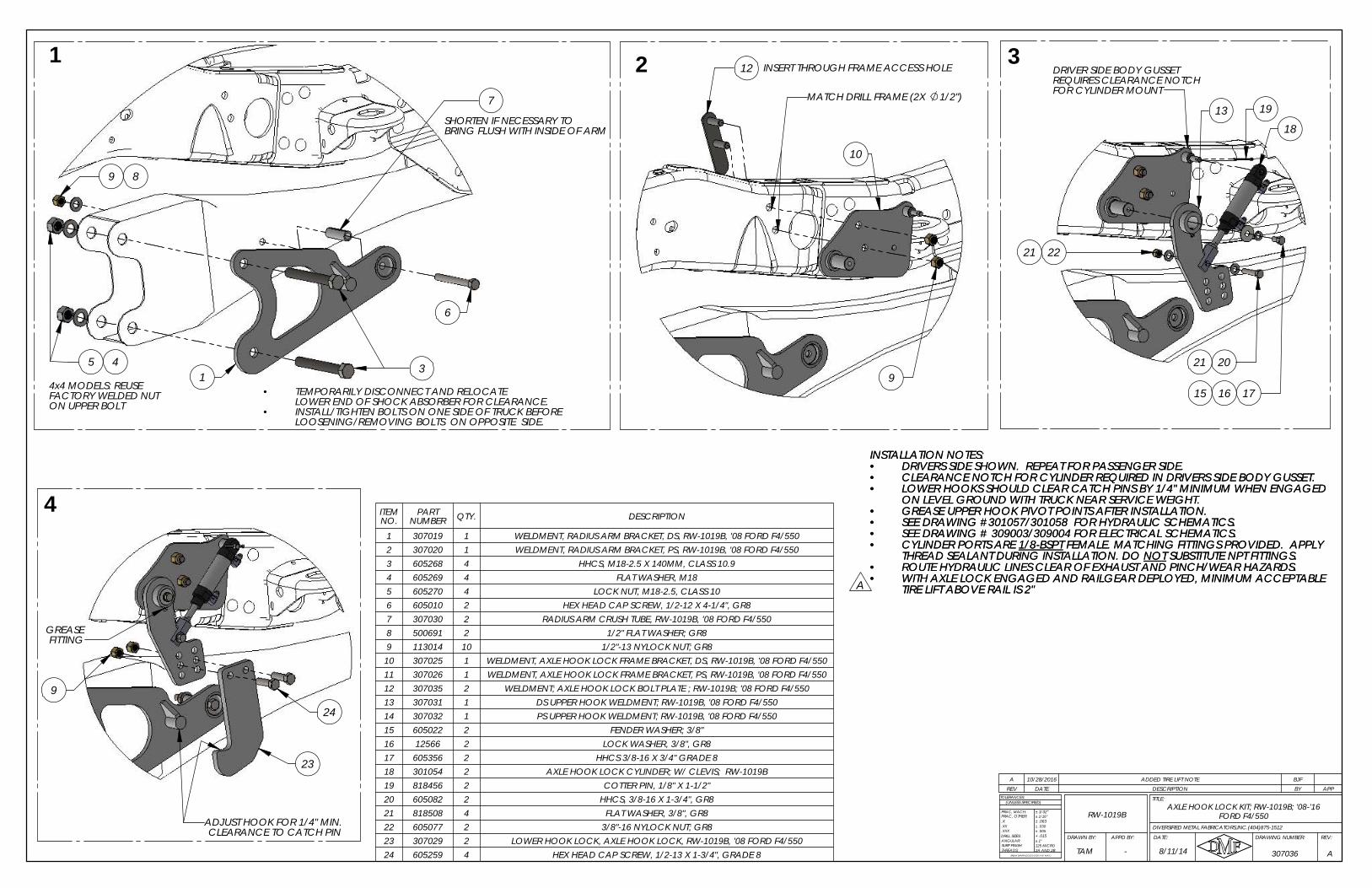
10
9
2MATCH DRILL FRAME (2X 1/2")
12 INSERT THROUGH FRAME ACCESS HOLEREQUIRES CLEARANCE NOTCHFOR CYLINDER MOUNT
21 22
16 1715
18
1913
DRIVER SIDE BODY GUSSET
2021
3
9
ADJUST HOOK FOR 1/4" MIN.
FITTINGGREASE
CLEARANCE TO CATCH PIN
23
24
4
SHORTEN IF NECESSARY TO BRING FLUSH WITH INSIDE OF ARM
LOWER END OF SHOCK ABSORBER FOR CLEARANCE.INSTALL/TIGHTEN BOLTS ON ONE SIDE OF TRUCK BEFORE
9
ON UPPER BOLT
3
6
7
5 4
8
1
14x4 MODELS: REUSEFACTORY WELDED NUT
•LOOSENING/REMOVING BOLTS ON OPPOSITE SIDE.
TEMPORARILY DISCONNECT AND RELOCATE •
REV DATE DESCRIPTION BY APPA 10/28/2016 ADDED TIRE LIFT NOTE BJF
INSTALLATION NOTES:DRIVERS SIDE SHOWN. REPEAT FOR PASSENGER SIDE.•CLEARANCE NOTCH FOR CYLINDER REQUIRED IN DRIVERS SIDE BODY GUSSET.•LOWER HOOKS SHOULD CLEAR CATCH PINS BY 1/4" MINIMUM WHEN ENGAGED•ON LEVEL GROUND WITH TRUCK NEAR SERVICE WEIGHT.GREASE UPPER HOOK PIVOT POINTS AFTER INSTALLATION.•SEE DRAWING #301057/301058 FOR HYDRAULIC SCHEMATICS.•SEE DRAWING # 309003/309004 FOR ELECTRICAL SCHEMATICS.•CYLINDER PORTS ARE 1/8-BSPT FEMALE. MATCHING FITTINGS PROVIDED. APPLY •THREAD SEALANT DURING INSTALLATION. DO NOT SUBSTITUTE NPT FITTINGS.ROUTE HYDRAULIC LINES CLEAR OF EXHAUST AND PINCH/WEAR HAZARDS.•WITH AXLE LOCK ENGAGED AND RAILGEAR DEPLOYED, MINIMUM ACCEPTABLE •TIRE LIFT ABOVE RAIL IS 2"
ITEM NO.
PART NUMBER QTY. DESCRIPTION
1 307019 1 WELDMENT, RADIUS ARM BRACKET, DS, RW-1019B, '08 FORD F4/5502 307020 1 WELDMENT, RADIUS ARM BRACKET, PS, RW-1019B, '08 FORD F4/5503 605268 4 HHCS, M18-2.5 X 140MM, CLASS 10.94 605269 4 FLAT WASHER, M185 605270 4 LOCK NUT, M18-2.5, CLASS 106 605010 2 HEX HEAD CAP SCREW, 1/2-12 X 4-1/4", GR87 307030 2 RADIUS ARM CRUSH TUBE, RW-1019B, '08 FORD F4/5508 500691 2 1/2" FLAT WASHER; GR89 113014 10 1/2"-13 NYLOCK NUT; GR8
10 307025 1 WELDMENT, AXLE HOOK LOCK FRAME BRACKET, DS, RW-1019B, '08 FORD F4/55011 307026 1 WELDMENT, AXLE HOOK LOCK FRAME BRACKET, PS, RW-1019B, '08 FORD F4/55012 307035 2 WELDMENT; AXLE HOOK LOCK BOLT PLATE ; RW-1019B; '08 FORD F4/55013 307031 1 DS UPPER HOOK WELDMENT; RW-1019B, '08 FORD F4/55014 307032 1 PS UPPER HOOK WELDMENT; RW-1019B, '08 FORD F4/55015 605022 2 FENDER WASHER; 3/8"16 12566 2 LOCK WASHER, 3/8", GR817 605356 2 HHCS 3/8-16 X 3/4" GRADE 818 301054 2 AXLE HOOK LOCK CYLINDER; W/ CLEVIS; RW-1019B19 818456 2 COTTER PIN, 1/8" X 1-1/2"20 605082 2 HHCS, 3/8-16 X 1-3/4", GR821 818508 4 FLAT WASHER, 3/8", GR822 605077 2 3/8"-16 NYLOCK NUT; GR823 307029 2 LOWER HOOK LOCK, AXLE HOOK LOCK, RW-1019B, '08 FORD F4/55024 605259 4 HEX HEAD CAP SCREW, 1/2-13 X 1-3/4", GRADE 8
A
INSTALLATION NOTES:DRIVERS SIDE SHOWN. REPEAT FOR PASSENGER SIDE.•CLEARANCE NOTCH FOR CYLINDER REQUIRED IN DRIVERS SIDE BODY GUSSET.•LOWER HOOKS SHOULD CLEAR CATCH PINS BY 1/4" MINIMUM WHEN ENGAGED•ON LEVEL GROUND WITH TRUCK NEAR SERVICE WEIGHT.GREASE UPPER HOOK PIVOT POINTS AFTER INSTALLATION.•SEE DRAWING #301057/301058 FOR HYDRAULIC SCHEMATICS.•SEE DRAWING # 309003/309004 FOR ELECTRICAL SCHEMATICS.•CYLINDER PORTS ARE 1/8-BSPT FEMALE. MATCHING FITTINGS PROVIDED. APPLY •THREAD SEALANT DURING INSTALLATION. DO NOT SUBSTITUTE NPT FITTINGS.ROUTE HYDRAULIC LINES CLEAR OF EXHAUST AND PINCH/WEAR HAZARDS.•WITH AXLE LOCK ENGAGED AND RAILGEAR DEPLOYED, MINIMUM ACCEPTABLE •TIRE LIFT ABOVE RAIL IS 2"
RW-1019B
A
.X
ANGULAR:
BREAK SHARP EDGES ( 0.030 X 45° MAX )
± 1/16"
± .005± .030
+ .015
± 1/32"
± .063
± 1°
2A AND 2B125 MICRO
DRILL SIZES:
SURF FINISH:THREADS:
.XXX
.XX
TOLERANCES:
FRAC, MACH:
(UNLESS SPECIFIED)
8/11/14 307036
REV:DRAWING NUMBER:
TITLE:
DATE:APPD BY:DRAWN BY:
FRAC, OTHER:
DIVERSIFIED METAL FABRICATORS,INC.(404)875-1512
TAM -
AXLE HOOK LOCK KIT; RW-1019B; '08-'16 FORD F4/550
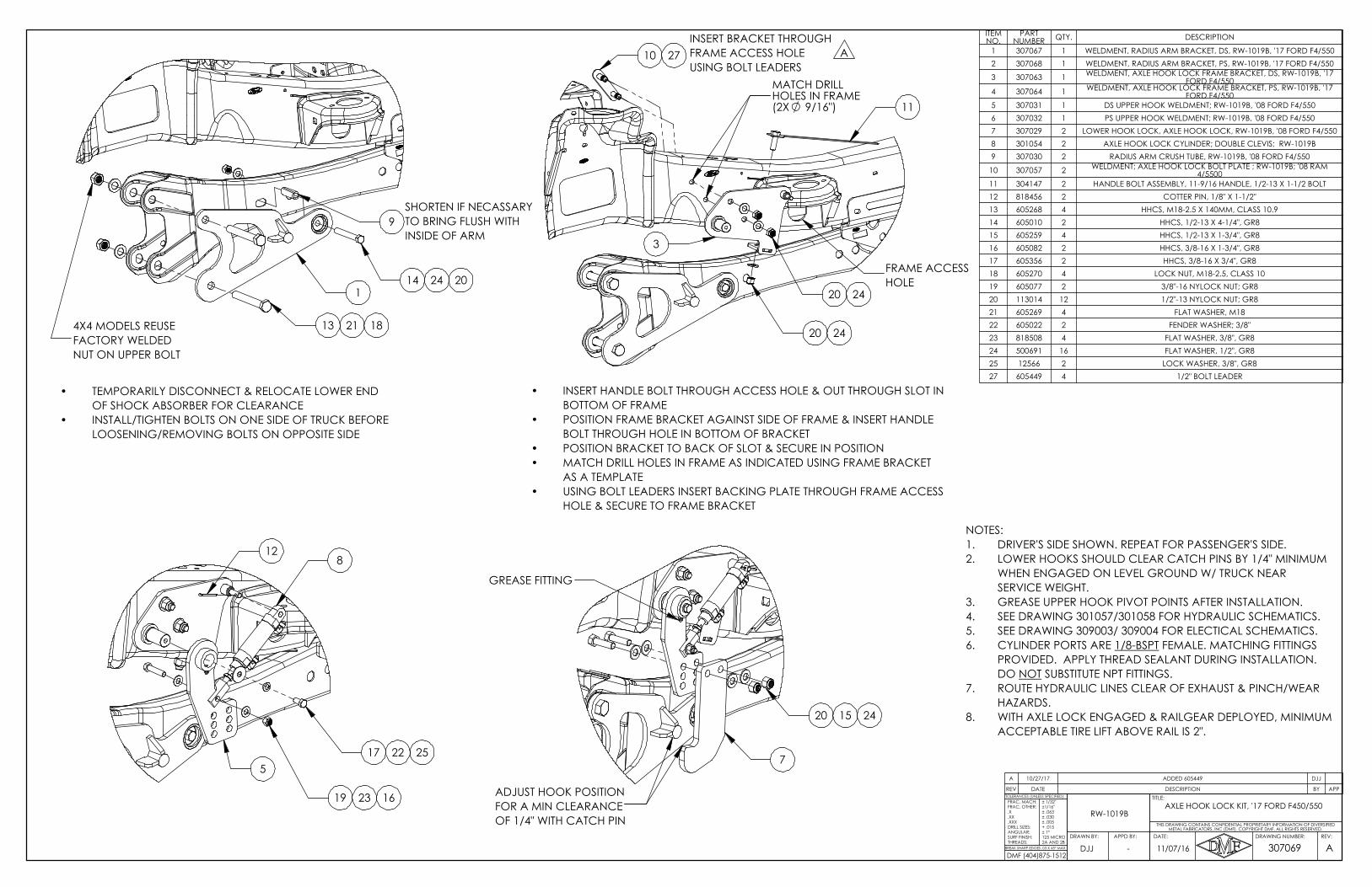
13
TO BRING FLUSH WITH
1
NUT ON UPPER BOLT
4X4 MODELS REUSE
INSIDE OF ARM
SHORTEN IF NECASSARY
FACTORY WELDED
24 20
9
14
21 18
TEMPORARILY DISCONNECT & RELOCATE LOWER END •OF SHOCK ABSORBER FOR CLEARANCEINSTALL/TIGHTEN BOLTS ON ONE SIDE OF TRUCK BEFORE •LOOSENING/REMOVING BOLTS ON OPPOSITE SIDE
11
FRAME ACCESS HOLE
HOLE & SECURE TO FRAME BRACKET
FRAME ACCESS
INSERT BRACKET THROUGH
•
2420
3
2420
10USING BOLT LEADERS
HOLE
INSERT HANDLE BOLT THROUGH ACCESS HOLE & OUT THROUGH SLOT IN •BOTTOM OF FRAMEPOSITION FRAME BRACKET AGAINST SIDE OF FRAME & INSERT HANDLE •BOLT THROUGH HOLE IN BOTTOM OF BRACKETPOSITION BRACKET TO BACK OF SLOT & SECURE IN POSITION•MATCH DRILL HOLES IN FRAME AS INDICATED USING FRAME BRACKET •AS A TEMPLATEUSING BOLT LEADERS INSERT BACKING PLATE THROUGH FRAME ACCESS
27 A
MATCH DRILL HOLES IN FRAME (2X 9/16")
RW-1019BFRAC, MACH:
-BREAK SHARP EDGES .03 X 45° MAX
TOLERANCES (UNLESS SPECIFIED):
307069REV:DRAWING NUMBER:
TITLE:
DATE:
ADJJ
THIS DRAWING CONTAINS CONFIDENTIAL PROPRIETARY INFORMATION OF DIVERSIFIED
AXLE HOOK LOCK KIT, '17 FORD F450/550
METAL FABRICATORS, INC (DMF). COPYRIGHT DMF, ALL RIGHTS RESERVED.
FRAC, OTHER:
2A AND 2B
11/07/16APPD BY:DRAWN BY:
.X
.XX
.XXXDRILL SIZES:ANGULAR:SURF FINISH:THREADS:
± 1/32"±1/16"± .063± .030± .005+ .015± 1°125 MICRO
DMF (404)875-1512
REV DATE DESCRIPTION BY APP
A 10/27/17 ADDED 605449 DJJ
ITEM NO.
PART NUMBER QTY. DESCRIPTION
1 307067 1 WELDMENT, RADIUS ARM BRACKET, DS, RW-1019B, '17 FORD F4/5502 307068 1 WELDMENT, RADIUS ARM BRACKET, PS, RW-1019B, '17 FORD F4/550
3 307063 1 WELDMENT, AXLE HOOK LOCK FRAME BRACKET, DS, RW-1019B, '17 FORD F4/550
4 307064 1 WELDMENT, AXLE HOOK LOCK FRAME BRACKET, PS, RW-1019B, '17 FORD F4/550
5 307031 1 DS UPPER HOOK WELDMENT; RW-1019B, '08 FORD F4/5506 307032 1 PS UPPER HOOK WELDMENT; RW-1019B, '08 FORD F4/5507 307029 2 LOWER HOOK LOCK, AXLE HOOK LOCK, RW-1019B, '08 FORD F4/5508 301054 2 AXLE HOOK LOCK CYLINDER; DOUBLE CLEVIS; RW-1019B9 307030 2 RADIUS ARM CRUSH TUBE, RW-1019B, '08 FORD F4/550
10 307057 2 WELDMENT; AXLE HOOK LOCK BOLT PLATE ; RW-1019B; '08 RAM 4/5500
11 304147 2 HANDLE BOLT ASSEMBLY, 11-9/16 HANDLE, 1/2-13 X 1-1/2 BOLT12 818456 2 COTTER PIN, 1/8" X 1-1/2"13 605268 4 HHCS, M18-2.5 X 140MM, CLASS 10.914 605010 2 HHCS, 1/2-13 X 4-1/4", GR815 605259 4 HHCS, 1/2-13 X 1-3/4", GR816 605082 2 HHCS, 3/8-16 X 1-3/4", GR817 605356 2 HHCS, 3/8-16 X 3/4", GR818 605270 4 LOCK NUT, M18-2.5, CLASS 1019 605077 2 3/8"-16 NYLOCK NUT; GR820 113014 12 1/2"-13 NYLOCK NUT; GR821 605269 4 FLAT WASHER, M1822 605022 2 FENDER WASHER; 3/8"23 818508 4 FLAT WASHER, 3/8", GR824 500691 16 FLAT WASHER, 1/2", GR825 12566 2 LOCK WASHER, 3/8", GR827 605449 4 1/2" BOLT LEADER
NOTES:DRIVER'S SIDE SHOWN. REPEAT FOR PASSENGER'S SIDE.1.LOWER HOOKS SHOULD CLEAR CATCH PINS BY 1/4" MINIMUM 2.WHEN ENGAGED ON LEVEL GROUND W/ TRUCK NEAR SERVICE WEIGHT.GREASE UPPER HOOK PIVOT POINTS AFTER INSTALLATION.3.SEE DRAWING 301057/301058 FOR HYDRAULIC SCHEMATICS.4.SEE DRAWING 309003/ 309004 FOR ELECTICAL SCHEMATICS.5.CYLINDER PORTS ARE 1/8-BSPT FEMALE. MATCHING FITTINGS 6.PROVIDED. APPLY THREAD SEALANT DURING INSTALLATION. DO NOT SUBSTITUTE NPT FITTINGS.ROUTE HYDRAULIC LINES CLEAR OF EXHAUST & PINCH/WEAR 7.HAZARDS.WITH AXLE LOCK ENGAGED & RAILGEAR DEPLOYED, MINIMUM 8.ACCEPTABLE TIRE LIFT ABOVE RAIL IS 2".
8
2217
2319 16
12
255
7
20 2415
ADJUST HOOK POSITION FOR A MIN CLEARANCE OF 1/4" WITH CATCH PIN
GREASE FITTING

84
REPLACES FACTORY LOWER
PASSENGER SIDE SHOWN
1/2"
SUSPENSION ARM BOLT
8
INSTALL AXLE BRACKETS ON FRONT AXLE1
MATCH DRILL
7
6
35 9
5
AXLE BRACKET SHOULD CONTACT AXLE TUBE
TAM -
RW-1019B
12/19/14
.X
ANGULAR:
BREAK SHARP EDGES ( 0.030 X 45° MAX )
± 1/16"
± .005± .030
+ .015
± 1/32"
± .063
± 1°
2A AND 2B125 MICRO
DRILL SIZES:
SURF FINISH:THREADS:
.XXX
.XX DIVERSIFIED METAL FABRICATORS,INC.(404)875-1512
FRAC, MACH:
(UNLESS SPECIFIED)
FRAC, OTHER:
307058
REV:DRAWING NUMBER:
TITLE:TOLERANCES:
DATE:APPD BY:DRAWN BY:
A
REV DATE DESCRIPTION BY APPA 10/28/2016 ADDED TIRE LIFT NOTE BJF
ITEM NO. PART NUMBER QTY. DESCRIPTION
1 307048 1 DS AXLE BRACKET,4X4, AXLE LOCK,4X4, '08 RAM 4/5500, RW-1019B
2 307049 1 DS AXLE BRACKET, 4x2, AXLE LOCK, '08 RAM 4/5500, RW-1019B
3 307050 1 PS AXLE BRACKET, AXLE LOCK, '08 RAM 4/5500, RW-1019B
4 605268 2 HHCS, M18-2.5 X 140MM, CLASS 10.9
5 605269 4 FLAT WASHER, M18
6 605270 2 LOCK NUT, M18-2.5, CLASS 10
7 605259 6 HEX HEAD CAP SCREW, 1/2-13 X 1-3/4", GRADE 8
8 500691 4 FLAT WASHER, 1/2", GR8
9 113014 6 1/2"-13 NYLOCK NUT; GR8
10 307038 1 WELDMENT, AXLE HOOK LOCK FRAME BRACKET, DS, '08 RAM 4/5500, RW-1019B
11 307039 1 WELDMENT, AXLE HOOK LOCK FRAME BRACKET, PS, '08 RAM 4/5500, RW-1019B
12 307057 2 WELDMENT; AXLE HOOK LOCK BOLT PLATE ; RW-1019B; '08 RAM 4/5500
13 605449 4 1/2" BOLT LEADER
14 605448 4 FLANGE LOCKNUT; 1/2-13 GR8
15 307040 1 DS UPPER AXLE HOOK WELDMENT; '08 RAM 4/5500; RW-1019B
16 307041 1 PS UPPER AXLE HOOK WELDMENT; '08 RAM 4/5500; RW-1019B
17 605356 2 HHCS, 3/8-16 X 3/4", GR8
18 12566 2 LOCK WASHER, 3/8", GR8
19 605022 2 FENDER WASHER; 3/8"
20 301064 2 AXLE HOOK LOCK CYLINDER; SINGLE CLEVIS; RW-1019B
21 605446 2 SHOULDER BOLT; 3/8" X 2-1/4
22 605447 2 SHOULDER BOLT; 3/8" X 3/4"
23 818508 4 FLAT WASHER, 3/8", GR8
24 20342 4 5/16"-18 NYLOCK NUT; GR8
25 307043 2 LOWER HOOK LOCK, AXLE HOOK LOCK, RW-1019B, '08 RAM 4/5500
26 605445 4 CUSHION CLAMP; 1/2"
27 11257 4 1/4"-20 NYLOCK NUT; GR8
28 605177 4 HHCS, 1/4-20 X 1", GR5
FISH BARE ENDS OF BOLT LEADERSFROM INBOARD FRAME ACCESS HOLE
TO OUTBOARD FRAME HOLE
INSTALLATION NOTES:SEE MANUAL SECTION 4.6.5 FOR BRAKE LINE RELOCATION DETAILS•PASSENGER SIDE SHOWN. REPEAT ALL STEPS FOR DRIVER SIDE.•LOWER LOOKS SHOULD CLEAR CATCH PINS BY 1/4" MINIMUM •WHEN ENGAGED ON LEVEL GROUND WITH TRUCK NEAR SERVICE WEIGHT.GREASE UPPER HOOK PIVOT POINTS AFTER INSTALLATION.•SEE DRAWING #301057/301058 FOR HYDRAULIC SCHEMATICS.•SEE DRAWING # 309003/309004 FOR ELECTRICAL SCHEMATICS.•CYLINDER PORTS ARE 1/8-BSPT FEMALE. MATCHING FITTINGS •PROVIDED. APPLY THREAD SEALANT DURING INSTALLATION. DO NOT SUBSTITUTE NPT FITTINGS.ROUTE HYDRAULIC LINES CLEAR OF EXHAUST AND PINCH/WEAR •HAZARDS.WITH AXLE LOCK ENGAGED AND RAILGEAR DEPLOYED, MINIMUM •ACCEPTABLE TIRE LIFT ABOVE RAIL IS 2".
REPLACE LOWER SUSPENSION BOLT ON ONE SIDE OF TRUCK AT A TIME.•AXLE BRACKET WELDMENT SHOULD CONTACT TRUCK AXLE TUBE.•
INCLUDED IN 4x4 KIT (307058) ONLYINCLUDED IN 4x2 KIT (307059) ONLY
DS 4x4307048
AXLE LOCK KIT; '08 RAM 4/5500; RW-1019B
A
INSTALLATION NOTES:SEE MANUAL SECTION 4.6.5 FOR BRAKE LINE RELOCATION DETAILS•PASSENGER SIDE SHOWN. REPEAT ALL STEPS FOR DRIVER SIDE.•LOWER LOOKS SHOULD CLEAR CATCH PINS BY 1/4" MINIMUM •WHEN ENGAGED ON LEVEL GROUND WITH TRUCK NEAR SERVICE WEIGHT.GREASE UPPER HOOK PIVOT POINTS AFTER INSTALLATION.•SEE DRAWING #301057/301058 FOR HYDRAULIC SCHEMATICS.•SEE DRAWING # 309003/309004 FOR ELECTRICAL SCHEMATICS.•CYLINDER PORTS ARE 1/8-BSPT FEMALE. MATCHING FITTINGS •PROVIDED. APPLY THREAD SEALANT DURING INSTALLATION. DO NOT SUBSTITUTE NPT FITTINGS.ROUTE HYDRAULIC LINES CLEAR OF EXHAUST AND PINCH/WEAR •HAZARDS.WITH AXLE LOCK ENGAGED AND RAILGEAR DEPLOYED, MINIMUM •ACCEPTABLE TIRE LIFT ABOVE RAIL IS 2".
EXISTING FRAMEHOLES MATCH DRILL
12
•
9/16"
REMOVE BOLT LEADER BEFORE INSTALLING LOCKNUTS.
2
FRAME. FISH BARE ENDS THROUGH LARGE INBOARD OVAL FRAME ACCESS HOLE AND THRU HOLES ON OUTBOARD SIDE OF FRAME.
PASSENGER SIDE SHOWNINSTALL FRAME BRACKETS ON OUTBOARD SIDES OF FRAME
PS SHOCK TOWER
13
11
14
REMOVE FACTORY PLASTIC BRAKE LINE CLIPS NEAR BOTTOM EDGE OF FRAME RAIL.•ALIGN BRACKET WITH EXISTING HOLES SHOWN AND MATCH DRILL FORWARD HOLE.•TEMPORARILY REMOVE TRANSMISSION COOLER LINE BRACKET BLOCKING ACCESS •TO OVAL INBOARD FRAME ACCESS HOLE.BOLT LEADERS CAN BE USED TO HELP GUIDE BOLT PLATE INTO POSITION INSIDE •
23
22
INSTALL FITTINGS AND CLEVIS BEFORE MOUNTING.MOUNT WITH FITTINGS FACING DOWN.
FLAT FACE OF CYLINDER CLEVIS MOUNTS AGAINST OUTBOARD SIDE OF UPPER HOOK.•
3
24
INSTALL UPPER HOOKS AND CYLINDERS TO FRAME BRACKETSPASSENGER SIDE SHOWN
20
18
CYLINDER FITTINGS SHOULD FACE DOWNWARDS AS SHOWN.•
19 17
24
23
21
TEMPORARILY LOOSENING FRAME BRACKET LOCKNUTS FOR EXTRA CLEARANCE TO •INSTALL UPPER HOOK MAY BE REQUIRED ON PASSENGER SIDE.INSTALL FITTINGS INTO CYLINDER BEFORE MOUNTING TO TRUCK.•
16
ADJUST HOOK FOR 1/4" MIN.
HOOK AND
7
INSTALL LOWER HOOK AGAINSTCLEARANCE TO CATCH PIN
9
1/4" MINIMUM WHEN ENGAGED ON LEVEL GROUND
GREASE FITTING BETWEEN
•
FRAME BRACKET
ADJUST LOWER HOOKS TO CLEAR CATCH PINS BY
4 INSTALL LOWER HOOKS PASSENGER SIDE SHOWN
WITH TRUCK NEAR SERVICE WEIGHT.
25
OUTBOARD FACE OF UPPER HOOKADD GREASE TO UPPER HOOK PIVOT.•
5 INSTALL BRAKE LINE RELOCATION HARDWAREPASSENGER SIDE SHOWN
26 2827
*SEE MANUAL SECTION 4.6.5 FOR BRAKE LINE RELOCATION DETAILS*
DS 4x2307049
PS (ALL)307050
DIVERSIFIED METAL FABRICATORS, INC. RW-1019B
DMF � 665 Pylant Street � Atlanta, Georgia 30306
Parts (404) 607-1684� Parts Fax (404) 879-7888� [email protected]
Service Department (404) 879-7882� [email protected]
Phone (404) 875-1512 � Fax (404) 875-4835� [email protected]
http://www.dmfatlanta.com
DMF LIMITED WARRANTY POLICY
Diversified Metal Fabricators (DMF) products are designed to provide the utmost service
and reliability. Competent workmen, guided by stringent quality standards, manufacture the
products from high-grade material. DMF warrants products of its manufacture to be free of
defects in material and workmanship, under normal use and service, for a period of ONE
CALENDAR YEAR. DMF’s obligation under this warranty is limited to repairing or replacing at
its factory, or other location designated by us, any part or parts there-of which shall, within 30
DAYS of the date of failure or notice of defect, be returned, and which upon examination shall
appear to DMF’s satisfaction to have been defective. Such repair or replacement does not
include the cost of installing the new part or any other expenses incident thereto; however, the
outbound direct ground freight on the part will be prepaid to locations within the continental
United States and Canada. DMF shall not be liable for other loss, damage, or expense directly
or indirectly arising from the use of its products.
Ordinary wear and tear, abuse, misuse, neglect, or alteration is not covered by this warranty.
DMF assumes no liability for expenses or repairs made outside its factory except by written
consent. Warranty is null and void if instructions and operating procedures specifically referring
to warranty coverage are not followed.
Equipment or parts not manufactured by this company, but which are furnished in connection
with DMF products are covered directly and solely by the warranty of the manufacturer
supplying them.
This warranty is in lieu of other warranties, expressed or implied, including any implied
warranties of merchantability or fitness for a particular purpose and any liability for special or
consequential damages.
All warranty claims must reference a serial number. Returns must reference a RA number.
Related Documents