1 Rules on the carriage of liquefied natural gas (LNG) Transmitted by the Russian Maritime Register of Shipping At the 23rd session of the ADN Safety Committee, the Classification Societies were asked to submit their rules for the transport of LNG (see ECE/TRANS/WP.15/AC.2/48, para. 53). Russian Maritime Register of Shipping’s rules for transport of LNG can be found below: INF.11 Economic Commission for Europe Inland Transport Committee Working Party on the Transport of Dangerous Goods Joint Meeting of Experts on the Regulations annexed to the European Agreement concerning the International Carriage of Dangerous Goods by Inland Waterways (ADN) (ADN Safety Committee) Twenty-fourth session Geneva, 27-31 January 2014 Item 4 (e) of the provisional agenda Implementation of ADN: Matters related to classification societies 6 December 2013

Welcome message from author
This document is posted to help you gain knowledge. Please leave a comment to let me know what you think about it! Share it to your friends and learn new things together.
Transcript

1
Rules on the carriage of liquefied natural gas (LNG)
Transmitted by the Russian Maritime Register of Shipping
At the 23rd session of the ADN Safety Committee, the Classification Societies were asked to submit their rules for the transport of LNG (see ECE/TRANS/WP.15/AC.2/48, para. 53).
Russian Maritime Register of Shipping’s rules for transport of LNG can be found below:
INF.11Economic Commission for Europe
Inland Transport Committee Working Party on the Transport of Dangerous Goods
Joint Meeting of Experts on the Regulations annexed to the European Agreement concerning the International Carriage of Dangerous Goods by Inland Waterways (ADN) (ADN Safety Committee)
Twenty-fourth session Geneva, 27-31 January 2014 Item 4 (e) of the provisional agenda Implementation of ADN: Matters related to classification societies
6 December 2013
Р О С С И Й С К И Й М О Р С К О Й Р Е Г И С Т Р С У Д О Х О Д С Т В А
RULES FOR THE CLASSIFICATION
AND CONSTRUCTION OF SHIPS CARRYING LIQUEFIED GASES
IN BULK
RULES FOR THE CLASSIFICATION
AND CONSTRUCTION OF SHIPS CARRYING COMPRESSED
NATURAL GAS
Saint-Petersburg 2012
Electronic version of printed document approved on 26.06.12
ND No. 2-020101-068-E

The Rules for the Classification and Construction of Ships Carrying Liquefied Gases in Bulk and the Rules for the Classification and Construction of Ships Carrying Compressed Natural Gas have been approved in accordance with the established approval procedure and come into force since 1 July 2012.
The Rules for the Classification and Construction of Ships Carrying Liquefied Gases in Bulk are based on the Rules for the Classification and Construction of Gas Carriers, 2004, taking into account additions and amendments developed by the time of publication.
The Rules for the Classification and Construction of Ships Carrying Compressed Natural Gas are based on Research Work No. RS-26/2008 "Development of the RS Requirements for Compressed Natural Gas (CNG) Carriers".
The provisions of the International Code for the Construction and Equipment of Ships Carrying Liquefied Gases in Bulk as amended by IMO Resolutions, as well as IACS Unified Requirements have been taken into consideration in the Rules.
The Rules set the requirements, which are specific for the ships carrying liquefied gases in bulk and liquefied natural gas, and supplement the Rules for the Classification and Construction of Sea-Going Ships and the Rules for the Equipment of Sea-Going Ships of Russian Maritime Register of Shipping.
ISBN 978-5-89331-212-6 © Российский морской регистр судоходства, 2012

CONTENTS
R U L E S FOR THE CLASSIFICATION AND CONSTRUCTION OF SHIPS CARRYING L I Q U E F I E D GASES IN B U L K
PART I. CLASSIFICATION PART V. FIRE PROTECTION
1 General 7 1.1 Application 7 1.2 Definitions and explanations 7 2 Equivalents 8 3 Documents 8 4 Class notation 8 4.1 Class notation of a ship 8 4.2 Descriptive notation in the class notation 9 5 Classification surveys 9 6 Plan approval documentation 9
1 Application 24 2 Structural fire protection 24 3 Fire fighting equipment and systems 25 3.1 General requirements 25 3.2 Water fire main system 25 3.3 Water spray system 25 3.4 Dry chemical powder fire extinguishing
system 25 4 Personnel protection 25
PART II. GAS CARRIER DESIGN
1 General 10 2 Structural protection types. Location
of cargo tanks 11
PART III. STABILITY. SUBDIVISION. FREEBOARD
1 Stability 12 2 Damage stability with local damages 12 3 Subdivision 12 4 Freeboard 13
PART IV. CARGO TANKS
1 Definitions and explanations 13 2 Cargo tank types 14 3 Design loads 15 4 Structural analyses 16 5 Allowable stresses 18 6 Corrosion allowances 19 7 Cargo tank supports 19 8 Secondary barrier 20 9 Insulation 20 10 Materials 22 11 Construction and testing 22 12 Stress relieving for type C independent tanks . 23
PART VI. SYSTEMS AND PIPING
1 General 26 2 Piping 26 2.1 Materials 26 2.2 Pipe wall thickness 26 2.3 Pipe joints 27 2.4 Heat treatment of pipes 27 2.5 Insulation of piping 27 2.6 Piping arrangement 27 2.7 Side overboard discharges below freeboard
deck 28 3 Cargo system 28 3.1 Pumps and compressors 28 3.2 Piping and valves 28 3.3 Pressure relief system 30 3.4 Additional pressure relieving system
for liquid level control 30 3.5 Vacuum protection systems 31 3.6 Size of valves 31 3.7 Filling limits for cargo tanks 32 4 Cargo pressure/temperature control 33 4.1 General 33 4.2 Refrigeration systems 33 5 Vent piping system 34 6 Inert gas system 34 6.1 General 34 6.2 Inerting of hull spaces 34 6.3 Inerting of cargo tanks and systems 35 6.4 Inert gas generation plant 35 7 Bilge and ballast systems 35 8 Ventilation system 35 8.1 Spaces required to be entered during normal
cargo handling operations 35

4 Contents
8.2 Spaces not normally entered 36 8.3 Ventilation of other spaces 36 9 Cargo pump rooms and cargo compressor
rooms 36 10 Cargo control rooms 37 11 Use of cargo as fuel 37 12 Testing 39 12.1 Testing of piping components and pumps prior
to installation on board 39 12.2 Testing of cargo systems and piping on board 40
PART VII. ELECTRICAL EQUIPMENT
1 General 41 1.1 Application 41 1.2 Definitions and explanations 41 2 Electrical installation 41 2.1 General 41 2.2 Electrical equipment in gas-dangerous spaces
and zones 41 3 Earthing 42 4 Sources of electrical power 42 5 Power supply of essential services 42 6 Distribution of electrical power from emergency
sources 43 7 Location of switchboards and switchgear . . . . 43 8 Electric drives for shipboard mechanisms
and equipment 43 8.1 General 43 8.2 Electric drives of pumps 43 8.3 Electric drives of fans 43 9 Lighting 43 10 Alarm system 43 11 Construction of electrical equipment 44
PART VIII. INSTRUMENTATION
1 General 44 2 Level indicators for cargo tanks 44 3 Liquid level alarms 45 4 Pressure gauges 45 5 Temperature indicating devices 45 6 Gas detectors 45
PART IX. MATERIALS AND WELDING
1 General 47 2 Material requirements 47 3 Welding and non-destructive testing 47
3.1 General 47 3.2 Welding consumables 47 3.3 Welding procedure tests for cargo tanks,
process pressure vessels and secondary barriers . 49 3.4 Tests 51 3.5 Welding procedure tests for piping welded
joints 51 3.6 Production weld tests 51 3.7 Non-destructive testing 52
PART X. SPECIAL REQUIREMENTS
1 General 52 2 Personnel protection 52 3 Materials of construction 52 4 Independent tanks 53 5 Refrigeration systems 53 6 Deck cargo piping 53 7 Bow or stern loading and unloading
arrangements 53 8 Exclusion of air from vapour spaces 53 9 Moisture control 54 10 Inhibition 54 11 Permanently installed toxic gas detectors 54 12 Ethylene oxide 54 13 Methyl acetylene-propadiene mixtures 54 14 Nitrogen 54 15 Chlorine 55 15.1 Cargo tanks 55 15.2 Cargo piping systems 55 15.3 Materials 55 15.4 Instrumentation 55 15.5 Personnel protection 55 15.6 Filling limits for cargo tanks 56 16 Vinyl chloride 56 17 Diethyl ether and vinyl ethyl ether 56 18 Propylene oxide and mixtures of ethylene
oxide-propylene oxide with ethylene oxide content of not more than 30 per cent by weight. 56
19 Ammonia 57 20 Vapour return pipelines 58 21 Toxic products 58 22 Flame screens on vent outlets 58 23 Maximum allowable quantity of cargo per tank. 58 24 Incompatible cargoes 58 25 Carriage of cargoes identified (*) in the Table
of Technical Requirements (Appendix 1 ) . . . . 58 A p p e n d i x 1. Table of Technical Requirements . 59 A p p e n d i x 2. International Code for the Const¬
ruction and Equipment of Ships Carrying Liquefied Gases in Bulk (Chapter 18. Operating Requirements) 62

Contents 5
R U L E S FOR THE CLASSIFICATION AND CONSTRUCTION OF SHIPS CARRYING COMPRESSED NATURAL GAS
PART I. CLASSIFICATION
1 General 66 1.1 Application 66 1.2 Definitions and explanations 66 2 Equivalents 66 3 Documents 66 4 Class notation 66 4.1 Class notation of a ship 66 4.2 Descriptive notation in the class notation 66 5 Classification surveys 67 6 Plan approval documentation 67
PART II. GAS CARRIER DESIGN
1 General 67
PART III. STABILITY. SUBDIVISION. FREEBOARD
6 Dry chemical powder fire extinguishing system . 71 7 Water spray system 72
PART VI. SYSTEMS AND PIPING
1 Piping systems in cargo area 72 2 Cargo system 72 3 Cargo valves 73 4 Protection of cargo tanks and cargo piping
against excessive pressure 73 5 Gas discharge from cargo system 73 6 Filling limits for cargo tanks 73 7 Inerting of cargo spaces 74 8 Protection of cargo spaces against excessive
pressure 74 9 Drainage 74 10 Exhaust gas system 74 11 Testing 74
1 General 68 PART VII. ELECTRICAL EQUIPMENT
PART IV. CARGO TANKS
General 74 Classification of dangerous zones 74
1 2
1 General 68 2 Coiled cargo tanks 68 3 Cylindrical cargo tanks 68 3.1 Cargo tank cylinders 68 4 Cargo tank piping 69 5 Pressure testing 70 6 Prototype testing 70
PART VIII. INSTRUMENTATION
1 General 75
PART IX. MATERIALS AND WELDING
PART V. FIRE PROTECTION 1 General. Design conditions for selecting material 75 2 Materials for hull structures 75 3 Materials for cylindrical cargo tanks 75
1 General 70 4 Materials for coiled cargo tanks 75 2 Structural fire protection 70 5 Materials for cargo systems and piping 76 3 Escape routes 71 6 Composite materials 76 4 Fireman's outfit 71 7 Welding requirements 76 5 Water fire main system 71 A p p e n d i x 1. Cargo specification 76
A p p e n d i x 2. General safety requirements . . . 77

RULES FOR THE CLASSIFICATION
AND CONSTRUCTION OF SHIPS CARRYING LIQUEFIED GASES
IN BULK

Part I. Classification 7
PART I. CLASSIFICATION
1 GENERAL
1.1 Application. 1.1.1 Rules for the Classification and Construction
of Ships Carrying Liquefied Gases in Bulk 1 apply to specially built or converted ships, regardless of their gross tonnage and power plant output, intended for the carriage of liquefied gases in bulk having a vapour pressure exceeding 280 kPa absolute at a temperature of 37,8 °C, and other substances listed in Table of Technical Requirements (Appendix 1).
Ships carrying liquefied gases in bulk 2 are in full measure covered by the requirements of Rules for the Equipment of Sea-Going Ships, Rules for the Cargo Handling Gear of Sea-Going Ships, Load Line Rules for Sea-Going Ships. Rules for the Classification and Construction of Sea-Going Ships3 apply to LG carriers to the extent stipulated in the text of the LG Rules.
1.2 Definitions and explanations. 1.2.1 The following definitions are used in the LG
Rules. U p p e r f l a m m a b l e l i m i t means the concen¬
tration of a hydrocarbon gas in air above which there is insufficient air to support and propagate combustion.
S e c o n d a r y b a r r i e r is the liquid-resisting outer element of a cargo containment system designed to afford temporary containment of any envisaged leakage of liquid cargo through the primary barrier and to prevent the lowering of the temperature of the ship's structure to an unsafe level.
Gas - sa f e space is a space other than a gas-dangerous space.
L G c a r r i e r is a ship designed for the carriage of liquefied gases and other products in bulk listed in the Table of Technical Requirements (Appendix 1).
L G - d a n g e r o u s space is: a space in the cargo area which is not arranged or
equipped in an approved manner to ensure that its atmosphere is at all times maintained in a gas-safe condition;
an enclosed space outside the cargo area through which any piping containing liquid or gaseous product passes, or within which such piping terminates, unless approved arrangements are installed to prevent any escape of product vapour into the atmosphere of that space;
a cargo containment system and cargo piping;
hereinafter referred to as "the LG Rules". 2Hereinafter referred to as "the LG carriers". 3Hereinafter referred to as "the Rules for the Classification".
a hold space where cargo is carried in a cargo containment system not requiring a secondary barrier;
a space separated from a hold space, in which a cargo containment system requiring a secondary barrier is arranged, by a single gastight steel boundary;
a cargo pump-room and cargo compressor room; a zone on the open deck, or semi-enclosed space on
the open deck, within 3 m of any cargo tank outlet, gas or vapour outlet, cargo pipe flange or cargo valve or of entrances and ventilation openings to cargo pump-rooms and cargo compressor rooms;
the open deck over the cargo area and 3 m forward and aft of the cargo area on the open deck up to a height of 2,4 m above the weather deck;
a zone within 2,4 m of the outer surface of a cargo containment system where such surface is exposed to the weather;
an enclosed or semi-enclosed space in which pipes containing products are located. (A space which contains gas detection equipment specified in 6.3, Part V I I I "Instrumentation" and a space utilizing boil-off gas as fuel and complying with the requirements of Part V I "Systems and Piping" are not considered as gas-dangerous spaces);
a compartment for cargo hoses; an enclosed or semi-enclosed space having a direct
opening into any gas-dangerous space or zone. C a r g o t a n k is the liquid-tight shell designed to
be the primary container of the cargo and includes all such containers whether or not associated with insulation or secondary barriers or both.
C a r g o a r e a is that part of the ship which contains the cargo containment system and cargo pump and compressor rooms and includes deck areas over the full length and breadth of the part of the ship over the above-mentioned spaces. Where fitted, the cofferdams, ballast or void spaces at the after end of the aftermost hold space or at the forward end of the forward most hold space are excluded from the cargo area.
C a r g o s e r v i c e spaces are spaces within the cargo area used for workshops, lockers and store-rooms of more that 2 m 2 in area.
C a r g o c o n t a i n m e n t s y s t e m is the arrange¬ment for containment of cargo including, where fitted, a primary and secondary barrier, associated insulation and any intervening spaces, and adjacent structure i f necessary for the support of these elements.
C a r g o e s are products listed in the Table of Technical Requirements (Appendix 1) and carried in bulk by ships, which meet the LG Rules requirements.

8 Rules for the Classification and Construction of Ships Carrying Liquefied Gases in Bulk
V a p o u r p r e s s u r e is the equilibrium pressure of the saturated vapour above the liquid expressed in kilopascals absolute at a specified temperature.
A c c o m m o d a t i o n spaces — see 1.5.2, Part V I "Fire Protection" of the Rules for the Classification.
T a n k c o v e r is the protective structure intended to protect the cargo containment system against damage where it protrudes through the weather deck or to ensure the continuity and integrity of the deck structure.
I n s u l a t i o n space is the space, which may or may not be an interbarrier space, occupied wholly or in part by insulation.
C o f f e r d a m is the isolating space between two adjacent steel bulkheads or decks. This space may be a void space or a ballast space.
T a n k d o m e is the upward extension of a portion of a cargo tank protruding through the weather deck or a tank cover.
M A R V S is the maximum allowable relief valve setting of a cargo tank.
I n t e r b a r r i e r space is the space between a primary and a secondary barrier, whether or not completely or partially occupied by insulation or other material.
L o w e r f l a m m a b l e l i m i t means the concen¬tration of a hydrocarbon gas in air below when it is impossible to support and propagate combustion.
P r i m a r y b a r r i e r is the inner element designed to contain cargo when the cargo containment system includes two boundaries.
V a p o u r d e n s i t y is the relative weight of vapour compared with the weight of an equivalent volume air at the same pressure and temperature.
C a r g o c o n t r o l r o o m is a space used in the control of cargo handling operations and complying with the requirements of Section 10, Part V I "Systems and Piping".
C o n t r o l s t a t i o n s — see 1.5.1, Part V I "Fire Protection" of the Rules for the Classification.
Vo i d s p a c e is an enclosed space in the cargo area external to a cargo containment system, other than a hold space, ballast space, fuel oil tank, cargo pump or compressor room, or any space in normal use by personnel.
S e r v i c e space — see 1.5.3, Part V I "Fire Protection" of Rules for the Classification.
L N G is a liquefied natural gas primarily consisting of methane.
L P G is a liquefied petroleum gas, primarily consisting of hydrocarbons (mixtures of propane and butane in any combination), whose composition may include small amounts of other components like hydro¬gen sulphide or lead alkyls.
Bo i l i n g p o i n t is the temperature in Celsius degrees at which a product exhibits a vapour pressure equal to the atmospheric pressure.
H o l d space is the space enclosed by the ship's structure in which a cargo containment system is situated. Where the secondary barrier is the part of the hull structure, it may be the boundary of the hold space.
2 EQUIVALENTS
2.1 The Register may allow the use of ship's structures, equipment, materials, appliances and apparatus or carrying out of arrangements others than those required by the LG Rules. In this case, the deviations from the LG Rules may be allowed by the Register only in those cases when such deviations are consistent with the requirements of the International Code for the Construction and Equipment of Ships Carrying Liquefied Gases in Bulk.1
In the above cases, the data which allow to establish the conformity of such structures, equipment, materials, appliances and apparatus, or arrangements to the conditions ensuring ship's safety, safety of life, safe cargo carriage and prevention of pollution from ships, are to be submitted to the Register.
3 DOCUMENTS
3.1 An International Certificate of Fitness for the Carriage of Liquefied Gases in Bulk 2 based on the positive results of survey reflected in survey reports is issued to the ships meeting the requirements of the LG Rules and the Code for the Construction and Equipment of Ships Carrying Liquefied Gases in Bulk supplementing the documents provided for in the General Regulations for the Classification and Other Activity.
The Certificate period of validity is not more than 5 years.
3.2 The Certificate is to be permanently onboard a ship and available for inspection.
3.3 I f the equivalents specified in Section 2 are allowed for a ship by the Register, the contents of these equivalents is to be reflected in the Certificate.
4 CLASS NOTATION
4.1 Class notation of a ship. 4.1.1 The character of classification and additional
distinguishing marks are assigned in accordance with the requirements of 2.2, Part I "Classification" of the Rules for the Classification.
1 Hereinafter referred to as "the Code". 2 Hereinafter referred to as "the Certificate".

Part I. Classification 9
4.2 Descriptive notation in the class notation. 4.2.1 The ships meeting the requirements of the
Rules for the Classification and the LG Rules are assigned the descriptive notation: gas carrier added to the character of classification (see Section 2, Part I "Classification" of the Rules for the Classification).
4.2.2 The descriptive notation is supplemented with the words: type 1G, type 2G, type 2PG and type 3G, depending on the extent, to which a ship meets the requirements of Part I I I "Stability. Subdivision. Free¬board", as well as on the location of cargo tanks relative to the ship's shell plating and on the extent to which ship's survival capability is ensured taking into account the biological hazard of cargoes permitted for carriage.
4.2.3 I f a LG carrier is intended for the carriage of one specific cargo only, the name of that cargo, e.g. a type 2G (ethylene) gas carrier, is additionally indicated in the class notation. In this case, the requirements imposed on the ship are to take into account the specific hazards associated with the carriage of that cargo.
4.2.4 I f a LG carrier is intended for the carriage of several specific cargoes, the requirements are specified proceeding from the combination of properties of the most dangerous cargoes carried.
4.2.5 A ship intended for the carriage of liquefied gases in bulk in combination with other types of cargoes is subject to special consideration by the Register in each case.
5 CLASSIFICATION SURVEYS
5.1 Initial and/or periodical surveys of gas carriers to assign and/or confirm the class are carried out in accordance with Section 8, Part I I I "Additional Surveys of Ships Depending on Their Purpose and Hull Material" of the Rules for Classification Surveys of Ships in Service.
5.2 The survey of a ship to issue the Certificate is carried out during the initial or periodical survey of the ship.
5.3 Ship's annual surveys are carried out within 3 months before or after every anniversary date since the day of issue of the Certificate, and are intended to ascertain that equipment, fittings, arrangements and materials of the ship meet the relevant requirements of
the LG Rules. An appropriate entry on the surveys carried out is
made in the Certificate.
6 PLAN APPROVAL DOCUMENTATION
6.1 In addition to the technical documentation specified in Section 3, Part I "Classification" of the Rules for the Classification, the following technical data and documents confirming fulfillment of the LG Rules are to be submitted to the Register:
.1 drawings and strength calculations of cargo tanks with their distances from side plating and the bottom specified;
.2 drawings of supports and other structures for securing of independent cargo tanks;
.3 drawings and diagrams of systems and piping for cargo specifying the components like compensators, flange joints, stop and regulating valves;
.4 drawings and descriptions of an inert gas generation plant;
.5 justification of fitness of fire-extinguishing media, fire detection and extinction system apparatus for cargoes carried, as well as the documents confirming the design time of fire extinction, the rate of fire-extinguishing media delivery and the stores of fire-extinguishing media on board;
.6 diagrams and calculations of the ventilation system of spaces in the cargo area and of other spaces to be accessible for cargo operations performance. The diagrams are to contain data on fitness of materials used for manufacture of fan impellers and air ducts;
.7 diagrams and calculations of the vent system;
.8 drawings and descriptions of all systems and arrangements for the measurement of cargo amount and characteristics, and for gas detection;
.9 diagrams and calculations of drain and ballast systems in the cargo area, pump-rooms, cofferdams, pipe tunnels, spaces for independent cargo tanks, etc.;
.10 justification of fitness of insulating materials used in the cargo area, as well as data on the procedure of their manufacture, storage conditions, quality control techniques, the extent of a harmful effect of solar radiation, resistance to vibration and temperature;
.11 drawings of quick-closing arrangements of the cargo containment system;
.12 diagrams of cargo heating and refrigeration systems and the heat transfer calculation;
.13 drawings of relief and vacuum relief valves of cargo tanks;
.14 diagrams of cargo pressure and temperature regulation systems;
.15 calculations of stresses in cargo and other piping containing cargo at a temperature below -110 °C;
.16 diagrams of piping relating to the use of cargo as fuel with indication of separate units of pipe joints, and of valves location and design;

10 Rules for the Classification and Construction of Ships Carrying Liquefied Gases in Bulk
.17 circuit diagrams of electric drives and control systems for a reliquefaction plant, liquefied gas refrig¬eration units, cargo pumps and compressors, an inert gas generation plant, fans of dangerous spaces and air locks;
.18 circuit diagrams of electric measurement and alarm systems;
.19 circuit diagrams of systems for automatic and remote disconnection of electrical equipment, for remote control over hull structure heating valves;
.20 drawings of electrical equipment layout;
.21 drawings of cable laying in dangerous spaces and areas;
.22 drawings of earthing for electrical equipment, cables, piping located in gas-dangerous spaces;
.23 justification of electrical equipment fitness;
.24 techniques for mechanical relief of stresses in independent cargo tanks.
6.2 General arrangement drawings or separate drawings are to demonstrate the layout of:
.1 cargo hatches (tank domes) and any other openings in cargo tanks;
.2 doors, hatches and any other openings into gas-dangerous spaces or zones (see 2.1, Part V I I "Electrical Equipment");
.3 vent pipes and air inlet and outlet locations of a ventilation system;
.4 doors, scuttles, companions, ventilating duct outlets locations and other openings in spaces of the superstructure and spaces adjacent to the cargo area;
.5 assumed break-down of cargo tanks into groups for cargo separation.
6.3 The list of cargoes to be carried onboard a ship specifying their basic chemical and physical properties, as well as dangerous properties related to their carriage and storage, are to be submitted to the Register for consideration.
PART II . GAS C A R R I E R DESIGN
1 GENERAL
1.1 The ship with a machinery installation arranged aft is taken as the basic type of a LG carrier. Dimensions of hull structure elements are determined in accordance with the requirements of the Rules for the Classification for tankers or dry cargo ships depending on the ship's constructive type adopted, cargo tank type and freeboard.
1.2 Hold spaces are to be separated from ship's spaces in accordance with the requirements of 2.3, Part V "Fire Protection".
1.3 The ships having cargo tanks with the secondary barrier, which are designed for the carriage of cargoes at a temperature below -10 °C, are to have a double bottom over the entire length of the cargo area, and also longitudinal bulkheads forming side tanks where cargo tanks fitted are intended for the carriage of cargoes at a temperature -55 °C and below.
1.4 Arrangements ensuring a seal between a deck and cargo tanks are to be provided in places where cargo tanks get through the weather deck.
1.5 Control stations, accommodation and service spaces are not to be arranged within the cargo area.
In ships having cargo tanks with a secondary barrier, gastightness of accommodation and service spaces and control station bulkheads facing the cargo area is to be ensured.
1.6 Entrances and openings into control stations, machinery, accommodation and service spaces are not to
face the cargo area, forward and aft cargo-handling arran¬gements. These may be made in the bulkhead not facing the cargo area, forward and aft cargo-handling arrangements, and/or in side walls of superstructures or deckhouses at a distance of Z/25, but at least 3 m, from the superstructure or deckhouse end. That distance may not exceed 5 m.
Wheelhouse doors may be installed within the specified limits i f their design ensures quick closing and reliable wheelhouse gastightness.
1.7 Scuttles in outer superstructure and deckhouse walls facing the cargo area, forward and aft cargo-handling arrangements, in superstructure and deckhouse side walls at the less distance from the cargo area than specified in 1.6, in the hull shell plating below the upper continuous deck and in the first tier of a superstructure are to be of the fixed (non-opening) type.
This requirement does not apply to wheelhouse windows.
1.8 The design of a hold space is to ensure the visual inspection of insulation as viewed from the hold space.
Where insulation integrity can be checked by the visual inspection of the bulkhead, separating the hold space, at the operational temperature of a cargo tank, the insulation inspection from the hold space is not required.
1.9 The visual inspection is to be ensured at least on one side of the inner hull structure without removal of some permanent structure or equipment.
Where such inspection is possible on the outside of the inner hull only, the inner hull is not to be a fuel-oil tank boundary wall.

Part II. Gas Carrier Design 11
1.10 Arrangement of hold spaces, cargo tanks, void and other gas-dangerous spaces are to ensure access for their inspection by personnel wearing protective clothing and breathing apparatus, as well as the unimpeded evacuation of unconscious personnel in the event of injury using the stretcher or cradles. Access is to be provided:
.1 to cargo tanks direct from the open deck;
.2 through horizontal openings, hatches or manholes whose dimensions are to ensure the unimpeded evacua¬tion of victims from the bottom of the space. The minimum clear opening is to be not less than 800 x 800 mm;
.3 through vertical openings or manholes providing passage over the entire area of the space and at a height of not more than 600 mm from the bottom plating unless gratings or platforms for movement are provided. The minimum clear opening is to be not less than
800x 800 mm. 1.11 Access to the space separated by a single
gastight steel boundary from the hold space containing cargo tanks with a secondary barrier is to be provided from the open weather deck only.
1.12 To ensure access from a gas-dangerous space to a gas-safe space, provision is to be made for an air lock formed by two self-closing gastight steel doors spaced at least 1,5 m but not more than 2,5 m apart. Air lock door coamings are to be at least 300 mm high.
The requirements for alarm, electrical equipment, ventilation and cargo vapour presence monitoring are specified in 8.3.3, Part V I "Systems and Piping", in Part V I I "Electrical Equipment" and in Section 6, Part V I I I "Instrumentation".
1.13 Where an air lock is not provided, access from the open weather deck to gas-dangerous spaces is to be arranged within a gas-safe zone at least 2,4 m above the weather deck.
1.14 Pipe tunnels are to have at least two independent exits, leading to the open deck, arranged in opposite ends of the tunnel.
On agreement with the Register, exits in forward spaces or void spaces of the cargo area may be arranged in opposite ends of the tunnel. These exits are to be fitted with closures of the type approved by the Register.
1.15 The dimensions and design of pipe tunnels are to make possible the unimpeded inspection and repair of piping, as well as the unimpeded evacuation of unconscious personnel in the event of injury.
1.16 The requirements for the design and dimensions of cofferdams are specified in 2.7, Part I I "Hull" of the Rules for the Classification.
1.17 The design of covers for tank domes is subject to special consideration by the Register in each case.
1.18 Arrangement of solid ballast in way of cargo tanks is generally not permitted. In special cases when taking in the solid ballast in way of cargo tanks is inevitable, this ballast is to be arranged so that impact
loads in case of bottom damage are not transmitted directly to the cargo tanks.
2 STRUCTURAL PROTECTION TYPES. LOCATION OF CARGO TANKS
2.1 The following standards of structural protection are provided for LG carriers.
Type 1G is the highest standard of structural protection in the transportation of products specified in the Table of Technical Requirements (Appendix 1) which are the most hazardous for the human and environment, and require maximum preventive measures to preclude the escape of such cargo.
Type 2G is a standard of structural protection in the transportation of less dangerous products specified in the Table of Technical Requirements (Appendix 1) which require significant preventive measures to preclude the escape of such cargo.
Type 2PG is a standard of structural protection for ships of 150 m in length and less in the transportation of dangerous products specified in the Table of Technical Requirements (Appendix 1) which require significant preventive measures to preclude the escape of such cargo, and where the products are to be carried in independent type C tanks designed for MARVS of at least 0,7 MPa gauge and a cargo containment system design temperature of-55 °C or above. The ship meeting these requirements, but having over 150 m in length is to be considered a type 2G ship.
Type 3G is a standard of structural protection in the transportation of products specified in the Table of Technical Requirements (Appendix 1) which require moderate preventive measures to preclude the escape of such cargo.
2.2 The type of structural protection required in the transportation of individual products is specified in the Table of Technical Requirements (Appendix 1).
2.3 When several products with a different degree of hazard are carried, the requirements for ship's damage trim and stability are to correspond to those for ships carrying the most dangerous of products carried.
2.4 In ships carrying products, which require the type 1G structural protection, a distance from a cargo tank to the side plating is not to be less than the dimension across the width of a damage according to 3.2.1.2, Part V "Subdivision" of the Rules for the Classification.
2.5 In all ships, a distance from a cargo tank to the bottom plating is not to be less than the vertical damage extent according to 3.2.1.3, Part V "Subdivision" of the Rules for the Classification (see Figs. 2.6-1 and 2.6-2).
2.6 A minimum distance from a cargo tank to the shell plating is to be not less than 760 mm (see Figs. 2.6-1 and 2.6-2).

12 Rules for the Classification and Construction of Ships Carrying Liquefied Gases in Bulk
Fig. 2.6-1 Type 1G structural protection
2.7 To arrange cargo tanks, dimensions are to be determined from the inner surface of the shell plating to the outer surface of the cargo tank.
In ships with membrane and semi-membrane tanks, the requirements of 2.4, 2.5 and 2.6 concern the arrangement of longitudinal bulkheads and the inner-bottom plating.
2.8 Except the ships carrying products, which require the type 1G structural protection, suction wells of cargo tanks may protrude into the vertical extent of bottom damage, but their protrusion below the inner bottom plating is not to exceed 25 per cent of the double bottom depth or 350 mm, whichever is less. The wells meeting this requirement are ignored in determining the number of compartments flooded.
2.9 The location requirements may be applied separately to each cargo tank depending on the degree of hazard of the product carried in it.
Fig. 2.6-2 Types 2G, 2PG and 3G structural protection
PART III . STABILITY. SUBDIVISION. FREEBOARD
1 STABILITY 2 DAMAGE STABILITY WITH LOCAL DAMAGES
1.1 The stability of gas carriers is to meet the requirements of Part IV "Stability" of the Rules for the Classification covering tankers and is to be verified for each type ofcargo for loading conditions specified in 3.4, Part IV "Stability" of Rules for the Classification.
The free surface effect in cargo tanks is to be taken into account according to their actual filing with due regard for its potential change in voyage.
1.2 During cargo operations a corrected metacentric height is to be at least 0,15 m. The calculations confirming fulfillment of this requirement are to be submitted as part of design documentation.
1.3 In addition to the requirements of 1.4.11, Part IV "Stability" of the Rules for the Classification, the Information on Stability is to include data on gas carrier stability during cargo operations and the instructions on the sequence of cargo tanks loading and unloading.
2.1 The requirements of 3.3, Part V "Subdivision" of the Rules for the Classification are to be met with local side damages in any location within the cargo area. The inboard extent of damage is to be assumed equal to 760 mm and to be measured normally to the plating.
The number of flooded compartments is to be taken in accordance with 3.4.6, Part V "Subdivision" of the Rules for the Classification.
3 SUBDIVISION
3.1 A l l ships are to meet the requirements of Part V "Subdivision" of the Rules for the Classification.
3.2 Ships of 75 m in length and less having the type 2G/2PG and type 3G structural protection may, on agreement with the Register, dispense with fulfillment of

Part IV. Cargo Tanks 13
some requirements of Section 3, Part V "Subdivision" of the Rules for the Classification where special measures to ensure the safety level required are taken; in this case, the relevant entry is made in the Certificate.
3.3 The main transverse bulkhead may have a recess provided that all recess parts are located between the vertical planes which are inside the hull at a distance of B/5 from the shell plating measured at right angles to the centerline at the level of the ship's subdivision load line.
Any part of the recess outside the above limits is to be considered as a step.
3.4 The ship is to be so designed as to keep the probability of unsymmetrical flooding to a minimum.
Valves (slide valves) and cross-flooding pipes are not to be taken into account in damage trim and stability calculations. The exception concerns calculations of the ship's equalization time only.
The spaces linked by cross-flooding ducts of large cross-sectional area may be considered to be common.
3.5 I f pipes, ducts and tunnels are situated within the extent of damage penetration defined in 3.2, Part V "Subdivision" of the Rules for the Classification, provision is to be made for arrangements preventing ship's progressive flooding. The exception concerns the spaces whose flooding is considered in damage trim and stability calculations.
3.6 The angle of heel in the final stage of flooding is not to exceed the angle wherein the emergency source of power may still be capable of operating.
4 FREEBOARD
4.1 The minimum freeboard for LG carriers is assigned in accordance with the Load Line Rules for Sea¬Going Ships.
The assigned freeboard is not to be less than that wherein the requirements of the present Part are met.
PART IV. CARGO TANKS
1 DEFINITIONS AND EXPLANATIONS
1.1 For the purpose of stress evaluation specified in 5.3, the following definitions have been adopted.
N o r m a l s t r e s s is the component of stress normal to the plane under consideration.
M e m b r a n e s t r e ss is the component of normal stress, which is uniformly distributed and equal to the average value of the stress across the thickness of the section under consideration.
B e n d i n g s t ress is the variable stress across the thickness of the section under consideration, after the subtraction of the membrane stress.
P r i m a r y s t ress is a stress produced by the imposed loading and which is necessary to balance the external forces and moments. The primary stress is not self-limiting.
P r i m a r y g e n e r a l m e m b r a n e s t r e ss is a primary membrane stress, which is so distributed in the structure that no redistribution of load occurs as a result of yielding.
P r i m a r y l o c a l m e m b r a n e s t ress is a membrane stress caused by pressure or other mechanical loading and associated with a primary or a discontinuity effect. This stress produces excessive distortion in the transfer of loads for other portions of the structure. A stress region may be considered as local i f
S1 «S 0,5^/Rt and S2 ^ 2,5^ Rt
where S1 = distance in the meridional direction over which the equivalent stress exceeds 1,1/;
S2 = distance in the meridional direction to another region where the limits for primary general membrane stress are exceeded;
R = mean radius of the cargo tank; t = wall thickness of the cargo tank at the location where the
primary general membrane stress limit is exceeded; / = allowable primary general membrane stress.
S e c o n d a r y s t r e ss is a normal or shear stress developed by constraints of adjacent parts or by self-constraint of a structure. The secondary stress is self-limiting. Local yielding and minor plastic distortions result in the reduction of this stress.
D e s i g n t e m p e r a t u r e o f c a r g o t a n k m a t e r i a l is the minimum temperature at which cargo may be loaded and/or transported in cargo tanks.
D e s i g n v a p o u r p r e s s u r e P 0 is the max¬imum gauge pressure at the top of the cargo tank.
For cargo tanks where there is no temperature control and where the pressure of the cargo is dictated only by the ambient temperature, P0 is to be not less than the gauge vapour pressure of the cargo at a temperature of 45 °C.
The Register may accept the lower values of the temperature, considering the presence of cargo tank insulation, for ships operating in restricted areas of navigation or on voyages of restricted duration.

14 Rules for the Classification and Construction of Ships Carrying Liquefied Gases in Bulk
The Register may require the higher values of this temperature for ships permanently operating in areas of high ambient temperature.
In all cases, P0 is to be not less than MARVS. Subject to special consideration by the Register and
to the limitations specified in Section 2 for the various cargo tank types, a vapour pressure higher than P0 may be accepted in harbour conditions.
2 CARGO TANK TYPES
2.1 I n d e p e n d e n t c a r g o t a n k s are tanks, which do not form part of the ship's hull and are not essential to the hull strength.
The independent cargo tanks are subdivided into three categories.
2.1.1 T y p e A i n d e p e n d e n t t a n k s are cargo tanks whose strength meets the requirements of the Register-approved strength standards for ship's struc¬tures; where such tanks are constructed of plane surfaces, P0 is not to exceed 70 kPa.
2.1.2 T y p e B i n d e p e n d e n t t a n k s are cargo tanks whose strength is confirmed by the results of model tests and calculations performed according to refined methods to determine stress levels, fatigue life and crack propagation characteristics.
Where such tanks are constructed of plane surfaces, P0 is not to exceed 70 kPa.
2.1.3 T y p e C i n d e p e n d e n t t a n k s are cargo tanks meeting pressure vessel criteria and having a design vapour pressure not less than
P 0 = 2 + ^ C p 3 / 2 (2.1.3-1)
where A = 0,0185 (am/ Aa^) 2; (2.1.3-2) am = design primary membrane stress;
Aa^ = double amplitude of dynamic membrane stresses at the probability level or 10~8 equal to 55 MPa for ferritic-martensitic steel, and 25 MPa for aluminium alloys;
С = a characteristic vertical tank dimension, in m, to be taken as the greatest of the following quantities: h; 0,75b or 0,45/ with
h = height of the cargo tank, in m; b = width of the cargo tank (dimension in ship's transverse
direction), in m; / = length of the cargo tank (dimension in ship's longitudinal
direction), in m; p = the relative density of the cargo at the design temperature
(p — 1 for fresh water).
2.1.4 The correspondence of an independent cargo tank to the type A or Bdepending on its configuration, location and the arrangement of its supports and attachments is subject to special consideration by the Register in each case.
2.2 I n t e g r a l c a r g o t a n k s are tanks, which form a structural part of the ship's hull and are essential to the hull strength.
2.2.1 The design vapour pressure P0 is not to normally exceed 25 kPa. If, however, the hull scantlings are increased accordingly, P0 may be increased to a higher value but less than 70 kPa.
2.2.2 Integral cargo tanks may be used for the carriage of liquefied gases having the boiling point not below -10 °C. A lower temperature is subject to special consideration by the Register in each case.
2.3 I n t e r n a l i n s u l a t i o n c a r g o t a n k s are cargo tanks formed by thermal insulation, which is supported by the structure of the adjacent inner hull or of an independent tank. The inner surface of the insulation is exposed to the cargo.
2.3.1 The internal insulation cargo tanks are subdivided into two categories.
2.3.1.1 T y p e 1 c a r g o t a n k s are those whose insulation or a combination of the insulation and one or more inner liners functions as the primary barrier. The inner hull or an independent tank structure is to function as the secondary barrier.
2.3.1.2 T y p e 2 c a r g o t a n k s are those whose insulation or a combination of the insulation and one or more inner liners functions as both the primary and the secondary barrier and these barriers are clearly distin¬guishable.
2.3.2 The term "inner liner" means a relatively thin load-free protective layer of metallic, nonmetallic or composite materials, which forms part of an internal insulation cargo tank structure. The inner liner is intended for prevention of cracking and for improvement of mechanical properties of the insulation.
2.3.3 The requirement to ensure tightness does not apply to the inner liner.
2.3.4 The properties of materials used for manufac¬ture of internal insulation cargo tanks are to allow the use of model tests and refined analytical methods (see 4.7.1).
2.3.5 The design vapour pressure P0 is not to normally exceed 25 kPa, but it may be increased up to 70 kPa subject to adequate strength of hull structures supporting an internal insulation cargo tank. A pressure over 70 kPa may be allowed i f the internal insulation cargo tank is supported by an independent tank structure.
2.4 M e mb rane t a n k s are cargo tanks consist¬ing of a thin layer (membrane) supported through insulation by adjacent hull structures. The membrane design is to prevent damages at thermal and other expansion or contraction.
2.4.1 The design vapour pressure P0 is not to normally exceed 25 kPa, but it may be increased up to 70 kPa subject to the relevant increase of hull member scantlings and to consideration of supporting insulation strength.
2.4.2 In design of membrane tanks, the structures in which nonmetallic membranes are used or in which membranes are included or incorporated in insulation, may be permitted on a special agreement with the
Part IV. Cargo Tanks 15
Register. The thickness of such membranes is not to normally exceed 10 mm.
2.5 S e m i - m e m b r a n e t a n k s are cargo tanks consisting of a thin layer (membrane) partially supported through insulation by adjacent hull structures; in this case the rounded parts of the membrane are designed to compensate thermal and other expansion or contraction.
2.5.1 The design vapour pressure P 0 is not to normally exceed 25 kPa, but it may be increased up to 70 kPa subject to the relevant increase of hull member scantlings and to consideration of supporting insulation strength.
3 DESIGN LOADS
3.1 The strength of cargo tank structure elements, tank supports and attachments under the action of any potential operational loads and their real combinations is to be confirmed by calculations; in so doing, the following is additionally to be considered:
loads arising in the course of tests (see Section 2); a possibility of a design vapour pressure P 0 increase
in harbour conditions (see Section 1);
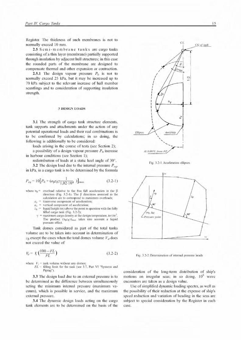
redistribution of loads at a static heel angle of 30°. 3.2 The design load due to the internal pressure Peq,
in kPa, in a cargo tank is to be determined by the formula
Peq = 1 0 [ P 0 + ( a p Z p Y 1 ; ( ) 2 , 1 0 4 ) ] m a x
( 3 . 2 - 1 )
where ap — overload relative to the free fall acceleration in the P direction (Fig. 3.2-1). The P directions assumed in the calculation are to correspond to maximum overloads;
ay — transverse component of acceleration; ax — vertical component of acceleration; Zp — liquid height (m) above the point in question with the fully
filled cargo tank (Fig. 3.2-2); у — maximum cargo density at the design temperature, in t/m3.
The product (apZpy)max takes into account a liquid pressure effect.
Tank domes considered as part of the total tanks volume are to be taken into account in determination of Zp except the cases when the total domes volume Vj does not exceed the value of
Vd=V ( 1 0 0 ^ ) (3.2-2)
where V, = tank volume without any domes; FL = filling limit for the tank (see 3.7, Part VI "Systems and
Piping").
3.3 The design load due to an external pressure is to be determined as the difference between simultaneously acting the minimum internal pressure (maximum va¬cuum), which is possible in service, and the maximum external pressure.
3.4 The dynamic design loads acting on the cargo tank elements are to be determined on the basis of the
CL CG of tank
Fig. 3.2-1 Acceleration ellipses
Fig. 3.2-2 Determination of internal pressure heads
consideration of the long-term distribution of ship's motions on irregular seas; in so doing, 108 wave encounters are taken as a design value.
Use of simplified dynamic loading spectra, as well as the possibility of their reduction at the expense of ship's speed reduction and variation of heading in the seas are subject to special consideration by the Register in each case.

16 Rules for the Classification and Construction of Ships Carrying Liquefied Gases in Bulk
For practical application of crack propagation estimates, simplified load distribution over a period of 15 days may be used in accordance with Fig. 3.4.
-15 days
Response cycles
Fig. 3.4 Simplified load distribution (a 0 = most probable maximum stress over the life of the ship.
Response cycle scale is logarithmic. The value of 2 x 10⁵ is given as an example of estimate)
3.5 The accelerations acting on cargo tanks are estimated at their centre of gravity and include the following components:
v e r t i c a l a c c e l e r a t i o n means motion accelerations of heave, pitch and roll normal to the ship's base;
t r a n s v e r s e a c c e l e r a t i o n means motion accelerations of sway, yaw and roll, and also the gravity component of roll;
l o n g i t u d i n a l a c c e l e r a t i o n means motion accelerations of surge and pitch, and also the gravity component of pitch.
Where reliable data on inertial forces acting on cargo tanks during ship's motions in the seas are unavailable, the following formulae may be used to determine the acceleration components:
for vertical acceleration
az — ±a0^1 + (5 ,3 - 4 L 5
0 ) 2 (L ! 0 +0,05) 2 ( 0 ^ j )3 / 2 ; (3.5-1)
for transverse acceleration
ay— ±a0^0,6+2,5(L0+0,05) 2 +^(1+0,6^B) 2 ; (3.5-2)
for longitudinal acceleration
ax—±a0^0,6+ A2-0,25A (3.5-3)
a t A ^ ( 0 ' 7 ^ ^ + ^ L 0 ) ( 0 6 ) ( 3 . 5 - 4 )
where L 0 = ship's length, in m (see Part II "Hull" of the Rules for the Classification);
C = block coefficient; В = greatest moulded ship's breadth, in m; x = longitudinal distance, in m, from amidships to the centre
of gravity of the cargo tank (x is positive forward of amidships);
z = vertical distance, in m, from the ship's actual waterline to the centre of gravity of the cargo tank with contents (z is positive above and negative below the waterline);
600 3 4 -
V L0 a0 — 0,2 - = - + ; (3.5-5)
V= service speed, in knots; К = 1 in general. For ship's particular loading conditions and
hull forms, the value of К may be determined by the formula
К = 13Gm/B, K > 1and Gm = metacentric height, in m; a x, ay and az = maximum dimensionless accelerations (i. e. relative to
the free fall acceleration) in the respective directions (they are considered as acting separately for calculation purposes);
ax includes the component due to the static weight in the longitudinal direction due to pitching;
ay includes the component due to the static weight in the transverse direction due to rolling;
az does not include the component due to the static weight.
3.6 The dynamic design load on the walls of a cargo tank at its partial filling is subject to special consideration by the Register in each case.
3.7 Thermal loads and their design values are subject to special consideration by the Register in each case.
Transient thermal loads during cooling down periods are to be considered in strength calculations for cargo tanks intended for a specification temperature of cargo below -55 °C.
3.8 The design loads on supports are to be determined according to the requirements of Section 7.
4 STRUCTURAL ANALYSES
4.1 The calculation of the cargo tank boundary thickness and of the adjacent structure element scantlings is to be carried out according to the procedures approved by the Register.
4.2 The scantlings of elements of hull structures bounding integral cargo tanks are to be determined with due regard for the requirements of 2.13, Part I I "Hull" of the Rules for the Classification.
4.2.1 The selection of the above structure scantlings is to be confirmed by the strength calculation performed according to the procedure approved by the Register.
4.3 The effects of all static and dynamic loads possible in service are to be considered in the calculation of membrane tank structure strength.
4.3.1 Coincident with the strength calculation, the results of structure model tests are to be submitted to the Register for information to confirm the expediency of assumptions adopted in the calculation and the adequate accuracy and reliability of its results. Test conditions are to represent the extreme conditions of tank service.

Part IV. Cargo Tanks 17
4.3.2 Material tests are to ensure that ageing is not liable to prevent the materials from carrying out their intended function.
4.3.3 Where reliable data on external loads on similar ships are unavailable, the types and values of test loads are to be determined on the basis of all possible in-service combinations of actual loads; in so doing, it is to be confirmed that an overpressure in the interbarrier space, a vacuum in the cargo tank, sloshing effects or vibration do not break membrane integrity.
4.3.4 The calculation of hull strength is to be performed with due regard to the internal pressure specified in 3.2; in this case, deflections of the hull and their compatibility with the membrane and associated insulation are to be considered.
4.3.5 The inner hull plating thickness and inner bottom plating are to meet the requirements of Part I I "Hull" of the Rules for the Classification with due regard to the internal pressure (see 3.2 of the present Part).
4.3.6 Allowable stresses for the calculation of a membrane, its supports and insulation are subject to special consideration by the Register in each case.
4.4 The procedure for semi-membrane tank strength calculation is subject to special consideration by the Register in each case.
4.5 A structural analysis of type A independent Cargo tanks is to be performed in accordance with the requirements in Part I I "Hull" of the Rules for the Classification taking into account the internal pressure (see 3.2 of the present Part) and any corrosion allowance specified in Section 6.
4.5.1 For structures in way of supports, design stresses are to be determined taking into account the loads specified in Section 3, as far as applicable, and the ship's hull deflection in way of supports.
4.6 A structural analysis of type Bindependent cargo tanks is to be performed regarding the effects of all possible in-service static and dynamic loads and their combinations to meet the requirement on limiting plastic deformation, buckling, fatigue endurance and a critical size of cracks; in so doing, the following is to be carried out:
statistical wave load analysis (see 3.4); finite element analysis or similar methods according
to the procedure approved by the Register; calculation of a crack propagation velocity; structural analysis with the effects of the load
transmitted to the cargo tank structure from its supports and attachments, using a three-dimensional analysis.
4.6.1 A complete analysis of the particular ship accelerations and motions in irregular waves and of the response of the ship and its cargo tanks to these forces and motions is to be performed unless these data are available from similar ships.
4.6.2 A buckling analysis is to consider the maximum construction tolerances.
4.6.3 Where deemed necessary by the Register, model tests may be required to determine stress concentration factors and fatigue life of structural elements.
4.6.4 The cumulative effect of the fatigue load is to comply with
3
^N+lt ^ Cw (4.6.4)
where ni = number of stress cycles at each stress level during the ship's life;
Ni = number of cycles to fracture for the respective stress level according to the Wohler (S — N) curve;
N = number of cycles to fracture for the fatigue loads due to loading and unloading;
Cw < 0,5 dependent on the test procedure and data used to establish the Wohler (S — N) curve, but, on a special agreement with the Register, Cw > 0,5 may be allowed, but not more than 1,0.
4.7 A structural analysis of type C independent cargo tanks is to be performed regarding the following requirements.
4.7.1 The thickness of shell of type C independent cargo tanks is to be determined taking into account the form of their parts according to the procedures approved by the Register.
The design and ways of reinforcing openings in type C tanks are subject to special consideration by the Register in each case.
4.7.2 Where non-destructive testing is provided, the design welded joint efficiency factor is to be assumed equal to 0,95. On agreement with the Register, it may be increased up to 1,0 depending on material properties, the joint type, welding procedure and loading type.
For process pressure vessels, on a special agreement with the Register, the partial non-destructive testing may be accepted. In this case, the welded joint efficiency factor is to be assumed not more than 0,85.
4.7.3 I f type C independent cargo tanks are subjected in service to loads causing compressive stresses, their thickness and form are subject to special consideration by the Register in each case.
A structural analysis of these tanks is to be performed according to the procedure approved by the Register regarding manufacturing tolerances.
4.7.4 The design external pressure Pe, in kPa, is to be determined by the formula
Pe—P1+ P 2 + P 3 + P4 (4.7.4)
where P 1 = setting value of vacuum relief valves; for cargo tanks not fitted with vacuum relief valves P 1 is subject to special consideration by the Register in each case, but is not to be less than 2 kPa;
P 2 = the set pressure of the pressure relief valves for ship's compartments wherein cargo tanks or their parts are located; elsewhere P2 =0;

18 Rules for the Classification and Construction of Ships Carrying Liquefied Gases in Bulk
P3 = any compressive actions (due to the weight and contrac¬tion of insulation, weight of shell, including corrosion allowance, etc.) the cargo tank may be subjected to. These also include weight of domes, towers and piping, effect of cargo in the partially filled condition, accelerations and hull deflection. In addition, the local effect of external and/or internal pressure is to be taken into account;
P 4 = conditional external load due to water run-up onto tanks or their parts on the exposed deck; elsewhere P 4 = 0.
4.7.5 A stress analysis in way of tank supports (in the tank shell and shell attachments) under loads specified in Section 3 is to be performed.
The Register may additionally require the results of a fatigue analysis, and also the calculations taking into account secondary stresses and thermal stresses.
4.7.6 The thickness of the type C independent cargo tank shell is to be not less than calculated regarding corrosion allowance and in any case not less than:
5 mm for carbon-manganese steels and nickel steels; 3 mm for austenitic steels; 7 mm for aluminium alloys.
4.8 A structural analysis of internal insulation cargo tanks is to be performed regarding all possible in-service static and dynamic loads and their actual combinations. Elements of structures forming the boundaries of the cargo tank with regard to ensuring fatigue strength, to a tendency to crack propagation, an adhesive capability of insulation, to ensuring compressive, tensile and shear strength are to be evaluated. In addition, the following is to be submitted to the Register for approval:
statistical wave load analysis (see 3.4); finite element analysis or similar methods; fracture mechanics analysis. 4.8.1 The analysis (using a three-dimensional
analysis) to evaluate the stress levels and deformations contributed either by the inner hull or by the independent tank structure is to be carried out to make sure that these deformations do not result in peeling and fracture of the insulation material. This analysis is to take into account a load due to the internal pressure in a cargo tank (see 3.2) and the dynamic loads caused by water ballast in ballast compartments i f they are adjacent to the inner hull forming the supporting structure of the internal insulation tank.
4.8.2 The allowable stresses for internal insulation tanks and the allowable joint deflections for the inner hull structure and the insulation material are subject to special consideration by the Register in each case.
4.8.3 The results of structure model tests including the tests of structural elements of composite structures under combined effects of static, dynamic and thermal loads are to be submitted to the Register.
4.8.3.1 Test conditions are to correspond to the most extreme service conditions the cargo containment system wil l be exposed to during the lifetime of the ship, including thermal cycles. For this purpose, 400 thermal cycles are considered to be a minimum, based upon
19 round voyages per year; where more than 19 round voyages per year are expected, a higher number of thermal cycles wi l l be required. These 400 thermal cycles may be divided into 20 full cycles (cargo temperature to 45 °C) and 380 partial cycles (cargo temperature to that temperature expected to be reached in the ballast voyage).
4.8.3.2 Models are to be representative of the actual construction including corners, joints, pump mounts, piping penetrations and other stress concentrators, and are to take into account variations in cargo tank material properties, workmanship and quality control.
4.8.3.3 Combined tension and fatigue tests are to be carried out to evaluate crack behaviour of the insulation material in the case where a through crack develops in the inner hull or independent tank structure. In these tests, where applicable, the crack area is to be subjected to the maximum hydrostatic pressure of the ballast water.
4.8.3.4 The cumulative effect of the load causing a fatigue failure is to be determined in accordance with 4.6.4 or by an equivalent method.
4.8.3.5 For internal insulation tanks, repair proce¬dures are to be developed during the prototype testing programme for both the insulation material and the inner hull or the independent tank structure.
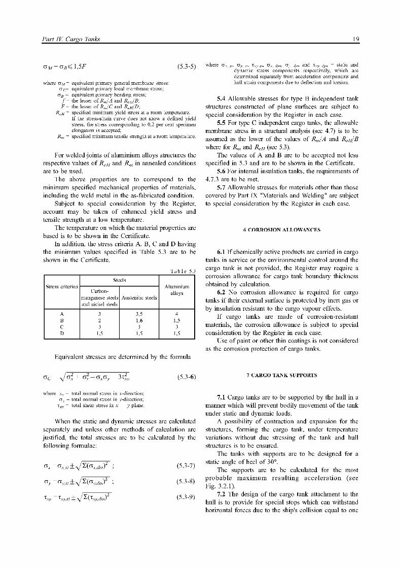
5 ALLOWABLE STRESSES
5.1 Selecting the scantlings of structure elements, which form integral and membrane cargo tanks, the requirements of 4.2 and 4.3 are to be met.
5.2 For type A independent tanks constructed of plane surfaces, the design stresses for members (web frames, stiffeners, stringers, girders) are not to exceed the lower of the following values:
i W 2 , 6 6 or Re^/1,33.
I f detailed strength calculations are carried out taking into account the effects of bending, axial and torsional deformation as well as of the hull/cargo tank interaction forces due to the deflection of the double bottom and cargo tank bottoms, the larger values of allowable stresses may be accepted on a special agreement with the Register.
5.3 For type Bindependent tanks constructed of bodies of revolution, the allowable stresses are not to exceed
aM^f; (5.3-1)
<*L<1,5f; (5.3-2)
CTB^1,5F; (5.3-3)
CTL+CTB^ 1,5F; (5.3-4)
Part IV. Cargo Tanks 19
CTM+CTB^1,5F (5.3-5)
where aM = equivalent primary general membrane stress; a L = equivalent primary local membrane stress;
аВ = equivalent primary bending stress; / = the lesser of Rm/A and ReH/B; F = the lesser of Rm/C and ReH/D;
ReH = specified minimum yield stress at a room temperature. If the stress-strain curve does not show a defined yield stress, the stress corresponding to 0,2 per cent specimen elongation is accepted;
Rm = specified minimum tensile strength at a room temperature.
For welded joints of aluminium alloys structures the respective values of ReH and Rm in annealed conditions are to be used.
The above properties are to correspond to the minimum specified mechanical properties of materials, including the weld metal in the as-fabricated condition.
Subject to special consideration by the Register, account may be taken of enhanced yield stress and tensile strength at a low temperature.
The temperature on which the material properties are based is to be shown in the Certificate.
In addition, the stress criteria A, B, C and D having the minimum values specified in Table 5.3 are to be shown in the Certificate.
Table 5.3
Stress criterion Steels
Aluminium alloys
Stress criterion Carbon-
manganese steels and nickel steels
Austenitic steels
Aluminium alloys
A 3 3,5 4 B 2 1,6 1,5 C 3 3 3 D 1,5 1,5 1,5
Equivalent stresses are determined by the formula
OC = V C T 2 +
СТ2 -ПХПУ + 3%ly (5.3-6)
where sx = total normal stress in x-direction; oy = total normal stress in y-direction;
x x y = total shear stress in x — y plane.
When the static and dynamic stresses are calculated separately and unless other methods of calculation are justified, the total stresses are to be calculated by the following formulae:
Ox =<5x,st±\l'Z('3x,dmf ; ( 5 . 3 - 7 )
O y = °y,st± V S ( C T y > J i ' n ) 2 ; ( 5 . 3 - 8 )
where Ox, M , <Jy,«, ixy st, ®x, dyn, c>y, dyn and i x y , jyn = static and dynamic stress components respectively, which are determined separately from acceleration components and hull strain components due to deflection and torsion.
5.4 Allowable stresses for type Bindependent tank structures constructed of plane surfaces are subject to special consideration by the Register in each case.
5.5 For type C independent cargo tanks, the allowable membrane stress in a structural analysis (see 4.7) is to be assumed as the lower of the values of Rm/A and ReH/B where for Rm and ReH (see 5.3).
The values of A and Bare to be accepted not less specified in 5.3 and are to be shown in the Certificate.
5.6 For internal insulation tanks, the requirements of 4.7.3 are to be met.
5.7 Allowable stresses for materials other than those covered by Part IX "Materials and Welding" are subject to special consideration by the Register in each case.
6 CORROSION ALLOWANCES
6.1 I f chemically active products are carried in cargo tanks in service or the environmental control around the cargo tank is not provided, the Register may require a corrosion allowance for cargo tank boundary thickness obtained by calculation.
6.2 No corrosion allowance is required for cargo tanks i f their external surface is protected by inert gas or by insulation resistant to the cargo vapour effects.
I f cargo tanks are made of corrosion-resistant materials, the corrosion allowance is subject to special consideration by the Register in each case.
Use of paint or other thin coatings is not considered as the corrosion protection of cargo tanks.
7CARGO TANK SUPPORTS
7.1 Cargo tanks are to be supported by the hull in a manner which wil l prevent bodily movement of the tank under static and dynamic loads.
A possibility of contraction and expansion for the structures, forming the cargo tank, under temperature variations without due stressing of the tank and hull structures is to be ensured.
The tanks with supports are to be designed for a static angle of heel of 30°.
The supports are to be calculated for the most probable maximum resulting acceleration (see Fig. 3.2.1).
7.2 The design of the cargo tank attachment to the hull is to provide for special stops which can withstand horizontal forces due to the ship's collision equal to one
20 Rules for the Classification and Construction of Ships Carrying Liquefied Gases in Bulk
half and one quarter the weight of the tank and cargo in the forward and aft direction respectively; any damages therewith to cargo tank structures are to be prevented.
7.3 A structural analysis of cargo tank structures and tank supports is to be carried out on the assumption that the loads specified in 7.1 and 7.2 act separately and are not superimposed on the forces due to ship's hull deformations in the seas.
7.4 Provision is to be made for structural measures to prevent potential cargo tanks (independent tanks and, where necessary, membrane and semi-membrane tanks) shifting relative to the ship's hull under the inertia forces caused by rolling.
7.5 The design of independent cargo tanks is to provide for antifloatation arrangements (keys, stops, etc.) which withstand an upward force caused by an empty tank in a hold space flooded to the full-load draught; in such a case, a stress in ship's hull structure elements is not to exceed R e H .
8 SECONDARY BARRIER
8.1 Where the cargo temperature at atmospheric pressure is below -10 °C, a secondary barrier (see 8.2) is to be provided to act as a temporary containment for any envisaged leakage of liquid cargo from the cargo tank.
Where the cargo temperature at atmospheric pressure is not below -55 °C, the ship's hull structure may act as a secondary barrier; in such a case, the hull material is to meet the requirements of 10.2 and the ship's hull elements forming the secondary barrier are not to be damaged under the loads due to thermal deformations.
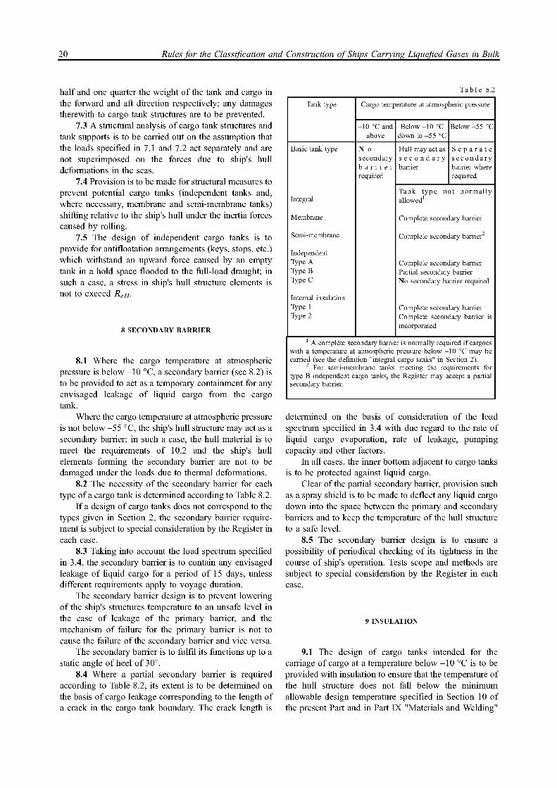
8.2 The necessity of the secondary barrier for each type of a cargo tank is determined according to Table 8.2.
I f a design of cargo tanks does not correspond to the types given in Section 2, the secondary barrier requirement is subject to special consideration by the Register in each case.
8.3 Taking into account the load spectrum specified in 3.4, the secondary barrier is to contain any envisaged leakage of liquid cargo for a period of 15 days, unless different requirements apply to voyage duration.
The secondary barrier design is to prevent lowering of the ship's structures temperature to an unsafe level in the case of leakage of the primary barrier, and the mechanism of failure for the primary barrier is not to cause the failure of the secondary barrier and vice versa.
The secondary barrier is to fulfil its functions up to a static angle of heel of 30°.
8.4 Where a partial secondary barrier is required according to Table 8.2, its extent is to be determined on the basis of cargo leakage corresponding to the length of a crack in the cargo tank boundary. The crack length is
Table 8.2
Tank type Cargo temperature at atmospheric pressure
-10 °C and above
Below -10 °C down to -55 °C
Below -55 °C
Basic tank type N o secondary b a r r i e r required
Hull may act as s e c o n d a r y barrier
S e p a r a t e secondary barrier where required
Integral Tank type not normally allowed1
Membrane Complete secondary barrier
Semi-membrane Complete secondary barrier2
Independent Type A Type B Type C
Complete secondary barrier Partial secondary barrier No secondary barrier required
Internal insulation Type 1 Type 2
Complete secondary barrier Complete secondary barrier is incorporated
1 A complete secondary barrier is normally required if cargoes with a temperature at atmospheric pressure below -10 °C may be carried (see the definition "integral cargo tanks" in Section 2).
2 For semi-membrane tanks meeting the requirements for type Bindependent cargo tanks, the Register may accept a partial secondary barrier.
determined on the basis of consideration of the load spectrum specified in 3.4 with due regard to the rate of liquid cargo evaporation, rate of leakage, pumping capacity and other factors.
In all cases, the inner bottom adjacent to cargo tanks is to be protected against liquid cargo.
Clear of the partial secondary barrier, provision such as a spray shield is to be made to deflect any liquid cargo down into the space between the primary and secondary barriers and to keep the temperature of the hull structure to a safe level.
8.5 The secondary barrier design is to ensure a possibility of periodical checking of its tightness in the course of ship's operation. Tests scope and methods are subject to special consideration by the Register in each case.
9 INSULATION
9.1 The design of cargo tanks intended for the carriage of cargo at a temperature below -10 °C is to be provided with insulation to ensure that the temperature of the hull structure does not fall below the minimum allowable design temperature specified in Section 10 of the present Part and in Part IX "Materials and Welding"
Part IV. Cargo Tanks 21
when the cargo tanks are at their design temperature and the ambient temperatures are 0 °C for sea water and 5 °C for air.
9.1.1 For ships of restricted areas of navigation, on agreement with the Register, higher values of the ambient temperatures may be accepted.
9.1.2 I f the ship is supposed to operate in latitude areas with lower temperatures, the Register may require reducing the ambient design temperatures and the relevant entry is to be made in the Certificate.
9.2 Where a second barrier is provided, the insulation is to be calculated in accordance with 9.1 to check the temperature of the hull structure does not fall below the minimum allowable design temperature for the certain grade of steel (see Section 10 of the present Part and Part IX "Materials and Welding").
9.2.1 The secondary barrier is to withstand the cargo temperature at atmospheric pressure.
9.2.2 The above calculations are to be made assuming still water and still air.
9.2.3 The use of means for hull structures heating is not a cause for alteration of design characteristics except the cases specified in 9.3.
9.2.4 In case of secondary barrier, the cooling effect of the rising boil-off vapour from the leaked cargo is to be considered in the heat transmission studies for insulation calculations.
9.2.5 In selection of material for structural members connecting the structures, forming the secondary barrier, with the ship's hull, the design temperature is to be determined as the arithmetic mean of the cargo temperature and the ambient temperature.
9.3 In the cases specified in 9.1 and 9.2 it is assumed that the ship is provided with Register-approved means for heating transverse hull structural members to prevent fall of their temperatures below the minimum allowable level.
9.3.1 I f the ship is supposed to operate at lower ambient temperatures, the above means of heating may be used for longitudinal hull structural members, provided they retain the required mechanical character¬istics at temperatures of 0 °C for seawater and 5 °C for air without heating.
9.3.2 The means for heating hull structures are to meet the following requirements:
sufficient heat is to be available to maintain the hull structures temperature above the minimum allowable values specified in 9.1 and 9.2;
the heating system is to be so arranged that, in the event of a failure in any part of the system, its intact part could ensure at least 100 per cent design heat supply;
the heating system is to be considered as an essential auxiliary;
the design of the heating system is subject to special consideration by the Register in each case.
9.4 In determining the insulation thickness, the presence of the cargo temperature regulation system, reliquefaction plant and main propulsion machinery, which uses the cargo as fuel oil, are to be taken into account.
9.5 The insulation materials are to withstand the loads, which may be imposed on them by adjacent structures.
9.6 The non-combustibility and flame spread requirements may be imposed on the insulation materials depending on their location on a ship.
9.6.1 The insulation is to be protected against mechanical damage and penetration of water vapour.
9.7 The insulation materials are to be tested to determine conformity of their properties and mechanical characteristics with regard to:
compatibility with the cargo; solubility in the cargo; absorption of the cargo; shrinkage; ageing; porosity; density; mechanical properties; thermal expansion; abrasion; adhesive properties; thermal conductivity; resistance to vibrations; non-combustibility and flame spread. In addition, the insulation materials for internal
insulation cargo tanks are to be tested for the following properties:
adhesive properties; resistance to cargo pressure; fatigue and crack propagation properties; compatibility with cargo constituents and any other
agent expected to be in contact with the insulation during ship's operation;
influence of the area and water pressure on the insulation properties;
gas de-absorbing. The above properties of the insulation materials are
to be tested for the range between the expected maximum temperature in service and 5 °C below the minimum design temperature, but not lower than -196 °C.
9.8 The procedure for fabrication, storage, erection, handling, quality control and control against harmful exposure to sunlight of insulation materials are subject to special consideration by the Register in each case.
9.9 Where powder or granulated insulation is used, measures preventing its compacting due to vibrations are to be taken.
9.10 The insulation is to retain its properties and not to cause increase of pressure on the cargo containment system elements.

22 Rules for the Classification and Construction of Ships Carrying Liquefied Gases in Bulk
10 MATERIALS
10.1 The materials of hull structure elements are to meet the requirements of Part X I I I "Materials" of Rules for the Classification.
Where the design temperature of hull structures is below -5 °C, the material for their manufacture is to be determined according to Table 2-5, Part IX "Materials and Welding"; in this case, the ambient sea and water temperature is assumed equal to 0 °C and 5 °C respectively.
The design temperature of the complete or partial secondary barrier is to be assumed equal to the cargo temperature at atmospheric pressure.
For tanks without secondary barriers, the primary barrier is to be assumed to be at the cargo temperature.
10.2 Hull material forming the secondary barrier is to be determined according to Table 2-2, Part IX "Materials and Welding".
Where the secondary barrier is not the part of the ship's hull structure, the material is to be determined according to Tables 2-2 and 2-3, Part IX "Materials and Welding".
Where the secondary barrier is formed by the deck or side shell plating, the requirements of Table 2-2, Part IX "Materials and Welding" cover the adjacent deck or side shell plating as far as practicable.
The insulation materials forming the secondary barrier are to meet the requirements of Section 9 of the present Part.
10.3 The materials used in the construction of cargo tanks are to meet the requirements of Tables 2-1 — 2-3, Part IX "Materials and Welding".
10.4 The materials of the hull structures which do not form the secondary barrier and other than those specified in 10.1 — 10.3, i f they may be subjected to the reduced cargo temperature, are to be determined according to Table 2-5, Part IX "Materials and Welding". This requirement also refers to inner bottom plating, longitudinal and transverse bulkhead plating, stringers and all framing members.
11 CONSTRUCTION AND TESTING
11.1 A l l welded joints of the shells of independent cargo tanks are to be of the butt weld, full penetration type. The dome-to-shell connection, welds of connectors, nozzles, holes, etc. except small penetrations on the tank dome, are to be made with full penetration.
11.2 Welding joint details for type C independent tanks are to meet the following requirements.
A l l welded joints of tanks walls are to be of butt welded, full penetration, double V- or single U-type.
Other edge preparations may be allowed, on a special agreement with the Register, provided that the results of the tests carried out at the approval stage of the welding procedure are positive.
A l l welds of the cargo tank structure (connection of parts, welding-on of nozzles, connectors, manholes) are to be made with full penetration. On a special agreement with the Register, welding without full penetration may be allowed for small diameter nozzles.
The edge preparation of parts for welding is to be performed according to the standards approved by the Register.
11.3 Welded joint tests, including non-destructive inspection, for all types of cargo tanks, excepting type C independent tanks, are to be carried out in accordance with 3.7, Part IX "Materials and Welding".
11.4 Functioning of the membrane tank and internal insulation tank structure is to be consistent with the Register-agreed standards for design, manufacture and testing established on the basis of prototype test results.
11.5 Semi-membrane tanks are subject to the require¬ments of the present Section for independent cargo tanks and membrane tanks as far as practicable and justified.
11.6 Integral tanks are to be hydrostatically or hydropneumatically tested in accordance with the Register requirements for cargo tank testing. The test is to be so performed that the stresses approximate, as far as practicable, to the design stresses and that the pressure at the top of the tank corresponds at least to MARVS.
11.7 In ships fitted with membrane and semi-membrane tanks, all the spaces which normally contain liquid cargo and are adjacent to the hull structure supporting the membrane are to be hydrostatically or hydropneumatically tested.
The ship's hull structures supporting the membrane are to be tested for tightness.
Pipe tunnels and other compartments, which do not normally contain liquid, need not be hydrostatically tested.
11.8 In ships fitted with internal insulation tanks where the inner hull supports the insulation, all inner hull structure is to be tested for tightness (see Appendix 1 to Part I I "Hull" of the Rules for the Classification) with due regard to MARVS.
I f the structure supporting the insulation is independent tanks, they are to be tested according to 11.10 and 11.11.
For internal insulation tanks, the procedure and programme for tightness tests are subject to special consideration by the Register in each case.
Tightness tests are to be conducted prior to insulation installation.
11.9 Prior to pressure testing, type C independent tanks are subjected to non-destructive testing (see 11.10).
11.9.1 Visual testing ascertains conformity of deviations of the finished tank structure dimensions and shape to the standards previously agreed with the

Part IV. Cargo Tanks 23
Register, and also to the approved standards for structure fabrication workmanship.
11.9.2 The scope of non-destructive testing is subject to special agreement with the Register in each case, but it is to be not less than:
total non-destructive testing referred to in 4.7.2; radiographic testing for 100 per cent of butt-welded joints; magnetic particle or penetrant testing for 100 per
cent of welds around holes, nozzles, connectors, etc. for surface cracks;
10 per cent of other welds. 11.9.3 Ultrasonic testing may be accepted as a partial
substitute for radiographic testing, on a special agree¬ment with the Register.
11.10 The Register may additionally require: ultrasonic testing for all welds around holes, nozzles,
connectors, etc.; partial non-destructive testing (see 4.7.2); radiographic testing for butt welds at their crossing
and for 10 per cent of the full length at selected positions uniformly distributed;
magnetic particle or penetrant testing for 100 per cent of welds around holes, nozzles, connectors, etc. for surface cracks;
ultrasonic testing. 11.11 Each independent tank is to be pressure tested
considering the following. 11.11.1 For type A independent tanks, this test is to
be so performed that the stresses approximate, as far as practicable, to the design stresses and that the pressure at the top of the tank corresponds at least to MARVS.
In any case, the test conditions are to be as close to actual as possible, in particular, the loads on the cargo tanks and their supports are to correspond, where possible, to those in service.
11.11.2 For type Bindependent tanks, the test is to be performed in accordance with 11.11.1. In addition, the maximum primary membrane stress or maximum bending stress in primary members at the test temperature is not to exceed 90 per cent of the yield strength of the material.
Where the design stresses during testing exceed 75 per cent of the yield strength of the material, the structure prototype is to be tested using the strain measurement or similar techniques.
11.11.3 Each type C independent tank is to be tested at a pressure of at least 1,5/>0 measured at the top of the tank. In addition, the primary membrane stress at any point of its structure is not to exceed 90 per cent of the yield strength of the material.
Where the design stresses during testing exceed 75 per cent of the yield strength of the material, the structure prototype is to be tested using the strain measurement or similar techniques.
11.11.4 The temperature of water used for the test is to be at least 30 °C above the critical temperature of material embrittlement.
11.11.5 The time period for the pressure test is established on the basis of 2 h per 25 mm of the tank wall thickness, but not less than 2 h.
11.11.6 The substitution of the hydraulic tests of the cargo tanks by other test types is subject to special consideration by the Register in each case.
11.11.7 I f the higher values of allowable stresses as compared with those specified in Section 5 are used in cargo tank strength calculations, the procedure for cargo tank testing is subject to special consideration by the Register.
11.11.8 In any case, the test load is to be not less than
1,5^0.
11.12 A l l type cargo tanks are to be subjected to a tightness test, which may be performed in combination with the pressure test specified in 11.10 and 11.11.
11.13 The requirements for inspection of secondary barriers are subject to special consideration by the Register in each case.
11.14 Where the operational experience on the ships of similar dimensions is inadequate, at least one tank and its supports in the type Bindependent tank ship are to be instrumented to determine the level of actual stresses.
Similar instrumentation is recommended for ele¬ments of the type C independent tank structure.
11.15 The overall performance of the cargo contain¬ment system is to be verified for compliance with the design parameters during the initial cool-down, loading and discharging of the cargo. The documents confirming that compliance are to be submitted to the Register.
11.16 Heating arrangements fitted according to 9.3 are to be tested for required heat output and heat distribution.
11.17 The ship's hull is to be inspected for cold spots following the first loaded voyage.
11.18 The way type C independent tanks are marked, is not to cause local stress raisers.
11.19 The insulation materials of internal insulation tanks are to be subjected to additional inspection in order to verify their surface condition after the third loaded voyage of the ship, but not later than the first six months of the ship's service after building or a major repair work is undertaken on the internal insulation tanks.
12 STRESS RELIEVING FOR TYPE C INDEPENDENT TANKS
12.1 For type C independent tanks of carbon or carbon-manganese steel, pot-weld heat treatment is to be performed after welding i f the design temperature is below -10 °C. The soaking temperature and holding time are subject to special consideration by the Register in each case.
Heat treatment at other design temperature and with other materials is subject to special consideration by the Register in each case.

24 Rules for the Classification and Construction of Ships Carrying Liquefied Gases in Bulk
12.2 Where the heat treatment is impractical due to large dimensions of the structure, mechanical stress relieving by pressurizing, on agreement with the Register, maybecarriedouttakingintoaccountthefollowing.
12.2.1 Complicated welded structures (sumps, domes with nozzles and adjacent shell plates) are to be heat treated before welding to the main structure.
12.2.2 The mechanical stress relieving process is preferably to be carried out during the hydrostatic pressure test specified in 11.11.3 by applying a higher pressure than the test pressure. The pressurizing medium is to be water at a temperature specified in 11.11.4.
12.2.3 Stress relieving is to be performed while the cargo tank is supported by its regular saddles or supporting structures. When stress relieving cannot be carried out on board, it is to be effected in another way which wi l l give the same stress levels and stress distribution as for the cargo tank on board. The test time is specified according to 11.11.5.
12.2.4 The upper limits placed on the calculated stress levels during stress relieving are to be the following:
equivalent general primary membrane stress: 0,9R e
1; equivalent stress composed of primary bending
stress plus membrane stress: 1,35Re. 12.2.5 Measurements are to be provided to confirm
the limiting values of the stresses specified in 12.2.4 at least for the first of a series of identical tanks. The
PART V. F I R E
1 APPLICATION
1.1 The requirements of the present Part apply to ship's structural fire protection, fire extinguishing systems as well as to fire fighting equipment and outfit of LG carriers. The LG carriers are also covered by all the applicable requirements of Part V I "Fire Protection" of the Rules for the Classification.
1.2 The fire protection requirements relating to the structural members of the ship hull, machinery and electrical equipment, system and piping are set out in the relevant parts of the LG Rules.
1R e is a specific lower minimum yield stress of the material ReH
or R J j 0 > 2 of the yield area is lacking.
diagram of strain gauges location is to be included in the technological documents for mechanical stress relieving which are to be submitted to the Register for considera¬tion.
12.2.6 After stress relieving, repeated loading up to the design pressure is to demonstrate that the stresses in structures vary with a load.
12.2.7 High stress areas in way of nozzles or other openings are to be checked for cracking by magnetic particle or dye penetrant inspection after stress relieving. Particular attention is to be given to plates exceeding 30 mm in thickness.
12.2.8 Steels having a ratio of yield stress to ultimate tensile strength over 0,8 are generally not be mechani¬cally stress relieved. If, however, the yield stress of steel is raised by a method giving high ductility of the steel, slightly higher rates may be accepted upon special consideration.
12.2.9 Mechanical stress relieving cannot be sub¬stituted for heat treatment of tank elements formed by cold bending i f the degree of cold bending exceeds the limit above which heat treatment is required.
12.2.10 The thickness of the shell and heads of the tank is not to exceed 40 mm. Higher thicknesses may be accepted for heat-treated elements.
12.2.11 Local buckling is to be monitored particu¬larly when torispherical heads are used for tanks and domes.
PROTECTION
2 STRUCTURAL FIRE PROTECTION
2.1 The applicable requirements of 2.4, Part V I "Fire Protection" of the Rules for the Classification are to be complied with.
2.2 A l l sources of ignition are to be excluded from spaces where flammable vapour may be present.
I f electrical equipment is fitted in such spaces, it is to be documented that the equipment is safe for use in dangerous environment, to which it may be exposed.
2.3 Hold spaces are to be located forward of machinery spaces of category A. They are to be separated from adjacent machinery spaces of category A, accom¬modation and service spaces, control stations, chain lockers, storerooms, drinking water and domestic water tanks by cofferdams or fuel tanks.
Where the adjacent spaces contain no combustible medium, these spaces may be separated by gastight "A-0" class bulkheads.

Part V. Fire Protection 25
In ships with cargo tanks without secondary barrier, gastight "A-60" class bulkheads may be used instead of cofferdams and fuel tanks.
3 FIRE FIGHTING EQUIPMENT AND SYSTEMS
3.1 General requirements. 3.1.1 Cargo compressor and pump rooms are to be
provided with a carbon dioxide system as specified in 3.8, Part V I "Fire Protection" of the Rules for the Classification (with factor equal to 0,45 in Formula (3.8.1.1)).
A notice is to be exhibited at the controls stating that the system is only to be used for fire extinguishing and not for inerting purposes (due to electrostatic ignition hazard).
3.1.2 Cargo compressor and pump rooms of ships intended for carriage of cargoes for extinction of which the carbon dioxide system is unacceptable, are to be provided with an equivalent fire extinguishing system.
3.1.3 The automatic sound alarms to warn of the carbon dioxide discharge to the above spaces are to be safe for use in a flammable cargo vapour-air mixture.
3.2 Water fire main system. The water fire main system is to meet the
requirements of 3.2, Part V I "Fire Protection" of the Rules for the Classification, having regard to the following:
water pressure at any hydrant is not to be less than 0,5 MPa;
stop valves are to be fitted in any crossover and in the fire main where it is led out of the poop and at intervals of 40 m on the deck and in the cargo area;
length of fire hoses on open decks is not to exceed 33 m.
3.3 Water spray system. 3.3.1 On ships carrying flammable or toxic products,
a water spray system is to be installed to cover: .1 exposed cargo tank domes and any exposed parts
of cargo tanks; .2 exposed on-deck storage vessels for flammable or
toxic gases; .3 an area not less than the area of drip trays under
cargo discharge and loading manifolds, their control valves and essential control valves of the cargo system;
.4 boundaries of superstructures, deckhouses, cargo control rooms, cargo compressor and pump rooms and storerooms containing flammable materials and sub¬stances, all facing the cargo area.
3.3.2 The capacity of the water spray system is to be as follows:
10 l/min per m 2 for horizontal projected surfaces; 4 l/min per m 2 for vertical surfaces; for structures having no clearly defined horizontal or
vertical surfaces the rated capacity of the system is to be the greater of the following: projected horizontal surface
multiplied by 10 l/min per m 2 ; or actual surface multiplied by 4 l/min per m 2 .
3.3.3 Stop valves are to be fitted in the main for the purpose of isolating damaged sections. Alternatively, the system may be divided into two or more sections which may be operated independently, provided the necessary controls are located together, aft of the cargo area. Sections protecting any area specified in 3.3.1.1 and 3.3.1.2 are to cover the whole of the athwartship tank grouping which includes that area.
3.3.4 The capacity of the pumps is to be sufficient to deliver the required amount of water to all areas or where the system is divided into sections, the capacity is to be such as to supply water to any one section and to surfaces specified in 3.3.1.3 and 3.3.1.4.
3.3.5 Where the main fire pumps are used to supply the water spray system, the capacity of the pumps is to be rated for joint operation of these systems having regard to the requirements of 3.3.4. A connection, through a stop valve, is to be made between the water fire main and water spray main outside the cargo area.
3.3.6 On agreement with the Register, sanitary, ballast, bilge and other sea water pumps may be arranged to supply the water spray system provided their capacity and pressure head correspond to those required.
3.3.7 Remote starting of pumps supplying the water spray system and remote operation of any normally closed valves in the system is to be arranged in suitable locations outside the cargo area, adjacent to the accommodation spaces and readily accessible and operable in the event of fire.
3.4 Dry chemical powder fire extinguishing system. 3.4.1 Ships for the carriage of flammable products
are to be fitted with dry chemical powder fire extinguish¬ing system to protect cargo area and cargo discharge and loading manifolds.
3.4.2 The dry chemical powder fire extinguishing system is to meet the requirements of 3.10, Part V I "Fire Protection" of the Rules for the Classification and the requirements of IMO MSC.1/Circ. 1315.
4 PERSONNEL PROTECTION
4.1 In ships carrying flammable goods, the following fireman's outfit, stated in 5.1.15, Part V I "Fire Protec¬tion" of the Rules for the Classification, are to be provided in addition to the fireman's outfit required under item 10, Table 5.1.2 of the said Part:
4 - when the capacity of cargo tanks is 5000 m 3 and below;
5 - when the capacity of cargo tanks is over 5000 m 3 . 4.2 Air-breathing apparatus included in the fireman's
outfit are to be self-contained and have air bottles with a capacity of at least 1200 l of free air.
26 Rules for the Classification and Construction of Ships Carrying Liquefied Gases in Bulk
4.3 Protective equipment including protective gog¬gles is to be provided to protect crew members involved in loading and discharging operations, with due regard for the character of products.
4.4 The protective equipment is to be kept in a special locker located in a readily accessible place.
4.5 Sufficient, but not less than two complete sets of safety equipment in addition to the fireman's outfit required by 4.1 each permitting personnel to enter and work in gas-filled spaces, are to be provided.
4.6 One complete set of safety equipment required by 4.5 is to consist of:
one self-contained air-breathing apparatus with air bottles of free air capacity of at least 1200 l ;
protective clothing, boots, gloves and tight-fitting goggles;
steel-cored rescue line with belt; and explosion-proof lamp. 4.7 For the air-breathing apparatus required in 4.6
the following is to be provided: two spare charges for each breathing apparatus, a
special air compressor accepted by competent authorities for use and a charging manifold capable of dealing with spare breathing apparatus air bottles; or
fully charged spare air bottles with a total free air capacity of at least 6000 l for each breathing apparatus.
4.8 Safetyequipmentrequiredin4.6and4.7istobe kept in a special locker located in a readily accessible place.
PART VI. SYSTEMS AND PIPING
1 GENERAL
1.1 The present Part supplements Part V I I I "Systems and Piping" of the Rules for the Classification and sets forth the requirements for the special systems and piping of gas LG carriers.
1.2 Pumps, piping, valves and other fittings of the systems arranged in way of cargo tanks are to have identification markings.
2 PIPING
2.1 Materials. 2.1.1 Piping and valves used for media having the
working temperature from 0 to —165 °C are to be manufactured of materials specified in Part IX "Materials and Welding".
2.1.2 Materials having a melting point below 925 °C are not to be used for piping outside the cargo tanks except for short lengths of pipes attached to the cargo tanks having fire-resisting insulation.
2.1.3 Materials of the systems and piping intended for cargoes with a temperature below -165 °C are subject to special consideration by the Register in each case.
2.2 Pipe wall thickness. 2.2.1 The wall thickness of pipes operating under the
internal pressure is to be not less than that determined by Formula (2.3.1), Part V I I I "Systems and Piping" of the Rules for the Classification with due regard for the following values involved in the formula.
2.2.1.1 p (design pressure) is the maximum pressure, to which the system may be subjected in service.
For pipelines or components thereof the greater of the following values is to be taken as the design pressure:
the pressure of the saturated cargo vapours at 45 °C - for the pipelines or components thereof which contain cargo vapours or some amount of liquid cargo and may be disconnected from the relief valves;
the pressure of superheated vapours at 45 °C assuming the operating pressure and temperature as initial conditions for the saturated vapours in the system - for the pipelines or components thereof which contain only cargo vapours at all times and may be disconnected from the relief valves;
the maximum allowable relief valve setting of the cargo tanks and cargo processing systems;
the pressure setting of the associated pump or compressor discharge relief valve;
the maximum total discharge or loading head of the cargo piping system;
the relief valve setting on a pipeline system. In any case, the design pressure p is not to be less
than 1 MPa except for open-ended lines where it is to be not less than 0,5 MPa.
2.2.1.2 с is the corrosion allowance; it may be increased over the required in 2.3.1, Part V I I I "Systems and Piping" of the Rules for the Classification i f enhanced corrosion or piping erosion is expected. This allowance is to be consistent with the expected life of the
piping. 2.2.1.3 The remaining values involved in the
formula are to meet the requirements of 2.3.1, Part V I I I "Systems and Piping" of the Rules for the Classification; no reduction of the safety factors is allowed.
2.2.1.4 The minimum material ultimate strength and yield stress safety factors accepted for the cargo pipeline are to be specified in the Certificate.
Part VI. Systems and Piping 27
2.2.2 The minimum pipe wall thickness is to be taken in accordance with Table 2.3.8, Part V I I I "Systems and Piping" of the Rules for the Classification (for steel pipes, see column 2).
Where necessary for mechanical strength to prevent damage of pipes resulted from excessive sag due to superimposed loads from supports, ship deflection or other causes, the wall thickness is to be increased over that required by 2.2.1. I f this is impracticable or would cause excessive local stresses, these loads are to be reduced or eliminated completely by other design methods.
2.2.3 When the design temperature of the medium is -110 °C or lower, a complete stress analysis, taking into account all the stresses due to weight of pipes, including acceleration loads i f significant, internal pressure, thermal contraction and loads induced by hog and sag of the ship for each branch of the piping system is to be submitted to the Register.
For temperatures of above -110 °C, a stress analysis may be required by the Register in relation to such matters as the design or stiffness of the piping system and the choice of materials.
Such analysis is to be carried out according to methods approved by the Register.
In any case, consideration is to be given to thermal stresses, even though calculations are not submitted.
2.3 Pipe joints. 2.3.1 The present requirements apply to piping
inside and outside the cargo tanks. On agreement with the Register, relaxations from these requirements may be accepted for piping inside cargo tanks and open-ended piping.
2.3.2 Butt-welded joints with complete penetration may be used in all applications. For design temperatures below -10 °C, butt welds are to be either double welded or equivalent to a double welded butt joint. This may be accomplished by use of a backing ring, consumable insert or inert gas back-up on the first pass.
For design pressures in excess of 1 MPa and design temperatures of -10 °C or lower, backing rings are to be removed after welding. The scope of non-destructive testing is to be not less than that required in 3.2.3,
Part X I V "Welding" of the Rules for the Classification, for Class I piping.
2.3.3 Flange connections of piping, valves and other fittings are to meet the requirements of 2.4.3, Part V I I I "Systems and Piping" of the Rules for the Classifica¬tion.
The type Bflange connections are not to be used for the design temperatures lower than -10 °C and in nominal sizes above 100 mm.
The strength dimensions of the flanges are to be determined in accordance with standards approved by the Register for the design pressure accepted in compliance with 2.2.1.1.
2.3.4 Sleep-on welded joints with sleeves and related welding are only to be used for open-ended lines with external diameter of 50 mm or less and design temperature not lower than -55 °C.
The dimensions of sleeves and welded joints are subject to special consideration by the Register in each case.
2.3.5 On agreement with the Register, screwed couplings may only be used for accessory lines with external diameter of 25 mm or less.
2.3.6 Where bellows and expansion joints are uses in the piping, they are to be held to a minimum but their number is to be sufficient to protect the pipelines and individual assemblies of the system against excessive stresses due to thermal expansion of the cargo tanks, pipelines and ship's hull deformations.
Bellows may be only installed outside the cargo tanks. Expansion joints of other types may be installed inside the cargo tanks.
I f necessary, bellows are to be protected against icing.
2.4 Heat treatment of pipes. 2.4.1 Post-weld heat treatment is to be required for
all butt welds of liquefied gas pipes made with carbon, carbon-manganese and low alloy steels.
2.4.2 The Register may waive the requirement for thermal stress relieving of pipes having wall thickness not less than 10 mm in relation to the design temperature and pressure of the piping system concerned.
2.5 Insulation of piping. Pipelines intended for media with low temperature
are to be thermally isolated from the adjacent hull structures, where necessary, in order to prevent the temperature of these structures from falling below the design temperature.
Where liquid piping is dismantled regularly, or where liquid leakage may be anticipated (such as at shore connections or at the pump seals), protection for the hull beneath is to be provided.
2.6 Piping arrangement. 2.6.1 Any piping system, which may contain cargo
or cargo vapour is to meet the following requirements.
2.6.1.1 The system is to be separated from other piping systems, except for the connections required for cleaning, gas removal and supply of inert gas. In this case, precautions are to be taken to preclude ingress of cargo or its vapour into other piping systems through such connections.
2.6.1.2 With the exception of the case specified in Section 10, the pipelines are not to pass through the accommodation and service spaces, control stations and machinery spaces, except for the cargo pump and compressor rooms.
Emergency cargo removal arrangements may be located in the after part of the ship, in way of accommodation and service spaces, control stations and

28 Rules for the Classification and Construction of Ships Carrying Liquefied Gases in Bulk
machinery spaces; however, the pipelines are not to pass through these spaces.
2.6.1.3 The piping system is to be arranged in the cargo area on open deck, except for the cases of bow and stern loading according to 3.2.8 and use of cargo as fuel (see Section 10).
2.7Side overboard discharges below freeboard deck.
2.7.1 Provision and control of valves fitted at the side overboard discharges of piping from spaces situated below the freeboard deck, or from enclosed super¬structures and deckhouses on the freeboard deck are to comply with the requirements of 4.3.2, Part V I I I "Systems and Piping" of the Rules for the Classifica¬tion.
2.7.2 The choice of the valves is to be based on the following.
2.7.2.1 The overboard discharges are generally to be provided with one automatically operated non-return valve with a positive means of closing positioned above the freeboard deck.
2.7.2.2 Where the vertical distance from the summer load waterline to the inboard end of the discharge pipe exceeds 0,01 of the ship's length, the discharge opening may have two automatically operated non-return valves without positive means of closing provided that the inboard valve is readily accessible for inspection under service conditions.
3 CARGO SYSTEM
3.1 Pumps and compressors. 3.1.1 To transfer the liquefied gases, centrifugal,
peripheral and steam-driven direct acting pumps of special design may be used.
The construction of the pumps is to include special sealing components to keep the suction pressure above the liquid phase saturated vapour pressure at the maximum temperature.
3.1.2 Single-stage and double-stage compressors may be used to transfer liquefied gases cargo vapours.
3.1.3 Where cargo transfer is by means of cargo pumps not accessible for repair with the tanks in service, at least two separate means are to be provided to transfer cargo from each tank and the design is to be such that failure of one cargo pump, or means of transfer, wi l l not prevent the cargo transfer by another cargo pump or pumps, or other cargo transfer means.
3.1.4 Relief valves are to be provided for pumps and compressors the delivery pressure of which may exceed the design pressure in the system.
3.1.5 The procedure for transfer of cargo by gas pressurization is to preclude lifting of the relief valves during such transfer.
3.1.6 The cargo pumps and compressors are to be arranged to shutdown automatically if:
emergency shutdown valves in pressure pipelines required by 3.2.1 are closed by the emergency shutdown system required by 3.2.4;
prescribed cargo level in cargo tank is reached; pressure in the cargo tank drops to the minimum
allowable value. 3.1.7 Cargo hoses are to have Type Approval
Certificates and meet the requirements of Section 6, Part V I I I "Systems and Piping" of the Rules for the Classification.
3.2 Piping and valves. 3.2.1 Every cargo piping system and cargo tank is to
be provided with the emergency shutdown valves. 3.2.1.1 For cargo tanks with MARVS not exceeding
0,07 MPa, all liquid and vapour connections, except safety relief valves and closed liquid level gauging devices which penetrate the cargo tank, are to have shutoff valves located as close to the tank as practicable. These valves may be remotely controlled but are to be capable of local manual operation and provide full closure.
Remotely controlled emergency shutdown valves are to be provided on the ship for shutting down liquid and vapour cargo transfer between ship and shore and are to meet the requirements of 3.2.3 and 3.2.4.
3.2.1.2 For cargo tanks with MARVS exceeding 0,07 MPa, all liquid and vapour connections, except safety relief valves and closed liquid level gauging devices which penetrate the cargo tank, are to be equipped with a manually operated stop valve and a remotely controlled emergency shutdown valve. These valves are to be located as close to the tank as practicable.
Where the pipe size does not exceed 50 mm in diameter, excess flow valves specified in 3.2.5 may be used in lieu of the emergency shutdown valve.
A single valve may be substituted for the two separate valves provided the valve complies with the requirements of 3.2.4, is capable of local manual operation and provides full closure.
3.2.2 Cargo tank connections for gauging or measuring devices need not be equipped with excess flow or emergency shutdown valves provided that the internal diameter of a connection does not exceed 1,5 mm.
3.2.3 One remotely operated emergency shutdown valve is to be provided at each cargo hose connection.
Connections not used in transfer operations may be blinded with blank flanges.
3.2.4 A l l required emergency shutdown valves are to be controlled from at least two remote locations on the ship. One of these locations is to be the cargo control room.
The control system is to be also provided with fusible elements designed to melt at temperatures

Part VI. Systems and Piping 29
98 to 104 °C which wil l cause the emergency shutdown valves to close in the event of fire. Locations for such fusible elements are to include the tank domes and loading stations.
Emergency shutdown valves are to be of the fail-closed (closed on loss of power) type and be capable of local manual closing operation.
It is recommended that the valve closing operation is performed without use of a remote power supply but by physical mechanical over-ride forcing the valve onto its seat. Along with that, a clear indication of the valve opening and closing position is to be provided. The operating instruction of the valve Manufacturer is to be kept on board the ship and provide technical information on installation, maintenance, including disassembly and assembly, periodic inspections, including external and inner examinations and testing by pressure equal to the working pressure.
Emergency shutdown valves in liquid piping are to fully close under all service conditions with 30 s of actuation.
Valves connected with the high liquid level alarm and the sensor for automatic closure thereof, in accordance with Part V I I I "Instrumentation" are to comply with the following requirements to control overpressure in the cargo main and prevent the cargo tank from becoming liquid full.
3.2.4.1 The total valve closure time (i.e. the time from shutdown signal initiation to complete valve closure) , in s, is not to exceed 3600 U/LR (where U is ullage volume at operating signal level, in m 3 ; LR is the maximum loading rate agreed between ship and shore facility, in m 3/h) and is to be such as to avoid surge pressures.
3.2.4.2 The total valve closure time is to be such as to prevent pressure increase during closure of the valve above the acceptable level.
Information on the closing time of the valves and their operating characteristics is to be available on board and the valve closure time is to be verifiable and reproducible. Such valves are to close in such a manner as to cut off the flow smoothly.
3.2.5 Excess flow valve is to close automatically at the rated closing flow of vapour or liquid as specified by the manufacturer.
The piping including fittings, valves and appurte¬nances protected by an excess flow valve, are to have greater capacity than the rated closing flow of the excess flow valve.
Excess flow valves may be designed with a bypass not exceeding an area of 1,0 mm diameter circular opening to allow equalization of pressure, after an operating shutdown.
3.2.6 A l l pipelines or components which may be isolated in a liquid-full condition from the cargo piping systems and tanks are to be provided with relief valves.
Relief valves discharging liquid cargo from the cargo piping system are to discharge to the cargo vent mast i f means are provided to detect and dispose of any liquid cargo which may flow into the vent system.
Relief valves on cargo pumps are to discharge to the pump suction.
3.2.7 Suitable means are to be provided to relief the pressure and remove liquid contents from cargo loading and discharging crossover headers and cargo hoses to the cargo tanks or other suitable location, prior to dis¬connecting the cargo hoses (see 3.2.10).
3.2.8 On agreement with the Register, for the purpose of carrying out cargo handling operations from bow and stern, cargo piping may be laid aft or forward outside the cargo area in accordance with 3.2.9 and 3.2.10, but it is not to be used for transfer of toxic goods.
Connections for the cargo hoses are to be arranged as follows.
3.2.8.1 Entrances, air intakes and opening leading to the accommodation, service and machinery spaces as well as control stations are not to face the shore connections of bow or stern loading and discharging arrangements. They are to be situated at the super¬structure or deckhouse side at a distance equal to at least 4 per cent of ship length or 3 m from the deckhouse end facing the shore connection of the bow or stern loading and discharging arrangements. This distance need not, however, to exceed 5 m. Sidelights facing the side where the shore connections are fitted and situated on the superstructure or deckhouse side within the above distance are to be of dead (non-opening) type. Also, when the bow or stern loading and discharging arrangements are used, all doors, cargo ports and other openings situated on the relevant side of the super¬structure or deckhouse are to be kept closed at all times.
3.2.8.2 Deck opening and air intakes located at a distance of 10 m from the position of the shore connection of the bow or stern loading and discharging arrangements are to be kept closed over the whole period when these arrangements are used.
3.2.8.3 Electrical equipment located within the 3 m zone from the position of the shore connection of the above arrangements is to meet the requirements of Part V I I "Electrical Equipment".
3.2.8.4 Fire fighting equipment intended for use in the area where the bow or stern loading and discharging arrangements are located is to meet the requirements of 3.3, Part V "Fire Protection".
3.2.8.5 Communication is to be maintained between the cargo control room and the position of shore connection of the cargo hoses.
3.2.9 Cargo piping for bow or stern loading is to be permanently installed and meet the following require¬ments.
3.2.9.1 Cargo piping arranged forward or aft of the cargo area is to be laid on open parts of the deck, be

30 Rules for the Classification and Construction of Ships Carrying Liquefied Gases in Bulk
clearly marked and be at least 760 mm away from the ship side.
3.2.9.2 Only butt-welded joints with complete penetration and 100 per cent radiographic inspection of the welds are to be used in cargo piping outside the cargo area, irrespective of the diameter, temperature and pressure for which the piping has been designed. Flange connections may be only used within the cargo area and at cargo hose connection.
3.2.9.3 The bow and stern loading and discharging piping is to be isolated from the cargo main by shut-off valves, spool pieces and blank flanges located in the cargo area.
3.2.10 To remove the cargo residues after using the piping referred to in 3.2.8 special means for their purging and gas-freeing are to be provided.
Vent piping system connected with the means for re¬moving the cargo residues is to be located in the cargo area.
3.2.11 Where a part of the cargo which cannot be pumped out by cargo pump remains in the cargo tank, special means are to be provided to remove the cargo residues.
3.3 Pressure relief system. 3.3.1 A l l cargo tanks are to be provided with a
pressure relief system arranged to send the surplus of the evaporated cargo into the vent piping system. The relieving system is to be appropriate to the design of the cargo containment system and the cargo being carried.
Hold spaces, interbarrier spaces and cargo piping which may be subject to pressures beyond their design capabilities are to be also provided with a suitable system to carry off the evaporated cargo. These systems are to be connected to a vent piping system so designed as to minimize the possibility of cargo vapour accumulating on the decks, or entering accommodation spaces, service spaces, machinery and other spaces and control stations where it may create a dangerous condition.
Pressure relief systems are to be independent of other systems including the pressure control systems specified in Section 4.
3.3.2 Each cargo tank with a volume exceeding 20 m 3 is to be fitted with at least two pressure relief valves of approximately equal capacity, suitably de¬signed and constructed for the prescribed service.
For cargo tanks with a volume not exceeding 20 m 3 , a single relief valve may be fitted.
3.3.3 Interbarrier spaces are to be provided with pressure relief devices approved by the Register.
3.3.4 The setting of the pressure relief valves is not to be higher than the vapour pressure which has been used in the design of the tank.
3.3.5 Pressure relief valves are to be connected to the highest part of the cargo tank above deck level.
Pressure relief valves are to be arranged to prevent their becoming inoperative due to ice formation when they are closed.
Due consideration is to be given to the construction and arrangement of pressure relief valves on cargo tanks subject to low ambient temperatures.
3.3.6 Incaseofcargotankspermittedtohavemore than one relief valve setting this may be accomplished by:
installing two or more properly set and sealed valves and providing means as necessary for isolating the valves not in use from the cargo tank; or
installing relief valves whose settings may be changed by the insertion of previously approved spacer pieces or alternative springs or by other similar means not requiring pressure testing to verify the new set pressure.
A l l valve adjustments are to be sealed. The requirements for testing and adjusting the relief
valves are set out in 12.1.3.
3.3.7 Stop valves or other means of blanking off pipes between tanks and pressure relief valves to facilitate maintenance are not to be fitted unless all the following arrangements are provided:
.1 suitable arrangements to prevent more than one pressure relief valve being out of service;
.2 a device which automatically and in a clearly visible way indicates which one of the pressure relief valves is out of service;
.3 pressure relief capacities such that i f one valve is out of service the remaining valves have the combined relieving capacity required by 3.6. However, this capacity may be provided by the combined capacity of all valves, i f a suitably maintained spare valve is carried on board.
3.3.8 Each pressure relief valve installed on a cargo tank is to be connected to a venting system.
3.3.9 I f cargoes which react in a hazardous manner with each other are carried simultaneously, a separate pressure relief system is to be fitted for each cargo carried.
3.3.10 Pressure relief valves and piping are to be so arranged that liquid can under no circumstances accumulate in or near the pressure relief valves.
3.3.11 Pressure relief valves are to be positioned on the cargo tank so that they wi l l remain in the vapour phase under conditions of 15° list and 0,015L trim (for L , see the definition in Part I I "Hull" of the Rules for the Classification).
3.4 Additional pressure relieving system for liquid level control.
3.4.1 Where required by 3.7.4.2, an additional pressure relieving system to prevent the tank from becoming liquid full at any time during relief under the fire exposure conditions referred to in 3.6 is to be fitted to each tank. This pressure relieving system is to consist
of: .1 one or more relief valves set at a pressure
corresponding to the gauge vapour pressure of the cargo at the reference temperature defined in 3.7.4.2;
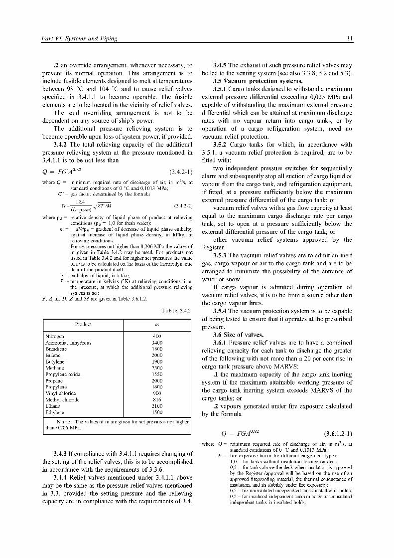
Part VI. Systems and Piping 31
.2 an override arrangement, whenever necessary, to prevent its normal operation. This arrangement is to include fusible elements designed to melt at temperatures between 98 °C and 104 °C and to cause relief valves specified in 3.4.1.1 to become operable. The fusible elements are to be located in the vicinity of relief valves.
The said overriding arrangement is not to be dependent on any source of ship's power.
The additional pressure relieving system is to become operable upon loss of system power, i f provided.
3.4.2 The total relieving capacity of the additional pressure relieving system at the pressure mentioned in 3.4.1.1 is to be not less than
Q = F G ' A 0 , 8 2 (3.4.2-1)
where Q = minimum required rate of discharge of air, in m3/s, at standard conditions of 0 °C and 0,1013 MPa;
G' = gas factor determined by the formula
G ' = — ^ 4 — jZTVM (3.4.2-2) (L+pR-m) v
where p R = relative density of liquid phase of product at relieving conditions (p R = 1,0 for fresh water);
m = — di/dpR = gradient of decrease of liquid phase enthalpy against increase of liquid phase density, in kJ/kg, at relieving conditions. For set pressures not higher than 0,206 MPa the values of m given in Table 3.4.2 may be used. For products not listed in Table 3.4.2 and for higher set pressures the value of m is to be calculated on the basis of the thermodynamic data of the product itself;
i = enthalpy of liquid, in kJ/kg; T' = temperature in kelvins (°K) at relieving conditions, i . e.
the pressure, at which the additional pressure relieving system is set;
F, A, L , D, Z and M are given in Table 3.6.1.2.
Table 3.4.2
Product m
Nitrogen 400 Ammonia, anhydrous 3400 Butadiene 1800 Butane 2000 Butylene 1900 Methane 2300 Propylene oxide 1550 Propane 2000 Propylene 1600 Vinyl chloride 900 Methyl chloride 816 Ethane 2100 Ethylene 1500
Note . The values of m are given for set pressures not higher than 0,206 MPa.
3.4.3 I f compliance with 3.4.1.1 requires changing of the setting of the relief valves, this is to be accomplished in accordance with the requirements of 3.3.6.
3.4.4 Relief valves mentioned under 3.4.1.1 above may be the same as the pressure relief valves mentioned in 3.3, provided the setting pressure and the relieving capacity are in compliance with the requirements of 3.4.
3.4.5 The exhaust of such pressure relief valves may be led to the venting system (see also 3.3.8, 5.2 and 5.3).
3.5 Vacuum protection systems. 3.5.1 Cargo tanks designed to withstand a maximum
external pressure differential exceeding 0,025 MPa and capable of withstanding the maximum external pressure differential which can be attained at maximum discharge rates with no vapour return into cargo tanks, or by operation of a cargo refrigeration system, need no vacuum relief protection.
3.5.2 Cargo tanks for which, in accordance with 3.5.1, a vacuum relief protection is required, are to be fitted with:
two independent pressure switches for sequentially alarm and subsequently stop all suction of cargo liquid or vapour from the cargo tank, and refrigeration equipment, i f fitted, at a pressure sufficiently below the maximum external pressure differential of the cargo tank; or
vacuum relief valves with a gas flow capacity at least equal to the maximum cargo discharge rate per cargo tank, set to open at a pressure sufficiently below the external differential pressure of the cargo tank; or
other vacuum relief systems approved by the Register.
3.5.3 The vacuum relief valves are to admit an inert gas, cargo vapour or air to the cargo tank and are to be arranged to minimize the possibility of the entrance of water or snow.
I f cargo vapour is admitted during operation of vacuum relief valves, it is to be from a source other than the cargo vapour lines.
3.5.4 The vacuum protection system is to be capable of being tested to ensure that it operates at the prescribed pressure.
3.6 Size of valves. 3.6.1 Pressure relief valves are to have a combined
relieving capacity for each tank to discharge the greater of the following with not more than a 20 per cent rise in cargo tank pressure above MARVS:
.1 the maximum capacity of the cargo tank inerting system i f the maximum attainable working pressure of the cargo tank inerting system exceeds MARVS of the cargo tanks; or
.2 vapours generated under fire exposure calculated by the formula
Q = F G A 0 , 8 2 (3.6.1.2-1)
where Q = minimum required rate of discharge of air, in m3/s, at standard conditions of 0 °C and 0,1013 MPa;
F= fire exposure factor for different cargo tank types: 1,0 - for tanks without insulation located on deck; 0,5 - for tanks above the deck when insulation is approved by the Register (approval will be based on the use of an approved fireproofing material, the thermal conductance of insulation, and its stability under fire exposure); 0,5 - for uninsulated independent tanks installed in holds; 0,2 - for insulated independent tanks in holds or uninsulated independent tanks in insulated holds;
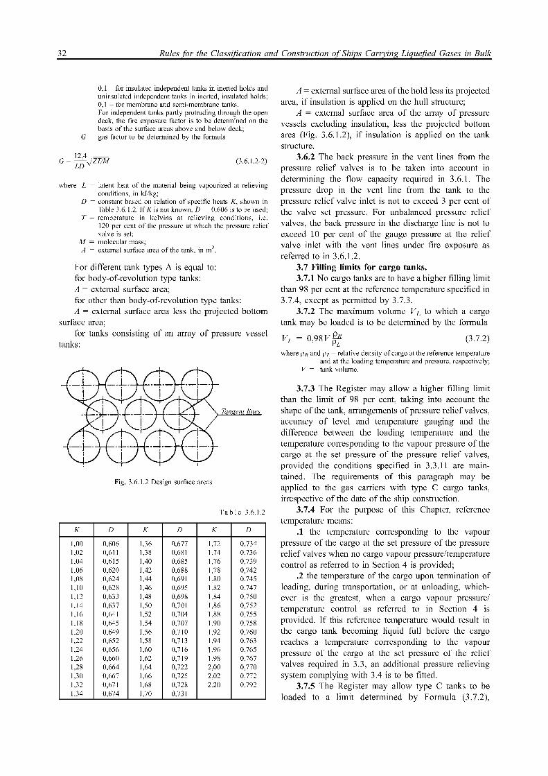
32 Rules for the Classification and Construction of Ships Carrying Liquefied Gases in Bulk
0,1 - for insulated independent tanks in inerted holds and uninsulated independent tanks in inerted, insulated holds; 0,1 - for membrane and semi-membrane tanks. For independent tanks partly protruding through the open deck, the fire exposure factor is to be determined on the basis of the surface areas above and below deck;
G = gas factor to be determined by the formula
G= ^LA^ZT/M (3.6.1.2-2)
where L = latent heat of the material being vapourized at relieving conditions, in kJ/kg;
D= constant based on relation of specific heats K, shown in Table 3.6.1.2. If Kis not known, D = 0,606 is to be used;
T = temperature in kelvins at relieving conditions, i.e. 120 per cent of the pressure at which the pressure relief valve is set;
M= molecular mass; A= external surface area of the tank, in m 2.
For different tank types A is equal to: for body-of-revolution type tanks: A = external surface area; for other than body-of-revolution type tanks: A = external surface area less the projected bottom
surface area;
for tanks consisting of an array of pressure vessel tanks:
Tangent lines
Fig. 3.6.1.2 Design surface areas
Table 3.6.1.2
К D К D К D
1,00 0,606 1,36 0,677 1,72 0,734 1,02 0,611 1,38 0,681 1,74 0,736 1,04 0,615 1,40 0,685 1,76 0,739 1,06 0,620 1,42 0,688 1,78 0,742 1,08 0,624 1,44 0,691 1,80 0,745 1,10 0,628 1,46 0,695 1,82 0,747 1,12 0,633 1,48 0,698 1,84 0,750 1,14 0,637 1,50 0,701 1,86 0,752 1,16 0,641 1,52 0,704 1,88 0,755 1,18 0,645 1,54 0,707 1,90 0,758 1,20 0,649 1,56 0,710 1,92 0,760 1,22 0,652 1,58 0,713 1,94 0,763 1,24 0,656 1,60 0,716 1,96 0,765 1,26 0,660 1,62 0,719 1,98 0,767 1,28 0,664 1,64 0,722 2,00 0,770 1,30 0,667 1,66 0,725 2,02 0,772 1,32 0,671 1,68 0,728 2,20 0,792 1,34 0,674 1,70 0,731 — —
A = external surface area of the hold less its projected area, i f insulation is applied on the hull structure;
A = external surface area of the array of pressure vessels excluding insulation, less the projected bottom area (Fig. 3.6.1.2), i f insulation is applied on the tank structure.
3.6.2 The back pressure in the vent lines from the pressure relief valves is to be taken into account in determining the flow capacity required in 3.6.1. The pressure drop in the vent line from the tank to the pressure relief valve inlet is not to exceed 3 per cent of the valve set pressure. For unbalanced pressure relief valves, the back pressure in the discharge line is not to exceed 10 per cent of the gauge pressure at the relief valve inlet with the vent lines under fire exposure as referred to in 3.6.1.2.
3.7Filling limits for cargo tanks. 3.7.1 No cargo tanks are to have a higher filling limit
than 98 per cent at the reference temperature specified in 3.7.4, except as permitted by 3.7.3.
3.7.2 The maximum volume VL to which a cargo tank may be loaded is to be determined by the formula
VL = 0,98 VppLR (3.7.2)
where p R and p L = relative density of cargo at the reference temperature and at the loading temperature and pressure, respectively;
V= tank volume.
3.7.3 The Register may allow a higher filling limit than the limit of 98 per cent, taking into account the shape of the tank, arrangements of pressure relief valves, accuracy of level and temperature gauging and the difference between the loading temperature and the temperature corresponding to the vapour pressure of the cargo at the set pressure of the pressure relief valves, provided the conditions specified in 3.3.11 are main¬tained. The requirements of this paragraph may be applied to the gas carriers with type C cargo tanks, irrespective of the date of the ship construction.
3.7.4 For the purpose of this Chapter, reference temperature means:
.1 the temperature corresponding to the vapour pressure of the cargo at the set pressure of the pressure relief valves when no cargo vapour pressure/temperature control as referred to in Section 4 is provided;
.2 the temperature of the cargo upon termination of loading, during transportation, or at unloading, which¬ever is the greatest, when a cargo vapour pressure/ t e m p e r a t u r e c o n t r o l a s r e f e r r e d t o i n S e c t i o n 4 i s provided. I f this reference temperature would result in the cargo tank becoming liquid full before the cargo reaches a temperature corresponding to the vapour pressure of the cargo at the set pressure of the relief valves required in 3.3, an additional pressure relieving system complying with 3.4 is to be fitted.
3.7.5 The Register may allow type C tanks to be loaded to a limit determined by Formula (3.7.2),

Part VI. Systems and Piping 33
where p R is the relative density of cargo at the highest temperature which the cargo may reach upon termination of loading, during transportation, or at unloading, under the ambient design temperature conditions described in 4.1.2. These requirements do not apply to products requiring a type 1G ship.
3.7.6 The maximum allowable loading limits for each cargo tank are to be indicated for each product which may be carried, for each loading temperature which may be applied and for the applicable maximum reference temperature, on a list. Pressures at which the pressure relief valves, including those valves required by 3.4, have been set are to be also stated on the list.
The list is to be approved by the Register and be permanently kept on board the ship.
4 CARGO PRESSURE/TEMPERATURE CONTROL
4.1 General. 4.1.1 Unless the entire cargo system is designed to
withstand the full gauge vapour pressure of the cargo under conditions of the upper ambient design tempera¬tures, maintenance of the cargo tank pressure below the MARVS is to be provided by one or more of the following means:
.1 a system which regulates the pressure in the cargo tanks by the use of mechanical refrigeration;
.2 a system whereby the boil-off vapours are utilized as fuel for shipboard use or waste heat system subject to the provision of Section 10. This system may be used at all times, including while in port and while manoeuvring, provided that a means of disposing of excess energy is provided, such as a steam dump system, that is approved by the Register;
.3 a system allowing the product to warm up and increase in pressure. The insulation or cargo tank design pressure is to be adequate to provide for a suitable margin for the operating time and temperatures involved. The system is to be considered the Register in each case;
.4 other systems approved by the Register. In addition to the above means, the Register may
permit certain cargoes to be controlled by venting cargo vapours to the atmosphere at sea. This may be permitted in port by special permission.
4.1.2 The systems required by 4.1.1 are to be constructed, fitted and tested to the satisfaction of the Register. Materials used in their construction are to be suitable for use with the cargoes to be carried. For normal service, the upper ambient design temperature is to be taken equal to 32 °C for sea and 45 °C for air. For service in especially hot or cold zones these design temperatures are to be increased or reduced, as appropriate, by the Register.
4.1.3 For certain highly dangerous cargoes specified in Part X "Special Requirements", the cargo tanks are to
be capable of withstanding the full vapour pressure under conditions of the upper design temperatures irrespective of any system provided for dealing with boil-off gas.
4.2 Refrigeration systems.
4.2.1 A refrigeration system is to consist of one or more units capable of maintaining the required cargo pressure/temperature under conditions of the upper ambient design temperatures.
In addition to the main unit, a stand-by unit (or units) affording space capacity at least equal to the largest required unit is to be provided.
A stand-by unit is to consist of a compressor with its driving motor, control system and any necessary fittings to permit operation independently of the normal service units.
A stand-by heat exchanger is to be provided unless the normal heat exchanger for the unit has an excess capacity of at least 25 per cent of the largest required capacity. Separate piping systems are not required for the stand-by heat exchanger.
Where in addition to the refrigeration system, other means to control cargo pressure/temperature are pro¬vided, the provision of stand-by units is subject to special consideration by the Register in each case.
4.2.2 The refrigeration system may be arranged in one of the following ways:
.1 a direct system where evaporated cargo is compressed, condensed and returned to the cargo tanks. For certain cargoes specified in Part X "Special Requirements" this system is not to be used;
.2 an indirect system where cargo or evaporated cargo is cooled or condensed by refrigerant without being compressed;
.3 a combined system where evaporated cargo is compressed and condensed in a heat exchanger by refrigeration and returned to the cargo tanks. For certain cargoes specified in Part X "Special Requirements" this system is not to be used.
The use of other refrigeration systems is subject to special consideration by the Register in each case.
4.2.3 Where two or more refrigerated cargoes which may react chemically in a dangerous manner are carried simultaneously, special consideration is to be given to the refrigeration systems to avoid the possibility of mixing cargoes.
For the carriage of such cargoes, separate refrigera¬tion systems, each complete with a stand-by unit as specified in 4.2.1, are to be provided for each cargo. However, where cooling is provided by an indirect or combined system and leakage in the heat exchanger cannot cause mixing of the cargoes, separate refrigera¬tion units are not required.
4.2.4 Where two or more refrigerated cargoes are not mutually soluble under the condition of carriage, so that their vapour pressures would be additive on mixing, special consideration is to be given to the refrigeration systems to avoid the possibility of mixing cargoes.

34 Rules for the Classification and Construction of Ships Carrying Liquefied Gases in Bulk
4.2.5 Where sea cooling water is required in the refrigeration system, a separate sea water pump used exclusively for supply of water to this system is to be provided. This pump is to have two sea suction lines, leading from sea chests, one port and one starboard.
A spare pump of adequate capacity is to be provided. This pump is also to have suction from two sea chests.
The said spare pump may be a pump of adequate capacity and pressure head, used for other services so long as its use for cooling would no interfere with any other essential service.
4.2.6 A l l primary and secondary refrigerants must be compatible with each other and with the cargo with which they come into contact.
The heat exchange may take place outside either remotely from the cargo tank or by cooling coils fitted inside or outside the cargo tank.
5 VENT PIPING SYSTEM
5.1 A vent piping system is to be provided to remove surplus gas from the cargo tank pressure relief valves.
5.2 The vent piping system is to be so constructed that the discharge of gas wi l l be directed upwards and so arranged as to minimize the possibility of water or snow entering the system.
5.3 The height of the vent exits is to be not less than B/3 or 6 m, whichever is the greater, above the weather deck and 6 m above the working area and fore and aft gangway.
5.4 Cargo tank pressure relief vent exits are to be arranged at a distance at least equal to ship breadth or 25 m, whichever is less, from the nearest air intake or opening to accommodation spaces, service spaces, or other gas-safe spaces.
For ships less than 90 m in length, smaller distances may be permitted by the Register. A l l other vent exits connected to the cargo containment system are to be arranged at a distance of at least 10 m from the nearest air intake or opening to accommodation spaces, service spaces and control stations, or other gas-safe spaces.
5.5 A l l other cargo vent exits associated with cargo and not dealt with in other parts are to meet the requirements of 5.2 to 5.4.
5.6 I f cargoes which react in a hazardous manner with each other are carried simultaneously, a separate pressure relief system is to be fitted for each cargo carried.
5.7 In the vent piping system, means for draining liquid from places where it may accumulate are to be provided.
5.8 Suitable protection screens are to be fitted on vent outlets to prevent the ingress of foreign objects.
5.9 A l l vent piping is to be so designed and arranged that it wi l l not be damaged by temperature variations to which it may be exposed, or by the ship's motions.
6 INERT GAS SYSTEM
6.1 General. 6.1.1 The inerting is to provide a non-combustible
environment, through the use of inert gases. The inert gas used is to be compatible chemically, under operating conditions, with the materials of construction and with the cargo carried at all temperatures likely to occur within the spaces in service.
6.1.2 I f the inert gas is stored at temperatures below 0 °C, the system is to prevent the temperature of the ship's structures from dropping below the limiting values imposed.
6.1.3 The inert gas system is to provide iterting of interbarrier and hold spaces of the ship as well as safe gas-freeing of these spaces and areas, cargo tanks and cargo pipelines.
The inert gas system is to be also capable of delivering gas to the dead zones of the spaces protected.
6.1.4 Arrangements are to be provided to prevent the backflow of cargo vapour into the inert gas system.
6.1.5 The inert gas system is to be such that each space being inerted can be isolated and the pressure therein can be controlled by appropriate controls and relief valves.
6.1.6 Inert gas which is used for the fire fighting purposes is to be stored separately and is not to be used for cargo services.
6.2 Inerting of hull spaces. 6.2.1 I f the ship is intended for the carriage of
flammable products, the interbarrier and hull spaces adjacent to cargo containment systems requiring a complete or partial secondary barrier, are to be inerted by dried inert gas. The inert environment is to be maintained by the shipboard gas generation plant or inert gas storage the capacity of which is to be sufficient for normal consumption of gas for at least 30 days.
6.2.2 The interbarrier and hull spaces adjacent to cargo containment systems requiring a complete or partial secondary barrier, except as listed in Part X "Special Requirements", may be filled by dry air, i f the ship is provided with an inert gas generation plant or inert gas storage the capacity of which is sufficient to inert the largest such space provided that their config¬uration and the capacity of the inert gas generation system ensure rapid detection of leakage from cargo tanks and the inerting thereof before a hazardous environment can develop.
Equipment is to be provided to produce a sufficient amount of dry air to satisfy the expected consumers.
6.2.3 Spaces adjacent to the refrigerated type C independent cargo tanks are to be inerted by dry inert gas or filled with dry air. Such condition is to be maintained by the shipboard devices specified in 6.2.1, or by equipment ensuring dry air supply.
6.2.4 In the internal insulation tanks, the interbarrier spaces as well as spaces between the secondary barrier
Part VI. Systems and Piping 35
and inner hull or the independent tank structure fully filled by the insulation complying with the requirements of 9.7, Part IV "Cargo Tanks" need not be inerted.
6.3 Inerting of cargo tanks and systems. 6.3.1 The inert gas system is to minimize the
possibility of flammable mixture formation in cargo tanks at any gas-freeing stage.
6.3.2 The cargo piping systems are to be capable of becoming free of inert gas and of being purged as indicated in 6.3.1.
6.3.3 To monitor the purging and gas-freeing process, each cargo tank is to be fitted with gas sampling arrangements.
Gas sampling connections are to be valved and fitted above the upper deck.
The gas sampling connection is to be fitted with at least two isolating valves. Use of threaded and union couplings is to be reduced to the minimum in the gas sampling pipeline and be avoided in the pipelines with an outside diameter more than 25 mm.
The open method of sampling is to be only allowed for the cargoes, which sample remains may be discharged to the atmosphere. For other cargoes an arrangement for the sample safe return into a cargo tank is to be provided.
6.3.4 The inert gas may be supplied from both the shipboard and shore-based facility.
6.4 Inert gas generation plant. 6.4.1 The plant is to produce inert gas with an oxygen
content at no time greater than 5 per cent by volume subject to the requirements of Part X "Special Requirements".
A continuous-reading oxygen content meter with an alarm set at a maximum of 5 per cent oxygen content by volume subject to the requirements of Part X "Special Requir¬ements" is to be fitted to the inert gas supply from the plant.
Liquefied nitrogen used as inert gas and produced by an onboard process of fractional distillation of the air, before entering the shipboard storage vessel, is to be monitored for traces of oxygen to avoid possible oxygen enrichment of the gas when released for inerting purposes.
6.4.2 The inert gas system is to be fitted with pressure controls and monitoring arrangements appro¬priate to the cargo containment system.
An arrangement is to be provided to prevent ingress of cargo into the inert gas system.
6.4.3 Spaces containing inert gas generation plants are not to have direct access to accommodation, service spaces and control stations. The plants may be located in the machinery spaces. Where the plants are arranged outside the cargo area, two non-return valves or equivalent devices required by 6.4.2 are to be fitted in the inert gas supply main within the cargo area.
The inert gas main is not to pass through accommodation, service spaces and control stations.
6.4.4 Flame burning equipment for generating inert gas are not to be located within the cargo area.
Special consideration is to be given to the location of inert gas generating equipment using the catalytic combustion process.
7BILGE AND BALLAST SYSTEMS
7.1 Where cargo is carried in cargo tanks not requiring a secondary barrier, hold spaces are to be provided with suitable drainage arrangements. These arrangements are to be independent and not connected with the machinery space.
Means of detecting any leakage are to be provided for such spaces.
7.2 Where there is a secondary barrier, suitable drainage arrangements for dealing with any leakage into the hold or insulation spaces through adjacent ship structure are to be provided.
The suction is not to be led to pumps inside the machinery space.
Means of detecting such leakage are to be provided. 7.3 The interbarrier space is to be provided with
drainage system suitable for handling liquid cargo in the event of cargo tank leakage or rupture. Such arrange¬ments are to provide for the return of any cargo leakage to cargo tanks.
7.4 Suitable independent arrangements are to be provided for drainage of pump and compressor rooms.
7.5 In case of internal insulation tanks, means of detecting leakage and drainage arrangements are not required for interbarrier spaces and spaces between the secondary barrier and the inner hull or independent tank structure which are completely filled by insulation material complying with the requirements of 9.7, Part IV "Cargo Tanks".
7.6 Ballast tanks, fuel oil tanks and gas-safe spaces may be connected to pumps in the machinery space.
Bottom pipe tunnels may be connected to pumps in the machinery space, provided the connections are led directly to the pumps and the discharge from pumps led directly overboard with no valves or manifolds in either line which could connect the line from the bottom tunnel to lines serving gas-safe spaces.
Pump vents are not to be open to the machinery space.
8 VENTILATION SYSTEM
8.1 Spaces required to be entered during normal cargo handling operations.
8.1.1 Electric motor rooms, cargo compressor and pump-rooms, other enclosed spaces which contain cargo handling equipment and similar spaces in which cargo handling operations are performed are to be fitted with mechanical ventilation systems independent of other

36 Rules for the Classification and Construction of Ships Carrying Liquefied Gases in Bulk
ventilation systems and capable of being controlled outside such spaces.
Provision is to be made to ventilate such spaces prior to entering the compartment and operating the equipment and a warning notice requiring the use of such ventilation is to be placed outside the compartment.
8.1.2 Mechanical ventilation inlets and outlets are to be arranged to ensure sufficient air movement through the space to avoid the accumulation of flammable or toxic vapours and to ensure a safe working environment.
The ventilation system is to have a capacity of not less than 30 air changes per hour based upon the total volume of the space. As an exception, gas-safe cargo control rooms may have 8 changes of air per hour.
8.1.3 Ventilation systems of spaces are to be fixed and, i f of the negative pressure type, permit extraction from both the upper and lower parts of the spaces, depending on the density of the vapours of the products carried.
8.1.4 In rooms housing electric motors driving cargo compressors or pumps, spaces containing inert gas generators, cargo control rooms i f considered as gas-safe spaces and other gas-safe spaces within the cargo area the ventilation is to be of positive pressure type and is to ensure positive pressure in these spaces.
8.1.5 In cargo compressor and pump-rooms and in cargo control rooms i f considered gas-dangerous, the ventilation is to be of the negative pressure type.
8.1.6 Ventilation exhaust ducts from gas-dangerous spaces are to discharge upwards. The outlets are to be located at a height of not less than 4 m above the cargo deck and at least 10 m in the horizontal direction from ventilation intakes and openings to accommodation spaces, service spaces, control stations and other gas-safe spaces.
8.1.7 Ventilation intakes are to be so arranged as to minimize the possibility of re-cycling hazardous vapours from any ventilation discharge opening.
8.1.8 Ventilation ducts from gas-dangerous spaces are not to be led through machinery, accommodation and service spaces or control stations, except as specified in Section 10.
8.1.9 Electric motors driving fans are to be placed outside the ventilation ducts i f the carriage of flammable products is intended.
Ventilation fans are not to produce a source of vapour ignition in either the ventilated space or the ventilation system associated with the space.
Ventilation fans and fan ducts, in way of fans only, for gas-dangerous spaces are to be of non-sparking construction complying with the requirements of 5.3.3, Part IX "Machinery" of the Rules for the Classification.
8.1.10 Spare impellers together with shaft, bearings and electric motors, one of each type, are to be carried for each type of fan used in cargo areas.
8.1.11 Protection screens of not more than 13 mm square mesh are to be fitted in outside openings of ventilation ducts.
8.2 Spaces not normally entered. 8.2.1 Hold spaces, interbarrier spaces, void spaces,
cofferdams, spaces containing cargo piping and other spaces where cargo vapours may accumulate, are to be capable of being ventilated to ensure a safe environment when entry into the spaces is necessary. Where a permanent ventilation system is not provided for such spaces, approved means of portable mechanical ventila¬tion are to be provided.
Where necessary, essential ventilation ducting in hold spaces and interbarrier spaces is to be permanently installed.
Fans or blowers are to be clear of personnel access openings, and are to comply with the requirements of 8.1.9.
8.3 Ventilation of other spaces. 8.3.1 The ventilation inlets are not to face the cargo
area. They are to be located on the end bulkhead not facing the cargo area, bow or stern loading and discharging arrangements and/or on the side of the superstructure at a distance equal to L/25, but not less than 3 m, from the bulkhead facing the cargo area. This distance may not to exceed 5 m.
Consideration is to be given to the arrangement of ventilation inlets in relation to cargo piping, vent piping and exhaust piping of arrangements operating on liquefied gas.
The Register may allow relaxation from the said requirements for ships intended for the carriage of cargoes which are not toxic or ignition hazardous as well as for small ships where these requirements cannot be
fulfilled. 8.3.2 A l l ventilation inlets and openings to accom¬
modation and service spaces and control stations are to be equipped with closing arrangements to ensure gas-tightness.
Where a cargo giving off toxic gas is carried, all the ventilation inlets are to be closed and opened from positions inside the spaces.
8.3.3 The air lock space is to be provided with mechanical ventilation of positive pressure type from the gas-safe space to maintain positive pressure in relation to the gasdangerous zone on the weather deck.
The ventilation is to have a capacity to give at least 30 air changes per hour.
8.4 In machinery spaces of category A where gas is used as fuel, an independent mechanical ventilation is to be provided to ensure freedom from dead zones.
9 CARGO PUMP ROOMS AND CARGO COMPRESSOR ROOMS
9.1 Cargo pump-rooms and cargo compressor rooms are to be situated above the weather deck and located within the cargo area unless specially approved by the

Part VI. Systems and Piping 37
Register. The fire integrity of bulkheads and decks of these spaces is to comply with the requirements of 2.4.2, Part V I "Fire Protection" of the Rules for the Classifica¬tion imposed on pump rooms.
9.2 Where pumps and compressors are driven by shafting passing through a bulkhead or deck, gastight seals with efficient lubrication or other means of ensuring the permanence of gas seal are to be fitted in way of the bulkhead or deck. Cargo pumps and compressors are to be fitted with temperature sensors of the seals of shafts passing through the bulkhead or deck, of the bearings and pump casings.
9.3 Arrangements of cargo pump rooms and cargo compressor rooms are to be such as to ensure safe unrestricted access for personnel wearing protective clothing and breathing apparatus, and in the event of injure, to allow unconscious personnel to be removed. A l l valves necessary for cargo handling are to be readily accessible to personnel wearing protective clothing.
10 CARGO CONTROL ROOMS
10.1 A l l cargo control rooms are to be above the weather deck and, as a rule, located in the cargo tank zone.
Cargo control rooms may be located within accommodation spaces, service spaces or control stations provided the following conditions are complied with:
the cargo control room is considered as a gas-safe space;
i f the cargo control room has access to the accommodation and service spaces, the entrance from the cargo tank zone is to comply with the requirements of 1.6, Part I I "Gas Carrier Design" and 8.3.1 of the present Part or i f the cargo control room has no access to the above spaces, air intakes and openings are to comply with the requirements of 1.7 and 1.12, Part I I "Gas Carrier Design" and 8.3.1 of the present Part.
10.2 I f the cargo control room is considered as gas-safe space, instrumentation is to be, as far as possible, by indirect reading system and is to be in any case designed to prevent any escape of gas into the atmosphere of that space.
Location of gas detectors within the cargo control room wi l l not violate the gas-safe space i f installed in accordance with Section 6, Part V I I I "Instrumentation".
10.3 I f the cargo control room for ships carrying flammable cargoes is considered as gas-dangerous space, sources of ignition are to be excluded.
Consideration is to be given to the safety character¬istics of any electrical installations in the cargo control rooms.
11 USE OF CARGO AS FUEL
11.1 Liquefied methane is the only cargo whose vapour or boil-off gas may be utilized as a fuel in boilers, inert gas generators, combustion engines and gas turbines.
Machinery spaces of category A in which gas fuel is utilized are to be fitted with gas detectors complying with the requirements of Section 6, Part VII I "Instrumentation".
11.2 Gas fuel piping is not to pass through accommodation spaces, service spaces and control stations.
Gas fuel piping may pass through or extend into other spaces provided they fulfil the following:
.1 the gas fuel piping is to be a double-wall piping system with the gas fuel contained in the inner pipe.
The space between the concentric pipes is to be pressurized with inert gas at a pressure greater than the gas fuel pressure.
Suitable alarms are to be provided to indicate a loss of inert gas pressure between the pipes;
.2 the gas fuel piping is to be installed within a ventilated pipe or duct.
The air space between the gas fuel piping and inner wall of this pipe or duct is to be equipped with mechanical exhaust ventilation having a capacity of at least 30 air changes per hour.
The ventilation system is to be arranged to maintain a pressure less than the atmospheric pressure.
T h e f a n m o t o r s a r e t o b e p l a c e d o u t s i d e t h e ventilated pipe or duct.
The ventilation outlet is to be placed in a position where no explosive gas-air mixture may be ignited.
The ventilation inlets are to be so arranged that no gas or gas-air mixture can be taken into the ventilation system.
The ventilation is to be always in operation when there is gas fuel in the piping.
Continuous gas detection is to be provided to indicate leaks and to shut down the gas fuel supply to the machinery space in accordance with 11.10.
The exhaust ventilation fan for such duct is to be so arranged as to shut down the gas fuel supply to the machinery space i f the required air flow is not established and maintained.
The electrical equipment arranged inside double-wall piping is to be of intrinsically safe type.
11.3 I f a gas leak occurs, the gas fuel supply is not to be restored until the leak has been found and repaired. Instructions to this effect are to be placed in a prominent position in the machinery spaces.
11.4 The double-wall piping systems or the ventilated pipe or duct provided for the gas fuel piping are to terminate at the ventilation hood or casing required by 11.5.

38 Rules for the Classification and Construction of Ships Carrying Liquefied Gases in Bulk
11.5 A ventilation hood or casing is to be provided for the areas occupied by flanges, valves, etc., and for the gas fuel piping, at the gas fuel utilization units.
I f this ventilation hood or casing is not served by the exhaust ventilation fan as specified in 11.2.2, then it is to be equipped with an exhaust ventilation system and continuous gas detection is to be provided to indicate leaks and to shut down the gas fuel supply to the machinery space in accordance with 11.10.
The exhaust ventilation fan is to be so arranged as to shut down the gas fuel supply to the machinery space i f the exhaust ventilation does not ensure the required air flow.
The ventilation hood or casing is to be installed or mounted to permit the ventilating air to sweep across the gas utilization unit and be exhausted at the top of the ventilation hood or casing.
11.6 Each gas utilization unit is to be provided with a set of three automatic valves. Two of these valves are to be in series in the gas fuel pipe to the consuming equipment. The third valve is to be in a pipe that vents, to a safe location in the open air, that portion of the gas fuel piping that is between the two valves in series. The shut-off valves are to be arranged for manual reset.
These valves are to be arranged so that failure of the necessary forced draught, loss of flame on boiler burners, abnormal pressure in the gas fuel supply line, or failure of the hydraulic valve control actuator wi l l cause the two gas fuel valves which are in series to close automatically and the vent valve to open automatically.
One of the valves in series and the vent valve can be incorporated into one valve body so arranged that, when one of the above conditions occurs, flow to the gas utilization unit wi l l be blocked and the vent opened.
11.7 A master gas fuel valve is to be installed outside the machinery space. The valve is to be arranged so as to close automatically if:
leakage of gas fuel is detected; conditions stated in 11.2.1 are fringed; engine crankcase oil mist concentration or engine
bearing monitoring sensor is actuated; It is recommended that the master gas fuel valve wil l
be closed automatically when the gas valves referred to in 11.6 are actuated.
11.8 Provision is to be made for inerting and gas-freeing that portion of the gas fuel piping system located in the machinery space.
11.9 The ventilation inlet and discharge for the required ventilation systems is to be respectively from and to a safe location.
11.10 Gas detection systems referred to in 11.2 and 11.5 are to activate the alarm at 30 per cent of the lower flammable limit and shut down the gas fuel supply to the machinery space before the gas concentration reaches 60 per cent of the lower flammable limit.
11.11 A l l items of the gas fuel system are to be approved by the Register.
11.12 Use of the gas fuel for other purposes, e.g. for re-liquefaction of cargo and for inert gas generation is subject to special consideration by the Register in each case.
11.13 Gas fuel piping in machinery spaces is to comply with the requirements of 13.12, Part V I I I "Systems and Piping" of the Rules for the Classification and Sections 2 and 12 of the present Part as far as applicable. The piping is to have welded joints. Those parts of the gas fuel piping which are not enclosed in ventilated pipe or duct according to 11.2 and are on the open deck outside the cargo area are to have full penetration butt-welded joints and are to be fully radiographed.
11.14 I f the cargo carried is utilized as fuel, a gas make-up plant and related storage tanks are to be provided on board the ship.
11.14.1 A l l equipment (heaters, compressors, filters, etc.) for making up the gas for its use as fuel and related storage tanks are to be located in the cargo area. I f the equipment is in an enclosed space, the requirements of 3.1, Part V "Fire Protection", 8.1 of the present Part and Section 6, Part V I I I "Instrumentation" are to be complied with.
11.14.2 The compressors are to be capable of being automatically stopped before the vacuum relief valves of the tanks are actuated.
The compressors are to be capable of being remotely stopped from a position which is readily accessible, and also from the engine room.
The compressors are to be provided with a device for automatic shut down when the automatic shut-off valves referred to in 11.6 and 11.7 are actuated. These valves are to be arranged for manual reset.
Volumetric compressors are to be fitted with pressure relief valves discharging into the suction line of the compressor. The size of the pressure relief valves is to be determined in such a way that under any circumstances the maximum pressure does not exceed by more than 10 per cent the maximum working pressure.
11.14.3 I f the heating medium for the gas fuel evaporator or heater is returned to spaces outside the cargo area it is first to go through a degassing tank. The degassing tank is to be located in the cargo area. Provisions are to be made to detect and alarm the presence of gas in the tank. The vent outlet of the tank is to be in a safe position and fitted with a flame screen.
11.15 Main boilers which use the cargo as fuel are to comply with the following requirements.
11.15.1 Each boiler is to have a separate uptake. 11.15.2 Combustion chambers of boilers are to be of
suitable form such as not to present pockets where gas may accumulate.
Part VI. Systems and Piping 39
11.15.3 The burning installations are to be suitable to burn either oil fuel or methane alone or oil and methane simultaneously.
Transfer from gas to oil burning is not to cause change of the boiler operating mode.
The gas burning installation is to be provided with a pilot burner operating on oil fuel.
The burning installations are to be interlocked and equipped with non-disconnectable protective devices as specified in 5.3.2 to 5.3.4, Part X "Boilers, Heat Exchangers and Pressure Vessels" of the Rules for the Classification.
11.15.4 On the pipe of each gas burner a manually operated shut-off valve is to be fitted.
An installation is to be provided for purging the gas supply piping to the burners by means of inert gas or steam, after the extinguishing of these burners.
11.15.5 The controls, regulators, interlocking, pro¬tective devices and alarms of the automated burning installations are to comply with the requirements of 4.3, Part XV "Automation" of the Rules for the Classifica¬tion.
11.16 Special requirements for gas-fuelled internal combustion engines and for gas turbines are to be considered by the Register in each case.
12 TESTING
12.1 Tests of piping components and pumps prior to installation on board.
12.1.1 Valves. 12.1.1.1 Tests of piping valves shall comply with the
requirements of 21.1, Part V I I I "Systems and Piping" of the Rules for the Classification. Moreover, valves of cargo system and piping containing cargo or its vapours shall be subjected to the prototype and unit production testing, as stipulated in 12.1.1.1.1 and 12.1.1.1.2.
12.1.1.1.1 Prototype testing. 12.1.1.1.1.1 Each size and type of valve intended to
be used at a working temperature below -55 °C is to be approved through design assessment and prototype testing. Prototype testing to the minimum design temperature or lower and to a pressure not lower than the maximum design pressure foreseen for the valves is to be witnessed in the presence of the surveyor to the Register. Prototype testing is to include hydrostatic test of the valve body at a pressure equal to 1,5 times the design pressure, seat and stem leakage test at a pressure equal to 1,1 times the design pressure, and cryogenic testing consisting of valve operation and leakage verification. For valves intended to be used at a working temperature above -55 °C, prototype testing is not required.
12.1.1.1.2 Unit production testing. 12.1.1.1.2.1 A l l valves are to be tested at the plant of
manufacturer in the presence of the surveyor to the Register. Testing is to include hydrostatic test of the valve body at a pressure equal to 1,5 times the design pressure, seat and stem leakage test at a pressure equal to 1,1 times the design pressure and cryogenic testing consisting of valve operation and leakage verification for a minimum of 10 per cent of each type and size of valve for valves intended to be used at a working temperature below -55 °C.
As an alternative to the above, i f so requested by the relevant manufacturer, the certification of a valve may be issued subject to the following:
.1 the valve has been approved as required by 12.1.1.1.1 for valves intended to be used at a working temperature below -55 °C;
.2 the manufacturer has a recognized quality system that has been assessed and certified by the Register subject to periodic audits;
.3 the quality control plan contains a provision to subject each valve to a hydrostatic test of the valve body at a pressure equal to 1,5 times the design pressure and seat and stem leakage test at a pressure equal to 1,1 times the design pressure. The manufacturer is to maintain records of such tests;
.4 cryogenic testing consisting of valve operation and leakage verification for a minimum of 10 per cent of each type and size of valve for valves intended to be used at a working temperature below -55 °C in the presence of the surveyor to the Register.
12.1.2 Bellows. 12.1.2.1 The following prototype tests are to be
performed on each type of expansion bellows intended for use on cargo piping outside the cargo tank, and, where necessary, on those expansion bellows installed within the cargo tank:
.1 a type element of the bellows, not precompressed, is to be pressure tested at not less than five times the design pressure without bursting. The duration of the test is not to be less than 5 min;
.2 a pressure test is to be performed on a type expansion joint complete with all the accessories (flanges, stays, articulations, etc.) at twice the design pressure at the extreme displacement conditions recom¬mended by the manufacturer without permanent defor¬mation.
Depending on the materials used, the Register may require the test to be performed at the minimum design temperature;
.3 a cyclic test (thermal movements) is to be performed on a complete expansion joint, which is to successfully withstand at least as many cycles, under the conditions of pressure, temperature, axial movement, rotational movement and transverse movement, as it wi l l encounter in actual service.
40 Rules for the Classification and Construction of Ships Carrying Liquefied Gases in Bulk
Testing at ambient temperature, when conservative, is permitted;
.4 a cyclic fatigue test (ship deformation) is to be pe r fo rmedona complete expansion joint, without internal pressure, by simulating the bellows movement corresponding to a compensated pipe length for at least 2 000 000 cycles at a frequency not higher than 5 cycles/s. This test is only required when, due to the piping arrangement, ship deformation loads are actually experi¬enced.
Prior to the above mentioned tests, documentation is to be presented to the Register to establish the suitability of the expansion joints to withstand the expected working conditions.
When the maximum internal pressure exceeds 0,1 MPa, this documentation is to include sufficient test data to substantiate the design method used.
12.1.3 Pressure relief valves. 12.1.3.1 Besides the tests stipulated under 12.1.1,
pressure relief valves fitted on cargo tanks in accordance with 3.3.2 are to be prototype tested to ensure the valves have the capacity required by 3.6.
Moreover, each valve is to be tested to ensure that it opens at the prescribed pressure setting with an allowance not exceeding:
+ 10 per cent for pressure 0 - 0,15 MPa; + 6 per cent for pressure 0,15 - 0,3 MPa; + 3 per cent for pressure 0,3 MPa and above. Pressure relief valves are to be checked and sealed
by the surveyor to the Register. The relevant record is to be entered into the report issued to the ship. The maximum permissible pressure prescribed for pressure relief valves is also to be specified in the report.
12.1.4 Cargo pumps. 12.1.4.1 Prototype testing. 12.1.4.1.1 Each size and type of pump is to be
approved through design assessment and prototype testing. Prototype testing is to be witnessed in the presence of the surveyor to the Register. In lieu of prototype testing, satisfactory in-service experience of an existing pump design approved by the Register sub¬mitted by the manufacturer may be considered. Prototype testing is to include a hydrostatic test of the pump body equal to 1,5 times the design pressure and a capacity test. For submerged electric motor driven pumps, the capacity test is to be carried out with the design medium or with a medium below the minimum working temperature. For shaft driven deep well pumps, the capacity test may be carried out with water. In addition, for shaft driven deep well pumps, a spin test to demonstrate satisfactory operation of bearing clearances, wear rings and sealing arrangements is to be carried out at the minimum design temperature. The full length of shafting is not required
for the spin test, but is to be of sufficient length to include at least one bearing and sealing arrangement. After completion of tests, the pump is to be opened out for examination.
12.1.4.2 Unit production testing. 12.1.4.2.1 A l l pumps are to be tested at the plant of
manufacturer in the presence of the surveyor to the Register. Testing is to include hydrostatic test of the pump body equal to 1,5 times the design pressure and a capacity test. For submerged electric motor driven pumps, the capacity test is to be carried out with the design medium or with a medium below the minimum working temperature. For shaft driven deep well pumps, the capacity test may be carried out with water.
As an alternative to the above, i f so requested by the relevant manufacturer, the certification of a pump may be issued subject to the following:
.1 the pump has been approved as required by 12.1.4.1;
.2 the manufacturer has a recognized quality system that has been assessed and certified by the Register subject to periodic audits;
.3 the quality control plan contains a provision to subject each pump to a hydrostatic test of the pump body equal to 1,5 times the design pressure and a capacity test. The manufacture is to maintain records of such tests.
12.2 Testing of cargo systems and piping on board. 12.2.1 After assembly, all cargo and process piping
is to be subjected to a hydrostatic test to at least 1,5 times the design pressure. However, when piping systems or parts of systems are completely manufactured and equipped with all fittings, the hydrostatic test may be conducted prior to installation aboard ship. Joints welded on board are to be hydrostatically tested to at least 1,5 the design pressure. Where water cannot be tolerated and the piping cannot be dried prior to putting the system into service, proposals for alternative testing fluids or testing means are to be submitted to the Register for approval. After assembly on board, each cargo and process piping system is to be subjected to a leak test (by air, halides, etc.) to a pressure depending on the leak detection method applied.
12.2.2 A l l piping systems including valves, fittings and associated equipment for handling cargo or vapours are to be tested under normal operating conditions not later than at the first loading operation.
12.2.3 On agreement with the Register, the scope of tests under 12.2.1 and 12.2.2 may be reduced for cargo piping inside cargo tanks, and open-ended piping.
12.2.4 Piping, which does not contain liquid cargo or its vapours, is to be tested in compliance with 21.2, Part V I I I "Systems and Piping" of the Rules for the Classification.
Part VII. Electrical Equipment 41
PART VII. E L E C T R I C A L EQUIPMENT
1 GENERAL
1.1 Application. 1.1.1 The requirements of the present Part are
applicable to electrical installations and individual kinds of electrical equipment of ships intended for the carriage of liquefied gases and other products in bulk specified in 1.1, Part I "Classification" of the LG Rules and supplement the requirements of Part X I "Electrical Equipment" of the Rules for the Classification.
1.1.2 In addition to the electrical equipment listed in 1.3.2, PartXI "Electrical Equipment" ofthe Rules forthe Classification, subject to survey on board the ship is the electrical equipment of:
.1 cargo containment system;
.2 gas re-liquefaction plants;
.3 inert gas system;
.4 cargo pressure/temperature control system;
.5 liquefied gas refrigeration plant drives and control systems;
.6 cargo pumps and compressors;
.7 ventilation systems of dangerous spaces and air locks;
.8 gauging, alarm and indication systems for:
.8.1 liquid level in cargo tanks;
.8.2 temperature in cargo piping;
.8.3 pressure in cargo tanks and cargo piping;
.8.4 pressure in ventilation systems for pressurization of air locks, spaces, safe-type electrical equipment enclosures;
.8.5 cargo (gas) vapour concentration in controlled spaces and areas;
.8.6 cargo leakage;
.8.7 presence of water in interbarrier spaces;
.8.8 explosive concentration and high toxicity level of gases;
.9 automatic and remote shutdown systems for driving motors;
.10 remote control systems of hull structure heater valves.
1.1.3 In addition to 1.3.3, Part X I "Electrical Equipment" of the Rules for the Classification, the electrical equipment of gas carriers specified in 1.1.2 of the present Part is subject to survey during manufac¬ture.
1.2 Definitions and explanations. 1.2.1 The requirements of 19.2.3, Part X I "Electrical
Equipment" of the Rules for the Classification apply also to the gas-dangerous spaces specified in 1.2, Part I "Classification" of the LG Rules.
1.2.2 Spaces containing gas detectors devices and spaces for utilization of gas fuel as required by Section 11, Part V I "Systems and Piping" are not to be considered as gas-dangerous spaces.
2 ELECTRICAL INSTALLATION
2.1 General. 2.1.1 The requirements of the present Part are to be
applied in conjunction with Part "D" of Chapter of SOLAS-74/83.
2.1.2 Electrical installations are to be such as to minimize the risk of fire and explosion from flammable products.
2.1.3 Electrical equipment or wiring is not to be installed in gas-dangerous spaces or zones unless essential for operation in these spaces and zones provided the requirements set forth in the present Part are complied with.
2.1.4 Where electrical equipment is installed in gas-dangerous spaces or zones, it is to satisfy the require¬ments of the LG Rules, be approved by the Register and permitted (i.e. certified) for operation in the explosive atmosphere by the relevant (competent body).
2.2 Electrical equipment in gas-dangerous spaces and zones.
2.2.1 Safe-type electrical equipment certified by the relevant competent body for the appropriate type of protection may be fitted in gas-dangerous spaces and zones as specified below.
2.2.1.1 Gas-dangerous spaces and zones "0". 2.2.1.1.1 Only intrinsically safe electrical equipment and
wiring may be fitted in all gas-dangerous spaces and zones "0" (where explosive gas/air mixture is permanently present).
2.2.1.2 Cargo containment systems. 2.2.1.2.1 Submerged cargo pump motors and their
supply cables may be fitted in cargo containment systems. Arrangements are to be made to automatically shut down the motors in the event of liquid level falling below the allowable value. This may be accomplished by sensing low pump discharge pressure, low motor current, or low liquefied gas level.
This shutdown is to be alarmed at the cargo control station. Cargo pump motors are to be provided with arrangements to isolate them from their electrical supply (including feeders). These arrangements are to be actuated in advance for the period of gas-freeing operations.

42 Rules for the Classification and Construction of Ships Carrying Liquefied Gases in Bulk
2.2.3 Cargo spaces and certain other spaces. 2.2.3.1 In cargo spaces (tanks) where cargo is carried
in a cargo containment system requiring a secondary barrier, supply cables for submerged cargo pump motors may be installed.
2.2.3.2 In cargo spaces (tanks) where cargo is carried in a cargo containment system not requiring a secondary barrier and in spaces separated from cargo containment spaces by a single gastight bulkhead, the following may be installed:
through runs of cables; lighting fittings with pressurized enclosures (Exp)or
of flameproof type (Exd). The lighting system is to comply with the requirements specified in Section 9;
electrical level gauges, log devices and impressed current cathodic protection system anodes (electrodes). These devices are to be housed in gastight enclosures.
In spaces separated from cargo spaces described in this paragraph by gastight bulkheads the following may be installed:
safe-type motors for remote valve operation for cargo or ballast systems;
safe-type general alarm audible indicators. 2.2.4 Cargo pump and cargo compressor rooms. 2.2.4.1 Lighting fittings are to have pressurized
enclosures (Exp) or are to be of flameproof type (Exd). The lighting system is to be supplied by at least two feeders. A l l switches and protective devices are to interrupt all poles or phases and be located in gas-safe spaces.
2.2.4.2 Electric motors for driving cargo pumps or cargo compressors are to be separated from the cargo pump (compressor) rooms by a gastight bulkhead or deck.
Flexible couplings or equivalent means of maintain¬ing alignment are to be fitted to the shafts between the driven equipment and its motors and, in addition, suitable glands are to be provided where the shafts pass through the gastight bulkhead or deck. Such electric motors and associated equipment (starters, etc.) are to be located in gas-safe spaces.
2.2.4.3 Where operational or structural requirements are such as to make it impossible to comply with the method described in 2.2.4.2, motors of the following certified safety types may be installed: of increased safety (Exe), of flameproof type (Exd), with pressurized exclosures (Exp).
2.4.4.4 General alarm audible indicators are to be of flameproof type (Exd).
2.2.5 Zones on open deck, spaces other than cargo spaces.
2.2.5.1 In zones on open decks or non-enclosed spaces on open deck, with 3 m of any cargo tank outlet, gas or vapour outlet, cargo pipe flange, cargo valves or entrances and ventilation openings to cargo pump rooms and cargo compressor rooms; in zones on the open deck
over the cargo area and 3 m forward and aft of the cargo area on the open deck and up to a height of 2,4 m above the deck; in zones within 2,4 m of the outer surface of a cargo containment system where such surface is exposed to the weather the following may be installed:
.1 certified safe-type equipment;
.2 through runs of cables. 2.2.5.2 In enclosed or semi-enclosed spaces in which
pipes containing cargoes are located and in compart¬ments for cargo hoses the following may be installed:
.1 lighting fittings with pressurized enclosures, or of the flameproof type.
The lighting system is to be divided and supplied by at least two feeders. A l l switches and protective devices are to interrupt all poles or phases and be located in gas-safe spaces as specified in Section 9;
.2 through runs of cables. 2.2.5.3 In enclosed or semi-enclosed spaces having a
direct opening into any gas-dangerous space or zone there are to be installed electrical installations complying with the requirements for the installations located in these gas-dangerous spaces or zones.
2.2.5.4 Electrical equipment within spaces protected by air locks is to be of the certified safe type unless arranged to be de-energized upon loss of overpressure in the space.
3 EARTHING
3.1 Metal means of protecting cables installed on the upper deck and passing through dangerous areas against mechanical damage, are to be earthed at least at both ends of each protective means (housing, steel pipe, armoured braiding).
3.2 Metal cargo tanks and piping separated from the hull structure by heat insulation and the connections of pipes and hoses having gaskets are to be earthed.
4 SOURCES OF ELECTRICAL POWER
4.1 Generators with their driving engines which utilize gas fuel are not to be considered as main sources of electrical power.
5 POWER SUPPLY OF ESSENTIAL SERVICES
5.1 The following consumers are to be supplied from the main switchboard busbars:
.1 switchboards of cargo pumps;
.2 switchboard of gas re-liquefaction compressors;

Part VII. Electrical Equipment 43
.3 inert gas plant switchboard;
.4 switchboard of alarm to indicate presence of gas in spaces;
.5 switchboard of cargo storage and transfer system alarm and control;
.6 switchboard of fans for pressurization of air locks and safe-type electrical equipment enclosures;
.7 switchboards of buster pumps and gas-air blowers. 5.2 Consumers listed in 5.1.4 and 5.1.5 may be
supplied from the integrated control console of cargo containment system. It is recommended to supply these consumers through the emergency switchboard.
5.3 Power supply of electric (electronic) automation systems is to comply with the requirements of Part X V "Automation" of the Rules for the Classification, except for power supply of automation devices for starting the emergency diesel generator which is to meet the requirements of 4.4.2, Part X I "Electrical Equipment" of the Rules for the Classification.
6 DISTRIBUTION OF ELECTRICAL POWER FROM EMERGENCY SOURCES
6.1 The following consumers are to be supplied through separate fiders from the emergency switchboard busbars:
.1 switchboard of alarm to indicate presence of cargo vapours in spaces;
.2 switchboard of fans for pressurization of air locks and safe-type electrical equipment enclosures;
.3 air lock door position alarm switchboard.
7LOCATION OF SWITCHBOARDS AND SWITCHGEAR
7.1 Switchboards and switchgear are not to be located in the air lock spaces.
8 ELECTRIC DRIVES FOR SHIPBOARD MECHANISMS AND EQUIPMENT
8.1 General. 8.1.1 Electric motors of non-safe type installed in
spaces, the access to which is provided through air locks are to be fitted with interlocking devices that wi l l switch off the power upon loss of overpressure in the air lock and prevent switching-on until the pressure is restored to its original value.
8.2 Electric drives of pumps. 8.2.1 The electric drives of cargo pumps, buster
pumps and compressors are to be provided with switches for automatic disconnection thereof upon closure of quick-closing valves in the piping.
8.2.2 The electric drives of submerged cargo pumps are to be provided with switches for automatic disconnection thereof in the event of low liquid level in a cargo tank as specified in 2.2.2.
8.2.3 The electric motors of cargo pumps, buster pumps, gas-air blowers and compressors of the gas re-liquefaction plant are to be located in spaces separated from the associated dangerous spaces by a gastight bulkhead and are to be connected with their mechanisms through flexible couplings. Where the motor shafts pass through the bulkhead, gastight glands are to be fitted.
8.3 Electric drives of fans. 8.3.1 The electric drives of ventilation fans for
pressurizing of air locks, spaces protected by air locks and safe-type electrical equipment enclosures are not to be used for other purposes.
8.3.2 The electric motors of fans are not to be located in the ventilation ducts of the exhaust and supply ventilation of dangerous spaces.
8.3.3 Opening of the doors and switching-on of the electrical equipment installed in these spaces are to be interlocked with the fan drive in such a way that the entrance into the spaces and switching-on of the electrical equipment is only possible after starting of the fans and their operation during a time period necessary to provide 3 to 4 air changes in this space.
9 LIGHTING
9.1 The lighting system of dangerous spaces and areas is to be divided between at least two branch circuits and is to be supplied from different switchboards.
9.2 Switches and protective devices of the lighting system of dangerous spaces and areas are to be located outside the dangerous spaces and areas and interrupt all phases.
9.3 Lighting fittings of dangerous spaces and areas are to have pressurized enclosures (Exp) or are to be of flameproof type (Exd).
10 ALARM SYSTEM
10.1 A permanently installed cargo vapour detection alarm system is to be provided for spaces and areas listed in 6.3, Part V I I I "Instrumentation".
10.2 Visible and audible alarms to indicate a dangerous cargo vapour concentration are to be located in the gas-sampling locations (spaces), on the navigation bridge and in the cargo control room.
In the locations where permanent watch is kept, common alarms are to be activated when the gas concentration exceeds the prescribed limit.

44 Rules for the Classification and Construction of Ships Carrying Liquefied Gases in Bulk
10.3 Two independent power supply sources are to be provided for the alarm system. The main source is to be the ship's mains, the standby source - an accumulator battery.
10.4 I f the alarm system is supplied from the ship's mains through the emergency generator switchboard, the capacity of the accumulator battery is to be sufficient for continuous supplying this system during 30 min. In all other cases, this time is to be not less than specified in 9.3.1, Part X I "Electrical Equipment" of the Rules for the Classification.
10.5 Alarms to indicate automatic shutdown of submerged cargo pumps, closure of quick-closing valves, presence of water in the interbarrier spaces, cargo leakage into the cargo heater condensate and operation of the inert gas generation plant are to be located in the cargo control room.
The alarm to indicate presence of water in the interbarrier space is to be duplicated in the wheelhouse.
10.6 When gas is utilized as fuel, the alarms to indicate the pressure drop in the fuel piping or the failure
of gas fuel supply to the machinery of the engine room are to be located in the main machinery control room.
10.7 The alarms to indicate the loss of overpressure in the air locks and in the safe-type electrical equipment with pressurized enclosures (Exp), are to be located in the main machinery control room and in the locations where permanent watch is kept.
11 CONSTRUCTION OF ELECTRICAL EQUIPMENT
11.1 Parts of electrical equipment and cables which are in permanent contact with the liquefied gases or their vapours, or come into short-time contact with them are to be manufactured of materials resistant to chemical attack.
11.2 Cables intended for the installation in dangerous spaces and areas are to withstand, without damage, the temperatures encountered in the said spaces over a long period of time, as well as elongation equal to 1/700 of the length of the metal structures on which they are installed.
PART VIII . INSTRUMENTATION
1 GENERAL 2 L E V E L INDICATORS FOR CARGO TANKS
1.1 Each cargo tank is to be provided with means for indicating level, pressure and temperature of the cargo.
Pressure gauges and temperature indicating devices are to be installed in the liquid and vapour piping systems, in cargo refrigerating installations and in the inert gas system according to the requirements of the present Part.
1.2 Where a secondary barrier is required, perma¬nently installed instrumentation is to be provided to detect liquid cargo leaks when the primary barrier fails to be liquid-tight or when liquid cargo is in contact with the secondary barrier. This instrumentation may consist of appropriate gas detecting devices according to Section 6.
However, the instrumentation need not be capable of locating the area where liquid cargo leaks through the primary barrier or where liquid cargo is in contact with the secondary barrier.
1.3 I f the loading or unloading of the ship is performed by means of remotely controlled valves and pumps, all controls and indicators associated with a given cargo tank are to be concentrated in one control position.
1.4 Instruments are to be tested in the working conditions and recalibrated at regular intervals. Test procedure for instruments and the intervals between recalibration are to be approved by the Register.
2.1 Each cargo tank is to be fitted with at least one liquid level gauging device, designed to operate at pressures not less than the MARVS of the cargo tank and at temperatures within the specified temperature range.
Where only one liquid level gauge is fitted it is to be so arranged that any necessary maintenance and repair can be carried out while the cargo tank is in service.
2.2 Cargo tank liquid level gauges may be of the following types subject to any special requirements for particular cargoes shown in column 8 of the Table of Technical Requirements (Appendix 1):
.1 indirect devices, which determine the amount of cargo by means such as weighing or pipe flow meters;
.2 closed devices, which do not penetrate the cargo tank, such as devices using radioisotopes or ultrasonic devices;
.3 closed devices, which penetrate the cargo tank, but which form part of a closed system and keep the cargo from being released, such as pneumatic devices, float type systems, electronic probes, magnetic probes.
I f a closed gauging device is not mounted directly on the tank it is to be provided with a shut-off valve located as close as possible to the tank;
.4 restricted devices, which penetrate the tank and when in use permit a small quantity of cargo vapour or

Part VIII. Instrumentation 45
liquid to escape to the atmosphere. When not in use, the devices are to be kept completely closed. The design and installation of these devices is to ensure that no dangerous escape of cargo can take place when opening the device. The area of the openings being uncovered during gauging is not to exceed 7 mm 2 .
2.3 Sighting ports with a suitable protective cover and situated above the liquid level with an internal scale may be allowed by the Register as a secondary means of gauging for cargo tanks having a design vapour pressure not higher than 70 kPa.
2.4 Tubular glasses are not to be used as level indicators. Gauge glasses of the robust type as fitted on high-
pressure boilers and fitted with excess flow valves may be allowed by the Register for deck tanks.
low-pressure alarm, is to be provided on the navigation bridge. Maximum and minimum allowable pressures are to be marked on the indicators.
4.2 Each cargo pump discharge line and each liquid and vapour cargo manifold are to be provided with a pressure gauge.
4.3 Local-reading manifold pressure gauges are to be provided to indicate the pressure between stop valves and hose connections to the shore.
4.4 Hold spaces and interbarrier spaces without open connection to the atmosphere are to be provided with pressure gauges.
4.5 The pressure gauge blowing-off pipes are to be carried to a safe place.
3 LIQUID L E V E L ALARMS
5 TEMPERATURE INDICATING DEVICES
3.1 Except as provided in 3.2, each cargo tank is to be fitted with a high liquid level alarm operating independently of other liquid level indicators and giving an audible and visual warning, when activated, to the cargo control room and to the wheelhouse. On receiving such warning, the operator on board who is in charge of the loading operations is to inform the personnel of the shore terminal about interruption of the loading.
Besides, another device operating independently of the high liquid level alarm is to automatically shut down shipboard pumps and/or automatically actuate an emer¬gency shutdown valve in a manner which wil l both avoid excessive liquid pressure in the cargo main and prevent the tank from becoming liquid full. The emergency shutdown valve is to comply with the requirements of 3.2, Part V I "Systems and Piping". Information on the availability of such device is to be submitted to the Administration of the shore terminal before the loading.
3.2 Except as provided in Part X "Special Require¬ments", a high liquid level alarm and automatic shutoff of cargo tank filling are not required when the cargo tank:
is a pressure tank with a volume not more than 200 m 3 ; or
is designed to withstand the maximum possible pressure during the loading operation and such pressure is below that of the start-to-discharge pressure of the cargo tank relief valve.
4 PRESSURE GAUGES
5.1 Each cargo tank is to be provided with at least two devices for indicating cargo temperatures, one placed at the bottom of the cargo tank and the second near the top of the tank, below the highest allowable liquid level.
The temperature indicating devices are to be marked to show the lowest temperature at which the cargo tank may be used.
5.2 When a cargo is carried in cargo tanks with a secondary barrier at a temperature lower than -55 °C, temperature indicating devices are to be provided within the insulation or on the hull structure adjacent to the cargo tanks.
The devices are to give readings at regular intervals and, where applicable, audible warning of temperatures approaching the lowest for which the hull steel is suitable.
5.3 I f cargo is carried at temperatures lower than -55 °C, the cargo tank boundaries, i f appropriate for the design of the cargo tank, are to be fitted with temperature indicating devices as follows:
.1 a sufficient number of devices to establish that an unsatisfactory temperature gradient does not occur;
.2 on one tank a number of devices in excess of those required in 5.3.1 in order to monitor the initial cool down procedure. These devices may be either temporary or permanent.
5.4 The number and position of temperature indicating devices are subject to special consideration by the Register in each case.
6 GAS DETECTORS 4.1 The vapour space of each cargo tank is to be
provided with a pressure gauge which is to incorporate an indicator in the cargo control room. In addition, a 6.1 Gas detectors approved by the Register and high-pressure alarm and, i f vacuum protection is fitted, a suitable for the gases to be carried are to be provided in

46 Rules for the Classification and Construction of Ships Carrying Liquefied Gases in Bulk
accordance with column 7 of the Table of Technical Requirements (Appendix 1).
6.2 The positions of fixed sampling heads are to be determined with due regard to the density of the vapours of the products intended to be carried and the dilution from compartment purging or ventilation.
6.3 A permanently installed gas detection system is to be provided for:
.1 cargo pump rooms;
.2 cargo compressor rooms;
.3 motor rooms for cargo pumps;
.4 cargo control rooms unless considered as gas-safe spaces;
.5 other enclosed spaces in the cargo area where vapour may accumulate including hold spaces and interbarrier spaces for independent tanks other than type C;
.6 ventilation hoods and gas ducts where required by Section 11, Part V I "Systems and Piping";
.7 air locks. Audible and visual alarms from the gas detection
system are to be located in the cargo control room, on the navigation bridge and at the gas detector readout location.
6.4 Gas detectors may be located in the cargo control room, on the navigation bridge or at other suitable locations.
When gas detectors are located in a gas-safe space the following conditions are to be met:
.1 gas-sampling lines are to be fitted with flame arresters. Sampled gas is to be discharged to the atmosphere via a special discharge pipe situated in a safe location;
.2 penetrations of the gas-sampling lines through gastight bulkheads are to be of approved type and have the same fire integrity as the bulkhead concerned;
.3 each gas-sampling line is to be fitted with a manually operated shut-off isolating valve installed on the gastight bulkhead on the gas-safe side;
.4 gas detection equipment is to be located in a special tight steel cabinet. One measuring point is to be within the cabinet. When the dangerous gas concentra¬tion within the cabinet reaches 30 per cent of the lower flammable limit, gas supply to the gas detector is to be automatically cut off;
.5 gas-sampling lines are generally not be led through the spaces outside the gas-dangerous zone. I f the cabinet for gas detection cannot be located on a gastight bulkhead, gas-sampling lines are to be as short as possible, made of steel or equivalent material and have no detachable connections, except for connections with the gas detection cabinet and isolating valves on the gastight bulkhead.
6.5 Gas detectors are to be capable of sampling and analysing for each sampling head location sequentially at intervals not exceeding 30 min, except that in the case of gas detection for the ventilation hoods and gas ducts referred to in 6.3.6 sampling is to be continuous.
Common sampling lines to gas detectors are not be fitted. 6.6 Pipes running from sampling heads are not to be
led through gas-safe spaces except as permitted by 6.4. 6.7 For the spaces listed in 5.3, alarms are to be
activated for flammable products when the vapour concen¬tration reaches 30 per cent of the lower flammable limit.
6.8 In case of flammable products, where cargo containment systems other than independent tanks are used, hold spaces and interbarrier spaces are to be provided with a permanently installed gas detection system capable of measuring gas concentrations of 0 to 100 per cent by volume.
6.9 In case of toxic gases, hold spaces and interbarrier spaces are to be provided with a permanently installed piping system for obtaining gas samples from the spaces and areas. Gas from these spaces is to be sampled and analysed from each sampling head location by means of fixed or portable equipment at intervals not exceeding 4 h and in any event before personnel enter the space and at 30-min intervals when they remain therein.
6.10 In case of toxic or both toxic and flammable products, the Register may authorize the use of portable equipment for detection of toxic gases in the spaces listed in 6.3 as an alternative to a permanently installed gas detection system, i f such equipment is used before personnel enter these spaces and at 30-min intervals while they remain therein.
The portable equipment is not required for the products, for which column 10 of the Table of Technical Requirements (Appendix 1) refers to Section 11, Part X "Special Requirements".
6.11 Gas detectors are to be so designed that they may readily be tested. Testing and calibration are to be carried out at regular intervals. Permanent connections are to be fitted for testing and calibration by metrological services.
6.12 Every ship is to be provided with at least two sets of portable gas detectors approved by the Register and suitable for the products to be carried.
6.13 A suitable instrument for the measurement of oxygen levels in inert atmosphere is to be provided.
6.14 Gas detectors intended for detecting gas in accommodation spaces, service spaces and control stations are to have a measuring range within the limits of the maximum allowable concentrations of gases for the carriage of which the ship is intended.

Part IX. Materials and Welding 47
PART IX. MATERIALS AND WELDING
1 GENERAL
1.1 The requirements of the present Part apply to plates, sections, pipes, forgings and castings used in the construction of cargo tanks, cargo process pressure vessels, cargo and process piping, secondary barriers, as well as to welded joints of the above products.
The requirements also cover hull structural steel plates and sections according to 3.2, Part X I I I "Materi¬als" of the Rules for the Classification, which are used for manufacture of structures subjected to low tempera¬tures, but of other than parts of the secondary barrier.
The requirements for rolled materials, forgings and castings are given in Tables 2-1 to 2-5, and for welded structures, in Section 3 of the present Part.
1.2 The manufacture, testing, survey and documen¬tation are to meet the requirements of Part XIII "Materials" of the Rules for the Classification, the approved standards and the requirements of the present Part.
1.3 Unless otherwise required by the Register, the impact tests in accordance with 2.2.3, Part X I I I "Materials" of the Rules for the Classification on the specimens according to Fig. 2.2.3.1-2 and Table 2.2.3.1-2 of the above Part are to be carried out; in addition, the standards for the minimum impact energy KV are established according to 2.2.3.1 and Table 2.2.3.1-4 of the above Part.
The requirements for testing of metal under 5 mm thick are to comply with standards.
In all cases, the largest-size specimens possible for the material thickness are to be machined. The long¬itudinal axis of the specimen is to be located halfway between the surface and the centre of the thickness. The notch is to be perpendicular to the surface.
On agreement with the Register, in addition to or instead of impact tests other tests may be carried out to determine brittle fracture resistance (crack resistance), e.g. the drop weight test.
1.4 The ultimate strength, yield stress and elongation of a specific material are to be given in the documenta¬tion to be approved by the Register.
1.5 The bend test may be omitted for a base material, but is required during testing of welded joints.
1.6 The Register may accept materials with alter¬native chemical composition and/or mechanical proper¬ties.
1.7 Where post-weld heat treatment is specified, the properties of the base material are to be determined in the heat-treated condition in accordance with Tables 2-1 to 2-5, and the weld properties are to be determined in the heat-treated condition according to the requirements of Section 3.
In cases where a post-weld heat treatment is applied, the test requirements may be modified on agreement with the Register.
1.8 The hull structural steel used is to meet the requirements of 3.2, Part X I I I "Materials" of the Rules for the Classification for the steel of an appropriate grade.
2 MATERIAL REQUIREMENTS
2.1 The requirements for materials of construction are shown in the tables as follows:
Table 2-1: plates, pipes (seamless and welded), sections and forgings for cargo tanks and process pressure vessels for design temperatures not lower than 0 °C;
Table 2-2: plates, sections and forgings for cargo tanks, secondary barriers and process pressure vessels for design temperatures below 0 °C and down to -55 °C;
Table 2-3: plates, sections and forgings for cargo tanks, secondary barriers and process pressure vessels for design temperatures below -55 °C and down to -165 °C;
Table 2-4: pipes (seamless and welded), forgings and castings for cargo and process piping for design temperatures below 0 °C and down to -165 °C;
Table 2-5: plates and sections for hull structures subjected to lowered cargo temperatures.
3 WELDING AND NON-DESTRUCTIVE TESTING
3.1 General. 3.1.1 The requirements of this Section are those
generally employed for carbon, carbon-manganese, nickel alloy and stainless steels, and may form the basis for acceptance testing of other material.
On agreement with the Register, impact testing of stainless steel and aluminium alloy weldments may be omitted.
The Register may demand other types of testing for any material.
3.2 Welding consumables. 3.2.1 Welding consumables intended for welding of
cargo tanks are to be recognized by the Register, have the relevant Certificate of Approval for Welding Consum¬ables and be in compliance with the standards and/or specifications agreed with the Register.
Deposited weld metal tests and butt weld tests are to be conducted for all welding consumables, unless otherwise stated.

48 Rules for the Classification and Construction of Ships Carrying Liquefied Gases in Bulk
Table 2-1
Plates, pipes (seamless and welded)1, sections and forgings for cargo tanks and process pressure vessels for design temperatures not lower than 0 °C
Chemical composition Carbon-manganese steel. Fully killed. Fine grain steel where thickness exceeds 20 mm Small additions of alloying elements on agreement with the Register Chemical composition of steel to be approved by the Register
Heat treatment Normalized or quenched and tempered2
Tensile and impact tests Plates Each "piece" to be tested Sections and forgings Batch test Tensile properties Specified minimum yield stress not to exceed 410 MPa3
Impact tests Plates Transverse test pieces
Minimum average impact energy value (KV)27J Sections and forgings Longitudinal test pieces
Minimum average impact energy value (KV)41J
Impact test temperature Thickness S, in mm Test temperature, in °C
S < 20 0 20 < S <40 -20
1 For seamless pipes and valves the requirements of the Rules for the Classification apply. The use of longitudinally and spirally welded pipes is subject to special agreement with the Register.
2 A controlled rolling procedure may be used as an alternative to normalizing or quenching and tempering, subject to special agreement with the Register.
3 Materials with specified minimum yield stress exceeding 410 MPa may be used if specially agreed with the Register. The hardness of the weld and heat-affected zone is to meet the standards in force.
Table 2-2
Plates, sections and forgings1 for cargo tanks, secondary barriers and process pressure vessels for design temperatures below 0 °C and down to -55 °C. Maximum thickness2 25 mm Chemical composition Carbon-manganese steel. Fully killed. Aluminium treated fine grain steel. Chemical composition (ladle analysis):
С Mn Si S P 0,16 per cent max3 0,70 — 1,60 per cent 0,10 — 0,50 per cent 0,035 per cent max 0,035 per cent max
Alloys and grain refining elements may be generally in accordance with the following: Ni Cr Mo Cu Nb V
0,80 per cent max 0,25 per cent max 0,08 per cent max 0,35 per cent max 0,05 per cent max 0,10 per cent max
Heat treatment Normalized or quenched and tempered4
Tensile and impact tests Plates Each "piece" to be tested Sections Batch test
Impact tests Plates Transverse test pieces. Minimum average impact energy value (KV)27 J Sections and forgings1 Longitudinal test pieces.
Minimum average impact energy value (KV)41J
Impact test temperature 5 °C below design temperature or -20 °C, whichever is lower
1 The requirements for chemical composition and the impact energy value for forgings are subject to special consideration by the Register. 2 Impact tests for materials over 25 mm thick are to be conducted as follows: Material thickness S, in mm Test temperature, in °C
25 < S < 30 10 °C below design temperature or -20 °C, whichever is lower 30 < S < 35 15 °C below design temperature or -20 °C, whichever is lower 35 < S < 40 20 °C below design temperature
The impact energy value is to correspond to that in the table for the relevant specimen. The impact energy value for material over 40 mm thick is subject to special consideration by the Register.
Materials for tanks and parts of tanks which are completely thermally stress relived after welding may be tested at temperature 5 °C below the design temperature or -20 °C, whichever is lower. Materials for foundations and their joints are to be tested at the temperature required for the adjacent cargo tank shell thickness.
3 On special agreement with the Register, the carbon content may be increased to 0,18 per cent maximum provided the design temperature is not lower than -40 °C.
4 A controlled rolling procedure may be used ad an alternative to normalizing or quenching and tempering, subject to special agreement with the Register.
For materials exceeding 25 mm in thickness for which the test temperature is -60 °C or lower, the Register may require the application of specially treated steels or steels according to Table 2-3.

Part IX. Materials and Welding 49
Table 2-3
Plates, sections and forgings1 for cargo tanks, secondary barriers and process pressure vessels for design temperatures2 below -55 °C and down to -165 °C. Maximum thickness3 25 mm
Minimum design temperature, in °C Chemical composition4 and heat treatment Impact test temperature, in °C
- 60 1,5 per cent nickel steel — normalized - 65
- 65 2,25 per cent nickel steel — normalized or normalized and tempered5 - 70
-90 3,5 per cent nickel steel — normalized or normalized and tempered5 - 95
- 105 5 per cent nickel steel — normalized or normalized and tempered5'6 -110
- 165 9 per cent nickel steel — double normalized and tempered or quenched and - 196 tempered
- 165 Austenitic steels, such as types* 304, 304L, 316, 316L, 321 and 347 - 196 Solution treated7
- 165 Aluminium alloys, such as type* 5083 Not required Annealed
- 165 Austenitic Fe Ni alloy (36 per cent Nickel) Not required Heat treatment on agreement with the Register
Tensile and impact tests Plates Each "piece" to be tested Sections Batch test
Impact tests Plates
Sections and forgings
Transverse test pieces Minimum average impact energy value (KV)27J
Longitudinal test pieces Minimum average impact energy value (KV)41J
The impact test required for forgings used in critical applications is subject to special consideration by the Register in each case. 2 The requirements for design temperatures below -165 °C are subject to special consideration by the Register in each case. 3 For 1,5 per cent, 2,25 per cent, 3,55 per cent and 5 per cent nickel steels over 25 mm thick, the impact test is to be conducted as follows: Material thickness S, in mm Test temperature, in °C
25 < S < 30 10 °C below design temperature 30 < S < 35 15 °C below design temperature 35 < S < 40 20 °C below design temperature
In no case shall the test temperature be above that indicated in the Table. The impact energy value is to correspond to that in the Table for the relevant specimen. For 9 per cent Ni, austenitic stainless steels and aluminium alloys, the use of thicknesses over 25 mm is subject to special consideration by
the Register in each case. 4 The chemical composition limits are to be approved by the Register. 5 A lower minimum design temperature for quenched and tempered steels may be agreed with the Register. 6 A specially heat treated steel, for example triple heat treated 5 per cent Ni, may be used down to -165 °C upon special agreement with the
Register, provided that the impact tests are carried out at -196 °C. 7 The impact test may be omitted subject to agreement with the Register.
In accordance with the international and national standards.
The results obtained from tensile and Charpy V-notch
impact tests are to meet the Register requirements.
The chemical composition of the deposited weld
metal is subject to agreement with the Register.
3.3 Welding procedure tests for cargo tanks,
process pressure vessels and secondary barriers.
3.3.1 Number and location of test assemblies.
3.3.1.1 Welding procedure tests are to be conducted
for all butt welds of:
each base material;
each type of consumable and welding process;
each welding position.
Butt test assemblies in steel plates are to be so
prepared that the rolling direction is parallel to the
direction of welding.
The range of thicknesses qualified by each welding
procedure test is established on agreement with the Register.
Radiographic or ultrasonic testing may be performed
at the discretion of the manufacturer or the Register.
Procedure tests for consumables intended for fillet
welding are to be performed in accordance with the
requirements of Part XIV "Welding" of the Rules for the
Classification; in such cases welding consumables are to
ensure the required impact energy value in the impact test.

50 Rules for the Classification and Construction of Ships Carrying Liquefied Gases in Bulk
Table 2-4
Pipes (seamless and welded1), forgings2 and castings2 for cargo and process piping for design temperatures below 0 °C and down to -165 °C3
Maximum thickness 25 mm
Minimum design temperature, in °C
Chemical composition4 and heat treatment Impact tes Minimum design temperature, in °C
Chemical composition4 and heat treatment
Test temperature, in °C
Minimum average impact energy
value (KV), in J
- 55 Carbon-manganese steel. Fully killed fine grain Normalized or treated as specially agreed with the Register6
— 5 27
- 65 2,25 per cent nickel steel Normalized or normalized and tempered6
- 70 34
- 90 3,5 per cent nickel steel Normalized or normalized and tempered6
- 95 34
- 165 9 per cent nickel steel7
Double normalized and tempered or quenched and tempered - 196 41
- 165
Austenitic steels, such as types* 304, 304L, 316, 316L, 321 and 347 Solution treated8
- 196 41
- 165 Aluminium alloys, such as type* 5083 Annealed
Not required
Tensile and impact test Each batch to be tested
Impact test Longitudinal test pieces
1 The use of longitudinally or spirally welded pipes is subject to special agreement with the Register in each case. 2 The requirements for forgings and castings may be subject to special agreement with the Register. 3 The requirements for design temperatures below -165 °C are subject to special consideration by the Register in each case. 4 The test temperature is to be 5 °C below the minimum design temperature or 20 °C, whichever is lower. 5 The composition limits are to be approved by the Register. 6 A lower minimum design temperature may be specially agreed with the Register for quenched and tempered steels. 7 This chemical composition is unsuitable for castings. 8 Impacts tests may be omitted subject to agreement with the Register.
* In accordance with the international and national standards.
Table 2-5
Plates and sections for hull structures subjected to reduced cargo temperature (see 9.1 and 10.4, Part IV "Cargo Tanks")
Minimum design temperature of hull
structure, in °C
Maximum thickness, in mm, for steel grades Minimum design temperature of hull
structure, in °C A В D E
A32 A36 A40
D32 D36 D40
E32 E36 E40
0 and above1
- 5 and above2
In accordance with 1.4, Part II "Hull" of the Rules for the Classification
down to - 5 15 25 30 50 25 45 50
down to - 10 * 20 25 50 20 40 50
down to - 20 * * 20 50 * 30 50
down to - 30 * * * 40 * 20 40
Below - 30 In accordance with Table 2-2 except that the thickness limitation given in Footnote 2 to the Table does not apply
1 For cases specified in 9.3, Part IV "Cargo Tanks". 2 For cases specified in 9.1, Part IV "Cargo Tanks".
* This steel grade is not to be used.

Part IX. Materials and Welding, 51
3.3.2 Test scope. 3.3.2.1 The following welding procedure tests are
specified for each test assembly: .1 cross-weld tensile tests; .2 transverse bend tests which may be face, root or
side bends at the discretion of the Register. However, longitudinal bend tests may be required in lieu of transverse bend tests in cases where the base material and weld metal have different strength levels;
.3 one set of three Charpy V-notch type specimens for the impact test is to be selected from the following locations (Fig. 3.3.2.1.3):
centerline of the weld (7); fusion line (FL) (2); 1 mm from the FL (3); 3 mm from the FL (4); 5 mm from the FL (5);
Single V-butt weld
Specimen
Double V-butt weld
Specimen
Fig. 3.3.2.1.3 Orientation of weld test specimen
.4 macrosection analysis. The Register may also require the microsection analysis and hardness determination.
3.4 Tests. 3.4.1 Tensile tests. 3.4.1.1 Tensile strength in testing of welded joints is
to be not less than required for the parent metal. The tensile strength of the weld metal below the tensile strength of the parent metal is allowed on a special agreement with the Register, unless in the tensile test of the transverse weld specimen, the tensile strength is less than that specified for the weld metal. In every case, the position of fracture is to be reported for information.
3.4.2 Bend tests. 3.4.2.1 No fracture is acceptable after a 180° bend
over a former of a diameter four times the thickness of the test piece, unless otherwise specially provided.
3.4.3 Charpy V-notch impact tests. 3.4.3.1 Charpy tests are to be conducted at the
temperature prescribed for the base materials being joined. In impact tests of the weld metal, the impact energy
value is to be at least 27 J. The requirements in testing of subsize specimens
and the permissible impact energy value for a single
specimen are to be in accordance with 2.2.3.1 and Table 2.2.3.1-4, Part X I I I "Materials" of the Rules for the Classification.
The results of fusion line and heat affected zone impact tests are to meet the requirements for the base material for longitudinal or transverse specimens which¬ever is applicable, and for subsize specimens, similarly to specified in 1.3.
3.5 Welding procedure tests for piping welded joints. 3.5.1 Welding procedure tests for piping welded joints
similar to the tests specified in 3.2 are to be conducted. The test requirements are to be in accordance with
3.4 unless provided otherwise. 3.6 Production weld tests. 3.6.1 For all cargo tanks and process pressure vessels
except integral and membrane tanks, production weld tests are generally to be performed for approximately each 50 m of butt-welded joints and are to be representative of each welding position.
For secondary barriers, the same type production tests are to be performed, but their scope may be reduced on agreement with the Register.
Tests, other than those specified in 3.6.2 to 3.6.4, may be required for cargo tanks or secondary barriers at the discretion of the Register.
3.6.2 The production tests for types A and В independent tanks and semi-membrane tanks are to include the following tests.
3.6.2.1 Bend tests and impacts test where required for procedure tests. One set of three Charpy V-notch specimens is to be tested for each 50 m of weld. The impact tests are to be made with specimens having the notch located either in the centre of the weld or in the heat affected zone (most critical location based on procedure qualification results). For austenitic stainless steel, all notches are to be in the centre of the weld.
3.6.2.2 The test requirements are the same as the applicable test requirements listed in 3.4 except that impact tests that do not meet the prescribed energy requirements may still be accepted, on a special agreement with the Register, by passing a drop weight test. In such cases, two specimens are to be tested provided that the average impact energy value obtained in the impact test comprises at least 70 per cent of the required value. The result is considered as satisfactory i f both specimens do not break down at the temperature, which is required for the impact tests.
3.6.3 In addition to the tests for type C independent tanks and process pressure vessels, transverse weld tensile tests are also to be performed. The test requirements are listed in 3.4. I f the impact test results are unsatisfactory, repeated tests according to 3.6.2.2 are to be conducted.
3.6.4 Production weld tests for integral and mem¬brane cargo tanks are to be performed in accordance with the Register requirements.
52 Rules for the Classification and Construction of Ships Carrying Liquefied Gases in Bulk
3.7Non-destructive testing. 3.7.1 For type A independent tanks and semi-
membrane tanks where the design temperature is -20 °C or less, and for type Bindependent tanks regardless of temperature, 100 per cent of full penetration butt welds of the shell plating of cargo tanks are to be subjected to radiographic testing.
3.7.1.1 Where the design temperature is higher than -20 °C, all full penetration butt welds in way of intersections and at least 10 per cent of the remaining full penetration welds of tank structures are to be subjected to radiographic testing.
3.7.1.2 In each case the welds of other cargo tank structures including the welding of stiffeners and other fittings and attachments are to be subjected to non-destructive testing on agreement with the Register.
3.7.1.3 A l l non-destructive testing methods and acceptance criteria are to be agreed with the Register.
On agreement with the Register, radiographic testing may be substituted by or supplemented with ultrasonic testing.
3.7.2 Non-destructive testing of type C independent tanks and process pressure vessels is to be carried out in accordance with the requirements of Section 11, Part IV "Cargo Tanks".
3.7.3 Non-destructive testing of welded joints of the inner hull or the independent tank structures supporting internal insulation tanks is to take into account the design criteria specified in 4.7, Part IV "Cargo Tanks". The non¬destructive testing scope and methods are to be agreed with the Register.
3.7.4 For integral and membrane cargo tanks, special weld non-destructive testing methods and acceptance criteria are subject to agreement with the Register.
3.7.5 Non-destructive testing of piping is to be carried out in accordance with the requirements of Part V I "Systems and Piping".
3.7.6 The welds of secondary barrier structures are subject to radiographic testing in the scope agreed with the Register.
Where the outer shell of the hull is part of the secondary barrier, all sheer strake butts and the intersections of all butts and seams in the side shell are subject to radiographic testing.
PART X. SPECIAL REQUIREMENTS
1 GENERAL
1.1 The requirements of the present Part apply where reference is made in column 10 of the Table of Technical Requirements (Appendix 1) and supplement the general requirements of the LG Rules.
2 PERSONNEL PROTECTION
2.1 Respiratory and eye protection suitable for emergency escape purposes is to be provided for every person on board subject to the following conditions.
2.1.1 Filter-type respiratory protection is only acceptable in case where the same filter is suitable for all products permitted for the carriage on board the ship concerned.
2.1.2 Self-contained breathing apparatus is normally to have a duration of service of at least 15 min.
2.1.3 Emergency escape respiratory protection is not to be used for fire-fighting or cargo handling purposes and is to be marked to that effect.
2.1.4 Two additional sets of the above respiratory and eye protection are to be permanently located on the navigation bridge.
2.2 Suitably marked decontamination showers and eyewash are to be available on deck in convenient locations.
2.3 In ships of a cargo capacity of 2000 m 3 and over, two complete sets of safety equipment are to be provided in addition to the equipment required by 4.1 and 4.5, Part V "Fire Protection".
At least three spare charged air bottles are to be provided for each self-contained breathing apparatus required in this paragraph.
2.4 Personnel are to be protected against the effects of major cargo release by the provision of a collective protection space within the accommodation area designed and equipped to the satisfaction of the Register.
2.5 For certain highly dangerous products, cargo control rooms are to be of the gas-safe type only.
3 MATERIALS OF CONSTRUCTION
3.1 Mercury, copper, zinc, copper-bearing alloys are not to be used as materials of construction for cargo tanks and associated pipelines, valves, fittings and other items of equipment which may be exposed to liquid cargo or its vapour.

Part X. Special Requirements 53
3.2 Copper, silver, mercury, magnesium and other acetylide-forming metals are not to be used as materials of construction for cargo tanks and associated pipelines, valves, fittings and other items of equipment which may be exposed to liquid cargo or its vapour.
3.3 Aluminium and aluminium-bearing alloys are not to be used as materials of construction for cargo tanks and associated pipelines, valves, fittings and other items of equipment which may be exposed to liquid cargo or its vapour.
3.4 Copper, copper alloys, zinc or galvanized steel are not to be used as materials of construction for cargo tanks and associated pipelines, valves, fittings and other items of equipment which may be exposed to liquid cargo or its vapour.
3.5 Aluminium, copper and alloys of either are not to be used as materials of construction for cargo tanks and associated pipelines, valves, fittings and other items of equipment which may be exposed to liquid cargo or its vapour.
3.6 Copper and copper-bearing alloys with greater than 1 per cent copper are not to be used as materials of construction for cargo tanks, and associated pipelines, valves, fittings and other items of equipment which may be exposed to liquid cargo or its vapour.
using the direct system or combined system described in 4.2.2.1 and 4.2.2.3, Part V I "Systems and Piping", or the indirect system described in 4.2.2.2 of the same Part with the condenser outside the cargo tank, and designing the condensate system to avoid any places in which liquid could collect and be retained. Where this is impossible inhibited liquid is to be added into such places.
5.3 I f the ship is to carry consecutively products as specified in 5.2 with a ballast passage between, all uninhibited liquid is to be removed prior to the ballast voyage.
I f a second cargo is to be carried between such consecutive cargoes, the reliquefaction system is to be thoroughly drained and purged before loading the second cargo. Purging is to be carried out using either inert gas or vapour from the second cargo, i f compatible.
Practical steps are to be taken to ensure that polymers or peroxides do not accumulate in the ship's cargo system.
6 DECK CARGO PIPING
6.1100 per cent radiography of all butt-welded joints in cargo piping exceeding 75 mm in diameter is required.
4 INDEPENDENT TANKS
4.1 Products are to be carried in independent tanks only.
4.2 Products are to be carried in type C independent tanks and the requirements of 4.1.3, Part V I "Systems and Piping" are to be complied with.
The design pressure of the cargo tank is to take into account the pressure of any medium used to separate air from cargo, and/or vapour discharge unloading pressure.
5 REFRIGERATION SYSTEMS
5.1 Only the indirect system described in 4.2.2.2, Part V I "Systems and Piping" is to be used.
5.2 For a ship engaged in the carriage of products which readily form dangerous peroxides, recondensed cargo is not to be allowed to form stagnant pockets of inhibited liquid. This may be achieved either by:
using the indirect system described in 4.2.2.2, Part V I "Systems and Piping" with the condenser inside the cargo tank; or
7BOW OR STERN LOADING AND UNLOADING ARRANGEMENTS
7.1 In type 1G gas carriers, bow or stern loading and unloading lines are not to be laid in accommodation spaces, service spaces and control stations.
In type 2G and 2PG gas carriers, bow or stern loading and unloading lines may be used for the transfer of dangerous products unless specifically approved by the Register.
8 EXCLUSION OF AIR FROM VAPOUR SPACES
8.1 Air is to be removed from the cargo tanks and associated piping before loading and then subsequently excluded by:
introducing inert gas to maintain a positive pressure. Storage or production capacity of inert gas is to be sufficient to meet normal operating requirements and relief valve leakage. The oxygen content of inert gas is at no time to be greater than 0,2 per cent by volume; or
control of cargo temperatures such that a positive pressure is maintained at all times.

54 Rules for the Classification and Construction of Ships Carrying Liquefied Gases in Bulk
9 MOISTURE CONTROL 13 METHYL ACETYLENE-PROPADIENE MIXTURES
9.1 For gases, which are non-flammable and may become corrosive or react dangerously with water, moisture control is to be provided to ensure that cargo tanks are dry before loading and during discharge, dry air or cargo vapour is introduced to prevent negative pressures. Dry air is air which has a dewpoint of -45 °C or below at atmospheric pressure.
10 INHIBITION
10.1 Care is to be taken to ensure that the cargo is sufficiently inhibited to prevent polymerization at all times during the voyage.
11 PERMANENTLY INSTALLED TOXIC GAS DETECTORS
11.1 Gas sampling lines are not to be led into or through gas-safe spaces. Alarm is to be activated when the vapour concentration reaches the threshold limiting value.
11.2 The alternative of using portable equipment in accordance with 6.9, Part V I I I "Instrumentation" is not permitted.
12 ETHYLENE OXIDE
12.1 Cargo piping system and vent piping system are to be completely separated from all other piping systems.
12.2 Hold spaces are to be inerted in accordance with 8.1.
12.3 Vapour spaces of cargo tanks are to be filled with nitrogen in accordance with 8.1 at a pressure equal to the difference between the cargo vapour pressure at 30 ° C and the set pressure of the relief valve.
12.4 Ethylene oxide is to be discharged only by deepwell pumps or inert gas displacement.
12.5 Ethylene oxide is to be carried refrigerated only and maintained at temperatures of less than 30 °C.
12.6 Pressure relief valves of the cargo tanks are to be set at a pressure of not less than 0,55 MPa.
12.7 A jettisoning arrangement is to be provided to allow the emergency discharge of ethylene oxide in the event of uncontrollable self-reaction.
12.8 Aluminium and aluminium alloys, copper and copper alloys, silver and silver alloys, magnesium and magnesium alloys, stainless steel, cast iron, mercury, asbestos are not to be used as materials of construction.
13.1 Methyl acetylene-propadiene mixtures are to be suitably stabilized for transport. Additionally, upper and lower limits of temperature and pressure during the refrigeration are to be specified for the mixtures.
13.2 A ship carrying methyl acetylene-propadiene mixtures is to have an indirect refrigeration system as required in 4.2.2.2, Part V I "Systems and Piping".
Alternatively, a ship may utilize direct-expansion refrigeration system subject to pressure and temperature limitations depending on the composition of mixtures. In this case, for the example compositions given in column 1 of the Table of Technical Requirements (Appendix 1), the following features are to be provided:
.1 a vapour compressor that does not raise the temperature and pressure of the vapour above 60 °C and 1,75 MPa, and that does not allow vapour to stagnate in the compressor while it continues to run;
.2 discharge piping from each compressor stage or each cylinder in the same stage of a reciprocating compressor is to have:
.2.1 two temperature-actuated shutdown switches set to operate at 60 °C or less;
.2.2 a pressure-actuated shutdown switch set to operate at 1,75 MPa or less;
.2.3 a safety relief valve set to relieve at 1,8 MPa or less and which vents to the vent system described in Section 5, Part V I "Systems and Piping";
.3 an alarm that gives an audible and visual warning to the cargo control room and to the navigation bridge when a high-pressure switch, or a high-temperature switch operates.
13.3 The piping system, including the cargo refrigeration system, for tanks to be loaded with methyl acetylene-propadiene mixtures is to be either indepen¬dent or separate from piping and refrigeration systems for other tanks by the removal of spool pieces, valves or other pipe sections and the installation of blank flanges at these locations.
This segregation applies to all liquid and vapour vent pipes and any other possible connections, such as common inert gas supply lines.
14 NITROGEN
14.1 Materials of construction and insulation are to be resistant to the effects of high oxygen concentrations caused by condensation and enrichment at the low temperatures attained in parts of the cargo system.
Ventilation is to be provided in such areas where condensation may occur to avoid the stratification of oxygen-enriched atmosphere.
Part X. Special Requirements 55
15 CHLORINE
15.1 Cargo tanks. 15.1.1 The capacity of each tank is not to exceed
600 m 3 and the total capacity of all cargo tanks is not to exceed 1200 m 3 .
15.1.2 The tank design vapour pressure is not to be less than 1,35 MPa (see also 4.1.3, Part V I "Systems and Piping" and 4.2 of the present Part).
15.1.3 Parts of tanks protruding above the upper deck are to be provided with protection against thermal radiation taking into account total engulfment by fire.
15.1.4 Each tank is to be provided with two pressure relief valves. A bursting disc is to be installed between the tank and the pressure relief valves. The rupture pressure of the bursting disc is to be 0,1 MPa lower than the opening pressure of the pressure relief valve, which is to be set at the design vapour pressure of the tank but not less than 1,35 MPa. The space between the bursting disc and the relief valve is to be connected through an excess flow valve to a pressure gauge and a gas detection system.
Provision is to be made to keep this space at or near the atmospheric pressure during normal operation.
15.1.5 Outlets from pressure relief valves are to be arranged in such a way as to minimize the hazards on board the ship as well as to the environment.
Leakage from the relief valves is to be led through the absorption plant to reduce the gas concentration as far as possible.
The relief valve exhaust line is to be arranged at the forward end of the ship to discharge outboard at deck level with an arrangement to select either port or starboard side, with a mechanical interlock to ensure that one line is always open.
15.1.6 The Register may require that chlorine is carried in refrigerated state at a specified or maximum pressure.
15.2 Cargo piping systems. 15.2.1 Cargo discharge is to be performed by means
of compressed chlorine vapour from shore, dry air or another acceptable gas or fully submerged pumps. The pressure in the vapour space of the tank during discharging is not to exceed 1,05 MPa.
Cargo discharge compressors on board ships are not permitted.
15.2.2 The design pressure of the cargo piping system is not to be less than 2,1 MPa. The internal diameter of the cargo pipes is not to exceed 100 mm.
Only pipe bends are to be accepted for compensation of pipeline thermal movement. The use of flanged joints is to be restricted to a minimum, and when used the flanges are to be of the welding neck type with tongue and groove.
15.2.3 Relief valves of the cargo piping system are to discharge to the absorption plant and in this case the back pressure in the vent lines as specified in 3.6.2, Part V I "Systems and Piping" is to be taken into account.
15.3 Materials. 15.3.1 The cargo tanks and cargo piping systems are
to be made of steel suitable for the cargo and for a temperature of -40 °C, even i f a higher transport temperature is intended to be used.
15.3.2 The tanks are to be thermally stress relieved. Mechanical stress relief is not to be accepted as an equivalent.
15.4 Instrumentation. 15.4.1 The ship is to be provided with a chlorine
absorbing plant with connections to the cargo piping system and the cargo tanks. The absorbing plant is to be capable of neutralizing at least 2 per cent of the total cargo capacity at a reasonable absorption rate.
15.4.2 During the gas-freeing of cargo tanks, vapours are not to be discharged to the atmosphere.
15.4.3 A gas detection system is to be provided capable of monitoring chlorine concentrations of at least 1 ppm by volume. Suction points are to be located:
near the bottom of the hold spaces; in the pipes from the safety relief valves; at the outlet of the gas absorbing plant; at the inlet to the ventilation systems for the
accommodation, service and machinery spaces and control stations;
on deck at the forward end, in the middle and at the after end of the cargo area (required to be used only during cargo handling and gas-freeing operations).
Audible and visual alarms activated when chlorine vapours reach concentration of more then 5 ppm are to be provided in spaces listed in 6.3, Part V I I I "Instru¬mentation", as well as in the wheelhouse.
15.4.4 Each cargo tank is to be fitted with high-pressure alarm giving an audible alarm at a pressure equal to 1,05 MPa.
15.5 Personnel protection. 15.5.1 In addition to the requirements of Section 2
the following requirements are to be met. 15.5.1.1 The collective protection space required by
2.4 is to be easily and quickly accessible from the open deck and from accommodation spaces and is to be capable of being rapidly closed gas-tight. Access to this space from the deck and from the accommodation spaces is to be by means of an air lock. The space is to be so designed as to accommodate the entire crew of the ship and be provided with a source of uncontaminated air for a period of not less than 4 h. One of the decontaminated showers required by 2.2 is to be located near the air lock to this space.
15.5.1.2 A compressor and the necessary equipment for filling the air bottles are to be provided.
56 Rules for the Classification and Construction of Ships Carrying Liquefied Gases in Bulk
15.5.1.3 One set of oxygen therapy equipment is to be carried in the space referred to in 15.5.1.1.
15.6 Filling limits for cargo tanks.
15.6.1 The requirements of 3.7.4.2, Part V I "Systems and Piping" do not apply when it is intended to carry chlorine.
15.6.2 The chlorine content of the gas in the vapour space of the cargo tank after loading is to be greater than 80 per cent by volume.
16 VINYL CHLORIDE
16.1 Sufficient inhibitor is to be added into the product to prevent its polymerization during the voyage.
16.2 In cases where no or insufficient inhibitor has been added, any inert gas used for the purposes of Section 8 is to contain not more oxygen than 0,1 per cent. Before loading is started, inert gas samples from the tanks and piping are to be analysed.
16.3 When vinyl chloride is carried, a positive pressure is to always be maintained in the tanks, also during ballast voyages between successive carriages.
17DIETHYL ETHER AND VINYL ETHYL ETHER
17.1 In case of unloading be means of pumps, the cargo is to be discharged only by hydraulically operated submerged pumps. These pumps are to be of a type designed to avoid liquid pressure against the shaft gland.
17.2 Inert gas displacement may be used for discharging cargo from type C independent tanks provided the cargo system is designed for the expected pressure.
18 PROPYLENE OXIDE AND MIXTURES OF ETHYLENE OXIDE-PROPYLENE OXIDE WITH ETHYLENE OXIDE
CONTENT OF NOT MORE THAN 30 PER CENT BY WEIGHT
18.1 Products transported under the requirements of the present Section are to be acetylene-free.
18.2 Tanks for the carriage of these products are to be of steel or stainless steel construction.
18.3 A l l valves, flanges, fittings and accessory equipment are to be of a type suitable for use with these products and are to be constructed of steel or stainless steel or other material acceptable to the Register.
The chemical composition of all materials to be used is to be submitted to the Register for approval before manufacture.
Discs or disc faces, seats and other wearing parts of valves are to be made of stainless steel containing not less than 11 per cent chromium.
18.4 Gaskets are to be constructed of materials which do not react with, dissolve in, or lower the autoignition temperature of these products and which are fire-resistant and possess adequate mechanical beha¬viour.
The surface presented to the cargo is to be polytetrafluoroethylene (PTFE) or materials giving a similar degree of safety by their inertness.
Spirally-wound stainless steel with a filler of PTFE or similar fluorinated polymer may be accepted by the Register.
18.5 Insulation and packing i f used are to be of material which does not react with, dissolve in, or lower the autoignition temperature of these products.
18.6 The following materials are generally found unsatisfactory for gaskets, packing and similar uses in containment systems for these products and are to undergo testing before being approved by the Register:
neoprene or natural rubber i f it comes into contact with the products;
asbestos or binders used with asbestos; materials containing oxides of magnesium, such as
mineral wools. 18.7 Filling and discharge piping is to be extend to
within 100 mm of the bottom of the tank or any sump. 18.8 The products are to be loaded and discharged in
such a manner that venting of the tanks to atmosphere does not occur. I f vapour return to shore is used during tank loading, the vapour return system connected to a containment system for the product is to be independent of all other containment systems.
"Independent" means that a piping or venting system is in no way connected to another system and there are no means available for the potential connection to other systems.
18.9 During discharging operations, the pressure in the cargo tank is to be maintained above 7 kPa.
18.10 The cargo is to be discharged only by hydraulically operated submerged pumps, or inert gas displacement. Each cargo pump is to be arranged to ensure that the product does not heat significantly i f the discharge line from the pump is shut off or otherwise blocked.
18.11 Tanks carrying these products are to be vented independently of tanks carrying other products.
Facilities are to be provided for sampling the tank contents without opening the tank to atmosphere.
18.12 Cargo hoses used for transfer of these products are to be marked "FOR ALKYLENE OXIDE TRANSFER ONLY".
18.13 Hold spaces are to be monitored for these products. Hold spaces surrounding type A and B independent tanks are also to be inerted and monitored

Part X. Special Requirements 57
for oxygen. The oxygen content of these spaces is to be maintained below 2 per cent. Portable sampling equip¬ment is permitted.
18.14 Prior to disconnecting shore-lines, the pressure in liquid and vapour lines is to be relieved through suitable valves installed in the loading header. Liquid and vapour from these lines are not to be discharged to atmosphere.
18.15 Cargo tanks are to be designed for the maximum pressure expected to be encountered during loading, carriage or unloading of cargo.
18.16 Tanks for the carriage of propylene oxide with a design vapour pressure of less than 60 kPa and tanks for the carriage of ethylene oxide-propylene oxide mixtures with a design vapour pressure of less than 120 kPa are to have a cooling system to maintain the cargo below the reference temperature.
18.17 For type C independent tanks, the pressure relief valve settings are not to be less than 21 kPa and not greater than 0,7 MPa for the carriage of propylene oxide and not greater than 0,53 MPa for the carriage of ethylene oxide-propylene oxide mixtures.
18.18 The piping system for tanks to be loaded with these products is to be completely separate from piping systems for all other tanks, including empty tanks, and from all cargo compressors.
I f the piping system for the tanks to be loaded with these products is not independent as defined in 18.8 the required piping separation is to be accomplished by the removal of spool pieces, valves, or other pipe sections and the installation of blank flanges at these locations.
The required separation applies to all liquid and vapour piping, liquid and vapour vent lines and any other possible connections such as common inert gas supply lines.
18.19 The products may be transported only in accordance with cargo-handling plans approved by the Register.
Each intended loading arrangement is to be shown on a separate cargo-handling plan.
Cargo-handling plans are to show the entire cargo piping system and the locations for installation of blank flanges needed to meet the above piping separation requirements.
A copy of each approved cargo-handling plan is to be kept on board the ship.
The Certificate is to include reference to the approved cargo-handling plans.
18.20 Before each initial loading of these products, a certificate verifying that the required piping separation has been achieved is to be obtained from a competent authority representative and carried on board the ship.
Each connection between a blank flange and pipeline flange is to be fitted with a wire and seal by the responsible person to ensure that inadvertent removal of the blank flange is impossible.
18.21 The maximum allowable tank filling limits for each tank are to be indicated for each loading temperature which may be applied and for the applicable maximum reference temperature, on a list to be approved by the Register. A copy of the list is to be permanently kept on board by the master.
18.22 The cargo is to be carried under suitable protective padding of nitrogen gas. Nitrogen of commer¬cially pure quality (99,9 per cent by volume) is to be used for padding.
An automatic nitrogen make-up system is to be installed to prevent the tank pressure falling below 7 kPa in the event of product temperature fall due to ambient conditions or malfunctioning of refrigeration system.
Sufficient nitrogen is to be available on board to satisfy the demand of the automatic pressure control.
A battery of nitrogen bottles connected to the cargo tanks through a pressure reduction valve satisfies the intention of the expression "automatic" in this context.
18.23 The cargo tank vapour space is to be tested prior to and after loading to ensure that the oxygen content is 2 per cent by volume or less.
18.24 A water spray system of such capacity and arrangement as to blanket effectively the area surround¬ing the exposed deck cargo piping and the tank domes is to be provided in areas where loading and unloading operations are performed.
The arrangement of piping and nozzles is to be such as to give a uniform distribution rate of 10 l/min per m 2 .
The water spray system is to be capable of both local and remote manual operation and the arrangement is to ensure that any spilled cargo is washed away. Addition¬ally, a water hose with pressure to the nozzle, when ambient temperatures permit, is to be connected ready for immediate use during loading and unloading operations.
19 AMMONIA
19.1 Anhydrous ammonia may cause stress corro¬sion cracking in containment and process systems made of carbon-manganese steel or nickel steel. To minimize the risk of this occurring, measures detailed in 19.2 to 19.8 are to be taken, as appropriate.
19.2 Where carbon-manganese steel is used, cargo tanks, process pressure vessels and cargo piping are to be made of fine-grained steel with a specified minimum yield strength not exceeding 355 MPa and with an actual yield strength not exceeding 440 MPa. One of the following constructional or operational measures is also to be taken.
19.2.1 Material with a specified minimum tensile strength not exceeding 410 MPa is to be used.
19.2.2 Cargo tanks, piping, etc., are to be post-weld stress relief heat treated.
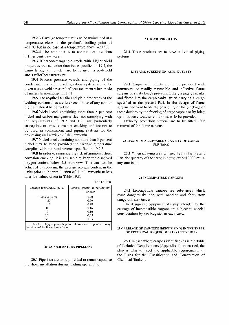
58 Rules for the Classification and Construction of Ships Carrying Liquefied Gases in Bulk
19.2.3 Carriage temperature is to be maintained at a temperature close to the product's boiling point of -33 °C but in no case at a temperature above -20 °C.
19.2.4 The ammonia is to contain not less than 0,1 per cent w/w water.
19.3 I f carbon-manganese steels with higher yield properties are used other than those specified in 19.2, the cargo tanks, piping, etc., are to be given a post-weld stress relief heat treatment.
19.4 Process pressure vessels and piping of the condensate part of the refrigeration system are to be given a post-weld stress relief heat treatment when made of materials mentioned in 19.1.
19.5 The required tensile and yield properties of the welding consumables are to exceed those of any tank or piping material to be welded.
19.6 Nickel steel containing more than 5 per cent nickel and carbon-manganese steel not complying with the requirements of 19.2 and 19.3 are particularly susceptible to stress corrosion cracking and are not to be used in containment and piping systems for the processing and carriage of the ammonia.
19.7 Nickel steel containing not more than 5 per cent nickel may be used provided the carriage temperature complies with the requirements specified in 19.2.3.
19.8 In order to minimize the risk of ammonia stress corrosion cracking, it is advisable to keep the dissolved oxygen content below 2,5 ppm w/w. This can best be achieved by reducing the average oxygen content in the tanks prior to the introduction of liquid ammonia to less than the values given in Table 19.8.
Table 19.8
Carriage temperature, in °C Oxygen content, in per cent by volume
— 30 and below 0,90 -20 0,50 — 10 0,28 0 0,16 10 0,10 20 0,05 30 0,03
No te . Oxygen percentage for intermediate temperatures may be obtained by linear interpolation.
20 VAPOUR RETURN PIPELINES
20.1 Pipelines are to be provided to return vapour to the shore installation during loading operations.
21 TOXIC PRODUCTS
21.1 Toxic products are to have individual piping systems.
22 FLAME SCREENS ON VENT OUTLETS
22.1 Cargo vent outlets are to be provided with permanent or readily renewable and effective flame screens or safety heads preventing the passage of sparks and flame into the cargo tanks, when carrying a cargo specified in the present Part. In the design of flame screens and vent heads the possibility of the blockage of these devices by the freezing of cargo vapour or by icing up in adverse weather conditions is to be provided.
Ordinary protection screens are to be fitted after removal of the flame screens.
23 MAXIMUM ALLOWABLE QUANTITY OF CARGO PER TANK
23.1 When carrying a cargo specified in the present Part, the quantity of the cargo is not to exceed 3000 m 3 in any one tank.
24 INCOMPATIBLE CARGOES
24.1 Incompatible cargoes are substances which react dangerously one with another and form new dangerous substances.
The design and equipment of a ship intended for the carriage of incompatible cargoes are subject to special consideration by the Register in each case.
25 CARRIAGE OF CARGOES IDENTIFIED (*) IN THE TABLE OF TECHNICAL REQUIREMENTS (APPENDIX 1)
25.1 In case where cargoes identified (*) in the Table of Technical Requirements (Appendix 1) are carried, the ship is also to meet the applicable requirements of the Rules for the Classification and Construction of Chemical Tankers.

Appendix 1 59
APPENDIX 1
TABLE OF TECHNICAL REQUIREMENTS
Explanatory notes to the Table of Technical Requirements 1. Product names (column 1) are listed in alphabetic order of their Latin names. 2. Chemical formula (column 2) is given for information only. 3. Density (column 3) is given for information only and is to be refined according to the shipper's data. 4. Ship type (column 4) according to the definition in Part I "Classification". 5. Definition of the type C independent tank (column 5) is given in Section 2, Part IV "Cargo Tanks". 6. Requirements for control of vapour space within cargo tanks (column 6) are given in Part V "Fire Protection": Inert = inert gas; Dry = dry air. 7. Vapour detection system (column 7): F = flammable vapour detection; T = toxic vapour detection; 0 = oxygen detection (oxygen analyzer); F+T = flammable and toxic vapor detection. 8. Gauge type (column 8): R = restricted type;
C = closed type; 1 = indirect type (see 2.2, Part V I I I "Instrumentation"). 9. MFAG (Medical First Aid Guide (MFAG) of the International Maritime Organization (IMO)) numbers
(column 9) are provided for information on the emergency procedures in accidents associated with the products covered by the LG Rules requirements.
Where any of the products listed are carried at the low temperature from which frostbite may occur, MFAG No. 620 is also applicable.
10. Special requirements (column 10), see chapters and sections of Part X "Special Requirements". 11. Products marked "*" are also covered by the requirements of the Rules for the Classification and Construction
of Chemical Tankers.

60 Rules for the Classification and Construction of Ships Carrying Liquefied Gases in Bulk
Product name Chemical formula
Den
sity
(kg/
m3)a
t te
mpe
ratu
re in
br
acke
ts
Ship
ty
pe
Type
C in
depe
nden
t tan
k re
quui
red
Syste
m fo
r con
trol o
f va
pour
spac
e wi
thin
ca
rgo
tanks
Carg
o va
pour
dete
ction
sy
stem
Gau
ge t
ype
MFA
G t
able
No.
Special requirements
Acetaldehyde CH3CHO 780 (20,8°C)
2G/2PG — Inert F+T C 300 2.2, 2.3, 5.1, Section 7, Section 8
Ammonia Anhydrous NH 3 771 (-33,4°C)
2G/2PG — — T C 725 2.1, 2.2, 2.3, 3.1, Section 7
Butadiene CH2CHCHCH2 646 (0°C)
2G/2PG — — F+T R 310 3.2, 5.2, Section 8, Section 10
Butane C 4 H 1 0 600 (0°C)
2G/2PG — — F R 310
Butane/Propane mixture (LPG)
2G/2PG — — F R 310
Butylenes CH3CH2CHCH2 670 (0°C)
2G/2PG — — F R 310
Chlorine 1560 (-34°C)
1G Yes Dry T I 740 Section 2, 4.2, 5.1, Section 6, Section 7, Section 9, Section 11,
Section 15
Diethyl Ether* (C2H5)2O 640 (34,6°C)
2G/2PG — Inert F+T C 330 2.1, 2.2, 3.6, 4.1, 8.1, Section 17, Section 22, Section 23
Dimethylamine (CH3)2NH 680 (0°C)
2G/2PG — — F+T C 320 2.1, 2.2, 2.3, 3.1, Section 7
Ethane CH3CH3 550 (-88°C)
2G — — F R 310
Ethyle Chloride CH3CH2Cl 921 (0°C)
2G/2PG — — F+T R 340 Section 7
Ethylene C 2 H 4 560 (-104°C)
2G — — F R 310
Ethylene Oxide CH2CH2O 882 (10°C)
1G Yes Inert F+T C 365 2.1, 2.2, 2.3, 2.5, 3.2, 4.2, Section 6, Section 7, Section 8,
Section 12
Ethylene Oxide/Propylene Oxide mixture with Ethylene Oxide content of not more than 30 per cent by weight*
2G/2PG Inert F+T C 365 2.2, 4.1, 5.1, 8.1, Section 18, Section 22, Section 23
Isoprene* CH2CHC(CH3)CH2 680 (34°C)
2G/2PG — — F R 310 2.2, Section 10, Section 19, Section 22
Isopropylamine* (CH3)2CHNH2 710 (34°C)
2G/2PG — — F+T C 320 2.1, 2.2, 3.4, Section 7, Section 20, Section 21, Section 22, Section 23
Methane (LNG)
CH4 420 (-164°C)
2G — — F C 620
Methylacetylene/Propadiene mixture
2G/2PG — — F R 310 Section 13
Methyl Bromide CH3Br 1730 (0°C)
1G Yes F+T C 345 Section 2, 3.3, Section 4, 5.1, Section 6, Section 11
Methyl Chloride CH3Cl 920 2G/2PG — — F+T C 340 3.3, Section 7
Monoethylamine* (Ethylamine)
C 2H 5NH 2 706 (0°C)
2G/2PG F+T C 320 2.1, 2.2, 2.3, 3.1, 4.1, Section 7, Section 20, Section 21, Section 22, Section 23
Nitrogen N2 808 (-196°C)
3G — — О C 620 Section 14
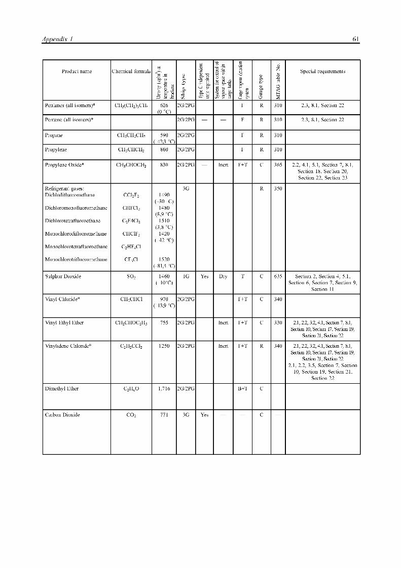
Appendix 1 61
Product name Chemical formula
Den
sity
(kg/
m3)a
t te
mpe
ratu
re in
br
acke
ts ft Д CO
Type
C in
depe
nden
t ta
nk r
equu
ired
Syste
m f
or c
ontro
l of
vapo
ur s
pace
with
in
carg
o ta
nks
Carg
o va
pour
dete
ction
sy
stem
Gau
ge t
ype
MFA
G t
able
No.
Special requirements
Pentanes (all isomers)* CH3(CH2)3CFb 626 (0 °C)
2G/2PG — — F R 310 2.3, 8.1, Section 22
Pentene (all isomers)* 2G/2PG — — F R 310 2.3, 8.1, Section 22
Propane CH3CH2CH3 590 (-12,3 °C)
2G/2PG — — F R 310
Propylene CH3CHCH2 860 2G/2PG — — F R 310
Propylene Oxide* CH3CHOCH2 830 2G/2PG Inert F+T C 365 2.2, 4.1, 5.1, Section 7, 8.1, Section 18, Section 20, Section 22, Section 23
Refrigerant gases: Dichlodifluoromethane
Dichloromonofluoromethane
Dichlorotetrafluoroethane
Monochlorodifluoromethane
Monochlorotetrafluoroethane
CCl2F2
CHFCl2
C2F4Cl2
CHClF2
C2HF4Cl
1490 (-30 °C)
1480 (8,9 °C)
1510 (3,8 °C)
1420 (-12 °C)
3G R 350
Monochlorotrifluoromethane CF3Cl 1520 (-81,4 °C)
Sulphur Dioxide SO2 1460 (-10°C)
1G Yes Dry T C 635 Section 2, Section 4, 5.1, Section 6, Section 7, Section 9,
Section 11
Vinyl Chloride* CH2CHCl 970 (-13,9 °C)
2G/2PG F+T C 340
Vinyl Ethyl Ether CH2CHOC2H5 755 2G/2PG Inert F+T C 330 2.1, 2.2, 3.2, 4.1, Section 7, 8.1, Section 10, Section 17, Section 19,
Section 21, Section 22
Vinylidene Chloride* C2H2CCl2 1250 2G/2PG Inert F+T R 340 2.1, 2.2, 3.2, 4.1, Section 7, 8.1, Section 10, Section 17, Section 19,
Section 21, Section 22 2.1, 2.2, 3.5, Section 7, Section
10, Section 19, Section 21, Section 22
Dimethyl Ether C2H6O 1,716 2G/2PG B+T C
Carbon Dioxide CO2 771 3G Yes C
62 Rules for the Classification and Construction of Ships Carrying Liquefied Gases in Bulk
APPENDIX 2
INTERNATIONAL CODE FOR THE CONSTRUCTION AND EQUIPMENT OF SHIPS CARRYING L I Q U E F I E D GASES IN B U L K
CHAPTER 18. OPERATING REQUIREMENTS
18.1 Cargo information. 18.1.1 A copy of the International Code for the
Construction and Equipment of Ships Carrying Liquefied Gases in Bulk with all the amendments adopted by the IMO Assembly, or of the national regulations, incorporating the provisions of the Code, is to be on board every ship covered by the Code.
18.1.2 Information on the safe carriage of cargo is to be available on board a ship. Such information is to include the plan of cargo arrangement as well as the following:
.1 a full description of physical and chemical properties of cargo, including reactivity, necessary for its safe containment;
.2 action to be taken in the event of spills or leaks;
.3 counter-measures against accidental personal contact;
.4 fire-fighting procedures and fire-fighting media;
.5 procedures for cargo transfer, gas-freeing, ballast¬ing, tank cleaning and changing cargoes;
.6 special equipment needed for the safe handling of the particular cargo;
.7 minimum temperature of the inner hull;
.8 emergency procedures;
.9 list of cargoes to be stabilized or inhibited. 18.1.3 The ship carrying cargoes to be inhibited is to
be provided with a manufacturer's certificate wherein the following is to be specified:
.1 name and amount of an inhibitor added;
.2 time (data) of inhibitor addition and its life;
.3 all temperature limitations defining inhibitor life;
.4 action to be taken i f voyage duration exceeds inhibitor life.
18.1.4 Where the adequate information on the safe carriage of cargo is lacking, the cargo is not to be taken on board for carriage.
18.2 Cargoes compatibility. 18.2.1 The master is to ascertain that the quantity
and characteristics of each product to be loaded are within the limits indicated in the Certificate and in the Information Stability specified in 1.3, Part I I I "Stability. Subdivision. Freeboard" of the LG Rules.
18.2.2 Care is to be taken to avoid dangerous chemical reactions i f cargoes are mixed. This is of particular significance in respect of:
.1 tank cleaning procedures required between successive cargoes in the same tank; and
.2 simultaneous carriage of cargoes which react when mixed. This is permitted only i f the complete cargo systems including cargo pipework, tanks, vent systems and refrigeration systems are physically separated.
18.3 Personnel training. 18.3.1 Personnel involved in cargo operations is to
be adequately trained in handling procedures. 18.3.2 A l l personnel is to be properly trained in the
use of protective equipment provided on board and have basic training in the procedures, appropriate to their duties, necessary under emergency conditions.
18.3.3 Officers are to be trained in emergency procedures to deal with conditions of leakage, spillage or fire involving the cargo.
A sufficient number of them is to be instructed and trained in essential first aid for the cargoes carried.
18.4 Entry into cargo tanks and spaces. 18.4.1 Crew members can enter cargo tanks, hold
spaces, void spaces around cargo tanks, cargo handling spaces and other enclosed spaces where gas may accumulate only once:
.1 a compartment is freed of toxic gases and an oxygen content in it is sufficient; or
.2 personnel wear breathing apparatus and other necessary protective equipment and the entire operation is under the close supervision of a responsible officer.
18.4.2 Personnel entering any space designated as gas-dangerous on a ship carrying flammable products is not to introduce any potential source of ignition into the space unless it has been certified gas-free and is maintained in that condition.
18.4.3 For internal insulation cargo tanks, special fire precautions are to be taken in the event of hot work carried out in the vicinity of the tanks. For this purpose, gas absorbing and deabsorbing characteristics of the insulation material are to be taken into account.
18.4.4 For internal insulation cargo tanks, repairs are to be carried out in accordance with 4.8.3.5, Part IV "Cargo Tanks" of the LG Rules.
18.5 Carriage of cargo at low temperature. 18.5.1 To ensure the safe carriage of cargoes at low
temperatures, the following requirements are to be met: .1 the heating arrangements associated with cargo
containment systems are to be operated in such a manner as to ensure that the temperature does not fall below that for which the material of the hull structure is designed;
.2 loading is to be carried out in such a manner as to ensure that unsatisfactory temperature gradients do not occur in any cargo tank, piping or other ancillary equipment;

Appendix 2 63
.3 when cooling down tanks from temperatures at or near ambient, the cool-down procedure laid down for that particular tank, piping and ancillary equipment is to be followed closely.
18.6 Systems and controls. 18.6.1 Cargo emergency shutdown and alarm
systems involved in cargo transfer are to be tested and/or checked before cargo handling operations begin.
Essential cargo handling controls are also to be tested and/or checked prior to transfer operations.
18.6.2 The check and calibration of gas detectors are to be conducted in certain time periods. For this purpose, the relevant equipment and reference gas detector are to be available on board.
18.7Cargo transfer operations. 18.7.1 Transfer operations including emergency
procedures are to be discussed between ship's personnel
and the Administration of the shore terminal prior to commencement and communications maintained throughout the transfer operations.
18.7.2 The closing time of the emergency shutdown valve referred to in 3.2.4.1, Part V I "Sistems and Piping" (i. e. time from shutdown signal initiation to complete valve closure) is to be not greater than 3600 U/LR where
U = ullage volume at operating signal level, in m 3 ; LR = maximum loading rate corresponding to the
capacity of ship's and shore facilities, in m 3/h.
The loading rate is to be adjusted to an acceptable level taking into account the value of the maximum pressure of emergency valve closing, the value of the pressure the ship's and shore cargo systems are designed at, including hoses.

RULES FOR THE CLASSIFICATION
AND CONSTRUCTION OF SHIPS CARRYING COMPRESSED
NATURAL GAS

66 Rules for the Classification and Construction of Ships Carrying Compressed Natural Gas
PART I. CLASSIFICATION
1 GENERAL
1.1 Application. 1.1.1 The Rules for the Classification and Construc¬
tion of Ships Carrying Compressed Natural Gas1 apply to specially built or converted ships, regardless of their gross tonnage and powerplant output, intended for the carriage of compressed natural gas (CNG). Ships carrying compressed natural gas2 are fully covered by the requirements of the Rules for the Equipment of Sea¬Going Ships and Load Line Rules for Sea-Going Ships. The Rules for the Classification and Construction of Sea¬Going Ships3, as well as the Rules for the Classification and Construction of Ships Carrying Liquefied Gases4
apply to the CNG carriers to the extent stipulated in the
text of the CNG Rules. 1.2 Definitions and explanations. 1.2.1 The general definitions and explanations are
given in the LG Rules. The following definitions and explanations are used in the CNG Rules.
C a r g o t a n k c y l i n d e r is a cylindrical vessel made of a standard large diameter pipe as used for subsea pipelines with dished ends forming the basic volume of the cargo tank.
C o i l e d c a r g o t a n k is a cargo tank consisting of a long length small diameter coiled pipe.
C y l i n d r i c a l c a r g o t a n k is a cargo tank consisting of multiple cylindrical pressure vessels interconnected by the cargo tank piping.
C a r g o h o l d c o v e r is the upper hatch cover of the cargo hold which makes it possible to monitor conditions of cargo carriage in the cargo holds.
M a x i m u m a l l o w a b l e w o r k i n g pres¬sure is a pressure equal to 95 per cent of the design value.
C a r g o h o l d space is the space enclosed by the ship's structures, in which the cargo tanks are situated.
D e s i g n p r e s s u r e is the maximum gas pressure at the top of a cargo tank, which is used in design of cargo tanks and cargo piping.
D e s i g n t e m p e r a t u r e is the maximum or minimum temperature, which may take place in the material of cargo tanks, piping, foundations and in the inner hull structures of cargo holds in service.
C a r g o t a n k p i p i n g i s t h e p i p i n g , w h i c h interconnects cargo tank cylinders and connects cargo cylinders with the cargo valve of a cargo tank.
hereinafter referred to as "the CNG Rules". 2Hereinafter referred to as "the CNG carriers". 3Hereinafter referred to as "the Rules for the Classification". 4Hereinafter referred to as "the LG Rules". 5Hereinafter referred to as "the Certificate".
2 EQUIVALENTS
2.1 The Register may allow the use of the ship's structures, equipment, materials, appliances and appara¬tus or carrying out of arrangements others than those required by the CNG Rules.
In the above cases, the data, which allow to establish the conformity of such structures, equipment, materials, appliances and apparatus, or arrangements to the conditions ensuring ship's safety, safety of life and prevention of pollution from ships are to be submitted to the Register.
3 DOCUMENTS
3.1 A Certificate of Fitness for the Carriage of Compressed Natural Gas5 based on the positive results of survey reflected in the survey reports is issued to the ships meeting the requirements of the CNG Rules in addition to the documents provided for in the General Regulations for the Classification and Other Activity of the Rules for the Classification.
The Certificate period of validity is not more than 5 years.
3.2 The Certificate is to be permanently kept on board a ship and be available for inspection.
3.3 I f the equivalents specified in Section 2 are allowed for a ship by the Register, the contents of these equivalents is to be reflected in the Certificate.
4 CLASS NOTATION
4.1 Class notation of a ship. 4.1.1 The character of classification and additional
distinguishing marks are assigned in compliance with the requirements of 2.2, Part I "Classification" of the Rules for the Classification.
4.2 Descriptive notation in the class notation. 4.2.1 The ships meeting the requirements of the Rules
for the Classification and the CNG Rules are assigned the descriptive notation: Gas carrier CNG added to the character of classification (refer to Section 2, Part I "Classification" of the Rules for the Classification).
Part I. Classification 67
5 CLASSIFICATION SURVEYS
5.1 Initial and/or periodical surveys to assign and/or confirm the class of the CNG carriers are carried out in compliance with the requirements of Section 8, Part I I I "Additional Surveys of Ships Depending on Their Purpose and Hull Material" of the Rules for the Classification Surveys of Ships in Service.
5.2 Survey of a ship to issue the Certificate is carried out during the initial or periodical survey of the ship.
5.3 Ship's annual surveys are carried out within 3 months before or after every anniversary date since the day of issue of the Certificate, and are intended to ascertain that the equipment, fittings, arrangements and materials of the ship meet the relevant requirements of the CNG Rules.
An appropriate entry on the surveys carried out is made in the Certificate.
6 PLAN APPROVAL DOCUMENTATION
6.1 In addition to the technical documentation specified in Section 3, Part I "Classification" of the Rules for the Classification, the following technical data and documents confirming fulfillment of the CNG Rules are to be submitted to the Register:
.1 arrangement plans of cargo tanks with their distance from side plating and the bottom specified;
.2 drawings and strength calculations of cargo tanks with information on the scope of non-destructive testing of welds, strength and leakage tests;
.3 arrangement plans of cargo piping intended for connection to shore or offshore facilities, including arrangements for unloading, loading and emergency disconnection, i f provided;
.4 specification of design loads and structural analysis of cargo tanks;
.5 calculations of the minimum and maximum design temperatures of materials in a cargo tank, supports and foundations in a cargo hold during loading/ unloading/decompression;
.6 calculation of cooling effect of gas release due to leaks or pipe fracture;
.7 program and procedure for testing full-scale prototype of a cargo tank for fatigue and fracture due to internal pressure;
.8 drawings and stress analysis in cargo piping in compliance with the requirements of Part V I "Systems and Piping" of the LG Rules, including loads due to vibration and fatigue analysis;
.9 calculation to determine the crack propagation characteristics for cargo tank piping, using the "leakage -fracture" principle;
.10 detailed drawings of all sections of cargo tank piping under pressure;
.11 documentation and calculations for holds and cargo tanks, using results of model tests, analysis methods to determine stress levels, fatigue life and crack propagation characteristics;
.12 calculations of stresses and analysis of fatigue stresses in cargo tank cylinders in compliance with the requirements of 3.6, Part I "Subsea Pipelines" of the Rules for the Classification and Construction of Subsea Pipelines for class G3 pipeline;
.13 calculations of fatigue crack propagation for cargo tank cylinders in compliance with the require¬ments of 3.5, Part I "Subsea Pipelines" of the Rules for the Classification and Construction of Subsea Pipelines;
.14 drawings of foundations of the cargo tank cylinders with calculations made in compliance with the requirements of Section 7, Part IV "Cargo Tanks" of the LG Rules;
.15 degassing arrangements and procedures;
.16 forced ventilation arrangement in a cargo area;
.17 description of tests by elevated pressure.
PART II . GAS C A R R I E R DESIGN
1 GENERAL
1.1 The CNG carrier design is to comply with the requirements ofPartII "Gas CarrierDesign" ofthe LG Rules, as for the ships carrying liquefied gases in bulk1 of Type 2G.
1.2 The CNG carrier is to be double-skin sided and double-bottomed. For the CNG carrier, the depth of the double bottom is to be not less than 1/15 of the ship breadth or 2 m, whichever is less. The width of the double skin of the
hereinafter referred to as "the LG carriers".
CNG carrier is to be 760 mm minimum. The minimum distance from the cargo hold to the shell plating is to be not less than 760 mm. I f the width of the double skin and the depth of the double bottom are different, the structure in the transition area is to be as shown in Fig. 2.6-1 of Part I I "Gas Carrier Design" of the LG Rules.
1.3 The structure equivalent to the inner bottom may be used, provided that a calculation or test proves that the proposed structure protects the cargo tanks against damage and is capable of absorbing energy as the standard double-bottomed structure.

68 Rules for the Classification and Construction of Ships Carrying Compressed Natural Gas
PART III . STABILITY. SUBDIVISION. F R E E B O A R D
1 GENERAL
1.1 Stability of the CNG carrier is to meet the requirements of Part IV "Stability" of the Rules for the Classification covering dry cargo ships and is to be verified for voyage in ballast and in full-load condition.
1.2 The CNG carrier is to meet the requirements of Part V "Subdivision" of the Rules for the Classification as for LG carriers of Type 2G. The cargo hold spaces are
to be isolated from machinery, accommodation and other similar spaces by cofferdams.
1.3 The damage stability of the CNG carrier is to meet the requirements of the International Code for the Construction and Equipment of Ships Carrying Liquefied Gases in Bulk (IGC Code) as for LG carriers of Type 2G.
1.4 The freeboard of the CNG carrier is assigned in compliance with the requirements of the Load Line Rules for Sea-Going Ships.
PART IV. CARGO TANKS
1 GENERAL
1.1 The cargo tanks are to be designed using model tests, proven analytical procedures and analysis methods to determine stress levels, fatigue life and crack propagation characteristics. For composite materials, changes in the material properties with time due to exposure to long-term static loads under various environmental conditions are to be reviewed and taken into account.
1.2 The cargo tanks together with foundations and supports are to be designed with regard to all loads specified in 3.1, 3.3 — 3.5, 3.8, Part IV "Cargo Tanks" of the LG Rules for LG carriers. Design load due to internal pressure is to be determined as a sum of the design internal pressure in the cargo tank and pressure of the cargo column with regard to the cargo density and accelerations arising in service (refer to 3.5, Part IV "Cargo Tanks" of the LG Rules).
1.3 The dynamic loads acting during the ship motion are to be assumed as the most probable maximum loads occurring during the ship's life. The frequency of load application is to be especially considered for composite materials as these materials have frequency-dependent properties.
1.4 Dynamic effect due to pressure variations during cargo handling operations is to be presented with regard to the most probable extreme operating conditions of the ship. The number of the pressure fluctuation cycles from the maximum to the minimum is to be consistent with the ship's service life of not less than 50 years.
1.5 The calculations are to consider the transient thermal loads arising during loading and unloading of the ship.
1.6 The effect of all static and dynamic loads is to be considered in strength analysis of the structures with account of the following:
maximum allowable stresses due to internal pres¬sure;
buckling; failure due to combined action of alternating cyclic
and static loads; possible crack propagation characteristics. 1.7 Tests of the cargo tank prototype are to show
effectiveness of the proposed structure as it relates to separation and draining of liquid from the cargo system. During tests the possibility of a hydraulic shock in piping during any cargo handling operation is to be checked, and structural measures are to be taken to exclude such possibility. I f the full-scale tests corresponding to operating conditions are impractical, computer simula¬tion or model non-full-scale tests may be performed. Acceptance tests are to be carried out by the surveyor and are to be considered only when all the systems, equipment and devices are fully functioning.
2 COILED CARGO TANKS
2.1 The coiled cargo tanks are subject to the special consideration by the Register. The requirements for cylindrical cargo tanks are to be applicable to the coiled cargo tanks, as far as practicable.
3 CYLINDRICAL CARGO TANKS
3.1 Cargo tank cylinders. 3.1.1 Stresses in the cargo tank cylinders are to
comply with the requirements for class G3 pipelines specified in the Rules for the Classification and Construction of Subsea Pipelines. As a rule, the spherical

Part IV Cargo tanks 69
ends are to be used. The stresses in the spherical ends are to comply with the requirements of the LG Rules for Type C independent tanks of LG carriers. Pressure used in the calculation of the wall thickness is the design pressure as indicated in 1.2, Part I "Classification". The maximum working pressure is to be at least by 5 per cent less than the design pressure. The spherical ends are to have a cylindrical part, which width to the circumfer¬ential weld on the cylindrical part of the cargo tank is to be not less than 1,0//Rt where R = radius of the spherical end; t = wall thickness of the spherical end.
For elliptical and torospherical ends the additional requirements may be applied on agreement with the Register.
3.1.2 Cylinders and other components of cargo tanks are to be subjected to fatigue analysis to predict the state of the structural material in service. During design the fatigue curve is to be determined by the model tests of the cargo tank components. The critical level of a sum of cumulative fatigue damages (both due to dynamic loads a n d d u e t o l o a d s c a u s e d b y t h e c a r g o h a n d l i n g operations) is to be not more than 0,1 (i.e. the minimal life time obtained by means of the fatigue curve is to be not less than 200 years with the designed service life of the ship being 20 years).
3.1.3 In addition to the fatigue calculations given in 3.1.2, it wi l l be necessary to make calculations of the propagation time of fatigue cracks, which can develop in the welds. The analysis is to be made for planar defects both in the longitudinal and circumferential welds. The estimated time of crack growth through the cylinder shell is to be by three times longer than the design service life of the cylinder but not less than 60 years. These calculations are to account for the actual stress concentration factor at the weld root. The initial defect initiating the crack is to be dimensioned in compliance with the maximum value of the defect permissible in the process of flaw detection of the welds. The adopted crack growth characteristic is to be recorded both for the cylinder material and for the welds.
3.1.4 I f the requirement concerning the time of fatigue crack propagation stated in 3.1.3 cannot be fulfilled for a given cylinder shell thickness, it is necessary to demonstrate that the "leakage - fracture" principle is applicable, i.e. to prove that any defect mentioned in 3.1.3 in its development wi l l become through and detected before the crack becomes instable with the cylinder complete loss followed. In this case, the value of fracture toughness (critical value of the stress intensity factor KIC) is to be experimentally determined for the cylinder material within the heat affected zone and welding at the operating temperatures.
3.1.5 Cargo tanks cylinders are to be supported by the hull in a manner, which wi l l prevent bodily movement of the cylinders under static and dynamic loads while allowing contraction and expansion of the
cylinders under temperature variations without additional stressing of the cargo tanks and hull structures. The following forces are to be taken into account:
the most probable maximum resulting acceleration in compliance with the requirements of 3.5, Part IV "Cargo Tanks" of the LG Rules for LG carriers;
static loads at heel up to 30 degrees; collision loads. 3.1.6 Where empty cargo tanks have positive
buoyancy and are situated below the summer waterline, provision is to be made for antiflotation arrangements during flooding. The antiflotation arrangements are to be designed to withstand an upward force without plastic deformations likely to endanger the hull structures.
3.1.7 Supports and foundations within the cargo area are to be protected against direct effect of the cold impact when directly exposed to gas leakages.
The local equivalent stresses in the cargo tank cylinders with regard to the loads in supports are to be not more than 0,8 yield stress of the material. The mentioned loads are to be taken into account in fatigue analysis as mentioned in 3.1.2.
4 CARGO TANK PIPING
4.1 The strength of the cargo tank piping is to meet the requirements for cargo piping for LG carriers set out in Part V I "Systems and Piping" of the LG Rules. Stress analyses shall consider all the applicable loads, including vibration. A l l design requirements and principles set out in Section 2, Part V I "Systems and Piping" of the LG Rules are applicable to the cargo tank piping of CNG carriers.
4.2 The cargo tank piping is to be subjected to the fatigue analysis. The fatigue curve is to be applied to material, structural members and stress state during investigations. Model tests of the piping components may be required to make the fatigue curve. The curve is to be based on average values of logarithmic fatigue curve, excluding two standard deviations. The critical level of a sum of cumulative fatigue damages (both due to dynamic loads and due to the loads caused by the cargo handling operations) is to be not more than 0,1.
4.3 Calculations of the fatigue crack propagation time are to be made for the cargo tank piping similarly to Section 3. I f seamless pipes or equivalent are used, the analysis is to be carried out only for defects in circumferential welds. Moreover, it is necessary to demonstrate that the "leakage - fracture" principle is followed in the same manner as stated in Section 4, i.e. it is necessary to prove that any defect mentioned in Section 3 in its development wi l l become through and wil l be detected before the crack becomes instable with the complete piping loss followed. The criteria set out in

70 Rules for the Classification and Construction of Ships Carrying Compressed Natural Gas
Section 3 are to be used as criteria for the possibility of using a material or a structure.
4.4 The cargo tank pipes are to be properly secured with the attachments, which, in the event of complete failure of the upper pipe, would prevent other pipes from being damaged as a result of impact due to falling of the fractured pipe. At the same time, a sufficient flexibility of piping is to be provided to allow vertical expansion of the cylinders and horizontal displacement of the cylinder heads due to accelerations and vibrations without any significant additional stresses in cargo pipes which may cause strength or fatigue-related damages. The cargo tank piping upstream of the master cargo valve is to be completely welded.
4.5 A l l fittings of the cargo tank piping are to be made of forgings. Other methods of fittings manufacturing are subject to special consideration by the Register.
5 PRESSURE TESTING
5.1 Hydraulic pressure tests of the finished cargo tank are to be carried out in compliance with the
requirements of the Rules for the Classification and Construction of Subsea Pipelines and the LG Rules, as far as applicable. Test pressure equal to 1,25 design pressure is considered to be sufficient.
6 PROTOTYPE TESTING
6.1 The full-scale cargo tank cylinder prototype (full-scale as regards diameter, shell thickness, number of transverse welds, including welded ends but not of full length) is to be subjected to fatigue and fracture tests. The tests are to confirm that the thickness of the vessel cylindrical part and ends, as well as the welds have adequate resistance to fatigue effect and the cylinder has adequate safety margin after the doubled expected number of loading cycles. Not less than 3 tests are to be carried out.
One specimen is to be tested to fracture after being tested by doubled expected (design) number of stress cycles. Two specimens are to be subjected to fatigue test with the number of stress cycles exceeding the expected number of cycles in service by at least 15 times.
PART V. F I R E PROTECTION
1 GENERAL
1.1 The CNG carrier is to meet the applicable requirements set out in Part V I "Fire Protection" of the Rules for the Classification and in Part V "Fire Protection" of the LG Rules applied to LG carriers and the additional requirements contained in the present Part.
2 STRUCTURAL FIRE PROTECTION
2.1 The external boundary of deckhouses and superstructures, including any overhangs, is to be made as "A-60" class division as applied to the surfaces facing the cargo area, space of the wing fuel tanks and spaces containing cargo handling equipment and at a distance of 3 m from any specified boundary line.
2.2 Where the cargo handling equipment or any other potential source of high pressure gas is situated nearby the accommodation spaces, the additional fire protection measures are to be taken subject to special
hereinafter referred to as "the MODU/FOP Rules".
consideration by the Register. Such measures may be application of "H-60" class fire-protection divisions (refer to definition given in 1.2.2 Part V I "Fire Protection" of the Rules for the Classification, Construc¬tion and Equipment of Mobile Offshore Drilling Units and Fixed Offshore Platforms1) of the external bound¬aries mentioned in Section 2 or a special enclosure to prevent the accommodation spaces from being hit by a gas jet.
2.3 In order to protect against fire progress covers of cargo holds facing the cargo handling spaces are to be made as divisions having fire integrity not lower than "H-0" class. The cargo hold covers facing the engine room or after signal mast are to be made as divisions having fire integrity not lower than "A-0" class. Along with that, the cargo hold covers are to:
maintain integrity under exposure to fire equivalent to exposure during the tests of "A" class divisions with external thermal radiation;
the surface flame propagation characteristic of the material, from which they are manufactured is to meet the requirements of IMO Resolution A.653(16) (relating to weather decks).
2.4 The cargo hold situated below the upper deck is to be protected from overlaying spaces or spaces containing cargo handling equipment by "A-0" class
Part V Fire protection 71
division. Where the cargo tanks are made of a material not equivalent to steel, the cargo hold covers are to be made as "A-60" class divisions. Moreover, in this case, the surfaces of the cargo hold covers facing the spaces containing cargo handling equipment or equipment that contains compressed hydrocarbons are to be made as "H-60" class fire-protection divisions.
2.5 Accommodation, service and machinery spaces situated below the upper deck are to be isolated from the spaces containing the cargo handling equipment and from the cargo areas by cofferdams. The minimum distance between the bulkheads in such cofferdam is to be 600 mm.
2.6 The cargo hold covers and other essential spaces or equipment, which can be heated due to ignition of gas leaking from the tanks/piping are to be protected within the time necessary to reduce pressure in the cargo tanks.
2.7 The bulkheads and decks, which are supposed to be the "H" class divisions, are to meet the requirements set out in 1.2.2, Part V I "Fire Protection" of the MODU/ FOP Rules.
3 ESCAPE ROUTES
3.1 Provision is to be made for escape routes from the engine room or service spaces to the accommodation spaces by means of a trunk, which, in general, has no surfaces, which can be exposed to thermal radiation.
3.2 The transverse fire-fighting divisions mentioned in Section 2 are to protect lifeboats against heating due to thermal radiation.
4 FIREMAN'S OUTFIT
4.1 4 sets of the fireman's outfit stored at 2 separate stations in accommodation spaces are to be provided. Where the cargo area separates the accommodation spaces from the engine room or service spaces, 2 additional sets of the fireman's outfit are to be stored in the engine room or service spaces.
5 WATER FIRE MAIN SYSTEM
5.1 In addition to the main requirements for fire pumps, hydrants and fire hoses set by Regulation II-2/10.2 of SOLAS and 3.2, Part V I "Fire Protection" of the Rules for the Classification, the requirements of the present Chapter are to be met.
5.2 The system is to be so arranged as to ensure delivery of at least two water jets from different hydrants,
one of the jets being delivered through a single hose to any area of deck and external surface of cargo hold covers. The minimum pressure in the hydrants with two connected hoses is to be not less than 5 kg/cm2. The length of the fire hose is to be not more than 33 m.
5.3 The fire main is to be designed in one of the following ways:
circled starboard and port main; single line along the centerline through the cargo
area, forming the fire main, which is to be protected against possible effect of flame jets from the cargo piping.
5.4 Two main fire pumps are to be installed, each having the capacity not less than specified in 3.2, Part V I "Fire Protection" of the Rules for the Classification. One of the pumps is to be located forward of the cargo area and the other - aft of the cargo area. Both pumps are to be remotely controlled from the bridge and from the engine room.
5.5 Both main fire pumps are to be ready for starting and delivery of water at any time of operation when the ship is not degassed.
5.6 Remotely controlled cut-off valves are to be fitted on the weather deck on each end of the fire main leading to the cargo or working area. Additionally the cut-off valves are to be fitted on the protected side of fire-fighting divisions or at the protected area boundary. Manually controlled shut-off valves are to be fitted between the cargo holds at the intervals not more than 40 m.
5.7 A l l pipes, valves, fire nozzles and other fittings of the fire-fighting system are to be resistant to corrosion in sea water and to fire.
5.8 The mooring equipment installed within the gas-dangerous area is to be protected by a sprinkler system with a capacity not less than 5 l/min per m 2 . The sprinkler system is to be set in operation before the use of any mooring arrangement and prior to cargo handling operations. Where in this case the mooring equipment only on one ship's side is used, the sprinkler system capacity may be designed taking into consideration operation of the mooring equipment on one ship'sside. The sprinkler system may be fed from the water fire main.
5.9 The loading/unloading area on the weather deck is to be covered by the water monitors, which are to be remotely controlled from a safe position.
6 DRY CHEMICAL POWDER FIRE EXTINGUISHING SYSTEM
6.1 A ship is to be provided with a dry chemical powder fire extinguishing system meeting the requirements of 3.10, Part V I "Fire Protection" of the Rules for the Classification.
6.2 In addition to the requirements mentioned in 6.1, the system is to be capable of delivering simultaneously

72 Rules for the Classification and Construction of Ships Carrying Compressed Natural Gas
water and dry powder in the form of two-component mixture from at least two widely spaced connections to the cargo area, working area and any other area of greater fire risk located on the upper deck. Hoses are to be of 25 to 30 m long.
6.3 The system may be fed from the water fire main, provided that when determining the capacity of the main fire pumps, the delivery of two-component powder wil l be additionally taken into account.
6.4 The dry powder is to be stored in two units each being capable of delivering 3,5 kg of powder per second within not less than 60 s for one fire nozzle.
7WATER SPRAY SYSTEM
7.1 Water spray system may not be considered as the means for fulfilling requirements for the minimum fire integrity of the structures mentioned in Section 2.
7.2 The water spray system is to protect: working area; superstructure; unprotected cargo tanks and piping under pressure
located on the upper deck; emergency cut-off valves;
other essential equipment to monitor and control pressure in cargo tanks during fire;
part of accommodation spaces facing the cargo area; external bulkhead of the cargo hold covers facing the
machinery space and flare mast. 7.3 The system is to be capable of covering all the
areas mentioned in 7.2 through uniform distribution of water sprayed at a rate of at least 10 l/min per m 2 for horizontal surfaces and 4 l/min per m 2 for vertical surfaces.
7.4 Outlets of the pressure relief system, of the additional pressure relief systems of flare type or using
cold gas discharge or gas discharge from pressure relief valves are to discharge gas into spaces so that the gas and thermal radiation due to its burning could not present threat to the ship, personnel or equipment. Thermal radiation from the flare directed onto the cargo tanks or other essential equipment is to be calculated in order to verify that the thermal radiation does not cause temperature rise in the cargo tanks and breakdown of the equipment. The flare is to satisfy the requirements of the recognized international or national standard, for example, API RP521 or equivalent.
7.5 The water spray system main is to be arranged in the following way:
starboard and port circled main; or single line along the centerline passing through the
cargo area and forming the fire main, which is to be protected against possible effect of flame jets from the cargo piping.
7.6 Both water spray pumps are to be able to be immediately started and to deliver water.
7.7 Provision is to be made for two water spray pumps, each of a capacity not less than 100 per cent of the capacity required by the water spray system. One pump is to be installed forward of the cargo area and the other pump - aft of the cargo area. Both pumps are to be remotely controlled from the bridge as well as from the engine room.
7.8 The capacity of each water spray pump is to be determined proceeding from the necessity of delivering water simultaneously to all the areas mentioned in 7.2 and 7.3.
7.9 Remotely controlled cut-off valves are to be fitted on the weather deck at each end of the fire main leading to a cargo or working area. Besides, the cut-off valves are to be fitted on the protected side of the fire-fighting divisions or at the protected area boundary. Manually controlled shut-off valves are to be fitted between the cargo holds at the intervals not more than 40 m.
PART VI. SYSTEMS AND PIPING
1 PIPING SYSTEMS IN CARGO AREA 2 CARGO SYSTEM
1.1 The requirements of the LG Rules, covering LG carriers, are also applicable to the bilge, ballast and fuel oil systems in the cargo area, which do not form part of the cargo system. Systems serving several cargo holds are to be so arranged that gas from one cargo space cannot permeate into another cargo space.
2.1 Cargo piping is to comply with the requirements of the LG Rules applied to the cargo piping of LG carriers and the requirements of Part V I I I "Systems and Piping" of the Rules for the Classification applied to the ship's piping, and in addition, with the following requirements.

Part VI. Systems and Piping 73
2.2 During design of the piping, the minimum temperature expected in service (loading/unloading) and in the event of emergency (pressure relief) is to be considered as design temperature.
2.3 The maximum pressure, to which the system is likely to be subjected in service, i.e. setting pressure of the pressure relief valves is to be considered as design pressure.
2.4 Pipes are to be seamless or equivalent. 2.5 After fabrication but prior to installation on
board the ship, each pipe is to be subjected to hydraulic test by a pressure not less than 1,5 design pressure.
2.6 After final installation on board the ship, the cargo piping is to be subjected to the leakage test using air, halogens or other suitable fluid in accordance with the approved technical documentation.
2.7 The vibration effect on the cargo piping is to be evaluated.
2.8 Stress analysis in each piping section is to be made according to the method approved by the Register.
2.9 Cargo handling operations, including emergency procedures, are to be described in a special instruction to be submitted to the Register for review. This instruction is to contain the potential faults associated with the cargo handling operations and information associated with the emergency disconnection, emergency closing and estab¬lishment of communication with the terminal (offshore or shore-based), etc.
2.10 Hull structures and foundations are to be protected against cargo leakages from the flanges, valves and other possible leakages in those cases when the cooling effect is not to be neglected.
2.11 Where cargo piping is arranged in an enclosed space, this space is to be protected from overpressure due to cargo leakages or explosion.
3 CARGO VALVES
3.1 A l l the remotely controlled valves are to be manually driven.
3.2 Each cargo tank is to be separated from the cargo piping by two shut-off valves (manually controlled and remotely controlled) connected in series. Means for leakage testing of the valves are to be provided.
3.3 Each cargohoseconnectiononthe cargomanifolds is to be fitted with two shut-off valves (manually controlled and remotely controlled) connected in series.
3.4 A l l the shut-off valves required in 3.2 and 3.3 are to be controlled from the stations arranged at least in two distant locations onboard the ship; one of these locations is to be the cargo control room.
The control system is to be also provided with fusible elements designed to melt temperature from 98 °C to 104 °C which wil l cause the emergency shut-off valves to close automatically in the event of fire.
Locations for such fusible elements are to include loading stations.
Shut-off valves in cargo piping are to fully close under all service conditions with 30 s of actuation.
Valves connected with the high pressure level alarm in cargo tanks and the sensor for automatic closure thereof, in compliance with Part V I I I "Instrumentation" of the LG Rules, are to comply with the requirements to prevent excessive pressure in the cargo main and prevent the cargo tank from becoming liquid full.
3.5 Cargo compressors are to be arranged to shutdown automatically in case of the emergency shutdown system actuation.
4 PROTECTION OF CARGO TANKS AND CARGO PIPING AGAINST EXCESSIVE PRESSURE
4.1 The system for protection against excessive pressure in cargo tanks is to consist of the pressure relief system and the additional pressure relief system and meet the requirements in 3.3 and 3.4, Part V I "Systems and Piping" of the LG Rules. At that the capacity of pressure relief valves is to be determined on the basis of the national and international standard agreed with the Register, and is subject to special consideration by the Register.
4.2 In order to prevent cargo piping from excessive pressure, pressure relief valves are to be provided. The pressure relief valves are to be so adjusted that the setting pressure does not exceed the design pressure of a cargo piping, considering allowance for the valve actuation.
5 GAS DISCHARGE FROM CARGO SYSTEM
5.1 Facilities for gas discharge are to be provided for all parts of the cargo system. Detailed gas discharge procedure is to be described in the Operating Instruction for the Cargo System and is to be submitted to the Register for review.
6 FILLING LIMITS FOR CARGO TANKS
6.1 Pressure in the cargo tanks after the loading is to be limited in such a manner as not to exceed 95 per cent of the design pressure throughout transportation and unloading with regard to the following:
for uncooled system - ambient temperature conditions (sea water temperature 32 ° C a n d a i r temperature 45 °C);
for cooled system - cooling system capacity under ambient temperature conditions mentioned above.

74 Rules for the Classification and Construction of Ships Carrying Compressed Natural Gas
7INERTING OF CARGO SPACES
7.1 Cargo spaces are to be inerted by nitrogen or by other suitable inert gas. The nitrogen producing system is to preclude backflow in the event of excessive pressure in a cargo space. The system is to be designed with a redundancy level providing maintenance of the necessary safety level on board the ship in service.
8 PROTECTION OF CARGO SPACES AGAINST EXCESSIVE PRESSURE
8.1 Cargo spaces are to be equipped with a pressure relief system covered by the following requirements.
8.1.1 Means are to be provided to automatically maintain the pressure of inert medium in cargo spaces by 0,05 - 0,15 kg/cm 2 above the atmospheric pressure.
8.1.2 Safety devices are to be provided with the setting pressure by 0,25 kg/cm 2 above the atmospheric pressure. The mentioned safety devices are to have a capacity sufficient for gas discharge in case of the complete rupture of the greatest pipe of the cylindrical cargo tank or complete rupture of a single pipe of the coiled cargo tank. This requirement is applicable to the largest cargo tank located in the protected cargo hold.
8.1.3 Gas is to be vented from the safety devices to a safe area.
8.1.4 In addition to the safety devices required in 8.1.2, provision is to be made for special covers (diaphragms) breaking under excessive pressure 0,4 kg/cm2.
8.1.5 During tests it is necessary to demonstrate that the safety devices and surrounding structures are capable of functioning at low temperatures due to pressure relief with the maximum capacity.
9 DRAINAGE
9.1 Cargo spaces are to be fitted with the drainage system not connected with machinery spaces. Moreover, water level detectors in the cargo holds are to be provided.
10 EXHAUST GAS SYSTEM
10.1 Outlets of the exhaust gas system of the internal combustion engines and boilers are to be provided with spark arresters.
11 TESTING
11.1 Testing of the systems and piping is to meet the requirements of Section 12, Part V I "Systems and Piping" of the LG Rules.
PART VII . E L E C T R I C A L EQUIPMENT
1 GENERAL
1.1 The electrical equipment is to meet the require¬ments of Part V I I "Electrical Equipment" of the LG Rules.
2 CLASSIFICATION OF DANGEROUS ZONES
2.2 I f the additional pressure relief system makes use of the cold gas discharge, a gas dissipation analysis is to be made in order to determine gas dangerous spaces. The analysis is to be made in compliance with the recognized standard or design module, and the boundaries of a dangerous zone are to be based on 50 per cent of the lower limit of the explosive range.
2.1 The sizes of gas-dangerous spaces and zones are to comply with the requirements set in Part V I I "Electrical Equipment" of the LG Rules.

Part VIII. Instrumentation 75
PART VIII . INSTRUMENTATION
1 GENERAL
1.1 The ship is to meet the requirements of Part VII I "Instrumentation" of the LG Rules applied to LG carriers, and the additional requirements set in the present Section.
1.2 Alarm signals are to be heard on the bridge and in the cargo control room.
1.3 Devices are to be provided to detect moisture and hydrogen sulphide (H2S) in a loading/unloading piping or in a shore connection.
1.4 As a minimum, the following compartments and spaces are to be provided with the gas analyzers:
each cargo tank area; deck piping area; ventilation inlets to gas safe spaces; air intakes of the engine room;
cargo manifold area. 1.5 As a minimum, the following compartments and
spaces are to be provided with the pressure gauges and alarms:
each cargo hold; each cargo tank;
cargo piping in way of the manifold. 1.6 Temperature sensors and oxygen content detec¬
tors are to be provided in each cargo hold. 1.7 Provision is to be made for the means to measure
temperature inside the cargo tanks. 1.8 Temperature in cargo tanks is to be monitored in
way of the exhaust piping when the pressure is reduced (i.e. during unloading, pressure relief). This monitoring is required to prevent the temperature drop below the design value.
PART IX. MATERIALS AND WELDING
1 GENERAL. DESIGN CONDITIONS 2 MATERIALS FOR HULL STRUCTURES FOR SELECTING MATERIAL
1.1 A l l materials used in cargo tanks and cargo systems are to be delivered with a Register Certificate.
1.2 The maximum design temperature for selecting materials is to be the highest temperature observed in cargo tanks during loading, unloading and transportation. The minimum design temperature for selecting materials is to be the lowest temperature observed in cargo tanks, piping, supports and internal hull structures of the cargo holds:
during loading, unloading and transportation; due to cooling effect at cargo leakage.
The determined minimum design temperature in the cargo holds during cargo leakage is to be supported by calculation. In so doing, the following cases are to be considered:
complete rupture of a pipe in a cargo tank (for cylindrical cargo tank);
complete rupture of a single pipe in a cargo tank (for coiled cargo tank).
In such calculations, the temperatures of sea water and outside air are to be assumed to be equal to 5 °C and 0 °C, respectively.
Partial closing is to prevent the hull structures from direct cooling effect due to cargo leakages.
2.1 The materials for hull structures are to comply with the requirements of Part X I I I "Materials" of the Rules for the Classification.
3 MATERIALS FOR CYLINDRICAL CARGO TANKS
3.1 The materials for cylindrical cargo tanks (including pipes and ends) are to comply with the requirements of Section 4, Part I "Subsea Pipelines" of the Rules for the Classification and Construction of Subsea Pipelines. The corrosion protection is to be specially agreed with the Register.
4 MATERIALS FOR COILED CARGO TANKS
4.1 The materials for coiled cargo tanks are to comply with the requirements of Section 4, Part I "Subsea Pipelines" of the Rules for the Classification and Construction of Subsea Pipelines or any other standard agreed with the Register.
76 Rules for the Classification and Construction of Ships Carrying Compressed Natural Gas
5 MATERIALS FOR CARGO SYSTEMS AND PIPING
5.1 The materials for cargo systems (piping, cargo tank piping, all valves and fittings) are to comply with the requirements of Part IX "Materials and Welding" of the LG Rules.
The determined minimum design temperature in cargo holds during cargo leakage is to be supported by calculation. In so doing, the following cases are to be considered:
complete rupture of a pipe in a cylindrical cargo tank;
complete rupture of a single pipe in a coiled cargo tank.
In such calculations, the temperatures of sea water and outside air are to be assumed to be equal to 5 °C and 0 °C, respectively.
Partial closing is to prevent the hull structures from direct cooling effect due to cargo leakages.
6 COMPOSITE MATERIALS
6.1 The composite materials for cargo tanks and other essential components are to be subject to special consideration by the Register.
7WELDING REQUIREMENTS
7.1 Welding is to comply with the requirements of Part IX "Materials and Welding" of the LG Rules applied
to LG carriers and with the additional requirements set in the present Section.
7.2 Prior to welding of cargo tanks, material specimens are to be subjected to weldability test together with the test of mechanical properties. In order to detect local metal embrittlement zones in the near-weld area, a metallographic examination is to be carried out.
7.3 When testing the specimens, the maximum and minimum current, which provides acceptable properties of material in the near-weld area with regard to preheating, working (welding) temperature and postweld heat treatment (where necessary) both for manufacture and installation of cargo tanks is to be determined.
7.4 Testing program for cargo tank cylinders is to comply with the requirements for testing subsea pipelines. The necessary documentation may be agreed upon results of weldability tests.
7.5 Tests of the specimen mechanical properties at the minimum temperature are to be carried out both for the base metal in the heat affected zone and for the weld metal after postweld heat treatment.
Welding tests are to be conducted in compliance with the requirements of the Rules for the Classification and Construction of Subsea Pipelines.
7.6 A l l welds of the cargo tanks are to be subjected to heat treatment or stress relief using equivalent procedure agreed with the Register.
7.7 100 per cent of welds in the cargo tank cylinders and piping are subject to non-destructive examination according to the approved scheme. In so doing, the maximum size of non-recorded crack-like defect is to be specified for the calculation required in 3.3, Part IV "Cargo Tanks" of the LG Rules.
APPENDIX 1 CARGO SPECIFICATION
1. Natural gas intended for loading on CNG carrier is to be delivered to the ship in properly prepared condition.
2. The dew point of water vapours contained in natural gas is to be such that their condensation during cargo handling operations could not result in formation of hydrates or corrosion due to free water in the system.
3. Chemical treatment of natural gas (removal of H 2S and other impurities) is to be carried out on
the shore to obtain safe (from the corrosion stand¬point) concentrations of the impurities with regard to protection of the ship's cargo tanks and piping against corrosion.
4. Information on safe carriage of natural gas with full description of its physical and chemical properties and emergency measures is to be kept on board the ship.
Appendix 2 77
APPENDIX 2 G E N E R A L S A F E T Y REQUIREMENTS
1. Safety levels with regard to the human life, safety of cargo, ship and environment for CNG carriers are to be not lower than those for the corresponding LG carrier.
2. For safety assessment it is necessary to use the quantitative risk assessment concept (IMO Report 72/16), as well as the following documents of the Register:
applicable requirements of Part X V "MODU and FOP Safety Assessment" of the MODU/FOP Rules;
applicable requirements of Appendices 1 and 2 of the Rules for the Classification and Construction of Subsea Pipelines.

Российский морской регистр судоходства Правила классификации и постройки судов
для перевозки сжиженных газов наливом Правила классификации и постройки судов
для перевозки сжатого природного газа
Russian Maritime Register of Shipping Rules for the Classification and Construction
of Ships Carrying Liquefied Gases in Bulk
Rules for the Classification and Construction of Ships Carrying Compressed Natural Gas
The edition is prepared by Russian Maritime Register of Shipping 8, Dvortsovaya Naberezhnaya, 191186, St. Petersburg, Russian Federation
Tel.: +7(812) 312-89-59 Fax.: +7(812) 312-89-86
Related Documents