CR Classification Society FOUNDED 1951 Consolidated 08.2015 RULES FOR THE CONSTRUCTION AND SURVEY OF CARGO GEAR 2013

Welcome message from author
This document is posted to help you gain knowledge. Please leave a comment to let me know what you think about it! Share it to your friends and learn new things together.
Transcript

CR Classification Society
FOUNDED 1951
Consolidated 08.2015
RULES FOR THE CONSTRUCTION AND SURVEY OF CARGO GEAR 2013


List of major changes in RULES FOR THE CONSTRUCTION AND SURVEY OF CARGO GEAR from 2013 edition
Nil-

RULES FOR THE CONSTRUCTION AND
SURVEY OF CARGO GEAR 2013
CONTENTS
1. General ........................................................................................................................................................ 1 2. Registration and Certification ..................................................................................................................... 2 3. Constructions .............................................................................................................................................. 3 4. Inspection and Tests .................................................................................................................................... 3 5. Surveys for Maintaining Registration ......................................................................................................... 5 6. Annealing .................................................................................................................................................... 8 7. Assignment of Safe Working Load and Marking ........................................................................................ 8 8. Derrick Systems .......................................................................................................................................... 9 9. Cranes ....................................................................................................................................................... 19 10. Cargo Fittings ........................................................................................................................................... 27 11. Loose Gears and Ropes ............................................................................................................................. 30 12. Machinery, Electrical Installations and Control Engineering Systems ..................................................... 32 13. Cargo Lifts and Cargo Ramps ................................................................................................................... 34 APPENDIX CG-1 ..................................................................................................................................................... 38 APPENDIX CG-2 ..................................................................................................................................................... 39


- 1 -
CR 2013 CG
1. General
1.1 The Rules for the Construction and Survey of Cargo Gear (hereinafter referred to as "the Rules") apply to the cargo gear which is installed on the ships classed with the Society, and which is intended to be registered under the requirement of Article 2 of the Rules.
1.2 Unless otherwise specified in the Rules, the materials, equipment, installation and workmanship of the cargo gears are to comply with the relevant requirements in the Rules for the Construction and Classification of Steel Ships (hereinafter referred to as "the Rules for Steel Ships").
1.3 Cargo gears which are not designed and manufactured under the requirements of the Rules may be accepted, provided that they comply with any rule or standard having the equivalency recognized by the Society and pass the tests and inspection required by the Society.
1.4 The terms used in the Rules are defined as in the followings:
(a) Cargo gears − lifting appliances and loose gears, where lifting appliances are derrick systems, cranes, cargo lifts, cargo ramps and other machinery used on board for the loading and unloading of cargoes and other articles and include their installations of driving systems, cargo fittings.
(b) Loose gear − blocks, ropes, chains, rings, hooks, links, shackles, swivels, clamps, grabs, lifting magnets, spreaders, etc., which a load can be attached to a lifting appliance but which does not form an integral part of the lifting appliance or load.
(c) Safe working load (SWL) of the cargo gear assembly − the maximum allowable load of the cargo gear approved to operate safely excluding the weight of the cargo gear itself.
(d) Safe working load (SWL) of the loose gear − the maximum allowable load upon the loose gear in the designed conditions assumed.
(e) Proof load − the load of the test provided in Article 4 of the Rules applied to prove that the cargo gear has the capacity for loading and unloading with the safe working load.
(f) Derrick system − installations including derrick posts or masts, stays, booms, goose necks, eye plates, winches and running gears for handling cargoes by suspending the cargo from the top of the derrick boom in hoisting, lowering, luffing and slewing motion. Union purchase derrick system is that a pair of derrick booms, on port and starboard sides, are fixed predetermined positions. The cargo falls of two derricks are connected to load or unload the cargo.
(g) Crane − jib cranes, gantry cranes, overhead cranes and hoists, cargo davits, etc. and are capable of performing the work of cargo loading and unloading, in slewing and/or horizontal movement simultaneously or separately.
(h) Cargo lifts − the installations designed to contain the cargo in their structure to loading and unloading the cargo.
(i) Cargo ramps − the installation mounted on the shell or provided in the ship, and arranged to permit passage of vehicles as cargo or vehicles loaded with cargo on themselves and having mechanism enabling its opening and closing or turning.
(j) Allowable minimum angle − the minimum angle to horizontal of a derrick boom at which the derrick system is permitted to operate under the safe working load.
(k) Maximum slewing radius − the maximum radius at which a jib crane is permitted to operate under the safe working load.
- 2 -
CR 2013 CG
(l) Cargo fittings – goose neck brackets, derrick heel lugs, fittings attached to head of derrick booms, etc. which are permanently fitted to the lifting appliances or the hull structure for the purpose of cargo handling.
(m) Acceleration of gravity (g) – 9.81 m/sec2.
1.5 When an application of newly installed cargo gear for registration is made to the Society, the following plans and calculations are to be submitted for consideration:
(a) General arrangement of the cargo gear.
(b) Force diagrams and strength calculations
(c) Construction drawings.
(d) Details of loose gear.
(e) Drawings of safety devices and protective devices.
(f) Construction drawings of the installation of driving machinery.
(g) Power system diagram.
(h) Drawings of operation and control system. (i) Other drawings and documents as deemed necessary by the Society.
1.6 The submission of drawings and data for existing cargo gear is generally to be the same as prescribed in 1.5. However, partial omission of these drawings and documents may be accepted by the Society if the former inspection records and certificates are found satisfactory.
2. Registration and Certification
2.1 A Register of Cargo Gear (ILO Form 1, “Register of Ship’s Lifting Appliances and Items of Loose Gear”, hereafter is called “the Register”) is to be issued by the Society to a ship of which the cargo gear has been subjected to a registration survey to the satisfaction of the Surveyor to the Society.
2.2 The Register is to be open to the inspection of the authorities concerned and be available for endorsement by the Surveyor to the Society at the time of each survey.
2.3 The Register is to include the following records:
(a) Thorough examination of lifting appliances and loose gear.
(b) Regular inspections of loose gear.
2.4 The following certificates are required to be attached to the Register:
(a) Certificate of Test and Thorough Examination of Derricks, Winches, and their Accessory Gear (ILO Form 2)(GC 17).
(b) Certificate of Test and Thorough Examination of Derricks, Winches, and their Accessory Gear, for operation in Union Purchase (ILO Form 2(U))(GC 17U).
(c) Certificate of Test and Thorough Examination of Cranes or Hoists and their Accessory Gear (ILO Form 3)(GC 18).
(d) Certificate of Test and Thorough Examination of Cargo Lifts/Cargo Ramps and their Accessory Gear (ILO Form 3LR)(GC 18LR).

- 3 -
CR 2013 CG
(e) Certificate of Test and Thorough Examination of Loose Gear (ILO Form 4)(GC 19).
(f) Certificate of Test and Thorough Examination of Rope(GC 20).
2.5 Records of overhaul, replacement and recondition of the cargo gear together with certificates of tests and examinations are to be attached to the Register.
2.6 A diagram showing the arrangement of the assembled cargo gear indicating the approved safe working load, the identifying mark for each component part and the particulars of special material are to be inserted in the Register.
3. Constructions
3.1 The materials of rolled steel, casting and forging used in the structural members and materials used in the main parts of the installations of driving systems are to comply with the requirements in Part XI of the Rules for Steel Ships respectively or of equivalent qualities.
3.2 The welding of the structural members is to comply with the requirements in Part XII of the Rules for Steel Ships and the additional requirements considered necessary by the Society according to the types of construction.
3.3 The dimensions of the structural strength members are to be determined by the method of direct calculation of strength approved by the Society using the design loads and allowable stresses specified in the respective Articles in the Rules concerned. The dimensions of the other strength members than specified in the Rules may be in accordance with national standard or any other recognized standard accepted by the Society.
4. Inspection and Tests
4.1 A Registration Survey is to be carried out when an application of newly installed cargo gear for registration is made to the Society.
4.2 At the Registration Survey –
(a) The structure, materials, scantlings, workmanship on the construction of cargo gears are to be subjected to thorough examinations and non-destructive testing where requested by the Surveyor.
(b) Operation test of the cargo gears, including the performance tests of safety devices and protective devices.
(c) Shop trial of the driving machinery.
(d) The load tests of the cargo gears are to be carried out as follows : (i) The load tests of the loose gears are to be carried out with a proof load as shown in Table 4.1. Ropes
are to be tested to satisfy the safety factors as specified in 11.3 of the Rules. However, the load tests of loose gears may be omitted when the loose gears have been examined/tested by the competent persons and issued the certificates with testing records of them.
(ii) The load tests of the cargo gear assemblies are to be carried out as a unit with a proof load as shown in Table 4.2.
(e) Other examinations/tests considered necessary by the Society.
- 4 -
CR 2013 CG
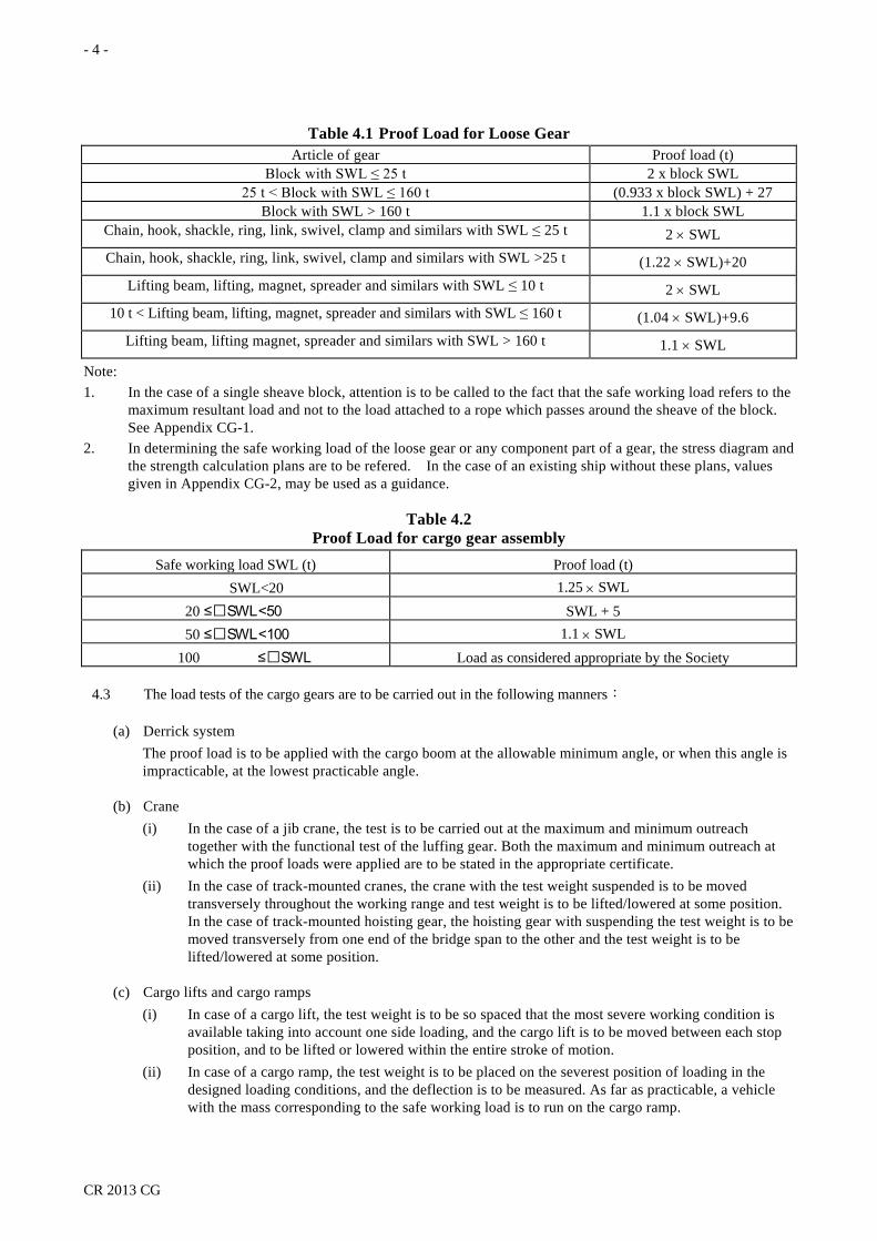
Table 4.1 Proof Load for Loose Gear Article of gear Proof load (t)
Block with SWL ≤ 25 t 2 x block SWL 25 t < Block with SWL ≤ 160 t (0.933 x block SWL) + 27
Block with SWL > 160 t 1.1 x block SWL Chain, hook, shackle, ring, link, swivel, clamp and similars with SWL ≤ 25 t 2 × SWL Chain, hook, shackle, ring, link, swivel, clamp and similars with SWL >25 t (1.22 × SWL)+20
Lifting beam, lifting, magnet, spreader and similars with SWL ≤ 10 t 2 × SWL 10 t < Lifting beam, lifting, magnet, spreader and similars with SWL ≤ 160 t (1.04 × SWL)+9.6
Lifting beam, lifting magnet, spreader and similars with SWL > 160 t 1.1 × SWL
Note: 1. In the case of a single sheave block, attention is to be called to the fact that the safe working load refers to the
maximum resultant load and not to the load attached to a rope which passes around the sheave of the block. See Appendix CG-1.
2. In determining the safe working load of the loose gear or any component part of a gear, the stress diagram and the strength calculation plans are to be refered. In the case of an existing ship without these plans, values given in Appendix CG-2, may be used as a guidance.
Table 4.2 Proof Load for cargo gear assembly
Safe working load SWL (t) Proof load (t) SWL<20 1.25 × SWL
20 ≤SWL<50 SWL + 5 50 ≤SWL<100 1.1 × SWL
100 ≤SWL Load as considered appropriate by the Society
4.3 The load tests of the cargo gears are to be carried out in the following manners:
(a) Derrick system The proof load is to be applied with the cargo boom at the allowable minimum angle, or when this angle is impracticable, at the lowest practicable angle.
(b) Crane (i) In the case of a jib crane, the test is to be carried out at the maximum and minimum outreach
together with the functional test of the luffing gear. Both the maximum and minimum outreach at which the proof loads were applied are to be stated in the appropriate certificate.
(ii) In the case of track-mounted cranes, the crane with the test weight suspended is to be moved transversely throughout the working range and test weight is to be lifted/lowered at some position. In the case of track-mounted hoisting gear, the hoisting gear with suspending the test weight is to be moved transversely from one end of the bridge span to the other and the test weight is to be lifted/lowered at some position.
(c) Cargo lifts and cargo ramps (i) In case of a cargo lift, the test weight is to be so spaced that the most severe working condition is
available taking into account one side loading, and the cargo lift is to be moved between each stop position, and to be lifted or lowered within the entire stroke of motion.
(ii) In case of a cargo ramp, the test weight is to be placed on the severest position of loading in the designed loading conditions, and the deflection is to be measured. As far as practicable, a vehicle with the mass corresponding to the safe working load is to run on the cargo ramp.

- 5 -
CR 2013 CG
(d) Winches are to be provided with efficient means to stop and hold the proof load at any position, and the efficiency of winch brake is to be demonstrated at normal lowering speed and when the winch drive is switched off.
(e) The load tests are to be performed either by hoisting movable weights, or by means of a spring or hydraulic balance or a similar appliance, but when the cargo gear is newly installed and tested for the first time, the load test is to be carried out only by hoisting movable weights.
(f) In the case of a load test by hoisting movable weights, after the movable weights have been hoisted, the cargo gear is to be swung as far as possible in both directions and then lifted/lowered at some position of the working range.
(g) In the case of a load test is performed by a spring or hydraulic balance or a similar appliance, suitably and safely anchored. The proof load is to be applied with the cargo gear swung as far as practicable first in one direction and then in the other, and such other intermediate positions may be directed at the discretion of the Surveyor. At any position, the indicator of the balance is to maintain a constant reading under the proof load for a period of at least 5 minutes.
(h) After being tested all the gear is to be examined to see whether any part has been injured or permanently deformed by the test.
4.4 For the registration survey of an existing cargo gear or when important repair and alteration are made, a proof load test as specified in 4.2 is to be carried out.
5. Surveys for Maintaining Registration
5.1 After the cargo gear has been registered to the Society, it is to undergo periodical surveys at following intervals:
(a) Annual thorough surveys are to be carried out at the dates not exceeding 12 months from the date of completion of the registration survey or the previous annual thorough survey.
(b) Load tests are to be carried out at the registration survey and at the dates not exceeding 5 years from the date of completion of the registration survey or the previous load test.
5.2 An occasional survey is to be carried out when the cargo gear fall under any of the following conditions at the time other than periodical surveys.
(a) When serious damage is caused on the structural members and the repair or conversion is made.
(b) When major conversion is made in the cargo handling procedures, rigging arrangements, operation and control methods.
(c) When the assignment and marking of safe working load, etc. is altered.
(d) Other cases when considered necessary by the Society.
5.3 Periodical surveys carried out in advance Periodical surveys may be carried out in advance of the due date of each Survey upon application by the owner.
5.4 Postponement of periodical surveys Periodical surveys may be postponed subject to approval by the Society. The period of such postponement is not to exceed 3 months from the date specified in 5.1.
5.5 Annual thorough surveys
(a) Derrick systems

- 6 -
CR 2013 CG
(i) At annual thorough surveys, the following items in (1) are to be visually examined for derrick systems and ascertained to be in good order. Where considered necessary by the Surveyor, the items in (2) are to be examined. (1) Items to be examined
- Structural members. - Connection between the structural members and hull structure. - Driving systems. - Safety devices and protective devices. - Markings of the safe working load, etc., and the effectiveness of the relevant certificates. - Preservation of the instruction manual on board the ship.
(2) Items to be examined where considered necessary by the Surveyor - Checking of plate thickness of the structural members, non-destructive testing and open-up
examinations of the topping brackets, goose neck brackets and derrick heel lugs. - Open-up examination of the driving systems. - Operation tests of the safety devices and protective devices.
(ii) Open-up examination of the topping bracket, goose neck brackets and derrick heel lugs are to be carried out during Annual Thorough Surveys at intervals not exceeding five years from the date of completion of the registration survey or the previous open-up examination.
(b) Crane At annual thorough surveys, the following items in (i) are to be visually examined for cranes and ascertained to be in good order. Where considered necessary by the Surveyor, the items in (ii) are to be examined. (i) Items to be examined
(1) Structural members. (2) For stationary cranes, the connection between the structural members and hull structure. (3) For track-mounted cranes, rails, buffers and the connection between those members and hull
structure. (4) Installations of driving system. (5) Safety devices and protective devices. (6) Markings of the safe working load, etc., and the effectiveness of the relevant certificates. (7) Preservation of instruction manual on board the ship.
(ii) Items to be examined where considered necessary by the Surveyor. (1) Checking of plate thickness of the structural members, non-destructive testing and open-up
examinations of the bearings. (2) Inside of the posts, their legs and stiffeners of cranes. (3) Open-up examinations of the driving gears. (4) Operation tests of the safety devices and protective devices.
(c) Cargo Ramps At annual thorough surveys, the following items in (i) are to be visually examined for cargo ramps and ascertained to be in good order. Where considered necessary by the Surveyor, the items in (ii) are to be examined. (i) Items to be examined.
(1) Structural members. (2) Connection between the structural members and hull structure. (3) Connection between the stoppers and hull structure. (4) Water-tight or weather-tight arrangements of cargo ramps that are used as water-tight or
weather-tight doors when closed. (5) The driving gears.

- 7 -
CR 2013 CG
(6) Safety devices and protective devices. (7) Markings of the safe working load and the effectiveness of the relevant certificates. (8) Preservation of the instruction manuals on board the ship.
(ii) Items to be examined where considered necessary by the Surveyor (1) Plate thickness measurements, open-up inspection of lifting pins, non- destructive tests, etc. (2) Hose testing or airtight testing for cargo ramps that are used as water-tight or weather-tight
doors when closed. (3) Open-up examinations of the driving gears. (4) Operation tests of safety devices and protective devices.
(d) Cargo Lifts, etc. At annual thorough surveys, the following items in (i) are to be visually examined for cargo lifts and ascertained to be in good order. Where considered necessary by the Surveyor, the items in (ii) are to be examined. (i) Items to be examined.
(1) Structural members. (2) Connection between the holding parts of cargo lifts and hull structure. (3) Connection between the lifting/lowering devices of cargo lifts and hull structure. (4) Driving gears. (5) Safety devices and protective devices. (6) Markings of the safe working load and the effectiveness of the relevant certificates. (7) Preservation of the instruction manuals on board the ship.
(ii) Items to be examined where considered necessary by the Surveyor (1) Plate thickness measurements, open-up-inspection of lifting pins, non-destructive tests, etc. (2) Open-up examinations of the driving gears. (3) Operation tests of the safety devices and protective devices.
(e) At annual thorough surveys for other cargo gears used for loading and unloading of cargoes and other articles, they are to be visually examined and ascertained to be in good order. When considered necessary by the Surveyor, a further examination may be carried out.
(f) Loose Gears (i) At annual thorough surveys, the following items in (1) through (3) of loose gears are to be visually
examined and ascertained to be in good order. However, where considered necessary by the Surveyor, the items in (2) are to be opened up and examined. (1) Wire ropes for their full length. (2) Cargo blocks, chains, rings, hooks, shackles, swivels, lifting beams, cramps, rigging screw
grabs, lifting magnets, spreaders, etc. (3) Markings of the safe working load and identification symbols, and the effectiveness of the
relevant certificates. (ii) In case where some of loose gears need to be repaired or renewed at times other than at the
Periodical Surveys, the Society may accept an autonomous inspection carried out by ship’s master or his representative. In this case, the personnel who carried out an autonomous inspection is to record the following (1) through (6) for the loose gears repaired or renewed in the Inspection Record Book of Loose Gear, and show this Inspection Record Book and the certificates of the loose gears concerned to the Surveyor for his approval at the next Periodical Survey or Occasional Survey. (1) Names and identification symbols. (2) Locations in service. (3) Safe working loads. (4) Testing loads.
- 8 -
CR 2013 CG
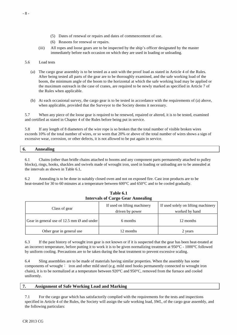
(5) Dates of renewal or repairs and dates of commencement of use. (6) Reasons for renewal or repairs.
(iii) All ropes and loose gears are to be inspected by the ship’s officer designated by the master immediately before each occasion on which they are used in loading or unloading.
5.6 Load tests
(a) The cargo gear assembly is to be tested as a unit with the proof load as stated in Article 4 of the Rules. After being tested all parts of the gear are to be thoroughly examined, and the safe working load of the boom, the minimum angle of the boom to the horizontal at which the safe working load may be applied or the maximum outreach in the case of cranes, are required to be newly marked as specified in Article 7 of the Rules when applicable.
(b) At each occasional survey, the cargo gear is to be tested in accordance with the requirements of (a) above, when applicable, provided that the Surveyor to the Society deems it necessary.
5.7 When any piece of the loose gear is required to be renewed, repaired or altered, it is to be tested, examined and certified as stated in Chapter 4 of the Rules before being put in service.
5.8 If any length of 8 diameters of the wire rope is so broken that the total number of visible broken wires exceeds 10% of the total number of wires, or so worn that 20% or above of the total number of wires shows a sign of excessive wear, corrosion, or other defects, it is not allowed to be put again in service.
6. Annealing
6.1 Chains (other than bridle chains attached to booms and any component parts permanently attached to pulley blocks), rings, hooks, shackles and swivels made of wrought iron, used in loading or unloading are to be annealed at the intervals as shown in Table 6.1.
6.2 Annealing is to be done in suitably closed oven and not on exposed fire. Cast iron products are to be heat-treated for 30 to 60 minutes at a temperature between 600°C and 650°C and to be cooled gradually.
Table 6.1 Intervals of Cargo Gear Annealing
Class of gear If used on lifting machinery
driven by power If used solely on lifting machinery
worked by hand
Gear in general use of 12.5 mm Ø and under 6 months 12 months
Other gear in general use 12 months 2 years
6.3 If the past history of wrought iron gear is not known or if it is suspected that the gear has been heat-treated at an incorrect temperature, before putting it to work it is to be given normalizing treatment at 950°C - 1000°C followed by uniform cooling. Precautions are to be taken during the heat treatment to prevent excessive scaling.
6.4 Sling assemblies are to be made of materials having similar properties. When the assembly has some components of wrought: iron and other mild steel (e.g. mild steel hooks permanently connected to wrought iron chain), it is to be normalized at a temperature between 920°C and 950°C, removed from the furnace and cooled uniformly.
7. Assignment of Safe Working Load and Marking
7.1 For the cargo gear which has satisfactorily complied with the requirements for the tests and inspections specified in Article 4 of the Rules, the Society will assign the safe working load, SWL, of the cargo gear assembly, and the following particulars:

- 9 -
CR 2013 CG
(a) in the case of derrick systems, the allowable minimum angle of the boom to the horizon and other restrictive conditions.
(b) in the case of jib cranes, the maximum outreach or ranges of slewing radius and other restrictive conditions.
(c) in the case of union purchase derrick systems, the safe working load determined with due regard to individual booms and their associated gear for swing loads, and the maximum angle between two cargo falls (not exceeding 120°), or the allowable lifting height.
7.2 The Society will assign, upon request, an angle smaller than the minimum allowable angle which has been approved in relation to a smaller safe working load. The allowable angle with relative safe working load so assigned will be stated in the Register.
7.3 Marking for Lifting Appliances
(a) On the heel of each boom and each crane, the mark of the Society, the safe working load, allowable minimum angle, maximum slewing radius and other restrictive conditions as specified in 7.1 are to be marked by stamping.
(b) In the case of other cargo gears and cargo ramps, at the conspicuous place which is hardly fouled, the stamp mark of the Society, the safe working load and other restrictive conditions are to be marked by stamping.
(c) In addition to the markings specified in (a) & (b) above, the same marks (except the mark of the Society) are to be painted at the conspicuous places in white or other suitable color. The size of letters is not to be less than 77 mm in height.
7.4 Marking for Loose Gears
(a) On the loose gears other than wire ropes and fiber ropes, test load, safe working load and identification symbols are to be marked by stamping at conspicuous places. The marking is not to cause adverse effect in strength and service.
(b) In addition to the markings specified in (a) above, the self-weight of grabs, lifting beams, lifting magnets, spreaders and other similar loose gears are to be stamped additionally.
(c) In addition to the markings specified in (a) & (b) above, grabs, lifting beams, lifting magnets, spreaders and other similar loose gears are to be marked with the safe working load and the self-weight of them with paint. The size of letters is not to be less than 77 mm in height.
7.5 Where it is difficult to make direct stamp mark or to mark with paint, other means may be taken when approved by the Society.
7.6 Where alterations of the assigned safe working load, etc. or of particulars of the cargo gear machinery take place, the cargo gear and machinery are to undergo survey and tests as specified in Article 4 of the Rules. Where necessary, the relevant entries in the Register and the markings are to be altered and verified by the Surveyor.
8. Derrick Systems
8.1 Design loads
(a) Load considerations The loads to be taken into the calculations of dimensions of the structural members are to be as specified in (i) to (vi) below: (i) Safe working load of the derrick systems. (ii) Self-weight of derrick boom and cargo fittings attached thereto.
- 10 -
CR 2013 CG
(iii) Self-weight of loose gear. (iv) Friction of cargo blocks. (v) Loads due to ship inclination. (vi) Other loads considered to be necessary by the Society.
(b) Friction of cargo blocks In calculating the load at the rope end, the following friction load coefficients are to be taken into account depending on the types of bearing:
Bush bearing : 0.05 Roller bearing : 0.02
(c) Load due to ship inclination The angles of inclination used for the calculation of the loads due to ship inclination are to be the angles expected to occur in service condition, but they are not to be taken as less than 5° in angle of heel and 2° in angle of trim. If data on the angles of inclination of the ship concerned are submitted and recognized as appropriate by the Society, however, these angles may be used in the calculations.
(d) Load combinations (i) The load to be used in the strength analysis of the structural members is to be such a combined load
that these members may be put in the most severe load condition considering the loads specified in 8.1(a).
(ii) The union-purchase derrick system is to be analyzed as a swinging derrick system and a union-purchase derrick system respectively using the combined load according to the requirement in (i) above.
8.2 Strength and construction of derrick posts, masts and stays
(a) Strength analysis (i) The strength of derrick posts, masts (hereinafter referred to as ”posts”) and stays are to be analyzed
for the combined load specified in 8.1(d) to determine the dimensions of their members in accordance with the requirement in (b) and (c) below.
(ii) The Young’s modulus of the wire ropes to be used in the analysis of strength of stayed posts is to be 30.4 kN/mm2and 45.1 kN/mm2 for the case of determining the dimensions of posts and stays respectively.
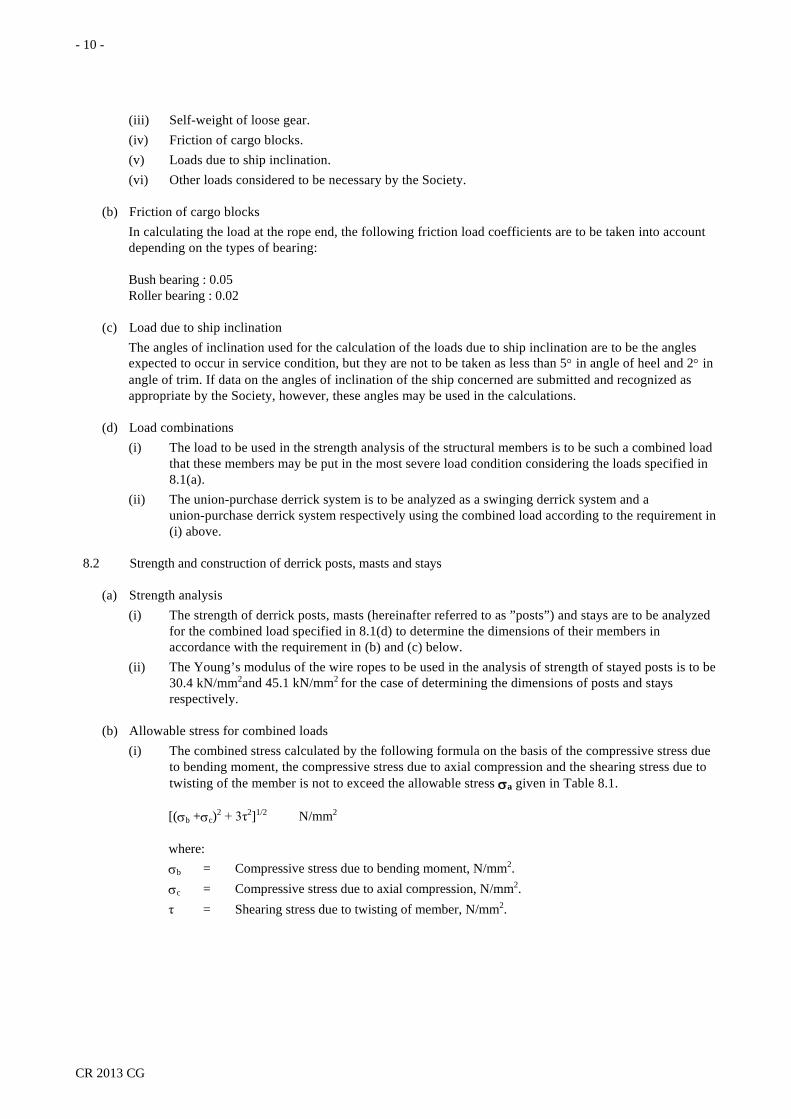
(b) Allowable stress for combined loads (i) The combined stress calculated by the following formula on the basis of the compressive stress due
to bending moment, the compressive stress due to axial compression and the shearing stress due to twisting of the member is not to exceed the allowable stress σa given in Table 8.1.
[(σb +σc)2 + 3τ2]1/2 N/mm2
where: σb = Compressive stress due to bending moment, N/mm2. σc = Compressive stress due to axial compression, N/mm2. τ = Shearing stress due to twisting of member, N/mm2.
- 11 -
CR 2013 CG
Table 8.1 Allowable Stress σa
Safe working load W (t)
Allowable stress N/mm2
W<10 10≤W<15 15≤W<50 50≤W<60 60≤W
0.50σy (0.016W+0.34) σy
0.58σy (0.005W+0.33) σy
0.63σy Note: σy = The yield point or proof stress of material, N/mm2.
(ii) The tension of the wire ropes used for stay is not to exceed the value obtained by dividing the value of breaking strength specified in Chapter 13 Part XI of the Rules for Steel Ships by the safety factor specified in 11.3.
(c) Minimum plate thickness of posts The plate thickness of posts is not to be less than 6 mm.
(d) Construction of posts (i) The lower part of the post is to be effectively connected to hull structures by any of the following
methods (1), (2) or (3), or any other method approved as appropriate by the Society: (1) To be supported by two or more superposed decks. (2) To be supported by deckhouse of an enough strength. (3) To be supported by bulkhead for an ample depth beneath the deck.
(ii) The post well below the base to well above the goose neck bracket is to be of the dimensions equivalent to that at the base as far as practicable.
(iii) The post is to be locally reinforced by the use of thicker plating, doubling plates, additional reinforcing members, etc. in the connection of post body and portal beam, the parts where the goose neck brackets and topping brackets are fitted, etc. and the parts where stress concentration expected.
(iv) At the ends of the upper portal, its depth and plate thickness are to be properly increased. When opening hole at the end of the upper portal is unavoidable, properly reinforcement is to be provided around the opening hole.
8.3 Strength and Construction of Derrick Booms
(a) The strength of derrick booms is to be analyzed for the load conditions specified in 8.1(d) and their dimensions are to be determined according to the requirements in (b) to (e) below.
(b) Strength for combined load The combined stress calculated by the following formula on the basis of the compressive stress due to bending moment, the compressive stress due to axial compression and the shearing stress due to twisting of the member is not to exceed the allowable stress σa given in Table 8.2.
[(σb+σc)2+3τ2]1/2 N/mm2
where: σb = Compressive stress due to bending moment, N/mm2. σc = Compressive stress due to axial compression, N/mm2. τ = Shearing stress due to twisting of member, N/mm2.
(c) Buckling strength For member subjected to compression, the value obtained from the following formula is not to exceed the allowable stress σa given in Table 8.2.

- 12 -
CR 2013 CG
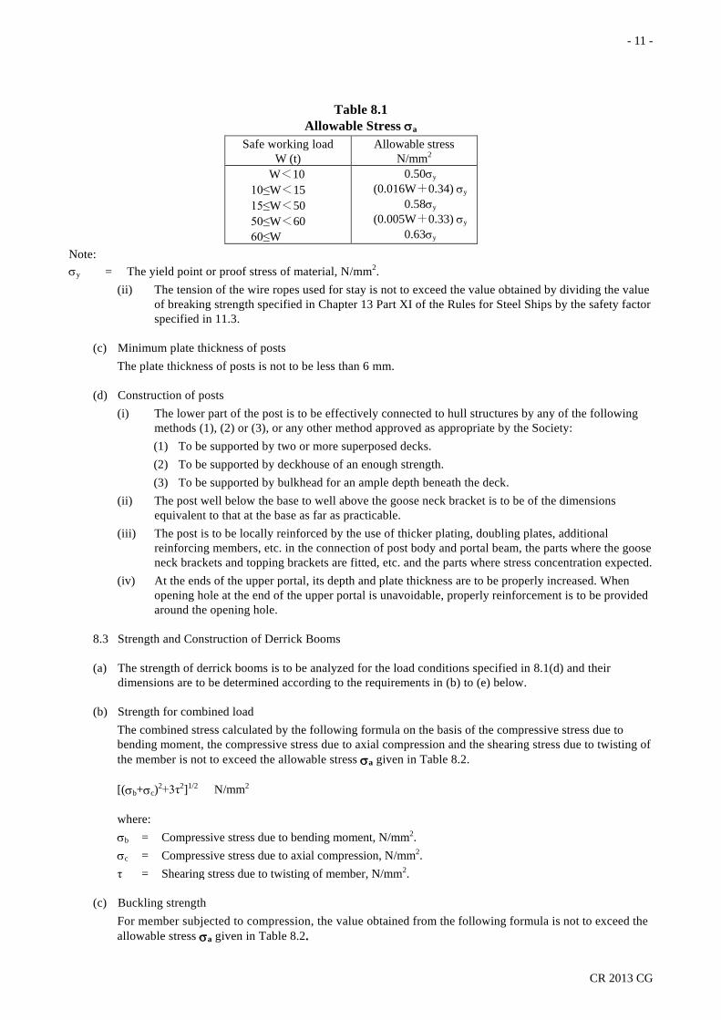
1.15 ωσc N/mm2
where: σc = Axial compressive stress, N/mm2. ω = Coefficient calculated by the formula in Table 8.3 and Table 8.4 for the slenderness ratio and type of the member concerned.
(d) Combined compressive stress The compressive stress due to combination of the compressive stress due to axial compression and that due to bending moment is to meet the following formula:
[(σc/σca)+(σb/σa) ]≤ 1.0
where: σa = Allowable bending stress given in Table 8.2, N/mm2. σca = Allowable compressive stress to be taken as a quotient of σa divided 1.15, N/mm2. σb = Compressive stress due to bending moment, N/mm2. σc = Compressive stress due to axial compression, N/mm2.
Table 8.2 Allowable Stress σa
Safe working load W (t) Allowable stress, N/mm2 W<10
10≤W<15 15≤W
0.34σy (0.018W+0.16)σy 0.43σy
Note: σy= The yield point or proof stress of material,
N/mm2.
Table 8.3 Formulae for ω
Relation of λ and λ0 Type of member Formulae for ω λ≥λ0 All members 2.9(λ/λ0) 2
λ<λ0 Plate members )( 0
20
/0.5-1
)/(45.01
λλ
λλ+
Cylindrical members )(
)(
02
02
0
/0.5-1/0.12)(460870
λλλλ+λλ+ /..
Notes: 1. λ is the slenderness ratio of the member subjected to compression to be obtained from the following formula: le(A/I)1/2 where: A = Sectional area of the member, m2. I = Moment of inertia of section of member, m4. le = Effective length of the member to be determined as the product of the actual length of the member
and coefficient K obtained from the following Table 8.4 for respective end conditions, m. 2. λ0 is the value obtained from the following formula: (2π2E/σy)1/2 where: π = The circular constant. E = Young’s modulus, N/mm2.
- 13 -
CR 2013 CG
σy = Specified yield stress of material, N/mm2.
Table 8.4 Values of K
Another end One end
R: con. D: con.
R: con. D: free
R: free D: con.
R: free D: free
R: con., D: con. 0.5 1.0 0.7 2.0 R: con., D: free 1.0 - 2.0 - R: free, D: con. 0.7 2.0 1.0 - R: free, D: free 2.0 - - -
Note: R = Rotation. D = Displacement. con.= constrained.
(e) Minimum plate thickness of derrick booms The plate thickness used for the body of derrick booms is not to be less than 2% of the outside diameter at middle of the effective length of the boom or 6 mm, whichever is the greater.
(f) Reinforcement of derrick booms (i) The plating at the head of the derricks booms to which fittings are attached is to be provided with
doubling plates or reinforced by other suitable means. (ii) Where cargo fittings for whipped rigging are attached to the boom, proper reinforcement is to be
made by doubling plates or other suitable means.
(g) Derrick boom stopper for dropping out Derrick booms are to be supported by a goose neck bracket and to be safeguarded against dropping out of their sockets or supports.
8.4 Simplified calculation method for post and stays of swinging derrick systems
(a) Diameter of post at the base The outside diameter of post at the base is not to be less than the value obtained from the following formula. For elliptic or oval section, its minor diameter is to be regarded as the outside diameter, while the short side is to be regarded as the outside diameter for rectangular cross section.
5h m
where: h = Vertical distance from the base of post to the topping bracket, m.
(b) Section modulus of post at the base (i) The section modulus of unstayed posts at the base is not to be less than the value obtained according
to (1) through (3) below depending upon the arrangement of derrick booms. (1) When a derrick boom is fitted on either of fore or aft side of the post, the section modulus is to
be the value obtained from the following formula:
C1C2 ρW cm3
where: W = Safe working load, t.
ρ = Slewing radius at the allowable minimum angle, m.
C1 and C2 = Coefficients obtained from Table 8.5. For intermediate values of W, the coefficients C1 and C2 are to be obtained by interpolation.

- 14 -
CR 2013 CG
Table 8.5 Values of C1 and C2
W(t) ≤2 3 4 5 6 7 8 9 10 C1 1.35 1.25 1.20 1.17 1.15 1.14 1.13 1.12 1.10 C2 125 120 117 115 114 113 112 111 110
(2) The section modulus about the axis parallel to the longitudinal direction of the ship is to be the value obtained from (1) above or the value obtained from the following formula, whichever is the greater, when two derrick booms are fitted on both the forward and aft the post.
∑ WuC2 cm3
where: ∑ WC2 = Sum of C2 W for derrick booms situated forward and aft the post respectively
Where C2 and W are those obtained from (1) above. u = Distance from the center of the post to the side of the ship, plus the outreach, m.
(3) Where derrick booms are supported by an independent structure other than the post, the section modulus is not to be less than obtained from the formula in (1) and (2) above, multiplied by the value obtained from the following formula. In this case, the coefficient C1 in the formula specified in (1) above is to be taken as 1.0.
h/(h-h')
where: h' = Vertical distance from the base of the post to the center of horizontal pin of the goose
neck bracket. h = As specified in 8.4(a).
(ii) The section modulus of stayed posts at the base may be the value specified in reduced by the value obtained from the following formula:
10(h3/dm)∑R cm3
where: h = As specified in 8.4(a). dm = Outside diameter of the post at the base in the direction in which R assumes minimum in the
slewing range for the formula in 8.4(b)(i)(1) or in the axis parallel to the athwartship direction of the ship for the formula in 8.4(b)(i)(2), cm.
∑R = Sum of the values obtained from the following formula for each effective stay:
(ds2a2)/(l0ls2)
ds = Diameter of the wire rope for stays, mm. ls = Length of stays between the upper and lower ends, m. lo = Length equal to ls reduced by the value obtained from the following formula: 0.045 ds+0.26 m a = Length of horizontal projection of the stays measured in the same direction as the
measurement of dm. (iii) Where the derrick booms are supported by a king post with a portal having uniform cross section,
the section modulus of the post at the base is not to be less than the values obtained from (1), (2)and (3) below: (1) The section modules about the axis parallel to the athwartship direction of the ship is to be the
value obtained by the formula in 8.4(b)(i)(1) multiplied by the following coefficient Cp :
- 15 -
CR 2013 CG
0.7 for γ≧0.6 1-0.5γ for γ< 0.6
where: γ = Ratio of the breadth of the cross section of the portal to the diameter of the post at the
base in the longitudinal of the ship. (2) The section modulus about the axis parallel to the longitudinal direction of the ship is to be the
values obtained from 8.4(b)(i)(1) or 8.4(b)(i)(2), whichever is the greater, multiplied by the following coefficient:
0.35 for γ'≧0.3 0.5-1.67γ'2 for γ'< 0.3
where: γ' = Ratio of the depth of the cross section of the portal to the diameter of the post at the base in the athwartship direction
(3) Where the distance between posts on the port and starboard sides exceed 2/3 of the height of the post, the coefficients specified in (1) and (2) above are to be suitably increased.
(iv) The section modules of the stayed king post at the base is not to be less than the values obtained from (1) and (2) below: (1) The section modulus about the axis parallel to the athwartship direction of the ship is to be the
value obtained from the following formula:
Cp[C1C2ρW-10(h3/dm)∑R ] cm3
where: Cp = As specified in 8.4(b)(iii)(1). C1、C2 and ρ = As specified in 8.4(b)(i) (1). 10(h3/dm)∑R = Values obtained according to 8.4(b)(ii) provided that stays on one
side only are to be taken into account. (2) The section modulus about the axis parallel to the longitudinal direction of the ship is to be the
value given in 8.4(b)(iii)(2) above. (v) The section modulus of the short side post at the base supporting the derrick boom is not to be less
than the value obtained according to (1) or (2) below: (1) When a derrick boom is fitted on either of the forward or aft side post, the section modulus is
to be the value obtained from the following formula:
85 h' ρ W/(h-h') cm3
where: W and ρ = As specified in 8.4(b)(i)(1). h' = As specified in 8.4(b)(i)(3). h = As specified in 8.4(a).
(2) Where derrick booms are fitted on the forward and aft the side post, the section modulus of the side post about the parallel to the longitudinal direction of the ship is to be the greater of the value obtained from (1) above or the value obtained from the formula in (1) above using, in place of ρW, the product of the sum of W values for the forward and aft booms and the value u given in 8.4(b)(i)(2), provided that u is to be measured from the center of the side post.
(c) Dimensions of post other than at the base (i) The post from well below the base to well above the goose neck bracket is to be of the dimensions
equivalent to that at the base as far as practicable.

- 16 -
CR 2013 CG
(ii) The diameter and thickness of the post above the position specified in (i) above may be gradually reduced according to the following (1) and (2). (1) The outside diameter where the outrigger or the topping bracket are fitted may be 85% of the
diameter at the base. (2) The plate thickness at any arbitrary position of the post is not to be less than obtained from the
following formula.
0.1dm+2.5 mm
where: dm = Minimum outside diameter of the post at each position, cm.
(d) Outriggers Outriggers are to be properly constructed and of sufficient strength.
(e) Portals (i) The section modulus of the portal of uniform section fitted to the king post is not to be less than the
values obtained from (1) to (3) below: (1) The section modulus about the vertical axis is to the value obtained from the formula given in
8.4(b)(i)(1) multiplied by the coefficient obtained from the following formula. Where this coefficient exceeds 0.2, it may be taken as 0.2.
0.1+0.235(γ/c)
where: γ = As specified in 8.4(b)(iii)(1). c = Ratio of the actual section modulus ,cm3, of the post at the base about the axis parallel to
the athwartship direction of the ship to that obtained from the formula in 8.4(b)(i)(1). (2) Notwithstanding the requirements in (1) above, the section modulus of the portal about the
vertical axis may be reduced to a half of the value in (1) above where derrick boom is fitted only on one side of the forward of post.
(3) The section modulus about the horizontal axis is to be the value obtained from the formula in 8.4(b)(i)(2) multiplied by the coefficient obtained from the following formula. Where this coefficient exceeds 0.2, it may be taken as 0.2.
0.25(γ'/c')
where: γ' = specified in 8.4(b)(iii)(2). c' = Ration of the actual section modulus ,cm3,of the post at the base about the axis parallel to the longitudinal direction of the ship to that obtained from the formula in 8.4(b)(i)(2).
(ii) The portal is to be properly stiffened so as to prevent the deformation due to bending.
(f) Stays The tension in wire ropes used for stays is not to be less than the value obtained from the following formula:
18δ(ds2a)/(l0ls) kN
where: a,ds,l0 and ls = As specified in 8.4(b)(ii). In this case, a is to be measured in the same direction as in
the calculation of the value of δ. δ = Value obtained from the following formula:
- 17 -
CR 2013 CG
Cs ρ W h /{[(I/h2)+7.32hΣR](h-h')} I = Moment of inertia of section, cm4, of the post at the base about the axis parallel to
the athwartship direction of the ship. For the king posts, however, the value of I divided by the coefficient CP given in 8.4(b)(iii)(1) is to be used in place of I.
h = As specified in 8.4(a). h', W and ρ = As specified in 8.4(b)(i)(1) and (3).
ΣR = As specified in 8.4(b)(ii). In this case, a is to be measured in all directions in the slewing range of the derrick boom in calculating ΣR.
Cs = given in Table 8.6. For intermediate values of W, the coefficient is to be obtained by interpolation.
Table 8.6 Value of Cs
W(t) ≤2 3 4 5 6 7 8 9 10 ≥15
Cs 2.64 2.52 2.46 2.41 2.38 2.35 2.33 2.31 2.29 2.22 8.5 Simplified Calculation Methods for Derrick Booms
(a) Derrick booms without whipped rigging (i) The dimensions of derrick booms of derrick system without whipped rigging are not to be less than
obtained according to (1), (2)and (3) below: (1) The moment of inertia of derrick boom at the middle post is not to be less than obtained from
the following formula:
CBPl2 cm4
where: CB = Value obtained from Table 8.7. l = Effective length of derrick boom, m, see Fig.8.1. P = Axial compression of derrick boom to be determined according to (A) or (B) below
depending on the type of the derrick systems. When the self-weight of derrick boom and its fitting are accurately estimated, the value obtained from the force diagram may be used as P.
(A) Swinging derrick systems
P={[α1l/(h-h')]+f}Wg kN
where: W and h' = As specified in 8.4(b)(i)(1) and (3). h = As specified in 8.4(a). α1 = Value obtained from Table 8.8. For intermediate values of W, α1 is to be
obtained by interpolation. f = Coefficient obtained from Table 8.9 depending on the number of cargo
block for cargo fall. Where the cargo fall is carried to the top of the post through the sheave fixed to the top of the boom, f may be taken as zero.
(B) Derrick systems other than swinging derrick systems
P = Wg{[α1l/(h-h')+f+ Kn1α1α2 l/[n2(b2+l2)1/2]} kN
where: α1, h, h', f and W = As specified in (A) above.

- 18 -
CR 2013 CG
α2 = As specified 10.1(b). b = Horizontal distance from the goose neck bracket to guy post, m. n1 = Number of guy ropes. n2 = Number of topping ropes. K = Values given in Table 8.10 depending on the type of rigging.
Table 8.7 Value of CB
Safe working load W (t) CB W≤10 10<W<15 15≤W≤50 50<W
0.28 0.4-0.012W
0.22 As value considered appropriate by the Society
Fig. 8.1
Derrick Boom with Whipped Rigging
Table 8.8 Value of α1
W(t) ≤2 3 4 5 6 7 8 9 10 >10
α1 1.28 1.23 1.20 1.18 1.16 1.15 1.14 1.13 1.13 Note Note: As value considered appropriate by the Society
Table 8.9 Value of f
n 1 2 3 4 5 6 7 8 f 1.102 0.570 0.392 0.304 0.251 0.216 0.192 0.172 Note: n= The sum of sheaves of cargo block for cargo fall.
Table 8.10 Values of K
Rigging system K Type A 0 Type B 1.2 Type C 2.0
Notes: 1. Type A is rigging system having two guy tackles on port and starboard sides of the top of the post so that
these guy tackles may also serve as topping lifts. 2. Type B is a rigging system having a delta plate connecting the end of topping lift and ends of port and
starboard side guy ropes so that the tension of topping lift may absorb the slackening of guy ropes. 3. Type C is a rigging systems having a connecting block connecting the end of guy rope(s) of both sides (or of
one side) and the topping lift led along the derrick post so that the slackening of guy rope(s) may be absorbed by the topping lift.
(2) In derrick booms with tapered end parts, the parallel part in the mid-length is, as a standard, to be of a length equal to 1/3 of the effective length, and the diameter at the ends is not to be less than 60% of the diameter of the parallel mid-length part.
l
x l1

- 19 -
CR 2013 CG
(3) The thickness of steel plate used for the body of derrick booms is not to be less than the value obtained from the following formula or 2% of the outside diameter at the middle part whichever is the greater. 6 (mm) for P < 75.5 (kN) 5+0.0133 P (mm) for P ≥ 75.5 (kN)
(ii) The shape and dimensions of the derrick boom of swinging derrick system may be in accordance with national standard or other standards recognized by the Society.
(b) Derrick booms with whipped rigging The dimensions of derrick booms of derrick system with whipped rigging are not to be less than obtained according to (i) and (ii) below. (i) The moment of inertia of section at an arbitrary position at a distance of x (m), from the center of
eye fitting at derrick heel is not to be less than obtained from the following formula. Where a doubling plate is fitted for a sufficient length, 70% of the doubling plate may be added to D(x) and A(x) in the formula.
I(x)=CBPl2{1-3.136[(x/l)-0.5]2}+1000D(x)l1xWg cosθ/[2ln(σ0-10P/A(x)]
where: I(x) = Required moment of inertia of section at a distance of x, m, from the derrick heel, cm4. CB = As specified in 8.5(a). P = Axial compression of boom specified in 8.5(a)(i)(1), kN. l = Effective length of boom, m. n = Sum of sheaves of cargo block for cargo fall (except cargo block for cargo relief). W = Safe working load as specified in 8.4(b)(i)(1), t. θ = Allowable minimum angle of boom, degree. l1 = Distance between the eye fittings for whipped rigging, m. See Fig. 8.1. D(x) = Outside diameter of derrick boom at a distance of x (m) from the boom heel minus plate
thickness , cm. A(x) = Sectional area of derrick boom at a distance of x (m) from the boom heel, cm2. σ0 = Value given in Table 8.11, N/mm2.
(ii) The length of parallel part at the middle, the diameter at ends and the plate thickness of the boom body are to be as specified in 8.5(a)(i)(2) and (3).
Table 8.11 Values of σ0
Safe working load W (t) σ0 W≤10 10<W<15 15≤W≤50 50<W
80.4 4.04W+40.0
100.6 As value considered appropriate by the Society
9. Cranes
9.1 Design loads
(a) Load considerations The loads to be taken into the calculation of dimensions of structural members are to be those related to the crane concerned among the items enumerated from (i) to (xi) below: (i) Safe working load of the cranes. (ii) Additional impact loads.
- 20 -
CR 2013 CG
(iii) Self-weight of crane system and cargo fittings attached thereto. (iv) Self-weight of loose gear. (v) Friction of cargo blocks. (vi) Horizontal forces. (vii) Wind loading. (viii) Buffer forces. (ix) Loads due to ship inclination. (x) Loads due to ship motion. (xi) Other loads considered necessary by the Society.
(b) Additional impact loads (i) The additional impact load is to be the product of the hoisting load and the impact load coefficient
given in Table 9.1 depending on the type of cranes. When the stress due to hoisting of cargo and the stress due to the self weight have different signs in a member, 50% of additional impact load is to be taken into account in addition to the self-weight, considering the shock due to unloading.
(ii) Notwithstanding the requirements specified in (i) above, additional impact load coefficient based on actual measurements taking into account the hoisting speed, deflections of girders, length of ropes, etc. may be used in place of the values given in Table 9.1.
Table 9.1 Additional Impact Load Coefficient
Types of cranes Additional impact load coefficient
Provision handling crane, Machinery handling crane, Maintenance crane and Hose handling crane
0.10
Jib crane and gantry crane for cargo handling 0.25 Jib crane and gantry crane occasionally used with hydraulically operated of rope-operated bucket, etc. for cargo handling
0.40
Jib crane and gantry crane always using grab, lifting magnet, etc. for cargo handling and Offshore jib crane
0.60
(c) Friction of cargo blocks The friction of cargo blocks is to be as specified in 8.1(b).
(d) Horizontal forces (i) In track-mounted cranes, the transverse forces due to travel motion is to be taken into consideration
as a factor of horizontal force in addition to the inertial force and centrifugal force. (ii) The inertial force is to be obtained by multiplying the sum of the mass of the moving parts and the
hoisting load (in slewing motion, the load is assumed to be at the top of jib) by the following coefficient depending on the condition of motion. In the case of traveling by driven wheels, however, this inertial force need not exceed 15% of the driving wheel load.
Level luffing motions : 0.01V1/2
Traversing or traveling motions: 0.008V1/2
Slewing motions : 0.006 V1/2
Where V = Velocity of motion concerned to be determined by the designer, m/min
(iii) Notwithstanding the requirements in (ii) above the values of the actual acceleration deceleration characteristics, the actual braking time, etc. for the mode of motion concerned may be used as the inertial forces, if such values are known.
- 21 -
CR 2013 CG
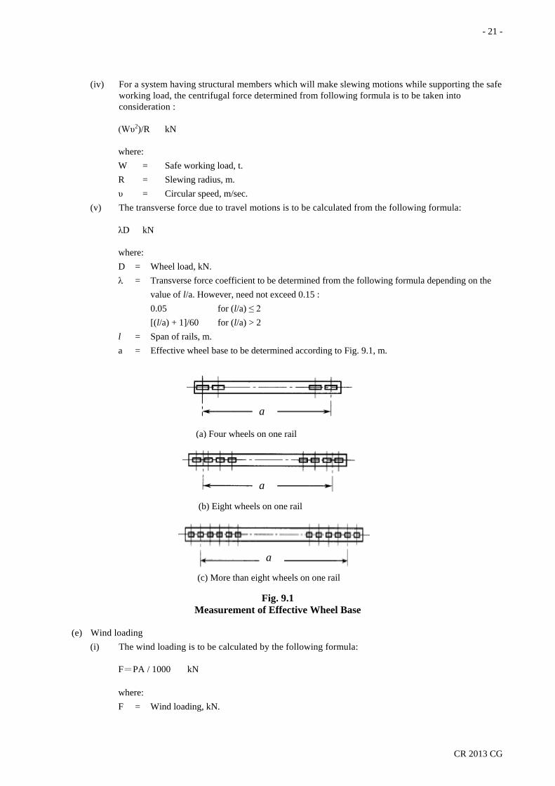
(iv) For a system having structural members which will make slewing motions while supporting the safe working load, the centrifugal force determined from following formula is to be taken into consideration :
(Wυ2)/R kN
where: W = Safe working load, t. R = Slewing radius, m. υ = Circular speed, m/sec.
(v) The transverse force due to travel motions is to be calculated from the following formula:
λD kN
where: D = Wheel load, kN. λ = Transverse force coefficient to be determined from the following formula depending on the
value of l/a. However, need not exceed 0.15 : 0.05 for (l/a) ≤ 2 [(l/a) + 1]/60 for (l/a) > 2 l = Span of rails, m. a = Effective wheel base to be determined according to Fig. 9.1, m.
Fig. 9.1
Measurement of Effective Wheel Base
(e) Wind loading (i) The wind loading is to be calculated by the following formula:
F=PA / 1000 kN
where: F = Wind loading, kN.
a
(a) Four wheels on one rail
(b) Eight wheels on one rail
(c) More than eight wheels on one rail
a
a

- 22 -
CR 2013 CG
A = Sum of structural members and cargo under wind pressure in projection in respective wind direction, corresponding to respective conditions of the cargo gear, m2. When a girder is wholly or party protected from wind by another girder, the areas of the superposed portions may be multiplied by the reduction factor, η, obtained from Fig. 9.2. The distance b between girders is to be as given in Fig. 9.3.
Fig. 9.2
Repleteness Ratio, Φ versus Reduction Factor, η
Fig. 9.3
Distance between two neighbour- ing girders, b
P = Wind pressure calculated by the following formula, Pa.
ChCsgV2/16 Pa
where: V = Wind velocity according to (1) and (2) below, m/sec: (1) The velocity of wind giving effect on the structural members and cargo in the service
conditions is to be the design wind velocity specified by the applicant, but not be less than 16 m/sec.
(2) The velocity of wind giving effect on the structural members in the stowage conditions is to be the design wind velocity specified by the applicant. In no case is the design wind velocity to be less than 51.5 m/sec. In ships with restricted navigation areas, however, the design wind velocity may be decreased according to the degree of restriction as approved by the Society in the range down to 25.8 m/sec. Ch = “Height factor” to be determined according to Table 9.2 depending on the height of
the position is question from the light weight waterline. Cs = “Shape factor” to be determined according to Table 9.3 depending on the shapes of
various parts of the cargo gear and the cargo.
η
- 23 -
CR 2013 CG
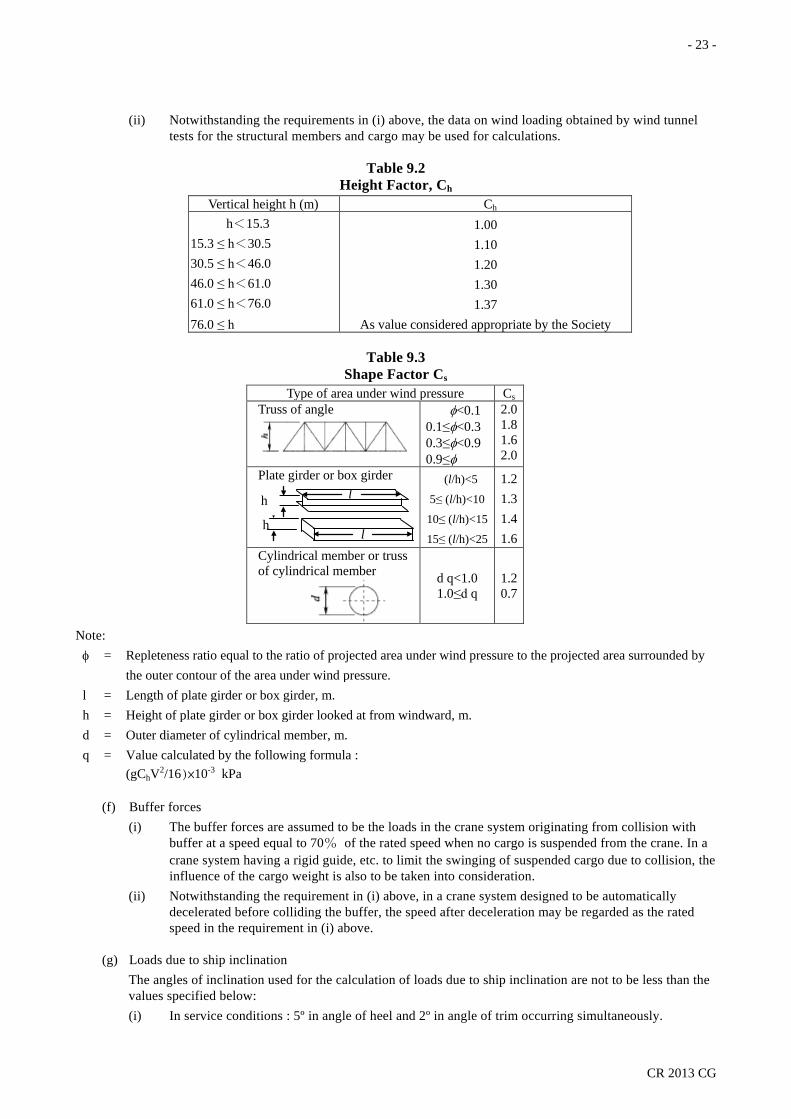
(ii) Notwithstanding the requirements in (i) above, the data on wind loading obtained by wind tunnel tests for the structural members and cargo may be used for calculations.
Table 9.2 Height Factor, Ch
Vertical height h (m) Ch h<15.3
15.3 ≤ h<30.5 30.5 ≤ h<46.0 46.0 ≤ h<61.0 61.0 ≤ h<76.0 76.0 ≤ h
1.00 1.10 1.20 1.30 1.37
As value considered appropriate by the Society
Table 9.3 Shape Factor Cs
Type of area under wind pressure Cs Truss of angle
φ<0.1 0.1≤φ<0.3 0.3≤φ<0.9 0.9≤φ
2.0 1.8 1.6 2.0
Plate girder or box girder
(l/h)<5
5≤ (l/h)<10
10≤ (l/h)<15
15≤ (l/h)<25
1.2 1.3 1.4 1.6
Cylindrical member or truss of cylindrical member
d q<1.0 1.0≤d q
1.2 0.7
Note: φ = Repleteness ratio equal to the ratio of projected area under wind pressure to the projected area surrounded by
the outer contour of the area under wind pressure. l = Length of plate girder or box girder, m. h = Height of plate girder or box girder looked at from windward, m. d = Outer diameter of cylindrical member, m. q = Value calculated by the following formula :
(gChV2/16)×10-3 kPa
(f) Buffer forces (i) The buffer forces are assumed to be the loads in the crane system originating from collision with
buffer at a speed equal to 70% of the rated speed when no cargo is suspended from the crane. In a crane system having a rigid guide, etc. to limit the swinging of suspended cargo due to collision, the influence of the cargo weight is also to be taken into consideration.
(ii) Notwithstanding the requirement in (i) above, in a crane system designed to be automatically decelerated before colliding the buffer, the speed after deceleration may be regarded as the rated speed in the requirement in (i) above.
(g) Loads due to ship inclination The angles of inclination used for the calculation of loads due to ship inclination are not to be less than the values specified below: (i) In service conditions : 5º in angle of heel and 2º in angle of trim occurring simultaneously.
h
h l
l
h h
- 24 -
CR 2013 CG
(ii) In stowage conditions : 30º in angle of heel.
(h) Loads due to ship motion The accelerations used for the calculation of loads due to ship motion are the severest of the combinations (i) or (ii) below for the stowage condition, and values recognized by the Society to be appropriate for the service condition. If data on the ship’s motions are submitted and recognized by the Society to be appropriate, the values in such data may be used in the calculations. (i) ±1.0 g in the direction normal to the deck and ±0.5 g in the longitudinal direction parallel to the
deck. (ii) ±1.0 g in the direction normal to the deck and ±0.5 g in the transverse direction parallel to the deck
(i) Load combinations (i) The load to be used in the strength analysis of structural members is to be such a combined load that
these members may be put in the severest loading condition considering the loads specified in (ii) through (v) below.
(ii) When the wind loading is not taken into account in service condition, the sum of loads from (1) to (9) below multiplied by a work coefficient given in Table 9.4 according to the type of crane concerned is to be considered. (1) Safe working load of the cranes. (2) Additional impact loads. (3) Self-weights of crane system and cargo fittings attached thereto. (4) Self-weights of loose gear. (5) Friction of cargo blocks. (6) Horizontal loads. (7) Loads due to ship inclination. (8) Loads due to ship motion (except those intended to cargo handling in harbours only). (9) Other loads considered necessary by the Society.
Table 9.4 Work Coefficient of Crane Systems
Types of cranes Work coefficient Provision handling crane, Machinery handling crane, Maintenance crane and Hose handling crane 1.00
Jib crane and gantry crane for cargo handling 1.05 Jib crane and gantry crane occasionally used with hydraulically operated of rope-operated bucket, etc. for cargo handling
1.10
Jib crane and gantry crane always using grab, lifting magnet, etc. for cargo handling and Offshore jib crane 1.20
(iii) When the wind loading are to be taken into consideration in the service conditions, the wind loading is to be added to the design load as specified in (ii) above.
(iv) The buffer forces as given in 9.1(f) are to be taken into consideration for the track-mounted cranes. (v) In stowage condition, the loads from (1) to (5) below are to be considered
(1) Self-weights of crane system and cargo fittings attached thereto. (2) Wind Loading in the stowage conditions. (3) Loads due to ship inclination in the stowage conditions. (4) Loads due to ship motion stowage conditions. (5) Other loads considered necessary by the Society.
9.2 Strength and construction
(a) General

- 25 -
CR 2013 CG
(i) The strength of structural members is to be analyzed on the load conditions specified in 9.1(i) to determine their dimensions according to requirements in 9.2(b) through 9.2(i).
(ii) For structures connected by bolts and nuts, proper considerations are to be given to the decrease of effective sectional areas.
(iii) When considered necessary the Society may require the confirmation of the appropriateness of strength analyses by examination of models or the things in question.
(b) Allowable stress for combined loads The allowable stress given in Table 9.5 are to be used for components subjected to combined loads.
(c) Buckling strength For members subjected to compression, the values obtained from the following formula is not to exceed the allowable compressive stress given in Table 9.5:
ωσc N/mm2
where: ω and σc = As specified in 8.3(c).
Table 9.5 Allowable Stress σa
Load Condition Kind of stress (Tens.= tension; Bend.= bending; Comp. = compression; Bear. = bearing.; Comb. = combined stress)
Tens. Bend. Shear Comp Bear. Comb. Condition given in 9.1(i)(ii) 0.67σy 0.67σy 0.39σy 0.58σy 0.94σy 0.77σy Condition given in 9.1(i)(iii) 0.77σy 0.77σy 0.45σy 0.67σy 1.09σy 0.89σy Condition given in 9.1(i)(iv) and (v) 0.87σy 0.87σy 0.50σy 0.76σy 1.23σy 1.00σy
Notes: 1. σy =The yield point or proof stress of material, N/mm2. 2. The combined stress is to be the value obtained from the following formula: (σX
2 +σY2 − σXσY + 3τXY
2)1/2 N/mm2
where: σX = Applied stress in X-direction at the middle of plate thickness, N/mm2. σY = Applied stress in Y-direction at the middle of plate thickness, N/mm2. τXY =Applied shear stress in the X-Y plane, N/mm2.
(d) Combined compressive stress When the compressive stress of a member is determined as a combination of compressive stress due to axial compression and that due to bending moment such a compressive stress is to comply with the following formula:
[(σc/σca) + (σb/σa)] ≤ 1.0
where: σa = Allowable bending stress given in Table 9.5, N/mm2. For fixed posts at the base, however, the
allowable stress in Table 8.1 is to be used.
σb = Compressive stress due to bending moment, N/mm2.
σc = Compressive stress due to axial compression, N/mm2.
σca = Allowable compressive stress given in Table 9.5, N/mm2. For fixed post at the base, however, the allowable stress, N/mm2, is to be taken equal to the allowable stress in Table 8.1 divided by 1.15.
(e) Fatigue strength
- 26 -
CR 2013 CG
Where the influence of repeated stress cannot be neglected, the member is to have an ample strength against fatigue with due consideration for the magnitude and frequency of repeated stress, the form of the member in question, etc.
(f) Minimum thickness The thickness of structural members is not to be less than 6 mm.
(g) Strength of bolts, nuts and pins Bolts, nuts and pins are to have sufficient strength for the magnitudes and directions of the loads they are subjected to.
(h) Fixed posts (i) The fixed posts are to be effectively connected to the hull structure in accordance with the
requirements in 8.2(d)(i). (ii) The upper part of fixed post where the flange is attached is to be sufficiently reinforced by
increasing the plate thickness or by providing of brackets.
(i) Slewing-ring fixing bolts (i) Any material having a tensile strength exceeding 1,180 N/mm2 and yield stress exceeding 1,060
N/mm2 is not to be used for the bolts fixing the slewing-rings except when special considerations have given to the strength characteristics of the bolts.
(ii) Special considerations are to be given to the tightening force of fixing bolts. (iii) The stress generated in fixing bolts is not to exceed the allowable stress given in Table 9.6
according to the load conditions specified in 9.1(i). In this case, the stress in bolts is taken as the value of the axial compression determined by the following formula divided by the minimum sectional area of fixing bolts.
(4M/Dn) − (W/n) N
where: M = Upsetting moment, N-mm. D = Pitch circle diameter of fixing bolts, mm. n = Number of fixing bolts. W = Axial compression on the slewing-ring, N.
Table 9.6 Allowable Stress of Fixing Bolts, σa Load condition σa
Condition specified in 9.1(i)(ii) and (iii) 0.4σy Condition specified in 9.1(i)(v) 0.54σy Note: σy = The yield point or proof stress of the material, N/mm2.
9.3 Special requirements for track-mounted cranes
(a) Stability The track-mounted cranes are to have an sufficient stability under the load conditions specified in 9.1(i).
(b) Prevention of upsetting The track-mounted crane are to be designed with sufficient considerations for the stability to prevent upsetting even if the wheel shafts or wheels are damaged.
(c) Deflection criteria When suspending the safe working load, deflection of the traveling girder of the track-mounted cranes is not to exceed 1/800 of the span between the supporting points.
- 27 -
CR 2013 CG
(d) Travel gear The travel gear is to be securely fixed to the main body of the track-mounted cranes by bolts, welding or pins. The inclinations of hull in service condition and stowage condition are to be taken into consideration.
(e) Buffers The track-mounted cranes are to be provided with buffers in accordance with (i) and (ii) below, except when automatic system for prevention of collision is provided. (i) At both ends of tracks or any other equivalent positions, these buffers may be replaced by stops of a
height not less than 1/2 of the diameter of wheels. (ii) Where more than two track-mounted cranes are provided on one track, between these
track-mounted cranes.
10. Cargo Fittings
10.1 Cargo fittings
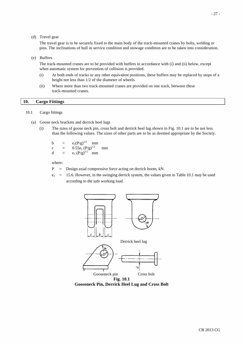
(a) Goose neck brackets and derrick heel lugs (i) The sizes of goose neck pin, cross bolt and derrick heel lug shown in Fig. 10.1 are to be not less
than the following values. The sizes of other parts are to be as deemed appropriate by the Society.
b = e1(P/g)1/2 mm c = 0.55e1 (P/g)1/2 mm d = e1 (P/g)1/2 mm
where: P = Design axial compressive force acting on derrick boom, kN. e1 = 15.6. However, in the swinging derrick system, the values given in Table 10.1 may be used
according to the safe working load.
Derrick heel lug
Gooseneck pin Cross bolt
Fig. 10.1 Gooseneck Pin, Derrick Heel Lug and Cross Bolt

- 28 -
CR 2013 CG
Table 10.1 Values of e1
Safe working load W (t) e1 W ≤ 10
10 < W < 15 15 ≤ W ≤ 50 50 < W
15.6 18.8-0.32W
14.0 As value considered appropriate by the Society
(ii) It is recommended that clearance at parts where the cross bolt penetrates through the derrick heel
lug and the gooseneck pin of gooseneck bracket is to be less than 2 mm in diameter. The size of the outer parts of bolt holes for the gooseneck pin and derrick heel lug is to be of the same size at the cross bolt radius, as a standard.
(iii) Notwithstanding the requirements in (i) above, the sizes of gooseneck bracket and derrick heel lug may be in accordance with national standard or any other recognized standards accepted by the Society. However, for the fittings used for other than the swinging derrick systems, consideration to the effect of increasing load caused by the guy ropes is to be given.
(b) Fittings attached to head of derrick booms (i) The sizes of fittings attached to the head of derrick booms are not to be less than the values given in
the following (1) to (3) according to the respective purpose and shapes of the fittings: (1) Where the shape of cargo fittings attached to the head of derrick boom are as given in Fig.10.2,
the sizes of them are not to be less than the following values. The sizes of other parts are to be as deemed appropriate by the Society.
d = e1(T/g)1/2 mm t = e2(T/g)1/2 mm
where: e1 = As specified in 10.1(a)(i). e2 = Value as given in Table 10.2. T = Maximum tension applied to cargo fitting at the head of derrick boom, kN. However, in
the swinging derrick system, the following value may be used: α1α2Wg for topping lift. λWg for cargo fall. W = Safe working load, t. α1 = As specified in 8.5(a). α2 = As given in Table 10.3 depending on the value of l/(h - h'). However, for intermediate
values of α2, it is to be obtained by interpolation. λ = Value given in Table 10.4 depending on the number of sheaves of blocks for cargo fall.
However, the value of λ may be taken as 1.0 where the cargo fall is led to the top of derrick post through the sheave incorporated in the head of the derrick boom.
- 29 -
CR 2013 CG
Fig. 10.2
Cargo Fitting attached at Head of Derrick Boom
Table 10.2 Values of e2
Safe working load W (t) e2 W ≤ 10
10 < W < 15 15 ≤ W ≤ 50 50 < W
12.5 15.1- 0.26W
11.2 As value considered appropriate by the Society
Table 10.3 Values of α2
l/(h-h') 2.0 1.9 1.8 1.7 1.6 1.5 1.4 1.3 1.2
α2 W<10 1.99 1.90 1.81 1.73 1.65 1.57 1.49 1.42 1.35
15≤W≤ 50 1.82 1.73 1.65 1.57 1.49 1.41 1.33 1.26 1.19 Note: l , h and h' = As specified in 8.5(a).
(2) Where the shape of cargo fitting attached to the head of cargo derrick boom is as shown in Fig. 10.3, the sizes of them are not to be less than the following values. The sizes of other parts are to be as deemed appropriate by the Society.
R ≥ D t = e1 (T/g)1/2 mm
However, where the value of R is larger than 1.15D, the value obtained from the following formula may be taken:
t = [e3/(R-D/2)](T/g) mm
where: e1 = As specified in 10.1(a)(i). T = As specified in (1) above. e3 = As given in Table 10.5.
(3) The sizes of guy fittings attached the head of derrick boom are to be enough against the design load.
d
t

- 30 -
CR 2013 CG
Table 10.4 Values of λ
Sum of the number of sheaves of blocks for cargo fall
1 2 3 4 5 6 7 8
λ 2.10 1.58 1.40 1.31 1.26 1.23 1.20 1.18
Table 10.5 Values of e3
Safe working load W (t) e3 W ≤ 10
10 < W < 15 15 ≤ W ≤ 50 50 < W
122 177 – 4.8 W
98 As value considered appropriate by the Society
Fig. 10.3
Cargo Fitting attached at Head of Derrick Boom
(ii) Notwithstanding the requirements in (i) above, the sizes of cargo fittings attached at the head of derrick boom may be in accordance with national standard or any other recognized standards accepted by the Society. However, for the fittings used for other than the swinging derrick systems, consideration to the effect of increasing load caused by the guy ropes is to be given.
(c) Other Cargo Fittings The sizes of the other cargo fittings such as topping bracket, guy cleat, eye and so on, may be in accordance with national standard or any other recognized standards by the Society. However, for the topping bracket used for other than the swinging derrick systems, consideration to the effect of increasing load caused by the guy ropes is to be given.
11. Loose Gears and Ropes
11.1 General requirements When the safe working load is applied to the lifting appliances, the load created in the important part of those loose gears and ropes is not to be exceed the respective specified safe working load.
11.2 Cargo blocks
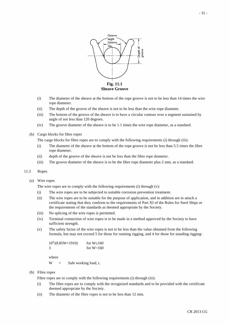
(a) Cargo blocks for wire ropes The cargo blocks for wire ropes are to comply with the following requirements (i) through (iv). However, in sheaves for equalizer sheaves or those for overload sensors, they are to be as deemed appropriate by the Society (See Fig. 11.1).
t
R D
- 31 -
CR 2013 CG
Fig. 11.1
Sheave Groove
(i) The diameter of the sheave at the bottom of the rope groove is not to be less than 14 times the wire rope diameter.
(ii) The depth of the groove of the sheave is not to be less than the wire rope diameter. (iii) The bottom of the groove of the sheave is to have a circular contour over a segment sustained by
angle of not less than 120 degrees. (iv) The groove diameter of the sheave is to be 1.1 times the wire rope diameter, as a standard.
(b) Cargo blocks for fibre ropes The cargo blocks for fibre ropes are to comply with the following requirements (i) through (iii): (i) The diameter of the sheave at the bottom of the rope groove is not be less than 5.5 times the fibre
rope diameter. (ii) depth of the groove of the sheave is not be less than the fibre rope diameter. (iii) The groove diameter of the sheave is to be the fibre rope diameter plus 2 mm, as a standard.
11.3 Ropes
(a) Wire ropes The wire ropes are to comply with the following requirements (i) through (v): (i) The wire ropes are to be subjected to suitable corrosion prevention treatment. (ii) The wire ropes are to be suitable for the purpose of application, and in addition are to attach a
certificate stating that they conform to the requirements of Part XI of the Rules for Steel Ships or the requirements of the standards as deemed appropriate by the Society.
(iii) No splicing of the wire ropes is permitted. (iv) Terminal connection of wire ropes is to be made in a method approved by the Society to have
sufficient strength. (v) The safety factor of the wire ropes is not to be less than the value obtained from the following
formula, but may not exceed 5 for those for running rigging, and 4 for those for standing rigging:
104/(8.85W+1910) for W≤160 3 for W>160
where W = Safe working load, t.
(b) Fibre ropes Fibre ropes are to comply with the following requirements (i) through (iii): (i) The fibre ropes are to comply with the recognized standards and to be provided with the certificate
deemed appropriate by the Society. (ii) The diameter of the fibre ropes is not to be less than 12 mm.

- 32 -
CR 2013 CG
(iii) The safety factor of fibre ropes is not be less than the value given in Table 11.1 depending on the rope diameter.
Table 11.1 Safety Factor or Fibre Ropes
Rope Diameter D (mm) Safety Factor e3 12 ≤ D < 14 14 ≤ D < 18 18 ≤ D < 24 24 ≤ D < 40 40 ≤ D
12 10
8 7 6
11.4 Other loose gears The design loads of loose gears such as chain, rings, hooks, shackles, swivels, clamps, grabs, lifting beams, lifting magnets, spreader, etc. are not to be more than the value obtained by dividing the breaking strength of each gears by the safety factor of 5.
11.5 Equivalent Requirements Notwithstanding the requirements in 11.2 through 11.4, the constructions of loose gear may be in accordance with national standard or any other recognized standards accepted by the Society.
12. Machinery, Electrical Installations and Control Engineering Systems
12.1 Machinery
(a) General The driving systems of the cargo gears are to be steadily operated in the rated speed under the safe working load.
(b) Hoisting machinery (i) The construction of the hoisting machinery is to comply with the following requirements (1)
through (6): (1) The drum end flange diameter is to have an allowance corresponding to not less than 2.5 times
the rope diameter as measured from the outer rim of the outermost layer of ropes in service condition. However, where rope disengagement prevention system is provided or in case of single layer winding on the drum, this requirement may be dispensed with.
(2) The pitch circle diameter of winch drum is to be not less than 18 times the rope diameter. (3) Winches are to be installed on the winch foundation with foundation bolts having sufficient
proof strength against the drum load (the maximum rope tension applied on the drum when the rope is wound under the single winding at a nominal rope hoisting speed) created when the safe working load is applied to the cargo gear.
(4) Braking system complying with the following requirements (A) through (C) is to be provided : (A) The braking system is to be able to exert a breaking torque 50% in excess of the torque
required when the safe working load is applied to the cargo gear. (B) The power operated braking system is to operate automatically when the maneuvering is
returned to its neutral position. (C) The power operated braking system is to operate automatically when there is any failure in
the power supply. In this case, emergency retrieval for cargo lowering is to be provided. (5) Clutchable drums are to be provided with effective locking system capable of restricting
rotation of the drum. The locking system is to be, as a rule, capable of resisting the torque not less than 1.5 times the torque required when the safe working load is applied to the cargo gear.
(6) Rope guards or suitable other means of protection are to be provided. (ii) The rope at its end is to be secured to the drum in such a manner that will not damage any part of
the rope and to have such a length that not less than 3 complete turns in case of an ungrooved drum,
- 33 -
CR 2013 CG
or 2 complete turns in case of a grooved drum are remaining on the drum when the complete working length of rope has been paid out.
12.2 Power supply
(a) The equipment, piping and cables consisting of the electric, hydraulic, pneumatic or steam power supply system and their arrangements are, as a rule, to comply with the relevant requirements of the Rules for Steel Ships.
(b) The construction, strength, materials, etc. of internal combustion engine used as the prime mover are to comply with the requirements in Part IV of the Rules for Steel Ships.
12.3 Control engineering systems
(a) General (i) The electric, hydraulic or pneumatic equipments used for the control, alarm and safety systems are,
as a rule, to comply with the relevant requirements of the Rules for Steel Ships. (ii) The control, alarm and safety systems are to be designed on the basis of the principle of fail-safe.
(b) Control system (i) Control systems are to be so arranged as not interfere with the operator or qualified other personnel
giving signals for operation. (ii) Control systems are, as a rule, to be of such design that controls automatically return to the neutral
position when control operation by the operator is interrupted. (iii) For electric winches, local power disconnecting switch is to be provided at the position in the
proximity of the place of operation. (iv) Cranes and cargo lifts are to be provided with emergency switch capable of stopping all the motions
at the position readily accessible for the operator. (v) Cargo lifts are to be provided with a suitable automatic speed control system that reduces the
starting acceleration and stopping deceleration as far as practicable. (vi) Cargo lifts are to be provided with a suitable control system that stops the lift at the specified deck
position. (vii) Where cargo lifts are secured by locking latches, suitable means is to be provided so as to prevent
the impact load to be induced on the lift in case of withdrawal of the latches.
(c) Safety system (i) The cargo gears are, as a rule, to be provided with an overload protection system. (ii) The cargo gears are to be provided with suitable safety systems capable of preventing the
abnormalities given in the following (1) through (6) according to kind of appliances and their motion: (1) Over hoisting. (2) Over slewing. (3) Over luffing. (4) Excessive traveling speed. (5) Over run on the track. (6) Other items of abnormality recognized by the Society.
(iii) In cranes where the safe working load varies according to the operating radius, rating chart showing the relationship between the operating radius and safe working load are to be provided in the control cab and in addition, equipment satisfying the following (1) and (2) or (3) is, as a rule, to be provided: (1) Operating radius indicator. (2) Hoisting load indicator. (3) Overload preventor with respect to the safe working load according to the operating radius.
(d) Protection system

- 34 -
CR 2013 CG
(i) For the rotating parts of the driving machinery, electrical installations and steam pipes, necessary means to protect the operator are to be provided.
(ii) Steam winches are to be arranged not to interfere with the operator’s field of vision by the steam. (iii) Cargo lifts are to be provided with the protection systems given in the following (1) through (4):
(1) Protective barriers of a height of not less than 1 m above deck level around the deck opening provided for lift platform.
(2) Interlocking system so that cargo lifts cannot be moved unless the barriers are all closed. (3) Interlocking system that prevents opening of protective barriers unless cargo lifts are at the
opening position of the barriers. (4) Warning lights or suitable other warning signs at the boarding place of cargo lifts.
13. Cargo Lifts and Cargo Ramps
13.1 Design loads
(a) Load considerations Consideration is to be given to the utilization and duty of the particular type of cargo lifts and cargo ramp in the “in service” and stowage conditions with respect to the following loads listed from (i) to (vii): (i) Safe working load. (ii) Self-weight of the installation. (iii) Wind loading. (iv) Wave loading. (v) Loads due to ship inclination. (vi) Loads due to ship motion. (vii) Other loads considered necessary by the Society.
(b) Wind loading The wind loading is to be calculated according to 9.1(e).
(c) Wave loading For the structural members forming parts of shell plating and subjected to the wave load, the head of water is not to be less than that obtained from the following formula:
[d-0.125 D+0.05L+ΔHw(x)]gD/(D+2hs) kPa
where: x = Distance from the forward face of stem on the designed water line corresponding to the full
load condition, m. d = Draught defined in 1.2.4, Part II of the Rules for Steel Ships, m. D = Depth of ship defined in 1.2.3, Part II of the Rules for Steel Ships, m. L = Length of ship defined in 1.2.1, Part II of the Rules for Steel Ships, m. is to be taken as 230 m
when the length exceeds 230 m. ΔHw(x) = Value obtained from the following formula for respective value of x, (38-45C b)[1-(x/0.3L)]2 for x ≤ 0.3L 0 for x > 0.3L Cb = Block coefficient defined in 1.2.8, Part II of the Rules for Steel Ships is to be taken as 0.85
when the block coefficient exceeds 0.85. hs = Value shown in Table 13.1 depending on the length of ship.
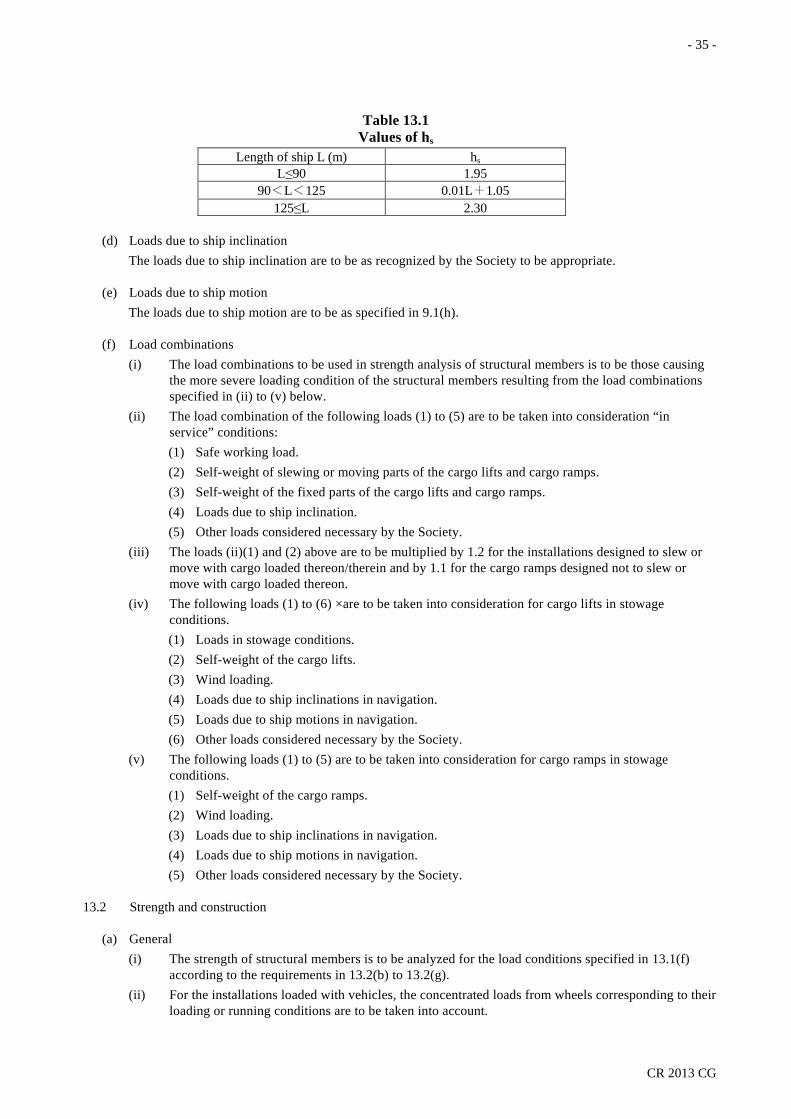
- 35 -
CR 2013 CG
Table 13.1 Values of hs
Length of ship L (m) hs L≤90 1.95
90<L<125 0.01L+1.05 125≤L 2.30
(d) Loads due to ship inclination The loads due to ship inclination are to be as recognized by the Society to be appropriate.
(e) Loads due to ship motion The loads due to ship motion are to be as specified in 9.1(h).
(f) Load combinations (i) The load combinations to be used in strength analysis of structural members is to be those causing
the more severe loading condition of the structural members resulting from the load combinations specified in (ii) to (v) below.
(ii) The load combination of the following loads (1) to (5) are to be taken into consideration “in service” conditions: (1) Safe working load. (2) Self-weight of slewing or moving parts of the cargo lifts and cargo ramps. (3) Self-weight of the fixed parts of the cargo lifts and cargo ramps. (4) Loads due to ship inclination. (5) Other loads considered necessary by the Society.
(iii) The loads (ii)(1) and (2) above are to be multiplied by 1.2 for the installations designed to slew or move with cargo loaded thereon/therein and by 1.1 for the cargo ramps designed not to slew or move with cargo loaded thereon.
(iv) The following loads (1) to (6) ×are to be taken into consideration for cargo lifts in stowage conditions. (1) Loads in stowage conditions. (2) Self-weight of the cargo lifts. (3) Wind loading. (4) Loads due to ship inclinations in navigation. (5) Loads due to ship motions in navigation. (6) Other loads considered necessary by the Society.
(v) The following loads (1) to (5) are to be taken into consideration for cargo ramps in stowage conditions. (1) Self-weight of the cargo ramps. (2) Wind loading. (3) Loads due to ship inclinations in navigation. (4) Loads due to ship motions in navigation. (5) Other loads considered necessary by the Society.
13.2 Strength and construction
(a) General (i) The strength of structural members is to be analyzed for the load conditions specified in 13.1(f)
according to the requirements in 13.2(b) to 13.2(g). (ii) For the installations loaded with vehicles, the concentrated loads from wheels corresponding to their
loading or running conditions are to be taken into account.
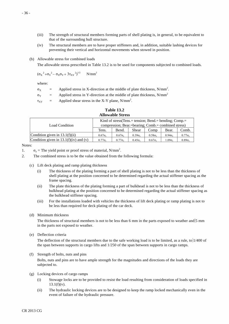
- 36 -
CR 2013 CG
(iii) The strength of structural members forming parts of shell plating is, in general, to be equivalent to that of the surrounding hull structure.
(iv) The structural members are to have proper stiffeners and, in addition, suitable lashing devices for preventing their vertical and horizontal movements when stowed in position.
(b) Allowable stress for combined loads The allowable stress prescribed in Table 13.2 is to be used for components subjected to combined loads.
(σX 2 +σY
2 − σXσY + 3τXY 2)1/2 N/mm2
where: σX = Applied stress in X-direction at the middle of plate thickness, N/mm2. σY = Applied stress in Y-direction at the middle of plate thickness, N/mm2 τXY = Applied shear stress in the X-Y plane, N/mm2.
Table 13.2 Allowable Stress
Load Condition Kind of stress(Tens.= tension; Bend.= bending; Comp.= compression; Bear.=bearing; Comb.= combined stress)
Tens. Bend. Shear Comp Bear. Comb. Condition given in 13.1(f)(ii) 0.67σy 0.67σy 0.39σy 0.58σy 0.94σy 0.77σy Condition given in 13.1(f)(iv) and (v) 0.77σy 0.77σy 0.45σy 0.67σy 1.09σy 0.89σy
Notes: 1. σy = The yield point or proof stress of material, N/mm2. 2. The combined stress is to be the value obtained from the following formula:
(c) Lift deck plating and ramp plating thickness (i) The thickness of the plating forming a part of shell plating is not to be less than the thickness of
shell plating at the position concerned to be determined regarding the actual stiffener spacing as the frame spacing.
(ii) The plate thickness of the plating forming a part of bulkhead is not to be less than the thickness of bulkhead plating at the position concerned to be determined regarding the actual stiffener spacing as the bulkhead stiffener spacing.
(iii) For the installations loaded with vehicles the thickness of lift deck plating or ramp plating is not to be less than required for deck plating of the car deck.
(d) Minimum thickness The thickness of structural members is not to be less than 6 mm in the parts exposed to weather and 5 mm in the parts not exposed to weather.
(e) Deflection criteria The deflection of the structural members due to the safe working load is to be limited, as a rule, to 1/400 of the span between supports in cargo lifts and 1/250 of the span between supports in cargo ramps.
(f) Strength of bolts, nuts and pins Bolts, nuts and pins are to have ample strength for the magnitudes and directions of the loads they are subjected to.
(g) Locking devices of cargo ramps (i) Stowage locks are to be provided to resist the load resulting from consideration of loads specified in
13.1(f)(v). (ii) The hydraulic locking devices are to be designed to keep the ramp locked mechanically even in the
event of failure of the hydraulic pressure.

- 37 -
CR 2013 CG
(iii) For a cargo ramp utilized commonly as a means for closing openings, the closing devices may be utilized as locking devices, if the area of opening is larger than half of the projected area of the stowed ramp. The design load of the closing devices is to include also the loads specified in 13.1(f)(v) in addition to the loads in Chapter 13, Part II of the Rules for Steel Ships.

- 38 -
CR 2013 CG
APPENDIX CG-1
Table A-1 Test Arrangements of Cargo Block
Type* 1A 1B 2A 2B 3A 3B 4A 4B 5A 5B
Arrangements for test
PL = 2 x SWL for SWL ≤ 25 where: *Note: Type A − Block without becket. = 27 + 0.933SWL for 25 < SWL ≤ 160 PL = Proof load to be tested, t. Type B − Block with becket.
= 1.1 x SWL for SWL > 160 SWL= Safe working load of block, t.
PL
2PL
PL PL PL PL PL PL PL PL PL
2PL
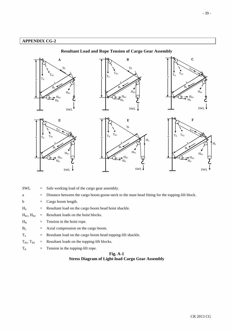
- 39 -
CR 2013 CG
APPENDIX CG-2
Resultant Load and Rope Tension of Cargo Gear Assembly
SWL = Safe working load of the cargo gear assembly.
a = Distance between the cargo boom goose-neck to the mast head fitting for the topping-lift block.
b = Cargo boom length.
HS = Resultant load on the cargo boom head hoist shackle.
HB1, HB2 = Resultant loads on the hoist blocks.
HR = Tension in the hoist rope.
BC = Axial compression on the cargo boom.
TS = Resultant load on the cargo boom head topping-lift shackle.
TB1, TB2 = Resultant loads on the topping-lift blocks.
TR = Tension in the topping-lift rope. Fig. A-1
Stress Diagram of Light-load Cargo Gear Assembly
B
Ts
TB2 TR
BC
HB1
HB2 HR
SWL
b
a
A
Ts
TB2
TR
BC
HB1
HB2 HR
SWL
a
b
C
TB1
TB2 TR
BC
HB1
HB2 HR
SWL
a
b
D
TB1
TB2 TR
BC
HB1
HB2 HR
SWL
a
b
E
Ts
TB2 TR
BC
HB1
HB2
HR
SWL
a
b
HS
F
TB1
TB2 TR
BC
HB1
HB2 HR
SWL a
b HS

- 40 -
CR 2013 CG
Table A-2 Resultant Load and Rope Tension of Light-load Cargo Gear Assembly
(SWL Below 10 Tons Rigged According to Figs. A-1 A to F) Type of rigging
Fig. A-1 a/b
HB1 HB2 HS HR BC TS or TB1 TB2 TR Inclination of cargo boom, θ
15°~45° 15°~45° 15°~45° 15°~45° 15° 30° 45° 15° 30° 45° 15° 30° 45° 15° 30° 45°
A
0.4 0.5 0.6 0.7 0.8 0.9 1.0 1.1
2.00
2.15
−
1.11
3.82 3.27 2.91 2.64 2.45 2.29 2.17 2.07
3.82 3.27 2.91 2.64 2.45 2.29 2.17 2.07
3.82 3.27 2.91 2.64 2.45 2.29 2.17 2.07
2.70 2.19 1.87 1.65 1.51 1.41 1.33 1.27
2.41 1.92 1.61 1.40 1.25 1.16 1.09 1.05
2.15 1.65 1.32 1.11 0.99 0.91 0.85 0.81
4.19 3.53 3.11 2.84 2.66 2.54 2.43 2.37
3.36 2.78 2.47 2.25 2.10 2.02 2.09 1.91
2.42 2.04 1.77 1.62 1.54 1.48 1.44 1.42
2.81 2.28 1.94 1.72 1.57 1.46 1.38 1.32
2.51 2.00 1.67 1.46 1.30 1.21 1.13 1.09
2.24 1.72 1.37 1.16 1.03 0.94 0.87 0.84
B
0.4 0.5 0.6 0.7 0.8 0.9 1.0 1.1
1.50
1.12
−
0.58
3.30 2.75 2.39 2.12 1.93 1.77 1.65 1.55
3.30 2.75 2.39 2.12 1.93 1.77 1.65 1.55
3.30 2.75 2.39 2.12 1.93 1.77 1.65 1.55
2.70 2.19 1.87 1.65 1.51 1.41 1.33 1.27
2.41 1.92 1.61 1.40 1.25 1.16 1.09 1.05
2.15 1.65 1.32 1.11 0.99 0.91 0.85 0.81
4.19 3.53 3.11 2.84 2.66 2.54 2.43 2.37
3.36 2.78 2.47 2.25 2.10 2.02 2.09 2.91
2.42 2.04 1.77 1.62 1.54 1.48 1.44 1.42
2.81 2.28 1.94 1.72 1.57 1.46 1.38 1.32
2.51 2.00 1.67 1.46 1.30 1.21 1.13 1.09
2.24 1.72 1.37 1.16 1.03 0.94 0.87 0.84
C
0.4 0.5 0.6 0.7 0.8 0.9 1.0 1.1
2.00
2.15
−
1.11
3.82 3.27 2.91 2.64 2.45 2.29 2.17 2.07
3.82 3.27 2.91 2.64 2.45 2.29 2.17 2.07
3.82 3.27 2.91 2.64 2.45 2.29 2.17 2.07
2.70 2.19 1.87 1.65 1.51 1.41 1.33 1.27
2.41 1.92 1.61 1.40 1.25 1.16 1.09 1.05
2.15 1.65 1.32 1.11 0.99 0.91 0.85 0.81
3.24 2.73 2.39 2.17 2.03 1.93 1.86 1.80
2.70 2.19 1.93 1.74 1.60 1.54 1.49 1.46
2.00 1.65 1.42 1.26 1.20 1.15 1.12 1.10
1.43 1.16 0.99 0.87 0.80 0.75 0.71 0.67
1.28 1.02 0.85 0.74 0.66 0.62 0.58 0.56
1.14 0.88 0.70 0.59 0.53 0.48 0.45 0.43
D
0.4 0.5 0.6 0.7 0.8 0.9 1.0 1.1
1.50
1.12
−
0.58
3.30 2.75 2.39 2.12 1.93 1.77 1.65 1.55
3.30 2.75 2.39 2.12 1.93 1.77 1.65 1.55
3.30 2.75 2.39 2.12 1.93 1.77 1.65 1.55
2.70 2.19 1.87 1.65 1.51 1.41 1.33 1.27
2.41 1.92 1.61 1.40 1.25 1.16 1.09 1.05
2.15 1.65 1.32 1.11 0.99 0.91 0.85 0.81
3.24 2.73 2.39 2.17 2.03 1.93 1.86 1.80
2.70 2.19 1.93 1.74 1.60 1.54 1.49 1.46
2.00 1.65 1.42 1.26 1.20 1.15 1.12 1.10
1.43 1.16 0.99 0.87 0.80 0.75 0.71 0.67
1.28 1.02 0.85 0.74 0.66 0.62 0.58 0.56
1.14 0.88 0.70 0.59 0.53 0.48 0.45 0.43
E
0.4 0.5 0.6 0.7 0.8 0.9 1.0 1.1
1.00
1.12
0.51
0.58
3.42 2.89 2.52 2.30 2.06 1.91 1.78 1.89
3.55 3.02 2.65 2.35 2.19 2.04 1.91 2.02
3.65 3.12 2.75 2.40 2.29 2.14 2.01 2.12
2.70 2.19 1.87 1.65 1.51 1.41 1.33 1.27
2.41 1.92 1.61 1.40 1.25 1.16 1.09 1.05
2.15 1.65 1.32 1.11 0.99 0.91 0.85 0.81
4.19 3.53 3.11 2.84 2.66 2.54 2.43 2.37
3.36 2.78 2.47 2.25 2.10 2.02 2.09 1.91
2.42 2.04 1.77 1.62 1.54 1.48 1.44 1.42
2.81 2.28 1.94 1.72 1.57 1.46 1.38 1.32
2.51 2.00 1.67 1.46 1.30 1.21 1.13 1.09
2.24 1.72 1.37 1.16 1.03 0.94 0.87 0.84
F
0.4 0.5 0.6 0.7 0.8 0.9 1.0 1.1
1.00
1.12
0.51
0.58
3.42 2.89 2.52 2.30 2.06 1.91 1.78 1.89
3.55 3.02 2.65 2.35 2.19 2.04 1.91 2.02
3.65 3.12 2.75 2.40 2.29 2.14 2.01 2.12
2.70 2.19 1.87 1.65 1.51 1.41 1.33 1.27
2.41 1.92 1.61 1.40 1.25 1.16 1.09 1.05
2.15 1.65 1.32 1.11 0.99 0.91 0.85 0.81
3.24 2.73 2.39 2.17 2.03 1.93 1.86 1.80
2.70 2.19 1.93 1.74 1.60 1.54 1.49 1.46
2.00 1.65 1.42 1.26 1.20 1.15 1.12 1.10
1.43 1.16 0.99 0.87 0.80 0.75 0.71 0.67
1.28 1.02 0.85 0.74 0.66 0.62 0.58 0.56
1.14 0.88 0.70 0.59 0.53 0.48 0.45 0.43
Notes: 1. The above tabular resultant load and rope tension are calculated at a SWL of 1 tons, for other values: (Actual load or tension) = (Table value) × (Required SWL) 2. The values at intermediate ratio of a/b or angle of inclination of the cargo boom, θ, are to be determined by
interpolation.

- 41 -
CR 2013 CG
Fig. A-2
Stress Diagram of Heavy-lift Cargo Gear Assembly SWL 10 Tons and Over
Table A-3a Resultant Load and Rope Tension of Hoist Gear of the Heavy-lift Cargo Gear Assembly (SWL 10 Tons and Over, Inclination of Cargo Boom θ = 15° ~ 45° Rigged According to Figs. A-2 A and B) Total number
of sheaves in hoist blocks
HB1 HB2 HR HC
0.6
0.7
0.8
a/b 0.9
1.0
1.1
1.2
1+1 1+2
2+2 2+3
3+3 3+4
4+4 4+5
5+5
1.50 1.40
1.30 1.20
1.17 1.16
1.15 1.14
1.13
1.12 0.75
0.58 0.47
0.39 0.35
0.31 0.29
0.27
0.58 0.39
0.29 0.24
0.20 0.18
0.16 0.15
0.14
2.40 2.22
2.12 2.07
2.03 2.01
1.99 1.98
1.97
2.13 1.95
1.86 1.80
1.76 1.74
1.72 1.71
1.70
1.94 1.76
1.66 1.61
1.57 1.55
1.53 1.52
1.52
1.78 1.60
1.50 1.45
1.41 1.39
1.37 1.36
1.35
1.66 1.48
1.38 1.33
1.29 1.27
1.25 1.24
1.23
1.56 1.38
1.28 1.23
1.19 1.17
1.15 1.14
1.13
1.47 1.29
1.19 1.14
1.10 1.08
1.06 1.05
1.04
Notes: 1. The above tabular resultant load and rope tension are calculated at a SWL of 1 ton, for other values: (Actual load or tension) = (Table value) × (Required SWL) 2. The values at intermediate ratio of a/b are to be determined by interpolation.
TB1 TB3 TB1
TB4
TB2
HB1 HB1
HB2
TB5 HR
TR SWL SWL
BC b
A
a
TB1 TB3 TB1
TB4
TB2
HB2 HB1
HB4
TB5 HR
TR
SWL SWL
BC
b
B
a
HB3
HB2 HB1
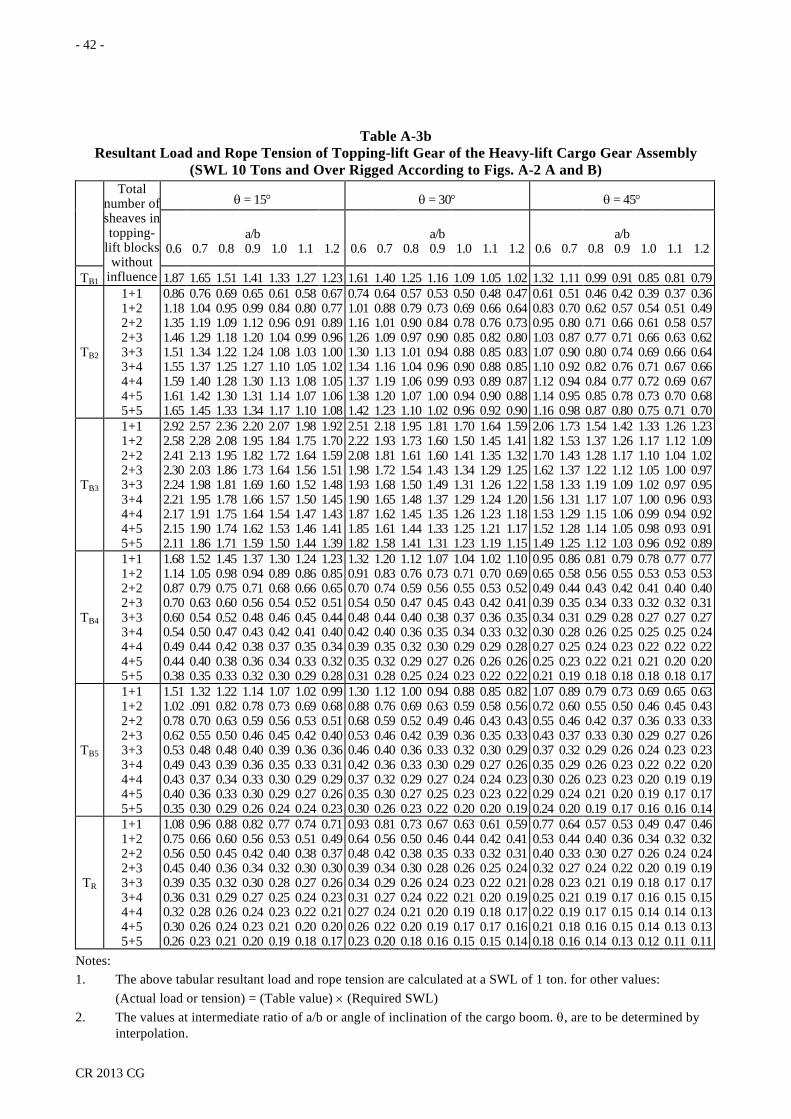
- 42 -
CR 2013 CG
Table A-3b Resultant Load and Rope Tension of Topping-lift Gear of the Heavy-lift Cargo Gear Assembly
(SWL 10 Tons and Over Rigged According to Figs. A-2 A and B) Total
number of sheaves in topping-
lift blocks without
influence
θ = 15° θ = 30° θ = 45°
0.6
0.7
0.8 a/b 0.9
1.0
1.1
1.2
0.6
0.7
0.8 a/b 0.9
1.0
1.1
1.2
0.6
0.7
0.8 a/b 0.9
1.0
1.1
1.2
TB1 1.87 1.65 1.51 1.41 1.33 1.27 1.23 1.61 1.40 1.25 1.16 1.09 1.05 1.02 1.32 1.11 0.99 0.91 0.85 0.81 0.79
TB2
1+1 1+2 2+2 2+3 3+3 3+4 4+4 4+5 5+5
0.86 1.18 1.35 1.46 1.51 1.55 1.59 1.61 1.65
0.76 1.04 1.19 1.29 1.34 1.37 1.40 1.42 1.45
0.69 0.95 1.09 1.18 1.22 1.25 1.28 1.30 1.33
0.65 0.99 1.12 1.20 1.24 1.27 1.30 1.31 1.34
0.61 0.84 0.96 1.04 1.08 1.10 1.13 1.14 1.17
0.58 0.80 0.91 0.99 1.03 1.05 1.08 1.07 1.10
0.67 0.77 0.89 0.96 1.00 1.02 1.05 1.061.08
0.74 1.01 1.16 1.26 1.30 1.34 1.37 1.38 1.42
0.64 0.88 1.01 1.09 1.13 1.16 1.19 1.20 1.23
0.57 0.79 0.90 0.97 1.01 1.04 1.06 1.07 1.10
0.53 0.73 0.84 0.90 0.94 0.96 0.99 1.00 1.02
0.50 0.69 0.78 0.85 0.88 0.90 0.93 0.94 0.96
0.48 0.66 0.76 0.82 0.85 0.88 0.89 0.90 0.92
0.47 0.64 0.73 0.80 0.83 0.85 0.87 0.88 0.90
0.61 0.83 0.95 1.03 1.07 1.10 1.12 1.14 1.16
0.51 0.70 0.80 0.87 0.90 0.92 0.94 0.95 0.98
0.46 0.62 0.71 0.77 0.80 0.82 0.84 0.85 0.87
0.42 0.57 0.66 0.71 0.74 0.76 0.77 0.78 0.80
0.39 0.54 0.61 0.66 0.69 0.71 0.72 0.73 0.75
0.37 0.51 0.58 0.63 0.66 0.67 0.69 0.70 0.71
0.36 0.49 0.57 0.62 0.64 0.66 0.67 0.68 0.70
TB3
1+1 1+2 2+2 2+3 3+3 3+4 4+4 4+5 5+5
2.92 2.58 2.41 2.30 2.24 2.21 2.17 2.15 2.11
2.57 2.28 2.13 2.03 1.98 1.95 1.91 1.90 1.86
2.36 2.08 1.95 1.86 1.81 1.78 1.75 1.74 1.71
2.20 1.95 1.82 1.73 1.69 1.66 1.64 1.62 1.59
2.07 1.84 1.72 1.64 1.60 1.57 1.54 1.53 1.50
1.98 1.75 1.64 1.56 1.52 1.50 1.47 1.46 1.44
1.92 1.70 1.59 1.51 1.48 1.45 1.43 1.41 1.39
2.51 2.22 2.08 1.98 1.93 1.90 1.87 1.85 1.82
2.18 1.93 1.81 1.72 1.68 1.65 1.62 1.61 1.58
1.95 1.73 1.61 1.54 1.50 1.48 1.45 1.44 1.41
1.81 1.60 1.60 1.43 1.49 1.37 1.35 1.33 1.31
1.70 1.50 1.41 1.34 1.31 1.29 1.26 1.25 1.23
1.64 1.45 1.35 1.29 1.26 1.24 1.23 1.21 1.19
1.59 1.41 1.32 1.25 1.22 1.20 1.18 1.17 1.15
2.06 1.82 1.70 1.62 1.58 1.56 1.53 1.52 1.49
1.73 1.53 1.43 1.37 1.33 1.31 1.29 1.28 1.25
1.54 1.37 1.28 1.22 1.19 1.17 1.15 1.14 1.12
1.42 1.26 1.17 1.12 1.09 1.07 1.06 1.05 1.03
1.33 1.17 1.10 1.05 1.02 1.00 0.99 0.98 0.96
1.26 1.12 1.04 1.00 0.97 0.96 0.94 0.93 0.92
1.23 1.09 1.02 0.97 0.95 0.93 0.92 0.91 0.89
TB4
1+1 1+2 2+2 2+3 3+3 3+4 4+4 4+5 5+5
1.68 1.14 0.87 0.70 0.60 0.54 0.49 0.44 0.38
1.52 1.05 0.79 0.63 0.54 0.50 0.44 0.40 0.35
1.45 0.98 0.75 0.60 0.52 0.47 0.42 0.38 0.33
1.37 0.94 0.71 0.56 0.48 0.43 0.38 0.36 0.32
1.30 0.89 0.68 0.54 0.46 0.42 0.37 0.34 0.30
1.24 0.86 0.66 0.52 0.45 0.41 0.35 0.33 0.29
1.23 0.85 0.65 0.51 0.44 0.40 0.34 0.32 0.28
1.32 0.91 0.70 0.54 0.48 0.42 0.39 0.35 0.31
1.20 0.83 0.74 0.50 0.44 0.40 0.35 0.32 0.28
1.12 0.76 0.59 0.47 0.40 0.36 0.32 0.29 0.25
1.07 0.73 0.56 0.45 0.38 0.35 0.30 0.27 0.24
1.04 0.71 0.55 0.43 0.37 0.34 0.29 0.26 0.23
1.02 0.70 0.53 0.42 0.36 0.33 0.29 0.26 0.22
1.10 0.69 0.52 0.41 0.35 0.32 0.28 0.26 0.22
0.95 0.65 0.49 0.39 0.34 0.30 0.27 0.25 0.21
0.86 0.58 0.44 0.35 0.31 0.28 0.25 0.23 0.19
0.81 0.56 0.43 0.34 0.29 0.26 0.24 0.22 0.18
0.79 0.55 0.42 0.33 0.28 0.25 0.23 0.21 0.18
0.78 0.53 0.41 0.32 0.27 0.25 0.22 0.21 0.18
0.77 0.53 0.40 0.32 0.27 0.25 0.22 0.20 0.18
0.77 0.53 0.40 0.31 0.27 0.24 0.22 0.20 0.17
TB5
1+1 1+2 2+2 2+3 3+3 3+4 4+4 4+5 5+5
1.51 1.02 0.78 0.62 0.53 0.49 0.43 0.40 0.35
1.32 .091 0.70 0.55 0.48 0.43 0.37 0.36 0.30
1.22 0.82 0.63 0.50 0.48 0.39 0.34 0.33 0.29
1.14 0.78 0.59 0.46 0.40 0.36 0.33 0.30 0.26
1.07 0.73 0.56 0.45 0.39 0.35 0.30 0.29 0.24
1.02 0.69 0.53 0.42 0.36 0.33 0.29 0.27 0.24
0.99 0.68 0.51 0.40 0.36 0.31 0.29 0.26 0.23
1.30 0.88 0.68 0.53 0.46 0.42 0.37 0.35 0.30
1.12 0.76 0.59 0.46 0.40 0.36 0.32 0.30 0.26
1.00 0.69 0.52 0.42 0.36 0.33 0.29 0.27 0.23
0.94 0.63 0.49 0.39 0.33 0.30 0.27 0.25 0.22
0.88 0.59 0.46 0.36 0.32 0.29 0.24 0.23 0.20
0.85 0.58 0.43 0.35 0.30 0.27 0.24 0.23 0.20
0.82 0.56 0.43 0.33 0.29 0.26 0.23 0.22 0.19
1.07 0.72 0.55 0.43 0.37 0.35 0.30 0.29 0.24
0.89 0.60 0.46 0.37 0.32 0.29 0.26 0.24 0.20
0.79 0.55 0.42 0.33 0.29 0.26 0.23 0.21 0.19
0.73 0.50 0.37 0.30 0.26 0.23 0.23 0.20 0.17
0.69 0.46 0.36 0.29 0.24 0.22 0.20 0.19 0.16
0.65 0.45 0.33 0.27 0.23 0.22 0.19 0.17 0.16
0.63 0.43 0.33 0.26 0.23 0.20 0.19 0.17 0.14
TR
1+1 1+2 2+2 2+3 3+3 3+4 4+4 4+5 5+5
1.08 0.75 0.56 0.45 0.39 0.36 0.32 0.30 0.26
0.96 0.66 0.50 0.40 0.35 0.31 0.28 0.26 0.23
0.88 0.60 0.45 0.36 0.32 0.29 0.26 0.24 0.21
0.82 0.56 0.42 0.34 0.30 0.27 0.24 0.23 0.20
0.77 0.53 0.40 0.32 0.28 0.25 0.23 0.21 0.19
0.74 0.51 0.38 0.30 0.27 0.24 0.22 0.20 0.18
0.71 0.49 0.37 0.30 0.26 0.23 0.21 0.20 0.17
0.93 0.64 0.48 0.39 0.34 0.31 0.27 0.26 0.23
0.81 0.56 0.42 0.34 0.29 0.27 0.24 0.22 0.20
0.73 0.50 0.38 0.30 0.26 0.24 0.21 0.20 0.18
0.67 0.46 0.35 0.28 0.24 0.22 0.20 0.19 0.16
0.63 0.44 0.33 0.26 0.23 0.21 0.19 0.17 0.15
0.61 0.42 0.32 0.25 0.22 0.20 0.18 0.17 0.15
0.59 0.41 0.31 0.240.21 0.19 0.17 0.16 0.14
0.77 0.53 0.40 0.32 0.28 0.25 0.22 0.21 0.18
0.64 0.44 0.33 0.27 0.23 0.21 0.19 0.18 0.16
0.57 0.40 0.30 0.24 0.21 0.19 0.17 0.16 0.14
0.53 0.360.27 0.22 0.19 0.17 0.15 0.15 0.13
0.49 0.34 0.26 0.20 0.18 0.16 0.14 0.14 0.12
0.47 0.32 0.24 0.19 0.17 0.15 0.14 0.13 0.11
0.46 0.32 0.24 0.19 0.17 0.15 0.13 0.13 0.11
Notes: 1. The above tabular resultant load and rope tension are calculated at a SWL of 1 ton. for other values: (Actual load or tension) = (Table value) × (Required SWL) 2. The values at intermediate ratio of a/b or angle of inclination of the cargo boom. θ, are to be determined by
interpolation.
Related Documents


![[Survey Results] How Do You Report Cargo VGM?](https://static.cupdf.com/doc/110x72/58f2b2d91a28abaf6c8b459f/survey-results-how-do-you-report-cargo-vgm.jpg)