The content of this service document is the subject of intellectual property rights reserved by DNV GL AS ("DNV GL"). The user accepts that it is prohibited by anyone else but DNV GL and/or its licensees to offer and/or perform classification, certification and/or verification services, including the issuance of certificates and/or declarations of conformity, wholly or partly, on the basis of and/or pursuant to this document whether free of charge or chargeable, without DNV GL's prior written consent. DNV GL is not responsible for the consequences arising from any use of this document by others. The electronic pdf version of this document, available free of charge from http://www.dnvgl.com, is the officially binding version. DNV GL AS RULES FOR CLASSIFICATION Ships Edition October 2015 Part 3 Hull Chapter 4 Loads

Welcome message from author
This document is posted to help you gain knowledge. Please leave a comment to let me know what you think about it! Share it to your friends and learn new things together.
Transcript

The content of this service document is the subject of intellectual property rights reserved by DNV GL AS ("DNV GL"). The useraccepts that it is prohibited by anyone else but DNV GL and/or its licensees to offer and/or perform classification, certificationand/or verification services, including the issuance of certificates and/or declarations of conformity, wholly or partly, on thebasis of and/or pursuant to this document whether free of charge or chargeable, without DNV GL's prior written consent.DNV GL is not responsible for the consequences arising from any use of this document by others.
The electronic pdf version of this document, available free of chargefrom http://www.dnvgl.com, is the officially binding version.
DNV GL AS
RULES FOR CLASSIFICATION
ShipsEdition October 2015
Part 3 Hull
Chapter 4 Loads
FOREWORD
DNV GL rules for classification contain procedural and technical requirements related to obtainingand retaining a class certificate. The rules represent all requirements adopted by the Society asbasis for classification.
© DNV GL AS October 2015
Any comments may be sent by e-mail to [email protected]
If any person suffers loss or damage which is proved to have been caused by any negligent act or omission of DNV GL, then DNV GL shallpay compensation to such person for his proved direct loss or damage. However, the compensation shall not exceed an amount equal to tentimes the fee charged for the service in question, provided that the maximum compensation shall never exceed USD 2 million.
In this provision "DNV GL" shall mean DNV GL AS, its direct and indirect owners as well as all its affiliates, subsidiaries, directors, officers,employees, agents and any other acting on behalf of DNV GL.

Part
3 C
hapt
er 4
Cha
nges
- c
urre
nt
Rules for classification: Ships — DNVGL-RU-SHIP-Pt3Ch4. Edition October 2015 Page 3Loads
DNV GL AS
CHANGES – CURRENT
This is a new document.
The rules enter into force 1 January 2016.

Part
3 C
hapt
er 4
Con
tent
s
Rules for classification: Ships — DNVGL-RU-SHIP-Pt3Ch4. Edition October 2015 Page 4Loads
DNV GL AS
CONTENTS
Changes – current...................................................................................................... 3
Section 1 Introduction............................................................................................... 71 General................................................................................................... 7
1.1 Application.......................................................................................... 71.2 Definitions...........................................................................................8
Section 2 Dynamic load cases.................................................................................. 101 General................................................................................................. 10
1.1 Definition of dynamic load cases.......................................................... 101.2 Application.........................................................................................11
2 Dynamic load cases for strength assessment....................................... 122.1 Description of dynamic load cases........................................................ 122.2 Load combination factors.................................................................... 17
3 Dynamic load cases for fatigue assessment..........................................203.1 Description of dynamic load cases........................................................ 203.2 Load combination factors.................................................................... 23
Section 3 Ship motions and accelerations................................................................ 261 General................................................................................................. 27
1.1 Definition...........................................................................................272 Ship motions and accelerations............................................................ 27
2.1 Ship motions..................................................................................... 272.2 Ship accelerations at the centre of gravity.............................................28
3 Accelerations at any position................................................................313.1 General............................................................................................. 313.2 Accelerations for dynamic load cases.................................................... 313.3 Envelope accelerations........................................................................ 31
Section 4 Hull girder loads.......................................................................................341 Application............................................................................................34
1.1 General............................................................................................. 342 Still water hull girder loads..................................................................35
2.1 General............................................................................................. 352.2 Vertical still water bending moment......................................................352.3 Still water torsion moment for container ships....................................... 372.4 Vertical still water shear force..............................................................37

Part
3 C
hapt
er 4
Con
tent
s
Rules for classification: Ships — DNVGL-RU-SHIP-Pt3Ch4. Edition October 2015 Page 5Loads
DNV GL AS
3 Dynamic hull girder loads.....................................................................383.1 Vertical wave bending moment............................................................ 383.2 Vertical wave shear force.................................................................... 403.3 Horizontal wave bending moment.........................................................423.4 Wave torsional moment...................................................................... 433.5 Hull girder loads for dynamic load cases............................................... 44
Section 5 External loads...........................................................................................461 Sea pressure.........................................................................................46
1.1 Total pressure.................................................................................... 461.2 Hydrostatic pressure...........................................................................471.3 External dynamic pressures for strength assessment...............................481.4 External dynamic pressures for fatigue assessments............................... 63
2 Pressures on exposed decks.................................................................712.1 Application.........................................................................................712.2 Green sea loads.................................................................................712.3 Load carried on decks and platforms.................................................... 73
3 External pressures on superstructure and deckhouses......................... 743.1 Application.........................................................................................743.2 Exposed superstructure and deckhouse tops.......................................... 743.3 Sides of superstructures......................................................................743.4 End bulkheads of superstructures and deckhouse walls............................753.5 Windows and side scuttles...................................................................77
Section 6 Internal loads...........................................................................................791 Pressures due to liquids....................................................................... 80
1.1 Total pressure.................................................................................... 801.2 Static liquid pressure.......................................................................... 801.3 Dynamic liquid pressure......................................................................83
2 Non-exposed decks and platforms........................................................862.1 Application.........................................................................................862.2 Pressure due to distributed load...........................................................862.3 Concentrated force due to unit load......................................................86
3 Pressure for internal structures in tanks.............................................. 863.1 Definition...........................................................................................86
Section 7 Design load scenarios...............................................................................871 General................................................................................................. 88
1.1 Application.........................................................................................882 Design load scenarios for strength assessment.................................... 88

Part
3 C
hapt
er 4
Con
tent
s
Rules for classification: Ships — DNVGL-RU-SHIP-Pt3Ch4. Edition October 2015 Page 6Loads
DNV GL AS
2.1 Principal design load scenarios.............................................................883 Design load scenarios for fatigue assessment...................................... 90
3.1 Design load scenarios......................................................................... 90
Section 8 Loading conditions....................................................................................911 Standard design loading conditions...................................................... 91
1.1 Seagoing design loading conditions.......................................................911.2 Partially filled ballast tanks in seagoing design loading condition............... 91
2 Loading conditions for primary supporting members............................922.1 General............................................................................................. 92

Part
3 C
hapt
er 4
Sec
tion
1
Rules for classification: Ships — DNVGL-RU-SHIP-Pt3Ch4. Edition October 2015 Page 7Loads
DNV GL AS
SECTION 1 INTRODUCTIONSymbols
For symbols not defined in this section, refer to Ch.1 Sec.4.
S = static load caseS+D = static plus dynamic load case.
1 General
1.1 Application1.1.1 ScopeThis chapter provides the design loads for strength and fatigue assessments.The load combinations shall be derived for the design load scenarios as described in Sec.7. This sectionuses the concept of design load scenarios to specify consistent design load sets which cover the appropriateoperating modes of the vessel in question.
1.1.2 Equivalent design wave (EDW)The dynamic loads associated with each dynamic load case are based on the Equivalent Design Wave (EDW)concept. The EDW concept applies a consistent set of dynamic loads to the ship such that the specifieddominant load response is equivalent to the required long term response value.
1.1.3 Probability level for strength and fatigue assessmentsIn this chapter, the assessments shall be understood as follows:
— strength assessment means the assessment for the strength criteria excluding fatigue. Wave induceddynamic loads for strength assessment are at a probability level of 10-8
— fatigue assessment means the assessment for the fatigue criteria for the loads corresponding to theprobability level of 10-2.
1.1.4 Dynamic load componentsAll dynamic load components for each dynamic load case shall be applied as simultaneous values.
1.1.5 Loads for strength assessmentThe strength assessment shall be undertaken for all design load scenarios and the final assessment shall bebased on the most onerous strength requirement.Each design load scenario for strength assessment is composed of either a Static (S) load case or a Static +Dynamic (S+D) load case, where the static and dynamic loads are dependent on the loading condition beingconsidered.The static and dynamic loads are defined in the following sections:
— hull girder loads in Sec.4— external loads in Sec.5— internal loads in Sec.6 and in Pt.5.
The EDWs for the strength assessment and the dynamic load combination factors for global loads are listed inSec.2 [2].
1.1.6 Loads for fatigue assessmentEach design load scenario for fatigue assessment is composed of a Static + Dynamic (S+D) load case, wherethe static and dynamic loads are dependent on the loading condition being considered.The loads are defined in the following sections:
Part
3 C
hapt
er 4
Sec
tion
1
Rules for classification: Ships — DNVGL-RU-SHIP-Pt3Ch4. Edition October 2015 Page 8Loads
DNV GL AS
— hull girder loads in Sec.4— external loads in Sec.5— internal loads in Sec.6 and in Pt.5.
The EDWs for the fatigue assessment are listed in Sec.2 [3].
1.2 Definitions1.2.1 Coordinate systemThe coordinate system is defined in Ch.1 Sec.4.
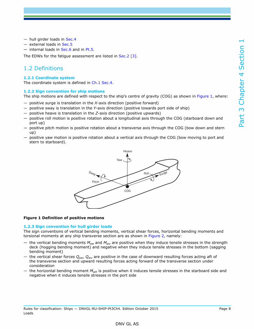
1.2.2 Sign convention for ship motionsThe ship motions are defined with respect to the ship’s centre of gravity (COG) as shown in Figure 1, where:
— positive surge is translation in the X-axis direction (positive forward)— positive sway is translation in the Y-axis direction (positive towards port side of ship)— positive heave is translation in the Z-axis direction (positive upwards)— positive roll motion is positive rotation about a longitudinal axis through the COG (starboard down and
port up)— positive pitch motion is positive rotation about a transverse axis through the COG (bow down and stern
up)— positive yaw motion is positive rotation about a vertical axis through the COG (bow moving to port and
stern to starboard).
Figure 1 Definition of positive motions
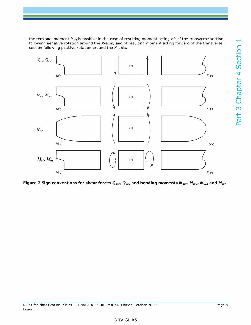
1.2.3 Sign convention for hull girder loadsThe sign conventions of vertical bending moments, vertical shear forces, horizontal bending moments andtorsional moments at any ship transverse section are as shown in Figure 2, namely:
— the vertical bending moments Msw and Mwv are positive when they induce tensile stresses in the strengthdeck (hogging bending moment) and negative when they induce tensile stresses in the bottom (saggingbending moment)
— the vertical shear forces Qsw, Qwv are positive in the case of downward resulting forces acting aft ofthe transverse section and upward resulting forces acting forward of the transverse section underconsideration
— the horizontal bending moment Mwh is positive when it induces tensile stresses in the starboard side andnegative when it induces tensile stresses in the port side
Part
3 C
hapt
er 4
Sec
tion
1
Rules for classification: Ships — DNVGL-RU-SHIP-Pt3Ch4. Edition October 2015 Page 9Loads
DNV GL AS
— the torsional moment Mwt is positive in the case of resulting moment acting aft of the transverse sectionfollowing negative rotation around the X-axis, and of resulting moment acting forward of the transversesection following positive rotation around the X-axis.
Figure 2 Sign conventions for shear forces Qsw, Qwv and bending moments Msw, Mwv, Mwh and Mwt

Part
3 C
hapt
er 4
Sec
tion
2
Rules for classification: Ships — DNVGL-RU-SHIP-Pt3Ch4. Edition October 2015 Page 10Loads
DNV GL AS
SECTION 2 DYNAMIC LOAD CASESSymbols
For symbols not defined in this section, refer to Ch.1 Sec.4.
asurge, apitch-x, asway,aroll-y, aheave, aroll-z,apitch-z
= acceleration components, as defined in Sec.3
fxL = ratio between X-coordinate of the load point and L, to be taken as:
, but shall not be taken less than 0.0 or greater than 1.0.
fT = ratio between draught at a loading condition and scantling draught, as defined in Sec.3fℓp = factor depending on longitudinal position along the ship, to be taken as:
fℓp = 1.0 for x/L ≤ 0.5
fℓp = -1.0 for 0.5 < x/L
fℓp-OST = factor for the longitudinal distribution of the torsional moment for the OST load case, as definedin Sec.4 [3.4]
fℓp-OSA = factor for the longitudinal distribution of the torsional moment for the OSA load case as definedin Sec.4 [3.4]
WS = weather side, side of the ship exposed to the incoming wavesLS = lee side, sheltered side of the ship away from the incoming wavesMWV = vertical wave bending moment, in kNm, defined in Sec.4QWV = vertical wave shear force, in kN, defined in Sec.4MWH = horizontal wave bending moment, in kNm, defined in Sec.4MWT = torsional wave bending moment, in kNm, defined in Sec.4CWV = load combination factor to be applied to the vertical wave bending momentCQW = load combination factor to be applied to the vertical wave shear forceCWH = load combination factor to be applied to the horizontal wave bending momentCWT = load combination factor to be applied to the wave torsional momentCXS = load combination factor to be applied to the surge accelerationCXP = load combination factor to be applied to the longitudinal acceleration due to pitchCXG = load combination factor to be applied to the longitudinal acceleration due to pitch motionCYS = load combination factor to be applied to the sway accelerationCYR = load combination factor to be applied to the transverse acceleration due to rollCYG = load combination factor to be applied to the transverse acceleration due to roll motionCZH = load combination factor to be applied to the heave accelerationCZR = load combination factor to be applied to the vertical acceleration due to rollCZP = load combination factor to be applied to the vertical acceleration due to pitchθ = roll angle, in deg, as defined in Sec.3 [2.1.1]φ = pitch angle, in deg, as defined in Sec.3 [2.1.2].
1 General
1.1 Definition of dynamic load cases
1.1.1 The following Equivalent Design Waves (EDW) shall be used to generate the dynamic load cases forstructural assessment:
— HSM load cases:

Part
3 C
hapt
er 4
Sec
tion
2
Rules for classification: Ships — DNVGL-RU-SHIP-Pt3Ch4. Edition October 2015 Page 11Loads
DNV GL AS
HSM-1 and HSM-2: head sea EDWs that minimise and maximise the vertical wave bending momentamidships respectively.
— HSA load cases:HSA-1 and HSA-2: head sea EDWs that maximise and minimise the head sea vertical acceleration at FPrespectively.
— FSM load cases:FSM-1 and FSM-2: following sea EDWs that minimise and maximise the vertical wave bending momentamidships respectively.
— BSR load cases:BSR-1P and BSR-2P: beam sea EDWs that minimise and maximise the roll motion downward and upwardon the port side respectively with waves from the port side.BSR-1S and BSR-2S: beam sea EDWs that maximise and minimise the roll motion downward and upwardon the starboard side respectively with waves from the starboard side.
— BSP load cases:BSP-1P and BSP-2P: beam sea EDWs that maximise and minimise the hydrodynamic pressure at thewaterline amidships on the port side respectively.BSP-1S and BSP-2S: beam sea EDWs that maximise and minimise the hydrodynamic pressure at thewaterline amidships on the starboard side respectively.
— OST load cases:OST-1P and OST-2P: oblique sea EDWs that minimise and maximise the torsional moment at 0.25 L fromthe AE with waves from the port side respectively.OST-1S and OST-2S: oblique sea EDWs that maximise and minimise the torsional moment at 0.25 L fromthe AE with waves from the starboard side respectively.
— OSA load cases:OSA-1P and OSA-2P: oblique sea EDWs that maximise and minimise the pitch acceleration with wavesfrom the port side respectively. OSA-1S and OSA-2S: oblique sea EDWs that maximise and minimise thepitch acceleration with waves from the starboard side respectively.
HSA and OSA load cases shall not be used for fatigue assessment.Guidance note:1) 1 and 2 denote the maximum or the minimum dominant load component for each EDW.2) P and S denote that the weather side is on port side or starboard side respectively.
---e-n-d---of---g-u-i-d-a-n-c-e---n-o-t-e---
1.2 Application
1.2.1 The dynamic load cases described in this section shall be used for determining the dynamic loadsrequired by the design load scenarios described in Sec.7. These dynamic load cases shall be applied to thefollowing structural assessments:
a) Strength assessment:
— for plating, stiffeners and primary supporting members by prescriptive methods— for hull girder strength— for the direct strength method (FE analysis) assessment of structural members.
b) Fatigue assessment:
— for structural details covered by simplified stress analysis— for structural details covered by FE stress analysis.

Part
3 C
hapt
er 4
Sec
tion
2
Rules for classification: Ships — DNVGL-RU-SHIP-Pt3Ch4. Edition October 2015 Page 12Loads
DNV GL AS
2 Dynamic load cases for strength assessment
2.1 Description of dynamic load cases
2.1.1 Table 1 to Table 3 describe the ship motion responses and the global loads corresponding to eachdynamic load case to be considered for the strength assessment.
Table 1 Ship responses for HSM, HSA and FSM load cases - strength assessment
Load case HSM-1 HSM-2 HSA-1 HSA-2 FSM-1 FSM-2
EDW HSM HSA FSM
Heading Head Head Following
Effect Max. bending moment Max. vertical acceleration Max. bending moment
VWBM Sagging Hogging Sagging Hogging Sagging Hogging
VWSFNegative–aftPositive–fore
Positive–aftNegative–fore
Negative–aftPositive–fore
Positive–aftNegative–fore
Negative–aftPositive–fore
Positive–aftNegative–fore
HWBM - - - - - -
TM - - - - - -
Surge To stern To bow To stern To bow To bow To stern
asurge
Sway - - - - - -
asway - - - - - -
Heave Down Up Down Up - -
aheave
- -
Roll - - - - - -
aroll - - - - - -
Pitch Bow down Bow up Bow down Bow up Bow up Bow down
apitch

Rules for classification: S
hips — D
NVG
L-RU
-SH
IP-Pt3Ch4. Edition O
ctober 2015Page 13
Loads
DN
V G
L AS
Part 3 Chapter 4 Section 2
Table 2 Ship responses for BSR and BSP load cases - strength assessment
Loadcase
BSR-1P BSR-2P BSR-1S BSR-2S BSP-1P BSP-2P BSP-1S BSP-2S
EDW BSR BSR BSP BSP
Heading Beam Beam
Effect Max. roll Max. pressure at waterline
VWBM Sagging Hogging Sagging Hogging Sagging Hogging Sagging Hogging
VWSF Negative–aftPositive–fore
Positive–aftNegative–fore
Negative–aftPositive–fore
Positive–aftNegative–fore
Negative–aftPositive–fore
Positive–aftNegative–fore
Negative–aftPositive–fore
Positive–aftNegative–fore
HWBM Stbd tensile Port tensile Port tensile Stbd tensile Stbd tensile Port tensile Port tensile Stbd tensile
TM - - - - - - - -
Surge - - - - - - - -
asurge - - - - - - - -
Sway To starboard To portside To portside To starboard To portside To starboard To starboard To portside
asway
Heave Down Up Down Up Down Up Down Up
aheave
Roll Portside down Portside up Starboard down Starboard up Portside down Portside up Starboard down Starboard up
aroll
Pitch - - - - Bow down Bow up Bow down Bow up
Rules for classification: S
hips — D
NVG
L-RU
-SH
IP-Pt3Ch4. Edition O
ctober 2015Page 14
Loads
DN
V G
L AS
Part 3 Chapter 4 Section 2
Loadcase
BSR-1P BSR-2P BSR-1S BSR-2S BSP-1P BSP-2P BSP-1S BSP-2S
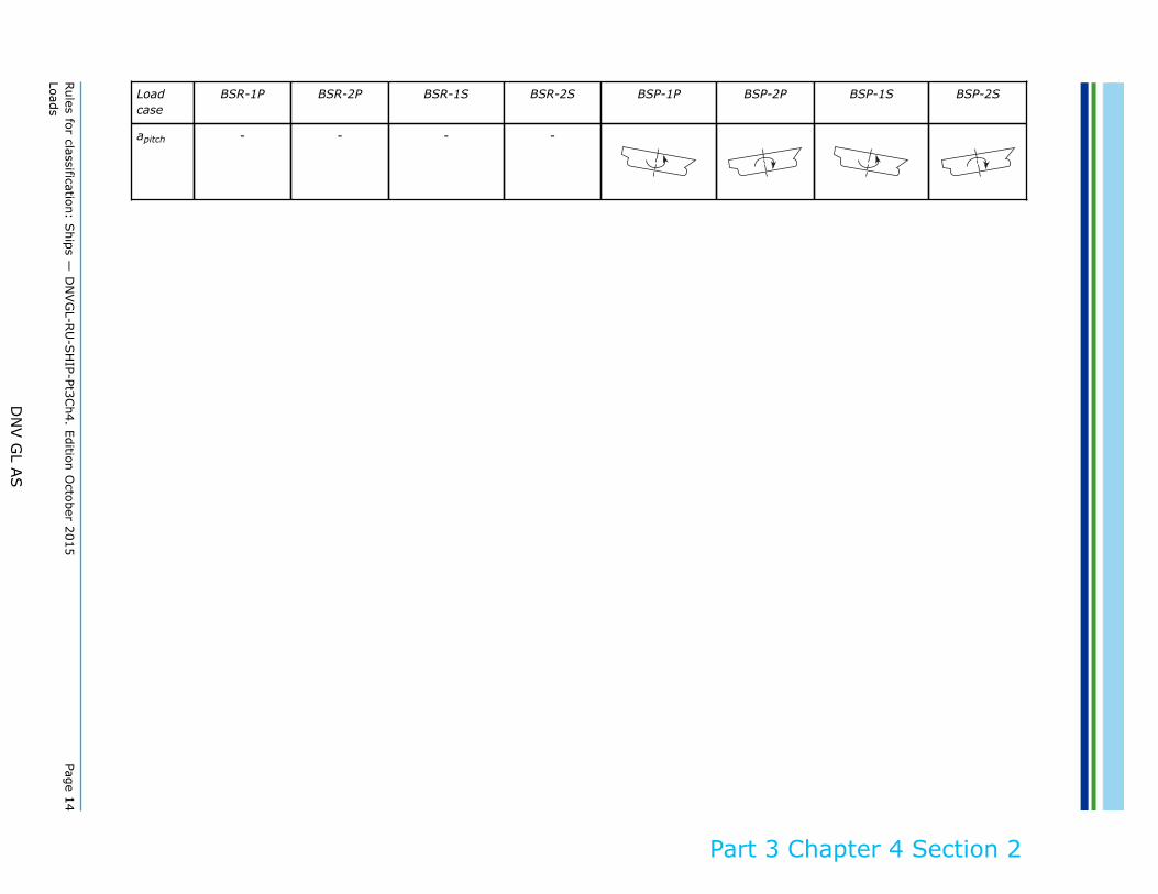
apitch - - - -

Rules for classification: S
hips — D
NVG
L-RU
-SH
IP-Pt3Ch4. Edition O
ctober 2015Page 15
Loads
DN
V G
L AS
Part 3 Chapter 4 Section 2
Table 3 Ship responses for OST and OSA load cases - strength assessment
Loadcase
OST-1P OST-2P OST-1S OST-2S OSA-1P OSA-2P OSA-1S OSA-2S
EDW OST OSA
Heading Oblique Oblique
Effect Max. torsional moment Max. pitch acceleration
VWBM Sagging Hogging Sagging Hogging Hogging Sagging Hogging Sagging
VWSF Negative–aftPositive–fore
Positive–aftNegative–fore
Negative–aftPositive–fore
Positive–aftNegative–fore
Positive–aftNegative–fore
Negative–aftPositive–fore
Positive–aftNegative–fore
Negative–aftPositive–fore
HWBM Port tensile Stbd tensile Stbd tensile Port tensile Stbd tensile Port tensile Port tensile Stbd tensile
TM
Surge To bow To stern To bow To stern To bow To stern To bow To stern
asurge
Sway - - - - To portside To starboard To starboard To portside
asway - - - -
Heave Down Up Down Up Up Down Up Down
aheave
Roll Portside down Portside up Starboard down Starboard up Portside down Portside up Starboard down Starboard up

Rules for classification: S
hips — D
NVG
L-RU
-SH
IP-Pt3Ch4. Edition O
ctober 2015Page 16
Loads
DN
V G
L AS
Part 3 Chapter 4 Section 2
Loadcase
OST-1P OST-2P OST-1S OST-2S OSA-1P OSA-2P OSA-1S OSA-2S
aroll
Pitch Bow up Bow down Bow up Bow down Bow up Bow down Bow up Bow down
apitch

Part
3 C
hapt
er 4
Sec
tion
2
Rules for classification: Ships — DNVGL-RU-SHIP-Pt3Ch4. Edition October 2015 Page 17Loads
DNV GL AS
2.2 Load combination factors
2.2.1 The load combinations factors, LCFs for the global loads and inertia load components for strengthassessment are defined in:Table 4: LCFs for HSM, HSA and FSM load cases.Table 5: LCFs for BSR and BSP load cases.Table 6: LCFs for OST and OSA load cases.
Table 4 Load combination factors, LCFs for HSM, HSA and FSM load cases - strength assessment
Load Component LCF HSM-1 HSM-2 HSA-1 HSA-2 FSM-1 FSM-2
MWV CWV -1 1 -0.7 0.7 -0.4fT - 0.6 0.4fT + 0.6
QWV CQW -1.0fℓp 1.0fℓp -0.6fℓp 0.6fℓp -1.0fℓp 1.0fℓp
MWH CWH 0 0 0 0 0 0
Hull girderloads
MWT CWT 0 0 0 0 0 0
asurge CXS 0.3 – 0.2fT 0.2fT - 0.3 0.2 -0.2 0.2 – 0.4fT 0.4fT - 0.2
apitch-x CXP -0.7 0.7 -1.0 1.0 0.15 -0.15Longitudinalaccelerations
gsinφ CXG 0.6 -0.6 0.4fT + 0.4 -0.4fT - 0.4 -0.2 0.2
asway CYS 0 0 0 0 0 0
aroll-y CYR 0 0 0 0 0 0Transverseaccelerations
gsinθ CYG 0 0 0 0 0 0
aheave CZH 0.5fT - 0.15 0.15 – 0.5fT 0.4 – 0.4 0 0
aroll-z CZR 0 0 0 0 0 0Verticalaccelerations
apitch-z CZP -0.7 0.7 -1.0 1.0 0.15 -0.15

Rules for classification: S
hips — D
NVG
L-RU
-SH
IP-Pt3Ch4. Edition O
ctober 2015Page 18
Loads
DN
V G
L AS
Part 3 Chapter 4 Section 2
Table 5 Load combination factors, LCFs for BSR and BSP load cases - strength assessment
Load component LCF BSR-1P BSR-2P BSR-1S BSR-2S BSP-1P BSP-2P BSP-1S BSP-2S
MWV CWV 0.1 – 0.2fT 0.2fT - 0.1 0.1 – 0.2fT 0.2fT - 0.1 0.3 – 0.8fT 0.8fT - 0.3 0.3 – 0.8fT 0.8fT - 0.3
QWV CQW (0.1 –0.2fT) fℓp
(0.2fT -0.1) fℓp
(0.1 –0.2fT) fℓp
(0.2fT -0.1) fℓp
(0.3 –0.8fT) fℓp
(0.8fT -0.3) fℓp
(0.3 –0.8fT) fℓp
(0.8fT -0.3) fℓp
MWH CWH 1.2 – 1.1fT 1.1fT – 1.2 1.1fT – 1.2 1.2 – 1.1fT 0.7 – 0.7fT 0.7fT - 0.7 0.7fT - 0.7 0.7 – 0.7fT
Hull girderloads
MWT CWT 0 0 0 0 0 0 0 0
asurge CXS 0 0 0 0 0 0 0 0
apitch-
x
CXP 0 0 0 0 0.1 – 0.3fT 0.3fT - 0.1 0.1 – 0.3fT 0.3fT - 0.1Longitudinalaccelerations
gsinφ CXG 0 0 0 0 0.3fT - 0.1 0.1 – 0.3fT 0.3fT - 0.1 0.1 – 0.3fT
asway CYS 0.2 – 0.2fT 0.2fT - 0.2 0.2fT - 0.2 0.2 – 0.2fT -0.9 0.9 0.9 -0.9
aroll-y CYR 1 -1 -1 1 0.3 -0.3 -0.3 0.3Transverseaccelerations
gsinθ CYG -1 1 1 -1 -0.2 0.2 0.2 -0.2
aheave CZH 0.7 – 0.4fT 0.4fT - 0.7 0.7 – 0.4fT 0.4fT - 0.7 1 -1 1 -1
aroll-z CZR 1 -1 -1 1 0.3 -0.3 -0.3 0.3Verticalaccelerations
apitch-
z
CZP 0 0 0 0 0.1 – 0.3fT 0.3fT - 0.1 0.1 – 0.3fT 0.3fT - 0.1

Rules for classification: S
hips — D
NVG
L-RU
-SH
IP-Pt3Ch4. Edition O
ctober 2015Page 19
Loads
DN
V G
L AS
Part 3 Chapter 4 Section 2
Table 6 Load combination factors, LCFs for OST and OSA load cases - strength assessment
Load component LCF OST-1P OST-2P OST-1S OST-2S OSA-1P OSA-2P OSA-1S OSA-2S
MWV CWV - 0.3 – 0.2fT 0.3 + 0.2fT - 0.3 – 0.2fT 0.3 + 0.2fT 0.75 - 0.5fT - 0.75+ 0.5fT
0.75 - 0.5fT - 0.75 + 0.5fT
QWV CQW (-0.35–0.2fT) fℓp
(0.35+0.2fT)fℓp
(-0.35-0.2fT)fℓp
(0.35+0.2fT)fℓp
(0.6-0.4fT)fℓp
(-0.6+0.4fT)fℓp
(0.6-0.4fT)fℓp
(-0.6+0.4fT) fℓp
MWH CWH - 0.9 0.9 0.9 - 0.9 0.55 + 0.2fT - 0.55 - 0.2fT - 0.55- 0.2fT
0.55 + 0.2fT
Hull girderloads
MWT CWT - fℓp-OST fℓp-OST fℓp-OST - fℓp-OST - fℓp-OSA fℓp-OSA fℓp-OSA -fℓp-OSA
asurge CXS 0.1fT - 0.15 0.15 – 0.1fT 0.1fT - 0.15 0.15 – 0.1fT 0.1fT - 0.45 0.45 – 0.1fT - 0.45+ 0.1fT
0.45 – 0.1fT
apitch-
x
CXP 0.7 – 0.3fT 0.3fT - 0.7 0.7 – 0.3fT 0.3fT - 0.7 1.0 - 1.0 1.0 - 1.0Longitudinalaccelerations
gsinφ CXG 0.2fT - 0.45 0.45 – 0.2fT 0.2fT - 0.45 0.45 – 0.2fT - 1.0 1.0 - 1.0 1.0
asway CYS 0 0 0 0 - 0.2 – 0.1fT 0.2 + 0.1fT 0.2 + 0.1fT - 0.2 – 0.1fT
aroll-y CYR 0.4fT - 0.25 0.25 - 0.4fT 0.25 - 0.4fT 0.4fT - 0.25 0.3 - 0.2fT 0.2fT - 0.3 0.2fT - 0.3 0.3 - 0.2fTTransverseaccelerations
gsinθ CYG 0.1 - 0.2fT 0.2fT - 0.1 0.2fT - 0.1 0.1 - 0.2fT 0.1fT - 0.2 0.2 - 0.1fT 0.2 - 0.1fT 0.1fT - 0.2
aheave CZH 0.2fT - 0.05 0.05 - 0.2fT 0.2fT - 0.05 0.05 - 0.2fT - 0.2fT 0.2fT - 0.2fT 0.2fT
aroll-z CZR 0.4fT - 0.25 0.25 - 0.4fT 0.25 - 0.4fT 0.4fT - 0.25 0.3 - 0.2fT 0.2fT - 0.3 0.2fT - 0.3 0.3 - 0.2fTVerticalaccelerations
apitch-
z
CZP 0.7 - 0.3fT 0.3fT - 0.7 0.7 - 0.3fT 0.3fT - 0.7 1.0 - 1.0 1.0 - 1.0

Part
3 C
hapt
er 4
Sec
tion
2
Rules for classification: Ships — DNVGL-RU-SHIP-Pt3Ch4. Edition October 2015 Page 20Loads
DNV GL AS
3 Dynamic load cases for fatigue assessment
3.1 Description of dynamic load cases
3.1.1 Table 7 to Table 9 define the ship motion responses and the global loads corresponding to eachdynamic load case to be considered for fatigue assessment.
Table 7 Ship responses for HSM and FSM load cases - fatigue assessment
Load case HSM-1 HSM-2 FSM-1 FSM-2
EDW HSM FSM
Heading Head Following
Effect Max. bending moment Max. bending moment
VWBM Sagging Hogging Sagging Hogging
VWSFNegative–aftPositive–fore
Positive–aftNegative–fore
Negative–aftPositive–fore
Positive–aftNegative–fore
HWBM - - - -
TM - - - -
Surge To stern To bow To bow To stern
asurge
Sway - - - -
asway - - - -
Heave Down Up - -
aheave
- -
Roll - - - -
aroll - - - -
Pitch Bow down Bow up Bow up Bow down
apitch

Rules for classification: S
hips — D
NVG
L-RU
-SH
IP-Pt3Ch4. Edition O
ctober 2015Page 21
Loads
DN
V G
L AS
Part 3 Chapter 4 Section 2
Table 8 Ship responses for BSR and BSP load cases - fatigue assessment
Loadcase BSR-1P BSR-2P BSR-1S BSR-2S BSP-1P BSP-2P BSP-1S BSP-2S
EDW BSR BSR BSP BSP
Heading Beam Beam
Effect Max. roll Max. pressure at waterline
VWBM Sagging Hogging Sagging Hogging Sagging Hogging Sagging Hogging
VWSFNegative–aftPositive–fore
Positive–aftNegative–fore
Negative–aftPositive–fore
Positive–aftNegative–fore
Negative–aftPositive–fore
Positive–aftNegative–fore
Negative–aftPositive–fore
Positive–aftNegative–fore
HWBM Stbd tensile Port tensile Port tensile Stbd tensile Stbd tensile Port tensile Port tensile Stbd tensile
TM - - - - - - - -
Surge - - - - - - - -
asurge - - - - - - - -
Sway To starboard To portside To portside To starboard To portside To starboard To starboard To portside
asway
Heave Down Up Down Up Down Up Down Up
aheave
Roll Portside down Portside up Starboard down Starboard up Portside down Portside up Starboard down Starboard up
aroll
Pitch - - - - - - - -
apitch - - - - - - - -

Part
3 C
hapt
er 4
Sec
tion
2
Rules for classification: Ships — DNVGL-RU-SHIP-Pt3Ch4. Edition October 2015 Page 22Loads
DNV GL AS
Table 9 Ship responses for OST load cases - fatigue assessment
Load case OST-1P OST-2P OST-1S OST-2S
EDW OST
Heading Oblique
Effect Max. torsional moment
VWBM Sagging Hogging Sagging Hogging
VWSFNegative–aftPositive–fore
Positive–aftNegative–fore
Negative–aftPositive–fore
Positive–aftNegative–fore
HWBM Port tensile Stbd tensile Stbd tensile Port tensile
TM
Surge To bow To stern To bow To stern
asurge
Sway - - - -
asway - - - -
Heave Up Down Up Down
aheave
Roll Portside down Portside up Starboard down Starboard up
aroll
Pitch Bow up Bow down Bow up Bow down
apitch

Part
3 C
hapt
er 4
Sec
tion
2
Rules for classification: Ships — DNVGL-RU-SHIP-Pt3Ch4. Edition October 2015 Page 23Loads
DNV GL AS
3.2 Load combination factors
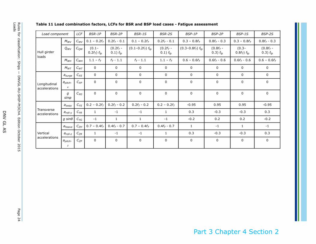
3.2.1 The load combinations factors, LCFs for the global loads and inertial load components for fatigueassessment are defined in:Table 10: LCFs for HSM and FSM load cases.Table 11: LCFs for BSR and BSP load cases.Table 12: LCFs for OST load case.
Table 10 Load combination factors, LCFs for HSM and FSM load cases - fatigue assessment
Load component LCF HSM-1 HSM-2 FSM-1 FSM-2
MWV CWV -1 1 -0.75 – 0.2fT 0.75 + 0.2fT
QWV CQW -1.0 fℓp 1.0 fℓp (-0.75-0.2fT) fℓp (0.75+0.2fT) fℓp
MWH CWH 0 0 0 0Hull girderloads
MWT CWT 0 0 0 0
asurge CXS 0.3 – 0.2fT 0.2fT - 0.3 -0.4fT + 0.2 0.4fT - 0.2
apitch-x CXP -0.9 0.9 0.1 -0.1Longitudinalaccelerations
g sinφ CXG 0.4fT + 0.4 -0.4fT - 0.4 -0.15 0.15
asway CYS 0 0 0 0
aroll-y CYR 0 0 0 0Transverseaccelerations
g sinθ CYG 0 0 0 0
aheave CZH 0.8fT - 0.15 0.15 – 0.8fT 0 0
aroll-z CZR 0 0 0 0Verticalaccelerations
apitch-z CZP -0.9 0.9 0.1 -0.1
Rules for classification: S
hips — D
NVG
L-RU
-SH
IP-Pt3Ch4. Edition O
ctober 2015Page 24
Loads
DN
V G
L AS
Part 3 Chapter 4 Section 2
Table 11 Load combination factors, LCFs for BSR and BSP load cases - Fatigue assessment
Load component LCF BSR-1P BSR-2P BSR-1S BSR-2S BSP-1P BSP-2P BSP-1S BSP-2S
MWV CWV 0.1 – 0.2fT 0.2fT - 0.1 0.1 – 0.2fT 0.2fT - 0.1 0.3 – 0.8fT 0.8fT - 0.3 0.3 – 0.8fT 0.8fT - 0.3
QWV CQW (0.1–0.2fT) fℓp
(0.2fT -0.1) fℓp
(0.1–0.2fT) fℓp (0.2fT -0.1) fℓp
(0.3–0.8fT) fℓp (0.8fT -0.3) fℓp
(0.3–0.8fT) fℓp
(0.8fT -0.3) fℓp
MWH CWH 1.1 – fT fT - 1.1 fT - 1.1 1.1 – fT 0.6 – 0.6fT 0.6fT - 0.6 0.6fT - 0.6 0.6 – 0.6fT
Hull girderloads
MWT CWT 0 0 0 0 0 0 0 0
asurge CXS 0 0 0 0 0 0 0 0
apitch-
x
CXP 0 0 0 0 0 0 0 0Longitudinalaccelerations
gsinφ
CXG 0 0 0 0 0 0 0 0
asway CYS 0.2 – 0.2fT 0.2fT - 0.2 0.2fT - 0.2 0.2 – 0.2fT -0.95 0.95 0.95 -0.95
aroll-y CYR 1 -1 -1 1 0.3 -0.3 -0.3 0.3Transverseaccelerations
g sinθ CYG -1 1 1 -1 -0.2 0.2 0.2 -0.2
aheave CZH 0.7 – 0.4fT 0.4fT - 0.7 0.7 – 0.4fT 0.4fT - 0.7 1 -1 1 -1
aroll-z CZR 1 -1 -1 1 0.3 -0.3 -0.3 0.3Verticalaccelerations
apitch-
z
CZP 0 0 0 0 0 0 0 0

Part
3 C
hapt
er 4
Sec
tion
2
Rules for classification: Ships — DNVGL-RU-SHIP-Pt3Ch4. Edition October 2015 Page 25Loads
DNV GL AS
Table 12 Load combination factors, LCFs for OST load cases - Fatigue assessment
Load component LCF OST-1P OST-2P OST-1S OST-2S
MWV CWV -0.4 0.4 -0.4 0.4
QWV CQW -0.4 fℓp 0.4 fℓp -0.4 fℓp 0.4 fℓp
MWH CWH -0.9 0.9 0.9 -0.9
Hull girderloads
MWT CWT - fℓp-OST fℓp-OST fℓp-OST - fℓp-OST
asurge CXS -0.25 + 0.2fT 0.25 - 0.2fT -0.25 + 0.2fT 0.25 - 0.2fT
apitch-x CXP 0.4 - 0.2fT -0.4 + 0.2fT 0.4 - 0.2fT -0.4 + 0.2fTLongitudinalaccelerations
gsinφ CXG -0.4 + 0.2fT 0.4 - 0.2fT -0.4 + 0.2fT 0.4 - 0.2fT
asway CYS 0 0 0 0
aroll-y CYR -0.4 + 0.6fT 0.4 - 0.6fT 0.4 - 0.6fT -0.4 + 0.6fTTransverseaccelerations
gsinθ CYG 0.2 - 0.3fT -0.2 + 0.3fT -0.2 + 0.3fT 0.2 - 0.3fT
aheave CZH -0.05 0.05 -0.05 0.05
aroll-z CZR -0.4 + 0.6fT 0.4 - 0.6fT 0.4 - 0.6fT -0.4 + 0.6fTVertical accelerations
apitch-z CZP 0.4 - 0.2fT -0.4 + 0.2fT 0.4 - 0.2fT -0.4 + 0.2fT

Part
3 C
hapt
er 4
Sec
tion
3
Rules for classification: Ships — DNVGL-RU-SHIP-Pt3Ch4. Edition October 2015 Page 26Loads
DNV GL AS
SECTION 3 SHIP MOTIONS AND ACCELERATIONSSymbols
For symbols not defined in this section, refer to Ch.1 Sec.4.
a0 = acceleration parameter, shall be taken as:
Tθ = roll period, in s, as defined in [2.1.1]θ = roll angle, in deg, as defined in [2.1.1]Tφ = pitch period, in s, as defined in [2.1.2]φ = pitch angle, in deg, as defined in [2.1.2]R = vertical coordinate, in m, of the ship rotation centre, shall be taken as:
CXG, CXS, CXP, CYG,CYS, CYR, CZH, CZR,and CZP
= load combination factors, as defined in Sec.2
aroll-y = transverse acceleration due to roll, in m/s2, as defined in [3.3.2]apitch-x = longitudinal acceleration due to pitch, in m/s2, as defined in [3.3.1]aroll-z = vertical acceleration due to roll, in m/s2, as defined in [3.3.3]apitch-z = vertical acceleration due to pitch, in m/s2, as defined in [3.3.3]fT = ratio between draught at a loading condition and scantling draught, shall be taken as:
, but shall not be taken less than 0.5
TLC = draught, in m, amidships for the considered loading condition. In case loading condition is notdefined, TLC = TSC shall be applied
x, y, z = X, Y and Z coordinates, in m, of the considered point with respect to the coordinate system, asdefined in Sec.1 [1.2.1]
fβ = heading correction factor, shall be taken as:for strength assessment:fβ = 1.0 in generalfβ = 0.8 for BSR and BSP load cases for the extreme sea loads design load scenariofor fatigue assessment:fβ = 1.0
fps = coefficient for strength assessments which is dependant on the applicable design load scenariospecified in Sec.7, and shall be taken as:fps = 1.0 for extreme sea loads design load scenariofps = fr for extreme sea loads design load scenario for vessels with service restrictionfps = 0.8 for the ballast water exchange design load scenariofps = 0.8·fr for the ballast water exchange design load scenario for vessels with service restriction
fr = reduction factor related to service restrictions as defined in Pt.1 Ch.2 Sec.5:1.0 for service area notation R0 (No reduction)0.9 for service area notation R1 (10% reduction)0.8 for service area notation R2 (20% reduction)0.7 for service area notation R3 (30% reduction)
Part
3 C
hapt
er 4
Sec
tion
3
Rules for classification: Ships — DNVGL-RU-SHIP-Pt3Ch4. Edition October 2015 Page 27Loads
DNV GL AS
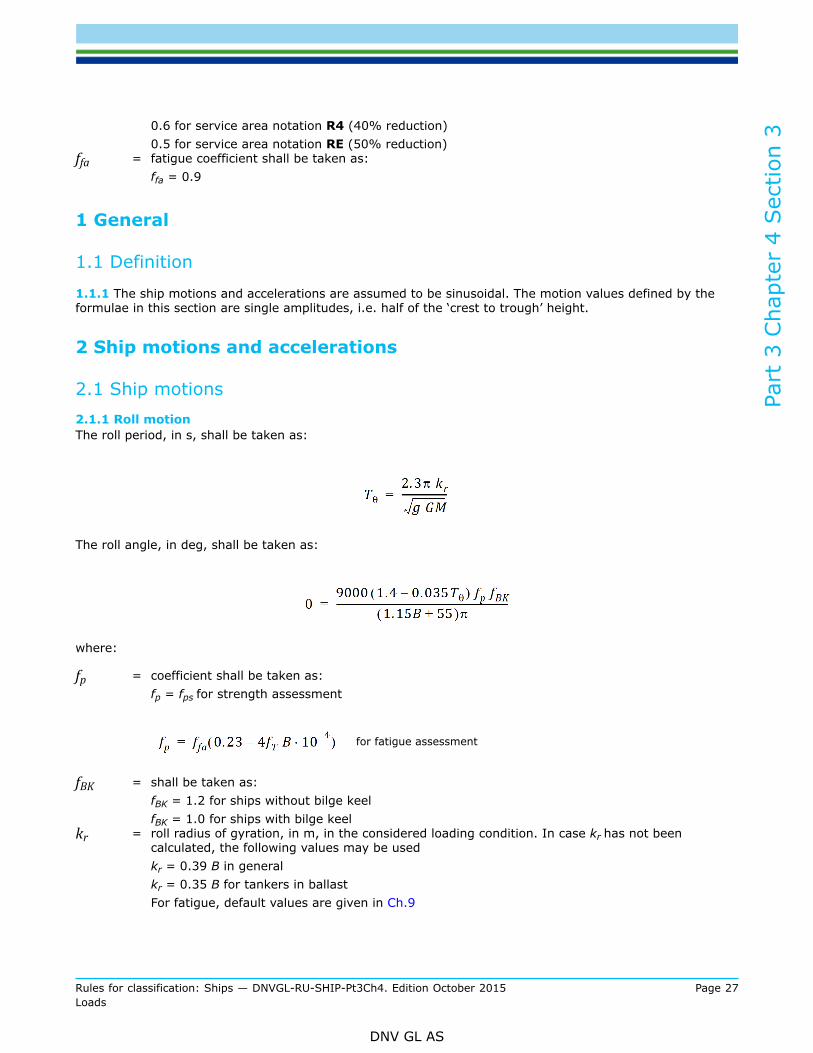
0.6 for service area notation R4 (40% reduction)0.5 for service area notation RE (50% reduction)
ffa = fatigue coefficient shall be taken as:ffa = 0.9
1 General
1.1 Definition
1.1.1 The ship motions and accelerations are assumed to be sinusoidal. The motion values defined by theformulae in this section are single amplitudes, i.e. half of the ‘crest to trough’ height.
2 Ship motions and accelerations
2.1 Ship motions2.1.1 Roll motionThe roll period, in s, shall be taken as:
The roll angle, in deg, shall be taken as:
where:
fp = coefficient shall be taken as:fp = fps for strength assessment
for fatigue assessment
fBK = shall be taken as:fBK = 1.2 for ships without bilge keelfBK = 1.0 for ships with bilge keel
kr = roll radius of gyration, in m, in the considered loading condition. In case kr has not beencalculated, the following values may be usedkr = 0.39 B in generalkr = 0.35 B for tankers in ballastFor fatigue, default values are given in Ch.9

Part
3 C
hapt
er 4
Sec
tion
3
Rules for classification: Ships — DNVGL-RU-SHIP-Pt3Ch4. Edition October 2015 Page 28Loads
DNV GL AS
GM = metacentric height, in m, in the considered loading condition, minimum 0.05 B. In case GM hasnot been calculated, the following values may be adopted:GM = 0.07 B in generalGM = 0.12 B for tankersGM = 0.05 B for container ship with B ≤ 32.2 mGM = 0.11 B for container ship with B ≥ 40.0 mLinear interpolation may be used for 32.2 m ≤ B ≤ 40.0 mFor fatigue, default values are given in Ch.9.
2.1.2 Pitch motionThe pitch period, in s, shall be taken as:
where:
The pitch angle, in deg, shall be taken as:
where:
fp = coefficient shall be taken as:fp = fps for strength assessment
for fatigue assessment.
2.2 Ship accelerations at the centre of gravity2.2.1 Surge accelerationThe longitudinal acceleration due to surge, in m/s2, shall be taken as:

Part
3 C
hapt
er 4
Sec
tion
3
Rules for classification: Ships — DNVGL-RU-SHIP-Pt3Ch4. Edition October 2015 Page 29Loads
DNV GL AS
where:
fp = coefficient shall be taken as:fp = fps for strength assessment
for fatigue assessment.
2.2.2 Sway accelerationThe transverse acceleration due to sway, in m/s2, shall be taken as:
where:
fp = coefficient shall be taken as:fp = fps for strength assessment
for fatigue assessment.
2.2.3 Heave accelerationThe vertical acceleration due to heave, in m/s2, shall be taken as:
L < 100 m
100 ≤ L < 150 m
L ≥ 150 m
where:
v = Unless otherwise specified in Pt.5, to be taken as:0 kt for L < 100 m5 kt for L ≥ 150 mLinear interpolation for L between 100 m and 150 m
fp = coefficient shall be taken as:fp = fps for strength assessment

Part
3 C
hapt
er 4
Sec
tion
3
Rules for classification: Ships — DNVGL-RU-SHIP-Pt3Ch4. Edition October 2015 Page 30Loads
DNV GL AS
for fatigue assessment.
2.2.4 Roll accelerationThe roll acceleration, aroll, in rad/s2, shall be taken as:
where:
θ = roll angle using fp equal to 1.0fp = coefficient shall be taken as:
fp = fps for strength assessment
for fatigue assessment.
2.2.5 Pitch accelerationThe pitch acceleration, in rad/s2, shall be taken as:
L < 100 m
100 ≤ L < 150 m
L ≥ 150 m
where:
φ = pitch angle using fp equal to 1.0v = as defined in [2.2.3]fp = coefficient shall be taken as:
fp = fps for strength assessment.
for fatigue assessment.
Part
3 C
hapt
er 4
Sec
tion
3
Rules for classification: Ships — DNVGL-RU-SHIP-Pt3Ch4. Edition October 2015 Page 31Loads
DNV GL AS
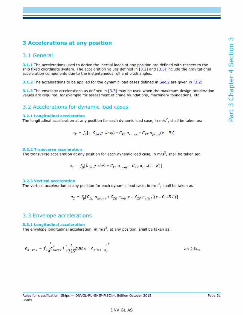
3 Accelerations at any position
3.1 General
3.1.1 The accelerations used to derive the inertial loads at any position are defined with respect to theship fixed coordinate system. The acceleration values defined in [3.2] and [3.3] include the gravitationalacceleration components due to the instantaneous roll and pitch angles.
3.1.2 The accelerations to be applied for the dynamic load cases defined in Sec.2 are given in [3.2].
3.1.3 The envelope accelerations as defined in [3.3] may be used when the maximum design accelerationvalues are required, for example for assessment of crane foundations, machinery foundations, etc.
3.2 Accelerations for dynamic load cases3.2.1 Longitudinal accelerationThe longitudinal acceleration at any position for each dynamic load case, in m/s2, shall be taken as:
3.2.2 Transverse accelerationThe transverse acceleration at any position for each dynamic load case, in m/s2, shall be taken as:
3.2.3 Vertical accelerationThe vertical acceleration at any position for each dynamic load case, in m/s2, shall be taken as:
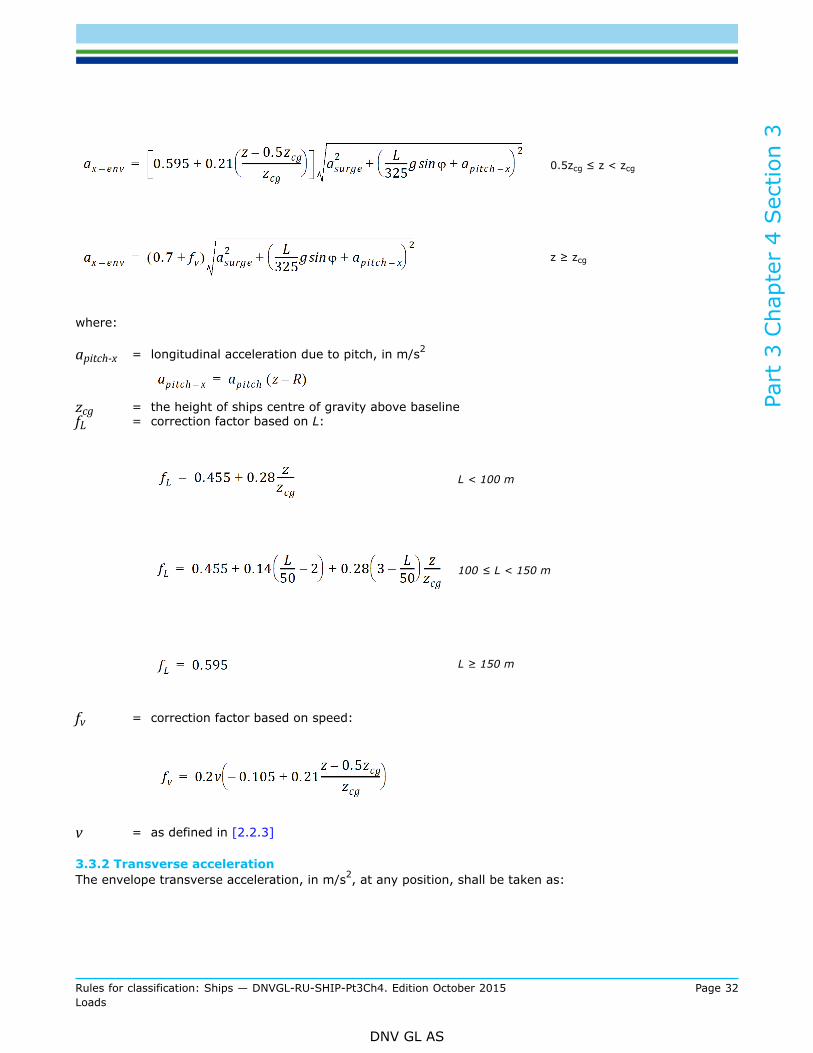
3.3 Envelope accelerations3.3.1 Longitudinal accelerationThe envelope longitudinal acceleration, in m/s2, at any position, shall be taken as:
z < 0.5zcg
Part
3 C
hapt
er 4
Sec
tion
3
Rules for classification: Ships — DNVGL-RU-SHIP-Pt3Ch4. Edition October 2015 Page 32Loads
DNV GL AS
0.5zcg ≤ z < zcg
z ≥ zcg
where:
apitch-x = longitudinal acceleration due to pitch, in m/s2
zcg = the height of ships centre of gravity above baselinefL = correction factor based on L:
L < 100 m
100 ≤ L < 150 m
L ≥ 150 m
fv = correction factor based on speed:
v = as defined in [2.2.3]
3.3.2 Transverse accelerationThe envelope transverse acceleration, in m/s2, at any position, shall be taken as:

Part
3 C
hapt
er 4
Sec
tion
3
Rules for classification: Ships — DNVGL-RU-SHIP-Pt3Ch4. Edition October 2015 Page 33Loads
DNV GL AS
where:
aroll-y = transverse acceleration due to roll, in m/s2
aroll-y = aroll(z-R)
3.3.3 Vertical accelerationThe envelope vertical acceleration, in m/s2, at any position, shall be taken as:
where:
apitch-z = vertical acceleration due to pitch, in m/s2
apitch-z = apitch(1.08x - 0.45L)aroll-z = vertical acceleration due to roll, in m/s2
aroll-z = arolly

Part
3 C
hapt
er 4
Sec
tion
4
Rules for classification: Ships — DNVGL-RU-SHIP-Pt3Ch4. Edition October 2015 Page 34Loads
DNV GL AS
SECTION 4 HULL GIRDER LOADSSymbols
For symbols not defined in this section, refer to Ch.1 Sec.4.
x = X coordinate, in m, of the calculation point with respect to the reference coordinate system definedin Sec.1 [1.2.1]
Cw = wave coefficient, in m, shall be taken as:
for L < 90
for 90 ≤ L ≤ 300
for 300 < L ≤ 350
for 350 < L ≤ 500
fβ = heading correction factor, shall be taken as:for strength assessment:fβ = 1.0 in generalfβ = 0.8 for BSR and BSP load cases for the extreme sea loads design load scenariofor fatigue assessment:fβ = 1.0fps = coefficient, as defined in Sec.3
BSR, BSP, HSM, HSA, FSM, OST, OSA = Dynamic load cases, as defined in Sec.2
1 Application
1.1 General
1.1.1 The hull girder loads for the static (S) design load scenarios shall be taken as the still water loadsdefined in [2].
1.1.2 The total hull girder loads for the static plus dynamic (S+D) design load scenarios shall be derived foreach dynamic load case and shall be taken as the sum of the still water loads defined in [2] and the dynamicloads defined in [3.5].

Part
3 C
hapt
er 4
Sec
tion
4
Rules for classification: Ships — DNVGL-RU-SHIP-Pt3Ch4. Edition October 2015 Page 35Loads
DNV GL AS
2 Still water hull girder loads
2.1 General2.1.1 Seagoing conditionsPermissible still water bending moments and shear forces for seagoing operations shall be provided for shipswith L > 65m, and may upon consideration also be requested for smaller ships.The permissible still water hull girder loads shall be given at points of local maxima for the design loadingconditions. For typical cargo vessels permissible values at the following points shall be provided: at eachtransverse bulkhead in the cargo area, at the middle of cargo compartments, at the collision bulkhead, at theengine room forward bulkhead and at the mid-point between the forward and aft engine room bulkheads.The permissible hull girder bending moments and shear forces at any other position may be obtained bylinear interpolation.
Guidance note:It is recommended that, for initial design, the permissible hull girder hogging and sagging still water bending moments are at least5% above the maximum still water bending moment from loading conditions in the loading manual, and the permissible hull girdershear forces are at least 10 % above the maximum still water shear force from loading condition in the loading manual, to accountfor growth and design margins during the design and construction phase of the ship.
---e-n-d---of---g-u-i-d-a-n-c-e---n-o-t-e---
2.1.2 Still water loads for the fatigue assessmentThe still water bending moment and shear force values and distribution shall be used for the fatigueassessment should be taken as the most typical values applicable for the loading conditions that the ship willoperate in for most of its life. The definition of loading conditions to use is specified in Pt.5.
2.2 Vertical still water bending moment2.2.1 Minimum still water bending moment in seagoing conditionAs guidance values, at a preliminary design stage, the minimum still water bending moments, in kNm, forhogging and sagging respectively, in seagoing condition amidships are normally to be taken as:
Hogging conditions:
Sagging conditions:
where:
Mwv-h-mid = vertical wave bending moment for strength assessment amidships in hogging condition, asdefined in [3.1.1] using fp and fm equal to 1.0
Mwv-s-mid = vertical wave bending moment for strength assessment amidships in sagging condition, asdefined in [3.1.1] using fp and fm equal to 1.0
fsw = distribution factor along the ship length, shall be taken as, see Figure 1:

Part
3 C
hapt
er 4
Sec
tion
4
Rules for classification: Ships — DNVGL-RU-SHIP-Pt3Ch4. Edition October 2015 Page 36Loads
DNV GL AS
fsw = 0.0 for x ≤ 0
fsw = 0.15 at x = 0.1 L
fsw = 1.0 for 0.3 L ≤ x ≤ 0.7 L
fsw = 0.15 at x = 0.9 L
fsw = 0.0 for x ≥ L
Intermediate values of fsw shall be obtained by linear interpolation.
Figure 1 Distribution factor fsw
2.2.2 Permissible vertical still water bending moment in seagoing conditionThe permissible vertical still water bending moments, Msw-h and Msw-s, in kNm, for hogging and saggingrespectively, in seagoing condition at any longitudinal position are to envelop:
— the most severe still water bending moments calculated, in hogging and sagging conditions, respectively,for the seagoing loading conditions defined in Sec.8
— the most severe still water bending moments for the seagoing loading conditions defined in the loadingmanual
2.2.3 Permissible vertical still water bending moment in harbour/sheltered water conditionThe permissible vertical still water bending moments, Msw-p-h and Msw-p-s, in kNm, for hogging and saggingrespectively, in the harbour/sheltered water condition at any longitudinal position are to envelop:
— the most severe still water bending moments for the harbour/sheltered water loading conditions defined inthe loading manual
— the permissible still water bending moment defined in [2.2.2].

Part
3 C
hapt
er 4
Sec
tion
4
Rules for classification: Ships — DNVGL-RU-SHIP-Pt3Ch4. Edition October 2015 Page 37Loads
DNV GL AS
2.3 Still water torsion moment for container ships
2.3.1 The design still water torsion moment in seagoing condition, in kNm, may be taken as a constant valuealong the whole ship length and may be taken as:
where:
CC = distribution factor.Shall be taken as:
CC = n · G
n = maximum number of 20 ft containers (TEU)G = maximum mass in tonnes of each TEU the ship can carry
For the purpose of a direct calculation the following static torsional moment, in kNm, over the ship length fora dynamic load case may be taken as:
2.4 Vertical still water shear force2.4.1 Minimum still water shear forceAs guidance values, at a preliminary design stage, the minimum hull girder positive and negative vertical stillwater shear force, in kN, in seagoing condition shall be taken as:
where:
Msw-min = absolute maximum of Msw-h-min and Msw-s-min with fsw=1.0fqs = distribution factor along the ship length. Shall be taken as:
fqs = 0.0 for x ≤ 0
fqs = 1.0 at 0.15 L ≤ x ≤ 0.3 L
Part
3 C
hapt
er 4
Sec
tion
4
Rules for classification: Ships — DNVGL-RU-SHIP-Pt3Ch4. Edition October 2015 Page 38Loads
DNV GL AS
fqs = 0.8 for 0.4 L ≤ x ≤ 0.6 L
fqs = 1.0 at 0.7 L ≤ x ≤ 0.85 L
fqs = 0.0 for x ≥ L
Intermediate values of fqs shall be obtained by linear interpolation.
2.4.2 Permissible still water shear forceThe permissible vertical still water shear forces, Qsw-pos and Qsw-neg in seagoing condition at any longitudinalposition are to envelop:
— the most severe still water shear forces, positive or negative, for the seagoing loading conditions definedin Sec.8
— the most severe still water shear forces for the seagoing loading conditions defined in the loading manual
2.4.3 Permissible still water shear force in harbour/sheltered water conditionThe permissible vertical still water shear forces, Qsw-p-pos and Qsw-p-neg, in kN, in the harbour/sheltered waterand tank testing condition at any longitudinal position are to envelop:
— the most severe still water shear forces for the harbour/sheltered water loading conditions defined in theloading manual
— the permissible still water shear forces defined in [2.4.2].
3 Dynamic hull girder loads
3.1 Vertical wave bending moment
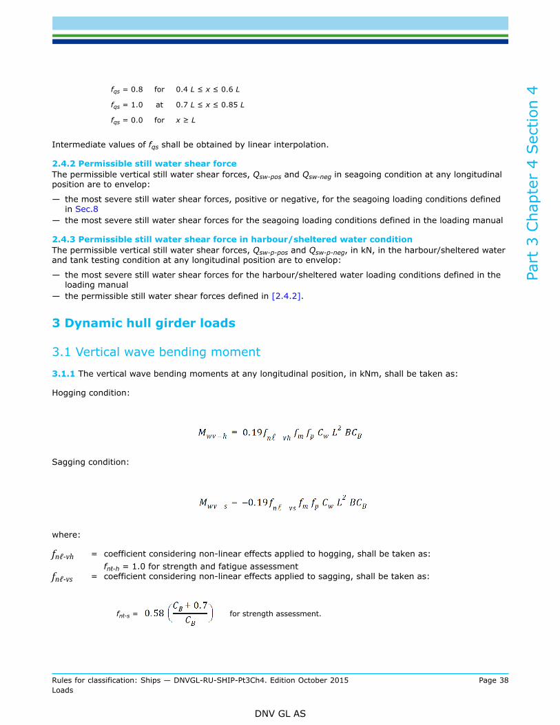
3.1.1 The vertical wave bending moments at any longitudinal position, in kNm, shall be taken as:
Hogging condition:
Sagging condition:
where:
fnℓ-vh = coefficient considering non-linear effects applied to hogging, shall be taken as:fnℓ-h = 1.0 for strength and fatigue assessment
fnℓ-vs = coefficient considering non-linear effects applied to sagging, shall be taken as:
fnℓ-s =
for strength assessment.
Part
3 C
hapt
er 4
Sec
tion
4
Rules for classification: Ships — DNVGL-RU-SHIP-Pt3Ch4. Edition October 2015 Page 39Loads
DNV GL AS
fnℓ-s = 1.0 for fatigue assessment.
fp = coefficient shall be taken as:
fp = fps for strength assessment.
fp = 0.9fvib[0.27 - (6 + 4fT) L · 10-5] for fatigue assessment.
fvib = correction for minimum contribution from hull girder vibration:= 1.10 for B ≤ 28 m= 1.2 for B > 40 mLinear interpolation shall be applied between 28 m < B ≤ 40 m
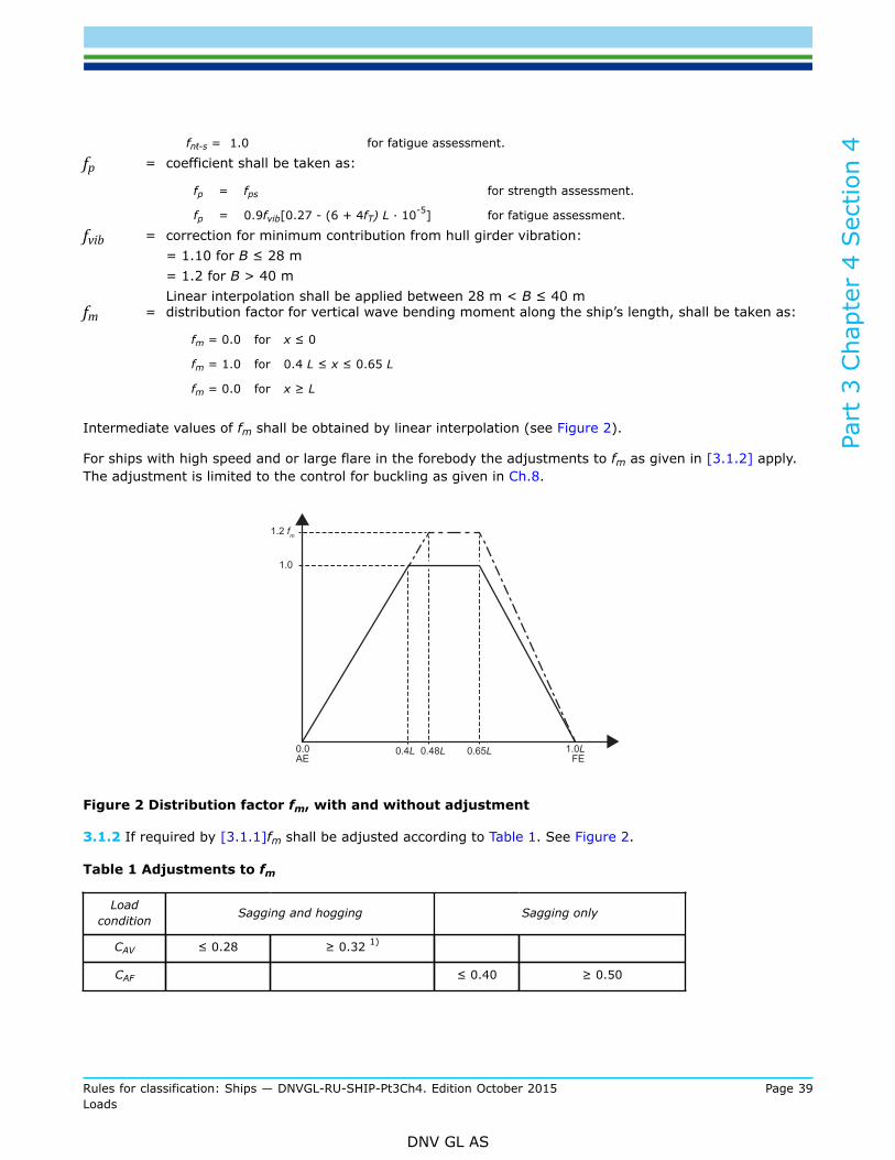
fm = distribution factor for vertical wave bending moment along the ship’s length, shall be taken as:
fm = 0.0 for x ≤ 0
fm = 1.0 for 0.4 L ≤ x ≤ 0.65 L
fm = 0.0 for x ≥ L
Intermediate values of fm shall be obtained by linear interpolation (see Figure 2).
For ships with high speed and or large flare in the forebody the adjustments to fm as given in [3.1.2] apply.The adjustment is limited to the control for buckling as given in Ch.8.
Figure 2 Distribution factor fm, with and without adjustment
3.1.2 If required by [3.1.1]fm shall be adjusted according to Table 1. See Figure 2.
Table 1 Adjustments to fm
Loadcondition Sagging and hogging Sagging only
CAV ≤ 0.28 ≥ 0.32 1)
CAF ≤ 0.40 ≥ 0.50

Part
3 C
hapt
er 4
Sec
tion
4
Rules for classification: Ships — DNVGL-RU-SHIP-Pt3Ch4. Edition October 2015 Page 40Loads
DNV GL AS
Loadcondition Sagging and hogging Sagging only
fm
No adjustment1.2 between 0.48 L and0.65 L from A.E.
0.0 at F.E. and A.E.
Noadjustment
1.2 between 0.48 L and0.65 L from A.E.
0.0 at F.E. and A.E.
1) Adjustment for CAV shall not be applied when CAF ≥ 0.50.
CAV =
CAF =
cv =
ADK = projected area in the horizontal plane of upper deck (including any forecastle deck) forward of0.2 L from F.E
AWP = area of waterplane forward of 0.2 L from F.E. at draught TSCzf = vertical distance from summer load waterline to deckline measured at F.E
Between specified CA-values and positions fm shall be varied linearly.
3.2 Vertical wave shear force
3.2.1 The vertical wave shear forces at any longitudinal position, in kN, shall be taken as:
Qwv-pos = 0.52 fq-pos fp · CW L ·B · CB
Qwv-neg = -(0.52 fq-neg fp · CW L ·B · CB)
where:
fp = coefficient shall be taken as:
fp = fps for strength assessment.
fp = 0.97 [0.27 - (17 - 8 fT) L · 10-5] for fatigue assessment.
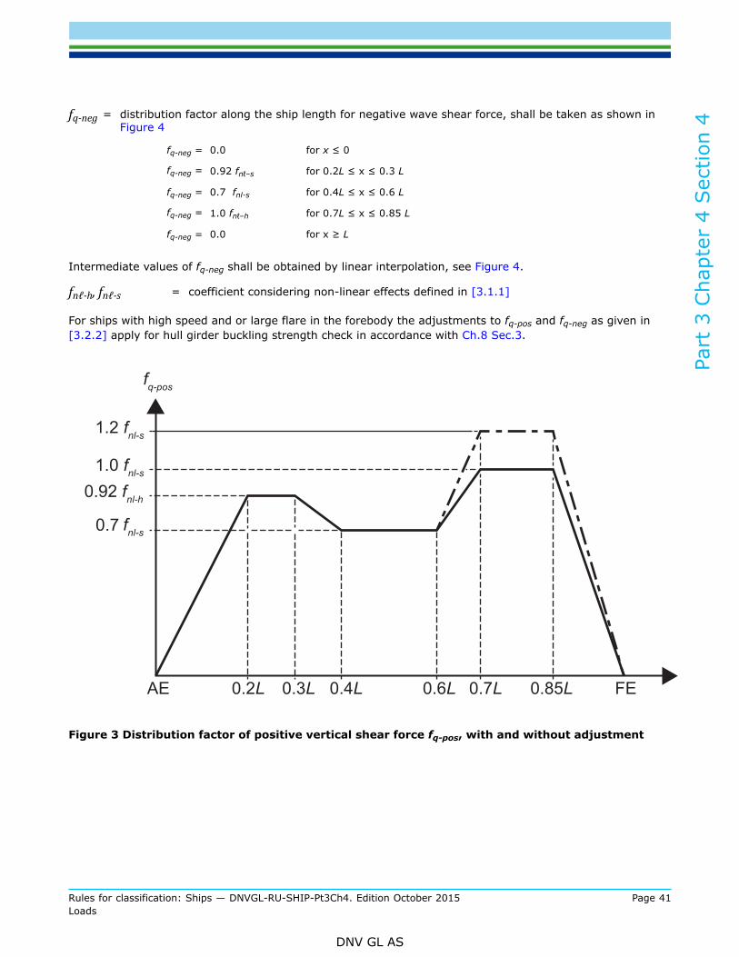
fq-pos = distribution factor along the ship length for positive wave shear force, shall be taken as shown inFigure 3
fq-pos = 0.0 for x ≤ 0
fq-pos = 0.92 fnℓ-h for 0.2 L ≤ x ≤ 0.3 L
fq-pos = 0.7 fnl-s for 0.4 L ≤ x ≤ 0.6 L
fq-pos = 1.0 fnℓ-s for 0.7 L ≤ x ≤ 0.85 L
fq-pos = 0.0 for x ≥ L
Intermediate values of fq-pos shall be obtained by linear interpolation (see Figure 3).
Part
3 C
hapt
er 4
Sec
tion
4
Rules for classification: Ships — DNVGL-RU-SHIP-Pt3Ch4. Edition October 2015 Page 41Loads
DNV GL AS
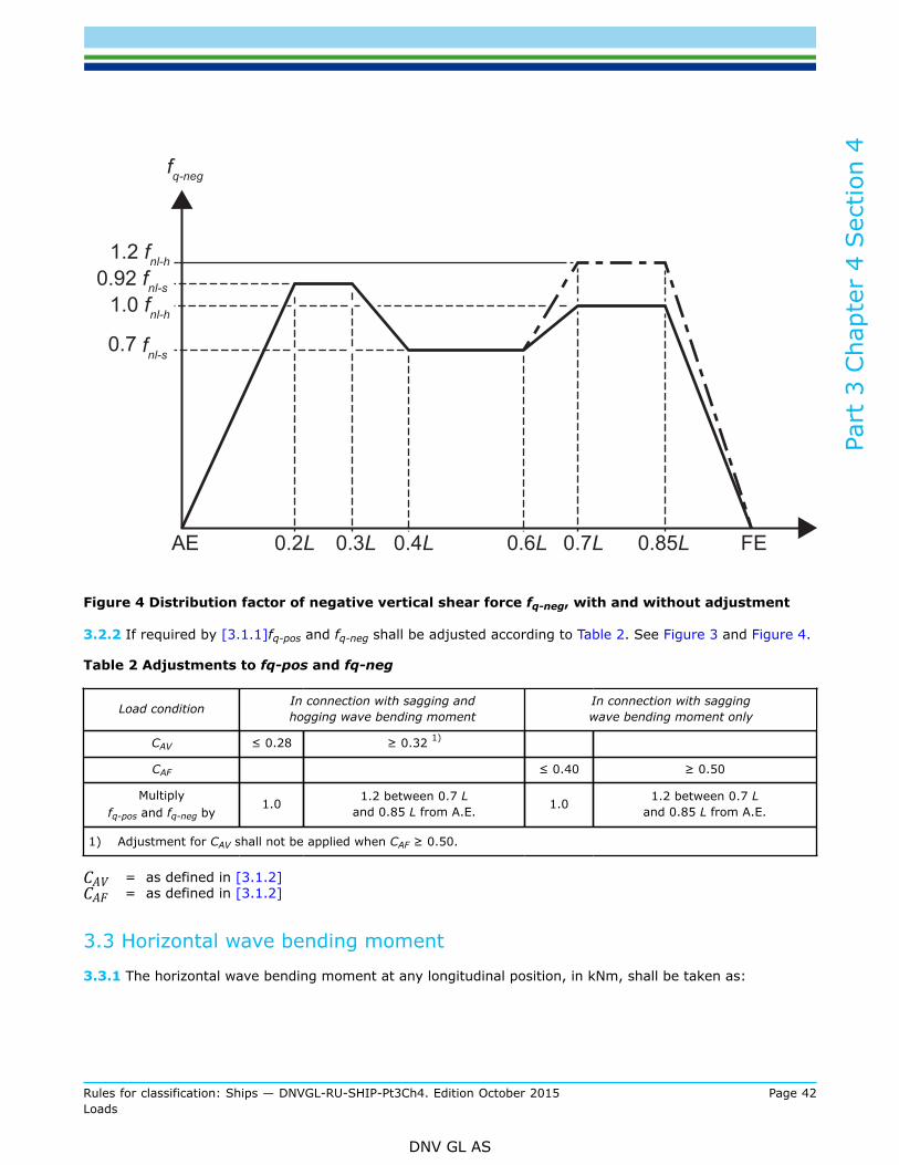
fq-neg = distribution factor along the ship length for negative wave shear force, shall be taken as shown inFigure 4
fq-neg = 0.0 for x ≤ 0
fq-neg = 0.92 fnℓ–s for 0.2L ≤ x ≤ 0.3 L
fq-neg = 0.7 fnl-s for 0.4L ≤ x ≤ 0.6 L
fq-neg = 1.0 fnℓ–h for 0.7L ≤ x ≤ 0.85 L
fq-neg = 0.0 for x ≥ L
Intermediate values of fq-neg shall be obtained by linear interpolation, see Figure 4.
fnℓ-h, fnℓ-s = coefficient considering non-linear effects defined in [3.1.1]
For ships with high speed and or large flare in the forebody the adjustments to fq-pos and fq-neg as given in[3.2.2] apply for hull girder buckling strength check in accordance with Ch.8 Sec.3.
Figure 3 Distribution factor of positive vertical shear force fq-pos, with and without adjustment
Part
3 C
hapt
er 4
Sec
tion
4
Rules for classification: Ships — DNVGL-RU-SHIP-Pt3Ch4. Edition October 2015 Page 42Loads
DNV GL AS
Figure 4 Distribution factor of negative vertical shear force fq-neg, with and without adjustment
3.2.2 If required by [3.1.1]fq-pos and fq-neg shall be adjusted according to Table 2. See Figure 3 and Figure 4.
Table 2 Adjustments to fq-pos and fq-neg
Load condition In connection with sagging andhogging wave bending moment
In connection with saggingwave bending moment only
CAV ≤ 0.28 ≥ 0.32 1)
CAF ≤ 0.40 ≥ 0.50
Multiplyfq-pos and fq-neg by
1.0 1.2 between 0.7 Land 0.85 L from A.E. 1.0 1.2 between 0.7 L
and 0.85 L from A.E.
1) Adjustment for CAV shall not be applied when CAF ≥ 0.50.
CAV = as defined in [3.1.2]CAF = as defined in [3.1.2]
3.3 Horizontal wave bending moment
3.3.1 The horizontal wave bending moment at any longitudinal position, in kNm, shall be taken as:

Part
3 C
hapt
er 4
Sec
tion
4
Rules for classification: Ships — DNVGL-RU-SHIP-Pt3Ch4. Edition October 2015 Page 43Loads
DNV GL AS
where:
fnℓh = coefficient considering non-linear effect shall be taken as:fnℓh = 0.9 for strength assessmentfnℓh = 1.0 for fatigue assessment
fp = coefficient shall be taken as:
fp = fps for strength assessment.
fp = 0.9 · [(0.2 + 0.04fT) + (11 - 8fT) L ·10-5] for fatigue assessment.
fm = distribution factor defined in [3.1.1]
3.4 Wave torsional moment3.4.1 GeneralThe factors for the longitudinal distribution of the torsional moment for the OST load case shall be taken asfollows:
fℓp-OST = 5 fxL for x/L < 0.2
fℓp-OST = 1.0 for 0.2 ≤ x/L < 0.4
fℓp-OST = -7.6 fxL + 4.04 for 0.4 ≤ x/L < 0.65
fℓp-OST = -0.9 for 0.65 ≤ x/L < 0.85
fℓp-OST = 6 fxL - 6 for 0.85 ≤ x/L
The factors for the longitudinal distribution of the torsional moment for the OSA load case shall be taken asfollows:
fℓp-OSA = -(0.2 + 0.3 fT) for x/L < 0.4
fℓp-OSA = -(0.2 + 0.3 fT)(5.6 – 11.5 fxL) for 0.4 ≤ x/L < 0.6
fℓp-OSA = 1.3(0.2 + 0.3 fT) for 0.6 ≤ x/L
3.4.2 The wave torsional moment at any longitudinal position with respect to the ship baseline, in kNm, shallbe taken as:
Mwt = fp (Mwt1 + Mwt2)
where:

Part
3 C
hapt
er 4
Sec
tion
4
Rules for classification: Ships — DNVGL-RU-SHIP-Pt3Ch4. Edition October 2015 Page 44Loads
DNV GL AS
ft1, ft2 = distribution factors, taken as:
ft1 = 0 for x < 0
for 0 ≤ x ≤ L
ft1 = 0 for x > L
ft2 = 0 for x < 0
for 0 ≤ x ≤ L
ft2 = 0 for x > L
fp = coefficient shall be taken as:
fp = fps for strength assessment.
fp = 0.9 [0.2 + (5fT - 4.25) B · 10-4] for fatigue assessment.
3.5 Hull girder loads for dynamic load cases3.5.1 GeneralThe dynamic hull girder loads shall be applied for the dynamic load cases defined in Sec.2, are given in[3.5.2] to [3.5.5].
3.5.2 Vertical wave bending momentThe vertical wave bending moment, Mwv-LC, in kNm, shall be used for each dynamic load case in Sec.2, isdefined in Table 3.
Table 3 Vertical wave bending moment for dynamic load cases
Load combination factor Mwv-LC
CWV ≥ 0
CWV < 0
where:
CWV = load combination factor for vertical wave bending moment, shall be taken as specified inSec.2
Mwv-h, Mwv-s = hogging and sagging vertical wave bending moment taking into account the considereddesign load scenario, as defined in [3.1.1].
Part
3 C
hapt
er 4
Sec
tion
4
Rules for classification: Ships — DNVGL-RU-SHIP-Pt3Ch4. Edition October 2015 Page 45Loads
DNV GL AS
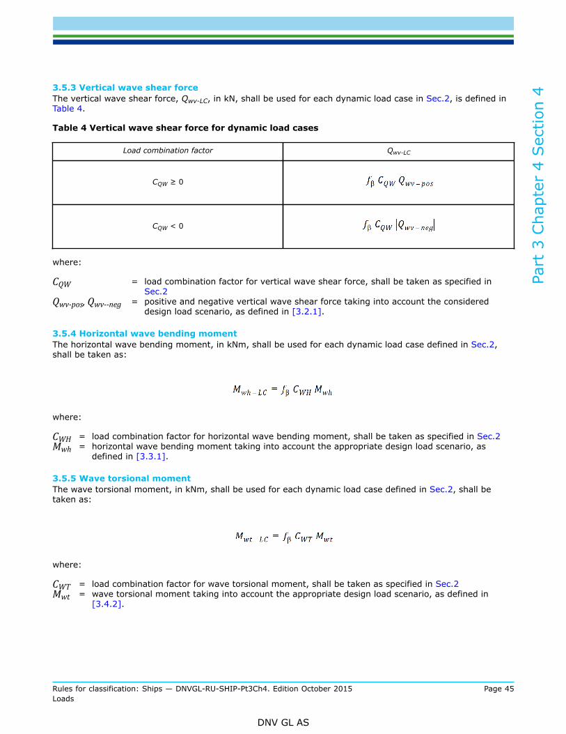
3.5.3 Vertical wave shear forceThe vertical wave shear force, Qwv-LC, in kN, shall be used for each dynamic load case in Sec.2, is defined inTable 4.
Table 4 Vertical wave shear force for dynamic load cases
Load combination factor Qwv-LC
CQW ≥ 0
CQW < 0
where:
CQW = load combination factor for vertical wave shear force, shall be taken as specified inSec.2
Qwv-pos, Qwv--neg = positive and negative vertical wave shear force taking into account the considereddesign load scenario, as defined in [3.2.1].
3.5.4 Horizontal wave bending momentThe horizontal wave bending moment, in kNm, shall be used for each dynamic load case defined in Sec.2,shall be taken as:
where:
CWH = load combination factor for horizontal wave bending moment, shall be taken as specified in Sec.2Mwh = horizontal wave bending moment taking into account the appropriate design load scenario, as
defined in [3.3.1].
3.5.5 Wave torsional momentThe wave torsional moment, in kNm, shall be used for each dynamic load case defined in Sec.2, shall betaken as:
where:
CWT = load combination factor for wave torsional moment, shall be taken as specified in Sec.2Mwt = wave torsional moment taking into account the appropriate design load scenario, as defined in
[3.4.2].
Part
3 C
hapt
er 4
Sec
tion
5
Rules for classification: Ships — DNVGL-RU-SHIP-Pt3Ch4. Edition October 2015 Page 46Loads
DNV GL AS
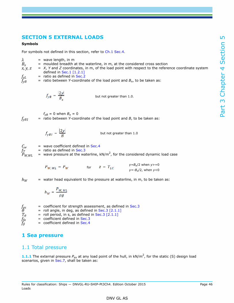
SECTION 5 EXTERNAL LOADSSymbols
For symbols not defined in this section, refer to Ch.1 Sec.4.
λ = wave length, in mBx = moulded breadth at the waterline, in m, at the considered cross sectionx, y, z = X, Y and Z coordinates, in m, of the load point with respect to the reference coordinate system
defined in Sec.1 [1.2.1]fxL = ratio as defined in Sec.2fyB = ratio between Y-coordinate of the load point and Bx, to be taken as:
but not greater than 1.0.
fyB = 0 when Bx = 0fyB1 = ratio between Y-coordinate of the load point and B, to be taken as:
but not greater than 1.0
Cw = wave coefficient defined in Sec.4fT = ratio as defined in Sec.3PW,WL = wave pressure at the waterline, kN/m2, for the considered dynamic load case
for
y=Bx/2 when y>=0
y=-Bx/2, when y<0
hW = water head equivalent to the pressure at waterline, in m, to be taken as:
fps = coefficient for strength assessment, as defined in Sec.3θ = roll angle, in deg, as defined in Sec.3 [2.1.1]Tθ = roll period, in s, as defined in Sec.3 [2.1.1]ffa = coefficient defined in Sec.3fβ = coefficient defined in Sec.4
1 Sea pressure
1.1 Total pressure
1.1.1 The external pressure Pex at any load point of the hull, in kN/m2, for the static (S) design loadscenarios, given in Sec.7, shall be taken as:

Part
3 C
hapt
er 4
Sec
tion
5
Rules for classification: Ships — DNVGL-RU-SHIP-Pt3Ch4. Edition October 2015 Page 47Loads
DNV GL AS
but not less than 0.
The total pressure Pex at any load point of the hull for the static plus dynamic (S+D) design load scenarios,given in Sec.7, shall be derived from each dynamic load case and shall be taken as:
but not less than 0.
where:
PS = Hydrostatic pressure, in kN/m2, defined in [1.2].PW = Wave pressure, in kN/m2, is defined in [1.3].
1.2 Hydrostatic pressure1.2.1 The hydrostatic pressure, PS at any load point, in kN/m2, is obtained from Table 1. See also Figure 1.
Table 1 Hydrostatic pressure, PS
Location Hydrostatic Pressure,PS, in kN/m2
z ≤ TLC ρ g (TLC – z)
z > TLC 0
Figure 1 Hydrostatic pressure, PS

Part
3 C
hapt
er 4
Sec
tion
5
Rules for classification: Ships — DNVGL-RU-SHIP-Pt3Ch4. Edition October 2015 Page 48Loads
DNV GL AS
1.3 External dynamic pressures for strength assessment1.3.1 GeneralThe hydrodynamic pressures for each dynamic load case defined in Sec.2 [2] are defined in [1.3.2] to[1.3.8].
1.3.2 Hydrodynamic pressures for HSM load casesThe hydrodynamic pressures, PW, for HSM-1 and HSM-2 load cases, at any load point, in kN/m2, shall beobtained from Table 2. See also Figure 2 and Figure 3.
Table 2 Hydrodynamic pressures for HSM load cases
Wave pressure, in kN/m2
Load case
HSM-1
HSM-2
PW = PW,WL - ρg(z - TLC) PW = 0.0
where:
CfT = fT + 0.5 -(0.7fT - 0.2)CBfnℓ = coefficient considering non-linear effects, to be taken as:
for extreme sea loads design load scenario:fnℓ = 0.7 at fxL = 0fnℓ = 0.9 at fxL = 0.3fnℓ = 0.9 at fxL = 0.7fnℓ = 0.6 at fxL = 1for ballast water exchange design load scenario:fnℓ = 0.85 at fxL = 0fnℓ = 0.95 at fxL = 0.3fnℓ = 0.95 at fxL = 0.7fnℓ = 0.80 at fxL = 1Intermediate values are obtained by linear interpolation.
fyz = girth distribution coefficient, to be taken as:

Part
3 C
hapt
er 4
Sec
tion
5
Rules for classification: Ships — DNVGL-RU-SHIP-Pt3Ch4. Edition October 2015 Page 49Loads
DNV GL AS
Cx = coefficient to be taken as:
fh = coefficient to be taken as:
ka = amplitude coefficient in the longitudinal direction of the ship, to be taken as:
for
for
for
λ = wave length of the dynamic load case, in m, to be taken as: λ = 0.6(1 + fT)Lkp = phase coefficient to be obtained from Table 3. Intermediate values shall be interpolated
Table 3 kp values for HSM load cases
fxL 0 0.3 – 0.1 fT 0.35 – 0.1 fT 0.8 – 0.2 fT 0.9 – 0.2 fT 1.0
kp – 0.25 fT(1 + fyB) -1 1 1 -1 -1
Figure 2 Transverse distribution amidships of dynamic pressure for HSM-1, HSA-1 and FSM-1 loadcases

Part
3 C
hapt
er 4
Sec
tion
5
Rules for classification: Ships — DNVGL-RU-SHIP-Pt3Ch4. Edition October 2015 Page 50Loads
DNV GL AS
Figure 3 Transverse distribution amidships of dynamic pressure for HSM-2, HSA-2 and FSM-2 loadcases
1.3.3 Hydrodynamic pressures for HSA load casesThe hydrodynamic pressures, PW, for HSA-1 and HSA-2 load cases at any load point, in kN/m2, shall beobtained from Table 4. See also Figure 2 and Figure 3.
Table 4 Hydrodynamic pressures for HSA load cases
Wave pressure, in kN/m2
Load case
HSA-1
HSA-2
PW = PW,WL - ρg(z - TLC) PW = 0.0
where:
PHS = as defined in [1.3.2]fnℓ = coefficient considering non-linear effects, to be taken as defined in [1.3.2]fyz = girth distribution coefficient as defined in [1.3.2]fh = coefficient to be taken as:
fh = 2.4(1.21 – 0.66 fT)ka = amplitude coefficient in the longitudinal direction of the ship, to be taken as defined in [1.3.2]λ = wave length of the dynamic load case, in m, as defined in [1.3.2]

Part
3 C
hapt
er 4
Sec
tion
5
Rules for classification: Ships — DNVGL-RU-SHIP-Pt3Ch4. Edition October 2015 Page 51Loads
DNV GL AS
kp = phase coefficient to be obtained from Table 5. Intermediate values shall be interpolated.
Table 5 kp values for HSA load cases
fxL 0 0.3 – 0.1 fT 0.5 – 0.2 fT 0.8 – 0.2 fT 0.9 – 0.2 fT 1.0
kp 1.5 – fT – 0.5 fyB) -1 1 1 -1 -1
1.3.4 Hydrodynamic pressures for FSM load casesThe hydrodynamic pressures, PW, for FSM-1 and FSM-2 load cases, at any load point, in kN/m2, shall beobtained from Table 6. See also Figure 2 and Figure 3.
Table 6 Hydrodynamic pressures for FSM load cases
Wave pressure, in kN/m2
Load case
FSM-1
FSM-2
PW = PW,WL - ρg(z - TLC) PW = 0.0
where:
CfT = coefficient to be taken as:
fnℓ = coefficient considering non-linear effects, to be taken as:fnℓ = 0.9 for extreme sea loads design load scenario.fnℓ = 0.95 for ballast water exchange design load scenarios.
fyz = girth distribution coefficient to be taken as:
Cx = coefficient to be taken as:

Part
3 C
hapt
er 4
Sec
tion
5
Rules for classification: Ships — DNVGL-RU-SHIP-Pt3Ch4. Edition October 2015 Page 52Loads
DNV GL AS
fh = coefficient to be taken as: fh = 2.6ka = amplitude coefficient in the longitudinal direction of the ship, to be taken as:
for
for
for
λ = wave length of the dynamic load case, in m, to be taken as:
kp = phase coefficient to be obtained from Table 7. Intermediate values shall be interpolated.
Table 7 kp values for FSM load cases
fxL 0
0.75 0.8 1.0
kp
-1 1 1 -1
1.3.5 Hydrodynamic pressures for BSR load casesThe wave pressures, PW, for BSR-1 and BSR-2 load cases, at any load point, in kN/m2, shall be obtained fromTable 8. See also Figure 4 and Figure 5.
Table 8 Hydrodynamic pressures for BSR load cases
Wave pressure, in kN/m2
Load case
BSR-1P PW = max (PBSR, ρg(z - TLC))
BSR-2P PW = max (- PBSR, ρg(z - TLC))
BSR-1S PW = max (PBSR, ρg(z - TLC))
BSR-2S PW = max (- PBSR, ρg(z - TLC))
PW = PW,WL - ρg(z - TLC) PW = 0.0
where:

Part
3 C
hapt
er 4
Sec
tion
5
Rules for classification: Ships — DNVGL-RU-SHIP-Pt3Ch4. Edition October 2015 Page 53Loads
DNV GL AS
for BSR-1P and BSR-2P load cases.
for BSR-1S and BSR-2S load cases.
fnℓ = coefficient considering non-linear effect, to be taken as:fnℓ = 1 for extreme sea loads design load scenario.fnℓ = 1 for ballast water exchange design load scenarios.
λ = wave length of the dynamic load case, in m, to be taken as:
PD = Green sea pressure on exposed deck as defined in [2.2].
Figure 4 Transverse distribution of dynamic pressure for BSR-1P (left) and BSR-1S (right) loadcases
Figure 5 Transverse distribution of dynamic pressure for BSR-2P (left) and BSR-2S (right) loadcases

Part
3 C
hapt
er 4
Sec
tion
5
Rules for classification: Ships — DNVGL-RU-SHIP-Pt3Ch4. Edition October 2015 Page 54Loads
DNV GL AS
1.3.6 Hydrodynamic pressures for BSP load casesThe wave pressures, PW, for BSP-1 and BSP-2 load cases, at any load point, in kN/m2, shall be obtained fromTable 9. See also Figure 6 and Figure 7.
Table 9 Hydrodynamic pressures for BSP load cases
Wave pressure, in kN/m2
Load case z ≤ TLC TLC < z ≤ hW + TLC z > hW + TLC
BSP-1P PW = max (PBSP, ρg (z - TLC))
BSP-2P PW = max (- PBSP, ρg (z - TLC))
BSP-1S PW = max (PBSP, ρg (z - TLC))
BSP-2S PW = max (- PBSP, ρg (z - TLC))
PW = PW,WL - ρg (z-TLC) PW = 0.0
where:
λ = wave length of the dynamic load case, in m, to be taken as: λ = 0.2(1 + 2fT)Lfyz = girth distribution coefficient, to be obtained from Table 10
Table 10 Girth distribution coefficient, fyz for BSP load cases
Transverse position BSP-1P - BSP-2P BSP-1S - BSP-2S
fnℓ = coefficient considering non-linear effect, to be taken as:for extreme sea loads design load scenario:fnℓ = 0.6 at fxL = 0fnℓ = 0.8 at fxL = 0.3fnℓ = 0.8 at fxL = 0.7fnℓ = 0.6 at fxL = 1for ballast water exchange design load scenario:fnℓ = 0.6 at fxL = 0fnℓ = 0.8 at fxL = 0.3fnℓ = 0.8 at fxL = 0.7fnℓ = 0.6 at fxL = 1

Part
3 C
hapt
er 4
Sec
tion
5
Rules for classification: Ships — DNVGL-RU-SHIP-Pt3Ch4. Edition October 2015 Page 55Loads
DNV GL AS
Intermediate values are obtained by linear interpolation.fcorr1 = fullness and draft correction factor, to be taken as:
fcorr1 =
fcorr2 = ship length correction factor, to be taken as:
for
for
for
for
Figure 6 Transverse distribution of dynamic pressure for BSP-1P (left) and BSP-1S (right) loadcases
Part
3 C
hapt
er 4
Sec
tion
5
Rules for classification: Ships — DNVGL-RU-SHIP-Pt3Ch4. Edition October 2015 Page 56Loads
DNV GL AS
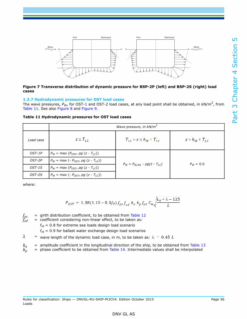
Figure 7 Transverse distribution of dynamic pressure for BSP-2P (left) and BSP-2S (right) loadcases
1.3.7 Hydrodynamic pressures for OST load casesThe wave pressures, PW, for OST-1 and OST-2 load cases, at any load point shall be obtained, in kN/m2, fromTable 11. See also Figure 8 and Figure 9.
Table 11 Hydrodynamic pressures for OST load cases
Wave pressure, in kN/m2
Load case
OST-1P PW = max (POST, ρg (z - TLC))
OST-2P PW = max (- POST, ρg (z - TLC))
OST-1S PW = max (POST, ρg (z - TLC))
OST-2S PW = max (- POST, ρg (z - TLC))
PW = PW,WL - ρg(z - TLC) PW = 0.0
where:
fyz = girth distribution coefficient, to be obtained from Table 12fnℓ = coefficient considering non-linear effect, to be taken as:
fnℓ = 0.8 for extreme sea loads design load scenariofnℓ = 0.9 for ballast water exchange design load scenarios
λ = wave length of the dynamic load case, in m, to be taken as:
ka = amplitude coefficient in the longitudinal direction of the ship, to be obtained from Table 13kp = phase coefficient to be obtained from Table 14. Intermediate values shall be interpolated

Part
3 C
hapt
er 4
Sec
tion
5
Rules for classification: Ships — DNVGL-RU-SHIP-Pt3Ch4. Edition October 2015 Page 57Loads
DNV GL AS
Table 12 Girth distribution coefficient, fyz for OST load cases
Transverse position OST-1P - OST-2P OST-1S - OST-2S
Table 13 ka values for OST load cases
Transverseposition
LongitudinalPosition OST-1P - OST-2P OST-1S - OST-2S
1.0 1.0
1.0
1.0 1.0
1.0
Table 14 kp values for OST load cases
Transverse position fxL OST-1P - OST-2P OST-1S - OST-2S
0.0 1.0 1.0
0.2 1.0

Part
3 C
hapt
er 4
Sec
tion
5
Rules for classification: Ships — DNVGL-RU-SHIP-Pt3Ch4. Edition October 2015 Page 58Loads
DNV GL AS
Transverse position fxL OST-1P - OST-2P OST-1S - OST-2S
0.4 -1.0
0.5 -1.0
0.7
0.9
1.0
0.0 1.0 1.0
0.2
1.0
0.4
-1.0
0.5
-1.0
0.7
0.9
1.0
Part
3 C
hapt
er 4
Sec
tion
5
Rules for classification: Ships — DNVGL-RU-SHIP-Pt3Ch4. Edition October 2015 Page 59Loads
DNV GL AS
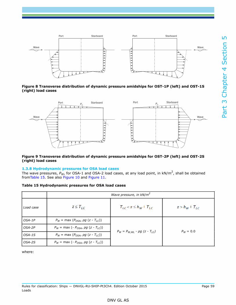
Figure 8 Transverse distribution of dynamic pressure amidships for OST-1P (left) and OST-1S(right) load cases
Figure 9 Transverse distribution of dynamic pressure amidships for OST-2P (left) and OST-2S(right) load cases
1.3.8 Hydrodynamic pressures for OSA load casesThe wave pressures, PW, for OSA-1 and OSA-2 load cases, at any load point, in kN/m2, shall be obtainedfromTable 15. See also Figure 10 and Figure 11.
Table 15 Hydrodynamic pressures for OSA load cases
Wave pressure, in kN/m2
Load case
OSA-1P PW = max (POSA, ρg (z - TLC))
OSA-2P PW = max (- POSA, ρg (z - TLC))
OSA-1S PW = max (POSA, ρg (z - TLC))
OSA-2S PW = max (- POSA, ρg (z - TLC))
PW = PW,WL - ρg (z - TLC) PW = 0.0
where:

Part
3 C
hapt
er 4
Sec
tion
5
Rules for classification: Ships — DNVGL-RU-SHIP-Pt3Ch4. Edition October 2015 Page 60Loads
DNV GL AS
λ = wave length of the dynamic load case, in m, to be taken as: λ = 0.7 Lfcorr = fullness and draft correction factor, to be taken as:
fcorr =
fnℓ = coefficient considering non-linear effect, to be taken as:for extreme sea loads design load scenario:fnℓ = 0.5 at fxL = 0fnℓ = 0.8 at fxL = 0.3fnℓ = 0.8 at fxL = 0.7fnℓ = 0.6 at fxL = 1for ballast water exchange design load scenario:fnℓ = 0.75 at fxL = 0fnℓ = 0.9 at fxL = 0.3fnℓ = 0.9 at fxL = 0.7fnℓ = 0.8 at fxL = 1
Intermediate values are obtained by linear interpolation.
fyz = girth distribution coefficient, to be obtained from Table 16ka = amplitude coefficient in the longitudinal direction of the ship, to be obtained from Table 17kp = phase coefficient to be obtained from Table 18. Intermediate values shall be interpolated
Table 16 Girth distribution coefficient, fyz for OSA load cases
Transverse position OSA-1P - OSA-2P OSA-1S - OSA-2S

Part
3 C
hapt
er 4
Sec
tion
5
Rules for classification: Ships — DNVGL-RU-SHIP-Pt3Ch4. Edition October 2015 Page 61Loads
DNV GL AS
Figure 10 Transverse distribution of dynamic pressure amidships for OSA-1P (left) and OSA-1S(right) load cases
Figure 11 Transverse distribution of dynamic pressure amidships for OSA-2P (left) and OSA-2S(right) load cases
Table 17 ka values for OSA load cases
Transverseposition
Longitudinalposition OSA-1P - OSA-2P OSA-1S - OSA-2S
1.0
1.0

Part
3 C
hapt
er 4
Sec
tion
5
Rules for classification: Ships — DNVGL-RU-SHIP-Pt3Ch4. Edition October 2015 Page 62Loads
DNV GL AS
Transverseposition
Longitudinalposition OSA-1P - OSA-2P OSA-1S - OSA-2S
1.0
1.0
where:
Table 18 kp values for OSA load cases
Transverseposition fxL OSA-1P; OSA-2P OSA-1S; OSA-2S
0.0 0.75
0.1
0.35 1.0
0.4
0.55

Part
3 C
hapt
er 4
Sec
tion
5
Rules for classification: Ships — DNVGL-RU-SHIP-Pt3Ch4. Edition October 2015 Page 63Loads
DNV GL AS
Transverseposition fxL OSA-1P; OSA-2P OSA-1S; OSA-2S
0.85
1.0
0.0 0.75
0.1
0.35 1.0
0.4
0.55
0.85
1.0
1.3.9 Envelope of dynamic pressureThe envelope of dynamic pressure at any point, Pex-max, shall be taken as the greatest pressure obtainedfrom any of the load cases determined by [1.3.2] to [1.3.8].
1.4 External dynamic pressures for fatigue assessments1.4.1 GeneralThe external pressure Pex at any load point of the hull for the fatigue static plus dynamic (F:S+D) design loadscenario, shall be derived for each fatigue dynamic load case and shall be taken as:
Pex = PS + PW but not less than 0.
where:
PS = hydrostatic pressure, in kN/m2, defined in [1.2]PW = hydrodynamic pressure, in kN/m2, is defined in [1.4.2] to [1.4.6]
1.4.2 Hydrodynamic pressures for HSM load casesThe hydrodynamic pressures, PW, for load cases HSM-1 and HSM-2, at any load point, in kN/m2, shall beobtained from Table 19.
Table 19 Hydrodynamic pressures for HSM load cases
Wave pressure, in kN/m2
Load case
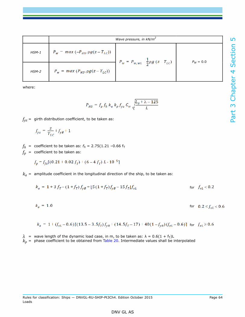
Part
3 C
hapt
er 4
Sec
tion
5
Rules for classification: Ships — DNVGL-RU-SHIP-Pt3Ch4. Edition October 2015 Page 64Loads
DNV GL AS
Wave pressure, in kN/m2
HSM-1
HSM-2
PW = 0.0
where:
fyz = girth distribution coefficient, to be taken as:
fh = coefficient to be taken as: fh = 2.75(1.21 –0.66 fTfp = coefficient to be taken as:
ka = amplitude coefficient in the longitudinal direction of the ship, to be taken as:
for
for
for
λ = wave length of the dynamic load case, in m, to be taken as: λ = 0.6(1 + fT)Lkp = phase coefficient to be obtained from Table 20. Intermediate values shall be interpolated

Part
3 C
hapt
er 4
Sec
tion
5
Rules for classification: Ships — DNVGL-RU-SHIP-Pt3Ch4. Edition October 2015 Page 65Loads
DNV GL AS
Table 20 kp values for HSM load cases
fxL kP
0
-1
1
1
-1
1.0 -1
1.4.3 Hydrodynamic pressures for FSM load casesThe hydrodynamic pressures, PW, for FSM-1 and FSM-2 load cases, at any load point, in kN/m2, shall beobtained from Table 21.
Table 21 Hydrodynamic pressures for FSM load cases
Wave pressure, in kN/m2
Load case
FSM-1
FSM-2
PW = 0.0
where:

Part
3 C
hapt
er 4
Sec
tion
5
Rules for classification: Ships — DNVGL-RU-SHIP-Pt3Ch4. Edition October 2015 Page 66Loads
DNV GL AS
fyz = girth distribution coefficient, to be taken as:
fh = coefficient to be taken as: fh = 2.6fp = coefficient to be taken as: fp = ffa[(0.21 + 0.02 fT + (6 – 4 fT)L · 10-5]ka = amplitude coefficient in the longitudinal direction of the ship, to be taken as:
for
for
for
λ = wave length of the dynamic load case, in m, to be taken as:
kp = phase coefficient to be obtained from Table 22. Intermediate values shall be interpolated
Table 22 kp values for HSM load cases
fxL kP
0
-1
1
1

Part
3 C
hapt
er 4
Sec
tion
5
Rules for classification: Ships — DNVGL-RU-SHIP-Pt3Ch4. Edition October 2015 Page 67Loads
DNV GL AS
fxL kP
-1
1.0
1.4.4 Hydrodynamic pressures for BSR load casesThe hydrodynamic pressures, PW, for BSR-1 and BSR-2 load cases, at any load point, in kN/m2, shall beobtained from Table 23.
Table 23 Hydrodynamic pressures for BSR load cases
Wave pressure, in kN/m2
Load case
BSR-1P PW = max (PBSR, ρg(z - TLC))
BSR-2P PW = max (- PBSR, ρg(z - TLC))
BSR-1S PW = max (PBSR, ρg(z - TLC))
BSR-2S PW = max (- PBSR, ρg(z - TLC))
PW = 0.0
where:
for BSR-1P and BSR-2P load cases.
for BSR-1S and BSR-2S load cases.
fp = coefficient to be taken as: fp = ffa[(0.21 + 0.04 fT – (12 fT – 2) B · 10-4]λ = wave length of the dynamic load case, in m, to be taken as:
1.4.5 Hydrodynamic pressures for BSP load cases

Part
3 C
hapt
er 4
Sec
tion
5
Rules for classification: Ships — DNVGL-RU-SHIP-Pt3Ch4. Edition October 2015 Page 68Loads
DNV GL AS
The wave pressures, PW, for BSP-1 and BSP-2 load cases, at any load point, in kN/m2, shall be obtained fromTable 24.
Table 24 Hydrodynamic pressures for BSP load cases
Wave pressure, in kN/m2
Load case
BSP-1P PW = max (PBSP, ρg(z - TLC))
BSP-2P PW = max (- PBSP, ρg(z - TLC))
BSP-1S PW = max (PBSP, ρg(z - TLC))
BSP-2S PW = max (- PBSP, ρg(z - TLC))
PW = 0.0
where:
λ = wave length of the dynamic load case, in m, to be taken as: λ = (0.2(1 + 2 fT) Lfcorr1 = fullness and draft correction factor, to be taken as:
fcorr2 = ship length correction factor, to be taken as:
for
for
for
for
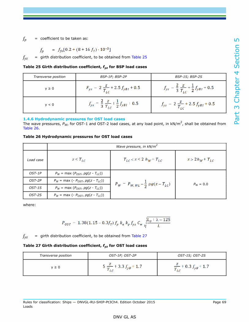
Part
3 C
hapt
er 4
Sec
tion
5
Rules for classification: Ships — DNVGL-RU-SHIP-Pt3Ch4. Edition October 2015 Page 69Loads
DNV GL AS
fp = coefficient to be taken as:
fp =
fyz = girth distribution coefficient, to be obtained from Table 25
Table 25 Girth distribution coefficient, fyz for BSP load cases
Transverse position BSP-1P; BSP-2P BSP-1S; BSP-2S
y ≥ 0
y < 0
1.4.6 Hydrodynamic pressures for OST load casesThe wave pressures, PW, for OST-1 and OST-2 load cases, at any load point, in kN/m2, shall be obtained fromTable 26.
Table 26 Hydrodynamic pressures for OST load cases
Wave pressure, in kN/m2
Load case
OST-1P PW = max (POST, ρg(z - TLC))
OST-2P PW = max (- POST, ρg(z - TLC))
OST-1S PW = max (POST, ρg(z - TLC))
OST-2S PW = max (- POST, ρg(z - TLC))
PW = 0.0
where:
fyz = girth distribution coefficient, to be obtained from Table 27
Table 27 Girth distribution coefficient, fyz for OST load cases
Transverse position OST-1P; OST-2P OST-1S; OST-2S
y ≥ 0

Part
3 C
hapt
er 4
Sec
tion
5
Rules for classification: Ships — DNVGL-RU-SHIP-Pt3Ch4. Edition October 2015 Page 70Loads
DNV GL AS
Transverse position OST-1P; OST-2P OST-1S; OST-2S
y < 0
fp = coefficient to be taken as: fp= 0.28CB + 0.01λ = wave length of the dynamic load case, in m, to be taken as:λ = 0.45 Lka = amplitude coefficient in the longitudinal direction of the ship, to be obtained from Table 28kp = phase coefficient to be obtained from Table 29. Intermediate values shall be interpolated
Table 28 ka values for OST load cases
Transverseposition
LongitudinalPosition OST-1P; OST-2P OST-1S; OST-2S
1.0 1.0
y ≥ 0
1.0
1.0 1.0
y < 0
1.0
Table 29 kp values for OST load cases
Transverse position fxL OST-1P - OST-2P OST-1S - OST-2S
0.0 1.0
0.2 1.0
0.4 -1.0
0.5 -1.0
0.7
y ≥ 0
0.9

Part
3 C
hapt
er 4
Sec
tion
5
Rules for classification: Ships — DNVGL-RU-SHIP-Pt3Ch4. Edition October 2015 Page 71Loads
DNV GL AS
Transverse position fxL OST-1P - OST-2P OST-1S - OST-2S
1.0
0.0 1.0
0.2 1.0
0.4 -1.0
0.5 -1.0
0.7
0.9
y < 0
1.0 – 1.0
2 Pressures on exposed decks
2.1 Application
2.1.1 Pressures and forces on exposed decks are only to be applied for strength assessment, i.e yield andbuckling assessment.
2.1.2 The green sea pressures defined in [2.2] for exposed decks shall be considered independently of thepressures due to distributed cargo or other equipment loads and any concentrated forces due to cargo orother unit equipment loads, defined in [2.3.1] and [2.3.2] respectively.
2.2 Green sea loads2.2.1 Pressure on exposed deckThe external dynamic pressure due to green sea loading, PD, at any point of an exposed deck, in kN/m2, forthe static plus dynamic (S + D) design load scenarios shall be derived for each dynamic load case and shallbe taken as defined in [2.2.3] to [2.2.4]The external dynamic pressure due to green sea loading, PD, at any point of an exposed deck for the static(S) design load scenarios is zero.
2.2.2 If a wave breaker is fitted on the exposed deck, no reduction in the green sea pressure is allowed forthe area of the exposed deck located aft of the wave breaker.
2.2.3 HSM, HSA and FSM load casesThe external pressure, PD, for HSM, HSA and FSM load cases, at any load point of an exposed deck shall beobtained, in kN/m2, from the following formula, see Figure 2 and Figure 3:
PD = max (χPW, PW,D – ρg (z – zdk-s)), but not to be taken less than 0

Part
3 C
hapt
er 4
Sec
tion
5
Rules for classification: Ships — DNVGL-RU-SHIP-Pt3Ch4. Edition October 2015 Page 72Loads
DNV GL AS
where:
PW = PW,D, but not to be taken less than PD-minPW,D = pressure in kN/m2 obtained at side of the exposed deck for HSM, HSA and FSM load cases as
defined in [1.3]PD-min
= minimum exposed freeboard deck pressure, in kN/m2, to be taken as:for cargo hold analysis according to Ch.7: PD-min = 0for other cases: PD-min as defined in Table 30
χ = reduction factor for pressure on exposed deck above freeboard deck:
= 1.0 for freeboard deckzdk = distance from baseline to deck, in mzfdk = distance from baseline to freeboard deck, in mzdk-s = distance from baseline to moulded deck line at side, in m
Table 30 Minimum pressures on exposed decks for HSM, HSA, FSM load cases
Minimum pressure on exposed freeboard deck, PD-min, in kN/m2
LocationLLL ≥ 100m LLL < 100m
34.3 14.9 + 0.195 LLL
where:a = coefficient taken equal to:
a = 0.356 for Type A, Type B-60 and Type B-100 freeboard ships
a = 0.0726 for Type B freeboard shipsxLL = X-coordinate of the load point measured from the aft end of the freeboard length LLL
2.2.4 BSR, BSP, OST and OSA load casesThe external pressure, PD, for BSR, BSP, OST and OSA load cases at any load point of an exposed deck shallbe obtained, in kN/m2, by linear interpolation between the pressures at the port and starboard deck edges(see also Figure 4, [1.3.6], Figure 9 and Figure 10):
PD = max (χPW,D-int, PW,D-int – ρg (z – zdk-s)), but not to be taken less than 0
where:
PW,D-int = pressure obtained by linear interpolation in transverse direction to the load point between PW,D-stb and PW,D-pt
PW,D-stb = pressure obtained at starboard deck edge for BSR, BSP, OST or OSA load cases as defined in[1.3], as appropriate
PW,D-pt = pressure obtained at port deck edge for BSR, BSP, OST and OSA load cases as defined in [1.3],as appropriate

Part
3 C
hapt
er 4
Sec
tion
5
Rules for classification: Ships — DNVGL-RU-SHIP-Pt3Ch4. Edition October 2015 Page 73Loads
DNV GL AS
χ = coefficient defined in [2.2.3]z = distance from baseline to load point, in mzdk-s = distance from baseline to moulded deck line at side, in m
2.2.5 Envelope of dynamic pressures on exposed deckThe envelope of dynamic pressure at any point of an exposed deck, PD-max, shall be taken as the greatestpressure obtained from any of the load cases determined by [2.2.3] and [2.2.4].
2.3 Load carried on decks and platforms2.3.1 Pressure due to distributed loadIf a distributed load is carried on a deck or platform, for example deck cargo or other equipment, the staticand dynamic pressures due to this distributed load shall be considered.
The total pressure, in kN/m2, due to this distributed load for the static (S) design load scenario shall be takenas:
The pressure, in kN/m2, due to this distributed load for the static plus dynamic (S+D) design load scenarioshall be derived for each dynamic load case and shall be taken as:
where:
Pdl-s = static pressure, in kN/m2, due to the distributed load, to be defined by the DesigneraZ = vertical envelope acceleration, in m/s2, as defined in Sec.3 [3.3.3]. Optionally, the acceleration for
the considered dynamic load case, according to Sec.3 [3.2.3], may be applied
2.3.2 Concentrated force due to unit loadIf a unit load, for example deck cargo, is carried on a deck or platform, the static and dynamic forces due tothe unit load carried shall be considered.
The force, in kN, due to this concentrated load for the static (S) design load scenarios, shall be taken as:
The force, in kN, due to this concentrated load for the static plus dynamic (S + D) design load scenarios shallbe derived for each dynamic load case and shall be taken as:
where:
FU-s = static force, in kN, due to the unit load to be taken equal to: FU–s = mU g
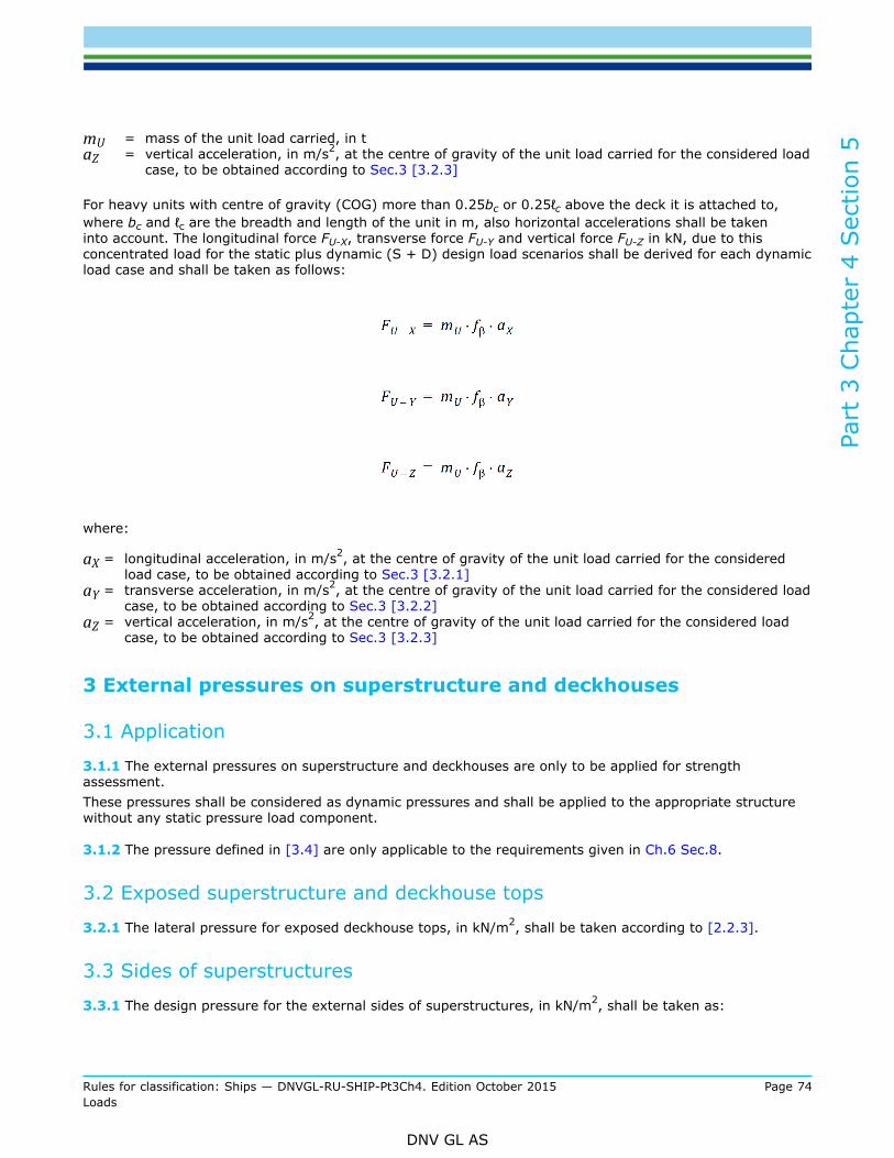
Part
3 C
hapt
er 4
Sec
tion
5
Rules for classification: Ships — DNVGL-RU-SHIP-Pt3Ch4. Edition October 2015 Page 74Loads
DNV GL AS
mU = mass of the unit load carried, in taZ = vertical acceleration, in m/s2, at the centre of gravity of the unit load carried for the considered load
case, to be obtained according to Sec.3 [3.2.3]
For heavy units with centre of gravity (COG) more than 0.25bc or 0.25ℓc above the deck it is attached to,where bc and ℓc are the breadth and length of the unit in m, also horizontal accelerations shall be takeninto account. The longitudinal force FU-X, transverse force FU-Y and vertical force FU-Z in kN, due to thisconcentrated load for the static plus dynamic (S + D) design load scenarios shall be derived for each dynamicload case and shall be taken as follows:
where:
aX = longitudinal acceleration, in m/s2, at the centre of gravity of the unit load carried for the consideredload case, to be obtained according to Sec.3 [3.2.1]
aY = transverse acceleration, in m/s2, at the centre of gravity of the unit load carried for the considered loadcase, to be obtained according to Sec.3 [3.2.2]
aZ = vertical acceleration, in m/s2, at the centre of gravity of the unit load carried for the considered loadcase, to be obtained according to Sec.3 [3.2.3]
3 External pressures on superstructure and deckhouses
3.1 Application
3.1.1 The external pressures on superstructure and deckhouses are only to be applied for strengthassessment.These pressures shall be considered as dynamic pressures and shall be applied to the appropriate structurewithout any static pressure load component.
3.1.2 The pressure defined in [3.4] are only applicable to the requirements given in Ch.6 Sec.8.
3.2 Exposed superstructure and deckhouse tops
3.2.1 The lateral pressure for exposed deckhouse tops, in kN/m2, shall be taken according to [2.2.3].
3.3 Sides of superstructures
3.3.1 The design pressure for the external sides of superstructures, in kN/m2, shall be taken as:
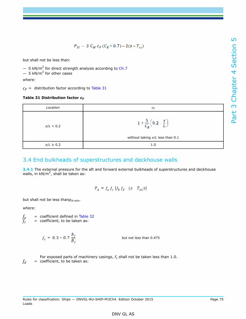
Part
3 C
hapt
er 4
Sec
tion
5
Rules for classification: Ships — DNVGL-RU-SHIP-Pt3Ch4. Edition October 2015 Page 75Loads
DNV GL AS
but shall not be less than:
— 0 kN/m2 for direct strength analysis according to Ch.7— 5 kN/m2 for other cases
where:
cF = distribution factor according to Table 31
Table 31 Distribution factor cF
Location cF
x/L < 0.2
without taking x/L less than 0.1
x/L ≥ 0.2 1.0
3.4 End bulkheads of superstructures and deckhouse walls
3.4.1 The external pressure for the aft and forward external bulkheads of superstructures and deckhousewalls, in kN/m2, shall be taken as:
but shall not be less thanpA-min.
where:
fn = coefficient defined in Table 32fc = coefficient, to be taken as:
but not less than 0.475
For exposed parts of machinery casings, fc shall not be taken less than 1.0.fd = coefficient, to be taken as:

Part
3 C
hapt
er 4
Sec
tion
5
Rules for classification: Ships — DNVGL-RU-SHIP-Pt3Ch4. Edition October 2015 Page 76Loads
DNV GL AS
for L < 150 m
for 150 m ≤ L < 300 m
for L ≥ 300 m
b1 = breadth of deckhouse at the position consideredB1 = actual breadth of ship on the exposed weather deck at the position consideredfb = coefficient defined in Table 33PA-min
= minimum lateral pressure, in kN/m2, as defined in Table 34
Table 32 Coefficient fn
Type of bulkhead Location fn
Lowest tier2)
Second tier
Unprotected front bulkhead 1)
Third tier and above
Protected front bulkhead 1) All tiers
Side bulkheads All tiers
Aft end bulkheads Abaft amidships

Part
3 C
hapt
er 4
Sec
tion
5
Rules for classification: Ships — DNVGL-RU-SHIP-Pt3Ch4. Edition October 2015 Page 77Loads
DNV GL AS
Type of bulkhead Location fn
Forward of amidships
1) The front bulkhead of a superstructure or deckhouse may be considered as protected when it is located less than Bxbehind another superstructure or deckhouse, and the width of the front bulkhead being considered is less than thewidth of the aft bulkhead of the superstructure or deckhouse forward of it. Bx is the local breadth of the ship at thefront bulkhead.
2) The lowest tier is normally that tier which is directly situated above the uppermost continuous deck to which themoulded depth, D is measured. However, when (D-TSC) exceeds the minimum non-corrected tabular freeboard(according to ILLC as amended) by at least one standard superstructure height (as defined in Ch.1 Sec.4 [3.3]),then this tier may be defined as the 2nd tier and the tier above as the 3rd tier.
Table 33 Coefficient fb
Location of bulkhead1) fb
where:CB1 = Block coefficient, but not less than 0.60 nor greater than 0.80. For aft deckhouse bulkheads located forward
of amidships, CB1 may be taken as 0.80.
1) For deckhouse sides, the deckhouse shall be subdivided into parts of approximately equal length, not exceeding0.15 L each, and x shall be taken as the X-coordinate of the centre of each part considered.
Table 34 Minimum lateral pressure, PA-min
PA-min, in kN/m2
L Lowest tier of unprotected fronts Elsewhere 1)
L ≤ 250
L > 250 50 25
1) For the 4th tier and above, PA-min shall be taken equal to 12.5 kN/m2.
Part
3 C
hapt
er 4
Sec
tion
5
Rules for classification: Ships — DNVGL-RU-SHIP-Pt3Ch4. Edition October 2015 Page 78Loads
DNV GL AS
3.5 Windows and side scuttles
3.5.1 The design pressure P on side scuttles and windows shall be calculated according to [3.3] and [3.4].
3.5.2 The design pressure P on side scuttles and windows shall be calculated as per Ch.10 Sec.1 [2] whenlocated in a position where bow impact is applicable.
3.5.3 For windows and side scuttles located on the 2nd tier and below, the minimum design pressure shall betaken as described in ISO 5779 and ISO 5780 respectively.
3.5.4 Windows and side scuttles, as per Ch.12 Sec.6 [1.1.4], subjected to larger design pressure than givenin ISO 5779 and ISO 5789 respectively, need to be tested according to requirements given in Ch.12 Sec.6[6].
3.5.5 When windows are allowed on exposed front bulkheads on the weather deck, the design pressure ofexposed front bulkhead on 1st tier shall be used for the calculation of the required glass thickness.

Part
3 C
hapt
er 4
Sec
tion
6
Rules for classification: Ships — DNVGL-RU-SHIP-Pt3Ch4. Edition October 2015 Page 79Loads
DNV GL AS
SECTION 6 INTERNAL LOADSSymbols
For symbols not defined in this section, refer to Ch.1 Sec.4
x, y, z = X, Y and Z coordinates, in m, of the load point with respect to the reference coordinatesystem defined in Sec.1 [1.2.1]
xG, yG, zG = X, Y and Z coordinates, in m, of the volumetric centre of gravity of the tank, considered withrespect to the reference coordinate system defined in Sec.1 [1.2]
aX, aY, aZ = longitudinal, transverse and vertical accelerations, in m/s2, at xG, yG, zG, as defined in Sec.3[3.2]
ρL = density of liquid in the tank and ballast hold, in t/m3, normally not to be taken less than:for strength assessment:ρL= 1.025 for all liquids including oil and product cargoes. If a tank filled at 98% is intendedto carry heavier liquid cargoes than 1.025 (i.e. ρmax-LM > 1.025), then ρL = ρmax-LM
for fatigue assessment:ρL = 0.9 for oil and oil product cargoesρL= 1.025 for ballast tanksFor the cargo tank intended to carry liquid other than oil or oil products and with a cargodensity between 0.9 and 1.025 t/m3, then ρL = ρmax-LM.The liquid cargo density for liquified gas is given in Pt.5 Ch.7.
ρmax-LM = maximum liquid cargo density in t/m3, associated with a full tank at 98%, from any loadingcondition in the ship's loading manual or value specified by the designer
ρpart = maximum permissible high liquid cargo density, in t/m3, associated with a partially filledcargo tank but not taken less than ρL considered for strength assessment
ρslh = liquid density, in t/m3, to be used for sloshing assessment, taken as:
ρslh = ρpart for heavy liquid cargo density associated with partial filling of cargo tank
ρslh = ρL for all other cases
hmax = maximum permissible filling level, in m, taken as:for ballast tanks: maximum tank height,for cargo tanks with cargo density equal to ρL: maximum tank heightfor cargo tanks with heavy liquid cargo density equal to ρpart associated with a partially filledcargo tank: hpart as defined in Ch.10 Sec.4 [1.2.1]
fcd = factor for joint probability of occurrence of liquid cargo density and maximum sea state in 25years design life, to be taken as:
fcd = 0.88 for strength assessment with FE analysis of cargo tanks filled with for oil or oil productscargo
fcf = 1.0 for other cases
ρST = density of steel, in t/m3, to be taken as 7.8ztop = Z coordinate of the highest point of tank, excluding small hatchways, in mhair = height of air pipe or overflow pipe above the top of the tank, in mPPV = setting of pressure relief valve, in kN/m2, if fitted, not to be taken less than 25 kN/m2 and not
greater than 70 kN/m2. Pressure relief valve setting greater than 70 kN/m2 may be acceptedon a case-by-case basis
ϕ = pitch angle, in deg, defined in Sec.3 [2.1.2]θ = roll angle, in deg, defined in Sec.3 [2.1.1]Tθ = roll period, in s, as defined in Sec.3 [2.1.1]fβ = coefficient defined in Sec.4

Part
3 C
hapt
er 4
Sec
tion
6
Rules for classification: Ships — DNVGL-RU-SHIP-Pt3Ch4. Edition October 2015 Page 80Loads
DNV GL AS
1 Pressures due to liquids
1.1 Total pressure1.1.1 Pressures for the strength and fatigue assessments of intact conditionsThe internal pressure due to liquid acting on any load point of a tank and ballast hold boundary, in kN/m2, forthe static (S) design load scenarios, given in Sec.7, shall be taken as:
Pin = Pℓs but not less than 0
The internal pressure due to liquid acting on any load point of a tank and ballast hold boundary, in kN/m2, forthe static plus dynamic (S+D) design load scenarios shall be derived for each dynamic load case and shall betaken as:
Pin = Pℓs + Pℓd but not less than 0
where:
Pℓs = static pressure due to liquid in tanks and ballast holds, in kN/m2, as defined in [1.2.1] to [1.2.6]Pℓd = dynamic inertial pressure due to liquid in tanks and ballast holds, in kN/m2, as defined in [1.3]
1.1.2 Pressures for the strength assessments of flooded conditionsThe internal pressure in flooded condition, in kN/m2, acting on any load point of the watertight boundary of ahold, tank or other space for the flooded static (S) design load scenario, given in Sec.7, shall be taken as:
Pin = Pfs
where:
Pfs = static pressure of seawater due to flooding in the compartment, in kN/m2, as defined in [1.2.7]
1.2 Static liquid pressure1.2.1 Normal operations at seaThe static pressure, in kN/m2, in tanks and ballast holds for normal operations at sea, shall be taken as:
for tanks arranged with pressure relief valves.
for other cases.
1.2.2 Flow through ballast water exchangeThe static pressure, in kN/m2, in ballast water tanks for ballast water exchange at sea, shall be taken as:
Part
3 C
hapt
er 4
Sec
tion
6
Rules for classification: Ships — DNVGL-RU-SHIP-Pt3Ch4. Edition October 2015 Page 81Loads
DNV GL AS
where:
hdrop = maximum overflow height above top of the tank, in m, of flow through ballast water exchangesystem
Pdrop-1 = overpressure, in kN/m2, during flow through ballast water exchange. Pdrop-1 shall not be takenless than 25 kN/m2
1.2.3 Normal operations at harbour/ sheltered waterThe static pressure, in kN/m2, due to liquid in tanks and ballast holds for normal operation at harbour/sheltered water, shall be taken as:
for cargo tanks arranged with pressure relief valves
for all other cases
where:
P0 = static pressure, in kN/m2, to be taken as:for tanks:
P0 = 10 for L ≤ 50 m
P0 = 0.3L - 5 for 50 m < L < 100 m
P0 = 25 for L ≥ 100 m
for ballast hold in dry cargo vessels:P0 = 0
1.2.4 Overfilling water ballast tanksThe static pressure, in kN/m2, due to ballast water overfilling, shall be taken as:
where:
Pdrop-2 = overpressure in kN/m2, generally taken equal to zero. If the ship is not equipped with remotesoundings for the ballast system or equipped with an electronic ballast system - to adjustgeneral draft and trim condition - or other measures are provided to avoid accidental overfilling,an overpressure has to be considered but not less than 25 kN/m2.

Part
3 C
hapt
er 4
Sec
tion
6
Rules for classification: Ships — DNVGL-RU-SHIP-Pt3Ch4. Edition October 2015 Page 82Loads
DNV GL AS
1.2.5 Tank testingThe tank testing pressure, in kN/m2, shall be taken as:
where:
zST = testing load height, in m, as defined in Table 1
The actual tank testing shall be carried out in accordance with Pt.2 Ch.4 Sec.6.
Table 1 Design testing load height zST
Compartment zST
Double bottom tanksThe greater of the following:zST = ztop + hair
zST = zbd
Hopper side tanks1), topside tanks1), double side tanks1), fore andaft peaks used as tank, cofferdams
The greater of the following:zST = ztop + hair
zST = ztop + 2.4
Tanks, deep tanks, fuel oil bunkers, cargo tanks2)
The greater of the following:zST
3) = ztop + hair
zST = ztop + 2.4
zST = ztop + 0.1 PPV
Ballast hold zST = zh + 0.9
Chain locker (if aft of collision bulkhead) zST = ztop
Independent tanksThe greater of the following:zST = ztop + hair
zST = ztop + 0.9
Ballast ducts Testing load height corresponding to ballast pumpmaximum pressure
where:zbd = Z coordinate, in m, of the bulkhead deck.zh = Z coordinate, in m, of the top of hatch coaming.
1) Applicable to double bottom tank connected with hopper side tanks, topside tanks or double side tanks.2) Tank test load is not applicable for cargo tanks carrying LNG.3) Not applicable for cargo tanks.
1.2.6 Static liquid pressure for the fatigue assessmentThe static pressure due to liquid in tanks and ballast holds to be used for the fatigue assessment, in kN/m2,shall be taken as:

Part
3 C
hapt
er 4
Sec
tion
6
Rules for classification: Ships — DNVGL-RU-SHIP-Pt3Ch4. Edition October 2015 Page 83Loads
DNV GL AS
1.2.7 FloodingThe internal pressure in flooded condition, in kN/m2, on watertight bulkheads shall be taken as:
where:
hfs = pressure height, in m, in flooded condition, to be taken as:
d0 = distance, in m, to be taken as:
d0 = 0.22L for L < 120 m
d0 = 2.4 for L ≥ 120 m
zfd = Z coordinate, in m, of the freeboard deck at side in way of the transverse section considered.Zdam = Z coordinate, in m, of the deepest equilibrium waterline at centre line in the damaged condition.θ dam = angle, in degrees, between the deepest equilibrium waterline in the damaged condition and the
base line
1.3 Dynamic liquid pressure
1.3.1 The dynamic pressure due to liquid in tanks and ballast holds, in kN/m2 shall be taken as:
Pℓd = fcd ρL [aZ (z0 – z) + fullℓ- aX (x0 – x) + full-t aY (y0 – y)]
where:
full-ℓ = longitudinal acceleration correction factor for the ullage space above the liquid in tanks and ballastholds, taken as:for strength assessment:full-ℓ = 0.62 for cargo tanks filled with any liquids inclusive water ballastfull-ℓ = 1.0 for other casesfor fatigue assessment:
for cargo tanks and ballast holds
full-ℓ = 1.0 for other casesfull-lℓ shall not be less than 0.0 nor greater than 1.0
ℓfs = cargo tank length at the top of the tank or length of the ballast hold hatch coaming, in mfull-t = transverse acceleration correction factor to account for the ullage space above the liquid in tanks
and ballast holds, taken as:for strength assessment:full-t = 0.67 for cargo tanks filled with any liquids inclusive water ballastfull-t = 1.0 for other cases
Part
3 C
hapt
er 4
Sec
tion
6
Rules for classification: Ships — DNVGL-RU-SHIP-Pt3Ch4. Edition October 2015 Page 84Loads
DNV GL AS
for fatigue assessment:
for cargo tanks and ballast holds
full-t = 1.0 for other casesbtop = cargo tank breadth at the top of the tank or breadth of the ballast hold hatch coaming, in m
determined at mid length of the tank or ballast hold hatch coamingx0 = X coordinate, in m, of the reference pointy0 = Y coordinate, in m, of the reference pointz0 = Z coordinate, in m, of the reference point
The reference point shall be taken as the point with the highest value of Vj, calculated for all points thatdefine the upper boundary of the tank or ballast hold as follows:
where:
xj = X coordinate, in m, of the point j on the upper boundary of the tank or ballast holdyj = Y coordinate, in m, of the point j on the upper boundary of the tank or ballast holdzj = Z coordinate, in m, of the point j on the upper boundary of the tank or ballast hold
The following simplified method of determination of the reference point assuming a rectangular shape witharea equal Atop of the top of the tank or the ballast hold hatch coaming is acceptable, see Figure 1:
xj = xtop ± 0.5ℓfs
yj = ytop ± 0.5btop
where
xtop = X coordinate, in m, of the centre of the rectangular area Atop at the top of the tank or the ballasthold hatch coaming
ytop = Y coordinate, in m, of the centre of the rectangular area Atop at the top of the tank or the ballasthold hatch coaming
Atop = ℓfs · btop: The area of an rectangular shape at the top of the tank or the ballast hold hatch coaming,in m2

Part
3 C
hapt
er 4
Sec
tion
6
Rules for classification: Ships — DNVGL-RU-SHIP-Pt3Ch4. Edition October 2015 Page 85Loads
DNV GL AS
Figure 1 Area of a rectangular shape at the top of a tank

Part
3 C
hapt
er 4
Sec
tion
6
Rules for classification: Ships — DNVGL-RU-SHIP-Pt3Ch4. Edition October 2015 Page 86Loads
DNV GL AS
2 Non-exposed decks and platforms
2.1 Application2.1.1 GeneralThe loads on non-exposed decks including inner bottom are given in Sec.5 [2.3], except accommodationdecks, wheelhouse decks and platforms in machinery space. For these decks loads defined in [2.2] and [2.3]are applicable.
2.2 Pressure due to distributed load
2.2.1 If a distributed load is carried on a deck, the static and dynamic pressures due to this distributed loadshall be considered. The distributed loads shall be calculated according to Sec.5 [2.3.1].The static distributed load Pdl-s, including selfweight, shall be defined by the designer without being less than:
— 2.5 kN/m2 for accommodation decks, tween decks and platforms in general.— 3.5 kN/m2 for wheelhouse deck— 8 kN/m2 for platforms in machinery space
2.3 Concentrated force due to unit load
2.3.1 Concentrated forces on non-exposed decks shall be calculated according to Sec.5 [2.3.2].
3 Pressure for internal structures in tanks
3.1 DefinitionThe pressure, in kN/m2, for internal structures in tanks, e.g. web of primary supporting members, shall betaken as:

Part
3 C
hapt
er 4
Sec
tion
7
Rules for classification: Ships — DNVGL-RU-SHIP-Pt3Ch4. Edition October 2015 Page 87Loads
DNV GL AS
SECTION 7 DESIGN LOAD SCENARIOSSymbols
For symbols not defined in this section, refer to Ch.1 Sec.4.
VBM = design vertical bending moment, in kNmMst = design still water torsional moment in seagoing condition, in kNm, at the hull transverse section
being considered, as defined in Sec.4 [2.3.1]Msw = permissible hull girder hogging and sagging still water bending moment for seagoing operation,
in kNm, as defined in Sec.4 [2.2.2]Mwv-LC = vertical wave bending moment for a considered dynamic load case, in kNm, as defined in Sec.4
[3.5.2]HBM = design horizontal bending moment, in kNmMwh-LC = horizontal wave bending moment for a considered dynamic load case, in kNm, as defined in
Sec.4 [3.5.4]TM = design torsional moment, in kNmMwt-LC = wave torsional moment for a considered dynamic load case, in kNm, as defined in Sec.4 [3.5.5]VSF = design vertical shear force, in kNQsw = permissible hull girder positive and negative still water shear force limits for seagoing operation,
in kN, as defined in Sec.4 [2.4.1] or Sec.4 [2.4.2]Qwv-LC = vertical wave shear force for a considered dynamic load case, in kN, as defined in Sec.4 [3.5.3]Pex = design external pressure, in kN/m2
PS = static sea pressure at considered draught, in kN/m2, as defined in Sec.5 [1.2.1]PW = dynamic pressure for a considered dynamic load case, in kN/m2, as defined in Sec.5 [1.3.2] to
Sec.5 [1.3.8]PD = green sea load for a considered dynamic load case, in kN/m2, as defined in Sec.5 [2.2.3] and
Sec.5 [2.2.4]Pin = design internal pressure, in kN/m2
Pint = minimum pressure for internal structures in tanks as given in Sec.6 [3.1]PST = tank testing pressure, in kN/m2, see Sec.6 [1.2.5]Pℓs-1 = static tank pressure during normal operations at sea as given in Sec.6 [1.2.1]Pℓs-2 = static tank pressure during flow through ballast water exchange as given in Sec.6 [1.2.2]Pℓs-3 = static tank pressure during normal operations at harbour/sheltered water as given in Sec.6
[1.2.3]Pℓs-4 = static tank pressure during overfilling of ballast water tanks as given in Sec.6 [1.2.4]Pℓd = dynamic liquid pressure in tank for a considered dynamic load case, in kN/m2, as defined in
Sec.6 [1.3]Pbs = dry bulk cargo static pressure, in kN/m2, as defined in Pt.5 Ch.1 Sec.2Pbd = dry bulk cargo dynamic pressure for a considered dynamic load case, in kN/m2, as defined in
Pt.5 Ch.1 Sec.2Pfs = static pressure in compartments and tanks in flooded condition, in kN/m2, as defined in Sec.6
[1.2.7]Pdℓ-s = static pressure on non-exposed decks and platforms, in kN/m2, as defined in Sec.6 [2.2.1]Pdℓ-d = dynamic pressure on non-exposed decks and platforms for a considered dynamic load case, in
kN/m2, as defined in Sec.6 [2.2.1]FU-s = static load acting on supporting structures and securing systems for heavy units or cargo,
equipment or structural components, in kN, as defined in Sec.5 [2.3.2]FU-d = dynamic load acting on supporting structures and securing systems for heavy units of cargo,
equipment or structural components, in kN, as defined in Sec.5 [2.3.2]
Part
3 C
hapt
er 4
Sec
tion
7
Rules for classification: Ships — DNVGL-RU-SHIP-Pt3Ch4. Edition October 2015 Page 88Loads
DNV GL AS
1 General
1.1 Application
1.1.1 This section gives the design load scenarios that shall be used for:
— strength assessment by prescriptive and direct analysis (Finite Element Method, FEM) methods, see [2]— fatigue assessment by prescriptive and direct analysis (FEM) methods, see [3].
1.1.2 For the strength assessment, the principal design load scenarios consist of either S (Static) loads orS + D (Static + Dynamic) loads. In some cases, the letter ‘A’ prefixes the S or S + D to denote that this isan accidental design load scenario. There are some additional design load scenarios to be considered whichrelate to impact (I) loads, sloshing (SL) loads and fatigue (F) load. Design load scenarios for impact loads (I)are given in Ch.10 Sec.1, Sec.2 and Sec.3. Design load scenarios for sloshing and liquid impact in tanks (SL)are given in Ch.10 Sec.4.
2 Design load scenarios for strength assessment
2.1 Principal design load scenarios
2.1.1 The principal design load scenarios are given in Table 1.

Part
3 C
hapt
er 4
Sec
tion
7
Rules for classification: Ships — DNVGL-RU-SHIP-Pt3Ch4. Edition October 2015 Page 89Loads
DNV GL AS
Table 1 Principal design load scenarios
Design load scenario
1 2 3 4 5
Normaloperationsat harbour
and shelteredwater
Normaloperation
at sea
Flow throughballast water
exchange
Overfilling ofballast tanks
and tank testingFlooding
Static (S)Static +Dynamic(S+D)
Static +dynamic(S+D)
Static (S)and (T)
Static(S)
VBM Msw Msw + Mwv-LC Msw + Mwv-LC Msw Msw
HBM - Mwh-LC Mwh-LC - -
VSF Qsw Qsw + Qwv-LC Qsw + Qwv-LC - -
Hul
l Girde
r lo
ads
TM 2) Mst Mst + Mwt-LC Mst + Mwt-LC Mst Mst
Exposed decks - PD - - -
External shell PS PS + PW PS + PW PS -
Superstructure sides - max(PW;PSI)
- - -Pex
Superstructure endbulkheads and deckhousewalls
- PA - - -
Boundaries of waterballast tanks1) Pℓs-2 + Pℓd
max(Pℓs-4, Pℓs-
ST)-
Boundaries of tanks otherthan water ballast tanks
Pℓs-3 Pℓs-1 + Pℓd
- Pℓs-ST -
Watertight boundaries - - - - Pfs
Boundaries ofbulk cargo holds Pbs Pbs + Pbd - - -
Pin
Internal structures in tanks Pint - - -
Pdℓ
Exposed decksand non-exposed
decks and platformsPdℓ-s Pdℓ-s + Pdℓ-d - - -
Load
com
pone
nt
Hul
l Girde
r lo
ads
FUHeavy units on internal andexternal decks FU-s FU-s + FU-d - - -
1) WB cargo hold is considered as ballast tank except for design load scenario ‘ballast water exchange’.2) Hull girder torsion to be considered for ships with large deck openings only.

Part
3 C
hapt
er 4
Sec
tion
7
Rules for classification: Ships — DNVGL-RU-SHIP-Pt3Ch4. Edition October 2015 Page 90Loads
DNV GL AS
3 Design load scenarios for fatigue assessment
3.1 Design load scenarios
3.1.1 The design load scenarios for fatigue assessment are given in Table 2.
Table 2 Design load scenarios for fatigue assessment
Design load scenario
Fatigue
Static + Dynamic (F: S+D)
VBM Msw + Mwv-LC
HBM Mwh-LC
VSF Qsw + Qwv-LC
Hul
l girde
r lo
ads
TM 2) Mwt-LC
Exposed decks -Pex
External shell PS + PW
Boundaries of water ballast tanks 1)
Boundaries of tanks other than water ballast tanks
Watertight bulkheads
Pℓs + PℓdPin
Boundaries of bulk cargo holds Pbs + Pbd
PdℓExposed decks and non-
exposed decks and platforms -
Load
com
pone
nt
Loca
l loa
ds
FU Heavy units on internal and external decks -
1) WB cargo hold is considered as ballast tank except for design load scenario ‘ballast water exchange at sea’.2) Hull girder torsion to be considered for ships with large deck openings only.

Part
3 C
hapt
er 4
Sec
tion
8
Rules for classification: Ships — DNVGL-RU-SHIP-Pt3Ch4. Edition October 2015 Page 91Loads
DNV GL AS
SECTION 8 LOADING CONDITIONS
1 Standard design loading conditions
1.1 Seagoing design loading conditions
1.1.1 Design loading conditions as specified in Ch.15 Sec.1 [4.3] shall be provided as design basis in additionto, if applicable, design load conditions required by Pt.5 or related to the vessels particular operation.All the above design loading conditions shall be evaluated for at least departure and arrival conditions. Thedeparture conditions shall be based on bunker tanks not taken less than 95% full and other consumablestaken at 100% capacity.The arrival conditions shall be based on bunker tanks not taken more than 10% full and other consumablestaken at 10% capacity.
1.1.2 The design cargo and ballast loading conditions, based on the amount of bunker, fresh water andstores at departure and arrival, shall be considered for the still water bending moment and shear forcecalculations. Where the amount and disposition of consumables and cargo at any intermediate stage ofthe voyage are considered more severe, calculations for such intermediate conditions shall be submittedin addition to those for departure and arrival conditions. Also, where any ballasting and/or de-ballasting isintended during voyage, calculations of the intermediate condition just before and just after ballasting and/orde-ballasting shall be submitted and included in the loading manual.
1.1.3 Conditions covering procedures for sequential ballast water exchange, if applicable, shall be included inthe loading manual.
1.2 Partially filled ballast tanks in seagoing design loading condition1.2.1 Partially filled ballast tanks in ballast loading conditionBallast loading conditions involving partially filled peak and/or other ballast tanks at departure, arrival orduring intermediate conditions are not permitted to be used as design loading conditions unless design stresslimits are satisfied for all filling levels between empty and full.To demonstrate the strength compliance with all filling levels between empty and full, it will be acceptable ifthe still water bending moment, shear force and torsional moment, if applicable, are calculated and shownwithin the relevant permissible limits. These values shall be obtained for each condition at departure, arrivaland any intermediate condition as required by [1.1.2], with the tanks intended to be partially filled assumedto be:
— empty— full— partially filled at intended level.
Where multiple tanks are intended to be partially filled, all combinations of empty, full or partially filled atintended level for those tanks shall be investigated.
1.2.2 Partially filled ballast tanks in cargo loading conditionIn cargo loading conditions, the requirement in [1.2.1] applies to peak ballast tanks only.
1.2.3 Partially filled ballast tanks in ballast water exchange conditionThe requirements [1.2.1] and [1.2.2] are not applicable to ballast water exchange conditions.
Part
3 C
hapt
er 4
Sec
tion
8
Rules for classification: Ships — DNVGL-RU-SHIP-Pt3Ch4. Edition October 2015 Page 92Loads
DNV GL AS
2 Loading conditions for primary supporting members
2.1 General
2.1.1 Loading conditions for evaluation of primary supporting members shall envelop the most criticalloading combinations the ship can be subject to when operated in accordance with loading guidanceinformation.
2.1.2 The loading conditions shall be defined with consideration to:
— all intact loading conditions in loading manual— operational limitations in loading guidance information— the ship arrangement and possible combination of local loading and global loading draught of empty hold
and hull girder.
Reference is made to Pt.5 for standard loading conditions for different ship types.

DNV GLDriven by our purpose of safeguarding life, property and the environment, DNV GL enablesorganizations to advance the safety and sustainability of their business. We provide classification andtechnical assurance along with software and independent expert advisory services to the maritime,oil and gas, and energy industries. We also provide certification services to customers across a widerange of industries. Operating in more than 100 countries, our 16 000 professionals are dedicated tohelping our customers make the world safer, smarter and greener.
SAFER, SMARTER, GREENER
Related Documents