RUGGEDCOM ROS v4.3 User Guide For RS400, RS401 07/2016 Preface Introduction 1 Using ROS 2 Device Management 3 System Administration 4 Setup and Configuration 5 Troubleshooting 6 RC1273-EN-03

Welcome message from author
This document is posted to help you gain knowledge. Please leave a comment to let me know what you think about it! Share it to your friends and learn new things together.
Transcript

RUGGEDCOM ROSv4.3
User Guide
For RS400, RS401
07/2016
Preface
Introduction 1
Using ROS 2
Device Management 3
System Administration 4
Setup and Configuration 5
Troubleshooting 6
RC1273-EN-03
RUGGEDCOM ROSUser Guide
ii
Copyright © 2016 Siemens Canada LtdAll rights reserved. Dissemination or reproduction of this document, or evaluation and communication of its contents, is not authorizedexcept where expressly permitted. Violations are liable for damages. All rights reserved, particularly for the purposes of patent application ortrademark registration.This document contains proprietary information, which is protected by copyright. All rights are reserved. No part of this document may bephotocopied, reproduced or translated to another language without the prior written consent of Siemens Canada Ltd.
Disclaimer Of LiabilitySiemens has verified the contents of this document against the hardware and/or software described. However, deviations between the productand the documentation may exist.Siemens shall not be liable for any errors or omissions contained herein or for consequential damages in connection with the furnishing,performance, or use of this material.The information given in this document is reviewed regularly and any necessary corrections will be included in subsequent editions. Weappreciate any suggested improvements. We reserve the right to make technical improvements without notice.
Registered TrademarksRUGGEDCOM™ and ROS™ are trademarks of Siemens Canada Ltd.Other designations in this manual might be trademarks whose use by third parties for their own purposes would infringe the rights of theowner.
Third Party CopyrightsSiemens recognizes the following third party copyrights:• Copyright © 2004 GoAhead Software, Inc. All Rights Reserved.
Open SourceRUGGEDCOM ROS contains Open Source Software. For license conditions, refer to the associated License Conditions document.
Security InformationSiemens provides products and solutions with industrial security functions that support the secure operation of plants, machines, equipmentand/or networks. They are important components in a holistic industrial security concept. With this in mind, Siemens' products and solutionsundergo continuous development. Siemens recommends strongly that you regularly check for product updates.For the secure operation of Siemens products and solutions, it is necessary to take suitable preventive action (e.g. cell protection concept) andintegrate each component into a holistic, state-of-the-art industrial security concept. Third-party products that may be in use should also beconsidered. For more information about industrial security, visit http://www.siemens.com/industrialsecurity .To stay informed about product updates as they occur, sign up for a product-specific newsletter. For more information, visit http://support.automation.siemens.com .
WarrantyRefer to the License Agreement for the applicable warranty terms and conditions, if any.

RUGGEDCOM ROSUser Guide
Table of Contents
v
Table of ContentsPreface ............................................................................................................ xv
Conventions ....................................................................................................................................... xvRelated Documents ............................................................................................................................ xviSystem Requirements ......................................................................................................................... xviAccessing Documentation .................................................................................................................. xviTraining ........................................................................................................................................... xviiCustomer Support ............................................................................................................................. xvii
Chapter 1Introduction ..................................................................................................... 1
1.1 Features and Benefits ................................................................................................................... 11.2 Security Recommendations and Considerations ............................................................................... 3
1.2.1 Security Recommendations ................................................................................................. 31.2.2 Credential Files .................................................................................................................. 5
1.2.2.1 SSL Certificates ....................................................................................................... 61.2.2.2 SSH Key Pairs .......................................................................................................... 8
1.3 Supported Networking Standards ................................................................................................... 91.4 Port Numbering Scheme ............................................................................................................... 91.5 Available Services by Port ............................................................................................................ 101.6 SNMP Management Interface Base (MIB) Support .......................................................................... 12
1.6.1 Supported Standard MIBs ................................................................................................. 131.6.2 Supported Proprietary RUGGEDCOM MIBs .......................................................................... 131.6.3 Supported Agent Capabilities ............................................................................................ 14
1.7 SNMP Traps ................................................................................................................................ 151.8 ModBus Management Support ..................................................................................................... 16
1.8.1 ModBus Function Codes ................................................................................................... 161.8.2 ModBus Memory Map ...................................................................................................... 171.8.3 ModBus Memory Formats ................................................................................................. 23
1.8.3.1 Text ..................................................................................................................... 231.8.3.2 Cmd ..................................................................................................................... 231.8.3.3 Uint16 .................................................................................................................. 241.8.3.4 Uint32 .................................................................................................................. 241.8.3.5 PortCmd ............................................................................................................... 241.8.3.6 Alarm ................................................................................................................... 251.8.3.7 PSStatusCmd ......................................................................................................... 25

Table of Contents
RUGGEDCOM ROSUser Guide
vi
1.8.3.8 TruthValues .......................................................................................................... 261.9 SSH and SSL Keys and Certificates ................................................................................................ 27
1.9.1 Certificate and Keys Life Cycle ........................................................................................... 271.9.2 Certificate and Key Requirements ...................................................................................... 28
Chapter 2Using ROS ....................................................................................................... 31
2.1 Connecting to ROS ...................................................................................................................... 312.1.1 Connecting Directly .......................................................................................................... 312.1.2 Connecting via the Network ............................................................................................. 32
2.2 Logging In .................................................................................................................................. 332.3 Logging Out ............................................................................................................................... 342.4 Using the Web Interface .............................................................................................................. 352.5 Using the Console Interface ......................................................................................................... 362.6 Using the Command Line Interface .............................................................................................. 38
2.6.1 Available CLI Commands .................................................................................................. 382.6.2 Tracing Events ................................................................................................................. 412.6.3 Executing Commands Remotely via RSH ............................................................................ 422.6.4 Using SQL Commands ...................................................................................................... 42
2.6.4.1 Finding the Correct Table ....................................................................................... 432.6.4.2 Retrieving Information ........................................................................................... 432.6.4.3 Changing Values in a Table .................................................................................... 452.6.4.4 Resetting a Table ................................................................................................... 462.6.4.5 Using RSH and SQL ............................................................................................... 46
2.7 Selecting Ports in RUGGEDCOM ROS ............................................................................................. 462.8 Managing the Flash File System ................................................................................................... 47
2.8.1 Viewing a List of Flash Files .............................................................................................. 472.8.2 Viewing Flash File Details ................................................................................................. 472.8.3 Defragmenting the Flash File System ................................................................................. 48
2.9 Accessing BIST Mode ................................................................................................................... 482.10 Managing SSH Public Keys ......................................................................................................... 49
2.10.1 Adding a Public Key ....................................................................................................... 492.10.2 Viewing a List of Public Keys ........................................................................................... 512.10.3 Updating a Public Key .................................................................................................... 512.10.4 Deleting a Public Key ...................................................................................................... 52
Chapter 3Device Management ....................................................................................... 53
3.1 Viewing Product Information ....................................................................................................... 533.2 Viewing CPU Diagnostics ............................................................................................................. 553.3 Restoring Factory Defaults ........................................................................................................... 56

RUGGEDCOM ROSUser Guide
Table of Contents
vii
3.4 Uploading/Downloading Files ....................................................................................................... 573.4.1 Uploading/Downloading Files Using XMODEM .................................................................... 583.4.2 Uploading/Downloading Files Using a TFTP Client ............................................................... 593.4.3 Uploading/Downloading Files Using a TFTP Server .............................................................. 603.4.4 Uploading/Downloading Files Using an SFTP Server ............................................................ 60
3.5 Managing Logs ........................................................................................................................... 613.5.1 Viewing Local Logs .......................................................................................................... 613.5.2 Clearing Local Logs .......................................................................................................... 623.5.3 Configuring the Local System Log ..................................................................................... 623.5.4 Managing Remote Logging ............................................................................................... 63
3.5.4.1 Configuring the Remote Syslog Client ..................................................................... 633.5.4.2 Viewing a List of Remote Syslog Servers .................................................................. 643.5.4.3 Adding a Remote Syslog Server .............................................................................. 653.5.4.4 Deleting a Remote Syslog Server ............................................................................ 66
3.6 Managing Ethernet Ports ............................................................................................................. 673.6.1 Controller Protection Through Link Fault Indication (LFI) ..................................................... 683.6.2 Viewing the Status of Ethernet Ports ................................................................................. 693.6.3 Viewing Statistics for All Ethernet Ports ............................................................................. 703.6.4 Viewing Statistics for Specific Ethernet Ports ...................................................................... 703.6.5 Clearing Statistics for Specific Ethernet Ports ...................................................................... 733.6.6 Configuring an Ethernet Port ............................................................................................ 743.6.7 Configuring Port Rate Limiting .......................................................................................... 763.6.8 Configuring Port Mirroring ................................................................................................ 783.6.9 Configuring Link Detection ............................................................................................... 793.6.10 Detecting Cable Faults .................................................................................................... 81
3.6.10.1 Viewing Cable Diagnostics Results ........................................................................ 813.6.10.2 Performing Cable Diagnostics ............................................................................... 833.6.10.3 Clearing Cable Diagnostics ................................................................................... 853.6.10.4 Determining the Estimated Distance To Fault (DTF) ................................................ 85
3.6.11 Resetting Ethernet Ports ................................................................................................. 863.7 Managing IP Interfaces ................................................................................................................ 86
3.7.1 Viewing a List of IP Interfaces ........................................................................................... 873.7.2 Adding an IP Interface ...................................................................................................... 873.7.3 Deleting an IP Interface .................................................................................................... 89
3.8 Managing IP Gateways ................................................................................................................ 903.8.1 Viewing a List of IP Gateways ........................................................................................... 903.8.2 Adding an IP Gateway ...................................................................................................... 913.8.3 Deleting an IP Gateway .................................................................................................... 92
3.9 Configuring IP Services ................................................................................................................ 933.10 Managing Remote Monitoring ................................................................................................... 95
Table of Contents
RUGGEDCOM ROSUser Guide
viii
3.10.1 Managing RMON History Controls ................................................................................... 963.10.1.1 Viewing a List of RMON History Controls ............................................................... 963.10.1.2 Adding an RMON History Control .......................................................................... 963.10.1.3 Deleting an RMON History Control ........................................................................ 98
3.10.2 Managing RMON Alarms ................................................................................................. 993.10.2.1 Viewing a List of RMON Alarms .......................................................................... 1003.10.2.2 Adding an RMON Alarm ..................................................................................... 1013.10.2.3 Deleting an RMON Alarm ................................................................................... 103
3.10.3 Managing RMON Events ............................................................................................... 1043.10.3.1 Viewing a List of RMON Events ........................................................................... 1053.10.3.2 Adding an RMON Event ..................................................................................... 1053.10.3.3 Deleting an RMON Event .................................................................................... 107
3.11 Testing the Internal Modem ..................................................................................................... 1073.12 Upgrading/Downgrading Firmware ........................................................................................... 108
3.12.1 Upgrading Firmware ..................................................................................................... 1093.12.2 Downgrading Firmware ................................................................................................ 109
3.13 Resetting the Device ............................................................................................................... 1103.14 Decommissioning the Device ................................................................................................... 111
Chapter 4System Administration ................................................................................... 113
4.1 Configuring the System Information ........................................................................................... 1134.2 Customizing the Login Screen .................................................................................................... 1144.3 Configuring Passwords .............................................................................................................. 1144.4 Clearing Private Data ................................................................................................................. 1174.5 Enabling/Disabling the Web Interface ......................................................................................... 1184.6 Managing Alarms ...................................................................................................................... 118
4.6.1 Viewing a List of Pre-Configured Alarms ........................................................................... 1194.6.2 Viewing and Clearing Latched Alarms .............................................................................. 1204.6.3 Configuring an Alarm ..................................................................................................... 1204.6.4 Authentication Related Security Alarms ............................................................................ 123
4.6.4.1 Security Alarms for Login Authentication ............................................................... 1234.6.4.2 Security Messages for Port Authentication ............................................................. 125
4.7 Managing the Configuration File ................................................................................................ 1264.7.1 Configuring Data Encryption ........................................................................................... 1264.7.2 Updating the Configuration File ...................................................................................... 128
4.8 Managing an Authentication Server ........................................................................................... 1284.8.1 Managing RADIUS Authentication .................................................................................... 129
4.8.1.1 Configuring the RADIUS Server ............................................................................. 1304.8.1.2 Configuring the RADIUS Client .............................................................................. 130
4.8.2 Managing TACACS+ Authentication ................................................................................. 132

RUGGEDCOM ROSUser Guide
Table of Contents
ix
4.8.2.1 Configuring TACACS+ .......................................................................................... 1324.8.2.2 Configuring User Privileges .................................................................................. 133
Chapter 5Setup and Configuration ................................................................................ 135
5.1 Managing PPP and the Internal Modem ...................................................................................... 1355.1.1 PPP Concepts ................................................................................................................. 136
5.1.1.1 Remote Dial-In for Monitoring .............................................................................. 1365.1.1.2 Router Concentration ........................................................................................... 1385.1.1.3 Assigning IP Addresses ......................................................................................... 1395.1.1.4 PAP/CHAP Authentication ..................................................................................... 1395.1.1.5 Static Routes ....................................................................................................... 140
5.1.2 Configuring the Modem ................................................................................................. 1405.1.3 Configuring IP Addresses and Authentication ................................................................... 1415.1.4 Managing PPP Users ....................................................................................................... 142
5.1.4.1 Viewing a List of PPP Users .................................................................................. 1425.1.4.2 Adding a PPP User ............................................................................................... 1435.1.4.3 Deleting a PPP User ............................................................................................. 145
5.1.5 Viewing and Clearing PPP Statistics .................................................................................. 1455.1.6 Resetting the Modem ..................................................................................................... 147
5.2 Managing Virtual LANs .............................................................................................................. 1475.2.1 VLAN Concepts .............................................................................................................. 148
5.2.1.1 Tagged vs. Untagged Frames ............................................................................... 1485.2.1.2 Native VLAN ........................................................................................................ 1495.2.1.3 The Management VLAN ....................................................................................... 1495.2.1.4 Edge and Trunk Port Types ................................................................................... 1495.2.1.5 Ingress and Egress Rules ...................................................................................... 1505.2.1.6 Forbidden Ports List ............................................................................................. 1505.2.1.7 VLAN-Aware and VLAN-Unaware Modes ................................................................ 1505.2.1.8 GARP VLAN Registration Protocol (GVRP) ............................................................... 1515.2.1.9 VLAN Advantages ................................................................................................ 153
5.2.2 Viewing a List of VLANs .................................................................................................. 1545.2.3 Configuring VLANs Globally ............................................................................................ 1555.2.4 Configuring VLANs for Specific Ethernet Ports .................................................................. 1555.2.5 Managing Static VLANs ................................................................................................... 157
5.2.5.1 Viewing a List of Static VLANs .............................................................................. 1585.2.5.2 Adding a Static VLAN ........................................................................................... 1585.2.5.3 Deleting a Static VLAN ......................................................................................... 160
5.3 Managing Spanning Tree Protocol .............................................................................................. 1615.3.1 RSTP Operation .............................................................................................................. 161
5.3.1.1 RSTP States and Roles .......................................................................................... 162
Table of Contents
RUGGEDCOM ROSUser Guide
x
5.3.1.2 Edge Ports .......................................................................................................... 1635.3.1.3 Point-to-Point and Multipoint Links ....................................................................... 1645.3.1.4 Path and Port Costs ............................................................................................. 1645.3.1.5 Bridge Diameter .................................................................................................. 1655.3.1.6 eRSTP ................................................................................................................. 1655.3.1.7 Fast Root Failover ................................................................................................ 166
5.3.2 RSTP Applications ........................................................................................................... 1665.3.2.1 RSTP in Structured Wiring Configurations .............................................................. 1675.3.2.2 RSTP in Ring Backbone Configurations .................................................................. 1685.3.2.3 RSTP Port Redundancy ......................................................................................... 170
5.3.3 Configuring STP Globally ................................................................................................. 1705.3.4 Configuring STP for Specific Ethernet Ports ...................................................................... 1725.3.5 Configuring eRSTP .......................................................................................................... 1755.3.6 Viewing Global Statistics for STP ..................................................................................... 1775.3.7 Viewing STP Statistics for Ethernet Ports .......................................................................... 1795.3.8 Clearing Spanning Tree Protocol Statistics ........................................................................ 181
5.4 Managing Classes of Service ...................................................................................................... 1815.4.1 Configuring Classes of Service Globally ............................................................................ 1825.4.2 Configuring Classes of Service for Specific Ethernet Ports .................................................. 1835.4.3 Configuring Priority to CoS Mapping ................................................................................ 1845.4.4 Configuring DSCP to CoS Mapping ................................................................................... 185
5.5 Managing MAC Addresses ......................................................................................................... 1875.5.1 Viewing a List of MAC Addresses ..................................................................................... 1875.5.2 Configuring MAC Address Learning Options ..................................................................... 1885.5.3 Managing Static MAC Addresses ...................................................................................... 189
5.5.3.1 Viewing a List of Static MAC Addresses ................................................................. 1895.5.3.2 Adding a Static MAC Address ............................................................................... 1895.5.3.3 Deleting a Static MAC Address .............................................................................. 191
5.5.4 Purging All Dynamic MAC Addresses ................................................................................ 1925.6 Managing Time Services ............................................................................................................ 192
5.6.1 Configuring the Time and Date ....................................................................................... 1935.6.2 Managing NTP ............................................................................................................... 194
5.6.2.1 Enabling/Disabling NTP Service ............................................................................. 1945.6.2.2 Configuring NTP Servers ...................................................................................... 195
5.7 Managing SNMP ....................................................................................................................... 1965.7.1 Managing SNMP Users .................................................................................................... 197
5.7.1.1 Viewing a List of SNMP Users ............................................................................... 1975.7.1.2 Adding an SNMP User .......................................................................................... 1985.7.1.3 Deleting an SNMP User ........................................................................................ 200
5.7.2 Managing Security-to-Group Mapping .............................................................................. 202

RUGGEDCOM ROSUser Guide
Table of Contents
xi
5.7.2.1 Viewing a List of Security-to-Group Maps .............................................................. 2025.7.2.2 Adding a Security-to-Group Map ........................................................................... 2025.7.2.3 Deleting a Security-to-Group Map ......................................................................... 204
5.7.3 Managing SNMP Groups ................................................................................................. 2045.7.3.1 Viewing a List of SNMP Groups ............................................................................. 2055.7.3.2 Adding an SNMP Group ....................................................................................... 2055.7.3.3 Deleting an SNMP Group ..................................................................................... 207
5.8 Managing Network Discovery .................................................................................................... 2085.8.1 Network Discovery Concepts ........................................................................................... 208
5.8.1.1 Link Layer Discovery Protocol (LLDP) ..................................................................... 2085.8.1.2 RUGGEDCOM Discovery Protocol (RCDP) ............................................................... 209
5.8.2 Configuring LLDP Globally ............................................................................................... 2095.8.3 Configuring LLDP for an Ethernet Port ............................................................................. 2115.8.4 Enabling/Disabling RCDP ................................................................................................. 2125.8.5 Viewing Global Statistics and Advertised System Information ............................................. 2135.8.6 Viewing Statistics for LLDP Neighbors .............................................................................. 2145.8.7 Viewing Statistics for LLDP Ports ...................................................................................... 215
5.9 Managing Multicast Filtering ...................................................................................................... 2165.9.1 Managing IGMP ............................................................................................................. 216
5.9.1.1 IGMP Concepts .................................................................................................... 2165.9.1.2 Viewing a List of Multicast Group Memberships ..................................................... 2205.9.1.3 Viewing Forwarding Information for Multicast Groups ............................................ 2215.9.1.4 Configuring IGMP ................................................................................................ 222
5.9.2 Managing GMRP ............................................................................................................ 2235.9.2.1 GMRP Concepts ................................................................................................... 2245.9.2.2 Viewing a Summary of Multicast Groups ............................................................... 2265.9.2.3 Configuring GMRP Globally .................................................................................. 2265.9.2.4 Configuring GMRP for Specific Ethernet Ports ........................................................ 2275.9.2.5 Viewing a List of Static Multicast Groups ............................................................... 2295.9.2.6 Adding a Static Multicast Group ........................................................................... 2295.9.2.7 Deleting a Static Multicast Group .......................................................................... 230
5.10 Managing Serial Protocols ........................................................................................................ 2315.10.1 Encapsulation Concepts ................................................................................................ 233
5.10.1.1 Raw Socket Character Encapsulation ................................................................... 2345.10.1.2 RTU Polling ....................................................................................................... 2345.10.1.3 Broadcast RTU Polling ........................................................................................ 2355.10.1.4 Preemptive Raw Socket ...................................................................................... 2365.10.1.5 Port Redirectors ................................................................................................. 2375.10.1.6 Message Packetization ....................................................................................... 238
5.10.2 Modbus Concepts ......................................................................................................... 238
Table of Contents
RUGGEDCOM ROSUser Guide
xii
5.10.2.1 Modbus Server Client Applications ...................................................................... 2385.10.2.2 Modbus TCP Performance Determinants .............................................................. 2395.10.2.3 Turnaround Delay .............................................................................................. 241
5.10.3 DNP, Microlok, TIN and WIN Concepts ............................................................................ 2415.10.3.1 DNP, Microlok, TIN and WIN Applications ............................................................. 2415.10.3.2 The Concept of Links ......................................................................................... 2425.10.3.3 Address Learning for TIN .................................................................................... 2425.10.3.4 Address Learning for DNP .................................................................................. 2435.10.3.5 Broadcast Messages ........................................................................................... 2445.10.3.6 Transport Protocols ............................................................................................ 244
5.10.4 Force Half-Duplex (HD) Operation Mode ........................................................................ 2455.10.5 Configuring a Serial Port ............................................................................................... 2465.10.6 Configuring the Raw Socket Protocol ............................................................................. 2495.10.7 Configuring the Preemptive Raw Socket Protocol ............................................................ 2525.10.8 Configuring a TCP Modbus Server .................................................................................. 2545.10.9 Configuring a TCP Modbus Client .................................................................................. 2565.10.10 Configuring the WIN and TIN Protocols ........................................................................ 2575.10.11 Configuring the MicroLok Protocol ............................................................................... 2595.10.12 Configuring the DNP Protocol ...................................................................................... 2605.10.13 Configuring the DNP Over Raw Socket Protocol ............................................................. 2615.10.14 Configuring the Mirrored Bits Protocol ......................................................................... 2635.10.15 Configuring the Telnet Com Port Protocol .................................................................... 2655.10.16 Managing Raw Socket Remote Hosts ........................................................................... 267
5.10.16.1 Viewing a List of Remote Hosts ......................................................................... 2685.10.16.2 Adding a Remote Host ..................................................................................... 2685.10.16.3 Deleting a Remote Host ................................................................................... 269
5.10.17 Managing Device Addresses ........................................................................................ 2705.10.17.1 Viewing a List of Device Addresses .................................................................... 2705.10.17.2 Adding a Device Address .................................................................................. 2715.10.17.3 Deleting a Device Address ................................................................................ 273
5.10.18 Viewing the TIN Dynamic Address Table ....................................................................... 2745.10.19 Viewing Statistics for Serial Protocol Links .................................................................... 2755.10.20 Viewing Statistics for Serial Protocol Connections .......................................................... 2765.10.21 Viewing Serial Port Statistics ....................................................................................... 2765.10.22 Clearing Statistics for Specific Serial Ports ..................................................................... 2775.10.23 Resetting Serial Ports .................................................................................................. 278
Chapter 6Troubleshooting ............................................................................................ 279
6.1 General .................................................................................................................................... 2796.2 Ethernet Ports ........................................................................................................................... 280

RUGGEDCOM ROSUser Guide
Table of Contents
xiii
6.3 Spanning Tree .......................................................................................................................... 2806.4 VLANs ...................................................................................................................................... 2816.5 PPP .......................................................................................................................................... 282

Table of Contents
RUGGEDCOM ROSUser Guide
xiv

RUGGEDCOM ROSUser Guide
Preface
Conventions xv
PrefaceThis guide describes v4.3 of ROS (Rugged Operating System) running on the RUGGEDCOM RS400/RS401. Itcontains instructions and guidelines on how to use the software, as well as some general theory.It is intended for use by network technical support personnel who are familiar with the operation of networks. It isalso recommended for use by network and system planners, system programmers, and line technicians.
IMPORTANT!Some of the parameters and options described may not be available depending on variations in thedevice hardware. While every attempt is made to accurately describe the specific parameters andoptions available, this Guide should be used as a companion to the Help text included in the software.
ConventionsThis User Guide uses the following conventions to present information clearly and effectively.
AlertsThe following types of alerts are used when necessary to highlight important information.
DANGER!DANGER alerts describe imminently hazardous situations that, if not avoided, will result in death orserious injury.
WARNING!WARNING alerts describe hazardous situations that, if not avoided, may result in serious injury and/orequipment damage.
CAUTION!CAUTION alerts describe hazardous situations that, if not avoided, may result in equipment damage.
IMPORTANT!IMPORTANT alerts provide important information that should be known before performing a procedureor step, or using a feature.
NOTENOTE alerts provide additional information, such as facts, tips and details.
CLI Command SyntaxThe syntax of commands used in a Command Line Interface (CLI) is described according to the followingconventions:

Preface
RUGGEDCOM ROSUser Guide
xvi Related Documents
Example Description
command Commands are in bold.
command parameter Parameters are in plain text.
command parameter1 parameter2 Parameters are listed in the order they must be entered.
command parameter1 parameter2 Parameters in italics must be replaced with a user-defined value.
command [ parameter1 | parameter2 ] Alternative parameters are separated by a vertical bar (|).Square brackets indicate a required choice between two or moreparameters.
command { parameter3 | parameter4 } Curly brackets indicate an optional parameter(s).
command parameter1 parameter2 { parameter3 |parameter4 }
All commands and parameters are presented in the order they mustbe entered.
Related DocumentsOther documents that may be of interest include:• RUGGEDCOM RS400 Installation Guide• RUGGEDCOM RS401 Installation Guide
System RequirementsEach workstation used to connect to the RUGGEDCOM ROS interface must meet the following systemrequirements:• Must have one of the following Web browsers installed:
▫ Microsoft Internet Explorer 8.0 or higher▫ Mozilla Firefox▫ Google Chrome▫ Iceweasel/IceCat (Linux Only)
• Must have a working Ethernet interface compatible with at least one of the port types on the RUGGEDCOMdevice
• The ability to configure an IP address and netmask on the computer’s Ethernet interface
Accessing DocumentationThe latest user documentation for RUGGEDCOM ROS v4.3 is available online at www.siemens.com/ruggedcom. Torequest or inquire about a user document, contact Siemens Customer Support.
RUGGEDCOM ROSUser Guide
Preface
Training xvii
TrainingSiemens offers a wide range of educational services ranging from in-house training of standard courses onnetworking, Ethernet switches and routers, to on-site customized courses tailored to the customer's needs,experience and application.Siemens' Educational Services team thrives on providing our customers with the essential practical skills to makesure users have the right knowledge and expertise to understand the various technologies associated with criticalcommunications network infrastructure technologies.Siemens' unique mix of IT/Telecommunications expertise combined with domain knowledge in the utility,transportation and industrial markets, allows Siemens to provide training specific to the customer's application.For more information about training services and course availability, visit www.siemens.com/ruggedcom orcontact a Siemens Sales representative.
Customer SupportCustomer support is available 24 hours, 7 days a week for all Siemens customers. For technical support or generalinformation, contact Siemens Customer Support through any of the following methods:
OnlineVisit http://www.siemens.com/automation/support-request to submit a Support Request (SR) or checkon the status of an existing SR.
TelephoneCall a local hotline center to submit a Support Request (SR). To locate a local hotline center, visit http://www.automation.siemens.com/mcms/aspa-db/en/automation-technology/Pages/default.aspx .
Mobile AppInstall the Industry Online Support app by Siemens AG on any Android, Apple iOS or Windows mobiledevice and be able to:• Access Siemens' extensive library of support documentation, including FAQs and manuals• Submit SRs or check on the status of an existing SR• Contact a local Siemens representative from Sales, Technical Support, Training, etc.• Ask questions or share knowledge with fellow Siemens customers and the support community

RUGGEDCOM ROSUser Guide
Preface
Customer Support xviii

RUGGEDCOM ROSUser Guide
Chapter 1Introduction
Features and Benefits 1
IntroductionWelcome to the RUGGEDCOM ROS v4.3 Software User Guide for the RS400. This Guide describes the wide array ofcarrier grade features made available by ROS (Rugged Operating System).
CONTENTS• Section 1.1, “Features and Benefits”• Section 1.2, “Security Recommendations and Considerations”• Section 1.3, “Supported Networking Standards”• Section 1.4, “Port Numbering Scheme”• Section 1.5, “Available Services by Port”• Section 1.6, “SNMP Management Interface Base (MIB) Support”• Section 1.7, “SNMP Traps”• Section 1.8, “ModBus Management Support”• Section 1.9, “SSH and SSL Keys and Certificates”
Section 1.1
Features and BenefitsThe following describes the many features available in RUGGEDCOM ROS and their benefits:• Cyber Security
Cyber security is an urgent issue in many industries where advanced automation and communications networksplay a crucial role in mission critical applications and where high reliability is of paramount importance. KeyRUGGEDCOM ROS features that address security issues at the local area network level include:
Passwords Multi-level user passwords secures against unauthorized configuration
SSH/SSL Extends capability of password protection to add encryption of passwords and data as theycross the network
Enable/Disable Ports Capability to disable ports so that traffic cannot pass
802.1Q VLAN Provides the ability to logically segregate traffic between predefined ports on switches
SNMPv3 Encrypted authentication and access security
HTTPS For secure access to the Web interface
• Enhanced Rapid Spanning Tree Protocol (eRSTP)™Siemens's eRSTP allows the creation of fault-tolerant ring and mesh Ethernet networks that incorporateredundant links that are pruned to prevent loops. eRSTP implements both STP and RSTP to promoteinteroperability with commercial switches, unlike other proprietary ring solutions. The fast root failover featureof eRSTP provides quick network convergence in case of an RSTP root bridge failure in a mesh topology.

Chapter 1Introduction
RUGGEDCOM ROSUser Guide
2 Features and Benefits
• Quality of Service (IEEE 802.1p)Some networking applications such as real-time control or VoIP (Voice over IP) require predictable arrivaltimes for Ethernet frames. Switches can introduce latency in times of heavy network traffic due to the internalqueues that buffer frames and then transmit on a first come first serve basis. RUGGEDCOM ROS supports Classof Service, which allows time critical traffic to jump to the front of the queue, thus minimizing latency andreducing jitter to allow such demanding applications to operate correctly. RUGGEDCOM ROS allows priorityclassification by port, tags, MAC address, and IP Type of Service (ToS). A configurable weighted fair queuingalgorithm controls how frames are emptied from the queues.
• VLAN (IEEE 802.1Q)Virtual Local Area Networks (VLAN) allow the segregation of a physical network into separate logical networkswith independent broadcast domains. A measure of security is provided since hosts can only access other hostson the same VLAN and traffic storms are isolated. RUGGEDCOM ROS supports 802.1Q tagged Ethernet framesand VLAN trunks. Port based classification allows legacy devices to be assigned to the correct VLAN. GVRPsupport is also provided to simplify the configuration of the switches on the VLAN.
• Simple Network Management Protocol (SNMP)SNMP provides a standardized method, for network management stations, to interrogate devices from differentvendors. SNMP versions supported by RUGGEDCOM ROS are v1, v2c and v3. SNMPv3 in particular providessecurity features (such as authentication, privacy, and access control) not present in earlier SNMP versions.RUGGEDCOM ROS also supports numerous standard MIBs (Management Information Base) allowing for easyintegration with any Network Management System (NMS). A feature of SNMP is the ability to generate trapsupon system events. RUGGEDCOM NMS, the Siemens management solution, can record traps from multipledevices providing a powerful network troubleshooting tool. It also provides a graphical visualization of thenetwork and is fully integrated with all Siemens products.
• Remote Monitoring and Configuration with RUGGEDCOM NMSRUGGEDCOM NMS (RNMS) is Siemens's Network Management System software for the discovery, monitoringand management of RUGGEDCOM products and other IP enabled devices on a network. This highlyconfigurable, full-featured product records and reports on the availability and performance of networkcomponents and services. Device, network and service failures are quickly detected and reported to reducedowntime.RNMS is especially suited for remotely monitoring and configuring RUGGEDCOM routers, switches, serial serversand WiMAX wireless network equipment. For more information, contact a Siemens Sales representative.
• NTP (Network Time Protocol)NTP automatically synchronizes the internal clock of all RUGGEDCOM ROS devices on the network. This allowsfor correlation of time stamped events for troubleshooting.
• Port Rate LimitingRUGGEDCOM ROS supports configurable rate limiting per port to limit unicast and multicast traffic. This canbe essential to managing precious network bandwidth for service providers. It also provides edge security forDenial of Service (DoS) attacks.
• Broadcast Storm FilteringBroadcast storms wreak havoc on a network and can cause attached devices to malfunction. This could bedisastrous on a network with mission critical equipment. RUGGEDCOM ROS limits this by filtering broadcastframes with a user-defined threshold.
• Port MirroringRUGGEDCOM ROS can be configured to duplicate all traffic on one port to a designated mirror port. Whencombined with a network analyzer, this can be a powerful troubleshooting tool.
• Port Configuration and StatusRUGGEDCOM ROS allows individual ports to be hard configured for speed, duplex, auto-negotiation, flowcontrol and more. This allows proper connection with devices that do not negotiate or have unusual settings.Detailed status of ports with alarm and SNMP trap on link problems aid greatly in system troubleshooting.

RUGGEDCOM ROSUser Guide
Chapter 1Introduction
Security Recommendations and Considerations 3
• Port Statistics and RMON (Remote Monitoring)RUGGEDCOM ROS provides continuously updating statistics per port that provide both ingress and egress packetand byte counters, as well as detailed error figures.Also provided is full support for RMON statistics. RMON allows for very sophisticated data collection, analysisand detection of traffic patterns.
• Multicast FilteringRUGGEDCOM ROS supports static multicast groups and the ability to join or leave multicast groups dynamicallyusing IGMP (Internet Group Management Protocol) or GMRP (GARP Multicast Registration Protocol).
• Event Logging and AlarmsRUGGEDCOM ROS records all significant events to a non-volatile system log allowing forensic troubleshooting.Events include link failure and recovery, unauthorized access, broadcast storm detection, and self-testdiagnostics among others. Alarms provide a snapshot of recent events that have yet to be acknowledged bythe network administrator. An external hardware relay is de-energized during the presence of critical alarms,allowing an external controller to react if desired.
• HTML Web Browser User InterfaceRUGGEDCOM ROS provides a simple, intuitive user interface for configuration and monitoring via a standardgraphical Web browser or via a standard telcom user interface. All system parameters include detailedonline help to make setup a breeze. RUGGEDCOM ROS presents a common look and feel and standardizedconfiguration process, allowing easy migration to other managed RUGGEDCOM products.
• Brute Force Attack PreventionProtection against Brute Force Attacks (BFAs) is standard in RUGGEDCOM ROS. If an external host fails to log into the Terminal or Web interfaces after a fixed number of attempts, the service will be blocked for one hour.
Section 1.2
Security Recommendations and ConsiderationsThis section describes important security-related recommendations and suggestions that should be consideredbefore implementing the RS400 on any network.
CONTENTS• Section 1.2.1, “Security Recommendations”• Section 1.2.2, “Credential Files”
Section 1.2.1
Security RecommendationsTo prevent unauthorized access to the device, note the following security recommendations:
Authentication
• Replace the default passwords for all user accounts and processes (where applicable) before the device isdeployed.
• Use strong passwords with high randomization (i.e. entropy), without repetition of characters. Avoid weakpasswords such as password1, 123456789, abcdefgh, and any dictionary words or proper names in anycombination. For more information about creating strong passwords, refer to the password requirements in Section 4.3, “Configuring Passwords” .

Chapter 1Introduction
RUGGEDCOM ROSUser Guide
4 Security Recommendations
• Make sure passwords are protected and not shared with unauthorized personnel.• Passwords should not be re-used across different user names and systems, or after they expire.• If RADIUS authentication is done remotely, make sure all communications are within the security perimeter or
on a secure channel.
Physical/Remote Access
• Do not connect the device to the Internet. Deploy the device only within a secure network perimeter.• Restrict physical access to the device to only authorized personnel. A person with malicious intent could extract
critical information, such as certificates, keys, etc. (user passwords are protected by hash codes), or reprogramthe device.
• Control access to the serial console to the same degree as any physical access to the device. Access to the serialconsole allows for potential access to the RUGGEDCOM ROS boot loader, which includes tools that may be usedto gain complete access to the device.
• Only enable services that will be used on the device, including physical ports. Unused physical ports couldpotentially be used to gain access to the network behind the device.
• If SNMP is enabled, limit the number of IP addresses that can connect to the device and change the communitynames. Also configure SNMP to raise a trap upon authentication failures. For more information, refer to Section 5.7, “Managing SNMP” .
• Avoid using insecure services such as Telnet and TFTP, or disable them completely if possible. These services areavailable for historical reasons and are disabled by default.
• Limit the number of simultaneous Web Server, Telnet and SSH sessions allowed.• Configure remote system logging to forward all logs to a central location. For more information, refer to
Section 3.5, “Managing Logs” .• Configuration files are provided in the CSV (comma separated values) format for ease of use. Make sure
configuration files are properly protected when they exist outside of the device. For instance, encrypt the files,store them in a secure place, and do not transfer them via insecure communication channels.
• Management of the configuration file, certificates and keys is the responsibility of the device owner.Consider using RSA key sizes of at least 2048 bits in length and certificates signed with SHA256 for increasedcryptographic strength. Before returning the device to Siemens for repair, make sure encryption is disabled (tocreate a cleartext version of the configuration file) and replace the current certificates and keys with temporarythrowaway certificates and keys that can be destroyed upon the device's return.
• Be aware of any non-secure protocols enabled on the device. While some protocols, such as HTTPS and SSH, aresecure, others, such as Telnet and RSH, were not designed for this purpose. Appropriate safeguards against non-secure protocols should be taken to prevent unauthorized access to the device/network.
Hardware/Software
• Make sure the latest firmware version is installed, including all security-related patches. For the latestinformation on security patches for Siemens products, visit the Industrial Security website [http://www.industry.siemens.com/topics/global/en/industrial-security/news-alerts/Pages/alerts.aspx] or theProductCERT Security Advisories website [http://www.siemens.com/innovation/en/technology-focus/siemens-cert/cert-security-advisories.htm] . Updates to Siemens Product Security Advisories can be obtainedby subscribing to the RSS feed on the Siemens ProductCERT Security Advisories website, or by following@ProductCert on Twitter.
• Enable BPDU Guard on ports where RSTP BPDUs are not expected.• Use the latest Web browser version compatible with RUGGEDCOM ROS to make sure the most secure Transport
Layer Security (TLS) versions and ciphers available are employed. Additionally, 1/n-1 record splitting isenabled in the latest web browser versions of Mozilla Firefox, Google Chrome and Internet Explorer, and

RUGGEDCOM ROSUser Guide
Chapter 1Introduction
Credential Files 5
mitigates against attacks such as SSL/TLS Protocol Initialization Vector Implementation Information DisclosureVulnerability (BEAST) for Non-Controlled (NC) versions of RUGGEDCOM ROS.
• Modbus can be deactivated if not required by the user. If Modbus activation is required, then it is recommendedto follow the security recommendations outlined in this User Guide and to configure the environment accordingto defense-in-depth best practices.
• Prevent access to external, untrusted Web pages while accessing the device via a Web browser. This can assist inpreventing potential security threats, such as session hijacking.
• For optimal security, use SNMPv3 whenever possible. Use strong passwords without repetitive strings ( e.g.abc or abcabc) with this feature. For more information about creating strong passwords, refer to the passwordrequirements in Section 4.3, “Configuring Passwords” .
• Unless required for a particular network topology, the IP Forward setting should be set to { Disabled } to preventthe routing of packets.
NOTEFor configuration compatibility reasons, the configured setting will not change when upgrading fromRUGGEDCOM ROS versions older than v4.2.0 to v4.2.0 and newer. This setting is always enabled andcannot be configured on versions before v4.2.0. For new units with firmware v4.2.0 this setting isconfigurable and disabled by default.
Policy
• Periodically audit the device to make sure it complies with these recommendations and/or any internal securitypolicies.
• Review the user documentation for other Siemens products used in coordination with device for further securityrecommendations.
Section 1.2.2
Credential FilesRUGGEDCOM ROS uses security keys to establish secure remote logins (SSH) and Web access (SSL).It is strongly recommended that a unique SSL certificate and SSH keys be created and provisioned. NewRUGGEDCOM ROS-based units from Siemens will be shipped with a unique certificate and keys preconfigured inthe ssl.crt and ssh.keys flash files.The default and auto-generated SSL certificates are self-signed. It is recommended to use an SSL certificate thatis either signed by a trusted third-party Certificate Authority (CA) or by an organization's own CA. This techniqueis described in the Siemens application note: Creating/Uploading SSH Keys and SSL Certificates to ROS UsingWindows, available from www.siemens.com/ruggedcom.The sequence of events related to Key Management during an upgrade to RUGGEDCOM ROS v4.3 or later is asfollows:
NOTEThe auto-generation of SSH keys is not available for Non-Controlled (NC) versions of RUGGEDCOM ROS.
• On first boot, RUGGEDCOM ROS will start the SSH and SSL services using the default keys.• Immediately after boot, RUGGEDCOM ROS will start to generate a unique SSL certificate and SSH key pair, and
save each one to its corresponding flash file. This process may take several minutes to complete. As each one iscreated, the corresponding service is immediately restarted with the new keys.
Chapter 1Introduction
RUGGEDCOM ROSUser Guide
6 SSL Certificates
• At any time during the key generation process, custom keys can be uploaded. The custom keys will takeprecedence over both the default and auto-generated keys.
• On subsequent boot, if there is a valid ssl.crt file, the default certificate will not be used for SSL. If there is avalid ssh.keys file, the default SSH key will not be used.
• At any time, new keys may be uploaded or generated by RUGGEDCOM ROS using the sslkeygen orsshkeygen CLI commands.
CONTENTS• Section 1.2.2.1, “SSL Certificates”• Section 1.2.2.2, “SSH Key Pairs”
Section 1.2.2.1SSL Certificates
RUGGEDCOM ROS supports SSL certificates that conform to the following specifications:• X.509 v3 digital certificate format• PEM format• For RUGGEDCOM ROS Controlled verions: RSA key pair, 1024, 2048 or 3072 bits; or EC 256, 384 or 521 bits• For RUGGEDCOM ROS Non-Controlled (NC) verions: RSA key pair, 512 to 2048 bitsThe RSA key pair used in the default certificate and in those generated by RUGGEDCOM ROS uses a public key of1024 bits in length.
NOTERSA keys smaller than 2048 bits in length are not recommended. Support is only included here forcompatibility with legacy equipment.
NOTEThe default certificate and keys are common to all RUGGEDCOM ROS versions without a certificate orkey files. That is why it is important to either allow the key auto-generation to complete or to provisioncustom keys. In this way, one has at least unique, and at best, traceable and verifiable keys installedwhen establishing secure communication with the unit.
NOTERSA key generation times increase depending on the key length. 1024 bit RSA keys may take severalminutes to generate, whereas 2048 bit keys may take significantly longer. A typical modern PC system,however, can generate these keys in seconds.
The following (bash) shell script fragment uses the openssl command line utility to generate a self-signed X.509v3 SSL certificate with a 1024 bit RSA key suitable for use in RUGGEDCOM ROS. Note that two standard PEM filesare required: the SSL certificate and the RSA private key file. These are concatenated into the resulting ssl.crtfile, which may then be uploaded to RUGGEDCOM ROS:
# RSA key size:BITS=1024# 20 years validity:DAYS=7305
# Values that will be stored in the Distinguished Name fields:

RUGGEDCOM ROSUser Guide
Chapter 1Introduction
SSL Certificates 7
COUNTRY_NAME=CA # Two-letter country codeSTATE_OR_PROVINCE_NAME=Ontario # State or ProvinceLOCALITY_NAME=Concord # CityORGANIZATION=Ruggedcom.com # Your organization's nameORGANIZATION_CA=${ORGANIZATION}_CA # Your Certificate AuthorityCOMMON_NAME=RC # The DNS or IP address of the ROS unitORGANIZATIONAL_UNIT=ROS # Organizational unit name
# Variables used in the construction of the certificateREQ_SUBJ="/C=${COUNTRY_NAME}/ST=${STATE_OR_PROVINCE_NAME}/L=${LOCALITY_NAME}/O=${ORGANIZATION}/OU=${ORGANIZATIONAL_UNIT}/CN=${COMMON_NAME}/"REQ_SUBJ_CA="/C=${COUNTRY_NAME}/ST=${STATE_OR_PROVINCE_NAME}/L=${LOCALITY_NAME}/O=${ORGANIZATION_CA}/OU=${ORGANIZATIONAL_UNIT}/"
######################################################################### Make the self-signed SSL certificate and RSA key pair:
openssl req -x509 -newkey rsa:${BITS} -nodes \ -days ${DAYS} -subj ${REQ_SUBJ} \ -keyout ros_ssl.key \ -out ros_ssl.crt
# Concatenate Cert and Key into a single file suitable for upload to ROS:# Note that cert must precede the RSA key:cat ros_ssl.crt ros_ssl.key > ssl.crt
For information on creating SSL certificates for use with RUGGEDCOM ROS in a Microsoft Windows environment,refer to the following Siemens application note: Creating/Uploading SSH Keys and SSL Certificates to ROS UsingWindows.The following is an example of a self-signed SSL certificate generated by RUGGEDCOM ROS:
Certificate: Data: Version: 3 (0x2) Serial Number: ca:01:2d:c0:bf:f9:fd:f2 Signature Algorithm: sha1WithRSAEncryption Issuer: C=CA, ST=Ontario, L=Concord, O=RuggedCom.com, OU=RC, CN=ROS Validity Not Before: Dec 6 00:00:00 2012 GMT Not After : Dec 7 00:00:00 2037 GMT Subject: C=CA, ST=Ontario, L=Concord, O=RuggedCom.com, OU=RC, CN=ROS Subject Public Key Info: Public Key Algorithm: rsaEncryption RSA Public Key: (1024 bit) Modulus (1024 bit): 00:83:e8:1f:02:6b:cd:34:1f:01:6d:3e:b6:d3:45: b0:18:0a:17:ae:3d:b0:e9:c6:f2:0c:af:b1:3e:e7: fd:f2:0e:75:8d:6a:49:ce:47:1d:70:e1:6b:1b:e2: fa:5a:1b:10:ea:cc:51:41:aa:4e:85:7c:01:ea:c3: 1e:9e:98:2a:a9:62:48:d5:27:1e:d3:18:cc:27:7e: a0:94:29:db:02:5a:e4:03:51:16:03:3a:be:57:7d: 3b:d1:75:47:84:af:b9:81:43:ab:90:fd:6d:08:d3: e8:5b:80:c5:ca:29:d8:45:58:5f:e4:a3:ed:9f:67: 44:0f:1a:41:c9:d7:62:7f:3f Exponent: 65537 (0x10001) X509v3 extensions: X509v3 Subject Key Identifier: EC:F3:09:E8:78:92:D6:41:5F:79:4D:4B:7A:73:AD:FD:8D:12:77:88 X509v3 Authority Key Identifier: keyid:EC:F3:09:E8:78:92:D6:41:5F:79:4D:4B:7A:73:AD:FD:8D:12:77:88 DirName:/C=CA/ST=Ontario/L=Concord/O=RuggedCom.com/OU=RC/CN=ROS serial:CA:01:2D:C0:BF:F9:FD:F2 X509v3 Basic Constraints: CA:TRUE

Chapter 1Introduction
RUGGEDCOM ROSUser Guide
8 SSH Key Pairs
Signature Algorithm: sha1WithRSAEncryption 64:cf:68:6e:9f:19:63:0e:70:49:a6:b2:fd:09:15:6f:96:1d: 4a:7a:52:c3:46:51:06:83:7f:02:8e:42:b2:dd:21:d2:e9:07: 5c:c4:4c:ca:c5:a9:10:49:ba:d4:28:fd:fc:9d:a9:0b:3f:a7: 84:81:37:ca:57:aa:0c:18:3f:c1:b2:45:2a:ed:ad:dd:7f:ad: 00:04:76:1c:f8:d9:c9:5c:67:9e:dd:0e:4f:e5:e3:21:8b:0b: 37:39:8b:01:aa:ca:30:0c:f1:1e:55:7c:9c:1b:43:ae:4f:cd: e4:69:78:25:5a:a5:f8:98:49:33:39:e3:15:79:44:37:52:da: 28:dd
Section 1.2.2.2SSH Key Pairs
Controlled versions of RUGGEDCOM ROS support SSH public/private key pairs that conform to the followingspecifications:• PEM format• DSA key pair, 1024, 2048 or 3072 bits in length; or RSA 1024, 2048 or 3072 bits in lengthThe DSA key pair used in the default key pair and in those generated by RUGGEDCOM ROS uses a public key of1024 bits in length.
NOTEDSA or RSA keys smaller than 2048 bits in length are not recommended, and support is only includedhere for compatibility with legacy equipment.
NOTEDSA/RSA key generation times increase depending on the key length. 1024 bit RSA keys may takeseveral minutes to generate, whereas 2048 bit keys may take significantly longer. A typical modern PCsystem, however, can generate these keys in seconds.
The following (bash) shell script fragment uses the ssh-keygen command line utility to generate a 1024 bitDSA key suitable for use in RUGGEDCOM ROS. The resulting ssh.keys file, which may then be uploaded toRUGGEDCOM ROS:
# DSA key size:BITS=1024
# Make an SSH key pair:ssh-keygen -t dsa -b 1024 -N '' -f ssh.keys
The following is an example of an SSH key generated by RUGGEDCOM ROS:
Private-Key: (1024 bit)priv: 00:b2:d3:9d:fa:56:99:a5:7a:ba:1e:91:c5:e1:35: 77:85:e8:c5:28:36pub: 6f:f3:9e:af:e6:d6:fd:51:51:b9:fa:d5:f9:0a:b7: ef:fc:d7:7c:14:59:52:48:52:a6:55:65:b7:cb:38: 2e:84:76:a3:83:62:d0:83:c5:14:b2:6d:7f:cc:f4: b0:61:0d:12:6d:0f:5a:38:02:67:a4:b7:36:1d:49: 0a:d2:58:e2:ff:4a:0a:54:8e:f2:f4:c3:1c:e0:1f: 9b:1a:ee:16:e0:e9:eb:c8:fe:e8:16:99:e9:61:81: ed:e4:f2:58:fb:3b:cb:c3:f5:9a:fa:ed:cd:39:51: 47:90:5d:6d:1b:27:d5:04:c5:de:57:7e:a7:a3:03: e8:fb:0a:d5:32:89:40:12P: 00:f4:81:c1:9b:5f:1f:eb:ac:43:2e:db:dd:77:51:
RUGGEDCOM ROSUser Guide
Chapter 1Introduction
Supported Networking Standards 9
6e:1c:62:8d:4e:95:c6:e7:b9:4c:fb:39:9c:9d:da: 60:4b:0f:1f:c6:61:b0:fc:5f:94:e7:45:c3:2b:68: 9d:11:ba:e1:8a:f9:c8:6a:40:95:b9:93:7c:d0:99: 96:bf:05:2e:aa:f5:4e:f0:63:02:00:c7:c2:52:c7: 1a:70:7c:f7:e5:fe:dd:3d:57:02:86:ae:d4:89:20: ca:4b:46:80:ea:de:a1:30:11:5c:91:e2:40:d4:a3: 82:c5:40:3b:25:8e:d8:b2:85:cc:f5:9f:a9:1d:ea: 0a:ac:77:95:ee:d6:f7:61:e3Q: 00:d5:db:48:18:bd:ec:69:99:eb:ff:5f:e1:40:af: 20:80:6d:5c:b1:23G: 01:f9:a1:91:c0:82:12:74:49:8a:d5:13:88:21:3e: 32:ea:f1:74:55:2b:de:61:6c:fd:dd:f5:e1:c5:03: 68:b4:ad:40:48:58:62:6c:79:75:b1:5d:42:e6:a9: 97:86:37:d8:1e:e5:65:09:28:86:2e:6a:d5:3d:62: 50:06:b8:d3:f9:d4:9c:9c:75:84:5b:db:96:46:13: f0:32:f0:c5:cb:83:01:a8:ae:d1:5a:ac:68:fb:49: f9:b6:8b:d9:d6:0d:a7:de:ad:16:2b:23:ff:8e:f9: 3c:41:16:04:66:cf:e8:64:9e:e6:42:9a:d5:97:60: c2:e8:9e:f4:bc:8f:6f:e0
Section 1.3
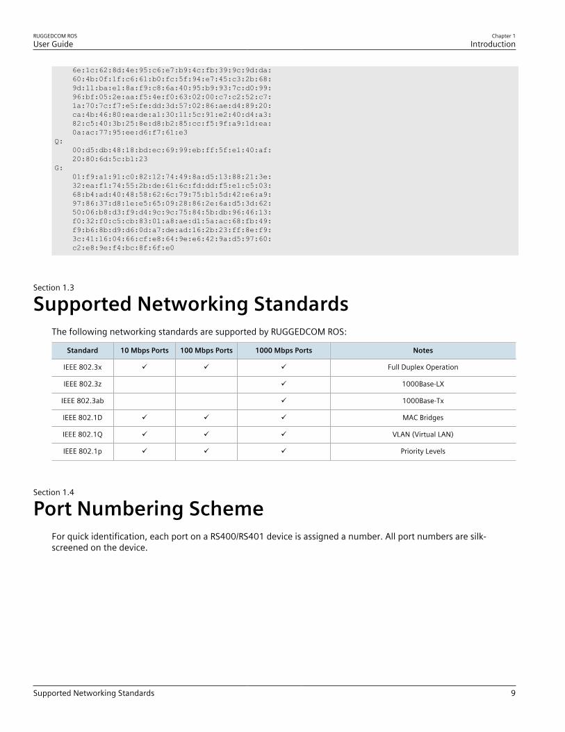
Supported Networking StandardsThe following networking standards are supported by RUGGEDCOM ROS:
Standard 10 Mbps Ports 100 Mbps Ports 1000 Mbps Ports Notes
IEEE 802.3x ü ü ü Full Duplex Operation
IEEE 802.3z ü 1000Base-LX
IEEE 802.3ab ü 1000Base-Tx
IEEE 802.1D ü ü ü MAC Bridges
IEEE 802.1Q ü ü ü VLAN (Virtual LAN)
IEEE 802.1p ü ü ü Priority Levels
Section 1.4
Port Numbering SchemeFor quick identification, each port on a RS400/RS401 device is assigned a number. All port numbers are silk-screened on the device.
Chapter 1Introduction
RUGGEDCOM ROSUser Guide
10 Available Services by Port
1 2 3 4 1 2 3 4
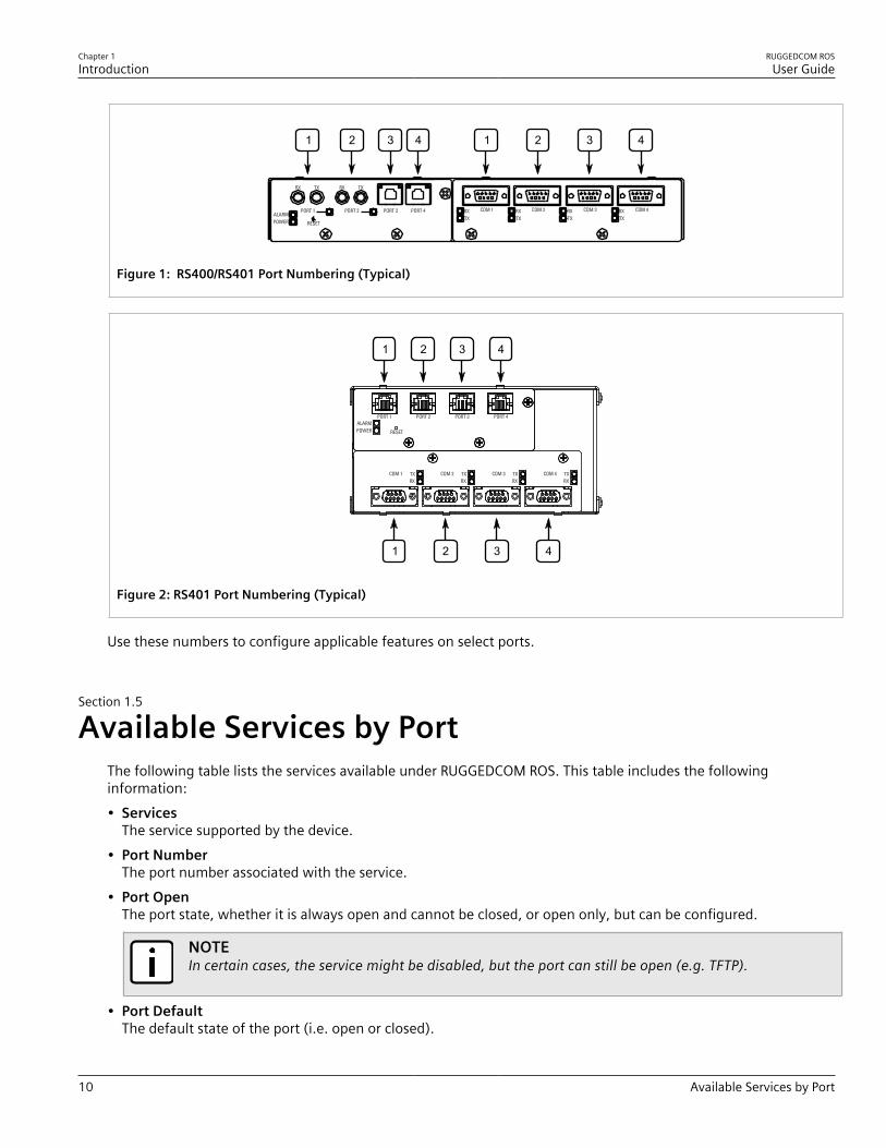
Figure 1: RS400/RS401 Port Numbering (Typical)
1
4321
2 3 4
Figure 2: RS401 Port Numbering (Typical)
Use these numbers to configure applicable features on select ports.
Section 1.5
Available Services by PortThe following table lists the services available under RUGGEDCOM ROS. This table includes the followinginformation:• Services
The service supported by the device.• Port Number
The port number associated with the service.• Port Open
The port state, whether it is always open and cannot be closed, or open only, but can be configured.
NOTEIn certain cases, the service might be disabled, but the port can still be open (e.g. TFTP).
• Port DefaultThe default state of the port (i.e. open or closed).

RUGGEDCOM ROSUser Guide
Chapter 1Introduction
Available Services by Port 11
• Access AuthorizedDenotes whether the ports/services are authenticated during access.
Services Port Number Service Enabled/Disabled Access Authorized Note
Telnet TCP/23 Disabled Yes Only availablethrough twomanagementinterfaces.
HTTP TCP/80 Enabled(configurable),redirects to 443
—
HTTPS TCP/443 Enabled(configurable)
Yes
RSH TCP/512 Disabled(configurable)
Yes Only availablethrough twomanagementinterfaces.
TFTP UDP/69 Disabled(configurable)
No Only availablethrough twomanagementinterfaces.
SFTP TCP/22 Enabled Yes Only availablethrough twomanagementinterfaces.
SNMP UDP/161 Disabled(configurable)
Yes Only availablethrough twomanagementinterfaces.
SNTP UDP/123 Enabled(configurable)
No Only availablethrough twomanagementinterfaces.
SSH TCP/22 Enabled Yes Only availablethrough twomanagementinterfaces.
ICMP — Enabled No
TACACS+ TCP/49(configurable)
Disabled(configurable)
Yes
RADIUS UDP/1812 to send(configurable),opens random portto listen to
Disabled(configurable)
Yes Only availablethrough twomanagementinterfaces.
Remote Syslog UDP/514(configurable)
Disabled(configurable)
No Only availablethrough twomanagementinterfaces.
DNP over RawSocket TCP/21001 toTCP/21016
Disabled(configurable)
No
DNPv3 UDP/20000TCP/20000
UDP Disabled(configurable);
No

Chapter 1Introduction
RUGGEDCOM ROSUser Guide
12 SNMP Management Interface Base (MIB) Support
Services Port Number Service Enabled/Disabled Access Authorized Note
TCP Enabled(configurable)
RawSocket/Telnet COM UDP/50001 toUDP/50016TCP/50001 toTCP/50016
UDP Disabled(configurable);TCP Disabled(configurable)
No
Preemptive RAW Socket TCP/62001 toTCP/62016
Disabled(configurable)
No
TIN UDP/51000TCP/51000
UDP Enabled(configurable);TCP Disabled(configurable)
No
WIN UDP/52000TCP/52000
UDP Enabled(configurable);TCP Disabled(configurable)
No
MICROLOK UDP/60000 UDP Enabled(configurable);TCP Disabled(configurable)
No
MirroredBits UDP/61001 toUDP/61016
Disabled(configurable)
No
TCP Modbus (Server) TCP/502 Disabled(configurable)
No Only availablethrough twomanagementinterfaces.
TCP Modbus (Switch) TCP/502 Disabled(configurable)
No
DHCP, DHCP Agent UDP/67, 68 sendingmsg if enabled - ifreceived, alwayscome to CPU,dropped if servicenot configured
Disabled(configurable)
No
RCDP — Disabled(configurable)
Yes
Section 1.6
SNMP Management Interface Base (MIB) SupportRUGGEDCOM ROS supports a variety of standard MIBs, proprietary RUGGEDCOM MIBs and Agent Capabilities MIBs,all for SNMP (Simple Network Management Protocol).
CONTENTS• Section 1.6.1, “Supported Standard MIBs”• Section 1.6.2, “Supported Proprietary RUGGEDCOM MIBs”
RUGGEDCOM ROSUser Guide
Chapter 1Introduction
Supported Standard MIBs 13
• Section 1.6.3, “Supported Agent Capabilities”
Section 1.6.1
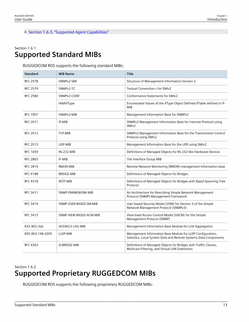
Supported Standard MIBsRUGGEDCOM ROS supports the following standard MIBs:
Standard MIB Name Title
RFC 2578 SNMPv2-SMI Structure of Management Information Version 2
RFC 2579 SNMPv2-TC Textual Convention s for SMIv2
SNMPv2-CONF Conformance Statements for SMIv2RFC 2580
IANAifType Enumerated Values of the ifType Object Defined ifTable defined in IF-MIB
RFC 1907 SNMPv2-MIB Management Information Base for SNMPv2
RFC 2011 IP-MIB SNMPv2 Management Information Base for Internet Protocol usingSMIv2
RFC 2012 TCP-MIB SNMPv2 Management Information Base for the Transmission ControlProtocol using SMIv2
RFC 2013 UDP-MIB Management Information Base for the UDP using SMIv2
RFC 1659 RS-232-MIB Definitions of Managed Objects for RS-232-like Hardware Devices
RFC 2863 IF-MIB The Interface Group MIB
RFC 2819 RMON-MIB Remote Network Monitoring (RMON) management Information base
RFC 4188 BRIDGE-MIB Definitions of Managed Objects for Bridges
RFC 4318 RSTP-MIB Definitions of Managed Objects for Bridges with Rapid Spanning TreeProtocol
RFC 3411 SNMP-FRAMEWORK-MIB An Architecture for Describing Simple Network ManagementProtocol (SNMP) Management Framework
RFC 3414 SNMP-USER-BASED-SM-MIB User-based Security Model (USM) for Version 3 of the SimpleNetwork Management Protocol (SNMPv3)
RFC 3415 SNMP-VIEW-BASED-ACM-MIB View-bsed Access Control Model (VACM) for the SimpleManagement Protocol (SNMP)
IEEE 802.3ad IEEE8023-LAG-MIB Management Information Base Module for Link Aggregation
IEEE 802.1AB-2005 LLDP-MIB Management Information Base Module for LLDP Configuration,Statistics, Local System Data and Remote Systems Data Components
RFC 4363 Q-BRIDGE-MIB Definitions of Managed Objects for Bridges with Traffic Classes,Multicast Filtering, and Virtual LAN Extensions
Section 1.6.2
Supported Proprietary RUGGEDCOM MIBsRUGGEDCOM ROS supports the following proprietary RUGGEDCOM MIBs:

Chapter 1Introduction
RUGGEDCOM ROSUser Guide
14 Supported Agent Capabilities
File Name MIB Name Description
RUGGEDCOM-MIB.mib RUGGEDCOM-MIB RUGGEDCOM enterprise SMI
RUGGEDCOM-TRAPS-MIB.mib RUGGEDCOM-TRAPS-MIB RUGGEDCOM traps definition
RUGGEDCOM-SYS-INFO-MIB.mib RUGGEDCOM-SYS-INFO-MIB General system information aboutRUGGEDCOM device
RUGGEDCOM-DOT11-MIB.mib RUGGEDCOM-DOT11-MIB Managemet for wireless interface onRUGGEDCOM device
RUGGEDCOM-POE-MIB.mib RUGGEDCOM-POE-MIB Management for PoE ports on RUGGEDCOMdevice
RUGGEDCOM-SERIAL-MIB.mib RUGGEDCOM-SERIAL-MIB Managemet for seral ports on RUGGEDCOMdevice
RUGGEDCOM-STP-MIB.mib RUGGEDCOM-STP-MIB Management for RSTP protocol
Section 1.6.3
Supported Agent CapabilitiesRUGGEDCOM ROS supports the following agent capabilities for the SNMP agent:
NOTEFor information about agent capabilities for SNMPv2, refer to RFC 2580 [http://tools.ietf.org/html/rfc2580].
File Name MIB Name Supported MIB
RC-SNMPv2-MIB-AC.mib RC-SNMPv2-MIB-AC SNMPv2-MIB
RC-UDP-MIB-AC.mib RC-UDP-MIB-AC UDP-MIB
RC-TCP-MIB-AC.mib RC-TCP-MIB-AC TCP-MIB
RC-SNMP-USER-BASED-SM-MIB-AC.mib RC-SNMP-USER-BASED-SM-MIB-AC SNMP-USER-BASED-SM-MIB-AC
RC-SNMP-VIEW-BASED-ACM-MIB-AC.mib RC-SNMP-VIEW-BASED-ACM-MIB-AC SNMP-VIEW-BASED-ACM-MIB-AC
RC-IF-MIB-AC.mib RC-IF-MIB-AC IF-MIB
RC-BRIDGE-MIB-AC.mib RC-BRIDGE-MIB-AC BRIDGE-MIB
RC-RMON-MIB-AC.mib RC-RMON-MIB-AC RMON-MIB
RC-Q-BRIDGE-MIB-AC.mib RC-Q-BRIDGE-MIB-AC Q-BRIDGE-MIB
RC-IP-MIB-AC.mib RC-IP-MIB-AC IP-MIB
RC-LLDP-MIB-AC.mib RC-LLDP-MIB-AC LLDP-MIB
RC-LAG-MIB-AC.mib RC-LAG-MIB-AC IEEE8023-LAG-MIB
RC_RSTP-MIB-AC.mib RC_RSTP-MIB-AC RSTP-MIB
RC-RUGGEDCOM-DOT11-MIB-AC.mib RC-RUGGEDCOM-DOT11-MIB-AC RUGGEDCOM-DOT11- MIB
RC-RUGGEDCOM-POE-MIB-AC.mib RC-RUGGEDCOM-POE-MIB-AC RUGGEDCOM-POE-MIB
RC-RUGGEDCOM-STP-AC-MIB.mib RC-RUGGEDCOM-STP-AC-MIB RUGGEDCOM-STP-MIB

RUGGEDCOM ROSUser Guide
Chapter 1Introduction
SNMP Traps 15
File Name MIB Name Supported MIB
RC-RUGGEDCOM-SYS-INFO-MIB-AC.mib RC-RUGGEDCOM-SYS-INFO-MIB-AC RUGGEDCOM-SYS-INFO-MIB
RC-RUGGEDCOM-TRAPS-MIB-AC.mib RC-RUGGEDCOM-TRAPS-MIB-AC RUGGEDCOM-TRAPS-MIB
RUGGEDCOM_RS-232-MIB-AC.mib RUGGEDCOM_RS-232-MIB-AC RS-232-MIB
RC-RUGGEDCOM-SERIAL-MIB-AC.mib RC-RUGGEDCOM-SERIAL-MIB-AC RUGGEDCOM-SERIAL-MIB
Section 1.7
SNMP TrapsThe device generates the following standard traps:
Table: Standard Traps
Trap MIB
linkDown
linkUp
IF-MIB
authenticationFailure
coldStart
SNMPv2-MIB
newRoot
topologyChage
BRIDGE-MIB
risingAlarm
fallingAlarm
RMON-MIB
lldpRemoteTablesChange LLDP-MIB
The device also generates the following proprietary traps:
Table: Proprietary Traps
Trap MIB
genericTrap
powerSupplyTrap
swUpgradeTrap
cfgChangeTrap
weakPasswordTrap
defaultKeysTrap
RUGGEDCOM-TRAPS-MIB
Generic traps carry information about events in their severity and description objects. They are sent at the sametime an alarm is generated for the device. The following are examples of RUGGEDCOM generic traps:
NOTEInformation about generic traps can be retrieved using the CLI command alarms. For moreinformation about the alarms command, refer to Section 2.6.1, “Available CLI Commands” .

Chapter 1Introduction
RUGGEDCOM ROSUser Guide
16 ModBus Management Support
Table: Generic Traps
Trap Severity
heap error Alert
NTP server failure notification
real time clock failure Error
failed password Warning
MAC address not learned by switch fabric Warning
BootP client: TFTP transfer failure Error
received looped back BPDU Error
received two consecutive confusing BPDUs on port, forcing down Error
GVRP failed to learn – too many VLANs Warning
The device generates the following traps when specific events occur:
Table: Event-Based Traps
Trap MIB Event
rcRstpNewTopology RUGGEDCOM-STP-MIB This trap is generated when the devicetopology becomes stable after a topologychange occurs on a switch port.
Section 1.8
ModBus Management SupportModbus management support in RUGGEDCOM devices provides a simple interface for retrieving basic statusinformation. ModBus support simplifies the job of SCADA (Supervisory Control and Data Acquisition) systemintegrators by providing familiar protocols for retrieving RUGGEDCOM device information. ModBus providesmostly read-only status information, but there are some writable registers for operator commands.The ModBus protocol PDU (Protocol Data Unit) format is as follows:
Function Code Data
CONTENTS• Section 1.8.1, “ModBus Function Codes”• Section 1.8.2, “ModBus Memory Map”• Section 1.8.3, “ModBus Memory Formats”
Section 1.8.1
ModBus Function CodesRUGGEDCOM devices support the following ModBus function codes for device management through ModBus:

RUGGEDCOM ROSUser Guide
Chapter 1Introduction
ModBus Memory Map 17
NOTEWhile RUGGEDCOM devices have a variable number of ports, not all registers and bits apply to allproducts.Registers that are not applicable to a particular device return a zero (0) value. For example, registersreferring to serial ports are not applicable to RUGGEDCOM switch devices.
Read Input Registers or Read Holding Registers — 0x04 or 0x03Example PDU Request
Function Code 1 Byte 0x04(0x03)
Starting Address 2 Bytes 0x0000 to 0xFFFF (Hexadecimal)128 to 65535 (Decimal)
Number of Input Registers 2 Bytes Bytes 0x0001 to 0x007D
Example PDU Response
Function Code 1 Byte 0x04(0x03)
Byte Count 1 Byte 2 x N a
Number of Input Registers N a x 2 Bytesa The number of input registers
Write Multiple Registers — 0x10Example PDU Request
Function Code 1 Byte 0x10
Starting Address 2 Bytes 0x0000 to 0xFFFF
Number of Input Registers 2 Bytes Bytes 0x0001 to 0x0079
Byte Count 1 Byte 2 x N b
Registers Value N b x 2 Bytes Value of the registerb The number of input registers
Example PDU Response
Function Code 1 Byte 0x10
Starting Address 2 Bytes 0x0000 to 0xFFFF
Number of Registers 2 Bytes 1 to 121 (0x79)
Section 1.8.2
ModBus Memory MapThe following details how ModBus process variable data is mapped.

Chapter 1Introduction
RUGGEDCOM ROSUser Guide
18 ModBus Memory Map
Product InfoThe following data is mapped to the Productinfo table:
Address #Registers Description (Reference Table in UI) R/W Format
0000 16 Product Identification R Text
0010 32 Firmware Identification R Text
0040 1 Number of Ethernet Ports R Uint16
0041 1 Number of Serial Ports R Uint16
0042 1 Number of Alarms R Uint16
0043 1 Power Supply Status R PSStatusCmd
0044 1 FailSafe Relay Status R TruthValue
0045 1 ErrorAlarm Status R TruthValue
Product Write RegisterThe following data is mapped to various tables:
Address #Registers Description (Reference Table in UI) R/W Format
0080 1 Clear Alarms W Cmd
0081 2 Reset Ethernet Ports W PortCmd
0083 2 Clear Ethernet Statistics W PortCmd
0085 2 Reset Serial Ports W PortCmd
0087 2 Clear Serial Port Statistics W PortCmd
AlarmsThe following data is mapped to the alarms table:
Address #Registers Description (Reference Table in UI) R/W Format
0100 64 Alarm 1 R Alarm
0140 64 Alarm 2 R Alarm
0180 64 Alarm 3 R Alarm
01C0 64 Alarm 4 R Alarm
0200 64 Alarm 5 R Alarm
0240 64 Alarm 6 R Alarm
0280 64 Alarm 7 R Alarm
02C0 64 Alarm 8 R Alarm

RUGGEDCOM ROSUser Guide
Chapter 1Introduction
ModBus Memory Map 19
Ethernet Port StatusThe following data is mapped to the ethPortStats table:
Address #Registers Description (Reference Table in UI) R/W Format
03FE 2 Port Link Status R PortCmd
Ethernet StatisticsThe following data is mapped to the rmonStats table:
Address #Registers Description (Reference Table in UI) R/W Format
0400 2 Port s1/p1 Statistics - Ethernet In Packets R Uinst32
0402 2 Port s1/p2 Statistics - Ethernet In Packets R Uinst32
0404 2 Port s1/p3 Statistics - Ethernet In Packets R Uinst32
0406 2 Port s1/p4 Statistics - Ethernet In Packets R Uinst32
0408 2 Port s2/p1 Statistics - Ethernet In Packets R Uinst32
040A 2 Port s2/p2 Statistics - Ethernet In Packets R Uinst32
040C 2 Port s2/p3 Statistics - Ethernet In Packets R Uinst32
040E 2 Port s2/p4 Statistics - Ethernet In Packets R Uinst32
0410 2 Port s3/p1 Statistics - Ethernet In Packets R Uinst32
0412 2 Port s3/p2 Statistics - Ethernet In Packets R Uinst32
0414 2 Port s3/p3 Statistics - Ethernet In Packets R Uinst32
0416 2 Port s3/p4 Statistics - Ethernet In Packets R Uinst32
0418 2 Port s4/p1 Statistics - Ethernet In Packets R Uinst32
041A 2 Port s4/p2 Statistics - Ethernet In Packets R Uinst32
041C 2 Port s4/p3 Statistics - Ethernet In Packets R Uinst32
041E 2 Port s4/p4 Statistics - Ethernet In Packets R Uinst32
0420 2 Port s5/p1 Statistics - Ethernet In Packets R Uinst32
0422 2 Port s5/p2 Statistics - Ethernet In Packets R Uinst32
0424 2 Port s5/p3 Statistics - Ethernet In Packets R Uinst32
0426 2 Port s5/p4 Statistics - Ethernet In Packets R Uinst32
0428 2 Port s6/p1 Statistics - Ethernet In Packets R Uinst32
042A 2 Port s6/p2 Statistics - Ethernet In Packets R Uinst32
042C 2 Port s6/p3 Statistics - Ethernet In Packets R Uinst32
042E 2 Port s6/p4 Statistics - Ethernet In Packets R Uinst32
0430 2 Port s7/p1 Statistics - Ethernet In Packets R Uinst32
0432 2 Port s7/p2 Statistics - Ethernet In Packets R Uinst32
0434 2 Port s8/p1 Statistics - Ethernet In Packets R Uinst32

Chapter 1Introduction
RUGGEDCOM ROSUser Guide
20 ModBus Memory Map
Address #Registers Description (Reference Table in UI) R/W Format
0436 2 Port s8/p2 Statistics - Ethernet In Packets R Uinst32
0440 2 Port s1/p1 Statistics - Ethernet Out Packets R Uinst32
0442 2 Port s1/p2 Statistics - Ethernet Out Packets R Uinst32
0444 2 Port s1/p3 Statistics - Ethernet Out Packets R Uinst32
0446 2 Port s1/p4 Statistics - Ethernet Out Packets R Uinst32
0448 2 Port s2/p1 Statistics - Ethernet Out Packets R Uinst32
044A 2 Port s2/p2 Statistics - Ethernet Out Packets R Uinst32
044C 2 Port s2/p3 Statistics - Ethernet Out Packets R Uinst32
044E 2 Port s2/p4 Statistics - Ethernet Out Packets R Uinst32
0450 2 Port s3/p1 Statistics - Ethernet Out Packets R Uinst32
0452 2 Port s3/p2 Statistics - Ethernet Out Packets R Uinst32
0454 2 Port s3/p3 Statistics - Ethernet Out Packets R Uinst32
0456 2 Port s3/p4 Statistics - Ethernet Out Packets R Uinst32
0458 2 Port s4/p1 Statistics - Ethernet Out Packets R Uinst32
045A 2 Port s4/p2 Statistics - Ethernet Out Packets R Uinst32
045C 2 Port s4/p3 Statistics - Ethernet Out Packets R Uinst32
045E 2 Port s4/p4 Statistics - Ethernet Out Packets R Uinst32
0460 2 Port s5/p1 Statistics - Ethernet Out Packets R Uinst32
0462 2 Port s5/p2 Statistics - Ethernet Out Packets R Uinst32
0464 2 Port s5/p3 Statistics - Ethernet Out Packets R Uinst32
0466 2 Port s5/p4 Statistics - Ethernet Out Packets R Uinst32
0468 2 Port s6/p1 Statistics - Ethernet Out Packets R Uinst32
046A 2 Port s6/p2 Statistics - Ethernet Out Packets R Uinst32
046C 2 Port s6/p3 Statistics - Ethernet Out Packets R Uinst32
046E 2 Port s6/p4 Statistics - Ethernet Out Packets R Uinst32
0470 2 Port s7/p1 Statistics - Ethernet Out Packets R Uinst32
0472 2 Port s7/p2 Statistics - Ethernet Out Packets R Uinst32
0474 2 Port s8/p1 Statistics - Ethernet Out Packets R Uinst32
0476 2 Port s8/p2 Statistics - Ethernet Out Packets R Uinst32
0480 2 Port s1/p1 Statistics - Ethernet In Packets R Uinst32
0482 2 Port s1/p2 Statistics - Ethernet In Packets R Uinst32
0484 2 Port s1/p3 Statistics - Ethernet In Packets R Uinst32
0486 2 Port s1/p4 Statistics - Ethernet In Packets R Uinst32
0488 2 Port s2/p1 Statistics - Ethernet In Packets R Uinst32

RUGGEDCOM ROSUser Guide
Chapter 1Introduction
ModBus Memory Map 21
Address #Registers Description (Reference Table in UI) R/W Format
048A 2 Port s2/p2 Statistics - Ethernet In Packets R Uinst32
048C 2 Port s2/p3 Statistics - Ethernet In Packets R Uinst32
048E 2 Port s2/p4 Statistics - Ethernet In Packets R Uinst32
0490 2 Port s3/p1 Statistics - Ethernet In Packets R Uinst32
0492 2 Port s3/p2 Statistics - Ethernet In Packets R Uinst32
0494 2 Port s3/p3 Statistics - Ethernet In Packets R Uinst32
0496 2 Port s3/p4 Statistics - Ethernet In Packets R Uinst32
0498 2 Port s4/p1 Statistics - Ethernet In Packets R Uinst32
049A 2 Port s4/p2 Statistics - Ethernet In Packets R Uinst32
049C 2 Port s4/p3 Statistics - Ethernet In Packets R Uinst32
049E 2 Port s4/p4 Statistics - Ethernet In Packets R Uinst32
04A0 2 Port s5/p1 Statistics - Ethernet In Packets R Uinst32
04A2 2 Port s5/p2 Statistics - Ethernet In Packets R Uinst32
04A4 2 Port s5/p3 Statistics - Ethernet In Packets R Uinst32
04A6 2 Port s5/p4 Statistics - Ethernet In Packets R Uinst32
04A8 2 Port s6/p1 Statistics - Ethernet In Packets R Uinst32
04AA 2 Port s6/p2 Statistics - Ethernet In Packets R Uinst32
04AC 2 Port s6/p3 Statistics - Ethernet In Packets R Uinst32
04AE 2 Port s6/p4 Statistics - Ethernet In Packets R Uinst32
04B0 2 Port s7/p1 Statistics - Ethernet In Packets R Uinst32
04B2 2 Port s7/p2 Statistics - Ethernet In Packets R Uinst32
04B4 2 Port s8/p1 Statistics - Ethernet In Packets R Uinst32
04B6 2 Port s8/p2 Statistics - Ethernet In Packets R Uinst32
04C0 2 Port s1/p1 Statistics - Ethernet Out Packets R Uinst32
04C2 2 Port s1/p2 Statistics - Ethernet Out Packets R Uinst32
04C4 2 Port s1/p3 Statistics - Ethernet Out Packets R Uinst32
04C6 2 Port s1/p4 Statistics - Ethernet Out Packets R Uinst32
04C8 2 Port s2/p1 Statistics - Ethernet Out Packets R Uinst32
04CA 2 Port s2/p2 Statistics - Ethernet Out Packets R Uinst32
04CC 2 Port s2/p3 Statistics - Ethernet Out Packets R Uinst32
04CE 2 Port s2/p4 Statistics - Ethernet Out Packets R Uinst32
04D0 2 Port s3/p1 Statistics - Ethernet Out Packets R Uinst32
04D2 2 Port s3/p2 Statistics - Ethernet Out Packets R Uinst32
04D4 2 Port s3/p3 Statistics - Ethernet Out Packets R Uinst32

Chapter 1Introduction
RUGGEDCOM ROSUser Guide
22 ModBus Memory Map
Address #Registers Description (Reference Table in UI) R/W Format
04D6 2 Port s3/p4 Statistics - Ethernet Out Packets R Uinst32
04D8 2 Port s4/p1 Statistics - Ethernet Out Packets R Uinst32
04DA 2 Port s4/p2 Statistics - Ethernet Out Packets R Uinst32
04DC 2 Port s4/p3 Statistics - Ethernet Out Packets R Uinst32
04DE 2 Port s4/p4 Statistics - Ethernet Out Packets R Uinst32
04E0 2 Port s5/p1 Statistics - Ethernet Out Packets R Uinst32
04E2 2 Port s5/p2 Statistics - Ethernet Out Packets R Uinst32
04E4 2 Port s5/p3 Statistics - Ethernet Out Packets R Uinst32
04E6 2 Port s5/p4 Statistics - Ethernet Out Packets R Uinst32
04E8 2 Port s6/p1 Statistics - Ethernet Out Packets R Uinst32
04EA 2 Port s6/p2 Statistics - Ethernet Out Packets R Uinst32
04EC 2 Port s6/p3 Statistics - Ethernet Out Packets R Uinst32
04EE 2 Port s6/p4 Statistics - Ethernet Out Packets R Uinst32
04F0 2 Port s7/p1 Statistics - Ethernet Out Packets R Uinst32
04F2 2 Port s7/p2 Statistics - Ethernet Out Packets R Uinst32
04F4 2 Port s8/p1 Statistics - Ethernet Out Packets R Uinst32
04F6 2 Port s8/p2 Statistics - Ethernet Out Packets R Uinst32
Serial StatisticsThe following data is mapped to the uartPortStatus table:
Address #Registers Description (Reference Table in UI) R/W Format
0600 2 Port 1 Statistics – Serial In characters R Uint32
0602 2 Port 2 Statistics – Serial In characters R Uint32
0604 2 Port 3 Statistics – Serial In characters R Uint32
0606 2 Port 4 Statistics – Serial In characters R Uint32
0640 2 Port 1 Statistics – Serial Out characters R Uint32
0642 2 Port 2 Statistics – Serial Out characters R Uint32
0644 2 Port 3 Statistics – Serial Out characters R Uint32
0646 2 Port 4 Statistics – Serial Out characters R Uint32
0680 2 Port 1 Statistics – Serial In Packets R Uint32
0682 2 Port 2 Statistics – Serial In Packets R Uint32
0684 2 Port 3 Statistics – Serial In Packets R Uint32
0686 2 Port 4 Statistics – Serial In Packets R Uint32
06C0 2 Port 1 Statistics – Serial Out Packets R Uint32

RUGGEDCOM ROSUser Guide
Chapter 1Introduction
ModBus Memory Formats 23
Address #Registers Description (Reference Table in UI) R/W Format
06C2 2 Port 2 Statistics – Serial Out Packets R Uint32
06C4 2 Port 3 Statistics – Serial Out Packets R Uint32
06C6 2 Port 4 Statistics – Serial Out Packets R Uint32
Section 1.8.3
ModBus Memory FormatsThe following ModBus memory formats are supported by Siemens.
CONTENTS• Section 1.8.3.1, “Text”• Section 1.8.3.2, “Cmd”• Section 1.8.3.3, “Uint16”• Section 1.8.3.4, “Uint32”• Section 1.8.3.5, “PortCmd”• Section 1.8.3.6, “Alarm”• Section 1.8.3.7, “PSStatusCmd”• Section 1.8.3.8, “TruthValues”
Section 1.8.3.1Text
The Text format provides a simple ASCII representation of the information related to the product. The mostsignificant register byte of an ASCII characters comes first.For example, consider a Read Multiple Registers request to read Product Identification from location 0x0000.
0x04 0x00 0x00 0x00 0x08
The response may look like:
0x04 0x10 0x53 0x59 0x53 0x54 0x45 0x4D 0x20 0x4E 0x41 0x4D 0x45
0x00 0x00 0x00 0x00 0x00
In this example, starting from byte 3 until the end, the response presents an ASCII representation of the charactersfor the product identification, which reads as SYSTEM NAME. Since the length of this field is smaller than eightregisters, the rest of the field is filled with zeros (0).
Section 1.8.3.2Cmd
The Cmd format instructs the device to set the output to either true or false. The most significant byte comes first.
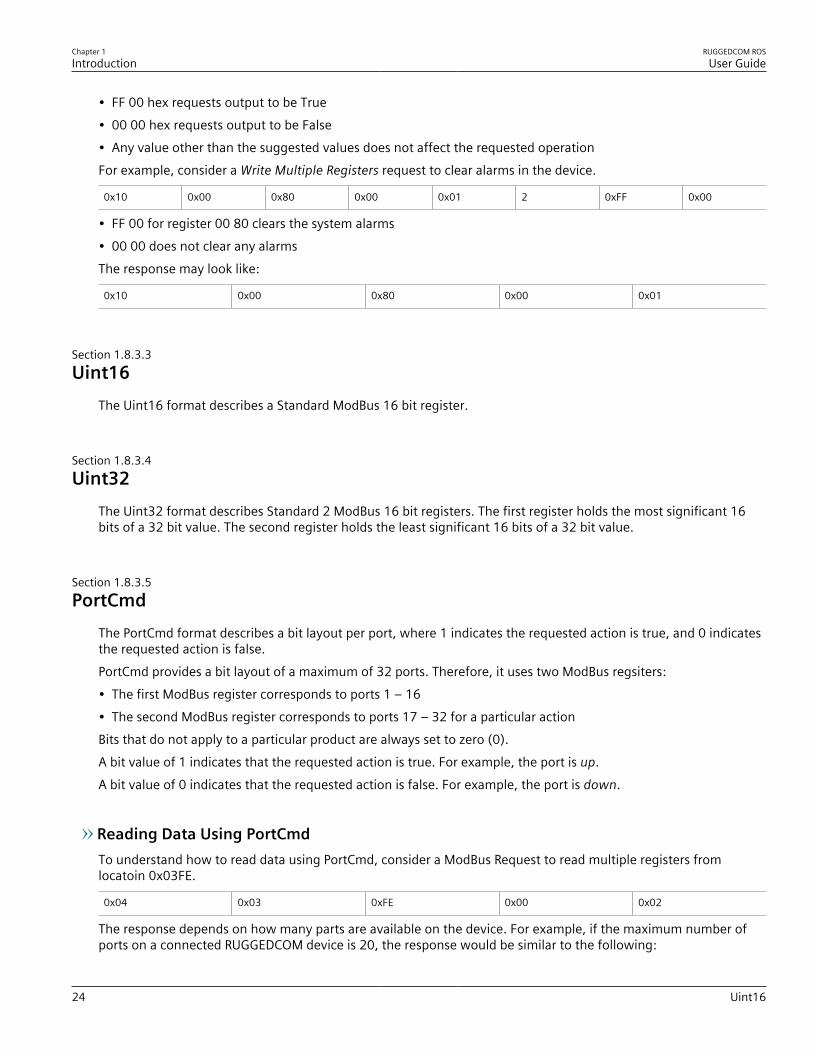
Chapter 1Introduction
RUGGEDCOM ROSUser Guide
24 Uint16
• FF 00 hex requests output to be True• 00 00 hex requests output to be False• Any value other than the suggested values does not affect the requested operationFor example, consider a Write Multiple Registers request to clear alarms in the device.
0x10 0x00 0x80 0x00 0x01 2 0xFF 0x00
• FF 00 for register 00 80 clears the system alarms• 00 00 does not clear any alarmsThe response may look like:
0x10 0x00 0x80 0x00 0x01
Section 1.8.3.3Uint16
The Uint16 format describes a Standard ModBus 16 bit register.
Section 1.8.3.4Uint32
The Uint32 format describes Standard 2 ModBus 16 bit registers. The first register holds the most significant 16bits of a 32 bit value. The second register holds the least significant 16 bits of a 32 bit value.
Section 1.8.3.5PortCmd
The PortCmd format describes a bit layout per port, where 1 indicates the requested action is true, and 0 indicatesthe requested action is false.PortCmd provides a bit layout of a maximum of 32 ports. Therefore, it uses two ModBus regsiters:• The first ModBus register corresponds to ports 1 – 16• The second ModBus register corresponds to ports 17 – 32 for a particular actionBits that do not apply to a particular product are always set to zero (0).A bit value of 1 indicates that the requested action is true. For example, the port is up.A bit value of 0 indicates that the requested action is false. For example, the port is down.
Reading Data Using PortCmdTo understand how to read data using PortCmd, consider a ModBus Request to read multiple registers fromlocatoin 0x03FE.
0x04 0x03 0xFE 0x00 0x02
The response depends on how many parts are available on the device. For example, if the maximum number ofports on a connected RUGGEDCOM device is 20, the response would be similar to the following:

RUGGEDCOM ROSUser Guide
Chapter 1Introduction
Alarm 25
0x04 0x04 0xF2 0x76 0x00 0x05
In this example, bytes 3 and 4 refer to register 1 at location 0x03FE, and represent the status of ports 1 – 16. Bytes5 and 6 refer to register 2 at location 0x03FF, and represent the status of ports 17 – 32. The device only has 20ports, so byte 6 contains the status for ports 17 – 20 starting from right to left. The rest of the bites in register 2corresponding to the non-existing ports 21 – 31 are zero (0).
Performing Write Actions Using PortCmdTo understand how data is written using PortCmd, consider a Write Multiple Register request to clear Ethernet portstatistics:
0x10 0x00 0x83 0x00 0x01 2 0x55 0x76 0x00 0x50
A bit value of 1 clears Ethernet statistics on the corresponding port. A bit value of 0 does not clear the Ethernetstatistics.
0x10 0x00 0x81 0x00 0x02
Section 1.8.3.6Alarm
The Alarm format is another form of text description. Alarm text corresponds to the alarm description from thetable holding all of the alarms. Similar to the Text format, this format returns an ASCII representation of alarms.
NOTEAlarms are stacked in the device in the sequence of their occurence (i.e. Alarm 1, Alarm 2, Alarm 3,etc.).
The first eight alarms from the stack can be returned, if they exist. A zero (0) value is returned if an alarm does notexist.
Section 1.8.3.7PSStatusCmd
The PSStatusCmd format describes a bit layout for providing the status of available power supplies. Bits 0-4 of thelower byte of the register are used for this purpose.• Bits 0-1: Power Supply 1 Status• Bits 2-3: Power Supply 2 StatusOther bits in the register do not provide any system status information.
Bit Value Description
01 Power Supply not present (01 = 1)
10 Power Supply is functional (10 = 2)
11 Power Supply is not functional (11 = 3)
The values used for power supply status are derived from the RUGGEDCOM-specific SNMP MIB.

Chapter 1Introduction
RUGGEDCOM ROSUser Guide
26 TruthValues
Reading the Power Supply Status from a Device Using PSStatusCmdTo understand how to read the power supply status from a device using PSStatusCmd, consider a ModBus Requestto read multiple registers from location 0x0043.
0x04 0x00 0x43 0x00 0x01
The response may look like:
0x04 0x02 0x00 0x0A
The lower byte of the register displays the power supply's status. In this example, both power supplies in the unitare functional.
Section 1.8.3.8TruthValues
The Truthvalues format represents a true or false status in the device:• 1 indicates the corresponding status for the device to be true• 2 indicates the corresponding status for the device to be false
Reading the FailSafe Relay Status From a Device Using TruthValueTo understand how to use the TruthValue format to read the FailSafe Relay status from a device, consider aModBus request to read multiple registers from location 0x0044.
0x04 0x00 0x44 0x00 0x01
The response may look like:
0x04 0x02 0x00 0x01
The register's lower byte shows the FailSafe Relay status. In this example, the FailSafe Relay is energized.
Reading the ErrorAlarm Status From a Device Using TruthValueTo understand how to use the TruthValue format to read the ErrorAlarm status from a device, conside a ModBusrequest to read mulitple registers from location 0x0045.
0x04 0x00 0x45 0x00 0x01
The response may look like:
0x04 0x02 0x00 0x01
The register's lower byte shows the ErrorAlarm status. In this example, there is no active ERROR, ALERT or CRITICALalarm in the device.

RUGGEDCOM ROSUser Guide
Chapter 1Introduction
SSH and SSL Keys and Certificates 27
Section 1.9
SSH and SSL Keys and CertificatesThe following describes the SSH and SSL keys and certificates in RS400, along with the certificate and SSH keyrequirements.
CONTENTS• Section 1.9.1, “Certificate and Keys Life Cycle”• Section 1.9.2, “Certificate and Key Requirements”
Section 1.9.1
Certificate and Keys Life CycleEach RUGGEDCOM ROS device is shipped with an SSL certificate and RSA key pair, and a DSA host key pair forSSH, that are generated at and provisioned by the factory. The administrator may upload a new certificate andkeys to the system at any time, which will overwrite the existing ones. In addition, CLI commands are available toregenerate SSL certificate and key pair as well as the SSH host key pair.There are three types of certificates and keys used in RUGGEDCOM ROS:
NOTESSH is not supported in Non-Controlled (NC) versions of RUGGEDCOM ROS.
NOTENetwork exposure to a ROS unit operating with the default keys, although always only temporaryby design, should be avoided. The best way to reduce or eliminate this exposure is to provision user-created certificate and keys as quickly as possible, and preferably before the unit is placed in networkservice.
• DefaultA default certificate and SSL/SSH keys are built in to RUGGEDCOM ROS and are common across all RUGGEDCOMROS units sharing the same firmware image. In the event that valid SSL certificate or SSL/SSH key files are notavailable on the device (as is usually only the case when upgrading from an old ROS version that does notsupport user-configurable keys and therefore does was not shipped with unique, factory-generated keys), thedefault certificate and keys are put into service *temporarily* so that SSH and SSL (https) sessions can be serveduntil generated or provisioned keys are available.
• Auto-GeneratedIf a default SSL certificate and SSL/SSH keys are in use, RUGGEDCOM ROS immediately begins to generate aunique certificate and SSL/SSH keys for the device in the background. This process may take several minutes tocomplete depending on the requested key length and how busy the device is at the time. If a custom certificateand keys are loaded while auto-generated certificates and keys are being generated, the generator will abortand the custom certificate and keys and will be used.
• User-Generated (Recommended)Custom certificates and keys are the most secure option. They give the user complete control over certificateand key management, allow for the provision of certificates signed by a public or local certificate authority,enable strictly controlled access to private keys, and allow authoritative distribution of SSL certificates, any CAcertificates, and public SSH keys.
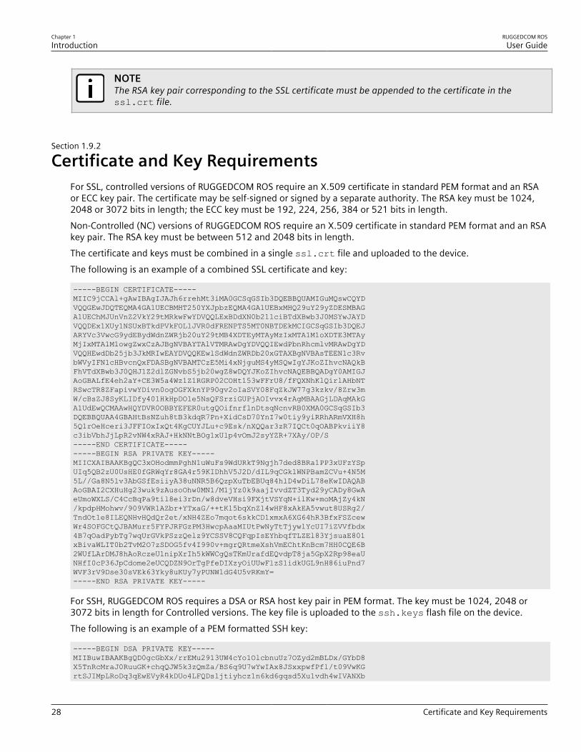
Chapter 1Introduction
RUGGEDCOM ROSUser Guide
28 Certificate and Key Requirements
NOTEThe RSA key pair corresponding to the SSL certificate must be appended to the certificate in thessl.crt file.
Section 1.9.2
Certificate and Key RequirementsFor SSL, controlled versions of RUGGEDCOM ROS require an X.509 certificate in standard PEM format and an RSAor ECC key pair. The certificate may be self-signed or signed by a separate authority. The RSA key must be 1024,2048 or 3072 bits in length; the ECC key must be 192, 224, 256, 384 or 521 bits in length.Non-Controlled (NC) versions of RUGGEDCOM ROS require an X.509 certificate in standard PEM format and an RSAkey pair. The RSA key must be between 512 and 2048 bits in length.The certificate and keys must be combined in a single ssl.crt file and uploaded to the device.The following is an example of a combined SSL certificate and key:
-----BEGIN CERTIFICATE-----MIIC9jCCAl+gAwIBAgIJAJh6rrehMt3iMA0GCSqGSIb3DQEBBQUAMIGuMQswCQYDVQQGEwJDQTEQMA4GA1UECBMHT250YXJpbzEQMA4GA1UEBxMHQ29uY29yZDESMBAGA1UEChMJUnVnZ2VkY29tMRkwFwYDVQQLExBDdXN0b21lciBTdXBwb3J0MSYwJAYDVQQDEx1XUy1NSUxBTkdPVkFOLlJVR0dFRENPTS5MT0NBTDEkMCIGCSqGSIb3DQEJARYVc3VwcG9ydEBydWdnZWRjb20uY29tMB4XDTEyMTAyMzIxMTA1M1oXDTE3MTAyMjIxMTA1M1owgZwxCzAJBgNVBAYTAlVTMRAwDgYDVQQIEwdPbnRhcmlvMRAwDgYDVQQHEwdDb25jb3JkMRIwEAYDVQQKEwlSdWdnZWRDb20xGTAXBgNVBAsTEEN1c3RvbWVyIFN1cHBvcnQxFDASBgNVBAMTCzE5Mi4xNjguMS4yMSQwIgYJKoZIhvcNAQkBFhVTdXBwb3J0QHJ1Z2dlZGNvbS5jb20wgZ8wDQYJKoZIhvcNAQEBBQADgY0AMIGJAoGBALfE4eh2aY+CE3W5a4Wz1Z1RGRP02COHt153wFFrU8/fFQXNhKlQirlAHbNTRSwcTR8ZFapivwYDivn0ogOGFXknYP90gv2oIaSVY08FqZkJW77g3kzkv/8Zrw3mW/cBsZJ8SyKLIDfy401HkHpDOle5NsQFSrziGUPjAOIvvx4rAgMBAAGjLDAqMAkGA1UdEwQCMAAwHQYDVR0OBBYEFER0utgQOifnrflnDtsqNcnvRB0XMA0GCSqGSIb3DQEBBQUAA4GBAHtBsNZuh8tB3kdqR7Pn+XidCsD70YnI7w0tiy9yiRRhARmVXH8h5Q1rOeHceri3JFFIOxIxQt4KgCUYJLu+c9Esk/nXQQar3zR7IQCt0qOABPkviiY8c3ibVbhJjLpR2vNW4xRAJ+HkNNtBOg1xUlp4vOmJ2syYZR+7XAy/OP/S-----END CERTIFICATE----------BEGIN RSA PRIVATE KEY-----MIICXAIBAAKBgQC3xOHodmmPghN1uWuFs9WdURkT9Ngjh7ded8BRa1PP3xUFzYSpUIq5QB2zU0UsHE0fGRWqYr8GA4r59KIDhhV5J2D/dIL9qCGklWNPBamZCVu+4N5M5L//Ga8N5lv3AbGSfEsiiyA38uNNR5B6QzpXuTbEBUq84hlD4wDiL78eKwIDAQABAoGBAI2CXHuHg23wuk9zAusoOhw0MN1/M1jYz0k9aajIvvdZT3Tyd29yCADy8GwAeUmoWXLS/C4CcBqPa9til8ei3rDn/w8dveVHsi9FXjtVSYqN+ilKw+moMAjZy4kN/kpdpHMohwv/909VWR1AZbr+YTxaG/++tKl5bqXnZl4wHF8xAkEA5vwut8USRg2/TndOt1e8ILEQNHvHQdQr2et/xNH4ZEo7mqot6skkCD1xmxA6XG64hR3BfxFSZcewWr4SOFGCtQJBAMurr5FYPJRFGzPM3HwcpAaaMIUtPwNyTtTjywlYcUI7iZVVfbdx4B7qOadPybTg7wqUrGVkPSzzQelz9YCSSV8CQFqpIsEYhbqfTLZEl83YjsuaE801xBivaWLIT0b2TvM2O7zSDOG5fv4I990v+mgrQRtmeXshVmEChtKnBcm7HH0CQE6B2WUfLArDMJ8hAoRczeU1nipXrIh5kWWCgQsTKmUrafdEQvdpT8ja5GpX2Rp98eaUNHfI0cP36JpCdome2eUCQDZN9OrTgPfeDIXzyOiUUwFlzS1idkUGL9nH86iuPnd7WVF3rV9Dse30sVEk63Yky8uKUy7yPUNWldG4U5vRKmY=-----END RSA PRIVATE KEY-----
For SSH, RUGGEDCOM ROS requires a DSA or RSA host key pair in PEM format. The key must be 1024, 2048 or3072 bits in length for Controlled versions. The key file is uploaded to the ssh.keys flash file on the device.The following is an example of a PEM formatted SSH key:
-----BEGIN DSA PRIVATE KEY-----MIIBuwIBAAKBgQD0gcGbXx/rrEMu2913UW4cYo1OlcbnuUz7OZyd2mBLDx/GYbD8X5TnRcMraJ0RuuGK+chqQJW5k3zQmZa/BS6q9U7wYwIAx8JSxxpwfPfl/t09VwKGrtSJIMpLRoDq3qEwEVyR4kDUo4LFQDsljtiyhcz1n6kd6gqsd5Xu1vdh4wIVANXb

RUGGEDCOM ROSUser Guide
Chapter 1Introduction
Certificate and Key Requirements 29
SBi97GmZ6/9f4UCvIIBtXLEjAoGAAfmhkcCCEnRJitUTiCE+MurxdFUr3mFs/d314cUDaLStQEhYYmx5dbFdQuapl4Y32B7lZQkohi5q1T1iUAa40/nUnJx1hFvblkYT8DLwxcuDAaiu0VqsaPtJ+baL2dYNp96tFisj/475PEEWBGbP6GSe5kKa1Zdgwuie9LyPb+ACgYBv856v5tb9UVG5+tX5Crfv/Nd8FFlSSFKmVWW3yzguhHajg2LQg8UUsm1/zPSwYQ0SbQ9aOAJnpLc2HUkK0lji/0oKVI7y9MMc4B+bGu4W4OnryP7oFpnpYYHt5PJY+zvLw/Wa+u3NOVFHkF1tGyfVBMXeV36nowPo+wrVMolAEgIVALLTnfpWmaV6uh6RxeE1d4XoxSg2-----END DSA PRIVATE KEY-----
For more information about encryption key management, refer to Section 1.2, “Security Recommendations andConsiderations” .

RUGGEDCOM ROSUser Guide
Chapter 1Introduction
Certificate and Key Requirements 30

RUGGEDCOM ROSUser Guide
Chapter 2Using ROS
Connecting to ROS 31
Using ROSThis chapter describes how to use the RUGGEDCOM ROS interface.
CONTENTS• Section 2.1, “Connecting to ROS”• Section 2.2, “Logging In”• Section 2.3, “Logging Out”• Section 2.4, “Using the Web Interface”• Section 2.5, “Using the Console Interface”• Section 2.6, “Using the Command Line Interface”• Section 2.7, “Selecting Ports in RUGGEDCOM ROS ”• Section 2.8, “Managing the Flash File System”• Section 2.9, “Accessing BIST Mode”• Section 2.10, “Managing SSH Public Keys”
Section 2.1
Connecting to ROSThis section describes the various methods for connecting the device.
CONTENTS• Section 2.1.1, “Connecting Directly”• Section 2.1.2, “Connecting via the Network”
Section 2.1.1
Connecting DirectlyRUGGEDCOM ROS can be accessed through a direct RS-232 serial console connection for management andtroubleshooting purposes. A console connection provides access to the console interface and CLI.To establish a console connection to the device, do the following:1. Connect a workstation (either a terminal or computer running terminal emulation software) to the RS-232
serial console port on the device. For more information about the RS-232 serial console port, refer to the RS400 Installation Guide.
NOTEThe baud rate for the device is printed on the chassis exterior near the RS-232 serial console port.
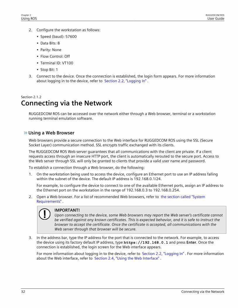
Chapter 2Using ROS
RUGGEDCOM ROSUser Guide
32 Connecting via the Network
2. Configure the workstation as follows:• Speed (baud): 57600• Data Bits: 8• Parity: None• Flow Control: Off• Terminal ID: VT100• Stop Bit: 1
3. Connect to the device. Once the connection is established, the login form appears. For more informationabout logging in to the device, refer to Section 2.2, “Logging In” .
Section 2.1.2
Connecting via the NetworkRUGGEDCOM ROS can be accessed over the network either through a Web browser, terminal or a workstationrunning terminal emulation software.
Using a Web BrowserWeb browsers provide a secure connection to the Web interface for RUGGEDCOM ROS using the SSL (SecureSocket Layer) communication method. SSL encrypts traffic exchanged with its clients.The RUGGEDCOM ROS Web server guarantees that all communications with the client are private. If a clientrequests access through an insecure HTTP port, the client is automatically rerouted to the secure port. Access tothe Web server through SSL will only be granted to clients that provide a valid user name and password.To establish a connection through a Web browser, do the following:1. On the workstation being used to access the device, configure an Ethernet port to use an IP address falling
within the subnet of the device. The default IP address is 192.168.0.1/24.For example, to configure the device to connect to one of the available Ethernet ports, assign an IP address tothe Ethernet port on the workstation in the range of 192.168.0.3 to 192.168.0.254.
2. Open a Web browser. For a list of recommended Web browsers, refer to the section called “SystemRequirements” .
IMPORTANT!Upon connecting to the device, some Web browsers may report the Web server's certificate cannotbe verified against any known certificates. This is expected behavior, and it is safe to instruct thebrowser to accept the certificate. Once the certificate is accepted, all communications with theWeb server through that browser will be secure.
3. In the address bar, type the IP address for the port that is connected to the network. For example, to accessthe device using its factory default IP address, type https://192.168.0.1 and press Enter. Once theconnection is established, the login screen for the Web interface appears.For more information about logging in to the device, refer to Section 2.2, “Logging In” . For more informationabout the Web interface, refer to Section 2.4, “Using the Web Interface” .
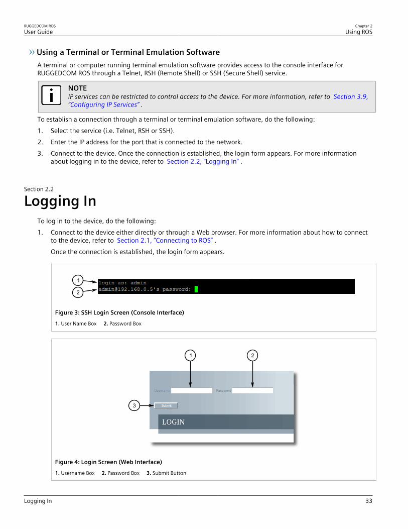
RUGGEDCOM ROSUser Guide
Chapter 2Using ROS
Logging In 33
Using a Terminal or Terminal Emulation SoftwareA terminal or computer running terminal emulation software provides access to the console interface forRUGGEDCOM ROS through a Telnet, RSH (Remote Shell) or SSH (Secure Shell) service.
NOTEIP services can be restricted to control access to the device. For more information, refer to Section 3.9,“Configuring IP Services” .
To establish a connection through a terminal or terminal emulation software, do the following:1. Select the service (i.e. Telnet, RSH or SSH).2. Enter the IP address for the port that is connected to the network.3. Connect to the device. Once the connection is established, the login form appears. For more information
about logging in to the device, refer to Section 2.2, “Logging In” .
Section 2.2
Logging InTo log in to the device, do the following:1. Connect to the device either directly or through a Web browser. For more information about how to connect
to the device, refer to Section 2.1, “Connecting to ROS” .Once the connection is established, the login form appears.
1
2
Figure 3: SSH Login Screen (Console Interface)
1. User Name Box 2. Password Box
1
3
2
Figure 4: Login Screen (Web Interface)
1. Username Box 2. Password Box 3. Submit Button

Chapter 2Using ROS
RUGGEDCOM ROSUser Guide
34 Logging Out
NOTEThe following default usernames and passwords are set on the device for each user type:GuestUsername: guestPassword: guest
OperatorUsername: operatorPassword: operator
AdminUsername: adminPassword: admin
CAUTION!To prevent unauthorized access to the device, make sure to change the default guest, operator,and admin passwords before commissioning the device.For more information about changing passwords, refer to Section 4.3, “Configuring Passwords” .
2. In the User Name field, type the username for an account setup on the device.3. In the Password field, typ the password for the account.4. Click Enter or click Submit (Web interface only).
Section 2.3
Logging OutTo log out of the device, navigate to the main screen and do the following:• To log out of the Console or secure shell interfaces, press CTRL + X.• To log out of the Web interface, click Logout.
1
Figure 5: Web Interface (Example)
1. Logout
NOTEIf any pending configuration changes have not been committed, RUGGEDCOM ROS will requestconfirmation before discarding the changes and logging out of the device.
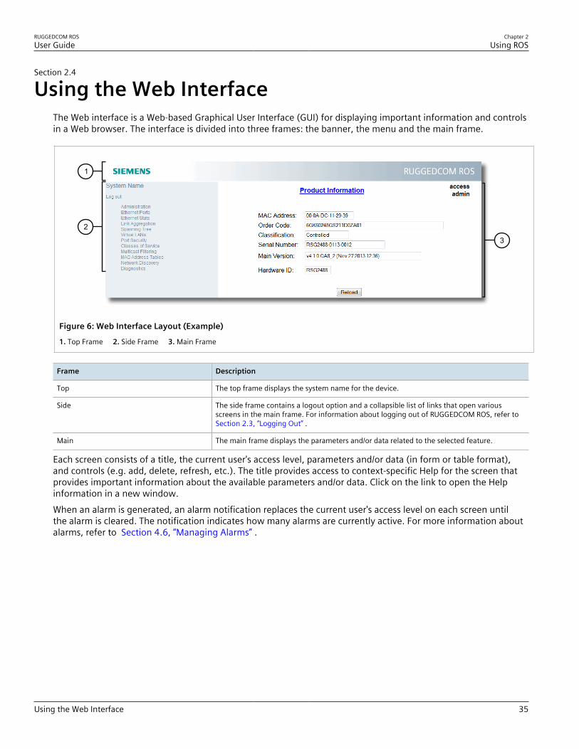
RUGGEDCOM ROSUser Guide
Chapter 2Using ROS
Using the Web Interface 35
Section 2.4
Using the Web InterfaceThe Web interface is a Web-based Graphical User Interface (GUI) for displaying important information and controlsin a Web browser. The interface is divided into three frames: the banner, the menu and the main frame.
2
1
3
Figure 6: Web Interface Layout (Example)
1. Top Frame 2. Side Frame 3. Main Frame
Frame Description
Top The top frame displays the system name for the device.
Side The side frame contains a logout option and a collapsible list of links that open variousscreens in the main frame. For information about logging out of RUGGEDCOM ROS, refer to Section 2.3, “Logging Out” .
Main The main frame displays the parameters and/or data related to the selected feature.
Each screen consists of a title, the current user's access level, parameters and/or data (in form or table format),and controls (e.g. add, delete, refresh, etc.). The title provides access to context-specific Help for the screen thatprovides important information about the available parameters and/or data. Click on the link to open the Helpinformation in a new window.When an alarm is generated, an alarm notification replaces the current user's access level on each screen untilthe alarm is cleared. The notification indicates how many alarms are currently active. For more information aboutalarms, refer to Section 4.6, “Managing Alarms” .

Chapter 2Using ROS
RUGGEDCOM ROSUser Guide
36 Using the Console Interface
31
2
4
Figure 7: Elements of a Typical Screen (Example)
1. Title 2. Parameters and/or Data 3. Access Level or Alarm Notification 4. Controls
NOTEIf desired, the web interface can be disabled. For more information, refer to Section 4.5, “Enabling/Disabling the Web Interface” .
Section 2.5
Using the Console InterfaceThe Console interface is a Graphical User Interface (GUI) organized as a series of menus. It is primarily accessiblethrough a serial console connection, but can also be accessed through IP services, such as a Telnet, RSH (RemoteShell), SSH (Secure Shell) session, or SSH remote command execution.
NOTEIP services can be restricted to control access to the device. For more information, refer to Section 3.9,“Configuring IP Services” .
Each screen consists of a system identifier, the name of the current menu, and a command bar. Alarms are alsoindicated on each screen in the upper right corner.

RUGGEDCOM ROSUser Guide
Chapter 2Using ROS
Using the Console Interface 37
5
4
1
2
3
Figure 8: Console Interface (Example)
1. System Identification 2. Menus 3. Command Bar 4. Menu Name 5. Alarms Indicator
NOTEThe system identifier is user configurable. For more information about setting the system name, referto Section 4.1, “Configuring the System Information” .
Navigating the InterfaceUse the following controls to navigate between screens in the Console interface:
Enter Select a menu item and press this Enter to enter the sub-menu or screen beneath.
Esc Press Esc to return to the previous screen.
Configuring ParametersUse the following controls to select and configure parameters in the Console interface:
Up/Down Arrow Keys Use the up and down arrow keys to select parameters.
Enter Select a parameter and press Enter to start editing a parameter. Press Enter again to commit the change.
Esc When editing a parameter, press Esc to abort all changes.

Chapter 2Using ROS
RUGGEDCOM ROSUser Guide
38 Using the Command Line Interface
CommandsThe command bar lists the various commands that can be issued in the Console interface. Some commands arespecific to select screens. The standard commands include the following:
Ctrl + A Commits configuration changes made on the current screen.
NOTEBefore exiting a screen, RUGGEDCOM ROS will automatically prompt the user to save any changesthat have not been committed.
Ctrl + I Inserts a new record.
Ctrl + L Deletes a record.
Ctrl + S Opens the CLI interface.
Ctrl + X Terminates the current session. This command is only available from the main menu.
Ctrl + Z Displays important information about the current screen or selected parameter.
Section 2.6
Using the Command Line InterfaceThe Command Line Interface (CLI) offers a series of powerful commands for updating ROS, generating certificates/keys, tracing events, troubleshooting and much more. It is accessed via the Console interface by pressing Ctrl-S.
CONTENTS• Section 2.6.1, “Available CLI Commands”• Section 2.6.2, “Tracing Events”• Section 2.6.3, “Executing Commands Remotely via RSH”• Section 2.6.4, “Using SQL Commands”
Section 2.6.1
Available CLI CommandsThe following commands are available at the command line:
Command Description
alarms all Displays a list of available alarms.Optional and/or required parameters include:• all displays all available alarms
arp Displays the IP to MAC address resolution table.
clearalarms Clears all alarms.
clearethstats [ all | port ] Clears Ethernet statistics for one or more ports.Optional and/or required parameters include:• all clears statistics for all ports

RUGGEDCOM ROSUser Guide
Chapter 2Using ROS
Available CLI Commands 39
Command Description
• port is a comma separated list of port numbers (e.g. 1,3-5,7)
clearlogs Clears the system and crash logs.
clrcblstats [ all | port ] Clears cable diagnostics statistics for one or more ports.Optional and/or required parameters include:• all clears statistics for all ports• port is a comma separated list of port numbers (e.g. 1,3-5,7)
clrstpstats Clears all spanning tree statistics.
cls Clears the screen.
dir Prints the directory listing.
exit Terminates the session.
factory Enables factory mode, which includes several factory-level commands used for testing andtroubleshooting. Only available to admin users.
CAUTION!Misuse of the factory commands may corrupt the operational state of deviceand/or may permanently damage the ability to recover the device withoutmanufacturer intervention.
flashfiles { info filename |defrag }
A set of diagnostic commands to display information about the Flash filesystem and todefragment Flash memory.Optional and/or required parameters include:• info filename displays information about the specified file in the Flash file system• defrag defragments files in the Flash file systemFor more information about the flashfiles command, refer to Section 2.8, “Managingthe Flash File System” .
flashleds timeout Flashes the LED indicators on the device for a specified number of seconds.Optional and/or required parameters include:• timeout is the number of seconds to flash the LED indicators. To stop the LEDs from
flashing, set the timeout period to 0 (zero).
fpgacmd Provides access to the FPGA management tool for troubleshooting time synchronization.
help command Displays a brief description of the specified command. If no command is specified, it displaysa list of all available commands, including a description for each.Optional and/or required parameters include:• command is the command name.
ipconfig Displays the current IP address, subnet mask and default gateway. This command providesthe only way of determining these values when DHCP is used.
loaddflts Loads the factory default configuration.
login Logs in to the shell.
logout Logs out of the shell.
logs Displays syslog entries in CLI shell.
ping address { count | timeout }
Sends an ICMP echo request to a remotely connected device. For each reply received, theround trip time is displayed. Use this command to verify connectivity to the next connecteddevice. It is a useful tool for testing commissioned links. This command also includes theability to send a specific number of pings with a specified time for which to wait for aresponse.Optional and/or required parameters include:

Chapter 2Using ROS
RUGGEDCOM ROSUser Guide
40 Available CLI Commands
Command Description
• address is the target IP address.• count is the number of echo requests to send. The default is 4.• timeout is the time in milliseconds to wait for each reply. The range is 2 to 5000
seconds. The default is 300 milliseconds.
NOTEThe device to be pinged must support ICMP echo. Upon commencing the ping,an ARP request for the MAC address of the device is issued. If the device to bepinged is not on the same network as the device pinging the other device, thedefault gateway must be programmed.
purgemac Purges the MAC Addrtess table.
random Display seeds or random numbers.
reset Perform a hard reset of the switch.
resetport { all | ports } Resets one or more Ethernet ports, which may be useful for forcing re-negotiation of speedand duplex, or in situations where the link partner has latched into an inappropriate state.Optional and/or required parameters include:• all resets all ports• ports is a comma separated list of port numbers (e.g. 1,3-5,7)
rmon Displays the names of all RMON alarm eligible objects.
route Displays the gateway configuration.
sfp port { base | alarms |diag | calibr | thr | all | noparameter specified }
Displays SFP (Small Form Factor Pluggable) device information and diagnostics. If optionalor required parameters are not used, this command displays the base and extendedinformation.Optional and/or required parameters include:• port is the port number for which the data are required• base displays the base information• alarms displays alarms and warning flags• diag displays measured data• calibr displays calibration data for external calibration• thr displays thresholds data• all displays all diagnostic data
sql { default | delete | help |info | insert | save | select |update }
Provides an SQL-like interface for manipulating all system configuration and statusparameters. All commands, clauses, table, and column names are case insensitive.Optional and/or required parameters include:• default sets all records in a table(s) to factory defaults• delete allows for records to be deleted from a table• help provides a brief description for any SQL command or clause• info displays a variety of information about the tables in the database• insert enables new records to be inserted into a table• save saves the database to non-volatile memory storage• select queries the dtabase and displays selected records• update enable existing records in a table to be updatedFor more information about the sql command, refer to Section 2.6.4, “Using SQLCommands” .
sshkeygen keytype N Generates new SSH keys in ssh.keys.Optional and/or required parameters include:• keytype is the type of key, either rsa or dsa• N is the number of bits in length. The allowable sizes are 1024, 2048 or 3072

RUGGEDCOM ROSUser Guide
Chapter 2Using ROS
Tracing Events 41
Command Description
sshpubkey List, remove and update key entries in sshpub.keys file.
sslkeygen keytype N Generates a new SSL certificate in ssl.crt.Optional and/or required parameters include:• keytype is the type of key, either rsa or ecc• N is the number of bits in length. For RSA keys, the allowable sizes are 1024, 2048 or
3072. For ECC keys, the allowable sizes are 192, 224, 256, 384, or 521.
telnet dest Opens a telnet session. Press Ctrl-C to close the session.Optional and/or required parameters include:• dest is the server's IP address
tftp { dest | cmd | fsource | fdest }
Opens a TFTP session. Press Ctrl-C to close the session.Optional and/or required parameters include:• dest is the remote TFTP server's IP address• cmd is either put (upload) or get (download)• fsource is the source filename• fdest is the destination filename
trace Starts event tracing. Run trace ? for more help.
type filename Displays the contents of a text file.Optional and/or required parameters include:• filename is the name of the file to be read
version Prints the software version.
xmodem { send | receive } filename
Opens an XModem session.Optional and/or required parameters include:• send sends the file to the client.• receive receives the file from the client.• filename is the name of the file to be read.
Section 2.6.2
Tracing EventsThe CLI trace command provides a means to trace the operation of various protocols supported by the device.Trace provides detailed information, including STP packet decodes, IGMP activity and MAC address displays.
NOTETracing has been designed to provide detailed information to expert users. Note that all tracing isdisabled upon device startup.
To trace an event, do the following:1. Log in to the device as an admin user and access the CLI shell. For more information about accessing the CLI
shell, refer to Section 2.6, “Using the Command Line Interface” .2. Determine the protocols and associated options available by typing:
trace ?
If an option such as allon or alloff is required, determine which options are available for the desiredprotocol by typing:
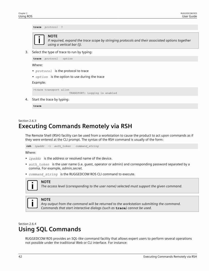
Chapter 2Using ROS
RUGGEDCOM ROSUser Guide
42 Executing Commands Remotely via RSH
trace protocol ?
NOTEIf required, expand the trace scope by stringing protocols and their associated options togetherusing a vertical bar (|).
3. Select the type of trace to run by typing:
trace protocol option
Where:• protocol is the protocol to trace• option is the option to use during the traceExample:
>trace transport allon TRANSPORT: Logging is enabled
4. Start the trace by typing:
trace
Section 2.6.3
Executing Commands Remotely via RSHThe Remote Shell (RSH) facility can be used from a workstation to cause the product to act upon commands as ifthey were entered at the CLI prompt. The syntax of the RSH command is usually of the form:
rsh ipaddr –l auth_token command_string
Where:• ipaddr is the address or resolved name of the device.• auth_token is the user name (i.e. guest, operator or admin) and corresponding password separated by a
comma. For example, admin,secret.• command_string is the RUGGEDCOM ROS CLI command to execute.
NOTEThe access level (corresponding to the user name) selected must support the given command.
NOTEAny output from the command will be returned to the workstation submitting the command.Commands that start interactive dialogs (such as trace) cannot be used.
Section 2.6.4
Using SQL CommandsRUGGEDCOM ROS provides an SQL-like command facility that allows expert users to perform several operationsnot possible under the traditional Web or CLI interface. For instance:

RUGGEDCOM ROSUser Guide
Chapter 2Using ROS
Finding the Correct Table 43
• Restoring the contents of a specific table, but not the whole configuration, to their factory defaults.• Search tables in the database for specific configurations.• Make changes to tables predicated upon existing configurations.When combined with RSH, SQL commands provide a means to query and configure large numbers of devices froma central location.
NOTEFor a list of parameters available under the sql command, refer to Section 2.6.1, “Available CLICommands” .
NOTERead/write access to tables containing passwords or shared secrets is unavailable using SQLcommands.
CONTENTS• Section 2.6.4.1, “Finding the Correct Table”• Section 2.6.4.2, “Retrieving Information”• Section 2.6.4.3, “Changing Values in a Table”• Section 2.6.4.4, “Resetting a Table”• Section 2.6.4.5, “Using RSH and SQL”
Section 2.6.4.1Finding the Correct Table
Many SQL commands operate upon specific tables in the database, and require the table name to be specified.Navigating the menu system in the console interface to the desired menu and pressing Ctrl-Z displays the name ofthe table. The menu name and the corresponding database table name will be cited.Another way to find a table name is to type the following in the CLI:
sql info tables
This command also displays menu names and their corresponding database table names depending upon thefeatures supported by the device. For example:
Table Description-------------------------------------------------------------------------------alarms AlarmscpuDiags CPU DiagnosticsethPortCfg Port ParametersethPortStats Ethernet StatisticsethPortStatus Port StatusipCfg IP Services
Section 2.6.4.2Retrieving Information
The following describes various methods for retrieving information about tables and parameters.
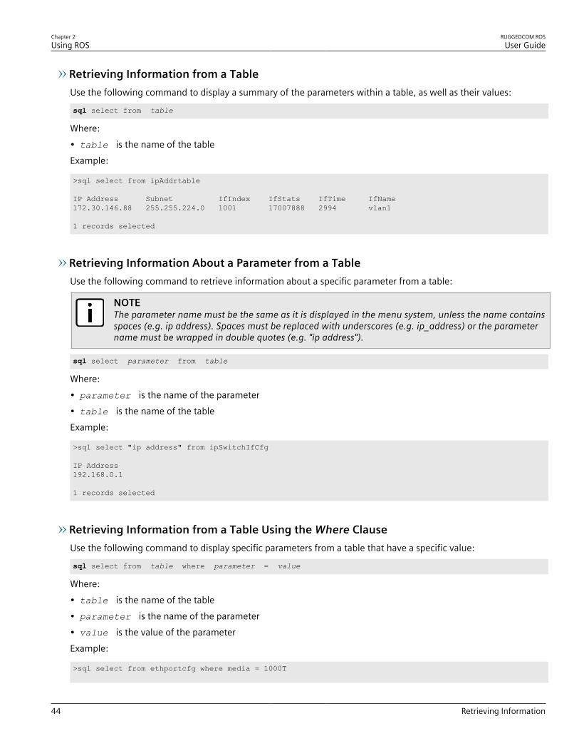
Chapter 2Using ROS
RUGGEDCOM ROSUser Guide
44 Retrieving Information
Retrieving Information from a TableUse the following command to display a summary of the parameters within a table, as well as their values:
sql select from table
Where:• table is the name of the tableExample:
>sql select from ipAddrtable
IP Address Subnet IfIndex IfStats IfTime IfName 172.30.146.88 255.255.224.0 1001 17007888 2994 vlan1
1 records selected
Retrieving Information About a Parameter from a TableUse the following command to retrieve information about a specific parameter from a table:
NOTEThe parameter name must be the same as it is displayed in the menu system, unless the name containsspaces (e.g. ip address). Spaces must be replaced with underscores (e.g. ip_address) or the parametername must be wrapped in double quotes (e.g. "ip address").
sql select parameter from table
Where:• parameter is the name of the parameter• table is the name of the tableExample:
>sql select "ip address" from ipSwitchIfCfg
IP Address192.168.0.1
1 records selected
Retrieving Information from a Table Using the Where ClauseUse the following command to display specific parameters from a table that have a specific value:
sql select from table where parameter = value
Where:• table is the name of the table• parameter is the name of the parameter• value is the value of the parameterExample:
>sql select from ethportcfg where media = 1000T
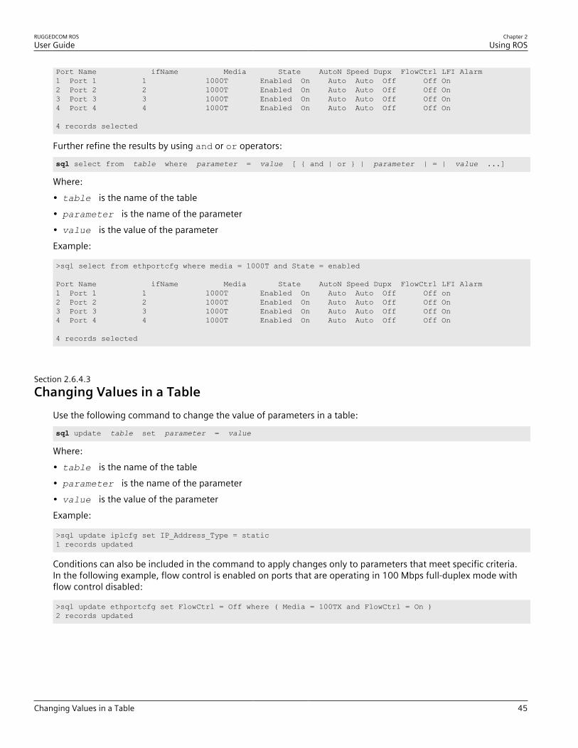
RUGGEDCOM ROSUser Guide
Chapter 2Using ROS
Changing Values in a Table 45
Port Name ifName Media State AutoN Speed Dupx FlowCtrl LFI Alarm1 Port 1 1 1000T Enabled On Auto Auto Off Off On2 Port 2 2 1000T Enabled On Auto Auto Off Off On3 Port 3 3 1000T Enabled On Auto Auto Off Off On4 Port 4 4 1000T Enabled On Auto Auto Off Off On
4 records selected
Further refine the results by using and or or operators:
sql select from table where parameter = value [ { and | or } | parameter | = | value ...]
Where:• table is the name of the table• parameter is the name of the parameter• value is the value of the parameterExample:
>sql select from ethportcfg where media = 1000T and State = enabled
Port Name ifName Media State AutoN Speed Dupx FlowCtrl LFI Alarm1 Port 1 1 1000T Enabled On Auto Auto Off Off on2 Port 2 2 1000T Enabled On Auto Auto Off Off On3 Port 3 3 1000T Enabled On Auto Auto Off Off On4 Port 4 4 1000T Enabled On Auto Auto Off Off On
4 records selected
Section 2.6.4.3Changing Values in a Table
Use the following command to change the value of parameters in a table:
sql update table set parameter = value
Where:• table is the name of the table• parameter is the name of the parameter• value is the value of the parameterExample:
>sql update iplcfg set IP_Address_Type = static1 records updated
Conditions can also be included in the command to apply changes only to parameters that meet specific criteria.In the following example, flow control is enabled on ports that are operating in 100 Mbps full-duplex mode withflow control disabled:
>sql update ethportcfg set FlowCtrl = Off where ( Media = 100TX and FlowCtrl = On )2 records updated
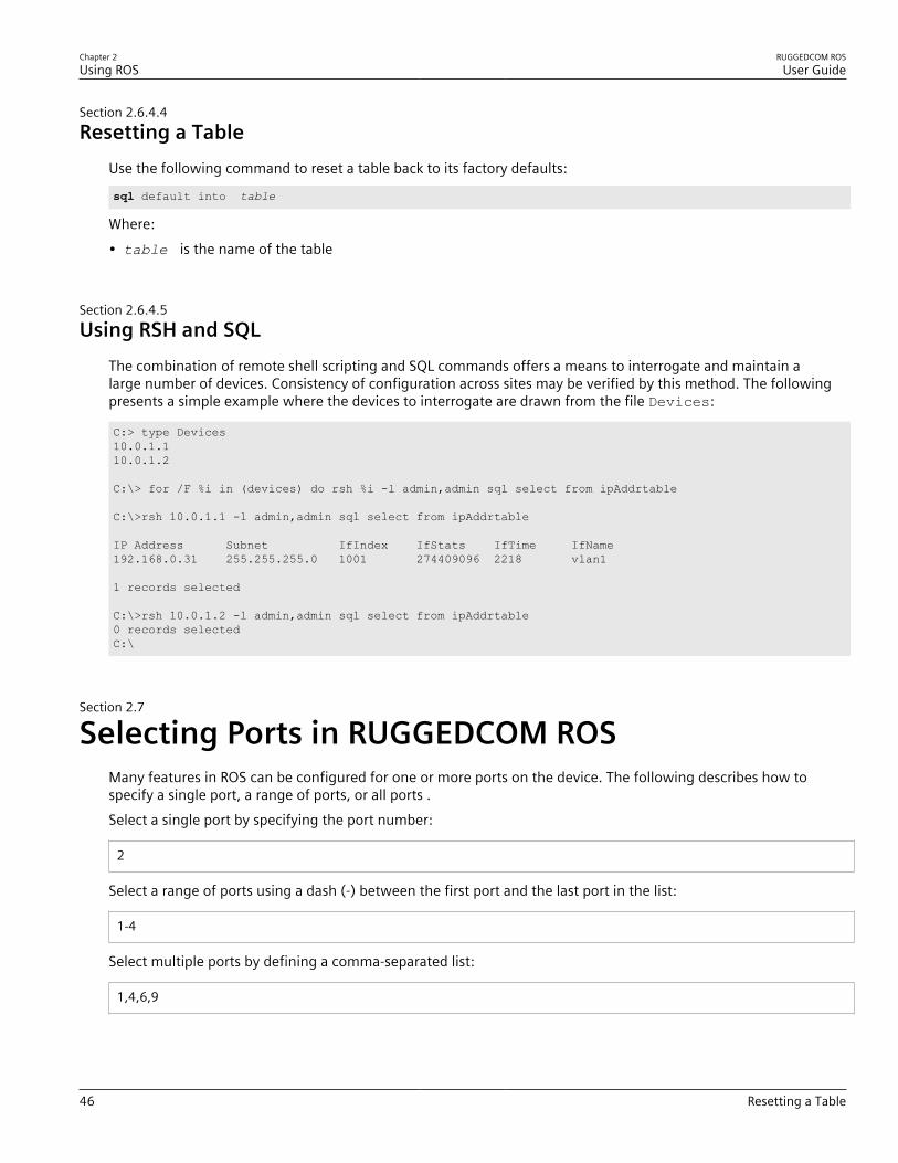
Chapter 2Using ROS
RUGGEDCOM ROSUser Guide
46 Resetting a Table
Section 2.6.4.4Resetting a Table
Use the following command to reset a table back to its factory defaults:
sql default into table
Where:• table is the name of the table
Section 2.6.4.5Using RSH and SQL
The combination of remote shell scripting and SQL commands offers a means to interrogate and maintain alarge number of devices. Consistency of configuration across sites may be verified by this method. The followingpresents a simple example where the devices to interrogate are drawn from the file Devices:
C:> type Devices10.0.1.110.0.1.2
C:\> for /F %i in (devices) do rsh %i -l admin,admin sql select from ipAddrtable
C:\>rsh 10.0.1.1 -l admin,admin sql select from ipAddrtable
IP Address Subnet IfIndex IfStats IfTime IfName192.168.0.31 255.255.255.0 1001 274409096 2218 vlan1
1 records selected
C:\>rsh 10.0.1.2 -l admin,admin sql select from ipAddrtable0 records selectedC:\
Section 2.7
Selecting Ports in RUGGEDCOM ROSMany features in ROS can be configured for one or more ports on the device. The following describes how tospecify a single port, a range of ports, or all ports .Select a single port by specifying the port number:
2
Select a range of ports using a dash (-) between the first port and the last port in the list:
1-4
Select multiple ports by defining a comma-separated list:
1,4,6,9
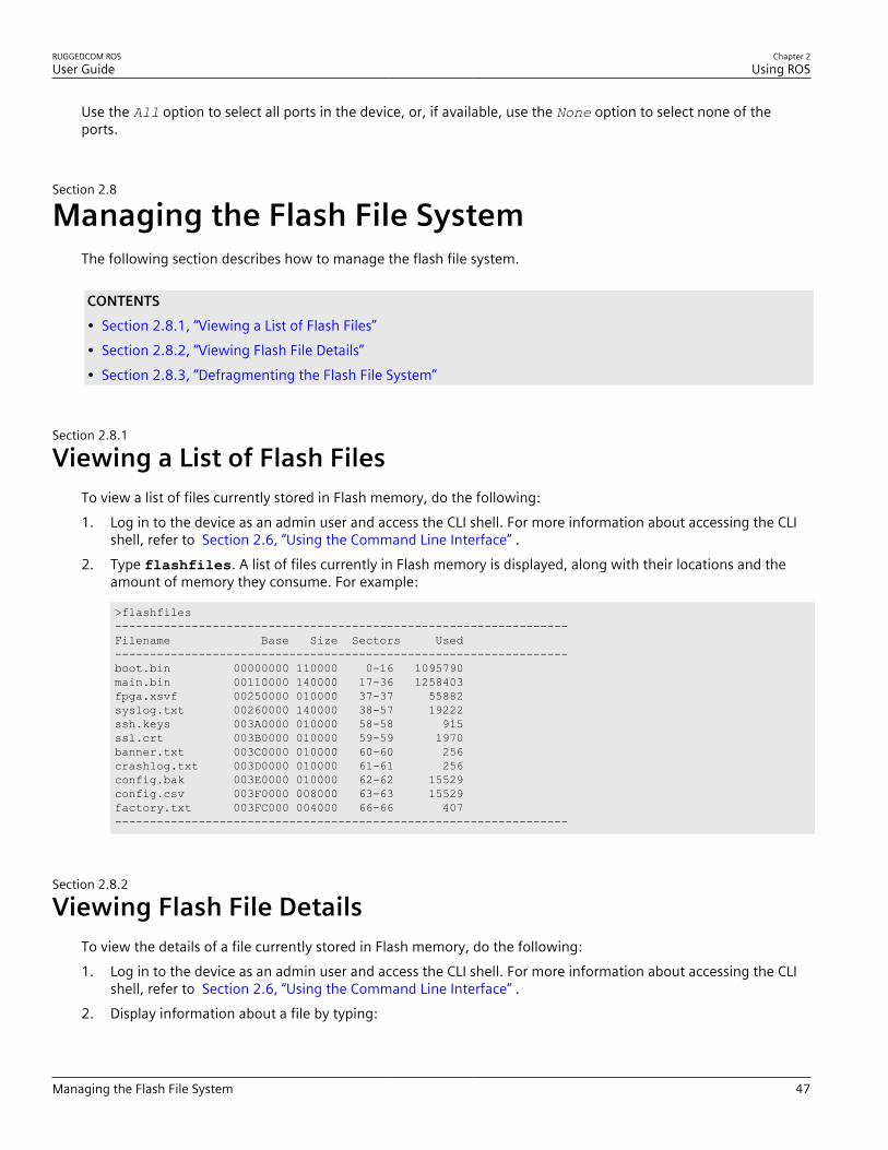
RUGGEDCOM ROSUser Guide
Chapter 2Using ROS
Managing the Flash File System 47
Use the All option to select all ports in the device, or, if available, use the None option to select none of theports.
Section 2.8
Managing the Flash File SystemThe following section describes how to manage the flash file system.
CONTENTS• Section 2.8.1, “Viewing a List of Flash Files”• Section 2.8.2, “Viewing Flash File Details”• Section 2.8.3, “Defragmenting the Flash File System”
Section 2.8.1
Viewing a List of Flash FilesTo view a list of files currently stored in Flash memory, do the following:1. Log in to the device as an admin user and access the CLI shell. For more information about accessing the CLI
shell, refer to Section 2.6, “Using the Command Line Interface” .2. Type flashfiles. A list of files currently in Flash memory is displayed, along with their locations and the
amount of memory they consume. For example:
>flashfiles-----------------------------------------------------------------Filename Base Size Sectors Used-----------------------------------------------------------------boot.bin 00000000 110000 0-16 1095790main.bin 00110000 140000 17-36 1258403fpga.xsvf 00250000 010000 37-37 55882syslog.txt 00260000 140000 38-57 19222ssh.keys 003A0000 010000 58-58 915ssl.crt 003B0000 010000 59-59 1970banner.txt 003C0000 010000 60-60 256crashlog.txt 003D0000 010000 61-61 256config.bak 003E0000 010000 62-62 15529config.csv 003F0000 008000 63-63 15529factory.txt 003FC000 004000 66-66 407-----------------------------------------------------------------
Section 2.8.2
Viewing Flash File DetailsTo view the details of a file currently stored in Flash memory, do the following:1. Log in to the device as an admin user and access the CLI shell. For more information about accessing the CLI
shell, refer to Section 2.6, “Using the Command Line Interface” .2. Display information about a file by typing:

Chapter 2Using ROS
RUGGEDCOM ROSUser Guide
48 Defragmenting the Flash File System
flashfiles info filename
Where:• filename is the name of the file stored in Flash memoryDetails, similar to the following, are displayed.
>flashfiles info main.bin
Flash file information for main.bin:Header version : 4Platform : ROS-CF52
File name : main.binFirmware version : v4.3.0Build date : Sep 27 2014 15:50File length : 2624659Board IDs : 3dHeader CRC : 73b4Header CRC Calc : 73b4Body CRC : b441Body CRC Calc : b441
Section 2.8.3
Defragmenting the Flash File SystemThe flash memory is defragmented automatically whenever there is not enough memory available for a binaryupgrade. However, fragmentation can occur whenever a new file is uploaded to the unit. Fragmentation causessectors of available memory to become separated by ones allocated to files. In some cases, the total availablememory might be sufficient for a binary upgrade, but that memory may not be available in one contiguous region.To defragment the flash memory, do the following:1. Log in to the device as an admin user and access the CLI shell. For more information about accessing the CLI
shell, refer to Section 2.6, “Using the Command Line Interface” .2. Defragment the flash memory by typing:
flashfiles defrag
Section 2.9
Accessing BIST ModeBIST (Built-In-Self-Test) mode is used by service technicians to test and configure internal functions of the device.It should only be accessed for troubleshooting purposes.
CAUTION!Mechanical hazard – risk of damage to the device. Excessive use of BIST functions may cause increasewear on the device, which may void the warranty. Avoid using BIST functions unless instructed by aSiemens Customer Support representative.
To access BIST mode, do the following:
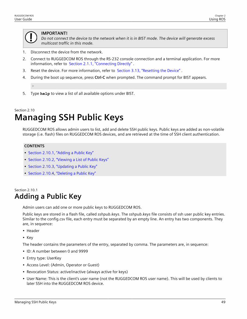
RUGGEDCOM ROSUser Guide
Chapter 2Using ROS
Managing SSH Public Keys 49
IMPORTANT!Do not connect the device to the network when it is in BIST mode. The device will generate excessmulticast traffic in this mode.
1. Disconnect the device from the network.2. Connect to RUGGEDCOM ROS through the RS-232 console connection and a terminal application. For more
information, refer to Section 2.1.1, “Connecting Directly” .3. Reset the device. For more information, refer to Section 3.13, “Resetting the Device” .4. During the boot up sequence, press Ctrl-C when prompted. The command prompt for BIST appears.
>
5. Type help to view a list of all available options under BIST.
Section 2.10
Managing SSH Public KeysRUGGEDCOM ROS allows admin users to list, add and delete SSH public keys. Public keys are added as non-volatilestorage (i.e. flash) files on RUGGEDCOM ROS devices, and are retrieved at the time of SSH client authentication.
CONTENTS• Section 2.10.1, “Adding a Public Key”• Section 2.10.2, “Viewing a List of Public Keys”• Section 2.10.3, “Updating a Public Key”• Section 2.10.4, “Deleting a Public Key”
Section 2.10.1
Adding a Public KeyAdmin users can add one or more public keys to RUGGEDCOM ROS.Public keys are stored in a flash file, called sshpub.keys. The sshpub.keys file consists of ssh user public key entries.Similar to the config.csv file, each entry must be separated by an empty line. An entry has two components. Theyare, in sequence:• Header• KeyThe header contains the parameters of the entry, separated by comma. The parameters are, in sequence:• ID: A number between 0 and 9999• Entry type: UserKey• Access Level: (Admin, Operator or Guest)• Revocation Status: active/inactive (always active for keys)• User Name: This is the client's user name (not the RUGGEDCOM ROS user name). This will be used by clients to
later SSH into the RUGGEDCOM ROS device.

Chapter 2Using ROS
RUGGEDCOM ROSUser Guide
50 Adding a Public Key
The key must be in RFC4716 or PEM format, with any of the following header and footer lines:
-----BEGIN PUBLIC KEY----------END PUBLIC KEY-----
-----BEGIN SSH2 PUBLIC KEY----------END SSH2 PUBLIC KEY-----
-----BEGIN RSA PUBLIC KEY----------END RSA PUBLIC KEY-----
The following is an example of a valid entry in the sshpub.keys file in PEM format:
1,userkey,admin,active,alice---- BEGIN SSH2 PUBLIC KEY ----AAAAB3NzaC1yc2EAAAABIwAAAQEA4mRrqfk+RKXnmGRvzMyWVDsbq5VwpGGrlLQYCrjVEaNdbXsphqYKop8V5VUeXFRAUFzOy82yk8TF/5JxGPWq6wRNjhnYR7IY2AiMBq0+K8XeURl/z5K2XNRjnqTZSFwkhaUVJeduvjGgOlNN4yvgUwF3n0idU9k3E1q/na+LmYIeGhOwzCqoAcipHAdR4fhD5u0jbmvjv+gDikTSZIbj9eFJfP09ekImMLHwbBry0SSBpqAKbwVdWEXIKQ47zz7ao2/rs3rSV16IXSq3Qe8VZh2irah0Md6JFMOX2qm9fo1I62q1DDgheCOsOiGPf4xerHrI2cs6FT31rAdx2JOjvw==---- END SSH2 PUBLIC KEY ----
The following is an example of a valid entry in the sshpub.keys file in in RFC4716 format:
2,userkey,admin,active,bobssh-rsa AAAAB3NzaC1yc2EAAAADAQABAAABAQDH0NivR8zzbTxlecvFPzR/GR24NrRJa0Lc7scNsWRgi0XulHuGrRLRB5RoQ39+spdig88Y8CqhRI49XJx7uLJe0Su3RvyNYz1jkdSwHq2hSZCpukJxJ6CK95Po/sVa5Gq2gMaHowiYDSkcx+AJywzK/eM6i/jc125lRxFPdfkj74u+ob3PCvmIWz5z3WAJBrQU1IDPHDets511WMu8O9/mAPZRwjqrWhRsqmcXZuv5oo54wIopCAZSo20SPzM2VmXFuUsEwDkvYMXLJK1koJPbDjH7yFFC7mwK2eMU/oMFFn934cbO5N6etsJSvplYQ4pMCw6Ok8Q/bB5cPSOa/rAt bob@work
IMPORTANT!The content of the sshaddpub.keys file must follow the same syntax as the sshpub.keys file.
RUGGEDCOM ROS allows only 16 user key entries to be stored. Each key entry must meet the following limits:• Key type must be either RSA 2048 bits or RSA 3072 bits• Key size must not exceed 4000 base64 encoded characters• Entry Type in the header must not exceed 8 ASCII characters• Access Level in the header must not exceed 8 ASCII characters (operator is maximum)• Revocation status in the header must not exceed 8 ASCII characters (inactive is maximum)• User Name must not exceed 12 ASCII charactersThere are two ways to update sshpub.keys. Users can either upload a locally-created file directly to thesshpub.keys file, which will replace the content in flash with the uploaded content. Or, users can upload a locally-created file to the sshaddpub.keys file, which will keep the existing entries in the sshpub.keys file and append thenew entries.To add keys, do the following:1. Create a public key file via a host computer.2. Transfer the public key file to the device using SFTP or Xmodem. For more information about transferring
files, refer to Section 3.4, “Uploading/Downloading Files” .3. Log in to the device as an admin user and access the CLI shell. For more information about accessing the CLI
shell, refer to Section 2.6, “Using the Command Line Interface” .

RUGGEDCOM ROSUser Guide
Chapter 2Using ROS
Viewing a List of Public Keys 51
4. Check the system log to make sure the files were properly transferred. For more information about viewingthe system log, refer to Section 3.5.1, “Viewing Local Logs” .
Section 2.10.2
Viewing a List of Public KeysAdmin users can view a list of existing public keys on the device.To view public keys, do the following:1. Log in to the device as an admin user and access the CLI shell. For more information about accessing the CLI
shell, refer to Section 2.6, “Using the Command Line Interface” .2. At the CLI prompt, type:
sshpubkey list
A list of public keys will appear, including their key ID, access level, revocation status, user name and keyfingerprint.
Section 2.10.3
Updating a Public KeyAdmin users can update public keys.To update public keys, do the following:1. Log in to the device as an admin user and access the CLI shell. For more information about accessing the CLI
shell, refer to Section 2.6, “Using the Command Line Interface” .2. At the CLI prompt, type:
sshpubkey list
A list of public keys will appear, including their key ID, access level, revocation status, user name and keyfingerprint.
3. Type the following commands to update the public keys:Command Description
sshpubkey update_id current_IDnew_ID
Updates the ID of user public key.
NOTEThe user public key ID must be a number between 0 and 9999.
• current_ID is the ID currently assigned to the public key• new_ID is the ID that will be used to identify the public key going forward
sshpubkey update_al AL Updates the access level of a user public key.• AL is the access level (admin, operator or guest) of the public key to be updated
sshpubkey update_rs RS Updates the revocation status (active, inactive) of a user public key.• RS is the revocation status of the public key to be updated
sshpubkey update_un UN Updates the user name of a user public key.• UN is the user name of the public key to be updated
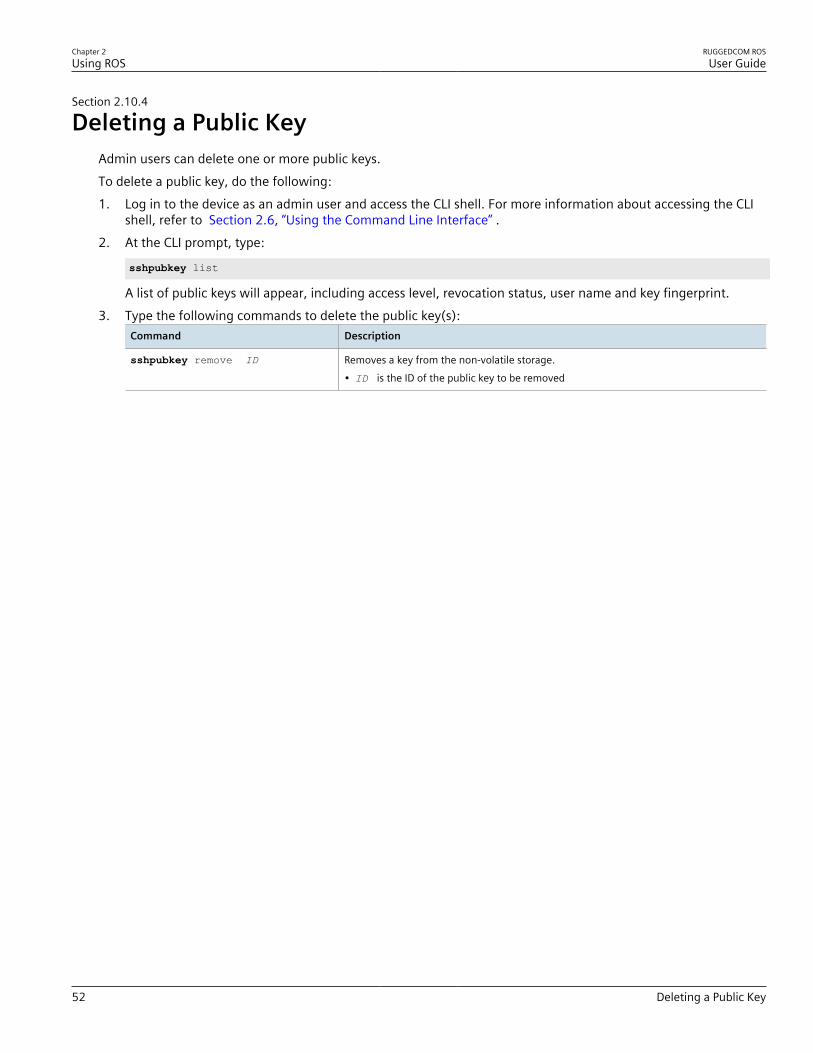
Chapter 2Using ROS
RUGGEDCOM ROSUser Guide
52 Deleting a Public Key
Section 2.10.4
Deleting a Public KeyAdmin users can delete one or more public keys.To delete a public key, do the following:1. Log in to the device as an admin user and access the CLI shell. For more information about accessing the CLI
shell, refer to Section 2.6, “Using the Command Line Interface” .2. At the CLI prompt, type:
sshpubkey list
A list of public keys will appear, including access level, revocation status, user name and key fingerprint.3. Type the following commands to delete the public key(s):
Command Description
sshpubkey remove ID Removes a key from the non-volatile storage.• ID is the ID of the public key to be removed

RUGGEDCOM ROSUser Guide
Chapter 3Device Management
Viewing Product Information 53
Device ManagementThis chapter describes how to configure and manage the device and its components, such as module interfaces,logs and files.
NOTEFor information about how to configure the device to work with a network, refer to Chapter 5, Setupand Configuration .
CONTENTS• Section 3.1, “Viewing Product Information”• Section 3.2, “Viewing CPU Diagnostics”• Section 3.3, “Restoring Factory Defaults”• Section 3.4, “Uploading/Downloading Files”• Section 3.5, “Managing Logs”• Section 3.6, “Managing Ethernet Ports”• Section 3.7, “Managing IP Interfaces”• Section 3.8, “Managing IP Gateways”• Section 3.9, “Configuring IP Services”• Section 3.10, “Managing Remote Monitoring”• Section 3.11, “Testing the Internal Modem”• Section 3.12, “Upgrading/Downgrading Firmware”• Section 3.13, “Resetting the Device”• Section 3.14, “Decommissioning the Device”
Section 3.1
Viewing Product InformationDuring troubleshooting or when ordering new devices, Siemens personnel may request specific information aboutthe device, such as the model, order code or serial number.To view information about the device, navigate to Diagnostics » View Product Information . The ProductInformation form appears.

Chapter 3Device Management
RUGGEDCOM ROSUser Guide
54 Viewing Product Information
9
5
4
3
2
1
6
7
8
Figure 9: Product Information Form (Example)
1. MAC Address Box 2. Order Code Box 3. Classification Box 4. Serial Number Box 5. Boot Version Box 6. Main Version Box 7. Required Boot Box 8. Hardware ID Box 9. Reload Button
This screen displays the following information:
Parameter Description
MAC Address Synopsis: ##-##-##-##-##-## where ## ranges 0 to FFShows the unique MAC address of the device.
Order Code Synopsis: Any 57 charactersShows the order code of the device.
Classification Synopsis: Any 15 charactersProvides system classification.The value Controlled indicates the main firmware is a Controlledrelease. The value Non-Controlled indicates the main firmware is aNon-Controlled release. The Controlled main firmware can run onControlled units, but it can not run on Non-Controlled units. TheNon-Controlled main firmware can run on both Controlled and Non-Controlled units.
Serial Number Synopsis: Any 31 charactersShows the serial number of the device.
Boot Version Synopsis: Any 47 charactersShows the version and the build date of the boot loader software.
Main Version Synopsis: Any 47 charactersShows the version and build date of the main operating systemsoftware.
Required Boot Synopsis: Any 15 charactersShows the minimum boot software loader version required byrunning main.
Hardware ID Synopsis: { RSMCPU (40-00-0008 Rev B1), RSMCPU2 (40-00-0026Rev A1), RS400 (40-00-0010 Rev B2), RMC30, RS900 (40-00-0025Rev B1), RS900 (40-00-0032 Rev B1), RS1600M, RS400 (40-00-0010

RUGGEDCOM ROSUser Guide
Chapter 3Device Management
Viewing CPU Diagnostics 55
Parameter Description
Rev C1), RSG2100, RS900G, RSG2200, RS969, RS900 (v2,40-00-0066), RS900 (v2, 40-00-0067), , RS416 (40-00-0078),RMC30 (v2), RS930 (40-00-0089), RS969 (v2, 40-00-0090), RS910(40-00-0091-001 Rev A), RS920L (40-00-0102-001 Rev A), RS940G(40-00-0097-000 Rev A), RSi80X series CPU board, RSG2300,RS416v2, ... }Shows the type, part number, and revision level of the hardware.
Section 3.2
Viewing CPU DiagnosticsTo view CPU diagnostic information useful for troubleshooting hardware and software performance, navigate to Diagnostics » View CPU Diagnostics . The CPU Diagnostics form appears.
2
10
1
3
4
5
6
7
8
9
Figure 10: CPU Diagnostics Form
1. Running Time Box 2. Total Powered Time Box 3. CPU Usage Box 4. RAM Total Box 5. RAM Free Box 6. RAM Low WatermarkBox 7. Temperature Box 8. Free Rx Bufs Box 9. Free Tx Bufs Box 10. Reload Button
This screen displays the following information:
Parameter Description
Running Time Synopsis: DDDD days, HH:MM:SSThe amount of time since the device was last powered on.
Total Powered time Synopsis: DDDD days, HH:MM:SSThe cumulative powered up time of the device.
CPU Usage Synopsis: 0.0 to 100.0%The percentage of available CPU cycles used for device operation asmeasured over the last second.
RAM Total Synopsis: 0 to 4294967295

Chapter 3Device Management
RUGGEDCOM ROSUser Guide
56 Restoring Factory Defaults
Parameter Description
The total size of RAM in the system.
RAM Free Synopsis: 0 to 4294967295The total size of RAM still available.
RAM Low Watermark Synopsis: 0 to 4294967295The size of RAM that have never been used during the systemruntime.
Temperature Synopsis: -32768 to 32767 CThe temperature on CPU board.
Free Rx Bufs Synopsis: 0 to 4294967295Free Rx Buffers.
Free Tx Bufs Synopsis: 0 to 4294967295Free Tx Buffers.
Section 3.3
Restoring Factory DefaultsThe device can be completely or partially restored to its original factory default settings. Excluding groups ofparameters from the factory reset, such as those that affect basic connectivity and SNMP management, is usefulwhen communication with the device is still required during the reset.The following categories are not affected by a selective configuration reset:• IP Interfaces• IP Gateways• SNMP Users• SNMP Security to Group Maps• SNMP Access• RUGGEDCOM Discovery Protocol™ (RCDP)In addition, the following categories are not affected by a full or selective configuration reset:• Time Zone• DST Offset• DST RuleTo restore factory defaults, do the following:1. Navigate to Diagnostics » Load Factory Defaults . The Load Factory Defaults form appears.

RUGGEDCOM ROSUser Guide
Chapter 3Device Management
Uploading/Downloading Files 57
32
1
Figure 11: Load Factory Defaults Form
1. Defaults Choice List 2. Apply Button 3. Reload
2. Configure the following parameter(s) as required:
NOTEIf the VLAN ID for the Management IP interface is not 1, setting Defaults Choice to Selected willautomatically set it to 1.
Parameter Description
Defaults Choice Synopsis: { None, Selected, All }Setting some records like IP Interfaces management interface,default gateway, SNMP settings to default value would causeswitch not to be accessible with management applications. Thisparameter allows user to choose to load defaults to Selectedtables, which would preserve configuration for tables that arecritical for switch management applications, or to force All tablesto default settings.
3. Click Apply.
Section 3.4
Uploading/Downloading FilesFiles can be transferred between the device and a host computer using any of the following methods:• Xmodem using the CLI shell over a Telnet or RS-232 console session• TFTP client using the CLI shell in a console session and a remote TFTP server• TFTP server from a remote TFTP client• SFTP (secure FTP over SSH) from a remote SFTP client
IMPORTANT!Scripts can be used to automate the management of files on the device. However, depending on thesize of the target file(s), a delay between any concurrent write and read commands may be required,as the file may not have been fully saved before the read command is issued. A general delay of fiveseconds is recommended, but testing is encouraged to optimize the delay for the target file(s) andoperating environment.

Chapter 3Device Management
RUGGEDCOM ROSUser Guide
58 Uploading/Downloading Files Using XMODEM
NOTEThe contents of the internal file system are fixed. New files and directories cannot be created, andexisting files cannot be deleted. Only the files that can be uploaded to the device can be overwritten.
Files that may need to be uploaded or downloaded include:• main.bin – the main RUGGEDCOM ROS application firmware image• boot.bin – the boot loader firmware image• fpga.xsvf – the FPGA firmware binary image• config.csv – the complete configuration database, in the form of a comma-delimited ASCII text file• factory.txt – Contains the MAC address, order code and serial number. Factory data must be signed.• banner.txt – contains text that appears on the login screen
CONTENTS• Section 3.4.1, “Uploading/Downloading Files Using XMODEM”• Section 3.4.2, “Uploading/Downloading Files Using a TFTP Client”• Section 3.4.3, “Uploading/Downloading Files Using a TFTP Server”• Section 3.4.4, “Uploading/Downloading Files Using an SFTP Server”
Section 3.4.1
Uploading/Downloading Files Using XMODEMTo updload or download a file using XMODEM, do the following:
NOTEThis method requires a host computer that has terminal emulation or Telnet software installed and theability to perform XMODEM transfers.
NOTEXmodem transfers can only be performed through the serial console, which is authenticated duringlogin.
1. Establish a direct connection between the device and the host computer. For more information, refer to Section 2.1.1, “Connecting Directly” .
2. Log in to the device as an admin user and access the CLI shell. For more information about accessing the CLIshell, refer to Section 2.6, “Using the Command Line Interface” .
NOTEThe send option sends files to the host computer, while the receive option pulls files from thehost computer.
3. At the CLI prompt, type:
xmodem [ send | receive ] filename
Where:• filename is the name of the file (i.e. main.bin)

RUGGEDCOM ROSUser Guide
Chapter 3Device Management
Uploading/Downloading Files Using a TFTP Client 59
NOTEIf available in the terminal emulation or Telnet software, select the XModem 1K protocol fortransmission over the standard XModem option.
4. When the device responds withPress Ctrl-X to cancel
, launch the XMODEM transfer from the host computer. The device will indicate when the transfer iscomplete.The following is an example from the CLI shell of a successful XMODEM file transfer:
>xmodem receive main.binPress Ctrl-X to cancelReceiving data now ...CReceived 1428480 bytes. Closing file main.bin ...main.bin transferred successfully
Section 3.4.2
Uploading/Downloading Files Using a TFTP ClientTo updload or download a file using a TFTP client, do the following:
IMPORTANT!TFTP does not define an authentication scheme. Any use of the TFTP client or server is consideredhighly insecure.
NOTEThis method requires a TFTP server that is accessible over the network.
1. Identify the IP address of the computer running the TFTP server.2. Establish a direct connection between the device and a host computer. For more information, refer to
Section 2.1.1, “Connecting Directly” .3. Log in to the device as an admin user and access the CLI shell. For more information about accessing the CLI
shell, refer to Section 2.6, “Using the Command Line Interface” .4. At the CLI prompt, type:
tftp address [ get | put ] source-filename destination-filename
Where:• get copies files from the host computer to the device• put copies files from the device to the host computer• address is the IP address of the computer running the TFTP server• source-filename is the name of the file to be transferred• destination-filename is the name of the file (on the device or the TFTP server) that will be replaced
during the transferThe following is an example of a successful TFTP client file transfer:
>tftp 10.0.0.1 get ROS-CF52_Main_v3.7.0.bin main.binTFTP CMD: main.bin transfer ok. Please wait, closing file ...
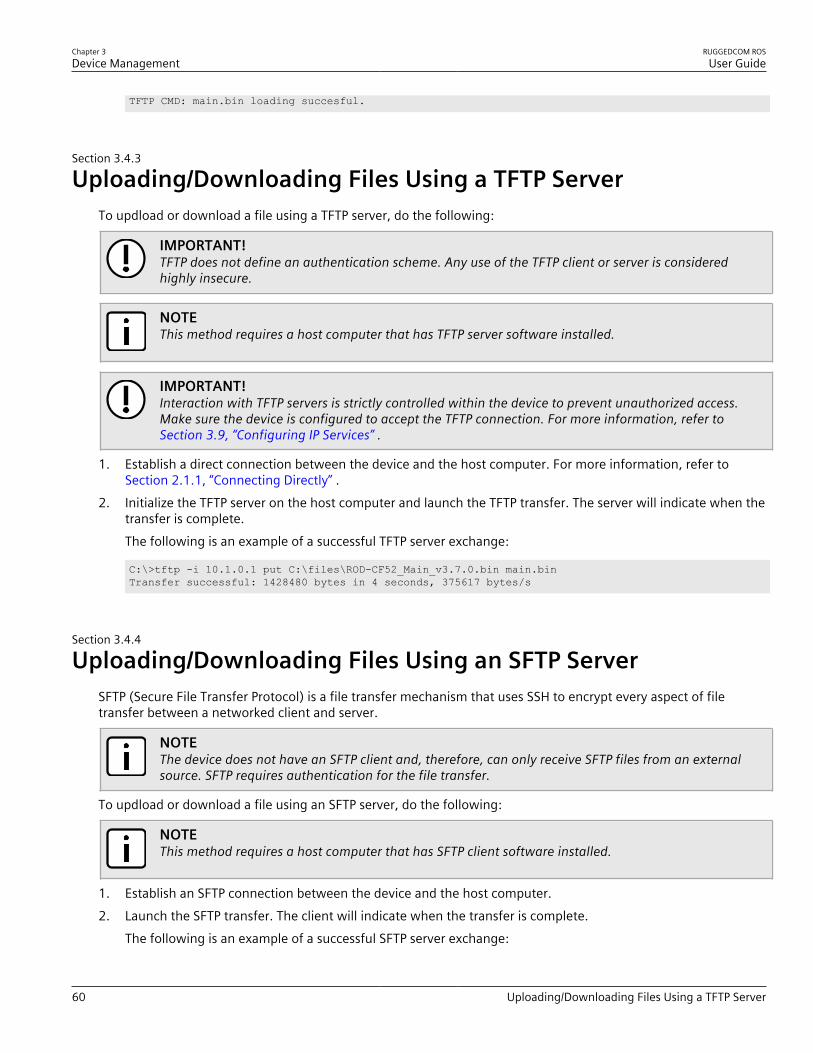
Chapter 3Device Management
RUGGEDCOM ROSUser Guide
60 Uploading/Downloading Files Using a TFTP Server
TFTP CMD: main.bin loading succesful.
Section 3.4.3
Uploading/Downloading Files Using a TFTP ServerTo updload or download a file using a TFTP server, do the following:
IMPORTANT!TFTP does not define an authentication scheme. Any use of the TFTP client or server is consideredhighly insecure.
NOTEThis method requires a host computer that has TFTP server software installed.
IMPORTANT!Interaction with TFTP servers is strictly controlled within the device to prevent unauthorized access.Make sure the device is configured to accept the TFTP connection. For more information, refer to Section 3.9, “Configuring IP Services” .
1. Establish a direct connection between the device and the host computer. For more information, refer to Section 2.1.1, “Connecting Directly” .
2. Initialize the TFTP server on the host computer and launch the TFTP transfer. The server will indicate when thetransfer is complete.The following is an example of a successful TFTP server exchange:
C:\>tftp -i 10.1.0.1 put C:\files\ROD-CF52_Main_v3.7.0.bin main.binTransfer successful: 1428480 bytes in 4 seconds, 375617 bytes/s
Section 3.4.4
Uploading/Downloading Files Using an SFTP ServerSFTP (Secure File Transfer Protocol) is a file transfer mechanism that uses SSH to encrypt every aspect of filetransfer between a networked client and server.
NOTEThe device does not have an SFTP client and, therefore, can only receive SFTP files from an externalsource. SFTP requires authentication for the file transfer.
To updload or download a file using an SFTP server, do the following:
NOTEThis method requires a host computer that has SFTP client software installed.
1. Establish an SFTP connection between the device and the host computer.2. Launch the SFTP transfer. The client will indicate when the transfer is complete.
The following is an example of a successful SFTP server exchange:

RUGGEDCOM ROSUser Guide
Chapter 3Device Management
Managing Logs 61
user@host$ sftp admin@ros_ipConnecting to ros_ip...admin@ros_ip's password:sftp> put ROS-CF52_Main_v3-7-0.bin main.binUploading ROS-CF52_Main_v3-7-0.bin to /main.binROS-CF52_Main_v3-7-0.bin 100% 2139KB 48.6KB/s 00:44sftp>
Section 3.5
Managing LogsThe crash (crashlog.txt) and system (syslog.txt) log files contain historical information about events thathave occurred during the operation of the device.The crash log contains debugging information related to problems that might have resulted in unplanned restartsof the device or which may effect the operation of the device. A file size of 0 bytes indicates that no unexpectedevents have occurred.The system log contains a record of significant events including startups, configuration changes, firmwareupgrades and database re-initializations due to feature additions. The system log will accumulate information untilit is full, holding approximately 2 MB of data.
CONTENTS• Section 3.5.1, “Viewing Local Logs”• Section 3.5.2, “Clearing Local Logs”• Section 3.5.3, “Configuring the Local System Log”• Section 3.5.4, “Managing Remote Logging”
Section 3.5.1
Viewing Local LogsThe local crash and system logs can both be downloaded from the device and viewed in a text editor. For moreinformation about downloading log files, refer to Section 3.4, “Uploading/Downloading Files” .To view the system log through the Web interface, navigate to Diagnostics » View System Log . The syslog.txtform appears.
Figure 12: syslog.txt Form
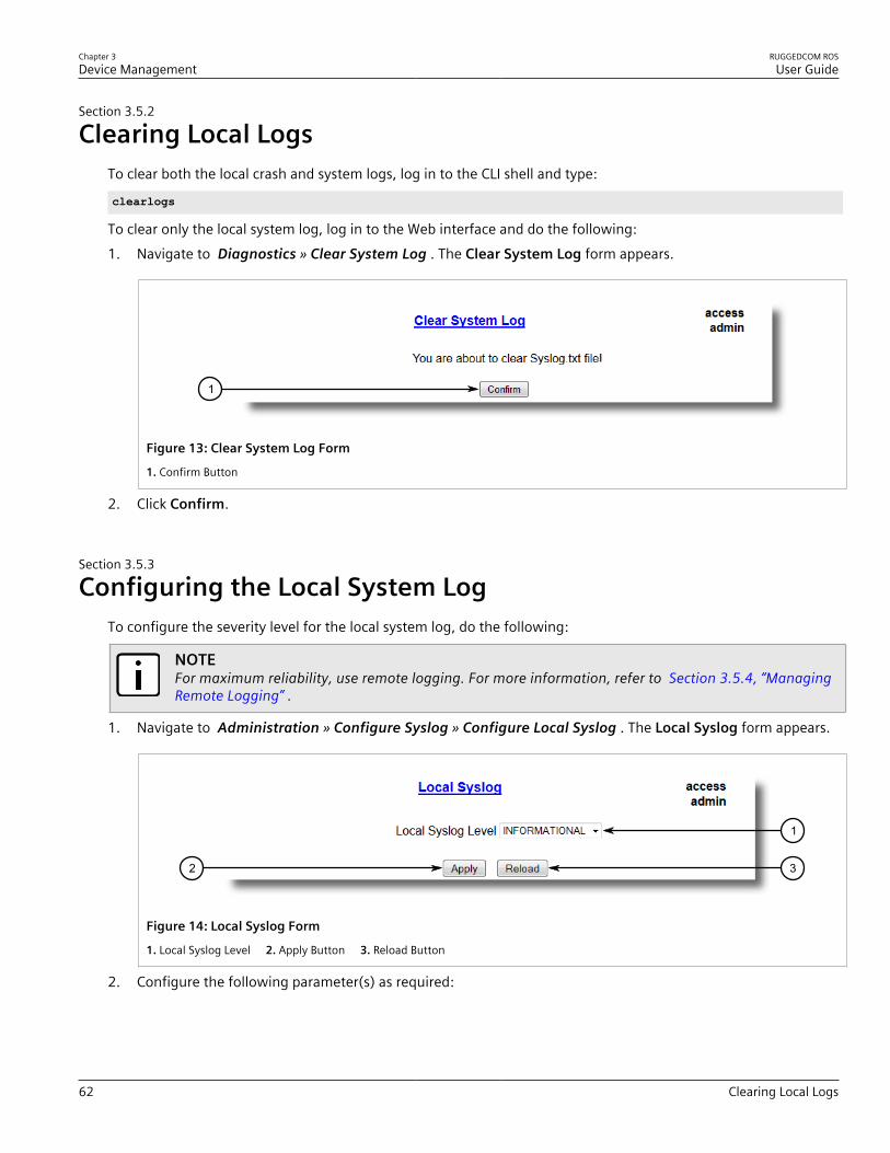
Chapter 3Device Management
RUGGEDCOM ROSUser Guide
62 Clearing Local Logs
Section 3.5.2
Clearing Local LogsTo clear both the local crash and system logs, log in to the CLI shell and type:
clearlogs
To clear only the local system log, log in to the Web interface and do the following:1. Navigate to Diagnostics » Clear System Log . The Clear System Log form appears.
1
Figure 13: Clear System Log Form
1. Confirm Button
2. Click Confirm.
Section 3.5.3
Configuring the Local System LogTo configure the severity level for the local system log, do the following:
NOTEFor maximum reliability, use remote logging. For more information, refer to Section 3.5.4, “ManagingRemote Logging” .
1. Navigate to Administration » Configure Syslog » Configure Local Syslog . The Local Syslog form appears.
32
1
Figure 14: Local Syslog Form
1. Local Syslog Level 2. Apply Button 3. Reload Button
2. Configure the following parameter(s) as required:
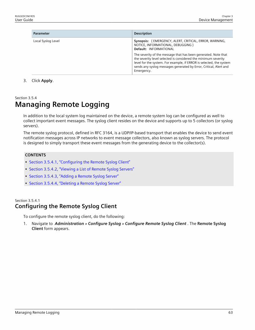
RUGGEDCOM ROSUser Guide
Chapter 3Device Management
Managing Remote Logging 63
Parameter Description
Local Syslog Level Synopsis: { EMERGENCY, ALERT, CRITICAL, ERROR, WARNING,NOTICE, INFORMATIONAL, DEBUGGING }Default: INFORMATIONALThe severity of the message that has been generated. Note thatthe severity level selected is considered the minimum severitylevel for the system. For example, if ERROR is selected, the systemsends any syslog messages generated by Error, Critical, Alert andEmergency.
3. Click Apply.
Section 3.5.4
Managing Remote LoggingIn addition to the local system log maintained on the device, a remote system log can be configured as well tocollect important event messages. The syslog client resides on the device and supports up to 5 collectors (or syslogservers).The remote syslog protocol, defined in RFC 3164, is a UDP/IP-based transport that enables the device to send eventnotification messages across IP networks to event message collectors, also known as syslog servers. The protocolis designed to simply transport these event messages from the generating device to the collector(s).
CONTENTS• Section 3.5.4.1, “Configuring the Remote Syslog Client”• Section 3.5.4.2, “Viewing a List of Remote Syslog Servers”• Section 3.5.4.3, “Adding a Remote Syslog Server”• Section 3.5.4.4, “Deleting a Remote Syslog Server”
Section 3.5.4.1Configuring the Remote Syslog Client
To configure the remote syslog client, do the following:1. Navigate to Administration » Configure Syslog » Configure Remote Syslog Client . The Remote Syslog
Client form appears.
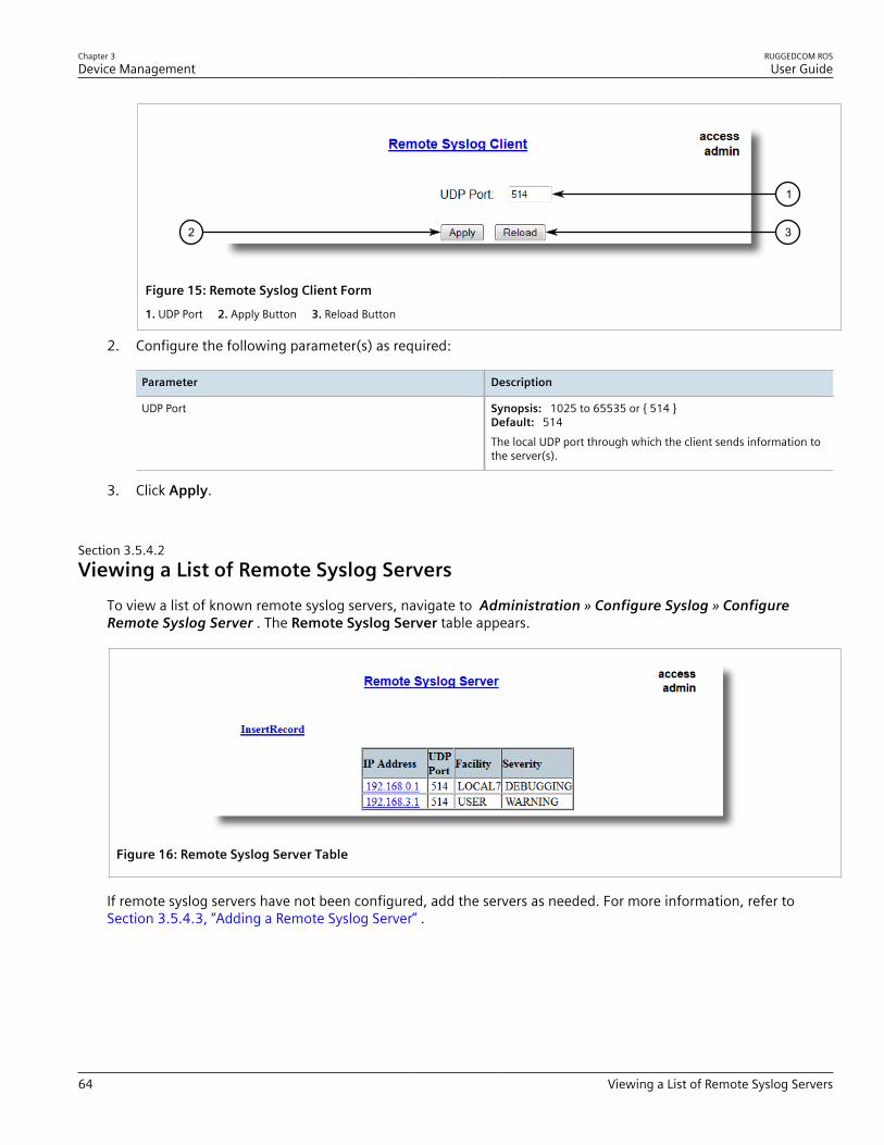
Chapter 3Device Management
RUGGEDCOM ROSUser Guide
64 Viewing a List of Remote Syslog Servers
32
1
Figure 15: Remote Syslog Client Form
1. UDP Port 2. Apply Button 3. Reload Button
2. Configure the following parameter(s) as required:
Parameter Description
UDP Port Synopsis: 1025 to 65535 or { 514 }Default: 514The local UDP port through which the client sends information tothe server(s).
3. Click Apply.
Section 3.5.4.2Viewing a List of Remote Syslog Servers
To view a list of known remote syslog servers, navigate to Administration » Configure Syslog » ConfigureRemote Syslog Server . The Remote Syslog Server table appears.
Figure 16: Remote Syslog Server Table
If remote syslog servers have not been configured, add the servers as needed. For more information, refer to Section 3.5.4.3, “Adding a Remote Syslog Server” .

RUGGEDCOM ROSUser Guide
Chapter 3Device Management
Adding a Remote Syslog Server 65
Section 3.5.4.3Adding a Remote Syslog Server
RUGGEDCOM ROS supports up to 5 remote syslog servers (or collectors). Similar to the local system log, a remotesystem log server can be configured to log information at a specific severity level. Only messages of a severitylevel equal to or greater than the specified severity level are written to the log.To add a remote syslog server to the list of known servers, do the following:1. Navigate to Administration » Configure Syslog » Configure Remote Syslog Server . The Remote Syslog
Server table appears.
1
Figure 17: Remote Syslog Server Table
1. InsertRecord
2. Click InsertRecord. The Remote Syslog Server form appears.
75
6
4
3
2
1
Figure 18: Remote Syslog Server Form
1. IP Address Box 2. UDP Port Box 3. Facility Box 4. Severity Box 5. Apply Button 6. Delete Button 7. Reload Button
3. Configure the following parameter(s) as required:
Parameter Description
IP Address Synopsis: ###.###.###.### where ### ranges from 0 to 255Syslog server IP Address.
UDP Port Synopsis: 1025 to 65535 or { 514 }
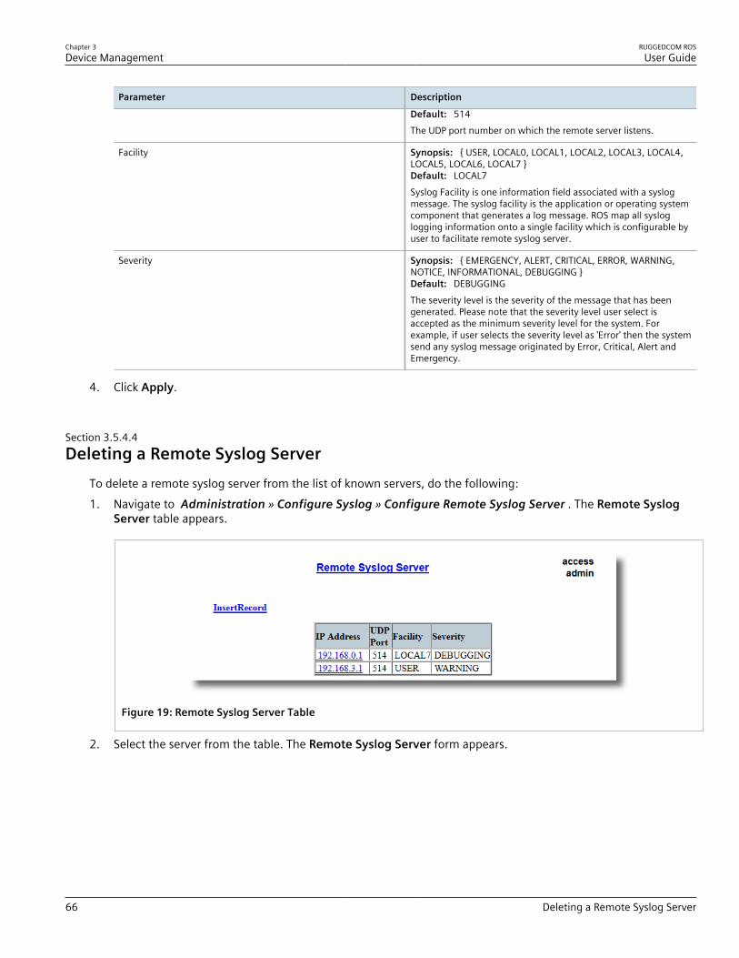
Chapter 3Device Management
RUGGEDCOM ROSUser Guide
66 Deleting a Remote Syslog Server
Parameter Description
Default: 514The UDP port number on which the remote server listens.
Facility Synopsis: { USER, LOCAL0, LOCAL1, LOCAL2, LOCAL3, LOCAL4,LOCAL5, LOCAL6, LOCAL7 }Default: LOCAL7Syslog Facility is one information field associated with a syslogmessage. The syslog facility is the application or operating systemcomponent that generates a log message. ROS map all sysloglogging information onto a single facility which is configurable byuser to facilitate remote syslog server.
Severity Synopsis: { EMERGENCY, ALERT, CRITICAL, ERROR, WARNING,NOTICE, INFORMATIONAL, DEBUGGING }Default: DEBUGGINGThe severity level is the severity of the message that has beengenerated. Please note that the severity level user select isaccepted as the minimum severity level for the system. Forexample, if user selects the severity level as 'Error' then the systemsend any syslog message originated by Error, Critical, Alert andEmergency.
4. Click Apply.
Section 3.5.4.4Deleting a Remote Syslog Server
To delete a remote syslog server from the list of known servers, do the following:1. Navigate to Administration » Configure Syslog » Configure Remote Syslog Server . The Remote Syslog
Server table appears.
Figure 19: Remote Syslog Server Table
2. Select the server from the table. The Remote Syslog Server form appears.

RUGGEDCOM ROSUser Guide
Chapter 3Device Management
Managing Ethernet Ports 67
75
6
4
3
2
1
Figure 20: Remote Syslog Server Form
1. IP Address Box 2. UDP Port Box 3. Facility Box 4. Severity Box 5. Apply Button 6. Delete Button 7. Reload Button
3. Click Delete.
Section 3.6
Managing Ethernet PortsThe following section describes how to set up and manage Ethernet ports.
NOTEFor information about configuring remote monitoring for Ethernet ports, refer to Section 3.10,“Managing Remote Monitoring” .
CONTENTS• Section 3.6.1, “Controller Protection Through Link Fault Indication (LFI)”• Section 3.6.2, “Viewing the Status of Ethernet Ports”• Section 3.6.3, “Viewing Statistics for All Ethernet Ports”• Section 3.6.4, “Viewing Statistics for Specific Ethernet Ports”• Section 3.6.5, “Clearing Statistics for Specific Ethernet Ports”• Section 3.6.6, “Configuring an Ethernet Port”• Section 3.6.7, “Configuring Port Rate Limiting”• Section 3.6.8, “Configuring Port Mirroring”• Section 3.6.9, “Configuring Link Detection”• Section 3.6.10, “Detecting Cable Faults”

Chapter 3Device Management
RUGGEDCOM ROSUser Guide
68 Controller Protection Through Link Fault Indication (LFI)
• Section 3.6.11, “Resetting Ethernet Ports”
Section 3.6.1
Controller Protection Through Link Fault Indication (LFI)Modern industrial controllers often feature backup Ethernet ports used in the event of a link failure. When theseinterfaces are supported by media (such as fiber) that employ separate transmit and receive paths, the interfacecan be vulnerable to failures that occur in only one of the two paths.Consider for instance two switches (A and B) connected to a controller. Switch A is connected to the main port onthe controller, while Switch B is connected to the backup port, which is shut down by the controller while the linkwith Switch A is active. Switch B must forward frames to the controller through Switch A.
21
43
5
Figure 21: Example
1. Switch A 2. Switch B 3. Main Transmit Path 4. Backup Transmit Path 5. Controller
If the transmit path from the controller to Switch A fails, Switch A still generates a link signal to the controllerthrough the receive path. The controller still detects the link with Switch A and does not failover to the backupport.This situation illustrates the need for a notification method that tells a link partner when the link integrity signalhas stopped. Such a method natively exists in some link media, but not all.
100Base-TX, 1000Base-T, 1000Base-X Includes a built-in auto-negotiation feature (i.e. a special flag called Remote Fault Indicationis set in the transmitted auto-negotation signal).
100Base-FX Links Includes a standard Far-End-Fault-Indication (FEFI) feature defined by the IEEE 802.3standard for this link type. This feature includes:• Transmitting FEFI
Transmits a modified link integrity signal in case a link failure is detected (i.e. no link signalis received from the link partner)
• Detecting FEFIIndicates link loss in case an FEFI signal is received from the link partner
10Base-FL LInks No standard support.
10Base-FL links do not have a native link partner notification mechanism and FEFI support in 100Base-FX links isoptional according to the IEEE 802.3 standard, which means that some links partners may not support it.Siemens offers an advanced Link-Fault-Indication (LFI) feature for the links that do not have a native link partnernotification mechanism. With LFI enabled, the device bases the generation of a link integrity signal upon itsreception of a link signal. In the example described previously, if switch A fails to receive a link signal from thecontroller, it will stop generating a link signal. The controller will detect the link failure and failover to the backkupport.

RUGGEDCOM ROSUser Guide
Chapter 3Device Management
Viewing the Status of Ethernet Ports 69
IMPORTANT!If both link partners have the LFI feature, it must not be enabled on both sides of the link. If it isenabled on both sides, the link will never be established, as each link partner will be waiting for theother to transmit a link signal.
The switch can also be configured to flush the MAC address table for the controller port. Frames destined for thecontroller will be flooded to Switch B where they will be forwarded to the controller (after the controller transmitsits first frame).
Section 3.6.2
Viewing the Status of Ethernet PortsTo view the current status of each Ethernet port, navigate to Ethernet Ports » View Port Status . The Port Statustable appears.
Figure 22: Port Status Table
This table displays the following information:
Parameter Description
Port Synopsis: 1 to maximum port numberThe port number as seen on the front plate silkscreen of the switch.
Name Synopsis: Any 15 charactersA descriptive name that may be used to identify the device conectedon that port.
Link Synopsis: { ----, ----, Down, Up }The port's link status.
Speed Synopsis: { ---, 10M, 100M, 1G, 10G }The port's current speed.
Duplex Synopsis: { ----, Half, Full }The port's current duplex status.
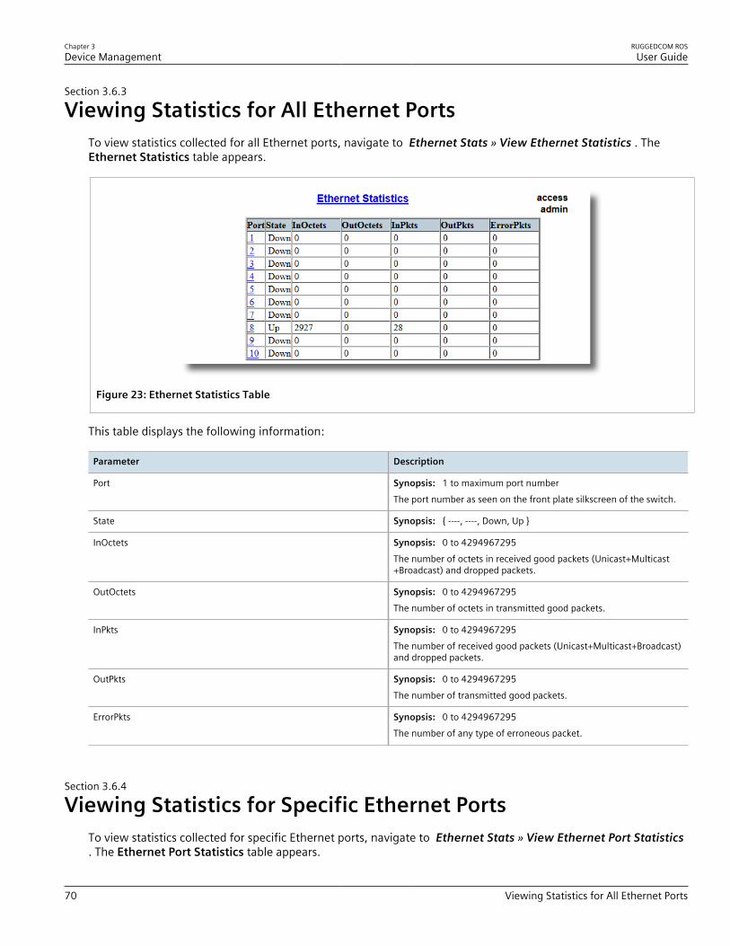
Chapter 3Device Management
RUGGEDCOM ROSUser Guide
70 Viewing Statistics for All Ethernet Ports
Section 3.6.3
Viewing Statistics for All Ethernet PortsTo view statistics collected for all Ethernet ports, navigate to Ethernet Stats » View Ethernet Statistics . TheEthernet Statistics table appears.
Figure 23: Ethernet Statistics Table
This table displays the following information:
Parameter Description
Port Synopsis: 1 to maximum port numberThe port number as seen on the front plate silkscreen of the switch.
State Synopsis: { ----, ----, Down, Up }
InOctets Synopsis: 0 to 4294967295The number of octets in received good packets (Unicast+Multicast+Broadcast) and dropped packets.
OutOctets Synopsis: 0 to 4294967295The number of octets in transmitted good packets.
InPkts Synopsis: 0 to 4294967295The number of received good packets (Unicast+Multicast+Broadcast)and dropped packets.
OutPkts Synopsis: 0 to 4294967295The number of transmitted good packets.
ErrorPkts Synopsis: 0 to 4294967295The number of any type of erroneous packet.
Section 3.6.4
Viewing Statistics for Specific Ethernet PortsTo view statistics collected for specific Ethernet ports, navigate to Ethernet Stats » View Ethernet Port Statistics. The Ethernet Port Statistics table appears.

RUGGEDCOM ROSUser Guide
Chapter 3Device Management
Viewing Statistics for Specific Ethernet Ports 71
Figure 24: Ethernet Port Statistics Table
This table displays the following information:
Parameter Description
Port Synopsis: 1 to maximum port numberThe port number as seen on the front plate silkscreen of the switch.
InOctets Synopsis: 0 to 18446744073709551615The number of octets in received good packets (Unicast+Multicast+Broadcast) and dropped packets.
OutOctets Synopsis: 0 to 18446744073709551615The number of octets in transmitted good packets.
InPkts Synopsis: 0 to 18446744073709551615The number of received good packets (Unicast+Multicast+Broadcast)and dropped packets.
OutPkts Synopsis: 0 to 18446744073709551615The number of transmitted good packets.
TotalInOctets Synopsis: 0 to 18446744073709551615The total number of octets of all received packets. This includes dataoctets of rejected and local packets which are not forwarded to theswitching core for transmission. It should reflect all the data octetsreceived on the line.
TotalInPkts Synopsis: 0 to 18446744073709551615The number of received packets. This includes rejected, droppedlocal, and packets which are not forwarded to the switching core fortransmission. It should reflect all packets received ont the line.
InBroadcasts Synopsis: 0 to 18446744073709551615The number of good Broadcast packets received.
InMulticasts Synopsis: 0 to 18446744073709551615The number of good Multicast packets received.
CRCAlignErrors Synopsis: 0 to 4294967295The number of packets received which meet all the followingconditions:

Chapter 3Device Management
RUGGEDCOM ROSUser Guide
72 Viewing Statistics for Specific Ethernet Ports
Parameter Description
• Packet data length is between 64 and 1536 octets inclusive.• Packet has invalid CRC.• Collision Event has not been detected.• Late Collision Event has not been detected.
OversizePkts Synopsis: 0 to 4294967295The number of packets received with data length greater than 1536octets and valid CRC.
Fragments Synopsis: 0 to 4294967295The number of packets received which meet all the followingconditions:• Packet data length is less than 64 octets, or packet without SFD
and is less than 64 octets in length.• Collision Event has not been detected.• Late Collision Event has not been detected.• Packet has invalid CRC.
Jabbers Synopsis: 0 to 4294967295The number of packets which meet all the following conditions:• Packet data length is greater that 1536 octets.• Packet has invalid CRC.
Collisions Synopsis: 0 to 4294967295The number of received packets for which Collision Event has beendetected.
LateCollisions Synopsis: 0 to 4294967295The number of received packets for which Late Collision Event hasbeen detected.
Pkt64Octets Synopsis: 0 to 4294967295The number of received and transmitted packets with size of 64octets. This includes received and transmitted packets as well asdropped and local received packets. This does not include rejectedreceived packets.
Pkt65to127Octets Synopsis: 0 to 4294967295The number of received and transmitted packets with size of 65 to127 octets. This includes received and transmitted packets as well asdropped and local received packets. This does not include rejectedreceived packets.
Pkt128to255Octets Synopsis: 0 to 4294967295The number of received and transmitted packets with size of 128 to257 octets. This includes received and transmitted packets as well asdropped and local received packets. This does not include rejectedreceived packets.
Pkt256to511Octets Synopsis: 0 to 4294967295The number of received and transmitted packets with size of 256 to511 octets. This includes received and transmitted packets as well asdropped and local received packets. This does not include rejectedreceived packets.
Pkt512to1023Octets Synopsis: 0 to 4294967295The number of received and transmitted packets with size of 512 to1023 octets. This includes received and transmitted packets as well
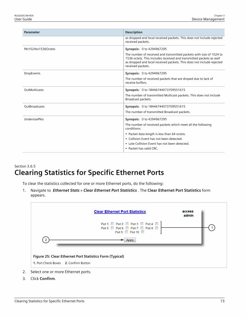
RUGGEDCOM ROSUser Guide
Chapter 3Device Management
Clearing Statistics for Specific Ethernet Ports 73
Parameter Description
as dropped and local received packets. This does not include rejectedreceived packets.
Pkt1024to1536Octets Synopsis: 0 to 4294967295The number of received and transmitted packets with size of 1024 to1536 octets. This includes received and transmitted packets as wellas dropped and local received packets. This does not include rejectedreceived packets.
DropEvents Synopsis: 0 to 4294967295The number of received packets that are droped due to lack ofreceive buffers.
OutMulticasts Synopsis: 0 to 18446744073709551615The number of transmitted Multicast packets. This does not includeBroadcast packets.
OutBroadcasts Synopsis: 0 to 18446744073709551615The number of transmitted Broadcast packets.
UndersizePkts Synopsis: 0 to 4294967295The number of received packets which meet all the followingconditions:• Packet data length is less than 64 octets.• Collision Event has not been detected.• Late Collision Event has not been detected.• Packet has valid CRC.
Section 3.6.5
Clearing Statistics for Specific Ethernet PortsTo clear the statistics collected for one or more Ethernet ports, do the following:1. Navigate to Ethernet Stats » Clear Ethernet Port Statistics . The Clear Ethernet Port Statistics form
appears.
1
2
Figure 25: Clear Ethernet Port Statistics Form (Typical)
1. Port Check Boxes 2. Confirm Button
2. Select one or more Ethernet ports.3. Click Confirm.

Chapter 3Device Management
RUGGEDCOM ROSUser Guide
74 Configuring an Ethernet Port
Section 3.6.6
Configuring an Ethernet PortTo configure an Ethernet port, do the following:1. Navigate to Ethernet Ports » Configure Port Parameters . The Port Parameters table appears.
Figure 26: Port Parameters Table
2. Select an Ethernet port. The Port Parameters form appears.
7
11
6
5
4
3
2
1
8
12
9
10
Figure 27: Port Parameters Form
1. Port Box 2. Name Box 3. Media Box 4. State Box 5. AutoN Box 6. Speed Box 7. Dupx Box 8. FlowCtrl Box 9. LFIBox 10. Alarm Box 11. Apply Button 12. Reload Button
3. Configure the following parameter(s) as required:
Parameter Description
Port Synopsis: 1 to maximum port number

RUGGEDCOM ROSUser Guide
Chapter 3Device Management
Configuring an Ethernet Port 75
Parameter Description
Default: 1The port number as seen on the front plate silkscreen of theswitch.
Name Synopsis: Any 15 charactersDefault: Port xA descriptive name that may be used to identify the deviceconnected on that port.
Media Synopsis: { 100TX, 10FL, 100FX, 1000X, 1000T, 802.11g,EoVDSL, 100TX Only, 10FL/100SX, 10GX }Default: 100TXThe type of the port media.
State Synopsis: { Disabled, Enabled }Default: EnabledDisabling a port will prevent all frames from being sent andreceived on that port. Also, when disabled link integrity signalis not sent so that the link/activity LED will never be lit. You maywant to disable a port for troubleshooting or to secure it fromunauthorized connections.
NOTEDisabling a port whose media type is set to 802.11gdisables the corresponding wireless module.
AutoN Synopsis: { Off, On }Default: OnEnable or disable IEEE 802.3 auto-negotiation. Enabling auto-negotiation results in speed and duplex being negotiated uponlink detection; both end devices must be auto-negotiationcompliant for the best possible results. 10Mbps and 100Mbpsfiber optic media do not support auto-negotiation so these mediamust be explicitly configured to either half or full duplex. Fullduplex operation requires that both ends are configured as suchor else severe frame loss will occur during heavy network traffic.
Speed Synopsis: { Auto, 10M, 100M, 1G }Default: AutoSpeed (in Megabit-per-second or Gigabit-per-second). If auto-negotiation is enabled, this is the speed capability advertised bythe auto-negotiation process. If auto-negotiation is disabled, theport is explicitly forced to this speed mode.AUTO means advertise all supported speed modes.
Dupx Synopsis: { Auto, Half, Full }Default: AutoDuplex mode. If auto-negotiation is enabled, this is the duplexcapability advertised by the auto-negotiation process. If auto-negotiation is disabled, the port is explicitly forced to this duplexmode.AUTO means advertise all supported duplex modes.
Flow Control Synopsis: { Off, On }Default: OnFlow Control is useful for preventing frame loss during times ofsevere network traffic. Examples of this include multiple sourceports sending to a single destination port or a higher speed portbursting to a lower speed port.

Chapter 3Device Management
RUGGEDCOM ROSUser Guide
76 Configuring Port Rate Limiting
Parameter Description
When the port is half-duplex it is accomplished using'backpressure' where the switch simulates collisions causing thesending device to retry transmissions according to the Ethernetbackoff algorithm.When the port is full-duplex it is accomplished using PAUSEframes which causes the sending device to stop transmitting for acertain period of time.
LFI Synopsis: { Off, On }Default: OffEnabling Link-Fault-Indication (LFI) inhibits transmitting linkintegrity signal when the receive link has failed. This allows thedevice at far end to detect link failure under all circumstances.
NOTEThis feature must not be enabled at both ends of afiber link.
Alarm Synopsis: { On, Off }Default: OnDisabling link state alarms will prevent alarms and LinkUp andLinkDown SNMP traps from being sent for that port.
NOTEIf one end of the link is fixed to a specific speed and duplex type and the peer auto-negotiates,there is a strong possibility that the link will either fail to raise, or raise with the wrong settings onthe auto-negotiating side. The auto-negotiating peer will fall back to half-duplex operation, evenwhen the fixed side is full duplex. Full-duplex operation requires that both ends are configuredas such or else severe frame loss will occur during heavy network traffic. At lower traffic volumesthe link may display few, if any, errors. As the traffic volume rises, the fixed negotiation side willbegin to experience dropped packets, while the auto-negotiating side will experience excessivecollisions. Ultimately, as traffic load approaches 100%, the link will become entirely unusable.These problems can be avoided by always configuring ports to the appropriate fixed values.
4. Click Apply.
Section 3.6.7
Configuring Port Rate LimitingTo configure port rate limiting, do the following:1. Navigate to Ethernet Ports » Configure Port Rate Limiting . The Port Rate Limiting table appears.
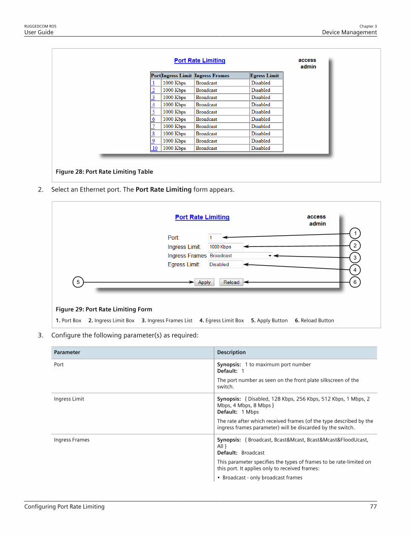
RUGGEDCOM ROSUser Guide
Chapter 3Device Management
Configuring Port Rate Limiting 77
Figure 28: Port Rate Limiting Table
2. Select an Ethernet port. The Port Rate Limiting form appears.
65
4
3
2
1
Figure 29: Port Rate Limiting Form
1. Port Box 2. Ingress Limit Box 3. Ingress Frames List 4. Egress Limit Box 5. Apply Button 6. Reload Button
3. Configure the following parameter(s) as required:
Parameter Description
Port Synopsis: 1 to maximum port numberDefault: 1The port number as seen on the front plate silkscreen of theswitch.
Ingress Limit Synopsis: { Disabled, 128 Kbps, 256 Kbps, 512 Kbps, 1 Mbps, 2Mbps, 4 Mbps, 8 Mbps }Default: 1 MbpsThe rate after which received frames (of the type described by theingress frames parameter) will be discarded by the switch.
Ingress Frames Synopsis: { Broadcast, Bcast&Mcast, Bcast&Mcast&FloodUcast,All }Default: BroadcastThis parameter specifies the types of frames to be rate-limited onthis port. It applies only to received frames:• Broadcast - only broadcast frames
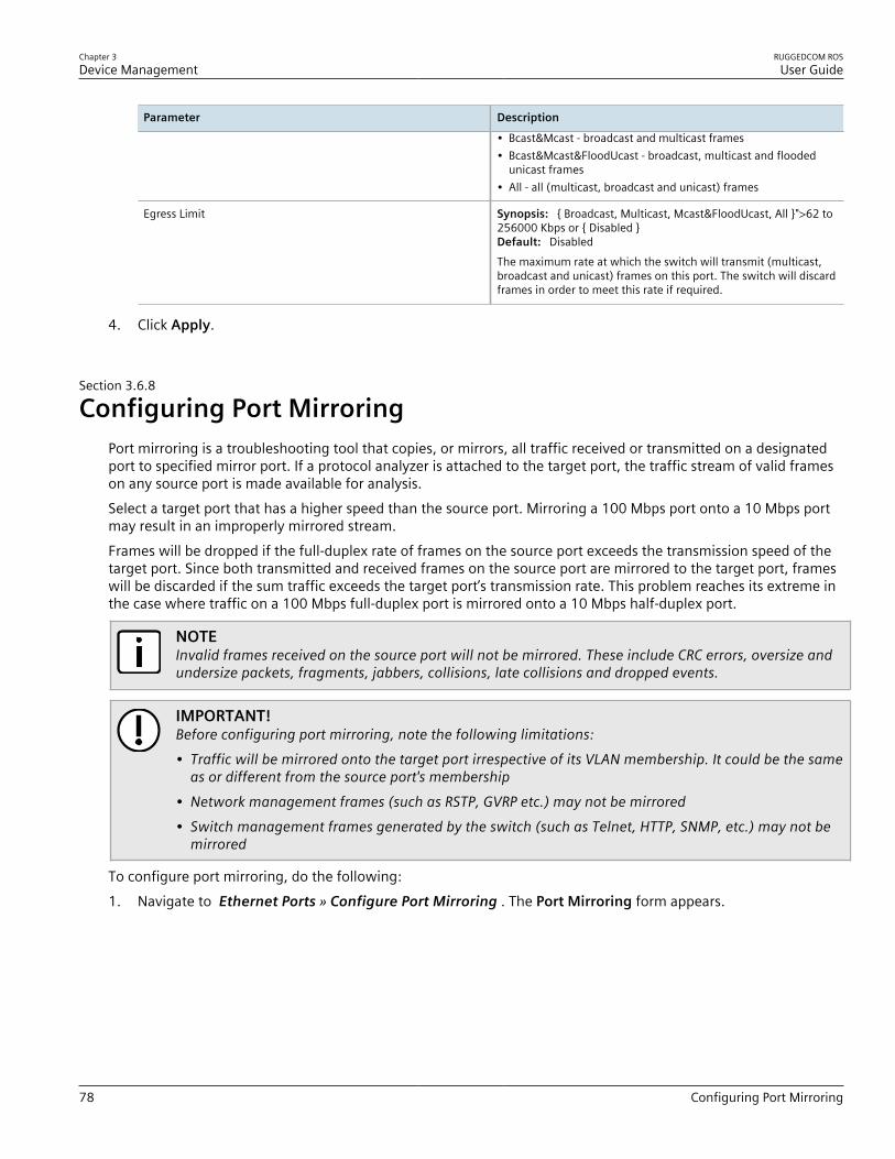
Chapter 3Device Management
RUGGEDCOM ROSUser Guide
78 Configuring Port Mirroring
Parameter Description
• Bcast&Mcast - broadcast and multicast frames• Bcast&Mcast&FloodUcast - broadcast, multicast and flooded
unicast frames• All - all (multicast, broadcast and unicast) frames
Egress Limit Synopsis: { Broadcast, Multicast, Mcast&FloodUcast, All }">62 to256000 Kbps or { Disabled }Default: DisabledThe maximum rate at which the switch will transmit (multicast,broadcast and unicast) frames on this port. The switch will discardframes in order to meet this rate if required.
4. Click Apply.
Section 3.6.8
Configuring Port MirroringPort mirroring is a troubleshooting tool that copies, or mirrors, all traffic received or transmitted on a designatedport to specified mirror port. If a protocol analyzer is attached to the target port, the traffic stream of valid frameson any source port is made available for analysis.Select a target port that has a higher speed than the source port. Mirroring a 100 Mbps port onto a 10 Mbps portmay result in an improperly mirrored stream.Frames will be dropped if the full-duplex rate of frames on the source port exceeds the transmission speed of thetarget port. Since both transmitted and received frames on the source port are mirrored to the target port, frameswill be discarded if the sum traffic exceeds the target port’s transmission rate. This problem reaches its extreme inthe case where traffic on a 100 Mbps full-duplex port is mirrored onto a 10 Mbps half-duplex port.
NOTEInvalid frames received on the source port will not be mirrored. These include CRC errors, oversize andundersize packets, fragments, jabbers, collisions, late collisions and dropped events.
IMPORTANT!Before configuring port mirroring, note the following limitations:• Traffic will be mirrored onto the target port irrespective of its VLAN membership. It could be the same
as or different from the source port's membership• Network management frames (such as RSTP, GVRP etc.) may not be mirrored• Switch management frames generated by the switch (such as Telnet, HTTP, SNMP, etc.) may not be
mirrored
To configure port mirroring, do the following:1. Navigate to Ethernet Ports » Configure Port Mirroring . The Port Mirroring form appears.

RUGGEDCOM ROSUser Guide
Chapter 3Device Management
Configuring Link Detection 79
5 6
4
3
2
1
Figure 30: Port Mirroring Form
1. Port Mirroring Box 2. Source Port Box 3. Target Port Box 4. Apply Button 5. Reload Button
2. Configure the following parameter(s) as required:
Parameter Description
Port Mirroring Synopsis: { Disabled, Enabled }Default: DisabledEnabling port mirroring causes all frames received andtransmitted by the source port(s) to be transmitted out of thetarget port.
Source Port Synopsis: Any combination of numbers valid for this parameterThe port(s) being monitored.
Source Direction Synopsis: Egress and Ingress, Egress OnlyDefault: Egress and IngressSpecifies monitoring whether both egress and ingress traffics oronly egress traffic of the source port.
Target Port Synopsis: 1 to maximum port numberDefault: 1The port where a monitoring device should be connected.
3. Click Apply.
Section 3.6.9
Configuring Link DetectionTo configure link detection, do the following:1. Navigate to Ethernet Ports » Configure Link Detection . The Link Detection form appears.

Chapter 3Device Management
RUGGEDCOM ROSUser Guide
80 Configuring Link Detection
43
2
1
Figure 31: Link Detection Form
1. Fast Link Detection Box 2. Link Detection Time Box 3. Apply Button 4. Reload Button
2. Configure the following parameter(s) as required:
NOTEWhen Fast Link Detection is enabled, the system prevents link state change processing fromconsuming all available CPU resources. However, if Port Guard is not used, it is possible for almostall available CPU time to be consumed by frequent link state changes, which could have a negativeimpact on overall system responsiveness.
Parameter Description
Fast Link Detection Synopsis: { Off, On, On_withPortGuard }Default: On_withPortGuardThis parameter provides protection against faulty end devicesgenerating an improper link integrity signal. When a faulty enddevice or a mis-matching fiber port is connected to the unit, alarge number of continuous link state changes could be reportedin a short period of time. These large number of bogus link statechanges could render the system unresponsive as most, if notall, of the system resources are used to process the link statechanges. This could in turn cause a serious network problem asthe unit's RSTP process may not be able to run, thus allowingnetwork loop to form.Three different settings are available for this parameter:• ON_withPortGuard - This is the recommended setting. With this
setting, an extended period (~2 minutes) of excessive link statechanges reported by a port will prompt Port Guard feature todisable FAST LINK DETECTION on that port and raise an alarm.By disabling FAST LINK DETECTION on the problematic port,excessive link state changes can no longer consume substantialamount of system resources. However if FAST LINK DETECTIONis disabled, the port will need a longer time to detect a linkfailure. This may result in a longer network recovery time ofup to 2s. Once Port Guard disables FAST LINK DETECTION of aparticular port, user can re-enable FAST LINK DETECTION on theport by clearing the alarm.
• ON - In certain special cases where a prolonged excessive linkstate changes constitute a legitimate link operation, usingthis setting can prevent Port Guard from disabling FAST LINKDETECTION on the port in question. If excessive link statechanges persist for more than 2 minutes, an alarm will begenerated to warn user about the observed bouncing link. Ifthe excessive link state changes condition is resolved later on,the alarm will be cleared automatically. Since this option doesnot disable FAST LINK DETECTION, a persistent bouncing link

RUGGEDCOM ROSUser Guide
Chapter 3Device Management
Detecting Cable Faults 81
Parameter Description
could continue affect the system in terms of response time. Thissetting should be used with caution.
• OFF - Turning this parameter OFF will disable FAST LINKDETECTION completely. The switch will need a longer time todetect a link failure. This will result in a longer network recoverytime of up to 2s.
Link Detection Time Synopsis: 100 ms to 1000 msDefault: 100 msThe time that the link has to continuously stay up before the "linkup" decision is made by the device.(The device performs de-bouncing of Ethernet link detectionto avoid multiple responses to an occasional link bouncingevent, e.g. when a cable is shaking while being plugged-in orunplugged).
3. Click Apply.
Section 3.6.10
Detecting Cable FaultsConnectivity issues can sometimes be attributed to faults in Ethernet cables. To help detect cable faults, shortcircuits, open cables or cables that are too long, ROS includes a built-in cable diagnostics utility.
CONTENTS• Section 3.6.10.1, “Viewing Cable Diagnostics Results”• Section 3.6.10.2, “Performing Cable Diagnostics”• Section 3.6.10.3, “Clearing Cable Diagnostics”• Section 3.6.10.4, “Determining the Estimated Distance To Fault (DTF)”
Section 3.6.10.1Viewing Cable Diagnostics Results
To view the results of previous diagnostic tests, navigate to Ethernet Ports » Configure/View Cable DiagnosticsParameters . The Cable Diagnostics Parameters table appears.
NOTEFor information about how to start a diagnostic test, refer to Section 3.6.10.2, “Performing CableDiagnostics” .
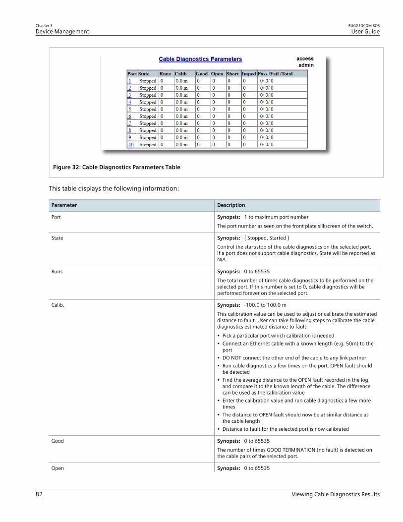
Chapter 3Device Management
RUGGEDCOM ROSUser Guide
82 Viewing Cable Diagnostics Results
Figure 32: Cable Diagnostics Parameters Table
This table displays the following information:
Parameter Description
Port Synopsis: 1 to maximum port numberThe port number as seen on the front plate silkscreen of the switch.
State Synopsis: { Stopped, Started }Control the start/stop of the cable diagnostics on the selected port.If a port does not support cable diagnostics, State will be reported asN/A.
Runs Synopsis: 0 to 65535The total number of times cable diagnostics to be performed on theselected port. If this number is set to 0, cable diagnostics will beperformed forever on the selected port.
Calib. Synopsis: -100.0 to 100.0 mThis calibration value can be used to adjust or calibrate the estimateddistance to fault. User can take following steps to calibrate the cablediagnostics estimated distance to fault:• Pick a particular port which calibration is needed• Connect an Ethernet cable with a known length (e.g. 50m) to the
port• DO NOT connect the other end of the cable to any link partner• Run cable diagnostics a few times on the port. OPEN fault should
be detected• Find the average distance to the OPEN fault recorded in the log
and compare it to the known length of the cable. The differencecan be used as the calibration value
• Enter the calibration value and run cable diagnostics a few moretimes
• The distance to OPEN fault should now be at similar distance asthe cable length
• Distance to fault for the selected port is now calibrated
Good Synopsis: 0 to 65535The number of times GOOD TERMINATION (no fault) is detected onthe cable pairs of the selected port.
Open Synopsis: 0 to 65535

RUGGEDCOM ROSUser Guide
Chapter 3Device Management
Performing Cable Diagnostics 83
Parameter Description
The number of times OPEN is detected on the cable pairs of theselected port.
Short Synopsis: 0 to 65535The number of times SHORT is detected on the cable pairs of theselected port.
Imped Synopsis: 0 to 65535The number of times IMPEDANCE MISMATCH is detected on thecable pairs of the selected port.
Pass /Fail /Total Synopsis: Any 19 charactersThis field summarizes the results of the cable diagnostics performedso far.Pass - number of times cable diagnostics successfully completed onthe selected port.Fail - number of times cable diagnostics failed to complete on theselected port.Total - total number of times cable diagnostics have been attemptedon the selected port.
NOTEFor each successful diagnostic test, the values for Good, Open, Short or Imped will increment basedon the number of cable pairs connected to the port. For a 100Base-T port, which has two cable pairs,the number will increase by two. For a 1000Base-T port, which has four cable pairs, the number willincrease by four.
NOTEWhen a cable fault is detected, an estimated distance-to-fault is calculated and recorded in the systemlog. The log lists the cable pair, the fault that was detected, and the distance-to-fault value. For moreinformation about the system log, refer to Section 3.5.1, “Viewing Local Logs” .
Section 3.6.10.2Performing Cable Diagnostics
To perform a cable diagnostic test on one or more Ethernet ports, do the following:1. Connect a CAT-5 (or better quality) Ethernet cable to the selected Ethernet port.
IMPORTANT!Both the selected Ethernet port and its partner port can be configured to run in Enabled modewith auto-negotiation, or in Disabled mode. Other modes are not recommended, as they mayinterfere with the cable diagnostics procedure.
2. Connect the other end of the cable to a similar network port. For example, connect a 100Base-T port to a100Base-T port, or a 1000Base-T port to a 1000Base-T port.
3. In ROS, navigate to Ethernet Ports » Configure/View Cable Diagnostics Parameters . The CableDiagnostics Parameters table appears.

Chapter 3Device Management
RUGGEDCOM ROSUser Guide
84 Performing Cable Diagnostics
Figure 33: Cable Diagnostics Parameters Table
4. Select an Ethernet port. The Cable Diagnostics Parameters form appears.
1110
9
8
7
6
5
4
3
2
1
Figure 34: Cable Diagnostics Parameters Form
1. Port Box 2. State Options 3. Runs Box 4. Calib. Box 5. Good Box 6. Open Box 7. Short Box 8. Imped Box 9. Pass /Fail /Total Box 10. Apply Button 11. Reload Button
5. Under Runs, enter the number of consecutive diagnostic tests to perform. A value of 0 indicates the test willrun continuously until stopped by the user.
6. Under Calib., enter the estimated Distance To Fault (DTF) value. For information about how to determine theDTF value, refer to Section 3.6.10.4, “Determining the Estimated Distance To Fault (DTF)” .
7. Select Started.
IMPORTANT!A diagnostic test can be stopped by selecting Stopped and clicking Apply. However, if the test isstopped in the middle of a diagnostic run, the test will run to completion.
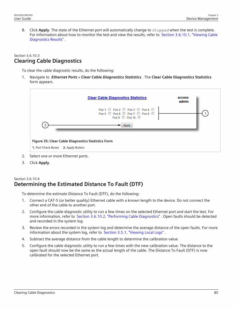
RUGGEDCOM ROSUser Guide
Chapter 3Device Management
Clearing Cable Diagnostics 85
8. Click Apply. The state of the Ethernet port will automatically change to Stopped when the test is complete.For information about how to monitor the test and view the results, refer to Section 3.6.10.1, “Viewing CableDiagnostics Results” .
Section 3.6.10.3Clearing Cable Diagnostics
To clear the cable diagnostic results, do the following:1. Navigate to Ethernet Ports » Clear Cable Diagnostics Statistics . The Clear Cable Diagnostics Statistics
form appears.
1
2
Figure 35: Clear Cable Diagnostics Statistics Form
1. Port Check Boxes 2. Apply Button
2. Select one or more Ethernet ports.3. Click Apply.
Section 3.6.10.4Determining the Estimated Distance To Fault (DTF)
To determine the estimate Distance To Fault (DTF), do the following:1. Connect a CAT-5 (or better quality) Ethernet cable with a known length to the device. Do not connect the
other end of the cable to another port.2. Configure the cable diagnostic utility to run a few times on the selected Ethernet port and start the test. For
more information, refer to Section 3.6.10.2, “Performing Cable Diagnostics” . Open faults should be detectedand recorded in the system log.
3. Review the errors recorded in the system log and determine the average distance of the open faults. For moreinformation about the system log, refer to Section 3.5.1, “Viewing Local Logs” .
4. Subtract the average distance from the cable length to determine the calibration value.5. Configure the cable diagnostic utility to run a few times with the new calibration value. The distance to the
open fault should now be the same as the actual length of the cable. The Distance To Fault (DTF) is nowcalibrated for the selected Ethernet port.

Chapter 3Device Management
RUGGEDCOM ROSUser Guide
86 Resetting Ethernet Ports
Section 3.6.11
Resetting Ethernet PortsAt times, it may be necessary to reset a specific Ethernet port, such as when the link partner has latched into aninappropriate state. This is also useful for forcing a re-negotiation of the speed and duplex modes.To reset a specific Ethernet port(s), do the following:1. Navigate to Ethernet Ports » Reset Port(s) . The Reset Port(s) form appears.
1
2
Figure 36: Reset Port(s) Form
1. Ports 2. Apply Button
2. Select one or more Ethernet ports to reset.3. Click Apply. The selected Ethernet ports are reset.
Section 3.7
Managing IP InterfacesRUGGEDCOM ROS allows one IP interface to be configured for each subnet (or VLAN), up to a maximum of 15 255interfaces. One of the interfaces must also be configured to be a management interface for certain IP services,such as DHCP relay agent.Each IP interface must be assigned an IP address. In the case of the management interface, the IP address type canbe either static, DHCP, BOOTP or dynamic. For all other interfaces, the IP address must be static.
CAUTION!Configuration hazard – risk of communication disruption. Changing the ID for the management VLANwill break any active Raw Socket TCP connections. If this occurs, reset all serial ports.
CONTENTS• Section 3.7.1, “Viewing a List of IP Interfaces”• Section 3.7.2, “Adding an IP Interface”

RUGGEDCOM ROSUser Guide
Chapter 3Device Management
Viewing a List of IP Interfaces 87
• Section 3.7.3, “Deleting an IP Interface”
Section 3.7.1
Viewing a List of IP InterfacesTo view a list of IP interfaces configured on the device, navigate to Administration » Configure IP Interfaces »Configure IP Interfaces . The IP Interfaces table appears.
Figure 37: IP Interfaces Table
If IP interfaces have not been configured, add IP interfaces as needed. For more information, refer to Section 3.7.2, “Adding an IP Interface” .
Section 3.7.2
Adding an IP InterfaceTo add an IP interface, do the following:1. Navigate to Administration » Configure IP Interfaces . The IP Interfaces table appears.
1
Figure 38: IP Interfaces Table
1. InsertRecord
2. Click InsertRecord. The Switch IP Interfaces form appears.
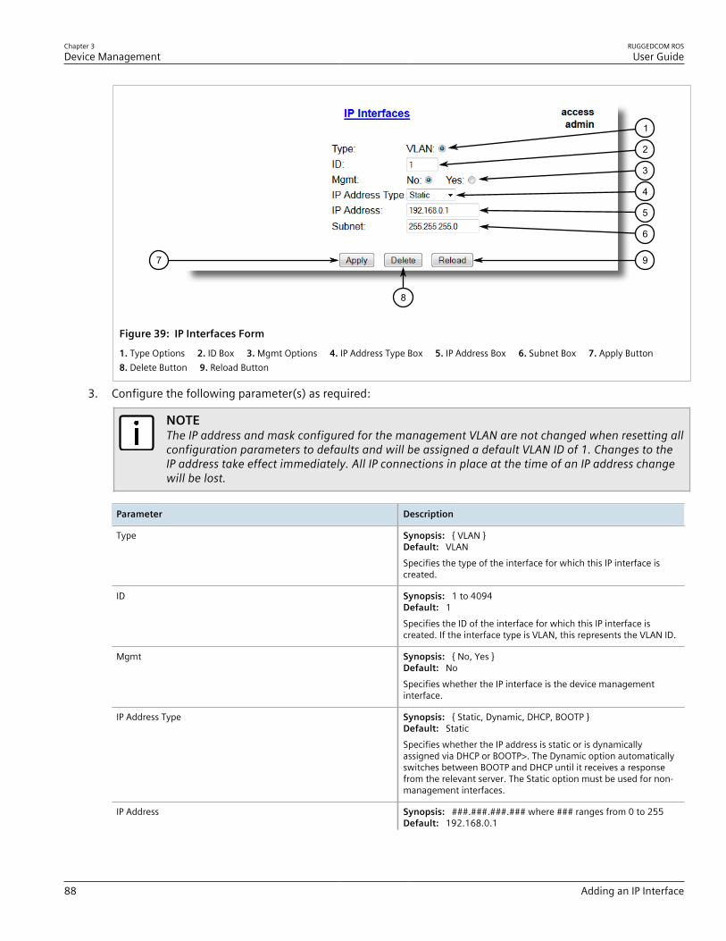
Chapter 3Device Management
RUGGEDCOM ROSUser Guide
88 Adding an IP Interface
7
8
1
2
3
4
5
6
9
Figure 39: IP Interfaces Form
1. Type Options 2. ID Box 3. Mgmt Options 4. IP Address Type Box 5. IP Address Box 6. Subnet Box 7. Apply Button 8. Delete Button 9. Reload Button
3. Configure the following parameter(s) as required:
NOTEThe IP address and mask configured for the management VLAN are not changed when resetting allconfiguration parameters to defaults and will be assigned a default VLAN ID of 1. Changes to theIP address take effect immediately. All IP connections in place at the time of an IP address changewill be lost.
Parameter Description
Type Synopsis: { VLAN }Default: VLANSpecifies the type of the interface for which this IP interface iscreated.
ID Synopsis: 1 to 4094Default: 1Specifies the ID of the interface for which this IP interface iscreated. If the interface type is VLAN, this represents the VLAN ID.
Mgmt Synopsis: { No, Yes }Default: NoSpecifies whether the IP interface is the device managementinterface.
IP Address Type Synopsis: { Static, Dynamic, DHCP, BOOTP }Default: StaticSpecifies whether the IP address is static or is dynamicallyassigned via DHCP or BOOTP>. The Dynamic option automaticallyswitches between BOOTP and DHCP until it receives a responsefrom the relevant server. The Static option must be used for non-management interfaces.
IP Address Synopsis: ###.###.###.### where ### ranges from 0 to 255Default: 192.168.0.1

RUGGEDCOM ROSUser Guide
Chapter 3Device Management
Deleting an IP Interface 89
Parameter Description
Specifies the IP address of this device. An IP address is a 32-bitnumber that is notated by using four numbers from 0 through255, separated by periods. Only a unicast IP address is allowed,which ranges from 1.0.0.0 to 233.255.255.255.
Subnet Synopsis: ###.###.###.### where ### ranges from 0 to 255Default: 255.255.255.0Specifies the IP subnet mask of this device. An IP subnet maskis a 32-bit number that is notated by using four numbers from0 through 255, separated by periods. Typically, subnet masknumbers use either 0 or 255 as values (e.g. 255.255.255.0) butother numbers can appear.
IMPORTANT!Each IP interface must have a unique networkaddress.
4. Click Apply.
Section 3.7.3
Deleting an IP InterfaceTo delete an IP interface configured on the device, do the following:1. Navigate to Administration » Configure IP Interfaces . The IP Interfaces table appears.
Figure 40: IP Interfaces Table
2. Select the IP interface from the table. The IP Interfaces form appears.

Chapter 3Device Management
RUGGEDCOM ROSUser Guide
90 Managing IP Gateways
7
8
1
2
3
4
5
6
9
Figure 41: IP Interfaces Form
1. IP Address Type Box 2. IP Address Box 3. Subnet Box 4. Apply Button 5. Delete Button 6. Reload Button
3. Click Delete.
Section 3.8
Managing IP GatewaysRUGGEDCOM ROS allows up to ten IP gateways to be configured. When both the Destination and Subnetparameters are blank, the gateway is considered to be a default gateway.
NOTEThe default gateway configuration will not be changed when resetting all configuration parameters totheir factory defaults.
CONTENTS• Section 3.8.1, “Viewing a List of IP Gateways”• Section 3.8.2, “Adding an IP Gateway”• Section 3.8.3, “Deleting an IP Gateway”
Section 3.8.1
Viewing a List of IP GatewaysTo view a list of IP gateways configured on the device, navigate to Administration » Configure IP Gateways .The IP Gateways table appears.

RUGGEDCOM ROSUser Guide
Chapter 3Device Management
Adding an IP Gateway 91
Figure 42: IP Gateways Table
If IP gateways have not been configured, add IP gateways as needed. For more information, refer to Section 3.8.2, “Adding an IP Gateway” .
Section 3.8.2
Adding an IP GatewayTo add an IP gateway, do the following:1. Navigate to Administration » Configure IP Gateways . The IP Gateways table appears.
1
Figure 43: IP Gateways Table
1. InsertRecord
2. Click InsertRecord. The IP Gateways form appears.

Chapter 3Device Management
RUGGEDCOM ROSUser Guide
92 Deleting an IP Gateway
64
5
2
1
3
Figure 44: IP Gateways
1. Destination Box 2. Subnet Box 3. Gateway Box 4. Apply Button 5. Delete Button 6. Reload Button
3. Configure the following parameter(s) as required:
Parameter Description
Destination Synopsis: ###.###.###.### where ### ranges from 0 to 255Specifies the IP address of destination network or host. For defaultgateway, both the destination and subnet are 0.
Subnet Synopsis: ###.###.###.### where ### ranges from 0 to 255Specifies the destination IP subnet mask. For default gateway,both the destination and subnet are 0.
Gateway Synopsis: ###.###.###.### where ### ranges from 0 to 255Specifies the gateway to be used to reach the destination.
4. Click Apply.
Section 3.8.3
Deleting an IP GatewayTo delete an IP gateway configured on the device, do the following:1. Navigate to Administration » Configure IP Gateways . The IP Gateways table appears.
Figure 45: IP Gateways Table
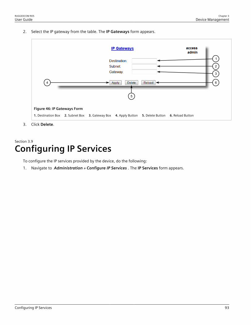
RUGGEDCOM ROSUser Guide
Chapter 3Device Management
Configuring IP Services 93
2. Select the IP gateway from the table. The IP Gateways form appears.
64
5
2
1
3
Figure 46: IP Gateways Form
1. Destination Box 2. Subnet Box 3. Gateway Box 4. Apply Button 5. Delete Button 6. Reload Button
3. Click Delete.
Section 3.9
Configuring IP ServicesTo configure the IP services provided by the device, do the following:1. Navigate to Administration » Configure IP Services . The IP Services form appears.

Chapter 3Device Management
RUGGEDCOM ROSUser Guide
94 Configuring IP Services
12 13
11
10
9
8
7
6
5
4
3
2
1
Figure 47: IP Services Form
1. Inactivity Timeout Box 2. Telnet Sessions Allowed Box 3. Web Server Users Allowed Box 4. TFTP Server Box 5. ModbusAddress Box 6. SSH Sessions Allowed Box 7. RSH Server Options 8. IP Forward Options 9. Max Failed Attempts Box 10. Failed Attempts Window Box 11. Lockout Time Box 12. Apply Button 13. Reload Button
2. Configure the following parameter(s) as required:
Parameter Description
Inactivity Timeout Synopsis: 1 to 60 or { Disabled }Default: 5 minSpecifies when the console will timeout and display the loginscreen if there is no user activity. A value of zero disablestimeouts. For Web Server users maximum timeout value is limitedto 30 minutes.
Telnet Sessions Allowed Synopsis: 1 to 4 or { Disabled }Default: DisabledLimits the number of Telnet sessions. A value of zero prevents anyTelnet access.
Web Server Users Allowed Synopsis: 1 to 4 or { Disabled }Default: 4Limits the number of simultaneous web server users.
TFTP Server Synopsis: { Disabled, Get Only, Enabled }Default: DisabledAs TFTP is a very insecure protocol, this parameter allows user tolimit or disable TFTP Server access..DISABLED - disables read and write access to TFTP ServerGET ONLY - only allows reading of files via TFTP ServerENABLED - allows reading and writing of files via TFTP Server
ModBus Address Synopsis: 1 to 255 or { Disabled }Default: Disabled
RUGGEDCOM ROSUser Guide
Chapter 3Device Management
Managing Remote Monitoring 95
Parameter Description
Determines the Modbus address to be used for Managementthrough Modbus.
SSH Sessions Allowed (Controlled Version Only) Synopsis: 1 to 4Default: 4Limits the number of SSH sessions.
RSH Server Synopsis: { Disabled, Enabled }Default: Disabled (controlled version) or Enabled (non-controlled version)Disables/enables Remote Shell access.
IP Forward Synopsis: { Disabled, Enabled }Controls the ability of IP Forwarding between VLANs in SerialServer or IP segments.
NOTEWhen upgrading to ROS v4.3, the default will be setto { Enabled }.
Max Failed Attempts Synopsis: 1 to 20Default: 10Maximum number of consecutive failed access attempts onservice within Failed Attempts Window before blocking theservice.
Failed Attempts Window Synopsis: 1 to 30 minDefault: 5 minThe time in minutes (min) in which the maximum numberof failed login attempts must be exceeded before a service isblocked. The counter of failed attempts resets to 0 when the timerexpires.
Lockout Time Synopsis: 1 to 120 minDefault: 60 minThe time in minutes (min) the service remains locked out after themaximum number of failed access attempts has been reached.
3. Click Apply.
Section 3.10
Managing Remote MonitoringRemote Monitoring (RMON) is used to collect and view historical statistics related to the performance andoperation of Ethernet ports. It can also record a log entry and/or generate an SNMP trap when the rate ofoccurrence of a specified event is exceeded.
CONTENTS• Section 3.10.1, “Managing RMON History Controls”• Section 3.10.2, “Managing RMON Alarms”

Chapter 3Device Management
RUGGEDCOM ROSUser Guide
96 Managing RMON History Controls
• Section 3.10.3, “Managing RMON Events”
Section 3.10.1
Managing RMON History ControlsThe history controls for Remote Monitoring take samples of the RMON-MIB history statistics of an Ethernet port atregular intervals.
CONTENTS• Section 3.10.1.1, “Viewing a List of RMON History Controls”• Section 3.10.1.2, “Adding an RMON History Control”• Section 3.10.1.3, “Deleting an RMON History Control”
Section 3.10.1.1Viewing a List of RMON History Controls
To view a list of RMON history controls, navigate to Ethernet Stats » Configure RMON History Controls . TheRMON History Controls table appears.
Figure 48: RMON History Controls Table
If history controls have not been configured, add controls as needed. For more information, refer to Section 3.10.1.2, “Adding an RMON History Control” .
Section 3.10.1.2Adding an RMON History Control
To add an RMON history control, do the following:1. Navigate to Ethernet Stats » Configure RMON History Controls . The RMON History Controls table
appears.

RUGGEDCOM ROSUser Guide
Chapter 3Device Management
Adding an RMON History Control 97
1
Figure 49: RMON History Controls Table
1. InsertRecord
2. Click InsertRecord. The RMON History Controls form appears.
107
8
1
2
3
4
5
6
9
Figure 50: RMON History Controls Form
1. Index Box 2. Port Box 3. Requested Buckets Box 4. Granted Buckets Box 5. Interval Box 6. Owner Box 7. Apply Button 8. Delete Button 9. Reload Button
3. Configure the following parameter(s) as required:
Parameter Description
Index Synopsis: 1 to 65535Default: 1The index of this RMON History Contol record.
Port Synopsis: 1 to maximum port numberDefault: 1The port number as seen on the front plate silkscreen of theswitch.
Requested Buckets Synopsis: 1 to 4000Default: 50The maximum number of buckets requested for this RMONcollection history group of statistics. The range is 1 to 4000. Thedefault is 50.

Chapter 3Device Management
RUGGEDCOM ROSUser Guide
98 Deleting an RMON History Control
Parameter Description
Granted Buckets Synopsis: 0 to 65535The number of buckets granted for this RMON collection history.This field is not editable.
Interval Synopsis: 1 to 3600Default: 1800The number of seconds in over which the data is sampled for eachbucket. The range is 1 to 3600. The default is 1800.
Owner Synopsis: Any 127 charactersDefault: MonitorThe owner of this record. It is suggested to start this stringwithword 'monitor'.
4. Click Apply.
Section 3.10.1.3Deleting an RMON History Control
To delete an RMON history control, do the following:1. Navigate to Ethernet Stats » Configure RMON History Controls . The RMON History Controls table
appears.
Figure 51: RMON History Controls Table
2. Select the history control from the table. The RMON History Controls form appears.
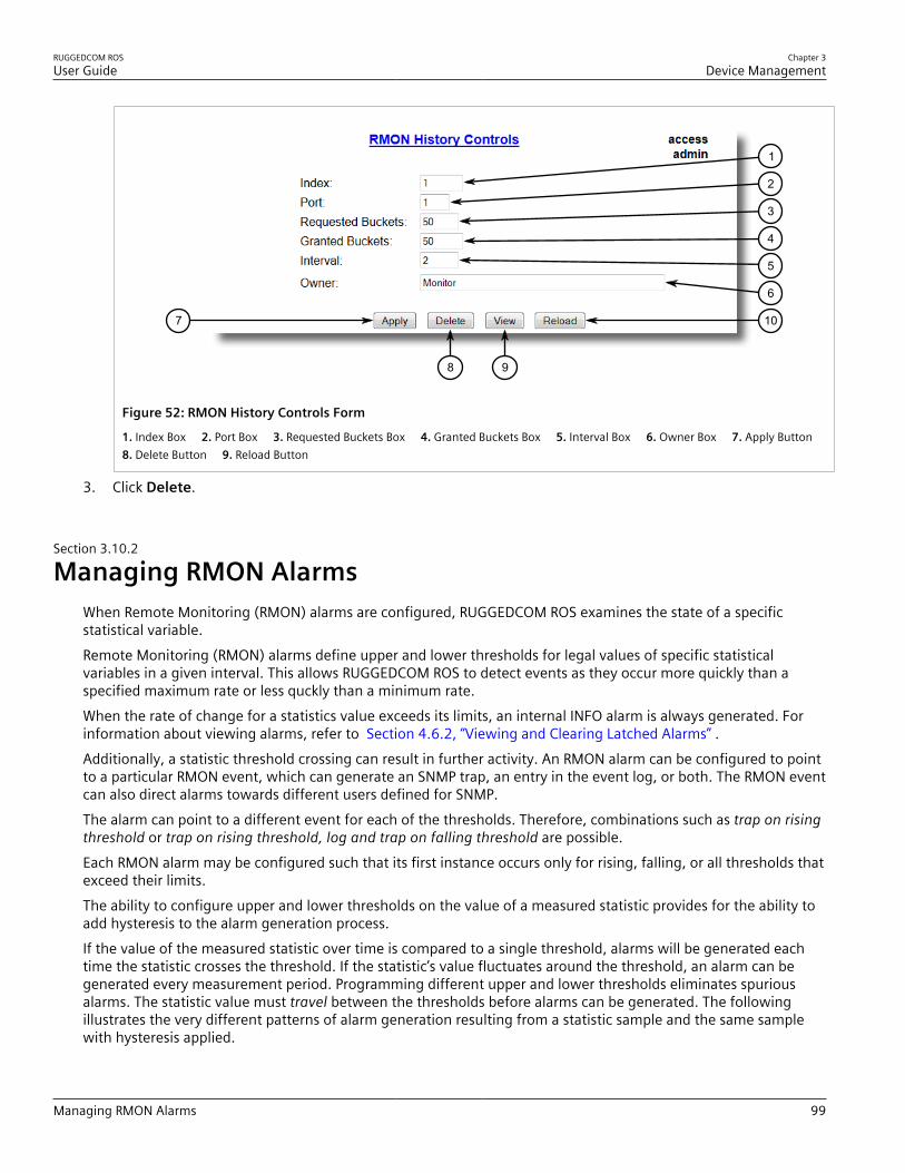
RUGGEDCOM ROSUser Guide
Chapter 3Device Management
Managing RMON Alarms 99
107
8
1
2
3
4
5
6
9
Figure 52: RMON History Controls Form
1. Index Box 2. Port Box 3. Requested Buckets Box 4. Granted Buckets Box 5. Interval Box 6. Owner Box 7. Apply Button 8. Delete Button 9. Reload Button
3. Click Delete.
Section 3.10.2
Managing RMON AlarmsWhen Remote Monitoring (RMON) alarms are configured, RUGGEDCOM ROS examines the state of a specificstatistical variable.Remote Monitoring (RMON) alarms define upper and lower thresholds for legal values of specific statisticalvariables in a given interval. This allows RUGGEDCOM ROS to detect events as they occur more quickly than aspecified maximum rate or less quckly than a minimum rate.When the rate of change for a statistics value exceeds its limits, an internal INFO alarm is always generated. Forinformation about viewing alarms, refer to Section 4.6.2, “Viewing and Clearing Latched Alarms” .Additionally, a statistic threshold crossing can result in further activity. An RMON alarm can be configured to pointto a particular RMON event, which can generate an SNMP trap, an entry in the event log, or both. The RMON eventcan also direct alarms towards different users defined for SNMP.The alarm can point to a different event for each of the thresholds. Therefore, combinations such as trap on risingthreshold or trap on rising threshold, log and trap on falling threshold are possible.Each RMON alarm may be configured such that its first instance occurs only for rising, falling, or all thresholds thatexceed their limits.The ability to configure upper and lower thresholds on the value of a measured statistic provides for the ability toadd hysteresis to the alarm generation process.If the value of the measured statistic over time is compared to a single threshold, alarms will be generated eachtime the statistic crosses the threshold. If the statistic’s value fluctuates around the threshold, an alarm can begenerated every measurement period. Programming different upper and lower thresholds eliminates spuriousalarms. The statistic value must travel between the thresholds before alarms can be generated. The followingillustrates the very different patterns of alarm generation resulting from a statistic sample and the same samplewith hysteresis applied.
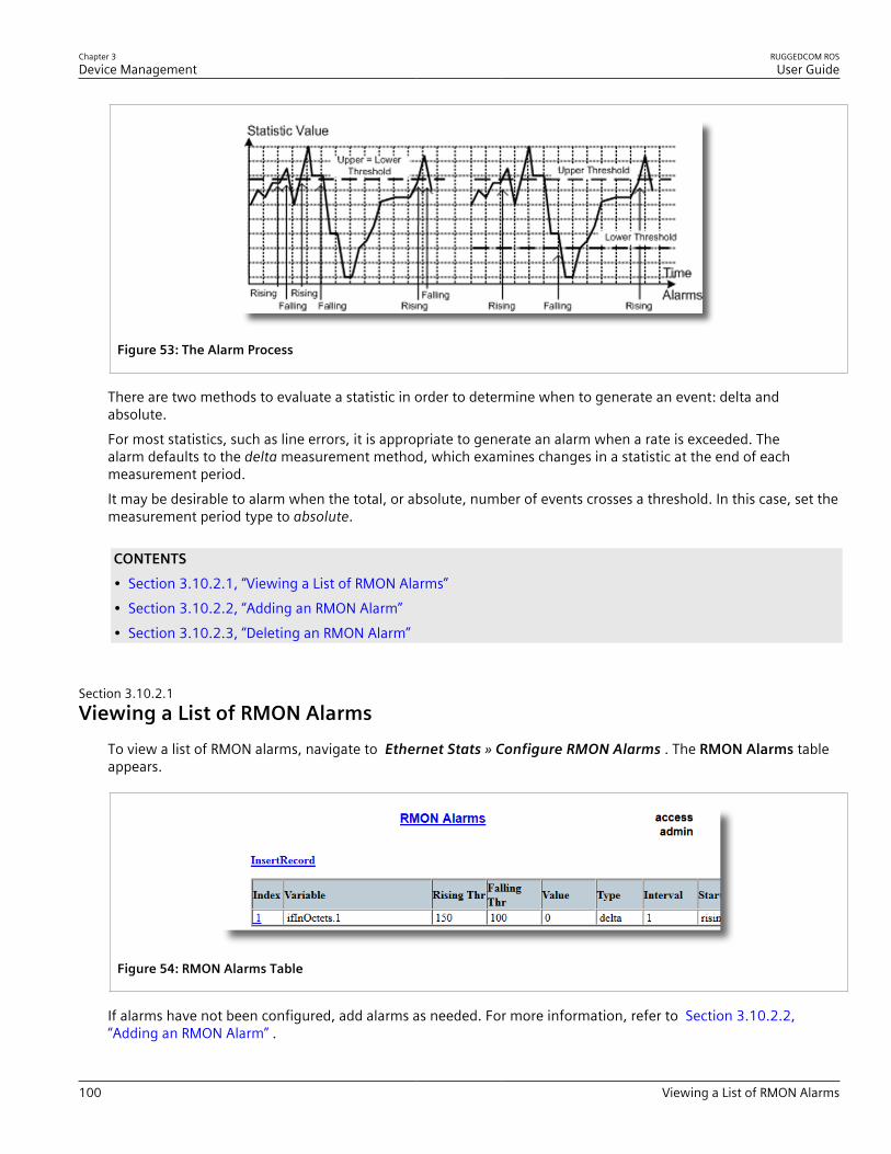
Chapter 3Device Management
RUGGEDCOM ROSUser Guide
100 Viewing a List of RMON Alarms
Figure 53: The Alarm Process
There are two methods to evaluate a statistic in order to determine when to generate an event: delta andabsolute.For most statistics, such as line errors, it is appropriate to generate an alarm when a rate is exceeded. Thealarm defaults to the delta measurement method, which examines changes in a statistic at the end of eachmeasurement period.It may be desirable to alarm when the total, or absolute, number of events crosses a threshold. In this case, set themeasurement period type to absolute.
CONTENTS• Section 3.10.2.1, “Viewing a List of RMON Alarms”• Section 3.10.2.2, “Adding an RMON Alarm”• Section 3.10.2.3, “Deleting an RMON Alarm”
Section 3.10.2.1Viewing a List of RMON Alarms
To view a list of RMON alarms, navigate to Ethernet Stats » Configure RMON Alarms . The RMON Alarms tableappears.
Figure 54: RMON Alarms Table
If alarms have not been configured, add alarms as needed. For more information, refer to Section 3.10.2.2,“Adding an RMON Alarm” .
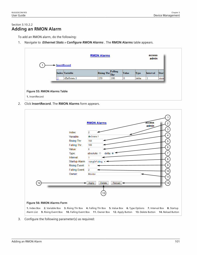
RUGGEDCOM ROSUser Guide
Chapter 3Device Management
Adding an RMON Alarm 101
Section 3.10.2.2Adding an RMON Alarm
To add an RMON alarm, do the following:1. Navigate to Ethernet Stats » Configure RMON Alarms . The RMON Alarms table appears.
1
Figure 55: RMON Alarms Table
1. InsertRecord
2. Click InsertRecord. The RMON Alarms form appears.
1412
13
1
2
3
4
5
6
7
8
9
10
11
Figure 56: RMON Alarms Form
1. Index Box 2. Variable Box 3. Rising Thr Box 4. Falling Thr Box 5. Value Box 6. Type Options 7. Interval Box 8. StartupAlarm List 9. Rising Event Box 10. Falling Event Box 11. Owner Box 12. Apply Button 13. Delete Button 14. Reload Button
3. Configure the following parameter(s) as required:

Chapter 3Device Management
RUGGEDCOM ROSUser Guide
102 Adding an RMON Alarm
Parameter Description
Index Synopsis: 1 to 65535Default: 1The index of this RMON Alarm record.
Variable Synopsis: SNMP Object Identifier - up to 39 charactersThe SNMP object identifier (OID) of the particular variable tobe sampled. Only variables that resolve to an ASN.1 primitivetype INTEGER (INTEGER, Integer32,Counter32, Counter64,Gauge, or TimeTicks) may be sampled. A list of objects canbe printed using shell command 'rmon'. The OID format:objectName.index1.index2... where index format depends onindex object type.
Rising Thr Synopsis: -2147483647 to 2147483647Default: 0A threshold for the sampled variable. When the current sampledvariable value is greater than or equal to this threshold, and thevalue at the last sampling interval was less than this threshold,a single event will be generated. A single event will also begenerated if the first sample after this record is created is greaterthan or equal to this threshold and the associated startup alarmils equal to 'rising'.After rising alarm is generated, another suchevent will not be generated until the sampled value falls belowthis threshold and reaches the value of FallingThreshold.
Falling Thr Synopsis: -2147483647 to 2147483647Default: 0A threshold for the sampled variable. When the current sampledvariable value is less than or equal to this threshold, and the valueat the last sampling interval was greater than this threshold,a single event will be generated. A single event will also begenerated if the first sample after this record is created is lessthan or equal to this threshold and the associated startup alarmils equal to 'falling'.After falling alarm is generated, another suchevent will not be generated until the sampled value rises abovethis threshold and reaches the value of RisingThreshold.
Value Synopsis: -2147483647 to 2147483647The value of monitoring object during the last sampling period.The presentation of value depends of sample type ('absolute' or'delta').
Type Synopsis: { absolute, delta }Default: deltaThe method of sampling the selected variable and calculating thevalue to be compared against the thresholds. The value of sampletype can be 'absolute' or 'delta'.
Interval Synopsis: 0 to 2147483647Default: 60The number of seconds in over which the data is sampled andcompared with the rising and falling thresholds.
Startup Alarm Synopsis: { rising, falling, risingOrFalling }Default: risingOrFallingThe alarm that may be sent when this record is first created ifcondition for raising alarm is met. The value of startup alarm canbe 'rising', 'falling' or 'risingOrFalling'.
Rising Event Synopsis: 0 to 65535Default: 0
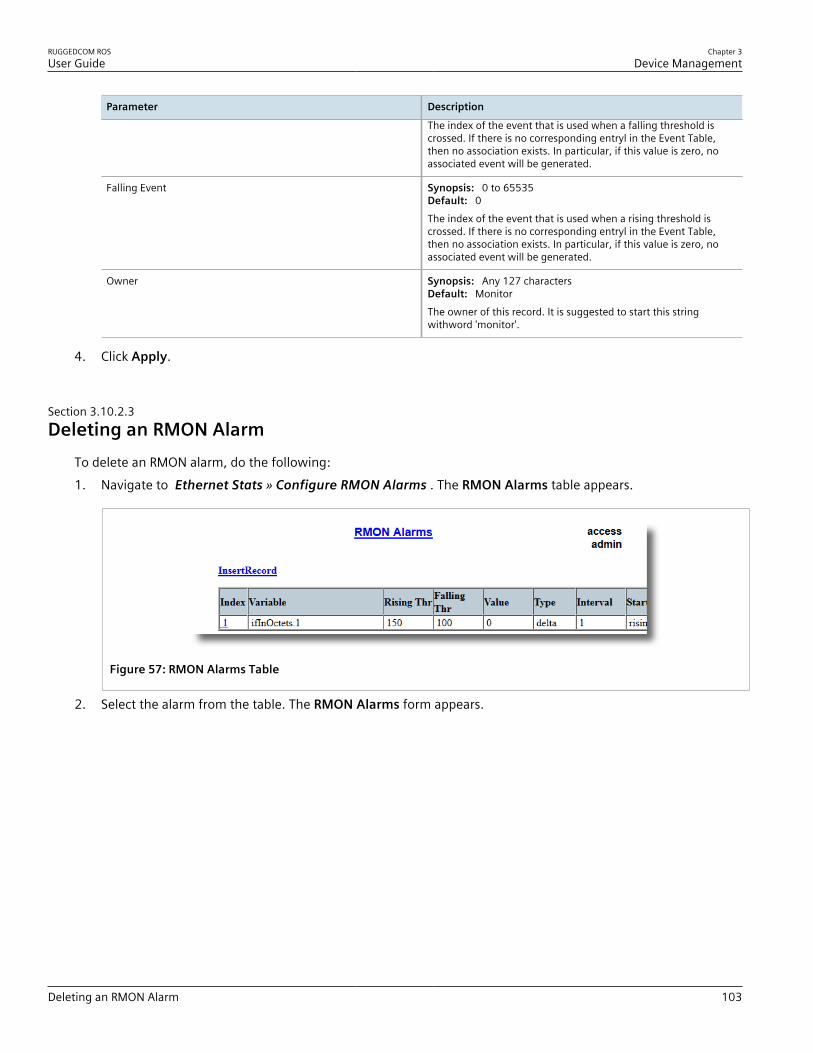
RUGGEDCOM ROSUser Guide
Chapter 3Device Management
Deleting an RMON Alarm 103
Parameter Description
The index of the event that is used when a falling threshold iscrossed. If there is no corresponding entryl in the Event Table,then no association exists. In particular, if this value is zero, noassociated event will be generated.
Falling Event Synopsis: 0 to 65535Default: 0The index of the event that is used when a rising threshold iscrossed. If there is no corresponding entryl in the Event Table,then no association exists. In particular, if this value is zero, noassociated event will be generated.
Owner Synopsis: Any 127 charactersDefault: MonitorThe owner of this record. It is suggested to start this stringwithword 'monitor'.
4. Click Apply.
Section 3.10.2.3Deleting an RMON Alarm
To delete an RMON alarm, do the following:1. Navigate to Ethernet Stats » Configure RMON Alarms . The RMON Alarms table appears.
Figure 57: RMON Alarms Table
2. Select the alarm from the table. The RMON Alarms form appears.

Chapter 3Device Management
RUGGEDCOM ROSUser Guide
104 Managing RMON Events
1412
13
1
2
3
4
5
6
7
8
9
10
11
Figure 58: RMON Alarms Form
1. Index Box 2. Variable Box 3. Rising Thr Box 4. Falling Thr Box 5. Value Box 6. Type Options 7. Interval Box 8. StartupAlarm List 9. Rising Event Box 10. Falling Event Box 11. Owner Box 12. Apply Button 13. Delete Button 14. Reload Button
3. Click Delete.
Section 3.10.3
Managing RMON EventsRemote Monitoring (RMON) events define behavior profiles used in event logging. These profiles are used byRMON alarms to send traps and log events.Each alarm may specify that a log entry be created on its behalf whenever the event occurs. Each entry may alsospecify that a notification should occur by way of SNMP trap messages. In this case, the user for the trap messageis specified as the Community.Two traps are defined: risingAlarm and fallingAlarm.
CONTENTS• Section 3.10.3.1, “Viewing a List of RMON Events”• Section 3.10.3.2, “Adding an RMON Event”
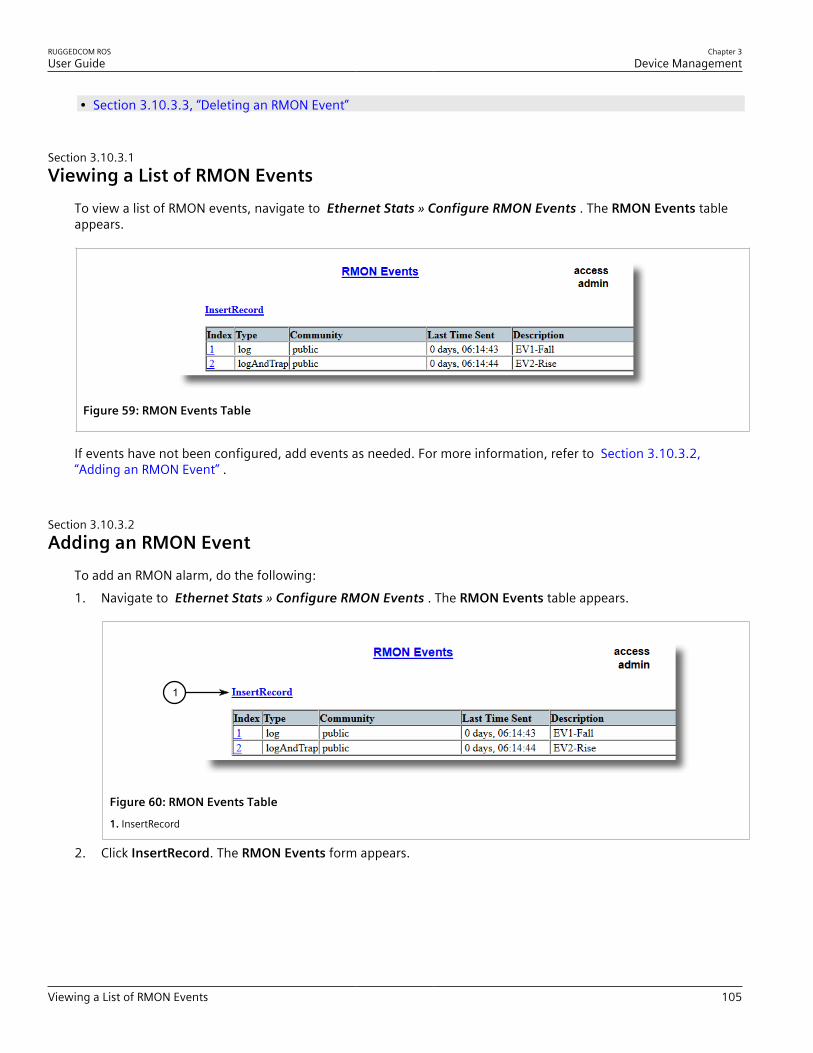
RUGGEDCOM ROSUser Guide
Chapter 3Device Management
Viewing a List of RMON Events 105
• Section 3.10.3.3, “Deleting an RMON Event”
Section 3.10.3.1Viewing a List of RMON Events
To view a list of RMON events, navigate to Ethernet Stats » Configure RMON Events . The RMON Events tableappears.
Figure 59: RMON Events Table
If events have not been configured, add events as needed. For more information, refer to Section 3.10.3.2,“Adding an RMON Event” .
Section 3.10.3.2Adding an RMON Event
To add an RMON alarm, do the following:1. Navigate to Ethernet Stats » Configure RMON Events . The RMON Events table appears.
1
Figure 60: RMON Events Table
1. InsertRecord
2. Click InsertRecord. The RMON Events form appears.

Chapter 3Device Management
RUGGEDCOM ROSUser Guide
106 Adding an RMON Event
97
8
1
2
3
4
5
6
Figure 61: RMON Events Form
1. Index Box 2. Type List 3. Community Box 4. Last Time Sent Box 5. Description Box 6. Owner Box 7. Apply Button 8. Delete Button 9. View Button 10. Reload Button
3. Configure the following parameter(s) as required:
Parameter Description
Index Synopsis: 1 to 65535Default: 3The index of this RMON Event record.
Type Synopsis: { none, log, snmpTrap, logAndTrap }Default: logAndTrapThe type of notification that the probe will make about this event.In the case of 'log', an entry is made in the RMON Log table foreach event. In the case of snmp_trap, an SNMP trap is sent to oneor more management stations.
Community Synopsis: Any 31 charactersDefault: publicIf the SNMP trap is to be sent, it will be sent to the SNMPcommunity specified by this string.
Last Time Sent Synopsis: DDDD days, HH:MM:SSThe time from last reboot at the time this event entry lastgenerated an event. If this entry has not generated any events,this value will be 0.
Description Synopsis: Any 127 charactersDefault: EV2-RiseA comment describing this event.
Owner Synopsis: Any 127 charactersDefault: MonitorThe owner of this event record. It is suggested to start this stringwithword 'monitor'.
4. Click Apply.

RUGGEDCOM ROSUser Guide
Chapter 3Device Management
Deleting an RMON Event 107
Section 3.10.3.3Deleting an RMON Event
To delete an RMON event, do the following:1. Navigate to Ethernet Stats » Configure RMON Events . The RMON Events table appears.
Figure 62: RMON Events Table
2. Select the event from the table. The RMON Events form appears.
97
8
1
2
3
4
5
6
Figure 63: RMON Events Form
1. Index Box 2. Type List 3. Community Box 4. Last Time Sent Box 5. Description Box 6. Owner Box 7. Apply Button 8. Delete Button 9. View Button 10. Reload Button
3. Click Delete.
Section 3.11
Testing the Internal ModemTo test the functionality of the internal modem, do the following:1. Disable PPP. For more information, refer to Section 5.1.3, “Configuring IP Addresses and Authentication” .2. Navigate to PPP Configuration » PPP Statistics . The PPP Statistics form appears.

Chapter 3Device Management
RUGGEDCOM ROSUser Guide
108 Upgrading/Downgrading Firmware
Figure 64: PPP Statistics Form
3. Connect to RUGGEDCOM ROS through the RS-232 console connection and a separate terminal application.For more information, refer to Section 2.1.1, “Connecting Directly” .Make sure the PPP Statistics form and the console interface are visible in separate applications.
4. In the terminal application, press Ctrl-S to access the CLI.5. Enter the following command:
modem
6. Press Ctrl-D to reset the modem.7. Enter the following command and monitor the Current Status parameter on the PPP Statistics form in the
browser window:
at number
Where:• number is the telephone number of the line the modem is connected toWhen the modem attempts to dial its own line, the Current Status parameter should display Number Busy.If the number is not busy, verify the telephone number and try again.If the number is still busy, the modem is not functioning. Contact Siemens Customer Support for assistance.
Section 3.12
Upgrading/Downgrading FirmwareThe following section describes how to upgrade and downgrade the firmware.
CONTENTS• Section 3.12.1, “Upgrading Firmware”

RUGGEDCOM ROSUser Guide
Chapter 3Device Management
Upgrading Firmware 109
• Section 3.12.2, “Downgrading Firmware”
Section 3.12.1
Upgrading FirmwareUpgrading RUGGEDCOM ROS firmware, including the main, bootloader and FPGA firmware, may be necessaryto take advantage of new features or bug fixes. Binary firmware images are available from Siemens. Visitwww.siemens.com/ruggedcom to determine which versions/updates are available or contact Siemens CustomerSupport.Binary firmware images transferred to the device are stored in non-volatile Flash memory and require a devicereset in order to take effect.
IMPORTANT!Non-Controlled (NC) versions of RUGGEDCOM ROS can not be upgraded to Controlled firmwareversions. However, Controlled firmware versions can be upgraded to an NC firmware version.
NOTEThe IP address set for the device will not be changed following a firmware upgrade.
To upgrade the RUGGEDCOM ROS firmware, do the following:1. Upload a different version of the binary firmware image to the device. For more information, refer to
Section 3.4, “Uploading/Downloading Files” .2. Reset the device to complete the installation. For more information, refer to Section 3.13, “Resetting the
Device” .3. Access the CLI shell and verify the new software version has been installed by typing version. The currently
installed versions of the main and boot firmware are displayed.
>versionCurrent ROS-CF52 Boot Software v2.20.0 (Jan 29 2013 13:25)Current ROS-CF52 Main Software v4.0 (Feb 2 2013 09:33)
Section 3.12.2
Downgrading FirmwareDowngrading the RUGGEDCOM ROS firmware is generally not recommended, as it may have unpredictableeffects. However, if a downgrade is required, do the following:
IMPORTANT!Before downgrading the firmware, make sure the hardware and FPGA code types installed in thedevice are supported by the older firmware version. Refer to the Release Notes for the older firmwareversion to confirm.
IMPORTANT!Non-Controlled (NC) versions of RUGGEDCOM ROS can not be downgraded to Controlled firmwareversions. However, Controlled firmware versions can be downgraded to an NC firmware version.

Chapter 3Device Management
RUGGEDCOM ROSUser Guide
110 Resetting the Device
CAUTION!Do not downgrade the RUGGEDCOM ROS boot version.
1. Disconnect the device from the network.2. Log in to the device as an admin user. For more information, refer to Section 2.2, “Logging In” .3. Make a local copy of the current configuration file. For more information, refer to Section 3.4, “Uploading/
Downloading Files” .
IMPORTANT!Never downgrade the RUGGEDCOM ROS software version beyond RUGGEDCOM ROS v4.3when encryption is enabled. Make sure the device has been restored to factory defaults beforedowngrading.
4. Restore the device to its factory defaults. For more information, refer to Section 3.3, “Restoring FactoryDefaults” .
5. Upload and apply the older firmware version and its associated FPGA files using the same methods used toinstall newer firmware versions. For more information , refer to Section 3.12.1, “Upgrading Firmware” .
6. Press Ctrl-S to access the CLI.7. Clear all logs by typing:
clearlogs
8. Clear all alarms by typing:
clearalarms
IMPORTANT!After downgrading the firmware and FPGA files, be aware that some settings from the previousconfiguration may be lost or reverted back to the factory defaults (including user passwords ifdowngrading from a security related version), as those particular tables or fields may not exist inthe older firmware version. Because of this, the unit must be configured after the downgrade.
9. Configure the device as required.
Section 3.13
Resetting the DeviceTo reset the device, do the following:1. Navigate to Diagnostics » Reset Device . The Reset Device form appears.

RUGGEDCOM ROSUser Guide
Chapter 3Device Management
Decommissioning the Device 111
1
Figure 65: Reset Device Form
1. Confirm Button
2. Click Confirm.
Section 3.14
Decommissioning the DeviceBefore taking the device out of service, either permanently or for maintenance by a third-party, make sure thedevice has been fully decommissioned. This includes removing any sensitive, proprietary information.To decommission the device, do the following:1. Disconnect all network cables from the device.2. Connect to the device via the RS-232 serial console port. For more information, refer to Section 2.1.1,
“Connecting Directly” .3. Restore all factory default settings for the device. For more information, refer to Section 3.3, “Restoring
Factory Defaults” .4. Access the CLI. For more information, refer to Section 2.6, “Using the Command Line Interface” .5. Upload a blank version of the banner.txt file to the device to replace the existing file. For more information
about uploading a file, refer to Section 3.4, “Uploading/Downloading Files” .6. Confirm the upload was successful by typing:
type banner.txt
7. Clear the system and crash logs by typing:
clearlog
8. Generate a random SSL certificate by typing:
sslkeygen
This may take several minutes to complete. To verify the certificate has been generated, type:
type syslog.txt
When the phraseGenerated ssl.crt was saved
appears in the log, the SSL certificate has been generated.9. Generate random SSH keys by typing:
sshkeygen
This may take several minutes to complete. To verify the keys have been generated, type:

Chapter 3Device Management
RUGGEDCOM ROSUser Guide
112 Decommissioning the Device
type syslog.txt
When the phraseGenerated ssh.keys was saved
appears in the log, the SSH keys have been generated.10. De-fragment and erase all free flash memory by typing:
flashfile defrag
This may take several minutes to complete.
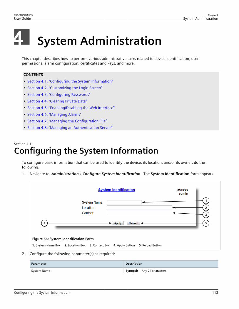
RUGGEDCOM ROSUser Guide
Chapter 4System Administration
Configuring the System Information 113
System AdministrationThis chapter describes how to perform various administrative tasks related to device identification, userpermissions, alarm configuration, certificates and keys, and more.
CONTENTS• Section 4.1, “Configuring the System Information”• Section 4.2, “Customizing the Login Screen”• Section 4.3, “Configuring Passwords”• Section 4.4, “Clearing Private Data”• Section 4.5, “Enabling/Disabling the Web Interface”• Section 4.6, “Managing Alarms”• Section 4.7, “Managing the Configuration File”• Section 4.8, “Managing an Authentication Server”
Section 4.1
Configuring the System InformationTo configure basic information that can be used to identify the device, its location, and/or its owner, do thefollowing:1. Navigate to Administration » Configure System Identification . The System Identification form appears.
54
3
2
1
Figure 66: System Identification Form
1. System Name Box 2. Location Box 3. Contact Box 4. Apply Button 5. Reload Button
2. Configure the following parameter(s) as required:
Parameter Description
System Name Synopsis: Any 24 characters
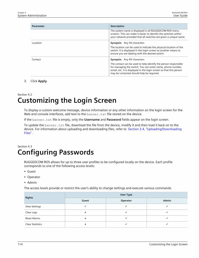
Chapter 4System Administration
RUGGEDCOM ROSUser Guide
114 Customizing the Login Screen
Parameter Description
The system name is displayed in all RUGGEDCOM ROS menuscreens. This can make it easier to identify the switches withinyour network provided that all switches are given a unique name.
Location Synopsis: Any 49 charactersThe location can be used to indicate the physical location of theswitch. It is displayed in the login screen as another means toensure you are dealing with the desired switch.
Contact Synopsis: Any 49 charactersThe contact can be used to help identify the person responsiblefor managing the switch. You can enter name, phone number,email, etc. It is displayed in the login screen so that this personmay be contacted should help be required.
3. Click Apply.
Section 4.2
Customizing the Login ScreenTo display a custom welcome message, device information or any other information on the login screen for theWeb and console interfaces, add text to the banner.txt file stored on the device.If the banner.txt file is empty, only the Username and Password fields appear on the login screen.To update the banner.txt file, download the file from the device, modify it and then load it back on to thedevice. For information about uploading and downloading files, refer to Section 3.4, “Uploading/DownloadingFiles” .
Section 4.3
Configuring PasswordsRUGGEDCOM ROS allows for up to three user profiles to be configured locally on the device. Each profilecorresponds to one of the following access levels:• Guest• Operator• AdminThe access levels provide or restrict the user's ability to change settings and execute various commands.
User TypeRights
Guest Operator Admin
View Settings ü ü ü
Clear Logs û ü ü
Reset Alarms û ü ü
Clear Statistics û ü ü

RUGGEDCOM ROSUser Guide
Chapter 4System Administration
Configuring Passwords 115
User TypeRights
Guest Operator Admin
Change Basic Settings û ü ü
Change Advanced Settings û û ü
Run Commands û û ü
Default passwords are configured for each user type initially. It is strongly recommended that these be changedbefore the device is commissioned.
NOTEUsers can also be verified through a RADIUS or TACACS+ server. When enabled for authentication andauthorization, the RADIUS or TACACS+ server will be used in the absence of any local settings. Formore information about configuring a RADIUS or TACACS+ server, refer to Section 4.8, “Managing anAuthentication Server” .
CAUTION!To prevent unauthorized access to the device, make sure to change the default passwords for eachprofile before commissioning the device.
To configure passwords for one or more of the user profiles, do the following:1. Navigate to Administration » Configure Passwords . The Configure Passwords form appears.
12 13
11
10
9
8
7
6
5
4
3
2
1
Figure 67: Configure Passwords Form
1. Auth Type Box 2. Guest Username Box 3. Guest Password Box 4. Confirm Guest Password Box 5. Operator Username Box 6. Operator Password Box 7. Confirm Operator Password Box 8. Admin Username Box 9. Admin Password Box 10. ConfirmAdmin Password Box 11. Password Minimum Length box 12. Apply Button 13. Reload Button

Chapter 4System Administration
RUGGEDCOM ROSUser Guide
116 Configuring Passwords
NOTERUGGEDCOM ROS requires that all user passwords meet strict guidelines to prevent the use ofweak passwords. When creating a new password, make sure it adheres to the following rules:• Must not be less than 8 characters in length.• Must not include the username or any 4 continous characters found in the username.
For example, if the username is Subnet25, the password may not be subnet25admin,subnetadmin or net25admin. However, net-25admin or Sub25admin is permitted.
• Must have at least one alphabetic character and one number. Special characters are permitted.• Must not have more than 3 continuously incrementing or decrementing numbers. For example,
Sub123 and Sub19826 are permitted, but Sub12345 is not.An alarm will generate if a weak password is configured. The weak password alarm can bedisabled by the user. For more information about disabling alarms, refer to Section 4.6,“Managing Alarms” .
2. Configure the following parameter(s) as required:
Parameter Description
Auth Type Synopsis: { Local, RADIUS, TACACS+, RADIUSorLocal, TACACS+orLocal }Default: LocalPassword can be authenticated using localy configured values,or remote RADIUS or TACACS+ server. Setting value to any ofcombinations that involve RADIUS or TACACS+ require SecurityServer Table to be configured.Settings:• Local - Authentication from the local Password Table.• RADIUS - Authentication using a RADIUS server.• TACACS+ - Authentication using a TACACS+ server.• RADIUSOrLocal - Authentication using RADIUS. If the server
cannot be reached, authenticate from the local Password Table.• TACACS+OrLocal - Authentication using TACACS+. If the server
cannot be reached, authenticate from the local Password Table
NOTEFor console access, local credentials will always bechecked first regardless of the device configuration.If server authentication is required, requests to theserver will be sent only if local authentication fails.
Guest Username Synopsis: Any 15 charactersDefault: guestRelated password is in field Guest Password; view only, cannotchange settings or run any commands.
Guest Password Synopsis: 19 character ASCII stringRelated username is in field Guest Username; view only, cannotchange settings or run any commands.
Confirm Guest Password Synopsis: 19 character ASCII stringRelated username is in field Guest Username; view only, cannotchange settings or run any commands.
Operator Username Synopsis: Any 15 charactersDefault: operator

RUGGEDCOM ROSUser Guide
Chapter 4System Administration
Clearing Private Data 117
Parameter Description
Related password is in field Oper Password; cannot changesettings; can reset alarms, statistics, logs, etc.
Operator Password Synopsis: 19 character ASCII stringRelated username is in field Oper Username; cannot changesettings; can reset alarms, statistics, logs, etc
Confirm Operator Password Synopsis: 19 character ASCII stringRelated username is in field Oper Username; cannot changesettings; can reset alarms, statistics, logs, etc.
Admin Username Synopsis: Any 15 charactersDefault: adminRelated password is in field Admin Password; full read/writeaccess to all settings and commands.
Admin Password Synopsis: 19 character ASCII stringRelated username is in field Admin Username; full read/writeaccess to all settings and commands.
Confirm Admin Password Synopsis: 19 character ASCII stringRelated username is in field Admin Username; full read/writeaccess to all settings and commands.
Password Minimum Length Synopsis: 1 to 17Default: 1Configure the password string minimum length. The newpassword shorter than the minimum length will be rejected.
3. Click Apply.
Section 4.4
Clearing Private DataWhen enabled, during system boot up, a user with serial console access can clear all configuration data and keysstored on the device, and restore all user names and passwords to factory default settings.To clear private data, do the following:
NOTEThe commands used in the following procedure are time-sensitive. If the specified time limits areexceeded before providing the appropriate response, the device will continue normal boot up.
1. Connect to the device via the RS-232 serial console port. For more information, refer to Section 2.1.1,“Connecting Directly” .
2. Cycle power to the device. As the device is booting up, the following prompt will appear:
Press any key to start
3. Within four seconds, press CTRL + r. The access banner will appear, followed by the command prompt:
>
4. Type the following command, then press Enter within 30 seconds:

Chapter 4System Administration
RUGGEDCOM ROSUser Guide
118 Enabling/Disabling the Web Interface
clear private data
5. When prompted "Do you want to clear private data (Yes/No)?", answer yes and press Enter within fiveseconds. All configuration and keys in flash will be zeroized. An entry in the event log will be created.Crashlog.txt files (if existing) and syslog.txt files will be preserved. The device will reboot automatically.
Section 4.5
Enabling/Disabling the Web InterfaceIn some cases, users may want to disable the web interface to increase cyber security.To disable or enable the web interface, do the following:
NOTEThe web interface can be disabled via the web UI by configuring the Web Server Users Allowedparameter in the IP Services form. For more information, refer to Section 3.9, “Configuring IP Services”.
1. Log in to the device as an admin user and access the CLI shell. For more information about accessing the CLIshell, refer to Section 2.6, “Using the Command Line Interface” .
2. Navigate to Administration » Configure IP Services » Web Server Users Allowed .3. Select Disabled to disable the web interface, or select the desired number of web server users allowed to
enable the interface.
Section 4.6
Managing AlarmsAlarms indicate the occurrence of events of either importance or interest that are logged by the device.There are two types of alarms:• Active alarms signify states of operation that are not in accordance with normal operation. Examples include
links that should be up, but are not, or error rates that repeatedly exceed a certain threshold. These alarms arecontinuously active and are only cleared when the problem that triggered the alarms is resolved.
• Passive alarms are a record of abnormal conditions that occurred in the past and do not affect th currentoperation state of the device. Examples include authentication failures, Remote Network MONitoring (RMON)MIB generated alarms, or error states that temporarily exceeded a certain threshold . These alarms can becleared from the list of alarms.
NOTEFor more information about RMON alarms, refer to Section 3.10.2, “Managing RMON Alarms” .
When either type of alarm occurs, a message appears in the top right corner of the user interface. If more thanone alarm has occurred, the message will indicate the number of alarms. Active alarms also trip the Critical FailureRelay LED on the device. The message and the LED will remain active until the alarm is cleared.
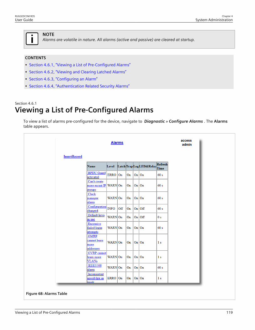
RUGGEDCOM ROSUser Guide
Chapter 4System Administration
Viewing a List of Pre-Configured Alarms 119
NOTEAlarms are volatile in nature. All alarms (active and passive) are cleared at startup.
CONTENTS• Section 4.6.1, “Viewing a List of Pre-Configured Alarms”• Section 4.6.2, “Viewing and Clearing Latched Alarms”• Section 4.6.3, “Configuring an Alarm”• Section 4.6.4, “Authentication Related Security Alarms”
Section 4.6.1
Viewing a List of Pre-Configured AlarmsTo view a list of alarms pre-configured for the device, navigate to Diagnostic » Configure Alarms . The Alarmstable appears.
Figure 68: Alarms Table
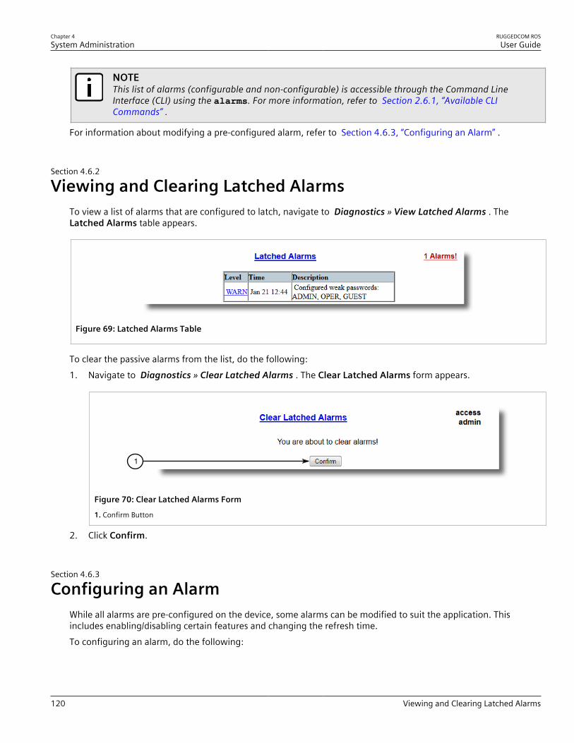
Chapter 4System Administration
RUGGEDCOM ROSUser Guide
120 Viewing and Clearing Latched Alarms
NOTEThis list of alarms (configurable and non-configurable) is accessible through the Command LineInterface (CLI) using the alarms. For more information, refer to Section 2.6.1, “Available CLICommands” .
For information about modifying a pre-configured alarm, refer to Section 4.6.3, “Configuring an Alarm” .
Section 4.6.2
Viewing and Clearing Latched AlarmsTo view a list of alarms that are configured to latch, navigate to Diagnostics » View Latched Alarms . TheLatched Alarms table appears.
Figure 69: Latched Alarms Table
To clear the passive alarms from the list, do the following:1. Navigate to Diagnostics » Clear Latched Alarms . The Clear Latched Alarms form appears.
1
Figure 70: Clear Latched Alarms Form
1. Confirm Button
2. Click Confirm.
Section 4.6.3
Configuring an AlarmWhile all alarms are pre-configured on the device, some alarms can be modified to suit the application. Thisincludes enabling/disabling certain features and changing the refresh time.To configuring an alarm, do the following:

RUGGEDCOM ROSUser Guide
Chapter 4System Administration
Configuring an Alarm 121
IMPORTANT!Critical and Alert level alarms are not configurable and cannot be disabled.
1. Navigate to Diagnostic » Configure Alarms . The Alarms table appears.
Figure 71: Alarms Table
2. Select an alarm. The Alarms form appears.
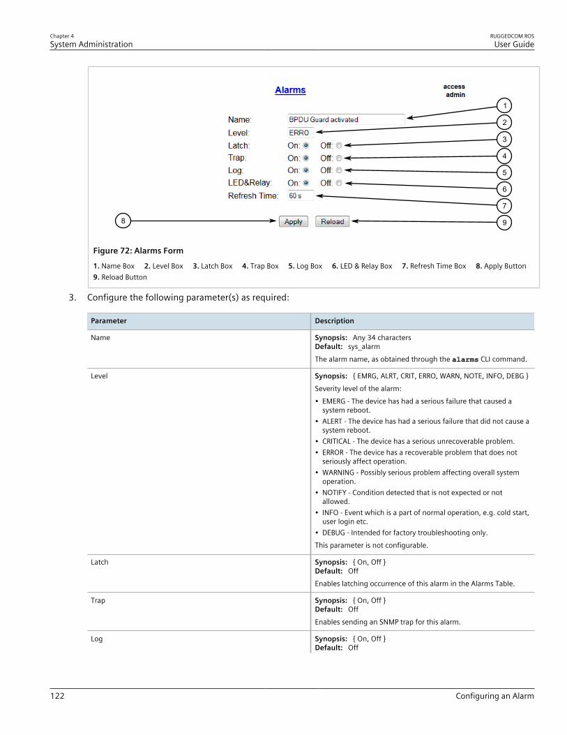
Chapter 4System Administration
RUGGEDCOM ROSUser Guide
122 Configuring an Alarm
98
7
6
5
4
3
2
1
Figure 72: Alarms Form
1. Name Box 2. Level Box 3. Latch Box 4. Trap Box 5. Log Box 6. LED & Relay Box 7. Refresh Time Box 8. Apply Button 9. Reload Button
3. Configure the following parameter(s) as required:
Parameter Description
Name Synopsis: Any 34 charactersDefault: sys_alarmThe alarm name, as obtained through the alarms CLI command.
Level Synopsis: { EMRG, ALRT, CRIT, ERRO, WARN, NOTE, INFO, DEBG }Severity level of the alarm:• EMERG - The device has had a serious failure that caused a
system reboot.• ALERT - The device has had a serious failure that did not cause a
system reboot.• CRITICAL - The device has a serious unrecoverable problem.• ERROR - The device has a recoverable problem that does not
seriously affect operation.• WARNING - Possibly serious problem affecting overall system
operation.• NOTIFY - Condition detected that is not expected or not
allowed.• INFO - Event which is a part of normal operation, e.g. cold start,
user login etc.• DEBUG - Intended for factory troubleshooting only.This parameter is not configurable.
Latch Synopsis: { On, Off }Default: OffEnables latching occurrence of this alarm in the Alarms Table.
Trap Synopsis: { On, Off }Default: OffEnables sending an SNMP trap for this alarm.
Log Synopsis: { On, Off }Default: Off
RUGGEDCOM ROSUser Guide
Chapter 4System Administration
Authentication Related Security Alarms 123
Parameter Description
Enables logging the occurrence of this alarm in syslog.txt.
LED & Relay Synopsis: { On, Off }Default: OffEnables LED and fail-safe relay control for this alarm. If latching isnot enabled, this field will remain disabled.
Refresh Time Synopsis: 0 s to 60 sDefault: 60 sRefreshing time for this alarm.
4. Click Apply.
Section 4.6.4
Authentication Related Security AlarmsThis section describes the authentication-related security messages that can be generated by RUGGEDCOM ROS.
CONTENTS• Section 4.6.4.1, “Security Alarms for Login Authentication”• Section 4.6.4.2, “Security Messages for Port Authentication”
Section 4.6.4.1Security Alarms for Login Authentication
RUGGEDCOM ROS provides various logging options related to login authentication. A user can log into aRUGGEDCOM ROS device in three different ways: Console, SSH or Telnet. RUGGEDCOM ROS can log messagesin the syslog, send a trap to notify an SNMP manager, and/or raise an alarm when a successful and unsuccessfullogin event occurs. In addition, when a weak password is configured on a unit or when the primary authenticationserver for TACACS+ or RADIUS is not reachable, RUGGEDCOM ROS will raise alarms, send SNMP traps and logmessages in the syslog.The following is a list of log and alarm messages related to user authentication:• Weak Password Configured• Login and Logout Information• Excessive Failed Login Attempts• RADIUS Server Unreachable• TACACS Server Unreachable• TACACS Response Invalid• SNMP Authentication Failure
NOTEAll alarms and log messages related to login authentication are configurable. For more informationabout configuring alarms, refer to Section 4.6.3, “Configuring an Alarm” .
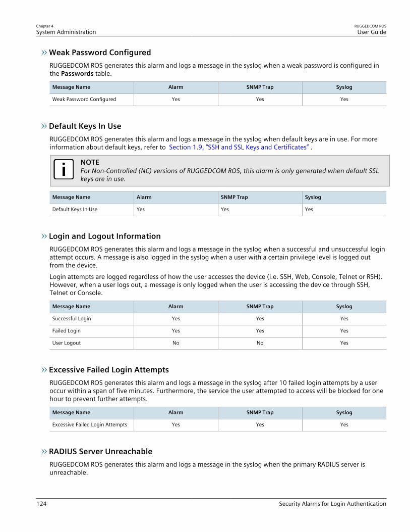
Chapter 4System Administration
RUGGEDCOM ROSUser Guide
124 Security Alarms for Login Authentication
Weak Password ConfiguredRUGGEDCOM ROS generates this alarm and logs a message in the syslog when a weak password is configured inthe Passwords table.
Message Name Alarm SNMP Trap Syslog
Weak Password Configured Yes Yes Yes
Default Keys In UseRUGGEDCOM ROS generates this alarm and logs a message in the syslog when default keys are in use. For moreinformation about default keys, refer to Section 1.9, “SSH and SSL Keys and Certificates” .
NOTEFor Non-Controlled (NC) versions of RUGGEDCOM ROS, this alarm is only generated when default SSLkeys are in use.
Message Name Alarm SNMP Trap Syslog
Default Keys In Use Yes Yes Yes
Login and Logout InformationRUGGEDCOM ROS generates this alarm and logs a message in the syslog when a successful and unsuccessful loginattempt occurs. A message is also logged in the syslog when a user with a certain privilege level is logged outfrom the device.Login attempts are logged regardless of how the user accesses the device (i.e. SSH, Web, Console, Telnet or RSH).However, when a user logs out, a message is only logged when the user is accessing the device through SSH,Telnet or Console.
Message Name Alarm SNMP Trap Syslog
Successful Login Yes Yes Yes
Failed Login Yes Yes Yes
User Logout No No Yes
Excessive Failed Login AttemptsRUGGEDCOM ROS generates this alarm and logs a message in the syslog after 10 failed login attempts by a useroccur within a span of five minutes. Furthermore, the service the user attempted to access will be blocked for onehour to prevent further attempts.
Message Name Alarm SNMP Trap Syslog
Excessive Failed Login Attempts Yes Yes Yes
RADIUS Server UnreachableRUGGEDCOM ROS generates this alarm and logs a message in the syslog when the primary RADIUS server isunreachable.
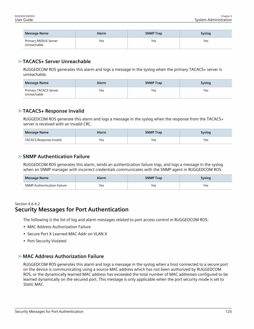
RUGGEDCOM ROSUser Guide
Chapter 4System Administration
Security Messages for Port Authentication 125
Message Name Alarm SNMP Trap Syslog
Primary RADIUS ServerUnreachable
Yes Yes Yes
TACACS+ Server UnreachableRUGGEDCOM ROS generates this alarm and logs a message in the syslog when the primary TACACS+ server isunreachable.
Message Name Alarm SNMP Trap Syslog
Primary TACACS ServerUnreachable
Yes Yes Yes
TACACS+ Response InvalidRUGGEDCOM ROS generate this alarm and logs a message in the syslog when the response from the TACACS+server is received with an invalid CRC.
Message Name Alarm SNMP Trap Syslog
TACACS Response Invalid Yes Yes Yes
SNMP Authentication FailureRUGGEDCOM ROS generates this alarm, sends an authentication failure trap, and logs a message in the syslogwhen an SNMP manager with incorrect credentials communicates with the SNMP agent in RUGGEDCOM ROS.
Message Name Alarm SNMP Trap Syslog
SNMP Authentication Failure Yes Yes Yes
Section 4.6.4.2Security Messages for Port Authentication
The following is the list of log and alarm messages related to port access control in RUGGEDCOM ROS:• MAC Address Authorization Failure• Secure Port X Learned MAC Addr on VLAN X• Port Security Violated
MAC Address Authorization FailureRUGGEDCOM ROS generates this alarm and logs a message in the syslog when a host connected to a secure porton the device is communicating using a source MAC address which has not been authorized by RUGGEDCOMROS, or the dynamically learned MAC address has exceeded the total number of MAC addresses configured to belearned dynamically on the secured port. This message is only applicable when the port security mode is set toStatic MAC.
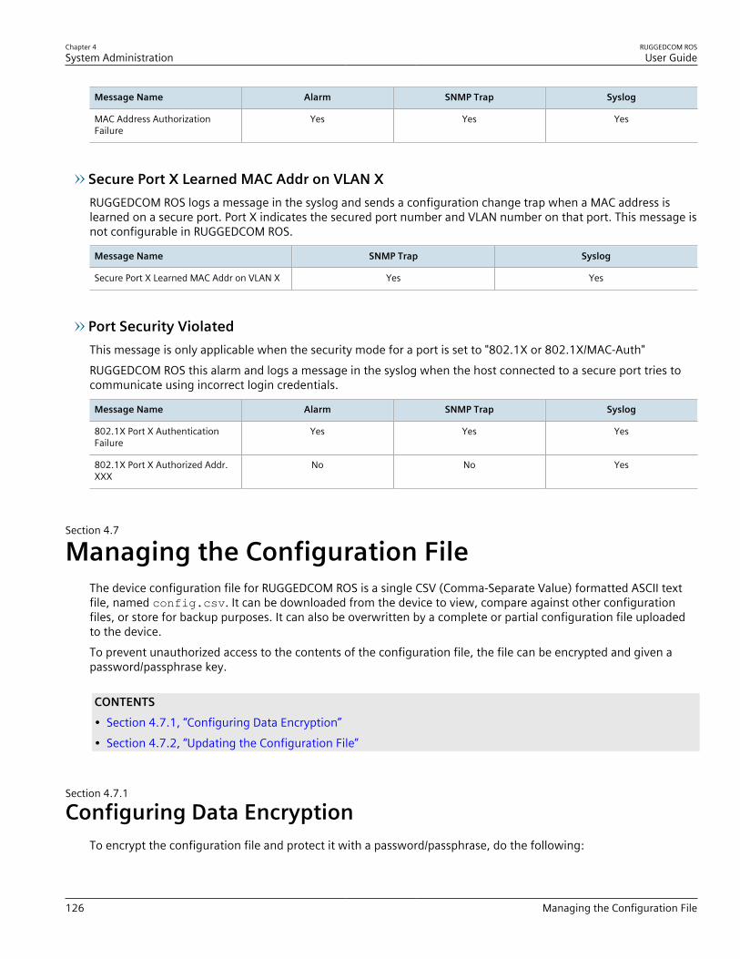
Chapter 4System Administration
RUGGEDCOM ROSUser Guide
126 Managing the Configuration File
Message Name Alarm SNMP Trap Syslog
MAC Address AuthorizationFailure
Yes Yes Yes
Secure Port X Learned MAC Addr on VLAN XRUGGEDCOM ROS logs a message in the syslog and sends a configuration change trap when a MAC address islearned on a secure port. Port X indicates the secured port number and VLAN number on that port. This message isnot configurable in RUGGEDCOM ROS.
Message Name SNMP Trap Syslog
Secure Port X Learned MAC Addr on VLAN X Yes Yes
Port Security ViolatedThis message is only applicable when the security mode for a port is set to "802.1X or 802.1X/MAC-Auth"RUGGEDCOM ROS this alarm and logs a message in the syslog when the host connected to a secure port tries tocommunicate using incorrect login credentials.
Message Name Alarm SNMP Trap Syslog
802.1X Port X AuthenticationFailure
Yes Yes Yes
802.1X Port X Authorized Addr.XXX
No No Yes
Section 4.7
Managing the Configuration FileThe device configuration file for RUGGEDCOM ROS is a single CSV (Comma-Separate Value) formatted ASCII textfile, named config.csv. It can be downloaded from the device to view, compare against other configurationfiles, or store for backup purposes. It can also be overwritten by a complete or partial configuration file uploadedto the device.To prevent unauthorized access to the contents of the configuration file, the file can be encrypted and given apassword/passphrase key.
CONTENTS• Section 4.7.1, “Configuring Data Encryption”• Section 4.7.2, “Updating the Configuration File”
Section 4.7.1
Configuring Data EncryptionTo encrypt the configuration file and protect it with a password/passphrase, do the following:

RUGGEDCOM ROSUser Guide
Chapter 4System Administration
Configuring Data Encryption 127
NOTEData encryption is not available in Non-Controlled (NC) versions of RUGGEDCOM ROS. When switchingbetween Controlled and Non-Controlled (NC) versions of RUGGEDCOM ROS, make sure data encryptionis disabled. Otherwise, the NC version of RUGGEDCOM ROS will ignore the encrypted configuration fileand load the factory defaults.
NOTEOnly configuration data is encrypted. All comments and table names in the configuration file are savedas clear text.
NOTEWhen sharing a configuration file between devices, make sure both devices have the same passphraseconfigured. Otherwise, the configuration file will be rejected.
NOTEEncryption must be disabled before the device is returned to Siemens or the configuration file is sharedwith Customer Support.
IMPORTANT!Never downgrade the RUGGEDCOM ROS software version beyond RUGGEDCOM ROS v4.3 whenencryption is enabled. Make sure the device has been restored to factory defaults before downgrading.
1. Navigate to Administration » Configure Data Storage . The Data Storage form appears.
54
3
2
1
Figure 73: Data Storage Form
1. Encryption Options 2. Passphrase Box 3. Confirm Passphrase Box 4. Apply Button 5. Reload Button
2. Configure the following parameter(s) as required:
Parameter Description
Encryption Synopsis: { On, Off }Enable/disable encryption of data in configuration file.
Passphrase Synopsis: 31 character ascii stringThis passphrase is used as a secret key to encrypt theconfiguration data.Encrypted data can be decrypted by any device configured withthe same passphrase.
Confirm Passphrase Synopsis: 31 character ascii string

Chapter 4System Administration
RUGGEDCOM ROSUser Guide
128 Updating the Configuration File
Parameter Description
This passphrase is used as a secret key to encrypt theconfiguration data.Encrypted data can be decrypted by any device configured withthe same passphrase.
3. Click Apply.
Section 4.7.2
Updating the Configuration FileOnce downloaded from the device, the configuration file can be updated using a variety of different tools:
NOTEFor information about uploading/downloading files, refer to Section 3.4, “Uploading/DownloadingFiles” .
• Any text editing program capable of reading and writing ASCII files• Difference/patching tools (e.g. the UNIX diff and patch command line utilities)• Source Code Control systems (e.g. CVS, SVN)
CAUTION!Configuration hazard – risk of data loss. Do not edit an encrypted configuration file. Any line that hasbeen modified manually will be ignored.
RUGGEDCOM ROS also has the ability to accept partial configuration updates. For example, to update only theparameters for Ethernet port 1 and leave all other parameters unchanged, transfer a file containing only thefollowing lines to the device:
# Port ParametersethPortCfgPort,Name,Media,State,AutoN,Speed,Dupx,FlowCtrl,LFI,Alarm,1,Port 1,100TX,Enabled,On,Auto,Auto,Off,Off,On,
Section 4.8
Managing an Authentication ServerThe following section describes how to setup and configure an authentication server.
CONTENTS• Section 4.8.1, “Managing RADIUS Authentication”

RUGGEDCOM ROSUser Guide
Chapter 4System Administration
Managing RADIUS Authentication 129
• Section 4.8.2, “Managing TACACS+ Authentication”
Section 4.8.1
Managing RADIUS AuthenticationRUGGEDCOM ROS can be configured to act as a RADIUS client and forward user credentials to a RADIUS (RemoteAuthentication Dial In User Service) server for remote authentication and authorization.RADIUS is a UDP-based protocol used for carrying authentication, authorization and configuration informationbetween a Network Access Server (NAS) that desires to authenticate its links and a shared authentication server. Itprovides centralized authentication and authorization for network access.RADIUS is also widely used in conjunction with the IEEE 802.1X standard for port security using the ExtensibleAuthentication Protocol (EAP).
NOTEFor more information about the RADIUS protocol, refer to RFC 2865.For more information about the Extensible Authentication Protocol (EAP), refer to RFC 3748.
IMPORTANT!RADIUS messages are sent as UDP messages. The switch and the RADIUS server must use the sameauthentication and encryption key.
IMPORTANT!RUGGEDCOM ROS supports both Protected Extensible Authentication Protocol (PEAP) and EAP-MD5.PEAP is more secure and is recommended if available in the supplicant.
In a RADIUS access request, the following attributes and values are typically sent by the RADIUS client to theRADIUS server:
Attribute Value
User-Name { Guest, Operator, Admin }
User-Password { password }
Service-Type 1
Vendor-Specific Vendor-ID: 15004Type: 1Length: 11String: RuggedCom
A RADIUS server may also be used to authenticate access on ports with 802.1X security support. When this isrequired, the following attributes are sent by the RADIUS client to the RADIUS server:
Attribute Value
User-Name { The username as derived from the client's EAP identity response }
NAS-IP-Address { The Network Access Server IP address }
Service-Type 2
Frame-MTU 1500
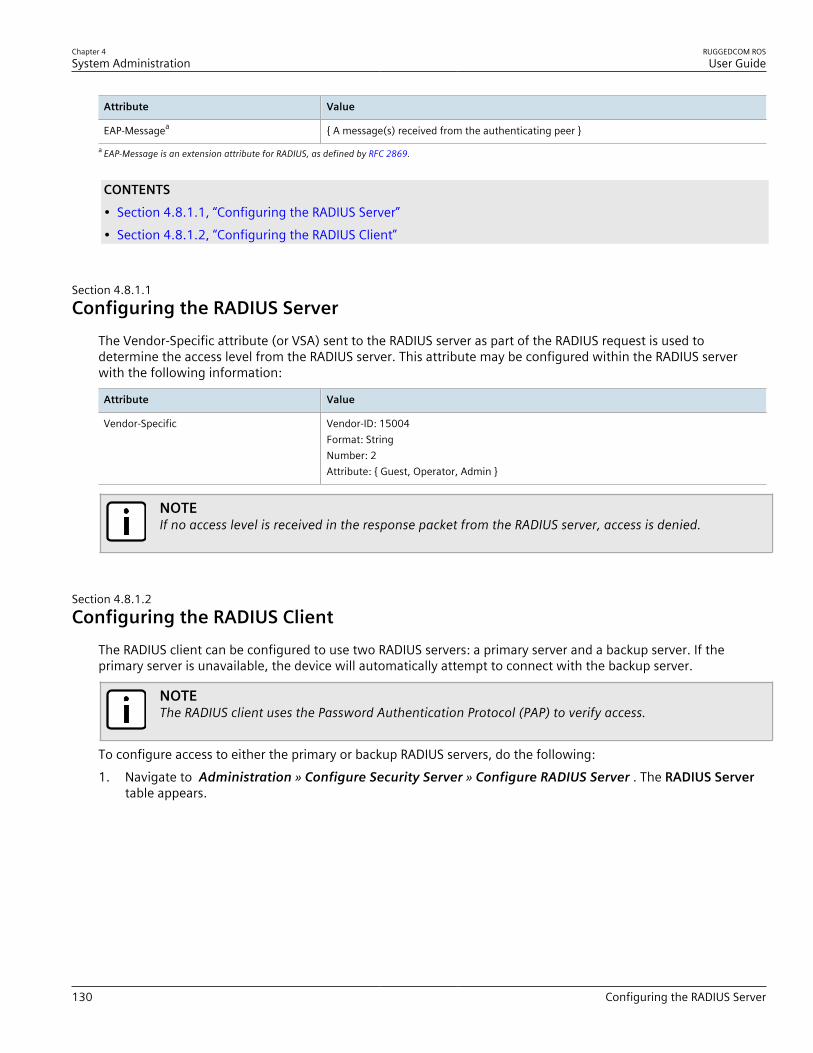
Chapter 4System Administration
RUGGEDCOM ROSUser Guide
130 Configuring the RADIUS Server
Attribute Value
EAP-Messagea { A message(s) received from the authenticating peer }a EAP-Message is an extension attribute for RADIUS, as defined by RFC 2869.
CONTENTS• Section 4.8.1.1, “Configuring the RADIUS Server”• Section 4.8.1.2, “Configuring the RADIUS Client”
Section 4.8.1.1Configuring the RADIUS Server
The Vendor-Specific attribute (or VSA) sent to the RADIUS server as part of the RADIUS request is used todetermine the access level from the RADIUS server. This attribute may be configured within the RADIUS serverwith the following information:
Attribute Value
Vendor-Specific Vendor-ID: 15004Format: StringNumber: 2Attribute: { Guest, Operator, Admin }
NOTEIf no access level is received in the response packet from the RADIUS server, access is denied.
Section 4.8.1.2Configuring the RADIUS Client
The RADIUS client can be configured to use two RADIUS servers: a primary server and a backup server. If theprimary server is unavailable, the device will automatically attempt to connect with the backup server.
NOTEThe RADIUS client uses the Password Authentication Protocol (PAP) to verify access.
To configure access to either the primary or backup RADIUS servers, do the following:1. Navigate to Administration » Configure Security Server » Configure RADIUS Server . The RADIUS Server
table appears.

RUGGEDCOM ROSUser Guide
Chapter 4System Administration
Configuring the RADIUS Client 131
Figure 74: RADIUS Server Table
2. Select either Primary or Backup from the table. The RADIUS Server form appears.
76
5
4
3
2
1
Figure 75: RADIUS Server Form
1. Server Box 2. IP Address Box 3. Auth UDP Port Box 4. Auth Key Box 5. Confirm Auth Key Box 6. Apply Button 7. ReloadButton
3. Configure the following parameter(s) as required:
Parameter Description
Server Synopsis: Any 8 charactersDefault: PrimaryThis field tells whether this configuration is for a Primary or aBackup Server.
IP Address Synopsis: ###.###.###.### where ### ranges from 0 to 255The Server IP Address.
Auth UDP Port Synopsis: 1 to 65535Default: 1812The IP Port on server.
Auth Key Synopsis: 31 character ASCII stringThe authentication key to be shared with server.
Confirm Auth Key Synopsis: 31 character ASCII stringThe authentication key to be shared with server.
4. Click Apply.

Chapter 4System Administration
RUGGEDCOM ROSUser Guide
132 Managing TACACS+ Authentication
Section 4.8.2
Managing TACACS+ AuthenticationTACACS+ (Terminal Access Controller Access-Control System Plus) is a TCP-based access control protocol thatprovides authentication, authorization and accounting services to routers, Network Access Servers (NAS) andother networked computing devices via one or more centralized servers.The following section describes how to configure TACACs+ authentication.
CONTENTS• Section 4.8.2.1, “Configuring TACACS+”• Section 4.8.2.2, “Configuring User Privileges”
Section 4.8.2.1Configuring TACACS+
RUGGEDCOM ROS can be configured to use two TACACS+ servers: a primary server and a backup server. If theprimary server is unavailable, the device will automatically attempt to connect with the backup server.To configure access to either the primary or backup TACACS+ servers, do the following:1. Navigate to Administration » Configure Security Server » Configure TacPlus Server » Configure TACACS
Plus Server . The TACACS Plus Server table appears.
Figure 76: TACACS Plus Server Table
2. Select either Primary or Backup from the table. The TACACS Plus Server form appears.
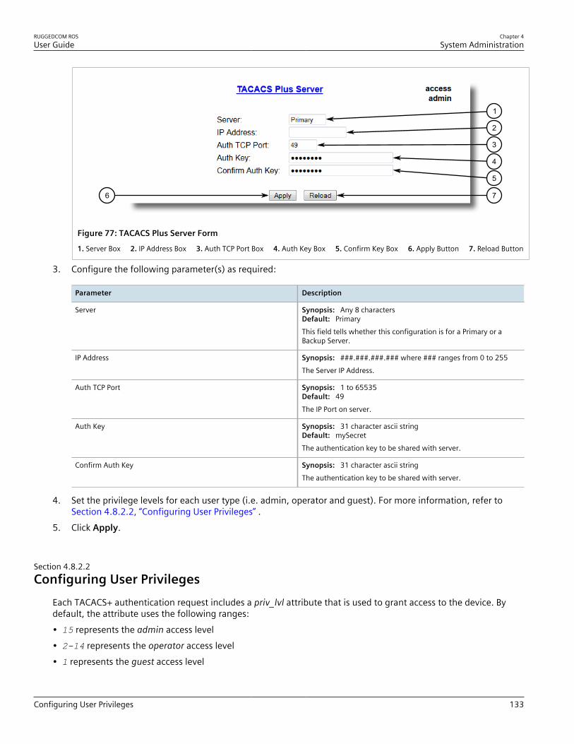
RUGGEDCOM ROSUser Guide
Chapter 4System Administration
Configuring User Privileges 133
76
5
4
3
2
1
Figure 77: TACACS Plus Server Form
1. Server Box 2. IP Address Box 3. Auth TCP Port Box 4. Auth Key Box 5. Confirm Key Box 6. Apply Button 7. Reload Button
3. Configure the following parameter(s) as required:
Parameter Description
Server Synopsis: Any 8 charactersDefault: PrimaryThis field tells whether this configuration is for a Primary or aBackup Server.
IP Address Synopsis: ###.###.###.### where ### ranges from 0 to 255The Server IP Address.
Auth TCP Port Synopsis: 1 to 65535Default: 49The IP Port on server.
Auth Key Synopsis: 31 character ascii stringDefault: mySecretThe authentication key to be shared with server.
Confirm Auth Key Synopsis: 31 character ascii stringThe authentication key to be shared with server.
4. Set the privilege levels for each user type (i.e. admin, operator and guest). For more information, refer to Section 4.8.2.2, “Configuring User Privileges” .
5. Click Apply.
Section 4.8.2.2Configuring User Privileges
Each TACACS+ authentication request includes a priv_lvl attribute that is used to grant access to the device. Bydefault, the attribute uses the following ranges:• 15 represents the admin access level• 2-14 represents the operator access level• 1 represents the guest access level
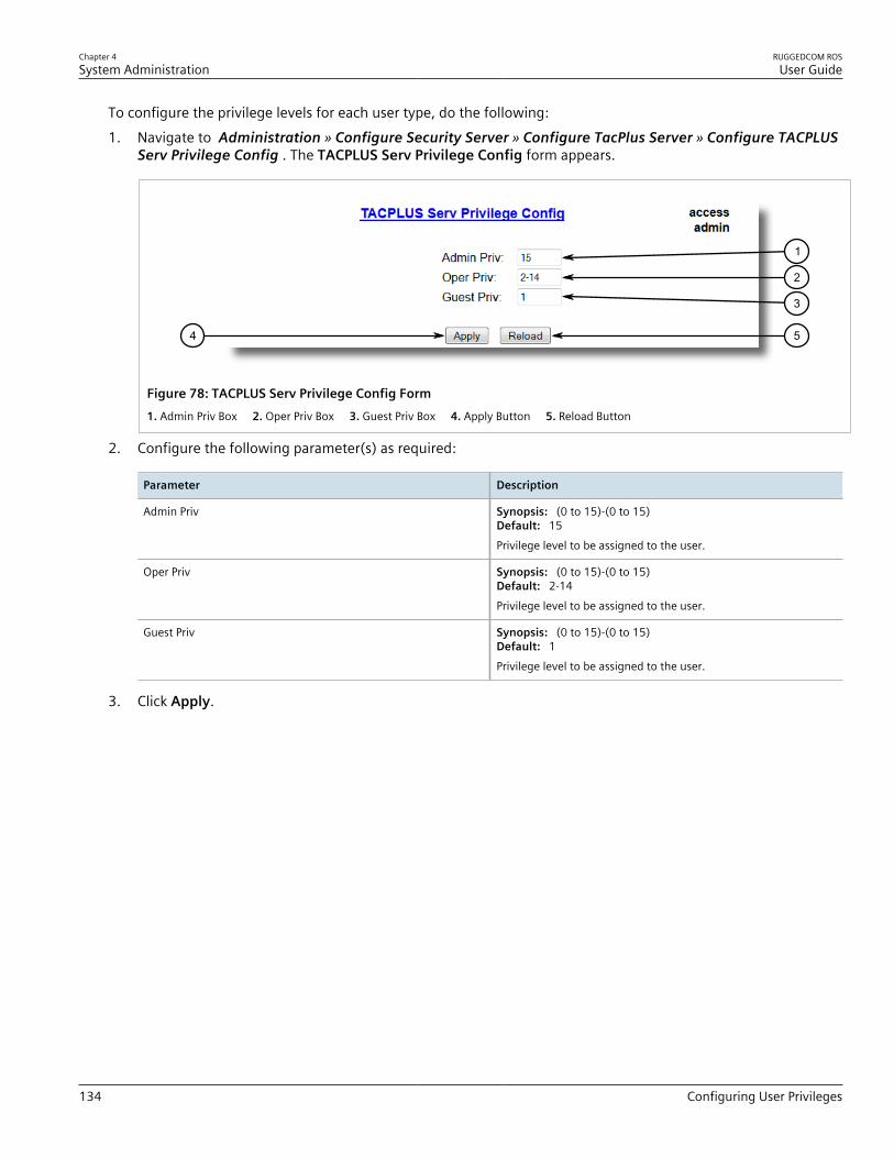
Chapter 4System Administration
RUGGEDCOM ROSUser Guide
134 Configuring User Privileges
To configure the privilege levels for each user type, do the following:1. Navigate to Administration » Configure Security Server » Configure TacPlus Server » Configure TACPLUS
Serv Privilege Config . The TACPLUS Serv Privilege Config form appears.
54
3
2
1
Figure 78: TACPLUS Serv Privilege Config Form1. Admin Priv Box 2. Oper Priv Box 3. Guest Priv Box 4. Apply Button 5. Reload Button
2. Configure the following parameter(s) as required:
Parameter Description
Admin Priv Synopsis: (0 to 15)-(0 to 15)Default: 15Privilege level to be assigned to the user.
Oper Priv Synopsis: (0 to 15)-(0 to 15)Default: 2-14Privilege level to be assigned to the user.
Guest Priv Synopsis: (0 to 15)-(0 to 15)Default: 1Privilege level to be assigned to the user.
3. Click Apply.
RUGGEDCOM ROSUser Guide
Chapter 5Setup and Configuration
Managing PPP and the Internal Modem 135
Setup and ConfigurationThis chapter describes how to setup and configure the device for use on a network using the various featuresavailable in RUGGEDCOM ROS.
CONTENTS• Section 5.1, “Managing PPP and the Internal Modem”• Section 5.2, “Managing Virtual LANs”• Section 5.3, “Managing Spanning Tree Protocol”• Section 5.4, “Managing Classes of Service”• Section 5.5, “Managing MAC Addresses”• Section 5.6, “Managing Time Services”• Section 5.7, “Managing SNMP”• Section 5.8, “Managing Network Discovery”• Section 5.9, “Managing Multicast Filtering”• Section 5.10, “Managing Serial Protocols”
Section 5.1
Managing PPP and the Internal ModemRS400's equipped with an internal modem support the following features:• Industrial grade v.90 modem offering connection speeds of v.22bis (2400 bps), v.32bis (14.4 kbps), v.34 (33.6
kbps) or v.90 (56 kbps)• MNP 5 Link Compression• Country Code selectable• Uses a standard RJ-11 connectorRUGGEDCOM ROS is able to establish a PPP (Point-To-Point Protocol) link via the internal modem to provide IPconnectivity via the PSTN (Public Switched Telephone Network). RUGGEDCOM ROS implements a PPP server withthe ability to authenticate dial-in clients using PAP or CHAP and to automatically assign each one an IP address.Ten user name/password combinations are supported. A static route is installed upon accepting a call.
NOTEIP Forward must be enabled for PPP to function. For more information about enabling IP Forward, referto Section 3.9, “Configuring IP Services” .

Chapter 5Setup and Configuration
RUGGEDCOM ROSUser Guide
136 PPP Concepts
NOTEFor more information about the internal v.90 modem, refer to the RUGGEDCOM RS400 InstallationGuide.
CONTENTS• Section 5.1.1, “PPP Concepts”• Section 5.1.2, “Configuring the Modem”• Section 5.1.3, “Configuring IP Addresses and Authentication”• Section 5.1.4, “Managing PPP Users”• Section 5.1.5, “Viewing and Clearing PPP Statistics”• Section 5.1.6, “Resetting the Modem”
Section 5.1.1
PPP ConceptsThe following section describes some of the concepts important to the implementation of PPP in RUGGEDCOMROS.
CONTENTS• Section 5.1.1.1, “Remote Dial-In for Monitoring”• Section 5.1.1.2, “Router Concentration”• Section 5.1.1.3, “Assigning IP Addresses”• Section 5.1.1.4, “PAP/CHAP Authentication”• Section 5.1.1.5, “Static Routes”
Section 5.1.1.1Remote Dial-In for Monitoring
In a Remote Dial-In for Monitoring application, the device is typically part of an Ethernet network. A clientworkstation can raise a call to the device and establish a PPP link. Hosts on the network may be contacted by theirIP addresses.

RUGGEDCOM ROSUser Guide
Chapter 5Setup and Configuration
Remote Dial-In for Monitoring 137
192.168.1.1
10.0.0.0/16
10.0.0.20
10.0.0.10
192.168.1.2
43
6
5
2
1
Figure 79: Remote Dial-in For Monitoring
1. Terminal 2. Modem 3. Public Switched Telephone Network (PSTN) 4. RS400 5. Ethernet Network 6. IED
To configure this application, the following configuration is required:• On the RS400:
▫ At least one user name and password for PAP or CHAP to authenticate against▫ A server name, if CHAP authentication is used▫ An outgoing PAP password, if two-way PAP authentication is used▫ A local and remote IP address that does not conflict with that used by the server to operate on the Ethernet
network• On the dial-in client:
▫ The telephone number to dial to reach the RS400▫ The authentication protocol (PAP or CHAP) to use, and a username and password that will be accepted by the
server▫ The server name, if the client requires it during CHAP authentication▫ The client must be configured to accept an IP address from the device▫ If necessary, configure the PPP as a default route.
• On devices in the remote Ethernet network:▫ In some circumstances, the gateway settings may need to be configured to forward packets from the subnet
using the RS400's local PPP address as the gateway

Chapter 5Setup and Configuration
RUGGEDCOM ROSUser Guide
138 Router Concentration
Section 5.1.1.2Router Concentration
PPP can be used to accept calls from a router. In this mode, the server is typically connected to an Ethernetnetwork. The router uses the PPP link to access the network.
211.3.0.0/16
192.168.1.1
10.0.0.0/16
10.0.0.20
10.0.0.10
192.168.1.2
2 4 5
1 1
3
3
Figure 80: Router Concentration1. Ethernet Network 2. RUGGEDCOM ROS 3. Public Switched Telephone Network (PSTN) 4. Router
To configure this application, the following configuration is required:• On the RS400:
▫ At least one user name and password for PAP or CHAP to authenticate against▫ A server name, if CHAP authentication is used▫ An outgoing PAP password, if two way PAP Authentication is used▫ A local and remote IP address that does not conflict with that used by the device to operate on the Ethernet
network▫ A remote network number and subnet mask
• On the dial-in client:▫ The telephone number to dial to reach the RS400▫ The authentication protocol (PAP or CHAP) to use, and a username and password that will be accepted by the
server▫ The server name, if the client requires it during CHAP authentication▫ The client must be configured to accept an IP address from the device▫ The router must be configured to treat the PPP link as its default route (or a specific static route to the server’s
IP network must be installed)

RUGGEDCOM ROSUser Guide
Chapter 5Setup and Configuration
Assigning IP Addresses 139
Section 5.1.1.3Assigning IP Addresses
The PPP connection is a routed connection, and IP addresses must be assigned. Make sure the addresses used areunique in the network. They should not conflict with the network numbers of the management interface or of anyremote networks installed as static routes.The default IP link addresses are 192.168.1.1 (server) and 192.168.1.2 (client).If multiple RUGGEDCOM devices need to be connected, the minimum subnet mask of 255.255.255.252will generate server/client address pairs of the form 192.168.1.1/192.168.1.2, 192.168.1.5/192.168.1.6,192.168.1.9/192.168.1.10, etc.
Section 5.1.1.4PAP/CHAP Authentication
RUGGEDCOM ROS utilizes PAP/CHAP to authenticate incoming modem calls.
User ProfilesBy default, the server will accept modem calls from all clients after PPP is enabled. To restrict connections tospecific clients, up to ten profiles including a user name and password may be configured. The client must beconfigured to use one of these profiles to connect.
NOTEAuthentication validates computer systems, not users. After the connection to the client computer isauthenticated, any users of that system or any other hosts that can route packets to that computer willbe able to issue packets to the server.
Using PAPThe Password Authentication Protocol (PAP) verifies the identity of the client in a two-step process:1. After the PPP link establishment phase is complete, the client sends its user name and password repeatedly (in
clear text)2. The RS400 acknowledges the authentication or terminates the connectionThe client may also use PAP to authenticate the server. This is known as two-way authentication. When two-wayauthentication is required, configure the outgoing PAP password. A separate authentication will proceed in thereverse direction (i.e. the server will send the password and the client will issue the acknowledgment).
Using CHAPThe Challenge Handshake Authentication Protocol (CHAP) verifies the identity of the client in a three-step process:1. After the PPP link establishment phase is complete, the RS400 sends a challenge message to the client2. The client responds with an MD5 hashed value of the password3. The RS400 checks the response against its own calculation of the hashed password and clears the call if the
values do not matchThe client may also use CHAP to authenticate the server. This is known as two-way authentication. Two-wayauthentication is automatically supported, using the user names and passwords configured in the PPP Users menu.
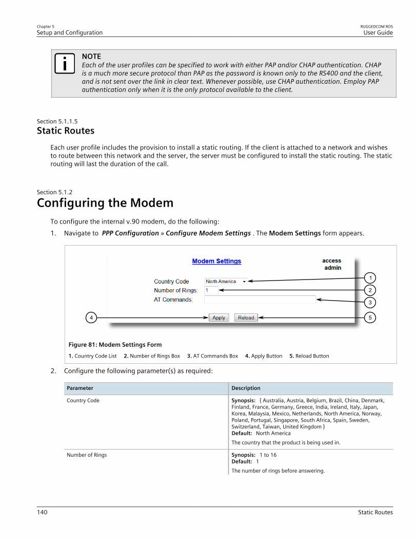
Chapter 5Setup and Configuration
RUGGEDCOM ROSUser Guide
140 Static Routes
NOTEEach of the user profiles can be specified to work with either PAP and/or CHAP authentication. CHAPis a much more secure protocol than PAP as the password is known only to the RS400 and the client,and is not sent over the link in clear text. Whenever possible, use CHAP authentication. Employ PAPauthentication only when it is the only protocol available to the client.
Section 5.1.1.5Static Routes
Each user profile includes the provision to install a static routing. If the client is attached to a network and wishesto route between this network and the server, the server must be configured to install the static routing. The staticrouting will last the duration of the call.
Section 5.1.2
Configuring the ModemTo configure the internal v.90 modem, do the following:1. Navigate to PPP Configuration » Configure Modem Settings . The Modem Settings form appears.
54
1
2
3
Figure 81: Modem Settings Form
1. Country Code List 2. Number of Rings Box 3. AT Commands Box 4. Apply Button 5. Reload Button
2. Configure the following parameter(s) as required:
Parameter Description
Country Code Synopsis: { Australia, Austria, Belgium, Brazil, China, Denmark,Finland, France, Germany, Greece, India, Ireland, Italy, Japan,Korea, Malaysia, Mexico, Netherlands, North America, Norway,Poland, Portugal, Singapore, South Africa, Spain, Sweden,Switzerland, Taiwan, United Kingdom }Default: North AmericaThe country that the product is being used in.
Number of Rings Synopsis: 1 to 16Default: 1The number of rings before answering.
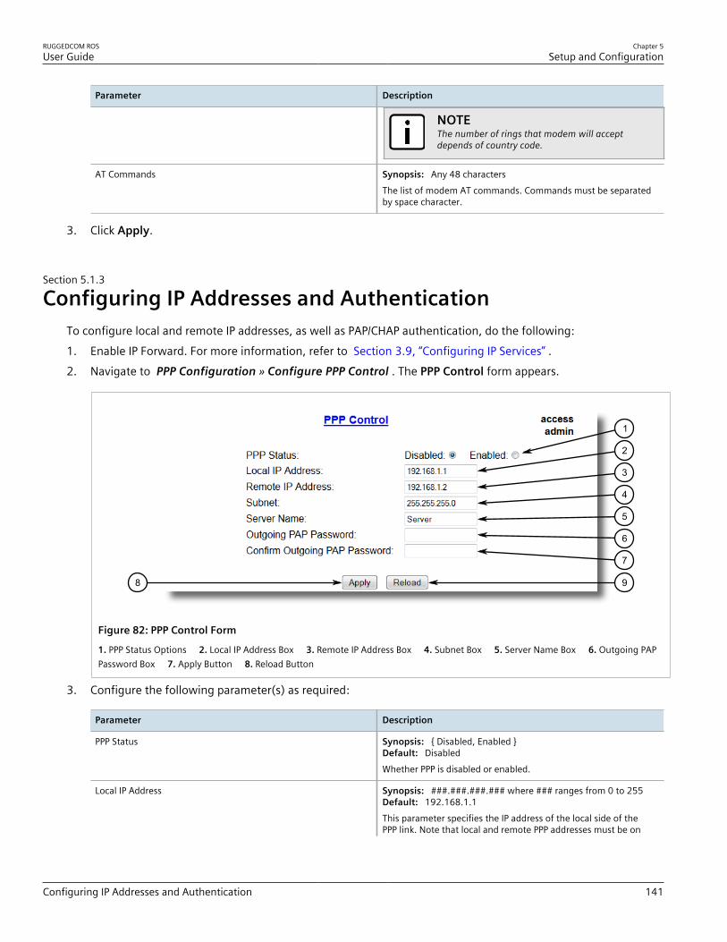
RUGGEDCOM ROSUser Guide
Chapter 5Setup and Configuration
Configuring IP Addresses and Authentication 141
Parameter Description
NOTEThe number of rings that modem will acceptdepends of country code.
AT Commands Synopsis: Any 48 charactersThe list of modem AT commands. Commands must be separatedby space character.
3. Click Apply.
Section 5.1.3
Configuring IP Addresses and AuthenticationTo configure local and remote IP addresses, as well as PAP/CHAP authentication, do the following:1. Enable IP Forward. For more information, refer to Section 3.9, “Configuring IP Services” .2. Navigate to PPP Configuration » Configure PPP Control . The PPP Control form appears.
98
1
2
3
4
5
6
7
Figure 82: PPP Control Form
1. PPP Status Options 2. Local IP Address Box 3. Remote IP Address Box 4. Subnet Box 5. Server Name Box 6. Outgoing PAPPassword Box 7. Apply Button 8. Reload Button
3. Configure the following parameter(s) as required:
Parameter Description
PPP Status Synopsis: { Disabled, Enabled }Default: DisabledWhether PPP is disabled or enabled.
Local IP Address Synopsis: ###.###.###.### where ### ranges from 0 to 255Default: 192.168.1.1This parameter specifies the IP address of the local side of thePPP link. Note that local and remote PPP addresses must be on
Chapter 5Setup and Configuration
RUGGEDCOM ROSUser Guide
142 Managing PPP Users
Parameter Description
the same subnetwork and that this subnetwork must be differentfrom the management network address.
Remote IP Address Synopsis: ###.###.###.### where ### ranges from 0 to 255Default: 192.168.1.2This parameter specifies the IP address of the remote side of thePPP link. Note that local and remote PPP addresses must be onthe same subnetwork and that this subnetwork must be differentfrom the management network address.
Subnet Synopsis: ###.###.###.### where ### ranges from 0 to 255Default: 255.255.255.0This parameter specifies the IP subnet mask of this local andremote PPP addresses.
Server Name Synopsis: Any 15 charactersDefault: ServerThis string determines the server name and is used for CHAP andwhen authenticating ourselves to the caller using PAP.
Outgoing PAP Password Synopsis: 15 character ascii stringDefault: If the caller requests the server to authenticate itself, theserver will reply with an id set to the Server name and thispassword. Leave this field blank if you do not require two-wayauthentication.
Confirm Outgoing PAP Password Synopsis: 15 character ascii stringIf the caller requests the server to authenticate itself, theserver will reply with an id set to the Server name and thispassword. Leave this field blank if you do not require two-wayauthentication.
4. Click Apply.
Section 5.1.4
Managing PPP UsersThe following section describes how to manage PPP users.
CONTENTS• Section 5.1.4.1, “Viewing a List of PPP Users”• Section 5.1.4.2, “Adding a PPP User”• Section 5.1.4.3, “Deleting a PPP User”
Section 5.1.4.1Viewing a List of PPP Users
To view a list of PPP users configured on the device, navigate to PPP Configuration » Configure PPP Users . ThePPP Users table appears.
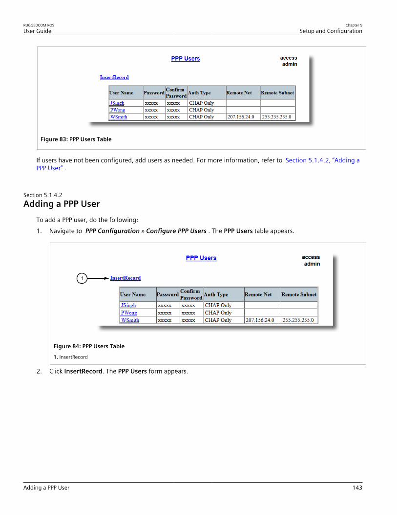
RUGGEDCOM ROSUser Guide
Chapter 5Setup and Configuration
Adding a PPP User 143
Figure 83: PPP Users Table
If users have not been configured, add users as needed. For more information, refer to Section 5.1.4.2, “Adding aPPP User” .
Section 5.1.4.2Adding a PPP User
To add a PPP user, do the following:1. Navigate to PPP Configuration » Configure PPP Users . The PPP Users table appears.
1
Figure 84: PPP Users Table
1. InsertRecord
2. Click InsertRecord. The PPP Users form appears.

Chapter 5Setup and Configuration
RUGGEDCOM ROSUser Guide
144 Adding a PPP User
97
8
1
2
3
4
5
6
Figure 85: PPP Users Form
1. User Name Box 2. Password Box 3. Auth Type List 4. Remote Net Box 5. Remote Subnet Box 6. Apply Button 7. DeleteButton 8. Reload Button
3. Configure the following parameter(s) as required:
Parameter Description
User Name Synopsis: Any 15 charactersThe username used to validate the PPP connection.
Password Synopsis: 9 character ascii stringThe password associated with a specific username.
Confirm Password Synopsis: 9 character ascii stringThe password associated with a specific username.
Auth Type Synopsis: { CHAP Only, PAP Only, Both PAP/CHAP, NoAuthentication }Default: CHAP OnlyDetermines whether the username/password applies to PAP, CHAPor both. Setting authentication to "none" should be used onlywhen debugging new installs, and only temporarily.
Remote Net Synopsis: ###.###.###.### where ### ranges from 0 to 255Specifies the IP address of a remote subnet on the other side ofthe PPP link. Take care not to confuse the remote subnet addresswith that of the locally connected Ethernet.
Remote Subnet Synopsis: ###.###.###.### where ### ranges from 0 to 255Specifies the IP subnet mask of the remote net.
4. Click Apply.

RUGGEDCOM ROSUser Guide
Chapter 5Setup and Configuration
Deleting a PPP User 145
Section 5.1.4.3Deleting a PPP User
To delete a PPP user, do the following:1. Navigate to PPP Configuration » Configure PPP Users . The PPP Users table appears.
Figure 86: PPP Users Table
2. Select the user from the table. The PPP Users form appears.
97
8
1
2
3
4
5
6
Figure 87: PPP Users Form
1. User Name Box 2. Password Box 3. Auth Type List 4. Remote Net Box 5. Remote Subnet Box 6. Apply Button 7. DeleteButton 8. Reload Button
3. Click Delete.
Section 5.1.5
Viewing and Clearing PPP StatisticsTo view statistics on PPP activity, navigate to PPP Configuration » PPP Statistics . The PPP Statistics formappears.

Chapter 5Setup and Configuration
RUGGEDCOM ROSUser Guide
146 Viewing and Clearing PPP Statistics
Figure 88: PPP Statistics Form
This form displays the following information:
Parameter Description
Current Status Synopsis: { Disabled, Waiting for a call, Authenticating user, Call inprogress, Stopping call, No Dialtone, Number Busy, No Answer }The current port status.
Modem Speed Synopsis: 0 to 2147483647 bps or { Offline }The speed in bps that the modem connected at.
Rx Packets Synopsis: 0 to 4294967295The number of received packets on the connection.
Tx Packets Synopsis: 0 to 4294967295The number of packets transmitted on the connection.
Rx LCP Packets Synopsis: 0 to 4294967295The number of received LCP packets on the connection.
Tx LCP Packets Synopsis: 0 to 4294967295The number of packets LCP transmitted on the connection.
Authentication Synopsis: { , None, PAP, PAP Failure, CHAP, CHAP Failure }The current authentication status.
Connected User Synopsis: Any 15 charactersThe name of the currently connected user.
To clear the statistics, do the following:1. Navigate to PPP Configuration » Clear PPP Statistics . The Clear PPP Statistics form appears.

RUGGEDCOM ROSUser Guide
Chapter 5Setup and Configuration
Resetting the Modem 147
1
Figure 89: Clear PPP Statistics Form
1. Confirm Button
2. Click Confirm.
Section 5.1.6
Resetting the ModemTo reset the internal v.90 modem, do the following:1. Navigate to PPP Configuration » Reset PPP Port . The Reset PPP Port form appears.
1
Figure 90: Reset PPP Port Form
1. Confirm Button
2. Click Confirm.
Section 5.2
Managing Virtual LANsA Virtual Local Area Network (VLAN) is a group of devices on one or more LAN segments that communicate as ifthey were attached to the same physical LAN segment. VLANs are extremely flexible because they are based onlogical connections, rather than physical connections.When VLANs are introduced, all traffic in the network must belong to one VLAN or another. Traffic on one VLANcannot pass to another, except through an inter-network router or Layer 3 switch.VLANs are created in three ways:• Explicitly
Static VLANs can be created in the switch. For more information about static VLANs, refer to Section 5.2.5,“Managing Static VLANs” .
Chapter 5Setup and Configuration
RUGGEDCOM ROSUser Guide
148 VLAN Concepts
• ImplicitlyWhen a VLAN ID (VID) is set for a port-based VLAN, static MAC address or IP interface, an appropriate VLAN isautomatically created if it does not yet exist.
• DynamicallyVLANs can be learned through GVRP. For more information about GVRP, refer to Section 5.2.1.8, “GARP VLANRegistration Protocol (GVRP)”
For more information about VLANs, refer to Section 5.2.1, “VLAN Concepts” .
CONTENTS• Section 5.2.1, “VLAN Concepts”• Section 5.2.2, “Viewing a List of VLANs”• Section 5.2.3, “Configuring VLANs Globally”• Section 5.2.4, “Configuring VLANs for Specific Ethernet Ports”• Section 5.2.5, “Managing Static VLANs”
Section 5.2.1
VLAN ConceptsThe following section describes some of the concepts important to the implementation of VLANs in RUGGEDCOMROS.
CONTENTS• Section 5.2.1.1, “Tagged vs. Untagged Frames”• Section 5.2.1.2, “Native VLAN”• Section 5.2.1.3, “The Management VLAN”• Section 5.2.1.4, “Edge and Trunk Port Types”• Section 5.2.1.5, “Ingress and Egress Rules”• Section 5.2.1.6, “Forbidden Ports List”• Section 5.2.1.7, “VLAN-Aware and VLAN-Unaware Modes”• Section 5.2.1.8, “GARP VLAN Registration Protocol (GVRP)”• Section 5.2.1.9, “VLAN Advantages”
Section 5.2.1.1Tagged vs. Untagged Frames
VLAN tags identify frames as part of a VLAN network. When a switch receives a frame with a VLAN (or 802.1Q)tag, the VLAN identifier (VID) is extracted and the frame is forwarded to other ports on the same VLAN.When a frame does not contain a VLAN tag, or contains an 802.1p (prioritization) tag that only has prioritizationinformation and a VID of 0, it is considered an untagged frame.

RUGGEDCOM ROSUser Guide
Chapter 5Setup and Configuration
Native VLAN 149
Section 5.2.1.2Native VLAN
Each port is assigned a native VLAN number, the Port VLAN ID (PVID). When an untagged frame ingresses a port, itis associated with the port's native VLAN.By default, when a switch transmits a frame on the native VLAN, it sends the frame untagged. The switch can beconfigured to transmit tagged frames on the native VLAN.
Section 5.2.1.3The Management VLAN
Management traffic, like all traffic on the network, must belong to a specific VLAN. The management VLAN isconfigurable and always defaults to VLAN 1. This VLAN is also the default native VLAN for all ports, thus allowingall ports the possibility of managing the product. Changing the management VLAN can be used to restrictmanagement access to a specific set of users.
Section 5.2.1.4Edge and Trunk Port Types
Each port can be configured as an edge or trunk port.An edge port attaches to a single end device, such as a PC or Intelligent Electronic Device (IED). An edge portcarries traffic on the native VLAN.Trunk ports are part of the network and carry traffic for all VLANs between switches. Trunk ports are automaticallymembers of all VLANs configured in the switch.The switch can 'pass through' traffic, forwarding frames received on one trunk port out of another trunk port. Thetrunk ports must be members of all VLANs that the 'pass through' traffic is part of, even if none of those VLANs areused on edge ports.Frames transmitted out of the port on all VLANs other than the port's native VLAN are always sent tagged.
NOTEIt may be desirable to manually restrict the traffic on the trunk to a specific group of VLANs. Forexample, when the trunk connects to a device, such as a Layer 3 router, that supports a subset of theavailable LANs. To prevent the trunk port from being a member of the VLAN, include it in the VLAN'sForbidden Ports list.For more information about the Forbidden Ports list, refer to Section 5.2.1.6, “Forbidden Ports List” .
Port Type VLANs Supported PVID Format Usage
Untagged VLAN Unaware Networks: All frames are sent and received withoutthe need for VLAN tags.
Edge 1 (Native)Configured
Tagged VLAN Aware Networks: VLAN traffic domains are enforced on asingle VLAN.
Trunk All Configured Tagged or Untagged Switch-to-Switch Connections: VLANs must be manually created andadministered, or can be dynamically learned through GVRP.Multiple-VLAN End Devices: Implement connections to end devicesthat support multiple VLANs at the same time.

Chapter 5Setup and Configuration
RUGGEDCOM ROSUser Guide
150 Ingress and Egress Rules
Section 5.2.1.5Ingress and Egress Rules
Ingress and egress rules determine how traffic is received and transmitted by the switch.Ingress rules are applied as follows to all frame when they are received by the switch:
Frame Receiveda Untagged Priority Tagged(VID = 0) Tagged (Valid VID)
VLAN ID associated with the frame PVID PVID VID in the Tag
Frame dropped due to its tagged/untagged format No No No
Frame dropped if the ingress port is not a member of the VLAN theframe is associated with and ingress filtering is enabled
Yes
a Does not depend on the ingress port's VLAN configuration parameters.
Egress rules are applied as follows to all frames when they are transmitted by the switch.
On Other VLAN
Egress Port Type On Egress Port's Native VLANPort Is a Member Of the VLAN Port Is Not a Member
Of the VLAN
Edge Dropped
Trunk
According to the egress port'sPVID Format parameter
Tagged Dropped
Section 5.2.1.6Forbidden Ports List
Each VLAN can be configured to exclude ports from membership in the VLAN using the forbidden ports list. Formore information, refer to Section 5.2.5.2, “Adding a Static VLAN” .
Section 5.2.1.7VLAN-Aware and VLAN-Unaware Modes
The native operation mode for an IEEE 802.1Q compliant switch is VLAN-aware. Even if a specific networkarchitecture does not use VLANs, RUGGEDCOM ROS's default VLAN settings allow the switch to still operate in aVLAN-aware mode, while providing functionality required for almost any network application. However, the IEEE802.1Q standard defines a set of rules that must be followed by all VLAN-aware switches:• Valid VIDs are within the range of 1 to 4094. VIDs equal to 0 or 4095 are invalid.• Each frame ingressing a VLAN-aware switch is associated with a valid VID.• Each frame egressing a VLAN-aware switch is either untagged or tagged with a valid VID. Priority-tagged frames
with an invalid VID will never sent out by a VLAN-aware switch.
NOTESome applications have requirements conflicting with IEEE 802.Q1 native mode of operation. Forexample, some applications explicitly require priority-tagged frames to be received by end devices.To avoid conflicts and provide full compatibility with legacy (VLAN-unaware) devices, RUGGEDCOMROS can be configured to work in VLAN-unaware mode.In that mode:

RUGGEDCOM ROSUser Guide
Chapter 5Setup and Configuration
GARP VLAN Registration Protocol (GVRP) 151
• Frames ingressing a VLAN-unaware device are not associated with any VLAN• Frames egressing a VLAN-unaware device are sent out unmodified (i.e. in the same untagged,
802.1Q-tagged or priority-tagged format as they were received)
Section 5.2.1.8GARP VLAN Registration Protocol (GVRP)
GARP VLAN Registration Protocol (GVRP) is a standard protocol built on GARP (Generic Attribute RegistrationProtocol) to automatically distribute VLAN configuration information in a network. Each switch in a network needsonly to be configured with VLANs it requires locally. VLANs configured elsewhere in the network are learnedthrough GVRP. A GVRP-aware end station (i.e. PC or Intelligent Electronic Device) configured for a particular VIDcan be connected to a trunk on a GVRP-aware switch and automatically become part of the desired VLAN.When a switch sends GVRP bridge protocol data units (BPDUs) out of all GVRP-enabled ports, GVRP BPDUs advertiseall the VLANs known to that switch (configured manually or learned dynamically through GVRP) to the rest of thenetwork.When a GVRP-enabled switch receives a GVRP BPDU advertising a set of VLANs, the receiving port becomes amember of those advertised VLANs and the switch begins advertising those VLANs through all the GVRP-enabledports (other than the port on which the VLANs were learned).To improve network security using VLANs, GVRP-enabled ports may be configured to prohibit the learning of anynew dynamic VLANs but at the same time be allowed to advertise the VLANs configured on the switch.The following is an example of how to use GVRP:

Chapter 5Setup and Configuration
RUGGEDCOM ROSUser Guide
152 GARP VLAN Registration Protocol (GVRP)
A
A2
A1
D
D1
D2
B
B4
B3
B1B2
C
C2
C1E
E2
E1
D
EA C
1
2
Figure 91: Using GVRP
1. Switch 2. End Node
• Switch B is the core switch, all others are edge switches• Ports A1, B1 to B4, C1, D1, D2 and E1 are GVRP aware• Ports B1 to B4, D1 and D2 are set to advertise and learn• Ports A1, C1 and E1 are set to advertise only• Ports A2, C2 and E2 are edge ports• End node D is GVRP aware• End nodes A, E and C are GVRP unaware• Ports A2 and C2 are configured with PVID 7• Port E2 is configured with PVID 20• End node D is interested in VLAN 20, hence VLAN 20 is advertised by it towards switch D• D2 becomes a member of VLAN 20• Ports A1 and C1 advertise VID 7• Ports B1 and B2 become members of VLAN 7• Ports B1, B2 and D1 advertise VID 20• Ports B3, B4 and D1 become members of VLAN 20

RUGGEDCOM ROSUser Guide
Chapter 5Setup and Configuration
VLAN Advantages 153
For more information about how to configure GVRP, refer to Section 5.2.4, “Configuring VLANs for SpecificEthernet Ports” .
Section 5.2.1.9VLAN Advantages
The following are a few of the advantages offered by VLANs.
Traffic Domain IsolationVLANs are most often used for their ability to restrict traffic flows between groups of devices.Unnecessary broadcast traffic can be restricted to the VLAN that requires it. Broadcast storms in one VLAN neednot affect users in other VLANs.Hosts on one VLAN can be prevented from accidentally or deliberately assuming the IP address of a host onanother VLAN.The use of creative bridge filtering and multiple VLANs can carve seemingly unified IP subnets into multipleregions policed by different security/access policies.Multi-VLAN hosts can assign different traffic types to different VLANs.
2
3
54
2
1
Figure 92: Multiple Overlapping VLANs
1. VLAN 2. Switch
Administrative ConvenienceVLANs enable equipment moves to be handled by software reconfiguration instead of by physical cablemanagement. When a host's physical location is changed, its connection point is often changed as well. WithVLANs, the host's VLAN membership and priority are simply copied to the new port.
Reduced HardwareWithout VLANs, traffic domain isolation requires the use of separate bridges for separate networks. VLANseliminate the need for separate bridges.

Chapter 5Setup and Configuration
RUGGEDCOM ROSUser Guide
154 Viewing a List of VLANs
The number of network hosts may often be reduced. Often, a server is assigned to provide services forindependent networks. These hosts may be replaced by a single, multi-horned host supporting each network onits own VLAN. This host can perform routing between VLANs.Multi-VLAN hosts can assign different traffic types to different VLANs.
199.85.245.192/26
199.85.245.128/26
199.85.245.1/25
1 4
2
3
5
Figure 93: Inter-VLAN Communications
1. Server, Router or Layer 3 Switch 2. Switch 3. VLAN 2 4. VLAN 3 5. VLAN 4
Section 5.2.2
Viewing a List of VLANsTo view a list of all VLANs, whether they were created statically, implicitly or dynamically , navigate to VirtualLANs » View VLAN Summary . The VLAN Summary table appears.
Figure 94: VLAN Summary Table
If a VLANs are not listed, add static VLANs as needed. For more information, refer to Section 5.2.5.2, “Adding aStatic VLAN” .

RUGGEDCOM ROSUser Guide
Chapter 5Setup and Configuration
Configuring VLANs Globally 155
Section 5.2.3
Configuring VLANs GloballyTo configure global settings for all VLANs, do the following:1. Navigate to Virtual LANs » Configure Global VLAN Parameters . The Global VLAN Parameters form
appears.
3 4
2
1
Figure 95: Global VLAN Parameters Form
1. VLAN-aware Options 2. Ingress Filtering Options 3. Apply Button 4. Reload Button
2. Configure the following parameter(s) as required:
Parameter Description
VLAN-aware Synopsis: { No, Yes }Default: YesSet either VLAN-aware or VLAN-unaware mode of operation.
Ingress Filtering Synopsis: { Disabled, Enabled }Default: DisabledEnables or disables VLAN ingress filtering on all ports. Whenenabled, any tagged packet arriving at a port, which is nota member of a VLAN with which that packet is associated, isdropped. When disabled, packets are not dropped.
NOTEIngress filtering has no effect when ports are ineither VLAN-unaware mode or Q-in-Q mode.
3. Click Apply.
Section 5.2.4
Configuring VLANs for Specific Ethernet PortsWhen a VLAN ID is assigned to an Ethernet port, the VLAN appears in the VLAN Summary table where it can befurther configured.To configure a VLAN for a specific Ethernet port, do the following:1. Navigate to Virtual LANs » Configure Port VLAN Parameters . The Port VLAN Parameters table appears.

Chapter 5Setup and Configuration
RUGGEDCOM ROSUser Guide
156 Configuring VLANs for Specific Ethernet Ports
Figure 96: Port VLAN Parameters Table
2. Select a port. The Port VLAN Parameters form appears.
76
4
3
2
1
5
Figure 97: Port VLAN Parameters Form
1. Port(s) Box 2. Type List 3. PVID Box 4. PVID Format Options 5. GVRP List 6. Apply Button 7. Reload Button
3. Configure the following parameter(s) as required:
Parameter Description
Port(s) Synopsis: Any combination of numbers valid for this parameterThe port number as seen on the front plate silkscreen of theswitch (or a list of ports, if aggregated in a port trunk).
Type Synopsis: { Edge, Trunk }Default: EdgeThis parameter specifies how the port determines its membershipin VLANs. There are few types of ports:• Edge - the port is only a member of one VLAN (its native VLAN
specified by the PVID parameter).• Trunk - the port is automatically a member of all configured
VLANs. Frames transmitted out of the port on all VLANs except

RUGGEDCOM ROSUser Guide
Chapter 5Setup and Configuration
Managing Static VLANs 157
Parameter Description
the port's native VLAN will be always tagged. It can also beconfigured to use GVRP for automatic VLAN configuration.
PVID Synopsis: 1 to 4094Default: 1The Port VLAN Identifier specifies the VLAN ID associated withuntagged (and 802.1p priority tagged) frames received on thisport.Frames tagged with a non-zero VLAN ID will always be associatedwith the VLAN ID retrieved from the frame tag.Modify this parameter with care! By default, the switch isprogrammed to use VLAN 1 for management and every port onthe switch is programmed to use VLAN 1. If you modify a switchport to use a VLAN other than the management VLAN, devices onthat port will not be able to manage the switch.
PVID Format Synopsis: { Untagged, Tagged }Default: UntaggedSpecifies whether frames transmitted out of the port on itsnative VLAN (specified by the PVID parameter) will be tagged oruntagged.
NOTEWhen QinQ is enabled, all non-QinQ ports will beuntagged and cannot be changed, and all QinQports will be tagged, and cannot be changed.
GVRP Synopsis: { Adv&Learn, Adv Only, Disabled }Default: DisabledConfigures GVRP (Generic VLAN Registration Protocol) operationon the port. There are several GVRP operation modes:• DISABLED - the port is not capable of any GVRP processing.• ADVERTISE ONLY - the port will declare all VLANs existing in the
switch (configured or learned) but will not learn any VLANs.• ADVERTISE & LEARN - the port will declare all VLANs existing in
the switch (configured or learned) and can dynamically learnVLANs.
Only Trunk ports are GVRP-capable.
4. Click Apply.
Section 5.2.5
Managing Static VLANsThe following section describes how to configure and manage static VLANs.
CONTENTS• Section 5.2.5.1, “Viewing a List of Static VLANs”• Section 5.2.5.2, “Adding a Static VLAN”
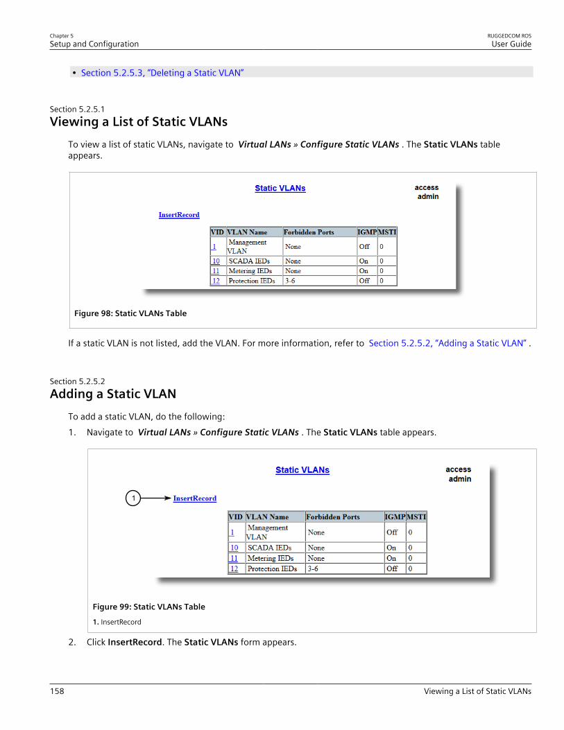
Chapter 5Setup and Configuration
RUGGEDCOM ROSUser Guide
158 Viewing a List of Static VLANs
• Section 5.2.5.3, “Deleting a Static VLAN”
Section 5.2.5.1Viewing a List of Static VLANs
To view a list of static VLANs, navigate to Virtual LANs » Configure Static VLANs . The Static VLANs tableappears.
Figure 98: Static VLANs Table
If a static VLAN is not listed, add the VLAN. For more information, refer to Section 5.2.5.2, “Adding a Static VLAN” .
Section 5.2.5.2Adding a Static VLAN
To add a static VLAN, do the following:1. Navigate to Virtual LANs » Configure Static VLANs . The Static VLANs table appears.
1
Figure 99: Static VLANs Table
1. InsertRecord
2. Click InsertRecord. The Static VLANs form appears.
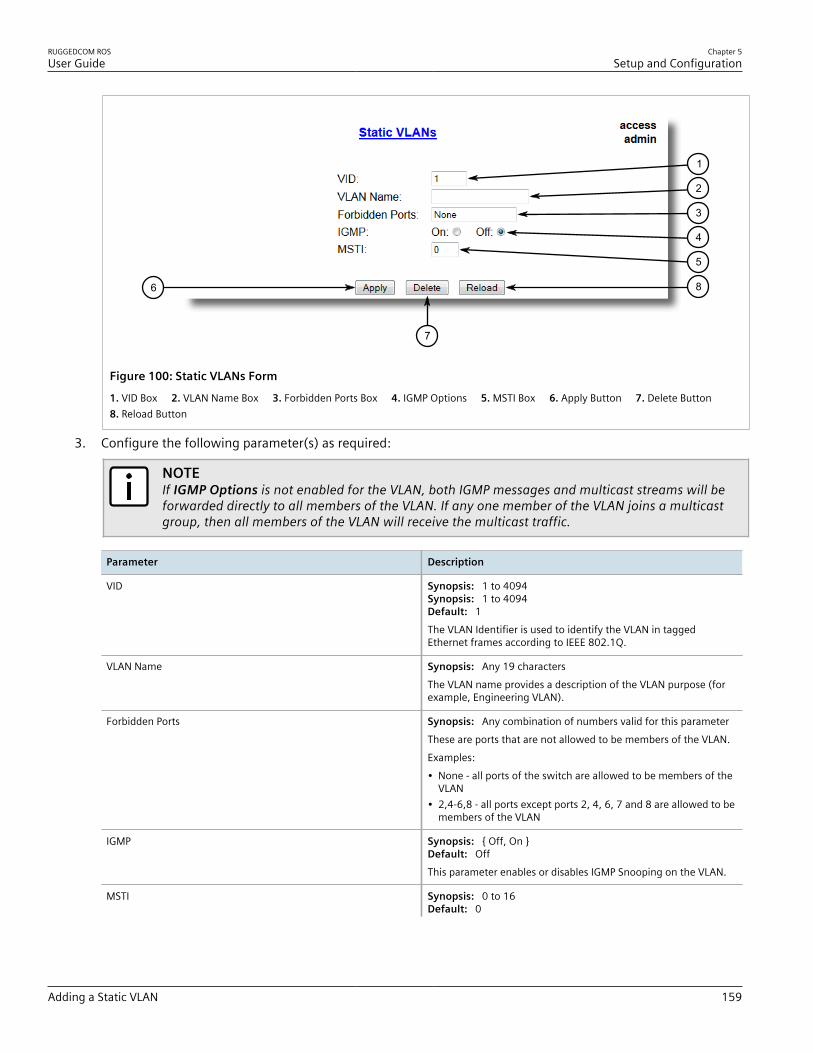
RUGGEDCOM ROSUser Guide
Chapter 5Setup and Configuration
Adding a Static VLAN 159
6
7
8
1
2
3
4
5
Figure 100: Static VLANs Form
1. VID Box 2. VLAN Name Box 3. Forbidden Ports Box 4. IGMP Options 5. MSTI Box 6. Apply Button 7. Delete Button 8. Reload Button
3. Configure the following parameter(s) as required:
NOTEIf IGMP Options is not enabled for the VLAN, both IGMP messages and multicast streams will beforwarded directly to all members of the VLAN. If any one member of the VLAN joins a multicastgroup, then all members of the VLAN will receive the multicast traffic.
Parameter Description
VID Synopsis: 1 to 4094Synopsis: 1 to 4094Default: 1The VLAN Identifier is used to identify the VLAN in taggedEthernet frames according to IEEE 802.1Q.
VLAN Name Synopsis: Any 19 charactersThe VLAN name provides a description of the VLAN purpose (forexample, Engineering VLAN).
Forbidden Ports Synopsis: Any combination of numbers valid for this parameterThese are ports that are not allowed to be members of the VLAN.Examples:• None - all ports of the switch are allowed to be members of the
VLAN• 2,4-6,8 - all ports except ports 2, 4, 6, 7 and 8 are allowed to be
members of the VLAN
IGMP Synopsis: { Off, On }Default: OffThis parameter enables or disables IGMP Snooping on the VLAN.
MSTI Synopsis: 0 to 16Default: 0

Chapter 5Setup and Configuration
RUGGEDCOM ROSUser Guide
160 Deleting a Static VLAN
Parameter Description
This parameter is only valid for Multiple Spanning Tree Protocol(MSTP) and has no effect if MSTP is not used. The parameterspecifies the Multiple Spanning Tree Instance (MSTI) to which theVLAN should be mapped.
4. Click Apply.
Section 5.2.5.3Deleting a Static VLAN
To delete a static VLAN, do the following:1. Navigate to Virtual LANs » Configure Static VLANs . The Static VLANs table appears.
Figure 101: Static VLANs Table
2. Select the static VLAN from the table. The Static VLANs form appears.
6
7
8
1
2
3
4
5
Figure 102: Static VLANs Form
1. VID Box 2. VLAN Name Box 3. Forbidden Ports Box 4. IGMP Options 5. MSTI Box 6. Apply Button 7. Delete Button 8. Reload Button

RUGGEDCOM ROSUser Guide
Chapter 5Setup and Configuration
Managing Spanning Tree Protocol 161
3. Click Delete.
Section 5.3
Managing Spanning Tree ProtocolCONTENTS• Section 5.3.1, “RSTP Operation”• Section 5.3.2, “RSTP Applications”• Section 5.3.3, “Configuring STP Globally”• Section 5.3.4, “Configuring STP for Specific Ethernet Ports”• Section 5.3.5, “Configuring eRSTP”• Section 5.3.6, “Viewing Global Statistics for STP”• Section 5.3.7, “Viewing STP Statistics for Ethernet Ports”• Section 5.3.8, “Clearing Spanning Tree Protocol Statistics”
Section 5.3.1
RSTP OperationThe 802.1D Spanning Tree Protocol (STP) was developed to enable the construction of robust networks thatincorporate redundancy while pruning the active topology of the network to prevent loops. While STP is effective,it requires that frame transfer halt after a link outage until all bridges in the network are guaranteed to be awareof the new topology. Using the values recommended by 802.1D, this period lasts 30 seconds.The Rapid Spanning Tree Protocol (RSTP, IEEE 802.1w) was a further evolution of the 802.1D Spanning TreeProtocol. It replaced the settling period with an active handshake between bridges that guarantees the rapidpropagation of topology information throughout the network. RSTP also offers a number of other significantinnovations, including:• Topology changes in RSTP can originate from and be acted upon by any designated bridges, leading to more
rapid propagation of address information, unlike topology changes in STP, which must be passed to the rootbridge before they can be propagated to the network.
• RSTP explicitly recognizes two blocking roles - Alternate and Backup Port - which are included in computationsof when to learn and forward. STP, however, recognizes only one state - Blocking - for ports that should notforward.
• RSTP bridges generate their own configuration messages, even if they fail to receive any from the root bridge.This leads to quicker failure detection. STP, by contrast, must relay configuration messages received on the rootport out its designated ports. If an STP bridge fails to receive a message from its neighbor, it cannot be surewhere along the path to the root a failure occurred.
• RSTP offers edge port recognition, allowing ports at the edge of the network to forward frames immediatelyafter activation, while at the same time protecting them against loops.
While providing much better performance than STP, IEEE 802.1w RSTP still required up to several seconds torestore network connectivity when a topology change occurred.

Chapter 5Setup and Configuration
RUGGEDCOM ROSUser Guide
162 RSTP States and Roles
A revised and highly optimized RSTP version was defined in the IEEE standard 802.1D-2004 edition. IEEE802.1D-2004 RSTP reduces network recovery times to just milliseconds and optimizes RSTP operation for variousscenarios.RUGGEDCOM ROS supports IEEE 802.1D-2004 RSTP.
CONTENTS• Section 5.3.1.1, “RSTP States and Roles”• Section 5.3.1.2, “Edge Ports”• Section 5.3.1.3, “Point-to-Point and Multipoint Links”• Section 5.3.1.4, “Path and Port Costs”• Section 5.3.1.5, “Bridge Diameter”• Section 5.3.1.6, “eRSTP”• Section 5.3.1.7, “Fast Root Failover”
Section 5.3.1.1RSTP States and Roles
RSTP bridges have roles to play, either root or designated. One bridge - the Root Bridge - is the logical center ofthe network. All other bridges in the network are Designated bridges. RSTP also assigns each port of the bridge astate and a role. The RSTP state describes what is happening at the port in relation to address learning and frameforwarding. The RSTP role basically describes whether the port is facing the center or the edges of the networkand whether it can currently be used.
StateThere are three RSTP states: Discarding, Learning and Forwarding.The discarding state is entered when the port is first put into service. The port does not learn addresses in thisstate and does not participate in frame transfer. The port looks for RSTP traffic in order to determine its role inthe network. When it is determined that the port will play an active part in the network, the state will change tolearning.The learning state is entered when the port is preparing to play an active part in the network. The port learnsaddresses in this state but does not participate in frame transfer. In a network of RSTP bridges, the time spent inthis state is usually quite short. RSTP bridges operating in STP compatibility mode will spend six to 40 seconds inthis state.After learning, the bridge will place the port in the forwarding state. The port both learns addresses andparticipates in frame transfer while in this state.
IMPORTANT!RUGGEDCOM ROS introduces two more states - Disabled and Link Down. Introduced purely for purposesof management, these states may be considered subclasses of the RSTP Discarding state. The Disabledstate refers to links for which RSTP has been disabled. The Link Down state refers to links for whichRSTP is enabled but are currently down.

RUGGEDCOM ROSUser Guide
Chapter 5Setup and Configuration
Edge Ports 163
RoleThere are four RSTP port roles: Root, Designated, Alternate and Backup. If the bridge is not the root bridge, it musthave a single Root Port. The Root Port is the "best” (i.e. quickest) way to send traffic to the root bridge.A port is marked as Designated if it is the best port to serve the LAN segment it is connected to. All bridges on thesame LAN segment listen to each others’ messages and agree on which bridge is the Designated Bridge. The portsof other bridges on the segment must become either Root, Alternate or Backup ports.
3
21C
1
2
1
23
3
D
4
2 2
1
3
4
5 6 3
Figure 103: Bridge and Port Roles
1. Root Bridge 2. Designated Bridge 3. Designated Port 4. Root Port 5. Alternate Port 6. Backup Port
A port is alternate when it receives a better message from another bridge on the LAN segment it is connected to.The message that an Alternate Port receives is better than the port itself would generate, but not good enough toconvince it to become the Root Port. The port becomes the alternate to the current Root Port and will become thenew Root Port should the current Root Port fail. The Alternate Port does not participate in the network.A port is a Backup Port when it receives a better message from the LAN segment it is connected to, originatingfrom another port on the same bridge. The port is a backup for another port on the bridge and will become activeif that port fails. The Backup Port does not participate in the network.
Section 5.3.1.2Edge Ports
A port may be designated as an Edge Port if it is directly connected to an end station. As such, it cannot createbridging loops in the network and can thus directly transition to forwarding, skipping the listening and learningstages.Edge ports that receive configuration messages immediately lose their Edge Port status and become normalspanning tree ports. A loop created on an improperly connected edge port is thus quickly repaired.
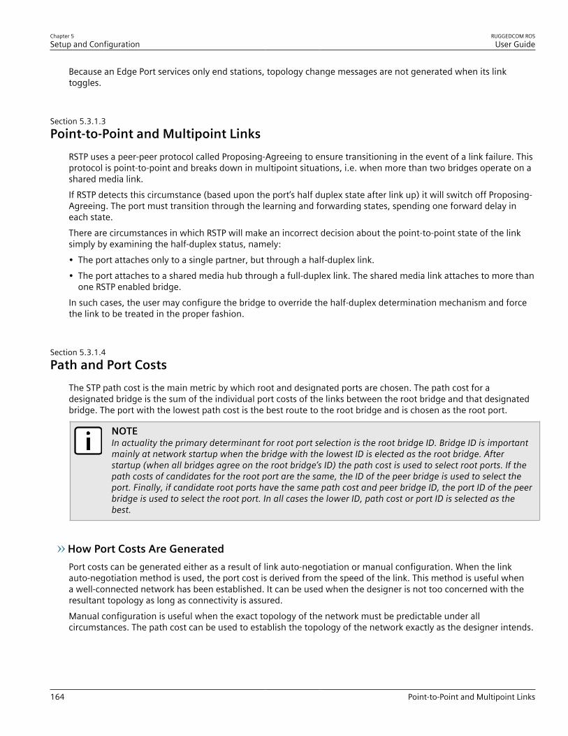
Chapter 5Setup and Configuration
RUGGEDCOM ROSUser Guide
164 Point-to-Point and Multipoint Links
Because an Edge Port services only end stations, topology change messages are not generated when its linktoggles.
Section 5.3.1.3Point-to-Point and Multipoint Links
RSTP uses a peer-peer protocol called Proposing-Agreeing to ensure transitioning in the event of a link failure. Thisprotocol is point-to-point and breaks down in multipoint situations, i.e. when more than two bridges operate on ashared media link.If RSTP detects this circumstance (based upon the port’s half duplex state after link up) it will switch off Proposing-Agreeing. The port must transition through the learning and forwarding states, spending one forward delay ineach state.There are circumstances in which RSTP will make an incorrect decision about the point-to-point state of the linksimply by examining the half-duplex status, namely:• The port attaches only to a single partner, but through a half-duplex link.• The port attaches to a shared media hub through a full-duplex link. The shared media link attaches to more than
one RSTP enabled bridge.In such cases, the user may configure the bridge to override the half-duplex determination mechanism and forcethe link to be treated in the proper fashion.
Section 5.3.1.4Path and Port Costs
The STP path cost is the main metric by which root and designated ports are chosen. The path cost for adesignated bridge is the sum of the individual port costs of the links between the root bridge and that designatedbridge. The port with the lowest path cost is the best route to the root bridge and is chosen as the root port.
NOTEIn actuality the primary determinant for root port selection is the root bridge ID. Bridge ID is importantmainly at network startup when the bridge with the lowest ID is elected as the root bridge. Afterstartup (when all bridges agree on the root bridge’s ID) the path cost is used to select root ports. If thepath costs of candidates for the root port are the same, the ID of the peer bridge is used to select theport. Finally, if candidate root ports have the same path cost and peer bridge ID, the port ID of the peerbridge is used to select the root port. In all cases the lower ID, path cost or port ID is selected as thebest.
How Port Costs Are GeneratedPort costs can be generated either as a result of link auto-negotiation or manual configuration. When the linkauto-negotiation method is used, the port cost is derived from the speed of the link. This method is useful whena well-connected network has been established. It can be used when the designer is not too concerned with theresultant topology as long as connectivity is assured.Manual configuration is useful when the exact topology of the network must be predictable under allcircumstances. The path cost can be used to establish the topology of the network exactly as the designer intends.
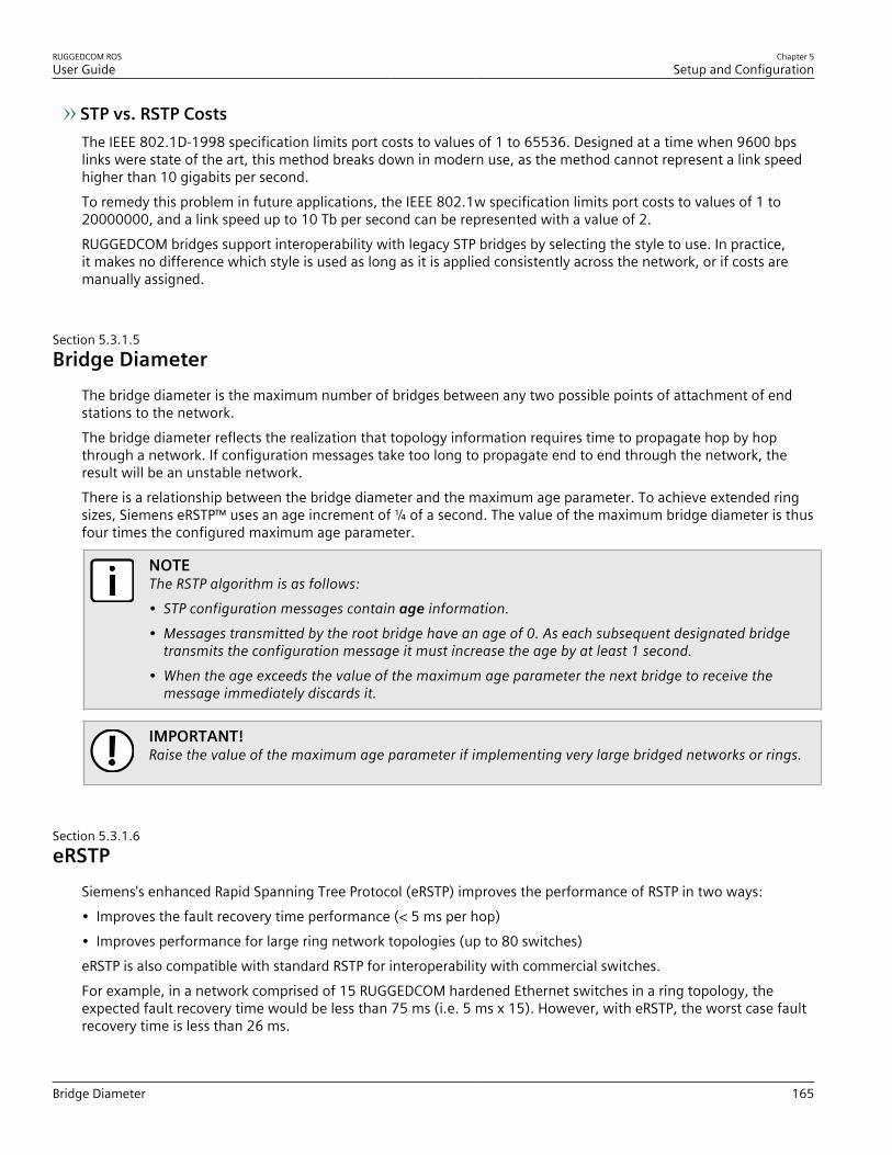
RUGGEDCOM ROSUser Guide
Chapter 5Setup and Configuration
Bridge Diameter 165
STP vs. RSTP CostsThe IEEE 802.1D-1998 specification limits port costs to values of 1 to 65536. Designed at a time when 9600 bpslinks were state of the art, this method breaks down in modern use, as the method cannot represent a link speedhigher than 10 gigabits per second.To remedy this problem in future applications, the IEEE 802.1w specification limits port costs to values of 1 to20000000, and a link speed up to 10 Tb per second can be represented with a value of 2.RUGGEDCOM bridges support interoperability with legacy STP bridges by selecting the style to use. In practice,it makes no difference which style is used as long as it is applied consistently across the network, or if costs aremanually assigned.
Section 5.3.1.5Bridge Diameter
The bridge diameter is the maximum number of bridges between any two possible points of attachment of endstations to the network.The bridge diameter reflects the realization that topology information requires time to propagate hop by hopthrough a network. If configuration messages take too long to propagate end to end through the network, theresult will be an unstable network.There is a relationship between the bridge diameter and the maximum age parameter. To achieve extended ringsizes, Siemens eRSTP™ uses an age increment of ¼ of a second. The value of the maximum bridge diameter is thusfour times the configured maximum age parameter.
NOTEThe RSTP algorithm is as follows:• STP configuration messages contain age information.• Messages transmitted by the root bridge have an age of 0. As each subsequent designated bridge
transmits the configuration message it must increase the age by at least 1 second.• When the age exceeds the value of the maximum age parameter the next bridge to receive the
message immediately discards it.
IMPORTANT!Raise the value of the maximum age parameter if implementing very large bridged networks or rings.
Section 5.3.1.6eRSTP
Siemens's enhanced Rapid Spanning Tree Protocol (eRSTP) improves the performance of RSTP in two ways:• Improves the fault recovery time performance (< 5 ms per hop)• Improves performance for large ring network topologies (up to 80 switches)eRSTP is also compatible with standard RSTP for interoperability with commercial switches.For example, in a network comprised of 15 RUGGEDCOM hardened Ethernet switches in a ring topology, theexpected fault recovery time would be less than 75 ms (i.e. 5 ms x 15). However, with eRSTP, the worst case faultrecovery time is less than 26 ms.
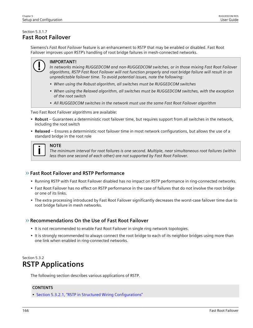
Chapter 5Setup and Configuration
RUGGEDCOM ROSUser Guide
166 Fast Root Failover
Section 5.3.1.7Fast Root Failover
Siemens’s Fast Root Failover feature is an enhancement to RSTP that may be enabled or disabled. Fast RootFailover improves upon RSTP’s handling of root bridge failures in mesh-connected networks.
IMPORTANT!In networks mixing RUGGEDCOM and non-RUGGEDCOM switches, or in those mixing Fast Root Failoveralgorithms, RSTP Fast Root Failover will not function properly and root bridge failure will result in anunpredictable failover time. To avoid potential issues, note the following:• When using the Robust algorithm, all switches must be RUGGEDCOM switches• When using the Relaxed algorithm, all switches must be RUGGEDCOM switches, with the exception
of the root switch• All RUGGEDCOM switches in the network must use the same Fast Root Failover algorithm
Two Fast Root Failover algorithms are available:• Robust – Guarantees a deterministic root failover time, but requires support from all switches in the network,
including the root switch• Relaxed – Ensures a deterministic root failover time in most network configurations, but allows the use of a
standard bridge in the root role
NOTEThe minimum interval for root failures is one second. Multiple, near simultaneous root failures (withinless than one second of each other) are not supported by Fast Root Failover.
Fast Root Failover and RSTP Performance• Running RSTP with Fast Root Failover disabled has no impact on RSTP performance in ring-connected networks.• Fast Root Failover has no effect on RSTP performance in the case of failures that do not involve the root bridge
or one of its links.• The extra processing introduced by Fast Root Failover significantly decreases the worst-case failover time due to
root bridge failure in mesh networks.
Recommendations On the Use of Fast Root Failover• It is not recommended to enable Fast Root Failover in single ring network topologies.• It is strongly recommended to always connect the root bridge to each of its neighbor bridges using more than
one link when enabled in ring-connected networks.
Section 5.3.2
RSTP ApplicationsThe following section describes various applications of RSTP.
CONTENTS• Section 5.3.2.1, “RSTP in Structured Wiring Configurations”

RUGGEDCOM ROSUser Guide
Chapter 5Setup and Configuration
RSTP in Structured Wiring Configurations 167
• Section 5.3.2.2, “RSTP in Ring Backbone Configurations”• Section 5.3.2.3, “RSTP Port Redundancy”
Section 5.3.2.1RSTP in Structured Wiring Configurations
RSTP may be used to construct structured wiring systems where connectivity is maintained in the event of linkfailures. For example, a single link failure of any link between A and N in Figure 104 would leave all the ports ofbridges 555 through 888 connected to the network.
B
A
D
2
1
4 3
F
4
1
666
3
2
4
1
777
3
2
4
1
888
3
2
4
1
555
3
2
C
KH
E
32
1
4
1
444
2
43
56
1
444
2
56
43
IG MJ NL
111 222
Figure 104: Example - Structured Wiring Configuration
To design a structured wiring configuration, do the following:1. Select the design parameters for the network.
What are the requirements for robustness and network failover/recovery times? Are there any specialrequirements for diverse routing to a central host computer? Are there any special port redundancyrequirements?

Chapter 5Setup and Configuration
RUGGEDCOM ROSUser Guide
168 RSTP in Ring Backbone Configurations
2. Identify required legacy support.Are STP bridges used in the network? These bridges do not support rapid transitioning to forwarding. If thesebridges are present, can they be re-deployed closer to the network edge?
3. Identify edge ports and ports with half-duplex/shared media restrictions.Ports that connect to host computers, Intelligent Electronic Devices (IEDs) and controllers may be set to edgeports in order to guarantee rapid transitioning to forwarding as well as to reduce the number of topologychange notifications in the network. Ports with half-duplex/shared media restrictions require special attentionin order to guarantee that they do not cause extended fail-over/recovery times.
4. Choose the root bridge and backup root bridge carefully.The root bridge should be selected to be at the concentration point of network traffic. Locate the backup rootbridge adjacent to the root bridge. One strategy that may be used is to tune the bridge priority to establishthe root bridge and then tune each bridge’s priority to correspond to its distance from the root bridge.
5. Identify desired steady state topology.Identify the desired steady state topology taking into account link speeds, offered traffic and QOS. Examine ofthe effects of breaking selected links, taking into account network loading and the quality of alternate links.
6. Decide upon a port cost calculation strategy.Select whether fixed or auto-negotiated costs should be used? It is recommended to use the auto-negotiatedcost style, unless it is necessary for the network design to change the auto-negotiated cost style. Selectwhether the STP or RSTP cost style should be used. Make sure to configure the same cost style on all deviceson the network.
7. Enable RSTP Fast Root Failover option.This is a proprietary feature of Siemens. In a mesh network with only RUGGEDCOM devices in the core of thenetwork, it is recommended to enable the RSTP Fast Root Failover option to minimize the network downtimein the event of a Root bridge failure.
8. Calculate and configure priorities and costs.9. Implement the network and test under load.
Section 5.3.2.2RSTP in Ring Backbone Configurations
RSTP may be used in ring backbone configurations where rapid recovery from link failure is required. In normaloperation, RSTP will block traffic on one of the links, for example, as indicated by the double bars through link H inFigure 105 . In the event of a failure on link D, bridge 444 will unblock link H. Bridge 333 will communicate withthe network through link F.

RUGGEDCOM ROSUser Guide
Chapter 5Setup and Configuration
RSTP in Ring Backbone Configurations 169
E
1
3
31
C
G
A
K
I1
32
2
2 32
1
3321B
J
555
666 333
444
F
L D
H
111 222
Figure 105: Example - Ring Backbone Configuration
To design a ring backbone configuration with RSTP, do the following:1. Select the design parameters for the network.
What are the requirements for robustness and network fail-over/recovery times? Typically, ring backbones arechosen to provide cost effective but robust network designs.
2. Identify required legacy support and ports with half-duplex/shared media restrictions.These bridges should not be used if network fail-over/recovery times are to be minimized.
3. Identify edge ports.Ports that connect to host computers, Intelligent Electronic Devices (IEDs) and controllers may be set to edgeports in order to guarantee rapid transitioning to forwarding as well as to reduce the number of topologychange notifications in the network.
4. Choose the root bridge.The root bridge can be selected to equalize either the number of bridges, number of stations or amount oftraffic on either of its legs. It is important to realize that the ring will always be broken in one spot and thattraffic always flows through the root.

Chapter 5Setup and Configuration
RUGGEDCOM ROSUser Guide
170 RSTP Port Redundancy
5. Assign bridge priorities to the ring.The strategy that should be used is to assign each bridge’s priority to correspond to its distance from the rootbridge. If the root bridge is assigned the lowest priority of 0, the bridges on either side should use a priorityof 4096 and the next bridges 8192 and so on. As there are 16 levels of bridge priority available, this methodprovides for up to 31 bridges in the ring.
6. Decide upon a port cost calculation strategy.It is recommended to use the auto-negotiated cost style, unless it is necessary for the network design tochange the auto-negotiated cost style. Select whether the STP or RSTP cost style should be used. Make sure toconfigure the same cost style on all devices on the network.
7. Disable RSTP Fast Root Failover option.This is a proprietary feature of Siemens. In RUGGEDCOM ROS, the RSTP Fast Root Failover option is enabled bydefault. It is recommended to disable this feature when operating in a Ring network.
8. Implement the network and test under load.
Section 5.3.2.3RSTP Port Redundancy
In cases where port redundancy is essential, RSTP allows more than one bridge port to service a LAN. In thefollowing example, if port 3 is designated to carry the network traffic of LAN A, port 4 will block traffic. Should aninterface failure occur on port 3, port 4 will assume control of the LAN.
A
1 2
34
Figure 106: Example - Port Redundancy
Section 5.3.3
Configuring STP GloballyTo configure global settings for the Spanning Tree Protocol (STP), do the following:1. Navigate to Spanning Tree » Configure Bridge RSTP Parameters . The Bridge RSTP Parameters form
appears.
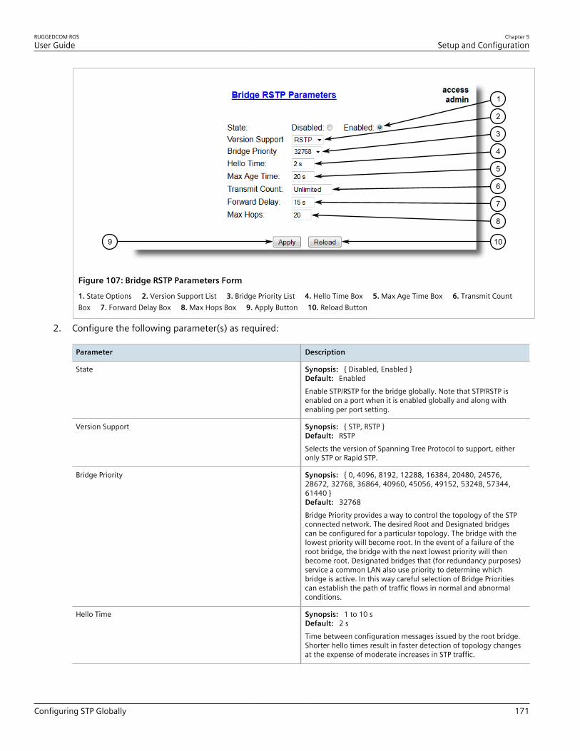
RUGGEDCOM ROSUser Guide
Chapter 5Setup and Configuration
Configuring STP Globally 171
9 10
2
3
4
5
6
7
8
1
Figure 107: Bridge RSTP Parameters Form
1. State Options 2. Version Support List 3. Bridge Priority List 4. Hello Time Box 5. Max Age Time Box 6. Transmit CountBox 7. Forward Delay Box 8. Max Hops Box 9. Apply Button 10. Reload Button
2. Configure the following parameter(s) as required:
Parameter Description
State Synopsis: { Disabled, Enabled }Default: EnabledEnable STP/RSTP for the bridge globally. Note that STP/RSTP isenabled on a port when it is enabled globally and along withenabling per port setting.
Version Support Synopsis: { STP, RSTP }Default: RSTPSelects the version of Spanning Tree Protocol to support, eitheronly STP or Rapid STP.
Bridge Priority Synopsis: { 0, 4096, 8192, 12288, 16384, 20480, 24576,28672, 32768, 36864, 40960, 45056, 49152, 53248, 57344,61440 }Default: 32768Bridge Priority provides a way to control the topology of the STPconnected network. The desired Root and Designated bridgescan be configured for a particular topology. The bridge with thelowest priority will become root. In the event of a failure of theroot bridge, the bridge with the next lowest priority will thenbecome root. Designated bridges that (for redundancy purposes)service a common LAN also use priority to determine whichbridge is active. In this way careful selection of Bridge Prioritiescan establish the path of traffic flows in normal and abnormalconditions.
Hello Time Synopsis: 1 to 10 sDefault: 2 sTime between configuration messages issued by the root bridge.Shorter hello times result in faster detection of topology changesat the expense of moderate increases in STP traffic.

Chapter 5Setup and Configuration
RUGGEDCOM ROSUser Guide
172 Configuring STP for Specific Ethernet Ports
Parameter Description
Max Age Time Synopsis: 6 to 40 sDefault: 20 sThe time for which a configuration message remains valid afterbeing issued by the root bridge. Configure this parameter withcare when many tiers of bridges exist, or slow speed links (such asthose used in WANs) are part of the network
Transmit Count Synopsis: 3 to 100 or { Unlimited }Default: UnlimitedMaximum number of BPDUs on each port that may be sent in onesecond. Larger values allow the network to recover from failedlinks/bridges more quickly.
Forward Delay Synopsis: 4 to 30 sDefault: 15 sThe amount of time a bridge spends learning MAC addresses on arising port before beginning to forward traffic. Lower values allowthe port to reach the forwarding state more quickly, but at theexpense of flooding unlearned addresses to all ports.
Max Hops Synopsis: 6 to 40Default: 20Only applicable to MSTP. The maximum possible bridge diameterinside an MST region.MSTP BPDUs propagating inside an MST region specify a time-to-live that is decremented by every switch that propagates theBPDU. If the maximum number of hops inside the region exceedsthe configured maximum, BPDUs may be discarded due to theirtime-to-live setting.
3. Click Apply.
Section 5.3.4
Configuring STP for Specific Ethernet PortsTo configure the Spanning Tree Protocol (STP) for a specific Ethernet port, do the following:1. Navigate to Spanning Tree » Configure Port RSTP Parameters . The Port RSTP Parameters table appears.

RUGGEDCOM ROSUser Guide
Chapter 5Setup and Configuration
Configuring STP for Specific Ethernet Ports 173
Figure 108: Port RSTP Parameters Table
2. Select an Ethernet port. The Port RSTP Parameters form appears.
8
10
7
6
5
4
3
2
1
11
9
Figure 109: Port RSTP Parameters Form
1. Port(s) Box 2. Enabled Options 3. Priority List 4. STP Cost Box 5. RSTP Cost Box 6. Edge Port List 7. Point to Point List 8. Restricted Role Box 9. Restricted TCN Box 10. Apply Button 11. Reload Button
3. Configure the following parameter(s) as required:
Parameter Description
Port(s) Synopsis: Any combination of numbers valid for this parameterThe port number as seen on the front plate silkscreen of theswitch (or a list of ports, if aggregated in a port trunk).
Enabled Synopsis: { Disabled, Enabled }Default: Enabled

Chapter 5Setup and Configuration
RUGGEDCOM ROSUser Guide
174 Configuring STP for Specific Ethernet Ports
Parameter Description
Enabling STP activates the STP or RSTP protocol for this port perthe configuration in the STP Configuration menu. STP may bedisabled for the port ONLY if the port does not attach to an STPenabled bridge in any way. Failure to meet this requirement WILLresult in an undetectable traffic loop in the network. A betteralternative to disabling the port is to leave STP enabled but toconfigure the port as an edge port. A good candidate for disablingSTP would be a port that services only a single host computer.
Priority Synopsis: { 0, 16, 32, 48, 64, 80, 96, 112, 128, 144, 160, 176,194, 208, 224, 240 }Default: 128Selects the STP port priority. Ports of the same cost that attach toa common LAN will select the port to be used based upon the portpriority.
STP Cost Synopsis: 0 to 65535 or { Auto }Default: AutoSelects the cost to use in cost calculations, when the CostStyle parameter is set to STP in the Bridge RSTP Parametersconfiguration. Setting the cost manually provides the ability topreferentially select specific ports to carry traffic over others.Leave this field set to "auto" to use the standard STP port costs asnegotiated (4 for 1Gbps, 19 for 100 Mbps links and 100 for 10Mbps links).For MSTP, this parameter applies to both external and internalpath cost.
RSTP Cost Synopsis: 0 to 2147483647 or { Auto }Default: AutoSelects the cost to use in cost calculations, when the CostStyle parameter is set to RSTP in the Bridge RSTP Parametersconfiguration. Setting the cost manually provides the ability topreferentially select specific ports to carry traffic over others.Leave this field set to "auto" to use the standard RSTP port costsas negotiated (20,000 for 1Gbps, 200,000 for 100 Mbps links and2,000,000 for 10 Mbps links).
Edge Port Synopsis: { False, True, Auto }Default: AutoEdge ports are ports that do not participate in the SpanningTree, but still send configuration messages. Edge ports transitiondirectly to frame forwarding without any listening and learningdelays. The MAC tables of Edge ports do not need to be flushedwhen topology changes occur in the STP network. Unlike an STPdisabled port, accidentally connecting an edge port to anotherport in the spanning tree will result in a detectable loop. The"Edgeness" of the port will be switched off and the standard RSTPrules will apply (until the next link outage).
Point to Point Synopsis: { False, True, Auto }Default: AutoRSTP uses a peer-to-peer protocol that provides rapid transitioningon point-to-point links. This protocol is automatically turned off insituations where multiple STP bridges communicate over a shared(non point-to-point) LAN. The bridge will automatically take point-to-point to be true when the link is found to be operating in full-duplex mode. The point-to-point parameter allows this behavioror overrides it, forcing point-to-point to be true or false. Force theparameter true when the port operates a point-to-point link butcannot run the link in full-duplex mode. Force the parameter falsewhen the port operates the link in full-duplex mode, but is still not

RUGGEDCOM ROSUser Guide
Chapter 5Setup and Configuration
Configuring eRSTP 175
Parameter Description
point-to-point (e.g. a full-duplex link to an unmanaged bridge thatconcentrates two other STP bridges).
Restricted Role Synopsis: { True or False }Default: FalseA boolean value set by management. If TRUE, causes the Portnot to be selected as the Root Port for the CIST or any MSTI, evenif it has the best spanning tree priority vector. Such a Port willbe selected as an Alternate Port after the Root Port has beenselected. This parameter should be FALSE by default. If set, it cancause a lack of spanning tree connectivity. It is set by a networkadministrator to prevent bridges that are external to a coreregion of the network from influencing the spanning tree activetopology. This may be necessary, for example, if those bridges arenot under the full control of the administrator.
Restricted TCN Synopsis: { True or False }Default: FalseA boolean value set by management. If TRUE, it causes the Portnot to propagate received topology change notifications andtopology changes to other Ports. If set, it can cause temporaryloss of connectivity after changes in a spanning tree’s activetopology as a result of persistent, incorrectly learned, stationlocation information. It is set by a network administrator toprevent bridges that are external to a core region of the networkfrom causing address flushing in that region. This may benecessary, for example, if those bridges are not under the fullcontrol of the administrator or if the MAC_Operational statusparameter for the attached LANs transitions frequently.
4. Click Apply.
Section 5.3.5
Configuring eRSTPTo configure eRSTP, do the following:1. Navigate to Spanning Tree » Configure eRSTP Parameters . The eRSTP Parameters form appears.
76
5
4
3
2
1
Figure 110: eRSTP Parameters Form
1. Max Network Diameter Options 2. BPDU Guart Timeout Box 3. Fast Root Failover List 4. IEEE802.1w Interoperability Options 5. Cost Style Options 6. Apply Button 7. Reload Button
2. Configure the following parameter(s) as required:

Chapter 5Setup and Configuration
RUGGEDCOM ROSUser Guide
176 Configuring eRSTP
Parameter Description
Max Network Diameter Synopsis: { MaxAgeTime, 4*MaxAgeTime }Default: 4*MaxAgeTimeThe RSTP standard puts a limit on the maximum network sizethat can be controlled by the RSTP protocol. The network sizeis described by the term 'maximum network diameter', whichis the number of switches that comprise the longest path thatRSTP BPDUs have to traverse. The standard supported maximumnetwork diameter is equal to the value of the 'MaxAgeTime' RSTPconfiguration parameter.eRSTP offers an enhancement to RSTP which allows it to covernetworks larger than ones defined by the standard.This configuration parameter selects the maximum supportednetwork size.
BPDU Guard Timeout Synopsis: 1 to 86400 s or { Until reset, Don't shutdown }Default: Don't shutdownThe RSTP standard does not address network security. RSTP mustprocess every received BPDU and take an appropriate action.This opens a way for an attacker to influence RSTP topology byinjecting RSTP BPDUs into the network.BPDU Guard is a feature that protects the network from BPDUsreceived by a port where RSTP capable devices are not expectedto be attached. If a BPDU is received by a port for which 'Edge'parameter is set to 'TRUE' or RSTP is disabled, the port will beshutdown for the time period specified by this parameter.• DON'T SHUTDOWN - BPDU Guard is disabled• UNTIL RESET - port will remain shutdown until the port reset
command is issued by the user
Fast Root Failover Synopsis: { On, On with standard root, Off }Default: OnIn mesh network topologies, the standard RSTP algorithm doesnot guarantee deterministic network recovery time in the case ofa root switch failure. Such a recovery time is hard to calculate andit can be different (and may be relatively long) for any given meshtopology.This configuration parameter enables Siemens's enhancement toRSTP which detects a failure of the root switch and performs someextra RSTP processing steps, significantly reducing the networkrecovery time and making it deterministic.
NOTE• This feature is only available in RSTP mode.• In a single ring topology, this feature is not
needed and should be disabled to avoid longernetwork recovery times due to extra RSTPprocessing.
The Fast Root Failover algorithm must be supported by allswitches in the network, including the root, to guarantee optimalperformance. However, it is not uncommon to assign the root roleto a switch from a vendor different from the rest of the switchesin the network. In other words, it is possible that the root mightnot suport the Fast Root Failover algorithm. In such a scenario,a "relaxed" algorithm should be used, which tolerates the lack ofsupport in the root switch.These are the supported configuration options:

RUGGEDCOM ROSUser Guide
Chapter 5Setup and Configuration
Viewing Global Statistics for STP 177
Parameter Description
• Off - Fast Root Failover algorithm is disabled and hence a rootswitch failure may result in excessive connectivity recoverytime.
• On - Fast Root Failover is enabled and the most robustalgorithm is used, which requires the appropriate support in theroot switch.
• On with standard root - Fast Root Failover is enabled but a"relaxed" algorithm is used, allowing the use of a standardswitch in the root role.
IEEE802.1w Interoperability Synopsis: { On, Off }Default: OnThe original RSTP protocol defined in the IEEE 802.1w standardhas minor differences from more recent, enhanced, standard(s).Those differences cause interoperability issues which, althoughthey do not completely break RSTP operation, can lead to a longerrecovery time from failures in the network.eRSTP offers some enhancements to the protocol which make theswitch fully interoperable with other vendors' switches, whichmay be running IEEE 802.2w RSTP. The enhancements do notaffect interoperability with more recent RSTP editions.This configuration parameter enables the aforementionedinteroperability mode.
Cost Style Synopsis: { STP (16 bit), RSTP (32 bit) }Default: STP (16 bit)The RSTP standard defines two styles of a path cost value. STPuses 16-bit path costs based upon 1x10E9/link speed (4 for1Gbps, 19 for 100 Mbps and 100 for 10 Mbps) whereas RSTPuses 32-bit costs based upon 2x10E13/link speed (20,000 for1Gbps, 200,000 for 100 Mbps and 2,000,000 for 10 Mbps).However, switches from some vendors keep using the STP pathcost style even in RSTP mode, which can cause confusion andinteroperability problems.This configuration parameter selects the style of link costs toemploy.Note that RSTP link costs are used only when the bridge versionsupport is set to allow RSTP and the port does not migrate to STP.
3. Click Apply.
Section 5.3.6
Viewing Global Statistics for STPTo view global statistics for STP, navigate to Spanning Tree » View Bridge RSTP Statistics . The Bridge RSTPStatistics form appears.

Chapter 5Setup and Configuration
RUGGEDCOM ROSUser Guide
178 Viewing Global Statistics for STP
14
13
12
11
10
9
8
7
6
5
4
3
2
1
Figure 111: Bridge RSTP Statistics Form
1. Bridge Status Box 2. Bridge ID Box 3. Root ID Box 4. Root Port Box 5. Root Path Cost Box 6. Configure Hello Time Box 7. Learned Hello Time Box 8. Configured Forward Delay Box 9. Learned Forward Delay Box 10. Configured Max Age Box 11. LearnedMax Age Box 12. Total Topology Changes Box 13. Time Since Last TC Box 14. Reload Button
This table displays the following information:
Parameter Description
Bridge Status Synopsis: { , Designated Bridge, Not Designated For Any LAN, RootBridge }Spanning Tree status of the bridge. The status may be root ordesignated. This field may show text saying not designated for anyLAN if the bridge is not designated for any of its ports.
Bridge ID Synopsis: $$ / ##-##-##-##-##-## where $$ is 0 to 65535, ## is 0to FFBridge Identifier of this bridge.
Root ID Synopsis: $$ / ##-##-##-##-##-## where $$ is 0 to 65535, ## is 0to FFBridge Identifier of the root bridge.
Root Port Synopsis: 1 to maximum port number or { <empty string> }If the bridge is designated, this is the port that provides connectivitytowards the root bridge of the network.
Root Path Cost Synopsis: 0 to 4294967295Total cost of the path to the root bridge composed of the sum ofthe costs of each link in the path. If custom costs have not beenconfigured. 1Gbps ports will contribute 4, 100 Mbps ports willcontribute 19 and 10 Mbps ports will contribute a cost of 100 to thisfigure.
Configured Hello Time Synopsis: 0 to 65535The configured Hello time from the Bridge RSTP Parameters menu.
Learned Hello Time Synopsis: 0 to 65535The actual Hello time provided by the root bridge as learned inconfiguration messages. This time is used in designated bridges.
Configured Forward Delay Synopsis: 0 to 65535

RUGGEDCOM ROSUser Guide
Chapter 5Setup and Configuration
Viewing STP Statistics for Ethernet Ports 179
Parameter Description
The configured Forward Delay time from the Bridge RSTP Parametersmenu.
Learned Forward Delay Synopsis: 0 to 65535The actual Forward Delay time provided by the root bridge aslearned in configuration messages. This time is used in designatedbridges.
Configured Max Age Synopsis: 0 to 65535The configured Maximum Age time from the Bridge RSTP Parametersmenu.
Learned Max Age Synopsis: 0 to 65535The actual Maximum Age time provided by the root bridge aslearned in configuration messages. This time is used in designatedbridges.
Total Topology Changes Synopsis: 0 to 65535A count of topology changes in the network, as detected on thisbridge through link failures or as signaled from other bridges.Excessively high or rapidly increasing counts signal networkproblems.
Time since Last TC Synopsis: DDDD days, HH:MM:SSThe time since the last time a topology change was detected by thebridge.
Section 5.3.7
Viewing STP Statistics for Ethernet PortsTo view STP statistics for Ethernet ports, navigate to Spanning Tree » View Port RSTP Statistics . The Port RSTPStatistics table appears.
Figure 112: Port RSTP Statistics Table
This table displays the following information:

Chapter 5Setup and Configuration
RUGGEDCOM ROSUser Guide
180 Viewing STP Statistics for Ethernet Ports
Parameter Description
Port(s) Synopsis: Any combination of numbers valid for this parameterThe port number as seen on the front plate silkscreen of the switch(or a list of ports, if aggregated in a port trunk).
Status Synopsis: { Disabled, Listening, Learning, Forwarding, Blocking,Link Down, Discarding }Status of this port in Spanning Tree. This may be one of thefollowing:• Disabled - STP is disabled on this port.• Link Down - STP is enabled on this port but the link is down.• Discarding - The link is not used in the STP topology but is
standing by.• Learning - The port is learning MAC addresses in order to prevent
flooding when it begins forwarding traffic.• Forwarding - The port is forwarding traffic.
Role Synopsis: { , Root, Designated, Alternate, Backup, Master }Role of this port in Spanning Tree. This may be one of the following:• Designated - The port is designated for (i.e. carries traffic towards
the root for) the LAN it is connected to.• Root - The single port on the bridge, which provides connectivity
towards the root bridge.• Backup - The port is attached to a LAN that is serviced by another
port on the bridge. It is not used but is standing by.• Alternate - The port is attached to a bridge that provides
connectivity to the root bridge. It is not used but is standing by.• Master - Only exists in MSTP. The port is an MST region boundary
port and the single port on the bridge, which provides connectivityfor the Multiple Spanning Tree Instance towards the CommonSpanning Tree root bridge (i.e. this port is the root port for theCommon Spanning Tree Instance).
Cost Synopsis: 0 to 4294967295Cost offered by this port. If the Bridge RSTP Parameters Cost Styleis set to STP, 1Gbps ports will contribute 4, 100 Mbps ports willcontribute 19 and 10 Mbps ports contribute a cost of 100. If the CostStyle is set to RSTP, 1Gbps will contribute 20,000, 100 Mbps portswill contribute a cost of 200,000 and 10 Mbps ports contribute acost of 2,000,000. Note that even if the Cost style is set to RSTP, aport that migrates to STP will have its cost limited to a maximum of65535.
RX RSTs Synopsis: 0 to 4294967295The count of RSTP configuration messages received on this port.
TX RSTs Synopsis: 0 to 4294967295The count of RSTP configuration messages transmitted on this port.
RX Configs Synopsis: 0 to 4294967295The count of STP configuration messages received on this port.
TX Configs Synopsis: 0 to 4294967295The count of STP configuration messages transmitted on this port.
RX Tcns Synopsis: 0 to 4294967295The count of STP topology change notification messages receivedon this port. Excessively high or rapidly increasing counts signalnetwork problems.

RUGGEDCOM ROSUser Guide
Chapter 5Setup and Configuration
Clearing Spanning Tree Protocol Statistics 181
Parameter Description
TX Tcns Synopsis: 0 to 4294967295The count of STP topology change notification messages transmittedon this port.
Desig Bridge ID Synopsis: $$ / ##-##-##-##-##-## where $$ is 0 to 65535, ## is 0to FFProvided on the root ports of designated bridges, the BridgeIdentifier of the bridge this port is connected to.
operEdge Synopsis: True or FalseThe port is operating as an edge port or not.
Section 5.3.8
Clearing Spanning Tree Protocol StatisticsTo clear all spanning tree protocol statistics, do the following:1. Navigate to Spanning Tree » Clear Spanning Tree Statistics . The Clear Spanning Tree Statistics form
appears.
1
Figure 113: Clear Spanning Tree Statistics Form
1. Confirm Button
2. Click Confirm.
Section 5.4
Managing Classes of ServiceClasses of Service (CoS) provides the ability to expedite the transmission of certain frames and port traffic overothers. The CoS of a frame can be set to Normal, Medium, High, or Critical. By default, other than the controlframes, RUGGEDCOM ROS enforces Normal CoS for all incoming traffic received without a priority tag.
IMPORTANT!Use the highest supported CoS with caution, as it is always used by the switch for handling networkmanagement traffic, such as RSTP BPDUs.If this CoS is used for regular network traffic, upon traffic bursts, it may result in the loss of somenetwork management frames, which in turn may result in the loss of connectivity over the network.
The process of controlling traffic based on CoS occurs over two phases:

Chapter 5Setup and Configuration
RUGGEDCOM ROSUser Guide
182 Configuring Classes of Service Globally
1. Inspection PhaseIn the inspection phase, the CoS priority of a received frame is determined from either:• A specific CoS based upon the destination MAC address (as set in the Static MAC Address Table)• The priority field in the IEEE 802.1Q tags• The Differentiated Services Code Point (DSCP) component of the Type Of Service (TOS) field in the IP
header, if the frame is IP• The default CoS for the portEach frame’s CoS will be determined once the first examined parameter is found in the frame.
NOTEFor information on how to configure the Inspect TOS parameter, refer to Section 5.4.2,“Configuring Classes of Service for Specific Ethernet Ports” .
Received frames are first examined to determine if their destination MAC address is found in the Static MACAddress Table. If they are, the CoS configured for the static MAC address is used. If the destination MACaddress is in the Static MAC Address Table, the frame is then examined for IEEE 802.1Q tags and the priorityfield is mapped to a CoS. If a tag is not present, the frame is examined to determine if it is an IP frame. If theframe is an IP frame and Inspect TOS is enabled in RUGGEDCOM ROS, the CoS is determined from the DSCPfield. If the frame is not an IP frame or Inspect TOS is disabled, the default CoS for the port is used.After inspection, the frame is forwarded to the egress port for transmission.
2. Forwarding PhaseOnce the CoS of the frame is determined, the frame is forwarded to the egress port, where it is collected intoone of the priority queues according to the assigned CoS.CoS weighting selects the degree of preferential treatment that is attached to different priority queues. Theratio of the number of higher CoS to lower CoS frames transmitted can be configured. If desired, lower CoSframes can be transmitted only after all higher CoS frames have been serviced.
CONTENTS• Section 5.4.1, “Configuring Classes of Service Globally”• Section 5.4.2, “Configuring Classes of Service for Specific Ethernet Ports”• Section 5.4.3, “Configuring Priority to CoS Mapping”• Section 5.4.4, “Configuring DSCP to CoS Mapping”
Section 5.4.1
Configuring Classes of Service GloballyTo configure global settings for Classes of Service (CoS), do the following:1. Navigate to Classes of Service » Configure Global CoS Parameters . The Global CoS Parameters form
appears.
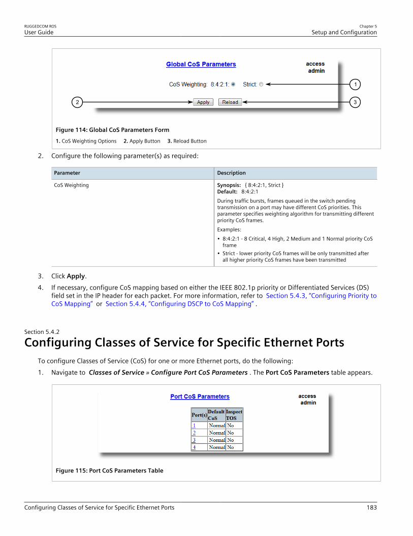
RUGGEDCOM ROSUser Guide
Chapter 5Setup and Configuration
Configuring Classes of Service for Specific Ethernet Ports 183
32
1
Figure 114: Global CoS Parameters Form
1. CoS Weighting Options 2. Apply Button 3. Reload Button
2. Configure the following parameter(s) as required:
Parameter Description
CoS Weighting Synopsis: { 8:4:2:1, Strict }Default: 8:4:2:1During traffic bursts, frames queued in the switch pendingtransmission on a port may have different CoS priorities. Thisparameter specifies weighting algorithm for transmitting differentpriority CoS frames.Examples:• 8:4:2:1 - 8 Critical, 4 High, 2 Medium and 1 Normal priority CoS
frame• Strict - lower priority CoS frames will be only transmitted after
all higher priority CoS frames have been transmitted
3. Click Apply.4. If necessary, configure CoS mapping based on either the IEEE 802.1p priority or Differentiated Services (DS)
field set in the IP header for each packet. For more information, refer to Section 5.4.3, “Configuring Priority toCoS Mapping” or Section 5.4.4, “Configuring DSCP to CoS Mapping” .
Section 5.4.2
Configuring Classes of Service for Specific Ethernet PortsTo configure Classes of Service (CoS) for one or more Ethernet ports, do the following:1. Navigate to Classes of Service » Configure Port CoS Parameters . The Port CoS Parameters table appears.
Figure 115: Port CoS Parameters Table

Chapter 5Setup and Configuration
RUGGEDCOM ROSUser Guide
184 Configuring Priority to CoS Mapping
2. Select an Ethernet port. The Port CoS Parameters form appears.
54
3
2
1
Figure 116: Port CoS Parameters Form
1. Port(s) Box 2. Default CoS Box 3. Inspect TOS Options 4. Apply Button 5. Reload Button
3. Configure the following parameter(s) as required:
Parameter Description
Port(s) Synopsis: Any combination of numbers valid for this parameterThe port number as seen on the front plate silkscreen of theswitch (or a list of ports, if aggregated in a port trunk).
Default CoS Synopsis: { Normal, Medium, High, Crit }Default: NormalThis parameter allows to prioritize frames received on this portthat are not prioritized based on the frames contents (e.g. priorityfield in the VLAN tag, DiffServ field in the IP header, prioritizedMAC address).
Inspect TOS Synopsis: { No, Yes }Default: NoThis parameters enables or disables parsing of the Type-Of-Service(TOS) field in the IP header of the received frames to determinewhat Class of Service they should be assigned. When TOS parsingis enabled the switch will use the Differentiated Services bits inthe TOS field.
4. Click Apply.
Section 5.4.3
Configuring Priority to CoS MappingFrames received untagged can be automatically assigned a CoS based on their priority level.To map a priority level to a CoS, do the following:1. Navigate to Classes of Service » Configure Priority to CoS Mapping . The Priority to CoS Mapping table
appears.

RUGGEDCOM ROSUser Guide
Chapter 5Setup and Configuration
Configuring DSCP to CoS Mapping 185
Figure 117: Priority to CoS Mapping Table
2. Select a priority level. The Priority to CoS Mapping form appears.
43
2
1
Figure 118: Priority to CoS Mapping Form
1. Priority Box 2. CoS List 3. Apply Button 4. Reload Button
3. Configure the following parameter(s) as required:
Parameter Description
Priority Synopsis: 0 to 7Default: 0Value of the IEEE 802.1p priority.
CoS Synopsis: { Normal, Medium, High, Crit }Default: NormalCoS assigned to received tagged frames with the specified IEEE802.1p priority value.
4. Click Apply.
Section 5.4.4
Configuring DSCP to CoS MappingMapping CoS to the Differentiated Services (DS) field set in the IP header for each packet is done by definingDifferentiated Services Code Points (DSCPs) in the CoS configuration.To map a DSCP to a Class of Service, do the following:

Chapter 5Setup and Configuration
RUGGEDCOM ROSUser Guide
186 Configuring DSCP to CoS Mapping
1. Navigate to Classes of Service » Configure DSCP to CoS Mapping . The DSCP to CoS Mapping tableappears.
Figure 119: DSCP to CoS Mapping Table
2. Select a DSCP level. The DSCP to CoS Mapping form appears.
1
3 4
2
Figure 120: DSCP to CoS Mapping Form
1. DSCP Box 2. CoS List 3. Apply Button 4. Reload Button
3. Configure the following parameter(s) as required:
Parameter Description
DSCP Synopsis: 0 to 63Default: 0Differentiated Services Code Point (DSCP) - a value of the 6 bitDiffServ field in the Type-Of-Service (TOS) field of the IP header.
CoS Synopsis: { Normal, Medium, High, Crit }Default: NormalClass of Service assigned to received frames with the specifiedDSCP.
4. Click Apply.5. Configure the CoS parameters on select switched Ethernet ports as needed. For more information, refer to
Section 5.4.2, “Configuring Classes of Service for Specific Ethernet Ports” .

RUGGEDCOM ROSUser Guide
Chapter 5Setup and Configuration
Managing MAC Addresses 187
Section 5.5
Managing MAC AddressesThe following section describes how to configure and manage MAC addresses.
CONTENTS• Section 5.5.1, “Viewing a List of MAC Addresses”• Section 5.5.2, “Configuring MAC Address Learning Options”• Section 5.5.3, “Managing Static MAC Addresses”• Section 5.5.4, “Purging All Dynamic MAC Addresses”
Section 5.5.1
Viewing a List of MAC AddressesTo view a list of all static and dynamically learned MAC addresses, navigate to MAC Address Tables » View MACAddresses . The MAC Addresses table appears.
Figure 121: MAC Address Table
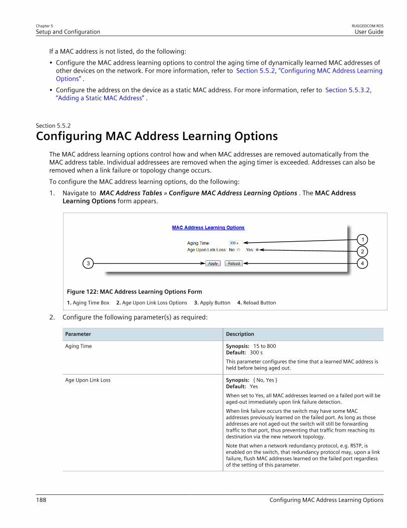
Chapter 5Setup and Configuration
RUGGEDCOM ROSUser Guide
188 Configuring MAC Address Learning Options
If a MAC address is not listed, do the following:• Configure the MAC address learning options to control the aging time of dynamically learned MAC addresses of
other devices on the network. For more information, refer to Section 5.5.2, “Configuring MAC Address LearningOptions” .
• Configure the address on the device as a static MAC address. For more information, refer to Section 5.5.3.2,“Adding a Static MAC Address” .
Section 5.5.2
Configuring MAC Address Learning OptionsThe MAC address learning options control how and when MAC addresses are removed automatically from theMAC address table. Individual addressees are removed when the aging timer is exceeded. Addresses can also beremoved when a link failure or topology change occurs.To configure the MAC address learning options, do the following:1. Navigate to MAC Address Tables » Configure MAC Address Learning Options . The MAC Address
Learning Options form appears.
43
2
1
Figure 122: MAC Address Learning Options Form
1. Aging Time Box 2. Age Upon Link Loss Options 3. Apply Button 4. Reload Button
2. Configure the following parameter(s) as required:
Parameter Description
Aging Time Synopsis: 15 to 800Default: 300 sThis parameter configures the time that a learned MAC address isheld before being aged out.
Age Upon Link Loss Synopsis: { No, Yes }Default: YesWhen set to Yes, all MAC addresses learned on a failed port will beaged-out immediately upon link failure detection.When link failure occurs the switch may have some MACaddresses previously learned on the failed port. As long as thoseaddresses are not aged-out the switch will still be forwardingtraffic to that port, thus preventing that traffic from reaching itsdestination via the new network topology.Note that when a network redundancy protocol, e.g. RSTP, isenabled on the switch, that redundancy protocol may, upon a linkfailure, flush MAC addresses learned on the failed port regardlessof the setting of this parameter.

RUGGEDCOM ROSUser Guide
Chapter 5Setup and Configuration
Managing Static MAC Addresses 189
3. Click Apply.
Section 5.5.3
Managing Static MAC AddressesStatic MAC addresses must be configured when the device is only able to receive frames, not transmit them.Prioritized MAC addresses are configured when traffic to or from a specific device on a LAN segment is to beassigned a higher CoS priority than other devices on that LAN segment.
CONTENTS• Section 5.5.3.1, “Viewing a List of Static MAC Addresses”• Section 5.5.3.2, “Adding a Static MAC Address”• Section 5.5.3.3, “Deleting a Static MAC Address”
Section 5.5.3.1Viewing a List of Static MAC Addresses
To view a list of static MAC addresses configured on the device, navigate to MAC Address Tables » ConfigureStatic MAC Addresses . The Static MAC Addresses table appears.
Figure 123: Static MAC Address Table
If static MAC addresses have not been configured, add addresses as needed. For more information, refer to Section 5.5.3.2, “Adding a Static MAC Address” .
Section 5.5.3.2Adding a Static MAC Address
To add a static MAC address to the Static MAC Address Table, do the following:1. Navigate to MAC Address Tables » Configure Static MAC Addresses . The Static MAC Addresses table
appears.

Chapter 5Setup and Configuration
RUGGEDCOM ROSUser Guide
190 Adding a Static MAC Address
1
Figure 124: Static MAC Addresses Table
1. InsertRecord
2. Click InsertRecord. The Static MAC Addresses form appears.
75
6
4
3
2
1
Figure 125: Static MAC Addresses Form
1. MAC Address Box 2. VID Box 3. Port Box 4. CoS List 5. Apply Button 6. Delete Button 7. Reload Button
3. Configure the following parameter(s) as required:
Parameter Description
MAC Address Synopsis: ##-##-##-##-##-## where ## ranges 0 to FFA MAC address learned by the switch.Maximum of 6 wildcard characters may be used to specify a rangeof MAC addresses allowed to be learned by the Port Securitymodule (when Port Security is set to 'Static MAC' mode). Wildcardmust start from the right hand end and continuous.Examples:• 00-0A-DC-**-**-** means the entire MAC address space of
RuggedCom.• 00-0A-DC-12-3*-** means the range 00-0A-DC-12-30-00 to
00-0A-DC-12-3F-FF.
VID Synopsis: 1 to 4094Default: 1

RUGGEDCOM ROSUser Guide
Chapter 5Setup and Configuration
Deleting a Static MAC Address 191
Parameter Description
VLAN Identifier of the VLAN upon which the MAC addressoperates.
Port Synopsis: 1 to maximum port number or { Learn }Default: LearnEnter the port number upon which the device with this address islocated. The security mode of the port being selected should notbe '802.1X'.If the port should be auto-learned, set this parameter to 'Learn'.The option 'Learn' is applicable for Port Security in 'Static MAC'mode.
CoS Synopsis: { Normal, Medium, High, Crit }Default: NormalPrioritizes traffic for the specified MAC address.
4. Click Apply.
Section 5.5.3.3Deleting a Static MAC Address
To delete a static MAC address from the Static MAC Address Table, do the following:1. Navigate to MAC Address Tables » Configure Static MAC Addresses . The Static MAC Addresses table
appears.
Figure 126: Static MAC Addresses Table
2. Select the MAC address from the table. The Static MAC Addresses form appears.

Chapter 5Setup and Configuration
RUGGEDCOM ROSUser Guide
192 Purging All Dynamic MAC Addresses
75
6
4
3
2
1
Figure 127: Static MAC Addresses Form
1. MAC Address Box 2. VID Box 3. Port Box 4. CoS List 5. Apply Button 6. Delete Button 7. Reload Button
3. Click Delete.
Section 5.5.4
Purging All Dynamic MAC AddressesTo purge the dynamic MAC address list of all entries, do the following:1. Navigate to MAC Address Tables » Purge MAC Address Table . The Purge MAC Address Table form
appears.
1
Figure 128: Purge MAC Address Table Form
1. Confirm Button
2. Click Confirm.
Section 5.6
Managing Time ServicesThe System Time Manager offers the following time-keeping and time synchronization features:• Local hardware time keeping and time zone management

RUGGEDCOM ROSUser Guide
Chapter 5Setup and Configuration
Configuring the Time and Date 193
• SNTP (Simple Network Time Protocol) client and server
CONTENTS• Section 5.6.1, “Configuring the Time and Date”• Section 5.6.2, “Managing NTP”
Section 5.6.1
Configuring the Time and DateTo set the time, date and other time-keeping related parameters, do the following:1. Navigate to Administration » System Time Manager » Configure Time and Date . The Time and Date
form appears.
76
5
4
3
2
1
Figure 129: Time and Date Form
1. Time 2. Date 3. Time Zone 4. DST Offset 5. DST Rule 6. Apply Button 7. Reload Button
2. Configure the following parameter(s) as required:
Parameter Description
Time Synopsis: HH:MM:SSThis parameter allows for both the viewing and setting of thelocal time.
Date Synopsis: MMM DD, YYYYThis parameter allows for both the viewing and setting of thelocal date.
Time Zone Synopsis: { UTC-12:00 (Eniwetok, Kwajalein), UTC-11:00(Midway Island, Samoa), UTC-10:00 (Hawaii), UTC-9:00(Alaska), UTC-8:00 (Los Angeles, Vancouver), UTC-7:00 (Calgary,Denver), UTC-6:00 (Chicago, Mexico City), UTC-5:00 (New York,Toronto), UTC-4:30 (Caracas), UTC-4:00 (Santiago), UTC-3:30(Newfoundland), UTC-3:00 (Brasilia, Buenos Aires), UTC-2:00(Mid Atlantic), UTC-1:00 (Azores), UTC-0:00 (Lisbon, London),UTC+1:00 (Berlin, Paris, Rome), UTC+2:00 (Athens, Cairo,Helsinki), ... }Default: UTC-5:00 (New York, Toronto)
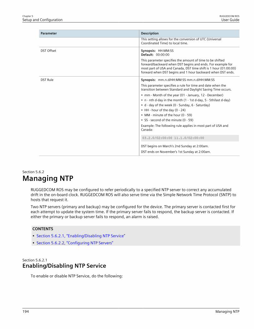
Chapter 5Setup and Configuration
RUGGEDCOM ROSUser Guide
194 Managing NTP
Parameter Description
This setting allows for the conversion of UTC (UniversalCoordinated Time) to local time.
DST Offset Synopsis: HH:MM:SSDefault: 00:00:00This parameter specifies the amount of time to be shiftedforward/backward when DST begins and ends. For example formost part of USA and Canada, DST time shift is 1 hour (01:00:00)forward when DST begins and 1 hour backward when DST ends.
DST Rule Synopsis: mm.n.d/HH:MM:SS mm.n.d/HH:MM:SSThis parameter specifies a rule for time and date when thetransition between Standard and Daylight Saving Time occurs.• mm - Month of the year (01 - January, 12 - December)• n - nth d-day in the month (1 - 1st d-day, 5 - 5th/last d-day)• d - day of the week (0 - Sunday, 6 - Saturday)• HH - hour of the day (0 - 24)• MM - minute of the hour (0 - 59)• SS - second of the minute (0 - 59)Example: The following rule applies in most part of USA andCanada:
03.2.0/02:00:00 11.1.0/02:00:00
DST begins on March's 2nd Sunday at 2:00am.DST ends on November's 1st Sunday at 2:00am.
Section 5.6.2
Managing NTPRUGGEDCOM ROS may be configured to refer periodically to a specified NTP server to correct any accumulateddrift in the on-board clock. RUGGEDCOM ROS will also serve time via the Simple Network Time Protocol (SNTP) tohosts that request it.Two NTP servers (primary and backup) may be configured for the device. The primary server is contacted first foreach attempt to update the system time. If the primary server fails to respond, the backup server is contacted. Ifeither the primary or backup server fails to respond, an alarm is raised.
CONTENTS• Section 5.6.2.1, “Enabling/Disabling NTP Service”• Section 5.6.2.2, “Configuring NTP Servers”
Section 5.6.2.1Enabling/Disabling NTP Service
To enable or disable NTP Service, do the following:

RUGGEDCOM ROSUser Guide
Chapter 5Setup and Configuration
Configuring NTP Servers 195
1. NOTEIf the device is running as an NTP server, NTP service must be enabled.
Navigate to Administration » System Time Manager » Configure NTP » Configure NTP Service . The SNTPParameters form appears.
1
32
Figure 130: SNTP Parameters Form
1. SNTP Options 2. Apply Button 3. Reload Button
2. Select Enabled to enable SNTP, or select Disabled to disable SNTP.3. Click Apply.
Section 5.6.2.2Configuring NTP Servers
To configure either the primary or backup NTP server, do the following:1. Navigate to Administration » System Time Manager » Configure NTP » Configure NTP Servers . The NTP
Servers table appears.
Figure 131: NTP Servers Table
2. Select either Primary or Backup. The NTP Servers form appears.

Chapter 5Setup and Configuration
RUGGEDCOM ROSUser Guide
196 Managing SNMP
54
2
3
1
Figure 132: NTP Servers Form
1. Server Box 2. IP Address Box 3. Update Period Box 4. Apply Button 5. Reload Button
3. Configure the following parameter(s) as required:
Parameter Description
Server Synopsis: Any 8 charactersDefault: PrimaryThis field tells whether this configuration is for a Primary or aBackup Server.
IP Address Synopsis: ###.###.###.### where ### ranges from 0 to 255The Server IP Address.
Update Period Synopsis: 1 to 1440 minDefault: 60 minDetermines how frequently the (S)NTP server is polled for a timeupdate.If the server cannot be reached in three attempts that aremade at one minute intervals an alarm is generated.
4. Click Apply.
Section 5.7
Managing SNMPRUGGEDCOM ROS supports versions 1, 2 and 3 of the Simple Network Management Protocol (SNMP), otherwisereferred to as SNMPv1, SNMPv2c and SNMPv3 respectively. SNMPv3 provides secure access to the devices througha combination of authentication and packet encryption over the network. Security features for this protocolinclude:
Feature Description
Message Integrity Makes sure that a packet has not been tampered with in-transit.
Authentication Determines if the message is from a valid source.
Encryption Encrypts the contents of a packet to prevent it from being seen by an unauthorized source.
SNMPv3 provides security models and security levels. A security model is an authentication strategy setup fora user and the group in which the user resides. A security level is a permitted level of security within a security

RUGGEDCOM ROSUser Guide
Chapter 5Setup and Configuration
Managing SNMP Users 197
model. A combination of a security model and level will determine which security mechanism is employed whenhandling an SNMP packet.Before configuring SNMPv3, note the following:• Each user belongs to a group• A group defines the access policy for a set of users• An access policy defines what SNMP objects can be accessed for (i.e. reading, writing and creating notifications)• A group determines the list of notifications its users can receive• A group also defines the security model and security level for its usersFor SNMPv1 and SNMPv2c, a community string can be configured. The string is mapped to the group and accesslevel with a security name, which is configured as User Name.
CONTENTS• Section 5.7.1, “Managing SNMP Users”• Section 5.7.2, “Managing Security-to-Group Mapping”• Section 5.7.3, “Managing SNMP Groups”
Section 5.7.1
Managing SNMP UsersThe following section describes how to configure and manage SNMP users.
CONTENTS• Section 5.7.1.1, “Viewing a List of SNMP Users”• Section 5.7.1.2, “Adding an SNMP User”• Section 5.7.1.3, “Deleting an SNMP User”
Section 5.7.1.1Viewing a List of SNMP Users
To view a list of SNMP users configured on the device, navigate to Administration » Configure SNMP »Configure SNMP Users . The SNMP Users table appears.

Chapter 5Setup and Configuration
RUGGEDCOM ROSUser Guide
198 Adding an SNMP User
Figure 133: SNMP Users Table
If users have not been configured, add users as needed. For more information, refer to Section 5.7.1.2, “Addingan SNMP User” .
Section 5.7.1.2Adding an SNMP User
Multiple users (up to a maximum of 32) can be configured for the local SNMPv3 engine, as well as SNMPv1 andSNMPv2c communities.
NOTEWhen employing the SNMPv1 or SNMPv2c security level, the User Name parameter maps thecommunity name with the security group and access level.
To add a new SNMP user, do the following:1. Navigate to Administration » Configure SNMP » Configure SNMP Users . The SNMP Users table appears.
1
Figure 134: SNMP Users Table
1. InsertRecord
2. Click InsertRecord. The SNMP Users form appears.
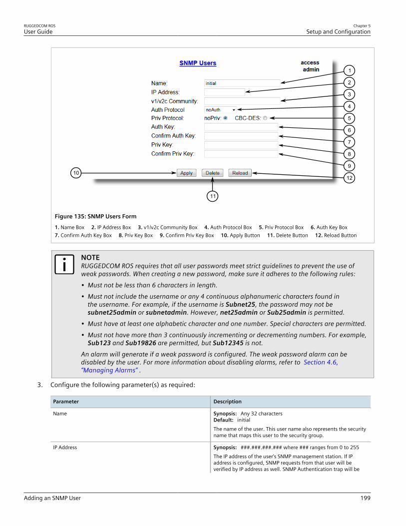
RUGGEDCOM ROSUser Guide
Chapter 5Setup and Configuration
Adding an SNMP User 199
1210
11
9
8
7
6
5
4
3
2
1
Figure 135: SNMP Users Form
1. Name Box 2. IP Address Box 3. v1/v2c Community Box 4. Auth Protocol Box 5. Priv Protocol Box 6. Auth Key Box 7. Confirm Auth Key Box 8. Priv Key Box 9. Confirm Priv Key Box 10. Apply Button 11. Delete Button 12. Reload Button
NOTERUGGEDCOM ROS requires that all user passwords meet strict guidelines to prevent the use ofweak passwords. When creating a new password, make sure it adheres to the following rules:• Must not be less than 6 characters in length.• Must not include the username or any 4 continuous alphanumeric characters found in
the username. For example, if the username is Subnet25, the password may not besubnet25admin or subnetadmin. However, net25admin or Sub25admin is permitted.
• Must have at least one alphabetic character and one number. Special characters are permitted.• Must not have more than 3 continuously incrementing or decrementing numbers. For example,
Sub123 and Sub19826 are permitted, but Sub12345 is not.An alarm will generate if a weak password is configured. The weak password alarm can bedisabled by the user. For more information about disabling alarms, refer to Section 4.6,“Managing Alarms” .
3. Configure the following parameter(s) as required:
Parameter Description
Name Synopsis: Any 32 charactersDefault: initialThe name of the user. This user name also represents the securityname that maps this user to the security group.
IP Address Synopsis: ###.###.###.### where ### ranges from 0 to 255The IP address of the user's SNMP management station. If IPaddress is configured, SNMP requests from that user will beverified by IP address as well. SNMP Authentication trap will be

Chapter 5Setup and Configuration
RUGGEDCOM ROSUser Guide
200 Deleting an SNMP User
Parameter Description
generated to trap receivers if request was received from this user,but from any other IP address.If IP address is empty, traps can notbe generated to this user, but SNMP requests will be served forthis user from any IP address.
v1/v2c Community Synopsis: Any 32 charactersThe community string which is mapped by this user/security nameto the security group if security model is SNMPv1 or SNMPv2c. Ifthis string is left empty, it will be assumed to be equal to the sameas user name.
Auth Protocol Synopsis: { noAuth, HMACMD5, HMACSHA }Default: noAuthAn indication of whether messages sent on behalf of this user to/from SNMP engine, can be authenticated, and if so, the type ofauthentication protocol which is used.
Priv Protocol Synopsis: { noPriv, CBC-DES }Default: noPrivAn Indication of whether messages sent on behalf of this user to/from SNMP engine can be protected from disclosure, and if so,the type of privacy protocol which is used.
Auth Key Synopsis: 31 character ASCII stringThe secret authentication key (password) that must be sharedwith SNMP client. If the key is not an emtpy string, it must be atleast 6 characters long.
Confirm Auth Key Synopsis: 31 character ASCII stringThe secret authentication key (password) that must be sharedwith SNMP client. If the key is not an emtpy string, it must be atleast 6 characters long.
Priv Key Synopsis: 31 character ASCII stringThe secret encription key (password) that must be shared withSNMP client. If the key is not an emtpy string, it must be at least 6characters long.
Confirm Priv Key Synopsis: 31 character ASCII stringThe secret encription key (password) that must be shared withSNMP client. If the key is not an emtpy string, it must be at least 6characters long.
4. Click Apply.
Section 5.7.1.3Deleting an SNMP User
To delete an SNMP user, do the following:1. Navigate to Administration » Configure SNMP » Configure SNMP Users . The SNMP Users table appears.
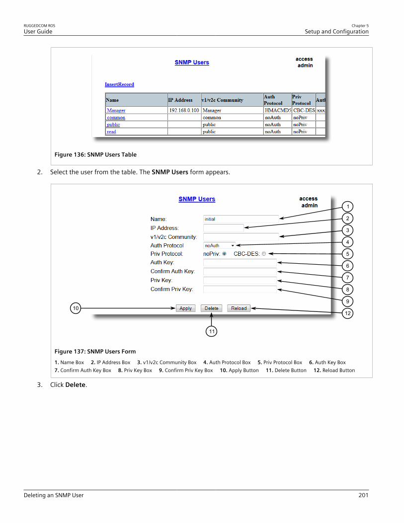
RUGGEDCOM ROSUser Guide
Chapter 5Setup and Configuration
Deleting an SNMP User 201
Figure 136: SNMP Users Table
2. Select the user from the table. The SNMP Users form appears.
1210
11
9
8
7
6
5
4
3
2
1
Figure 137: SNMP Users Form
1. Name Box 2. IP Address Box 3. v1/v2c Community Box 4. Auth Protocol Box 5. Priv Protocol Box 6. Auth Key Box 7. Confirm Auth Key Box 8. Priv Key Box 9. Confirm Priv Key Box 10. Apply Button 11. Delete Button 12. Reload Button
3. Click Delete.

Chapter 5Setup and Configuration
RUGGEDCOM ROSUser Guide
202 Managing Security-to-Group Mapping
Section 5.7.2
Managing Security-to-Group MappingThe following section describes how to configure and manage security-to-group maps.
CONTENTS• Section 5.7.2.1, “Viewing a List of Security-to-Group Maps”• Section 5.7.2.2, “Adding a Security-to-Group Map”• Section 5.7.2.3, “Deleting a Security-to-Group Map”
Section 5.7.2.1Viewing a List of Security-to-Group Maps
To view a list of security-to-group maps configured on the device, navigate to Administration » ConfigureSNMP » Configure SNMP Security to Group Maps . The SNMP Security to Group Maps table appears.
Figure 138: SNMP Security to Group Maps Table
If security-to-group maps have not been configured, add maps as needed. For more information, refer to Section 5.7.2.2, “Adding a Security-to-Group Map” .
Section 5.7.2.2Adding a Security-to-Group Map
Multiple combinations of security models and groups can be mapped (up to a maximum of 32) for SNMP.To add a security-to-group map, do the following:1. Navigate to Administration » Configure SNMP » Configure SNMP Security to Group Maps . The SNMP
Security to Group Maps table appears.
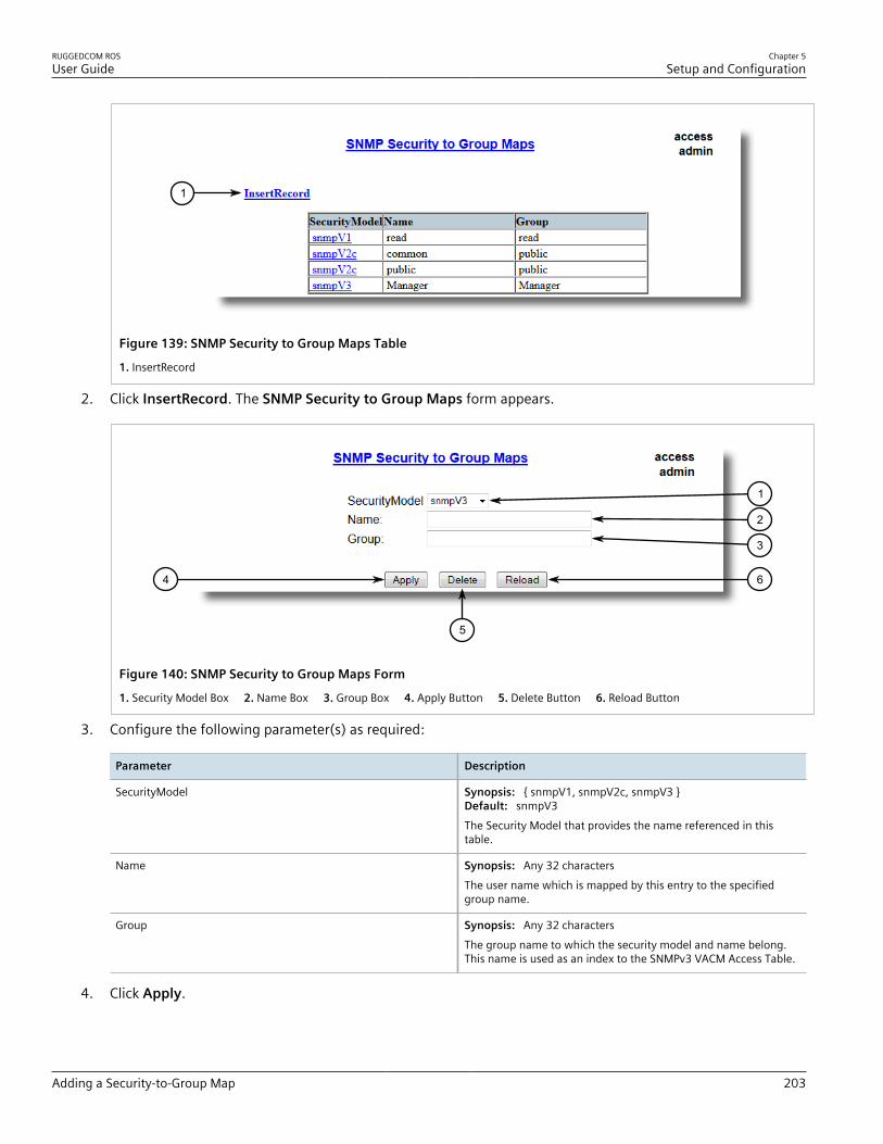
RUGGEDCOM ROSUser Guide
Chapter 5Setup and Configuration
Adding a Security-to-Group Map 203
1
Figure 139: SNMP Security to Group Maps Table
1. InsertRecord
2. Click InsertRecord. The SNMP Security to Group Maps form appears.
64
5
3
2
1
Figure 140: SNMP Security to Group Maps Form
1. Security Model Box 2. Name Box 3. Group Box 4. Apply Button 5. Delete Button 6. Reload Button
3. Configure the following parameter(s) as required:
Parameter Description
SecurityModel Synopsis: { snmpV1, snmpV2c, snmpV3 }Default: snmpV3The Security Model that provides the name referenced in thistable.
Name Synopsis: Any 32 charactersThe user name which is mapped by this entry to the specifiedgroup name.
Group Synopsis: Any 32 charactersThe group name to which the security model and name belong.This name is used as an index to the SNMPv3 VACM Access Table.
4. Click Apply.

Chapter 5Setup and Configuration
RUGGEDCOM ROSUser Guide
204 Deleting a Security-to-Group Map
Section 5.7.2.3Deleting a Security-to-Group Map
To delete a security-to-group map, do the following:1. Navigate to Administration » Configure SNMP » Configure SNMP Security to Group Maps . The SNMP
Security to Group Maps table appears.
Figure 141: SNMP Security to Group Maps Table
2. Select the map from the table. The SNMP Security to Group Maps form appears.
64
5
3
2
1
Figure 142: SNMP Security to Group Maps Form
1. Security Model Box 2. Name Box 3. Group Box 4. Apply Button 5. Delete Button 6. Reload Button
3. Click Delete.
Section 5.7.3
Managing SNMP GroupsMultiple SNMP groups (up to a maximum of 32) can be configured to have access to SNMP.
CONTENTS• Section 5.7.3.1, “Viewing a List of SNMP Groups”• Section 5.7.3.2, “Adding an SNMP Group”
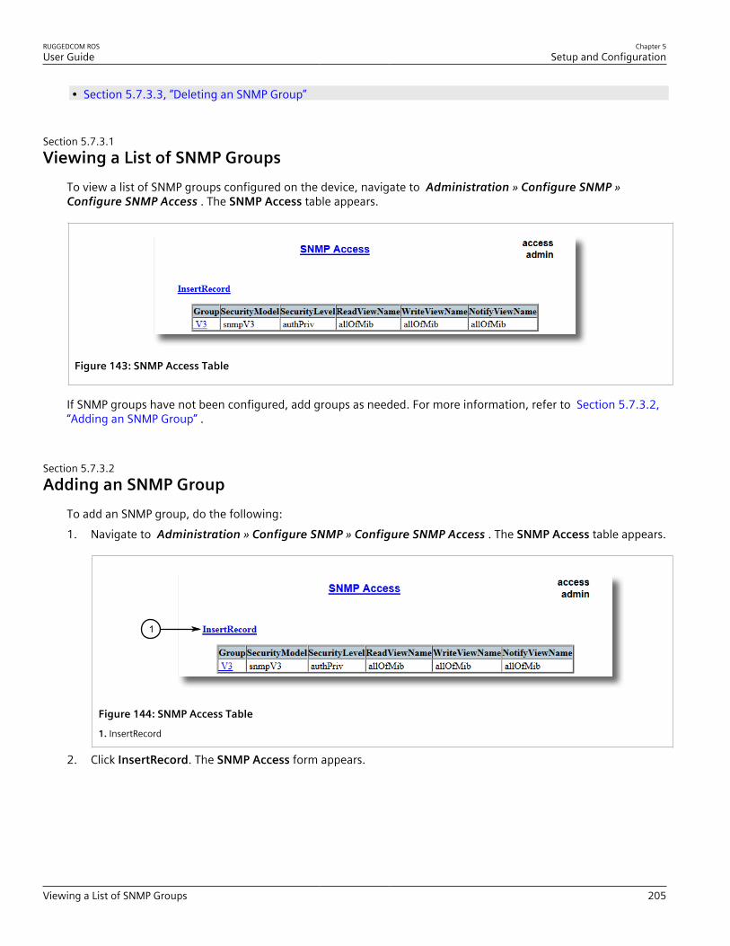
RUGGEDCOM ROSUser Guide
Chapter 5Setup and Configuration
Viewing a List of SNMP Groups 205
• Section 5.7.3.3, “Deleting an SNMP Group”
Section 5.7.3.1Viewing a List of SNMP Groups
To view a list of SNMP groups configured on the device, navigate to Administration » Configure SNMP »Configure SNMP Access . The SNMP Access table appears.
Figure 143: SNMP Access Table
If SNMP groups have not been configured, add groups as needed. For more information, refer to Section 5.7.3.2,“Adding an SNMP Group” .
Section 5.7.3.2Adding an SNMP Group
To add an SNMP group, do the following:1. Navigate to Administration » Configure SNMP » Configure SNMP Access . The SNMP Access table appears.
1
Figure 144: SNMP Access Table
1. InsertRecord
2. Click InsertRecord. The SNMP Access form appears.

Chapter 5Setup and Configuration
RUGGEDCOM ROSUser Guide
206 Adding an SNMP Group
97
8
6
5
4
3
2
1
Figure 145: SNMP Access Form
1. Group Box 2. Security Model Box 3. Security Level Box 4. ReadViewName Box 5. WriteViewName Box 6. NotifyViewNameBox 7. Apply Button 8. Delete Button 9. Reload Button
3. Configure the following parameter(s) as required:
Parameter Description
Group Synopsis: Any 32 charactersThe group name to which the security model and name belong.This name is used as an index to the SNMPv3 VACM Access Table.
SecurityModel Synopsis: { snmpV1, snmpV2c, snmpV3 }Default: snmpV3In order to gain the access rights allowed by this entry, configuredsecurity model must be in use.
SecurityLevel Synopsis: { noAuthNoPriv, authNoPriv, authPriv }Default: noAuthNoPrivThe minimum level of security reqwuired in order to gainthe access rights allowed by this entry. A security level ofnoAuthNoPriv is less than authNoPriv, which is less than authPriv.
ReadViewName Synopsis: { noView, V1Mib, allOfMib }Default: noViewThis parameter identifies the MIB tree(s) to which this entryauthorizes read access. If the value is noView, then no read accessis granted.
WriteViewName Synopsis: { noView, V1Mib, allOfMib }Default: noViewThis parameter identifies the MIB tree(s) to which this entryauthorizes write access. If the value is noView, then no writeaccess is granted.
NotifyViewName Synopsis: { noView, V1Mib, allOfMib }Default: noViewThis parameter identifies the MIB tree(s) to which this entryauthorizes access for notifications. If the value is noView, then noaccess for notifications is granted.

RUGGEDCOM ROSUser Guide
Chapter 5Setup and Configuration
Deleting an SNMP Group 207
4. Click Apply.
Section 5.7.3.3Deleting an SNMP Group
To delete an SNMP group, do the following:1. Navigate to Administration » Configure SNMP » Configure SNMP Access . The SNMP Access table appears.
Figure 146: SNMP Access Table
2. Select the group from the table. The SNMP Access form appears.
97
8
6
5
4
3
2
1
Figure 147: SNMP Access Form
1. Group Box 2. Security Model Box 3. Security Level Box 4. ReadViewName Box 5. WriteViewName Box 6. NotifyViewNameBox 7. Apply Button 8. Delete Button 9. Reload Button
3. Click Delete.

Chapter 5Setup and Configuration
RUGGEDCOM ROSUser Guide
208 Managing Network Discovery
Section 5.8
Managing Network DiscoveryRUGGEDCOM ROS supports the Link Layer Discovery Protocol (LLDP) and RUGGEDCOM Discovery Protocol (RCDP),both Layer 2 protocols for automated network discovery.
CONTENTS• Section 5.8.1, “Network Discovery Concepts”• Section 5.8.2, “Configuring LLDP Globally”• Section 5.8.3, “Configuring LLDP for an Ethernet Port”• Section 5.8.4, “Enabling/Disabling RCDP”• Section 5.8.5, “Viewing Global Statistics and Advertised System Information”• Section 5.8.6, “Viewing Statistics for LLDP Neighbors”• Section 5.8.7, “Viewing Statistics for LLDP Ports”
Section 5.8.1
Network Discovery ConceptsThe following section describes some of the concepts important to the implementation of network discovery inRUGGEDCOM ROS.
CONTENTS• Section 5.8.1.1, “Link Layer Discovery Protocol (LLDP)”• Section 5.8.1.2, “ RUGGEDCOM Discovery Protocol (RCDP)”
Section 5.8.1.1Link Layer Discovery Protocol (LLDP)
LLDP is an IEEE standard protocol, IEEE 802.11AB, that allows a networked device to advertise its own basicnetworking capabilities and configuration.LLDP allows a networked device to discover its neighbors across connected network links using a standardmechanism. Devices that support LLDP are able to advertise information about themselves, including theircapabilities, configuration, interconnections, and identifying information.LLDP agent operation is typically implemented as two modules: the LLDP transmit module and LLDP receivemodule. The LLDP transmit module, when enabled, sends the local device’s information at regular intervals, inIEEE 802.1AB standard format. Whenever the transmit module is disabled, it transmits an LLDPDU (LLDP data unit)with a time-to-live (TTL) type-length-value (TLV) containing 0 in the information field. This enables remote devicesto remove the information associated with the local device in their databases. The LLDP receive module, whenenabled, receives remote devices’ information and updates its LLDP database of remote systems. When new orupdated information is received, the receive module initiates a timer for the valid duration indicated by the TTLTLV in the received LLDPDU. A remote system’s information is removed from the database when an LLDPDU isreceived from it with TTL TLV containing 0 in its information field.
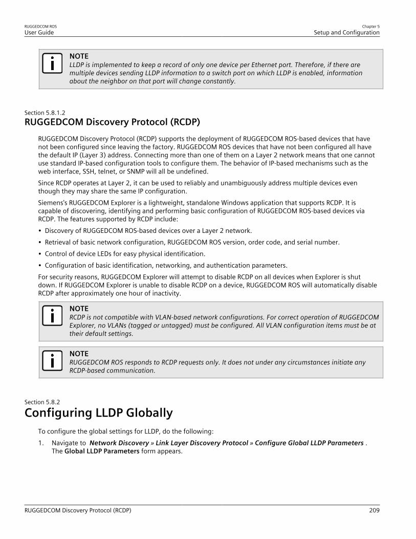
RUGGEDCOM ROSUser Guide
Chapter 5Setup and Configuration
RUGGEDCOM Discovery Protocol (RCDP) 209
NOTELLDP is implemented to keep a record of only one device per Ethernet port. Therefore, if there aremultiple devices sending LLDP information to a switch port on which LLDP is enabled, informationabout the neighbor on that port will change constantly.
Section 5.8.1.2RUGGEDCOM Discovery Protocol (RCDP)
RUGGEDCOM Discovery Protocol (RCDP) supports the deployment of RUGGEDCOM ROS-based devices that havenot been configured since leaving the factory. RUGGEDCOM ROS devices that have not been configured all havethe default IP (Layer 3) address. Connecting more than one of them on a Layer 2 network means that one cannotuse standard IP-based configuration tools to configure them. The behavior of IP-based mechanisms such as theweb interface, SSH, telnet, or SNMP will all be undefined.Since RCDP operates at Layer 2, it can be used to reliably and unambiguously address multiple devices eventhough they may share the same IP configuration.Siemens's RUGGEDCOM Explorer is a lightweight, standalone Windows application that supports RCDP. It iscapable of discovering, identifying and performing basic configuration of RUGGEDCOM ROS-based devices viaRCDP. The features supported by RCDP include:• Discovery of RUGGEDCOM ROS-based devices over a Layer 2 network.• Retrieval of basic network configuration, RUGGEDCOM ROS version, order code, and serial number.• Control of device LEDs for easy physical identification.• Configuration of basic identification, networking, and authentication parameters.For security reasons, RUGGEDCOM Explorer will attempt to disable RCDP on all devices when Explorer is shutdown. If RUGGEDCOM Explorer is unable to disable RCDP on a device, RUGGEDCOM ROS will automatically disableRCDP after approximately one hour of inactivity.
NOTERCDP is not compatible with VLAN-based network configurations. For correct operation of RUGGEDCOMExplorer, no VLANs (tagged or untagged) must be configured. All VLAN configuration items must be attheir default settings.
NOTERUGGEDCOM ROS responds to RCDP requests only. It does not under any circumstances initiate anyRCDP-based communication.
Section 5.8.2
Configuring LLDP GloballyTo configure the global settings for LLDP, do the following:1. Navigate to Network Discovery » Link Layer Discovery Protocol » Configure Global LLDP Parameters .
The Global LLDP Parameters form appears.

Chapter 5Setup and Configuration
RUGGEDCOM ROSUser Guide
210 Configuring LLDP Globally
6
5
4
3
2
1
7
Figure 148: Global LLDP Parameters Form
1. State Options 2. Tx Interval Box 3. Tx Hold Box 4. Reinit Delay Box 5. Tx Delay Box 6. Apply Button 7. Reload Button
2. Configure the following parameter(s) as required:
Parameter Description
State Synopsis: { Disabled, Enabled }Default: EnabledEnables LLDP protocol. Note that LLDP is enabled on a port whenLLDP is enabled globally and along with enabling per port settingin Port LLDP Parameters menu.
Tx Interval Synopsis: 5 to 32768 sDefault: 30 sThe interval at which LLDP frames are transmitted on behalf ofthis LLDP agent.
Tx Hold Synopsis: 2 to 10Default: 4The multiplier of the Tx Interval parameter that determines theactual time-to-live (TTL) value used in a LLDPDU. The actual TTLvalue can be expressed by the following formula:
TTL = MIN(65535, (Tx Interval * Tx Hold))
Reinit Delay Synopsis: 1 to 10 sDefault: 2 sThe delay in seconds from when the value of Admin Statusparameter of a particular port becomes 'Disbled' until re-initialization will be lattempted.
Tx Delay Synopsis: 1 to 8192 sDefault: 2 sThe delay in seconds between successive LLDP frametransmissions initiated by value or status changed. Therecommended value is set by the following formula:
1 <= txDelay <= (0.25 * Tx Interval)
3. Click Apply.

RUGGEDCOM ROSUser Guide
Chapter 5Setup and Configuration
Configuring LLDP for an Ethernet Port 211
Section 5.8.3
Configuring LLDP for an Ethernet PortTo configure LLDP for a specific Ethernet Port, do the following:1. Navigate to Network Discovery » Link Layer Discovery Protocol » Configure Port LLDP Parameters . The
Port LLDP Parameters table appears.
Figure 149: Port LLDP Parameters Table
2. Select a port. The Port LLDP Parameters form appears.
54
3
2
1
Figure 150: Port LLDP Parameters Form
1. Port Box 2. Admin Status List 3. Notifications Options 4. Apply Button 5. Reload Button
3. Configure the following parameter(s) as required:
Parameter Description
Port Synopsis: 1 to maximum port numberDefault: 1The port number as seen on the front plate silkscreen of theswitch.
Admin Status Synopsis: { rxTx, txOnly, rxOnly, Disabled }Default: rxTx

Chapter 5Setup and Configuration
RUGGEDCOM ROSUser Guide
212 Enabling/Disabling RCDP
Parameter Description
rxTx: the local LLDP agent can both transmit and receive LLDPframes through the port.txOnly: the local LLDP agent can only transmit LLDP frames.rxOnly: the local LLDP agent can only receive LLDP frames.disabled: the local LLDP agent can neither transmit or receiveLLDP frames.
Notifications Synopsis: { Disabled, Enabled }Default: DisabledDisabling notifications will prevent sending notifications andgenerating alarms for particular port from the LLDP agent.
4. Click Apply.
Section 5.8.4
Enabling/Disabling RCDPRUGGEDCOM ROS supports the RUGGEDCOM Discovery Protocol (RCDP). RCDP supports the deployment ofRUGGEDCOM ROS-based devices that have not been configured since leaving the factory. RUGGEDCOM ROSdevices that have not been configured all have the default IP (Layer 3) address. Connecting more than one ofthem on a Layer 2 network means that one cannot use standard IP-based configuration tools to configure them.The behavior of IP-based mechanisms such as the web interface, SSH, telnet, or SNMP will all be undefined.Since RCDP operates at Layer 2, it can be used to reliably and unambiguously address multiple devices eventhough they may share the same IP configuration.Siemens's RUGGEDCOM Explorer is a lightweight, standalone Windows application that supports RCDP. It iscapable of discovering, identifying and performing basic configuration of RUGGEDCOM ROS-based devices viaRCDP. The features supported by RCDP include:• Discovery of RUGGEDCOM ROS-based devices over a Layer 2 network.• Retrieval of basic network configuration, RUGGEDCOM ROS version, order code, and serial number.• Control of device LEDs for easy physical identification.• Configuration of basic identification, networking, and authentication parameters.For security reasons, RUGGEDCOM Explorer will attempt to disable RCDP on all devices when Explorer is shutdown. If RUGGEDCOM Explorer is unable to disable RCDP on a device, RUGGEDCOM ROS will automatically disableRCDP after approximately one hour of inactivity.
NOTERCDP is not compatible with VLAN-based network configurations. For correct operation of RUGGEDCOMExplorer, no VLANs (tagged or untagged) must be configured. All VLAN configuration items must be attheir default settings.
NOTERUGGEDCOM ROS responds to RCDP requests only. It does not under any circumstances initiate anyRCDP-based communication.
To enable or disable RCDP, do the following:1. Navigate to Network Discovery » RuggedCom Discovery Protocol » Configure RCDP Parameters . The
RCDP Parameters form appears.
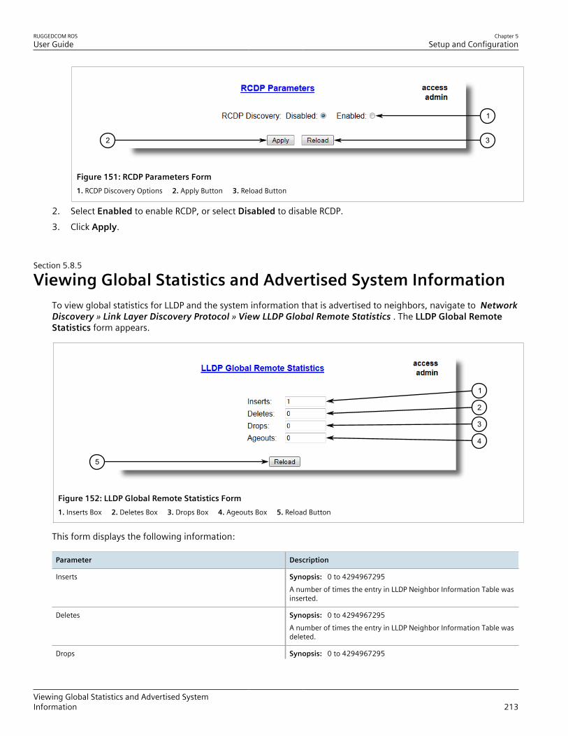
RUGGEDCOM ROSUser Guide
Chapter 5Setup and Configuration
Viewing Global Statistics and Advertised SystemInformation 213
32
1
Figure 151: RCDP Parameters Form1. RCDP Discovery Options 2. Apply Button 3. Reload Button
2. Select Enabled to enable RCDP, or select Disabled to disable RCDP.3. Click Apply.
Section 5.8.5
Viewing Global Statistics and Advertised System InformationTo view global statistics for LLDP and the system information that is advertised to neighbors, navigate to NetworkDiscovery » Link Layer Discovery Protocol » View LLDP Global Remote Statistics . The LLDP Global RemoteStatistics form appears.
1
5
2
3
4
Figure 152: LLDP Global Remote Statistics Form1. Inserts Box 2. Deletes Box 3. Drops Box 4. Ageouts Box 5. Reload Button
This form displays the following information:
Parameter Description
Inserts Synopsis: 0 to 4294967295A number of times the entry in LLDP Neighbor Information Table wasinserted.
Deletes Synopsis: 0 to 4294967295A number of times the entry in LLDP Neighbor Information Table wasdeleted.
Drops Synopsis: 0 to 4294967295

Chapter 5Setup and Configuration
RUGGEDCOM ROSUser Guide
214 Viewing Statistics for LLDP Neighbors
Parameter Description
A number of times an entry was deleted from LLDP NeighborInformation Table because the information timeliness interval hasexpired.
Ageouts Synopsis: 0 to 4294967295A counter of all TLVs discarded.
Section 5.8.6
Viewing Statistics for LLDP NeighborsTo view statistics for LLDP neighbors, navigate to Network Discovery » Link Layer Discovery Protocol » ViewLLDP Neighbor Information . The LLDP Neighbor Information table appears.
1
6
2
3
4
5
Figure 153: LLDP Neighbor Information Table
1. Port Box 2. ChassisId Box 3. PortId Box 4. SysName Box 5. SysDesc Box 6. Reload Button
This form displays the following information:
Parameter Description
Port Synopsis: 1 to maximum port numberThe local port associated with this entry.
ChassisId Synopsis: Any 45 charactersChassis Id information received from remote LLDP agent.
PortId Synopsis: Any 45 charactersPort Id information received from remote LLDP agent.
SysName Synopsis: Any 45 charactersSystem Name information received from remote LLDP agent.
SysDesc Synopsis: Any 45 charactersSystem Descriptor information received from remote LLDP agent.

RUGGEDCOM ROSUser Guide
Chapter 5Setup and Configuration
Viewing Statistics for LLDP Ports 215
Section 5.8.7
Viewing Statistics for LLDP PortsTo view statistics for LLDP ports, navigate to Network Discovery » Link Layer Discovery Protocol » View LLDPStatistics . The LLDP Statistics table appears.
Figure 154: LLDP Statistics Table
This table displays the following information:
Parameter Description
Port Synopsis: 1 to maximum port numberThe port number as seen on the front plate silkscreen of the switch.
FrmDrop Synopsis: 0 to 4294967295A counter of all LLDP frames discarded.
ErrFrm Synopsis: 0 to 4294967295A counter of all LLDPDUs received with detectable errors.
FrmIn Synopsis: 0 to 4294967295A counter of all LLDPDUs received.
FrmOut Synopsis: 0 to 4294967295A counter of all LLDPDUs transmitted.
Ageouts Synopsis: 0 to 4294967295A counter of the times that a neighbor's information has beendeleted from the LLDP remote system MIB because the txinfoTTLtimer has expired.
TLVsDrop Synopsis: 0 to 4294967295A counter of all TLVs discarded.
TLVsUnknown Synopsis: 0 to 4294967295A counter of all TLVs received on the port that are not recognized bythe LLDP local agent.

Chapter 5Setup and Configuration
RUGGEDCOM ROSUser Guide
216 Managing Multicast Filtering
Section 5.9
Managing Multicast FilteringMulticast traffic can be filtered using IGMP (Internet Group Management Protocol) snooping or GMRP (GARPMulticast Registration Protocol).
CONTENTS• Section 5.9.1, “Managing IGMP”• Section 5.9.2, “Managing GMRP”
Section 5.9.1
Managing IGMPIGMP is used by IP hosts to report their host group memberships with multicast routers. As hosts join and leavespecific multicast groups, streams of traffic are directed to or withheld from that host.The IGMP protocol operates between multicast routers and IP hosts. When an unmanaged switch is placedbetween multicast routers and their hosts, the multicast streams will be distributed to all ports.This may introducesignificant traffic onto ports that do not require it and receive no benefit from it.IGMP Snooping, when enabled, will act on IGMP messages sent from the router and the host, restricting trafficstreams to the appropriate LAN segments.
IMPORTANT!RUGGEDCOM ROS restricts IGMP hosts from subscribing to the following special multicast addresses:• 224.0.0.0 to 224.0.0.255• 224.0.1.129These addresses are reserved for routing protocols and IEEE 1588. If an IGMP membership reportcontains one of these addresses, the report is forwarded by the switch without learning about the host.
CONTENTS• Section 5.9.1.1, “IGMP Concepts”• Section 5.9.1.2, “Viewing a List of Multicast Group Memberships”• Section 5.9.1.3, “Viewing Forwarding Information for Multicast Groups”• Section 5.9.1.4, “Configuring IGMP”
Section 5.9.1.1IGMP Concepts
The following describes some of the concepts important to the implementation of multicast filtering using IGMP:
IGMP In OperationThe following network diagram provides a simple example of the use of IGMP.
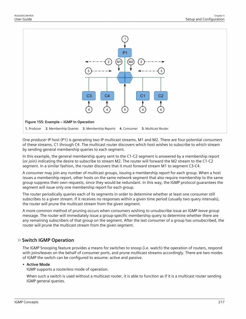
RUGGEDCOM ROSUser Guide
Chapter 5Setup and Configuration
IGMP Concepts 217
P1
C3 C4 C1 C2
3
2
3
2
1
4
M2M1
4544
Figure 155: Example – IGMP In Operation
1. Producer 2. Membership Queries 3. Membership Reports 4. Consumer 5. Multicast Router
One producer IP host (P1) is generating two IP multicast streams, M1 and M2. There are four potential consumersof these streams, C1 through C4. The multicast router discovers which host wishes to subscribe to which streamby sending general membership queries to each segment.In this example, the general membership query sent to the C1-C2 segment is answered by a membership report(or join) indicating the desire to subscribe to stream M2. The router will forward the M2 stream to the C1-C2segment. In a similar fashion, the router discovers that it must forward stream M1 to segment C3-C4.A consumer may join any number of multicast groups, issuing a membership report for each group. When a hostissues a membership report, other hosts on the same network segment that also require membership to the samegroup suppress their own requests, since they would be redundant. In this way, the IGMP protocol guarantees thesegment will issue only one membership report for each group.The router periodically queries each of its segments in order to determine whether at least one consumer stillsubscribes to a given stream. If it receives no responses within a given time period (usually two query intervals),the router will prune the multicast stream from the given segment.A more common method of pruning occurs when consumers wishing to unsubscribe issue an IGMP leave groupmessage. The router will immediately issue a group-specific membership query to determine whether there areany remaining subscribers of that group on the segment. After the last consumer of a group has unsubscribed, therouter will prune the multicast stream from the given segment.
Switch IGMP OperationThe IGMP Snooping feature provides a means for switches to snoop (i.e. watch) the operation of routers, respondwith joins/leaves on the behalf of consumer ports, and prune multicast streams accordingly. There are two modesof IGMP the switch can be configured to assume: active and passive.• Active Mode
IGMP supports a routerless mode of operation.When such a switch is used without a multicast router, it is able to function as if it is a multicast router sendingIGMP general queries.
Chapter 5Setup and Configuration
RUGGEDCOM ROSUser Guide
218 IGMP Concepts
• Passive ModeWhen such a switch is used in a network with a multicast router, it can be configured to run Passive IGMP. Thismode prevents the switch from sending the queries that can confuse the router causing it to stop issuing IGMPqueries.
NOTEA switch running in passive mode requires the presence of a multicast router or it will be unable toforward multicast streams at all if no multicast routers are present.
NOTEAt least one IGMP Snooping switch must be in active mode to make IGMP functional.
IGMP Snooping RulesIGMP Snooping adheres to the following rules:• When a multicast source starts multicasting, the traffic stream will be immediately blocked on segments from
which joins have not been received.• Unless configured otherwise, the switch will forward all multicast traffic to the ports where multicast routers are
attached.• Packets with a destination IP multicast address in the 224.0.0.X range that are not IGMP are always forwarded
to all ports. This behavior is based on the fact that many systems do not send membership reports for IPmulticast addresses in this range while still listening to such packets.
• The switch implements IGMPv2 proxy-reporting (i.e. membership reports received from downstream aresummarized and used by the switch to issue its own reports).
• The switch will only send IGMP membership reports out of those ports where multicast routers are attached, assending membership reports to hosts could result in unintentionally preventing a host from joining a specificgroup.
• Multicast routers use IGMP to elect a master router known as the querier. The querier is the router with thelowest IP address. All other routers become non-queriers, participating only in forwarding multicast traffic.Switches running in active mode participate in the querier election the same as multicast routers.
• When the querier election process is complete, the switch simply relays IGMP queries received from the querier.• When sending IGMP packets, the switch uses its own IP address, if it has one, for the VLAN on which packets are
sent, or an address of 0.0.0.0, if it does not have an assigned IP address.
NOTEIGMP Snooping switches perform multicast pruning using a multicast frames’ destination MACmulticast address, which depends on the group IP multicast address. IP address W.X.Y.Z corresponds toMAC address 01-00-5E-XX-YY-ZZ where XX is the lower 7 bits of X, and YY and ZZ are simply Y and Zcoded in hexadecimal.One can note that IP multicast addresses, such as 224.1.1.1 and 225.1.1.1, will both map onto thesame MAC address 01-00-5E-01-01-01. This is a problem for which the IETF Network Working Groupcurrently has offered no solution. Users are advised to be aware of and avoid this problem.
IGMP and RSTPAn RSTP change of topology can render the routes selected to carry multicast traffic as incorrect. This results in lostmulticast traffic.

RUGGEDCOM ROSUser Guide
Chapter 5Setup and Configuration
IGMP Concepts 219
If RSTP detects a change in the network topology, IGMP will take some actions to avoid the loss of multicastconnectivity and reduce network convergence time:• The switch will immediately issue IGMP queries (if in IGMP Active mode) to obtain potential new group
membership information.• The switch can be configured to flood multicast streams temporarily out of all ports that are not configured as
RSTP Edge Ports.
Combined Router and Switch IGMP OperationThe following example illustrates the challenges faced with multiple routers, VLAN support and switching.Producer P1 resides on VLAN 2 while P2 resides on VLAN 3. Consumer C1 resides on both VLANs whereas C2 andC3 reside on VLANs 3 and 2, respectively. Router 2 resides on VLAN 2, presumably to forward multicast traffic to aremote network or act as a source of multicast traffic itself.
C1 C3C2
P1
P2
2
1
5
3
4
Figure 156: Example – Combined Router and Switch IGMP In Operation
1. Producer 2. Multicast Router 1 3. Multicast Router 2 4. Switch 5. Host
In this example:• P1, Router 1, Router 2 and C3 are on VLAN 2• P2 and C2 are on VLAN 3• C1 is on both VLAN 2 and 3Assuming that router 1 is the querier for VLAN 2 and router 2 is simply a non-querier, the switch will periodicallyreceive queries from router 1 and maintain the information concerning which port links to the multicast router.However, the switch port that links to router 2 must be manually configured as a router port. Otherwise, theswitch will send neither multicast streams nor joins/leaves to router 2.Note that VLAN 3 does not have an external multicast router. The switch should be configured to operate in itsrouterless mode and issue general membership queries as if it is the router.• Processing Joins
If host C1 wants to subscribe to the multicast streams for both P1 and P2, it will generate two membershipreports. The membership report from C1 on VLAN 2 will cause the switch to immediately initiate its ownmembership report to multicast router 1 (and to issue its own membership report as a response to queries).

Chapter 5Setup and Configuration
RUGGEDCOM ROSUser Guide
220 Viewing a List of Multicast Group Memberships
The membership report from host C1 for VLAN 3 will cause the switch to immediately begin forwardingmulticast traffic from producer P2 to host C2.
• Processing LeavesWhen host C1 decides to leave a multicast group, it will issue a leave request to the switch. The switch will pollthe port to determine if host C1 is the last member of the group on that port. If host C1 is the last (or only)member, the group will immediately be pruned from the port.Should host C1 leave the multicast group without issuing a leave group message and then fail to respond to ageneral membership query, the switch will stop forwarding traffic after two queries.When the last port in a multicast group leaves the group (or is aged-out), the switch will issue an IGMP leavereport to the router.
Section 5.9.1.2Viewing a List of Multicast Group Memberships
Using IGMP snooping, RUGGEDCOM ROS records group membership information on a per-port basis based onmembership reports it observes between the router and host.To view a list of multicast group memberships, navigate to Multicast Filtering » View IGMP Group Membership. The IGMP Group Membership table appears.
Figure 157: IGMP Group Membership Table
This table provides the following information:
Parameter Description
Port Synopsis: 1 to maximum port numberThe port number as seen on the front plate silkscreen of the switch.
VID Synopsis: 0 to 65535VLAN Identifier of the VLAN upon which the multicast groupoperates.
Group Synopsis: ###.###.###.### where ### ranges from 0 to 255Multicast Group Address.
Ver Synopsis: { v3, v2, v1 }Specifies the IGMP version of the learnt multicast group.
Reporter Synopsis: ###.###.###.### where ### ranges from 0 to 255Specifies the source IP address that is reporting subscription to themulticast group.
Age Synopsis: 0 to 7210 sSpecifies the current age of the IP multicast group learned on theport in seconds.
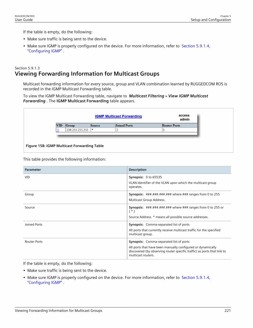
RUGGEDCOM ROSUser Guide
Chapter 5Setup and Configuration
Viewing Forwarding Information for Multicast Groups 221
If the table is empty, do the following:• Make sure traffic is being sent to the device.• Make sure IGMP is properly configured on the device. For more information, refer to Section 5.9.1.4,
“Configuring IGMP” .
Section 5.9.1.3Viewing Forwarding Information for Multicast Groups
Multicast forwarding information for every source, group and VLAN combination learned by RUGGEDCOM ROS isrecorded in the IGMP Multicast Forwarding table.To view the IGMP Multicast Forwarding table, navigate to Multicast Filtering » View IGMP MulticastForwarding . The IGMP Multicast Forwarding table appears.
Figure 158: IGMP Multicast Forwarding Table
This table provides the following information:
Parameter Description
VID Synopsis: 0 to 65535VLAN Identifier of the VLAN upon which the multicast groupoperates.
Group Synopsis: ###.###.###.### where ### ranges from 0 to 255Multicast Group Address.
Source Synopsis: ###.###.###.### where ### ranges from 0 to 255 or{ * }Source Address. * means all possible source addresses.
Joined Ports Synopsis: Comma-separated list of portsAll ports that currently receive multicast traffic for the specifiedmulticast group.
Router Ports Synopsis: Comma-separated list of portsAll ports that have been manually configured or dynamicallydiscovered (by observing router specific traffic) as ports that link tomulticast routers.
If the table is empty, do the following:• Make sure traffic is being sent to the device.• Make sure IGMP is properly configured on the device. For more information, refer to Section 5.9.1.4,
“Configuring IGMP” .

Chapter 5Setup and Configuration
RUGGEDCOM ROSUser Guide
222 Configuring IGMP
Section 5.9.1.4Configuring IGMP
To configure the IGMP, do the following:1. Make sure one or more static VLANs exist with IGMP enabled. For more information, refer to Section 5.2.5,
“Managing Static VLANs” .2. Navigate to Multicast Filtering » Configure IGMP Parameters . The IGMP Parameters form appears.
7 8
6
5
4
3
2
1
Figure 159: IGMP Parameters Form
1. Mode Options 2. IGMP Version 3. Query Interval Box 4. Router Ports Box 5. Router Forwarding Options 6. RSTP FloodingOptions 7. Apply Button 8. Reload Button
3. Configure the following parameter(s) as required:
Parameter Description
Mode Synopsis: { Passive, Active }Default: PassiveSpecifies the IGMP mode. Options include:• PASSIVE – the switch passively snoops IGMP traffic and never
sends IGMP queries• ACTIVE – the switch generates IGMP queries, if no queries
from a better candidate for being the querier are detected for awhile.
IGMP Version Synopsis: { v2, v3 }Default: v2Specifies the configured IGMP version on the switch. Optionsinclude:• v2 – Sets the IGMP version to version 2. When selected for a
snooping switch, all IGMP reports and queries greater than v2are forwarded, but not added to the IGMP Multicast Forwardingtable.
• v3 – Sets the IGMP version to version 3. General queries aregenerated in IGMPv3 format, all versions of IGMP messagesare processed by the switch, and traffic is pruned based onmulticast group address only.
Query Interval Synopsis: 10 to 3600Default: 60 sThe time interval between IGMP queries generated by the switch.
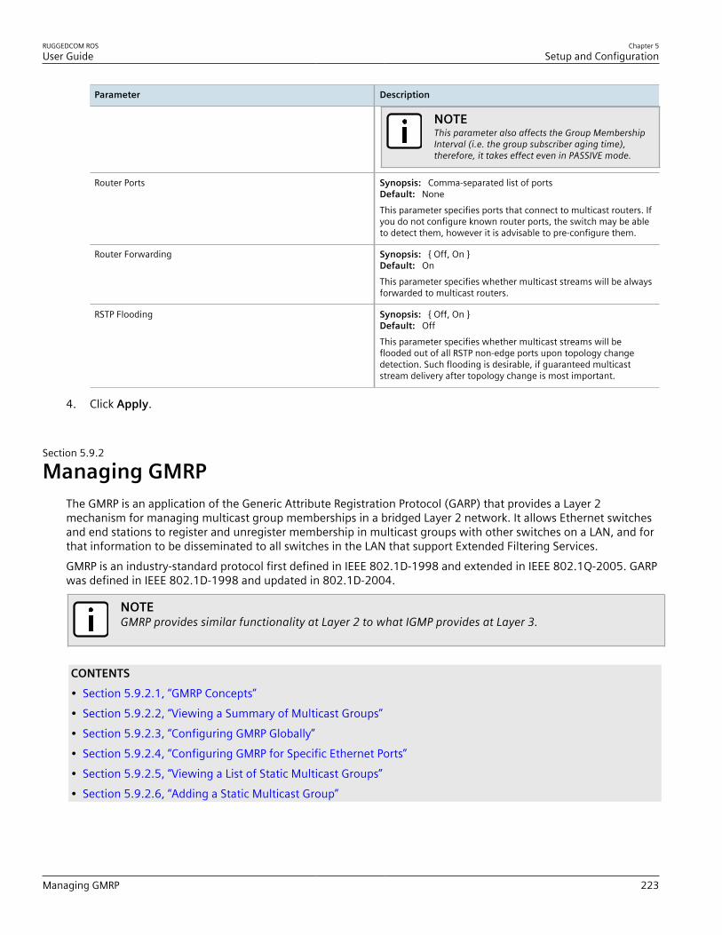
RUGGEDCOM ROSUser Guide
Chapter 5Setup and Configuration
Managing GMRP 223
Parameter Description
NOTEThis parameter also affects the Group MembershipInterval (i.e. the group subscriber aging time),therefore, it takes effect even in PASSIVE mode.
Router Ports Synopsis: Comma-separated list of portsDefault: NoneThis parameter specifies ports that connect to multicast routers. Ifyou do not configure known router ports, the switch may be ableto detect them, however it is advisable to pre-configure them.
Router Forwarding Synopsis: { Off, On }Default: OnThis parameter specifies whether multicast streams will be alwaysforwarded to multicast routers.
RSTP Flooding Synopsis: { Off, On }Default: OffThis parameter specifies whether multicast streams will beflooded out of all RSTP non-edge ports upon topology changedetection. Such flooding is desirable, if guaranteed multicaststream delivery after topology change is most important.
4. Click Apply.
Section 5.9.2
Managing GMRPThe GMRP is an application of the Generic Attribute Registration Protocol (GARP) that provides a Layer 2mechanism for managing multicast group memberships in a bridged Layer 2 network. It allows Ethernet switchesand end stations to register and unregister membership in multicast groups with other switches on a LAN, and forthat information to be disseminated to all switches in the LAN that support Extended Filtering Services.GMRP is an industry-standard protocol first defined in IEEE 802.1D-1998 and extended in IEEE 802.1Q-2005. GARPwas defined in IEEE 802.1D-1998 and updated in 802.1D-2004.
NOTEGMRP provides similar functionality at Layer 2 to what IGMP provides at Layer 3.
CONTENTS• Section 5.9.2.1, “GMRP Concepts”• Section 5.9.2.2, “Viewing a Summary of Multicast Groups”• Section 5.9.2.3, “Configuring GMRP Globally”• Section 5.9.2.4, “Configuring GMRP for Specific Ethernet Ports”• Section 5.9.2.5, “Viewing a List of Static Multicast Groups”• Section 5.9.2.6, “Adding a Static Multicast Group”

Chapter 5Setup and Configuration
RUGGEDCOM ROSUser Guide
224 GMRP Concepts
• Section 5.9.2.7, “Deleting a Static Multicast Group”
Section 5.9.2.1GMRP Concepts
The following describes some of the concepts important to the implementation of multicast filtering using GMRP:
Joining a Multicast GroupIn order to join a multicast group, an end station transmits a GMRP join message. The switch that receives the joinmessage adds the port through which the message was received to the multicast group specified in the message.It then propagates the join message to all other hosts in the VLAN, one of which is expected to be the multicastsource.When a switch transmits GMRP updates (from GMRP-enabled ports), all of the multicast groups known to theswitch, whether configured manually or learned dynamically through GMRP, are advertised to the rest of network.As long as one host on the Layer 2 network has registered for a given multicast group, traffic from thecorresponding multicast source will be carried on the network. Traffic multicast by the source is only forwarded byeach switch in the network to those ports from which it has received join messages for the multicast group.
Leaving a Multicast GroupPeriodically, the switch sends GMRP queries in the form of a leave all message. If a host (either a switch or anend station) wishes to remain in a multicast group, it reasserts its group membership by responding with anappropriate join request. Otherwise, it can either respond with a leave message or simply not respond at all. If theswitch receives a leave message or receives no response from the host for a timeout period, the switch removesthe host from the multicast group.
Notes About GMRPSince GMRP is an application of GARP, transactions take place using the GARP protocol. GMRP defines thefollowing two Attribute Types:• The Group Attribute Type, used to identify the values of group MAC addresses• The Service Requirement Attribute Type, used to identify service requirements for the groupService Requirement Attributes are used to change the receiving port's multicast filtering behavior to one of thefollowing:• Forward All Multicast group traffic in the VLAN, or• Forward All Unknown Traffic (Multicast Groups) for which there are no members registered in the device in a
VLANIf GMRP is disabled on the RS400, GMRP packets received will be forwarded like any other traffic. Otherwise, GMRPpackets will be processed by the RS400, and not forwarded.
Establishing Membership with GMRPThe following example illustrates how a network of hosts and switches can dynamically join two multicast groupsusing GMRP.
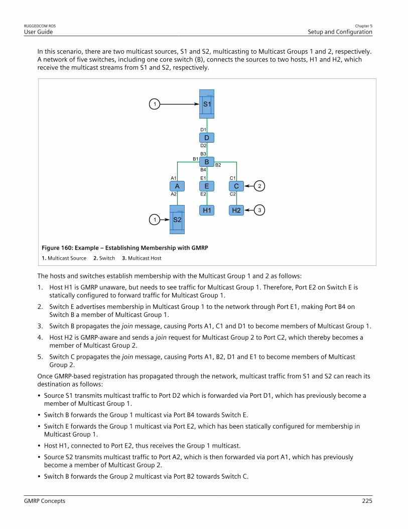
RUGGEDCOM ROSUser Guide
Chapter 5Setup and Configuration
GMRP Concepts 225
In this scenario, there are two multicast sources, S1 and S2, multicasting to Multicast Groups 1 and 2, respectively.A network of five switches, including one core switch (B), connects the sources to two hosts, H1 and H2, whichreceive the multicast streams from S1 and S2, respectively.
A1
A2A E C
D
S1
S2H2H1
E1
E2
C1
C2
B3
B4
B1B2B
D1
D2
1
1
2
3
Figure 160: Example – Establishing Membership with GMRP1. Multicast Source 2. Switch 3. Multicast Host
The hosts and switches establish membership with the Multicast Group 1 and 2 as follows:1. Host H1 is GMRP unaware, but needs to see traffic for Multicast Group 1. Therefore, Port E2 on Switch E is
statically configured to forward traffic for Multicast Group 1.2. Switch E advertises membership in Multicast Group 1 to the network through Port E1, making Port B4 on
Switch B a member of Multicast Group 1.3. Switch B propagates the join message, causing Ports A1, C1 and D1 to become members of Multicast Group 1.4. Host H2 is GMRP-aware and sends a join request for Multicast Group 2 to Port C2, which thereby becomes a
member of Multicast Group 2.5. Switch C propagates the join message, causing Ports A1, B2, D1 and E1 to become members of Multicast
Group 2.Once GMRP-based registration has propagated through the network, multicast traffic from S1 and S2 can reach itsdestination as follows:• Source S1 transmits multicast traffic to Port D2 which is forwarded via Port D1, which has previously become a
member of Multicast Group 1.• Switch B forwards the Group 1 multicast via Port B4 towards Switch E.• Switch E forwards the Group 1 multicast via Port E2, which has been statically configured for membership in
Multicast Group 1.• Host H1, connected to Port E2, thus receives the Group 1 multicast.• Source S2 transmits multicast traffic to Port A2, which is then forwarded via port A1, which has previously
become a member of Multicast Group 2.• Switch B forwards the Group 2 multicast via Port B2 towards Switch C.

Chapter 5Setup and Configuration
RUGGEDCOM ROSUser Guide
226 Viewing a Summary of Multicast Groups
• Switch C forwards the Group 2 multicast via Port C2, which has previously become a member of Group 2.• Ultimately, Host H2, connected to Port C2, receives the Group 2 multicast.
Section 5.9.2.2Viewing a Summary of Multicast Groups
To view a summary of all multicast groups, navigate to Multicast Filtering » View Multicast Group Summary .The Multicast Group Summary table appears.
Figure 161: Multicast Group Summary Table
This table provides the following information:
Parameter Description
VID Synopsis: 0 to 65535VLAN Identifier of the VLAN upon which the multicast groupoperates.
MAC Address Synopsis: ##-##-##-##-##-## where ## ranges 0 to FFMulticast group MAC address.
Static Ports Synopsis: Any combination of numbers valid for this parameterPorts that joined this group statically through static configurationin Static MAC Table and to which the multicast group traffic isforwarded.
GMRP Dynamic Ports Synopsis: Any combination of numbers valid for this parameterPorts that joined this group dynamically through GMRP Applicationand to which the multicast group traffic is forwarded.
Section 5.9.2.3Configuring GMRP Globally
To configure global settings for GMRP, do the following:1. Navigate to Multicast Filtering » Configure Global GMRP Parameters . The Global GMRP Parameters form
appears.

RUGGEDCOM ROSUser Guide
Chapter 5Setup and Configuration
Configuring GMRP for Specific Ethernet Ports 227
54
2
1
3
Figure 162: Global GMRP Parameters Form
1. GMRP Enable Options 2. RSTP Flooding Options 3. Leave Timer Box 4. Apply Button 5. Reload Button
2. Configure the following parameter(s) as required:
Parameter Description
GMRP Enable Synopsis: { No, Yes }Default: NoGlobally enable or disable GMRP.When GMRP is globally disabled, GMRP configurations onindividual ports are ignored. When GMRP is globally enabled, eachport can be individually configured.
RSTP Flooding Synopsis: { On, Off }Default: OffThis parameter specifies whether multicast streams will beflooded out of all RSTP non-edge ports upon topology changedetection. Such flooding is desirable, if guaranteed multicaststream delivery after topology change is most important.
Leave Timer Synopsis: 600 to 300000 msDefault: 4000 msTime (milliseconds) to wait after issuing Leave or LeaveAll beforeremoving registered multicast groups. If Join messages forspecific addresses are received before this timer expires, theaddresses will be kept registered.
3. Click Apply.
Section 5.9.2.4Configuring GMRP for Specific Ethernet Ports
To configure GMRP for a specific Ethernet port, do the following:1. Make sure the global settings for GMRP have been configured. For more information, refer to Section 5.9.2.3,
“Configuring GMRP Globally” .2. Navigate to Multicast Filtering » Configure Port GMRP Parameters . The Port GMRP Parameters table
appears.
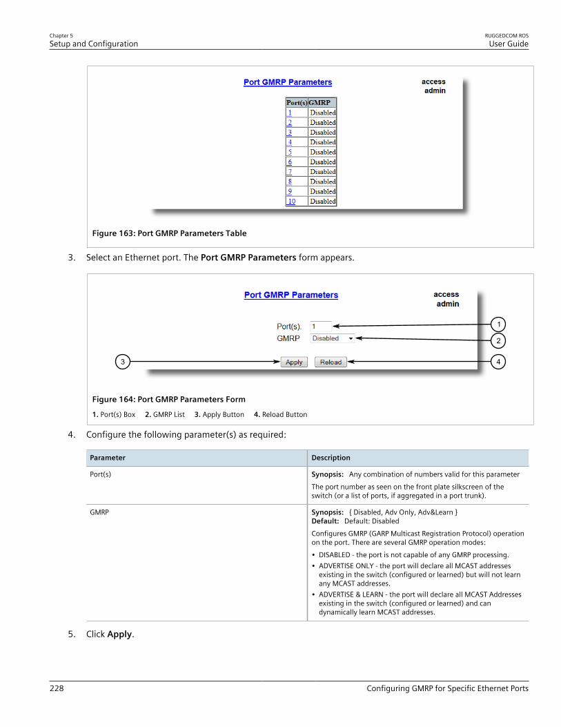
Chapter 5Setup and Configuration
RUGGEDCOM ROSUser Guide
228 Configuring GMRP for Specific Ethernet Ports
Figure 163: Port GMRP Parameters Table
3. Select an Ethernet port. The Port GMRP Parameters form appears.
43
1
2
Figure 164: Port GMRP Parameters Form
1. Port(s) Box 2. GMRP List 3. Apply Button 4. Reload Button
4. Configure the following parameter(s) as required:
Parameter Description
Port(s) Synopsis: Any combination of numbers valid for this parameterThe port number as seen on the front plate silkscreen of theswitch (or a list of ports, if aggregated in a port trunk).
GMRP Synopsis: { Disabled, Adv Only, Adv&Learn }Default: Default: DisabledConfigures GMRP (GARP Multicast Registration Protocol) operationon the port. There are several GMRP operation modes:• DISABLED - the port is not capable of any GMRP processing.• ADVERTISE ONLY - the port will declare all MCAST addresses
existing in the switch (configured or learned) but will not learnany MCAST addresses.
• ADVERTISE & LEARN - the port will declare all MCAST Addressesexisting in the switch (configured or learned) and candynamically learn MCAST addresses.
5. Click Apply.

RUGGEDCOM ROSUser Guide
Chapter 5Setup and Configuration
Viewing a List of Static Multicast Groups 229
Section 5.9.2.5Viewing a List of Static Multicast Groups
To view a list of static multicast groups, navigate to Multicast Filtering » Configure Static Multicast Groups .The Static Multicast Groups table appears.
Figure 165: Static Multicast Groups Table
If a static multicast group is not listed, add the group. For more information, refer to Section 5.9.2.6, “Adding aStatic Multicast Group” .
Section 5.9.2.6Adding a Static Multicast Group
To add a static multicast group from another device, do the following:1. Navigate to Multicast Filtering » Configure Static Multicast Groups . The Static Multicast Groups table
appears.
1
Figure 166: Static Multicast Groups Table
1. InsertRecord
2. Click InsertRecord. The Static Multicast Groups form appears.

Chapter 5Setup and Configuration
RUGGEDCOM ROSUser Guide
230 Deleting a Static Multicast Group
75
6
3
2
1
4
Figure 167: Static Multicast Groups Form
1. MAC Address Box 2. VID Box 3. CoS List 4. Ports Box 5. Apply Button 6. Delete Button 7. Reload Button
3. Configure the following parameter(s) as required:
Parameter Description
MAC Address Synopsis: ##-##-##-##-##-## where ## ranges 0 to FFDefault: 00-00-00-00-00-00Multicast group MAC address.
VID Synopsis: 1 to 4094Default: 1VLAN Identifier of the VLAN upon which the multicast groupoperates.
CoS Synopsis: { Normal, Medium, High, Crit }Default: NormalPrioritizes traffic for the specified MAC address.
Ports Synopsis: Any combination of numbers valid for this parameterDefault: NonePorts to which the multicast group traffic is forwarded.
4. Click Apply.
Section 5.9.2.7Deleting a Static Multicast Group
To delete a static multicast group, do the following:1. Navigate to Multicast Filtering » Configure Static Multicast Groups . The Static Multicast Groups table
appears.

RUGGEDCOM ROSUser Guide
Chapter 5Setup and Configuration
Managing Serial Protocols 231
Figure 168: Static Multicast Groups Table
2. Select the group from the table. The Static Multicast Groups form appears.
75
6
3
2
1
4
Figure 169: Static Multicast Groups Form
1. MAC Address Box 2. VID Box 3. Priority Box 4. Ports Box 5. Apply Button 6. Delete Button 7. Reload Button
3. Click Delete.
Section 5.10
Managing Serial ProtocolsRUGGEDCOM ROS supports the use of numerous serial protocols to control serial port communication.Serial interface bit rates can be configured in the range of 100 to 230400 bps. A turnaround time is supported toenforce minimum times between successive messages transmitted via a serial port.
CAUTION!Configuration hazard – risk of communication disruption. Changing the ID for the management VLANwill break any active Raw Socket TCP connections. If this occurs, reset all serial ports.
NOTEPorts 1025 through 5000 are used by the internal IP stack and should not be configured as listeningports for any serial protocol.

Chapter 5Setup and Configuration
RUGGEDCOM ROSUser Guide
232 Managing Serial Protocols
NOTETo transport protocol messages through the network, either TCP/IP or UDP/IP transport can be used. Theexception is the TCPModbus protocol, which cannot be employed over UDP.
NOTEThe setting of Differentiated Services Code Point (DSCP) in the IP header is provided for TCP/IP and UDP/IP transport in the egress direction only.
NOTEDebugging facilities include statistics and tracing information on a serial port and/or network transport.
ROS supports the following serial protocols:
Protocol Features
Raw Socket • Transport streams of characters from one serial port to another over an IP network• XON/XOFF flow control• Configurable local and remote IP port numbers per serial port• Many-to-many UDP transactions• TCP accept or request connection mode• Point-to-point TCP connection mode and a broadcast connection mode, in which up to 64
remote servers may connect to a central server• Packetization and sending data on a specific packet size, a specific character, or up on a
timeout• Configurable turnaround time to enforce minimum time between messages sent out the
serial port
DNP Over Raw Socket • Packetization and sending data per the DNP v3.0 protocol specification
Preemptive Raw Socket • Transport streams of characters from one serial port to another over an IP network• XON/XOFF flow control for a permanent connection• Configurable local and remote IP port numbers per serial port• TCP accept or request one permanent connection on a configured IP address• TCP accept one dynamic connection from a different IP address• Dynamic connection activity timer controlled• Packetization triggered by a specific packet size, a specific character, or a timeout for each
connection
Modbus • Operation in TCPModbus Server Gateway or Client Gateway mode• Multi-master mode on the server• Configurable behavior for sending exceptions• Full control over packetization timers• A configurable Auxiliary IP port number for applications that do not support port 502
DNP • Packetization per the protocol specification• CRC checking in message headers received from the serial port• Local and remote source address learning
Microlok • Packetization per the protocol specification
WIN • Packetization per the protocol specification• CRC checking in message headers received from the serial port
TIN • Support for two TIN protocol modes• Packetization per the protocol specification• CRC checking in message headers received from the serial port
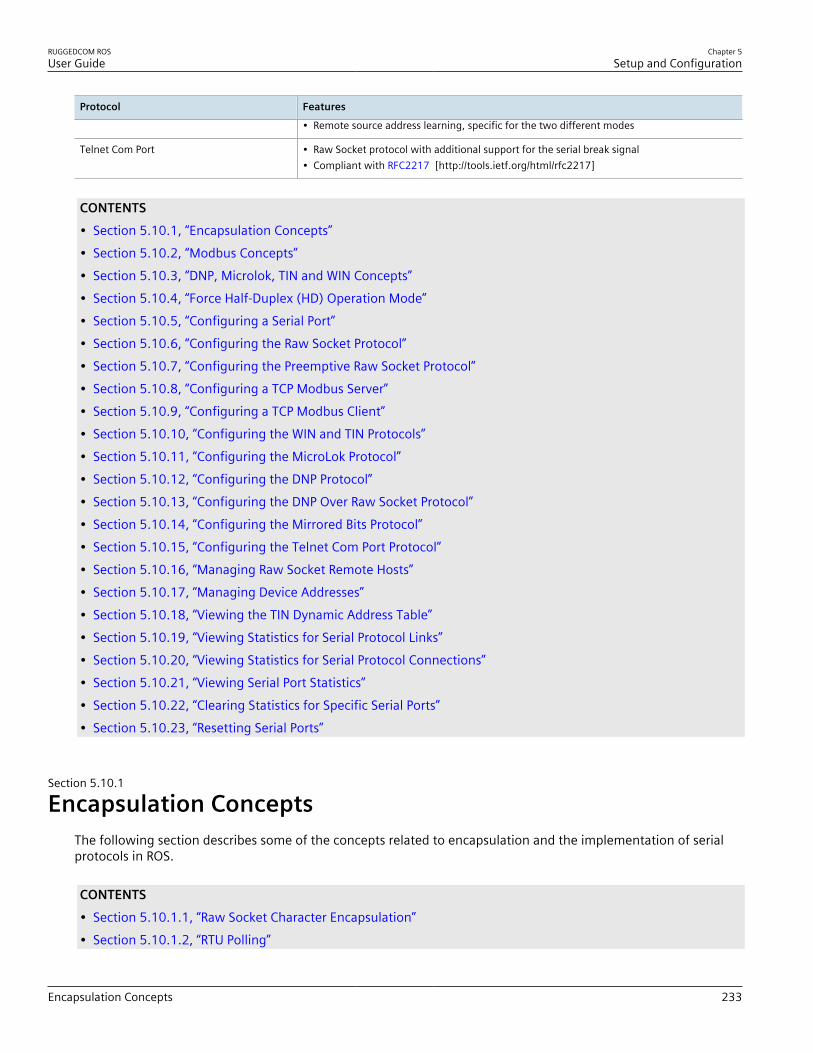
RUGGEDCOM ROSUser Guide
Chapter 5Setup and Configuration
Encapsulation Concepts 233
Protocol Features
• Remote source address learning, specific for the two different modes
Telnet Com Port • Raw Socket protocol with additional support for the serial break signal• Compliant with RFC2217 [http://tools.ietf.org/html/rfc2217]
CONTENTS• Section 5.10.1, “Encapsulation Concepts”• Section 5.10.2, “Modbus Concepts”• Section 5.10.3, “DNP, Microlok, TIN and WIN Concepts”• Section 5.10.4, “Force Half-Duplex (HD) Operation Mode”• Section 5.10.5, “Configuring a Serial Port”• Section 5.10.6, “Configuring the Raw Socket Protocol”• Section 5.10.7, “Configuring the Preemptive Raw Socket Protocol”• Section 5.10.8, “Configuring a TCP Modbus Server”• Section 5.10.9, “Configuring a TCP Modbus Client”• Section 5.10.10, “Configuring the WIN and TIN Protocols”• Section 5.10.11, “Configuring the MicroLok Protocol”• Section 5.10.12, “Configuring the DNP Protocol”• Section 5.10.13, “Configuring the DNP Over Raw Socket Protocol”• Section 5.10.14, “Configuring the Mirrored Bits Protocol”• Section 5.10.15, “Configuring the Telnet Com Port Protocol”• Section 5.10.16, “Managing Raw Socket Remote Hosts”• Section 5.10.17, “Managing Device Addresses”• Section 5.10.18, “Viewing the TIN Dynamic Address Table”• Section 5.10.19, “Viewing Statistics for Serial Protocol Links”• Section 5.10.20, “Viewing Statistics for Serial Protocol Connections”• Section 5.10.21, “Viewing Serial Port Statistics”• Section 5.10.22, “Clearing Statistics for Specific Serial Ports”• Section 5.10.23, “Resetting Serial Ports”
Section 5.10.1
Encapsulation ConceptsThe following section describes some of the concepts related to encapsulation and the implementation of serialprotocols in ROS.
CONTENTS• Section 5.10.1.1, “Raw Socket Character Encapsulation”• Section 5.10.1.2, “RTU Polling”

Chapter 5Setup and Configuration
RUGGEDCOM ROSUser Guide
234 Raw Socket Character Encapsulation
• Section 5.10.1.3, “Broadcast RTU Polling”• Section 5.10.1.4, “Preemptive Raw Socket”• Section 5.10.1.5, “Port Redirectors”• Section 5.10.1.6, “Message Packetization”
Section 5.10.1.1Raw Socket Character Encapsulation
Character encapsulation is used any time a stream of characters must be reliably transported across a network.Character streams can be created by any type of device. The baud rates supported at either server need not be thesame. If configured, the server will obey XON/XOFF flow control from the end devices.
11 3 22
Figure 170: Character Encapsulation
1. Server 2. RS400 3. Ethernet
Section 5.10.1.2RTU Polling
Remote Terminal Unit (RTU) polling applies to a variety of RTU protocols, including Modbus ASCII and DNP.
NOTEIf a given device or service employs a serial protocol that is supported by RUGGEDCOM ROS, it isadvised to configure RUGGEDCOM ROS to use that particular protocol, rather than another one (e.g.RawSocket) that can be made to be (partly) compatible.
Host equipment may connect directly to a server via a serial port, may use a port redirection package, or mayconnect natively to the (Ethernet/IP) network.
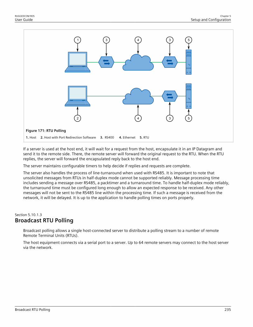
RUGGEDCOM ROSUser Guide
Chapter 5Setup and Configuration
Broadcast RTU Polling 235
53431
5342
Figure 171: RTU Polling
1. Host 2. Host with Port Redirection Software 3. RS400 4. Ethernet 5. RTU
If a server is used at the host end, it will wait for a request from the host, encapsulate it in an IP Datagram andsend it to the remote side. There, the remote server will forward the original request to the RTU. When the RTUreplies, the server will forward the encapsulated reply back to the host end.The server maintains configurable timers to help decide if replies and requests are complete.The server also handles the process of line-turnaround when used with RS485. It is important to note thatunsolicited messages from RTUs in half-duplex mode cannot be supported reliably. Message processing timeincludes sending a message over RS485, a packtimer and a turnaround time. To handle half-duplex mode reliably,the turnaround time must be configured long enough to allow an expected response to be received. Any othermessages will not be sent to the RS485 line within the processing time. If such a message is received from thenetwork, it will be delayed. It is up to the application to handle polling times on ports properly.
Section 5.10.1.3Broadcast RTU Polling
Broadcast polling allows a single host-connected server to distribute a polling stream to a number of remoteRemote Terminal Units (RTUs).The host equipment connects via a serial port to a server. Up to 64 remote servers may connect to the host servervia the network.

Chapter 5Setup and Configuration
RUGGEDCOM ROSUser Guide
236 Preemptive Raw Socket
2
12
2
2
4
4
4
1 3
Figure 172: Broadcast RTU Polling
1. Host 2. RS400 3. Ethernet 4. RTU
Initially, the remote servers establish connections with the host server. The host server is configured to accept amaximum of three incoming connections.The host sequentially polls each RTU. Each poll received by the host server is forwarded (i.e. broadcast) to all ofthe remote servers. All RTUs receive the request and the appropriate RTU issues a reply. The reply is returned tothe host server, where it is forwarded to the host.
Section 5.10.1.4Preemptive Raw Socket
Most SCADA protocols are master/slave and support only a single master device. Preemptive Raw Socket offers theability to have multiple masters communicate to Remote Terminal Units (RTUs) or Intelligent Electronic Devices(IEDs) in a protocol-independent manner. For example, the SCADA master polling device is the normal backgroundprocess collecting data from the RTUs/IEDs on a permanent TCP connection. Occasionally, RTU/IED maintenanceconfiguration or control may be required from a different master (on a dynamic TCP connection).This feature allows a dynamic master to automatically preempt a permanent master. A connection request fromthe dynamic master would cause the permanent master to be suspended. Either closing the dynamic connectionor timing out on data packets causes the permanent master session to be resumed.The illustrates the scenario where all RTUs are connected to Preemptive Raw Socket ports of RS400 devices.

RUGGEDCOM ROSUser Guide
Chapter 5Setup and Configuration
Port Redirectors 237
3
3
3
1 43
5
5
5
5
2
Figure 173: Permanent and Dynamic Master Connection Support
1. Permanent Master (Polling RTUs) 2. Dynamic Master 3. RS400 4. Ethernet 5. RTU
The permanent master is connected to the Raw Socket port of the RS400. Raw Socket is configured to beconnected to all Preemptive Raw Socket ports where polled RTUs are connected (multiple incoming connection).Preemptive Raw Socket configuration on all ports connected to RTUs will point to that Raw Socket as a permanentmaster (IP address and Remote IP port).A dynamic master can establish a connection to any Preemptive Raw Socket port at any time and temporarilysuspend the polling process (until the dynamic connection is cleared or times out).
Section 5.10.1.5Port Redirectors
Port redirectors refer to software packages that emulate the existence of serial communications ports. Theredirector software creates and makes these virtual serial ports available, providing access to the network via aTCP connection.When a software package uses one of the virtual serial ports, a TCP connection request is sent to a remote IPaddress and IP port that have been programmed in to the redirector. Some redirectors also offer the ability toaccept connection requests.The Raw Socket protocol is the one most frequently used on the RS400 for connection to serial port redirectionsoftware. The Telnet Com Port protocol may be used in place of Raw Socket if the redirection software on theother end of the connection also supports the serial break command, as defined in RFC 2217. In Telnet Com Portmode, a serial break received from the remote RFC 2217 compatible client will be transmitted as a serial breakon the configured serial port, and a break signal received on the serial port will be transmitted as an RFC 2217compatible break signal to the remote client. Note that a break signal on a serial port is defined as a conditionwhere the serial data signal is in space or logic zero state for longer than the time needed to transmit one wholecharacter, including start and stop bits.
Chapter 5Setup and Configuration
RUGGEDCOM ROSUser Guide
238 Message Packetization
Section 5.10.1.6Message Packetization
The serial server buffers received characters into packets to improve network efficiency and demarcate messages.The server uses three methods to decide when to packetize and forward the buffered characters to the network:• Packetize on a specific character• Packetize on timeout• Packetize on a specific packet sizeIf configured to packetize on a specific character, the server will examine each received character and willpacketize and forward upon receiving the configured character. The character is usually a <CR> or an <LF>character, but may be any 8 bit (0 to 255) value.If configured to packetize on a timeout, the server will wait for a configurable time after receiving a characterbefore packetizing and forwarding. If another character arrives during the waiting interval, the timer is restarted.This method allows characters transmitted as part of an entire message to be forwarded to the network in a singlepacket, when the timer expires after receiving the very last character of the message.
NOTESome polling software packages that perform well under DOS have been known to experienceproblems when used with Windows-based software or port redirection software. If the operatingsystem does not expedite the transmission of characters in a timely fashion, pauses in transmissioncan be interpreted as the end of a message. Messages can be split into separate TCP packets. A locallyattached server or a port redirector could packetize and forward the message incorrectly. Solutionsinclude tuning the operating system to prevent the problem or increasing the packetizing timer.
Finally, the server will always packetize and forward on a specific packet size, specifically when the number ofcharacters received from the serial port reaches a configured value.
Section 5.10.2
Modbus ConceptsThe following section describes some of the concepts related to Modbus and the implementation of serialprotocols in ROS.
CONTENTS• Section 5.10.2.1, “Modbus Server Client Applications”• Section 5.10.2.2, “Modbus TCP Performance Determinants”• Section 5.10.2.3, “Turnaround Delay”
Section 5.10.2.1Modbus Server Client Applications
Modbus Server and Client applications are used to transport Modbus requests and responses across IP networks.The Modbus Client application accepts Modbus polls from a master and determines the IP address of thecorresponding Remote Terminal Unit (RTU). The client then encapsulates the message in Transmission Control

RUGGEDCOM ROSUser Guide
Chapter 5Setup and Configuration
Modbus TCP Performance Determinants 239
Protocol (TCP), respecting the Modbus TCP protocol, and forwards the frame to a Server Gateway or nativeModbus TCP RTU. Returning responses are stripped of their TCP headers and issued to the master.The Modbus Server application accepts TCP encapsulated Modbus TCP messages from Client Gateways and nativemasters. After removing the TCP headers, the messages are issued to the RTU. Responses are TCP encapsulatedand returned to the originator.The following illustrates a complex network of Client Gateways, Server Gateways and native TCPModbus devices.
17
4 65
8
9
11
10
1
2
3 7
Figure 174: Modbus Client and Server
1. Master (Polling RTUs 1 and 2) 2. Master (Polling RTUs 1, 2 and 4) 3. Native Modbus TCP Master (Polling All RTUs) 4. RS400 ClientGateway 5. RUGGEDCOM Media Converter Client Gateway 6. Ethernet 7. RUGGEDCOM Media Converter Server Gateway 8. RS400Server Gateway 9. RTU 1 10. RTU 2 11. RTU 3 12. RTU 4
Section 5.10.2.2Modbus TCP Performance Determinants
The following illustrates the possible sources of delay and error in an end-to-end Modbus TCP exchange.

Chapter 5Setup and Configuration
RUGGEDCOM ROSUser Guide
240 Modbus TCP Performance Determinants
2 3 41
1a
1b
2
3a
3b
5
4
6
9a7
8
9d
9c9b
Figure 175: Sources of Delay and Error in an End-to-End Exchange
1. Master 2. Client Gateway 3. Server Gateway 4. Remote Terminal Unit (RTU)
In step 1a, the master issues a request to the Client Gateway. If the Client Gateway validates the message, it willforward it to the network as step 2.The Client Gateway can respond immediately in certain circumstances, as shown in step 1b. When the ClientGateway does not have a configuration for the specified RTU, it will respond to the master with an exception usingModbus TCP exception code 11 ("No Path"). When the Client Gateway has a configured RTU but the connectionis not yet active, it will respond to the master with an exception using Modbus TCP exception code 10 ("NoResponse"). If the forwarding of Modbus TCP exceptions is disabled, the client will not issue any responses.Steps 3a and 3b represent the possibility that the Server Gateway does not have a configuration for the specifiedRTU. The Server Gateway will always respond with a type 10 ("No Path") in step 3a, which the client will forward instep 3b.Step 4 represents the possibility of a queuing delay. The Server Gateway may have to queue the request while itawaits the response to a previous request. The worst case occurs when a number of requests are queued for anRTU that has gone off-line, especially when the server is programmed to retry the request upon failure.Steps 5-8 represent the case where the request is responded to by the RTU and is forwarded successfully to themaster. It includes the "think time" for the RTU to process the request and build the response.Step 9a represents the possibility the RTU is off-line, the RTU receives the request in error or that the ServerGateway receives the RTU response in error. The Server Gateway will issue an exception to the originator. Ifsending exceptions has not been enabled, the Server Gateway will not send any responses.
RUGGEDCOM ROSUser Guide
Chapter 5Setup and Configuration
Turnaround Delay 241
Section 5.10.2.3Turnaround Delay
The Modbus protocol uses the concept of a turnaround delay in conjunction with broadcast messages. When thehost sends a broadcast message (that does not invoke an RTU response), it waits for a turnaround delay time. Thisdelay makes sure the RTU has enough time to process the broadcast message before it receives the next poll.When polling is performed over TCP, network delays may cause the broadcast and next poll to arrive at the remoteserver at the same time. Configuring a turnaround delay at the server will enforce a minimum separation timebetween each message transmitted via the serial port.Note that turnaround delays do not need to be configured at the host computer side and may be disabled there.
Section 5.10.3
DNP, Microlok, TIN and WIN ConceptsThe following section describes some of the concepts related to Distributed Network Protocol (DNP), Microlok, TINand Wireless Intelligent Network (WIN) as they relate to the implementation of serial protocols in ROS.
CONTENTS• Section 5.10.3.1, “DNP, Microlok, TIN and WIN Applications”• Section 5.10.3.2, “The Concept of Links”• Section 5.10.3.3, “Address Learning for TIN”• Section 5.10.3.4, “Address Learning for DNP”• Section 5.10.3.5, “Broadcast Messages”• Section 5.10.3.6, “Transport Protocols”
Section 5.10.3.1DNP, Microlok, TIN and WIN Applications
RS400 supports a variety of protocols that specify source and destination addresses. A destination addressspecifies which device should process the data, and the source address specifies which device sent the message.Having both destination and source addresses satisfies at least one requirement for peer-to-peer communicationbecause the receiver knows where to direct responses. Each device supporting one of these protocols must have aunique address within the collection of devices sending and receiving messages to and from each other.
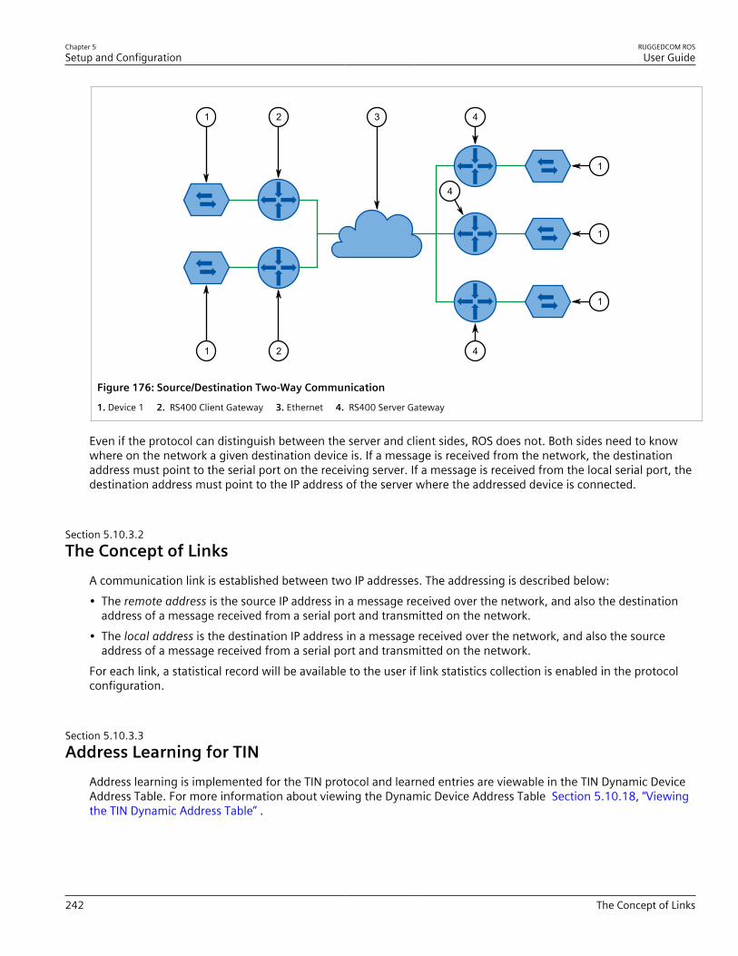
Chapter 5Setup and Configuration
RUGGEDCOM ROSUser Guide
242 The Concept of Links
4
41 2
1
1
1
4
21 3
Figure 176: Source/Destination Two-Way Communication
1. Device 1 2. RS400 Client Gateway 3. Ethernet 4. RS400 Server Gateway
Even if the protocol can distinguish between the server and client sides, ROS does not. Both sides need to knowwhere on the network a given destination device is. If a message is received from the network, the destinationaddress must point to the serial port on the receiving server. If a message is received from the local serial port, thedestination address must point to the IP address of the server where the addressed device is connected.
Section 5.10.3.2The Concept of Links
A communication link is established between two IP addresses. The addressing is described below:• The remote address is the source IP address in a message received over the network, and also the destination
address of a message received from a serial port and transmitted on the network.• The local address is the destination IP address in a message received over the network, and also the source
address of a message received from a serial port and transmitted on the network.For each link, a statistical record will be available to the user if link statistics collection is enabled in the protocolconfiguration.
Section 5.10.3.3Address Learning for TIN
Address learning is implemented for the TIN protocol and learned entries are viewable in the TIN Dynamic DeviceAddress Table. For more information about viewing the Dynamic Device Address Table Section 5.10.18, “Viewingthe TIN Dynamic Address Table” .
RUGGEDCOM ROSUser Guide
Chapter 5Setup and Configuration
Address Learning for DNP 243
Address Learning for TIN Mode 1When a message with an unknown source address is received from the IP network, it is learned on the IP addressand IP port. If a message with the same source address is received from another IP address and/or IP port, theaddress will be relearned.The aging time will be reset whenever a unicast TIN message is received from a particular source address.The address will be removed from the table when the aging time expires.
Address Learning for TIN Mode 2When a message with an unknown source address is received from the IP network, it is learned on the IP address.If a message with the same source address is received from another IP address and/or IP port, it will be learnedagain, and another entry will be created in the Dynamic Device Address Table (TIN addresses will be duplicated).Aging time will be reset whenever a unicast TIN message is received from a particular source address.The address will be removed from the table when the aging time expires.
Section 5.10.3.4Address Learning for DNP
For the DNP protocol, both the local and remote concepts of address learning are implemented. Source addressesare learned from messages received from the network for specific IP Addresses. Source addresses from messagesreceived from the serial ports are learned for specific local serial ports.Although the DNP protocol can be configured for TCP or UDP transport, UDP transport is used during the addresslearning phase as it supports all types of IP addresses: unicast, multicast and broadcast.When a message with an unknown source address is received from the local serial port, the address is learned onthat port and the local IP address.When a message with an unknown source address is received from the IP network, on IP interface that isconfigured as learning interface, it is learned on the IP address of the sender and serial port is unknown.When a message with an unknown destination address is received from a serial port, a UDP broadcast datagram istransmitted on the UDP port configured for the DNP protocol. The IP interface that transmits this broadcast is theone configured as the learning interface.When a message with an unknown destination address is received from the IP network, it is sent to all DNP serialports.All learned addresses will be kept in the Device Address Table until they are active. They will also be saved innon-volatile memory and recovered if the device reboots, so the learning process does not have to be repeatedbecause of, for example, an accidental power interruption.The aging timer is reset whenever a message is received or sent to the specified address.This concept makes the DNP protocol configurable with the minimum number of parameters: an IP port, alearning IP interface and an aging timer.
Chapter 5Setup and Configuration
RUGGEDCOM ROSUser Guide
244 Broadcast Messages
Section 5.10.3.5Broadcast Messages
DNP Broadcast MessagesAddresses 65521 through 65535 are DNP 3.0 broadcast addresses. ROS supports broadcasts sending messageswith those destination addresses received from serial ports to all IP Addresses found in the Device Address Table(either learned or statically configured). When a DNP broadcast message is received from the IP network, it will bedistributed to all ports configured to support the DNP protocol.
TIN Broadcast MessagesTIN broadcast messages can be received only from devices connected to the serial ports.
TIN Mode 1 Broadcast MessagesThese messages will be sent to all TIN Address/Ports found in the Dynamic Address Table.
TIN Mode 2 Broadcast MessagesThese messages will be sent according to the configuration: to all TIN addresses on every IP address found in theDynamic Address Table and/or to all Wayside Data Radio IP addresses found in the Static Device Address Table.
Section 5.10.3.6Transport Protocols
For supported protocols, with exception of Modbus, either UDP datagram or TCP connection packets can be usedto transport protocol data over the IP network. The Modbus data can be transported only using TCP connection,following Modbus TCP protocol. UDP supports all the addressing modes of IP – unicast, multicast and broadcast.Therefore, if address learning is enabled, UDP broadcasts will be sent across the network.
Transport for Raw SocketThe TCP transport for RawSocket requires configuration of connection request direction, remote IP address, andIP port for listening or requesting outgoing TCP connections. Only one outgoing connection can be requested,but up to 64 connections can be accepted if the port is configured to listen to incoming connection requests. Forports configured to request connections and to listen to incoming connection requests, only one connection canbecome active.ROS will attempt to connect periodically if the first attempt fails and after a connection is broken.ROS can be used to connect to any device supporting TCP (e.g. a host computer’s TCP stack or a serial applicationon a host using port redirection software).If Raw Socket ports are configured to use UDP for transport, up to 64 remote hosts can communicate withdevices connected to local serial ports. Data in UDP packets from remote hosts configured to communicate witha particular serial port will be forwarded to that port, as long as the serial port is configured to listen on the UDPport to which the remote hosts are transmitting. Data received from the serial port will be forwarded to all remotehosts configured to communicate with that serial port.

RUGGEDCOM ROSUser Guide
Chapter 5Setup and Configuration
Force Half-Duplex (HD) Operation Mode 245
The Raw Socket mechanism transparently passes data. It does not attempt to determine where to demarcatepackets in the data received from connected devices. Given this transparency, any protocol can be encapsulatedwithin Raw Socket.
Transport for Protocols with Defined LinksAll protocols with defined links (source and destination addresses are part of protocol) can use either TCP or UDPto transport data.The Device Address Table contains addresses and locations of devices configured (or learned) for specificprotocols.If a protocol is configured to use TCP to transport data, the server will start listening to the IP Port configured forthe protocol. At the same time, TCP connections will be placed to all IP addresses where devices for that protocolare attached. ROS will keep only one connection open to one IP Address on one IP Port.
Use of Differentiated Services Code Point (DSCP)ROS has the ability to set the DS byte in the IP header of outbound IP packets. The value can be configured on aningress serial port, and/or for a protocol. Which value will be used depends on the protocol configured on a portand the transport configured for the particular protocol.UDP/IP transport supports a DSCP setting per serial port or per protocol. If a configuration contains a DSCP settingper serial port as well as per protocol then the system will use whichever setting has a higher DSCP value.TCP/IP transport supports per protocol DSCP setting. RawSocket and Modbus Server protocol properties areconfigured per port as well, so they always support DSCP setting per serial port.
Section 5.10.4
Force Half-Duplex (HD) Operation ModeA force half-duplex mode of operation allows use of extensions to create echo loops, similar for example to anoptical loop topology that utilizes the RUGGEDCOM RMC20 repeat mode function.
NOTEIf a port is set to force half-duplex mode, all data received while data is being sent will be discarded. Toset this mode, the port must work natively in full-duplex mode.
The following illustrates a topology that utilizes the RMC20 repeat mode function.

Chapter 5Setup and Configuration
RUGGEDCOM ROSUser Guide
246 Configuring a Serial Port
6 7 821 5
2 4 13
Figure 177: Optical Loop Topology
1. RS485 Slave with Repeat On 2. RMC20 3. Multiple RMC20s 4. RMC20 in Force Half-Duplex Mode 5. RS-232/422 with Repeat On 6. RUGGEDCOM Server 7. Ethernet 8. RS485 Master
The repeat function will optically retransmit any data received on the optical receiver, in addition to any connectedserial devices. As a result, any data transmitted from the master will be retransmitted optically to all the slaves.This topology can be used for RS-232, RS485, or RS422 multi-drop networks. In all cases, all slaves have the repeatfunction (DIP position 4) ON, while the one connected to the RUGGEDCOM RMC30 is configured with the repeatfunction OFF. The port used on the RMC30 must be in full-duplex mode, while the ForceHD (Force Half-Duplex)parameter must be turned ON.
Section 5.10.5
Configuring a Serial PortTo configure a serial port, do the following:1. Navigate to Serial Protocols » Configure Serial Ports . The Serial Ports table appears.
Figure 178: Serial Ports Table
2. Select a serial port. The Serial Ports form appears.
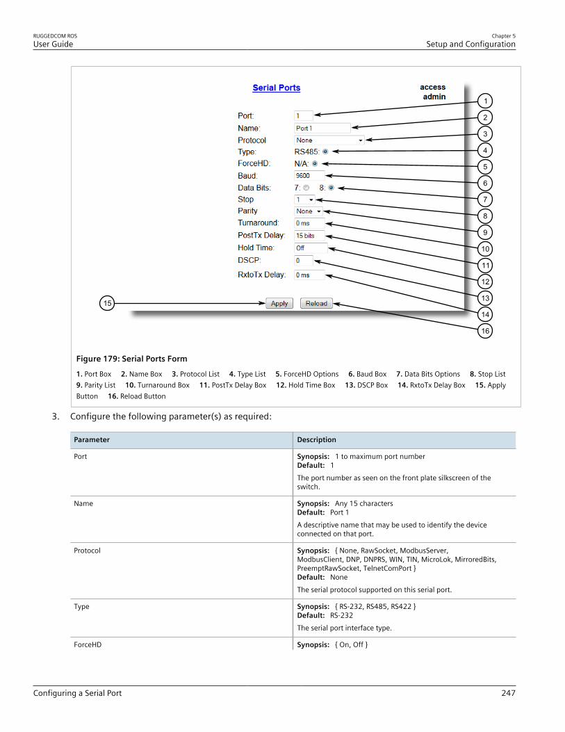
RUGGEDCOM ROSUser Guide
Chapter 5Setup and Configuration
Configuring a Serial Port 247
15
16
1
2
3
4
5
6
7
8
9
10
11
12
13
14
Figure 179: Serial Ports Form
1. Port Box 2. Name Box 3. Protocol List 4. Type List 5. ForceHD Options 6. Baud Box 7. Data Bits Options 8. Stop List 9. Parity List 10. Turnaround Box 11. PostTx Delay Box 12. Hold Time Box 13. DSCP Box 14. RxtoTx Delay Box 15. ApplyButton 16. Reload Button
3. Configure the following parameter(s) as required:
Parameter Description
Port Synopsis: 1 to maximum port numberDefault: 1The port number as seen on the front plate silkscreen of theswitch.
Name Synopsis: Any 15 charactersDefault: Port 1A descriptive name that may be used to identify the deviceconnected on that port.
Protocol Synopsis: { None, RawSocket, ModbusServer,ModbusClient, DNP, DNPRS, WIN, TIN, MicroLok, MirroredBits,PreemptRawSocket, TelnetComPort }Default: NoneThe serial protocol supported on this serial port.
Type Synopsis: { RS-232, RS485, RS422 }Default: RS-232The serial port interface type.
ForceHD Synopsis: { On, Off }

Chapter 5Setup and Configuration
RUGGEDCOM ROSUser Guide
248 Configuring a Serial Port
Parameter Description
Default: OffEnables forcing half-duplex mode of operation. While sendingdata out of the serial port, all received data are ignored. Thismode of operation is available only on ports that operate in full-duplex mode.
Baud Synopsis: 100 to 230400Default: 9600The baud rate at which to operate the port.
Data Bits Synopsis: { 7, 8 }Default: 8The number of data bits to operate the port with.
Stop Synopsis: { 1, 1.5, 2 }Default: 1The number of stop bits to operate the port with.
Parity Synopsis: { None, Even, Odd }Default: NoneThe parity to operate the port with.
Turnaround Synopsis: 0 to 1000Default: 0 msThe amount of delay (if any) to insert between the transmissionsof individual messages via the serial port. For Modbus protocolthis value must be non-zero. It represents the delay betweensending a brodcast message and the next poll out of the serialport. Because RTUs do not reply to a broadcast, enough time mustbe ensured to process it.
PostTX Delay Synopsis: 0 to 15Default: 15 bitsThe number of data bits needed to generate required delay withconfigured baudrate after the last bit of the packet was sent outbefore serial UART starts listening to the RX line. This value isrelevant for RS485 interfaces only.
Hold Time Synopsis: 1 to 15000 ms or { off }Default: offThe maximum amount of time, in milliseconds, that the serialpacket can be held in the queue before being sent to the serialline. Time is measured from the moment the packet is receivedfrom the IP layer.
DSCP Synopsis: 0 to 63Default: 0Sets the DS byte in the IP header. DS byte setting is supported inthe egress direction only.
RXtoTX Delay Synopsis: 0 ms to 1000 msDefault: 0 msThe minimum amount of time, in milliseconds, that thetransmission of a new message delays after the last messageis received through the serial port. This parameter is especiallyuseful for half duplex transmission modes, such as the two-wireRS485 serial protocol. It provides the connected device with timeto turn off its transmitter and to turn on its receiver, helping toensure that the device receives the next message without dataloss.
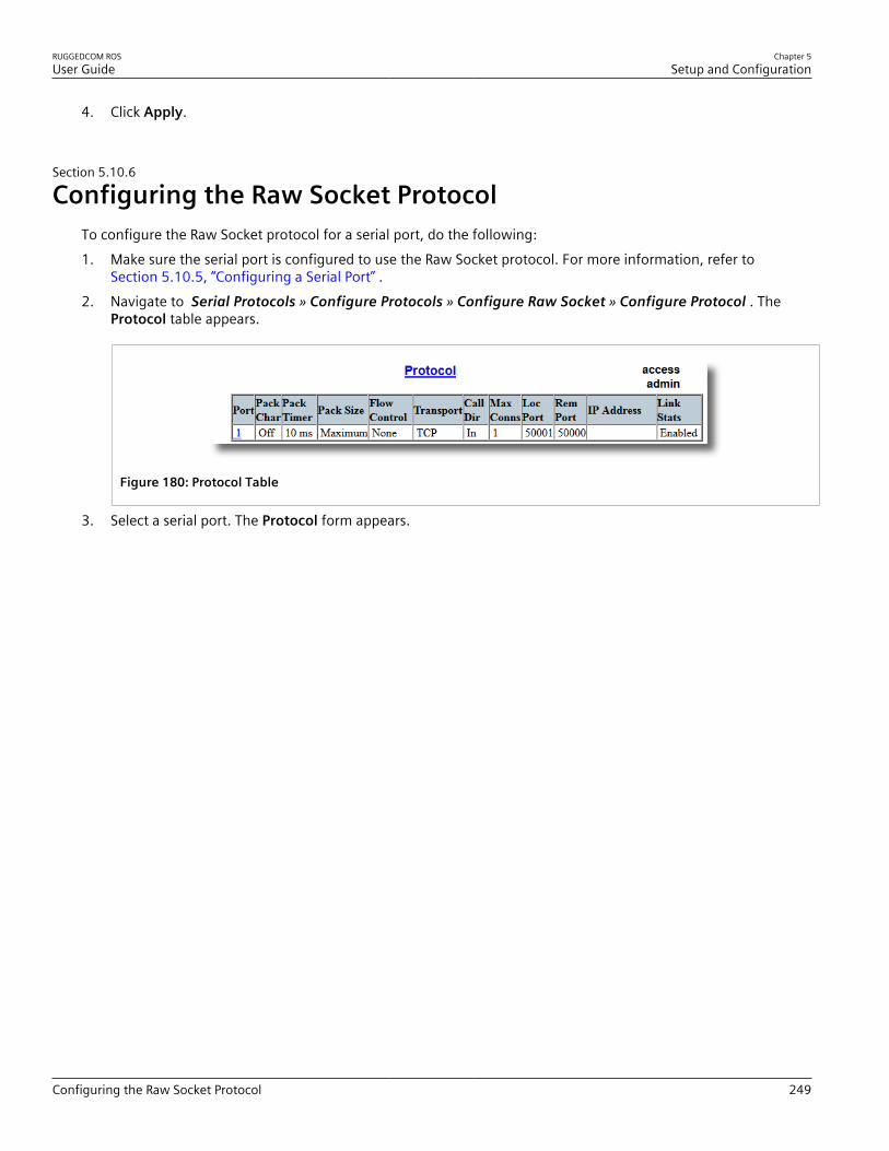
RUGGEDCOM ROSUser Guide
Chapter 5Setup and Configuration
Configuring the Raw Socket Protocol 249
4. Click Apply.
Section 5.10.6
Configuring the Raw Socket ProtocolTo configure the Raw Socket protocol for a serial port, do the following:1. Make sure the serial port is configured to use the Raw Socket protocol. For more information, refer to
Section 5.10.5, “Configuring a Serial Port” .2. Navigate to Serial Protocols » Configure Protocols » Configure Raw Socket » Configure Protocol . The
Protocol table appears.
Figure 180: Protocol Table
3. Select a serial port. The Protocol form appears.

Chapter 5Setup and Configuration
RUGGEDCOM ROSUser Guide
250 Configuring the Raw Socket Protocol
1516
14
13
12
11
10
9
8
7
6
5
4
3
2
1
Figure 181: Protocol Form
1. Port Box 2. Pack Char Box 3. Pack Timer Box 4. Pack Size Box 5. Flow Control Options 6. Response Time Box 7. Response Dest Options 8. Transport Options 9. Call Dir List 10. Max Conns Box 11. Loc Port Box 12. Rem Port Box 13. IPAddress Box 14. Link Stats Options 15. Apply Button 16. Reload Button
4. Configure the following parameter(s) as required:
Parameter Description
Port Synopsis: 1 to maximum port numberDefault: 1The port number as seen on the front plate silkscreen of theswitch.
Pack Char Synopsis: 0 to 255 or { Off }Default: OffThe character that can be used to force forwarding ofaccumulated data to the network. If a packetization character isnot configured, accumulated data will be forwarded based uponthe packetization timeout (Pack Timer) parameter.
Pack Timer Synopsis: 3 to 1000Default: 10 msThe delay from the last received character until when data isforwarded.
Pack Size Synopsis: 16 to 1400 or { Maximum }Default: MaximumThe maximum number of bytes received from the serial port to beforwarded.
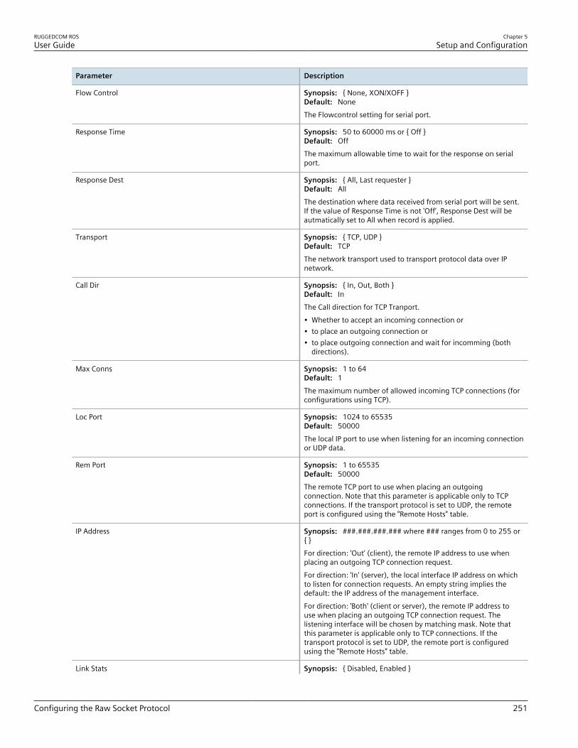
RUGGEDCOM ROSUser Guide
Chapter 5Setup and Configuration
Configuring the Raw Socket Protocol 251
Parameter Description
Flow Control Synopsis: { None, XON/XOFF }Default: NoneThe Flowcontrol setting for serial port.
Response Time Synopsis: 50 to 60000 ms or { Off }Default: OffThe maximum allowable time to wait for the response on serialport.
Response Dest Synopsis: { All, Last requester }Default: AllThe destination where data received from serial port will be sent.If the value of Response Time is not 'Off', Response Dest will beautmatically set to All when record is applied.
Transport Synopsis: { TCP, UDP }Default: TCPThe network transport used to transport protocol data over IPnetwork.
Call Dir Synopsis: { In, Out, Both }Default: InThe Call direction for TCP Tranport.• Whether to accept an incoming connection or• to place an outgoing connection or• to place outgoing connection and wait for incomming (both
directions).
Max Conns Synopsis: 1 to 64Default: 1The maximum number of allowed incoming TCP connections (forconfigurations using TCP).
Loc Port Synopsis: 1024 to 65535Default: 50000The local IP port to use when listening for an incoming connectionor UDP data.
Rem Port Synopsis: 1 to 65535Default: 50000The remote TCP port to use when placing an outgoingconnection. Note that this parameter is applicable only to TCPconnections. If the transport protocol is set to UDP, the remoteport is configured using the "Remote Hosts" table.
IP Address Synopsis: ###.###.###.### where ### ranges from 0 to 255 or{ }For direction: 'Out' (client), the remote IP address to use whenplacing an outgoing TCP connection request.For direction: 'In' (server), the local interface IP address on whichto listen for connection requests. An empty string implies thedefault: the IP address of the management interface.For direction: 'Both' (client or server), the remote IP address touse when placing an outgoing TCP connection request. Thelistening interface will be chosen by matching mask. Note thatthis parameter is applicable only to TCP connections. If thetransport protocol is set to UDP, the remote port is configuredusing the "Remote Hosts" table.
Link Stats Synopsis: { Disabled, Enabled }

Chapter 5Setup and Configuration
RUGGEDCOM ROSUser Guide
252 Configuring the Preemptive Raw Socket Protocol
Parameter Description
Default: EnabledEnables link statistics collection for the protocol.
5. Click Apply.6. Add one or more remote hosts. For more information, refer to Section 5.10.16.2, “Adding a Remote Host” .
Section 5.10.7
Configuring the Preemptive Raw Socket ProtocolTo configure the Preemptive Raw Socket protocol for a serial port, do the following:1. Make sure the serial port is configured to use the Preemptive Raw Socket protocol. For more information,
refer to Section 5.10.5, “Configuring a Serial Port” .2. Navigate to Serial Protocols » Configure Protocols » Configure Preemptive Raw Socket . The Preemptive
Raw Socket table appears.
Figure 182: Preemptive Raw Socket Table
3. Select a serial port. The Preemptive Raw Socket form appears.

RUGGEDCOM ROSUser Guide
Chapter 5Setup and Configuration
Configuring the Preemptive Raw Socket Protocol 253
14
13
1
10
6
2
5
11
8
3
7
12
9
4
Figure 183: Preemptive Raw Socket Form
1. Port Box 2. Pack Char Box 3. Pack Timer Box 4. Pack Size Box 5. Flow Control Options 6. Loc Port Box 7. Rem Port Box 8. IP Address Box 9. Link Stats Options 10. Dyn Pack Char Box 11. Dyn Pack Timer Box 12. Timeout Box 13. Apply Button 14. Reload Button
4. Configure the following parameter(s) as required:
Parameter Description
Pack Size Synopsis: 16 to 1400 or { Maximum }Default: MaximumThe maximum number of bytes received from serial port to beforwarded.
Dyn Pack Char Synopsis: 0 to 255 or { Off }Default: OffThe character that can be used to force forwarding ofaccumulated data to the network for connection to dynamicmaster.If a packetization character is not configured, accumulateddata will be forwarded based upon the packetization timeoutparameter.
Loc Port Synopsis: 1 to 65535Default: 62001The local IP port to use when listening for an incoming connectionor UDP data.
Rem Port Synopsis: 1 to 65535Default: 62000The remote TCP port to use when placing an outgoingconnection.
Port Synopsis: 1 to 4Default: 1

Chapter 5Setup and Configuration
RUGGEDCOM ROSUser Guide
254 Configuring a TCP Modbus Server
Parameter Description
The port number as seen on the front plate silkscreen of theswitch.
Pack Char Synopsis: 0 to 255 or { Off }Default: OffThe character that can be used to force forwarding ofaccumulated data to the network.If a packetization character isnot configured, accumulated data will be forwarded based uponthe packetization timeout parameter.
Pack Timer Synopsis: 1 to 1000 msDefault: 10 msThe delay from the last received character until when data isforwarded.If parameter value is set to be less than 3 ms, there isnot guaranty that it will be obeyed. It will be a minimum possibletime in which device can react under certain data load.
Dyn Pack Timer Synopsis: 1 to 1000 msDefault: 10 msThe delay from the last received character until when data isforwarded to the dynamic master.
Flow Control Synopsis: { None, XON/XOFF }Default: NoneThe Flowcontrol setting for serial port.
IP Address Synopsis: ###.###.###.### where ### ranges from 0 to 255 or{ <empty string> }The permanent master's IP address. Empty string representsmanagement IP address of this device.
Link Stats Synopsis: { Disabled, Enabled }Default: EnabledEnables links statistics collection for protocol.
Timeout Synopsis: 10 to 3600 sDefault: 10 sThe time in seconds that is allowed to dynamic master to be idlebefore it's connection is closed. The protocol listens to the socketopen to dynamic master, and if no data are received within thistime, connection will be closed.
5. Click Apply.
Section 5.10.8
Configuring a TCP Modbus ServerTo configure the TCP Modbus Server protocol for a serial port, do the following:1. Make sure the serial port is configured to use the TCP Modbus Server protocol. For more information, refer to
Section 5.10.5, “Configuring a Serial Port” .2. Navigate to Serial Protocols » Configure Protocols » Configure Modbus Server . The Modbus Server table
appears.

RUGGEDCOM ROSUser Guide
Chapter 5Setup and Configuration
Configuring a TCP Modbus Server 255
Figure 184: Modbus Server Table
3. Select a serial port. The Modbus Server form appears.
87
3
4
5
1
2
Figure 185: Modbus Server Form
1. Port Box 2. Response Timer Box 3. Auxiliary TCP Port Box 4. Send Exceptions Options 5. Link Stats Options 6. ApplyButton 7. Reload Button
4. Configure the following parameter(s) as required:
Parameter Description
Port Synopsis: 1 to maximum port numberDefault: 1The port number as seen on the front plate silkscreen of theswitch.
Response Timer Synopsis: 50 to 10000Default: 1000 msThe maximum allowable time to wait for the RTU to start torespond.
Auxiliary TCP Port Synopsis: 1024 to 65535 or { Disabled }Default: DisabledThe TCP Modbus Server always listens on TCP port 502. It may beadditionally configured to listen on this auxiliary port number,accepting calls on both.
Send Exceptions Synopsis: { Disabled, Enabled }Default: EnabledThis parameter enables/disables sending a TCP Modbus exceptionback to the master if a response has not been received from theRTU within expected time.
Link Stats Synopsis: { Disabled, Enabled }Default: Enabled

Chapter 5Setup and Configuration
RUGGEDCOM ROSUser Guide
256 Configuring a TCP Modbus Client
Parameter Description
Enables link statistics collection for this protocol.
5. Click Apply.
Section 5.10.9
Configuring a TCP Modbus ClientTo configure the TCP Modbus Client protocol for a serial port, do the following:1. Make sure the serial port is configured to use the TCP Modbus Client protocol. For more information, refer to
Section 5.10.5, “Configuring a Serial Port” .2. Navigate to Serial Protocols » Configure Protocols » Configure Modbus Client . The Modbus Client form
appears.
65
3
4
1
2
Figure 186: Modbus Client Form
1. IP Port Box 2. Forward Exceptions Options 3. Link Stats Options 4. DSCP Box 5. Apply Button 6. Reload Button
3. Configure the following parameter(s) as required:
Parameter Description
IP Port Synopsis: 1 to 65535Default: 502The remote port number at which the Modbus protocol makesTCP connection requests.
Forward Exceptions Synopsis: { Disabled, Enabled }Default: EnabledEnables forwarding exception messages to the Master asexception codes 10 (no path) or 11 (no response) When theMaster polls for an unconfigured RTU or the remote ModbusServer receives a poll for an RTU which is not configured or istiming out, it returns an exception message. Disable this feature ifyour Master does not support exceptions but recognizes failure bytime-out when waiting for response.
Link Stats Synopsis: { Disabled, Enabled }Default: EnabledEnables link statistics collection for this protocol.
DSCP Synopsis: 0 to 63

RUGGEDCOM ROSUser Guide
Chapter 5Setup and Configuration
Configuring the WIN and TIN Protocols 257
Parameter Description
Default: 0To set the DS byte in the IP header. DS byte setting is supported inthe egress direction only.
4. Click Apply.
Section 5.10.10
Configuring the WIN and TIN ProtocolsTo configure the WIN or TIN protocols for a serial port, do the following:1. Make sure the serial port is configured to use either the WIN or TIN protocol. For more information, refer to
Section 5.10.5, “Configuring a Serial Port” .2. Navigate to Serial Protocols » Configure Protocols » Configure WIN and TIN . The WIN and TIN form
appears.
14
13
1
2
3
4
5
6
7
8
9
10
11
12
Figure 187: WIN and TIN Form
1. TIN Mode Box 2. TIN Transport List 3. WIN Transport List 4. TIN IP Box 5. WIN IP Box 6. Messaging Aging Timer Box 7. Address Aging Timer Box 8. Broadcast Addresses List 9. Unicast Addresses List 10. Link Stats Options 11. WIN DSCP Box 12. TIN DSCP Box 13. Apply Button 14. Reload Button
3. Configure the following parameter(s) as required:
Parameter Description
TIN Mode Synopsis: 1 to 2Default: 1The TIN Protocol running mode.

Chapter 5Setup and Configuration
RUGGEDCOM ROSUser Guide
258 Configuring the WIN and TIN Protocols
Parameter Description
TIN Transport Synopsis: { TCP, UDP, Disabled }Default: UDPThe network transport used to transport protocol data over an IPnetwork.
WIN Transport Synopsis: { TCP, UDP, Disabled }Default: UDPThe network transport used to transport protocol data over an IPnetwork.
TIN IP Port Synopsis: 1024 to 65535Default: 51000The local port number on which the TIN protocol listens forconnections or UDP datagrams.
WIN IP Port Synopsis: 1024 to 65535Default: 52000The local port number on which the WIN protocol listens forconnections or UDP datagrams.
Message Aging Timer Synopsis: 1 to 3600 or { Disabled }Default: DisabledThe Aging Time for TIN mode2 messages. It specifies how long amessage should be stored in the internal table. When the featureis enabled, any TIN mode2 message received will be stored in aninternal table which can be examined by using command 'SQLSELECT FROM ItcsTin2Dup'. If the same message is received withinthe time window specified by this parameter, the new message isconsidered duplicate, and thus discarded.
Address Aging Timer Synopsis: 60 to 1000Default: 300 sThe time of communication inactivity after which a learned TINaddress is removed from the device address table. Entries inthe Link Statistics Table with the aged address will be kept untilstatistics are cleared.
Broadcast Addresses Synopsis: { Static, Dynamic, StaticAndDynamic }Default: StaticThe device address table in which addresses will be found forbroadcast messages.
Unicast Addresses Synopsis: { Static, Dynamic, StaticAndDynamic }Default: DynamicThe device address table in which addresses will be found forunicast messages.
Link Stats Synopsis: { Disabled, Enabled }Default: EnabledEnables link statistics collection for this protocol.
WIN DSCP Synopsis: 0 to 63Default: 0To set the DS byte in the IP header. DS byte setting is supported inthe egress direction only.
TIN DSCP Synopsis: 0 to 63Default: 0To set the DS byte in the IP header. DS byte setting is supported inthe egress direction only.

RUGGEDCOM ROSUser Guide
Chapter 5Setup and Configuration
Configuring the MicroLok Protocol 259
4. Click Apply.
Section 5.10.11
Configuring the MicroLok ProtocolTo configure the MicroLok protocol for a serial port, do the following:1. Make sure the serial port is configured to use the MicroLok protocol. For more information, refer to
Section 5.10.5, “Configuring a Serial Port” .2. Navigate to Serial Protocols » Configure Protocols » Configure MicroLok . The MicroLok form appears.
65
1
2
3
4
Figure 188: MicroLok Form
1. Transport List 2. IP Port Box 3. Link Stats Options 4. DSCP Box 5. Apply Button 6. Reload Button
3. Configure the following parameter(s) as required:
Parameter Description
Transport Synopsis: { TCP, UDP, Disabled }Default: UDPThe network transport used to transport protocol data over an IPnetwork.
IP Port Synopsis: 1024 to 65535Default: 60000A local port number on which the MicroLok protocol listens forUDP datagrams or TCP connections.
Link Stats Synopsis: { Disabled, Enabled }Default: EnabledEnables link statistics collection for this protocol.
DSCP Synopsis: 0 to 63Default: 0To set the DS byte in the IP header. DS byte setting is supported inthe egress direction only.
4. Click Apply.
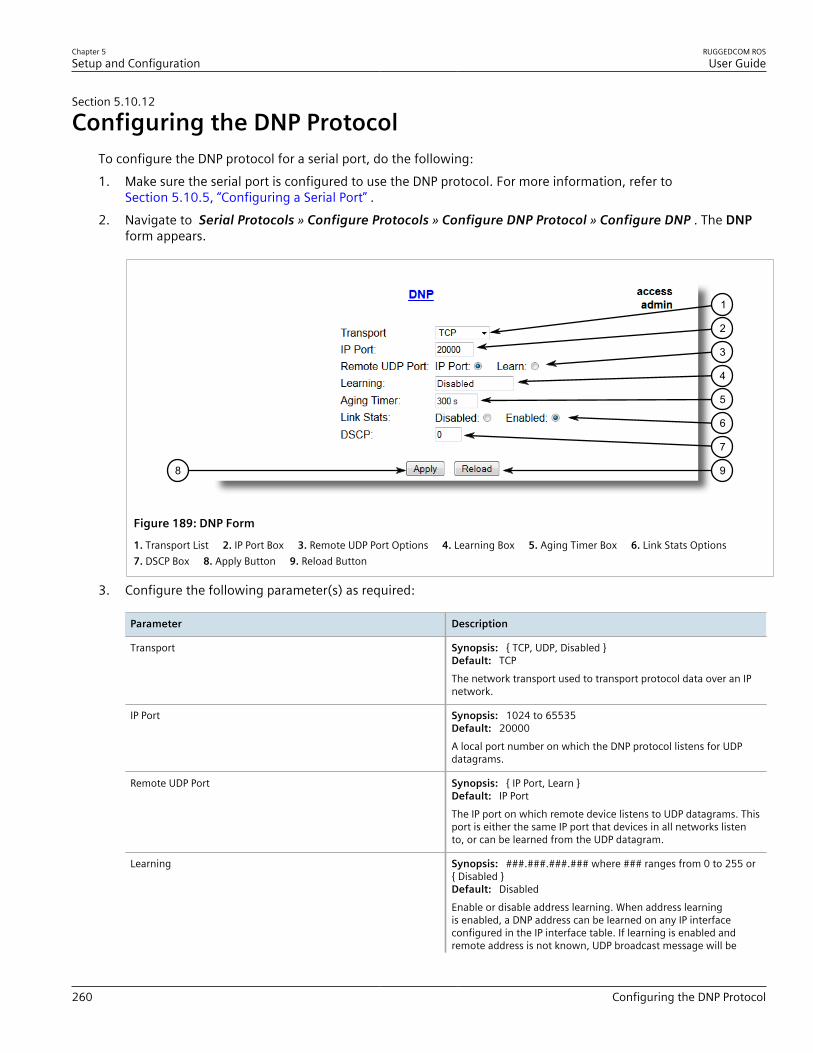
Chapter 5Setup and Configuration
RUGGEDCOM ROSUser Guide
260 Configuring the DNP Protocol
Section 5.10.12
Configuring the DNP ProtocolTo configure the DNP protocol for a serial port, do the following:1. Make sure the serial port is configured to use the DNP protocol. For more information, refer to
Section 5.10.5, “Configuring a Serial Port” .2. Navigate to Serial Protocols » Configure Protocols » Configure DNP Protocol » Configure DNP . The DNP
form appears.
98
1
7
6
2
3
4
5
Figure 189: DNP Form
1. Transport List 2. IP Port Box 3. Remote UDP Port Options 4. Learning Box 5. Aging Timer Box 6. Link Stats Options 7. DSCP Box 8. Apply Button 9. Reload Button
3. Configure the following parameter(s) as required:
Parameter Description
Transport Synopsis: { TCP, UDP, Disabled }Default: TCPThe network transport used to transport protocol data over an IPnetwork.
IP Port Synopsis: 1024 to 65535Default: 20000A local port number on which the DNP protocol listens for UDPdatagrams.
Remote UDP Port Synopsis: { IP Port, Learn }Default: IP PortThe IP port on which remote device listens to UDP datagrams. Thisport is either the same IP port that devices in all networks listento, or can be learned from the UDP datagram.
Learning Synopsis: ###.###.###.### where ### ranges from 0 to 255 or{ Disabled }Default: DisabledEnable or disable address learning. When address learningis enabled, a DNP address can be learned on any IP interfaceconfigured in the IP interface table. If learning is enabled andremote address is not known, UDP broadcast message will be

RUGGEDCOM ROSUser Guide
Chapter 5Setup and Configuration
Configuring the DNP Over Raw Socket Protocol 261
Parameter Description
sent to the subnet of the address configured for learning andsource addresses will be learned. If local address is not known,message will be sent to all serial ports running DNP protocol.Local addresses will be learned from local responses. If TCPtransport is configured, connection will be established to thedevices with the corresponding IP address.
4. Click Apply.
Section 5.10.13
Configuring the DNP Over Raw Socket ProtocolTo configure the DNP Over Raw Socket protocol for a serial port, do the following:1. Make sure the serial port is configured to use the DNP Over Raw Socket protocol. For more information, refer
to Section 5.10.5, “Configuring a Serial Port” .2. Navigate to Serial Protocols » Configure Protocols » Configure DNP Protocol » Configure DNP over
RawSocket . The DNP over RawSocket table appears.
Figure 190: DNP over RawSocket Table
3. Select a serial port. The DNP over RawSocket form appears.

Chapter 5Setup and Configuration
RUGGEDCOM ROSUser Guide
262 Configuring the DNP Over Raw Socket Protocol
11 12
9
8
7
6
5
4
3
2
1
10
Figure 191: DNP over RawSocket Form
1. Port Box 2. Response Time Box 3. Response Dest Options 4. Transport Options 5. Call Dir List 6. Max Conns Box 7. LocPort Box 8. Rem Port Box 9. IP Address Box 10. Link Stats Options 11. Apply Button 12. Reload Button
4. Configure the following parameter(s) as required:
Parameter Description
Port Synopsis: 1 to 4Default: 1The port number as seen on the front plate silkscreen on theswitch.
Response Time Synopsis: 50 to 60000 ms or { Off }Default: OffThe maximum allowable time to wait for the response on serialport.
Response Dest Synopsis: All, Last requesterDefault: AllThe destination where data received from serial port will be sent.If the value of Response Time is not 'Off', Response Dest will beautmatically set to All when record is applied.
Transport Synopsis: { TCP, UDP }Default: TCPThe network transport used to transport protocol data over the IPnetwork.
Call Dir Synopsis: { In, Out, Both }Default: InThe Call direction for TCP Tranport.• In: accepts an incoming connection.• Out: places an outgoing connection• Both: places an outgoing connection and waits for as incoming
connection (both directions).

RUGGEDCOM ROSUser Guide
Chapter 5Setup and Configuration
Configuring the Mirrored Bits Protocol 263
Parameter Description
Max Conns Synopsis: 1 to 64Default: 1The maximum number of allowed incoming TCP connections.
Loc Port Synopsis: 1 to 65535Default: 21001The local IP port to use when listening for an incoming connectionor UDP data.
Rem Port Synopsis: 1 to 65535Default: 21000The remote TCP port to use when placing an outgoingconnection.
IP Address Synopsis: ###.###.###.### (where ### ranges from 0 to 255) |{ <empty string> }Default: <empty string>Defines the IP address based on the following:• For outgoing TCP connection (client), this is the remote IP
address to communicate with.• For incoming TCP connection (server), this is the local interface
IP address to listen to for the local port for connectionrequest. If an empty string is configured, the IP address of themanagement interface is used.
• When both outgoing and incoming connections are enabled(client or server), this is remote IP address to use to place anoutgoing TCP connection request or from which to accept calls
• For UDP transport, this is the IP address of the interface to listento for UDP datagrams.
Link Stats Synopsis: { Disabled, Enabled }Default: EnabledEnables links statistics collection for the protocol.
5. Click Apply.
Section 5.10.14
Configuring the Mirrored Bits ProtocolTo configure the Mirrored Bits protocol for a serial port, do the following:1. Make sure the serial port is configured to use the Mirrored Bits protocol. For more information, refer to
Section 5.10.5, “Configuring a Serial Port” .2. Navigate to Serial Protocols » Configure Protocols » Configure Mirrored Bits . The Mirrored Bits table
appears.

Chapter 5Setup and Configuration
RUGGEDCOM ROSUser Guide
264 Configuring the Mirrored Bits Protocol
Figure 192: Mirrored Bits Table
3. Select a serial port. The Mirrored Bits form appears.
87
3
4
5
6
1
2
Figure 193: Mirrored Bits Form
1. Port Box 2. Transport Box 3. Loc Port Box 4. Rem Port Box 5. IP Address Box 6. Link Stats Options 7. Apply Button 8. Reload Button
4. Configure the following parameter(s) as required:
Parameter Description
Port Synopsis: 1 to 4Default: 1The port number as seen on the front plate silkscreen of theswitch.
Transport Synopsis: { TCP, UDP }Default: UDPThe network transport used to transport Mirrored Bits protocoldata over an IP network.
Loc Port Synopsis: 1 to 65535Default: 61001The local IP port to use when listening for an incoming connectionor UDP data.
Rem Port Synopsis: 1 to 65535Default: 61000The remote TCP port to use when placing an outgoingconnection.

RUGGEDCOM ROSUser Guide
Chapter 5Setup and Configuration
Configuring the Telnet Com Port Protocol 265
Parameter Description
IP Address Synopsis: ###.###.###.### where ### ranges from 0 to 255 or{ <EMPTY STRING> }Default:For an outgoing TCP connection (client) and UDP transport, this isthe remote IP address to communicate with.For an incoming TCP connection (server), the local interface IPaddress on which to listen for connection requests. An emptystring implies the default: the IP address of the managementinterface.When both outgoing and incoming connections are enabled(client or server), this is the remote IP address to which to placean outgoing TCP connection request or from which to accept anincoming request.
Link Stats Synopsis: { Disabled, Enabled }Default: EnabledEnables link statistics collection for this protocol.
5. Click Apply.
Section 5.10.15
Configuring the Telnet Com Port ProtocolTo configure the Telnet Com Port protocol for a serial port, do the following:1. Make sure the serial port is configured to use the Telnet Com Port protocol. For more information, refer to
Section 5.10.5, “Configuring a Serial Port” .2. Navigate to Serial Protocols » Configure Protocols » Configure Telnet Com Port . The Telnet Com Port
table appears.
Figure 194: Telnet Com Port Table
3. Select a serial port. The Telnet Com Port form appears.

Chapter 5Setup and Configuration
RUGGEDCOM ROSUser Guide
266 Configuring the Telnet Com Port Protocol
12
11
1
2
3
4
5
6
7
8
9
10
Figure 195: Telnet Com Port Form
1. Port Box 2. Pack Char Box 3. Pack Timer Box 4. Pack Size Box 5. Flow Control Options 6. Call Dir List 7. Loc Port Box 8. Rem Port Box 9. IP Address Box 10. Link Stats Options 11. Apply Button 12. Reload Button
4. Configure the following parameter(s) as required:
Parameter Description
Port Synopsis: 1 to maximum port numberDefault: 1The serial port number as seen on the front plate silkscreen of theRS400.
Pack Char Synopsis: 0 to 255 or { Off }Default: OffThe character that will be used to force the forwarding ofbuffered data to the network. If a packetization character is notconfigured, buffered data will be forwarded based upon thepacketization timeout (Pack Timer) parameter.
Pack Timer Synopsis: 1 to 1000Default: 10 msThe delay from the last received character until when data isforwarded. If parameter value is set to be less than 3 ms, there isnot guaranty that it will be obeyed. It will be a minimum possibletime in which device can react under certain data load.
Pack Size Synopsis: 16 to 1400 or { Maximum }Default: MaximumThe maximum number of bytes received from serial port to beforwarded.
Flow Control Synopsis: { None, XON/XOFF }Default: NoneThe Flowcontrol setting for serial port.
Call Dir Synopsis: { In, Out, Both }

RUGGEDCOM ROSUser Guide
Chapter 5Setup and Configuration
Managing Raw Socket Remote Hosts 267
Parameter Description
Default: InThe Call direction for TCP Transport.• Whether to accept an incoming connection or• to place an outgoing connection or• to place outgoing connection and wait for incoming (both
directions).
Loc Port Synopsis: 1024 to 65535Default: 50000The local IP port to use when listening for an incomingconnection.
Rem Port Synopsis: 1 to 65535Default: 50000The remote TCP port to use when placing an outgoingconnection. This parameter is applicable only to TCP transport.
IP Address Synopsis: ###.###.###.### where ### ranges from 0 to 255 or{ }Default: For direction 'OUT' (client), remote IP address to use when placingan outgoing TCP connection request. For direction 'IN' (server),local interface IP address to listen to the local port for connectionrequest. Empty string can be used for IP address of managementinterface. For direction 'BOTH' (client or server), remote IP addressto use when placing an outgoing TCP connection requestListeninginterface will be chosen by matching mask. This parameter isapplicable only to TCP connections. If the transport protocol is setto UDP, the remote port is configured using the "Remote Hosts"table.
Link Stats Synopsis: { Disabled, Enabled }Default: EnabledEnables links statistics collection for this protocol.
5. Click Apply.
Section 5.10.16
Managing Raw Socket Remote HostsThis section describes how to configure and manage remote hosts.
CONTENTS• Section 5.10.16.1, “Viewing a List of Remote Hosts”• Section 5.10.16.2, “Adding a Remote Host”

Chapter 5Setup and Configuration
RUGGEDCOM ROSUser Guide
268 Viewing a List of Remote Hosts
• Section 5.10.16.3, “Deleting a Remote Host”
Section 5.10.16.1Viewing a List of Remote Hosts
To view a list of remote hosts configured for the Raw socket protocol, navigate to Serial Protocols » ConfigureProtocols » Configure Raw Socket » Configure Remote Hosts . The Remote table appears.
Figure 196: Remote Table
If remote hosts have not been configured, add hosts as needed. For more information, refer to Section 5.10.16.2,“Adding a Remote Host” .
Section 5.10.16.2Adding a Remote Host
To add a remote host for the Raw socket protocol, do the following:1. Navigate to Serial Protocols » Configure Protocols » Configure Raw Socket » Configure Remote Hosts .
The Remote Hosts table appears.
Figure 197: Remote Table
2. Click InsertRecord. The Remote Hosts form appears.
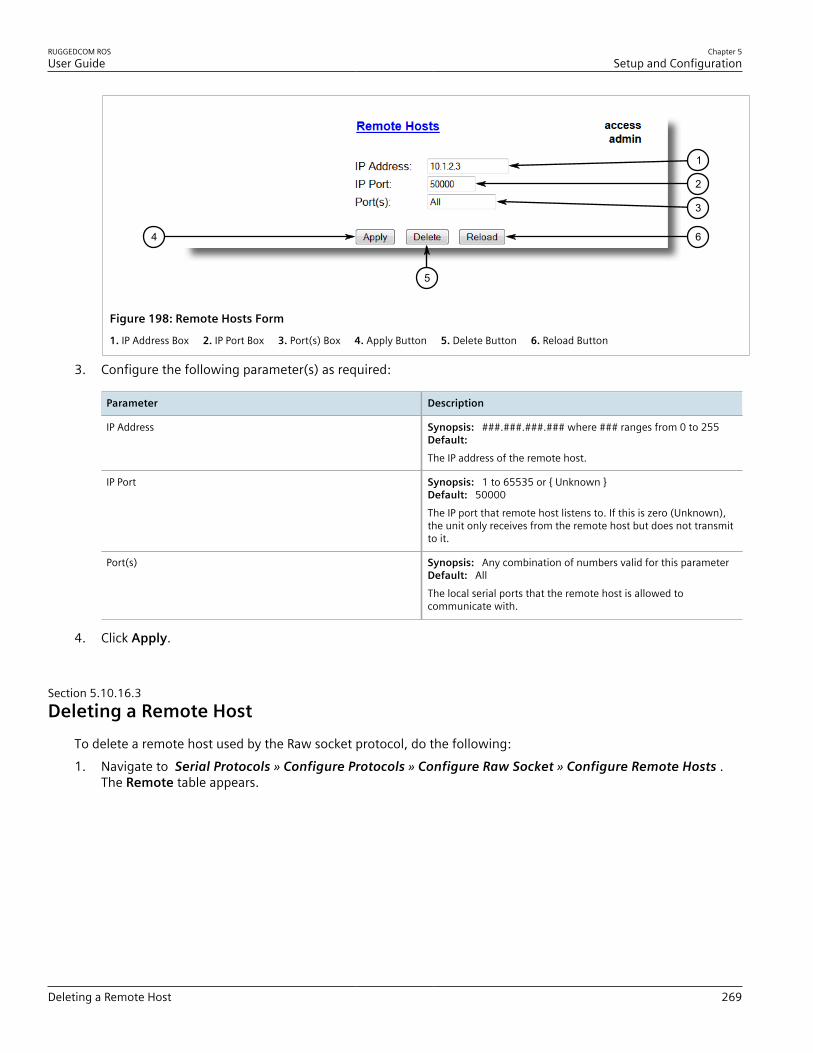
RUGGEDCOM ROSUser Guide
Chapter 5Setup and Configuration
Deleting a Remote Host 269
64
5
1
2
3
Figure 198: Remote Hosts Form
1. IP Address Box 2. IP Port Box 3. Port(s) Box 4. Apply Button 5. Delete Button 6. Reload Button
3. Configure the following parameter(s) as required:
Parameter Description
IP Address Synopsis: ###.###.###.### where ### ranges from 0 to 255Default: The IP address of the remote host.
IP Port Synopsis: 1 to 65535 or { Unknown }Default: 50000The IP port that remote host listens to. If this is zero (Unknown),the unit only receives from the remote host but does not transmitto it.
Port(s) Synopsis: Any combination of numbers valid for this parameterDefault: AllThe local serial ports that the remote host is allowed tocommunicate with.
4. Click Apply.
Section 5.10.16.3Deleting a Remote Host
To delete a remote host used by the Raw socket protocol, do the following:1. Navigate to Serial Protocols » Configure Protocols » Configure Raw Socket » Configure Remote Hosts .
The Remote table appears.

Chapter 5Setup and Configuration
RUGGEDCOM ROSUser Guide
270 Managing Device Addresses
Figure 199: Remote Table
2. Select the remote host from the table. The Remote form appears.
64
5
1
2
3
Figure 200: Remote Form
1. IP Address Box 2. IP Port Box 3. Port(s) Box 4. Apply Button 5. Delete Button 6. Reload Button
3. Click Delete.
Section 5.10.17
Managing Device AddressesThis section describes how to configure and manage device addresses.
CONTENTS• Section 5.10.17.1, “Viewing a List of Device Addresses”• Section 5.10.17.2, “Adding a Device Address”• Section 5.10.17.3, “Deleting a Device Address”
Section 5.10.17.1Viewing a List of Device Addresses
To view a list of device addresses configured on the device, navigate to Serial Protocols » Configure DeviceAddress Table . The Device Address Table table appears.

RUGGEDCOM ROSUser Guide
Chapter 5Setup and Configuration
Adding a Device Address 271
Figure 201: Device Address Table Table
If device addresses have not been configured, add addresses as needed. For more information, refer to Section 5.10.17.2, “Adding a Device Address” .
Section 5.10.17.2Adding a Device Address
To add a device address, do the following:1. Navigate to Serial Protocols » Configure Device Addresses . The Device Address Table table appears.
1
Figure 202: Device Address Table Table
1. InsertRecord
2. Click InsertRecord. The Device Address Table form appears.

Chapter 5Setup and Configuration
RUGGEDCOM ROSUser Guide
272 Adding a Device Address
86
7
1
5
4
2
3
Figure 203: Device Address Table Form
1. Protocol List 2. Address Box 3. Remote IP Address Box 4. Port Box 5. Name Box 6. Apply Button 7. Delete Button 8. Reload Button
3. Configure the following parameter(s) as required:
Parameter Description
Protocol Synopsis: { ModbusServer, ModbusClient, DNP, WIN, TIN,MicroLok }Default: ModbusServerThe serial protocol supported on this serial port.
Address Synopsis: Any 31 charactersDefault:The complete address of a device, which might be either local tothe RUGGEDCOM device or remote.A local address is one associated with a device connected to aserial port on this device. The corresponding serial port must beconfigured to match this address specification.A remote address is the address of a device connected to a serialport on a remote host over an IP network. In this case, "Remote IpAddr" must also be configured.The format and range of this address field is determined by theprotocol:• Modbus: 1 to 244• MicroLok: 1 to 65535, or 8 to hexadecimal digits ‘1’ to ‘a’• DNP 3.0: 1 to 65520• WIN: 6 bits address (0 to 63)• TIN: String 'wdr' for wayside data radio (TIN mode 2), or a 32 bit
address (8 digits, expressed in hexadecimal digits '0' through'f'). An all-zero address is not allowed.
Remote IP Addr Synopsis: ###.###.###.### where ### ranges from 0 to 255Default:The IP address of a remote host where a device with a configuredremote address is connected.
Port Synopsis: 1 to maximum port number or {Unknown}Default: Unknown

RUGGEDCOM ROSUser Guide
Chapter 5Setup and Configuration
Deleting a Device Address 273
Parameter Description
The serial port to which a device is attached. If the device withthis address is attached to the serial port of a remote host, thevalue of this parameter is 'Unknown'.
Name Synopsis: Any 16 charactersDefault:The addressed device name.
4. Click Apply.
Section 5.10.17.3Deleting a Device Address
To delete a device address, do the following:1. Navigate to Serial Protocols » Configure Device Address Table . The Device Address Table table appears.
Figure 204: Device Address Table Table
2. Select the device address from the table. The Device Address Table form appears.

Chapter 5Setup and Configuration
RUGGEDCOM ROSUser Guide
274 Viewing the TIN Dynamic Address Table
86
7
1
5
4
2
3
Figure 205: Device Address Table Form
1. Protocol List 2. Address Box 3. Remote IP Address Box 4. Port Box 5. Name Box 6. Apply Button 7. Delete Button 8. Reload Button
3. Click Delete.
Section 5.10.18
Viewing the TIN Dynamic Address TableTo view the device addresses learned dynamically by the TIN protocol from remote locations, navigate to SerialProtocols » View TIN Dynamic Address Table . The TIN Dynamic Address Table table appears.
Figure 206: TIN Dynamic Address Table
This table displays the following information:
Parameter Description
Address Synopsis: Any 31 charactersThe remote device address.
Location Synopsis: ###.###.###.### where ### ranges from 0 to 255The IP Address of the remote host.
IP Port Synopsis: 1 to 65535The remote port number through which remote device sent a UDPdatagram or TCP connection is established
RSSI Synopsis: -128 to 0 or { N/A }

RUGGEDCOM ROSUser Guide
Chapter 5Setup and Configuration
Viewing Statistics for Serial Protocol Links 275
Parameter Description
The signal strength indicator received from wayside data radio. N/Afor TIN Mode 1.
Aging Time Synopsis: 0 to 1000 sThe amount of time since the last packet arrived from the device.Once this time exceeds the Aging Timer setting for protocol, thedevice will be removed from the table. This value is updated every10 seconds.
Section 5.10.19
Viewing Statistics for Serial Protocol LinksTo view statistics for serial protocol links, navigate to Serial Protocols » View Links Statistics . The LinksStatistics table appears.
Figure 207: Links Statistics Table
This table displays the following information:
Parameter Description
Protocol Synopsis: { None, RawSocket, ModbusServer, ModbusClient,DNP, DNPRS, WIN, TIN, MicroLok, MirroredBits, PreemptRawSocket,TelnetComPort }The serial protocol supported by devices that create this link.
Local Address Synopsis: Any 27 charactersThe address of the device connected to the serial port on this device.
Remote Address Synopsis: Any 35 charactersThe address of the device connected to the remote host's serial port.
Rx Local Synopsis: 0 to 4294967295The number of packets received from the local address that wereforwarded to the remote side.
Rx Remote Synopsis: 0 to 4294967295The number of packets received from the local address that wereforwarded to the local serial port.
Erroneous Synopsis: 0 to 4294967295The number of erroneous packets received from the remote address.
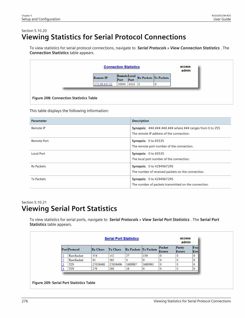
Chapter 5Setup and Configuration
RUGGEDCOM ROSUser Guide
276 Viewing Statistics for Serial Protocol Connections
Section 5.10.20
Viewing Statistics for Serial Protocol ConnectionsTo view statistics for serial protocol connections, navigate to Serial Protocols » View Connection Statistics . TheConnection Statistics table appears.
Figure 208: Connection Statistics Table
This table displays the following information:
Parameter Description
Remote IP Synopsis: ###.###.###.### where ### ranges from 0 to 255The remote IP address of the connection.
Remote Port Synopsis: 0 to 65535The remote port number of the connection.
Local Port Synopsis: 0 to 65535The local port number of the connection.
Rx Packets Synopsis: 0 to 4294967295The number of received packets on the connection.
Tx Packets Synopsis: 0 to 4294967295The number of packets transmitted on the connection.
Section 5.10.21
Viewing Serial Port StatisticsTo view statistics for serial ports, navigate to Serial Protocols » View Serial Port Statistics . The Serial PortStatistics table appears.
Figure 209: Serial Port Statistics Table

RUGGEDCOM ROSUser Guide
Chapter 5Setup and Configuration
Clearing Statistics for Specific Serial Ports 277
This table displays the following information:
Parameter Description
Port Synopsis: 1 to maximum port numberThe port number as seen on the front plate silkscreen of the switch.
Protocol Synopsis: Any 15 charactersThe serial protocol supported on this serial port.
Rx Chars Synopsis: 0 to 4294967295The number of received characters.
Tx Chars Synopsis: 0 to 4294967295The number of transmitted characters.
Rx Packets Synopsis: 0 to 4294967295The number of received packets.
Tx Packets Synopsis: 0 to 4294967295The number of transmitted packets.
Packet Errors Synopsis: 0 to 4294967295The number of packets received from this port and discarded (errorin protocol, CRC or routing information not found).
Parity Errors Synopsis: 0 to 4294967295The number of Parity Errors.
Framing Errors Synopsis: 0 to 4294967295The number of Framing Errors.
Overrun Errors Synopsis: 0 to 4294967295The number of Overrun Errors.
Section 5.10.22
Clearing Statistics for Specific Serial PortsTo clear the statistics collected for one or more serial ports, do the following:1. Navigate to Serial Protocols » Clear Serial Port Statistics . The Clear Serial Port Statistics form appears.
1
2
Figure 210: Clear Serial Port Statistics Form
1. Port Check Boxes 2. Confirm Button
2. Select one or more serial ports.

Chapter 5Setup and Configuration
RUGGEDCOM ROSUser Guide
278 Resetting Serial Ports
3. Click Confirm.
Section 5.10.23
Resetting Serial PortsTo reset a specific serial port(s), do the following:1. Navigate to Serial Protocols » Reset Serial Port(s) . The Reset Serial Port(s) form appears.
1
2
Figure 211: Reset Serial Port(s) Form1. Ports 2. Apply Button
2. Select one or more serial ports to reset.3. Click Apply. The selected serial ports are reset.
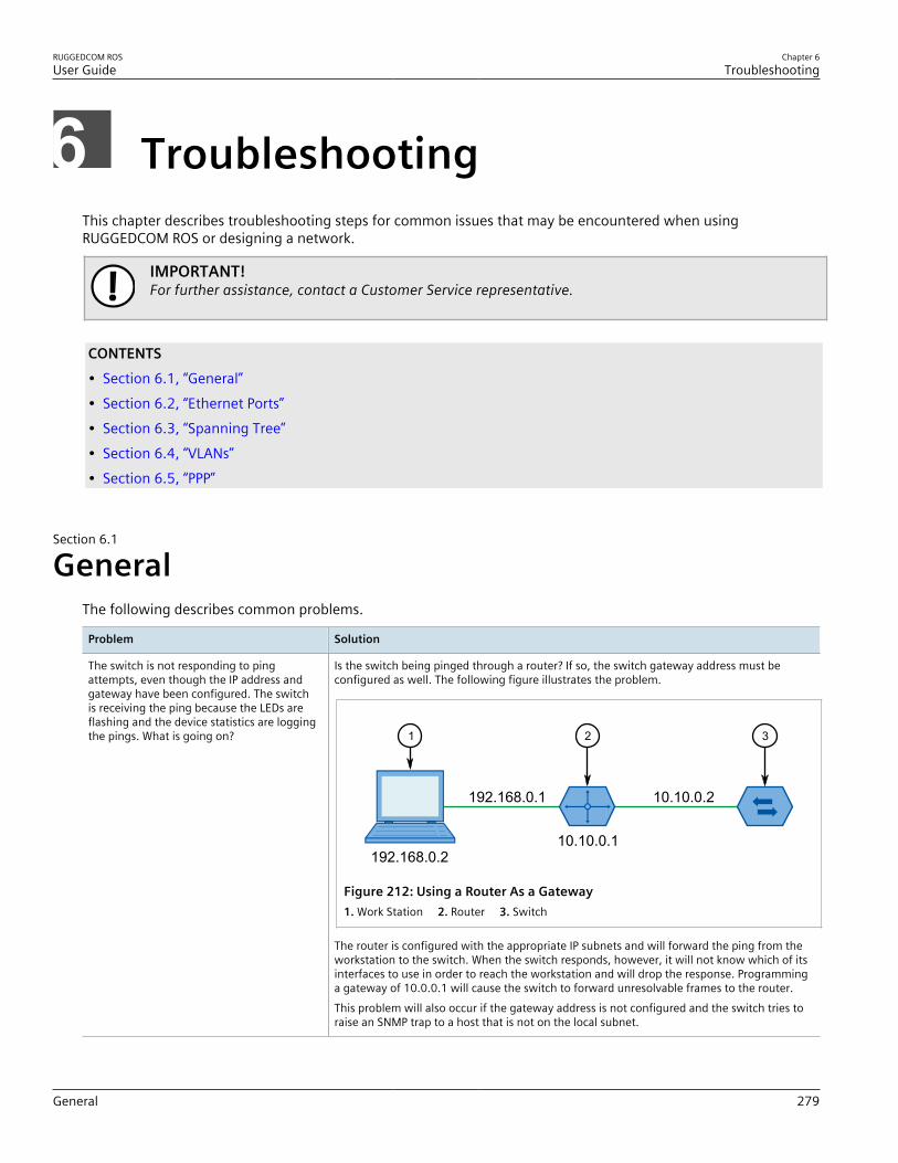
RUGGEDCOM ROSUser Guide
Chapter 6Troubleshooting
General 279
TroubleshootingThis chapter describes troubleshooting steps for common issues that may be encountered when usingRUGGEDCOM ROS or designing a network.
IMPORTANT!For further assistance, contact a Customer Service representative.
CONTENTS• Section 6.1, “General”• Section 6.2, “Ethernet Ports”• Section 6.3, “Spanning Tree”• Section 6.4, “VLANs”• Section 6.5, “PPP”
Section 6.1
GeneralThe following describes common problems.
Problem Solution
The switch is not responding to pingattempts, even though the IP address andgateway have been configured. The switchis receiving the ping because the LEDs areflashing and the device statistics are loggingthe pings. What is going on?
Is the switch being pinged through a router? If so, the switch gateway address must beconfigured as well. The following figure illustrates the problem.
192.168.0.2
192.168.0.1
10.10.0.1
10.10.0.2
1 2 3
Figure 212: Using a Router As a Gateway1. Work Station 2. Router 3. Switch
The router is configured with the appropriate IP subnets and will forward the ping from theworkstation to the switch. When the switch responds, however, it will not know which of itsinterfaces to use in order to reach the workstation and will drop the response. Programminga gateway of 10.0.0.1 will cause the switch to forward unresolvable frames to the router.This problem will also occur if the gateway address is not configured and the switch tries toraise an SNMP trap to a host that is not on the local subnet.

Chapter 6Troubleshooting
RUGGEDCOM ROSUser Guide
280 Ethernet Ports
Section 6.2
Ethernet PortsThe following describes common problems related to Ethernet ports.
Problem Solution
A link seems fine when traffic levels are low,but fails as traffic rates increase OR a link canbe pinged but has problems with FTP/SQL/HTTP/etc.
A possible cause of intermittent operation is that of a ‘duplex mismatch’. If one end of thelink is fixed to full-duplex and the peer auto-negotiates, the auto-negotiating end falls backto half-duplex operation.At lower traffic volumes, the link may display few if any errors. As the traffic volumerises, the fixed negotiation side will begin to experience dropped packets while the auto-negotiating side will experience collisions. Ultimately, as traffic loads approach 100%, thelink will become entirely unusable.The ping command with flood options is a useful tool for testing commissioned links. Thecommand ping 192.168.0.1 500 2 can be used to issue 500 pings each separated bytwo milliseconds to the next switch. If the link used is of high quality, then no pings shouldbe lost and the average round trip time should be small.
Links are inaccessible, even when using theLink Fault Indication (LFI) protection feature.
Make sure LFI is not enabled on the peer as well. If both sides of the link have LFI enabled,then both sides will withhold link signal generation from each other.
Section 6.3
Spanning TreeThe following describes common problems related to the Spanning Tree Protocol (STP).
Problem Solution
The network locks up when a new port isconnected and the port status LEDs areflashing rapidly.
Occasionally, the ports seem to experiencesignificant flooding for a brief period of time.
A switch displays a strange behavior wherethe root port hops back and forth betweentwo switch ports and never settles down.
Is it possible that one of the switches in the network or one of the ports on a switch in thenetwork has STP disabled and accidentally connects to another switch? If this has occurred,then a traffic loop has been formed.If the problem appears to be transient in nature, it is possible that ports that are part of thespanning tree have been configured as edge ports. After the link layers have come up onedge ports, STP will directly transition them (perhaps improperly) to the forwarding state.If an RSTP configuration message is then received, the port will be returned to blocking. Atraffic loop may be formed for the length of time the port was in forwarding.If one of the switches appears to flip the root from one port to another, the problem may beone of traffic prioritization. For more information refer to "The network becomes unstablewhen a specific application is started."Another possible cause of intermittent operation is that of an auto-negotiation mismatch.If one end of the link is fixed to full-duplex mode and the peer auto-negotiates, the auto-negotiating end will fall back to half-duplex operation. At lower traffic, the volumes thelink may display few if any errors. As the traffic volume rises, the fixed negotiation sidewill begin to experience dropped packets while the auto-negotiating side will experiencecollisions. Ultimately, as traffic loads approach 100%, the link will become entirely unusable.At this point, RSTP will not be able to transmit configuration messages over the link andthe spanning tree topology will break down. If an alternate trunk exists, RSTP will activate itin the place of the congested port. Since activation of the alternate port often relieves thecongested port of its traffic, the congested port will once again become reliable. RSTP willpromptly enter it back into service, beginning the cycle once again. The root port will flipback and forth between two ports on the switch.
A computer or device is connected to aswitch. After the switch is reset, it takes along time for it to come up.
Is it possible that the RSTP edge setting for this port is set to false? If Edge is set to false, thebridge will make the port go through two forward delay times before the port can send orreceive frames. If Edge is set to true, the bridge will transition the port directly to forwardingupon link up.

RUGGEDCOM ROSUser Guide
Chapter 6Troubleshooting
VLANs 281
Problem Solution
Another possible explanation is that some links in the network run in half-duplex mode.RSTP uses a peer-to-peer protocol called Proposal-Agreement to ensure transitioning in theevent of a link failure. This protocol requires full-duplex operation. When RSTP detects anon-full duplex port, it cannot rely on Proposal-Agreement protocol and must make the porttransition the slow (i.e. STP) way. If possible, configure the port for full-duplex operation.Otherwise, configure the port’s point-to-point setting to true.Either one will allow the Proposal-Agreement protocol to be used.
When the switch is tested by deliberatelybreaking a link, it takes a long time beforedevices beyond the switch can be polled.
Is it possible that some ports participating in the topology have been configured to STP modeor that the port’s point-to-point parameter is set to false? STP and multipoint ports convergeslowly after failures occur.Is it possible that the port has migrated to STP? If the port is connected to the LAN segmentby shared media and STP bridges are connected to that media, then convergence after linkfailure will be slow.Delays on the order of tens or hundreds of milliseconds can result in circumstances wherethe link broken is the sole link to the root bridge and the secondary root bridge is poorlychosen. The worst of all possible designs occurs when the secondary root bridge is locatedat the farthest edge of the network from the root. In this case, a configuration message willhave to propagate out to the edge and then back in order to reestablish the topology.
The network is composed of a ring ofbridges, of which two (connected toeach other) are managed and the rest areunmanaged. Why does the RSTP protocolwork quickly when a link is broken betweenthe managed bridges, but not in theunmanaged bridge part of the ring?
A properly operating unmanaged bridge is transparent to STP configuration messages. Themanaged bridges will exchange configuration messages through the unmanaged bridgepart of the ring as if it is non-existent. When a link in the unmanaged part of the ring failshowever, the managed bridges will only be able to detect the failure through timing out ofhello messages. Full connectivity will require three hello times plus two forwarding times tobe restored.
The network becomes unstable when aspecific application is started. The networkreturns to normal when the application isstopped.
RSTP sends its configuration messages using the highest possible priority level. If CoS isconfigured to allow traffic flows at the highest priority level and these traffic flows burstcontinuously to 100% of the line bandwidth, STP may be disrupted. It is therefore advisednot to use the highest CoS.
When a new port is brought up, the rootmoves on to that port instead of the port itshould move to or stay on.
Is it possible that the port cost is incorrectly programmed or that auto-negotiation derives anundesired value? Inspect the port and path costs with each port active as root.
An Intelligent Electronic Device (IED) orcontroller does not work with the device.
Certain low CPU bandwidth controllers have been found to behave less than perfectly whenthey receive unexpected traffic. Try disabling STP for the port.If the controller fails around the time of a link outage, there is the remote possibility thatframe disordering or duplication may be the cause of the problem. Try setting the root portof the failing controller’s bridge to STP.
Polls to other devices are occassionally lost. Review the network statistics to determine whether the root bridge is receiving TopologyChange Notifications (TCNs) around the time of observed frame loss. It may be possible thereare problems with intermittent links in the network.
The root is receiving a number of TCNs.Where are they coming from?
Examine the RSTP port statistics to determine the port from which the TCNs are arriving.Sign-on to the switch at the other end of the link attached to that port. Repeat this step untilthe switch generating the TCNs is found (i.e. the switch that is itself not receiving a largenumber of TCNs). Determine the problem at that switch.
Section 6.4
VLANsThe following describes common problems related to the VLANs.
Chapter 6Troubleshooting
RUGGEDCOM ROSUser Guide
282 PPP
Problem Solution
VLANs are not needed on the network. Canthey be turned off?
Yes. Simply leave all ports set to type edge and leave the native VLAN set to 1. This is thedefault configuration for the switch.
Two VLANs were created and a number ofports were made members of them. Nowsome of the devices in one VLAN need tosend messages to devices in the other VLAN.
If the devices need to communicate at the physical address layer, they must be members ofthe same VLAN. If they can communicate in a Layer 3 fashion (i.e. using a protocol such as IPor IPX), use a router. The router will treat each VLAN as a separate interface, which will haveits own associated IP address space.
On a network of 30 switches, managementtraffic needs to be restricted to a separatedomain. What is the best method for doingthis while staying in contact with theseswitches?
At the switch where the management station is located, configure a port to use the newmanagement VLAN as its native VLAN. Configure a host computer to act as a temporarymanagement station.At each switch, configure the management VLAN to the new value. Contact with eachindividual switch will be lost immediately as they are being configured, but it should bepossible re-establish communication from the temporary management station. After allswitches have been taken to the new management VLAN, configure the ports of all attachedmanagement devices to use the new VLAN.
NOTEEstablishing a management domain is often accompanied with theestablishment of an IP subnet specifically for the managed devices.
Section 6.5
PPPThe following describes common problems related to PPP (Point-to-Point Protocol), which is available on devicesequipped with an internal modem.
Problem Solution
The workstation/terminal is calling theRUGGEDCOM device, but the call neverconnects.
It is important to discriminate between the call connecting (i.e. the modem answering thecall) and the PPP session connecting (i.e. successful link up and authentication). Perform thefollowing tasks in order to identify/solve the problem:1. Make sure the RUGGEDCOM device is equipped with a modem. For more information
about how to determine the device's hardware configuration, refer to Section 3.1,“Viewing Product Information” .
2. Make sure the modem is functional. For more information, refer to Section 3.11,“Testing the Internal Modem” .
3. Monitor the statistics for PPP traffic as a call is made. The modem should detect theincoming call and then go off-line. For more information about PPP statistics, refer to Section 5.1.5, “Viewing and Clearing PPP Statistics” .
4. Make sure the correct phone number is programmed in to the client modem.5. Make sure the client modem is not aborting the connection when a connect speed short
of the maximum is negotiated.6. Make sure a negotiation problem does not exist. The internal modem will attempt to
negotiate a wide range of connection speeds, but the client modem may be configuredto abandon the call if it does not achieve a specific speed.
If the problem persists, contact Siemens Customer Support.
The modem connects, but the PPP sessiondos not.
This is most likely an authentication problem. Monitor the PPP statistics as a call is beingmade. If authentication is the problem, the value for the Authentication parameter willbriefly change to PAP Failure or CHAP Failure before retraining for the next call.For more information about PPP statistics, refer to Section 5.1.5, “Viewing and Clearing PPPStatistics” .If authentication is required by the client, but not the RS400, the client may be closing theconnection.

RUGGEDCOM ROSUser Guide
Chapter 6Troubleshooting
Problem Solution
If the client is expecting a CHAP server name different than the one configured on theRS400, the client may terminate the connection.Ultimately, it may be necessary to trace the connection activity. For a detailed description ofthe PPP connection activity, enable and start tracing at the PPP level. For more information,refer to Section 2.6.2, “Tracing Events” .
A connection is established with the server,but it cannot be pinged or accessed viaTelnet.
From the client, try to ping or Telnet in to the local IP address configured in the RS400.For more information about the Local IP Address parameter, refer to Section 5.1.3,“Configuring IP Addresses and Authentication” .If a connection can be established with the server using this address, but not with themanagement address, the client is most likely not configured to treat the PPP connection asits default gateway.Alternatively, if the client is configured to treat the PPP connection as its default gateway,the client may be connected to a LAN. If the client is connected to a LAN and the best routeis to the LAN, the PPP connection will not be used. The following illustrates this scenario:
192.16
8.1.2
10.0.0.20
192.168.1.1
10.0.0.0/16
10.0.0.10
3
3
1
2 4
Figure 213: Gateway Collisions1. Client 2. RTU 3. LAN 4. Switch
The client always directs all packets bound for 10.0.0.10 to its Ethernet connection. This willoccur regardless of the PPP gateway setting and possible lack of connectivity in the Ethernetcloud.If a temporary connection to the server is required, disconnect the LAN. Otherwise, connectto the server at its PPP-assigned address.
The server can be pinged, but not any of thedevices connected to it.
Every device must have a default gateway setting that points to the local PPP address on theserver with the PPP connection.
The PPP connection is experienceperformance problems.
Consider the following:• What connection speed did the modems negotiate?• Are there line quality problems?• What type of traffic is traversing the PPP connection? Is it being saturated with HTTP, FTP
or TFTP traffic?If a solution is not evident, contact Siemens Customer Support.
Related Documents