Supporting FastIron Software Release 08.0.30b CONFIGURATION GUIDE Ruckus FastIron Ethernet Switch Stacking Configuration Guide, 08.0.30b Part Number: 53-1003633-09 Publication Date: 15 February 2018

Welcome message from author
This document is posted to help you gain knowledge. Please leave a comment to let me know what you think about it! Share it to your friends and learn new things together.
Transcript
Supporting FastIron Software Release 08.0.30b
CONFIGURATION GUIDE
Ruckus FastIron Ethernet Switch StackingConfiguration Guide, 08.0.30b
Part Number: 53-1003633-09Publication Date: 15 February 2018

Copyright Notice and Proprietary InformationCopyright © 2018 Ruckus Networks, an ARRIS company. All rights reserved.
No part of this content may be reproduced in any form or by any means or used to make any derivative work (such as translation,transformation, or adaptation) without written permission from Ruckus Networks (“Ruckus”). Ruckus reserves the right to revise or changethis content from time to time without obligation on the part of Ruckus to provide notification of such revision or change.
Destination Control StatementThese products and associated technical data (in print or electronic form) may be subject to export control laws of the United States ofAmerica. It is your responsibility to determine the applicable regulations and to comply with them. The following notice is applicable for allproducts or technology subject to export control:
These items are controlled by the U.S. Government and authorized for export only to the country of ultimate destination for use by theultimate consignee or end-user(s) herein identified. They may not be resold, transferred, or otherwise disposed of, to any other country or toany person other than the authorized ultimate consignee or end-user(s), either in their original form or after being incorporated into otheritems, without first obtaining approval from the U.S. government or as otherwise authorized by U.S. law and regulations.
DisclaimerTHIS CONTENT AND ASSOCIATED PRODUCTS OR SERVICES ("MATERIALS"), ARE PROVIDED "AS IS" AND WITHOUT WARRANTIESOF ANY KIND, WHETHER EXPRESS OR IMPLIED. TO THE FULLEST EXTENT PERMISSIBLE PURSUANT TO APPLICABLE LAW,RUCKUS DISCLAIMS ALL WARRANTIES, EXPRESS OR IMPLIED, INCLUDING, BUT NOT LIMITED TO, IMPLIED WARRANTIES OFMERCHANTABILITY AND FITNESS FOR A PARTICULAR PURPOSE, TITLE, NON-INFRINGEMENT, FREEDOM FROM COMPUTER VIRUS,AND WARRANTIES ARISING FROM COURSE OF DEALING OR COURSE OF PERFORMANCE. Ruckus does not represent or warrant thatthe functions described or contained in the Materials will be uninterrupted or error-free, that defects will be corrected, or are free of virusesor other harmful components. Ruckus does not make any warranties or representations regarding the use of the Materials in terms of theircompleteness, correctness, accuracy, adequacy, usefulness, timeliness, reliability or otherwise. As a condition of your use of the Materials,you warrant to Ruckus that you will not make use thereof for any purpose that is unlawful or prohibited by their associated terms of use.
Limitation of LiabilityIN NO EVENT SHALL RUCKUS, ARRIS, OR THEIR OFFICERS, DIRECTORS, EMPLOYEES, AGENTS, SUPPLIES, LICENSORS ANDTHIRD PARTY PARTNERS, BE LIABLE FOR ANY DIRECT, INDIRECT, SPECIAL, PUNITIVE, INCIDENTAL, EXEMPLARY ORCONSEQUENTIAL DAMAGES, OR ANY DAMAGES WHATSOEVER, EVEN IF RUCKUS HAS BEEN PREVIOUSLY ADVISED OF THEPOSSIBILITY OF SUCH DAMAGES, WHETHER IN AN ACTION UNDER CONTRACT, TORT, OR ANY OTHER THEORY ARISING FROMYOUR ACCESS TO, OR USE OF, THE MATERIALS.
If you are dissatisfied with the Materials or with the associated terms of use, your sole and exclusive remedy is to discontinue their use.
Because some jurisdictions do not allow limitations on how long an implied warranty lasts, or the exclusion or limitation of liability forconsequential or incidental damages, some of the above limitations may not apply to you.
Ruckus FastIron Ethernet Switch Stacking Configuration Guide, 08.0.30b2 Part Number: 53-1003633-09

TrademarksThe Ruckus, Ruckus Wireless, Ruckus logo, Big Dog design, BeamFlex, ChannelFly, EdgeIron, FastIron, HyperEdge, ICX, IronPoint,OPENG, Xclaim, and ZoneFlex and trademarks are registered in the U.S. and other countries. Ruckus Networks, Dynamic PSK, MediaFlex,FlexMaster, Simply Better Wireless, SmartCast, SmartCell, SmartMesh, SpeedFlex, Unleashed, ZoneDirector and ZoneFlex are Ruckustrademarks worldwide. Other names and brands mentioned in these materials may be claimed as the property of others.
Wi-Fi Alliance®, Wi-Fi®, the Wi-Fi logo, the Wi-Fi CERTIFIED logo, Wi-Fi Protected Access® (WPA), the Wi-Fi Protected Setup logo, andWMM® are registered trademarks of Wi-Fi Alliance. Wi-Fi Protected Setup™, Wi-Fi Multimedia™, and WPA2™ are trademarks of Wi-FiAlliance.
Ruckus FastIron Ethernet Switch Stacking Configuration Guide, 08.0.30bPart Number: 53-1003633-09 3

Ruckus FastIron Ethernet Switch Stacking Configuration Guide, 08.0.30b4 Part Number: 53-1003633-09
ContentsPreface........................................................................................................................................................................................................11
Document Conventions........................................................................................................................................................................11Notes, Cautions, and Warnings.....................................................................................................................................................11
Command Syntax Conventions............................................................................................................................................................11Document Feedback............................................................................................................................................................................12Ruckus Product Documentation Resources......................................................................................................................................... 12Online Training Resources.................................................................................................................................................................... 12Contacting Ruckus Customer Services and Support............................................................................................................................13
What Support Do I Need?.............................................................................................................................................................13Open a Case.................................................................................................................................................................................13Self-Service Resources................................................................................................................................................................. 13
About This Guide........................................................................................................................................................................................ 15Supported hardware............................................................................................................................................................................ 15What’s new in this document................................................................................................................................................................15How command information is presented in this guide...........................................................................................................................16
Traditional Stacking..................................................................................................................................................................................... 17Traditional stacking benefits................................................................................................................................................................. 17Connectivity options for stacking with FCX and ICX devices.................................................................................................................18Brocade stackable models...................................................................................................................................................................18Brocade traditional stacking terminology.............................................................................................................................................. 19
Stack unit roles............................................................................................................................................................................. 19Stacking terms..............................................................................................................................................................................19
Planning to build a traditional stack...................................................................................................................................................... 20Software requirements.................................................................................................................................................................. 20Traditional stack requirements.......................................................................................................................................................21Traditional stacks versus mixed stacks..........................................................................................................................................21Brocade traditional stacking topologies.........................................................................................................................................21FastIron stacking distances and optics by device..........................................................................................................................21Software requirements for traditional stacks.................................................................................................................................. 23Traditional stacking configuration guidelines.................................................................................................................................. 23
Traditional stack construction methods................................................................................................................................................ 24Scenario 1 - Three-member traditional stack in a ring topology using secure-setup...................................................................... 24Scenario 2 - Configuring a three-member traditional stack in a ring topology using the automatic setup process.......................... 29Scenario 3 - Manually configuring a three member traditional stack in a ring topology...................................................................31
Verifying a traditional stack configuration.............................................................................................................................................. 32Displaying information on stack connections........................................................................................................................................ 34FCX stack configuration overview.........................................................................................................................................................35
FCX stack topologies.................................................................................................................................................................... 36Configuring an FCX traditional stack..............................................................................................................................................39
ICX 6430 or ICX 6450 stack configuration overview............................................................................................................................. 45ICX 6430 and ICX 6450 stack topologies......................................................................................................................................46Connecting ICX 6430 or ICX 6450 devices in a traditional stack....................................................................................................48Configuring an ICX 6430 or ICX 6450 traditional stack.................................................................................................................. 50
ICX 6610 traditional stack configuration overview.................................................................................................................................53ICX 6610 stacking for different topologies..................................................................................................................................... 53
Ruckus FastIron Ethernet Switch Stacking Configuration Guide, 08.0.30bPart Number: 53-1003633-09 5
Configuration notes for ICX 6610 stack topologies........................................................................................................................56ICX 6610 trunked stacking port configuration................................................................................................................................57Stack port resiliency in the ICX 6610............................................................................................................................................. 57
ICX 7250 stack configuration overview.................................................................................................................................................59ICX 7250 stacking topologies........................................................................................................................................................60ICX 7250 stacking configuration notes.......................................................................................................................................... 61Reconfiguring ICX 7250 1 Gbps ports to 10 Gbps........................................................................................................................ 62Changing default ports on the ICX 7250........................................................................................................................................62ICX 7250 trunk configuration.........................................................................................................................................................62ICX 7250 secure-setup example................................................................................................................................................... 63Displaying basic information for an ICX 7250 stack....................................................................................................................... 65Displaying detailed information for an ICX 7250 stack................................................................................................................... 66
ICX 7450 stack configuration overview.................................................................................................................................................67ICX 7450 stacking topologies........................................................................................................................................................68ICX 7450 stacking configuration notes.......................................................................................................................................... 71Configuring 10 Gbps stacking ports on the ICX 7450....................................................................................................................72Creating stack trunks on the ICX 7450..........................................................................................................................................74ICX 7450 secure-setup examples................................................................................................................................................. 76Displaying basic information for an ICX 7450 stack....................................................................................................................... 85Displaying details for an ICX 7450 stack........................................................................................................................................86
ICX 7750 stack configuration overview.................................................................................................................................................87ICX 7750 stacking topologies........................................................................................................................................................88Installing the ICX 7750 in a remote stack.......................................................................................................................................91ICX 7750 stacking configuration notes.......................................................................................................................................... 95ICX 7750 secure-setup example................................................................................................................................................... 96Removing stacking ports from an ICX 7750................................................................................................................................ 100Creating an ICX 7750 stack trunk in a production environment................................................................................................... 100Converting an ICX 7750 trunk to a port connection.....................................................................................................................101Displaying basic information for an ICX 7750 stack..................................................................................................................... 101Displaying details for an ICX 7750 stack......................................................................................................................................102
Traditional Stack Management.................................................................................................................................................................. 105Managing a traditional stack through one IP address..........................................................................................................................105Enabling or disabling stacking mode.................................................................................................................................................. 105
Disabling stacking mode............................................................................................................................................................. 106Traditional stack unit identification .............................................................................................................................................. 106
Controlling the stack through the CLI................................................................................................................................................. 106Logging in through the console port............................................................................................................................................107CLI command syntax for stack units........................................................................................................................................... 108Traditional stack CLI commands................................................................................................................................................. 108
Traditional stack management MAC address......................................................................................................................................109Manually allocating the traditional stack MAC address................................................................................................................ 110Removing MAC address entries.................................................................................................................................................. 111
Traditional stack device roles and elections........................................................................................................................................ 111Active controller.......................................................................................................................................................................... 111Standby controller.......................................................................................................................................................................112Bootup role.................................................................................................................................................................................112Active controller and standby controller elections........................................................................................................................ 112Active controller and standby controller resets............................................................................................................................ 113Standby controller selection based on priority configuration........................................................................................................ 113Standby controller election criteria...............................................................................................................................................114
Ruckus FastIron Ethernet Switch Stacking Configuration Guide, 08.0.30b6 Part Number: 53-1003633-09
Traditional stack unit priority............................................................................................................................................................... 114Changing the priority of a stack unit............................................................................................................................................ 115
Traditional stack software images.......................................................................................................................................................115Confirming traditional stack software versions.............................................................................................................................115Encountering a problem after upgrading and reloading the software........................................................................................... 116
Copying the flash image to a stack unit from the active controller.......................................................................................................117Adding, removing, or replacing units in a traditional stack...................................................................................................................117
Installing a new unit in a traditional stack using secure-setup...................................................................................................... 117Installing a new unit using static configuration............................................................................................................................. 118Removing a unit from a traditional stack......................................................................................................................................118Replacing traditional stack units.................................................................................................................................................. 118Moving a unit to another stack.................................................................................................................................................... 119Removing an active controller from a powered stack...................................................................................................................119
Renumbering stack units....................................................................................................................................................................120Configuration notes for renumbering stack units .........................................................................................................................120
Reloading a stack unit........................................................................................................................................................................121Controlling stack size to allow for a data port..................................................................................................................................... 121Managing traditional stack partitioning................................................................................................................................................122Merging traditional stacks.................................................................................................................................................................. 122Unconfiguring a traditional stack........................................................................................................................................................ 123Syslog, SNMP, and traps for stack units.............................................................................................................................................124
Configuring SNMP for a traditional stack.....................................................................................................................................124SNMP engine IDs for stackable devices...................................................................................................................................... 124
PHY calibration errors in stack ports of the ICX 6610......................................................................................................................... 125Syslog messages for PHY calibration.......................................................................................................................................... 125
Displaying traditional stack information...............................................................................................................................................125Displaying stacking topology.......................................................................................................................................................125Displaying running configuration information................................................................................................................................126How the show running-config command displays configured stacking ports...............................................................................127Displaying software version information.......................................................................................................................................128Displaying traditional stack flash information................................................................................................................................130Displaying traditional stack memory information.......................................................................................................................... 130Displaying traditional stack chassis information .......................................................................................................................... 131Displaying stack module information........................................................................................................................................... 132Displaying stack resource information......................................................................................................................................... 133Displaying general or detailed information about stack members.................................................................................................133Displaying IPC statistics for a specific stack unit..........................................................................................................................135Displaying reliable IPC statistics for stack units............................................................................................................................136Displaying information about stack neighbors............................................................................................................................. 140Displaying stack port information................................................................................................................................................ 140Displaying stacking port statistics................................................................................................................................................141Displaying stacking port interface information..............................................................................................................................142
MIB support for the traditional stack...................................................................................................................................................143
Traditional Stack Troubleshooting.............................................................................................................................................................. 145Problems commonly diagnosed with stack formation.........................................................................................................................145Background problem diagnosis..........................................................................................................................................................146
Manually triggering stack diagnosis.............................................................................................................................................146Suppressing background stack diagnostic warnings...................................................................................................................146
Troubleshooting an unsuccessful stack build......................................................................................................................................146Troubleshooting secure-setup............................................................................................................................................................ 148
Ruckus FastIron Ethernet Switch Stacking Configuration Guide, 08.0.30bPart Number: 53-1003633-09 7
Troubleshooting unit replacement issues............................................................................................................................................ 149Troubleshooting a stacking upgrade...................................................................................................................................................149Stack mismatches..............................................................................................................................................................................150
Advanced feature privileges........................................................................................................................................................ 150Auto Image Copy for stack units................................................................................................................................................. 151Configuration mismatch for stack units....................................................................................................................................... 152Memory allocation failure.............................................................................................................................................................153
Troubleshooting image copy issues....................................................................................................................................................153Configuration, startup configuration files, and stacking flash...............................................................................................................153Stacking unit role transition considerations.........................................................................................................................................154Port down and aging..........................................................................................................................................................................154
Hitless Stacking.........................................................................................................................................................................................155Hitless stacking overview................................................................................................................................................................... 155Supported hitless stacking events ..................................................................................................................................................... 156Non-supported hitless stacking events...............................................................................................................................................156Supported hitless stacking protocols and services............................................................................................................................. 156Hitless stacking configuration notes and feature limitations.................................................................................................................158What happens during a hitless stacking switchover or failover............................................................................................................159
Real-time synchronization among all units in a stack................................................................................................................... 159Standby controller role in hitless stacking........................................................................................................................................... 160
Standby controller election..........................................................................................................................................................160Runtime configuration mismatch................................................................................................................................................. 160
Support during stack formation, stack merge, and stack split............................................................................................................ 161Hitless stacking behavior....................................................................................................................................................................164
Enabling hitless stacking............................................................................................................................................................. 165Displaying hitless stacking status................................................................................................................................................ 166Displaying pending device roles.................................................................................................................................................. 166
Hitless stacking failover...................................................................................................................................................................... 166Enabling hitless stacking failover................................................................................................................................................. 167Hitless stacking failover example.................................................................................................................................................168
Hitless stacking switchover................................................................................................................................................................ 168Executing a hitless stacking switchover.......................................................................................................................................169Hitless stacking switchover examples......................................................................................................................................... 169
Displaying information about hitless stacking......................................................................................................................................174Displaying information about stack failover......................................................................................................................................... 175Displaying information about link synchronization status.....................................................................................................................175Syslog messages for hitless stacking failover and switchover............................................................................................................. 175
Mixed Stacking..........................................................................................................................................................................................177Mixed stacking overview.................................................................................................................................................................... 177
Mixed stacking devices............................................................................................................................................................... 177Mixed stacking topologies...........................................................................................................................................................177Additional topology support for mixed stacking...........................................................................................................................177Mixed stacking terms..................................................................................................................................................................179Mixed stacking software image requirements.............................................................................................................................. 180Mixed stacking configuration prerequisites.................................................................................................................................. 180
Configuring basic mixed stacking....................................................................................................................................................... 180Configuring a mixed stack using secure-setup............................................................................................................................ 181Configuring a mixed stack using automatic configuration............................................................................................................ 184Configuring a mixed stack using manual configuration................................................................................................................ 187
Ruckus FastIron Ethernet Switch Stacking Configuration Guide, 08.0.30b8 Part Number: 53-1003633-09

Displaying information about mixed stacking configuration................................................................................................................. 189Displaying mixed stack information for an automatic configuration.............................................................................................. 189Displaying mixed stack information for a manual configuration.................................................................................................... 191Displaying mixed stack information for a star topology................................................................................................................ 192
Specifying a TFTP server for Autocopy...............................................................................................................................................194How Autocopy works..................................................................................................................................................................194
Recovering a pre-stacking configuration on peripheral devices...........................................................................................................194Verifying pre-stacking configuration recovery...............................................................................................................................198
Ruckus FastIron Ethernet Switch Stacking Configuration Guide, 08.0.30bPart Number: 53-1003633-09 9

Ruckus FastIron Ethernet Switch Stacking Configuration Guide, 08.0.30b10 Part Number: 53-1003633-09
Preface• Document Conventions...........................................................................................................................................11• Command Syntax Conventions............................................................................................................................... 11• Document Feedback...............................................................................................................................................12• Ruckus Product Documentation Resources............................................................................................................ 12• Online Training Resources....................................................................................................................................... 12• Contacting Ruckus Customer Services and Support............................................................................................... 13
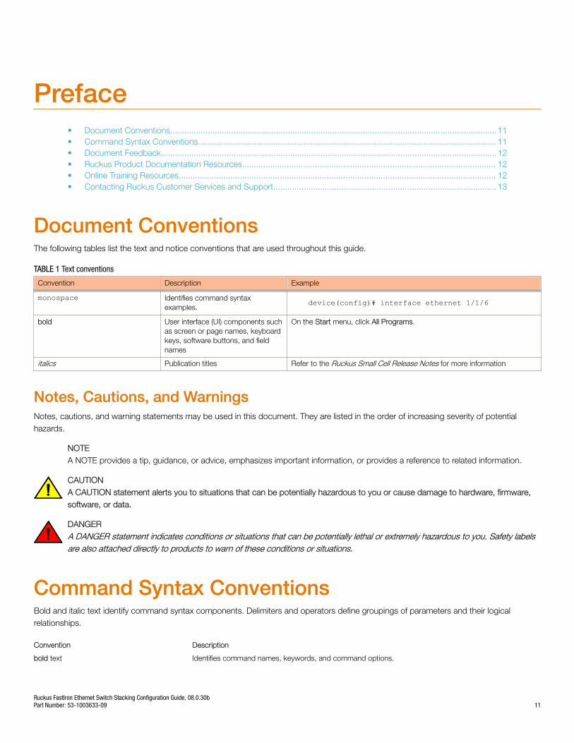
Document ConventionsThe following tables list the text and notice conventions that are used throughout this guide.
TABLE 1 Text conventions
Convention Description Example
monospace Identifies command syntaxexamples.
device(config)# interface ethernet 1/1/6
bold User interface (UI) components suchas screen or page names, keyboardkeys, software buttons, and fieldnames
On the Start menu, click All Programs.
italics Publication titles Refer to the Ruckus Small Cell Release Notes for more information
Notes, Cautions, and WarningsNotes, cautions, and warning statements may be used in this document. They are listed in the order of increasing severity of potentialhazards.
NOTEA NOTE provides a tip, guidance, or advice, emphasizes important information, or provides a reference to related information.
CAUTIONA CAUTION statement alerts you to situations that can be potentially hazardous to you or cause damage to hardware, firmware,software, or data.
DANGERA DANGER statement indicates conditions or situations that can be potentially lethal or extremely hazardous to you. Safety labelsare also attached directly to products to warn of these conditions or situations.
Command Syntax ConventionsBold and italic text identify command syntax components. Delimiters and operators define groupings of parameters and their logicalrelationships.
Convention Description
bold text Identifies command names, keywords, and command options.
Ruckus FastIron Ethernet Switch Stacking Configuration Guide, 08.0.30bPart Number: 53-1003633-09 11

Convention Description
italic text Identifies a variable.
[ ] Syntax components displayed within square brackets are optional.
Default responses to system prompts are enclosed in square brackets.
{ x | y | z } A choice of required parameters is enclosed in curly brackets separated by vertical bars. You must selectone of the options.
x | y A vertical bar separates mutually exclusive elements.
< > Nonprinting characters, for example, passwords, are enclosed in angle brackets.
... Repeat the previous element, for example, member[member...].
\ Indicates a “soft” line break in command examples. If a backslash separates two lines of a command input,enter the entire command at the prompt without the backslash.
Document FeedbackRuckus is interested in improving its documentation and welcomes your comments and suggestions.
You can email your comments to Ruckus at: [email protected]
When contacting us, please include the following information:
• Document title and release number
• Document part number (on the cover page)
• Page number (if appropriate)
• For example:
– Ruckus Small Cell Alarms Guide SC Release 1.3– Part number: 800-71306-001– Page 88
Ruckus Product Documentation ResourcesVisit the Ruckus website to locate related documentation for your product and additional Ruckus resources.
Release Notes and other user documentation are available at https://support.ruckuswireless.com/documents. You can locatedocumentation by product or perform a text search. Access to Release Notes requires an active support contract and Ruckus SupportPortal user account. Other technical documentation content is available without logging into the Ruckus Support Portal.
White papers, data sheets, and other product documentation are available at https://www.ruckuswireless.com.
Online Training ResourcesTo access a variety of online Ruckus training modules, including free introductory courses to wireless networking essentials, site surveys,and Ruckus products, visit the Ruckus Training Portal at https://training.ruckuswireless.com.
PrefaceDocument Feedback
Ruckus FastIron Ethernet Switch Stacking Configuration Guide, 08.0.30b12 Part Number: 53-1003633-09
Contacting Ruckus Customer Services and SupportThe Customer Services and Support (CSS) organization is available to provide assistance to customers with active warranties on theirRuckus Networks products, and customers and partners with active support contracts.
For product support information and details on contacting the Support Team, go directly to the Support Portal using https://support.ruckuswireless.com, or go to https://www.ruckuswireless.com and select Support.
What Support Do I Need?Technical issues are usually described in terms of priority (or severity). To determine if you need to call and open a case or access the self-service resources use the following criteria:
• Priority 1 (P1)—Critical. Network or service is down and business is impacted. No known workaround. Go to the Open a Casesection.
• Priority 2 (P2)—High. Network or service is impacted, but not down. Business impact may be high. Workaround may be available.Go to the Open a Case section.
• Priority 3 (P3)—Medium. Network or service is moderately impacted, but most business remains functional. Go to the Self-ServiceResources section.
• Priority 4 (P4)—Low. Request for information, product documentation, or product enhancements. Go to the Self-ServiceResources section.
Open a CaseWhen your entire network is down (P1), or severely impacted (P2), call the appropriate telephone number listed below to get help:
• Continental United States: 1-855-782-5871
• Canada: 1-855-782-5871
• Europe, Middle East, Africa, and Asia Pacific, toll-free numbers are available at https://support.ruckuswireless.com/contact-us andLive Chat is also available.
Self-Service ResourcesThe Support Portal at https://support.ruckuswireless.com/contact-us offers a number of tools to help you to research and resolve problemswith your Ruckus products, including:
• Technical Documentation—https://support.ruckuswireless.com/documents
• Community Forums—https://forums.ruckuswireless.com/ruckuswireless/categories
• Knowledge Base Articles—https://support.ruckuswireless.com/answers
• Software Downloads and Release Notes—https://support.ruckuswireless.com/software
• Security Bulletins—https://support.ruckuswireless.com/security
Using these resources will help you to resolve some issues, and will provide TAC with additional data from your troubleshooting analysis ifyou still require assistance through a support case or RMA. If you still require help, open and manage your case at https://support.ruckuswireless.com/case_management
PrefaceContacting Ruckus Customer Services and Support
Ruckus FastIron Ethernet Switch Stacking Configuration Guide, 08.0.30bPart Number: 53-1003633-09 13

Ruckus FastIron Ethernet Switch Stacking Configuration Guide, 08.0.30b14 Part Number: 53-1003633-09
About This Guide• Supported hardware................................................................................................................................................15• What’s new in this document...................................................................................................................................15• How command information is presented in this guide..............................................................................................16
Supported hardwareThe following devices from the Ruckus FastIron product family support stacking:
• Ruckus FCX Series (FCX) Switch
• Ruckus ICX 6430 Series (ICX 6430)
• Ruckus ICX 6450 Series (ICX 6450)
• Ruckus ICX™ 6610 (ICX 6610) Switch
• Ruckus ICX 7250 Series (ICX 7250)
• Ruckus ICX 7450 Series (ICX 7450)
• Ruckus ICX 7750 Series (ICX 7750)
NOTEThe Ruckus ICX 6430-C switch supports the same feature set as the Ruckus ICX 6430 switch unless otherwise noted.
NOTEThe Ruckus ICX 6450-C12-PD switch supports the same feature set as the Ruckus ICX 6450 switch, unless otherwise noted.
For information about the specific models and modules supported in a product family, refer to the hardware installation guide for thatproduct family.
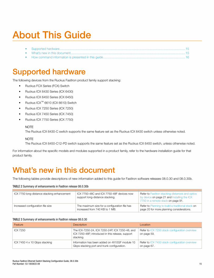
What’s new in this documentThe following tables provide descriptions of new information added to this guide for FastIron software releases 08.0.30 and 08.0.30b.
TABLE 2 Summary of enhancements in FastIron release 08.0.30b
ICX 7750 long-distance stacking enhancement ICX 7750-48C and ICX 7750-48F devices nowsupport long-distance stacking.
Refer to FastIron stacking distances and opticsby device on page 21 and Installing the ICX7750 in a remote stack on page 91.
Increased configuration file size The maximum size for a configuration file hasincreased from 740 KB to 1 MB.
Refer to Planning to build a traditional stack onpage 20 for more planning considerations.
TABLE 3 Summary of enhancements in FastIron release 08.0.30
Feature Description Location
ICX 7250 The ICX-7250-24, ICX 7250-24P, ICX 7250-48, andICX 7250-48P, introduced in this release, supportstacking.
Refer to ICX 7250 stack configuration overviewon page 59.
ICX 7450 4 x 10 Gbps stacking Information has been added on 4X10GF module 10Gbps stacking port and trunk configuration.
Refer to ICX 7450 stack configuration overviewon page 67.
Ruckus FastIron Ethernet Switch Stacking Configuration Guide, 08.0.30bPart Number: 53-1003633-09 15
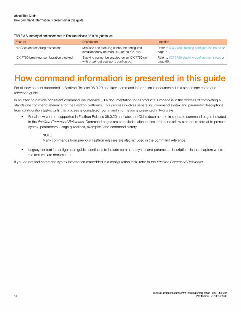
TABLE 3 Summary of enhancements in FastIron release 08.0.30 (continued)
Feature Description Location
MACsec and stacking restrictions MACsec and stacking cannot be configuredsimultaneously on module 2 of the ICX 7450.
Refer to ICX 7450 stacking configuration notes onpage 71.
ICX 7750 break-out configuration blocked Stacking cannot be enabled on an ICX 7750 unitwith break-out sub-ports configured.
Refer to ICX 7750 stacking configuration notes onpage 95.
How command information is presented in this guideFor all new content supported in FastIron Release 08.0.20 and later, command information is documented in a standalone commandreference guide.
In an effort to provide consistent command line interface (CLI) documentation for all products, Brocade is in the process of completing astandalone command reference for the FastIron platforms. This process involves separating command syntax and parameter descriptionsfrom configuration tasks. Until this process is completed, command information is presented in two ways:
• For all new content supported in FastIron Release 08.0.20 and later, the CLI is documented in separate command pages includedin the FastIron Command Reference. Command pages are compiled in alphabetical order and follow a standard format to presentsyntax, parameters, usage guidelines, examples, and command history.
NOTEMany commands from previous FastIron releases are also included in the command reference.
• Legacy content in configuration guides continues to include command syntax and parameter descriptions in the chapters wherethe features are documented.
If you do not find command syntax information embedded in a configuration task, refer to the FastIron Command Reference.
About This GuideHow command information is presented in this guide
Ruckus FastIron Ethernet Switch Stacking Configuration Guide, 08.0.30b16 Part Number: 53-1003633-09
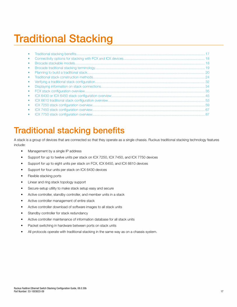
Traditional Stacking• Traditional stacking benefits.....................................................................................................................................17• Connectivity options for stacking with FCX and ICX devices.................................................................................... 18• Brocade stackable models...................................................................................................................................... 18• Brocade traditional stacking terminology................................................................................................................. 19• Planning to build a traditional stack......................................................................................................................... 20• Traditional stack construction methods....................................................................................................................24• Verifying a traditional stack configuration................................................................................................................. 32• Displaying information on stack connections........................................................................................................... 34• FCX stack configuration overview............................................................................................................................ 35• ICX 6430 or ICX 6450 stack configuration overview.................................................................................................45• ICX 6610 traditional stack configuration overview.................................................................................................... 53• ICX 7250 stack configuration overview.................................................................................................................... 59• ICX 7450 stack configuration overview.................................................................................................................... 67• ICX 7750 stack configuration overview.................................................................................................................... 87
Traditional stacking benefitsA stack is a group of devices that are connected so that they operate as a single chassis. Ruckus traditional stacking technology featuresinclude:
• Management by a single IP address
• Support for up to twelve units per stack on ICX 7250, ICX 7450, and ICX 7750 devices
• Support for up to eight units per stack on FCX, ICX 6450, and ICX 6610 devices
• Support for four units per stack on ICX 6430 devices
• Flexible stacking ports
• Linear and ring stack topology support
• Secure-setup utility to make stack setup easy and secure
• Active controller, standby controller, and member units in a stack
• Active controller management of entire stack
• Active controller download of software images to all stack units
• Standby controller for stack redundancy
• Active controller maintenance of information database for all stack units
• Packet switching in hardware between ports on stack units
• All protocols operate with traditional stacking in the same way as on a chassis system.
Ruckus FastIron Ethernet Switch Stacking Configuration Guide, 08.0.30bPart Number: 53-1003633-09 17
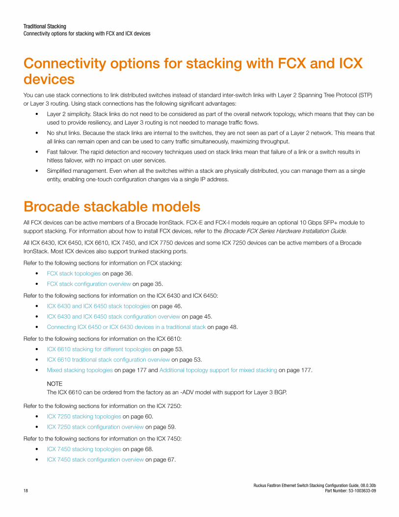
Connectivity options for stacking with FCX and ICXdevicesYou can use stack connections to link distributed switches instead of standard inter-switch links with Layer 2 Spanning Tree Protocol (STP)or Layer 3 routing. Using stack connections has the following significant advantages:
• Layer 2 simplicity. Stack links do not need to be considered as part of the overall network topology, which means that they can beused to provide resiliency, and Layer 3 routing is not needed to manage traffic flows.
• No shut links. Because the stack links are internal to the switches, they are not seen as part of a Layer 2 network. This means thatall links can remain open and can be used to carry traffic simultaneously, maximizing throughput.
• Fast failover. The rapid detection and recovery techniques used on stack links mean that failure of a link or a switch results inhitless failover, with no impact on user services.
• Simplified management. Even when all the switches within a stack are physically distributed, you can manage them as a singleentity, enabling one-touch configuration changes via a single IP address.
Brocade stackable modelsAll FCX devices can be active members of a Brocade IronStack. FCX-E and FCX-I models require an optional 10 Gbps SFP+ module tosupport stacking. For information about how to install FCX devices, refer to the Brocade FCX Series Hardware Installation Guide.
All ICX 6430, ICX 6450, ICX 6610, ICX 7450, and ICX 7750 devices and some ICX 7250 devices can be active members of a BrocadeIronStack. Most ICX devices also support trunked stacking ports.
Refer to the following sections for information on FCX stacking:
• FCX stack topologies on page 36.
• FCX stack configuration overview on page 35.
Refer to the following sections for information on the ICX 6430 and ICX 6450:
• ICX 6430 and ICX 6450 stack topologies on page 46.
• ICX 6430 and ICX 6450 stack configuration overview on page 45.
• Connecting ICX 6450 or ICX 6430 devices in a traditional stack on page 48.
Refer to the following sections for information on the ICX 6610:
• ICX 6610 stacking for different topologies on page 53.
• ICX 6610 traditional stack configuration overview on page 53.
• Mixed stacking topologies on page 177 and Additional topology support for mixed stacking on page 177.
NOTEThe ICX 6610 can be ordered from the factory as an -ADV model with support for Layer 3 BGP.
Refer to the following sections for information on the ICX 7250:
• ICX 7250 stacking topologies on page 60.
• ICX 7250 stack configuration overview on page 59.
Refer to the following sections for information on the ICX 7450:
• ICX 7450 stacking topologies on page 68.
• ICX 7450 stack configuration overview on page 67.
Traditional StackingConnectivity options for stacking with FCX and ICX devices
Ruckus FastIron Ethernet Switch Stacking Configuration Guide, 08.0.30b18 Part Number: 53-1003633-09
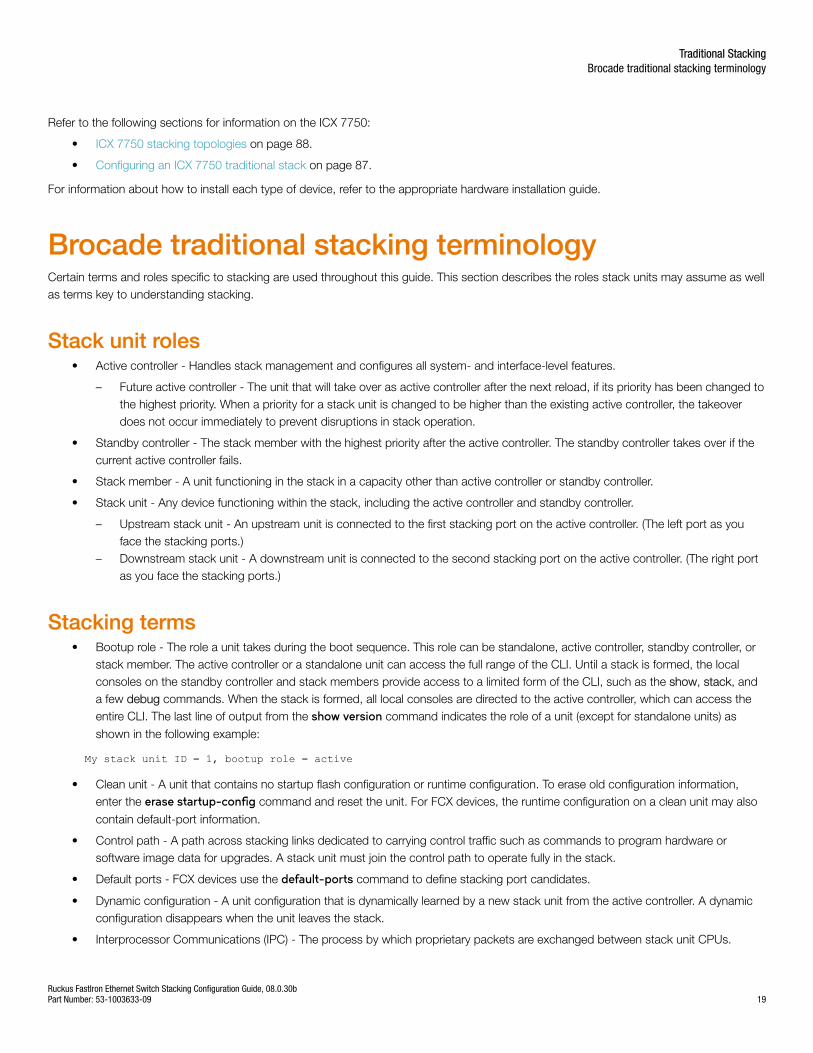
Refer to the following sections for information on the ICX 7750:
• ICX 7750 stacking topologies on page 88.
• Configuring an ICX 7750 traditional stack on page 87.
For information about how to install each type of device, refer to the appropriate hardware installation guide.
Brocade traditional stacking terminologyCertain terms and roles specific to stacking are used throughout this guide. This section describes the roles stack units may assume as wellas terms key to understanding stacking.
Stack unit roles• Active controller - Handles stack management and configures all system- and interface-level features.
– Future active controller - The unit that will take over as active controller after the next reload, if its priority has been changed tothe highest priority. When a priority for a stack unit is changed to be higher than the existing active controller, the takeoverdoes not occur immediately to prevent disruptions in stack operation.
• Standby controller - The stack member with the highest priority after the active controller. The standby controller takes over if thecurrent active controller fails.
• Stack member - A unit functioning in the stack in a capacity other than active controller or standby controller.
• Stack unit - Any device functioning within the stack, including the active controller and standby controller.
– Upstream stack unit - An upstream unit is connected to the first stacking port on the active controller. (The left port as youface the stacking ports.)
– Downstream stack unit - A downstream unit is connected to the second stacking port on the active controller. (The right portas you face the stacking ports.)
Stacking terms• Bootup role - The role a unit takes during the boot sequence. This role can be standalone, active controller, standby controller, or
stack member. The active controller or a standalone unit can access the full range of the CLI. Until a stack is formed, the localconsoles on the standby controller and stack members provide access to a limited form of the CLI, such as the show, stack, anda few debug commands. When the stack is formed, all local consoles are directed to the active controller, which can access theentire CLI. The last line of output from the show version command indicates the role of a unit (except for standalone units) as
shown in the following example:
My stack unit ID = 1, bootup role = active
• Clean unit - A unit that contains no startup flash configuration or runtime configuration. To erase old configuration information,enter the erase startup-config command and reset the unit. For FCX devices, the runtime configuration on a clean unit may also
contain default-port information.
• Control path - A path across stacking links dedicated to carrying control traffic such as commands to program hardware orsoftware image data for upgrades. A stack unit must join the control path to operate fully in the stack.
• Default ports - FCX devices use the default-ports command to define stacking port candidates.
• Dynamic configuration - A unit configuration that is dynamically learned by a new stack unit from the active controller. A dynamicconfiguration disappears when the unit leaves the stack.
• Interprocessor Communications (IPC) - The process by which proprietary packets are exchanged between stack unit CPUs.
Traditional StackingBrocade traditional stacking terminology
Ruckus FastIron Ethernet Switch Stacking Configuration Guide, 08.0.30bPart Number: 53-1003633-09 19
• IronStack - A set of Ruckus stackable units (maximum of eight) and their connected stacking links so that all units can beaccessed through their common connections. A single unit can manage the entire stack, and configurable entities, such as VLANsand trunk groups, can have members on multiple stack units.
• Non-Functioning stack unit - A stack unit that is recognized as a stack member, and is communicating with the active controllerover the Control Path, but is in a non-functioning state. A non-functioning stack unit will drop or discard traffic from non-stackedports. This may be caused by an image or configuration mismatch.
• Reserved / provisional unit - A unit configuration number that has no physical unit associated with it.
• Secure-setup - A software utility that establishes a secure stack.
• Sequential connection - Stack unit IDs, beginning with the active controller, are sequential. For example, 1, 3, 4, 6, 7 is sequentialif active controller is 1. 1, 7, 6, 4, 3 are non-sequential in a linear topology, but become sequential in a ring topology when countedfrom the other direction as: 1, 3, 4, 6, 7. Gaps in numbering are allowed.
• Stack path - A data path formed across the stacking links to determine the set of stack members that are present in the stacktopology, and their locations in the stack.
• Stack slot - A slot in a stack is synonymous with a line model in a chassis.
• Stack topology - A contiguously-connected set of stack units in an IronStack that are currently communicating with each other. Allunits that are present in the stack topology appear in output from the show stack command.
• Stacking link - A cable that connects a stacking port on one unit to a stacking port on another unit.
• Stacking port - A physical interface on a stack unit that connects a stacking link. Stacking ports are point-to-point links thatexchange proprietary packets. Stacking ports must be 10 Gbps Ethernet ports (except for the ICX 6430 that uses 1 Gbps ports),and cannot be configured for any other purpose while operating as stacking ports. The number of available stacking portsdepends on the platform. Some ports can be configured as either stacking ports or regular data ports. Refer to the hardwareinstallation guide for the specific device for more information.
• Standalone unit - A unit that is not enabled for stacking, or an active controller without any standby controller or stack members.
• Static configuration - A configuration that remains in the database of the active controller even if the unit it refers to is removedfrom the stack. Static configurations are derived from the startup configuration file during the boot sequence, are manuallyentered, or are converted from dynamic configurations after a write memory command is issued.
• Trunked stacking port (trunk) - A trunk consists of multiple stacking ports and is treated as one logical link. It provides morebandwidth and better resilience than individually connected ports.
• Unit replacement - The process of swapping out a unit with a clean unit. No configuration change is required.
Planning to build a traditional stackBefore you begin to build a traditional stack, you should be familiar with supported stacking software requirements, topologies, andrecommendations.
Software requirementsAll units in a traditional stack must be running the same software version.
Maximum configuration file size for any stack is 1 MB.
Traditional StackingPlanning to build a traditional stack
Ruckus FastIron Ethernet Switch Stacking Configuration Guide, 08.0.30b20 Part Number: 53-1003633-09
Traditional stack requirementsTraditional stacks must contain devices of the same type or product line. For example, a traditional stack cannot combine ICX 7250, ICX7450, and ICX 7750 devices. However, a traditional stack can contain any combination of devices from the same product line, for example,any combination of ICX 7250 devices.
NOTEA core stack for an 802.1br (SPX) configuration is a traditional stack that contains only ICX 7750 devices, although the stack maycontain different types of ICX 7750 devices. Refer to the Brocade FastIron Campus Fabric Configuration Guide for moreinformation.
Traditional stacks versus mixed stacksTraditional stacks must contain devices of the same type or product line. For example, a traditional stack cannot contain both FCX and ICX6450 devices. However, a traditional stack can contain any combination of FCX devices because they are from the same product line.
Stacks that contain more than one type of device are called mixed stacks. For example, a mixed stack may contain ICX 6610 and ICX 6450devices. For information about configuring a mixed stack, refer to Mixed Stacking.
Brocade traditional stacking topologiesBrocade traditional stacking technology supports linear and ring topologies.
Although Brocade stackable units may be connected in a simple linear topology, Brocade recommends a ring topology because it offers thebest redundancy and the most resilient operation. Unicast switching follows the shortest path in a ring topology. When the ring is broken,the stack recalculates the forwarding path and then resumes the flow of traffic within a few seconds.
In a ring topology, all stack members must have two stacking ports; however, in a linear topology, both end units use only one stackingport, leaving the other port available as a data port.
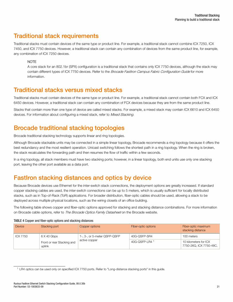
FastIron stacking distances and optics by deviceBecause Brocade devices use Ethernet for the inter-switch stack connections, the deployment options are greatly increased. If standardcopper stacking cables are used, the inter-switch connections can be up to 5 meters, which is usually sufficient for locally distributedstacks, such as in Top-of-Rack (ToR) applications. For broader distribution, fiber-optic cables should be used, allowing a stack to bedeployed across multiple physical locations, such as the wiring closets of an office building.
The following table shows copper and fiber-optic options approved for stacking and stacking distance combinations. For more informationon Brocade cable options, refer to The Brocade Optics Family Datasheet on the Brocade website.
TABLE 4 Copper and fiber-optic options and stacking distances
Device Stacking port Copper options Fiber-optic options Fiber-optic maximumstacking distance
ICX 7750 6 X 40 Gbps
Front or rear Stacking anduplink
1-, 3-, or 5-meter QSFP-QSFPactive copper
40G-QSFP-SR4 100 meters
40G-QSFP-LR4 1 10 kilometers for ICX7750-26Q, ICX 7750-48C,
1 LR4 optics can be used only on specified ICX 7750 ports. Refer to "Long-distance stacking ports" in this guide.
Traditional StackingPlanning to build a traditional stack
Ruckus FastIron Ethernet Switch Stacking Configuration Guide, 08.0.30bPart Number: 53-1003633-09 21
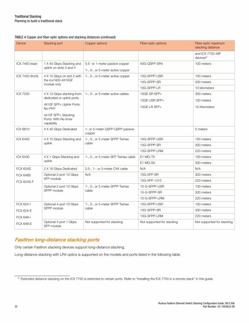
TABLE 4 Copper and fiber-optic options and stacking distances (continued)
Device Stacking port Copper options Fiber-optic options Fiber-optic maximumstacking distance
and ICX 7750-48Fdevices2
ICX 7450 (rear) 1 X 40 Gbps Stacking anduplink on slots 3 and 4
0.5- or 1-meter passive copper
1-, 3-, or 5-meter active copper
40G-QSFP-SR4 100 meters
ICX 7450 (front) 4 X 10 Gbps on slot 2 withthe icx7400-4X10GFmodule only
1-, 3-, or 5-meter active copper 10G-SFPP-USR 100 meters
10G-SFPP-SR 300 meters
10G-SFPP-LR 10 kilometers
ICX 7250 4 X 10 Gbps stacking fromdedicated or uplink ports
4X10F SFP+ Uplink Ports:No-PHY
4x10F SFP+ StackingPorts: With Re-timercapability
1-, 3-, or 5-meter active cables 10GE SR SFP+
10GE USR SFP+
10GE LR SFP+
300 meters
100 meters
10 Kilometers
ICX 6610 4 X 40 Gbps Dedicated 1- or 5-meter QSFP-QSFP passivecopper
5 meters
ICX 6450 4 X 10 Gbps Stacking anduplink
1-, 3-, or 5-meter SFPP Twinaxcable
10G-SFPP-USR 100 meters
10G-SFPP-SR 300 meters
10G-SFPP-LRM 220 meters
ICX 6430 4 X 1 Gbps Stacking anduplink
1-, 3-, or 5-meter SFP Twinax cable E1 MG-TX 100 meters
E1 MG-SX 300 meters
FCX 624S
FCX 648S
FCX 624S-F
2 X 16 Gbps Dedicated 0.5-, 1-, or 3-meter CX4 cable N/A N/A
Optional 2-port 10 GbpsXFP module
N/A 10G-XFP-SR 300 meters
10G-XFP-1310 220 meters
Optional 2-port 10 GbpsSFPP module
1-, 3-, or 5-meter SFPP Twinaxcable
10-G-SFPP-USR 100 meters
10-G-SFPP-SR 300 meters
10-G-SFPP-LRM 220 meters
FCX 624-I
FCX 624-E
FCX 648-I
FCX 648-E
Optional 4-port 10 GbpsSFPP module
1-, 3-, or 5-meter SFPP Twinaxcable
10G-SFPP-USR 100 meters
10G-SFPP-SR 300 meters
10G-SFPP-LRM 220 meters
Optional 4-port 1 GbpsSFP module
Not supported for stacking Not supported for stacking Not supported for stacking
FastIron long-distance stacking portsOnly certain FastIron stacking devices support long-distance stacking.
Long-distance stacking with LR4 optics is supported on the models and ports listed in the following table.
2 Extended distance stacking on the ICX 7750 is restricted to certain ports. Refer to "Installing the ICX 7750 in a remote stack" in this guide.
Traditional StackingPlanning to build a traditional stack
Ruckus FastIron Ethernet Switch Stacking Configuration Guide, 08.0.30b22 Part Number: 53-1003633-09
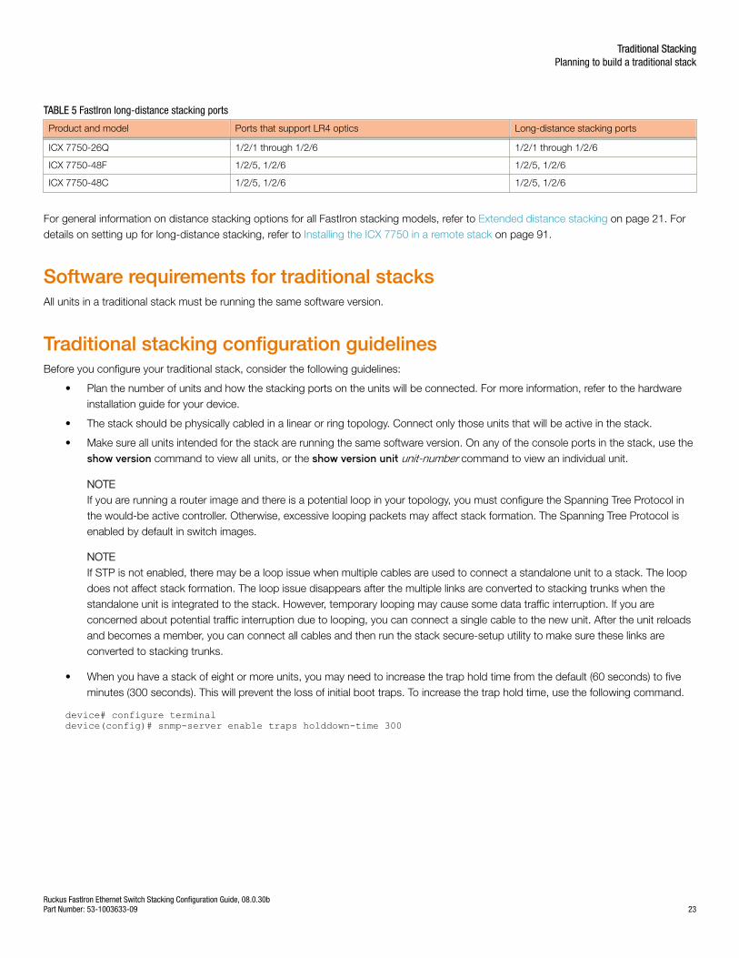
TABLE 5 FastIron long-distance stacking ports
Product and model Ports that support LR4 optics Long-distance stacking ports
ICX 7750-26Q 1/2/1 through 1/2/6 1/2/1 through 1/2/6
ICX 7750-48F 1/2/5, 1/2/6 1/2/5, 1/2/6
ICX 7750-48C 1/2/5, 1/2/6 1/2/5, 1/2/6
For general information on distance stacking options for all FastIron stacking models, refer to Extended distance stacking on page 21. Fordetails on setting up for long-distance stacking, refer to Installing the ICX 7750 in a remote stack on page 91.
Software requirements for traditional stacksAll units in a traditional stack must be running the same software version.
Traditional stacking configuration guidelinesBefore you configure your traditional stack, consider the following guidelines:
• Plan the number of units and how the stacking ports on the units will be connected. For more information, refer to the hardwareinstallation guide for your device.
• The stack should be physically cabled in a linear or ring topology. Connect only those units that will be active in the stack.
• Make sure all units intended for the stack are running the same software version. On any of the console ports in the stack, use theshow version command to view all units, or the show version unit unit-number command to view an individual unit.
NOTEIf you are running a router image and there is a potential loop in your topology, you must configure the Spanning Tree Protocol inthe would-be active controller. Otherwise, excessive looping packets may affect stack formation. The Spanning Tree Protocol isenabled by default in switch images.
NOTEIf STP is not enabled, there may be a loop issue when multiple cables are used to connect a standalone unit to a stack. The loopdoes not affect stack formation. The loop issue disappears after the multiple links are converted to stacking trunks when thestandalone unit is integrated to the stack. However, temporary looping may cause some data traffic interruption. If you areconcerned about potential traffic interruption due to looping, you can connect a single cable to the new unit. After the unit reloadsand becomes a member, you can connect all cables and then run the stack secure-setup utility to make sure these links areconverted to stacking trunks.
• When you have a stack of eight or more units, you may need to increase the trap hold time from the default (60 seconds) to fiveminutes (300 seconds). This will prevent the loss of initial boot traps. To increase the trap hold time, use the following command.
device# configure terminaldevice(config)# snmp-server enable traps holddown-time 300
Traditional StackingPlanning to build a traditional stack
Ruckus FastIron Ethernet Switch Stacking Configuration Guide, 08.0.30bPart Number: 53-1003633-09 23
Traditional stack construction methodsNOTEThe principles outlined in stack construction scenarios apply to all ICX devices. Some figures (for example, to illustrate a certainstack topology) are not necessarily representative of other devices described in the scenario. For illustrations specific to aparticular device, refer to the configuration section for that device. The configuration section for a particular stacking device alsocontains device-specific stacking considerations and configuration examples.
There are three ways to build a traditional stack.
1. The secure-setup utility. Secure-setup gives you control over the design of your stack topology and provides security throughpassword verification. For the secure-setup procedure, refer to Scenario 1 - Three-member traditional stack in a ring topologyusing secure-setup on page 24.
2. Automatic stack configuration. With this method, you enter all configuration information, including the module type and thepriorities of all members into the unit you decide will be the active controller and set its priority to be the highest. When you enablestacking on the active controller, the stack then forms automatically. This method requires that you start with clean units (except forthe active controller) that do not contain startup or runtime configurations. Refer to Configuring a three-member traditional stack ina ring topology using secure-setup on page 25.
3. Manual stack configuration. With this method, you configure every unit individually and enable stacking on each unit. Once theunits are connected together, they automatically operate as a traditional stack. With this method, the unit with the highest prioritybecomes the active controller, and ID assignment is determined by the sequence in which you physically connect the units. Referto Scenario 3 - Manually configuring a three member traditional stack in a ring topology on page 31.
Scenario 1 - Three-member traditional stack in a ring topology usingsecure-setupSecure-setup lets you easily configure your entire stack through the active controller, which propagates the configuration to all stackmembers. Secure-setup is the most secure way to build a traditional stack. It gives you the most control over how your stack is built. Forexample, secure-setup offers three security features that prevent unauthorized devices from accessing or joining a traditional stack:
• Authentication of secure-setup packets provides verification that these packets are from a genuine Ruckus stack unit. MD5-basedport verification confirms stacking ports.
• A superuser password is required to allow password-protected devices to become members of a traditional stack.
• The stack disable command prevents a unit from listening for or sending stacking packets. When a unit is stack-disabled, no
other device in the network can force the unit to join a traditional stack.
Secure-setup can also be used to add units to an existing traditional stack and to change the stack IDs of stack members.
When secure-setup is issued on a unit that is not already the active controller, the unit becomes the active controller. If this unit does notalready have an assigned priority and if no other unit in the stack has a priority higher than 128, secure-setup assigns the unit a priority of128 by default. However, if another unit in the stack has a priority of 128 or higher, secure-setup gives the active controller a priority equal tothe highest priority unit in the stack (which is by default the standby controller). When the active controller and the standby controller haveidentical priorities, during a reset, the old active controller cannot reassume its role from the standby controller (which became the activecontroller at the reset).
If the previous active controller again becomes active and you want it to resume the role of active controller, you should set the priority forthe standby controller to a priority lower than 128. If you do not want the previous active controller to remain the active controller, you canset the same priority for both active and standby controllers (equal to or higher than128).
Traditional StackingTraditional stack construction methods
Ruckus FastIron Ethernet Switch Stacking Configuration Guide, 08.0.30b24 Part Number: 53-1003633-09
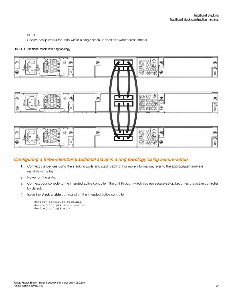
NOTESecure-setup works for units within a single stack. It does not work across stacks.
FIGURE 1 Traditional stack with ring topology
Configuring a three-member traditional stack in a ring topology using secure-setup1. Connect the devices using the stacking ports and stack cabling. For more information, refer to the appropriate hardware
installation guides.
2. Power on the units.
3. Connect your console to the intended active controller. The unit through which you run secure-setup becomes the active controllerby default.
4. Issue the stack enable command on the intended active controller.
device# configure terminaldevice(config)# stack enabledevice(config)# exit
Traditional StackingTraditional stack construction methods
Ruckus FastIron Ethernet Switch Stacking Configuration Guide, 08.0.30bPart Number: 53-1003633-09 25
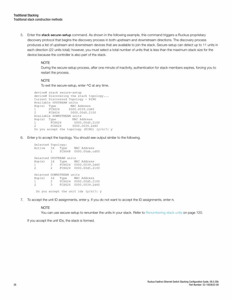
5. Enter the stack secure-setup command. As shown in the following example, this command triggers a Ruckus proprietary
discovery protocol that begins the discovery process in both upstream and downstream directions. The discovery processproduces a list of upstream and downstream devices that are available to join the stack. Secure-setup can detect up to 11 units ineach direction (22 units total); however, you must select a total number of units that is less than the maximum stack size for thedevice because the controller is also part of the stack.
NOTEDuring the secure-setup process, after one minute of inactivity, authentication for stack members expires, forcing you torestart the process.
NOTETo exit the secure-setup, enter ^C at any time.
device# stack secure-setupdevice# Discovering the stack topology...Current Discovered Topology - RINGAvailable UPSTREAM unitsHop(s) Type MAC Address1 FCX624 0000.0039.2d402 FCX624 0000.00d5.2100Available DOWNSTREAM unitsHop(s) Type MAC Address1 FCX624 0000.00d5.21002 FCX624 0000.0039.2d40Do you accept the topology (RING) (y/n)?: y
6. Enter y to accept the topology. You should see output similar to the following.
Selected Topology:Active Id Type MAC Address 1 FCX648 0000.00ab.cd00
Selected UPSTREAM unitsHop(s) Id Type MAC Address1 3 FCX624 0000.0039.2d402 2 FCX624 0000.00d5.2100
Selected DOWNSTREAM unitsHop(s) Id Type MAC Address1 2 FCX624 0000.00d5.21002 3 FCX624 0000.0039.2d40
Do you accept the unit ids (y/n)?: y
7. To accept the unit ID assignments, enter y. If you do not want to accept the ID assignments, enter n.
NOTEYou can use secure-setup to renumber the units in your stack. Refer to Renumbering stack units on page 120.
If you accept the unit IDs, the stack is formed.
Traditional StackingTraditional stack construction methods
Ruckus FastIron Ethernet Switch Stacking Configuration Guide, 08.0.30b26 Part Number: 53-1003633-09
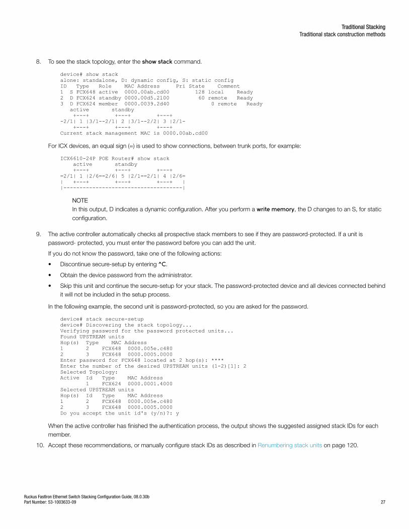
8. To see the stack topology, enter the show stack command.
device# show stackalone: standalone, D: dynamic config, S: static configID Type Role MAC Address Pri State Comment1 S FCX648 active 0000.00ab.cd00 128 local Ready2 D FCX624 standby 0000.00d5.2100 60 remote Ready3 D FCX624 member 0000.0039.2d40 0 remote Ready active standby +---+ +---+ +---+-2/1| 1 |3/1--2/1| 2 |3/1--2/2| 3 |2/1- +---+ +---+ +---+Current stack management MAC is 0000.00ab.cd00
For ICX devices, an equal sign (=) is used to show connections, between trunk ports, for example:
ICX6610-24P POE Router# show stack active standby +---+ +---+ +---+=2/1| 1 |2/6==2/6| 5 |2/1==2/1| 4 |2/6=| +---+ +---+ +---+ ||-------------------------------------|
NOTEIn this output, D indicates a dynamic configuration. After you perform a write memory, the D changes to an S, for static
configuration.
9. The active controller automatically checks all prospective stack members to see if they are password-protected. If a unit ispassword- protected, you must enter the password before you can add the unit.
If you do not know the password, take one of the following actions:
• Discontinue secure-setup by entering ^C.
• Obtain the device password from the administrator.
• Skip this unit and continue the secure-setup for your stack. The password-protected device and all devices connected behindit will not be included in the setup process.
In the following example, the second unit is password-protected, so you are asked for the password.
device# stack secure-setupdevice# Discovering the stack topology...Verifying password for the password protected units...Found UPSTREAM unitsHop(s) Type MAC Address1 2 FCX648 0000.005e.c4802 3 FCX648 0000.0005.0000Enter password for FCX648 located at 2 hop(s): ****Enter the number of the desired UPSTREAM units (1-2)[1]: 2Selected Topology:Active Id Type MAC Address 1 FCX624 0000.0001.4000Selected UPSTREAM unitsHop(s) Id Type MAC Address1 2 FCX648 0000.005e.c4802 3 FCX648 0000.0005.0000Do you accept the unit id's (y/n)?: y
When the active controller has finished the authentication process, the output shows the suggested assigned stack IDs for eachmember.
10. Accept these recommendations, or manually configure stack IDs as described in Renumbering stack units on page 120.
Traditional StackingTraditional stack construction methods
Ruckus FastIron Ethernet Switch Stacking Configuration Guide, 08.0.30bPart Number: 53-1003633-09 27
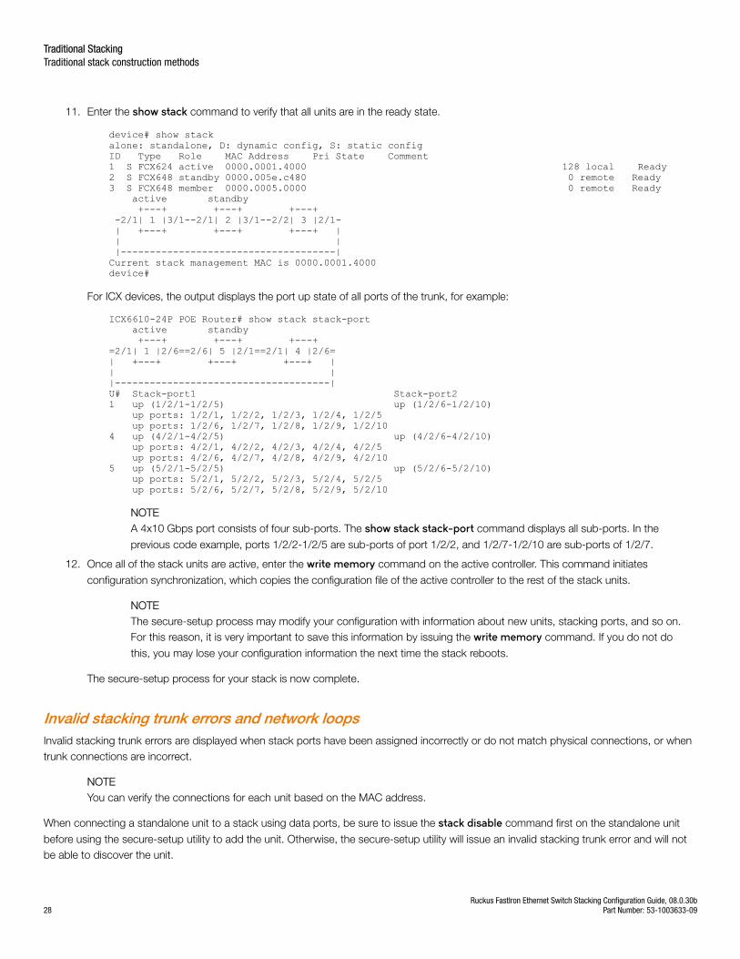
11. Enter the show stack command to verify that all units are in the ready state.
device# show stackalone: standalone, D: dynamic config, S: static configID Type Role MAC Address Pri State Comment1 S FCX624 active 0000.0001.4000 128 local Ready2 S FCX648 standby 0000.005e.c480 0 remote Ready3 S FCX648 member 0000.0005.0000 0 remote Ready active standby +---+ +---+ +---+ -2/1| 1 |3/1--2/1| 2 |3/1--2/2| 3 |2/1- | +---+ +---+ +---+ | | | |-------------------------------------|Current stack management MAC is 0000.0001.4000device#
For ICX devices, the output displays the port up state of all ports of the trunk, for example:
ICX6610-24P POE Router# show stack stack-port active standby +---+ +---+ +---+=2/1| 1 |2/6==2/6| 5 |2/1==2/1| 4 |2/6=| +---+ +---+ +---+ || ||-------------------------------------|U# Stack-port1 Stack-port21 up (1/2/1-1/2/5) up (1/2/6-1/2/10) up ports: 1/2/1, 1/2/2, 1/2/3, 1/2/4, 1/2/5 up ports: 1/2/6, 1/2/7, 1/2/8, 1/2/9, 1/2/104 up (4/2/1-4/2/5) up (4/2/6-4/2/10) up ports: 4/2/1, 4/2/2, 4/2/3, 4/2/4, 4/2/5 up ports: 4/2/6, 4/2/7, 4/2/8, 4/2/9, 4/2/105 up (5/2/1-5/2/5) up (5/2/6-5/2/10) up ports: 5/2/1, 5/2/2, 5/2/3, 5/2/4, 5/2/5 up ports: 5/2/6, 5/2/7, 5/2/8, 5/2/9, 5/2/10
NOTEA 4x10 Gbps port consists of four sub-ports. The show stack stack-port command displays all sub-ports. In the
previous code example, ports 1/2/2-1/2/5 are sub-ports of port 1/2/2, and 1/2/7-1/2/10 are sub-ports of 1/2/7.
12. Once all of the stack units are active, enter the write memory command on the active controller. This command initiates
configuration synchronization, which copies the configuration file of the active controller to the rest of the stack units.
NOTEThe secure-setup process may modify your configuration with information about new units, stacking ports, and so on.For this reason, it is very important to save this information by issuing the write memory command. If you do not do
this, you may lose your configuration information the next time the stack reboots.
The secure-setup process for your stack is now complete.
Invalid stacking trunk errors and network loopsInvalid stacking trunk errors are displayed when stack ports have been assigned incorrectly or do not match physical connections, or whentrunk connections are incorrect.
NOTEYou can verify the connections for each unit based on the MAC address.
When connecting a standalone unit to a stack using data ports, be sure to issue the stack disable command first on the standalone unit
before using the secure-setup utility to add the unit. Otherwise, the secure-setup utility will issue an invalid stacking trunk error and will notbe able to discover the unit.
Traditional StackingTraditional stack construction methods
Ruckus FastIron Ethernet Switch Stacking Configuration Guide, 08.0.30b28 Part Number: 53-1003633-09
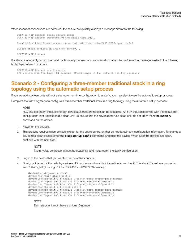
When incorrect connections are detected, the secure-setup utility displays a message similar to the following.
ICX7750-48F Router# stack secure-setupICX7750-48F Router# Discovering the stack topology...
Invalid Stacking Trunk connection at Unit with mac cc4e.2439.1280, port 1/3/5
Please check connection and then re-try...
ICX7750-48F Router#
If a stack is incorrectly constructed and contains loop connections, secure-setup cannot be performed. A message similar to the followingis displayed when this occurs.
ICX7750-48F Router# stack secureCPU utilization too high: 81 percent. Check loops in the network and try again...
Scenario 2 - Configuring a three-member traditional stack in a ringtopology using the automatic setup processIf you are adding clean units without a startup or run-time configuration to a stack, you may elect to use the automatic setup process.
Complete the following steps to configure a three-member traditional stack in a ring topology using the automatic setup process.
NOTEFCX devices determine stacking port candidates through the default-ports setting. An FCX stackable device with the default portconfiguration is still considered a clean unit. To ensure that the device remains a clean unit, do not enter the write memorycommand on the device.
1. Power on the devices.
2. This process requires clean devices (except for the active controller) that do not contain any configuration information. To change adevice to a clean device, enter the erase startup-config command and reset the device. When all of the devices are clean,
continue with the next step.
NOTEThe physical connections must be sequential and must match the stack configuration.
3. Log in to the device that you want to be the active controller.
4. Configure the rest of the units by assigning ID numbers and module information for each unit. The stack ID can be any numberfrom 1 through 8 (1 through 12 for ICX 7450 and ICX 7750 devices).
device# configure terminaldevice(config)# stack unit 2device(config-unit-2)# module 1 fcx-24-port-copper-base-moduledevice(config-unit-2)# module 2 fcx-xfp-1-port-10g-moduledevice(config-unit-2)# module 3 fcx-xfp-1-port-10g-moduledevice(config-unit-2)# stack unit 3device(config-unit-3)# module 1 fcx-24-port-copper-base-moduledevice(config-unit-3)# module 2 fcx-xfp-1-port-10g-moduledevice(config-unit-3)# module 3 fcx-xfp-1-port-10g-module
NOTEEach stack unit must have a unique ID number.
Traditional StackingTraditional stack construction methods
Ruckus FastIron Ethernet Switch Stacking Configuration Guide, 08.0.30bPart Number: 53-1003633-09 29
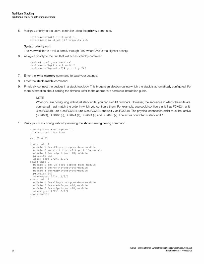
5. Assign a priority to the active controller using the priority command.
device(config)# stack unit 1 device(config-stack-1)# priority 255
Syntax: priority numThe num variable is a value from 0 through 255, where 255 is the highest priority.
6. Assign a priority to the unit that will act as standby controller.
device# configure terminaldevice(config)# stack unit 2device(config-unit-2)# priority 240
7. Enter the write memory command to save your settings.
8. Enter the stack enable command.
9. Physically connect the devices in a stack topology. This triggers an election during which the stack is automatically configured. Formore information about cabling the devices, refer to the appropriate hardware installation guide.
NOTEWhen you are configuring individual stack units, you can skip ID numbers. However, the sequence in which the units areconnected must match the order in which you configure them. For example, you could configure unit 1 as FCX624, unit3 as FCX648, unit 4 as FCX624, unit 6 as FCX624 and unit 7 as FCX648. The physical connection order must be: active(FCX624), FCX648 (3), FCX624 (4), FCX624 (6) and FCX648 (7). The active controller is stack unit 1.
10. Verify your stack configuration by entering the show running config command.
device# show running-configCurrent configuration:!ver 05.0.02!stack unit 1 module 1 fcx-24-port-copper-base-module module 2 module 2 fcx-cx4-2-port-16g-module module 3 fcx-xfp-1-port-10g-module priority 255 stack-port 2/2/1 2/2/2stack unit 2 module 1 fcx-24-port-copper-base-module module 2 fcx-cx4-2-port-16g-module module 3 fcx-xfp-1-port-10g-module priority 240 stack-port 2/2/1 2/2/2stack unit 3 module 1 fcx-24-port-copper-base-module module 2 fcx-cx4-2-port-16g-module module 3 fcx-xfp-1-port-10g-module stack-port 2/2/1 2/2/2stack enable!
Traditional StackingTraditional stack construction methods
Ruckus FastIron Ethernet Switch Stacking Configuration Guide, 08.0.30b30 Part Number: 53-1003633-09
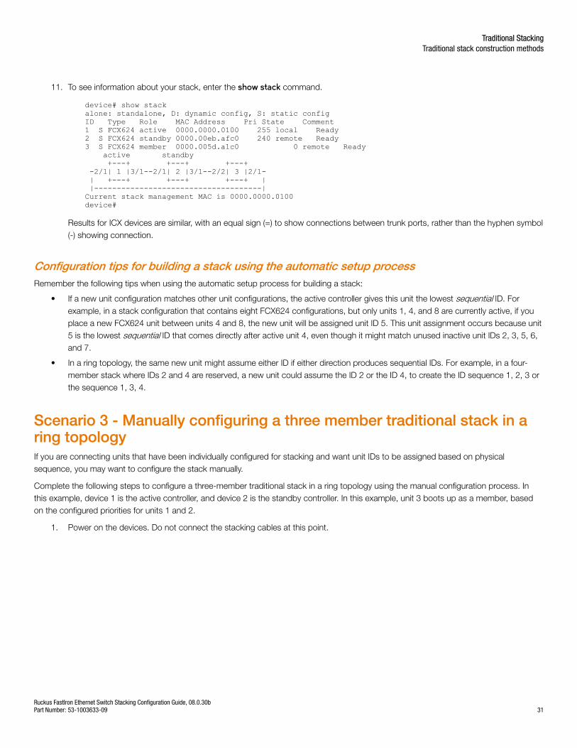
11. To see information about your stack, enter the show stack command.
device# show stackalone: standalone, D: dynamic config, S: static configID Type Role MAC Address Pri State Comment1 S FCX624 active 0000.0000.0100 255 local Ready2 S FCX624 standby 0000.00eb.afc0 240 remote Ready3 S FCX624 member 0000.005d.a1c0 0 remote Ready active standby +---+ +---+ +---+ -2/1| 1 |3/1--2/1| 2 |3/1--2/2| 3 |2/1- | +---+ +---+ +---+ | |-------------------------------------|Current stack management MAC is 0000.0000.0100device#
Results for ICX devices are similar, with an equal sign (=) to show connections between trunk ports, rather than the hyphen symbol(-) showing connection.
Configuration tips for building a stack using the automatic setup processRemember the following tips when using the automatic setup process for building a stack:
• If a new unit configuration matches other unit configurations, the active controller gives this unit the lowest sequential ID. Forexample, in a stack configuration that contains eight FCX624 configurations, but only units 1, 4, and 8 are currently active, if youplace a new FCX624 unit between units 4 and 8, the new unit will be assigned unit ID 5. This unit assignment occurs because unit5 is the lowest sequential ID that comes directly after active unit 4, even though it might match unused inactive unit IDs 2, 3, 5, 6,and 7.
• In a ring topology, the same new unit might assume either ID if either direction produces sequential IDs. For example, in a four-member stack where IDs 2 and 4 are reserved, a new unit could assume the ID 2 or the ID 4, to create the ID sequence 1, 2, 3 orthe sequence 1, 3, 4.
Scenario 3 - Manually configuring a three member traditional stack in aring topologyIf you are connecting units that have been individually configured for stacking and want unit IDs to be assigned based on physicalsequence, you may want to configure the stack manually.
Complete the following steps to configure a three-member traditional stack in a ring topology using the manual configuration process. Inthis example, device 1 is the active controller, and device 2 is the standby controller. In this example, unit 3 boots up as a member, basedon the configured priorities for units 1 and 2.
1. Power on the devices. Do not connect the stacking cables at this point.
Traditional StackingTraditional stack construction methods
Ruckus FastIron Ethernet Switch Stacking Configuration Guide, 08.0.30bPart Number: 53-1003633-09 31
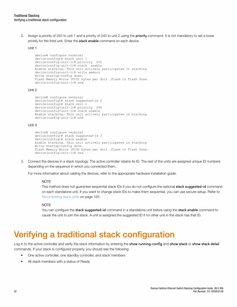
2. Assign a priority of 255 to unit 1 and a priority of 240 to unit 2 using the priority command. It is not mandatory to set a lower
priority for the third unit. Enter the stack enable command on each device.
Unit 1
device# configure terminaldevice(config)# stack unit 1device(config-unit-1)# priority 255device(config-unit-1)# stack enableEnable stacking. This unit actively participates in stackingdevice(config-unit-1)# write memoryWrite startup-config done.Flash Memory Write (8192 bytes per dot) .Flash to Flash Done.device(config-unit-1)# end
Unit 2
device# configure terminaldevice(config)# stack suggested-id 2device(config)# stack unit 1device(config-unit-1)# priority 240device(config-unit-1)# stack enableEnable stacking. This unit actively participates in stackingdevice(config-unit-1)# end
Unit 3
device# configure terminaldevice(config)# stack suggested-id 3device(config)# stack enableEnable stacking. This unit actively participates in stackingWrite startup-config done.Flash Memory Write (8192 bytes per dot) .Flash to Flash Done.device(config-unit-1)# end
3. Connect the devices in a stack topology. The active controller retains its ID. The rest of the units are assigned unique ID numbersdepending on the sequence in which you connected them.
For more information about cabling the devices, refer to the appropriate hardware installation guide.
NOTEThis method does not guarantee sequential stack IDs if you do not configure the optional stack suggested-id command
on each standalone unit. If you want to change stack IDs to make them sequential, you can use secure-setup. Refer to Renumbering stack units on page 120.
NOTEYou can configure the stack suggested-id command in a standalone unit before using the stack enable command to
cause the unit to join the stack. A unit is assigned the suggested ID if no other unit in the stack has that ID.
Verifying a traditional stack configurationLog in to the active controller and verify the stack information by entering the show running-config and show stack or show stack detailcommands. If your stack is configured properly, you should see the following:
• One active controller, one standby controller, and stack members
• All stack members with a status of Ready
Traditional StackingVerifying a traditional stack configuration
Ruckus FastIron Ethernet Switch Stacking Configuration Guide, 08.0.30b32 Part Number: 53-1003633-09
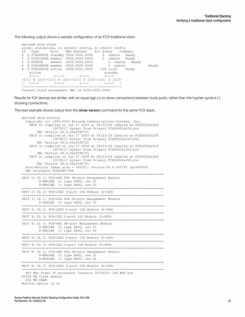
The following output shows a sample configuration of an FCX traditional stack.
device# show stackalone: standalone, D: dynamic config, S: static configID Type Role MAC Address Pri State Comment2 S FCX648POE standby 0000.0002.0000 0 remote Ready3 S FCX624POE member 0000.0003.0000 0 remote Ready4 S FCX648 member 0000.0004.0000 0 remote Ready5 S FCX648POE member 0000.0000.0000 0 remote Ready8 S FCX648POE active 0000.0001.0000 128 local Ready active standby +---+ +---+ +---+ +---+-2/1| 8 |2/2--2/1| 4 |2/2--2/1| 3 |2/2--2/1| 2 |2/2-| +---+ +---+ +---+ +---+ ||--------------------------------------------------|Current stack management MAC is 0000.0001.0000
Results for ICX devices are similar, with an equal sign (=) to show connections between trunk ports, rather than the hyphen symbol (-)showing connections.
The next example shows output from the show version command for the same FCX stack.
device# show version Copyright (c) 1996-2009 Brocade Communications Systems, Inc. UNIT 8: compiled on Jun 17 2009 at 06:23:29 labeled as FCX06000a359 (3578117 bytes) from Primary FCX06000a359.bin SW: Version 06.0.00a359T7f1 UNIT 2: compiled on Jun 17 2009 at 06:23:29 labeled as FCX06000a359 (3578117 bytes) from Primary FCX06000a359.bin SW: Version 06.0.00a359T7f1 UNIT 3: compiled on Jun 17 2009 at 06:23:29 labeled as FCX06000a359 (3578117 bytes) from Primary FCX06000a359.bin SW: Version 06.0.00a359T7f1 UNIT 4: compiled on Jun 17 2009 at 06:23:29 labeled as FCX06000a359 (3578117 bytes) from Primary FCX06000a359.bin SW: Version 06.0.00a359T7f1 Boot-Monitor Image size = 365257, Version:06.0.00T7f5 (grz06000) HW: Stackable FCX648P-POE==========================================================================UNIT 2: SL 1: FCX-48G POE 48-port Management Module P-ENGINE 0: type DB90, rev 01 P-ENGINE 1: type DB90, rev 01==========================================================================UNIT 2: SL 2: FCX-2XGC 2-port 16G Module (2-CX4)==========================================================================UNIT 3: SL 1: FCX-24G POE 24-port Management Module P-ENGINE 0: type DB90, rev 01==========================================================================UNIT 3: SL 2: FCX-2XGC 2-port 16G Module (2-CX4)==========================================================================UNIT 3: SL 3: FCX-2XG 2-port 10G Module (2-XFP)==========================================================================UNIT 4: SL 1: FCX-48G 48-port Management Module P-ENGINE 0: type DB90, rev 01 P-ENGINE 1: type DB90, rev 01==========================================================================UNIT 4: SL 2: FCX-2XGC 2-port 16G Module (2-CX4)==========================================================================UNIT 4: SL 3: FCX-2XG 2-port 10G Module (2-XFP)==========================================================================UNIT 8: SL 1: FCX-48G POE 48-port Management Module P-ENGINE 0: type DB90, rev 01 P-ENGINE 1: type DB90, rev 01==========================================================================UNIT 8: SL 2: FCX-2XGC 2-port 16G Module (2-CX4)========================================================================== 800 MHz Power PC processor (version 33/0022) 144 MHz bus65536 KB flash memory 256 MB DRAMMonitor Option is on
Traditional StackingVerifying a traditional stack configuration
Ruckus FastIron Ethernet Switch Stacking Configuration Guide, 08.0.30bPart Number: 53-1003633-09 33
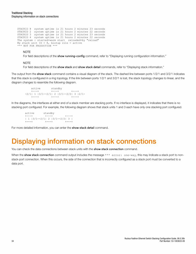
STACKID 8 system uptime is 21 hours 2 minutes 23 secondsSTACKID 2 system uptime is 21 hours 2 minutes 22 secondsSTACKID 3 system uptime is 21 hours 2 minutes 23 secondsSTACKID 4 system uptime is 21 hours 2 minutes 22 secondsThe system : started=warm start reloaded=by "reload"My stack unit ID = 8, bootup role = active*** NOT FOR PRODUCTION ***
NOTEFor field descriptions of the show running-config command, refer to “Displaying running configuration information.”
NOTEFor field descriptions of the show stack and show stack detail commands, refer to “Displaying stack information.”
The output from the show stack command contains a visual diagram of the stack. The dashed line between ports 1/2/1 and 3/2/1 indicates
that this stack is configured in a ring topology. If the link between ports 1/2/1 and 3/2/1 is lost, the stack topology changes to linear, and thediagram changes to resemble the following diagram.
active standby +---+ +---+ +---+ -2/1| 1 |3/1--2/1| 2 |3/1--2/2| 3 |2/1- +---+ +---+ +---+
In the diagrams, the interfaces at either end of a stack member are stacking ports. If no interface is displayed, it indicates that there is nostacking port configured. For example, the following diagram shows that stack units 1 and 3 each have only one stacking port configured.
active standby +---+ +---+ +---+ | 1 |3/1--2/1| 2 |3/1--2/2| 3 | +---+ +---+ +---+
For more detailed information, you can enter the show stack detail command.
Displaying information on stack connectionsYou can check the data connections between stack units with the show stack connection command.
When the show stack connection command output includes the message *** error: one-way, this may indicate a stack port to non-
stack-port connection. When this occurs, the side of the connection that is incorrectly configured as a stack port must be converted to adata port.
Traditional StackingDisplaying information on stack connections
Ruckus FastIron Ethernet Switch Stacking Configuration Guide, 08.0.30b34 Part Number: 53-1003633-09
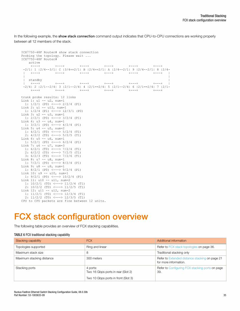
In the following example, the show stack connection command output indicates that CPU-to-CPU connections are working properly
between all 12 members of the stack.
ICX7750-48F Router# show stack connectionProbing the topology. Please wait ...ICX7750-48F Router# active +---+ +---+ +---+ +---+ +---+ +---+ -2/1| 1 |2/4--3/1| C |3/4==2/1| B |2/4==2/1| A |2/4--2/1| 9 |2/4--2/1| 8 |2/4- | +---+ +---+ +---+ +---+ +---+ +---+ | | | | standby | | +---+ +---+ +---+ +---+ +---+ +---+ | -2/4| 2 |2/1--2/4| 3 |2/1--2/4| 4 |2/1==2/4| 5 |2/1--2/4| 6 |2/1==2/4| 7 |2/1- +---+ +---+ +---+ +---+ +---+ +---+
trunk probe results: 12 linksLink 1: u1 -- u2, num=1 1: 1/2/1 (P0) <---> 2/2/4 (P1) Link 2: u1 -- u12, num=1 1: 1/2/4 (P1) <---> 12/3/1 (P0) Link 3: u2 -- u3, num=1 1: 2/2/1 (P0) <---> 3/2/4 (P1) Link 4: u3 -- u4, num=1 1: 3/2/1 (P0) <---> 4/2/4 (P1) Link 5: u4 -- u5, num=2 1: 4/2/1 (T0) <---> 5/2/4 (T1) 2: 4/2/2 (T0) <---> 5/2/5 (T1) Link 6: u5 -- u6, num=1 1: 5/2/1 (P0) <---> 6/2/4 (P1) Link 7: u6 -- u7, num=3 1: 6/2/1 (T0) <---> 7/2/4 (T1) 2: 6/2/2 (T0) <---> 7/2/5 (T1) 3: 6/2/3 (T0) <---> 7/2/6 (T1) Link 8: u7 -- u8, num=1 1: 7/2/1 (P0) <---> 8/2/4 (P1) Link 9: u8 -- u9, num=1 1: 8/2/1 (P0) <---> 9/2/4 (P1) Link 10: u9 -- u10, num=1 1: 9/2/1 (P0) <---> 10/2/4 (P1) Link 11: u10 -- u11, num=2 1: 10/2/1 (T0) <---> 11/2/4 (T1) 2: 10/2/2 (T0) <---> 11/2/5 (T1) Link 12: u11 -- u12, num=2 1: 11/2/1 (T0) <---> 12/3/4 (T1) 2: 11/2/2 (T0) <---> 12/3/5 (T1) CPU to CPU packets are fine between 12 units.
FCX stack configuration overviewThe following table provides an overview of FCX stacking capabilities.
TABLE 6 FCX traditional stacking capability
Stacking capability FCX Additional information
Topologies supported Ring and linear Refer to FCX stack topologies on page 36.
Maximum stack size 8 Traditional stacking only
Maximum stacking distance 300 meters Refer to Extended distance stacking on page 21for more information.
Stacking ports 4 ports:Two 16 Gbps ports in rear (Slot 2)
Two 10 Gbps ports in front (Slot 3)
Refer to Configuring FCX stacking ports on page39.
Traditional StackingFCX stack configuration overview
Ruckus FastIron Ethernet Switch Stacking Configuration Guide, 08.0.30bPart Number: 53-1003633-09 35
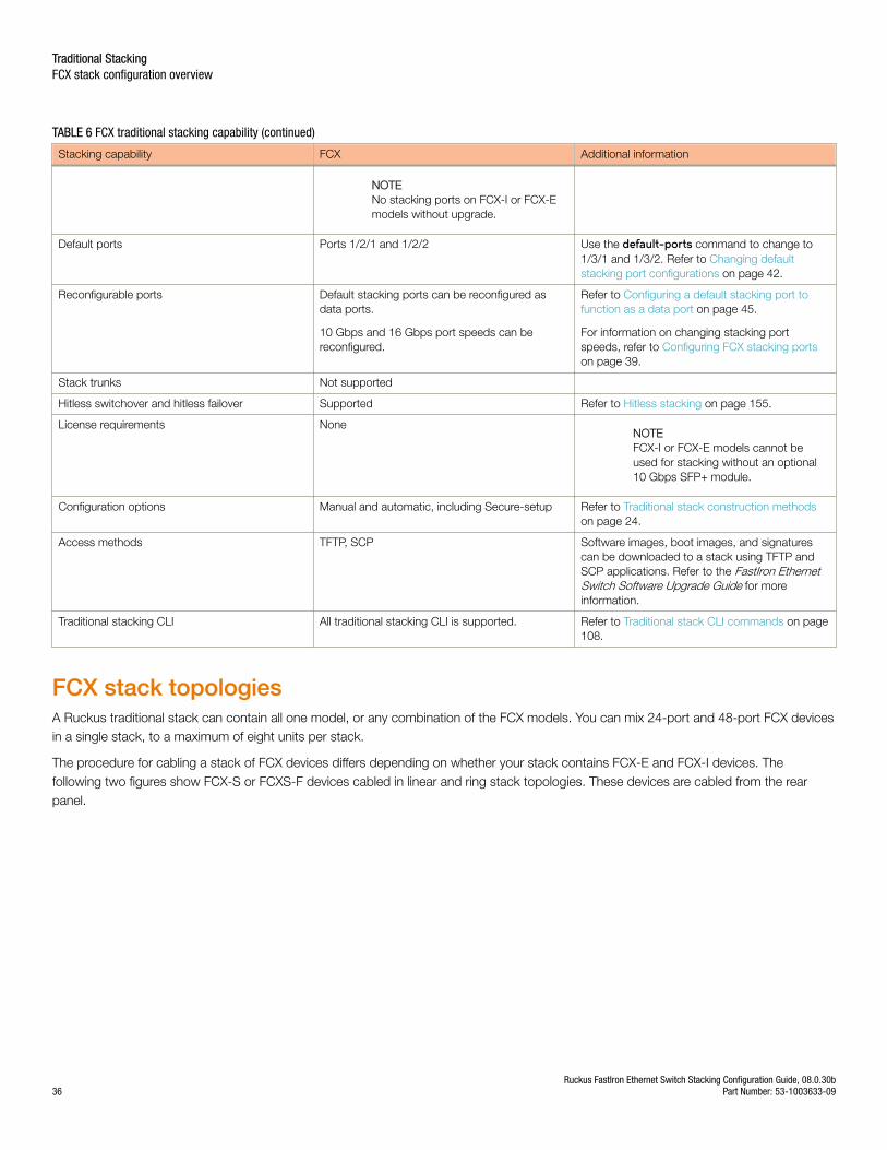
TABLE 6 FCX traditional stacking capability (continued)
Stacking capability FCX Additional information
NOTENo stacking ports on FCX-I or FCX-Emodels without upgrade.
Default ports Ports 1/2/1 and 1/2/2 Use the default-ports command to change to1/3/1 and 1/3/2. Refer to Changing defaultstacking port configurations on page 42.
Reconfigurable ports Default stacking ports can be reconfigured asdata ports.
10 Gbps and 16 Gbps port speeds can bereconfigured.
Refer to Configuring a default stacking port tofunction as a data port on page 45.
For information on changing stacking portspeeds, refer to Configuring FCX stacking portson page 39.
Stack trunks Not supported
Hitless switchover and hitless failover Supported Refer to Hitless stacking on page 155.
License requirements NoneNOTEFCX-I or FCX-E models cannot beused for stacking without an optional10 Gbps SFP+ module.
Configuration options Manual and automatic, including Secure-setup Refer to Traditional stack construction methodson page 24.
Access methods TFTP, SCP Software images, boot images, and signaturescan be downloaded to a stack using TFTP andSCP applications. Refer to the FastIron EthernetSwitch Software Upgrade Guide for moreinformation.
Traditional stacking CLI All traditional stacking CLI is supported. Refer to Traditional stack CLI commands on page108.
FCX stack topologiesA Ruckus traditional stack can contain all one model, or any combination of the FCX models. You can mix 24-port and 48-port FCX devicesin a single stack, to a maximum of eight units per stack.
The procedure for cabling a stack of FCX devices differs depending on whether your stack contains FCX-E and FCX-I devices. Thefollowing two figures show FCX-S or FCXS-F devices cabled in linear and ring stack topologies. These devices are cabled from the rearpanel.
Traditional StackingFCX stack configuration overview
Ruckus FastIron Ethernet Switch Stacking Configuration Guide, 08.0.30b36 Part Number: 53-1003633-09
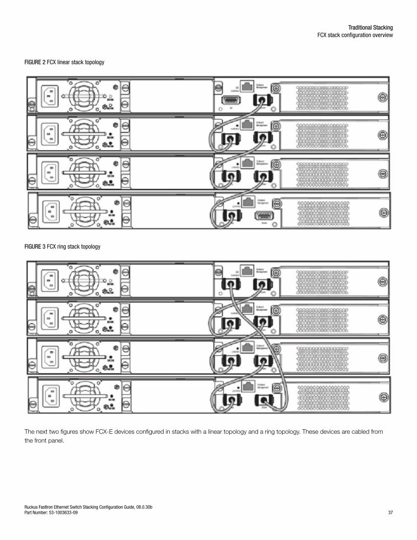
FIGURE 2 FCX linear stack topology
FIGURE 3 FCX ring stack topology
The next two figures show FCX-E devices configured in stacks with a linear topology and a ring topology. These devices are cabled fromthe front panel.
Traditional StackingFCX stack configuration overview
Ruckus FastIron Ethernet Switch Stacking Configuration Guide, 08.0.30bPart Number: 53-1003633-09 37
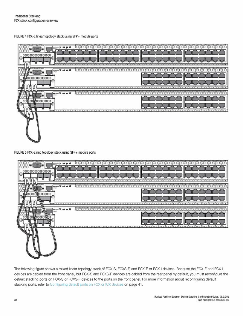
FIGURE 4 FCX-E linear topology stack using SFP+ module ports
FIGURE 5 FCX-E ring topology stack using SFP+ module ports
The following figure shows a mixed linear topology stack of FCX-S, FCXS-F, and FCX-E or FCX-I devices. Because the FCX-E and FCX-Idevices are cabled from the front panel, but FCX-S and FCXS-F devices are cabled from the rear panel by default, you must reconfigure thedefault stacking ports on FCX-S or FCXS-F devices to the ports on the front panel. For more information about reconfiguring defaultstacking ports, refer to Configuring default ports on FCX or ICX devices on page 41.
Traditional StackingFCX stack configuration overview
Ruckus FastIron Ethernet Switch Stacking Configuration Guide, 08.0.30b38 Part Number: 53-1003633-09
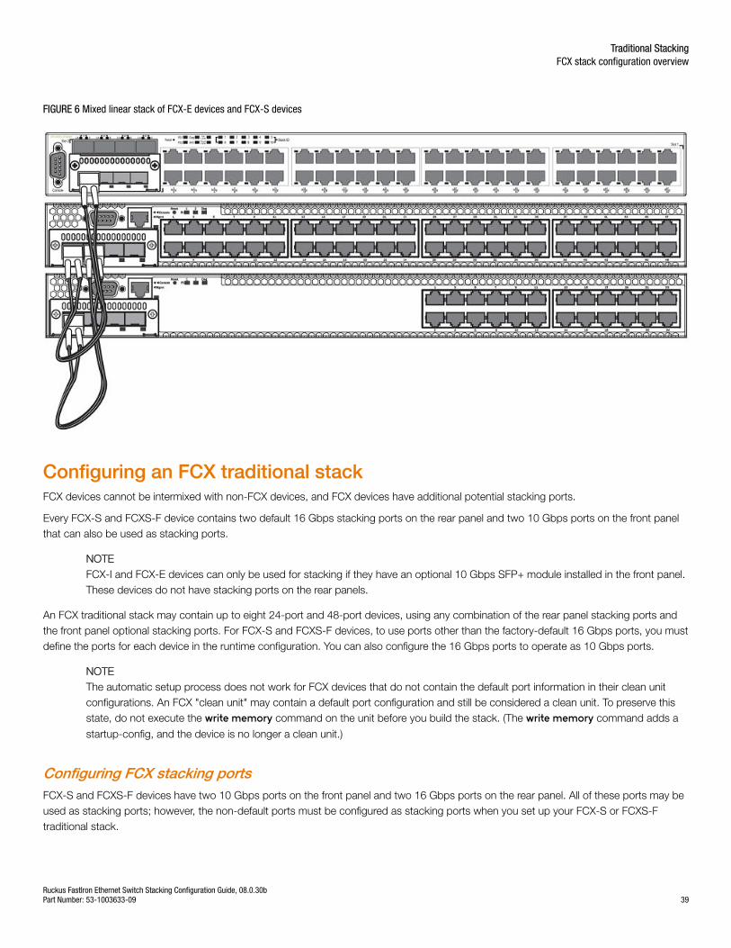
FIGURE 6 Mixed linear stack of FCX-E devices and FCX-S devices
Configuring an FCX traditional stackFCX devices cannot be intermixed with non-FCX devices, and FCX devices have additional potential stacking ports.
Every FCX-S and FCXS-F device contains two default 16 Gbps stacking ports on the rear panel and two 10 Gbps ports on the front panelthat can also be used as stacking ports.
NOTEFCX-I and FCX-E devices can only be used for stacking if they have an optional 10 Gbps SFP+ module installed in the front panel.These devices do not have stacking ports on the rear panels.
An FCX traditional stack may contain up to eight 24-port and 48-port devices, using any combination of the rear panel stacking ports andthe front panel optional stacking ports. For FCX-S and FCXS-F devices, to use ports other than the factory-default 16 Gbps ports, you mustdefine the ports for each device in the runtime configuration. You can also configure the 16 Gbps ports to operate as 10 Gbps ports.
NOTEThe automatic setup process does not work for FCX devices that do not contain the default port information in their clean unitconfigurations. An FCX "clean unit" may contain a default port configuration and still be considered a clean unit. To preserve thisstate, do not execute the write memory command on the unit before you build the stack. (The write memory command adds a
startup-config, and the device is no longer a clean unit.)
Configuring FCX stacking portsFCX-S and FCXS-F devices have two 10 Gbps ports on the front panel and two 16 Gbps ports on the rear panel. All of these ports may beused as stacking ports; however, the non-default ports must be configured as stacking ports when you set up your FCX-S or FCXS-Ftraditional stack.
Traditional StackingFCX stack configuration overview
Ruckus FastIron Ethernet Switch Stacking Configuration Guide, 08.0.30bPart Number: 53-1003633-09 39
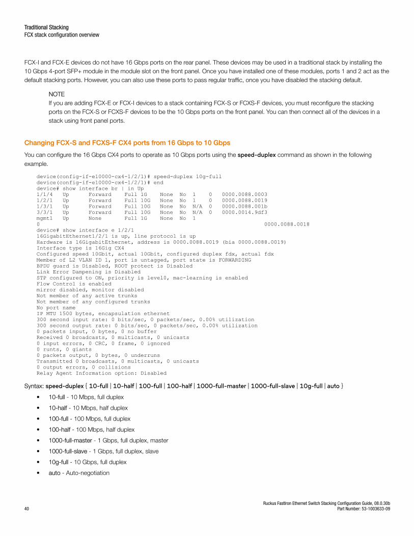
FCX-I and FCX-E devices do not have 16 Gbps ports on the rear panel. These devices may be used in a traditional stack by installing the10 Gbps 4-port SFP+ module in the module slot on the front panel. Once you have installed one of these modules, ports 1 and 2 act as thedefault stacking ports. However, you can also use these ports to pass regular traffic, once you have disabled the stacking default.
NOTEIf you are adding FCX-E or FCX-I devices to a stack containing FCX-S or FCXS-F devices, you must reconfigure the stackingports on the FCX-S or FCXS-F devices to be the 10 Gbps ports on the front panel. You can then connect all of the devices in astack using front panel ports.
Changing FCX-S and FCXS-F CX4 ports from 16 Gbps to 10 Gbps
You can configure the 16 Gbps CX4 ports to operate as 10 Gbps ports using the speed-duplex command as shown in the following
example.
device(config-if-e10000-cx4-1/2/1)# speed-duplex 10g-fulldevice(config-if-e10000-cx4-1/2/1)# enddevice# show interface br | in Up1/1/4 Up Forward Full 1G None No 1 0 0000.0088.00031/2/1 Up Forward Full 10G None No 1 0 0000.0088.00191/3/1 Up Forward Full 10G None No N/A 0 0000.0088.001b3/3/1 Up Forward Full 10G None No N/A 0 0000.0014.9df3mgmt1 Up None Full 1G None No 1 0 0000.0088.0018device# show interface e 1/2/116GigabitEthernet1/2/1 is up, line protocol is upHardware is 16GigabitEthernet, address is 0000.0088.0019 (bia 0000.0088.0019)Interface type is 16Gig CX4Configured speed 10Gbit, actual 10Gbit, configured duplex fdx, actual fdxMember of L2 VLAN ID 1, port is untagged, port state is FORWARDINGBPDU guard is Disabled, ROOT protect is DisabledLink Error Dampening is DisabledSTP configured to ON, priority is level0, mac-learning is enabledFlow Control is enabledmirror disabled, monitor disabledNot member of any active trunksNot member of any configured trunksNo port nameIP MTU 1500 bytes, encapsulation ethernet300 second input rate: 0 bits/sec, 0 packets/sec, 0.00% utilization300 second output rate: 0 bits/sec, 0 packets/sec, 0.00% utilization0 packets input, 0 bytes, 0 no bufferReceived 0 broadcasts, 0 multicasts, 0 unicasts0 input errors, 0 CRC, 0 frame, 0 ignored0 runts, 0 giants0 packets output, 0 bytes, 0 underrunsTransmitted 0 broadcasts, 0 multicasts, 0 unicasts0 output errors, 0 collisionsRelay Agent Information option: Disabled
Syntax: speed-duplex { 10-full | 10-half | 100-full | 100-half | 1000-full-master | 1000-full-slave | 10g-full | auto }
• 10-full - 10 Mbps, full duplex
• 10-half - 10 Mbps, half duplex
• 100-full - 100 Mbps, full duplex
• 100-half - 100 Mbps, half duplex
• 1000-full-master - 1 Gbps, full duplex, master
• 1000-full-slave - 1 Gbps, full duplex, slave
• 10g-full - 10 Gbps, full duplex
• auto - Auto-negotiation
Traditional StackingFCX stack configuration overview
Ruckus FastIron Ethernet Switch Stacking Configuration Guide, 08.0.30b40 Part Number: 53-1003633-09
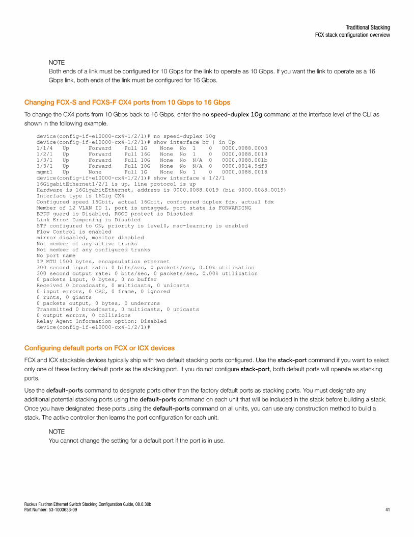
NOTEBoth ends of a link must be configured for 10 Gbps for the link to operate as 10 Gbps. If you want the link to operate as a 16Gbps link, both ends of the link must be configured for 16 Gbps.
Changing FCX-S and FCXS-F CX4 ports from 10 Gbps to 16 Gbps
To change the CX4 ports from 10 Gbps back to 16 Gbps, enter the no speed-duplex 10g command at the interface level of the CLI as
shown in the following example.
device(config-if-e10000-cx4-1/2/1)# no speed-duplex 10gdevice(config-if-e10000-cx4-1/2/1)# show interface br | in Up1/1/4 Up Forward Full 1G None No 1 0 0000.0088.00031/2/1 Up Forward Full 16G None No 1 0 0000.0088.00191/3/1 Up Forward Full 10G None No N/A 0 0000.0088.001b3/3/1 Up Forward Full 10G None No N/A 0 0000.0014.9df3mgmt1 Up None Full 1G None No 1 0 0000.0088.0018device(config-if-e10000-cx4-1/2/1)# show interface e 1/2/116GigabitEthernet1/2/1 is up, line protocol is upHardware is 16GigabitEthernet, address is 0000.0088.0019 (bia 0000.0088.0019)Interface type is 16Gig CX4Configured speed 16Gbit, actual 16Gbit, configured duplex fdx, actual fdxMember of L2 VLAN ID 1, port is untagged, port state is FORWARDINGBPDU guard is Disabled, ROOT protect is DisabledLink Error Dampening is DisabledSTP configured to ON, priority is level0, mac-learning is enabledFlow Control is enabledmirror disabled, monitor disabledNot member of any active trunksNot member of any configured trunksNo port nameIP MTU 1500 bytes, encapsulation ethernet300 second input rate: 0 bits/sec, 0 packets/sec, 0.00% utilization300 second output rate: 0 bits/sec, 0 packets/sec, 0.00% utilization0 packets input, 0 bytes, 0 no bufferReceived 0 broadcasts, 0 multicasts, 0 unicasts0 input errors, 0 CRC, 0 frame, 0 ignored0 runts, 0 giants0 packets output, 0 bytes, 0 underrunsTransmitted 0 broadcasts, 0 multicasts, 0 unicasts0 output errors, 0 collisionsRelay Agent Information option: Disableddevice(config-if-e10000-cx4-1/2/1)#
Configuring default ports on FCX or ICX devices
FCX and ICX stackable devices typically ship with two default stacking ports configured. Use the stack-port command if you want to select
only one of these factory default ports as the stacking port. If you do not configure stack-port, both default ports will operate as stacking
ports.
Use the default-ports command to designate ports other than the factory default ports as stacking ports. You must designate any
additional potential stacking ports using the default-ports command on each unit that will be included in the stack before building a stack.
Once you have designated these ports using the default-ports command on all units, you can use any construction method to build a
stack. The active controller then learns the port configuration for each unit.
NOTEYou cannot change the setting for a default port if the port is in use.
Traditional StackingFCX stack configuration overview
Ruckus FastIron Ethernet Switch Stacking Configuration Guide, 08.0.30bPart Number: 53-1003633-09 41
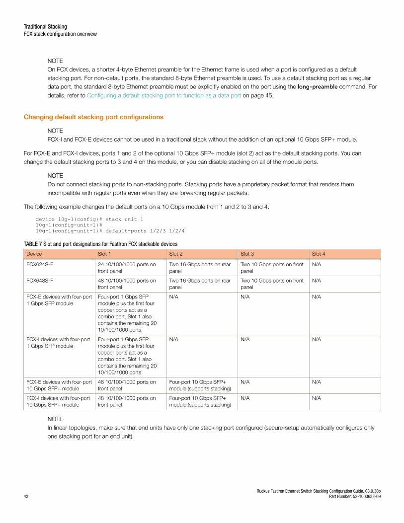
NOTEOn FCX devices, a shorter 4-byte Ethernet preamble for the Ethernet frame is used when a port is configured as a defaultstacking port. For non-default ports, the standard 8-byte Ethernet preamble is used. To use a default stacking port as a regulardata port, the standard 8-byte Ethernet preamble must be explicitly enabled on the port using the long-preamble command. For
details, refer to Configuring a default stacking port to function as a data port on page 45.
Changing default stacking port configurations
NOTEFCX-I and FCX-E devices cannot be used in a traditional stack without the addition of an optional 10 Gbps SFP+ module.
For FCX-E and FCX-I devices, ports 1 and 2 of the optional 10 Gbps SFP+ module (slot 2) act as the default stacking ports. You canchange the default stacking ports to 3 and 4 on this module, or you can disable stacking on all of the module ports.
NOTEDo not connect stacking ports to non-stacking ports. Stacking ports have a proprietary packet format that renders themincompatible with regular ports even when they are forwarding regular packets.
The following example changes the default ports on a 10 Gbps module from 1 and 2 to 3 and 4.
device 10g-1(config)# stack unit 110g-1(config-unit-1)#10g-1(config-unit-1)# default-ports 1/2/3 1/2/4
TABLE 7 Slot and port designations for FastIron FCX stackable devices
Device Slot 1 Slot 2 Slot 3 Slot 4
FCX624S-F 24 10/100/1000 ports onfront panel
Two 16 Gbps ports on rearpanel
Two 10 Gbps ports on frontpanel
N/A
FCX648S-F 48 10/100/1000 ports onfront panel
Two 16 Gbps ports on rearpanel
Two 10 Gbps ports on frontpanel
N/A
FCX-E devices with four-port1 Gbps SFP module
Four-port 1 Gbps SFPmodule plus the first fourcopper ports act as acombo port. Slot 1 alsocontains the remaining 2010/100/1000 ports.
N/A N/A N/A
FCX-I devices with four-port1 Gbps SFP module
Four-port 1 Gbps SFPmodule plus the first fourcopper ports act as acombo port. Slot 1 alsocontains the remaining 2010/100/1000 ports.
N/A N/A N/A
FCX-E devices with four-port10 Gbps SFP+ module
48 10/100/1000 ports onfront panel
Four-port 10 Gbps SFP+module (supports stacking)
N/A N/A
FCX-I devices with four-port10 Gbps SFP+ module
48 10/100/1000 ports onfront panel
Four-port 10 Gbps SFP+module (supports stacking)
N/A N/A
NOTEIn linear topologies, make sure that end units have only one stacking port configured (secure-setup automatically configures onlyone stacking port for an end unit).
Traditional StackingFCX stack configuration overview
Ruckus FastIron Ethernet Switch Stacking Configuration Guide, 08.0.30b42 Part Number: 53-1003633-09
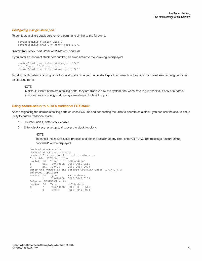
Configuring a single stack port
To configure a single stack port, enter a command similar to the following.
device(config)# stack unit 3device(config-unit-3)# stack-port 3/2/1
Syntax: [no] stack-port stack-unit/slotnum/portnum
If you enter an incorrect stack port number, an error similar to the following is displayed.
device(config-unit-3)# stack-port 3/4/1Error! port 3/4/1 is invaliddevice(config-unit-3)# stack-port 3/2/1
To return both default stacking ports to stacking status, enter the no stack-port command on the ports that have been reconfigured to act
as stacking ports.
NOTEBy default, if both ports are stacking ports, they are displayed by the system only when stacking is enabled. If only one port isconfigured as a stacking port, the system always displays this port.
Using secure-setup to build a traditional FCX stack
After designating the desired stacking ports on each FCX unit and connecting the units to operate as a stack, you can use the secure-setuputility to build a traditional stack.
1. On stack unit 1, enter stack enable.
2. Enter stack secure-setup to discover the stack topology.
NOTETo cancel the secure-setup process and exit the session at any time, enter CTRL+C. The message "secure-setup
cancelled" will be displayed.
device# stack enabledevice# stack secure-setupdevice# Discovering the stack topology...Available UPSTREAM unitsHop(s) Id Type MAC Address1 new FCX648POE 0000.00d6.05112 new FCX624 0000.0099.0000Enter the number of the desired UPSTREAM units (0-2)[0]: 2Selected Topology:Active Id Type MAC Address 1 FCX624POE 0000.00e5.0100Selected UPSTREAM unitsHop(s) Id Type MAC Address1 2 FCX648POE 0000.00d6.05112 3 FCX624 0000.0099.0000
Traditional StackingFCX stack configuration overview
Ruckus FastIron Ethernet Switch Stacking Configuration Guide, 08.0.30bPart Number: 53-1003633-09 43
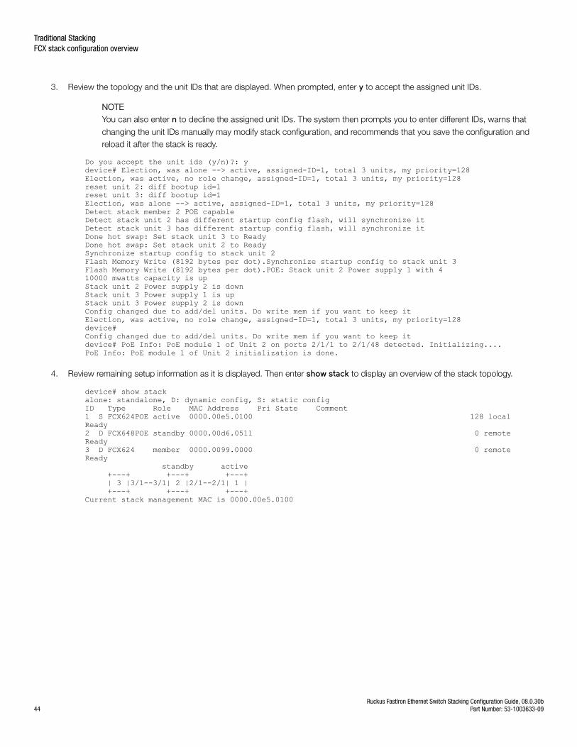
3. Review the topology and the unit IDs that are displayed. When prompted, enter y to accept the assigned unit IDs.
NOTEYou can also enter n to decline the assigned unit IDs. The system then prompts you to enter different IDs, warns that
changing the unit IDs manually may modify stack configuration, and recommends that you save the configuration andreload it after the stack is ready.
Do you accept the unit ids (y/n)?: ydevice# Election, was alone --> active, assigned-ID=1, total 3 units, my priority=128Election, was active, no role change, assigned-ID=1, total 3 units, my priority=128reset unit 2: diff bootup id=1reset unit 3: diff bootup id=1Election, was alone --> active, assigned-ID=1, total 3 units, my priority=128Detect stack member 2 POE capableDetect stack unit 2 has different startup config flash, will synchronize itDetect stack unit 3 has different startup config flash, will synchronize itDone hot swap: Set stack unit 3 to ReadyDone hot swap: Set stack unit 2 to ReadySynchronize startup config to stack unit 2Flash Memory Write (8192 bytes per dot).Synchronize startup config to stack unit 3Flash Memory Write (8192 bytes per dot).POE: Stack unit 2 Power supply 1 with 410000 mwatts capacity is upStack unit 2 Power supply 2 is downStack unit 3 Power supply 1 is upStack unit 3 Power supply 2 is downConfig changed due to add/del units. Do write mem if you want to keep itElection, was active, no role change, assigned-ID=1, total 3 units, my priority=128device#Config changed due to add/del units. Do write mem if you want to keep itdevice# PoE Info: PoE module 1 of Unit 2 on ports 2/1/1 to 2/1/48 detected. Initializing....PoE Info: PoE module 1 of Unit 2 initialization is done.
4. Review remaining setup information as it is displayed. Then enter show stack to display an overview of the stack topology.
device# show stackalone: standalone, D: dynamic config, S: static configID Type Role MAC Address Pri State Comment1 S FCX624POE active 0000.00e5.0100 128 local Ready2 D FCX648POE standby 0000.00d6.0511 0 remote Ready3 D FCX624 member 0000.0099.0000 0 remote Ready standby active +---+ +---+ +---+ | 3 |3/1--3/1| 2 |2/1--2/1| 1 | +---+ +---+ +---+Current stack management MAC is 0000.00e5.0100
Traditional StackingFCX stack configuration overview
Ruckus FastIron Ethernet Switch Stacking Configuration Guide, 08.0.30b44 Part Number: 53-1003633-09
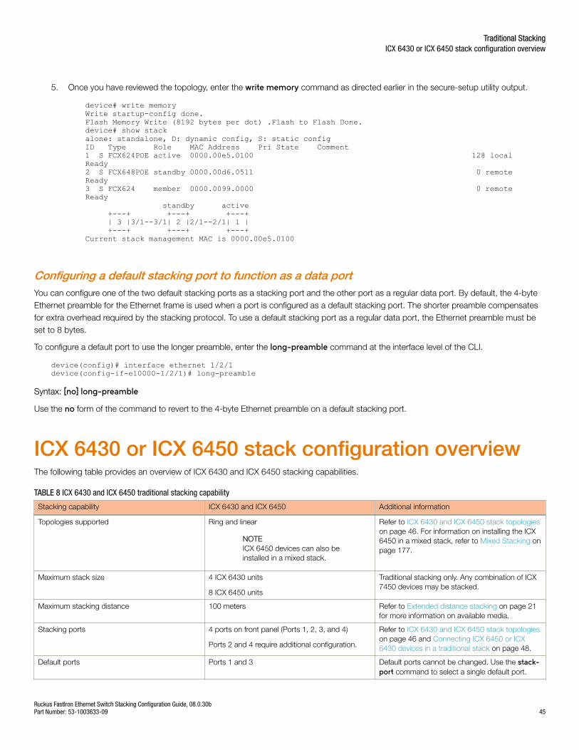
5. Once you have reviewed the topology, enter the write memory command as directed earlier in the secure-setup utility output.
device# write memoryWrite startup-config done.Flash Memory Write (8192 bytes per dot) .Flash to Flash Done.device# show stackalone: standalone, D: dynamic config, S: static configID Type Role MAC Address Pri State Comment1 S FCX624POE active 0000.00e5.0100 128 local Ready2 S FCX648POE standby 0000.00d6.0511 0 remote Ready3 S FCX624 member 0000.0099.0000 0 remote Ready standby active +---+ +---+ +---+ | 3 |3/1--3/1| 2 |2/1--2/1| 1 | +---+ +---+ +---+Current stack management MAC is 0000.00e5.0100
Configuring a default stacking port to function as a data portYou can configure one of the two default stacking ports as a stacking port and the other port as a regular data port. By default, the 4-byteEthernet preamble for the Ethernet frame is used when a port is configured as a default stacking port. The shorter preamble compensatesfor extra overhead required by the stacking protocol. To use a default stacking port as a regular data port, the Ethernet preamble must beset to 8 bytes.
To configure a default port to use the longer preamble, enter the long-preamble command at the interface level of the CLI.
device(config)# interface ethernet 1/2/1device(config-if-e10000-1/2/1)# long-preamble
Syntax: [no] long-preamble
Use the no form of the command to revert to the 4-byte Ethernet preamble on a default stacking port.
ICX 6430 or ICX 6450 stack configuration overviewThe following table provides an overview of ICX 6430 and ICX 6450 stacking capabilities.
TABLE 8 ICX 6430 and ICX 6450 traditional stacking capability
Stacking capability ICX 6430 and ICX 6450 Additional information
Topologies supported Ring and linear
NOTEICX 6450 devices can also beinstalled in a mixed stack.
Refer to ICX 6430 and ICX 6450 stack topologieson page 46. For information on installing the ICX6450 in a mixed stack, refer to Mixed Stacking onpage 177.
Maximum stack size 4 ICX 6430 units
8 ICX 6450 units
Traditional stacking only. Any combination of ICX7450 devices may be stacked.
Maximum stacking distance 100 meters Refer to Extended distance stacking on page 21for more information on available media.
Stacking ports 4 ports on front panel (Ports 1, 2, 3, and 4)
Ports 2 and 4 require additional configuration.
Refer to ICX 6430 and ICX 6450 stack topologieson page 46 and Connecting ICX 6450 or ICX6430 devices in a traditional stack on page 48.
Default ports Ports 1 and 3 Default ports cannot be changed. Use the stack-port command to select a single default port.
Traditional StackingICX 6430 or ICX 6450 stack configuration overview
Ruckus FastIron Ethernet Switch Stacking Configuration Guide, 08.0.30bPart Number: 53-1003633-09 45
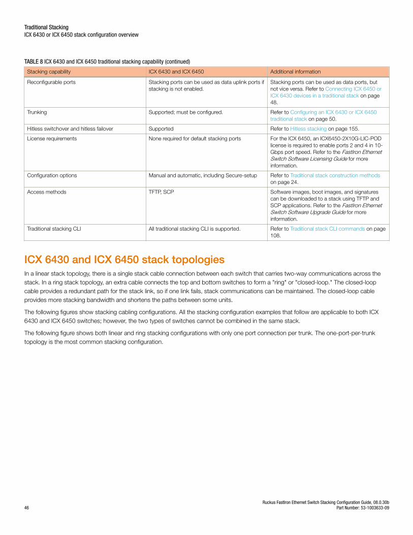
TABLE 8 ICX 6430 and ICX 6450 traditional stacking capability (continued)
Stacking capability ICX 6430 and ICX 6450 Additional information
Reconfigurable ports Stacking ports can be used as data uplink ports ifstacking is not enabled.
Stacking ports can be used as data ports, butnot vice versa. Refer to Connecting ICX 6450 orICX 6430 devices in a traditional stack on page48.
Trunking Supported; must be configured. Refer to Configuring an ICX 6430 or ICX 6450traditional stack on page 50.
Hitless switchover and hitless failover Supported Refer to Hitless stacking on page 155.
License requirements None required for default stacking ports For the ICX 6450, an ICX6450-2X10G-LIC-PODlicense is required to enable ports 2 and 4 in 10-Gbps port speed. Refer to the FastIron EthernetSwitch Software Licensing Guide for moreinformation.
Configuration options Manual and automatic, including Secure-setup Refer to Traditional stack construction methodson page 24.
Access methods TFTP, SCP Software images, boot images, and signaturescan be downloaded to a stack using TFTP andSCP applications. Refer to the FastIron EthernetSwitch Software Upgrade Guide for moreinformation.
Traditional stacking CLI All traditional stacking CLI is supported. Refer to Traditional stack CLI commands on page108.
ICX 6430 and ICX 6450 stack topologiesIn a linear stack topology, there is a single stack cable connection between each switch that carries two-way communications across thestack. In a ring stack topology, an extra cable connects the top and bottom switches to form a "ring" or "closed-loop." The closed-loopcable provides a redundant path for the stack link, so if one link fails, stack communications can be maintained. The closed-loop cableprovides more stacking bandwidth and shortens the paths between some units.
The following figures show stacking cabling configurations. All the stacking configuration examples that follow are applicable to both ICX6430 and ICX 6450 switches; however, the two types of switches cannot be combined in the same stack.
The following figure shows both linear and ring stacking configurations with only one port connection per trunk. The one-port-per-trunktopology is the most common stacking configuration.
Traditional StackingICX 6430 or ICX 6450 stack configuration overview
Ruckus FastIron Ethernet Switch Stacking Configuration Guide, 08.0.30b46 Part Number: 53-1003633-09
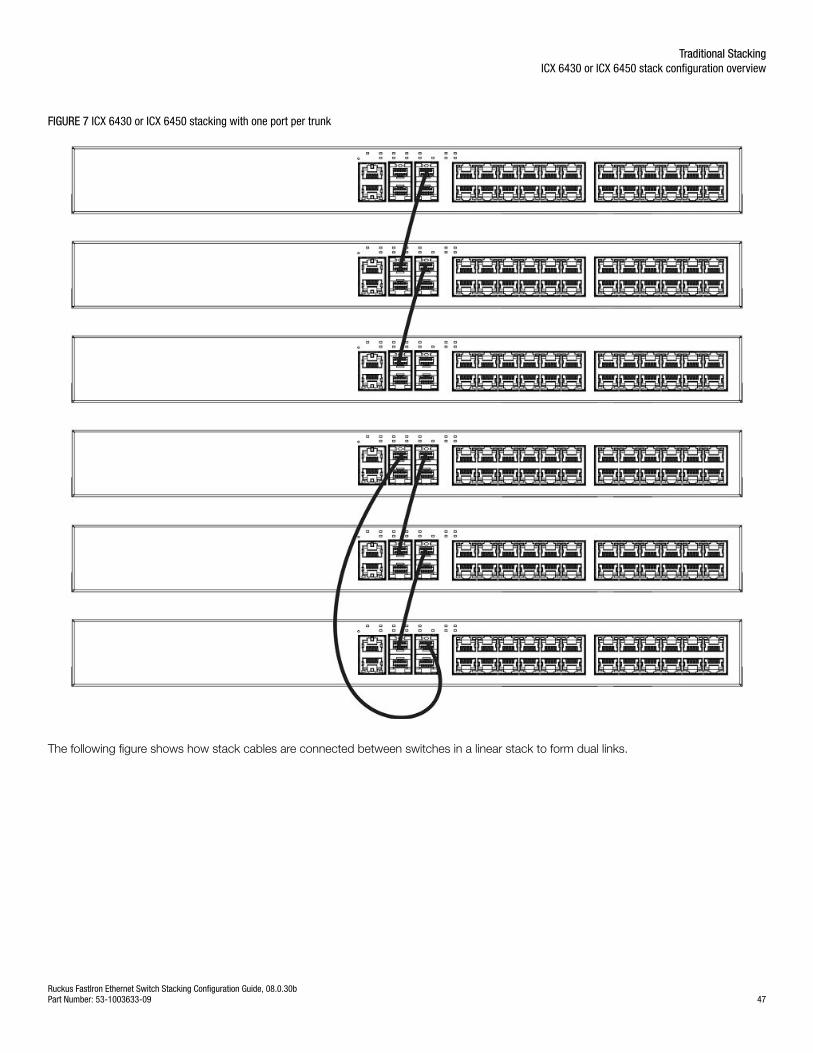
FIGURE 7 ICX 6430 or ICX 6450 stacking with one port per trunk
The following figure shows how stack cables are connected between switches in a linear stack to form dual links.
Traditional StackingICX 6430 or ICX 6450 stack configuration overview
Ruckus FastIron Ethernet Switch Stacking Configuration Guide, 08.0.30bPart Number: 53-1003633-09 47
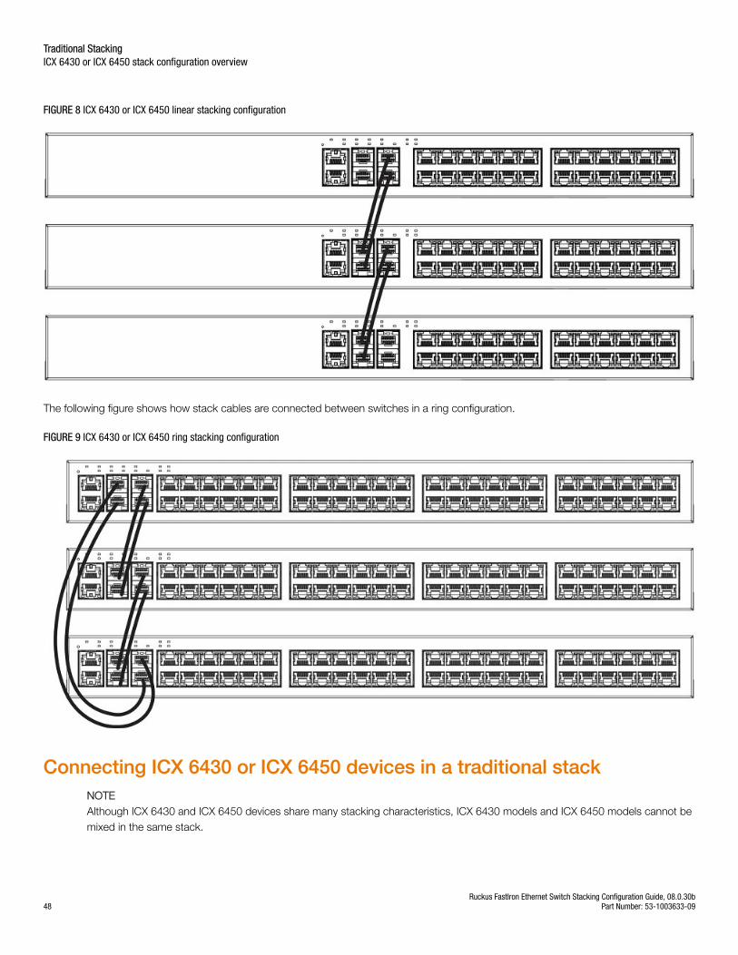
FIGURE 8 ICX 6430 or ICX 6450 linear stacking configuration
The following figure shows how stack cables are connected between switches in a ring configuration.
FIGURE 9 ICX 6430 or ICX 6450 ring stacking configuration
Connecting ICX 6430 or ICX 6450 devices in a traditional stackNOTEAlthough ICX 6430 and ICX 6450 devices share many stacking characteristics, ICX 6430 models and ICX 6450 models cannot bemixed in the same stack.
Traditional StackingICX 6430 or ICX 6450 stack configuration overview
Ruckus FastIron Ethernet Switch Stacking Configuration Guide, 08.0.30b48 Part Number: 53-1003633-09

ICX 6430 and ICX 6450 devices support linear and ring stack topologies and can also operate as standalone devices. Up to four ICX 6430units can be combined in a stack. Up to eight ICX 6450 units can be combined in a stack.
ICX 6430 and ICX 6450 devices have four ports on the front panel that can be used for a stack configuration. If stacking is not enabled onthe ports, then all four stacking ports can be used for data or uplink ports.
ICX 6430 and ICX 6450 devices ship with two default stacking ports configured. When stacking is enabled, ports 1 and 3 are dedicated tostacking and cannot be used for data ports. Use the stack-port command to select only one of these default ports as the stacking port. If
you do not select a default port as the stacking port, both default ports operate as stacking ports. For more information about using thestack-port command on ICX 6430 or ICX 6450 devices, refer to Error messages encountered during configuration of an ICX 6430 or ICX
6450 traditional stack on page 52.
By default, ICX 6430 and ICX 6450 devices are not configured for trunked stacking. You can dynamically configure or remove a stackingtrunk port configuration using the stack-trunk command or the multi-stack-trunk command. For more information about these
commands, refer to Configuring an ICX 6430 or ICX 6450 traditional stack on page 50.
ICX 6430 and ICX 6450 devices support hitless stacking switchover and failover. The secure-setup utility is supported for ICX 6430 and ICX6450 devices.
Connecting ICX 6450 devices in a stackICX 6450 devices have 24 or 48 10/100/1000 Mbps data ports and 4 ports with 1-Gbps or 10-Gbps SFP+ fiber uplink and stacking ports.The top row consists of ports 1 and 3, and the bottom row consists of ports 2 and 4. By default, ports 1 and 3 are 10-Gbps stacking portsand do not have license-based restrictions. However, without a license, ports 2 and 4 boot up in an error-disabled state. To enable ports 2and 4 in 10-Gbps port speed, you must purchase the ICX6450-2X10G-LIC-POD license.
ICX 6450 devices are available with 4 1/10-Gbps optical (dual mode) ports. If you want to use more than two 1-Gbps ports on the ICX 6450with the optical ports, you must enable the 10-Gbps ports as 1-Gbps ports for uplinks.
For more information about enabling ports 2 and 4 to 10-Gbps port speed, refer to "Licensing for Ports on Demand" in the FastIronEthernet Switch Administration Guide.
Configuring a 10-Gbps port for a 1-Gbps uplinkIf you want to use more than two 1-Gbps ports on an ICX 6450 device with 4 1/10-Gbps optical (dual mode) ports, you must enable the10-Gbps ports as 1-Gbps ports for uplinks.
To reconfigure a 10-Gbps port as a 1-Gbps data port, enter the speed-duplex 1000-full-master command in router configuration mode.
In the following example, port 1/2/1 is reconfigured as a 1-Gbps data port.
ICX6450-24 Router# show moduleU1:M1 ICX6450-24 24-port Management Module OK 24 748e.f883.0120U1:M2 ICX6450-SFP-Plus 4port 40G Module OK 4 748e.f883.0139ICX6450-24 Router# configure terminalICX6450-24 Router(config)# speed-duplex 1000-full-masterICX6450-24 Router(config)# interface ethernet 1/2/1ICX6450-24 Router(config-if-e10000-1/2/1)# speed-duplex 1000-full-masterICX6450-24 Router# show running interface ethernet 1/2/1interface ethernet 1/2/1speed-duplex 1000-full-master
Traditional StackingICX 6430 or ICX 6450 stack configuration overview
Ruckus FastIron Ethernet Switch Stacking Configuration Guide, 08.0.30bPart Number: 53-1003633-09 49
Connecting ICX 6430 devices in a stackICX 6430 devices have 24 or 48 10/100/1000 Mbps data ports and four 1-Gbps SFP fiber uplink and stacking ports. The default stackingports are 1 and 3. The four 1-Gbps ports are not eligible for an upgrade to 10-Gbps port speed. Trunk stacking configuration is supportedfor ICX 6430 devices. Link Aggregation Group (LAG) configuration is supported for stacking or uplink ports when a pair of 1-Gbps ports areaggregated.
Configuring an ICX 6430 or ICX 6450 traditional stackICX 6430 or ICX 6450 devices can be stacked using the methods and topologies described in Connecting ICX 6430 or ICX 6450 devices ina traditional stack on page 48. ICX 6430 or ICX 6450 devices can be trunked to form a single trunk-to-port connection on two directlyconnected stack units. The ICX 6430 or ICX 6450 can also be configured with a dual-port trunk.
Trunking configuration considerations for ICX 6430 and ICX 6450 devicesThe ICX 6430 and ICX 6450 stacking ports are grouped into two trunks. Follow these guidelines for connecting and configuring the stackingports.
NOTEAfter enabling the ICX 6430 and ICX 6450 trunked stacking ports, it is recommended that you enter the write memory command
to save your configuration.
• You can connect one or both ports in a trunk. Connecting both ports in a trunk increases stacking bandwidth and providesresiliency.
• You must enable stacking and connect cables properly for the stack to work. The active copper cable lengths for 1-Gbps portsare 1 m (3.2 ft) and 5 m (16.4 ft). The copper cable lengths for 10-Gbps ports are 1 m (3.2 ft), 3 m (9.8 ft), and 5 m (16.4 ft).
• The default stacking ports are always ports 1 and 3. You can trunk (or un-trunk) ports 1 to 2 or ports 3 to 4. One or both of thetwo sets of stacking ports can be trunked (or un-trunked).
• For ICX 6450 devices, all stack ports must be configured to 10-Gbps port speed to enable trunking.
• For ICX 6430 devices, all stack ports must be at 1-Gbps port speed to enable trunking.
• When creating a trunk, the ports in the same column are always trunked. For example, you can connect ports 1/2/3 to 1/2/4 toform one trunk on one device, and ports 2/2/1 to 2/2/2 to form a second trunk on another device.
• If you connect both ports in a trunk, both ports must connect to both ports of one trunk on another device.
Configuring ICX 6430 or ICX 6450 trunked stacking ports
NOTEUse the stack-trunk command in a new environment on first deployment. Use the multi-stack-trunk command in a production
environment.
The stack-trunk command forms a single trunk-to-port connection on two connected stack units. A trunk-to-port connection is formed
when one side of the ports forms a trunk, but the other side of the ports does not. You can use the stack-trunk command to configure a
stack trunk if one or both of the units are provisional units. You must enable stacking and connect cables properly for the stack to work. Toenable the stack-trunk command, the primary port in the trunk must be configured under the stack-port command configuration.
For ICX 6450 devices, the data ports on both units must be configured to 10-Gbps port speed to enable trunking. To upgrade to 10-Gbpsport speed on ports 2 and 4, you need the ICX6450-2X10G-LIC-POD license. If the data port is not enabled for 10-Gbps port speed, theport status is down. For more information about configuring ports to 10-Gbps port speed, refer to "Licensing for Ports on Demand" in theFastIron Ethernet Switch Administration Guide.
Traditional StackingICX 6430 or ICX 6450 stack configuration overview
Ruckus FastIron Ethernet Switch Stacking Configuration Guide, 08.0.30b50 Part Number: 53-1003633-09
Configure a stack trunk by entering the following command under the stack unit configuration level.
Ruckus (config)# stack unit 1Ruckus (config-unit-1)# stack-trunk 1/2/3 to 1/2/4
The following warning is displayed in the CLI if the stack-trunk command results in a trunk-to-port connection.
Error- this command will result in a port-to-trunk connection between stack 1 and 2. Please use "multi-stack-trunk" command instead.
Syntax: [no] stack-trunk
Use the no form of the command to disable the stack trunk configuration.
Use the multi-stack-trunk command to configure a stack trunk on two directly connected stack units to ensure that a trunk-to-trunk
connection is formed on both units at the same time.
To save the configuration, enter the write memory command.
Configuring ICX 6430 or ICX 6450 multi-trunked stacking portsTo upgrade from a single to a double port trunk configuration, use the multi-stack-trunk command. The multi-stack-trunk command is
used to ensure that a stack trunk is formed on two directly connected stack units at the same time. The multi-stack-trunk command can
only be enabled on the active controller unit. By configuring a multi-stack trunk on two sets of connected stack ports, a trunk-to-portconnection is avoided. A trunk-to-port connection is formed when one side of the ports forms a trunk, and the other side of the ports doesnot. A trunk-to-port connection can result in dropped packets and can potentially break a stacking link.
To upgrade to a double port trunk configuration, enter the multi-stack-trunk command at the stack unit configuration level. Your entries
should look similar to the following example.
device(config)# stack unit 1device(config-unit-1)# multi-stack-trunk 1/2/3 to 1/2/4 and 2/2/1 to 2/2/2device(config-unit-1)# stack unit 2device(config-unit-2)# multi-stack-trunk 2/2/3 to 2/2/4 and 3/2/1 to 3/2/2
Syntax: [no] multi-stack-trunk
Use the no form of the command to disable the configuration of the two connected stack trunk ports.
A stack trunk cannot be removed if the primary port is down. The primary ports of the stack trunk must be connected and in an up statusto use the no multi-stack-trunk command. If the primary stack trunk ports are not connected and are not in an up status, the command is
rejected, and the following error message is displayed.
Error- Primary trunk port 1/2/3 is not UP; removing the trunk might break the stack
Displaying multi-trunked stacking configuration
The multi-stack-trunk command is effectively a combination of two stack-trunk commands to ensure that a trunk-to-trunk connection is
created on both ends of a stack link. When the multi-stack trunk command is used to upgrade to a double port trunk, the configuration is
saved as stack trunk ports, and the running configuration displays the stack trunk details on both ends under the heading stack unit<unit> configuration. Use the show running-config command to display the related configuration under "stack-trunk" and "stack-
port" as shown in the following example.
In the following code sample, a multi-stack trunk is created.
device(config-unit-1)# multi-stack-trunk 1/2/3 to 1/2/4 and 2/2/1 to 2/2/2
Traditional StackingICX 6430 or ICX 6450 stack configuration overview
Ruckus FastIron Ethernet Switch Stacking Configuration Guide, 08.0.30bPart Number: 53-1003633-09 51
For the multi-stack trunk created in the previous example, the running or startup configuration displays the following configuration for theshow running-config command.
device# show running-configstack unit 1 module 1 icx6450-48p-poe-port-management-module module 2 icx6450-sfp-plus-4port-40g-module stack-trunk 1/2/3 to 1/2/4 stack-port 1/2/1 1/2/3stack unit 2 module 1 icx6450-24-port-management-module module 2 icx6450-sfp-plus-4port-40g-module stack-trunk 2/2/1 to 2/2/2 stack-port 2/2/1 2/2/3
Error messages encountered during configuration of an ICX 6430 or ICX 6450 traditional stackThe following error messages may occur when you configure an ICX 6430 or ICX 6450 traditional stack:
• If you form a multi-trunk connection on two sets of stack ports that are not directly connected on neighboring units, the multi-stack-trunk command is rejected, and an error message similar to the follow example is displayed.
Error! 1/2/3 has no connection. Please use "stack-trunk".
• When a unit joins or leaves a stack, or a stack trunk is configured using the stack-trunk command, a stack election is triggered.
The multi-stack-trunk command triggers a stack election among the stack units and reprograms (or removes) the stack trunk
port in the hardware. A timer is set on all units to coordinate a stack election. Traffic is generally interrupted for less than 5 secondsfor the system to detect the port down event and reprogram hardware. You must wait for the stack election to be completedbefore entering another command. If you do not wait for the stack election to finish, the following warning message is displayed.
Stack port or trunk change is in progress, please try later.
• You cannot enter the stack switch-over command until the stack election is completed or until the multi-stack-trunk command
configuration is complete. If you enter the stack switch-over command too early, the following warning message is displayed.
Please try later, reason: during stack port or trunk deployment.
• If ports 2 and 4 of the ICX 6450 device are not configured to 10 Gbps port speed, then the multi-stack-trunk command and the
stack-trunk command are rejected with the following error message.
Error! port 1/2/2 is not configured as 10G
You must first enable the port to 10 Gbps port speed using the speed-duplex 10g-full command. For more information about
configuring ports to 10 Gbps port speed, refer to “Licensing for Ports on Demand” in the FastIron Ethernet Switch AdministrationGuide.
• You cannot use the stack-port command to remove a stacking port if the port is part of a stack trunk. You must first remove the
stack trunk and then remove the stack port. Use the stack-trunk command or the multi-stack-trunk command to remove the
stack trunk. If you attempt to remove the stack port before removing the stack trunk, an error message similar to the followingexample is displayed.
Please remove stack-trunk 1/2/3 - 1/2/4 using "stack-trunk" or "multi-stack-trunk" command before removing stack port 1/2/3.
Traditional StackingICX 6430 or ICX 6450 stack configuration overview
Ruckus FastIron Ethernet Switch Stacking Configuration Guide, 08.0.30b52 Part Number: 53-1003633-09
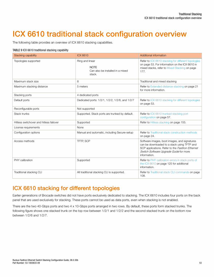
ICX 6610 traditional stack configuration overviewThe following table provides an overview of ICX 6610 stacking capabilities.
TABLE 9 ICX 6610 traditional stacking capability
Stacking capability ICX 6610 Additional information
Topologies supported Ring and linear
NOTECan also be installed in a mixedstack.
Refer to ICX 6610 stacking for different topologieson page 53. For information on the ICX 6610 inmixed stacks, refer to Mixed Stacking on page177.
Maximum stack size 8 Traditional and mixed stacking
Maximum stacking distance 5 meters Refer to Extended distance stacking on page 21for more information.
Stacking ports 4 dedicated ports
Default ports Dedicated ports: 1/2/1, 1/2/2, 1/2/6, and 1/2/7 Refer to ICX 6610 stacking for different topologieson page 53.
Reconfigurable ports Not supported
Stack trunks Supported. Stack ports are trunked by default. Refer to ICX 6610 trunked stacking portconfiguration on page 57.
Hitless switchover and hitless failover Supported Refer to Hitless stacking on page 155.
License requirements None
Configuration options Manual and automatic, including Secure-setup Refer to Traditional stack construction methodson page 24.
Access methods TFTP, SCP Software images, boot images, and signaturescan be downloaded to a stack using TFTP andSCP applications. Refer to the FastIron EthernetSwitch Software Upgrade Guide for moreinformation.
PHY calibration Supported Refer to PHY calibration errors in stack ports ofthe ICX 6610 on page 125 for additionalinformation.
Traditional stacking CLI All traditional stacking CLI is supported. Refer to Traditional stack CLI commands on page108.
ICX 6610 stacking for different topologiesEarlier generations of Brocade switches did not have ports exclusively dedicated to stacking. The ICX 6610 includes four ports on the backpanel that are used exclusively for stacking. These ports cannot be used as data ports, even when stacking is not enabled.
There are the two 40-Gbps ports and two 4 x 10-Gbps ports arranged in two rows. By default, these ports form stacked trunks. Thefollowing figure shows one stacked trunk on the top row between 1/2/1 and 1/2/2 and the second stacked trunk on the bottom rowbetween 1/2/6 and 1/2/7.
Traditional StackingICX 6610 traditional stack configuration overview
Ruckus FastIron Ethernet Switch Stacking Configuration Guide, 08.0.30bPart Number: 53-1003633-09 53
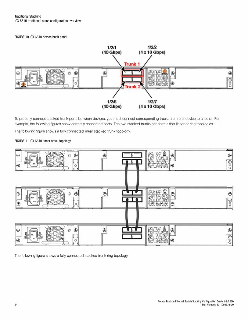
FIGURE 10 ICX 6610 device back panel
To properly connect stacked trunk ports between devices, you must connect corresponding trucks from one device to another. Forexample, the following figures show correctly connected ports. The two stacked trunks can form either linear or ring topologies.
The following figure shows a fully connected linear stacked trunk topology.
FIGURE 11 ICX 6610 linear stack topology
The following figure shows a fully connected stacked trunk ring topology.
Traditional StackingICX 6610 traditional stack configuration overview
Ruckus FastIron Ethernet Switch Stacking Configuration Guide, 08.0.30b54 Part Number: 53-1003633-09
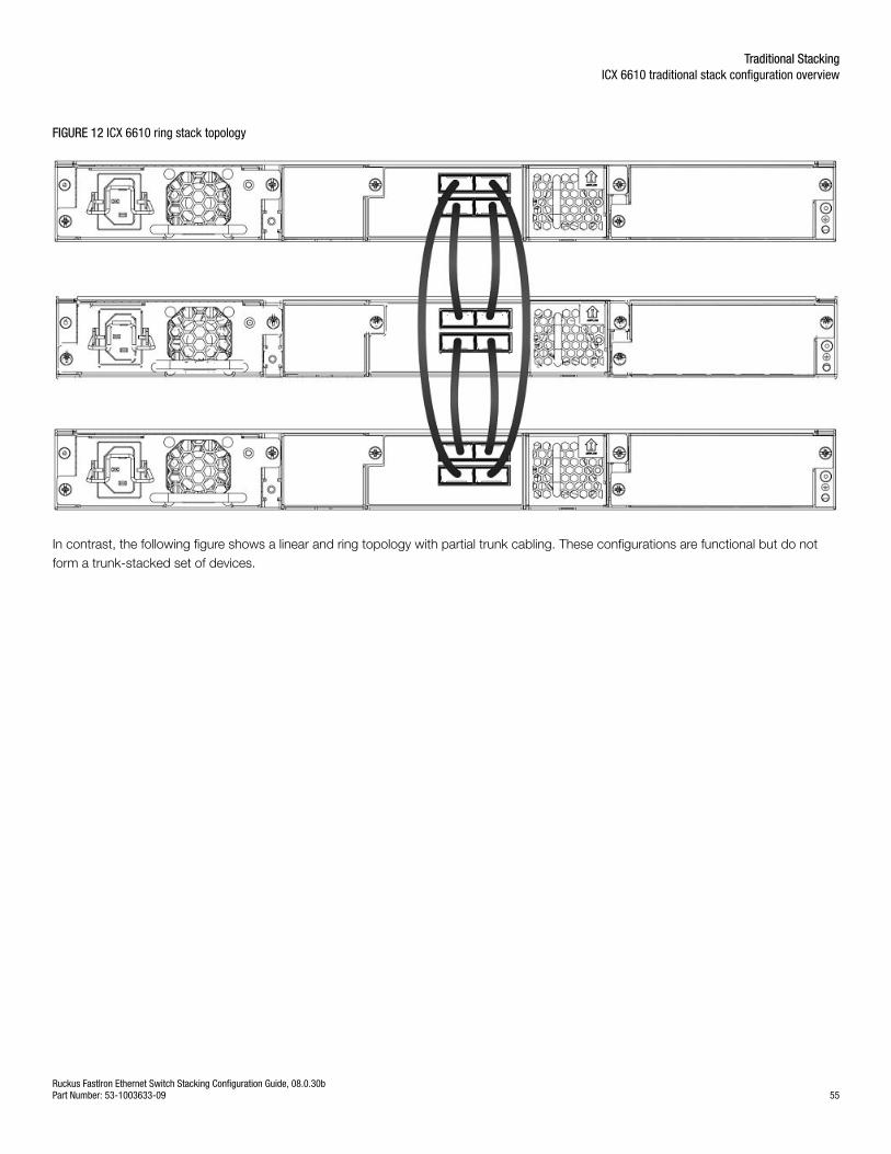
FIGURE 12 ICX 6610 ring stack topology
In contrast, the following figure shows a linear and ring topology with partial trunk cabling. These configurations are functional but do notform a trunk-stacked set of devices.
Traditional StackingICX 6610 traditional stack configuration overview
Ruckus FastIron Ethernet Switch Stacking Configuration Guide, 08.0.30bPart Number: 53-1003633-09 55
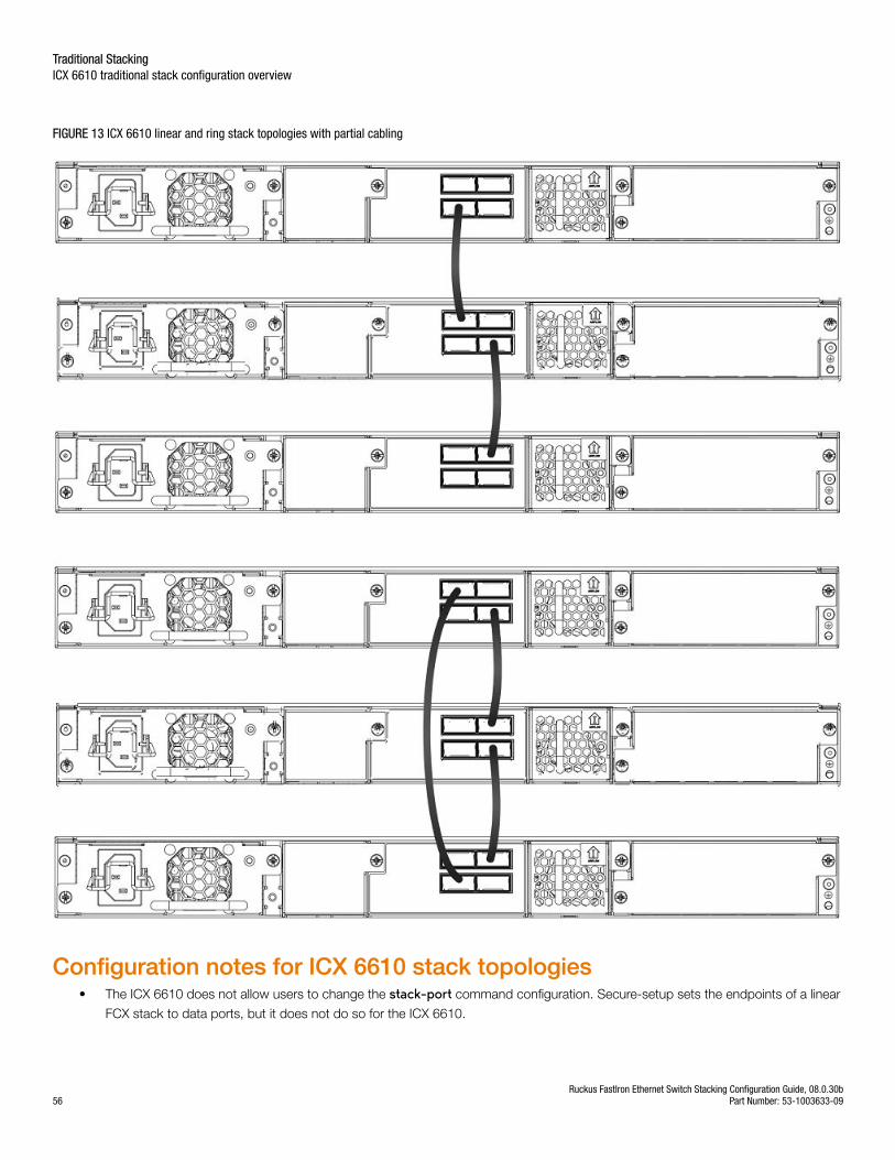
FIGURE 13 ICX 6610 linear and ring stack topologies with partial cabling
Configuration notes for ICX 6610 stack topologies• The ICX 6610 does not allow users to change the stack-port command configuration. Secure-setup sets the endpoints of a linear
FCX stack to data ports, but it does not do so for the ICX 6610.
Traditional StackingICX 6610 traditional stack configuration overview
Ruckus FastIron Ethernet Switch Stacking Configuration Guide, 08.0.30b56 Part Number: 53-1003633-09
• An ICX 6610 supports up to 120 user-configured or LACP trunks. IDs 121-124 are reserved for peri-trunks in mixed stacking. Formore information, refer to Mixed Stacking on page 177.
NOTEThe ICX 6610 40-Gbps and 4 x 10-Gbps ports cannot be used as data ports, even when stacking is not enabled. In standalonemode, these ports drop all packets except stacking probe packets. As a result, secure-setup and unit replacement can stilldiscover a standalone unit.
ICX 6610 trunked stacking port configurationA trunk doubles the stacking port bandwidth and provides better resilience than a single port-to-port link. As long as at least one port onthe trunk is connected properly, communication between the neighboring units will work. Traffic is load balanced to the trunk ports. Withlarge numbers of sessions, traffic load should be well balanced between 40-Gbps and 4 x10-Gbps ports. Traffic should also be welldistributed among the four sub-ports of a 4 x10-Gbps port. If a 4 x10-Gbps sub-port fails due to hardware failure, traffic is re-distributed toother ports, and the stack system should still work. Periodic background diagnosis provides warning messages when any 4 x10-Gbps sub-port is down.
When only one stacking port on a trunk goes down, no stack election or topology changes should occur. The resulting traffic interruptiontime should be in the sub-second range as the system detects that the port is down and re-programs hardware.
Stacking ports are trunked by default in the ICX 6610. The system automatically generates the trunk configuration; however, you do have toenable stacking and connect cables properly for the stack to work.
The show trunk command shows user-configured or LACP trunks but does not show stacking trunks.
At least one port of a trunk must be connected. If multiple ports of a trunk are connected, they must be connected to the same trunk on theother unit. Two ports on the same trunk cannot connect to two different units, nor can two ports on the same trunk connect to differenttrunks on the same unit. Incorrect connections are likely to cause stacking formation failure or other problems.
Some invalid connections still form a stack but with forwarding problems. Stack probe packets use the first connected port of a stackingtrunk. Consequently, as long as the first connected port on a trunk is connected properly, a stack can form. However, packet forwardingmay not work for some streams that are hashed into the incorrectly connected trunk port. In this case, periodic background diagnosis maydetect wrong connections and provide related error messages in about 20 minutes.
Stack port resiliency in the ICX 6610In an ICX 6610, sometimes a stacking port cannot send or receive packets, even though the port is logically operational. To detect thisproblem, probe packets are sent between the ICX 6610 units in a stack every two seconds. If a port is logically operational but does notreceive a probe packet for 90 seconds, it is considered a malfunctioning port. To resolve this, you can configure the active controller toperform corrective steps such as error-disabling malfunctioning ports and reloading one or more stack units. You can use the showerrdisable summary command to view a list of all error-disabled ports along with the reason these ports were error-disabled.
NOTEA malfunctioning stack port that is error-disabled cannot be enabled until the unit is reloaded.
NOTETraffic may be interrupted for a few seconds or more while the port malfunction is detected and fixed.
Traditional StackingICX 6610 traditional stack configuration overview
Ruckus FastIron Ethernet Switch Stacking Configuration Guide, 08.0.30bPart Number: 53-1003633-09 57

Configuring stack port resiliency in the ICX 6610To configure stack port resiliency on an ICX 6610 in a stack, enter the stack stack-port-resiliency command on the active
controller in global configuration mode.
The command enables the active controller to perform corrective steps. The steps that the active controller takes are specified bythe level variable entered after the command, with 0 being the lowest setting and 3 being the highest possible setting. No action istaken when the level is set to 0. The active controller may error-disable malfunctioning ports and reload one or more stack unitsbased on the level specified.
The following example shows a stack being configured for stack port resiliency with the level variable set to 2.
Brocade(config)# stack stack-port-resiliency 2
Syntax: [no] stack stack-port-resiliency level
Syslog messages for stack port resiliencyFor stack port resiliency, syslog messages are generated when the active controller performs corrective steps such as error-disablingmalfunctioning ports, reloading one or more stack units, or reloading an entire stack. These syslog messages do not have a fixed format.The messages may not be entirely accurate because of communication problems between stack units.
When a malfunctioning port is error-disabled, the stack unit generates a syslog message similar to the following example.
SYSLOG: <10>0d00h10m22s : ICX6610-24P Router Stack: port 2/2/8 U2 errdisable 2/2/8: reason: 2/2/8 --> 1/2/8
When a stack unit reloads, the stack unit generates a syslog message similar to the following example.
SYSLOG: <9>3d21h52m57s : ICX6610-24P Router Stack: unit 3 Reload u3 in 10 sec due to 3/2/6 port problems. reason: lose one nbrSYSLOG: <9>0d00h08m59s : ICX6610-48 Router Stack: unit 2 U3 detects stack port problem. will reload u2: one directional CPU to CPU: u2 --> u3, one directional CPU to CPU: u2 --> u4,
When the entire stack reloads, the active controller generates a syslog message similar to the following example.
SYSLOG: <9>0d00h12m07s : ICX6610-48 Router Stack: "stack stack-port-resiliency 3" is configured. Active u3 reloads the stack in 5s. reason: no CPU to CPU: u1 -x- u4, no CPU to CPU: u2 -x- u4, no CPU to CPU: u3 -x- u4,SYSLOG: <9>0d00h12m28s : ICX6610-24P Router Stack: "stack stack-port-resiliency 3" is configured. Active u1 reloads the stack in 5s. reason: 1: 1/2/1 (T0) ---> 2/2/6 (T1) *** error: one-way 2: 1/2/2 (T0) ---> 2/2/7 (T1) *** error: one-way 3: 1/2/3 (T0) ---> 2/2/8 (T1) *** error: one-way 4: 1/2/4 (T0) ---> 2/2/9 (T1) *** error: one-way 5: 1/2/5 (T0) ---> 2/2/10(T1) *** error: one-way one directional CPU to CPU: u2 --> u4,
Traditional StackingICX 6610 traditional stack configuration overview
Ruckus FastIron Ethernet Switch Stacking Configuration Guide, 08.0.30b58 Part Number: 53-1003633-09
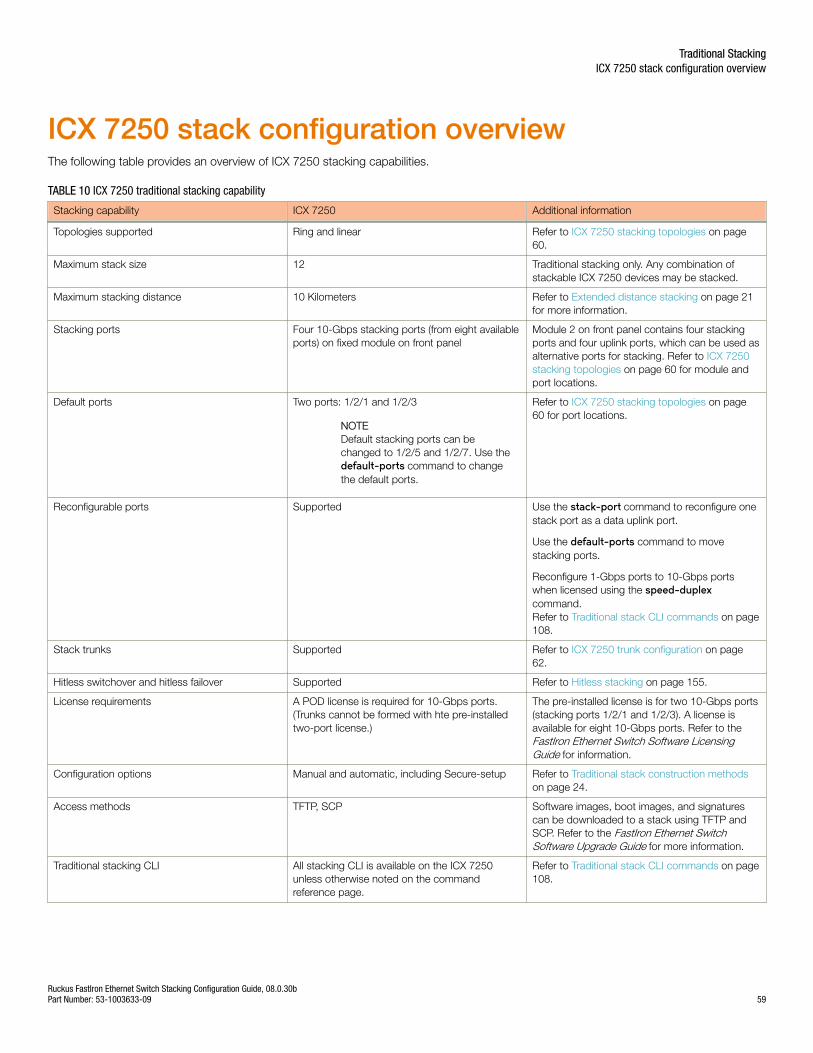
ICX 7250 stack configuration overviewThe following table provides an overview of ICX 7250 stacking capabilities.
TABLE 10 ICX 7250 traditional stacking capability
Stacking capability ICX 7250 Additional information
Topologies supported Ring and linear Refer to ICX 7250 stacking topologies on page60.
Maximum stack size 12 Traditional stacking only. Any combination ofstackable ICX 7250 devices may be stacked.
Maximum stacking distance 10 Kilometers Refer to Extended distance stacking on page 21for more information.
Stacking ports Four 10-Gbps stacking ports (from eight availableports) on fixed module on front panel
Module 2 on front panel contains four stackingports and four uplink ports, which can be used asalternative ports for stacking. Refer to ICX 7250stacking topologies on page 60 for module andport locations.
Default ports Two ports: 1/2/1 and 1/2/3
NOTEDefault stacking ports can bechanged to 1/2/5 and 1/2/7. Use thedefault-ports command to changethe default ports.
Refer to ICX 7250 stacking topologies on page60 for port locations.
Reconfigurable ports Supported Use the stack-port command to reconfigure onestack port as a data uplink port.
Use the default-ports command to movestacking ports.
Reconfigure 1-Gbps ports to 10-Gbps portswhen licensed using the speed-duplexcommand.Refer to Traditional stack CLI commands on page108.
Stack trunks Supported Refer to ICX 7250 trunk configuration on page62.
Hitless switchover and hitless failover Supported Refer to Hitless stacking on page 155.
License requirements A POD license is required for 10-Gbps ports.(Trunks cannot be formed with hte pre-installedtwo-port license.)
The pre-installed license is for two 10-Gbps ports(stacking ports 1/2/1 and 1/2/3). A license isavailable for eight 10-Gbps ports. Refer to theFastIron Ethernet Switch Software LicensingGuide for information.
Configuration options Manual and automatic, including Secure-setup Refer to Traditional stack construction methodson page 24.
Access methods TFTP, SCP Software images, boot images, and signaturescan be downloaded to a stack using TFTP andSCP. Refer to the FastIron Ethernet SwitchSoftware Upgrade Guide for more information.
Traditional stacking CLI All stacking CLI is available on the ICX 7250unless otherwise noted on the commandreference page.
Refer to Traditional stack CLI commands on page108.
Traditional StackingICX 7250 stack configuration overview
Ruckus FastIron Ethernet Switch Stacking Configuration Guide, 08.0.30bPart Number: 53-1003633-09 59
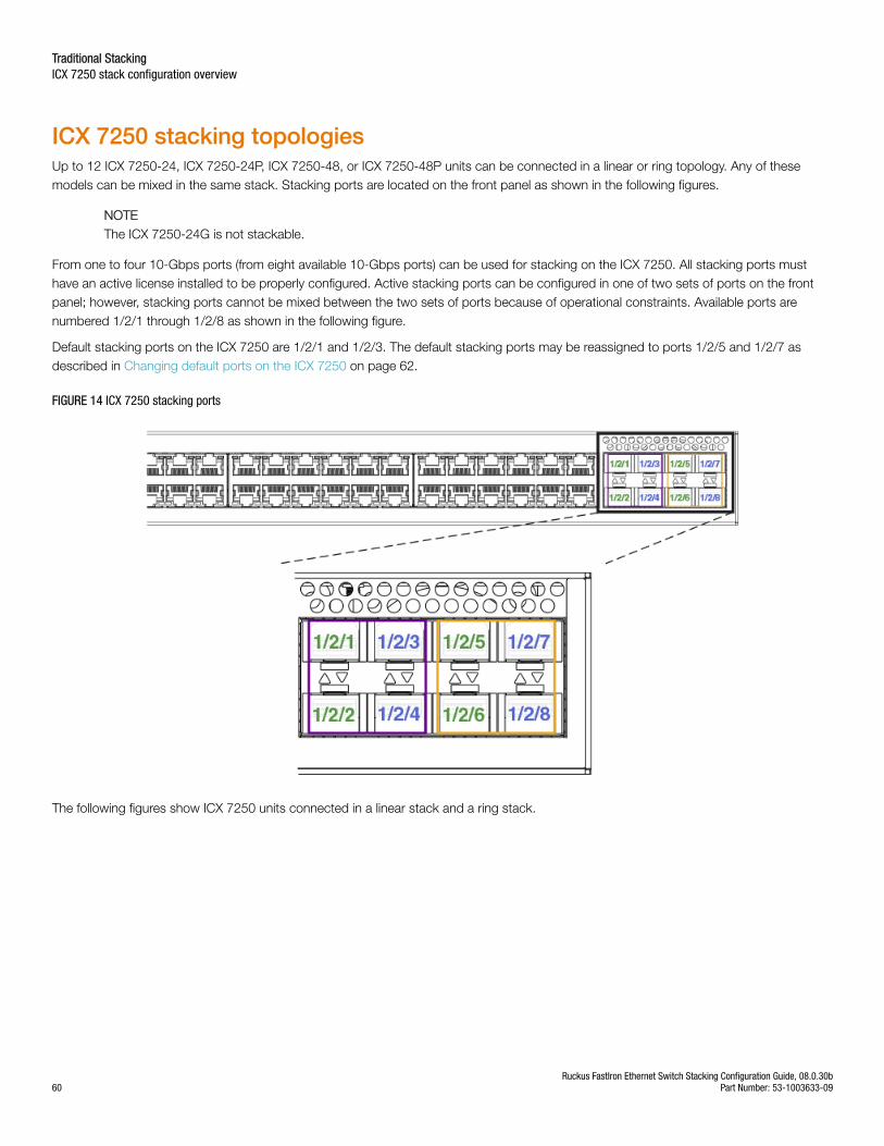
ICX 7250 stacking topologiesUp to 12 ICX 7250-24, ICX 7250-24P, ICX 7250-48, or ICX 7250-48P units can be connected in a linear or ring topology. Any of thesemodels can be mixed in the same stack. Stacking ports are located on the front panel as shown in the following figures.
NOTEThe ICX 7250-24G is not stackable.
From one to four 10-Gbps ports (from eight available 10-Gbps ports) can be used for stacking on the ICX 7250. All stacking ports musthave an active license installed to be properly configured. Active stacking ports can be configured in one of two sets of ports on the frontpanel; however, stacking ports cannot be mixed between the two sets of ports because of operational constraints. Available ports arenumbered 1/2/1 through 1/2/8 as shown in the following figure.
Default stacking ports on the ICX 7250 are 1/2/1 and 1/2/3. The default stacking ports may be reassigned to ports 1/2/5 and 1/2/7 asdescribed in Changing default ports on the ICX 7250 on page 62.
FIGURE 14 ICX 7250 stacking ports
The following figures show ICX 7250 units connected in a linear stack and a ring stack.
Traditional StackingICX 7250 stack configuration overview
Ruckus FastIron Ethernet Switch Stacking Configuration Guide, 08.0.30b60 Part Number: 53-1003633-09
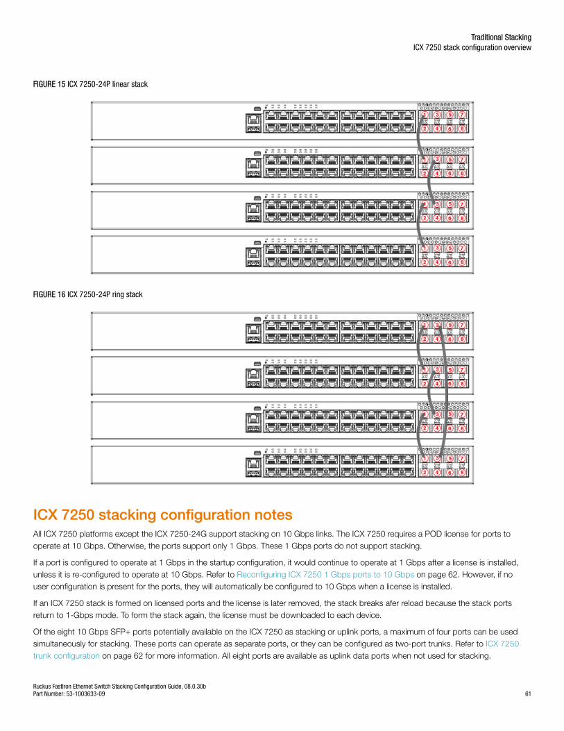
FIGURE 15 ICX 7250-24P linear stack
FIGURE 16 ICX 7250-24P ring stack
ICX 7250 stacking configuration notesAll ICX 7250 platforms except the ICX 7250-24G support stacking on 10 Gbps links. The ICX 7250 requires a POD license for ports tooperate at 10 Gbps. Otherwise, the ports support only 1 Gbps. These 1 Gbps ports do not support stacking.
If a port is configured to operate at 1 Gbps in the startup configuration, it would continue to operate at 1 Gbps after a license is installed,unless it is re-configured to operate at 10 Gbps. Refer to Reconfiguring ICX 7250 1 Gbps ports to 10 Gbps on page 62. However, if nouser configuration is present for the ports, they will automatically be configured to 10 Gbps when a license is installed.
If an ICX 7250 stack is formed on licensed ports and the license is later removed, the stack breaks afer reload because the stack portsreturn to 1-Gbps mode. To form the stack again, the license must be downloaded to each device.
Of the eight 10 Gbps SFP+ ports potentially available on the ICX 7250 as stacking or uplink ports, a maximum of four ports can be usedsimultaneously for stacking. These ports can operate as separate ports, or they can be configured as two-port trunks. Refer to ICX 7250trunk configuration on page 62 for more information. All eight ports are available as uplink data ports when not used for stacking.
Traditional StackingICX 7250 stack configuration overview
Ruckus FastIron Ethernet Switch Stacking Configuration Guide, 08.0.30bPart Number: 53-1003633-09 61
When stacking is configured, all stack ports and trunks must be either in the port range of 1/2/1 through 1/2/4 or in the port range 1/2/5through 1/2/8. Ports 1/2/1 through 1/2/4 require active cables. Ports 1/2/5 through 1/2/8 have re-timers that support both active andpassive cables. Any of these ports can be used for long-distance stacking if appropriate long-distance cables are used. When any units inthe stack are cross-cabled to a unit with stacking on ports 1/2/1 through 1/2/4, active cables should be used throughout the stack.
Reconfiguring ICX 7250 1 Gbps ports to 10 GbpsA port previously configured as 1 Gbps must be reconfigured to operate at 10 Gbps. Stacking on the ICX 7250 is only available on 10 Gbpsports in module 2.
NOTEA license is required for 10 Gbps ports on the ICX 7250. Refer to the FastIron Ethernet Switch Licensing Guide for additionalinformation.
NOTEOnce a 10 Gbps port license is installed, previously unconfigured ports that are covered by the license come up automatically as10 Gbps ports. Ports must then be configured for stacking. Refer to ICX 7250 stacking configuration notes on page 61.
Use the speed-duplex command to reconfigure port speed on a 1 Gbps port.
In the following example, port 1/2/1, a 1 Gbps port, is reconfigured to 10 Gbps.
ICX7250-48P Router# configure terminal ICX7250-48P Router(config)# interface ethernet 1/2/1ICX7250-48P Router(config-if-e10000-1/2/1)# speed-duplex 10g-full
Changing default ports on the ICX 7250Use the default-ports command to change default stacking ports on the ICX 7250.
When a port is not configured as a stacking port or a stacking trunk, it is an available uplink or data port.
When stacking is enabled, the default stacking ports on the ICX 7250 are ports 1/2/1 and 1/2/3. All other ports in module 2 can be used asuplinks. You can change the default stacking ports to 1/2/5 and 1/2/7 as shown in the following example.
device# configure terminaldevice(config)# stack unit 1device(config-unit-1)# default-ports 1/2/5 1/2/7
Return the stacking ports to the original defaults using the no default-ports command as shown in the second example.
device# configure terminaldevice(config)# stack unit 1device(config-unit-1)# no default-ports
ICX 7250 trunk configurationWhen a 10-port license is installed, two stacking trunks containing two ports each can be configured on each ICX 7250 unit.
Stacked trunks can be formed using the following port combinations only:
• Stack ports 1/2/1 and 1/2/2
• Stack ports 1/2/3 and 1/2/4
• Stack ports 1/2/5 and 1/2/6
• Stack ports 1/2/7 and 1/2/8
Traditional StackingICX 7250 stack configuration overview
Ruckus FastIron Ethernet Switch Stacking Configuration Guide, 08.0.30b62 Part Number: 53-1003633-09
The following example designates ports 1/2/1 and 1/2/3 as stacking default ports and then creates two trunks.
ICX7250-24P Router(config)# stack unit 1ICX7250-24P Router(config-unit-1)# default-ports 1/2/1 1/2/3ICX7250-24P Router(config-unit-1)# stack-trunk 1/2/1 to 1/2/2ICX7250-24P Router(config-unit-1)# stack-trunk 1/2/3 to 1/2/4
The following example reassigns ports 1/2/5 and 1/2/7 as stacking default ports and creates two trunks.
ICX7250-24P Router(config)# stack unit 1ICX7250-24P Router(config-unit-1)# default-ports 1/2/5 1/2/7ICX7250-24P Router(config-unit-1)# stack-trunk 1/2/5 to 1/2/6ICX7250-24P Router(config-unit-1)# stack-trunk 1/2/7 to 1/2/8
Creating ICX 7250 trunks in a production environmentThe stack-trunk command cannot be used in a live environment. Instead, use the multi-stack-trunk command to configure both ends of a
trunk simultaneously.
The following example creates a multi-stack-trunk cross-cabled connection between unit 1 and unit 2 on ports 1/2/7 through 1/2/8 andports 2/2/5 through 2/2/6.
ICX7250-48 Router(config-unit-1)# multi-stack-trunk 1/2/7 to 1/2/8 and 2/2/5 to 2/2/6
ICX7250-48 Router(config-unit-1)# show stackT=15d23h18m0.7: alone: standalone, D: dynamic cfg, S: staticID Type Role Mac Address Pri State Comment 1 S ICX7250-48 active cc4e.24b4.23e8 0 local Ready2 S ICX7250-24P member cc4e.24b4.8aa8 0 remote Ready3 S ICX7250-24 standby cc4e.24b4.8cc4 0 remote Ready4 S ICX7250-48P member cc4e.24b4.2d84 0 remote Ready
active standby +---+ +---+ +---+ +---+ =2/5| 1 |2/7==2/5| 2 |2/7--2/5| 4 |2/7--2/5| 3 |2/7= | +---+ +---+ +---+ +---+ | | | |--------------------------------------------------| Standby u3 - protocols ready, can failover or manually switch overCurrent stack management MAC is cc4e.24b4.23e8
The double lines between unit 1 and unit 2 in the previous output indicate a trunk connection with 2 ports form each unit.
ICX 7250 secure-setup exampleUse the stack secure-setup command to form a correctly connected stack automatically. For more information on stack construction, refer
to Traditional stack construction methods on page 24.
In the following example, the stack secure-setup command is used to form a 3-unit ICX 7250 stack in a ring topology with a stacking trunk
connection.
ICX7250-24 Router# stack secure-setup ICX7250-24 Router# Discovering the stack topology...
Current Discovered Topology - RING
Available UPSTREAM unitsHop(s) Id Type Mac Address1 3 ICX7250-24 cc4e.24b4.77402 2 ICX7250-24 cc4e.24b4.75d8
Available DOWNSTREAM unitsHop(s) Id Type Mac Address1 2 ICX7250-24 cc4e.24b4.75d8
Traditional StackingICX 7250 stack configuration overview
Ruckus FastIron Ethernet Switch Stacking Configuration Guide, 08.0.30bPart Number: 53-1003633-09 63
2 3 ICX7250-24 cc4e.24b4.7740
Do you accept the topology (RING) (y/n)?: y
ICX7250-24 Router# stack secure-setup ICX7250-24 Router# Discovering the stack topology...
Current Discovered Topology - RING
Available UPSTREAM unitsHop(s) Id Type Mac Address1 3 ICX7250-24 cc4e.24b4.77402 2 ICX7250-24 cc4e.24b4.75d8
Available DOWNSTREAM unitsHop(s) Id Type Mac Address1 2 ICX7250-24 cc4e.24b4.75d82 3 ICX7250-24 cc4e.24b4.7740
Do you accept the topology (RING) (y/n)?: y
Confirm Stacking Links...
UPSTREAM Unit: Id 3 at 1 hop(s) ICX7250-24 cc4e.24b4.7740
Enter the desired links(1-2)[1]: 2
Selected Topology:Active Id Type Mac Address 1 ICX7250-24 cc4e.24b4.7278
Selected UPSTREAM unitsHop(s) Id Type Mac Address1 3 ICX7250-24 cc4e.24b4.77402 2 ICX7250-24 cc4e.24b4.75d8
Selected DOWNSTREAM unitsHop(s) Id Type Mac Address1 2 ICX7250-24 cc4e.24b4.75d82 3 ICX7250-24 cc4e.24b4.7740
Do you accept the unit id's (y/n)?: y
The following example shows secure-setup of 12 units in a ring stack.
ICX7250-24P Router# stack secure-setup ICX7250-24P Router# Discovering the stack topology...
Available UPSTREAM unitsHop(s) Id Type Mac Address1 2 ICX7250-24P cc4e.24b4.7bc02 3 ICX7250-24P cc4e.24b4.7efc3 4 ICX7250-24 cc4e.24b4.86704 5 ICX7250-24 cc4e.24b4.84c05 6 ICX7250-24 cc4e.24b4.80646 7 ICX7250-24 cc4e.24b4.83a07 8 ICX7250-48 cc4e.24b4.25148 9 ICX7250-48 cc4e.24b4.28209 10 ICX7250-24 cc4e.24b4.898810 11 ICX7250-48P cc4e.24b4.2f2811 12 ICX7250-48P cc4e.24b4.2eb0
No new core units found...
Selected Topology:Active Id Type Mac Address 1 ICX7250-24P cc4e.24b4.7c50
Selected UPSTREAM unitsHop(s) Id Type Mac Address
Traditional StackingICX 7250 stack configuration overview
Ruckus FastIron Ethernet Switch Stacking Configuration Guide, 08.0.30b64 Part Number: 53-1003633-09
1 2 ICX7250-24P cc4e.24b4.7bc02 3 ICX7250-24P cc4e.24b4.7efc3 4 ICX7250-24 cc4e.24b4.86704 5 ICX7250-24 cc4e.24b4.84c05 6 ICX7250-24 cc4e.24b4.80646 7 ICX7250-24 cc4e.24b4.83a07 8 ICX7250-48 cc4e.24b4.25148 9 ICX7250-48 cc4e.24b4.28209 10 ICX7250-24 cc4e.24b4.898810 11 ICX7250-48P cc4e.24b4.2f2811 12 ICX7250-48P cc4e.24b4.2eb0
Do you accept the unit id's (y/n)?: y
Displaying basic information for an ICX 7250 stackEnter the show stack command at the device level to display general information about the stack, including unit IDs, device type, role, MAC
address, priority, status, and connections.
The following show stack command output display details for the 3-unit stack and the 12-unit stack formed in the previous secure-setup
examples.
ICX7250-24 Router# show stack T=15h50m28.8: alone: standalone, D: dynamic cfg, S: staticID Type Role Mac Address Pri State Comment 1 S ICX7250-24 active cc4e.24b4.7278 128 local Ready2 S ICX7250-24 standby cc4e.24b4.75d8 128 remote Ready3 S ICX7250-24 member cc4e.24b4.7740 0 remote Ready
active standby +---+ +---+ +---+ | 1 |2/3--2/3| 2 |2/1--2/3| 3 | +---+ +---+ +---+ Standby u2 - protocols ready, can failover or manually switch overCurrent stack management MAC is cc4e.24b4.7278
The following show stack command output displays information for the 12-unit stack.
ICX7250-24P Router# show stackT=8h40m5.7: alone: standalone, D: dynamic cfg, S: static, A=10, B=11, C=12ID Type Role Mac Address Pri State Comment 1 S ICX7250-24P active cc4e.24b4.7c50 200 local Ready2 S ICX7250-24P member cc4e.24b4.7bc0 128 remote Ready3 S ICX7250-24P member cc4e.24b4.7efc 0 remote Ready4 S ICX7250-24 member cc4e.24b4.8670 0 remote Ready5 S ICX7250-24 member cc4e.24b4.84c0 0 remote Ready6 S ICX7250-24 member cc4e.24b4.8064 0 remote Ready7 S ICX7250-24 member cc4e.24b4.83a0 0 remote Ready8 S ICX7250-48 member cc4e.24b4.2514 0 remote Ready9 S ICX7250-48 member cc4e.24b4.2820 0 remote Ready10 S ICX7250-24 member cc4e.24b4.8988 0 remote Ready11 S ICX7250-48P member cc4e.24b4.2f28 0 remote Ready12 S ICX7250-48P standby cc4e.24b4.2eb0 200 remote Ready
standby +---+ +---+ +---+ +---+ +---+ +---+ 2/7| C |2/5==2/5| B |2/7==2/5| A |2/7==2/1| 9 |2/3==2/3| 8 |2/1==2/1| 7 |2/3= +---+ +---+ +---+ +---+ +---+ +---+ | | active | +---+ +---+ +---+ +---+ +---+ +---+ | -2/7| 1 |2/5==2/7| 2 |2/5==2/3| 3 |2/1==2/3| 4 |2/1==2/1| 5 |2/3==2/3| 6 |2/1= +---+ +---+ +---+ +---+ +---+ +---+ Standby u12 - protocols ready, can failover or manually switch overCurrent stack management MAC is cc4e.24b4.7c50
Traditional StackingICX 7250 stack configuration overview
Ruckus FastIron Ethernet Switch Stacking Configuration Guide, 08.0.30bPart Number: 53-1003633-09 65
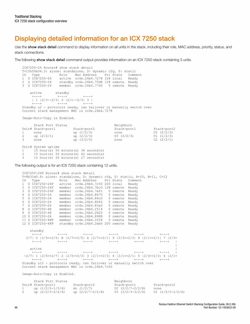
Displaying detailed information for an ICX 7250 stackUse the show stack detail command to display information on all units in the stack, including their role, MAC address, priority, status, and
stack connections.
The following show stack detail command output provides information on an ICX 7250 stack containing 3 units.
ICX7250-24 Router# show stack detail T=15h50m34.3: alone: standalone, D: dynamic cfg, S: staticID Type Role Mac Address Pri State Comment 1 S ICX7250-24 active cc4e.24b4.7278 128 local Ready2 S ICX7250-24 standby cc4e.24b4.75d8 128 remote Ready3 S ICX7250-24 member cc4e.24b4.7740 0 remote Ready
active standby +---+ +---+ +---+ | 1 |2/3--2/3| 2 |2/1--2/3| 3 | +---+ +---+ +---+ Standby u2 - protocols ready, can failover or manually switch overCurrent stack management MAC is cc4e.24b4.7278
Image-Auto-Copy is Enabled.
Stack Port Status Neighbors Unit# Stack-port1 Stack-port2 Stack-port1 Stack-port2 1 none up (1/2/3) none U2 (2/2/3) 2 up (2/2/1) up (2/2/3) U3 (3/2/3) U1 (1/2/3) 3 none up (3/2/3) none U2 (2/2/1)
Unit# System uptime1 15 hour(s) 50 minute(s) 34 second(s) 2 15 hour(s) 50 minute(s) 42 second(s) 3 15 hour(s) 50 minute(s) 27 second(s)
The following output is for an ICX 7250 stack containing 12 units.
ICX7250-24P Router# show stack detail T=8h31m0.8: alone: standalone, D: dynamic cfg, S: static, A=10, B=11, C=12ID Type Role Mac Address Pri State Comment 1 S ICX7250-24P active cc4e.24b4.7c50 200 local Ready2 S ICX7250-24P member cc4e.24b4.7bc0 128 remote Ready3 S ICX7250-24P member cc4e.24b4.7efc 0 remote Ready4 S ICX7250-24 member cc4e.24b4.8670 0 remote Ready5 S ICX7250-24 member cc4e.24b4.84c0 0 remote Ready6 S ICX7250-24 member cc4e.24b4.8064 0 remote Ready7 S ICX7250-24 member cc4e.24b4.83a0 0 remote Ready8 S ICX7250-48 member cc4e.24b4.2514 0 remote Ready9 S ICX7250-48 member cc4e.24b4.2820 0 remote Ready10 S ICX7250-24 member cc4e.24b4.8988 0 remote Ready11 S ICX7250-48P member cc4e.24b4.2f28 0 remote Ready12 S ICX7250-48P standby cc4e.24b4.2eb0 200 remote Ready
standby +---+ +---+ +---+ +---+ +---+ +---+ 2/7| C |2/5==2/5| B |2/7==2/5| A |2/7==2/1| 9 |2/3==2/3| 8 |2/1==2/1| 7 |2/3= +---+ +---+ +---+ +---+ +---+ +---+ | | active | +---+ +---+ +---+ +---+ +---+ +---+ | -2/7| 1 |2/5==2/7| 2 |2/5==2/3| 3 |2/1==2/3| 4 |2/1==2/1| 5 |2/3==2/3| 6 |2/1= +---+ +---+ +---+ +---+ +---+ +---+ Standby u12 - protocols ready, can failover or manually switch overCurrent stack management MAC is cc4e.24b4.7c50
Image-Auto-Copy is Enabled.
Stack Port Status Neighbors Unit# Stack-port1 Stack-port2 Stack-port1 Stack-port2 1 up (1/2/5-1/2/6) dn (1/2/7) U2 (2/2/7-2/2/8) none 2 up (2/2/5-2/2/6) up (2/2/7-2/2/8) U3 (3/2/3-3/2/4) U1 (1/2/5-1/2/6)
Traditional StackingICX 7250 stack configuration overview
Ruckus FastIron Ethernet Switch Stacking Configuration Guide, 08.0.30b66 Part Number: 53-1003633-09
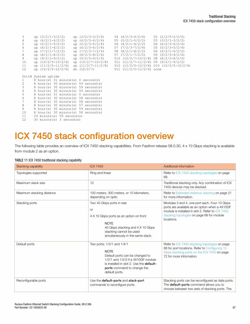
3 up (3/2/1-3/2/2) up (3/2/3-3/2/4) U4 (4/2/3-4/2/4) U2 (2/2/5-2/2/6) 4 up (4/2/1-4/2/2) up (4/2/3-4/2/4) U5 (5/2/1-5/2/2) U3 (3/2/1-3/2/2) 5 up (5/2/1-5/2/2) up (5/2/3-5/2/4) U4 (4/2/1-4/2/2) U6 (6/2/3-6/2/4) 6 up (6/2/1-6/2/2) up (6/2/3-6/2/4) U7 (7/2/3-7/2/4) U5 (5/2/3-5/2/4) 7 up (7/2/1-7/2/2) up (7/2/3-7/2/4) U8 (8/2/1-8/2/2) U6 (6/2/1-6/2/2) 8 up (8/2/1-8/2/2) up (8/2/3-8/2/4) U7 (7/2/1-7/2/2) U9 (9/2/3-9/2/4) 9 up (9/2/1-9/2/2) up (9/2/3-9/2/4) U10 (10/2/7-10/2/8) U8 (8/2/3-8/2/4) 10 up (10/2/5-10/2/6) up (10/2/7-10/2/8) U11 (11/2/7-11/2/8) U9 (9/2/1-9/2/2) 11 up (11/2/5-11/2/6) up (11/2/7-11/2/8) U12 (12/2/5-12/2/6) U10 (10/2/5-10/2/6)12 up (12/2/5-12/2/6) dn (12/2/7) U11 (11/2/5-11/2/6) none
Unit# System uptime1 8 hour(s) 31 minute(s) 0 second(s) 2 8 hour(s) 30 minute(s) 59 second(s) 3 8 hour(s) 30 minute(s) 59 second(s) 4 8 hour(s) 30 minute(s) 59 second(s) 5 8 hour(s) 31 minute(s) 0 second(s) 6 8 hour(s) 30 minute(s) 58 second(s) 7 8 hour(s) 30 minute(s) 58 second(s) 8 8 hour(s) 30 minute(s) 57 second(s) 9 8 hour(s) 30 minute(s) 59 second(s) 10 8 hour(s) 30 minute(s) 58 second(s) 11 29 minute(s) 59 second(s) 12 30 minute(s) 3 second(s)
ICX 7450 stack configuration overviewThe following table provides an overview of ICX 7450 stacking capabilities. From FastIron release 08.0.30, 4 x 10 Gbps stacking is availablefrom module 2 as an option.
TABLE 11 ICX 7450 traditional stacking capability
Stacking capability ICX 7450 Additional information
Topologies supported Ring and linear Refer to ICX 7450 stacking topologies on page68.
Maximum stack size 12 Traditional stacking only. Any combination of ICX7450 devices may be stacked.
Maximum stacking distance 100 meters, 300 meters, or 10 kilometers,depending on optic
Refer to Extended distance stacking on page 21for more information.
Stacking ports Two 40 Gbps ports in rear
or
4 X 10 Gbps ports as an option on front
NOTE40 Gbps stacking and 4 X 10 Gbpsstacking cannot be usedsimultaneously in the same stack.
Modules 3 and 4, one port each. Four 10 Gbpsports are available as an option when a 4X10GFmodule is installed in slot 2. Refer to ICX 7450stacking topologies on page 68 for modulelocations.
Default ports Two ports: 1/3/1 and 1/4/1
NOTEDefault ports can be changed to1/2/1 and 1/2/3 if a 4X10GF moduleis installed in slot 2. Use the default-ports command to change thedefault ports.
Refer to ICX 7450 stacking topologies on page68 for port locations. Refer to Configuring 10Gbps stacking ports on the ICX 7450 on page72 for more information.
Reconfigurable ports Use the default-ports and stack-portcommands to reconfigure ports.
Stacking ports can be reconfigured as data ports.The default-ports command allows you tochoose between two sets of stacking ports. The
Traditional StackingICX 7450 stack configuration overview
Ruckus FastIron Ethernet Switch Stacking Configuration Guide, 08.0.30bPart Number: 53-1003633-09 67
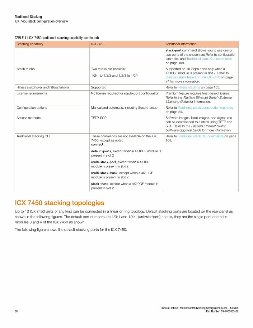
TABLE 11 ICX 7450 traditional stacking capability (continued)
Stacking capability ICX 7450 Additional information
stack-port command allows you to use one ortwo ports of the chosen set.Refer to configurationexamples and Traditional stack CLI commandson page 108.
Stack trunks Two trunks are possible:
1/2/1 to 1/2/2 and 1/2/3 to 1/2/4
Supported on 10 Gbps ports only when a4X10GF module is present in slot 2. Refer to Creating stack trunks on the ICX 7450 on page74 for more information.
Hitless switchover and hitless failover Supported Refer to Hitless stacking on page 155.
License requirements No license required for stack-port configuration Premium feature requires trust-based license.Refer to the FastIron Ethernet Switch SoftwareLicensing Guide for information.
Configuration options Manual and automatic, including Secure-setup Refer to Traditional stack construction methodson page 24.
Access methods TFTP, SCP Software images, boot images, and signaturescan be downloaded to a stack using TFTP andSCP. Refer to the FastIron Ethernet SwitchSoftware Upgrade Guide for more information.
Traditional stacking CLI These commands are not available on the ICX7450, except as noted:connect
default-ports, except when a 4X10GF module ispresent in slot 2
multi-stack-port, except when a 4X10GFmodule is present in slot 2
multi-stack-trunk, except when a 4X10GFmodule is present in slot 2
stack-trunk, except when a 4X10GF module ispresent in slot 2
Refer to Traditional stack CLI commands on page108.
ICX 7450 stacking topologiesUp to 12 ICX 7450 units of any kind can be connected in a linear or ring topology. Default stacking ports are located on the rear panel asshown in the following figures. The default port numbers are 1/3/1 and 1/4/1 (unit/slot/port); that is, they are the single port located inmodules 3 and 4 of the ICX 7450 as shown.
The following figure shows the default stacking ports for the ICX 7450.
Traditional StackingICX 7450 stack configuration overview
Ruckus FastIron Ethernet Switch Stacking Configuration Guide, 08.0.30b68 Part Number: 53-1003633-09
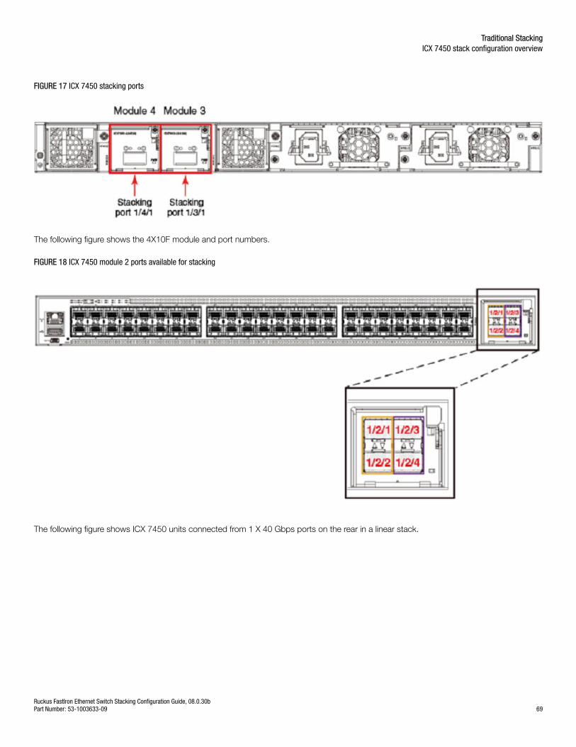
FIGURE 17 ICX 7450 stacking ports
The following figure shows the 4X10F module and port numbers.
FIGURE 18 ICX 7450 module 2 ports available for stacking
The following figure shows ICX 7450 units connected from 1 X 40 Gbps ports on the rear in a linear stack.
Traditional StackingICX 7450 stack configuration overview
Ruckus FastIron Ethernet Switch Stacking Configuration Guide, 08.0.30bPart Number: 53-1003633-09 69
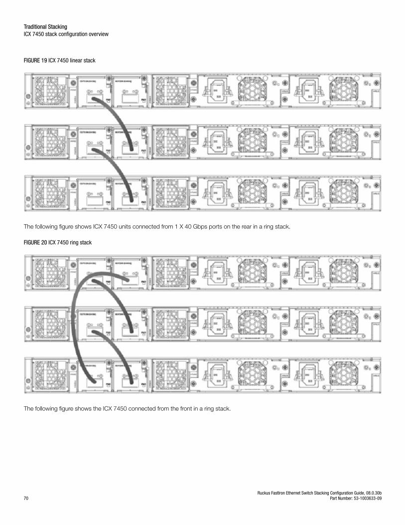
FIGURE 19 ICX 7450 linear stack
The following figure shows ICX 7450 units connected from 1 X 40 Gbps ports on the rear in a ring stack.
FIGURE 20 ICX 7450 ring stack
The following figure shows the ICX 7450 connected from the front in a ring stack.
Traditional StackingICX 7450 stack configuration overview
Ruckus FastIron Ethernet Switch Stacking Configuration Guide, 08.0.30b70 Part Number: 53-1003633-09
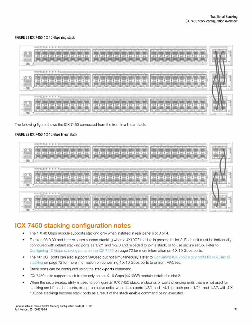
FIGURE 21 ICX 7450 4 X 10 Gbps ring stack
The following figure shows the ICX 7450 connected from the front in a linear stack.
FIGURE 22 ICX 7450 4 X 10 Gbps linear stack
ICX 7450 stacking configuration notes• The 1 X 40 Gbps module supports stacking only when installed in rear panel slot 3 or 4.
• FastIron 08.0.30 and later releases support stacking when a 4X10GF module is present in slot 2. Each unit must be individuallyconfigured with default stacking ports as 1/2/1 and 1/2/3 and reloaded to join a stack, or to use secure setup. Refer to Configuring 10 Gbps stacking ports on the ICX 7450 on page 72 for more information on 4 X 10 Gbps ports.
• The 4X10GF ports can also support MACsec but not simultaneously. Refer to Converting ICX 7450 slot 2 ports for MACsec orstacking on page 72 for more information on converting 4 X 10 Gbps ports to or from MACsec.
• Stack ports can be configured using the stack-ports command.
• ICX 7450 units support stack trunks only on a 4 X 10 Gbps (4X10GF) module installed in slot 2.
• When the secure-setup utility is used to configure an ICX 7450 stack, endpoints or ports of ending units that are not used forstacking are left as data ports, except on active units, where both ports 1/3/1 and 1/4/1 (or both ports 1/2/1 and 1/2/3 with 4 X10Gbps stacking) become stack ports as a result of the stack enable command being executed.
Traditional StackingICX 7450 stack configuration overview
Ruckus FastIron Ethernet Switch Stacking Configuration Guide, 08.0.30bPart Number: 53-1003633-09 71
Configuring 10 Gbps stacking ports on the ICX 7450By default, the ICX 7450 uses 40 Gbps ports in slots 3 and 4 as stacking ports. When a 4X10GF module is installed in slot 2 on the frontpanel of an ICX 7450, 10 Gbps stacking can be configured.
NOTEStacking and MACsec cannot be configured on these 10 Gbps ports at the same time. Refer to Converting ICX 7450 slot 2 portsfor MACsec or stacking on page 72 for more information.
To configure stacking on 10 Gbps ports in a 4X10GF module installed in slot 2, change the default stacking ports as shown in the followingexample.
ICX7450-48F Router# configure terminalICX7450-48F Router(config)# stack unit 1ICX7450-48F Router(config-unit-1)# default-ports 1/2/1 1/2/3Reload required. Please write memory and then reload or power cycle.ICX7450-48F Router(config-unit-1)# write memoryWrite startup-config done.ICX7450-48F Router(config-unit-1)# endICX7450-48F Router# reload
When the default-ports command is issued, the following error messages may be returned.
Error - Module <module_number> is not a 4x10GF module.
Error- Module <module_number> is not present.
Error- Invalid default ports "<port_1> and <port_2>" on ICX7450.
Once the default stacking ports are configured, the configuration is written to memory, and the unit is reloaded, it is ready to join an existingstack or to be configured for stacking using secure-setup or manual stack construction.
NOTEAutomatic stack configuration (described in "Traditional stack construction methods") and unit replacement features do not workwith ICX 7450 4X10GF stacking. For unit replacement to work, you must use the same model as the one you are replacing, andthe new unit must be a clean unit. Refer to Brocade traditional stacking terminology on page 19 for a definition of clean unit.Suppose the stack is using a 4X10GF module installed in slot 2, and you want to replace a unit. To configure the new unit with thesame configuration, you must configure the default ports, write memory, and reload. As a result, the new unit is no longer a cleanunit because it has startup configuration flash, and the unit replacement feature will not automatically integrate this unit into astack. You must use secure-setup or the manual stack construction method described in Traditional stack construction methodson page 24 to add the new unit to the stack. If you use the manual stack construction method, you must configure the stacksuggested-id with the same ID in the replacement unit before you enable the stack.
Converting ICX 7450 slot 2 ports for MACsec or stackingWhen a 4x10GF module is installed in slot 2 of the ICX 7450, it is enabled for MACsec even if the ports have not been configured. To usethese ports for stacking, you must reconfigure them.
NOTEThe ICX 7450 can support 4 X 10 Gbps stacking from slot 2 or 40 Gbps stacking from rear ports; however, it cannot support bothat the same time.
By default, if a 4X10GF module is present in slot 2, it is enabled for MACsec. No reload or power-cycle is required to enable or disableMACsec on slot 2 interfaces. However, to use the slot 2 ports for stacking, the default ports must be changed, and the unit must bereloaded as described in Configuring 10 Gbps stacking ports on the ICX 7450 on page 72.
Traditional StackingICX 7450 stack configuration overview
Ruckus FastIron Ethernet Switch Stacking Configuration Guide, 08.0.30b72 Part Number: 53-1003633-09
If the 4X10GF module in slot 2 is programmed for stacking during bootup, MACsec cannot be configured on the ports until the stackingdefault ports have been changed to rear panel ports and the unit has been reloaded or turned off and on.
MACsec and stacking cannot be configured at the same time on slot 2 interfaces. However, 4X10GF modules installed in slots 3 and 4 onthe rear panel of the ICX 7450 can support MACsec at the same time that slot 2 is configured for 4X10GF stacking.
The following error message is displayed when MACsec is configured on slot 2 and you try to set the stacking default ports to slot 2.
Error - Please remove MACsec configuration from port <port_id> before using 4x10GF for stacking
If you try to use the stack enable command, the command is blocked, and the following message is displayed.
Error - Please remove MACsec configuration from port <port_id> before using 4x10GF for stacking
The following error message is displayed if stacking is configured on these ports and you enter the enable-mka ethernet command for any
of the ports.
Error: MACsec is not allowed when 4x10GF module is used for stacking.Please use "default-ports" command to change the default stacking ports
The following example reconfigures stacking ports on slot 2 for use as MACsec ports.
ICX7450-48 Router#ICX7450-48 Router# show running-configCurrent configuration:!ver 08.0.30q070T213!stack unit 1 module 1 icx7450-48-port-management-module module 2 icx7400-xgf-4port-40g-module module 3 icx7400-qsfp-1port-40g-module module 4 icx7400-qsfp-1port-40g-module default-ports 1/2/1 1/2/3!!!!!!!!ip dns domain-list englab.brocade.comip dns server-address 10.31.2.10!!!--More--, next page: Space, next line: Return key, quit: Control-c^CICX7450-48 Router#ICX7450-48 Router#ICX7450-48 Router#ICX7450-48 Router# configure terminalICX7450-48 Router(config)#ICX7450-48 Router(config)# dot1x-mkaICX7450-48 Router(config-dot1x-mka)# enable-mka ethernet 1/2/1 <cr>ICX7450-48 Router(config-dot1x-mka)# enable-mka ethernet 1/2/1 Error: MACsec is not allowed when 4x10GF module is used for stacking.Please use "default-ports" command to change the default stacking portsICX7450-48 Router(config-dot1x-mka)# exitICX7450-48 Router(config)# stack unit 1 ICX7450-48 Router(config-unit-1)#ICX7450-48 Router(config-unit-1)# default-ports 1/3/1 1/4/11/3/1 and 1/4/1 are default, so they won't show up in "show run"ICX7450-48 Router(config-unit-1)# show running-configCurrent configuration:!ver 08.0.30q070T213
Traditional StackingICX 7450 stack configuration overview
Ruckus FastIron Ethernet Switch Stacking Configuration Guide, 08.0.30bPart Number: 53-1003633-09 73
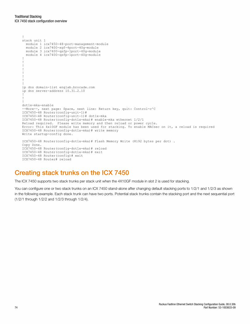
!stack unit 1 module 1 icx7450-48-port-management-module module 2 icx7400-xgf-4port-40g-module module 3 icx7400-qsfp-1port-40g-module module 4 icx7400-qsfp-1port-40g-module!!!!!!!!ip dns domain-list englab.brocade.comip dns server-address 10.31.2.10!!!dot1x-mka-enable--More--, next page: Space, next line: Return key, quit: Control-c^CICX7450-48 Router(config-unit-1)#ICX7450-48 Router(config-unit-1)# dot1x-mka ICX7450-48 Router(config-dot1x-mka)# enable-mka ethernet 1/2/1 Reload required. Please write memory and then reload or power cycle.Error: This 4x10GF module has been used for stacking. To enable MACsec on it, a reload is requiredICX7450-48 Router(config-dot1x-mka)# write memoryWrite startup-config done.
ICX7450-48 Router(config-dot1x-mka)# Flash Memory Write (8192 bytes per dot) .Copy Done.ICX7450-48 Router(config-dot1x-mka)# reloadICX7450-48 Router(config-dot1x-mka)# exit ICX7450-48 Router(config)# exitICX7450-48 Router# reload
Creating stack trunks on the ICX 7450The ICX 7450 supports two stack trunks per stack unit when the 4X10GF module in slot 2 is used for stacking.
You can configure one or two stack trunks on an ICX 7450 stand-alone after changing default stacking ports to 1/2/1 and 1/2/3 as shownin the following example. Each stack trunk can have two ports. Potential stack trunks contain the stacking port and the next sequential port(1/2/1 through 1/2/2 and 1/2/3 through 1/2/4).
Traditional StackingICX 7450 stack configuration overview
Ruckus FastIron Ethernet Switch Stacking Configuration Guide, 08.0.30b74 Part Number: 53-1003633-09
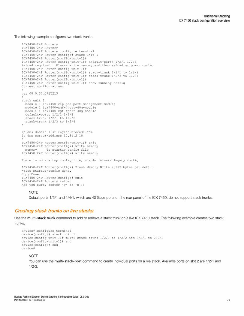
The following example configures two stack trunks.
ICX7450-24P Router#ICX7450-24P Router#ICX7450-24P Router# configure terminal ICX7450-24P Router(config)# stack unit 1ICX7450-24P Router(config-unit-1)#ICX7450-24P Router(config-unit-1)# default-ports 1/2/1 1/2/3Reload required. Please write memory and then reload or power cycle.ICX7450-24P Router(config-unit-1)#ICX7450-24P Router(config-unit-1)# stack-trunk 1/2/1 to 1/2/2ICX7450-24P Router(config-unit-1)# stack-trunk 1/2/3 to 1/2/4ICX7450-24P Router(config-unit-1)#ICX7450-24P Router(config-unit-1)# show running-configCurrent configuration:!ver 08.0.30q071T213!stack unit 1 module 1 icx7450-24p-poe-port-management-module module 2 icx7400-xgf-4port-40g-module module 4 icx7400-xgf-4port-40g-module default-ports 1/2/1 1/2/3 stack-trunk 1/2/1 to 1/2/2 stack-trunk 1/2/3 to 1/2/4!
ip dns domain-list englab.brocade.comip dns server-address 10.31.2.10!ICX7450-24P Router(config-unit-1)# exitICX7450-24P Router(config)# write memory memory To startup config fileICX7450-24P Router(config)# write memory
There is no startup config file, unable to save legacy config
ICX7450-24P Router(config)# Flash Memory Write (8192 bytes per dot) .Write startup-config done.Copy Done.ICX7450-24P Router(config)# exitICX7450-24P Router# reloadAre you sure? (enter 'y' or 'n'):
NOTEDefault ports 1/3/1 and 1/4/1, which are 40 Gbps ports on the rear panel of the ICX 7450, do not support stack trunks.
Creating stack trunks on live stacksUse the multi-stack trunk command to add or remove a stack trunk on a live ICX 7450 stack. The following example creates two stack
trunks.
device# configure terminaldevice(config)# stack unit 1device(config-unit-1)# multi-stack-trunk 1/2/1 to 1/2/2 and 2/2/1 to 2/2/2device(config-unit-1)# enddevice(config)# enddevice#
NOTEYou can use the multi-stack-port command to create individual ports on a live stack. Available ports on slot 2 are 1/2/1 and
1/2/3.
Traditional StackingICX 7450 stack configuration overview
Ruckus FastIron Ethernet Switch Stacking Configuration Guide, 08.0.30bPart Number: 53-1003633-09 75
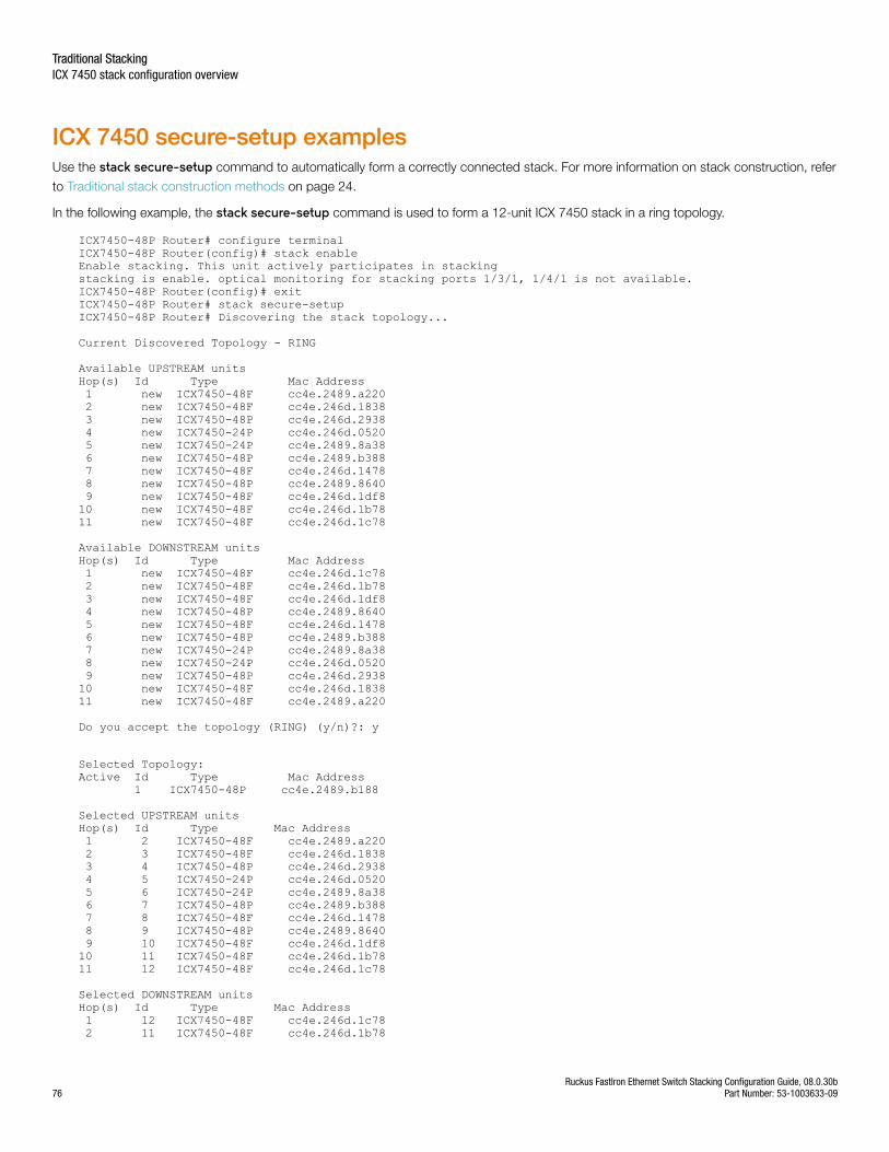
ICX 7450 secure-setup examplesUse the stack secure-setup command to automatically form a correctly connected stack. For more information on stack construction, refer
to Traditional stack construction methods on page 24.
In the following example, the stack secure-setup command is used to form a 12-unit ICX 7450 stack in a ring topology.
ICX7450-48P Router# configure terminalICX7450-48P Router(config)# stack enableEnable stacking. This unit actively participates in stackingstacking is enable. optical monitoring for stacking ports 1/3/1, 1/4/1 is not available.ICX7450-48P Router(config)# exitICX7450-48P Router# stack secure-setupICX7450-48P Router# Discovering the stack topology...
Current Discovered Topology - RING
Available UPSTREAM unitsHop(s) Id Type Mac Address 1 new ICX7450-48F cc4e.2489.a220 2 new ICX7450-48F cc4e.246d.1838 3 new ICX7450-48P cc4e.246d.2938 4 new ICX7450-24P cc4e.246d.0520 5 new ICX7450-24P cc4e.2489.8a38 6 new ICX7450-48P cc4e.2489.b388 7 new ICX7450-48F cc4e.246d.1478 8 new ICX7450-48P cc4e.2489.8640 9 new ICX7450-48F cc4e.246d.1df810 new ICX7450-48F cc4e.246d.1b7811 new ICX7450-48F cc4e.246d.1c78
Available DOWNSTREAM unitsHop(s) Id Type Mac Address 1 new ICX7450-48F cc4e.246d.1c78 2 new ICX7450-48F cc4e.246d.1b78 3 new ICX7450-48F cc4e.246d.1df8 4 new ICX7450-48P cc4e.2489.8640 5 new ICX7450-48F cc4e.246d.1478 6 new ICX7450-48P cc4e.2489.b388 7 new ICX7450-24P cc4e.2489.8a38 8 new ICX7450-24P cc4e.246d.0520 9 new ICX7450-48P cc4e.246d.293810 new ICX7450-48F cc4e.246d.183811 new ICX7450-48F cc4e.2489.a220
Do you accept the topology (RING) (y/n)?: y
Selected Topology:Active Id Type Mac Address 1 ICX7450-48P cc4e.2489.b188
Selected UPSTREAM unitsHop(s) Id Type Mac Address 1 2 ICX7450-48F cc4e.2489.a220 2 3 ICX7450-48F cc4e.246d.1838 3 4 ICX7450-48P cc4e.246d.2938 4 5 ICX7450-24P cc4e.246d.0520 5 6 ICX7450-24P cc4e.2489.8a38 6 7 ICX7450-48P cc4e.2489.b388 7 8 ICX7450-48F cc4e.246d.1478 8 9 ICX7450-48P cc4e.2489.8640 9 10 ICX7450-48F cc4e.246d.1df810 11 ICX7450-48F cc4e.246d.1b7811 12 ICX7450-48F cc4e.246d.1c78
Selected DOWNSTREAM unitsHop(s) Id Type Mac Address 1 12 ICX7450-48F cc4e.246d.1c78 2 11 ICX7450-48F cc4e.246d.1b78
Traditional StackingICX 7450 stack configuration overview
Ruckus FastIron Ethernet Switch Stacking Configuration Guide, 08.0.30b76 Part Number: 53-1003633-09
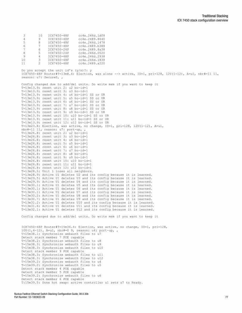
3 10 ICX7450-48F cc4e.246d.1df8 4 9 ICX7450-48P cc4e.2489.8640 5 8 ICX7450-48F cc4e.246d.1478 6 7 ICX7450-48P cc4e.2489.b388 7 6 ICX7450-24P cc4e.2489.8a38 8 5 ICX7450-24P cc4e.246d.0520 9 4 ICX7450-48P cc4e.246d.293810 3 ICX7450-48F cc4e.246d.183811 2 ICX7450-48F cc4e.2489.a220
Do you accept the unit id's (y/n)?: yICX7450-48P Router#T=13m8.4: Election, was alone --> active, ID=1, pri=128, 12U(1-12), A=u1, nbr#=11 11, reason: u7: SecureS, ,
Config changed due to add/del units. Do write mem if you want to keep itT=13m13.9: reset unit 2: u2 bo-id=1T=13m13.9: reset unit 3: u3 bo-id=1T=13m13.9: reset unit 4: u4 bo-id=1 SS or URT=13m13.9: reset unit 5: u5 bo-id=1 SS or URT=13m13.9: reset unit 6: u6 bo-id=1 SS or URT=13m13.9: reset unit 7: u7 bo-id=1 SS or URT=13m13.9: reset unit 8: u8 bo-id=1 SS or URT=13m13.9: reset unit 9: u9 bo-id=1 SS or URT=13m13.9: reset unit 10: u10 bo-id=1 SS or URT=13m13.9: reset unit 11: u11 bo-id=1 SS or URT=13m13.9: reset unit 12: u12 bo-id=1 SS or URT=13m23.8: Election, was active, no change, ID=1, pri=128, 12U(1-12), A=u1, nbr#=11 11, reason: u7: port-up, , T=13m26.8: reset unit 2: u2 bo-id=1T=13m26.8: reset unit 3: u3 bo-id=1T=13m26.8: reset unit 4: u4 bo-id=1T=13m26.8: reset unit 5: u5 bo-id=1T=13m26.8: reset unit 6: u6 bo-id=1T=13m26.8: reset unit 7: u7 bo-id=1T=13m26.8: reset unit 8: u8 bo-id=1T=13m26.8: reset unit 9: u9 bo-id=1T=13m26.8: reset unit 10: u10 bo-id=1T=13m26.8: reset unit 11: u11 bo-id=1T=13m26.8: reset unit 12: u12 bo-id=1T=13m28.5: Unit 1 loses all neighbors.T=13m28.9: Active U1 deletes U2 and its config because it is learned.T=13m29.5: Active U1 deletes U3 and its config because it is learned.T=13m29.9: Active U1 deletes U4 and its config because it is learned.T=13m30.1: Active U1 deletes U5 and its config because it is learned.T=13m30.1: Active U1 deletes U6 and its config because it is learned.T=13m30.1: Active U1 deletes U7 and its config because it is learned.T=13m30.2: Active U1 deletes U8 and its config because it is learned.T=13m30.7: Active U1 deletes U9 and its config because it is learned.T=13m31.2: Active U1 deletes U10 and its config because it is learned.T=13m31.6: Active U1 deletes U11 and its config because it is learned.T=13m32.1: Active U1 deletes U12 and its config because it is learned.
Config changed due to add/del units. Do write mem if you want to keep it
ICX7450-48P Router#T=15m36.4: Election, was active, no change, ID=1, pri=128, 10U(1,4-12), A=u1, nbr#=0 9, reason: u4: port-up, , T=15m38.1: Synchronize webauth files to u7Detect stack member 7 POE capableT=15m38.2: Synchronize webauth files to u8T=15m38.3: Synchronize webauth files to u9T=15m38.3: Synchronize webauth files to u10Detect stack member 9 POE capableT=15m38.3: Synchronize webauth files to u11T=15m38.3: Synchronize webauth files to u12T=15m39.2: Synchronize webauth files to u4T=15m39.2: Synchronize webauth files to u5Detect stack member 4 POE capableDetect stack member 5 POE capableT=15m39.2: Synchronize webauth files to u6Detect stack member 6 POE capableT:15m39.5: Done hot swap: active controller u1 sets u7 to Ready.
Traditional StackingICX 7450 stack configuration overview
Ruckus FastIron Ethernet Switch Stacking Configuration Guide, 08.0.30bPart Number: 53-1003633-09 77
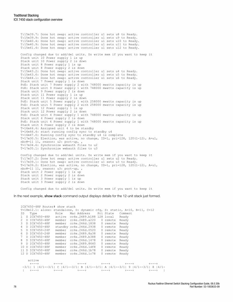
T:15m39.7: Done hot swap: active controller u1 sets u8 to Ready.T:15m39.9: Done hot swap: active controller u1 sets u9 to Ready.T:15m40.4: Done hot swap: active controller u1 sets u10 to Ready.T:15m40.9: Done hot swap: active controller u1 sets u11 to Ready.T:15m41.4: Done hot swap: active controller u1 sets u12 to Ready.
Config changed due to add/del units. Do write mem if you want to keep itStack unit 10 Power supply 1 is upStack unit 10 Power supply 2 is downStack unit 8 Power supply 1 is upStack unit 8 Power supply 2 is downT:15m43.2: Done hot swap: active controller u1 sets u4 to Ready.T:15m43.6: Done hot swap: active controller u1 sets u5 to Ready.T:15m44.1: Done hot swap: active controller u1 sets u6 to Ready.Stack unit 7 Power supply 1 is downPoE: Stack unit 7 Power supply 2 with 748000 mwatts capacity is upPoE: Stack unit 9 Power supply 1 with 748000 mwatts capacity is upStack unit 9 Power supply 2 is downStack unit 11 Power supply 1 is upStack unit 11 Power supply 2 is downPoE: Stack unit 5 Power supply 1 with 258000 mwatts capacity is upPoE: Stack unit 5 Power supply 2 with 258000 mwatts capacity is upStack unit 12 Power supply 1 is upStack unit 12 Power supply 2 is downPoE: Stack unit 4 Power supply 1 with 748000 mwatts capacity is upStack unit 4 Power supply 2 is downPoE: Stack unit 6 Power supply 1 with 748000 mwatts capacity is upStack unit 6 Power supply 2 is downT=16m44.4: Assigned unit 4 to be standbyT=16m46.4: start running config sync to standby u4T=16m47.0: Running config sync to standby u4 is completeT=17m30.5: Election, was active, no change, ID=1, pri=128, 12U(1-12), A=u1, nbr#=11 11, reason: u2: port-up, , T=17m34.6: Synchronize webauth files to u2T=17m35.1: Synchronize webauth files to u3
Config changed due to add/del units. Do write mem if you want to keep itT:17m37.2: Done hot swap: active controller u1 sets u2 to Ready.T:17m39.1: Done hot swap: active controller u1 sets u3 to Ready.T=17m39.2: Election, was active, no change, ID=1, pri=128, 12U(1-12), A=u1, nbr#=11 11, reason: u3: port-up, , Stack unit 2 Power supply 1 is upStack unit 2 Power supply 2 is downStack unit 3 Power supply 1 is upStack unit 3 Power supply 2 is down
Config changed due to add/del units. Do write mem if you want to keep it
In the next example, show stack command output displays details for the 12-unit stack just formed.
ICX7450-48P Router# show stack T=18m12.1: alone: standalone, D: dynamic cfg, S: static, A=10, B=11, C=12ID Type Role Mac Address Pri State Comment 1 S ICX7450-48P active cc4e.2489.b188 128 local Ready2 D ICX7450-48F member cc4e.2489.a220 0 remote Ready3 D ICX7450-48F member cc4e.246d.1838 0 remote Ready4 D ICX7450-48P standby cc4e.246d.2938 0 remote Ready5 D ICX7450-24P member cc4e.246d.0520 0 remote Ready6 D ICX7450-24P member cc4e.2489.8a38 0 remote Ready7 D ICX7450-48P member cc4e.2489.b388 0 remote Ready8 D ICX7450-48F member cc4e.246d.1478 0 remote Ready9 D ICX7450-48P member cc4e.2489.8640 0 remote Ready10 D ICX7450-48F member cc4e.246d.1df8 0 remote Ready11 D ICX7450-48F member cc4e.246d.1b78 0 remote Ready12 D ICX7450-48F member cc4e.246d.1c78 0 remote Ready
active +---+ +---+ +---+ +---+ +---+ +---+ -3/1| 1 |4/1--3/1| C |4/1--3/1| B |4/1--3/1| A |4/1--3/1| 9 |4/1--3/1| 8 |4/1- | +---+ +---+ +---+ +---+ +---+ +---+ |
Traditional StackingICX 7450 stack configuration overview
Ruckus FastIron Ethernet Switch Stacking Configuration Guide, 08.0.30b78 Part Number: 53-1003633-09
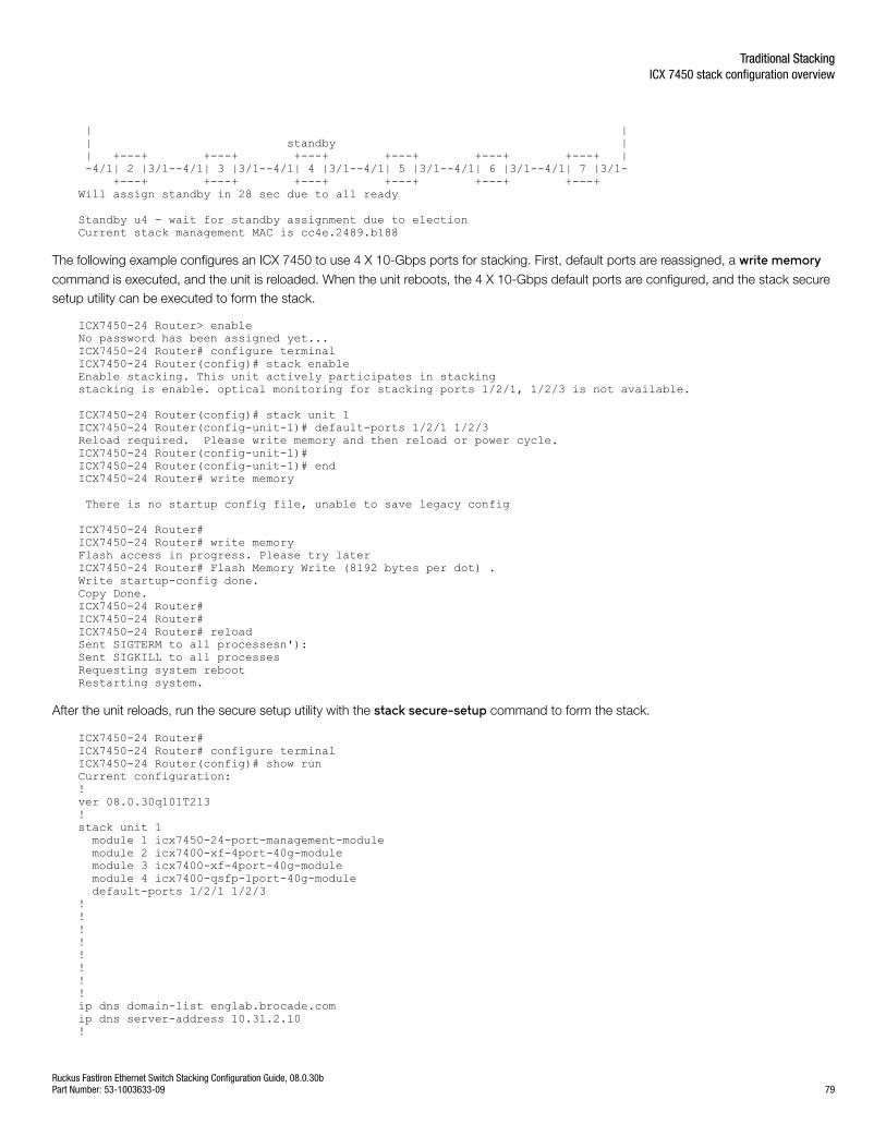
| | | standby | | +---+ +---+ +---+ +---+ +---+ +---+ | -4/1| 2 |3/1--4/1| 3 |3/1--4/1| 4 |3/1--4/1| 5 |3/1--4/1| 6 |3/1--4/1| 7 |3/1- +---+ +---+ +---+ +---+ +---+ +---+ Will assign standby in 28 sec due to all ready
Standby u4 - wait for standby assignment due to electionCurrent stack management MAC is cc4e.2489.b188
The following example configures an ICX 7450 to use 4 X 10-Gbps ports for stacking. First, default ports are reassigned, a write memorycommand is executed, and the unit is reloaded. When the unit reboots, the 4 X 10-Gbps default ports are configured, and the stack securesetup utility can be executed to form the stack.
ICX7450-24 Router> enableNo password has been assigned yet...ICX7450-24 Router# configure terminalICX7450-24 Router(config)# stack enableEnable stacking. This unit actively participates in stackingstacking is enable. optical monitoring for stacking ports 1/2/1, 1/2/3 is not available.
ICX7450-24 Router(config)# stack unit 1ICX7450-24 Router(config-unit-1)# default-ports 1/2/1 1/2/3Reload required. Please write memory and then reload or power cycle.ICX7450-24 Router(config-unit-1)#ICX7450-24 Router(config-unit-1)# endICX7450-24 Router# write memory
There is no startup config file, unable to save legacy config
ICX7450-24 Router#ICX7450-24 Router# write memoryFlash access in progress. Please try laterICX7450-24 Router# Flash Memory Write (8192 bytes per dot) .Write startup-config done.Copy Done.ICX7450-24 Router#ICX7450-24 Router#ICX7450-24 Router# reloadSent SIGTERM to all processesn'): Sent SIGKILL to all processesRequesting system rebootRestarting system.
After the unit reloads, run the secure setup utility with the stack secure-setup command to form the stack.
ICX7450-24 Router#ICX7450-24 Router# configure terminalICX7450-24 Router(config)# show run Current configuration:!ver 08.0.30q101T213!stack unit 1 module 1 icx7450-24-port-management-module module 2 icx7400-xf-4port-40g-module module 3 icx7400-xf-4port-40g-module module 4 icx7400-qsfp-1port-40g-module default-ports 1/2/1 1/2/3!!!!!!!!ip dns domain-list englab.brocade.comip dns server-address 10.31.2.10!
Traditional StackingICX 7450 stack configuration overview
Ruckus FastIron Ethernet Switch Stacking Configuration Guide, 08.0.30bPart Number: 53-1003633-09 79
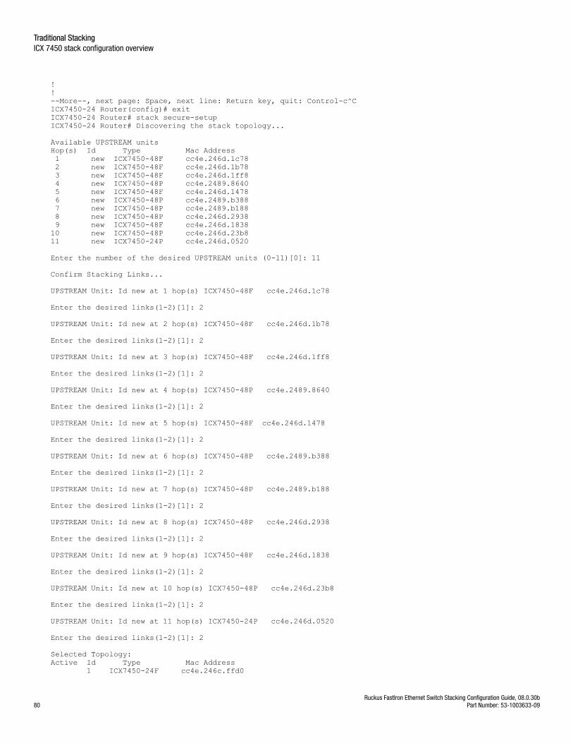
!!--More--, next page: Space, next line: Return key, quit: Control-c^CICX7450-24 Router(config)# exitICX7450-24 Router# stack secure-setup ICX7450-24 Router# Discovering the stack topology...
Available UPSTREAM unitsHop(s) Id Type Mac Address 1 new ICX7450-48F cc4e.246d.1c78 2 new ICX7450-48F cc4e.246d.1b78 3 new ICX7450-48F cc4e.246d.1ff8 4 new ICX7450-48P cc4e.2489.8640 5 new ICX7450-48F cc4e.246d.1478 6 new ICX7450-48P cc4e.2489.b388 7 new ICX7450-48P cc4e.2489.b188 8 new ICX7450-48P cc4e.246d.2938 9 new ICX7450-48F cc4e.246d.183810 new ICX7450-48P cc4e.246d.23b811 new ICX7450-24P cc4e.246d.0520
Enter the number of the desired UPSTREAM units (0-11)[0]: 11
Confirm Stacking Links...
UPSTREAM Unit: Id new at 1 hop(s) ICX7450-48F cc4e.246d.1c78
Enter the desired links(1-2)[1]: 2
UPSTREAM Unit: Id new at 2 hop(s) ICX7450-48F cc4e.246d.1b78
Enter the desired links(1-2)[1]: 2
UPSTREAM Unit: Id new at 3 hop(s) ICX7450-48F cc4e.246d.1ff8
Enter the desired links(1-2)[1]: 2
UPSTREAM Unit: Id new at 4 hop(s) ICX7450-48P cc4e.2489.8640
Enter the desired links(1-2)[1]: 2
UPSTREAM Unit: Id new at 5 hop(s) ICX7450-48F cc4e.246d.1478
Enter the desired links(1-2)[1]: 2
UPSTREAM Unit: Id new at 6 hop(s) ICX7450-48P cc4e.2489.b388
Enter the desired links(1-2)[1]: 2
UPSTREAM Unit: Id new at 7 hop(s) ICX7450-48P cc4e.2489.b188
Enter the desired links(1-2)[1]: 2
UPSTREAM Unit: Id new at 8 hop(s) ICX7450-48P cc4e.246d.2938
Enter the desired links(1-2)[1]: 2
UPSTREAM Unit: Id new at 9 hop(s) ICX7450-48F cc4e.246d.1838
Enter the desired links(1-2)[1]: 2
UPSTREAM Unit: Id new at 10 hop(s) ICX7450-48P cc4e.246d.23b8
Enter the desired links(1-2)[1]: 2
UPSTREAM Unit: Id new at 11 hop(s) ICX7450-24P cc4e.246d.0520
Enter the desired links(1-2)[1]: 2
Selected Topology:Active Id Type Mac Address 1 ICX7450-24F cc4e.246c.ffd0
Traditional StackingICX 7450 stack configuration overview
Ruckus FastIron Ethernet Switch Stacking Configuration Guide, 08.0.30b80 Part Number: 53-1003633-09
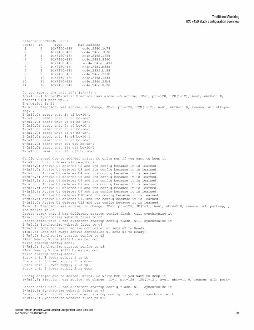
Selected UPSTREAM unitsHop(s) Id Type Mac Address 1 2 ICX7450-48F cc4e.246d.1c78 2 3 ICX7450-48F cc4e.246d.1b78 3 4 ICX7450-48F cc4e.246d.1ff8 4 5 ICX7450-48P cc4e.2489.8640 5 6 ICX7450-48F vcc4e.246d.1478 6 7 ICX7450-48P cc4e.2489.b388 7 8 ICX7450-48P cc4e.2489.b188 8 9 ICX7450-48P cc4e.246d.2938 9 10 ICX7450-48F cc4e.246d.183810 11 ICX7450-48P cc4e.246d.23b811 12 ICX7450-24P cc4e.246d.0520
Do you accept the unit id's (y/n)?: yICX7450-24 Router#T=5m2.9: Election, was alone --> active, ID=1, pri=128, 12U(1-12), A=u1, nbr#=11 0, reason: u12: port-up, , The period is 25 T=5m6.9: Election, was active, no change, ID=1, pri=128, 12U(1-12), A=u1, nbr#=11 0, reason: u1: stk-po-chg, , T=5m10.0: reset unit 2: u2 bo-id=1T=5m10.0: reset unit 3: u3 bo-id=1T=5m10.0: reset unit 4: u4 bo-id=1T=5m10.0: reset unit 5: u5 bo-id=1T=5m10.0: reset unit 6: u6 bo-id=1T=5m10.0: reset unit 7: u7 bo-id=1T=5m10.0: reset unit 8: u8 bo-id=1T=5m10.0: reset unit 9: u9 bo-id=1T=5m10.0: reset unit 10: u10 bo-id=1T=5m10.0: reset unit 11: u11 bo-id=1T=5m10.0: reset unit 12: u12 bo-id=1
Config changed due to add/del units. Do write mem if you want to keep itT=5m15.0: Unit 1 loses all neighbors.T=5m18.0: Active U1 deletes U2 and its config because it is learned.T=5m21.0: Active U1 deletes U3 and its config because it is learned.T=5m23.8: Active U1 deletes U4 and its config because it is learned.T=5m26.6: Active U1 deletes U5 and its config because it is learned.T=5m29.5: Active U1 deletes U6 and its config because it is learned.T=5m30.5: Active U1 deletes U7 and its config because it is learned.T=5m31.5: Active U1 deletes U8 and its config because it is learned.T=5m32.5: Active U1 deletes U9 and its config because it is learned.T=5m33.5: Active U1 deletes U10 and its config because it is learned.T=5m34.5: Active U1 deletes U11 and its config because it is learned.T=5m35.0: Active U1 deletes U12 and its config because it is learned.T=7m5.1: Election, was active, no change, ID=1, pri=128, 3U(1-3), A=u1, nbr#=2 0, reason: u3: port-up, , The period is 25 Detect stack unit 2 has different startup config flash, will synchronize itT=7m5.5: Synchronize webauth files to u2Detect stack unit 3 has different startup config flash, will synchronize itT=7m5.5: Synchronize webauth files to u3T:7m6.7: Done hot swap: active controller u1 sets u2 to Ready.T:7m6.8: Done hot swap: active controller u1 sets u3 to Ready.T=7m7.5: Synchronize startup config to u2Flash Memory Write (8192 bytes per dot) .Write startup-config done.T=7m8.5: Synchronize startup config to u3Flash Memory Write (8192 bytes per dot) .Write startup-config done.Stack unit 3 Power supply 1 is upStack unit 3 Power supply 2 is downStack unit 2 Power supply 1 is upStack unit 2 Power supply 2 is down
Config changed due to add/del units. Do write mem if you want to keep itT=7m10.7: Election, was active, no change, ID=1, pri=128, 12U(1-12), A=u1, nbr#=11 0, reason: u12: port-up, , Detect stack unit 9 has different startup config flash, will synchronize itT=7m11.6: Synchronize webauth files to u9Detect stack unit 12 has different startup config flash, will synchronize itT=7m11.6: Synchronize webauth files to u12
Traditional StackingICX 7450 stack configuration overview
Ruckus FastIron Ethernet Switch Stacking Configuration Guide, 08.0.30bPart Number: 53-1003633-09 81
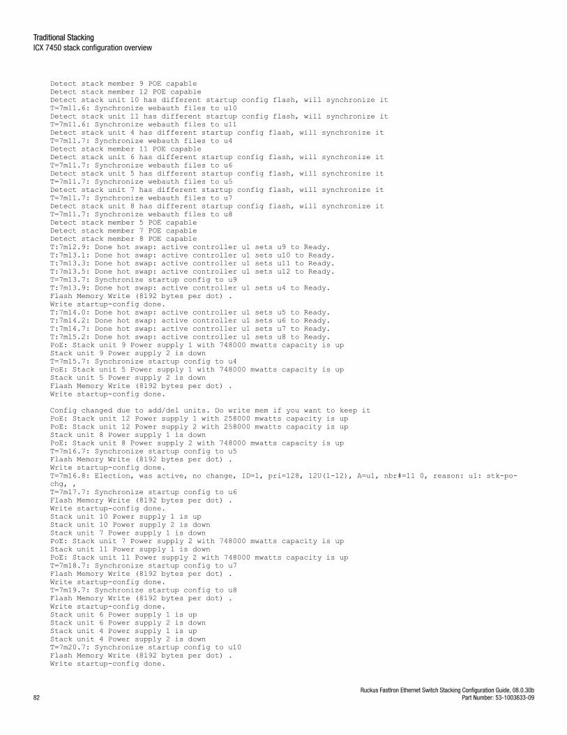
Detect stack member 9 POE capableDetect stack member 12 POE capableDetect stack unit 10 has different startup config flash, will synchronize itT=7m11.6: Synchronize webauth files to u10Detect stack unit 11 has different startup config flash, will synchronize itT=7m11.6: Synchronize webauth files to u11Detect stack unit 4 has different startup config flash, will synchronize itT=7m11.7: Synchronize webauth files to u4Detect stack member 11 POE capableDetect stack unit 6 has different startup config flash, will synchronize itT=7m11.7: Synchronize webauth files to u6Detect stack unit 5 has different startup config flash, will synchronize itT=7m11.7: Synchronize webauth files to u5Detect stack unit 7 has different startup config flash, will synchronize itT=7m11.7: Synchronize webauth files to u7Detect stack unit 8 has different startup config flash, will synchronize itT=7m11.7: Synchronize webauth files to u8Detect stack member 5 POE capableDetect stack member 7 POE capableDetect stack member 8 POE capableT:7m12.9: Done hot swap: active controller u1 sets u9 to Ready.T:7m13.1: Done hot swap: active controller u1 sets u10 to Ready.T:7m13.3: Done hot swap: active controller u1 sets u11 to Ready.T:7m13.5: Done hot swap: active controller u1 sets u12 to Ready.T=7m13.7: Synchronize startup config to u9T:7m13.9: Done hot swap: active controller u1 sets u4 to Ready.Flash Memory Write (8192 bytes per dot) .Write startup-config done.T:7m14.0: Done hot swap: active controller u1 sets u5 to Ready.T:7m14.2: Done hot swap: active controller u1 sets u6 to Ready.T:7m14.7: Done hot swap: active controller u1 sets u7 to Ready.T:7m15.2: Done hot swap: active controller u1 sets u8 to Ready.PoE: Stack unit 9 Power supply 1 with 748000 mwatts capacity is upStack unit 9 Power supply 2 is downT=7m15.7: Synchronize startup config to u4PoE: Stack unit 5 Power supply 1 with 748000 mwatts capacity is upStack unit 5 Power supply 2 is downFlash Memory Write (8192 bytes per dot) .Write startup-config done.
Config changed due to add/del units. Do write mem if you want to keep itPoE: Stack unit 12 Power supply 1 with 258000 mwatts capacity is upPoE: Stack unit 12 Power supply 2 with 258000 mwatts capacity is upStack unit 8 Power supply 1 is downPoE: Stack unit 8 Power supply 2 with 748000 mwatts capacity is upT=7m16.7: Synchronize startup config to u5Flash Memory Write (8192 bytes per dot) .Write startup-config done.T=7m16.8: Election, was active, no change, ID=1, pri=128, 12U(1-12), A=u1, nbr#=11 0, reason: u1: stk-po-chg, , T=7m17.7: Synchronize startup config to u6Flash Memory Write (8192 bytes per dot) .Write startup-config done.Stack unit 10 Power supply 1 is upStack unit 10 Power supply 2 is downStack unit 7 Power supply 1 is downPoE: Stack unit 7 Power supply 2 with 748000 mwatts capacity is upStack unit 11 Power supply 1 is downPoE: Stack unit 11 Power supply 2 with 748000 mwatts capacity is upT=7m18.7: Synchronize startup config to u7Flash Memory Write (8192 bytes per dot) .Write startup-config done.T=7m19.7: Synchronize startup config to u8Flash Memory Write (8192 bytes per dot) .Write startup-config done.Stack unit 6 Power supply 1 is upStack unit 6 Power supply 2 is downStack unit 4 Power supply 1 is upStack unit 4 Power supply 2 is downT=7m20.7: Synchronize startup config to u10Flash Memory Write (8192 bytes per dot) .Write startup-config done.
Traditional StackingICX 7450 stack configuration overview
Ruckus FastIron Ethernet Switch Stacking Configuration Guide, 08.0.30b82 Part Number: 53-1003633-09
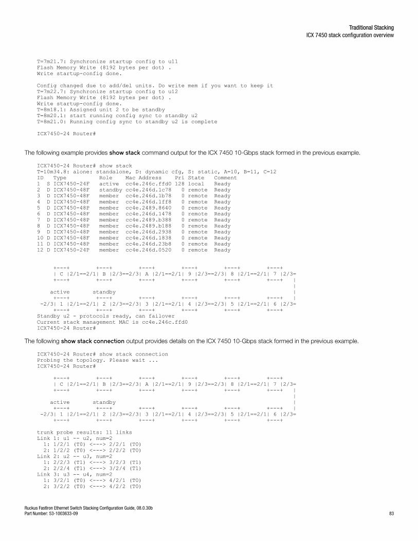
T=7m21.7: Synchronize startup config to u11Flash Memory Write (8192 bytes per dot) .Write startup-config done.
Config changed due to add/del units. Do write mem if you want to keep itT=7m22.7: Synchronize startup config to u12Flash Memory Write (8192 bytes per dot) .Write startup-config done.T=8m18.1: Assigned unit 2 to be standbyT=8m20.1: start running config sync to standby u2T=8m21.0: Running config sync to standby u2 is complete
ICX7450-24 Router#
The following example provides show stack command output for the ICX 7450 10-Gbps stack formed in the previous example.
ICX7450-24 Router# show stackT=10m34.8: alone: standalone, D: dynamic cfg, S: static, A=10, B=11, C=12ID Type Role Mac Address Pri State Comment 1 S ICX7450-24F active cc4e.246c.ffd0 128 local Ready2 D ICX7450-48F standby cc4e.246d.1c78 0 remote Ready3 D ICX7450-48F member cc4e.246d.1b78 0 remote Ready4 D ICX7450-48F member cc4e.246d.1ff8 0 remote Ready5 D ICX7450-48P member cc4e.2489.8640 0 remote Ready6 D ICX7450-48F member cc4e.246d.1478 0 remote Ready7 D ICX7450-48P member cc4e.2489.b388 0 remote Ready8 D ICX7450-48P member cc4e.2489.b188 0 remote Ready9 D ICX7450-48P member cc4e.246d.2938 0 remote Ready10 D ICX7450-48F member cc4e.246d.1838 0 remote Ready11 D ICX7450-48P member cc4e.246d.23b8 0 remote Ready12 D ICX7450-24P member cc4e.246d.0520 0 remote Ready
+---+ +---+ +---+ +---+ +---+ +---+ | C |2/1==2/1| B |2/3==2/3| A |2/1==2/1| 9 |2/3==2/3| 8 |2/1==2/1| 7 |2/3= +---+ +---+ +---+ +---+ +---+ +---+ | | active standby | +---+ +---+ +---+ +---+ +---+ +---+ | -2/3| 1 |2/1==2/1| 2 |2/3==2/3| 3 |2/1==2/1| 4 |2/3==2/3| 5 |2/1==2/1| 6 |2/3= +---+ +---+ +---+ +---+ +---+ +---+ Standby u2 - protocols ready, can failoverCurrent stack management MAC is cc4e.246c.ffd0ICX7450-24 Router#
The following show stack connection output provides details on the ICX 7450 10-Gbps stack formed in the previous example.
ICX7450-24 Router# show stack connection Probing the topology. Please wait ...ICX7450-24 Router# +---+ +---+ +---+ +---+ +---+ +---+ | C |2/1==2/1| B |2/3==2/3| A |2/1==2/1| 9 |2/3==2/3| 8 |2/1==2/1| 7 |2/3= +---+ +---+ +---+ +---+ +---+ +---+ | | active standby | +---+ +---+ +---+ +---+ +---+ +---+ | -2/3| 1 |2/1==2/1| 2 |2/3==2/3| 3 |2/1==2/1| 4 |2/3==2/3| 5 |2/1==2/1| 6 |2/3= +---+ +---+ +---+ +---+ +---+ +---+
trunk probe results: 11 linksLink 1: u1 -- u2, num=2 1: 1/2/1 (T0) <---> 2/2/1 (T0) 2: 1/2/2 (T0) <---> 2/2/2 (T0) Link 2: u2 -- u3, num=2 1: 2/2/3 (T1) <---> 3/2/3 (T1) 2: 2/2/4 (T1) <---> 3/2/4 (T1) Link 3: u3 -- u4, num=2 1: 3/2/1 (T0) <---> 4/2/1 (T0) 2: 3/2/2 (T0) <---> 4/2/2 (T0)
Traditional StackingICX 7450 stack configuration overview
Ruckus FastIron Ethernet Switch Stacking Configuration Guide, 08.0.30bPart Number: 53-1003633-09 83
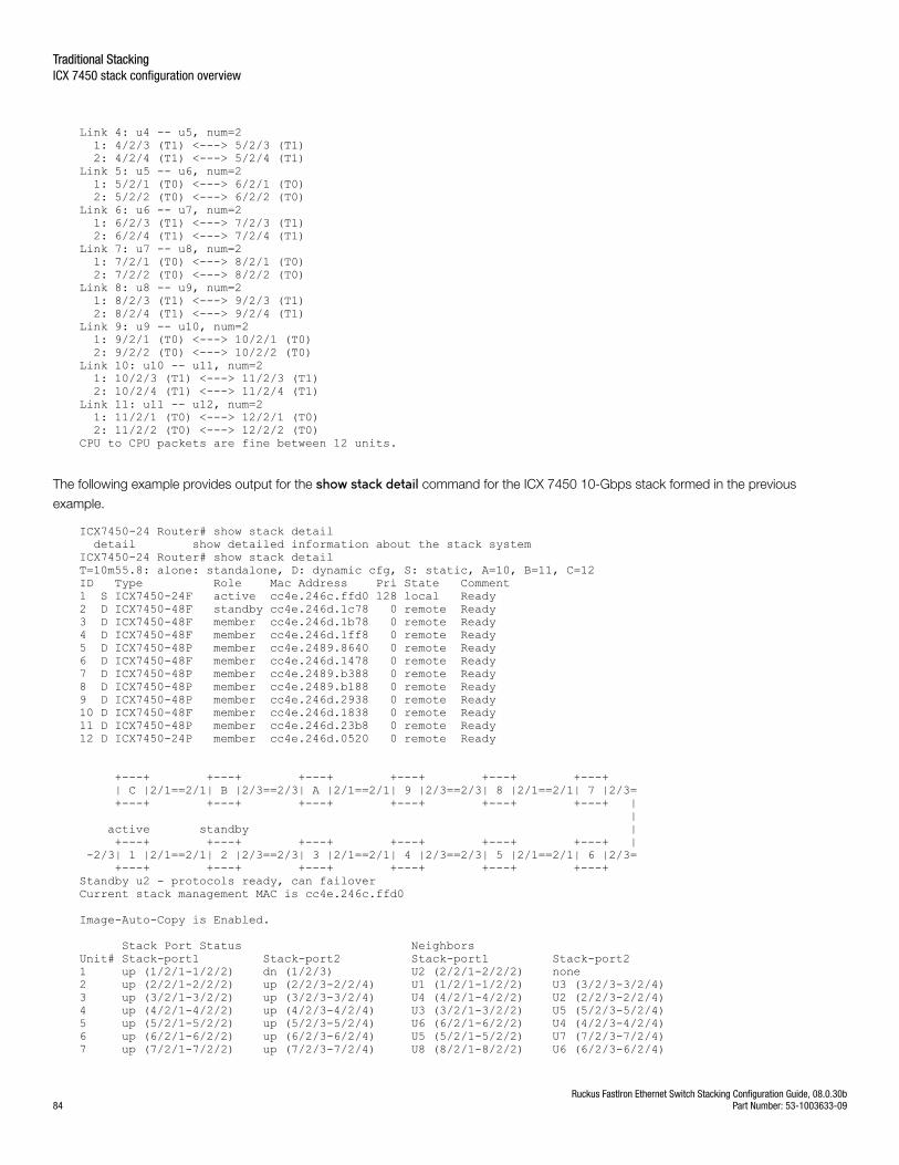
Link 4: u4 -- u5, num=2 1: 4/2/3 (T1) <---> 5/2/3 (T1) 2: 4/2/4 (T1) <---> 5/2/4 (T1) Link 5: u5 -- u6, num=2 1: 5/2/1 (T0) <---> 6/2/1 (T0) 2: 5/2/2 (T0) <---> 6/2/2 (T0) Link 6: u6 -- u7, num=2 1: 6/2/3 (T1) <---> 7/2/3 (T1) 2: 6/2/4 (T1) <---> 7/2/4 (T1) Link 7: u7 -- u8, num=2 1: 7/2/1 (T0) <---> 8/2/1 (T0) 2: 7/2/2 (T0) <---> 8/2/2 (T0) Link 8: u8 -- u9, num=2 1: 8/2/3 (T1) <---> 9/2/3 (T1) 2: 8/2/4 (T1) <---> 9/2/4 (T1) Link 9: u9 -- u10, num=2 1: 9/2/1 (T0) <---> 10/2/1 (T0) 2: 9/2/2 (T0) <---> 10/2/2 (T0) Link 10: u10 -- u11, num=2 1: 10/2/3 (T1) <---> 11/2/3 (T1) 2: 10/2/4 (T1) <---> 11/2/4 (T1) Link 11: u11 -- u12, num=2 1: 11/2/1 (T0) <---> 12/2/1 (T0) 2: 11/2/2 (T0) <---> 12/2/2 (T0) CPU to CPU packets are fine between 12 units.
The following example provides output for the show stack detail command for the ICX 7450 10-Gbps stack formed in the previous
example.
ICX7450-24 Router# show stack detail detail show detailed information about the stack systemICX7450-24 Router# show stack detail T=10m55.8: alone: standalone, D: dynamic cfg, S: static, A=10, B=11, C=12ID Type Role Mac Address Pri State Comment 1 S ICX7450-24F active cc4e.246c.ffd0 128 local Ready2 D ICX7450-48F standby cc4e.246d.1c78 0 remote Ready3 D ICX7450-48F member cc4e.246d.1b78 0 remote Ready4 D ICX7450-48F member cc4e.246d.1ff8 0 remote Ready5 D ICX7450-48P member cc4e.2489.8640 0 remote Ready6 D ICX7450-48F member cc4e.246d.1478 0 remote Ready7 D ICX7450-48P member cc4e.2489.b388 0 remote Ready8 D ICX7450-48P member cc4e.2489.b188 0 remote Ready9 D ICX7450-48P member cc4e.246d.2938 0 remote Ready10 D ICX7450-48F member cc4e.246d.1838 0 remote Ready11 D ICX7450-48P member cc4e.246d.23b8 0 remote Ready12 D ICX7450-24P member cc4e.246d.0520 0 remote Ready
+---+ +---+ +---+ +---+ +---+ +---+ | C |2/1==2/1| B |2/3==2/3| A |2/1==2/1| 9 |2/3==2/3| 8 |2/1==2/1| 7 |2/3= +---+ +---+ +---+ +---+ +---+ +---+ | | active standby | +---+ +---+ +---+ +---+ +---+ +---+ | -2/3| 1 |2/1==2/1| 2 |2/3==2/3| 3 |2/1==2/1| 4 |2/3==2/3| 5 |2/1==2/1| 6 |2/3= +---+ +---+ +---+ +---+ +---+ +---+ Standby u2 - protocols ready, can failoverCurrent stack management MAC is cc4e.246c.ffd0
Image-Auto-Copy is Enabled.
Stack Port Status Neighbors Unit# Stack-port1 Stack-port2 Stack-port1 Stack-port2 1 up (1/2/1-1/2/2) dn (1/2/3) U2 (2/2/1-2/2/2) none 2 up (2/2/1-2/2/2) up (2/2/3-2/2/4) U1 (1/2/1-1/2/2) U3 (3/2/3-3/2/4) 3 up (3/2/1-3/2/2) up (3/2/3-3/2/4) U4 (4/2/1-4/2/2) U2 (2/2/3-2/2/4) 4 up (4/2/1-4/2/2) up (4/2/3-4/2/4) U3 (3/2/1-3/2/2) U5 (5/2/3-5/2/4) 5 up (5/2/1-5/2/2) up (5/2/3-5/2/4) U6 (6/2/1-6/2/2) U4 (4/2/3-4/2/4) 6 up (6/2/1-6/2/2) up (6/2/3-6/2/4) U5 (5/2/1-5/2/2) U7 (7/2/3-7/2/4) 7 up (7/2/1-7/2/2) up (7/2/3-7/2/4) U8 (8/2/1-8/2/2) U6 (6/2/3-6/2/4)
Traditional StackingICX 7450 stack configuration overview
Ruckus FastIron Ethernet Switch Stacking Configuration Guide, 08.0.30b84 Part Number: 53-1003633-09
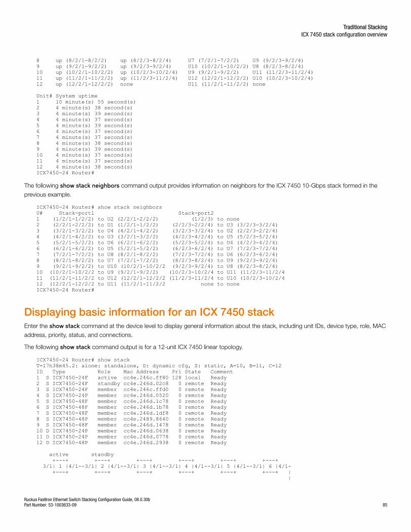
8 up (8/2/1-8/2/2) up (8/2/3-8/2/4) U7 (7/2/1-7/2/2) U9 (9/2/3-9/2/4) 9 up (9/2/1-9/2/2) up (9/2/3-9/2/4) U10 (10/2/1-10/2/2) U8 (8/2/3-8/2/4) 10 up (10/2/1-10/2/2) up (10/2/3-10/2/4) U9 (9/2/1-9/2/2) U11 (11/2/3-11/2/4)11 up (11/2/1-11/2/2) up (11/2/3-11/2/4) U12 (12/2/1-12/2/2) U10 (10/2/3-10/2/4)12 up (12/2/1-12/2/2) none U11 (11/2/1-11/2/2) none
Unit# System uptime1 10 minute(s) 55 second(s) 2 4 minute(s) 38 second(s) 3 4 minute(s) 39 second(s) 4 4 minute(s) 37 second(s) 5 4 minute(s) 39 second(s) 6 4 minute(s) 37 second(s) 7 4 minute(s) 37 second(s) 8 4 minute(s) 38 second(s) 9 4 minute(s) 39 second(s) 10 4 minute(s) 37 second(s) 11 4 minute(s) 37 second(s) 12 4 minute(s) 38 second(s) ICX7450-24 Router#
The following show stack neighbors command output provides information on neighbors for the ICX 7450 10-Gbps stack formed in the
previous example.
ICX7450-24 Router# show stack neighbors U# Stack-port1 Stack-port2 1 (1/2/1-1/2/2) to U2 (2/2/1-2/2/2) (1/2/3) to none 2 (2/2/1-2/2/2) to U1 (1/2/1-1/2/2) (2/2/3-2/2/4) to U3 (3/2/3-3/2/4) 3 (3/2/1-3/2/2) to U4 (4/2/1-4/2/2) (3/2/3-3/2/4) to U2 (2/2/3-2/2/4) 4 (4/2/1-4/2/2) to U3 (3/2/1-3/2/2) (4/2/3-4/2/4) to U5 (5/2/3-5/2/4) 5 (5/2/1-5/2/2) to U6 (6/2/1-6/2/2) (5/2/3-5/2/4) to U4 (4/2/3-4/2/4) 6 (6/2/1-6/2/2) to U5 (5/2/1-5/2/2) (6/2/3-6/2/4) to U7 (7/2/3-7/2/4) 7 (7/2/1-7/2/2) to U8 (8/2/1-8/2/2) (7/2/3-7/2/4) to U6 (6/2/3-6/2/4) 8 (8/2/1-8/2/2) to U7 (7/2/1-7/2/2) (8/2/3-8/2/4) to U9 (9/2/3-9/2/4) 9 (9/2/1-9/2/2) to U10 (10/2/1-10/2/2 (9/2/3-9/2/4) to U8 (8/2/3-8/2/4) 10 (10/2/1-10/2/2 to U9 (9/2/1-9/2/2) (10/2/3-10/2/4 to U11 (11/2/3-11/2/411 (11/2/1-11/2/2 to U12 (12/2/1-12/2/2 (11/2/3-11/2/4 to U10 (10/2/3-10/2/412 (12/2/1-12/2/2 to U11 (11/2/1-11/2/2 none to none ICX7450-24 Router#
Displaying basic information for an ICX 7450 stackEnter the show stack command at the device level to display general information about the stack, including unit IDs, device type, role, MAC
address, priority, status, and connections.
The following show stack command output is for a 12-unit ICX 7450 linear topology.
ICX7450-24 Router# show stackT=17h38m45.2: alone: standalone, D: dynamic cfg, S: static, A=10, B=11, C=12ID Type Role Mac Address Pri State Comment 1 S ICX7450-24F active cc4e.246c.ff80 128 local Ready2 S ICX7450-24F standby cc4e.246d.02c8 0 remote Ready3 S ICX7450-24F member cc4e.246c.ffd0 0 remote Ready4 S ICX7450-24P member cc4e.246d.0520 0 remote Ready5 S ICX7450-48F member cc4e.246d.1c78 0 remote Ready6 S ICX7450-48F member cc4e.246d.1b78 0 remote Ready7 S ICX7450-48F member cc4e.246d.1df8 0 remote Ready8 S ICX7450-48P member cc4e.2489.8640 0 remote Ready9 S ICX7450-48F member cc4e.246d.1478 0 remote Ready10 D ICX7450-24P member cc4e.246d.0638 0 remote Ready11 D ICX7450-24P member cc4e.246d.0778 0 remote Ready12 D ICX7450-48P member cc4e.246d.2938 0 remote Ready
active standby +---+ +---+ +---+ +---+ +---+ +---+ 3/1| 1 |4/1--3/1| 2 |4/1--3/1| 3 |4/1--3/1| 4 |4/1--3/1| 5 |4/1--3/1| 6 |4/1- +---+ +---+ +---+ +---+ +---+ +---+ | |
Traditional StackingICX 7450 stack configuration overview
Ruckus FastIron Ethernet Switch Stacking Configuration Guide, 08.0.30bPart Number: 53-1003633-09 85
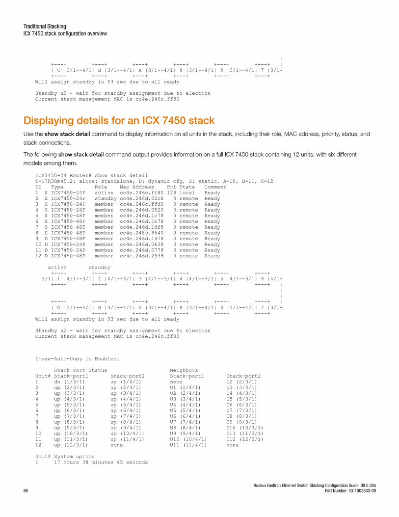
| +---+ +---+ +---+ +---+ +---+ +---+ | | C |3/1--4/1| B |3/1--4/1| A |3/1--4/1| 9 |3/1--4/1| 8 |3/1--4/1| 7 |3/1- +---+ +---+ +---+ +---+ +---+ +---+ Will assign standby in 53 sec due to all ready
Standby u2 - wait for standby assignment due to electionCurrent stack management MAC is cc4e.246c.ff80
Displaying details for an ICX 7450 stackUse the show stack detail command to display information on all units in the stack, including their role, MAC address, priority, status, and
stack connections.
The following show stack detail command output provides information on a full ICX 7450 stack containing 12 units, with six different
models among them.
ICX7450-24 Router# show stack detailT=17h38m45.2: alone: standalone, D: dynamic cfg, S: static, A=10, B=11, C=12ID Type Role Mac Address Pri State Comment 1 S ICX7450-24F active cc4e.246c.ff80 128 local Ready2 S ICX7450-24F standby cc4e.246d.02c8 0 remote Ready3 S ICX7450-24F member cc4e.246c.ffd0 0 remote Ready4 S ICX7450-24P member cc4e.246d.0520 0 remote Ready5 S ICX7450-48F member cc4e.246d.1c78 0 remote Ready6 S ICX7450-48F member cc4e.246d.1b78 0 remote Ready7 S ICX7450-48F member cc4e.246d.1df8 0 remote Ready8 S ICX7450-48P member cc4e.2489.8640 0 remote Ready9 S ICX7450-48F member cc4e.246d.1478 0 remote Ready10 D ICX7450-24P member cc4e.246d.0638 0 remote Ready11 D ICX7450-24P member cc4e.246d.0778 0 remote Ready12 D ICX7450-48P member cc4e.246d.2938 0 remote Ready
active standby +---+ +---+ +---+ +---+ +---+ +---+ 3/1| 1 |4/1--3/1| 2 |4/1--3/1| 3 |4/1--3/1| 4 |4/1--3/1| 5 |4/1--3/1| 6 |4/1- +---+ +---+ +---+ +---+ +---+ +---+ | | | +---+ +---+ +---+ +---+ +---+ +---+ | | C |3/1--4/1| B |3/1--4/1| A |3/1--4/1| 9 |3/1--4/1| 8 |3/1--4/1| 7 |3/1- +---+ +---+ +---+ +---+ +---+ +---+ Will assign standby in 53 sec due to all ready
Standby u2 - wait for standby assignment due to electionCurrent stack management MAC is cc4e.246c.ff80
Image-Auto-Copy is Enabled.
Stack Port Status Neighbors Unit# Stack-port1 Stack-port2 Stack-port1 Stack-port2 1 dn (1/3/1) up (1/4/1) none U2 (2/3/1) 2 up (2/3/1) up (2/4/1) U1 (1/4/1) U3 (3/3/1) 3 up (3/3/1) up (3/4/1) U2 (2/4/1) U4 (4/3/1) 4 up (4/3/1) up (4/4/1) U3 (3/4/1) U5 (5/3/1) 5 up (5/3/1) up (5/4/1) U4 (4/4/1) U6 (6/3/1) 6 up (6/3/1) up (6/4/1) U5 (5/4/1) U7 (7/3/1) 7 up (7/3/1) up (7/4/1) U6 (6/4/1) U8 (8/3/1) 8 up (8/3/1) up (8/4/1) U7 (7/4/1) U9 (9/3/1) 9 up (9/3/1) up (9/4/1) U8 (8/4/1) U10 (10/3/1) 10 up (10/3/1) up (10/4/1) U9 (9/4/1) U11 (11/3/1) 11 up (11/3/1) up (11/4/1) U10 (10/4/1) U12 (12/3/1) 12 up (12/3/1) none U11 (11/4/1) none
Unit# System uptime 1 17 hours 38 minutes 45 seconds
Traditional StackingICX 7450 stack configuration overview
Ruckus FastIron Ethernet Switch Stacking Configuration Guide, 08.0.30b86 Part Number: 53-1003633-09
2 17 hours 38 minutes 43 seconds 3 17 hours 38 minutes 45 seconds 4 17 hours 38 minutes 44 seconds 5 17 hours 38 minutes 44 seconds 6 17 hours 38 minutes 44 seconds 7 17 hours 38 minutes 44 seconds 8 17 hours 38 minutes 45 seconds 9 17 hours 38 minutes 43 seconds 10 17 hours 32 minutes 24 seconds 11 1 minutes 9 seconds 12 1 minutes 9 seconds
ICX 7750 stack configuration overviewThe following table provides an overview of ICX 7750 stacking capabilities.
TABLE 12 ICX 7750 Traditional stacking capability
Stacking capability ICX 7750 Additional information
Topologies supported Ring and linear Refer to ICX 7750 stacking topologies on page88.
Maximum stack size 12 Traditional stacking only.
Maximum stacking distance 100 meters (most models)
10 kilometers (ICX 7750-2Q, ICX 7750-48C, ICX7750-48F, from specific ports)
Refer to FastIron stacking distances and opticsby device on page 21 and Installing the ICX 7750in a remote stack on page 91 for moreinformation.
ICX 7750 model combinations Allowed ICX 7750-48C, ICX 7750 -48F, and ICX7750-26Q models can be combined in the samestack.
Stacking ports Six 40 Gbps ports, Module 2: 1/2/1 to 1/2/6(Front)
or
Six 40 Gbps ports, Module 3: 1/3/1 to 1/3/6(Rear)
Module 2 (right front) and Module 3 (rear). Use allfront or all rear 40 Gbps ports for ICX 7750stacking. No mixed combination is allowed.
Default ports Ports 1/2/1 and 1/2/4 Default ports can be changed to rear ports 1/3/1or 1/3/4. No other ports are allowed.
Reconfigurable ports Use the default-ports and stack-portcommands to reconfigure ports.
Default ports can be changed only between frontand rear 40 Gbps modules.
Trunking Up to two stack trunks Each stack trunk can support up to three ports.
Possible 3-port trunks:
1/2/1 to 1/2/3
1/2/4 to 1/2/6
1/3/1 to 1/3/3
1/3/4 to 1/3/6
Possible 2-port trunks:
1/2/1 to 1/2/2
1/2/4 to 1/2/5
1/3/1 to 1/3/2
1/3/4 to 1/3/5
Hitless switchover and hitless failover Supported Refer to Hitless stacking on page 155.
Traditional StackingICX 7750 stack configuration overview
Ruckus FastIron Ethernet Switch Stacking Configuration Guide, 08.0.30bPart Number: 53-1003633-09 87
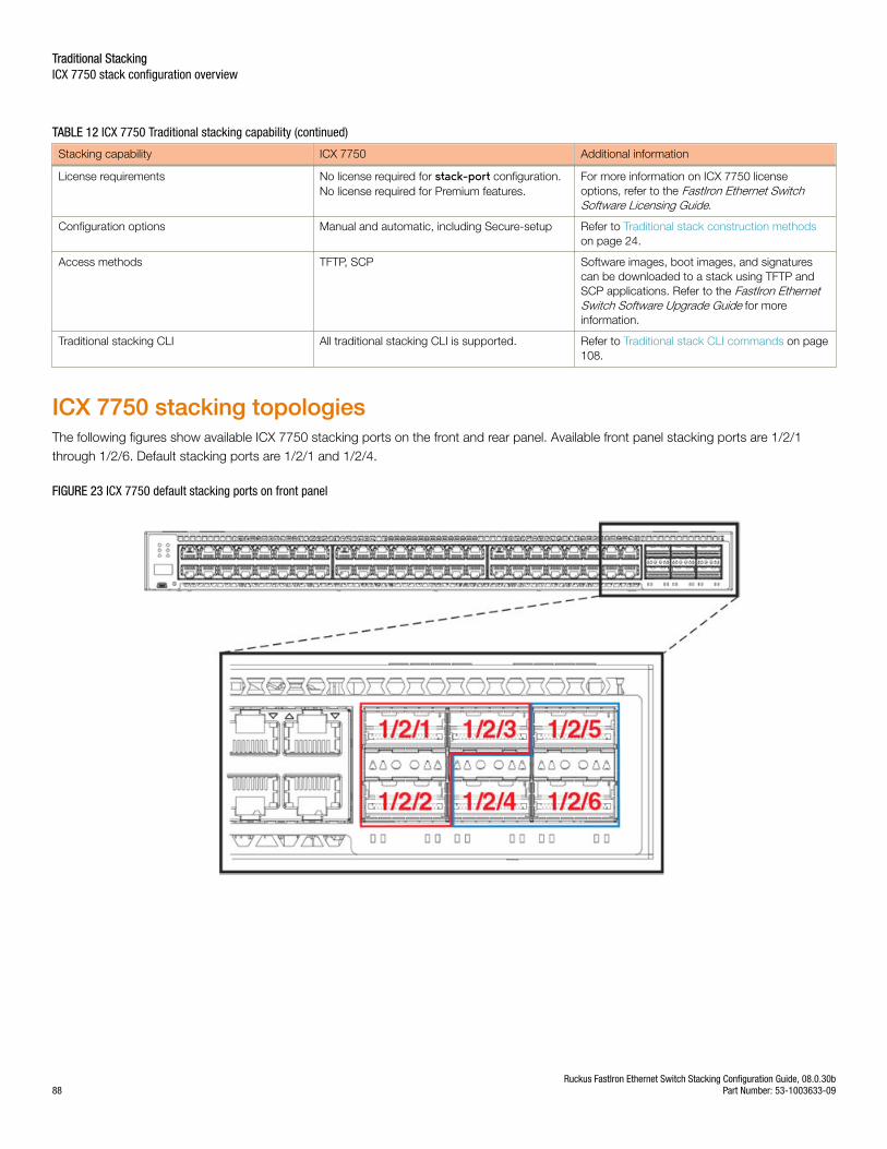
TABLE 12 ICX 7750 Traditional stacking capability (continued)
Stacking capability ICX 7750 Additional information
License requirements No license required for stack-port configuration.No license required for Premium features.
For more information on ICX 7750 licenseoptions, refer to the FastIron Ethernet SwitchSoftware Licensing Guide.
Configuration options Manual and automatic, including Secure-setup Refer to Traditional stack construction methodson page 24.
Access methods TFTP, SCP Software images, boot images, and signaturescan be downloaded to a stack using TFTP andSCP applications. Refer to the FastIron EthernetSwitch Software Upgrade Guide for moreinformation.
Traditional stacking CLI All traditional stacking CLI is supported. Refer to Traditional stack CLI commands on page108.
ICX 7750 stacking topologiesThe following figures show available ICX 7750 stacking ports on the front and rear panel. Available front panel stacking ports are 1/2/1through 1/2/6. Default stacking ports are 1/2/1 and 1/2/4.
FIGURE 23 ICX 7750 default stacking ports on front panel
Traditional StackingICX 7750 stack configuration overview
Ruckus FastIron Ethernet Switch Stacking Configuration Guide, 08.0.30b88 Part Number: 53-1003633-09
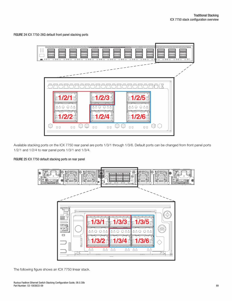
FIGURE 24 ICX 7750-26Q default front panel stacking ports
Available stacking ports on the ICX 7750 rear panel are ports 1/3/1 through 1/3/6. Default ports can be changed from front panel ports1/2/1 and 1/2/4 to rear panel ports 1/3/1 and 1/3/4.
FIGURE 25 ICX 7750 default stacking ports on rear panel
The following figure shows an ICX 7750 linear stack.
Traditional StackingICX 7750 stack configuration overview
Ruckus FastIron Ethernet Switch Stacking Configuration Guide, 08.0.30bPart Number: 53-1003633-09 89
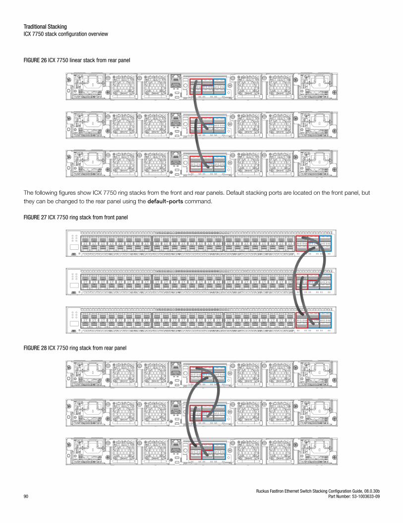
FIGURE 26 ICX 7750 linear stack from rear panel
The following figures show ICX 7750 ring stacks from the front and rear panels. Default stacking ports are located on the front panel, butthey can be changed to the rear panel using the default-ports command.
FIGURE 27 ICX 7750 ring stack from front panel
FIGURE 28 ICX 7750 ring stack from rear panel
Traditional StackingICX 7750 stack configuration overview
Ruckus FastIron Ethernet Switch Stacking Configuration Guide, 08.0.30b90 Part Number: 53-1003633-09
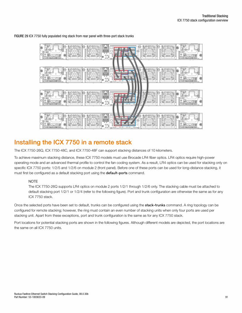
FIGURE 29 ICX 7750 fully populated ring stack from rear panel with three-port stack trunks
Installing the ICX 7750 in a remote stackThe ICX 7750-26Q, ICX 7750-48C, and ICX 7750-48F can support stacking distances of 10 kilometers.
To achieve maximum stacking distance, these ICX 7750 models must use Brocade LR4 fiber optics. LR4 optics require high-poweroperating mode and an advanced thermal profile to control the fan cooling system. As a result, LR4 optics can be used for stacking only onspecific ICX 7750 ports: 1/2/5 and 1/2/6 on module 2 (front panel). Before one of these ports can be used for long-distance stacking, itmust first be configured as a default stacking port using the default-ports command.
NOTEThe ICX 7750-26Q supports LR4 optics on module 2 ports 1/2/1 through 1/2/6 only. The stacking cable must be attached todefault stacking port 1/2/1 or 1/2/4 (refer to the following figure). Port and trunk configuration are otherwise the same as for anyICX 7750 stack.
Once the selected ports have been set to default, trunks can be configured using the stack-trunks command. A ring topology can be
configured for remote stacking; however, the ring must contain an even number of stacking units when only four ports are used perstacking unit. Apart from these exceptions, port and trunk configuration is the same as for any ICX 7750 stack.
Port locations for potential stacking ports are shown in the following figures. Although different models are depicted, the port locations arethe same on all ICX 7750 units.
Traditional StackingICX 7750 stack configuration overview
Ruckus FastIron Ethernet Switch Stacking Configuration Guide, 08.0.30bPart Number: 53-1003633-09 91
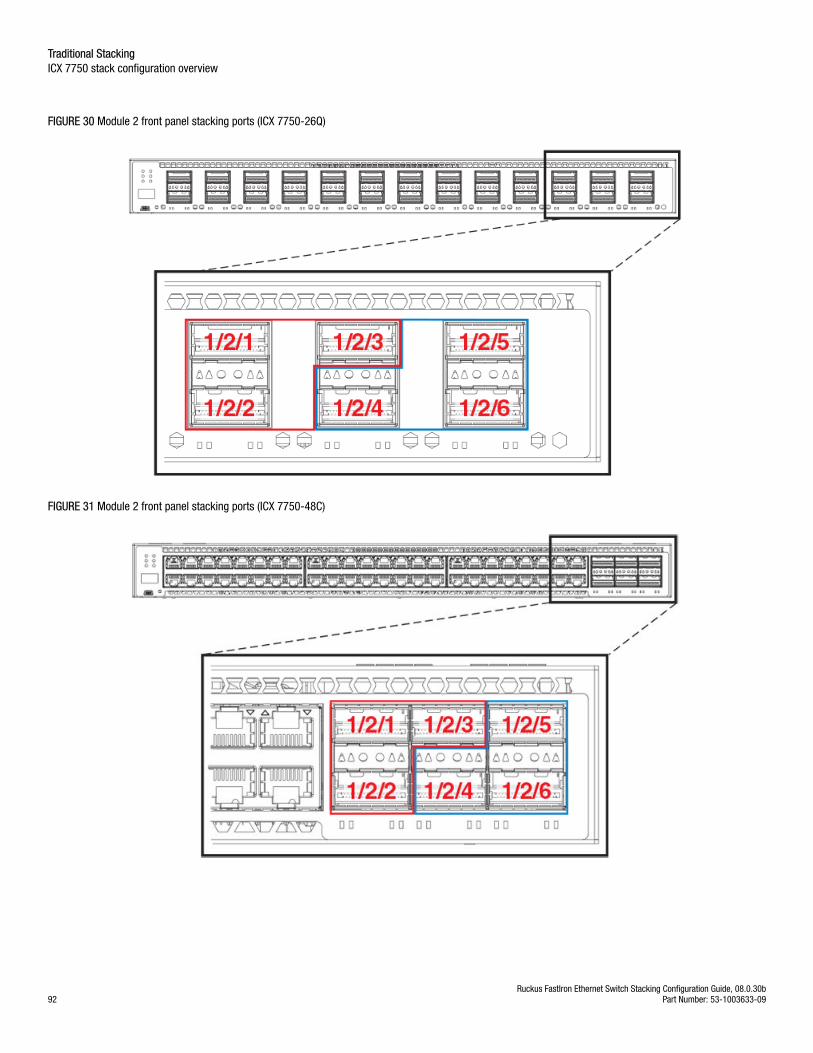
FIGURE 30 Module 2 front panel stacking ports (ICX 7750-26Q)
FIGURE 31 Module 2 front panel stacking ports (ICX 7750-48C)
Traditional StackingICX 7750 stack configuration overview
Ruckus FastIron Ethernet Switch Stacking Configuration Guide, 08.0.30b92 Part Number: 53-1003633-09
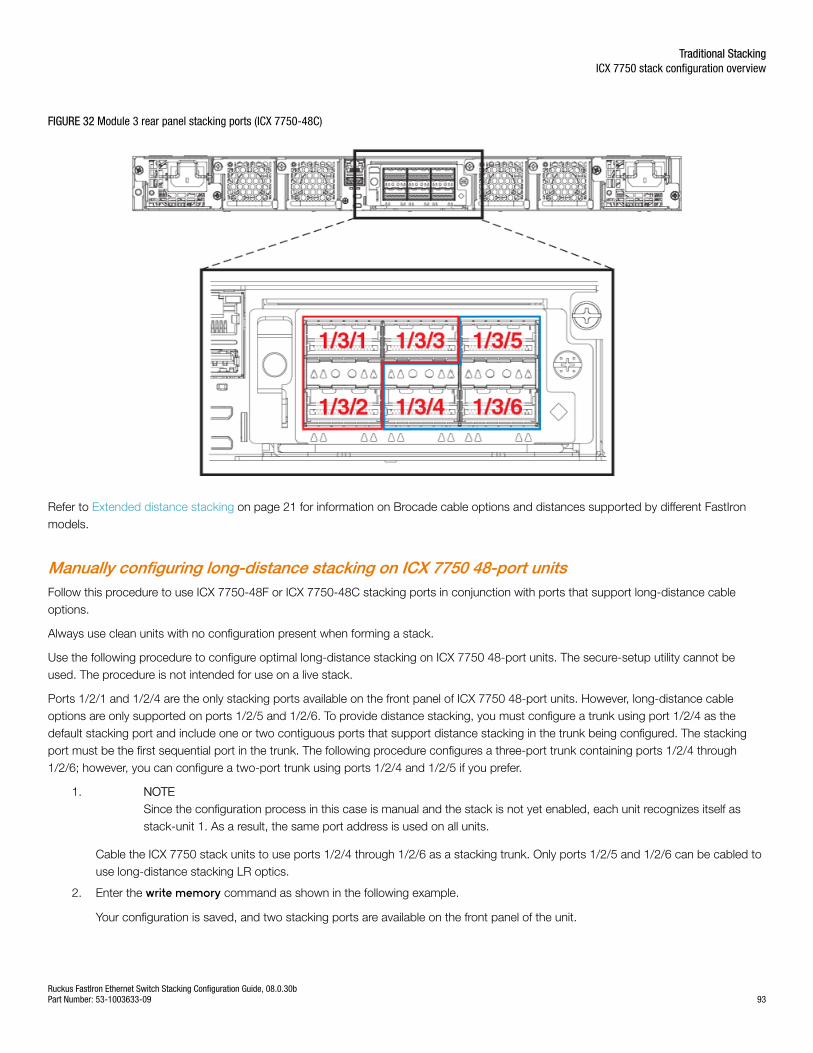
FIGURE 32 Module 3 rear panel stacking ports (ICX 7750-48C)
Refer to Extended distance stacking on page 21 for information on Brocade cable options and distances supported by different FastIronmodels.
Manually configuring long-distance stacking on ICX 7750 48-port unitsFollow this procedure to use ICX 7750-48F or ICX 7750-48C stacking ports in conjunction with ports that support long-distance cableoptions.
Always use clean units with no configuration present when forming a stack.
Use the following procedure to configure optimal long-distance stacking on ICX 7750 48-port units. The secure-setup utility cannot beused. The procedure is not intended for use on a live stack.
Ports 1/2/1 and 1/2/4 are the only stacking ports available on the front panel of ICX 7750 48-port units. However, long-distance cableoptions are only supported on ports 1/2/5 and 1/2/6. To provide distance stacking, you must configure a trunk using port 1/2/4 as thedefault stacking port and include one or two contiguous ports that support distance stacking in the trunk being configured. The stackingport must be the first sequential port in the trunk. The following procedure configures a three-port trunk containing ports 1/2/4 through1/2/6; however, you can configure a two-port trunk using ports 1/2/4 and 1/2/5 if you prefer.
1. NOTESince the configuration process in this case is manual and the stack is not yet enabled, each unit recognizes itself asstack-unit 1. As a result, the same port address is used on all units.
Cable the ICX 7750 stack units to use ports 1/2/4 through 1/2/6 as a stacking trunk. Only ports 1/2/5 and 1/2/6 can be cabled touse long-distance stacking LR optics.
2. Enter the write memory command as shown in the following example.
Your configuration is saved, and two stacking ports are available on the front panel of the unit.
Traditional StackingICX 7750 stack configuration overview
Ruckus FastIron Ethernet Switch Stacking Configuration Guide, 08.0.30bPart Number: 53-1003633-09 93
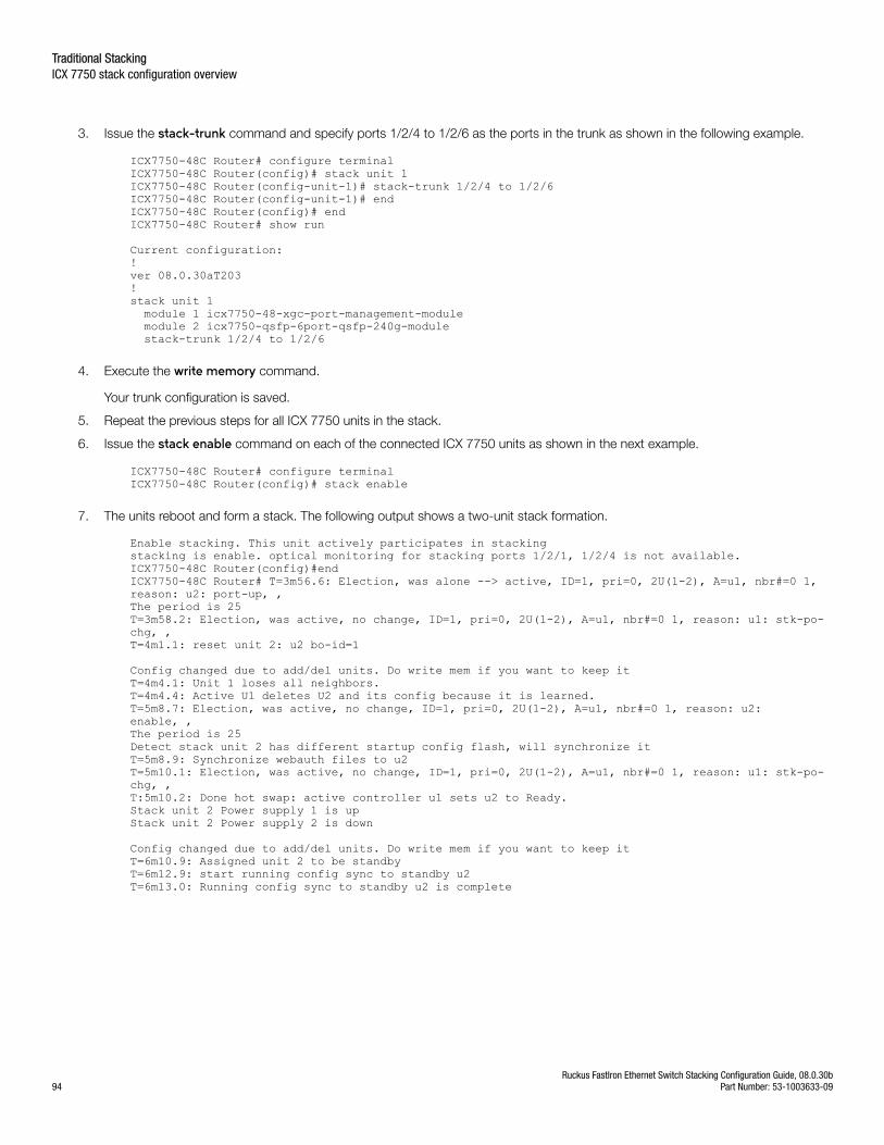
3. Issue the stack-trunk command and specify ports 1/2/4 to 1/2/6 as the ports in the trunk as shown in the following example.
ICX7750-48C Router# configure terminalICX7750-48C Router(config)# stack unit 1ICX7750-48C Router(config-unit-1)# stack-trunk 1/2/4 to 1/2/6ICX7750-48C Router(config-unit-1)# endICX7750-48C Router(config)# endICX7750-48C Router# show run
Current configuration:!ver 08.0.30aT203!stack unit 1 module 1 icx7750-48-xgc-port-management-module module 2 icx7750-qsfp-6port-qsfp-240g-module stack-trunk 1/2/4 to 1/2/6
4. Execute the write memory command.
Your trunk configuration is saved.
5. Repeat the previous steps for all ICX 7750 units in the stack.
6. Issue the stack enable command on each of the connected ICX 7750 units as shown in the next example.
ICX7750-48C Router# configure terminalICX7750-48C Router(config)# stack enable
7. The units reboot and form a stack. The following output shows a two-unit stack formation.
Enable stacking. This unit actively participates in stackingstacking is enable. optical monitoring for stacking ports 1/2/1, 1/2/4 is not available.ICX7750-48C Router(config)#endICX7750-48C Router# T=3m56.6: Election, was alone --> active, ID=1, pri=0, 2U(1-2), A=u1, nbr#=0 1, reason: u2: port-up, , The period is 25 T=3m58.2: Election, was active, no change, ID=1, pri=0, 2U(1-2), A=u1, nbr#=0 1, reason: u1: stk-po-chg, , T=4m1.1: reset unit 2: u2 bo-id=1
Config changed due to add/del units. Do write mem if you want to keep itT=4m4.1: Unit 1 loses all neighbors.T=4m4.4: Active U1 deletes U2 and its config because it is learned.T=5m8.7: Election, was active, no change, ID=1, pri=0, 2U(1-2), A=u1, nbr#=0 1, reason: u2: enable, , The period is 25 Detect stack unit 2 has different startup config flash, will synchronize itT=5m8.9: Synchronize webauth files to u2T=5m10.1: Election, was active, no change, ID=1, pri=0, 2U(1-2), A=u1, nbr#=0 1, reason: u1: stk-po-chg, , T:5m10.2: Done hot swap: active controller u1 sets u2 to Ready.Stack unit 2 Power supply 1 is upStack unit 2 Power supply 2 is down
Config changed due to add/del units. Do write mem if you want to keep itT=6m10.9: Assigned unit 2 to be standbyT=6m12.9: start running config sync to standby u2T=6m13.0: Running config sync to standby u2 is complete
Traditional StackingICX 7750 stack configuration overview
Ruckus FastIron Ethernet Switch Stacking Configuration Guide, 08.0.30b94 Part Number: 53-1003633-09
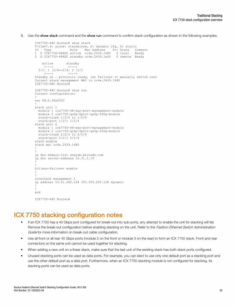
8. Use the show stack command and the show run command to confirm stack configuration as shown in the following examples.
ICX7750-48C Router# show stackT=11m47.4: alone: standalone, D: dynamic cfg, S: staticID Type Role Mac Address Pri State Comment 1 S ICX7750-48XGC active cc4e.2439.1680 0 local Ready2 D ICX7750-48XGC standby cc4e.2439.1a00 0 remote Ready
active standby +---+ +---+ 2/1| 1 |2/4==2/4| 2 |2/1 +---+ +---+ Standby u2 - protocols ready, can failover or manually switch overCurrent stack management MAC is cc4e.2439.1680ICX7750-48C Router#
ICX7750-48C Router# show runCurrent configuration:!ver 08.0.30aT203!stack unit 1 module 1 icx7750-48-xgc-port-management-module module 2 icx7750-qsfp-6port-qsfp-240g-module stack-trunk 1/2/4 to 1/2/6 stack-port 1/2/1 1/2/4stack unit 2 module 1 icx7750-48-xgc-port-management-module module 2 icx7750-qsfp-6port-qsfp-240g-module stack-trunk 2/2/4 to 2/2/6 stack-port 2/2/1 2/2/4stack enablestack mac cc4e.2439.1680!!ip dns domain-list englab.brocade.comip dns server-address 10.31.2.10!!hitless-failover enable!!interface management 1ip address 10.21.242.124 255.255.255.128 dynamic!!end
ICX7750-48C Router#
ICX 7750 stacking configuration notes• If an ICX 7750 has a 40 Gbps port configured for break-out into sub-ports, any attempt to enable the unit for stacking will fail.
Remove the break-out configuration before enabling stacking on the unit. Refer to the FastIron Ethernet Switch AdministrationGuide for more information on break-out cable configuration.
• Use all front or all rear 40 Gbps ports (module 2 on the front or module 3 on the rear) to form an ICX 7750 stack. Front and rearconnectors on the same unit cannot be used together for stacking.
• When adding a new unit on a linear stack, make sure that the last unit of the existing stack has both stack ports configured.
• Unused stacking ports can be used as data ports. For example, you can elect to use only one default port as a stacking port anduse the other default port as a data port. Furthermore, when an ICX 7750 stacking module is not configured for stacking, itsstacking ports can be used as data ports.
Traditional StackingICX 7750 stack configuration overview
Ruckus FastIron Ethernet Switch Stacking Configuration Guide, 08.0.30bPart Number: 53-1003633-09 95
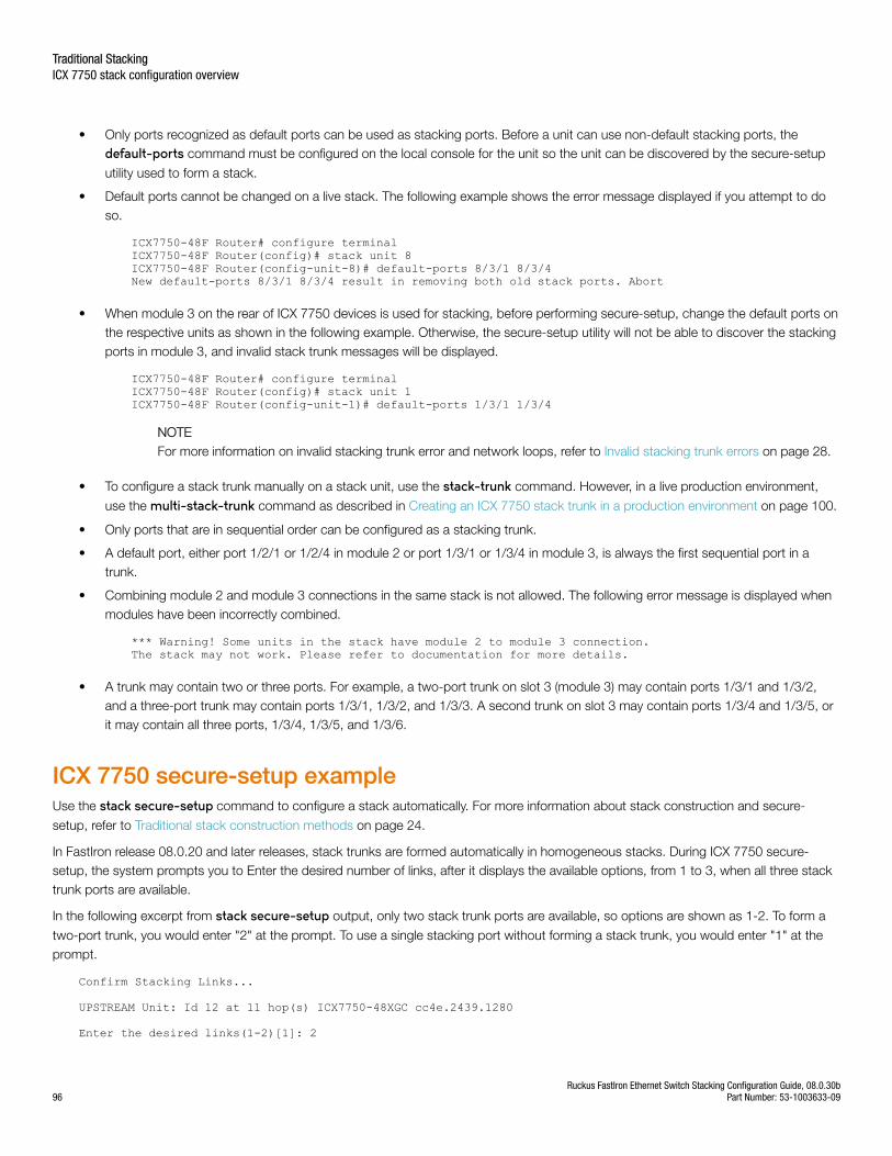
• Only ports recognized as default ports can be used as stacking ports. Before a unit can use non-default stacking ports, thedefault-ports command must be configured on the local console for the unit so the unit can be discovered by the secure-setup
utility used to form a stack.
• Default ports cannot be changed on a live stack. The following example shows the error message displayed if you attempt to doso.
ICX7750-48F Router# configure terminalICX7750-48F Router(config)# stack unit 8 ICX7750-48F Router(config-unit-8)# default-ports 8/3/1 8/3/4New default-ports 8/3/1 8/3/4 result in removing both old stack ports. Abort
• When module 3 on the rear of ICX 7750 devices is used for stacking, before performing secure-setup, change the default ports onthe respective units as shown in the following example. Otherwise, the secure-setup utility will not be able to discover the stackingports in module 3, and invalid stack trunk messages will be displayed.
ICX7750-48F Router# configure terminalICX7750-48F Router(config)# stack unit 1 ICX7750-48F Router(config-unit-1)# default-ports 1/3/1 1/3/4
NOTEFor more information on invalid stacking trunk error and network loops, refer to Invalid stacking trunk errors on page 28.
• To configure a stack trunk manually on a stack unit, use the stack-trunk command. However, in a live production environment,
use the multi-stack-trunk command as described in Creating an ICX 7750 stack trunk in a production environment on page 100.
• Only ports that are in sequential order can be configured as a stacking trunk.
• A default port, either port 1/2/1 or 1/2/4 in module 2 or port 1/3/1 or 1/3/4 in module 3, is always the first sequential port in atrunk.
• Combining module 2 and module 3 connections in the same stack is not allowed. The following error message is displayed whenmodules have been incorrectly combined.
*** Warning! Some units in the stack have module 2 to module 3 connection. The stack may not work. Please refer to documentation for more details.
• A trunk may contain two or three ports. For example, a two-port trunk on slot 3 (module 3) may contain ports 1/3/1 and 1/3/2,and a three-port trunk may contain ports 1/3/1, 1/3/2, and 1/3/3. A second trunk on slot 3 may contain ports 1/3/4 and 1/3/5, orit may contain all three ports, 1/3/4, 1/3/5, and 1/3/6.
ICX 7750 secure-setup exampleUse the stack secure-setup command to configure a stack automatically. For more information about stack construction and secure-
setup, refer to Traditional stack construction methods on page 24.
In FastIron release 08.0.20 and later releases, stack trunks are formed automatically in homogeneous stacks. During ICX 7750 secure-setup, the system prompts you to Enter the desired number of links, after it displays the available options, from 1 to 3, when all three stacktrunk ports are available.
In the following excerpt from stack secure-setup output, only two stack trunk ports are available, so options are shown as 1-2. To form a
two-port trunk, you would enter "2" at the prompt. To use a single stacking port without forming a stack trunk, you would enter "1" at theprompt.
Confirm Stacking Links...
UPSTREAM Unit: Id 12 at 11 hop(s) ICX7750-48XGC cc4e.2439.1280
Enter the desired links(1-2)[1]: 2
Traditional StackingICX 7750 stack configuration overview
Ruckus FastIron Ethernet Switch Stacking Configuration Guide, 08.0.30b96 Part Number: 53-1003633-09
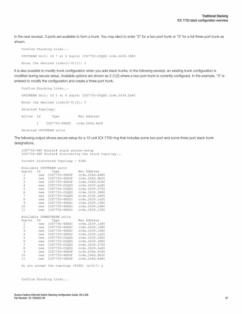
In the next excerpt, 3 ports are available to form a trunk. You may elect to enter "2" for a two-port trunk or "3" for a full three-port trunk asshown.
Confirm Stacking Links...
UPSTREAM Unit: Id 7 at 6 hop(s) ICX7750-20QXG cc4e.2439.3880
Enter the desired links(1-3)[1]: 3
It is also possible to modify trunk configuration when you add stack trunks. In the following excerpt, an existing trunk configuration ismodified during secure-setup. Available options are shown as 2-3 [2] where a two-port trunk is currently configured. In the example, "3" isentered to modify the configuration and create a three-port trunk.
Confirm Stacking Links...
UPSTREAM Unit: Id 5 at 4 hop(s) ICX7750-20QXG cc4e.2439.2a80
Enter the desired links(2-3)[2]: 3
Selected Topology:
Active Id Type Mac Address
1 ICX7750-48XGF cc4e.246d.9e00
Selected UPSTREAM units
The following output shows secure-setup for a 12-unit ICX 7750 ring that includes some two-port and some three-port stack trunkdesignations.
ICX7750-48F Router# stack secure-setupICX7750-48F Router# Discovering the stack topology...
Current Discovered Topology - RING
Available UPSTREAM unitsHop(s) Id Type Mac Address 1 new ICX7750-48XGF cc4e.246d.8d80 2 new ICX7750-48XGF cc4e.246d.9b00 3 new ICX7750-48XGF cc4e.246d.9c80 4 new ICX7750-20QXG cc4e.2439.2a80 5 new ICX7750-20QXG cc4e.2439.3700 6 new ICX7750-20QXG cc4e.2439.3880 7 new ICX7750-20QXG cc4e.2439.2d00 8 new ICX7750-48XGC cc4e.2439.1a00 9 new ICX7750-48XGC cc4e.2439.168010 new ICX7750-48XGC cc4e.2439.1d8011 new ICX7750-48XGC cc4e.2439.1280
Available DOWNSTREAM unitsHop(s) Id Type Mac Address 1 new ICX7750-48XGC cc4e.2439.1280 2 new ICX7750-48XGC cc4e.2439.1d80 3 new ICX7750-48XGC cc4e.2439.1680 4 new ICX7750-48XGC cc4e.2439.1a00 5 new ICX7750-20QXG cc4e.2439.2d00 6 new ICX7750-20QXG cc4e.2439.3880 7 new ICX7750-20QXG cc4e.2439.3700 8 new ICX7750-20QXG cc4e.2439.2a80 9 new ICX7750-48XGF cc4e.246d.9c8010 new ICX7750-48XGF cc4e.246d.9b0011 new ICX7750-48XGF cc4e.246d.8d80
Do you accept the topology (RING) (y/n)?: y
Confirm Stacking Links...
Traditional StackingICX 7750 stack configuration overview
Ruckus FastIron Ethernet Switch Stacking Configuration Guide, 08.0.30bPart Number: 53-1003633-09 97
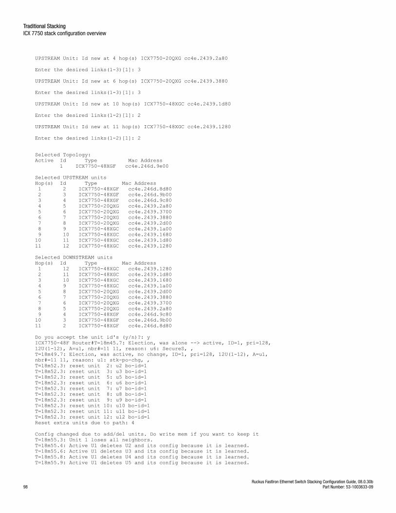
UPSTREAM Unit: Id new at 4 hop(s) ICX7750-20QXG cc4e.2439.2a80
Enter the desired links(1-3)[1]: 3
UPSTREAM Unit: Id new at 6 hop(s) ICX7750-20QXG cc4e.2439.3880
Enter the desired links(1-3)[1]: 3
UPSTREAM Unit: Id new at 10 hop(s) ICX7750-48XGC cc4e.2439.1d80
Enter the desired links(1-2)[1]: 2
UPSTREAM Unit: Id new at 11 hop(s) ICX7750-48XGC cc4e.2439.1280
Enter the desired links(1-2)[1]: 2
Selected Topology:Active Id Type Mac Address 1 ICX7750-48XGF cc4e.246d.9e00
Selected UPSTREAM unitsHop(s) Id Type Mac Address 1 2 ICX7750-48XGF cc4e.246d.8d80 2 3 ICX7750-48XGF cc4e.246d.9b00 3 4 ICX7750-48XGF cc4e.246d.9c80 4 5 ICX7750-20QXG cc4e.2439.2a80 5 6 ICX7750-20QXG cc4e.2439.3700 6 7 ICX7750-20QXG cc4e.2439.3880 7 8 ICX7750-20QXG cc4e.2439.2d00 8 9 ICX7750-48XGC cc4e.2439.1a00 9 10 ICX7750-48XGC cc4e.2439.168010 11 ICX7750-48XGC cc4e.2439.1d8011 12 ICX7750-48XGC cc4e.2439.1280
Selected DOWNSTREAM unitsHop(s) Id Type Mac Address 1 12 ICX7750-48XGC cc4e.2439.1280 2 11 ICX7750-48XGC cc4e.2439.1d80 3 10 ICX7750-48XGC cc4e.2439.1680 4 9 ICX7750-48XGC cc4e.2439.1a00 5 8 ICX7750-20QXG cc4e.2439.2d00 6 7 ICX7750-20QXG cc4e.2439.3880 7 6 ICX7750-20QXG cc4e.2439.3700 8 5 ICX7750-20QXG cc4e.2439.2a80 9 4 ICX7750-48XGF cc4e.246d.9c8010 3 ICX7750-48XGF cc4e.246d.9b0011 2 ICX7750-48XGF cc4e.246d.8d80
Do you accept the unit id's (y/n)?: yICX7750-48F Router#T=18m45.7: Election, was alone --> active, ID=1, pri=128, 12U(1-12), A=u1, nbr#=11 11, reason: u6: SecureS, , T=18m49.7: Election, was active, no change, ID=1, pri=128, 12U(1-12), A=u1, nbr#=11 11, reason: u1: stk-po-chg, , T=18m52.3: reset unit 2: u2 bo-id=1T=18m52.3: reset unit 3: u3 bo-id=1T=18m52.3: reset unit 5: u5 bo-id=1T=18m52.3: reset unit 6: u6 bo-id=1T=18m52.3: reset unit 7: u7 bo-id=1T=18m52.3: reset unit 8: u8 bo-id=1T=18m52.3: reset unit 9: u9 bo-id=1T=18m52.3: reset unit 10: u10 bo-id=1T=18m52.3: reset unit 11: u11 bo-id=1T=18m52.3: reset unit 12: u12 bo-id=1Reset extra units due to path: 4
Config changed due to add/del units. Do write mem if you want to keep itT=18m55.3: Unit 1 loses all neighbors.T=18m55.4: Active U1 deletes U2 and its config because it is learned.T=18m55.6: Active U1 deletes U3 and its config because it is learned.T=18m55.8: Active U1 deletes U4 and its config because it is learned.T=18m55.9: Active U1 deletes U5 and its config because it is learned.
Traditional StackingICX 7750 stack configuration overview
Ruckus FastIron Ethernet Switch Stacking Configuration Guide, 08.0.30b98 Part Number: 53-1003633-09
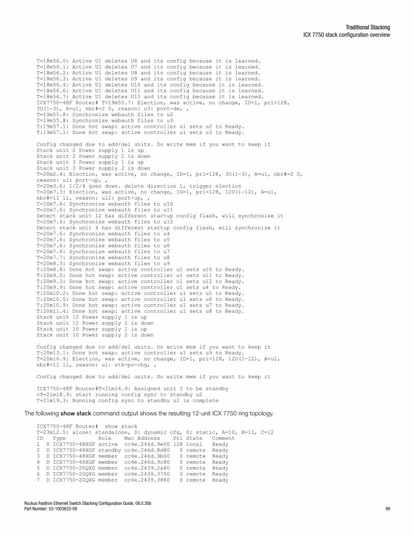
T=18m56.0: Active U1 deletes U6 and its config because it is learned.T=18m56.1: Active U1 deletes U7 and its config because it is learned.T=18m56.2: Active U1 deletes U8 and its config because it is learned.T=18m56.3: Active U1 deletes U9 and its config because it is learned.T=18m56.4: Active U1 deletes U10 and its config because it is learned.T=18m56.6: Active U1 deletes U11 and its config because it is learned.T=18m56.7: Active U1 deletes U12 and its config because it is learned.ICX7750-48F Router# T=19m55.7: Election, was active, no change, ID=1, pri=128, 3U(1-3), A=u1, nbr#=2 0, reason: u3: port-dw, , T=19m55.8: Synchronize webauth files to u2T=19m55.8: Synchronize webauth files to u3T:19m57.1: Done hot swap: active controller u1 sets u2 to Ready.T:19m57.1: Done hot swap: active controller u1 sets u3 to Ready.
Config changed due to add/del units. Do write mem if you want to keep itStack unit 2 Power supply 1 is upStack unit 2 Power supply 2 is downStack unit 3 Power supply 1 is upStack unit 3 Power supply 2 is downT=20m2.4: Election, was active, no change, ID=1, pri=128, 3U(1-3), A=u1, nbr#=2 0, reason: u1: port-up, , T=20m3.6: 1/2/4 goes down. delete direction 1, trigger electionT=20m7.3: Election, was active, no change, ID=1, pri=128, 12U(1-12), A=u1, nbr#=11 11, reason: u12: port-up, , T=20m7.6: Synchronize webauth files to u10T=20m7.6: Synchronize webauth files to u11Detect stack unit 12 has different startup config flash, will synchronize itT=20m7.6: Synchronize webauth files to u12Detect stack unit 4 has different startup config flash, will synchronize itT=20m7.6: Synchronize webauth files to u4T=20m7.6: Synchronize webauth files to u5T=20m7.6: Synchronize webauth files to u6T=20m7.6: Synchronize webauth files to u7T=20m7.7: Synchronize webauth files to u8T=20m8.3: Synchronize webauth files to u9T:20m8.8: Done hot swap: active controller u1 sets u10 to Ready.T:20m9.0: Done hot swap: active controller u1 sets u11 to Ready.T:20m9.3: Done hot swap: active controller u1 sets u12 to Ready.T:20m9.9: Done hot swap: active controller u1 sets u4 to Ready.T:20m10.2: Done hot swap: active controller u1 sets u5 to Ready.T:20m10.5: Done hot swap: active controller u1 sets u6 to Ready.T:20m10.9: Done hot swap: active controller u1 sets u7 to Ready.T:20m11.4: Done hot swap: active controller u1 sets u8 to Ready.Stack unit 12 Power supply 1 is upStack unit 12 Power supply 2 is downStack unit 10 Power supply 1 is upStack unit 10 Power supply 2 is down
Config changed due to add/del units. Do write mem if you want to keep itT:20m13.1: Done hot swap: active controller u1 sets u9 to Ready.T=20m16.9: Election, was active, no change, ID=1, pri=128, 12U(1-12), A=u1, nbr#=11 11, reason: u1: stk-po-chg, ,
Config changed due to add/del units. Do write mem if you want to keep it
ICX7750-48F Router#T=21m16.9: Assigned unit 2 to be standbycT=21m18.9: start running config sync to standby u2T=21m19.3: Running config sync to standby u2 is complete
The following show stack command output shows the resulting 12-unit ICX 7750 ring topology.
ICX7750-48F Router# show stackT=23m12.5: alone: standalone, D: dynamic cfg, S: static, A=10, B=11, C=12ID Type Role Mac Address Pri State Comment 1 S ICX7750-48XGF active cc4e.246d.9e00 128 local Ready2 D ICX7750-48XGF standby cc4e.246d.8d80 0 remote Ready3 D ICX7750-48XGF member cc4e.246d.9b00 0 remote Ready4 D ICX7750-48XGF member cc4e.246d.9c80 0 remote Ready5 D ICX7750-20QXG member cc4e.2439.2a80 0 remote Ready6 D ICX7750-20QXG member cc4e.2439.3700 0 remote Ready7 D ICX7750-20QXG member cc4e.2439.3880 0 remote Ready
Traditional StackingICX 7750 stack configuration overview
Ruckus FastIron Ethernet Switch Stacking Configuration Guide, 08.0.30bPart Number: 53-1003633-09 99
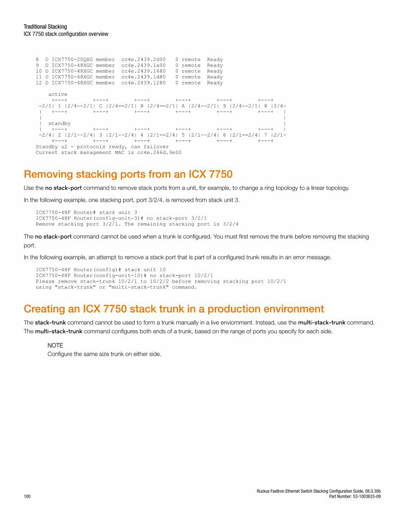
8 D ICX7750-20QXG member cc4e.2439.2d00 0 remote Ready9 D ICX7750-48XGC member cc4e.2439.1a00 0 remote Ready10 D ICX7750-48XGC member cc4e.2439.1680 0 remote Ready11 D ICX7750-48XGC member cc4e.2439.1d80 0 remote Ready12 D ICX7750-48XGC member cc4e.2439.1280 0 remote Ready
active +---+ +---+ +---+ +---+ +---+ +---+ -2/1| 1 |2/4--2/1| C |2/4==2/1| B |2/4==2/1| A |2/4--2/1| 9 |2/4--2/1| 8 |2/4- | +---+ +---+ +---+ +---+ +---+ +---+ | | | | standby | | +---+ +---+ +---+ +---+ +---+ +---+ | -2/4| 2 |2/1--2/4| 3 |2/1--2/4| 4 |2/1==2/4| 5 |2/1--2/4| 6 |2/1==2/4| 7 |2/1- +---+ +---+ +---+ +---+ +---+ +---+ Standby u2 - protocols ready, can failoverCurrent stack management MAC is cc4e.246d.9e00
Removing stacking ports from an ICX 7750Use the no stack-port command to remove stack ports from a unit, for example, to change a ring topology to a linear topology.
In the following example, one stacking port, port 3/2/4, is removed from stack unit 3.
ICX7750-48F Router# stack unit 3ICX7750-48F Router(config-unit-3)# no stack-port 3/2/1Remove stacking port 3/2/1. The remaining stacking port is 3/2/4
The no stack-port command cannot be used when a trunk is configured. You must first remove the trunk before removing the stacking
port.
In the following example, an attempt to remove a stack port that is part of a configured trunk results in an error message.
ICX7750-48F Router(config)# stack unit 10ICX7750-48F Router(config-unit-10)# no stack-port 10/2/1Please remove stack-trunk 10/2/1 to 10/2/2 before removing stacking port 10/2/1using "stack-trunk" or "multi-stack-trunk" command.
Creating an ICX 7750 stack trunk in a production environmentThe stack-trunk command cannot be used to form a trunk manually in a live enviornment. Instead, use the multi-stack-trunk command.
The multi-stack-trunk command configures both ends of a trunk, based on the range of ports you specify for each side.
NOTEConfigure the same size trunk on either side.
Traditional StackingICX 7750 stack configuration overview
Ruckus FastIron Ethernet Switch Stacking Configuration Guide, 08.0.30b100 Part Number: 53-1003633-09
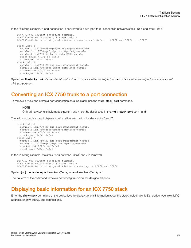
In the following example, a port connection is converted to a two-port trunk connection between stack unit 4 and stack unit 5.
ICX7750-48F Router# configure terminalICX7750-48F Router(config)# stack unit 4ICX7750-48F Router(config-unit-4)# multi-stack-trunk 4/2/1 to 4/2/2 and 5/2/4 to 5/2/5
stack unit 4 module 1 icx7750-48-xgf-port-management-module module 2 icx7750-qsfp-6port-qsfp-240g-module module 3 icx7750-6q-6port-qsfp-240g-module stack-trunk 4/2/1 to 4/2/2 stack-port 4/2/1 4/2/4stack unit 5 module 1 icx7750-20-qxg-port-management-module module 2 icx7750-qsfp-6port-qsfp-240g-module stack-trunk 5/2/4 to 5/2/5 stack-port 5/2/1 5/2/4
Syntax: multi-stack-trunk stack-unit/slotnum/portnum to stack-unit/slotnum/portnum and stack-unit/slotnum/portnum to stack-unit/slotnum/portnum
Converting an ICX 7750 trunk to a port connectionTo remove a trunk and create a port connection on a live stack, use the multi-stack-port command.
NOTEOnly primary ports (stack module ports 1 and 4) can be designated in the multi-stack-port command.
The following code excerpt displays configuration information for stack units 6 and 7.
stack unit 6 module 1 icx7750-20-qxg-port-management-module module 2 icx7750-qsfp-6port-qsfp-240g-module stack-trunk 6/2/1 to 6/2/3 stack-port 6/2/1 6/2/4stack unit 7 module 1 icx7750-20-qxg-port-management-module module 2 icx7750-qsfp-6port-qsfp-240g-module stack-trunk 7/2/4 to 7/2/6 stack-port 7/2/1 7/2/4
In the following example, the stack trunk between units 6 and 7 is removed.
ICX7750-48F Router# configure terminalICX7750-48F Router(config)# stack unit 6ICX7750-48F Router(config-unit-6)# multi-stack-port 6/2/1 and 7/2/4
Syntax: [no] multi-stack-port stack-unit/slot/port and stack-unit/slot/port
The no form of the command removes port configuration on the designated ports.
Displaying basic information for an ICX 7750 stackEnter the show stack command at the device level to display general information about the stack, including unit IDs, device type, role, MAC
address, priority, status, and connections.
Traditional StackingICX 7750 stack configuration overview
Ruckus FastIron Ethernet Switch Stacking Configuration Guide, 08.0.30bPart Number: 53-1003633-09 101
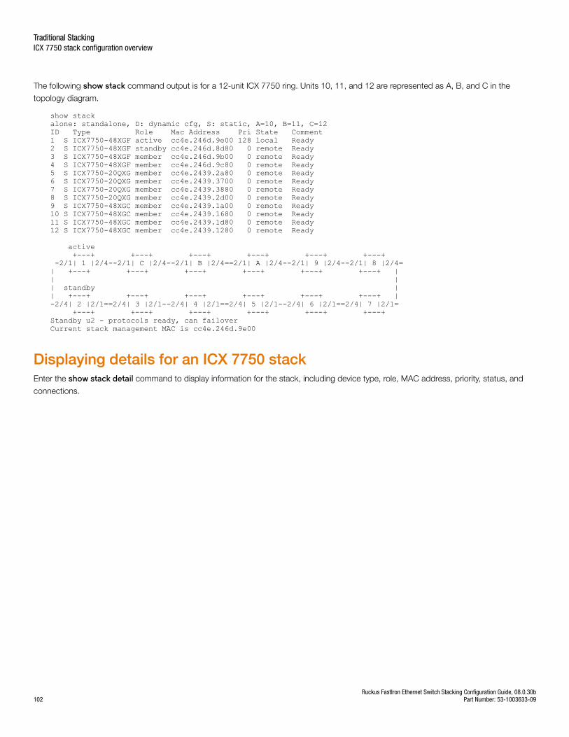
The following show stack command output is for a 12-unit ICX 7750 ring. Units 10, 11, and 12 are represented as A, B, and C in the
topology diagram.
show stackalone: standalone, D: dynamic cfg, S: static, A=10, B=11, C=12ID Type Role Mac Address Pri State Comment 1 S ICX7750-48XGF active cc4e.246d.9e00 128 local Ready2 S ICX7750-48XGF standby cc4e.246d.8d80 0 remote Ready3 S ICX7750-48XGF member cc4e.246d.9b00 0 remote Ready4 S ICX7750-48XGF member cc4e.246d.9c80 0 remote Ready5 S ICX7750-20QXG member cc4e.2439.2a80 0 remote Ready6 S ICX7750-20QXG member cc4e.2439.3700 0 remote Ready7 S ICX7750-20QXG member cc4e.2439.3880 0 remote Ready8 S ICX7750-20QXG member cc4e.2439.2d00 0 remote Ready9 S ICX7750-48XGC member cc4e.2439.1a00 0 remote Ready10 S ICX7750-48XGC member cc4e.2439.1680 0 remote Ready11 S ICX7750-48XGC member cc4e.2439.1d80 0 remote Ready12 S ICX7750-48XGC member cc4e.2439.1280 0 remote Ready
active +---+ +---+ +---+ +---+ +---+ +---+ -2/1| 1 |2/4--2/1| C |2/4--2/1| B |2/4==2/1| A |2/4--2/1| 9 |2/4--2/1| 8 |2/4=| +---+ +---+ +---+ +---+ +---+ +---+ || || standby || +---+ +---+ +---+ +---+ +---+ +---+ |-2/4| 2 |2/1==2/4| 3 |2/1--2/4| 4 |2/1==2/4| 5 |2/1--2/4| 6 |2/1==2/4| 7 |2/1= +---+ +---+ +---+ +---+ +---+ +---+ Standby u2 - protocols ready, can failoverCurrent stack management MAC is cc4e.246d.9e00
Displaying details for an ICX 7750 stackEnter the show stack detail command to display information for the stack, including device type, role, MAC address, priority, status, and
connections.
Traditional StackingICX 7750 stack configuration overview
Ruckus FastIron Ethernet Switch Stacking Configuration Guide, 08.0.30b102 Part Number: 53-1003633-09
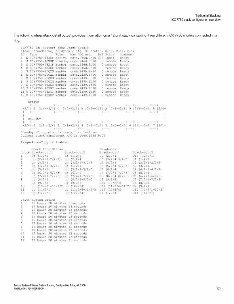
The following show stack detail output provides information on a 12-unit stack containing three different ICX 7750 models connected in a
ring.
ICX7750-48F Router# show stack detailalone: standalone, D: dynamic cfg, S: static, A=10, B=11, C=12ID Type Role Mac Address Pri State Comment 1 S ICX7750-48XGF active cc4e.246d.9e00 128 local Ready2 S ICX7750-48XGF standby cc4e.246d.8d80 0 remote Ready3 S ICX7750-48XGF member cc4e.246d.9b00 0 remote Ready4 S ICX7750-48XGF member cc4e.246d.9c80 0 remote Ready5 S ICX7750-20QXG member cc4e.2439.2a80 0 remote Ready6 S ICX7750-20QXG member cc4e.2439.3700 0 remote Ready7 S ICX7750-20QXG member cc4e.2439.3880 0 remote Ready8 S ICX7750-20QXG member cc4e.2439.2d00 0 remote Ready9 S ICX7750-48XGC member cc4e.2439.1a00 0 remote Ready10 S ICX7750-48XGC member cc4e.2439.1680 0 remote Ready11 S ICX7750-48XGC member cc4e.2439.1d80 0 remote Ready12 S ICX7750-48XGC member cc4e.2439.1280 0 remote Ready
active +---+ +---+ +---+ +---+ +---+ +---+ -2/1| 1 |2/4--2/1| C |2/4--2/1| B |2/4==2/1| A |2/4--2/1| 9 |2/4--2/1| 8 |2/4= | +---+ +---+ +---+ +---+ +---+ +---+ | | | | standby | | +---+ +---+ +---+ +---+ +---+ +---+ | -2/4| 2 |2/1==2/4| 3 |2/1--2/4| 4 |2/1==2/4| 5 |2/1--2/4| 6 |2/1==2/4| 7 |2/1= +---+ +---+ +---+ +---+ +---+ +---+ Standby u2 - protocols ready, can failoverCurrent stack management MAC is cc4e.246d.9e00
Image-Auto-Copy is Enabled.
Stack Port Status Neighbors Unit# Stack-port1 Stack-port2 Stack-port1 Stack-port2 1 up (1/2/1) up (1/2/4) U2 (2/2/4) U12 (12/2/1) 2 up (2/2/1-2/2/2) up (2/2/4) U3 (3/2/4-3/2/5) U1 (1/2/1) 3 up (3/2/1) up (3/2/4-3/2/5) U4 (4/2/4) U2 (2/2/1-2/2/2) 4 up (4/2/1-4/2/2) up (4/2/4) U5 (5/2/4-5/2/5) U3 (3/2/1) 5 up (5/2/1) up (5/2/4-5/2/5) U6 (6/2/4) U4 (4/2/1-4/2/2) 6 up (6/2/1-6/2/3) up (6/2/4) U7 (7/2/4-7/2/6) U5 (5/2/1) 7 up (7/2/1-7/2/2) up (7/2/4-7/2/6) U8 (8/2/4-8/2/5) U6 (6/2/1-6/2/3) 8 up (8/2/1) up (8/2/4-8/2/5) U9 (9/2/4) U7 (7/2/1-7/2/2) 9 up (9/2/1) up (9/2/4) U10 (10/2/4) U8 (8/2/1) 10 up (10/2/1-10/2/2 up (10/2/4) U11 (11/2/4-11/2/ U9 (9/2/1) 11 up (11/2/1) up (11/2/4-11/2/5 U12 (12/2/4) U10 (10/2/1-10/2/12 up (12/2/1) up (12/2/4) U1 (1/2/4) U11 (11/2/1)
Unit# System uptime1 17 hours 20 minutes 8 seconds 2 17 hours 20 minutes 13 seconds 3 17 hours 20 minutes 13 seconds 4 17 hours 20 minutes 12 seconds 5 17 hours 20 minutes 13 seconds 6 17 hours 20 minutes 13 seconds 7 17 hours 20 minutes 13 seconds 8 17 hours 20 minutes 11 seconds 9 17 hours 20 minutes 13 seconds 10 17 hours 20 minutes 15 seconds 11 17 hours 20 minutes 13 seconds 12 17 hours 20 minutes 11 seconds
Traditional StackingICX 7750 stack configuration overview
Ruckus FastIron Ethernet Switch Stacking Configuration Guide, 08.0.30bPart Number: 53-1003633-09 103

Ruckus FastIron Ethernet Switch Stacking Configuration Guide, 08.0.30b104 Part Number: 53-1003633-09
Traditional Stack Management• Managing a traditional stack through one IP address.............................................................................................105• Enabling or disabling stacking mode..................................................................................................................... 105• Controlling the stack through the CLI.....................................................................................................................106• Traditional stack management MAC address.........................................................................................................109• Traditional stack device roles and elections............................................................................................................111• Traditional stack unit priority.................................................................................................................................. 114• Traditional stack software images.......................................................................................................................... 115• Copying the flash image to a stack unit from the active controller.......................................................................... 117• Adding, removing, or replacing units in a traditional stack......................................................................................117• Renumbering stack units.......................................................................................................................................120• Reloading a stack unit........................................................................................................................................... 121• Controlling stack size to allow for a data port.........................................................................................................121• Managing traditional stack partitioning...................................................................................................................122• Merging traditional stacks......................................................................................................................................122• Unconfiguring a traditional stack............................................................................................................................123• Syslog, SNMP, and traps for stack units................................................................................................................ 124• PHY calibration errors in stack ports of the ICX 6610.............................................................................................125• Displaying traditional stack information.................................................................................................................. 125• MIB support for the traditional stack......................................................................................................................143
Managing a traditional stack through one IP addressYour Ruckus traditional stack can be managed through a single IP address. You can manage the stack using this IP address even if youremove the active controller or any member from the stack. You can also connect to the active controller through Telnet or SSH using thisaddress. All management functions, such as SNMP, use this IP address to acquire MIB information and other management data.
Enabling or disabling stacking modeWhen a unit is stack-enabled or joins a stack either actively or passively, it reserves priority queue 7 for stacking traffic control, assignsbuffers for the stacking ports, and configures the first two 10 Gbps ports as stacking ports.
NOTEDesignated stacking ports cannot contain any configuration information, such as VLAN membership. If configuration informationexists, stack enable will fail. You must remove all configuration information from the port and re-issue the stack enable command.
To enable stacking mode on a new unit before you add it to the stack, enter the following command.
device(config)# stack enableEnable stacking. This unit actively participates in stacking
Syntax: [no] stack enable
To see the configuration of the stack at any time, enter the show running-config command. Refer to "Displaying running configuration
information" for details.
Ruckus FastIron Ethernet Switch Stacking Configuration Guide, 08.0.30bPart Number: 53-1003633-09 105
Disabling stacking modeTo remove stacking capability, enter the no stack enable command. This prevents the unit from actively sending out probe messages;
however, the unit could still be called to join a stack by an active controller. To prevent this, enter the stack disable command in device
configuration mode.
The stack disable command prevents a unit from sending or listening for any stacking probe messages. In this mode, the unit cannot be
forced to join a stack.
device# configure terminaldevice(config)# stack disable
Syntax: [no] stack disable
To restore the capability of the device to send and receive stacking probe messages, enter the no stack disable command in device
configuration mode.
Traditional stack unit identificationStack units are identified by numbers 1 though 8 (1 through 12 on ICX 7450 and ICX 7750 devices). You can display stack unit IDs byentering the show stack command.
A new device (one that has not been connected in a traditional stack or that has not been manually assigned a stack unit number) shipswith a default number of 1. Once you enable stacking and the unit becomes part of a traditional stack, its default stack unit numberchanges to the lowest available number in the stack. You can configure the stack suggested-id command in a standalone unit before it
joins a stack to assign this unit the suggested ID.
Stack units must each have a unique identification number. Every stack member, including any standalone units, retains its stack unitnumber unless that number is already being used in the stack, or until you manually renumber the unit using secure-setup. For moreinformation about how to renumber stack IDs using secure-setup, refer to Renumbering stack units on page 120.
Controlling the stack through the CLIA Ruckus traditional stack can be configured and managed using the command line interface (CLI). You can access the traditional stackand the command CLI in two ways:
• Through a direct serial connection to the console port
• Through a local or remote Telnet session using the stack IP address
You can initiate a local Telnet or SNMP connection by attaching a cable to a port and specifying the assigned management station IPaddress.
The stacking commands in the CLI are organized into the following levels:
• Global - Commands issued in global mode are applied to the entire stack.
• Configuration mode - In this mode, you can make configuration changes to the entire stack. To save changes across reloads, youmust save them to the active controller startup-config file. The configuration mode contains sub-levels for individual units andports, VLANs, routing protocols, and other configuration areas.
• Stack unit configuration mode - Commands issued in this mode apply to the specified stack unit. Configuration informationresides in the active controller.
Traditional Stack ManagementControlling the stack through the CLI
Ruckus FastIron Ethernet Switch Stacking Configuration Guide, 08.0.30b106 Part Number: 53-1003633-09
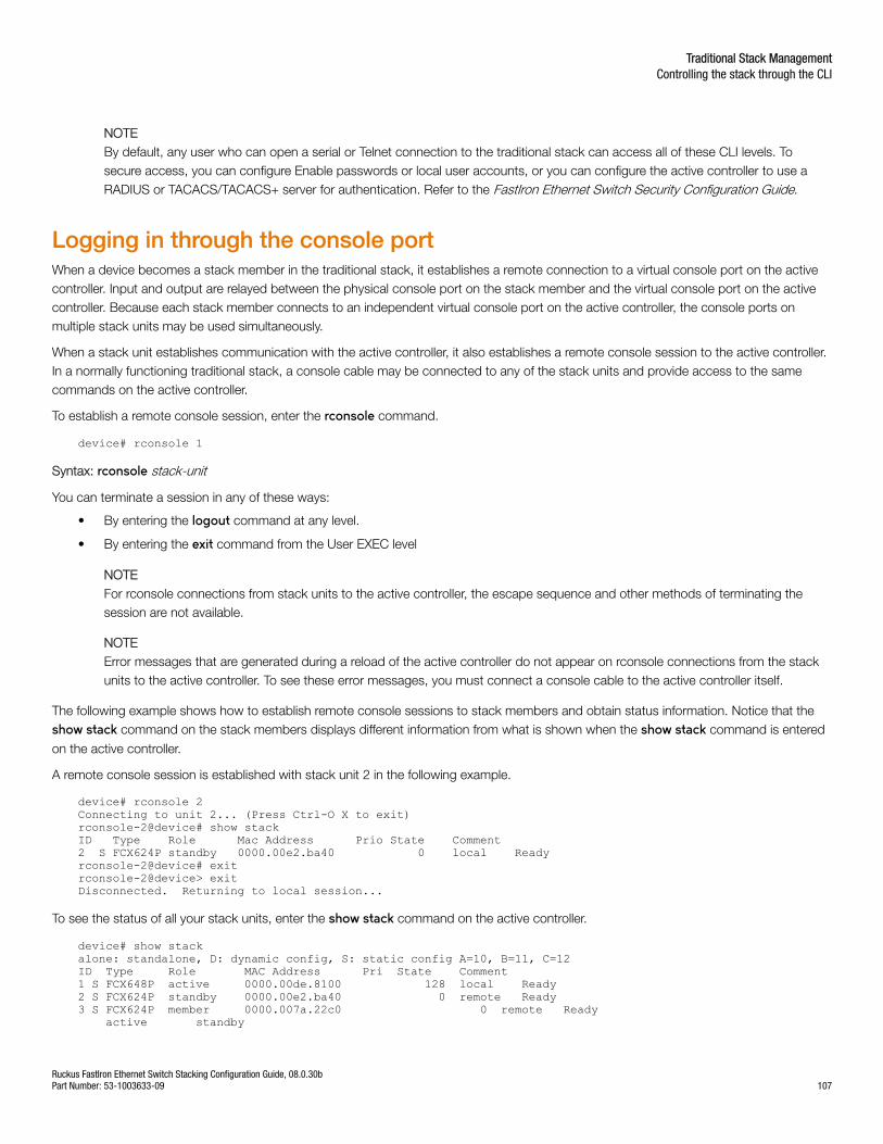
NOTEBy default, any user who can open a serial or Telnet connection to the traditional stack can access all of these CLI levels. Tosecure access, you can configure Enable passwords or local user accounts, or you can configure the active controller to use aRADIUS or TACACS/TACACS+ server for authentication. Refer to the FastIron Ethernet Switch Security Configuration Guide.
Logging in through the console portWhen a device becomes a stack member in the traditional stack, it establishes a remote connection to a virtual console port on the activecontroller. Input and output are relayed between the physical console port on the stack member and the virtual console port on the activecontroller. Because each stack member connects to an independent virtual console port on the active controller, the console ports onmultiple stack units may be used simultaneously.
When a stack unit establishes communication with the active controller, it also establishes a remote console session to the active controller.In a normally functioning traditional stack, a console cable may be connected to any of the stack units and provide access to the samecommands on the active controller.
To establish a remote console session, enter the rconsole command.
device# rconsole 1
Syntax: rconsole stack-unit
You can terminate a session in any of these ways:
• By entering the logout command at any level.
• By entering the exit command from the User EXEC level
NOTEFor rconsole connections from stack units to the active controller, the escape sequence and other methods of terminating thesession are not available.
NOTEError messages that are generated during a reload of the active controller do not appear on rconsole connections from the stackunits to the active controller. To see these error messages, you must connect a console cable to the active controller itself.
The following example shows how to establish remote console sessions to stack members and obtain status information. Notice that theshow stack command on the stack members displays different information from what is shown when the show stack command is entered
on the active controller.
A remote console session is established with stack unit 2 in the following example.
device# rconsole 2Connecting to unit 2... (Press Ctrl-O X to exit)rconsole-2@device# show stackID Type Role Mac Address Prio State Comment2 S FCX624P standby 0000.00e2.ba40 0 local Readyrconsole-2@device# exitrconsole-2@device> exitDisconnected. Returning to local session...
To see the status of all your stack units, enter the show stack command on the active controller.
device# show stackalone: standalone, D: dynamic config, S: static config A=10, B=11, C=12ID Type Role MAC Address Pri State Comment1 S FCX648P active 0000.00de.8100 128 local Ready2 S FCX624P standby 0000.00e2.ba40 0 remote Ready3 S FCX624P member 0000.007a.22c0 0 remote Ready active standby
Traditional Stack ManagementControlling the stack through the CLI
Ruckus FastIron Ethernet Switch Stacking Configuration Guide, 08.0.30bPart Number: 53-1003633-09 107
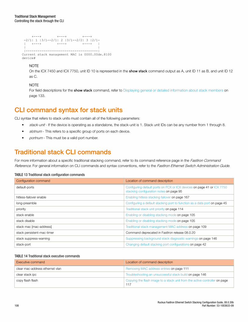
+---+ +---+ +---+ -2/1| 1 |3/1--2/1| 2 |3/1--2/2| 3 |2/1- | +---+ +---+ +---+ | | | |-------------------------------------|Current stack management MAC is 0000.00de.8100device#
NOTEOn the ICX 7450 and ICX 7750, unit ID 10 is represented in the show stack command output as A, unit ID 11 as B, and unit ID 12
as C.
NOTEFor field descriptions for the show stack command, refer to Displaying general or detailed information about stack members on
page 133.
CLI command syntax for stack unitsCLI syntax that refers to stack units must contain all of the following parameters:
• stack-unit - If the device is operating as a standalone, the stack-unit is 1. Stack unit IDs can be any number from 1 through 8.
• slotnum - This refers to a specific group of ports on each device.
• portnum - This must be a valid port number.
Traditional stack CLI commandsFor more information about a specific traditional stacking command, refer to its command reference page in the FastIron CommandReference. For general information on CLI commands and syntax conventions, refer to the FastIron Ethernet Switch Administration Guide.
TABLE 13 Traditional stack configuration commands
Configuration command Location of command description
default-ports Configuring default ports on FCX or ICX devices on page 41 or ICX 7750stacking configuration notes on page 95
hitless-failover enable Enabling hitless stacking failover on page 167
long-preamble Configuring a default stacking port to function as a data port on page 45
priority Traditional stack unit priority on page 114
stack enable Enabling or disabling stacking mode on page 105
stack disable Enabling or disabling stacking mode on page 105
stack mac [mac-address] Traditional stack management MAC address on page 109
stack persistent-mac-timer Command deprecated in FastIron release 08.0.20
stack suppress-warning Suppressing background stack diagnostic warnings on page 146
stack-port Changing default stacking port configurations on page 42
TABLE 14 Traditional stack executive commands
Executive command Location of command description
clear mac-address ethernet vlan Removing MAC address entries on page 111
clear stack ipc Troubleshooting an unsuccessful stack build on page 146
copy flash flash Copying the flash image to a stack unit from the active controller on page117
Traditional Stack ManagementControlling the stack through the CLI
Ruckus FastIron Ethernet Switch Stacking Configuration Guide, 08.0.30b108 Part Number: 53-1003633-09
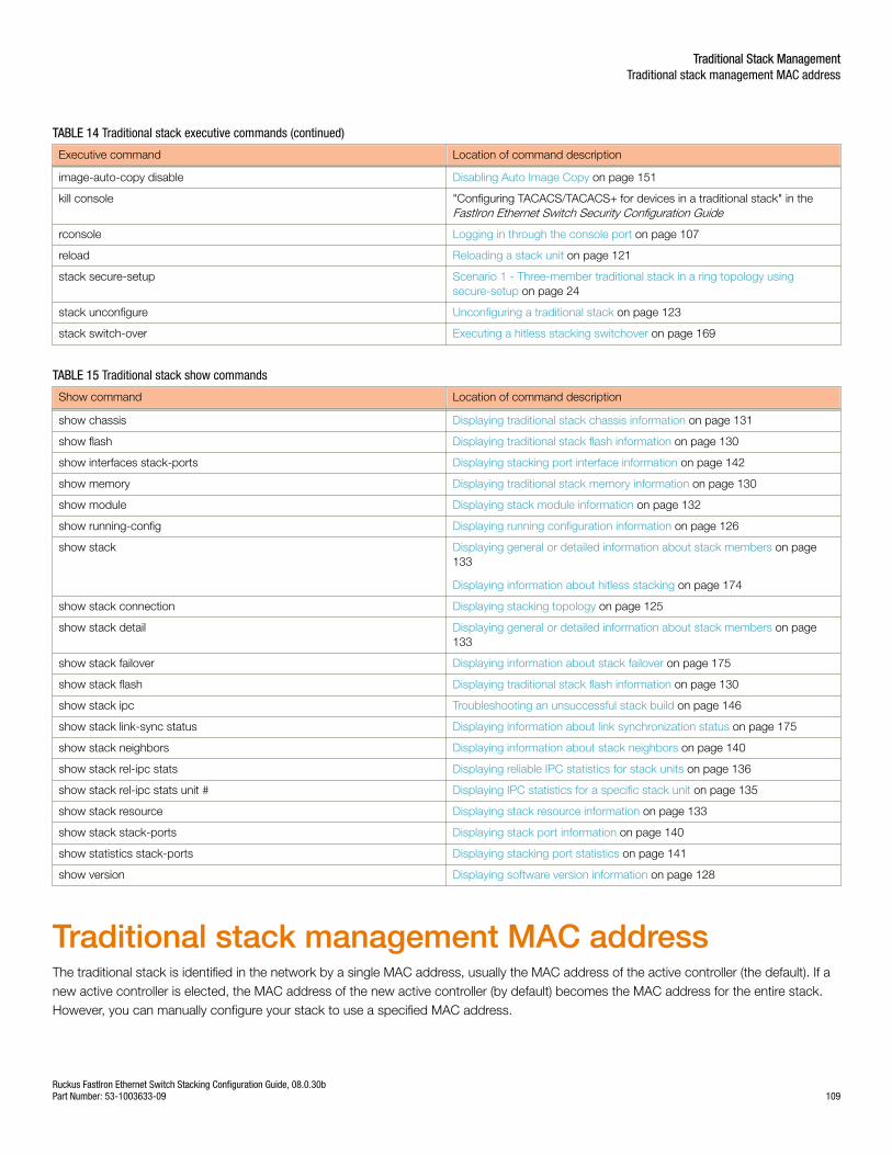
TABLE 14 Traditional stack executive commands (continued)
Executive command Location of command description
image-auto-copy disable Disabling Auto Image Copy on page 151
kill console "Configuring TACACS/TACACS+ for devices in a traditional stack" in theFastIron Ethernet Switch Security Configuration Guide
rconsole Logging in through the console port on page 107
reload Reloading a stack unit on page 121
stack secure-setup Scenario 1 - Three-member traditional stack in a ring topology usingsecure-setup on page 24
stack unconfigure Unconfiguring a traditional stack on page 123
stack switch-over Executing a hitless stacking switchover on page 169
TABLE 15 Traditional stack show commands
Show command Location of command description
show chassis Displaying traditional stack chassis information on page 131
show flash Displaying traditional stack flash information on page 130
show interfaces stack-ports Displaying stacking port interface information on page 142
show memory Displaying traditional stack memory information on page 130
show module Displaying stack module information on page 132
show running-config Displaying running configuration information on page 126
show stack Displaying general or detailed information about stack members on page133
Displaying information about hitless stacking on page 174
show stack connection Displaying stacking topology on page 125
show stack detail Displaying general or detailed information about stack members on page133
show stack failover Displaying information about stack failover on page 175
show stack flash Displaying traditional stack flash information on page 130
show stack ipc Troubleshooting an unsuccessful stack build on page 146
show stack link-sync status Displaying information about link synchronization status on page 175
show stack neighbors Displaying information about stack neighbors on page 140
show stack rel-ipc stats Displaying reliable IPC statistics for stack units on page 136
show stack rel-ipc stats unit # Displaying IPC statistics for a specific stack unit on page 135
show stack resource Displaying stack resource information on page 133
show stack stack-ports Displaying stack port information on page 140
show statistics stack-ports Displaying stacking port statistics on page 141
show version Displaying software version information on page 128
Traditional stack management MAC addressThe traditional stack is identified in the network by a single MAC address, usually the MAC address of the active controller (the default). If anew active controller is elected, the MAC address of the new active controller (by default) becomes the MAC address for the entire stack.However, you can manually configure your stack to use a specified MAC address.
Traditional Stack ManagementTraditional stack management MAC address
Ruckus FastIron Ethernet Switch Stacking Configuration Guide, 08.0.30bPart Number: 53-1003633-09 109
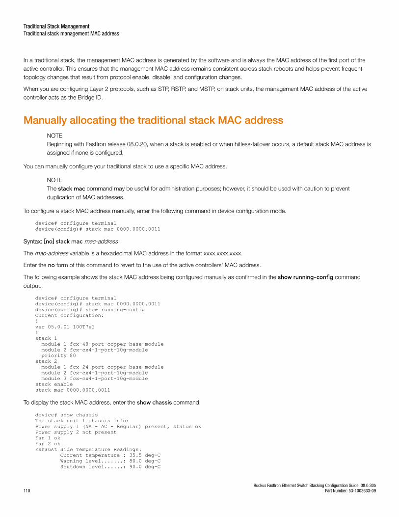
In a traditional stack, the management MAC address is generated by the software and is always the MAC address of the first port of theactive controller. This ensures that the management MAC address remains consistent across stack reboots and helps prevent frequenttopology changes that result from protocol enable, disable, and configuration changes.
When you are configuring Layer 2 protocols, such as STP, RSTP, and MSTP, on stack units, the management MAC address of the activecontroller acts as the Bridge ID.
Manually allocating the traditional stack MAC addressNOTEBeginning with FastIron release 08.0.20, when a stack is enabled or when hitless-failover occurs, a default stack MAC address isassigned if none is configured.
You can manually configure your traditional stack to use a specific MAC address.
NOTEThe stack mac command may be useful for administration purposes; however, it should be used with caution to prevent
duplication of MAC addresses.
To configure a stack MAC address manually, enter the following command in device configuration mode.
device# configure terminaldevice(config)# stack mac 0000.0000.0011
Syntax: [no] stack mac mac-address
The mac-address variable is a hexadecimal MAC address in the format xxxx.xxxx.xxxx.
Enter the no form of this command to revert to the use of the active controllers' MAC address.
The following example shows the stack MAC address being configured manually as confirmed in the show running-config command
output.
device# configure terminaldevice(config)# stack mac 0000.0000.0011device(config)# show running-configCurrent configuration:!ver 05.0.01 100T7e1!stack 1 module 1 fcx-48-port-copper-base-module module 2 fcx-cx4-1-port-10g-module priority 80stack 2 module 1 fcx-24-port-copper-base-module module 2 fcx-cx4-1-port-10g-module module 3 fcx-cx4-1-port-10g-modulestack enablestack mac 0000.0000.0011
To display the stack MAC address, enter the show chassis command.
device# show chassisThe stack unit 1 chassis info:Power supply 1 (NA - AC - Regular) present, status okPower supply 2 not presentFan 1 okFan 2 okExhaust Side Temperature Readings: Current temperature : 35.5 deg-C Warning level.......: 80.0 deg-C Shutdown level......: 90.0 deg-C
Traditional Stack ManagementTraditional stack management MAC address
Ruckus FastIron Ethernet Switch Stacking Configuration Guide, 08.0.30b110 Part Number: 53-1003633-09
Intake Side Temperature Readings: Current temperature : 33.5 deg-CBoot Prom MAC: 0000.00de.9440Management MAC: 0000.0000.0011The stack unit 2 chassis info:Power supply 1 (NA - AC - Regular) present, status okPower supply 2 not presentFan 1 okFan 2 ok--More--, next page: Space, next line: Return key, quit: Control-c
NOTEFor field descriptions of the show chassis command, refer to Displaying traditional stack chassis information on page 131.
Removing MAC address entriesYou can remove the following types of learned MAC address entries, for example, for debugging purposes, from the Ruckus system MACaddress table:
• All MAC address entries
• All MAC address entries for a specified Ethernet port
• All MAC address entries for a specified VLAN
• A specified MAC address entry in all VLANs
For example, to remove entries for the MAC address 0000.0080.00d in all VLANs, enter the following command at the device prompt.
device# clear mac-address 0000.0080.00d0
Syntax: clear mac-address [ mac-address | ethernet port | vlan number ]
• If you enter the clear mac-address command without any parameters, the software removes all MAC entries.
• Use the mac-address variable to remove a specified MAC address from all VLANs. Specify the MAC address in the followingformat: XXXX.XXXX.XXXX.
• Use the ethernet port parameter to remove all MAC addresses for a specified Ethernet port. Specify the port variable in the formatstack-unit/slot number/port number
• Use the vlan number parameter to remove all MAC addresses for a specified VLAN.
Traditional stack device roles and electionsThere are three distinct roles played by units that are part of a traditional stack:
• Active controller
• Standby controller
• Stack member
Active controllerThe active controller contains the saved and running configuration files for each stack member. The configuration files include the system-level settings for the stack and the interface-level settings for each stack member, as well as MIB counters and port status. The standbycontroller also has a synchronized copy of the active controller startup-config file in case the active controller fails.
When a stack is formed, the console function for each stack member is automatically redirected to the active controller console. The activecontroller console port handles all stack management functions, as well as ping activity, Telnet sessions, and TFTP image downloads for
Traditional Stack ManagementTraditional stack device roles and elections
Ruckus FastIron Ethernet Switch Stacking Configuration Guide, 08.0.30bPart Number: 53-1003633-09 111
every stack member. If you connect to the console port on a stack member that is not the active controller, you are automatically directedthrough the console of the active controller.
The active controller synchronizes its startup configuration with the standby controller and the rest of the stack members. You can recoverthe previous flash configuration of the standby controller and the stack members by issuing the stack unconfigure command. For anexample of this command and the output generated, refer to Unconfiguring a traditional stack on page 123.
The active controller may reset the rest of the stack members, if necessary. However, if the active controller itself must be reset because of arole or ID change, you must issue the reset command.
If the active controller fails, the standby controller waits 30 seconds and then takes over as active controller, resetting itself and all otherstack members. If the old active controller becomes operational, it may or may not resume its role as active controller, depending on theconfigured priorities.
Standby controllerIn addition to the active controller, another stack member is elected as the standby controller. If the active controller fails, the standbycontroller takes over after a default interval of 30 seconds. If hitless stacking failover is enabled, the standby controller can take overimmediately without reloading any unit.
The standby controller synchronizes its configuration with the active controller at each reset.
Bootup roleWhen a stack unit boots, it boots in a particular role, active controller, standby controller, or stack member, or as a standalone device. Whenthe bootup role is standby controller or stack member, the CLI available to the unit is limited to show and stack commands. A unit in therole of standby controller or stack member does not act without instructions from the active controller.
The last line of the show version output identifies the unit role unless the unit is in standalone mode.
My stack unit ID = 1, bootup role = activeMy stack unit ID = 3, bootup role = standby
NOTETo convert a standby controller or stack member to a standalone device, use the stack unconfigure me command (refer to Unconfiguring a traditional stack on page 123).
Active controller and standby controller electionsWhenever there is a topology change in the stack (a reset, unit failure, or the addition or removal of members), elections are held todetermine the status of the active controller and standby controller. The results of the election take effect after the next stack reset.
The following conditions, in the order shown, determine which units serve as active controller and standby controller after an election. Thereason for this hierarchy of factors is to achieve a predictable winner, regardless of the boot up sequence for a unit.
• Boot as active controller - Indicates that a unit was previously active controller before the current boot sequence and will againassume the role of active controller when two standalone units are combined into a stack. When a third standalone unit joins thestack, the current active controller becomes subject to the other factors in this list. You can upgrade your current active controllerto "boot as active controller" status by executing the write memory command. The system interprets the write memory action as
a directive to maintain the current active controller role regardless of resets or a new unit joining the stack.
• Priority - The unit with the highest priority value.
• Greater number of members - The unit that has control over the greater number of stack members.
Traditional Stack ManagementTraditional stack device roles and elections
Ruckus FastIron Ethernet Switch Stacking Configuration Guide, 08.0.30b112 Part Number: 53-1003633-09
• Longer up time - An up time that is more than 30 seconds longer than the next one in size is considered. Where up times arecompared, there is no effect if the difference is less than 30 seconds.
• Lowest boot stack ID - The unit that has the lowest boot stack ID. Unit ID 1 is the lowest. The unit ID may be 1 through 8 (or 1through 12 for ICX 7450 or ICX 7750 devices).
• MAC address - The member with the lowest MAC address.
Active controller and standby controller resetsIf hitless stacking failover is enabled, when an active controller is reset or removed from the stack, the standby controller takes overimmediately.
NOTEHitless stacking failover is enabled by default in FastIron release 08.0.20 and later releases.
If hitless stacking failover is not enabled, the stack behaves differently when a failover occurs. When hitless stacking failover is not enabledand the active controller is reset or removed from the stack, the entire stack reloads, and active controller and standby controller electionsare initiated. If the unit that previously functioned as the active controller is no longer part of the stack, the standby controller unit becomesthe active controller. After a reset, if no stack member qualifies as active controller, the existing standby controller waits 120 seconds andthen assumes the role of active controller.
If both the active and the standby controllers are removed, the rest of the stack continues to function because the other stack members areoperating on whatever is programmed in the hardware. However, the stack members are not able to learn any new addresses. In this case,the following message is displayed every few minutes.
Stack member is non-operational because of no Active or standby controllerYou can recover to standalone mode by "stack unconfigure me"
Use the stack unconfigure me command to restore the units as standalone devices with a pre-stacking configuration.
Standby controller selection based on priority configurationYou can choose a standby controller by configuring a stack unit with the second highest priority or with the same priority as the activecontroller. If the two stack units have the same priority configured, the standby controller takes over when the active controller fails. If theoriginal active controller becomes active again, it does not win back its active role, which helps to minimize traffic interruption on the stack.However, if the original active controller has the higher priority and hitless failover is enabled, the active controller regains its role withoutresetting other stack units. If hitless failover is disabled, the active controller resets the other stack units after it regains control.
Two-unit stack controller selection scenarioIn a two-unit stack, you can ensure that one unit resumes the active-controller role after a reset by assigning it a higher priority. However,assigning the two units the same priority reduces the number of resets during failover.
The following steps occur on failover when hitless failover is enabled and both members of a two-unit stack are configured with the samepriority:
1. Unit 1 (the active-controller) resets.
2. The stack fails over to the standby controller (Unit 2).
3. Unit 1 returns to operation with the role of stack member.
4. Unit 2 (now acting as controller) sends a stack merge request to Unit 1.
5. Unit 1 resets and rejoins the stack as the standby controller.
Traditional Stack ManagementTraditional stack device roles and elections
Ruckus FastIron Ethernet Switch Stacking Configuration Guide, 08.0.30bPart Number: 53-1003633-09 113
If the active controller has a higher priority than the standby controller in a two-unit stack, the following steps occur:
1. Unit 1 (the active-controller) resets.
2. The stack fails over to the standby controller (Unit 2).
3. Unit 1 returns to operation.
4. Unit 2 (now acting as controller) sends a stack merge request to Unit 1.
5. Unit 1 resets and rejoins the stack as the active controller.
6. Unit 2 resets and returns to the stack as standby controller.
Standby controller election criteriaStandby controller election is based on the following criteria:
• The highest priority
• Bootup as active controller
• Bootup as standby controller
• The lowest boot stack ID
• The lowest MAC address
Because standby election candidates must have startup configurations that have been synchronized with the active controller, if the activecontroller does not have a startup-config.txt file, no standby controller is elected. Once the write memory command is executed on the
active controller, the startup-config.txt file is written and synchronized to all stack members, and a standby controller can be elected.
Traditional stack unit priorityA unit with a higher priority is more likely to be elected active controller. The priority value can be from 0 through 255, with a priority of 255being the highest. The default priority value assigned to the active controller and standby controller is 128.
You can assign the highest priority value to the stack unit you want to function as the active controller. When you enter a new priority valuefor a stack unit, that value takes effect immediately but does not affect the current active controller until the next reset. However, with hitlessstacking failover enabled, the stack unit with the highest priority will become the active controller in about five minutes (two minutes in thecase of ICX 6430 devices).
NOTEHitless stacking failover is enabled by default in FastIron release 08.0.20 and later releases.
You can give your active controller and standby controllers the same priority or different priorities (active controller highest, standbycontroller second-highest). If the active controller and standby controller have the same priority, when the active controller fails and thestandby controller takes over, the original active controller is not able to resume its original role once it becomes operational again if the newactive controller has more members.
In the same situation, when the priority of the active controller is higher than the priority of the standby controller, the old active controller willregain its role and will reset the other units.
As an example, suppose both the active controller and standby controller have the same priority. If there are more than two units in a stackand the active controller leaves and comes back, it cannot win back the active role because the new active controller now has moremembers, and the old active controller has none.
Traditional Stack ManagementTraditional stack unit priority
Ruckus FastIron Ethernet Switch Stacking Configuration Guide, 08.0.30b114 Part Number: 53-1003633-09
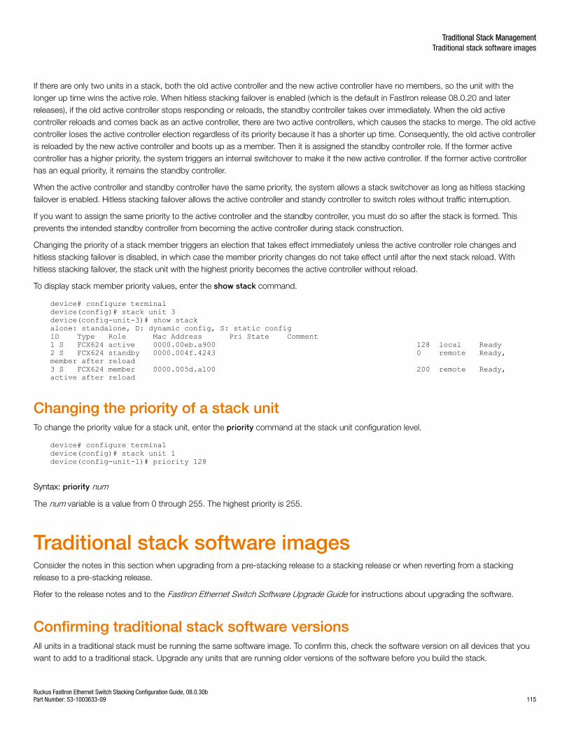
If there are only two units in a stack, both the old active controller and the new active controller have no members, so the unit with thelonger up time wins the active role. When hitless stacking failover is enabled (which is the default in FastIron release 08.0.20 and laterreleases), if the old active controller stops responding or reloads, the standby controller takes over immediately. When the old activecontroller reloads and comes back as an active controller, there are two active controllers, which causes the stacks to merge. The old activecontroller loses the active controller election regardless of its priority because it has a shorter up time. Consequently, the old active controlleris reloaded by the new active controller and boots up as a member. Then it is assigned the standby controller role. If the former activecontroller has a higher priority, the system triggers an internal switchover to make it the new active controller. If the former active controllerhas an equal priority, it remains the standby controller.
When the active controller and standby controller have the same priority, the system allows a stack switchover as long as hitless stackingfailover is enabled. Hitless stacking failover allows the active controller and standy controller to switch roles without traffic interruption.
If you want to assign the same priority to the active controller and the standby controller, you must do so after the stack is formed. Thisprevents the intended standby controller from becoming the active controller during stack construction.
Changing the priority of a stack member triggers an election that takes effect immediately unless the active controller role changes andhitless stacking failover is disabled, in which case the member priority changes do not take effect until after the next stack reload. Withhitless stacking failover, the stack unit with the highest priority becomes the active controller without reload.
To display stack member priority values, enter the show stack command.
device# configure terminaldevice(config)# stack unit 3device(config-unit-3)# show stackalone: standalone, D: dynamic config, S: static configID Type Role Mac Address Pri State Comment1 S FCX624 active 0000.00eb.a900 128 local Ready2 S FCX624 standby 0000.004f.4243 0 remote Ready, member after reload3 S FCX624 member 0000.005d.a100 200 remote Ready, active after reload
Changing the priority of a stack unitTo change the priority value for a stack unit, enter the priority command at the stack unit configuration level.
device# configure terminaldevice(config)# stack unit 1device(config-unit-1)# priority 128
Syntax: priority num
The num variable is a value from 0 through 255. The highest priority is 255.
Traditional stack software imagesConsider the notes in this section when upgrading from a pre-stacking release to a stacking release or when reverting from a stackingrelease to a pre-stacking release.
Refer to the release notes and to the FastIron Ethernet Switch Software Upgrade Guide for instructions about upgrading the software.
Confirming traditional stack software versionsAll units in a traditional stack must be running the same software image. To confirm this, check the software version on all devices that youwant to add to a traditional stack. Upgrade any units that are running older versions of the software before you build the stack.
Traditional Stack ManagementTraditional stack software images
Ruckus FastIron Ethernet Switch Stacking Configuration Guide, 08.0.30bPart Number: 53-1003633-09 115
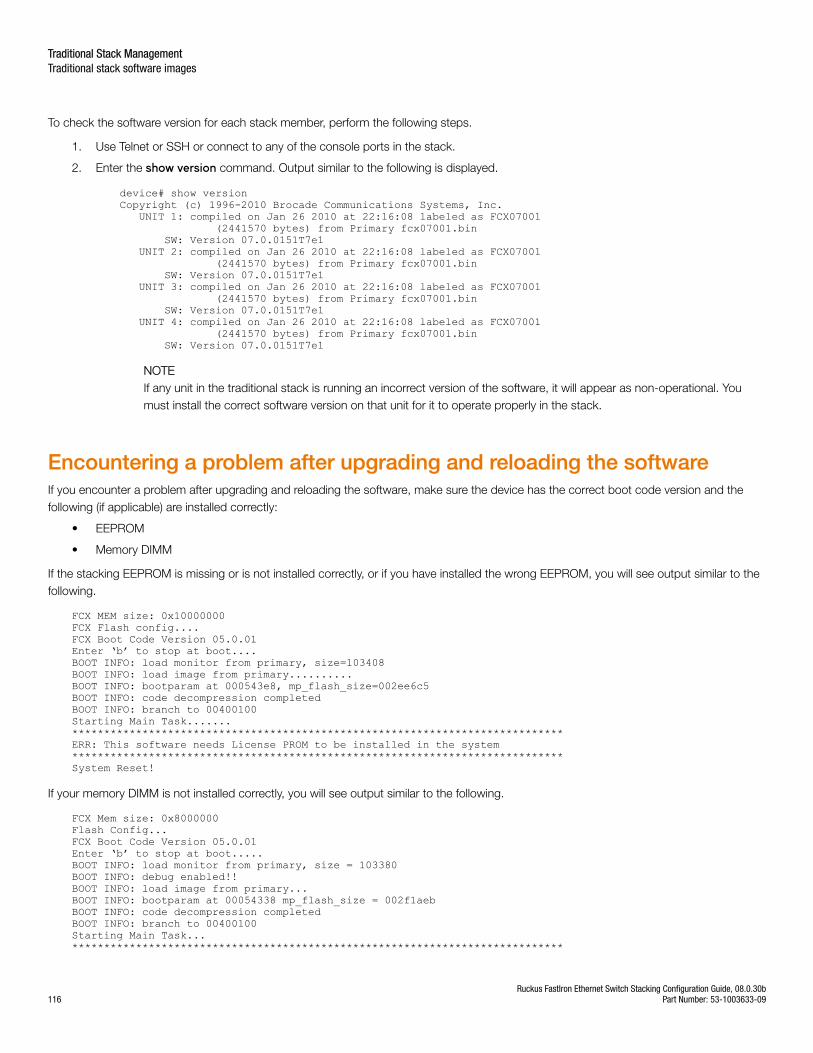
To check the software version for each stack member, perform the following steps.
1. Use Telnet or SSH or connect to any of the console ports in the stack.
2. Enter the show version command. Output similar to the following is displayed.
device# show versionCopyright (c) 1996-2010 Brocade Communications Systems, Inc. UNIT 1: compiled on Jan 26 2010 at 22:16:08 labeled as FCX07001 (2441570 bytes) from Primary fcx07001.bin SW: Version 07.0.0151T7e1 UNIT 2: compiled on Jan 26 2010 at 22:16:08 labeled as FCX07001 (2441570 bytes) from Primary fcx07001.bin SW: Version 07.0.0151T7e1 UNIT 3: compiled on Jan 26 2010 at 22:16:08 labeled as FCX07001 (2441570 bytes) from Primary fcx07001.bin SW: Version 07.0.0151T7e1 UNIT 4: compiled on Jan 26 2010 at 22:16:08 labeled as FCX07001 (2441570 bytes) from Primary fcx07001.bin SW: Version 07.0.0151T7e1
NOTEIf any unit in the traditional stack is running an incorrect version of the software, it will appear as non-operational. Youmust install the correct software version on that unit for it to operate properly in the stack.
Encountering a problem after upgrading and reloading the softwareIf you encounter a problem after upgrading and reloading the software, make sure the device has the correct boot code version and thefollowing (if applicable) are installed correctly:
• EEPROM
• Memory DIMM
If the stacking EEPROM is missing or is not installed correctly, or if you have installed the wrong EEPROM, you will see output similar to thefollowing.
FCX MEM size: 0x10000000FCX Flash config....FCX Boot Code Version 05.0.01Enter ‘b’ to stop at boot....BOOT INFO: load monitor from primary, size=103408BOOT INFO: load image from primary..........BOOT INFO: bootparam at 000543e8, mp_flash_size=002ee6c5BOOT INFO: code decompression completedBOOT INFO: branch to 00400100Starting Main Task.......*****************************************************************************ERR: This software needs License PROM to be installed in the system*****************************************************************************System Reset!
If your memory DIMM is not installed correctly, you will see output similar to the following.
FCX Mem size: 0x8000000Flash Config...FCX Boot Code Version 05.0.01Enter ‘b’ to stop at boot.....BOOT INFO: load monitor from primary, size = 103380BOOT INFO: debug enabled!!BOOT INFO: load image from primary...BOOT INFO: bootparam at 00054338 mp_flash_size = 002f1aebBOOT INFO: code decompression completedBOOT INFO: branch to 00400100Starting Main Task...*****************************************************************************
Traditional Stack ManagementTraditional stack software images
Ruckus FastIron Ethernet Switch Stacking Configuration Guide, 08.0.30b116 Part Number: 53-1003633-09
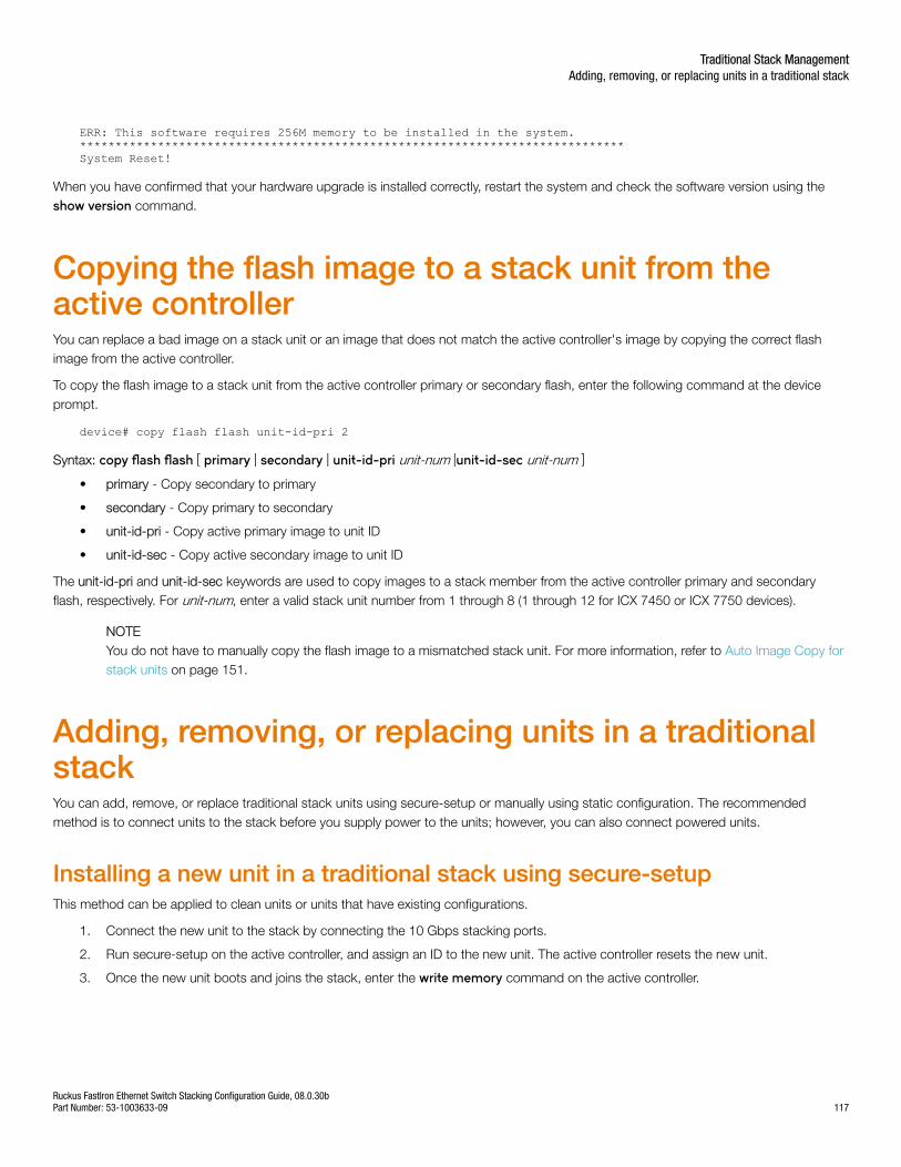
ERR: This software requires 256M memory to be installed in the system.*****************************************************************************System Reset!
When you have confirmed that your hardware upgrade is installed correctly, restart the system and check the software version using theshow version command.
Copying the flash image to a stack unit from theactive controllerYou can replace a bad image on a stack unit or an image that does not match the active controller's image by copying the correct flashimage from the active controller.
To copy the flash image to a stack unit from the active controller primary or secondary flash, enter the following command at the deviceprompt.
device# copy flash flash unit-id-pri 2
Syntax: copy flash flash [ primary | secondary | unit-id-pri unit-num |unit-id-sec unit-num ]
• primary - Copy secondary to primary
• secondary - Copy primary to secondary
• unit-id-pri - Copy active primary image to unit ID
• unit-id-sec - Copy active secondary image to unit ID
The unit-id-pri and unit-id-sec keywords are used to copy images to a stack member from the active controller primary and secondaryflash, respectively. For unit-num, enter a valid stack unit number from 1 through 8 (1 through 12 for ICX 7450 or ICX 7750 devices).
NOTEYou do not have to manually copy the flash image to a mismatched stack unit. For more information, refer to Auto Image Copy forstack units on page 151.
Adding, removing, or replacing units in a traditionalstackYou can add, remove, or replace traditional stack units using secure-setup or manually using static configuration. The recommendedmethod is to connect units to the stack before you supply power to the units; however, you can also connect powered units.
Installing a new unit in a traditional stack using secure-setupThis method can be applied to clean units or units that have existing configurations.
1. Connect the new unit to the stack by connecting the 10 Gbps stacking ports.
2. Run secure-setup on the active controller, and assign an ID to the new unit. The active controller resets the new unit.
3. Once the new unit boots and joins the stack, enter the write memory command on the active controller.
Traditional Stack ManagementAdding, removing, or replacing units in a traditional stack
Ruckus FastIron Ethernet Switch Stacking Configuration Guide, 08.0.30bPart Number: 53-1003633-09 117
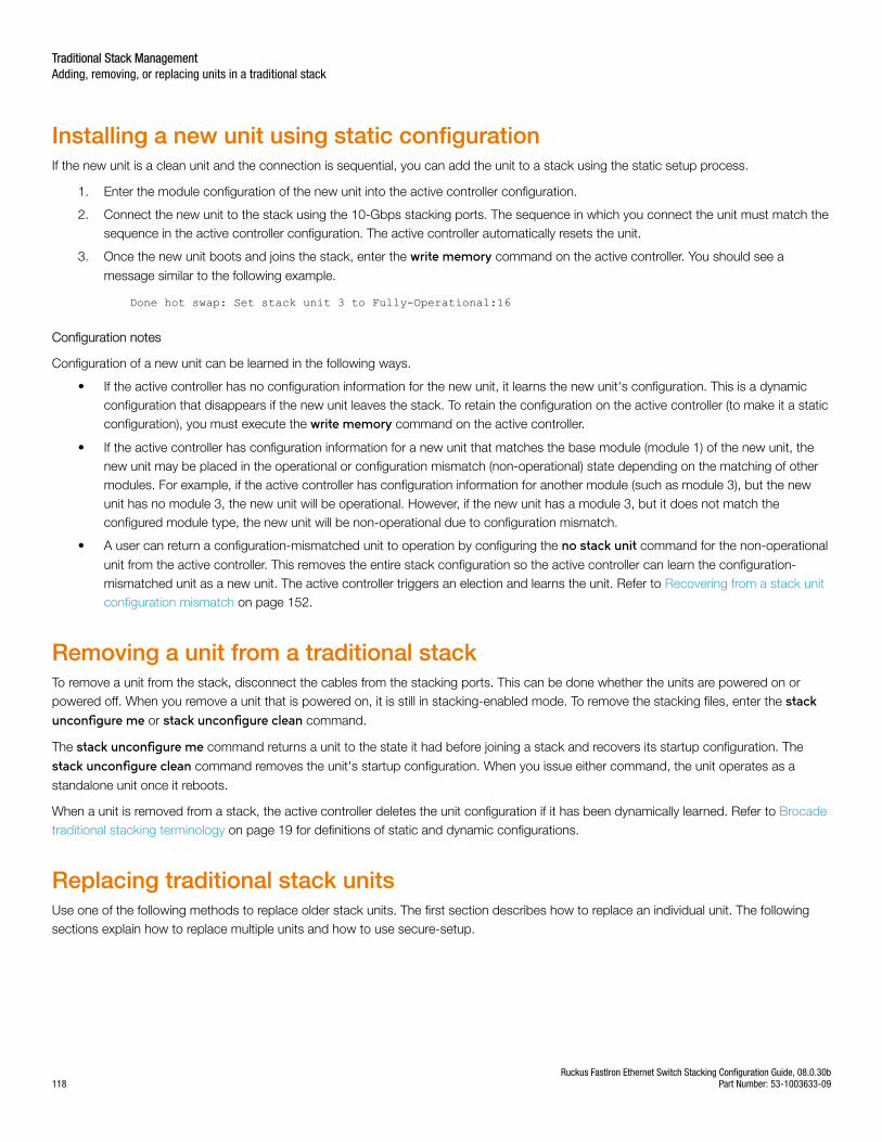
Installing a new unit using static configurationIf the new unit is a clean unit and the connection is sequential, you can add the unit to a stack using the static setup process.
1. Enter the module configuration of the new unit into the active controller configuration.
2. Connect the new unit to the stack using the 10-Gbps stacking ports. The sequence in which you connect the unit must match thesequence in the active controller configuration. The active controller automatically resets the unit.
3. Once the new unit boots and joins the stack, enter the write memory command on the active controller. You should see a
message similar to the following example.
Done hot swap: Set stack unit 3 to Fully-Operational:16
Configuration notes
Configuration of a new unit can be learned in the following ways.
• If the active controller has no configuration information for the new unit, it learns the new unit's configuration. This is a dynamicconfiguration that disappears if the new unit leaves the stack. To retain the configuration on the active controller (to make it a staticconfiguration), you must execute the write memory command on the active controller.
• If the active controller has configuration information for a new unit that matches the base module (module 1) of the new unit, thenew unit may be placed in the operational or configuration mismatch (non-operational) state depending on the matching of othermodules. For example, if the active controller has configuration information for another module (such as module 3), but the newunit has no module 3, the new unit will be operational. However, if the new unit has a module 3, but it does not match theconfigured module type, the new unit will be non-operational due to configuration mismatch.
• A user can return a configuration-mismatched unit to operation by configuring the no stack unit command for the non-operational
unit from the active controller. This removes the entire stack configuration so the active controller can learn the configuration-mismatched unit as a new unit. The active controller triggers an election and learns the unit. Refer to Recovering from a stack unitconfiguration mismatch on page 152.
Removing a unit from a traditional stackTo remove a unit from the stack, disconnect the cables from the stacking ports. This can be done whether the units are powered on orpowered off. When you remove a unit that is powered on, it is still in stacking-enabled mode. To remove the stacking files, enter the stackunconfigure me or stack unconfigure clean command.
The stack unconfigure me command returns a unit to the state it had before joining a stack and recovers its startup configuration. The
stack unconfigure clean command removes the unit's startup configuration. When you issue either command, the unit operates as a
standalone unit once it reboots.
When a unit is removed from a stack, the active controller deletes the unit configuration if it has been dynamically learned. Refer to Brocadetraditional stacking terminology on page 19 for definitions of static and dynamic configurations.
Replacing traditional stack unitsUse one of the following methods to replace older stack units. The first section describes how to replace an individual unit. The followingsections explain how to replace multiple units and how to use secure-setup.
Traditional Stack ManagementAdding, removing, or replacing units in a traditional stack
Ruckus FastIron Ethernet Switch Stacking Configuration Guide, 08.0.30b118 Part Number: 53-1003633-09
Replacing one traditional stack unit with a clean traditional stack unitIf the stack unit ID numbering is sequential, you can swap a failed unit with an identical clean unit using this procedure.
1. Remove the old unit from the stack.
2. Make sure that the hardware (module) configuration of the replacement unit is identical to the hardware configuration of the failedunit.
3. Connect the new unit to the stack using the same stacking ports as the old unit.
4. If the replacement unit configuration matches the configuration retained on the active controller, the active controller resets the newunit. The new unit automatically becomes active in the stack, and the stack keeps its original topology.
Replacing multiple traditional stack units with multiple clean traditional stack unitsIf you are replacing multiple old units with clean units, the active controller replaces the unit with the lowest ID first. For example, if youremove units 5 and 6, the active controller assigns ID 5 to the first new device you install. If you wanted this particular unit to replace unit 6instead of unit 5, you must use secure-setup.
Using secure-setup to replace traditional stack unitsYou must use secure-setup to replace traditional stack units in the following cases:
• The replacement is not a clean unit.
• The connection is not sequential.
• You do not want the active controller to trigger an automatic replacement.
Use the following steps.
1. Remove the old stack unit from the stack.
2. Connect the new unit to the existing stack using the same stacking ports as the old unit.
3. Run secure‐setup to select the ID of the old unit for the new unit. The active controller resets the unit, and it joins the stack.
NOTEAdding, removing, or replacing a stack unit that is not at the end of a linear topology may cause the other units in thestack to reset if these units lose their path to the active controller during the change. Adding or removing a unit in a ringtopology should not cause the other units to reset because each unit can still find a path to the active controller.
Moving a unit to another stackMoving a member from one stack to another stack can cause non-sequential ID assignment. The active controller will honor the original IDof the newly added unit if the ID is not already in use. The active controller assigns a new ID if the original ID is already in use. To preventnon-sequential stack ID assignments, configure the unit as a clean unit before adding it to the stack.
Removing an active controller from a powered stackTo remove an active controller from a powered stack, disconnect the active controller. The standby controller waits for 30 seconds and thenassumes the role of active controller. If hitless failover is enabled on the stack, the standby controller takes over immediately. A single activecontroller device functions as a standalone unit even if it is still stacking-enabled. You do not have to issue a stack unconfigure mecommand for an active controller.
Traditional Stack ManagementAdding, removing, or replacing units in a traditional stack
Ruckus FastIron Ethernet Switch Stacking Configuration Guide, 08.0.30bPart Number: 53-1003633-09 119
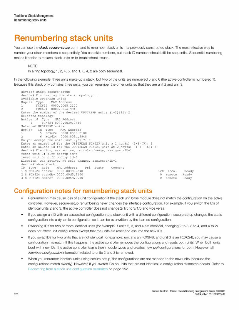
Renumbering stack unitsYou can use the stack secure-setup command to renumber stack units in a previously constructed stack. The most effective way to
number your stack members is sequentially. You can skip numbers, but stack ID numbers should still be sequential. Sequential numberingmakes it easier to replace stack units or to troubleshoot issues.
NOTEIn a ring topology, 1, 2, 4, 5, and 1, 5, 4, 2 are both sequential.
In the following example, three units make up a stack, but two of the units are numbered 5 and 6 (the active controller is numbered 1).Because this stack only contains three units, you can renumber the other units so that they are unit 2 and unit 3.
device# stack secure-setupdevice# Discovering the stack topology...Available UPSTREAM unitsHop(s) Type MAC Address1 FCX624 0000.00d5.21002 FCX624 0000.005d.9940Enter the number of the desired UPSTREAM units (1-2)[1]: 2Selected topology:Active id Type MAC Address 1 FCX624 0000.0039.2d40Selected UPSTREAM unitsHop(s) id Type MAC Address1 5 FCX624 0000.00d5.21002 6 FCX624 0000.005d.9940Do you accept the unit ids? (y/n)?: nEnter an unused id for the UPSTREAM FCX623 unit a 1 hop(s) (1-8)[5]: 2Enter an unused id for the UPSTREAM FCX624 unit at 2 hop(s) (1-8) [6]: 3device# Election, was active, no role change, assigned-ID=1reset unit 2: diff bootup id=5reset unit 3: diff bootup id=6Election, was active, no role change, assigned-ID=1device# show stackID Type Role MAC Address Pri State Comment1 S FCX624 active 0000.0039.2d40 128 local Ready2 S FCX624 standby 0000.00d5.2100 0 remote Ready3 S FCX624 member 0000.005d.9940 0 remote Ready
Configuration notes for renumbering stack units• Renumbering may cause loss of a unit configuration if the stack unit base module does not match the configuration on the active
controller. However, secure-setup renumbering never changes the interface configuration. For example, if you switch the IDs ofidentical units 2 and 3, the active controller does not change 2/1/5 to 3/1/5 and vice versa.
• If you assign an ID with an associated configuration to a stack unit with a different configuration, secure-setup changes the staticconfiguration into a dynamic configuration so it can be overwritten by the learned configuration.
• Swapping IDs for two or more identical units (for example, if units 2, 3, and 4 are identical, changing 2 to 3, 3 to 4, and 4 to 2)does not affect unit configuration except that the units are reset and assume the new IDs.
• If you swap IDs for two units that are not identical (for example, unit 2 is an FCX648, and unit 3 is an FCX624), you may cause aconfiguration mismatch. If this happens, the active controller removes the configurations and resets both units. When both unitsboot with new IDs, the active controller learns their module types and creates new unit configurations for both. However, allinterface configuration information related to units 2 and 3 is removed.
• When you renumber identical units using secure-setup, the configurations are not mapped to the new units (because theconfigurations match exactly). However, if you switch IDs on units that are not identical, a configuration mismatch occurs. Refer to Recovering from a stack unit configuration mismatch on page 152.
Traditional Stack ManagementRenumbering stack units
Ruckus FastIron Ethernet Switch Stacking Configuration Guide, 08.0.30b120 Part Number: 53-1003633-09
• When you assign an unused ID to a stack unit, the unit is reset with the new ID. All unit and interface configuration informationrelated to the old stack ID is deleted. The active controller learns the configuration for the new unit.
• Secure-setup does not swap configuration information for units that have had their IDs changed. For example, it does not changethe 2/1/3 interface configuration or VLAN membership information into 3/1/3 information if the unit ID changes from 2 to 3.
• If the configuration for a unit being replaced does not match the new unit type, the active controller removes the unit configurationand associated interface configuration.
• All configurations learned following mismatches or the addition of new units are dynamic configurations. To convert them intostatic configurations, execute a write memory command on the active controller. This command preserves the configuration if a
unit is removed from the stack.
Reloading a stack unitUse the reload command to reload one or more stack units, for example, when necessary to repair a malfunctioning unit. Stack units can
be reloaded only if they are not the active controller. When hitless stacking failover is enabled, the active controller is automatically reloaded.
When the reload command is entered on the active controller without the unit-id parameter as shown in the following example, the entire
stack reloads.
NOTE
device# reload
Syntax: reload [ after duration | at time | cancel | unit-id unit-list ]
• after - Schedules reloading after a specified length of time (duration in seconds, entered as a value from 1 to 4096)
• at - Schedules reloading at an exact later time (time, entered in the format: hh:mm:ss, where hh represents hours from 01 to 24,mm represents minutes, from 00 to 59, and ss represents seconds, from 0 to 59)
• cancel - Cancels scheduled reload
• unit-id - Designates stack member or members to reload. The unit-list variable can be a single ID, a list of IDs, a range of IDs, or acombination, such as 2,4-6,8. Values must be separated by a comma, with no space.
If you need to reload the active controller, use the stack switch-over command. When switchover occurs, the original active controller can
be reloaded using the reload unit-id command.
Controlling stack size to allow for a data portBecause stackable devices allow you to use one of the two ports intended for stacking as a regular data port, you may wish to control thesize of your stack. The following example shows a stack where the existing ring topology is changed so that only one unit in the upstreamdirection is connected through a stacking port, which limits the size of the stack to two units.
device# stack secure-setupdevice# Discovering the stack topology...Current Discovered Topology - RINGAvailable UPSTREAM unitsHop(s) Type MAC Address1 FCX624 0000.00d5.21002 FCX624 0000.005d.9940Available DOWNSTREAM unitsHop(s) Type MAC Address1 FCX624 0000.005d.99402 FCX624 0000.00d5.2100Do you accept the topology (RING) (y/n)?: nAvailable UPSTREAM units
Traditional Stack ManagementControlling stack size to allow for a data port
Ruckus FastIron Ethernet Switch Stacking Configuration Guide, 08.0.30bPart Number: 53-1003633-09 121
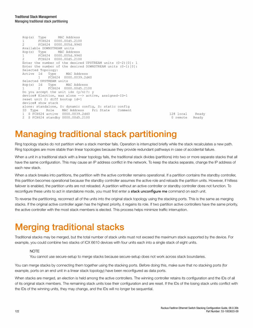
Hop(s) Type MAC Address1 FCX624 0000.00d5.21002 FCX624 0000.005d.9940Available DOWNSTREAM unitsHop(s) Type MAC Address1 FCX624 0000.005d.99402 FCX624 0000.00d5.2100Enter the number of the desired UPSTREAM units (0-2)[0]: 1Enter the number of the desired DOWNSTREAM units (0-1)[0]:Selected Topology:Active Id Type MAC Address 1 FCX624 0000.0039.2d40Selected UPSTREAM unitsHop(s) Id Type MAC Address1 2 FCX624 0000.00d5.2100Do you accept the unit ids (y/n)?: ydevice# Election, was alone --> active, assigned-ID=1reset unit 2: diff bootup id=1device# show stackalone: standalone, D: dynamic config, S: static configID Type Role MAC Address Pri State Comment1 S FCX624 active 0000.0039.2d40 128 local Ready2 S FCX624 standby 0000.00d5.2100 0 remote Ready
Managing traditional stack partitioningRing topology stacks do not partition when a stack member fails. Operation is interrupted briefly while the stack recalculates a new path.Ring topologies are more stable than linear topologies because they provide redundant pathways in case of accidental failure.
When a unit in a traditional stack with a linear topology fails, the traditional stack divides (partitions) into two or more separate stacks that allhave the same configuration. This may cause an IP address conflict in the network. To keep the stacks separate, change the IP address ofeach new stack.
When a stack breaks into partitions, the partition with the active controller remains operational. If a partition contains the standby controller,this partition becomes operational because the standby controller assumes the active role and reloads the partition units. However, if hitlessfailover is enabled, the partition units are not reloaded. A partition without an active controller or standby controller does not function. Toreconfigure these units to act in standalone mode, you must first enter a stack unconfigure me command on each unit.
To reverse the partitioning, reconnect all of the units into the original stack topology using the stacking ports. This is the same as mergingstacks. If the original active controller again has the highest priority, it regains its role. If two partition active controllers have the same priority,the active controller with the most stack members is elected. This process helps minimize traffic interruption.
Merging traditional stacksTraditional stacks may be merged, but the total number of stack units must not exceed the maximum stack supported by the device. Forexample, you could combine two stacks of ICX 6610 devices with four units each into a single stack of eight units.
NOTEYou cannot use secure-setup to merge stacks because secure-setup does not work across stack boundaries.
You can merge stacks by connecting them together using the stacking ports. Before doing this, make sure that no stacking ports (forexample, ports on an end unit in a linear stack topology) have been reconfigured as data ports.
When stacks are merged, an election is held among the active controllers. The winning controller retains its configuration and the IDs of allof its original stack members. The remaining stack units lose their configuration and are reset. If the IDs of the losing stack units conflict withthe IDs of the winning units, they may change, and the IDs will no longer be sequential.
Traditional Stack ManagementManaging traditional stack partitioning
Ruckus FastIron Ethernet Switch Stacking Configuration Guide, 08.0.30b122 Part Number: 53-1003633-09
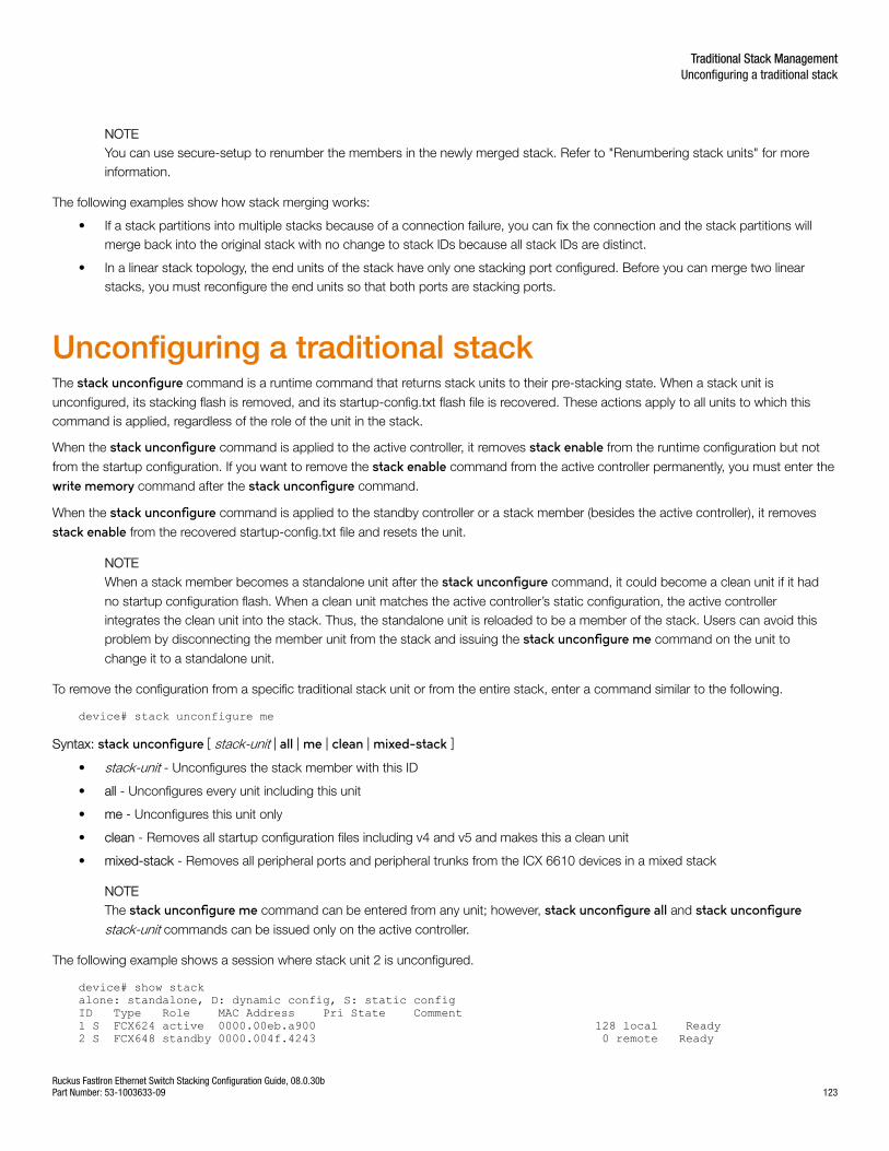
NOTEYou can use secure-setup to renumber the members in the newly merged stack. Refer to "Renumbering stack units" for moreinformation.
The following examples show how stack merging works:
• If a stack partitions into multiple stacks because of a connection failure, you can fix the connection and the stack partitions willmerge back into the original stack with no change to stack IDs because all stack IDs are distinct.
• In a linear stack topology, the end units of the stack have only one stacking port configured. Before you can merge two linearstacks, you must reconfigure the end units so that both ports are stacking ports.
Unconfiguring a traditional stackThe stack unconfigure command is a runtime command that returns stack units to their pre-stacking state. When a stack unit is
unconfigured, its stacking flash is removed, and its startup-config.txt flash file is recovered. These actions apply to all units to which thiscommand is applied, regardless of the role of the unit in the stack.
When the stack unconfigure command is applied to the active controller, it removes stack enable from the runtime configuration but not
from the startup configuration. If you want to remove the stack enable command from the active controller permanently, you must enter the
write memory command after the stack unconfigure command.
When the stack unconfigure command is applied to the standby controller or a stack member (besides the active controller), it removes
stack enable from the recovered startup-config.txt file and resets the unit.
NOTEWhen a stack member becomes a standalone unit after the stack unconfigure command, it could become a clean unit if it had
no startup configuration flash. When a clean unit matches the active controller’s static configuration, the active controllerintegrates the clean unit into the stack. Thus, the standalone unit is reloaded to be a member of the stack. Users can avoid thisproblem by disconnecting the member unit from the stack and issuing the stack unconfigure me command on the unit to
change it to a standalone unit.
To remove the configuration from a specific traditional stack unit or from the entire stack, enter a command similar to the following.
device# stack unconfigure me
Syntax: stack unconfigure [ stack-unit | all | me | clean | mixed-stack ]
• stack-unit - Unconfigures the stack member with this ID
• all - Unconfigures every unit including this unit
• me - Unconfigures this unit only
• clean - Removes all startup configuration files including v4 and v5 and makes this a clean unit
• mixed-stack - Removes all peripheral ports and peripheral trunks from the ICX 6610 devices in a mixed stack
NOTEThe stack unconfigure me command can be entered from any unit; however, stack unconfigure all and stack unconfigurestack-unit commands can be issued only on the active controller.
The following example shows a session where stack unit 2 is unconfigured.
device# show stackalone: standalone, D: dynamic config, S: static configID Type Role MAC Address Pri State Comment1 S FCX624 active 0000.00eb.a900 128 local Ready2 S FCX648 standby 0000.004f.4243 0 remote Ready
Traditional Stack ManagementUnconfiguring a traditional stack
Ruckus FastIron Ethernet Switch Stacking Configuration Guide, 08.0.30bPart Number: 53-1003633-09 123
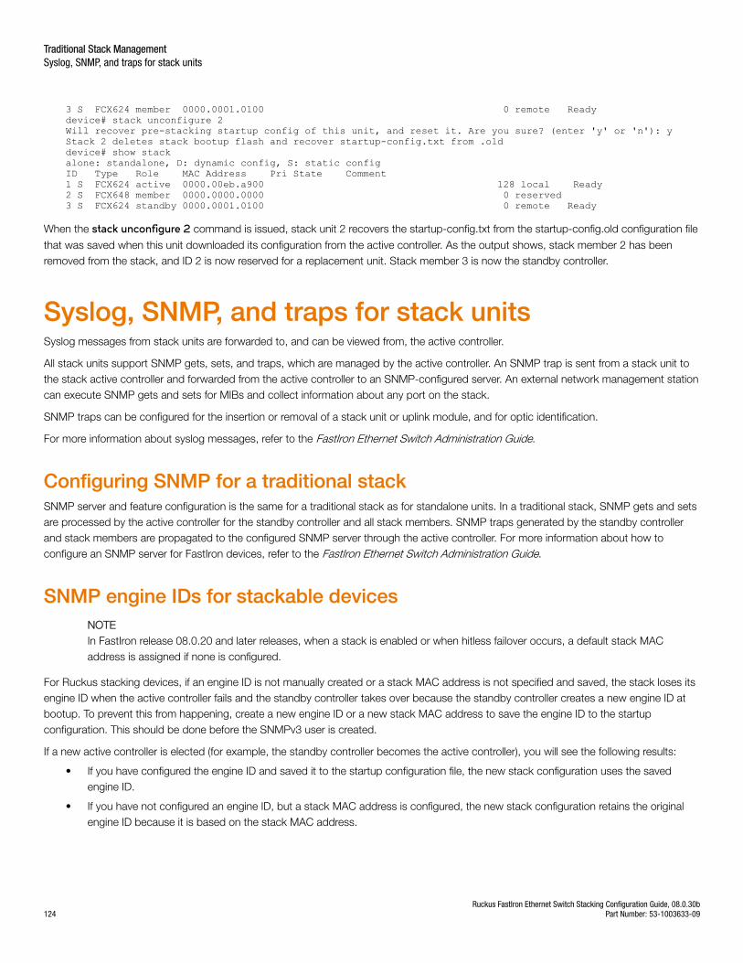
3 S FCX624 member 0000.0001.0100 0 remote Readydevice# stack unconfigure 2Will recover pre-stacking startup config of this unit, and reset it. Are you sure? (enter 'y' or 'n'): yStack 2 deletes stack bootup flash and recover startup-config.txt from .olddevice# show stackalone: standalone, D: dynamic config, S: static configID Type Role MAC Address Pri State Comment1 S FCX624 active 0000.00eb.a900 128 local Ready2 S FCX648 member 0000.0000.0000 0 reserved3 S FCX624 standby 0000.0001.0100 0 remote Ready
When the stack unconfigure 2 command is issued, stack unit 2 recovers the startup-config.txt from the startup-config.old configuration file
that was saved when this unit downloaded its configuration from the active controller. As the output shows, stack member 2 has beenremoved from the stack, and ID 2 is now reserved for a replacement unit. Stack member 3 is now the standby controller.
Syslog, SNMP, and traps for stack unitsSyslog messages from stack units are forwarded to, and can be viewed from, the active controller.
All stack units support SNMP gets, sets, and traps, which are managed by the active controller. An SNMP trap is sent from a stack unit tothe stack active controller and forwarded from the active controller to an SNMP-configured server. An external network management stationcan execute SNMP gets and sets for MIBs and collect information about any port on the stack.
SNMP traps can be configured for the insertion or removal of a stack unit or uplink module, and for optic identification.
For more information about syslog messages, refer to the FastIron Ethernet Switch Administration Guide.
Configuring SNMP for a traditional stackSNMP server and feature configuration is the same for a traditional stack as for standalone units. In a traditional stack, SNMP gets and setsare processed by the active controller for the standby controller and all stack members. SNMP traps generated by the standby controllerand stack members are propagated to the configured SNMP server through the active controller. For more information about how toconfigure an SNMP server for FastIron devices, refer to the FastIron Ethernet Switch Administration Guide.
SNMP engine IDs for stackable devicesNOTEIn FastIron release 08.0.20 and later releases, when a stack is enabled or when hitless failover occurs, a default stack MACaddress is assigned if none is configured.
For Ruckus stacking devices, if an engine ID is not manually created or a stack MAC address is not specified and saved, the stack loses itsengine ID when the active controller fails and the standby controller takes over because the standby controller creates a new engine ID atbootup. To prevent this from happening, create a new engine ID or a new stack MAC address to save the engine ID to the startupconfiguration. This should be done before the SNMPv3 user is created.
If a new active controller is elected (for example, the standby controller becomes the active controller), you will see the following results:
• If you have configured the engine ID and saved it to the startup configuration file, the new stack configuration uses the savedengine ID.
• If you have not configured an engine ID, but a stack MAC address is configured, the new stack configuration retains the originalengine ID because it is based on the stack MAC address.
Traditional Stack ManagementSyslog, SNMP, and traps for stack units
Ruckus FastIron Ethernet Switch Stacking Configuration Guide, 08.0.30b124 Part Number: 53-1003633-09
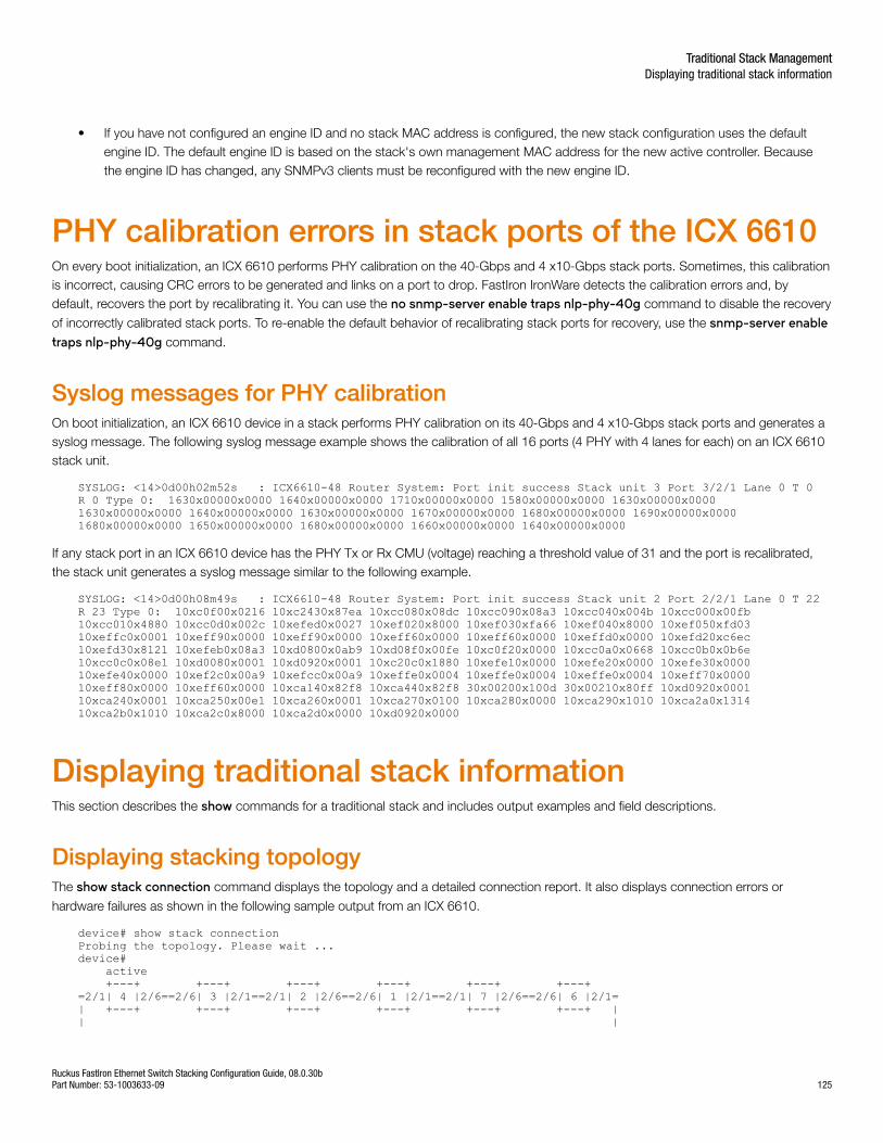
• If you have not configured an engine ID and no stack MAC address is configured, the new stack configuration uses the defaultengine ID. The default engine ID is based on the stack's own management MAC address for the new active controller. Becausethe engine ID has changed, any SNMPv3 clients must be reconfigured with the new engine ID.
PHY calibration errors in stack ports of the ICX 6610On every boot initialization, an ICX 6610 performs PHY calibration on the 40-Gbps and 4 x10-Gbps stack ports. Sometimes, this calibrationis incorrect, causing CRC errors to be generated and links on a port to drop. FastIron IronWare detects the calibration errors and, bydefault, recovers the port by recalibrating it. You can use the no snmp-server enable traps nlp-phy-40g command to disable the recovery
of incorrectly calibrated stack ports. To re-enable the default behavior of recalibrating stack ports for recovery, use the snmp-server enabletraps nlp-phy-40g command.
Syslog messages for PHY calibrationOn boot initialization, an ICX 6610 device in a stack performs PHY calibration on its 40-Gbps and 4 x10-Gbps stack ports and generates asyslog message. The following syslog message example shows the calibration of all 16 ports (4 PHY with 4 lanes for each) on an ICX 6610stack unit.
SYSLOG: <14>0d00h02m52s : ICX6610-48 Router System: Port init success Stack unit 3 Port 3/2/1 Lane 0 T 0 R 0 Type 0: 1630x00000x0000 1640x00000x0000 1710x00000x0000 1580x00000x0000 1630x00000x0000 1630x00000x0000 1640x00000x0000 1630x00000x0000 1670x00000x0000 1680x00000x0000 1690x00000x0000 1680x00000x0000 1650x00000x0000 1680x00000x0000 1660x00000x0000 1640x00000x0000
If any stack port in an ICX 6610 device has the PHY Tx or Rx CMU (voltage) reaching a threshold value of 31 and the port is recalibrated,the stack unit generates a syslog message similar to the following example.
SYSLOG: <14>0d00h08m49s : ICX6610-48 Router System: Port init success Stack unit 2 Port 2/2/1 Lane 0 T 22 R 23 Type 0: 10xc0f00x0216 10xc2430x87ea 10xcc080x08dc 10xcc090x08a3 10xcc040x004b 10xcc000x00fb 10xcc010x4880 10xcc0d0x002c 10xefed0x0027 10xef020x8000 10xef030xfa66 10xef040x8000 10xef050xfd03 10xeffc0x0001 10xeff90x0000 10xeff90x0000 10xeff60x0000 10xeff60x0000 10xeffd0x0000 10xefd20xc6ec 10xefd30x8121 10xefeb0x08a3 10xd0800x0ab9 10xd08f0x00fe 10xc0f20x0000 10xcc0a0x0668 10xcc0b0x0b6e 10xcc0c0x08e1 10xd0080x0001 10xd0920x0001 10xc20c0x1880 10xefe10x0000 10xefe20x0000 10xefe30x0000 10xefe40x0000 10xef2c0x00a9 10xefcc0x00a9 10xeffe0x0004 10xeffe0x0004 10xeffe0x0004 10xeff70x0000 10xeff80x0000 10xeff60x0000 10xca140x82f8 10xca440x82f8 30x00200x100d 30x00210x80ff 10xd0920x0001 10xca240x0001 10xca250x00e1 10xca260x0001 10xca270x0100 10xca280x0000 10xca290x1010 10xca2a0x1314 10xca2b0x1010 10xca2c0x8000 10xca2d0x0000 10xd0920x0000
Displaying traditional stack informationThis section describes the show commands for a traditional stack and includes output examples and field descriptions.
Displaying stacking topologyThe show stack connection command displays the topology and a detailed connection report. It also displays connection errors or
hardware failures as shown in the following sample output from an ICX 6610.
device# show stack connectionProbing the topology. Please wait ...device# active +---+ +---+ +---+ +---+ +---+ +---+ =2/1| 4 |2/6==2/6| 3 |2/1==2/1| 2 |2/6==2/6| 1 |2/1==2/1| 7 |2/6==2/6| 6 |2/1=| +---+ +---+ +---+ +---+ +---+ +---+ || |
Traditional Stack ManagementDisplaying traditional stack information
Ruckus FastIron Ethernet Switch Stacking Configuration Guide, 08.0.30bPart Number: 53-1003633-09 125
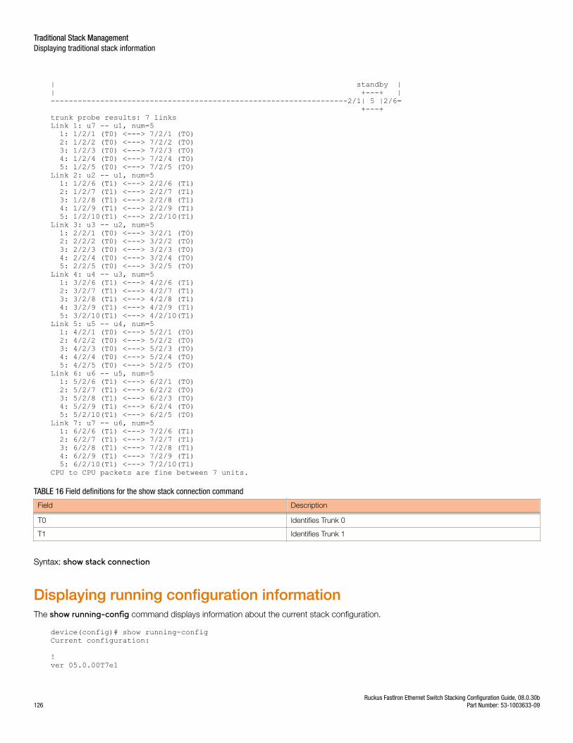
| standby || +---+ |------------------------------------------------------------------2/1| 5 |2/6= +---+ trunk probe results: 7 linksLink 1: u7 -- u1, num=5 1: 1/2/1 (T0) <---> 7/2/1 (T0) 2: 1/2/2 (T0) <---> 7/2/2 (T0) 3: 1/2/3 (T0) <---> 7/2/3 (T0) 4: 1/2/4 (T0) <---> 7/2/4 (T0) 5: 1/2/5 (T0) <---> 7/2/5 (T0) Link 2: u2 -- u1, num=5 1: 1/2/6 (T1) <---> 2/2/6 (T1) 2: 1/2/7 (T1) <---> 2/2/7 (T1) 3: 1/2/8 (T1) <---> 2/2/8 (T1) 4: 1/2/9 (T1) <---> 2/2/9 (T1) 5: 1/2/10(T1) <---> 2/2/10(T1) Link 3: u3 -- u2, num=5 1: 2/2/1 (T0) <---> 3/2/1 (T0) 2: 2/2/2 (T0) <---> 3/2/2 (T0) 3: 2/2/3 (T0) <---> 3/2/3 (T0) 4: 2/2/4 (T0) <---> 3/2/4 (T0) 5: 2/2/5 (T0) <---> 3/2/5 (T0) Link 4: u4 -- u3, num=5 1: 3/2/6 (T1) <---> 4/2/6 (T1) 2: 3/2/7 (T1) <---> 4/2/7 (T1) 3: 3/2/8 (T1) <---> 4/2/8 (T1) 4: 3/2/9 (T1) <---> 4/2/9 (T1) 5: 3/2/10(T1) <---> 4/2/10(T1) Link 5: u5 -- u4, num=5 1: 4/2/1 (T0) <---> 5/2/1 (T0) 2: 4/2/2 (T0) <---> 5/2/2 (T0) 3: 4/2/3 (T0) <---> 5/2/3 (T0) 4: 4/2/4 (T0) <---> 5/2/4 (T0) 5: 4/2/5 (T0) <---> 5/2/5 (T0) Link 6: u6 -- u5, num=5 1: 5/2/6 (T1) <---> 6/2/1 (T0) 2: 5/2/7 (T1) <---> 6/2/2 (T0) 3: 5/2/8 (T1) <---> 6/2/3 (T0) 4: 5/2/9 (T1) <---> 6/2/4 (T0) 5: 5/2/10(T1) <---> 6/2/5 (T0) Link 7: u7 -- u6, num=5 1: 6/2/6 (T1) <---> 7/2/6 (T1) 2: 6/2/7 (T1) <---> 7/2/7 (T1) 3: 6/2/8 (T1) <---> 7/2/8 (T1) 4: 6/2/9 (T1) <---> 7/2/9 (T1) 5: 6/2/10(T1) <---> 7/2/10(T1) CPU to CPU packets are fine between 7 units.
TABLE 16 Field definitions for the show stack connection command
Field Description
T0 Identifies Trunk 0
T1 Identifies Trunk 1
Syntax: show stack connection
Displaying running configuration informationThe show running-config command displays information about the current stack configuration.
device(config)# show running-configCurrent configuration:
!ver 05.0.00T7e1
Traditional Stack ManagementDisplaying traditional stack information
Ruckus FastIron Ethernet Switch Stacking Configuration Guide, 08.0.30b126 Part Number: 53-1003633-09
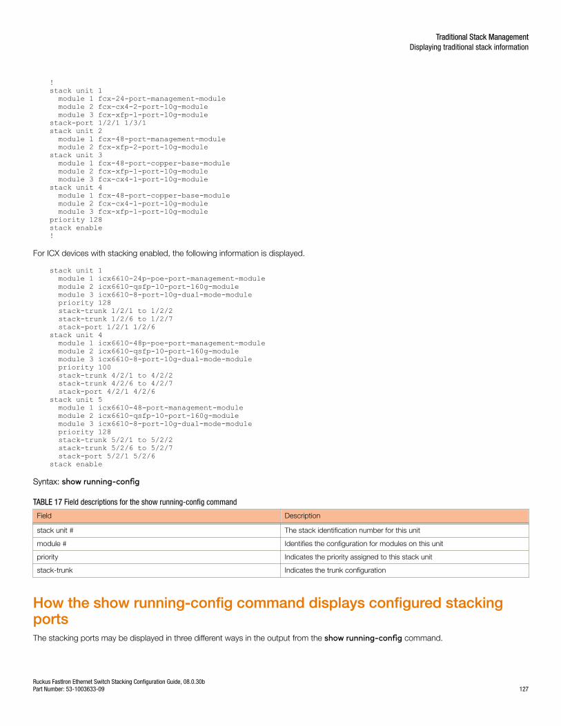
!stack unit 1 module 1 fcx-24-port-management-module module 2 fcx-cx4-2-port-10g-module module 3 fcx-xfp-1-port-10g-modulestack-port 1/2/1 1/3/1stack unit 2 module 1 fcx-48-port-management-module module 2 fcx-xfp-2-port-10g-modulestack unit 3 module 1 fcx-48-port-copper-base-module module 2 fcx-xfp-1-port-10g-module module 3 fcx-cx4-1-port-10g-modulestack unit 4 module 1 fcx-48-port-copper-base-module module 2 fcx-cx4-1-port-10g-module module 3 fcx-xfp-1-port-10g-modulepriority 128stack enable!
For ICX devices with stacking enabled, the following information is displayed.
stack unit 1 module 1 icx6610-24p-poe-port-management-module module 2 icx6610-qsfp-10-port-160g-module module 3 icx6610-8-port-10g-dual-mode-module priority 128 stack-trunk 1/2/1 to 1/2/2 stack-trunk 1/2/6 to 1/2/7 stack-port 1/2/1 1/2/6stack unit 4 module 1 icx6610-48p-poe-port-management-module module 2 icx6610-qsfp-10-port-160g-module module 3 icx6610-8-port-10g-dual-mode-module priority 100 stack-trunk 4/2/1 to 4/2/2 stack-trunk 4/2/6 to 4/2/7 stack-port 4/2/1 4/2/6stack unit 5 module 1 icx6610-48-port-management-module module 2 icx6610-qsfp-10-port-160g-module module 3 icx6610-8-port-10g-dual-mode-module priority 128 stack-trunk 5/2/1 to 5/2/2 stack-trunk 5/2/6 to 5/2/7 stack-port 5/2/1 5/2/6stack enable
Syntax: show running-config
TABLE 17 Field descriptions for the show running-config command
Field Description
stack unit # The stack identification number for this unit
module # Identifies the configuration for modules on this unit
priority Indicates the priority assigned to this stack unit
stack-trunk Indicates the trunk configuration
How the show running-config command displays configured stackingportsThe stacking ports may be displayed in three different ways in the output from the show running-config command.
Traditional Stack ManagementDisplaying traditional stack information
Ruckus FastIron Ethernet Switch Stacking Configuration Guide, 08.0.30bPart Number: 53-1003633-09 127
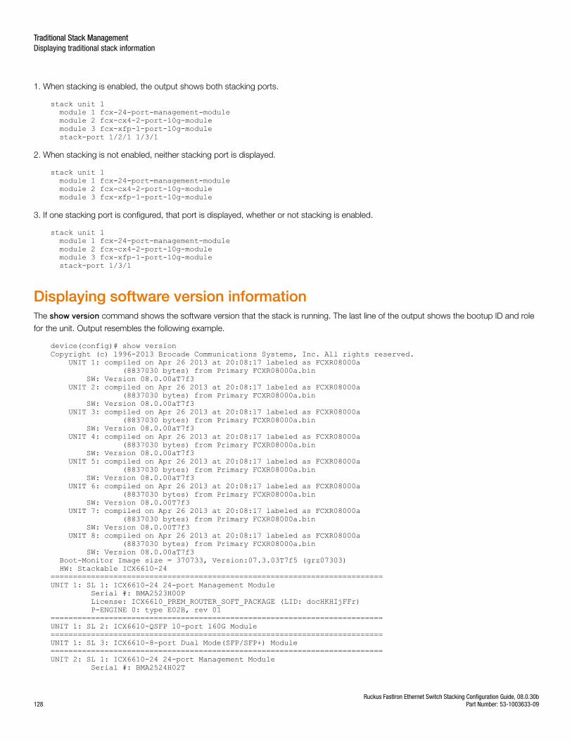
1. When stacking is enabled, the output shows both stacking ports.
stack unit 1 module 1 fcx-24-port-management-module module 2 fcx-cx4-2-port-10g-module module 3 fcx-xfp-1-port-10g-module stack-port 1/2/1 1/3/1
2. When stacking is not enabled, neither stacking port is displayed.
stack unit 1 module 1 fcx-24-port-management-module module 2 fcx-cx4-2-port-10g-module module 3 fcx-xfp-1-port-10g-module
3. If one stacking port is configured, that port is displayed, whether or not stacking is enabled.
stack unit 1 module 1 fcx-24-port-management-module module 2 fcx-cx4-2-port-10g-module module 3 fcx-xfp-1-port-10g-module stack-port 1/3/1
Displaying software version informationThe show version command shows the software version that the stack is running. The last line of the output shows the bootup ID and role
for the unit. Output resembles the following example.
device(config)# show versionCopyright (c) 1996-2013 Brocade Communications Systems, Inc. All rights reserved. UNIT 1: compiled on Apr 26 2013 at 20:08:17 labeled as FCXR08000a (8837030 bytes) from Primary FCXR08000a.bin SW: Version 08.0.00aT7f3 UNIT 2: compiled on Apr 26 2013 at 20:08:17 labeled as FCXR08000a (8837030 bytes) from Primary FCXR08000a.bin SW: Version 08.0.00aT7f3 UNIT 3: compiled on Apr 26 2013 at 20:08:17 labeled as FCXR08000a (8837030 bytes) from Primary FCXR08000a.bin SW: Version 08.0.00aT7f3 UNIT 4: compiled on Apr 26 2013 at 20:08:17 labeled as FCXR08000a (8837030 bytes) from Primary FCXR08000a.bin SW: Version 08.0.00aT7f3 UNIT 5: compiled on Apr 26 2013 at 20:08:17 labeled as FCXR08000a (8837030 bytes) from Primary FCXR08000a.bin SW: Version 08.0.00aT7f3 UNIT 6: compiled on Apr 26 2013 at 20:08:17 labeled as FCXR08000a (8837030 bytes) from Primary FCXR08000a.bin SW: Version 08.0.00T7f3 UNIT 7: compiled on Apr 26 2013 at 20:08:17 labeled as FCXR08000a (8837030 bytes) from Primary FCXR08000a.bin SW: Version 08.0.00T7f3 UNIT 8: compiled on Apr 26 2013 at 20:08:17 labeled as FCXR08000a (8837030 bytes) from Primary FCXR08000a.bin SW: Version 08.0.00aT7f3 Boot-Monitor Image size = 370733, Version:07.3.03T7f5 (grz07303) HW: Stackable ICX6610-24==========================================================================UNIT 1: SL 1: ICX6610-24 24-port Management Module Serial #: BMA2523H00P License: ICX6610_PREM_ROUTER_SOFT_PACKAGE (LID: docHKHIjFFr) P-ENGINE 0: type E02B, rev 01==========================================================================UNIT 1: SL 2: ICX6610-QSFP 10-port 160G Module==========================================================================UNIT 1: SL 3: ICX6610-8-port Dual Mode(SFP/SFP+) Module==========================================================================UNIT 2: SL 1: ICX6610-24 24-port Management Module Serial #: BMA2524H02T
Traditional Stack ManagementDisplaying traditional stack information
Ruckus FastIron Ethernet Switch Stacking Configuration Guide, 08.0.30b128 Part Number: 53-1003633-09
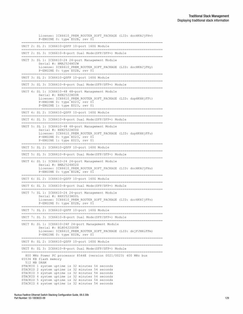
License: ICX6610_PREM_ROUTER_SOFT_PACKAGE (LID: docHKHJjFHv) P-ENGINE 0: type E02B, rev 01==========================================================================UNIT 2: SL 2: ICX6610-QSFP 10-port 160G Module==========================================================================UNIT 2: SL 3: ICX6610-8-port Dual Mode(SFP/SFP+) Module==========================================================================UNIT 3: SL 1: ICX6610-24 24-port Management Module Serial #: BMA2524H02W License: ICX6610_PREM_ROUTER_SOFT_PACKAGE (LID: docHKHJjFHy) P-ENGINE 0: type E02B, rev 01==========================================================================UNIT 3: SL 2: ICX6610-QSFP 10-port 160G Module==========================================================================UNIT 3: SL 3: ICX6610-8-port Dual Mode(SFP/SFP+) Module==========================================================================UNIT 4: SL 1: ICX6610-48 48-port Management Module Serial #: BXN2522H00R License: ICX6610_PREM_ROUTER_SOFT_PACKAGE (LID: dzpHKHHjFFt) P-ENGINE 0: type E023, rev 01 P-ENGINE 1: type E023, rev 01==========================================================================UNIT 4: SL 2: ICX6610-QSFP 10-port 160G Module==========================================================================UNIT 4: SL 3: ICX6610-8-port Dual Mode(SFP/SFP+) Module==========================================================================UNIT 5: SL 1: ICX6610-48 48-port Management Module Serial #: BXN2522H00S License: ICX6610_PREM_ROUTER_SOFT_PACKAGE (LID: dzpHKHHjFFu) P-ENGINE 0: type E023, rev 01 P-ENGINE 1: type E023, rev 01 ==========================================================================UNIT 5: SL 2: ICX6610-QSFP 10-port 160G Module==========================================================================UNIT 5: SL 3: ICX6610-8-port Dual Mode(SFP/SFP+) Module==========================================================================UNIT 6: SL 1: ICX6610-24 24-port Management Module Serial #: BMA2524H02S License: ICX6610_PREM_ROUTER_SOFT_PACKAGE (LID: docHKHJjFHu) P-ENGINE 0: type E02B, rev 01==========================================================================UNIT 6: SL 2: ICX6610-QSFP 10-port 160G Module==========================================================================UNIT 6: SL 3: ICX6610-8-port Dual Mode(SFP/SFP+) Module==========================================================================UNIT 7: SL 1: ICX6610-24 24-port Management Module Serial #: BXP2523H00L License: ICX6610_PREM_ROUTER_SOFT_PACKAGE (LID: dzrHKHIjFFn) P-ENGINE 0: type E02B, rev 01==========================================================================UNIT 7: SL 2: ICX6610-QSFP 10-port 160G Module==========================================================================UNIT 7: SL 3: ICX6610-8-port Dual Mode(SFP/SFP+) Module==========================================================================UNIT 8: SL 1: ICX6610-24F 24-port Management Module Serial #: BLH0422G00K License: ICX6610_PREM_ROUTER_SOFT_PACKAGE (LID: dnjFJHHiFFm) P-ENGINE 0: type E02B, rev 01==========================================================================UNIT 8: SL 2: ICX6610-QSFP 10-port 160G Module==========================================================================UNIT 8: SL 3: ICX6610-8-port Dual Mode(SFP/SFP+) Module========================================================================== 800 MHz Power PC processor 8544E (version 0021/0023) 400 MHz bus65536 KB flash memory 512 MB DRAMSTACKID 1 system uptime is 32 minutes 54 seconds STACKID 2 system uptime is 32 minutes 54 seconds STACKID 3 system uptime is 32 minutes 54 seconds STACKID 4 system uptime is 32 minutes 54 seconds STACKID 5 system uptime is 32 minutes 54 seconds STACKID 6 system uptime is 32 minutes 54 seconds
Traditional Stack ManagementDisplaying traditional stack information
Ruckus FastIron Ethernet Switch Stacking Configuration Guide, 08.0.30bPart Number: 53-1003633-09 129
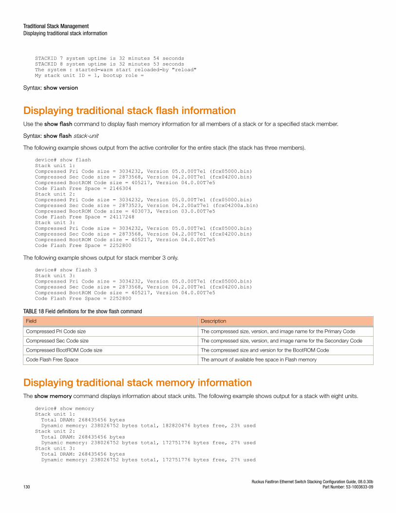
STACKID 7 system uptime is 32 minutes 54 seconds STACKID 8 system uptime is 32 minutes 53 seconds The system : started=warm start reloaded=by "reload"My stack unit ID = 1, bootup role =
Syntax: show version
Displaying traditional stack flash informationUse the show flash command to display flash memory information for all members of a stack or for a specified stack member.
Syntax: show flash stack-unit
The following example shows output from the active controller for the entire stack (the stack has three members).
device# show flashStack unit 1:Compressed Pri Code size = 3034232, Version 05.0.00T7e1 (fcx05000.bin)Compressed Sec Code size = 2873568, Version 04.2.00T7e1 (fcx04200.bin)Compressed BootROM Code size = 405217, Version 04.0.00T7e5Code Flash Free Space = 2146304Stack unit 2:Compressed Pri Code size = 3034232, Version 05.0.00T7e1 (fcx05000.bin)Compressed Sec Code size = 2873523, Version 04.2.00aT7e1 (fcx04200a.bin)Compressed BootROM Code size = 403073, Version 03.0.00T7e5Code Flash Free Space = 24117248Stack unit 3:Compressed Pri Code size = 3034232, Version 05.0.00T7e1 (fcx05000.bin)Compressed Sec Code size = 2873568, Version 04.2.00T7e1 (fcx04200.bin)Compressed BootROM Code size = 405217, Version 04.0.00T7e5Code Flash Free Space = 2252800
The following example shows output for stack member 3 only.
device# show flash 3Stack unit 3:Compressed Pri Code size = 3034232, Version 05.0.00T7e1 (fcx05000.bin)Compressed Sec Code size = 2873568, Version 04.2.00T7e1 (fcx04200.bin)Compressed BootROM Code size = 405217, Version 04.0.00T7e5Code Flash Free Space = 2252800
TABLE 18 Field definitions for the show flash command
Field Description
Compressed Pri Code size The compressed size, version, and image name for the Primary Code
Compressed Sec Code size The compressed size, version, and image name for the Secondary Code
Compressed BootROM Code size The compressed size and version for the BootROM Code
Code Flash Free Space The amount of available free space in Flash memory
Displaying traditional stack memory informationThe show memory command displays information about stack units. The following example shows output for a stack with eight units.
device# show memory Stack unit 1: Total DRAM: 268435456 bytes Dynamic memory: 238026752 bytes total, 182820476 bytes free, 23% usedStack unit 2: Total DRAM: 268435456 bytes Dynamic memory: 238026752 bytes total, 172751776 bytes free, 27% usedStack unit 3: Total DRAM: 268435456 bytes Dynamic memory: 238026752 bytes total, 172751776 bytes free, 27% used
Traditional Stack ManagementDisplaying traditional stack information
Ruckus FastIron Ethernet Switch Stacking Configuration Guide, 08.0.30b130 Part Number: 53-1003633-09
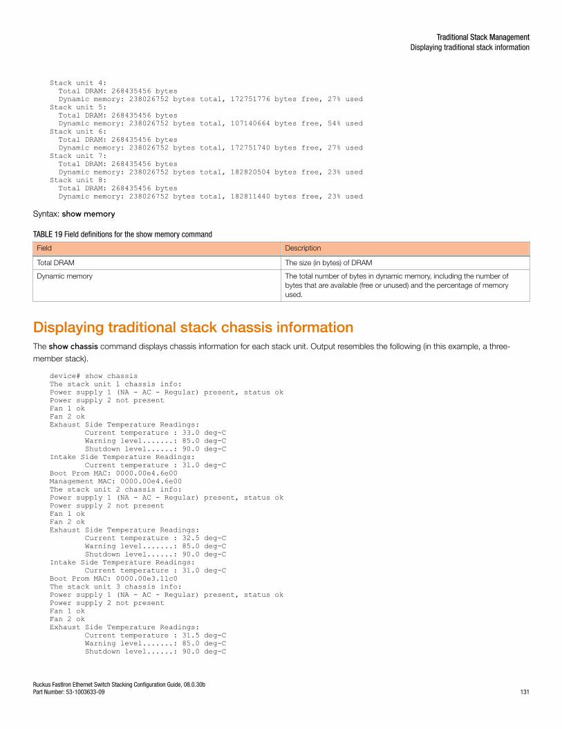
Stack unit 4: Total DRAM: 268435456 bytes Dynamic memory: 238026752 bytes total, 172751776 bytes free, 27% usedStack unit 5: Total DRAM: 268435456 bytes Dynamic memory: 238026752 bytes total, 107140664 bytes free, 54% usedStack unit 6: Total DRAM: 268435456 bytes Dynamic memory: 238026752 bytes total, 172751740 bytes free, 27% usedStack unit 7: Total DRAM: 268435456 bytes Dynamic memory: 238026752 bytes total, 182820504 bytes free, 23% usedStack unit 8: Total DRAM: 268435456 bytes Dynamic memory: 238026752 bytes total, 182811440 bytes free, 23% used
Syntax: show memory
TABLE 19 Field definitions for the show memory command
Field Description
Total DRAM The size (in bytes) of DRAM
Dynamic memory The total number of bytes in dynamic memory, including the number ofbytes that are available (free or unused) and the percentage of memoryused.
Displaying traditional stack chassis informationThe show chassis command displays chassis information for each stack unit. Output resembles the following (in this example, a three-
member stack).
device# show chassisThe stack unit 1 chassis info:Power supply 1 (NA - AC - Regular) present, status okPower supply 2 not presentFan 1 okFan 2 okExhaust Side Temperature Readings: Current temperature : 33.0 deg-C Warning level.......: 85.0 deg-C Shutdown level......: 90.0 deg-CIntake Side Temperature Readings: Current temperature : 31.0 deg-CBoot Prom MAC: 0000.00e4.6e00Management MAC: 0000.00e4.6e00The stack unit 2 chassis info: Power supply 1 (NA - AC - Regular) present, status okPower supply 2 not presentFan 1 okFan 2 okExhaust Side Temperature Readings: Current temperature : 32.5 deg-C Warning level.......: 85.0 deg-C Shutdown level......: 90.0 deg-CIntake Side Temperature Readings: Current temperature : 31.0 deg-CBoot Prom MAC: 0000.00e3.11c0The stack unit 3 chassis info: Power supply 1 (NA - AC - Regular) present, status okPower supply 2 not presentFan 1 okFan 2 okExhaust Side Temperature Readings: Current temperature : 31.5 deg-C Warning level.......: 85.0 deg-C Shutdown level......: 90.0 deg-C
Traditional Stack ManagementDisplaying traditional stack information
Ruckus FastIron Ethernet Switch Stacking Configuration Guide, 08.0.30bPart Number: 53-1003633-09 131
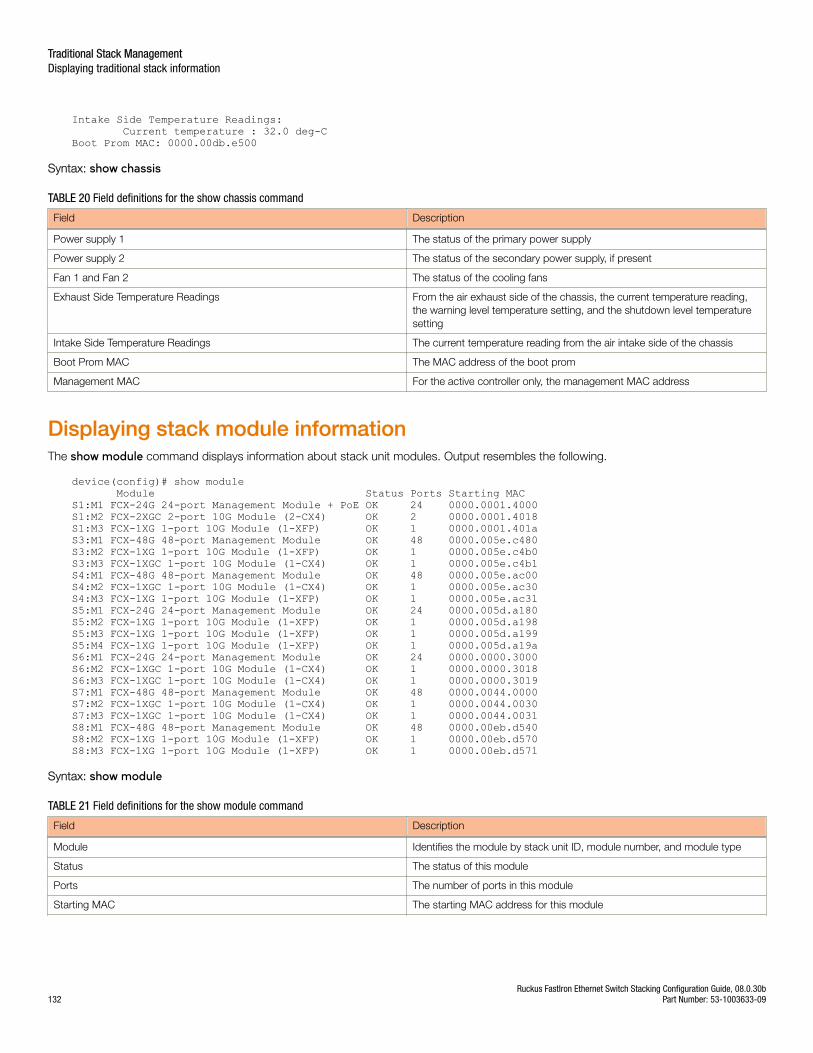
Intake Side Temperature Readings: Current temperature : 32.0 deg-CBoot Prom MAC: 0000.00db.e500
Syntax: show chassis
TABLE 20 Field definitions for the show chassis command
Field Description
Power supply 1 The status of the primary power supply
Power supply 2 The status of the secondary power supply, if present
Fan 1 and Fan 2 The status of the cooling fans
Exhaust Side Temperature Readings From the air exhaust side of the chassis, the current temperature reading,the warning level temperature setting, and the shutdown level temperaturesetting
Intake Side Temperature Readings The current temperature reading from the air intake side of the chassis
Boot Prom MAC The MAC address of the boot prom
Management MAC For the active controller only, the management MAC address
Displaying stack module informationThe show module command displays information about stack unit modules. Output resembles the following.
device(config)# show module Module Status Ports Starting MACS1:M1 FCX-24G 24-port Management Module + PoE OK 24 0000.0001.4000S1:M2 FCX-2XGC 2-port 10G Module (2-CX4) OK 2 0000.0001.4018S1:M3 FCX-1XG 1-port 10G Module (1-XFP) OK 1 0000.0001.401aS3:M1 FCX-48G 48-port Management Module OK 48 0000.005e.c480S3:M2 FCX-1XG 1-port 10G Module (1-XFP) OK 1 0000.005e.c4b0S3:M3 FCX-1XGC 1-port 10G Module (1-CX4) OK 1 0000.005e.c4b1S4:M1 FCX-48G 48-port Management Module OK 48 0000.005e.ac00S4:M2 FCX-1XGC 1-port 10G Module (1-CX4) OK 1 0000.005e.ac30S4:M3 FCX-1XG 1-port 10G Module (1-XFP) OK 1 0000.005e.ac31S5:M1 FCX-24G 24-port Management Module OK 24 0000.005d.a180S5:M2 FCX-1XG 1-port 10G Module (1-XFP) OK 1 0000.005d.a198S5:M3 FCX-1XG 1-port 10G Module (1-XFP) OK 1 0000.005d.a199S5:M4 FCX-1XG 1-port 10G Module (1-XFP) OK 1 0000.005d.a19aS6:M1 FCX-24G 24-port Management Module OK 24 0000.0000.3000S6:M2 FCX-1XGC 1-port 10G Module (1-CX4) OK 1 0000.0000.3018S6:M3 FCX-1XGC 1-port 10G Module (1-CX4) OK 1 0000.0000.3019S7:M1 FCX-48G 48-port Management Module OK 48 0000.0044.0000S7:M2 FCX-1XGC 1-port 10G Module (1-CX4) OK 1 0000.0044.0030S7:M3 FCX-1XGC 1-port 10G Module (1-CX4) OK 1 0000.0044.0031S8:M1 FCX-48G 48-port Management Module OK 48 0000.00eb.d540S8:M2 FCX-1XG 1-port 10G Module (1-XFP) OK 1 0000.00eb.d570S8:M3 FCX-1XG 1-port 10G Module (1-XFP) OK 1 0000.00eb.d571
Syntax: show module
TABLE 21 Field definitions for the show module command
Field Description
Module Identifies the module by stack unit ID, module number, and module type
Status The status of this module
Ports The number of ports in this module
Starting MAC The starting MAC address for this module
Traditional Stack ManagementDisplaying traditional stack information
Ruckus FastIron Ethernet Switch Stacking Configuration Guide, 08.0.30b132 Part Number: 53-1003633-09
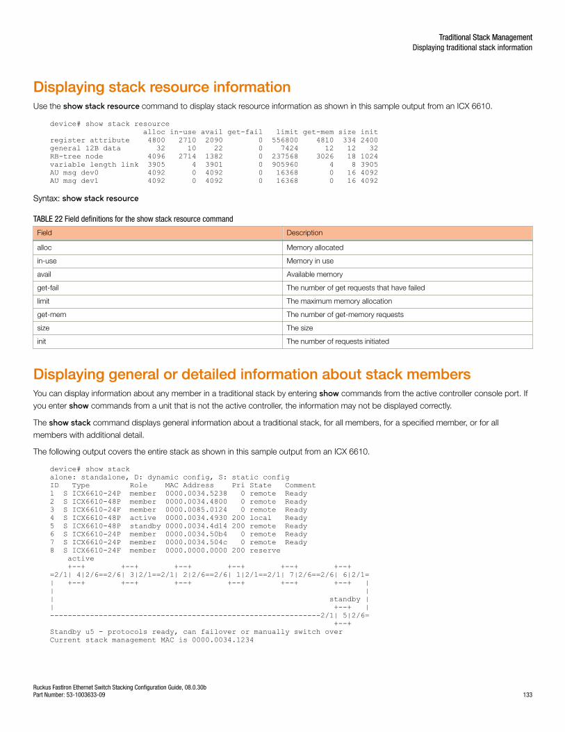
Displaying stack resource informationUse the show stack resource command to display stack resource information as shown in this sample output from an ICX 6610.
device# show stack resource alloc in-use avail get-fail limit get-mem size initregister attribute 4800 2710 2090 0 556800 4810 334 2400general 12B data 32 10 22 0 7424 12 12 32RB-tree node 4096 2714 1382 0 237568 3026 18 1024variable length link 3905 4 3901 0 905960 4 8 3905AU msg dev0 4092 0 4092 0 16368 0 16 4092AU msg dev1 4092 0 4092 0 16368 0 16 4092
Syntax: show stack resource
TABLE 22 Field definitions for the show stack resource command
Field Description
alloc Memory allocated
in-use Memory in use
avail Available memory
get-fail The number of get requests that have failed
limit The maximum memory allocation
get-mem The number of get-memory requests
size The size
init The number of requests initiated
Displaying general or detailed information about stack membersYou can display information about any member in a traditional stack by entering show commands from the active controller console port. If
you enter show commands from a unit that is not the active controller, the information may not be displayed correctly.
The show stack command displays general information about a traditional stack, for all members, for a specified member, or for all
members with additional detail.
The following output covers the entire stack as shown in this sample output from an ICX 6610.
device# show stack alone: standalone, D: dynamic config, S: static configID Type Role MAC Address Pri State Comment1 S ICX6610-24P member 0000.0034.5238 0 remote Ready 2 S ICX6610-48P member 0000.0034.4800 0 remote Ready 3 S ICX6610-24F member 0000.0085.0124 0 remote Ready 4 S ICX6610-48P active 0000.0034.4930 200 local Ready 5 S ICX6610-48P standby 0000.0034.4d14 200 remote Ready 6 S ICX6610-24P member 0000.0034.50b4 0 remote Ready 7 S ICX6610-24P member 0000.0034.504c 0 remote Ready 8 S ICX6610-24F member 0000.0000.0000 200 reserve active +--+ +--+ +--+ +--+ +--+ +--+ =2/1| 4|2/6==2/6| 3|2/1==2/1| 2|2/6==2/6| 1|2/1==2/1| 7|2/6==2/6| 6|2/1=| +--+ +--+ +--+ +--+ +--+ +--+ || || standby || +--+ |-------------------------------------------------------------2/1| 5|2/6= +--+ Standby u5 - protocols ready, can failover or manually switch overCurrent stack management MAC is 0000.0034.1234
Traditional Stack ManagementDisplaying traditional stack information
Ruckus FastIron Ethernet Switch Stacking Configuration Guide, 08.0.30bPart Number: 53-1003633-09 133
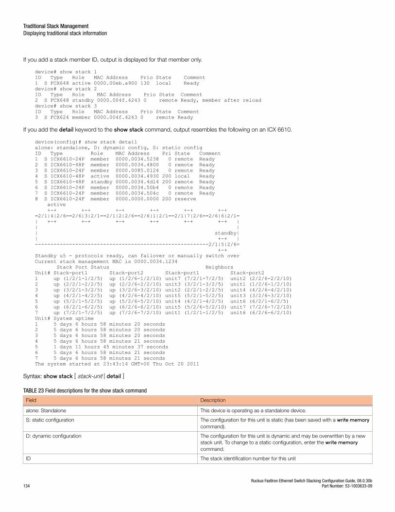
If you add a stack member ID, output is displayed for that member only.
device# show stack 1ID Type Role MAC Address Prio State Comment1 S FCX648 active 0000.00eb.a900 130 local Readydevice# show stack 2ID Type Role MAC Address Prio State Comment2 S FCX648 standby 0000.004f.4243 0 remote Ready, member after reloaddevice# show stack 3ID Type Role MAC Address Prio State Comment3 S FCX624 member 0000.004f.4243 0 remote Ready
If you add the detail keyword to the show stack command, output resembles the following on an ICX 6610.
device(config)# show stack detailalone: standalone, D: dynamic config, S: static configID Type Role MAC Address Pri State Comment 1 S ICX6610-24P member 0000.0034.5238 0 remote Ready 2 S ICX6610-48P member 0000.0034.4800 0 remote Ready 3 S ICX6610-24F member 0000.0085.0124 0 remote Ready 4 S ICX6610-48P active 0000.0034.4930 200 local Ready 5 S ICX6610-48P standby 0000.0034.4d14 200 remote Ready 6 S ICX6610-24P member 0000.0034.50b4 0 remote Ready 7 S ICX6610-24P member 0000.0034.504c 0 remote Ready 8 S ICX6610-24F member 0000.0000.0000 200 reserve active +-+ +-+ +-+ +-+ +-+ +-+ =2/1|4|2/6==2/6|3|2/1==2/1|2|2/6==2/6|1|2/1==2/1|7|2/6==2/6|6|2/1=| +-+ +-+ +-+ +-+ +-+ +-+ || || standby|| +-+ |--------------------------------------------------------2/1|5|2/6= +-+ Standby u5 - protocols ready, can failover or manually switch overCurrent stack management MAC is 0000.0034.1234 Stack Port Status Neighbors Unit# Stack-port1 Stack-port2 Stack-port1 Stack-port2 1 up (1/2/1-1/2/5) up (1/2/6-1/2/10) unit7 (7/2/1-7/2/5) unit2 (2/2/6-2/2/10)2 up (2/2/1-2/2/5) up (2/2/6-2/2/10) unit3 (3/2/1-3/2/5) unit1 (1/2/6-1/2/10)3 up (3/2/1-3/2/5) up (3/2/6-3/2/10) unit2 (2/2/1-2/2/5) unit4 (4/2/6-4/2/10)4 up (4/2/1-4/2/5) up (4/2/6-4/2/10) unit5 (5/2/1-5/2/5) unit3 (3/2/6-3/2/10)5 up (5/2/1-5/2/5) up (5/2/6-5/2/10) unit4 (4/2/1-4/2/5) unit6 (6/2/1-6/2/5)6 up (6/2/1-6/2/5) up (6/2/6-6/2/10) unit5 (5/2/6-5/2/10) unit7 (7/2/6-7/2/10)7 up (7/2/1-7/2/5) up (7/2/6-7/2/10) unit1 (1/2/1-1/2/5) unit6 (6/2/6-6/2/10)Unit# System uptime1 5 days 6 hours 58 minutes 20 seconds 2 5 days 6 hours 58 minutes 20 seconds 3 5 days 6 hours 58 minutes 20 seconds 4 5 days 6 hours 58 minutes 21 seconds 5 1 days 11 hours 45 minutes 37 seconds 6 5 days 6 hours 58 minutes 21 seconds 7 5 days 6 hours 58 minutes 21 seconds The system started at 23:43:14 GMT+00 Thu Oct 20 2011
Syntax: show stack [ stack-unit | detail ]
TABLE 23 Field descriptions for the show stack command
Field Description
alone: Standalone This device is operating as a standalone device.
S: static configuration The configuration for this unit is static (has been saved with a write memorycommand).
D: dynamic configuration The configuration for this unit is dynamic and may be overwritten by a newstack unit. To change to a static configuration, enter the write memorycommand.
ID The stack identification number for this unit
Traditional Stack ManagementDisplaying traditional stack information
Ruckus FastIron Ethernet Switch Stacking Configuration Guide, 08.0.30b134 Part Number: 53-1003633-09
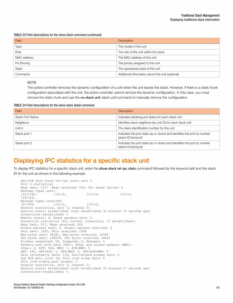
TABLE 23 Field descriptions for the show stack command (continued)
Field Description
Type The model of this unit
Role The role of this unit within the stack
MAC address The MAC address of this unit
Pri (Priority) The priority assigned to this unit
State The operational state of this unit
Comments Additional information about this unit (optional)
NOTEThe active controller removes the dynamic configuration of a unit when the unit leaves the stack. However, if there is a static trunkconfiguration associated with the unit, the active controller cannot remove the dynamic configuration. In this case, you mustremove the static trunk and use the no stack unit stack-unit command to manually remove the configuration.
TABLE 24 Field descriptions for the show stack detail command
Field Description
Stack Port Status Indicates stacking port status for each stack unit
Neighbors Identifies stack neighbors (by unit ID) for each stack unit
Unit # The stack identification number for this unit
Stack-port 1 Indicates the port state (up or down) and identifies the port by number(stack-ID/slot/port)
Stack-port 2 Indicates the port state (up or down) and identifies the port by number(stack-ID/slot/port)
Displaying IPC statistics for a specific stack unitTo display IPC statistics for a specific stack unit, enter the show stack rel-ipc stats command followed by the keyword unit and the stack
ID for the unit as shown in the following example.
device# show stack rel-ipc stats unit 3Unit 3 statistics:Msgs sent: 1217 Msgs received: 509, Pkt sends failed: 0Message types sent:[9]=1182, [10]=2, [11]=2, [13]=2,[19]=29,Message types received:[9]=506, [10]=1, [13]=2,Session statistics, unit 3, channel 0:Session state: established (last established 32 minutes 19 seconds ago)Connections established: 1Remote resets: 0, Reset packets sent: 0Connection statistics (for current connection, if established):Msgs sent: 971, Msgs received: 506Atomic batches sent: 0, Atomic batches received: 0Pkts sent: 1205, Pkts received: 1088Msg bytes sent: 44281, Msg bytes received: 19308Pkt bytes sent: 238004, Pkt bytes received: 34652Flushes requested: 59, Suspends: 0, Resumes: 0Packets sent with data (DAT), ACKs, and window updates (WND):Other: 2, ACK: 504, WND: 7, ACK+WND: 0DAT: 691, DAT+ACK: 1, DAT+WND: 0, DAT+ACK+WND: 0Data retransmits done: 129, Zero-window probes sent: 0Dup ACK pkts rcvd: 18, Pkts rcvd w/dup data: 0Pkts rcvd w/data past window: 0Session statistics, unit 3, channel 2:Session state: established (last established 32 minutes 17 seconds ago)Connections established: 1
Traditional Stack ManagementDisplaying traditional stack information
Ruckus FastIron Ethernet Switch Stacking Configuration Guide, 08.0.30bPart Number: 53-1003633-09 135
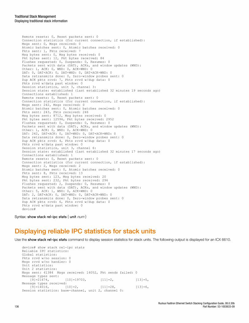
Remote resets: 0, Reset packets sent: 0Connection statistics (for current connection, if established):Msgs sent: 0, Msgs received: 0Atomic batches sent: 0, Atomic batches received: 0Pkts sent: 1, Pkts received: 7Msg bytes sent: 0, Msg bytes received: 0Pkt bytes sent: 12, Pkt bytes received: 84Flushes requested: 0, Suspends: 0, Resumes: 0Packets sent with data (DAT), ACKs, and window updates (WND):Other: 1, ACK: 0, WND: 0, ACK+WND: 0DAT: 0, DAT+ACK: 0, DAT+WND: 0, DAT+ACK+WND: 0Data retransmits done: 0, Zero-window probes sent: 0Dup ACK pkts rcvd: 7, Pkts rcvd w/dup data: 0Pkts rcvd w/data past window: 0Session statistics, unit 3, channel 3:Session state: established (last established 32 minutes 19 seconds ago)Connections established: 1Remote resets: 0, Reset packets sent: 0Connection statistics (for current connection, if established):Msgs sent: 242, Msgs received: 0Atomic batches sent: 0, Atomic batches received: 0Pkts sent: 243, Pkts received: 246Msg bytes sent: 8712, Msg bytes received: 0Pkt bytes sent: 12596, Pkt bytes received: 2952Flushes requested: 0, Suspends: 0, Resumes: 0Packets sent with data (DAT), ACKs, and window updates (WND):Other: 1, ACK: 0, WND: 0, ACK+WND: 0DAT: 242, DAT+ACK: 0, DAT+WND: 0, DAT+ACK+WND: 0Data retransmits done: 0, Zero-window probes sent: 0Dup ACK pkts rcvd: 4, Pkts rcvd w/dup data: 0Pkts rcvd w/data past window: 0Session statistics, unit 3, channel 6:Session state: established (last established 32 minutes 17 seconds ago)Connections established: 1Remote resets: 0, Reset packets sent: 0Connection statistics (for current connection, if established):Msgs sent: 2, Msgs received: 2Atomic batches sent: 0, Atomic batches received: 0Pkts sent: 8, Pkts received: 13Msg bytes sent: 123, Msg bytes received: 20Pkt bytes sent: 232, Pkt bytes received: 296Flushes requested: 2, Suspends: 0, Resumes: 0Packets sent with data (DAT), ACKs, and window updates (WND):Other: 5, ACK: 1, WND: 0, ACK+WND: 0DAT: 2, DAT+ACK: 0, DAT+WND: 0, DAT+ACK+WND: 0Data retransmits done: 0, Zero-window probes sent: 0Dup ACK pkts rcvd: 6, Pkts rcvd w/dup data: 0Pkts rcvd w/data past window: 0device#
Syntax: show stack rel-ipc stats { unit num }
Displaying reliable IPC statistics for stack unitsUse the show stack rel-ipc stats command to display session statistics for stack units. The following output is displayed for an ICX 6610.
device# show stack rel-ipc statsReliable IPC statistics:Global statistics:Pkts rcvd w/no session: 0Msgs rcvd w/no handler: 0Unit statistics:Unit 2 statistics:Msgs sent: 41384 Msgs received: 14052, Pkt sends failed: 0Message types sent: [9]=21674, [10]=19703, [11]=2, [13]=5, Message types received: [9]=14016, [10]=2, [11]=28, [13]=6, Session statistics: base-channel, unit 2, channel 0:
Traditional Stack ManagementDisplaying traditional stack information
Ruckus FastIron Ethernet Switch Stacking Configuration Guide, 08.0.30b136 Part Number: 53-1003633-09

Session state: established (last established 15 hours 33 minutes 31 seconds ago)Connections established: 1Remote resets: 0, Reset packets sent: 0Connection statistics (for current connection, if established):Msgs sent: 14636, Msgs received: 14039Atomic batches sent: 0, Atomic batches received: 0 Pkts sent: 30892, Pkts received: 30842Msg bytes sent: 1828190, Msg bytes received: 1232988Pkt bytes sent: 2659848, Pkt bytes received: 1763028Flushes requested: 30, Suspends: 0, Resumes: 0Packets sent with data (DAT), ACKs, and window updates (WND):Other: 888, ACK: 14010, WND: 437, ACK+WND: 0DAT: 15556, DAT+ACK: 1, DAT+WND: 0, DAT+ACK+WND: 0Data retransmits done: 1069, Zero-window probes sent: 0Dup ACK pkts rcvd: 1224, Pkts rcvd w/dup data: 0Pkts rcvd w/data past window: 0Session statistics: image-transfer, unit 2, channel 1:Session state: established (last established 15 hours 11 minutes 2 seconds ago)Connections established: 1Remote resets: 0, Reset packets sent: 0Connection statistics (for current connection, if established):Msgs sent: 9850, Msgs received: 1Atomic batches sent: 0, Atomic batches received: 0Pkts sent: 9899, Pkts received: 10606Msg bytes sent: 10124076, Msg bytes received: 8Pkt bytes sent: 10341308, Pkt bytes received: 127284Flushes requested: 1, Suspends: 0, Resumes: 0Packets sent with data (DAT), ACKs, and window updates (WND): Other: 1, ACK: 1, WND: 0, ACK+WND: 0DAT: 9897, DAT+ACK: 0, DAT+WND: 0, DAT+ACK+WND: 0Data retransmits done: 49, Zero-window probes sent: 0Dup ACK pkts rcvd: 757, Pkts rcvd w/dup data: 0Pkts rcvd w/data past window: 0Session statistics: ACL, unit 2, channel 3:Session state: established (last established 15 hours 33 minutes 31 seconds ago)Connections established: 1Remote resets: 0, Reset packets sent: 0Connection statistics (for current connection, if established):Msgs sent: 7011, Msgs received: 4Atomic batches sent: 0, Atomic batches received: 0Pkts sent: 7588, Pkts received: 7617Msg bytes sent: 629316, Msg bytes received: 5840Pkt bytes sent: 802504, Pkt bytes received: 107508Flushes requested: 0, Suspends: 0, Resumes: 0Packets sent with data (DAT), ACKs, and window updates (WND):Other: 1, ACK: 1, WND: 0, ACK+WND: 2DAT: 7584, DAT+ACK: 0, DAT+WND: 0, DAT+ACK+WND: 0Data retransmits done: 573, Zero-window probes sent: 0Dup ACK pkts rcvd: 596, Pkts rcvd w/dup data: 0Pkts rcvd w/data past window: 0 Session statistics: sync-reliable, unit 2, channel 4:Session state: established (last established 15 hours 32 minutes 27 seconds ago)Connections established: 1Remote resets: 0, Reset packets sent: 0Connection statistics (for current connection, if established):Msgs sent: 27, Msgs received: 1Atomic batches sent: 0, Atomic batches received: 0Pkts sent: 53, Pkts received: 40Msg bytes sent: 39420, Msg bytes received: 1460Pkt bytes sent: 73836, Pkt bytes received: 1944Flushes requested: 0, Suspends: 0, Resumes: 0Packets sent with data (DAT), ACKs, and window updates (WND):Other: 2, ACK: 1, WND: 0, ACK+WND: 0DAT: 50, DAT+ACK: 0, DAT+WND: 0, DAT+ACK+WND: 0Data retransmits done: 22, Zero-window probes sent: 0Dup ACK pkts rcvd: 6, Pkts rcvd w/dup data: 0Pkts rcvd w/data past window: 0Session statistics: rconsole-server-to-2, unit 2, channel 6:Session state: established (last established 15 hours 33 minutes 30 seconds ago)Connections established: 1Remote resets: 0, Reset packets sent: 0 Connection statistics (for current connection, if established):
Traditional Stack ManagementDisplaying traditional stack information
Ruckus FastIron Ethernet Switch Stacking Configuration Guide, 08.0.30bPart Number: 53-1003633-09 137

Msgs sent: 5, Msgs received: 6Atomic batches sent: 0, Atomic batches received: 0Pkts sent: 14, Pkts received: 40Msg bytes sent: 183, Msg bytes received: 56Pkt bytes sent: 384, Pkt bytes received: 1052Flushes requested: 5, Suspends: 0, Resumes: 0Packets sent with data (DAT), ACKs, and window updates (WND):Other: 4, ACK: 5, WND: 0, ACK+WND: 0DAT: 5, DAT+ACK: 0, DAT+WND: 0, DAT+ACK+WND: 0Data retransmits done: 0, Zero-window probes sent: 0Dup ACK pkts rcvd: 0, Pkts rcvd w/dup data: 0Pkts rcvd w/data past window: 0Unit 3 statistics:Msgs sent: 41356 Msgs received: 14007, Pkt sends failed: 0Message types sent: [9]=21623, [10]=19703, [11]=29, [13]=1, Message types received: [9]=14003, [10]=2, [13]=2, Session statistics: base-channel, unit 3, channel 0:Session state: established (last established 15 hours 33 minutes 49 seconds ago)Connections established: 1Remote resets: 0, Reset packets sent: 0Connection statistics (for current connection, if established):Msgs sent: 14647, Msgs received: 14003Atomic batches sent: 0, Atomic batches received: 0Pkts sent: 31055, Pkts received: 31403Msg bytes sent: 1801742, Msg bytes received: 1232204Pkt bytes sent: 2402644, Pkt bytes received: 1877788Flushes requested: 32, Suspends: 0, Resumes: 0Packets sent with data (DAT), ACKs, and window updates (WND):Other: 1269, ACK: 13911, WND: 437, ACK+WND: 0DAT: 15346, DAT+ACK: 92, DAT+WND: 0, DAT+ACK+WND: 0Data retransmits done: 966, Zero-window probes sent: 0Dup ACK pkts rcvd: 661, Pkts rcvd w/dup data: 0Pkts rcvd w/data past window: 0Session statistics: image-transfer, unit 3, channel 1:Session state: established (last established 15 hours 11 minutes 2 seconds ago)Connections established: 1Remote resets: 0, Reset packets sent: 0Connection statistics (for current connection, if established): Msgs sent: 9850, Msgs received: 1Atomic batches sent: 0, Atomic batches received: 0Pkts sent: 9930, Pkts received: 10599Msg bytes sent: 10124076, Msg bytes received: 8Pkt bytes sent: 10457352, Pkt bytes received: 127200Flushes requested: 1, Suspends: 0, Resumes: 0Packets sent with data (DAT), ACKs, and window updates (WND):Other: 1, ACK: 1, WND: 0, ACK+WND: 0DAT: 9928, DAT+ACK: 0, DAT+WND: 0, DAT+ACK+WND: 0Data retransmits done: 140, Zero-window probes sent: 0Dup ACK pkts rcvd: 798, Pkts rcvd w/dup data: 0Pkts rcvd w/data past window: 0Session statistics: ACL, unit 3, channel 3:Session state: established (last established 15 hours 33 minutes 49 seconds ago)Connections established: 1Remote resets: 0, Reset packets sent: 0Connection statistics (for current connection, if established):Msgs sent: 7004, Msgs received: 0Atomic batches sent: 0, Atomic batches received: 0Pkts sent: 7447, Pkts received: 7300Msg bytes sent: 616352, Msg bytes received: 0Pkt bytes sent: 774304, Pkt bytes received: 87600 Flushes requested: 0, Suspends: 0, Resumes: 0Packets sent with data (DAT), ACKs, and window updates (WND):Other: 2, ACK: 0, WND: 0, ACK+WND: 0DAT: 7445, DAT+ACK: 0, DAT+WND: 0, DAT+ACK+WND: 0Data retransmits done: 441, Zero-window probes sent: 0Dup ACK pkts rcvd: 295, Pkts rcvd w/dup data: 0Pkts rcvd w/data past window: 0Session statistics: rconsole-server-to-3, unit 3, channel 7:Session state: established (last established 15 hours 33 minutes 48 seconds ago)
Traditional Stack ManagementDisplaying traditional stack information
Ruckus FastIron Ethernet Switch Stacking Configuration Guide, 08.0.30b138 Part Number: 53-1003633-09

Connections established: 1Remote resets: 0, Reset packets sent: 0Connection statistics (for current connection, if established):Msgs sent: 1, Msgs received: 2Atomic batches sent: 0, Atomic batches received: 0Pkts sent: 3, Pkts received: 2Msg bytes sent: 35, Msg bytes received: 20Pkt bytes sent: 76, Pkt bytes received: 52Flushes requested: 1, Suspends: 0, Resumes: 0Packets sent with data (DAT), ACKs, and window updates (WND):Other: 1, ACK: 1, WND: 0, ACK+WND: 0DAT: 1, DAT+ACK: 0, DAT+WND: 0, DAT+ACK+WND: 0Data retransmits done: 0, Zero-window probes sent: 0 Dup ACK pkts rcvd: 0, Pkts rcvd w/dup data: 0Pkts rcvd w/data past window: 0Unit 4 statistics:Msgs sent: 41337 Msgs received: 14035, Pkt sends failed: 0Message types sent: [9]=21632, [10]=19702, [11]=2, [13]=1, Message types received: [9]=14031, [10]=2, [13]=2, Session statistics: base-channel, unit 4, channel 0:Session state: established (last established 15 hours 33 minutes 49 seconds ago)Connections established: 1Remote resets: 0, Reset packets sent: 0Connection statistics (for current connection, if established):Msgs sent: 14630, Msgs received: 14031Atomic batches sent: 0, Atomic batches received: 0Pkts sent: 30186, Pkts received: 31052Msg bytes sent: 1801548, Msg bytes received: 1234680Pkt bytes sent: 2325044, Pkt bytes received: 1857824Flushes requested: 30, Suspends: 0, Resumes: 0 Packets sent with data (DAT), ACKs, and window updates (WND):Other: 1199, ACK: 13879, WND: 434, ACK+WND: 4DAT: 14522, DAT+ACK: 148, DAT+WND: 0, DAT+ACK+WND: 0Data retransmits done: 197, Zero-window probes sent: 0Dup ACK pkts rcvd: 560, Pkts rcvd w/dup data: 0Pkts rcvd w/data past window: 0Session statistics: image-transfer, unit 4, channel 1:Session state: established (last established 15 hours 11 minutes 2 seconds ago)Connections established: 1Remote resets: 0, Reset packets sent: 0Connection statistics (for current connection, if established):Msgs sent: 9850, Msgs received: 1Atomic batches sent: 0, Atomic batches received: 0Pkts sent: 9852, Pkts received: 10675Msg bytes sent: 10124076, Msg bytes received: 8Pkt bytes sent: 10284896, Pkt bytes received: 128112Flushes requested: 1, Suspends: 0, Resumes: 0Packets sent with data (DAT), ACKs, and window updates (WND):Other: 1, ACK: 1, WND: 0, ACK+WND: 0DAT: 9850, DAT+ACK: 0, DAT+WND: 0, DAT+ACK+WND: 0Data retransmits done: 2, Zero-window probes sent: 0Dup ACK pkts rcvd: 826, Pkts rcvd w/dup data: 0 Pkts rcvd w/data past window: 0Session statistics: ACL, unit 4, channel 3:Session state: established (last established 15 hours 33 minutes 49 seconds ago)Connections established: 1Remote resets: 0, Reset packets sent: 0Connection statistics (for current connection, if established):Msgs sent: 7004, Msgs received: 0Atomic batches sent: 0, Atomic batches received: 0Pkts sent: 7051, Pkts received: 7240Msg bytes sent: 616352, Msg bytes received: 0Pkt bytes sent: 733028, Pkt bytes received: 86880Flushes requested: 0, Suspends: 0, Resumes: 0Packets sent with data (DAT), ACKs, and window updates (WND):Other: 3, ACK: 0, WND: 0, ACK+WND: 0DAT: 7048, DAT+ACK: 0, DAT+WND: 0, DAT+ACK+WND: 0Data retransmits done: 44, Zero-window probes sent: 0Dup ACK pkts rcvd: 234, Pkts rcvd w/dup data: 0Pkts rcvd w/data past window: 0
Traditional Stack ManagementDisplaying traditional stack information
Ruckus FastIron Ethernet Switch Stacking Configuration Guide, 08.0.30bPart Number: 53-1003633-09 139
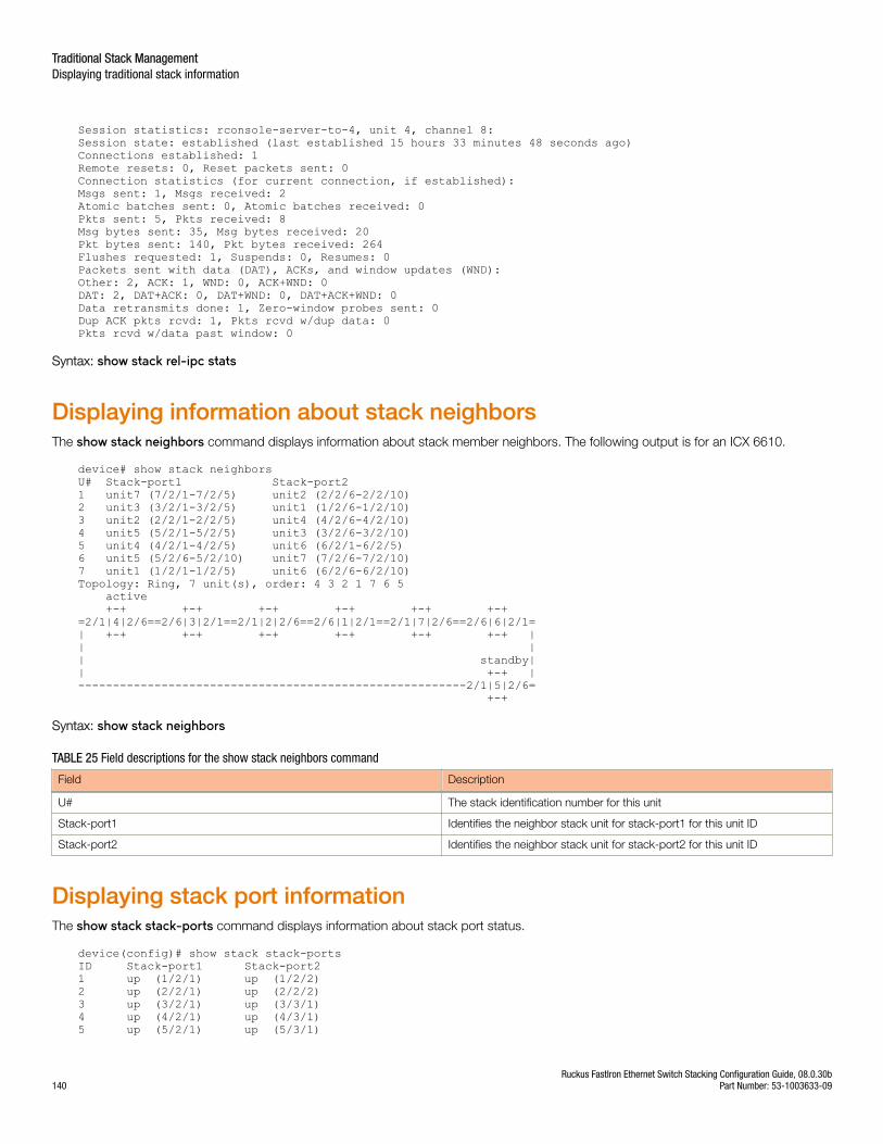
Session statistics: rconsole-server-to-4, unit 4, channel 8:Session state: established (last established 15 hours 33 minutes 48 seconds ago)Connections established: 1 Remote resets: 0, Reset packets sent: 0Connection statistics (for current connection, if established):Msgs sent: 1, Msgs received: 2Atomic batches sent: 0, Atomic batches received: 0Pkts sent: 5, Pkts received: 8Msg bytes sent: 35, Msg bytes received: 20Pkt bytes sent: 140, Pkt bytes received: 264Flushes requested: 1, Suspends: 0, Resumes: 0Packets sent with data (DAT), ACKs, and window updates (WND):Other: 2, ACK: 1, WND: 0, ACK+WND: 0DAT: 2, DAT+ACK: 0, DAT+WND: 0, DAT+ACK+WND: 0Data retransmits done: 1, Zero-window probes sent: 0Dup ACK pkts rcvd: 1, Pkts rcvd w/dup data: 0Pkts rcvd w/data past window: 0
Syntax: show stack rel-ipc stats
Displaying information about stack neighborsThe show stack neighbors command displays information about stack member neighbors. The following output is for an ICX 6610.
device# show stack neighborsU# Stack-port1 Stack-port2 1 unit7 (7/2/1-7/2/5) unit2 (2/2/6-2/2/10) 2 unit3 (3/2/1-3/2/5) unit1 (1/2/6-1/2/10) 3 unit2 (2/2/1-2/2/5) unit4 (4/2/6-4/2/10) 4 unit5 (5/2/1-5/2/5) unit3 (3/2/6-3/2/10) 5 unit4 (4/2/1-4/2/5) unit6 (6/2/1-6/2/5) 6 unit5 (5/2/6-5/2/10) unit7 (7/2/6-7/2/10) 7 unit1 (1/2/1-1/2/5) unit6 (6/2/6-6/2/10) Topology: Ring, 7 unit(s), order: 4 3 2 1 7 6 5 active +-+ +-+ +-+ +-+ +-+ +-+ =2/1|4|2/6==2/6|3|2/1==2/1|2|2/6==2/6|1|2/1==2/1|7|2/6==2/6|6|2/1=| +-+ +-+ +-+ +-+ +-+ +-+ || || standby|| +-+ |--------------------------------------------------------2/1|5|2/6= +-+
Syntax: show stack neighbors
TABLE 25 Field descriptions for the show stack neighbors command
Field Description
U# The stack identification number for this unit
Stack-port1 Identifies the neighbor stack unit for stack-port1 for this unit ID
Stack-port2 Identifies the neighbor stack unit for stack-port2 for this unit ID
Displaying stack port informationThe show stack stack-ports command displays information about stack port status.
device(config)# show stack stack-portsID Stack-port1 Stack-port21 up (1/2/1) up (1/2/2)2 up (2/2/1) up (2/2/2)3 up (3/2/1) up (3/3/1)4 up (4/2/1) up (4/3/1)5 up (5/2/1) up (5/3/1)
Traditional Stack ManagementDisplaying traditional stack information
Ruckus FastIron Ethernet Switch Stacking Configuration Guide, 08.0.30b140 Part Number: 53-1003633-09
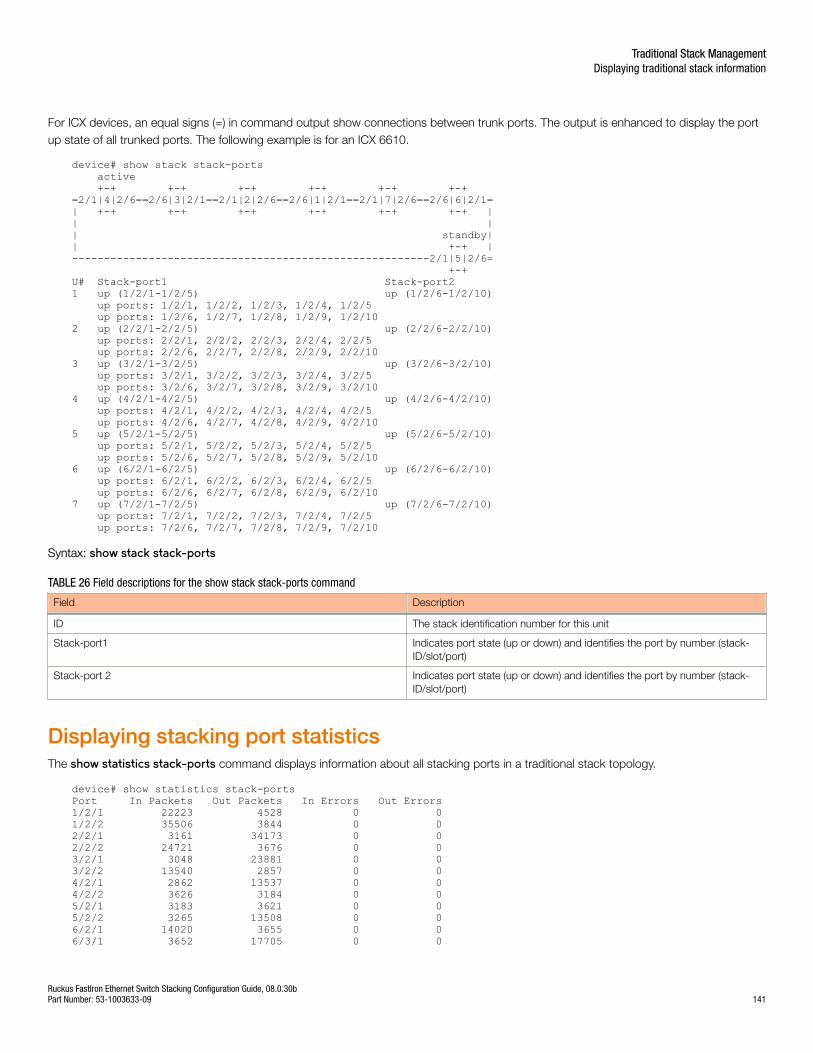
For ICX devices, an equal signs (=) in command output show connections between trunk ports. The output is enhanced to display the portup state of all trunked ports. The following example is for an ICX 6610.
device# show stack stack-ports active +-+ +-+ +-+ +-+ +-+ +-+ =2/1|4|2/6==2/6|3|2/1==2/1|2|2/6==2/6|1|2/1==2/1|7|2/6==2/6|6|2/1=| +-+ +-+ +-+ +-+ +-+ +-+ || || standby|| +-+ |--------------------------------------------------------2/1|5|2/6= +-+ U# Stack-port1 Stack-port2 1 up (1/2/1-1/2/5) up (1/2/6-1/2/10) up ports: 1/2/1, 1/2/2, 1/2/3, 1/2/4, 1/2/5 up ports: 1/2/6, 1/2/7, 1/2/8, 1/2/9, 1/2/102 up (2/2/1-2/2/5) up (2/2/6-2/2/10) up ports: 2/2/1, 2/2/2, 2/2/3, 2/2/4, 2/2/5 up ports: 2/2/6, 2/2/7, 2/2/8, 2/2/9, 2/2/103 up (3/2/1-3/2/5) up (3/2/6-3/2/10) up ports: 3/2/1, 3/2/2, 3/2/3, 3/2/4, 3/2/5 up ports: 3/2/6, 3/2/7, 3/2/8, 3/2/9, 3/2/104 up (4/2/1-4/2/5) up (4/2/6-4/2/10) up ports: 4/2/1, 4/2/2, 4/2/3, 4/2/4, 4/2/5 up ports: 4/2/6, 4/2/7, 4/2/8, 4/2/9, 4/2/105 up (5/2/1-5/2/5) up (5/2/6-5/2/10) up ports: 5/2/1, 5/2/2, 5/2/3, 5/2/4, 5/2/5 up ports: 5/2/6, 5/2/7, 5/2/8, 5/2/9, 5/2/106 up (6/2/1-6/2/5) up (6/2/6-6/2/10) up ports: 6/2/1, 6/2/2, 6/2/3, 6/2/4, 6/2/5 up ports: 6/2/6, 6/2/7, 6/2/8, 6/2/9, 6/2/107 up (7/2/1-7/2/5) up (7/2/6-7/2/10) up ports: 7/2/1, 7/2/2, 7/2/3, 7/2/4, 7/2/5 up ports: 7/2/6, 7/2/7, 7/2/8, 7/2/9, 7/2/10
Syntax: show stack stack-ports
TABLE 26 Field descriptions for the show stack stack-ports command
Field Description
ID The stack identification number for this unit
Stack-port1 Indicates port state (up or down) and identifies the port by number (stack-ID/slot/port)
Stack-port 2 Indicates port state (up or down) and identifies the port by number (stack-ID/slot/port)
Displaying stacking port statisticsThe show statistics stack-ports command displays information about all stacking ports in a traditional stack topology.
device# show statistics stack-portsPort In Packets Out Packets In Errors Out Errors1/2/1 22223 4528 0 01/2/2 35506 3844 0 02/2/1 3161 34173 0 02/2/2 24721 3676 0 03/2/1 3048 23881 0 03/2/2 13540 2857 0 04/2/1 2862 13537 0 04/2/2 3626 3184 0 05/2/1 3183 3621 0 05/2/2 3265 13508 0 06/2/1 14020 3655 0 06/3/1 3652 17705 0 0
Traditional Stack ManagementDisplaying traditional stack information
Ruckus FastIron Ethernet Switch Stacking Configuration Guide, 08.0.30bPart Number: 53-1003633-09 141
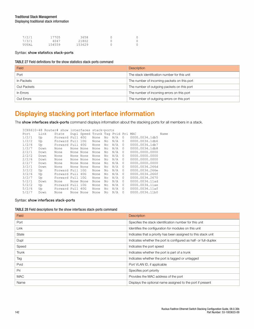
7/2/1 17705 3658 0 07/3/1 4047 21802 0 0TOTAL 154559 153629 0 0
Syntax: show statistics stack-ports
TABLE 27 Field definitions for the show statistics stack-ports command
Field Description
Port The stack identification number for this unit
In Packets The number of incoming packets on this port
Out Packets The number of outgoing packets on this port
In Errors The number of incoming errors on this port
Out Errors The number of outgoing errors on this port
Displaying stacking port interface informationThe show interfaces stack-ports command displays information about the stacking ports for all members in a stack.
ICX6610-48 Router# show interfaces stack-portsPort Link State Dupl Speed Trunk Tag Pvid Pri MAC Name1/2/1 Up Forward Full 40G None No N/A 0 0000.0034.1db51/2/2 Up Forward Full 10G None No N/A 0 0000.0034.1db61/2/6 Up Forward Full 40G None No N/A 0 0000.0034.1db71/2/7 Down None None None None No N/A 0 0000.0034.1db82/2/1 Down None None None None No N/A 0 0000.0000.00002/2/2 Down None None None None No N/A 0 0000.0000.00002/2/6 Down None None None None No N/A 0 0000.0000.00002/2/7 Down None None None None No N/A 0 0000.0000.00003/2/1 Down None None None None No N/A 0 0000.0034.266d3/2/2 Up Forward Full 10G None No N/A 0 0000.0034.266e3/2/6 Up Forward Full 40G None No N/A 0 0000.0034.266f3/2/7 Up Forward Full 10G None No N/A 0 0000.0034.26705/2/1 Down None None None None No N/A 0 0000.0034.11ad5/2/2 Up Forward Full 10G None No N/A 0 0000.0034.11ae5/2/6 Up Forward Full 40G None No N/A 0 0000.0034.11af5/2/7 Down None None None None No N/A 0 0000.0034.11b0
Syntax: show interfaces stack-ports
TABLE 28 Field descriptions for the show interfaces stack-ports command
Field Description
Port Specifies the stack identification number for this unit
Link Identifies the configuration for modules on this unit
State Indicates that a priority has been assigned to this stack unit
Dupl Indicates whether the port is configured as half- or full-duplex
Speed Indicates the port speed
Trunk Indicates whether the port is part of a trunk
Tag Indicates whether the port is tagged or untagged
Pvid Port VLAN ID, if applicable
Pri Specifies port priority
MAC Provides the MAC address of the port
Name Displays the optional name assigned to the port if present
Traditional Stack ManagementDisplaying traditional stack information
Ruckus FastIron Ethernet Switch Stacking Configuration Guide, 08.0.30b142 Part Number: 53-1003633-09
NOTEIf a unit is provisional (that is, if it is reserved and does not have a physical unit associated with the unit ID), its interface MACaddress shows as 0000.0000.0000.
MIB support for the traditional stackAll statistics about packets received and sent, RMON, jumbo frames (greater than 1518 bytes), runts, giants, and other instances aregathered through the stack interfaces and are accessible through SNMP. MIB support for traditional stacks is the same as for a standard 10Gbps interface. Information includes types of modules, including optics modules.
Traditional Stack ManagementMIB support for the traditional stack
Ruckus FastIron Ethernet Switch Stacking Configuration Guide, 08.0.30bPart Number: 53-1003633-09 143

Ruckus FastIron Ethernet Switch Stacking Configuration Guide, 08.0.30b144 Part Number: 53-1003633-09
Traditional Stack Troubleshooting• Problems commonly diagnosed with stack formation............................................................................................ 145• Background problem diagnosis............................................................................................................................. 146• Troubleshooting an unsuccessful stack build......................................................................................................... 146• Troubleshooting secure-setup............................................................................................................................... 148• Troubleshooting unit replacement issues............................................................................................................... 149• Troubleshooting a stacking upgrade...................................................................................................................... 149• Stack mismatches.................................................................................................................................................150• Troubleshooting image copy issues....................................................................................................................... 153• Configuration, startup configuration files, and stacking flash.................................................................................. 153• Stacking unit role transition considerations............................................................................................................ 154• Port down and aging.............................................................................................................................................154
Problems commonly diagnosed with stack formationThe most common reason for an unsuccessful stack build is a hardware configuration mismatch, a software configuration mismatch, or acombination of both.
After a stack forms, the system performs background problem diagnosis, which helps to reveal common problems with stack formation.For information on background diagnostics and manual control, refer to "Background problem diagnosis."
The following common problems may be encountered when building stacks:
• Ports on the same trunk connect to different units.
• Ports on the same trunk connect to different trunks on the same unit.
• Sub-ports of the 4 x 10-Gbps module are down.
• One end of a 10 Gbps port is up, but the other end is down.
• Communication problems exist between units in the stack.
A common connection error is that the two cables of a trunk go to different units or to different trunks on the same unit. A stack may stillform in these cases, but the incorrect connection may cause an internal forwarding loop, or the unit may have forwarding problems.
The most common connection error in forming an ICX 6610 stack is connecting a 40 Gbps port to a 4 x10-Gbps port, possibly becausethe two port types use the same type of cable. When this happens, the system may show one end is up, and one end is down. The stackcannot be formed, and the periodic background diagnosis does not run.
When a stack diagnosis indicates that 4 x 10-Gbps sub-ports are down, one end of a 10-Gbps port is down, or communication problemsexist between stack units, the cause may be hardware failure or a software problem.
For example, the active controller console displays the following messages for an ICX 6610 stack if a 4 x10-Gbps sub-port is down.
*** Warning! miss 4*10G link 5/2/8(down)to 1/2/8(down). Stack can still work.*** Warning! U1, dir=1, 4*10G ports: 1/2/8 are down.*** Warning! U5, dir=1, 4*10G ports: 5/2/8 are down.Please use "show stack conn" to view detailed connectionsYou can suppress the error messages by configuring "stack suppress-warning"
In this situation, the ICX 6610 stack should still work because of trunking. However, if all sub-ports of a 4 x10-Gbps are down, no diagnosticwarning is displayed because the periodic probe cannot distinguish between a hardware failure and a disconnected cable.
Ruckus FastIron Ethernet Switch Stacking Configuration Guide, 08.0.30bPart Number: 53-1003633-09 145
Background problem diagnosisAfter a stack forms, the system periodically probes the topology to check connections between units in the stack. This diagnosis, which isrun in the background, can detect user connection errors and hardware failures. Related error messages are provided approximately every20 minutes. No messages are displayed if no problem is detected.
Manually triggering stack diagnosisYou can manually trigger the diagnosis using the show stack connection command. This command can provide additional detail on
connections that are identified as problems in the diagnostic report. The command can also be used when periodic diagnostic warningshave been suppressed.
NOTEPeriodic background stack diagnosis is performed every minute. When you manually trigger stack diagnosis, the system may printthe following message:
There is a trunk probe going on. Please try later.
Suppressing background stack diagnostic warningsYou can control the automatic background stacking diagnosis that runs periodically when stacking is enabled.
To stop periodic output of background diagnostic reports, enter the stack suppress-warning command at the configuration level on the
active controller.
To start receiving diagnostic warnings again, enter the no form of the command.
Troubleshooting an unsuccessful stack buildIf you are unable to build a stack (for example, the show stack command does not display any stack units), perform the following steps.
1. Enter the show run command on each unit to make sure the configuration contains “stack enable.” If it does not, enter the stackenable command on the unit. Before a stack is formed, you can still access the console port on each device. Once a stack is
successfully formed, you are redirected to the active controller.
NOTEIf you are building a stack using secure-setup, you do not have to enter the stack enable command on each unit.
2. Check that all of your stacking port connections are secure and working properly. Enter show interfaces stack on each device to
confirm that the stacking port links are up and the ports are in the forward state.
device# show interfaces stackPort Link State Dupl Speed Trunk Tag P MAC Name1/2/1 Up Forward Full 10G None No 1 0000.00eb.a9021/2/2 Up Forward Full 10G None No 1 0000.00eb.a904
3. Confirm that all of the devices are running the same software image.
4. Use the show log command to display any IPC version mismatch messages. These messages appear in one minute when
receiving mismatched probe packets, and then once every 10 minutes.
Traditional Stack TroubleshootingBackground problem diagnosis
Ruckus FastIron Ethernet Switch Stacking Configuration Guide, 08.0.30b146 Part Number: 53-1003633-09
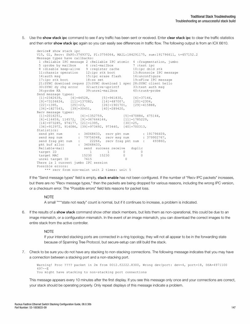
5. Use the show stack ipc command to see if any traffic has been sent or received. Enter clear stack ipc to clear the traffic statistics
and then enter show stack ipc again so you can easily see differences in traffic flow. The following output is from an ICX 6610.
device# show stack ipcV15, G1, Recv: SkP0:3749372, P1:3756064, MAIL:184291175, sum:191796611, t=457152.2Message types have callbacks: 1 :Reliable IPC message 2 :Reliable IPC atomic 4 :fragmentation, jumbo 5 :probe by mailbox 6 :rel-mailbox 7 :test ipc 8 :disable keep-alive 9 :register cache 10:ipc dnld stk 11:chassis operation 12:ipc stk boot 13:Rconsole IPC message 14:auth msg 15:ipc erase flash 16:unconfigure 17:ipc stk boot 18:ss set 19:sFlow IPC message 21:SYNC download reques 23:SYNC download 1 spec 28:SYNC client hello 30:SYNC dy chg error 32:active-uprintf 33:test auth msg 34:probe KA 39:unrel-mailbox 40:trunk-probe Send message types: [1]=2342639, [4]=44528, [5]=961830, [6]=37146, [9]=73104634, [11]=137082, [14]=487007, [20]=2304, [22]=1395, [25]=23, [26]=1901701, [29]=415888, [34]=1827543, [39]=30451, [40]=289420, Recv message types: [1]=2016251, [4]=1352759, [5]=470884, 475144, [6]=114459, 114572, [9]=367644144, [11]=1785229, [14]=973285, 974177, [21]=1395, [30]=25, [34]=912972, 914086, [39]=973492, 973440, [40]=700313, Statistics: send pkt num : 34068433, recv pkt num : 191796609, send msg num : 79756048, recv msg num : 379902767, send frag pkt num : 22264, recv frag pkt num : 493860, pkt buf alloc : 34068433, Reliable-mail send success receive duplic target ID 1 1 0 0 target MAC 15230 15230 0 0 unrel target ID 7615 0 There is 1 current jumbo IPC sessionPossible errors: *** recv from non-exist unit 2 times: unit 5
If the "Send message types" field is empty, stack enable has not been configured. If the number of "Recv IPC packets" increases,
but there are no "Recv message types," then the packets are being dropped for various reasons, including the wrong IPC version,or a checksum error. The "Possible errors" field lists reasons for packet loss.
NOTEA small "***state not ready" count is normal, but if it continues to increase, a problem is indicated.
6. If the results of a show stack command show other stack members, but lists them as non-operational, this could be due to an
image mismatch, or a configuration mismatch. In the event of an image mismatch, you can download the correct images to theentire stack from the active controller.
NOTEIf your intended stacking ports are connected in a ring topology, they will not all appear to be in the forwarding statebecause of Spanning Tree Protocol, but secure-setup can still build the stack.
7. Check to be sure you do not have any stacking to non-stacking connections. The following message indicates that you may havea connection between a stacking port and a non-stacking port.
Warning! Proc ???? packet in 2m from 0012.f2222.8300, Wrong dev/port: dev=4, port=18, DSA=4971100 497--EYou might have stacking to non-stacking port connections
This message appears every 10 minutes after the first display. If you see this message only once and your connections are correct,your stack should be operating properly. Only repeat displays of this message indicate a problem.
Traditional Stack TroubleshootingTroubleshooting an unsuccessful stack build
Ruckus FastIron Ethernet Switch Stacking Configuration Guide, 08.0.30bPart Number: 53-1003633-09 147
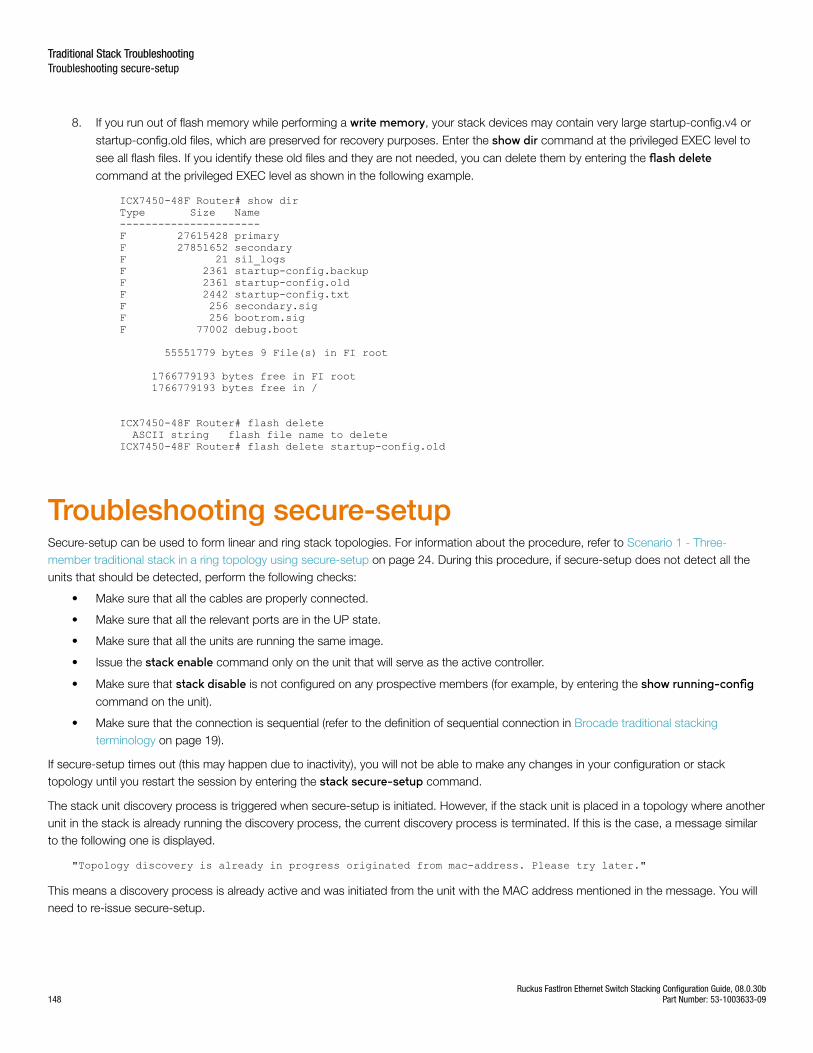
8. If you run out of flash memory while performing a write memory, your stack devices may contain very large startup-config.v4 or
startup-config.old files, which are preserved for recovery purposes. Enter the show dir command at the privileged EXEC level to
see all flash files. If you identify these old files and they are not needed, you can delete them by entering the flash deletecommand at the privileged EXEC level as shown in the following example.
ICX7450-48F Router# show dirType Size Name----------------------F 27615428 primaryF 27851652 secondaryF 21 sil_logsF 2361 startup-config.backupF 2361 startup-config.oldF 2442 startup-config.txtF 256 secondary.sigF 256 bootrom.sigF 77002 debug.boot
55551779 bytes 9 File(s) in FI root
1766779193 bytes free in FI root 1766779193 bytes free in /
ICX7450-48F Router# flash delete ASCII string flash file name to deleteICX7450-48F Router# flash delete startup-config.old
Troubleshooting secure-setupSecure-setup can be used to form linear and ring stack topologies. For information about the procedure, refer to Scenario 1 - Three-member traditional stack in a ring topology using secure-setup on page 24. During this procedure, if secure-setup does not detect all theunits that should be detected, perform the following checks:
• Make sure that all the cables are properly connected.
• Make sure that all the relevant ports are in the UP state.
• Make sure that all the units are running the same image.
• Issue the stack enable command only on the unit that will serve as the active controller.
• Make sure that stack disable is not configured on any prospective members (for example, by entering the show running-configcommand on the unit).
• Make sure that the connection is sequential (refer to the definition of sequential connection in Brocade traditional stackingterminology on page 19).
If secure-setup times out (this may happen due to inactivity), you will not be able to make any changes in your configuration or stacktopology until you restart the session by entering the stack secure-setup command.
The stack unit discovery process is triggered when secure-setup is initiated. However, if the stack unit is placed in a topology where anotherunit in the stack is already running the discovery process, the current discovery process is terminated. If this is the case, a message similarto the following one is displayed.
"Topology discovery is already in progress originated from mac-address. Please try later."
This means a discovery process is already active and was initiated from the unit with the MAC address mentioned in the message. You willneed to re-issue secure-setup.
Traditional Stack TroubleshootingTroubleshooting secure-setup
Ruckus FastIron Ethernet Switch Stacking Configuration Guide, 08.0.30b148 Part Number: 53-1003633-09
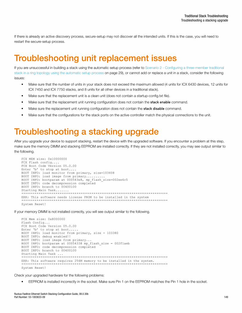
If there is already an active discovery process, secure-setup may not discover all the intended units. If this is the case, you will need torestart the secure-setup process.
Troubleshooting unit replacement issuesIf you are unsuccessful in building a stack using the automatic setup process (refer to Scenario 2 - Configuring a three-member traditionalstack in a ring topology using the automatic setup process on page 29), or cannot add or replace a unit in a stack, consider the followingissues:
• Make sure that the number of units in your stack does not exceed the maximum allowed (4 units for ICX 6430 devices, 12 units forICX 7450 and ICX 7750 stacks, and 8 units for all other devices in a traditional stack).
• Make sure that the replacement unit is a clean unit (does not contain a startup-config.txt file).
• Make sure that the replacement unit running configuration does not contain the stack enable command.
• Make sure the replacement unit running configuration does not contain the stack disable command.
• Make sure that the configurations for the stack ports on the active controller match the physical connections to the unit.
Troubleshooting a stacking upgradeAfter you upgrade your device to support stacking, restart the device with the upgraded software. If you encounter a problem at this step,make sure the memory DIMM and stacking EEPROM are installed correctly. If they are not installed correctly, you may see output similar tothe following.
FCX MEM size: 0x10000000FCX Flash config....FCX Boot Code Version 05.0.00Enter ‘b’ to stop at boot....BOOT INFO: load monitor from primary, size=103408BOOT INFO: load image from primary..........BOOT INFO: bootparam at 000543e8, mp_flash_size=002ee6c5BOOT INFO: code decompression completedBOOT INFO: branch to 00400100Starting Main Task.......*****************************************************************************ERR: This software needs License PROM to be installed in the system*****************************************************************************System Reset!
If your memory DIMM is not installed correctly, you will see output similar to the following.
FCX Mem size: 0x8000000Flash Config...FCX Boot Code Version 05.0.00Enter ‘b’ to stop at boot.....BOOT INFO: load monitor from primary, size = 103380BOOT INFO: debug enabled!!BOOT INFO: load image from primary...BOOT INFO: bootparam at 00054338 mp_flash_size = 002f1aebBOOT INFO: code decompression completedBOOT INFO: branch to 00400100Starting Main Task ...*****************************************************************************ERR: This software requires 256M memory to be installed in the system.*****************************************************************************System Reset!
Check your upgraded hardware for the following problems:
• EEPROM is installed incorrectly in the socket. Make sure Pin 1 on the EEPROM matches the Pin 1 hole in the socket.
Traditional Stack TroubleshootingTroubleshooting a stacking upgrade
Ruckus FastIron Ethernet Switch Stacking Configuration Guide, 08.0.30bPart Number: 53-1003633-09 149
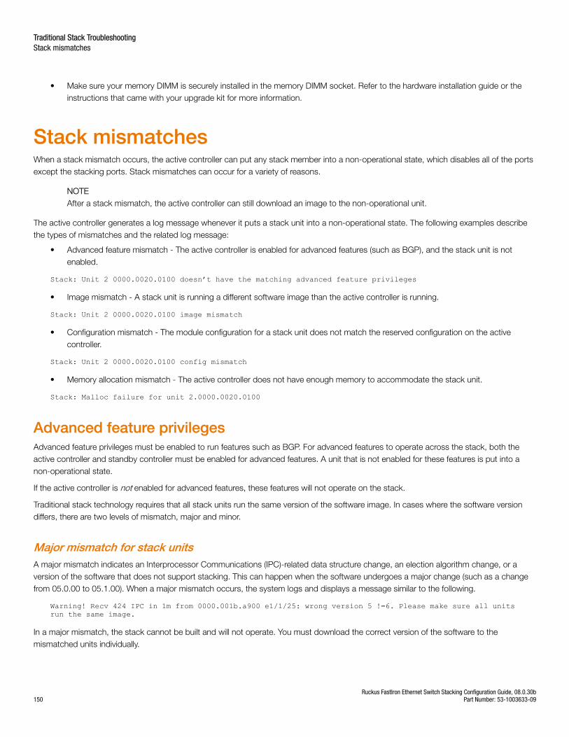
• Make sure your memory DIMM is securely installed in the memory DIMM socket. Refer to the hardware installation guide or theinstructions that came with your upgrade kit for more information.
Stack mismatchesWhen a stack mismatch occurs, the active controller can put any stack member into a non-operational state, which disables all of the portsexcept the stacking ports. Stack mismatches can occur for a variety of reasons.
NOTEAfter a stack mismatch, the active controller can still download an image to the non-operational unit.
The active controller generates a log message whenever it puts a stack unit into a non-operational state. The following examples describethe types of mismatches and the related log message:
• Advanced feature mismatch - The active controller is enabled for advanced features (such as BGP), and the stack unit is notenabled.
Stack: Unit 2 0000.0020.0100 doesn’t have the matching advanced feature privileges
• Image mismatch - A stack unit is running a different software image than the active controller is running.
Stack: Unit 2 0000.0020.0100 image mismatch
• Configuration mismatch - The module configuration for a stack unit does not match the reserved configuration on the activecontroller.
Stack: Unit 2 0000.0020.0100 config mismatch
• Memory allocation mismatch - The active controller does not have enough memory to accommodate the stack unit.
Stack: Malloc failure for unit 2.0000.0020.0100
Advanced feature privilegesAdvanced feature privileges must be enabled to run features such as BGP. For advanced features to operate across the stack, both theactive controller and standby controller must be enabled for advanced features. A unit that is not enabled for these features is put into anon-operational state.
If the active controller is not enabled for advanced features, these features will not operate on the stack.
Traditional stack technology requires that all stack units run the same version of the software image. In cases where the software versiondiffers, there are two levels of mismatch, major and minor.
Major mismatch for stack unitsA major mismatch indicates an Interprocessor Communications (IPC)-related data structure change, an election algorithm change, or aversion of the software that does not support stacking. This can happen when the software undergoes a major change (such as a changefrom 05.0.00 to 05.1.00). When a major mismatch occurs, the system logs and displays a message similar to the following.
Warning! Recv 424 IPC in 1m from 0000.001b.a900 e1/1/25: wrong version 5 !=6. Please make sure all units run the same image.
In a major mismatch, the stack cannot be built and will not operate. You must download the correct version of the software to themismatched units individually.
Traditional Stack TroubleshootingStack mismatches
Ruckus FastIron Ethernet Switch Stacking Configuration Guide, 08.0.30b150 Part Number: 53-1003633-09
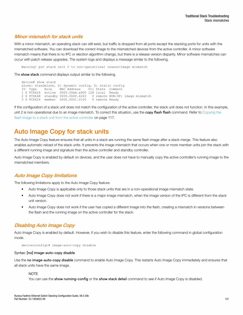
Minor mismatch for stack unitsWith a minor mismatch, an operating stack can still exist, but traffic is dropped from all ports except the stacking ports for units with themismatched software. You can download the correct image to the mismatched devices from the active controller. A minor softwaremismatch means that there is no IPC or election algorithm change, but there is a release version disparity. Minor software mismatches canoccur with patch release upgrades. The system logs and displays a message similar to the following.
Warning! put stack unit 2 to non-operational reason=image mismatch
The show stack command displays output similar to the following.
device# show stackalone: standalone, D: dynamic config, S: static configID Type Role MAC Address Pri State Comment1 S FCX624 active 0000.00eb.a900 128 local Ready2 S FCX648 standby 0000.004f.4243 0 remote NON-OP: image mismatch3 S FCX624 member 0000.0001.0100 0 remote Ready
If the configuration of a stack unit does not match the configuration of the active controller, the stack unit does not function. In this example,unit 2 is non-operational due to an image mismatch. To correct this situation, use the copy flash flash command. Refer to Copying the
flash image to a stack unit from the active controller on page 117.
Auto Image Copy for stack unitsThe Auto Image Copy feature ensures that all units in a stack are running the same flash image after a stack merge. This feature alsoenables automatic reload of the stack units. It prevents the image mismatch that occurs when one or more member units join the stack witha different running image and signature than the active controller and standby controller.
Auto Image Copy is enabled by default on devices, and the user does not have to manually copy the active controller’s running image to themismatched members.
Auto Image Copy limitationsThe following limitations apply to the Auto Image Copy feature:
• Auto Image Copy is applicable only to those stack units that are in a non-operational image mismatch state.
• Auto Image Copy does not work if there is a major image mismatch, when the image version of the IPC is different from the stackunit version.
• Auto Image Copy does not work if the user has copied a different image into the flash, creating a mismatch in versions betweenthe flash and the running image on the active controller for the stack.
Disabling Auto Image CopyAuto Image Copy is enabled by default. However, if you wish to disable this feature, enter the following command in global configurationmode.
device(config)# image-auto-copy disable
Syntax: [no] image-auto-copy disable
Use the no image-auto-copy disable command to enable Auto Image Copy. This restarts Auto Image Copy immediately and ensures that
all stack units have the same image.
NOTEYou can use the show running-config or the show stack detail command to see if Auto Image Copy is disabled.
Traditional Stack TroubleshootingStack mismatches
Ruckus FastIron Ethernet Switch Stacking Configuration Guide, 08.0.30bPart Number: 53-1003633-09 151
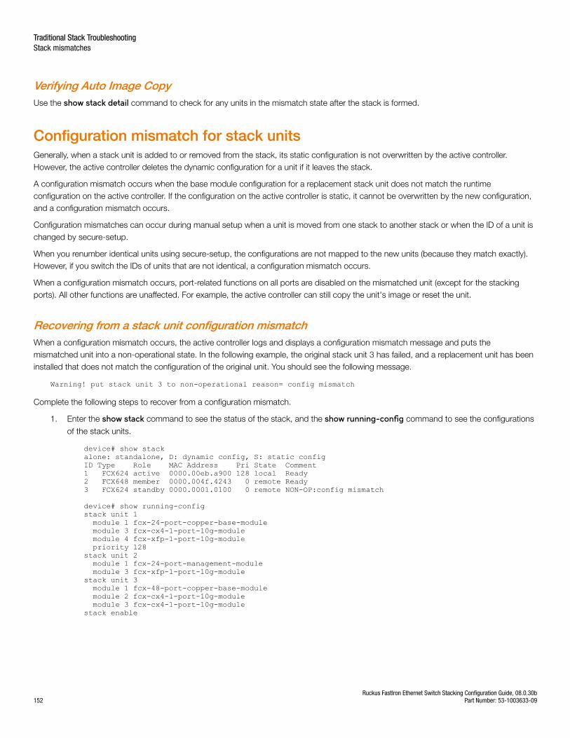
Verifying Auto Image CopyUse the show stack detail command to check for any units in the mismatch state after the stack is formed.
Configuration mismatch for stack unitsGenerally, when a stack unit is added to or removed from the stack, its static configuration is not overwritten by the active controller.However, the active controller deletes the dynamic configuration for a unit if it leaves the stack.
A configuration mismatch occurs when the base module configuration for a replacement stack unit does not match the runtimeconfiguration on the active controller. If the configuration on the active controller is static, it cannot be overwritten by the new configuration,and a configuration mismatch occurs.
Configuration mismatches can occur during manual setup when a unit is moved from one stack to another stack or when the ID of a unit ischanged by secure-setup.
When you renumber identical units using secure-setup, the configurations are not mapped to the new units (because they match exactly).However, if you switch the IDs of units that are not identical, a configuration mismatch occurs.
When a configuration mismatch occurs, port-related functions on all ports are disabled on the mismatched unit (except for the stackingports). All other functions are unaffected. For example, the active controller can still copy the unit's image or reset the unit.
Recovering from a stack unit configuration mismatchWhen a configuration mismatch occurs, the active controller logs and displays a configuration mismatch message and puts themismatched unit into a non-operational state. In the following example, the original stack unit 3 has failed, and a replacement unit has beeninstalled that does not match the configuration of the original unit. You should see the following message.
Warning! put stack unit 3 to non-operational reason= config mismatch
Complete the following steps to recover from a configuration mismatch.
1. Enter the show stack command to see the status of the stack, and the show running-config command to see the configurations
of the stack units.
device# show stackalone: standalone, D: dynamic config, S: static configID Type Role MAC Address Pri State Comment1 FCX624 active 0000.00eb.a900 128 local Ready2 FCX648 member 0000.004f.4243 0 remote Ready3 FCX624 standby 0000.0001.0100 0 remote NON-OP:config mismatch
device# show running-configstack unit 1 module 1 fcx-24-port-copper-base-module module 3 fcx-cx4-1-port-10g-module module 4 fcx-xfp-1-port-10g-module priority 128stack unit 2 module 1 fcx-24-port-management-module module 3 fcx-xfp-1-port-10g-modulestack unit 3 module 1 fcx-48-port-copper-base-module module 2 fcx-cx4-1-port-10g-module module 3 fcx-cx4-1-port-10g-modulestack enable
Traditional Stack TroubleshootingStack mismatches
Ruckus FastIron Ethernet Switch Stacking Configuration Guide, 08.0.30b152 Part Number: 53-1003633-09
2. To resolve the mismatch, you must remove the configuration for stack unit 3. Use the no stack unit command in configuration
mode.
device# configure terminaldevice(config)# no stack unit 3
This removes configuration related to unit 3.
If you are unable to remove the configuration because of a multi-slot trunk configuration or other configuration identified by systemoutput, you must first manually remove the problem configuration.
When you have successfully deleted the mismatched stack unit, a re-election is triggered, and the active controller learns thecorrect module configuration from the standby controller or from other stack members. No reload is required.
Memory allocation failureA memory allocation (malloc) failure occurs when the active controller does not have enough memory to run a stack unit. This failure mayoccur if you configure a large number of VLANs (for example, 4000) or STP instances (for example, 255) in the router image. A memoryallocation failure message means that the active controller is low on memory after allocating these resources and does not have enoughremaining memory to control a stack member. You can correct this by reducing the number of VLANs or STP instances.
NOTEAfter you make configuration changes, such as the number of VLANs or STP instances, you must reset the stack.
Troubleshooting image copy issuesThe copy tftp flash command copies the image to all stack units including the active controller. The copy flash flash command copies the
image from the primary or secondary flash on the active controller to the primary or secondary flash image of a stack member. If you areunable to copy an image to one or more stack units, check the following:
• Make sure the unit is actually part of the stack. Use the show stack command.
• If a unit joins a stack after the image copy command was issued, you will need to copy the image to this unit separately.
Configuration, startup configuration files, andstacking flashStacking system behavior is defined by the runtime configuration, which can be displayed using the show run command. The writememory command stores the runtime configuration in a flash file called startup-config.txt. During bootup, the system reads and applies the
startup-config.txt file to the runtime configuration. The startup-config.txt file can be shown using the show config command.
The stacking system installs a stacking.boot file on each unit that tells the unit what its role is during the boot process. The stacking.boot fileis generated whenever there is an election that defines the roles for all units.
When an active controller is booted or a write memory command is issued, the active controller synchronizes its startup-config.txt file to
every stack unit. The original startup-config.txt files in the standby controller and other stack members are renamed to startup-config.old. Ifyou issue the stack unconfigure me command on the standby controller or stack member directly, these units recover their original startup-
config.txt files and reboot as standalone devices. If you enter the stack unconfigure all command from the active controller, all devices
recover their old startup-config.txt files and become standalone devices. When this happens, the startup-config.old file is renamed tostartup-config.txt, and the stacking.boot file is removed.
Traditional Stack TroubleshootingConfiguration, startup configuration files, and stacking flash
Ruckus FastIron Ethernet Switch Stacking Configuration Guide, 08.0.30bPart Number: 53-1003633-09 153
Whenever a stack unit configuration parameter, such as the priority setting, is changed, an election is held to determine the active controller,and the result is written into the stacking.boot file. A prompt message appears on the console that recommends you use the write memorycommand. For an active controller role change to take effect, you must reset the entire stack.
If you do not use the write memory command but reset the stack, the stack units continue to operate in their roles as defined by the
stacking.boot file. After the reset, each unit readjusts based on the current runtime configuration. However, you may observe differentresults depending on what has not been saved. If you have renumbered the stack unit IDs, you may see a configuration mismatch becauseyour changes no longer match the active controller configuration.
If you change priorities to elect an active controller, the new active controller assumes its role after a reboot, whether or not you have usedthe write memory command. If you do not save your priority change before the next reboot, the reboot triggers an election that may result
in a different winner based on the priority in the unsaved configuration. The new winner assumes the active controller role after the nextreboot.
If you change the stacking port configuration and do not save your changes, you may encounter connectivity errors. To recover from aconfiguration error, define the correct stacking port by running secure-setup.
NOTEYou should always execute the write memory command after making stacking-related configuration changes such as changing
priority or changing stacking ports. If you do not want to keep the changes, change the configuration back to the previousversion, and then execute the write memory command. Do not discard configuration changes by using a reset without executing
the write memory command.
Stacking unit role transition considerationsAn active or standby controller contains the stacking system configuration and its internal data structures. When an active or standbycontroller becomes a member, the configuration and data structures are not cleared. This does not affect its capability to function as amember. However, if the user changes the configuration, this member unit cannot become a standby again because of the difference inconfiguration. A member unit can become a standby only if the member was never a standby or active controller (with no configuration) or ifit has the same configuration as the current active controller.
Port down and agingAging is only used as a safeguard. If a unit is powered down or the stacking link is removed, the system immediately detects that the port isdown and knows that its neighbor is gone. That unit is immediately removed from the active controller.
If a stacking port does not receive keep-alive messages from its neighbor within 60 seconds, it ages out the neighbor. When a unit is nolonger stack-enabled or when one stacking port becomes a non-stacking port, it sends a notification that the port is no longer a stackingport. When the neighboring port receives the notification from its neighbor, it immediately removes the neighbor.
The following message is logged and displayed when a port is aged out.
Warning! my mac=0000.004f.4243, age out up-stream
Traditional Stack TroubleshootingStacking unit role transition considerations
Ruckus FastIron Ethernet Switch Stacking Configuration Guide, 08.0.30b154 Part Number: 53-1003633-09
Hitless Stacking• Hitless stacking overview.......................................................................................................................................155• Supported hitless stacking events ........................................................................................................................ 156• Non-supported hitless stacking events..................................................................................................................156• Supported hitless stacking protocols and services................................................................................................ 156• Hitless stacking configuration notes and feature limitations....................................................................................158• What happens during a hitless stacking switchover or failover............................................................................... 159• Standby controller role in hitless stacking.............................................................................................................. 160• Support during stack formation, stack merge, and stack split................................................................................161• Hitless stacking behavior....................................................................................................................................... 164• Hitless stacking failover......................................................................................................................................... 166• Hitless stacking switchover....................................................................................................................................168• Displaying information about hitless stacking.........................................................................................................174• Displaying information about stack failover............................................................................................................ 175• Displaying information about link synchronization status........................................................................................ 175• Syslog messages for hitless stacking failover and switchover................................................................................ 175
Hitless stacking overviewHitless stacking is supported on FCX and ICX units in a traditional stack. It is a High Availability feature set that ensures sub-second or noloss of data traffic during the following events:
• Active controller failure or role change
• Software failure
• Addition or removal of units in a stack
• Removal or disconnection of the stacking cable between the active controller and the standby controller
During such events, the standby controller takes over the active role, and the system continues to forward traffic seamlessly, as if no failureor topology change has occurred. In software releases that do not support hitless stacking, events such as these could cause most of theunits in a stack to reset, affecting data traffic.
FCX and ICX stackable units support the following hitless stacking features:
Hitless stacking switchover - A manually-controlled (CLI-driven) or automatic switchover of the active controller and standby controllerwithout reloading the stack and without any packet loss to the services and protocols that are supported by hitless stacking. A switchoveris activated by the CLI command stack switch-over command. A switchover may also be activated by the priority command, depending
on the configured priority value.
Hitless stacking failover - An automatic, forced switchover of the active controller and standby controller because of a failure or abnormaltermination of the active controller. During a failover, the active controller abruptly leaves the stack, and the standby controller immediatelyassumes the active role. As with a switchover, a failover occurs without the stack being reloaded. Unlike a switchover, a failover generallyoccurs without warning and is likely to result in sub-second packet loss (although packets traversing the stacking link may be lost).
Hitless stacking failover is enabled by default beginning with Fastiron release 08.0.20.
Ruckus FastIron Ethernet Switch Stacking Configuration Guide, 08.0.30bPart Number: 53-1003633-09 155
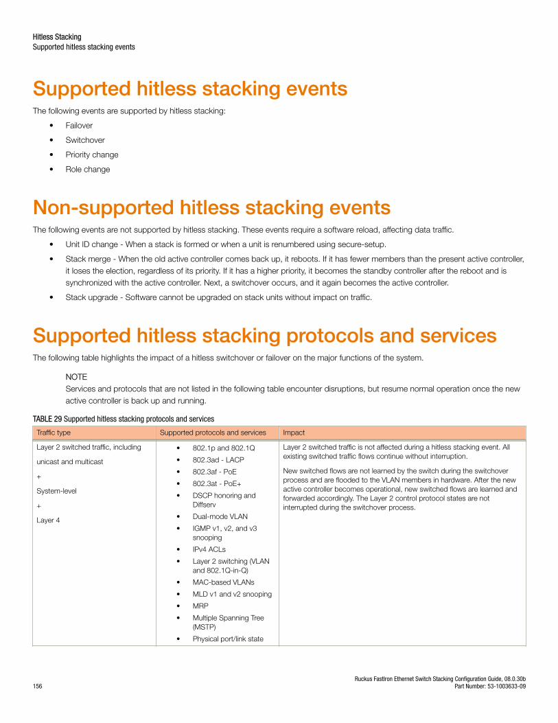
Supported hitless stacking eventsThe following events are supported by hitless stacking:
• Failover
• Switchover
• Priority change
• Role change
Non-supported hitless stacking eventsThe following events are not supported by hitless stacking. These events require a software reload, affecting data traffic.
• Unit ID change - When a stack is formed or when a unit is renumbered using secure-setup.
• Stack merge - When the old active controller comes back up, it reboots. If it has fewer members than the present active controller,it loses the election, regardless of its priority. If it has a higher priority, it becomes the standby controller after the reboot and issynchronized with the active controller. Next, a switchover occurs, and it again becomes the active controller.
• Stack upgrade - Software cannot be upgraded on stack units without impact on traffic.
Supported hitless stacking protocols and servicesThe following table highlights the impact of a hitless switchover or failover on the major functions of the system.
NOTEServices and protocols that are not listed in the following table encounter disruptions, but resume normal operation once the newactive controller is back up and running.
TABLE 29 Supported hitless stacking protocols and services
Traffic type Supported protocols and services Impact
Layer 2 switched traffic, including
unicast and multicast
+
System-level
+
Layer 4
• 802.1p and 802.1Q
• 802.3ad - LACP
• 802.3af - PoE
• 802.3at - PoE+
• DSCP honoring andDiffserv
• Dual-mode VLAN
• IGMP v1, v2, and v3snooping
• IPv4 ACLs
• Layer 2 switching (VLANand 802.1Q-in-Q)
• MAC-based VLANs
• MLD v1 and v2 snooping
• MRP
• Multiple Spanning Tree(MSTP)
• Physical port/link state
Layer 2 switched traffic is not affected during a hitless stacking event. Allexisting switched traffic flows continue without interruption.
New switched flows are not learned by the switch during the switchoverprocess and are flooded to the VLAN members in hardware. After the newactive controller becomes operational, new switched flows are learned andforwarded accordingly. The Layer 2 control protocol states are notinterrupted during the switchover process.
Hitless StackingSupported hitless stacking events
Ruckus FastIron Ethernet Switch Stacking Configuration Guide, 08.0.30b156 Part Number: 53-1003633-09
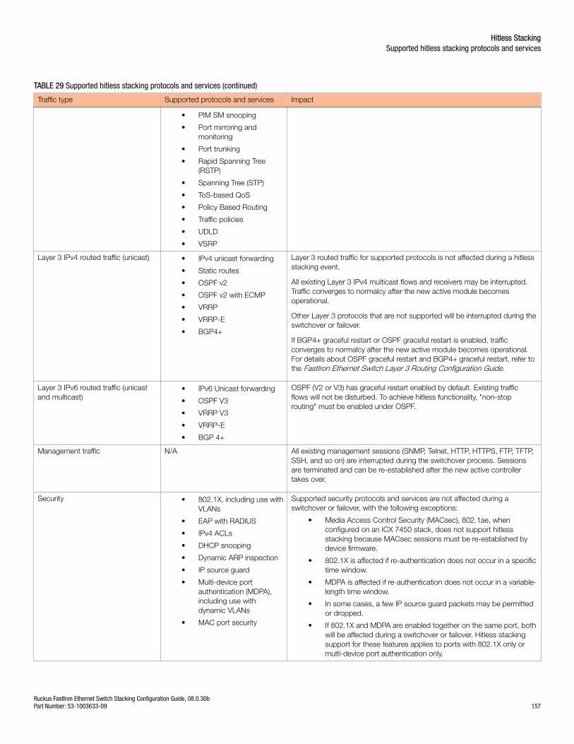
TABLE 29 Supported hitless stacking protocols and services (continued)
Traffic type Supported protocols and services Impact
• PIM SM snooping
• Port mirroring andmonitoring
• Port trunking
• Rapid Spanning Tree(RSTP)
• Spanning Tree (STP)
• ToS-based QoS
• Policy Based Routing
• Traffic policies
• UDLD
• VSRP
Layer 3 IPv4 routed traffic (unicast) • IPv4 unicast forwarding
• Static routes
• OSPF v2
• OSPF v2 with ECMP
• VRRP
• VRRP-E
• BGP4+
Layer 3 routed traffic for supported protocols is not affected during a hitlessstacking event.
All existing Layer 3 IPv4 multicast flows and receivers may be interrupted.Traffic converges to normalcy after the new active module becomesoperational.
Other Layer 3 protocols that are not supported will be interrupted during theswitchover or failover.
If BGP4+ graceful restart or OSPF graceful restart is enabled, trafficconverges to normalcy after the new active module becomes operational.For details about OSPF graceful restart and BGP4+ graceful restart, refer tothe FastIron Ethernet Switch Layer 3 Routing Configuration Guide.
Layer 3 IPv6 routed traffic (unicastand multicast)
• IPv6 Unicast forwarding
• OSPF V3
• VRRP V3
• VRRP-E
• BGP 4+
OSPF (V2 or V3) has graceful restart enabled by default. Existing trafficflows will not be disturbed. To achieve hitless functionality, "non-stoprouting" must be enabled under OSPF.
Management traffic N/A All existing management sessions (SNMP, Telnet, HTTP, HTTPS, FTP, TFTP,SSH, and so on) are interrupted during the switchover process. Sessionsare terminated and can be re-established after the new active controllertakes over.
Security • 802.1X, including use withVLANs
• EAP with RADIUS
• IPv4 ACLs
• DHCP snooping
• Dynamic ARP inspection
• IP source guard
• Multi-device portauthentication (MDPA),including use withdynamic VLANs
• MAC port security
Supported security protocols and services are not affected during aswitchover or failover, with the following exceptions:
• Media Access Control Security (MACsec), 802.1ae, whenconfigured on an ICX 7450 stack, does not support hitlessstacking because MACsec sessions must be re-established bydevice firmware.
• 802.1X is affected if re-authentication does not occur in a specifictime window.
• MDPA is affected if re-authentication does not occur in a variable-length time window.
• In some cases, a few IP source guard packets may be permittedor dropped.
• If 802.1X and MDPA are enabled together on the same port, bothwill be affected during a switchover or failover. Hitless stackingsupport for these features applies to ports with 802.1X only ormulti-device port authentication only.
Hitless StackingSupported hitless stacking protocols and services
Ruckus FastIron Ethernet Switch Stacking Configuration Guide, 08.0.30bPart Number: 53-1003633-09 157
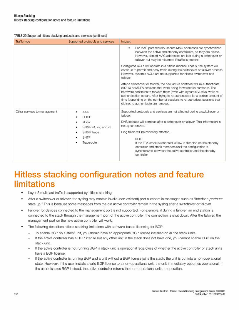
TABLE 29 Supported hitless stacking protocols and services (continued)
Traffic type Supported protocols and services Impact
• For MAC port security, secure MAC addresses are synchronizedbetween the active and standby controllers, so they are hitless.However, denied MAC addresses are lost during a switchover orfailover but may be relearned if traffic is present.
Configured ACLs will operate in a hitless manner. That is, the system willcontinue to permit and deny traffic during the switchover or failover process.However, dynamic ACLs are not supported for hitless switchover andfailover.
After a switchover or failover, the new active controller will re-authenticate802.1X or MDPA sessions that were being forwarded in hardware. Thehardware continues to forward them (even with dynamic VLANs) while re-authentication occurs. After trying to re-authenticate for a certain amount oftime (depending on the number of sessions to re-authorize), sessions thatdid not re-authenticate are removed.
Other services to management • AAA
• DHCP
• sFlow
• SNMP v1, v2, and v3
• SNMP traps
• SNTP
• Traceroute
Supported protocols and services are not affected during a switchover orfailover.
DNS lookups will continue after a switchover or failover. This information isnot synchronized.
Ping traffic will be minimally affected.
NOTEIf the FCX stack is rebooted, sFlow is disabled on the standbycontroller and stack members until the configuration issynchronized between the active controller and the standbycontroller.
Hitless stacking configuration notes and featurelimitations
• Layer 3 multicast traffic is supported by hitless stacking.
• After a switchover or failover, the syslog may contain invalid (non-existent) port numbers in messages such as “Interface portnumstate up.” This is because some messages from the old active controller remain in the syslog after a switchover or failover.
• Failover for devices connected to the management port is not supported. For example, if during a failover, an end station isconnected to the stack through the management port of the active controller, the connection is shut down. After the failover, themanagement port on the new active controller will work.
• The following describes hitless stacking limitations with software-based licensing for BGP:
– To enable BGP on a stack unit, you should have an appropriate BGP license installed on all the stack units.– If the active controller has a BGP license but any other unit in the stack does not have one, you cannot enable BGP on the
stack unit.– If the active controller is not running BGP, a stack unit is operational regardless of whether the active controller or stack units
have a BGP license.– If the active controller is running BGP and a unit without a BGP license joins the stack, the unit is put into a non-operational
state. However, If the user installs a valid BGP license to a non-operational unit, the unit immediately becomes operational. Ifthe user disables BGP instead, the active controller returns the non-operational units to operation.
Hitless StackingHitless stacking configuration notes and feature limitations
Ruckus FastIron Ethernet Switch Stacking Configuration Guide, 08.0.30b158 Part Number: 53-1003633-09
What happens during a hitless stacking switchoveror failoverThis section describes the internal events that enable a controlled or forced switchover to take place in a hitless manner as well as theevents that occur during the switchover.
Real-time synchronization among all units in a stackHitless stacking requires the active controller, standby controller, and stack members to be fully synchronized at all times. This isaccomplished by baseline and dynamic synchronization of all units in a stack.
When a stack is first booted and becomes operational, baseline synchronization occurs across all of the units in the stack. The activecontroller copies the current state of its CPU to all units of the stack, including the standby controller. The information received from theactive controller is programmed locally in the hardware on all units. The information includes:
• Startup and runtime configuration (CLI) - These files are copied to the standby controller only.
• Layer 2 protocols - Layer 2 protocols such as STP, RSTP, MRP, and VSRP run concurrently on both the active controller andstandby controller.
• Hardware Abstraction Layer (HAL) - This includes the prefix-based routing table, next hop information for outgoing interfaces, andtunnel information.
• Layer 3 IP forwarding information - This includes the routing table, IP cache table, and ARP table as well as static and connectedroutes. Layer 3 routing protocols are not copied to any of the units in the stack but remain in standby state on the standbycontroller until a switchover occurs. Peer adjacency is restored after a switchover. If BGP4 or OSPF graceful restart is enabledduring a switchover, the standby controller (new active controller) initiates a graceful restart, and a new set of routes is relearned.The new set of routes will be the same as the old routes, unless the network has changed.
• OSPFv2 and OSPFv3 non-stop routing support - For more information, refer to the FastIron Ethernet Switch Layer 3 RoutingConfiguration Guide.
When control protocols are synchronized and protocol synchronization timers have expired, the standby controller is placed in hot-standbymode, ready to take over as the active controller. If a switchover occurs, the standby controller takes over without interrupting data traffic.
After baseline synchronization, any new events that occur on the active controller are dynamically synchronized on the standby controller.Such events include:
• CLI, HTTP, and SNMP configurations
• Link events
• Interrupts
• Layer 2 and Layer 3 forwarding table updates
• Dynamic user authentication updates such as 802.1X or multi-device port authentication
After a switchover, the new active controller receives updates from the stack members and sends verification information to the stackmembers to ensure that they are synchronized.
NOTEThe events described previously occur internally and do not create or affect the external network topology.
NOTEIf there is no active controller after a reload, the bootup standby assumes the active role in approximately 60 seconds without areload. A bootup standby is the device that was the standby controller before the reload. It may not be the current standbycontroller.
Hitless StackingWhat happens during a hitless stacking switchover or failover
Ruckus FastIron Ethernet Switch Stacking Configuration Guide, 08.0.30bPart Number: 53-1003633-09 159
Standby controller role in hitless stackingIn software releases that do not support hitless stacking, the standby controller functions as a dummy device, meaning it provides limitedaccess to CLI commands such as show, stack, and a few debug commands. The active controller can access the full range of the CLI. The
standby controller synchronizes its configuration with the active controller at each reset.
With the introduction of hitless stacking, the standby controller shadows the active controller. The role or behavior of the standby controllerwith hitless stacking is as follows:
• The local console on the standby controller still accepts only show, stack, and a few debug commands.
• The runtime configuration on the standby controller is synchronized with the active controller whenever there is a configurationchange.
• Protocols are configured in the runtime configuration, but no protocol packets are sent out on the standby controller.
• The state of every unit is known, including the state of the active controller. The show commands display current information suchas STP or port states.
• When a failover occurs, the standby controller uses its current runtime configuration. The configuration could be different from theactive controller if the last configuration transmission was lost.
• After a failover, the new active controller (the old standby controller) programs all other units in hardware, based on its runtimeconfiguration.
Standby controller electionCandidates for standby controller must meet the following criteria:
• The unit is operational, and the image and module configuration match those of the active controller.
• The runtime configuration matches that of the active controller.
If more than one unit in the stack meets these criteria, the standby controller is chosen according to the following criteria, in the ordershown:
• Priority - The unit with the highest priority value.
• Current standby - The unit that is currently the standby controller.
• Bootup master - The unit that was the active controller before the stack was reloaded.
• Bootup standby - The unit that was the standby controller before the stack was reloaded.
Once the standby controller is identified, the following internal events take place.
1. The standby controller is assigned by the active controller 30 to 60 seconds after election (60 seconds if the active controller bootsup in less than 120 seconds).
2. The standby controller receives and processes the runtime configuration sent by the active controller.
3. The standby controller learns the protocols within 70 seconds.
When the standby controller is fully synchronized, the system is ready for a switchover or failover.
Runtime configuration mismatchIn some cases, such as a runtime configuration mismatch between the active controller and candidate standby controller, the standbycontroller cannot be assigned by the active controller unless the candidate standby controller is reloaded.
Hitless StackingStandby controller role in hitless stacking
Ruckus FastIron Ethernet Switch Stacking Configuration Guide, 08.0.30b160 Part Number: 53-1003633-09
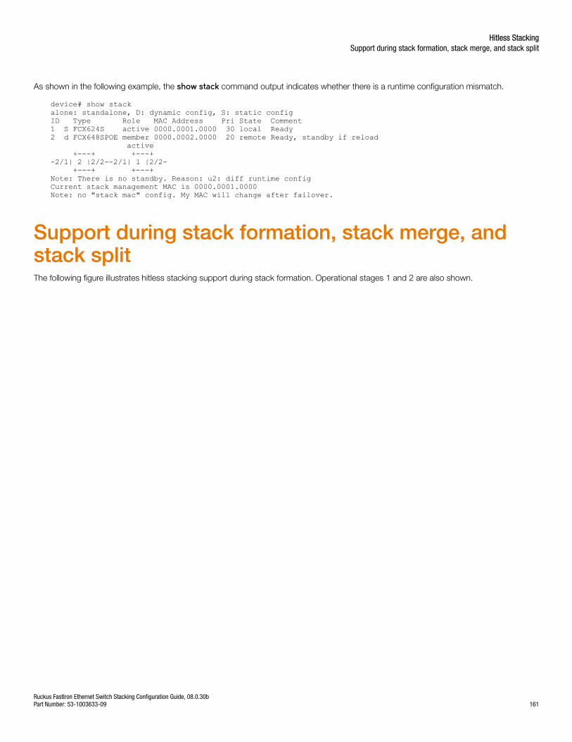
As shown in the following example, the show stack command output indicates whether there is a runtime configuration mismatch.
device# show stackalone: standalone, D: dynamic config, S: static configID Type Role MAC Address Pri State Comment1 S FCX624S active 0000.0001.0000 30 local Ready2 d FCX648SPOE member 0000.0002.0000 20 remote Ready, standby if reload active +---+ +---+-2/1| 2 |2/2--2/1| 1 |2/2- +---+ +---+Note: There is no standby. Reason: u2: diff runtime configCurrent stack management MAC is 0000.0001.0000Note: no "stack mac" config. My MAC will change after failover.
Support during stack formation, stack merge, andstack splitThe following figure illustrates hitless stacking support during stack formation. Operational stages 1 and 2 are also shown.
Hitless StackingSupport during stack formation, stack merge, and stack split
Ruckus FastIron Ethernet Switch Stacking Configuration Guide, 08.0.30bPart Number: 53-1003633-09 161
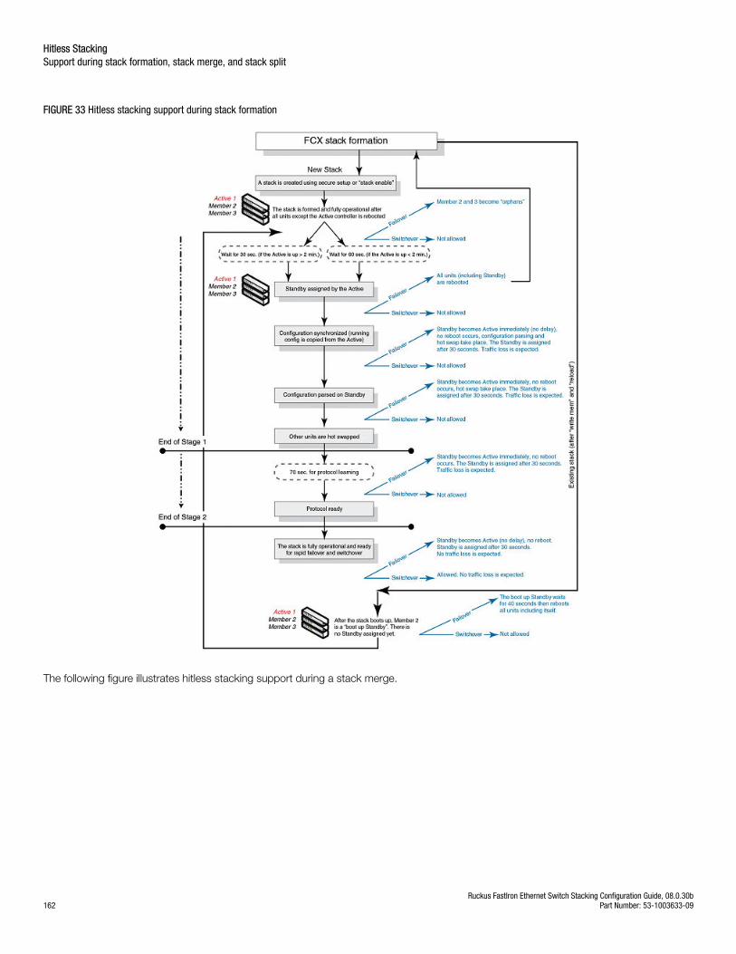
FIGURE 33 Hitless stacking support during stack formation
The following figure illustrates hitless stacking support during a stack merge.
Hitless StackingSupport during stack formation, stack merge, and stack split
Ruckus FastIron Ethernet Switch Stacking Configuration Guide, 08.0.30b162 Part Number: 53-1003633-09
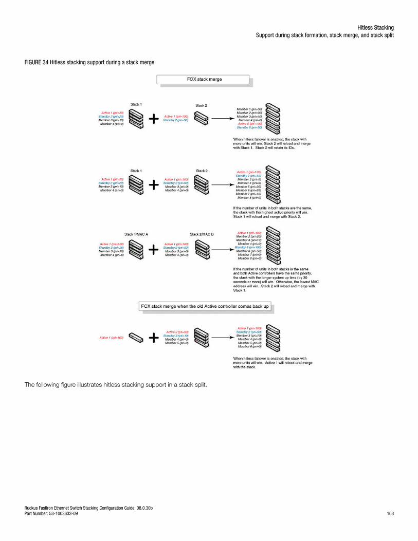
FIGURE 34 Hitless stacking support during a stack merge
The following figure illustrates hitless stacking support in a stack split.
Hitless StackingSupport during stack formation, stack merge, and stack split
Ruckus FastIron Ethernet Switch Stacking Configuration Guide, 08.0.30bPart Number: 53-1003633-09 163
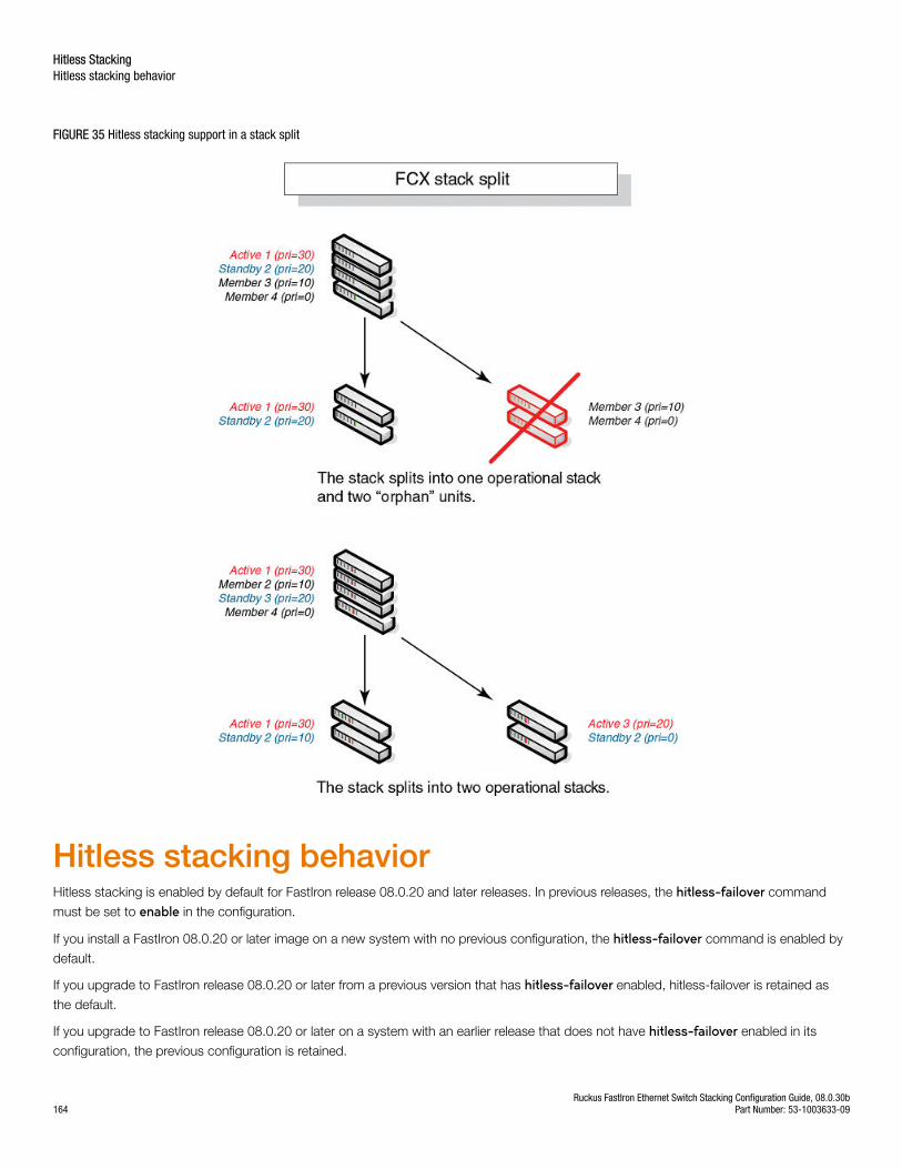
FIGURE 35 Hitless stacking support in a stack split
Hitless stacking behaviorHitless stacking is enabled by default for FastIron release 08.0.20 and later releases. In previous releases, the hitless-failover command
must be set to enable in the configuration.
If you install a FastIron 08.0.20 or later image on a new system with no previous configuration, the hitless-failover command is enabled by
default.
If you upgrade to FastIron release 08.0.20 or later from a previous version that has hitless-failover enabled, hitless-failover is retained as
the default.
If you upgrade to FastIron release 08.0.20 or later on a system with an earlier release that does not have hitless-failover enabled in its
configuration, the previous configuration is retained.
Hitless StackingHitless stacking behavior
Ruckus FastIron Ethernet Switch Stacking Configuration Guide, 08.0.30b164 Part Number: 53-1003633-09
Hitless stacking can be disabled using the no hitless-failover enable command. When stacking is disabled, the following limitations are in
effect:
• If a failover occurs, every unit in the stack reloads.
• Manual switchover is not allowed. If the stack switch-over command is entered, the following message appears on the console:
Switch-over is not allowed. Reason: hitless-failover not configured.
• Internal switchover resulting from a priority change is blocked until the entire stack is reloaded or hitless stacking is enabled. Apriority change triggers an election, but the newly elected winner does not immediately assume its role.
• If there is no active controller after a reload, the bootup standby assumes the active role after reloading every unit in the stack,including itself.
• During a stack merge, the active controller with the highest priority wins the election and reloads every unit of the losing stack.
NOTESynchronization between the active controller, standby controller, and stack members occurs whether or not hitless stacking isenabled.
If hitless stacking has been disabled, enable hitless stacking failover as described in "Enabling hitless stacking failover." As soon as hitlessstacking is enabled, the following behavior takes effect immediately:
• If a failover occurs, the stack does not reload.
• Manual switchover (CLI command stack switch-over) is allowed.
• If a priority change occurred while hitless stacking was disabled and the configured priority value requires a switchover, the systemstarts a 60-second timer before performing a switchover. After the switchover, the highest priority standby controller becomes theactive controller.
• If there is no active controller after a reload, the bootup standby controller assumes the active controller role in approximately 120seconds without a reload.
• During a stack merge, the active controller with the larger number of units wins the election and reloads every unit of the losingstack. If two stacks have the same number of units, then the priority, system up time, ID, and finally the MAC address arecompared. If two stacks have the same number of units and the same priority, then the stack with the longest system up time (by30 seconds or more) wins the election. Otherwise, the smallest ID is compared next, followed by MAC address. If the losing activecontroller has the highest priority, it becomes the standby controller after reloading and relearning the protocols. It becomes theactive controller after an internal switchover.
NOTEIf the active controllers of two merging stacks have different hitless stacking settings (for example, hitless stacking is enabled inone stack and disabled in the other), the winning controller retains its hitless stacking setting and runtime configuration for themerged stack.
You can use the show stack command to check whether hitless stacking is enabled.
Enabling hitless stackingHitless stacking is enabled by default, beginning with FastIron release 08.0.20; however, certain restrictions apply as described in Hitlessstacking behavior on page 164.
If hitless stacking has been disabled, you can enable it as described in Enabling hitless stacking failover on page 167.
Hitless StackingHitless stacking behavior
Ruckus FastIron Ethernet Switch Stacking Configuration Guide, 08.0.30bPart Number: 53-1003633-09 165
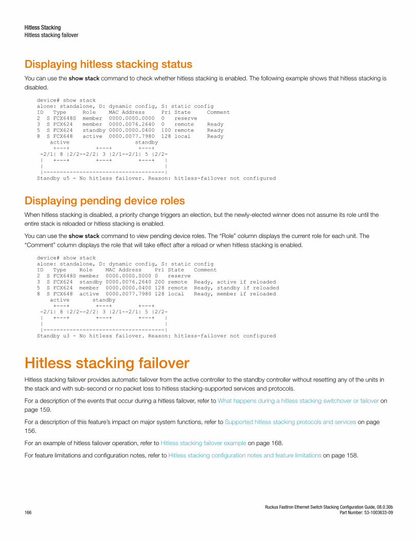
Displaying hitless stacking statusYou can use the show stack command to check whether hitless stacking is enabled. The following example shows that hitless stacking is
disabled.
device# show stackalone: standalone, D: dynamic config, S: static configID Type Role MAC Address Pri State Comment2 S FCX648S member 0000.0000.0000 0 reserve3 S FCX624 member 0000.0076.2640 0 remote Ready5 S FCX624 standby 0000.0000.0400 100 remote Ready8 S FCX648 active 0000.0077.7980 128 local Ready active standby +---+ +---+ +---+ -2/1| 8 |2/2--2/2| 3 |2/1--2/1| 5 |2/2- | +---+ +---+ +---+ | | | |-------------------------------------|Standby u5 - No hitless failover. Reason: hitless-failover not configured
Displaying pending device rolesWhen hitless stacking is disabled, a priority change triggers an election, but the newly-elected winner does not assume its role until theentire stack is reloaded or hitless stacking is enabled.
You can use the show stack command to view pending device roles. The “Role” column displays the current role for each unit. The
“Comment” column displays the role that will take effect after a reload or when hitless stacking is enabled.
device# show stackalone: standalone, D: dynamic config, S: static configID Type Role MAC Address Pri State Comment2 S FCX648S member 0000.0000.0000 0 reserve3 S FCX624 standby 0000.0076.2640 200 remote Ready, active if reloaded5 S FCX624 member 0000.0000.0400 128 remote Ready, standby if reloaded8 S FCX648 active 0000.0077.7980 128 local Ready, member if reloaded active standby +---+ +---+ +---+ -2/1| 8 |2/2--2/2| 3 |2/1--2/1| 5 |2/2- | +---+ +---+ +---+ | | | |-------------------------------------|Standby u3 - No hitless failover. Reason: hitless-failover not configured
Hitless stacking failoverHitless stacking failover provides automatic failover from the active controller to the standby controller without resetting any of the units inthe stack and with sub-second or no packet loss to hitless stacking-supported services and protocols.
For a description of the events that occur during a hitless failover, refer to What happens during a hitless stacking switchover or failover onpage 159.
For a description of this feature’s impact on major system functions, refer to Supported hitless stacking protocols and services on page156.
For an example of hitless failover operation, refer to Hitless stacking failover example on page 168.
For feature limitations and configuration notes, refer to Hitless stacking configuration notes and feature limitations on page 158.
Hitless StackingHitless stacking failover
Ruckus FastIron Ethernet Switch Stacking Configuration Guide, 08.0.30b166 Part Number: 53-1003633-09

Enabling hitless stacking failoverNOTEHitless stacking failover is enabled by default in FastIron release 08.0.20 and later releases.
To enable hitless stacking failover, enter the following command at the global CONFIG level of the CLI:
device# configure terminaldevice(config)# hitless-failover enable
The command takes effect immediately. Hitless switchover is allowed, and in the event of a failover, the standby controller takes over theactive role without reloading the stack.
Syntax: [no] hitless-failover enable
Use the no form of the command to disable hitless stacking failover once it has been enabled.
Hitless StackingHitless stacking failover
Ruckus FastIron Ethernet Switch Stacking Configuration Guide, 08.0.30bPart Number: 53-1003633-09 167
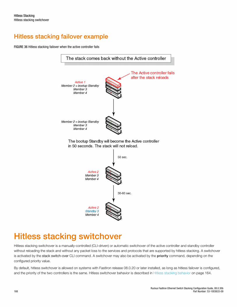
Hitless stacking failover example
FIGURE 36 Hitless stacking failover when the active controller fails
Hitless stacking switchoverHitless stacking switchover is a manually-controlled (CLI-driven) or automatic switchover of the active controller and standby controllerwithout reloading the stack and without any packet loss to the services and protocols that are supported by hitless stacking. A switchoveris activated by the stack switch-over CLI command. A switchover may also be activated by the priority command, depending on the
configured priority value.
By default, hitless switchover is allowed on systems with FastIron release 08.0.20 or later installed, as long as hitless failover is configured,and the priority of the two controllers is the same. Hitless switchover behavior is described in Hitless stacking behavior on page 164.
Hitless StackingHitless stacking switchover
Ruckus FastIron Ethernet Switch Stacking Configuration Guide, 08.0.30b168 Part Number: 53-1003633-09
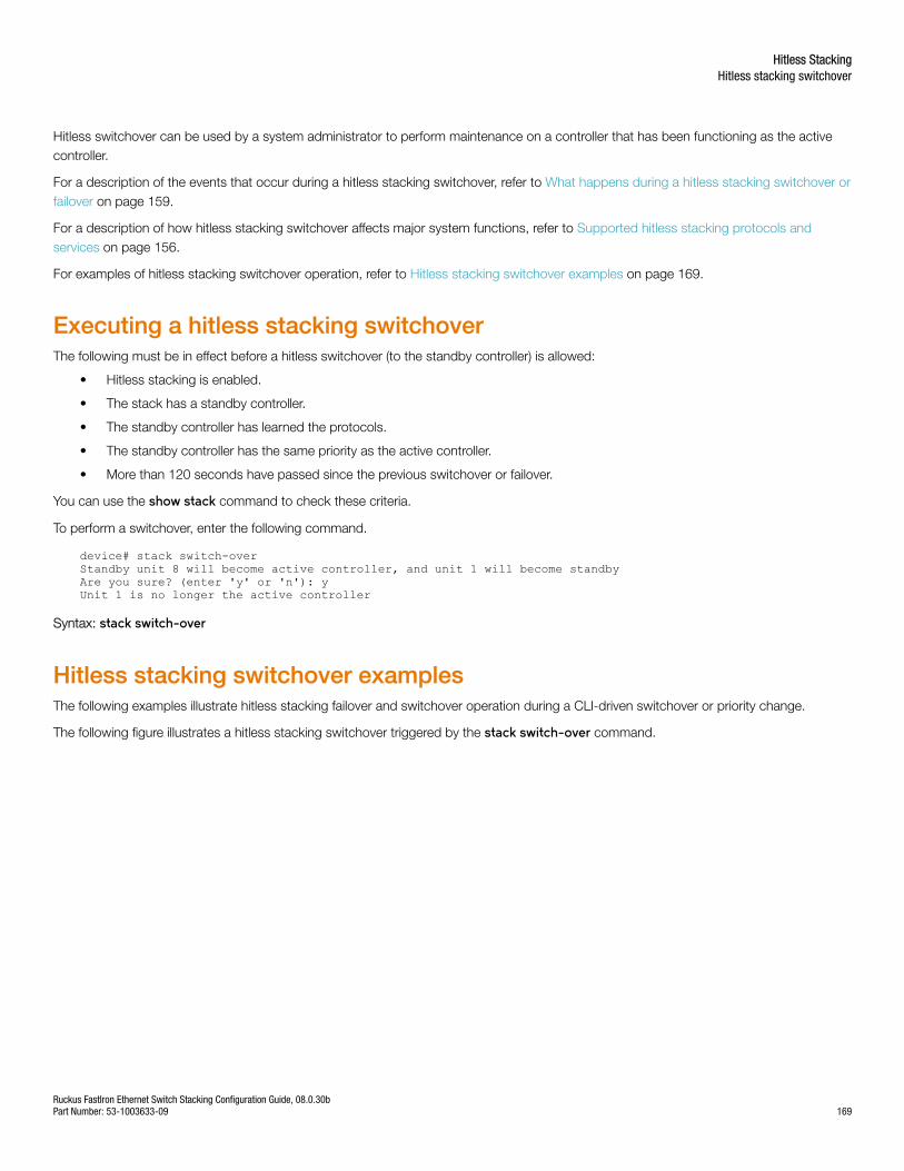
Hitless switchover can be used by a system administrator to perform maintenance on a controller that has been functioning as the activecontroller.
For a description of the events that occur during a hitless stacking switchover, refer to What happens during a hitless stacking switchover orfailover on page 159.
For a description of how hitless stacking switchover affects major system functions, refer to Supported hitless stacking protocols andservices on page 156.
For examples of hitless stacking switchover operation, refer to Hitless stacking switchover examples on page 169.
Executing a hitless stacking switchoverThe following must be in effect before a hitless switchover (to the standby controller) is allowed:
• Hitless stacking is enabled.
• The stack has a standby controller.
• The standby controller has learned the protocols.
• The standby controller has the same priority as the active controller.
• More than 120 seconds have passed since the previous switchover or failover.
You can use the show stack command to check these criteria.
To perform a switchover, enter the following command.
device# stack switch-overStandby unit 8 will become active controller, and unit 1 will become standbyAre you sure? (enter 'y' or 'n'): yUnit 1 is no longer the active controller
Syntax: stack switch-over
Hitless stacking switchover examplesThe following examples illustrate hitless stacking failover and switchover operation during a CLI-driven switchover or priority change.
The following figure illustrates a hitless stacking switchover triggered by the stack switch-over command.
Hitless StackingHitless stacking switchover
Ruckus FastIron Ethernet Switch Stacking Configuration Guide, 08.0.30bPart Number: 53-1003633-09 169
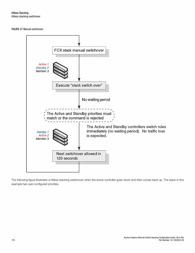
FIGURE 37 Manual switchover
The following figure illustrates a hitless stacking switchover when the active controller goes down and then comes back up. The stack in thisexample has user-configured priorities.
Hitless StackingHitless stacking switchover
Ruckus FastIron Ethernet Switch Stacking Configuration Guide, 08.0.30b170 Part Number: 53-1003633-09
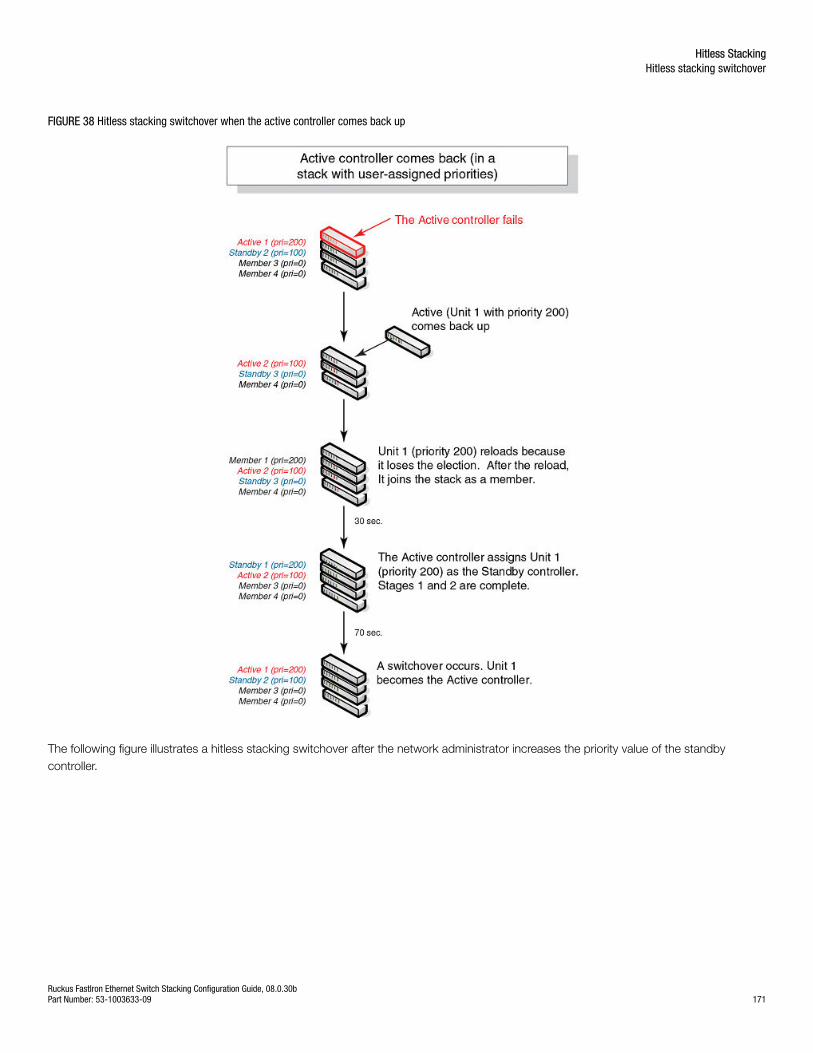
FIGURE 38 Hitless stacking switchover when the active controller comes back up
The following figure illustrates a hitless stacking switchover after the network administrator increases the priority value of the standbycontroller.
Hitless StackingHitless stacking switchover
Ruckus FastIron Ethernet Switch Stacking Configuration Guide, 08.0.30bPart Number: 53-1003633-09 171
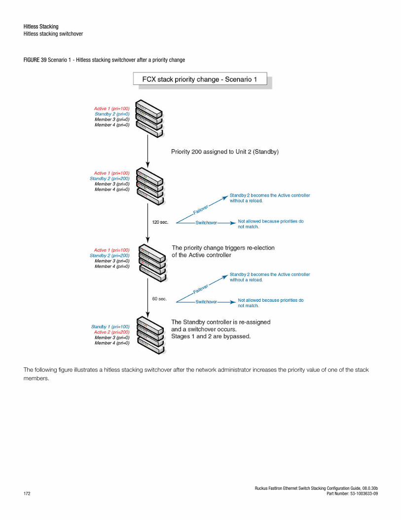
FIGURE 39 Scenario 1 - Hitless stacking switchover after a priority change
The following figure illustrates a hitless stacking switchover after the network administrator increases the priority value of one of the stackmembers.
Hitless StackingHitless stacking switchover
Ruckus FastIron Ethernet Switch Stacking Configuration Guide, 08.0.30b172 Part Number: 53-1003633-09
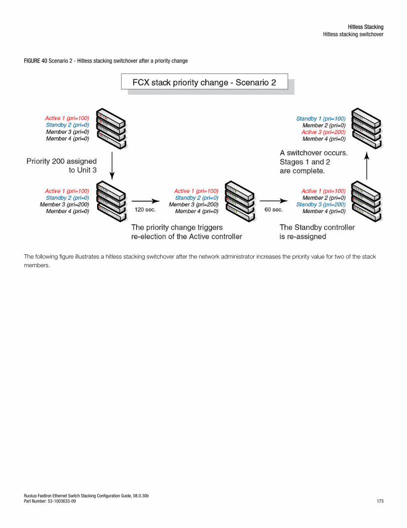
FIGURE 40 Scenario 2 - Hitless stacking switchover after a priority change
The following figure illustrates a hitless stacking switchover after the network administrator increases the priority value for two of the stackmembers.
Hitless StackingHitless stacking switchover
Ruckus FastIron Ethernet Switch Stacking Configuration Guide, 08.0.30bPart Number: 53-1003633-09 173
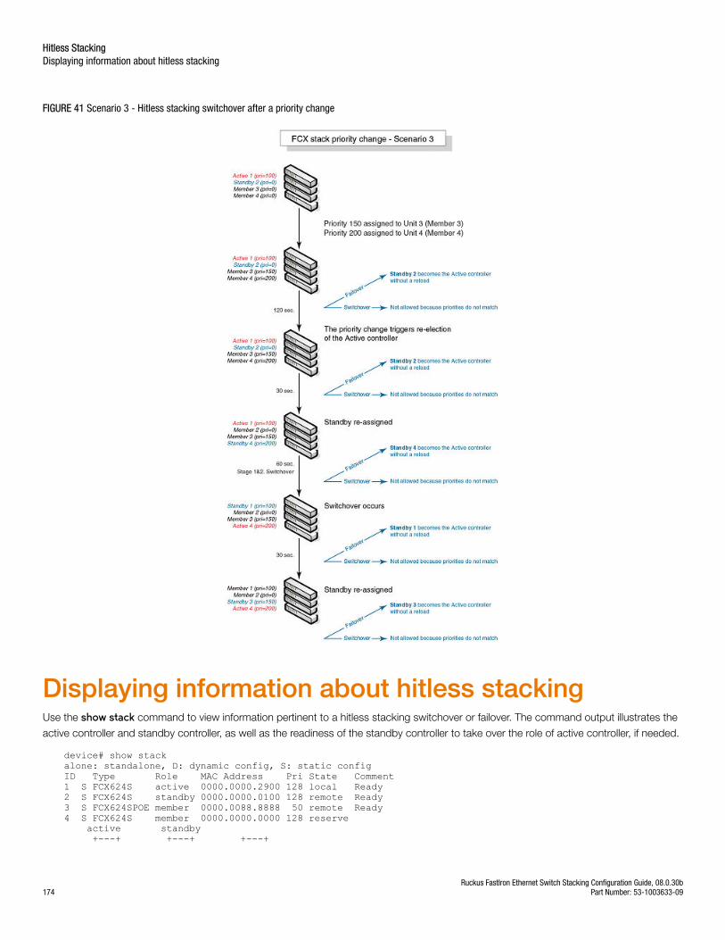
FIGURE 41 Scenario 3 - Hitless stacking switchover after a priority change
Displaying information about hitless stackingUse the show stack command to view information pertinent to a hitless stacking switchover or failover. The command output illustrates the
active controller and standby controller, as well as the readiness of the standby controller to take over the role of active controller, if needed.
device# show stackalone: standalone, D: dynamic config, S: static configID Type Role MAC Address Pri State Comment1 S FCX624S active 0000.0000.2900 128 local Ready2 S FCX624S standby 0000.0000.0100 128 remote Ready3 S FCX624SPOE member 0000.0088.8888 50 remote Ready4 S FCX624S member 0000.0000.0000 128 reserve active standby +---+ +---+ +---+
Hitless StackingDisplaying information about hitless stacking
Ruckus FastIron Ethernet Switch Stacking Configuration Guide, 08.0.30b174 Part Number: 53-1003633-09
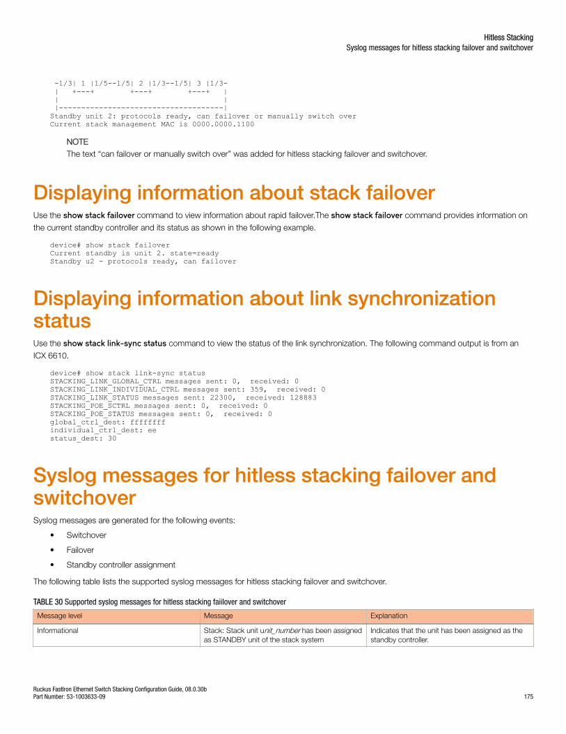
-1/3| 1 |1/5--1/5| 2 |1/3--1/5| 3 |1/3- | +---+ +---+ +---+ | | | |-------------------------------------|Standby unit 2: protocols ready, can failover or manually switch overCurrent stack management MAC is 0000.0000.1100
NOTEThe text “can failover or manually switch over” was added for hitless stacking failover and switchover.
Displaying information about stack failoverUse the show stack failover command to view information about rapid failover.The show stack failover command provides information on
the current standby controller and its status as shown in the following example.
device# show stack failover Current standby is unit 2. state=readyStandby u2 - protocols ready, can failover
Displaying information about link synchronizationstatusUse the show stack link-sync status command to view the status of the link synchronization. The following command output is from an
ICX 6610.
device# show stack link-sync statusSTACKING_LINK_GLOBAL_CTRL messages sent: 0, received: 0STACKING_LINK_INDIVIDUAL_CTRL messages sent: 359, received: 0STACKING_LINK_STATUS messages sent: 22300, received: 128883STACKING_POE_SCTRL messages sent: 0, received: 0STACKING_POE_STATUS messages sent: 0, received: 0global_ctrl_dest: ffffffffindividual_ctrl_dest: eestatus_dest: 30
Syslog messages for hitless stacking failover andswitchoverSyslog messages are generated for the following events:
• Switchover
• Failover
• Standby controller assignment
The following table lists the supported syslog messages for hitless stacking failover and switchover.
TABLE 30 Supported syslog messages for hitless stacking faiilover and switchover
Message level Message Explanation
Informational Stack: Stack unit unit_number has been assignedas STANDBY unit of the stack system
Indicates that the unit has been assigned as thestandby controller.
Hitless StackingSyslog messages for hitless stacking failover and switchover
Ruckus FastIron Ethernet Switch Stacking Configuration Guide, 08.0.30bPart Number: 53-1003633-09 175
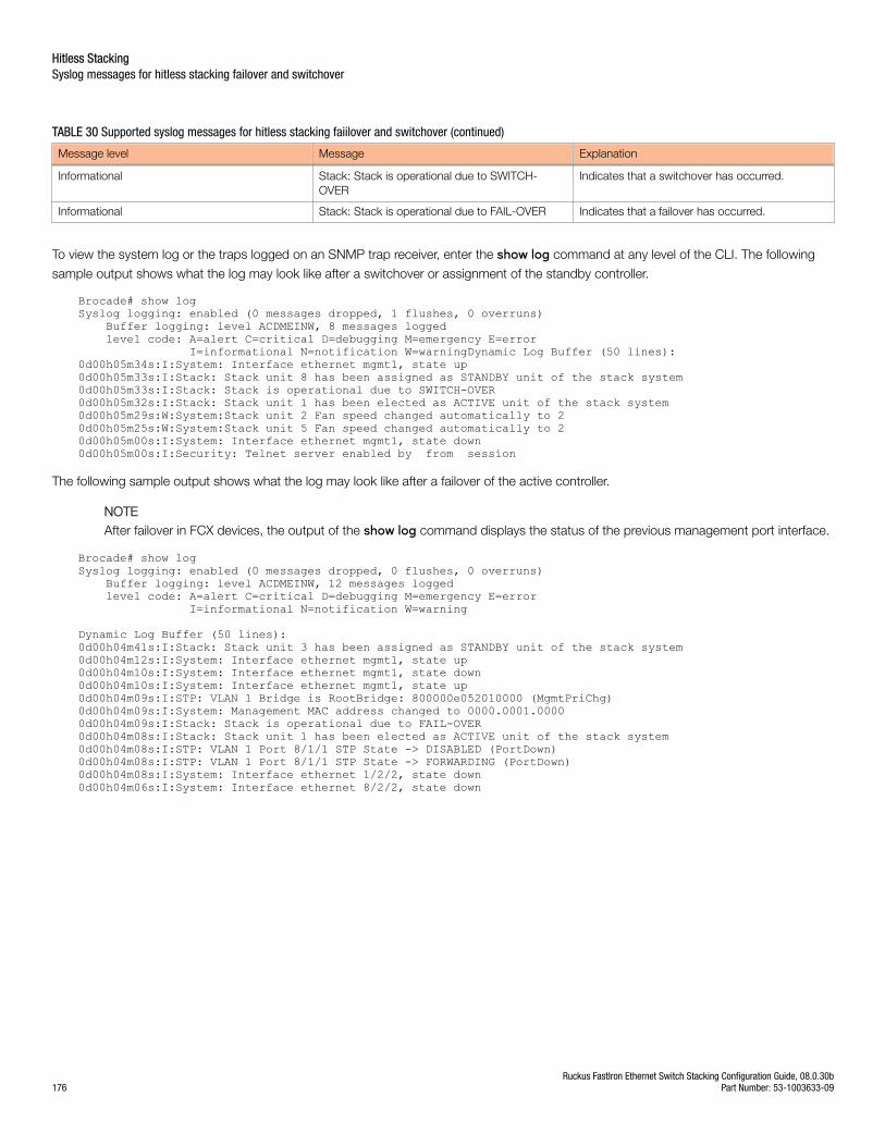
TABLE 30 Supported syslog messages for hitless stacking faiilover and switchover (continued)
Message level Message Explanation
Informational Stack: Stack is operational due to SWITCH-OVER
Indicates that a switchover has occurred.
Informational Stack: Stack is operational due to FAIL-OVER Indicates that a failover has occurred.
To view the system log or the traps logged on an SNMP trap receiver, enter the show log command at any level of the CLI. The following
sample output shows what the log may look like after a switchover or assignment of the standby controller.
Brocade# show logSyslog logging: enabled (0 messages dropped, 1 flushes, 0 overruns) Buffer logging: level ACDMEINW, 8 messages logged level code: A=alert C=critical D=debugging M=emergency E=error I=informational N=notification W=warningDynamic Log Buffer (50 lines):0d00h05m34s:I:System: Interface ethernet mgmt1, state up0d00h05m33s:I:Stack: Stack unit 8 has been assigned as STANDBY unit of the stack system0d00h05m33s:I:Stack: Stack is operational due to SWITCH-OVER0d00h05m32s:I:Stack: Stack unit 1 has been elected as ACTIVE unit of the stack system0d00h05m29s:W:System:Stack unit 2 Fan speed changed automatically to 20d00h05m25s:W:System:Stack unit 5 Fan speed changed automatically to 20d00h05m00s:I:System: Interface ethernet mgmt1, state down0d00h05m00s:I:Security: Telnet server enabled by from session
The following sample output shows what the log may look like after a failover of the active controller.
NOTEAfter failover in FCX devices, the output of the show log command displays the status of the previous management port interface.
Brocade# show logSyslog logging: enabled (0 messages dropped, 0 flushes, 0 overruns) Buffer logging: level ACDMEINW, 12 messages logged level code: A=alert C=critical D=debugging M=emergency E=error I=informational N=notification W=warning
Dynamic Log Buffer (50 lines):0d00h04m41s:I:Stack: Stack unit 3 has been assigned as STANDBY unit of the stack system0d00h04m12s:I:System: Interface ethernet mgmt1, state up0d00h04m10s:I:System: Interface ethernet mgmt1, state down0d00h04m10s:I:System: Interface ethernet mgmt1, state up0d00h04m09s:I:STP: VLAN 1 Bridge is RootBridge: 800000e052010000 (MgmtPriChg)0d00h04m09s:I:System: Management MAC address changed to 0000.0001.00000d00h04m09s:I:Stack: Stack is operational due to FAIL-OVER0d00h04m08s:I:Stack: Stack unit 1 has been elected as ACTIVE unit of the stack system0d00h04m08s:I:STP: VLAN 1 Port 8/1/1 STP State -> DISABLED (PortDown)0d00h04m08s:I:STP: VLAN 1 Port 8/1/1 STP State -> FORWARDING (PortDown)0d00h04m08s:I:System: Interface ethernet 1/2/2, state down0d00h04m06s:I:System: Interface ethernet 8/2/2, state down
Hitless StackingSyslog messages for hitless stacking failover and switchover
Ruckus FastIron Ethernet Switch Stacking Configuration Guide, 08.0.30b176 Part Number: 53-1003633-09
Mixed Stacking• Mixed stacking overview........................................................................................................................................177• Configuring basic mixed stacking.......................................................................................................................... 180• Displaying information about mixed stacking configuration.................................................................................... 189• Specifying a TFTP server for Autocopy.................................................................................................................. 194• Recovering a pre-stacking configuration on peripheral devices..............................................................................194
Mixed stacking overviewA stack is a group of Brocade stackable units and their connected stacking links that are connected so that the stack is managed as asingle entity.
Distributed Services extend advanced features such as Layer 3 services, VRF, and IPv6 multicast across devices in a stack. Mixed stackingis a topology that allows the distribution of services to occur between stack members. In mixed stacking, Distributed Services enable themixing of premium and entry-level devices in a single domain so that the advanced features and services of premium devices arepropagated to all switches in the domain.
Mixed stacking devicesA mixed stack contains ICX 6610 devices and ICX 6450 devices. ICX 6610 devices form the backbone of the mixed stack. ICX 6450devices are peripheral units that connect to the backbone and to other peripheral units.
A mixed stack can contain one or two ICX 6610 devices and one to six ICX 6450 devices. ICX 6610 devices have full Layer 2 and Layer 3unicast and multicast capabilities. ICX 6450 devices support full Layer 2 switching and basic Layer 3 routing capabilities.
In a mixed stack, all Layer 3 functions are performed by the ICX 6610 devices. Layer 3 traffic received on ICX 6450 devices is redirected tothe ICX 6610 devices.
Mixed stacking topologiesLinear and ring topologies are supported. For information about how to connect devices in a mixed stack, including cabling, stacking ports,stacking trunks, trunking requirements, and supported topologies, refer to the hardware installation guides:
• Brocade ICX 6610 Stackable Switch Hardware Installation Guide
• Brocade ICX 6430 and ICX 6450 Stackable Switches Hardware Installation Guide
Additional topology support for mixed stackingAdditional stacking topologies are available for mixed stacking, including a star topology, for ICX 6610 and ICX 6450 devices.
The following restrictions apply to the topologies:
• Up to two ICX 6610 devices
• Up to six ICX 6450 devices
• Up to six logical peripheral links per ICX 6610 (either ports or trunks)
• Each ICX 6450 must be connected directly to an ICX 6610 device.
Ruckus FastIron Ethernet Switch Stacking Configuration Guide, 08.0.30bPart Number: 53-1003633-09 177
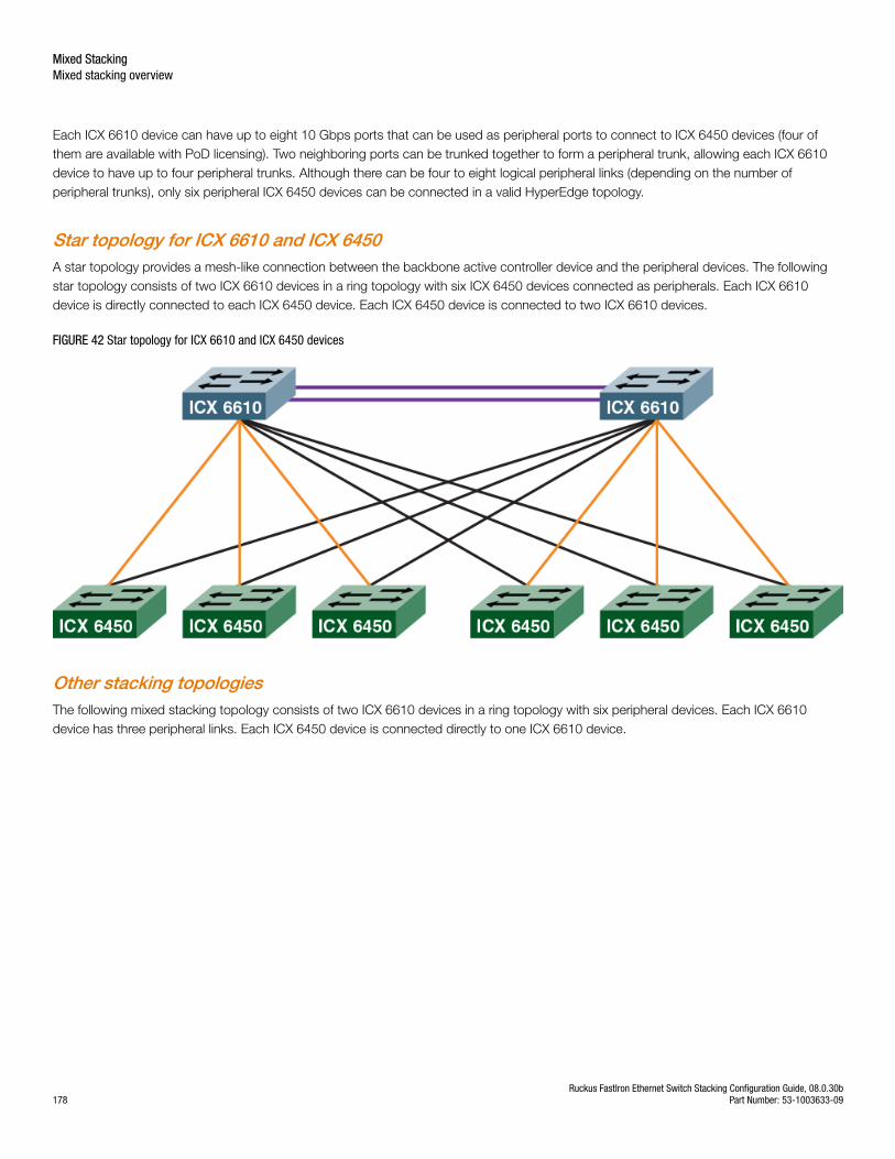
Each ICX 6610 device can have up to eight 10 Gbps ports that can be used as peripheral ports to connect to ICX 6450 devices (four ofthem are available with PoD licensing). Two neighboring ports can be trunked together to form a peripheral trunk, allowing each ICX 6610device to have up to four peripheral trunks. Although there can be four to eight logical peripheral links (depending on the number ofperipheral trunks), only six peripheral ICX 6450 devices can be connected in a valid HyperEdge topology.
Star topology for ICX 6610 and ICX 6450A star topology provides a mesh-like connection between the backbone active controller device and the peripheral devices. The followingstar topology consists of two ICX 6610 devices in a ring topology with six ICX 6450 devices connected as peripherals. Each ICX 6610device is directly connected to each ICX 6450 device. Each ICX 6450 device is connected to two ICX 6610 devices.
FIGURE 42 Star topology for ICX 6610 and ICX 6450 devices
Other stacking topologiesThe following mixed stacking topology consists of two ICX 6610 devices in a ring topology with six peripheral devices. Each ICX 6610device has three peripheral links. Each ICX 6450 device is connected directly to one ICX 6610 device.
Mixed StackingMixed stacking overview
Ruckus FastIron Ethernet Switch Stacking Configuration Guide, 08.0.30b178 Part Number: 53-1003633-09
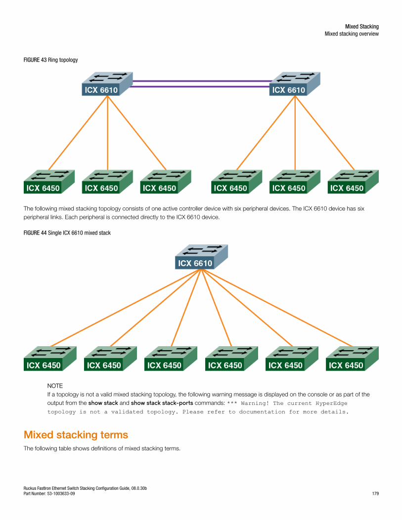
FIGURE 43 Ring topology
The following mixed stacking topology consists of one active controller device with six peripheral devices. The ICX 6610 device has sixperipheral links. Each peripheral is connected directly to the ICX 6610 device.
FIGURE 44 Single ICX 6610 mixed stack
NOTEIf a topology is not a valid mixed stacking topology, the following warning message is displayed on the console or as part of theoutput from the show stack and show stack stack-ports commands: *** Warning! The current HyperEdgetopology is not a validated topology. Please refer to documentation for more details.
Mixed stacking termsThe following table shows definitions of mixed stacking terms.
Mixed StackingMixed stacking overview
Ruckus FastIron Ethernet Switch Stacking Configuration Guide, 08.0.30bPart Number: 53-1003633-09 179
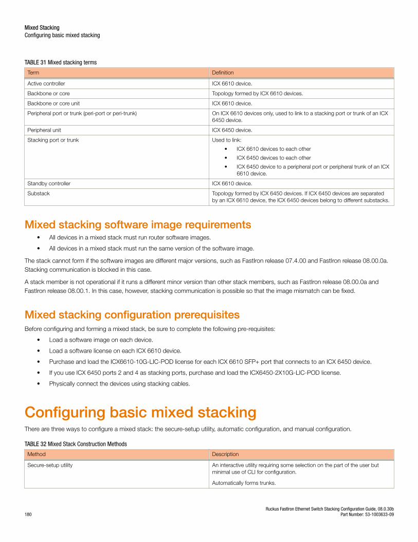
TABLE 31 Mixed stacking terms
Term Definition
Active controller ICX 6610 device.
Backbone or core Topology formed by ICX 6610 devices.
Backbone or core unit ICX 6610 device.
Peripheral port or trunk (peri-port or peri-trunk) On ICX 6610 devices only, used to link to a stacking port or trunk of an ICX6450 device.
Peripheral unit ICX 6450 device.
Stacking port or trunk Used to link:
• ICX 6610 devices to each other
• ICX 6450 devices to each other
• ICX 6450 device to a peripheral port or peripheral trunk of an ICX6610 device.
Standby controller ICX 6610 device.
Substack Topology formed by ICX 6450 devices. If ICX 6450 devices are separatedby an ICX 6610 device, the ICX 6450 devices belong to different substacks.
Mixed stacking software image requirements• All devices in a mixed stack must run router software images.
• All devices in a mixed stack must run the same version of the software image.
The stack cannot form if the software images are different major versions, such as FastIron release 07.4.00 and FastIron release 08.00.0a.Stacking communication is blocked in this case.
A stack member is not operational if it runs a different minor version than other stack members, such as FastIron release 08.00.0a andFastIron release 08.00.1. In this case, however, stacking communication is possible so that the image mismatch can be fixed.
Mixed stacking configuration prerequisitesBefore configuring and forming a mixed stack, be sure to complete the following pre-requisites:
• Load a software image on each device.
• Load a software license on each ICX 6610 device.
• Purchase and load the ICX6610-10G-LIC-POD license for each ICX 6610 SFP+ port that connects to an ICX 6450 device.
• If you use ICX 6450 ports 2 and 4 as stacking ports, purchase and load the ICX6450-2X10G-LIC-POD license.
• Physically connect the devices using stacking cables.
Configuring basic mixed stackingThere are three ways to configure a mixed stack: the secure-setup utility, automatic configuration, and manual configuration.
TABLE 32 Mixed Stack Construction Methods
Method Description
Secure-setup utility An interactive utility requiring some selection on the part of the user butminimal use of CLI for configuration.
Automatically forms trunks.
Mixed StackingConfiguring basic mixed stacking
Ruckus FastIron Ethernet Switch Stacking Configuration Guide, 08.0.30b180 Part Number: 53-1003633-09
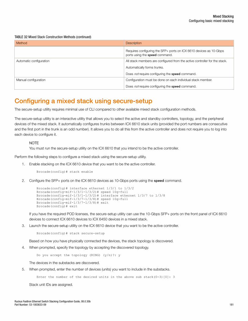
TABLE 32 Mixed Stack Construction Methods (continued)
Method Description
Requires configuring the SFP+ ports on ICX 6610 devices as 10-Gbpsports using the speed command.
Automatic configuration All stack members are configured from the active controller for the stack.
Automatically forms trunks.
Does not require configuring the speed command.
Manual configuration Configuration must be done on each individual stack member.
Does not require configuring the speed command.
Configuring a mixed stack using secure-setupThe secure-setup utility requires minimal use of CLI compared to other available mixed stack configuration methods.
The secure-setup utility is an interactive utility that allows you to select the active and standby controllers, topology, and the peripheraldevices of the mixed stack. It automatically configures trunks between ICX 6610 stack units (provided the port numbers are consecutiveand the first port in the trunk is an odd number). It allows you to do all this from the active controller and does not require you to log intoeach device to configure it.
NOTEYou must run the secure-setup utility on the ICX 6610 that you intend to be the active controller.
Perform the following steps to configure a mixed stack using the secure-setup utility.
1. Enable stacking on the ICX 6610 device that you want to be the active controller.
Brocade(config)# stack enable
2. Configure the SFP+ ports on the ICX 6610 devices as 10-Gbps ports using the speed command.
Brocade(config)# interface ethernet 1/3/1 to 1/3/2Brocade(config-mif-1/3/1-1/3/2)# speed 10g-fullBrocade(config-mif-1/3/1-1/3/2)# interface ethernet 1/3/7 to 1/3/8Brocade(config-mif-1/3/7-1/3/8)# speed 10g-fullBrocade(config-mif-1/3/7-1/3/8)# exitBrocade(config)# exit
If you have the required POD licenses, the secure-setup utility can use the 10-Gbps SFP+ ports on the front panel of ICX 6610devices to connect ICX 6610 devices to ICX 6450 devices in a mixed stack.
3. Launch the secure-setup utility on the ICX 6610 device that you want to be the active controller.
Brocade(config)# stack secure-setup
Based on how you have physically connected the devices, the stack topology is discovered.
4. When prompted, specify the topology by accepting the discovered topology.
Do you accept the topology (RING) (y/n)?: y
The devices in the substacks are discovered.
5. When prompted, enter the number of devices (units) you want to include in the substacks.
Enter the number of the desired units in the above sub stack(0-3)[0]: 3
Stack unit IDs are assigned.
Mixed StackingConfiguring basic mixed stacking
Ruckus FastIron Ethernet Switch Stacking Configuration Guide, 08.0.30bPart Number: 53-1003633-09 181
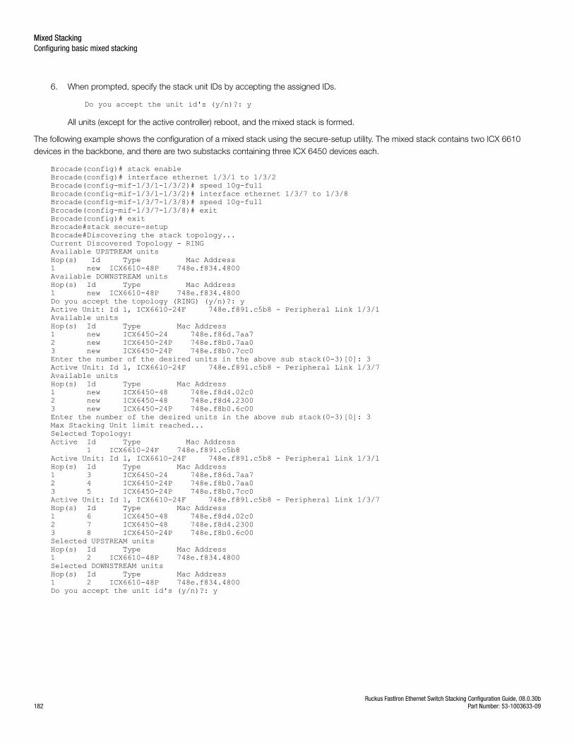
6. When prompted, specify the stack unit IDs by accepting the assigned IDs.
Do you accept the unit id's (y/n)?: y
All units (except for the active controller) reboot, and the mixed stack is formed.
The following example shows the configuration of a mixed stack using the secure-setup utility. The mixed stack contains two ICX 6610devices in the backbone, and there are two substacks containing three ICX 6450 devices each.
Brocade(config)# stack enableBrocade(config)# interface ethernet 1/3/1 to 1/3/2Brocade(config-mif-1/3/1-1/3/2)# speed 10g-fullBrocade(config-mif-1/3/1-1/3/2)# interface ethernet 1/3/7 to 1/3/8Brocade(config-mif-1/3/7-1/3/8)# speed 10g-fullBrocade(config-mif-1/3/7-1/3/8)# exitBrocade(config)# exitBrocade#stack secure-setup Brocade#Discovering the stack topology...Current Discovered Topology - RINGAvailable UPSTREAM unitsHop(s) Id Type Mac Address1 new ICX6610-48P 748e.f834.4800Available DOWNSTREAM unitsHop(s) Id Type Mac Address1 new ICX6610-48P 748e.f834.4800Do you accept the topology (RING) (y/n)?: yActive Unit: Id 1, ICX6610-24F 748e.f891.c5b8 - Peripheral Link 1/3/1Available unitsHop(s) Id Type Mac Address1 new ICX6450-24 748e.f86d.7aa72 new ICX6450-24P 748e.f8b0.7aa03 new ICX6450-24P 748e.f8b0.7cc0Enter the number of the desired units in the above sub stack(0-3)[0]: 3Active Unit: Id 1, ICX6610-24F 748e.f891.c5b8 - Peripheral Link 1/3/7Available unitsHop(s) Id Type Mac Address1 new ICX6450-48 748e.f8d4.02c02 new ICX6450-48 748e.f8d4.23003 new ICX6450-24P 748e.f8b0.6c00Enter the number of the desired units in the above sub stack(0-3)[0]: 3Max Stacking Unit limit reached...Selected Topology:Active Id Type Mac Address 1 ICX6610-24F 748e.f891.c5b8Active Unit: Id 1, ICX6610-24F 748e.f891.c5b8 - Peripheral Link 1/3/1Hop(s) Id Type Mac Address1 3 ICX6450-24 748e.f86d.7aa72 4 ICX6450-24P 748e.f8b0.7aa03 5 ICX6450-24P 748e.f8b0.7cc0Active Unit: Id 1, ICX6610-24F 748e.f891.c5b8 - Peripheral Link 1/3/7Hop(s) Id Type Mac Address1 6 ICX6450-48 748e.f8d4.02c02 7 ICX6450-48 748e.f8d4.23003 8 ICX6450-24P 748e.f8b0.6c00Selected UPSTREAM unitsHop(s) Id Type Mac Address1 2 ICX6610-48P 748e.f834.4800Selected DOWNSTREAM unitsHop(s) Id Type Mac Address1 2 ICX6610-48P 748e.f834.4800Do you accept the unit id's (y/n)?: y
Mixed StackingConfiguring basic mixed stacking
Ruckus FastIron Ethernet Switch Stacking Configuration Guide, 08.0.30b182 Part Number: 53-1003633-09
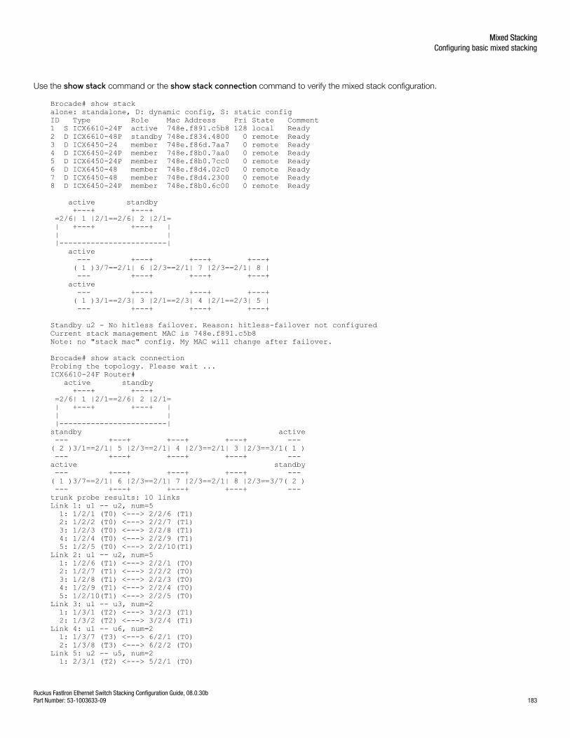
Use the show stack command or the show stack connection command to verify the mixed stack configuration.
Brocade# show stackalone: standalone, D: dynamic config, S: static configID Type Role Mac Address Pri State Comment 1 S ICX6610-24F active 748e.f891.c5b8 128 local Ready2 D ICX6610-48P standby 748e.f834.4800 0 remote Ready3 D ICX6450-24 member 748e.f86d.7aa7 0 remote Ready4 D ICX6450-24P member 748e.f8b0.7aa0 0 remote Ready5 D ICX6450-24P member 748e.f8b0.7cc0 0 remote Ready6 D ICX6450-48 member 748e.f8d4.02c0 0 remote Ready7 D ICX6450-48 member 748e.f8d4.2300 0 remote Ready8 D ICX6450-24P member 748e.f8b0.6c00 0 remote Ready
active standby +---+ +---+ =2/6| 1 |2/1==2/6| 2 |2/1= | +---+ +---+ | | | |------------------------| active --- +---+ +---+ +---+ ( 1 )3/7==2/1| 6 |2/3==2/1| 7 |2/3==2/1| 8 | --- +---+ +---+ +---+ active --- +---+ +---+ +---+ ( 1 )3/1==2/3| 3 |2/1==2/3| 4 |2/1==2/3| 5 | --- +---+ +---+ +---+ Standby u2 - No hitless failover. Reason: hitless-failover not configuredCurrent stack management MAC is 748e.f891.c5b8Note: no "stack mac" config. My MAC will change after failover.
Brocade# show stack connection Probing the topology. Please wait ...ICX6610-24F Router# active standby +---+ +---+ =2/6| 1 |2/1==2/6| 2 |2/1= | +---+ +---+ | | | |------------------------| standby active --- +---+ +---+ +---+ --- ( 2 )3/1==2/1| 5 |2/3==2/1| 4 |2/3==2/1| 3 |2/3==3/1( 1 ) --- +---+ +---+ +---+ --- active standby --- +---+ +---+ +---+ --- ( 1 )3/7==2/1| 6 |2/3==2/1| 7 |2/3==2/1| 8 |2/3==3/7( 2 ) --- +---+ +---+ +---+ --- trunk probe results: 10 linksLink 1: u1 -- u2, num=5 1: 1/2/1 (T0) <---> 2/2/6 (T1) 2: 1/2/2 (T0) <---> 2/2/7 (T1) 3: 1/2/3 (T0) <---> 2/2/8 (T1) 4: 1/2/4 (T0) <---> 2/2/9 (T1) 5: 1/2/5 (T0) <---> 2/2/10(T1) Link 2: u1 -- u2, num=5 1: 1/2/6 (T1) <---> 2/2/1 (T0) 2: 1/2/7 (T1) <---> 2/2/2 (T0) 3: 1/2/8 (T1) <---> 2/2/3 (T0) 4: 1/2/9 (T1) <---> 2/2/4 (T0) 5: 1/2/10(T1) <---> 2/2/5 (T0) Link 3: u1 -- u3, num=2 1: 1/3/1 (T2) <---> 3/2/3 (T1) 2: 1/3/2 (T2) <---> 3/2/4 (T1) Link 4: u1 -- u6, num=2 1: 1/3/7 (T3) <---> 6/2/1 (T0) 2: 1/3/8 (T3) <---> 6/2/2 (T0) Link 5: u2 -- u5, num=2 1: 2/3/1 (T2) <---> 5/2/1 (T0)
Mixed StackingConfiguring basic mixed stacking
Ruckus FastIron Ethernet Switch Stacking Configuration Guide, 08.0.30bPart Number: 53-1003633-09 183
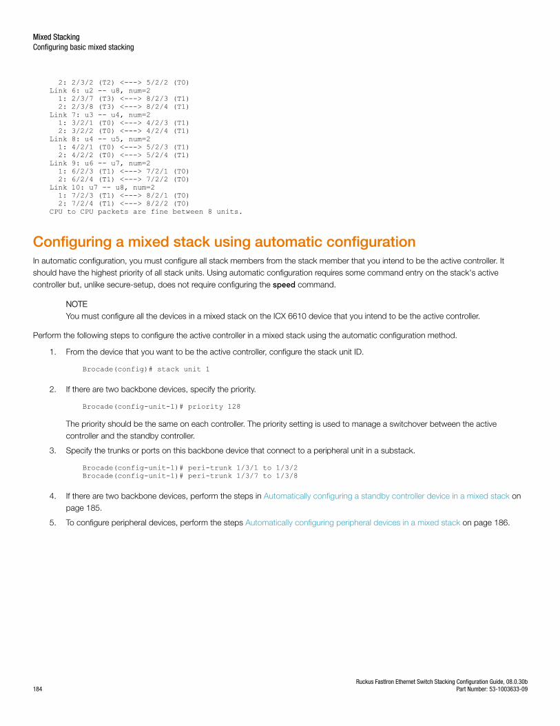
2: 2/3/2 (T2) <---> 5/2/2 (T0) Link 6: u2 -- u8, num=2 1: 2/3/7 (T3) <---> 8/2/3 (T1) 2: 2/3/8 (T3) <---> 8/2/4 (T1) Link 7: u3 -- u4, num=2 1: 3/2/1 (T0) <---> 4/2/3 (T1) 2: 3/2/2 (T0) <---> 4/2/4 (T1) Link 8: u4 -- u5, num=2 1: 4/2/1 (T0) <---> 5/2/3 (T1) 2: 4/2/2 (T0) <---> 5/2/4 (T1) Link 9: u6 -- u7, num=2 1: 6/2/3 (T1) <---> 7/2/1 (T0) 2: 6/2/4 (T1) <---> 7/2/2 (T0) Link 10: u7 -- u8, num=2 1: 7/2/3 (T1) <---> 8/2/1 (T0) 2: 7/2/4 (T1) <---> 8/2/2 (T0) CPU to CPU packets are fine between 8 units.
Configuring a mixed stack using automatic configurationIn automatic configuration, you must configure all stack members from the stack member that you intend to be the active controller. Itshould have the highest priority of all stack units. Using automatic configuration requires some command entry on the stack's activecontroller but, unlike secure-setup, does not require configuring the speed command.
NOTEYou must configure all the devices in a mixed stack on the ICX 6610 device that you intend to be the active controller.
Perform the following steps to configure the active controller in a mixed stack using the automatic configuration method.
1. From the device that you want to be the active controller, configure the stack unit ID.
Brocade(config)# stack unit 1
2. If there are two backbone devices, specify the priority.
Brocade(config-unit-1)# priority 128
The priority should be the same on each controller. The priority setting is used to manage a switchover between the activecontroller and the standby controller.
3. Specify the trunks or ports on this backbone device that connect to a peripheral unit in a substack.
Brocade(config-unit-1)# peri-trunk 1/3/1 to 1/3/2Brocade(config-unit-1)# peri-trunk 1/3/7 to 1/3/8
4. If there are two backbone devices, perform the steps in Automatically configuring a standby controller device in a mixed stack onpage 185.
5. To configure peripheral devices, perform the steps Automatically configuring peripheral devices in a mixed stack on page 186.
Mixed StackingConfiguring basic mixed stacking
Ruckus FastIron Ethernet Switch Stacking Configuration Guide, 08.0.30b184 Part Number: 53-1003633-09

The following example shows the configuration of a mixed stack using the automatic configuration method in which all stack members areconfigured from the active controller. The mixed stack contains two ICX 6610 devices in the backbone and two substacks of three ICX6450 peripheral devices each.
Brocade(config)# stack unit 1Brocade(config-unit-1)# priority 128Brocade(config-unit-1)# peri-trunk 1/3/1 to 1/3/2Brocade(config-unit-1)# peri-trunk 1/3/7 to 1/3/8Brocade(config-unit-1)# stack unit 2Brocade(config-unit-2)# module 1 icx6610-48p-poe-port-management-moduleBrocade(config-unit-2)# priority 128Brocade(config-unit-2)# peri-trunk 2/3/1 to 2/3/2Brocade(config-unit-2)# peri-trunk 2/3/7 to 2/3/8 Brocade(config-unit-2)# stack unit 3Brocade(config-unit-3)# module 1 icx6450-24-port-management-moduleBrocade(config-unit-3)# stack-trunk 3/2/1 to 3/2/2Brocade(config-unit-3)# stack-trunk 3/2/3 to 3/2/4Brocade(config-unit-3)# connect 1/3/1Brocade(config-unit-3)# connect 4/2/3Brocade(config-unit-3)# stack unit 4Brocade(config-unit-4)# module 1 icx6450-24p-poe-port-management-moduleBrocade(config-unit-4)# stack-trunk 4/2/1 to 4/2/2Brocade(config-unit-4)# stack-trunk 4/2/3 to 4/2/4Brocade(config-unit-4)# connect 3/2/1Brocade(config-unit-4)# connect 7/2/3Brocade(config-unit-4)# stack unit 5Brocade(config-unit-5)# module 1 icx6450-48-port-management-moduleBrocade(config-unit-5)# stack-trunk 5/2/1 to 5/2/2Brocade(config-unit-5)# stack-trunk 5/2/3 to 5/2/4Brocade(config-unit-5)# connect 1/3/7 Brocade(config-unit-5)# connect 6/2/1Brocade(config-unit-5)# stack unit 6Brocade(config-unit-6)# module 1 icx6450-48-port-management-moduleBrocade(config-unit-6)# stack-trunk 6/2/1 to 6/2/2Brocade(config-unit-6)# stack-trunk 6/2/3 to 6/2/4Brocade(config-unit-6)# connect 5/2/3Brocade(config-unit-6)# connect 8/2/1Brocade(config-unit-6)# stack unit 7Brocade(config-unit-7)# module 1 icx6450-24p-poe-port-management-moduleBrocade(config-unit-7)# stack-trunk 7/2/1 to 7/2/2Brocade(config-unit-7)# stack-trunk 7/2/3 to 7/2/4Brocade(config-unit-7)# connect 2/3/1Brocade(config-unit-7)# connect 4/2/1Brocade(config-unit-7)# stack unit 8Brocade(config-unit-8)# module 1 icx6450-24p-poe-port-management-moduleBrocade(config-unit-8)# stack-trunk 8/2/1 to 8/2/2Brocade(config-unit-8)# stack-trunk 8/2/3 to 8/2/4 Brocade(config-unit-8)# connect 2/3/7Brocade(config-unit-8)# connect 6/2/3Brocade(config-unit-8)# stack enableEnable stacking. This unit actively participates in stacking.
Automatically configuring a standby controller device in a mixed stackIf there are two backbone devices, perform the following steps to configure the standby controller in a mixed stack using the automaticconfiguration method.
1. From the ICX 6610 device that you want to be the active controller, configure the stack unit ID.
Brocade(config)# stack unit 2
Mixed StackingConfiguring basic mixed stacking
Ruckus FastIron Ethernet Switch Stacking Configuration Guide, 08.0.30bPart Number: 53-1003633-09 185
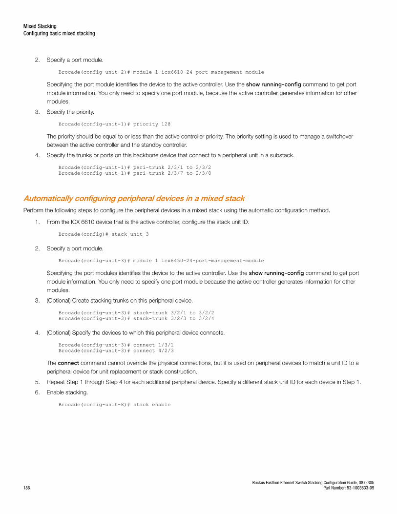
2. Specify a port module.
Brocade(config-unit-2)# module 1 icx6610-24-port-management-module
Specifying the port module identifies the device to the active controller. Use the show running-config command to get port
module information. You only need to specify one port module, because the active controller generates information for othermodules.
3. Specify the priority.
Brocade(config-unit-1)# priority 128
The priority should be equal to or less than the active controller priority. The priority setting is used to manage a switchoverbetween the active controller and the standby controller.
4. Specify the trunks or ports on this backbone device that connect to a peripheral unit in a substack.
Brocade(config-unit-1)# peri-trunk 2/3/1 to 2/3/2Brocade(config-unit-1)# peri-trunk 2/3/7 to 2/3/8
Automatically configuring peripheral devices in a mixed stackPerform the following steps to configure the peripheral devices in a mixed stack using the automatic configuration method.
1. From the ICX 6610 device that is the active controller, configure the stack unit ID.
Brocade(config)# stack unit 3
2. Specify a port module.
Brocade(config-unit-3)# module 1 icx6450-24-port-management-module
Specifying the port modules identifies the device to the active controller. Use the show running-config command to get port
module information. You only need to specify one port module because the active controller generates information for othermodules.
3. (Optional) Create stacking trunks on this peripheral device.
Brocade(config-unit-3)# stack-trunk 3/2/1 to 3/2/2Brocade(config-unit-3)# stack-trunk 3/2/3 to 3/2/4
4. (Optional) Specify the devices to which this peripheral device connects.
Brocade(config-unit-3)# connect 1/3/1Brocade(config-unit-3)# connect 4/2/3
The connect command cannot override the physical connections, but it is used on peripheral devices to match a unit ID to a
peripheral device for unit replacement or stack construction.
5. Repeat Step 1 through Step 4 for each additional peripheral device. Specify a different stack unit ID for each device in Step 1.
6. Enable stacking.
Brocade(config-unit-8)# stack enable
Mixed StackingConfiguring basic mixed stacking
Ruckus FastIron Ethernet Switch Stacking Configuration Guide, 08.0.30b186 Part Number: 53-1003633-09
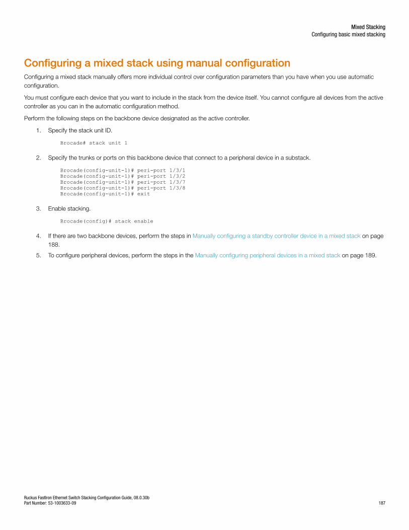
Configuring a mixed stack using manual configurationConfiguring a mixed stack manually offers more individual control over configuration parameters than you have when you use automaticconfiguration.
You must configure each device that you want to include in the stack from the device itself. You cannot configure all devices from the activecontroller as you can in the automatic configuration method.
Perform the following steps on the backbone device designated as the active controller.
1. Specify the stack unit ID.
Brocade# stack unit 1
2. Specify the trunks or ports on this backbone device that connect to a peripheral device in a substack.
Brocade(config-unit-1)# peri-port 1/3/1Brocade(config-unit-1)# peri-port 1/3/2Brocade(config-unit-1)# peri-port 1/3/7Brocade(config-unit-1)# peri-port 1/3/8Brocade(config-unit-1)# exit
3. Enable stacking.
Brocade(config)# stack enable
4. If there are two backbone devices, perform the steps in Manually configuring a standby controller device in a mixed stack on page188.
5. To configure peripheral devices, perform the steps in the Manually configuring peripheral devices in a mixed stack on page 189.
Mixed StackingConfiguring basic mixed stacking
Ruckus FastIron Ethernet Switch Stacking Configuration Guide, 08.0.30bPart Number: 53-1003633-09 187
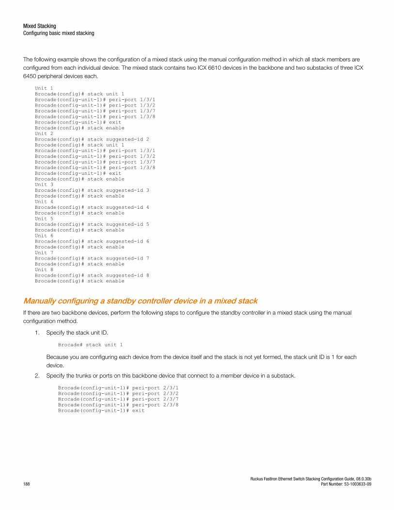
The following example shows the configuration of a mixed stack using the manual configuration method in which all stack members areconfigured from each individual device. The mixed stack contains two ICX 6610 devices in the backbone and two substacks of three ICX6450 peripheral devices each.
Unit 1 Brocade(config)# stack unit 1Brocade(config-unit-1)# peri-port 1/3/1Brocade(config-unit-1)# peri-port 1/3/2Brocade(config-unit-1)# peri-port 1/3/7Brocade(config-unit-1)# peri-port 1/3/8Brocade(config-unit-1)# exitBrocade(config)# stack enableUnit 2 Brocade(config)# stack suggested-id 2Brocade(config)# stack unit 1Brocade(config-unit-1)# peri-port 1/3/1Brocade(config-unit-1)# peri-port 1/3/2Brocade(config-unit-1)# peri-port 1/3/7Brocade(config-unit-1)# peri-port 1/3/8Brocade(config-unit-1)# exitBrocade(config)# stack enableUnit 3 Brocade(config)# stack suggested-id 3Brocade(config)# stack enableUnit 4Brocade(config)# stack suggested-id 4Brocade(config)# stack enableUnit 5Brocade(config)# stack suggested-id 5Brocade(config)# stack enableUnit 6Brocade(config)# stack suggested-id 6Brocade(config)# stack enableUnit 7Brocade(config)# stack suggested-id 7Brocade(config)# stack enableUnit 8Brocade(config)# stack suggested-id 8Brocade(config)# stack enable
Manually configuring a standby controller device in a mixed stackIf there are two backbone devices, perform the following steps to configure the standby controller in a mixed stack using the manualconfiguration method.
1. Specify the stack unit ID.
Brocade# stack unit 1
Because you are configuring each device from the device itself and the stack is not yet formed, the stack unit ID is 1 for eachdevice.
2. Specify the trunks or ports on this backbone device that connect to a member device in a substack.
Brocade(config-unit-1)# peri-port 2/3/1Brocade(config-unit-1)# peri-port 2/3/2Brocade(config-unit-1)# peri-port 2/3/7Brocade(config-unit-1)# peri-port 2/3/8Brocade(config-unit-1)# exit
Mixed StackingConfiguring basic mixed stacking
Ruckus FastIron Ethernet Switch Stacking Configuration Guide, 08.0.30b188 Part Number: 53-1003633-09
3. Specify the stack unit ID that you want this device to have in the stack.
Brocade(config)# stack suggested-id 2
The system attempts to assign a device bootup ID as its stack unit ID. However, due to timing issues or the possible unavailabilityof the bootup ID, a member device might not get the stack unit ID that you want. The optional stack suggested-id command
allows you to specify the stack unit ID for devices other than the active controller.
4. Enable stacking.
Brocade(config)# stack enable
Manually configuring peripheral devices in a mixed stackPerform the following steps to configure the peripheral devices in a mixed stack using the manual configuration method.
1. Specify the stack unit ID that you want this device to have in the stack.
Brocade(config)# stack suggested-id 3
The system attempts to assign a device bootup ID as its stack unit ID. However, due to timing issues or the possible unavailabilityof the bootup ID, a member device might not get the stack unit ID that you want. The optional stack suggested-id command
allows you to specify the stack unit ID for devices other than the active controller.
2. Enable stacking.
Brocade(config)# stack enable
3. Repeat Step 1 and Step 2 for each additional member device. Specify a different suggested stack unit ID for each device in Step1.
Displaying information about mixed stackingconfigurationSeveral show commands are available to verify mixed stack configurations, including a star topology.
You can use any of the following commands to verify the configuration of a mixed stack.
• show running-config
• show stack
• show stack detail.
Displaying mixed stack information for an automatic configurationUse the show running-config command to view the mixed stack configuration.
Mixed StackingDisplaying information about mixed stacking configuration
Ruckus FastIron Ethernet Switch Stacking Configuration Guide, 08.0.30bPart Number: 53-1003633-09 189
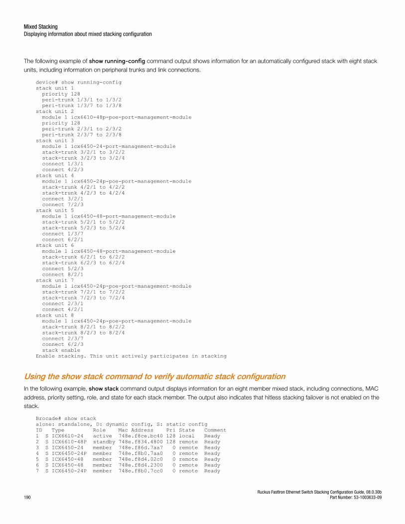
The following example of show running-config command output shows information for an automatically configured stack with eight stack
units, including information on peripheral trunks and link connections.
device# show running-configstack unit 1 priority 128 peri-trunk 1/3/1 to 1/3/2 peri-trunk 1/3/7 to 1/3/8stack unit 2 module 1 icx6610-48p-poe-port-management-module priority 128 peri-trunk 2/3/1 to 2/3/2 peri-trunk 2/3/7 to 2/3/8 stack unit 3 module 1 icx6450-24-port-management-module stack-trunk 3/2/1 to 3/2/2 stack-trunk 3/2/3 to 3/2/4 connect 1/3/1 connect 4/2/3stack unit 4 module 1 icx6450-24p-poe-port-management-module stack-trunk 4/2/1 to 4/2/2 stack-trunk 4/2/3 to 4/2/4 connect 3/2/1 connect 7/2/3stack unit 5 module 1 icx6450-48-port-management-module stack-trunk 5/2/1 to 5/2/2 stack-trunk 5/2/3 to 5/2/4 connect 1/3/7 connect 6/2/1stack unit 6 module 1 icx6450-48-port-management-module stack-trunk 6/2/1 to 6/2/2 stack-trunk 6/2/3 to 6/2/4 connect 5/2/3 connect 8/2/1stack unit 7 module 1 icx6450-24p-poe-port-management-module stack-trunk 7/2/1 to 7/2/2 stack-trunk 7/2/3 to 7/2/4 connect 2/3/1 connect 4/2/1stack unit 8 module 1 icx6450-24p-poe-port-management-module stack-trunk 8/2/1 to 8/2/2 stack-trunk 8/2/3 to 8/2/4 connect 2/3/7 connect 6/2/3 stack enableEnable stacking. This unit actively participates in stacking
Using the show stack command to verify automatic stack configurationIn the following example, show stack command output displays information for an eight member mixed stack, including connections, MAC
address, priority setting, role, and state for each stack member. The output also indicates that hitless stacking failover is not enabled on thestack.
Brocade# show stackalone: standalone, D: dynamic config, S: static configID Type Role Mac Address Pri State Comment 1 S ICX6610-24 active 748e.f8ce.bc40 128 local Ready2 S ICX6610-48P standby 748e.f834.4800 128 remote Ready3 S ICX6450-24 member 748e.f86d.7aa7 0 remote Ready4 S ICX6450-24P member 748e.f8b0.7aa0 0 remote Ready5 S ICX6450-48 member 748e.f8d4.02c0 0 remote Ready6 S ICX6450-48 member 748e.f8d4.2300 0 remote Ready7 S ICX6450-24P member 748e.f8b0.7cc0 0 remote Ready
Mixed StackingDisplaying information about mixed stacking configuration
Ruckus FastIron Ethernet Switch Stacking Configuration Guide, 08.0.30b190 Part Number: 53-1003633-09
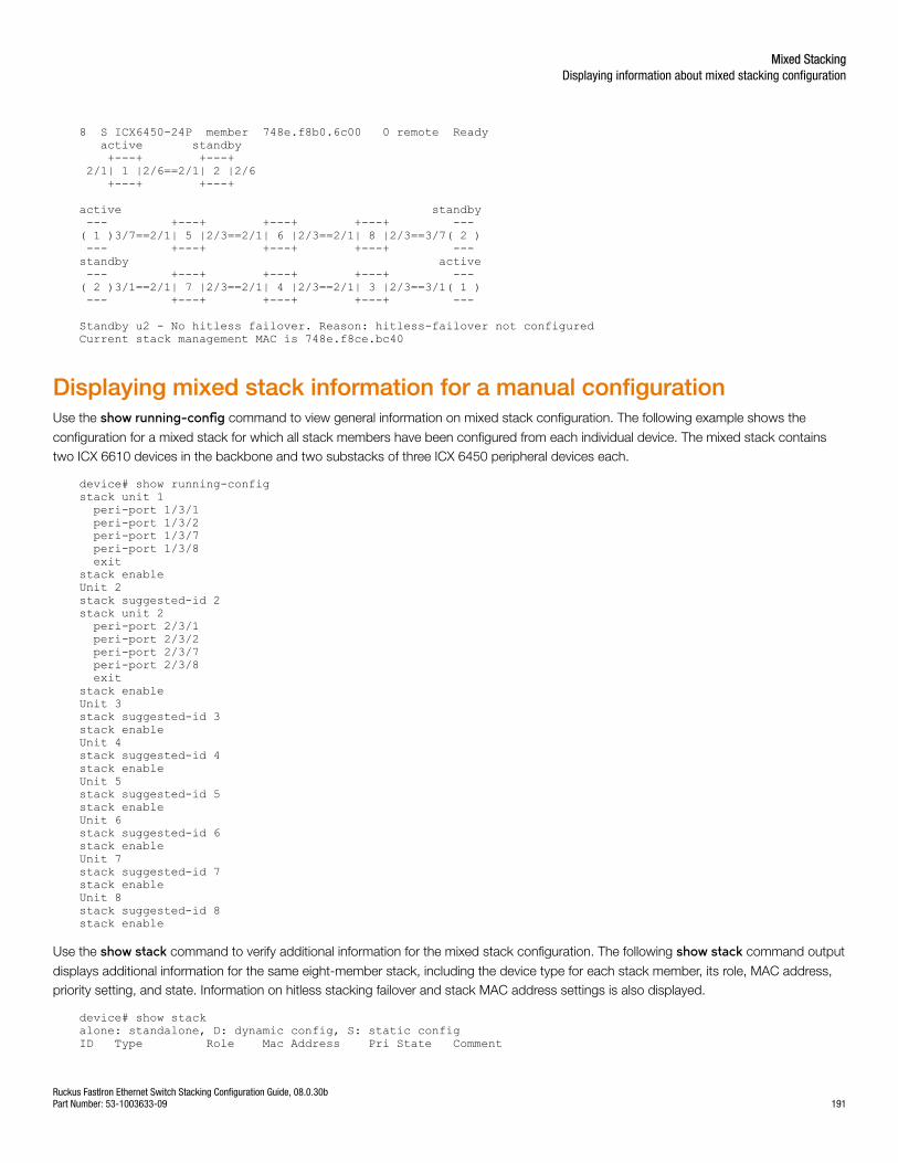
8 S ICX6450-24P member 748e.f8b0.6c00 0 remote Ready active standby +---+ +---+ 2/1| 1 |2/6==2/1| 2 |2/6 +---+ +---+
active standby --- +---+ +---+ +---+ --- ( 1 )3/7==2/1| 5 |2/3==2/1| 6 |2/3==2/1| 8 |2/3==3/7( 2 ) --- +---+ +---+ +---+ --- standby active --- +---+ +---+ +---+ --- ( 2 )3/1==2/1| 7 |2/3==2/1| 4 |2/3==2/1| 3 |2/3==3/1( 1 ) --- +---+ +---+ +---+ --- Standby u2 - No hitless failover. Reason: hitless-failover not configuredCurrent stack management MAC is 748e.f8ce.bc40
Displaying mixed stack information for a manual configurationUse the show running-config command to view general information on mixed stack configuration. The following example shows the
configuration for a mixed stack for which all stack members have been configured from each individual device. The mixed stack containstwo ICX 6610 devices in the backbone and two substacks of three ICX 6450 peripheral devices each.
device# show running-configstack unit 1 peri-port 1/3/1 peri-port 1/3/2 peri-port 1/3/7 peri-port 1/3/8 exitstack enableUnit 2 stack suggested-id 2stack unit 2 peri-port 2/3/1 peri-port 2/3/2 peri-port 2/3/7 peri-port 2/3/8 exitstack enableUnit 3 stack suggested-id 3stack enableUnit 4stack suggested-id 4stack enableUnit 5stack suggested-id 5stack enableUnit 6stack suggested-id 6stack enableUnit 7stack suggested-id 7stack enableUnit 8stack suggested-id 8stack enable
Use the show stack command to verify additional information for the mixed stack configuration. The following show stack command output
displays additional information for the same eight-member stack, including the device type for each stack member, its role, MAC address,priority setting, and state. Information on hitless stacking failover and stack MAC address settings is also displayed.
device# show stackalone: standalone, D: dynamic config, S: static configID Type Role Mac Address Pri State Comment
Mixed StackingDisplaying information about mixed stacking configuration
Ruckus FastIron Ethernet Switch Stacking Configuration Guide, 08.0.30bPart Number: 53-1003633-09 191
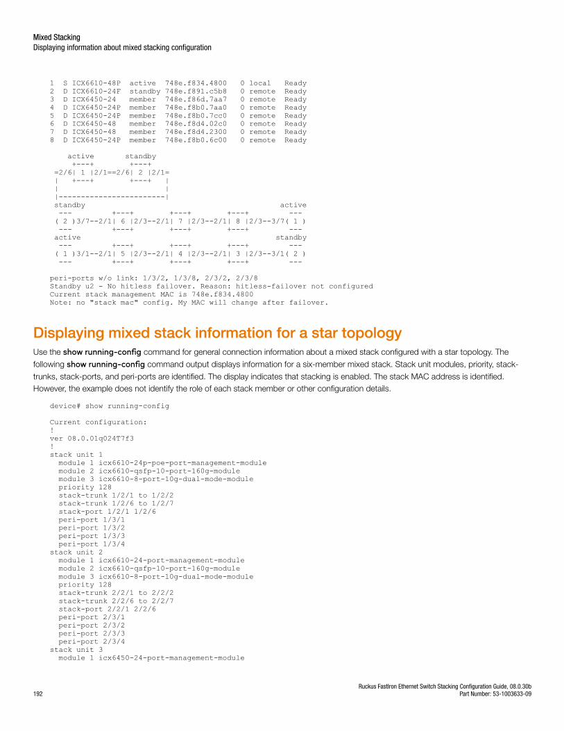
1 S ICX6610-48P active 748e.f834.4800 0 local Ready2 D ICX6610-24F standby 748e.f891.c5b8 0 remote Ready3 D ICX6450-24 member 748e.f86d.7aa7 0 remote Ready4 D ICX6450-24P member 748e.f8b0.7aa0 0 remote Ready5 D ICX6450-24P member 748e.f8b0.7cc0 0 remote Ready6 D ICX6450-48 member 748e.f8d4.02c0 0 remote Ready7 D ICX6450-48 member 748e.f8d4.2300 0 remote Ready8 D ICX6450-24P member 748e.f8b0.6c00 0 remote Ready
active standby +---+ +---+ =2/6| 1 |2/1==2/6| 2 |2/1= | +---+ +---+ | | | |------------------------| standby active --- +---+ +---+ +---+ --- ( 2 )3/7--2/1| 6 |2/3--2/1| 7 |2/3--2/1| 8 |2/3--3/7( 1 ) --- +---+ +---+ +---+ --- active standby --- +---+ +---+ +---+ --- ( 1 )3/1--2/1| 5 |2/3--2/1| 4 |2/3--2/1| 3 |2/3--3/1( 2 ) --- +---+ +---+ +---+ ---
peri-ports w/o link: 1/3/2, 1/3/8, 2/3/2, 2/3/8Standby u2 - No hitless failover. Reason: hitless-failover not configuredCurrent stack management MAC is 748e.f834.4800Note: no "stack mac" config. My MAC will change after failover.
Displaying mixed stack information for a star topologyUse the show running-config command for general connection information about a mixed stack configured with a star topology. The
following show running-config command output displays information for a six-member mixed stack. Stack unit modules, priority, stack-
trunks, stack-ports, and peri-ports are identified. The display indicates that stacking is enabled. The stack MAC address is identified.However, the example does not identify the role of each stack member or other configuration details.
device# show running-config
Current configuration:!ver 08.0.01q024T7f3!stack unit 1 module 1 icx6610-24p-poe-port-management-module module 2 icx6610-qsfp-10-port-160g-module module 3 icx6610-8-port-10g-dual-mode-module priority 128 stack-trunk 1/2/1 to 1/2/2 stack-trunk 1/2/6 to 1/2/7 stack-port 1/2/1 1/2/6 peri-port 1/3/1 peri-port 1/3/2 peri-port 1/3/3 peri-port 1/3/4stack unit 2 module 1 icx6610-24-port-management-module module 2 icx6610-qsfp-10-port-160g-module module 3 icx6610-8-port-10g-dual-mode-module priority 128 stack-trunk 2/2/1 to 2/2/2 stack-trunk 2/2/6 to 2/2/7 stack-port 2/2/1 2/2/6 peri-port 2/3/1 peri-port 2/3/2 peri-port 2/3/3 peri-port 2/3/4stack unit 3 module 1 icx6450-24-port-management-module
Mixed StackingDisplaying information about mixed stacking configuration
Ruckus FastIron Ethernet Switch Stacking Configuration Guide, 08.0.30b192 Part Number: 53-1003633-09
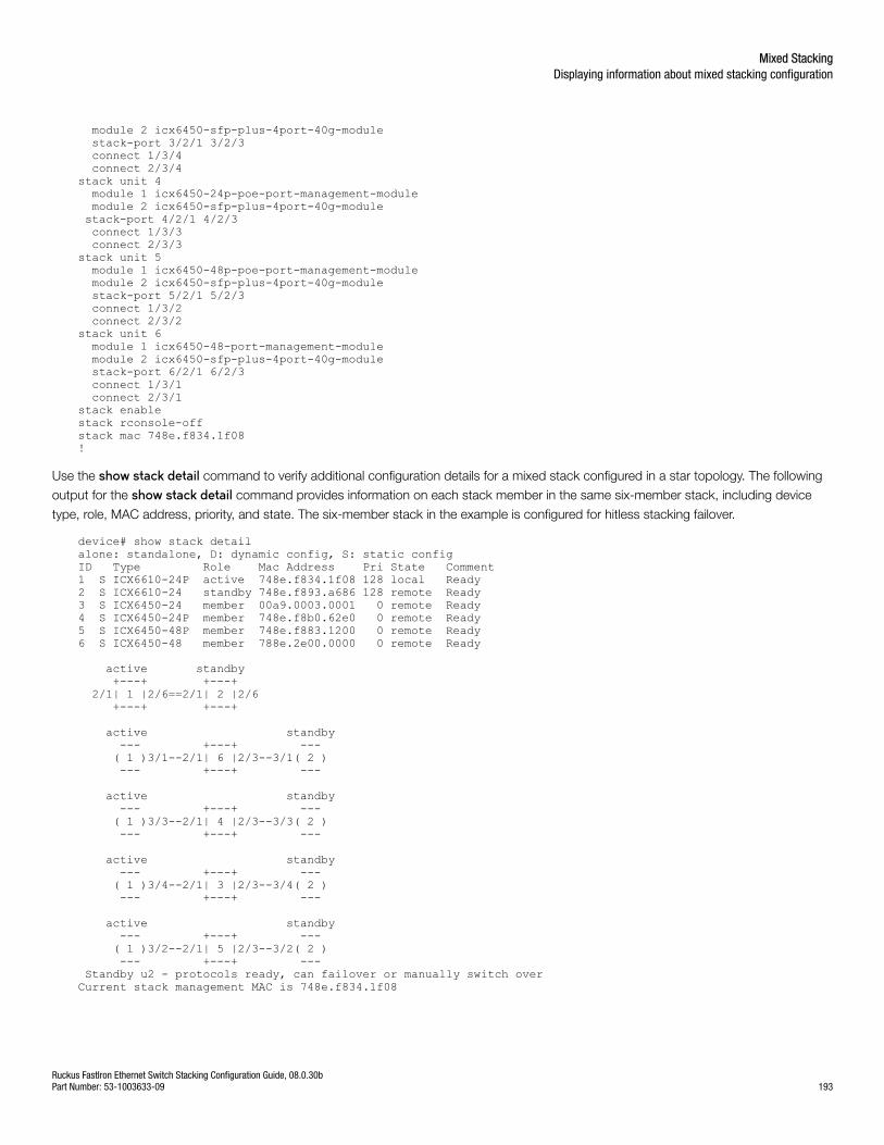
module 2 icx6450-sfp-plus-4port-40g-module stack-port 3/2/1 3/2/3 connect 1/3/4 connect 2/3/4stack unit 4 module 1 icx6450-24p-poe-port-management-module module 2 icx6450-sfp-plus-4port-40g-module stack-port 4/2/1 4/2/3 connect 1/3/3 connect 2/3/3stack unit 5 module 1 icx6450-48p-poe-port-management-module module 2 icx6450-sfp-plus-4port-40g-module stack-port 5/2/1 5/2/3 connect 1/3/2 connect 2/3/2stack unit 6 module 1 icx6450-48-port-management-module module 2 icx6450-sfp-plus-4port-40g-module stack-port 6/2/1 6/2/3 connect 1/3/1 connect 2/3/1stack enablestack rconsole-offstack mac 748e.f834.1f08!
Use the show stack detail command to verify additional configuration details for a mixed stack configured in a star topology. The following
output for the show stack detail command provides information on each stack member in the same six-member stack, including device
type, role, MAC address, priority, and state. The six-member stack in the example is configured for hitless stacking failover.
device# show stack detailalone: standalone, D: dynamic config, S: static configID Type Role Mac Address Pri State Comment1 S ICX6610-24P active 748e.f834.1f08 128 local Ready2 S ICX6610-24 standby 748e.f893.a686 128 remote Ready3 S ICX6450-24 member 00a9.0003.0001 0 remote Ready4 S ICX6450-24P member 748e.f8b0.62e0 0 remote Ready5 S ICX6450-48P member 748e.f883.1200 0 remote Ready6 S ICX6450-48 member 788e.2e00.0000 0 remote Ready
active standby +---+ +---+ 2/1| 1 |2/6==2/1| 2 |2/6 +---+ +---+
active standby --- +---+ --- ( 1 )3/1--2/1| 6 |2/3--3/1( 2 ) --- +---+ --- active standby --- +---+ --- ( 1 )3/3--2/1| 4 |2/3--3/3( 2 ) --- +---+ ---
active standby --- +---+ --- ( 1 )3/4--2/1| 3 |2/3--3/4( 2 ) --- +---+ ---
active standby --- +---+ --- ( 1 )3/2--2/1| 5 |2/3--3/2( 2 ) --- +---+ --- Standby u2 - protocols ready, can failover or manually switch overCurrent stack management MAC is 748e.f834.1f08
Mixed StackingDisplaying information about mixed stacking configuration
Ruckus FastIron Ethernet Switch Stacking Configuration Guide, 08.0.30bPart Number: 53-1003633-09 193
Specifying a TFTP server for AutocopyAll devices in a mixed stack must run the same version of the software image. If they run different major or minor versions, an imagemismatch occurs.
If they run different minor versions, the active controller uses the Autocopy mechanism to copy an image from another device to the devicethat has the image mismatch. Autocopy does not work if mismatched devices run different major versions because stackingcommunication is blocked.
Autocopy is enabled by default.
To avoid image mismatch issues in a mixed stack, set up a TFTP server for Autocopy before configuring a stack. Configure the tftp-server atthe device configuration level as shown in the following example. Indicate the IP address of the server where the image is stored and thedirectory path to the correct software image on the server.
device# configure terminaldevice(config)# tftp-server 10.1.2.1 image-location /server/builds/
Syntax: tftp-server ip-address image-location path
How Autocopy worksWhen an ICX 6610 minor image version mismatch occurs, the active controller copies its own image to the mismatched ICX 6610 device.When an ICX 6450 minor image version mismatch occurs, the active controller copies an image from another peripheral device that runsthe correct image.
In some cases, Autocopy must retrieve the image from a TFTP server (if there is only one ICX 6450 device or if all of the ICX 6450 devicesare in mismatch with the backbone). If you have not configured a TFTP server for Autocopy, the system prompts you to configure a TFTPserver where an image for an ICX 6450 device can be downloaded.
If the TFTP server has the correct image and Autocopy has not been disabled, the image is downloaded to the mismatched device. Whenthe image copy is complete, a reboot for the mismatched devices is issued. All mismatched devices are rebooted at the same time.
NOTEYou cannot upload an ICX 6450 image from a mixed stack to a TFTP server or SCP client.
Recovering a pre-stacking configuration onperipheral devicesBefore joining a mixed stack as member devices in a substack, ICX 6450 devices in a mixed stack can be part of independent traditionalstacks or can be standalone devices. A recovery mechanism allows you to recover the configuration that the ICX 6450 devices had beforethey were members of the mixed stack. If a member device was a clean unit before joining the mixed stack, it becomes a clean unit afterthe recovery mechanism is performed.
The recovery mechanism removes all the peripheral ports and peripheral trunks from the ICX 6610 devices. It also detaches member ICX6450 devices from the mixed stack and reloads them after recovering their previous configurations.
Perform the following steps to execute recovery.
Mixed StackingSpecifying a TFTP server for Autocopy
Ruckus FastIron Ethernet Switch Stacking Configuration Guide, 08.0.30b194 Part Number: 53-1003633-09
NOTEYou must execute the recovery commands from the active controller.
1. Launch the recovery mechanism on the active controller.
device# stack unconfigure mixed-stack
2. When prompted, confirm the removal of all peripheral ports and peripheral trunks and the recovery of previous configurations forthe member devices.
All the peri-ports/trunks will be removed and all the ICX6450 units will recover pre-mixed-stacking configuration. Are you sure? (enter 'y' or 'n'):y
All peripheral ports and peripheral trunks are removed from the ICX 6610 devices. The ICX 6450 devices recover theconfigurations they had before becoming members of the mixed stack, and they are reloaded.
Mixed StackingRecovering a pre-stacking configuration on peripheral devices
Ruckus FastIron Ethernet Switch Stacking Configuration Guide, 08.0.30bPart Number: 53-1003633-09 195
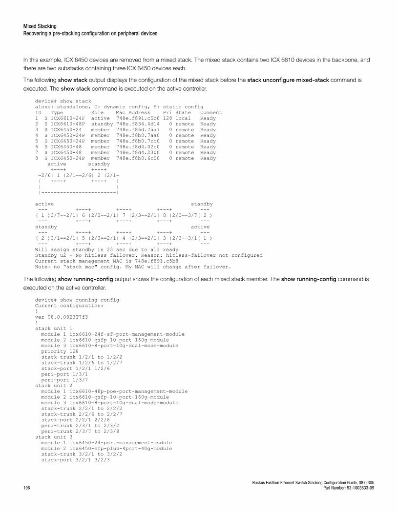
In this example, ICX 6450 devices are removed from a mixed stack. The mixed stack contains two ICX 6610 devices in the backbone, andthere are two substacks containing three ICX 6450 devices each.
The following show stack output displays the configuration of the mixed stack before the stack unconfigure mixed-stack command is
executed. The show stack command is executed on the active controller.
device# show stackalone: standalone, D: dynamic config, S: static configID Type Role Mac Address Pri State Comment 1 S ICX6610-24F active 748e.f891.c5b8 128 local Ready2 S ICX6610-48P standby 748e.f834.4d14 0 remote Ready3 S ICX6450-24 member 748e.f86d.7aa7 0 remote Ready4 S ICX6450-24P member 748e.f8b0.7aa0 0 remote Ready5 S ICX6450-24P member 748e.f8b0.7cc0 0 remote Ready6 S ICX6450-48 member 748e.f8d4.02c0 0 remote Ready7 S ICX6450-48 member 748e.f8d4.2300 0 remote Ready8 S ICX6450-24P member 748e.f8b0.6c00 0 remote Ready active standby +---+ +---+ =2/6| 1 |2/1==2/6| 2 |2/1= | +---+ +---+ | | | |------------------------|
active standby --- +---+ +---+ +---+ --- ( 1 )3/7--2/1| 6 |2/3==2/1| 7 |2/3==2/1| 8 |2/3==3/7( 2 ) --- +---+ +---+ +---+ --- standby active --- +---+ +---+ +---+ ---( 2 )3/1==2/1| 5 |2/3==2/1| 4 |2/3==2/1| 3 |2/3--3/1( 1 ) --- +---+ +---+ +---+ --- Will assign standby in 23 sec due to all readyStandby u2 - No hitless failover. Reason: hitless-failover not configuredCurrent stack management MAC is 748e.f891.c5b8Note: no "stack mac" config. My MAC will change after failover.
The following show running-config output shows the configuration of each mixed stack member. The show running-config command is
executed on the active controller.
device# show running-configCurrent configuration:!ver 08.0.00B3T7f3!stack unit 1 module 1 icx6610-24f-sf-port-management-module module 2 icx6610-qsfp-10-port-160g-module module 3 icx6610-8-port-10g-dual-mode-module priority 128 stack-trunk 1/2/1 to 1/2/2 stack-trunk 1/2/6 to 1/2/7 stack-port 1/2/1 1/2/6 peri-port 1/3/1 peri-port 1/3/7stack unit 2 module 1 icx6610-48p-poe-port-management-module module 2 icx6610-qsfp-10-port-160g-module module 3 icx6610-8-port-10g-dual-mode-module stack-trunk 2/2/1 to 2/2/2 stack-trunk 2/2/6 to 2/2/7 stack-port 2/2/1 2/2/6 peri-trunk 2/3/1 to 2/3/2 peri-trunk 2/3/7 to 2/3/8stack unit 3 module 1 icx6450-24-port-management-module module 2 icx6450-sfp-plus-4port-40g-module stack-trunk 3/2/1 to 3/2/2 stack-port 3/2/1 3/2/3
Mixed StackingRecovering a pre-stacking configuration on peripheral devices
Ruckus FastIron Ethernet Switch Stacking Configuration Guide, 08.0.30b196 Part Number: 53-1003633-09
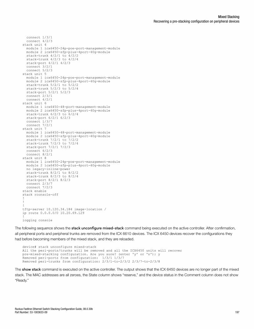
connect 1/3/1 connect 4/2/3stack unit 4 module 1 icx6450-24p-poe-port-management-module module 2 icx6450-sfp-plus-4port-40g-module stack-trunk 4/2/1 to 4/2/2 stack-trunk 4/2/3 to 4/2/4 stack-port 4/2/1 4/2/3 connect 3/2/1 connect 5/2/3stack unit 5 module 1 icx6450-24p-poe-port-management-module module 2 icx6450-sfp-plus-4port-40g-module stack-trunk 5/2/1 to 5/2/2 stack-trunk 5/2/3 to 5/2/4 stack-port 5/2/1 5/2/3 connect 2/3/1 connect 4/2/1stack unit 6 module 1 icx6450-48-port-management-module module 2 icx6450-sfp-plus-4port-40g-module stack-trunk 6/2/3 to 6/2/4 stack-port 6/2/1 6/2/3 connect 1/3/7 connect 7/2/1stack unit 7 module 1 icx6450-48-port-management-module module 2 icx6450-sfp-plus-4port-40g-module stack-trunk 7/2/1 to 7/2/2 stack-trunk 7/2/3 to 7/2/4 stack-port 7/2/1 7/2/3 connect 6/2/3 connect 8/2/1stack unit 8 module 1 icx6450-24p-poe-port-management-module module 2 icx6450-sfp-plus-4port-40g-module no legacy-inline-power stack-trunk 8/2/1 to 8/2/2 stack-trunk 8/2/3 to 8/2/4 stack-port 8/2/1 8/2/3 connect 2/3/7 connect 7/2/3 stack enablestack rconsole-off!!!tftp-server 10.120.34.184 image-location / ip route 0.0.0.0/0 10.20.69.129!logging console
The following sequence shows the stack unconfigure mixed-stack command being executed on the active controller. After confirmation,
all peripheral ports and peripheral trunks are removed from the ICX 6610 devices. The ICX 6450 devices recover the configurations theyhad before becoming members of the mixed stack, and they are reloaded.
device# stack unconfigure mixed-stack All the peri-ports/trunks will be removed and all the ICX6450 units will recoverpre-mixed-stacking configuration. Are you sure? (enter 'y' or 'n'): yRemoved peri-ports from configuration: 1/3/1 1/3/7 Removed peri-trunks from configuration: 2/3/1-to-2/3/2 2/3/7-to-2/3/8
The show stack command is executed on the active controller. The output shows that the ICX 6450 devices are no longer part of the mixed
stack. The MAC addresses are all zeroes, the State column shows “reserve,” and the device status in the Comment column does not show“Ready.”
Mixed StackingRecovering a pre-stacking configuration on peripheral devices
Ruckus FastIron Ethernet Switch Stacking Configuration Guide, 08.0.30bPart Number: 53-1003633-09 197
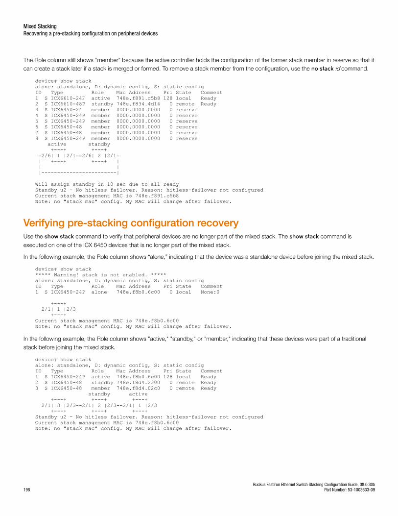
The Role column still shows “member” because the active controller holds the configuration of the former stack member in reserve so that itcan create a stack later if a stack is merged or formed. To remove a stack member from the configuration, use the no stack id command.
device# show stackalone: standalone, D: dynamic config, S: static configID Type Role Mac Address Pri State Comment 1 S ICX6610-24F active 748e.f891.c5b8 128 local Ready2 S ICX6610-48P standby 748e.f834.4d14 0 remote Ready3 S ICX6450-24 member 0000.0000.0000 0 reserve 4 S ICX6450-24P member 0000.0000.0000 0 reserve 5 S ICX6450-24P member 0000.0000.0000 0 reserve 6 S ICX6450-48 member 0000.0000.0000 0 reserve 7 S ICX6450-48 member 0000.0000.0000 0 reserve 8 S ICX6450-24P member 0000.0000.0000 0 reserve active standby +---+ +---+ =2/6| 1 |2/1==2/6| 2 |2/1= | +---+ +---+ | | | |------------------------|
Will assign standby in 10 sec due to all readyStandby u2 - No hitless failover. Reason: hitless-failover not configuredCurrent stack management MAC is 748e.f891.c5b8Note: no "stack mac" config. My MAC will change after failover.
Verifying pre-stacking configuration recoveryUse the show stack command to verify that peripheral devices are no longer part of the mixed stack. The show stack command is
executed on one of the ICX 6450 devices that is no longer part of the mixed stack.
In the following example, the Role column shows “alone,” indicating that the device was a standalone device before joining the mixed stack.
device# show stack***** Warning! stack is not enabled. *****alone: standalone, D: dynamic config, S: static configID Type Role Mac Address Pri State Comment 1 S ICX6450-24P alone 748e.f8b0.6c00 0 local None:0 +---+ 2/1| 1 |2/3 +---+ Current stack management MAC is 748e.f8b0.6c00Note: no "stack mac" config. My MAC will change after failover.
In the following example, the Role column shows "active," "standby," or "member," indicating that these devices were part of a traditionalstack before joining the mixed stack.
device# show stackalone: standalone, D: dynamic config, S: static configID Type Role Mac Address Pri State Comment 1 S ICX6450-24P active 748e.f8b0.6c00 128 local Ready2 S ICX6450-48 standby 748e.f8d4.2300 0 remote Ready3 S ICX6450-48 member 748e.f8d4.02c0 0 remote Ready standby active +---+ +---+ +---+ 2/1| 3 |2/3--2/1| 2 |2/3--2/1| 1 |2/3 +---+ +---+ +---+ Standby u2 - No hitless failover. Reason: hitless-failover not configuredCurrent stack management MAC is 748e.f8b0.6c00Note: no "stack mac" config. My MAC will change after failover.
Mixed StackingRecovering a pre-stacking configuration on peripheral devices
Ruckus FastIron Ethernet Switch Stacking Configuration Guide, 08.0.30b198 Part Number: 53-1003633-09

Copyright © 2018 Ruckus Networks, an ARRIS company. All rights reserved.350 West Java Dr., Sunnyvale, CA 94089 USAwww.ruckuswireless.com
Related Documents