1 Copyright COMEVAL VALVE SYSTEMS © - Data subject to revision - Regularly updated data on www.comeval.es - DS17G - Ed.15/06 Rubber Joints - SERIES TORAFLEX S10-S15-S20-S30 TORAFLEX Rubber Joints are devised for piping works, consisting of a flexible main shell made of synthetic rubber with inner reinforcements to provide consistency, and pipe connections by means of loose flanges or threaded unions. Noise and vibrations caused by equipment such as pumps are absorbed by Rubber Joints. Rubber Joints balance thermal mo- vements in rigid systems due to temperature changes, provide a great assistance to the plant commissioning team by balancing slight pipe works misalignments and can even be used as telescopic mounting kits. Rubber joints can withstand surge pressures and mitigate the effects caused by water hammers thanks to their relatively high ten- sile strength. Its non-conductive feature avoids the electrolysis problem that appears when putting two different metals in contact. A correct pipe system arrangement and installation according to our Installation Operating and Maintenance Manual is essential to ensure a safe performance. Nominal Pressure: PN10 / PN16 Valve end connections: Loose flanges drilled to EN1092-1 PN10, PN16, or ASME B16.5 ASA150 Marking: EN 19 Pressure Tests: EN 12266-1 Rubber Joints are excluded from the Pressure Equipment Directive PED 97/23/CE, according to its article 1.3-15. TORAFLEX TYPE S10-S15-S20 Main Features Precision injection molded of synthetic rubber and nylon Outer layer protects the bellows surfa- ce form eventual ozone attack, strikes and other environmental aggressions Rugged design with high burst pressu- re, to absorb noise and vibration and withstand water hammers to a certain extent by: -Inner Reinforcement placed in be- tween the outer and inner layers, made of braided nylon fabrics as standard -End Bellows reinforcement Light and easy to install, little installa- tion space required, easy maintenance of replaceable bellows 4 different allowable movements: axial compression and expansion, lateral and angular deflection Loose flanges for easy assembly, spe- cially machined to accept the full turned rubber, with standard execution in zinc plated steel Full turned rubber design, self-sealing, no additional gaskets are required; it prevents electrolytic corrosion Lot number punched for full traceability purpose Rubber material identification and maximum service pressu- re & temperature S10/15 Spherical design for better strength and efficiency S20 Double sphere design allows greater axial, lateral and angular movements subject to less effort and material wea- ring down during movements. With op- tional root ring

Welcome message from author
This document is posted to help you gain knowledge. Please leave a comment to let me know what you think about it! Share it to your friends and learn new things together.
Transcript
1Copyright COMEVAL VALVE SYSTEMS © - Data subject to revision - Regularly updated data on www.comeval.es - DS17G - Ed.15/06
Rubber Joints - SERIES TORAFLEX S10-S15-S20-S30
TORAFLEX Rubber Joints are devised for piping works, consisting of a fl exible main shell made of synthetic rubber with inner reinforcements to provide consistency, and pipe connections by means of loose fl anges or threaded unions. Noise and vibrations caused by equipment such as pumps are absorbed by Rubber Joints. Rubber Joints balance thermal mo-vements in rigid systems due to temperature changes, provide a great assistance to the plant commissioning team by balancing slight pipe works misalignments and can even be used as telescopic mounting kits. Rubber joints can withstand surge pressures and mitigate the effects caused by water hammers thanks to their relatively high ten-sile strength. Its non-conductive feature avoids the electrolysis problem that appears when putting two different metals in contact. A correct pipe system arrangement and installation according to our Installation Operating and Maintenance Manual is essential to ensure a safe performance.
Nominal Pressure: PN10 / PN16Valve end connections: Loose fl anges drilled to EN1092-1 PN10, PN16, or ASME B16.5 ASA150Marking: EN 19Pressure Tests: EN 12266-1Rubber Joints are excluded from the Pressure Equipment Directive PED 97/23/CE, according to its article 1.3-15.
TORAFLEX TYPE S10-S15-S20
Main Features
Precision injection molded of synthetic rubber and nylon
Outer layer protects the bellows surfa-ce form eventual ozone attack, strikes and other environmental aggressions
Rugged design with high burst pressu-re, to absorb noise and vibration and withstand water hammers to a certain extent by:-Inner Reinforcement placed in be-tween the outer and inner layers, made of braided nylon fabrics as standard -End Bellows reinforcement
Light and easy to install, little installa-tion space required, easy maintenance of replaceable bellows
4 different allowable movements: axial compression and expansion, lateral and angular defl ection
Loose fl anges for easy assembly, spe-cially machined to accept the full turned rubber, with standard execution in zinc plated steel
Full turned rubber design, self-sealing, no additional gaskets are required; it prevents electrolytic corrosion
Lot number punched for full traceability purpose
Rubber material identifi cation and maximum service pressu-re & temperature
S10/15Spherical design for better strength and effi ciency
S20Double sphere design allows greater axial, lateral and angular movements subject to less effort and material wea-ring down during movements. With op-tional root ring
2Copyright COMEVAL VALVE SYSTEMS © - Data subject to revision - Regularly updated data on www.comeval.es - DS17G - Ed.15/06
Rubber Joints - SERIES TORAFLEX S10-S15-S20-S30
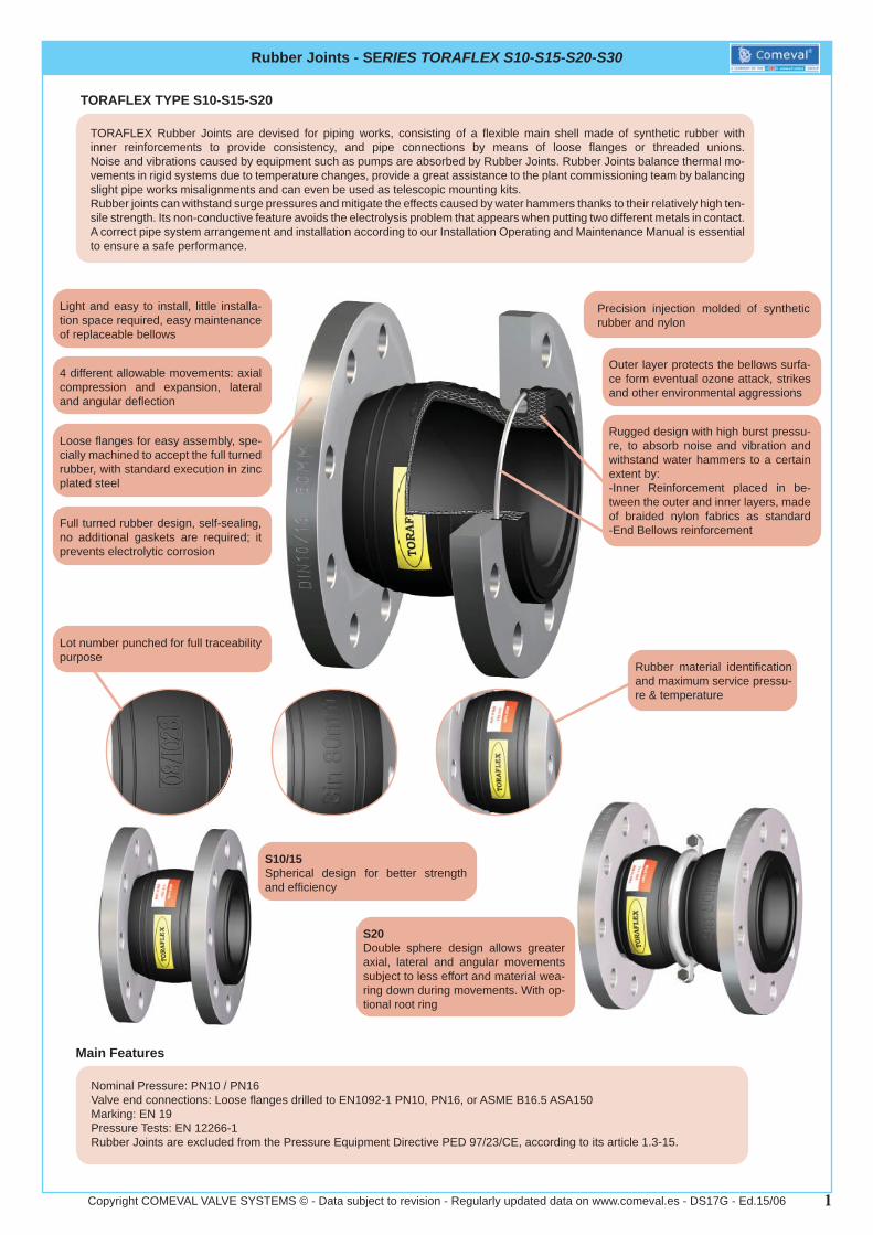
Nominal Pressure: PN10 / PN16Valve end connections: Threaded unions to EN 10266-1, with parallel female threads GAS-Rp-BSPPMarking: EN 19Pressure Tests: EN 12266-1Rubber Joints are excluded from the Pressure Equipment Directive PED 97/23/CE, according to its article 1.3-15.
TYPE S30
Main Features
Precision injection moulded of synthetic rubber inserted into union threads
Outer layer protects the bellows surface form eventual ozone attack, strikes and other environmental aggressions
Rugged design with high burst pressure, to absorb noise and vibration and withstand water hammers to a certain extent
Light and easy to install, little installa-tion space required, easy maintenance of replaceable bellows
Root ring, compulsory for temperatures above 50ºC and/or pressures above 10 bar
Lot number punched for full traceability purpose
Rubber material identifi cation and maximum service pressure &temperature
S30Double Sphere design for better strength and effi ciency allow greater axial, lateral and angular movements subject to less effort and material wearing down during movements
3Copyright COMEVAL VALVE SYSTEMS © - Data subject to revision - Regularly updated data on www.comeval.es - DS17G - Ed.15/06
Rubber Joints - SERIES TORAFLEX S10-S15-S20-S30
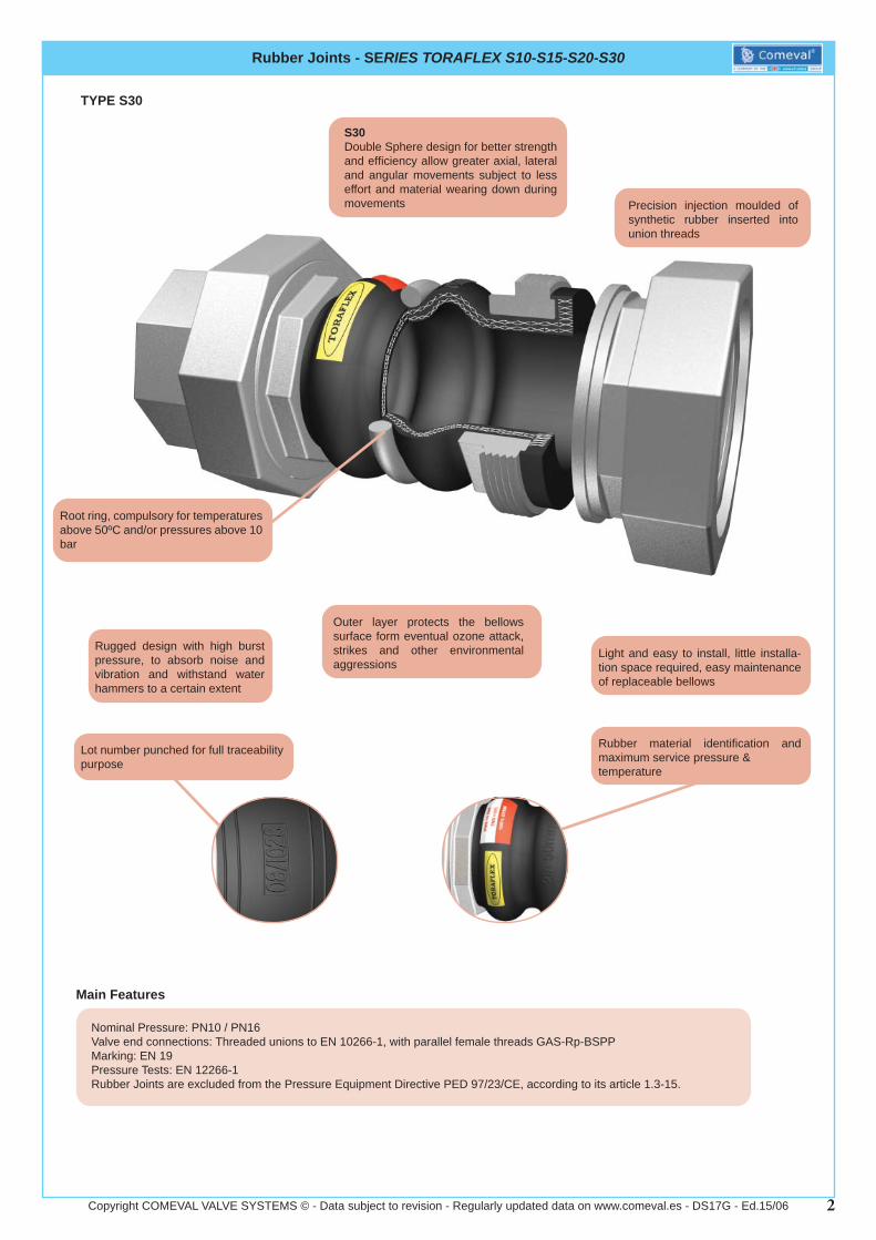
Codifi cation
S 1 0 E 1 0 0 0 0 0 0 0 5 0
DESIGNS10 Single sphere Rubber Joints with fl angesS15 Single sphere Rubber Joints with fl angesS20 Double sphere Rubber Joints with fl angesS30 Double sphere Rubber Joints with Threaded Unions
MATERIAL OF RUBBERE EPDMN NBRH HypalonV VitonC NeopreneT PTFE
CONNECTIONS10 Flanges drilled to EN 1092-1 DIN PN1016 Flanges drilled to EN 1092-1 DIN PN16AS Flanges drilled to B16.5 Class 15000 Female Threaded unions, BSPPNP Female Threaded unions, NPT
CONNECTIONS MATERIAL0 StandardG Hot Dip GalvanizedI Stainless Steel 316J Stainless Steel 304
ADDING PERFORMANCE0 NoneR Root Ring Reinforcement (For S20/S30 only)V Vulcanized Vacuum Reinforcement RingT External Vacuum Reinforcement Ring
LIMITERS0 NoneT Carbon Steel Tie Rods
OTHER SPECIAL OPTIONS0 Standard
VALVE SIZE050 DN50100 DN100912 DN1200
4Copyright COMEVAL VALVE SYSTEMS © - Data subject to revision - Regularly updated data on www.comeval.es - DS17G - Ed.15/06
Rubber Joints - SERIES TORAFLEX S10-S15-S20-S30
Options
Other designs and approvals, please consult us
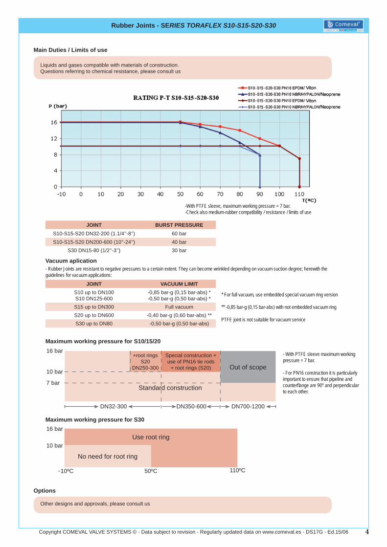
Main Duties / Limits of use
Liquids and gases compatible with materials of construction.Questions referring to chemical resistance, please consult us
-With PTFE sleeve, maximum working pressure = 7 bar.-Check also medium-rubber compatibility / resistance / limits of use
JOINT BURST PRESSURES10-S15-S20 DN32-200 (1.1/4’’-8’’) 60 barS10-S15-S20 DN200-600 (10’’-24’’) 40 bar
S30 DN15-80 (1/2’’-3’’) 30 bar
Vacuum aplication- Rubber Joints are resistant to negative pressures to a certain extent. They can become wrinkled depending on vacuum suction degree; herewith the guidelines for vacuum applications:
JOINT VACUUM LIMITS10 up to DN100S10 DN125-600
-0,85 bar-g (0,15 bar-abs) *-0,50 bar-g (0,50 bar-abs) *
S15 up to DN300 Full vacuumS20 up to DN600 -0,40 bar-g (0,60 bar-abs) **S30 up to DN80 -0,50 bar-g (0,50 bar-abs)
* For full vacuum, use embedded special vacuum ring version
** -0,85 bar-g (0,15 bar-abs) with not embedded vacuum ring
PTFE joint is not suitable for vacuum service
+root rings S20
DN250-300
Special construction + use of PN16 tie rods
+ root rings (S20) Out of scope
Standard construction
Maximum working pressure for S10/15/2016 bar
10 bar
7 bar
DN32-300 DN350-600 DN700-1200
- With PTFE sleeve maximum working pressure = 7 bar.
- For PN16 construction it is particularly important to ensure that pipeline and counterfl ange are 90º and perpendicular to each other.
Maximum working pressure for S30
Use root ring
No need for root ring
16 bar
10 bar
-10ºC 50ºC 110ºC
5Copyright COMEVAL VALVE SYSTEMS © - Data subject to revision - Regularly updated data on www.comeval.es - DS17G - Ed.15/06
Rubber Joints - SERIES TORAFLEX S10-S15-S20-S30
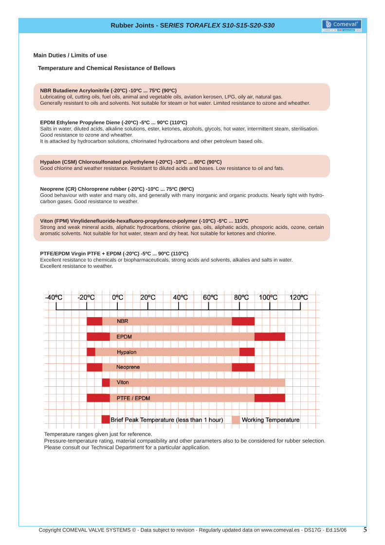
NBR Butadiene Acrylonitrile (-20ºC) -10ºC ... 75ºC (90ºC)Lubricating oil, cutting oils, fuel oils, animal and vegetable oils, aviation kerosen, LPG, oily air, natural gas.Generally resistant to oils and solvents. Not suitable for steam or hot water. Limited resistance to ozone and wheather.
Temperature and Chemical Resistance of Bellows
EPDM Ethylene Propylene Diene (-20ºC) -5ºC ... 90ºC (110ºC)Salts in water, diluted acids, alkaline solutions, ester, ketones, alcohols, glycols, hot water, intermittent steam, sterilisation.Good resistance to ozone and wheather.It is attacked by hydrocarbon solutions, chlorinated hydrocarbons and other petroleum based oils.
Hypalon (CSM) Chlorosulfonated polyethylene (-20ºC) -10ºC ... 80ºC (90ºC)Good chlorine and weather resistance. Resistant to diluted acids and bases. Low resistance to oil and fats.
Neoprene (CR) Chloroprene rubber (-20ºC) -10ºC ... 75ºC (90ºC)Good behaviour with water and many oils, and generally with many inorganic and organic products. Nearly tight with hydro-carbon gases. Good resistance to weather.
Viton (FPM) Vinylidenefl uoride-hexafl uoro-propyleneco-polymer (-10ºC) -5ºC ... 110ºCStrong and weak mineral acids, aliphatic hydrocarbons, chlorine gas, oils, aliphatic acids, phosporic acids, ozone, certain aromatic solvents. Not suitable for hot water, steam and dry heat. Not suitable for ketones and chlorine.
PTFE/EPDM Virgin PTFE + EPDM (-20ºC) -5ºC ... 90ºC (110ºC)Excellent resistance to chemicals or biopharmaceuticals, strong acids and solvents, alkalies and salts in water.Excellent resistance to weather.
Temperature ranges given just for reference.Pressure-temperature rating, material compatibility and other parameters also to be considered for rubber selection.Please consult our Technical Department for a particular application.
Main Duties / Limits of use
6Copyright COMEVAL VALVE SYSTEMS © - Data subject to revision - Regularly updated data on www.comeval.es - DS17G - Ed.15/06
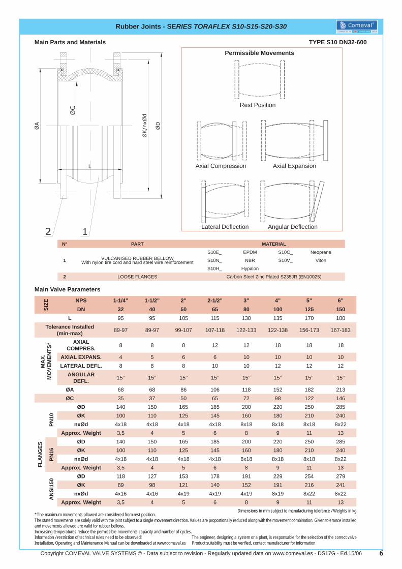
Main Parts and Materials
Nº PART MATERIAL
1 VULCANISED RUBBER BELLOWWith nylon tire cord and hard steel wire reinforcement
S10E_ EPDM S10C_ Neoprene
S10N_ NBR S10V_ Viton
S10H_ Hypalon
2 LOOSE FLANGES Carbon Steel Zinc Plated S235JR (EN10025)
Rubber Joints - SERIES TORAFLEX S10-S15-S20-S30
TYPE S10 DN32-600
Dimensions in mm subject to manufacturing tolerance / Weights in kg
Information / restriction of technical rules need to be observed!Installation, Operating and Maintenance Manual can be downloaded at www.comeval.es
The engineer, designing a system or a plant, is responsable for the selection of the correct valveProduct suitability must be verifi ed, contact manufacturer for information
SIZE NPS 1-1/4” 1-1/2” 2” 2-1/2” 3” 4” 5” 6”
DN 32 40 50 65 80 100 125 150L 95 95 105 115 130 135 170 180
Tolerance Installed (min-max) 89-97 89-97 99-107 107-118 122-133 122-138 156-173 167-183
MA
X.
MO
VEM
ENTS
* AXIAL COMPRES. 8 8 8 12 12 18 18 18
AXIAL EXPANS. 4 5 6 6 10 10 10 10LATERAL DEFL. 8 8 8 10 10 12 12 12
ANGULAR DEFL. 15° 15° 15° 15° 15° 15° 15° 15°
ØA 68 68 86 106 118 152 182 213ØC 35 37 50 65 72 98 122 146
FLA
NG
ES
PN10
ØD 140 150 165 185 200 220 250 285ØK 100 110 125 145 160 180 210 240
nxØd 4x18 4x18 4x18 4x18 8x18 8x18 8x18 8x22Approx. Weight 3,5 4 5 6 8 9 11 13
PN16
ØD 140 150 165 185 200 220 250 285ØK 100 110 125 145 160 180 210 240
nxØd 4x18 4x18 4x18 4x18 8x18 8x18 8x18 8x22Approx. Weight 3,5 4 5 6 8 9 11 13
AN
SI15
0 ØD 118 127 153 178 191 229 254 279ØK 89 98 121 140 152 191 216 241
nxØd 4x16 4x16 4x19 4x19 4x19 8x19 8x22 8x22Approx. Weight 3,5 4 5 6 8 9 11 13
Permissible Movements
Rest Position
Axial Compression Axial Expansion
Lateral Defl ection Angular Defl ection
* The maximum movements allowed are considered from rest position.The stated movements are solely valid with the joint subject to a single movement direction. Values are proportionally reduced along with the movement combination. Given tolerance installed and movements allowed are valid for rubber bellows.Increasing temperatures reduce the permissible movements capacity and number of cycles.
Main Valve Parameters
7Copyright COMEVAL VALVE SYSTEMS © - Data subject to revision - Regularly updated data on www.comeval.es - DS17G - Ed.15/06
Rubber Joints - SERIES TORAFLEX S10-S15-S20-S30
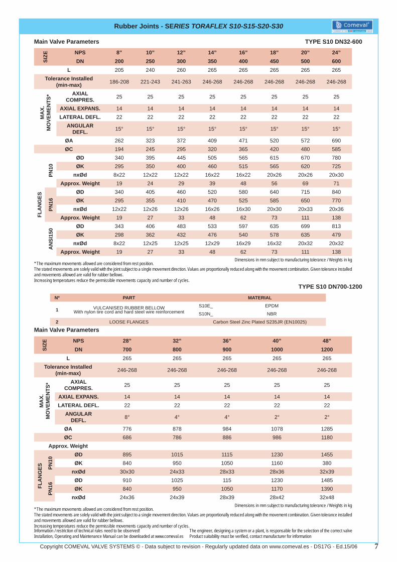
Main Valve Parameters
Dimensions in mm subject to manufacturing tolerance / Weights in kg
Information / restriction of technical rules need to be observed!Installation, Operating and Maintenance Manual can be downloaded at www.comeval.es
The engineer, designing a system or a plant, is responsable for the selection of the correct valveProduct suitability must be verifi ed, contact manufacturer for information
TYPE S10 DN32-600
TYPE S10 DN700-1200
Main Valve Parameters
Dimensions in mm subject to manufacturing tolerance / Weights in kg
SIZE NPS 28” 32” 36” 40” 48”
DN 700 800 900 1000 1200L 265 265 265 265 265
Tolerance Installed (min-max) 246-268 246-268 246-268 246-268 246-268
MA
X.
MO
VEM
ENTS
* AXIAL COMPRES. 25 25 25 25 25
AXIAL EXPANS. 14 14 14 14 14LATERAL DEFL. 22 22 22 22 22
ANGULAR DEFL. 8° 4° 4° 2° 2°
ØA 776 878 984 1078 1285ØC 686 786 886 986 1180
Approx. Weight
FLA
NG
ES PN10
ØD 895 1015 1115 1230 1455ØK 840 950 1050 1160 380
nxØd 30x30 24x33 28x33 28x36 32x39
PN16
ØD 910 1025 115 1230 1485ØK 840 950 1050 1170 1390
nxØd 24x36 24x39 28x39 28x42 32x48
Nº PART MATERIAL
1 VULCANISED RUBBER BELLOWWith nylon tire cord and hard steel wire reinforcement
S10E_ EPDM
S10N_ NBR
2 LOOSE FLANGES Carbon Steel Zinc Plated S235JR (EN10025)
* The maximum movements allowed are considered from rest position.The stated movements are solely valid with the joint subject to a single movement direction. Values are proportionally reduced along with the movement combination. Given tolerance installed and movements allowed are valid for rubber bellows.Increasing temperatures reduce the permissible movements capacity and number of cycles.
* The maximum movements allowed are considered from rest position.The stated movements are solely valid with the joint subject to a single movement direction. Values are proportionally reduced along with the movement combination. Given tolerance installed and movements allowed are valid for rubber bellows.Increasing temperatures reduce the permissible movements capacity and number of cycles.
SIZE NPS 8” 10” 12” 14” 16” 18” 20” 24”
DN 200 250 300 350 400 450 500 600L 205 240 260 265 265 265 265 265
Tolerance Installed (min-max) 186-208 221-243 241-263 246-268 246-268 246-268 246-268 246-268
MA
X.
MO
VEM
ENTS
* AXIAL COMPRES. 25 25 25 25 25 25 25 25
AXIAL EXPANS. 14 14 14 14 14 14 14 14LATERAL DEFL. 22 22 22 22 22 22 22 22
ANGULAR DEFL. 15° 15° 15° 15° 15° 15° 15° 15°
ØA 262 323 372 409 471 520 572 690ØC 194 245 295 320 365 420 480 585
FLA
NG
ES
PN10
ØD 340 395 445 505 565 615 670 780ØK 295 350 400 460 515 565 620 725
nxØd 8x22 12x22 12x22 16x22 16x22 20x26 20x26 20x30Approx. Weight 19 24 29 39 48 56 69 71
PN16
ØD 340 405 460 520 580 640 715 840ØK 295 355 410 470 525 585 650 770
nxØd 12x22 12x26 12x26 16x26 16x30 20x30 20x33 20x36Approx. Weight 19 27 33 48 62 73 111 138
AN
SI15
0 ØD 343 406 483 533 597 635 699 813ØK 298 362 432 476 540 578 635 479
nxØd 8x22 12x25 12x25 12x29 16x29 16x32 20x32 20x32Approx. Weight 19 27 33 48 62 73 111 138
8Copyright COMEVAL VALVE SYSTEMS © - Data subject to revision - Regularly updated data on www.comeval.es - DS17G - Ed.15/06
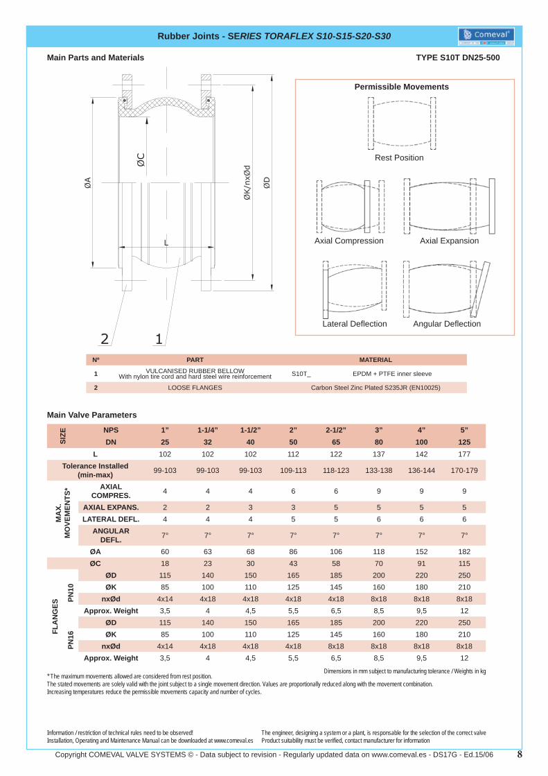
Main Parts and Materials
Nº PART MATERIAL
1 VULCANISED RUBBER BELLOWWith nylon tire cord and hard steel wire reinforcement S10T_ EPDM + PTFE inner sleeve
2 LOOSE FLANGES Carbon Steel Zinc Plated S235JR (EN10025)
Rubber Joints - SERIES TORAFLEX S10-S15-S20-S30
Main Valve Parameters
TYPE S10T DN25-500
Dimensions in mm subject to manufacturing tolerance / Weights in kg
Information / restriction of technical rules need to be observed!Installation, Operating and Maintenance Manual can be downloaded at www.comeval.es
The engineer, designing a system or a plant, is responsable for the selection of the correct valveProduct suitability must be verifi ed, contact manufacturer for information
SIZE NPS 1” 1-1/4” 1-1/2” 2” 2-1/2” 3” 4” 5”
DN 25 32 40 50 65 80 100 125L 102 102 102 112 122 137 142 177
Tolerance Installed (min-max) 99-103 99-103 99-103 109-113 118-123 133-138 136-144 170-179
MA
X.
MO
VEM
ENTS
* AXIAL COMPRES. 4 4 4 6 6 9 9 9
AXIAL EXPANS. 2 2 3 3 5 5 5 5LATERAL DEFL. 4 4 4 5 5 6 6 6
ANGULAR DEFL. 7° 7° 7° 7° 7° 7° 7° 7°
ØA 60 63 68 86 106 118 152 182ØC 18 23 30 43 58 70 91 115
FLA
NG
ES
PN10
ØD 115 140 150 165 185 200 220 250ØK 85 100 110 125 145 160 180 210
nxØd 4x14 4x18 4x18 4x18 4x18 8x18 8x18 8x18Approx. Weight 3,5 4 4,5 5,5 6,5 8,5 9,5 12
PN16
ØD 115 140 150 165 185 200 220 250ØK 85 100 110 125 145 160 180 210
nxØd 4x14 4x18 4x18 4x18 8x18 8x18 8x18 8x18Approx. Weight 3,5 4 4,5 5,5 6,5 8,5 9,5 12
Permissible Movements
Rest Position
Axial Compression Axial Expansion
Lateral Defl ection Angular Defl ection
* The maximum movements allowed are considered from rest position.The stated movements are solely valid with the joint subject to a single movement direction. Values are proportionally reduced along with the movement combination. Increasing temperatures reduce the permissible movements capacity and number of cycles.
9Copyright COMEVAL VALVE SYSTEMS © - Data subject to revision - Regularly updated data on www.comeval.es - DS17G - Ed.15/06
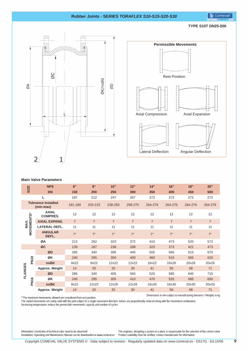
Rubber Joints - SERIES TORAFLEX S10-S15-S20-S30
Main Valve Parameters
Dimensions in mm subject to manufacturing tolerance / Weights in kg
Information / restriction of technical rules need to be observed!Installation, Operating and Maintenance Manual can be downloaded at www.comeval.es
The engineer, designing a system or a plant, is responsable for the selection of the correct valveProduct suitability must be verifi ed, contact manufacturer for information
TYPE S10T DN25-500
* The maximum movements allowed are considered from rest position.The stated movements are solely valid with the joint subject to a single movement direction. Values are proportionally reduced along with the movement combination. Increasing temperatures reduce the permissible movements capacity and number of cycles.
SIZE NPS 6” 8” 10” 12” 14” 16” 18” 20”
DN 150 200 250 300 350 400 450 500L 187 212 247 267 272 272 272 272
Tolerance Installed (min-max) 181-189 203-215 238-250 258-270 264-276 264-276 264-276 264-276
MA
X.
MO
VEM
ENTS
* AXIAL COMPRES. 12 12 12 12 12 12 12 12
AXIAL EXPANS. 7 7 7 7 7 7 7 7LATERAL DEFL. 11 11 11 11 11 11 11 11
ANGULAR DEFL. 7° 7° 7° 7° 7° 7° 7° 7°
ØA 213 262 323 372 410 473 520 572ØC 139 187 238 288 323 373 421 473
FLA
NG
ES
PN10
ØD 285 340 395 445 505 565 615 670ØK 240 295 350 400 460 515 565 620
nxØd 8x22 8x22 12x22 12x22 16x22 16x26 20x26 20x26Approx. Weight 14 20 25 30 41 50 58 71
PN16
ØD 285 340 405 560 520 580 640 715ØK 240 295 355 410 470 525 585 650
nxØd 8x22 12x22 12x26 12x26 16x26 16x30 20x30 20x33Approx. Weight 14 20 25 30 41 50 58 71
Permissible Movements
Rest Position
Axial Compression Axial Expansion
Lateral Defl ection Angular Defl ection
10Copyright COMEVAL VALVE SYSTEMS © - Data subject to revision - Regularly updated data on www.comeval.es - DS17G - Ed.15/06
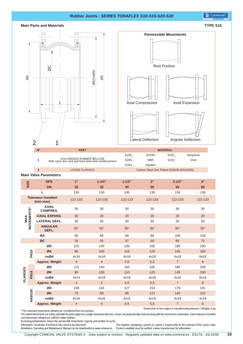
Main Parts and Materials
Nº PART MATERIAL
1 VULCANISED RUBBER BELLOWWith nylon tire cord and hard steel wire reinforcement
S15E_ EPDM S15C_ Neoprene
S15N_ NBR S15V_ Viton
S15H_ Hypalon
2 LOOSE FLANGES Carbon Steel Zinc Plated S235JR (EN10025)
Rubber Joints - SERIES TORAFLEX S10-S15-S20-S30
Main Valve Parameters
SIZE NPS 1” 1-1/4” 1-1/2” 2” 2-1/2” 3”
DN 25 32 40 50 65 80L 130 130 130 130 130 130
Tolerance Installed (min-max) 122-133 122-133 122-133 122-133 122-133 122-133
MA
X.
MO
VEM
ENTS
* AXIAL COMPRES. 30 30 30 30 30 30
AXIAL EXPANS. 20 20 20 20 20 20LATERAL DEFL. 30 30 30 30 30 30
ANGULAR DEFL. 35° 35° 35° 35° 30° 30°
ØA 60 68 68 86 106 118ØC 25 35 37 50 65 72
FLA
NG
ES
PN10
ØD 115 140 150 165 185 200ØK 85 100 110 125 145 160
nxØd 4x14 4x18 4x18 4x18 4x18 8x18Approx. Weight 4 4 4,5 5,5 7 8
PN16
ØD 115 140 150 165 185 200ØK 85 100 110 125 145 160
nxØd 4x14 4x18 4x18 4x18 4x18 8x18Approx. Weight 4 4 4,5 5,5 7 8
AN
SI15
0 ØD 108 118 127 153 178 191ØK 79 89 98 121 140 152
nxØd 4x16 4x16 4x16 4x19 4x19 4x19Approx. Weight 4 4 4,5 5,5 7 8
TYPE S15
Dimensions in mm subject to manufacturing tolerance / Weights in kg
Information / restriction of technical rules need to be observed!Installation, Operating and Maintenance Manual can be downloaded at www.comeval.es
The engineer, designing a system or a plant, is responsable for the selection of the correct valveProduct suitability must be verifi ed, contact manufacturer for information
Permissible Movements
Rest Position
Axial Compression Axial Expansion
Lateral Defl ection Angular Defl ection
* The maximum movements allowed are considered from rest position.The stated movements are solely valid with the joint subject to a single movement direction. Values are proportionally reduced along with the movement combination. Given tolerance installed and movements allowed are valid for rubber bellows.Increasing temperatures reduce the permissible movements capacity and number of cycles.
11Copyright COMEVAL VALVE SYSTEMS © - Data subject to revision - Regularly updated data on www.comeval.es - DS17G - Ed.15/06
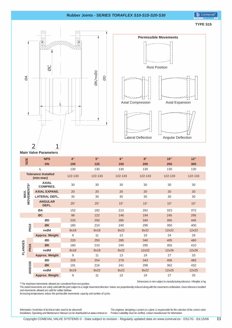
Rubber Joints - SERIES TORAFLEX S10-S15-S20-S30
Main Valve Parameters
TYPE S15
Dimensions in mm subject to manufacturing tolerance / Weights in kg
Information / restriction of technical rules need to be observed!Installation, Operating and Maintenance Manual can be downloaded at www.comeval.es
The engineer, designing a system or a plant, is responsable for the selection of the correct valveProduct suitability must be verifi ed, contact manufacturer for information
* The maximum movements allowed are considered from rest position.The stated movements are solely valid with the joint subject to a single movement direction. Values are proportionally reduced along with the movement combination. Given tolerance installed and movements allowed are valid for rubber bellows.Increasing temperatures reduce the permissible movements capacity and number of cycles.
SIZE NPS 4” 5” 6” 8” 10” 12”
DN 100 125 150 200 250 300L 130 130 130 130 130 130
Tolerance Installed (min-max) 122-133 122-133 122-133 122-133 122-133 122-133
MA
X.
MO
VEM
ENTS
* AXIAL COMPRES. 30 30 30 30 30 30
AXIAL EXPANS. 20 20 20 20 20 20LATERAL DEFL. 30 30 30 30 30 30
ANGULAR DEFL. 25° 25° 15° 15° 10° 10°
ØA 152 182 213 262 323 372ØC 98 122 146 194 245 295
FLA
NG
ES
PN10
ØD 220 250 285 340 395 445ØK 180 210 240 295 350 400
nxØd 8x18 8x18 8x22 8x22 12x22 12x22Approx. Weight 9 11 13 19 24 29
PN16
ØD 220 250 285 340 405 460ØK 180 210 240 295 355 410
nxØd 8x18 8x18 8x22 12x22 12x26 12x26Approx. Weight 9 11 13 19 27 33
AN
SI15
0 ØD 229 254 279 343 406 483ØK 191 216 241 298 362 432
nxØd 8x19 8x22 8x22 8x22 12x25 12x25Approx. Weight 9 11 13 19 27 33
Permissible Movements
Rest Position
Axial Compression Axial Expansion
Lateral Defl ection Angular Defl ection
12Copyright COMEVAL VALVE SYSTEMS © - Data subject to revision - Regularly updated data on www.comeval.es - DS17G - Ed.15/06
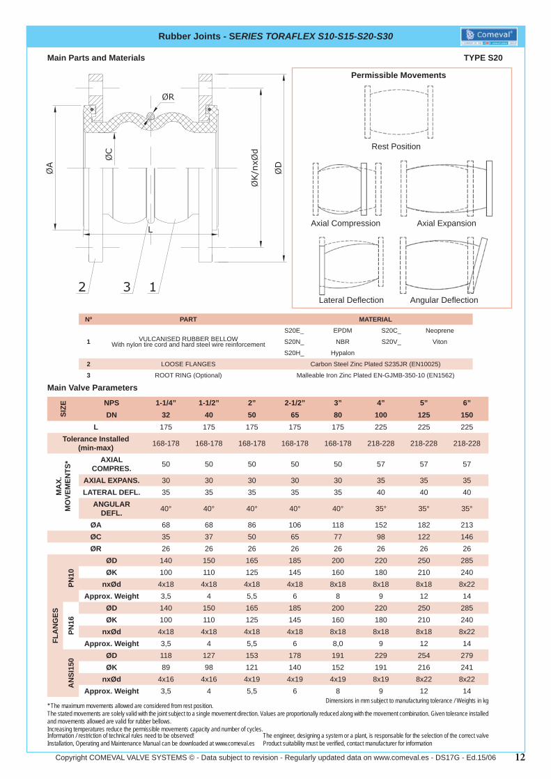
Nº PART MATERIAL
1 VULCANISED RUBBER BELLOWWith nylon tire cord and hard steel wire reinforcement
S20E_ EPDM S20C_ Neoprene
S20N_ NBR S20V_ Viton
S20H_ Hypalon
2 LOOSE FLANGES Carbon Steel Zinc Plated S235JR (EN10025)
3 ROOT RING (Optional) Malleable Iron Zinc Plated EN-GJMB-350-10 (EN1562)
Rubber Joints - SERIES TORAFLEX S10-S15-S20-S30
Main Valve Parameters
SIZE NPS 1-1/4” 1-1/2” 2” 2-1/2” 3” 4” 5” 6”
DN 32 40 50 65 80 100 125 150L 175 175 175 175 175 225 225 225
Tolerance Installed (min-max) 168-178 168-178 168-178 168-178 168-178 218-228 218-228 218-228
MA
X.
MO
VEM
ENTS
* AXIAL COMPRES. 50 50 50 50 50 57 57 57
AXIAL EXPANS. 30 30 30 30 30 35 35 35LATERAL DEFL. 35 35 35 35 35 40 40 40
ANGULAR DEFL. 40° 40° 40° 40° 40° 35° 35° 35°
ØA 68 68 86 106 118 152 182 213ØC 35 37 50 65 77 98 122 146ØR 26 26 26 26 26 26 26 26
FLA
NG
ES
PN10
ØD 140 150 165 185 200 220 250 285ØK 100 110 125 145 160 180 210 240
nxØd 4x18 4x18 4x18 4x18 8x18 8x18 8x18 8x22Approx. Weight 3,5 4 5,5 6 8 9 12 14
PN16
ØD 140 150 165 185 200 220 250 285ØK 100 110 125 145 160 180 210 240
nxØd 4x18 4x18 4x18 4x18 8x18 8x18 8x18 8x22Approx. Weight 3,5 4 5,5 6 8,0 9 12 14
AN
SI15
0 ØD 118 127 153 178 191 229 254 279ØK 89 98 121 140 152 191 216 241
nxØd 4x16 4x16 4x19 4x19 4x19 8x19 8x22 8x22Approx. Weight 3,5 4 5,5 6 8 9 12 14
TYPE S20
Dimensions in mm subject to manufacturing tolerance / Weights in kg
Information / restriction of technical rules need to be observed!Installation, Operating and Maintenance Manual can be downloaded at www.comeval.es
The engineer, designing a system or a plant, is responsable for the selection of the correct valveProduct suitability must be verifi ed, contact manufacturer for information
Main Parts and Materials
Permissible Movements
Rest Position
Axial Compression Axial Expansion
Lateral Defl ection Angular Defl ection
* The maximum movements allowed are considered from rest position.The stated movements are solely valid with the joint subject to a single movement direction. Values are proportionally reduced along with the movement combination. Given tolerance installed and movements allowed are valid for rubber bellows.Increasing temperatures reduce the permissible movements capacity and number of cycles.
13Copyright COMEVAL VALVE SYSTEMS © - Data subject to revision - Regularly updated data on www.comeval.es - DS17G - Ed.15/06
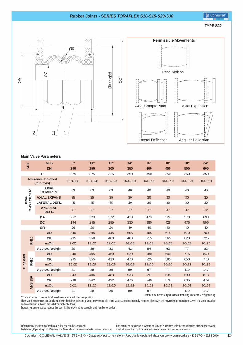
Rubber Joints - SERIES TORAFLEX S10-S15-S20-S30
Main Valve Parameters
TYPE S20
Dimensions in mm subject to manufacturing tolerance / Weights in kg
Information / restriction of technical rules need to be observed!Installation, Operating and Maintenance Manual can be downloaded at www.comeval.es
The engineer, designing a system or a plant, is responsable for the selection of the correct valveProduct suitability must be verifi ed, contact manufacturer for information
* The maximum movements allowed are considered from rest position.The stated movements are solely valid with the joint subject to a single movement direction. Values are proportionally reduced along with the movement combination. Given tolerance installed and movements allowed are valid for rubber bellows.Increasing temperatures reduce the permissible movements capacity and number of cycles.
SIZE NPS 8” 10” 12” 14” 16” 18” 20” 24”
DN 200 250 300 350 400 450 500 600L 325 325 325 350 350 350 350 350
Tolerance Installed (min-max) 318-328 318-328 318-328 344-353 344-353 344-353 344-353 344-353
MA
X.
MO
VEM
ENTS
* AXIAL COMPRES. 63 63 63 40 40 40 40 40
AXIAL EXPANS. 35 35 35 30 30 30 30 30LATERAL DEFL. 45 45 45 30 30 30 30 30
ANGULAR DEFL. 30° 30° 30° 20° 20° 20° 20° 20°
ØA 262 323 372 410 473 522 570 690ØC 194 245 295 330 380 428 476 596ØR 26 26 26 40 40 40 40 40
FLA
NG
ES
PN10
ØD 340 395 445 505 565 615 670 780ØK 295 350 400 460 515 565 620 725
nxØd 8x22 12x22 12x22 16x22 16x22 20x26 20x26 20x30Approx. Weight 20 26 32 42 54 62 77 82
PN16
ØD 340 405 460 520 580 640 715 840ØK 295 355 410 470 525 585 650 770
nxØd 12x22 12x26 12x26 16x26 16x30 20x30 20x33 20x36Approx. Weight 21 29 35 50 67 77 119 147
AN
SI15
0 ØD 343 406 483 533 597 635 699 813ØK 298 362 432 476 540 578 635 479
nxØd 8x22 12x25 12x25 12x29 16x29 16x32 20x32 20x32Approx. Weight 21 29 35 50 67 77 119 147
Permissible Movements
Rest Position
Axial Compression Axial Expansion
Lateral Defl ection Angular Defl ection
14Copyright COMEVAL VALVE SYSTEMS © - Data subject to revision - Regularly updated data on www.comeval.es - DS17G - Ed.15/06
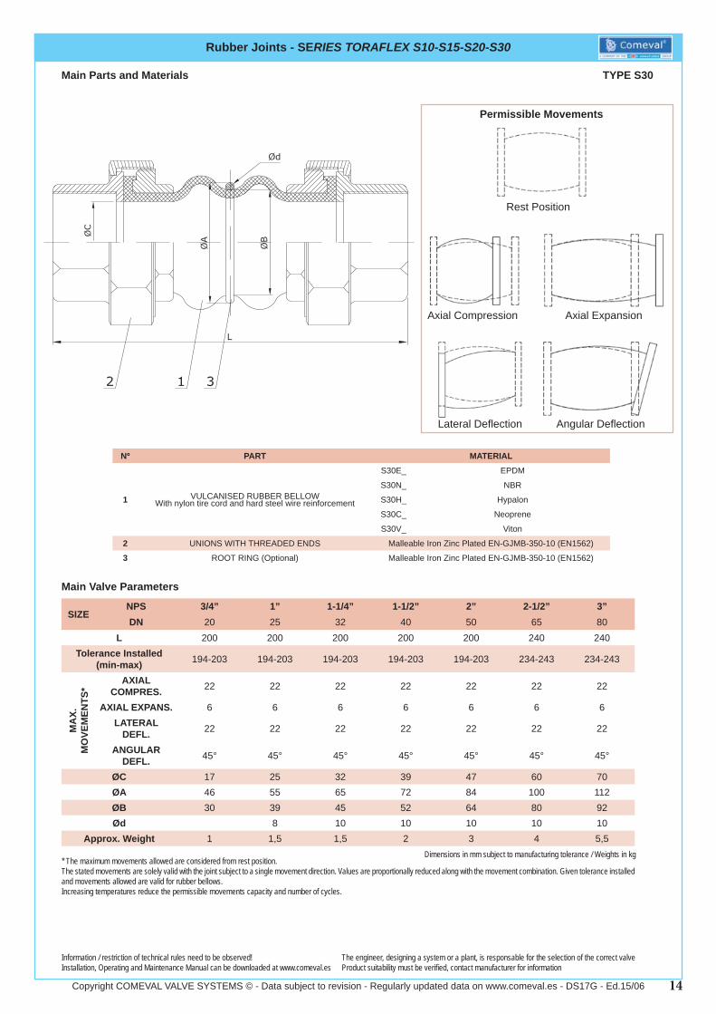
Main Parts and Materials
Nº PART MATERIAL
1 VULCANISED RUBBER BELLOWWith nylon tire cord and hard steel wire reinforcement
S30E_ EPDM
S30N_ NBR
S30H_ Hypalon
S30C_ Neoprene
S30V_ Viton
2 UNIONS WITH THREADED ENDS Malleable Iron Zinc Plated EN-GJMB-350-10 (EN1562)
3 ROOT RING (Optional) Malleable Iron Zinc Plated EN-GJMB-350-10 (EN1562)
Rubber Joints - SERIES TORAFLEX S10-S15-S20-S30
Main Valve Parameters
SIZENPS 3/4” 1” 1-1/4” 1-1/2” 2” 2-1/2” 3”DN 20 25 32 40 50 65 80
L 200 200 200 200 200 240 240Tolerance Installed
(min-max) 194-203 194-203 194-203 194-203 194-203 234-243 234-243
MA
X.
MO
VEM
ENTS
*
AXIAL COMPRES. 22 22 22 22 22 22 22
AXIAL EXPANS. 6 6 6 6 6 6 6LATERAL
DEFL. 22 22 22 22 22 22 22
ANGULAR DEFL. 45° 45° 45° 45° 45° 45° 45°
ØC 17 25 32 39 47 60 70ØA 46 55 65 72 84 100 112ØB 30 39 45 52 64 80 92Ød 8 10 10 10 10 10
Approx. Weight 1 1,5 1,5 2 3 4 5,5
TYPE S30
Dimensions in mm subject to manufacturing tolerance / Weights in kg
Information / restriction of technical rules need to be observed!Installation, Operating and Maintenance Manual can be downloaded at www.comeval.es
The engineer, designing a system or a plant, is responsable for the selection of the correct valveProduct suitability must be verifi ed, contact manufacturer for information
Permissible Movements
Rest Position
Axial Compression Axial Expansion
Lateral Defl ection Angular Defl ection
* The maximum movements allowed are considered from rest position.The stated movements are solely valid with the joint subject to a single movement direction. Values are proportionally reduced along with the movement combination. Given tolerance installed and movements allowed are valid for rubber bellows.Increasing temperatures reduce the permissible movements capacity and number of cycles.
15Copyright COMEVAL VALVE SYSTEMS © - Data subject to revision - Regularly updated data on www.comeval.es - DS17G - Ed.15/06
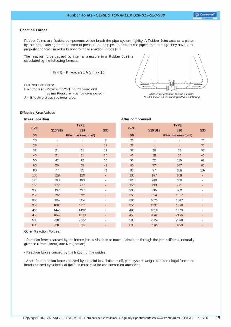
Rubber Joints - SERIES TORAFLEX S10-S15-S20-S30
Rubber Joints are fl exible components which break the pipe system rigidity. A Rubber Joint acts as a piston by the forces arising from the internal pressure of the pipe. To prevent the pipes from damage they have to be properly anchored in order to absorb these reaction forces (Fr).
Reaction Forces
The reaction force caused by internal pressure in a Rubber Joint is calculated by the following formula:
Fr =Reaction ForceP = Pressure (Maximum Working Pressure and Testing Pressure must be considered)A = Effective cross sectional area
Joint under pressure acts as a piston.Results shown when working without anchoring.
Fr (N) = P (kg/cm2) x A (cm2) x 10
In rest position
SIZETYPE
S10/S15 S20 S30DN Effective Area (cm2)20 - - 725 - - 1332 21 21 1740 21 21 2550 42 42 3565 59 59 4980 77 85 71
100 129 129 -125 193 193 -150 277 277 -200 437 437 -250 692 692 -300 934 934 -350 1086 1110 -400 1445 1492 -450 1847 1839 -500 2306 2222 -600 3286 3337 -
Effective Area Values
After compressed
Other Reaction Forces:
- Reaction forces caused by the innate joint resistance to move, calculated through the joint stiffness, normally given in N/mm (linear) and Nm (torsion).
- Reaction forces caused by the friction of the guides.
- Apart from reaction forces caused by the joint installation itself, pipe system weight and centrifugal forces on bends caused by velocity of the fl uid must also be considered for anchoring.
SIZETYPE
S10/S15 S20 S30DN Effective Area (cm2)20 - - 2025 - - 3132 28 82 3740 28 82 4850 52 119 6265 77 147 8080 97 186 107
100 167 269 -125 240 360 -150 333 471 -200 535 702 -250 814 1017 -300 1075 1307 -350 1237 1358 -400 1618 1779 -450 2042 2155 -500 2524 2568 -600 3545 3759 -
16Copyright COMEVAL VALVE SYSTEMS © - Data subject to revision - Regularly updated data on www.comeval.es - DS17G - Ed.15/06
Rubber Joints - SERIES TORAFLEX S10-S15-S20-S30
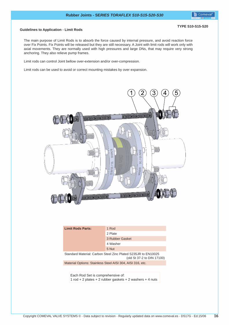
TYPE S10-S15-S20
The main purpose of Limit Rods is to absorb the force caused by internal pressure, and avoid reaction force over Fix Points. Fix Points will be released but they are still necessary. A Joint with limit rods will work only with axial movements. They are normally used with high pressures and large DNs, that may require very strong anchoring. They also relieve pump frames.
Limit rods can control Joint bellow over-extension and/or over-compression.
Limit rods can be used to avoid or correct mounting mistakes by over expansion.
Guidelines to Application - Limit Rods
Limit Rods Parts: 1 Rod2 Plate3 Rubber Gasket4 Washer5 Nut
Standard Material: Carbon Steel Zinc Plated S235JR to EN10025 (old St 37-2 to DIN 17100)
Material Options: Stainless Steel AISI 304, AISI 316, etc.
Each Rod Set is comprehensive of:1 rod + 2 plates + 2 rubber gaskets + 2 washers + 4 nuts

17Copyright COMEVAL VALVE SYSTEMS © - Data subject to revision - Regularly updated data on www.comeval.es - DS17G - Ed.15/06
Rubber Joints - SERIES TORAFLEX S10-S15-S20-S30
TYPE S10Limit Rods - Dimensions
Rod Sets - S10 for fl anges PN10 (Maximum Working Pressure: 10 bar)SIZE
M L A B W° ØD ØE R1 R2 F C T Number of Rod Sets per JointNPS DN
1-1/2” 40 16 240 37 55 90 18 18 18 20 78 60 10 22” 50 16 250 45 62,5 90 18 18 18 20 88 65 10 2
2-1/2” 65 16 260 33 72,5 90 18 18 20 20 103 65 10 23” 80 16 280 60 80 45 18 18 20 20 61 50 10 24” 100 16 290 70 90 45 18 18 20 20 69 50 10 25” 125 16 325 85 105 45 18 18 20 20 80 55 10 26” 150 16 340 94 120 45 23 18 22 20 92 60 12 28” 200 20 370 125 147,5 45 23 23 22 24 113 65 12 2
10” 250 20 440 153 175 30 23 23 22 24 91 65 18 312” 300 20 460 178 200 30 23 23 22 24 104 65 18 314” 350 20 460 208 230 22,5 23 23 22 24 90 60 20 416” 400 20 470 233 257,5 22,5 27 23 25 24 100 60 20 418” 450 20 480 258 282,5 18 27 23 25 24 88 60 20 420” 500 20 480 285 310 18 27 23 25 24 97 60 20 424” 600 24 495 333 362,5 18 30 27 30 28 113 70 20 4
Plate
Rod Sets - S10 for fl anges PN16 (Maximum Working Pressure: 16 bar (DN40-300); 10 bar (DN350-600))SIZE
M L A B W° ØD ØE R1 R2 F C T Number of Rod Sets per JointNPS DN
1-1/2” 40 16 240 37 55 90 18 18 18 20 78 60 10 22” 50 16 250 45 62,5 90 18 18 18 20 88 65 10 2
2-1/2” 65 16 260 53 72,5 90 18 18 20 20 103 65 10 23” 80 16 280 60 80 45 18 18 20 20 61 50 10 24” 100 16 290 70 90 45 18 18 20 20 69 50 10 25” 125 16 325 85 105 45 18 18 20 20 80 55 10 26” 150 16 340 98 120 45 23 18 22 20 92 60 12 28” 200 20 370 125 147,5 30 23 23 22 24 76 65 12 3
10” 250 20 440 153 177,5 30 27 23 25 24 92 65 18 312” 300 20 460 180 205 30 27 23 25 24 106 65 18 314” 350 20 460 210 235 22,5 27 23 25 24 92 65 20 416” 400 20 470 233 262,5 22,5 30 23 30 24 102 65 20 418” 450 20 480 263 292,5 18 30 23 30 24 92 65 20 420” 500 20 480 292 325 18 33 23 33 24 102 70 20 424” 600 24 495 348 385 18 37 27 37 28 120 80 22 4
Dimensions in mm., subject to manufacturing tolerancesFor higher maximum working pressures please consult us
Rod
18Copyright COMEVAL VALVE SYSTEMS © - Data subject to revision - Regularly updated data on www.comeval.es - DS17G - Ed.15/06
Rubber Joints - SERIES TORAFLEX S10-S15-S20-S30
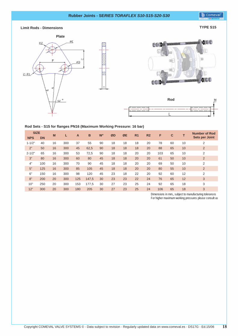
TYPE S15Limit Rods - Dimensions
Plate
Rod Sets - S15 for fl anges PN16 (Maximum Working Pressure: 16 bar)SIZE
M L A B W° ØD ØE R1 R2 F C T Number of Rod Sets per JointNPS DN
1-1/2” 40 16 300 37 55 90 18 18 18 20 78 60 10 22” 50 16 300 45 62,5 90 18 18 18 20 88 65 10 2
2-1/2” 65 16 300 53 72,5 90 18 18 20 20 103 65 10 23” 80 16 300 60 80 45 18 18 20 20 61 50 10 24” 100 16 300 70 90 45 18 18 20 20 69 50 10 25” 125 16 300 85 105 45 18 18 20 20 80 55 10 26” 150 16 300 98 120 45 23 18 22 20 92 60 12 28” 200 20 300 125 147,5 30 23 23 22 24 76 65 12 3
10” 250 20 300 153 177,5 30 27 23 25 24 92 65 18 312” 300 20 300 180 205 30 27 23 25 24 106 65 18 3
Dimensions in mm., subject to manufacturing tolerancesFor higher maximum working pressures please consult us
Rod

19Copyright COMEVAL VALVE SYSTEMS © - Data subject to revision - Regularly updated data on www.comeval.es - DS17G - Ed.15/06
Rubber Joints - SERIES TORAFLEX S10-S15-S20-S30
TYPE S20Limit Rods - Dimensions
Rod Sets - S20 for fl anges PN10 (Maximum Working Pressure: 10 bar)SIZE
M L A B W° ØD ØE R1 R2 F C T Number of Rod Sets per JointNPS DN
1-1/2” 40 16 320 37 55 90 18 18 18 20 78 60 10 22” 50 16 320 45 62,5 90 18 18 18 20 88 65 10 2
2-1/2” 65 16 320 33 72,5 90 18 18 20 20 103 65 10 23” 80 16 320 60 80 45 18 18 20 20 61 50 10 24” 100 16 380 70 90 45 18 18 20 20 69 50 10 25” 125 16 380 85 105 45 18 18 20 20 80 55 10 26” 150 16 380 94 120 45 23 18 22 20 92 60 12 28” 200 20 515 125 147,5 45 23 23 22 24 113 65 12 2
10” 250 20 515 153 175 30 23 23 22 24 91 65 18 312” 300 20 515 178 200 30 23 23 22 24 104 65 18 314” 350 20 515 208 230 22,5 23 23 22 24 90 60 20 416” 400 20 560 233 257,5 22,5 27 23 25 24 100 60 20 418” 450 20 560 258 282,5 18 27 23 25 24 88 60 20 420” 500 20 560 285 310 18 27 23 25 24 97 60 20 424” 600 24 600 333 362,5 18 30 27 30 28 113 70 20 4
Plate
Rod Sets - S20 for fl anges PN16 (Maximum Working Pressure: 16 bar (DN40-300); 10 bar (DN350-600))SIZE
M L A B W° ØD ØE R1 R2 F C T Number of Rod Sets per JointNPS DN
1-1/2” 40 16 320 37 55 90 18 18 18 20 78 60 10 22” 50 16 320 45 62,5 90 18 18 18 20 88 65 10 2
2-1/2” 65 16 320 53 72,5 90 18 18 20 20 103 65 10 23” 80 16 320 60 80 45 18 18 20 20 61 50 10 24” 100 16 380 70 90 45 18 18 20 20 69 50 10 25” 125 16 380 85 105 45 18 18 20 20 80 55 10 26” 150 16 380 98 120 45 23 18 22 20 92 60 12 28” 200 20 515 125 147,5 30 23 23 22 24 76 65 12 3
10” 250 20 515 153 177,5 30 27 23 25 24 92 65 18 312” 300 20 515 180 205 30 27 23 25 24 106 65 18 314” 350 20 515 210 235 22,5 27 23 25 24 92 65 20 416” 400 20 560 233 262,5 22,5 30 23 30 24 102 65 20 418” 450 20 560 263 292,5 18 30 23 30 24 92 65 20 420” 500 20 560 292 325 18 33 23 33 24 102 70 20 424” 600 24 600 348 385 18 37 27 37 28 120 80 22 4
Dimensions in mm., subject to manufacturing tolerancesFor higher maximum working pressures please consult us
Rod
Related Documents