RTX-IOM-RTX1000/1000L-R01-0416 Page 1 of 26 www.rotexautomation.com ELECTRO-PNEUMATIC POSITIONER Installation Operation and Maintenance Manual RTX1000 SERIES

Welcome message from author
This document is posted to help you gain knowledge. Please leave a comment to let me know what you think about it! Share it to your friends and learn new things together.
Transcript
RTX-IOM-RTX1000/1000L-R01-0416 Page 1 of 26
www.rotexautomation.com
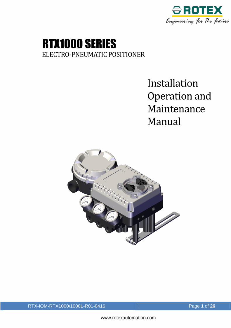
ELECTRO-PNEUMATIC POSITIONER
Installation Operation and Maintenance Manual
RTX1000 SERIES
RTX-IOM-RTX1000/1000L-R01-0416 Page 2 of 26
www.rotexautomation.com
Contents
1. Introduction ........................................................................................................... 4
1.1. General information...................................................................................... 4
1.2. Definitions .................................................................................................... 5
1.3. Explosion proof warning ............................................................................... 5
2. Product Description .............................................................................................. 6
2.1. General ........................................................................................................ 6
2.2. Label description .......................................................................................... 6
2.3. Product number ........................................................................................... 7
2.4. Product specification .................................................................................... 8
2.4.1. RTX1000L & R ......................................................................................... 8
2.5. Part and assembly ....................................................................................... 9
2.6. RTX1000R ................................................................................................... 9
2.7. RTX1000L .................................................................................................. 10
2.8. Product dimension ..................................................................................... 11
2.9. RTX1000L .................................................................................................. 11
2.10. RTX1000R ................................................................................................. 11
3. Installation .......................................................................................................... 12
3.1. Safety ......................................................................................................... 12
3.2. RTX1000L Installation ................................................................................ 12
3.3. Installation steps ........................................................................................ 12
3.4. RTX1000R Installation ............................................................................... 14
3.5. Bracket information .................................................................................... 14
3.6. Installation steps ........................................................................................ 14
4. Connections ....................................................................................................... 16
4.1. Safety ......................................................................................................... 16

RTX-IOM-RTX1000/1000L-R01-0416 Page 3 of 26
www.rotexautomation.com
4.2. Supply Pressure Condition ......................................................................... 16
4.3. Piping Condition ......................................................................................... 16
4.4. Pipe Connection with actuator ................................................................... 17
4.4.1. Single acting actuator ............................................................................. 17
4.4.2. Double acting actuator ........................................................................... 17
5. Adjustment ......................................................................................................... 18
5.1. Adjustment – cam ...................................................................................... 18
5.2. Adjustment – Zero point ............................................................................. 18
5.3. Adjustment – Span ..................................................................................... 19
5.4. Adjustment - A/M Switch (Auto/Manual)..................................................... 19
5.5. Adjustment - Seat Adjuster ........................................................................ 20
5.6. Adjustment – Orifice ................................................................................... 20
6. Maintenance ....................................................................................................... 21
7. Troubleshooting .................................................................................................. 22
8. Position transmitter calibration ........................................................................... 24
8.1. Calibration .................................................................................................. 25
8.1.1. Potentiometer setting ............................................................................. 25
8.1.2. ‘ZERO’ (Close 0%) & ‘SPAN’ (Open 100%) setting................................ 25
9. Packaging & store .............................................................................................. 26
10. Assistance .......................................................................................................... 26
RTX-IOM-RTX1000/1000L-R01-0416 Page 4 of 26
www.rotexautomation.com
1. Introduction
1.1. General information
Thank you for choosing ROTEX product. Each product is fully inspected after the
production to offer you the highest quality. In order to fully utilize the product, we
strongly recommend users to read this manual carefully and understood.
This manual provides information on installation, operation and maintenance
procedures and related instructions for the ROTEX make Positioner (RTX
series).
The aim of this literature is to support the use of products in correct manner,
and all the technical information provided in the catalogue.
The manual should be given to the end user.
The manual can be changed or revised without any prior notice. Any changes
in product's specification, structure, and/or any components may not result
immediate revised version of the manual.
The manual should not be duplicated or reproduced for any purpose without
any consent of Rotex Manufacturers & Engineers Private Limited, INDIA.
Manufacturer Warranty
For the safety, it is vital to follow instructions in the manual. It is not ROTEX’s
liability for any damages which caused by users' negligence.
It is not ROTEX's liability for any damages or accidents which resulted by any
alteration or modification of the product and parts. If alteration or modification
is necessary, please contact the ROTEX directly.
ROTEX warrants the product from the date of original retail purchase of the
product for one (1) year, except as otherwise stated.
ROTEX warranty will not cover the products that the product have been
subjected to abuse, accident, alteration, modification, tampering, negligence,
misuse, faulty installation, lack of reasonable care, repair or service in any way
that is not contemplated in the documentation for the product, or if the model
or serial number has been altered, tampered with, defaced or removed;
damages that occurs in shipment, failure due to power surge, and cosmetic
damage. Improper or incorrectly performed maintenance or report voids this
Limited Warranty.
For detailed warranty information, please contact :
ROTEX MANUFACTERURS & ENGINEERS PRIVATE LIMITED, Manapada road,
Dombivli (e), Maharashtra, India, Pin - 421204
RTX-IOM-RTX1000/1000L-R01-0416 Page 5 of 26
www.rotexautomation.com
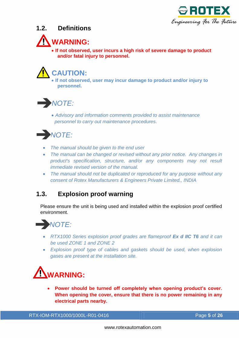
1.2. Definitions
WARNING:
If not observed, user incurs a high risk of severe damage to product and/or fatal injury to personnel.
CAUTION:
If not observed, user may incur damage to product and/or injury to personnel.
NOTE:
Advisory and information comments provided to assist maintenance
personnel to carry out maintenance procedures.
NOTE:
The manual should be given to the end user
The manual can be changed or revised without any prior notice. Any changes in
product's specification, structure, and/or any components may not result
immediate revised version of the manual.
The manual should not be duplicated or reproduced for any purpose without any
consent of Rotex Manufacturers & Engineers Private Limited., INDIA
1.3. Explosion proof warning
Please ensure the unit is being used and installed within the explosion proof certified
environment.
NOTE:
RTX1000 Series explosion proof grades are flameproof Ex d IIC T6 and it can
be used ZONE 1 and ZONE 2
Explosion proof type of cables and gaskets should be used, when explosion
gases are present at the installation site.
WARNING:
Power should be turned off completely when opening product’s cover.
When opening the cover, ensure that there is no power remaining in any
electrical parts nearby.
RTX-IOM-RTX1000/1000L-R01-0416 Page 6 of 26
www.rotexautomation.com
2. Product Description
2.1. General
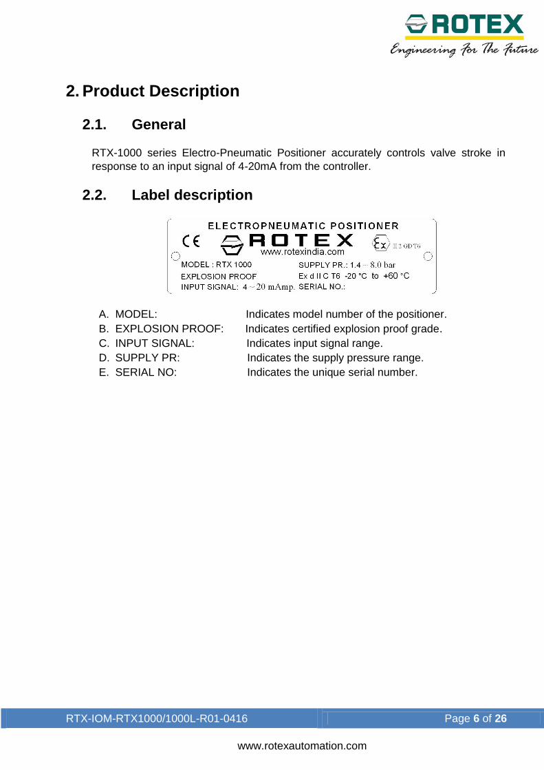
RTX-1000 series Electro-Pneumatic Positioner accurately controls valve stroke in
response to an input signal of 4-20mA from the controller.
2.2. Label description
A. MODEL: Indicates model number of the positioner.
B. EXPLOSION PROOF: Indicates certified explosion proof grade.
C. INPUT SIGNAL: Indicates input signal range.
D. SUPPLY PR: Indicates the supply pressure range.
E. SERIAL NO: Indicates the unique serial number.
RTX-IOM-RTX1000/1000L-R01-0416 Page 7 of 26
www.rotexautomation.com
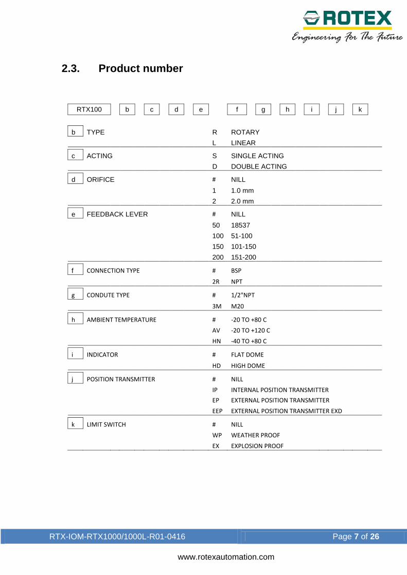
2.3. Product number
RTX100
b
c
d
e
f
g
h
i
j
k
b TYPE R ROTARY
L LINEAR
c ACTING S SINGLE ACTING
D DOUBLE ACTING
d ORIFICE # NILL
1 1.0 mm
2 2.0 mm
e FEEDBACK LEVER # NILL
50 18537
100 51-100
150 101-150
200 151-200
f CONNECTION TYPE # BSP
2R NPT
g CONDUTE TYPE # 1/2"NPT
3M M20
h AMBIENT TEMPERATURE # -20 TO +80 C
AV -20 TO +120 C
HN -40 TO +80 C
i INDICATOR # FLAT DOME
HD HIGH DOME
j POSITION TRANSMITTER # NILL
IP INTERNAL POSITION TRANSMITTER
EP EXTERNAL POSITION TRANSMITTER
EEP EXTERNAL POSITION TRANSMITTER EXD
k LIMIT SWITCH # NILL
WP WEATHER PROOF
EX EXPLOSION PROOF

RTX-IOM-RTX1000/1000L-R01-0416 Page 8 of 26
www.rotexautomation.com
2.4. Product specification
2.4.1. RTX1000L & R
Category RTX – 1000R
Input Signal 4 ~ 20mA *
Impedance 250 ± 15 Ω
Supply Pressure 1.4 ~ 8.0 kgf/cm² (20 ~ 120psi)
Stroke 0 ~90° **
Air Connection PT (2G / 2R)
Conduit Entry PF 1/2 or G 1/2
Explosion Proof ATEX:
Protection IP 65
Cam Linear / Equal / SQ. / SQ. RT
Ambient Temp. Standard: -40°C ~ +150°C
Linearity ± 1.0 % F.S
Hysteresis 1 .0% F.S.
Sensitivity ±0.2% F.S. ±0.5% F.S.
Repeatability ± 0.3 % F.S.
Internal
Bleeding
3.0LPM(Sup=1.4kgf/cm², 20psi),
Flow Capacity 80LPM(Sup=1.4kgf/cm², 20psi)
Material Aluminium Die casting
Weight 2.8 kg.
RTX-IOM-RTX1000/1000L-R01-0416 Page 9 of 26
www.rotexautomation.com
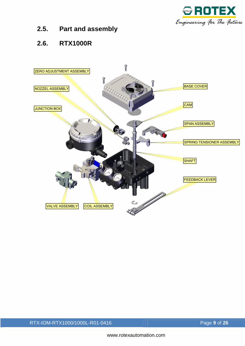
2.5. Part and assembly
2.6. RTX1000R

RTX-IOM-RTX1000/1000L-R01-0416 Page 10 of 26
www.rotexautomation.com
2.7. RTX1000L
RTX-IOM-RTX1000/1000L-R01-0416 Page 11 of 26
www.rotexautomation.com
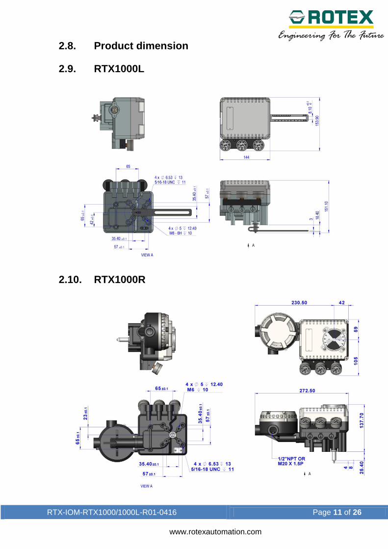
2.8. Product dimension
2.9. RTX1000L
2.10. RTX1000R
RTX-IOM-RTX1000/1000L-R01-0416 Page 12 of 26
www.rotexautomation.com
3. Installation
3.1. Safety
When installing a positioner, please ensure to read and follow safety instruction
NOTE:
Use bypass valve or other supportive equipment to avoid entire system shut
down.
WARNING:
Any input or supply pressure to valve, actuator and / or to other related
devices must be turned off
Ensure there is no remaining pressure in the actuator.
3.2. RTX1000L Installation
RTX 1000 L should be installed on linear motion valves such as globe or gate type
which uses spring return type diaphragm or piston actuators. Before proceeding with
the installation, ensure following components are available
a. Positioner unit
b. Feedback lever and lever spring
c. Mounting bolts and washer
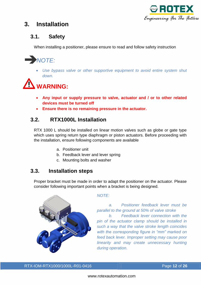
3.3. Installation steps
Proper bracket must be made in order to adapt the positioner on the actuator. Please
consider following important points when a bracket is being designed.
NOTE:
a. Positioner feedback lever must be
parallel to the ground at 50% of valve stroke
b. Feedback lever connection with the
pin of the actuator clamp should be installed in
such a way that the valve stroke length coincides
with the corresponding figure in “mm” marked on
feed back lever. Improper setting may cause poor
linearity and may create unnecessary hunting
during operation.

RTX-IOM-RTX1000/1000L-R01-0416 Page 13 of 26
www.rotexautomation.com
Assemble the positioner with bracket
made in previous step by fastening the
bolts.
Attach Positioner with bracket to the
actuator yoke
NOTE: Do not tighten Positioner
completely
Connect supply pressure to actuator
temporarily. Supply enough supply
pressure to the actuator in order to
position the actuator clamp at 50% of the valve stroke.
Insert connection pin into the feedback
lever. The pin should be inserted when
the actuator clamp is at 50% of the total
valve stroke.
Check if feedback lever is parallel to the
ground at 50% of the valve stroke. If it is not
parallel, adjust the bracket or feedback link bar
to make parallel. Improper installation may
cause poor linearity and may create
unnecessary hunting during the operation.
Check the valve stroke. The stroke marks are
indicated on the feedback lever of the
positioner. Position the connection pin at the
number on the feedback lever which
corresponds to the desired valve stroke. To
adjust, move the bracket, the connection pin
or both. .
After installing the positioner, operate the valve from 0% to 100% stroke by using
direct air to the actuator (manual position). On both 0% and 100%, the feedback
lever should not touch the lever stopper, which is located on the backside of the
positioner. If the feedback lever touches the stopper, the positioner should be
installed further away from the yoke.

RTX-IOM-RTX1000/1000L-R01-0416 Page 14 of 26
www.rotexautomation.com
After the installation, tighten all of the bolts on the bracket, the feedback lever, and
the connection pin.
3.4. RTX1000R Installation
RTX – 1000R can be used for rotary actuator as well as linear actuator (Cylinder).
Rotary actuator motion valves are used for regulating ball valve, butterfly valve using
rack and pinion, scotch yoke of complex type actuator, which its stem rotates 90
degrees. And linear actuators are used to regulate the motion of dampers, In this
arrangement we use a profile plate which converts linear movement of cylinder into
rotary motion.
Be sure to check the following components before installation on rotary actuator.
d. RTX - 1000 main assembly
e. IOM
f. 1 Set of bracket (Not as a part of supply, needs to be order
separately)
g. 4 Socket set screw
h. 4 Spring washer
i. 4 Hexagon head bolt
3.5. Bracket information
Standard bracket (included with the positioner) contains two components. The
bracket can be used for NAMUR lever type. The bracket is designed to fit onto the
actuator with 20mm stem height (H).
3.6. Installation steps
Please check the actuator’s stem height
Mount bracket onto the actuator. It is
recommended to use spring washer so the
bolts will not be loosen from vibration
RTX-IOM-RTX1000/1000L-R01-0416 Page 15 of 26
www.rotexautomation.com
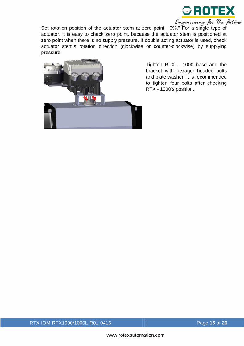
Set rotation position of the actuator stem at zero point, "0%." For a single type of
actuator, it is easy to check zero point, because the actuator stem is positioned at
zero point when there is no supply pressure. If double acting actuator is used, check
actuator stem's rotation direction (clockwise or counter-clockwise) by supplying
pressure.
Tighten RTX – 1000 base and the
bracket with hexagon-headed bolts
and plate washer. It is recommended
to tighten four bolts after checking
RTX - 1000's position.

RTX-IOM-RTX1000/1000L-R01-0416 Page 16 of 26
www.rotexautomation.com
4. Connections
4.1. Safety
Supply pressure should be clean and dry air – avoiding moisture, oil or dust.
Always recommended to use air filter regulator (i.e. YT-200 series).
ROTEX has not tested positioner operation with any gases other than clean air.
Please contact ROTEX for any questions.
4.2. Supply Pressure Condition
Dry air with at least 10 0C lower than ambient temperature.
Avoid from dusty air. Positioner inner filter can only filter 5 micron or larger.
Avoid oil.
Comply with ANSI/ISA-57.3 1975(R1981) or ISA S7.3-1975(R1981).
Supply pressure range is 1.4 ~ 7 kgf/cm2 (140-700 kPA)
Set air filter regulator’s pressure level 10% higher than actuator’s spring range
pressure.
4.3. Piping Condition
Ensure inside of pipe is clean of obstructions.
Do not use pipeline that is squeezed or shows any type of damages.
Pipeline should have more than 6mm of inner diameter (10mm outer diameter) to
maintain flow rate.
The length of pipeline system should not be extremely long. Longer pipeline system
may affect flow rate due to the friction inside of the pipeline.
RTX-IOM-RTX1000/1000L-R01-0416 Page 17 of 26
www.rotexautomation.com
4.4. Pipe Connection with actuator
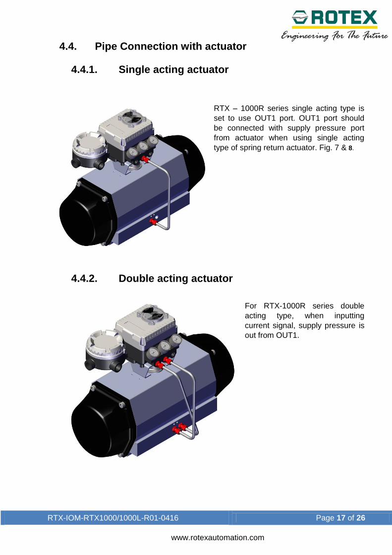
4.4.1. Single acting actuator
RTX – 1000R series single acting type is
set to use OUT1 port. OUT1 port should
be connected with supply pressure port
from actuator when using single acting
type of spring return actuator. Fig. 7 & 8.
4.4.2. Double acting actuator
For RTX-1000R series double
acting type, when inputting
current signal, supply pressure is
out from OUT1.

RTX-IOM-RTX1000/1000L-R01-0416 Page 18 of 26
www.rotexautomation.com
5. Adjustment
5.1. Adjustment – cam
Direction of actuator's stem rotation must be checked when supply signal is supplied.
When actuator's stem rotates clockwise, the face of cam must be shown "DA." On
the other hand, when the stem rotates counter-clockwise, adjust cam so "RA" shows
on the face of cam.
Check whether actuator's angle is at the initial point.
After checking the initial point, release the hexagonal flange nut and adjust the
position of the bearing so it is at 0 point. Fig. 11
When produced, the cam is set as RA.
5.2. Adjustment – Zero point
Set supply signal at 3 psi and rotate adjuster
clockwise or counter-clockwise to adjust
actuator's rotation angle. Fig.12
When adjusting zero for single actuator,
rotation angle is equal to positioner's pressure
gauge.

RTX-IOM-RTX1000/1000L-R01-0416 Page 19 of 26
www.rotexautomation.com
5.3. Adjustment – Span
After setting zero, rotate Span screw so
supply signal reaches at the span point on
the indicator.
Changing span point affects zero point
setting. So zero setting must be set again.
After setting zero point, confirm the span
point. This step must be repeated until both
points are properly set.
For RTX – 1000R with 1/2 split range, the
span spring must be changed.
After setting is completed, tighten Lock
Screw.
5.4. Adjustment - A/M Switch (Auto/Manual)
A/M switch adjusts the valve
operation to automatic or
manual.
When produced, RTX-1000
series is set at
"A(Automatic)". If user
prefers the positioner setting
as "M (Manual)," the setting
can be changed by turning
the switch counter-
clockwise. Fig. 14
If it is set as "M (Manual)", the air pressure will be supplied to the actuator directly.
Always set back to "A (Automatic)" after setting change.
If OUT2 in single acting actuator or double acting actuator is used, A/M Switch will
not operate. Fig.14

RTX-IOM-RTX1000/1000L-R01-0416 Page 20 of 26
www.rotexautomation.com
5.5. Adjustment - Seat Adjuster
Seat Adjuster is set according to the customer's request before the positioner is
delivered. Please do not adjust the Seat Adjuster.
Seat Adjuster is used for double acting actuator always. Please do not touch the
Seat Adjuster, because it can affect the positioner's performance.
5.6. Adjustment – Orifice
If the size of actuator is too small relative to the flow rate, positioner can have
hunting. In order to avoid hunting, orifice can be used. There are three types of the
orifice.
Actuator Size Orifice Size Suffix symbol
90cm² less Ø1.0 1
90 ~ 180cm² Ø2.0 2
180cm² and above None 3
Remove the o-ring from OUT1 and OUT2 port and insert appropriate orifice. After
inserting orifice, place back the o-ring. Make sure there is no substance entering into
port.
If hunting persists after inserting the orifice, please contact ROTEX or its appropriate
agent.
RTX-IOM-RTX1000/1000L-R01-0416 Page 21 of 26
www.rotexautomation.com
6. Maintenance
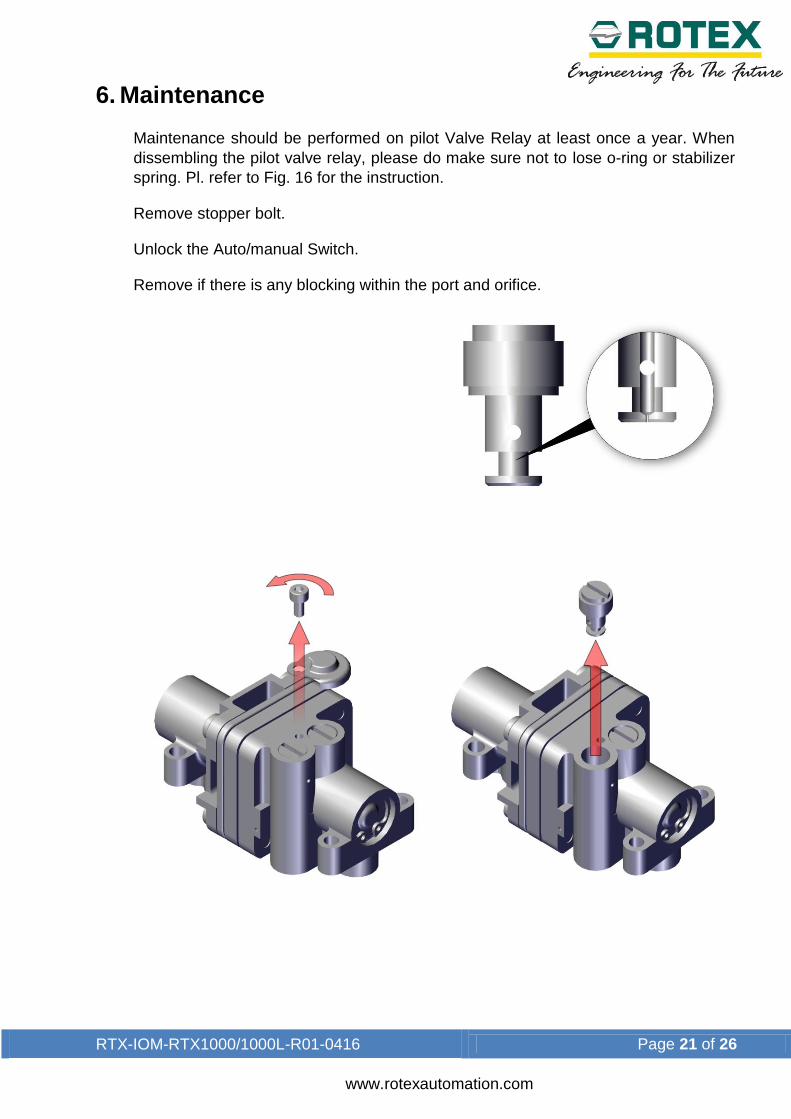
Maintenance should be performed on pilot Valve Relay at least once a year. When
dissembling the pilot valve relay, please do make sure not to lose o-ring or stabilizer
spring. Pl. refer to Fig. 16 for the instruction.
Remove stopper bolt.
Unlock the Auto/manual Switch.
Remove if there is any blocking within the port and orifice.

RTX-IOM-RTX1000/1000L-R01-0416 Page 22 of 26
www.rotexautomation.com
7. Troubleshooting Positioner does not respond to the input signal.
Check supply pressure level. The level must be at least 1.4 kgf/cm².
Check if input signal is properly supplied to the positioner. The signal should be
4~20mA DC.
Check if the positioner nozzle has been blocked. Also, check if the pressure is
supplied to the positioner and the pressure is being exhausted through the nozzle. If
the nozzle has been blocked by any substances, please send the product to ROTEX
for repair.
Check if feedback lever has been installed properly.
Check if zero point or span point is properly set.
Check if feedback lever has been installed properly.
The pressure of OUT1 reaches exhausting pressure level and does not come back down.
Check A/M Switch. If the switch has been damaged, replace the switch or pilot relay-
valve.
Check for a gap or damages between the nozzle and the flapper. If damaged, please
send the product to ROTEX for repair.
The pressure is exhausted only by A/M Switch.
Check if the positioner nozzle has been blocked. Also, check if the pressure is
supplied to the positioner and the pressure is being exhausted through the nozzle. If
the nozzle has been blocked by any substances, please send the product to ROTEX
for repair.
Hunting occurs.
Check if safety spring has been displaced. (Next to Pilot relay valve)
Check if the size of actuator is too small. If so, insert an orifice in order to reduce the
pressure flow rate.
Check if there is any friction between the valve and the actuator. If so, increase
actuator's size or reduce the friction level.
Actuator only operates by On/Off.

RTX-IOM-RTX1000/1000L-R01-0416 Page 23 of 26
www.rotexautomation.com
Check pipe connection.
Check cam direction.
Linearity is too low.
Check if the feedback lever is properly installed. Especially check if the feedback
lever is parallel to the ground at 50% point.
Check if zero and span have been properly adjusted, that is not too low or not too
high.
Check if supply air pressure level is stable from the regulator. If the level is unstable,
replace the regulator.
Hysteresis is too low.
In case of double acting actuator, check if seat adjustment has been properly done.
Please contact ROTEX for any further inquiries regarding the seat adjustment.
Backlash can occur when feedback lever and lever spring is loosen. To avoid
backlash, adjust the lever spring.
Check if the connection bar to the feedback lever is tightly fastened.
RTX-IOM-RTX1000/1000L-R01-0416 Page 24 of 26
www.rotexautomation.com
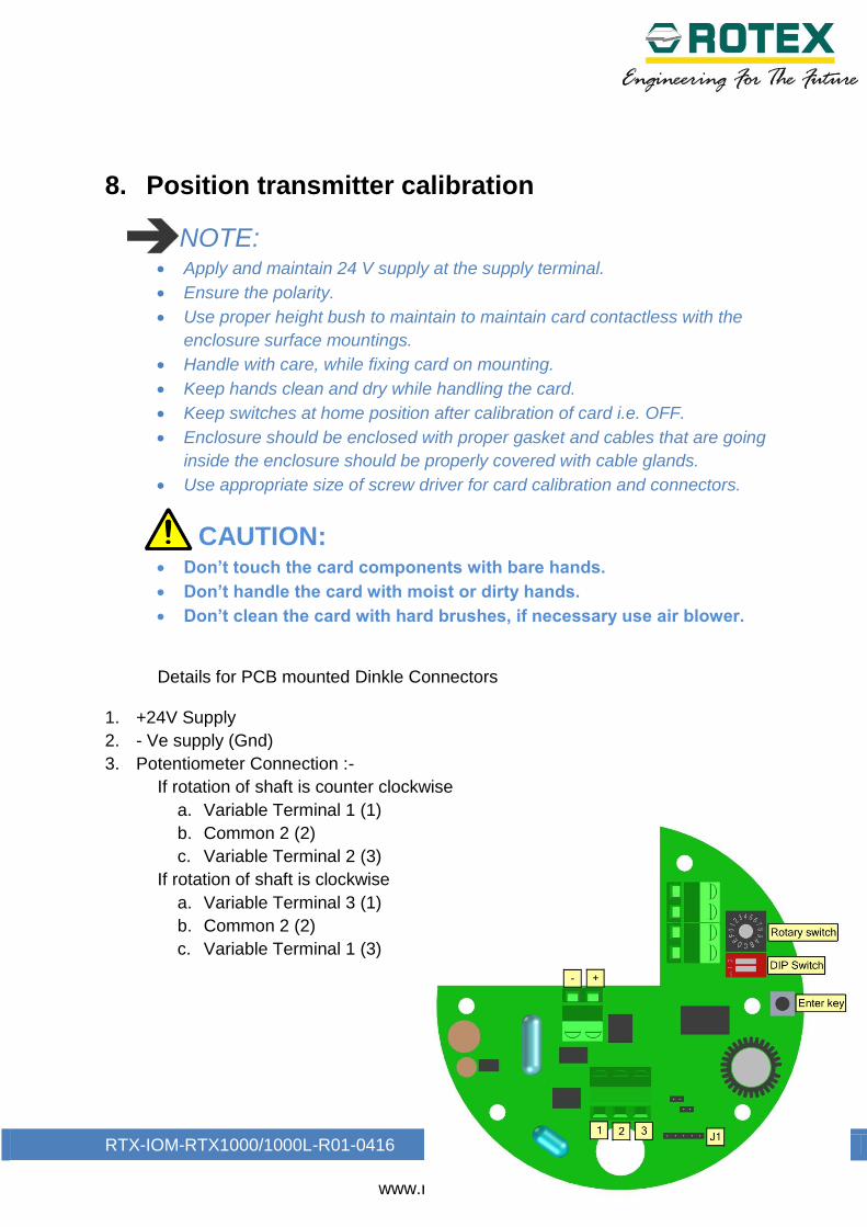
8. Position transmitter calibration
NOTE: Apply and maintain 24 V supply at the supply terminal.
Ensure the polarity.
Use proper height bush to maintain to maintain card contactless with the
enclosure surface mountings.
Handle with care, while fixing card on mounting.
Keep hands clean and dry while handling the card.
Keep switches at home position after calibration of card i.e. OFF.
Enclosure should be enclosed with proper gasket and cables that are going
inside the enclosure should be properly covered with cable glands.
Use appropriate size of screw driver for card calibration and connectors.
CAUTION:
Don’t touch the card components with bare hands.
Don’t handle the card with moist or dirty hands.
Don’t clean the card with hard brushes, if necessary use air blower.
Details for PCB mounted Dinkle Connectors
1. +24V Supply
2. - Ve supply (Gnd)
3. Potentiometer Connection :-
If rotation of shaft is counter clockwise
a. Variable Terminal 1 (1)
b. Common 2 (2)
c. Variable Terminal 2 (3)
If rotation of shaft is clockwise
a. Variable Terminal 3 (1)
b. Common 2 (2)
c. Variable Terminal 1 (3)
RTX-IOM-RTX1000/1000L-R01-0416 Page 25 of 26
www.rotexautomation.com
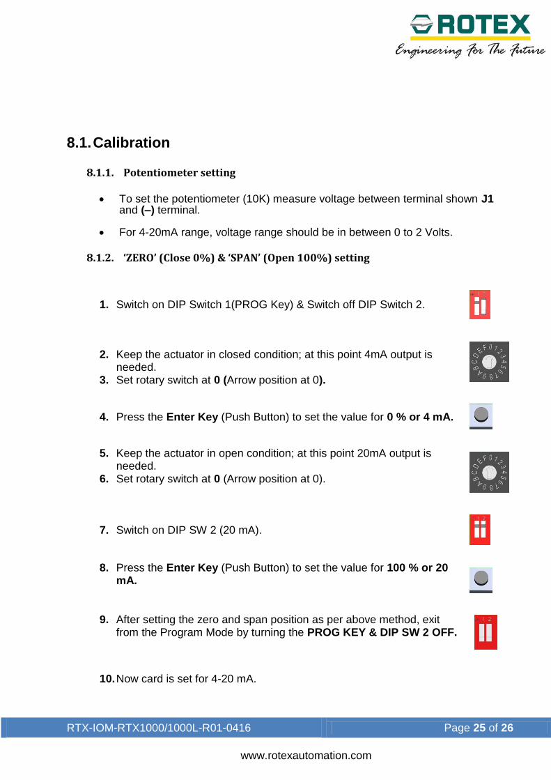
8.1. Calibration
8.1.1. Potentiometer setting
To set the potentiometer (10K) measure voltage between terminal shown J1
and (–) terminal. For 4-20mA range, voltage range should be in between 0 to 2 Volts.
8.1.2. ‘ZERO’ (Close 0%) & ‘SPAN’ (Open 100%) setting
1. Switch on DIP Switch 1(PROG Key) & Switch off DIP Switch 2.
2. Keep the actuator in closed condition; at this point 4mA output is needed.
3. Set rotary switch at 0 (Arrow position at 0).
4. Press the Enter Key (Push Button) to set the value for 0 % or 4 mA.
5. Keep the actuator in open condition; at this point 20mA output is needed.
6. Set rotary switch at 0 (Arrow position at 0).
7. Switch on DIP SW 2 (20 mA).
8. Press the Enter Key (Push Button) to set the value for 100 % or 20 mA.
9. After setting the zero and span position as per above method, exit from the Program Mode by turning the PROG KEY & DIP SW 2 OFF.
10. Now card is set for 4-20 mA.

RTX-IOM-RTX1000/1000L-R01-0416 Page 26 of 26
www.rotexautomation.com
9. Packaging & store 1. When not in use, Positioner should be kept in a sealed plastic bag in a
cardboard box to prevent moisture or dust from contacting product. 2. Positioner should be stored in a dry place free from water and dust. 3. Store at temperature between 40oF and 120°F (4°C and 49°C). 4. Locate in an area to avoid damage by impact.
10. Assistance For technical questions or assistance, contact any authorized distributor of ROTEX or: ROTEX MANUFACTURERS AND ENGINEERS PRIVATE LIMITED Manpada Road, Dombivli (East)-421204 Maharastra, INDIA. Tel: +91 251 2871033/ 2871390/ 2871196/ 2871989 Fax: +91 251 2871191
To find your local ROTEX representative:
For more information about ROTEX and its network, Please visit www.rotexautomation.com
Related Documents