IEEE 802.3bp RTPGE Task Force– November 12, 2013 Page 1 Version 1.0 Ahmad Chini, Broadcom Mehmet Tazebay, Broadcom RTPGE BCI Noise Analysis for Common Mode Termination & Grounding Effects November 12, 2013

Welcome message from author
This document is posted to help you gain knowledge. Please leave a comment to let me know what you think about it! Share it to your friends and learn new things together.
Transcript
IEEE 802.3bp RTPGE Task Force– November 12, 2013 Page 1 Version 1.0
Ahmad Chini, Broadcom
Mehmet Tazebay, Broadcom
RTPGE BCI Noise Analysis for
Common Mode Termination & Grounding Effects
November 12, 2013
Page 2 IEEE P802.3 Maintenance report – July 2008 Plenary Version 1.0 IEEE 802.3bp RTPGE Task Force– November 12, 2013 Version 1.0 Page 2
Contributors & Supporters
Contributors Ahmad Chini, Broadcom Neven Pischl, Broadcom
Jay Cordaro, Broadcom Mehmet Tazebay, Broadcom
Supporters
Stefan Buntz, Daimler Kirsten Matheus, BMW
Thomas Hogenmueller, Bosch Sasha Babenko, Molex
Bryan Moffitt, Commscope Benson Huang, Realtek
Thuyen Dinh, Pulse Electronics Mandeep Chadha, Vitesse
Mike Gardner, Molex Sujan Pandey, NXP
Dave Dwelley, Linear Technology Xiaofeng Wang, Qualcomm
Bernd Koerber, FTZ Nirmal Warke, Texas Instruments
Sterling Vaden, OCC Michael Rucks, Delphi
Todd Hermann, Commscope Martin Huber, MD Electronics
Richard Mei, Commscope Thomas Muller, Rosenberger
Page 3 IEEE P802.3 Maintenance report – July 2008 Plenary Version 1.0 IEEE 802.3bp RTPGE Task Force– November 12, 2013 Version 1.0 Page 3
AGENDA
• Objectives & Methodology
• Set-up & Calibration Information
• 3-Port Test Model & Results
• 5-Port Test Model & Results
• A Simplified Link Model for EMC
• Conclusions
Page 4 IEEE P802.3 Maintenance report – July 2008 Plenary Version 1.0 IEEE 802.3bp RTPGE Task Force– November 12, 2013 Version 1.0 Page 4
OBJECTIVES
1. Investigate the effect of test head grounding (floating)
on BCI noise.
2. Analyze the effect of CM termination on CM-to-DM
conversion and BCI Noise.
3. Preliminary analysis of noise for a simplified link model
with CM chokes & terminations.

Page 5 IEEE P802.3 Maintenance report – July 2008 Plenary Version 1.0 IEEE 802.3bp RTPGE Task Force– November 12, 2013 Version 1.0 Page 5
METHODOLOGY
1. A BCI test setup was established in order to measure 3-port and 4-
port VNA Transfer Functions with grounding and floating options.
2. 3-port VNA measurements were used in Agilent ADS simulations to
obtain Differential Mode Transfer Functions and estimate noise for
various Common Mode termination values and grounding options.
3. 5-port model generated in ADS using 3-port and 4-port VNA
measurements, allowing noise analysis for various CM
terminations applied on both sides of a link.
4. A simplified link model established in ADS incorporating measured
CMC and CM terminations for input-referred noise analysis.
Page 6 IEEE P802.3 Maintenance report – July 2008 Plenary Version 1.0 IEEE 802.3bp RTPGE Task Force– November 12, 2013 Version 1.0 Page 6
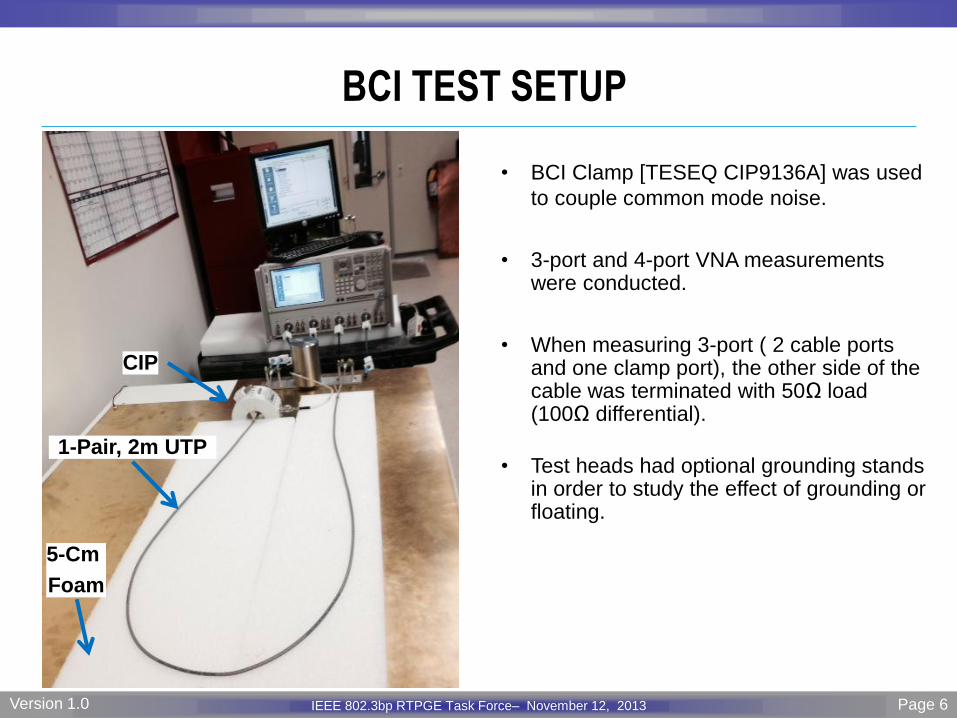
BCI TEST SETUP
• BCI Clamp [TESEQ CIP9136A] was used
to couple common mode noise.
• 3-port and 4-port VNA measurements were conducted.
• When measuring 3-port ( 2 cable ports and one clamp port), the other side of the cable was terminated with 50Ω load (100Ω differential).
• Test heads had optional grounding stands in order to study the effect of grounding or floating.
CIP
1-Pair, 2m UTP
5-Cm
Foam
Page 7 IEEE P802.3 Maintenance report – July 2008 Plenary Version 1.0 IEEE 802.3bp RTPGE Task Force– November 12, 2013 Version 1.0 Page 7
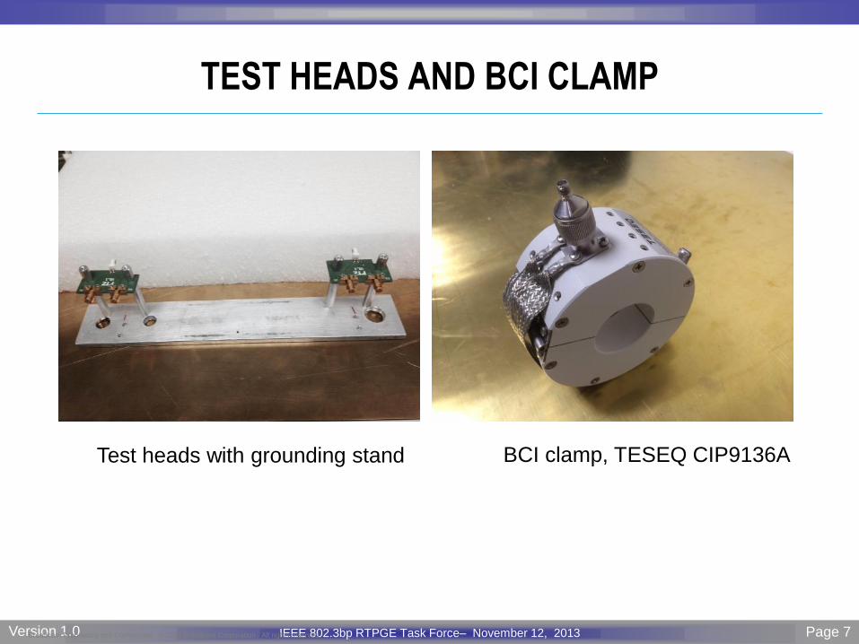
TEST HEADS AND BCI CLAMP
Broadcom Proprietary and Confidential. © 2012 Broadcom Corporation. All rights reserved.
Test heads with grounding stand BCI clamp, TESEQ CIP9136A
Page 8 IEEE P802.3 Maintenance report – July 2008 Plenary Version 1.0 IEEE 802.3bp RTPGE Task Force– November 12, 2013 Version 1.0 Page 8
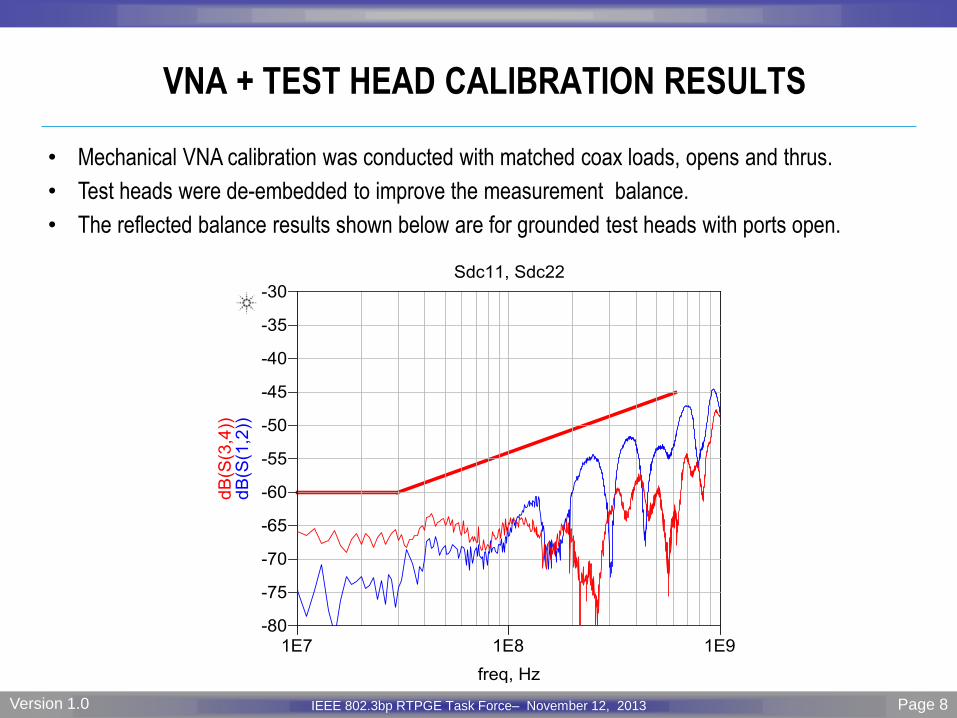
VNA + TEST HEAD CALIBRATION RESULTS
• Mechanical VNA calibration was conducted with matched coax loads, opens and thrus.
• Test heads were de-embedded to improve the measurement balance.
• The reflected balance results shown below are for grounded test heads with ports open.

Page 9 IEEE P802.3 Maintenance report – July 2008 Plenary Version 1.0 IEEE 802.3bp RTPGE Task Force– November 12, 2013 Version 1.0 Page 9
3-PORT BCI TEST MODEL
SETUP INFORMATION
• S3P data was measured for a 2m 1-pair UTP cable with three different test head configurations; 1. Test heads grounded on both sides
2. Test heads grounded on clamp side and floating on the other side
3. Test heads floating on both sides
• The measured S3P data was then used in Agilent ADS to simulate for various CM termination values. The CM termination value (X) varied on the clamp side of the cable which is connected to the VNA.
Noise Injection Port
ADS MODEL
Ideal Balun
Page 10 IEEE P802.3 Maintenance report – July 2008 Plenary Version 1.0 IEEE 802.3bp RTPGE Task Force– November 12, 2013 Version 1.0 Page 10
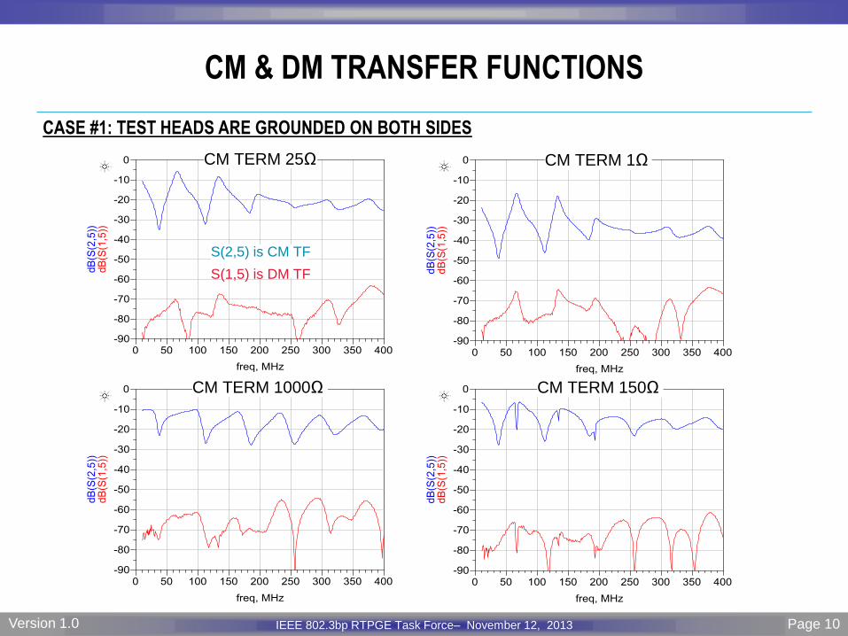
CM & DM TRANSFER FUNCTIONS
CASE #1: TEST HEADS ARE GROUNDED ON BOTH SIDES
CM TERM 25Ω CM TERM 1Ω
CM TERM 1000Ω CM TERM 150Ω
S(2,5) is CM TF
S(1,5) is DM TF
Page 11 IEEE P802.3 Maintenance report – July 2008 Plenary Version 1.0 IEEE 802.3bp RTPGE Task Force– November 12, 2013 Version 1.0 Page 11
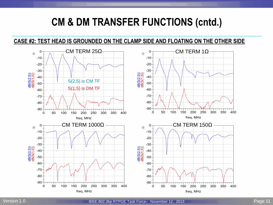
CM & DM TRANSFER FUNCTIONS (cntd.)
CASE #2: TEST HEAD IS GROUNDED ON THE CLAMP SIDE AND FLOATING ON THE OTHER SIDE
CM TERM 25Ω CM TERM 1Ω
CM TERM 1000Ω CM TERM 150Ω
S(2,5) is CM TF
S(1,5) is DM TF
Page 12 IEEE P802.3 Maintenance report – July 2008 Plenary Version 1.0 IEEE 802.3bp RTPGE Task Force– November 12, 2013 Version 1.0 Page 12
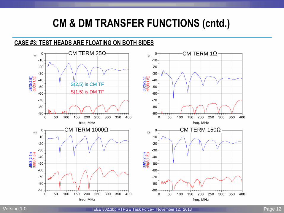
CM & DM TRANSFER FUNCTIONS (cntd.)
CASE #3: TEST HEADS ARE FLOATING ON BOTH SIDES
CM TERM 25Ω CM TERM 1Ω
CM TERM 1000Ω CM TERM 150Ω
S(2,5) is CM TF
S(1,5) is DM TF
Page 13 IEEE P802.3 Maintenance report – July 2008 Plenary Version 1.0 IEEE 802.3bp RTPGE Task Force– November 12, 2013 Version 1.0 Page 13
0 50 100 150 200 250 300 350 400-10
-9.5
-9
-8.5
-8
-7.5
-7
-6.5
-6
-5.5
-5
Frequency, MHz
dB
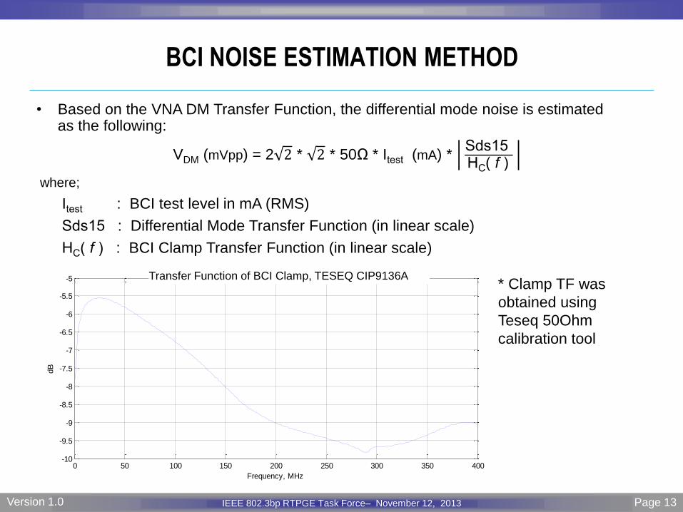
Transfer Function of BCI Clamp, TESEQ CIP9136A
BCI NOISE ESTIMATION METHOD
• Based on the VNA DM Transfer Function, the differential mode noise is estimated as the following:
VDM (mVpp) = 2 2 * 2 * 50Ω * Itest (mA) * Sds15 HC( f )
where;
Itest : BCI test level in mA (RMS)
Sds15 : Differential Mode Transfer Function (in linear scale)
HC( f ) : BCI Clamp Transfer Function (in linear scale)
* Clamp TF was
obtained using
Teseq 50Ohm
calibration tool

Page 14 IEEE P802.3 Maintenance report – July 2008 Plenary Version 1.0 IEEE 802.3bp RTPGE Task Force– November 12, 2013 Version 1.0 Page 14
DIFFERENTIAL NOISE FOR Itest = 200mA (RMS) & ZCM = 1Ω
0 50 100 150 200 250 300 350 4000
20
40
60
80
100
120
140
160
180
200
Frequency, MHz
DM
Nois
e,
mV
pp
Ground -Ground
Ground - Float
Float - Float
• DM noise shown above are for three grounding options of test heads
Page 15 IEEE P802.3 Maintenance report – July 2008 Plenary Version 1.0 IEEE 802.3bp RTPGE Task Force– November 12, 2013 Version 1.0 Page 15
0 50 100 150 200 250 300 350 4000
20
40
60
80
100
120
140
160
180
200
Frequency, MHz
DM
Nois
e,
mV
pp
Ground -Ground
Ground - Float
Float - Float
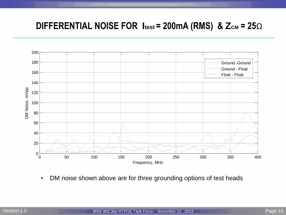
DIFFERENTIAL NOISE FOR Itest = 200mA (RMS) & ZCM = 25Ω
• DM noise shown above are for three grounding options of test heads
Page 16 IEEE P802.3 Maintenance report – July 2008 Plenary Version 1.0 IEEE 802.3bp RTPGE Task Force– November 12, 2013 Version 1.0 Page 16
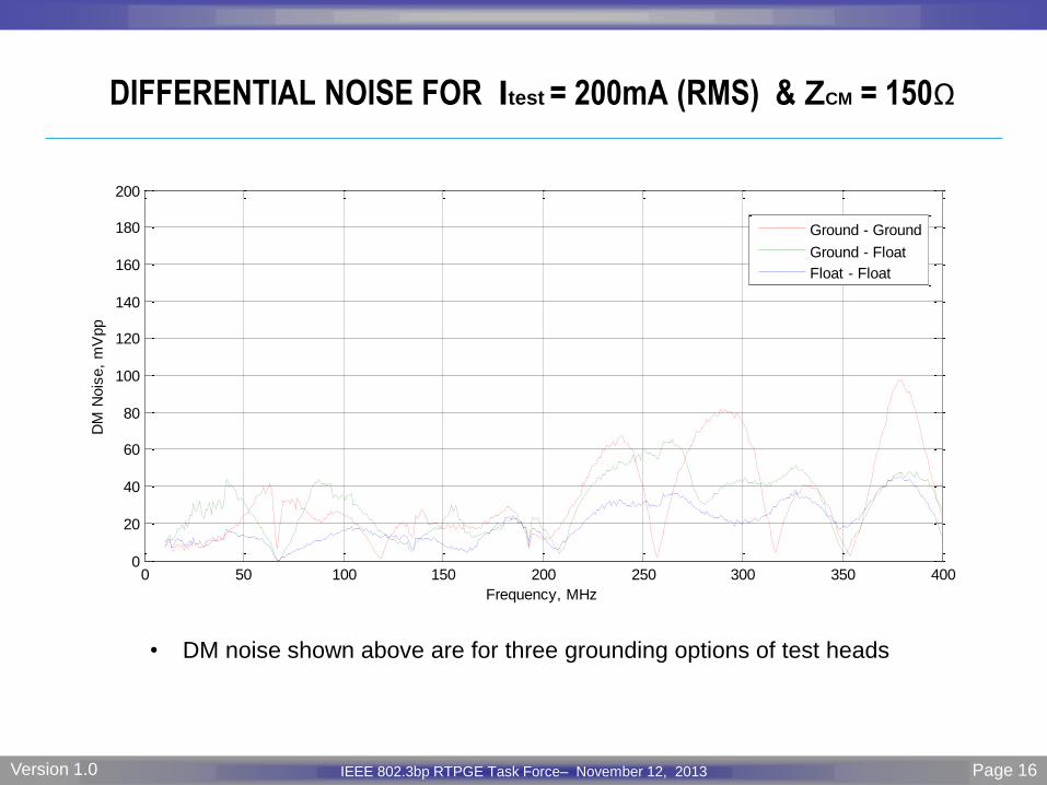
DIFFERENTIAL NOISE FOR Itest = 200mA (RMS) & ZCM = 150Ω
0 50 100 150 200 250 300 350 4000
20
40
60
80
100
120
140
160
180
200
Frequency, MHz
DM
Nois
e,
mV
pp
Ground - Ground
Ground - Float
Float - Float
• DM noise shown above are for three grounding options of test heads
Page 17 IEEE P802.3 Maintenance report – July 2008 Plenary Version 1.0 IEEE 802.3bp RTPGE Task Force– November 12, 2013 Version 1.0 Page 17
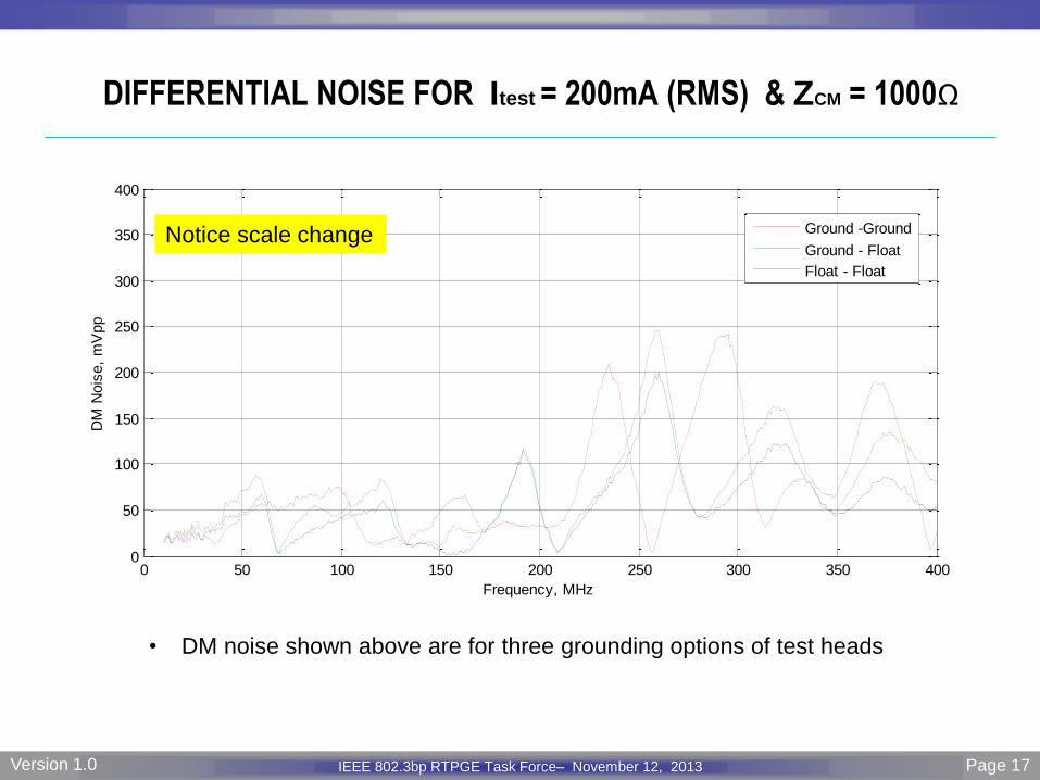
DIFFERENTIAL NOISE FOR Itest = 200mA (RMS) & ZCM = 1000Ω
• DM noise shown above are for three grounding options of test heads
0 50 100 150 200 250 300 350 4000
50
100
150
200
250
300
350
400
Frequency, MHz
DM
Nois
e,
mV
pp
Ground -Ground
Ground - Float
Float - Float
Notice scale change
Page 18 IEEE P802.3 Maintenance report – July 2008 Plenary Version 1.0 IEEE 802.3bp RTPGE Task Force– November 12, 2013 Version 1.0 Page 18
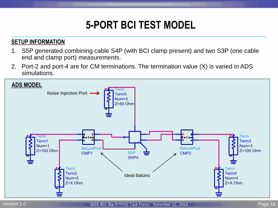
SETUP INFORMATION
1. S5P generated combining cable S4P (with BCI clamp present) and two S3P (one cable end and clamp port) measurements.
2. Port-2 and port-4 are for CM terminations. The termination value (X) is varied in ADS simulations.
5-PORT BCI TEST MODEL
Noise Injection Port
ADS MODEL
Ideal Baluns

Page 19 IEEE P802.3 Maintenance report – July 2008 Plenary Version 1.0 IEEE 802.3bp RTPGE Task Force– November 12, 2013 Version 1.0 Page 19
DIFFERENTIAL NOISE FOR Itest = 200mA (RMS) and VARIOUS CM
TERMINATIONS ON BOTH SIDES OF THE CABLE
• CM termination is applied on both grounded sides.
• To avoid high noise levels, CM termination should not be too high or too low.
• The results suggest a CM termination between 25 and 300 Ohms.
0 50 100 150 200 250 300 350 4000
50
100
150
200
250
300
Frequency, MHz
DM
Nois
e,
mV
pp
CM Term 1 Ohm
CM Term 25 Ohms
CM Term 75 Ohms
CM Term 150 Ohms
CM Term 300 Ohms
CM Term 1000 Ohms
CM Term 2000 Ohms
Notice low noise levels when
ZCM is between 25Ω and 300Ω
Page 20 IEEE P802.3 Maintenance report – July 2008 Plenary Version 1.0 IEEE 802.3bp RTPGE Task Force– November 12, 2013 Version 1.0 Page 20
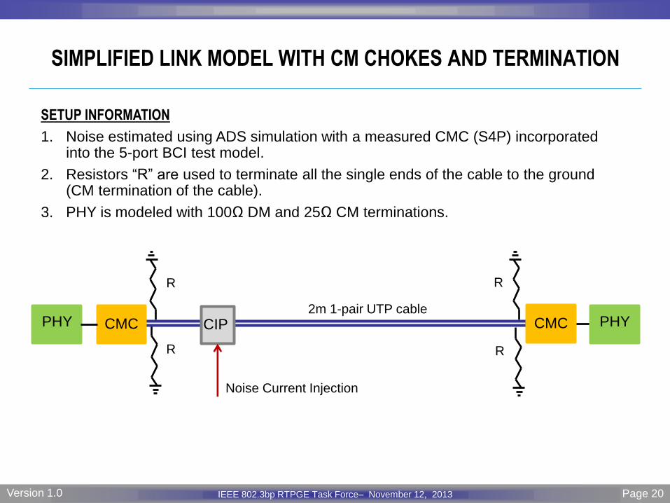
SIMPLIFIED LINK MODEL WITH CM CHOKES AND TERMINATION
SETUP INFORMATION
1. Noise estimated using ADS simulation with a measured CMC (S4P) incorporated into the 5-port BCI test model.
2. Resistors “R” are used to terminate all the single ends of the cable to the ground (CM termination of the cable).
3. PHY is modeled with 100Ω DM and 25Ω CM terminations.
PHY CIP CMC CMC
Noise Current Injection
R
R R
R
2m 1-pair UTP cable PHY
Page 21 IEEE P802.3 Maintenance report – July 2008 Plenary Version 1.0 IEEE 802.3bp RTPGE Task Force– November 12, 2013 Version 1.0 Page 21
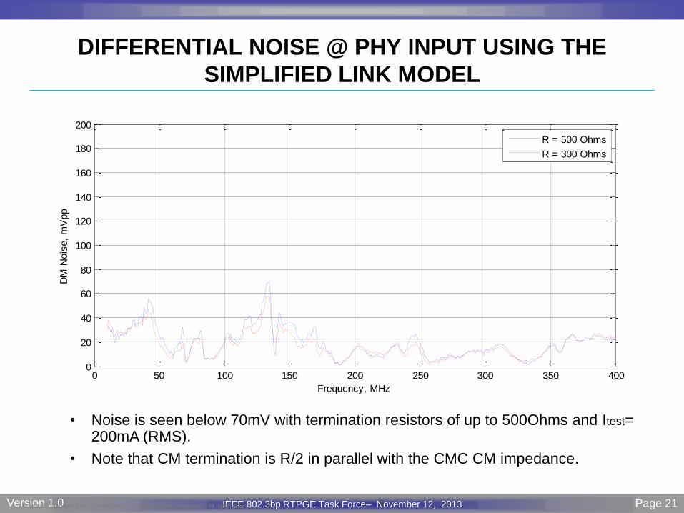
DIFFERENTIAL NOISE @ PHY INPUT USING THE
SIMPLIFIED LINK MODEL
Broadcom Proprietary and Confidential. © 2012 Broadcom Corporation. All rights reserved.
0 50 100 150 200 250 300 350 4000
20
40
60
80
100
120
140
160
180
200
Frequency, MHz
DM
Nois
e,
mV
pp
R = 500 Ohms
R = 300 Ohms
• Noise is seen below 70mV with termination resistors of up to 500Ohms and Itest= 200mA (RMS).
• Note that CM termination is R/2 in parallel with the CMC CM impedance.
Page 22 IEEE P802.3 Maintenance report – July 2008 Plenary Version 1.0 IEEE 802.3bp RTPGE Task Force– November 12, 2013 Version 1.0 Page 22
CONCLUSIONS
• Grounding Effects for the Test Heads
– Comparing noise results for grounded and floating test heads, show lower noise for
floating case. Notice that when test heads are floating, connection to ground plane is
established through VNA 3rd port that is connected to BCI clamp. The BCI clamp
ground is connected to the brass ground plane.
• CM Termination Effect
– As expected, a proper choice of CM termination helps limiting the input differential
noise.
• BCI Noise Results
– With BCI test current of 200mA (RMS), noise is seen below 100mVpp when proper
CM termination is used.
– At 100mA test level, the noise is scaled down below 50mVpp.
Related Documents