RTA-OS RCarX3A5X/ARM Port Guide

Welcome message from author
This document is posted to help you gain knowledge. Please leave a comment to let me know what you think about it! Share it to your friends and learn new things together.
Transcript

RTA-OSRCarX3A5X/ARM Port Guide
Copyright
The data in this document may not be altered or amended without specialnotification from ETAS GmbH. ETAS GmbH undertakes no further obligationin relation to this document. The software described in it can only be usedif the customer is in possession of a general license agreement or single li-cense. Using and copying is only allowed in concurrence with the specifica-tions stipulated in the contract. Under no circumstances may any part of thisdocument be copied, reproduced, transmitted, stored in a retrieval system ortranslated into another language without the express written permission ofETAS GmbH.
©Copyright 2008-2018 ETAS GmbH, Stuttgart.
The names and designations used in this document are trademarks or brandsbelonging to the respective owners.
Document: 10734-PG-5.0.0 EN-06-2018
2 Copyright

Safety Notice
This ETAS product fulfills standard quality management requirements. If re-quirements of specific safety standards (e.g. IEC 61508, ISO 26262) need tobe fulfilled, these requirements must be explicitly defined and ordered by thecustomer. Before use of the product, customer must verify the compliancewith specific safety standards.
Safety Notice 3
Contents
1 Introduction 71.1 About You . . . . . . . . . . . . . . . . . . . . . . . . . . . . . . . . . . 81.2 Document Conventions . . . . . . . . . . . . . . . . . . . . . . . . 81.3 References . . . . . . . . . . . . . . . . . . . . . . . . . . . . . . . . . 9
2 Installing the RTA-OS Port Plug-in 102.1 Preparing to Install . . . . . . . . . . . . . . . . . . . . . . . . . . . . 10
2.1.1 Hardware Requirements . . . . . . . . . . . . . . . . 102.1.2 Software Requirements . . . . . . . . . . . . . . . . . 10
2.2 Installation . . . . . . . . . . . . . . . . . . . . . . . . . . . . . . . . . 112.2.1 Installation Directory . . . . . . . . . . . . . . . . . . . 11
2.3 Licensing . . . . . . . . . . . . . . . . . . . . . . . . . . . . . . . . . . . 122.3.1 Installing the ETAS License Manager . . . . . . . . 122.3.2 Licenses . . . . . . . . . . . . . . . . . . . . . . . . . . . . 132.3.3 Installing a Concurrent License Server . . . . . . 142.3.4 Using the ETAS License Manager . . . . . . . . . . 152.3.5 Troubleshooting Licenses . . . . . . . . . . . . . . . . 18
3 Verifying your Installation 213.1 Checking the Port . . . . . . . . . . . . . . . . . . . . . . . . . . . . 213.2 Running the Sample Applications . . . . . . . . . . . . . . . . . 21
4 Port Characteristics 234.1 Parameters of Implementation . . . . . . . . . . . . . . . . . . . 234.2 Configuration Parameters . . . . . . . . . . . . . . . . . . . . . . . 23
4.2.1 Stack used for C-startup . . . . . . . . . . . . . . . . 234.2.2 Stack used when idle . . . . . . . . . . . . . . . . . . . 244.2.3 Stack overheads for ISR activation . . . . . . . . . 244.2.4 Stack overheads for ECC tasks . . . . . . . . . . . . 244.2.5 Stack overheads for ISR . . . . . . . . . . . . . . . . . 254.2.6 ORTI/Lauterbach . . . . . . . . . . . . . . . . . . . . . . 254.2.7 ORTI Stack Fill . . . . . . . . . . . . . . . . . . . . . . . . 254.2.8 Enable stack repositioning . . . . . . . . . . . . . . . 254.2.9 Enable untrusted stack check . . . . . . . . . . . . . 264.2.10 CrossCore SGI0 . . . . . . . . . . . . . . . . . . . . . . . 264.2.11 CrossCore SGI1 . . . . . . . . . . . . . . . . . . . . . . . 264.2.12 CrossCore SGI2 . . . . . . . . . . . . . . . . . . . . . . . 274.2.13 CrossCore SGI3 . . . . . . . . . . . . . . . . . . . . . . . 274.2.14 Set floating-point mode . . . . . . . . . . . . . . . . . 274.2.15 Block default interrupt . . . . . . . . . . . . . . . . . . 284.2.16 GetAbortStack always . . . . . . . . . . . . . . . . . . 284.2.17 Set interrupt priority range . . . . . . . . . . . . . . . 284.2.18 Read CoreID from GIC . . . . . . . . . . . . . . . . . . 29
4.3 Generated Files . . . . . . . . . . . . . . . . . . . . . . . . . . . . . . 29
4 Contents

5 Port-Specific API 315.1 API Calls . . . . . . . . . . . . . . . . . . . . . . . . . . . . . . . . . . . 31
5.1.1 Os_InitializeGICGroup . . . . . . . . . . . . . . . . . . 315.1.2 Os_InitializeVectorTable . . . . . . . . . . . . . . . . . 31
5.2 Callbacks . . . . . . . . . . . . . . . . . . . . . . . . . . . . . . . . . . 325.2.1 Os_Cbk_GetAbortStack . . . . . . . . . . . . . . . . . 325.2.2 Os_Cbk_StartCore . . . . . . . . . . . . . . . . . . . . . 335.2.3 Os_Cbk_StopCore . . . . . . . . . . . . . . . . . . . . . 35
5.3 Macros . . . . . . . . . . . . . . . . . . . . . . . . . . . . . . . . . . . . 365.3.1 CAT1_ISR . . . . . . . . . . . . . . . . . . . . . . . . . . . 365.3.2 Os_Clear_x . . . . . . . . . . . . . . . . . . . . . . . . . . 375.3.3 Os_DisableAllConfiguredInterrupts_CPUx . . . . . 375.3.4 Os_Disable_x . . . . . . . . . . . . . . . . . . . . . . . . 375.3.5 Os_EnableAllConfiguredInterrupts_CPUx . . . . . 385.3.6 Os_Enable_x . . . . . . . . . . . . . . . . . . . . . . . . . 385.3.7 Os_IntChannel_x . . . . . . . . . . . . . . . . . . . . . . 385.3.8 Os_Set_Edge_Triggered_x . . . . . . . . . . . . . . . 395.3.9 Os_Set_Level_Sensitive_x . . . . . . . . . . . . . . . . 39
5.4 Type Definitions . . . . . . . . . . . . . . . . . . . . . . . . . . . . . . 395.4.1 Os_StackSizeType . . . . . . . . . . . . . . . . . . . . . 395.4.2 Os_StackValueType . . . . . . . . . . . . . . . . . . . . 40
6 Toolchain 416.1 Compiler Versions . . . . . . . . . . . . . . . . . . . . . . . . . . . . 41
6.1.1 ARM DS-5 Ultimate Edition: ARM Compiler 6.6 . 416.2 Options used to generate this guide . . . . . . . . . . . . . . . 42
6.2.1 Compiler . . . . . . . . . . . . . . . . . . . . . . . . . . . . 426.2.2 Assembler . . . . . . . . . . . . . . . . . . . . . . . . . . 436.2.3 Librarian . . . . . . . . . . . . . . . . . . . . . . . . . . . . 446.2.4 Linker . . . . . . . . . . . . . . . . . . . . . . . . . . . . . . 446.2.5 Debugger . . . . . . . . . . . . . . . . . . . . . . . . . . . 45
Contents 5
7 Hardware 477.1 Supported Devices . . . . . . . . . . . . . . . . . . . . . . . . . . . . 477.2 Register Usage . . . . . . . . . . . . . . . . . . . . . . . . . . . . . . 47
7.2.1 Initialization . . . . . . . . . . . . . . . . . . . . . . . . . 477.2.2 Modification . . . . . . . . . . . . . . . . . . . . . . . . . 48
7.3 Interrupts . . . . . . . . . . . . . . . . . . . . . . . . . . . . . . . . . . 497.3.1 Interrupt Priority Levels . . . . . . . . . . . . . . . . . 497.3.2 Allocation of ISRs to Interrupt Vectors . . . . . . . 507.3.3 Vector Table . . . . . . . . . . . . . . . . . . . . . . . . . 517.3.4 Writing Category 1 Interrupt Handlers . . . . . . . 527.3.5 Writing Category 2 Interrupt Handlers . . . . . . . 527.3.6 Default Interrupt . . . . . . . . . . . . . . . . . . . . . . 53
7.4 Memory Model . . . . . . . . . . . . . . . . . . . . . . . . . . . . . . . 537.5 Processor Modes . . . . . . . . . . . . . . . . . . . . . . . . . . . . . 537.6 Stack Handling . . . . . . . . . . . . . . . . . . . . . . . . . . . . . . 547.7 Processor state when calling StartOS() . . . . . . . . . . . . . 54
8 Performance 558.1 Measurement Environment . . . . . . . . . . . . . . . . . . . . . . 558.2 RAM and ROM Usage for OS Objects . . . . . . . . . . . . . . . 55
8.2.1 Single Core . . . . . . . . . . . . . . . . . . . . . . . . . . 568.2.2 Multi Core . . . . . . . . . . . . . . . . . . . . . . . . . . . 56
8.3 Stack Usage . . . . . . . . . . . . . . . . . . . . . . . . . . . . . . . . 568.4 Library Module Sizes . . . . . . . . . . . . . . . . . . . . . . . . . . 57
8.4.1 Single Core . . . . . . . . . . . . . . . . . . . . . . . . . . 578.4.2 Multi Core . . . . . . . . . . . . . . . . . . . . . . . . . . . 59
8.5 Execution Time . . . . . . . . . . . . . . . . . . . . . . . . . . . . . . 628.5.1 Context Switching Time . . . . . . . . . . . . . . . . . 63
9 Finding Out More 66
10 Contacting ETAS 6710.1 Technical Support . . . . . . . . . . . . . . . . . . . . . . . . . . . . 6710.2 General Enquiries . . . . . . . . . . . . . . . . . . . . . . . . . . . . 67
10.2.1 ETAS Global Headquarters . . . . . . . . . . . . . . . 6710.2.2 ETAS Local Sales & Support Offices . . . . . . . . . 67
6 Contents
1 Introduction
RTA-OS is a small and fast real-time operating system that conforms to boththe AUTOSAR OS (R3.0.1 -> R3.0.7, R3.1.1 -> R3.1.5, R3.2.1 -> R3.2.2, R4.0.1-> R4.3.1) and OSEK/VDX 2.2.3 standards (OSEK is now standardized in ISO17356). The operating system is configured and built on a PC, but runs onyour target hardware.
This document describes the RTA-OS RCarX3A5X/ARM port plug-in that cus-tomizes the RTA-OS development tools for the Renesas R-Car x3 Cortex-A5xwith the ARM_DS_5_V6 compiler. It supplements the more general informa-tion you can find in the User Guide and the Reference Guide.
The document has two parts. Chapters 2 to 3 help you understand theRCarX3A5X/ARM port and cover:
• how to install the RCarX3A5X/ARM port plug-in;
• how to configure RCarX3A5X/ARM-specific attributes;
• how to build an example application to check that the RCarX3A5X/ARMport plug-in works.
Chapters 4 to 8 provide reference information including:
• the number of OS objects supported;
• required and recommended toolchain parameters;
• how RTA-OS interacts with the R-Car x3 Cortex-A5x, including requiredregister settings, memory models and interrupt handling;
• memory consumption for each OS object;
• memory consumption of each API call;
• execution times for each API call.
For the best experience with RTA-OS it is essential that you read and under-stand this document.
Introduction 7

1.1 About You
You are a trained embedded systems developer who wants to build real-timeapplications using a preemptive operating system. You should have knowl-edge of the C programming language, including the compilation, assemblingand linking of C code for embedded applications with your chosen toolchain.Elementary knowledge about your target microcontroller, such as the startaddress, memory layout, location of peripherals and so on, is essential.
You should also be familiar with common use of the Microsoft Windows op-erating system, including installing software, selecting menu items, clickingbuttons, navigating files and folders.
1.2 Document Conventions
The following conventions are used in this guide:
Choose File > Open. Menu options appear in bold, blue characters.
Click OK. Button labels appear in bold characters
Press <Enter>. Key commands are enclosed in angle brackets.
The “Open file” dialogbox appears
GUI element names, for example window titles,fields, etc. are enclosed in double quotes.
Activate(Task1) Program code, header file names, C type names,C functions and API call names all appear in amonospaced typeface.
See Section 1.2. Internal document hyperlinks are shown in blueletters.
Functionality in RTA-OS that might not be portableto other implementations of AUTOSAR OS ismarked with the RTA-OS icon.
Important instructions that you must follow care-fully to ensure RTA-OS works as expected aremarked with a caution sign.
8 Introduction
1.3 References
OSEK is a European automotive industry standards effort to produce opensystems interfaces for vehicle electronics. OSEK is now standardized in ISO17356. For details of the OSEK standards, please refer to:
http://www.osek-vdx.org
AUTOSAR (AUTomotive Open System ARchitecture) is an open and standard-ized automotive software architecture, jointly developed by automobile man-ufacturers, suppliers and tool developers. For details of the AUTOSAR stan-dards, please refer to:
http://www.autosar.org
Introduction 9

2 Installing the RTA-OS Port Plug-in
2.1 Preparing to Install
RTA-OS port plug-ins are supplied as a downloadable electronic installationimage which you obtain from the ETAS Web Portal. You will have been pro-vided with access to the download when you bought the port. You may op-tionally have requested an installation CD which will have been shipped toyou. In either case, the electronic image and the installation CD contain iden-tical content.
Integration Guidance 2.1:You must have installed the RTA-OS tools be-fore installing the RCarX3A5X/ARM port plug-in. If you have not yet donethis then please follow the instructions in the Getting Started Guide.
2.1.1 Hardware Requirements
You should make sure that you are using at least the following hardware be-fore installing and using RTA-OS on a host PC:
• 1GHz Pentium Windows-capable PC.
• 2G RAM.
• 20G hard disk space.
• CD-ROM or DVD drive (Optional)
• Ethernet card.
2.1.2 Software Requirements
RTA-OS requires that your host PC has one of the following versions of Mi-crosoft Windows installed:
• Windows 7
• Windows 8
• Windows 10
Integration Guidance 2.2:The tools provided with RTA-OS requireMicrosoft’s .NET Framework v2.0 (included as part of .NET Frame-work v3.5) and v4.0 to be installed. You should ensure that thesehave been installed before installing RTA-OS. The .NET frameworkis not supplied with RTA-OS but is freely available from https://www.microsoft.com/net/download. To install .NET 3.5 on Win-dows 10 see https://docs.microsoft.com/en-us/dotnet/framework/install/dotnet-35-windows-10.The migration of the code from v2.0 to v4.0 will occur over a period of timefor performance and maintenance reasons.
10 Installing the RTA-OS Port Plug-in

2.2 Installation
Target port plug-ins are installed in the same way as the tools:
1. Either
• Double click the executable image; or
• Insert the RTA-OS RCarX3A5X/ARM CD into your CD-ROM or DVDdrive.
If the installation program does not run automatically then you willneed to start the installation manually. Navigate to the root direc-tory of your CD/DVD drive and double click autostart.exe to startthe setup.
2. Follow the on-screen instructions to install the RCarX3A5X/ARM portplug-in.
By default, ports are installed into C:\ETAS\RTA-OS\Targets. During theinstallation process, you will be given the option to change the folder to whichRTA-OS ports are installed. You will normally want to ensure that you installthe port plug-in in the same location that you have installed the RTA-OS tools.You can install different versions of the tools/targets into different directoriesand they will not interfere with each other.
Integration Guidance 2.3:Port plug-ins can be installed into anylocation, but using a non-default directory requires the use of the--target_include argument to both rtaosgen and rtaoscfg. For ex-ample:
rtaosgen --target_include:<target_directory>
2.2.1 Installation Directory
The installation will create a sub-directory under Targets with the nameRCarX3A5XARM_5.0.0. This contains everything to do with the port plug-in.
Each version of the port installs in its own directory - the trailing _5.0.0 is theport’s version identifier. You can have multiple different versions of the sameport installed at the same time and select a specific version in a project’sconfiguration.
The port directory contains:
RCarX3A5XARM.dll - the port plug-in that is used by rtaosgen andrtaoscfg.
Installing the RTA-OS Port Plug-in 11

RTA-OS RCarX3A5XARM Port Guide.pdf - the documentation for the port(the document you are reading now).
RTA-OS RCarX3A5XARM Release Note.pdf - the release note for theport. This document provides information about the port plug-in re-lease, including a list of changes from previous releases and a list ofknown limitations.
There may be other port-specific documentation supplied which you can alsofind in the root directory of the port installation. All user documentation isdistributed in PDF format which can be read using Adobe Acrobat Reader.Adobe Acrobat Reader is not supplied with RTA-OS but is freely available fromhttp://www.adobe.com.
2.3 Licensing
RTA-OS is protected by FLEXnet licensing technology. You will need a validlicense key in order to use RTA-OS.
Licenses for the product are managed using the ETAS License Managerwhich keeps track of which licenses are installed and where to find them.The information about which features are required for RTA-OS and any portplug-ins is stored as license signature files that are stored in the folder<install_folder>\bin\Licenses.
The ETAS License Manager can also tell you key information about your li-censes including:
• Which ETAS products are installed
• Which license features are required to use each product
• Which licenses are installed
• When licenses expire
• Whether you are using a local or a server-based license
Figure 2.1 shows the ETAS License Manager in operation.
2.3.1 Installing the ETAS License Manager
Integration Guidance 2.4:The ETAS License Manager must be installedfor RTA-OS to work. It is highly recommended that you install the ETASLicense Manager during your installation of RTA-OS.
The installer for the ETAS License Manager contains two components:
1. the ETAS License Manager itself;
12 Installing the RTA-OS Port Plug-in
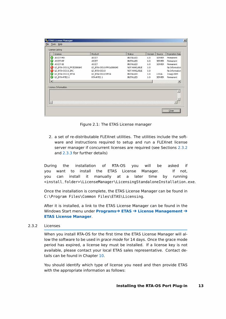
Figure 2.1: The ETAS License manager
2. a set of re-distributable FLEXnet utilities. The utilities include the soft-ware and instructions required to setup and run a FLEXnet licenseserver manager if concurrent licenses are required (see Sections 2.3.2and 2.3.3 for further details)
During the installation of RTA-OS you will be asked ifyou want to install the ETAS License Manager. If not,you can install it manually at a later time by running<install_folder>\LicenseManager\LicensingStandaloneInstallation.exe.
Once the installation is complete, the ETAS License Manager can be found inC:\Program Files\Common Files\ETAS\Licensing.
After it is installed, a link to the ETAS License Manager can be found in theWindows Start menu under ProgramsÔ ETAS Ô License Management Ô
ETAS License Manager.
2.3.2 Licenses
When you install RTA-OS for the first time the ETAS License Manager will al-low the software to be used in grace mode for 14 days. Once the grace modeperiod has expired, a license key must be installed. If a license key is notavailable, please contact your local ETAS sales representative. Contact de-tails can be found in Chapter 10.
You should identify which type of license you need and then provide ETASwith the appropriate information as follows:
Installing the RTA-OS Port Plug-in 13
Machine-named licenses allows RTA-OS to be used by any user loggedonto the PC on which RTA-OS and the machine-named license is in-stalled.
A machine-named license can be issued by ETAS when you provide thehost ID (Ethernet MAC address) of the host PC
User-named licenses allow the named user (or users) to use RTA-OS onany PC in the network domain.
A user-named license can be issued by ETAS when you provide the Win-dows user-name for your network domain.
Concurrent licenses allow any user on any PC up to a specified number ofusers to use RTA-OS. Concurrent licenses are sometimes called floatinglicenses because the license can float between users.
A concurrent license can be issued by ETAS when you provide the fol-lowing information:
1. The name of the server
2. The Host ID (MAC address) of the server.
3. The TCP/IP port over which your FLEXnet license server will servelicenses. A default installation of the FLEXnet license server usesport 27000.
You can use the ETAS License Manager to get the details that you must pro-vide to ETAS when requesting a machine-named or user-named license and(optionally) store this information in a text file.
Open the ETAS License Manager and choose Tools Ô Obtain License Infofrom the menu. For machine-named licenses you can then select the networkadaptor which provides the Host ID (MAC address) that you want to use asshown in Figure 2.2. For a user-based license, the ETAS License Managerautomatically identifies the Windows username for the current user.
Selecting “Get License Info” tells you the Host ID and User information andlets you save this as a text file to a location of your choice.
2.3.3 Installing a Concurrent License Server
Concurrent licenses are allocated to client PCs by a FLEXnet license servermanager working together with a vendor daemon. The vendor daemon forETAS is called ETAS.exe. A copy of the vendor daemon is placed on diskwhen you install the ETAS License Manager and can be found in:
C:\Program Files\Common Files\ETAS\Licensing\Utility
14 Installing the RTA-OS Port Plug-in
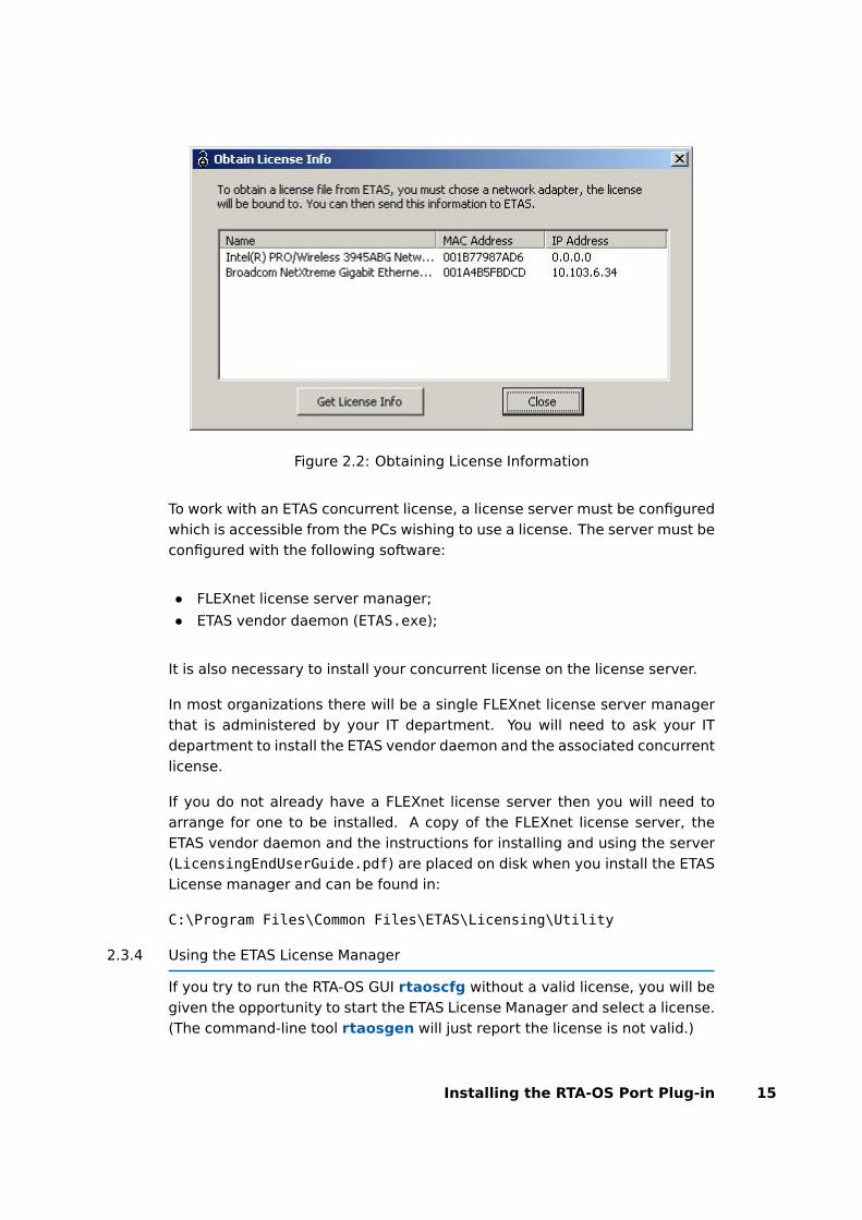
Figure 2.2: Obtaining License Information
To work with an ETAS concurrent license, a license server must be configuredwhich is accessible from the PCs wishing to use a license. The server must beconfigured with the following software:
• FLEXnet license server manager;
• ETAS vendor daemon (ETAS.exe);
It is also necessary to install your concurrent license on the license server.
In most organizations there will be a single FLEXnet license server managerthat is administered by your IT department. You will need to ask your ITdepartment to install the ETAS vendor daemon and the associated concurrentlicense.
If you do not already have a FLEXnet license server then you will need toarrange for one to be installed. A copy of the FLEXnet license server, theETAS vendor daemon and the instructions for installing and using the server(LicensingEndUserGuide.pdf) are placed on disk when you install the ETASLicense manager and can be found in:
C:\Program Files\Common Files\ETAS\Licensing\Utility
2.3.4 Using the ETAS License Manager
If you try to run the RTA-OS GUI rtaoscfg without a valid license, you will begiven the opportunity to start the ETAS License Manager and select a license.(The command-line tool rtaosgen will just report the license is not valid.)
Installing the RTA-OS Port Plug-in 15
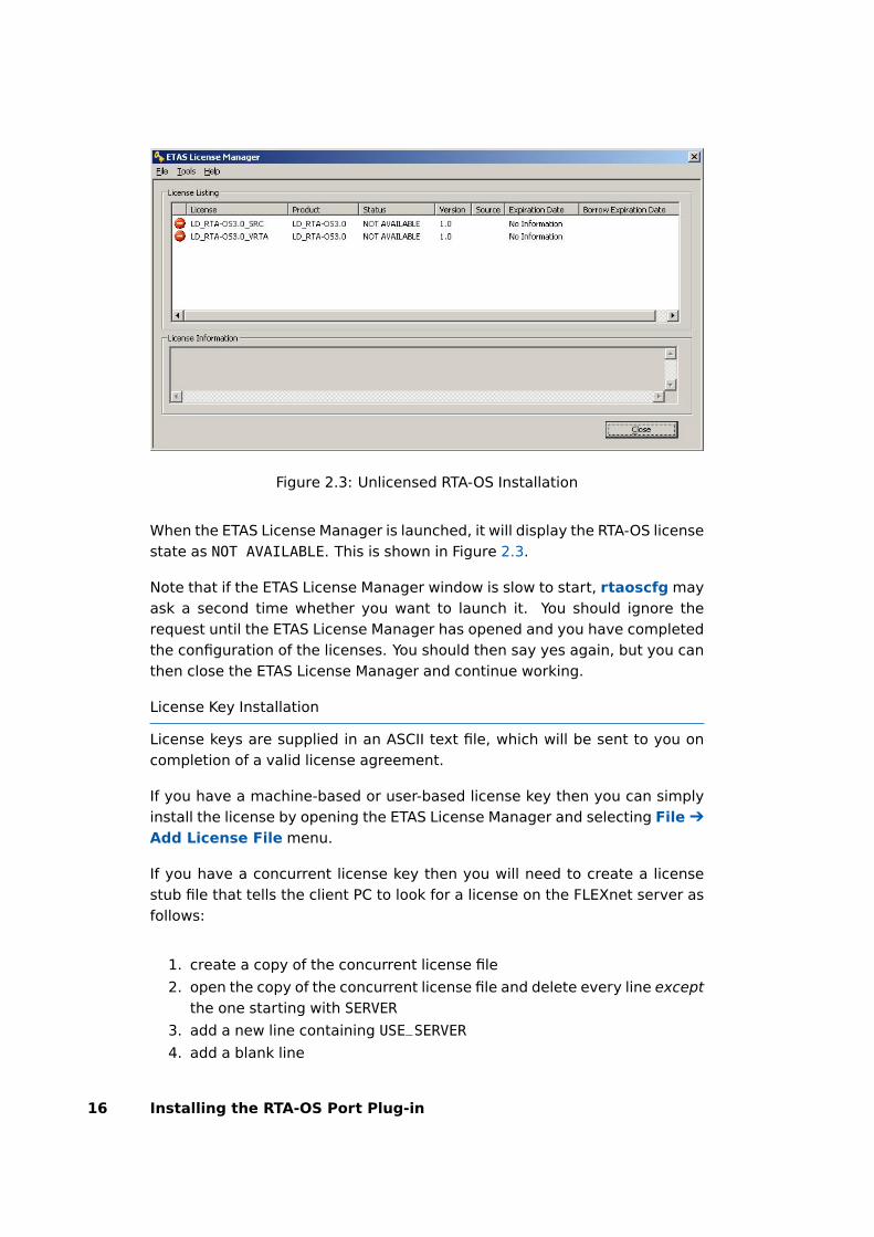
Figure 2.3: Unlicensed RTA-OS Installation
When the ETAS License Manager is launched, it will display the RTA-OS licensestate as NOT AVAILABLE. This is shown in Figure 2.3.
Note that if the ETAS License Manager window is slow to start, rtaoscfg mayask a second time whether you want to launch it. You should ignore therequest until the ETAS License Manager has opened and you have completedthe configuration of the licenses. You should then say yes again, but you canthen close the ETAS License Manager and continue working.
License Key Installation
License keys are supplied in an ASCII text file, which will be sent to you oncompletion of a valid license agreement.
If you have a machine-based or user-based license key then you can simplyinstall the license by opening the ETAS License Manager and selecting File Ô
Add License File menu.
If you have a concurrent license key then you will need to create a licensestub file that tells the client PC to look for a license on the FLEXnet server asfollows:
1. create a copy of the concurrent license file
2. open the copy of the concurrent license file and delete every line exceptthe one starting with SERVER
3. add a new line containing USE_SERVER
4. add a blank line
16 Installing the RTA-OS Port Plug-in

Figure 2.4: Licensed features for RTA-OS
5. save the file
The file you create should look something like this:
SERVER <server name> <MAC address> <TCP/IP Port>¶USE_SERVER¶¶
Once you have create the license stub file you can install the license by open-ing the ETAS License Manager and selecting File Ô Add License File menuand choosing the license stub file.
License Key Status
When a valid license has been installed, the ETAS License Manager will dis-play the license version, status, expiration date and source as shown in Fig-ure 2.4.
Borrowing a concurrent license
If you use a concurrent license and need to use RTA-OS on a PC that will bedisconnected from the network (for example, you take a demonstration toa customer site), then the concurrent license will not be valid once you aredisconnected.
To address this problem, the ETAS License Manager allows you to temporarilyborrow a license from the license server.
To borrow a license:
Installing the RTA-OS Port Plug-in 17

1. Right click on the license feature you need to borrow.
2. Select “Borrow License”
3. From the calendar, choose the date that the borrowed license shouldexpire.
4. Click “OK”
The license will automatically expire when the borrow date elapses. A bor-rowed license can also be returned before this date. To return a license:
1. Reconnect to the network;
2. Right-click on the license feature you have borrowed;
3. Select “Return License”.
2.3.5 Troubleshooting Licenses
RTA-OS tools will report an error if you try to use a feature for which a correctlicense key cannot be found. If you think that you should have a licensefor a feature but the RTA-OS tools appear not to work, then the followingtroubleshooting steps should be followed before contacting ETAS:
Can the ETAS License Manager see the license?
The ETAS License Manager must be able to see a valid license key foreach product or product feature you are trying to use.
You can check what the ETAS License Manager can see by starting itfrom the Help Ô License Manager. . . menu option in rtaoscfg or di-rectly from the Windows Start Menu - Start Ô ETAS Ô License Man-agement Ô ETAS License Manager.
The ETAS License Manager lists all license features and their status.Valid licenses have status INSTALLED. Invalid licenses have statusNOT AVAILABLE.
Is the license valid?
You may have been provided with a time-limited license (for example,for evaluation purposes) and the license may have expired. You cancheck that the Expiration Date for your licensed features to check thatit has not elapsed using the ETAS License Manager.
If a license is due to expire within the next 30 days, the ETAS Li-cense Manager will use a warning triangle to indicate that you needto get a new license. Figure 2.5 shows that the license featuresLD_RTA-OS3.0_VRTA and LD_RTA-OS3.0_SRC are due to expire.
If your license has elapsed then please contact your local ETAS salesrepresentative to discuss your options.
18 Installing the RTA-OS Port Plug-in
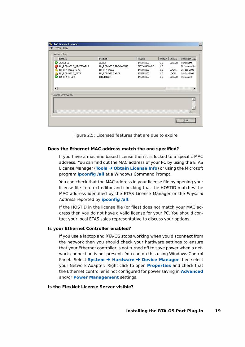
Figure 2.5: Licensed features that are due to expire
Does the Ethernet MAC address match the one specified?
If you have a machine based license then it is locked to a specific MACaddress. You can find out the MAC address of your PC by using the ETASLicense Manager (Tools Ô Obtain License Info) or using the Microsoftprogram ipconfig /all at a Windows Command Prompt.
You can check that the MAC address in your license file by opening yourlicense file in a text editor and checking that the HOSTID matches theMAC address identified by the ETAS License Manager or the PhysicalAddress reported by ipconfig /all.
If the HOSTID in the license file (or files) does not match your MAC ad-dress then you do not have a valid license for your PC. You should con-tact your local ETAS sales representative to discuss your options.
Is your Ethernet Controller enabled?
If you use a laptop and RTA-OS stops working when you disconnect fromthe network then you should check your hardware settings to ensurethat your Ethernet controller is not turned off to save power when a net-work connection is not present. You can do this using Windows ControlPanel. Select System Ô Hardware Ô Device Manager then selectyour Network Adapter. Right click to open Properties and check thatthe Ethernet controller is not configured for power saving in Advancedand/or Power Management settings.
Is the FlexNet License Server visible?
Installing the RTA-OS Port Plug-in 19

If your license is served by a FlexNet license server, then the ETAS Li-cense Manager will report the license as NOT AVAILABLE if the licenseserver cannot be accessed.
You should contact your IT department to check that the server is work-ing correctly.
Still not fixed?
If you have not resolved your issues, after confirming these pointsabove, please contact ETAS technical support. The contact address isprovided in Section 10.1. You must provide the contents and location ofyour license file and your Ethernet MAC address.
20 Installing the RTA-OS Port Plug-in

3 Verifying your Installation
Now that you have installed both the RTA-OS tools and a port plug-in andhave obtained and installed a valid license key you can check that things areworking.
3.1 Checking the Port
The first thing to check is that the RTA-OS tools can see the new port. You cando this in two ways:
1. use the rtaosgen tool
You can run the command rtaosgen −−target:? to get a list of avail-able targets, the versions of each target and the variants supported, forexample:
RTA-OS Code GeneratorVersion p.q.r.s, Copyright © ETAS nnnnAvailable targets:TriCoreHighTec_n.n.n [TC1797...]VRTA_n.n.n [MinGW,VS2005,VS2008,VS2010]
2. use the rtaoscfg tool
The second way to check that the port plug-in can be seen is by start-ing rtaoscfg and selecting Help Ô Information... drop down menu.This will show information about your complete RTA-OS installation andlicense checks that have been performed.
Integration Guidance 3.1:If the target port plug-ins have been installedto a non-default location, then the --target_include argument must beused to specify the target location.
If the tools can see the port then you can move on to the next stage – check-ing that you can build an RTA-OS library and use this in a real program thatwill run on your target hardware.
3.2 Running the Sample Applications
Each RTA-OS port is supplied with a set of sample applications that allow youto check that things are running correctly. To generate the sample applica-tions:
1. Create a new working directory in which to build the sample applica-tions.
2. Open a Windows command prompt in the new directory.
Verifying your Installation 21
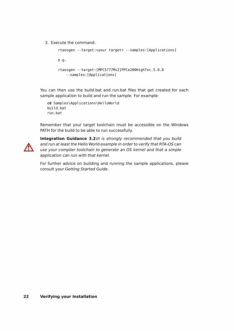
3. Execute the command:
rtaosgen --target:<your target> --samples:[Applications]
e.g.
rtaosgen --target:[MPC5777Mv2]PPCe200HighTec_5.0.8--samples:[Applications]
You can then use the build.bat and run.bat files that get created for eachsample application to build and run the sample. For example:
cd Samples\Applications\HelloWorldbuild.batrun.bat
Remember that your target toolchain must be accessible on the WindowsPATH for the build to be able to run successfully.
Integration Guidance 3.2:It is strongly recommended that you buildand run at least the Hello World example in order to verify that RTA-OS canuse your compiler toolchain to generate an OS kernel and that a simpleapplication can run with that kernel.
For further advice on building and running the sample applications, pleaseconsult your Getting Started Guide.
22 Verifying your Installation
4 Port Characteristics
This chapter tells you about the characteristics of RTA-OS for theRCarX3A5X/ARM port.
4.1 Parameters of Implementation
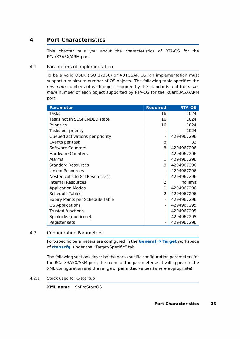
To be a valid OSEK (ISO 17356) or AUTOSAR OS, an implementation mustsupport a minimum number of OS objects. The following table specifies theminimum numbers of each object required by the standards and the maxi-mum number of each object supported by RTA-OS for the RCarX3A5X/ARMport.
Parameter Required RTA-OS
Tasks 16 1024Tasks not in SUSPENDED state 16 1024Priorities 16 1024Tasks per priority - 1024Queued activations per priority - 4294967296Events per task 8 32Software Counters 8 4294967296Hardware Counters - 4294967296Alarms 1 4294967296Standard Resources 8 4294967296Linked Resources - 4294967296Nested calls to GetResource() - 4294967296Internal Resources 2 no limitApplication Modes 1 4294967296Schedule Tables 2 4294967296Expiry Points per Schedule Table - 4294967296OS Applications - 4294967295Trusted functions - 4294967295Spinlocks (multicore) - 4294967295Register sets - 4294967296
4.2 Configuration Parameters
Port-specific parameters are configured in the General Ô Target workspaceof rtaoscfg, under the “Target-Specific” tab.
The following sections describe the port-specific configuration parameters forthe RCarX3A5X/ARM port, the name of the parameter as it will appear in theXML configuration and the range of permitted values (where appropriate).
4.2.1 Stack used for C-startup
XML name SpPreStartOS
Port Characteristics 23
Description
The amount of stack already in use at the point that StartOS() is called. Thisvalue is simply added to the total stack size that the OS needs to support alltasks and interrupts at run-time. Typically you use this to obtain the amountof stack that the linker must allocate. The value does not normally change ifthe OS configuration changes.
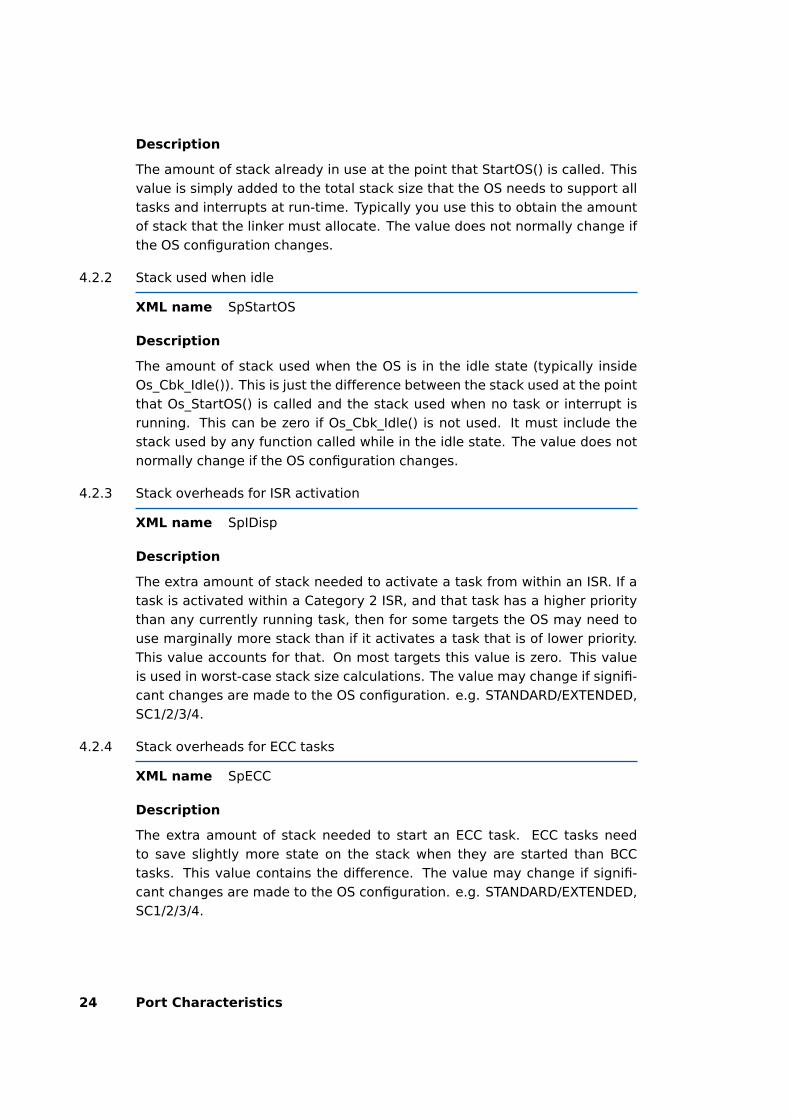
4.2.2 Stack used when idle
XML name SpStartOS
Description
The amount of stack used when the OS is in the idle state (typically insideOs_Cbk_Idle()). This is just the difference between the stack used at the pointthat Os_StartOS() is called and the stack used when no task or interrupt isrunning. This can be zero if Os_Cbk_Idle() is not used. It must include thestack used by any function called while in the idle state. The value does notnormally change if the OS configuration changes.
4.2.3 Stack overheads for ISR activation
XML name SpIDisp
Description
The extra amount of stack needed to activate a task from within an ISR. If atask is activated within a Category 2 ISR, and that task has a higher prioritythan any currently running task, then for some targets the OS may need touse marginally more stack than if it activates a task that is of lower priority.This value accounts for that. On most targets this value is zero. This valueis used in worst-case stack size calculations. The value may change if signifi-cant changes are made to the OS configuration. e.g. STANDARD/EXTENDED,SC1/2/3/4.
4.2.4 Stack overheads for ECC tasks
XML name SpECC
Description
The extra amount of stack needed to start an ECC task. ECC tasks needto save slightly more state on the stack when they are started than BCCtasks. This value contains the difference. The value may change if signifi-cant changes are made to the OS configuration. e.g. STANDARD/EXTENDED,SC1/2/3/4.
24 Port Characteristics

4.2.5 Stack overheads for ISR
XML name SpPreemption
Description
The amount of stack used to service a Category 2 ISR. When a Category 2 ISRinterrupts a task, it usually places some data on the stack. If the ISR measuresthe stack to determine if the preempted task has exceeded its stack budget,then it will overestimate the stack usage unless this value is subtracted fromthe measured size. The value is also used when calculating the worst-casestack usage of the system. Be careful to set this value accurately. If its valueis too high then when the subtraction occurs, 32-bit underflow can occur andcause the OS to think that a budget overrun has been detected. The valuemay change if significant changes are made to the OS configuration. e.g.STANDARD/EXTENDED, SC1/2/3/4.
4.2.6 ORTI/Lauterbach
XML name Orti22Lauterbach
Description
Select ORTI generation for the Lauterbach debugger.
Settings
Value Description
true Generate ORTIfalse No ORTI (default)
4.2.7 ORTI Stack Fill
XML name OrtiStackFill
Description
Expands ORTI information to cover stack address, size and fill pattern detailsto support debugger stack usage monitoring.
Settings
Value Description
true Support ORTI stack trackingfalse ORTI stack tracking unsupported (default)
4.2.8 Enable stack repositioning
XML name AlignUntrustedStacks
Port Characteristics 25
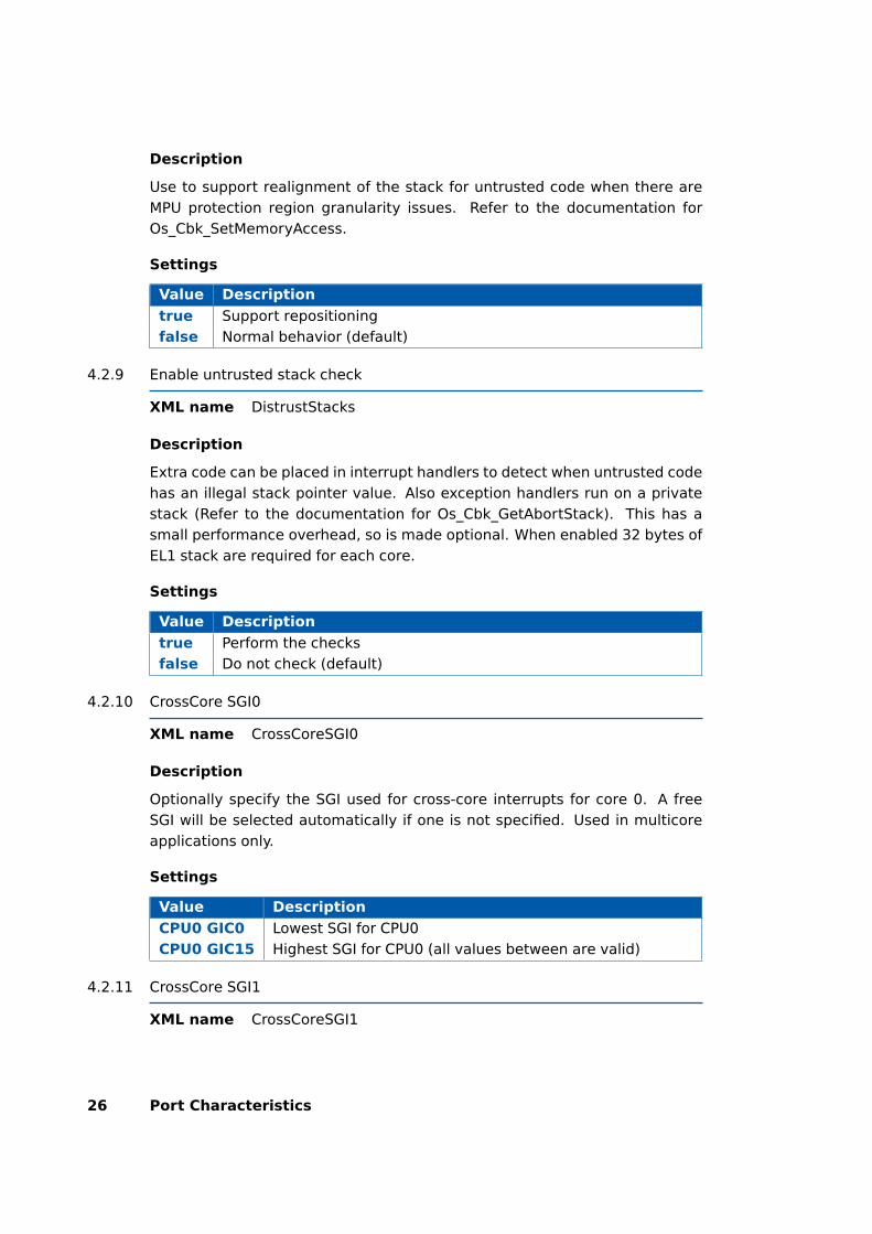
Description
Use to support realignment of the stack for untrusted code when there areMPU protection region granularity issues. Refer to the documentation forOs_Cbk_SetMemoryAccess.
Settings
Value Description
true Support repositioningfalse Normal behavior (default)
4.2.9 Enable untrusted stack check
XML name DistrustStacks
Description
Extra code can be placed in interrupt handlers to detect when untrusted codehas an illegal stack pointer value. Also exception handlers run on a privatestack (Refer to the documentation for Os_Cbk_GetAbortStack). This has asmall performance overhead, so is made optional. When enabled 32 bytes ofEL1 stack are required for each core.
Settings
Value Description
true Perform the checksfalse Do not check (default)
4.2.10 CrossCore SGI0
XML name CrossCoreSGI0
Description
Optionally specify the SGI used for cross-core interrupts for core 0. A freeSGI will be selected automatically if one is not specified. Used in multicoreapplications only.
Settings
Value Description
CPU0 GIC0 Lowest SGI for CPU0CPU0 GIC15 Highest SGI for CPU0 (all values between are valid)
4.2.11 CrossCore SGI1
XML name CrossCoreSGI1
26 Port Characteristics
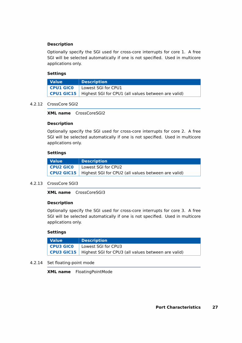
Description
Optionally specify the SGI used for cross-core interrupts for core 1. A freeSGI will be selected automatically if one is not specified. Used in multicoreapplications only.
Settings
Value Description
CPU1 GIC0 Lowest SGI for CPU1CPU1 GIC15 Highest SGI for CPU1 (all values between are valid)
4.2.12 CrossCore SGI2
XML name CrossCoreSGI2
Description
Optionally specify the SGI used for cross-core interrupts for core 2. A freeSGI will be selected automatically if one is not specified. Used in multicoreapplications only.
Settings
Value Description
CPU2 GIC0 Lowest SGI for CPU2CPU2 GIC15 Highest SGI for CPU2 (all values between are valid)
4.2.13 CrossCore SGI3
XML name CrossCoreSGI3
Description
Optionally specify the SGI used for cross-core interrupts for core 3. A freeSGI will be selected automatically if one is not specified. Used in multicoreapplications only.
Settings
Value Description
CPU3 GIC0 Lowest SGI for CPU3CPU3 GIC15 Highest SGI for CPU3 (all values between are valid)
4.2.14 Set floating-point mode
XML name FloatingPointMode
Port Characteristics 27

Description
Enable or disable hardware floating-point instructions. Used in the compilercommand line option -mcpu to select the optional architectural feature forfloating-point mode extensions to the instruction set.
Settings
Value Description
nofp Code does not use floating-point (default)fp Floating-point instructions generated
4.2.15 Block default interrupt
XML name block_default_interrupt
Description
Where a default interrupt is specified, it will normally execute if an unex-pected (i.e. unused) interrupt triggers. This option changes this behavior bylowering the priority assigned to unused interrupt sources. When selectedthe default interrupt handler will be blocked by higher priority code.
Settings
Value Description
true Block the default interruptfalse Allow the default interrupt handler to run if an unexpected inter-
rupt fires (default)
4.2.16 GetAbortStack always
XML name always_call_GetAbortStack
Description
When an unexpected interrupt/exception or memory protection violation oc-curs always use the Os_Cbk_GetAbortStack() callback to set up a safe area ofmemory to use as a stack executing the ProtectionHook (please refer to thedocumentation for Os_Cbk_GetAbortStack).
Settings
Value Description
true Always call Os_Cbk_GetAbortStack()false Only call Os_Cbk_GetAbortStack() when the ’Enable untrusted
stack check’ target option is selected (default)
4.2.17 Set interrupt priority range
XML name InterruptPriorityRange
28 Port Characteristics

Description
Select the range of priorities used by the Generic Interrupt Controller (GIC) forSoftware Generated Interrupts (SGIs), Private Peripheral Interrupts (PPIs), orShared Peripheral Interrupts (SPIs). If applications are run in the non-securestate then the GIC only supports 16 priority levels and this option should beset accordingly.
Settings
Value Description
16 4 bit GIC interrupt priority values32 5 bit GIC interrupt priority values (default)
4.2.18 Read CoreID from GIC
XML name read_CoreID_from_GIC
Description
In untrusted code the RTA-OS by default uses an SVC call to identify the cur-rent CPU core from the MPIDR_EL1 register. Selecting this option causesRTA-OS to to identify the CPU core from the memory mapped registerGICD_ITARGETSR0 instead. This improves the performance of untrusted codeby removing the need for an expensive synchronous exception. Since thisisn’t necessary for trusted code the option is ignored if no untrusted code ispresent. If selected the MMU must allow untrusted code read access for theGIC registers.
Settings
Value Description
true Read from GICfalse Read from MPIDR_EL1 (default)
4.3 Generated Files
The following table lists the files that are generated by rtaosgen for all ports:
Port Characteristics 29

Filename Contents
Os.h The main include file for the OS.Os_Cfg.h Declarations of the objects you have configured.
This is included by Os.h.Os_MemMap.h AUTOSAR memory mapping configuration used by
RTA-OS to merge with the system-wide MemMap.hfile in AUTOSAR versions 4.0 and earlier. From AU-TOSAR version 4.1, Os_MemMap.h is used by the OSinstead of MemMap.h.
RTAOS.<lib> The RTA-OS library for your application. The exten-sion <lib> depends on your target.
RTAOS.<lib>.sig A signature file for the library for your application.This is used by rtaosgen to work out which parts ofthe kernel library need to be rebuilt if the configu-ration has changed. The extension <lib> dependson your target.
<projectname>.log A log file that contains a copy of the text that thetool and compiler sent to the screen during thebuild process.
30 Port Characteristics
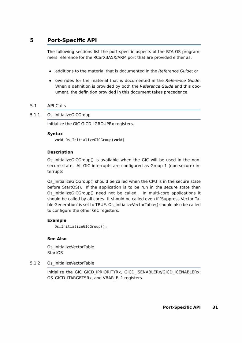
5 Port-Specific API
The following sections list the port-specific aspects of the RTA-OS program-mers reference for the RCarX3A5X/ARM port that are provided either as:
• additions to the material that is documented in the Reference Guide; or
• overrides for the material that is documented in the Reference Guide.When a definition is provided by both the Reference Guide and this doc-ument, the definition provided in this document takes precedence.
5.1 API Calls
5.1.1 Os_InitializeGICGroup
Initialize the GIC GICD_IGROUPRx registers.
Syntax
void Os_InitializeGICGroup(void)
Description
Os_InitializeGICGroup() is available when the GIC will be used in the non-secure state. All GIC interrupts are configured as Group 1 (non-secure) in-terrupts
Os_InitializeGICGroup() should be called when the CPU is in the secure statebefore StartOS(). If the application is to be run in the secure state thenOs_InitializeGICGroup() need not be called. In multi-core applications itshould be called by all cores. It should be called even if ’Suppress Vector Ta-ble Generation’ is set to TRUE. Os_InitializeVectorTable() should also be calledto configure the other GIC registers.
Example
Os_InitializeGICGroup();
See Also
Os_InitializeVectorTableStartOS
5.1.2 Os_InitializeVectorTable
Initialize the GIC GICD_IPRIORITYRx, GICD_ISENABLERx/GICD_ICENABLERx,OS_GICD_ITARGETSRx, and VBAR_EL1 registers.
Port-Specific API 31

Syntax
void Os_InitializeVectorTable(void)
Description
Os_InitializeVectorTable() initializes the GIC GICD_IPRIORITYRx,GICD_ISENABLERx/GICD_ICENABLERx, and OS_GICD_ITARGETSRx accordingto the requirements of the project configuration. The GIC priority is set toblock Category 2 interrupts and allow Category 1 interrupts. FIQ and IRQinterrupts are also enabled
When the CPU is run in the secure state the GICD_IGROUPx registers are alsoinitialized.
Os_InitializeVectorTable() should be called before StartOS(). In multi-core ap-plications it should be called by all cores. It should be called even if ’SuppressVector Table Generation’ is set to TRUE.
Example
Os_InitializeVectorTable();
See Also
Os_InitializeGICGroupStartOS
5.2 Callbacks
5.2.1 Os_Cbk_GetAbortStack
Callback routine to provide the start address of the stack to use to handleexceptions.
Syntax
FUNC(void *,OS_APPL_CODE) Os_Cbk_GetAbortStack(void)
Return Values
The call returns values of type void *.
32 Port-Specific API
Description
Untrusted code can misbehave and cause a protection exception. When thishappens, AUTOSAR requires that ProtectionHook is called and the task, ISRor OS Application must be terminated.
It is possible that at the time of the fault the stack pointer is invalid. Forthis reason, if ’Enable untrusted stack check’ is configured, RTA-OS will callOs_Cbk_GetAbortStack to get the address of a safe area of memory that itshould use for the stack while it performs this processing.
Maskable interrupts will be disabled during this process so the stack onlyneeds to be large enough to perform the ProtectionHook.
A default implementation of Os_Cbk_GetAbortStack is supplied in the RTA-OS library that will place the abort stack at the starting stack location of theuntrusted code.
In systems that use the Os_Cbk_SetMemoryAccess callback, the returnvalue is the last stack location returned in ApplicationContext fromOs_Cbk_SetMemoryAccess. This is to avoid having to reserve memory. Notethat this relies on Os_Cbk_SetMemoryAccess having been called at least onceon that core otherwise zero will be returned. (The stack will not get adjusted ifzero is returned.) Otherwise the default implementation returns the addressof an area of static memory that is reserved for sole use by the abort stack.
Example
FUNC(void *,OS_APPL_CODE) Os_Cbk_GetAbortStack(void) {/* 64-bit alignment is needed for EABI. */static long long abortstack[40U] __attribute__((aligned (16)));return &abortstack[40U];
}
Required when
The callback must be present if ’Enable untrusted stack check’ is configuredand there are untrusted OS Applications. The callback is also present if the’GetAbortStack always’ target option is enabled.
5.2.2 Os_Cbk_StartCore
Callback routine used to start a non-master core on a multi-core variant.
Syntax
FUNC(StatusType, {memclass})Os_Cbk_StartCore(uint16 CoreID
)
Port-Specific API 33

Return Values
The call returns values of type StatusType.
Value Build Description
E_OK all No error.E_OS_ID all The core does not exist or can not be started.
Description
In a multi-core application, the StartCore or StartNonAutosarCore OS APIshave to be called prior to StartOS for each core that is to run. For this targetport, these APIs make a call to Os_Cbk_StartCore() which is responsible forstarting the specified core.
RTA-OS provides a default implementation of Os_Cbk_StartCore() that will beappropriate for most normal situations. To support multi-core applicationsthe caches and SCU must be enabled in all cores otherwise data coherencycannot be maintained between cores. Os_Cbk_StartCore() does not get calledfor core 0,
Note: memclass is OS_APPL_CODE for AUTOSAR 3.x, OS_CALLOUT_CODE forAUTOSAR 4.0, OS_OS_CBK_STARTCORE_CODE for AUTOSAR 4.1.
Example
FUNC(StatusType, {memclass}) Os_Cbk_StartCore(uint16 CoreID){StatusType ret = E_OS_ID;volatile uint32 *Os_CoreStartPtr = (volatile uint32
*)&Os_StartCoreFlags;
/* If not the primary core. */if (CoreID != 0U) {/* Issue a SEV instruction to signal an event to all PEs to
wake-up a
* secondary core. Events can be triggered by the debuggerand semi-hosting
* so additionally use a variable to signal that RTA-OS iswaking-up a
* specific core. This is reset once the core is awake. */
*(Os_CoreStartPtr + CoreID) = 0xA0U;__asm volatile("dsb SY" : : : "memory", "cc");__asm volatile("sev" : : : "memory", "cc");
/* Wait for the core to wake up by monitoring the variablevalue */
while (*(Os_CoreStartPtr + CoreID) == 0xA0U) {__asm volatile("dsb SY" : : : "memory", "cc");__asm volatile("nop" : : : "memory", "cc");
34 Port-Specific API
__asm volatile("nop" : : : "memory", "cc");__asm volatile("nop" : : : "memory", "cc");__asm volatile("nop" : : : "memory", "cc");__asm volatile("nop" : : : "memory", "cc");__asm volatile("nop" : : : "memory", "cc");
}
ret = E_OK;}
return ret;}
Required when
Required for non-master cores that will be started.
See Also
StartCoreStartNonAutosarCoreStartOS
5.2.3 Os_Cbk_StopCore
Callback routine used to stop a non-master core on a multi-core variant.
Syntax
FUNC(StatusType, {memclass})Os_Cbk_StopCore(uint16 CoreID
)
Return Values
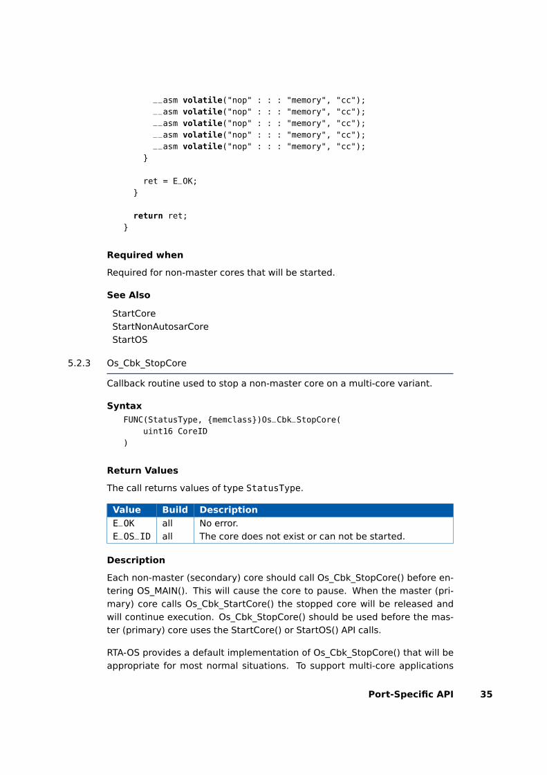
The call returns values of type StatusType.
Value Build Description
E_OK all No error.E_OS_ID all The core does not exist or can not be started.
Description
Each non-master (secondary) core should call Os_Cbk_StopCore() before en-tering OS_MAIN(). This will cause the core to pause. When the master (pri-mary) core calls Os_Cbk_StartCore() the stopped core will be released andwill continue execution. Os_Cbk_StopCore() should be used before the mas-ter (primary) core uses the StartCore() or StartOS() API calls.
RTA-OS provides a default implementation of Os_Cbk_StopCore() that will beappropriate for most normal situations. To support multi-core applications
Port-Specific API 35

the caches and SCU must be enabled in all cores otherwise data coherency isnot maintained between cores. Os_Cbk_StopCore() should not get called forcore 0 as this is the master (primary) core.
Note: memclass is OS_APPL_CODE for AUTOSAR 3.x, OS_CALLOUT_CODE forAUTOSAR 4.0, OS_OS_CBK_STOPCORE_CODE for AUTOSAR 4.1.
Example
FUNC(StatusType, {memclass}) Os_Cbk_StopCore(uint16 CoreID){volatile uint32 *Os_CoreStartPtr = (volatile uint32
*)&Os_StartCoreFlags;
/* If an expected core, shutdown until the value inOs_StartCoreFlags[] holds
* a value set by Os_Cbk_StartCore() for this core */while (*(Os_CoreStartPtr + CoreID) != 0xA0U) {/* Issue a WFE instruction to put the secondary core into a
low power state.
* Note starting other cores, debug and semihosting eventscan cause a SEV
* to wake-up the core. Check if it is valid to wake-up thiscore. */
__asm volatile("wfe" : : : "memory", "cc")}
/* Reset the variable to let core 0 know that the core hasstarted. */
*(Os_CoreStartPtr + CoreID) = 0x0U;__asm volatile("dsb SY" : : : "memory", "cc");
return E_OK;}
Required when
Required for non-master cores that will be started.
See Also
StartCoreStartNonAutosarCoreStartOS
5.3 Macros
5.3.1 CAT1_ISR
Macro that should be used to create a Category 1 ISR entry function. Thisshould only be used on Category 1 ISRs that are attached to the Generic
36 Port-Specific API
Interrupt Controller (GIC) not the Cortex CPU exceptions (See the later sectionon "Writing Category 1 Interrupt Handlers" for more information). This macroexists to help make your code portable between targets.
Example
CAT1_ISR(MyISR) {...}
5.3.2 Os_Clear_x
Use of the Os_Clear_x macro will clear the interrupt request bit of theGICD_ICPEND register for the named interrupt channel. The macro can becalled using either the GIC channel number or the RTA-OS configured vectorname. In the example, this is Os_Clear_GIC48() and Os_Clear_Millisecond()respectively. To use the Os_Clear_x macro the file Os_ConfigInterrupts.h mustbe included through the use of #include. The macro is provided so the inter-rupt channel can be cleared without corrupting the interrupt priority valueconfigured by calling Os_InitializeVectorTable(). It may not be used by un-trusted code.
Example
Os_Clear_GIC48()Os_Clear_Millisecond()
5.3.3 Os_DisableAllConfiguredInterrupts_CPUx
The Os_DisableAllConfiguredInterrupts_CPUx macro will disable all config-ured GIC interrupt channels on CPUx (where x = 0 to 3). In the ex-ample, this is CPU0. To use the Os_DisableAllConfiguredInterrupts_CPUxmacro the file Os_ConfigInterrupts.h must be included through the use of#include. The macro is provided so the interrupt channels can be dis-abled without corrupting the interrupt priority values configured by callingOs_InitializeVectorTable(). It may not be used by untrusted code.
Example
Os_DisableAllConfiguredInterrupts_CPU0()...Os_EnableAllConfiguredInterrupts_CPU0()
5.3.4 Os_Disable_x
Use of the Os_Disable_x macro will disable the named interrupt channel.The macro can be called using either the GIC channel number or the RTA-OS configured vector name. In the example, this is Os_Disable_GIC48() andOs_Disable_Millisecond() respectively. To use the Os_Disable_x macro the fileOs_ConfigInterrupts.h must be included through the use of #include. Themacro is provided so the interrupt channel can be masked without corrupting
Port-Specific API 37
the interrupt priority value configured by calling Os_InitializeVectorTable(). Itmay not be used by untrusted code.
Example
Os_Disable_GIC48()Os_Disable_Millisecond()
5.3.5 Os_EnableAllConfiguredInterrupts_CPUx
The Os_EnableAllConfiguredInterrupts_CPUx macro will enable all config-ured EI interrupt channels on CPUx (where x = 0 to 3). In the ex-ample, this is CPU0. To use the Os_EnableAllConfiguredInterrupts_CPUxmacro the file Os_ConfigInterrupts.h must be included through the use of#include. The macro is provided so the interrupt channels can be en-abled without corrupting the interrupt priority values configured by callingOs_InitializeVectorTable(). It may not be used by untrusted code.
Example
Os_DisableAllConfiguredInterrupts_CPU0()...Os_EnableAllConfiguredInterrupts_CPU0()
5.3.6 Os_Enable_x
Use of the Os_Enable_x macro will enable the named interrupt channel. Themacro can be called using either the GIC channel number or the RTA-OSconfigured vector name. In the example, this is Os_Enable_GIC48() andOs_Enable_Millisecond() respectively. To use the Os_Enable_x macro the fileOs_ConfigInterrupts.h must be included through the use of #include. Themacro is provided so the interrupt channel can be enabled without corruptingthe interrupt priority value configured by calling Os_InitializeVectorTable(). Itmay not be used by untrusted code.
Example
Os_Enable_GIC48()Os_Enable_Millisecond()
5.3.7 Os_IntChannel_x
The Os_IntChannel_x macro can be used to get the vector number associatedwith the named GIC interrupt (0, 1, 2...). The macro can be called using eitherthe GIC vector name or the RTA-OS configured vector name. In the example,this is Os_IntChannel_Parity_Core_0 and Os_IntChannel_Millisecond respec-tively. To use the Os_IntChannel_x macro the file Os_ConfigInterrupts.h mustbe included through the use of #include. On a multi-core CPU GIC interruptson different cores may have the same vector number. This is because the
38 Port-Specific API
GIC maintains a copy of interrupts 0 to 31 for each CPU core. Those outsidethis range share a single copy between all CPU cores.
Example
trigger_interrupt(Os_IntChannel_TPU);trigger_interrupt(Os_IntChannel_Millisecond);
5.3.8 Os_Set_Edge_Triggered_x
Use of the Os_Set_Edge_Triggered_x macro will configure the named GIC in-terrupt channel as Edge-triggered. The macro can be called using either thechannel name or the RTA-OS configured vector name. In the example, thisis Os_Set_Edge_Triggered_GIC32() and Os_Set_Edge_Triggered_Millisecond()respectively. Only GIC channels 32 and above can be modified; the otherchannels have fixed settings. To use the Os_Set_Edge_Triggered_x macro thefile Os_ConfigInterrupts.h must be included through the use of #include. Itmay not be used by untrusted code.
Example
Os_Set_Edge_Triggered_GIC32()Os_Set_Edge_Triggered_Millisecond()
5.3.9 Os_Set_Level_Sensitive_x
Use of the Os_Set_Level_Sensitive_x macro will configure the named GIC in-terrupt channel as Level-sensitive. The macro can be called using either thechannel name or the RTA-OS configured vector name. In the example, thisis Os_Set_Level_Sensitive_GIC32() and Os_Set_Level_Sensitive_Millisecond()respectively. Only GIC channels 32 and above can be modified; the otherchannels have fixed settings. To use the Os_Set_Level_Sensitive_x macro thefile Os_ConfigInterrupts.h must be included through the use of #include. Itmay not be used by untrusted code.
Example
Os_Set_Level_Sensitive_GIC32()Os_Set_Level_Sensitive_Millisecond()
5.4 Type Definitions
5.4.1 Os_StackSizeType
An unsigned value representing an amount of stack in bytes.
Port-Specific API 39
Example
Os_StackSizeType stack_size;stack_size = Os_GetStackSize(start_position, end_position);
5.4.2 Os_StackValueType
An unsigned value representing the position of the stack pointer (USR/SYSmode).
Example
Os_StackValueType start_position;start_position = Os_GetStackValue();
40 Port-Specific API

6 Toolchain
This chapter contains important details about RTA-OS and the ARM_DS_5_V6toolchain. A port of RTA-OS is specific to both the target hardware and aspecific version of the compiler toolchain. You must make sure that you buildyour application with the supported toolchain.
In addition to the version of the toolchain, RTA-OS may use specific tool op-tions (switches). The options are divided into three classes:
kernel options are those used by rtaosgen to build the RTA-OS kernel.
mandatory options must be used to build application code so that it willwork with the RTA-OS kernel.
forbidden options must not be used to build application code.
Any options that are not explicitly forbidden can be used by application codeproviding that they do not conflict with the kernel and mandatory options forRTA-OS.
Integration Guidance 6.1:ETAS has developed and tested RTA-OS us-ing the tool versions and options indicated in the following sections. Cor-rect operation of RTA-OS is only covered by the warranty in the termsand conditions of your deployment license agreement when using identi-cal versions and options. If you choose to use a different version of thetoolchain or an alternative set of options then it is your responsibility tocheck that the system works correctly. If you require a statement thatRTA-OS works correctly with your chosen tool version and options thenplease contact ETAS to discuss validation possibilities.
6.1 Compiler Versions
This port of RTA-OS has been developed to work with the following com-piler(s):
6.1.1 ARM DS-5 Ultimate Edition: ARM Compiler 6.6
Ensure that armclang.exe is on the path and that the appropriate environ-ment variables have been set.
Tested on ARM Compiler 6.6
If you require support for a compiler version not listed above, please contactETAS.
Toolchain 41

6.2 Options used to generate this guide
6.2.1 Compiler
Name armclang.exeVersion Component: ARM Compiler 6.6
Options
Kernel Options
The following options were used to build the RTA-OS kernel for the configu-ration that was used to generate the performance figures in this document.If you select different target options, then the values used to build the ker-nel might change. You can run a Configuration Summary report to check thevalues used for your configuration.
--target=aarch64-arm-none-eabi Generates A64 instructions for AArch64state
-fno-vectorize Disables generation of Advanced SIMD vector instructions
-mcpu=cortex-a53+nocrc+nocrypto+nofp+nosimd Target the Cortex-A53architecture and additional features including the floating-point mode(value set by target option)
-mno-unaligned-access Disable unaligned access to data
-Ofast Set fast optimization level
-std=gnu11 2011 C standard code with GNU extensions
-fms-extensions Enable the compiler extensions for section use pragmas
Mandatory Options for Application Code
The following options were mandatory for application code used with the con-figuration that was used to generate the performance figures in this docu-ment. If you select different target options, then the values required by ap-plication code might change. You can run a Configuration Summary report tocheck the values used for your configuration.
- The same options as for compilation
42 Toolchain
Forbidden Options for Application Code
The following options were forbidden for application code used with the con-figuration that was used to generate the performance figures in this docu-ment. If you select different target options, then the forbidden values mightchange. You can run a Configuration Summary report to check the valuesused for your configuration.
-fshort-enums Set the size of an enumeration type to the smallest data type
-fvectorize Generate Advanced SIMD vector instructions
-mbig-endian Generate big-endian code
-munaligned-access Enable unaligned access to data
-std=x Other C standard code apart from gnu11
--target=arm-arm-none-eab Generates A32/T32 instructions for AArch32state
- Any other options that conflict with kernel options
6.2.2 Assembler
Name armclang.exeVersion Component: ARM Compiler 6.6
Options
Kernel Options
The following options were used to build the RTA-OS kernel for the configu-ration that was used to generate the performance figures in this document.If you select different target options, then the values used to build the ker-nel might change. You can run a Configuration Summary report to check thevalues used for your configuration.
- The same options as for compilation
Mandatory Options for Application Code
The following options were mandatory for application code used with the con-figuration that was used to generate the performance figures in this docu-ment. If you select different target options, then the values required by ap-plication code might change. You can run a Configuration Summary report tocheck the values used for your configuration.
- The same options as for compilation
Toolchain 43
Forbidden Options for Application Code
The following options were forbidden for application code used with the con-figuration that was used to generate the performance figures in this docu-ment. If you select different target options, then the forbidden values mightchange. You can run a Configuration Summary report to check the valuesused for your configuration.
- Any options that conflict with kernel options
6.2.3 Librarian
Name armar.exeVersion Component: ARM Compiler 6.6
6.2.4 Linker
Name armlink.exeVersion Component: ARM Compiler 6.6
Options
Kernel Options
The following options were used to build the RTA-OS kernel for the configu-ration that was used to generate the performance figures in this document.If you select different target options, then the values used to build the ker-nel might change. You can run a Configuration Summary report to check thevalues used for your configuration.
--info=totals,sizes,unused Specify map file contents
--datacompressor=off Disable RW data compression
--noremove Do not remove unused input sections
--xref Output cross reference information to the map file
--map Output memory map to the map file
--symbols Output symbol table to the map file
--verbose Output detailed information to the map file
--entry=reset_handler Specify the application entry point
44 Toolchain

Mandatory Options for Application Code
The following options were mandatory for application code used with the con-figuration that was used to generate the performance figures in this docu-ment. If you select different target options, then the values required by ap-plication code might change. You can run a Configuration Summary report tocheck the values used for your configuration.
- The same options as for compilation
Forbidden Options for Application Code
The following options were forbidden for application code used with the con-figuration that was used to generate the performance figures in this docu-ment. If you select different target options, then the forbidden values mightchange. You can run a Configuration Summary report to check the valuesused for your configuration.
- Any options that conflict with kernel options
6.2.5 Debugger
Name Lauterbach TRACE32Version Build 92037 or later
Notes on using ORTI with the Lauterbach debugger
When ORTI information for the Trace32 debugger is enabled entry and exittimes for Category 1 interrupts are increased by a few cycles to support track-ing of Category 1 interrupts by the debugger.
ORTI Stack Fill with the Lauterbach debugger
The ’ORTI Stack Fill’ target option is provided to extend the ORTI support toallow evaluation of unused stack space. The Task.Stack.View command canthen be used in the Trace32 debugger. The following must also be added toan application to ensure correct operation (as demonstrated in the sampleapplications):
The linker file must create labels holding the start address and stack size foreach stack (one per core). The labels automatically generated by the linkercan be used. For a single core system (i.e. core 0 only) the labels are:
extern const uint64 Image$$ARM_LIB_STACKHEAP$$ZI$$Base;extern const uint64 Image$$ARM_LIB_STACKHEAP$$ZI$$Length;OS_STACK0_BASE = (uint64)&Image$$ARM_LIB_STACKHEAP$$ZI$$Base;OS_STACK0_SIZE = (uint64)&Image$$ARM_LIB_STACKHEAP$$ZI$$Length;
Toolchain 45

where ARM_LIB_STACKHEAP is the section containing the Core 0 stack.
The fill pattern used by the debugger must be contained with in a 32 bitconstant OS_STACK_FILL (i.e. for a fill pattern 0xCAFEF00D).
const uint32 OS_STACK_FILL = 0xCAFEF00D;
The stack must also be initialized with this fill pattern either in the applicationstart-up routines or during debugger initialization.
46 Toolchain
7 Hardware
7.1 Supported Devices
This port of RTA-OS has been developed to work with the following target:
Name: RenesasDevice: R-Car x3 Cortex-A5x
The following variants of the R-Car x3 Cortex-A5x are supported:
• RCarH3A53
• RCarV3HA53
If you require support for a variant of R-Car x3 Cortex-A5x not listed above,please contact ETAS.
7.2 Register Usage
7.2.1 Initialization
RTA-OS requires the following registers to be initialized to the indicated valuesbefore StartOS() is called.
Hardware 47

Register Setting
GICD_IGROUPRx The GIC group registers have tobe configured to match the securestate that the application runs in.These registers can only be modi-fied in the secure state. If runningin the secure state then these reg-isters can be configured by callingOs_InitializeVectorTable(). If run-ning in the non-secure state thenOs_InitializeGICGroup() should becalled before entering the non-secure state.
GICD_IPRIORITYRx The GIC priorities have to be set tomatch the values declared in theconfiguration. This can be done bycalling Os_InitializeVectorTable().
GICD_ISENABLERx/GICD_ICENABLERx The GIC mask registers haveto be set to match the de-clared ISRs in the configuration.This can be done by callingOs_InitializeVectorTable().
GICD_ITARGETSRx The GIC processor targets haveto be set to match the val-ues declared in the configura-tion. This can be done by callingOs_InitializeVectorTable().
PSTATE The PSTATE must select a privi-leged mode (i.e. EL1) before call-ing Os_InitializeVectorTable().
SP The stack must be allocatedand SP initialized to onlyuse SP_EL0 before callingOs_InitializeVectorTable().
VBAR_EL1 The VBAR_EL1 must be set tothe address of the EL1 vector ta-ble. This can be done by callingOs_InitializeVectorTable().
7.2.2 Modification
The following registers must not be modified by user code after the call toStartOS():
48 Hardware
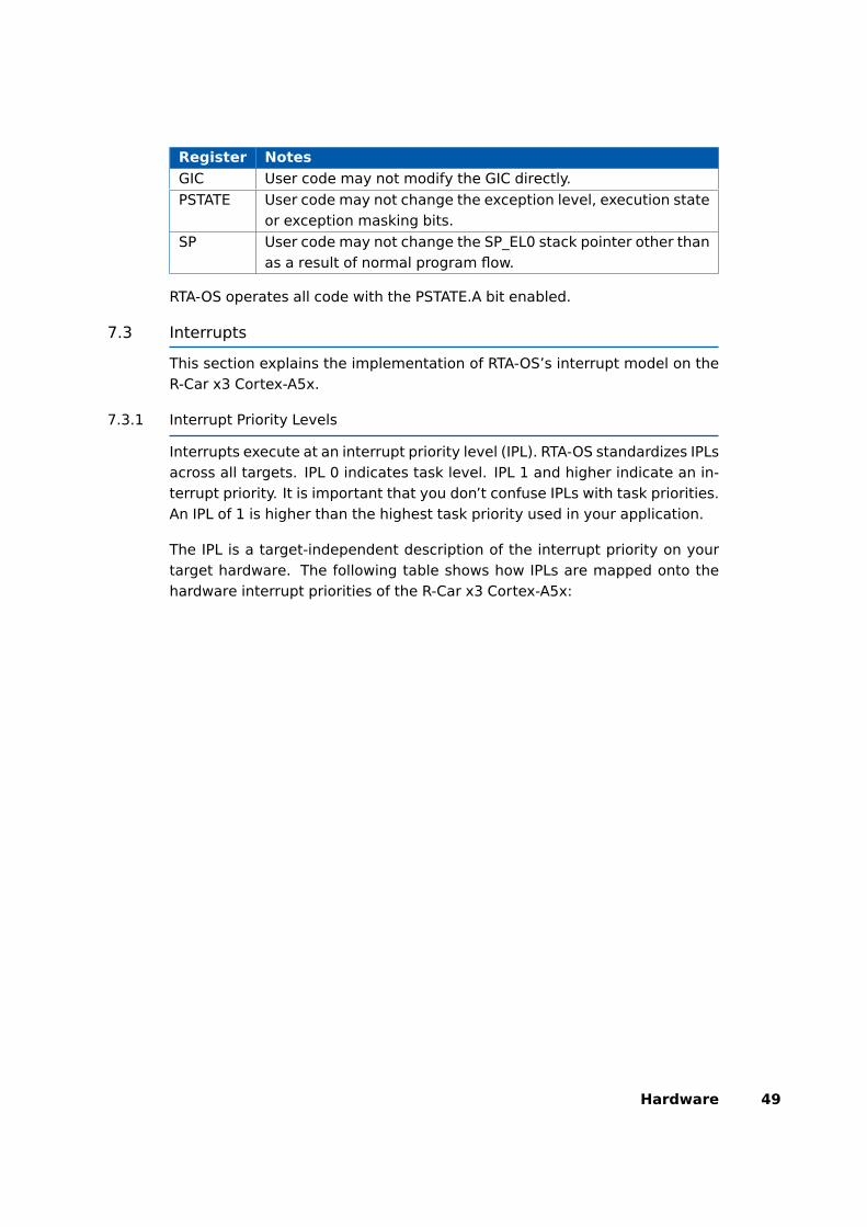
Register Notes
GIC User code may not modify the GIC directly.
PSTATE User code may not change the exception level, execution stateor exception masking bits.
SP User code may not change the SP_EL0 stack pointer other thanas a result of normal program flow.
RTA-OS operates all code with the PSTATE.A bit enabled.
7.3 Interrupts
This section explains the implementation of RTA-OS’s interrupt model on theR-Car x3 Cortex-A5x.
7.3.1 Interrupt Priority Levels
Interrupts execute at an interrupt priority level (IPL). RTA-OS standardizes IPLsacross all targets. IPL 0 indicates task level. IPL 1 and higher indicate an in-terrupt priority. It is important that you don’t confuse IPLs with task priorities.An IPL of 1 is higher than the highest task priority used in your application.
The IPL is a target-independent description of the interrupt priority on yourtarget hardware. The following table shows how IPLs are mapped onto thehardware interrupt priorities of the R-Car x3 Cortex-A5x:
Hardware 49
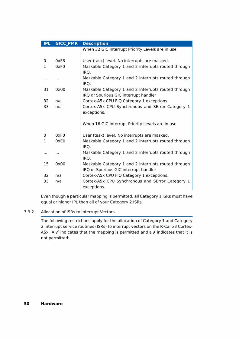
IPL GICC_PMR Description
When 32 GIC Interrupt Priority Levels are in use
0 0xF8 User (task) level. No interrupts are masked.1 0xF0 Maskable Category 1 and 2 interrupts routed through
IRQ.... ... Maskable Category 1 and 2 interrupts routed through
IRQ.31 0x00 Maskable Category 1 and 2 interrupts routed through
IRQ or Spurious GIC interrupt handler32 n/a Cortex-A5x CPU FIQ Category 1 exceptions.33 n/a Cortex-A5x CPU Synchronous and SError Category 1
exceptions.
When 16 GIC Interrupt Priority Levels are in use
0 0xF0 User (task) level. No interrupts are masked.1 0xE0 Maskable Category 1 and 2 interrupts routed through
IRQ.... ... Maskable Category 1 and 2 interrupts routed through
IRQ.15 0x00 Maskable Category 1 and 2 interrupts routed through
IRQ or Spurious GIC interrupt handler32 n/a Cortex-A5x CPU FIQ Category 1 exceptions.33 n/a Cortex-A5x CPU Synchronous and SError Category 1
exceptions.
Even though a particular mapping is permitted, all Category 1 ISRs must haveequal or higher IPL than all of your Category 2 ISRs.
7.3.2 Allocation of ISRs to Interrupt Vectors
The following restrictions apply for the allocation of Category 1 and Category2 interrupt service routines (ISRs) to interrupt vectors on the R-Car x3 Cortex-A5x. A 3 indicates that the mapping is permitted and a 7 indicates that it isnot permitted:
50 Hardware
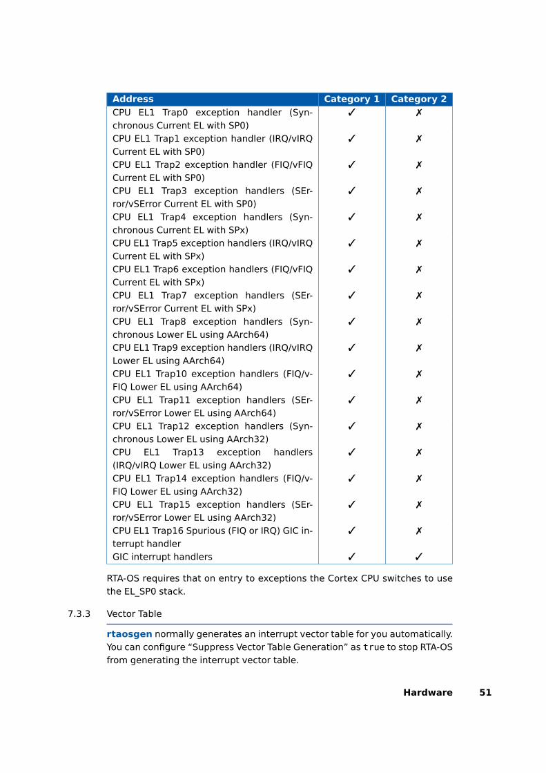
Address Category 1 Category 2
CPU EL1 Trap0 exception handler (Syn-chronous Current EL with SP0)
3 7
CPU EL1 Trap1 exception handler (IRQ/vIRQCurrent EL with SP0)
3 7
CPU EL1 Trap2 exception handler (FIQ/vFIQCurrent EL with SP0)
3 7
CPU EL1 Trap3 exception handlers (SEr-ror/vSError Current EL with SP0)
3 7
CPU EL1 Trap4 exception handlers (Syn-chronous Current EL with SPx)
3 7
CPU EL1 Trap5 exception handlers (IRQ/vIRQCurrent EL with SPx)
3 7
CPU EL1 Trap6 exception handlers (FIQ/vFIQCurrent EL with SPx)
3 7
CPU EL1 Trap7 exception handlers (SEr-ror/vSError Current EL with SPx)
3 7
CPU EL1 Trap8 exception handlers (Syn-chronous Lower EL using AArch64)
3 7
CPU EL1 Trap9 exception handlers (IRQ/vIRQLower EL using AArch64)
3 7
CPU EL1 Trap10 exception handlers (FIQ/v-FIQ Lower EL using AArch64)
3 7
CPU EL1 Trap11 exception handlers (SEr-ror/vSError Lower EL using AArch64)
3 7
CPU EL1 Trap12 exception handlers (Syn-chronous Lower EL using AArch32)
3 7
CPU EL1 Trap13 exception handlers(IRQ/vIRQ Lower EL using AArch32)
3 7
CPU EL1 Trap14 exception handlers (FIQ/v-FIQ Lower EL using AArch32)
3 7
CPU EL1 Trap15 exception handlers (SEr-ror/vSError Lower EL using AArch32)
3 7
CPU EL1 Trap16 Spurious (FIQ or IRQ) GIC in-terrupt handler
3 7
GIC interrupt handlers 3 3
RTA-OS requires that on entry to exceptions the Cortex CPU switches to usethe EL_SP0 stack.
7.3.3 Vector Table
rtaosgen normally generates an interrupt vector table for you automatically.You can configure “Suppress Vector Table Generation” as true to stop RTA-OSfrom generating the interrupt vector table.
Hardware 51

Depending upon your target, you may be responsible for locating the gener-ated vector table at the correct base address. The following table shows thesection (or sections) that need to be located and the associated valid baseaddress:
Section Valid Addresses
Os_ExceptionVectors Should either be located in accordance withthe EL1 Cortex Vector Base Address RegisterVBAR_EL1. The first entry is the Current EL withSP0 Synchronous exception handler.
The RTA-OS generated vector table does not include the reset vector. Thisshould be added for an application and be located at the address containedwithin the the RVBAR_Elx register.
When the default interrupt is configured the RTA-OS generated vector tablecontains entries for all supported interrupts for the selected chip variant. Ifthe default interrupt is not configured then entries are only created up thehighest configured interrupt.
7.3.4 Writing Category 1 Interrupt Handlers
Raw Category 1 interrupt service routines (ISRs) must correctly handle theinterrupt context themselves. RTA-OS provides an optional helper macroCAT1_ISR that can be used to make code more portable. Depending on thetarget, this may cause the selection of an appropriate interrupt control di-rective to indicate to the compiler that a function requires additional code tosave and restore the interrupt context.
A Category 1 ISR therefore has the same structure as a Category 2 ISR, asshown below.
CAT1_ISR(Category1Handler) {/* Handler routine */
}
Cortex-A53 CPU exception handlers can be configured as Category 1 ISRs. Asthere is no compiler support to write the entry code in C these should not usethe the CAT1_ISR macro.
7.3.5 Writing Category 2 Interrupt Handlers
Category 2 ISRs are provided with a C function context by RTA-OS, since theRTA-OS kernel handles the interrupt context itself. The handlers are writtenusing the ISR() macro as shown below:
52 Hardware
#include <Os.h>ISR(MyISR) {/* Handler routine */
}
You must not insert a return from interrupt instruction in such a function. Thereturn is handled automatically by RTA-OS.
7.3.6 Default Interrupt
The ’default interrupt’ is intended to be used to catch all unexpected in-terrupts. All unused interrupts have their interrupt vectors directed to thenamed routine that you specify. The routine you provide is not handled byRTA-OS and must correctly handle the interrupt context itself. The handlermust use the CAT1_ISR macro in the same way as a Category 1 ISR (seeSection 7.3.4 for further details).
7.4 Memory Model
The following memory models are supported:
Model Description
Standard The standard AArch64 EABI memory model is used.
Apart from some small code sections RTA-OS uses the default compiler mem-ory sections unless modified by the AUTOSAR MemMap.h overrides. The non-default code sections all use the prefix ’Os_’ (i.e. Os_primitives).
7.5 Processor Modes
RTA-OS can run in the following processor modes:
Mode Notes
Trusted All trusted code runs at Exception level 1 (EL1).Untrusted All untrusted code runs at Exception level 0 (EL0).
RTA-OS uses the Synchronous handler to transfer between Untrusted andTrusted code in applications containing untrusted objects (i.e. ISRs, tasksand functions). This functionality must be supported if a user provided SVChandler is used in such applications. RTA-OS does not support use of theAArch32 instruction set in application code.
Hardware 53
7.6 Stack Handling
RTA-OS uses a single stack for all tasks and ISRs.
RTA-OS manages the SP_EL0 stack (via register SP). No other stacks are used.
If there are Category 1 ISRs attached to the Cortex CPU exception handlers(i.e. Synchronous, FIQ, SError) then care must be taken that either the SP_EL1stack has been initialized or that the exception handler transfers back to theSP_EL0 before using any stack.
If the ’Enable untrusted stack check’ target option is selected then a smallamount of SP_EL1 stack is required for each core (32 bytes per core).
7.7 Processor state when calling StartOS()
At StartOS() the following conditions should be true:
• The CPU must be operating in trusted EL1 mode.
• The CPU must be using the SP_EL0 stack.
• FIQ and IRQ interrupts must be enabled (see Os_InitializeVectorTable()).
• The GIC must be enabled and the GIC group configured (seeOs_InitializeVectorTable() and Os_InitializeGICGroup()).
If any of these conditions are not met then ShutdownOS() will be called.
54 Hardware

8 Performance
This chapter provides detailed information on the functionality, performanceand memory demands of the RTA-OS kernel. RTA-OS is highly scalable. As aresult, different figures will be obtained when your application uses differentsets of features. The figures presented in this chapter are representative forthe RCarX3A5X/ARM port based on the following configuration:
• There are 32 tasks in the system
• Standard build is used
• Stack monitoring is disabled
• Time monitoring is disabled
• There are no calls to any hooks
• Tasks have unique priorities
• Tasks are not queued (i.e. tasks are BCC1 or ECC1)
• All tasks terminate/wait in their entry function
• Tasks and ISRs do not save any auxiliary registers (for example, floatingpoint registers)
• Resources are shared by tasks only
• The generation of the resource RES_SCHEDULER is disabled
8.1 Measurement Environment
The following hardware environment was used to take the measurements inthis chapter:
Device RCarH3A53 onCPU Clock Speed 600.0MHzStopwatch Speed 600.0MHz
8.2 RAM and ROM Usage for OS Objects
Each OS object requires some ROM and/or RAM. The OS objects are generatedby rtaosgen and placed in the RTA-OS library. In the main:
• Os_Cfg_Counters includes data for counters, alarms and schedule ta-bles.
• Os_Cfg contains the data for most other OS objects.
Performance 55

8.2.1 Single Core
The following table gives the ROM and/or RAM requirements (in bytes) foreach OS object in a simple single-core configuration. Note that object sizeswill vary depending on the project configuration and compiler packing issues.
Object ROM RAM
Alarm 2 12Cat 2 ISR 16 0Counter 32 4CounterCallback 8 0ExpiryPoint 3.5 0OS Overheads (max) 0 81OS-Application 0 0PeripheralArea 0 0Resource 16 4ScheduleTable 24 24Task 32 0
8.2.2 Multi Core
The following table gives the ROM and/or RAM requirements (in bytes) foreach OS object in a simple multi-core configuration. Note that object sizes willvary depending on the project configuration and compiler packing issues.
Object ROM RAM
Alarm 8 12Cat 2 ISR 24 0Core Overheads (each OS core) 0 80Core Overheads (each processor core) 40 25Counter 48 4CounterCallback 8 0ExpiryPoint 3.5 0OS Overheads (max) 0 8OS-Application 8 0PeripheralArea 0 0Resource 24 4ScheduleTable 32 24Task 48 0
8.3 Stack Usage
The amount of stack used by each Task/ISR in RTA-OS is equal to the stackused in the Task/ISR body plus the context saved by RTA-OS. The size of the
56 Performance
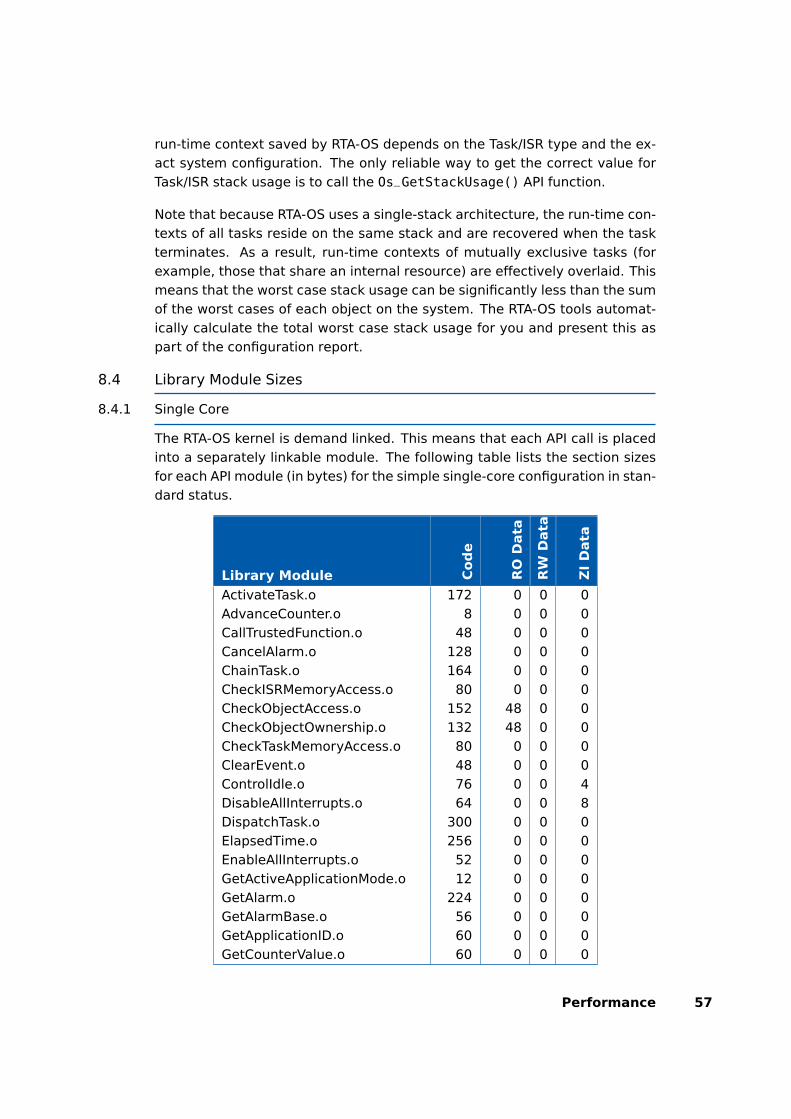
run-time context saved by RTA-OS depends on the Task/ISR type and the ex-act system configuration. The only reliable way to get the correct value forTask/ISR stack usage is to call the Os_GetStackUsage() API function.
Note that because RTA-OS uses a single-stack architecture, the run-time con-texts of all tasks reside on the same stack and are recovered when the taskterminates. As a result, run-time contexts of mutually exclusive tasks (forexample, those that share an internal resource) are effectively overlaid. Thismeans that the worst case stack usage can be significantly less than the sumof the worst cases of each object on the system. The RTA-OS tools automat-ically calculate the total worst case stack usage for you and present this aspart of the configuration report.
8.4 Library Module Sizes
8.4.1 Single Core
The RTA-OS kernel is demand linked. This means that each API call is placedinto a separately linkable module. The following table lists the section sizesfor each API module (in bytes) for the simple single-core configuration in stan-dard status.
Library Module Cod
e
RO
Data
RW
Data
ZI
Data
ActivateTask.o 172 0 0 0AdvanceCounter.o 8 0 0 0CallTrustedFunction.o 48 0 0 0CancelAlarm.o 128 0 0 0ChainTask.o 164 0 0 0CheckISRMemoryAccess.o 80 0 0 0CheckObjectAccess.o 152 48 0 0CheckObjectOwnership.o 132 48 0 0CheckTaskMemoryAccess.o 80 0 0 0ClearEvent.o 48 0 0 0ControlIdle.o 76 0 0 4DisableAllInterrupts.o 64 0 0 8DispatchTask.o 300 0 0 0ElapsedTime.o 256 0 0 0EnableAllInterrupts.o 52 0 0 0GetActiveApplicationMode.o 12 0 0 0GetAlarm.o 224 0 0 0GetAlarmBase.o 56 0 0 0GetApplicationID.o 60 0 0 0GetCounterValue.o 60 0 0 0
Performance 57

Library Module Cod
e
RO
Data
RW
Data
ZI
Data
GetCurrentApplicationID.o 60 0 0 0GetElapsedCounterValue.o 88 0 0 0GetEvent.o 48 0 0 0GetExecutionTime.o 48 0 0 0GetISRID.o 12 0 0 0GetIsrMaxExecutionTime.o 48 0 0 0GetIsrMaxStackUsage.o 48 0 0 0GetResource.o 96 0 0 0GetScheduleTableStatus.o 60 0 0 0GetStackSize.o 8 0 0 0GetStackUsage.o 48 0 0 0GetStackValue.o 20 0 0 0GetTaskID.o 24 0 0 0GetTaskMaxExecutionTime.o 48 0 0 0GetTaskMaxStackUsage.o 48 0 0 0GetTaskState.o 56 0 0 0GetVersionInfo.o 44 0 0 0Idle.o 8 0 0 0InShutdown.o 4 0 0 0IncrementCounter.o 24 0 0 0InterruptSource.o 304 2 0 0ModifyPeripheral.o 192 0 0 0NextScheduleTable.o 176 0 0 0Os_Cfg.o 268 1296 0 765Os_Cfg_Counters.o 5268 1112 0 0Os_Cfg_KL.o 64 0 0 0Os_ExceptionVectors.o 2144 0 0 0Os_GICSupport.o 44 0 0 0Os_GetAbortStack.o 16 0 0 320Os_GetCurrentIMask.o 16 0 0 0Os_GetCurrentTPL.o 40 0 0 0Os_IRQConst.o 16 297 0 0Os_IRQHandler.o 156 0 0 0Os_StartCores.o 152 0 0 16Os_Wrapper.o 152 0 0 0Os_setjmp.o 80 0 0 0Os_tgt.o 44 0 0 0Os_vec_init.o 384 1056 0 0ProtectionSupport.o 64 0 0 0ReadPeripheral.o 168 0 0 0
58 Performance
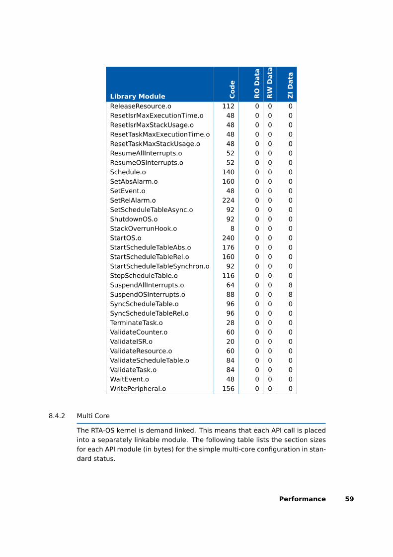
Library Module Cod
e
RO
Data
RW
Data
ZI
Data
ReleaseResource.o 112 0 0 0ResetIsrMaxExecutionTime.o 48 0 0 0ResetIsrMaxStackUsage.o 48 0 0 0ResetTaskMaxExecutionTime.o 48 0 0 0ResetTaskMaxStackUsage.o 48 0 0 0ResumeAllInterrupts.o 52 0 0 0ResumeOSInterrupts.o 52 0 0 0Schedule.o 140 0 0 0SetAbsAlarm.o 160 0 0 0SetEvent.o 48 0 0 0SetRelAlarm.o 224 0 0 0SetScheduleTableAsync.o 92 0 0 0ShutdownOS.o 92 0 0 0StackOverrunHook.o 8 0 0 0StartOS.o 240 0 0 0StartScheduleTableAbs.o 176 0 0 0StartScheduleTableRel.o 160 0 0 0StartScheduleTableSynchron.o 92 0 0 0StopScheduleTable.o 116 0 0 0SuspendAllInterrupts.o 64 0 0 8SuspendOSInterrupts.o 88 0 0 8SyncScheduleTable.o 96 0 0 0SyncScheduleTableRel.o 96 0 0 0TerminateTask.o 28 0 0 0ValidateCounter.o 60 0 0 0ValidateISR.o 20 0 0 0ValidateResource.o 60 0 0 0ValidateScheduleTable.o 84 0 0 0ValidateTask.o 84 0 0 0WaitEvent.o 48 0 0 0WritePeripheral.o 156 0 0 0
8.4.2 Multi Core
The RTA-OS kernel is demand linked. This means that each API call is placedinto a separately linkable module. The following table lists the section sizesfor each API module (in bytes) for the simple multi-core configuration in stan-dard status.
Performance 59
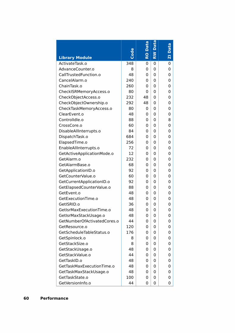
Library Module Cod
e
RO
Data
RW
Data
ZI
Data
ActivateTask.o 348 0 0 0AdvanceCounter.o 8 0 0 0CallTrustedFunction.o 48 0 0 0CancelAlarm.o 240 0 0 0ChainTask.o 260 0 0 0CheckISRMemoryAccess.o 80 0 0 0CheckObjectAccess.o 232 48 0 0CheckObjectOwnership.o 292 48 0 0CheckTaskMemoryAccess.o 80 0 0 0ClearEvent.o 48 0 0 0ControlIdle.o 88 0 0 8CrossCore.o 60 0 0 0DisableAllInterrupts.o 84 0 0 0DispatchTask.o 684 0 0 0ElapsedTime.o 256 0 0 0EnableAllInterrupts.o 72 0 0 0GetActiveApplicationMode.o 12 0 0 0GetAlarm.o 232 0 0 0GetAlarmBase.o 68 0 0 0GetApplicationID.o 92 0 0 0GetCounterValue.o 60 0 0 0GetCurrentApplicationID.o 92 0 0 0GetElapsedCounterValue.o 88 0 0 0GetEvent.o 48 0 0 0GetExecutionTime.o 48 0 0 0GetISRID.o 36 0 0 0GetIsrMaxExecutionTime.o 48 0 0 0GetIsrMaxStackUsage.o 48 0 0 0GetNumberOfActivatedCores.o 44 0 0 0GetResource.o 120 0 0 0GetScheduleTableStatus.o 176 0 0 0GetSpinlock.o 8 0 0 0GetStackSize.o 8 0 0 0GetStackUsage.o 48 0 0 0GetStackValue.o 44 0 0 0GetTaskID.o 48 0 0 0GetTaskMaxExecutionTime.o 48 0 0 0GetTaskMaxStackUsage.o 48 0 0 0GetTaskState.o 100 0 0 0GetVersionInfo.o 44 0 0 0
60 Performance
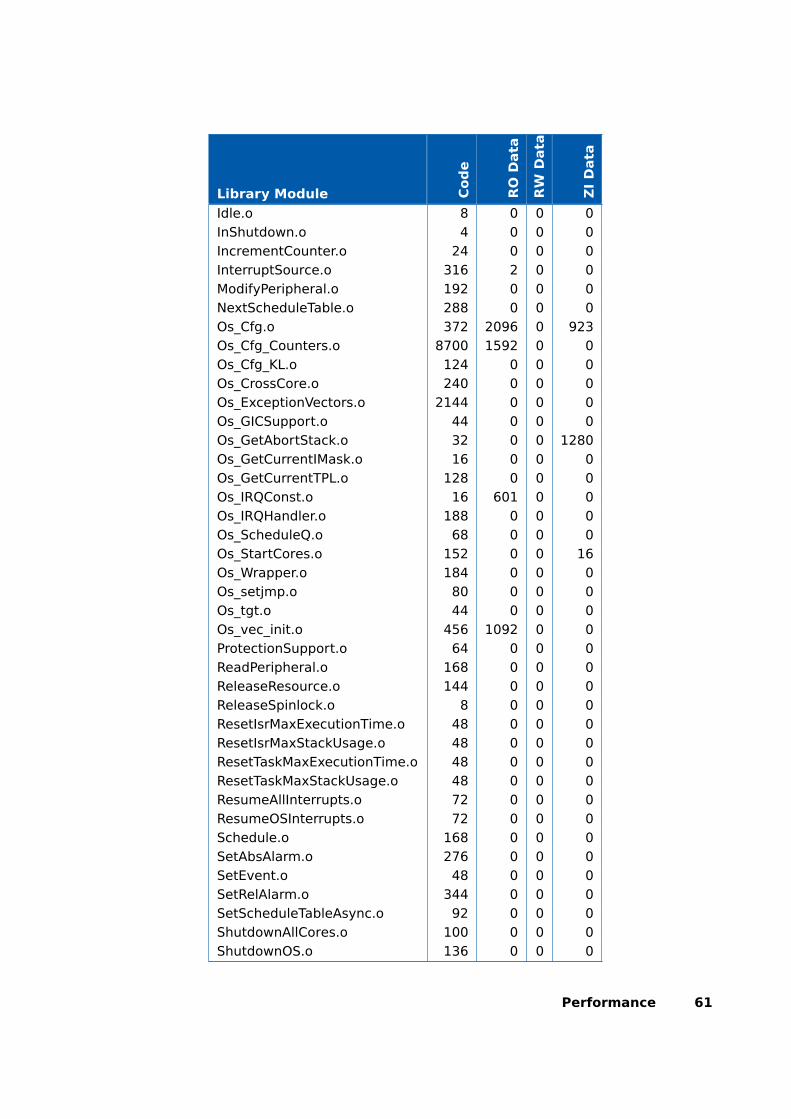
Library Module Cod
e
RO
Data
RW
Data
ZI
Data
Idle.o 8 0 0 0InShutdown.o 4 0 0 0IncrementCounter.o 24 0 0 0InterruptSource.o 316 2 0 0ModifyPeripheral.o 192 0 0 0NextScheduleTable.o 288 0 0 0Os_Cfg.o 372 2096 0 923Os_Cfg_Counters.o 8700 1592 0 0Os_Cfg_KL.o 124 0 0 0Os_CrossCore.o 240 0 0 0Os_ExceptionVectors.o 2144 0 0 0Os_GICSupport.o 44 0 0 0Os_GetAbortStack.o 32 0 0 1280Os_GetCurrentIMask.o 16 0 0 0Os_GetCurrentTPL.o 128 0 0 0Os_IRQConst.o 16 601 0 0Os_IRQHandler.o 188 0 0 0Os_ScheduleQ.o 68 0 0 0Os_StartCores.o 152 0 0 16Os_Wrapper.o 184 0 0 0Os_setjmp.o 80 0 0 0Os_tgt.o 44 0 0 0Os_vec_init.o 456 1092 0 0ProtectionSupport.o 64 0 0 0ReadPeripheral.o 168 0 0 0ReleaseResource.o 144 0 0 0ReleaseSpinlock.o 8 0 0 0ResetIsrMaxExecutionTime.o 48 0 0 0ResetIsrMaxStackUsage.o 48 0 0 0ResetTaskMaxExecutionTime.o 48 0 0 0ResetTaskMaxStackUsage.o 48 0 0 0ResumeAllInterrupts.o 72 0 0 0ResumeOSInterrupts.o 72 0 0 0Schedule.o 168 0 0 0SetAbsAlarm.o 276 0 0 0SetEvent.o 48 0 0 0SetRelAlarm.o 344 0 0 0SetScheduleTableAsync.o 92 0 0 0ShutdownAllCores.o 100 0 0 0ShutdownOS.o 136 0 0 0
Performance 61

Library Module Cod
e
RO
Data
RW
Data
ZI
Data
StackOverrunHook.o 8 0 0 0StartCore.o 76 0 0 0StartNonAutosarCore.o 76 0 0 0StartOS.o 944 0 0 0StartScheduleTableAbs.o 284 0 0 0StartScheduleTableRel.o 268 0 0 0StartScheduleTableSynchron.o 92 0 0 0StopScheduleTable.o 228 0 0 0SuspendAllInterrupts.o 84 0 0 0SuspendOSInterrupts.o 108 0 0 0SyncScheduleTable.o 96 0 0 0SyncScheduleTableRel.o 96 0 0 0TerminateTask.o 48 0 0 0TryToGetSpinlock.o 16 0 0 0ValidateCounter.o 84 0 0 0ValidateISR.o 20 0 0 0ValidateResource.o 84 0 0 0ValidateScheduleTable.o 60 0 0 0ValidateTask.o 160 0 0 0WaitEvent.o 48 0 0 0WritePeripheral.o 156 0 0 0
8.5 Execution Time
The following tables give the execution times in CPU cycles, i.e. in termsof ticks of the processor’s program counter. These figures will normally beindependent of the frequency at which you clock the CPU. To convert betweenCPU cycles and SI time units the following formula can be used:
Time in microseconds = Time in cycles / CPU Clock rate in MHz
For example, an operation that takes 50 CPU cycles would be:
• at 20MHz = 50/20 = 2.5µs
• at 80MHz = 50/80 = 0.625µs
• at 150MHz = 50/150 = 0.333µs
While every effort is made to measure execution times using a stopwatchrunning at the same rate as the CPU clock, this is not always possible on
62 Performance

the target hardware. If the stopwatch runs slower than the CPU clock, thenwhen RTA-OS reads the stopwatch, there is a possibility that the time read isless than the actual amount of time that has elapsed due to the difference inresolution between the CPU clock and the stopwatch (the User Guide providesfurther details on the issue of uncertainty in execution time measurement).
The figures presented in Section 8.5.1 have an uncertainty of 0 CPU cycle(s).
Values are given for single-core operation only. Timings for cross-core acti-vations, though interesting, are variable because of the nature of multi-coreoperation. Minimum values cannot be given, because timings are dependenton the activity on the core that receives the activation.
8.5.1 Context Switching Time
Task switching time is the time between the last instruction of the previ-ous task and the first instruction of the next task. The switching time dif-fers depending on the switching contexts (e.g. an ActivateTask() versus aChainTask()).
Interrupt latency is the time between an interrupt request being recognizedby the target hardware and the execution of the first instruction of the userprovided handler function:
For Category 1 ISRs this is the time required for the hardware to recognizethe interrupt.
For Category 2 ISRs this is the time required for the hardware to recognizethe interrupt plus the time required by RTA-OS to set-up the context inwhich the ISR runs.
Figure 8.1 shows the measured context switch times for RTA-OS.
Performance 63
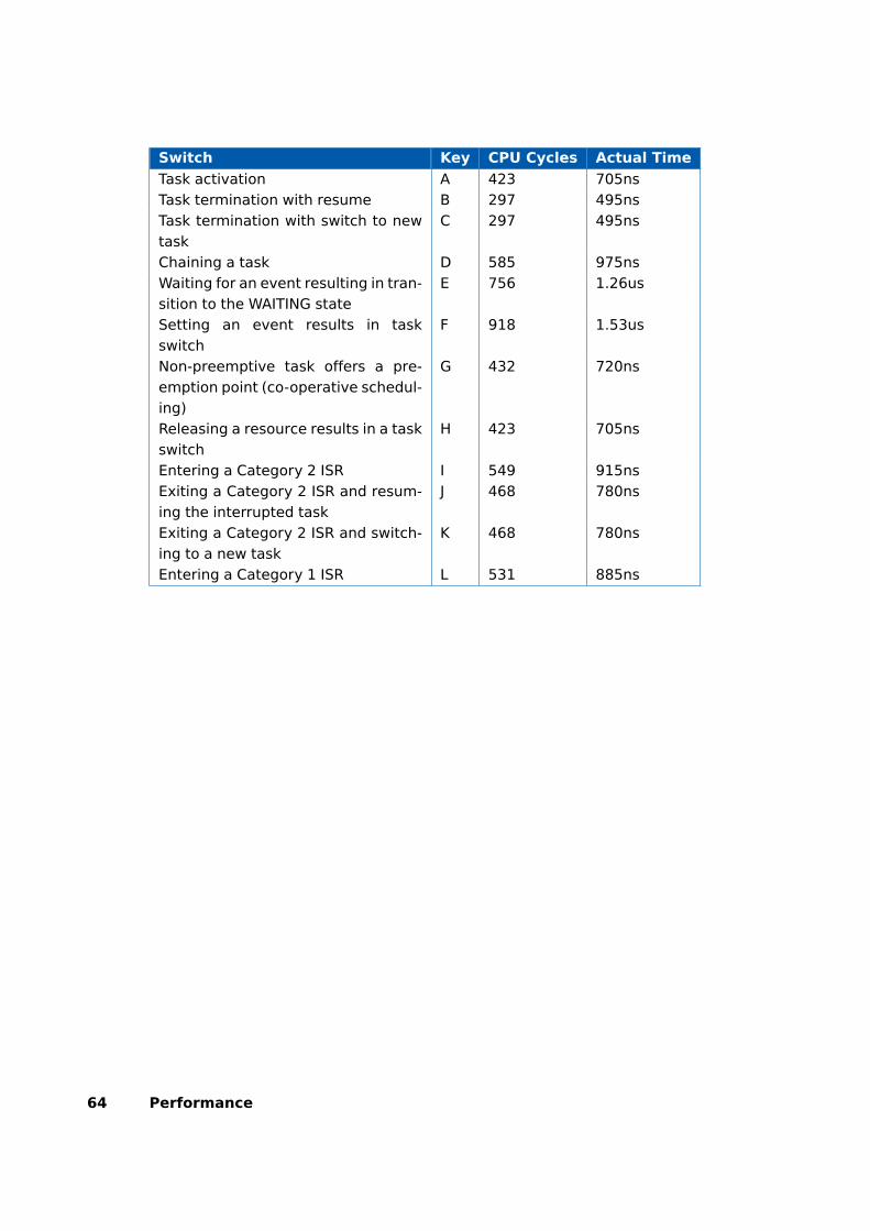
Switch Key CPU Cycles Actual Time
Task activation A 423 705nsTask termination with resume B 297 495nsTask termination with switch to newtask
C 297 495ns
Chaining a task D 585 975nsWaiting for an event resulting in tran-sition to the WAITING state
E 756 1.26us
Setting an event results in taskswitch
F 918 1.53us
Non-preemptive task offers a pre-emption point (co-operative schedul-ing)
G 432 720ns
Releasing a resource results in a taskswitch
H 423 705ns
Entering a Category 2 ISR I 549 915nsExiting a Category 2 ISR and resum-ing the interrupted task
J 468 780ns
Exiting a Category 2 ISR and switch-ing to a new task
K 468 780ns
Entering a Category 1 ISR L 531 885ns
64 Performance

(a) Task activated. Termination resumespreempted task.
(b) Task activated. Termination switches into new task.
(c) Task chained. (d) Task waits. Task is resumed whenevent set.
(e) Task switch when re-source is released.
(f) Request for scheduling made by non-preemptive task.
(g) Category 2 interrupt entry. Interruptedtask resumed on exit.
(h) Category 2 interrupt entry. Switch to new task on exit. (i) Category 1 interrupt entry.
Figure 8.1: Context Switching
Performance 65
9 Finding Out More
Additional information about RCarX3A5X/ARM-specific parts of RTA-OS can befound in the following manuals:
RCarX3A5X/ARM Release Note. This document provides informationabout the RCarX3A5X/ARM port plug-in release, including a list ofchanges from previous releases and a list of known limitations.
Information about the port-independent parts of RTA-OS can be found in thefollowing manuals, which can be found in the RTA-OS installation (typically inthe Documents folder):
Getting Started Guide. This document explains how to install RTA-OS toolsand describes the underlying principles of the operating system
Reference Guide. This guide provides a complete reference to the API, pro-gramming conventions and tool operation for RTA-OS.
User Guide. This guide shows you how to use RTA-OS to build real-time ap-plications.
66 Finding Out More
10 Contacting ETAS
10.1 Technical Support
Technical support is available to all users with a valid support contract. If youdo not have a valid support contract, please contact your regional sales office(see Section 10.2.2).
The best way to get technical support is by email. Any problems or questionsabout the use of the product should be sent to:
If you prefer to discuss your problem with the technical support team, youcall the support hotline on:
+44 (0)1904 562624.
The hotline is available during normal office hours (0900-1730 GMT/BST).
In either case, it is helpful if you can provide technical support with the fol-lowing information:
• Your support contract number
• Your .xml, .arxml, .rtaos and/or .stc files
• The command line which caused the error
• The version of the ETAS tools you are using
• The version of the compiler tool chain you are using
• The error message you received (if any)
• The file Diagnostic.dmp if it was generated
10.2 General Enquiries
10.2.1 ETAS Global Headquarters
ETAS GmbHBorsigstrasse 24 Phone: +49 711 3423-070469 Stuttgart Fax: +49 711 3423-2106Germany WWW: www.etas.com
10.2.2 ETAS Local Sales & Support Offices
Contact details for your local sales office and local technical support team(where available) can be found on the ETAS web site:
ETAS subsidiaries www.etas.com/en/contact.phpETAS technical support www.etas.com/en/hotlines.php
Contacting ETAS 67

Index
AAssembler, 43AUTOSAR OS includes
Os.h, 30Os_Cfg.h, 30Os_MemMap.h, 30
CCAT1_ISR, 36Compiler, 42Compiler (ARM DS-5 Ultimate Edition:
ARM Compiler 6.6), 41Compiler Versions, 41Configuration
Port-Specific Parameters, 23
DDebugger, 45
EETAS License Manager, 12
Installation, 12
FFiles, 29
HHardware
Requirements, 10
IInstallation, 10
Default Directory, 11Verification, 21
Interrupts, 49Category 1, 52Category 2, 52Default, 53
IPL, 49
LLibrarian, 44Library
Name of, 30License, 12
Borrowing, 17
Concurrent, 14
Grace Mode, 13
Installation, 16
Machine-named, 14
Status, 17
Troubleshooting, 18
User-named, 14
Linker, 44
M
Memory Model, 53
O
Options, 42
Os_Cbk_GetAbortStack, 32
Os_Cbk_StartCore, 33
Os_Cbk_StopCore, 35
Os_Clear_x, 37
Os_Disable_x, 37
Os_DisableAllConfiguredInterrupts_CPUx,37
Os_Enable_x, 38
Os_EnableAllConfiguredInterrupts_CPUx,38
Os_InitializeGICGroup, 31
Os_InitializeVectorTable, 31
Os_IntChannel_x, 38
Os_Set_Edge_Triggered_x, 39
Os_Set_Level_Sensitive_x, 39
Os_StackSizeType, 39
Os_StackValueType, 40
P
Parameters of Implementation, 23
Performance, 55
Context Switching Times, 63
Library Module Sizes, 57
RAM and ROM, 55
Stack Usage, 56
Processor Modes, 53
Trusted, 53
Untrusted, 53
68 Index

Processor state when calling Star-tOS(), 54
R
Registers
GIC, 49
GICD_IGROUPRx, 48
GICD_IPRIORITYRx, 48
GICD_ISENABLERx/GICD_ICENABLERx,48
GICD_ITARGETSRx, 48
Initialization, 47
Non-modifiable, 48
PSTATE, 48, 49
SP, 48, 49
VBAR_EL1, 48
SSoftware
Requirements, 10Stack, 54
TTarget, 47
Variants, 47Toolchain, 41
VVariants, 47Vector Table
Base Address, 52
Index 69
Related Documents