www.raycap.com INSTALLATION INSTRUCTIONS RSE Series 2 ©Raycap • All rights reserved (320-1373) QRC | Rev.A Page 1 of 9 RSE Series 2 Installation, Operation & Maintenance Manual WARNINGS Safety First – Hazardous Voltage & Shock Hazard • Only qualified licensed electricians should install or service SPDs • Hazardous voltages exist within SPDs • SPDs should never be installed or serviced when energized • Use appropriate safety precautions including Personal Protection Equipment • Failure to follow these instructions can result in death, serious injury, and/or equipment damage • This manual shall be read in its entirety prior to installing Bonding and Grounding Hazard Verify that the neutral conductor in the service entrance equipment is bonded to ground in accordance with the National Electric Code (NEC ® ) and all applicable codes. During installation into an electrical system the SPD must not be energized until the electrical system is completely installed, inspected and tested. All conductors must be connected and functional including the neutral (if required). The voltage rating of the SPD and system must be verified before energizing the SPD. Failure to follow these guidelines can lead to abnormally high voltages at the SPD. This may cause the SPD to fail. The warranty is voided if the SPD is incorrectly installed and/or if the neutral conductor in the service entrance equipment or downstream of separately derived systems is not bonded to ground in accordance with the NEC ® . Do Not Hi-Pot Test SPDs Any factory or on-site testing of power distribution equipment that exceeds normal operating voltage such as high-potential insulation testing, or any other tests where the suppression components will be subjected to higher voltage than their rated Maximum Continuous Operating Voltage (MCOV) must be conducted with the SPD disconnected from the power source. For 4-wire systems, the neutral connection at the SPD must also be disconnected prior to performing high-potential testing. Failure to disconnect SPD and associated components during elevated voltage testing will damage the SPD and will void the warranty. SPDs on Ungrounded Systems Caution – Ungrounded systems are inherently unstable and can produce excessively high line-toground voltages during certain fault conditions. During these fault conditions, any electrical equipment including an SPD may be subjected to voltages which exceed their designed ratings. An SPD designed specifically for Ungrounded systems should be used. Unpacking & Preliminary Inspection Inspect the entire shipping container for damage or signs of mishandling. Remove the packing materials and further inspect the unit for any obvious shipping damages. If any damage was found and is a result of shipping or handling, immediately file a claim with the shipping company and forward a copy to Raycap. Storage Environment This SPD should be stored in a clean, dry environment. Storage temperature range is -35°C (-31°F) to +75°C (+167°F). Avoid exposure to high condensation.

Welcome message from author
This document is posted to help you gain knowledge. Please leave a comment to let me know what you think about it! Share it to your friends and learn new things together.
Transcript

www.raycap.com
INSTALLATION INSTRUCTIONS RSE Series 2
©Raycap • All rights reserved(320-1373) QRC | Rev.A
Page 1 of 9
RSE Series 2 Installation, Operation & Maintenance Manual
WARNINGSSafety First – Hazardous Voltage & Shock Hazard
• Only qualified licensed electricians should install or service SPDs• Hazardous voltages exist within SPDs• SPDs should never be installed or serviced when energized• Use appropriate safety precautions including Personal Protection Equipment• Failure to follow these instructions can result in death, serious injury, and/or equipment damage• This manual shall be read in its entirety prior to installing
Bonding and Grounding HazardVerify that the neutral conductor in the service entrance equipment is bonded to ground in accordancewith the National Electric Code (NEC®) and all applicable codes. During installation into an electrical system the SPD must not be energized until the electrical system is completely installed, inspected and tested. All conductors must be connected and functional including the neutral (if required). The voltage rating of the SPD and system must be verified before energizing the SPD. Failure to follow these guidelines can lead to abnormally high voltages at the SPD. This may cause the SPD to fail. The warranty is voided if the SPD is incorrectly installed and/or if the neutral conductor in the service entrance equipment or downstream of separately derived systems is not bonded to ground in accordance with the NEC®.
Do Not Hi-Pot Test SPDsAny factory or on-site testing of power distribution equipment that exceeds normal operating voltagesuch as high-potential insulation testing, or any other tests where the suppression components will besubjected to higher voltage than their rated Maximum Continuous Operating Voltage (MCOV) mustbe conducted with the SPD disconnected from the power source. For 4-wire systems, the neutralconnection at the SPD must also be disconnected prior to performing high-potential testing. Failure todisconnect SPD and associated components during elevated voltage testing will damage the SPD andwill void the warranty.
SPDs on Ungrounded Systems Caution – Ungrounded systems are inherently unstable and can produce excessively high line-togroundvoltages during certain fault conditions. During these fault conditions, any electrical equipmentincluding an SPD may be subjected to voltages which exceed their designed ratings. An SPD designedspecifically for Ungrounded systems should be used.
Unpacking & Preliminary InspectionInspect the entire shipping container for damage or signs of mishandling. Remove the packing materialsand further inspect the unit for any obvious shipping damages. If any damage was found and is a resultof shipping or handling, immediately file a claim with the shipping company and forward a copy toRaycap.
Storage EnvironmentThis SPD should be stored in a clean, dry environment. Storage temperature range is -35°C (-31°F) to+75°C (+167°F). Avoid exposure to high condensation.

www.raycap.com
INSTALLATION INSTRUCTIONS RSE Series 2
©Raycap • All rights reserved(320-1373) QRC | Rev.A
Page 2 of 9
PRE-INSTALLATION
Operating EnvironmentThe standard unit uses a Type 4 enclosure. Flush-mount kitsare available as options. Before installing, ensure that yourenclosure type and application are appropriate with regard tomoisture, dirt, excessive dust, flammable materials or atmospheres, corrosive vapors, etc. Please consult factory if enclosure needs to be changed. This SPD is designed in an ambient temperature range of -35°C (-31°F) to +75°C (+167°F) with a relative humidity of 0% to 95% (noncondensing).Excessive temperature may inadvertently operateinternal thermal overtemperature protectors.
Line Side versus Load Side InstallationThe RSE Series 2 are tested and qualified as Type 1 SPDs per UL 1449 Fourth Edition (cUL type 2). This SPD can be installed on the Line Side of the service overcurrent device. Type 1 SPDs may also be installed in Type 2 applications. As a generalization, it is more practical to install as Type 2 on load side of main overcurrent device for maintenance reasons.
Audible NoiseSPD background noise is negligible or non-existent, and does not restrict the location of installation.
Lead Lengths & Maximizing SPD PerformanceSPDs must be located as close to the circuit as possible to minimize parasitic losses. Use the shortest& straightest possible leads. Pre-Plan installations and ensure that nearest breaker positions are used.If new construction, adjust breaker locations as appropriate. When longer leads are unavoidable, gentlytwist leads together (one to two twists per foot), or tie-wrap leads together.
Voltage RatingBefore installing SPD, verify that it has the same voltage rating as the power distribution system.Compare the SPDs nameplate voltage or model number and ensure that SPD configuration matches theintended power source.
Circuit Breaker ConnectedWhen connected on load side of main disconnect, we suggest connecting via a 60A circuit breaker. Thecircuit breaker is the intended disconnect switch and provides short circuit protection to the connectingconductors. These SPDs have internal overload protection elements within the product. These SPDshave demonstrated 200kA Short Circuit Current Ratings (SCCRs).
www.raycap.com
INSTALLATION INSTRUCTIONS RSE Series 2
©Raycap • All rights reserved(320-1373) QRC | Rev.A
Page 3 of 9
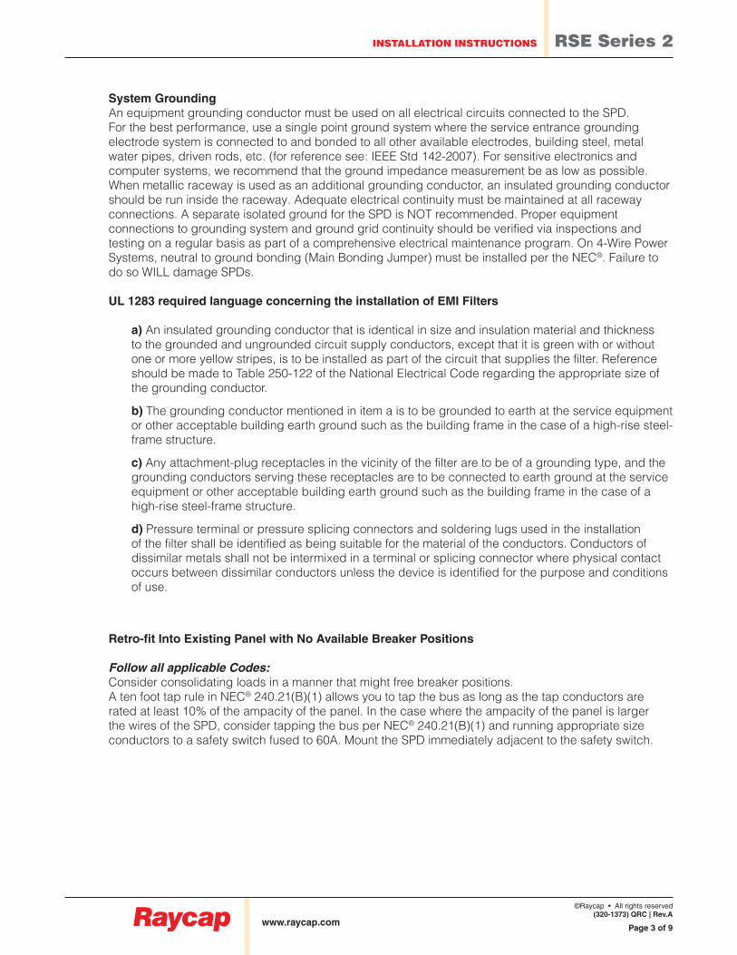
System GroundingAn equipment grounding conductor must be used on all electrical circuits connected to the SPD.For the best performance, use a single point ground system where the service entrance groundingelectrode system is connected to and bonded to all other available electrodes, building steel, metalwater pipes, driven rods, etc. (for reference see: IEEE Std 142-2007). For sensitive electronics andcomputer systems, we recommend that the ground impedance measurement be as low as possible.When metallic raceway is used as an additional grounding conductor, an insulated grounding conductorshould be run inside the raceway. Adequate electrical continuity must be maintained at all raceway connections. A separate isolated ground for the SPD is NOT recommended. Proper equipment connections to grounding system and ground grid continuity should be verified via inspections and testing on a regular basis as part of a comprehensive electrical maintenance program. On 4-Wire Power Systems, neutral to ground bonding (Main Bonding Jumper) must be installed per the NEC®. Failure to do so WILL damage SPDs.
UL 1283 required language concerning the installation of EMI Filters
a) An insulated grounding conductor that is identical in size and insulation material and thickness to the grounded and ungrounded circuit supply conductors, except that it is green with or without one or more yellow stripes, is to be installed as part of the circuit that supplies the filter. Reference should be made to Table 250-122 of the National Electrical Code regarding the appropriate size of the grounding conductor.
b) The grounding conductor mentioned in item a is to be grounded to earth at the service equipment or other acceptable building earth ground such as the building frame in the case of a high-rise steel-frame structure.
c) Any attachment-plug receptacles in the vicinity of the filter are to be of a grounding type, and the grounding conductors serving these receptacles are to be connected to earth ground at the service equipment or other acceptable building earth ground such as the building frame in the case of a high-rise steel-frame structure.
d) Pressure terminal or pressure splicing connectors and soldering lugs used in the installation of the filter shall be identified as being suitable for the material of the conductors. Conductors of dissimilar metals shall not be intermixed in a terminal or splicing connector where physical contact occurs between dissimilar conductors unless the device is identified for the purpose and conditions of use.
Retro-fit Into Existing Panel with No Available Breaker Positions
Follow all applicable Codes:Consider consolidating loads in a manner that might free breaker positions.A ten foot tap rule in NEC® 240.21(B)(1) allows you to tap the bus as long as the tap conductors arerated at least 10% of the ampacity of the panel. In the case where the ampacity of the panel is largerthe wires of the SPD, consider tapping the bus per NEC® 240.21(B)(1) and running appropriate sizeconductors to a safety switch fused to 60A. Mount the SPD immediately adjacent to the safety switch.

www.raycap.com
INSTALLATION INSTRUCTIONS RSE Series 2
©Raycap • All rights reserved(320-1373) QRC | Rev.A
Page 4 of 9
INSTALLATION
Pre-Plan your installation • Meet all National and Local codes. (NEC® Article 285 addresses SPDs) • Mount SPD as close to panel or equipment as possible to keep leads short • Ensure leads are as short and straight as possible, including neutral and ground. • Consider a breaker position that is closest to the SPD and the panel’s neutral & ground • Suggested breaker size is 60A-30A • Make sure system is grounded per NEC® and clear of faults before energizing SPD
1. Use a voltmeter to check all voltages to ensure correct SPD.
2. If SPD has Dry Contact, pre-plan their installation.
3. Remove power for panel. Confirm panel is deenergized.
4. Identify connection/breaker location and SPD location.
5. Make sure leads are short.
6. Remove an appropriately sized knockout from panel.
7. Mount SPD. Connect to equipment using an approved wiring method, including seals appropriate for the enclosure rating.
8. Connect conductors as appropriate – short and straight as possible. (Note that Hi-Legs are Phase B).
9. Label or mark conductors as appropriate Energized: black Neutral: white Ground: green Hi-Leg (Delta units only): orange
10. Make sure system is bonded per NEC® and is clear of hazards or faults before energizing (N-G bonding not per NEC® will fail SPDs: #1 cause of SPD failures).
11. Energize and confirm proper operation of indicators and/or options. If Red LED flashes & Audible Alarm cycles, deenergize immediately and call for help.
Connect to Alarming
black
yellow
brownNO (Normally Open)
Common
black
green
Connect to Mains
whiteNeutral
Ground
Line(s)
NC (Normally Closed)
www.raycap.com
INSTALLATION INSTRUCTIONS RSE Series 2
©Raycap • All rights reserved(320-1373) QRC | Rev.A
Page 5 of 9
OPERATION
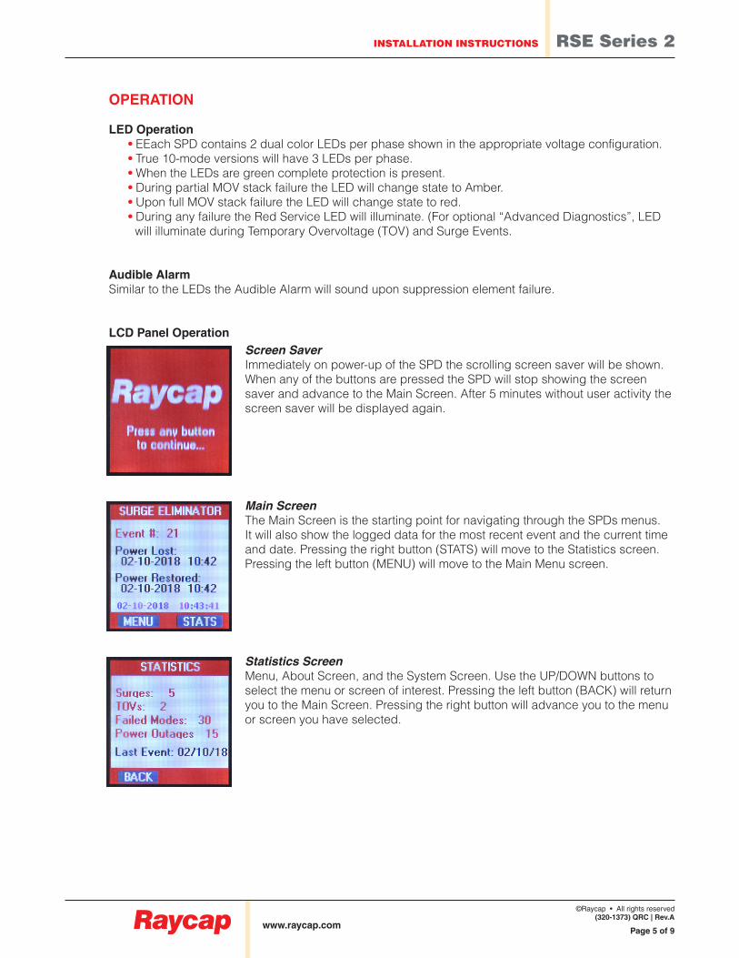
LED Operation • EEach SPD contains 2 dual color LEDs per phase shown in the appropriate voltage configuration. • True 10-mode versions will have 3 LEDs per phase. • When the LEDs are green complete protection is present. • During partial MOV stack failure the LED will change state to Amber. • Upon full MOV stack failure the LED will change state to red. • During any failure the Red Service LED will illuminate. (For optional “Advanced Diagnostics”, LED will illuminate during Temporary Overvoltage (TOV) and Surge Events.
Audible AlarmSimilar to the LEDs the Audible Alarm will sound upon suppression element failure.
LCD Panel OperationScreen SaverImmediately on power-up of the SPD the scrolling screen saver will be shown.When any of the buttons are pressed the SPD will stop showing the screensaver and advance to the Main Screen. After 5 minutes without user activity thescreen saver will be displayed again.
Main ScreenThe Main Screen is the starting point for navigating through the SPDs menus.It will also show the logged data for the most recent event and the current time and date. Pressing the right button (STATS) will move to the Statistics screen.Pressing the left button (MENU) will move to the Main Menu screen.
Statistics ScreenMenu, About Screen, and the System Screen. Use the UP/DOWN buttons to select the menu or screen of interest. Pressing the left button (BACK) will return you to the Main Screen. Pressing the right button will advance you to the menu or screen you have selected.
www.raycap.com
INSTALLATION INSTRUCTIONS RSE Series 2
©Raycap • All rights reserved(320-1373) QRC | Rev.A
Page 6 of 9
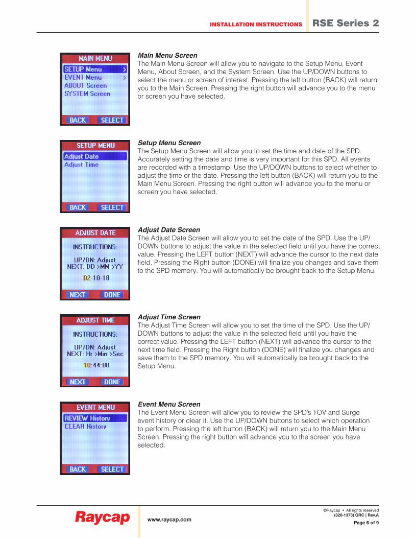
Main Menu ScreenThe Main Menu Screen will allow you to navigate to the Setup Menu, EventMenu, About Screen, and the System Screen. Use the UP/DOWN buttons toselect the menu or screen of interest. Pressing the left button (BACK) will returnyou to the Main Screen. Pressing the right button will advance you to the menuor screen you have selected.
Setup Menu ScreenThe Setup Menu Screen will allow you to set the time and date of the SPD.Accurately setting the date and time is very important for this SPD. All eventsare recorded with a timestamp. Use the UP/DOWN buttons to select whether toadjust the time or the date. Pressing the left button (BACK) will return you to theMain Menu Screen. Pressing the right button will advance you to the menu orscreen you have selected.
Adjust Date ScreenThe Adjust Date Screen will allow you to set the date of the SPD. Use the UP/DOWN buttons to adjust the value in the selected field until you have the correctvalue. Pressing the LEFT button (NEXT) will advance the cursor to the next datefield. Pressing the Right button (DONE) will finalize you changes and save themto the SPD memory. You will automatically be brought back to the Setup Menu.
Adjust Time ScreenThe Adjust Time Screen will allow you to set the time of the SPD. Use the UP/DOWN buttons to adjust the value in the selected field until you have thecorrect value. Pressing the LEFT button (NEXT) will advance the cursor to thenext time field. Pressing the Right button (DONE) will finalize you changes andsave them to the SPD memory. You will automatically be brought back to theSetup Menu.
Event Menu ScreenThe Event Menu Screen will allow you to review the SPD’s TOV and Surge event history or clear it. Use the UP/DOWN buttons to select which operation to perform. Pressing the left button (BACK) will return you to the Main Menu Screen. Pressing the right button will advance you to the screen you have selected.

www.raycap.com
INSTALLATION INSTRUCTIONS RSE Series 2
©Raycap • All rights reserved(320-1373) QRC | Rev.A
Page 7 of 9
Event History Screen The Event History Screen will allow you to review each event the SPD has on record. Use the UP/DOWN buttons to scroll through the event log. Pressing the left button (BACK) will return you to the Event Menu Screen. Pressing the right button (CLEAR) will send you to the Clear Event History Screen.
Clear Event History ScreenThe Clear Event History Screen will allow you to clear the SPD’s event log.Pressing the left button (YES) will clear the event log. Pressing the right button(NO) will keep the current event log intact. Either operation will return you to theEvent History Screen.
About ScreenFrom the “Main Menu” screen the “About Screen” can be accessed to display the manufacturer’s information, the model number, and the serial number for this specific SPD. Pressing the left button (back) will return you to the “Main Menu” Screen.
System Info ScreenThe System Screen displays the important electrical information for this system.This includes the nominal operating voltage, System configuration (ie. Wye,Delta, Single Phase) and maximum current rating for each mode of the SPD.The processor serial number, firmware edition, build and test dates are alsoshown on this page. Pressing the left button (back) will return you to the MainMenu Screen.

www.raycap.com
INSTALLATION INSTRUCTIONS RSE Series 2
©Raycap • All rights reserved(320-1373) QRC | Rev.A
Page 8 of 9
Surge EventWhen the SPD detects a surge event the “Surge Detected“ animation will be shown. It will remain on screen until acknowledged by an operator. Any subsequent events that occur while the Surge event animation is on screen will be registered and queued for acknowledgment. Along with displaying the Surge animation, the Audio alarm will sound and the “Form C” dry contacts will change state. Pressing the left button (INFO) will display additional information about the event. Pressing the right button (CANCEL) will acknowledge the event and silence the alarms.
Temporary Over Voltage EventWhen the SPD detects a Temporary Over Voltage Event (TOV) the “TOV Detected” animation will be shown. It will remain on screen until acknowledged by an operator. Any subsequent events that occur while the TOV event animation is on screen will be registered and queued for acknowledgment. Along with displaying the TOV animation, the Audio alarm will sound and the “Form C” dry contacts will change state. Pressing the left button (INFO) will display additional information about the event. Pressing the right button (CANCEL) will acknowledge the event and silence the alarms.
System Event Alarms
Extended TOV EventIn the event of an operator attempting to clear a “TOV Detected” event while the TOV event is still occuring, the “TOV IN Progress” screen will be displayed.

www.raycap.com
INSTALLATION INSTRUCTIONS RSE Series 2
©Raycap • All rights reserved(320-1373) QRC | Rev.A
Page 9 of 9
Mode Disconnection When the SPD detects a MOV disconnection the “Mode Disoconnect” animation will be shown. It will remain on screen until acknowledged by an operator. Any subsequent events that occur while the disconnection event animation is on screen will be registered and queued for acknowledgment. Along with displaying the disconnection animation, the Audio alarm will sound and the “Form C” dry contacts will change state. A corresponding LED will also change state during an MOV disconnection. Pressing the left button (INFO) will display additional information about the event. Pressing the right button (CANCEL) will acknowledge the event and silence the alarms.
Power OutageShould the SPD be subjected to a power outage this animation will be shown.It will remain on screen until acknowledged by an operator. Any subsequentevents that occur while the power outage event animation is on screen will beregistered and queued for acknowledgment. Along with displaying the poweroutage animation, the Audio alarm will sound and the “Form C” dry contacts will change state. Pressing the left button (INFO) will display additional information about the event. Pressing the right button (CANCEL) will acknowledge the event and silence the alarms.
This SPD’s timekeeping is equipped to survive several days of a power outage.When power returns the SPD will record the date and time of the power lossand when power was restored. Should the SPD be exposed to an extendedpower outage the SPD’s time and date should be checked for accuracy.
On initial installations where power may be cycled several times. The power outage alarm is is designed to be suspended unitl the SPD has been energized for at least 1 hour.
Dry ContactThree 3' 18 AWG wires are included through the nipple as the Dry Contacts.
• Please note: Dry Contacts are designed for low voltage or control signals only.
• Maximum switching current is 5A
• Maximum switching voltage is 240V DC or AC.
• Higher energy applications require additional relay implementation outside the SPD.
• Gray is Common, Blue is Normally Open and Red is Normally Closed. If the Dry Contacts are not utilized, insulate lead ends, coil and secure.
MAINTENANCESPDs require minimal maintenance. We recommend periodic inspection of diagnostic indicators to ensure proper operation. We also recommend keeping the SPD clean as appropriate.
Troubleshooting & ServicePlease contact us for any service related issues. We want to take care of any problems.
Related Documents