Hardware and start-up guide Issue 1.2 October 2018 © Copyright 2016-2018 MuLogic B.V. Plesmanstraat 58D 3905KZ, Veenendaal, The Netherlands RSA-1 X 20 I NDUSTRIAL R EMOTE A CCESS R OUTER ( SOFTWARE V ERSION 2.1)

Welcome message from author
This document is posted to help you gain knowledge. Please leave a comment to let me know what you think about it! Share it to your friends and learn new things together.
Transcript

Hardware and start-up guide Issue 1.2 October 2018
© Copyright 2016-2018 MuLogic B.V. Plesmanstraat 58D 3905KZ, Veenendaal, The Netherlands
RSA-1X20
I N D U S T R I A L R E M O T E A C C E S S R O U T E R
( S O F T W A R E V E R S I O N 2 . 1 )


RSA-1120, RSA-1220 Industrial Remote Access Router
Compliances CE Compliance
• EMC: Directive 2004/108/EC (EN 55022, EN55024) • Safety: Directive 2006/95/EC (EN 60950)
The RSA series of routers complies with EMC directive 2004/108/EC and is classified for use in Residential areas. Test standard: EN 55022 Class B The RSA series also complies with the Immunity standard for ITE equipment EN 55024 with the applicable test levels increased to levels compatible with Industrial standards (ref. EN 61000-6-2).
About this user guide Although this user guide was written with greatest possible care, omissions and errors cannot be precluded. MuLogic BV accepts no liability for any inaccuracies that may be found. However, if you have comments or suggestions about this guide, please don’t hesitate to contact us in order to help us to improve our product documentation.
Use of open source software The firmware of the RSA series partly contains open source software that was written under GNU General Public Licence (GPL). The source code of this open source software can be made available on request. Contact MuLogic for more information. Tel: +31 850 160600 Fax: +31 850 160601 E-mail: [email protected] Website: www.mulogic.com © MuLogic BV, 2016-2018 This guide is for information purposes only. All design characteristics, specifications, etc. are subject to change without notice. No part of this publication may be reproduced, transmitted, transcribed, stored in a retrieval system or translated into any human or computer language in any form by any means without the prior permission of MuLogic BV. Issue No 1.2 (October 2018)

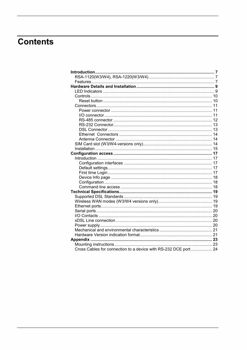
Contents
Introduction ........................................................................................................ 7 RSA-1120(W3/W4), RSA-1220(W3/W4) ......................................................... 7 Features ........................................................................................................... 7
Hardware Details and Installation .................................................................... 9 LED Indicators ................................................................................................. 9 Controls .......................................................................................................... 10
Reset button ............................................................................................... 10 Connectors ..................................................................................................... 11
Power connector ........................................................................................ 11 I/O connector .............................................................................................. 11 RS-485 connector ...................................................................................... 12 RS-232 Connector ...................................................................................... 13 DSL Connector ........................................................................................... 13 Ethernet Connectors ................................................................................. 14 Antenna Connector .................................................................................... 14
SIM Card slot (W3/W4-versions only) ............................................................ 14 Installation ...................................................................................................... 15
Configuration access ...................................................................................... 17 Introduction .................................................................................................... 17
Configuration interfaces ............................................................................. 17 Default settings ........................................................................................... 17 First time Login ........................................................................................... 17 Device Info page ........................................................................................ 18 Configuration .............................................................................................. 18 Command line access ................................................................................ 18
Technical Specifications ................................................................................. 19 Supported DSL Standards ............................................................................. 19 Wireless WAN modes (W3/W4 versions only) ............................................... 19 Ethernet ports................................................................................................. 19 Serial ports ..................................................................................................... 20 I/O Contacts ................................................................................................... 20 xDSL Line connection .................................................................................... 20 Power supply.................................................................................................. 20 Mechanical and environmental characteristics .............................................. 21 Hardware Version indication format ............................................................... 21
Appendix .......................................................................................................... 23 Mounting instructions ..................................................................................... 23 Cross Cables for connection to a device with RS-232 DCE port................... 24

Industrial remote access router - RSA-series User Guide – Introduction
Page 7
1 Introduction
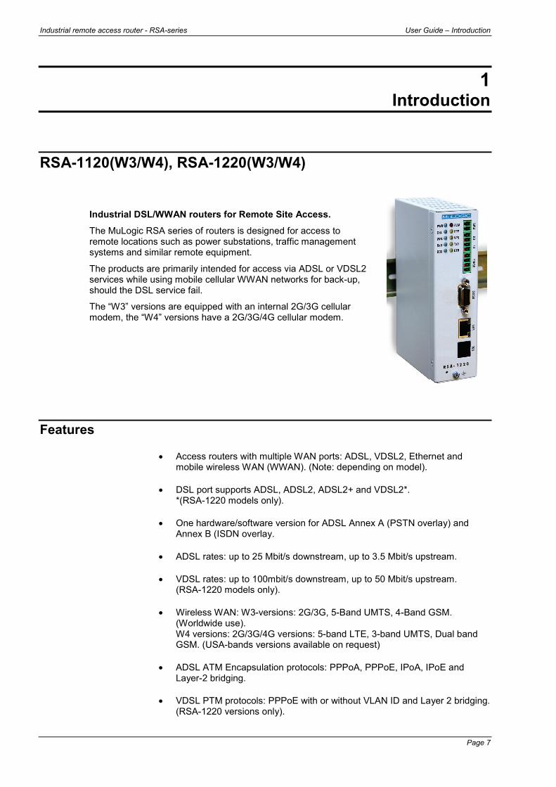
RSA-1120(W3/W4), RSA-1220(W3/W4)
Industrial DSL/WWAN routers for Remote Site Access. The MuLogic RSA series of routers is designed for access to remote locations such as power substations, traffic management systems and similar remote equipment.
The products are primarily intended for access via ADSL or VDSL2 services while using mobile cellular WWAN networks for back-up, should the DSL service fail.
The “W3” versions are equipped with an internal 2G/3G cellular modem, the “W4” versions have a 2G/3G/4G cellular modem.
Features
• Access routers with multiple WAN ports: ADSL, VDSL2, Ethernet and mobile wireless WAN (WWAN). (Note: depending on model).
• DSL port supports ADSL, ADSL2, ADSL2+ and VDSL2*. *(RSA-1220 models only).
• One hardware/software version for ADSL Annex A (PSTN overlay) and Annex B (ISDN overlay.
• ADSL rates: up to 25 Mbit/s downstream, up to 3.5 Mbit/s upstream.
• VDSL rates: up to 100mbit/s downstream, up to 50 Mbit/s upstream. (RSA-1220 models only).
• Wireless WAN: W3-versions: 2G/3G, 5-Band UMTS, 4-Band GSM. (Worldwide use). W4 versions: 2G/3G/4G versions: 5-band LTE, 3-band UMTS, Dual band GSM. (USA-bands versions available on request)
• ADSL ATM Encapsulation protocols: PPPoA, PPPoE, IPoA, IPoE and Layer-2 bridging.
• VDSL PTM protocols: PPPoE with or without VLAN ID and Layer 2 bridging. (RSA-1220 versions only).
User Guide – Introduction Industrial remote access router - RSA-series
Page 8
• Automatic Network Failover operation between DSL, Ethernet-WAN and Wireless WAN ports.
• Ethernet port supports 10/100baseT, Auto-MDI/MDIX. All Ethernet port can be used as LAN or WAN port.
• IEEE 802.1Q VLAN support for VDSL2/PTM, LAN and WAN Ethernet interfaces.
• LAN side Ethernet switch can be configured as Hub for monitoring purposes.
• Two Serial Port Gateways for remote serial data (TCP/IP or UDP/IP).
• Two serial ports (one RS-232, one RS-485) for data rates from 300 to 115200 bit/s.
• Support for SCADA protocols like Modbus RTU/ASCII, Modbus/TCP, DNP3, DNP3/IP, IEC60870-5-101and IEC60870-5-104.
• IPsec and OpenVPN tunnels for secure access and data transport.
• OpenVPN bridged (layer 2) and routed (Layer-3) modes.
• GRE tunnels for linking multicast protocols like RIPv2 and OSPF over IPsec.
• Internal DHCP server, DNS gateway and Dynamic DNS client.
• Static routing and dynamic routing (BGP, OSPF, RIPv1 and RIPv2)
• NAT features: Dynamic NAT (IP masquerading) and NAPT (Port forwarding)
• Stateful firewall for Access Control, Forwarding control, NAT routing and port forwarding.
• Device Management: HTTP/HTTPS, Telnet/SSH, SNMP and serial command port.
• Alerts for system events by means of Email, SNMP traps, SMS, Dry contact and LED
• Independent watchdog/reset controller for monitoring vital system functions to guarantee automatic failure recovery.
• Dry contact sensor (input) and dry contact for status/alarm indication and remote control.
• Isolated supply voltage input for industrial applications (suitable for low Voltage AC and DC).
• Extended operating temperature range: -40°C to +70°C.
• Rugged metal housing for DIN-rail or panel mounting..

Industrial remote access router - RSA-series User Guide – Hardware Details and Installation
Page 9
2 Hardware Details and Installation
LED Indicators The LED indicators display the status of the various ports and functions of the unit. In case a communication problem occurs, these LEDs can help you determine the cause of the problem.
LED Description
PWR Indicates that the unit is powered on and functions correctly. After start-up, this LED briefly blinks once per second to indicate the “alive” signal sent to the system watchdog.
ALM Indicates a System Alert. DSL Indicates the ADSL link status.
This LED blinks slowly when the remote DSLAM is detected and blinks rapidly during the training stage. When the ADSL link is established the LED will be on continuously.
PPP Indicates that a WAN connection is established.
ETH/WRL On the RSA-1x20 the ETH LED indicates that the Ethernet port is connected. On the RSA-1x20W the WRL LED Indicates the WWAN link status. This LED blinks shortly every 2 seconds when registered on the mobile network. The LED will blink during establishment of a data connection and will be on continuously when the data connection is established.
VPN Indicates that one or more VPN tunnel connections are established.
RxD Flashes when the unit sends data to the device connected to the serial port. (RS-232 and/or RS-485)
TxD Flashes when the unit sends data to the device connected to the serial port. (RS-232 and/or RS-485)
DCD Indicates that the serial port is in use. (RS-232 and/or RS-485)
DTR Indicates that the RS-232 DTR input is active (high).

User Guide – Hardware Details and Installation Industrial remote access router - RSA-series
Page 10
Controls The reset button is positioned behind the tiny hole near the ground terminal screw on the front panel. It can be used to restart the unit, enable the serial console port and to restore the factory default settings.
Restart
The unit is restarted by pressing the reset button for 1 second.
Serial RS-232 port console mode
The serial RS-232 port is normally used for the internal serial port gateway. However, for configuration without IP network access or for maintenance purposes, the serial port gateway can be disabled and command line access is enabled via the serial port.
To enable the serial port console mode, press and hold the reset button while connecting the power. Then release the reset button. After the system is started up, the DCD LED will go on to indicate that the port is in console mode. The RS-232 port will remain in this state until the power is disconnected.
The RS-232 port is of the type DCE and can be connected to a serial port of a PC by means of a straight male to female cable or a USB to RS-232 serial converter. The data rate and format is 115200, 8, N.
Factory default settings
To reset the unit to its original factory default settings, power on the unit and wait at least 60 seconds. Then press and hold the reset button for more than 5 seconds until the PWR, DSL, PPP and VPN LEDs start blinking. Then release the reset button. The unit will restart within 15 seconds. After a restart with restored factory settings, the following settings will apply:
• LAN IP address: 192.168.1.1
• user name: admin
• password: rsa-admin
Custom default settings
When custom default settings are present (custom defaults settings are made by the user, not the factory ), the procedure as described above will force a reset to the custom default settings. To force factory default settings when a custom defaults file is present, wait at least 60 seconds after power on and then press and hold the reset button for more than 30 seconds. The unit will restart within 15 seconds.
Reset button

Industrial remote access router - RSA-series User Guide – Hardware Details and Installation
Page 11
Connectors
The operating power of the RSA series is supplied at pins 1 and 2 of the PWR screw terminal connector. The voltage range depends on the model and is indicated by the “Vr suffix”:
Vr1: 11-36 Vdc, 11-28 Vac
Vr2: 18-60 Vdc, 18-28 Vac
Vr3: 18-72 Vdc, (no ac)
Note: The power input of the unit is not polarised. You can connect DC power (+/- or -/+) in either way.
Input
Pins 1 and 2 (marked CI) of the I/O connector are connected to a dry contact sensor.
Status changes of this input can be monitored via one of the management services or reported via one of the system alerts: Email, SNMP-trap, SMS, or read by means of an SNMP-Get.
• Maximum closed contact current (depending on PWR voltage): 6 mA. • Maximum loop resistance (contact plus cable): 100Ω.
Note: Only use this input for “dry contacts” like the contact of a switch or relay. Caution: Do not connect to any power source, including the unit’s power source, nor apply any voltage to the input pins. The contact inputs are galvanically connected with the unit’s power input.
Power connector
I/O connector

User Guide – Hardware Details and Installation Industrial remote access router - RSA-series
Page 12
Output
Pins 3 and 4 (marked CO) of the I/O connector are connected to an internal relay contact (electronic solid state relay). The relay contacts are galvanically isolated from the device and power input. The contact state (open/closed) can be controlled by means of an SNMP set, http request or selected as system alert output.
• Maximum load voltage: 100V • Maximum load current: 150mA • Maximum On-resistance: 8Ω. • Isolation Voltage: 1500 Vrms.
• A 2-wire RS-485 connection is made to pins 2 and 3. • Pins 1 and 4 are RS-485/RS-422 “Rx” inputs used in 4-wire RS-
485/RS-422 mode. (Note 2). • Pins 2 and 3 are used for 2-wire RS-485 or as “Tx” outputs in 4-wire
RS-485/R422 mode. (Note 2).
Note 1: The RS-485 output/inputs are not terminated. In general no termination resistors are needed. Note 2: The receive data input connector pins 1 and 4 are biased with 10kΩ. When not used (2-wire RS-485 mode) these pins can remain unconnected.
RS-485 connector
Pin Description Direction Input Output 1 Rx– Receive data input, negative
2 TR– Transmit/Receive data, negative
3 TR+ Transmit/Receive data, positive
4 Rx+ Receive data input, positive
Industrial remote access router - RSA-series User Guide – Hardware Details and Installation
Page 13
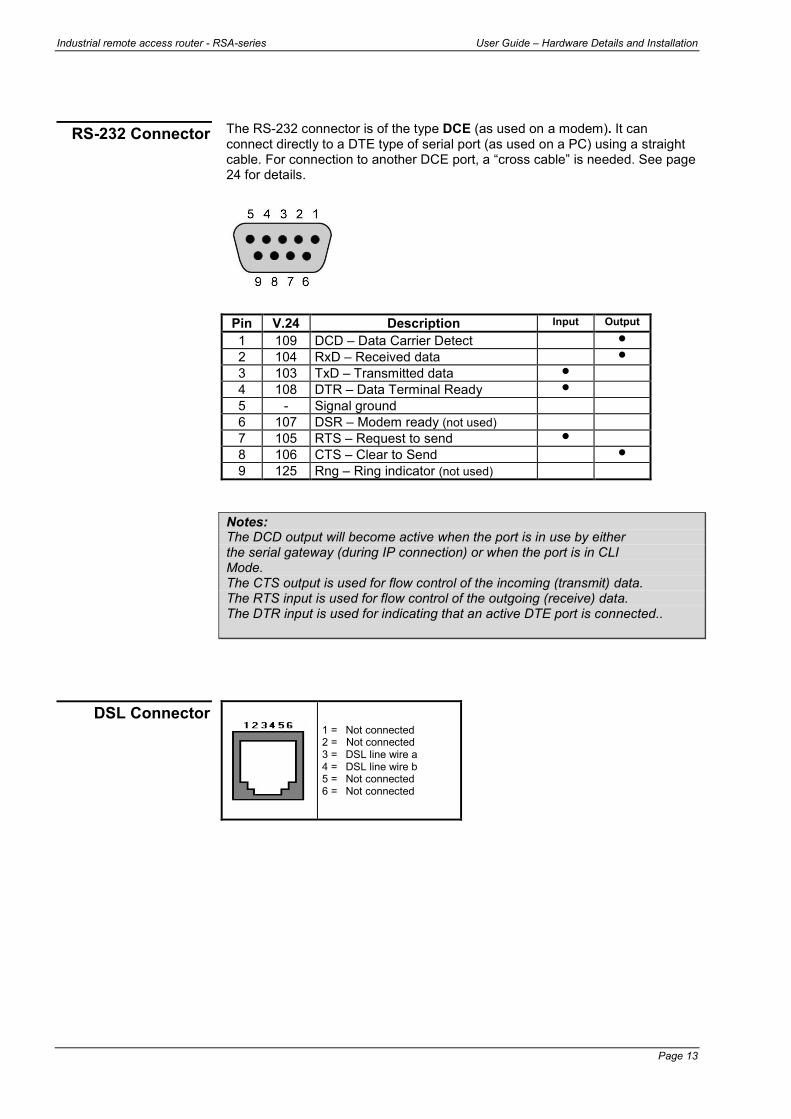
The RS-232 connector is of the type DCE (as used on a modem). It can connect directly to a DTE type of serial port (as used on a PC) using a straight cable. For connection to another DCE port, a “cross cable” is needed. See page 24 for details.
Notes: The DCD output will become active when the port is in use by either the serial gateway (during IP connection) or when the port is in CLI Mode. The CTS output is used for flow control of the incoming (transmit) data. The RTS input is used for flow control of the outgoing (receive) data. The DTR input is used for indicating that an active DTE port is connected..
1 = Not connected 2 = Not connected 3 = DSL line wire a 4 = DSL line wire b 5 = Not connected 6 = Not connected
RS-232 Connector
Pin V.24 Description Input Output 1 109 DCD – Data Carrier Detect
2 104 RxD – Received data
3 103 TxD – Transmitted data
4 108 DTR – Data Terminal Ready
5 - Signal ground
6 107 DSR – Modem ready (not used)
7 105 RTS – Request to send
8 106 CTS – Clear to Send
9 125 Rng – Ring indicator (not used)
DSL Connector
User Guide – Hardware Details and Installation Industrial remote access router - RSA-series
Page 14
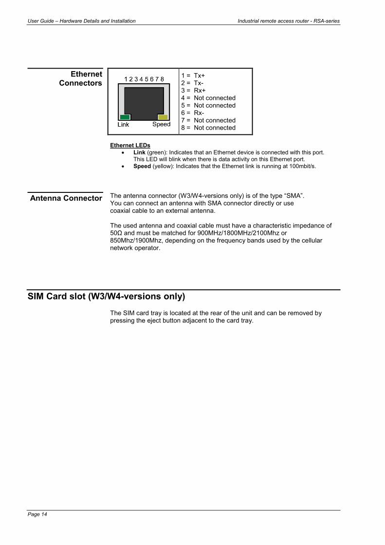
1 = Tx+ 2 = Tx- 3 = Rx+ 4 = Not connected 5 = Not connected 6 = Rx- 7 = Not connected 8 = Not connected
Ethernet LEDs
• Link (green): Indicates that an Ethernet device is connected with this port. This LED will blink when there is data activity on this Ethernet port.
• Speed (yellow): Indicates that the Ethernet link is running at 100mbit/s. The antenna connector (W3/W4-versions only) is of the type “SMA”. You can connect an antenna with SMA connector directly or use coaxial cable to an external antenna. The used antenna and coaxial cable must have a characteristic impedance of 50Ω and must be matched for 900MHz/1800MHz/2100Mhz or 850Mhz/1900Mhz, depending on the frequency bands used by the cellular network operator.
SIM Card slot (W3/W4-versions only) The SIM card tray is located at the rear of the unit and can be removed by pressing the eject button adjacent to the card tray.
Ethernet Connectors
Antenna Connector
Industrial remote access router - RSA-series User Guide – Hardware Details and Installation
Page 15
Installation This chapter covers the hardware installation procedure.
Power connection Connect the power cable to the screw terminal socket called PWR. The unit can be powered from low voltage DC or AC sources. The voltage range indication (Vr1, Vr2 or Vr3) is printed on the serial number label. Refer to page 20 (Power supply) for specification of the voltage ranges. Note: The power input of the RSA-4x22 is not polarised. You can connect DC power in either direction.
DSL line connection If the line is used only for connecting the RSA unit and no telephony service is needed, then the line can be connected directly to the DSL connector. If, apart from the DSL service, telephone service is required, then a splitter must be added. Note: Use the appropriate splitter for the telephone service: - a “POTS (PSTN) splitter” for use with traditional telephone service (Annex A). - an “ISDN splitter” for use with ISDN service (Annex B). For VDSL2 services, make sure that the splitter is suitable for VDSL.
• Connect the outside telephone line (coming from the telephone exchange/DSLAM) with the splitter port called “LINE”
• Connect the splitter port called “Phone” with the telephone set or ISDN NT.
• Connect the splitter port called “Modem” or “DSL” with the LINE connector of the modem.
When properly connected to the line, the DSL LED of the modem shall start blinking within 1 minute after power-on. When the DSL connection is established, the DSL LED is On continuously. The actual Internet connection will not be established until the unit is configured with the correct parameters (like VPI/VCI, and ATM Encapsulation Protocol). These parameters are provided by your ISP.
Ethernet cable(s) The Ethernet ports support 10/100baseT, HD or FD with Auto-MDI/MDIX feature. The ports will automatically adapt to the operating mode of the connected device and will automatically make a straight or crossed connection. When the unit is powered on and the Ethernet cable is properly connected between the unit’s Ethernet port and the Ethernet device, the green (link) LED at the Ethernet connector unit will be on. When data passes over the Ethernet cable, the link will briefly blink off. When connected in 100baseT mode, the yellow LED will be on.

User Guide – Hardware Details and Installation Industrial remote access router - RSA-series
Page 16
RS-232 connection The RS-232 port of the unit is of the type “DCE”, which means that it has the pin-out and behaviour of a (DB9) serial port of a modem. The port can be connected directly to the serial port of a PC using a straight “DB9-male to DB9-female” or “DB9-male to DB25-female” cable. It can also Connect directly to a USB-to-Serial converter cable. For connecting to the serial port of another DCE device, a “crossed DB9-male to DB9/DB25-male” cable is used. See chapter 5.
RS-485 connection The RS-485 port of the unit is factory configured for both 2-wire and 4-wire operation. This means that the RS-485 port can receive data from the RS-485 bus at both pins 1/4 and pins 2/3. To disable the receive data input on pins 2/3, select “4-wire only” in the RS-485 port setup page. In “4-wire only” mode, pins 2 and 3 of the RS-485 connector are only used for transmitted data (like for an RS-422 interface) but still go into high impedance mode while not transmitting. This allows the 4-wire interface to be used for both point-to-point and multidrop circuits. Note: The RS-485 inputs are biased with 10kΩ to the internal signal ground and 3,3V.
SIM card insertion (W3/W4-versions only)
The SIM card slot is located at the rear of the unit. The SIM card tray can be removed by pressing the eject button adjacent to the card tray. Place the SIM card in the card tray and reinsert the card tray making sure it is inserted correctly in the card slot. Note: Make sure to enter the correct SIM PIN. When a wrong PIN is detected, no further action is taken is taken until the next restart of the unit. After 3 restarts with the wrong PIN, the SIM will be locked and the PUK code must be entered to unlock the SIM card.
Industrial remote access router - RSA-series User Guide – Configuration Acces
Page 17
3 Configuration access
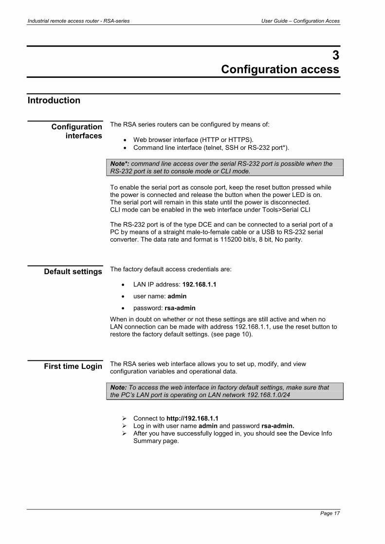
Introduction The RSA series routers can be configured by means of:
• Web browser interface (HTTP or HTTPS). • Command line interface (telnet, SSH or RS-232 port*).
Note*: command line access over the serial RS-232 port is possible when the RS-232 port is set to console mode or CLI mode. To enable the serial port as console port, keep the reset button pressed while the power is connected and release the button when the power LED is on. The serial port will remain in this state until the power is disconnected. CLI mode can be enabled in the web interface under Tools>Serial CLI The RS-232 port is of the type DCE and can be connected to a serial port of a PC by means of a straight male-to-female cable or a USB to RS-232 serial converter. The data rate and format is 115200 bit/s, 8 bit, No parity. The factory default access credentials are:
• LAN IP address: 192.168.1.1
• user name: admin
• password: rsa-admin
When in doubt on whether or not these settings are still active and when no LAN connection can be made with address 192.168.1.1, use the reset button to restore the factory default settings. (see page 10). The RSA series web interface allows you to set up, modify, and view configuration variables and operational data. Note: To access the web interface in factory default settings, make sure that the PC’s LAN port is operating on LAN network 192.168.1.0/24
Connect to http://192.168.1.1 Log in with user name admin and password rsa-admin. After you have successfully logged in, you should see the Device Info
Summary page.
Configuration interfaces
Default settings
First time Login

User Guide – Configuration Acces Industrial remote access router - RSA-series
Page 18
The Info page will show the model and general information and status of the unit. For example:
Further details on configuration are outside the scope of this manual. Please refer to the RSA series configuration guide for additional information. On factory default, ssh and telnet access is enabled for the LAN port. You can log in with user name admin and password rsa-admin. Upon successful log-in you will get a ~# prompt. Further details on configuration are outside the scope of this manual. Please refer to the RSA series configuration guide for additional information.
Device Info page
Configuration
Command line access

Industrial remote access router - RSA-series User Guide –Technical Specifications
Page 19
4 Technical Specifications
Supported DSL Standards Handshake:
• ITU-T G.994.1 (G.hs) • ANSI T1.413 Issue 2 (ADSL)
Modulation:
• ANSI T1.413 Issue 2 (ADSL) • ITU-T G.992.1 (G.dmt) • ITU-T G.992.2 (G.lite) • ITU-T G.992.3/4 (ADSL2) • ITU-T G.992.3 Annex L (RE-ADSL) • ITU-T G.992.3 Annex M (ADSL2 A/M) • ITU-T G.992.3 Annex J (ADSL2 B/J) • ITU-T G.992.5 (ADSL2+) • ITU-T G.992.5 Annex M (ADSL2+ M) • ITU-T G.992.5 Annex J (ADSL2 B/J) • ITU-T G.993.2 (VDSL2, profiles 8a, 8b, 8c, 8d, 12a, 12b, 17a) *
Note*: RSA-1220 models only
Wireless WAN modes (W3/W4 versions only)
• W3 versions: Five Band UMTS (WCDMA/FDD): 800, 850, 1900, 1700AWS and 2100 MHz. Quad-Band GSM: 850, 900, 1800 and 1900 MHz.
• W4 versions: Five band LTE 800/900/1800/2100/2600 MHz; FDD-Band (20,8,3,7,1); Tri Band UMTS (WCDMA): 900/1800/2100 MHz; FDD-Band (8,3,1); Dual Band GSM/GPRS/EDGE: 900/1800 MHz
• UMTS/HSPA+, 3GPP release 6/7. • GSM/GPRS/EDGE, 3GPP release 99/4. • HSDPA/HSUPA data rates DL: 7.2/14.4 Mbit/s, UL: 2.0/5.76 Mbit/s.
concurrent data rate: DL 7.2 Mbit/s / UL 5.76 Mbit/s. • LTE Cat. 3 DL: max. 100 Mbps, UL: max. 50 Mbps, 2x2 DL MIMO • Approvals: R&TTE, GCF, CE, FCC, IC, PTCRB, UL
Ethernet ports
• 10/100baseT • Half and Full duplex • Auto-MDI/MDIX • IEEE 802.1Q VLAN support
User Guide – Technical Specifications Industrial remote access router - RSA-series
Page 20
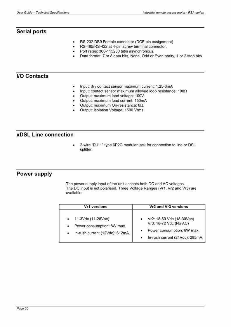
Serial ports
• RS-232 DB9 Female connector (DCE pin assignment) • RS-485/RS-422 at 4-pin screw terminal connector. • Port rates: 300-115200 bit/s asynchronous. • Data format: 7 or 8 data bits, None, Odd or Even parity, 1 or 2 stop bits.
I/O Contacts
• Input: dry contact sensor maximum current: 1,25-6mA • Input: contact sensor maximum allowed loop resistance: 100Ω • Output: maximum load voltage: 100V • Output: maximum load current: 150mA • Output: maximum On-resistance: 8Ω. • Output: isolation Voltage: 1500 Vrms.
xDSL Line connection
• 2-wire “RJ11” type 6P2C modular jack for connection to line or DSL splitter.
Power supply The power supply input of the unit accepts both DC and AC voltages. The DC input is not polarised. Three Voltage Ranges (Vr1, Vr2 and Vr3) are available.
Vr1 versions Vr2 and Vr3 versions
• 11-3Vdc (11-28Vac)
• Power consumption: 8W max.
• In-rush current (12Vdc): 612mA.
• Vr2: 18-60 Vdc (18-30Vac) Vr3: 18-72 Vdc (No AC)
• Power consumption: 8W max.
• In-rush current (24Vdc): 295mA.
Industrial remote access router - RSA-series User Guide –Technical Specifications
Page 21
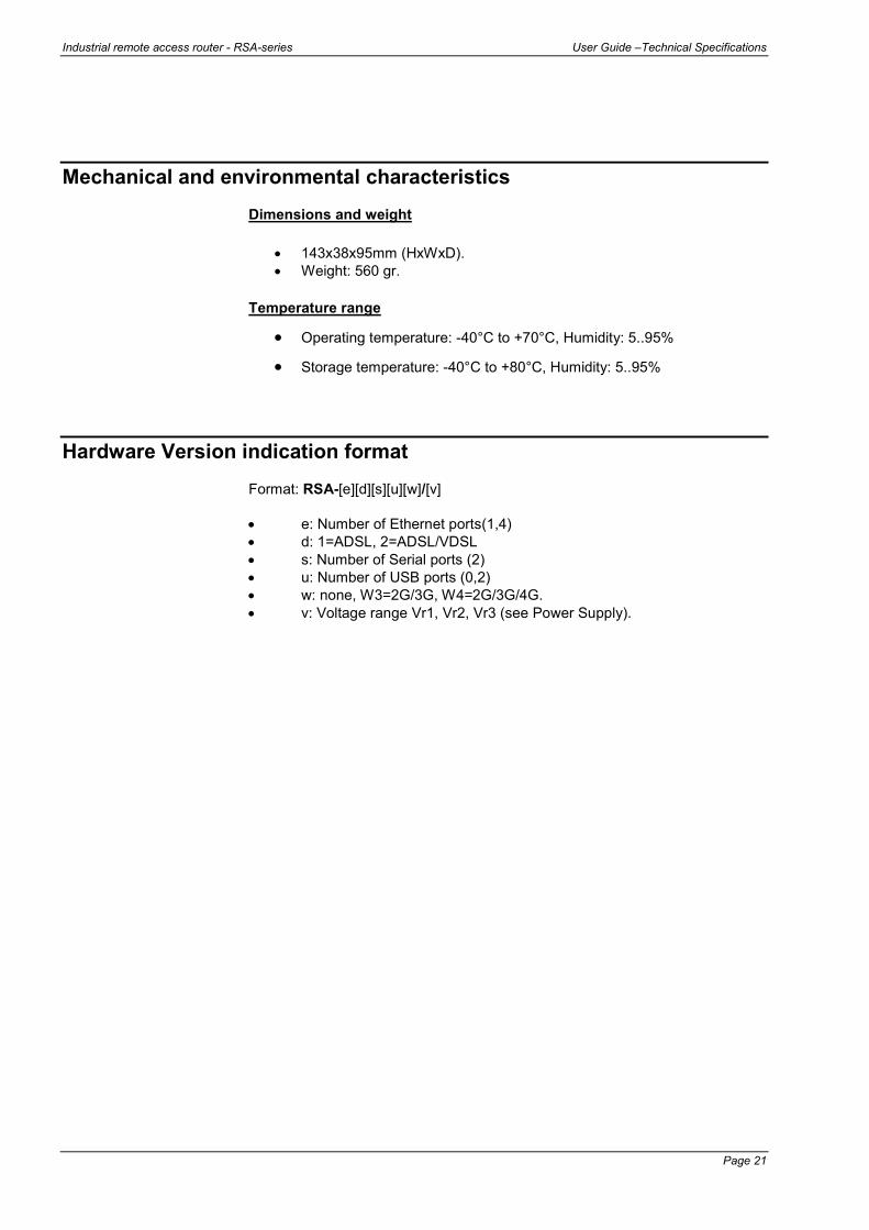
Mechanical and environmental characteristics Dimensions and weight
• 143x38x95mm (HxWxD). • Weight: 560 gr.
Temperature range
• Operating temperature: -40°C to +70°C, Humidity: 5..95% • Storage temperature: -40°C to +80°C, Humidity: 5..95%
Hardware Version indication format Format: RSA-[e][d][s][u][w]/[v] • e: Number of Ethernet ports(1,4) • d: 1=ADSL, 2=ADSL/VDSL • s: Number of Serial ports (2) • u: Number of USB ports (0,2) • w: none, W3=2G/3G, W4=2G/3G/4G. • v: Voltage range Vr1, Vr2, Vr3 (see Power Supply).

User Guide – Technical Specifications Industrial remote access router - RSA-series
Page 22

Industrial remote access router - RSA-series User Guide – Appendix
Page 23
5 Appendix
Mounting instructions The units of the RSA series are supplied with a mounting bracket for symmetrical rails of 35 mm according to DIN 46277-3, BS5584:1978 or EN 50-022. To mount the unit on the DINrail, hook the upper side of the DINrail clamp on the DINrail and then move the lower end housing towards the DINrail until it latches. Pressing the housing downwards will make the latching easier.
To remove the housing from the DINrail, press the housing downwards while moving the lower end of the housing away from the DINrail.
Note: For reliable operation over the full temperature range up to +70°C, it is important that the ventilation slots on top and bottom have free air flow.
User Guide – Appendix Industrial remote access router - RSA-series
Page 24
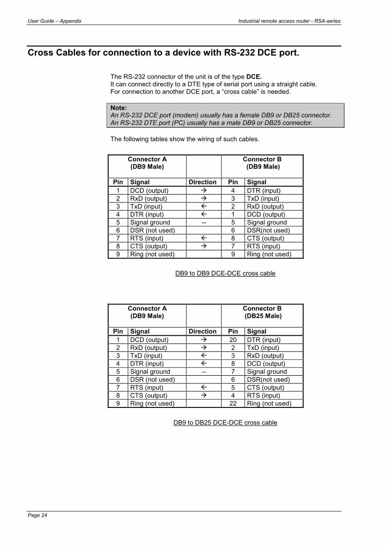
Cross Cables for connection to a device with RS-232 DCE port. The RS-232 connector of the unit is of the type DCE. It can connect directly to a DTE type of serial port using a straight cable. For connection to another DCE port, a “cross cable” is needed. Note: An RS-232 DCE port (modem) usually has a female DB9 or DB25 connector. An RS-232 DTE port (PC) usually has a male DB9 or DB25 connector. The following tables show the wiring of such cables.
DB9 to DB9 DCE-DCE cross cable
DB9 to DB25 DCE-DCE cross cable
Connector A (DB9 Male)
Connector B (DB9 Male)
Pin Signal Direction Pin Signal 1 DCD (output) 4 DTR (input) 2 RxD (output) 3 TxD (input) 3 TxD (input) 2 RxD (output) 4 DTR (input) 1 DCD (output) 5 Signal ground -- 5 Signal ground 6 DSR (not used) 6 DSR(not used) 7 RTS (input) 8 CTS (output) 8 CTS (output) 7 RTS (input) 9 Ring (not used) 9 Ring (not used)
Connector A (DB9 Male)
Connector B (DB25 Male)
Pin Signal Direction Pin Signal 1 DCD (output) 20 DTR (input) 2 RxD (output) 2 TxD (input) 3 TxD (input) 3 RxD (output) 4 DTR (input) 8 DCD (output) 5 Signal ground -- 7 Signal ground 6 DSR (not used) 6 DSR(not used) 7 RTS (input) 5 CTS (output) 8 CTS (output) 4 RTS (input) 9 Ring (not used) 22 Ring (not used)

Industrial remote access router - RSA-series User Guide – Appendix
Page 25
Related Documents