R&S ® FSV-K7/K7S Analog Demodulation and FM Stereo Operating Manual Operating Manual 1176.7561.02 ─ 05 (;ÚÙË2) Test & Measurement

Welcome message from author
This document is posted to help you gain knowledge. Please leave a comment to let me know what you think about it! Share it to your friends and learn new things together.
Transcript

R&S® FSV-K7/K7SAnalog Demodulation and FM StereoOperating Manual
Oper
ating
Man
ual
1176.7561.02 ─ 05(;ÚÙË2)
Test
& Me
asur
emen
t
This manual describes the following R&S®FSV/FSVA options:● R&S FSV-K7 (1310.8103.02)
● R&S FSV-K7S (1310.8126.02)
This manual describes the following R&S FSV/FSVA models with firmware version 3.00 and higher:● R&S®FSV4 (1321.3008K04)
● R&S®FSVA4 (1321.3008K05)
● R&S®FSV7 (1321.3008K07)
● R&S®FSVA7 (1321.3008K08)
● R&S®FSV13 (1321.3008K13)
● R&S®FSVA13 (1321.3008K14)
● R&S®FSV30 (1321.3008K30)
● R&S®FSVA30 (1321.3008K31)
● R&S®FSV40 (1321.3008K39/1321.3008K40)
● R&S®FSVA40 (1321.3008K41)
It also applies to the following R&S®FSV models. However, note the differences described in Chapter 1.4,"Notes for Users of R&S FSV 1307.9002Kxx Models", on page 9.● R&S®FSV3 (1307.9002K03)
● R&S®FSV7 (1307.9002K07)
● R&S®FSV13 (1307.9002K13)
● R&S®FSV30 (1307.9002K30)
● R&S®FSV40 (1307.9002K39/1307.9002K40)
© 2015 Rohde & Schwarz GmbH & Co. KGMühldorfstr. 15, 81671 München, GermanyPhone: +49 89 41 29 - 0Fax: +49 89 41 29 12 164Email: [email protected]: www.rohde-schwarz.comSubject to change – Data without tolerance limits is not binding.R&S® is a registered trademark of Rohde & Schwarz GmbH & Co. KG.Trade names are trademarks of the owners.
The following abbreviations are used throughout this manual: R&S®FSV/FSVA is abbreviated as R&S FSV/FSVA.
ContentsR&S® FSV-K7/K7S
3Operating Manual 1176.7561.02 ─ 05
Contents1 Preface.................................................................................................... 5
1.1 Documentation Overview............................................................................................. 5
1.2 Conventions Used in the Documentation...................................................................7
1.3 How to Use the Help System........................................................................................8
1.4 Notes for Users of R&S FSV 1307.9002Kxx Models.................................................. 9
2 Analog Demodulation Option R&S FSV–K7...................................... 102.1 Instrument Functions Analog Demodulation........................................................... 10
2.2 Softkeys of the Analog Demodulation option.......................................................... 24
2.3 Remote Commands of the Analog Demodulation (R&S FSV–K7)..........................80
3 FM Stereo Option R&S FSV–K7S......................................................1883.1 Instrument Functions FM Stereo (R&S FSV–K7S)................................................. 188
3.2 Remote Commands of the FM Stereo Option (R&S FSV–K7S).............................227
List of Commands..............................................................................252
Index....................................................................................................258

ContentsR&S® FSV-K7/K7S
4Operating Manual 1176.7561.02 ─ 05

PrefaceR&S® FSV-K7/K7S
5Operating Manual 1176.7561.02 ─ 05
1 Preface
1.1 Documentation Overview
The user documentation for the R&S FSV/FSVA is divided as follows:
● Quick Start Guide● Operating Manuals for base unit and options● Service Manual● Online Help● Release Notes
Quick Start Guide
This manual is delivered with the instrument in printed form and in PDF format on theCD. It provides the information needed to set up and start working with the instrument.Basic operations and basic measurements are described. Also a brief introduction toremote control is given. The manual includes general information (e.g. Safety Instruc-tions) and the following chapters:
Chapter 1 Introduction, General information
Chapter 2 Front and Rear Panel
Chapter 3 Preparing for Use
Chapter 4 Firmware Update and Installation of Firmware Options
Chapter 5 Basic Operations
Chapter 6 Basic Measurement Examples
Chapter 7 Brief Introduction to Remote Control
Appendix LAN Interface
Operating Manuals
The Operating Manuals are a supplement to the Quick Start Guide. Operating Manualsare provided for the base unit and each additional (software) option.
The Operating Manual for the base unit provides basic information on operating theR&S FSV/FSVA in general, and the "Spectrum" mode in particular. Furthermore, thesoftware options that enhance the basic functionality for various measurement modesare described here. The set of measurement examples in the Quick Start Guide isexpanded by more advanced measurement examples. In addition to the brief introduc-tion to remote control in the Quick Start Guide, a description of the basic analyzer com-mands and programming examples is given. Information on maintenance, instrumentinterfaces and error messages is also provided.
In the individual option manuals, the specific instrument functions of the option aredescribed in detail. For additional information on default settings and parameters, refer
Documentation Overview

PrefaceR&S® FSV-K7/K7S
6Operating Manual 1176.7561.02 ─ 05
to the data sheets. Basic information on operating the R&S FSV/FSVA is not includedin the option manuals.
The following Operating Manuals are available for the R&S FSV/FSVA:
● R&S FSV/FSVA base unit; in addition:– R&S FSV-K9 Power Sensor Support– R&S FSV-K14 Spectrogram Measurement
● R&S FSV-K7 Analog Demodulation and R&S FSV-K7S FM Stereo Measurements● R&S FSV-K10 GSM/EDGE Measurement● R&S FSV-K30 Noise Figure Measurement● R&S FSV-K40 Phase Noise Measurement● R&S FSV-K70 Vector Signal Analysis Operating Manual
R&S FSV-K70 Vector Signal Analysis Getting Started (First measurements)● R&S FSV-K72 3GPP FDD BTS Analysis● R&S FSV-K73 3GPP FDD UE Analysis● R&S FSV-K76/77 3GPP TD-SCDMA BTS/UE Measurement● R&S FSV-K82/83 CDMA2000 BTS/MS Analysis● R&S FSV-K84/85 1xEV-DO BTS/MS Analysis● R&S FSV-K91 WLAN IEEE 802.11● R&S FSV-K93 WiMAX IEEE 802.16 OFDM/OFDMA Analysis● R&S FSV-K100/K104 EUTRA / LTE Downlink Measurement Application● R&S FSV-K101/K105 EUTRA / LTE Uplink Measurement Application
These manuals are available in PDF format on the CD delivered with the instrument.
Service Manual
This manual is available in PDF format on the CD delivered with the instrument. Itdescribes how to check compliance with rated specifications, instrument function,repair, troubleshooting and fault elimination. It contains all information required forrepairing the R&S FSV/FSVA by replacing modules. The manual includes the followingchapters:
Chapter 1 Performance Test
Chapter 2 Adjustment
Chapter 3 Repair
Chapter 4 Software Update / Installing Options
Chapter 5 Documents
Online Help
The online help contains context-specific help on operating the R&S FSV/FSVA and allavailable options. It describes both manual and remote operation. The online help isinstalled on the R&S FSV/FSVA by default, and is also available as an executa-ble .chm file on the CD delivered with the instrument.
Documentation Overview

PrefaceR&S® FSV-K7/K7S
7Operating Manual 1176.7561.02 ─ 05
Release Notes
The release notes describe the installation of the firmware, new and modified func-tions, eliminated problems, and last minute changes to the documentation. The corre-sponding firmware version is indicated on the title page of the release notes. The cur-rent release notes are provided in the Internet.
1.2 Conventions Used in the Documentation
1.2.1 Typographical Conventions
The following text markers are used throughout this documentation:
Convention Description
"Graphical user interface ele-ments"
All names of graphical user interface elements on the screen, such asdialog boxes, menus, options, buttons, and softkeys are enclosed byquotation marks.
KEYS Key names are written in capital letters.
File names, commands,program code
File names, commands, coding samples and screen output are distin-guished by their font.
Input Input to be entered by the user is displayed in italics.
Links Links that you can click are displayed in blue font.
"References" References to other parts of the documentation are enclosed by quota-tion marks.
1.2.2 Conventions for Procedure Descriptions
When describing how to operate the instrument, several alternative methods may beavailable to perform the same task. In this case, the procedure using the touchscreenis described. Any elements that can be activated by touching can also be clicked usingan additionally connected mouse. The alternative procedure using the keys on theinstrument or the on-screen keyboard is only described if it deviates from the standardoperating procedures.
The term "select" may refer to any of the described methods, i.e. using a finger on thetouchscreen, a mouse pointer in the display, or a key on the instrument or on a key-board.
1.2.3 Notes on Screenshots
When describing the functions of the product, we use sample screenshots. Thesescreenshots are meant to illustrate as much as possible of the provided functions andpossible interdependencies between parameters.
Conventions Used in the Documentation
PrefaceR&S® FSV-K7/K7S
8Operating Manual 1176.7561.02 ─ 05
The screenshots usually show a fully equipped product, that is: with all options instal-led. Thus, some functions shown in the screenshots may not be available in your par-ticular product configuration.
1.3 How to Use the Help System
Calling context-sensitive and general help
► To display the general help dialog box, press the HELP key on the front panel.
The help dialog box "View" tab is displayed. A topic containing information aboutthe current menu or the currently opened dialog box and its function is displayed.
For standard Windows dialog boxes (e.g. File Properties, Print dialog etc.), no context-sensitive help is available.
► If the help is already displayed, press the softkey for which you want to displayhelp.
A topic containing information about the softkey and its function is displayed.
If a softkey opens a submenu and you press the softkey a second time, the submenuof the softkey is displayed.
Contents of the help dialog box
The help dialog box contains four tabs:
● "Contents" - contains a table of help contents● "View" - contains a specific help topic● "Index" - contains index entries to search for help topics● "Zoom" - contains zoom functions for the help display
To change between these tabs, press the tab on the touchscreen.
Navigating in the table of contents
● To move through the displayed contents entries, use the UP ARROW and DOWNARROW keys. Entries that contain further entries are marked with a plus sign.
● To display a help topic, press the ENTER key. The "View" tab with the correspond-ing help topic is displayed.
● To change to the next tab, press the tab on the touchscreen.
Navigating in the help topics
● To scroll through a page, use the rotary knob or the UP ARROW and DOWNARROW keys.
How to Use the Help System

PrefaceR&S® FSV-K7/K7S
9Operating Manual 1176.7561.02 ─ 05
● To jump to the linked topic, press the link text on the touchscreen.
Searching for a topic
1. Change to the "Index" tab.
2. Enter the first characters of the topic you are interested in. The entries starting withthese characters are displayed.
3. Change the focus by pressing the ENTER key.
4. Select the suitable keyword by using the UP ARROW or DOWN ARROW keys orthe rotary knob.
5. Press the ENTER key to display the help topic.
The "View" tab with the corresponding help topic is displayed.
Changing the zoom
1. Change to the "Zoom" tab.
2. Set the zoom using the rotary knob. Four settings are available: 1-4. The smallestsize is selected by number 1, the largest size is selected by number 4.
Closing the help window
► Press the ESC key or a function key on the front panel.
1.4 Notes for Users of R&S FSV 1307.9002Kxx Models
Users of R&S FSV 1307.9002Kxx models should consider the following differences tothe description of the newer R&S FSV/FSVA 1321.3008Kxx models:● Functions that are based on the Windows7 operating system (e.g. printing or set-
ting up networks) may have a slightly different appearance or require different set-tings on the Windows XP based models. For such functions, refer to the Windowsdocumentation or the documentation originally provided with the R&S FSV instru-ment.
● The R&S FSV 1307.9002K03 model is restricted to a maximum frequency of3 GHz, whereas the R&S FSV/FSVA1321.3008K04 model has a maximum fre-quency of 4 GHz.
● The bandwidth extension option R&S FSV-B160 (1311.2015.xx) is not available forthe R&S FSV 1307.9002Kxx models. The maximum usable I/Q analysis bandwidthfor these models is 28 MHz, or with option R&S FSV-B70, 40 MHz.
Notes for Users of R&S FSV 1307.9002Kxx Models
Analog Demodulation Option R&S FSV–K7R&S® FSV-K7/K7S
10Operating Manual 1176.7561.02 ─ 05
2 Analog Demodulation Option R&S FSV–K7Overview of firmware option R&S FSV–K7
This section contains all information required for operation of an R&S FSV/FSVAequipped with Application Firmware R&S FSV–K7. It covers operation via menus andthe remote control commands for analog demodulation measurements.
This part of the documentation consists of the following chapters:
● Chapter 2.1, "Instrument Functions Analog Demodulation", on page 10 describesthe overall instrument functions and provides further information
● Chapter 2.2.1, "Softkeys of the Analog Demodulation Menu", on page 25 showsall softkeys available in the "Analog Demod" menu. This chapter also presents theremote control commands associated with each softkey function.
● The following chapters describe the softkeys of the other keys for the AnalogDemodulation option.
● Chapter 2.3, "Remote Commands of the Analog Demodulation (R&S FSV–K7)",on page 80 describes all remote control commands defined for the analogdemodulation measurement.
This part of the documentation includes only functions of the Application FirmwareR&S FSV–K7. For all other descriptions, please refer to the description of the baseunit.
2.1 Instrument Functions Analog Demodulation
The digital signal processing in the R&S FSV/FSVA, used in the analyzer mode for dig-ital IF filters, is also ideally suited for demodulating AM, FM, or PM signals. The firm-ware option R&S FSV–K7 provides the necessary measurement functions.
The R&S FSV/FSVA is equipped with a demodulator that is capable of performing AM,FM, and PM demodulation at a time. Additionally maximum, minimum and average orcurrent values can be obtained parallel over a selected number of measurements.
By sampling (digitization) already at the IF and digital down-conversion to the base-band (I/Q), the demodulator achieves maximum accuracy and temperature stability.There is no evidence of typical errors of an analog down-conversion and demodulationlike AM to FM conversion and vice versa, deviation error, frequency response or fre-quency drift at DC coupling.
To open the Analog Demodulation menu
● If the "Analog Demodulation" mode is not the active measurement mode, press theMODE key and select the "Analog Demodulation" softkey.
● If the "Analog Demodulation" mode is already active, press the HOME or MEASkey.The "Analog Demod" menu is displayed (see Chapter 2.2, "Softkeys of the AnalogDemodulation option", on page 24).
Instrument Functions Analog Demodulation

Analog Demodulation Option R&S FSV–K7R&S® FSV-K7/K7S
11Operating Manual 1176.7561.02 ─ 05
Further information
2.1.1 Circuit Description – Block Diagrams............................................................................11
2.1.2 Demodulation Bandwidth.............................................................................................. 13
2.1.3 Sample Rate, Measurement Time and Trigger Offset.................................................. 13
2.1.4 Variable-Sized Capture Buffer...................................................................................... 15
2.1.5 AF Trigger..................................................................................................................... 16
2.1.6 Configuring Traces........................................................................................................16
2.1.7 Trace Mode Overview................................................................................................... 17
2.1.8 Detector Overview.........................................................................................................19
2.1.9 Stability of Measurement Results..................................................................................20
2.1.10 Measurement Result Display........................................................................................ 20
2.1.11 ASCII File Export Format.............................................................................................. 23
2.1.1 Circuit Description – Block Diagrams
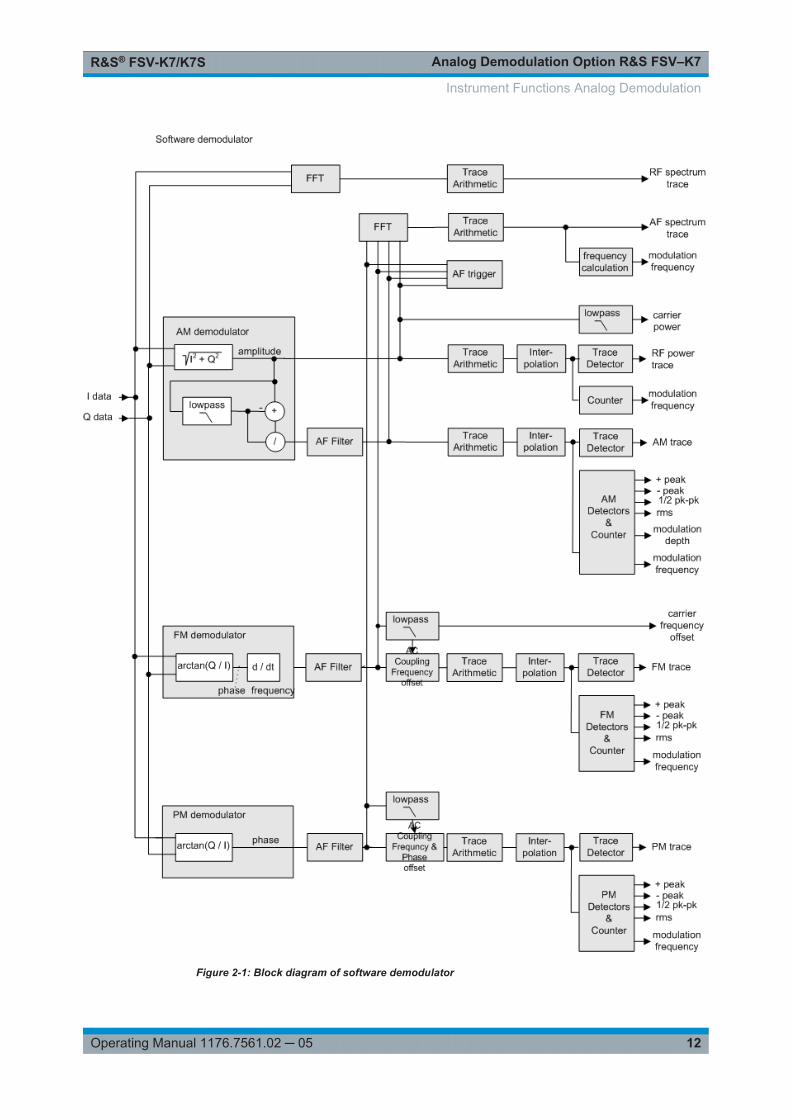
The software demodulator runs on the main processor of the analyzer. The demodula-tion process is shown in Figure 2-1 the figure below. All calculations are performedsimultaneously with the same I/Q data set. Magnitude (= amplitude) and phase of thecomplex I/Q pairs are determined. The frequency result is obtained from the differentialphase.
For details on the analyzer signal processing refer to the TRACe:IQ subsystem in thebase unit.
Instrument Functions Analog Demodulation
Analog Demodulation Option R&S FSV–K7R&S® FSV-K7/K7S
12Operating Manual 1176.7561.02 ─ 05
Figure 2-1: Block diagram of software demodulator
Instrument Functions Analog Demodulation

Analog Demodulation Option R&S FSV–K7R&S® FSV-K7/K7S
13Operating Manual 1176.7561.02 ─ 05
The AM DC, FM DC and PM DC raw data of the demodulators is fed into the TraceArithmetic block that combines consecutive data sets. Possible trace modes are:Clear Write, Max Hold, Min Hold and Average (for details refer to Chapter 2.1.7, "TraceMode Overview", on page 17. The output data of the Trace Arithmetic block canbe read via remote control.
The collected measured values are evaluated by the selected detector (for details referto Chapter 2.1.8, "Detector Overview", on page 19. The result is displayed on thescreen and can be read out via remote control.
In addition, important parameters are calculated:
● A counter determines the modulation frequency for AM, FM, and PM.● average power = carrier power (RF power)● average frequency = carrier frequency offset (FM)● The modulation depth or the frequency or phase deviation is displayed.● AC coupling is possible with FM and PM display. The deviations are determined
from the trace data. +Peak, –Peak, ½ Peak-Peak and RMS are displayed.
2.1.2 Demodulation Bandwidth
The demodulation bandwidth is not the 3 dB bandwidth but the useful bandwidth whichis distortion-free with regard to phase and amplitude.
Therefore the following formulas apply:
● AM: demodulation bandwidth ≥ 2 x modulation frequency● FM: demodulation bandwidth ≥ 2 x (frequency deviation + modulation frequency)● PM: demodulation bandwidth ≥ 2 x modulation frequency x (1 + phase deviation)
If the center frequency of the analyzer is not set exactly to the signal frequency, thedemodulation bandwidth must be selected larger by the carrier offset, in addition to therequirement described above. This also applies if FM or PM AC coupling has beenselected.
In general, the demodulation bandwidth should be as narrow as possible to improvethe S/N ratio. The residual FM caused by noise floor and phase noise increases dra-matically with the bandwidth, especially with FM.
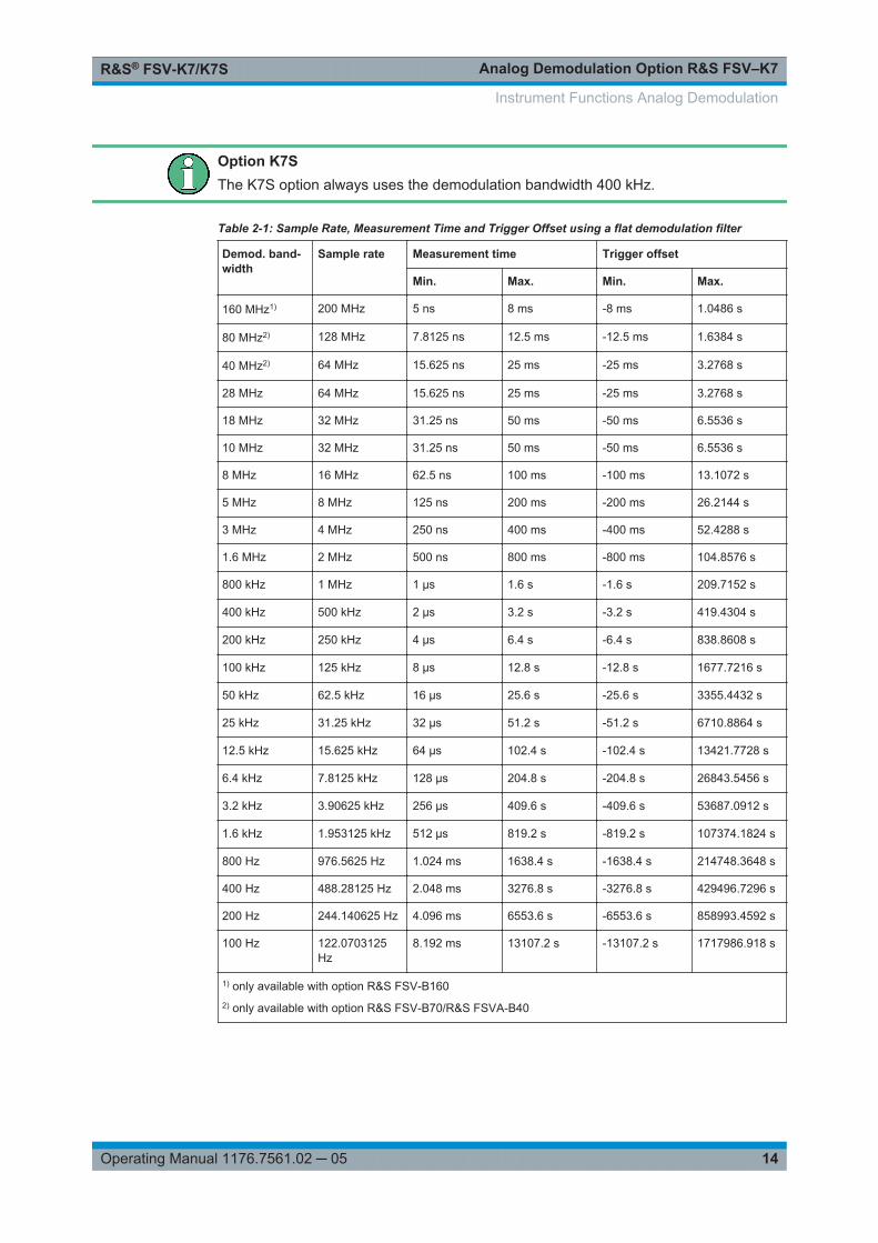
2.1.3 Sample Rate, Measurement Time and Trigger Offset
Depending on the sample rate, the maximum demodulation bandwidths listed in thetable can be obtained during the measurement. The permissible value range of themeasurement time and trigger offset depends on the selected demodulation bandwidthand demodulation filter. If the AF filter or the AF trigger are not active, the measure-ment time increases by 20 %.
Instrument Functions Analog Demodulation
Analog Demodulation Option R&S FSV–K7R&S® FSV-K7/K7S
14Operating Manual 1176.7561.02 ─ 05
Option K7SThe K7S option always uses the demodulation bandwidth 400 kHz.
Table 2-1: Sample Rate, Measurement Time and Trigger Offset using a flat demodulation filter
Demod. band-width
Sample rate Measurement time Trigger offset
Min. Max. Min. Max.
160 MHz1) 200 MHz 5 ns 8 ms -8 ms 1.0486 s
80 MHz2) 128 MHz 7.8125 ns 12.5 ms -12.5 ms 1.6384 s
40 MHz2) 64 MHz 15.625 ns 25 ms -25 ms 3.2768 s
28 MHz 64 MHz 15.625 ns 25 ms -25 ms 3.2768 s
18 MHz 32 MHz 31.25 ns 50 ms -50 ms 6.5536 s
10 MHz 32 MHz 31.25 ns 50 ms -50 ms 6.5536 s
8 MHz 16 MHz 62.5 ns 100 ms -100 ms 13.1072 s
5 MHz 8 MHz 125 ns 200 ms -200 ms 26.2144 s
3 MHz 4 MHz 250 ns 400 ms -400 ms 52.4288 s
1.6 MHz 2 MHz 500 ns 800 ms -800 ms 104.8576 s
800 kHz 1 MHz 1 µs 1.6 s -1.6 s 209.7152 s
400 kHz 500 kHz 2 µs 3.2 s -3.2 s 419.4304 s
200 kHz 250 kHz 4 µs 6.4 s -6.4 s 838.8608 s
100 kHz 125 kHz 8 µs 12.8 s -12.8 s 1677.7216 s
50 kHz 62.5 kHz 16 µs 25.6 s -25.6 s 3355.4432 s
25 kHz 31.25 kHz 32 µs 51.2 s -51.2 s 6710.8864 s
12.5 kHz 15.625 kHz 64 µs 102.4 s -102.4 s 13421.7728 s
6.4 kHz 7.8125 kHz 128 µs 204.8 s -204.8 s 26843.5456 s
3.2 kHz 3.90625 kHz 256 µs 409.6 s -409.6 s 53687.0912 s
1.6 kHz 1.953125 kHz 512 µs 819.2 s -819.2 s 107374.1824 s
800 Hz 976.5625 Hz 1.024 ms 1638.4 s -1638.4 s 214748.3648 s
400 Hz 488.28125 Hz 2.048 ms 3276.8 s -3276.8 s 429496.7296 s
200 Hz 244.140625 Hz 4.096 ms 6553.6 s -6553.6 s 858993.4592 s
100 Hz 122.0703125Hz
8.192 ms 13107.2 s -13107.2 s 1717986.918 s
1) only available with option R&S FSV-B1602) only available with option R&S FSV-B70/R&S FSVA-B40
Instrument Functions Analog Demodulation

Analog Demodulation Option R&S FSV–K7R&S® FSV-K7/K7S
15Operating Manual 1176.7561.02 ─ 05
Table 2-2: Sample Rate, Measurement Time and Trigger Offset using a Gaussian demodulation filter
Demod. band-width
Sample rate Measurement time Trigger offset
Min. Max. Min. Max.
28 MHz1) 112 MHz 8.929 ns 14.28 ms -14.28 1.872457134 s
18 MHz1) 72 MHz 13.88 ns 22.22 ms -22.22 ms 2.912711097 s
10 MHz 40 MHz 25 ns 40 ms -40 ms 5,242879975 s
8 MHz 32 MHz 31.25 ns 50 ms -50 ms 6.553599969 s
5 MHz 12 MHz 83.33 ns 133.3 ms -80 ms 10,48575995 s
3 MHz 10.666 MHz 93.75 ns 150 ms -133.3 ms 17,47626667 s
1.6 MHz 6.4 MHz 156.25 ns 250 ms -250 ms 32.76799984 s
800 kHz 3.2 MHz 312.5 ns 5 ms -5 ms 65.53599969 s
400 kHz 1.6 MHz 625 ns 1 s -1 s 131.0719994 s
200 kHz 800 kHz 1.25 us 2 s -2 s 262.1439988 s
100 kHz 400 kHz 2.5 us 4 s -4 s 524.2879975 s
50 kHz 200 kHz 5 us 8 s -8 s 1048.575995 s
25 kHz 100 kHz 10 us 16 s -16 s 2097.15199 s
12.5 kHz 50 kHz 20 us 32 s -32 s 4194.30398 s
6.4 kHz 25.6 kHz 39.0625 us 62.5 s -62.5 s 8191.999961 s
3.2 kHz 12.8 kHz 78.125 us 125 s -125 s 16383.99992 s
1.6 kHz 6.4 kHz 156.25 us 250 s -250 s 32767.99984 s
800 Hz 3.2 kHz 312.5 us 500 s -500 s 65535.99969 s
400 Hz 1.6 kHz 625 us 1000 s -1000 s 131071.9994 s
200 Hz 800 Hz 1.25 ms 2000 s -2000 s 262143.9988 s
100 Hz 400 Hz 2.5 ms 4000 s -4000 s 524287.9975 s
1) gaussian filter curve is limited by IQ bandwidth
Large numbers of samples
Principally, the R&S FSV/FSVA can handle up to 1.6 million samples. However, when480 001 samples are exceeded, all traces that are not currently being displayed on ascreen are deactivated to improve performance. The traces can only be activatedagain when the samples are reduced.
2.1.4 Variable-Sized Capture Buffer
The capture buffer size is now variable. By default, the size of the capture buffer isidentical to the defined measurement time. However, if you select a larger capture timemanually, you can then scroll through the data in the capture buffer by changing the
Instrument Functions Analog Demodulation
Analog Demodulation Option R&S FSV–K7R&S® FSV-K7/K7S
16Operating Manual 1176.7561.02 ─ 05
offset of the measurement time from the beginning of the capture buffer. The results,which are based on the measurement time, are recalculated automatically based onthe new data.
2.1.5 AF Trigger
The analog demodulation option allows triggering to the demodulated signal. The dis-play is stable if a minimum of five modulation periods are within the recording time.
Triggering is always DC-coupled. Therefore triggering is possible directly to the pointwhere a specific carrier level, phase or frequency is exceeded or not attained.
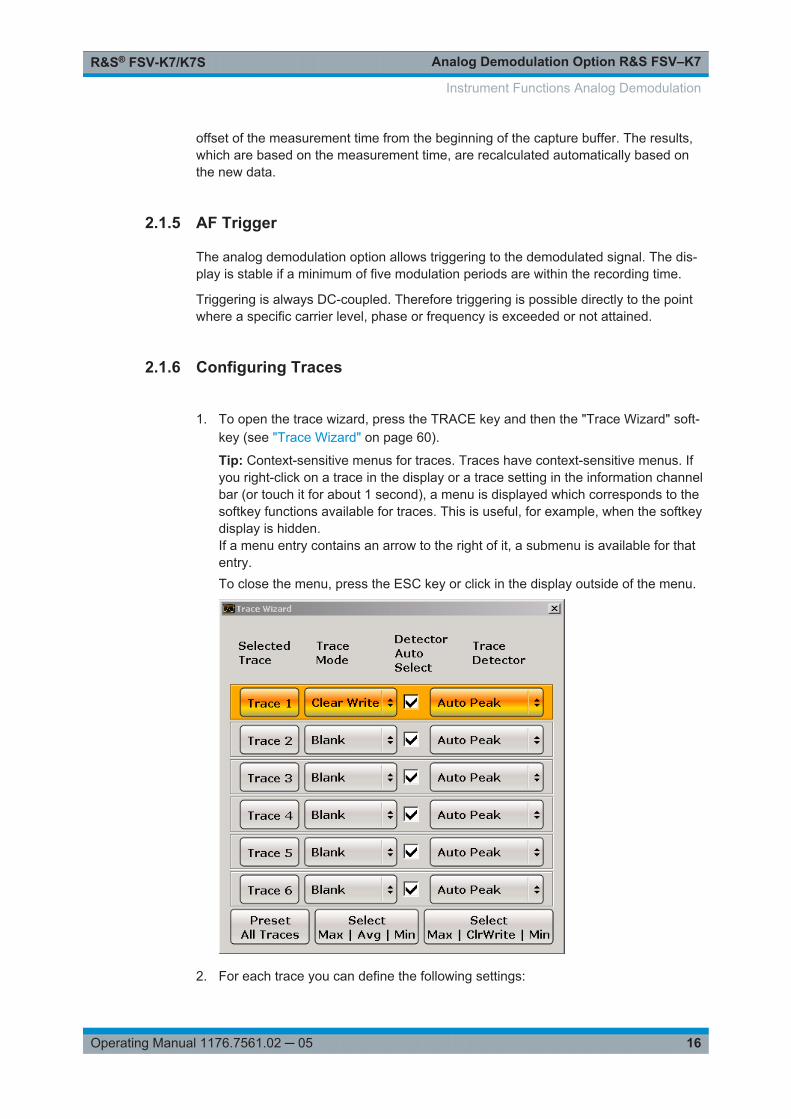
2.1.6 Configuring Traces
1. To open the trace wizard, press the TRACE key and then the "Trace Wizard" soft-key (see "Trace Wizard" on page 60).
Tip: Context-sensitive menus for traces. Traces have context-sensitive menus. Ifyou right-click on a trace in the display or a trace setting in the information channelbar (or touch it for about 1 second), a menu is displayed which corresponds to thesoftkey functions available for traces. This is useful, for example, when the softkeydisplay is hidden.If a menu entry contains an arrow to the right of it, a submenu is available for thatentry.To close the menu, press the ESC key or click in the display outside of the menu.
2. For each trace you can define the following settings:
Instrument Functions Analog Demodulation
Analog Demodulation Option R&S FSV–K7R&S® FSV-K7/K7S
17Operating Manual 1176.7561.02 ─ 05
Display Mode ● Clear Write● Max Hold● Min Hold● Average● View● Blank
For details see Chapter 2.1.7, "Trace Mode Overview", on page 17.
Detector Auto Select Activates automatic detector selection (see Auto Select softkey). Ifactivated, the "Trace Detector" setting is ignored.
Trace Detector Defines a specific trace detector. If one of the following settings isdefined, the "Detector Auto Select" option is deactivated.● "Auto Select" on page 58● "Auto Peak" on page 58● "Positive Peak" on page 59● "Negative Peak" on page 59● "Sample" on page 59● "RMS" on page 59● "Average" on page 59● "Quasipeak" on page 59
3. To configure several traces to predefined display modes in one step, press the but-ton for the required function:
Preset All Traces Trace 1: Clear Write
Trace 2-6: Blank
Select Max | Avg | Min Trace 1: Max Hold
Trace 2: Average
Trace 3: Min Hold
Trace 4-6: Blank
Select Max | ClrWrite | Min Trace 1: Max Hold
Trace 2: Clear Write
Trace 3: Min Hold
Trace 4-6: Blank
For details see Chapter 2.1.7, "Trace Mode Overview", on page 17.
2.1.7 Trace Mode Overview
The traces can be activated individually for a measurement or frozen after completionof a measurement. Traces that are not activate are hidden. Each time the trace modeis changed, the selected trace memory is cleared.
The R&S FSV/FSVA offers 6 different trace modes:
Clear WriteOverwrite mode: the trace is overwritten by each sweep. This is the default setting.
All available detectors can be selected.
Instrument Functions Analog Demodulation

Analog Demodulation Option R&S FSV–K7R&S® FSV-K7/K7S
18Operating Manual 1176.7561.02 ─ 05
Remote command: DISP:TRAC:MODE WRIT, see DISPlay[:WINDow<n>]:TRACe<t>:MODEon page 110
Max HoldThe maximum value is determined over several sweeps and displayed. The R&S FSV/FSVA saves the sweep result in the trace memory only if the new value is greater thanthe previous one.
The detector is automatically set to "Positive Peak".
This mode is especially useful with modulated or pulsed signals. The signal spectrumis filled up upon each sweep until all signal components are detected in a kind of enve-lope.
This mode is not available for statistics measurements.
Remote command: DISP:TRAC:MODE MAXH, see DISPlay[:WINDow<n>]:TRACe<t>:MODEon page 110
Min HoldThe minimum value is determined from several measurements and displayed. TheR&S FSV/FSVA saves the smallest of the previously stored/currently measured valuesin the trace memory.
The detector is automatically set to "Negative Peak".
This mode is useful e.g. for making an unmodulated carrier in a composite signal visi-ble. Noise, interference signals or modulated signals are suppressed whereas a CWsignal is recognized by its constant level.
This mode is not available for statistics measurements.
Remote command: DISP:TRAC:MODE MINH, see DISPlay[:WINDow<n>]:TRACe<t>:MODEon page 110
AverageThe average is formed over several sweeps. The Sweep Count determines the numberof averaging procedures.
All available detectors can be selected. If the detector is automatically selected, thesample detector is used (see Chapter 2.1.8, "Detector Overview", on page 19).
This mode is not available for statistics measurements.
Remote command: DISP:TRAC:MODE AVER, see DISPlay[:WINDow<n>]:TRACe<t>:MODEon page 110
ViewThe current contents of the trace memory are frozen and displayed.
Note: If a trace is frozen, the instrument settings, apart from level range and referencelevel (see below), can be changed without impact on the displayed trace. The fact thatthe displayed trace no longer matches the current instrument setting is indicated by the
icon on the tab label.
Instrument Functions Analog Demodulation
Analog Demodulation Option R&S FSV–K7R&S® FSV-K7/K7S
19Operating Manual 1176.7561.02 ─ 05
If the level range or reference level is changed, the R&S FSV/FSVA automaticallyadapts the measured data to the changed display range. This allows an amplitudezoom to be made after the measurement in order to show details of the trace.
Remote command: DISP:TRAC:MODE VIEW, see DISPlay[:WINDow<n>]:TRACe<t>:MODEon page 110
BlankHides the selected trace.
Remote command: DISP:TRAC OFF, see DISPlay[:WINDow<n>]:TRACe<t>[:STATe] on page 111
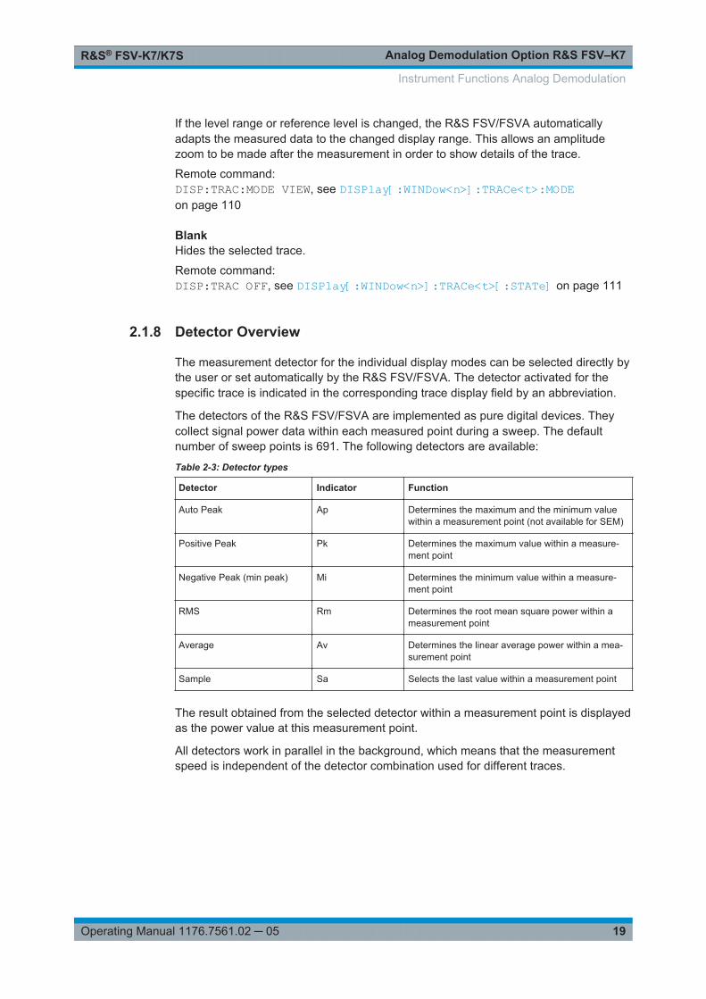
2.1.8 Detector Overview
The measurement detector for the individual display modes can be selected directly bythe user or set automatically by the R&S FSV/FSVA. The detector activated for thespecific trace is indicated in the corresponding trace display field by an abbreviation.
The detectors of the R&S FSV/FSVA are implemented as pure digital devices. Theycollect signal power data within each measured point during a sweep. The defaultnumber of sweep points is 691. The following detectors are available:
Table 2-3: Detector types
Detector Indicator Function
Auto Peak Ap Determines the maximum and the minimum valuewithin a measurement point (not available for SEM)
Positive Peak Pk Determines the maximum value within a measure-ment point
Negative Peak (min peak) Mi Determines the minimum value within a measure-ment point
RMS Rm Determines the root mean square power within ameasurement point
Average Av Determines the linear average power within a mea-surement point
Sample Sa Selects the last value within a measurement point
The result obtained from the selected detector within a measurement point is displayedas the power value at this measurement point.
All detectors work in parallel in the background, which means that the measurementspeed is independent of the detector combination used for different traces.
Instrument Functions Analog Demodulation

Analog Demodulation Option R&S FSV–K7R&S® FSV-K7/K7S
20Operating Manual 1176.7561.02 ─ 05
Number of measured valuesDuring a frequency sweep, the R&S FSV/FSVA increments the first local oscillator insteps that are smaller than approximately 1/10 of the bandwidth. This ensures that theoscillator step speed is conform to the hardware settling times and does not affect theprecision of the measured power.The number of measured values taken during a sweep is independent of the number ofoscillator steps. It is always selected as a multiple or a fraction of 691 (= default num-ber of trace points displayed on the screen). Choosing less then 691 measured values(e.g. 125 or 251) will lead to an interpolated measurement curve, choosing more than691 points (e.g. 1001, 2001 …) will result in several measured values being overlaid atthe same frequency position.
RMS detector and VBWIf the RMS detector is selected, the video bandwidth in the hardware is bypassed.Thus, duplicate trace averaging with small VBWs and RMS detector no longer occurs.However, the VBW is still considered when calculating the sweep time. This leads to alonger sweep time for small VBW values. Thus, you can reduce the VBW value to ach-ieve more stable trace curves even when using an RMS detector. Normally, if the RMSdetector is used the sweep time should be increased to get more stable trace curves.
2.1.9 Stability of Measurement Results
Despite amplitude and frequency modulation, the display of carrier power and carrierfrequency offset is stable.
This is achieved by a digital filter which sufficiently suppresses the modulation, provi-ded, however, that the measurement time is ≥ 3 x 1 / modulation frequency, i.e. that atleast three periods of the AF signal are recorded.
The mean carrier power for calculating the AM is also calculated with a digital filter thatreturns stable results after a measurement time of ≥ 3 x 1 / modulation frequency, i.e.at least three cycles of the AF signal must be recorded before a stable AM can beshown.
2.1.10 Measurement Result Display
In Analog Demodulation mode, the measurement results can be displayed in up to 4different screens (windows), plus an additional marker table, if applicable. Each screenshows either the measurement results as a diagram or the results of evaluation func-tions in a table ("Result Summary").
All displays are determined by the I/Q data set recorded for the measurement.
You can define the display configuration for up to 4 different screens at once using the"Display Config" on page 27 softkey.
Instrument Functions Analog Demodulation
Analog Demodulation Option R&S FSV–K7R&S® FSV-K7/K7S
21Operating Manual 1176.7561.02 ─ 05
Screen configuration
For each screen you can define:
● Off: Whether it is displayed or not● Summary: Whether a result summary for all screens is displayed instead of a dia-
gram● AM/FM/PM/RF Diagrams: Which type of diagram is displayed
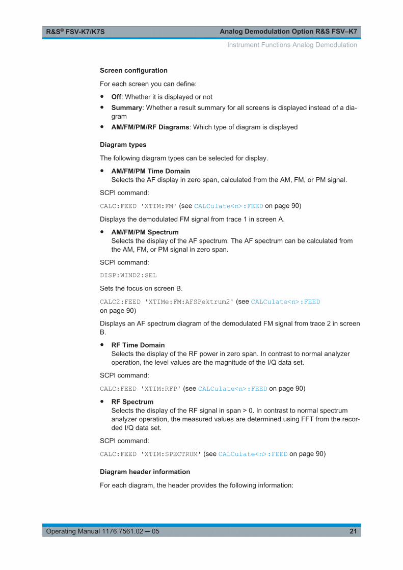
Diagram types
The following diagram types can be selected for display.
● AM/FM/PM Time DomainSelects the AF display in zero span, calculated from the AM, FM, or PM signal.
SCPI command:
CALC:FEED 'XTIM:FM' (see CALCulate<n>:FEED on page 90)
Displays the demodulated FM signal from trace 1 in screen A.
● AM/FM/PM SpectrumSelects the display of the AF spectrum. The AF spectrum can be calculated fromthe AM, FM, or PM signal in zero span.
SCPI command:
DISP:WIND2:SELSets the focus on screen B.
CALC2:FEED 'XTIMe:FM:AFSPektrum2' (see CALCulate<n>:FEEDon page 90)
Displays an AF spectrum diagram of the demodulated FM signal from trace 2 in screenB.
● RF Time DomainSelects the display of the RF power in zero span. In contrast to normal analyzeroperation, the level values are the magnitude of the I/Q data set.
SCPI command:
CALC:FEED 'XTIM:RFP' (see CALCulate<n>:FEED on page 90)
● RF SpectrumSelects the display of the RF signal in span > 0. In contrast to normal spectrumanalyzer operation, the measured values are determined using FFT from the recor-ded I/Q data set.
SCPI command:
CALC:FEED 'XTIM:SPECTRUM' (see CALCulate<n>:FEED on page 90)
Diagram header information
For each diagram, the header provides the following information:
Instrument Functions Analog Demodulation

Analog Demodulation Option R&S FSV–K7R&S® FSV-K7/K7S
22Operating Manual 1176.7561.02 ─ 05
1. Screen A/B/C/D
2. Modulation type
3. Trace color
4. Trace number
5. Detector
6. Trace mode
7. Reference value
8. AF coupling (AC/DC), only in AF time domains, if applicable
Result Summary
The result summary displays the results of the evaluation functions for all channels in atable.
Summaries that take up the entire width of the screen are displayed as tables; if onlyhalf the screen width is available (2 windows next to each other), the summary is dis-played as a list. Thus, the factory-set predefined screen configurations contain only 3screens: 2 for diagrams and one full-width screen for the summary.
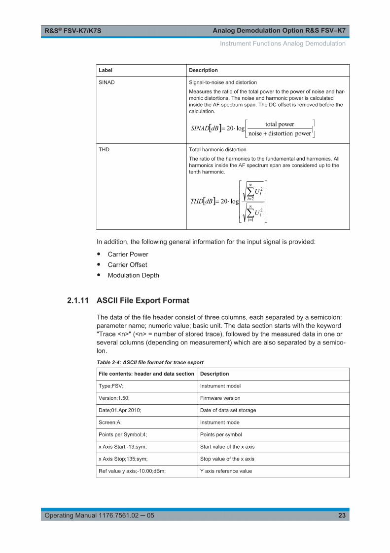
For each channel, the following information is provided:
Label Description
+Peak Positive peak (maximum)
-Peak Negative peak (minimum)
+/-Peak/2 Average of positive and negative peaks
RMS Root Mean Square value
Mod Freq Modulation frequency
Instrument Functions Analog Demodulation
Analog Demodulation Option R&S FSV–K7R&S® FSV-K7/K7S
23Operating Manual 1176.7561.02 ─ 05
Label Description
SINAD Signal-to-noise and distortion
Measures the ratio of the total power to the power of noise and har-monic distortions. The noise and harmonic power is calculatedinside the AF spectrum span. The DC offset is removed before thecalculation.
power distortion noise
power totallog20dBSINAD
THD Total harmonic distortion
The ratio of the harmonics to the fundamental and harmonics. Allharmonics inside the AF spectrum span are considered up to thetenth harmonic.
1
2
2
2
log20
ii
ii
U
UdBTHD
In addition, the following general information for the input signal is provided:
● Carrier Power● Carrier Offset● Modulation Depth
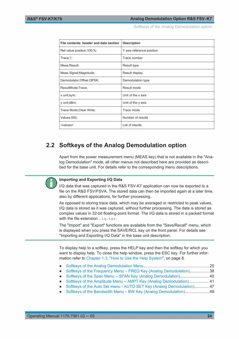
2.1.11 ASCII File Export Format
The data of the file header consist of three columns, each separated by a semicolon:parameter name; numeric value; basic unit. The data section starts with the keyword"Trace <n>" (<n> = number of stored trace), followed by the measured data in one orseveral columns (depending on measurement) which are also separated by a semico-lon.
Table 2-4: ASCII file format for trace export
File contents: header and data section Description
Type;FSV; Instrument model
Version;1.50; Firmware version
Date;01.Apr 2010; Date of data set storage
Screen;A; Instrument mode
Points per Symbol;4; Points per symbol
x Axis Start;-13;sym; Start value of the x axis
x Axis Stop;135;sym; Stop value of the x axis
Ref value y axis;-10.00;dBm; Y axis reference value
Instrument Functions Analog Demodulation
Analog Demodulation Option R&S FSV–K7R&S® FSV-K7/K7S
24Operating Manual 1176.7561.02 ─ 05
File contents: header and data section Description
Ref value position;100;%; Y axis reference position
Trace;1; Trace number
Meas;Result; Result type
Meas Signal;Magnitude; Result display
Demodulator;Offset QPSK; Demodulation type
ResultMode;Trace; Result mode
x unit;sym; Unit of the x axis
y unit;dBm; Unit of the y axis
Trace Mode;Clear Write; Trace mode
Values;592; Number of results
<values> List of results
2.2 Softkeys of the Analog Demodulation option
Apart from the power measurement menu (MEAS key) that is not available in the "Ana-log Demodulation" mode, all other menus not described here are provided as descri-bed for the base unit. For details refer to the corresponding menu descriptions.
Importing and Exporting I/Q DataI/Q data that was captured in the R&S FSV-K7 application can now be exported to afile on the R&S FSV/FSVA. The stored data can then be imported again at a later time,also by different applications, for further processing.As opposed to storing trace data, which may be averaged or restricted to peak values,I/Q data is stored as it was captured, without further processing. The data is stored ascomplex values in 32-bit floating-point format. The I/Q data is stored in a packed formatwith the file extension .iq.tar.
The "Import" and "Export" functions are available from the "Save/Recall" menu, whichis displayed when you press the SAVE/RCL key on the front panel. For details see"Importing and Exporting I/Q Data" in the base unit description.
To display help to a softkey, press the HELP key and then the softkey for which youwant to display help. To close the help window, press the ESC key. For further infor-mation refer to Chapter 1.3, "How to Use the Help System", on page 8.
● Softkeys of the Analog Demodulation Menu...........................................................25● Softkeys of the Frequency Menu – FREQ Key (Analog Demodulation)................. 38● Softkeys of the Span Menu – SPAN Key (Analog Demodulation).......................... 40● Softkeys of the Amplitude Menu – AMPT Key (Analog Demodulation).................. 41● Softkeys of the Auto Set menu - AUTO SET Key (Analog Demodulation)............. 47● Softkeys of the Bandwidth Menu – BW Key (Analog Demodulation)......................49
Softkeys of the Analog Demodulation option

Analog Demodulation Option R&S FSV–K7R&S® FSV-K7/K7S
25Operating Manual 1176.7561.02 ─ 05
● Softkeys of the Sweep Menu – SWEEP Key (Analog Demodulation).................... 54● Softkeys of the Trace Menu – TRACE key (Analog Demodulation)........................56● Softkeys of the Trigger Menu – TRIG Key (Analog Demodulation)........................ 62● Softkeys of the Marker Menu – MKR key (Analog Demodulation)..........................66● Softkeys of the Marker Function Menu – MKR FUNC Key (Analog Demodulation)
................................................................................................................................ 70● Softkeys of the Input/Output Menu..........................................................................75
2.2.1 Softkeys of the Analog Demodulation Menu
The following table shows all softkeys available in the "Analog Demod" menu.
AM.................................................................................................................................26└ Display Config.................................................................................................27
└ Screen A-D........................................................................................... 27└ Predefined............................................................................................ 28
└ Add............................................................................................. 28└ Apply...........................................................................................28└ Remove...................................................................................... 28└ Restore.......................................................................................28
└ Select Trace....................................................................................................28└ Demod BW......................................................................................................28└ Meas Time...................................................................................................... 29└ AF Filter.......................................................................................................... 29
└ High Pass............................................................................................. 29└ Low Pass.............................................................................................. 29└ Weighting..............................................................................................30
└ None...........................................................................................30└ CCITT.........................................................................................30└ CCIR Unweighted.......................................................................30└ CCIR Weighted...........................................................................31└ A Weighted.................................................................................31
└ Deemphasis..........................................................................................31└ All AF Filter Off..................................................................................... 32
└ AF Range........................................................................................................32└ Dev per Division....................................................................................32└ Reference Position............................................................................... 32└ Reference Value...................................................................................32└ AF Coupling AC/DC..............................................................................33└ Deviation Lin/Log..................................................................................33└ Unit....................................................................................................... 33
└ Phase Unit (Rad/Deg)................................................................ 33└ THD Unit (% / DB)...................................................................... 33└ Abs. Dev Unit (kHz/dBm)............................................................34└ Rel. Dev Unit (dB / %)................................................................ 34
└ Time Domain Zoom........................................................................................ 34└ State On / Off........................................................................................34└ Start...................................................................................................... 34└ Length Manual......................................................................................34
Softkeys of the Analog Demodulation option

Analog Demodulation Option R&S FSV–K7R&S® FSV-K7/K7S
26Operating Manual 1176.7561.02 ─ 05
└ Length Auto.......................................................................................... 34└ Squelch...........................................................................................................35└ Squelch Level................................................................................................. 35
FM................................................................................................................................. 35└ Display Config.................................................................................................35└ Select Trace....................................................................................................35└ Demod BW......................................................................................................35└ Meas Time...................................................................................................... 35└ AF Filter.......................................................................................................... 35└ AF Range........................................................................................................35└ Time Domain Zoom........................................................................................ 35└ Squelch...........................................................................................................36└ Squelch Level................................................................................................. 36
PM.................................................................................................................................36└ Display Config.................................................................................................36└ Select Trace....................................................................................................36└ Demod BW......................................................................................................36└ Meas Time...................................................................................................... 36└ AF Filter.......................................................................................................... 36└ AF Range........................................................................................................36└ Time Domain Zoom........................................................................................ 36└ Squelch...........................................................................................................36└ Squelch Level................................................................................................. 36└ Zero Phase Reference Point...........................................................................36└ Phase Wrap On/Off.........................................................................................37
RF Power...................................................................................................................... 37└ Display Config.................................................................................................37└ Select Trace....................................................................................................37└ Demod BW......................................................................................................37└ Meas Time...................................................................................................... 37└ AF Filter.......................................................................................................... 37└ AF Range........................................................................................................37└ Time Domain Zoom........................................................................................ 37└ Squelch...........................................................................................................37└ Squelch Level................................................................................................. 38
Display Config............................................................................................................... 38
AMSelects AM as the modulation type, changes the signal display, and opens a submenuto set the measurement configuration.
In single sweep mode, the data is determined from the current I/Q data set, i.e. achange to a different type does not trigger a new measurement.
This menu is also displayed when you press the MEAS CONFIG key after changingthe modulation type.
Softkeys of the Analog Demodulation option

Analog Demodulation Option R&S FSV–K7R&S® FSV-K7/K7S
27Operating Manual 1176.7561.02 ─ 05
Remote command: CALC:FEED 'XTIM:AM' (see CALCulate<n>:FEED on page 90)
Display Config ← AMYou configure the display settings for the results in the "Display Configuration" dialogbox. This dialog box contains the following tabs:● "Screen A-D": a separate tab for each of the four available screens● "Predefined": for predefined display configurations
Screen A-D ← Display Config ← AMFor each of the four available screens you can configure what is to be displayed. Todefine the result display configuration for a screen, select the corresponding tab. Foreach screen you can define:
● Off: Whether it is displayed or not● Summary: Whether a summary of the evaluation lists from all screens is displayed
instead of a diagram● AM/FM/PM/RF Diagrams: Which type of diagram is displayed
For details on the result diagram types, see Chapter 2.1.10, "Measurement ResultDisplay", on page 20.
Note: By default, the diagram or summary displays the data from trace 1. To changethe trace, use the Select Trace softkey.
Remote command: DISP:WIND2:STAT ON (see DISPlay[:WINDow<n>]:STATe on page 109 )Displays second window (Screen B).CALC2:FEED 'XTIMe:FM:AFSPektrum1' (see CALCulate<n>:FEEDon page 90)Displays an AF spectrum diagram of the demodulated FM signal from trace 1 in screenB.
Softkeys of the Analog Demodulation option
Analog Demodulation Option R&S FSV–K7R&S® FSV-K7/K7S
28Operating Manual 1176.7561.02 ─ 05
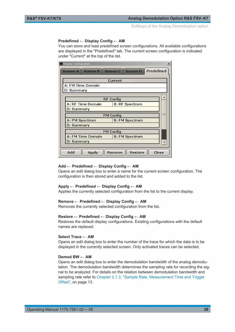
Predefined ← Display Config ← AMYou can store and load predefined screen configurations. All available configurationsare displayed in the "Predefined" tab. The current screen configuration is indicatedunder "Current" at the top of the list.
Add ← Predefined ← Display Config ← AMOpens an edit dialog box to enter a name for the current screen configuration. Theconfiguration is then stored and added to the list.
Apply ← Predefined ← Display Config ← AMApplies the currently selected configuration from the list to the current display.
Remove ← Predefined ← Display Config ← AMRemoves the currently selected configuration from the list.
Restore ← Predefined ← Display Config ← AMRestores the default display configurations. Existing configurations with the defaultnames are replaced.
Select Trace ← AMOpens an edit dialog box to enter the number of the trace for which the data is to bedisplayed in the currently selected screen. Only activated traces can be selected.
Demod BW ← AMOpens an edit dialog box to enter the demodulation bandwidth of the analog demodu-lation. The demodulation bandwidth determines the sampling rate for recording the sig-nal to be analyzed. For details on the relation between demodulation bandwidth andsampling rate refer to Chapter 2.1.3, "Sample Rate, Measurement Time and TriggerOffset", on page 13.
Softkeys of the Analog Demodulation option

Analog Demodulation Option R&S FSV–K7R&S® FSV-K7/K7S
29Operating Manual 1176.7561.02 ─ 05
Remote command: [SENSe:]BANDwidth|BWIDth:DEMod on page 147
Meas Time ← AMOpens an editor for entering the measurement time of the analog demodulation. Fordetails on the measurement time values refer to Chapter 2.1.3, "Sample Rate, Mea-surement Time and Trigger Offset", on page 13.
Note: For FM Stereo measurements (option K7S), the minimum measurement time is2 ms.
Remote command: [SENSe:]ADEMod:MTIMe on page 133
AF Filter ← AMThe bandwidth of the demodulated signal can be reduced by high pass or low pass fil-ters and also a de-emphasis can be switched on. The selected filters are used for AM,FM and PM demodulation in common. Individual settings are not possible.
High Pass ← AF Filter ← AMOpens the "High Pass" selection list to switch on a high pass filter with the given limitto separate the DC component. The filters are indicated by the 3 dB cutoff frequency.The 50 Hz and 300 Hz filters are designed as 2nd-order Butterworth filter (12 dB/octave). The 20 Hz filter is designed as 3rd-order Butterworth filter (18 dB/octave).
"None" deactivates the AF high pass filter. Default is "None".
The high pass filters are active in the following demodulation bandwidth range:
20 Hz 100 Hz ≤ demodulation bandwidth ≤ 1.6 MHz
50 Hz: 200 Hz ≤ demodulation bandwidth ≤ 3 MHz
300 Hz: 800 Hz ≤ demodulation bandwidth ≤ 8 MHz
Note: for FM stereo (K7S), all filters are active at all times, as the demodulation range is always 400 kHz
Remote command: [SENSe:]FILTer<n>:HPASs[:STATe] on page 151[SENSe:]FILTer<n>:HPASs:FREQuency on page 152
Low Pass ← AF Filter ← AMOpens the "Low Pass" selection list to select the filter type. Relative and absolute lowpass filter are available.● Absolute low pass filters:
The 3 kHz, 15 kHz; 23 kHz and 150 kHz softkeys switch on a absolute low passfilter. The filters are indicated by the 3 dB cutoff frequency. The 3 kHz, 15 kHz and23 kHz filters are designed as 5th-order Butterworth filters (30 dB/octave). The 150kHz filter is designed as 8th-order Butterworth filter (48 dB/octave).The absolute low pass filters are active in the following demodulation bandwidthrange:
Softkeys of the Analog Demodulation option
Analog Demodulation Option R&S FSV–K7R&S® FSV-K7/K7S
30Operating Manual 1176.7561.02 ─ 05
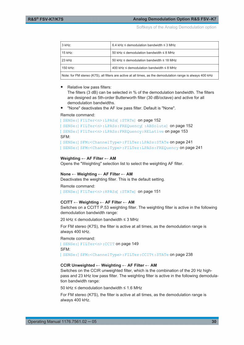
3 kHz: 6.4 kHz ≤ demodulation bandwidth ≤ 3 MHz
15 kHz: 50 kHz ≤ demodulation bandwidth ≤ 8 MHz
23 kHz 50 kHz ≤ demodulation bandwidth ≤ 18 MHz
150 kHz: 400 kHz ≤ demodulation bandwidth ≤ 8 MHz
Note: for FM stereo (K7S), all filters are active at all times, as the demodulation range is always 400 kHz
● Relative low pass filters:The filters (3 dB) can be selected in % of the demodulation bandwidth. The filtersare designed as 5th-order Butterworth filter (30 dB/octave) and active for alldemodulation bandwidths.
● "None" deactivates the AF low pass filter. Default is "None".
Remote command: [SENSe:]FILTer<n>:LPASs[:STATe] on page 152[SENSe:]FILTer<n>:LPASs:FREQuency[:ABSolute] on page 152[SENSe:]FILTer<n>:LPASs:FREQuency:RELative on page 153SFM:[SENSe:]SFM:<ChannelType>:FILTer:LPASs:STATe on page 241[SENSe:]SFM:<ChannelType>:FILTer:LPASs:FREQuency on page 241
Weighting ← AF Filter ← AMOpens the "Weighting" selection list to select the weighting AF filter.
None ← Weighting ← AF Filter ← AMDeactivates the weighting filter. This is the default setting.
Remote command: [SENSe:]FILTer<n>:HPASs[:STATe] on page 151
CCITT ← Weighting ← AF Filter ← AMSwitches on a CCITT P.53 weighting filter. The weighting filter is active in the followingdemodulation bandwidth range:
20 kHz ≤ demodulation bandwidth ≤ 3 MHz
For FM stereo (K7S), the filter is active at all times, as the demodulation range isalways 400 kHz.
Remote command: [SENSe:]FILTer<n>:CCIT on page 149SFM:[SENSe:]SFM:<ChannelType>:FILTer:CCITt:STATe on page 238
CCIR Unweighted ← Weighting ← AF Filter ← AMSwitches on the CCIR unweighted filter, which is the combination of the 20 Hz high-pass and 23 kHz low pass filter. The weighting filter is active in the following demodula-tion bandwidth range:
50 kHz ≤ demodulation bandwidth ≤ 1.6 MHz
For FM stereo (K7S), the filter is active at all times, as the demodulation range isalways 400 kHz.
Softkeys of the Analog Demodulation option

Analog Demodulation Option R&S FSV–K7R&S® FSV-K7/K7S
31Operating Manual 1176.7561.02 ─ 05
Remote command: [SENSe:]FILTer<n>:CCIR[:UNWeighted][:STATe] on page 150SFM:[SENSe:]SFM:<ChannelType>:FILTer:CCIR[:UNWeighted][:STATe]on page 238
CCIR Weighted ← Weighting ← AF Filter ← AMSwitches on the CCIR weighted filter. The weighting filter is active in the followingdemodulation bandwidth range:
100 kHz ≤ demodulation bandwidth ≤ 3.0 MHz
For FM stereo (K7S), the filter is active at all times, as the demodulation range isalways 400 kHz.
Remote command: [SENSe:]FILTer<n>:CCIR:WEIGhted[:STATe] on page 150SFM:[SENSe:]SFM:<ChannelType>:FILTer:CCIR:WEIGhted[:STATe] on page 239
A Weighted ← Weighting ← AF Filter ← AMSwitches on the A weighted filter. The weighting filter is active in the following demodu-lation bandwidth range:
100 kHz ≤ demodulation bandwidth ≤ 800 kHz
Remote command: [SENSe:]FILTer<n>:AWEighted[:STATe] on page 149SFM:[SENSe:]SFM:<ChannelType>:FILTer:AWEighted[:STATe] on page 237
Deemphasis ← AF Filter ← AMOpens the "Deemphasis" selection list to switch on a deemphasis with the given timeconstant.
The deemphasis is active in the following demodulation bandwidth range:
Note: For FM stereo measurements (K7S), the demodulation bandwidth is always 400kHz, thus the deemphasis is always active.
25 µs: 25 kHz ≤ demodulation bandwidth ≤ 40 MHz
50 µs: 6.4 kHz ≤ demodulation bandwidth ≤ 18 MHz
75 µs: 6.4 kHz ≤ demodulation bandwidth ≤ 18 MHz
750 µs: 800 Hz ≤ demodulation bandwidth ≤ 3 MHz
The following table shows the required demodulation bandwidth for an error less than0.5 dB up to a maximum AF frequency.
deemphasis 25 µs 50 µs 75 µs 750 µs
max. AF frequency 25 kHz 12 kHz 8 kHz 800 Hz
required demodulation bandwidth ≥ 200 kHz ≥ 100 kHz ≥ 50 kHz ≥ 6.4 kHz
Softkeys of the Analog Demodulation option
Analog Demodulation Option R&S FSV–K7R&S® FSV-K7/K7S
32Operating Manual 1176.7561.02 ─ 05
For higher AF frequencies the demodulation bandwidth must be increased.
Remote command: [SENSe:]FILTer<n>:DEMPhasis[:STATe] on page 150[SENSe:]FILTer<n>:DEMPhasis:TCONstant on page 151SFM:[SENSe:]SFM:<ChannelType>:FILTer:DEMPhasis:STATe on page 239[SENSe:]SFM:<ChannelType>:FILTer:DEMPhasis:TCONstant on page 240
All AF Filter Off ← AF Filter ← AMDisables all specified AF Filters.
Remote command: [SENSe:]FILTer<n>:AOFF on page 148
AF Range ← AMOpens a submenu to define the diagram scaling for AF displays.
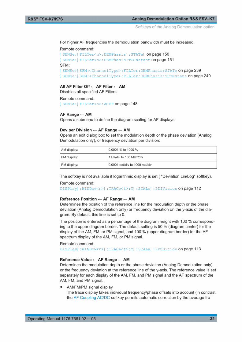
Dev per Division ← AF Range ← AMOpens an edit dialog box to set the modulation depth or the phase deviation (AnalogDemodulation only), or frequency deviation per division:
AM display: 0.0001 % to 1000 %
FM display: 1 Hz/div to 100 MHz/div
PM display: 0.0001 rad/div to 1000 rad/div
The softkey is not available if logarithmic display is set ( "Deviation Lin/Log" softkey).
Remote command: DISPlay[:WINDow<n>]:TRACe<t>:Y[:SCALe]:PDIVision on page 112
Reference Position ← AF Range ← AMDetermines the position of the reference line for the modulation depth or the phasedeviation (Analog Demodulation only) or frequency deviation on the y-axis of the dia-gram. By default, this line is set to 0.
The position is entered as a percentage of the diagram height with 100 % correspond-ing to the upper diagram border. The default setting is 50 % (diagram center) for thedisplay of the AM, FM, or PM signal, and 100 % (upper diagram border) for the AFspectrum display of the AM, FM, or PM signal.
Remote command: DISPlay[:WINDow<n>]:TRACe<t>:Y[:SCALe]:RPOSition on page 113
Reference Value ← AF Range ← AMDetermines the modulation depth or the phase deviation (Analog Demodulation only)or the frequency deviation at the reference line of the y-axis. The reference value is setseparately for each display of the AM, FM, and PM signal and the AF spectrum of theAM, FM, and PM signal.● AM/FM/PM signal display
The trace display takes individual frequency/phase offsets into account (in contrast,the AF Coupling AC/DC softkey permits automatic correction by the average fre-
Softkeys of the Analog Demodulation option

Analog Demodulation Option R&S FSV–K7R&S® FSV-K7/K7S
33Operating Manual 1176.7561.02 ─ 05
quency/phase offset of the signal, and can therefore not be activated simultane-ously).Possible values: 0 and ± 10000 % (AM), 0 and ± 10 MHz (FM), 0 and ± 10000 rad(PM).
● AF spectrum display of the AM/FM/PM signalIn the default setting, the reference value defines the modulation depth or theFM/PM deviation at the upper diagram border.Possible values: 0 and 10000 % (AM), 0 and 10 MHz (FM), 0 and 10000 rad (PM).
Remote command: DISPlay[:WINDow<n>]:TRACe<t>:Y[:SCALe]:RVALue on page 114
AF Coupling AC/DC ← AF Range ← AMControls the automatic correction of the frequency offset and phase offset of the inputsignal:
(Note: This function is not available with the AF spectrum display of the FM or PM sig-nal.)● FM signal display
If DC is selected, the absolute frequency is displayed, i.e. an input signal with anoffset relative to the center frequency is not displayed symmetrically with respect tothe zero line.If AC is selected, the frequency offset is automatically corrected, i.e. the trace isalways symmetric with respect to the zero line.
● PM signal displayIf DC is selected, the phase runs according to the existing frequency offset. In addi-tion, the DC signal contains a phase offset of ± π.If AC is selected, the frequency offset and phase offset are automatically corrected,i.e. the trace is always symmetric with respect to the zero line.
Remote command: [SENSe:]ADEMod<n>:AF:COUPling on page 122
Deviation Lin/Log ← AF Range ← AMSwitches between logarithmic and linear display of the modulation depth or the phasedeviation (Analog Demodulation only) or the frequency deviation.
Remote command: DISPlay[:WINDow<n>]:TRACe<t>:Y:SPACing on page 114
Unit ← AF Range ← AMOpens a submenu to define the modulation unit.
Phase Unit (Rad/Deg) ← Unit ← AF Range ← AMSets the phase unit to rad or deg for displaying PM signals.
Remote command: UNIT:THD on page 170
THD Unit (% / DB) ← Unit ← AF Range ← AMSets the unit to percent or DB for THD measurements.
Softkeys of the Analog Demodulation option

Analog Demodulation Option R&S FSV–K7R&S® FSV-K7/K7S
34Operating Manual 1176.7561.02 ─ 05
Remote command: UNIT:THD on page 170
Abs. Dev Unit (kHz/dBm) ← Unit ← AF Range ← AMSets the unit for absolute deviation to kHz or dBm. This softkey is only available withthe FM Stereo option K7S.
Remote command: UNIT:ADEV on page 250
Rel. Dev Unit (dB / %) ← Unit ← AF Range ← AMSets the unit for relative deviation to dB or percent. This softkey is only available withthe FM Stereo option K7S.
Remote command: UNIT:RDEV on page 251
Time Domain Zoom ← AMOpens a submenu to activate and configure the zoom function.
State On / Off ← Time Domain Zoom ← AMActivates or deactivates the time domain zoom according to the defined settings.
"ON" Activates the time domain zoom. The zoom area is defined using the"Start""Start" on page 34 and "Length Manual""Length Manual"on page 34 / "Length Auto""Length Auto" on page 34 softkeys.
"OFF" If more measured values than measurement points are available,several measured values are combined in one measurement pointaccording to the method of the selected trace detector. For details ondetectors refer to Chapter 2.1.8, "Detector Overview", on page 19.
Remote command: [SENSe:]ADEMod<n>:ZOOM[:STATe] on page 143
Start ← Time Domain Zoom ← AMOpens an edit dialog box to define the start time for the zoom area.
Remote command: [SENSe:]ADEMod<n>:ZOOM:STARt on page 144
Length Manual ← Time Domain Zoom ← AMOpens an edit dialog box to define the length of the zoom area (as a time value) man-ually.
Remote command: [SENSe:]ADEMod<n>:ZOOM:LENGth on page 144
Length Auto ← Time Domain Zoom ← AMAutomatically sets the length of the zoom area to the number of sweep points (see"Sweep Points" on page 55).
Softkeys of the Analog Demodulation option
Analog Demodulation Option R&S FSV–K7R&S® FSV-K7/K7S
35Operating Manual 1176.7561.02 ─ 05
Remote command: [SENSe:]ADEMod<n>:ZOOM:LENGth:MODE on page 145
Squelch ← AMActivates the squelch function, i.e. if the signal falls below a defined threshold, thedemodulated data is automatically set to 0. This is useful, for example, to avoiddemodulation noise during transmission breaks.
Remote command: [SENSe:]ADEMod:SQUelch[:STATe] on page 142
Squelch Level ← AMDefines the level threshold below which the demodulated data is set to 0 if squelchingis enabled. The squelch level is an absolute value.
Remote command: [SENSe:]ADEMod:SQUelch:LEVel on page 142
FMSelects FM as the modulation type, changes the signal display, and opens a submenuto set the measurement configuration. The average value of the demodulated signal ismapped depending on the "AF Coupling" softkey setting (see "AF Coupling AC/DC"on page 33).
In single sweep mode, the data is determined from the current I/Q data set, i.e. achange to a different type does not trigger a new measurement.
This menu is also displayed when you press the MEAS CONFIG key after changingthe modulation type.
Remote command: CALC:FEED 'XTIM:FM' (see CALCulate<n>:FEED on page 90)
Display Config ← FMSee "Display Config" on page 27.
Select Trace ← FMSee "Select Trace" on page 28.
Demod BW ← FMSee "Demod BW" on page 28.
Meas Time ← FMSee "Meas Time" on page 29.
AF Filter ← FMSee "AF Filter" on page 29.
AF Range ← FMSee "AF Range" on page 32.
Time Domain Zoom ← FMSee "Time Domain Zoom" on page 34.
Softkeys of the Analog Demodulation option

Analog Demodulation Option R&S FSV–K7R&S® FSV-K7/K7S
36Operating Manual 1176.7561.02 ─ 05
Squelch ← FMSee "Squelch" on page 35.
Squelch Level ← FMSee "Squelch Level" on page 35.
PMSelects PM as the modulation type, changes the signal display, and opens a submenuto set the measurement configuration.
In single sweep mode, the data is determined from the current I/Q data set, i.e. achange to a different type does not trigger a new measurement.
This menu is also displayed when you press the MEAS CONFIG key after changingthe modulation type.
Remote command: CALC:FEED 'XTIM:PM' (see CALCulate<n>:FEED on page 90)
Display Config ← PMSee "Display Config" on page 27.
Select Trace ← PMSee "Select Trace" on page 28.
Demod BW ← PMSee "Demod BW" on page 28.
Meas Time ← PMSee "Meas Time" on page 29.
AF Filter ← PMSee "AF Filter" on page 29.
AF Range ← PMSee "AF Range" on page 32.
Time Domain Zoom ← PMSee "Time Domain Zoom" on page 34.
Squelch ← PMSee "Squelch" on page 35.
Squelch Level ← PMSee "Squelch Level" on page 35.
Zero Phase Reference Point ← PMDefines the position at which the phase of the PM-demodulated signal is set to 0 rad.The entry is made with respect to time. In the default setting, the first measured valueis set to 0 rad.
This softkey is only available in the PM display with DC coupling.
Softkeys of the Analog Demodulation option

Analog Demodulation Option R&S FSV–K7R&S® FSV-K7/K7S
37Operating Manual 1176.7561.02 ─ 05
Remote command: [SENSe:]ADEMod:PM:RPOint[:X] on page 137
Phase Wrap On/Off ← PMActivates/deactivates the phase wrap.
On The phase will be displayed in the range ±180° (± Π). For example, if the phase exceeds +180°,360° is subtracted from the phase value, with the display thus showing >-180°.
Off The phase will not be wrapped.
This softkey is available in the PM signal displays.
Remote command: CALC:FORM PHAS (see CALCulate<n>:FORMat on page 93)
RF PowerSelects RF power as the modulation type, changes the signal display, and opens asubmenu to set the measurement configuration.
In single sweep mode, the data is determined from the current I/Q data set, i.e. achange to a different type does not trigger a new measurement.
This menu is also displayed when you press the MEAS CONFIG key after changingthe modulation type.
Remote command: CALC:FEED 'XTIM:RFPower' (see CALCulate<n>:FEED on page 90)
Display Config ← RF PowerSee "Display Config" on page 27.
Select Trace ← RF PowerSee "Select Trace" on page 28.
Demod BW ← RF PowerSee "Demod BW" on page 28.
Meas Time ← RF PowerSee "Meas Time" on page 29.
AF Filter ← RF PowerSee "AF Filter" on page 29.
AF Range ← RF PowerSee "AF Range" on page 32.
Time Domain Zoom ← RF PowerSee "Time Domain Zoom" on page 34.
Squelch ← RF PowerSee "Squelch" on page 35.
Softkeys of the Analog Demodulation option

Analog Demodulation Option R&S FSV–K7R&S® FSV-K7/K7S
38Operating Manual 1176.7561.02 ─ 05
Squelch Level ← RF PowerSee "Squelch Level" on page 35.
Display ConfigSee "Display Config" on page 27.
2.2.2 Softkeys of the Frequency Menu – FREQ Key (Analog Demodula-tion)
The following table shows all softkeys available in the "Frequency" menu in "AnalogDemodulation" mode (FREQ key). It is possible that your instrument configuration doesnot provide all softkeys. If a softkey is only available with a special option, model or(measurement) mode, this information is delivered in the corresponding softkeydescription.
Center........................................................................................................................... 38CF Stepsize...................................................................................................................38
└ 0.1*Span (RF Spectrum).................................................................................39└ 0.1*Demod BW (AF/RF Time Domain, AF Spectrum)....................................39└ 0.5*Span (RF Spectrum).................................................................................39└ 0.5*Demod BW (AF/RF Time Domain, AF Spectrum)....................................39└ x*Span (RF Spectrum)....................................................................................39└ x*Demod BW (AF/RF Time Domain, AF Spectrum)....................................... 39└ =Center........................................................................................................... 39└ Manual............................................................................................................ 39
AF Center (AF Spectrum)............................................................................................. 40AF Start......................................................................................................................... 40AF Stop......................................................................................................................... 40
CenterOpens an edit dialog box to enter the center frequency. The allowed range of valuesfor the center frequency depends on the frequency span.
span > 0: spanmin/2 ≤ fcenter ≤ fmax – spanmin/2
span = 0: 0 Hz ≤ fcenter ≤ fmax
fmax and spanmin are specified in the data sheet.
If the bandwidth extension option R&S FSV-B160 is active, center frequencies above7 GHz are not available.
Remote command: [SENSe:]FREQuency:CENTer on page 153
CF StepsizeOpens a submenu to set the step size of the center frequency. Apart from the =CenterandManual softkeys, the other softkeys are displayed depending on the selected fre-quency span.
The step size can be coupled to the span (span > 0) or the demodulation bandwidth(span = 0) or it can be manually set to a fixed value.
Softkeys of the Analog Demodulation option
Analog Demodulation Option R&S FSV–K7R&S® FSV-K7/K7S
39Operating Manual 1176.7561.02 ─ 05
0.1*Span (RF Spectrum) ← CF StepsizeSets the step size for the center frequency to 10 % of the span.
Remote command: [SENSe:]FREQuency:CENTer:STEP:LINK on page 154[SENSe:]FREQuency:CENTer:STEP:LINK:FACTor on page 155
0.1*Demod BW (AF/RF Time Domain, AF Spectrum) ← CF StepsizeSets the step size for the center frequency to 10 % of the demodulation bandwidth.This is the default setting.
Remote command: [SENSe:]FREQuency:CENTer:STEP:LINK on page 154[SENSe:]FREQuency:CENTer:STEP:LINK:FACTor on page 155
0.5*Span (RF Spectrum) ← CF StepsizeSets the step size for the center frequency to 50 % of the span.
Remote command: [SENSe:]FREQuency:CENTer:STEP:LINK on page 154[SENSe:]FREQuency:CENTer:STEP:LINK:FACTor on page 155
0.5*Demod BW (AF/RF Time Domain, AF Spectrum) ← CF StepsizeSets the step size for the center frequency to 50 % of the demodulation bandwidth.
Remote command: [SENSe:]FREQuency:CENTer:STEP:LINK on page 154[SENSe:]FREQuency:CENTer:STEP:LINK:FACTor on page 155
x*Span (RF Spectrum) ← CF StepsizeOpens an edit dialog box to set the step size for the center frequency as % of the span.
Remote command: [SENSe:]FREQuency:CENTer:STEP:LINK on page 154[SENSe:]FREQuency:CENTer:STEP:LINK:FACTor on page 155
x*Demod BW (AF/RF Time Domain, AF Spectrum) ← CF StepsizeOpens an edit dialog box to set the step size for the center frequency as % of thedemodulation bandwidth. Values between 1 and 100 % in steps of 1 % are allowed.The default setting is 10 %.
Remote command: [SENSe:]FREQuency:CENTer:STEP:LINK on page 154[SENSe:]FREQuency:CENTer:STEP:LINK:FACTor on page 155
=Center ← CF StepsizeSets the step size to the value of the center frequency and removes the coupling of thestep size to span or resolution bandwidth.
This function is especially useful for measurements of the signal harmonics. In thiscase, each stroke of the arrow key selects the center frequency of another harmonic.
Manual ← CF StepsizeOpens an edit dialog box to enter a fixed step size for the center frequency.
Softkeys of the Analog Demodulation option
Analog Demodulation Option R&S FSV–K7R&S® FSV-K7/K7S
40Operating Manual 1176.7561.02 ─ 05
Remote command: [SENSe:]FREQuency:CENTer:STEP on page 154
AF Center (AF Spectrum)Opens an edit box to enter the center frequency within the AF spectrum.
Remote command: [SENSe:]ADEMod<n>:AF:CENTer on page 121
AF StartOpens an edit box to define the start frequency within the AF spectrum.
Remote command: [SENSe:]ADEMod<n>:AF:STARt on page 123
AF StopOpens an edit box to define the stop frequency within the AF spectrum.
The maximum AF stop frequency corresponds to half the demodulation bandwidth.
Remote command: [SENSe:]ADEMod<n>:AF:STOP on page 124
2.2.3 Softkeys of the Span Menu – SPAN Key (Analog Demodulation)
The following table shows all softkeys available in the ""Span"" menu in ""AnalogDemodulation"" mode (SPAN key). It is possible that your instrument configurationdoes not provide all softkeys. If a softkey is only available with a special option, modelor (measurement) mode, this information is delivered in the corresponding softkeydescription.
Span Manual (RF Spectrum)........................................................................................ 40AF Span Manual (AF Spectrum)................................................................................... 40Demod BW....................................................................................................................41Full Span (RF Spectrum).............................................................................................. 41AF Full Span (AF Spectrum)......................................................................................... 41
Span Manual (RF Spectrum)Opens an edit dialog box to enter the frequency span. The center frequency is keptconstant. If the RF spectrum display is active, values between the sampling rate/1000and the demodulation bandwidth are allowed.
Remote command: [SENSe:]ADEMod:SPECtrum:SPAN:ZOOM on page 142
AF Span Manual (AF Spectrum)Opens an edit dialog box to enter the frequency range for the AF spectrum display.Values between the sampling rate/1000 and the demodulation bandwidth/2 areallowed.
Softkeys of the Analog Demodulation option
Analog Demodulation Option R&S FSV–K7R&S® FSV-K7/K7S
41Operating Manual 1176.7561.02 ─ 05
Remote command: [SENSe:]ADEMod<n>:AF:SPAN on page 122
Demod BWOpens an edit dialog box to enter the demodulation bandwidth of the analog demodu-lation. The demodulation bandwidth determines the sampling rate for recording the sig-nal to be analyzed. For details on the relation between demodulation bandwidth andsampling rate refer to Chapter 2.1.3, "Sample Rate, Measurement Time and TriggerOffset", on page 13.
Remote command: [SENSe:]BANDwidth|BWIDth:DEMod on page 147
Full Span (RF Spectrum)Sets the span to the maximum frequency range of the R&S FSV/FSVA specified in thedata sheet. This setting is useful for overview measurements.
If the RF spectrum display is active, the full frequency range corresponds to thedemodulation bandwidth.
Remote command: [SENSe:]ADEMod:SPECtrum:SPAN:ZOOM on page 142
AF Full Span (AF Spectrum)Sets the span to the maximum frequency range for the AF spectrum display. The maxi-mum frequency range corresponds to half the demodulation bandwidth.
Remote command: [SENSe:]ADEMod<n>:AF:SPAN:FULL on page 123
2.2.4 Softkeys of the Amplitude Menu – AMPT Key (Analog Demodula-tion)
The following table shows all softkeys available in the "Amplitude" menu in "AnalogDemodulation" mode (AMPT key). It is possible that your instrument configuration doesnot provide all softkeys. If a softkey is only available with a special option, model or(measurement) mode, this information is delivered in the corresponding softkeydescription.
Ref Level....................................................................................................................... 42AF Range...................................................................................................................... 42Range............................................................................................................................42
└ Range Log 100 dB..........................................................................................42└ Range Log 50 dB............................................................................................42└ Range Log 10 dB............................................................................................43└ Range Log 5 dB..............................................................................................43└ Range Log 1 dB..............................................................................................43└ Range Log Manual..........................................................................................43└ Range Linear %.............................................................................................. 43└ Range Lin. Unit............................................................................................... 44
Unit................................................................................................................................44└ Phase Unit (Rad/Deg).....................................................................................44
Softkeys of the Analog Demodulation option

Analog Demodulation Option R&S FSV–K7R&S® FSV-K7/K7S
42Operating Manual 1176.7561.02 ─ 05
└ THD Unit (% / DB)...........................................................................................44Preamp On/Off.............................................................................................................. 44RF Atten Manual/Mech Att Manual............................................................................... 44RF Atten Auto/Mech Att Auto........................................................................................ 45El Atten On/Off.............................................................................................................. 45El Atten Mode (Auto/Man).............................................................................................46Ref Level Offset............................................................................................................ 46Ref Level Position......................................................................................................... 46Grid Abs/Rel .................................................................................................................46Input (AC/DC)................................................................................................................47Input 50 Ω/75 Ω ............................................................................................................47
Ref LevelOpens an edit dialog box to enter the reference level in the current unit (dBm, dBµV,etc).
The reference level is the maximum value the AD converter can handle without distor-tion of the measured value. Signal levels above this value will not be measured cor-rectly, which is indicated by the "IFOVL" status display.
Remote command: DISPlay[:WINDow<n>]:TRACe<t>:Y[:SCALe]:RLEVel on page 113
AF RangeOnly available for AM/FM/PM measurements (see Chapter 2.1.10, "MeasurementResult Display", on page 20).
For details refer to the "AF Range" softkey of the main menu (see "AF Range"on page 32).
RangeOnly available for RF measurements (see Chapter 2.1.10, "Measurement Result Dis-play", on page 20).
Opens a submenu to define the level display range.
Range Log 100 dB ← RangeSets the level display range to 100 dB.
Remote command: Logarithmic scaling:DISP:WIND:TRAC:Y:SPAC LOG, see DISPlay[:WINDow<n>]:TRACe<t>:Y:SPACing on page 114Display range:DISP:WIND:TRAC:Y 100DB, see DISPlay[:WINDow<n>]:TRACe<t>:Y[:SCALe]on page 111
Range Log 50 dB ← RangeSets the level display range to 50 dB.
Remote command: Logarithmic scaling:DISP:WIND:TRAC:Y:SPAC LOG, see DISPlay[:WINDow<n>]:TRACe<t>:Y:SPACing on page 114
Softkeys of the Analog Demodulation option

Analog Demodulation Option R&S FSV–K7R&S® FSV-K7/K7S
43Operating Manual 1176.7561.02 ─ 05
Display range:DISP:WIND:TRAC:Y 50DB, see DISPlay[:WINDow<n>]:TRACe<t>:Y[:SCALe]on page 111
Range Log 10 dB ← RangeSets the level display range to 10 dB.
Remote command: Logarithmic scaling:DISP:WIND:TRAC:Y:SPAC LOG, see DISPlay[:WINDow<n>]:TRACe<t>:Y:SPACing on page 114Display range:DISP:WIND:TRAC:Y 10DB, see DISPlay[:WINDow<n>]:TRACe<t>:Y[:SCALe]on page 111
Range Log 5 dB ← RangeSets the level display range to 5 dB.
Remote command: Logarithmic scaling:DISP:WIND:TRAC:Y:SPAC LOG, see DISPlay[:WINDow<n>]:TRACe<t>:Y:SPACing on page 114Display range:DISP:WIND:TRAC:Y 5DB, see DISPlay[:WINDow<n>]:TRACe<t>:Y[:SCALe]on page 111
Range Log 1 dB ← RangeSets the level display range to 1 dB.
Remote command: Logarithmic scaling:DISP:WIND:TRAC:Y:SPAC LOG, see DISPlay[:WINDow<n>]:TRACe<t>:Y:SPACing on page 114Display range:DISP:WIND:TRAC:Y 1DB, see DISPlay[:WINDow<n>]:TRACe<t>:Y[:SCALe]on page 111
Range Log Manual ← RangeOpens an edit dialog box to define the display range of a logarithmic level axis man-ually.
Remote command: Logarithmic scaling:DISP:WIND:TRAC:Y:SPAC LOG, see DISPlay[:WINDow<n>]:TRACe<t>:Y:SPACing on page 114Display range:DISPlay[:WINDow<n>]:TRACe<t>:Y[:SCALe] on page 111
Range Linear % ← RangeSelects linear scaling for the level axis in %.
The grid is divided into decadal sections.
Softkeys of the Analog Demodulation option
Analog Demodulation Option R&S FSV–K7R&S® FSV-K7/K7S
44Operating Manual 1176.7561.02 ─ 05
Markers are displayed in the selected unit ("Unit" softkey). Delta markers are displayedin % referenced to the voltage value at the position of marker 1. This is the default set-ting for linear scaling.
Remote command: DISP:TRAC:Y:SPAC LIN, see DISPlay[:WINDow<n>]:TRACe<t>:Y:SPACingon page 114
Range Lin. Unit ← RangeSelects linear scaling in dB for the level display range, i.e. the horizontal lines arelabeled in dB.
Markers are displayed in the selected unit ("Unit" softkey). Delta markers are displayedin dB referenced to the power value at the position of marker 1.
Remote command: DISP:TRAC:Y:SPAC LDB, see DISPlay[:WINDow<n>]:TRACe<t>:Y:SPACingon page 114
UnitOpens a submenu to define the unit of the measurement results.
Phase Unit (Rad/Deg) ← UnitSets the phase unit to rad or deg for displaying PM signals.
Remote command: UNIT:THD on page 170
THD Unit (% / DB) ← UnitSets the unit to percent or DB for THD measurements.
Remote command: UNIT:THD on page 170
Preamp On/OffSwitches the preamplifier on and off.
If option R&S FSV-B22 is installed, the preamplifier is only active below 7 GHz.
If option R&S FSV-B24 is installed, the preamplifier is active for all frequencies.
This function is not available for input from the R&S Digital I/Q Interface (optionR&S FSV-B17).
Remote command: INPut:GAIN:STATe on page 181
RF Atten Manual/Mech Att ManualOpens an edit dialog box to enter the attenuation, irrespective of the reference level. Ifelectronic attenuation is activated (option R&S FSV-B25 only; "El Atten Mode Auto"softkey), this setting defines the mechanical attenuation.
The mechanical attenuation can be set in 10 dB steps.
Softkeys of the Analog Demodulation option

Analog Demodulation Option R&S FSV–K7R&S® FSV-K7/K7S
45Operating Manual 1176.7561.02 ─ 05
The RF attenuation can be set in 5 dB steps (R&S FSV with option R&S FSV-B25 orR&S FSVA: 1 dB steps). The range is specified in the data sheet. If the current refer-ence level cannot be set for the set RF attenuation, the reference level is adjustedaccordingly.
This function is not available for input from the R&S Digital I/Q Interface (optionR&S FSV-B17).
The RF attenuation defines the level at the input mixer according to the formula:
levelmixer = levelinput – RF attenuation
Note: As of firmware version 1.61, the maximum mixer level allowed is 0 dBm. Mixerlevels above this value may lead to incorrect measurement results, which are indicatedby the "OVLD" status display. The increased mixer level allows for an improved signal,but also increases the risk of overloading the instrument!
Remote command: INPut:ATTenuation on page 177
RF Atten Auto/Mech Att AutoSets the RF attenuation automatically as a function of the selected reference level.This ensures that the optimum RF attenuation is always used. It is the default setting.
This function is not available for input from the R&S Digital I/Q Interface (optionR&S FSV-B17).
Remote command: INPut:ATTenuation:AUTO on page 177
El Atten On/OffThis softkey switches the electronic attenuator on or off. This softkey is only availablewith option R&S FSV-B25.
When the electronic attenuator is activated, the mechanical and electronic attenuationcan be defined separately. Note however, that both parts must be defined in the samemode, i.e. either both manually, or both automatically.
This function is not available for input from the R&S Digital I/Q Interface (optionR&S FSV-B17).
● To define the mechanical attenuation, use the RF Atten Manual/Mech Att Manualor RF Atten Auto/Mech Att Auto softkeys.
● To define the electronic attenuation, use the El Atten Mode (Auto/Man) softkey.Note: This function is not available for stop frequencies (or center frequencies in zerospan) >7 GHz. In this case, the electronic and mechanical attenuation are summarizedand the electronic attenuation can no longer be defined individually. As soon as thestop or center frequency is reduced below 7 GHz, this function is available again.When the electronic attenuator is switched off, the corresponding RF attenuation mode(auto/manual) is automatically activated.
Softkeys of the Analog Demodulation option

Analog Demodulation Option R&S FSV–K7R&S® FSV-K7/K7S
46Operating Manual 1176.7561.02 ─ 05
Remote command: INPut:EATT:AUTO on page 181
El Atten Mode (Auto/Man)This softkey defines whether the electronic attenuator value is to be set automaticallyor manually. If manual mode is selected, an edit dialog box is opened to enter thevalue. This softkey is only available with option R&S FSV-B25, and only if the elec-tronic attenuator has been activated via the El Atten On/Off softkey.
Note: This function is not available for stop frequencies (or center frequencies in zerospan) >7 GHz. In this case, the electronic and mechanical attenuation are summarizedand the electronic attenuation can no longer be defined individually. As soon as thestop or center frequency is reduced below 7 GHz, electronic attenuation is availableagain. If the electronic attenuation was defined manually, it must be re-defined.The attenuation can be varied in 1 dB steps from 0 to 30 dB. Other entries are roundedto the next lower integer value.
To re-open the edit dialog box for manual value definition, select the "Man" modeagain.
If the defined reference level cannot be set for the given RF attenuation, the referencelevel is adjusted accordingly and the warning "Limit reached" is output.
Remote command: INPut:EATT:AUTO on page 181INPut:EATT on page 181
Ref Level OffsetOpens an edit dialog box to enter the arithmetic level offset. This offset is added to themeasured level irrespective of the selected unit. The scaling of the y-axis is changedaccordingly. The setting range is ±200 dB in 0.1 dB steps.
Remote command: DISPlay[:WINDow<n>]:TRACe<t>:Y[:SCALe]:RLEVel:OFFSet on page 113
Ref Level PositionOpens an edit dialog box to enter the reference level position, i.e. the position of themaximum AD converter value on the level axis. The setting range is from -200 to+200 %, 0 % corresponding to the lower and 100 % to the upper limit of the diagram.
Only available for RF measurements.
Remote command: DISPlay[:WINDow<n>]:TRACe<t>:Y[:SCALe]:RPOSition on page 113
Grid Abs/RelSwitches between absolute and relative scaling of the level axis (not available with"Linear" range).
Only available for RF measurements.
"Abs" Absolute scaling: The labeling of the level lines refers to the absolutevalue of the reference level. Absolute scaling is the default setting.
Softkeys of the Analog Demodulation option
Analog Demodulation Option R&S FSV–K7R&S® FSV-K7/K7S
47Operating Manual 1176.7561.02 ─ 05
"Rel" Relative scaling: The upper line of the grid is always at 0 dB. Thescaling is in dB whereas the reference level is always in the set unit(for details on unit settings see the "Unit" softkey).
Remote command: DISPlay[:WINDow<n>]:TRACe<t>:Y[:SCALe]:MODE on page 112
Input (AC/DC)Toggles the RF input of the R&S FSV/FSVA between AC and DC coupling.
This function is not available for input from the R&S Digital I/Q Interface (optionR&S FSV-B17).
Remote command: INPut:COUPling on page 178
Input 50 Ω/75 ΩUses 50 Ω or 75 Ω as reference impedance for the measured levels. Default setting is50 Ω.
The setting 75 Ω should be selected if the 50 Ω input impedance is transformed to ahigher impedance using a 75 Ω adapter of the RAZ type (= 25 Ω in series to the inputimpedance of the instrument). The correction value in this case is 1.76 dB = 10 log (75Ω/50 Ω).
All levels specified in this Operating Manual refer to the default setting of the instru-ment (50 Ω).
This function is not available for input from the R&S Digital I/Q Interface (optionR&S FSV-B17).
Remote command: INPut:IMPedance on page 182
2.2.5 Softkeys of the Auto Set menu - AUTO SET Key (Analog Demodula-tion)
The following table shows all softkeys available in the "Auto Set" menu. It is possiblethat your instrument configuration does not provide all softkeys. If a softkey is onlyavailable with a special option, model or (measurement) mode, this information is pro-vided in the corresponding softkey description.
Softkeys of the Analog Demodulation option

Analog Demodulation Option R&S FSV–K7R&S® FSV-K7/K7S
48Operating Manual 1176.7561.02 ─ 05
Adjusting settings automatically during triggered measurementsWhen you select an auto adjust function a measurement is performed to determine theoptimal settings. If you select an auto adjust funtion for a triggered measurement, youcan select how the R&S FSV/FSVA should behave:● (default:) The measurement for adjustment waits for the next trigger● The measurement for adjustment is performed without waiting for a trigger.
The trigger source is temporarily set to "Free Run". After the measurement is com-pleted, the original trigger source is restored. The trigger level for IF Power and RFPower triggers is adjusted as follows:Trigger Level = Reference Level - 15 dB
Auto All..........................................................................................................................48Auto Freq...................................................................................................................... 48Auto Level..................................................................................................................... 48Settings......................................................................................................................... 48
└ Meas Time Manual......................................................................................... 49└ Meas Time Auto..............................................................................................49└ Upper Level Hysteresis...................................................................................49└ Lower Level Hysteresis...................................................................................49
AF Auto Scale............................................................................................................... 49
Auto AllPerforms all automatic settings.● "Auto Freq" on page 48● "Auto Level" on page 48
Remote command: [SENSe:]ADJust:ALL on page 145
Auto FreqDefines the center frequency and the reference level automatically by determining thehighest frequency level in the frequency span. This function uses the signal counter;thus it is intended for use with sinusoidal signals.
This function is not available for input from the R&S Digital I/Q Interface (optionR&S FSV-B17).
Remote command: [SENSe:]ADJust:FREQuency on page 146
Auto LevelDefines the optimal reference level for the current measurement automatically.
The measurement time for automatic leveling can be defined using the Settings soft-key.
Remote command: [SENSe:]ADJust:LEVel on page 147
SettingsOpens a submenu to define settings for automatic leveling.
Softkeys of the Analog Demodulation option

Analog Demodulation Option R&S FSV–K7R&S® FSV-K7/K7S
49Operating Manual 1176.7561.02 ─ 05
Possible settings are:● "Meas Time Manual" on page 49● "Meas Time Auto" on page 49
Meas Time Manual ← SettingsOpens an edit dialog box to enter the duration of the level measurement in seconds.The level measurement is used to determine the optimal reference level automatically(see the "Auto Level" softkey, "Auto Level" on page 48). The default value is 1 ms.
Remote command: [SENSe:]ADJust:CONFigure:LEVel:DURation on page 146
Meas Time Auto ← SettingsThe level measurement is used to determine the optimal reference level automatically(see the Auto Level softkey).
This softkey resets the level measurement duration for automatic leveling to the defaultvalue of 100 ms.
Upper Level Hysteresis ← SettingsDefines an upper threshold the signal must exceed before the reference level is auto-matically adjusted when the "Auto Level" function is performed.
Remote command: [SENSe:]ADJust:CONFiguration:HYSTeresis:UPPer on page 146
Lower Level Hysteresis ← SettingsDefines a lower threshold the signal must exceed before the reference level is auto-matically adjusted when the "Auto Level" function is performed.
Remote command: [SENSe:]ADJust:CONFiguration:HYSTeresis:LOWer on page 145
AF Auto ScaleActivates automatic scaling of the y-axis for AF measurements. RF power and RFspectrum measurements are not affected by the auto-scaling.
Remote command: [SENSe:]ADJust:SCALe:Y:AUTO[:CONTinuous] on page 147
2.2.6 Softkeys of the Bandwidth Menu – BW Key (Analog Demodulation)
The following table shows all softkeys available in the "Bandwidth" menu in "AnalogDemodulation" mode (BW key). It is possible that your instrument configuration doesnot provide all softkeys. If a softkey is only available with a special option, model or(measurement) mode, this information is delivered in the corresponding softkeydescription.
Res BW (span > 0)........................................................................................................50Demod BW....................................................................................................................50Meas Time.................................................................................................................... 50AF Filter.........................................................................................................................50
Softkeys of the Analog Demodulation option
Analog Demodulation Option R&S FSV–K7R&S® FSV-K7/K7S
50Operating Manual 1176.7561.02 ─ 05
└ High Pass........................................................................................................50└ Low Pass........................................................................................................ 51└ Weighting........................................................................................................51
└ None..................................................................................................... 52└ CCITT................................................................................................... 52└ CCIR Unweighted.................................................................................52└ CCIR Weighted.....................................................................................52└ A Weighted........................................................................................... 52
└ Deemphasis....................................................................................................53└ All AF Filter Off................................................................................................53
Demod Filter..................................................................................................................53
Res BW (span > 0)Opens an edit dialog box to enter a value for the resolution bandwidth. The range isspecified in the data sheet.
This softkey is only available for spectrum measurements (see Chapter 2.1.10, "Mea-surement Result Display", on page 20).
Remote command: [SENSe:]ADEMod:SPECtrum:BANDwidth|BWIDth[:RESolution] on page 140
Demod BWOpens an edit dialog box to enter the demodulation bandwidth of the analog demodu-lation. The demodulation bandwidth determines the sampling rate for recording the sig-nal to be analyzed. For details on the relation between demodulation bandwidth andsampling rate refer to Chapter 2.1.3, "Sample Rate, Measurement Time and TriggerOffset", on page 13.
Remote command: [SENSe:]BANDwidth|BWIDth:DEMod on page 147
Meas TimeOpens an editor for entering the measurement time of the analog demodulation. Fordetails on the measurement time values refer to Chapter 2.1.3, "Sample Rate, Mea-surement Time and Trigger Offset", on page 13.
Note: For FM Stereo measurements (option K7S), the minimum measurement time is2 ms.
Remote command: [SENSe:]ADEMod:MTIMe on page 133
AF FilterThe bandwidth of the demodulated signal can be reduced by high pass or low pass fil-ters and also a de-emphasis can be switched on. The selected filters are used for AM,FM and PM demodulation in common. Individual settings are not possible.
High Pass ← AF FilterOpens the "High Pass" selection list to switch on a high pass filter with the given limitto separate the DC component. The filters are indicated by the 3 dB cutoff frequency.The 50 Hz and 300 Hz filters are designed as 2nd-order Butterworth filter (12 dB/octave). The 20 Hz filter is designed as 3rd-order Butterworth filter (18 dB/octave).
Softkeys of the Analog Demodulation option
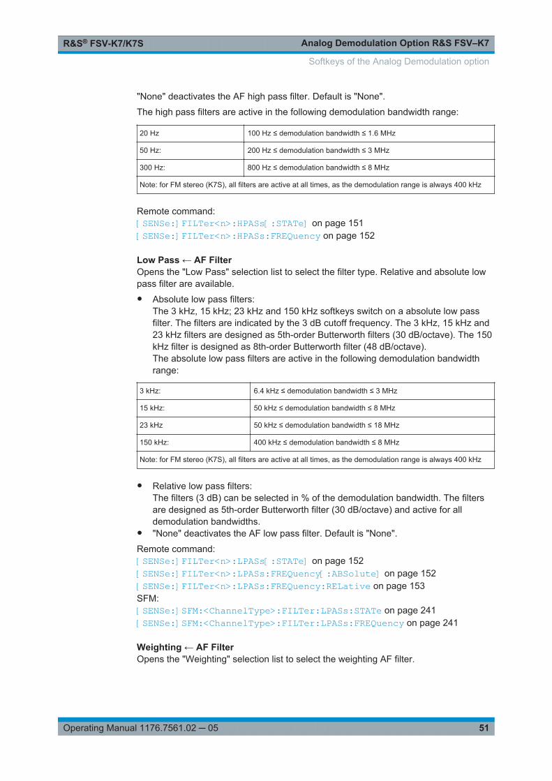
Analog Demodulation Option R&S FSV–K7R&S® FSV-K7/K7S
51Operating Manual 1176.7561.02 ─ 05
"None" deactivates the AF high pass filter. Default is "None".
The high pass filters are active in the following demodulation bandwidth range:
20 Hz 100 Hz ≤ demodulation bandwidth ≤ 1.6 MHz
50 Hz: 200 Hz ≤ demodulation bandwidth ≤ 3 MHz
300 Hz: 800 Hz ≤ demodulation bandwidth ≤ 8 MHz
Note: for FM stereo (K7S), all filters are active at all times, as the demodulation range is always 400 kHz
Remote command: [SENSe:]FILTer<n>:HPASs[:STATe] on page 151[SENSe:]FILTer<n>:HPASs:FREQuency on page 152
Low Pass ← AF FilterOpens the "Low Pass" selection list to select the filter type. Relative and absolute lowpass filter are available.● Absolute low pass filters:
The 3 kHz, 15 kHz; 23 kHz and 150 kHz softkeys switch on a absolute low passfilter. The filters are indicated by the 3 dB cutoff frequency. The 3 kHz, 15 kHz and23 kHz filters are designed as 5th-order Butterworth filters (30 dB/octave). The 150kHz filter is designed as 8th-order Butterworth filter (48 dB/octave).The absolute low pass filters are active in the following demodulation bandwidthrange:
3 kHz: 6.4 kHz ≤ demodulation bandwidth ≤ 3 MHz
15 kHz: 50 kHz ≤ demodulation bandwidth ≤ 8 MHz
23 kHz 50 kHz ≤ demodulation bandwidth ≤ 18 MHz
150 kHz: 400 kHz ≤ demodulation bandwidth ≤ 8 MHz
Note: for FM stereo (K7S), all filters are active at all times, as the demodulation range is always 400 kHz
● Relative low pass filters:The filters (3 dB) can be selected in % of the demodulation bandwidth. The filtersare designed as 5th-order Butterworth filter (30 dB/octave) and active for alldemodulation bandwidths.
● "None" deactivates the AF low pass filter. Default is "None".
Remote command: [SENSe:]FILTer<n>:LPASs[:STATe] on page 152[SENSe:]FILTer<n>:LPASs:FREQuency[:ABSolute] on page 152[SENSe:]FILTer<n>:LPASs:FREQuency:RELative on page 153SFM:[SENSe:]SFM:<ChannelType>:FILTer:LPASs:STATe on page 241[SENSe:]SFM:<ChannelType>:FILTer:LPASs:FREQuency on page 241
Weighting ← AF FilterOpens the "Weighting" selection list to select the weighting AF filter.
Softkeys of the Analog Demodulation option

Analog Demodulation Option R&S FSV–K7R&S® FSV-K7/K7S
52Operating Manual 1176.7561.02 ─ 05
None ← Weighting ← AF FilterDeactivates the weighting filter. This is the default setting.
Remote command: [SENSe:]FILTer<n>:HPASs[:STATe] on page 151
CCITT ← Weighting ← AF FilterSwitches on a CCITT P.53 weighting filter. The weighting filter is active in the followingdemodulation bandwidth range:
20 kHz ≤ demodulation bandwidth ≤ 3 MHz
For FM stereo (K7S), the filter is active at all times, as the demodulation range isalways 400 kHz.
Remote command: [SENSe:]FILTer<n>:CCIT on page 149SFM:[SENSe:]SFM:<ChannelType>:FILTer:CCITt:STATe on page 238
CCIR Unweighted ← Weighting ← AF FilterSwitches on the CCIR unweighted filter, which is the combination of the 20 Hz high-pass and 23 kHz low pass filter. The weighting filter is active in the following demodula-tion bandwidth range:
50 kHz ≤ demodulation bandwidth ≤ 1.6 MHz
For FM stereo (K7S), the filter is active at all times, as the demodulation range isalways 400 kHz.
Remote command: [SENSe:]FILTer<n>:CCIR[:UNWeighted][:STATe] on page 150SFM:[SENSe:]SFM:<ChannelType>:FILTer:CCIR[:UNWeighted][:STATe]on page 238
CCIR Weighted ← Weighting ← AF FilterSwitches on the CCIR weighted filter. The weighting filter is active in the followingdemodulation bandwidth range:
100 kHz ≤ demodulation bandwidth ≤ 3.0 MHz
For FM stereo (K7S), the filter is active at all times, as the demodulation range isalways 400 kHz.
Remote command: [SENSe:]FILTer<n>:CCIR:WEIGhted[:STATe] on page 150SFM:[SENSe:]SFM:<ChannelType>:FILTer:CCIR:WEIGhted[:STATe] on page 239
A Weighted ← Weighting ← AF FilterSwitches on the A weighted filter. The weighting filter is active in the following demodu-lation bandwidth range:
100 kHz ≤ demodulation bandwidth ≤ 800 kHz
Softkeys of the Analog Demodulation option
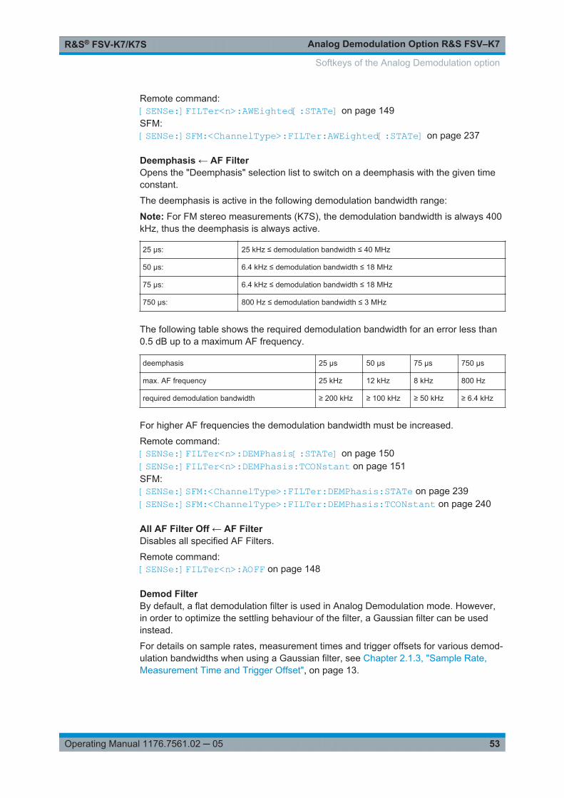
Analog Demodulation Option R&S FSV–K7R&S® FSV-K7/K7S
53Operating Manual 1176.7561.02 ─ 05
Remote command: [SENSe:]FILTer<n>:AWEighted[:STATe] on page 149SFM:[SENSe:]SFM:<ChannelType>:FILTer:AWEighted[:STATe] on page 237
Deemphasis ← AF FilterOpens the "Deemphasis" selection list to switch on a deemphasis with the given timeconstant.
The deemphasis is active in the following demodulation bandwidth range:
Note: For FM stereo measurements (K7S), the demodulation bandwidth is always 400kHz, thus the deemphasis is always active.
25 µs: 25 kHz ≤ demodulation bandwidth ≤ 40 MHz
50 µs: 6.4 kHz ≤ demodulation bandwidth ≤ 18 MHz
75 µs: 6.4 kHz ≤ demodulation bandwidth ≤ 18 MHz
750 µs: 800 Hz ≤ demodulation bandwidth ≤ 3 MHz
The following table shows the required demodulation bandwidth for an error less than0.5 dB up to a maximum AF frequency.
deemphasis 25 µs 50 µs 75 µs 750 µs
max. AF frequency 25 kHz 12 kHz 8 kHz 800 Hz
required demodulation bandwidth ≥ 200 kHz ≥ 100 kHz ≥ 50 kHz ≥ 6.4 kHz
For higher AF frequencies the demodulation bandwidth must be increased.
Remote command: [SENSe:]FILTer<n>:DEMPhasis[:STATe] on page 150[SENSe:]FILTer<n>:DEMPhasis:TCONstant on page 151SFM:[SENSe:]SFM:<ChannelType>:FILTer:DEMPhasis:STATe on page 239[SENSe:]SFM:<ChannelType>:FILTer:DEMPhasis:TCONstant on page 240
All AF Filter Off ← AF FilterDisables all specified AF Filters.
Remote command: [SENSe:]FILTer<n>:AOFF on page 148
Demod FilterBy default, a flat demodulation filter is used in Analog Demodulation mode. However,in order to optimize the settling behaviour of the filter, a Gaussian filter can be usedinstead.
For details on sample rates, measurement times and trigger offsets for various demod-ulation bandwidths when using a Gaussian filter, see Chapter 2.1.3, "Sample Rate,Measurement Time and Trigger Offset", on page 13.
Softkeys of the Analog Demodulation option

Analog Demodulation Option R&S FSV–K7R&S® FSV-K7/K7S
54Operating Manual 1176.7561.02 ─ 05
Remote command: [SENSe:]BANDwidth:DEMod:TYPE on page 148
2.2.7 Softkeys of the Sweep Menu – SWEEP Key (Analog Demodulation)
The following table shows all softkeys available in the "Sweep" menu in "AnalogDemodulation" mode (SWEEP key). It is possible that your instrument configurationdoes not provide all softkeys. If a softkey is only available with a special option, modelor (measurement) mode, this information is delivered in the corresponding softkeydescription.
Continuous Sweep........................................................................................................ 54Single Sweep................................................................................................................ 54Continue Single Sweep.................................................................................................54Meas Time.................................................................................................................... 55Sweep Count.................................................................................................................55Sweep Points................................................................................................................ 55Capture Mode............................................................................................................... 55Capture Time................................................................................................................ 56Demod Offset................................................................................................................ 56
Continuous SweepSets the continuous sweep mode: the sweep takes place continuously according to thetrigger settings. This is the default setting.
The trace averaging is determined by the sweep count value (see the "Sweep Count"softkey, "Sweep Count" on page 55).
Remote command: INIT:CONT ON, see INITiate<n>:CONTinuous on page 186
Single SweepSets the single sweep mode: after triggering, starts the number of sweeps that aredefined by using the Sweep Count softkey. The measurement stops after the definednumber of sweeps has been performed.
Remote command: INIT:CONT OFF, see INITiate<n>:CONTinuous on page 186
Continue Single SweepRepeats the number of sweeps set by using the Sweep Count softkey, without deletingthe trace of the last measurement.
This is particularly of interest when using the trace configurations "Average" or "MaxHold" to take previously recorded measurements into account for averaging/maximumsearch.
Softkeys of the Analog Demodulation option
Analog Demodulation Option R&S FSV–K7R&S® FSV-K7/K7S
55Operating Manual 1176.7561.02 ─ 05
Remote command: INITiate<n>:CONMeas on page 185
Meas TimeOpens an editor for entering the measurement time of the analog demodulation. Fordetails on the measurement time values refer to Chapter 2.1.3, "Sample Rate, Mea-surement Time and Trigger Offset", on page 13.
Note: For FM Stereo measurements (option K7S), the minimum measurement time is2 ms.
Remote command: [SENSe:]ADEMod:MTIMe on page 133
Sweep CountOpens an edit dialog box to enter the number of sweeps to be performed in the singlesweep mode. Values from 0 to 32767 are allowed. If the values 0 or 1 are set, onesweep is performed. The sweep count is applied to all the traces in a diagram.
If the trace configurations "Average", "Max Hold" or "Min Hold" are set, the sweepcount value also determines the number of averaging or maximum search procedures.
In continuous sweep mode, if sweep count = 0 (default), averaging is performed over10 sweeps. For sweep count =1, no averaging, maxhold or minhold operations are per-formed.
Remote command: [SENSe:]SWEep:COUNt on page 155
Sweep PointsOpens an edit dialog box to enter the number of measured values to be collected dur-ing one sweep.● Entry via rotary knob:
– In the range from 101 to 1001, the sweep points are increased or decreased insteps of 100 points.
– In the range from 1001 to 32001, the sweep points are increased or decreasedin steps of 1000 points.
● Entry via keypad:All values in the defined range can be set.
The default value is 691 sweep points.
Remote command: [SENSe:]SWEep:POINts on page 157
Capture ModeThis command defines how the size of the the capture buffer is defined for analogdemodulation.
In Auto mode, the size of the capture buffer is identical to the defined Meas Time.
In Manual mode, the size of the capture buffer can be defined manually (CaptureTime).
Softkeys of the Analog Demodulation option
Analog Demodulation Option R&S FSV–K7R&S® FSV-K7/K7S
56Operating Manual 1176.7561.02 ─ 05
Remote command: [SENSe:]ADEMod:CAPTure[:MODE] on page 121
Capture TimeDefines the size of the capture buffer for analog demodulation if Capture Mode is set to"Manual".
The maximum capture buffer size is 7.5 MSamples; the capture time depends on thedefined DBW. For a DBW of 25 kHz, for example, the maximum capture time is 240 s.
Remote command: [SENSe:]ADEMod:CAPTure:TIME on page 120
Demod OffsetThis command defines an offset of the defined measurement time from the beginningof the capture buffer for analog demodulation if Capture Mode is set to "Manual". Allresults are recalculated automatically based on the new data.
Remote command: [SENSe:]ADEMod:CAPTure:DOFFset on page 120
2.2.8 Softkeys of the Trace Menu – TRACE key (Analog Demodulation)
The TRACE key is used to configure the data acquisition for measurement and theanalysis of the measurement data.
Trace 1/Trace 2/Trace 3/Trace 4/Trace 5/Trace 6Selects the active trace (1, 2, 3, 4, 5, 6) and opens the "Trace Mode" submenu for theselected trace.
The default setting is trace 1 in the overwrite mode (see "Clear Write" on page 17), theother traces are switched off (see "Blank" on page 19). For details see Chapter 2.1.7,"Trace Mode Overview", on page 17.
Tip: To configure several traces in one step, press the Trace Wizard softkey to open atrace configuration dialog. See also Chapter 2.1.6, "Configuring Traces", on page 16.
Remote command: Selected via numeric suffix of:TRACe<1...6> commands
Clear Write ← Trace 1/Trace 2/Trace 3/Trace 4/Trace 5/Trace 6Overwrite mode: the trace is overwritten by each sweep. This is the default setting.
All available detectors can be selected.
Remote command: DISP:TRAC:MODE WRIT, see DISPlay[:WINDow<n>]:TRACe<t>:MODEon page 110
Max Hold ← Trace 1/Trace 2/Trace 3/Trace 4/Trace 5/Trace 6The maximum value is determined over several sweeps and displayed. The R&S FSV/FSVA saves the sweep result in the trace memory only if the new value is greater thanthe previous one.
The detector is automatically set to "Positive Peak".
Softkeys of the Analog Demodulation option

Analog Demodulation Option R&S FSV–K7R&S® FSV-K7/K7S
57Operating Manual 1176.7561.02 ─ 05
This mode is especially useful with modulated or pulsed signals. The signal spectrumis filled up upon each sweep until all signal components are detected in a kind of enve-lope.
This mode is not available for statistics measurements.
Remote command: DISP:TRAC:MODE MAXH, see DISPlay[:WINDow<n>]:TRACe<t>:MODEon page 110
Min Hold ← Trace 1/Trace 2/Trace 3/Trace 4/Trace 5/Trace 6The minimum value is determined from several measurements and displayed. TheR&S FSV/FSVA saves the smallest of the previously stored/currently measured valuesin the trace memory.
The detector is automatically set to "Negative Peak".
This mode is useful e.g. for making an unmodulated carrier in a composite signal visi-ble. Noise, interference signals or modulated signals are suppressed whereas a CWsignal is recognized by its constant level.
This mode is not available for statistics measurements.
Remote command: DISP:TRAC:MODE MINH, see DISPlay[:WINDow<n>]:TRACe<t>:MODEon page 110
Average ← Trace 1/Trace 2/Trace 3/Trace 4/Trace 5/Trace 6The average is formed over several sweeps. The Sweep Count determines the numberof averaging procedures.
All available detectors can be selected. If the detector is automatically selected, thesample detector is used (see Chapter 2.1.8, "Detector Overview", on page 19).
This mode is not available for statistics measurements.
Remote command: DISP:TRAC:MODE AVER, see DISPlay[:WINDow<n>]:TRACe<t>:MODEon page 110
View ← Trace 1/Trace 2/Trace 3/Trace 4/Trace 5/Trace 6The current contents of the trace memory are frozen and displayed.
Note: If a trace is frozen, the instrument settings, apart from level range and referencelevel (see below), can be changed without impact on the displayed trace. The fact thatthe displayed trace no longer matches the current instrument setting is indicated by the
icon on the tab label.If the level range or reference level is changed, the R&S FSV/FSVA automaticallyadapts the measured data to the changed display range. This allows an amplitudezoom to be made after the measurement in order to show details of the trace.
Remote command: DISP:TRAC:MODE VIEW, see DISPlay[:WINDow<n>]:TRACe<t>:MODEon page 110
Blank ← Trace 1/Trace 2/Trace 3/Trace 4/Trace 5/Trace 6Hides the selected trace.
Softkeys of the Analog Demodulation option
Analog Demodulation Option R&S FSV–K7R&S® FSV-K7/K7S
58Operating Manual 1176.7561.02 ─ 05
Remote command: DISP:TRAC OFF, see DISPlay[:WINDow<n>]:TRACe<t>[:STATe] on page 111
Detector ← Trace 1/Trace 2/Trace 3/Trace 4/Trace 5/Trace 6Opens a submenu to select the detector manually, or activate automatic selection.
If a detector was selected manually, the "MAN" indicator is highlighted.
If "AUTO" is selected, the detector is defined automatically, depending on the selectedtrace mode:
Trace mode Detector
Clear Write Auto Peak
Max Hold Positive Peak
Min Hold Negative Peak
Average Sample Peak
View –
Blank –
For details see Chapter 2.1.8, "Detector Overview", on page 19.
Note: In Analog Demod mode, if AUTO is selected, the Auto Peak detector is usedregardless of the trace mode. However, if Noise or Phase Noise measurements areperformed in Analog Demod mode, the Sample Detector is used.
Auto Select ← Detector ← Trace 1/Trace 2/Trace 3/Trace 4/Trace 5/Trace 6Selects the best detector for the selected trace and filter mode. This is the default set-ting.
For details see also Chapter 2.1.8, "Detector Overview", on page 19.
Trace mode Detector
Clear/Write Auto Peak
Average Sample
Max Hold Max Peak
Min Hold Min Peak
Remote command: [SENSe:][WINDow:]DETector<trace>[:FUNCtion]:AUTO on page 159
Auto Peak ← Detector ← Trace 1/Trace 2/Trace 3/Trace 4/Trace 5/Trace 6Selects the "Auto Peak" detector.
For details see Chapter 2.1.8, "Detector Overview", on page 19.
Softkeys of the Analog Demodulation option
Analog Demodulation Option R&S FSV–K7R&S® FSV-K7/K7S
59Operating Manual 1176.7561.02 ─ 05
Remote command: DET APE, see [SENSe:][WINDow:]DETector<trace>[:FUNCtion]on page 159
Positive Peak ← Detector ← Trace 1/Trace 2/Trace 3/Trace 4/Trace 5/Trace 6Selects the "Positive Peak" detector.
For details see Chapter 2.1.8, "Detector Overview", on page 19.
Remote command: DET POS, see [SENSe:][WINDow:]DETector<trace>[:FUNCtion]on page 159
Negative Peak ← Detector ← Trace 1/Trace 2/Trace 3/Trace 4/Trace 5/Trace 6Selects the "Negative Peak" detector.
For details see Chapter 2.1.8, "Detector Overview", on page 19.
Remote command: DET NEG, see [SENSe:][WINDow:]DETector<trace>[:FUNCtion]on page 159
Sample ← Detector ← Trace 1/Trace 2/Trace 3/Trace 4/Trace 5/Trace 6Selects the "Sample" detector.
For details see Chapter 2.1.8, "Detector Overview", on page 19.
Remote command: DET SAMP, see [SENSe:][WINDow:]DETector<trace>[:FUNCtion]on page 159
RMS ← Detector ← Trace 1/Trace 2/Trace 3/Trace 4/Trace 5/Trace 6Selects the "RMS" detector.
For details see Chapter 2.1.8, "Detector Overview", on page 19.
Remote command: DET RMS, see [SENSe:][WINDow:]DETector<trace>[:FUNCtion]on page 159
Average ← Detector ← Trace 1/Trace 2/Trace 3/Trace 4/Trace 5/Trace 6Selects the "Average" detector.
For details see Chapter 2.1.8, "Detector Overview", on page 19.
Remote command: DET AVER, see [SENSe:][WINDow:]DETector<trace>[:FUNCtion]on page 159
Quasipeak ← Detector ← Trace 1/Trace 2/Trace 3/Trace 4/Trace 5/Trace 6Selects the "Quasipeak" detector.
The quasipeak detector is available with option R&S FSV-K54.
For details see Chapter 2.1.8, "Detector Overview", on page 19.
Softkeys of the Analog Demodulation option

Analog Demodulation Option R&S FSV–K7R&S® FSV-K7/K7S
60Operating Manual 1176.7561.02 ─ 05
Remote command: DET QPE, see [SENSe:][WINDow:]DETector<trace>[:FUNCtion]on page 159
CISPR Average ← Detector ← Trace 1/Trace 2/Trace 3/Trace 4/Trace 5/Trace 6Selects the "CISPR Average" detector.
The CISPR Average detector is available with option R&S FSV-K54.
For details see Chapter 2.1.8, "Detector Overview", on page 19.
Remote command: DET CAV, see [SENSe:][WINDow:]DETector<trace>[:FUNCtion]on page 159
RMS Average ← Detector ← Trace 1/Trace 2/Trace 3/Trace 4/Trace 5/Trace 6Selects the "RMS Average" detector.
The quasipeak detector is available with option R&S FSV-K54.
For details see Chapter 2.1.8, "Detector Overview", on page 19.
Remote command: DET CRMS, see [SENSe:][WINDow:]DETector<trace>[:FUNCtion]on page 159
More TracesOpens a submenu to select one of the traces not currently displayed in the main menu.
Trace WizardOpens the "Trace Wizard" dialog. See Chapter 2.1.6, "Configuring Traces",on page 16.
Average ModeOpens a submenu to select the averaging method for the average trace mode. The fol-lowing methods are available:● Lin● Log● PowerLogarithmic averaging is recommended to display signals with a low signal to noiseratio. While positive peak values are decreased in logarithmic averaging due to thecharacteristics involved, it is also true that negative peaks are increased relative to theaverage value. If the distorted amplitude distribution is averaged, a value is obtainedthat is smaller than the actual average value. The difference is -2.5 dB.
This low average value is usually corrected in noise power measurements by a 2.5 dBfactor. Therefore the R&S FSV/FSVA offers the selection of linear averaging. The tracedata is converted to linear values prior to averaging, then averaged and reconverted tologarithmic values. After these conversions the data is displayed on the screen. Theaverage value is always correctly displayed irrespective of the signal characteristic.
In case of stationary sinusoidal signals both logarithmic and linear averaging has thesame results.
Softkeys of the Analog Demodulation option
Analog Demodulation Option R&S FSV–K7R&S® FSV-K7/K7S
61Operating Manual 1176.7561.02 ─ 05
Lin ← Average ModeActivates linear averaging. Linear averaging means that the power level values areconverted into linear units prior to averaging. After the averaging, the data is convertedback into its original unit.
This softkey takes effect if the grid is set to a linear scale (see "Range Linear" softkey,"Range Linear %" on page 43). In this case, the averaging is done in two ways(depending on the set unit – see "Unit" softkey):● The unit is set to either W or dBm: the data is converted into W prior to averaging,
i.e. averaging is done in W.● The unit is set to either V, A, dBmV, dBµV, dBµA or dBpW: the data is converted
into V prior to averaging, i.e. averaging is done in V.
Remote command: SENS:AVER1:TYPE LIN, see [SENSe:]AVERage<n>:TYPE on page 158
Log ← Average ModeActivates logarithmic averaging.
This averaging method only takes effect if the grid is set to a logarithmic scale("Range" softkey), i.e. the unit of the data is dBm. In this case the values are averagedin dBm. Otherwise (i.e. with linear scaling), the behavior is the same as with linearaveraging (see Lin softkey). For further information on logarithmic scaling refer to the"Average Mode" softkey.
Remote command: SENS:AVER1:TYPE VID, see [SENSe:]AVERage<n>:TYPE on page 158
Power ← Average ModeActivates linear power averaging.
The power level values are converted into unit Watt prior to averaging. After the aver-aging, the data is converted back into its original unit.
Unlike the linear mode, the averaging is always done in W.
Remote command: SENS:AVER1:TYPE POW, see [SENSe:]AVERage<n>:TYPE on page 158
ASCII Trace ExportOpens the "ASCII Trace Export Name" dialog box and saves the active trace in ASCIIformat to the specified file and directory.
The file consists of the header containing important scaling parameters and a data sec-tion containing the trace data. For details on an ASCII file see Chapter 2.1.11, "ASCIIFile Export Format", on page 23.
This format can be processed by spreadsheet calculation programs, e.g. MS-Excel. Itis necessary to define ';' as a separator for the data import. Different language versionsof evaluation programs may require a different handling of the decimal point. It is there-fore possible to select between separators '.' (decimal point) and ',' (comma) using the"Decim Sep" softkey (see "Decim Sep" on page 62).
Remote command: FORMat:DEXPort:DSEParator on page 185MMEMory:STORe<n>:TRACe on page 183
Softkeys of the Analog Demodulation option
Analog Demodulation Option R&S FSV–K7R&S® FSV-K7/K7S
62Operating Manual 1176.7561.02 ─ 05
Decim SepSelects the decimal separator with floating-point numerals for the ASCII Trace exportto support evaluation programs (e.g. MS-Excel) in different languages. The values '.'(decimal point) and ',' (comma) can be set.
Remote command: FORMat:DEXPort:DSEParator on page 185
2.2.9 Softkeys of the Trigger Menu – TRIG Key (Analog Demodulation)
The following table shows all softkeys available in the "Trigger" menu in "AnalogDemodulation" mode (TRIG key). It is possible that your instrument configuration doesnot provide all softkeys. If a softkey is only available with a special option, model or(measurement) mode, this information is delivered in the corresponding softkeydescription.
Trigger Source.............................................................................................................. 62└ Free Run.........................................................................................................62└ External...........................................................................................................63└ RF Power........................................................................................................63└ IF Power..........................................................................................................63└ FM...................................................................................................................64└ AM...................................................................................................................64└ PM...................................................................................................................64└ RF................................................................................................................... 64└ Time................................................................................................................64
Trigger Level................................................................................................................. 64Trigger Polarity..............................................................................................................65Trigger Offset................................................................................................................ 65Repetition Interval......................................................................................................... 65Trigger Hysteresis......................................................................................................... 66Trigger Holdoff.............................................................................................................. 66
Trigger SourceOpens the "Trg Source" submenu to select the trigger source.
In "Analog Demodulation" mode, the next measurement is triggered if the selectedinput signal exceeds the threshold specified using the "Trigger Level" softkey (see"Trigger Level" on page 64). A periodic signal modulated onto the carrier frequencycan be displayed in this way. It is recommended that the measurement time covers atleast five periods of the audio signal.
For triggering with AM, FM, PM or RF trigger sources to be successful, the measure-ment time must cover at least 5 periods of the audio signal.
Remote command: TRIGger<n>[:SEQuence]:SOURce on page 167
Free Run ← Trigger SourceThe start of a sweep is not triggered. Once a measurement is completed, another isstarted immediately.
Softkeys of the Analog Demodulation option
Analog Demodulation Option R&S FSV–K7R&S® FSV-K7/K7S
63Operating Manual 1176.7561.02 ─ 05
Remote command: TRIG:SOUR IMM, see TRIGger<n>[:SEQuence]:SOURce on page 167
External ← Trigger SourceDefines triggering via a TTL signal at the "EXT TRIG/GATE IN" input connector on therear panel.
Remote command: TRIG:SOUR EXT, see TRIGger<n>[:SEQuence]:SOURce on page 167
RF Power ← Trigger SourceDefines triggering of the measurement via signals which are outside the measurementchannel.
This trigger mode is available with detector board 1307.9554.02 Rev 05.00 or higher. Itis not available for input from the R&S Digital I/Q Interface (option R&S FSV/FSVA-B17). If RF Power trigger mode is selected and digital baseband input is activated, thetrigger mode is automatically switched to "Free Run".
RF power triggers are not available together with the bandwidth extension optionR&S FSV-B160.
In RF Power trigger mode the instrument uses a level detector at the first intermediatefrequency. The detector threshold can be selected in a range between - 50 dBm and-10 dBm at the input mixer. The resulting trigger level at the RF input lies within thefollowing range:
(-24dBm + RF Att ) ≤ Triggerlevel ≤ (+5dBm + RF Att), max. 30 dBm, for Preamp =OFF
(-40dBm + RF Att ) ≤ Triggerlevel ≤ (-11dBm + RF Att), max. 30 dBm, for Preamp =ON
with
500 MHz ≤ InputSignal ≤ 7 GHz
Note: If input values outside of this range occur (e.g. for fullspan measurements), thesweep may be aborted and a message indicating the allowed input values is displayedin the status bar.
Remote command: TRIG:SOUR RFP, see TRIGger<n>[:SEQuence]:SOURce on page 167SWE:EGAT:SOUR RFP for gated triggering, see [SENSe:]SWEep:EGATe:SOURceon page 156
IF Power ← Trigger SourceDefines triggering of the measurement via signals which are outside the measurementchannel.
For this purpose, the R&S FSV/FSVA uses a level detector at the second intermediatefrequency.
The available trigger levels depend on the RF attenuation and preamplification. A refer-ence level offset, if defined, is also considered.
For details on available trigger levels and trigger bandwidths see the data sheet.
Softkeys of the Analog Demodulation option
Analog Demodulation Option R&S FSV–K7R&S® FSV-K7/K7S
64Operating Manual 1176.7561.02 ─ 05
The bandwidth at the intermediate frequency is 20 MHz. The R&S FSV/FSVA is trig-gered as soon as the trigger level is exceeded within a 10 MHz range around theselected frequency (= start frequency in the frequency sweep).
Thus, the measurement of spurious emissions, e.g. for pulsed carriers, is possibleeven if the carrier lies outside the selected frequency span.
IF power triggers are not available together with the bandwidth extension optionR&S FSV-B160.
Remote command: TRIG:SOUR IFP, see TRIGger<n>[:SEQuence]:SOURce on page 167SWE:EGAT:SOUR IFP for gated triggering, see [SENSe:]SWEep:EGATe:SOURceon page 156
FM ← Trigger SourceTriggers on the specified frequency level of the FM signal.
Remote command: TRIG:SEQ:SOUR FM, see TRIGger<n>[:SEQuence]:SOURce on page 167
AM ← Trigger SourceTriggers on the specified modulation depth of the AM signal.
Remote command: TRIG:SEQ:SOUR AMR, see TRIGger<n>[:SEQuence]:SOURce on page 167
PM ← Trigger SourceTriggers on the specified phase of the PM signal.
Remote command: TRIG:SEQ:SOUR PM, see TRIGger<n>[:SEQuence]:SOURce on page 167
RF ← Trigger SourceTriggers on the specified level of the RF signal.
Note: The RF offline trigger is based on the I/Q data of the demodulated signal, limi-ted to the demodulation bandwidth. For a wider trigger bandwidth and triggering basedon the currently measured RF input signal, use the more powerful RF Power trigger.
Remote command: TRIG:SEQ:SOUR AM, see TRIGger<n>[:SEQuence]:SOURce on page 167
Time ← Trigger SourceOpens an edit dialog box to define a repetition interval in which the measurement istriggered. The shortest interval is 2 ms.
Remote command: TRIG:SOUR TIMETRIGger<n>[:SEQuence]:SOURce on page 167
Trigger LevelDefines the trigger level as a numeric value.
In the trigger mode "Time", this softkey is not available.
Softkeys of the Analog Demodulation option
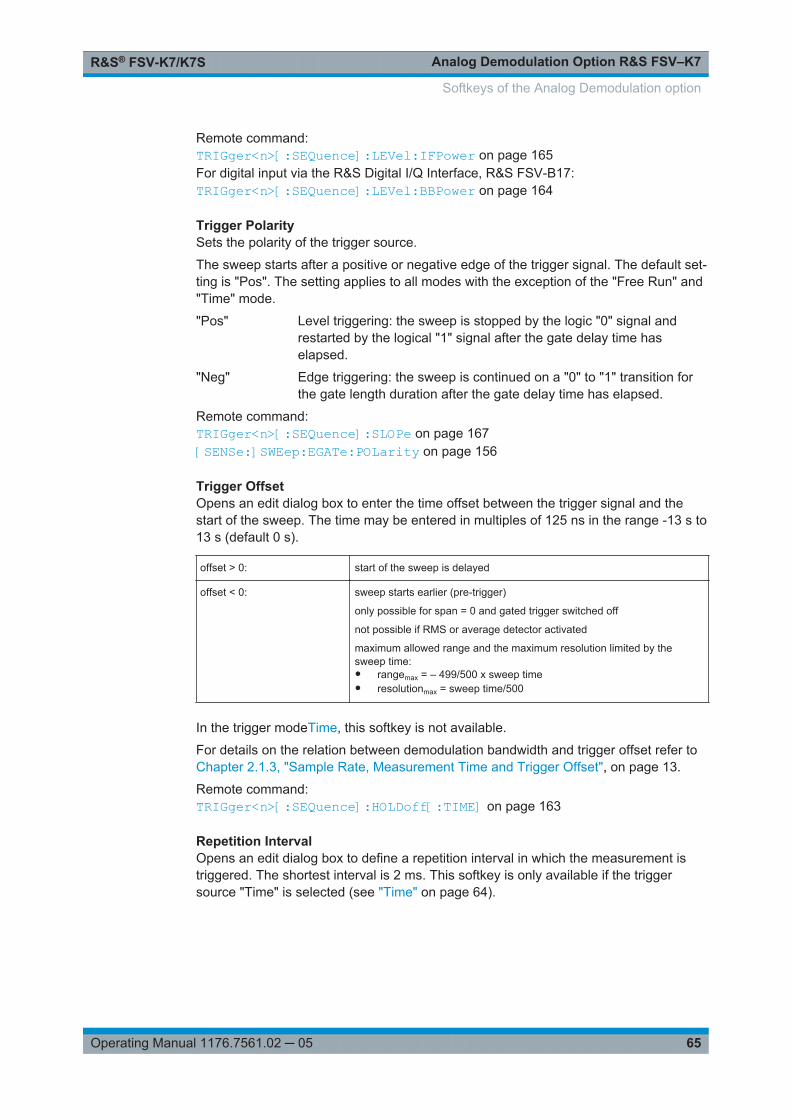
Analog Demodulation Option R&S FSV–K7R&S® FSV-K7/K7S
65Operating Manual 1176.7561.02 ─ 05
Remote command: TRIGger<n>[:SEQuence]:LEVel:IFPower on page 165For digital input via the R&S Digital I/Q Interface, R&S FSV-B17:TRIGger<n>[:SEQuence]:LEVel:BBPower on page 164
Trigger PolaritySets the polarity of the trigger source.
The sweep starts after a positive or negative edge of the trigger signal. The default set-ting is "Pos". The setting applies to all modes with the exception of the "Free Run" and"Time" mode.
"Pos" Level triggering: the sweep is stopped by the logic "0" signal andrestarted by the logical "1" signal after the gate delay time haselapsed.
"Neg" Edge triggering: the sweep is continued on a "0" to "1" transition forthe gate length duration after the gate delay time has elapsed.
Remote command: TRIGger<n>[:SEQuence]:SLOPe on page 167[SENSe:]SWEep:EGATe:POLarity on page 156
Trigger OffsetOpens an edit dialog box to enter the time offset between the trigger signal and thestart of the sweep. The time may be entered in multiples of 125 ns in the range -13 s to13 s (default 0 s).
offset > 0: start of the sweep is delayed
offset < 0: sweep starts earlier (pre-trigger)
only possible for span = 0 and gated trigger switched off
not possible if RMS or average detector activated
maximum allowed range and the maximum resolution limited by thesweep time:● rangemax = – 499/500 x sweep time● resolutionmax = sweep time/500
In the trigger modeTime, this softkey is not available.
For details on the relation between demodulation bandwidth and trigger offset refer toChapter 2.1.3, "Sample Rate, Measurement Time and Trigger Offset", on page 13.
Remote command: TRIGger<n>[:SEQuence]:HOLDoff[:TIME] on page 163
Repetition IntervalOpens an edit dialog box to define a repetition interval in which the measurement istriggered. The shortest interval is 2 ms. This softkey is only available if the triggersource "Time" is selected (see "Time" on page 64).
Softkeys of the Analog Demodulation option

Analog Demodulation Option R&S FSV–K7R&S® FSV-K7/K7S
66Operating Manual 1176.7561.02 ─ 05
Remote command: TRIGger<n>[:SEQuence]:TIME:RINTerval on page 166
Trigger HysteresisDefines the value for the trigger hysteresis for "IF power" or "RF Power" trigger sour-ces. The hysteresis in dB is the value the input signal must stay below the power trig-ger level in order to allow a trigger to start the measurement. The range of the value isbetween 3 dB and 50 dB with a step width of 1 dB.
Remote command: TRIGger<n>[:SEQuence]:IFPower:HYSTeresis on page 163
Trigger HoldoffDefines the value for the trigger holdoff. The holdoff value in s is the time which mustpass before triggering, in case another trigger event happens.
This softkey is only available if "IFPower", "RF Power" or "BBPower" is the selectedtrigger source.
Remote command: TRIGger<n>[:SEQuence]:IFPower:HOLDoff on page 163For digital input via the R&S Digital I/Q Interface, R&S FSV-B17:TRIGger<n>[:SEQuence]:BBPower:HOLDoff on page 162
2.2.10 Softkeys of the Marker Menu – MKR key (Analog Demodulation)
The following table shows all softkeys available in the "Marker" menu in "AnalogDemodulation" mode (MKR key). It is possible that your instrument configuration doesnot provide all softkeys. If a softkey is only available with a special option, model or(measurement) mode, this information is provided in the corresponding softkeydescription.
Marker 1 / Marker 2 / Marker 3 / … Marker 16,/ Marker Norm/Delta............................ 66More Markers................................................................................................................ 67Marker to Trace.............................................................................................................67Marker Wizard...............................................................................................................67
└ All Marker Off..................................................................................................68All Marker Off................................................................................................................ 68Marker Table................................................................................................................. 69Marker Stepsize............................................................................................................ 69
└ Stepsize Standard...........................................................................................69└ Stepsize Sweep Points................................................................................... 69
Marker Zoom (span > 0)................................................................................................70Link Mkr1 and Delta1.................................................................................................... 70Link Time Marker.......................................................................................................... 70Link AF Spectrum Marker............................................................................................. 70
Marker 1 / Marker 2 / Marker 3 / … Marker 16,/ Marker Norm/DeltaThe "Marker X" softkey activates the corresponding marker and opens an edit dialogbox to enter a value for the marker to be set to. Pressing the softkey again deactivatesthe selected marker.
Softkeys of the Analog Demodulation option

Analog Demodulation Option R&S FSV–K7R&S® FSV-K7/K7S
67Operating Manual 1176.7561.02 ─ 05
If a marker value is changed using the rotary knob, the step size is defined via theStepsize Standard or Stepsize Sweep Points softkeys.
Marker 1 is always the reference marker for relative measurements. If activated, mark-ers 2 to 16 are delta markers that refer to marker 1. These markers can be convertedinto markers with absolute value display using the "Marker Norm/Delta" softkey. Ifmarker 1 is the active marker, pressing the "Marker Norm/Delta" softkey switches onan additional delta marker.
Remote command: CALCulate<n>:MARKer<m>[:STATe] on page 104CALCulate<n>:MARKer<m>:X on page 105CALCulate<n>:MARKer<m>:Y? on page 107CALCulate<n>:DELTamarker<m>[:STATe] on page 174CALCulate<n>:DELTamarker<m>:X on page 175CALCulate<n>:DELTamarker<m>:X:RELative? on page 175CALCulate<n>:DELTamarker<m>:Y? on page 176
More MarkersOpens a sub-menu to select one of up to 16 available markers. See "Marker 1 / Marker2 / Marker 3 / … Marker 16,/ Marker Norm/Delta" on page 66.
Marker to TraceOpens an edit dialog box to enter the number of the trace on which the marker is to beplaced.
Remote command: CALCulate<n>:MARKer<m>:TRACe on page 105
Marker WizardOpens a configuration dialog for markers. The marker wizard allows you to configureand activate up to 16 different markers in one dialog. The first 8 markers are displayedon one tab, the last 8 markers on a second tab. For each marker, the following settingsare available:
Softkeys of the Analog Demodulation option

Analog Demodulation Option R&S FSV–K7R&S® FSV-K7/K7S
68Operating Manual 1176.7561.02 ─ 05
"Selected/State"
When you press the "Selected" or "State" field the correspondingmarker is activated and the marker row is highlighted.
"Normal/Delta" Defines whether it is a normal marker or delta marker. For deltamarkers you can define a reference marker.
"Ref. Marker" Reference marker for delta markers. The marker values for the deltamarker are indicated relative to the specified reference marker.The reference marker can either be another active marker, or a fixedreference marker ("FXD", see "Ref Fixed" on page 71).
"Trace" Trace for which the marker is to be set.
Remote command: CALCulate<n>:MARKer<m>[:STATe] on page 104CALCulate<n>:DELTamarker<m>[:STATe] on page 174CALCulate<n>:MARKer<m>:TRACe on page 105CALCulate<n>:DELTamarker<m>:TRACe on page 174CALCulate<n>:DELTamarker<m>:MREF on page 174
All Marker Off ← Marker WizardSwitches all markers off. It also switches off all functions and displays that are associ-ated with the markers/delta markers.
Remote command: CALCulate<n>:MARKer<m>:AOFF on page 98
All Marker OffSwitches all markers off. It also switches off all functions and displays that are associ-ated with the markers/delta markers.
Softkeys of the Analog Demodulation option

Analog Demodulation Option R&S FSV–K7R&S® FSV-K7/K7S
69Operating Manual 1176.7561.02 ─ 05
Remote command: CALCulate<n>:MARKer<m>:AOFF on page 98
Marker TableDefines how the marker information is displayed.
For more information, see "Displayed Marker Information" in the description of thebase unit.
"On" Displays the marker information in a table in a separate area beneaththe diagram.
"Off" Displays the marker information within the diagram area.
"Aut" (Default) The marker table is displayed automatically if more than 2markers are active, and removed if only 1 or 2 markers are active.This helps keep the information in the display clear.
Remote command: DISPlay:MTABle on page 109
Marker StepsizeOpens a submenu to set the step size of all markers and delta markers.
Default value for the marker step size is Stepsize Sweep Points.
Stepsize Standard ← Marker StepsizeMoves the marker or delta marker from one measurement point to the next, if themarker or delta marker value is changed via the rotary knob ( "Marker 1 / Marker 2 /Marker 3 / … Marker 16,/ Marker Norm/Delta" softkeys, see "Marker 1 / Marker 2 /Marker 3 / … Marker 16,/ Marker Norm/Delta" on page 66). If more measured valuesthan measurement points exist, it is not possible to read out all measured values. Inthis case, use the Stepsize Sweep Points softkey.
Remote command: CALC:MARK:X:SSIZ STAN (see CALCulate<n>:MARKer<m>:X:SSIZeon page 107)
Stepsize Sweep Points ← Marker StepsizeMoves the marker or delta marker from one measured value to the next, if the markeror delta marker value is changed via the rotary knob ( "Marker 1 / Marker 2 / Marker 3 /… Marker 16,/ Marker Norm/Delta" softkeys, see "Marker 1 / Marker 2 / Marker 3 / …Marker 16,/ Marker Norm/Delta" on page 66). If more measured values than measure-ment points exist, every single measured value is accessible and its value is displayedin the marker field.
The number of measured values is defined in the ""Sweep"" menu via the SweepPoints softkey.
This functionality is available for all base unit measurements with the exception of sta-tistics ( "APD" and "CCDF" softkeys in the "Measurement" menu).
Softkeys of the Analog Demodulation option
Analog Demodulation Option R&S FSV–K7R&S® FSV-K7/K7S
70Operating Manual 1176.7561.02 ─ 05
Remote command: CALC:MARK:X:SSIZ POIN (see CALCulate<n>:MARKer<m>:X:SSIZeon page 107)
Marker Zoom (span > 0)Opens an edit dialog box to enter a display range for the zoom. The area aroundmarker 1 is expanded accordingly and more details of the result can be seen. If nomarker is activated, marker 1 is switched on and set on the largest signal.
The following sweep is stopped at the position of the reference marker. The frequencyof the signal is counted and the measured frequency becomes the new center fre-quency. The zoomed display range is then configured and the new settings are usedby the R&S FSV/FSVA for further measurements.
If the display has not yet been switched to the new frequency display range and youpress the softkey, the procedure is aborted. If an instrument setting is changed duringthis operation, the procedure is also aborted.
Remote command: CALCulate<n>:MARKer<m>:FUNCtion:ZOOM on page 95
Link Mkr1 and Delta1The delta marker 1 is linked to marker 1, so if the x-axis value of the marker 1 ischanged, the delta marker 1 will follow on the same x-position. The link is off bydefault.
You can set the two markers on different traces to measure the difference (e.g.between a max hold trace and a min hold trace or between a measurement and a ref-erence trace).
Remote command: CALCulate<n>:DELTamarker<m>:LINK on page 173
Link Time MarkerLinks the markers in all time domain diagrams.
Remote command: CALCulate<n>:MARKer<m>:LINK on page 96
Link AF Spectrum MarkerLinks the markers in all AF spectrum displays.
Remote command: CALCulate<n>:MARKer<m>:LINK on page 96
2.2.11 Softkeys of the Marker Function Menu – MKR FUNC Key (AnalogDemodulation)
The following table shows all softkeys available in the "Marker Function" menu.
Select Marker (No)........................................................................................................ 71Phase Noise..................................................................................................................71Ref Fixed.......................................................................................................................71
└ Ref. Fixed On/Off............................................................................................71
Softkeys of the Analog Demodulation option
Analog Demodulation Option R&S FSV–K7R&S® FSV-K7/K7S
71Operating Manual 1176.7561.02 ─ 05
└ Ref Point Level................................................................................................72└ Ref Point Frequency (span > 0)/Ref Point Time (zero span)..........................72└ Peak Search................................................................................................... 72
n dB down..................................................................................................................... 72Marker Peak List........................................................................................................... 73
└ Peak List On/Off..............................................................................................73└ Sort Mode Freq/Lvl......................................................................................... 73└ Max Peak Count............................................................................................. 73└ Peak Excursion...............................................................................................73└ Left Limit......................................................................................................... 74└ Right Limit.......................................................................................................74└ Threshold........................................................................................................74└ ASCII File Export............................................................................................ 74└ Decim Sep...................................................................................................... 74└ Marker Number...............................................................................................75
Select Marker (No)Opens a submenu to select one of 16 markers and define whether the marker is a nor-mal or a delta marker (see "Marker 1 / Marker 2 / Marker 3 / … Marker 16,/ MarkerNorm/Delta" on page 66). "(No)" indicates the number of the currently active marker.
See "Marker 1 / Marker 2 / Marker 3 / … Marker 16,/ Marker Norm/Delta" on page 66.
Phase NoiseFor AF spectrum displays, the Phase Noise marker is a normal marker with a specialdisplay value.
Remote command: CALCulate<n>:MARKer<m>:FUNCtion:PNOise:RESult? on page 93CALCulate<n>:MARKer<m>:FUNCtion:PNOise:RESult? on page 93
Ref FixedOpens a submenu to set all values of a reference point. Instead of using the currentvalues of the reference marker (marker 1) as reference point for the delta markers,level and frequency or time are set to fixed values and used as reference point.
Ref. Fixed On/Off ← Ref FixedSwitches the relative measurement to a fixed reference value on or off. The level andfrequency or time values of marker 1 immediately become the reference point, but canbe altered using the corresponding softkeys ("Ref Point Level" on page 72, "RefPoint Frequency (span > 0)/Ref Point Time (zero span)" on page 72 and "PeakSearch" on page 72).
When set to ON, all delta markers which previously referenced marker 1 are automati-cally set to reference the fixed marker.
The reference marker assignment can be changed using the "Marker Wizard" (see"Marker Wizard" on page 67).
Softkeys of the Analog Demodulation option
Analog Demodulation Option R&S FSV–K7R&S® FSV-K7/K7S
72Operating Manual 1176.7561.02 ─ 05
Remote command: CALCulate<n>:DELTamarker<m>:FUNCtion:FIXed[:STATe] on page 172
Ref Point Level ← Ref FixedOpens an edit dialog box to enter a reference level value. All relative level values of thedelta markers refer to this reference level.
Remote command: CALCulate<n>:DELTamarker<m>:FUNCtion:FIXed:RPOint:Y on page 171
Ref Point Frequency (span > 0)/Ref Point Time (zero span) ← Ref FixedOpens an edit dialog box to enter a frequency reference or time value. All relative fre-quency or time values of the delta markers refer to this frequency reference. For phasenoise measurement, input of reference time is not possible.
Remote command: CALCulate<n>:DELTamarker<m>:FUNCtion:FIXed:RPOint:X on page 171
Peak Search ← Ref FixedSets the maximum value of the selected trace as the reference point.
Remote command: CALCulate<n>:DELTamarker<m>:FUNCtion:FIXed:RPOint:MAXimum[:PEAK]on page 170
n dB downOpens an edit dialog box to enter a value to define the level spacing of the two tempo-rary markers to the right and left of marker 1 (default setting: 3 dB). Activates the tem-porary markers T1 and T2. The values of the temporary markers (T1, T2) and theentered value (ndB) are displayed in the marker field.
If a positive value is entered, the markers T1 and T2 are placed below the active refer-ence marker. If a negative value (e.g. for notch filter measurements) is entered, themarkers T1 and T2 are placed above the active reference marker. Marker T1 is placedto the left and marker T2 to the right of the reference marker.
In the marker table, the following results are displayed:
Span setting Parameter name Description
span > 0 Bw frequency spacing of the two temporary markers
Q factor quality of the displayed bandwidth value (Bw)
span = 0 PWid pulse width between the two temporary markers
If it is not possible to form the frequency spacing for the n dB value (e.g. because ofnoise display), dashes instead of a measured value are displayed.
Remote command: CALC:MARK1:FUNC:NDBD:STAT ON, see CALCulate<n>:MARKer<m>:FUNCtion:NDBDown:STATe on page 103CALC:MARK1:FUNC:NDBD 3dB, see CALCulate<n>:MARKer<m>:FUNCtion:NDBDown on page 100
Softkeys of the Analog Demodulation option
Analog Demodulation Option R&S FSV–K7R&S® FSV-K7/K7S
73Operating Manual 1176.7561.02 ─ 05
CALC:MARK1:FUNC:NDBD:RES? , see CALCulate<n>:MARKer<m>:FUNCtion:NDBDown:RESult? on page 102CALC:MARK:FUNC:NDBD:QFAC?, see CALCulate<n>:MARKer<m>:FUNCtion:NDBDown:QFACtor on page 102CALC:MARK1:FUNC:NDBD:FREQ? (span > 0), see CALCulate<n>:MARKer<m>:FUNCtion:NDBDown:FREQuency? on page 101CALC:MARK1:FUNC:NDBD:TIME? (span = 0), see CALCulate<n>:MARKer<m>:FUNCtion:NDBDown:TIME? on page 103
Marker Peak ListOpens the "Peak List" submenu to define criteria for the sort order and the contents ofthe peak list. For each listed peak the frequency ("Stimulus") and level ("Response")values are given. In addition, the peaks are indicated in the trace display. A maximumof 50 entries are listed.
Remote command: CALCulate<n>:MARKer<m>:FUNCtion:FPEaks:COUNt? on page 98CALCulate<n>:MARKer<m>:FUNCtion:FPEaks:X on page 99CALCulate<n>:MARKer<m>:FUNCtion:FPEaks:Y? on page 100
Peak List On/Off ← Marker Peak ListActivates/deactivates the marker peak list. If activated, the peak list is displayed andthe peaks are indicated in the trace display.
Remote command: CALCulate<n>:MARKer<m>:FUNCtion:FPEaks:STAT on page 95
Sort Mode Freq/Lvl ← Marker Peak ListDefines the criteria for sorting:
"Freq" sorting in ascending order of frequency values (span > 0) or time val-ues (span = 0)
"Lvl" sorting in ascending order of the level
Remote command: CALCulate<n>:MARKer<m>:FUNCtion:FPEaks:SORT on page 99
Max Peak Count ← Marker Peak ListDefines the maximum number of peaks to be determined and displayed.
Remote command: CALCulate<n>:MARKer<m>:FUNCtion:FPEaks:LIST:SIZE on page 94
Peak Excursion ← Marker Peak ListOpens an edit dialog box for level measurements to enter the minimum level value bywhich a signal must rise or fall so that it will be identified as a maximum or a minimumby the search functions. Entries from 0 dB to 80 dB are allowed; the resolution is 0.1dB. The default setting for the peak excursion is 6 dB.
For more information see "Specifying the suitable peak excursion" and "Effect of differ-ent peak excursion settings".
Softkeys of the Analog Demodulation option

Analog Demodulation Option R&S FSV–K7R&S® FSV-K7/K7S
74Operating Manual 1176.7561.02 ─ 05
Remote command: CALCulate<n>:MARKer<m>:PEXCursion on page 104
Left Limit ← Marker Peak ListOpens an edit dialog box to enter a value for the lower limit (left vertical line: S1 forspan > 0; T1 for zero span). The search is performed between the lines of the left andright limit (see also Right Limit softkey).
Remote command: CALCulate<n>:MARKer<m>:X:SLIMits:LEFT on page 106
Right Limit ← Marker Peak ListOpens an edit dialog box to enter a value for the upper limit (left vertical line: S2 forspan > 0; T2 for zero span). The search is performed between the lines of the left andright limit (see also Left Limit softkey). If no value is set, the upper limit corresponds tothe stop frequency.
Remote command: CALCulate<n>:MARKer<m>:X:SLIMits:RIGHT on page 106
Threshold ← Marker Peak ListOpens an edit dialog box to define the threshold line. The threshold line represents thelower level limit for a "Peak" search and the upper level limit for a "Min" search.
Remote command: CALCulate<n>:THReshold:STATe on page 97CALCulate<n>:THReshold on page 96
ASCII File Export ← Marker Peak ListOpens the "ASCII File Export Name" dialog box and saves the active peak list in ASCIIformat to the specified file and directory.
The file consists of the header containing important scaling parameters and a data sec-tion containing the marker data. For details on an ASCII file see Chapter 2.1.11, "ASCIIFile Export Format", on page 23.
This format can be processed by spreadsheet calculation programs, e.g. MS-Excel. Itis necessary to define ';' as a separator for the data import. Different language versionsof evaluation programs may require a different handling of the decimal point. It is there-fore possible to select between separators '.' (decimal point) and ',' (comma) using the"Decim Sep" softkey (see "Decim Sep" on page 62).
Remote command: FORMat:DEXPort:DSEParator on page 185MMEMory:STORe<n>:LIST on page 183
Decim Sep ← Marker Peak ListSelects the decimal separator with floating-point numerals for the ASCII Trace exportto support evaluation programs (e.g. MS-Excel) in different languages. The values '.'(decimal point) and ',' (comma) can be set.
Softkeys of the Analog Demodulation option

Analog Demodulation Option R&S FSV–K7R&S® FSV-K7/K7S
75Operating Manual 1176.7561.02 ─ 05
Remote command: FORMat:DEXPort:DSEParator on page 185
Marker Number ← Marker Peak ListIf enabled, the determined peaks are indicated by their corresponding marker numberin the trace display.
Remote command: CALCulate<n>:MARKer<m>:FUNCtion:FPEaks:ANNotation:LABel:STATeon page 94
2.2.12 Softkeys of the Input/Output Menu
The following table shows all softkeys available in the "Input/Output" menu. It is possi-ble that your instrument configuration does not provide all softkeys. If a softkey is onlyavailable with a special option, model or (measurement) mode, this information is pro-vided in the corresponding softkey description.
Input (AC/DC)................................................................................................................75Noise Source.................................................................................................................76Video Output................................................................................................................. 76Tracking Generator....................................................................................................... 76Power Sensor................................................................................................................76Trigger Out.................................................................................................................... 76External Mixer............................................................................................................... 76Probe Config................................................................................................................. 77Signal Source................................................................................................................77
└ Input Path........................................................................................................77└ Connected Device...........................................................................................77└ Input Sample Rate.......................................................................................... 77└ Full Scale Level...............................................................................................77└ Level Unit........................................................................................................77└ Adjust Reference Level to Full Scale Level.................................................... 78
EXIQ..............................................................................................................................78└ TX Settings..................................................................................................... 78└ RX Settings.....................................................................................................78└ Send To.......................................................................................................... 78└ Firmware Update............................................................................................ 78└ R&S Support...................................................................................................78└ DigIConf..........................................................................................................79
Digital IQ Info................................................................................................................ 79
Input (AC/DC)Toggles the RF input of the R&S FSV/FSVA between AC and DC coupling.
This function is not available for input from the R&S Digital I/Q Interface (optionR&S FSV-B17).
Softkeys of the Analog Demodulation option
Analog Demodulation Option R&S FSV–K7R&S® FSV-K7/K7S
76Operating Manual 1176.7561.02 ─ 05
Remote command: INPut:COUPling on page 178
Noise SourceSwitches the supply voltage for an external noise source on or off. For details on con-nectors refer to the R&S FSV/FSVA Quick Start Guide, "Front and Rear Panel" chap-ter.
Remote command: DIAGnostic<n>:SERVice:NSOurce on page 185
Video OutputSends a video output signal according to the measured level to the connector on therear panel of the R&S FSV/FSVA.
Note: Video output does not return valid values in IQ or FFT mode.
Remote command: OUTP:IF VID , see OUTPut:IF[:SOURce] on page 183
Tracking GeneratorThis softkey is only available if the R&S FSV option Tracking Generator (R&S FSV-B9)or External Tracking Generator (R&S FSV-B10) or both are installed. It is not availablein I/Q Analyzer mode.
For details see the base unit description.
Power SensorFor precise power measurement a power sensor can be connected to the instrumentvia the front panel (USB connector) or the rear panel (power sensor, option R&S FSV-B5). The Power Sensor Support firmware option (R&S FSV-K9) provides the powermeasurement functions for this test setup.
This softkey is only available if the R&S FSV/FSVA option Power Sensor (R&S FSV-K9) is installed.
For details see the chapter "Instrument Functions Power Sensor (K9)" in the base unitdescription.
This softkey is available for RF measurements.
Trigger OutSets the Trigger Out port in the Additional Interfaces (option R&S FSV-B5 only) to lowor high. Thus, you can trigger an additional device via the external trigger port, forexample.
Remote command: OUTPut:TRIGger on page 184
External MixerOpens the submenu for the external mixer.
For details see the base unit description.
Softkeys of the Analog Demodulation option

Analog Demodulation Option R&S FSV–K7R&S® FSV-K7/K7S
77Operating Manual 1176.7561.02 ─ 05
Probe ConfigWith firmware R&S FSV/FSVA 1.61SP2 or newer, active probes are supported (via anadapter). This softkey opens an edit dialog box to activate and configure a connectedprobe which is to provide an input signal. It is only available if a probe is connected tothe instrument's RF INPUT and USB connectors.
For details see the base unit Operating Manual.
Remote command: PROBe[:STATe] on page 117PROBe:SETup:MODE on page 116
Signal SourceOpens a dialog box to select the signal source.
For "Digital Baseband (I/Q)", the source can also be configured here.
Input Path ← Signal SourceDefines whether the "RF Radio Frequency" or the "Digital IQ" input path is used formeasurements. "Digital IQ" is only available if option R&S FSV-B17 (R&S Digital I/QInterface) is installed.
Note: Note that the input path defines the characteristics of the signal, which differ sig-nificantly between the RF input and digital input.
Remote command: INPut:SELect on page 182
Connected Device ← Signal SourceDisplays the name of the device connected to the optional R&S Digital I/Q Interface(R&S FSV-B17) to provide Digital IQ input. The device name cannot be changed here.
The device name is unknown.
Remote command: INPut:DIQ:CDEVice on page 178
Input Sample Rate ← Signal SourceDefines the sample rate of the digital I/Q signal source. This sample rate must corre-spond with the sample rate provided by the connected device, e.g. a generator.
Remote command: INPut:DIQ:SRATe on page 180
Full Scale Level ← Signal SourceThe "Full Scale Level" defines the level that should correspond to an I/Q sample withthe magnitude "1".
The level can be defined either in dBm or Volt.
Remote command: INPut:DIQ:RANGe[:UPPer] on page 179
Level Unit ← Signal SourceDefines the unit used for the full scale level.
Softkeys of the Analog Demodulation option
Analog Demodulation Option R&S FSV–K7R&S® FSV-K7/K7S
78Operating Manual 1176.7561.02 ─ 05
Remote command: INPut:DIQ:RANGe[:UPPer]:UNIT on page 180
Adjust Reference Level to Full Scale Level ← Signal SourceIf enabled, the reference level is adjusted to the full scale level automatically if anychange occurs.
Remote command: INPut:DIQ:RANGe:COUPling on page 179
EXIQOpens a configuration dialog box for an optionally connected R&S EX-IQ-BOX and asubmenu to access the main settings quickly.
Note: The EX-IQ-Box functionality is not supported for R&S FSV models1307.9002Kxx.If the optional R&S DigIConf software is installed, the submenu consists only of onekey to access the software. Note that R&S DigIConf requires a USB connection(not LAN!) from the R&S FSV/FSVA to the R&S EX-IQ-BOX in addition to the R&SDigital I/Q Interface connection. R&S DigIConf version 2.10 or higher is required.For typical applications of the R&S EX-IQ-BOX see also the description of the R&SDigital I/Q Interface (R&S FSV-B17) in the base unit manual.
For details on configuration see the "R&S®Ex I/Q Box - External Signal Interface Mod-ule Manual".
For details on installation and operation of the R&S DigIConf software, see the"R&S®EX-IQ-BOX Digital Interface Module R&S®DigIConf Software Operating Man-ual".
TX Settings ← EXIQOpens the "EX-IQ-BOX Settings" dialog box to configure the R&S FSV/FSVA for digitaloutput to a connected device ("Transmitter" Type).
RX Settings ← EXIQOpens the "EX-IQ-BOX Settings" dialog box to configure the R&S FSV/FSVA for digitalinput from a connected device ("Receiver" Type).
Send To ← EXIQThe configuration settings defined in the dialog box are transferred to the R&S EX-IQ-BOX.
Firmware Update ← EXIQIf a firmware update for the R&S EX-IQ-BOX is delivered with the R&S FSV/FSVA firm-ware, this function is available. In this case, when you select the softkey, the firmwareupdate is performed.
R&S Support ← EXIQStores useful information for troubleshooting in case of errors.
This data is stored in the C:\R_S\Instr\user\Support directory on the instru-ment.
Softkeys of the Analog Demodulation option
Analog Demodulation Option R&S FSV–K7R&S® FSV-K7/K7S
79Operating Manual 1176.7561.02 ─ 05
If you contact the Rohde&Schwarz support to get help for a certain problem, sendthese files to the support in order to identify and solve the problem faster.
DigIConf ← EXIQStarts the optional R&S DigIConf application. This softkey is only available if theoptional software is installed.
To return to the R&S FSV/FSVA application, press any key on the front panel. Theapplication is displayed with the "EXIQ" menu, regardless of which key was pressed.
For details on the R&S DigIConf application, see the "R&S®EX-IQ-BOX Digital Inter-face Module R&S®DigIConf Software Operating Manual".
Note: If you close the R&S DigIConf window using the "Close" icon, the window isminimized, not closed.If you select the "File > Exit" menu item in the R&S DigIConf window, the application isclosed. Note that in this case the settings are lost and the EX-IQ-BOX functionality isno longer available until you restart the application using the "DigIConf" softkey in theR&S FSV/FSVA once again.
Remote command: Remote commands for the R&S DigIConf software always begin with SOURce:EBOX.Such commands are passed on from the R&S FSV/FSVA to the R&S DigIConf auto-matically which then configures the R&S EX-IQ-BOX via the USB connection.All remote commands available for configuration via the R&S DigIConf software aredescribed in the "R&S®EX-IQ-BOX Digital Interface Module R&S®DigIConf SoftwareOperating Manual".Example 1:SOURce:EBOX:*RSTSOURce:EBOX:*IDN?Result:"Rohde&Schwarz,DigIConf,02.05.436 Build 47"Example 2:SOURce:EBOX:USER:CLOCk:REFerence:FREQuency 5MHZDefines the frequency value of the reference clock.
Digital IQ InfoDisplays a dialog box with information on the digital I/Q input and output connection viathe optional R&S Digital I/Q Interface (R&S FSV-B17), if available. The informationincludes:● Device identification● Used port● (Maximum) digital input/output sample rates and maximum digital input/output
transfer rates● Status of the connection protocol● Status of the PRBS descewing test
Softkeys of the Analog Demodulation option
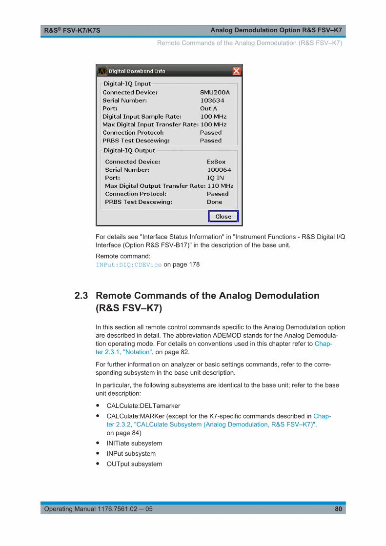
Analog Demodulation Option R&S FSV–K7R&S® FSV-K7/K7S
80Operating Manual 1176.7561.02 ─ 05
For details see "Interface Status Information" in "Instrument Functions - R&S Digital I/QInterface (Option R&S FSV-B17)" in the description of the base unit.
Remote command: INPut:DIQ:CDEVice on page 178
2.3 Remote Commands of the Analog Demodulation(R&S FSV–K7)
In this section all remote control commands specific to the Analog Demodulation optionare described in detail. The abbreviation ADEMOD stands for the Analog Demodula-tion operating mode. For details on conventions used in this chapter refer to Chap-ter 2.3.1, "Notation", on page 82.
For further information on analyzer or basic settings commands, refer to the corre-sponding subsystem in the base unit description.
In particular, the following subsystems are identical to the base unit; refer to the baseunit description:
● CALCulate:DELTamarker● CALCulate:MARKer (except for the K7-specific commands described in Chap-
ter 2.3.2, "CALCulate Subsystem (Analog Demodulation, R&S FSV–K7)",on page 84)
● INITiate subsystem● INPut subsystem● OUTput subsystem
Remote Commands of the Analog Demodulation (R&S FSV–K7)
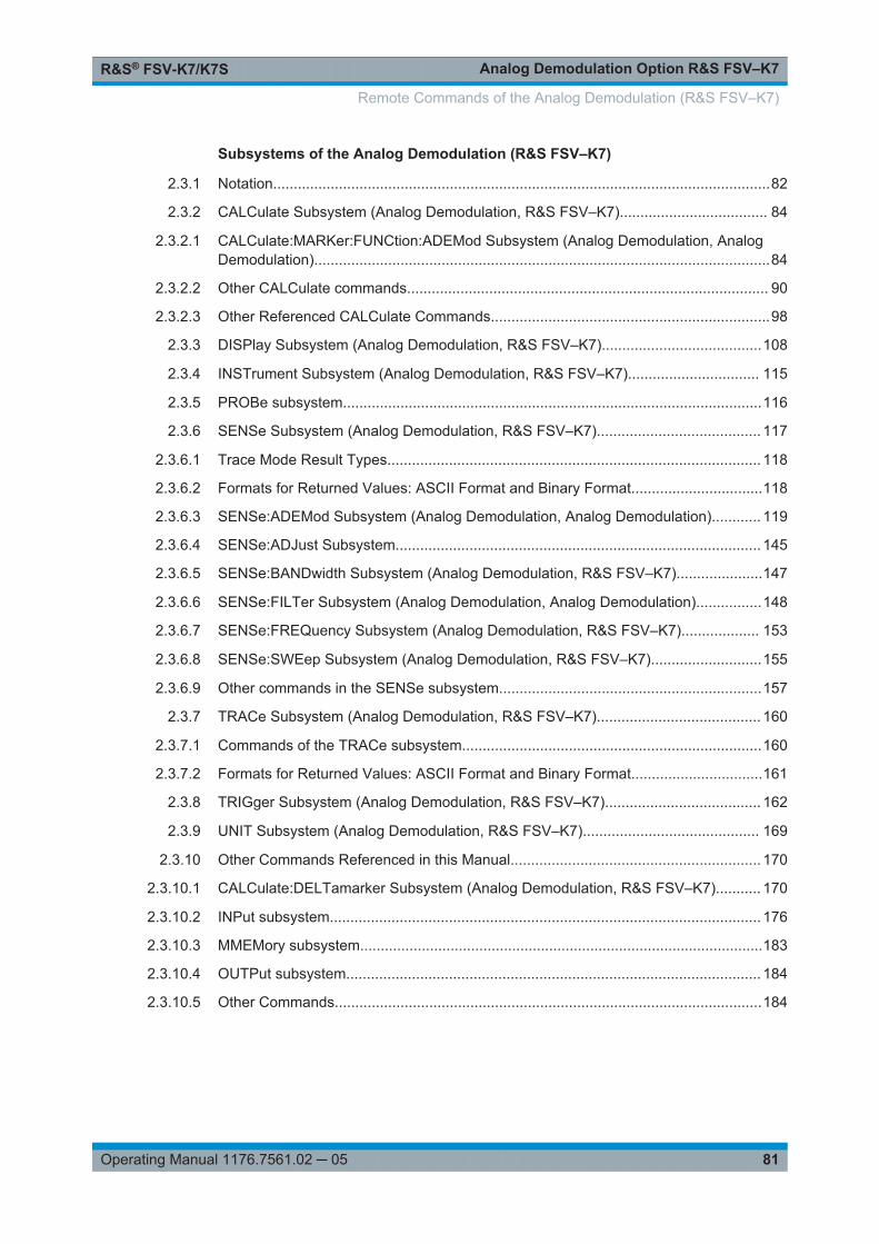
Analog Demodulation Option R&S FSV–K7R&S® FSV-K7/K7S
81Operating Manual 1176.7561.02 ─ 05
Subsystems of the Analog Demodulation (R&S FSV–K7)
2.3.1 Notation.........................................................................................................................82
2.3.2 CALCulate Subsystem (Analog Demodulation, R&S FSV–K7).................................... 84
2.3.2.1 CALCulate:MARKer:FUNCtion:ADEMod Subsystem (Analog Demodulation, AnalogDemodulation)...............................................................................................................84
2.3.2.2 Other CALCulate commands........................................................................................ 90
2.3.2.3 Other Referenced CALCulate Commands....................................................................98
2.3.3 DISPlay Subsystem (Analog Demodulation, R&S FSV–K7).......................................108
2.3.4 INSTrument Subsystem (Analog Demodulation, R&S FSV–K7)................................ 115
2.3.5 PROBe subsystem......................................................................................................116
2.3.6 SENSe Subsystem (Analog Demodulation, R&S FSV–K7)........................................ 117
2.3.6.1 Trace Mode Result Types........................................................................................... 118
2.3.6.2 Formats for Returned Values: ASCII Format and Binary Format................................118
2.3.6.3 SENSe:ADEMod Subsystem (Analog Demodulation, Analog Demodulation)............ 119
2.3.6.4 SENSe:ADJust Subsystem......................................................................................... 145
2.3.6.5 SENSe:BANDwidth Subsystem (Analog Demodulation, R&S FSV–K7).....................147
2.3.6.6 SENSe:FILTer Subsystem (Analog Demodulation, Analog Demodulation)................148
2.3.6.7 SENSe:FREQuency Subsystem (Analog Demodulation, R&S FSV–K7)................... 153
2.3.6.8 SENSe:SWEep Subsystem (Analog Demodulation, R&S FSV–K7)...........................155
2.3.6.9 Other commands in the SENSe subsystem................................................................157
2.3.7 TRACe Subsystem (Analog Demodulation, R&S FSV–K7)........................................ 160
2.3.7.1 Commands of the TRACe subsystem.........................................................................160
2.3.7.2 Formats for Returned Values: ASCII Format and Binary Format................................161
2.3.8 TRIGger Subsystem (Analog Demodulation, R&S FSV–K7)...................................... 162
2.3.9 UNIT Subsystem (Analog Demodulation, R&S FSV–K7)........................................... 169
2.3.10 Other Commands Referenced in this Manual............................................................. 170
2.3.10.1 CALCulate:DELTamarker Subsystem (Analog Demodulation, R&S FSV–K7)........... 170
2.3.10.2 INPut subsystem......................................................................................................... 176
2.3.10.3 MMEMory subsystem..................................................................................................183
2.3.10.4 OUTPut subsystem..................................................................................................... 184
2.3.10.5 Other Commands........................................................................................................184
Remote Commands of the Analog Demodulation (R&S FSV–K7)
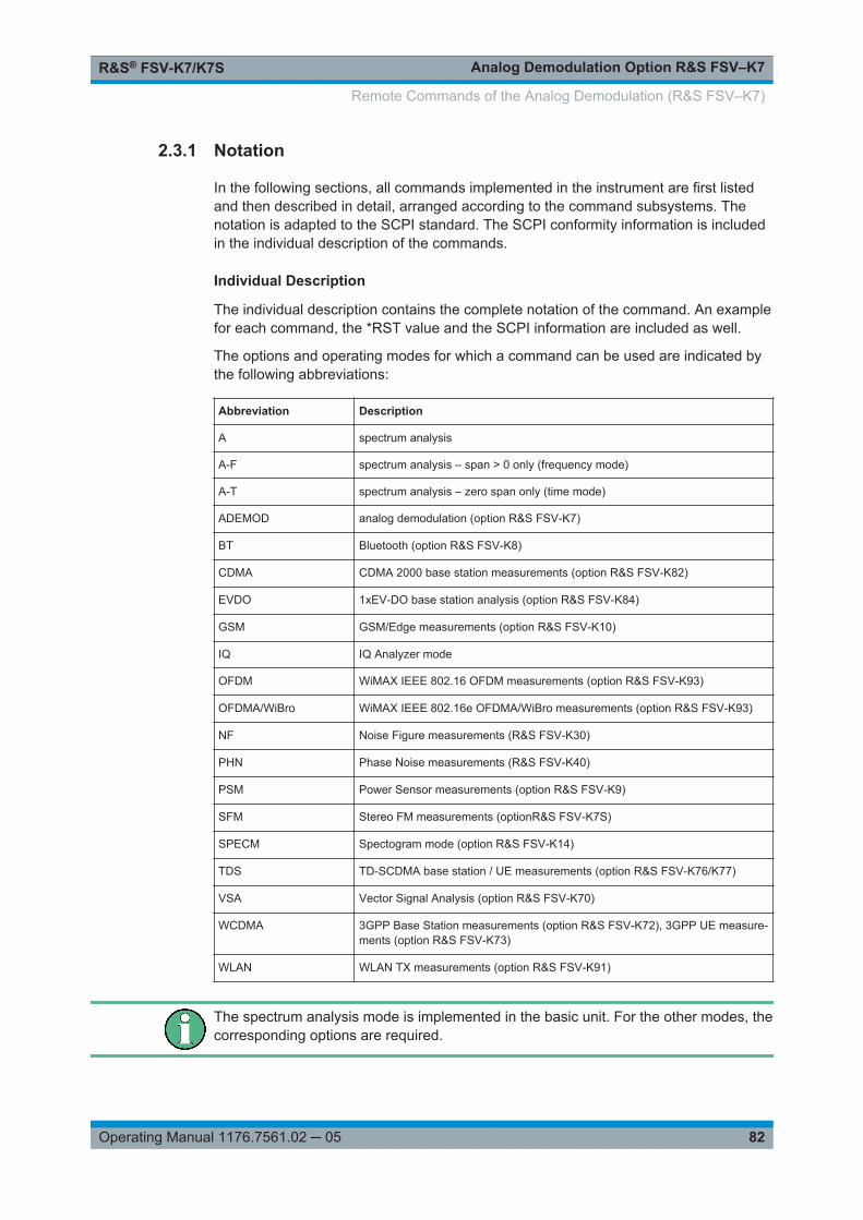
Analog Demodulation Option R&S FSV–K7R&S® FSV-K7/K7S
82Operating Manual 1176.7561.02 ─ 05
2.3.1 Notation
In the following sections, all commands implemented in the instrument are first listedand then described in detail, arranged according to the command subsystems. Thenotation is adapted to the SCPI standard. The SCPI conformity information is includedin the individual description of the commands.
Individual Description
The individual description contains the complete notation of the command. An examplefor each command, the *RST value and the SCPI information are included as well.
The options and operating modes for which a command can be used are indicated bythe following abbreviations:
Abbreviation Description
A spectrum analysis
A-F spectrum analysis – span > 0 only (frequency mode)
A-T spectrum analysis – zero span only (time mode)
ADEMOD analog demodulation (option R&S FSV-K7)
BT Bluetooth (option R&S FSV-K8)
CDMA CDMA 2000 base station measurements (option R&S FSV-K82)
EVDO 1xEV-DO base station analysis (option R&S FSV-K84)
GSM GSM/Edge measurements (option R&S FSV-K10)
IQ IQ Analyzer mode
OFDM WiMAX IEEE 802.16 OFDM measurements (option R&S FSV-K93)
OFDMA/WiBro WiMAX IEEE 802.16e OFDMA/WiBro measurements (option R&S FSV-K93)
NF Noise Figure measurements (R&S FSV-K30)
PHN Phase Noise measurements (R&S FSV-K40)
PSM Power Sensor measurements (option R&S FSV-K9)
SFM Stereo FM measurements (optionR&S FSV-K7S)
SPECM Spectogram mode (option R&S FSV-K14)
TDS TD-SCDMA base station / UE measurements (option R&S FSV-K76/K77)
VSA Vector Signal Analysis (option R&S FSV-K70)
WCDMA 3GPP Base Station measurements (option R&S FSV-K72), 3GPP UE measure-ments (option R&S FSV-K73)
WLAN WLAN TX measurements (option R&S FSV-K91)
The spectrum analysis mode is implemented in the basic unit. For the other modes, thecorresponding options are required.
Remote Commands of the Analog Demodulation (R&S FSV–K7)

Analog Demodulation Option R&S FSV–K7R&S® FSV-K7/K7S
83Operating Manual 1176.7561.02 ─ 05
Upper/Lower Case Notation
Upper/lower case letters are used to mark the long or short form of the key words of acommand in the description. The instrument itself does not distinguish between upperand lower case letters.
Special Characters
| A selection of key words with an identical effect exists for several commands. These keywordsare indicated in the same line; they are separated by a vertical stroke. Only one of these key-words needs to be included in the header of the command. The effect of the command is inde-pendent of which of the keywords is used.
Example:
SENSe:FREQuency:CW|:FIXedThe two following commands with identical meaning can be created. They set the fre-quency of the fixed frequency signal to 1 kHz:
SENSe:FREQuency:CW 1E3SENSe:FREQuency:FIXed 1E3A vertical stroke in parameter indications marks alternative possibilities in the sense of"or". The effect of the command differs, depending on which parameter is used.
Example: Selection of the parameters for the command
[SENSe<1…4>:]AVERage<1…4>:TYPE VIDeo | LINear
[] Key words in square brackets can be omitted when composing the header. The full commandlength must be accepted by the instrument for reasons of compatibility with the SCPI standards.
Parameters in square brackets can be incorporated optionally in the command or omitted aswell.
{} Parameters in braces can be incorporated optionally in the command, either not at all, once orseveral times.
Description of Parameters
Due to the standardization, the parameter section of SCPI commands consists alwaysof the same syntactical elements. SCPI has therefore specified a series of definitions,which are used in the tables of commands. In the tables, these established definitionsare indicated in angled brackets (<…>) and is briefly explained in the following.
For details see the chapter "SCPI Command Structure" in the base unit description.
<Boolean>
This keyword refers to parameters which can adopt two states, "on" and "off". The "off"state may either be indicated by the keyword OFF or by the numeric value 0, the "on"state is indicated by ON or any numeric value other than zero. Parameter queries arealways returned the numeric value 0 or 1.
Remote Commands of the Analog Demodulation (R&S FSV–K7)
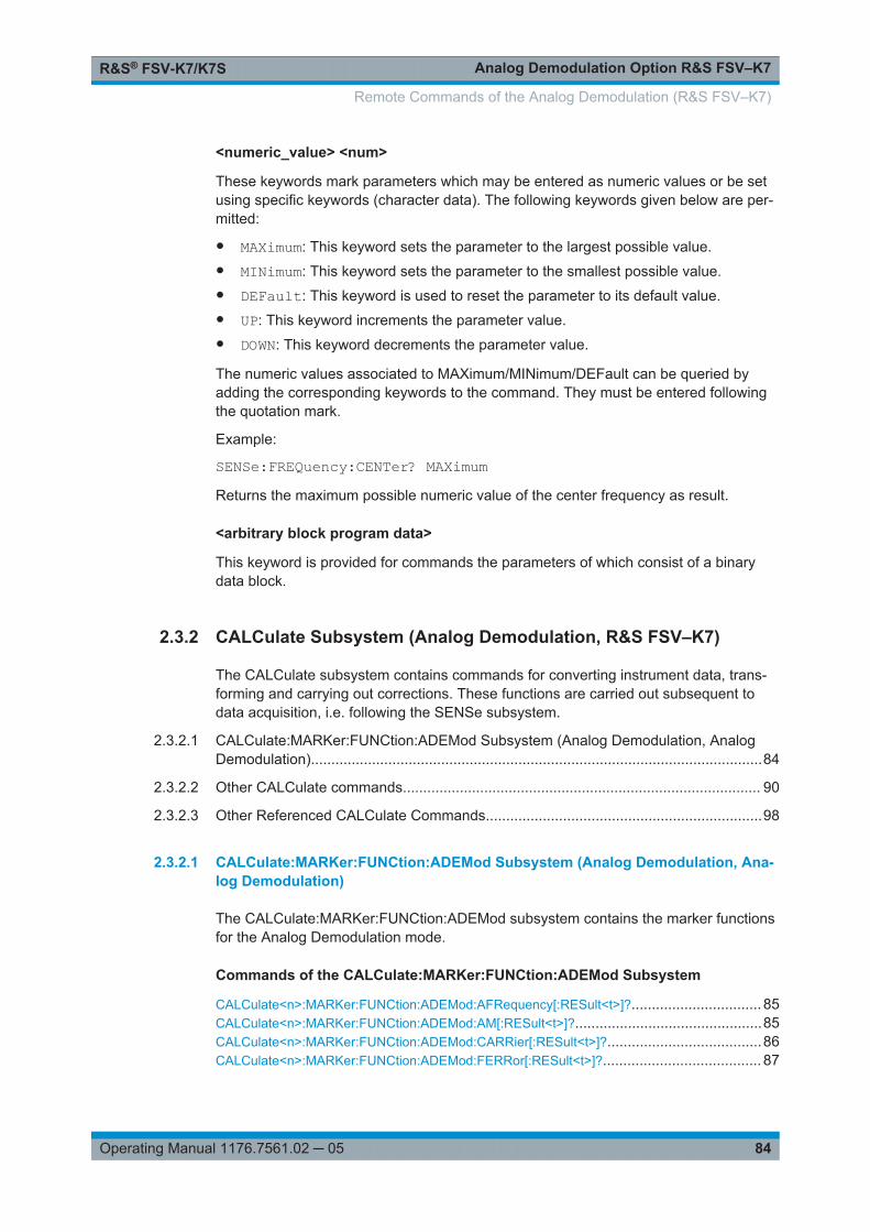
Analog Demodulation Option R&S FSV–K7R&S® FSV-K7/K7S
84Operating Manual 1176.7561.02 ─ 05
<numeric_value> <num>
These keywords mark parameters which may be entered as numeric values or be setusing specific keywords (character data). The following keywords given below are per-mitted:
● MAXimum: This keyword sets the parameter to the largest possible value.● MINimum: This keyword sets the parameter to the smallest possible value.● DEFault: This keyword is used to reset the parameter to its default value.● UP: This keyword increments the parameter value.● DOWN: This keyword decrements the parameter value.
The numeric values associated to MAXimum/MINimum/DEFault can be queried byadding the corresponding keywords to the command. They must be entered followingthe quotation mark.
Example:
SENSe:FREQuency:CENTer? MAXimumReturns the maximum possible numeric value of the center frequency as result.
<arbitrary block program data>
This keyword is provided for commands the parameters of which consist of a binarydata block.
2.3.2 CALCulate Subsystem (Analog Demodulation, R&S FSV–K7)
The CALCulate subsystem contains commands for converting instrument data, trans-forming and carrying out corrections. These functions are carried out subsequent todata acquisition, i.e. following the SENSe subsystem.
2.3.2.1 CALCulate:MARKer:FUNCtion:ADEMod Subsystem (Analog Demodulation, AnalogDemodulation)...............................................................................................................84
2.3.2.2 Other CALCulate commands........................................................................................ 90
2.3.2.3 Other Referenced CALCulate Commands....................................................................98
2.3.2.1 CALCulate:MARKer:FUNCtion:ADEMod Subsystem (Analog Demodulation, Ana-log Demodulation)
The CALCulate:MARKer:FUNCtion:ADEMod subsystem contains the marker functionsfor the Analog Demodulation mode.
Commands of the CALCulate:MARKer:FUNCtion:ADEMod Subsystem
CALCulate<n>:MARKer:FUNCtion:ADEMod:AFRequency[:RESult<t>]?................................ 85CALCulate<n>:MARKer:FUNCtion:ADEMod:AM[:RESult<t>]?..............................................85CALCulate<n>:MARKer:FUNCtion:ADEMod:CARRier[:RESult<t>]?......................................86CALCulate<n>:MARKer:FUNCtion:ADEMod:FERRor[:RESult<t>]?....................................... 87
Remote Commands of the Analog Demodulation (R&S FSV–K7)

Analog Demodulation Option R&S FSV–K7R&S® FSV-K7/K7S
85Operating Manual 1176.7561.02 ─ 05
CALCulate<n>:MARKer:FUNCtion:ADEMod:FM[:RESult<t>]?.............................................. 87CALCulate<n>:MARKer:FUNCtion:ADEMod:PM[:RESult<t>]?..............................................88CALCulate<n>:MARKer:FUNCtion:ADEMod:SINad:RESult<t>?............................................89CALCulate<n>:MARKer:FUNCtion:ADEMod:THD:RESult<t>?..............................................89
CALCulate<n>:MARKer:FUNCtion:ADEMod:AFRequency[:RESult<t>]?
This command queries the audio frequency with analog demodulation in the specifiedwindow.
If several demodulation modes are activated simultaneously (e.g. with the [SENSe:]ADEMod:FM[:TDOMain][:TYPE] command, the audio frequency of the displaymode selected with CALCulate<n>:FEED on page 90 is returned.
Suffix: <n>
.1window
<t> 1...6irrelevant
Example: ADEM ON, see [SENSe:]ADEMod[:STATe] on page 121Switches on analog demodulatorCALC:FEED 'XTIM:AM:TDOM', see CALCulate<n>:FEEDon page 90Switches on AM result display.DISP:TRAC ON, see DISPlay[:WINDow<n>]:TRACe<t>[:STATe] on page 111Switches the trace on.CALC:MARK:FUNC:ADEM:AFR?Queries the audio frequency.
Usage: Query only
Mode: ADEMOD
CALCulate<n>:MARKer:FUNCtion:ADEMod:AM[:RESult<t>]? <Result>CALCulate<n>:MARKer:FUNCtion:ADEMod:AM[:RESult<t>]?? <MeasType>
This command queries the results of the AM modulation measurement.
Suffix: <n>
.1...4irrelevant
<t> 1...6trace 1, 2, 3, 4, 5 or 6
Parameters:<Result> The result of the selected measurement type is returned.
Remote Commands of the Analog Demodulation (R&S FSV–K7)

Analog Demodulation Option R&S FSV–K7R&S® FSV-K7/K7S
86Operating Manual 1176.7561.02 ─ 05
Query parameters: <MeasType> PPEak | MPEak | MIDDle | RMS
PPEakMeasurement with detector Pluspeak (+PK)MPEakMeasurement with detector MinusPeak (-PK)MIDDleAveraging ±PK/2RMSRMS measurement
Example: ADEM ON (see [SENSe:]ADEMod[:STATe] on page 121)Switches on the analog demodulator.CALC:FEED 'XTIM:AM:TDOM', see CALCulate<n>:FEEDon page 90Switches on the AM result display.DISP:TRAC ON, see DISPlay[:WINDow<n>]:TRACe<t>[:STATe] on page 111Switches on the trace.CALC:MARK:FUNC:ADEM:AM? PPEQueries the peak value.
Usage: Query only
Mode: ADEMOD
CALCulate<n>:MARKer:FUNCtion:ADEMod:CARRier[:RESult<t>]?
This command queries the carrier power.
With RF Power result display, the carrier power is determined from trace 1 to 6 indica-ted in the suffix. With all other result displays, the carrier power is determined from thecurrent trace data (CLR/WRITE trace).
Suffix: <n>
.1...4irrelevant
<t> 1...6irrelevant
Example: ADEM ON (see [SENSe:]ADEMod[:STATe] on page 121)Switches on analog demodulatorCALC:FEED 'XTIM:RFP', see CALCulate<n>:FEEDon page 90Switches on RF power result displayCALC:MARK:FUNC:ADEM:CARR?Queries the carrier power
Usage: Query only
Mode: ADEMOD
Remote Commands of the Analog Demodulation (R&S FSV–K7)
Analog Demodulation Option R&S FSV–K7R&S® FSV-K7/K7S
87Operating Manual 1176.7561.02 ─ 05
CALCulate<n>:MARKer:FUNCtion:ADEMod:FERRor[:RESult<t>]?
This command queries the frequency error with FM and PM demodulation. The fre-quency error is determined from the current measurement data (CLR/WRITE trace).
The offset thus determined differs from that calculated in the [SENSe:]ADEMod:FM:OFFSet on page 132 command since, for determination of the frequency deviation,the modulation is removed by means of low pass filtering, producing results that aredifferent from those obtained by averaging with the SENSe command.
Suffix: <n>
.1...4irrelevant
<t> 1...6irrelevant
Example: ADEM ON (see [SENSe:]ADEMod[:STATe] on page 121)Switches on analog demodulatorCALC:FEED 'XTIM:FM:TDOM', see CALCulate<n>:FEEDon page 90Switches on FM result displayCALC:MARK:FUNC:ADEM:FERR?Queries the frequency error of trace 1
Usage: Query only
Mode: ADEMOD
CALCulate<n>:MARKer:FUNCtion:ADEMod:FM[:RESult<t>]? <Result>CALCulate<n>:MARKer:FUNCtion:ADEMod:FM[:RESult<t>]?? <MeasType>
This command queries the results of FM modulation measurement.
Suffix: <n>
.1...4irrelevant
<t> 1...6trace 1, 2, 3, 4, 5 or 6
Parameters:<Result> The result of the selected measurement type is returned.
Remote Commands of the Analog Demodulation (R&S FSV–K7)

Analog Demodulation Option R&S FSV–K7R&S® FSV-K7/K7S
88Operating Manual 1176.7561.02 ─ 05
Query parameters: <MeasType> PPEak | MPEak | MIDDle | RMS
PPEakMeasurement with detector Pluspeak (+PK)MPEakMeasurement with detector MinusPeak (-PK)MIDDleAveraging ±PK/2RMSRMS measurement
Example: ADEM ON (see [SENSe:]ADEMod[:STATe] on page 121)Switches on the analog demodulator.CALC:FEED 'XTIM:FM:TDOM', see CALCulate<n>:FEEDon page 90Switches on the FM result display.CALC:MARK:FUNC:ADEM:FM? PPEQueries the peak value.
Usage: Query only
Mode: ADEMOD
CALCulate<n>:MARKer:FUNCtion:ADEMod:PM[:RESult<t>]? <Result>CALCulate<n>:MARKer:FUNCtion:ADEMod:PM[:RESult<t>]?? <MeasType>
This command queries the results of PM modulation measurement of analog demodu-lation.
Suffix: <t>
.1...6trace 1, 2, 3, 4, 5 or 6
<n> 1...4irrelevant
Parameters:<Result> The result of the selected measurement type is returned.
Query parameters: <MeasType> PPEak | MPEak | MIDDle | RMS
PPEakMeasurement with detector Pluspeak (+PK)MPEakMeasurement with detector MinusPeak (-PK)MIDDleAveraging ±PK/2RMSRMS measurement
Remote Commands of the Analog Demodulation (R&S FSV–K7)

Analog Demodulation Option R&S FSV–K7R&S® FSV-K7/K7S
89Operating Manual 1176.7561.02 ─ 05
Example: ADEM ON (see [SENSe:]ADEMod[:STATe] on page 121)Switches on the analog demodulator.CALC:FEED 'XTIM:FM:TDOM', see CALCulate<n>:FEEDon page 90Switches on the FM result display.CALC:MARK:FUNC:ADEM:PM? PPEQueries the peak value.
Usage: Query only
Mode: ADEMOD
CALCulate<n>:MARKer:FUNCtion:ADEMod:SINad:RESult<t>?
This command queries the result of the SINAD measurement in the specified window.
Suffix: <n>
.1...4window
<t> 1...6trace 1, 2, 3, 4, 5 or 6
Example: ADEM ON (see [SENSe:]ADEMod[:STATe] on page 121)Switches on analog demodulatorCALC:FEED 'XTIM:FM:AFSP', see CALCulate<n>:FEEDon page 90Switches on AF spectrum of FMCALC:MARK:FUNC:ADEM:SIN:RES?Queries SINAD value
Usage: Query only
Mode: ADEMOD
CALCulate<n>:MARKer:FUNCtion:ADEMod:THD:RESult<t>?
This command queries the result of the THD measurement in the specified window.
Suffix: <n>
.1...4window
<t> 1...6trace 1, 2, 3, 4, 5 or 6
Remote Commands of the Analog Demodulation (R&S FSV–K7)
Analog Demodulation Option R&S FSV–K7R&S® FSV-K7/K7S
90Operating Manual 1176.7561.02 ─ 05
Example: ADEM ON (see [SENSe:]ADEMod[:STATe] on page 121)Switches on analog demodulatorCALC:FEED 'XTIM:FM:AFSP', see CALCulate<n>:FEEDon page 90Switches on AF spectrum of FMDISP:TRAC ON, see DISPlay[:WINDow<n>]:TRACe<t>[:STATe] on page 111Switches on the traceCALC:MARK:FUNC:ADEM:THD:RES?Queries THD result
Usage: Query only
Mode: ADEMOD
2.3.2.2 Other CALCulate commands
CALCulate<n>:FEED <Evaluation>
This command selects the evaluation method of the measured data that is to be dis-played in the specified window.
The suffix <1...6> indicates which of the traces is evaluated in the result summary.Note that all result summaries are identical, as the results of all evaluations are inclu-ded in the summary.
Suffix: <n>
.1...4window
Remote Commands of the Analog Demodulation (R&S FSV–K7)
Analog Demodulation Option R&S FSV–K7R&S® FSV-K7/K7S
91Operating Manual 1176.7561.02 ─ 05
Parameters:<Evaluation> XTIM:AM:RELative[:TDOMain] |
XTIM:AM:RELative:AFSPectrum<1…6> |XTIM:AM[:ABSolute][:TDOMain] | XTIM:RFPower[:TDOMain] |XTIM:FM[:TDOMain] | XTIM:FM:AFSPectrum<1…6> |XTIM:PM[:TDOMain] | XTIM:PM:AFSPectrum<1…6> |XTIM:AMSummary<1…6>[:ABSolute] |XTIM:AMSummary<1…6>:RELative |XTIM:FMSummary<1…6> | XTIM:PMSummary<1…6> |XTIM:SPECtrum | XTIM:SUMMary<1...6> |XTIM:RFPower[:TDOMain] | XTIM:SPECtrum |XTIM:SUMMary<1...6> | XFRequency:SFM:LEFT |XFRequency:SFM:RIGHt | XFRequency:SFM:MPX |XFRequency:SFM:MONO | XFRequency:SFM:STEReo |XFRequency:SFM:RDS | XFRequency:SFM:PILot |XTIMe:SFM:LEFT | XTIMe:SFM:RIGHt | XTIMe:SFM:MPX |XTIMe:SFM:MONO | XTIMe:SFM:STEReo | XTIMe:SFM:RDS |XTIMe:SFM:PILotXTIM:AM:RELative[:TDOMain]Demodulated AM signal in time domainXTIM:AM:RELative:AFSPectrum<1…6>AF spectrum of the demodulated AM signalXTIM:AM[:ABSolute][:TDOMain]RF signal in time domain (RF power)Same as 'XTIM:RFPower'XTIM:RFPower[:TDOMain]RF power of the signal (RF signal in time domain)XTIM:FM[:TDOMain]Demodulated FM signal in time domainXTIM:FM:AFSPectrum<1…6>AF spectrum of the demodulated FM signalXTIM:PM[:TDOMain]Demodulated PM signal in time domainXTIM:PM:AFSPectrum<1…6>AF spectrum of the demodulated PM signalXTIM:AMSummary<1…6>[:ABSolute]Result summary for RF signalXTIM:AMSummary<1…6>:RELativeResult summary for demodulated AM signalXTIM:FMSummary<1…6>Result summary for demodulated FM signalXTIM:PMSummary<1…6>Result summary for demodulated PM signalXTIM:SPECtrum
Remote Commands of the Analog Demodulation (R&S FSV–K7)

Analog Demodulation Option R&S FSV–K7R&S® FSV-K7/K7S
92Operating Manual 1176.7561.02 ─ 05
RF spectrum of the signal determined from the measured datavia FFTXTIM:SUMMary<1...6>Summary of all evaluation listsXFRequency:SFM:LEFTLeft channel spectrum of FM stereo signalXFRequency:SFM:RIGHtRight channel spectrum of FM stereo signalXFRequency:SFM:MPXMPX channel spectrum of FM stereo signalXFRequency:SFM:MONOMono channel spectrum of FM stereo signalXFRequency:SFM:STEReoStereo channel spectrum of FM stereo signalXFRequency:SFM:RDSRDS channel spectrum of FM stereo signalXFRequency:SFM:PILotPilot channel spectrum of FM stereo signalXTIMe:SFM:LEFTLeft channel of FM stereo signal in time domainXTIMe:SFM:RIGHtRight channel of FM stereo signal in time domainXTIMe:SFM:MPXMPX channel of FM stereo signal in time domainXTIMe:SFM:MONOMono channel of FM stereo signal in time domainXTIMe:SFM:STEReoStereo channel of FM stereo signal in time domainXTIMe:SFM:RDSRDS channel of FM stereo signal in time domainXTIMe:SFM:PILotPilot channel of FM stereo signal in time domain
Example: INST:SEL ADEM(see INSTrument[:SELect] on page 115)Activates analog demodulator.CALC:FEED 'XTIM:FM'Selects the display of the FM signal.
Usage: SCPI confirmed
Mode: ADEMOD, SFM
Remote Commands of the Analog Demodulation (R&S FSV–K7)

Analog Demodulation Option R&S FSV–K7R&S® FSV-K7/K7S
93Operating Manual 1176.7561.02 ─ 05
Manual operation: See "AM" on page 26See "Screen A-D" on page 27See "FM" on page 35See "PM" on page 36See "RF Power" on page 37See "Left" on page 193See "Screen A-D" on page 194See "Right" on page 205See "MPX" on page 205See "Mono" on page 205See "Stereo" on page 205See "RDS" on page 205See "Pilot" on page 205See "RF Power" on page 205
CALCulate<n>:FORMat <Limitation>
This command activates the limitation to ±180°.
Suffix: <n>
.1...4irrelevant
Parameters:<Limitation> PHASe | UPHase
PHASeLimitation to ±180°UPHaseUnwrapped*RST: UPHase
Example: CALC:FORM PHASActivates the limitation to ±180°.
Usage: SCPI confirmed
Mode: ADEMOD
Manual operation: See "Phase Wrap On/Off" on page 37
CALCulate<n>:MARKer<m>:FUNCtion:PNOise:RESult?
This command queries the result of the phase noise measurement at the specifiedmarker in the specified window.
A complete sweep with synchronization to the sweep end must be performed betweenswitching on the function and querying the measured value in order to obtain a correctquery result. This is only possible in single sweep mode.
Suffix: <n>
.1...4window
Remote Commands of the Analog Demodulation (R&S FSV–K7)
Analog Demodulation Option R&S FSV–K7R&S® FSV-K7/K7S
94Operating Manual 1176.7561.02 ─ 05
<m> 1...16marker
Example: INIT:CONT OFFSwitches to single sweep mode.CALC:MARK2 ONSwitches on marker 2.CALC:MARK2:FUNC:PNO ONSwitches on the phase noise marker 2.INIT;*WAIStarts a sweep and waits for the end.CALC:MARK2:PNO:RES?Outputs the phase noise result of marker 2.
Usage: Query only
Mode: ADEMOD
Manual operation: See "Phase Noise" on page 71
CALCulate<n>:MARKer<m>:FUNCtion:FPEaks:ANNotation:LABel:STATe <State>
This command turns labels for peaks found during a peak search on and off.
The labels correspond to the marker number in the marker peak list.
Suffix: <n>
.Selects the measurement window.
<m> Selects the marker.
Parameters:<State> ON | OFF
*RST: ON
Example: CALC:MARK:FUNC:FPE:ANN:LAB:STAT OFFRemoves the peak labels from the diagram
Manual operation: See "Marker Number" on page 75
CALCulate<n>:MARKer<m>:FUNCtion:FPEaks:LIST:SIZE <MaxNoPeaks>
This command defines the maximum number of peaks the marker peak list may con-tain.
Suffix: <n>
.Selects the measurement window.
<m> Selects the marker.
Parameters:<MaxNoPeaks> Maximum number of peaks to be determined.
*RST: 50
Remote Commands of the Analog Demodulation (R&S FSV–K7)
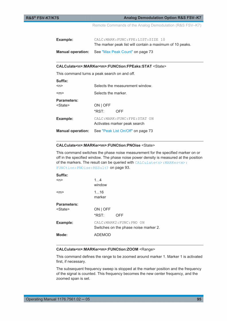
Analog Demodulation Option R&S FSV–K7R&S® FSV-K7/K7S
95Operating Manual 1176.7561.02 ─ 05
Example: CALC:MARK:FUNC:FPE:LIST:SIZE 10The marker peak list will contain a maximum of 10 peaks.
Manual operation: See "Max Peak Count" on page 73
CALCulate<n>:MARKer<m>:FUNCtion:FPEaks:STAT <State>
This command turns a peak search on and off.
Suffix: <n>
.Selects the measurement window.
<m> Selects the marker.
Parameters:<State> ON | OFF
*RST: OFF
Example: CALC:MARK:FUNC:FPE:STAT ONActivates marker peak search
Manual operation: See "Peak List On/Off" on page 73
CALCulate<n>:MARKer<m>:FUNCtion:PNOise <State>
This command switches the phase noise measurement for the specified marker on oroff in the specified window. The phase noise power density is measured at the positionof the markers. The result can be queried with CALCulate<n>:MARKer<m>:FUNCtion:PNOise:RESult? on page 93.
Suffix: <n>
.1...4window
<m> 1...16marker
Parameters:<State> ON | OFF
*RST: OFF
Example: CALC:MARK2:FUNC:PNO ONSwitches on the phase noise marker 2.
Mode: ADEMOD
CALCulate<n>:MARKer<m>:FUNCtion:ZOOM <Range>
This command defines the range to be zoomed around marker 1. Marker 1 is activatedfirst, if necessary.
The subsequent frequency sweep is stopped at the marker position and the frequencyof the signal is counted. This frequency becomes the new center frequency, and thezoomed span is set.
Remote Commands of the Analog Demodulation (R&S FSV–K7)

Analog Demodulation Option R&S FSV–K7R&S® FSV-K7/K7S
96Operating Manual 1176.7561.02 ─ 05
Note that you should perform a complete measurement with synchronization to the endof the measurement. This is only possible for single sweeps.
Suffix: <n>
.Selects the measurement window.
<m> Selects the marker.
Parameters:<Range> <numeric_value>
Example: INIT:CONT OFFSwitches to single sweep modeCALC:MARK:FUNC:ZOOM 1kHz;*WAIActivates zooming and waits for its end.
Manual operation: See "Marker Zoom (span > 0)" on page 70
CALCulate<n>:MARKer<m>:LINK <DisplayType>
Links the markers in all displays of the specified type.
Suffix: <n>
.1...4window
<m> 1...16marker
Parameters:<DisplayType> TIME | SPECtrum | BOTH | NONE
TIMELinks the markers in all time domain diagramsSPECtrumLinks the markers in all AF Spectrum displaysBOTHLinks the markers both in the time domain diagrams and in theAF Spectrum displaysNONEMarkers are not linked.*RST: NONE
Example: CALC1:MARK1:LINK TIMELinks the marker 1 in all time domain diagrams in screen A.
Mode: ADEMOD
Manual operation: See "Link Time Marker" on page 70See "Link AF Spectrum Marker" on page 70
CALCulate<n>:THReshold <Threshold>
This command defines a threshold value for the marker peak search.
Remote Commands of the Analog Demodulation (R&S FSV–K7)
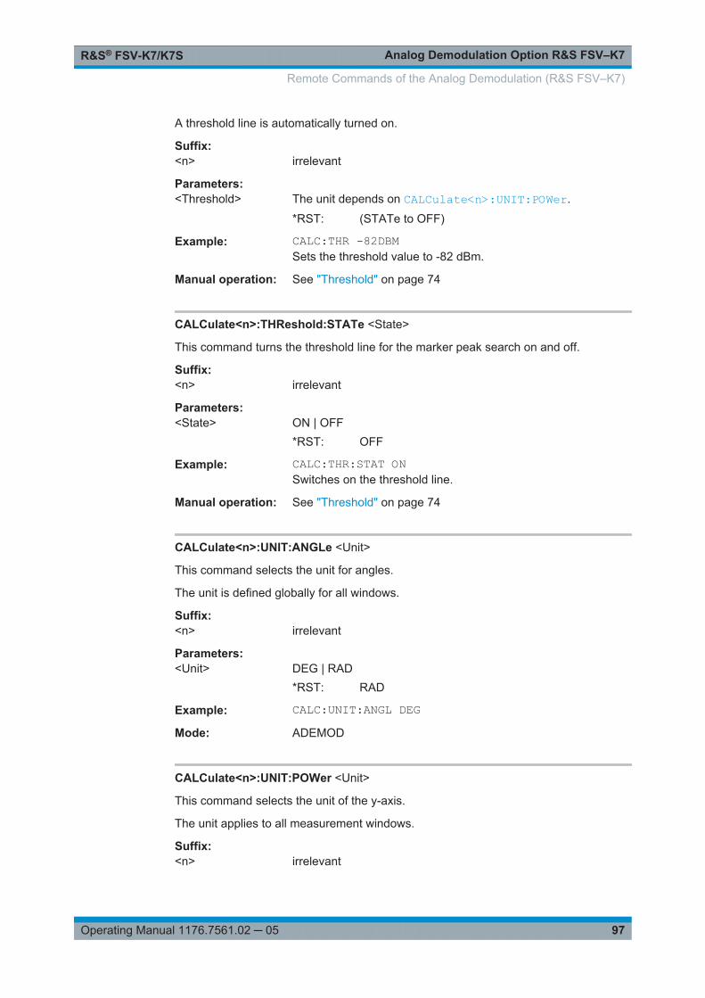
Analog Demodulation Option R&S FSV–K7R&S® FSV-K7/K7S
97Operating Manual 1176.7561.02 ─ 05
A threshold line is automatically turned on.
Suffix: <n>
.irrelevant
Parameters:<Threshold> The unit depends on CALCulate<n>:UNIT:POWer.
*RST: (STATe to OFF)
Example: CALC:THR -82DBMSets the threshold value to -82 dBm.
Manual operation: See "Threshold" on page 74
CALCulate<n>:THReshold:STATe <State>
This command turns the threshold line for the marker peak search on and off.
Suffix: <n>
.irrelevant
Parameters:<State> ON | OFF
*RST: OFF
Example: CALC:THR:STAT ONSwitches on the threshold line.
Manual operation: See "Threshold" on page 74
CALCulate<n>:UNIT:ANGLe <Unit>
This command selects the unit for angles.
The unit is defined globally for all windows.
Suffix: <n>
.irrelevant
Parameters:<Unit> DEG | RAD
*RST: RAD
Example: CALC:UNIT:ANGL DEGMode: ADEMOD
CALCulate<n>:UNIT:POWer <Unit>
This command selects the unit of the y-axis.
The unit applies to all measurement windows.
Suffix: <n>
.irrelevant
Remote Commands of the Analog Demodulation (R&S FSV–K7)
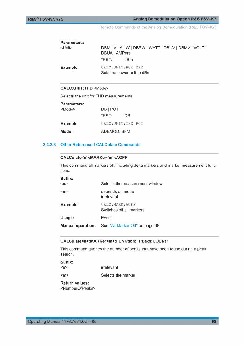
Analog Demodulation Option R&S FSV–K7R&S® FSV-K7/K7S
98Operating Manual 1176.7561.02 ─ 05
Parameters:<Unit> DBM | V | A | W | DBPW | WATT | DBUV | DBMV | VOLT |
DBUA | AMPere*RST: dBm
Example: CALC:UNIT:POW DBMSets the power unit to dBm.
CALC:UNIT:THD <Mode>
Selects the unit for THD measurements.
Parameters:<Mode> DB | PCT
*RST: DB
Example: CALC:UNIT:THD PCTMode: ADEMOD, SFM
2.3.2.3 Other Referenced CALCulate Commands
CALCulate<n>:MARKer<m>:AOFF
This command all markers off, including delta markers and marker measurement func-tions.
Suffix: <n>
.Selects the measurement window.
<m> depends on modeirrelevant
Example: CALC:MARK:AOFFSwitches off all markers.
Usage: Event
Manual operation: See "All Marker Off" on page 68
CALCulate<n>:MARKer<m>:FUNCtion:FPEaks:COUNt?
This command queries the number of peaks that have been found during a peaksearch.
Suffix: <n>
.irrelevant
<m> Selects the marker.
Return values: <NumberOfPeaks>
Remote Commands of the Analog Demodulation (R&S FSV–K7)

Analog Demodulation Option R&S FSV–K7R&S® FSV-K7/K7S
99Operating Manual 1176.7561.02 ─ 05
Example: CALC:MARK:FUNC:FPE 3Searches the 3 highest maxima for trace 1CALC:MARK:FUNC:FPE:COUN?Queries the number of maxima found
Usage: Query only
Manual operation: See "Marker Peak List" on page 73
CALCulate<n>:MARKer<m>:FUNCtion:FPEaks:SORT <SortMode>
This command selects the order in which the results of a peak search are returned.
Suffix: <n>
.Selects the measurement window.
<m> Selects the marker.
Parameters:<SortMode> X
Sorts the peaks according to increasing position on the x-axis.YSorts the peaks according to decreasing position on the y-axis.
Example: CALC:MARK:FUNC:FPE:SORT YSets the sort mode to decreasing y values
Manual operation: See "Sort Mode Freq/Lvl" on page 73
CALCulate<n>:MARKer<m>:FUNCtion:FPEaks:X
This command queries the position of the peaks on the x-axis.
The order depends on the sort order that has been set with CALCulate<n>:MARKer<m>:FUNCtion:FPEaks:SORT on page 99.
The number of peaks on the number that has been set with CALCulate<n>:MARKer<m>:FUNCtion:FPEaks:COUNt?.
Suffix: <n>
.Selects the measurement window.
<m> Selects the marker.
Return values: <PeakPosition> Position of the peaks on the x-axis. The unit depends on the
measurement.
Remote Commands of the Analog Demodulation (R&S FSV–K7)

Analog Demodulation Option R&S FSV–K7R&S® FSV-K7/K7S
100Operating Manual 1176.7561.02 ─ 05
Example: CALC:MARK:FUNC:FPE:SORT YSets the sort mode to decreasing y valuesCALC:MARK:FUNC:FPE 3Searches the 3 highest maxima for trace 1CALC:MARK:FUNC:FPE:COUN?Queries the number of maxima foundCALC:MARK:FUNC:FPE:X?Queries the frequencies (span <> 0) or. time (span = 0) of themaxima found107.5E6,153.8E6,187.9E6frequencies in increasing order2.05E-3,2.37E-3, 3.71e-3times in increasing order
Manual operation: See "Marker Peak List" on page 73
CALCulate<n>:MARKer<m>:FUNCtion:FPEaks:Y?
This command queries the position of the peaks on the y-axis.
The order depends on the sort order that has been set with CALCulate<n>:MARKer<m>:FUNCtion:FPEaks:SORT on page 99.
The number of peaks on the number that has been set with CALCulate<n>:MARKer<m>:FUNCtion:FPEaks:COUNt?.
Suffix: <n>
.Selects the measurement window.
<m> Selects the marker.
Return values: <PeakPosition> Position of the peaks on the y-axis. The unit depends on the
measurement.
Example: CALC:MARK:FUNC:FPE:SORT YSets the sort mode to decreasing y valuesCALC:MARK:FUNC:FPE 3Searches the 3 highest maxima for trace 1CALC:MARK:FUNC:FPE:COUN?Queries the number of maxima foundCALC:MARK:FUNC:FPE:Y?Queries the levels of the maxima found
Usage: Query only
Manual operation: See "Marker Peak List" on page 73
CALCulate<n>:MARKer<m>:FUNCtion:NDBDown <Distance>
This command defines the distance of the n dB down markers to the reference marker.
Remote Commands of the Analog Demodulation (R&S FSV–K7)

Analog Demodulation Option R&S FSV–K7R&S® FSV-K7/K7S
101Operating Manual 1176.7561.02 ─ 05
The temporary markers T1 and T2 are positioned n dB below the active referencemarker. The frequency and time position of these markers can be queried withCALCulate<n>:MARKer<m>:FUNCtion:NDBDown:FREQuency? andCALCulate<n>:MARKer<m>:FUNCtion:NDBDown:TIME?. The bandwidth betweenthe markers can be queried with CALCulate<n>:MARKer<m>:FUNCtion:NDBDown:RESult?.
Suffix: <n>
.Selects the measurement window.
<m> irrelevant
Parameters:<Distance> Distance of the temporary markers to the reference marker in
dB.*RST: 6dB
Example: CALC:MARK:FUNC:NDBD 3dBSets the level spacing to 3 dB.
Manual operation: See "n dB down" on page 72
CALCulate<n>:MARKer<m>:FUNCtion:NDBDown:FREQuency?
This command queries the position of the n dB down markers on the x-axis when mea-suring in the frequency domain.
To get a valid result, you have to perform a complete measurement with synchroniza-tion to the end of the measurement before reading out the result. This is only possiblefor single sweeps.
Suffix: <n>
.Selects the measurement window.
<m> irrelevant
Return values: <Frequency> <frequency 1>
absolute frequency of the n dB marker to the left of the referencemarker in Hz<frequency 2>absolute frequency of the n dB marker to the right of the refer-ence marker in Hz
Example: INIT:CONT OFFSwitches to single sweep mode.CALC:MARK:FUNC:NDBD ONSwitches on the n dB down function.INIT;*WAIStarts a sweep and waits for the end.CALC:MARK:FUNC:NDBD:FREQ?Outputs the frequencies of the temporary markers.
Usage: Query only
Remote Commands of the Analog Demodulation (R&S FSV–K7)
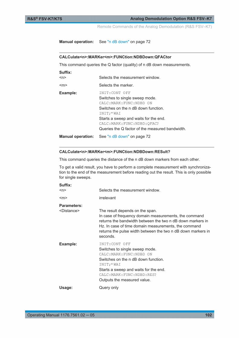
Analog Demodulation Option R&S FSV–K7R&S® FSV-K7/K7S
102Operating Manual 1176.7561.02 ─ 05
Manual operation: See "n dB down" on page 72
CALCulate<n>:MARKer<m>:FUNCtion:NDBDown:QFACtor
This command queries the Q factor (quality) of n dB down measurements.
Suffix: <n>
.Selects the measurement window.
<m> Selects the marker.
Example: INIT:CONT OFFSwitches to single sweep mode.CALC:MARK:FUNC:NDBD ONSwitches on the n dB down function.INIT;*WAIStarts a sweep and waits for the end.CALC:MARK:FUNC:NDBD:QFAC?Queries the Q factor of the measured bandwidth.
Manual operation: See "n dB down" on page 72
CALCulate<n>:MARKer<m>:FUNCtion:NDBDown:RESult?
This command queries the distance of the n dB down markers from each other.
To get a valid result, you have to perform a complete measurement with synchroniza-tion to the end of the measurement before reading out the result. This is only possiblefor single sweeps.
Suffix: <n>
.Selects the measurement window.
<m> irrelevant
Parameters:<Distance> The result depends on the span.
In case of frequency domain measurements, the commandreturns the bandwidth between the two n dB down markers inHz. In case of time domain measurements, the commandreturns the pulse width between the two n dB down markers inseconds.
Example: INIT:CONT OFFSwitches to single sweep mode.CALC:MARK:FUNC:NDBD ONSwitches on the n dB down function.INIT;*WAIStarts a sweep and waits for the end.CALC:MARK:FUNC:NDBD:RES?Outputs the measured value.
Usage: Query only
Remote Commands of the Analog Demodulation (R&S FSV–K7)

Analog Demodulation Option R&S FSV–K7R&S® FSV-K7/K7S
103Operating Manual 1176.7561.02 ─ 05
Manual operation: See "n dB down" on page 72
CALCulate<n>:MARKer<m>:FUNCtion:NDBDown:STATe <State>
This command turns the n dB Down marker function on and off.
Suffix: <n>
.Selects the measurement window.
<m> irrelevant
Parameters:<State> ON | OFF
*RST: OFF
Example: CALC:MARK:FUNC:NDBD:STAT ONSwitches on the "N dB Down" function.
Manual operation: See "n dB down" on page 72
CALCulate<n>:MARKer<m>:FUNCtion:NDBDown:TIME?
This command queries the position of the n dB down markers on the x-axis when mea-suring in the time domain.
To get a valid result, you have to perform a complete measurement with synchroniza-tion to the end of the measurement before reading out the result. This is only possiblefor single sweeps.
Suffix: <n>
.Selects the measurement window.
<m> irrelevant
Return values: <Time> <time 1>
absolute position in time of the n dB marker to the left of the ref-erence marker in seconds<time 2>absolute position in time of the n dB marker to the right of thereference marker in seconds
Example: INIT:CONT OFFSwitches to single sweep modeCALC:MARK:FUNC:NDBD ONSwitches on the n dB down function.INIT;*WAIStarts a sweep and waits for the end.CALC:MARK:FUNC:NDBD:TIME?Outputs the time values of the temporary markers.
Usage: Query only
Manual operation: See "n dB down" on page 72
Remote Commands of the Analog Demodulation (R&S FSV–K7)
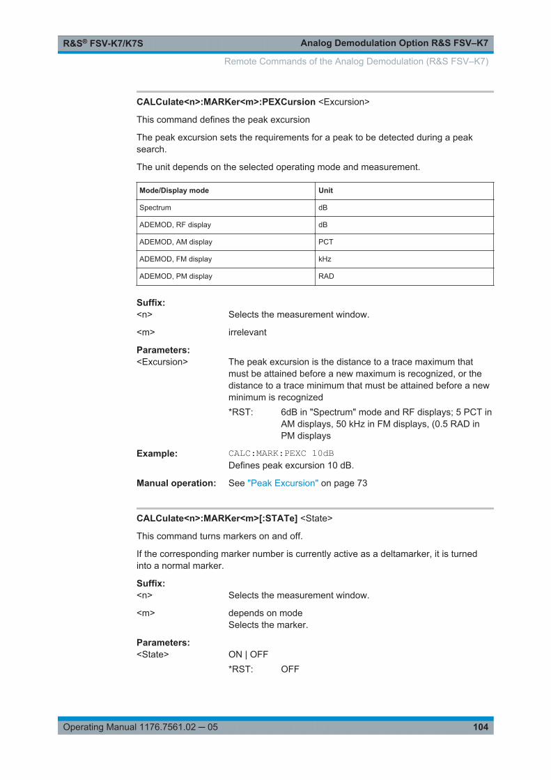
Analog Demodulation Option R&S FSV–K7R&S® FSV-K7/K7S
104Operating Manual 1176.7561.02 ─ 05
CALCulate<n>:MARKer<m>:PEXCursion <Excursion>
This command defines the peak excursion
The peak excursion sets the requirements for a peak to be detected during a peaksearch.
The unit depends on the selected operating mode and measurement.
Mode/Display mode Unit
Spectrum dB
ADEMOD, RF display dB
ADEMOD, AM display PCT
ADEMOD, FM display kHz
ADEMOD, PM display RAD
Suffix: <n>
.Selects the measurement window.
<m> irrelevant
Parameters:<Excursion> The peak excursion is the distance to a trace maximum that
must be attained before a new maximum is recognized, or thedistance to a trace minimum that must be attained before a newminimum is recognized*RST: 6dB in "Spectrum" mode and RF displays; 5 PCT in
AM displays, 50 kHz in FM displays, (0.5 RAD inPM displays
Example: CALC:MARK:PEXC 10dBDefines peak excursion 10 dB.
Manual operation: See "Peak Excursion" on page 73
CALCulate<n>:MARKer<m>[:STATe] <State>
This command turns markers on and off.
If the corresponding marker number is currently active as a deltamarker, it is turnedinto a normal marker.
Suffix: <n>
.Selects the measurement window.
<m> depends on modeSelects the marker.
Parameters:<State> ON | OFF
*RST: OFF
Remote Commands of the Analog Demodulation (R&S FSV–K7)
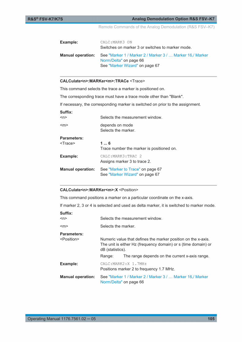
Analog Demodulation Option R&S FSV–K7R&S® FSV-K7/K7S
105Operating Manual 1176.7561.02 ─ 05
Example: CALC:MARK3 ONSwitches on marker 3 or switches to marker mode.
Manual operation: See "Marker 1 / Marker 2 / Marker 3 / … Marker 16,/ MarkerNorm/Delta" on page 66See "Marker Wizard" on page 67
CALCulate<n>:MARKer<m>:TRACe <Trace>
This command selects the trace a marker is positioned on.
The corresponding trace must have a trace mode other than "Blank".
If necessary, the corresponding marker is switched on prior to the assignment.
Suffix: <n>
.Selects the measurement window.
<m> depends on modeSelects the marker.
Parameters:<Trace> 1 ... 6
Trace number the marker is positioned on.
Example: CALC:MARK3:TRAC 2Assigns marker 3 to trace 2.
Manual operation: See "Marker to Trace" on page 67See "Marker Wizard" on page 67
CALCulate<n>:MARKer<m>:X <Position>
This command positions a marker on a particular coordinate on the x-axis.
If marker 2, 3 or 4 is selected and used as delta marker, it is switched to marker mode.
Suffix: <n>
.Selects the measurement window.
<m> Selects the marker.
Parameters:<Position> Numeric value that defines the marker position on the x-axis.
The unit is either Hz (frequency domain) or s (time domain) ordB (statistics).Range: The range depends on the current x-axis range.
Example: CALC:MARK2:X 1.7MHzPositions marker 2 to frequency 1.7 MHz.
Manual operation: See "Marker 1 / Marker 2 / Marker 3 / … Marker 16,/ MarkerNorm/Delta" on page 66
Remote Commands of the Analog Demodulation (R&S FSV–K7)
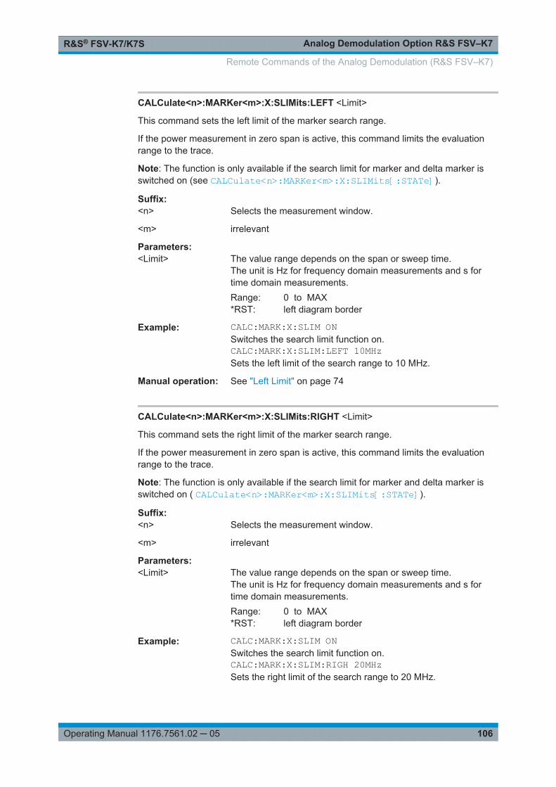
Analog Demodulation Option R&S FSV–K7R&S® FSV-K7/K7S
106Operating Manual 1176.7561.02 ─ 05
CALCulate<n>:MARKer<m>:X:SLIMits:LEFT <Limit>
This command sets the left limit of the marker search range.
If the power measurement in zero span is active, this command limits the evaluationrange to the trace.
Note: The function is only available if the search limit for marker and delta marker isswitched on (see CALCulate<n>:MARKer<m>:X:SLIMits[:STATe]).
Suffix: <n>
.Selects the measurement window.
<m> irrelevant
Parameters:<Limit> The value range depends on the span or sweep time.
The unit is Hz for frequency domain measurements and s fortime domain measurements.Range: 0 to MAX*RST: left diagram border
Example: CALC:MARK:X:SLIM ONSwitches the search limit function on.CALC:MARK:X:SLIM:LEFT 10MHzSets the left limit of the search range to 10 MHz.
Manual operation: See "Left Limit" on page 74
CALCulate<n>:MARKer<m>:X:SLIMits:RIGHT <Limit>
This command sets the right limit of the marker search range.
If the power measurement in zero span is active, this command limits the evaluationrange to the trace.
Note: The function is only available if the search limit for marker and delta marker isswitched on ( CALCulate<n>:MARKer<m>:X:SLIMits[:STATe]).
Suffix: <n>
.Selects the measurement window.
<m> irrelevant
Parameters:<Limit> The value range depends on the span or sweep time.
The unit is Hz for frequency domain measurements and s fortime domain measurements.Range: 0 to MAX*RST: left diagram border
Example: CALC:MARK:X:SLIM ONSwitches the search limit function on.CALC:MARK:X:SLIM:RIGH 20MHzSets the right limit of the search range to 20 MHz.
Remote Commands of the Analog Demodulation (R&S FSV–K7)

Analog Demodulation Option R&S FSV–K7R&S® FSV-K7/K7S
107Operating Manual 1176.7561.02 ─ 05
Manual operation: See "Right Limit" on page 74
CALCulate<n>:MARKer<m>:X:SLIMits[:STATe] <State>
This command turns marker search limits on and off.
If the power measurement in zero span is active, this command limits the evaluationrange on the trace.
Suffix: <n>
.Selects the measurement window.
<m> marker
Parameters:<State> ON | OFF
*RST: OFF
Example: CALC:MARK:X:SLIM ONSwitches on search limitation.
CALCulate<n>:MARKer<m>:X:SSIZe <StepSize>
This command defines the step size of the rotary knob for marker or delta marker valuechanges. It only takes effect in manual operation.
The marker step size is unavailable for statistical measurements.
Suffix: <n>
.irrelevant
<m> irrelevant
Parameters:<StepSize> STANdard
step size corresponds to space between two pixelsPOINtsstep size corresponds to space between two measured values(number of measured values is defined via the[SENSe<n>:]SWEep:POINts command, see [SENSe:]SWEep:POINts on page 157)
*RST: POINts
Example: CALC:MARK:X:SSIZ STANSets the measured value step size.
Manual operation: See "Stepsize Standard" on page 69See "Stepsize Sweep Points" on page 69
CALCulate<n>:MARKer<m>:Y?
This command queries the measured value of a marker.
Remote Commands of the Analog Demodulation (R&S FSV–K7)
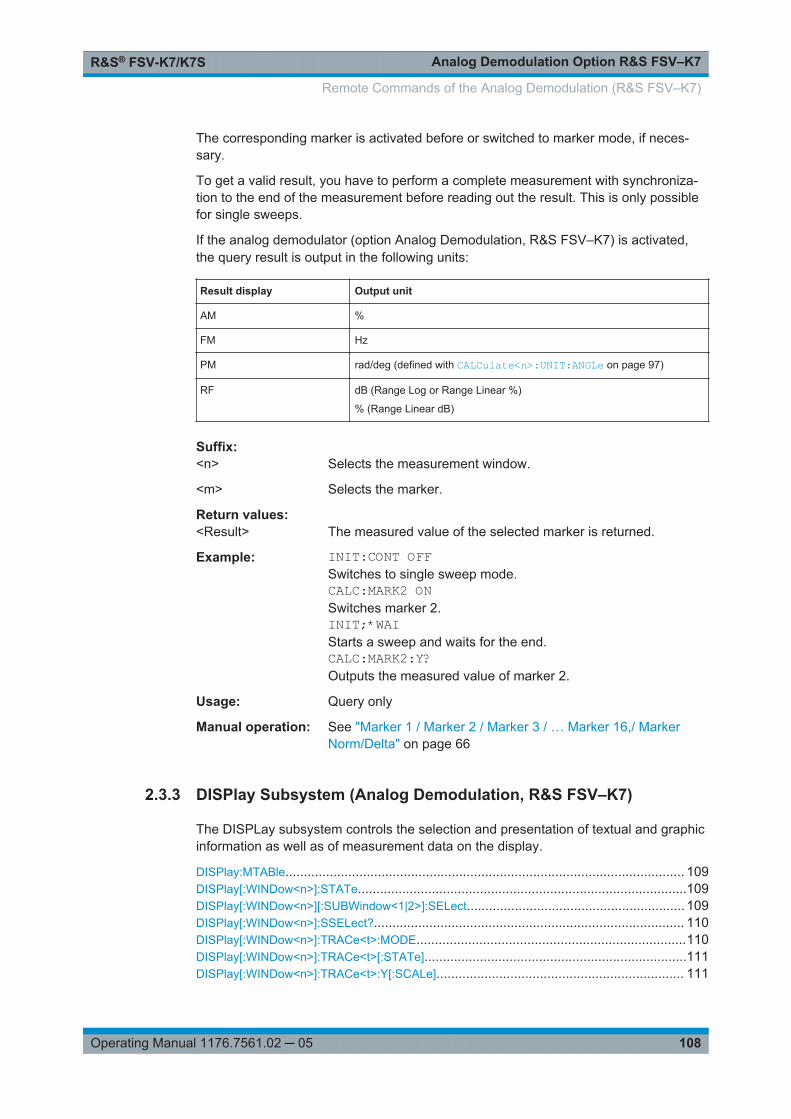
Analog Demodulation Option R&S FSV–K7R&S® FSV-K7/K7S
108Operating Manual 1176.7561.02 ─ 05
The corresponding marker is activated before or switched to marker mode, if neces-sary.
To get a valid result, you have to perform a complete measurement with synchroniza-tion to the end of the measurement before reading out the result. This is only possiblefor single sweeps.
If the analog demodulator (option Analog Demodulation, R&S FSV–K7) is activated,the query result is output in the following units:
Result display Output unit
AM %
FM Hz
PM rad/deg (defined with CALCulate<n>:UNIT:ANGLe on page 97)
RF dB (Range Log or Range Linear %)
% (Range Linear dB)
Suffix: <n>
.Selects the measurement window.
<m> Selects the marker.
Return values: <Result> The measured value of the selected marker is returned.
Example: INIT:CONT OFFSwitches to single sweep mode.CALC:MARK2 ONSwitches marker 2.INIT;*WAIStarts a sweep and waits for the end.CALC:MARK2:Y?Outputs the measured value of marker 2.
Usage: Query only
Manual operation: See "Marker 1 / Marker 2 / Marker 3 / … Marker 16,/ MarkerNorm/Delta" on page 66
2.3.3 DISPlay Subsystem (Analog Demodulation, R&S FSV–K7)
The DISPLay subsystem controls the selection and presentation of textual and graphicinformation as well as of measurement data on the display.
DISPlay:MTABle............................................................................................................ 109DISPlay[:WINDow<n>]:STATe.........................................................................................109DISPlay[:WINDow<n>][:SUBWindow<1|2>]:SELect........................................................... 109DISPlay[:WINDow<n>]:SSELect?.................................................................................... 110DISPlay[:WINDow<n>]:TRACe<t>:MODE.........................................................................110DISPlay[:WINDow<n>]:TRACe<t>[:STATe].......................................................................111DISPlay[:WINDow<n>]:TRACe<t>:Y[:SCALe]................................................................... 111
Remote Commands of the Analog Demodulation (R&S FSV–K7)
Analog Demodulation Option R&S FSV–K7R&S® FSV-K7/K7S
109Operating Manual 1176.7561.02 ─ 05
DISPlay[:WINDow<n>]:TRACe<t>:Y[:SCALe]:MODE.........................................................112DISPlay[:WINDow<n>]:TRACe<t>:Y[:SCALe]:PDIVision.................................................... 112DISPlay[:WINDow<n>]:TRACe<t>:Y[:SCALe]:RLEVel....................................................... 113DISPlay[:WINDow<n>]:TRACe<t>:Y[:SCALe]:RLEVel:OFFSet........................................... 113DISPlay[:WINDow<n>]:TRACe<t>:Y[:SCALe]:RPOSition................................................... 113DISPlay[:WINDow<n>]:TRACe<t>:Y[:SCALe]:RVALue...................................................... 114DISPlay[:WINDow<n>]:TRACe<t>:Y:SPACing.................................................................. 114DISPlay:WSELect?........................................................................................................ 115
DISPlay:MTABle <DisplayMode>
This command turns the marker table on and off.
Parameters:<DisplayMode> ON
Marker table is displayed.OFFMarker table is not displayed.AUTOMarker table is only displayed if 2 or more markers are active.*RST: AUTO
Example: To activate the table display:DISP:MTAB ONTo query the current state of the marker table display:DISP:MTAB?
Manual operation: See "Marker Table" on page 69
DISPlay[:WINDow<n>]:STATe <State>
This command activates the measurement specified window.
Suffix: <n>
.1...4window
Parameters:<State> ON | OFF
Example: DISP:WIND2:STAT ONDisplays a second window (Screen B).
Usage: SCPI confirmed
Mode: ADEMOD
Manual operation: See "Screen A-D" on page 27
DISPlay[:WINDow<n>][:SUBWindow<1|2>]:SELect
Moves the focus area to the selected window and subwindow.
Remote Commands of the Analog Demodulation (R&S FSV–K7)
Analog Demodulation Option R&S FSV–K7R&S® FSV-K7/K7S
110Operating Manual 1176.7561.02 ─ 05
Suffix: <n>
.1window
Example: DISP:WIND2:STAT ONDisplays a second window (Screen B).CALC2:FEED 'XTIMe:FM:AFSPektrum1'Displays an AF spectrum diagram of the demodulated FM signalfrom trace 1 in screen B.DISP:WIND2:SELSwitches the focus area to the evaluation list of the AF spectrumdiagram in screen B.
Usage: SCPI confirmed
Mode: ADEMOD
DISPlay[:WINDow<n>]:SSELect?
Queries the currently selected subwindow.
Suffix: <n>
.1...4window
Return values: <Result> 1 | 2
1Diagram2Result list
Example: DISP:WIND2:SUBW2:SELSwitches the focus area to the result list in screen B.DISP:WIND2:SSEL?Result: 2
Usage: Query onlySCPI confirmed
Mode: ADEMOD
DISPlay[:WINDow<n>]:TRACe<t>:MODE <Mode>
This command defines the type of display and the evaluation of the traces. WRITE cor-responds to the Clr/Write mode of manual operation. The trace is switched off (=BLANK in manual operation) with DISPlay[:WINDow<n>]:TRACe<t>[:STATe].
The number of measurements for AVERage, MAXHold and MINHold is defined withthe [SENSe:]AVERage<n>:COUNt or [SENSe:]SWEep:COUNt commands. It shouldbe noted that synchronization to the end of the indicated number of measurements isonly possible in single sweep mode.
Remote Commands of the Analog Demodulation (R&S FSV–K7)

Analog Demodulation Option R&S FSV–K7R&S® FSV-K7/K7S
111Operating Manual 1176.7561.02 ─ 05
Suffix: <n>
.window; For applications that do not have more than 1 measure-ment window, the suffix <n> is irrelevant.
<t> trace
Parameters:<Mode> WRITe | VIEW | AVERage | MAXHold | MINHold | BLANk
*RST: WRITe for TRACe1, STATe OFF forTRACe2/3/4/5/6
For details on trace modes refer to Chapter 2.1.7, "Trace ModeOverview", on page 17.
Example: INIT:CONT OFFSwitching to single sweep mode.SWE:COUN 16Sets the number of measurements to 16.DISP:TRAC3:MODE MAXHSwitches on the calculation of the maximum peak for trace 3.INIT;*WAIStarts the measurement and waits for the end of the 16 sweeps.
Manual operation: See "Clear Write" on page 17See "Max Hold" on page 18See "Min Hold" on page 18See "Average" on page 18See "View" on page 18
DISPlay[:WINDow<n>]:TRACe<t>[:STATe] <State>
This command switches on or off the display of the corresponding trace. The othermeasurements are not aborted but continue running in the background.
Suffix: <n>
.window; For applications that do not have more than 1 measure-ment window, the suffix <n> is irrelevant.
<t> trace
Parameters:<State> ON | OFF
*RST: ON for TRACe1, OFF for TRACe2 to 6
Example: DISP:TRAC3 ONManual operation: See "Blank" on page 19
DISPlay[:WINDow<n>]:TRACe<t>:Y[:SCALe] <Range>
This command defines the display range of the y-axis with logarithmic scaling.
The command works only for a logarithmic scaling. You can select the scaling withDISPlay[:WINDow<n>]:TRACe<t>:Y:SPACing on page 114.
Remote Commands of the Analog Demodulation (R&S FSV–K7)

Analog Demodulation Option R&S FSV–K7R&S® FSV-K7/K7S
112Operating Manual 1176.7561.02 ─ 05
Suffix: <n>
.window; For applications that do not have more than 1 measure-ment window, the suffix <n> is irrelevant.
<t> irrelevant
Parameters:<Range> Range: 10 to 200
*RST: 100Default unit: dB
Example: DISP:TRAC:Y 110dBManual operation: See "Range Log 100 dB" on page 42
See "Range Log 50 dB" on page 42See "Range Log 10 dB" on page 43See "Range Log 5 dB" on page 43See "Range Log 1 dB" on page 43See "Range Log Manual" on page 43
DISPlay[:WINDow<n>]:TRACe<t>:Y[:SCALe]:MODE <Mode>
This command selects the type of scaling of the y-axis.
When SYSTem:DISPlay:UPDate is turned off, this command has no immediateeffect on the screen.
Suffix: <n>
.window; For applications that do not have more than 1 measure-ment window, the suffix <n> is irrelevant.
<t> irrelevant
Parameters:<Mode> ABSolute
absolute scaling of the y-axisRELativerelative scaling of the y-axis*RST: ABS
Example: DISP:TRAC:Y:MODE RELManual operation: See "Grid Abs/Rel " on page 46
DISPlay[:WINDow<n>]:TRACe<t>:Y[:SCALe]:PDIVision <Distance>
This command defines the distance between two grid lines of the y-axis in the currentunit.
Suffix: <n>
.irrelevant
<t> irrelevant
Remote Commands of the Analog Demodulation (R&S FSV–K7)
Analog Demodulation Option R&S FSV–K7R&S® FSV-K7/K7S
113Operating Manual 1176.7561.02 ─ 05
Parameters:<Distance> <numeric value>
*RST: 20 PCT = linear AM display, (50 kHz = linear FMdisplay), (2 rad = linear PM display), (10 dB = loga-rithmic AF spectrum display)
Example: DISP:TRAC:Y:PDIV +10kHzSets the Y scale to 10 kHz per division.
Mode: ADEMOD
Manual operation: See "Dev per Division" on page 32
DISPlay[:WINDow<n>]:TRACe<t>:Y[:SCALe]:RLEVel <ReferenceLevel>
This command defines the reference level.
With the reference level offset ≠ 0, the value range of the reference level is modified bythe offset.
Suffix: <n>
.irrelevant.
<t> irrelevant
Parameters:<ReferenceLevel> The unit is variable.
Range: see datasheet*RST: -10dBm
Example: DISP:TRAC:Y:RLEV -60dBmManual operation: See "Ref Level" on page 42
DISPlay[:WINDow<n>]:TRACe<t>:Y[:SCALe]:RLEVel:OFFSet <Value>
This command defines a reference level offset.
Suffix: <n>
.irrelevant.
<t> irrelevant
Parameters:<Value> Range: -200 to 200
*RST: 0Default unit: dB
Example: DISP:TRAC:Y:RLEV:OFFS -10dBManual operation: See "Ref Level Offset" on page 46
DISPlay[:WINDow<n>]:TRACe<t>:Y[:SCALe]:RPOSition <Position>
This command defines the position of the reference level on the display grid..
Remote Commands of the Analog Demodulation (R&S FSV–K7)
Analog Demodulation Option R&S FSV–K7R&S® FSV-K7/K7S
114Operating Manual 1176.7561.02 ─ 05
When using a tracking generator (only with option R&S FSV-B9 or -B10, requiresactive normalization), and in Bluetooth mode (option R&S FSV-K8) this commanddefines the position of the reference value for all windows.
Suffix: <n>
.Selects the measurement window.
<t> irrelevant
Parameters:<Position> 0 PCT corresponds to the lower display border, 100% corre-
sponds to the upper display border.Range: 0 to 100*RST: Spectrum mode: 100 PCT, with tracking generator
or time display: 50 PCTDefault unit: PCT
Example: DISP:TRAC:Y:RPOS 50PCTManual operation: See "Reference Position" on page 32
See "Ref Level Position" on page 46
DISPlay[:WINDow<n>]:TRACe<t>:Y[:SCALe]:RVALue <Value>
This command defines the reference value assigned to the reference position in thespecified window. Separate reference values are maintained for the various displays.
Suffix: <n>
.1...4window
<t> irrelevant
Parameters:<Value> *RST: 0 PCT = AM display, (0 Hz = FM display), (0 rad =
PM display), (100 PCT = AF spectrum display ofAM signal), (250 kHz = AF spectrum display of FMsignal), (10 rad = AF spectrum display of PM sig-nal)
Example: DISP:TRAC:Y:RVAL 0Sets the value assigned to the reference position to 0 Hz (ana-log demodulation)
Manual operation: See "Reference Value" on page 32
DISPlay[:WINDow<n>]:TRACe<t>:Y:SPACing <ScalingType>
This command selects the scaling of the y-axis.
For AF spectrum displays, only the parameters "LINear" and "LOGarithmic" are permit-ted.
Suffix: <n>
.Selects the measurement window.
Remote Commands of the Analog Demodulation (R&S FSV–K7)
Analog Demodulation Option R&S FSV–K7R&S® FSV-K7/K7S
115Operating Manual 1176.7561.02 ─ 05
<t> irrelevant
Parameters:<ScalingType> LOGarithmic
Logarithmic scaling.LINearLinear scaling in %.LDBLinear scaling in dB.*RST: LOGarithmic
Example: DISP:TRAC:Y:SPAC LINSelect a linear scale.
Manual operation: See "Deviation Lin/Log" on page 33See "Range Log 100 dB" on page 42See "Range Log 50 dB" on page 42See "Range Log 10 dB" on page 43See "Range Log 5 dB" on page 43See "Range Log 1 dB" on page 43See "Range Log Manual" on page 43See "Range Linear %" on page 43See "Range Lin. Unit" on page 44
DISPlay:WSELect?
Queries the currently selected window.
Example: DISP:WIND2:SELSwitches the focus area to screen B.DISP:WSEL?Result: 2
Usage: Query onlySCPI confirmed
Mode: ADEMOD
2.3.4 INSTrument Subsystem (Analog Demodulation, R&S FSV–K7)
The INSTrument subsystem selects the operating mode of the unit either via textparameters or fixed numbers.
INSTrument[:SELect]......................................................................................................115INSTrument:NSELect <Mode>........................................................................................ 116
INSTrument[:SELect] <Mode>
Selects the instrument mode.
Remote Commands of the Analog Demodulation (R&S FSV–K7)

Analog Demodulation Option R&S FSV–K7R&S® FSV-K7/K7S
116Operating Manual 1176.7561.02 ─ 05
Parameters:<Mode> ADEMod
Analog Demodulation option, R&S FSV–K7SFMFM Stereo option, R&S FSV–K7S
Mode: ADEMOD, SFM
Manual operation: See "Screen A-D" on page 194
INSTrument:NSELect <Mode> <Mode>
Selects the instrument mode.
Parameters:<Mode> 3
Analog Demodulation option, R&S FSV–K77FM Stereo option, R&S FSV–K7S
Mode: ADEMOD, SFM
2.3.5 PROBe subsystem
With firmware R&S FSV/FSVA 1.61SP2 or newer, active probes are supported (via anadapter). The following commands activate and configure a connected probe which isto provide an input signal. They are only available if a probe is connected to the instru-ment's RF INPUT and USB connectors.
For details see the base unit description.
PROBe:ID:PARTnumber?
This command returns the material part number of the connected probe.
Example: PROB:ID:PART?Usage: Query only
PROBe:ID:SRNumber?
This command returns the serial number of the connected probe.
Example: PROB:ID:SRN?Usage: Query only
PROBe:SETup:MODE <Mode>
This command defines which action is taken when the probe's micro button is pressed.
Remote Commands of the Analog Demodulation (R&S FSV–K7)
Analog Demodulation Option R&S FSV–K7R&S® FSV-K7/K7S
117Operating Manual 1176.7561.02 ─ 05
Parameters:<Mode> RSINgle
A single sweep is performed.NOACtionNo action is taken.*RST: OFF
Example: PROB:SET:STAT ONManual operation: See "Probe Config" on page 77
PROBe:SETup:NAME?
This command returns the name of the connected probe.
Example: PROB:SET:NAME?Usage: Query only
PROBe:SETup:STATe?
This command queries whether a probe is connected to the instrument's RF INPUTand USB connectors and was recognized by the R&S FSV/FSVA.
Example: PROB:SET:STAT ONUsage: Query only
PROBe[:STATe] <State>
This command activates a connected probe. Use this command to switch off the probeand measure the digital input without considering the transducer factor of the probe.
Parameters:<State> ON | OFF
*RST: OFF
Example: PROB:STAT ONManual operation: See "Probe Config" on page 77
2.3.6 SENSe Subsystem (Analog Demodulation, R&S FSV–K7)
The SENSe subsystem is organized in several subsystems. The commands of thesesubsystems directly control device-specific settings, they do not refer to the signalcharacteristics of the measurement signal.
The SENSe subsystem controls the essential parameters of the analyzer. In accord-ance with the SCPI standard, the keyword "SENSe" is optional for this reason, whichmeans that it is not necessary to include the SENSe node in command sequences.
The following subsystems are included:
Remote Commands of the Analog Demodulation (R&S FSV–K7)

Analog Demodulation Option R&S FSV–K7R&S® FSV-K7/K7S
118Operating Manual 1176.7561.02 ─ 05
2.3.6.1 Trace Mode Result Types........................................................................................... 118
2.3.6.2 Formats for Returned Values: ASCII Format and Binary Format................................118
2.3.6.3 SENSe:ADEMod Subsystem (Analog Demodulation, Analog Demodulation)............ 119
2.3.6.4 SENSe:ADJust Subsystem......................................................................................... 145
2.3.6.5 SENSe:BANDwidth Subsystem (Analog Demodulation, R&S FSV–K7).....................147
2.3.6.6 SENSe:FILTer Subsystem (Analog Demodulation, Analog Demodulation)................148
2.3.6.7 SENSe:FREQuency Subsystem (Analog Demodulation, R&S FSV–K7)................... 153
2.3.6.8 SENSe:SWEep Subsystem (Analog Demodulation, R&S FSV–K7)...........................155
2.3.6.9 Other commands in the SENSe subsystem................................................................157
2.3.6.1 Trace Mode Result Types
The following result types can be set:
WRITe The current trace results will be obtained
AVERage The trace results will be averaged over the given # of measurements
MAXHold The maximum trace result values will be obtained over the given # of measurements
MINHold The minimum trace result values will be obtained over the given # of measurements
VIEW The trace results are frozen and displayed, i.e. they are not calculated for subse-quent measurements. Traces in this mode cannot be queried.
OFF The result type will not be used.
It is not possible to query trace data when result type VIEW is selected.Each value besides OFF can only be assigned to one result type at a time.If all result types are set to OFF, the AM, FM, or PM demodulator will be deactivated.
2.3.6.2 Formats for Returned Values: ASCII Format and Binary Format
● ASCII Format (FORMat ASCII):The command reads out a list of comma separated values (CSV) of the measuredvalues in floating point format.
● Binary Format (FORMat REAL,32):The command reads out binary data (Definite Length Block Data according to IEEE488.2), each measurement value being formatted in 32 Bit IEEE 754 Floating-Point-Format. The schematics of the result string will be as follows:#41024<value1><value2>…<value n> with
Remote Commands of the Analog Demodulation (R&S FSV–K7)
Analog Demodulation Option R&S FSV–K7R&S® FSV-K7/K7S
119Operating Manual 1176.7561.02 ─ 05
#4 number of digits (= 4 in the example) of the following number of data bytes
1024 number of following data bytes (= 1024 in the example)
<value> 4-byte floating point value
2.3.6.3 SENSe:ADEMod Subsystem (Analog Demodulation, Analog Demodulation)
The SENSe:ADEMod Subsystem contains commands to set up the instrument for themeasurement of analog demodulated signals and query the result at the end of themeasurement.
Further information
● Chapter 2.3.6.1, "Trace Mode Result Types", on page 118● Chapter 2.3.6.2, "Formats for Returned Values: ASCII Format and Binary Format",
on page 118
[SENSe:]ADEMod:CAPTure:DOFFset..............................................................................120[SENSe:]ADEMod:CAPTure:TIME................................................................................... 120[SENSe:]ADEMod:CAPTure[:MODE]............................................................................... 121[SENSe:]ADEMod[:STATe]............................................................................................. 121[SENSe:]ADEMod<n>:AF:CENTer...................................................................................121[SENSe:]ADEMod<n>:AF:COUPling................................................................................ 122[SENSe:]ADEMod<n>:AF:SPAN......................................................................................122[SENSe:]ADEMod<n>:AF:SPAN:FULL.............................................................................123[SENSe:]ADEMod<n>:AF:STARt.....................................................................................123[SENSe:]ADEMod<n>:AF:STOP......................................................................................124[SENSe:]ADEMod:AM[:ABSolute][:TDOMain]:RESult?.......................................................125[SENSe:]ADEMod:AM[:ABSolute][:TDOMain][:TYPE]........................................................ 125[SENSe:]ADEMod:AM:RELative[:TDOMain][:TYPE].......................................................... 126[SENSe:]ADEMod:AM:RELative[:TDOMain]:RESult?.........................................................126[SENSe:]ADEMod:AM:RELative:AFSPectrum[:TYPE]........................................................127[SENSe:]ADEMod:AM:RELative:AFSPectrum:RESult?...................................................... 128[SENSe:]ADEMod:BANDwidth|BWIDth:DEModulation....................................................... 129[SENSe:]ADEMod:BANDwidth|BWIDth:DEModulation:TYPE..............................................129[SENSe:]ADEMod:FM[:TDOMain][:TYPE].........................................................................129[SENSe:]ADEMod:FM[:TDOMain]:RESult.........................................................................130[SENSe:]ADEMod:FM:AFSPectrum[:TYPE]......................................................................131[SENSe:]ADEMod:FM:AFSPectrum:RESult...................................................................... 131[SENSe:]ADEMod:FM:OFFSet........................................................................................ 132[SENSe:]ADEMod:MTIMe...............................................................................................133[SENSe:]ADEMod:PM[:TDOMain][:TYPE]........................................................................ 134[SENSe:]ADEMod:PM[:TDOMain]:RESult.........................................................................134[SENSe:]ADEMod:PM:AFSPectrum[:TYPE]......................................................................135[SENSe:]ADEMod:PM:AFSPectrum:RESult......................................................................136[SENSe:]ADEMod:PM:RPOint[:X].................................................................................... 137[SENSe:]ADEMod:RLENgth?.......................................................................................... 138[SENSe:]ADEMod:SET...................................................................................................138[SENSe:]ADEMod:SPECtrum[:TYPE]...............................................................................139
Remote Commands of the Analog Demodulation (R&S FSV–K7)
Analog Demodulation Option R&S FSV–K7R&S® FSV-K7/K7S
120Operating Manual 1176.7561.02 ─ 05
[SENSe:]ADEMod:SPECtrum:BANDwidth|BWIDth[:RESolution]......................................... 140[SENSe:]ADEMod:SPECtrum:RESult...............................................................................140[SENSe:]ADEMod:SPECtrum:SPAN[:MAXimum].............................................................. 141[SENSe:]ADEMod:SPECtrum:SPAN:ZOOM..................................................................... 142[SENSe:]ADEMod:SQUelch[:STATe]............................................................................... 142[SENSe:]ADEMod:SQUelch:LEVel...................................................................................142[SENSe:]ADEMod:SRATe?.............................................................................................143[SENSe:]ADEMod<n>:ZOOM[:STATe].............................................................................143[SENSe:]ADEMod<n>:ZOOM:STARt............................................................................... 144[SENSe:]ADEMod<n>:ZOOM:LENGth............................................................................. 144[SENSe:]ADEMod<n>:ZOOM:LENGth:MODE...................................................................145
[SENSe:]ADEMod:CAPTure:DOFFset <Time>
This command defines an offset of the defined measurement time from the beginningof the capture buffer for analog demodulation if [SENSe:]ADEMod:CAPTure[:MODE]is set to manual mode.
All results are recalculated automatically based on the new data.
Parameters:<Time> *RST: 0
Example: ADEM:CAPT MANActivates the manual capture buffer processing mode.ADEM:CAPT:TIME 500 usSets the size of the capture buffer to 500 us.ADEM:CAPT:DOFF 10usResults are recalculated for the data in the capture buffer start-ing at 10us.
Mode: ADEMOD
Manual operation: See "Demod Offset" on page 56
[SENSe:]ADEMod:CAPTure:TIME <Time>
This command defines the size of the capture buffer for analog demodulation if[SENSe:]ADEMod:CAPTure[:MODE] is set to manual mode.
Parameters:<Time> Range: 0 to 7.5 MSamples (time depends on DBW)
*RST: 62.5us
Example: ADEM:CAPT MANActivates the manual capture buffer processing mode.ADEM:CAPT:TIME 500 us
Mode: ADEMOD
Manual operation: See "Capture Time" on page 56
Remote Commands of the Analog Demodulation (R&S FSV–K7)
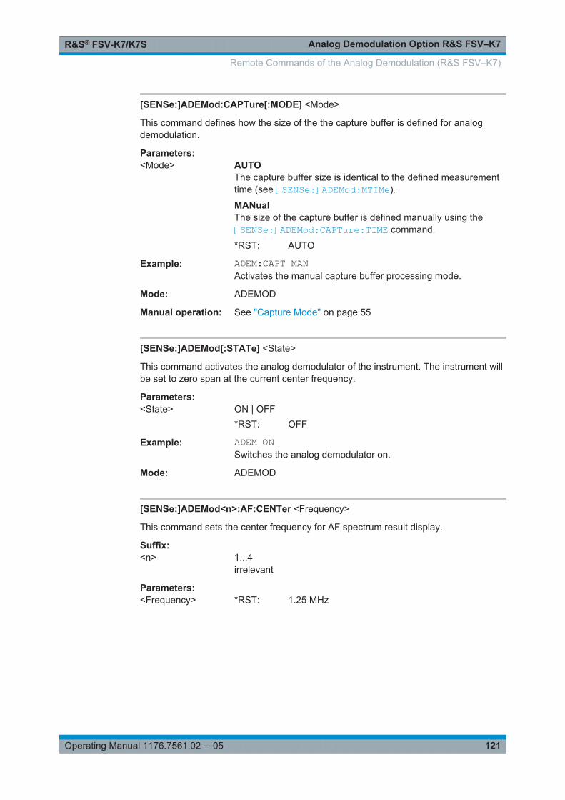
Analog Demodulation Option R&S FSV–K7R&S® FSV-K7/K7S
121Operating Manual 1176.7561.02 ─ 05
[SENSe:]ADEMod:CAPTure[:MODE] <Mode>
This command defines how the size of the the capture buffer is defined for analogdemodulation.
Parameters:<Mode> AUTO
The capture buffer size is identical to the defined measurementtime (see [SENSe:]ADEMod:MTIMe).
MANualThe size of the capture buffer is defined manually using the[SENSe:]ADEMod:CAPTure:TIME command.
*RST: AUTO
Example: ADEM:CAPT MANActivates the manual capture buffer processing mode.
Mode: ADEMOD
Manual operation: See "Capture Mode" on page 55
[SENSe:]ADEMod[:STATe] <State>
This command activates the analog demodulator of the instrument. The instrument willbe set to zero span at the current center frequency.
Parameters:<State> ON | OFF
*RST: OFF
Example: ADEM ONSwitches the analog demodulator on.
Mode: ADEMOD
[SENSe:]ADEMod<n>:AF:CENTer <Frequency>
This command sets the center frequency for AF spectrum result display.
Suffix: <n>
.1...4irrelevant
Parameters:<Frequency> *RST: 1.25 MHz
Remote Commands of the Analog Demodulation (R&S FSV–K7)
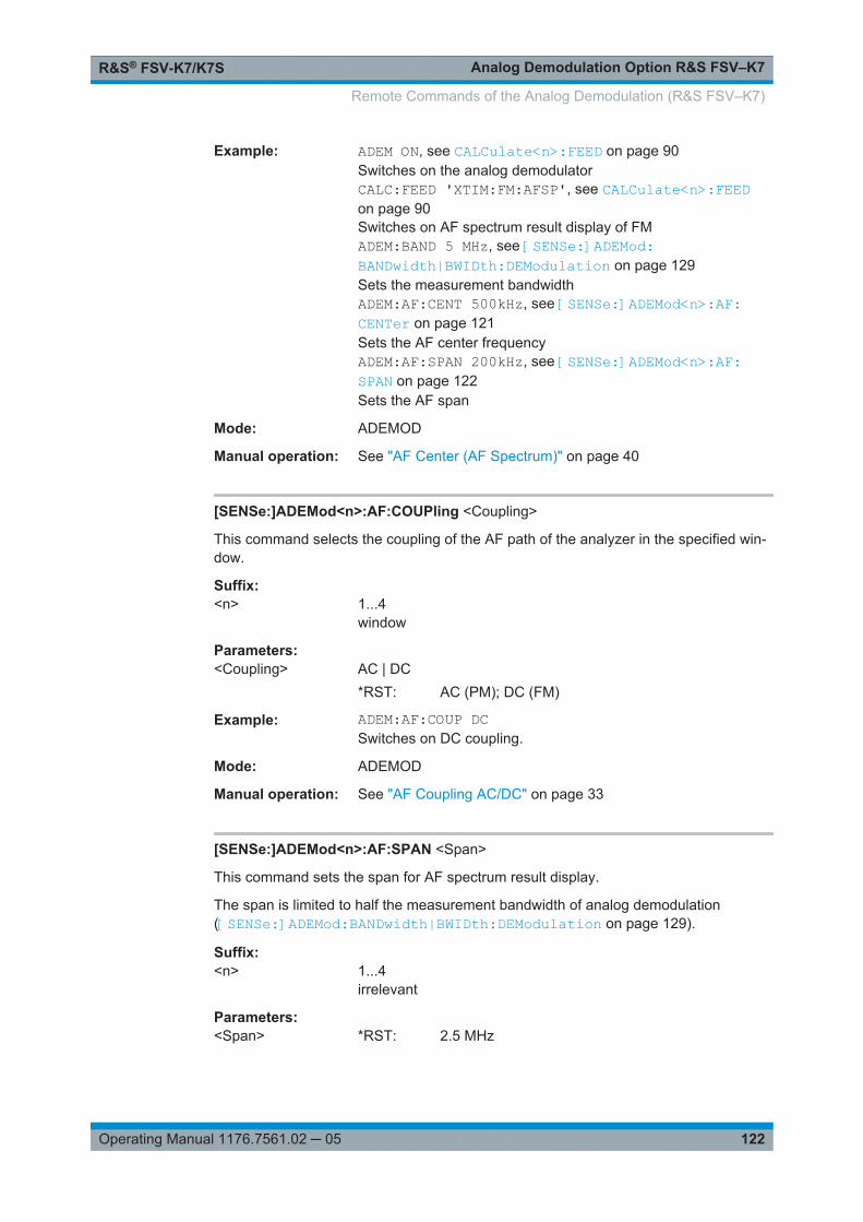
Analog Demodulation Option R&S FSV–K7R&S® FSV-K7/K7S
122Operating Manual 1176.7561.02 ─ 05
Example: ADEM ON, see CALCulate<n>:FEED on page 90Switches on the analog demodulatorCALC:FEED 'XTIM:FM:AFSP', see CALCulate<n>:FEEDon page 90Switches on AF spectrum result display of FMADEM:BAND 5 MHz, see [SENSe:]ADEMod:BANDwidth|BWIDth:DEModulation on page 129Sets the measurement bandwidthADEM:AF:CENT 500kHz, see [SENSe:]ADEMod<n>:AF:CENTer on page 121Sets the AF center frequencyADEM:AF:SPAN 200kHz, see [SENSe:]ADEMod<n>:AF:SPAN on page 122Sets the AF span
Mode: ADEMOD
Manual operation: See "AF Center (AF Spectrum)" on page 40
[SENSe:]ADEMod<n>:AF:COUPling <Coupling>
This command selects the coupling of the AF path of the analyzer in the specified win-dow.
Suffix: <n>
.1...4window
Parameters:<Coupling> AC | DC
*RST: AC (PM); DC (FM)
Example: ADEM:AF:COUP DCSwitches on DC coupling.
Mode: ADEMOD
Manual operation: See "AF Coupling AC/DC" on page 33
[SENSe:]ADEMod<n>:AF:SPAN <Span>
This command sets the span for AF spectrum result display.
The span is limited to half the measurement bandwidth of analog demodulation([SENSe:]ADEMod:BANDwidth|BWIDth:DEModulation on page 129).
Suffix: <n>
.1...4irrelevant
Parameters:<Span> *RST: 2.5 MHz
Remote Commands of the Analog Demodulation (R&S FSV–K7)

Analog Demodulation Option R&S FSV–K7R&S® FSV-K7/K7S
123Operating Manual 1176.7561.02 ─ 05
Example: ADEM ON, see [SENSe:]ADEMod[:STATe] on page 121Switches on the analog demodulatorCALC:FEED 'XTIM:FM:AFSP', see CALCulate<n>:FEEDon page 90Switches on AF spectrum result display of FMADEM:BAND 5 MHz, see [SENSe:]ADEMod:BANDwidth|BWIDth:DEModulation on page 129Sets the measurement bandwidthADEM:AF:CENT 500kHz, see [SENSe:]ADEMod<n>:AF:CENTer on page 121ADEM:AF:SPAN 200 kHzSets the AF span to 200 kHz
Mode: ADEMOD
Manual operation: See "AF Span Manual (AF Spectrum)" on page 40
[SENSe:]ADEMod<n>:AF:SPAN:FULL
This command sets the maximum span for AF spectrum result display.
The maximum span corresponds to half the measurement bandwidth of analog demod-ulation ( [SENSe:]ADEMod:BANDwidth|BWIDth:DEModulation on page 129).
Suffix: <n>
.1...4irrelevant
Example: ADEM ON, see [SENSe:]ADEMod[:STATe] on page 121Switches on the analog demodulatorCALC:FEED 'XTIM:FM:AFSP', see CALCulate<n>:FEEDon page 90Switches on AF spectrum result display of FMADEM:BAND 5 MHz, see [SENSe:]ADEMod:BANDwidth|BWIDth:DEModulation on page 129Sets the measurement bandwidth to 5 MHzADEM:AF:SPAN:FULLSets the AF span to 2.5 MHz
Mode: ADEMOD
Manual operation: See "AF Full Span (AF Spectrum)" on page 41
[SENSe:]ADEMod<n>:AF:STARt <Frequency>
This command sets the start frequency for AF spectrum result display.
Suffix: <n>
.1...4irrelevant
Parameters:<Frequency> *RST: 0 MHz
Remote Commands of the Analog Demodulation (R&S FSV–K7)

Analog Demodulation Option R&S FSV–K7R&S® FSV-K7/K7S
124Operating Manual 1176.7561.02 ─ 05
Example: ADEM ON, see [SENSe:]ADEMod[:STATe] on page 121Switches on the analog demodulatorCALC:FEED 'XTIM:FM:AFSP', see CALCulate<n>:FEEDon page 90Switches on AF spectrum result display of FMADEM:BAND 5 MHz, see [SENSe:]ADEMod:BANDwidth|BWIDth:DEModulation on page 129Sets the measurement bandwidth to 5 MHzADEM:AF:STAR 0 kHzSets the AF start frequency to 0 kHz[SENSe:]ADEMod<n>:AF:STOP on page 124Sets the AF stop frequency to 500 kHz
Mode: ADEMOD
Manual operation: See "AF Start" on page 40
[SENSe:]ADEMod<n>:AF:STOP <Frequency>
This command sets the stop frequency for AF spectrum result display.
The stop frequency is limited to half the measurement bandwidth of analog demodula-tion ([SENSe:]ADEMod:BANDwidth|BWIDth:DEModulation on page 129).
Suffix: <n>
.1...4irrelevant
Parameters:<Frequency> *RST: 2.5 MHz
Example: ADEM ON, see [SENSe:]ADEMod[:STATe] on page 121Switches on the analog demodulatorCALC:FEED 'XTIM:FM:AFSP', see CALCulate<n>:FEEDon page 90Switches on AF spectrum result display of FMADEM:BAND 5 MHz, see [SENSe:]ADEMod:BANDwidth|BWIDth:DEModulation on page 129Sets the measurement bandwidth to 5 MHz[SENSe:]ADEMod<n>:AF:STARt on page 123Sets the AF start frequency to 0 kHzADEM:AF:STOP 500 kHzSets the AF stop frequency to 500 kHz
Mode: ADEMOD
Manual operation: See "AF Stop" on page 40
Remote Commands of the Analog Demodulation (R&S FSV–K7)
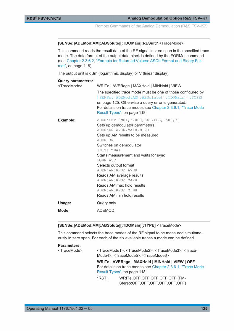
Analog Demodulation Option R&S FSV–K7R&S® FSV-K7/K7S
125Operating Manual 1176.7561.02 ─ 05
[SENSe:]ADEMod:AM[:ABSolute][:TDOMain]:RESult? <TraceMode>
This command reads the result data of the RF signal in zero span in the specified tracemode. The data format of the output data block is defined by the FORMat command(see Chapter 2.3.6.2, "Formats for Returned Values: ASCII Format and Binary For-mat", on page 118).
The output unit is dBm (logarithmic display) or V (linear display).
Query parameters: <TraceMode> WRITe | AVERage | MAXHold | MINHold | VIEW
The specified trace mode must be one of those configured by[SENSe:]ADEMod:AM[:ABSolute][:TDOMain][:TYPE]on page 125. Otherwise a query error is generated.For details on trace modes see Chapter 2.3.6.1, "Trace ModeResult Types", on page 118.
Example: ADEM:SET 8MHz,32000,EXT,POS,-500,30Sets up demodulator parametersADEM:AM AVER,MAXH,MINHSets up AM results to be measuredADEM ONSwitches on demodulatorINIT; *WAIStarts measurement and waits for syncFORM ASCSelects output formatADEM:AM:RES? AVERReads AM average resultsADEM:AM:RES? MAXHReads AM max hold resultsADEM:AM:RES? MINHReads AM min hold results
Usage: Query only
Mode: ADEMOD
[SENSe:]ADEMod:AM[:ABSolute][:TDOMain][:TYPE] <TraceMode>
This command selects the trace modes of the RF signal to be measured simultane-ously in zero span. For each of the six available traces a mode can be defined.
Parameters:<TraceMode> <TraceMode1>, <TraceMode2>, <TraceMode3>, <Trace-
Mode4>, <TraceMode5>, <TraceMode6>WRITe | AVERage | MAXHold | MINHold | VIEW | OFFFor details on trace modes see Chapter 2.3.6.1, "Trace ModeResult Types", on page 118.*RST: WRITe,OFF,OFF,OFF,OFF,OFF (FM-
Stereo:OFF,OFF,OFF,OFF,OFF,OFF)
Remote Commands of the Analog Demodulation (R&S FSV–K7)

Analog Demodulation Option R&S FSV–K7R&S® FSV-K7/K7S
126Operating Manual 1176.7561.02 ─ 05
Example: ADEM:AM AVER,MAXH,MINH,OFF,OFF,OFFDetermines average, max hold and min hold values simultane-ously for the traces 1-3.ADEM:AM WRIT,OFF,OFF,OFF,OFF,OFFDetermines only the current measurement values for trace 1.ADEM:AM OFF,OFF,OFF,OFF,OFF,OFFSwitches AM demodulation off.
Mode: ADEMOD
[SENSe:]ADEMod:AM:RELative[:TDOMain][:TYPE] <TraceMode>
This command selects the result types to be measured simultaneously by AM demodu-lation.
Parameters for setting and query: <TraceMode> <TraceMode1>, <TraceMode2>, <TraceMode3>, <Trace-
Mode4>, <TraceMode5>, <TraceMode6>WRITe | AVERage | MAXHold | MINHold | VIEW | OFFFor details on trace modes see Chapter 2.3.6.1, "Trace ModeResult Types", on page 118.*RST: WRITe,OFF,OFF,OFF,OFF,OFF (FM-
Stereo:OFF,OFF,OFF,OFF,OFF,OFF)
Example: ADEM:AM:REL AVER,MAXH,MINHDetermines average, max hold and min hold values simultane-ously.ADEM:AM:REL WRIT,OFF,OFFDetermines only the current measurement values.ADEM:AM:REL OFF,OFF,OFFSwitches AM demodulation off.
Mode: ADEMOD
[SENSe:]ADEMod:AM:RELative[:TDOMain]:RESult? <TraceMode>
This command reads the result data obtained by AM demodulation for the specifiedresult type. The data format of the output data block is defined by the FORMat com-mand (see Chapter 2.3.6.2, "Formats for Returned Values: ASCII Format and BinaryFormat", on page 118).
The output unit is %.
Query parameters: <TraceMode> WRITe | AVERage | MAXHold | MINHold | VIEW
The specified trace mode must be one of those configured by[SENSe:]ADEMod:AM[:ABSolute][:TDOMain][:TYPE]on page 125. Otherwise a query error is generated.For details on trace modes see Chapter 2.3.6.1, "Trace ModeResult Types", on page 118.
Remote Commands of the Analog Demodulation (R&S FSV–K7)
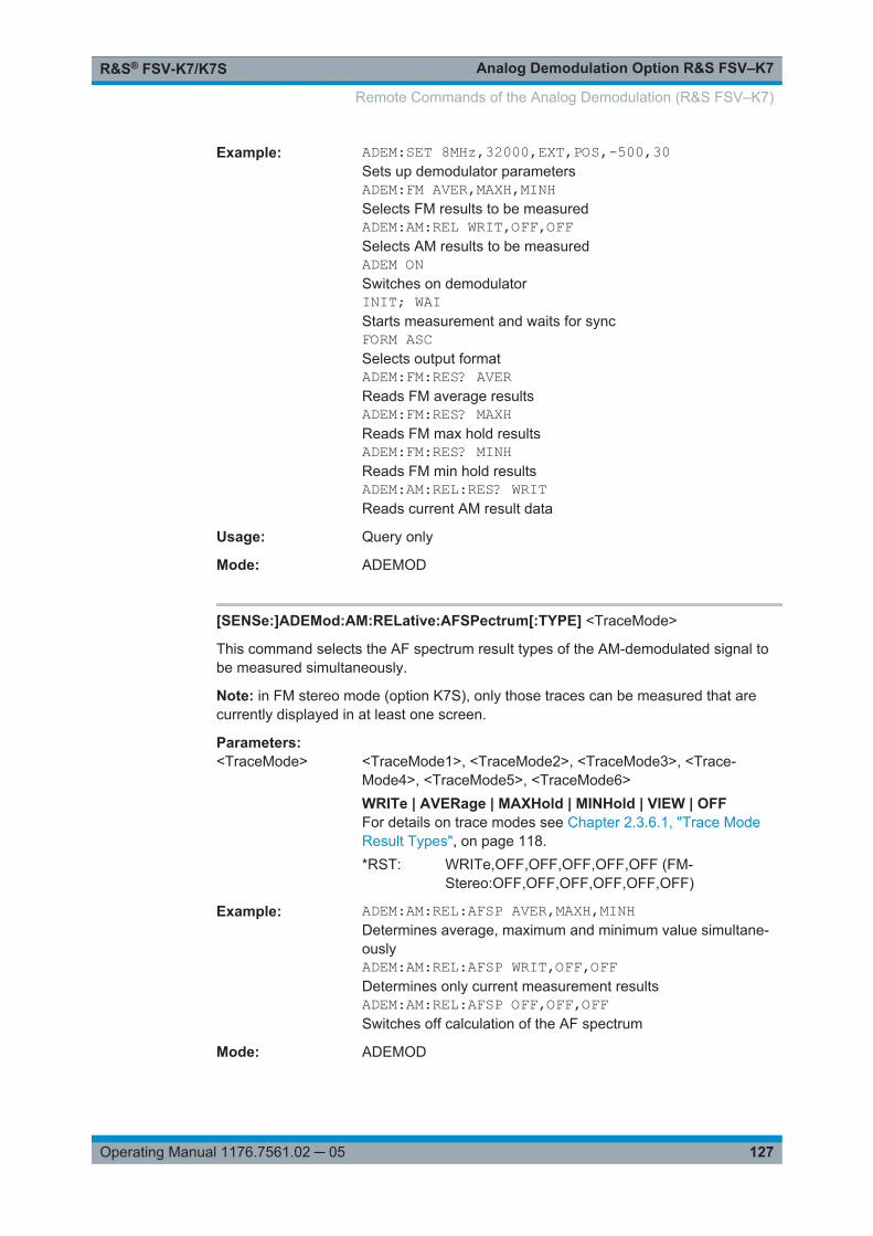
Analog Demodulation Option R&S FSV–K7R&S® FSV-K7/K7S
127Operating Manual 1176.7561.02 ─ 05
Example: ADEM:SET 8MHz,32000,EXT,POS,-500,30Sets up demodulator parametersADEM:FM AVER,MAXH,MINHSelects FM results to be measuredADEM:AM:REL WRIT,OFF,OFFSelects AM results to be measuredADEM ONSwitches on demodulatorINIT; WAIStarts measurement and waits for syncFORM ASCSelects output formatADEM:FM:RES? AVERReads FM average resultsADEM:FM:RES? MAXHReads FM max hold resultsADEM:FM:RES? MINHReads FM min hold resultsADEM:AM:REL:RES? WRITReads current AM result data
Usage: Query only
Mode: ADEMOD
[SENSe:]ADEMod:AM:RELative:AFSPectrum[:TYPE] <TraceMode>
This command selects the AF spectrum result types of the AM-demodulated signal tobe measured simultaneously.
Note: in FM stereo mode (option K7S), only those traces can be measured that arecurrently displayed in at least one screen.
Parameters:<TraceMode> <TraceMode1>, <TraceMode2>, <TraceMode3>, <Trace-
Mode4>, <TraceMode5>, <TraceMode6>WRITe | AVERage | MAXHold | MINHold | VIEW | OFFFor details on trace modes see Chapter 2.3.6.1, "Trace ModeResult Types", on page 118.*RST: WRITe,OFF,OFF,OFF,OFF,OFF (FM-
Stereo:OFF,OFF,OFF,OFF,OFF,OFF)
Example: ADEM:AM:REL:AFSP AVER,MAXH,MINHDetermines average, maximum and minimum value simultane-ouslyADEM:AM:REL:AFSP WRIT,OFF,OFFDetermines only current measurement resultsADEM:AM:REL:AFSP OFF,OFF,OFFSwitches off calculation of the AF spectrum
Mode: ADEMOD
Remote Commands of the Analog Demodulation (R&S FSV–K7)
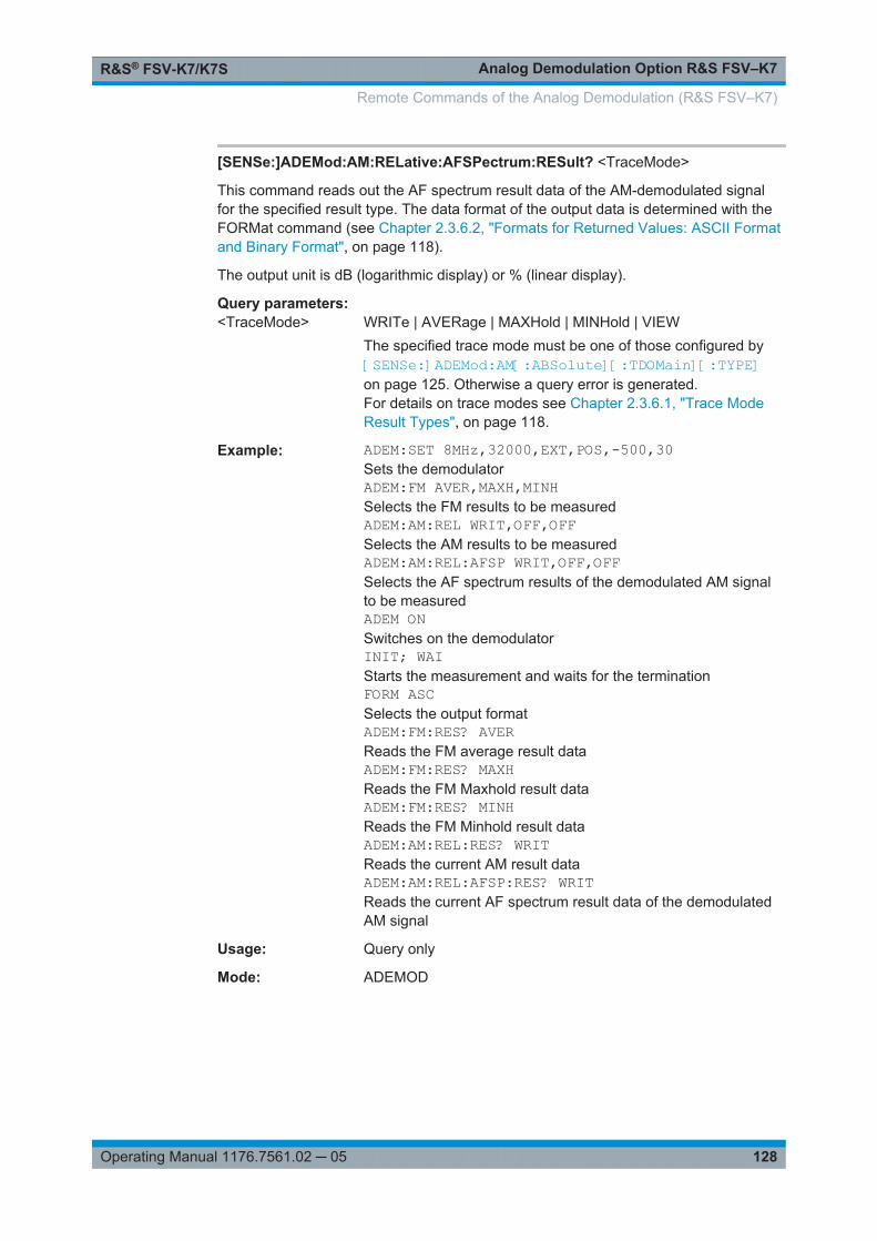
Analog Demodulation Option R&S FSV–K7R&S® FSV-K7/K7S
128Operating Manual 1176.7561.02 ─ 05
[SENSe:]ADEMod:AM:RELative:AFSPectrum:RESult? <TraceMode>
This command reads out the AF spectrum result data of the AM-demodulated signalfor the specified result type. The data format of the output data is determined with theFORMat command (see Chapter 2.3.6.2, "Formats for Returned Values: ASCII Formatand Binary Format", on page 118).
The output unit is dB (logarithmic display) or % (linear display).
Query parameters: <TraceMode> WRITe | AVERage | MAXHold | MINHold | VIEW
The specified trace mode must be one of those configured by[SENSe:]ADEMod:AM[:ABSolute][:TDOMain][:TYPE]on page 125. Otherwise a query error is generated.For details on trace modes see Chapter 2.3.6.1, "Trace ModeResult Types", on page 118.
Example: ADEM:SET 8MHz,32000,EXT,POS,-500,30Sets the demodulatorADEM:FM AVER,MAXH,MINHSelects the FM results to be measuredADEM:AM:REL WRIT,OFF,OFFSelects the AM results to be measuredADEM:AM:REL:AFSP WRIT,OFF,OFFSelects the AF spectrum results of the demodulated AM signalto be measuredADEM ONSwitches on the demodulatorINIT; WAIStarts the measurement and waits for the terminationFORM ASCSelects the output formatADEM:FM:RES? AVERReads the FM average result dataADEM:FM:RES? MAXHReads the FM Maxhold result dataADEM:FM:RES? MINHReads the FM Minhold result dataADEM:AM:REL:RES? WRITReads the current AM result dataADEM:AM:REL:AFSP:RES? WRITReads the current AF spectrum result data of the demodulatedAM signal
Usage: Query only
Mode: ADEMOD
Remote Commands of the Analog Demodulation (R&S FSV–K7)
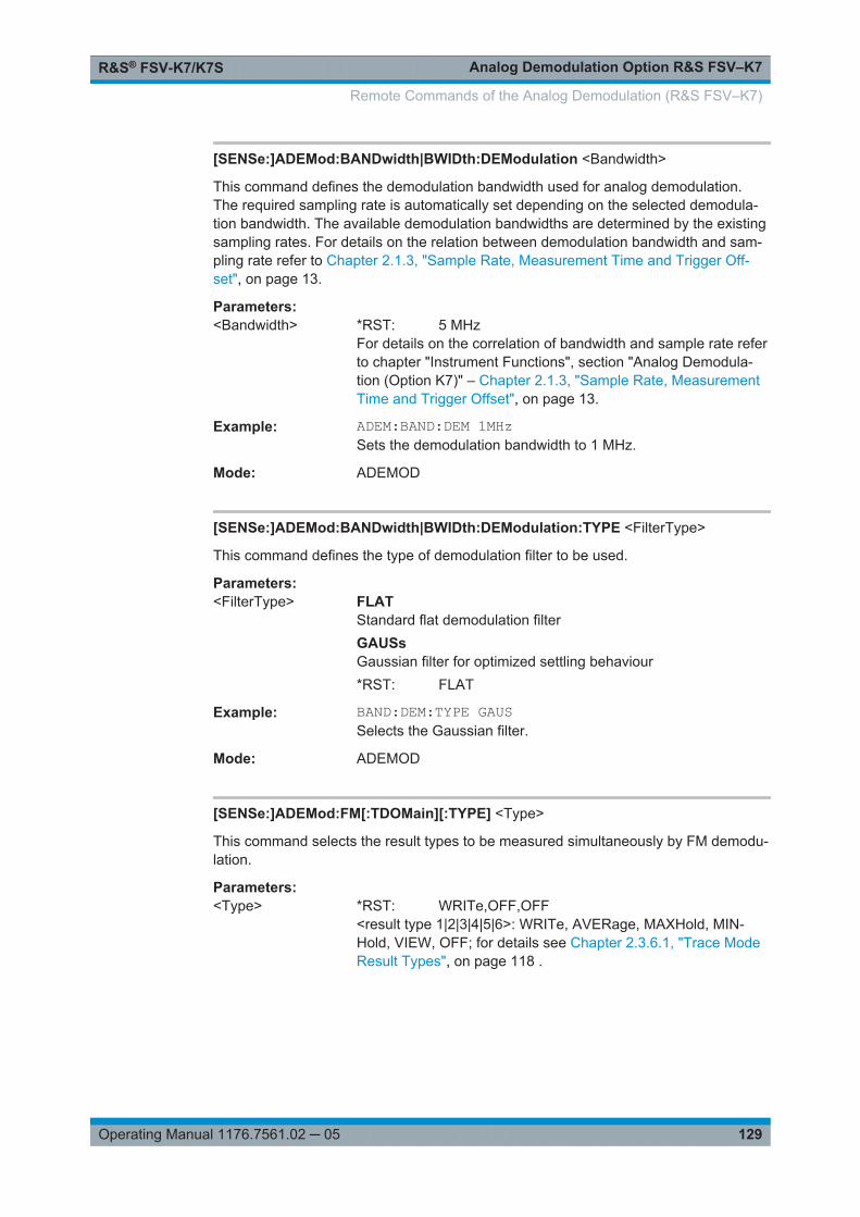
Analog Demodulation Option R&S FSV–K7R&S® FSV-K7/K7S
129Operating Manual 1176.7561.02 ─ 05
[SENSe:]ADEMod:BANDwidth|BWIDth:DEModulation <Bandwidth>
This command defines the demodulation bandwidth used for analog demodulation.The required sampling rate is automatically set depending on the selected demodula-tion bandwidth. The available demodulation bandwidths are determined by the existingsampling rates. For details on the relation between demodulation bandwidth and sam-pling rate refer to Chapter 2.1.3, "Sample Rate, Measurement Time and Trigger Off-set", on page 13.
Parameters:<Bandwidth> *RST: 5 MHz
For details on the correlation of bandwidth and sample rate referto chapter "Instrument Functions", section "Analog Demodula-tion (Option K7)" – Chapter 2.1.3, "Sample Rate, MeasurementTime and Trigger Offset", on page 13.
Example: ADEM:BAND:DEM 1MHzSets the demodulation bandwidth to 1 MHz.
Mode: ADEMOD
[SENSe:]ADEMod:BANDwidth|BWIDth:DEModulation:TYPE <FilterType>
This command defines the type of demodulation filter to be used.
Parameters:<FilterType> FLAT
Standard flat demodulation filterGAUSsGaussian filter for optimized settling behaviour*RST: FLAT
Example: BAND:DEM:TYPE GAUSSelects the Gaussian filter.
Mode: ADEMOD
[SENSe:]ADEMod:FM[:TDOMain][:TYPE] <Type>
This command selects the result types to be measured simultaneously by FM demodu-lation.
Parameters:<Type> *RST: WRITe,OFF,OFF
<result type 1|2|3|4|5|6>: WRITe, AVERage, MAXHold, MIN-Hold, VIEW, OFF; for details see Chapter 2.3.6.1, "Trace ModeResult Types", on page 118 .
Remote Commands of the Analog Demodulation (R&S FSV–K7)
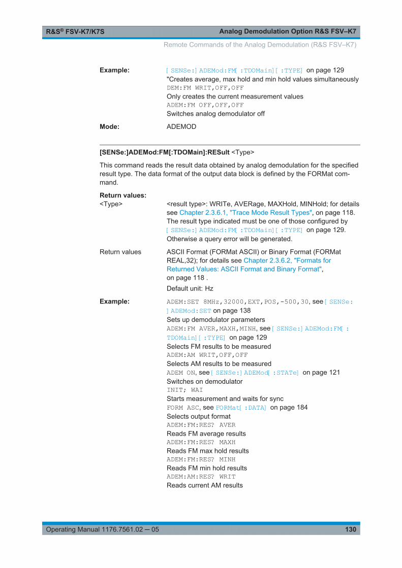
Analog Demodulation Option R&S FSV–K7R&S® FSV-K7/K7S
130Operating Manual 1176.7561.02 ─ 05
Example: [SENSe:]ADEMod:FM[:TDOMain][:TYPE] on page 129"Creates average, max hold and min hold values simultaneouslyDEM:FM WRIT,OFF,OFFOnly creates the current measurement valuesADEM:FM OFF,OFF,OFFSwitches analog demodulator off
Mode: ADEMOD
[SENSe:]ADEMod:FM[:TDOMain]:RESult <Type>
This command reads the result data obtained by analog demodulation for the specifiedresult type. The data format of the output data block is defined by the FORMat com-mand.
Return values: <Type> <result type>: WRITe, AVERage, MAXHold, MINHold; for details
see Chapter 2.3.6.1, "Trace Mode Result Types", on page 118.The result type indicated must be one of those configured by[SENSe:]ADEMod:FM[:TDOMain][:TYPE] on page 129.Otherwise a query error will be generated.
Return values ASCII Format (FORMat ASCII) or Binary Format (FORMatREAL,32); for details see Chapter 2.3.6.2, "Formats forReturned Values: ASCII Format and Binary Format",on page 118 .Default unit: Hz
Example: ADEM:SET 8MHz,32000,EXT,POS,-500,30, see [SENSe:]ADEMod:SET on page 138Sets up demodulator parametersADEM:FM AVER,MAXH,MINH, see [SENSe:]ADEMod:FM[:TDOMain][:TYPE] on page 129Selects FM results to be measuredADEM:AM WRIT,OFF,OFFSelects AM results to be measuredADEM ON, see [SENSe:]ADEMod[:STATe] on page 121Switches on demodulatorINIT; WAIStarts measurement and waits for syncFORM ASC, see FORMat[:DATA] on page 184Selects output formatADEM:FM:RES? AVERReads FM average resultsADEM:FM:RES? MAXHReads FM max hold resultsADEM:FM:RES? MINHReads FM min hold resultsADEM:AM:RES? WRITReads current AM results
Remote Commands of the Analog Demodulation (R&S FSV–K7)

Analog Demodulation Option R&S FSV–K7R&S® FSV-K7/K7S
131Operating Manual 1176.7561.02 ─ 05
Mode: ADEMOD
[SENSe:]ADEMod:FM:AFSPectrum[:TYPE] <Type>
This command selects the AF spectrum result types of the FM demodulated signal tobe measured simultaneously.
Parameters:<Type> *RST: OFF,OFF,OFF
<result type 1|2|3|4|5|6>: WRITe, AVERage, MAXHold, MIN-Hold, VIEW, OFF; for details see Chapter 2.3.6.1, "Trace ModeResult Types", on page 118.The result type "AF spectrum of the FM demodulated signal"cannot be activated at the same time as "AF spectrum of AM orPM demodulated signal".
Example: ADEM:FM:AFSP AVER,MAXH,MINHDetermines average, maximum and minimum value simultane-ouslyADEM:FM:AFSP WRIT,OFF,OFFDetermines only current measurement resultsADEM:FM:AFSP OFF,OFF,OFFSwitches calculation of AF spectrum off
Mode: ADEMOD
[SENSe:]ADEMod:FM:AFSPectrum:RESult <Type>
This command reads out the AF spectrum result data of the FM demodulated signal forthe specified result type. The data format of the output data is determined with theFORMat command.
Return values: <Type> <result type>: WRITe, AVERage, MAXHold, MINHold; for details
see Chapter 2.3.6.1, "Trace Mode Result Types", on page 118.The specified result type must be one of those configured withthe [SENSe:]ADEMod:FM:AFSPectrum[:TYPE] command.Otherwise a query error will be generated.
Return values ASCII Format (FORMat ASCII) or Binary Format (FORMatREAL,32); for details see Chapter 2.3.6.2, "Formats forReturned Values: ASCII Format and Binary Format",on page 118.Default unit: dB (logarithmic display) or Hz (linear display)
Remote Commands of the Analog Demodulation (R&S FSV–K7)
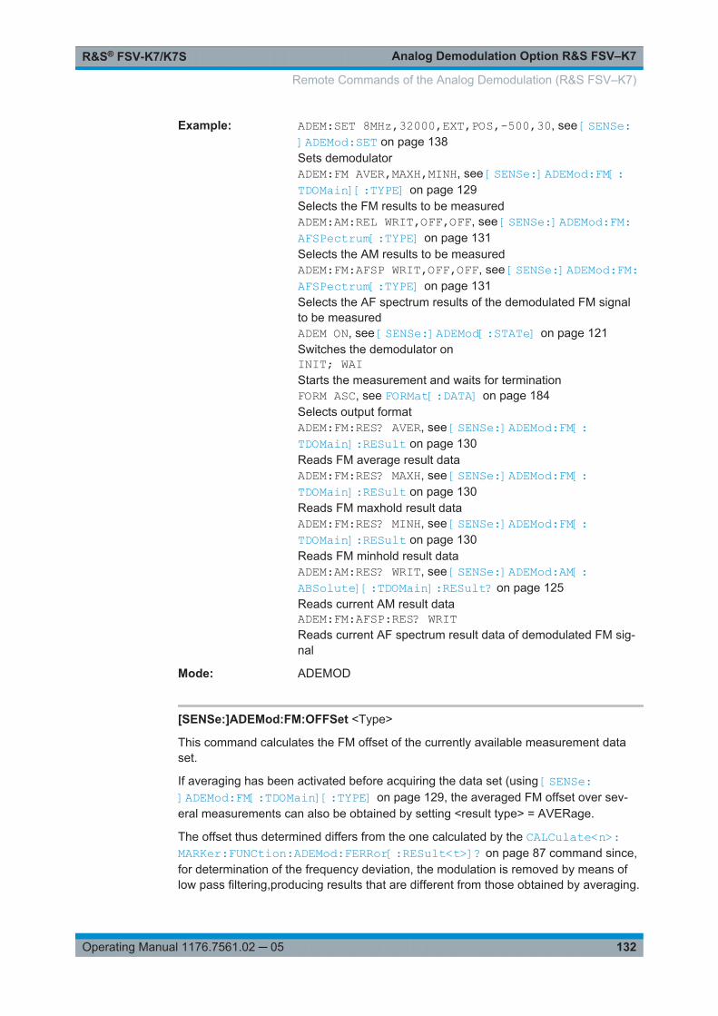
Analog Demodulation Option R&S FSV–K7R&S® FSV-K7/K7S
132Operating Manual 1176.7561.02 ─ 05
Example: ADEM:SET 8MHz,32000,EXT,POS,-500,30, see [SENSe:]ADEMod:SET on page 138Sets demodulatorADEM:FM AVER,MAXH,MINH, see [SENSe:]ADEMod:FM[:TDOMain][:TYPE] on page 129Selects the FM results to be measuredADEM:AM:REL WRIT,OFF,OFF, see [SENSe:]ADEMod:FM:AFSPectrum[:TYPE] on page 131Selects the AM results to be measuredADEM:FM:AFSP WRIT,OFF,OFF, see [SENSe:]ADEMod:FM:AFSPectrum[:TYPE] on page 131Selects the AF spectrum results of the demodulated FM signalto be measuredADEM ON, see [SENSe:]ADEMod[:STATe] on page 121Switches the demodulator onINIT; WAIStarts the measurement and waits for terminationFORM ASC, see FORMat[:DATA] on page 184Selects output formatADEM:FM:RES? AVER, see [SENSe:]ADEMod:FM[:TDOMain]:RESult on page 130Reads FM average result dataADEM:FM:RES? MAXH, see [SENSe:]ADEMod:FM[:TDOMain]:RESult on page 130Reads FM maxhold result dataADEM:FM:RES? MINH, see [SENSe:]ADEMod:FM[:TDOMain]:RESult on page 130Reads FM minhold result dataADEM:AM:RES? WRIT, see [SENSe:]ADEMod:AM[:ABSolute][:TDOMain]:RESult? on page 125Reads current AM result dataADEM:FM:AFSP:RES? WRITReads current AF spectrum result data of demodulated FM sig-nal
Mode: ADEMOD
[SENSe:]ADEMod:FM:OFFSet <Type>
This command calculates the FM offset of the currently available measurement dataset.
If averaging has been activated before acquiring the data set (using [SENSe:]ADEMod:FM[:TDOMain][:TYPE] on page 129, the averaged FM offset over sev-eral measurements can also be obtained by setting <result type> = AVERage.
The offset thus determined differs from the one calculated by the CALCulate<n>:MARKer:FUNCtion:ADEMod:FERRor[:RESult<t>]? on page 87 command since,for determination of the frequency deviation, the modulation is removed by means oflow pass filtering,producing results that are different from those obtained by averaging.
Remote Commands of the Analog Demodulation (R&S FSV–K7)
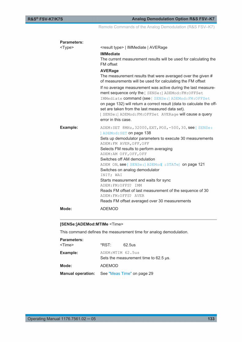
Analog Demodulation Option R&S FSV–K7R&S® FSV-K7/K7S
133Operating Manual 1176.7561.02 ─ 05
Parameters:<Type> <result type> | IMMediate | AVERage
IMMediateThe current measurement results will be used for calculating theFM offsetAVERageThe measurement results that were averaged over the given #of measurements will be used for calculating the FM offsetIf no average measurement was active during the last measure-ment sequence only the [SENSe:]ADEMod:FM:OFFSetIMMediate command (see [SENSe:]ADEMod:FM:OFFSeton page 132) will return a correct result (data to calculate the off-set are taken from the last measured data set).[SENSe:]ADEMod:FM:OFFSet AVERage will cause a queryerror in this case.
Example: ADEM:SET 8MHz,32000,EXT,POS,-500,30, see [SENSe:]ADEMod:SET on page 138Sets up demodulator parameters to execute 30 measurementsADEM:FM AVER,OFF,OFFSelects FM results to perform averagingADEM:AM OFF,OFF,OFFSwitches off AM demodulationADEM ON, see [SENSe:]ADEMod[:STATe] on page 121Switches on analog demodulatorINIT; WAIStarts measurement and waits for syncADEM:FM:OFFS? IMMReads FM offset of last measurement of the sequence of 30ADEM:FM:OFFS? AVERReads FM offset averaged over 30 measurements
Mode: ADEMOD
[SENSe:]ADEMod:MTIMe <Time>
This command defines the measurement time for analog demodulation.
Parameters:<Time> *RST: 62.5us
Example: ADEM:MTIM 62.5usSets the measurement time to 62.5 µs.
Mode: ADEMOD
Manual operation: See "Meas Time" on page 29
Remote Commands of the Analog Demodulation (R&S FSV–K7)

Analog Demodulation Option R&S FSV–K7R&S® FSV-K7/K7S
134Operating Manual 1176.7561.02 ─ 05
[SENSe:]ADEMod:PM[:TDOMain][:TYPE] <Type>
This command selects the result types of the PM-demodulated signal to be createdsimultaneously.
Parameters:<Type> *RST: OFF,OFF,OFF
<result type 1|2|3|4|5|6>: WRITe, AVERage, MAXHold, MIN-Hold, VIEW; for details see Chapter 2.3.6.1, "Trace Mode ResultTypes", on page 118.
Example: ADEM:PM AVER,MAXH,MINH, see [SENSe:]ADEMod:PM[:TDOMain][:TYPE] on page 134Determines average, maximum and minimum value simultane-ouslyADEM:PM WRIT,OFF,OFFDetermines only current measurement resultsADEM:PM OFF,OFF,OFFSwitches the PM demodulator off.
Mode: ADEMOD
[SENSe:]ADEMod:PM[:TDOMain]:RESult <Type>
This command reads the result data of the PM demodulation for the specified resulttype. The data format of the output data is determined with the FORMat command.
Return values: <Type> <result type>: WRITe, AVERage, MAXHold, MINHold; for details
see Chapter 2.3.6.1, "Trace Mode Result Types", on page 118.The specified result type must be one of those configured withthe [SENSe:]ADEMod:PM[:TDOMain][:TYPE] command.Otherwise a query error will be generated.
Return values ASCII Format (FORMat ASCII) or Binary Format (FORMatREAL,32); for details see Chapter 2.3.6.2, "Formats forReturned Values: ASCII Format and Binary Format",on page 118 .Default unit: dB (logarithmic display) or RAD or DEG (linear dis-
play)
Remote Commands of the Analog Demodulation (R&S FSV–K7)
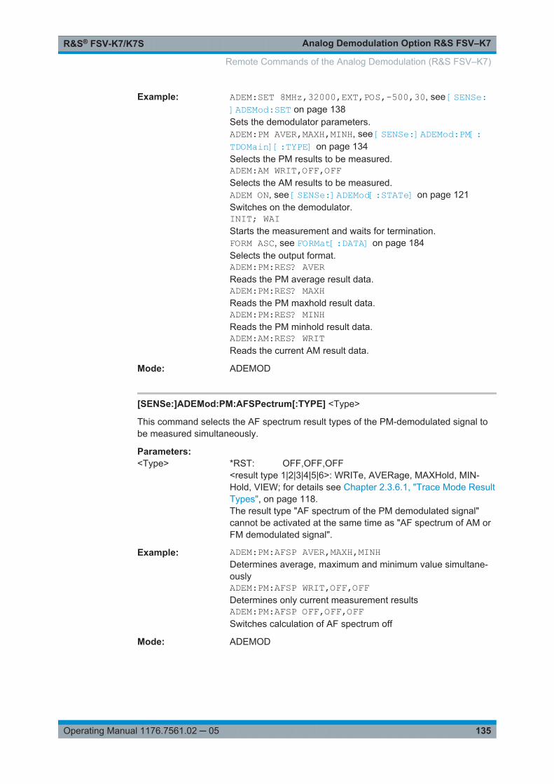
Analog Demodulation Option R&S FSV–K7R&S® FSV-K7/K7S
135Operating Manual 1176.7561.02 ─ 05
Example: ADEM:SET 8MHz,32000,EXT,POS,-500,30, see [SENSe:]ADEMod:SET on page 138Sets the demodulator parameters.ADEM:PM AVER,MAXH,MINH, see [SENSe:]ADEMod:PM[:TDOMain][:TYPE] on page 134Selects the PM results to be measured.ADEM:AM WRIT,OFF,OFFSelects the AM results to be measured.ADEM ON, see [SENSe:]ADEMod[:STATe] on page 121Switches on the demodulator.INIT; WAIStarts the measurement and waits for termination.FORM ASC, see FORMat[:DATA] on page 184Selects the output format.ADEM:PM:RES? AVERReads the PM average result data.ADEM:PM:RES? MAXHReads the PM maxhold result data.ADEM:PM:RES? MINHReads the PM minhold result data.ADEM:AM:RES? WRITReads the current AM result data.
Mode: ADEMOD
[SENSe:]ADEMod:PM:AFSPectrum[:TYPE] <Type>
This command selects the AF spectrum result types of the PM-demodulated signal tobe measured simultaneously.
Parameters:<Type> *RST: OFF,OFF,OFF
<result type 1|2|3|4|5|6>: WRITe, AVERage, MAXHold, MIN-Hold, VIEW; for details see Chapter 2.3.6.1, "Trace Mode ResultTypes", on page 118.The result type "AF spectrum of the PM demodulated signal"cannot be activated at the same time as "AF spectrum of AM orFM demodulated signal".
Example: ADEM:PM:AFSP AVER,MAXH,MINHDetermines average, maximum and minimum value simultane-ouslyADEM:PM:AFSP WRIT,OFF,OFFDetermines only current measurement resultsADEM:PM:AFSP OFF,OFF,OFFSwitches calculation of AF spectrum off
Mode: ADEMOD
Remote Commands of the Analog Demodulation (R&S FSV–K7)

Analog Demodulation Option R&S FSV–K7R&S® FSV-K7/K7S
136Operating Manual 1176.7561.02 ─ 05
[SENSe:]ADEMod:PM:AFSPectrum:RESult <Type>
This command reads out the AF spectrum result data of the PM-demodulated signalfor the specified result type. The data format of the output data is determined with theFORMat command.
Return values: <Type> <result type>: WRITe, AVERage, MAXHold, MINHold; for details
see Chapter 2.3.6.1, "Trace Mode Result Types", on page 118 .The specified result type must be one of those configured withthe [SENSe:]ADEMod:PM:AFSPectrum[:TYPE] on page 135command. Otherwise a query error will be generated.
Return values ASCII Format (FORMat ASCII) or Binary Format (FORMatREAL,32); for details see Chapter 2.3.6.2, "Formats forReturned Values: ASCII Format and Binary Format",on page 118 .Default unit: dB (logarithmic display) or RAD or DEG (linear dis-
play)
Remote Commands of the Analog Demodulation (R&S FSV–K7)

Analog Demodulation Option R&S FSV–K7R&S® FSV-K7/K7S
137Operating Manual 1176.7561.02 ─ 05
Example: ADEM:SET 8MHz,32000,EXT,POS,-500,30, see [SENSe:]ADEMod:SET on page 138Sets demodulatorADEM:PM AVER,MAXH,MINH, see [SENSe:]ADEMod:PM[:TDOMain][:TYPE] on page 134Selects the PM results to be measuredADEM:AM:REL WRIT,OFF,OFF, see [SENSe:]ADEMod:FM:AFSPectrum[:TYPE] on page 131Selects the AM results to be measuredADEM:PM:AFSP WRIT,OFF,OFF, see [SENSe:]ADEMod:PM:AFSPectrum[:TYPE] on page 135Selects the AF spectrum results of the demodulated PM signalto be measuredADEM ON, see [SENSe:]ADEMod[:STATe] on page 121Switches the demodulator onINIT; WAIStarts the measurement and waits for terminationFORM ASC, see FORMat[:DATA] on page 184Selects output formatADEM:PM:RES? AVER, see [SENSe:]ADEMod:PM:AFSPectrum:RESult on page 136Reads PM average result dataADEM:PM:RES? MAXH, see [SENSe:]ADEMod:PM:AFSPectrum:RESult on page 136Reads PM maxhold result dataADEM:PM:RES? MINH, see [SENSe:]ADEMod:PM:AFSPectrum:RESult on page 136Reads PM minhold result dataADEM:AM:RES? WRIT, see [SENSe:]ADEMod:PM:AFSPectrum:RESult on page 136Reads current AM result dataADEM:PM:AFSP:RES? WRITReads current AF spectrum result data of demodulated PM sig-nal
Mode: ADEMOD
[SENSe:]ADEMod:PM:RPOint[:X] <Time>
This command determines the position where the phase of the PM-demodulated signalis set to 0 rad. The maximum possible value depends on the measurement timeselected in the instrument; this value is output in response to the queryADEM:PM:RPO:X? MAX.
Parameters:<Time> 0 s to measurement time
*RST: 0 s
Example: ADEM:PM:RPO 500usSets the position where the phase to 0 rad setting to 500 µs.
Remote Commands of the Analog Demodulation (R&S FSV–K7)
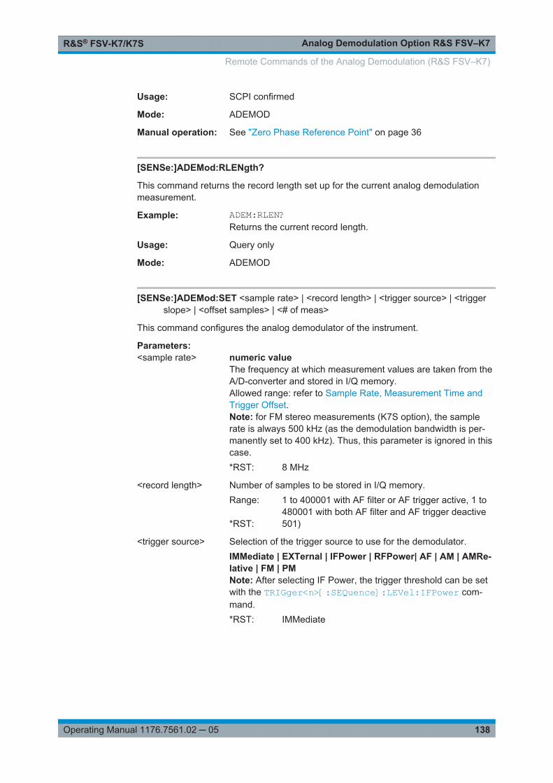
Analog Demodulation Option R&S FSV–K7R&S® FSV-K7/K7S
138Operating Manual 1176.7561.02 ─ 05
Usage: SCPI confirmed
Mode: ADEMOD
Manual operation: See "Zero Phase Reference Point" on page 36
[SENSe:]ADEMod:RLENgth?
This command returns the record length set up for the current analog demodulationmeasurement.
Example: ADEM:RLEN?Returns the current record length.
Usage: Query only
Mode: ADEMOD
[SENSe:]ADEMod:SET <sample rate> | <record length> | <trigger source> | <triggerslope> | <offset samples> | <# of meas>
This command configures the analog demodulator of the instrument.
Parameters:<sample rate> numeric value
The frequency at which measurement values are taken from theA/D-converter and stored in I/Q memory.Allowed range: refer to Sample Rate, Measurement Time andTrigger Offset.Note: for FM stereo measurements (K7S option), the samplerate is always 500 kHz (as the demodulation bandwidth is per-manently set to 400 kHz). Thus, this parameter is ignored in thiscase.*RST: 8 MHz
<record length> Number of samples to be stored in I/Q memory.Range: 1 to 400001 with AF filter or AF trigger active, 1 to
480001 with both AF filter and AF trigger deactive*RST: 501)
<trigger source> Selection of the trigger source to use for the demodulator.IMMediate | EXTernal | IFPower | RFPower| AF | AM | AMRe-lative | FM | PMNote: After selecting IF Power, the trigger threshold can be setwith the TRIGger<n>[:SEQuence]:LEVel:IFPower com-mand.*RST: IMMediate
Remote Commands of the Analog Demodulation (R&S FSV–K7)

Analog Demodulation Option R&S FSV–K7R&S® FSV-K7/K7S
139Operating Manual 1176.7561.02 ─ 05
<trigger slope> POSitive | NEGativeUsed slope of the trigger signal.The value indicated here will be ignored for <trigger source> =IMMediate.*RST: POSitive
<offset samples> Number of samples to be used as an offset to the trigger signal.For details refer to Chapter 2.1.3, "Sample Rate, MeasurementTime and Trigger Offset", on page 13.The value indicated here is ignored for <trigger source> ="IMMediate".*RST: 0
<# of meas> Number of repetitions of the measurement to be executed. Thevalue indicated here is especially necessary for the average/maxhold/minhold function.Range: 0 to 32767*RST: 0
Example: ADEM:SET 8MHz,32000,EXT,POS,-500,30Performs a measurement at:sample rate = 8 MHzrecord length = 32000trigger source = EXTernaltrigger slope = POSitiveoffset samples = -500 (500 samples before trigger occurred)# of meas = 30
Mode: ADEMOD
[SENSe:]ADEMod:SPECtrum[:TYPE] <Type>
This command selects the result types to be created in parallel by the RF spectrummeasurement with active analog demodulation.
Parameters:<Type> *RST: OFF,OFF,OFF
<result type 1|2|3|4|5|6>: WRITe, AVERage, MAXHold, MIN-Hold, VIEW, OFF; for details see Chapter 2.3.6.1, "Trace ModeResult Types", on page 118.
Example: ADEM:SPEC AVER,MAXH,MINHCreates average, max hold and min hold values at a timeADEM:SPEC WRIT,OFF,OFFOnly creates the current measurement valuesADEM:SPEC OFF,OFF,OFFSwitches analog demodulator off
Mode: ADEMOD
Remote Commands of the Analog Demodulation (R&S FSV–K7)
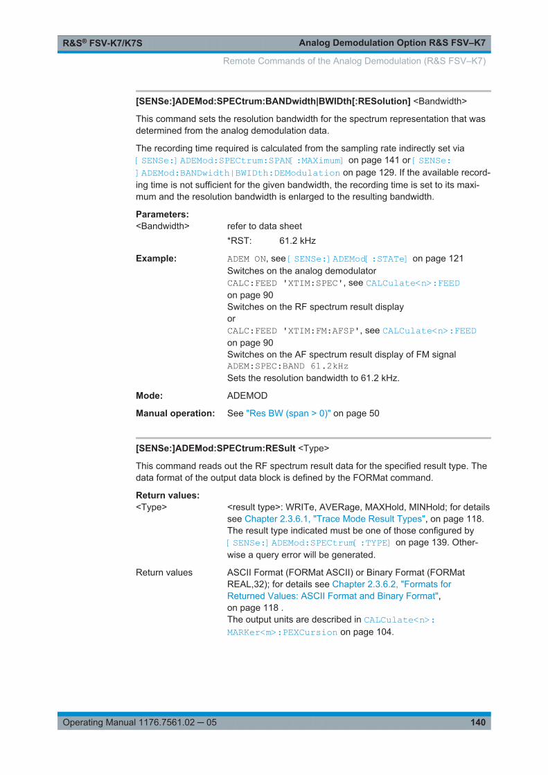
Analog Demodulation Option R&S FSV–K7R&S® FSV-K7/K7S
140Operating Manual 1176.7561.02 ─ 05
[SENSe:]ADEMod:SPECtrum:BANDwidth|BWIDth[:RESolution] <Bandwidth>
This command sets the resolution bandwidth for the spectrum representation that wasdetermined from the analog demodulation data.
The recording time required is calculated from the sampling rate indirectly set via[SENSe:]ADEMod:SPECtrum:SPAN[:MAXimum] on page 141 or [SENSe:]ADEMod:BANDwidth|BWIDth:DEModulation on page 129. If the available record-ing time is not sufficient for the given bandwidth, the recording time is set to its maxi-mum and the resolution bandwidth is enlarged to the resulting bandwidth.
Parameters:<Bandwidth> refer to data sheet
*RST: 61.2 kHz
Example: ADEM ON, see [SENSe:]ADEMod[:STATe] on page 121Switches on the analog demodulatorCALC:FEED 'XTIM:SPEC', see CALCulate<n>:FEEDon page 90Switches on the RF spectrum result displayorCALC:FEED 'XTIM:FM:AFSP', see CALCulate<n>:FEEDon page 90Switches on the AF spectrum result display of FM signalADEM:SPEC:BAND 61.2kHzSets the resolution bandwidth to 61.2 kHz.
Mode: ADEMOD
Manual operation: See "Res BW (span > 0)" on page 50
[SENSe:]ADEMod:SPECtrum:RESult <Type>
This command reads out the RF spectrum result data for the specified result type. Thedata format of the output data block is defined by the FORMat command.
Return values: <Type> <result type>: WRITe, AVERage, MAXHold, MINHold; for details
see Chapter 2.3.6.1, "Trace Mode Result Types", on page 118.The result type indicated must be one of those configured by[SENSe:]ADEMod:SPECtrum[:TYPE] on page 139. Other-wise a query error will be generated.
Return values ASCII Format (FORMat ASCII) or Binary Format (FORMatREAL,32); for details see Chapter 2.3.6.2, "Formats forReturned Values: ASCII Format and Binary Format",on page 118 .The output units are described in CALCulate<n>:MARKer<m>:PEXCursion on page 104.
Remote Commands of the Analog Demodulation (R&S FSV–K7)
Analog Demodulation Option R&S FSV–K7R&S® FSV-K7/K7S
141Operating Manual 1176.7561.02 ─ 05
Example: ADEM:SET 8MHz,32000,EXT,POS,-500,30, see [SENSe:]ADEMod:SET on page 138Sets demodulatorADEM:SPEC AVER,MAXH,MINHSelects RF spectrum results to be measuredADEM:SPEC WRIT,OFF,OFFSelects the AM results to be measuredADEM ON, see [SENSe:]ADEMod[:STATe] on page 121Switches the demodulator onINIT; WAIStarts the measurement and waits for terminationFORM ASC, see FORMat[:DATA] on page 184Selects output formatADEM:SPEC:RES? AVERReads RF spectrum average resultsADEM:SPEC:RES? MAXHReads RF spectrum max hold resultsADEM:SPEC:RES? MINHReads RF spectrum min hold resultsADEM:SPEC:RES? WRITReads spectrum current results
Mode: ADEMOD
[SENSe:]ADEMod:SPECtrum:SPAN[:MAXimum] <FreqRange>
This command sets the maximum frequency range for displaying the RF spectrum thatwas determined from the FM demodulation data. The maximum span corresponds tothe measurement bandwidth of analog demodulation (for details refer to [SENSe:]ADEMod:BANDwidth|BWIDth:DEModulation on page 129).
For details refer on the relation of bandwidth and sample rate refer to Sample Rate,Measurement Time and Trigger Offset.
Parameters:<FreqRange> *RST: 5 MHz
Example: ADEM ON, see [SENSe:]ADEMod[:STATe] on page 121Switches on the analog demodulatorCALC:FEED 'XTIM:SPEC', see CALCulate<n>:FEEDon page 90Switches on RF spectrum result display.ADEM:SPEC:SPAN:MAX 5 MHzSets the max. span to 5 MHzADEM:SPEC:SPAN:ZOOM 1 MHzSets the displayed span to 1 MHz
Mode: ADEMOD
Remote Commands of the Analog Demodulation (R&S FSV–K7)

Analog Demodulation Option R&S FSV–K7R&S® FSV-K7/K7S
142Operating Manual 1176.7561.02 ─ 05
[SENSe:]ADEMod:SPECtrum:SPAN:ZOOM <FreqRange>
This command sets the frequency range for the RF spectrum result display determinedfrom analog demodulation data. The frequency range for result display is limited to themaximum span ( [SENSe:]ADEMod:SPECtrum:SPAN[:MAXimum] on page 141) orto the measurement bandwidth of analog demodulation ( [SENSe:]ADEMod:BANDwidth|BWIDth:DEModulation on page 129).
Parameters:<FreqRange> *RST: 5 MHz
Example: ADEM ON, see [SENSe:]ADEMod[:STATe] on page 121Switches on the analog demodulatorCALC:FEED 'XTIM:SPEC', see CALCulate<n>:FEEDon page 90Switches on RF spectrum result display.ADEM:SPEC:SPAN:MAX 5 MHz, see [SENSe:]ADEMod:SPECtrum:SPAN[:MAXimum] on page 141Sets the maximum span to 5 MHzADEM:SPEC:SPAN:ZOOM 1 MHzSets displayed span to 1 MHz
Mode: ADEMOD
Manual operation: See "Span Manual (RF Spectrum)" on page 40See "Full Span (RF Spectrum)" on page 41
[SENSe:]ADEMod:SQUelch[:STATe] <State>
This command activates the squelch function, i.e. if the signal falls below a definedthreshold (see [SENSe:]ADEMod:SQUelch:LEVel on page 142), the demodulateddata is automatically set to 0.
Parameters:<State> ON | OFF
*RST: OFF
Example: DEM:SQU ONSignals below the level threshold are squelched.
Usage: SCPI confirmed
Mode: A, ADEMOD, SFM
Manual operation: See "Squelch" on page 35
[SENSe:]ADEMod:SQUelch:LEVel <Threshold>
This command defines the level threshold below which the demodulated data is set to0 if squelching is enabled (see [SENSe:]ADEMod:SQUelch[:STATe] on page 142).
Remote Commands of the Analog Demodulation (R&S FSV–K7)
Analog Demodulation Option R&S FSV–K7R&S® FSV-K7/K7S
143Operating Manual 1176.7561.02 ─ 05
Parameters:<Threshold> numeric value
The absolute threshold levelRange: -150 dBm to 30 dBm*RST: -40 dBm
Example: DEM:SQU:LEV -80If the signal drops below -80 dBm, the demodulated data is setto 0.
Usage: SCPI confirmed
Mode: ADEMOD, SFM
Manual operation: See "Squelch Level" on page 35
[SENSe:]ADEMod:SRATe?
This command returns the sample rate set up for the current analog demodulationmeasurement.
Example: ADEM:SRAT?Returns the current sample rate.
Usage: Query only
Mode: ADEMOD
[SENSe:]ADEMod<n>:ZOOM[:STATe] <State>
The command enables or disables the zoom function for the analog-demodulated mea-surement data in the specified window. Depending on the selected measurement timeand the demodulation bandwidth, the number of recorded test points may be greaterthan that shown on the display.
If the zoom function is enabled, the default number of sweep points in "Spectrum"mode of the result memory are displayed from the specified start time with [SENSe:]ADEMod<n>:ZOOM:STARt on page 144.
If the zoom function is disabled, data reduction is used to adapt the test points to thenumber of points available on the display.
Suffix: <n>
.1...4window
Parameters:<State> ON | OFF
*RST: OFF
Example: ADEM:ZOOM ONSwitches on the zoom function
Mode: ADEMOD
Remote Commands of the Analog Demodulation (R&S FSV–K7)
Analog Demodulation Option R&S FSV–K7R&S® FSV-K7/K7S
144Operating Manual 1176.7561.02 ─ 05
Manual operation: See "State On / Off" on page 34
[SENSe:]ADEMod<n>:ZOOM:STARt <Time>
The command selects the start time for the display of individual measured values ofthe analog demodulation in the specified window. The maximum possible valuedepends on the measurement time, which is set in the instrument and can be queriedwith the [SENSe:]ADEMod:MTIMe on page 133 command.
If the zoom function is enabled, the default number of sweep points in "Spectrum"mode of the result memory are displayed from the specified start time with [SENSe:]ADEMod<n>:ZOOM:STARt on page 144.
Suffix: <n>
.1...4window
Parameters:<Time> *RST: 0 s
0 s to measurement time – (default number of sweep points in"Spectrum" mode – 1 * 1/sample rate)
Example: ADEM:ZOOM:STAT ON (see [SENSe:]ADEMod<n>:ZOOM[:STATe] on page 143)Switches on the zoom functionADEM:ZOOM:STAR 500usSets the starting point of the display to 500 µs.
Mode: ADEMOD
Manual operation: See "Start" on page 34
[SENSe:]ADEMod<n>:ZOOM:LENGth <Length>
The command allows you to define the length of the zoom area for the analog-demodulated measurement data in the specified window manually. If the length isdefined manually using this command, the zoom mode is also set to manual.
Suffix: <n>
.1...4window
Parameters:<Length> *RST: sweep time
Length of the zoom area in seconds.
Example: ADEM:ZOOM:LENG 2sZoom mode is set to manual and the zoom length to 2 seconds.
Mode: ADEMOD
Manual operation: See "Length Manual" on page 34
Remote Commands of the Analog Demodulation (R&S FSV–K7)
Analog Demodulation Option R&S FSV–K7R&S® FSV-K7/K7S
145Operating Manual 1176.7561.02 ─ 05
[SENSe:]ADEMod<n>:ZOOM:LENGth:MODE <Mode>
The command defines whether the length of the zoom area for the analog-demodula-ted measurement data is defined automatically or manually in the specified window. Bydefault and in automatic mode, the number of sweep points is used as the zoomlength. If the zoom length was already entered using [SENSe:]ADEMod<n>:ZOOM:LENGth on page 144, manual zoom mode is set automatically.
Suffix: <n>
.1...4window
Parameters:<Mode> AUTO | MAN
*RST: AUTO
Example: ADEM:ZOOM:LENG:MODE MANZoom function uses the length defined manually.
Mode: ADEMOD
Manual operation: See "Length Auto" on page 34
2.3.6.4 SENSe:ADJust Subsystem
The ADJust subsystem controls automatic definition of frequency and level settings.
[SENSe:]ADJust:ALL......................................................................................................145[SENSe:]ADJust:CONFiguration:HYSTeresis:LOWer.........................................................145[SENSe:]ADJust:CONFiguration:HYSTeresis:UPPer......................................................... 146[SENSe:]ADJust:CONFigure:LEVel:DURation...................................................................146[SENSe:]ADJust:FREQuency..........................................................................................146[SENSe:]ADJust:LEVel...................................................................................................147[SENSe:]ADJust:SCALe:Y:AUTO[:CONTinuous]...............................................................147
[SENSe:]ADJust:ALL
This command determines the ideal frequency and level configuration for the currentmeasurement.
Example: ADJ:ALLManual operation: See "Auto All" on page 48
[SENSe:]ADJust:CONFiguration:HYSTeresis:LOWer <Threshold>
This command defines a lower threshold the signal must drop below before the refer-ence level is automatically adjusted when the "Auto Level" function is performed.
For more information see [SENSe:]ADJust:LEVel).
Remote Commands of the Analog Demodulation (R&S FSV–K7)
Analog Demodulation Option R&S FSV–K7R&S® FSV-K7/K7S
146Operating Manual 1176.7561.02 ─ 05
Parameters:<Threshold> Range: 0 to 200
*RST: +1 dBDefault unit: dB
Example: SENS:ADJ:CONF:HYST:LOW 2Example: For an input signal level of currently 20 dBm, the reference level
will only be adjusted when the signal level falls below 18 dBm.
Manual operation: See "Lower Level Hysteresis" on page 49
[SENSe:]ADJust:CONFiguration:HYSTeresis:UPPer <Threshold>
This command defines an upper threshold the signal must exceed before the referencelevel is automatically adjusted when the "Auto Level" function is performed.
For more information see [SENSe:]ADJust:LEVel).
Parameters:<Threshold> Range: 0 to 200
*RST: +1 dBDefault unit: dB
Example: SENS:ADJ:CONF:HYST:UPP 2For an input signal level of currently 20 dBm, the reference levelwill only be adjusted when the signal level rises above 22 dBm.
Manual operation: See "Upper Level Hysteresis" on page 49
[SENSe:]ADJust:CONFigure:LEVel:DURation <Duration>
This command defines the duration of the level measurement used to determine theoptimal reference level automatically (for SENS:ADJ:LEV ON).
Parameters:<Duration> <numeric value> in seconds
Range: 0.001 to 16000.0*RST: 0.001Default unit: s
Example: ADJ:CONF:LEV:DUR:5Manual operation: See "Meas Time Manual" on page 49
[SENSe:]ADJust:FREQuency
This command defines the center frequency and the reference level automatically bydetermining the highest level in the frequency span.
Example: ADJ:FREQManual operation: See "Auto Freq" on page 48
Remote Commands of the Analog Demodulation (R&S FSV–K7)

Analog Demodulation Option R&S FSV–K7R&S® FSV-K7/K7S
147Operating Manual 1176.7561.02 ─ 05
[SENSe:]ADJust:LEVel
This command automatically sets the optimal reference level for the current measure-ment.
You can define a threshold that the signal must exceed before the reference level isadjusted, see [SENSe:]ADJust:CONFiguration:HYSTeresis:UPPer and[SENSe:]ADJust:CONFiguration:HYSTeresis:LOWer.
Example: ADJ:LEVManual operation: See "Auto Level" on page 48
[SENSe:]ADJust:SCALe:Y:AUTO[:CONTinuous] <state>
Activates automatic scaling of the y-axis. Currently auto-scaling is only available for AFmeasurements. RF power and RF spectrum measurements are not affected by theauto-scaling.
Parameters:<state> ON | OFF
*RST: OFF
Example: SENS1:ADJ:SCAL:Y:AUTO ONMode: ADEMOD, SFM
Manual operation: See "AF Auto Scale" on page 49
2.3.6.5 SENSe:BANDwidth Subsystem (Analog Demodulation, R&S FSV–K7)
This subsystem controls the setting of the instruments filter bandwidths. Both groups ofcommands (BANDwidth and BWIDth) perform the same functions.
[SENSe:]BANDwidth|BWIDth:DEMod...............................................................................147[SENSe:]BANDwidth:DEMod:TYPE................................................................................. 148
[SENSe:]BANDwidth|BWIDth:DEMod <Bandwidth>
This command sets the bandwidth for analog demodulation. Depending on theselected demodulation bandwidth, the instrument selects the required sampling rate.
The available values of the demodulation bandwidths are determined by the samplingrates. For details on the correlation between demodulation bandwidth and samplingrate refer to Chapter 2.1.3, "Sample Rate, Measurement Time and Trigger Offset",on page 13.
Parameters:<Bandwidth> *RST: 5 MHz
Example: BAND:DEM 1MHzSets test bandwidth to 1 MHz
Mode: A-F, ADEMOD
Remote Commands of the Analog Demodulation (R&S FSV–K7)
Analog Demodulation Option R&S FSV–K7R&S® FSV-K7/K7S
148Operating Manual 1176.7561.02 ─ 05
Manual operation: See "Demod BW" on page 28
[SENSe:]BANDwidth:DEMod:TYPE <FilterType>
This command defines the type of demodulation filter to be used.
Parameters:<FilterType> FLAT
Standard flat demodulation filterGAUSsGaussian filter for optimized settling behaviour*RST: FLAT
Example: BAND:DEM:TYPE GAUSSelects the Gaussian filter.
Mode: ADEMOD
Manual operation: See "Demod Filter" on page 53
2.3.6.6 SENSe:FILTer Subsystem (Analog Demodulation, Analog Demodulation)
The SENSe:FILTer subsystem selects the filters to reduce the bandwidth of thedemodulated signal. The selected filters are used for AM, FM and PM demodulation incommon.
Using the commands in the SENSe:FILTer subsystem you can define filter settings foreach window individually. Note, however, that if the same modulation type is used inseveral windows, the settings defined for that modulation are used in all the corre-sponding windows.
Commands of the SENSe:FILTer subsystem
[SENSe:]FILTer<n>:AOFF.............................................................................................. 148[SENSe:]FILTer<n>:AWEighted[:STATe]..........................................................................149[SENSe:]FILTer<n>:CCIT............................................................................................... 149[SENSe:]FILTer<n>:CCIR[:UNWeighted][:STATe]............................................................. 150[SENSe:]FILTer<n>:CCIR:WEIGhted[:STATe].................................................................. 150[SENSe:]FILTer<n>:DEMPhasis[:STATe]......................................................................... 150[SENSe:]FILTer<n>:DEMPhasis:TCONstant.....................................................................151[SENSe:]FILTer<n>:HPASs[:STATe]................................................................................151[SENSe:]FILTer<n>:HPASs:FREQuency..........................................................................152[SENSe:]FILTer<n>:LPASs[:STATe]................................................................................ 152[SENSe:]FILTer<n>:LPASs:FREQuency[:ABSolute].......................................................... 152[SENSe:]FILTer<n>:LPASs:FREQuency:RELative............................................................ 153
[SENSe:]FILTer<n>:AOFF
This command switches all AF filters in the specified window off.
Remote Commands of the Analog Demodulation (R&S FSV–K7)
Analog Demodulation Option R&S FSV–K7R&S® FSV-K7/K7S
149Operating Manual 1176.7561.02 ─ 05
Suffix: <n>
.1...4window
Example: SENS:FILT:AOFFUsage: Event
Mode: ADEMOD, SFM
Manual operation: See "All AF Filter Off" on page 32
[SENSe:]FILTer<n>:AWEighted[:STATe] <State>
This command activates/deactivates the "A" weighting filter in the specified window.
For details on the A weighted filter see "A Weighted" on page 31.
Suffix: <n>
.1...4window
Parameters:<State> ON | OFF
*RST: OFF
Example: FILT:AWE ONActivates the A weighting filter.
Mode: ADEMOD
Manual operation: See "A Weighted" on page 31
[SENSe:]FILTer<n>:CCIT <State>
This command activates/deactivates the CCITT (CCITT P.53) weighting filter in thespecified window.
For details on the CCITT filter see "CCITT" on page 30.
Suffix: <n>
.1...4window
Parameters:<State> ON | OFF
*RST: OFF
Example: FILT:CCIT ONActivates the CCITT weighting filter.
Mode: ADEMOD
Manual operation: See "CCITT" on page 30
Remote Commands of the Analog Demodulation (R&S FSV–K7)

Analog Demodulation Option R&S FSV–K7R&S® FSV-K7/K7S
150Operating Manual 1176.7561.02 ─ 05
[SENSe:]FILTer<n>:CCIR[:UNWeighted][:STATe] <State>
This command activates/deactivates the unweighted CCIR filter in the specified win-dow.
For details on the unweighted CCIR filter see "CCIR Unweighted" on page 30.
Suffix: <n>
.1...4window
Parameters:<State> ON | OFF
*RST: OFF
Example: FILT:CCIR:UNW ONActivates the unweighted CCIR filter.
Mode: ADEMOD
Manual operation: See "CCIR Unweighted" on page 30
[SENSe:]FILTer<n>:CCIR:WEIGhted[:STATe] <State>
This command activates/deactivates the weighted CCIR filter in the specified window.
For details on the weighted CCIR filter see "CCIR Weighted" on page 31.
Suffix: <n>
.1...4window
Parameters:<State> ON | OFF
*RST: OFF
Example: FILT:CCIR:WEIG ONActivates the weighted CCIR filter.
Mode: ADEMOD
Manual operation: See "CCIR Weighted" on page 31
[SENSe:]FILTer<n>:DEMPhasis[:STATe] <State>
This command activates/deactivates the selected deemphasis in the specified window.
For details about deemphasis refer to "Deemphasis" on page 31.
Suffix: <n>
.1...4window
Parameters:<State> ON | OFF
*RST: OFF
Remote Commands of the Analog Demodulation (R&S FSV–K7)
Analog Demodulation Option R&S FSV–K7R&S® FSV-K7/K7S
151Operating Manual 1176.7561.02 ─ 05
Example: FILT:DEMP ONActivates the selected deemphasis.
Mode: ADEMOD
Manual operation: See "Deemphasis" on page 31
[SENSe:]FILTer<n>:DEMPhasis:TCONstant
This command selects the deemphasis in the specified window.
For details on deemphasis refer to "Deemphasis" on page 31.
For details on the demodulation bandwidth range refer to "Demod BW" on page 28.
Suffix: <n>
.1...4window
Parameters:25 us | 50 us | 75 us | 750 us*RST: 50 us
Example: FILT:DEMP:TCON 750usSelects the deemphasis for the demodulation bandwidth rangefrom 800 Hz to 4 MHz with a time constant of 750 µs.
Mode: ADEMOD
Manual operation: See "Deemphasis" on page 31
[SENSe:]FILTer<n>:HPASs[:STATe] <State>
This command activates/deactivates the selected high pass filter in the specified win-dow.
For details on the high pass filter refer to "High Pass" on page 29.
Suffix: <n>
.1...4window
Parameters:<State> ON | OFF
*RST: OFF
Example: FILT:HPAS ONActivates the selected high pass filter.
Mode: ADEMOD
Manual operation: See "High Pass" on page 29See "None" on page 30
Remote Commands of the Analog Demodulation (R&S FSV–K7)
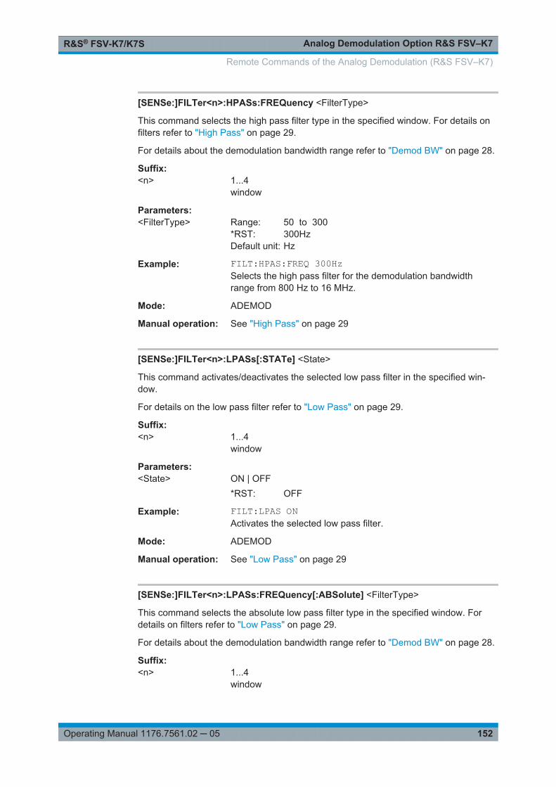
Analog Demodulation Option R&S FSV–K7R&S® FSV-K7/K7S
152Operating Manual 1176.7561.02 ─ 05
[SENSe:]FILTer<n>:HPASs:FREQuency <FilterType>
This command selects the high pass filter type in the specified window. For details onfilters refer to "High Pass" on page 29.
For details about the demodulation bandwidth range refer to "Demod BW" on page 28.
Suffix: <n>
.1...4window
Parameters:<FilterType> Range: 50 to 300
*RST: 300HzDefault unit: Hz
Example: FILT:HPAS:FREQ 300HzSelects the high pass filter for the demodulation bandwidthrange from 800 Hz to 16 MHz.
Mode: ADEMOD
Manual operation: See "High Pass" on page 29
[SENSe:]FILTer<n>:LPASs[:STATe] <State>
This command activates/deactivates the selected low pass filter in the specified win-dow.
For details on the low pass filter refer to "Low Pass" on page 29.
Suffix: <n>
.1...4window
Parameters:<State> ON | OFF
*RST: OFF
Example: FILT:LPAS ONActivates the selected low pass filter.
Mode: ADEMOD
Manual operation: See "Low Pass" on page 29
[SENSe:]FILTer<n>:LPASs:FREQuency[:ABSolute] <FilterType>
This command selects the absolute low pass filter type in the specified window. Fordetails on filters refer to "Low Pass" on page 29.
For details about the demodulation bandwidth range refer to "Demod BW" on page 28.
Suffix: <n>
.1...4window
Remote Commands of the Analog Demodulation (R&S FSV–K7)

Analog Demodulation Option R&S FSV–K7R&S® FSV-K7/K7S
153Operating Manual 1176.7561.02 ─ 05
Parameters:<FilterType> 3kHz | 15kHz | 150kHz
*RST: 15kHz
Example: FILT:LPAS:FREQ 150kHzSelects the low pass filter for the demodulation bandwidth rangefrom 400 kHz to 16 MHz.
Mode: ADEMOD
Manual operation: See "Low Pass" on page 29
[SENSe:]FILTer<n>:LPASs:FREQuency:RELative <FilterType>
This command selects the relative low pass filter type in the specified window. Fordetails on filters refer to Low Pass softkey.
For details about the demodulation bandwidth range refer to "Demod BW" on page 28.
Suffix: <n>
.1...4window
Parameters:<FilterType> 5PCT | 10PCT | 25PCT
*RST: 25PCT
Example: FILT:LPAS:FREQ 25PCTSelects the low pass filter as 25 % of the demodulation band-width.
Mode: ADEMOD
Manual operation: See "Low Pass" on page 29
2.3.6.7 SENSe:FREQuency Subsystem (Analog Demodulation, R&S FSV–K7)
The SENSe:FREQuency subsystem defines the frequency axis of the active display.The frequency axis can either be defined via the start/stop frequency or via the centerfrequency and span.
[SENSe:]FREQuency:CENTer.........................................................................................153[SENSe:]FREQuency:CENTer:STEP............................................................................... 154[SENSe:]FREQuency:CENTer:STEP:LINK....................................................................... 154[SENSe:]FREQuency:CENTer:STEP:LINK:FACTor........................................................... 155
[SENSe:]FREQuency:CENTer <Frequency>
This command defines the center frequency (frequency domain) or measuring fre-quency (time domain).
Remote Commands of the Analog Demodulation (R&S FSV–K7)

Analog Demodulation Option R&S FSV–K7R&S® FSV-K7/K7S
154Operating Manual 1176.7561.02 ─ 05
Parameters:<Frequency> Range: 0 to fmax
*RST: fmax/2Default unit: Hzfmax is specified in the data sheet. min span is 10 Hz
Example: FREQ:CENT 100 MHzManual operation: See "Center" on page 38
[SENSe:]FREQuency:CENTer:STEP <StepSize>
This command defines the center frequency step size.
Parameters:<StepSize> Range: 1 to fmax
*RST: 0.1 x <span value>Default unit: Hz
Example: FREQ:CENT:STEP 120 MHzManual operation: See "Manual" on page 39
[SENSe:]FREQuency:CENTer:STEP:LINK <CouplingType>
This command couples and decouples the center frequency step size to the span orthe resolution bandwidth.
Parameters:<CouplingType> SPAN
Couples the step size to the span. Available for measurementsin the frequency domain.(for RF spectrum result display)RBWCouples the step size to the resolution bandwidth. Available formeasurements in the time domain.(for all result displays except RF spectrum)OFFDecouples the step size (manual input).*RST: SPAN
Example: FREQ:CENT:STEP:LINK SPANManual operation: See "0.1*Span (RF Spectrum)" on page 39
See "0.1*Demod BW (AF/RF Time Domain, AF Spectrum)"on page 39See "0.5*Span (RF Spectrum)" on page 39See "0.5*Demod BW (AF/RF Time Domain, AF Spectrum)"on page 39See "x*Span (RF Spectrum)" on page 39See "x*Demod BW (AF/RF Time Domain, AF Spectrum)"on page 39
Remote Commands of the Analog Demodulation (R&S FSV–K7)

Analog Demodulation Option R&S FSV–K7R&S® FSV-K7/K7S
155Operating Manual 1176.7561.02 ─ 05
[SENSe:]FREQuency:CENTer:STEP:LINK:FACTor <Factor>
This command defines a step size factor if the center frequency step size is coupled tothe span or the resolution bandwidth.
Parameters:<Factor> Range: 1 to 100
*RST: 10Default unit: PCT
Example: FREQ:CENT:STEP:LINK:FACT 20PCTManual operation: See "0.1*Span (RF Spectrum)" on page 39
See "0.1*Demod BW (AF/RF Time Domain, AF Spectrum)"on page 39See "0.5*Span (RF Spectrum)" on page 39See "0.5*Demod BW (AF/RF Time Domain, AF Spectrum)"on page 39See "x*Span (RF Spectrum)" on page 39See "x*Demod BW (AF/RF Time Domain, AF Spectrum)"on page 39
2.3.6.8 SENSe:SWEep Subsystem (Analog Demodulation, R&S FSV–K7)
The SENSe:SWEep subsystem controls the sweep parameters.
[SENSe:]SWEep:COUNt.................................................................................................155[SENSe:]SWEep:EGATe:HOLDoff...................................................................................156[SENSe:]SWEep:EGATe:POLarity...................................................................................156[SENSe:]SWEep:EGATe:SOURce...................................................................................156[SENSe:]SWEep:EGATe:TYPE....................................................................................... 156[SENSe:]SWEep:POINts.................................................................................................157[SENSe:]SWEep:TIME................................................................................................... 157
[SENSe:]SWEep:COUNt <NumberSweeps>
This command defines the number of sweeps started with single sweep, which areused for calculating the average or maximum value. If the values 0 or 1 are set, onesweep is performed.
Parameters:<NumberSweeps> 0 to 32767
*RST: 0 (GSM: 200, PHN:1)
Example: SWE:COUN 64Sets the number of sweeps to 64.INIT:CONT OFFSwitches to single sweep mode.INIT;*WAIStarts a sweep and waits for its end.
Manual operation: See "Sweep Count" on page 55
Remote Commands of the Analog Demodulation (R&S FSV–K7)

Analog Demodulation Option R&S FSV–K7R&S® FSV-K7/K7S
156Operating Manual 1176.7561.02 ─ 05
[SENSe:]SWEep:EGATe:HOLDoff <DelayTime>
This command defines the delay time between the external gate signal and the contin-uation of the sweep.
Note: Using gate mode "level" (see [SENSe:]SWEep:EGATe:TYPE on page 156)and an IFP trigger (see TRIGger<n>[:SEQuence]:SOURce on page 167), the hold-off time for the IFP trigger is ignored for frequency sweep, FFT sweep, zero span andIQ mode measurements.
Parameters:<DelayTime> 0 s to 30 s
*RST: 0s
Example: SWE:EGAT:HOLD 100us
[SENSe:]SWEep:EGATe:POLarity <Polarity>
This command determines the polarity of the external gate signal. The setting appliesboth to the edge of an edge-triggered signal and the level of a level-triggered signal.
Parameters:<Polarity> POSitive | NEGative
*RST: POSitive
Example: SWE:EGAT:POL POSManual operation: See "Trigger Polarity" on page 65
[SENSe:]SWEep:EGATe:SOURce <Source>
This command selects the signal source for gated measurements.
If an IF power signal is used, the gate is opened as soon as a signal at > -20 dBm isdetected within the IF path bandwidth (10 MHz).
For details see the "Trigger Source" on page 62 softkey.
Parameters:<Source> EXTernal | IFPower | VIDeo | RFPower | PSEN
*RST: IFPower
Example: SWE:EGAT:SOUR IFPSwitches the gate source to IF power.
Manual operation: See "RF Power" on page 63See "IF Power" on page 63
[SENSe:]SWEep:EGATe:TYPE <Type>
This command sets the type of triggering by the external gate signal.
A delay between applying the gate signal and the start of recording measured valuescan be defined, see [SENSe:]SWEep:EGATe:HOLDoff on page 156.
Remote Commands of the Analog Demodulation (R&S FSV–K7)
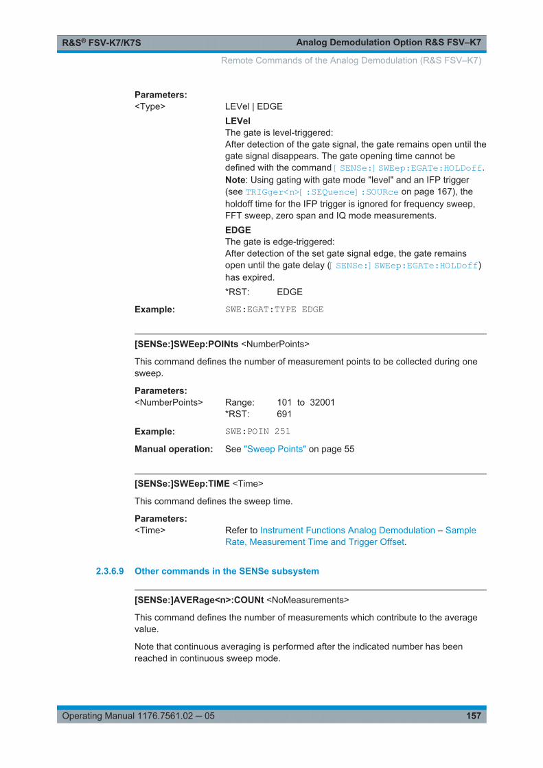
Analog Demodulation Option R&S FSV–K7R&S® FSV-K7/K7S
157Operating Manual 1176.7561.02 ─ 05
Parameters:<Type> LEVel | EDGE
LEVelThe gate is level-triggered:After detection of the gate signal, the gate remains open until thegate signal disappears. The gate opening time cannot bedefined with the command [SENSe:]SWEep:EGATe:HOLDoff.Note: Using gating with gate mode "level" and an IFP trigger(see TRIGger<n>[:SEQuence]:SOURce on page 167), theholdoff time for the IFP trigger is ignored for frequency sweep,FFT sweep, zero span and IQ mode measurements.EDGEThe gate is edge-triggered:After detection of the set gate signal edge, the gate remainsopen until the gate delay ([SENSe:]SWEep:EGATe:HOLDoff)has expired.*RST: EDGE
Example: SWE:EGAT:TYPE EDGE
[SENSe:]SWEep:POINts <NumberPoints>
This command defines the number of measurement points to be collected during onesweep.
Parameters:<NumberPoints> Range: 101 to 32001
*RST: 691
Example: SWE:POIN 251Manual operation: See "Sweep Points" on page 55
[SENSe:]SWEep:TIME <Time>
This command defines the sweep time.
Parameters:<Time> Refer to Instrument Functions Analog Demodulation – Sample
Rate, Measurement Time and Trigger Offset.
2.3.6.9 Other commands in the SENSe subsystem
[SENSe:]AVERage<n>:COUNt <NoMeasurements>
This command defines the number of measurements which contribute to the averagevalue.
Note that continuous averaging is performed after the indicated number has beenreached in continuous sweep mode.
Remote Commands of the Analog Demodulation (R&S FSV–K7)

Analog Demodulation Option R&S FSV–K7R&S® FSV-K7/K7S
158Operating Manual 1176.7561.02 ─ 05
In single sweep mode, the sweep is stopped as soon as the indicated number of mea-surements (sweeps) is reached. Synchronization to the end of the indicated number ofmeasurements is only possible in single sweep mode.
This command has the same effect as the [SENSe<source>:]SWEep:COUNt com-mand. In both cases, the number of measurements is defined whether the average cal-culation is active or not.
The number of measurements applies to all traces in the window.
Suffix: <n>
.Selects the measurement window.
Parameters:<NoMeasurements> 0 to 32767
*RST: 0
Example: SWE:CONT OFFSwitching to single sweep mode.AVER:COUN 16Sets the number of measurements to 16.AVER:STAT ONSwitches on the calculation of average.INIT;*WAIStarts the measurement and waits for the end of the 16 sweeps.
[SENSe:]AVERage<n>:TYPE <FunctionType>
This command selects the type of average function.
Suffix: <n>
.Selects the measurement window.
Parameters:<FunctionType> VIDeo | LINear | POWer
VIDeoThe logarithmic power values are averaged.LINearThe power values are averaged before they are converted tologarithmic values.POWerThe power level values are converted into unit Watt prior toaveraging. After the averaging, the data is converted back intoits original unit.*RST: VIDeo
Example: AVER:TYPE LINSwitches to linear average calculation.
Manual operation: See "Lin" on page 61See "Log" on page 61See "Power" on page 61
Remote Commands of the Analog Demodulation (R&S FSV–K7)

Analog Demodulation Option R&S FSV–K7R&S® FSV-K7/K7S
159Operating Manual 1176.7561.02 ─ 05
[SENSe:][WINDow:]DETector<trace>[:FUNCtion] <Function>
This command selects the detector for the data acquisition in the selected trace.
Suffix: <trace>
.1...6Selects the trace.
<trace> 1...6trace
Parameters:<Function> APEak | NEGative | POSitive | SAMPle | RMS | AVERage |
QPEak*RST: APEakFor details on detectors refer to Chapter 2.1.8, "Detector Over-view", on page 19.
Example: DET POSSets the detector to "positive peak".
Manual operation: See "Auto Peak" on page 58See "Positive Peak" on page 59See "Negative Peak" on page 59See "Sample" on page 59See "RMS" on page 59See "Average" on page 59See "Quasipeak" on page 59See "CISPR Average" on page 60See "RMS Average" on page 60
[SENSe:][WINDow:]DETector<trace>[:FUNCtion]:AUTO <State>
This command either couples the detector to the current trace setting or turns couplingoff.
Suffix: <trace>
.1...6trace
Parameters:<State> ON | OFF
*RST: ON
Example: DET:AUTO OFFManual operation: See "Auto Select" on page 58
Remote Commands of the Analog Demodulation (R&S FSV–K7)
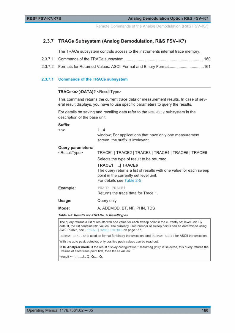
Analog Demodulation Option R&S FSV–K7R&S® FSV-K7/K7S
160Operating Manual 1176.7561.02 ─ 05
2.3.7 TRACe Subsystem (Analog Demodulation, R&S FSV–K7)
The TRACe subsystem controls access to the instruments internal trace memory.
2.3.7.1 Commands of the TRACe subsystem.........................................................................160
2.3.7.2 Formats for Returned Values: ASCII Format and Binary Format................................161
2.3.7.1 Commands of the TRACe subsystem
TRACe<n>[:DATA]? <ResultType>
This command returns the current trace data or measurement results. In case of sev-eral result displays, you have to use specific parameters to query the results.
For details on saving and recalling data refer to the MMEMory subsystem in thedescription of the base unit.
Suffix: <n>
.1...4window; For applications that have only one measurementscreen, the suffix is irrelevant.
Query parameters: <ResultType> TRACE1 | TRACE2 | TRACE3 | TRACE4 | TRACE5 | TRACE6
Selects the type of result to be returned.TRACE1 | ...| TRACE6The query returns a list of results with one value for each sweeppoint in the currently set level unit.For details see Table 2-5
Example: TRAC? TRACE1Returns the trace data for Trace 1.
Usage: Query only
Mode: A, ADEMOD, BT, NF, PHN, TDS
Table 2-5: Results for <TRACe...> ResultTypes
The query returns a list of results with one value for each sweep point in the currently set level unit. Bydefault, the list contains 691 values. The currently used number of sweep points can be determined usingSWE:POIN?, see [SENSe:]SWEep:POINts on page 157.
FORMat REAL,32 is used as format for binary transmission, and FORMat ASCii for ASCII transmission.
With the auto peak detector, only positive peak values can be read out.
In IQ Analyzer mode, if the result display configuration "Real/Imag (I/Q)" is selected, this query returns theI values of each trace point first, then the Q values:
<result>= I1,I2,...,In, Q1,Q2,...,Qn
Remote Commands of the Analog Demodulation (R&S FSV–K7)

Analog Demodulation Option R&S FSV–K7R&S® FSV-K7/K7S
161Operating Manual 1176.7561.02 ─ 05
2.3.7.2 Formats for Returned Values: ASCII Format and Binary Format
ASCII Format (FORMat ASCII)
The command reads out a list of comma separated values (CSV) of the measured val-ues in floating point format.
Reading out data in binary format is quicker than in ASCII format. Thus, binary formatis recommended for large amounts of data.
Binary Format (FORMat REAL,32)
The command reads out binary data (Definite Length Block Data according to IEEE488.2), each measurement value being formatted in 32 Bit IEEE 754 Floating-Point-Format.
Depending on the number of samples to be transferred, 2 different kinds of syntax areused:
For <1010 samples:
The schema of the result string is as follows:
#<NoOfDigits><NoOfDataBytes><value1><value2>…<value n>, with
# Header prefix, 1 byte
<NoOfDigits> Number of digits of the following number of data bytes (= 4 in the example), 1 byte
<NoOfDataBytes> Number of following data bytes in decimal form (= 1024 in the example), 1...9 bytes
<Value> Data values, each one is a 4-byte floating point value
Example:
#41024<value1><value2>…<value 256>4: the following number of data bytes has 4 digits
1024: 1024 Bytes of following data; float: 4 Bytes / value => 1024 / 4 = 256 values (128I and 128 Q values)
<value x>: 4 Byte values, must be interpreted as float
For ≧1010 samples:
The schema of the result string is as follows:
#(<NoOfDataBytes>)<value1><value2>…<value n>, with
# Header prefix, 1 byte
( 1 byte
<NoOfDataBytes> number of following data bytes (= 1024 in the example), 10 bytes
Remote Commands of the Analog Demodulation (R&S FSV–K7)

Analog Demodulation Option R&S FSV–K7R&S® FSV-K7/K7S
162Operating Manual 1176.7561.02 ─ 05
) 1 byte
<Value> Data values, each one is a 4-byte floating point value
Example:
#(1677721600)<value 1><value 2> ... <value 419430400>(1677721600): 1677721600 Bytes of following data; float: 4 Bytes / value ==>1677721600/ 4 = 419430400 values (200Ms I and 200Ms Q values)
<value x>: 4 Byte values, must be interpreted as float
2.3.8 TRIGger Subsystem (Analog Demodulation, R&S FSV–K7)
The TRIGger subsystem is used to synchronize instrument actions with events. It isthus possible to control and synchronize the start of a sweep.
TRIGger<n>[:SEQuence]:BBPower:HOLDoff....................................................................162TRIGger<n>[:SEQuence]:HOLDoff[:TIME]........................................................................163TRIGger<n>[:SEQuence]:IFPower:HOLDoff..................................................................... 163TRIGger<n>[:SEQuence]:IFPower:HYSTeresis.................................................................163TRIGger<n>[:SEQuence]:LEVel:AM[:ABSolute]................................................................ 164TRIGger<n>[:SEQuence]:LEVel:AM:RELative...................................................................164TRIGger<n>[:SEQuence]:LEVel:BBPower........................................................................164TRIGger<n>[:SEQuence]:LEVel:FM.................................................................................165TRIGger<n>[:SEQuence]:LEVel:IFPower......................................................................... 165TRIGger<n>[:SEQuence]:LEVel:RFPower........................................................................165TRIGger<n>[:SEQuence]:LEVel:PM.................................................................................166TRIGger<n>[:SEQuence]:TIME:RINTerval........................................................................166TRIGger<n>[:SEQuence]:LEVel:VIDeo............................................................................ 166TRIGger<n>[:SEQuence]:SLOPe.....................................................................................167TRIGger<n>[:SEQuence]:SOURce.................................................................................. 167
TRIGger<n>[:SEQuence]:BBPower:HOLDoff <Value>
This command sets the holding time before the next BB power trigger event (for digitalinput via the R&S Digital I/Q Interface, R&S FSV-B17).
Suffix: <n>
.irrelevant
Parameters:<Value> *RST: 150 ns
Example: TRIG:SOUR BBPSets the baseband power trigger source.TRIG:BBP:HOLD 200 nsSets the holding time to 200 ns.
Mode: all
Manual operation: See "Trigger Holdoff" on page 66
Remote Commands of the Analog Demodulation (R&S FSV–K7)

Analog Demodulation Option R&S FSV–K7R&S® FSV-K7/K7S
163Operating Manual 1176.7561.02 ─ 05
TRIGger<n>[:SEQuence]:HOLDoff[:TIME] <Delay>
This command defines the length of the trigger delay.
A negative delay time (pretrigger) can be set in zero span only.
Suffix: <n>
.irrelevant
Parameters:<Delay> Range: zero span: -sweeptime (see data sheet) to 30 s;
span: 0 to 30 s*RST: 0 s
Example: TRIG:HOLD 500usManual operation: See "Trigger Offset" on page 65
See "Trigger Offset" on page 219
TRIGger<n>[:SEQuence]:IFPower:HOLDoff <Value>
This command sets the holding time before the next IF power trigger event.
Suffix: <n>
.irrelevant
Parameters:<Value> *RST: 150 ns
Example: TRIG:SOUR IFPSets the IF power trigger source.TRIG:IFP:HOLD 200 nsSets the holding time to 200 ns.
Manual operation: See "Trigger Holdoff" on page 66
TRIGger<n>[:SEQuence]:IFPower:HYSTeresis <Value>
This command sets the limit that the hysteresis value for the IF power trigger has to fallbelow in order to trigger the next measurement.
Suffix: <n>
.irrelevant
Parameters:<Value> *RST: 3 dB
Example: TRIG:SOUR IFPSets the IF power trigger source.TRIG:IFP:HYST 10DBSets the hysteresis limit value.
Manual operation: See "Trigger Hysteresis" on page 66
Remote Commands of the Analog Demodulation (R&S FSV–K7)
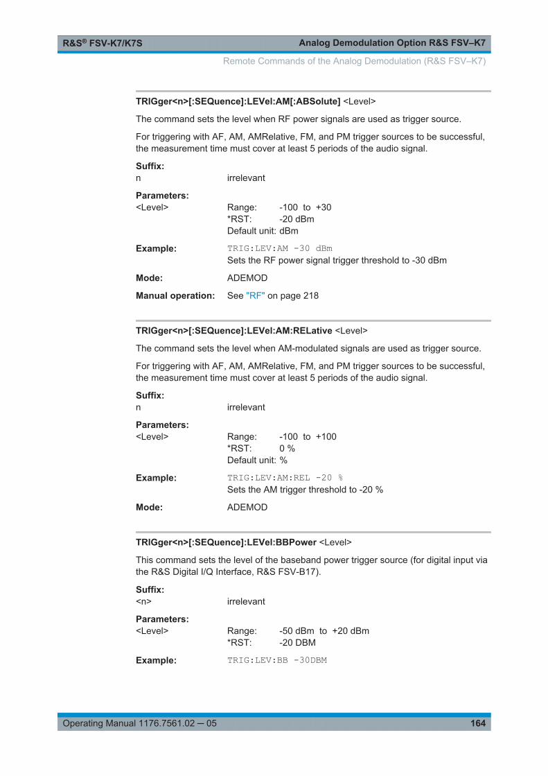
Analog Demodulation Option R&S FSV–K7R&S® FSV-K7/K7S
164Operating Manual 1176.7561.02 ─ 05
TRIGger<n>[:SEQuence]:LEVel:AM[:ABSolute] <Level>
The command sets the level when RF power signals are used as trigger source.
For triggering with AF, AM, AMRelative, FM, and PM trigger sources to be successful,the measurement time must cover at least 5 periods of the audio signal.
Suffix: n
.irrelevant
Parameters:<Level> Range: -100 to +30
*RST: -20 dBmDefault unit: dBm
Example: TRIG:LEV:AM -30 dBmSets the RF power signal trigger threshold to -30 dBm
Mode: ADEMOD
Manual operation: See "RF" on page 218
TRIGger<n>[:SEQuence]:LEVel:AM:RELative <Level>
The command sets the level when AM-modulated signals are used as trigger source.
For triggering with AF, AM, AMRelative, FM, and PM trigger sources to be successful,the measurement time must cover at least 5 periods of the audio signal.
Suffix: n
.irrelevant
Parameters:<Level> Range: -100 to +100
*RST: 0 %Default unit: %
Example: TRIG:LEV:AM:REL -20 %Sets the AM trigger threshold to -20 %
Mode: ADEMOD
TRIGger<n>[:SEQuence]:LEVel:BBPower <Level>
This command sets the level of the baseband power trigger source (for digital input viathe R&S Digital I/Q Interface, R&S FSV-B17).
Suffix: <n>
.irrelevant
Parameters:<Level> Range: -50 dBm to +20 dBm
*RST: -20 DBM
Example: TRIG:LEV:BB -30DBM
Remote Commands of the Analog Demodulation (R&S FSV–K7)
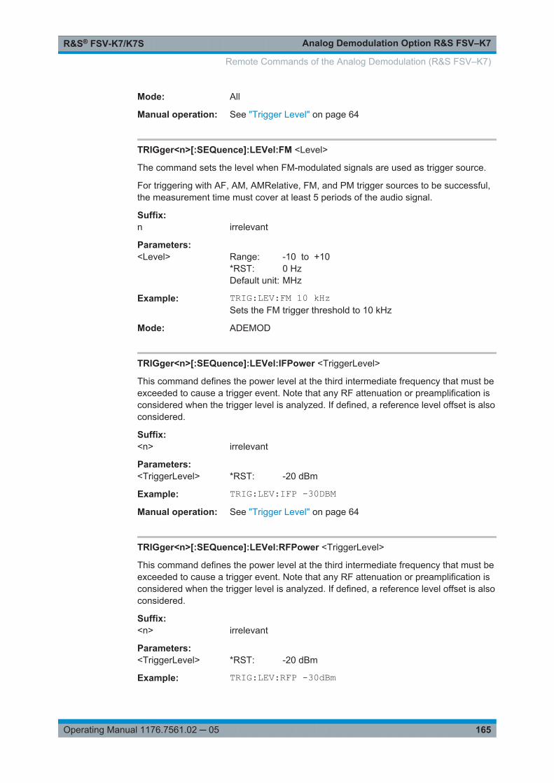
Analog Demodulation Option R&S FSV–K7R&S® FSV-K7/K7S
165Operating Manual 1176.7561.02 ─ 05
Mode: All
Manual operation: See "Trigger Level" on page 64
TRIGger<n>[:SEQuence]:LEVel:FM <Level>
The command sets the level when FM-modulated signals are used as trigger source.
For triggering with AF, AM, AMRelative, FM, and PM trigger sources to be successful,the measurement time must cover at least 5 periods of the audio signal.
Suffix: n
.irrelevant
Parameters:<Level> Range: -10 to +10
*RST: 0 HzDefault unit: MHz
Example: TRIG:LEV:FM 10 kHzSets the FM trigger threshold to 10 kHz
Mode: ADEMOD
TRIGger<n>[:SEQuence]:LEVel:IFPower <TriggerLevel>
This command defines the power level at the third intermediate frequency that must beexceeded to cause a trigger event. Note that any RF attenuation or preamplification isconsidered when the trigger level is analyzed. If defined, a reference level offset is alsoconsidered.
Suffix: <n>
.irrelevant
Parameters:<TriggerLevel> *RST: -20 dBm
Example: TRIG:LEV:IFP -30DBMManual operation: See "Trigger Level" on page 64
TRIGger<n>[:SEQuence]:LEVel:RFPower <TriggerLevel>
This command defines the power level at the third intermediate frequency that must beexceeded to cause a trigger event. Note that any RF attenuation or preamplification isconsidered when the trigger level is analyzed. If defined, a reference level offset is alsoconsidered.
Suffix: <n>
.irrelevant
Parameters:<TriggerLevel> *RST: -20 dBm
Example: TRIG:LEV:RFP -30dBm
Remote Commands of the Analog Demodulation (R&S FSV–K7)
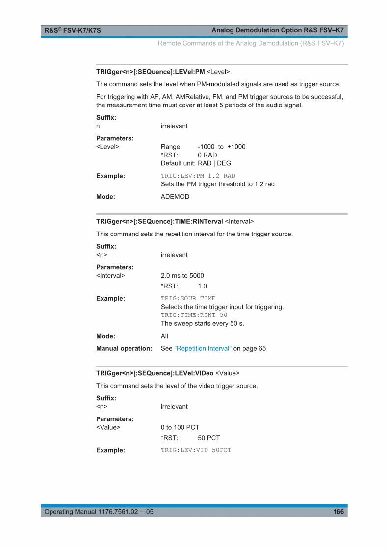
Analog Demodulation Option R&S FSV–K7R&S® FSV-K7/K7S
166Operating Manual 1176.7561.02 ─ 05
TRIGger<n>[:SEQuence]:LEVel:PM <Level>
The command sets the level when PM-modulated signals are used as trigger source.
For triggering with AF, AM, AMRelative, FM, and PM trigger sources to be successful,the measurement time must cover at least 5 periods of the audio signal.
Suffix: n
.irrelevant
Parameters:<Level> Range: -1000 to +1000
*RST: 0 RADDefault unit: RAD | DEG
Example: TRIG:LEV:PM 1.2 RADSets the PM trigger threshold to 1.2 rad
Mode: ADEMOD
TRIGger<n>[:SEQuence]:TIME:RINTerval <Interval>
This command sets the repetition interval for the time trigger source.
Suffix: <n>
.irrelevant
Parameters:<Interval> 2.0 ms to 5000
*RST: 1.0
Example: TRIG:SOUR TIMESelects the time trigger input for triggering.TRIG:TIME:RINT 50The sweep starts every 50 s.
Mode: All
Manual operation: See "Repetition Interval" on page 65
TRIGger<n>[:SEQuence]:LEVel:VIDeo <Value>
This command sets the level of the video trigger source.
Suffix: <n>
.irrelevant
Parameters:<Value> 0 to 100 PCT
*RST: 50 PCT
Example: TRIG:LEV:VID 50PCT
Remote Commands of the Analog Demodulation (R&S FSV–K7)

Analog Demodulation Option R&S FSV–K7R&S® FSV-K7/K7S
167Operating Manual 1176.7561.02 ─ 05
TRIGger<n>[:SEQuence]:SLOPe <Type>
This command selects the slope of the trigger signal. The selected trigger slopeapplies to all trigger signal sources.
Suffix: <n>
.irrelevant
Parameters:<Type> POSitive | NEGative
*RST: POSitive
Example: TRIG:SLOP NEGManual operation: See "Trigger Polarity" on page 65
TRIGger<n>[:SEQuence]:SOURce <Source>
This command selects the trigger source.
For triggering with AF, AM, AMRelative, FM, and PM trigger sources to be successful,the measurement time must cover at least 5 periods of the audio signal. For details ontrigger modes refer to the Trigger Source softkey.
IF power and RF power triggers are not available together with the bandwidth exten-sion option R&S FSV-B160.
For details on trigger modes refer to the "Trg/Gate Source" softkey in the base unitdescription.
Suffix: <n>
.irrelevant
Remote Commands of the Analog Demodulation (R&S FSV–K7)

Analog Demodulation Option R&S FSV–K7R&S® FSV-K7/K7S
168Operating Manual 1176.7561.02 ─ 05
Parameters:<Source> IMMediate
Free RunEXTernExternal triggerIFPowerPower trigger at the second intermediate frequencyTIMETime intervalGP0 | GP1 | GP2 | GP3 | GP4 | GP5For I/Q Analyzer or AnalogDemod mode only:Defines triggering of the measurement directly via the LVDSconnector. The parameter specifies which general purpose bit (0to 5) will provide the trigger data.This trigger mode is available for input from the R&S Digital I/QInterface (option R&S FSV-B17) only.The assignment of the general purpose bits used by the DigitalIQ trigger to the LVDS connector pins is provided in Table 2-6VIDeoVideo mode is only available in the time domain and only inSpectrum mode.BBPowerBaseband power (for digital input via the R&S Digital I/Q Inter-face, R&S FSV-B17)PSENExternal power sensor (requires R&S FSV-K9 option)AFAF power signalFMFM power signalAMcorresponds to the RF power signalAMRelativecorresponds to the AM signalPMPM power signal*RST: IMMediate
Example: TRIG:SOUR EXTSelects the external trigger input as source of the trigger signal
Remote Commands of the Analog Demodulation (R&S FSV–K7)
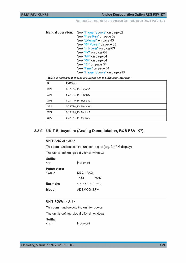
Analog Demodulation Option R&S FSV–K7R&S® FSV-K7/K7S
169Operating Manual 1176.7561.02 ─ 05
Manual operation: See "Trigger Source" on page 62See "Free Run" on page 62See "External" on page 63See "RF Power" on page 63See "IF Power" on page 63See "FM" on page 64See "AM" on page 64See "PM" on page 64See "RF" on page 64See "Time" on page 64See "Trigger Source" on page 216
Table 2-6: Assignment of general purpose bits to LVDS connector pins
Bit LVDS pin
GP0 SDATA4_P - Trigger1
GP1 SDATA4_P - Trigger2
GP2 SDATA0_P - Reserve1
GP3 SDATA4_P - Reserve2
GP4 SDATA0_P - Marker1
GP5 SDATA4_P - Marker2
2.3.9 UNIT Subsystem (Analog Demodulation, R&S FSV–K7)
UNIT:ANGLe <Unit>
This command selects the unit for angles (e.g. for PM display).
The unit is defined globally for all windows.
Suffix: <n>
.irrelevant
Parameters:<Unit> DEG | RAD
*RST: RAD
Example: UNIT:ANGL DEGMode: ADEMOD, SFM
UNIT:POWer <Unit>
This command selects the unit for power.
The unit is defined globally for all windows.
Suffix: <n>
.irrelevant
Remote Commands of the Analog Demodulation (R&S FSV–K7)

Analog Demodulation Option R&S FSV–K7R&S® FSV-K7/K7S
170Operating Manual 1176.7561.02 ─ 05
Parameters:<Unit> DBM | V | A | W | DBPW | WATT | DBUV | DBMV | VOLT |
DBUA | AMPere*RST: dBm
Example: UNIT:POW DBMSets the power unit to dBm.
Mode: A, ADEMOD, SFM, SPECM
UNIT:THD <Mode>
Selects the unit for THD measurements.
Parameters:<Mode> DB | PCT
*RST: DB
Example: UNIT:THD PCTMode: ADEMOD, SFM
Manual operation: See "Phase Unit (Rad/Deg)" on page 33See "THD Unit (% / DB)" on page 33
2.3.10 Other Commands Referenced in this Manual
2.3.10.1 CALCulate:DELTamarker Subsystem (Analog Demodulation, R&S FSV–K7)
The CALCulate:DELTamarker subsystem controls the delta marker functions of theinstrument.
CALCulate<n>:DELTamarker<m>:FUNCtion:FIXed:RPOint:MAXimum[:PEAK].................... 170CALCulate<n>:DELTamarker<m>:FUNCtion:FIXed:RPOint:X............................................ 171CALCulate<n>:DELTamarker<m>:FUNCtion:FIXed:RPOint:Y............................................ 171CALCulate<n>:DELTamarker<m>:FUNCtion:FIXed[:STATe].............................................. 172CALCulate<n>:DELTamarker<m>:FUNCtion:PNOise[:STATe]........................................... 172CALCulate<n>:DELTamarker<m>:FUNCtion:PNOise:AUTO.............................................. 173CALCulate<n>:DELTamarker<m>:LINK........................................................................... 173CALCulate<n>:DELTamarker<m>:MREF......................................................................... 174CALCulate<n>:DELTamarker<m>[:STATe].......................................................................174CALCulate<n>:DELTamarker<m>:TRACe........................................................................174CALCulate<n>:DELTamarker<m>:X................................................................................ 175CALCulate<n>:DELTamarker<m>:X:RELative?.................................................................175CALCulate<n>:DELTamarker<m>:Y?...............................................................................176
CALCulate<n>:DELTamarker<m>:FUNCtion:FIXed:RPOint:MAXimum[:PEAK]
This command moves the fixed reference marker to the peak power.
Remote Commands of the Analog Demodulation (R&S FSV–K7)
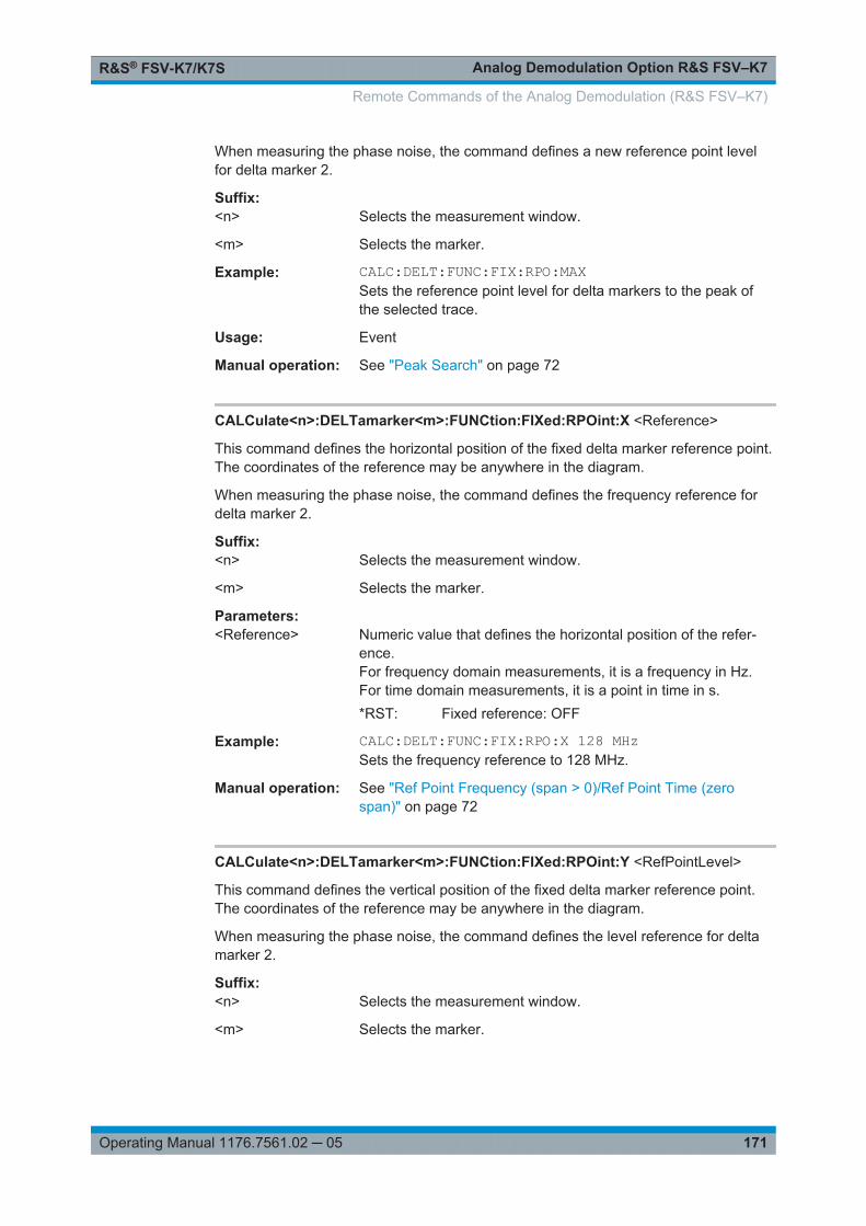
Analog Demodulation Option R&S FSV–K7R&S® FSV-K7/K7S
171Operating Manual 1176.7561.02 ─ 05
When measuring the phase noise, the command defines a new reference point levelfor delta marker 2.
Suffix: <n>
.Selects the measurement window.
<m> Selects the marker.
Example: CALC:DELT:FUNC:FIX:RPO:MAXSets the reference point level for delta markers to the peak ofthe selected trace.
Usage: Event
Manual operation: See "Peak Search" on page 72
CALCulate<n>:DELTamarker<m>:FUNCtion:FIXed:RPOint:X <Reference>
This command defines the horizontal position of the fixed delta marker reference point.The coordinates of the reference may be anywhere in the diagram.
When measuring the phase noise, the command defines the frequency reference fordelta marker 2.
Suffix: <n>
.Selects the measurement window.
<m> Selects the marker.
Parameters:<Reference> Numeric value that defines the horizontal position of the refer-
ence.For frequency domain measurements, it is a frequency in Hz.For time domain measurements, it is a point in time in s.*RST: Fixed reference: OFF
Example: CALC:DELT:FUNC:FIX:RPO:X 128 MHzSets the frequency reference to 128 MHz.
Manual operation: See "Ref Point Frequency (span > 0)/Ref Point Time (zerospan)" on page 72
CALCulate<n>:DELTamarker<m>:FUNCtion:FIXed:RPOint:Y <RefPointLevel>
This command defines the vertical position of the fixed delta marker reference point.The coordinates of the reference may be anywhere in the diagram.
When measuring the phase noise, the command defines the level reference for deltamarker 2.
Suffix: <n>
.Selects the measurement window.
<m> Selects the marker.
Remote Commands of the Analog Demodulation (R&S FSV–K7)

Analog Demodulation Option R&S FSV–K7R&S® FSV-K7/K7S
172Operating Manual 1176.7561.02 ─ 05
Parameters:<RefPointLevel> Numeric value that defines the vertical position of the reference.
The unit and value range is variable.*RST: Fixed reference: OFF
Example: CALC:DELT:FUNC:FIX:RPO:Y -10dBmSets the reference point level for delta markers to -10 dBm.
Manual operation: See "Ref Point Level" on page 72
CALCulate<n>:DELTamarker<m>:FUNCtion:FIXed[:STATe] <State>
This command switches the relative measurement to a fixed reference value on or off.Marker 1 is activated previously and a peak search is performed, if necessary. Ifmarker 1 is activated, its position becomes the reference point for the measurement.The reference point can then be modified with the CALCulate<n>:DELTamarker<m>:FUNCtion:FIXed:RPOint:X commands and CALCulate<n>:DELTamarker<m>:FUNCtion:FIXed:RPOint:Y independently of the position ofmarker 1 and of a trace. It applies to all delta markers as long as the function is active.
Suffix: <n>
.Selects the measurement window.
<m> Selects the marker.
Parameters:<State> ON | OFF
*RST: OFF
Example: CALC:DELT:FUNC:FIX ONSwitches on the measurement with fixed reference value for alldelta markers.CALC:DELT:FUNC:FIX:RPO:X 128 MHZSets the frequency reference to 128 MHz.CALC:DELT:FUNC:FIX:RPO:Y 30 DBMSets the reference level to +30 dBm.
Manual operation: See "Ref. Fixed On/Off" on page 71
CALCulate<n>:DELTamarker<m>:FUNCtion:PNOise[:STATe] <State>
This command turns the phase noise measurement at the delta marker position on andoff.
The correction values for the bandwidth and the log amplifier are taken into account inthe measurement.
The reference marker for phase noise measurements is either a normal marker or afixed reference. If necessary, the command turns on the reference marker
A fixed reference point can be modified with the CALCulate<n>:DELTamarker<m>:FUNCtion:FIXed:RPOint:X and CALCulate<n>:DELTamarker<m>:FUNCtion:FIXed:RPOint:Y commands independent of the position of marker 1 and of a trace.
Remote Commands of the Analog Demodulation (R&S FSV–K7)

Analog Demodulation Option R&S FSV–K7R&S® FSV-K7/K7S
173Operating Manual 1176.7561.02 ─ 05
Suffix: <n>
.Selects the measurement window.
<m> irrelevantNote: marker 2 is always the deltamarker for phase noise mea-surement results.
Parameters:<State> ON | OFF
*RST: OFF
Example: CALC:DELT:FUNC:PNO ONSwitches on the phase-noise measurement with all delta mark-ers.CALC:DELT:FUNC:FIX:RPO:X 128 MHZSets the frequency reference to 128 MHz.CALC:DELT:FUNC:FIX:RPO:Y 30 DBMSets the reference level to +30 dBm
CALCulate<n>:DELTamarker<m>:FUNCtion:PNOise:AUTO <State>
This command turns an automatic peak search for the fixed reference marker at theend of a sweep on and off.
Suffix: <n>
.Selects the measurement window.
<m> irrelevant
Parameters:<State> ON | OFF
*RST: OFF
Example: CALC:DELT:FUNC:PNO:AUTO ONActivates an automatic peak search for the reference marker ina phase-noise measurement.
CALCulate<n>:DELTamarker<m>:LINK <State>
This command links delta marker 1 to marker 1.
If you change the horizontal position of the marker, so does the delta marker.
Suffix: <n>
.Selects the measurement window.
<m> 1irrelevant
Parameters:<State> ON | OFF
*RST: OFF
Example: CALC:DELT:LINK ON
Remote Commands of the Analog Demodulation (R&S FSV–K7)
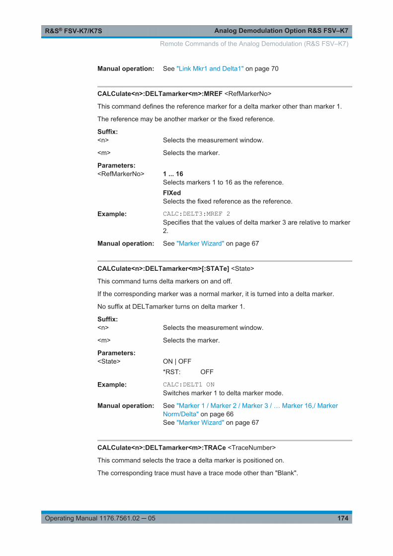
Analog Demodulation Option R&S FSV–K7R&S® FSV-K7/K7S
174Operating Manual 1176.7561.02 ─ 05
Manual operation: See "Link Mkr1 and Delta1" on page 70
CALCulate<n>:DELTamarker<m>:MREF <RefMarkerNo>
This command defines the reference marker for a delta marker other than marker 1.
The reference may be another marker or the fixed reference.
Suffix: <n>
.Selects the measurement window.
<m> Selects the marker.
Parameters:<RefMarkerNo> 1 ... 16
Selects markers 1 to 16 as the reference.FIXedSelects the fixed reference as the reference.
Example: CALC:DELT3:MREF 2Specifies that the values of delta marker 3 are relative to marker2.
Manual operation: See "Marker Wizard" on page 67
CALCulate<n>:DELTamarker<m>[:STATe] <State>
This command turns delta markers on and off.
If the corresponding marker was a normal marker, it is turned into a delta marker.
No suffix at DELTamarker turns on delta marker 1.
Suffix: <n>
.Selects the measurement window.
<m> Selects the marker.
Parameters:<State> ON | OFF
*RST: OFF
Example: CALC:DELT1 ONSwitches marker 1 to delta marker mode.
Manual operation: See "Marker 1 / Marker 2 / Marker 3 / … Marker 16,/ MarkerNorm/Delta" on page 66See "Marker Wizard" on page 67
CALCulate<n>:DELTamarker<m>:TRACe <TraceNumber>
This command selects the trace a delta marker is positioned on.
The corresponding trace must have a trace mode other than "Blank".
Remote Commands of the Analog Demodulation (R&S FSV–K7)

Analog Demodulation Option R&S FSV–K7R&S® FSV-K7/K7S
175Operating Manual 1176.7561.02 ─ 05
Suffix: <n>
.Selects the measurement window.
<m> Selects the marker.
Parameters:<TraceNumber> 1 ... 6
Trace number the marker is positioned on.
Example: CALC:DELT3:TRAC 2Assigns delta marker 3 to trace 2.
Manual operation: See "Marker Wizard" on page 67
CALCulate<n>:DELTamarker<m>:X <Position>
This command positions a delta marker on a particular coordinate on the x-axis.
The position is an absolute value.
Suffix: <n>
.Selects the measurement window.
<m> Selects the marker.
Parameters:<Position> 0 to maximum frequency or sweep time
Example: CALC:DELT:X?Outputs the absolute frequency/time of delta marker 1.
Manual operation: See "Marker 1 / Marker 2 / Marker 3 / … Marker 16,/ MarkerNorm/Delta" on page 66
CALCulate<n>:DELTamarker<m>:X:RELative?
This command queries the x-value of the selected delta marker relative to marker 1 orto the reference position (for CALC:DELT:FUNC:FIX:STAT ON). The command acti-vates the corresponding delta marker, if necessary.
Suffix: <n>
.Selects the measurement window.
<m> Selects the marker.
Example: CALC:DELT3:X:REL?Outputs the frequency of delta marker 3 relative to marker 1 orrelative to the reference position.
Usage: Query only
Manual operation: See "Marker 1 / Marker 2 / Marker 3 / … Marker 16,/ MarkerNorm/Delta" on page 66
Remote Commands of the Analog Demodulation (R&S FSV–K7)
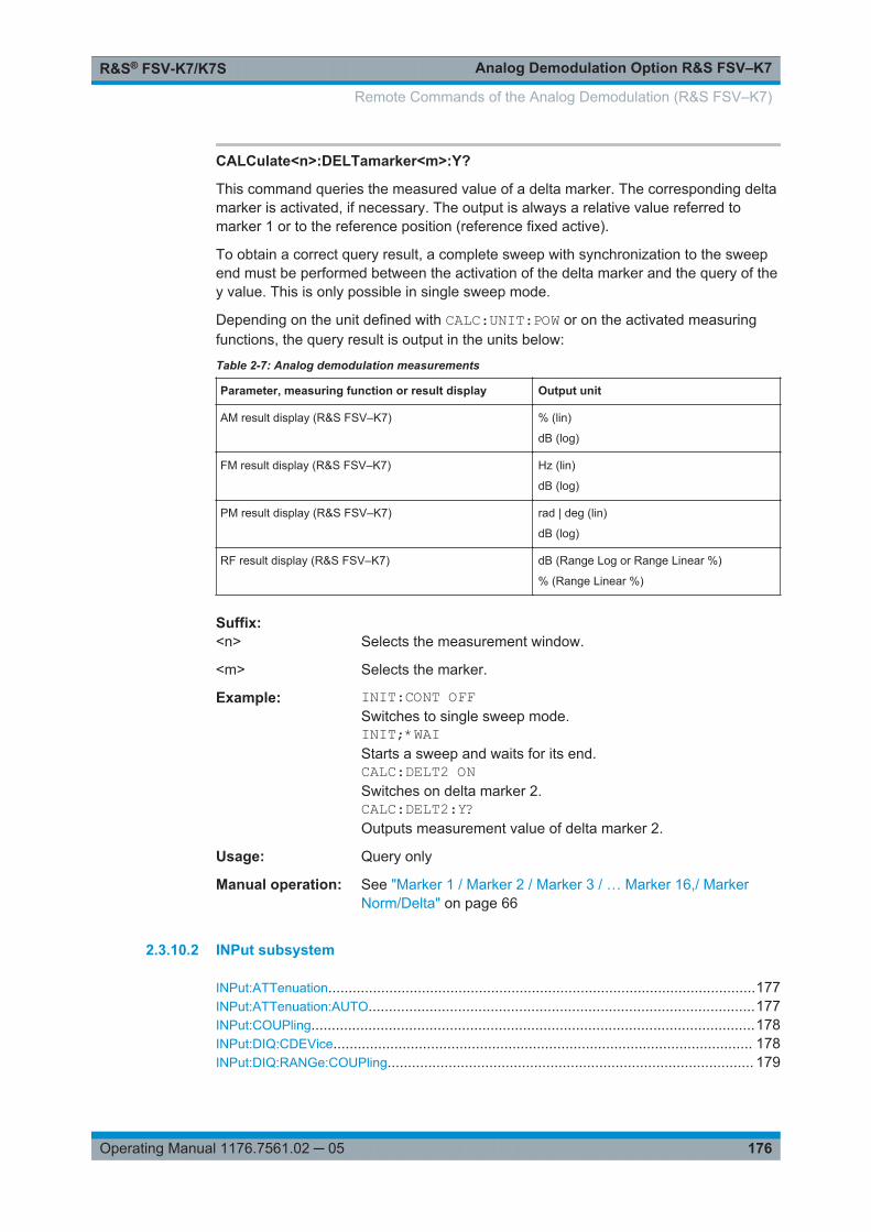
Analog Demodulation Option R&S FSV–K7R&S® FSV-K7/K7S
176Operating Manual 1176.7561.02 ─ 05
CALCulate<n>:DELTamarker<m>:Y?
This command queries the measured value of a delta marker. The corresponding deltamarker is activated, if necessary. The output is always a relative value referred tomarker 1 or to the reference position (reference fixed active).
To obtain a correct query result, a complete sweep with synchronization to the sweepend must be performed between the activation of the delta marker and the query of they value. This is only possible in single sweep mode.
Depending on the unit defined with CALC:UNIT:POW or on the activated measuringfunctions, the query result is output in the units below:
Table 2-7: Analog demodulation measurements
Parameter, measuring function or result display Output unit
AM result display (R&S FSV–K7) % (lin)
dB (log)
FM result display (R&S FSV–K7) Hz (lin)
dB (log)
PM result display (R&S FSV–K7) rad | deg (lin)
dB (log)
RF result display (R&S FSV–K7) dB (Range Log or Range Linear %)
% (Range Linear %)
Suffix: <n>
.Selects the measurement window.
<m> Selects the marker.
Example: INIT:CONT OFFSwitches to single sweep mode.INIT;*WAIStarts a sweep and waits for its end.CALC:DELT2 ONSwitches on delta marker 2.CALC:DELT2:Y?Outputs measurement value of delta marker 2.
Usage: Query only
Manual operation: See "Marker 1 / Marker 2 / Marker 3 / … Marker 16,/ MarkerNorm/Delta" on page 66
2.3.10.2 INPut subsystem
INPut:ATTenuation.........................................................................................................177INPut:ATTenuation:AUTO...............................................................................................177INPut:COUPling.............................................................................................................178INPut:DIQ:CDEVice....................................................................................................... 178INPut:DIQ:RANGe:COUPling.......................................................................................... 179
Remote Commands of the Analog Demodulation (R&S FSV–K7)
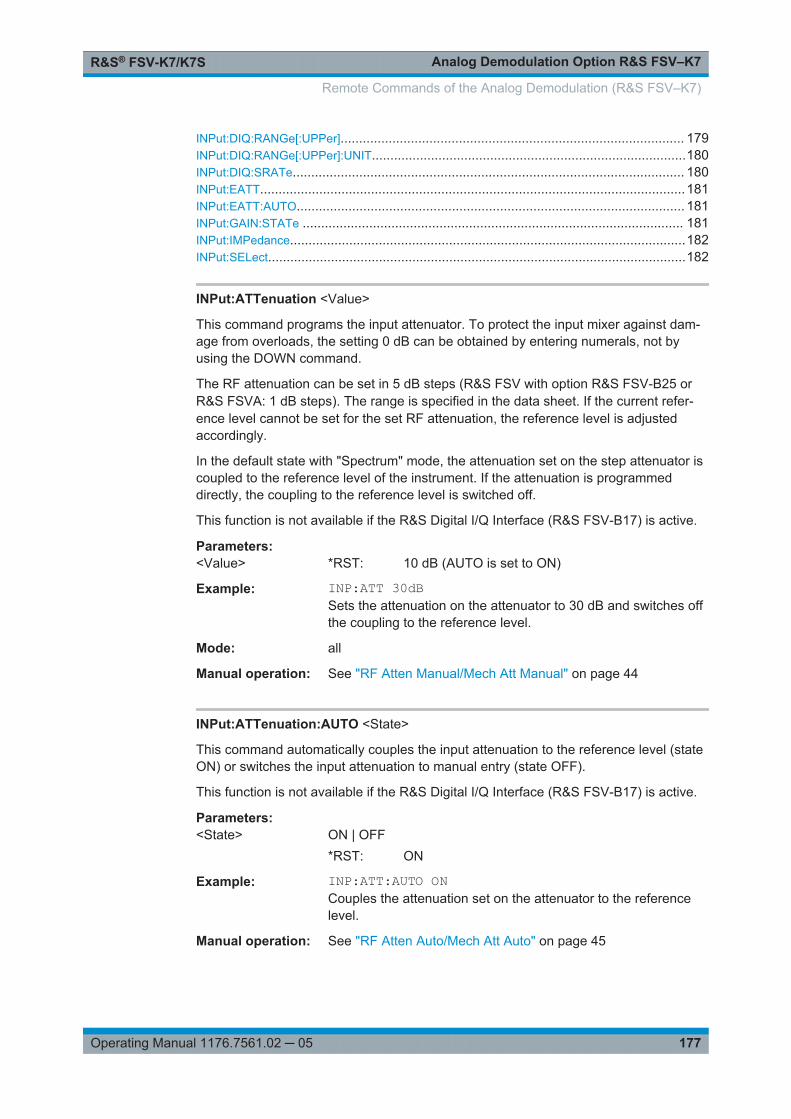
Analog Demodulation Option R&S FSV–K7R&S® FSV-K7/K7S
177Operating Manual 1176.7561.02 ─ 05
INPut:DIQ:RANGe[:UPPer]............................................................................................. 179INPut:DIQ:RANGe[:UPPer]:UNIT.....................................................................................180INPut:DIQ:SRATe.......................................................................................................... 180INPut:EATT...................................................................................................................181INPut:EATT:AUTO......................................................................................................... 181INPut:GAIN:STATe ....................................................................................................... 181INPut:IMPedance...........................................................................................................182INPut:SELect.................................................................................................................182
INPut:ATTenuation <Value>
This command programs the input attenuator. To protect the input mixer against dam-age from overloads, the setting 0 dB can be obtained by entering numerals, not byusing the DOWN command.
The RF attenuation can be set in 5 dB steps (R&S FSV with option R&S FSV-B25 orR&S FSVA: 1 dB steps). The range is specified in the data sheet. If the current refer-ence level cannot be set for the set RF attenuation, the reference level is adjustedaccordingly.
In the default state with "Spectrum" mode, the attenuation set on the step attenuator iscoupled to the reference level of the instrument. If the attenuation is programmeddirectly, the coupling to the reference level is switched off.
This function is not available if the R&S Digital I/Q Interface (R&S FSV-B17) is active.
Parameters:<Value> *RST: 10 dB (AUTO is set to ON)
Example: INP:ATT 30dBSets the attenuation on the attenuator to 30 dB and switches offthe coupling to the reference level.
Mode: all
Manual operation: See "RF Atten Manual/Mech Att Manual" on page 44
INPut:ATTenuation:AUTO <State>
This command automatically couples the input attenuation to the reference level (stateON) or switches the input attenuation to manual entry (state OFF).
This function is not available if the R&S Digital I/Q Interface (R&S FSV-B17) is active.
Parameters:<State> ON | OFF
*RST: ON
Example: INP:ATT:AUTO ONCouples the attenuation set on the attenuator to the referencelevel.
Manual operation: See "RF Atten Auto/Mech Att Auto" on page 45
Remote Commands of the Analog Demodulation (R&S FSV–K7)
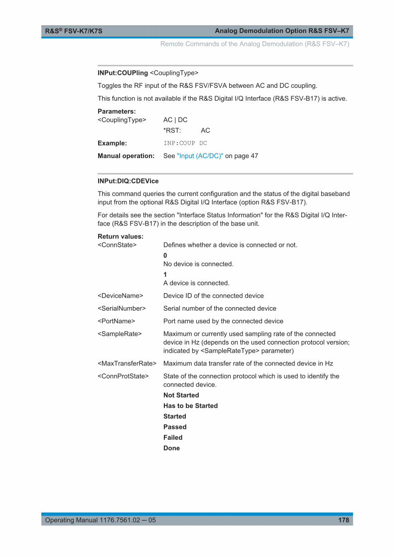
Analog Demodulation Option R&S FSV–K7R&S® FSV-K7/K7S
178Operating Manual 1176.7561.02 ─ 05
INPut:COUPling <CouplingType>
Toggles the RF input of the R&S FSV/FSVA between AC and DC coupling.
This function is not available if the R&S Digital I/Q Interface (R&S FSV-B17) is active.
Parameters:<CouplingType> AC | DC
*RST: AC
Example: INP:COUP DCManual operation: See "Input (AC/DC)" on page 47
INPut:DIQ:CDEVice
This command queries the current configuration and the status of the digital basebandinput from the optional R&S Digital I/Q Interface (option R&S FSV-B17).
For details see the section "Interface Status Information" for the R&S Digital I/Q Inter-face (R&S FSV-B17) in the description of the base unit.
Return values: <ConnState> Defines whether a device is connected or not.
0No device is connected.1A device is connected.
<DeviceName> Device ID of the connected device
<SerialNumber> Serial number of the connected device
<PortName> Port name used by the connected device
<SampleRate> Maximum or currently used sampling rate of the connecteddevice in Hz (depends on the used connection protocol version;indicated by <SampleRateType> parameter)
<MaxTransferRate> Maximum data transfer rate of the connected device in Hz
<ConnProtState> State of the connection protocol which is used to identify theconnected device.Not StartedHas to be StartedStartedPassedFailedDone
Remote Commands of the Analog Demodulation (R&S FSV–K7)

Analog Demodulation Option R&S FSV–K7R&S® FSV-K7/K7S
179Operating Manual 1176.7561.02 ─ 05
<PRBSTestState> State of the PRBS test.Not StartedHas to be StartedStartedPassedFailedDone
<SampleRateType> 0Maximum sampling rate is displayed1Current sampling rate is displayed
<Placeholder> for future use; currently "0"
Example: INP:DIQ:CDEV?Result:1,SMU200A,103634,OutA,70000000,100000000,Passed,Not Started,0,0
Mode: IQ, VSA, EVDO, CDMA, WCDMA, GSM, ADEMOD, TDS
Manual operation: See "Connected Device" on page 77See "Digital IQ Info" on page 79
INPut:DIQ:RANGe:COUPling <State>
If enabled, the reference level for digital input is adjusted to the full scale level automat-ically if the fullscale level changes.
This command is only available if the optional R&S Digital I/Q Interface (optionR&S FSV-B17) is installed.
For details see the R&S Digital I/Q Interface (R&S FSV-B17) description of the baseunit.
Parameters:<State> ON | OFF
*RST: OFF
Example: INP:DIQ:RANG:COUP OFFMode: IQ, VSA, EVDO, CDMA, WCDMA, GSM, ADEMOD, TDS
Manual operation: See "Adjust Reference Level to Full Scale Level" on page 78
INPut:DIQ:RANGe[:UPPer] <Level>
Defines or queries the "Full Scale Level", i.e. the level that should correspond to an I/Qsample with the magnitude "1".
It can be defined either in dBm or Volt (see "Full Scale Level" on page 77).
Remote Commands of the Analog Demodulation (R&S FSV–K7)
Analog Demodulation Option R&S FSV–K7R&S® FSV-K7/K7S
180Operating Manual 1176.7561.02 ─ 05
This command is only available if the optional R&S Digital I/Q Interface (optionR&S FSV-B17) is installed.
For details see the R&S Digital I/Q Interface (R&S FSV-B17) description of the baseunit.
Parameters:<Level> <numeric value>
Range: 70.711 nV to 7.071 V*RST: 1 V
Example: INP:DIQ:RANG 1VMode: A, IQ, NF, TDS, VSA, CDMA, EVDO, WCDMA, ADEMOD,
GSM, OFDM, OFDMA/WiBro, WLAN
Manual operation: See "Full Scale Level" on page 77
INPut:DIQ:RANGe[:UPPer]:UNIT <Unit>
Defines the unit of the full scale level (see "Level Unit" on page 77). The availability ofunits depends on the measurement application you are using.
This command is only available if the optional R&S Digital I/Q Interface (optionR&S FSV-B17) is installed.
For details see the R&S Digital I/Q Interface (R&S FSV-B17) description of the baseunit.
Parameters:<Level> V | dBm | dBpW | W | dBmV | dBuV | dBuA | A
*RST: Volt
Example: INP:DIQ:RANG:UNIT AMode: IQ, VSA, EVDO, CDMA, WCDMA, GSM, ADEMOD, TDS
Manual operation: See "Level Unit" on page 77
INPut:DIQ:SRATe <SampleRate>
This command specifies or queries the sample rate of the input signal from the R&SDigital I/Q Interface (see "Input Sample Rate" on page 77).
Note: the final user sample rate of the R&S FSV/FSVA may differ and is defined usingSENSe:ADEM:SRATe (see [SENSe:]ADEMod:SRATe? on page 143).
This command is only available if the optional R&S Digital I/Q Interface (optionR&S FSV-B17) is installed.
For details see the R&S Digital I/Q Interface (R&S FSV-B17) description of the baseunit.
Parameters:<SampleRate> Range: 1 Hz to 10 GHz
*RST: 32 MHz
Remote Commands of the Analog Demodulation (R&S FSV–K7)
Analog Demodulation Option R&S FSV–K7R&S® FSV-K7/K7S
181Operating Manual 1176.7561.02 ─ 05
Example: INP:DIQ:SRAT 200 MHz
Mode: A, IQ, NF, TDS, VSA, CDMA, EVDO, WCDMA, ADEMOD,GSM, OFDM, OFDMA/WiBro, WLAN
Manual operation: See "Input Sample Rate" on page 77
INPut:EATT <Attenuation>
This command defines the electronic attenuation.
If necessary, the command also turns the electronic attenuator on.
This command is only available with option R&S FSV-B25, but not if R&S FSV-B17 isactive.
The attenuation can be varied in 1 dB steps from 0 to 25 dB. Other entries are roundedto the next lower integer value.
If the defined reference level cannot be set for the given RF attenuation, the referencelevel is adjusted accordingly and the warning "Limit reached" is output.
Parameters:<Attenuation> 0...25
*RST: 0 dB (OFF)
Example: INP1:EATT 10 dBMode: all
Manual operation: See "El Atten Mode (Auto/Man)" on page 46
INPut:EATT:AUTO <State>
This command switches the automatic behaviour of the electronic attenuator on or off.If activated, electronic attenuation is used to reduce the operation of the mechanicalattenuation whenever possible.
This command is only available with option R&S FSV-B25, but not if R&S FSV-B17 isactive.
Parameters:<State> ON | OFF
*RST: ON
Example: INP1:EATT:AUTO OFFMode: all
Manual operation: See "El Atten On/Off" on page 45See "El Atten Mode (Auto/Man)" on page 46
INPut:GAIN:STATe <State>
This command turns the 20 dB preamplifier on and off.
Remote Commands of the Analog Demodulation (R&S FSV–K7)

Analog Demodulation Option R&S FSV–K7R&S® FSV-K7/K7S
182Operating Manual 1176.7561.02 ─ 05
With option R&S FSV-B22, the preamplifier only has an effect below 7 GHz.
With option R&S FSV-B24, the amplifier applies to the entire frequency range.
This command is not available when using R&S Digital I/Q Interface (R&S FSV-B17).
Parameters:<State> ON | OFF
*RST: OFF
Example: INP:GAIN:STAT ONTurns the preamplifier on.
Manual operation: See "Preamp On/Off" on page 44
INPut:IMPedance <Impedance>
This command selects the nominal input impedance.
75 Ω should be selected if the 50 Ω input impedance is transformed to a higher impe-dance using a 75 Ω adapter of the RAZ type (= 25 Ω in series to the input impedanceof the instrument). The correction value in this case is 1.76 dB = 10 log (75Ω/50Ω).
This function is not available if the R&S Digital I/Q Interface (R&S FSV-B17) is active.
Parameters:<Impedance> 50 | 75
*RST: 50 Ω
Example: INP:IMP 75Manual operation: See "Input 50 Ω/75 Ω " on page 47
INPut:SELect <Source>
This command selects the signal source for measurements.
Parameters:<Source> RF | DIQ
RFRadio Frequency ("RF INPUT" connector)DIQDigital IQ (only available with R&S Digital I/Q Interface, optionR&S FSV-B17)*RST: RF
Example: INP:SEL RF
Mode: A, IQ, NF, TDS, VSA, CDMA, EVDO, WCDMA, ADEMOD,GSM, OFDM, OFDMA/WiBro, WLAN
Manual operation: See "Input Path" on page 77
Remote Commands of the Analog Demodulation (R&S FSV–K7)
Analog Demodulation Option R&S FSV–K7R&S® FSV-K7/K7S
183Operating Manual 1176.7561.02 ─ 05
2.3.10.3 MMEMory subsystem
MMEMory:STORe<n>:LIST <FileName>
This command stores the current list evaluation results in a <file name>.dat file.The file consists of a data section containing the list evaluation results.
Suffix: <n>
.irrelevant
Parameters:<FileName> <file name>
Example: MMEM:STOR:LIST 'test'Stores the current list evaluation results in the test.dat file.
Manual operation: See "ASCII File Export" on page 74
OUTPut:IF[:SOURce] <Source>
This command selects the source of the IF output.
Parameters:<Source> IF
Outputs the intermediate frequency.VIDeoOutputs the video signal (200 mV).*RST: IF
Example: OUTP:IF VIDSelects the video signal for the IF output connector.
Manual operation: See "Video Output" on page 76
MMEMory:STORe<n>:TRACe <Trace>, <FileName>
This command stores the selected trace in the specified window in a file with ASCII for-mat. The file format is described in Chapter 2.1.11, "ASCII File Export Format",on page 23
The decimal separator (decimal point or comma) for floating-point numerals containedin the file is defined with the FORMat:DEXPort:DSEParator command (seeFORMat:DEXPort:DSEParator on page 185).
Suffix: <n>
.window; For applications that do not have more than 1 measure-ment window, the suffix <n> is irrelevant.
Parameters:<Trace> 1 to 6
Selected a trace.
Remote Commands of the Analog Demodulation (R&S FSV–K7)

Analog Demodulation Option R&S FSV–K7R&S® FSV-K7/K7S
184Operating Manual 1176.7561.02 ─ 05
<FileName> DOS file nameThe file name includes indication of the path and the drive name.Indication of the path complies with DOS conventions.
Example: MMEM:STOR:TRAC 3,'TEST.ASC'Stores trace 3 in the file TEST.ASC.
Manual operation: See "ASCII Trace Export" on page 61
2.3.10.4 OUTPut subsystem
OUTPut:DIQ <State>
If enabled, the captured IQ data is output to the R&S Digital I/Q Interface in a continu-ous stream. This function requires the LVDS interface option (R&S FSV-B17).
Digital input and digital output cannot be used simultaneously.
Parameters:<State> ON | OFF
*RST: OFF
Example: OUTP:DIQ ONMode: ADEMOD, IQ, VSA
OUTPut:TRIGger <PortLevel>
This command selects level of the Trigger Out port. Thus, you can trigger an additionaldevice via the external trigger port, for example.
Parameters:<PortLevel> LOW | HIGH
*RST: LOW
Example: OUTP:TRIG HIGHManual operation: See "Trigger Out" on page 76
2.3.10.5 Other Commands
FORMat[:DATA] <Format>
This command selects the data format for the data transmitted from the R&S FSV/FSVA to the controlling computer. It is used for the transmission of trace data. Thedata format of trace data received by the instrument is automatically recognized,regardless of the format which is programmed.
(See also TRACe<n>[:DATA]? on page 160).
Remote Commands of the Analog Demodulation (R&S FSV–K7)
Analog Demodulation Option R&S FSV–K7R&S® FSV-K7/K7S
185Operating Manual 1176.7561.02 ─ 05
Parameters:<Format> ASCii
ASCII data are transmitted in plain text, separated by commas.REALREAL data are transmitted as 32-bit IEEE 754 floating-pointnumbers in the "definite length block format".*RST: ASCII
Example: FORM REAL,32FORM ASC
FORMat:DEXPort:DSEParator <Separator>
This command defines which decimal separator (decimal point or comma) is to beused for outputting measurement data to the file in ASCII format. Different languagesof evaluation programs (e.g. MS-Excel) can thus be supported.
Parameters:<Separator> POINt | COMMA
*RST: (factory setting is POINt; *RST does not affect set-ting)
Example: FORM:DEXP:DSEP POINSets the decimal point as separator.
Manual operation: See "ASCII Trace Export" on page 61See "Decim Sep" on page 62See "ASCII File Export" on page 74
DIAGnostic<n>:SERVice:NSOurce <State>
This command switches the 28 V supply of the noise source on the front panel on oroff.
Suffix: <n>
.irrelevant
Parameters:<State> ON | OFF
*RST: OFF
Example: DIAG:SERV:NSO ONManual operation: See "Noise Source" on page 76
INITiate<n>:CONMeas
This command restarts a measurement that has been stopped in single sweep mode.
The measurement is restarted at the first sweep point.
Remote Commands of the Analog Demodulation (R&S FSV–K7)
Analog Demodulation Option R&S FSV–K7R&S® FSV-K7/K7S
186Operating Manual 1176.7561.02 ─ 05
As opposed to INITiate<n>[:IMMediate], this command does not reset traces inmaxhold, minhold or average mode. Therefore it can be used to continue measure-ments using max hold or averaging functions.
In single sweep mode, you can synchronize to the end of the measurement with *OPC,*OPC? or *WAI. In continuous sweep mode, synchronization to the end of the mea-surement is not possible. Thus, it is not recommended that you use continuous sweepmode in remote control, as results like trace data or markers are only valid after a sin-gle sweep end synchronization.
Suffix: <n>
.irrelevant
Example: INIT:CONT OFFSwitches to single sweep mode.DISP:WIND:TRAC:MODE AVERSwitches on trace averaging.SWE:COUN 20Setting the sweep counter to 20 sweeps.INIT;*WAIStarts the measurement and waits for the end of the 20 sweeps.INIT:CONM;*WAIContinues the measurement (next 20 sequences) and waits forthe end.
Manual operation: See "Continue Single Sweep" on page 54
INITiate<n>:CONTinuous <State>
This command determines whether the trigger system is continuously initiated (contin-uous) or performs single measurements (single).
The sweep is started immediately.
Suffix: <n>
.irrelevant
Parameters:<State> ON | OFF
*RST: ON
Example: INIT:CONT OFFSwitches the sequence to single sweep.INIT:CONT ONSwitches the sequence to continuous sweep.
Mode: all
Manual operation: See "Continuous Sweep" on page 54See "Single Sweep" on page 54
INITiate<n>[:IMMediate]
The command initiates a new measurement sequence.
Remote Commands of the Analog Demodulation (R&S FSV–K7)
Analog Demodulation Option R&S FSV–K7R&S® FSV-K7/K7S
187Operating Manual 1176.7561.02 ─ 05
With sweep count > 0 or average count > 0, this means a restart of the indicated num-ber of measurements. With trace functions MAXHold, MINHold and AVERage, the pre-vious results are reset on restarting the measurement.
In single sweep mode, you can synchronize to the end of the measurement with *OPC,*OPC? or *WAI. In continuous sweep mode, synchronization to the end of the mea-surement is not possible. Thus, it is not recommended that you use continuous sweepmode in remote control, as results like trace data or markers are only valid after a sin-gle sweep end synchronization.
Suffix: <n>
.irrelevant
Example: INIT:CONT OFFSwitches to single sweep mode.DISP:WIND:TRAC:MODE AVERSwitches on trace averaging.SWE:COUN 20Setting the sweep counter to 20 sweeps.INIT;*WAIStarts the measurement and waits for the end of the 20 sweeps.
Mode: all
SYSTem:DISPlay:UPDate <State>
In remote control mode, this command switches on or off the instrument display. Ifswitched on, only the diagrams, traces and display fields are displayed and updated.
The best performance is obtained if the display output is switched off during remotecontrol.
Parameters:<State> ON | OFF
*RST: OFF
Example: SYST:DISP:UPD ON
Remote Commands of the Analog Demodulation (R&S FSV–K7)
FM Stereo Option R&S FSV–K7SR&S® FSV-K7/K7S
188Operating Manual 1176.7561.02 ─ 05
3 FM Stereo Option R&S FSV–K7SThe firmware option "FM Stereo" extends the "Analog Demodulation" option K7 to han-dle FM stereo signals. The "FM Stereo" mode requires an instrument equipped withthe corresponding optional software, as well as the Analog Demodulation option (K7).
This section contains all information required for operation of an R&S FSV/FSVAequipped with Application Firmware R&S FSV–K7S. It covers operation via menus andthe remote control commands for FM stereo analog demodulation measurements.
● Chapter 3.1, "Instrument Functions FM Stereo (R&S FSV–K7S)", on page 188shows all softkeys available in the "FM Stereo" menu. This chapter also presentsthe remote control commands associated with each softkey function.
● The following chapters describe the softkeys of the other keys for the FM Stereooption.
● Chapter 3.2, "Remote Commands of the FM Stereo Option (R&S FSV–K7S)",on page 227 describes all remote control commands defined for the FM Stereooption.
This part of the documentation includes only additional functions of the ApplicationFirmware R&S FSV–K7S. For all other descriptions, please refer to the description ofthe Analog Demodulation option K7 (see Chapter 2.2.1, "Softkeys of the AnalogDemodulation Menu", on page 25).
3.1 Instrument Functions FM Stereo (R&S FSV–K7S)
The firmware option R&S FSV–K7S (together with the Analog Demodulation option K7)provides the necessary measurement functions to demodulate FM stereo signals. Itallows you to detect and analyze characteristic data in an FM stereo signal.
To open the FM Stereo menu
● If the "FM Stereo" mode is not the active measurement mode, press the MODE keyand select the "FM Stereo" softkey.
● If the "FM Stereo" mode is already active, press the HOME key or the MEAS key.The "FM Stereo" menu is displayed.
Menu and softkey description
The following softkey menus are specific to the FM Stereo option:
● Chapter 3.1.2, "Softkeys of the FM Stereo Menu - MEAS key (K7S)", on page 192● Chapter 3.1.3, "Softkeys of the Amplitude Menu – AMPT Key (R&S FSV–K7S)",
on page 206● Chapter 3.1.6, "Softkeys of the Marker Function Menu – MKR FUNC Key
(R&S FSV–K7S)", on page 220● Chapter 3.1.5, "Softkeys of the Trigger Menu – TRIG Key (R&S FSV–K7S)",
on page 215
Instrument Functions FM Stereo (R&S FSV–K7S)

FM Stereo Option R&S FSV–K7SR&S® FSV-K7/K7S
189Operating Manual 1176.7561.02 ─ 05
Apart from the power measurement menu (MEAS key) that is not available in the "FMStereo" mode, all other menus not described here are provided as described for Ana-log Demodulation mode (R&S FSV-K7). For details refer to the corresponding menudescriptions.
● Chapter 2.2.2, "Softkeys of the Frequency Menu – FREQ Key (Analog Demodula-tion)", on page 38
● Chapter 2.2.3, "Softkeys of the Span Menu – SPAN Key (Analog Demodulation)",on page 40
● Chapter 2.2.5, "Softkeys of the Auto Set menu - AUTO SET Key (Analog Demodu-lation)", on page 47
● Chapter 2.2.7, "Softkeys of the Sweep Menu – SWEEP Key (Analog Demodula-tion)", on page 54
● Chapter 2.2.8, "Softkeys of the Trace Menu – TRACE key (Analog Demodulation)",on page 56
● Chapter 2.2.10, "Softkeys of the Marker Menu – MKR key (Analog Demodulation)",on page 66
To display help to a softkey, press the HELP key and then the softkey for which youwant to display help. To close the help window, press the ESC key. For further infor-mation refer to Chapter 1.3, "How to Use the Help System", on page 8.
Further Information
● Chapter 2.1.3, "Sample Rate, Measurement Time and Trigger Offset", on page 13● Chapter 3.1.1, "Measurement Result Display (FM Stereo)", on page 189
3.1.1 Measurement Result Display (FM Stereo).................................................................. 189
3.1.2 Softkeys of the FM Stereo Menu - MEAS key (K7S).................................................. 192
3.1.3 Softkeys of the Amplitude Menu – AMPT Key (R&S FSV–K7S).................................206
3.1.4 Softkeys of the Bandwidth Menu – BW Key (R&S FSV–K7S).................................... 211
3.1.5 Softkeys of the Trigger Menu – TRIG Key (R&S FSV–K7S).......................................215
3.1.6 Softkeys of the Marker Function Menu – MKR FUNC Key (R&S FSV–K7S)..............220
3.1.1 Measurement Result Display (FM Stereo)
In FM Stereo mode, the measurement results can be displayed in up to 4 differentscreens (windows), plus an additional marker table, if applicable. Each screen showseither the measurement results as a diagram or the results of evaluation functions in atable ("Result Summary").
All displays are determined by the I/Q data set recorded for the measurement.
You can define the display configuration for up to 4 different screens at once using the"Display Config" on page 193 softkey.
Instrument Functions FM Stereo (R&S FSV–K7S)
FM Stereo Option R&S FSV–K7SR&S® FSV-K7/K7S
190Operating Manual 1176.7561.02 ─ 05
Screen configuration
For each screen you can define:
● Off: Whether it is displayed or not● Summary: Whether a result summary for all screens is displayed instead of a dia-
gram● RF Diagrams: Whether an RF diagram is displayed; these displays correspond to
those for Analog Demodulation mode (R&S FSV-K7, see Chapter 2.1.10, "Mea-surement Result Display", on page 20)
● FM Stereo Diagrams: For which channel a time domain or spectrum diagramis displayed
Diagram types
The following diagram types can be selected for display.
● RF Time DomainSelects the display of the RF power in zero span. In contrast to normal analyzeroperation, the level values are the magnitude of the I/Q data set.
SCPI command:
CALC:FEED 'XTIM:RFP' (see CALCulate<n>:FEED on page 90)
● RF SpectrumSelects the display of the RF signal in span > 0. In contrast to normal spectrumanalyzer operation, the measured values are determined using FFT from the recor-ded I/Q data set.
SCPI command:
CALC:FEED 'XTIM:SPECTRUM' (see CALCulate<n>:FEED on page 90)
● <FM Stereo Channel Type> Time DomainSelects the display of the channel power in zero span. In contrast to normal ana-lyzer operation, the level values are the magnitude of the I/Q data set.
SCPI command:
CALC:FEED 'XTIM:SFM:<ChannelType>', e.g. CALC:FEED 'XTIM:SFM:LEFT'(see CALCulate<n>:FEED on page 90)
● <FM Stereo Channel Type> SpectrumSelects the display of the channel signal in span > 0. In contrast to normal spec-trum analyzer operation, the measured values are determined using FFT from therecorded I/Q data set.
SCPI command:
CALC:FEED 'XFR:SFM:<ChannelType>', e.g. CALC:FEED 'XFR:SFM:LEFT'(see CALCulate<n>:FEED on page 90)
Diagram header information
For each diagram, the header provides the following information:
Instrument Functions FM Stereo (R&S FSV–K7S)
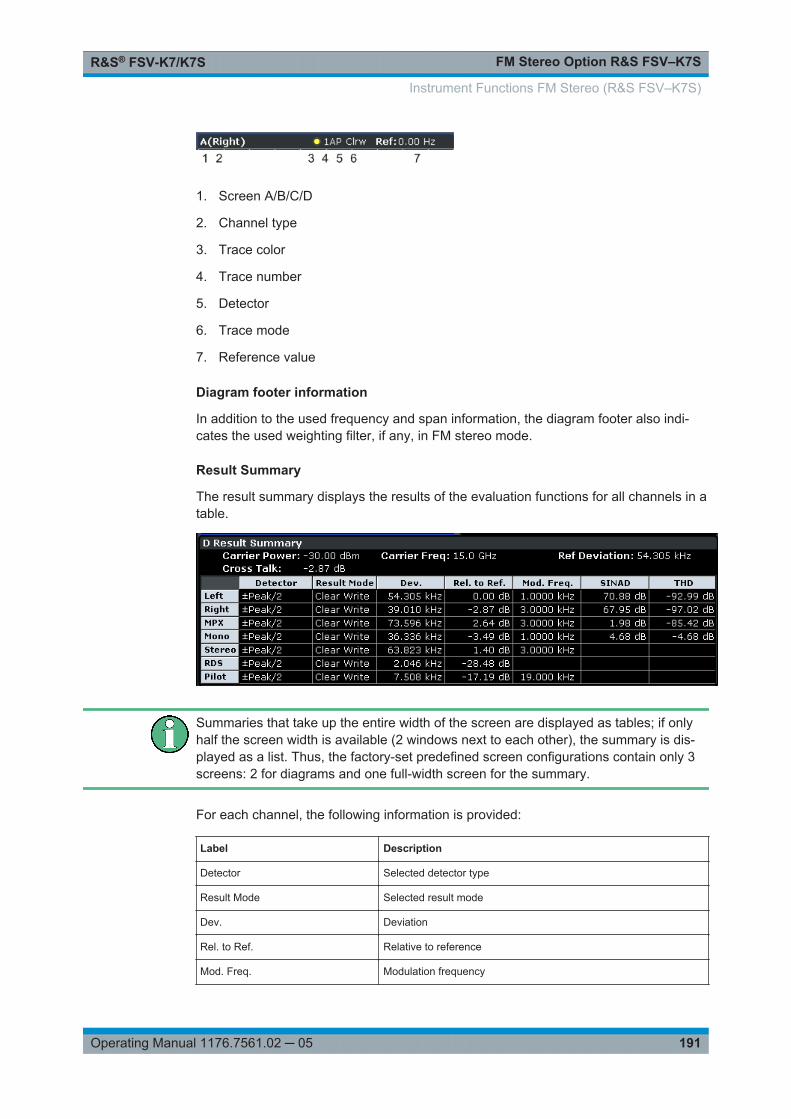
FM Stereo Option R&S FSV–K7SR&S® FSV-K7/K7S
191Operating Manual 1176.7561.02 ─ 05
1. Screen A/B/C/D
2. Channel type
3. Trace color
4. Trace number
5. Detector
6. Trace mode
7. Reference value
Diagram footer information
In addition to the used frequency and span information, the diagram footer also indi-cates the used weighting filter, if any, in FM stereo mode.
Result Summary
The result summary displays the results of the evaluation functions for all channels in atable.
Summaries that take up the entire width of the screen are displayed as tables; if onlyhalf the screen width is available (2 windows next to each other), the summary is dis-played as a list. Thus, the factory-set predefined screen configurations contain only 3screens: 2 for diagrams and one full-width screen for the summary.
For each channel, the following information is provided:
Label Description
Detector Selected detector type
Result Mode Selected result mode
Dev. Deviation
Rel. to Ref. Relative to reference
Mod. Freq. Modulation frequency
Instrument Functions FM Stereo (R&S FSV–K7S)
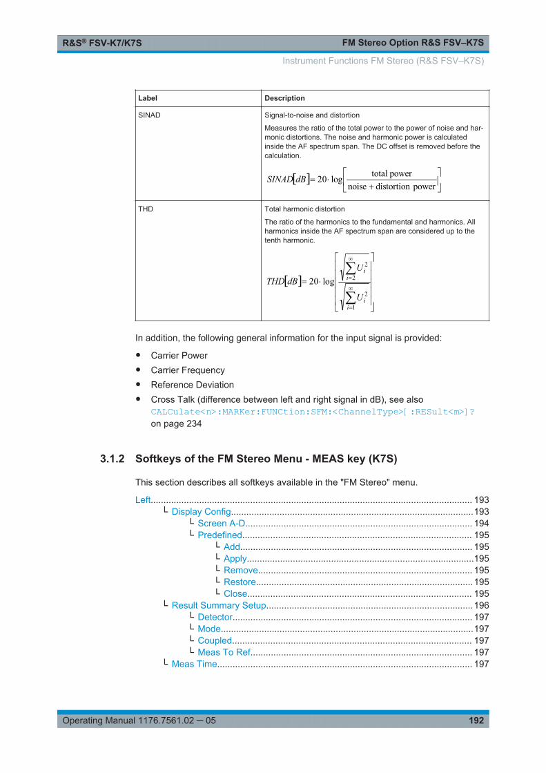
FM Stereo Option R&S FSV–K7SR&S® FSV-K7/K7S
192Operating Manual 1176.7561.02 ─ 05
Label Description
SINAD Signal-to-noise and distortion
Measures the ratio of the total power to the power of noise and har-monic distortions. The noise and harmonic power is calculatedinside the AF spectrum span. The DC offset is removed before thecalculation.
power distortion noise
power totallog20dBSINAD
THD Total harmonic distortion
The ratio of the harmonics to the fundamental and harmonics. Allharmonics inside the AF spectrum span are considered up to thetenth harmonic.
1
2
2
2
log20
ii
ii
U
UdBTHD
In addition, the following general information for the input signal is provided:
● Carrier Power● Carrier Frequency● Reference Deviation● Cross Talk (difference between left and right signal in dB), see also
CALCulate<n>:MARKer:FUNCtion:SFM:<ChannelType>[:RESult<m>]?on page 234
3.1.2 Softkeys of the FM Stereo Menu - MEAS key (K7S)
This section describes all softkeys available in the "FM Stereo" menu.
Left.............................................................................................................................. 193└ Display Config...............................................................................................193
└ Screen A-D......................................................................................... 194└ Predefined.......................................................................................... 195
└ Add........................................................................................... 195└ Apply.........................................................................................195└ Remove.................................................................................... 195└ Restore.....................................................................................195└ Close........................................................................................ 195
└ Result Summary Setup.................................................................................196└ Detector.............................................................................................. 197└ Mode...................................................................................................197└ Coupled.............................................................................................. 197└ Meas To Ref....................................................................................... 197
└ Meas Time.................................................................................................... 197
Instrument Functions FM Stereo (R&S FSV–K7S)

FM Stereo Option R&S FSV–K7SR&S® FSV-K7/K7S
193Operating Manual 1176.7561.02 ─ 05
└ AF Filter........................................................................................................ 198└ High Pass........................................................................................... 198└ Low Pass............................................................................................ 199└ Weighting............................................................................................199
└ None.........................................................................................199└ CCITT.......................................................................................199└ CCIR Unweighted.....................................................................200└ CCIR Weighted.........................................................................200└ A Weighted...............................................................................200
└ Deemphasis........................................................................................200└ Coupled.............................................................................................. 201└ All AF Filter Off................................................................................... 201
└ AF Range......................................................................................................201└ Dev per Division..................................................................................201└ Reference Position............................................................................. 202└ Reference Value.................................................................................202└ AF Coupling AC/DC............................................................................202└ Deviation Lin/Log................................................................................203└ Unit..................................................................................................... 203
└ Phase Unit (Rad/Deg).............................................................. 203└ THD Unit (% / DB).................................................................... 203└ Abs. Dev Unit (kHz/dBm)..........................................................203└ Rel. Dev Unit (dB / %).............................................................. 203
└ Time Domain Zoom...................................................................................... 203└ State On / Off......................................................................................203└ Start.................................................................................................... 204└ Length Manual....................................................................................204└ Length Auto........................................................................................ 204
└ Time per Division.......................................................................................... 204└ Squelch.........................................................................................................204└ Squelch Level............................................................................................... 204
Right............................................................................................................................205MPX............................................................................................................................ 205Mono........................................................................................................................... 205Stereo..........................................................................................................................205RDS.............................................................................................................................205Pilot............................................................................................................................. 205RF Power.................................................................................................................... 205Display Config............................................................................................................. 206
LeftDisplays the left signal of the FM stereo input and the "Left" submenu.
Remote command: CALCulate<n>:FEED on page 90
Display Config ← LeftYou configure the display settings for the results in the "Display Configuration" dialogbox. This dialog box contains the following tabs:● "Screen A-D": a separate tab for each of the four available screens
Instrument Functions FM Stereo (R&S FSV–K7S)
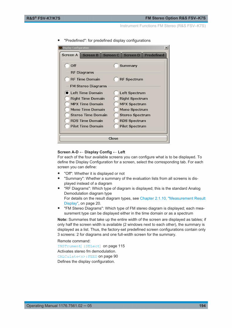
FM Stereo Option R&S FSV–K7SR&S® FSV-K7/K7S
194Operating Manual 1176.7561.02 ─ 05
● "Predefined": for predefined display configurations
Screen A-D ← Display Config ← LeftFor each of the four available screens you can configure what is to be displayed. Todefine the Display Configuration for a screen, select the corresponding tab. For eachscreen you can define:● "Off": Whether it is displayed or not● "Summary": Whether a summary of the evaluation lists from all screens is dis-
played instead of a diagram● "RF Diagrams": Which type of diagram is displayed; this is the standard Analog
Demodulation diagram typeFor details on the result diagram types, see Chapter 2.1.10, "Measurement ResultDisplay", on page 20.
● "FM Stereo Diagrams": Which type of FM stereo diagram is displayed; each mea-surement type can be displayed either in the time domain or as a spectrum
Note: Summaries that take up the entire width of the screen are displayed as tables; ifonly half the screen width is available (2 windows next to each other), the summary isdisplayed as a list. Thus, the factory-set predefined screen configurations contain only3 screens: 2 for diagrams and one full-width screen for the summary.
Remote command: INSTrument[:SELect] on page 115Activates stereo fm demodulation.CALCulate<n>:FEED on page 90Defines the display configuration.
Instrument Functions FM Stereo (R&S FSV–K7S)

FM Stereo Option R&S FSV–K7SR&S® FSV-K7/K7S
195Operating Manual 1176.7561.02 ─ 05
Predefined ← Display Config ← LeftYou can store and load predefined screen configurations. All available configurationsare displayed in the "Predefined" tab. The current screen configuration is indicatedunder "Current" at the top of the list.
Add ← Predefined ← Display Config ← LeftOpens an edit dialog box to enter a name for the current screen configuration. Theconfiguration is then stored and added to the list.
Apply ← Predefined ← Display Config ← LeftApplies the currently selected configuration from the list to the current display.
Remove ← Predefined ← Display Config ← LeftRemoves the currently selected configuration from the list.
Restore ← Predefined ← Display Config ← LeftRestores the default display configuration. Existing configurations with the defaultnames are replaced.
Close ← Predefined ← Display Config ← LeftCloses the displays settings dialog box.
Instrument Functions FM Stereo (R&S FSV–K7S)

FM Stereo Option R&S FSV–K7SR&S® FSV-K7/K7S
196Operating Manual 1176.7561.02 ─ 05
Result Summary Setup ← Left
The result summary table displays the results of all channel mesaurements in a table.It is configured in the "Result Summary Setup" dialog box. This function is only availa-ble for screens for which an FM stereo measurement is selected in the "Display Set-tings" (see "Display Config" on page 193).
Figure 3-1: Result summary for an FM stereo measurement
In the "General Settings" area you define the "Reference Deviation" for all summariesmanually. Alternatively, you can determine the reference deviation from one of thechannel measurements by selecting "Meas To Ref" (see "Meas To Ref" on page 197).
For each FM stereo channel you can define individual channel settings:● "Detector" on page 197● "Mode" on page 197● "Coupled" on page 197● "Meas To Ref" on page 197
Remote command: [SENSe:]SFM:REFerence on page 236[SENSe:]SFM:<ChannelType>:RSUMmary:DETector[:FUNCtion] on page 243[SENSe:]SFM:<ChannelType>:RSUMmary:MODE on page 243
Instrument Functions FM Stereo (R&S FSV–K7S)
FM Stereo Option R&S FSV–K7SR&S® FSV-K7/K7S
197Operating Manual 1176.7561.02 ─ 05
[SENSe:]SFM:<ChannelType>:RSUMmary:COUPling on page 242[SENSe:]SFM:<ChannelType>:RSUMmary:REFerence[:AUTO] ONCEon page 244
Detector ← Result Summary Setup ← LeftDefines the detector used for the deviation measurement.● "RMS"● "RMS*SQRT2"● "Pos Peak"● "Neg Peak"● "±Peak/2"● "QP CCIR"● "QP*SQRT2"Note: To ensure correct measurements with QP detectors, it is recommended that youset the measurement time to its maximum value (see "Meas Time" on page 29 andChapter 2.1.3, "Sample Rate, Measurement Time and Trigger Offset", on page 13).
Remote command: [SENSe:]SFM:<ChannelType>:RSUMmary:DETector[:FUNCtion] on page 243
Mode ← Result Summary Setup ← LeftDefines the result summary mode for the absolute deviation and the deviation relativeto the reference.
"Clear Write" Overwrite mode: the summary is overwritten by each sweep. This isthe default setting.
"Peak Hold" The peak values are determined over several sweeps and displayed.
"Average" The average is formed over several sweeps.
Remote command: [SENSe:]SFM:<ChannelType>:RSUMmary:MODE on page 243
Coupled ← Result Summary Setup ← LeftAll channels for which this option is enabled are configured identically, i.e. the channelsettings are coupled. If you change the settings for one coupled channel, the settingsare changed for all other coupled channels, as well. The settings are taken from thefirst channel for which coupling is enabled.
Remote command: [SENSe:]SFM:<ChannelType>:RSUMmary:COUPling on page 242
Meas To Ref ← Result Summary Setup ← LeftDetermines the "Reference Deviation" from the current channel measurement.
Remote command: [SENSe:]SFM:<ChannelType>:RSUMmary:REFerence[:AUTO] ONCEon page 244
Meas Time ← LeftOpens an editor for entering the measurement time of the analog demodulation. Fordetails on the measurement time values refer to Chapter 2.1.3, "Sample Rate, Mea-surement Time and Trigger Offset", on page 13.
Instrument Functions FM Stereo (R&S FSV–K7S)

FM Stereo Option R&S FSV–K7SR&S® FSV-K7/K7S
198Operating Manual 1176.7561.02 ─ 05
Note: For FM Stereo measurements (option K7S), the minimum measurement time is2 ms.
Remote command: [SENSe:]ADEMod:MTIMe on page 133
AF Filter ← LeftOpens a dialog to select the appropriate filters.
The bandwidth of the demodulated signal can be reduced by high pass or low pass fil-ters and also a weighting or de-emphasis can be switched on. You can define differentfilter settings for each channel.
High Pass ← AF Filter ← LeftOpens the "High Pass" selection list to switch on a high pass filter with the given limitto separate the DC component. The filters are indicated by the 3 dB cutoff frequency.The 50 Hz and 300 Hz filters are designed as 2nd-order Butterworth filter (12 dB/octave). The 20 Hz filter is designed as 3rd-order Butterworth filter (18 dB/octave).
"None" deactivates the AF high pass filter. Default is "None".
The high pass filters are active in the following demodulation bandwidth range:
20 Hz 100 Hz ≤ demodulation bandwidth ≤ 1.6 MHz
50 Hz: 200 Hz ≤ demodulation bandwidth ≤ 3 MHz
300 Hz: 800 Hz ≤ demodulation bandwidth ≤ 8 MHz
Note: for FM stereo (K7S), all filters are active at all times, as the demodulation range is always 400 kHz
Remote command: [SENSe:]FILTer<n>:HPASs[:STATe] on page 151[SENSe:]FILTer<n>:HPASs:FREQuency on page 152
Instrument Functions FM Stereo (R&S FSV–K7S)
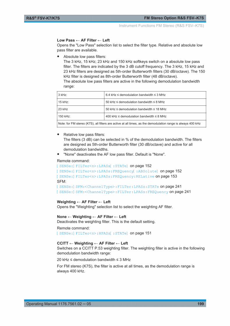
FM Stereo Option R&S FSV–K7SR&S® FSV-K7/K7S
199Operating Manual 1176.7561.02 ─ 05
Low Pass ← AF Filter ← LeftOpens the "Low Pass" selection list to select the filter type. Relative and absolute lowpass filter are available.● Absolute low pass filters:
The 3 kHz, 15 kHz; 23 kHz and 150 kHz softkeys switch on a absolute low passfilter. The filters are indicated by the 3 dB cutoff frequency. The 3 kHz, 15 kHz and23 kHz filters are designed as 5th-order Butterworth filters (30 dB/octave). The 150kHz filter is designed as 8th-order Butterworth filter (48 dB/octave).The absolute low pass filters are active in the following demodulation bandwidthrange:
3 kHz: 6.4 kHz ≤ demodulation bandwidth ≤ 3 MHz
15 kHz: 50 kHz ≤ demodulation bandwidth ≤ 8 MHz
23 kHz 50 kHz ≤ demodulation bandwidth ≤ 18 MHz
150 kHz: 400 kHz ≤ demodulation bandwidth ≤ 8 MHz
Note: for FM stereo (K7S), all filters are active at all times, as the demodulation range is always 400 kHz
● Relative low pass filters:The filters (3 dB) can be selected in % of the demodulation bandwidth. The filtersare designed as 5th-order Butterworth filter (30 dB/octave) and active for alldemodulation bandwidths.
● "None" deactivates the AF low pass filter. Default is "None".
Remote command: [SENSe:]FILTer<n>:LPASs[:STATe] on page 152[SENSe:]FILTer<n>:LPASs:FREQuency[:ABSolute] on page 152[SENSe:]FILTer<n>:LPASs:FREQuency:RELative on page 153SFM:[SENSe:]SFM:<ChannelType>:FILTer:LPASs:STATe on page 241[SENSe:]SFM:<ChannelType>:FILTer:LPASs:FREQuency on page 241
Weighting ← AF Filter ← LeftOpens the "Weighting" selection list to select the weighting AF filter.
None ← Weighting ← AF Filter ← LeftDeactivates the weighting filter. This is the default setting.
Remote command: [SENSe:]FILTer<n>:HPASs[:STATe] on page 151
CCITT ← Weighting ← AF Filter ← LeftSwitches on a CCITT P.53 weighting filter. The weighting filter is active in the followingdemodulation bandwidth range:
20 kHz ≤ demodulation bandwidth ≤ 3 MHz
For FM stereo (K7S), the filter is active at all times, as the demodulation range isalways 400 kHz.
Instrument Functions FM Stereo (R&S FSV–K7S)

FM Stereo Option R&S FSV–K7SR&S® FSV-K7/K7S
200Operating Manual 1176.7561.02 ─ 05
Remote command: [SENSe:]FILTer<n>:CCIT on page 149SFM:[SENSe:]SFM:<ChannelType>:FILTer:CCITt:STATe on page 238
CCIR Unweighted ← Weighting ← AF Filter ← LeftSwitches on the CCIR unweighted filter, which is the combination of the 20 Hz high-pass and 23 kHz low pass filter. The weighting filter is active in the following demodula-tion bandwidth range:
50 kHz ≤ demodulation bandwidth ≤ 1.6 MHz
For FM stereo (K7S), the filter is active at all times, as the demodulation range isalways 400 kHz.
Remote command: [SENSe:]FILTer<n>:CCIR[:UNWeighted][:STATe] on page 150SFM:[SENSe:]SFM:<ChannelType>:FILTer:CCIR[:UNWeighted][:STATe]on page 238
CCIR Weighted ← Weighting ← AF Filter ← LeftSwitches on the CCIR weighted filter. The weighting filter is active in the followingdemodulation bandwidth range:
100 kHz ≤ demodulation bandwidth ≤ 3.0 MHz
For FM stereo (K7S), the filter is active at all times, as the demodulation range isalways 400 kHz.
Remote command: [SENSe:]FILTer<n>:CCIR:WEIGhted[:STATe] on page 150SFM:[SENSe:]SFM:<ChannelType>:FILTer:CCIR:WEIGhted[:STATe] on page 239
A Weighted ← Weighting ← AF Filter ← LeftSwitches on the A weighted filter. The weighting filter is active in the following demodu-lation bandwidth range:
100 kHz ≤ demodulation bandwidth ≤ 800 kHz
Remote command: [SENSe:]FILTer<n>:AWEighted[:STATe] on page 149SFM:[SENSe:]SFM:<ChannelType>:FILTer:AWEighted[:STATe] on page 237
Deemphasis ← AF Filter ← LeftOpens the "Deemphasis" selection list to switch on a deemphasis with the given timeconstant.
The deemphasis is active in the following demodulation bandwidth range:
Note: For FM stereo measurements (K7S), the demodulation bandwidth is always 400kHz, thus the deemphasis is always active.
Instrument Functions FM Stereo (R&S FSV–K7S)
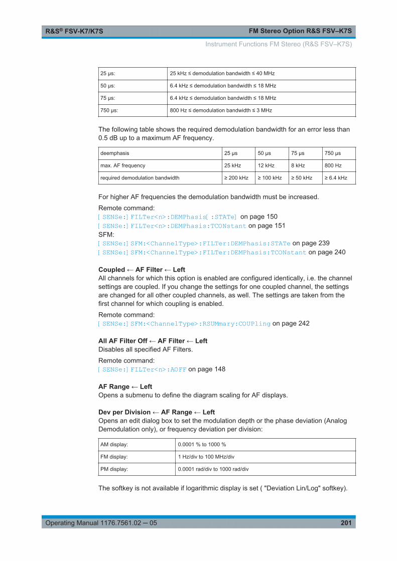
FM Stereo Option R&S FSV–K7SR&S® FSV-K7/K7S
201Operating Manual 1176.7561.02 ─ 05
25 µs: 25 kHz ≤ demodulation bandwidth ≤ 40 MHz
50 µs: 6.4 kHz ≤ demodulation bandwidth ≤ 18 MHz
75 µs: 6.4 kHz ≤ demodulation bandwidth ≤ 18 MHz
750 µs: 800 Hz ≤ demodulation bandwidth ≤ 3 MHz
The following table shows the required demodulation bandwidth for an error less than0.5 dB up to a maximum AF frequency.
deemphasis 25 µs 50 µs 75 µs 750 µs
max. AF frequency 25 kHz 12 kHz 8 kHz 800 Hz
required demodulation bandwidth ≥ 200 kHz ≥ 100 kHz ≥ 50 kHz ≥ 6.4 kHz
For higher AF frequencies the demodulation bandwidth must be increased.
Remote command: [SENSe:]FILTer<n>:DEMPhasis[:STATe] on page 150[SENSe:]FILTer<n>:DEMPhasis:TCONstant on page 151SFM:[SENSe:]SFM:<ChannelType>:FILTer:DEMPhasis:STATe on page 239[SENSe:]SFM:<ChannelType>:FILTer:DEMPhasis:TCONstant on page 240
Coupled ← AF Filter ← LeftAll channels for which this option is enabled are configured identically, i.e. the channelsettings are coupled. If you change the settings for one coupled channel, the settingsare changed for all other coupled channels, as well. The settings are taken from thefirst channel for which coupling is enabled.
Remote command: [SENSe:]SFM:<ChannelType>:RSUMmary:COUPling on page 242
All AF Filter Off ← AF Filter ← LeftDisables all specified AF Filters.
Remote command: [SENSe:]FILTer<n>:AOFF on page 148
AF Range ← LeftOpens a submenu to define the diagram scaling for AF displays.
Dev per Division ← AF Range ← LeftOpens an edit dialog box to set the modulation depth or the phase deviation (AnalogDemodulation only), or frequency deviation per division:
AM display: 0.0001 % to 1000 %
FM display: 1 Hz/div to 100 MHz/div
PM display: 0.0001 rad/div to 1000 rad/div
The softkey is not available if logarithmic display is set ( "Deviation Lin/Log" softkey).
Instrument Functions FM Stereo (R&S FSV–K7S)

FM Stereo Option R&S FSV–K7SR&S® FSV-K7/K7S
202Operating Manual 1176.7561.02 ─ 05
Remote command: DISPlay[:WINDow<n>]:TRACe<t>:Y[:SCALe]:PDIVision on page 112
Reference Position ← AF Range ← LeftDetermines the position of the reference line for the modulation depth or the phasedeviation (Analog Demodulation only) or frequency deviation on the y-axis of the dia-gram. By default, this line is set to 0.
The position is entered as a percentage of the diagram height with 100 % correspond-ing to the upper diagram border. The default setting is 50 % (diagram center) for thedisplay of the AM, FM, or PM signal, and 100 % (upper diagram border) for the AFspectrum display of the AM, FM, or PM signal.
Remote command: DISPlay[:WINDow<n>]:TRACe<t>:Y[:SCALe]:RPOSition on page 113
Reference Value ← AF Range ← LeftDetermines the modulation depth or the phase deviation (Analog Demodulation only)or the frequency deviation at the reference line of the y-axis. The reference value is setseparately for each display of the AM, FM, and PM signal and the AF spectrum of theAM, FM, and PM signal.● AM/FM/PM signal display
The trace display takes individual frequency/phase offsets into account (in contrast,the AF Coupling AC/DC softkey permits automatic correction by the average fre-quency/phase offset of the signal, and can therefore not be activated simultane-ously).Possible values: 0 and ± 10000 % (AM), 0 and ± 10 MHz (FM), 0 and ± 10000 rad(PM).
● AF spectrum display of the AM/FM/PM signalIn the default setting, the reference value defines the modulation depth or theFM/PM deviation at the upper diagram border.Possible values: 0 and 10000 % (AM), 0 and 10 MHz (FM), 0 and 10000 rad (PM).
Remote command: DISPlay[:WINDow<n>]:TRACe<t>:Y[:SCALe]:RVALue on page 114
AF Coupling AC/DC ← AF Range ← LeftControls the automatic correction of the frequency offset and phase offset of the inputsignal:
(Note: This function is not available with the AF spectrum display of the FM or PM sig-nal.)● FM signal display
If DC is selected, the absolute frequency is displayed, i.e. an input signal with anoffset relative to the center frequency is not displayed symmetrically with respect tothe zero line.If AC is selected, the frequency offset is automatically corrected, i.e. the trace isalways symmetric with respect to the zero line.
● PM signal displayIf DC is selected, the phase runs according to the existing frequency offset. In addi-tion, the DC signal contains a phase offset of ± π.
Instrument Functions FM Stereo (R&S FSV–K7S)

FM Stereo Option R&S FSV–K7SR&S® FSV-K7/K7S
203Operating Manual 1176.7561.02 ─ 05
If AC is selected, the frequency offset and phase offset are automatically corrected,i.e. the trace is always symmetric with respect to the zero line.
Remote command: [SENSe:]ADEMod<n>:AF:COUPling on page 122
Deviation Lin/Log ← AF Range ← LeftSwitches between logarithmic and linear display of the modulation depth or the phasedeviation (Analog Demodulation only) or the frequency deviation.
Remote command: DISPlay[:WINDow<n>]:TRACe<t>:Y:SPACing on page 114
Unit ← AF Range ← LeftOpens a submenu to define the modulation unit.
Phase Unit (Rad/Deg) ← Unit ← AF Range ← LeftSets the phase unit to rad or deg for displaying PM signals.
Remote command: UNIT:THD on page 170
THD Unit (% / DB) ← Unit ← AF Range ← LeftSets the unit to percent or DB for THD measurements.
Remote command: UNIT:THD on page 170
Abs. Dev Unit (kHz/dBm) ← Unit ← AF Range ← LeftSets the unit for absolute deviation to kHz or dBm. This softkey is only available withthe FM Stereo option K7S.
Remote command: UNIT:ADEV on page 250
Rel. Dev Unit (dB / %) ← Unit ← AF Range ← LeftSets the unit for relative deviation to dB or percent. This softkey is only available withthe FM Stereo option K7S.
Remote command: UNIT:RDEV on page 251
Time Domain Zoom ← LeftOpens a submenu to activate and configure the zoom function.
State On / Off ← Time Domain Zoom ← LeftActivates or deactivates the time domain zoom according to the defined settings.
"ON" Activates the time domain zoom. The zoom area is defined using the"Start""Start" on page 34 and "Length Manual""Length Manual"on page 34 / "Length Auto""Length Auto" on page 34 softkeys.
Instrument Functions FM Stereo (R&S FSV–K7S)

FM Stereo Option R&S FSV–K7SR&S® FSV-K7/K7S
204Operating Manual 1176.7561.02 ─ 05
"OFF" If more measured values than measurement points are available,several measured values are combined in one measurement pointaccording to the method of the selected trace detector. For details ondetectors refer to Chapter 2.1.8, "Detector Overview", on page 19.
Remote command: [SENSe:]ADEMod<n>:ZOOM[:STATe] on page 143
Start ← Time Domain Zoom ← LeftOpens an edit dialog box to define the start time for the zoom area.
Remote command: [SENSe:]ADEMod<n>:ZOOM:STARt on page 144
Length Manual ← Time Domain Zoom ← LeftOpens an edit dialog box to define the length of the zoom area (as a time value) man-ually.
Remote command: [SENSe:]ADEMod<n>:ZOOM:LENGth on page 144
Length Auto ← Time Domain Zoom ← LeftAutomatically sets the length of the zoom area to the number of sweep points (see"Sweep Points" on page 55).
Remote command: [SENSe:]ADEMod<n>:ZOOM:LENGth:MODE on page 145
Time per Division ← LeftThis function enables the "Time Domain Zoom" function and defines the zoom arealength in one step. The width of the zoom display is divided into 10 divisions; thus, byentering the time that is displayed in each division, you indirectly define the zoom arealength ("Time per Division" * 10). The starting point of the zoom area is determinedautomatically. To specify the starting point manually, use the "Start" function in the"Time Domain Zoom" submenu.
For details see "Time Domain Zoom".
Squelch ← LeftActivates the squelch function, i.e. if the signal falls below a defined threshold, thedemodulated data is automatically set to 0. This is useful, for example, to avoiddemodulation noise during transmission breaks.
Remote command: [SENSe:]ADEMod:SQUelch[:STATe] on page 142
Squelch Level ← LeftDefines the level threshold below which the demodulated data is set to 0 if squelchingis enabled. The squelch level is an absolute value.
Instrument Functions FM Stereo (R&S FSV–K7S)
FM Stereo Option R&S FSV–K7SR&S® FSV-K7/K7S
205Operating Manual 1176.7561.02 ─ 05
Remote command: [SENSe:]ADEMod:SQUelch:LEVel on page 142
RightDisplays the right signal of the FM stereo input and the "Right" submenu, which is iden-tical to the "Left" submenu, see "Left" on page 193.
Remote command: CALCulate<n>:FEED on page 90
MPXDisplays the MPX signal of the FM stereo input and the "MPX" submenu, which isidentical to the "Left" submenu, see "Left" on page 193.
Remote command: CALCulate<n>:FEED on page 90
MonoDisplays the mono signal of the FM stereo input (= Left channel + Right channel) andthe "Mono" submenu, which is identical to the "Left" submenu, see "Left" on page 193.
Remote command: CALCulate<n>:FEED on page 90
StereoDisplays the stereo signal of the FM stereo input (= Left channel - Right channel) andthe "Stereo" submenu, which is identical to the "Left" submenu, see "Left" on page 193.
Remote command: CALCulate<n>:FEED on page 90
RDSDisplays the RDS signal of the FM stereo input and the "RDS" submenu, which is iden-tical to the "Left" submenu, see "Left" on page 193.
Remote command: CALCulate<n>:FEED on page 90
PilotDisplays the pilot signal of the FM stereo input and the "Pilot" submenu, which is identi-cal to the "Left" submenu, see "Left" on page 193.
Remote command: CALCulate<n>:FEED on page 90
RF PowerSelects RF power as the modulation type, changes the signal display, and opens asubmenu to set the measurement configuration. For details see the Analog Demodula-tion option K7 ("RF Power" on page 37).
Instrument Functions FM Stereo (R&S FSV–K7S)

FM Stereo Option R&S FSV–K7SR&S® FSV-K7/K7S
206Operating Manual 1176.7561.02 ─ 05
Remote command: CALCulate<n>:FEED on page 90
Display ConfigSee "Display Config" on page 193
3.1.3 Softkeys of the Amplitude Menu – AMPT Key (R&S FSV–K7S)
The following table shows all softkeys available in the "Amplitude" menu in "FM stereo"mode (AMPT key).
Ref Level..................................................................................................................... 206AF Range.................................................................................................................... 206
└ Dev per Division............................................................................................207└ Reference Position........................................................................................207└ Reference Value........................................................................................... 207└ AF Coupling AC/DC......................................................................................207└ Deviation Lin/Log.......................................................................................... 208└ Unit................................................................................................................208
└ Phase Unit (Rad/Deg).........................................................................208└ THD Unit (% / DB).............................................................................. 208└ Abs. Dev Unit (kHz/dBm)....................................................................208└ Rel. Dev Unit (dB / %).........................................................................208
Unit..............................................................................................................................208└ Phase Unit (Rad/Deg)...................................................................................209└ THD Unit (% / DB).........................................................................................209└ Abs. Dev Unit (kHz/dBm)..............................................................................209└ Rel. Dev Unit (dB / %)...................................................................................209
Preamp On/Off............................................................................................................ 209RF Atten Manual/Mech Att Manual............................................................................. 209RF Atten Auto/Mech Att Auto...................................................................................... 210El Atten On/Off............................................................................................................ 210El Atten Mode (Auto/Man)...........................................................................................210Ref Level Offset.......................................................................................................... 211Input (AC/DC)..............................................................................................................211Input 50 Ω/75 Ω ..........................................................................................................211
Ref LevelOpens an edit dialog box to enter the reference level in the current unit (dBm, dBµV,etc).
The reference level is the maximum value the AD converter can handle without distor-tion of the measured value. Signal levels above this value will not be measured cor-rectly, which is indicated by the "IFOVL" status display.
Remote command: DISPlay[:WINDow<n>]:TRACe<t>:Y[:SCALe]:RLEVel on page 113
AF RangeOpens a submenu to define the diagram scaling for AF displays.
Instrument Functions FM Stereo (R&S FSV–K7S)
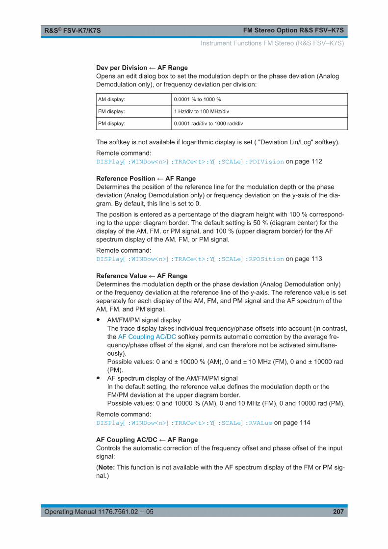
FM Stereo Option R&S FSV–K7SR&S® FSV-K7/K7S
207Operating Manual 1176.7561.02 ─ 05
Dev per Division ← AF RangeOpens an edit dialog box to set the modulation depth or the phase deviation (AnalogDemodulation only), or frequency deviation per division:
AM display: 0.0001 % to 1000 %
FM display: 1 Hz/div to 100 MHz/div
PM display: 0.0001 rad/div to 1000 rad/div
The softkey is not available if logarithmic display is set ( "Deviation Lin/Log" softkey).
Remote command: DISPlay[:WINDow<n>]:TRACe<t>:Y[:SCALe]:PDIVision on page 112
Reference Position ← AF RangeDetermines the position of the reference line for the modulation depth or the phasedeviation (Analog Demodulation only) or frequency deviation on the y-axis of the dia-gram. By default, this line is set to 0.
The position is entered as a percentage of the diagram height with 100 % correspond-ing to the upper diagram border. The default setting is 50 % (diagram center) for thedisplay of the AM, FM, or PM signal, and 100 % (upper diagram border) for the AFspectrum display of the AM, FM, or PM signal.
Remote command: DISPlay[:WINDow<n>]:TRACe<t>:Y[:SCALe]:RPOSition on page 113
Reference Value ← AF RangeDetermines the modulation depth or the phase deviation (Analog Demodulation only)or the frequency deviation at the reference line of the y-axis. The reference value is setseparately for each display of the AM, FM, and PM signal and the AF spectrum of theAM, FM, and PM signal.● AM/FM/PM signal display
The trace display takes individual frequency/phase offsets into account (in contrast,the AF Coupling AC/DC softkey permits automatic correction by the average fre-quency/phase offset of the signal, and can therefore not be activated simultane-ously).Possible values: 0 and ± 10000 % (AM), 0 and ± 10 MHz (FM), 0 and ± 10000 rad(PM).
● AF spectrum display of the AM/FM/PM signalIn the default setting, the reference value defines the modulation depth or theFM/PM deviation at the upper diagram border.Possible values: 0 and 10000 % (AM), 0 and 10 MHz (FM), 0 and 10000 rad (PM).
Remote command: DISPlay[:WINDow<n>]:TRACe<t>:Y[:SCALe]:RVALue on page 114
AF Coupling AC/DC ← AF RangeControls the automatic correction of the frequency offset and phase offset of the inputsignal:
(Note: This function is not available with the AF spectrum display of the FM or PM sig-nal.)
Instrument Functions FM Stereo (R&S FSV–K7S)
FM Stereo Option R&S FSV–K7SR&S® FSV-K7/K7S
208Operating Manual 1176.7561.02 ─ 05
● FM signal displayIf DC is selected, the absolute frequency is displayed, i.e. an input signal with anoffset relative to the center frequency is not displayed symmetrically with respect tothe zero line.If AC is selected, the frequency offset is automatically corrected, i.e. the trace isalways symmetric with respect to the zero line.
● PM signal displayIf DC is selected, the phase runs according to the existing frequency offset. In addi-tion, the DC signal contains a phase offset of ± π.If AC is selected, the frequency offset and phase offset are automatically corrected,i.e. the trace is always symmetric with respect to the zero line.
Remote command: [SENSe:]ADEMod<n>:AF:COUPling on page 122
Deviation Lin/Log ← AF RangeSwitches between logarithmic and linear display of the modulation depth or the phasedeviation (Analog Demodulation only) or the frequency deviation.
Remote command: DISPlay[:WINDow<n>]:TRACe<t>:Y:SPACing on page 114
Unit ← AF RangeOpens a submenu to define the modulation unit.
Phase Unit (Rad/Deg) ← Unit ← AF RangeSets the phase unit to rad or deg for displaying PM signals.
Remote command: UNIT:THD on page 170
THD Unit (% / DB) ← Unit ← AF RangeSets the unit to percent or DB for THD measurements.
Remote command: UNIT:THD on page 170
Abs. Dev Unit (kHz/dBm) ← Unit ← AF RangeSets the unit for absolute deviation to kHz or dBm. This softkey is only available withthe FM Stereo option K7S.
Remote command: UNIT:ADEV on page 250
Rel. Dev Unit (dB / %) ← Unit ← AF RangeSets the unit for relative deviation to dB or percent. This softkey is only available withthe FM Stereo option K7S.
Remote command: UNIT:RDEV on page 251
UnitOpens a submenu to define the modulation unit.
Instrument Functions FM Stereo (R&S FSV–K7S)

FM Stereo Option R&S FSV–K7SR&S® FSV-K7/K7S
209Operating Manual 1176.7561.02 ─ 05
Phase Unit (Rad/Deg) ← UnitSets the phase unit to rad or deg for displaying PM signals.
Remote command: UNIT:THD on page 170
THD Unit (% / DB) ← UnitSets the unit to percent or DB for THD measurements.
Remote command: UNIT:THD on page 170
Abs. Dev Unit (kHz/dBm) ← UnitSets the unit for absolute deviation to kHz or dBm. This softkey is only available withthe FM Stereo option K7S.
Remote command: UNIT:ADEV on page 250
Rel. Dev Unit (dB / %) ← UnitSets the unit for relative deviation to dB or percent. This softkey is only available withthe FM Stereo option K7S.
Remote command: UNIT:RDEV on page 251
Preamp On/OffSwitches the preamplifier on and off.
If option R&S FSV-B22 is installed, the preamplifier is only active below 7 GHz.
If option R&S FSV-B24 is installed, the preamplifier is active for all frequencies.
This function is not available for input from the R&S Digital I/Q Interface (optionR&S FSV-B17).
Remote command: INPut:GAIN:STATe on page 181
RF Atten Manual/Mech Att ManualOpens an edit dialog box to enter the attenuation, irrespective of the reference level. Ifelectronic attenuation is activated (option R&S FSV-B25 only; "El Atten Mode Auto"softkey), this setting defines the mechanical attenuation.
The mechanical attenuation can be set in 10 dB steps.
The RF attenuation can be set in 5 dB steps (R&S FSV with option R&S FSV-B25 orR&S FSVA: 1 dB steps). The range is specified in the data sheet. If the current refer-ence level cannot be set for the set RF attenuation, the reference level is adjustedaccordingly.
This function is not available for input from the R&S Digital I/Q Interface (optionR&S FSV-B17).
The RF attenuation defines the level at the input mixer according to the formula:
levelmixer = levelinput – RF attenuation
Instrument Functions FM Stereo (R&S FSV–K7S)
FM Stereo Option R&S FSV–K7SR&S® FSV-K7/K7S
210Operating Manual 1176.7561.02 ─ 05
Note: As of firmware version 1.61, the maximum mixer level allowed is 0 dBm. Mixerlevels above this value may lead to incorrect measurement results, which are indicatedby the "OVLD" status display. The increased mixer level allows for an improved signal,but also increases the risk of overloading the instrument!
Remote command: INPut:ATTenuation on page 177
RF Atten Auto/Mech Att AutoSets the RF attenuation automatically as a function of the selected reference level.This ensures that the optimum RF attenuation is always used. It is the default setting.
This function is not available for input from the R&S Digital I/Q Interface (optionR&S FSV-B17).
Remote command: INPut:ATTenuation:AUTO on page 177
El Atten On/OffThis softkey switches the electronic attenuator on or off. This softkey is only availablewith option R&S FSV-B25.
When the electronic attenuator is activated, the mechanical and electronic attenuationcan be defined separately. Note however, that both parts must be defined in the samemode, i.e. either both manually, or both automatically.
This function is not available for input from the R&S Digital I/Q Interface (optionR&S FSV-B17).
● To define the mechanical attenuation, use the RF Atten Manual/Mech Att Manualor RF Atten Auto/Mech Att Auto softkeys.
● To define the electronic attenuation, use the El Atten Mode (Auto/Man) softkey.Note: This function is not available for stop frequencies (or center frequencies in zerospan) >7 GHz. In this case, the electronic and mechanical attenuation are summarizedand the electronic attenuation can no longer be defined individually. As soon as thestop or center frequency is reduced below 7 GHz, this function is available again.When the electronic attenuator is switched off, the corresponding RF attenuation mode(auto/manual) is automatically activated.
Remote command: INPut:EATT:AUTO on page 181
El Atten Mode (Auto/Man)This softkey defines whether the electronic attenuator value is to be set automaticallyor manually. If manual mode is selected, an edit dialog box is opened to enter thevalue. This softkey is only available with option R&S FSV-B25, and only if the elec-tronic attenuator has been activated via the El Atten On/Off softkey.
Note: This function is not available for stop frequencies (or center frequencies in zerospan) >7 GHz. In this case, the electronic and mechanical attenuation are summarizedand the electronic attenuation can no longer be defined individually. As soon as thestop or center frequency is reduced below 7 GHz, electronic attenuation is availableagain. If the electronic attenuation was defined manually, it must be re-defined.The attenuation can be varied in 1 dB steps from 0 to 30 dB. Other entries are roundedto the next lower integer value.
Instrument Functions FM Stereo (R&S FSV–K7S)

FM Stereo Option R&S FSV–K7SR&S® FSV-K7/K7S
211Operating Manual 1176.7561.02 ─ 05
To re-open the edit dialog box for manual value definition, select the "Man" modeagain.
If the defined reference level cannot be set for the given RF attenuation, the referencelevel is adjusted accordingly and the warning "Limit reached" is output.
Remote command: INPut:EATT:AUTO on page 181INPut:EATT on page 181
Ref Level OffsetOpens an edit dialog box to enter the arithmetic level offset. This offset is added to themeasured level irrespective of the selected unit. The scaling of the y-axis is changedaccordingly. The setting range is ±200 dB in 0.1 dB steps.
Remote command: DISPlay[:WINDow<n>]:TRACe<t>:Y[:SCALe]:RLEVel:OFFSet on page 113
Input (AC/DC)Toggles the RF input of the R&S FSV/FSVA between AC and DC coupling.
This function is not available for input from the R&S Digital I/Q Interface (optionR&S FSV-B17).
Remote command: INPut:COUPling on page 178
Input 50 Ω/75 ΩUses 50 Ω or 75 Ω as reference impedance for the measured levels. Default setting is50 Ω.
The setting 75 Ω should be selected if the 50 Ω input impedance is transformed to ahigher impedance using a 75 Ω adapter of the RAZ type (= 25 Ω in series to the inputimpedance of the instrument). The correction value in this case is 1.76 dB = 10 log (75Ω/50 Ω).
All levels specified in this Operating Manual refer to the default setting of the instru-ment (50 Ω).
This function is not available for input from the R&S Digital I/Q Interface (optionR&S FSV-B17).
Remote command: INPut:IMPedance on page 182
3.1.4 Softkeys of the Bandwidth Menu – BW Key (R&S FSV–K7S)
The following table shows all softkeys available in the "Bandwidth" menu in FM Stereomode (BW key).
Res BW (span > 0)......................................................................................................212Meas Time.................................................................................................................. 212AF Filter.......................................................................................................................212
└ High Pass......................................................................................................212└ Low Pass...................................................................................................... 213
Instrument Functions FM Stereo (R&S FSV–K7S)

FM Stereo Option R&S FSV–K7SR&S® FSV-K7/K7S
212Operating Manual 1176.7561.02 ─ 05
└ Weighting......................................................................................................213└ None................................................................................................... 213└ CCITT................................................................................................. 213└ CCIR Unweighted...............................................................................214└ CCIR Weighted...................................................................................214└ A Weighted......................................................................................... 214
└ Deemphasis..................................................................................................214└ All AF Filter Off..............................................................................................215
Res BW (span > 0)Opens an edit dialog box to enter a value for the resolution bandwidth. The range isspecified in the data sheet.
This softkey is only available for spectrum measurements (see Chapter 2.1.10, "Mea-surement Result Display", on page 20).
Remote command: [SENSe:]ADEMod:SPECtrum:BANDwidth|BWIDth[:RESolution] on page 140
Meas TimeOpens an editor for entering the measurement time of the analog demodulation. Fordetails on the measurement time values refer to Chapter 2.1.3, "Sample Rate, Mea-surement Time and Trigger Offset", on page 13.
Note: For FM Stereo measurements (option K7S), the minimum measurement time is2 ms.
Remote command: [SENSe:]ADEMod:MTIMe on page 133
AF FilterThe bandwidth of the demodulated signal can be reduced by high pass or low pass fil-ters and also a de-emphasis can be switched on. The selected filters are used for AM,FM and PM demodulation in common. Individual settings are not possible.
High Pass ← AF FilterOpens the "High Pass" selection list to switch on a high pass filter with the given limitto separate the DC component. The filters are indicated by the 3 dB cutoff frequency.The 50 Hz and 300 Hz filters are designed as 2nd-order Butterworth filter (12 dB/octave). The 20 Hz filter is designed as 3rd-order Butterworth filter (18 dB/octave).
"None" deactivates the AF high pass filter. Default is "None".
The high pass filters are active in the following demodulation bandwidth range:
20 Hz 100 Hz ≤ demodulation bandwidth ≤ 1.6 MHz
50 Hz: 200 Hz ≤ demodulation bandwidth ≤ 3 MHz
300 Hz: 800 Hz ≤ demodulation bandwidth ≤ 8 MHz
Note: for FM stereo (K7S), all filters are active at all times, as the demodulation range is always 400 kHz
Instrument Functions FM Stereo (R&S FSV–K7S)
FM Stereo Option R&S FSV–K7SR&S® FSV-K7/K7S
213Operating Manual 1176.7561.02 ─ 05
Remote command: [SENSe:]FILTer<n>:HPASs[:STATe] on page 151[SENSe:]FILTer<n>:HPASs:FREQuency on page 152
Low Pass ← AF FilterOpens the "Low Pass" selection list to select the filter type. Relative and absolute lowpass filter are available.● Absolute low pass filters:
The 3 kHz, 15 kHz; 23 kHz and 150 kHz softkeys switch on a absolute low passfilter. The filters are indicated by the 3 dB cutoff frequency. The 3 kHz, 15 kHz and23 kHz filters are designed as 5th-order Butterworth filters (30 dB/octave). The 150kHz filter is designed as 8th-order Butterworth filter (48 dB/octave).The absolute low pass filters are active in the following demodulation bandwidthrange:
3 kHz: 6.4 kHz ≤ demodulation bandwidth ≤ 3 MHz
15 kHz: 50 kHz ≤ demodulation bandwidth ≤ 8 MHz
23 kHz 50 kHz ≤ demodulation bandwidth ≤ 18 MHz
150 kHz: 400 kHz ≤ demodulation bandwidth ≤ 8 MHz
Note: for FM stereo (K7S), all filters are active at all times, as the demodulation range is always 400 kHz
● Relative low pass filters:The filters (3 dB) can be selected in % of the demodulation bandwidth. The filtersare designed as 5th-order Butterworth filter (30 dB/octave) and active for alldemodulation bandwidths.
● "None" deactivates the AF low pass filter. Default is "None".
Remote command: [SENSe:]FILTer<n>:LPASs[:STATe] on page 152[SENSe:]FILTer<n>:LPASs:FREQuency[:ABSolute] on page 152[SENSe:]FILTer<n>:LPASs:FREQuency:RELative on page 153SFM:[SENSe:]SFM:<ChannelType>:FILTer:LPASs:STATe on page 241[SENSe:]SFM:<ChannelType>:FILTer:LPASs:FREQuency on page 241
Weighting ← AF FilterOpens the "Weighting" selection list to select the weighting AF filter.
None ← Weighting ← AF FilterDeactivates the weighting filter. This is the default setting.
Remote command: [SENSe:]FILTer<n>:HPASs[:STATe] on page 151
CCITT ← Weighting ← AF FilterSwitches on a CCITT P.53 weighting filter. The weighting filter is active in the followingdemodulation bandwidth range:
20 kHz ≤ demodulation bandwidth ≤ 3 MHz
Instrument Functions FM Stereo (R&S FSV–K7S)
FM Stereo Option R&S FSV–K7SR&S® FSV-K7/K7S
214Operating Manual 1176.7561.02 ─ 05
For FM stereo (K7S), the filter is active at all times, as the demodulation range isalways 400 kHz.
Remote command: [SENSe:]FILTer<n>:CCIT on page 149SFM:[SENSe:]SFM:<ChannelType>:FILTer:CCITt:STATe on page 238
CCIR Unweighted ← Weighting ← AF FilterSwitches on the CCIR unweighted filter, which is the combination of the 20 Hz high-pass and 23 kHz low pass filter. The weighting filter is active in the following demodula-tion bandwidth range:
50 kHz ≤ demodulation bandwidth ≤ 1.6 MHz
For FM stereo (K7S), the filter is active at all times, as the demodulation range isalways 400 kHz.
Remote command: [SENSe:]FILTer<n>:CCIR[:UNWeighted][:STATe] on page 150SFM:[SENSe:]SFM:<ChannelType>:FILTer:CCIR[:UNWeighted][:STATe]on page 238
CCIR Weighted ← Weighting ← AF FilterSwitches on the CCIR weighted filter. The weighting filter is active in the followingdemodulation bandwidth range:
100 kHz ≤ demodulation bandwidth ≤ 3.0 MHz
For FM stereo (K7S), the filter is active at all times, as the demodulation range isalways 400 kHz.
Remote command: [SENSe:]FILTer<n>:CCIR:WEIGhted[:STATe] on page 150SFM:[SENSe:]SFM:<ChannelType>:FILTer:CCIR:WEIGhted[:STATe] on page 239
A Weighted ← Weighting ← AF FilterSwitches on the A weighted filter. The weighting filter is active in the following demodu-lation bandwidth range:
100 kHz ≤ demodulation bandwidth ≤ 800 kHz
Remote command: [SENSe:]FILTer<n>:AWEighted[:STATe] on page 149SFM:[SENSe:]SFM:<ChannelType>:FILTer:AWEighted[:STATe] on page 237
Deemphasis ← AF FilterOpens the "Deemphasis" selection list to switch on a deemphasis with the given timeconstant.
The deemphasis is active in the following demodulation bandwidth range:
Note: For FM stereo measurements (K7S), the demodulation bandwidth is always 400kHz, thus the deemphasis is always active.
Instrument Functions FM Stereo (R&S FSV–K7S)
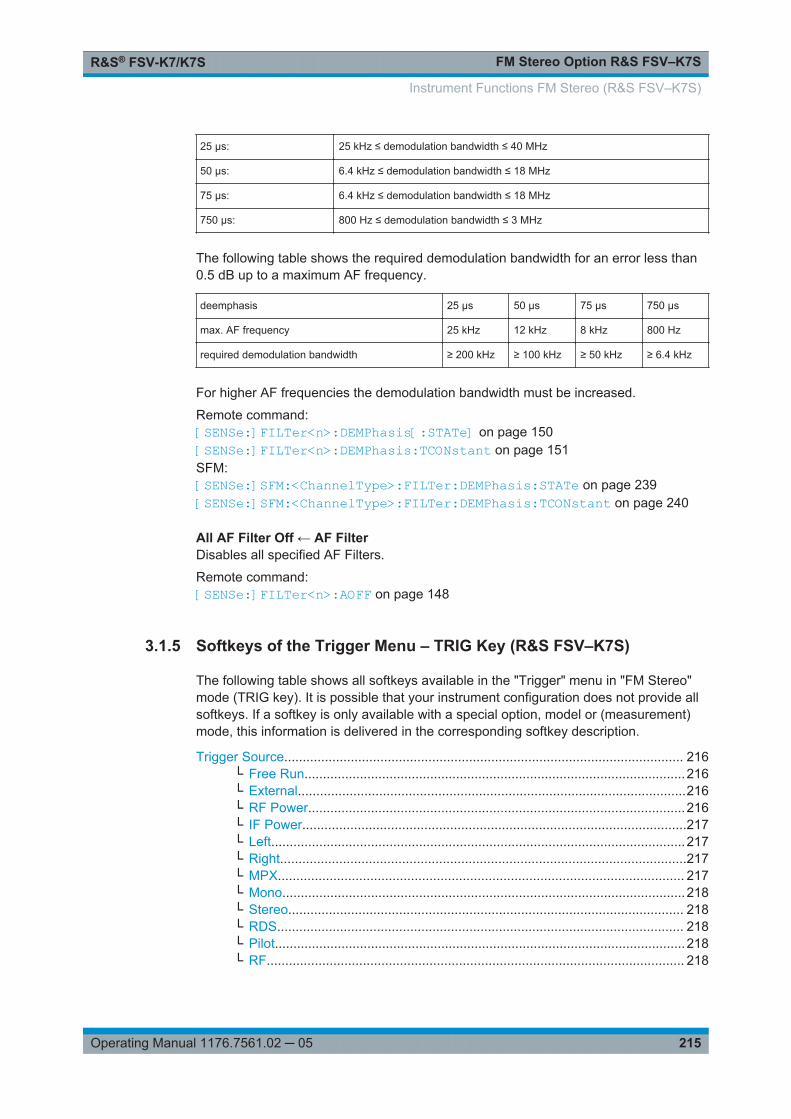
FM Stereo Option R&S FSV–K7SR&S® FSV-K7/K7S
215Operating Manual 1176.7561.02 ─ 05
25 µs: 25 kHz ≤ demodulation bandwidth ≤ 40 MHz
50 µs: 6.4 kHz ≤ demodulation bandwidth ≤ 18 MHz
75 µs: 6.4 kHz ≤ demodulation bandwidth ≤ 18 MHz
750 µs: 800 Hz ≤ demodulation bandwidth ≤ 3 MHz
The following table shows the required demodulation bandwidth for an error less than0.5 dB up to a maximum AF frequency.
deemphasis 25 µs 50 µs 75 µs 750 µs
max. AF frequency 25 kHz 12 kHz 8 kHz 800 Hz
required demodulation bandwidth ≥ 200 kHz ≥ 100 kHz ≥ 50 kHz ≥ 6.4 kHz
For higher AF frequencies the demodulation bandwidth must be increased.
Remote command: [SENSe:]FILTer<n>:DEMPhasis[:STATe] on page 150[SENSe:]FILTer<n>:DEMPhasis:TCONstant on page 151SFM:[SENSe:]SFM:<ChannelType>:FILTer:DEMPhasis:STATe on page 239[SENSe:]SFM:<ChannelType>:FILTer:DEMPhasis:TCONstant on page 240
All AF Filter Off ← AF FilterDisables all specified AF Filters.
Remote command: [SENSe:]FILTer<n>:AOFF on page 148
3.1.5 Softkeys of the Trigger Menu – TRIG Key (R&S FSV–K7S)
The following table shows all softkeys available in the "Trigger" menu in "FM Stereo"mode (TRIG key). It is possible that your instrument configuration does not provide allsoftkeys. If a softkey is only available with a special option, model or (measurement)mode, this information is delivered in the corresponding softkey description.
Trigger Source............................................................................................................ 216└ Free Run.......................................................................................................216└ External.........................................................................................................216└ RF Power......................................................................................................216└ IF Power........................................................................................................217└ Left................................................................................................................217└ Right..............................................................................................................217└ MPX.............................................................................................................. 217└ Mono.............................................................................................................218└ Stereo........................................................................................................... 218└ RDS.............................................................................................................. 218└ Pilot...............................................................................................................218└ RF................................................................................................................. 218
Instrument Functions FM Stereo (R&S FSV–K7S)
FM Stereo Option R&S FSV–K7SR&S® FSV-K7/K7S
216Operating Manual 1176.7561.02 ─ 05
└ Time..............................................................................................................218Trigger Level............................................................................................................... 218Trigger Polarity............................................................................................................218Trigger Offset.............................................................................................................. 219Repetition Interval....................................................................................................... 219Trigger Hysteresis....................................................................................................... 219Trigger Holdoff............................................................................................................ 220
Trigger SourceOpens the "Trg Source" submenu to select the trigger source.
In "FM Stereo" mode, the next measurement is triggered if the selected input signalexceeds the threshold specified using the "Trigger Level" on page 64 softkey. A peri-odic signal modulated onto the carrier frequency can be displayed in this way. It is rec-ommended that the measurement time covers at least five periods of the audio signal.
For triggering to be successful, the measurement time must cover at least 5 periods ofthe audio signal.
Remote command: TRIGger<n>[:SEQuence]:SOURce on page 167
Free Run ← Trigger SourceThe start of a sweep is not triggered. Once a measurement is completed, another isstarted immediately.
Remote command: TRIG:SOUR IMM, see TRIGger<n>[:SEQuence]:SOURce on page 167
External ← Trigger SourceDefines triggering via a TTL signal at the "EXT TRIG/GATE IN" input connector on therear panel.
Remote command: TRIG:SOUR EXT, see TRIGger<n>[:SEQuence]:SOURce on page 167
RF Power ← Trigger SourceDefines triggering of the measurement via signals which are outside the measurementchannel.
This trigger mode is available with detector board 1307.9554.02 Rev 05.00 or higher. Itis not available for input from the R&S Digital I/Q Interface (option R&S FSV/FSVA-B17). If RF Power trigger mode is selected and digital baseband input is activated, thetrigger mode is automatically switched to "Free Run".
RF power triggers are not available together with the bandwidth extension optionR&S FSV-B160.
In RF Power trigger mode the instrument uses a level detector at the first intermediatefrequency. The detector threshold can be selected in a range between - 50 dBm and-10 dBm at the input mixer. The resulting trigger level at the RF input lies within thefollowing range:
(-24dBm + RF Att ) ≤ Triggerlevel ≤ (+5dBm + RF Att), max. 30 dBm, for Preamp =OFF
Instrument Functions FM Stereo (R&S FSV–K7S)
FM Stereo Option R&S FSV–K7SR&S® FSV-K7/K7S
217Operating Manual 1176.7561.02 ─ 05
(-40dBm + RF Att ) ≤ Triggerlevel ≤ (-11dBm + RF Att), max. 30 dBm, for Preamp =ON
with
500 MHz ≤ InputSignal ≤ 7 GHz
Note: If input values outside of this range occur (e.g. for fullspan measurements), thesweep may be aborted and a message indicating the allowed input values is displayedin the status bar.
Remote command: TRIG:SOUR RFP, see TRIGger<n>[:SEQuence]:SOURce on page 167SWE:EGAT:SOUR RFP for gated triggering, see [SENSe:]SWEep:EGATe:SOURceon page 156
IF Power ← Trigger SourceDefines triggering of the measurement via signals which are outside the measurementchannel.
For this purpose, the R&S FSV/FSVA uses a level detector at the second intermediatefrequency.
The available trigger levels depend on the RF attenuation and preamplification. A refer-ence level offset, if defined, is also considered.
For details on available trigger levels and trigger bandwidths see the data sheet.
The bandwidth at the intermediate frequency is 20 MHz. The R&S FSV/FSVA is trig-gered as soon as the trigger level is exceeded within a 10 MHz range around theselected frequency (= start frequency in the frequency sweep).
Thus, the measurement of spurious emissions, e.g. for pulsed carriers, is possibleeven if the carrier lies outside the selected frequency span.
IF power triggers are not available together with the bandwidth extension optionR&S FSV-B160.
Remote command: TRIG:SOUR IFP, see TRIGger<n>[:SEQuence]:SOURce on page 167SWE:EGAT:SOUR IFP for gated triggering, see [SENSe:]SWEep:EGATe:SOURceon page 156
Left ← Trigger SourceTriggers on the specified frequency level of the left FM signal.
Remote command: TRIGger<n>[:SEQuence]:LEVel:SFM:LEFT on page 246
Right ← Trigger SourceTriggers on the specified frequency level of the right FM signal.
Remote command: TRIGger<n>[:SEQuence]:LEVel:SFM:RIGHt on page 246
MPX ← Trigger SourceTriggers on the specified frequency level of the MPX FM signal.
Instrument Functions FM Stereo (R&S FSV–K7S)
FM Stereo Option R&S FSV–K7SR&S® FSV-K7/K7S
218Operating Manual 1176.7561.02 ─ 05
Remote command: TRIGger<n>[:SEQuence]:LEVel:SFM:MPX on page 246
Mono ← Trigger SourceTriggers on the specified frequency level of the mono FM signal.
Remote command: TRIGger<n>[:SEQuence]:LEVel:SFM:MONO on page 247
Stereo ← Trigger SourceTriggers on the specified frequency level of the stereo FM signal.
Remote command: TRIGger<n>[:SEQuence]:LEVel:SFM:STEReo on page 247
RDS ← Trigger SourceTriggers on the specified frequency level of the RDS FM signal.
Remote command: TRIGger<n>[:SEQuence]:LEVel:SFM:RDS on page 248
Pilot ← Trigger SourceTriggers on the specified frequency level of the pilot FM signal.
Remote command: TRIGger<n>[:SEQuence]:LEVel:SFM:PILot on page 248
RF ← Trigger SourceTriggers on the specified level of the RF signal.
Note: The RF offline trigger is based on the I/Q data of the demodulated signal, in avery limited bandwidth. For a wider trigger bandwidth and triggering based on the cur-rently measured RF input signal, use the more powerful RF Power trigger.
Remote command: TRIGger<n>[:SEQuence]:LEVel:AM[:ABSolute] on page 164
Time ← Trigger SourceOpens an edit dialog box to define a repetition interval in which the measurement istriggered. The shortest interval is 2 ms.
Remote command: TRIG:SOUR TIMETRIGger<n>[:SEQuence]:SOURce on page 167
Trigger LevelDefines the trigger level as a numeric value.
In the trigger mode "Time", this softkey is not available.
Remote command: TRIGger<n>[:SEQuence]:LEVel:IFPower on page 165For digital input via the R&S Digital I/Q Interface, R&S FSV-B17:TRIGger<n>[:SEQuence]:LEVel:BBPower on page 164
Trigger PolaritySets the polarity of the trigger source.
Instrument Functions FM Stereo (R&S FSV–K7S)

FM Stereo Option R&S FSV–K7SR&S® FSV-K7/K7S
219Operating Manual 1176.7561.02 ─ 05
The sweep starts after a positive or negative edge of the trigger signal. The default set-ting is "Pos". The setting applies to all modes with the exception of the "Free Run" and"Time" mode.
"Pos" Level triggering: the sweep is stopped by the logic "0" signal andrestarted by the logical "1" signal after the gate delay time haselapsed.
"Neg" Edge triggering: the sweep is continued on a "0" to "1" transition forthe gate length duration after the gate delay time has elapsed.
Remote command: TRIGger<n>[:SEQuence]:SLOPe on page 167[SENSe:]SWEep:EGATe:POLarity on page 156
Trigger OffsetOpens an edit dialog box to enter the time offset between the trigger signal and thestart of the sweep.
offset > 0: Start of the sweep is delayed
offset < 0: Sweep starts earlier (pre-trigger)
Only possible for span = 0 (e.g. I/Q Analyzer mode) and gated triggerswitched off
Maximum allowed range limited by the sweep time:
pretriggermax = sweep time
When using the R&S Digital I/Q Interface (R&S FSV-B17) with I/Q Ana-lyzer mode, the maximum range is limited by the number of pretriggersamples.
See the R&S Digital I/Q Interface(R&S FSV-B17) description in the baseunit.
In the "External" or "IF Power" trigger mode, a common input signal is used for bothtrigger and gate. Therefore, changes to the gate delay will affect the trigger delay (trig-ger offset) as well.
In the "Time" trigger mode, this softkey is not available.
Remote command: TRIGger<n>[:SEQuence]:HOLDoff[:TIME] on page 163
Repetition IntervalOpens an edit dialog box to define a repetition interval in which the measurement istriggered. The shortest interval is 2 ms. This softkey is only available if the triggersource "Time" is selected (see "Time" on page 64).
Remote command: TRIGger<n>[:SEQuence]:TIME:RINTerval on page 166
Trigger HysteresisDefines the value for the trigger hysteresis for "IF power" or "RF Power" trigger sour-ces. The hysteresis in dB is the value the input signal must stay below the power trig-ger level in order to allow a trigger to start the measurement. The range of the value isbetween 3 dB and 50 dB with a step width of 1 dB.
Instrument Functions FM Stereo (R&S FSV–K7S)
FM Stereo Option R&S FSV–K7SR&S® FSV-K7/K7S
220Operating Manual 1176.7561.02 ─ 05
Remote command: TRIGger<n>[:SEQuence]:IFPower:HYSTeresis on page 163
Trigger HoldoffDefines the value for the trigger holdoff. The holdoff value in s is the time which mustpass before triggering, in case another trigger event happens.
This softkey is only available if "IFPower", "RF Power" or "BBPower" is the selectedtrigger source.
Remote command: TRIGger<n>[:SEQuence]:IFPower:HOLDoff on page 163For digital input via the R&S Digital I/Q Interface, R&S FSV-B17:TRIGger<n>[:SEQuence]:BBPower:HOLDoff on page 162
3.1.6 Softkeys of the Marker Function Menu – MKR FUNC Key(R&S FSV–K7S)
The MKR FUNC menu provides the following functions.
Select Marker (No)...................................................................................................... 220Ref Fixed.....................................................................................................................221
└ Ref. Fixed On/Off..........................................................................................221└ Ref Point Level..............................................................................................221└ Ref Point Frequency (span > 0)/Ref Point Time (zero span)........................221└ Peak Search................................................................................................. 221
Diff.Freq.Distortion...................................................................................................... 221└ Diff.Freq.Distortion (On/Off)..........................................................................222└ Unit (% / DB).................................................................................................222└ Search Signals..............................................................................................223
Intermod. Distortion.....................................................................................................223└ Intermod.Distortion (On/Off)..........................................................................224└ Unit (% / DB).................................................................................................224└ Search Signals..............................................................................................224
n dB down................................................................................................................... 224Marker Peak List......................................................................................................... 225
└ Peak List On/Off............................................................................................225└ Sort Mode Freq/Lvl....................................................................................... 225└ Max Peak Count........................................................................................... 225└ Peak Excursion.............................................................................................225└ Left Limit....................................................................................................... 226└ Right Limit.....................................................................................................226└ Threshold......................................................................................................226└ ASCII File Export.......................................................................................... 226└ Decim Sep.................................................................................................... 226└ Marker Number.............................................................................................227
Select Marker (No)Opens a submenu to select one of 16 markers and define whether the marker is a nor-mal or a delta marker (see "Marker 1 / Marker 2 / Marker 3 / … Marker 16,/ MarkerNorm/Delta" on page 66). "(No)" indicates the number of the currently active marker.
Instrument Functions FM Stereo (R&S FSV–K7S)
FM Stereo Option R&S FSV–K7SR&S® FSV-K7/K7S
221Operating Manual 1176.7561.02 ─ 05
See "Marker 1 / Marker 2 / Marker 3 / … Marker 16,/ Marker Norm/Delta" on page 66.
Ref FixedOpens a submenu to set all values of a reference point. Instead of using the currentvalues of the reference marker (marker 1) as reference point for the delta markers,level and frequency or time are set to fixed values and used as reference point.
Ref. Fixed On/Off ← Ref FixedSwitches the relative measurement to a fixed reference value on or off. The level andfrequency or time values of marker 1 immediately become the reference point, but canbe altered using the corresponding softkeys ("Ref Point Level" on page 72, "Ref PointFrequency (span > 0)/Ref Point Time (zero span)" on page 72 and "Peak Search"on page 72).
When set to ON, all delta markers which previously referenced marker 1 are automati-cally set to reference the fixed marker.
The reference marker assignment can be changed using the "Marker Wizard" (see"Marker Wizard" on page 67).
Remote command: CALCulate<n>:DELTamarker<m>:FUNCtion:FIXed[:STATe] on page 172
Ref Point Level ← Ref FixedOpens an edit dialog box to enter a reference level value. All relative level values of thedelta markers refer to this reference level.
Remote command: CALCulate<n>:DELTamarker<m>:FUNCtion:FIXed:RPOint:Y on page 171
Ref Point Frequency (span > 0)/Ref Point Time (zero span) ← Ref FixedOpens an edit dialog box to enter a frequency reference or time value. All relative fre-quency or time values of the delta markers refer to this frequency reference. For phasenoise measurement, input of reference time is not possible.
Remote command: CALCulate<n>:DELTamarker<m>:FUNCtion:FIXed:RPOint:X on page 171
Peak Search ← Ref FixedSets the maximum value of the selected trace as the reference point.
Remote command: CALCulate<n>:DELTamarker<m>:FUNCtion:FIXed:RPOint:MAXimum[:PEAK]on page 170
Diff.Freq.DistortionOpens a submenu to enable and configure difference frequency distortion measure-ment. This function is only available for AF spectrum measurements.
Definition of the difference frequency distortion:
f1 and f2 represent the frequencies of two sine-wave signals with the same level. Theirfrequencies should preferably differ by 80 Hz. The difference frequency distortion fac-tors of 2nd and 3rd order (dd2, dd3) are defined as follows:
Instrument Functions FM Stereo (R&S FSV–K7S)
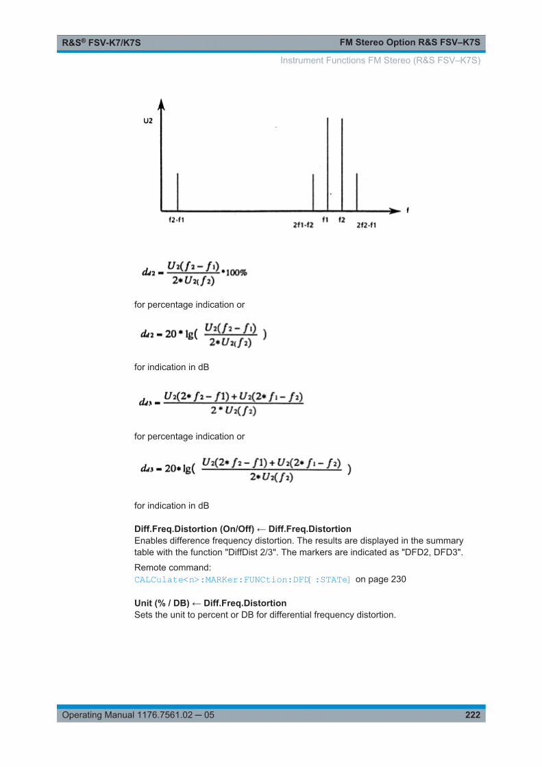
FM Stereo Option R&S FSV–K7SR&S® FSV-K7/K7S
222Operating Manual 1176.7561.02 ─ 05
for percentage indication or
for indication in dB
for percentage indication or
for indication in dB
Diff.Freq.Distortion (On/Off) ← Diff.Freq.DistortionEnables difference frequency distortion. The results are displayed in the summarytable with the function "DiffDist 2/3". The markers are indicated as "DFD2, DFD3".
Remote command: CALCulate<n>:MARKer:FUNCtion:DFD[:STATe] on page 230
Unit (% / DB) ← Diff.Freq.DistortionSets the unit to percent or DB for differential frequency distortion.
Instrument Functions FM Stereo (R&S FSV–K7S)
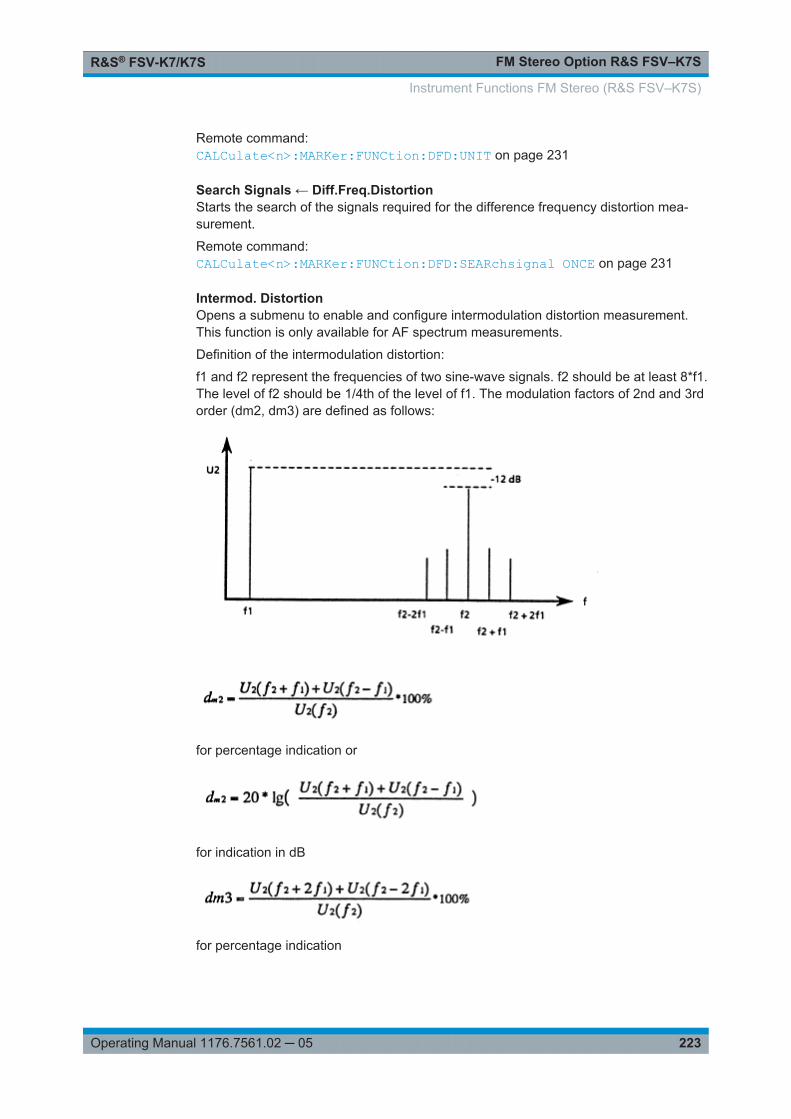
FM Stereo Option R&S FSV–K7SR&S® FSV-K7/K7S
223Operating Manual 1176.7561.02 ─ 05
Remote command: CALCulate<n>:MARKer:FUNCtion:DFD:UNIT on page 231
Search Signals ← Diff.Freq.DistortionStarts the search of the signals required for the difference frequency distortion mea-surement.
Remote command: CALCulate<n>:MARKer:FUNCtion:DFD:SEARchsignal ONCE on page 231
Intermod. DistortionOpens a submenu to enable and configure intermodulation distortion measurement.This function is only available for AF spectrum measurements.
Definition of the intermodulation distortion:
f1 and f2 represent the frequencies of two sine-wave signals. f2 should be at least 8*f1.The level of f2 should be 1/4th of the level of f1. The modulation factors of 2nd and 3rdorder (dm2, dm3) are defined as follows:
for percentage indication or
for indication in dB
for percentage indication
Instrument Functions FM Stereo (R&S FSV–K7S)
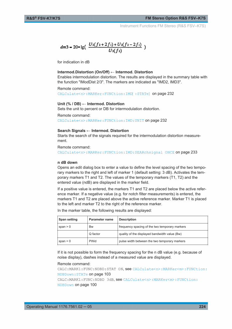
FM Stereo Option R&S FSV–K7SR&S® FSV-K7/K7S
224Operating Manual 1176.7561.02 ─ 05
for indication in dB
Intermod.Distortion (On/Off) ← Intermod. DistortionEnables intermodulation distortion. The results are displayed in the summary table withthe function "IModDist 2/3". The markers are indicated as "IMD2, IMD3".
Remote command: CALCulate<n>:MARKer:FUNCtion:IMD[:STATe] on page 232
Unit (% / DB) ← Intermod. DistortionSets the unit to percent or DB for intermodulation distortion.
Remote command: CALCulate<n>:MARKer:FUNCtion:IMD:UNIT on page 232
Search Signals ← Intermod. DistortionStarts the search of the signals required for the intermodulation distortion measure-ment.
Remote command: CALCulate<n>:MARKer:FUNCtion:IMD:SEARchsignal ONCE on page 233
n dB downOpens an edit dialog box to enter a value to define the level spacing of the two tempo-rary markers to the right and left of marker 1 (default setting: 3 dB). Activates the tem-porary markers T1 and T2. The values of the temporary markers (T1, T2) and theentered value (ndB) are displayed in the marker field.
If a positive value is entered, the markers T1 and T2 are placed below the active refer-ence marker. If a negative value (e.g. for notch filter measurements) is entered, themarkers T1 and T2 are placed above the active reference marker. Marker T1 is placedto the left and marker T2 to the right of the reference marker.
In the marker table, the following results are displayed:
Span setting Parameter name Description
span > 0 Bw frequency spacing of the two temporary markers
Q factor quality of the displayed bandwidth value (Bw)
span = 0 PWid pulse width between the two temporary markers
If it is not possible to form the frequency spacing for the n dB value (e.g. because ofnoise display), dashes instead of a measured value are displayed.
Remote command: CALC:MARK1:FUNC:NDBD:STAT ON, see CALCulate<n>:MARKer<m>:FUNCtion:NDBDown:STATe on page 103CALC:MARK1:FUNC:NDBD 3dB, see CALCulate<n>:MARKer<m>:FUNCtion:NDBDown on page 100
Instrument Functions FM Stereo (R&S FSV–K7S)
FM Stereo Option R&S FSV–K7SR&S® FSV-K7/K7S
225Operating Manual 1176.7561.02 ─ 05
CALC:MARK1:FUNC:NDBD:RES? , see CALCulate<n>:MARKer<m>:FUNCtion:NDBDown:RESult? on page 102CALC:MARK:FUNC:NDBD:QFAC?, see CALCulate<n>:MARKer<m>:FUNCtion:NDBDown:QFACtor on page 102CALC:MARK1:FUNC:NDBD:FREQ? (span > 0), see CALCulate<n>:MARKer<m>:FUNCtion:NDBDown:FREQuency? on page 101CALC:MARK1:FUNC:NDBD:TIME? (span = 0), see CALCulate<n>:MARKer<m>:FUNCtion:NDBDown:TIME? on page 103
Marker Peak ListOpens the "Peak List" submenu to define criteria for the sort order and the contents ofthe peak list. For each listed peak the frequency ("Stimulus") and level ("Response")values are given. In addition, the peaks are indicated in the trace display. A maximumof 50 entries are listed.
Remote command: CALCulate<n>:MARKer<m>:FUNCtion:FPEaks:COUNt? on page 98CALCulate<n>:MARKer<m>:FUNCtion:FPEaks:X on page 99CALCulate<n>:MARKer<m>:FUNCtion:FPEaks:Y? on page 100
Peak List On/Off ← Marker Peak ListActivates/deactivates the marker peak list. If activated, the peak list is displayed andthe peaks are indicated in the trace display.
Remote command: CALCulate<n>:MARKer<m>:FUNCtion:FPEaks:STAT on page 95
Sort Mode Freq/Lvl ← Marker Peak ListDefines the criteria for sorting:
"Freq" sorting in ascending order of frequency values (span > 0) or time val-ues (span = 0)
"Lvl" sorting in ascending order of the level
Remote command: CALCulate<n>:MARKer<m>:FUNCtion:FPEaks:SORT on page 99
Max Peak Count ← Marker Peak ListDefines the maximum number of peaks to be determined and displayed.
Remote command: CALCulate<n>:MARKer<m>:FUNCtion:FPEaks:LIST:SIZE on page 94
Peak Excursion ← Marker Peak ListOpens an edit dialog box for level measurements to enter the minimum level value bywhich a signal must rise or fall so that it will be identified as a maximum or a minimumby the search functions. Entries from 0 dB to 80 dB are allowed; the resolution is 0.1dB. The default setting for the peak excursion is 6 dB.
For more information see "Specifying the suitable peak excursion" and "Effect of differ-ent peak excursion settings".
Instrument Functions FM Stereo (R&S FSV–K7S)
FM Stereo Option R&S FSV–K7SR&S® FSV-K7/K7S
226Operating Manual 1176.7561.02 ─ 05
Remote command: CALCulate<n>:MARKer<m>:PEXCursion on page 104
Left Limit ← Marker Peak ListOpens an edit dialog box to enter a value for the lower limit (left vertical line: S1 forspan > 0; T1 for zero span). The search is performed between the lines of the left andright limit (see also Right Limit softkey).
Remote command: CALCulate<n>:MARKer<m>:X:SLIMits:LEFT on page 106
Right Limit ← Marker Peak ListOpens an edit dialog box to enter a value for the upper limit (left vertical line: S2 forspan > 0; T2 for zero span). The search is performed between the lines of the left andright limit (see also Left Limit softkey). If no value is set, the upper limit corresponds tothe stop frequency.
Remote command: CALCulate<n>:MARKer<m>:X:SLIMits:RIGHT on page 106
Threshold ← Marker Peak ListOpens an edit dialog box to define the threshold line. The threshold line represents thelower level limit for a "Peak" search and the upper level limit for a "Min" search.
Remote command: CALCulate<n>:THReshold:STATe on page 97CALCulate<n>:THReshold on page 96
ASCII File Export ← Marker Peak ListOpens the "ASCII File Export Name" dialog box and saves the active peak list in ASCIIformat to the specified file and directory.
The file consists of the header containing important scaling parameters and a data sec-tion containing the marker data. For details on an ASCII file see Chapter 2.1.11, "ASCIIFile Export Format", on page 23.
This format can be processed by spreadsheet calculation programs, e.g. MS-Excel. Itis necessary to define ';' as a separator for the data import. Different language versionsof evaluation programs may require a different handling of the decimal point. It is there-fore possible to select between separators '.' (decimal point) and ',' (comma) using the"Decim Sep" softkey (see "Decim Sep" on page 62).
Remote command: FORMat:DEXPort:DSEParator on page 185MMEMory:STORe<n>:LIST on page 183
Decim Sep ← Marker Peak ListSelects the decimal separator with floating-point numerals for the ASCII Trace exportto support evaluation programs (e.g. MS-Excel) in different languages. The values '.'(decimal point) and ',' (comma) can be set.
Instrument Functions FM Stereo (R&S FSV–K7S)

FM Stereo Option R&S FSV–K7SR&S® FSV-K7/K7S
227Operating Manual 1176.7561.02 ─ 05
Remote command: FORMat:DEXPort:DSEParator on page 185
Marker Number ← Marker Peak ListIf enabled, the determined peaks are indicated by their corresponding marker numberin the trace display.
Remote command: CALCulate<n>:MARKer<m>:FUNCtion:FPEaks:ANNotation:LABel:STATeon page 94
3.2 Remote Commands of the FM Stereo Option(R&S FSV–K7S)
In this section, all remote control commands specific to the FM Stereo option aredescribed in detail.
In addition to these, all remote control commands described for the analog Demodula-tion option (K7) are available, as well (see Chapter 2.3, "Remote Commands of theAnalog Demodulation (R&S FSV–K7)", on page 80).
For details on conventions used in this chapter refer to Chapter 2.3.1, "Notation",on page 82.
For further information on analyzer or basic settings commands, refer to the corre-sponding subsystem in the base unit description.
Subsystems for FM Stereo (R&S FSV–K7S)
3.2.1 Notation.......................................................................................................................227
3.2.2 CALCulate:MARKer:FUNCtion Subsystem (FM Stereo Option, R&S FSV–K7S).......230
3.2.3 SENSe Subsystem......................................................................................................235
3.2.4 [SENSe:]SFM:<ChannelType> Subsystem................................................................ 236
3.2.5 TRIGger Subsystem (FM Stereo, R&S FSV–K7S)..................................................... 245
3.2.6 UNIT Subsystem (FM Stereo, R&S FSV–K7S)...........................................................250
3.2.1 Notation
In the following sections, all commands implemented in the instrument are first listedand then described in detail, arranged according to the command subsystems. Thenotation is adapted to the SCPI standard. The SCPI conformity information is includedin the individual description of the commands.
Individual Description
The individual description contains the complete notation of the command. An examplefor each command, the *RST value and the SCPI information are included as well.
Remote Commands of the FM Stereo Option (R&S FSV–K7S)
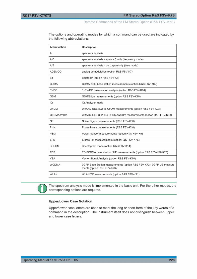
FM Stereo Option R&S FSV–K7SR&S® FSV-K7/K7S
228Operating Manual 1176.7561.02 ─ 05
The options and operating modes for which a command can be used are indicated bythe following abbreviations:
Abbreviation Description
A spectrum analysis
A-F spectrum analysis – span > 0 only (frequency mode)
A-T spectrum analysis – zero span only (time mode)
ADEMOD analog demodulation (option R&S FSV-K7)
BT Bluetooth (option R&S FSV-K8)
CDMA CDMA 2000 base station measurements (option R&S FSV-K82)
EVDO 1xEV-DO base station analysis (option R&S FSV-K84)
GSM GSM/Edge measurements (option R&S FSV-K10)
IQ IQ Analyzer mode
OFDM WiMAX IEEE 802.16 OFDM measurements (option R&S FSV-K93)
OFDMA/WiBro WiMAX IEEE 802.16e OFDMA/WiBro measurements (option R&S FSV-K93)
NF Noise Figure measurements (R&S FSV-K30)
PHN Phase Noise measurements (R&S FSV-K40)
PSM Power Sensor measurements (option R&S FSV-K9)
SFM Stereo FM measurements (optionR&S FSV-K7S)
SPECM Spectogram mode (option R&S FSV-K14)
TDS TD-SCDMA base station / UE measurements (option R&S FSV-K76/K77)
VSA Vector Signal Analysis (option R&S FSV-K70)
WCDMA 3GPP Base Station measurements (option R&S FSV-K72), 3GPP UE measure-ments (option R&S FSV-K73)
WLAN WLAN TX measurements (option R&S FSV-K91)
The spectrum analysis mode is implemented in the basic unit. For the other modes, thecorresponding options are required.
Upper/Lower Case Notation
Upper/lower case letters are used to mark the long or short form of the key words of acommand in the description. The instrument itself does not distinguish between upperand lower case letters.
Remote Commands of the FM Stereo Option (R&S FSV–K7S)
FM Stereo Option R&S FSV–K7SR&S® FSV-K7/K7S
229Operating Manual 1176.7561.02 ─ 05
Special Characters
| A selection of key words with an identical effect exists for several commands. These keywordsare indicated in the same line; they are separated by a vertical stroke. Only one of these key-words needs to be included in the header of the command. The effect of the command is inde-pendent of which of the keywords is used.
Example:
SENSe:FREQuency:CW|:FIXedThe two following commands with identical meaning can be created. They set the fre-quency of the fixed frequency signal to 1 kHz:
SENSe:FREQuency:CW 1E3SENSe:FREQuency:FIXed 1E3A vertical stroke in parameter indications marks alternative possibilities in the sense of"or". The effect of the command differs, depending on which parameter is used.
Example: Selection of the parameters for the command
[SENSe<1…4>:]AVERage<1…4>:TYPE VIDeo | LINear
[] Key words in square brackets can be omitted when composing the header. The full commandlength must be accepted by the instrument for reasons of compatibility with the SCPI standards.
Parameters in square brackets can be incorporated optionally in the command or omitted aswell.
{} Parameters in braces can be incorporated optionally in the command, either not at all, once orseveral times.
Description of Parameters
Due to the standardization, the parameter section of SCPI commands consists alwaysof the same syntactical elements. SCPI has therefore specified a series of definitions,which are used in the tables of commands. In the tables, these established definitionsare indicated in angled brackets (<…>) and is briefly explained in the following.
For details see the chapter "SCPI Command Structure" in the base unit description.
<Boolean>
This keyword refers to parameters which can adopt two states, "on" and "off". The "off"state may either be indicated by the keyword OFF or by the numeric value 0, the "on"state is indicated by ON or any numeric value other than zero. Parameter queries arealways returned the numeric value 0 or 1.
<numeric_value> <num>
These keywords mark parameters which may be entered as numeric values or be setusing specific keywords (character data). The following keywords given below are per-mitted:
● MAXimum: This keyword sets the parameter to the largest possible value.
Remote Commands of the FM Stereo Option (R&S FSV–K7S)

FM Stereo Option R&S FSV–K7SR&S® FSV-K7/K7S
230Operating Manual 1176.7561.02 ─ 05
● MINimum: This keyword sets the parameter to the smallest possible value.● DEFault: This keyword is used to reset the parameter to its default value.● UP: This keyword increments the parameter value.● DOWN: This keyword decrements the parameter value.
The numeric values associated to MAXimum/MINimum/DEFault can be queried byadding the corresponding keywords to the command. They must be entered followingthe quotation mark.
Example:
SENSe:FREQuency:CENTer? MAXimumReturns the maximum possible numeric value of the center frequency as result.
<arbitrary block program data>
This keyword is provided for commands the parameters of which consist of a binarydata block.
3.2.2 CALCulate:MARKer:FUNCtion Subsystem (FM Stereo Option,R&S FSV–K7S)
The CALCulate:MARKer:FUNCtion subsystem contains the marker functions for theoption FM Stereo,R&S FSV–K7S.
CALCulate<n>:MARKer:FUNCtion:DFD[:STATe].............................................................. 230CALCulate<n>:MARKer:FUNCtion:DFD:UNIT...................................................................231CALCulate<n>:MARKer:FUNCtion:DFD[:RESult<m>]?...................................................... 231CALCulate<n>:MARKer:FUNCtion:DFD:SEARchsignal ONCE........................................... 231CALCulate<n>:MARKer:FUNCtion:IMD[:STATe]............................................................... 232CALCulate<n>:MARKer:FUNCtion:IMD:UNIT................................................................... 232CALCulate<n>:MARKer:FUNCtion:IMD[:RESult<m>]?.......................................................232CALCulate<n>:MARKer:FUNCtion:IMD:SEARchsignal ONCE............................................ 233CALCulate<n>:MARKer:FUNCtion:SFM[:RESult<m>]?......................................................233CALCulate<n>:MARKer:FUNCtion:SFM:<ChannelType>[:RESult<m>]?.............................. 234
CALCulate<n>:MARKer:FUNCtion:DFD[:STATe] <State>
This command activates difference frequency distortion measurement in the specifiedwindow.
Suffix: <n>
.1...4window
Parameters:<State> ON | OFF
*RST: OFF
Example: CALC:MARK:FUNC:DFD:ONMode: SFM
Remote Commands of the FM Stereo Option (R&S FSV–K7S)
FM Stereo Option R&S FSV–K7SR&S® FSV-K7/K7S
231Operating Manual 1176.7561.02 ─ 05
Manual operation: See "Diff.Freq.Distortion (On/Off)" on page 222
CALCulate<n>:MARKer:FUNCtion:DFD:UNIT <ResultUnit>
This command defines the unit for the difference frequency distortion measurementresults.
Suffix: <n>
.1...4irrelevant
Parameters:<ResultUnit> PCT | DB
*RST: PCT
Example: CALC:MARK:FUNC:DFD:UNIT DBMode: SFM
Manual operation: See "Unit (% / DB)" on page 222
CALCulate<n>:MARKer:FUNCtion:DFD[:RESult<m>]?
This command queries the result of the difference frequency distortion measurement inthe specified window.
Suffix: <n>
.1...4window
<m> 1...6irrelevant
Return values: <Result> <dd2>,<dd3>
The difference frequency distortion factors of 2nd and 3rd order(see "Diff.Freq.Distortion" on page 221)
Example: CALC:MARK:FUNC:DFD:RES?Usage: Query only
Mode: SFM
CALCulate<n>:MARKer:FUNCtion:DFD:SEARchsignal ONCE
This command starts the search of the signals required for the difference frequencydistortion measurement in the specified window.
Suffix: <n>
.1...4window
Example: CALC:MARK:FUNC:DFD:SEAR ONCE
Remote Commands of the FM Stereo Option (R&S FSV–K7S)

FM Stereo Option R&S FSV–K7SR&S® FSV-K7/K7S
232Operating Manual 1176.7561.02 ─ 05
Usage: Event
Mode: SFM
Manual operation: See "Search Signals" on page 223
CALCulate<n>:MARKer:FUNCtion:IMD[:STATe] <State>
This command activates intermodulation distortion measurement in the specified win-dow.
Suffix: <n>
.1...4window
Parameters:<State> ON | OFF
*RST: OFF
Example: CALC:MARK:FUNC:IMD:ONMode: SFM
Manual operation: See "Intermod.Distortion (On/Off)" on page 224
CALCulate<n>:MARKer:FUNCtion:IMD:UNIT <ResultUnit>
This command defines the unit for the intermodulation distortion measurement results.
Suffix: <n>
.1...4irrelevant
Parameters:<ResultUnit> PCT | DB
*RST: PCT
Example: CALC:MARK:FUNC:IMD:UNIT DBMode: SFM
Manual operation: See "Unit (% / DB)" on page 224
CALCulate<n>:MARKer:FUNCtion:IMD[:RESult<m>]?
This command queries the result of the intermodulation distortion measurement in thespecified window.
Suffix: <n>
.1...4window
<m> 1...6irrelevant
Remote Commands of the FM Stereo Option (R&S FSV–K7S)
FM Stereo Option R&S FSV–K7SR&S® FSV-K7/K7S
233Operating Manual 1176.7561.02 ─ 05
Return values: <Result> <dm2>,<dm3>
The modulation factors of 2nd and 3rd order
Example: CALC:MARK:FUNC:IMD:RES?Usage: Query only
Mode: SFM
CALCulate<n>:MARKer:FUNCtion:IMD:SEARchsignal ONCE
This command starts the search of the signals required for the intermodulation distor-tion measurement in the specified window.
Suffix: <n>
.1...4window
Example: CALC:MARK:FUNC:IMD:SEAR ONCEUsage: Event
Mode: SFM
Manual operation: See "Search Signals" on page 224
CALCulate<n>:MARKer:FUNCtion:SFM[:RESult<m>]? <ResultType>
This command queries the results of the stereo measurement.
Suffix: <n>
.1...4window
Query parameters: <ResultType> SUMMary | FCARrier | XTALk
SUMMaryReturns all results of the measurement.FCARrierReturns only the carrier frequency.XTALkReturns crosstalk between left and right channels in dB:-20|log(Left [kHz] / Right[kHz])| dB
Remote Commands of the FM Stereo Option (R&S FSV–K7S)
FM Stereo Option R&S FSV–K7SR&S® FSV-K7/K7S
234Operating Manual 1176.7561.02 ─ 05
Return values: <SUMMary> <Absolute deviation>, <Relative deviation>, <SINAD>, <THD>,
<Modulation frequency>The results consist of the described 5 values for each channel,separated by commas.Note: if one of the result values is not available, 9.91E+37 isinserted for the missing value.To obtain the results for an individual channel, or only individualresults, use the specific commands:CALCulate<n>:MARKer:FUNCtion:SFM:<ChannelType>[:RESult<m>]? on page 234
<FCARrier> The carrier frequency is returned.
Example: CALC1:MARK:FUNC:SFM:RES?Usage: Query only
Mode: SFM
CALCulate<n>:MARKer:FUNCtion:SFM:<ChannelType>[:RESult<m>]?<MeasType>
This command queries the results of the measurement type for the selected channel inthe specified window.
Suffix: <n>
.1...4window
<ChannelType> LEFT | RIGHt | MPX | MONO | STEReo | RDS | PILotChannel type for which the command is performed.
Query parameters: <MeasType> ALL | ADEV | RDEV | SINad | THD | AFRequency
ALLAll available measurement valuesADEVThe absolute deviationRDEVThe relative deviationSINadThe signal-to-noise-and-distortion valueTHDTotal harmonic distortionAFRequencyAudio frequency*RST: ALL
Remote Commands of the FM Stereo Option (R&S FSV–K7S)

FM Stereo Option R&S FSV–K7SR&S® FSV-K7/K7S
235Operating Manual 1176.7561.02 ─ 05
Return values: <Result> Measurement value according to the specified measurement
type.Note: if the specified result value is not available, a "QueryError" is returned. If all result values are queried (query parame-ter "ALL"), and one of them is not available, 9.91E+37 is inser-ted for the missing value.
Example: CALC1:MARK:FUNC:SFM:LEFT? THDQueries the total harmonic distortion for the left stereo channel.
Usage: Query only
Mode: SFM
3.2.3 SENSe Subsystem
The SENSe subsystem controls the essential parameters of the stereo FM demodula-tor. In accordance with the SCPI standard, the keyword SENSe is optional for this rea-son, which means that it is not necessary to include the SENSe node in commandsequences.
[SENSe:]SFM:FILTer<n>:AOFF.......................................................................................235[SENSe:]SFM:STATe..................................................................................................... 235[SENSe:]SFM:REFerence...............................................................................................236
[SENSe:]SFM:FILTer<n>:AOFF
This command switches all AF filters off.
Suffix: <n>
.1...4window
Example: SENS:SFM:FILT:AOFFUsage: Event
Mode: SFM
[SENSe:]SFM:STATe <State>
This command switches between Stereo FM and Spectrum mode.
Parameters:<State> ON | OFF
*RST: OFF
Example: SFM:STAT ONMode: SFM
Remote Commands of the FM Stereo Option (R&S FSV–K7S)
FM Stereo Option R&S FSV–K7SR&S® FSV-K7/K7S
236Operating Manual 1176.7561.02 ─ 05
[SENSe:]SFM:REFerence <Level>
This command defines the reference deviation required for relative deviation measure-ments. Alternatively, it can be defined automatically, see e.g. [SENSe:]SFM:<ChannelType>:RSUMmary:REFerence[:AUTO] ONCE on page 244
Parameters:<Level> <numeric value> in Hz or dBm
*RST: -10.0 dBm
Example: SFM:REF 2HzMode: SFM
Manual operation: See "Result Summary Setup" on page 196
3.2.4 [SENSe:]SFM:<ChannelType> Subsystem
The [SENSe:]SFM:<ChannelType> subsystem contains commands for the defini-tion of frequency and level settings when measuring the specific channels of FM stereosignals.
[SENSe:]SFM:<ChannelType>:AFSPectrum:TYPE............................................................236[SENSe:]SFM:<ChannelType>:AFSPectrum:RESult?........................................................ 237[SENSe:]SFM:<ChannelType>:FILTer:AWEighted[:STATe]................................................237[SENSe:]SFM:<ChannelType>:FILTer:CCITt:STATe......................................................... 238[SENSe:]SFM:<ChannelType>:FILTer:CCIR[:UNWeighted][:STATe]................................... 238[SENSe:]SFM:<ChannelType>:FILTer:CCIR:WEIGhted[:STATe]........................................ 239[SENSe:]SFM:<ChannelType>:FILTer:COUPling.............................................................. 239[SENSe:]SFM:<ChannelType>:FILTer:DEMPhasis:STATe.................................................239[SENSe:]SFM:<ChannelType>:FILTer:DEMPhasis:TCONstant...........................................240[SENSe:]SFM:<ChannelType>:FILTer:HPASs:STATe....................................................... 240[SENSe:]SFM:<ChannelType>:FILTer:HPASs:FREQuency................................................240[SENSe:]SFM:<ChannelType>:FILTer:LPASs:STATe........................................................241[SENSe:]SFM:<ChannelType>:FILTer:LPASs:FREQuency................................................ 241[SENSe:]SFM:<ChannelType>:FILTer:LPASs:FREQuency[:ABSolute]................................ 241[SENSe:]SFM:<ChannelType>:FILTer:LPASs:FREQuency:RELative.................................. 242[SENSe:]SFM:<ChannelType>:RSUMmary:COUPling....................................................... 242[SENSe:]SFM:<ChannelType>:RSUMmary:DETector[:FUNCtion]....................................... 243[SENSe:]SFM:<ChannelType>:RSUMmary:MODE............................................................243[SENSe:]SFM:<ChannelType>:RSUMmary:REFerence[:AUTO] ONCE............................... 244[SENSe:]SFM:<ChannelType>:TDOmain:RESult?.............................................................244[SENSe:]SFM:<ChannelType>:TDOmain:TYPE................................................................ 245
[SENSe:]SFM:<ChannelType>:AFSPectrum:TYPE <TraceMode>
This command selects the trace modes of the FM stereo AF spectrum to be measuredsimultaneously. For each trace a mode can be defined, however only if the specifiedchannel is currently displayed in one of the four screens. If a trace mode is set for achannel that is not displayed, a query error is generated.
Remote Commands of the FM Stereo Option (R&S FSV–K7S)
FM Stereo Option R&S FSV–K7SR&S® FSV-K7/K7S
237Operating Manual 1176.7561.02 ─ 05
Suffix: <ChannelType>
.LEFT | RIGHt | MPX | MONO | STEReo | RDS | PILotChannel type for which the command is performed.
Parameters:<TraceMode> <TraceMode1>, <TraceMode2>, <TraceMode3>, <Trace-
Mode4>, <TraceMode5>, <TraceMode6>WRITe | AVERage | MAXHold | MINHold | VIEW | OFFFor details on trace modes see Chapter 2.3.6.1, "Trace ModeResult Types", on page 118.*RST: OFF,OFF,OFF,OFF,OFF,OFF
Example: SFM:LEFT:AFSP:TYPE WRIT,OFF,AVERMode: SFM
[SENSe:]SFM:<ChannelType>:AFSPectrum:RESult? <TraceMode>
This command reads the AF spectrum result data of the FM stereo signal in the speci-fied trace mode. The data format of the output data block is defined by the FORMatcommand (see Chapter 2.3.6.2, "Formats for Returned Values: ASCII Format andBinary Format", on page 118).
The output units are described in CALCulate<n>:MARKer<m>:PEXCursionon page 104.
Suffix: <ChannelType>
.LEFT | RIGHt | MPX | MONO | STEReo | RDS | PILotChannel type for which the command is performed.
Query parameters: <TraceMode> WRITe
At least one screen must display a channel with the specifiedchannel type that has the trace mode "Write" specified using[SENSe:]ADEMod:AM[:ABSolute][:TDOMain][:TYPE]on page 125. Otherwise a query error is generated.
Example: SFM:LEFT:AFSP:RES MINHReturns the minimum value in the left channel after a series ofmeasurements.
Usage: Query only
Mode: SFM
[SENSe:]SFM:<ChannelType>:FILTer:AWEighted[:STATe] <State>
This command activates/deactivates the weighted CCIR filter for the specified channeltype.
For details on the weighted "A" filter see "A Weighted" on page 31.
Remote Commands of the FM Stereo Option (R&S FSV–K7S)
FM Stereo Option R&S FSV–K7SR&S® FSV-K7/K7S
238Operating Manual 1176.7561.02 ─ 05
Suffix: <ChannelType>
.LEFT | RIGHt | MPX | MONO | STEReo | RDS | PILotChannel type for which the command is performed.
Parameters:<State> ON | OFF
*RST: OFF
Example: SFM:LEFT:FILT:AWEI ONMode: SFM
Manual operation: See "A Weighted" on page 31
[SENSe:]SFM:<ChannelType>:FILTer:CCITt:STATe <State>
This command activates/deactivates the CCIT (CCIT P.53) weighting filter for thespecified channel type.
For details on the CCIT filter see "CCITT" on page 30.
Suffix: <ChannelType>
.LEFT | RIGHt | MPX | MONO | STEReo | RDS | PILotChannel type for which the command is performed.
Parameters:<State> ON | OFF
*RST: OFF
Example: SFM:LEFT:FILT:CCIT:STAT ONMode: SFM
Manual operation: See "CCITT" on page 30
[SENSe:]SFM:<ChannelType>:FILTer:CCIR[:UNWeighted][:STATe] <State>
This command activates/deactivates the unweighted CCIR filter for the specified chan-nel type.
For details on the unweighted CCIR filter see "CCIR Unweighted" on page 30.
Suffix: <ChannelType>
.LEFT | RIGHt | MPX | MONO | STEReo | RDS | PILotChannel type for which the command is performed.
Parameters:<State> ON | OFF
*RST: OFF
Example: SFM:LEFT:FILT:CCIR ONMode: SFM
Manual operation: See "CCIR Unweighted" on page 30
Remote Commands of the FM Stereo Option (R&S FSV–K7S)

FM Stereo Option R&S FSV–K7SR&S® FSV-K7/K7S
239Operating Manual 1176.7561.02 ─ 05
[SENSe:]SFM:<ChannelType>:FILTer:CCIR:WEIGhted[:STATe] <State>
This command activates/deactivates the weighted CCIR filter for the specified channeltype.
For details on the weighted CCIR filter see "CCIR Weighted" on page 31.
Suffix: <ChannelType>
.LEFT | RIGHt | MPX | MONO | STEReo | RDS | PILotChannel type for which the command is performed.
Parameters:<State> ON | OFF
*RST: OFF
Example: SFM:LEFT:FILT:CCIR:WEIG ONMode: SFM
Manual operation: See "CCIR Weighted" on page 31
[SENSe:]SFM:<ChannelType>:FILTer:COUPling <State>
This command couples the filter settings for the specified channel type to other chan-nels. The filter settings for all channels for which this setting is set to "ON" are definedidentically.
Suffix: <ChannelType>
.LEFT | RIGHt | MPX | MONO | STEReo | RDS | PILotChannel type for which the command is performed.
Parameters:<State> ON | OFF
*RST: OFF
Example: SFM:LEFT:FILT:COUP ONMode: SFM
[SENSe:]SFM:<ChannelType>:FILTer:DEMPhasis:STATe <State>
This command activates/deactivates the selected deemphasis for the specified chan-nel type.
Suffix: <ChannelType>
.LEFT | RIGHt | MPX | MONO | STEReo | RDS | PILotChannel type for which the command is performed.
Parameters:<State> ON | OFF
*RST: OFF
Example: SFM:LEFT:FILT:DEMP:STAT ONMode: SFM
Remote Commands of the FM Stereo Option (R&S FSV–K7S)

FM Stereo Option R&S FSV–K7SR&S® FSV-K7/K7S
240Operating Manual 1176.7561.02 ─ 05
Manual operation: See "Deemphasis" on page 31
[SENSe:]SFM:<ChannelType>:FILTer:DEMPhasis:TCONstant <Value>
This command selects the deemphasis for the specified channel type. For details ondeemphasis refer to "Deemphasis" on page 31.
Suffix: <ChannelType>
.LEFT | RIGHt | MPX | MONO | STEReo | RDS | PILotChannel type for which the command is performed.
Parameters:<Value> 25 us | 50 us | 75 us | 750 us
*RST: 50 us
Example: SFM:LEFT:FILT:DEMP:TCON 75usMode: SFM
Manual operation: See "Deemphasis" on page 31
[SENSe:]SFM:<ChannelType>:FILTer:HPASs:STATe <State>
This command activates/deactivates the selected high pass filter for the specifiedchannel type.
For details on the high pass filter refer to "High Pass" on page 29.
Suffix: <ChannelType>
.LEFT | RIGHt | MPX | MONO | STEReo | RDS | PILotChannel type for which the command is performed.
Parameters:<State> ON | OFF
*RST: OFF
Example: SFM:LEFT:FILT:HPAS:STAT ONMode: SFM
[SENSe:]SFM:<ChannelType>:FILTer:HPASs:FREQuency <FilterType>
This command selects the high pass filter type for the specified channel type. Fordetails on filters refer to "Deemphasis" on page 31.
Suffix: <ChannelType>
.LEFT | RIGHt | MPX | MONO | STEReo | RDS | PILotChannel type for which the command is performed.
Parameters:<FilterType> Range: 50 to 300
*RST: 300HzDefault unit: Hz
Remote Commands of the FM Stereo Option (R&S FSV–K7S)

FM Stereo Option R&S FSV–K7SR&S® FSV-K7/K7S
241Operating Manual 1176.7561.02 ─ 05
Example: SFM:LEFT:FILT:HPAS:FREQ 300HzMode: SFM
[SENSe:]SFM:<ChannelType>:FILTer:LPASs:STATe <State>
This command activates the low pass filter for the specified channel type.
For details on the low pass filter refer to "Low Pass" on page 29.
Suffix: <ChannelType>
.LEFT | RIGHt | MPX | MONO | STEReo | RDS | PILotChannel type for which the command is performed.
Parameters:<State> ON | OFF
*RST: OFF
Example: SFM:LEFT:FILT:LPAS:STAT ONMode: SFM
Manual operation: See "Low Pass" on page 29
[SENSe:]SFM:<ChannelType>:FILTer:LPASs:FREQuency <Level>
This command activates/deactivates the selected low pass filter for the specified chan-nel type.
For details on the low pass filter refer to "Low Pass" on page 29.
Suffix: <ChannelType>
.LEFT | RIGHt | MPX | MONO | STEReo | RDS | PILotChannel type for which the command is performed.
Parameters:<Level> <numeric value>
*RST: RST value
Example: SFM:LEFT:FILT:LPAS:FREQ 10Mode: SFM
Manual operation: See "Low Pass" on page 29
[SENSe:]SFM:<ChannelType>:FILTer:LPASs:FREQuency[:ABSolute] <FilterType>
This command selects the absolute low pass filter type in the specified window. Fordetails on filters refer to "Low Pass" on page 29.
For details about the demodulation bandwidth range refer to "Demod BW" on page 28.
Suffix: <n>
.1...4window
Remote Commands of the FM Stereo Option (R&S FSV–K7S)
FM Stereo Option R&S FSV–K7SR&S® FSV-K7/K7S
242Operating Manual 1176.7561.02 ─ 05
Parameters:<FilterType> 3kHz | 15kHz | 150kHz
*RST: 15kHz
Example: SFM:LEFT:FILT:LPAS:FREQ 150kHzSelects the low pass filter for the demodulation bandwidth rangefrom 400 kHz to 16 MHz.
Mode: SFM
[SENSe:]SFM:<ChannelType>:FILTer:LPASs:FREQuency:RELative <FilterType>
This command selects the relative low pass filter type in the specified window. Fordetails on filters refer to Low Pass softkey.
For details about the demodulation bandwidth range refer to "Demod BW" on page 28.
Suffix: <n>
.1...4window
Parameters:<FilterType> 5PCT | 10PCT | 25PCT
*RST: 25PCT
Example: SFM:LEFT:FILT:LPAS:FREQ 25PCTSelects the low pass filter as 25 % of the demodulation band-width.
Mode: SFM
[SENSe:]SFM:<ChannelType>:RSUMmary:COUPling <State>
This command couples the channel settings to other channels, i.e. channels for whichthis command is set to "ON" are configured identically.
Suffix: <ChannelType>
.LEFT | RIGHt | MPX | MONO | STEReo | RDS | PILotChannel type for which the command is performed.
Parameters:<State> ON | OFF
*RST: OFF
Example: SFM:LEFT:RSUM:COUP ONMode: SFM
Manual operation: See "Result Summary Setup" on page 196See "Coupled" on page 197
Remote Commands of the FM Stereo Option (R&S FSV–K7S)
FM Stereo Option R&S FSV–K7SR&S® FSV-K7/K7S
243Operating Manual 1176.7561.02 ─ 05
[SENSe:]SFM:<ChannelType>:RSUMmary:DETector[:FUNCtion] <Detector>
This command defines the detector used to determine the deviation value of the leftchannel of the FM stereo signal in the result summary.
Suffix: <ChannelType>
.LEFT | RIGHt | MPX | MONO | STEReo | RDS | PILotChannel type for which the command is performed.
Parameters:<Detector> RMS | SRMS | PPEak | NPEak | PAVerage | QPEak | SQPeak
RMSRMSSRMSRMS*SQRT2PPEakPositive peakNPEakNegative peakPAVerage±Peak/2QPEakQuasipeak CCIRSQPeakQuasipeak*SQRT2*RST: PAVerage
Example: SFM:LEFT:RSUM:DET PPESets the detector for the left channel to positive peak.
Mode: SFM
Manual operation: See "Result Summary Setup" on page 196See "Detector" on page 197
[SENSe:]SFM:<ChannelType>:RSUMmary:MODE <Mode>
This command defines the result summary mode for the absolute and relative devia-tion. It does not affect the trace mode.
Suffix: <ChannelType>
.LEFT | RIGHt | MPX | MONO | STEReo | RDS | PILotChannel type for which the command is performed.
Remote Commands of the FM Stereo Option (R&S FSV–K7S)

FM Stereo Option R&S FSV–K7SR&S® FSV-K7/K7S
244Operating Manual 1176.7561.02 ─ 05
Parameters:<Mode> WRITe | AVERage | PHOLd
WRITeClear Write: Overwrite mode; the summary is overwritten byeach sweep.AVERageThe average is formed over several sweeps. The number ofsweeps is defined by the sweep count (see [SENSe:]SWEep:COUNt on page 155 or [SENSe:]AVERage<n>:COUNton page 157).PHOLdPeak hold: The maximum values are determined over severalsweeps and displayed. The number of sweeps is defined by thesweep count (see[SENSe:]SWEep:COUNt on page 155 or[SENSe:]AVERage<n>:COUNt on page 157).
*RST: WRITe
Example: AVER:COUN 16Sets the number of measurements to 16.SFM:LEFT:RSUM:MODE PHOLSets the result summary mode for the left channel to peak hold.The maximum value during 16 measurements is displayed in theresult summary.
Mode: SFM
Manual operation: See "Result Summary Setup" on page 196See "Mode" on page 197
[SENSe:]SFM:<ChannelType>:RSUMmary:REFerence[:AUTO] ONCE
This command determines the reference deviation from the current channel measure-ment.
Suffix: <ChannelType>
.LEFT | RIGHt | MPX | MONO | STEReo | RDS | PILotChannel type for which the command is performed.
Example: SFM:LEFT:RSUM:REF ONCEMode: SFM
Manual operation: See "Result Summary Setup" on page 196See "Meas To Ref" on page 197
[SENSe:]SFM:<ChannelType>:TDOmain:RESult? <TraceMode>
This command reads the result data of the FM stereo signal in zero span in the speci-fied trace mode. The data format of the output data block is defined by the FORMatcommand (see Chapter 2.3.6.2, "Formats for Returned Values: ASCII Format andBinary Format", on page 118).
Remote Commands of the FM Stereo Option (R&S FSV–K7S)

FM Stereo Option R&S FSV–K7SR&S® FSV-K7/K7S
245Operating Manual 1176.7561.02 ─ 05
The output units are described in CALCulate<n>:MARKer<m>:PEXCursionon page 104.
Suffix: <ChannelType>
.LEFT | RIGHt | MPX | MONO | STEReo | RDS | PILotChannel type for which the command is performed.
Query parameters: <TraceMode> WRITe
At least one screen must display a left channel that has the tracemode "Write" specified using [SENSe:]ADEMod:AM[:ABSolute][:TDOMain][:TYPE] on page 125. Otherwise aquery error is generated.
Example: SFM:LEFT:TDOM:RES WRITReturns the current trace results in the left channel.
Usage: Query only
Mode: SFM
[SENSe:]SFM:<ChannelType>:TDOmain:TYPE <TraceMode>
This command selects the trace modes of the FM stereo signal to be measured simul-taneously in zero span. For each trace a mode can be defined, however only if thespecified channel is currently displayed in one of the four screens. If a trace mode isset for a channel that is not displayed, a query error is generated.
Suffix: <ChannelType>
.LEFT | RIGHt | MPX | MONO | STEReo | RDS | PILotChannel type for which the command is performed.
Parameters:<TraceMode> <TraceMode1>, <TraceMode2>, <TraceMode3>, <Trace-
Mode4>, <TraceMode5>, <TraceMode6>WRITe | AVERage | MAXHold | MINHold | VIEW | OFFFor details on trace modes see Chapter 2.3.6.1, "Trace ModeResult Types", on page 118.*RST: OFF,OFF,OFF,OFF,OFF,OFF
Example: SFM:LEFT:TDOM:TYPE WRIT,OFF,AVERMode: SFM
3.2.5 TRIGger Subsystem (FM Stereo, R&S FSV–K7S)
The TRIGger subsystem is used to synchronize instrument actions with events. It isthus possible to control and synchronize the start of a sweep.
Remote Commands of the FM Stereo Option (R&S FSV–K7S)

FM Stereo Option R&S FSV–K7SR&S® FSV-K7/K7S
246Operating Manual 1176.7561.02 ─ 05
Commands of the TRIGger Subsystem
TRIGger<n>[:SEQuence]:LEVel:SFM:LEFT......................................................................246TRIGger<n>[:SEQuence]:LEVel:SFM:RIGHt.....................................................................246TRIGger<n>[:SEQuence]:LEVel:SFM:MPX.......................................................................246TRIGger<n>[:SEQuence]:LEVel:SFM:MONO....................................................................247TRIGger<n>[:SEQuence]:LEVel:SFM:STEReo................................................................. 247TRIGger<n>[:SEQuence]:LEVel:SFM:RDS.......................................................................248TRIGger<n>[:SEQuence]:LEVel:SFM:PILot...................................................................... 248TRIGger<n>[:SEQuence]:SOURce.................................................................................. 248
TRIGger<n>[:SEQuence]:LEVel:SFM:LEFT <Level>
The command sets the level when the left stereo channel is used as trigger source.
Suffix: <n>
.1...4irrelevant
Parameters:<Level> Range: -10 to +10
*RST: 0 HzDefault unit: MHz
Example: TRIG:LEV:SFM:LEFT 2HzSets the left stereo signal trigger threshold to 2 Hz.
Mode: SFM
Manual operation: See "Left" on page 217
TRIGger<n>[:SEQuence]:LEVel:SFM:RIGHt <Level>
The command sets the level when the right stereo channel is used as trigger source.
Suffix: <n>
.1...4irrelevant
Parameters:<Level> Range: -10 to +10
*RST: 0 HzDefault unit: MHz
Example: TRIG:LEV:SFM:RIGH 2HzSets the trigger threshold of the right stereo signal to 2 Hz.
Mode: SFM
Manual operation: See "Right" on page 217
TRIGger<n>[:SEQuence]:LEVel:SFM:MPX <Level>
The command sets the level when the MPX stereo channel is used as trigger source.
Remote Commands of the FM Stereo Option (R&S FSV–K7S)
FM Stereo Option R&S FSV–K7SR&S® FSV-K7/K7S
247Operating Manual 1176.7561.02 ─ 05
Suffix: <n>
.1...4irrelevant
Parameters:<Level> Range: -10 to +10
*RST: 0 HzDefault unit: MHz
Example: TRIG:LEV:SFM:MPX 2HzSets the trigger threshold of the MPX stereo signal to 2 Hz.
Mode: SFM
Manual operation: See "MPX" on page 217
TRIGger<n>[:SEQuence]:LEVel:SFM:MONO <Level>
The command sets the level when the mono channel of a FM stereo signal is used astrigger source.
Suffix: <n>
.1...4irrelevant
Parameters:<Level> Range: -10 to +10
*RST: 0 HzDefault unit: MHz
Example: TRIG:LEV:SFM:MONO 2HzSets the trigger threshold of the mono stereo signal to 2 Hz.
Mode: SFM
Manual operation: See "Mono" on page 218
TRIGger<n>[:SEQuence]:LEVel:SFM:STEReo <Level>
The command sets the level when the stereo channel is used as trigger source.
Suffix: <n>
.1...4irrelevant
Parameters:<Level> Range: -10 to +10
*RST: 0 HzDefault unit: MHz
Example: TRIG:LEV:SFM:STER 2HzSets the trigger threshold of the stereo signal to 2 Hz.
Mode: SFM
Manual operation: See "Stereo" on page 218
Remote Commands of the FM Stereo Option (R&S FSV–K7S)
FM Stereo Option R&S FSV–K7SR&S® FSV-K7/K7S
248Operating Manual 1176.7561.02 ─ 05
TRIGger<n>[:SEQuence]:LEVel:SFM:RDS <Level>
The command sets the level when the RDS stereo channel is used as trigger source.
Suffix: <n>
.1...4irrelevant
Parameters:<Level> Range: -10 to +10
*RST: 0 HzDefault unit: MHz
Example: TRIG:LEV:SFM:RDS 2HzSets the trigger threshold of the RDS stereo signal to 2 Hz.
Mode: SFM
Manual operation: See "RDS" on page 218
TRIGger<n>[:SEQuence]:LEVel:SFM:PILot <Level>
The command sets the level when the pilot stereo channel is used as trigger source.
Suffix: <n>
.1...4irrelevant
Parameters:<Level> Range: -10 to +10
*RST: 0 HzDefault unit: MHz
Example: TRIG:LEV:SFM:PIL 2HzSets the trigger threshold of the pilot stereo signal to 2 Hz.
Mode: SFM
Manual operation: See "Pilot" on page 218
TRIGger<n>[:SEQuence]:SOURce <Source>
This command selects the trigger source for the start of a sweep.
Suffix: <n>
.1...4irrelevant
Remote Commands of the FM Stereo Option (R&S FSV–K7S)
FM Stereo Option R&S FSV–K7SR&S® FSV-K7/K7S
249Operating Manual 1176.7561.02 ─ 05
Parameters:<Source> IMMediate | EXTern | IFPower | AF | FM | AM | AMRelative |
PM | TIME | SLEFt | SRIGht | SMPX | SMONo | SSTereo |SRDS | SPILotFor details on trigger sources refer to the "Trigger Source"on page 216 softkey.For triggering with AF, AM, AMRelative, FM, and PM triggersources to be successful, the measurement time must cover atleast 5 periods of the audio signal.IMMediateFree Run (no trigger)EXTernExternal triggerIFPowerTriggering via signals which are outside the measurement chan-nelAFAudio frequency triggerFMTriggering via FM frequency levelAMTriggering via RF power signalAMRelativeTriggering via AM signalPMTriggering via PM frequency levelTIMETriggering according to repetition intervalSLEFtTriggering via left stereo signalSRIGhtTriggering via right stereo signalSMPXTriggering via MPX stereo signalSMONoTriggering via mono stereo signalSSTereoTriggering via stereo FM signalSRDSTriggering via RDS stereo signalSPILotTriggering via pilot stereo signal*RST: IMM
Example: TRIG:SEQ:SOUR:SRDSDefines triggering on the RDS stereo signal.
Remote Commands of the FM Stereo Option (R&S FSV–K7S)

FM Stereo Option R&S FSV–K7SR&S® FSV-K7/K7S
250Operating Manual 1176.7561.02 ─ 05
Mode: SFM
3.2.6 UNIT Subsystem (FM Stereo, R&S FSV–K7S)
UNIT:ADEV <Unit>
Selects the unit for absolute deviation measurements.
Parameters:<Unit> HZ | DBM
*RST: HZ
Example: UNIT:ADEV DBMMode: SFM
Manual operation: See "Abs. Dev Unit (kHz/dBm)" on page 34
UNIT:ANGLe <Unit>
This command selects the unit for angles (e.g. for PM display).
The unit is defined globally for all windows.
Suffix: <n>
.irrelevant
Parameters:<Unit> DEG | RAD
*RST: RAD
Example: UNIT:ANGL DEGMode: ADEMOD, SFM
UNIT:POWer <Unit>
This command selects the unit for power.
The unit is defined globally for all windows.
Suffix: <n>
.irrelevant
Parameters:<Unit> DBM | V | A | W | DBPW | WATT | DBUV | DBMV | VOLT |
DBUA | AMPere*RST: dBm
Example: UNIT:POW DBMSets the power unit to dBm.
Mode: A, ADEMOD, SFM, SPECM
Remote Commands of the FM Stereo Option (R&S FSV–K7S)

FM Stereo Option R&S FSV–K7SR&S® FSV-K7/K7S
251Operating Manual 1176.7561.02 ─ 05
UNIT:RDEV <Unit>
Selects the unit for relative deviation measurements.
Parameters:<Unit> DB | PCT
*RST: HZ
Example: UNIT:RDEV PCTMode: SFM
Manual operation: See "Rel. Dev Unit (dB / %)" on page 34
UNIT:THD <Mode>
Selects the unit for THD measurements.
Parameters:<Mode> DB | PCT
*RST: DB
Example: UNIT:THD PCTMode: ADEMOD, SFM
Manual operation: See "Phase Unit (Rad/Deg)" on page 33See "THD Unit (% / DB)" on page 33
Remote Commands of the FM Stereo Option (R&S FSV–K7S)

List of CommandsR&S® FSV-K7/K7S
252Operating Manual 1176.7561.02 ─ 05
List of Commands[SENSe:][WINDow:]DETector<trace>[:FUNCtion].........................................................................................159[SENSe:][WINDow:]DETector<trace>[:FUNCtion]:AUTO..............................................................................159[SENSe:]ADEMod:AM:RELative:AFSPectrum:RESult?................................................................................ 128[SENSe:]ADEMod:AM:RELative:AFSPectrum[:TYPE]..................................................................................127[SENSe:]ADEMod:AM:RELative[:TDOMain]:RESult?................................................................................... 126[SENSe:]ADEMod:AM:RELative[:TDOMain][:TYPE].....................................................................................126[SENSe:]ADEMod:AM[:ABSolute][:TDOMain]:RESult?.................................................................................125[SENSe:]ADEMod:AM[:ABSolute][:TDOMain][:TYPE]...................................................................................125[SENSe:]ADEMod:BANDwidth|BWIDth:DEModulation................................................................................. 129[SENSe:]ADEMod:BANDwidth|BWIDth:DEModulation:TYPE.......................................................................129[SENSe:]ADEMod:CAPTure:DOFFset.......................................................................................................... 120[SENSe:]ADEMod:CAPTure:TIME................................................................................................................ 120[SENSe:]ADEMod:CAPTure[:MODE]............................................................................................................ 121[SENSe:]ADEMod:FM:AFSPectrum:RESult..................................................................................................131[SENSe:]ADEMod:FM:AFSPectrum[:TYPE]..................................................................................................131[SENSe:]ADEMod:FM:OFFSet......................................................................................................................132[SENSe:]ADEMod:FM[:TDOMain]:RESult.....................................................................................................130[SENSe:]ADEMod:FM[:TDOMain][:TYPE].....................................................................................................129[SENSe:]ADEMod:MTIMe..............................................................................................................................133[SENSe:]ADEMod:PM:AFSPectrum:RESult..................................................................................................136[SENSe:]ADEMod:PM:AFSPectrum[:TYPE]..................................................................................................135[SENSe:]ADEMod:PM:RPOint[:X]................................................................................................................. 137[SENSe:]ADEMod:PM[:TDOMain]:RESult.....................................................................................................134[SENSe:]ADEMod:PM[:TDOMain][:TYPE].....................................................................................................134[SENSe:]ADEMod:RLENgth?........................................................................................................................ 138[SENSe:]ADEMod:SET..................................................................................................................................138[SENSe:]ADEMod:SPECtrum:BANDwidth|BWIDth[:RESolution].................................................................. 140[SENSe:]ADEMod:SPECtrum:RESult............................................................................................................140[SENSe:]ADEMod:SPECtrum:SPAN:ZOOM................................................................................................. 142[SENSe:]ADEMod:SPECtrum:SPAN[:MAXimum]......................................................................................... 141[SENSe:]ADEMod:SPECtrum[:TYPE]........................................................................................................... 139[SENSe:]ADEMod:SQUelch:LEVel................................................................................................................142[SENSe:]ADEMod:SQUelch[:STATe]............................................................................................................ 142[SENSe:]ADEMod:SRATe?........................................................................................................................... 143[SENSe:]ADEMod[:STATe]............................................................................................................................121[SENSe:]ADEMod<n>:AF:CENTer................................................................................................................121[SENSe:]ADEMod<n>:AF:COUPling.............................................................................................................122[SENSe:]ADEMod<n>:AF:SPAN................................................................................................................... 122[SENSe:]ADEMod<n>:AF:SPAN:FULL......................................................................................................... 123[SENSe:]ADEMod<n>:AF:STARt.................................................................................................................. 123[SENSe:]ADEMod<n>:AF:STOP................................................................................................................... 124[SENSe:]ADEMod<n>:ZOOM:LENGth..........................................................................................................144[SENSe:]ADEMod<n>:ZOOM:LENGth:MODE.............................................................................................. 145[SENSe:]ADEMod<n>:ZOOM:STARt............................................................................................................ 144[SENSe:]ADEMod<n>:ZOOM[:STATe]..........................................................................................................143[SENSe:]ADJust:ALL..................................................................................................................................... 145[SENSe:]ADJust:CONFiguration:HYSTeresis:LOWer...................................................................................145
List of CommandsR&S® FSV-K7/K7S
253Operating Manual 1176.7561.02 ─ 05
[SENSe:]ADJust:CONFiguration:HYSTeresis:UPPer....................................................................................146[SENSe:]ADJust:CONFigure:LEVel:DURation.............................................................................................. 146[SENSe:]ADJust:FREQuency........................................................................................................................146[SENSe:]ADJust:LEVel..................................................................................................................................147[SENSe:]ADJust:SCALe:Y:AUTO[:CONTinuous]..........................................................................................147[SENSe:]AVERage<n>:COUNt......................................................................................................................157[SENSe:]AVERage<n>:TYPE........................................................................................................................158[SENSe:]BANDwidth:DEMod:TYPE.............................................................................................................. 148[SENSe:]BANDwidth|BWIDth:DEMod........................................................................................................... 147[SENSe:]FILTer<n>:AOFF.............................................................................................................................148[SENSe:]FILTer<n>:AWEighted[:STATe]...................................................................................................... 149[SENSe:]FILTer<n>:CCIR:WEIGhted[:STATe]..............................................................................................150[SENSe:]FILTer<n>:CCIR[:UNWeighted][:STATe]........................................................................................150[SENSe:]FILTer<n>:CCIT..............................................................................................................................149[SENSe:]FILTer<n>:DEMPhasis:TCONstant.................................................................................................151[SENSe:]FILTer<n>:DEMPhasis[:STATe]..................................................................................................... 150[SENSe:]FILTer<n>:HPASs:FREQuency...................................................................................................... 152[SENSe:]FILTer<n>:HPASs[:STATe].............................................................................................................151[SENSe:]FILTer<n>:LPASs:FREQuency:RELative....................................................................................... 153[SENSe:]FILTer<n>:LPASs:FREQuency[:ABSolute].....................................................................................152[SENSe:]FILTer<n>:LPASs[:STATe]............................................................................................................. 152[SENSe:]FREQuency:CENTer.......................................................................................................................153[SENSe:]FREQuency:CENTer:STEP............................................................................................................ 154[SENSe:]FREQuency:CENTer:STEP:LINK................................................................................................... 154[SENSe:]FREQuency:CENTer:STEP:LINK:FACTor......................................................................................155[SENSe:]SFM:<ChannelType>:AFSPectrum:RESult?.................................................................................. 237[SENSe:]SFM:<ChannelType>:AFSPectrum:TYPE...................................................................................... 236[SENSe:]SFM:<ChannelType>:FILTer:AWEighted[:STATe]......................................................................... 237[SENSe:]SFM:<ChannelType>:FILTer:CCIR:WEIGhted[:STATe].................................................................239[SENSe:]SFM:<ChannelType>:FILTer:CCIR[:UNWeighted][:STATe]...........................................................238[SENSe:]SFM:<ChannelType>:FILTer:CCITt:STATe....................................................................................238[SENSe:]SFM:<ChannelType>:FILTer:COUPling......................................................................................... 239[SENSe:]SFM:<ChannelType>:FILTer:DEMPhasis:STATe.......................................................................... 239[SENSe:]SFM:<ChannelType>:FILTer:DEMPhasis:TCONstant....................................................................240[SENSe:]SFM:<ChannelType>:FILTer:HPASs:FREQuency......................................................................... 240[SENSe:]SFM:<ChannelType>:FILTer:HPASs:STATe..................................................................................240[SENSe:]SFM:<ChannelType>:FILTer:LPASs:FREQuency..........................................................................241[SENSe:]SFM:<ChannelType>:FILTer:LPASs:FREQuency:RELative.......................................................... 242[SENSe:]SFM:<ChannelType>:FILTer:LPASs:FREQuency[:ABSolute]........................................................241[SENSe:]SFM:<ChannelType>:FILTer:LPASs:STATe.................................................................................. 241[SENSe:]SFM:<ChannelType>:RSUMmary:COUPling................................................................................. 242[SENSe:]SFM:<ChannelType>:RSUMmary:DETector[:FUNCtion]............................................................... 243[SENSe:]SFM:<ChannelType>:RSUMmary:MODE.......................................................................................243[SENSe:]SFM:<ChannelType>:RSUMmary:REFerence[:AUTO] ONCE.......................................................244[SENSe:]SFM:<ChannelType>:TDOmain:RESult?....................................................................................... 244[SENSe:]SFM:<ChannelType>:TDOmain:TYPE........................................................................................... 245[SENSe:]SFM:FILTer<n>:AOFF.................................................................................................................... 235[SENSe:]SFM:REFerence............................................................................................................................. 236[SENSe:]SFM:STATe.................................................................................................................................... 235[SENSe:]SWEep:COUNt............................................................................................................................... 155
List of CommandsR&S® FSV-K7/K7S
254Operating Manual 1176.7561.02 ─ 05
[SENSe:]SWEep:EGATe:HOLDoff................................................................................................................ 156[SENSe:]SWEep:EGATe:POLarity................................................................................................................ 156[SENSe:]SWEep:EGATe:SOURce................................................................................................................156[SENSe:]SWEep:EGATe:TYPE.....................................................................................................................156[SENSe:]SWEep:POINts............................................................................................................................... 157[SENSe:]SWEep:TIME.................................................................................................................................. 157CALC:UNIT:THD..............................................................................................................................................98CALCulate<n>:DELTamarker<m>:FUNCtion:FIXed:RPOint:MAXimum[:PEAK]...........................................170CALCulate<n>:DELTamarker<m>:FUNCtion:FIXed:RPOint:X..................................................................... 171CALCulate<n>:DELTamarker<m>:FUNCtion:FIXed:RPOint:Y..................................................................... 171CALCulate<n>:DELTamarker<m>:FUNCtion:FIXed[:STATe]....................................................................... 172CALCulate<n>:DELTamarker<m>:FUNCtion:PNOise:AUTO........................................................................173CALCulate<n>:DELTamarker<m>:FUNCtion:PNOise[:STATe].................................................................... 172CALCulate<n>:DELTamarker<m>:LINK........................................................................................................173CALCulate<n>:DELTamarker<m>:MREF......................................................................................................174CALCulate<n>:DELTamarker<m>:TRACe....................................................................................................174CALCulate<n>:DELTamarker<m>:X............................................................................................................. 175CALCulate<n>:DELTamarker<m>:X:RELative?............................................................................................175CALCulate<n>:DELTamarker<m>:Y?........................................................................................................... 176CALCulate<n>:DELTamarker<m>[:STATe]...................................................................................................174CALCulate<n>:FEED.......................................................................................................................................90CALCulate<n>:FORMat...................................................................................................................................93CALCulate<n>:MARKer:FUNCtion:ADEMod:AFRequency[:RESult<t>]?....................................................... 85CALCulate<n>:MARKer:FUNCtion:ADEMod:AM[:RESult<t>]?.......................................................................85CALCulate<n>:MARKer:FUNCtion:ADEMod:CARRier[:RESult<t>]?..............................................................86CALCulate<n>:MARKer:FUNCtion:ADEMod:FERRor[:RESult<t>]?............................................................... 87CALCulate<n>:MARKer:FUNCtion:ADEMod:FM[:RESult<t>]?.......................................................................87CALCulate<n>:MARKer:FUNCtion:ADEMod:PM[:RESult<t>]?.......................................................................88CALCulate<n>:MARKer:FUNCtion:ADEMod:SINad:RESult<t>?.................................................................... 89CALCulate<n>:MARKer:FUNCtion:ADEMod:THD:RESult<t>?.......................................................................89CALCulate<n>:MARKer:FUNCtion:DFD:SEARchsignal ONCE.................................................................... 231CALCulate<n>:MARKer:FUNCtion:DFD:UNIT.............................................................................................. 231CALCulate<n>:MARKer:FUNCtion:DFD[:RESult<m>]?................................................................................ 231CALCulate<n>:MARKer:FUNCtion:DFD[:STATe]......................................................................................... 230CALCulate<n>:MARKer:FUNCtion:IMD:SEARchsignal ONCE.....................................................................233CALCulate<n>:MARKer:FUNCtion:IMD:UNIT...............................................................................................232CALCulate<n>:MARKer:FUNCtion:IMD[:RESult<m>]?.................................................................................232CALCulate<n>:MARKer:FUNCtion:IMD[:STATe].......................................................................................... 232CALCulate<n>:MARKer:FUNCtion:SFM:<ChannelType>[:RESult<m>]?..................................................... 234CALCulate<n>:MARKer:FUNCtion:SFM[:RESult<m>]?................................................................................233CALCulate<n>:MARKer<m>:AOFF.................................................................................................................98CALCulate<n>:MARKer<m>:FUNCtion:FPEaks:ANNotation:LABel:STATe...................................................94CALCulate<n>:MARKer<m>:FUNCtion:FPEaks:COUNt?...............................................................................98CALCulate<n>:MARKer<m>:FUNCtion:FPEaks:LIST:SIZE............................................................................94CALCulate<n>:MARKer<m>:FUNCtion:FPEaks:SORT.................................................................................. 99CALCulate<n>:MARKer<m>:FUNCtion:FPEaks:STAT...................................................................................95CALCulate<n>:MARKer<m>:FUNCtion:FPEaks:X..........................................................................................99CALCulate<n>:MARKer<m>:FUNCtion:FPEaks:Y?......................................................................................100CALCulate<n>:MARKer<m>:FUNCtion:NDBDown.......................................................................................100CALCulate<n>:MARKer<m>:FUNCtion:NDBDown:FREQuency?................................................................ 101

List of CommandsR&S® FSV-K7/K7S
255Operating Manual 1176.7561.02 ─ 05
CALCulate<n>:MARKer<m>:FUNCtion:NDBDown:QFACtor........................................................................102CALCulate<n>:MARKer<m>:FUNCtion:NDBDown:RESult?.........................................................................102CALCulate<n>:MARKer<m>:FUNCtion:NDBDown:STATe...........................................................................103CALCulate<n>:MARKer<m>:FUNCtion:NDBDown:TIME?........................................................................... 103CALCulate<n>:MARKer<m>:FUNCtion:PNOise............................................................................................. 95CALCulate<n>:MARKer<m>:FUNCtion:PNOise:RESult?............................................................................... 93CALCulate<n>:MARKer<m>:FUNCtion:ZOOM...............................................................................................95CALCulate<n>:MARKer<m>:LINK...................................................................................................................96CALCulate<n>:MARKer<m>:PEXCursion.....................................................................................................104CALCulate<n>:MARKer<m>:TRACe.............................................................................................................105CALCulate<n>:MARKer<m>:X...................................................................................................................... 105CALCulate<n>:MARKer<m>:X:SLIMits:LEFT............................................................................................... 106CALCulate<n>:MARKer<m>:X:SLIMits:RIGHT.............................................................................................106CALCulate<n>:MARKer<m>:X:SLIMits[:STATe]...........................................................................................107CALCulate<n>:MARKer<m>:X:SSIZe........................................................................................................... 107CALCulate<n>:MARKer<m>:Y?.................................................................................................................... 107CALCulate<n>:MARKer<m>[:STATe]........................................................................................................... 104CALCulate<n>:THReshold.............................................................................................................................. 96CALCulate<n>:THReshold:STATe.................................................................................................................. 97CALCulate<n>:UNIT:ANGLe........................................................................................................................... 97CALCulate<n>:UNIT:POWer........................................................................................................................... 97DIAGnostic<n>:SERVice:NSOurce............................................................................................................... 185DISPlay:MTABle............................................................................................................................................ 109DISPlay:WSELect?........................................................................................................................................115DISPlay[:WINDow<n>]:SSELect?..................................................................................................................110DISPlay[:WINDow<n>]:STATe...................................................................................................................... 109DISPlay[:WINDow<n>]:TRACe<t>:MODE.....................................................................................................110DISPlay[:WINDow<n>]:TRACe<t>:Y:SPACing..............................................................................................114DISPlay[:WINDow<n>]:TRACe<t>:Y[:SCALe]...............................................................................................111DISPlay[:WINDow<n>]:TRACe<t>:Y[:SCALe]:MODE...................................................................................112DISPlay[:WINDow<n>]:TRACe<t>:Y[:SCALe]:PDIVision..............................................................................112DISPlay[:WINDow<n>]:TRACe<t>:Y[:SCALe]:RLEVel..................................................................................113DISPlay[:WINDow<n>]:TRACe<t>:Y[:SCALe]:RLEVel:OFFSet....................................................................113DISPlay[:WINDow<n>]:TRACe<t>:Y[:SCALe]:RPOSition.............................................................................113DISPlay[:WINDow<n>]:TRACe<t>:Y[:SCALe]:RVALue................................................................................ 114DISPlay[:WINDow<n>]:TRACe<t>[:STATe].................................................................................................. 111DISPlay[:WINDow<n>][:SUBWindow<1|2>]:SELect......................................................................................109FORMat:DEXPort:DSEParator...................................................................................................................... 185FORMat[:DATA].............................................................................................................................................184INITiate<n>:CONMeas.................................................................................................................................. 185INITiate<n>:CONTinuous.............................................................................................................................. 186INITiate<n>[:IMMediate]................................................................................................................................ 186INPut:ATTenuation........................................................................................................................................ 177INPut:ATTenuation:AUTO............................................................................................................................. 177INPut:COUPling.............................................................................................................................................178INPut:DIQ:CDEVice.......................................................................................................................................178INPut:DIQ:RANGe:COUPling........................................................................................................................ 179INPut:DIQ:RANGe[:UPPer]............................................................................................................................179INPut:DIQ:RANGe[:UPPer]:UNIT.................................................................................................................. 180INPut:DIQ:SRATe..........................................................................................................................................180
List of CommandsR&S® FSV-K7/K7S
256Operating Manual 1176.7561.02 ─ 05
INPut:EATT....................................................................................................................................................181INPut:EATT:AUTO.........................................................................................................................................181INPut:GAIN:STATe .......................................................................................................................................181INPut:IMPedance...........................................................................................................................................182INPut:SELect................................................................................................................................................. 182INSTrument:NSELect <Mode>...................................................................................................................... 116INSTrument[:SELect].....................................................................................................................................115MMEMory:STORe<n>:LIST...........................................................................................................................183MMEMory:STORe<n>:TRACe.......................................................................................................................183OUTPut:DIQ...................................................................................................................................................184OUTPut:IF[:SOURce].....................................................................................................................................183OUTPut:TRIGger........................................................................................................................................... 184PROBe:ID:PARTnumber?............................................................................................................................. 116PROBe:ID:SRNumber?................................................................................................................................. 116PROBe:SETup:MODE...................................................................................................................................116PROBe:SETup:NAME?................................................................................................................................. 117PROBe:SETup:STATe?.................................................................................................................................117PROBe[:STATe].............................................................................................................................................117SYSTem:DISPlay:UPDate.............................................................................................................................187TRACe<n>[:DATA]?...................................................................................................................................... 160TRIGger<n>[:SEQuence]:BBPower:HOLDoff................................................................................................162TRIGger<n>[:SEQuence]:HOLDoff[:TIME]....................................................................................................163TRIGger<n>[:SEQuence]:IFPower:HOLDoff................................................................................................. 163TRIGger<n>[:SEQuence]:IFPower:HYSTeresis............................................................................................163TRIGger<n>[:SEQuence]:LEVel:AM:RELative..............................................................................................164TRIGger<n>[:SEQuence]:LEVel:AM[:ABSolute]............................................................................................164TRIGger<n>[:SEQuence]:LEVel:BBPower....................................................................................................164TRIGger<n>[:SEQuence]:LEVel:FM..............................................................................................................165TRIGger<n>[:SEQuence]:LEVel:IFPower......................................................................................................165TRIGger<n>[:SEQuence]:LEVel:PM..............................................................................................................166TRIGger<n>[:SEQuence]:LEVel:RFPower....................................................................................................165TRIGger<n>[:SEQuence]:LEVel:SFM:LEFT..................................................................................................246TRIGger<n>[:SEQuence]:LEVel:SFM:MONO............................................................................................... 247TRIGger<n>[:SEQuence]:LEVel:SFM:MPX...................................................................................................246TRIGger<n>[:SEQuence]:LEVel:SFM:PILot..................................................................................................248TRIGger<n>[:SEQuence]:LEVel:SFM:RDS...................................................................................................248TRIGger<n>[:SEQuence]:LEVel:SFM:RIGHt................................................................................................ 246TRIGger<n>[:SEQuence]:LEVel:SFM:STEReo.............................................................................................247TRIGger<n>[:SEQuence]:LEVel:VIDeo.........................................................................................................166TRIGger<n>[:SEQuence]:SLOPe..................................................................................................................167TRIGger<n>[:SEQuence]:SOURce............................................................................................................... 167TRIGger<n>[:SEQuence]:SOURce............................................................................................................... 248TRIGger<n>[:SEQuence]:TIME:RINTerval....................................................................................................166UNIT:ADEV....................................................................................................................................................250UNIT:ANGLe..................................................................................................................................................169UNIT:ANGLe..................................................................................................................................................250UNIT:POWer..................................................................................................................................................169UNIT:POWer..................................................................................................................................................250UNIT:RDEV....................................................................................................................................................251UNIT:THD...................................................................................................................................................... 170

List of CommandsR&S® FSV-K7/K7S
257Operating Manual 1176.7561.02 ─ 05
UNIT:THD...................................................................................................................................................... 251
IndexR&S® FSV-K7/K7S
258Operating Manual 1176.7561.02 ─ 05
Index
A
A WeightedSoftkey .................................................. 31, 52, 200, 214
Abs. Dev Unitsoftkey ................................................ 34, 203, 208, 209
Active probesActivating .................................................................... 77
AF Auto Scalesoftkey ........................................................................ 49
AF diagram ........................................................................27K7 ............................................................................. 193
AF Full Spansoftkey ........................................................................ 41
AF Spectrum (analog demodulation) ................................ 21AF Time Domain (analog demodulation) .......................... 21AF trigger (K7) ...................................................................16All AF Filter Off
softkey .................................................. 32, 53, 201, 215AM
softkey ........................................................................ 64Amplitude menu
analog demodulation .................................................. 41K7 ............................................................................. 206
analog demodulation ......................................................... 10AF trigger (K7) ............................................................ 16bandwidth (K7) ............................................................13circuit description (K7) ................................................ 11measurement results (analog demodulation) ............. 20measurement time (analog demodulation) ................. 13sample rate (analog demodulation) ............................ 13trigger offset (analog demodulation) ........................... 13
Analog Demodulation menu (K7) ................................ 10, 25ASCII Trace export ............................................................23attenuation
(option B25) ........................................................ 46, 210Attenuation
(option B25) ........................................................ 45, 210Automatic ............................................................ 45, 210Manual ........................................................ 44, 177, 209Option B25 .......................................................... 44, 209
Auto levelHysteresis ................................................................... 49
Auto Peak detector ............................................................19Auto Set menu .................................................................. 47Average detector ............................................................... 19Average trace mode .................................................... 18, 57
B
bandwidthresolution (analog demodulation) ....................... 50, 212
Bandwidth menuanalog demodulation .................................................. 49K7S ........................................................................... 211
Blank trace mode ........................................................ 19, 57
C
Capture mode ................................................................... 55Capture time ......................................................................56CCIR
Softkey ............................................ 30, 31, 52, 200, 214
CCITSoftkey .................................................. 30, 52, 199, 213
Center frequency ...............................................................38Characters
Special ................................................................ 83, 229Clear Write trace mode ............................................... 17, 56Commands
Description .......................................................... 82, 227Continuous sweep .............................................................54Coupled
Result Summary Setup (K7S) ...........................197, 201
D
Demod FilterGaussian .....................................................................53softkey ........................................................................ 53
DemodulationOffset .......................................................................... 56
demodulation bandwidth (K7) ........................................... 13detector
overview ......................................................................19Detector
Auto Peak ................................................................... 58Autoselect ................................................................... 58Average ...................................................................... 59CISPR Average .......................................................... 60K7S ........................................................................... 197Negative Peak ............................................................ 59Positive Peak .............................................................. 59Quasi Peak ................................................................. 59RMS ............................................................................ 59RMS Average ............................................................. 60Sample ........................................................................59
Diff.Freq. Distortionremote control ........................................................... 230softkey ...................................................................... 221
Diff.Freq.Distortion (On/Off)softkey ...................................................................... 222
DigIConfSoftkey ........................................................................ 79
Digital IQ datadevice ......................................................................... 77
Digital IQ InfoRemote control ......................................................... 178Softkey ........................................................................ 79
display configurationanalog demodulation .................................................. 20K7 ............................................................................. 193K7S ........................................................................... 189
Display configuration ......................................................... 27display range
level ...................................................................... 42, 43Display range
Frequency ................................................................... 38
E
Electronic input attenuationFSV-B25 ................................................................... 181
EX-IQ-BOX ........................................................................78DigIConf ...................................................................... 79
export format ..................................................................... 23
IndexR&S® FSV-K7/K7S
259Operating Manual 1176.7561.02 ─ 05
External Mixer (B21)softkey ........................................................................ 76
external noise source ........................................................ 76external trigger .......................................................... 63, 216
F
FiltersA Weighted ........................................... 31, 52, 200, 214
fixed reference .......................................................... 71, 221FM
softkey ........................................................................ 64FM Stereo ....................................................................... 188FM Stereo menu (K7) ......................................................188Frequency
Center ......................................................................... 38Frequency menu
analog demodulation .................................................. 38Full Scale Level
Digital I/Q Interface (remote control) .........................179Digital IQ ..................................................................... 77
H
HysteresisLower (Auto level) ....................................................... 49Upper (Auto level) ....................................................... 49
I
IEC/IEEE busCommand description ......................................... 82, 227
ImpedanceInput .................................................................... 47, 211
Input sample rateDigital IQ ..................................................................... 77
Input/Output menu ............................................................ 75Intermod. Distortion
softkey .............................................................. 223, 232Intermod.Distortion (On/Off)
softkey ...................................................................... 224
K
keyMEAS CONFIG (K7) ................................................... 26
L
Leftsoftkey .............................................................. 193, 217
leveldisplay range ........................................................ 42, 43range .....................................................................42, 43
LevelReference ........................................................... 42, 206
Level UnitDigital I/Q Interface (remote control) .........................180Digital IQ ..................................................................... 77
linethreshold ............................................................. 74, 226
Lower Level HysteresisSoftkey ........................................................................ 49
Lower-case (commands) ...........................................83, 228
M
MarkerZoom ...........................................................................70
Marker menuanalog demodulation .................................................. 66
Marker Numbersoftkey ................................................................ 75, 227
Marker Peak ListActivating/Deactivating ....................................... 73, 225Configuring ......................................................... 73, 225Number display ................................................... 75, 227Number of entries ............................................... 73, 225
Marker Wizardsoftkey ........................................................................ 67
MarkersSet to trace ................................................................. 67
Max Hold trace mode .................................................. 18, 56Max Peak Count
softkey ................................................................ 73, 225MEAS CONFIG key
K7 ............................................................................... 26Meas To Ref
Result Summary Setup (K7S) ...................................197menu
Amplitude (analog demodulation) ............................... 41Amplitude (K7) .......................................................... 206Analog Demodulation (K7) ....................................10, 25Auto Set (analog demodulation) ................................. 47Bandwidth (analog demodulation) .............................. 49Bandwidth (K7S) ....................................................... 211FM Stereo (K7) ......................................................... 188Frequency (analog demodulation) .............................. 38Input/Output ................................................................ 75Marker (analog demodulation) .................................... 66Measurement (K7) ...................................................... 25Span (analog demodulation) .......................................40Sweep (analog demodulation) .................................... 54Trigger (analog demodulation) ....................................62Trigger (K7S) ............................................................ 215
Min Hold trace mode ................................................... 18, 57Mode
Result Summary (K7S) ............................................. 197Mono
softkey .............................................................. 205, 218More Traces
softkey ........................................................................ 60MPX
softkey .............................................................. 205, 217
N
n dB downmarker function ................................................... 72, 224
Negative Peak detector ..................................................... 19noise
source, external .......................................................... 76
O
offsetreference level .................................................... 46, 211
OffsetTrigger ...................................................................... 219
Online helpWorking with ................................................................. 8

IndexR&S® FSV-K7/K7S
260Operating Manual 1176.7561.02 ─ 05
optionsAnalog Demodulation (K7) ..........................................10FM Stereo (K7) ......................................................... 188
OptionsFSV-B25 ..................................................... 44, 181, 209RF Preamplifier (B22) ......................................... 44, 209
Overwrite mode ........................................................... 17, 56
P
Peak List On/Offsoftkey ................................................................ 73, 225
Ph. Noise Auto Peak Searchremote control ........................................................... 173
Pilosoftkey ...................................................................... 205
Pilotsoftkey ...................................................................... 218
PMsoftkey ........................................................................ 64
polarityexternal trigger .................................................... 65, 218trigger edge .........................................................65, 218
Positive Peak detector ...................................................... 19pre-trigger ..................................................................65, 219Preamplifier (B22) ..................................................... 44, 209Probes
Activating .................................................................... 77Configuration (Softkey) ............................................... 77
R
R&S Digital I/Q Interface (B17) ......................... 79, 178, 184R&S Support
softkey ........................................................................ 78RDS
softkey .............................................................. 205, 218reference
fixed .................................................................... 71, 221Reference Deviation
K7S ........................................................................... 196reference level
offset ................................................................... 46, 211Reference level ......................................................... 42, 206Reference Level
Digital IQ ..................................................................... 78reference point
frequency ............................................................ 72, 221level .................................................................... 72, 221peak search ........................................................ 72, 221time ..................................................................... 72, 221
Repetition intervalTime trigger .........................................................65, 219
resolution bandwidthanalog demodulation .......................................... 50, 212
Result Displayanalog demodulation .................................................. 20K7S ........................................................................... 189
Result Summary Setupsoftkey ...................................................................... 196
RFsoftkey ................................................................ 64, 218
RF diagram ....................................................................... 27K7 ............................................................................. 193
RF Power trigger ....................................................... 63, 216RF Preamplifier (B22) ............................................... 44, 209RF Spectrum (analog demodulation) ................................ 21
RF Spectrum (K7) ........................................................... 190RF Time Domain (analog demodulation) .......................... 21RF Time Domain (K7S) ................................................... 190Right
softkey .............................................................. 205, 217RMS
VBW ............................................................................20RMS detector .................................................................... 19RX Settings
softkey ........................................................................ 78
S
Sample detector ................................................................ 19Sample rate
Digital I/Q Interface (remote control) .........................180Digital IQ ..................................................................... 77
scalinglevel axis ..................................................................... 46
SCPIConformity information ........................................82, 227
Search Signalsremote control ........................................................... 233softkey .............................................................. 223, 224
Signal SourceI/Q Analyzer ................................................................ 77Remote control ......................................................... 182Softkey ........................................................................ 77
softkey= Center ...................................................................... 390.1 * RBW (remote control) ...............................154, 1550.1 * Span (remote control) ...............................154, 1550.5 * RBW (remote control) ...............................154, 1550.5 * Span (remote control) ...............................154, 155A Weighted (remote control) ..................................... 237Abs Dev. Unit (K7S, remote control) .................250, 251AF Center (analog demodulation) ...............................40AF Center (remote control, analog demodulation) ....121AF Coupling AC/DC (K7) ............................ 33, 202, 207AF Coupling AC/DC (remote control, analog demodula-tion) ........................................................................... 122AF Filter (K7s) ...........................................................198AF Full Span (analog demodulation) .......................... 41AF Full Span (remote control, analog demodulation) .....
123AF Range (K7s) .......................................... 32, 201, 206AF Span Manua (remote control, analog demodulation).................................................................................. 122
AF Span Manual (analog demodulation) .................... 40AF Start (analog demodulation) .................................. 40AF Start (remote control, analog demodulation) ....... 123AF Stop (analog demodulation) .................................. 40AF Stop (remote control, analog demodulation) ....... 124All AF Filter OFF (remote control, analog demodulation).......................................................................... 148, 235
All Marker Off .............................................................. 68AM (K7) .......................................................................26AM/FM/PM/RF (remote control, analog demodulation).................................................................................... 90
ASCII File Export ................................................ 74, 226ASCII File Export (remote control) ............................ 183ASCII Trace Export ..................................................... 61Auto All ....................................................................... 48Average Mode (remote control) ................................ 158CF Stepsize (remote control) .................................... 154Cont Meas (remote control) ...................................... 186Continue Single Sweep (remote control) .......... 185, 186

IndexR&S® FSV-K7/K7S
261Operating Manual 1176.7561.02 ─ 05
Continuous Sweep (remote control) ......................... 186Decim Sep .................................................... 62, 74, 226Deemphasis (remote control, analog demodulation) ......
150, 151Demod BW (analog demodulation) .................28, 41, 50Demod BW (remote control, analog demodulation) ..147Demod Filter ............................................................... 53Demod Filter (remote control) ........................... 129, 148Detector Auto Select (remote control) ...................... 159Detector Manual Select (remote control) .................. 159Dev per Division (K7) .................................. 32, 201, 207Deviation Lin/Log (K7) ................................ 33, 203, 208Deviation Lin/Log (remote control) ............................114Display Config (K7) ................................................... 193Display Config (remote control, analog demodulation).................................................................................... 90
Display Config (remote control) ................................ 109El Atten Mode (Auto/Man) .................................. 46, 210External ...............................................................63, 216FM (K7) ....................................................................... 35Free Run ............................................................. 62, 216Full Span (analog demodulation) ................................ 41Full Span (remote control, K7) .................................. 142Gate Delay (remote control) ..................................... 156Gate Mode Lvl/Edge (remote control) .......................156Gated Trigger (remote control) ................................. 156Grid Abs/Rel ............................................................... 46Grid Abs/Rel (remote control) ................................... 112High Pass AF Filter (analog demodulation) . 29, 50, 198,
212High Pass AF Filter (remote control, analog demodula-tion) ................................................................... 151, 152IF Output IF/Video (remote control) .......................... 183IF Power ............................................................. 63, 217Input 50 Ω/75 Ω (remote control) .............................. 182Left Limit ............................................................. 74, 226Left Limit (remote control) ......................................... 106Length Auto (K7) .................................................34, 204Length Auto (remote control, analog demodulation) .......
144, 145Length Manual (K7) ............................................ 34, 204Length Manual (remote control, analog demodulation).......................................................................... 144, 145
Limits On/Off (remote control) .................................. 107Lin ............................................................................... 61Link AF Spectrum Marker ........................................... 70Link AF Spectrum Marker (remote control) .................96Link Mkr1 and Delta1 .................................................. 70Link Mrk1 and Delta1 (remote control) ..................... 173Link Time Marker ........................................................ 70Link Time Marker (remote control) ..............................96Low Pass AF Filter (remote control, analog demodula-tion) ................................................... 152, 153, 241, 242Manual ........................................................................ 39Manual (remote control) ............................................154Marker 1 (remote control) ......................................... 174Marker 1 to 4 (remote control) .................. 104, 105, 175Marker 1-16 ................................................................ 66Marker 1, Marker 2 …16 ............................................. 66Marker 2 (remote control) ......................................... 174Marker 3 (remote control) ......................................... 174Marker 4 (remote control) ......................................... 174Marker Norm/Delta ..................................................... 66Marker Norm/Delta (remote control) ......................... 174Marker Stepsize .......................................................... 69Marker Stepsize (remote control) ............................. 107Marker Table (Off/On/Aut) (remote control) .............. 109
Marker Table (On/Off) .................................................69Marker to Trace (remote control) .............................. 174Marker Wizard ............................................................ 67Marker Zoom (remote control) .................................... 95Meas Time Auto ..........................................................49Meas Time Manual ............................................. 49, 146More Markers ..............................................................67n dB down ........................................................... 72, 224n dB down (remote control) .............. 100, 101, 102, 103Noise Source .............................................................. 76Noise Src On/Off (remote control) ............................ 185Peak Excursion ................................................... 73, 225Peak Excursion (remote control) .............................. 104Peak Search ....................................................... 72, 221Peak Search (remote control) ............... 98, 99, 100, 170Ph Noise On/Off (remote control) ............................. 172Ph Noise/Ref Fixed (remote control) ........................ 172Phase Noise ............................................................... 71Phase Noise (remote control, analog demodulation) ..95Phase Unit Rad/Deg (K7) ............. 33, 44, 203, 208, 209Phase Wrap On/Off (K7) .............................................37Phase Wrap On/Off (remote control, analog demodula-tion) ............................................................................. 93PM (K7) .......................................................................36Power ..........................................................................61Power Sensor ............................................................. 75R&S Support ............................................................... 78Range Lin. Unit ........................................................... 44Range Lin. Unit (remote control) ...............................114Range Linear % .......................................................... 43Range Linear % (remote control) ..............................114Range Log (remote control) .............................. 111, 114Range Log 1 dB .......................................................... 43Range Log 5 dB .......................................................... 43Range Log 10 dB ........................................................ 43Range Log 50 dB ........................................................ 42Range Log 100 dB ...................................................... 42Range Log Manual ..................................................... 43Ref Fixed ............................................................ 71, 221Ref Level Offset .................................................. 46, 211Ref Level Offset (remote control) ..............................113Ref Level Position ....................................................... 46Ref Level Position (remote control) .......................... 113Ref Point Frequency ........................................... 72, 221Ref Point Frequency (remote control) .......................171Ref Point Level ................................................... 72, 221Ref Point Level (remote control) ............................... 171Ref Point Time (remote control) ................................171Ref Value Position (remote control) .......................... 113Reference Fixed On/Off ...................................... 71, 221Reference Position (K7) ..............................32, 202, 207Reference Position (remote control) ......................... 113Reference Value (K7) ................................. 32, 202, 207Reference Value (remote control, analog demodulation).................................................................................. 114
Res BW (analog demodulation) .......................... 50, 212Res BW (remote control, K7) .................................... 140RF Power(K7) ............................................................. 37Right Limit ........................................................... 74, 226Right Limit (remote control) ...................................... 106Save Evaluation List (remote control) ....................... 183Search Lim Off (remote control) ......................... 97, 107Search Limits (remote control) ..................................107Select 1 2 3 4 (remote control) ................................. 104Select Marker (No) ..............................................71, 220Select Trace (K7) ........................................................ 28Settings ....................................................................... 48
IndexR&S® FSV-K7/K7S
262Operating Manual 1176.7561.02 ─ 05
Single Meas (remote control) ....................................186Single Sweep (remote control) ................................. 186Sort Mode Freq/Lvl (remote control) ..................... 95, 99Span Manual (analog demodulation) .......................... 40Span Manual (remote control, K7) ............................ 142Start (K7) ............................................................ 34, 204Stepsize Standard ...................................................... 69Stepsize Standard (remote control) .......................... 107Stepsize Sweep Points ............................................... 69Stepsize Sweep Points (remote control) ...................107Sweep Count .............................................................. 55Sweep Points .............................................................. 55Sweep Points (remote control) ................................. 157THD Unit %/DB (K7) ..................... 33, 44, 203, 208, 209THD Unit %/DB (remote control) ................ 98, 170, 251Threshold ............................................................ 74, 226Threshold (remote control) ................................... 96, 97Trace 1 2 3 4 5 6 (remote control) ............................ 111Trace Mode (remote control) .................................... 112Tracking Generator ..................................................... 75Trg/Gate Level (remote control) ................................166Trg/Gate Polarity Pos/Neg (remote control) ..... 156, 167Trg/Gate Source (remote control) ..................... 156, 165Trigger Holdoff (remote control) ................................163Trigger Offset (analog demodulation) ......................... 65Trigger Out (Low/High)(remote control) .................... 184Trigger Polarity ................................................... 65, 218Trigger Source (analog demodulation) ....................... 62Trigger Source (K7S) ................................................ 216Trigger Source (remote control, K7) ......................... 248Unit (K7s) .................................................... 33, 203, 208Unit (remote control) ................................... 97, 169, 250Unit %/DB (K7) ................................................. 222, 224Video Output ............................................................... 76Weighting (remote control, analog demodulation) ... 149,
150X * RBW (remote control) ................................. 154, 155X * Span (remote control) ................................. 154, 155Zero Phase Reference Point (K7) ...............................36Zero Phase Reference Point (remote control, K7) ....137Zoom (remote control, analog demodulation) ... 143, 144
SoftkeyAF Filter (analog demodulation) ................... 29, 50, 212Auto Freq .................................................................... 48Auto Level ................................................................... 48Average ................................................................ 18, 57Average Mode ............................................................ 60BB Power Retrigger Holdoff (remote control) ........... 162Blank ..................................................................... 19, 57Center ......................................................................... 38Center (remote control) .............................................153Clear Write ............................................................ 17, 56Cont Meas (remote control) ...................................... 186Continue Single Sweep .............................................. 54Continuous Sweep ......................................................54Continuous Sweep (remote control) ......................... 186Decim Sep (remote control) ...................................... 185Deemphasis (analog demodulation) ..... 31, 53, 200, 214DigIConf ...................................................................... 79Display Config .............................................................27EL Atten Mode (Auto/Man) (remote control) ............. 181El Atten On/Off ....................................................45, 210EX-IQ-BOX ................................................................. 78IF Power Retrigger Holdoff (remote control) ............. 163IF Power Retrigger Hysteresis (remote control) ....... 163Input (AC/DC) ............................................... 47, 75, 211Input (AC/DC)(remote control) .................................. 178
Input 50 Ω/75 Ω ................................................. 47, 211Log .............................................................................. 61Low Pass AF Filter (analog demodulation) .. 29, 51, 199,
213Marker 1 to 4 (remote control) .......................... 107, 176Marker Number ................................................... 75, 227Marker Number (remote control) ................................ 94Marker Peak List ................................................. 73, 225Marker to Trace .......................................................... 67Marker to Trace (remote control) .............................. 105Marker Zoom .............................................................. 70Max Hold ...............................................................18, 56Max Peak Count ................................................. 73, 225May Peak Size (remote control) ................................. 94Meas Time (analog demodulation) . 29, 50, 55, 197, 212Mech Atten Auto ................................................. 45, 210Mech Atten Auto (remote control) ............................. 177Mech Atten Manual ............................................. 44, 209Mech Atten Manual (remote control) ........................ 177Min Hold ................................................................18, 57Peak List On/Off ................................................. 73, 225Preamp On/Off ....................................................44, 209Preamp On/Off (remote control) ............................... 181Ref Level .............................................................42, 206Ref Level (remote control) ........................................ 113RF Atten Auto ..................................................... 45, 210RF Atten Auto (remote control) ................................. 177RF Atten Manual ................................................. 44, 209RF Atten Manual (remote control) ............................ 177RF Power ............................................................ 63, 216Save (remote control) ............................................... 183Select 1 2 3 4 (remote control) ................................. 107Single Meas (remote control) ....................................186Single Sweep .............................................................. 54Single Sweep (remote control) ................................. 186Sort Mode Freq/Lvl ............................................. 73, 225Squelch ............................................................... 35, 204Squelch (remote control) .......................................... 142Squelch Level ..................................................... 35, 204State On / Off ...................................................... 34, 203Sweep Count (remote control) .................................. 155Time Domain Zoom (K7) .................................... 34, 203Trace 1 ........................................................................56Trace 2 ........................................................................56Trace 3 ........................................................................56Trace 4 ........................................................................56Trace 5 ........................................................................56Trace 6 ........................................................................56Trace Mode (remote control) .................................... 110Trg/Gate Source (remote control) ............. 164, 165, 167Trigger Holdoff .................................................... 66, 220Trigger Hysteresis ...............................................66, 219Trigger Offset ............................................................ 219Trigger Out ..................................................................76View ...................................................................... 18, 57Weighting AF Filter ............................... 30, 51, 199, 213
SoftkeysAutoselect ................................................................... 58Detector Auto Peak .....................................................58Detector Average ........................................................ 59Detector CISPR Average ............................................ 60Detector Manual Select .............................................. 58Detector Negative Peak .............................................. 59Detector Positive Peak ............................................... 59Detector Quasi Peak ...................................................59Detector RMS ............................................................. 59Detector RMS Average ............................................... 60

IndexR&S® FSV-K7/K7S
263Operating Manual 1176.7561.02 ─ 05
Detector Sample ......................................................... 59Lower Level Hysteresis ...............................................49Probe Config ............................................................... 77Upper Level Hysteresis ...............................................49
Span menuanalog demodulation .................................................. 40
Special characters .....................................................83, 229Squelch
Remote control ......................................................... 142Softkey ................................................................ 35, 204
Squelch LevelSoftkey ................................................................ 35, 204
Stereosoftkey .............................................................. 205, 218
supply voltage, external noise source ............................... 76sweep
count ........................................................................... 55Free Run ............................................................. 62, 216
SweepContinue single sweep ................................................54Continuous ..................................................................54Single .......................................................................... 54
Sweep menuanalog demodulation .................................................. 54
T
thresholdline ...................................................................... 74, 226
Timesoftkey ................................................................ 64, 218
Time per Divisionsoftkey ...................................................................... 204
Time triggerRepetition interval ............................................... 65, 219
TraceClear Write ............................................................ 17, 56
Trace mode ....................................................................... 56Average ................................................................ 18, 57Blank ..................................................................... 19, 57Clear Write ............................................................ 17, 56Max Hold ...............................................................18, 56Min Hold ................................................................18, 57View ...................................................................... 18, 57
triggerexternal ............................................................... 63, 216slope ................................................................... 65, 218
TriggerHoldoff ................................................................ 66, 220Hysteresis ........................................................... 66, 219Level ................................................................... 64, 218Offset ........................................................................ 219
Trigger menuanalog demodulation .................................................. 62K7S ........................................................................... 215
trigger modeExternal ...............................................................63, 216Free Run ............................................................. 62, 216IF power .............................................................. 63, 217
Trigger modeRF power ............................................................ 63, 216
TX SettingsEX-IQ-BOX ................................................................. 78
U
Upper Level HysteresisSoftkey ........................................................................ 49
Upper-case (commands) ...........................................83, 228
V
VBWRMS detector .............................................................. 20
View trace mode ......................................................... 18, 57
W
WeightingAnalog demodulation ............................ 30, 52, 199, 213
Z
Zoom ................................................................................. 70Amplitude .............................................................. 18, 57
Related Documents