R&S ® FSC Spectrum Analyzer Operating Manual 1173.0966.12 – 07 Test & Measurement Operating Manual

Welcome message from author
This document is posted to help you gain knowledge. Please leave a comment to let me know what you think about it! Share it to your friends and learn new things together.
Transcript

R&S®FSC Spectrum Analyzer Operating Manual
1173.0966.12 – 07
Test
& Me
asur
emen
t
Oper
ating
Man
ual

The Operating Manual describes the following models and options:
● R&S® FSC3 (1314.3006K03) ● R&S® FSC6 (1314.3006K06) ● R&S® FSC13 (1314.3006K13) ● R&S® FSC16 (1314.3006K16)
© 2014 Rohde & Schwarz GmbH & Co. KG Muehldorfstr. 15, 81671 Munich. Germany Phone: +49 89 4129-0 Fax: +49 89 4129-12 164 E-mail: [email protected] Internet: http://www.rohde-schwarz.com 81671 Munich, Germany Subject to change – Data without tolerance limits is not binding. R&S® is a registered trademark of Rohde & Schwarz GmbH & Co. KG. Trade names are trademarks of the owners. The following abbreviations are used throughout this manual: R&S®FSC is abbreviated as R&S FSC R&S®FSCView is abbreviated as R&SFSCView

1171.0000.42 - 07 Page 1
Basic Safety Instructions Always read through and comply with the following safety instructions!
All plants and locations of the Rohde & Schwarz group of companies make every effort to keep the safety standards of our products up to date and to offer our customers the highest possible degree of safety. Our products and the auxiliary equipment they require are designed, built and tested in accordance with the safety standards that apply in each case. Compliance with these standards is continuously monitored by our quality assurance system. The product described here has been designed, built and tested in accordance with the EC Certificate of Conformity and has left the manufacturer’s plant in a condition fully complying with safety standards. To maintain this condition and to ensure safe operation, you must observe all instructions and warnings provided in this manual. If you have any questions regarding these safety instructions, the Rohde & Schwarz group of companies will be happy to answer them.
Furthermore, it is your responsibility to use the product in an appropriate manner. This product is designed for use solely in industrial and laboratory environments or, if expressly permitted, also in the field and must not be used in any way that may cause personal injury or property damage. You are responsible if the product is used for any purpose other than its designated purpose or in disregard of the manufacturer's instructions. The manufacturer shall assume no responsibility for such use of the product.
The product is used for its designated purpose if it is used in accordance with its product documentation and within its performance limits (see data sheet, documentation, the following safety instructions). Using the product requires technical skills and, in some cases, a basic knowledge of English. It is therefore essential that only skilled and specialized staff or thoroughly trained personnel with the required skills be allowed to use the product. If personal safety gear is required for using Rohde & Schwarz products, this will be indicated at the appropriate place in the product documentation. Keep the basic safety instructions and the product documentation in a safe place and pass them on to the subsequent users.
Observing the safety instructions will help prevent personal injury or damage of any kind caused by dangerous situations. Therefore, carefully read through and adhere to the following safety instructions before and when using the product. It is also absolutely essential to observe the additional safety instructions on personal safety, for example, that appear in relevant parts of the product documentation. In these safety instructions, the word "product" refers to all merchandise sold and distributed by the Rohde & Schwarz group of companies, including instruments, systems and all accessories. For product-specific information, see the data sheet and the product documentation.
Safety labels on products
The following safety labels are used on products to warn against risks and dangers.
Symbol Meaning Symbol Meaning
Notice, general danger location
Observe product documentation
ON/OFF supply voltage
Caution when handling heavy equipment Standby indication
Danger of electric shock Direct current (DC)

Basic Safety Instructions
1171.0000.42 - 07 Page 2
Symbol Meaning Symbol Meaning
Warning! Hot surface Alternating current (AC)
Protective conductor terminal Direct/alternating current (DC/AC)
Ground Device fully protected by double (reinforced) insulation
Ground terminal EU labeling for batteries and accumulators
For additional information, see section "Waste disposal/Environmental protection", item 1.
Be careful when handling electrostatic sensitive devices
EU labeling for separate collection of electrical and electronic devices
For additonal information, see section "Waste disposal/Environmental protection", item 2.
Warning! Laser radiation
For additional information, see section "Operation", item 7.
Signal words and their meaning
The following signal words are used in the product documentation in order to warn the reader about risks and dangers.
Indicates a hazardous situation which, if not avoided, will result in death or serious injury.
Indicates a hazardous situation which, if not avoided, could result in death or serious injury.
Indicates a hazardous situation which, if not avoided, could result in minor or moderate injury.
Indicates information considered important, but not hazard-related, e.g. messages relating to property damage. In the product documentation, the word ATTENTION is used synonymously.
These signal words are in accordance with the standard definition for civil applications in the European Economic Area. Definitions that deviate from the standard definition may also exist in other economic areas or military applications. It is therefore essential to make sure that the signal words described here are always used only in connection with the related product documentation and the related product. The use of signal words in connection with unrelated products or documentation can result in misinterpretation and in personal injury or material damage.

Basic Safety Instructions
1171.0000.42 - 07 Page 3
Operating states and operating positions
The product may be operated only under the operating conditions and in the positions specified by the manufacturer, without the product's ventilation being obstructed. If the manufacturer's specifications are not observed, this can result in electric shock, fire and/or serious personal injury or death. Applicable local or national safety regulations and rules for the prevention of accidents must be observed in all work performed.
1. Unless otherwise specified, the following requirements apply to Rohde & Schwarz products: predefined operating position is always with the housing floor facing down, IP protection 2X, use only indoors, max. operating altitude 2000 m above sea level, max. transport altitude 4500 m above sea level. A tolerance of ±10 % shall apply to the nominal voltage and ±5 % to the nominal frequency, overvoltage category 2, pollution severity 2.
2. Do not place the product on surfaces, vehicles, cabinets or tables that for reasons of weight or stability are unsuitable for this purpose. Always follow the manufacturer's installation instructions when installing the product and fastening it to objects or structures (e.g. walls and shelves). An installation that is not carried out as described in the product documentation could result in personal injury or even death.
3. Do not place the product on heat-generating devices such as radiators or fan heaters. The ambient temperature must not exceed the maximum temperature specified in the product documentation or in the data sheet. Product overheating can cause electric shock, fire and/or serious personal injury or even death.
Electrical safety
If the information on electrical safety is not observed either at all or to the extent necessary, electric shock, fire and/or serious personal injury or death may occur.
1. Prior to switching on the product, always ensure that the nominal voltage setting on the product matches the nominal voltage of the AC supply network. If a different voltage is to be set, the power fuse of the product may have to be changed accordingly.
2. In the case of products of safety class I with movable power cord and connector, operation is permitted only on sockets with a protective conductor contact and protective conductor.
3. Intentionally breaking the protective conductor either in the feed line or in the product itself is not permitted. Doing so can result in the danger of an electric shock from the product. If extension cords or connector strips are implemented, they must be checked on a regular basis to ensure that they are safe to use.
4. If there is no power switch for disconnecting the product from the AC supply network, or if the power switch is not suitable for this purpose, use the plug of the connecting cable to disconnect the product from the AC supply network. In such cases, always ensure that the power plug is easily reachable and accessible at all times. For example, if the power plug is the disconnecting device, the length of the connecting cable must not exceed 3 m. Functional or electronic switches are not suitable for providing disconnection from the AC supply network. If products without power switches are integrated into racks or systems, the disconnecting device must be provided at the system level.
5. Never use the product if the power cable is damaged. Check the power cables on a regular basis to ensure that they are in proper operating condition. By taking appropriate safety measures and carefully laying the power cable, ensure that the cable cannot be damaged and that no one can be hurt by, for example, tripping over the cable or suffering an electric shock.

Basic Safety Instructions
1171.0000.42 - 07 Page 4
6. The product may be operated only from TN/TT supply networks fuse-protected with max. 16 A (higher fuse only after consulting with the Rohde & Schwarz group of companies).
7. Do not insert the plug into sockets that are dusty or dirty. Insert the plug firmly and all the way into the socket provided for this purpose. Otherwise, sparks that result in fire and/or injuries may occur.
8. Do not overload any sockets, extension cords or connector strips; doing so can cause fire or electric shocks.
9. For measurements in circuits with voltages Vrms > 30 V, suitable measures (e.g. appropriate measuring equipment, fuse protection, current limiting, electrical separation, insulation) should be taken to avoid any hazards.
10. Ensure that the connections with information technology equipment, e.g. PCs or other industrial computers, comply with the IEC60950-1/EN60950-1 or IEC61010-1/EN 61010-1 standards that apply in each case.
11. Unless expressly permitted, never remove the cover or any part of the housing while the product is in operation. Doing so will expose circuits and components and can lead to injuries, fire or damage to the product.
12. If a product is to be permanently installed, the connection between the protective conductor terminal on site and the product's protective conductor must be made first before any other connection is made. The product may be installed and connected only by a licensed electrician.
13. For permanently installed equipment without built-in fuses, circuit breakers or similar protective devices, the supply circuit must be fuse-protected in such a way that anyone who has access to the product, as well as the product itself, is adequately protected from injury or damage.
14. Use suitable overvoltage protection to ensure that no overvoltage (such as that caused by a bolt of lightning) can reach the product. Otherwise, the person operating the product will be exposed to the danger of an electric shock.
15. Any object that is not designed to be placed in the openings of the housing must not be used for this purpose. Doing so can cause short circuits inside the product and/or electric shocks, fire or injuries.
16. Unless specified otherwise, products are not liquid-proof (see also section "Operating states and operating positions", item 1). Therefore, the equipment must be protected against penetration by liquids. If the necessary precautions are not taken, the user may suffer electric shock or the product itself may be damaged, which can also lead to personal injury.
17. Never use the product under conditions in which condensation has formed or can form in or on the product, e.g. if the product has been moved from a cold to a warm environment. Penetration by water increases the risk of electric shock.
18. Prior to cleaning the product, disconnect it completely from the power supply (e.g. AC supply network or battery). Use a soft, non-linting cloth to clean the product. Never use chemical cleaning agents such as alcohol, acetone or diluents for cellulose lacquers.
Operation
1. Operating the products requires special training and intense concentration. Make sure that persons who use the products are physically, mentally and emotionally fit enough to do so; otherwise, injuries or material damage may occur. It is the responsibility of the employer/operator to select suitable personnel for operating the products.

Basic Safety Instructions
1171.0000.42 - 07 Page 5
2. Before you move or transport the product, read and observe the section titled "Transport".
3. As with all industrially manufactured goods, the use of substances that induce an allergic reaction (allergens) such as nickel cannot be generally excluded. If you develop an allergic reaction (such as a skin rash, frequent sneezing, red eyes or respiratory difficulties) when using a Rohde & Schwarz product, consult a physician immediately to determine the cause and to prevent health problems or stress.
4. Before you start processing the product mechanically and/or thermally, or before you take it apart, be sure to read and pay special attention to the section titled "Waste disposal/Environmental protection", item 1.
5. Depending on the function, certain products such as RF radio equipment can produce an elevated level of electromagnetic radiation. Considering that unborn babies require increased protection, pregnant women must be protected by appropriate measures. Persons with pacemakers may also be exposed to risks from electromagnetic radiation. The employer/operator must evaluate workplaces where there is a special risk of exposure to radiation and, if necessary, take measures to avert the potential danger.
6. Should a fire occur, the product may release hazardous substances (gases, fluids, etc.) that can cause health problems. Therefore, suitable measures must be taken, e.g. protective masks and protective clothing must be worn.
7. Laser products are given warning labels that are standardized according to their laser class. Lasers can cause biological harm due to the properties of their radiation and due to their extremely concentrated electromagnetic power. If a laser product (e.g. a CD/DVD drive) is integrated into a Rohde & Schwarz product, absolutely no other settings or functions may be used as described in the product documentation. The objective is to prevent personal injury (e.g. due to laser beams).
8. EMC classes (in line with EN 55011/CISPR 11, and analogously with EN 55022/CISPR 22, EN 55032/CISPR 32) − Class A equipment:
Equipment suitable for use in all environments except residential environments and environments that are directly connected to a low-voltage supply network that supplies residential buildings Note: Class A equipment is intended for use in an industrial environment. This equipment may cause radio disturbances in residential environments, due to possible conducted as well as radiated disturbances. In this case, the operator may be required to take appropriate measures to eliminate these disturbances.
− Class B equipment: Equipment suitable for use in residential environments and environments that are directly connected to a low-voltage supply network that supplies residential buildings
Repair and service
1. The product may be opened only by authorized, specially trained personnel. Before any work is performed on the product or before the product is opened, it must be disconnected from the AC supply network. Otherwise, personnel will be exposed to the risk of an electric shock.

Basic Safety Instructions
1171.0000.42 - 07 Page 6
2. Adjustments, replacement of parts, maintenance and repair may be performed only by electrical experts authorized by Rohde & Schwarz. Only original parts may be used for replacing parts relevant to safety (e.g. power switches, power transformers, fuses). A safety test must always be performed after parts relevant to safety have been replaced (visual inspection, protective conductor test, insulation resistance measurement, leakage current measurement, functional test). This helps ensure the continued safety of the product.
Batteries and rechargeable batteries/cells
If the information regarding batteries and rechargeable batteries/cells is not observed either at all or to the extent necessary, product users may be exposed to the risk of explosions, fire and/or serious personal injury, and, in some cases, death. Batteries and rechargeable batteries with alkaline electrolytes (e.g. lithium cells) must be handled in accordance with the EN 62133 standard.
1. Cells must not be taken apart or crushed.
2. Cells or batteries must not be exposed to heat or fire. Storage in direct sunlight must be avoided. Keep cells and batteries clean and dry. Clean soiled connectors using a dry, clean cloth.
3. Cells or batteries must not be short-circuited. Cells or batteries must not be stored in a box or in a drawer where they can short-circuit each other, or where they can be short-circuited by other conductive materials. Cells and batteries must not be removed from their original packaging until they are ready to be used.
4. Cells and batteries must not be exposed to any mechanical shocks that are stronger than permitted.
5. If a cell develops a leak, the fluid must not be allowed to come into contact with the skin or eyes. If contact occurs, wash the affected area with plenty of water and seek medical aid.
6. Improperly replacing or charging cells or batteries that contain alkaline electrolytes (e.g. lithium cells) can cause explosions. Replace cells or batteries only with the matching Rohde & Schwarz type (see parts list) in order to ensure the safety of the product.
7. Cells and batteries must be recycled and kept separate from residual waste. Rechargeable batteries and normal batteries that contain lead, mercury or cadmium are hazardous waste. Observe the national regulations regarding waste disposal and recycling.
Transport
1. The product may be very heavy. Therefore, the product must be handled with care. In some cases, the user may require a suitable means of lifting or moving the product (e.g. with a lift-truck) to avoid back or other physical injuries.
2. Handles on the products are designed exclusively to enable personnel to transport the product. It is therefore not permissible to use handles to fasten the product to or on transport equipment such as cranes, fork lifts, wagons, etc. The user is responsible for securely fastening the products to or on the means of transport or lifting. Observe the safety regulations of the manufacturer of the means of transport or lifting. Noncompliance can result in personal injury or material damage.
3. If you use the product in a vehicle, it is the sole responsibility of the driver to drive the vehicle safely and properly. The manufacturer assumes no responsibility for accidents or collisions. Never use the product in a moving vehicle if doing so could distract the driver of the vehicle. Adequately secure the product in the vehicle to prevent injuries or other damage in the event of an accident.

Instrucciones de seguridad elementales
1171.0000.42 - 07 Page 7
Waste disposal/Environmental protection
1. Specially marked equipment has a battery or accumulator that must not be disposed of with unsorted municipal waste, but must be collected separately. It may only be disposed of at a suitable collection point or via a Rohde & Schwarz customer service center.
2. Waste electrical and electronic equipment must not be disposed of with unsorted municipal waste, but must be collected separately. Rohde & Schwarz GmbH & Co. KG has developed a disposal concept and takes full responsibility for take-back obligations and disposal obligations for manufacturers within the EU. Contact your Rohde & Schwarz customer service center for environmentally responsible disposal of the product.
3. If products or their components are mechanically and/or thermally processed in a manner that goes beyond their intended use, hazardous substances (heavy-metal dust such as lead, beryllium, nickel) may be released. For this reason, the product may only be disassembled by specially trained personnel. Improper disassembly may be hazardous to your health. National waste disposal regulations must be observed.
4. If handling the product releases hazardous substances or fuels that must be disposed of in a special way, e.g. coolants or engine oils that must be replenished regularly, the safety instructions of the manufacturer of the hazardous substances or fuels and the applicable regional waste disposal regulations must be observed. Also observe the relevant safety instructions in the product documentation. The improper disposal of hazardous substances or fuels can cause health problems and lead to environmental damage.
For additional information about environmental protection, visit the Rohde & Schwarz website.
Instrucciones de seguridad elementales ¡Es imprescindible leer y cumplir las siguientes instrucciones e informaciones de seguridad!
El principio del grupo de empresas Rohde & Schwarz consiste en tener nuestros productos siempre al día con los estándares de seguridad y de ofrecer a nuestros clientes el máximo grado de seguridad. Nuestros productos y todos los equipos adicionales son siempre fabricados y examinados según las normas de seguridad vigentes. Nuestro sistema de garantía de calidad controla constantemente que sean cumplidas estas normas. El presente producto ha sido fabricado y examinado según el certificado de conformidad de la UE y ha salido de nuestra planta en estado impecable según los estándares técnicos de seguridad. Para poder preservar este estado y garantizar un funcionamiento libre de peligros, el usuario deberá atenerse a todas las indicaciones, informaciones de seguridad y notas de alerta. El grupo de empresas Rohde & Schwarz está siempre a su disposición en caso de que tengan preguntas referentes a estas informaciones de seguridad.
Además queda en la responsabilidad del usuario utilizar el producto en la forma debida. Este producto está destinado exclusivamente al uso en la industria y el laboratorio o, si ha sido expresamente autorizado, para aplicaciones de campo y de ninguna manera deberá ser utilizado de modo que alguna persona/cosa pueda sufrir daño. El uso del producto fuera de sus fines definidos o sin tener en cuenta las instrucciones del fabricante queda en la responsabilidad del usuario. El fabricante no se hace en ninguna forma responsable de consecuencias a causa del mal uso del producto.

Instrucciones de seguridad elementales
1171.0000.42 - 07 Page 8
Se parte del uso correcto del producto para los fines definidos si el producto es utilizado conforme a las indicaciones de la correspondiente documentación del producto y dentro del margen de rendimiento definido (ver hoja de datos, documentación, informaciones de seguridad que siguen). El uso del producto hace necesarios conocimientos técnicos y ciertos conocimientos del idioma inglés. Por eso se debe tener en cuenta que el producto solo pueda ser operado por personal especializado o personas instruidas en profundidad con las capacidades correspondientes. Si fuera necesaria indumentaria de seguridad para el uso de productos de Rohde & Schwarz, encontraría la información debida en la documentación del producto en el capítulo correspondiente. Guarde bien las informaciones de seguridad elementales, así como la documentación del producto, y entréguelas a usuarios posteriores.
Tener en cuenta las informaciones de seguridad sirve para evitar en lo posible lesiones o daños por peligros de toda clase. Por eso es imprescindible leer detalladamente y comprender por completo las siguientes informaciones de seguridad antes de usar el producto, y respetarlas durante el uso del producto. Deberán tenerse en cuenta todas las demás informaciones de seguridad, como p. ej. las referentes a la protección de personas, que encontrarán en el capítulo correspondiente de la documentación del producto y que también son de obligado cumplimiento. En las presentes informaciones de seguridad se recogen todos los objetos que distribuye el grupo de empresas Rohde & Schwarz bajo la denominación de "producto", entre ellos también aparatos, instalaciones así como toda clase de accesorios. Los datos específicos del producto figuran en la hoja de datos y en la documentación del producto.
Señalización de seguridad de los productos
Las siguientes señales de seguridad se utilizan en los productos para advertir sobre riesgos y peligros.
Símbolo Significado Símbolo Significado
Aviso: punto de peligro general
Observar la documentación del producto
Tensión de alimentación de PUESTA EN MARCHA / PARADA
Atención en el manejo de dispositivos de peso elevado
Indicación de estado de espera (standby)
Peligro de choque eléctrico Corriente continua (DC)
Advertencia: superficie caliente Corriente alterna (AC)
Conexión a conductor de protección Corriente continua / Corriente alterna (DC/AC)
Conexión a tierra El aparato está protegido en su totalidad por un aislamiento doble (reforzado)
Conexión a masa Distintivo de la UE para baterías y acumuladores
Más información en la sección "Eliminación/protección del medio ambiente", punto 1.

Instrucciones de seguridad elementales
1171.0000.42 - 07 Page 9
Símbolo Significado Símbolo Significado
Aviso: Cuidado en el manejo de dispositivos sensibles a la electrostática (ESD)
Distintivo de la UE para la eliminación por separado de dispositivos eléctricos y electrónicos
Más información en la sección "Eliminación/protección del medio ambiente", punto 2.
Advertencia: rayo láser
Más información en la sección "Funcionamiento", punto 7.
Palabras de señal y su significado
En la documentación del producto se utilizan las siguientes palabras de señal con el fin de advertir contra riesgos y peligros.
Indica una situación de peligro que, si no se evita, causa lesiones graves o incluso la muerte.
Indica una situación de peligro que, si no se evita, puede causar lesiones graves o incluso la muerte.
Indica una situación de peligro que, si no se evita, puede causar lesiones leves o moderadas.
Indica información que se considera importante, pero no en relación con situaciones de peligro; p. ej., avisos sobre posibles daños materiales. En la documentación del producto se emplea de forma sinónima el término CUIDADO.
Las palabras de señal corresponden a la definición habitual para aplicaciones civiles en el área económica europea. Pueden existir definiciones diferentes a esta definición en otras áreas económicas o en aplicaciones militares. Por eso se deberá tener en cuenta que las palabras de señal aquí descritas sean utilizadas siempre solamente en combinación con la correspondiente documentación del producto y solamente en combinación con el producto correspondiente. La utilización de las palabras de señal en combinación con productos o documentaciones que no les correspondan puede llevar a interpretaciones equivocadas y tener por consecuencia daños en personas u objetos.
Estados operativos y posiciones de funcionamiento
El producto solamente debe ser utilizado según lo indicado por el fabricante respecto a los estados operativos y posiciones de funcionamiento sin que se obstruya la ventilación. Si no se siguen las indicaciones del fabricante, pueden producirse choques eléctricos, incendios y/o lesiones graves con posible consecuencia de muerte. En todos los trabajos deberán ser tenidas en cuenta las normas nacionales y locales de seguridad del trabajo y de prevención de accidentes.
Instrucciones de seguridad elementales
1171.0000.42 - 07 Page 10
1. Si no se convino de otra manera, es para los productos Rohde & Schwarz válido lo que sigue: como posición de funcionamiento se define por principio la posición con el suelo de la caja para abajo, modo de protección IP 2X, uso solamente en estancias interiores, utilización hasta 2000 m sobre el nivel del mar, transporte hasta 4500 m sobre el nivel del mar. Se aplicará una tolerancia de ±10 % sobre el voltaje nominal y de ±5 % sobre la frecuencia nominal. Categoría de sobrecarga eléctrica 2, índice de suciedad 2.
2. No sitúe el producto encima de superficies, vehículos, estantes o mesas, que por sus características de peso o de estabilidad no sean aptos para él. Siga siempre las instrucciones de instalación del fabricante cuando instale y asegure el producto en objetos o estructuras (p. ej. paredes y estantes). Si se realiza la instalación de modo distinto al indicado en la documentación del producto, se pueden causar lesiones o, en determinadas circunstancias, incluso la muerte.
3. No ponga el producto sobre aparatos que generen calor (p. ej. radiadores o calefactores). La temperatura ambiente no debe superar la temperatura máxima especificada en la documentación del producto o en la hoja de datos. En caso de sobrecalentamiento del producto, pueden producirse choques eléctricos, incendios y/o lesiones graves con posible consecuencia de muerte.
Seguridad eléctrica
Si no se siguen (o se siguen de modo insuficiente) las indicaciones del fabricante en cuanto a seguridad eléctrica, pueden producirse choques eléctricos, incendios y/o lesiones graves con posible consecuencia de muerte.
1. Antes de la puesta en marcha del producto se deberá comprobar siempre que la tensión preseleccionada en el producto coincida con la de la red de alimentación eléctrica. Si es necesario modificar el ajuste de tensión, también se deberán cambiar en caso dado los fusibles correspondientes del producto.
2. Los productos de la clase de protección I con alimentación móvil y enchufe individual solamente podrán enchufarse a tomas de corriente con contacto de seguridad y con conductor de protección conectado.
3. Queda prohibida la interrupción intencionada del conductor de protección, tanto en la toma de corriente como en el mismo producto. La interrupción puede tener como consecuencia el riesgo de que el producto sea fuente de choques eléctricos. Si se utilizan cables alargadores o regletas de enchufe, deberá garantizarse la realización de un examen regular de los mismos en cuanto a su estado técnico de seguridad.
4. Si el producto no está equipado con un interruptor para desconectarlo de la red, o bien si el interruptor existente no resulta apropiado para la desconexión de la red, el enchufe del cable de conexión se deberá considerar como un dispositivo de desconexión. El dispositivo de desconexión se debe poder alcanzar fácilmente y debe estar siempre bien accesible. Si, p. ej., el enchufe de conexión a la red es el dispositivo de desconexión, la longitud del cable de conexión no debe superar 3 m). Los interruptores selectores o electrónicos no son aptos para el corte de la red eléctrica. Si se integran productos sin interruptor en bastidores o instalaciones, se deberá colocar el interruptor en el nivel de la instalación.
5. No utilice nunca el producto si está dañado el cable de conexión a red. Compruebe regularmente el correcto estado de los cables de conexión a red. Asegúrese, mediante las medidas de protección y de instalación adecuadas, de que el cable de conexión a red no pueda ser dañado o de que nadie pueda ser dañado por él, p. ej. al tropezar o por un choque eléctrico.

Instrucciones de seguridad elementales
1171.0000.42 - 07 Page 11
6. Solamente está permitido el funcionamiento en redes de alimentación TN/TT aseguradas con fusibles de 16 A como máximo (utilización de fusibles de mayor amperaje solo previa consulta con el grupo de empresas Rohde & Schwarz).
7. Nunca conecte el enchufe en tomas de corriente sucias o llenas de polvo. Introduzca el enchufe por completo y fuertemente en la toma de corriente. La no observación de estas medidas puede provocar chispas, fuego y/o lesiones.
8. No sobrecargue las tomas de corriente, los cables alargadores o las regletas de enchufe ya que esto podría causar fuego o choques eléctricos.
9. En las mediciones en circuitos de corriente con una tensión Ueff > 30 V se deberán tomar las medidas apropiadas para impedir cualquier peligro (p. ej. medios de medición adecuados, seguros, limitación de tensión, corte protector, aislamiento etc.).
10. Para la conexión con dispositivos informáticos como un PC o un ordenador industrial, debe comprobarse que éstos cumplan los estándares IEC60950-1/EN60950-1 o IEC61010-1/EN 61010-1 válidos en cada caso.
11. A menos que esté permitido expresamente, no retire nunca la tapa ni componentes de la carcasa mientras el producto esté en servicio. Esto pone a descubierto los cables y componentes eléctricos y puede causar lesiones, fuego o daños en el producto.
12. Si un producto se instala en un lugar fijo, se deberá primero conectar el conductor de protección fijo con el conductor de protección del producto antes de hacer cualquier otra conexión. La instalación y la conexión deberán ser efectuadas por un electricista especializado.
13. En el caso de dispositivos fijos que no estén provistos de fusibles, interruptor automático ni otros mecanismos de seguridad similares, el circuito de alimentación debe estar protegido de modo que todas las personas que puedan acceder al producto, así como el producto mismo, estén a salvo de posibles daños.
14. Todo producto debe estar protegido contra sobretensión (debida p. ej. a una caída del rayo) mediante los correspondientes sistemas de protección. Si no, el personal que lo utilice quedará expuesto al peligro de choque eléctrico.
15. No debe introducirse en los orificios de la caja del aparato ningún objeto que no esté destinado a ello. Esto puede producir cortocircuitos en el producto y/o puede causar choques eléctricos, fuego o lesiones.
16. Salvo indicación contraria, los productos no están impermeabilizados (ver también el capítulo "Estados operativos y posiciones de funcionamiento", punto 1). Por eso es necesario tomar las medidas necesarias para evitar la entrada de líquidos. En caso contrario, existe peligro de choque eléctrico para el usuario o de daños en el producto, que también pueden redundar en peligro para las personas.
17. No utilice el producto en condiciones en las que pueda producirse o ya se hayan producido condensaciones sobre el producto o en el interior de éste, como p. ej. al desplazarlo de un lugar frío a otro caliente. La entrada de agua aumenta el riesgo de choque eléctrico.
18. Antes de la limpieza, desconecte por completo el producto de la alimentación de tensión (p. ej. red de alimentación o batería). Realice la limpieza de los aparatos con un paño suave, que no se deshilache. No utilice bajo ningún concepto productos de limpieza químicos como alcohol, acetona o diluyentes para lacas nitrocelulósicas.

Instrucciones de seguridad elementales
1171.0000.42 - 07 Page 12
Funcionamiento
1. El uso del producto requiere instrucciones especiales y una alta concentración durante el manejo. Debe asegurarse que las personas que manejen el producto estén a la altura de los requerimientos necesarios en cuanto a aptitudes físicas, psíquicas y emocionales, ya que de otra manera no se pueden excluir lesiones o daños de objetos. El empresario u operador es responsable de seleccionar el personal usuario apto para el manejo del producto.
2. Antes de desplazar o transportar el producto, lea y tenga en cuenta el capítulo "Transporte".
3. Como con todo producto de fabricación industrial no puede quedar excluida en general la posibilidad de que se produzcan alergias provocadas por algunos materiales empleados ―los llamados alérgenos (p. ej. el níquel)―. Si durante el manejo de productos Rohde & Schwarz se producen reacciones alérgicas, como p. ej. irritaciones cutáneas, estornudos continuos, enrojecimiento de la conjuntiva o dificultades respiratorias, debe avisarse inmediatamente a un médico para investigar las causas y evitar cualquier molestia o daño a la salud.
4. Antes de la manipulación mecánica y/o térmica o el desmontaje del producto, debe tenerse en cuenta imprescindiblemente el capítulo "Eliminación/protección del medio ambiente", punto 1.
5. Ciertos productos, como p. ej. las instalaciones de radiocomunicación RF, pueden a causa de su función natural, emitir una radiación electromagnética aumentada. Deben tomarse todas las medidas necesarias para la protección de las mujeres embarazadas. También las personas con marcapasos pueden correr peligro a causa de la radiación electromagnética. El empresario/operador tiene la obligación de evaluar y señalizar las áreas de trabajo en las que exista un riesgo elevado de exposición a radiaciones.
6. Tenga en cuenta que en caso de incendio pueden desprenderse del producto sustancias tóxicas (gases, líquidos etc.) que pueden generar daños a la salud. Por eso, en caso de incendio deben usarse medidas adecuadas, como p. ej. máscaras antigás e indumentaria de protección.
7. Los productos con láser están provistos de indicaciones de advertencia normalizadas en función de la clase de láser del que se trate. Los rayos láser pueden provocar daños de tipo biológico a causa de las propiedades de su radiación y debido a su concentración extrema de potencia electromagnética. En caso de que un producto Rohde & Schwarz contenga un producto láser (p. ej. un lector de CD/DVD), no debe usarse ninguna otra configuración o función aparte de las descritas en la documentación del producto, a fin de evitar lesiones (p. ej. debidas a irradiación láser).
8. Clases de compatibilidad electromagnética (conforme a EN 55011 / CISPR 11; y en analogía con EN 55022 / CISPR 22, EN 55032 / CISPR 32) − Aparato de clase A:
Aparato adecuado para su uso en todos los entornos excepto en los residenciales y en aquellos conectados directamente a una red de distribución de baja tensión que suministra corriente a edificios residenciales. Nota: Los aparatos de clase A están destinados al uso en entornos industriales. Estos aparatos pueden causar perturbaciones radioeléctricas en entornos residenciales debido a posibles perturbaciones guiadas o radiadas. En este caso, se le podrá solicitar al operador que tome las medidas adecuadas para eliminar estas perturbaciones.
− Aparato de clase B: Aparato adecuado para su uso en entornos residenciales, así como en aquellos conectados directamente a una red de distribución de baja tensión que suministra corriente a edificios residenciales.

Instrucciones de seguridad elementales
1171.0000.42 - 07 Page 13
Reparación y mantenimiento
1. El producto solamente debe ser abierto por personal especializado con autorización para ello. Antes de manipular el producto o abrirlo, es obligatorio desconectarlo de la tensión de alimentación, para evitar toda posibilidad de choque eléctrico.
2. El ajuste, el cambio de partes, el mantenimiento y la reparación deberán ser efectuadas solamente por electricistas autorizados por Rohde & Schwarz. Si se reponen partes con importancia para los aspectos de seguridad (p. ej. el enchufe, los transformadores o los fusibles), solamente podrán ser sustituidos por partes originales. Después de cada cambio de partes relevantes para la seguridad deberá realizarse un control de seguridad (control a primera vista, control del conductor de protección, medición de resistencia de aislamiento, medición de la corriente de fuga, control de funcionamiento). Con esto queda garantizada la seguridad del producto.
Baterías y acumuladores o celdas
Si no se siguen (o se siguen de modo insuficiente) las indicaciones en cuanto a las baterías y acumuladores o celdas, pueden producirse explosiones, incendios y/o lesiones graves con posible consecuencia de muerte. El manejo de baterías y acumuladores con electrolitos alcalinos (p. ej. celdas de litio) debe seguir el estándar EN 62133.
1. No deben desmontarse, abrirse ni triturarse las celdas.
2. Las celdas o baterías no deben someterse a calor ni fuego. Debe evitarse el almacenamiento a la luz directa del sol. Las celdas y baterías deben mantenerse limpias y secas. Limpiar las conexiones sucias con un paño seco y limpio.
3. Las celdas o baterías no deben cortocircuitarse. Es peligroso almacenar las celdas o baterías en estuches o cajones en cuyo interior puedan cortocircuitarse por contacto recíproco o por contacto con otros materiales conductores. No deben extraerse las celdas o baterías de sus embalajes originales hasta el momento en que vayan a utilizarse.
4. Las celdas o baterías no deben someterse a impactos mecánicos fuertes indebidos.
5. En caso de falta de estanqueidad de una celda, el líquido vertido no debe entrar en contacto con la piel ni los ojos. Si se produce contacto, lavar con agua abundante la zona afectada y avisar a un médico.
6. En caso de cambio o recarga inadecuados, las celdas o baterías que contienen electrolitos alcalinos (p. ej. las celdas de litio) pueden explotar. Para garantizar la seguridad del producto, las celdas o baterías solo deben ser sustituidas por el tipo Rohde & Schwarz correspondiente (ver lista de recambios).
7. Las baterías y celdas deben reciclarse y no deben tirarse a la basura doméstica. Las baterías o acumuladores que contienen plomo, mercurio o cadmio deben tratarse como residuos especiales. Respete en esta relación las normas nacionales de eliminación y reciclaje.
Transporte
1. El producto puede tener un peso elevado. Por eso es necesario desplazarlo o transportarlo con precaución y, si es necesario, usando un sistema de elevación adecuado (p. ej. una carretilla elevadora), a fin de evitar lesiones en la espalda u otros daños personales.
Instrucciones de seguridad elementales
1171.0000.42 - 07 Page 14
2. Las asas instaladas en los productos sirven solamente de ayuda para el transporte del producto por personas. Por eso no está permitido utilizar las asas para la sujeción en o sobre medios de transporte como p. ej. grúas, carretillas elevadoras de horquilla, carros etc. Es responsabilidad suya fijar los productos de manera segura a los medios de transporte o elevación. Para evitar daños personales o daños en el producto, siga las instrucciones de seguridad del fabricante del medio de transporte o elevación utilizado.
3. Si se utiliza el producto dentro de un vehículo, recae de manera exclusiva en el conductor la responsabilidad de conducir el vehículo de manera segura y adecuada. El fabricante no asumirá ninguna responsabilidad por accidentes o colisiones. No utilice nunca el producto dentro de un vehículo en movimiento si esto pudiera distraer al conductor. Asegure el producto dentro del vehículo debidamente para evitar, en caso de un accidente, lesiones u otra clase de daños.
Eliminación/protección del medio ambiente
1. Los dispositivos marcados contienen una batería o un acumulador que no se debe desechar con los residuos domésticos sin clasificar, sino que debe ser recogido por separado. La eliminación se debe efectuar exclusivamente a través de un punto de recogida apropiado o del servicio de atención al cliente de Rohde & Schwarz.
2. Los dispositivos eléctricos usados no se deben desechar con los residuos domésticos sin clasificar, sino que deben ser recogidos por separado. Rohde & Schwarz GmbH & Co.KG ha elaborado un concepto de eliminación de residuos y asume plenamente los deberes de recogida y eliminación para los fabricantes dentro de la UE. Para desechar el producto de manera respetuosa con el medio ambiente, diríjase a su servicio de atención al cliente de Rohde & Schwarz.
3. Si se trabaja de manera mecánica y/o térmica cualquier producto o componente más allá del funcionamiento previsto, pueden liberarse sustancias peligrosas (polvos con contenido de metales pesados como p. ej. plomo, berilio o níquel). Por eso el producto solo debe ser desmontado por personal especializado con formación adecuada. Un desmontaje inadecuado puede ocasionar daños para la salud. Se deben tener en cuenta las directivas nacionales referentes a la eliminación de residuos.
4. En caso de que durante el trato del producto se formen sustancias peligrosas o combustibles que deban tratarse como residuos especiales (p. ej. refrigerantes o aceites de motor con intervalos de cambio definidos), deben tenerse en cuenta las indicaciones de seguridad del fabricante de dichas sustancias y las normas regionales de eliminación de residuos. Tenga en cuenta también en caso necesario las indicaciones de seguridad especiales contenidas en la documentación del producto. La eliminación incorrecta de sustancias peligrosas o combustibles puede causar daños a la salud o daños al medio ambiente.
Se puede encontrar más información sobre la protección del medio ambiente en la página web de Rohde & Schwarz.

1171.0200.22-06.00
Customer Support
Technical support – where and when you need it For quick, expert help with any Rohde & Schwarz equipment, contact one of our Customer Support Centers. A team of highly qualified engineers provides telephone support and will work with you to find a solution to your query on any aspect of the operation, programming or applications of Rohde & Schwarz equipment.
Up-to-date information and upgrades To keep your instrument up-to-date and to be informed about new application notes related to your instrument, please send an e-mail to the Customer Support Center stating your instrument and your wish. We will take care that you will get the right information.
Europe, Africa, Middle East Phone +49 89 4129 12345 [email protected]
North America Phone 1-888-TEST-RSA (1-888-837-8772) [email protected]
Latin America Phone +1-410-910-7988 [email protected]
Asia/Pacific Phone +65 65 13 04 88 [email protected]
China Phone +86-800-810-8228 / +86-400-650-5896 [email protected]

R&S FSC Table of Contents
Operating Manual 1173.0966.12 - 07 1
Table of Contents
Documentation Overview ................................................................... 6
Conventions Used in the Documentation ......................................... 7
1 Operating the R&S FSC ...................................................................... 8
1.1 Screen Layout and Elements ...................................................................................... 8
1.2 Means of Input .............................................................................................................. 9
1.2.1 Using the Alphanumeric Keys ........................................................................................ 9
1.2.2 Confirming and Cancelling Entries ..............................................................................10
1.2.3 Using the Rotary Knob .................................................................................................10
1.2.4 Using the Cursor Keys .................................................................................................11
1.2.5 Remote Operation........................................................................................................11
1.3 Presetting the R&S FSC ............................................................................................12
1.4 Configuring Measurements ......................................................................................12
1.5 Configuring the Instrument ......................................................................................12
1.6 Taking Screenshots ...................................................................................................13
1.7 Managing Datasets ....................................................................................................14
1.7.1 Saving Datasets ...........................................................................................................15
1.7.2 Restoring Datasets ......................................................................................................19
1.7.3 Deleting Datasets.........................................................................................................20
1.8 Updating the Firmware ..............................................................................................21
2 Spectrum Analyzer Mode ................................................................. 22
2.1 Performing Spectrum Measurements ......................................................................22
2.1.1 Measuring the Channel Power of Continuously Modulated Signals ............................22
2.1.2 Measuring the Occupied Bandwidth ............................................................................26
2.1.3 Power Measurements on TDMA Signals .....................................................................30
2.1.4 Measuring the Adjacent Channel Leakage Ratio (ACLR) ...........................................33
2.1.5 Measuring the Spectrum Emission Mask ....................................................................41
2.1.6 Measuring the Harmonic Distortion .............................................................................44
2.1.7 Measuring the AM Modulation Depth ..........................................................................46
2.2 Configuring Spectrum Measurements ....................................................................48

R&S FSC Table of Contents
Operating Manual 1173.0966.12 - 07 2
2.2.1 Configuring the Horizontal Axis ...................................................................................48
2.2.2 Configuring the Vertical Axis ........................................................................................51
2.2.3 Setting Bandwidths ......................................................................................................55
2.2.4 Configuring and Triggering the Sweep ........................................................................58
2.2.5 Working with Traces ....................................................................................................63
2.2.6 Using Markers ..............................................................................................................68
2.2.7 Using Display Lines .....................................................................................................76
2.2.8 Using Limit Lines..........................................................................................................77
2.3 Working with Channel Tables ...................................................................................80
2.4 Using Transducer Factors ........................................................................................81
2.4.1 Unit for Measurements with Transducers ....................................................................82
2.4.2 Setting the Reference Level ........................................................................................82
2.4.3 Frequency Range of Transducer .................................................................................83
2.4.4 Data Sets Containing Transducer Factors ..................................................................83
3 Power Sensors .................................................................................. 84
3.1 Using a Power Sensor ...............................................................................................84
3.1.1 Connecting a Power Sensor ........................................................................................85
3.1.2 Performing and Configuring Measurements ................................................................86
4 Network Analyzer Mode ................................................................... 89
4.1 Calibrating Measurements ........................................................................................90
4.2 Performing Scalar Measurements ............................................................................93
4.2.1 Measuring the Transmission ....................................................................................93
4.3 Evaluating the Results ..............................................................................................94
4.3.1 Configuring the Vertical Axis ........................................................................................94
4.3.2 Using Markers ..............................................................................................................96
4.3.3 Working with Channel Tables ......................................................................................96
4.3.4 Using Limit Lines..........................................................................................................97
4.3.5 Using Trace Mathematics ............................................................................................97
5 Menu and Softkey Overview ............................................................ 98
5.1 General Functions .....................................................................................................98
5.1.1 General R&S FSC Setup .............................................................................................98
5.1.2 File Management .........................................................................................................99

R&S FSC Table of Contents
Operating Manual 1173.0966.12 - 07 3
5.1.3 Operating Mode Selection ...........................................................................................99
5.2 Functions of the Spectrum Analyzer .....................................................................100
5.2.1 Measurement Selection .............................................................................................100
5.2.2 Frequency Parameters ..............................................................................................102
5.2.3 Span Selection ...........................................................................................................102
5.2.4 Amplitude Parameters ...............................................................................................102
5.2.5 Sweep Configuration .................................................................................................103
5.2.6 Bandwidth Selection ..................................................................................................103
5.2.7 Trace Functionality.....................................................................................................103
5.2.8 Display and Limit Lines ..............................................................................................103
5.2.9 Markers ......................................................................................................................104
5.3 Functions of the Network Analyzer ........................................................................105
5.3.1 Measurement Configuration ......................................................................................105
5.3.2 Frequency Parameters ..............................................................................................105
5.3.3 Span Selection ...........................................................................................................105
5.3.4 Amplitude Parameters ...............................................................................................106
5.3.5 Sweep Configuration .................................................................................................106
5.3.6 Bandwidth Selection ..................................................................................................106
5.3.7 Trace Functionality.....................................................................................................106
5.3.8 Limit Lines ..................................................................................................................107
5.3.9 Markers ......................................................................................................................107
5.4 Functions of the Power Meter ................................................................................108
5.4.1 Power Meter Measurements ......................................................................................108
5.4.2 Frequency Parameters ..............................................................................................108
5.4.3 Amplitude Parameters ...............................................................................................108
6 How a Spectrum Analyzer Works .................................................. 109
7 Remote Control ............................................................................... 114
7.1 Interfaces and Protocols .........................................................................................114
7.1.1 LAN Interface .............................................................................................................115
7.1.2 USB Interface .............................................................................................................115
7.1.3 Protocols ....................................................................................................................115
7.2 Setting Up the Remote Control Connection .........................................................117
7.2.1 Preparing for Remote Control ....................................................................................117

R&S FSC Table of Contents
Operating Manual 1173.0966.12 - 07 4
7.3 Instrument Model and Command Processing ......................................................118
7.3.1 Input Unit ....................................................................................................................118
7.3.2 Command Recognition ..............................................................................................119
7.3.3 Data Base and Instrument Hardware ........................................................................119
7.3.4 Status Reporting System ...........................................................................................119
7.3.5 Output Unit .................................................................................................................120
7.4 SCPI Command Structure and Syntax ..................................................................120
7.4.1 Structure of a Command ............................................................................................120
7.4.2 Parameters ................................................................................................................125
7.4.3 Structure of a Program Message ...............................................................................128
7.4.4 Responses to Queries ...............................................................................................129
7.5 Command Sequence and Command Synchronization ........................................130
8 Remote Control – Commands ....................................................... 131
8.1 Common Commands ...............................................................................................132
8.2 Remote Commands of the Spectrum Analyzer ....................................................135
8.2.1 Configuring the Horizontal Axis .................................................................................135
8.2.2 Configuring the Vertical Axis ......................................................................................140
8.2.3 Setting the Bandwidths ..............................................................................................146
8.2.4 Performing and Triggering Measurements ................................................................148
8.2.5 Working with Traces ..................................................................................................154
8.2.6 Using Markers ............................................................................................................159
8.2.7 Using Display Lines and Limit Lines ..........................................................................174
8.2.8 Configuring and Using Measurement Functions .......................................................180
8.3 Remote Commands of the Network Analyzer Mode ............................................206
8.3.1 Configuring the Horizontal Axis .................................................................................206
8.3.2 Configuring the Vertical Axis ......................................................................................206
8.3.3 Setting the Bandwidths ..............................................................................................209
8.3.4 Performing and Triggering the Measurement ............................................................209
8.3.5 Working with Traces ..................................................................................................209
8.3.6 Using Markers and Deltamarkers ..............................................................................210
8.3.7 Configuring the Measurement ...................................................................................214
8.4 Remote Commands of the Power Meter ................................................................216
8.4.1 Setting the Frequency ................................................................................................216

R&S FSC Table of Contents
Operating Manual 1173.0966.12 - 07 5
8.4.2 Configuring Power Level Readout .............................................................................216
8.4.3 Performing Measurements with the Power Sensor ...................................................218
8.5 File Management ......................................................................................................220
8.6 Making and Storing Screenshots ...........................................................................227
8.7 Configuring Data Capture .......................................................................................228
8.8 Configuring the Instrument ....................................................................................230
8.8.1 Mode Selection ..........................................................................................................230
8.8.2 Display Configuration .................................................................................................231
8.8.3 Audio Settings ............................................................................................................232
8.8.4 Setting up a Network Connection ..............................................................................233
8.8.5 System Settings .........................................................................................................236
8.9 Status Reporting System ........................................................................................245
8.9.1 Structure of an SCPI Status Register ........................................................................245
8.9.2 Overview of the Status Register ................................................................................247
8.9.3 Status Byte (STB) & Service Request Enable Register (SRE) .................................248
8.9.4 Event Status Register (ESR) and Event Status Enable Register (ESE) ...................249
8.9.5 Application of the Status Reporting Systems ............................................................252
8.9.6 Reset Values of the Status Reporting System ..........................................................254
8.9.7 Remote Commands of the Status Reporting System ................................................255
Alphabetical List of Remote Commands ...................................... 260
Index ................................................................................................ 267

R&S FSC Documentation Overview
Operating Manual 1173.0966.12 - 07 6
Documentation Overview The user documentation for the R&S FSC is divided as follows:
Quick Start Guide
The Quick Start Guide provides basic information on the instrument's functions.
It covers the following topics:
● overview of all elements of the front and rear panels ● basic information on how to set up the R&S FSC ● information on how to operate the R&S FSC in a network ● instructions on how to perform measurements
Operating Manual
The Operating Manual provides a detailed description on the instrument's functions
It covers the following topics:
● instructions on how to set up and operate the R&S FSC in its various operating modes
● instructions on how to perform measurements with the R&S FSC ● instructions on how to work with the available software options and applications
Service Manual
The Service Manual provides information on maintenance.
It covers the following topics:
● instructions on how to perform a performance test ● instructions on how to repair the R&S FSC including a spare parts list ● mechanical drawings
Release Notes
The release notes describe the installation of the firmware, new and modified functions, eliminated problems, and last minute changes to the documentation. The corresponding firmware version is indicated on the title page of the release notes. The current release notes are provided on the internet.
Internet Site
The internet site at: http://www.rohde-schwarz.com/product/fsc.html provides the most up to date information on the R&S FSC. The most recent manuals are available as printable PDF files in the download area.
Also provided for download are firmware updates including the corresponding release notes, instrument drivers, current data sheets, application notes and image versions.

R&S FSC Conventions Used in the Documentation
Operating Manual 1173.0966.12 - 07 7
Conventions Used in the Documentation The following conventions are used throughout the R&S R&S FSC Operating Manual:
Typographical conventions
Convention Description
“Graphical user interface elements” All names of graphical user interface elements both on the screen and on the front and rear panels, such as dialog boxes, softkeys, menus, options, buttons etc., are enclosed by quotation marks.
“KEYS” Key names are written in capital letters and enclosed by quotation marks.
Input Input to be entered by the user is displayed in italics.
File names, commands, program code
File names, commands, coding samples and screen output are distinguished by their font.
"Links" Links that you can click are displayed in blue font.
"References" References to other parts of the documentation are enclosed by quotation marks.
Other conventions
● Remote commands: Remote commands may include abbreviations to simplify input. In the description of such commands, all parts that have to be entered are written in capital letters. Additional text in lower-case characters is for information only.

R&S FSC Table of Contents
Operating Manual 1173.0966.12 - 07 8
1 Operating the R&S FSC This chapter provides information about basic functionality and about the user interface of the R&S FSC.
1.1 Screen Layout and Elements
The following figure shows the screen layout in cable and antenna test operating mode. It shows all elements that are the same for all operating modes of the R&S FSC. Screen layouts that show specifics for each operating mode or measurement are provided in the corresponding sections of this manual.
1 Measurement information 11 Active menu item
2 Date and time 12 Unavailable menu item
3 Hardware settings 13 Selectable menu item
4 Marker information 14 Currently selected menu item
5 Reference position 15 Input field
6 Invalid trace indicator and overload information
16 Vertical axis labeling
7 Diagram 17 Selectable softkey
8 Marker 18 Active softkey function
9 Trace 19 Unavailable softkey
10 Horizontal axis labeling 20 Currently selected softkey

R&S FSC Table of Contents
Operating Manual 1173.0966.12 - 07 9
1.2 Means of Input
The user interface of the R&S FSC provides several elements for you to input data.
1 Alphanumeric keys 2 Unit keys 3 Enter key 4 Cancel key 5 Back key
1.2.1 Using the Alphanumeric Keys
Using the alphanumeric keys, you can enter numeric values or characters. The alphanumeric keys include the numbers from 0 to 9, the alphabet, a minus sign and dot.
If you have to enter a numeric value, press the corresponding key. In case of numeric values, each key covers just the number that's printed on it.
You can enter negative values with the minus sign key and enter values that contain decimal places with the dot key.
If the R&S FSC asks you to enter a character or you need to enter a character (e.g. file names), the key assignment changes. Each key covers one number and more than one character with the first choice being a character. If you need to enter a character, press the key several times until the character you require is selected. The following table shows an overview of character assignment.
You can correct entries with the BACK key. The BACK key moves the cursor one position backwards and deletes the character that was in that place.

R&S FSC Table of Contents
Operating Manual 1173.0966.12 - 07 10
1.2.2 Confirming and Cancelling Entries
Depending on the input you have made, there are several ways to confirm entries.
● Values without unit or values that have a fixed unit that you enter in an input field can be confirmed with the ENTER key or by pressing the center of the rotary knob.
Alternatively, you can confirm such an entry by pressing the softkey that has opened the input field in question.
● Values that have flexible units, like frequency or time, can be confirmed with one of the unit keys.
If you confirm a such a value with the ENTER key, the R&S FSC always uses the smallest possible unit (e.g. Hz).
● If you have opened a submenu or input field by accident, you can close it without making any changes with the CANCEL key.
1.2.3 Using the Rotary Knob
Using the rotary knob, you can do several things.
● The rotary knob works like a cursor key in dialog boxes or softkey submenus. In that case you can navigate to one of the items with the rotary knob. If the dialog box covers more than one screen page, it also scrolls through the dialog box.
Turning it to the right corresponds to a downward movement. Moving it to the left to an upward movement.
● The rotary knob increases or decreases any kind of numeric value if an input field is active.
Turning it to the right corresponds to an increase, turning it to the left to a decrease of a numeric value.
In most cases, the rotary knob changes numeric values with a fixed step size.
● The rotary knob moves markers around.
Again the step size is fixed.
● Pressing the rotary knob has the same effect as pressing the ENTER key as it confirms an entry or selection.

R&S FSC Table of Contents
Operating Manual 1173.0966.12 - 07 11
1.2.4 Using the Cursor Keys
Using the cursor keys, you can do several things.
● The cursor keys navigate through dialog boxes or softkey submenus. ● The up and down keys increase or decrease any kind of numeric value if an input
field is active.
The cursor keys change numeric values with a fixed step size.
● The up and down keys move markers around.
The step size is fixed.
● The left and right keys move the cursor in an input field in the corresponding direction.
1.2.5 Remote Operation
Remote operation is a way to control the R&S FSC from another device like a PC. To use the R&S FSC this way, you have to establish a connection between both devices via the LAN or USB interfaces of the R&S FSC.
The product range of the R&S FSC provides several tools for remote operation.
Remote control
The R&S FSC-K40 is a firmware option to control the R&S FSC with remote control commands that are compatible to the SCPI standard.
You can download the user manual for the R&S FSC-K40 from the R&S website.
Remote desktop with R&S FSCView
The remote desktop is an application provided by the R&S FSCView software. You can use it to access and control the R&S FSC in the R&S FSCView environment.
While the R&S FSC is running and connected to the control computer, the screen contents and control elements (keys, softkeys etc.) are displayed. Thus, you can operate the R&S FSC just like the hardware itself.
► Connect the R&S FSC to the control computer.
► Start the R&S FSCView software.
► Press the "Remote Display" button ( ) in the user interface.
The software opens the remote display to operate the R&S FSC remotely.

R&S FSC Table of Contents
Operating Manual 1173.0966.12 - 07 12
1.3 Presetting the R&S FSC
Before you prepare a measurement, it is recommended to preset the R&S FSC. During a preset, the R&S FSC resets all settings to their default state. Restoring the default configuration has the advantage that old settings do not affect measurements.
The default setup is specific to the operating mode. ► Press the PRESET key.
The R&S FSC restores its default setup.
You can also define your own default settings via a dataset. These are then loaded after pressing the PRESET key instead of the factory default.
► Press the SETUP key.
► Press the "User Preferences" softkey.
► Select the "Preset Dataset" menu item.
The R&S FSC opens a dialog box to select the dataset that contains the settings you would like to have as the preset settings.
► Select the dataset with the settings you want.
► Select the "Preset Mode" menu item in the "User Preferences" dialog box.
► Select the "User Defined" item from the dropdown menu.
The R&S FSC now loads the settings of the dataset after you press PRESET.
1.4 Configuring Measurements
The "Measurement Setup" dialog box provides an overview of the current configuration of the R&S FSC. In addition, you can also change the configuration in this dialog box.
► Press the SETUP key.
► Press the "Measurement Setup" softkey.
► Select one of the menu items and change the settings as you like.
Note that the contents of the "Measurement Setup" dialog box are customized for each operating mode of the R&S FSC. Therefore, the order and number of displayed settings is different in each mode.
1.5 Configuring the Instrument
The "Instrument Setup" dialog box contains functionality that is independent of the operating mode.

R&S FSC Table of Contents
Operating Manual 1173.0966.12 - 07 13
1.6 Taking Screenshots
You can take and store a screenshot of the current screen anytime with the HCOPY key.
► Press the HCOPY key.
The R&S FSC takes a screenshot.
If available, the R&S FSC stores the screenshot on an external storage device (USB memory stick or SD card). If both are connected, the R&S FSC uses the SD card.
If no external device is available, the R&S FSC stores the screenshot in its internal memory (if there is enough left). In that case you can transfer the pictures with the R&S FSCView software to your computer.
Saving screenshot and dataset at the same time Depending on the "Capture" settings available in the "User Preference" menu, using the HCOPY key also saves a dataset in addition to the screenshot. For more information see "Managing Datasets" on page 14.
Screenshot file name
All screenshots get a default file name "Screenshot####". The files also get numbers (####) in ascending order, beginning with 0000. You can select a default file name and start number in the "User Preference" menu.
► Press the SETUP key.
► Press the "User Preference" softkey.
► Select the "Default Filename" and "File Name Counter Starts At" items and assign a file name and number as you wish.
Screenshot file format
The file format of screenshots is either *.png or *.jpg, depending on your configuration in the "User Preference" menu.
► Press the SETUP key.
► Press the "User Preference" softkey.
► Select the "Capture Screen Format" item to select the screenshot file format.
Previewing screenshots
If you want to make sure if a screenshot you took contains the wanted information, you can preview screenshots on the R&S FSC.
► Press the SAVE/RECALL key.
► Press the "Recall Screenshot" softkey.
The R&S FSC opens a dialog box to select a screenshot for the preview.

R&S FSC Table of Contents
Operating Manual 1173.0966.12 - 07 14
1.7 Managing Datasets
The R&S FSC provides functionality to manage (save, restore etc.) datasets available in its internal memory or an external storage device.
Datasets
Basically, the R&S FSC supports various types of datasets. The instructions below primarily describe managing datasets that you create on the R&S FSC during measurements, for example measurement results and configurations. Note that these datasets have the file extension .set.
Datasets with the file extension .set are an image of measurement results and configurations. Thus, you can subsequently reproduce the context of the measurement.
You can use datasets for documentation, for example, or use them for a more detailed analysis later on (for example with the R&S FSCView software). Note that datasets also contain calibration data if calibration has been performed.
Templates
The R&S FSC also supports various other types of datasets (or templates). Such templates mainly contain additional requirements for a particular measurement, like limit lines or channel tables.
Creating and editing these templates is only possible with the functionality provided by the R&S FSCView software package. Note that the file extension depends on the application of the template. For example, a template containing a channel table has the extension .chntab.
For more information on working with templates refer to the documentation of the R&S FSCView software package.
Data synchronization
The R&S FSCView features a data synchronization that matches the data available on the R&S FSC and that on the computer with the R&S FSCView installation.
► Press the "Synchronization Control" ( ) button.
The software opens another dialog box to control synchronization.
By default, the software synchronizes a selected set of data, depending on the synchronization direction.
● Synchronization from PC to R&S FSC: button
Updates all files on the R&S FSC that have been created or edited with the R&S FSCView software package (cable models, limit lines, transducers, channel tables etc.).
● Synchronization from R&S FSC to PC: button
Updates all files on the PC that have been created on the R&S FSC (datasets, screenshots and wizard results).
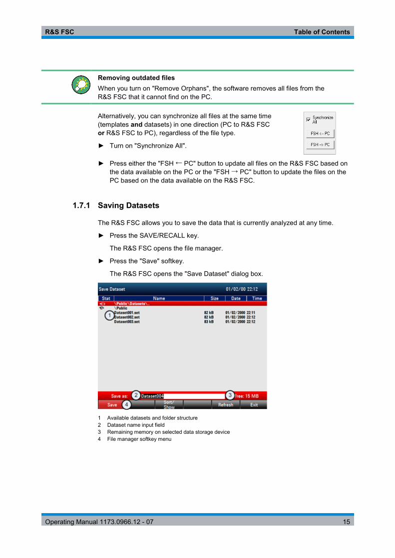
R&S FSC Table of Contents
Operating Manual 1173.0966.12 - 07 15
Removing outdated files When you turn on "Remove Orphans", the software removes all files from the R&S FSC that it cannot find on the PC.
Alternatively, you can synchronize all files at the same time (templates and datasets) in one direction (PC to R&S FSC or R&S FSC to PC), regardless of the file type.
► Turn on "Synchronize All".
► Press either the "FSH ← PC" button to update all files on the R&S FSC based on the data available on the PC or the "FSH → PC" button to update the files on the PC based on the data available on the R&S FSC.
1.7.1 Saving Datasets
The R&S FSC allows you to save the data that is currently analyzed at any time.
► Press the SAVE/RECALL key.
The R&S FSC opens the file manager.
► Press the "Save" softkey.
The R&S FSC opens the "Save Dataset" dialog box.
1 Available datasets and folder structure 2 Dataset name input field 3 Remaining memory on selected data storage device 4 File manager softkey menu
R&S FSC Table of Contents
Operating Manual 1173.0966.12 - 07 16
The folder structure shows all available data storage devices. Possible storage devices are the internal memory of the R&S FSC or a memory stick.
The default storage device depends on which devices are connected to the R&S FSC.
● If a memory stick is connected, datasets are always stored there first. ● The internal memory is used only if no memory stick is connected.
The internal memory provides approximately 20 MB of data, therefore the number of datasets you save on the R&S FSC is limited. Each dataset needs about 100 kB of memory, but this value can vary.
If you are using an external storage device, the number of datasets you can save is limited only by the size of the storage device.
The R&S FSC shows the remaining memory on the storage device in the dialog box.
► Select the storage device you want to save the data to.
► Select the folder you want to save the data to.
► Enter a file name in the corresponding input field.
The default file name for datasets is "Dataset###.set" with a new number in ascending order for each new dataset. The file extension for datasets is .set.
If you enter another name, the R&S FSC uses that name and assigns a new number to the file name if you save the data set the next time. This function allows you to assign consecutive dataset file names without entering a new name every time you want to save a dataset.
You can enter the file name with the alphanumeric keypad. Each key covers more than one character. To get the character you want, press the key in question the appropiate number of times.
► Press the "Save" softkey.
The R&S FSC saves the dataset.
1.7.1.1 Alternative Ways to Save Datasets
The R&S FSC provides alternative and more comfortable ways to save datasets.
Using the HCOPY key
You can configure the HCOPY key to take a screenshot as well as saving a dataset.
► Press the SETUP key.
► Press the "User Preference" softkey.
► Select the "Capture Mode" item.
● Select "Screen" to capture only the screenshot. ● Select "Dataset" to capture only the dataset. ● Select "Screen + Dataset" to capture both screenshot and dataset.
Pressing the HCOPY key saves the selected data of the current measurement.

R&S FSC Table of Contents
Operating Manual 1173.0966.12 - 07 17
1.7.1.2 Renaming File Names
If necessary, you can rename files or file directories directly on the R&S FSC. ► Enter the "File Manager".
► Select the file or directory you want to rename.
► Press the "Select Action" softkey.
► Select the "Rename" menu item.
The R&S FSC opens an input field to change the name of the file.
1.7.1.3 Quick Naming of Datasets
The R&S FSC provides a quick naming feature that speeds up the process of naming a file.
Putting together a file name
Basically, using the quick naming feature is a way of compiling a file name by putting one or more predefined text modules or terms together in a logical way.
The various terms are combined in a table, each cell of which contains one term. The table consists of 120 cells. You can define the contents of each cell freely.
► Press the SAVE/RECALL key.
► Press the "Save" softkey.
► Press the "Quick Naming" softkey.
The R&S FSC opens a dialog box that contains the terms.
► Select the term you want to add with the cursor keys.
► Press ENTER to add the term to the file name.
The current file name is displayed in the line above the table.
So, if you perform, for example, an ACLR measurement of an uplink LTE signal at a certain location, you might want that information in the file name:
'Site_LTE_UL_ACLR'
► Press the "OK" softkey to exit the quick naming table.
After you have exited the table, the file name appears in the "Save as:" field in the "Save Dataset" dialog box. If necessary, you can then add additional characters.

R&S FSC Table of Contents
Operating Manual 1173.0966.12 - 07 18
Note that by default, the R&S FSC adds a term without separators between each term. If you need a separator between the term, you can add a blank space or an underscore.
► After having added a term, press the "_" softkey or the "Space" softkey.
Or to add a separator automatically upon adding a term.
► Press the "Auto Insert" softkey.
► Select the "Off" menu item to add no separator, the "_" menu item to add an underscore or the "Space" menu item to add a blank space.
Designing a quick naming table
The firmware of the R&S FSC already has some basic mobile communication terms in the table. However, you can add up to 120 terms to the table.
► Press the SAVE/RECALL key.
► Press the "Save" softkey.
► Press the "Quick Naming" softkey.
► Select one of the table cells with the cursor keys.
► Press the "Change Table Item" softkey.
The R&S FSC opens an input field to define a term for the cell.
► Define a term with the number keys and confirm the term with ENTER.
The R&S FSC adds the term to the table.
You can create and edit quick naming tables with the R&S FSCView software package and then transfer them into the internal memory of the R&S FSC.
► In the "Quick Naming" softkey menu, press the "Import" softkey.
► Select the "Import Quick Naming Table" menu item.
The R&S FSC opens a dialog box to select a file to import.
The same way, you can also export a quick naming table.
► In the "Quick Naming" softkey menu, press the "Export" softkey.
► Select the "Export Quick Naming Table" menu item.
1.7.1.4 Converting Dataset File Types
The functionality of the R&S FSCView software allows you to convert a dataset of the file type *.set into the *.csv format.
The conversion is possible with a command line option for the FSCView.exe file.
The general syntax you have to use is:
FSCView.exe -csv "<InputDataset.set>" "<DestinationFile.csv>"
Note that you have to use quotation marks for the file name if it contains blank spaces.

R&S FSC Table of Contents
Operating Manual 1173.0966.12 - 07 19
Example:
FSCView.exe -csv 'Dataset.set' 'Dataset.csv'
Renames the file Datset.set into Dataset.csv.
Environment variables The command line option only works if you execute the command from the installation folder of R&S FSCView software. Otherwise, you have to set a "Path" environment variable to the destination of the location of the .exe file. You can access the environment variable via the MS Windows control panel.
"Start Menu" "Control Panel" "System" "Advanced System Settings"
"Advanced" tab
"Environment Variables" button "System Variables" "Path"
► Add a new variable with the installation path of the software.
The default installation path is ● C:\Program Files\Rohde-Schwarz\FSC View\ (for Windows XP, Vista and 7 (32-bit)
● C:\Program Files (x86)\Rohde-Schwarz\FSC View\ (for Windows 7 64-bit)
If necessary, change the path as required.
1.7.2 Restoring Datasets
You can preview and load previously saved measurement results with the recall function of the R&S FSC. This function also provides easy access to previous measurement settings so that you do not have to set up the R&S FSC again.
► Press the SAVE/RECALL key.
The R&S FSC opens the file manager.
► Select the dataset you want to use.
The R&S FSC restores the configuration that the dataset contains.
By default, the most recently saved dataset is highlighted. If you need another dataset, navigate to the folder or storage device that contains the dataset you need.
1.7.2.1 Previewing a Dataset
The R&S FSC provides a preview of datasets. The preview is like a screenshot and lets you take a quick look at that measurement and its settings. The R&S FSC does not yet activate the measurement settings of that dataset.

R&S FSC Table of Contents
Operating Manual 1173.0966.12 - 07 20
► Browse through the available datasets and select the one you want.
► Press the "Recall" softkey.
The R&S FSC shows a preview of the measurement contained in the selected dataset. The preview shows the measurement results as well as the measurement settings.
► Use the rotary knob to browse the previews of all datasets available in the selected folder.
► Press the "Exit" softkey to return to the "Recall Dataset" dialog box.
1.7.2.2 Loading a Dataset
If you find a dataset whose settings you need for your current measurement task, you can load it.
► Press the "Activate" softkey.
The R&S FSC loads the dataset in question and adjusts its measurement settings to those of the dataset.
1.7.3 Deleting Datasets
If you have to delete a dataset, you can do so with the file manager.
► Press the SAVE/RECALL key.
► Press the "File Manager" softkey.
The R&S FSC opens the file manager.
► In order to delete a single dataset, press the "Select Action" softkey. Select "Delete" and the dataset currently selected is deleted after your confirmation.
In order to delete multiple data sets, the respective datasets have to be marked first.
► Press the "Mark" softkey to mark files for deletion
► Select the dataset you'd like to delete.
► Mark the data sets with the ENTER key.
The selected data sets should be checked in the "Status" column.
Repeat the selection by moving the cursor with the rotary knob or the cursor key and marking more data sets with the ENTER key.
► Press the "Select Action" softkey.
► Select the "Delete" menu item and confirm with the ENTER key or the "Select Action" softkey.
Before deleting the data set, the R&S FSC shows a warning message that you need to confirm. After confirming the deletion process the R&S FSC deletes the selected data sets from its memory.

R&S FSC Table of Contents
Operating Manual 1173.0966.12 - 07 21
1.8 Updating the Firmware
You can download new firmware versions from the R&S FSC website.
http://www.rohde-schwarz.com/product/fsc.html
The website also provides release notes for each new firmware version. The release notes include instructions on how to perform a firmware update.

R&S FSC Table of Contents
Operating Manual 1173.0966.12 - 07 22
2 Spectrum Analyzer Mode The default operating mode of the R&S FSC is the spectrum analyzer. The spectrum analyzer provides the functionality to perform measurements in the frequency domain, e.g. to identify the power of signals.
2.1 Performing Spectrum Measurements
In addition to basic spectrum measurements, the R&S FSC provides several specific measurements. These measurements, also in combination with one of the available accessories, allow you to perform advanced and more complex measurement tasks.
2.1.1 Measuring the Channel Power of Continuously Modulated Signals
The channel power measurement selectively measures the power of modulated signals. Unlike a power meter that performs measurements over its entire frequency range, the channel power measurement measures the power of a specific transmission channel. Other signals in the frequency spectrum don't show in the results.
When measuring the spectrum within a channel, the R&S FSC uses a resolution bandwidth that is small compared to the channel bandwidth. It then determines the total power of the channel by integrating the results on the trace. The R&S FSC takes the following parameters into account:
● display mode (absolute or relative) ● detector ● resolution bandwidth
That means that you can compare the result to the result that would have been obtained from a thermal power meter. The small resolution bandwidth acts like a narrow channel filter and so prevents out-of-channel emissions from affecting the result.
► Press the MEAS key.
► Press the "Meas Mode" softkey.
► Select the "Channel Power" menu item.
The R&S FSC starts to measure the channel power.
By default, the 3GPP WCDMA standard is active. Two vertical lines show the channel bandwidth.

R&S FSC Table of Contents
Operating Manual 1173.0966.12 - 07 23
Screen layout for channel power measurements
1 Standard 2 Channel bandwidth 3 Channel power numerical 4 Channel bandwidth graphical (blue lines) 5 Channel power measurement softkey menu
2.1.1.1 Selecting the Standard
If you need to perform measurements that are conform to a telecommunications standard, you can activate one of the predefined standards that are already stored in the R&S FSC memory. However, you can create new configurations to perform measurements on other standards as well.
► Press the MEAS key.
► Press the "Standard" softkey.
The R&S FSC opens a dialog box to select the standard.
► Select one of the available standards.
► Confirm the selection with the "Select" softkey.
The R&S FSC loads the configuration of the selected standard. It automatically sets the optimal span, resolution bandwidth, video bandwidth, sweep time and detector for the standard.
If the measurement is not according to the selected standard anymore (e.g. if you make changes to a parameter), the R&S FSC puts a red dot in front of the standard display ( ).
You can create and edit standards with the R&S FSCView software and transfer them to the R&S FSC via the USB or the LAN interface. The number of standards the R&S FSC can store in its memory depends on the number of other data sets stored on the R&S FSC.
For more information see "Managing Datasets" on page 14.

R&S FSC Table of Contents
Operating Manual 1173.0966.12 - 07 24
2.1.1.2 Setting the Reference Level
The reference level is the power level that the R&S FSC expects at the RF input. When selecting the reference level, make sure that you do not overload the R&S FSC by applying a signal whose power exeeds the maximum reference level.
As the power is measured with a small resolution bandwidth compared to the signal bandwidth, it is still possible to overload the R&S FSC, even if the trace is within the measurement diagram. To prevent an overload, perform the measurement with the largest resolution bandwidth possible using the peak detector. If you set these parameters, it is not possible for the trace to exceed the reference level.
To simplify operation and to prevent incorrect measurements, the R&S FSC has an automatic routine for setting the reference level.
► Press the AMPT key.
► Press the "Level Adjust" softkey.
The R&S FSC performs a measurement to determine the optimal reference level.
It uses a resolution bandwidth of 1 MHz, a video bandwidth of 1 MHz and the peak detector. After finishing the automatic measurement, the R&S FSC sets the optimal reference level.
2.1.1.3 Setting the Channel Bandwidth
The channel bandwidth specifies the frequency range around the center frequency, over which the R&S FSC performs the power measurement.
► Press the MEAS key.
► Press the "Chan BW" softkey.
The R&S FSC opens an input field to specify the channel bandwidth.
► Enter the channel bandwidth you need.
The R&S FSC sets the appropriate span for the channel bandwidth that you have entered (span = 1.2 x channel bandwidth). This ensures that no incorrect channel power measurements are made.
The minimum channel bandwidth that you can set is 833 Hz at a span of 1 kHz.
2.1.1.4 Changing the Span
Usually, the span the R&S FSC sets yields optimal results. But sometimes you also need to see the spectrum outside the current span to detect other signal components that you need to include in the measurement. Therefore, you can adjust the span to up to ten times the channel bandwidth and hence still be able to see the spectrum outside the measurement channel.

R&S FSC Table of Contents
Operating Manual 1173.0966.12 - 07 25
► Press the SPAN key.
In the default configuration, "Auto Span" is active. The R&S FSC automatically sets the optimal span for the channel power measurement.
► Press the "Manual Span" softkey.
The R&S FSC opens an input field to define the span manually.
► Enter the span you need.
The largest possible span for the channel power measurement is ten times the channel bandwidth. At larger spans, the result of the channel power measurement would be increasingly imprecise, because too few points of the trace would be in the channel you are measuring.
► Press the "Auto Span" softkey.
The R&S FSC again calculates the span automatically.
2.1.1.5 Measuring the Maximum Channel Power
If signal levels fluctuate significantly, you can define the maximum channel power with the Max Hold function.
► Press the MEAS key.
► Press the "Power Display" softkey.
► Select the "Max Hold" menu item.
The power display switches from "Power" to "Max Power".
If you want to deactivate the Max Hold function and return to the normal power display, activate Clear/Write.
► To deactivate the Max Hold function, press the "Power Display" softkey.
► Select the "Clear/Write" menu item.
The power display returns to "Power" display.
2.1.1.6 Unit for Power Display
The R&S FSC can apply different units to the power output. The default unit is dBm.
► Press the MEAS key.
► Press the "Power Unit" softkey.
► Select the unit you want from the submenu.
The R&S FSC displays the power level in the selected unit.

R&S FSC Table of Contents
Operating Manual 1173.0966.12 - 07 26
2.1.2 Measuring the Occupied Bandwidth
The proper operation of a transmission network requires that all transmitters adhere to the bandwidths assigned to them. The occupied bandwidth is defined as the bandwidth that contains a specified percentage of the entire power of the transmitter.
Numerous standards require a occupied bandwidth of 99 %. Therefore this is the default setting. If you need another percentage for the occupied bandwidth you can set values from 10 % to 99.9 %.
After entering the channel bandwidth, the R&S FSC automatically selects the measurement parameters so that you can attain the best result.
► Press the MEAS key.
► Press the "Meas Mode" softkey.
The R&S FSC opens the measurement menu.
► Select the "Occupied BW" menu item.
The R&S FSC starts to measure the occupied bandwidth.
Two vertical lines show the occupied bandwidth.
Screen layout for the occupied bandwidth
1 Standard 2 Occupied bandwidth numerical 3 Channel bandwidth 4 Power percentage 5 Occupied bandwidth graphical (blue lines) 5 Occupied bandwidth measurement softkey menu

R&S FSC Table of Contents
Operating Manual 1173.0966.12 - 07 27
2.1.2.1 Selecting a Standard
If you need to perform measurements that are conform to a telecommunications standard, you can activate one of the predefined standards that are already stored in the R&S FSC memory. However, you can create new configurations to perform measurements on other standards as well.
► Press the MEAS key.
► Press the "Standard" softkey.
The R&S FSC opens a dialog box to select the standard.
► Select one of the available standards.
► Confirm the selection with the "Select" softkey.
The R&S FSC loads the configuration of the selected standard. It automatically sets the optimal span, resolution bandwidth, video bandwidth, sweep time and detector for the standard.
You can create and edit standards with the R&S FSCView software and transfer them to the R&S FSC via the USB or the LAN interface. The number of standards the R&S FSC can store in its memory depends on the number of other data sets stored on the R&S FSC.
For more information see "Managing Datasets" on page 14.
If you make changes to the settings or create datasets, note that
● the span is always coupled to the channel bandwidth. Changes to either of those automatically adjust the other (= 5 x channel bandwidth).
● the resolution bandwidth should be between 1 % and 4 % of the channel bandwidth. This ensures that the occupied bandwidth is measured with high accuracy.
● the video bandwidth must be at least three times the resolution bandwidth. This prevents incorrect results due to the compression of signal peaks by the video filter.
● you use the RMS detector if possible. This ensures that the power measurement is always correct irrespective of the waveform being investigated.
● the sweep time must be set so that the result is stable. If you increase the sweep time, the R&S FSC also increases the integration time for the RMS detector and thus ensures more stable measured values.
R&S FSC Table of Contents
Operating Manual 1173.0966.12 - 07 28
2.1.2.2 Setting the Reference Level
The reference level is the power level that the R&S FSC expects at the RF input. When selecting the reference level, make sure that you do not overload the R&S FSC by applying a signal whose power exeeds the maximum reference level.
As the power is measured with a small resolution bandwidth compared to the signal bandwidth, it is still possible to overload the R&S FSC, even if the trace is within the measurement diagram.
To prevent an overload, perform the measurement with the largest resolution bandwidth possible using the peak detector. If you set these parameters, it is not possible for the trace to exceed the reference level.
To simplify operation and to prevent incorrect measurements, the R&S FSC has an automatic routine for setting the reference level.
► Press the AMPT key.
► Press the "Level Adjust" softkey.
The R&S FSC performs a measurement to determine the ideal reference level.
It uses a resolution bandwidth of 1 MHz, a video bandwidth of 1 MHz and the peak detector. After finishing the automatic measurement, the R&S FSC sets the ideal reference level.
2.1.2.3 Setting the Channel Bandwidth
The channel bandwidth specifies the frequency range around the center frequency, over which the R&S FSC performs the power measurement.
► Press the MEAS key.
► Press the "Chan BW" softkey.
The R&S FSC opens an input field to specify the channel bandwidth.
► Enter the channel bandwidth you need.
The R&S FSC sets the appropriate span for the channel bandwidth that you have entered (span = 5 x channel bandwidth). This ensures that no incorrect channel power measurements are made.
The minimum channel bandwidth that you can set is 2 kHz at a span of 1 kHz.

R&S FSC Table of Contents
Operating Manual 1173.0966.12 - 07 29
2.1.2.4 Defining the Percentage of Occupied Bandwidth
By default, the power percentage inside the occupied bandwidth is 99 %, a number most standards require. If you measure standards that specify another power percentage you can change that value.
► Press the MEAS key.
► Press the "% Power BW" softkey.
The R&S FSC opens an input field to define the power percentage.
► Enter the power percentage you need.
The value you enter here is the power percentage that has to be inside the channel bandwidth relative to the power over the total span (the percentage of the total power).
The R&S FSC now displays the occupied bandwidth graphically in the trace window and numerically above the trace window.
2.1.2.5 Changing the Span
Usually, the span the R&S FSC sets yields optimal results. But sometimes you also need to see the spectrum outside the current span to detect other signal components that you need to include in the measurement. Therefore, you can adjust the span to up to ten times the channel bandwidth and still be able to see the spectrum outside the measurement channel.
► Press the SPAN key.
In the default configuration, "Auto Span" is active. The R&S FSC automatically sets the optimal span for the channel power measurement.
► Press the "Manual Span" softkey.
The R&S FSC opens an input field to define the span manually.
► Enter the span you need.
The largest possible span for the channel power measurement is ten times the channel bandwidth. At larger spans, the result of the channel power measurement would be increasingly imprecise, because too few points of the trace occur in the channel to be measured.
► Press the "Auto Span" softkey.
The R&S FSC again calculates the span automatically.

R&S FSC Table of Contents
Operating Manual 1173.0966.12 - 07 30
2.1.3 Power Measurements on TDMA Signals
When TDMA (time division multiple access) methods are used, e.g. for GSM, several users share a channel. Each user is assigned a period of time or timeslot. With the TDMA power measurement, you can determine the power over one of the timeslots.
The TDMA power measurement is a measurement in the time domain (span = 0 Hz). You can start it on an external or video trigger and specify the power measurement time.
To prevent incorrect power measurements in the time domain, make sure that the whole signal is within the selected resolution bandwidth. If the resolution bandwidth is too small, the displayed power will be lower than the actual power.
► Press the MEAS key.
► Press the "Meas Mode" softkey.
The R&S FSC opens the measurement menu.
► Select the "TDMA Power" menu item.
The R&S FSC starts to measure the TDMA power.
Two vertical lines define the measurement range.
Screen layout for TDMA power measurements
1 Standard 2 TDMA power 3 Measurement limits 4 Trigger delay 5 Trigger level 6 Measurement time 7 TDMA power measurement softkey menu

R&S FSC Table of Contents
Operating Manual 1173.0966.12 - 07 31
2.1.3.1 Selecting a Standard
If you need to perform measurements that are conform to a telecommunications standard, you can activate one of the predefined standards that are already stored in the R&S FSC memory. When starting the measurement in the default configuration, the R&S FSC automatically activates the GSM/EDGE standard. However, you can create new configurations to perform measurements on other standards as well.
► Press the MEAS key.
► Press the "Standard" softkey.
The R&S FSC opens a dialog box to select the standard.
► Select one of the available standards.
► Confirm the selection with the "Select" softkey.
The R&S FSC loads the configuration of the selected standard. It automatically sets the optimal settings for the selected standard.
You can create and edit standards with the R&S FSCView software and transfer them to the R&S FSC via the USB or the LAN interface. The number of standards the R&S FSC can store in its memory depends on the number of other data sets stored on the R&S FSC. For more information see "Managing Datasets" on page 14.
2.1.3.2 Setting the Burst Length
The burst length is the measurement time that the R&S FSC performs measurements with. The burst length can be equal or less than the sweep time.
► Press the MEAS key.
► Press the "Burst Length" softkey.
The R&S FSC opens an input field to define the burst length. ► Enter the length of the burst you need.
The R&S FSC performs the measurement over the time you have entered.
If the measurement time you have entered was greater than the sweep time, the R&S FSC sets a burst length equal to the sweep time. To work with a greater burst length, you have to increase the sweep time first.
The minimum burst length is the time corresponding to one trace pixel (= sweep time / 631).
2.1.3.3 Setting the Reference Level
The reference level is the power level that the R&S FSC expects at the RF input. When selecting the reference level, make sure that you do not overload the R&S FSC by applying a signal whose power exeeds the maximum reference level.
Because the resolution bandwidths of the R&S FSC are implemented digitally after the A/D converter, the signal level at the A/D converter can be higher than the level indicated by the trace, depending on the selected resolution bandwidth.

R&S FSC Table of Contents
Operating Manual 1173.0966.12 - 07 32
To prevent the A/D converter from being overloaded, the signal must be measured at the widest resolution bandwidth and video bandwidth with the peak detector. The trace maximum then determines the best reference level.
To simplify operation and to prevent incorrect measurements, the R&S FSC has an automatic routine for setting the reference level.
► Press the AMPT key.
► Press the "Level Adjust" softkey.
The R&S FSC performs a measurement to determine the ideal reference level.
It uses a resolution bandwidth of 3 MHz, a video bandwidth of 3 MHz and the peak detector. After finishing the automatic measurement, the R&S FSC sets the ideal reference level.
2.1.3.4 Using a Trigger
Usually you will apply a trigger when measuring bursts.
If a trigger is active, the R&S FSC uses the video trigger for TDMA measurements by default. The video trigger level is at 50 % of the range of the vertical axis but is variable. This means, the R&S FSC triggers a measurement if the rising edge of the burst exceeds this 50 % line.
If the DUT features some sort of trigger equipment, you can also use an external trigger to trigger measurements.
► Connect the DUT trigger output to the R&S FSC trigger input.
► Press the SWEEP key.
► Press the "Trigger" softkey.
► Select either the "External Rise" or "External Fall" menu item (rising or falling edge).
The R&S FSC activates the trigger and shows the results of the measurement.
It may be that the burst is not completely visible on the display. To correct that and make the whole burst visible, you can set a trigger delay.
► Press the "Trigger" softkey.
► Select the "Trigger Delay" menu item.
The R&S FSC opens an input field to define the trigger delay.
► Adjust the trigger delay until the burst is visible inside the vertical lines that show the measurement range.

R&S FSC Table of Contents
Operating Manual 1173.0966.12 - 07 33
2.1.4 Measuring the Adjacent Channel Leakage Ratio (ACLR)
The Adjacent Channel Leakage Ratio (ACLR) measurement is a method to measure the power over more than one transmission channel and also evaluate the power of the adjacent (or alternate) channels of the transmission channel. The ACLR performs measurements according to a specific channel configuration, e.g. a particular radio communications standard.
► Press the MEAS key.
► Press the "Meas Mode" softkey.
The R&S FSC opens the measurement menu.
► Select the "ACLR" menu item.
The R&S FSC starts to measure the adjacent channel leakage ratio.
In principle, the ACLR measurement works like the channel power measurement in that it determines the spectrum within the channel using a resolution bandwidth that is small compared to the channel bandwidth. In addition to the channel bandwidth, the ACLR measurement is also defined by the channel spacing, the bandwidth of adjacent channels and the adjacent channel spacing. The R&S FSC supports measurements on up to 12 carrier channels and 12 adjacent channels to either side of the carrier. When measuring more than one carrier or adjacent channels, the R&S FSC shows the powers of each channel in a list below the marker list. The channel itself is marked by red (transmission channels) or green (adjacent channels) vertical lines.
Screen Layout for ACLR measurements
1 Standard 2 Marker information 3 Limit check information 4 Channel information 5 TX channel (red line) 6 Adjacent channel (green line) 7 Alternate channels (green lines) 8 Marker (blue line) 9 ACLR softkey menu

R&S FSC Table of Contents
Operating Manual 1173.0966.12 - 07 34
The predefined standards are the same as for channel power measurements (3GPP WCDMA, cdmaOne and CDMA2000 1x systems). However, you can also customize the settings to set up the R&S FSC for other radio communication standards. You can define the settings directly on the R&S FSC or define and manage them using the R&S FSCView software.
When customizing settings, make sure to consider the following points to get valid and accurate measurement results: ● Reference level
Make sure not to overload the R&S FSC as the power is measured with a resolution bandwidth that is small in comparison with the signal bandwidth. As with Channel Power measurements, automatically set the reference to an optimal level with the "Level Adjust" softkey.
● Setting the span
The frequency span must at least cover the carriers and the adjacent channels plus a measurement margin of about 10 % to get valid results.
If the span is automatically calculated by the R&S FSC with the "Auto Span" function, the span is calculated as follows:
(No. of transmission channels - 1) x transmission channel spacing + 2 x transmission channel bandwidth + measurement margin
with the measurement margin being approx. 10 % of the value obtained by adding the channel spacing and the channel bandwidth.
Selecting the frequency span If the frequency span is too large in comparison to the channel bandwidth (or the adjacent-channel bandwidths) being examined, only a few points on the trace are available per channel. This reduces the accuracy of the waveform calculation for the channel filter used, which has a negative effect on the measurement accuracy. It is therefore strongly recommended that the formulas mentioned be taken into consideration when selecting the frequency span.
● Setting the resolution bandwidth:
The RBW should not be too high or too small to get both an acceptable measurement speed and a suppression of spectral components outside the channels. As a rule of thumb, it is recommended to set it to about 1 % to 4 % of the channel bandwidth.
You can select a larger resolution bandwidth if the spectrum within the channel to be measured and around it has a flat characteristic. In the standard setting, e.g. for standard cdmaOne at an adjacent channel bandwidth of 30 kHz, a resolution bandwidth of 30 kHz is used. This yields correct results since the spectrum in the neighborhood of the adjacent channels normally has a constant level.

R&S FSC Table of Contents
Operating Manual 1173.0966.12 - 07 35
For standard NADC/IS136 this would not be not possible, for example, since the spectrum of the transmit signal penetrates into the adjacent channels and a too large resolution bandwidth causes a too low selection of the channel filter. The adjacent-channel power would thus be measured too high.
If the RBW is automatically calculated by the R&S FSC with the "Auto RBW" function, the RBW is calculated as follows:
RBW ≤ 1/40 of channel bandwidth
The R&S FSC then selects the maximum possible resolution bandwidth resulting from the available RBW steps (1, 3).
● Setting the video bandwidth
To obtain correct power measurements, the video signal must not be limited in bandwidth. A restricted bandwidth of the logarithmic video signal would cause signal averaging and thus result in a too low indication of the power (-2.51 dB at very low video bandwidths). Therefore, the VBW should be at least three times the resolution bandwidth.
If the VBW is automatically calculated by the R&S FSC with the "Auto VBW" function, the VBW is calculated as follows:
VBW ≥ 3 x RBW
The R&S FSC then selects the smallest possible VBW with regard to the available step size.
● Selecting the detector:
It is best to use the RMS detector. This detector correctly indicates the power irrespective of the characteristics of the signal to be measured. The whole IF envelope is used to calculate the power for each measurement point. The IF envelope is digitized using a sampling frequency which is at least five times the resolution bandwidth which has been selected. Based on the sample values, the power is calculated for each measurement point using the following formula:
∑=
⋅=N
iiRMS s
NP
1
21
with si = linear digitized video voltage at the output of the A/D converter N = number of A/D converter values per measurement point PRMS = power represented by a measurement point
When the power has been calculated, the power units are converted into decibels and the value is displayed as a measurement point.
In principle, the sample detector would be possible as well. Due to the limited number of measurement points used to calculate the power in the channel, the sample detector would yield less stable results.

R&S FSC Table of Contents
Operating Manual 1173.0966.12 - 07 36
2.1.4.1 Selecting a Standard
If you need to perform measurements that are conform to a telecommunications standard, you can activate one of the predefined standards that are already stored in the R&S FSC memory. Those predefined standards have already been set up to yield the best results. However, the R&S FSC provides functionality to create new configurations to perform measurements on other test setups as well.
► Press the MEAS key.
► Press the "Standard" softkey.
The R&S FSC opens a dialog box to select the standard.
► Select one of the available standards.
► Confirm the selection with the "Select" softkey.
The R&S FSC loads the configuration of the selected standard. It automatically sets the optimal span, resolution bandwidth, video bandwidth, sweep time and detector for the standard.
You can create and edit standards with the R&S FSCView software and transfer them to the R&S FSC via the USB or the LAN interface. The number of standards the R&S FSC can store in its memory depends on the number of other data sets stored on the R&S FSC. For more information see "Managing Datasets" on page 14.
2.1.4.2 Configuring the Measurement
In addition to creating and editing standards with the R&S FSCView software, the R&S FSC also provides functionality to set up a measurement configuration.
Setting the number of transmission channels
► Press the MEAS key.
► Press the "Channel Settings" softkey.
► Select the "Tx Channels" menu item.
The R&S FSC opens an input field to define the number of transmission channels.
► Enter the number of transmission channels you need for the measurement.
Setting the number of adjacent channels
► Press the "Channel Settings" softkey.
► Select the "Adj Channels" menu item.
The R&S FSC opens an input field to define the number of adjacent channels.
► Enter the number of adjacent / alternate channels you need for the measurement.
The borders of Tx channels are displayed red in the trace diagram, the borders of adjacent and alternate channels are displayed green.

R&S FSC Table of Contents
Operating Manual 1173.0966.12 - 07 37
Setting the channel bandwidth
The channel bandwidth specifies the frequency range around the center frequency, over which the R&S FSC performs the power measurement.
► Press the MEAS key.
► Press the "Channel BW" softkey.
The R&S FSC opens a dialog box to specify the channel bandwidth for all channels.
► Select the channel you want to change the bandwidth for.
► Activate the input by pressing the ENTER key.
► Enter the channel bandwidth you need.
The R&S FSC sets the appropriate span for the channel bandwidth that you have entered according to the criteria desribed above. This ensures that no incorrect channel power measurements are made.
The minimum channel bandwidth that you can set is 833 Hz at a span of 1 kHz.
Setting the channel spacing
In case of the R&S FSC, the channel spacing is defined as the distance between the center frequency of the transmission channel and the center frequency to the next transmission channel or the distance between the center frequency of the transmission channel and the center frequency of the adjacent channel.
Specific channel spacing definitions Note that some some radio communication standards, e.g. CDMA2000 DS / MC1 / MC3 and IS95 B / C, IS97 B / C, IS98 B / C, define the channel spacing differently, namely the distance from the center of the transmission channel to the closest border of the adjacent channel. The R&S FSC does not consider these specifics. It always regards the channel spacing as the distance between the center of a channel and the center of its neighboring channel.
► Press the MEAS key.
► Press the "Channel Settings" softkey.
► Select the "Channel Spacing" menu item.

R&S FSC Table of Contents
Operating Manual 1173.0966.12 - 07 38
The R&S FSC opens a dialog box to define the spacings for all transmission channels and adjacent / alternate channels.
► Select the channel you want to change the spacing for.
► Activate the input by pressing the ENTER key.
► Enter the channel spacing you need.
The R&S FSC now takes the new values into account for future measurements.
When performing measurements on multi-carrier signals, you can define the spacing of the transmission (Tx) channels to one another. By default, the R&S FSC assumes equal spacing between all Tx channels in the system. Therefore, the spacing you enter for the first two Tx channels is automatically applied to all other Tx channels.
If you do measurements on systems with a different channel spacing for each Tx channel, you can also set the channel spacing for each Tx channel separately by entering the respective number in the fields.
If the spacings are not equal, the channel distribution according to the center frequency is as follows:
● Odd number of TX channels
The middle TX channel is centered to center frequency.
● Even number of TX channels
The two TX channels in the middle are used to calculate the frequency between those two channels. This frequency is aligned to the center frequency.
Adjacent or alternate channel spacing is also available for single-carrier measurements. The R&S FSC can perform measurements on up to 12 adjacent channels. Usually the first adjacent channel to the Tx channel is referred to as the Adjacent Channel (ADJ). All others are called Alternate Channels (ALT1 to ALT11).
By default, the R&S FSC assumes that the distance of the adjacent channels to each other is the same. In that case, you only have to enter the first spacing value. The R&S FSC then calculates all higher adjacent channels from that value. If you change the spacing of one of the higher channels, the R&S FSC only updates the channel spacings above the one you have changed, but not those below.
So, for example, if you set the first adjacent channel spacing (ADJ) to 20 kHz, the following spacings are 40 kHz (ALT1), 60 kHz (ALT2), 80 kHz (ALT3), 100 kHz (ALT4), 120 kHz (ALT5) and so on.
If you then change the spacing of the third alternate channel (ALT3) to 100 kHz, the R&S FSC adjusts the alternate channels above the third one accordingly: 125 kHz (ALT4), 150 kHz (ALT5) and so on.
R&S FSC Table of Contents
Operating Manual 1173.0966.12 - 07 39
2.1.4.3 Normalization of Measurement Results
By default, the power of the channels and adjacent channels is displayed in the unit dBm. It is also possible to display the power density of the signal to, for example, measure the signal/noise power density or obtain the signal to noise ratio.
► Press the MEAS key.
► Press the "Channel Settings" softkey.
► Select the "Channel Pwr/Hz" menu item.
The R&S FSC activates normalization and switches the unit from dBm to dBm/Hz.
The channel power density in dBm/Hz corresponds to the power inside a bandwidth of 1 Hz and is calculated as follows:
channel power density = channel power - log10(channel bandwidth)
2.1.4.4 Displaying Absolute and Relative Results
You can set up the result display to either show the absolute power of the adjacent channels or the power relative to one of the transmission channels.
► Press the MEAS key.
► Press the "Power Display" softkey.
► Select either the "Absolute" menu item to display the absolute results or the "Relative" menu item to display the power relative to one of the transmission channels.
2.1.4.5 Selecting the Reference Channel
When determining relative power values for the adjacent channels, you can set a specific transmission channel as the reference channel.
► Press the MEAS key.
► Press the "Channel Settings" softkey.
► Select the "ACLR Ref Setting" menu item.
The R&S FSC opens a another submenu to select the reference channel.
► Select the method of determining the reference channel.
The following methods are available:
- Tx Channel
Select a specific transmission channel by entering its number as the reference.
- Min Power Tx Channel
The channel with the lowest power level is the reference channel.
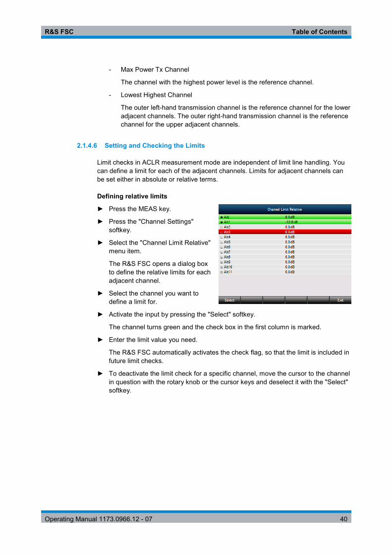
R&S FSC Table of Contents
Operating Manual 1173.0966.12 - 07 40
- Max Power Tx Channel
The channel with the highest power level is the reference channel.
- Lowest Highest Channel
The outer left-hand transmission channel is the reference channel for the lower adjacent channels. The outer right-hand transmission channel is the reference channel for the upper adjacent channels.
2.1.4.6 Setting and Checking the Limits
Limit checks in ACLR measurement mode are independent of limit line handling. You can define a limit for each of the adjacent channels. Limits for adjacent channels can be set either in absolute or relative terms.
Defining relative limits
► Press the MEAS key.
► Press the "Channel Settings" softkey.
► Select the "Channel Limit Relative" menu item.
The R&S FSC opens a dialog box to define the relative limits for each adjacent channel.
► Select the channel you want to define a limit for.
► Activate the input by pressing the "Select" softkey.
The channel turns green and the check box in the first column is marked.
► Enter the limit value you need.
The R&S FSC automatically activates the check flag, so that the limit is included in future limit checks.
► To deactivate the limit check for a specific channel, move the cursor to the channel in question with the rotary knob or the cursor keys and deselect it with the "Select" softkey.

R&S FSC Table of Contents
Operating Manual 1173.0966.12 - 07 41
Defining absolute limits
► Press the "Channel Settings" softkey.
► Select the "Channel Limit Absolute" menu item.
The R&S FSC opens a dialog box to define the absolute limits for each adjacent channel.
► The procedure of defining absolute limits is analogous to that of defining relative limits.
Performing a limit check
► Press the "Channel Settings" softkey.
► Select the "Check Channel Limits" menu item.
The R&S FSC automatically performs limit checks.
The results of the limit check are displayed in the table above the trace. If a result fails the limit check, it turns red and has a star (*) in front of its power level.
2.1.5 Measuring the Spectrum Emission Mask
The Spectrum Emission Mask (SEM) measurement is a method to detect spurious emissions or intermodulation products of a signal. When performing a SEM measurement, the R&S FSC checks the signal against a spectral mask to see whether the signal complies with a specific standard or not. Therefore, the R&S FSC provides predefined spectrum emission masks for various telecomunications standards.
However, you can define your own spectral masks with the R&S FSCView software to perform measurements in frequency ranges other than the predefined ones. To learn how to define Spectrum Emission Masks, refer to the R&S FSCView manual.
► Press the MEAS key.
► Press the "Meas Mode" softkey.
The R&S FSC opens the measurement menu.
► Select the "Spectrum Emission Mask" menu item.
The R&S FSC starts to measure the spectrum emission mask.
Note that the frequency range of the actual measurement depends on the start and stop frequency you have set on the R&S FSC. Correct measurement results are therefore only possible if the frequency ranges of the SEM are inside the current span of the R&S FSC.

R&S FSC Table of Contents
Operating Manual 1173.0966.12 - 07 42
Screen Layout for the SEM measurement
1 Standard 2 Marker information 3 SEM list 4 Limit check result 5 Spectrum emission mask (red line) 6 Trace (yellow line) 7 Marker (blue line) 8 SEM softkey menu
2.1.5.1 Selecting a Standard
If you need to perform measurements that are conform to a telecommunications standard, you can activate one of the predefined standards that are already stored in the R&S FSC memory. However, you can create new configurations to perform measurements on other standards as well.
► Press the MEAS key.
► Press the "Standard" softkey.
The R&S FSC opens a dialog box to select the standard.
► Select one of the available standards.
► Confirm the selection with the "Select" softkey.
The R&S FSC loads the configuration of the selected standard. It automatically sets the optimal span, resolution bandwidth, video bandwidth, sweep time and detector for the standard.
You can create and edit standards with the R&S FSCView software and transfer them to the R&S FSC via the USB or the LAN interface. The number of standards the R&S FSC can store in its memory depends on the number of other data sets stored on the R&S FSC. For more information see "Managing Datasets" on page 14.

R&S FSC Table of Contents
Operating Manual 1173.0966.12 - 07 43
2.1.5.2 Optimizing Measurement Settings
After selecting the standard and applying the signal to the R&S FSC, you can optimize measurement settings to avoid overloading the R&S FSC.
► Press the "Adjust Settings" softkey.
The R&S FSC performs a measurement to determine the ideal reference level ans span..
2.1.5.3 Viewing the Results in a Table
You can add a table to the display that shows the measurement results in numerical form.
► Press the MEAS key.
► Press the "View List" softkey.
The R&S FSC shows a list above the trace diagram.
If the list contains more than four entries, you can scroll through the list with the rotary knob or the cursor keys to see the other results. Note that scrolling works only if there is no active input field.
The list contains the following information:
● Tx Power
Power level of the transmission channel.
● Tx Bandwidth
Bandwidth of the transmission channel.
● PASS / FAIL information
If the signal is within the limits of the spectral mask, the R&S FSC shows , if not it shows .
● Range [Hz]
Frequency range. The first number is the start frequency, the second number the stop frequency of each defined frequency range. The character following the number indicates the unit (k = kHz, M = MHz, G = GHz)
● RBW [Hz]
Resolution bandwidth the corresponding frequency range is measured with.
● Freq [Hz] ● Power Abs
Absolute peak power in the corresponding frequency range.
● Power Rel
Relative peak power in relation to the channel power of the reference channel.

R&S FSC Table of Contents
Operating Manual 1173.0966.12 - 07 44
● Δ Limit
Minimum distance from the limit line to the trace in the corresponding frequency range. Negative values or a zero indicate a passed SEM limit check, positive values indicate a violation of the limit check.
2.1.6 Measuring the Harmonic Distortion
The Harmonic Distortion measurement is an easy way to identify the harmonics of a DUT. In addition to the graphic display of the harmonics, this measurement mode also calculates the Total Harmonic Distortion (THD) and shows the results.
You can perform a Harmonic Distortion measurement in frequency sweep (span > 0) and zero span mode (span = 0). When starting the measurement, the R&S FSC looks for the first harmonic of the signal (= the highest signal) in the defined frequency range. It then adjusts the frequency axis so that all harmonics are visible. In zero span mode, the center frequency remains the same.
► Press the MEAS key.
► Press the "Meas Mode" softkey.
► Select the "Harmonic Distortion" menu item.
The R&S FSC starts to measure the harmonic distortion.
The search for harmonics starts as soon as you enter the Harmonic Distortion measurement. Upon entering the measurement, the R&S FSC automatically adjusts the settings in order to display the selected number of harmonics (default = 2) on the screen.
Screen layout for the harmonic distortion measurement
1 Harmonics list 2 Total harmonic distortion in % 3 Total harmonic distortion in dB 4 Trace 5 Markers indicating harmonics (blue lines) 6 Harmonic distortion softkey menu

R&S FSC Table of Contents
Operating Manual 1173.0966.12 - 07 45
2.1.6.1 Defining the Number of Harmonics
By default, the R&S FSC shows the signal and its first harmonic. Each harmonic is indicated by a marker that the R&S FSC places on the harmonic (here M1 and M2). Note that all of the markers that have been set are normal markers that show the absolute frequency of the harmonic.
At the same time, the R&S FSC also calculates the values for the total harmonic distortion (THD) and shows the results in a box above the trace diagram. The values are output in % as well as dB.
If you want to see more than one harmonic, the R&S FSC can show up to six harmonics.
► Press the MEAS key.
► Press the "Harmonics" softkey.
► Enter the number of harmonics you'd like to see.
2.1.6.2 Optimizing the Display of Harmonics
The R&S FSC places the markers on the other harmonics even if they are outside of the display range.
► Press the MEAS key.
► Press the "Adjust Settings" softkey.
The R&S FSC performs a measurement to determine the ideal reference level, frequency and span in order to display all harmonics.
2.1.6.3 Activating the Harmonics List
To see the exact frequency of the harmonic, you can activate the marker list that shows the value for each harmonic or marker.
► Press the MKR key.
► Press the "View List" softkey.
The R&S FSC displays the marker list that contains the values for each harmonic.

R&S FSC Table of Contents
Operating Manual 1173.0966.12 - 07 46
2.1.7 Measuring the AM Modulation Depth
The AM Modulation Depth measurement analyzes AM modulated signals and calculates the modulation depth of the signal using the measurement results. Note that the measurement works properly only if you apply an AM modulated signal.
► Press the MEAS key.
► Press the "Meas Mode" softkey.
The R&S FSC opens the measurement menu.
► Select the "AM Modulation Depth" menu item.
The R&S FSC starts to measure the AM modulation depth.
After you have started the measurement, the R&S FSC places three markers on the trace. The first marker is placed on the peak power level. The R&S FSC assumes that position as the level of the carrier. The second and third markers are delta markers. These are placed symmetrically on the adjacent peak values to the left and right of the carrier.
By default, delta marker 2 is active for editing. If you move the delta marker to another position, the other delta marker will be moved by the same distance relative to the normal marker. Note that this happens only if you move delta marker 2 (D2). When moving delta marker 3 (D3), only this marker is repositioned.
From the values of the markers, the R&S FSC then calculates the AM modulation depth. The AM modulation depth is the ratio between the power values at the reference marker and at the delta markers. When the powers of the two AM side bands are not the same, the R&S FSC uses the mean value of the two sideband values.
If the R&S FSC is unable to find any AM modulated a carriers, it shows the message .
Screen layout for the AM modulation depth measurement

R&S FSC Table of Contents
Operating Manual 1173.0966.12 - 07 47
1 Marker list 2 Modulation depth 3 Trace 4 Threshold line 5 Markers (blue lines) 6 AM modulation depth softkey menu
2.1.7.1 Setting a Threshold
You can set a threshold that defines the minimum power level the signal must have. If the power of the signal is below the threshold, the R&S FSC will not set the markers and therefore will not calculate the modulation depth.
► Press the MEAS key.
► Press the "Threshold" softkey
The R&S FSC opens an input field to set the threshold.
► Enter the threshold value you need.
The threshold is represented as a horizontal blue line in the diagram area.
2.1.7.2 Optimizing the Settings
In order to get the best results, you can use the automatic adjustment routine that the R&S FSC offers.
► Press the MEAS key.
► Press the "Adjust Settings" softkey.
The R&S FSC performs a sweep and repeats the peak search sequence for the three markers.
2.1.7.3 Activating the Marker List
To see the exact frequency of the carrier and its sidebands, you can activate the marker list that shows the value for each marker.
► Press the MKR key.
► Press the "View List" softkey.
The R&S FSC displays the marker list that contains the values for carrier and sideband.

R&S FSC Table of Contents
Operating Manual 1173.0966.12 - 07 48
2.2 Configuring Spectrum Measurements
2.2.1 Configuring the Horizontal Axis
The FREQ key contains all necessary functions to configure the horizontal axis for spectrum measurements.
The contents of the menu depend on the currently selected measurement.
Usually, the horizontal axis contains frequency information in spectrum mode. You can specify the frequency in terms of the center frequency or by defining a start and stop frequency for a particular span.
If you know the frequency of the signal you are measuring, it is best to match the center frequency to the signal's frequency. If you are investigating signals, e.g. harmonics, that are within a particular frequency range, the best option is to enter a start and stop frequency to define the span.
2.2.1.1 Defining the Center Frequency
The center frequency represents the frequency at the center of the horizontal axis in the diagram area.
► Press the FREQ key.
The R&S FSC opens the frequency menu.
When you press the FREQ key, the R&S FSC automatically opens an input field to define the center frequency. If the input field is inactive, you can open it with the "Center Freq" softkey.
► Enter the center frequency you need.
The frequency you have entered becomes the new center frequency.
While adjusting the center frequency, you may obtain a value that is outside the R&S FSC maximum span. If this happens, the R&S FSC automatically reduces the span.
2.2.1.2 Defining a Frequency Step Size
If you set the center frequency with the rotary knob or the cursor keys, the distance of each step that you take depends on the span. With the rotary knob, the smallest possible step is a pixel. As the trace consists of 631 pixels, each step is equal to 1/630 of the span. With the cursor keys, the step is 10% of the span or one division of the grid.
You can set another step size. ► Press the FREQ key.
► Press the "CF Step Size" softkey.
The R&S FSC opens a submenu that contains possible step sizes.

R&S FSC Table of Contents
Operating Manual 1173.0966.12 - 07 49
- 0.1 x Span
The step size equals 10% of the span or 1 division of the horizontal axis.
- =Center
The step size equals the center frequency.
This step size is ideal for measurements on harmonics. When you increase or decrease the center frequency, the center frequency automatically moves to the next harmonic.
- Manual…
Define any step size you want.
This step size makes it easy to investigate a spectrum with frequencies at constant intervals.
► Select the step size you need from the menu.
The R&S FSC adjusts the step size accordingly.
If you set the step size to 10% of the span or to the center frequency, the R&S FSC sets the step size internally. Manually defining the step size opens an input field to define the step size.
2.2.1.3 Setting a Frequency Offset
For measurements on frequency converters such as satellite downconverters, it is often convenient to reference the results to the frequency prior to conversion. For this purpose, the R&S FSC offers a frequency offset that arithmetically shifts the center frequency to higher or lower frequencies. Thus, the R&S FSC displays the input frequency of the DUT.
Positive frequency offset is possible in the range from 1 Hz to 100 GHz, in steps of 1 Hz. The maximum negative frequency offset depends on the start frequency you have set. The start frequency, taking into account the frequency offset, is always ≥ 0 Hz.
► Press the FREQ key.
► Press the "Freq Offset" softkey.
The R&S FSC opens an input field to set the frequency offset.
► Enter the frequency offset you need.
The R&S FSC adds the frequency offset to the center frequency you have set. A red dot at the center frequency display indicates that a frequency offset has been set.

R&S FSC Table of Contents
Operating Manual 1173.0966.12 - 07 50
2.2.1.4 Defining a Start and Stop Frequency
Defining a start an stop frequency is best suited for example for measurements on harmonics or signals whose exact frequency is unknown.
► Press the FREQ key.
► Press the "Start Freq" softkey.
The R&S FSC opens an input field to define the start frequency.
► Enter the start frequency you need.
► Set a stop frequency with the "Stop Freq" softkey.
The R&S FSC adjusts the horizontal axis according to your input, beginning with the start frequency and ending with the stop frequency.
If you have entered a stop frequency that is outside the maximum frequency range, the R&S FSC sets the stop frequency to the possible maximum.
The label of the horizontal axis changes from "Center" and "Span" to "Start" and "Stop".
2.2.1.5 Setting the Span
The span is the frequency range around the center frequency that a spectrum analyzer displays on the screen. The span you should select depends on the signal and the measurement that you are performing. A rule of thumb is that it should be at least twice the bandwidth occupied by the signal.
The available span for frequency domain measurements depends on the instrument model.
● R&S FSC4: 100 Hz to 3.6 GHz ● R&S FSC6: 100 Hz to 6 GHz
If you set a span of 0 Hz (zero span), the R&S FSC performs measurements in the time domain.
► Press the SPAN key.
When you press the SPAN key, the R&S FSC automatically opens an input field to define the span. If the input field is inactive, you can open it with the "Manual Span" softkey.
► Enter the span you need.
The R&S FSC adjusts the span of the horizontal axis.
If you have to switch between full span and a smaller span, you can do so without having to enter the numeric values.
► Press the SPAN key.
► Press the "Full Span" softkey.
The R&S FSC displays the spectrum over its entire frequency range.

R&S FSC Table of Contents
Operating Manual 1173.0966.12 - 07 51
► Press the "Last Span" softkey.
The R&S FSC restores the span that you have set just before displaying the entire frequency range.
Time domain measurements
You can also activate time domain measurements without having to enter the value manually. When measuring in the time domain, the span is 0 Hz. In that state, the R&S FSC measures the signal at the current center frequency only. Instead of displaying the spectrum, the R&S FSC shows the signal power over a certain time period. The horizontal axis becomes the time axis. The display always starts at 0 s and stops after the currently set sweep time.
► Press the SPAN key.
► Press the "Zero Span" softkey.
The R&S FSC sets a span of 0 Hz and performs the measurement in the time domain.
2.2.2 Configuring the Vertical Axis
All relevant settings to configure the vertical axis are available in the amplitude menu. You can access it via the AMPT key.
2.2.2.1 Setting the Reference Level
The reference level is represented graphically by the grid line at the top of the diagram.
The reference level sets the input signal gain up to the display stage. If the reference level is low, the gain is high. That means that even weak signals are displayed clearly.
If you are measuring strong signals, you have to set a high reference level in order to prevent an overload of the signal path of the analyzer and to keep the signal within the display range. If you are measuring the spectrum of a composite signal, make sure that the reference level is high enough to cover all signals and that all signals are within the measurement diagram.
► Press the AMPT key.
When you press the AMPT key, the R&S FSC automatically opens an input field to define the center frequency. If the input field is inactive, you can open it with the "Ref Level" softkey.
► Enter the reference level you require.
If you change the reference level, the R&S FSC adjusts the position of the trace as you make the changes.
By default, the reference level corresponds to the grid line at the top of the diagram.

R&S FSC Table of Contents
Operating Manual 1173.0966.12 - 07 52
You can also change the position of the reference level to another grid line if you have a signal that would otherwise overlap with the top of the diagram area. The R&S FSC indicates the current reference level position with a triangle at the corresponding grid line on the vertical axis ( ).
► Press the AMPT key.
► Press the "Range / Ref Pos" softkey.
The R&S FSC opens a submenu.
► Select the "Ref Position 10…" menu item.
The R&S FSC opens an input field to define the reference position.
► Enter the number of the grid line you want the reference level at.
The range is from 0 to 10. "0" corresponds to the lowest grid line, "10" corresponds to highest grid line.
2.2.2.2 Setting a Display Range
The display range determines the scaling or resolution of the vertical axis. In the default state, the display range is a logarithmic scaling over a 100 dB. This corresponds to 10 dB per grid division. The R&S FSC provides other display ranges that either increase or decrease the resolution of the vertical axis.
However, increasing resolution does not increase the accuracy of, for example, the marker level readout, but only makes it easier to read values off the trace.
You can also select a linear scale for the vertical axis. In that case, the power levels are expressed as a percentage of the reference level. Linear scaling is useful to display AM modulated carriers in the time domain, for example.
► Press the AMPT key.
► Press the "Range / Ref Pos" softkey.
The R&S FSC opens a submenu to select the display range.
► Select the display range you need.
The R&S FSC adjusts the vertical axis accordingly.

R&S FSC Table of Contents
Operating Manual 1173.0966.12 - 07 53
2.2.2.3 Selecting the Display Unit
By default, the vertical axis (and therefore the reference level) is scaled in dBm. However, the units dBmV, dBµV, Watt and Volt are also available. Selecting the right unit is relevant for the marker level display because the unit of the marker level is the same as that of the reference level.
► Press the AMPT key.
► Press the "Unit" softkey.
The R&S FSC opens a submenu to select the display unit.
► Select one of the available units.
The R&S FSC adjusts the labels of the vertical axis accordingly.
2.2.2.4 Setting a Reference Offset
You can define a reference offset for the reference level. With a reference offset, you can increase the reference level by a certain amount. This is useful, for example, if an attenuator or amplifier has been inserted before the RF input. The R&S FSC automatically takes the loss or gain into account when the level is displayed and no manual calculations are necessary. A loss introduced at the RF input must be entered as a positive number and a gain as a negative number.
► Press the AMPT key.
► Press the "Ref Offset" softkey.
The R&S FSC open an input field to
► Enter the offset you need.
The R&S FSC includes the offset in the measurement.
To indicate an offset other than 0, the R&S FSC puts a red dot at the "Ref:" hardware setting ( ).
2.2.2.5 Setting the RF Attenuation
RF attenuation adjusts the input range inside the analyzer. It is coupled directly to the reference level. If you have set a high reference level, RF attenuation is turned on in 10 dB steps according to the table below so that the input mixer always remains in the linear range.
The R&S FSC provides three attenuation modes.
● Auto Low Distortion
If this mode is active, the R&S FSC sets the RF attenuation 10 dB higher according to the table below, making the stress of the input mixer 10 dB less at the specified reference level. If the spectrum is densely occupied with signals, e.g. in a television cable network, the input mixer reduces the R&S FSC inherent spurious products. However, the inherent noise display of the R&S FSC increases due to the increased attenuation in front of the input mixer.

R&S FSC Table of Contents
Operating Manual 1173.0966.12 - 07 54
● Auto Low Noise
If this mode is active, the R&S FSC sets the RF attenuation 10 dB lower. This increases the sensitivity of the R&S FSC, which means that the inherent noise display decreases due to the lower attenuation in front of the input mixer.
● Manual
Manual selection of the attenuation.
You can check the status of the RF attenuation and the preamplifier in the measurement setup dialog and the hardware settings area of the display.
Reference Level
Preamplifier OFF Preamplifier ON
RF Attenuation RF Attenuation
Low Noise Low Distortion Low Noise Low Distortion
≤-30 dBm 0 dB 0 dB 0 dB 0 dB
-29 to -25 dBm 0 dB 0 dB 0 dB 5 dB
-24 to -20 dBm 0 dB 0 dB 0 dB 10 dB
-19 to -15 dBm 0 dB 5 dB 5 dB 15 dB
-14 to -10 dBm 0 dB 10 dB 10 dB 20 dB
-9 to -5 dBm 5 dB 15 dB 15 dB 25 dB
-4 to 0 dBm 10 dB 20 dB 20 dB 30 dB
1 to 5 dBm 15 dB 25 dB 25 dB 35 dB
6 to 10 dBm 20 dB 30 dB 30 dB 40 dB
11 to 15 dBm 25 dB 35 dB 35 dB 40 dB
16 to 20 dBm 30 dB 40 dB 40 dB 40 dB
21 to 25 dBm 35 dB 40 dB 40 dB 40 dB
26 to 30 dBm 40 dB 40 dB 40 dB 40 dB
► Press the AMPT key.
► Press the "RF Att / Amp / Imp" softkey.
► Select either the "Auto Low Distortion" or the "Auto Low Noise" menu item.
The R&S FSC sets the attenuation according to the table above.
► Select the "Manual: 0 dB" menu item for manual selection of the RF attenuation.
The R&S FSC opens an input field to set the RF attenuation. You can set the attenuation from 0 dB to 40 dB in 5 dB steps.
To indicate a manual attenuation, the R&S FSC puts a red dot at the "Att:" hardware setting ( ).

R&S FSC Table of Contents
Operating Manual 1173.0966.12 - 07 55
2.2.2.6 Using the Preamplifier
To increase the input sensitivity, the R&S FSC provides an integrated 20 dB preamplifier after the input mixer.
In the default state of the R&S FSC, the preamplifer is turned off. If you want to measure signals with low powers, you can turn it on.
► Press the AMPT key.
► Press the "RF Att / Amp / Imp" softkey.
► Select either the "Preamp On" or "Preamp Off" menu item.
The R&S FSC turns the preamplifier on and off.
2.2.2.7 Setting the Input Impedance
In the default state, the input impedance is 50 Ω.
The R&S FSC can also handle 75 Ω systems. The R&S FSC does not select a 75 Ω RF input per se. Instead it selects a 75 Ω matching pad connected at the RF input. The 50/75 Ω matching pad R&S RAZ is recommended for 75 Ω matching (see recommended accessories). The R&S FSC automatically considers the conversion factor when a value of 75 Ω is set.
Press the AMPT key. ► Press the "RF Att / Amp / Imp" softkey.
► Select the impedance you need.
You can also use other matching pads (e.g. R&S RAM or R&S FSH-Z38) by activating transducer factors.
2.2.2.8 Using Transducer Factors
For more information see "Using Transducer Factors".
2.2.3 Setting Bandwidths
The bandwidth menu contains all settings to set up filter bandwidths available in the R&S FSC. You can access it with the BW key.
2.2.3.1 Setting the Resolution Bandwidth
The resolution bandwidth in a spectrum analyzer determines the frequency resolution for frequency domain measurements and therefore determines how well it can separate adjacent frequencies. The results as you see them on the display depend on the passband of a resolution filter.
The resolution bandwidth (RBW) has several effects on measurements.

R&S FSC Table of Contents
Operating Manual 1173.0966.12 - 07 56
● To be able to display two or more signals whose frequencies are close together separately, you need a (resolution) filter whose bandwidth is small enough. The frequency difference between two sinusoidal carriers can not be less than the selected resolution bandwidth if the carriers are to be resolved, for example.
● The bandwidth of the resolution filter also affects the noise that is displayed by the R&S FSC. The smaller the bandwidth, the less noisy the results are. The rule is, that if you increase or decrease the bandwidth by a factor of 3, the noise goes down or up by 5 dB. If you change the bandwidth by a factor of 10, the displayed noise changes by 10 dB.
● The resolution bandwidth affects the speed of the measurement. If you want to display the true spectrum, the resolution filters have to settle at all frequencies that are of interest. Narrow bandfilters have a longer settling time compared to wide ones. Therefore the sweep time increases the smaller the resolution bandwidth gets. The rule is, that if you reduce the bandwidth by a factor of 3, the sweep time goes up by a factor of 9. If you reduce the bandwidth by a factor of 10, the sweep time goes up by a factor of 100.
The R&S FSC has resolution bandwidths from 1 Hz to 3 MHz in a 1-3-10 sequence. Additionally, the R&S FSC provides a 200 kHz resolution bandwidth that you have to select and enter manually.
Setting the 200 kHz resolution bandwidth The 200 kHz bandwidth is not coupled to the span, so it will not be selected if automatic selection of the RBW is on. In fact, you have to enter the 200 kHz resolution bandwidth with the number keys. When using the rotary knob or the cursor keys, the 200 kHz bandwidth will be skipped.
In the R&S FSC's default state, the resolution bandwidth is coupled to the span, i.e. if you change the span, the R&S FSC adjusts the resolution bandwidth. Therefore, you do not have to set the resolution bandwidth manually in many cases, because the R&S FSC automatically sets the resolution bandwidth if you change the span.
► Press the BW key.
By default, the resolution bandwidth is coupled to the span.
► Press the "Manual RBW" softkey.
The R&S FSC opens an input field to define the resolution bandwidth.
► Enter the resolution bandwidth you need.
The R&S FSC uses the resolution bandwidth you have entered for the measurement.
If the resolution bandwidth is no longer coupled to the span, the R&S FSC puts a red dot at the "RBW" hardware setting ( ).
► Press the "Auto RBW" softkey to again couple the resolution bandwidth to the span.

R&S FSC Table of Contents
Operating Manual 1173.0966.12 - 07 57
Automatic adjustment of the sweep time In its default mode, the R&S FSC automatically adjusts the sweep time as soon as you change the resolution bandwidth. This is to make sure that the settling time required for the selected resolution filter is properly taken into account.The maximum allowed sweep time is 1000 s. For narrow resolution filters this value would be exceeded for large spans. In order to avoid this, the R&S FSC adjusts the span automatically as soon as the maximum sweep time is reached.
2.2.3.2 Setting the Video Bandwidth
The video bandwidth (VBW) basically smoothes the trace by reducing the noise and therefore making power levels easier to see.
The noise reduction is a result of the video filter. This lowpass filter defines the video bandwidth and filters the higher frequency parts of the voltage from the signal. Video voltage is the (DC) voltage that results from the IF signal passing through the envelope detector which removes the IF components and outputs the envelope only. This output is also known as the video signal.
The figure below shows that process on an AM modulated signal in the time domain.
In case of an AM modulated signal, the envelope (or video) signal contains a DC component that corresponds to the level of the carrier. The video signal also contains an AC component whose frequency is the same as the AM frequency.
If the bandwidth of the video filter is less than the frequency of the AC component, it is suppressed depending on its maximum frequency. If the AM component should be displayed truly, the cutoff frequency of the filter has to be greater than the modulation frequency.
If there is noise on the sine signal, the modulation signal can be thought of as noise. If the video bandwidth is reduced, the high-frequency noise components above the cutoff frequency of the video filter will be rejected. The smaller the video bandwidth, the smaller the noise amplitude at the video filter output.

R&S FSC Table of Contents
Operating Manual 1173.0966.12 - 07 58
The R&S FSC provides video bandwidths from 1 Hz to 3 MHz in a 1-3-10 sequence. In its default state, the video bandwidth is coupled to the resolution bandwidth and is the same as the resolution bandwidth. If you change the resolution bandwidth, the R&S FSC adjusts the video bandwidth accordingly.
The effects of the video bandwidth on measurements are as follows.
● if you are performing measurements on modulated signals, the video bandwidth must be sufficiently large so that significant modulation components are not rejected (≥ RBW)
● if you want to keep signals free of noise, you should select the smallest video bandwidth possible (≤ 0.1 x RBW)
● if you are performing measurements on pulsed signals, the video bandwidth should be at least three times greater than the resolution bandwidth so that the pulse edges are not distorted
Like the resolution bandwidth, the video bandwidth has an effect on sweep speed. Before each measurement, the video filter has to settle.
► Press the BW key.
► Press the "Manual VBW" softkey.
The R&S FSC opens an input field to define the video bandwidth.
► Enter the video bandwidth you need.
The R&S FSC uses the video bandwidth you have entered for the measurement.
If the video bandwidth is no longer coupled to the resolution bandwidth, the R&S FSC puts a red dot at the "VBW" hardware setting ( ).
► Press the "Auto VBW" softkey to again couple the video bandwidth to the RBW.
2.2.4 Configuring and Triggering the Sweep
You can find all necessary settings to configure the sweep itself in the sweep menu. To access it, press the SWEEP key.
2.2.4.1 Setting the Sweep Time
The sweep time is the time it takes the R&S FSC to get the results that are contained in one trace.
In the frequency domain (span > 0), the sweep time is the time it takes the R&S FSC to measure the spectrum in the specified span. To avoid the display of spurs in the spectrum, the sweep time has to meet some conditions.
● The sweep time depends on the resolution bandwidth. If the sweep time is too short, the resolution filter has no time to settle. In that case, the displayed levels will be too low. For more information see "Setting the Resolution Bandwidth".
● The sweep depends on the span. If you increase the span, you also have to increase the sweep time.

R&S FSC Table of Contents
Operating Manual 1173.0966.12 - 07 59
In its default state, the R&S FSC couples the sweep time to the span and the resolution bandwidth to avoid invalid settings. If the coupling is active, the R&S FSC always sets the shortest possible sweep time to make sure that the display of the spectrum is correct and valid.
The R&S FSC requires a minimum sweep time of 20 ms for every 600 MHz of span. If you increase the span, the R&S FSC will also increase the sweep time.
In the time domain (span = 0), the R&S FSC shows the video voltage over time. The horizontal axis becomes a time axis that starts at 0 s and ends at the sweep time that you selected. The range of the sweep time in the time domain is from 200 µs to 1000 s.
► Press the SWEEP key.
In the default state, "Auto SWP Time" is active.
► Press the "Manual SWP Time" softkey.
The R&S FSC opens an input field to set the sweep time.
► Enter the sweep time you need.
If the video bandwidth is no longer coupled to the span or the resolution bandwidth, the R&S FSC puts a red dot at the "SWT" hardware setting ( ).
2.2.4.2 Selecting the Sweep Mode
The sweep mode is the way the R&S FSC performs the measurement.
In its default state, the R&S FSC measures continuously. In this mode, the R&S FSC automatically repeats the sweep in the defined range of the horizontal axis (frequency or time) and updates the trace accordingly after it has finished with one sweep.
In some cases it may be sufficient to get the results over a single sweep only, e.g. if a particular trigger condition is met. In single sweep mode, the R&S FSC performs the sweep a certain number of times (depending on the number of averages you have set) over the defined range of the horizontal axis (frequency or time) and then stops measuring. It performs another sweep only after you tell it to. For more information on setting the number of sweeps included in a single sweep see "Selecting the Trace Mode (Average)".
► Press the SWEEP key.
► Press the "Single Sweep" softkey.
The R&S FSC activates single sweep mode.
► Press the "Cont Sweep" softkey.
The R&S FSC again starts to measure continuously.

R&S FSC Table of Contents
Operating Manual 1173.0966.12 - 07 60
2.2.4.3 Working with Trigger Functionality
If you have to perform measurements according to certain signal conditions, you can use a trigger. A trigger responds to certain events. If a trigger is active, the R&S FSC starts to measure if the trigger conditions are met. The trigger can be generated either externally or internally.
The R&S FSC provides the following trigger functions.
● Free Run
A new sweep starts on completion of the previous sweep. This is the default state of the R&S FSC.
● Video Trigger
A sweep starts when the video voltage exceeds a particular level. The video trigger is available only in the time domain (span = 0).
In the frequency domain, the R&S FSC would never start a measurement with the video trigger because there is no guarantee that there is a signal that generates video voltage present at the start frequency.
● External Trigger (rising or falling slope)
A sweep starts on the rising edge (RISE) or on the falling edge (FALL) of an external trigger signal. The external trigger signal is fed in via the BNC connector "Ext Trigger". The switching threshold is 1.4 V, i.e. a TTL signal level.
● Gated Trigger
When the gated trigger is active, a gate signal that is applied to the R&S FSC trigger input controls the sweep. The R&S FSC starts measuring when the applied gate signal becomes active and the set gate delay has expired, and it interrupts the measurement as soon as the defined gate length is reached. With the gate signal becoming active the next time the measurement is resumed etc.
Pulsed signals can be measured by this method, if the gate delay and gate length are selected in a way that the measurement is only performed while the pulse is active. Gated measurements are possible in the frequency domain (span > 0) and the time domain (span = 0), but it is available only in combination with an external gate signal.
► Press the SWEEP key.
► Press the "Trigger" softkey.
The R&S FSC opens a submenu to select the trigger source.
► Select the trigger source you need.
The R&S FSC activates the trigger.

R&S FSC Table of Contents
Operating Manual 1173.0966.12 - 07 61
Including a Delay Time
When you are using a video trigger in the time domain or an external trigger, you can delay the start of the measurement with respect to the trigger event by entering a delay time. In this way, you can include time differences between the trigger event and the measurement.
The range of the trigger delay is from 0 µs to 100 s. The resolution depends on the subrange.
Trigger delay Resolution
0 to 1 ms 10 µs
1 ms to 10 ms 100 µs
10 ms to 100 ms 1 ms
100 ms to 1 s 10 ms
1 s to 10 s 100 ms
10 s to 100 s 1 s
► Press the SWEEP key.
► Press the "Trigger" softkey.
► Select the "Trigger Delay…" menu item.
The R&S FSC opens an input field to define the trigger delay.
► Enter the delay time you need.
Defining the Trigger Level
When you are using the video trigger, you have to define a trigger level. The trigger level is a percentage of the reference level. A trigger level of 100 % is the same as the reference level. A trigger level of, e.g. 50% corresponds to the middle of the vertical axis. The R&S FSC indicates the video trigger level with a triangle.
► Press the SWEEP key.
► Press the "Trigger" softkey.
► Select the "Trace Video" menu item.
The R&S FSC opens an input field to define the trigger level.
► Enter the trigger level.
The R&S FSC shows the trigger level by adding a horizontal line to the diagram area.
Performing Gated Sweeps
When the external trigger is active, it is possible to perform a gated sweep.
► Press the SWEEP key.
► Press the "Trigger" softkey.

R&S FSC Table of Contents
Operating Manual 1173.0966.12 - 07 62
► Activate an external trigger.
Now that the external trigger is active, the "Gated Trigger" menu item becomes available.
► Press the "Trigger" softkey again.
► Select the "Gated Trigger" menu item.
In order to get appropriate results, you have to set the gate delay and gate length in a way that the measurement is active during the interesting part of the signal. You can also modify the sweep time in order to match the horizontal axis to the length of the signal and thus set the gate delay and gate length parameters more accurately.
The gate delay parameter defines the time between the trigger event and the beginning of the actual measurement. The gate length defines the duration of the measurement, before it is interrupted and the next gate signal is anticipated to resume the measurement.
► Press the SWEEP key.
► Press the "Trigger" softkey.
► Select the "Gate Settings" menu item.
The R&S FSC opens a softkey submenu to control the gate settings. At the same time, the R&S FSC switches into time domain, as indicated in the display.
► Press the "Manual SWP Time" softkey and set the sweep time in a way that the portion of interest of the signal is visible on the screen.
► Press the "Gate Delay" softkey.
The R&S FSC opens an input field to define the trigger delay.
► Enter the delay time you need.
The measurement now starts after the delay time has passed.
► Press the "Gate Length" softkey.
The R&S FSC opens an input field to define the gate length.
► Enter the length of the gate.
The R&S FSC now measures over the period of the gate length. After the gate has closed, the R&S FSC waits with the measurement until the next gate signal happens.
The delay time and gate length are represented by vertical red lines in the diagram area.
► After setting the gate delay and gate length, exit the gate settings menu with the "Exit" softkey.
The R&S FSC returns to the frequency domain provided it was active before setting up the gated trigger. The original span is restored. The R&S FSC is ready to perform measurements with an accurately set gate.

R&S FSC Table of Contents
Operating Manual 1173.0966.12 - 07 63
2.2.5 Working with Traces
The trace menu contains all functions available to customize the trace display.
2.2.5.1 Selecting the Trace Mode
The R&S FSC provides several trace modes. The trace mode defines the way the R&S FSC writes the trace.
● Clear/Write
In its default state, the R&S FSC overwrites the trace after each sweep.
You can apply all detectors in this mode.
● Average
The trace is the result of the moving average over several sweeps.
The R&S FSC calculates the (moving) average of the power levels for each pixel over a particular number of sweeps in the range from 2 to 999.
Averaging reduces the effects of noise, but has no effects on sine signals. Using the trace averaging therefore is a good way to detect signals in the vicinity of noise.
You can apply all detectors in this mode.
● Max Hold
The trace shows the maximum power levels that have been measured at each pixel.
To overwrite a max hold trace, change a parameter in a way that the results can not be compared any more, e.g. the span. Using the max hold trace mode is a good way to detect intermittent signals or the maximum values of fluctuating signals, for example.
Using the max hold trace mode automatically activates the max peak detector.
● Min Hold
The trace shows the minimum power levels that have been measured at each pixel.
To overwrite a min hold trace, change a parameter in a way that the results can not be compared any more, e.g. the span. Using the min hold trace mode is a good way to highlight signals within noise or suppress intermittent signals.
Using the min hold trace mode automatically activates the min peak detector.
● View
The view trace mode freezes the current trace and aborts the measurement.
Using the view trace mode is a good way to evaluate the trace, for example with markers.

R&S FSC Table of Contents
Operating Manual 1173.0966.12 - 07 64
► Press the TRACE key.
► Press the "Trace Mode" softkey.
The R&S FSC opens a submenu to select the trace mode.
► Select the trace mode you want to work with.
If you have selected the average trace mode ("Average: 10" menu item), the R&S FSC opens an input field to set the number of sweeps the R&S FSC includes in the averaging.
► Enter the number of sweeps to include in the averaging.
In continuous sweep mode, the R&S FSC now calculates the moving average over the number of sweeps you have specified. In single sweep mode, it stops the measurement after finishing the sweeps and averages the traces.
2.2.5.2 Selecting the Detector
The number of measurement results collected in a single sweep usually is very high, especially if the span is large. However, the display of the R&S FSC can display only 631 results in horizontal direction, as it is limited by the number of pixels that are available on the display. Therefore, it has to combine measurement results to fit them on the display. In that case, one pixel represents a frequency range = span/631.
The detector determines the way the R&S FSC combines and displays the results for one pixel. The data base is the video voltage of the analyzer.
The R&S FSC provides several types of detectors.
● Auto Peak
If the auto peak detector is active, the R&S FSC displays both the maximum and the minimum power levels that were measured in the frequency range covered by a pixel.
Therefore, the auto peak detector loses no information. If a signal power level fluctuates (e.g. noise), the width of the trace depends on the magnitude of the signal fluctuation.
The auto peak detector is the default detector.
● Max Peak
If the max peak detector is active, the R&S FSC displays only the maximum power levels that were measured in the frequency range covered by a pixel.
The max peak detector is useful for measurements on pulse or FM signals, for example.
● Min Peak
If the max peak detector is active, the R&S FSC displays only the minimum power level that were measured in the frequency range covered by a pixel.
The min peak detector displays sine signals with the correct level and suppresses noise. Therefore it is useful to find sine signals in the vicinity of noise.

R&S FSC Table of Contents
Operating Manual 1173.0966.12 - 07 65
● Sample
If the sample detector is active, the R&S FSC shows one random power level that was measured in the frequency range covered by a pixel.
The sample detector is useful for measurements in the time domain (span = 0 Hz) as it provides the only way to represent the timing of the video signal correctly.
In the frequency domain, the sample detector is a good way to measure noise power because noise usually has a uniform spectrum with a normal amplitude distribution.
Signals may get lost if you are using the sample detector for measurements with a span that is greater than "RBW*631".
● RMS
If the RMS detector is active, the R&S FSC measures the spectral power over one pixel. In case of power measurements, the RMS detector always shows the true power of a signal, regardless of the shape of the signal.
The RMS detector is best for measurements on digitally modulated signals because it provides stable and true power readings. In combination with a high sweep time you can increase the display stability even more because the measurement time for each pixel increases.
Noise measurements also provide stable results if you apply the RMS detector in combination with a high sweep time.
However, the bandwidth occupied by the signal to be measured should at least equal the frequency covered by a trace pixel or the selected resolution bandwidth (whichever is larger). Otherwise, the power the R&S FSC shows is too low because there are spectral components within the frequency range covered by the pixel that do not originate from the signal you want to observe (e.g. noise).
To get the true power, the video bandwidth (VBW) should also be greater than the resolution bandwidth (RBW). Otherwise, an averaging effect caused by video bandlimiting comes into play before the RMS value is calculated.
The R&S FSC provides automatic selection of the detector. In that case, the R&S FSC selects the detector that is most suitable for the current trace mode.
Trace mode Detector
Clear/Write Auto Peak
Average Sample
Max Hold Max Peak
Min Hold Min Peak
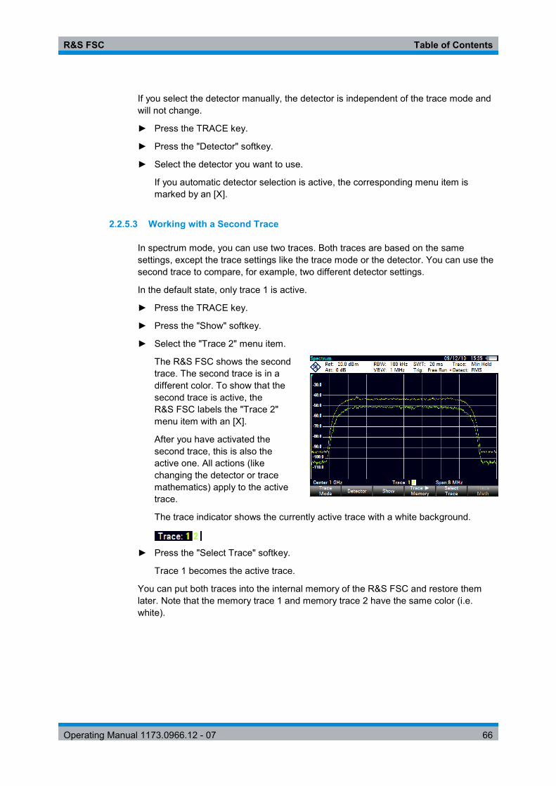
R&S FSC Table of Contents
Operating Manual 1173.0966.12 - 07 66
If you select the detector manually, the detector is independent of the trace mode and will not change.
► Press the TRACE key.
► Press the "Detector" softkey.
► Select the detector you want to use.
If you automatic detector selection is active, the corresponding menu item is marked by an [X].
2.2.5.3 Working with a Second Trace
In spectrum mode, you can use two traces. Both traces are based on the same settings, except the trace settings like the trace mode or the detector. You can use the second trace to compare, for example, two different detector settings.
In the default state, only trace 1 is active.
► Press the TRACE key.
► Press the "Show" softkey.
► Select the "Trace 2" menu item.
The R&S FSC shows the second trace. The second trace is in a different color. To show that the second trace is active, the R&S FSC labels the "Trace 2" menu item with an [X].
After you have activated the second trace, this is also the active one. All actions (like changing the detector or trace mathematics) apply to the active trace.
The trace indicator shows the currently active trace with a white background.
► Press the "Select Trace" softkey.
Trace 1 becomes the active trace.
You can put both traces into the internal memory of the R&S FSC and restore them later. Note that the memory trace 1 and memory trace 2 have the same color (i.e. white).

R&S FSC Table of Contents
Operating Manual 1173.0966.12 - 07 67
2.2.5.4 Working with Memory Traces
You can save the image of both traces to the memory of the R&S FSC and later restore it and compare it to a live trace. The memory trace is always colored white to distinguish it from the live trace.
Measurement settings Because the memory trace is just a bitmap, any modifications to measurement settings like span or reference level are nor reflected in the memory trace.
When you save a data set, the R&S FSC also stores the associated trace in the trace memory. If you restore it at a later time, you can display the memory trace as if it is a normal memory trace.
► Press the TRACE key.
► Select the trace you want to store in the trace memory with the "Select Trace" softkey.
► Press the "TraceMemory" softkey.
The R&S FSC saves the active trace.
► Press the "Show" softkey.
► Select the "Memory <x>" menu item.
The R&S FSC shows the corresponding memory trace. If active, it labels the "Memory <x>" menu item with an [X].
2.2.5.5 Using Trace Mathematics
Trace mathematics substract the memory trace from the live trace and vice versa and then display the results.
► Press the TRACE key.
► Press the "TraceMemory" softkey.
► Press the "Show" softkey.
► Press the "Trace Math" softkey.
► Select the "Trace-Memory" or "Memory-Trace" menu item.
The R&S FSC calculates and shows the resulting trace.
► To turn off trace mathematics, select the "Off" menu item.

R&S FSC Table of Contents
Operating Manual 1173.0966.12 - 07 68
2.2.6 Using Markers
The spectrum analyzer mode provides marker and deltamarker functionality. In addition, you can use several marker functions.
2.2.6.1 Using Markers and Deltamarkers
The R&S FSC has six markers, five of which can be used as either markers or delta markers.
The markers cannot leave the trace and indicate the horizontal and vertical coordinates of the point they are positioned on. The horizontal position of a marker is shown by a vertical line which extends from the top to the bottom of the measurement diagram. The marker list above the diagram area shows the exact coordinates of all markers in use.
The position of a delta marker is indicated by a dashed line to distinguish it from a normal marker. The delta marker level is always a relative to the main marker level and so the delta marker level unit is always dB. The delta marker frequency is always relative to the main marker – in other words, the delta marker frequency is the frequency difference between the frequency at the point marked by the main marker and the frequency at the point marked by the delta marker.
To measure complex signals, you can activate up to six markers. Marker 1 is always a normal marker and the reference of all delta markers. Markers 2 to 6 are either markers or delta markers depending on your set up.
Screen Layout with Active Markers
1 Marker list 2 Marker label: M(x) 3 Delta marker label: D(x) 4 Active marker label (red label) 5 Delta marker (blue dotted line) 6 Marker (blue line) 7 Marker input field 8 Marker menu

R&S FSC Table of Contents
Operating Manual 1173.0966.12 - 07 69
2.2.6.2 Positioning Markers
► Press the MARKER key.
The marker menu opens.
If, as yet, no marker has been activated, the R&S FSC automatically activates the main marker and positions it on the maximum level that has been measured. In addition, the marker frequency input field opens.
You can perform the following actions:
● Position the marker with the cursor keys.
When positioning the marker with the cursor keys, the step size is 10% of the span.
● Position the marker with the rotary knob
When positioning the marker with the rotary knob, the step size is one pixel.
● Enter a marker position with the number keys and confirm the entry with one of the unit keys.
► Confirm the marker position with the ENTER key.
The marker input field closes.
By default, the marker list above the diagram area is active. The marker list shows the horizontal position of all markers and the corresponding vertical value. If inactive, the list shows only the coordinates of markers 1 and 2.
You can turn it off and on again whenever you like.
► Press the "View List" softkey.
The marker list turns off or on, depending on its original state.
2.2.6.3 Positioning a Delta Marker
When a normal marker is already in use, you can add delta markers.
► Press the MARKER key.
► Press the "New Marker" softkey.
The R&S FSC activates a delta marker and positions it on the next maximum level that has been measured. In addition, the delta marker input field opens.
The R&S FSC adds the delta marker to the marker list and shows the marker position relative to the normal marker (M1).
You can perform the following actions:
● Enter a delta marker position with the number keys and confirm the entry with one of the unit keys.
● Change the delta marker position with the rotary knob or the cursor keys.

R&S FSC Table of Contents
Operating Manual 1173.0966.12 - 07 70
► Confirm the delta marker position with the ENTER key.
The delta marker input field closes.
► To add more markers, press the "New Marker" softkey several times until you have the number of markers you want in the display.
2.2.6.4 Selecting the Marker Type
When you add new markers, they will be delta markers by default. Their coordinates are relative to the first marker (M1). You can turn delta markers into normal markers if you need absolute information about the marker position.
► Press the MARKER key.
► Select the delta marker you want to convert with the "Select Marker" softkey.
The corresponding marker symbol turns red and the marker input field opens.
► Press the "Marker Type" softkey.
The delta marker turns into a normal marker. Its label changes accordingly (e.g. D2 to M2) and its coordinates are now absolute values.
2.2.6.5 Automatic Positioning of Markers
The R&S FSC offers functions that make setting the markers easier or allow to make instrument settings on the basis of the current marker position:
● "Set to Peak"
The Peak function places the active marker or the delta marker on the highest level value of the trace.
● "Set to Next Peak"
The Next Peak function places the active marker or delta marker on the next highest level value of the trace, relative to its current position.
● "Set to Minimum"
The Minimum function places the active marker or delta marker on the lowest value of the trace.
► Press the MKR key.
► Press the "Set to Peak", "Set to Next Peak" or "Set to Minimum" softkey.
The R&S FSC positions the marker accordingly.
R&S FSC Table of Contents
Operating Manual 1173.0966.12 - 07 71
2.2.6.6 Removing Markers
Remove markers any time you want.
Removing selected markers
► Select the marker you want to delete with the "Select Marker" softkey.
The corresponding marker symbol turns red and the marker input field opens.
► Press the MARKER key.
► Press the "Delete Marker" softkey.
► Select the "Delete Selected" menu item.
► Confirm the selection with the ENTER key.
The R&S FSC deletes the marker.
Deactivating markers If you delete marker 1 (M1), all delta markers that are relative to that marker are also deleted.
Removing delta markers only
► Press the MARKER key.
► Press the "Delete Marker" softkey.
► Select the "Delete All Delta" menu item.
► Confirm the selection with the ENTER key.
The R&S FSC deletes all delta markers.
Removing all markers at the same time.
► Press the MARKER key.
► Press the "Delete Marker" softkey.
► Select the "Delete All" menu item.
► Confirm the selection with the ENTER key.
The R&S FSC deletes all markers and delta markers.

R&S FSC Table of Contents
Operating Manual 1173.0966.12 - 07 72
2.2.6.7 Using Marker Search Limits
The R&S FSC allows you to use only a limited section of the trace for the "Set to Peak", "Set to Next Peak" and "Minimum" functions.
► Press the MKR key.
► Press the "Search Limits" softkey.
► Select the "Search Limits On/Off" menu item.
► Confirm the selection with the ENTER key.
The R&S FSC activates the marker search limits.
An [X] indicates an active search limit. Two vertical red lines show the lower and upper limits in the diagram.
By default, the search limit range is over the whole span.
► Press the "Search Limits" softkey
► Select the "Lower Limit" menu item.
► Confirm the selection with the ENTER key.
The R&S FSC opens an input field to define the lower limit of the search range.
► Enter the lower limit.
► Confirm the entry with one of the unit keys.
If the span is wide enough, the R&S FSC displays a red vertical line to indicate the lower limit.
► Define the upper search limit the same way.
Deactivating marker search limits
► Press the "Search Limits" softkey.
► Select the "Search Limits On/Off" menu item.
► Confirm the selection.
The "Search Limits" softkey turns grey again and in the "Search Limits" menu, the [X] is no longer displayed.

R&S FSC Table of Contents
Operating Manual 1173.0966.12 - 07 73
2.2.6.8 Using Marker Functions
In addition to the frequency and level readout, the R&S FSC provides several, more complex, marker functions in spectrum analyzer mode.
Deactivating marker functions Selecting a marker function again while it is still active turns that marker function off.
Measuring the Noise Power Density
The marker noise function calculates the noise power density at the marker position in dBm/Hz. The R&S FSC includes several variables in the calculation of the noise power density, including the trace pixel values, the resolution bandwidth, the detector and the level display mode (absolute or relative). To stabilize the noise power display, the R&S FSC uses the pixel the marker is on and four pixels to the right and four pixels to the left of the marker pixel.
Noise power density can provide useful information when you are measuring noise or digitally modulated signals. However, you will get valid results only if the spectrum in the vicinity of the marker has a flat frequency response. When measuring the noise power density on discrete signals, results are not valid.
► Press the MARKER key.
► Press the "Marker Function" softkey.
► Select the "Noise" menu item.
The R&S FSC shows the level at the marker frequency in dBm/Hz. If you are using a delta marker for the measurement, the results have the unit dBc/Hz with marker 1 being the reference.
Measuring the Frequency
The R&S FSC provides a frequency counter. The frequency counter accurately measures the frequency at the marker position.
When calculating the horizontal position of the marker, the R&S FSC includes the current span, center frequency and the frequency of the pixel the marker is on. As the trace only has 631 pixels, the marker position is just an approximation, especially if the span is very wide.
With the frequency counter, however, you can get a more accurate result of the horizontal marker position. If the frequency counter is active, the R&S FSC stops the measurement at the marker position for a short time and measures the frequency using the internal reference frequency.

R&S FSC Table of Contents
Operating Manual 1173.0966.12 - 07 74
The accuracy of the results therefore depends only on the accuracy of the internal reference frequency (TCXO). The frequency counter has a resolution of 0.1 Hz and therefore provides far more accurate results. Despite the accuracy, the measurement is still fast (because of a special algorithm for the I/Q baseband signal).
The frequency counter only gives completely accurate readings for sine signals that are at least 20 dB above the noise floor. If the S/N ratio is less, noise affects the results.
► Press the MARKER key.
► Press the "Marker Function" softkey.
► Select the "Frequency Count" menu item
The R&S FSC displays the counted marker frequency with a resolution of 1 Hz. If the frequency counter is on, the marker symbol changes from M1 to C.
Measuring the Signal Bandwidth
The "n dB Down" marker function places two temporary markers to the left and to the right of the reference marker and measures the bandwidth between the two temporary markers. The function therefore is a good way to measure the bandwidth of a signal or the bandwidth of a filter, for example. The temporary markers are represented as two vertical lines.
The distance to the reference marker is by default 3 dB below the reference marker. You can also adjust this value manually. Entering a positive value sets the temporary markers below the reference marker. If it is, for any reason, not possible to calculate the frequency spacing, dashes are displayed instead of a value.
Upon entering a negative value, the function turns into a n dB up function. You can use a n dB up function, for example, for measurements on notch filters.
► Press the MARKER key.
► Press the "Marker Function" softkey.
► Select the "n dB Down" menu item
The R&S FSC displays two temporary markers on the left and on the right of the reference marker M1. It also shows the bandwidth between the n dB down markers.

R&S FSC Table of Contents
Operating Manual 1173.0966.12 - 07 75
You can then adjust the distance of the temporary markers.
► Press the "Marker Function" softkey.
► Select the "n dB Down" menu item
The R&S FSC opens an input field
► Enter a different distance (in this case 6 dB).
The R&S FSC again shows the temporary markers, this time with a broader bandwidth.
Demodulating Signals
The R&S FSC features an AM and FM demodulator to demodulate and monitor audio signals. It demodulates the signal at the marker frequency.
You can listen to the demodulated signal with the internal speaker or headphones that you can connect to the 3.5 mm headphone jack on the top of the R&S FSC.
When demodulating an AM modulated signal, the R&S FSC turns the video voltage into an audible sound. You should therefore set the reference level to about the level of the signal that you are demodulating.
If you perform measurements in the time domain, the R&S FSC demodulates continuously. In the frequency domain, you can define a time period the R&S FSC demodulates the signal at the marker frequency. The frequency sweep then stops at the marker frequency for that time before finishing the sweep.
► Press the MARKER key.
► Press the "Marker Function" softkey.
► Select the demodulation scheme you require from the menu.
The R&S FSC starts to demodulate the signal.
Demodulating signals If you turn on the demodulator, the R&S FSC automatically turns off the noise marker or the frequency counter.
Defining the demodulation time period
► Press the MARKER key.
► Press the "Marker Function" softkey.
► Select the "Time…" menu item.
The R&S FSC opens an input field to define the demodulation time.
► Enter the demodulation time you need.
The range is from 100 ms to 500 s. In time domain the R&S FSC demodulates continuously, i.e. the demodulation time is not relevant.

R&S FSC Table of Contents
Operating Manual 1173.0966.12 - 07 76
Controlling the volume
► Press the MARKER key.
► Press the "Marker Function" softkey.
► Select the "Volume…" menu item.
The R&S FSC opens an input field to define the demodulation volume.
► Enter the volume you are comfortable with.
The demodulation volume is a percentage (0 % to 100 %) with 100 % being full volume.
For more information on general volume control see the Quick Start Guide.
2.2.7 Using Display Lines
Like markers, display lines help you to determine the level of the signal.
A display line is a straight line that runs horizontally and corresponds to a certain level value. You can move the display line to each pixel in the display. This means that the accuracy and exact vertical position of the display line depends on the resolution of the vertical axis. With a display range of 100 dB, for example, each pixel corresponds to 0.3 dB. In that case, the accuracy of the display line is 0.3 dB. If you enter a value with a higher resolution, the R&S FSC rounds that value.
You can also move the display line with the rotary knob or the cursor keys. The step size for movement with the rotary knob is one pixel. The step size for the cursor keys is 10 % of the display range.
► Press the LINES key.
► Press the "Display Line" softkey.
The R&S FSC displays the display line as a blue horizontal line. It shows the vertical position of the line in a table above the diagram area.
When you activate the display line, the R&S FSC also opens an input field to define the vertical position of the line.
► Enter the level value you need.
The R&S FSC positions the display line accordingly.
Alternatively you can also move the display line with the rotary knob or the cursor keys.

R&S FSC Table of Contents
Operating Manual 1173.0966.12 - 07 77
2.2.8 Using Limit Lines
Limit lines help you to identify if a signal complies with certain level characteristics.
A limit line is made up out of two or more points that are connected to a line. Each of the points that define the shape of the limit line consists of two coordinates. One coordinate defines the horizontal position (e.g. frequency), the other one the vertical position. With the R&S FSC you can build limit lines that consist of up to 1000 points.
Values that define the horizontal characteristics of the limit line can be either absolute values (e.g. frequency in MHz) or relative values whose reference is the center of the measurement trace (e.g. the center frequency). Relative values are of advantage if you, for example, measure modulated output signals and you change the center frequency but need the limit line to remain the same. Absolute limit lines have the file extension ".abslim" while relative limit lines have the file extension ".rellim"
Values that define the vertical characteristsics are always level values in dB. If the scaling of the vertical axis is currently a linear one (units V or W), the R&S FSC automatically switches to a logarithmic scaling after you turn on the limit line.
After turning on a limit line, the R&S FSC checks if the signal violates the shape of the limit line. If one or more signal levels violate the limits, the R&S FSC features several indicators that the limit check has failed.
● A general message in the diagram header that indicates if the signal violates the limit line, including the trace that violates the limit:
● An audio signal that sounds every time a limit is violated ● The trace color turns red in areas of the spectrum that violate a limit
You can create and edit limit lines with the R&S FSCView software package and then transfer them into the internal memory of the R&S FSC. The number of limit lines you can store in the memory depends on other datasets available on the R&S FSC or, if you are using an external storage device (e.g. memory stick), the size of it.
For more information see "Managing Datasets" on page 14.

R&S FSC Table of Contents
Operating Manual 1173.0966.12 - 07 78
2.2.8.1 Selecting a Limit Line
Before selecting a limit line, you need to decide if you want to use it as an upper or lower limit line. In case of upper limit lines, the R&S FSC checks if the signal is above the limit line. In case of lower limit lines, the R&S FSC checks if the signal is below the limit line.
You also have to make sure that the limit line is compatible to the scale of the horizontal axis.
► Press the LINES key.
► Depending on the application, press the "Upper Limit" or "Lower Limit" softkey.
The R&S FSC opens a dialog box to select the limit line.
► Select the "Load From File…" menu item.
► Press the "Sort/Show" softkey.
► Select the "Show Compatible" menu item.
The R&S FSC shows all limit lines that are compatible to the current settings.
► Select one of the available limit lines.
► Press the "Select" softkey.
The R&S FSC activates the limit line. In the diagram, the limit line is displayed as a red line.
If you have already selected a limit line, you can turn the limit line on and off with the "Limits On/Off" softkey.
Alternatively, you can define a threshold that works like a limit line. A threshold is a simple horizontal limit line.
► Press the "Upper Limit" or "Lower Limit" softkey.
► Select the "Threshold" menu item.
The R&S FSC opens a input field to define the threshold.
► Enter the threshold you need.
The R&S FSC displays the line and performs a limit check for that threshold.
Threshold line and display line Like the display line, a threshold line is a straight horizontal line. The difference is that the R&S FSC performs a limit check for threshold lines, but not for display lines. A failed limit check may be an issue if you want to create a measurement report, because measurements with failed limits are not included in this report. Using a display line, you can use a line and are able to create a measurement report at the same time, regardless if any limits have been violated or not.

R&S FSC Table of Contents
Operating Manual 1173.0966.12 - 07 79
The process of turning off a limit line completely is similar to that of selecting a line.
► Press the "Upper Limit" or "Lower Limit" softkey
► Select the "Unselect Limit" menu item.
The R&S FSC deactivates the limit line.
2.2.8.2 Performing Limit Checks
If limit lines are active, the R&S FSC automatically checks the trace for limit violations after each frequency sweep. As long as the signal does not violate the limit line, the R&S FSC shows a "Pass" message in the measurement diagram. As soon as one single value (i.e. one pixel) is outside of the limits, the R&S FSC displays a "Fail" message in the diagram area and, in addition, sounds a beep.
A limit checks relates only to the frequency range defined by the limit line, not the span.
Audio signal
You can turn the acoustic signal that sounds in case of a limit violation on and off.
► Press the "Options" softkey.
► Select the "Audio Beep" menu item.
An [X] in front of the "Audio Beep" menu item indicates that the beeper is active. If the audio beep is active, the R&S FSC beeps each time a limit is violated.
Limit violation Note that a limit check fails only if the signal exceeds the limit line. If the signal level is the same as the limit value, the limit check passes.

R&S FSC Table of Contents
Operating Manual 1173.0966.12 - 07 80
2.3 Working with Channel Tables
Almost all transmission systems divide their assigned frequency ranges into channels. Each channel corresponds to a specific frequency. To keep the handling of such systems simple, you can use channel tables instead of entering frequencies manually.
The R&S FSC already comes with an assortment of channel tables that you can use without doing anything. If you want to test transmission standards that are not listed, you can also build channel tables manually with the "Channel Table Editor" of the R&S FSCView software package that is delivered with the R&S FSC. To use one of those, you just have to copy the channel table to the R&S FSC.
For more information see "Managing Datasets" on page 14.
Selecting a channel table
► Press the FREQ key.
► Press the "Frequency Mode" softkey.
► Select the "Channel" menu item.
The R&S FSC opens a dialog box to select a channel table.
► Select one of the available channel tables.
After activating the channel table, the R&S FSC is set up according to the information contained in the channel table. Instead of a center frequency, the R&S FSC shows the currently active channel number including the name of the channel. The center frequency of a channel is defined in the channel table and is the frequency corresponding to the selected channel.
Selecting a channel
Entering a center, start or stop frequency is not possible anymore. Instead you select a channel. The R&S FSC then adjusts the center, start and stop frequency according to the channel table.
► Press the FREQ key.
► Press the "Center Frequency" softkey.
The R&S FSC opens an input field to select the channel.
► Enter the channel you want to perform measurements on.
The R&S FSC changes the channel according to the channel table.
Channel numbers are assigned to frequencies as follows:
- The first channel is assigned a channel number and a frequency. - All subsequent channels have ascending numbers. - The frequency spacing between channels is fixed. It can also be negative, i.e.
the center frequency of the R&S FSC decreases with ascending channel number.
- In transmission systems containing gaps in the frequency range (as in the case of television, for example), a channel table can comprise multiple ranges.

R&S FSC Table of Contents
Operating Manual 1173.0966.12 - 07 81
2.4 Using Transducer Factors
The frequency-dependent transducer factor of transducers and antennas can be directly considered in the measurement result. A transducer factor consists of a numeric value and a unit. The R&S FSC corrects the level values of the trace by the values of the transducer. At the same time, the unit of the transducer is assigned to the level axis. When field-strength measurements are performed with the aid of antennas, for instance, the electrical field strength is directly indicated in dBµV/m on the R&S FSC. A transducer factor can also be used to correct a frequency-dependent attenuation, e.g. of a cable between DUT and RF input of the R&S FSC.
You can create and edit transducer factor with the R&S FSCView software package and then transfer them into the internal memory of the R&S FSC. Each transducer factor may consist of up to 1000 reference values.
For more information see "Managing Datasets" on page 14.
Interpolation between the values is performed with the aid of a modified spline algorithm. Even if only relatively few values such as maxima, minima and turning points are available, this algorithm can easily simulate the correction factors of common transducers. Two transducers can be switched on at a time. The second transducer must be assigned the unit dB. The R&S FSC adds the two transducers to a total transducer.
Units supported for transducer factors:
● dB ● dBµV/m ● dBµA/m ● W/m2
The unit dB does not change the unit set on the R&S FSC. It can be used, for instance, to compensate for frequency-dependent loss and gain at the input of the R&S FSC. The units dBµV/m and dBµA/m convert the output power of an antenna into electric or magnetic field strength. The unit W/m2 is used to calculate and display the power flux density.
For example, to compensate for the cable loss between the transducer and the RF input, the R&S FSC can use two transducers at the same time. One of them must have the unit dB, however, i.e. it must correspond to one loss or gain value.
► Press the AMPT key.
► Press the "Transducer" softkey.
Transducer factor availability Transducer factors are not available for measurements with the tracking generator or the Power Sensors. The "Transducer" softkey is therefore inactive.

R&S FSC Table of Contents
Operating Manual 1173.0966.12 - 07 82
You can select two transducer factors, a primary transducer and a secondary transducer. If a transducer factor is active, the menu item has an [X] in front of it.
► Select the "Select Primary Transducer" menu item.
The R&S FSC opens a dialog box to select the transducer factor.
► Select the transducer factor you need.
► Confirm the selection with the "Select" softkey.
The R&S FSC shows the name of the active transducer on the display.
An example would be the transducer factor of the R&S HL223 antenna that is defined between 200 MHz and 1300 MHz. The R&S FSC therefore displays the noise in this frequency range as a function of frequency incremented by the transducer factor. Outside the transducer range, the R&S FSC sets the transducer factor at zero, i.e. measurements in this range do not yield conclusive results.
You can select a second transducer factor with the "Select Secondary Transducer" menu item. The secondary transducer factor in that case is added to the first. The unit of the second transducer factor must always be the relative unit dB as otherwise an addition would not be useful. When you select a secondary transducer factor, the dialog box shows only those transducer factors that have dB as their unit.
2.4.1 Unit for Measurements with Transducers
If the unit of the transducer is dB, the units dBm, dBmV or dBµV remain unchanged. The linear units Volt and Watt are not permissible. They are deactivated in the units menu.
If the unit of the transducer is dBµV/m or dBµA/m, this unit is also used for the R&S FSC level display. This means that both the level axis of the diagram and the level at the marker position are assigned the unit of the transducer. If dBµV/m is selected as the transducer unit, a switch to absolute level indication in V/m is possible.
► Press the AMPT key.
► Press the "Unit" softkey.
► Select the V(olt) menu item.
If you are using a transducer with the unit dBµA/m, it is not possible to select another unit. Level indication is entirely in dBµA/m.
2.4.2 Setting the Reference Level
The transducer shifts the trace by its value as a function of frequency. Positive transducer values increase the level, negative values reduce it. To ensure that the trace is always within the diagram, the R&S FSC adjusts the reference level accordingly. The reference level is shifted by the maximum transducer value in the positive or negative direction.
R&S FSC Table of Contents
Operating Manual 1173.0966.12 - 07 83
2.4.3 Frequency Range of Transducer
If the set frequency range is wider than the span in which a transducer is defined, the R&S FSC assumes the transducer values outside the defined range to be zero.
2.4.4 Data Sets Containing Transducer Factors
The R&S FSC stores data sets together with any transducer factors that may have been active for the measurement in question. When such a dataset is recalled, the associated transducer factor(s) are switched on as well. Transducer factors recalled as part of a data set do however not appear in the list of transducer factors.

R&S FSC Table of Contents
Operating Manual 1173.0966.12 - 07 84
3 Power Sensors For highly accurate power measurements, you can connect a power sensor to the R&S FSC and perform measurements.
3.1 Using a Power Sensor
A power sensor measures the power in the frequency range defined in the data sheet of the power sensor. This means that you can measure both sine signals and modulated signals precisely over a large dynamic range.
The R&S FSC supports the following power sensors.
● R&S NRP-Z11 (USB) ● R&S NRP-Z21 (USB) ● R&S NRP-Z22 (USB) ● R&S NRP-Z23 (USB) ● R&S NRP-Z24 (USB) ● R&S NRP-Z31 (USB) ● R&S NRP-Z51 (USB) ● R&S NRP-Z55 (USB) ● R&S NRP-Z56 (USB) ● R&S NRP-Z57 (USB) ● R&S NRP-Z81 (USB) ● R&S NRP-Z91 (USB) ● R&S NRP-Z92 (USB) ● R&S NRP-Z211 (USB) ● R&S NRP-Z221 (USB)
If you are using one of the NRP power sensors you also need a passive USB adapter (R&S NRP-Z4) to connect the power sensor to the R&S FSC.
For more information on the characteristics of the supported power sensors see
● the datasheet of the R&S FSC ● the website for R&S power sensors
http://www2.rohde-schwarz.com/en/products/test_and_measurement/power_volt_meter/NRPZ.html
The power sensor function turns the R&S FSC into a wideband power meter. It then always measures the power of the whole signal in the frequency range of the power sensor. In most cases the signal shape has no effect on the measurement.
► Press the MODE key.
► Press the "Power Meter" softkey
The R&S FSC activates the mode for power measurements.

R&S FSC Table of Contents
Operating Manual 1173.0966.12 - 07 85
Screen layout of the power meter mode
1 Connected power sensor model 2 Reference for relative power measurements 3 Power offset 4 Measurement time 5 Readout of the measured power 6 Analog readout of the measured power 7 Measurement frequency 8 Power sensor softkey menu
3.1.1 Connecting a Power Sensor
The R&S FSC controls and powers the power sensors via the USB interface.
Connect the power sensor to the USB interface with a passive USB adapter.
After connecting the power sensor to the R&S FSC, you can connect the DUT to the N-connector of the power sensor.
Risk of damage to the power sensor Before you start to work with the power sensor, make sure that the continuous power applied to the input of the power sensor does not exceed a certain level. Refer to the documentation of the power sensor for more information on the maximum input power.
If the R&S FSC recognizes a power sensor, it sets up a connection via the interface and after a few seconds shows the measured power. It displays the type of the power sensor in the display header.
If no power sensor has been connected or it is not connected appropriately, the R&S FSC shows nothing.
R&S FSC Table of Contents
Operating Manual 1173.0966.12 - 07 86
If there are communication problems between the R&S FSC and the power sensor, the R&S FSC displays one of the following error messages that indicate the possible cause.
Message Cause Remedy
Error in zeroing: signal at sensor A signal was present at the power sensor when zeroing was performed.
Unscrew the power sensor from the device under test and repeat zeroing.
Warning: Input overloaded The power at the input of the power sensor exceeds the permitted power (23 dBm = 200 mW).
Reduce the power at the sensor input.
Power sensor hardware error Communication error between the R&S FSC and the power sensor.
Unscrew the sensor from the R&S FSC and check the connectors.
If the problem persists, contact a Rohde & Schwarz service center.
Power sensor error The power sensor signals an error to the R&S FSC.
Contact a Rohde & Schwarz service center.
Unknown power sensor model connected
TheR&S FSC cannot identify the device connected to the power sensor interface.
3.1.2 Performing and Configuring Measurements
After you have connected a power sensor, the R&S FSC immediately starts to measure the signal power.
Defining the center frequency
Power sensors have a memory containing correction values that are dependent on the frequency. Hence, measurement results are the most accurate for signals whose frequency you know.
Note that the R&S FSC maintains the center frequency that you have set in another operating mode. In that case it uses that frequency as the power sensor frequency.
If you want to perform measurements on another known signal, you can change the power sensor frequency manually.
► Press the MEAS key
► Press the "Freq" softkey.
An input field to define the frequency opens.
► Enter the frequency of the signal.
The R&S FSC transfers the new frequency to the power sensor which then corrects the measured power readings.

R&S FSC Table of Contents
Operating Manual 1173.0966.12 - 07 87
Zeroing the power sensor
Offset voltages and currents have most effect on the power readout when measuring low powers. You can compensate for these offsets by zeroing the power sensor.
Do not apply power during the zeroing process, as the power sensor cannot distinguish between external powers and internal offsets.
► Press the "Zero" softkey.
The R&S FSC asks you not to apply any signals to the power sensor during the zeroing process.
► Disconnect the power sensor from any signal sources.
► Press the "Continue" softkey to start zeroing.
► Press "Cancel" to abort zeroing, for example, if you cannot disconnect the signal source.
The R&S FSC immediately starts power sensor zeroing.
While zeroing is in progress, the R&S FSC shows the message “Zeroing power sensor, please wait..”.
When zeroing is over, the R&S FSC shows the message and switches back to the softkey menu for the power sensor.
Selecting the unit for the power readout
The R&S FSC can display measured power in relative units (dBm) or in absolute units (W, mW, µW, nW and pW). It is also possible to set a reference level in dB.
► Press the "Unit" softkey.
A submenu to select the unit opens.
► Select the unit you want.
The R&S FSC adjusts the result display accordingly.
Setting the reference level
If you have selected the unit dB Rel, the R&S FSC opens an input field to set the reference level. The R&S FSC shows the currently set reference level in the diagram header.
► Enter the reference level you want.
Alternatively, you can set the current level readout as the reference level.
► Press the "Ref" softkey.
The R&S FSC sets the current result as the reference level.
It then displays the measured level relative to the reference level in dB. The unit is automatically set to dB Rel...

R&S FSC Table of Contents
Operating Manual 1173.0966.12 - 07 88
Setting the averaging time
The averaging time determines the length of the measurement. The longer the averaging time, the more stable the display, particularly if signals have low power or are noisy.
The averaging time is either "Short", "Normal" or "Long".
● A short measurement time provides stable and accurate results for stationary sine signals with high levels (> -40 dBm). It is also appropriate for measurements that require a high repition rate.
● A normal measurement time increases the stability of results for signals with low levels or modulated signals.
● A long measurement time is appropriate for signals with very low power levels (< -50 dBm)
To eliminate noise and the effects of noise on the measurement effectively, use the R&S FSH-Z1 power sensor.
► Press the "Meas Time" softkey.
► Select the measurement time most suitable for your test setup.
Taking additional loss or gain into account
At high powers that cause the power sensor maximum input level to be exceeded or at very low levels that are below the R&S FSC minimum sensitivity, the R&S FSC can take additional loss or gain between the DUT and the power sensor into account. These are defined in terms of an offset in dB relative to the measured level. A positive offset corresponds to a loss and a negative offset to a gain.
The R&S FSC shows the current offset in the diagram header.
► Press the AMPT key.
► Press the "Ref Offset" softkey.
The value entry box for the reference offset opens.
► Enter the required offset.
The offset is taken into account in the power or level display.

R&S FSC Table of Contents
Operating Manual 1173.0966.12 - 07 89
4 Network Analyzer Mode The network analyzer mode provides the functionality to characterize networks with one or two ports.
To enable the features of the network analyzer mode, you need at least an R&S FSC with tracking generator.
An R&S FSC with tracking generator can perform scalar measurements and determine the reverse transmission characteristics of the device under test (DUT). Scalar measurements determine the magnitude of the transmitted power.
Measurements yield the best results when you calibrate the R&S FSC to the test setup. Although the accuracy of measurements is high in the default factory calibration, the R&S FSC also provides all necessary calibration methods to correct the magnitude for these kinds of measurements and make results even more accurate.
► Press the MODE key.
► Press the "Network Analyzer" softkey.
The R&S FSC turns on the tracking generator. Frequency and level settings are inherited from the previous operating mode.
Defining the output level of the tracking generator
The tracking generator generates a signal at the current R&S FSC frequency. The nominal output level of the signal is adjustable from 0 dBm to -40 dBm in steps of 1 dB.
► Press the AMPT key.
The R&S FSC opens an input field to set the output level.
Screen layout of the network analyzer
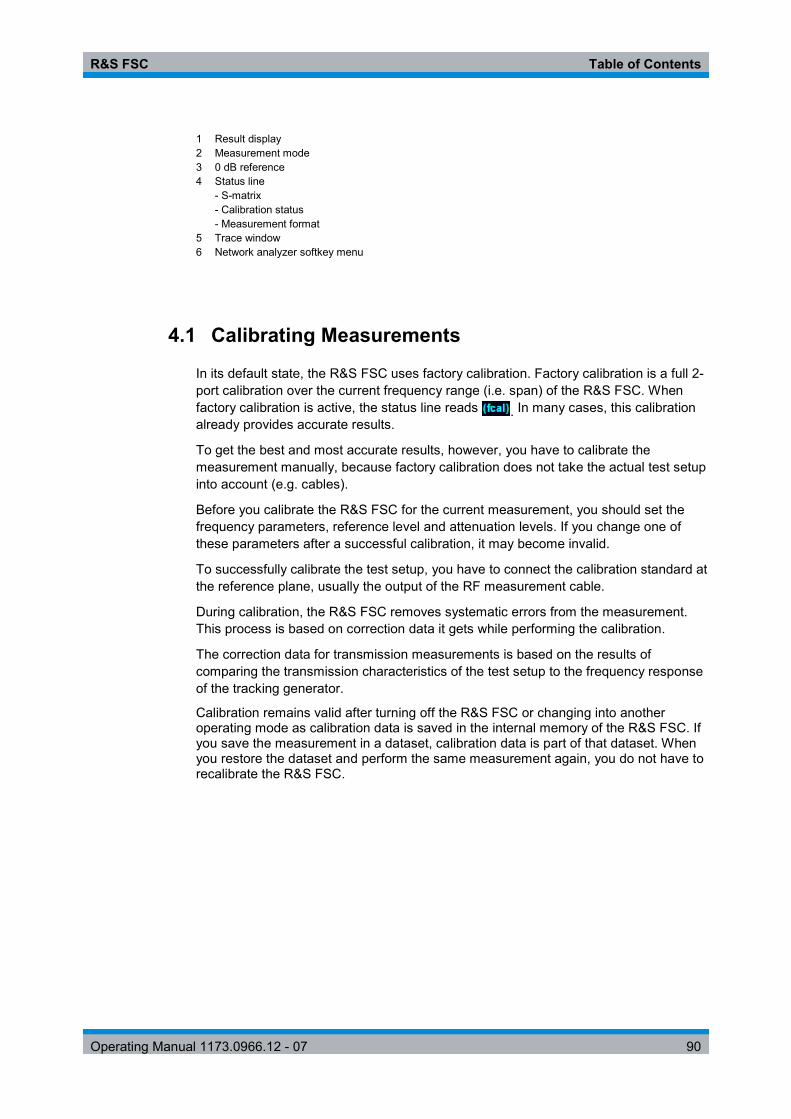
R&S FSC Table of Contents
Operating Manual 1173.0966.12 - 07 90
1 Result display 2 Measurement mode 3 0 dB reference 4 Status line - S-matrix - Calibration status - Measurement format 5 Trace window 6 Network analyzer softkey menu
4.1 Calibrating Measurements
In its default state, the R&S FSC uses factory calibration. Factory calibration is a full 2-port calibration over the current frequency range (i.e. span) of the R&S FSC. When factory calibration is active, the status line reads . In many cases, this calibration already provides accurate results.
To get the best and most accurate results, however, you have to calibrate the measurement manually, because factory calibration does not take the actual test setup into account (e.g. cables).
Before you calibrate the R&S FSC for the current measurement, you should set the frequency parameters, reference level and attenuation levels. If you change one of these parameters after a successful calibration, it may become invalid.
To successfully calibrate the test setup, you have to connect the calibration standard at the reference plane, usually the output of the RF measurement cable.
During calibration, the R&S FSC removes systematic errors from the measurement. This process is based on correction data it gets while performing the calibration.
The correction data for transmission measurements is based on the results of comparing the transmission characteristics of the test setup to the frequency response of the tracking generator.
Calibration remains valid after turning off the R&S FSC or changing into another operating mode as calibration data is saved in the internal memory of the R&S FSC. If you save the measurement in a dataset, calibration data is part of that dataset. When you restore the dataset and perform the same measurement again, you do not have to recalibrate the R&S FSC.

R&S FSC Table of Contents
Operating Manual 1173.0966.12 - 07 91
4.1.1.1 Calibration States
The R&S FSC features several calibration states. It displays the current state in the status line. The possible states depend on the calibration type (see below).
● (fcal)
The R&S FSC uses factory calibration. Factory calibration is restored after a preset or self alignment. The R&S FSC also uses factory calibration if you change a frequency parameter (span, start, stop or center frequency) to a value outside the calibrated frequency range or if you measure another s-parameter than the one the R&S FSC is calibrated for.
The calibration data for the factory calibration is already in the memory of the R&S FSC when it is delivered. The factory calibration is a full two-port calibration.
You can restore the factory calibration manually any time.
- Press the "Calibration" softkey. - Select the "User Calibration Off" menu item.
● (fcal?)
The R&S FSC uses factory calibration. However, the calibration is not accurate because the power of the tracking generator and the attenuation at the RF input are not in line with the default settings. In that case you should repeat calibration.
● (norm)
The R&S FSC uses normalization. To get that state you have to normalize the transmission.
● (norm?)
The R&S FSC uses normalization. However, the normalization is not accurate because the TG power and receiver attenuation are not in line with the settings at the time it has been calibrated. In that case you should repeat calibration.
● (interp) (network analysis only)
The R&S FSC interpolates the correction data between the reference points of the calibration. Interpolation is used when you change one of the frequency parameters (start, stop or center frequency). In that case the distribution of the measurement points is different to the distribution during calibration. This could result in an increasing measurement uncertainty.
When calibration has become invalid for any reason or the calibration data has changed, you can restore the most recent calibration that was valid.
► Press the "Calibration" softkey.
► Select the "Restore Calibration Settings" menu item.
The R&S FSC restores the calibration data and the frequency settings that were active.

R&S FSC Table of Contents
Operating Manual 1173.0966.12 - 07 92
4.1.1.2 Calibration Methods
The R&S FSC provides normalization for scalar transmission measurements.
Normalization is a simple but effective way to calibrate the measurement using one calibration standard only. The correction data is deducted from this measurement.
● Normalize…
Normalization is a simple way to calibrate the measurement using one calibration standard only. The correction data is deducted from this measurement. As only one calibration standard is used, the isolation between the test ports is ignored. A possible cross-talk between the test ports is therefore not eliminated and the accuracy is lower than that of a full calibration.
4.1.1.3 Performing Calibration
To perform normalization of the transmission measurement, you need a "Through" connection between the two ports only.
► Disconnect the DUT.
After disconnecting the DUT, the R&S FSC is ready for calibration.
► Press the MEAS key.
► Press the "Calibration" softkey.
► Select the "Normalize Transmission" menu item.
The R&S FSC asks you to set up a "Through" connection from port 1 to port 2.
► Firmly connect the "Through" connection to port 1 and port 2.
► Press the "Continue" softkey to start calibration.
The R&S FSC calibrates the "Through" connection.
After finishing the calibration routine, the R&S FSC shows that calibration is finished for a short time ( ). The status line now says (Norm) to indicate successful normalization.

R&S FSC Table of Contents
Operating Manual 1173.0966.12 - 07 93
4.2 Performing Scalar Measurements
With scalar measurements, you can measure the magnitude of transmission characteristics of a device under test. To calibrate the measurements, only normalization is available.
4.2.1 Measuring the Transmission
The example included here is based on a transmission measurement of a two-port filter. The filter has a center frequency of 2060 MHz and a bandwidth of about 11 MHz.
Test setup
► Connect the input of the DUT to the tracking generator output (port 2).
► Connect the output of the DUT to the RF input (port 1).
Preset the R&S FSC
Before starting the measurement procedure, preset the R&S FSC to restore the default configuration and connect the filter between the measurement ports.
► Press the PRESET key.
► Connect the DUT.
Define the frequency parameters
Before calibrating the measurement, you should define the frequency parameters to avoid inaccurate results because of invalid calibration.
► Press the FREQ key.
The R&S FSC opens an input field to set the center frequency.
► Enter a frequency of 2060 MHz.
► Press the SPAN key.
The R&S FSC opens an input field to define the span.
► Enter a span of 50 MHz to get a high resolution of the results.
Calibrate the measurement for scalar transmission measurements.
Scalar measurements provide normalization only. Normalization is not as accurate as a full calibration, but yields pretty accurate results nonetheless. In addition, normalization needs one calibration standard only and therefore is faster than a full calibration.
► Press the "Calibration" softkey.

R&S FSC Table of Contents
Operating Manual 1173.0966.12 - 07 94
► Select the "Normalize Transmission Rev (Port 12) menu item.
► Perform normalization. For more information see "Performing Calibration".
► Reconnect the DUT.
The R&S FSC shows the results of the scalar transmission measurement on the filter.
You can change the measurement configuration (e.g. select another sweep time or detector) without affecting the accuracy of the measurement except the frequency parameters and attenuation.
4.3 Evaluating the Results
4.3.1 Configuring the Vertical Axis
Some results may not fit in the diagram area as it is configured in the default state of the R&S FSC (for example measurements on amplifiers).
If you are performing measurements on an amplifier, you most likely have to change the scaling of the vertical axis in order to see the complete transmission function.
The R&S FSC provides several ways to adjust the scaling of the vertical axis.
Changing the reference value
Changing the reference value works like an attenuation or gain in that it moves the trace to another level. The R&S FSC adjusts the scale of the vertical axis accordingly. The R&S FSC indicates the value and position of the current reference value with a triangle at the vertical axis ( ). In the default state, it is 0 dB and its position is the grid line at the top of the diagram.
The reference value only changes the 0 dB reference without actually attenuating or amplifying the signal level.
When changing the reference value, make sure that you do not overload the R&S FSC. As long as the trace is completely within the diagram area and the reference position at the top of the diagram, the risk of an overload is eliminated.
► Press the AMPT key.
► Press the "Ref" softkey.
The R&S FSC opens an input field.
► Enter the reference value you need to see the trace completely.

R&S FSC Table of Contents
Operating Manual 1173.0966.12 - 07 95
The R&S FSC moves the trace accordingly, relabels the vertical axis and shows the new 0 dB reference in the hardware settings display.
Changing the reference position
Changing the reference position moves the position of the reference value up or down. The reference position also moves the trace up or down. The levels and the reference value, however, remain the same. The default reference position is the grid line at the top of the diagram. The reference position is indicated by a triangle at the vertical axis ( ).
The reference position is a number between 0 and 10 with 0 being the grid line at the bottom and 10 being the grid line at the top of the diagram.
► Press the AMPT key.
► Press the "Ref Pos" softkey.
The R&S FSC opens an input field.
► Enter the new position of the reference value.
The R&S FSC moves the trace accordingly and moves the triangle to the new position.

R&S FSC Table of Contents
Operating Manual 1173.0966.12 - 07 96
Changing the display range
The display range is the value range the vertical axis covers.
When you change the display range, the reference value and position remain the same. Merely the scale of the vertical axis is compressed or expanded.
► Press the AMPT key.
► Press the "Range" softkey.
► Select the display range you need from the submenu.
The R&S FSC adjusts the vertical axis accordingly.
Automatic scaling of the vertical axis All measurement formats feature an automatic scale function. If you use automatic scaling, the R&S FSC automatically sets the display range in a way that the trace best fits on the display. ► In the "Range" submenu, select the "Auto Scale" menu item.
4.3.2 Using Markers
The network analyzer mode also features markers. The functionality is similar to that of the spectrum analyzer.
For more information see "Using Markers" on page 68.
4.3.3 Working with Channel Tables
The R&S FSC allows you to use channel tables in network analyzer mode.
► Press the FREQ key.
► Press the "Channel Table" softkey.
The R&S FSC opens the list of channel tables loaded into the R&S FSC via R&S FSCView.
► Select the channel table you need.
The R&S FSC scans the channel table for the channels with the lowest and highest frequencies and sets those as the start and stop frequency.
The R&S FSC already comes with an assortment of channel tables that you can use without doing anything. If you want to test telecommunications standards that are not listed, you can also build channel tables manually with the "Channel Table Editor" of the R&S FSCView software package that is delivered with the R&S FSC. To use one of those, you just have to copy the channel table to the R&S FSC.

R&S FSC Table of Contents
Operating Manual 1173.0966.12 - 07 97
4.3.4 Using Limit Lines
When working with the magnitude format in the network analyzer, you can use limit lines to set limits for level characteristics on the display that must not be exceeded.
You can create and edit limit lines with the R&S FSCView software and load them into the R&S FSC via the USB or the LAN interface. The number of limit lines the R&S FSC can store in its memory depends on the number of other data sets on the R&S FSC. For more information see
● "Managing Datasets" on page 14 ● "Using Limit Lines" on page 77
4.3.5 Using Trace Mathematics
Trace mathematics that subtract one trace from another are available for most measurement formats in the network analyzer mode.
For more information see "Using Trace Mathematics" on page 67.

R&S FSC Table of Contents
Operating Manual 1173.0966.12 - 07 98
5 Menu and Softkey Overview This chapter shows an overview of all instrument functions in the form of softkey and menu overviews.
5.1 General Functions
General functions are those that are available for all operating modes.
5.1.1 General R&S FSC Setup
The SETUP key opens the setup menu that contains functionality to set up the R&S FSC in general and functionality to set up the measurement.

R&S FSC Table of Contents
Operating Manual 1173.0966.12 - 07 99
5.1.2 File Management
The SAVE/RECALL key opens the file manager that contains functionality to manage datasets and other files.
5.1.3 Operating Mode Selection
The MODE key opens the mode menu that contains functionality to select the operating mode of the R&S FSC.

R&S FSC Table of Contents
Operating Manual 1173.0966.12 - 07 100
5.2 Functions of the Spectrum Analyzer
This section contains all softkeys and menus that are available in spectrum analyzer mode.
5.2.1 Measurement Selection
The MEAS key opens the measurement menu that contains functionality to select and configure the measurement.
The spectrogram is available only if you have installed option R&S ZVH-K14.
Channel Power

R&S FSC Table of Contents
Operating Manual 1173.0966.12 - 07 101
Occupied Bandwith
TDMA Power
Spectrum Emission Mask
Harmonic Distortion
AM Modulation Depth

R&S FSC Table of Contents
Operating Manual 1173.0966.12 - 07 102
5.2.2 Frequency Parameters
The FREQ key opens the frequency menu that contains functionality to set up the horizontal axis of the measurement diagram.
5.2.3 Span Selection
The SPAN key opens the span menu that contains functionality to set the span.
5.2.4 Amplitude Parameters
The AMPT key opens the amplitude menu that contains functionality to set up the vertical axis of the measurement diagram.

R&S FSC Table of Contents
Operating Manual 1173.0966.12 - 07 103
5.2.5 Sweep Configuration
The SWEEP key opens a menu that contains all functionality to configure the sweep.
5.2.6 Bandwidth Selection
The BW key opens a menu that contains all functionality to set the bandwidths.
5.2.7 Trace Functionality
The TRACE key opens the trace menu that contains functionality to set up the traces.
5.2.8 Display and Limit Lines
The LINES key opens a menu that contains the functionality to control display and limit lines.

R&S FSC Table of Contents
Operating Manual 1173.0966.12 - 07 104
5.2.9 Markers
The MARKER and MKR keys open a menus to control markers and use marker functions.
Softkey in the Marker Menu
Softkeys in the Marker To Menu

R&S FSC Table of Contents
Operating Manual 1173.0966.12 - 07 105
5.3 Functions of the Network Analyzer
This section contains all softkeys and menus that are available in network analyzer mode.
5.3.1 Measurement Configuration
The MEAS key opens the measurement menu that contains functionality to select and configure the measurement.
5.3.2 Frequency Parameters
The FREQ key opens the frequency menu that contains functionality to set up the horizontal axis of the measurement diagram.
5.3.3 Span Selection
The SPAN key opens the span menu that contains functionality to set the span.

R&S FSC Table of Contents
Operating Manual 1173.0966.12 - 07 106
5.3.4 Amplitude Parameters
The AMPT key opens the amplitude menu that contains functionality to set up the vertical axis of the measurement diagram.
5.3.5 Sweep Configuration
The SWEEP key opens a menu that contains all functionality to configure the sweep.
5.3.6 Bandwidth Selection
The BW key opens a menu that contains all functionality to set the bandwidths.
5.3.7 Trace Functionality
The TRACE key opens the trace menu that contains functionality to set up the traces.

R&S FSC Table of Contents
Operating Manual 1173.0966.12 - 07 107
5.3.8 Limit Lines
The LINES key opens a menu that contains the functionality to control limit lines.
5.3.9 Markers
The MARKER and MKR keys open a menus to control markers and use marker functions.
Softkey in the Marker Menu
Softkeys in the Marker To Menu

R&S FSC Table of Contents
Operating Manual 1173.0966.12 - 07 108
5.4 Functions of the Power Meter
This section contains all softkeys and menus that are available in power meter mode.
5.4.1 Power Meter Measurements
The MEAS key opens a menu that contains the functionality to configure measurements with the power meter.
Power Meter
5.4.2 Frequency Parameters
The FREQ key opens a menu that contains the functionality to set the frequency.
5.4.3 Amplitude Parameters
The AMPT key contains functionality to configure level parameters.

R&S FSC Table of Contents
Operating Manual 1173.0966.12 - 07 109
6 How a Spectrum Analyzer Works Basically, it is possible to measure and analyze RF signals either in the time domain or the frequency domain.
Measurements in the time domain show signal variations over time. You can perform these with an oscilloscope, for example. Measurements in the frequency domain show the frequency components of a signal. To perform measurements in the frequency domain, you can use a spectrum analyzer.
Both modes are essentially equivalent because applying the Fourier transform to any signal converts it into its spectral components. Depending on the signal characteristic to be measured, one method is usually more appropriate than the other. With an oscilloscope, it is possible to tell whether a signal is a sine wave, a square wave with a certain on/off ratio or a sawtooth wave. However, detecting superimposed low-level signals or monitoring the harmonic content of the signal is easier with a spectrum or signal analyzer.
Figure 6-1 shows the theoretical basis of the two measurement methods. In the time domain, an oscilloscope would, for example, show a section of the signal that is a square wave. The same signal, when viewed with a spectrum analyzer, would show a line spectrum (the fundamental and its harmonics).
Figure 6-1: Visualization of time domain and frequency domain
Applying the Fourier transform to the periodic square wave transforms it into the frequency domain. The spectrum analyzer would show the fundamental (or frequency of the square wave) and its harmonics.
The spectrum analyzer uses a narrow bandpass filter for measurements in the frequency domain. Only at frequencies containing a signal there is a reading that gives the amplitude of the frequency component.
Figure 6-2 shows the basic principle of how a spectrum analyzer works.

R&S FSC Table of Contents
Operating Manual 1173.0966.12 - 07 110
Figure 6-2: Block diagram showing the basic functionality of a spectrum analyzer
The precision attenuator at the R&S FSC input attenuates the signal to a level that the mixer can handle without overdriving the mixer. The attenuator is directly coupled to the reference level. You can attenuate the signal in the range from 0 dB to 40 dB in steps of 5 dB.
The mixer converts the RF signal to a fixed intermediate frequency (IF). This process usually involves several stages. It lasts until you get an IF for which good narrowband filters are available. The R&S FSC needs three mixing stages to get an IF that the filter can handle. Figure 6-3 graphically shows the mixing process.
For models with a frequency limit of 3.6 GHz, the IFs are 4892.8 MHz, 860.8 MHz and 54.4 MHz. The conversion from a specific input frequency to the first IF is done by a local oscillator (LO). This LO can be tuned from 4.8 GHz to 8.4 GHz. All other conversions are handled by single-frequency oscillators.
In case of models with a frequency limit of 8 GHz, the IFs are 8924.8 MHz, 860.8 MHz and 54.4 MHz. The conversion from the first to the second IF for these models is done by a second local oscillator.
The frequency of the local oscillator determines the input frequency at which the spectrum analyzer performs measurements: fin = fLO – fIF.
The first mixer produces the sum frequency fLO + fin (= image frequency fimage) as well as the difference frequency fLO – fin.
The image frequency is rejected by the bandpass at the IF so that it does not interfere with the subsequent frequency conversions.
Figure 6-3: Mixing process

R&S FSC Table of Contents
Operating Manual 1173.0966.12 - 07 111
The first local oscillator is tuned with a sawtooth which simultaneously acts as the x deflection voltage for the display. In practice, synthesizer technology is used to generate the frequency of the first local oscillator and for a digital display.
The instantaneous sawtooth voltage therefore determines the input frequency of the spectrum analyzer.
The bandwidth of the IF filter at the IF determines the bandwidth that is used for measurements. Pure sine signals are passed by the IF filter characteristics. This means that signals closer together than the bandwidth of the IF filter cannot be resolved. This is why the bandwidth of the IF filter in a spectrum analyzer is referred to as the resolution bandwidth. The R&S FSC has resolution bandwidths from 1 Hz to 3 MHz.
The bandlimited IF is passed to the envelope detector. The envelope detector removes the IF from the signal and outputs its envelope. The output signal from the envelope detector is referred to as the video signal. As it has been demodulated, it only contains amplitude information. The phase information is lost.
With RF sine signals, the video signal is a DC voltage. With AM signals the video signal contains a DC component whose amplitude corresponds to the carrier power and an AC component whose frequency is equal to the modulation frequency, provided the modulation frequency is inside the resolution bandwidth.
The video filter comes after the envelope detector. The filter is a lowpass with an adjustable cutoff frequency which limits the bandwidth of the video signal. It is particularly useful when sine signals are to be measured in the vicinity of the spectrum analyzer’s intrinsic noise. The sine signal produces a video signal that is a DC voltage. At the IF, however, the noise is distributed over the whole bandwidth or, in the case of the video signal, over half the bandwidth of the resolution filter. By selecting a narrow video bandwidth relative to the resolution bandwidth, the noise can be suppressed, while the sine signal to be measured (= DC) is not affected.
The figures below show a weak sine signal. In the first picture, it is measured with a large video bandwidth and in the second with a narrow video bandwidth.

R&S FSC Table of Contents
Operating Manual 1173.0966.12 - 07 112
Limiting the video bandwidth smoothes the trace considerably. This makes it much easier to determine the level of the measured signal.
The detector comes after the video filter. The detector combines the measured spectrum so that it can be represented as one pixel in the trace. The R&S FSH uses 631 pixels to form the trace, i.e. the whole measured spectrum has to be represented using just 631 pixels. Common types of spectrum analyzer detectors are the peak detector (PEAK), the sample detector (SAMPLE) and the RMS detector (RMS). An Auto Peak detector which simultaneously displays the maximum peak and the minimum peak is usually also provided. The Fig. below explains how these detectors work.
The figure above shows 30 measured values which are represented by a single pixel. The peak detector determines and displays the maximum measured value. The Auto Peak detector takes the maximum and minimum and displays them together. The two values are joined by a vertical line segment. This gives a good indication of the level variation over the measured values represented by a single pixel. The RMS detector is used by the spectrum analyzer to determine the RMS value of the measured values. It is therefore a measure of the spectral power represented by a pixel. The sample detector takes an arbitrary measurement value and displays it (in the Fig. above, the first). The other measured values are ignored.

R&S FSC Table of Contents
Operating Manual 1173.0966.12 - 07 113
On the basis of the operating principles of detectors, a few recommendations can be made as to their use.
● It is best to use the Auto Peak detector or the peak detector for spectrum analysis over large frequency ranges. This ensures that all signals are displayed.
● The RMS detector is recommended for power measurements on modulated signals. However, the display range should be chosen so as not to exceed 100 times the bandwidth of the signal or the resolution bandwidth, whichever is larger.
● The sample detector or the RMS detector (preferred) should be used for noise measurements. Only these two detectors are capable of measuring noise power correctly.
● When measurements are made on sine signals, the level display does not depend on the detector. However, if you use the RMS detector or the sample detector, ensure that the span is not too great. Otherwise, the displayed levels of sine signals may be lower than their true value.

R&S FSC Remote Control
Interfaces and Protocols
Operating Manual 1173.0966.12 - 07 114
7 Remote Control 7.1 Interfaces and Protocols
The R&S FSC supports two different interfaces for remote control.
● LAN Interface: The protocol is based on TCP/IP and supports the VXI-11 standard. ● USB Interface
The connectors are located at the side of the instrument and permit a connection to a controller for remote control via a local area network (LAN) or directly via USB.
SCPI
SCPI (Standard Commands for Programmable Instruments) commands - messages - are used for remote control. Commands that are not taken from the SCPI standard follow the SCPI syntax rules. The instrument supports the SCPI version 1999. The SCPI standard is based on standard IEEE 488.2 and aims at the standardization of device-specific commands, error handling and the status registers. The tutorial "Automatic Measurement Control - A tutorial on SCPI and IEEE 488.2" from John M. Pieper (R&S order number 0002.3536.00) offers detailed information on concepts and definitions of SCPI.
The requirements that the SCPI standard places on command syntax, error handling and configuration of the status registers are explained in detail in the following sections. Tables provide a fast overview of the bit assignment in the status registers. The tables are supplemented by a comprehensive description of the status registers.
VISA
VISA is a standardized software interface library providing input and output functions to communicate with instruments. The I/O channel (LAN or USB) is selected at initialization time by means of a channel-specific resource string. For more information about VISA refer to its user documentation.
The programming examples for remote control are all written in Microsoft® VISUAL BASIC®. Access to the VISA functions require the declaration of the functions and constants prior to their use in the project. This can be accomplished either by adding the modules VISA32.BAS and VPPTYPE.BAS or a reference to the VISA32.DLL to the project.

R&S FSC Remote Control
Interfaces and Protocols
Operating Manual 1173.0966.12 - 07 115
The modules visa32.bas and vpptype.bas can be found in the following location:
<VXIpnpPath>\WinNT\include (typically C:\VXIpnp\WinNt\include).
Resetting the R&S FSC Manual operation is designed for maximum possible operating convenience. In contrast, the priority of remote control is the "predictability" of the device status. Therefore, control programs should always define an initial device status (e.g. with the command *RST) and then implement the required settings.
7.1.1 LAN Interface
To be integrated in a LAN, the instrument is equipped with a standard LAN interface, consisting of a connector, a network interface and protocols (VXI-11).
Instrument access via VXI-11 is usually achieved from high level programming platforms by using VISA as an intermediate abstraction layer. VISA encapsulates the low level VXI-11 (LAN) or USB function calls and thus makes the transport interface transparent for the user. The necessary VISA library is available as a separate product. For details contact your local R&S sales representative.
7.1.2 USB Interface
For remote control via the USB connection, the PC and the instrument must be connected via the USB interface. The required driver comes with the R&S FSCView software package and is automatically installed on the PC with the software package.
The driver adresses the instrument via the USB interface with the fix IP address 172.16.10.10.
In addition, a remote control connection via the SCPI interface requires the VISA library to be installed on the PC.
7.1.3 Protocols
VXI-11 Basics
The VXI-11 standard is based on the ONC-RPC protocol which in turn relies on TCP/IP as the network/transport layer. The TCP/IP network protocol and the associated network services are preconfigured. TCP/IP ensures connection-oriented communication, where the order of the exchanged messages is adhered to and interrupted links are identified. With this protocol, messages cannot be lost.
Remote control of an instrument via a network is based on standardized protocols which follow the OSI reference model (see Fig. below).

R&S FSC Remote Control
Interfaces and Protocols
Operating Manual 1173.0966.12 - 07 116
Application SCPI
Presentation
Session
Transport
Network
Data Link
Physical
XDR (VXI-11)
ONC-RPC
TCP / UDP
IP
Ethernet/802.3
802.3/10BASE-T
Figure 7-1: Example for LAN remote control based on the OSI reference model
Based on TCP/UDP, messages between the controller and the instrument are exchanged via open network computing (ONC) - remote procedure calls (RPC). With XDR (VXI-11), legal RPC messages are known as VXI-11 standard. Based on this standard, messages are exchanged between the controller and the instrument. The messages are identical with SCPI commands. They can be organized in four groups:
● program messages (control command to the instrument) ● response messages (values returned by the instrument) ● service request (spontaneous queries of the instrument) ● low-level control messages (interface messages).
A VXI-11 link between a controller and an instrument uses three channels: core, abort and interrupt channel. Instrument control is mainly performed on the core channel (program, response and low-level control messages). The abort channel is used for immediate abort of the core channel; the interrupt channel transmits spontaneous service requests of the instrument. Link setup itself is very complex. For more details refer to the VXI-11 specification.
Instrument
Core channel(program, response,control messages)
Abort channel (abort)
Interrupt channel(service request)
Controller
Figure 7-2: VXI-11 channels between instrument and controller
The number of controllers that can address an instrument is practically unlimited in the network. In the instrument, the individual controllers are clearly distinguished. This distinction continues up to the application level in the controller, i.e. two applications on a computer are identified by the instrument as two different controllers.

R&S FSC Remote Control
Setting Up the Remote Control Connection
Operating Manual 1173.0966.12 - 07 117
Controller
Controller
ControllerInstrument
Figure 7-3: Remote control via LAN from several controllers
The controllers can lock and unlock the instrument for exclusive access. This regulates access to the instrument of several controllers.
7.2 Setting Up the Remote Control Connection
7.2.1 Preparing for Remote Control
The short and simple operating sequence below shows how to put the instrument into operation and quickly set its basic functions. The current IP address for LAN operation is shown in the SETUP – Instrument Setup Menu. In case of USB connection the IP address is fixed to 172.16.10.10.
Refer to the Quick Start Guide for instructions on how to change the IP address.
► Connect the instrument to the LAN or directly to the controller via USB.
► Switch on the instruments.
► Write and start the following program on the controller:
status = viOpenDefaultRM(defaultRM) 'open default resource manager
status = viOpen(DefaultRM, "TCPIP::172.16.10.10", 0, 0, vi) 'in case of USB connection
status = viopen(DefaultRM, "TCPIP::xxx.xxx.xxx.xxx", 0, 0, vi) 'in case of a LAN connection, with xxx.xxx.xxx.xxx = IP address
cmd = "*RST;*CLS" status = viWrite(vi, Cmd, Len(Cmd), retCount)
'reset instrument and clear status registers cmd = "FREQ:CENT 100MHz" status = viWrite(vi, Cmd, Len(Cmd), retCount)
'set center frequency to 100 MHz cmd = "FREQ:SPAN 10MHz" status = viWrite(vi, Cmd, Len(Cmd), retCount)
'set span to 10 MHz cmd = "DISP:TRAC:Y:RLEV -10dBm" status = viWrite(vi, Cmd, Len(Cmd), retCount)
'set reference level to -10 dBm viclose vi viclose default RM
The instrument now performs a sweep in the frequency range of 95 MHz to 105 MHz.

R&S FSC Remote Control
Instrument Model and Command Processing
Operating Manual 1173.0966.12 - 07 118
Changing the IP Address
In order to operate the instrument via remote control, it must be accessed via LAN (IP address) or USB (fixed IP address). If the factory-set remote control address does not fit in the network environment, it can be changed. Refer to the Quick Start Guide, chapter "Setting up a LAN or USB Connection to a PC", for instructions on how to change the IP address.
7.3 Instrument Model and Command Processing
The block diagram in Fig. 1-2 shows how SCPI commands are serviced in the instrument. The individual components work independently and simultaneously. They communicate with each other by means of so-called "messages".
Input unit withinput buffer
Commandrecognition
Instrumenthardware
Instrumentsettings database
Output unit withoutput buffer
Status reportingsystem
USB interfaceEthernet
USB interfaceEthernet
Figure 7-4: Instrument model in the case of remote control
7.3.1 Input Unit
The input unit receives commands character by character from the controller and collects them in the input buffer. The input unit sends a message to the command recognition as soon as the input buffer is full or as soon as it receives a delimiter, <PROGRAM MESSAGE TERMINATOR>, as defined in IEEE 488.2, or the interface message DCL.
If the input buffer is full, the traffic is stopped and the data received up to then are processed. Subsequently the traffic is continued. If, however, the buffer is not yet full when receiving the delimiter, the input unit can already receive the next command during command recognition and execution. The receipt of DCL clears the input buffer and immediately resets the command recognition.

R&S FSC Remote Control
Instrument Model and Command Processing
Operating Manual 1173.0966.12 - 07 119
7.3.2 Command Recognition
The command recognition analyses the data received from the input unit. It proceeds in the order in which it receives the data. Only DCL is serviced with priority, for example GET (Group Execute Trigger) is only executed after the commands received before. Each recognized command is immediately transferred to the internal instrument settings data base but not executed immediately.
The command recognition detects syntax errors in the commands and transfers them to the status reporting system. The rest of a program message after a syntax error is analyzed further if possible and serviced. After the syntax test, the value range of the parameter is checked, if required.
If the command recognition detects a delimiter, it passes the command to an execution unit that performs the instrument settings. In the meantime, the command recognition is ready to process new commands (overlapping execution). A DCL command is processed in the same way.
7.3.3 Data Base and Instrument Hardware
Here the expression "instrument hardware" denotes the part of the instrument fulfilling the actual instrument function - signal generation, measurement etc. The controller is not included. The term "data base" denotes a database that manages all the parameters and associated settings required for setting the instrument hardware.
Setting commands lead to an alteration in the data set. The data set management enters the new values (e.g. frequency) into the data set, however, only passes them on to the hardware when requested by the command recognition. This only takes place at the end of a program message.
The data are checked for compatibility with the current instrument settings before they are transmitted to the instrument hardware. If the execution is not possible, an "execution error" is signaled to the status reporting system. The corresponding settings are discarded.
Before passing on the data to the hardware, the settling bit in the STATus:OPERation register is set (refer to section "STATus:OPERation Register"). The hardware executes the settings and resets the bit again as soon as the new state has settled. This fact can be used to synchronize command servicing.
Queries induce the data set management to send the desired data to the output unit.
7.3.4 Status Reporting System
For detailed information refer to section "Status Reporting System".

R&S FSC Remote Control
SCPI Command Structure and Syntax
Operating Manual 1173.0966.12 - 07 120
7.3.5 Output Unit
The output unit collects the information requested by the controller, which it receives from the data base management. It processes it according to the SCPI rules and makes it available in the output buffer.
If the instrument is addressed as a talker without the output buffer containing data or awaiting data from the data base management, the output unit sends error message "Query UNTERMINATED" to the status reporting system. No data are sent to the controller, the controller waits until it has reached its time limit. This behavior is defined by IEEE 488.2 and SCPI.
7.4 SCPI Command Structure and Syntax
SCPI (Standard Commands for Programmable Instruments) describes a standard command set for programming instruments, irrespective of the type of instrument or manufacturer. The goal of the SCPI consortium is to standardize the device-specific commands to a large extent. For this purpose, a model was developed which defines the same functions inside a device or for different devices. Command systems were generated which are assigned to these functions. Thus it is possible to address the same functions with identical commands. The command systems are of a hierarchical structure.
SCPI is based on standard IEEE 488.2, i.e. it uses the same syntactic basic elements as well as the common commands defined in this standard. Part of the syntax of the device responses is defined with greater restrictions than in standard IEEE 488.2 (see section "Responses to Queries").
Remote command examples Not all commands used in the following examples are implemented in the instrument.
7.4.1 Structure of a Command
The commands consist of a so-called header and, in most cases, one or more parameters. Header and parameter are separated by a "white space" (ASCII code 0 to 9, 11 to 32 decimal, e.g. blank). The headers may consist of several key words. Queries are formed by directly appending a question mark to the header.

R&S FSC Remote Control
SCPI Command Structure and Syntax
Operating Manual 1173.0966.12 - 07 121
7.4.1.1 Common Commands
Common commands consist of a header preceded by an asterisk "*" and one or several parameters, if any.
Examples
*RST RESET, resets the device *ESE 253 EVENT STATUS ENABLE, sets the bits of the event status enable
register *ESR? EVENT STATUS QUERY, queries the contents of the event status
register.
7.4.1.2 Device-Specific Commands
Hierarchy
Device-specific commands are of hierarchical structure. The different levels are represented by combined headers. Headers of the highest level (root level) have only one key word. This key word denotes a complete command system.
Example
SENSe This key word denotes the SENSe command system.
For commands of lower levels, the complete path has to be specified, starting on the left with the highest level, the individual key words being separated by a colon ":".
Example
SENSe:FREQuency:SPAN 10MHZ This command lies in the third level of the SENSe system. It sets the frequency span.
SENSe
BANDwidth FUNCtion FREQuency DETector
STARt STOP CENTer SPAN OFFSet
Figure 7-5: Tree structure the SCPI command systems using the SENSe system as example

R&S FSC Remote Control
SCPI Command Structure and Syntax
Operating Manual 1173.0966.12 - 07 122
Multiple Keywords
Some key words occur in several levels within one command system. Their effect depends on the structure of the command, i.e. at which position in the header of a command they are inserted.
Examples
SOURce:FM:POLarity NORMal This command contains key word POLarity in the third command level. It defines the polarity between modulator and modulation signal.
SOURce:FM:EXTernal:POLarity NORMal This command contains key word POLarity in the fourth command level. It defines the polarity between modulation voltage and the resulting direction of the modulation only for the external signal source indicated.
Optional Keywords
Some command systems permit certain key words to be inserted into the header or omitted. These key words are marked by square brackets in the description. The full command length must be recognized by the instrument for reasons of compatibility with the SCPI standard. Some commands are considerably shortened by these optional key words.
Example
[SENSe]:BANDwidth[:RESolution]:AUTO This command couples the resolution bandwidth of the instrument to other parameters. The following command has the same effect: BANDwidth:AUTO
Optional keywords with numeric suffixes Do not omit an optional keyword if it includes a numeric suffix that is relevant for the effect of the command.
Example
DISPlay[:WINDow<1...4>]:MAXimize <Boolean> Command DISP:MAX ON refers to window 1. In order to refer to a window other than 1, you must include the optional WINDow parameter with the suffix for the required window. DISP:WIND2:MAX ON refers to window 2.

R&S FSC Remote Control
SCPI Command Structure and Syntax
Operating Manual 1173.0966.12 - 07 123
Long and Short Form
The key words feature a long form and a short form. Either the short form or the long form can be entered, other abbreviations are not permitted.
Example
STATus:QUEStionable:ENABle 1 is equivalent to STAT:QUES:ENAB 1
Upper and lower case notation of commands Upper-case and lower-case notation only serves to distinguish the two forms in the manual, the instrument itself does not distinguish upper-case and lower-case letters.
Parameter
The parameter must be separated from the header by a "white space". If several parameters are specified in a command, they are separated by a comma ",". A few queries permit the parameters MINimum, MAXimum and DEFault to be entered. Refer to "Parameters" for a detailed description of the various parameters.
Example
SENSe:FREQuency:STOP? MAXimum Response: 3.5E9 This query requests the maximal value for the stop frequency.
Special Characters
| A vertical stroke in parameter definitions indicates alternative possibilities in the sense of "or". The effect of the command differs, depending on which parameter is used.
Example
DISPlay:FORMat SINGle | SPLit If parameter SINGle is selected, full screen is displayed, in the case of SPLit, split screen is displayed.
A selection of key words with an identical effect exists for several commands. These keywords are indicated in the same line; they are separated by a vertical stroke. Only one of these keywords needs to be included in the header of the command. The effect of the command is independent of which of the keywords is used.
Example
SENSe:BANDwidth|BWIDth[:RESolution] The two following commands with identical meaning can be created. They set the frequency of the fixed frequency signal to 1 kHz: SENSe:BAND 1 SENSe:BWID 1

R&S FSC Remote Control
SCPI Command Structure and Syntax
Operating Manual 1173.0966.12 - 07 124
[ ] Key words in square brackets can be omitted when composing the header. The full command length must be accepted by the instrument for reasons of compatibility with the SCPI standards.
Example
[SENSe:]BANDwidth|BWIDth[:RESolution] SENS:BAND:RES is equivalent to BAND
Parameters in square brackets can be incorporated optionally in the command or omitted as well.
Example
MMEMory:NETWork:MAP <string>,<string>[,string>,<string>,<boolean>]
Entries in square brackets are optional or can be omitted.
{ } Parameters in curly brackets are optional and can be inserted once or several times, or omitted.
Example
SENSe:LIST:FREQuency <numeric_value>{,<numeric_value>}
The following are valid commands: SENS:LIST:FREQ 10 SENS:LIST:FREQ 10,20 SENS:LIST:FREQ 10,20,30,40
Numeric Suffix
If a device features several functions or features of the same kind, e.g. inputs, the desired function can be selected by a suffix added to the command. Entries without suffix are interpreted like entries with the suffix 1. Optional keywords must be specified if they select a function with the suffix.
Example
SYSTem:COMMunicate:SERial2:BAUD 9600 This command sets the baud rate of a second serial interface.
Suffix counting In case of remote control, suffix counting may differ from the numbers of the corresponding selection used in manual operation. SCPI prescribes that suffix counting starts with 1. Suffix 1 is the default state and used when no specific suffix is specified. Some standards define a fixed numbering, starting with 0. With GSM, for instance, slots are counted from 0 to 7. In the case of remote control, the slots are selected with the suffixes 1 to 8. If the numbering differs in manual operation and remote control, it is indicated with the respective command.

R&S FSC Remote Control
SCPI Command Structure and Syntax
Operating Manual 1173.0966.12 - 07 125
7.4.1.3 Overview of Syntax Elements
The following table offers an overview of the syntax elements.
: The colon separates the key words of a command. In a program message the separating semicolon marks the uppermost command level.
; The semicolon separates two commands within a program message. It does not alter the path.
, The comma separates several parameters of a command.
? The question mark forms a query.
* The asterisk marks a common command.
" Quotation marks introduce a string and terminate it.
# The hash symbol # introduces binary, octal, hexadecimal and block data.
● Binary: #B10110
● Octal: #O7612
● Hexa: #HF3A7
● Block: #21312
A "white space" (ASCII-Code 0 to 9, 11 to 32 decimal, e.g. blank) separates header and parameter.
7.4.2 Parameters
For most commands a parameter needs to be supplemented. The parameter has to be separated from the header by a "white space". Possible parameters are:
● Numeric values ● Special numeric values ● Boolean parameters ● Text ● Character strings ● Block data.
The type of parameter required for each command and the allowed range of values are specified in the command description.

R&S FSC Remote Control
SCPI Command Structure and Syntax
Operating Manual 1173.0966.12 - 07 126
7.4.2.1 Numeric Values
Numeric values can be entered in any form, i.e. with sign, decimal point and exponent. Values exceeding the resolution of the instrument are rounded up or down. The mantissa may comprise up to 255 characters, the exponent must lie inside the value range -32000 to 32000. The exponent is introduced by an "E" or "e". Entry of the exponent alone is not permissible. In the case of physical quantities, the unit can be entered. Permissible unit prefixes are G (giga), MA (mega), MOHM and MHZ are also possible), K (kilo), M (milli), U (micro) and N (nano). If the unit is missing, the basic unit is used.
Example
SENSe:FREQuency:STOP 1.5GHz = SENSe:FREQuency:STOP 1.5E9
7.4.2.2 Special Numeric Values
The texts MINimum, MAXimum, DEFault, UP and DOWN are interpreted as special numeric values. In case of a query, the numeric value is returned.
● MIN/MAX
MINimum and MAXimum denote the minimum and maximum value.
● DEF
DEFault denotes a preset value which has been stored in the EPROM. This value conforms to the default setting, as it is called by the *RST command
● UP/DOWN
UP, DOWN increases or reduces the numerical value by one step. The step width can be specified via an allocated step command for each parameter which can be set via UP, DOWN.
● INF/NINF
INFinity, Negative INFinity (NINF) Negative INFinity (NINF) represent the numerical values -9.9E37 or 9.9E37, respectively. INF and NINF are only sent as device reponses.
● NAN
Not A Number (NAN) represents the value 9.91E37. NAN is only sent as device response. This value is not defined. Possible causes are the division of zero by zero, the subtraction of infinite from infinite and the representation of missing values.
Example:
Setting command: SENSe:FREQuency:STOP MAXimum
Query: SENSe:FREQuency:STOP?, Response: 3.5E9

R&S FSC Remote Control
SCPI Command Structure and Syntax
Operating Manual 1173.0966.12 - 07 127
7.4.2.3 Boolean Parameters
Boolean parameters represent two states. The ON state (logically true) is represented by ON or a numerical value unequal to 0. The OFF state (logically untrue) is represented by OFF or the numerical value 0. The numerical values are provided as response for query.
Example
Setting command: CALCulate:MARKer:STATe ON
Query: CALCulate:MARKer:STATe?, Response: 1
7.4.2.4 Text
Text parameters observe the syntactic rules for key words, i.e. they can be entered using a short or long form. Like any parameter, they have to be separated from the header by a white space. In the case of a query, the short form of the text is provided.
Example
Setting command: INPut:COUPling GROund
Query: INPut:COUPling?, Response: GRO
7.4.2.5 Strings
Strings must always be entered in quotation marks (' or ").
Example
SYSTem:LANGuage "SCPI" or SYSTem:LANGuage 'SCPI'
7.4.2.6 Block Data
Block data are a transmission format which is suitable for the transmission of large amounts of data. A command using a block data parameter has the following structure:
Example
HEADer:HEADer #45168xxxxxxxx
ASCII character # introduces the data block. The next number indicates how many of the following digits describe the length of the data block. In the example the 4 following digits indicate the length to be 5168 bytes. The data bytes follow. During the transmission of these data bytes all end or other control signs are ignored until all bytes are transmitted.

R&S FSC Remote Control
SCPI Command Structure and Syntax
Operating Manual 1173.0966.12 - 07 128
7.4.3 Structure of a Program Message
A program message may consist of one or several commands. It is terminated by the program message terminator which is the NL (New Line) charcter for LAN and USB connections.
Several commands in a program message must be separated by a semicolon ";". If the next command belongs to a different command system, the semicolon is followed by a colon. A colon ":" at the beginning of a command marks the root node of the command tree.
Example:
CALL InstrWrite(analyzer, "SENSe:FREQuency:CENTer 100MHz;:INPut:ATTenuation 10")
This program message contains two commands. The first one is part of the SENSe command system and is used to determine the center frequency of the instrument. The second one is part of the INPut command system and sets the input signal attenuation.
If the successive commands belong to the same system, having one or several levels in common, the program message can be abbreviated. For that purpose, the second command after the semicolon starts with the level that lies below the common levels (see also Fig. 1-1). The colon following the semicolon must be omitted in this case.
Example:
CALL InstrWrite(analyzer, "SENSe:FREQuency:STARt 1E6;:SENSe:FREQuency:STOP 1E9")
This program message is represented in its full length and contains two commands separated from each other by the semicolon. Both commands are part of the SENSe command system, subsystem FREQuency, i.e. they have two common levels.
When abbreviating the program message, the second command begins with the level below SENSe:FREQuency. The colon after the semicolon is omitted. The abbreviated form of the program message reads as follows:
CALL InstrWrite(analyzer, "SENSe:FREQuency:STARt 1E6;STOP 1E9")
However, a new program message always begins with the complete path.
Example:
CALL InstrWrite(analyzer, "SENSe:FREQuency:STARt 1E6") CALL InstrWrite(analyzer, "SENSe:FREQuency:STOP 1E9")
R&S FSC Remote Control
SCPI Command Structure and Syntax
Operating Manual 1173.0966.12 - 07 129
7.4.4 Responses to Queries
A query is defined for each setting command unless explicitly specified otherwise. It is formed by adding a question mark to the associated setting command. According to SCPI, the responses to queries are partly subject to stricter rules than in standard IEEE 488.2.
● The requested parameter is transmitted without header.
Example
INPut:COUPling? Response: DC
● Maximum values, minimum values and all further quantities, which are requested via a special text parameter are returned as numerical values.
Example
SENSe:FREQuency:STOP? MAX Response: 3.5E9
● Numerical values are output without a unit. Physical quantities are referred to the basic units or to the units set using the Unit command.
Example
SENSe:FREQuency:CENTer? Response: 1E6 (for 1 MHz)
● Truth values <Boolean values> are returned as 0 (for OFF) and 1 (for ON).
Example
SENSe:BANDwidth:AUTO? Response: 1 (for ON)
● Text (character data) is returned in a short form.
Example
SYSTem:COMMunicate:SERial:CONTrol:RTS? Response STAN (for standard)

R&S FSC Remote Control
Command Sequence and Command Synchronization
Operating Manual 1173.0966.12 - 07 130
7.5 Command Sequence and Command Synchronization
What has been said above makes clear that all commands can potentially be carried out overlapping. In order to prevent an overlapping execution of commands, one of the commands *OPC, *OPC? or *WAI must be used. All three commands cause a certain action only to be carried out after the hardware has been set. By suitable programming, the controller can be forced to wait for the respective action to occur. For more information see Table 7-1.
Table 7-1: Synchronization using *OPC, *OPC? and *WAI
Command Action Programming the controller
*OPC Sets the Operation Complete bit in the ESR after all previous commands have been executed.
− Setting bit 0 in the ESE − Setting bit 5 in the SRE
− Waiting for service request (SRQ)
*OPC? Stops command processing until 1 is returned. This is only the case after the Operation Complete bit has been set in the ESR. This bit indicates that the previous setting has been completed.
Sending *OPC? directly after the command whose processing should be terminated before other commands can be executed.
*WAI Stops further command processing until all commands sent before *WAI have been executed.
Sending *WAI directly after the command whose processing should be terminated before other commands are executed.
For a couple of commands the synchronization to the end of command execution is mandatory in order to obtain the desired result. The affected commands require either more than one measurement in order to accomplish the desired instrument setting (e.g. auto range functions), or they require a longer period of time for execution. If a new command is received during execution of the corresponding function this may either lead to either to an aborted measurement or to incorrect measurement data.
The following list includes the commands, for which a synchronization via *OPC, *OPC? or *WAI is mandatory:
Table 7-2: Commands with mandatory synchronization (overlapping commands)
Command Purpose
INIT start measurement (sweep)
INIT:CONT OFF Set to single sweep
CALC:MARK:FUNC:xx? All Marker function queries

R&S FSC Remote Control – Commands
Command Sequence and Command Synchronization
Operating Manual 1173.0966.12 - 07 131
8 Remote Control – Commands The following chapters provide a detailed description of all remote control commands currently available for the R&S FSC and its firmware options.
Each section describes the commands for one of the operating modes available in the R&S FSC, beginning with the description of common commands required to operate the instrument. The structure is based on that of the operating manual.
● Common Commands on page 132 ● Remote Commands of the Spectrum Analyzer on page 135 ● Remote Commands of the Network Analyzer Mode on page 206 ● Remote Commands of the Power Meter on page 216
Each section is subdivided into various tasks required to perform measurements with the R&S FSC, also based on the structure of the operating manual. Some commands like those for controlling markers or configuring the frequency axis are available for all operating modes. In that case you will find a list of these commands in the corresponding section. However, a detailed description is provided only in the CAT commands section.
Following the remote control commands required to perform specific measurements, you will find a description of general commands used to set up and control basic instrument functions. These commands are independent of the operating mode. Therefore they are listed separately.
● File Management on page 220 ● Making and Storing Screenshots on page 227 ● Configuring the Instrument on page 230 ● Remote Commands of the Status Reporting System on page 255
All chapters begin with a list of commands available in the context of that chapter. Following that list you will find a detailed description of all commands.
All individual descriptions contain:
● the complete notation and syntax of the command ● the description of the effects of the command ● a list of all parameters available for that command or the type of data the command
returns in case of query commands ● an example of how a program message would look like ● the *RST value ● information on SCPI conformity
An alphabetical list of all available commands is provided at the end of this manual.

R&S FSC Remote Control – Commands
Common Commands
Operating Manual 1173.0966.12 - 07 132
8.1 Common Commands
The common commands are taken from the IEEE 488.2 (IEC 625-2) standard. A particular command has the same effect on different devices. The headers of these commands consist of an asterisk "*" followed by three letters. Some of the common commands refer to the "Status Reporting System".
List of Common Commands
● *CLS (p. 132) ● *ESE (p. 132) ● *ESR? (p. 132) ● *IDN? (p. 133) ● *IST? (p. 133) ● *OPC (p. 133) ● *OPT? (p. 133) ● *RST (p. 133) ● *SRE (p. 134) ● *STB? (p. 134) ● *TRG (p. 134) ● *TST? (p. 134) ● *WAI (p. 134)
*CLS
CLEAR STATUS sets the status byte (STB), the standard event register (ESR) and the EVENt part of the QUEStionable and the OPERation register to zero. The command does not alter the mask and transition parts of the registers. It clears the output buffer.
*ESE
EVENT STATUS ENABLE sets the event status enable register to the value indicated. The query form *ESE? returns the contents of the event status enable register in decimal form.
Parameter
0 to 255
*ESR?
STANDARD EVENT STATUS QUERY returns the contents of the event status register in decimal form (0 to 255) and subsequently sets the register to zero.
Parameter
0 to 255

R&S FSC Remote Control – Commands
Common Commands
Operating Manual 1173.0966.12 - 07 133
*IDN?
IDENTIFICATION QUERY queries the instrument identification.
Return values
<InstrumentName>,<SerialNumber/Model>,<FirmwareVersion>
Example for R&S FSC: Rohde&Schwarz,FSC,100005/013,1.20
*IST?
INDIVIDUAL STATUS QUERY returns the contents of the IST flag in decimal form. The IST flag is the status bit which is sent during a parallel poll.
Parameter
0 | 1
*OPC
OPERATION COMPLETE sets bit 0 in the event status register after all preceding commands have been executed. This bit can be used to initiate a service request.
*OPT?
OPTION IDENTIFICATION QUERY queries the options included in the instrument and returns a list of the options installed. The options are separated from each other by means of commas.
Parameter
K<number> software options
For a list of all available options and their description refer to the CD-ROM.
Example
K40, K41, K42, K45
*RST
RESET sets the instrument to a defined default status. The command essentially corresponds to pressing the PRESET key.

R&S FSC Remote Control – Commands
Common Commands
Operating Manual 1173.0966.12 - 07 134
*SRE
SERVICE REQUEST ENABLE sets the service request enable register to the indicated value. Bit 6 (MSS mask bit) remains 0. This command determines under which conditions a service request is generated. The query form *SRE? reads the contents of the service request enable register in decimal form. Bit 6 is always 0.
Parameter
0 to 255
*STB?
READ STATUS BYTE QUERY reads out the contents of the status byte in decimal form.
*TRG
TRIGGER initiates all actions in the currently active test screen expecting a trigger event. This command corresponds to INITiate[:IMMediate].
*TST?
SELF TEST QUERY initiates the self test of the instrument and outputs an error code in decimal form.
Parameter
0 = no error
*WAI
WAIT TO CONTINUE permits servicing of subsequent commands only after all preceding commands have been executed and all signals have settled.

R&S FSC Remote Control – Commands
Remote Commands of the Spectrum Analyzer
Operating Manual 1173.0966.12 - 07 135
8.2 Remote Commands of the Spectrum Analyzer
This section provides a detailed description of all remote control commands required to configure and perform measurements with the spectrum analyzer. These commands are available in spectrum analyzer mode only.
Contents
Configuring the Horizontal Axis on page 135 Configuring the Vertical Axis on page 140 Setting the Bandwidths on page 146 Performing and Triggering Measurements on page 148 Working with Traces on page 154 Using Markers on page 159 Using Display Lines and Limit Lines on page 174 Configuring and Using Measurement Functions on page 180
8.2.1 Configuring the Horizontal Axis
The following commands configure the horizontal (frequency) axis of the active display.
List of commands
● [SENSe:]FREQuency:CENTer <Frequency> (p. 135) ● [SENSe:]FREQuency:CENTer:STEP <StepSize> (p. 136) ● [SENSe:]FREQuency:CENTer:STEP:LINK <StepSizeCoupling> (p. 136) ● [SENSe:]FREQuency:INPut:MODE <InputMode> (p. 137) ● [SENSe:]FREQuency:MODE <OperationMode> (p. 137) ● [SENSe:]FREQuency:OFFSet <FrequencyOffset> (p. 138) ● [SENSe:]FREQuency:SPAN <Span> (p. 138) ● [SENSe:]FREQuency:SPAN:AUTO <State> (p. 138) ● [SENSe:]FREQuency:SPAN:FULL (p. 139) ● [SENSe:]FREQuency:STARt <StartFrequency> (p. 139) ● [SENSe:]FREQuency:STOP <StopFrequency> (p. 139)
[SENSe:]FREQuency:CENTer <Frequency>
This command defines the center frequency of the R&S FSC.
In spectrum analyzer mode, the command also defines the measuring frequency for time domain measurements (span = 0).
Parameter
<Frequency> Numeric value in Hz.
The range depends on the operating mode and is specified in the data sheet.

R&S FSC Remote Control – Commands
Remote Commands of the Spectrum Analyzer
Operating Manual 1173.0966.12 - 07 136
Example
FREQ:CENT 100MHz Defines a center frequency of 100 MHz.
Characteristics
*RST value: fmax /2 with fmax = maximum frequency SCPI: conform
[SENSe:]FREQuency:CENTer:STEP <StepSize>
This command defines the center frequency step size.
Parameter
<StepSize> Numeric value in Hz.
The range is from 1 Hz to fmax.
Example
FREQ:CENT:STEP 120MHz Defines a CF step size of 120 MHz.
Characteristics
*RST value: – (AUTO 0.1*SPAN is switched on) SCPI: conform
[SENSe:]FREQuency:CENTer:STEP:LINK <StepSizeCoupling>
This command couples and decouples the center frequency step size to the span.
For time domain measurements, the command couples the step size to the resolution bandwidth.
Parameter
<StepSizeCoupling>
DIVTen Couples the step size to 10% of the span
OFF deactivates coupling (manual input)
Example
FREQ:CENT:STEP:LINK DIVT Couples the step size to 10% of the span.
Characteristics
*RST value: DIVTen SCPI: device-specific

R&S FSC Remote Control – Commands
Remote Commands of the Spectrum Analyzer
Operating Manual 1173.0966.12 - 07 137
[SENSe:]FREQuency:INPut:MODE <InputMode>
This command selects the frequency mode. Select the Channel frequency mode only if you want to work with channel tables. In this case, the input of the center frequency is not a frequency value, but a channel number.
Parameter
<InputMode>
FREQuency sets the frequency input mode to frequency input (Hz)
CHANnel sets the frequency input mode to selection of a channel
Example
FREQ:INP:MODE CHAN Sets the frequency mode to work with channel tables.
Characteristics
*RST value: FREQ SCPI: device-specific
[SENSe:]FREQuency:MODE <OperationMode>
This command the measurement domain (frequency or time).
In the time domain (CW and FIXed), set the frequency with:
- [SENSe:]FREQuency:CENTer <Frequency>
In the frequency domain (SWEep), set it with
- [SENSe:]FREQuency:CENTer <Frequency> - [SENSe:]FREQuency:SPAN <Span> - [SENSe:]FREQuency:STARt <StartFrequency> - [SENSe:]FREQuency:STOP <StopFrequency>
Parameter
<OperationMode>
CW time domain (span = 0)
FIXed time domain (span = 0)
SWEep frequency domain (span > 0
Example
FREQ:MODE SWE Activates frequency domain measurements.
Characteristics
*RST value: SWEep SCPI: conform

R&S FSC Remote Control – Commands
Remote Commands of the Spectrum Analyzer
Operating Manual 1173.0966.12 - 07 138
[SENSe:]FREQuency:OFFSet <FrequencyOffset>
This command defines a frequency offset.
Parameter
<FrequencyOffset> Numeric value in the range from -100 GHz to 100 GHz.
Example
FREQ:OFFS 1GHZ Defines a frequency offset of 1 GHz.
Characteristics
*RST value: 0 Hz SCPI: conform
[SENSe:]FREQuency:SPAN <Span>
This command defines the frequency span.
If you set a span of 0 Hz in spectrum mode, the R&S FSC starts a measurement in the time domain.
Parameter
<Span> Numeric value in Hz.
The value range is specified in the data sheet.
Example
FREQ:SPAN 10MHz Defines a span of 10 MHz.
Characteristics
*RST value: fmax with fmax = maximum frequency SCPI: conform
[SENSe:]FREQuency:SPAN:AUTO <State>
This command turns the automatic calculation of the ideal span on and off.
Parameter
<State> ON | OFF
Example
FREQ:SPAN:AUTO ON Turns automatic span determination on and off.

R&S FSC Remote Control – Commands
Remote Commands of the Spectrum Analyzer
Operating Manual 1173.0966.12 - 07 139
Characteristics
*RST value: OFF SCPI: device-specific
[SENSe:]FREQuency:SPAN:FULL
This command restores the full span.
This command is an event and therefore has no query and no *RST value.
Example
FREQ:SPAN:FULL Restores full span.
Characteristics
*RST value: – SCPI: conform
[SENSe:]FREQuency:STARt <StartFrequency>
This command defines the start frequency for measurements in the frequency domain (span > 0).
Parameter
<StartFrequency> Numeric value in Hz.
The range depends on the operating mode and is specified in the datasheet.
Example
FREQ:STAR 20MHz Defines a start frequency of 20 MHz.
Characteristics
*RST value: 0 SCPI: conform
[SENSe:]FREQuency:STOP <StopFrequency>
This command defines the stop frequency for measurements in the frequency domain (span > 0).
Parameter
<StopFrequency> Numeric value in Hz.
The range depends on the operating mode and is specified in the datasheet.

R&S FSC Remote Control – Commands
Remote Commands of the Spectrum Analyzer
Operating Manual 1173.0966.12 - 07 140
Example
FREQ:STOP 2000MHz Defines a stop frequency of 2 GHz
Characteristics
*RST value: fmax SCPI: conform
8.2.2 Configuring the Vertical Axis
The following commands configure the vertical (level) axis and level parameters of the active display.
The suffix <t> at TRACe is irrelevant for these commands.
The suffix <c> at TRANsducer selects the primary or secondary transducer. The range is <1…2>.
List of commands
● DISPlay[:WINDow]:TRACe<t>:Y[:SCALe]:ADJust (p. 140) ● DISPlay[:WINDow]:TRACe<t>:Y:SPACing <Scaling> (p. 141) ● DISPlay[:WINDow]:TRACe<t>:Y[:SCALe] <DisplayRange> (p. 141) ● DISPlay[:WINDow]:TRACe<t>:Y[:SCALe]:RLEVel <ReferenceLevel> (p. 141) ● DISPlay[:WINDow]:TRACe<t>:Y[:SCALe]:RLEVel:OFFSet <Offset> (p. 142) ● DISPlay[:WINDow]:TRACe<t>:Y[:SCALe]:RPOSition <ReferencePosition> (p. 142) ● INPut:ATTenuation <Attenuation> (p. 143) ● INPut:ATTenuation:MODE <AttenuationMode> (p. 143) ● INPut:ATTenuation:AUTO <State> (p. 143) ● INPut:GAIN:STATe <State> (p. 144) ● INPut:IMPedance <Impedance> (p. 144) ● [SENSe:]CORRection:TRANsducer<c>[:STATe] <State> (p. 144) ● [SENSe:]CORRection:TRANsducer<c>:SELect <TransducerFactor> (p. 145) ● [SENSe:]CORRection:TRANsducer<c>:UNIT? (p. 145) ● UNIT:POWer <Unit> (p. 145)
DISPlay[:WINDow]:TRACe<t>:Y[:SCALe]:ADJust
This command automatically scales the vertical axis for optimum display results.
This command is an event and therefore has no query and no *RST value.
Example
DISP:TRAC:Y:ADJ Adjusts the y-axis.
Characteristics
*RST value: - SCPI: device-specific

R&S FSC Remote Control – Commands
Remote Commands of the Spectrum Analyzer
Operating Manual 1173.0966.12 - 07 141
DISPlay[:WINDow]:TRACe<t>:Y:SPACing <Scaling>
This command selects the scaling of the vertical axis.
Parameter
<Scaling>
LOGarithmic logarithmic scaling
LINear linear scaling (%)
Example
DISP:TRAC:Y:SPAC LIN Selects linear scaling of the level axis.
Characteristics
*RST value: LOGarithmic SCPI: conform
DISPlay[:WINDow]:TRACe<t>:Y[:SCALe] <DisplayRange>
This command defines the display range of the vertical axis.
Note that you have to set a logarithmic scaling before you can use this command with DISPlay[:WINDow]:TRACe<t>:Y:SPACing. For a linear scale, you can not modify the display range as it is fixed.
Parameter
<DisplayRange> numeric value in the range from 10 dB to 200 dB
Example
DISP:TRAC:Y 110dB Sets the display range to 110 dB.
Characteristics
*RST value: 100dB SCPI: device–specific
DISPlay[:WINDow]:TRACe<t>:Y[:SCALe]:RLEVel <ReferenceLevel>
This command defines the reference level.
With a reference level offset ≠ 0, the value range of the reference level is modified by the offset.
Parameter
<ReferenceLevel> numeric value that sets the reference level; the unit depends on UNIT:POWer.
The available value range is specified in the data sheet.

R&S FSC Remote Control – Commands
Remote Commands of the Spectrum Analyzer
Operating Manual 1173.0966.12 - 07 142
Example
DISP:TRAC:Y:RLEV –60dBm Sets the reference level to -60 dBm.
Characteristics
*RST value: –20dBm SCPI: conform
DISPlay[:WINDow]:TRACe<t>:Y[:SCALe]:RLEVel:OFFSet <Offset>
This command defines a reference level offset.
Parameter
<Offset> numeric value (dB) that sets the reference level offset
The available value range is from -200dB to 200dB.
Example
DISP:TRAC:Y:RLEV:OFFS –10dB Characteristics
*RST value: 0dB SCPI: conform
DISPlay[:WINDow]:TRACe<t>:Y[:SCALe]:RPOSition <ReferencePosition>
This command defines the position of the reference level on the display grid.
First, you have to set a logarithmic scale for the vertical axis with DISPlay[:WINDow]:TRACe<t>:Y:SPACing. For a linear scale, you can not modify the reference position.
Parameter
<ReferencePosition> numeric value (%) that defines the reference position
The available value range is from 1 to 10.
Example
DISP:TRAC:Y:RPOS 5 Sets the reference position to the 5th grid line.
Characteristics
*RST value:10 SCPI: conform

R&S FSC Remote Control – Commands
Remote Commands of the Spectrum Analyzer
Operating Manual 1173.0966.12 - 07 143
INPut:ATTenuation <Attenuation>
This command defines the input attenuation.
In spectrum mode, the attenuation is coupled to the reference level. If you set the attenuation independently, the R&S FSC turns off this coupling.
The R&S FSC adjusts the reference level if it can not be set for the current RF attenuation.
Parameter
<Attenuation> Numeric value in in the range from 0 dB to 40 dB in 5 dB steps.
Example
INP:ATT 30dB Defines an attenuation of 30 dB and deactivates coupling to the reference level.
Characteristics
*RST value: 0 dB (AUTO is ON) SCPI: conform
INPut:ATTenuation:MODE <AttenuationMode>
This command selects the attenuation mode.
Parameter
<AttenuationMode>
LDIStortion Auto low distortion
LNOise Auto low noise
Example
INP:ATT:MODE LNO Sets the attenuation mode to Auto Low Noise.
Characteristics
*RST value: LNOise SCPI: device-specific
INPut:ATTenuation:AUTO <State>
This command couples and decouples input attenuation to the reference level.
Parameter
<State> ON | OFF
Example
INP:ATT:AUTO ON Couples the attenuation set on the attenuator to the reference level.

R&S FSC Remote Control – Commands
Remote Commands of the Spectrum Analyzer
Operating Manual 1173.0966.12 - 07 144
Characteristics
*RST value: ON SCPI: conform
INPut:GAIN:STATe <State>
This command turns the preamplifier on and off.
Parameter
<State> ON | OFF
Example
INP:GAIN:STAT ON Activates the preamplifier
Characteristics
*RST value: OFF SCPI: conform
INPut:IMPedance <Impedance>
This command selects the nominal input impedance. The set impedance is taken into account in all level indications of results.
The setting 75 Ω should be selected, if the 50 Ω input impedance is transformed to a higher impedance using a 75 Ω adapter of the RAZ type (= 25 Ω in series to the input impedance of the instrument). The correction value in this case is 1.76 dB = 10 log (75Ω / 50Ω).
Parameter
<Impedance> 50 | 75
Example
INP:IMP 75 Sets the input impedance to 75 Ohm.
Characteristics
*RST value: 50 Ω
SCPI: conform
[SENSe:]CORRection:TRANsducer<c>[:STATe] <State>
This command turns a transducer factor on and off.
Before turning it on, you have to select a transducer factor with [SENSe:]CORRection:TRANsducer<c>:SELect.

R&S FSC Remote Control – Commands
Remote Commands of the Spectrum Analyzer
Operating Manual 1173.0966.12 - 07 145
Parameter
<State> ON | OFF
Example
CORR:TRAN1 ON Activates the primary transducer
Characteristics
*RST value: OFF SCPI: device-specific
[SENSe:]CORRection:TRANsducer<c>:SELect <TransducerFactor>
This command selects a transducer factor.
If <name> does not exist yet, a new transducer factor is created.
The suffix<1...2> specifies the primary or secondary transducer.
Parameter
<Transducerfactor> string containing the file name of the transducer factor.
If the file does not exist, the R&S FSC creates a new transducer factor.
Example
CORR:TRAN2:SEL 'FSH-Z38.sectrd' Selects the FSH-Z38 secondary transducer factor.
Characteristics
*RST value: - SCPI: device-specific
[SENSe:]CORRection:TRANsducer<c>:UNIT?
This command queries the unit of the current transducer factor.
Example
CORR:TRAN2:UNIT? Queries the unit of the primary transducer.
Characteristics
*RST value: - SCPI: device-specific
UNIT:POWer <Unit>
This command selects the unit of the vertical axis.
The availability of units depends on the operating mode and type of measurement.

R&S FSC Remote Control – Commands
Remote Commands of the Spectrum Analyzer
Operating Manual 1173.0966.12 - 07 146
Parameter
<Unit> DBM | DBUV | DBMV | V | W | DUVM | DUAM | V_M | W_M2
Note that the availability of units depends on the operating mode.
Example
UNIT:POW DBUV Sets the power unit to dBμV.
Characteristics
*RST value: DBM SCPI: conform
8.2.3 Setting the Bandwidths
The following commands configure the filter bandwidths of the R&S FSC. Note that both groups of commands (BANDwidth and BWIDth) are the same.
List of commands
● [SENSe:]BANDwidth|BWIDth[:RESolution] <ResBW> (p. 146) ● [SENSe:]BANDwidth|BWIDth[:RESolution]:AUTO <State> (p. 147) ● [SENSe:]BANDwidth|BWIDth:VIDeo <VideoBW> (p. 147) ● [SENSe:]BANDwidth|BWIDth:VIDeo:AUTO <State> (p. 147)
[SENSe:]BANDwidth|BWIDth[:RESolution] <ResBW>
This command defines the resolution bandwidth.
Parameter
<ResBW> Numeric value in Hz.
The available value range is from 1 Hz to 3 MHz in 1 - 3 - 5 steps. In addition, you can select a 200 kHz bandwidth.
Example
BAND 100 kHz Sets the resolution bandwidth to 100 kHz
Characteristics
*RST value: - (AUTO is set to ON) SCPI: conform

R&S FSC Remote Control – Commands
Remote Commands of the Spectrum Analyzer
Operating Manual 1173.0966.12 - 07 147
[SENSe:]BANDwidth|BWIDth[:RESolution]:AUTO <State>
This command couples and decouples the resolution bandwidth to the span.
Parameter
<State> ON | OFF
Example
BAND:AUTO OFF Decouples the resolution bandwidth from the span.
Characteristics
*RST value: ON SCPI: conform
[SENSe:]BANDwidth|BWIDth:VIDeo <VideoBW>
This command defines the video bandwidth.
Parameter
<VideoBW> Numeric value in Hz.
The available value range is from 1 Hz to 3 MHz in 1 - 3 steps.
Example
BAND:VID 10kHz Sets the video bandwidth to 10 kHz.
Characteristics
*RST value: - (AUTO is set to ON) SCPI: conform
[SENSe:]BANDwidth|BWIDth:VIDeo:AUTO <State>
This command couples and decouples the video bandwidth to the resolution bandwidth.
Parameter
<State> ON | OFF
Example
BAND:VID:AUTO OFF Turns off video bandwidth coupling.
Characteristics
*RST value: ON SCPI: conform

R&S FSC Remote Control – Commands
Remote Commands of the Spectrum Analyzer
Operating Manual 1173.0966.12 - 07 148
8.2.4 Performing and Triggering Measurements
The following commands control the actual measurement process, including trigger functionality.
8.2.4.1 Performing the Measurement
The following commands initialize a measurement and set up the sweep.
List of commands
● *WAI (p. 134) ● ABORt (p. 148) ● INITiate[:IMMediate] (p. 148) ● INITiate:CONTinuous <SweepMode> (p. 149) ● [SENSe:]SWEep:COUNt <SweepCount> (p. 149) ● [SENSe:]SWEep:POINts? (p. 150) ● [SENSe:]SWEep:TIME <SweepTime> (p. 150) ● [SENSe:]SWEep:TIME:AUTO <State> (p. 150)
ABORt
This command aborts the current measurement and resets the trigger system.
This command is an event and therefore has no query and no *RST value.
Example
ABOR; INIT:IMM Aborts a measurement and starts a new one.
Characteristics
RST value: – SCPI: conform
INITiate[:IMMediate]
The command initiates a new measurement sequence.
With sweep count > 0 or average count > 0, this means a restart of the indicated number of measurements. With trace functions MAXHold, MINHold and AVERage, the previous results are reset on restarting the measurement.
In single sweep mode, synchronization to the end of the indicated number of measurements can be achieved with the command *OPC, *OPC? or *WAI. In continuous–sweep mode, synchronization to the sweep end is not possible since the overall measurement never ends.
This command is an event and therefore has no query and no *RST value.

R&S FSC Remote Control – Commands
Remote Commands of the Spectrum Analyzer
Operating Manual 1173.0966.12 - 07 149
Example
INIT:CONT OFF DISP:WIND:TRAC:MODE AVER Turns single sweep mode and trace averaging on.
INIT;*WAI Starts the measurement and waits for the end of the sweep.
Characteristics
*RST value: – SCPI: conform
INITiate:CONTinuous <SweepMode>
This command selects the sweep mode.
Parameter
<SweepMode>
ON Continuous sweep
OFF Single sweep
Example
INIT:CONT OFF Turns on single sweep mode.
Characteristics
*RST value: ON SCPI: conform
[SENSe:]SWEep:COUNt <SweepCount>
This command defines the number of sweeps included in a single sweep. It also defines the number of sweeps the R&S FSC uses to average traces or calculate maximum values.
The R&S FSC performs one sweep for sweep count 0 or 1.
Parameter
<SweepCount> 0 to 999
Example
SWE:COUN 64 Defines a sweep count of 64 sweeps.
INIT:CONT OFF INIT;*WAI Turns on single sweep mode, starts the sweep and waits for its end.

R&S FSC Remote Control – Commands
Remote Commands of the Spectrum Analyzer
Operating Manual 1173.0966.12 - 07 150
Characteristics
*RST value: 1 SCPI: conform
[SENSe:]SWEep:POINts?
This command queries the number of measurement points in a single sweep.
This command is a query and therefore has no *RST value.
Return value
Number of sweep points.
Example
SWE:POIN? Returns the number of sweep points.
Characteristics
*RST value: – SCPI: conform
[SENSe:]SWEep:TIME <SweepTime>
This command defines the sweep time.
If you set a sweep time in spectrum mode with this command, the R&S FSC decouples the sweep time from the span and the resolution and video bandwidths.
Parameter
<SweepTime> Numeric value in seconds.
The available value range is specified in the datasheet.
Example
SWE:TIME 10s Sets the sweep time to 10 s
Characteristics
*RST value: - (AUTO is set to ON) SCPI: conform
[SENSe:]SWEep:TIME:AUTO <State>
This command couples and decouples the sweep time to the span and the resolution and video bandwidths.
Parameter
<State> ON | OFF

R&S FSC Remote Control – Commands
Remote Commands of the Spectrum Analyzer
Operating Manual 1173.0966.12 - 07 151
Example
SWE:TIME:AUTO ON Switches on the coupling to frequency span and bandwidths.
Characteristics
*RST value: ON SCPI: conform
8.2.4.2 Triggering Measurements
The following commands set up trigger conditions if you are using a trigger for the measurement.
List of commands
● [SENSe:]SWEep:EGATe <State> (p. 151) ● [SENSe:]SWEep:EGATe:HOLDoff <GateDelay> (p. 151) ● [SENSe:]SWEep:EGATe:LENGth <GateLength> (p. 152) ● [SENSe:]SWEep:EGATe:TIME <SweepTime> (p. 152) ● TRIGger[:SEQuence]:HOLDoff[:TIME] <TriggerDelay> (p. 152) ● TRIGger[:SEQuence]:LEVel:VIDeo <TriggerLevel> (p. 153) ● TRIGger[:SEQuence]:SLOPe <TriggerSlope> (p. 153) ● TRIGger[:SEQuence]:SOURce <TriggerSource> (p. 154)
[SENSe:]SWEep:EGATe <State>
This command turns a gated trigger on and off.
Parameter
<State> ON | OFF
Example
SWE:EGAT ON Activates the gated trigger.
Characteristics
*RST value: off SCPI: device-specific
[SENSe:]SWEep:EGATe:HOLDoff <GateDelay>
This command defines the length of the gate delay.
Parameter
<GateDelay> Numeric value in the range from 0 s to 100 s.

R&S FSC Remote Control – Commands
Remote Commands of the Spectrum Analyzer
Operating Manual 1173.0966.12 - 07 152
Example
SWE:EGAT:HOLD 2.5 Sets a gate delay of 2.5 seconds.
Characteristics
*RST value: 0 s SCPI: device-specific
[SENSe:]SWEep:EGATe:LENGth <GateLength>
This command defines the gate length.
Parameter
<GateLength> Numeric value in the range from 10 µs to 100 s.
Example
SWE:EGAT:LENG 2.5 Sets a gate length of 2.5 seconds.
Characteristics
*RST value: 400 µs SCPI: device-specific
[SENSe:]SWEep:EGATe:TIME <SweepTime>
This command defines the sweep time for the gated trigger.
Parameter
<SweepTime> Numeric value in seconds.
Example
SWE:GATE:TIME 4ms Sets a sweep time of 4 ms for the gated trigger.
Characteristics
*RST value: 400 µs SCPI: device-specific
TRIGger[:SEQuence]:HOLDoff[:TIME] <TriggerDelay>
This command defines the length of the trigger delay.
Parameter
<TriggerDelay> Numeric value in the range from 0 s to 100 s.

R&S FSC Remote Control – Commands
Remote Commands of the Spectrum Analyzer
Operating Manual 1173.0966.12 - 07 153
Example
TRIG:HOLD 500us Sets the trigger delay to 500 µs.
Characteristics
*RST value: 0 s SCPI: conform
TRIGger[:SEQuence]:LEVel:VIDeo <TriggerLevel>
This command defines the level of the video trigger.
Video trigger is available for time domain measurements (span = 0).
Parameter
<TriggerLevel> Numeric value in the range from 0 % to 100 %.
Example
TRIG:LEV:VID 50PCT Sets the trigger level to 50%.
Characteristics
*RST value: 50 PCT SCPI: device–specific
TRIGger[:SEQuence]:SLOPe <TriggerSlope>
This command selects the slope of the trigger signal.
The trigger slope applies to all trigger sources.
Parameter
<TriggerSlope> POSitive | NEGative
Example
TRIG:SLOP NEG Characteristics
*RST value: POSitive SCPI: conform

R&S FSC Remote Control – Commands
Remote Commands of the Spectrum Analyzer
Operating Manual 1173.0966.12 - 07 154
TRIGger[:SEQuence]:SOURce <TriggerSource>
This command selects the trigger source.
Parameter
<TriggerSource>
IMMediate Free Run
EXTernal External trigger
VIDeo Video trigger
For more information see R&S FSC operating manual chapter "Setting the Sweep"
Example
TRIG:SOUR EXT Selects the external trigger input as source of the trigger signal
Characteristics
*RST value: IMMediate SCPI: conform
8.2.5 Working with Traces
The following commands set up the trace and the various functions associated with it, e.g. trace mathematics or the selection of the detector.
The suffix <t> is in the range {1..2} and selects the number of the trace.
List of commands
● CALCulate:MATH<t>[:EXPRession][:DEFine] <Expression> (p. 154) ● CALCulate:MATH<t>:COPY:MEMory (p. 155) ● CALCulate:MATH<t>:STATe <State> (p. 155) ● DISPlay[:WINDow]:TRACe<t>[:STATe] <State> (p. 155) ● DISPlay[:WINDow]:TRACe<t>:MEMory[:STATe] <State> (p. 156) ● DISPlay[:WINDow]:TRACe<t>:MODE <TraceMode> (p. 156) ● FORMat:BORDer <ByteOrder> (p. 157) ● [SENSe:]DETector<t>[:FUNCtion] <Detector> (p. 157) ● [SENSe:]DETector<t>[:FUNCtion]:AUTO <State> (p. 157) ● TRACe<t>[:DATA]? <Destination> (p. 158) ● FORMat[:DATA] <DataFormat> (p. 158)
CALCulate:MATH[:EXPRession][:DEFine] <Expression>
This command defines the mathematical expression for relating traces to trace 1.
You have to activate trace mathematics with CALCulate:MATH<t>:STATe <State> first.

R&S FSC Remote Control – Commands
Remote Commands of the Spectrum Analyzer
Operating Manual 1173.0966.12 - 07 155
Parameter
<Expression>
(IMPLied - memory) Subtracts the trace in memory from the current trace.
(memory - IMPLied) Subtracts the current trace from the trace in memory.
Example
CALC:MATH (MTRACE–TRACE) Selects the subtraction of the current trace from trace in the memory.
Characteristics
*RST value: – SCPI: conform
CALCulate:MATH<t>:COPY:MEMory
This command stores the selected trace into the memory trace of the R&S FSC.
This command is an event and therefore has no query and no *RST value.
Example
CALC:MATH:COPY:MEM Copies the trace into the memory.
Characteristics
*RST value: - SCPI: device-specific
CALCulate:MATH:STATe <State>
This command turns trace mathematics on and off.
Parameter <State> ON | OFF
Example
CALC:MATH:STAT ON Switches on the trace mathematics.
Characteristics
*RST value: OFF SCPI: conform
DISPlay[:WINDow]:TRACe<t>[:STATe] <State>
This command turns a trace on and off.
Parameter
<State> ON | OFF

R&S FSC Remote Control – Commands
Remote Commands of the Spectrum Analyzer
Operating Manual 1173.0966.12 - 07 156
Example
DISP:TRAC2 ON Turns the trace on.
Characteristics
*RST value: ON for TRACe1, OFF for TRACe2 SCPI: conform
DISPlay[:WINDow]:TRACe<t>:MEMory[:STATe] <State>
This command turns the memory trace on and off.
Parameter
<State> ON | OFF
Example
DISP:TRAC:MEM ON Activates the memory trace.
Characteristics
*RST value: OFF SCPI: device-specific
DISPlay[:WINDow]:TRACe<t>:MODE <TraceMode>
This command selects the trace mode.
If you are using the average, max hold or min hold trace mode, you can set the number of measurements with [SENSe:]SWEep:COUNt <SweepCount>. Note that synchronization to the end of the average count is possible only in single sweep mode.
Parameter
<TraceMode> AVERage | MAXHold | MINHold | VIEW | WRITe
You can turn off the trace with DISPlay[:WINDow]:TRACe<t>[:STATe] <State>.
For more information see the operating manual, chapter "Trace Mode".
Example
SWE:CONT OFF SWE:COUN 16 Turn on single sweep mode and sets the number of measurements to 16.
DISP:TRAC:MODE MAXH Activates MAXHold mode for the trace.
INIT;*WAI Starts the measurement and waits for the end of the 16 sweeps.

R&S FSC Remote Control – Commands
Remote Commands of the Spectrum Analyzer
Operating Manual 1173.0966.12 - 07 157
Characteristics
*RST value: WRITe SCPI: device–specific
FORMat:BORDer <ByteOrder>
This command selects the format of binary data.
Parameters
<ByteOrder>
SWAPped The least significant byte is transferred first (little endian)
NORMal The most significant byte is transferred first (big endian)
Example
FORM:BORD NORM Changes the byte order to normal mode
Characteristics
*RST value SWAPped SCPI: conform
[SENSe:]DETector<t>[:FUNCtion] <Detector>
This command selects the detector.
Parameter
<Detector> APEak | NEGative | POSitive | SAMPle | RMS
For more information see the operating manual, chapter "Detectors".
Example
DET POS Sets the detector to "positive peak".
Characteristics
*RST value: POS SCPI: conform
[SENSe:]DETector<t>[:FUNCtion]:AUTO <State>
This command couples and decouples the detector to the trace mode.
Parameter
<State> ON | OFF

R&S FSC Remote Control – Commands
Remote Commands of the Spectrum Analyzer
Operating Manual 1173.0966.12 - 07 158
Example
DET:AUTO OFF Turns off automatic detector selection.
Characteristics
*RST value: ON SCPI: conform
TRACe[:DATA]? <Destination>
This command queries the trace data of the current measurement.
It also transfers data from a file to a particular trace.
With FORMat[:DATA] <DataFormat> command, you can set the data format.
Parameter
<Destination>
TRACe1 writes to or reads out trace 1
TRACe2 writes to or reads out trace 2
LIST reads out peak list of SEM measurements
Return value
The R&S FSC returns 631 values. Each value corresponds to one pixel of a trace.
The unit depends on the measurement and the unit you have set with UNIT:POWer <Unit>.
Note: If you use the auto peak detector, the command reads out positive peak values only.
Example
TRAC:DATA? TRACE1 Reads out the data for trace 1
Characteristics
*RST value: - SCPI: conform
FORMat[:DATA] <DataFormat>
This command selects the data format that is used for transmission of trace data from the R&S FSC to the controlling computer.
Note that the command has no effect for data that you send to the R&S FSC. The R&S FSC automatically recognizes the data it receives, regardless of the format.
Parameter
<DataFormat>

R&S FSC Remote Control – Commands
Remote Commands of the Spectrum Analyzer
Operating Manual 1173.0966.12 - 07 159
ASCii ASCii format, separated by commas
REAL,32 32-bit IEEE 754 floating-point numbers in the "definite length block format"
In REAL,32 format, a string of return values would look like: #42524<value 1><value 2>...<value n> with
#4 Number of digits of the following number of data bytes (= 4 in this example)
2524 Number of following data bytes (2524, corresponds to the 631 sweep points of the R&S FSC.
<value> 4-byte floating point value
Example
FORM ASC Selects the ASCii data format.
Characteristics
*RST value: ASCii SCPI: conform
8.2.6 Using Markers
● Markers and Delta Markers on page 159 ● Marker Functions on page 168
8.2.6.1 Markers and Delta Markers
The following commands are for setting and controlling markers and deltamarkers.
In spectrum mode mode, the suffix <n> at CALCulate selects the trace.
The suffix <m> at MARKer is in the range {1..6} and selects the marker or deltamarker.
List of commands
● CALCulate<n>:DELTamarker<m>[:STATe] <State> (p. 160) ● CALCulate<n>:DELTamarker<m>:AOFF (p. 160) ● CALCulate<n>:DELTamarker<m>:MAXimum[:PEAK] (p. 160) ● CALCulate<n>:DELTamarker<m>:MAXimum:NEXT (p. 161) ● CALCulate<n>:DELTamarker<m>:MINimum[:PEAK] (p. 161) ● CALCulate<n>:DELTamarker<m>:X <Coordinate> (p. 161) ● CALCulate<n>:DELTamarker<m>:X:RELative <Distance> (p. 162) ● CALCulate<n>:DELTamarker<m>:Y? (p. 162) ● CALCulate<n>:MARKer<m>[:STATe] <State> (p. 163) ● CALCulate<n>:MARKer<m>:AOFF (p. 163) ● CALCulate<n>:MARKer<m>:MAXimum[:PEAK] (p. 164) ● CALCulate<n>:MARKer<m>:MAXimum:NEXT (p. 164) ● CALCulate<n>:MARKer<m>:MINimum[:PEAK] (p. 164) ● CALCulate<n>:MARKer<m>:X <Coordinate> (p. 165)

R&S FSC Remote Control – Commands
Remote Commands of the Spectrum Analyzer
Operating Manual 1173.0966.12 - 07 160
● CALCulate<n>:MARKer<m>:X:SLIMits[:STATe] <State> (p. 165) ● CALCulate<n>:MARKer<m>:X:SLIMits:LEFT <SearchLimit> (p. 166) ● CALCulate<n>:MARKer<m>:X:SLIMits:RIGHt <Searchlimit> (p. 166) ● CALCulate<n>:MARKer<m>:Y? (p. 167)
CALCulate<n>:DELTamarker<m>[:STATe] <State>
This command turns delta markers on and off.
If you set the suffix at DELTamarker to 1, or use no suffix, the R&S FSC interprets this as delta marker 2 because the first marker has to be a normal marker. If more than one normal marker (2 to 6) are already active, the command turns these marker into delta markers. If no delta marker is active yet, the command activates the delta marker and positions it on the trace maximum.
Parameter
<State> ON | OFF
Example
CALC:DELT3 ON Turns delta marker 3 on or turn marker 3 into a delta marker.
Characteristics
RST value: OFF SCPI: device–specific
CALCulate<n>:DELTamarker<m>:AOFF
This command turns off all active delta markers.
This command is an event and therefore has no query and no *RST value.
Example
CALC:DELT:AOFF Turns off all delta markers.
Characteristics
RST value: – SCPI: device–specific
CALCulate<n>:DELTamarker<m>:MAXimum[:PEAK]
This command positions a delta marker on the current trace maximum.
If necessary, the corresponding delta marker is activated first.
This command is an event and therefore has no *RST value and no query.
Example
CALC:DELT3:MAX Moves delta marker 3 to the maximum peak.

R&S FSC Remote Control – Commands
Remote Commands of the Spectrum Analyzer
Operating Manual 1173.0966.12 - 07 161
Characteristics
RST value: – SCPI: device–specific
CALCulate<n>:DELTamarker<m>:MAXimum:NEXT
This command positions a delta marker on the next smaller trace maximum.
If necessary, the corresponding delta marker is activated first.
This command is an event and therefore has no *RST value and no query.
Example
CALC:DELT2:MAX:NEXT Moves delta marker 2 to the next smaller maximum peak.
Characteristics
RST value: – SCPI: device–specific
CALCulate<n>:DELTamarker<m>:MINimum[:PEAK]
This command positions a delta marker on the current trace minimum.
If necessary, the corresponding delta marker is activated first.
This command is an event and therefore has no *RST value and no query.
Example
CALC:DELT3:MIN Moves delta marker 3 to the trace minimum.
Characteristics
RST value: – SCPI: device–specific
CALCulate<n>:DELTamarker<m>:X <Coordinate>
This command positions a delta marker on a particular coordinate on the horizontal axis.
Note that it is possible to place the marker outside the visible trace. In that case, this value is invalid.
If necessary, the corresponding delta marker is activated first.
Parameter
<Coordinate> Numeric value that indicates the coordinate on the horizontal axis.
The range corresponds to the maximum span.
The unit depends on the measurement, e.g. Hz for measurements in the frequency domain and seconds for measurements in the time domain.

R&S FSC Remote Control – Commands
Remote Commands of the Spectrum Analyzer
Operating Manual 1173.0966.12 - 07 162
Example
CALC:DELT:MOD REL Delta marker positions are relative to marker 1.
CALC:DELT2:X 10.7MHz Positions delta marker 2 10.7 MHz to the right of marker 1.
CALC:DELT2:X? CALC:DELT2:X:REL? Queries the absolute and relative position of delta marker 2.
Characteristics
RST value: – SCPI: device–specific
CALCulate<n>:DELTamarker<m>:X:RELative <Distance>
This command positions a delta marker on a position relative to the reference marker.
If necessary, the corresponding delta marker is activated first.
Parameter
<Distance> Numeric value that defines the distance of the marker to the reference marker
The range depends on the current scaling of the horizontal axis.
The unit depends on the measurement, e.g. Hz for measurements in the frequency domain and seconds for measurements in the time domain.
Example
CALC:DELT3:X:REL 5 kHz Sets the delta marker at a distance of 5 kHz to the reference position.
Characteristics
RST value: – SCPI: device–specific
CALCulate<n>:DELTamarker<m>:Y?
This command queries the vertical position of a delta marker. The result is always a relative value in relation to marker 1.
If necessary, the corresponding delta marker is activated first.
To get a valid result, you have to perform a complete sweep with synchronization to the sweep end between activating the delta marker and reading out the result. This is only possible in single sweep mode.
Return value
<MarkerPosition>

R&S FSC Remote Control – Commands
Remote Commands of the Spectrum Analyzer
Operating Manual 1173.0966.12 - 07 163
In spectrum analyzer mode, the unit depends on the unit you have set and the scaling of the vertical axis.
Parameter or measuring functions Output unit
DBM | DBPW | DBUV | DBMV | DBUA dB (lin/log)
WATT | VOLT | AMPere dB (lin), % (log)
Example
INIT:CONT OFF CALC:DELT2 ON Turns on single sweep mode and delta marker 2.
INIT;*WAI Starts a sweep and waits for its end.
CALC:DELT2:Y? Queries the position of delta marker 2.
Characteristics
RST value: – SCPI: device–specific
CALCulate<n>:MARKer<m>[:STATe] <State>
This command turns markers on and off.
If you do not use a suffix at MARKer, marker 1 is selected. If one or more delta markers (2 to 6) are already active, the command turns these delta markers into normal markers.
Parameter
<State> ON | OFF
Example
CALC:MARK3 ON Turns on marker 3.
Characteristics
*RST value: OFF SCPI: device–specific
CALCulate<n>:MARKer<m>:AOFF
This command turns off all active markers, delta markers and active marker measurement functions.
This command is an event and therefore has no query and no *RST value.

R&S FSC Remote Control – Commands
Remote Commands of the Spectrum Analyzer
Operating Manual 1173.0966.12 - 07 164
Example
CALC:MARK:AOFF Switches off all markers.
Characteristics
*RST value: – SCPI: device–specific
CALCulate<n>:MARKer<m>:MAXimum[:PEAK]
This command positions a marker on the current trace maximum.
If necessary, the corresponding marker is activated first.
This command is an event and therefore has no *RST value and no query.
Example
CALC:MARK2:MAX Moves marker 2 to the maximum peak.
Characteristics
*RST value: – SCPI: device–specific
CALCulate<n>:MARKer<m>:MAXimum:NEXT
This command positions a marker on the next smaller trace maximum.
If necessary, the corresponding marker is activated first.
This command is an event and therefore has no *RST value and no query.
Example
CALC:MARK2:MAX:NEXT Moves marker 2 to the next smaller maximum peak.
Characteristics
*RST value: – SCPI: device–specific
CALCulate<n>:MARKer<m>:MINimum[:PEAK]
This command positions a marker on the current trace minimum.
If necessary, the corresponding marker is activated first.
This command is an event and therefore has no *RST value and no query.
Example
CALC:MARK2:MIN Moves marker 2 to the trace minimum.

R&S FSC Remote Control – Commands
Remote Commands of the Spectrum Analyzer
Operating Manual 1173.0966.12 - 07 165
Characteristics
*RST value: – SCPI: device–specific
CALCulate<n>:MARKer<m>:X <Coordinate>
This command positions a marker on a particular coordinate on the horizontal axis.
If one or more delta markers (2 to 6) are already active, the command turns these delta markers into normal markers.
Note that it is possible to place the marker outside the visible trace. In that case, this value is invalid.
If necessary, the corresponding delta marker is activated first.
Parameter
<Coordinate> Numeric value indicating the coordinate on the horizontal axis.
The range corresponds to the maximum span.
The unit in spectrum analyzer mode depends on the measurement, e.g. Hz for measurements in the frequency domain and seconds for measurements in the time domain.
Example
CALC:MARK2:X 10.7MHz Positions marker 2 to frequency 10.7 MHz.
Characteristics
*RST value: – SCPI: device–specific
CALCulate<n>:MARKer<m>:X:SLIMits[:STATe] <State>
This command turns marker search limits on and off.
If you perform a measurement in zero span, this command, this command limits the evaluation range on the trace.
The numeric suffix at MARKer is irrelevant.
Parameter
<State> ON | OFF
Example
See CALCulate<n>:MARKer<m>:X:SLIMits:RIGHt <Searchlimit>.
Characteristics
*RST value: OFF SCPI: device–specific
R&S FSC Remote Control – Commands
Remote Commands of the Spectrum Analyzer
Operating Manual 1173.0966.12 - 07 166
CALCulate<n>:MARKer<m>:X:SLIMits:LEFT <SearchLimit>
This command defines the left limit of the marker search range.
To use the command, you first have to turn on search limits with CALCulate<n>:MARKer<m>:X:SLIMits[:STATe] <State>.
If you perform a measurement in zero span, this command, this command limits the evaluation range on the trace.
The numeric suffix at MARKer is irrelevant.
Parameter
<SearchLimit> Numeric value that sets the left marker search limit.
The value range corresponds to the maximum span.
The unit in spectrum analyzer mode depends on the measurement, e.g. Hz for measurements in the frequency domain and seconds for measurements in the time domain.
Example
See CALCulate<n>:MARKer<m>:X:SLIMits:RIGHt <Searchlimit>.
Characteristics
*RST value: – (is set to the left diagram border when switching on search limits) SCPI: device–specific
CALCulate<n>:MARKer<m>:X:SLIMits:RIGHt <Searchlimit>
This command defines the right limit of the marker search range.
To use the command, you first have to turn on search limits with CALCulate<n>:MARKer<m>:X:SLIMits[:STATe] <State>.
If you perform a measurement in zero span, this command, this command limits the evaluation range on the trace.
The numeric suffix at MARKer is irrelevant.
Parameter
<SearchLimit> Numeric value that sets the right marker search limit.
The value range corresponds to the maximum span.
The unit depends on the measurement, e.g. Hz for measurements in the frequency domain and seconds for measurements in the time domain.

R&S FSC Remote Control – Commands
Remote Commands of the Spectrum Analyzer
Operating Manual 1173.0966.12 - 07 167
Example
CALC:MARK:X:SLIM ON CALC:MARK:X:SLIM:LEFT 10MHz CALC:MARK:X:SLIM:RIGH 100MHz Turns search limits on and defines a search range from 10 MHz to 100 MHz.
Characteristics
*RST value: – (is set to the right diagram border when switching on search limits) SCPI: device–specific
CALCulate<n>:MARKer<m>:Y?
This command queries the absolute vertical position of a marker.
If necessary, the corresponding marker is activated first.
To get a valid result, you have to perform a complete sweep with synchronization to the sweep end between activating the delta marker and reading out the result. This is only possible in single sweep mode.
Return values
<MarkerPosition> numeric value of the marker position
In spectrum mode, the unit depends on UNIT:POWer.
Example
INIT:CONT OFF CALC:MARK2 ON Turns on single sweep mode and marker 2.
INIT;*WAI Starts a sweep and waits for the end.
CALC:MARK2:Y? Queries the position of marker 2.
Characteristics
*RST value: – SCPI: device–specific

R&S FSC Remote Control – Commands
Remote Commands of the Spectrum Analyzer
Operating Manual 1173.0966.12 - 07 168
8.2.6.2 Marker Functions
The following commands perform various kinds of analysis at the marker position.
The suffix <m> at MARKer is irrelevant, except where noted.
List of commands
● CALCulate:MARKer<m>:COUNt:FREQuency? (p. 168) ● CALCulate:MARKer<m>:COUNt[:STATe] <State> (p. 168) ● CALCulate:MARKer<m>:FREQuency:MODE <InputMode> (p. 169) ● CALCulate:MARKer<m>:FUNCtion:CENTer (p. 169) ● CALCulate:MARKer<m>:FUNCtion:DEModulation[:STATe] <State> (p. 170) ● CALCulate:MARKer<m>:FUNCtion:DEModulation:HOLDoff <Time> (p. 170) ● CALCulate:MARKer<m>:FUNCtion:DEModulation:SELect <Demodulation> (p.171) ● CALCulate:MARKer<m>:FUNCtion:NDBDown <Distance> (p. 171) ● CALCulate:MARKer<m>:FUNCtion:NDBDown:FREQuency? (p. 171) ● CALCulate:MARKer<m>:FUNCtion:NDBDown:RESult? (p. 172) ● CALCulate:MARKer<m>:FUNCtion:NDBDown:STATe <State> (p. 172) ● CALCulate:MARKer<m>:FUNCtion:NOISe[:STATe] <State> (p. 172) ● CALCulate:MARKer<m>:FUNCtion:NOISe:RESult? (p. 173) ● CALCulate:MARKer<m>:FUNCtion:REFerence (p. 173)
CALCulate:MARKer<m>:COUNt:FREQuency?
This command performs a frequency measurement at the marker position and returns the result.
To get a valid result, you have to perform a complete sweep with synchronization to the sweep end to make sure that the R&S FSC actually reaches the frequency you want to measure. This is only possible in single sweep mode.
Before you can use the command, you have to turn on the frequency counter with CALCulate:MARKer<m>:COUNt[:STATe] <State>.
Example
See CALCulate:MARKer<m>:COUNt[:STATe] <State>.
Characteristics
*RST value: – SCPI: device–specific
CALCulate:MARKer<m>:COUNt[:STATe] <State>
This command turns the frequency counter at the marker position on and off.
You can read out the result with CALCulate:MARKer<m>:COUNt:FREQuency?.
Frequency counting is possible only for one marker at a time. If it is activated for another marker, it is automatically deactivated for the previous marker.
R&S FSC Remote Control – Commands
Remote Commands of the Spectrum Analyzer
Operating Manual 1173.0966.12 - 07 169
To get a valid result, you have to perform a complete sweep with synchronization to the sweep end to make sure that the R&S FSC actually reaches the frequency you want to measure. This is only possible in single sweep mode.
The suffix <m> selects the marker.
Parameter
<State> ON | OFF
Example
INIT:CONT OFF CALC:MARK ON Turns on single sweep mode and marker 1.
CALC:MARK:COUN ON Turns on the frequency counter for marker 1.
INIT;*WAI CALC:MARK:COUN:FREQ? Performs a measurement and queries the results of the frequency counter.
Characteristics
*RST value: OFF SCPI: device–specific
CALCulate:MARKer<m>:FREQuency:MODE <InputMode>
This command selects the marker frequency display mode.
Parameter
<InputMode>
FREQuency sets the marker frequency mode to frequency input (Hz)
CHANnel sets the marker frequency mode to channel input (channel number)
Example
CALC:MARK:FREQ:MODE FREQ Selects the frequency display mode.
Characteristics
*RST value: FREQ SCPI: device-specific
CALCulate:MARKer<m>:FUNCtion:CENTer
This command matches the center frequency to the frequency of a marker
If you use a delta marker, the R&S FSC turns it into a normal marker.
The suffix <m> selects the marker.

R&S FSC Remote Control – Commands
Remote Commands of the Spectrum Analyzer
Operating Manual 1173.0966.12 - 07 170
This command is an event and therefore has no *RST value and no query.
Example
CALC:MARK1:FUNC:CENT Matches the center frequency to the frequency of marker 1.
Characteristics
*RST value: - SCPI: device-specific
CALCulate:MARKer<m>:FUNCtion:DEModulation[:STATe] <State>
This command turns the audio demodulator on and off when the measurement hits a marker position.
With a span greater than 0, you can define a hold time at the marker position with CALCulate:MARKer<m>:FUNCtion:DEModulation:HOLDoff <Time>.
In zero span the demodulation is on permanently.
Parameter
<State> ON | OFF
Example
CALC:MARK3:FUNC:DEM ON Switches on the demodulation for marker 3.
Characteristics
*RST value: OFF SCPI: device–specific
CALCulate:MARKer<m>:FUNCtion:DEModulation:HOLDoff <Time>
This command defines the hold time at the marker position for the demodulation with span > 0.
Parameter
<Time> Numeric value in the range from 10 ms to 500 s.
Example:
CALC:MARK:FUNC:DEM:HOLD 3s Sets a hold time of 3 seconds.
Characteristics:
*RST value: – (DEModulation is set to OFF) SCPI: device–specific

R&S FSC Remote Control – Commands
Remote Commands of the Spectrum Analyzer
Operating Manual 1173.0966.12 - 07 171
CALCulate:MARKer<m>:FUNCtion:DEModulation:SELect <Demodulation>
This command selects the type of demodulation type for the audio demodulator.
Parameter
<Demodulation> AM | FM
Example
CALC:MARK:FUNC:DEM:SEL FM Selects FM demodulation.
Characteristics
*RST value: AM SCPI: device–specific
CALCulate:MARKer<m>:FUNCtion:NDBDown <Distance>
This command defines the distance of the n dB down markers to the reference marker.
Parameter
<Distance> Distance of the temporary markers to the reference marker in dB.
Example
See CALCulate:MARKer<m>:FUNCtion:NDBDown:STATe <State>
Characteristics
*RST value: 3 dB SCPI: device-specific
CALCulate:MARKer<m>:FUNCtion:NDBDown:FREQuency?
This command queries the horizontal position of the n dB down markers.
Return value
<frequency1> absolute frequency of the n dB marker to the left of the reference marker in Hz
<frequency1> absolute frequency of the n dB marker to the right of the reference marker in Hz.
Example
See CALCulate:MARKer<m>:FUNCtion:NDBDown:STATe <State>
Characteristics
*RST value: - SCPI: device-specific

R&S FSC Remote Control – Commands
Remote Commands of the Spectrum Analyzer
Operating Manual 1173.0966.12 - 07 172
CALCulate:MARKer<m>:FUNCtion:NDBDown:RESult?
This command queries the frequency spacing or bandwidth of the n dB down markers.
Return value
<Bandwidth> Bandwidth in Hz.
Example
See CALCulate:MARKer<m>:FUNCtion:NDBDown:STATe <State>
Characteristics
*RST value: - SCPI: device-specific
CALCulate:MARKer<m>:FUNCtion:NDBDown:STATe <State>
This command turns the n dB Down marker function on and off.
Parameter
<State> ON | OFF
Example
CALC:MARK:FUNC:NDBD:STAT ON Turns on the n dB marker function.
CALC:MARK:FUNC:NDBD 3 Positions two temporary markers 3 dB below a reference marker.
CALC:MARK:FUNC:NDBD:FREQ? Queries the frequency position of the n dB Down markers; would return e.g. 100000000,200000000
CALC:MARK:FUNC:NDBD:RES? Queries the measurement result; would return e.g. 100000000
Characteristics
*RST value: OFF SCPI: device-specific
CALCulate:MARKer<m>:FUNCtion:NOISe[:STATe] <State>
This command turns the noise measurement for all markers on and off.
You can query the results of the noise power density at the marker position with CALCulate:MARKer<m>:FUNCtion:NOISe:RESult?.

R&S FSC Remote Control – Commands
Remote Commands of the Spectrum Analyzer
Operating Manual 1173.0966.12 - 07 173
Parameter
<State> ON | OFF
Example
See CALCulate:MARKer<m>:FUNCtion:NOISe:RESult?.
Characteristics
*RST value: OFF SCPI: device–specific
CALCulate:MARKer<m>:FUNCtion:NOISe:RESult?
This command queries the result of the noise measurement.
To get a valid result, you have to perform a complete sweep with synchronization to the sweep end before reading out the result. This is only possible in single sweep mode.
This command is an event and therefore has no *RST value and no query.
Return value
<NoiseLevel> The unit depends on UNIT:POWer.
Example
INIT:CONT OFF Turns on single sweep mode.
CALC:MARK2 ON CALC:MARK2:FUNC:NOIS ON Turns on marker 2 and assigns the noise measurement to that marker.
INIT;*WAI CALC:MARK2:NOIS:RES? Performs the measurement and queries the noise marker results.
Characteristics
*RST value: – SCPI: device–specific
CALCulate:MARKer<m>:FUNCtion:REFerence
This command matches the reference level to the power level of a marker
If you use a delta marker, the R&S FSC turns it into a normal marker.
This command is an event and therefore has no *RST value and no query.
Example
CALC:MARK1:FUNC:REF Matches the reference level to the power level of marker 1.
R&S FSC Remote Control – Commands
Remote Commands of the Spectrum Analyzer
Operating Manual 1173.0966.12 - 07 174
Characteristics
*RST value: - SCPI: device-specific
8.2.7 Using Display Lines and Limit Lines
8.2.7.1 Display Lines
The following commands define the position of the display line.
The suffix <n> at CALCulate is irrelevant.
List of commands
● CALCulate<n>:DLINe <Amplitude> (p. 174) ● CALCulate<n>:DLINe:STATe <State> (p. 174)
CALCulate<n>:DLINe <Amplitude>
This command defines the position of a display line.
Parameter
<Amplitude> Numeric value with a variable range and unit.
You can use any unit you want, the R&S FSC then converts the unit to the currently selected unit. If you omit a unit, the R&S FSC uses the currently selected unit.
Example
CALC:DLIN –20dBm Sets the display line threshold to -20 dBm.
Characteristics
*RST value: – (STATe to OFF) SCPI: device–specific
CALCulate<n>:DLINe:STATe <State>
This command turns display lines on and off.
Parameter
<State> ON | OFF
Example
CALC:DLIN:STAT OFF Turns on the display line.

R&S FSC Remote Control – Commands
Remote Commands of the Spectrum Analyzer
Operating Manual 1173.0966.12 - 07 175
Characteristics
*RST value: OFF SCPI: device–specific
8.2.7.2 Limit Lines
The following commands define limit lines and perform the corresponding limit checks.
The suffix <n> at CALCulate is irrelevant.
The suffix <k> at LIMit selects the limit line and is in the range <1…2>.
List of commands
● CALCulate<n>:LIMit<k>:BEEP[:STATe] <State> (p. 175) ● CALCulate<n>:LIMit<k>:COMMent? (p. 175) ● CALCulate<n>:LIMit<k>:DEFine (p. 176) ● CALCulate<n>:LIMit<k>:DELete (p. 177) ● CALCulate<n>:LIMit<k>:FAIL? (p. 177) ● CALCulate<n>:LIMit<k>:LOWer:SELect <LimitLine> (p. 177) ● CALCulate<n>:LIMit<k>:LOWer:THReshold <Level> (p. 178) ● CALCulate<n>:LIMit<k>:STATe <State> (p. 178) ● CALCulate<n>:LIMit<k>:UNIT:X? (p. 178) ● CALCulate<n>:LIMit<k>:UNIT[:Y]? (p. 179) ● CALCulate<n>:LIMit<k>:UPPer:SELect <LimitLine> (p. 179) ● CALCulate<n>:LIMit<k>:UPPer:THReshold <Level> (p. 179)
CALCulate<n>:LIMit<k>:BEEP[:STATe] <State>
This command turns the beeper that beeps if a limit line is violated on and off.
Parameter
<State> ON | OFF
Example
CALC:LIM:BEEP ON Activates the audio beep.
Characteristics
*RST value: OFF SCPI: device-specific
CALCulate<n>:LIMit<k>:COMMent?
This command queries the description of a limit line.
This command is a query and therefore has no RST value.

R&S FSC Remote Control – Commands
Remote Commands of the Spectrum Analyzer
Operating Manual 1173.0966.12 - 07 176
Return value
<Comment> String containing the description of the limit line.
Example
CALC:LIM:COMM? Queries the description of limit line 1.
Characteristics
*RST value: - SCPI: device-specific
CALCulate<n>:LIMit<k>:DEFine
<Name>,<Comment>,<Unit>,<Scale>,<Unit>,<x1>,<y1>[,<xn>,<yn>]
This command defines the shape of a limit line.
After you have defined the shape of the limit line you still have to activate it with CALCulate<n>:LIMit<k>:UPPer:SELect <LimitLine> before it takes effect.
Parameters
<Name> String containing the name of the limit line.
Note: if a limit line with the same name already exists, it will be overwritten.
<Comment> String containing a comment for the limit line.
<X-unit> Unit of the x-axis. HZ | S | M
<Scale> Scale of the x-axis: ABS | REL
<Y-unit> Unit of the y-axis: DB | DBM | DBUV | DBMV | DBUVM | DBUAM | VSWR | V | W
<x1>,<xn> Data points on the x-axis.
Note: a limit line may consist of up to 100 horizontal data points.
<y1>,<yn> Data points on the y-axis.
Example CALC:LIM:DEF 'Line','Example',HZ,ABS,DBM,10000000,-10, 10000000,0,20000000,0 Defines a limit line with three data points.
Characteristics
*RST value: - SCPI: device-specific

R&S FSC Remote Control – Commands
Remote Commands of the Spectrum Analyzer
Operating Manual 1173.0966.12 - 07 177
CALCulate<n>:LIMit<k>:DELete
This command deletes a limit line.
This command is an event and therefore has no *RST value and no query.
Example
CALC:LIM2:DEL Deletes the second limit line
Characteristics
*RST value: - SCPI: device-specific
CALCulate<n>:LIMit<k>:FAIL?
This command queries the result of a limit check.
To get a valid result, you have to perform a complete sweep with synchronization to the sweep end before reading out the result. This is only possible in single sweep mode.
Return value
0 for PASS and 1 for FAIL
Example
INIT;*WAI CALC:LIM1:FAIL? Performs a measurement and queries the result of the check for limit line 1.
Characteristics
*RST value: - SCPI: conform
CALCulate<n>:LIMit<k>:LOWer:SELect <LimitLine>
This command selects the lower limit line.
This command is an event and therefore has no *RST value and no query.
Parameter
<LimitLine> String containing the file name of the lower limit line.
Example
CALC:LIM:LOW:SEL 'GSM_Lower.rellim' Selects the lower limit line.
Characteristics
*RST value: SCPI: conform

R&S FSC Remote Control – Commands
Remote Commands of the Spectrum Analyzer
Operating Manual 1173.0966.12 - 07 178
CALCulate<n>:LIMit<k>:LOWer:THReshold <Level>
This command defines the level of a lower threshold limit line.
Parameter
<Level> Numeric value whose unit depends on the unit you have currently selected for the vertical axis.
Example
CALC:LIM:LOW:THR -10DBM Defines a threshold of -10 dBm
Characteristics
*RST value: - SCPI: device-specific
CALCulate<n>:LIMit<k>:STATe <State>
This command turns a limit check on and off.
You can query the result of the limit check with CALCulate<n>:LIMit<k>:FAIL?.
Parameter
<State> ON | OFF
Example
CALC:LIM:STAT ON Switches on the limit check for limit line 1.
Characteristics
*RST value: OFF SCPI: conform
CALCulate<n>:LIMit<k>:UNIT:X?
This command queries the horizontal unit of a limit line.
This command is a query and therefore has no *RST value.
Example
CALC:LIM:UNIT:X? Queries the x-unit of the first limit line.
Characteristics
*RST value: - SCPI: device-specific

R&S FSC Remote Control – Commands
Remote Commands of the Spectrum Analyzer
Operating Manual 1173.0966.12 - 07 179
CALCulate<n>:LIMit<k>:UNIT[:Y]?
This command queries the vertical unit of a limit line.
This command is a query and therefore has no *RST value.
Example
CALC:LIM1:UNIT? Queries the y-unit of the first limit line.
Characteristics
*RST value: - SCPI: device-specific
CALCulate<n>:LIMit<k>:UPPer:SELect <LimitLine>
This command selects the upper limit line.
This command is an event and therefore has no *RST value and no query.
Parameter
<LimitLine> string containing the file name of the upper limit line
Example
CALC:LIM:UPP:SEL 'GSM_Upper.rellim' Selects the upper limit line.
Characteristics
*RST value: - SCPI: conform
CALCulate<n>:LIMit<k>:UPPer:THReshold <Level>
This command defines the level of an upper threshold limit line.
Parameter
<Level> Numeric value whose unit depends on the unit you have currently selected for the vertical axis.
Example
CALC:LIM:UPP:THR -10DBM Defines a threshold of -10 dBm
Characteristics
*RST value: - SCPI: device-specific

R&S FSC Remote Control – Commands
Remote Commands of the Spectrum Analyzer
Operating Manual 1173.0966.12 - 07 180
8.2.8 Configuring and Using Measurement Functions
The R&S FSC provides measurement functions that allow you to perform advanced measurements and can also be controlled remotely.
General measurement functions:
● Working with Channel Tables on page 180
Power measurements:
● Power Measurements on page 182 ● Measuring the Channel Power on page 186 ● Measuring the Occupied Bandwidth on page 187 ● TDMA Measurements on page 188 ● Measuring the Adjacent Channel on page 189 ● Measuring the Spectrum Emission Mask on page 204
Other measurements
● Measuring the Harmonic Distortion on page 200 ● Measuring the AM Modulation Depth on page 203
8.2.8.1 Working with Channel Tables
Use the following commands to work with channel tables.
List of commands
● [SENSe:]CHANnel <ChannelNumber> (p. 180) ● [SENSe:]CHANnel:TABLe:SELect <ChannelTable> (p. 181) ● [SENSe]:CHANnel:TABLe:SELect:DOWNlink <ChannelTable> (p. 181) ● [SENSe]:CHANnel:TABLe:SElect:UPLink <ChannelTable> (p. 182) ● [SENSe]:CHANnel:TABLe:SET <Direction> (p. 182)
[SENSe:]CHANnel <ChannelNumber>
This command selects the channel to be analyzed.
You have to set the frequency mode with [SENSe:]FREQuency:INPut:MODE to channel first.
Parameter
<ChannelNumber> numeric value that selects the number of the channel to be analyzed
Example
See [SENSe:]CHANnel:TABLe:SELect <ChannelTable>.
Characteristics
*RST value:depends on the channel table SCPI: conform

R&S FSC Remote Control – Commands
Remote Commands of the Spectrum Analyzer
Operating Manual 1173.0966.12 - 07 181
[SENSe:]CHANnel:TABLe:SELect <ChannelTable>
This command selects a channel table configured for the link direction you have selected with [SENSe]:CHANnel:TABLe:SET <Direction>.
Note that if you have previously selected a channel table with [SENSe]:CHANnel:TABLe:SELect:DOWNlink <ChannelTable> or [SENSe]:CHANnel:TABLe:SElect:UPLink <ChannelTable>, this command replaces that file.
Parameter
<ChannelTable> String containing the file name of the channel table.
Example
CHAN:TABL:SET UP Selects channel tsble selection for uplink signals.
CHAN:TABL:SEL 'TV China.CHNTAB' Loads the channel table with the name 'TV China' for the uplink.
CHAN:TABL:SEL 'TV Italy.chntab' or CHAN:TABL:SEL:UPL 'TV Italy.chntab' Both commands replace the uplink channel table 'TV China' with 'TV Italy'. Downlink channel tables are not affected by the commands sent so far.
FREQ:INP:MODE CHAN CHAN 10 Select a particular uplink channel (e.g. #10) instead of a (center) frequency.
To select an additional downlink channel table, use either: CHAN:TABL:SET DOWN CHAN:TABL:SEL 'TV Italy.chntab'
or
CHAN:TABL:SEL:DOWN 'TV Italy.chntab'
Characteristics
*RST value: ' ' SCPI: device-specific
[SENSe]:CHANnel:TABLe:SELect:DOWNlink <ChannelTable>
This command selects a channel table configured for downlink signals.
Parameter
<ChannelTable> string containing the name of the channel table.
Example
See [SENSe:]CHANnel:TABLe:SELect <ChannelTable>.

R&S FSC Remote Control – Commands
Remote Commands of the Spectrum Analyzer
Operating Manual 1173.0966.12 - 07 182
Characteristics
*RST value: ' ' SCPI: device-specific
[SENSe]:CHANnel:TABLe:SElect:UPLink <ChannelTable>
This command selects a channel table configured for uplink signals.
Parameter <ChannelTable> string containing the name of the channel table.
Example
See [SENSe:]CHANnel:TABLe:SELect <ChannelTable>.
Characteristics
*RST value: ' ' SCPI: device-specific
[SENSe]:CHANnel:TABLe:SET <Direction>
This command selects the link direction for measurements with channel tables.
Parameter
<Direction>
DOWN Downlink
UP Uplink
Example
See [SENSe:]CHANnel:TABLe:SELect <ChannelTable>.
Characteristics
*RST value: UP SCPI: device-specific
8.2.8.2 Power Measurements
The following commands configure power measurements. To perform the actual measurement, use the commands described in section "Performing and Triggering Measurements".
List of commands
● CALCulate:MARKer:FUNCtion:POWer:SELect <Measurement> (p. 183) ● CALCulate:MARKer:FUNCtion:POWer[:STATe] <State> (p. 183) ● CALCulate:MARKer:FUNCtion:POWer:PRESet <Standard> (p. 183) ● CALCulate:MARKer:FUNCtion:POWer:PRESet:CHECk? (p. 184) ● CALCulate:MARKer:FUNCtion:LEVel:ONCE (p. 184) ● CALCulate:MARKer:FUNCtion:POWer:RESult? <Measurement> (p. 185)

R&S FSC Remote Control – Commands
Remote Commands of the Spectrum Analyzer
Operating Manual 1173.0966.12 - 07 183
CALCulate:MARKer:FUNCtion:POWer:SELect <Measurement>
This command selects a power measurement and turns the measurement on.
Parameter
ACPower | MCACpower
Adjacent channel leakage ratio (ACLR) aka adjacent channel power or multi carrier adjacent channel
CPOWer Channel power measurement
OBANdwidth | OBWidth
Occupied bandwidth
TDMA TDMA power
Example
CALC:MARK:FUNC:POW:SEL CPOW Selects the channel power measurement
Characteristics
*RST value: – SCPI: device–specific
CALCulate:MARKer:FUNCtion:POWer[:STATe] <State>
This command turns a power measurement on and off.
You can select a power measurement with CALCulate:MARKer:FUNCtion:POWer:SELect <Measurement>.
Parameter
ON Particular power measurement active
OFF Basic spectrum measurement
Example
CALC:MARK:FUNC:POW OFF Switches off the power measurement.
Characteristics
*RST value: OFF SCPI: device–specific
CALCulate:MARKer:FUNCtion:POWer:PRESet <Standard>
This command selects one of the predefined configurations for a telecommunications standard. This command only works if you have turned on power measurements with CALCulate:MARKer:FUNCtion:POWer[:STATe] <State>.
The configuration for a standard is in line with the specifications and includes parameters like weighting filter, channel bandwidth and spacing, resolution and video bandwidth, as well as detector and sweep time.

R&S FSC Remote Control – Commands
Remote Commands of the Spectrum Analyzer
Operating Manual 1173.0966.12 - 07 184
Parameter
<Standard> string containing the file name of the standard
Example
CALC:MARK:FUNC:POW:PRES '3GPP WCDMA.chpstd' Selects the 3GPP WCDMA standard for channel power measurements.
Characteristics
*RST value: - SCPI: device-specific
CALCulate:MARKer:FUNCtion:POWer:PRESet:CHECk?
This command checks if the current settings are in line with the settings defined by the standard selected with CALCulate:MARKer:FUNCtion:POWer:PRESet <Standard>.
Note that the command only checks those parameters that are defined by the standard.
This command is a query and therefore has no *RST value.
Return value
0 R&S FSC settings violate a standard configuration
1 R&S FSC setting comply with the standard
Example
CALC:MARK:FUNC:POW:PRES:CHEC? Queries compliance to the standard currently in use.
Characteristics
*RST value: - SCPI: device-specific
CALCulate:MARKer:FUNCtion:LEVel:ONCE
This command adjusts the reference level to the measured signal power.
This automatic routine makes sure that the that the signal power level does not overload the R&S FSC or limit the dynamic range by too small a S/N ratio.
To determine the best reference level, the R&S FSC aborts current measurements and performs a series of test sweeps. After it has finished the test, it continues with the actual measurement.
This command is an event and therefore has no *RST value and no query.
Example
CALC:MARK:FUNC:LEV:ONCE Initiates an automatic level adjust routine.

R&S FSC Remote Control – Commands
Remote Commands of the Spectrum Analyzer
Operating Manual 1173.0966.12 - 07 185
Characteristics
*RST value: - SCPI: device–specific
CALCulate:MARKer:FUNCtion:POWer:RESult? <Measurement>
This command queries the results of power measurements.
To get a valid result, you have to perform a complete sweep with synchronization to the sweep end before reading out the result. This is only possible in single sweep mode.
Before you can use this command, you have to select the power measurement with CALCulate:MARKer:FUNCtion:POWer:SELect <Measurement> and activate it with CALCulate:MARKer:FUNCtion:POWer[:STATe] <State>.
This command is a query and therefore has no *RST value.
Parameter and return value
ACPower | MCACpower
Returns the results for ACLR measurements aka adjacent channel power or multi carrier adjacent channel The number of return values depends on the number of TX and adjacent channel. The order of return values is:
● power of the transmission channel ● power of the lower adjacent channel ● power of the upper adjacent channel ● power of the lower alternate channel 1 ● power of the upper alternate channel 2 ● etc.
The unit of the return values depends on the scaling of the vertical axis:
● logarithmic scaling returns the power in the currently selected unit (see UNIT:POWer).
● linear scaling returns the power in W.
CPOWer Returns the results for channel power measurements The return value is the power of the channel. The unit depends on the scaling of the vertical axis: ● logarithmic scaling returns the power in the currently
selected unit (see UNIT:POWer). ● linear scaling returns the power in W.
OBANdwidth | OBWidth
Returns the results for measurements of the occupied bandwidth The command returns the occupied bandwidth in Hz.
TDMA Returns the results for TDMA power measurements The return value is the power of the signal. The unit depends on the scaling of the vertical axis: ● logarithmic scaling returns the power in the currently
selected unit (see UNIT:POWer). ● linear scaling returns the power in W.

R&S FSC Remote Control – Commands
Remote Commands of the Spectrum Analyzer
Operating Manual 1173.0966.12 - 07 186
Example of occupied bandwidth measurement
POW:BAND 90PCT Defines the occupied bandwidth (90%).
INIT:CONT OFF INIT;*WAI CALC:MARK:FUNC:POW:RES? OBW Turns on single sweep mode, performs a measurement and queries the results.
Characteristics
*RST value: - SCPI: device–specific
8.2.8.3 Measuring the Channel Power
The following commands configure channel power measurements. To perform the actual measurement, use the commands described in section "Performing and Triggering Measurements".
The suffix <m> at MARKer is irrelevant.
List of commands
● CALCulate:MARKer<m>:FUNCtion:CPOWer:BANDwidth <Bandwidth> (p. 186) ● CALCulate:MARKer<m>:FUNCtion:CPOWer:MODE <DisplayMode> (p. 186) ● CALCulate:MARKer<m>:FUNCtion:CPOWer:UNIT <Unit> (p. 187)
CALCulate:MARKer<m>:FUNCtion:CPOWer:BANDwidth <Bandwidth>
This command defines the channel bandwidth for channel power measurements.
Parameter
<Bandwidth> Numeric value in Hz.
Example
CALC:MARK:FUNC:CPOW:BAND 4 MHZ Sets the channel bandwidth to 4 MHz.
Characteristics
*RST value: 3.84 MHz SCPI: device-specific
CALCulate:MARKer<m>:FUNCtion:CPOWer:MODE <DisplayMode>
This command selects the display mode for channel power measurements.
Parameter
<DisplayMode>

R&S FSC Remote Control – Commands
Remote Commands of the Spectrum Analyzer
Operating Manual 1173.0966.12 - 07 187
CLR Clear/Write
MAX Max Hold
Example
CALC:MARK:FUNC:CPOW:MODE CLR Selects clear/write trace mode
Characteristics
*RST value: CLR SCPI: device-specific
CALCulate:MARKer<m>:FUNCtion:CPOWer:UNIT <Unit>
This command selects the unit of the vertical axis for channel power measurements.
Parameter
<Unit> DBM | DBMV | DBUV | VOLT | WATT | V | W
Example
CALC:MARK:FUNC:CPOW:UNIT DBM Sets the unit to dBm.
Characteristics
*RST value: dBm SCPI: device-specific
8.2.8.4 Measuring the Occupied Bandwidth
The following commands configure the measurement of the Occupied Bandwidth. To perform the actual measurement, use the commands described in section "Performing and Triggering Measurements".
The suffix <m> at MARKer is irrelevant.
List of commands
● CALCulate:MARKer<m>:FUNCtion:OBAN:BANDwidth <Bandwidth> (p. 187) ● CALCulate:MARKer<m>:FUNCtion:OBAN:BANDwidth:PCT <OBW> (p. 188)
CALCulate:MARKer<m>:FUNCtion:OBAN:BANDwidth <Bandwidth>
This command defines the channel bandwidth for occupied bandwidth measurements.
Instead of OBANwidth, you can also use the alias OBWidth

R&S FSC Remote Control – Commands
Remote Commands of the Spectrum Analyzer
Operating Manual 1173.0966.12 - 07 188
Parameter
<Bandwidth Numeric value in Hz.
Example
CALC:MARK:FUNC:OBW:BAND 1 MHZ Sets the channel bandwidth to 1 MHz
Characteristics
*RST value: 3.84 MHz SCPI: device-specific
CALCulate:MARKer<m>:FUNCtion:OBAN:BANDwidth:PCT <OBW>
This command defines the percentage of the total power that defines the occupied bandwidth.
Instead of OBANwidth, you can also use the alias OBWidth
Parameter
<Percentage> Numeric value in the range from 10% to 99.9%.
Example
CALC:MARK:FUNC:OBW:BAND:PCT 95 Sets the power percentage to 95%
Characteristics
*RST value: 99% SCPI: device-specific
8.2.8.5 TDMA Measurements
The following commands configure TDMA measurements. To perform the actual measurement, use the commands described in section "Performing and Triggering Measurements".
The suffix <m> at MARKer is irrelevant.
List of commands
● CALCulate:MARKer<m>:FUNCtion:TDMA:BURSt <BurstLength> (p. 188)
CALCulate:MARKer<m>:FUNCtion:TDMA:BURSt <BurstLength>
This command defines the burst length of the TDMA signal.
Parameter
<BurstLength> Numeric value in seconds.

R&S FSC Remote Control – Commands
Remote Commands of the Spectrum Analyzer
Operating Manual 1173.0966.12 - 07 189
The value range depends on the current sweep time.
Example
CALC:MARK:FUNC:TDMA:BURS 80 US Sets the burst length to 80 us.
Characteristics
*RST value: 470 us SCPI: device-specific
8.2.8.6 Measuring the Adjacent Channel Leakage Ratio
The following commands configures Adjacent Channel Leakage Ratio (ACLR) measurements. To perform the actual measurement, use the commands described in section "Performing and Triggering Measurements".
The suffix <y> selects one of the 11 alternate channels. The range is <1…11>.
The suffix <k> at LIMit is irrelevant.
● Configuring and Performing the ACLR Measurement on page 189 ● ACLR Limit Check on page 195
Configuring and Performing the ACLR Measurement
The following commands configure and perform the ACLR measurements.
List of commands
● [SENSe:]POWer:ACHannel:ACPairs <ChannelPairs> (p. 189) ● [SENSe:]POWer:ACHannel:BANDwidth[:CHANnel] <Bandwidth> (p. 190) ● [SENSe:]POWer:ACHannel:BANDwidth:ACHannel <Bandwidth> (p. 190) ● [SENSe:]POWer:ACHannel:BANDwidth:ALTernate<y> <Bandwidth> (p. 191) ● [SENSe:]POWer:ACHannel:MODE <PowerMode> (p. 191) ● [SENSe:]POWer:ACHannel:PRESet:RLEVel (p. 191) ● [SENSe:]POWer:ACHannel:REFerence:TXCHannel:AUTO <RefChannel> (p. 192) ● [SENSe:]POWer:ACHannel:REFerence:TXCHannel:MANual <RefChannel> (p. 192) ● [SENSe:]POWer:ACHannel:SPACing[:ACHannel] (p. 193) ● [SENSe:]POWer:ACHannel:SPACing:ALTernate<y> <Spacing> (p. 193) ● [SENSe:]POWer:ACHannel:SPACing:CHANnel<Tx> <Spacing> (p. 194) ● [SENSe:]POWer:ACHannel:TXCHannel:COUNt <TxChannels> (p. 194)
[SENSe:]POWer:ACHannel:ACPairs <ChannelPairs>
This command defines the number of pairs of adjacent channels.
Parameter
<ChannelPairs> Numeric value in the range from 1 to 12.
The number corresponds to a pair of adjacent channels, one channel on the left and one on the right of the transmission channel.

R&S FSC Remote Control – Commands
Remote Commands of the Spectrum Analyzer
Operating Manual 1173.0966.12 - 07 190
Example
See [SENSe:]POWer:ACHannel:TXCHannel:COUNt <TxChannels>
Characteristics
*RST value: 1 SCPI: device-specific
[SENSe:]POWer:ACHannel:BANDwidth[:CHANnel] <Bandwidth>
This command defines the channel bandwidth of the transmission channels.
Instead of BANDwidth, you can also use the alias BWIDth
Parameter
<Bandwidth> Numeric value in Hz.
Example
See [SENSe:]POWer:ACHannel:TXCHannel:COUNt <TxChannels>
Characteristics
*RST value: 14 kHz SCPI: device-specific
[SENSe:]POWer:ACHannel:BANDwidth:ACHannel <Bandwidth>
This command defines the channel bandwidth of the adjacent channel.
The adjacent channel is the first pair of channels next to the transmission channels. If you set the channel bandwidth for these channels, the R&S FSC sets the bandwidth of the alternate channels to the same value.
Instead of BANDwidth, you can also use the alias BWIDth
Parameter
<Bandwidth> Numeric value in Hz.
Example
See [SENSe:]POWer:ACHannel:TXCHannel:COUNt <TxChannels>
Characteristics
*RST value: 14 kHz SCPI: device-specific

R&S FSC Remote Control – Commands
Remote Commands of the Spectrum Analyzer
Operating Manual 1173.0966.12 - 07 191
[SENSe:]POWer:ACHannel:BANDwidth:ALTernate<y> <Bandwidth>
This command defines the bandwidth of the alternate channels.
If you set the channel bandwidth for the first alternate channel, the R&S FSC sets the bandwidth of the other alternate channels to the same value. The command works hierarchically: to set a bandwidth of the 10th and 8th channel, you have to set the bandwidth of the 8th channel first.
Instead of BANDwidth, you can also use the alias BWIDth
Parameter
<Bandwidth> Numeric value in Hz.
Example
See [SENSe:]POWer:ACHannel:TXCHannel:COUNt <TxChannels>
Characteristics
*RST value: 14 kHz SCPI: device-specific
[SENSe:]POWer:ACHannel:MODE <PowerMode>
This command selects the way the R&S FSC displays the power of adjacent channels.
The number of adjacent and alternate channels has to be greater than 0 for the command to work.
Parameter
<PowerMode>
ABSolute shows the absolute power of all channels
RELative shows the power of adjacent and alternate channels in relation to the transmission channel
Example
POW:ACH:MODE ABS Shows absolute powers for all channels.
Characteristics
*RST value SCPI: device-specific
[SENSe:]POWer:ACHannel:PRESet:RLEVel
This command adjusts the reference level to the measured signal power.
This automatic routine makes sure that the that the signal power level does not overload the R&S FSC or limit the dynamic range by too small a S/N ratio.

R&S FSC Remote Control – Commands
Remote Commands of the Spectrum Analyzer
Operating Manual 1173.0966.12 - 07 192
To determine the best reference level, the R&S FSC aborts current measurements and performs a series of test sweeps. After it has finished the test, it continues with the actual measurement.
This command is an event and therefore has no *RST value and no query.
Example
POW:ACH:PRES:RLEV Initiates an ACP measurement and adjusts the reference level.
Characteristics
*RST value: - SCPI: device-specific
[SENSe:]POWer:ACHannel:REFerence:TXCHannel:AUTO <RefChannel>
This command automatically selects a reference channel for relative ACLR measurements.
The number of transmission channels and adjacent / alternate channels has to be greater than 0 for the command to work.
Parameter
<RefChannel>
MINimum transmission power with the lowest power
MAXimum transmission channel with the highest power
LHIGest lowest transmission channel for lower adjacent channels and highest transmission channel for upper adjacent channels
Example
POW:ACH:REF:TXCH:AUTO MIN Sets the TX channel with the lowest power as reference channel
Characteristics
*RST value SCPI: device-specific
[SENSe:]POWer:ACHannel:REFerence:TXCHannel:MANual <RefChannel>
This command defines a reference channel for relative ACLR measurements.
The number of transmission channels and adjacent / alternate channels has to be greater than 0 for the command to work.
Parameter
<RefChannel> Numeric value from 1 to 12.
The actual value range depends on the number of active transmission channels.
R&S FSC Remote Control – Commands
Remote Commands of the Spectrum Analyzer
Operating Manual 1173.0966.12 - 07 193
Example
See [SENSe:]POWer:ACHannel:TXCHannel:COUNt <TxChannels>
Characteristics
*RST value: 1 SCPI: device-specific
[SENSe:]POWer:ACHannel:SPACing[:ACHannel]] <Spacing>
This command defines the spacing between the transmission channel and its adjacent channel.
A change of the adjacent channel spacing causes a change in the spacing of all alternate channels above the adjacent channel.
Parameter
<Spacing> Numeric value in Hz.
Example
See [SENSe:]POWer:ACHannel:TXCHannel:COUNt <TxChannels>
Characteristics
*RST value: 14 kHz SCPI: device-specific
[SENSe:]POWer:ACHannel:SPACing:ALTernate<y> <Spacing>
This command defines the spacing between alternate channels.
If you set the channel spacing for the first alternate channel, the R&S FSC sets the bandwidth of the other alternate channels to the same value. The command works hierarchically: to set a spacing of the 10th and 8th channel, you have to set the spacing of the 8th channel first.
Parameter
<Spacing> Numeric value in Hz.
Example
See [SENSe:]POWer:ACHannel:TXCHannel:COUNt <TxChannels>
Characteristics
*RST value: ALT1: 40 kHz; ALT2: 60 kHz; ALT3: 80 kHz etc. SCPI: device-specific

R&S FSC Remote Control – Commands
Remote Commands of the Spectrum Analyzer
Operating Manual 1173.0966.12 - 07 194
[SENSe:]POWer:ACHannel:SPACing:CHANnel<Tx> <Spacing>
This command defines the spacing between transmission channels.
If you set the channel spacing for the first transmission channel, the R&S FSC sets the bandwidth of the other transmission channels to the same value. The command works hierarchically: to set a spacing between the 9th and 10th and 8th and 9th channel, you have to set the spacing between the 8th and 9th channel first.
The suffix at CHANnel selects the transmission channel.
Parameter
<Spacing> Numeric value in Hz.
Example
See [SENSe:]POWer:ACHannel:TXCHannel:COUNt <TxChannels>
Characteristics
*RST value: 20 kHz SCPI: device-specific
[SENSe:]POWer:ACHannel:TXCHannel:COUNt <TxChannels>
This command defines the number of transmission channels.
The command is available for measurements with span > 0.
Parameter
<TxChannels> Numeric value from 1 to 12.
Example
CALC:MARK:FUNC:POW:SEL CPOW Selects the channel power measurement
POW:ACH:TXCH:COUN 2 Defines 2 transmission channels.
POW:ACH:ACP 2 Defines 2 pairs of neighboring channels to the left and right of the TX channel(s).
POW:ACH:SPAC:CHAN2 20KHZ Defines a distance of 20 kHz between the first and the second Tx channel.
POW:ACH:BAND:CHAN2 120KHZ Defines a bandwidth of 120 kHz for the second TX channel.
POW:ACH:REF:TXCH:MAN 2 Selects the second Tx channel as reference channel.
POW:ACH:SPAC 10KHZ Defines a distance of 10 kHz from the TX channel to the adjacent channel.

R&S FSC Remote Control – Commands
Remote Commands of the Spectrum Analyzer
Operating Manual 1173.0966.12 - 07 195
POW:ACH:BAND:ACH 120KHZ Defines a bandwidth of 120 kHz for the adjacent channel.
POW:ACH:SPAC:ALT 20KHZ Defines a distance of 20 kHz from the adjacent to the first alternate channel.
POW:ACH:BAND:ALT 120KHZ Defines a bandwidth of 120 kHz for the first alternate channel
Characteristics
*RST value: 1 SCPI: device-specific
ACLR Limit Check
The following commands configure and perform limit checks when measuring the adjacent channel power.
The suffix <k> at LIMit is irrelevant.
List of commands
● CALCulate:LIMit<k>:ACPower[:STATe] <State> (p. 195) ● CALCulate:LIMit<k>:ACPower:ACHannel[:RELative] <Limit> (p. 196) ● CALCulate:LIMit<k>:ACPower:ACHannel[:RELative]:STATe <State> (p. 196) ● CALCulate:LIMit<k>:ACPower:ACHannel:ABSolute <Limit> (p. 197) ● CALCulate:LIMit<k>:ACPower:ACHannel:ABSolute:STATe <State> (p. 197) ● CALCulate:LIMit<k>:ACPower:ACHannel:RESult? (p. 197) ● CALCulate:LIMit<k>:ACPower:ALTernate<y>[:RELative] <Limit> (p. 198) ● CALCulate:LIMit<k>:ACPower:ALTernate<y>[:RELative]:STATe <State> (p. 198) ● CALCulate:LIMit<k>:ACPower:ALTernate<y>:ABSolute <Limit> (p. 199) ● CALCulate:LIMit<k>:ACPower:ALTernate<y>:ABSolute:STATe <State> (p. 199) ● CALCulate:LIMit<k>:ACPower:ALTernate<y>:RESult? (p. 200)
CALCulate:LIMit<k>:ACPower[:STATe] <State>
This command turns the limit check for ACLR measurements on and off.
You have to use CALCulate:LIMit<k>:ACPower:ACHannel[:RELative]:STATe <State> or CALCulate:LIMit<k>:ACPower:ALTernate<y>[:RELative]:STATe <State> in combination with this command to select the channels the limit check should be performed on.
Parameter
<State> ON | OFF
Example
CALC:LIM:ACP ON Activates the limit check

R&S FSC Remote Control – Commands
Remote Commands of the Spectrum Analyzer
Operating Manual 1173.0966.12 - 07 196
Characteristics
*RST value: OFF SCPI: device-specific
CALCulate:LIMit<k>:ACPower:ACHannel[:RELative] <Limit>
This command defines the relative limit of the adjacent channels. The reference value for the relative limit value is the measured channel power.
Note that the relative limit has no effect on the limit check if it is below the absolute limit value (see CALCulate:LIMit<k>:ACPower:ACHannel:ABSolute <Limit>). This mechanism allows automatic checking of the absolute basic values of adjacent-channel power as defined in mobile radio standards.
Parameter
<Limit> Numeric value in the range from 0 dB to 100 dB.
Example
CALC:LIM:ACP:ACH 30 Defines a limit of 30 dB.
Characteristics
*RST value: - SCPI: device-specific
CALCulate:LIMit<k>:ACPower:ACHannel[:RELative]:STATe <State>
This command turns the relative limit check for the adjacent channels on and off.
You have to activate the general ACLR limit check before using this command with CALCulate:LIMit<k>:ACPower[:STATe] <State> first.
Parameter
<State> ON | OFF
Example
CALC:LIM:ACP:ACH:STAT ON Activates the relative limit check.
Characteristics
*RST value: OFF SCPI: device-specific

R&S FSC Remote Control – Commands
Remote Commands of the Spectrum Analyzer
Operating Manual 1173.0966.12 - 07 197
CALCulate:LIMit<k>:ACPower:ACHannel:ABSolute <Limit>
This command defines the absolute limit for the adjacent channels.
Note that the absolute limit has no effect on the limit check if it is below the relative limit (see CALCulate:LIMit<k>:ACPower:ACHannel[:RELative] <Limit>). This mechanism allows automatic checking of the absolute basic values of adjacent-channel power as defined in mobile radio standards.
Parameter
<Limit> Numeric value in the range from -200 dBm to 200 dBm.
Example
CALC:LIM:ACP:ACH:ABS -30 Sets the absolute limit to -30 dBm
Characteristics
*RST value: - SCPI: device-specific
CALCulate:LIMit<k>:ACPower:ACHannel:ABSolute:STATe <State>
This command turns the absolute limit check for the adjacent channel on and off.
You have to activate the general ACLR limit check before using this command with CALCulate:LIMit<k>:ACPower[:STATe] <State> first.
Parameter
<State> ON | OFF
Example
CALC:LIM:ACP:ACH:ABS:STAT ON Activates the absolute limit check.
Characteristics
*RST value: OFF SCPI: device-specific
CALCulate:LIMit<k>:ACPower:ACHannel:RESult?
This command queries the result of the limit check of the adjacent channels.
To get a valid result, you have to perform a complete sweep with synchronization to the sweep end before reading out the result. This is only possible in single sweep mode.
This command is a query and therefore has no *RST value.
R&S FSC Remote Control – Commands
Remote Commands of the Spectrum Analyzer
Operating Manual 1173.0966.12 - 07 198
Return value
The return value consists of two values, one for the lower and one for the upper adjacent channel.
FAILed limit check failed
PASSed limit check passed
Example
CALC:LIM:ACP:ACH:RES? Queries the limit check results. The command would return, e.g.
FAILED,FAILED Upper and lower adjacent channels violate a limit.
Characteristics
*RST value: - SCPI: device-specific
CALCulate:LIMit<k>:ACPower:ALTernate<y>[:RELative] <Limit>
This command defines the relative limit of the alternate channels. The reference value for the relative limit value is the measured channel power.
Note that the relative limit has no effect on the limit check if it is below the absolute limit value (see CALCulate:LIMit<k>:ACPower:ALTernate<y>:ABSolute <Limit>). This mechanism allows automatic checking of the absolute basic values of adjacent-channel power as defined in mobile radio standards.
Parameter
<Limit> Numeric value in the range from 0 dB to 100 dB.
Example
CALC:LIM:ACP:ALT3 30 Defines a limit of 30 dB for the third alternate channel.
Characteristics
*RST value: - SCPI: device-specific
CALCulate:LIMit<k>:ACPower:ALTernate<y>[:RELative]:STATe <State>
This command turns the relative limit check for an alternate channels on and off.
You have to activate the general ACLR limit check before using this command with CALCulate:LIMit<k>:ACPower[:STATe] <State> first.
Parameter
<State> ON | OFF

R&S FSC Remote Control – Commands
Remote Commands of the Spectrum Analyzer
Operating Manual 1173.0966.12 - 07 199
Example
CALC:LIM:ACP:ALT3:STAT ON Activates the relative limit check for the third alternate channel.
Characteristics
*RST value: OFF SCPI: device-specific
CALCulate:LIMit<k>:ACPower:ALTernate<y>:ABSolute <Limit>
This command defines the absolute limit for the alternate channels.
Note that the absolute limit has no effect on the limit check if it is below the relative limit (see CALCulate:LIMit<k>:ACPower:ALTernate<y>[:RELative] <Limit>). This mechanism allows automatic checking of the absolute basic values of adjacent-channel power as defined in mobile radio standards.
Parameters
<Limit> Numeric value in the range from -200 dBm to 200 dBm.
Example
CALC:LIM:ACP:ALT3:ABS -30 Sets the absolute limit to -30 dBm for the third alternate channel.
Characteristics
*RST value: - SCPI: device-specific
CALCulate:LIMit<k>:ACPower:ALTernate<y>:ABSolute:STATe <State>
This command turns the absolute limit check for an alternate channel on and off.
You have to activate the general ACLR limit check before using this command with CALCulate:LIMit<k>:ACPower[:STATe] <State> first.
Parameter
<State> ON | OFF
Example
CALC:LIM:ACP:ALT3:ABS:STAT ON Activates the absolute limit check for the third alternate channel.
Characteristics
*RST value: OFF SCPI: device-specific

R&S FSC Remote Control – Commands
Remote Commands of the Spectrum Analyzer
Operating Manual 1173.0966.12 - 07 200
CALCulate:LIMit<k>:ACPower:ALTernate<y>:RESult?
This command queries the result of the limit check of the alternate channels.
To get a valid result, you have to perform a complete sweep with synchronization to the sweep end before reading out the result. This is only possible in single sweep mode.
This command is a query and therefore has no *RST value.
Return value
The return value consists of two values, one for the lower and one for the upper alternate channel.
FAILed limit check failed
PASSed limit check passed
Example
CALC:LIM:ACP:ALT2:RES? Queries the limit check results for the second alternate channels. The command would return, e.g.
FAILED,FAILED Upper and lower alternate channels violate a limit.
Characteristics
*RST value: - SCPI: device-specific
8.2.8.7 Measuring the Harmonic Distortion
The following commands configure Harmonic Distortion measurements. To perform the actual measurement, use the commands described in section "Performing and Triggering Measurements".
The numeric suffixes <n> and <m> at CALCulate and MARKer are irrelevant.
List of commands
● CALCulate<n>:MARKer<m>:FUNCtion:HARMonics[:STATe] <State> (p. 201) ● CALCulate<n>:MARKer<m>:FUNCtion:HARMonics:DISTortion? (p. 201) ● CALCulate<n>:MARKer<m>:FUNCtion:HARMonics:LIST? (p. 201) ● CALCulate<n>:MARKer<m>:FUNCtion:HARMonics:NHARmonics <Harmonics>
(p. 202) ● CALCulate<n>:MARKer<m>:FUNCtion:HARMonics:PRESet (p. 202)

R&S FSC Remote Control – Commands
Remote Commands of the Spectrum Analyzer
Operating Manual 1173.0966.12 - 07 201
CALCulate<n>:MARKer<m>:FUNCtion:HARMonics[:STATe] <State>
This command turns the harmonic distortion measurement on and off.
Parameter
<State> ON | OFF
Example
See CALCulate<n>:MARKer<m>:FUNCtion:HARMonics:PRESet.
Characteristics
*RST value: OFF SCPI: device-specific
CALCulate<n>:MARKer<m>:FUNCtion:HARMonics:DISTortion? TOTal
This command queries the total harmonic distortion of the signal.
To get a valid result, you have to perform a complete sweep with synchronization to the sweep end before reading out the result. This is only possible in single sweep mode.
This command is a query and therefore has no *RST value.
Parameter
TOTal
Return value
<Distortion%>,<DistortiondB>
Pair of values, one showing the THD in %, one in dB.
Example
See CALCulate<n>:MARKer<m>:FUNCtion:HARMonics:PRESet.
Characteristics
*RST value: - SCPI: device-specific
CALCulate<n>:MARKer<m>:FUNCtion:HARMonics:LIST?
This command queries the position of the harmonics.
To get a valid result, you should perform a complete sweep in single sweep mode before querying the results.
This command is a query and therefore has no *RST value.
Return value
Returns one value for every harmonic.

R&S FSC Remote Control – Commands
Remote Commands of the Spectrum Analyzer
Operating Manual 1173.0966.12 - 07 202
The first value is the absolute power of the first harmonic. The level unit depends on the unit you have set with the UNIT:POWer command. The other values are power levels relative to the first harmonic. The unit for these is dB.
The total number of return values depends on the number of harmonics you have set with CALCulate<n>:MARKer<m>:FUNCtion:HARMonics:NHARmonics <Harmonics>.
Example See CALCulate<n>:MARKer<m>:FUNCtion:HARMonics:PRESet.
Characteristics *RST value: - SCPI: device-specific
CALCulate<n>:MARKer<m>:FUNCtion:HARMonics:NHARmonics <Harmonics>
This command sets the number of harmonics. The valid range is from 1 to 6 harmonics.
Parameter <Harmonics> Numeric value in the range from 1 to 6.
Example See CALCulate<n>:MARKer<m>:FUNCtion:HARMonics:PRESet.
Characteristics *RST value: 2 SCPI: device-specific
CALCulate<n>:MARKer<m>:FUNCtion:HARMonics:PRESet
This command optimizes the settings for the harmonic distortion measurement.
This command is an event and therefore has no query and no *RST value.
Example CALC:MARK:FUNC:HARM ON Activates the harmonic distortion measurement.
CALC:MARK:FUNC:HARM:NHAR 4 Sets the number of harmonics to 4.
CALC:MARK:FUNC:HARM:PRES Adjusts the settings of the measurement.
CALC:MARK:FUNC:HARM:LIST? CALC:MARK:FUNC:HARM:DIST? TOT Queries the position of the harmonics and the total harmonic distortion.
Characteristics
*RST value: - SCPI: device-specific

R&S FSC Remote Control – Commands
Remote Commands of the Spectrum Analyzer
Operating Manual 1173.0966.12 - 07 203
8.2.8.8 Measuring the AM Modulation Depth
The following commands configure AM Modulation Depth measurements. To perform the actual measurement, use the commands described in section "Performing and Triggering Measurements".
The numeric suffixes <n> and <m> at CALCulate and MARKer are irrelevant.
List of commands
● CALCulate<n>:MARKer<m>:FUNCtion:MDEPth[:STATe] <State> (p. 203) ● CALCulate<n>:MARKer<m>:FUNCtion:MDEPth:RESult? (p. 203)
CALCulate<n>:MARKer<m>:FUNCtion:MDEPth[:STATe] <State>
This command turns the AM Modulation Depth measurement on and off.
The numeric suffixes at CALCulate and MARKer are irrelevant.
Parameter
<State> ON | OFF
Example
CALC:MARK:FUNC:MDEP ON Activates the harmonic distortion measurement.
Characteristics
*RST value: OFF SCPI: device-specific
CALCulate<n>:MARKer<m>:FUNCtion:MDEPth:RESult?
This command queries the results of the AM modulation depth measurement.
This command is a query and therefore has no *RST value.
Return value
<ModulationDepth> Modulation depth in %.
Example
CALC:MARK:FUNC:MDEP:RES? Queries the AM modulation depth.
Characteristics
*RST value: - SCPI: device-specific

R&S FSC Remote Control – Commands
Remote Commands of the Spectrum Analyzer
Operating Manual 1173.0966.12 - 07 204
8.2.8.9 Measuring the Spectrum Emission Mask
The following commands configure Spectrum Emission Mask (SEM) measurements. To perform the actual measurement, use the commands described in section "Performing and Triggering Measurements".
List of commands
● [SENSe:]ESPectrum:PRESet[:STANdard] <Standard> (p. 204) ● [SENSe:]ESPectrum:PRESet:SETTings (p. 204) ● [SENSe:]SWEep:MODE <State> (p. 205)
[SENSe:]ESPectrum:PRESet[:STANdard] <Standard>
This command loads one of the predefined spectrum emission masks for a telecommunications standard.
Parameter
<Standard> String containing the file name of the spectrum emission mask.
Example
ESP:PRES 'W-CDMA 3GPP.semstd' Loads the SEM for 3GPP WCDMA.
Characteristics
*RST value: - SCPI: device-specific
[SENSe:]ESPectrum:PRESet:SETTings ONCE
This command optimizes the settings for the SEM measurement.
This command is an event and therefore has no query and no *RST value.
Parameter
ONCE
Example
ESP:PRES:SET ONCE Initializes an adjustment of the settings.
Characteristics
*RST value: - SCPI: device-specific
R&S FSC Remote Control – Commands
Remote Commands of the Spectrum Analyzer
Operating Manual 1173.0966.12 - 07 205
[SENSe:]SWEep:MODE <State>
This command turns the spectrum emission mask measurement on and off.
Parameter
AUTO turns on spectrum mode
ESPectrum turns on SEM measurements
LIST turns on spurious emission measurements
Example
SWE:MODE ESP Starts the SEM measurement.
Characteristics
*RST value: AUTO SCPI: device-specific

R&S FSC Remote Control – Commands
Remote Commands of the Network Analyzer Mode
Operating Manual 1173.0966.12 - 07 206
8.3 Remote Commands of the Network Analyzer Mode
The chapter provides information on remote commands that configure and perform two-port measurements with the tracking generator. These commands are available in network analyzer mode only.
Contents
Configuring the Horizontal Axis on page 206 Configuring the Vertical Axis on page 206 Setting the Bandwidths on page 209 Performing and Triggering the Measurement on page 209 Working with Traces on page 209 Using Markers and Deltamarkers on page 210 Configuring the Measurement on page 214
8.3.1 Configuring the Horizontal Axis
The following commands configure the horizontal axis of the active display.
List of commands
● [SENSe:]FREQuency:CENTer <Frequency> (p. 135) ● [SENSe:]FREQuency:CENTer:STEP <StepSize> (p. 136) ● [SENSe:]FREQuency:CENTer:STEP:LINK <StepSizeCoupling> (p. 136) ● [SENSe:]FREQuency:SPAN <Span> (p. 138) ● [SENSe:]FREQuency:SPAN:FULL (p. 139) ● [SENSe:]FREQuency:STARt <StartFrequency> (p. 139) ● [SENSe:]FREQuency:STOP <StopFrequency> (p. 139)
For a detailed description of the commands refer to "Configuring the Horizontal Axis" in spectrum mode.
8.3.2 Configuring the Vertical Axis
The following commands configure the level axis (y-axis) and level parameters of the active display.
The suffix <n> at DISPlay is irrelevant.
List of commands
● DISPlay<n>:MAGNitude:REFerence <RefValue> (p. 207) ● DISPlay<n>:MAGNitude:REFerence:POSition <RefPosition> (p. 207) ● DISPlay<n>:MAGNitude:Y:SCALe <DisplayRange> (p. 207) ● DISPlay<n>:MAGNitude:Y:SPACing <Scaling> (p. 208) ● INPut:ATTenuation <Attenuation> (p. 143) ● INPut:ATTenuation:AUTO <State> (p. 143) ● INPut:ATTenuation:MODE <AttenuationMode> (p. 143) ● INPut:IMPedance <Impedance> (p. 144)

R&S FSC Remote Control – Commands
Remote Commands of the Network Analyzer Mode
Operating Manual 1173.0966.12 - 07 207
● SOURce:TG:ATTenuation <TGAttenuation> (p. 208) ● UNIT:POWer <Unit> (p. 145)
For a detailed description of commands not described below refer to "Configuring the Vertical Axis" in spectrum analyzer mode.
DISPlay<n>:MAGNitude:REFerence <RefValue>
This command sets the reference value for the magnitude measurement format.
Parameter
<RefValue> Numeric value in the range from -80 dB to 30 dB.
Example
DISP:MAGN:REF -10 Sets the reference level to -10 dB
Characteristics
*RST value: 0 dB SCPI: device-specific
DISPlay<n>:MAGNitude:REFerence:POSition <RefPosition>
This command defines the position of the reference value on the display for the magnitude measurement format.
Each step shifts the reference position one grid line up or down.
Parameter
<RefPosition> Numeric value in the range from 0 to 10.
Example
DISP:MAGN:REF:POS 5 Sets the reference to the center of the display (i.e. the fifth grid line from the bottom).
Characteristics
*RST value: 10 SCPI: device-specific
DISPlay<n>:MAGNitude:Y:SCALe <DisplayRange>
This command defines the display range of the vertical axis for the magnitude measurement format.
Note that you have to set a logarithmic scaling before you can use this command with DISPlay<n>:MAGNitude:Y:SPACing <Scaling>.
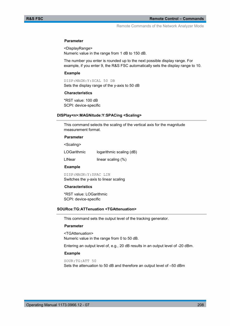
R&S FSC Remote Control – Commands
Remote Commands of the Network Analyzer Mode
Operating Manual 1173.0966.12 - 07 208
Parameter
<DisplayRange> Numeric value in the range from 1 dB to 150 dB.
The number you enter is rounded up to the next possible display range. For example, if you enter 9, the R&S FSC automatically sets the display range to 10.
Example
DISP:MAGN:Y:SCAL 50 DB Sets the display range of the y-axis to 50 dB
Characteristics
*RST value: 100 dB SCPI: device-specific
DISPlay<n>:MAGNitude:Y:SPACing <Scaling>
This command selects the scaling of the vertical axis for the magnitude measurement format.
Parameter
<Scaling>
LOGarithmic logarithmic scaling (dB)
LINear linear scaling (%)
Example
DISP:MAGN:Y:SPAC LIN Switches the y-axis to linear scaling
Characteristics
*RST value: LOGarithmic SCPI: device-specific
SOURce:TG:ATTenuation <TGAttenuation>
This command sets the output level of the tracking generator.
Parameter
<TGAttenuation> Numeric value in the range from 0 to 50 dB.
Entering an output level of, e.g., 20 dB results in an output level of -20 dBm.
Example
SOUR:TG:ATT 50 Sets the attenuation to 50 dB and therefore an output level of –50 dBm

R&S FSC Remote Control – Commands
Remote Commands of the Network Analyzer Mode
Operating Manual 1173.0966.12 - 07 209
Characteristics
*RST value: 0 dB SCPI: device-specific
8.3.3 Setting the Bandwidths
The following commands configure the filter bandwidths of the R&S FSC. Note that both groups of commands (BANDwidth and BWIDth) are the same.
List of commands
● [SENSe:]BANDwidth|BWIDth[:RESolution] <ResBW> (p. 146) ● [SENSe:]BANDwidth|BWIDth[:RESolution]:AUTO <State> (p. 147)
For a detailed description of commands refer to "Setting the Bandwidths" in spectrum analyzer mode.
8.3.4 Performing and Triggering the Measurement
The following commands configure the sweep.
List of commands
● *WAI (p. 134) ● ABORt (p. 148) ● INITiate[:IMMediate] (p. 148) ● INITiate:CONTinuous <SweepMode> (p. 149) ● [SENSe:]SWEep:COUNt <SweepCount> (p. 149) ● [SENSe:]SWEep:POINts? (p. 150) ● [SENSe:]SWEep:TIME <SweepTime> (p. 150) ● [SENSe:]SWEep:TIME:AUTO <State> (p. 150) ● TRIGger[:SEQuence]:HOLDoff[:TIME] <TriggerDelay> (p. 152) ● TRIGger[:SEQuence]:SLOPe <TriggerSlope> (p. 153) ● TRIGger[:SEQuence]:SOURce <TriggerSource> (p. 154)
For a detailed description of commands refer to "Performing and Triggering Measurements" in spectrum analyzer mode.
8.3.5 Working with Traces
The following commands set up the trace and the various functions associated with it, e.g. the selection of the detector.
List of commands
● DISPlay[:WINDow]:TRACe<t>:MEMory[:STATe] <State> (p. 156) ● DISPlay[:WINDow]:TRACe<t>:MODE <TraceMode> (p. 156) ● FORMat[:DATA] <DataFormat> (p. 158) ● FORMat:BORDer <ByteOrder> (p. 157)

R&S FSC Remote Control – Commands
Remote Commands of the Network Analyzer Mode
Operating Manual 1173.0966.12 - 07 210
● [SENSe:]DETector<t>[:FUNCtion] <Detector> (p. 157) ● [SENSe:]DETector<t>[:FUNCtion]:AUTO <State> (p. 157) ● TRACe[:DATA]? (p. 210)
For a detailed description of commands not described here refer to "Working with Traces" in spectrum analyzer mode.
TRACe[:DATA]?
This command reads out the trace data of the current measurement.
With the FORMat[:DATA] <DataFormat> command, you can set the data format.
Parameter
The available parameters depend on the format of the result display.
Display of one S-parameter
TRACE1 queries the data of the currently displayed data
Return value
The R&S FSC returns 631 values. Each value corresponds to one pixel of a trace.
The result and unit depends on the measurement format.
Example
TRAC:DATA? TRACE1 Reads out the data for trace 1.
Characteristics
*RST value: - SCPI: conform
8.3.6 Using Markers and Deltamarkers
8.3.6.1 Markers and Deltamarkers
The following commands are for setting and controlling markers and deltamarkers. If not otherwise noted, the numeric suffix <1...6> at MARKer or DELTamarker select the marker to be controlled.
The suffix <n> at CALCulate selects the measurement screen in dual trace mode and is in the range <1…2>.
The suffix <m> at MARKer selects the marker and is in the range <1…6>.
List of commands
● CALCulate<n>:DELTamarker<m>[:STATe] <State> (p. 160) ● CALCulate<n>:DELTamarker<m>:AOFF (p. 160) ● CALCulate<n>:DELTamarker<m>:MAXimum[:PEAK] (p. 160)

R&S FSC Remote Control – Commands
Remote Commands of the Network Analyzer Mode
Operating Manual 1173.0966.12 - 07 211
● CALCulate<n>:DELTamarker<m>:MAXimum:NEXT (p. 161) ● CALCulate<n>:DELTamarker<m>:MINimum[:PEAK] (p. 161) ● CALCulate<n>:DELTamarker<m>:X <Coordinate> (p. 161) ● CALCulate<n>:DELTamarker<m>:X:RELative <Distance> (p. 162) ● CALCulate<n>:DELTamarker<m>:Y? (p. 162) ● CALCulate<n>:MARKer<m>[:STATe] <State> (p. 163) ● CALCulate<n>:MARKer<m>:AOFF (p. 163) ● CALCulate<n>:MARKer<m>:MAXimum[:PEAK] (p. 164) ● CALCulate<n>:MARKer<m>:MAXimum:NEXT (p. 164) ● CALCulate<n>:MARKer<m>:MINimum[:PEAK] (p. 164) ● CALCulate<n>:MARKer<m>:X <Coordinate> (p. 165) ● CALCulate<n>:MARKer<m>:X:SLIMits[:STATe] <State> (p. 165) ● CALCulate<n>:MARKer<m>:X:SLIMits:LEFT <SearchLimit> (p. 166) ● CALCulate<n>:MARKer<m>:X:SLIMits:RIGHt <Searchlimit> (p. 166) ● CALCulate<n>:MARKer<m>:Y? (p. 211)
For a detailed description of commands not described below refer to "Using Markers" in spectrum analyzer mode.
CALCulate<n>:MARKer<m>:Y?
This command queries the measurement results at the marker position.
If necessary, the corresponding marker is activated first.
To get a valid result, you have to perform a complete sweep with synchronization to the sweep end between activating the delta marker and reading out the result. This is only possible in single sweep mode.
Return value
NORMal <value> = trace value
Example
INIT:CONT OFF CALC:MARK2 ON Turns on single sweep mode and marker 2.
INIT;*WAI CALC:MARK2:Y? Performs a measurement and queries the marker position.
Characteristics
*RST value: – SCPI: device–specific

R&S FSC Remote Control – Commands
Remote Commands of the Network Analyzer Mode
Operating Manual 1173.0966.12 - 07 212
8.3.6.2 Marker Functions
The following commands perform various kinds of analysis at the marker position.
The suffix <n> at DISPlay selects the measurement screen in dual trace mode and is in the range <1…2>.
List of commands
● DISPlay<n>:IMPedance:REFerence:POSition <Impedance> (p. 212) ● DISPlay<n>:ZOOM:AREA[:STAT] <State> (p. 212) ● DISPlay<n>:ZOOM:FACTor <ZoomFactor> (p. 213) ● DISPlay<n>:ZOOM:X <HorizShift> (p. 213) ● DISPlay<n>:ZOOM:Y <VerticalShift> (p. 213)
DISPlay<n>:IMPedance:REFerence:POSition <Impedance>
This command sets the reference impedance for the smith chart measurement format. The impedance can be between 1mΩ and 10 kΩ.
Parameter
<Impedance> Numeric value in the rnage from 1 mΩ to 10 kΩ.
Example
DISP:IMP:REF:POS 75 OHM Sets the reference impedance to 75 Ohm.
Characteristics
*RST value: 50 SCPI: device-specific
DISPlay<n>:ZOOM:AREA[:STAT] <State>
This command turns the marker zoom function in a Smith chart on and off.
Parameter
<State> ON | OFF
Example
DISP:ZOOM:AREA ON Activates the marker zoom function.
Characteristics
*RST value: OFF SCPI: device-specific
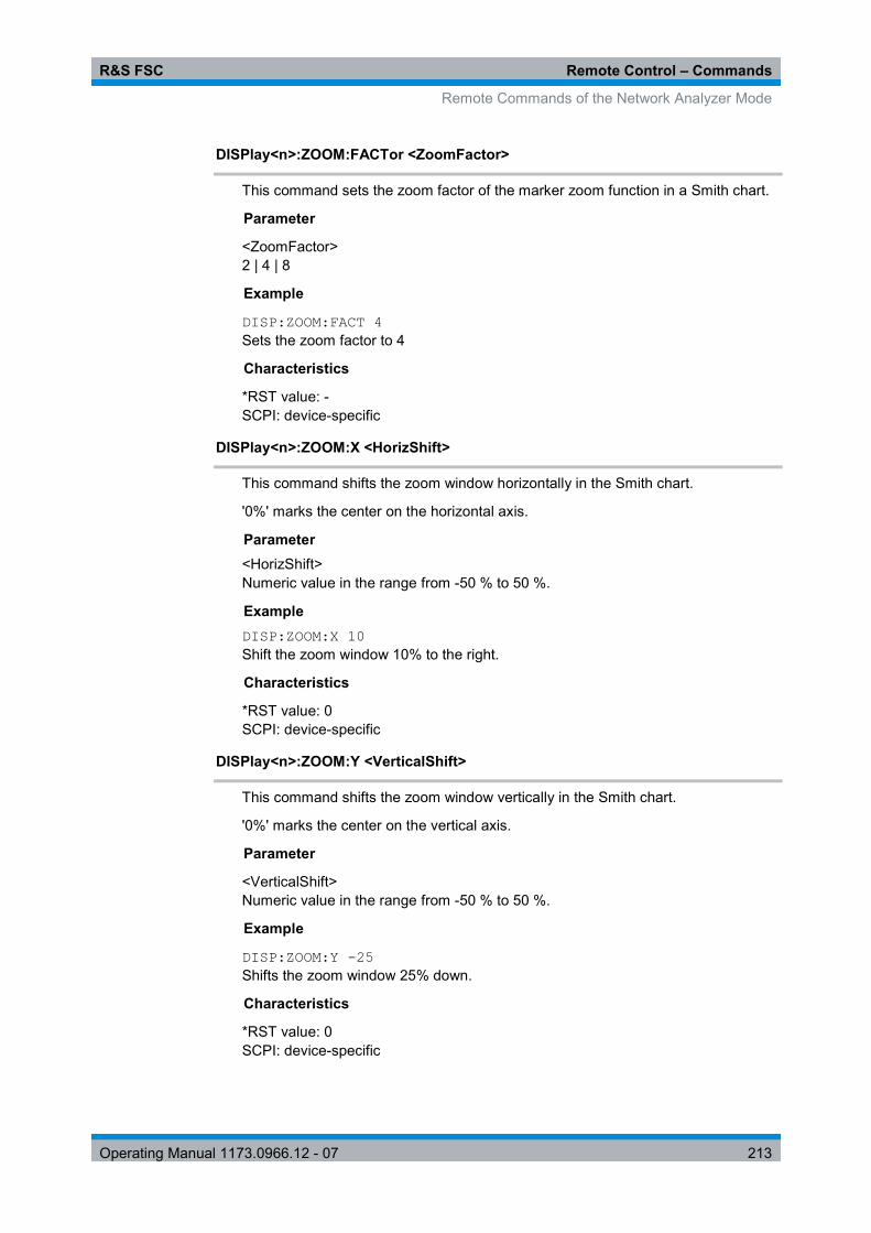
R&S FSC Remote Control – Commands
Remote Commands of the Network Analyzer Mode
Operating Manual 1173.0966.12 - 07 213
DISPlay<n>:ZOOM:FACTor <ZoomFactor>
This command sets the zoom factor of the marker zoom function in a Smith chart.
Parameter
<ZoomFactor> 2 | 4 | 8
Example
DISP:ZOOM:FACT 4 Sets the zoom factor to 4
Characteristics
*RST value: - SCPI: device-specific
DISPlay<n>:ZOOM:X <HorizShift>
This command shifts the zoom window horizontally in the Smith chart.
'0%' marks the center on the horizontal axis.
Parameter <HorizShift> Numeric value in the range from -50 % to 50 %.
Example DISP:ZOOM:X 10 Shift the zoom window 10% to the right.
Characteristics
*RST value: 0 SCPI: device-specific
DISPlay<n>:ZOOM:Y <VerticalShift>
This command shifts the zoom window vertically in the Smith chart.
'0%' marks the center on the vertical axis.
Parameter
<VerticalShift> Numeric value in the range from -50 % to 50 %.
Example
DISP:ZOOM:Y -25 Shifts the zoom window 25% down.
Characteristics
*RST value: 0 SCPI: device-specific

R&S FSC Remote Control – Commands
Remote Commands of the Network Analyzer Mode
Operating Manual 1173.0966.12 - 07 214
8.3.7 Configuring the Measurement
This chapter provides information on how to configure two-port measurements with the tracking generator. The structure follows the order of the actual operation sequence used when performing a measurement:
● Calibrating the Measurement on page 214
To perform the actual measurement, use the commands described in section "Performing and Triggering the Measurement".
Commands independent of the operating mode Note that some of the commands for configuring two-port measurements are also valid for other operating modes. If a command is available in another mode, it is indicated by the list in the respective section.
8.3.7.1 Calibrating the Measurement
The following commands query and control calibration for two-port measurements.
List of commands
● CALibration:MODE? (p. 214) ● CALibration:STATus? (p. 215)
The suffix <p> selects the measurement port. It is in the range <1…2>.
CALibration:MODE?
This command queries if the current measurement is calibrated.
This command is a query and therefore has no *RST value.
Return value
0 not calibrated
1 calibrated
Example
CAL:MODE? Queries the calibration state.
Characteristics
*RST value: - SCPI: device-specific

R&S FSC Remote Control – Commands
Remote Commands of the Network Analyzer Mode
Operating Manual 1173.0966.12 - 07 215
CALibration:STATus?
This command queries if the R&S FSC is fully calibrated for the current measurement.
This command is a query and therefore has no *RST value.
Return value
NORMalized full factory or user calibration
APPRoximate approximate calibration: measurement uncertainty must be anticipated
Example
CAL:STAT? Queries the calibration status of the R&S FSC.
Characteristics
*RST value: - SCPI: device-specific

R&S FSC Remote Control – Commands
Remote Commands of the Power Meter
Operating Manual 1173.0966.12 - 07 216
8.4 Remote Commands of the Power Meter
The chapter provides information on remote commands that configure and perform power measurements with the power sensor. These commands are available in power meter mode only.
Availability of remote commands for Power Sensor measurements Note that the listed remote commands take effect only if a power sensor is connected.
8.4.1 Setting the Frequency
The following chapter describes commands necessary to define frequency settings.
List of commands
● [SENSe:]PMETer:FREQuency <Frequency> (p. 216)
[SENSe:]PMETer:FREQuency <Frequency>
This command sets the frequency of the power sensor.
Parameter
<Frequency> Numeric value in Hz.
The available value range is specified in the data sheet.
Example
PMET:FREQ 500 MHZ Sets the power sensor's frequency to 500 MHz
Characteristics
*RST value: - SCPI: device-specific
8.4.2 Configuring Power Level Readout
The following chapter describes commands that configure the power level readout.
List of commands
● CALCulate:PMETer:RELative[:MAGNitude] <RefValue> (p. 217) ● CALCulate:PMETer:RELative[:MAGNitude]:AUTO (p. 217) ● CALCulate:PMETer:RELative[:MAGNitude]:OFFSet <Offset> (p. 217) ● UNIT<z>:PMETer:POWer <Unit> (p. 218)

R&S FSC Remote Control – Commands
Remote Commands of the Power Meter
Operating Manual 1173.0966.12 - 07 217
CALCulate:PMETer:RELative[:MAGNitude] <RefValue>
This command sets the reference value for relative measurements.
Parameter
<RefValue> Numeric value in dBm.
Example
CALC:PMET:REL 30 The the reference value to 30 dBm.
Characteristics
*RST value: - SCPI: device-specific
CALCulate:PMETer:RELative[:MAGNitude]:AUTO ONCE
This command sets the current measurement result as the reference level for relative measurements.
This command is an event and therefore has no *RST value and no query.
Parameter
ONCE
Example
CALC:PMET:REL ONCE Characteristics
*RST value: - SCPI: device-specific
CALCulate:PMETer:RELative[:MAGNitude]:OFFSet <Offset>
This command sets an offset for the reference value.
Parameter
<Offset> Numeric value in dB.
Example
CALC:PMET:REL -10 Characteristics
*RST value: - SCPI: device-specific

R&S FSC Remote Control – Commands
Remote Commands of the Power Meter
Operating Manual 1173.0966.12 - 07 218
UNIT<z>:PMETer:POWer <Unit>
This command selects the unit of the power sensor.
The suffix <z>at UNIT has the following effects:
Unit 1 Power unit
Unit 2 not available.
Parameter
<Unit> DBM | WATT | W | DB | VSWR
Note on the parameter DB: when applied to UNIT1, the power is relative to the reference level, when applied to UNIT2, the return loss is displayed.
Note on the parameter VSWR: the parameter is only available if applied to UNIT2.
Example
UNIT1:PMET:POW DBM Sets the unit to dBm.
Characteristics
*RST value: - SCPI: device-specific
8.4.3 Performing Measurements with the Power Sensor
The following chapter describes all commands that are available for performing power measurements with the power sensor.
● CALibration:PMETer:ZERO:AUTO (p. 218) ● FETCh<z>:PMETer? (p. 219)
8.4.3.1 Zeroing of the Power Sensor
CALibration:PMETer:ZERO:AUTO ONCE
This commands starts to zero the power sensor.
This command is an event and therefore has no *RST value and no query.
Parameter
ONCE
Example
CAL:PMET:ZERO:AUTO ONCE Starts to zero the power meter.
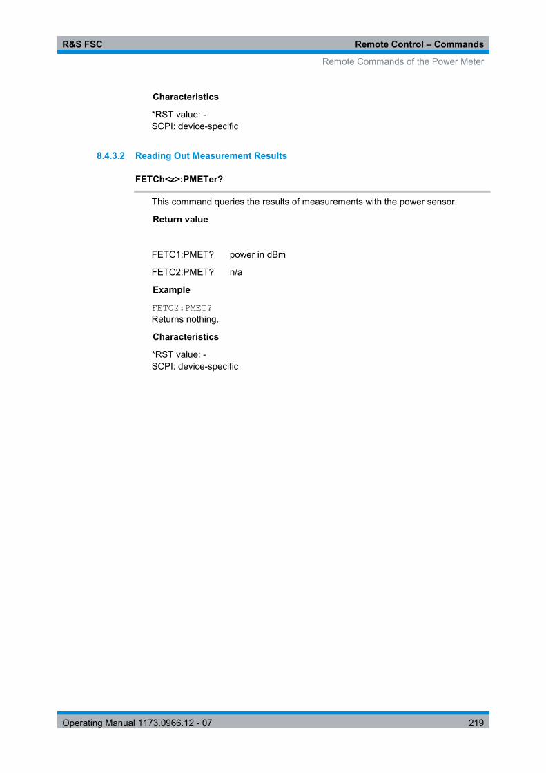
R&S FSC Remote Control – Commands
Remote Commands of the Power Meter
Operating Manual 1173.0966.12 - 07 219
Characteristics
*RST value: - SCPI: device-specific
8.4.3.2 Reading Out Measurement Results
FETCh<z>:PMETer?
This command queries the results of measurements with the power sensor.
Return value
FETC1:PMET? power in dBm
FETC2:PMET? n/a
Example
FETC2:PMET? Returns nothing.
Characteristics
*RST value: - SCPI: device-specific

R&S FSC Remote Control – Commands
File Management
Operating Manual 1173.0966.12 - 07 220
8.5 File Management
The following commands perform various tasks in the context of file management.
These commands are independent from the operating mode.
List of commands
● MMEMory:CATalog? (p. 220) ● MMEMory:CATalog:DIRectories? (p. 221) ● MMEMory:CDIRectory <Directory> (p. 221) ● MMEMory:COPY <SourceFile>,<DestinationFile> (p. 221) ● MMEMory:DATA <FileName>[,<BlockData>] (p. 222) ● MMEMory:DELete <File> (p. 223) ● MMEMory:FILE <File> (p. 223) ● MMEMory:FILE:DATE <FileName>,<Date> (p. 223) ● MMEMory:FILE:TIME <FileName>,<Time> (p. 224) ● MMEMory:INIT (p. 224) ● MMEMory:LOAD:STATe 1,<FileName> (p. 225) ● MMEMory:MDIRectory <Directory> (p. 225) ● MMEMory:MOVE <SourceFile>,<NewFileName> (p. 225) ● MMEMory:RDIRectory <Directory> (p. 226) ● MMEMory:STORe:STATe 1,<FileName> (p. 226)
MMEMory:CATalog?
This command queries the files of the current directory.
You can select directories with MMEMory:CDIRectory <Directory>.
This command is a query and therefore has no *RST value.
Return value
<UsedDiskSpace>,<FreeDiskSpace>,<FileName_1>,<SizeFile_1><Modification DateFile_1>,<ModificationTimeFile_1>,…,<FileName_n>,<SizeFile_n> <ModificationDateFile_n>, <ModificationTimeFile_n>
Example
MMEM:CDIR '\Public\Limit Lines' Opens directory 'Limit Lines'
MMEM:CAT? Returns all files in \Public\Limit Lines
Characteristics
*RST value: - SCPI: conform

R&S FSC Remote Control – Commands
File Management
Operating Manual 1173.0966.12 - 07 221
MMEMory:CATalog:DIRectories?
This command queries the directories of the current directory.
This command is a query and therefore has no *RST value.
Return value
<UsedMemory>,<FreeMemory>,<DirName_1>,<ModificationDateDir_1>, <ModificationTimeDir_1>,…,<DirName_n>,<ModificationDateDir_n>, <ModificationTimeDir_n>
Example
MMEM:CDIR '\Public' Opens directory \Public.
MMEM:CAT:DIR? Returns all directories in the \Public directory
Characteristics
*RST value: - SCPI: device-specific
MMEMory:CDIRectory <Directory>
This command changes the current directory.
Parameter
<Directory> String containing the path to another directory.
Example
MMEM:CDIR '\Public' Opens directory \Public.
Characteristics
*RST value: - SCPI: conform
MMEMory:COPY <SourceFile>,<DestinationFile>
This command copies one or more files to another directory.
This command is an event and therefore has no *RST value and no query.
Parameter
<SourceFile> String containing the path and file name of the source file.
<DestinationFile> String containing the path and name of the destination file.

R&S FSC Remote Control – Commands
File Management
Operating Manual 1173.0966.12 - 07 222
Example
MMEM:COPY '\Public\Standards\cdmaOne.obwstd','\USB\cdma.std' Copies the cdmaOne standard file to a memory stick.
Characteristics
*RST value: - SCPI: conform
MMEMory:DATA <FileName>[,<BlockData>]
This command writes block data into a file. The delimiter must be set to EOI to obtain error-free data transfer.
When you query the contents of a file, you can save them in a file on the remote control computer.
The command is useful for reading stored settings files or trace data from the instrument or for transferring them to the instrument.
Parameter
<FileName> String containing the path and file name.
<BlockData> Data block with the structure
# hash sign <number> length of the length information <number> length information of the binary data (number of bytes) <data> binary data with the indicated number of bytes Example
MMEM:NAME '\Public\User\Testfile.txt' Creates a new file called 'Testfile.txt'.
MMEM:DATA '\Public\User\Testfile.txt',#220Contents of the file The parameter mean:
- '\Public\...' selects the target file - #2: hash sign and length of the length information (20 bytes = 2 digits) - 20: indicates the number of subsequent binary data bytes - Contents of the file: store 20 binary bytes (characters) to the file
MMEM:DATA? '\Public\User\Testfile.txt' Transfers the contents of the file 'Testfile.txt' to the control computer.
Characteristics
*RST value: - SCPI: conform

R&S FSC Remote Control – Commands
File Management
Operating Manual 1173.0966.12 - 07 223
MMEMory:DELete <File>
This command deletes a file.
Parameter
<File> String containing the path and file name of the file to delete.
Example
MMEM:DEL '\Public\Screen Shots\Screen0001.png' Deletes the file Screen0001.png.
Characteristics
*RST value: - SCPI: conform
MMEMory:FILE <File>
This command creates a file.
Parameter
<File> String containing the file name.
Example
MMEM:FILE 'TEST.TXT' Creates the file TEST.TXT
Characteristics
*RST value: - SCPI: conform
MMEMory:FILE:DATE <FileName>,<Date>
This command sets the date of a file.
Parameter
<FileName> String containing the path and file name.
<Date> Numeric values indicating the date
You have to enter the date as comma separated values after the string with the file name. The sequence is year,month,day.
The available value range is 1980...2099, 1...12, 1...31
Example
MMEM:FILE:DATE '\Public\Screen Shots\Screen0001.png',2006,04,01 Sets the date to April, 1st, 2006.

R&S FSC Remote Control – Commands
File Management
Operating Manual 1173.0966.12 - 07 224
MMEM:FILE:DATE? '\Public\Screen Shots\Screen0001.png' Returns the modification date of the file Screen0001.png.
Characteristics
*RST value: - SCPI: conform
MMEMory:FILE:TIME <FileName>,<Time>
This command sets the time of a file. The sequence of entry is hour, minute, second.
Parameter
<FileName> String containing the path and file name.
<Time> Numeric values indicating the time.
You have to enter the time as comma separated values after the string with the file name. The sequence is hour,minute,second.
The available value range is 0...23, 0...59, 0...59.
Example
MMEM:FILE:TIME '\Public\Screen Shots\Screen0006.png',11,04,00 Sets the time to 11:04:00
Characteristics
*RST value: - SCPI: conform
MMEMory:INIT
This command formats the indicated drive.
Note Formatting deletes all data stored on the memory drive.
This command is an event and therefore has no *RST value and no query.
Example:
MMEM:INIT Formats and deletes all data from the drive.
Characteristics:
*RST value: - SCPI: conform

R&S FSC Remote Control – Commands
File Management
Operating Manual 1173.0966.12 - 07 225
MMEMory:LOAD:STATe 1,<FileName>
This command loads the settings from a *.set file.
Parameter
<FileName> String containing the path and file name.
Example
MMEM:LOAD:STAT 1,'\Public\Datasets\Dataset001.set' Loads the settings from the file Dataset001.
Characteristics
*RST value: - SCPI: conform
MMEMory:MDIRectory <Directory>
This command creates a new directory.
This command is an event and therefore has no *RST value and no query.
Parameter
<Directory> String containing the path and new directory name.
Example
MMEM:MDIR '\Public\USER' Creates the a directory called 'User'
Characteristics
*RST value: - SCPI: device-specific
MMEMory:MOVE <SourceFile>,<NewFileName>
This command renames files, if <file_destination> contains no path. Otherwise the file is moved to the indicated path and stored under the file name specified there.
This command is an event and therefore has no *RST value and no query.
Parameter
<SourceFile> String containing the path and file name of the source file.
<DestinationFile> String containing the path and name of the destination file.
Example
MMEM:MOVE '\Public\Screen Shots\Screen0002.png','\Public\Screen Shots\Screen0001.png' Renames Screen0002.png to Screen0001.png

R&S FSC Remote Control – Commands
File Management
Operating Manual 1173.0966.12 - 07 226
MMEM:MOVE '\Public\Screen Shots\Screen0001.png','\Public\Test\Pic1.png' Moves file Screen0006.png to the 'Test' folder and renames the file Pic1.png
Characteristics
*RST value: - SCPI: conform
MMEMory:RDIRectory <Directory>
This command deletes the indicated directory. The directory name includes the path and may also include the drive name. The path name complies with DOS conventions.
This command is an event and therefore has no *RST value and no query.
Parameter
<Directory> String containing the path of the directory to delete.
Example
MMEM:RDIR '\Public\Screen Shots\ Deletes the directory 'Screen Shots'.
Characteristics
*RST value: - SCPI: device-specific
MMEMory:STORe:STATe 1,<FileName>
This command stores the current device settings in a *set file.
This command is an event and therefore has no *RST value and no query.
Parameter
1,<FileName> String containing the path and name of the destination file.
Example
MMEM:STOR:STAT 1,'DATASET001.SET' Saves the current device settings in the file DATASET001.SET.
Characteristics
*RST value: - SCPI: conform

R&S FSC Remote Control – Commands
Making and Storing Screenshots
Operating Manual 1173.0966.12 - 07 227
8.6 Making and Storing Screenshots
The following commands manage screenshots.
These commands are independent from the operating mode.
List of commands
● DISPlay:WINDow:STORe (p. 227) ● HCOPy:DEVice:LANGuage (p. 227) ● HCOPy[:IMMediate] (p. 228) ● MMEMory:NAME <FileName> (p. 228)
DISPlay:WINDow:STORe
This command makes a screenshot of the current display contens in png or jpg format and stores it on the R&S ZVH internal memory.
You can select a file name for the screenshot in png format with MMEMory:NAME <FileName> and select the file format of the screenshot with HCOPy:DEVice:LANGuage.
This command is an event and therefore has no *RST value and no query.
Example
HCOP:DEV:LANG PNG MMEM:NAME '\Public\Screen Shots\Test.png' DISP:WIND:STOR Makes and stores a screenshot of the current screen in a file 'Test.png'.
Characteristics
*RST value: - SCPI: device-specific
HCOPy:DEVice:LANGuage
This command selects the file format for screenshots.
Parameter
PNG | JPG
Example
HCOP:DEV:LANG PNG Selects the png format for screenhots.
Characteristics
*RST value: - SCPI: device-specific

R&S FSC Remote Control – Commands
Configuring Data Capture
Operating Manual 1173.0966.12 - 07 228
HCOPy[:IMMediate]
This command makes a screenshot of the current trace and stores it on the R&S FSC internal memory.
This command is an event and therefore has no *RST value and no query.
Example
MMEM:NAME '\Public\Screenshots\Test.png' Defines the file name of the screenshot.
HCOP Makes and stores a screenshot of the current screen.
Characteristics
*RST value: - SCPI: device-specific
MMEMory:NAME <FileName>
This command defines the path and file name that the R&S FSH uses for storing screenshots (see HCOPy[:IMMediate]). The path and file name comply with DOS conventions.
This command is an event and therefore has no *RST value and no query.
Parameter
<FileName> String containing the file name.
Example
MMEM:NAME 'Public\Screeshots\Test.png' Stores the screenshot on the in the corresponding directory on the R&S ZVH.
Characteristics
*RST value: - SCPI: device-specific
8.7 Configuring Data Capture
The following commands configure the data capture.
These commands are independent from the operating mode.
List of commands
● SYSTem:CAPTure:COUNter <Counter> (p. 229) ● SYSTem:CAPture:MODE <MODE> (p. 229)

R&S FSC Remote Control – Commands
Configuring Data Capture
Operating Manual 1173.0966.12 - 07 229
SYSTem:CAPTure:COUNter <Counter>
This command defines the start of the file name counter.
The counter numbers the files stored when you capture data (screenshots, datasets etc.).
Parameter
<Counter> String containing the number with which to start numbering files.
Example
SYST:CAPT:COUN '0100' Starts numbering files with 0100, e.g. Measurement0100.png.
Characteristics
*RST value: '0000' SCPI: device-specific
SYSTem:CAPture:MODE <MODE>
This command selects the data types that the R&S FSC saves when you capture the current measurement data.
Parameter
<Mode>
SCReen Saves a screenshot
DATaset Saves a dataset
BOTH Saves a screenshot and a dataset
Example
SYST:CAPT:MODE BOTH Captures both a screenshot and a dataset of the current measurement.
Characteristics
*RST value: SCReen SCPI: device-specific

R&S FSC Remote Control – Commands
Configuring the Instrument
Operating Manual 1173.0966.12 - 07 230
8.8 Configuring the Instrument
The following commands configure general instrument settings. These commands are independent from the operating mode.
Contents
Mode Selection on page 230 Display Configuration on page 231 Audio Settings on page 232 Setting up a Network Connection on page 233 System Settings on page 236
8.8.1 Mode Selection
This chapter describes all commands that select the operating mode of the R&S FSC.
List of commands
● INSTrument[:SELect] <OperatingMode> (p. 230) ● INSTrument:NSELect <OperatingMode> (p. 230)
INSTrument[:SELect] <OperatingMode>
This command selects the operating mode.
Parameter
<OperatingMode>
NAN network analyzer
PM power meter
SANalyzer spectrum analyzer
Example
INST SAN Selects spectrum analyzer mode.
Characteristics
*RST value: ACT SCPI: conform
INSTrument:NSELect <OperatingMode>
This command selects the operating mode.
Parameter
1 spectrum analyzer
2 network analyzer
5 power meter

R&S FSC Remote Control – Commands
Configuring the Instrument
Operating Manual 1173.0966.12 - 07 231
Example
INST:NSEL 1 Selects spectrum analyzer mode.
Characteristics
*RST value: 4 SCPI: conform
8.8.2 Display Configuration
This chapter describes commands to set up the display of the R&S FSC via remote control.
List of Commands
● DISPlay:CMAP <ColorScheme> (p. 231) ● DISPlay:CMAP:DEFault (p. 231) ● DISPlay:DATE:FORMat <DateFormat> (p. 232)
DISPlay:CMAP <ColorScheme>
This command sets the color scheme of the display.
Parameter
<ColorScheme>
COLor color
BW black & white
PF printer friendly
Example
DISP:CMAP BW Sets the screen colors to black and white
Characteristics
*RST value: COLor SCPI: conform
DISPlay:CMAP:DEFault
This command sets the display to the default state.
This command is an event and therefore has no query and no *RST value.
Example
DISP:CMPA:DEF Restores the original color scheme

R&S FSC Remote Control – Commands
Configuring the Instrument
Operating Manual 1173.0966.12 - 07 232
Characteristics
*RST value: - SCPI: conform
DISPlay:DATE:FORMat <DateFormat>
This command sets the display date format.
Parameter
<DateFormat> DDMMyyyy | MMDDyyyy
Example
DISP:DATE:FORM DDMMyyyy Characteristics
*RST value: DDMMyyyy SCPI: device-specific
8.8.3 Audio Settings
This chapter describes all commands to control the audio functions of the R&S FSC.
List of commands
● SYSTem:AUDio:VOLume <Volume> (p. 232) ● SYSTem:BEEPer:VOLume <Volume> (p. 233) ● SYSTem:BEEPer:KEY:VOLume <Volume> (p. 233)
SYSTem:AUDio:VOLume <Volume>
This command sets the volume of the internal speaker.
Parameter
<Volume> Numeric value in the range from 0 to 1
Example
SYST:AUD:VOL 0.40 Sets the volume to 40%
Characteristics
*RST value: 0.3 (30%) SCPI: device-specific

R&S FSC Remote Control – Commands
Configuring the Instrument
Operating Manual 1173.0966.12 - 07 233
SYSTem:BEEPer:VOLume <Volume>
This command sets the volume of the system beeper.
Parameter
<Volume> Numeric value in the range from 0 to 1
Example
SYST:BEEP:VOL 0.50 Sets the volume of the beeper to 50%
Characteristics
*RST value: 0.6 (60%) SCPI: conform
SYSTem:BEEPer:KEY:VOLume <Volume>
This command sets the volume of the keyboard click noise.
Parameter
<Volume> Numeric value in the range from 0 to 1
Example
SYST:BEEP:KEY:VOL 0.10 Sets of keyboard clicking volume to 10%
Characteristics
*RST value: 0.3 (30%) SCPI: conform
8.8.4 Setting up a Network Connection
This chapter describes all commands that are used if the R&S FSC is part of a network.
List of commands
● SYSTem:COMMunicate:LAN:ETHernet? (p. 234) ● SYSTem:COMMunicate:LAN:SUBMask <SubnetMask> (p. 234) ● SYSTem:COMMunicate:SOCKet:ADDRess <IPAddress> (p. 234) ● SYSTem:COMMunicate:SOCKet:DHCP[:STATe] <State> (p. 235) ● SYSTem:COMMunicate:SOCKet:PORT <Port> (p. 235)

R&S FSC Remote Control – Commands
Configuring the Instrument
Operating Manual 1173.0966.12 - 07 234
SYSTem:COMMunicate:LAN:ETHernet?
This command queries the MAC address of the R&S FSC.
This command is a query and therefore has no *RST value.
Example
SYST:COMM:LAN:ETH? Returns the MAC address
Characteristics
*RST value: - SCPI: device-specific
SYSTem:COMMunicate:LAN:SUBMask <SubnetMask>
This command sets the subnet mask of the R&S FSC.
Parameter
<SubnetMask> String containing the subnet mask ('x.x.x.x').
Example
SYST:COMM:LAN:SUBM '255.255.255.0' Sets the subnet mask address to 255.255.255.0
Characteristics
*RST value: 255.255.255.0 SCPI: device-specific
SYSTem:COMMunicate:SOCKet:ADDRess <IPAddress>
This command sets the IP address of the R&S FSC.
Parameter
<IPAddress> String containing the IP address ('x.x.x.x').
Example
SYST:COMM:SOCK:ADDR '172.76.68.30' Sets the IP address of the R&S FSC to 172.76.68.30
Characteristics
*RST value: 172.76.68.24 SCPI: device-specific

R&S FSC Remote Control – Commands
Configuring the Instrument
Operating Manual 1173.0966.12 - 07 235
SYSTem:COMMunicate:SOCKet:DHCP[:STATe] <State>
This command turns the Dynamic Host Configuration Protocol (DHCP) on and off.
Parameter
<State> ON | OFF
Example
SYST:COMM:SOCK:DHCP ON Activates DHCP.
Characteristics
*RST value: ON SCPI: device-specific
SYSTem:COMMunicate:SOCKet:PORT <Port>
This command sets the port number for the connection.
Parameter
<Port> Port number
Example
SYST:COMM:SOCK:PORT 1000 Sets the port number to 1000
Characteristics
*RST value: 5555 SCPI: device-specific

R&S FSC Remote Control – Commands
Configuring the Instrument
Operating Manual 1173.0966.12 - 07 236
8.8.5 System Settings
This chapter describes all commands that define or query general system settings.
List of commands
● INPut:IMPedance:PAD <MatchingPad> (p. 236) ● [SENSe:]ROSCilator:SOURce <RefSource> (p. 237) ● SYSTem:BNC<1...2>:MODE <BNCFunction> (p. 237) ● SYSTem:DATE <Date> (p. 238) ● SYSTem:ERRor[:NEXT]? (p. 238) ● SYSTem:ERRor:ALL? (p. 238) ● SYSTem:ERRor:COUNt? (p. 240) ● SYSTem:ERRor:CODE[:NEXT]? (p. 239) ● SYSTem:ERRor:CODE:ALL? (p. 239) ● SYSTem:HELP:HEADers? (p. 240) ● SYSTem:HELP:SYNTax? (p. 240) ● SYSTem:LANGuage:CATalog? (p. 241) ● SYSTem:POWer:SOURce? (p. 241) ● SYSTem:POWer:STATus? (p. 242) ● SYSTem:PRESet (p. 242) ● SYSTem:PRESet:FACTory (p. 242) ● SYSTem:PRESet:MODE <Mode> (p. 242) ● SYSTem:PRESet:USER <Preset> (p. 243) ● SYSTem:SHUTdown (p. 243) ● SYSTem:TIME <Time> (p. 243) ● SYSTem:TZONee <TimeShift> (p. 244) ● SYSTem:VERSion? (p. 244)
INPut:IMPedance:PAD <MatchingPad>
This command selects the matching pad connected to the R&S FSC.
Parameter
<MatchingPad> RAM | RAZ | HZTE
Example
INPut:IMP 75;PAD RAZ Selects 75 Ω input impedance and the R&S RAZ as the matching pad.
Characteristics
*RST value: - SCPI: device-specific

R&S FSC Remote Control – Commands
Configuring the Instrument
Operating Manual 1173.0966.12 - 07 237
[SENSe:]ROSCilator:SOURce <RefSource>
This command selects the source of the frequency reference oscillator.
If you use an external reference signal, make sure to connect the signal to the Ext Ref BNC connector of the R&S FSC.
Parameter
<RefSource>
INTernal internal reference
EXTernal external reference
Example
ROSC:SOUR EXT Activates external source as reference signal.
Characteristics
*RST value: - SCPI: device-specific
SYSTem:BNC<1...2>:MODE <BNCFunction>
This command configures the BNC sockets.
The numeric suffix at BNC selects the BNC socket you want to configure.
Parameter
<BNCFunction>
REFerence input for external reference signal (BNC1)
TRIGger input for external trigger (BNC1)
IF3 IF output (BNC2)
Example
SYST:BNC2:MODE TRIG Sets the seconds BNC socket to trigger input.
Characteristics
*RST value: BNC 1: TRIGger, BNC 2: IF3 SCPI: device-specific

R&S FSC Remote Control – Commands
Configuring the Instrument
Operating Manual 1173.0966.12 - 07 238
SYSTem:DATE <Date>
This command sets the date for the internal calendar.
Parameter
<Date> Numeric value indicating the date
You have to enter the date as comma separated values after the string with the file name. The sequence is year,month,day.
The available value range is 1980...2099, 1...12, 1...31
Example
SYST:DATE 2000,6,1 Sets the date to 1/6/2000
Characteristics
*RST value: - SCPI: conform
SYSTem:ERRor[:NEXT]?
This command queries the oldest entry in the error queue and deletes it.
This command is a query and therefore has no *RST value.
Return value
<error number>,<error description>
<error number> number that contains information about the error
negative number: error as defined in the SCPI standard positive number: error that is specific to the R&S FSC
<error description> string containing a short error description
If the error queue is empty, the command returns 0,'no error'.
Example
STAT:ERR? Characteristics
*RST value: - SCPI: conform
SYSTem:ERRor:ALL?
This command queries the complete error queue.
This command is a query and therefore no *RST value.
Return value
<error number>,<error description>

R&S FSC Remote Control – Commands
Configuring the Instrument
Operating Manual 1173.0966.12 - 07 239
<error number> number that contains information about the error
negative number: error as defined in the SCPI standard positive number: error that is specific to the R&S FSC
<error description> string containing a short error description
The number of values depends on the length of the queue.
If the error queue is empty, the command returns 0,'no error'.
Example
SYST:ERR:ALL? Characteristics
*RST value: - SCPI: device-specific
SYSTem:ERRor:CODE[:NEXT]?
This command queries the code of the next error in the error queue.
This command is a query and therefore has no *RST value.
Return value
<error number> number that contains information about the error
Negative number: error as defined in the SCPI standard Positive number: error that is specific to the R&S FSC
If the error queue is empty, the command returns 0.
Example
STAT:ERR:CODE? Characteristics
*RST value: - SCPI: conform
SYSTem:ERRor:CODE:ALL?
This command queries the complete error queue.
This command is a query and therefore no *RST value.
Return value
<error number> number that contains information about the error
Negative number: error as defined in the SCPI standard Positive number: error that is specific to the R&S FSC
The number of values depends on the length of the queue.
If the error queue is empty, the command returns 0,'no error'.

R&S FSC Remote Control – Commands
Configuring the Instrument
Operating Manual 1173.0966.12 - 07 240
Example
SYST:ERR:CODE:ALL? Characteristics
*RST value: - SCPI: device-specific
SYSTem:ERRor:COUNt?
This command queries the number of errors currently in the error queue.
This command is a query and therefore no *RST value.
Return value
<numeric_value> number of the errors in the queue
Example
SYST:ERR:COUN? Characteristics
*RST value: - SCPI: device-specific
SYSTem:HELP:HEADers?
This command returns a list of all available remote control commands.
This command is a query and therefore no *RST value.
Example
SYST:HELP:HEAD? Returns the syntax of all available commands.
Characteristics
*RST value: - SCPI: conform
SYSTem:HELP:SYNTax?
This command returns the full syntax of the specified command.
This command is a query and therefore no *RST value.
Parameter
<Command> String containing the command you want to query
Example
SYST:HELP:SYNT? 'SYST:ERR?' Returns the full syntax. In this case: 'SYSTem:ERRor[:NEXT]'.

R&S FSC Remote Control – Commands
Configuring the Instrument
Operating Manual 1173.0966.12 - 07 241
Characteristics
*RST value: - SCPI: device-specific
SYSTem:LANGuage <Language>
This command sets the language of the R&S FSC user interface. You can query a list of available languages with SYSTem:LANGuage:CATalog?.
Parameter
<Language> string containing the language
Example
SYST:LANG 'english' Sets the system language to English
Characteristics
*RST value: - SCPI: conform
SYSTem:LANGuage:CATalog?
This command lists all languages available for the user interface.
This command is a query and therefore no *RST value.
Example
SYST:LANG:CAT? Characteristics
*RST value: - SCPI: device-specific
SYSTem:POWer:SOURce?
This command queries the current R&S FSC power source.
This command is a query and therefore has no *RST value.
Return values
ADAP R&S FSC is powered by the AC power supply
BATT R&S FSC is powered by the battery
Example
SYST:POW:SOUR? Characteristics
*RST value: - SCPI: conform

R&S FSC Remote Control – Commands
Configuring the Instrument
Operating Manual 1173.0966.12 - 07 242
SYSTem:POWer:STATus?
This command queries the remaining power of the battery.
This command is a query and therefore has no *RST value.
Return values
Numeric value in the range from 0 to 100 %.
Example
SYST:POW:STAT? Example
SYST:POW:STAT? Characteristics
*RST value: - SCPI: conform
SYSTem:PRESet
Resets the R&S FSC to its default state or a state defined by the user, depending on SYSTem:PRESet:MODE.
This command is an event and therefore has no *RST value and no query.
Example
SYST:PRES Characteristics
*RST value: - SCPI: conform
SYSTem:PRESet:FACTory
This command initiates an instrument reset back to factory settings.
This command is an event and therefore has no query and no *RST value.
Example
SYST:PRES:FACT Resets the R&S FSC to its factory settings.
Characteristics
*RST value: - SCPI: device-specific
SYSTem:PRESet:MODE <Mode>
This command selects the preset mode.
Parameter
<Mode>

R&S FSC Remote Control – Commands
Configuring the Instrument
Operating Manual 1173.0966.12 - 07 243
DEFault default preset state
USER user defined preset state
Example
SYST:PRES:MODE USER Selects a user defined preset.
Characteristics
*RST value: - SCPI: conform
SYSTem:PRESet:USER <Preset>
This command selects a file containing a user defined preset state.
Parameter
<Preset> filename of the user defined preset state
Characteristics
*RST value: - SCPI: conform
SYSTem:SHUTdown
This command turns the R&S FSC off.
This command is an event and therefore has no *RST value and no query.
Example
SYST:SHUT Turns the R&S FSC off.
Characteristics
*RST value: - SCPI: conform
SYSTem:TIME <Time>
This command sets the internal clock.
Parameter
<Time> Numeric value indicating the time
You have to enter the time as comma separated values after the string with the file name. The sequence is hour,minute,second.
The available value range is 0...23, 0...59, 0...59.

R&S FSC Remote Control – Commands
Configuring the Instrument
Operating Manual 1173.0966.12 - 07 244
Example
SYST:TIME 12,30,30 Characteristics
*RST value: - SCPI: conform
SYSTem:TZONee <TimeShift>
This command defines a shift of the system time to select another time zone.
Parameter
<TimeShift> Numeric vakue indicating the time shift.
You have to enter the time shift as comma separated value. The equence is hour,minute.
The available value range is 0…23, 0…59.
Example
SYST:TZON 01,00 Shifts the time an hour ahead
Characteristics
*RST value: 0,0 SCPI: device-specific
SYSTem:VERSion?
This command queries the SCPI version the remote control is based on.
This command is a query and therefore has no *RST value.
Return value
1999.0
Example
SYST:VERS? Characteristics
*RST value: - SCPI: conform

R&S FSC Remote Control – Commands
Status Reporting System
Operating Manual 1173.0966.12 - 07 245
8.9 Status Reporting System
The status reporting system stores all information on the present operating state of the instrument, and on errors which have occurred. This information is stored in the status registers and in the error queue. The status registers and the error queue can be queried via Ethernet.
The information is of a hierarchical structure. The register status byte (STB) defined in IEEE 488.2 and its associated mask register service request enable (SRE) form the uppermost level. The STB receives its information from the standard event status register (ESR) which is also defined in IEEE 488.2 with the associated mask register standard event status enable (ESE) and registers STATus:OPERation and STATus:QUEStionable which are defined by SCPI and contain detailed information on the instrument.
The output buffer contains the messages the instrument returns to the controller. It is not part of the status reporting system but determines the value of the MAV bit in the STB.
8.9.1 Structure of an SCPI Status Register
Each standard SCPI register consists of 5 parts which each have a width of 16 bits and have different functions. The individual bits are independent of each other, i.e. each hardware status is assigned a bit number that applies to all five parts. For example, bit 0 of the STATus:OPERation register is assigned to the calibration status of the R&S FSC. Bit 15 (the most significant bit) is set to zero for all parts. Thus the contents of the register parts can be processed by the controller as positive integer.
15 121314 CONDition Part 0123
15 121314 NTRansition Part 0123
15 121314 PTRansition Part 0123
15 121314 EVENt Part 0123
15 121314 ENABle Part 0123
& &&& & &&& & &&& & &&
to higher order register
+ Sum bit & = logical AND+ = logical ORof all bits
Figure 8-1: The status-register model
8.9.1.1 CONDition part
The CONDition part is directly written into by the hardware or the sum bit of the next lower register. Its contents reflects the current instrument status. This register part can only be read, but not written into or cleared. Its contents is not affected by reading.

R&S FSC Remote Control – Commands
Status Reporting System
Operating Manual 1173.0966.12 - 07 246
8.9.1.2 PTRansition part
The Positive-TRansition part acts as an edge detector. When a bit of the CONDition part is changed from 0 to 1, the associated PTR bit decides whether the EVENt bit is set to 1.
PTR bit =1: the EVENt bit is set.
PTR bit =0: the EVENt bit is not set.
This part can be written into and read at will. Its contents is not affected by reading.
8.9.1.3 NTRansition part
The Negative-TRansition part also acts as an edge detector. When a bit of the CONDition part is changed from 1 to 0, the associated NTR bit decides whether the EVENt bit is set to 1.
NTR-Bit = 1: the EVENt bit is set.
NTR-Bit = 0: the EVENt bit is not set.
This part can be written into and read at will. Its contents is not affected by reading.
With these two edge register parts the user can define which state transition of the condition part (none, 0 to 1, 1 to 0 or both) is stored in the EVENt part.
8.9.1.4 EVENt part
The EVENt part indicates whether an event has occurred since the last reading, it is the "memory" of the condition part. It only indicates events passed on by the edge filters. It is permanently updated by the instrument. This part can only be read by the user. Reading the register clears it. This part is often equated with the entire register.
8.9.1.5 ENABle part
The ENABle part determines whether the associated EVENt bit contributes to the sum bit (see below). Each bit of the EVENt part is ANDed with the associated ENABle bit (symbol '&'). The results of all logical operations of this part are passed on to the sum bit via an OR function (symbol '+').
ENABle-Bit = 0: the associated EVENt bit does not contribute to the sum bit
ENABle-Bit = 1: if the associated EVENT bit is "1", the sum bit is set to "1" as well.
This part can be written into and read by the user at will. Its contents is not affected by reading.

R&S FSC Remote Control – Commands
Status Reporting System
Operating Manual 1173.0966.12 - 07 247
8.9.1.6 Sum bit
As indicated above, the sum bit is obtained from the EVENt and ENABle part for each register. The result is then entered into a bit of the CONDition part of the higher-order register.
The instrument automatically generates the sum bit for each register. Thus an event, e.g. a PLL that has not locked, can lead to a service request throughout all levels of the hierarchy.
The service request enable register SRE defined in IEEE 488.2 can be taken as ENABle part of the STB if the STB is structured according to SCPI. By analogy, the ESE can be taken as the ENABle part of the ESR.
8.9.2 Overview of the Status Register
The following figure shows the status registers used by the R&S FSC.
Figure 8-2: Overview of the status registers

R&S FSC Remote Control – Commands
Status Reporting System
Operating Manual 1173.0966.12 - 07 248
8.9.3 Status Byte (STB) & Service Request Enable Register (SRE)
The STB is already defined in IEEE 488.2. It provides a rough overview of the instrument status by collecting the pieces of information of the lower registers. It can thus be compared with the CONDition part of an SCPI register and assumes the highest level within the SCPI hierarchy. A special feature is that bit 6 acts as the sum bit of the remaining bits of the status byte.
The STATUS BYTE is read using the command "*STB?" or a serial poll.
The STB is linked to the SRE. The latter corresponds to the ENABle part of the SCPI registers in its function. Each bit of the STB is assigned a bit in the SRE. Bit 6 of the SRE is ignored. If a bit is set in the SRE and the associated bit in the STB changes from 0 to 1, a service request (SRQ) is generated, which triggers an interrupt in the controller if this is appropriately configured and can be further processed there. The SRE can be set using the command "*SRE" and read using the command "*SRE?"
Table 8-1: Meaning of the bits used in the Status Byte
Bit No. Meaning
0 to 1 Not used
2 Error Queue not empty The bit is set when an entry is made in the error queue. If this bit is enabled by the SRE, each entry of the error queue generates a service request. Thus an error can be recognized and specified in greater detail by polling the error queue. The poll provides an informative error message. This procedure is to be recommended since it considerably reduces the problems involved with remote control.
3 QUEStionable status sum bit The bit is set if an EVENt bit is set in the QUEStionable: status register and the associated ENABle bit is set to 1.
A set bit indicates a questionable instrument status, which can be specified in greater detail by polling the QUEStionable status register.
4 MAV bit (message available)
The bit is set if a message is available in the output buffer which can be read. This bit can be used to enable data to be automatically read from the instrument to the controller.
5 ESB bit Sum bit of the event status register. It is set if one of the bits in the event status register is set and enabled in the event status enable register. Setting of this bit indicates a serious error which can be specified in greater detail by polling the event status register.
6 MSS bit (master status summary bit)
The bit is set if the instrument triggers a service request. This is the case if one of the other bits of this registers is set together with its mask bit in the service request enable register SRE.
7 OPERation status register sum bit The bit is set if an EVENt bit is set in the OPERation status register and the associated ENABle bit is set to 1. A set bit indicates that the instrument is just performing an action. The type of action can be determined by polling the OPERation status register.

R&S FSC Remote Control – Commands
Status Reporting System
Operating Manual 1173.0966.12 - 07 249
8.9.4 Event Status Register (ESR) and Event Status Enable Register (ESE)
The ESR is defined in IEEE 488.2. It can be compared with the EVENt part of a SCPI register. The event status register can be read out using command *ESR?.
The ESE is the associated ENABle part. It can be set using the command *ESE and read using the command *ESE?.
Table 8-2: Meaning of the bits in the event status register
Bit No. Meaning
0 Operation Complete This bit is set on receipt of the command *OPC exactly when all previous commands have been executed.
1 Not used
2 Query Error This bit is set if either the controller wants to read data from the instrument without having sent a query, or if it does not fetch requested data and sends new instructions to the instrument instead. The cause is often a query which is faulty and hence cannot be executed.
3 Device-dependent Error This bit is set if a device-dependent error occurs. An error message with a number between -300 and -399 or a positive error number, which denotes the error in greater detail, is entered into the error queue.
4 Execution Error This bit is set if a received command is syntactically correct but cannot be performed for other reasons. An error message with a number between -200 and -300, which denotes the error in greater detail, is entered into the error queue.
5 Command Error This bit is set if a command is received, which is undefined or syntactically incorrect. An error message with a number between -100 and -200, which denotes the error in greater detail, is entered into the error queue.
6 Not used
7 Power On (supply voltage on)
This bit is set on switching on the instrument.

R&S FSC Remote Control – Commands
Status Reporting System
Operating Manual 1173.0966.12 - 07 250
8.9.4.1 STATus:OPERation Register
In the CONDition part, this register contains information on which actions the instrument is being executing or, in the EVENt part, information on which actions the instrument has executed since the last reading. It can be read using the commands STATus:OPERation:CONDition? or STATus:OPERation[:EVENt]?.
Table 8-3: Meaning of the bits in the STATus:OPERation register
Bit No. Meaning
0 CALibrating This bit is set as long as the instrument is performing a calibration.
1 to 14 Not used
15 This bit is always 0
8.9.4.2 STATus:QUEStionable Register
This register contains information about indefinite states which may occur if the unit is operated without meeting the specifications. It can be read using the commands STATus:QUEStionable: CONDition? and STATus:QUEStionable[:EVENt]?.
Table 8-4: Meaning of bits in STATus:QUEStionable register
Bit No. Meaning
0 to 1 These bits are not used
2 BATTERY LOW If the instrument is running without any external power supply and the charging level of the internal battery is approximately lower than 5% this bit is set to indcate that the system will be shut down automatically in approx. 5 minutes.
3 Not used
4 TEMPerature This bit is set if a questionable temperature occurs.
5 to 8 Not used
9 LIMit (device-specific) This bit is set if a limit value is violated
10 CALibration The bit is set if a measurement is performed unaligned (label UNCAL)
11 to 14 Not used
15 This bit is always 0.
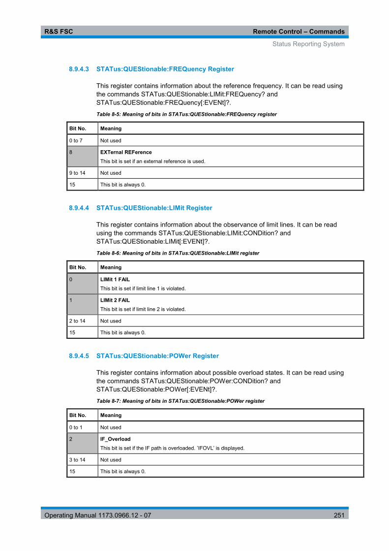
R&S FSC Remote Control – Commands
Status Reporting System
Operating Manual 1173.0966.12 - 07 251
8.9.4.3 STATus:QUEStionable:FREQuency Register
This register contains information about the reference frequency. It can be read using the commands STATus:QUEStionable:LIMit:FREQuency? and STATus:QUEStionable:FREQuency[:EVENt]?.
Table 8-5: Meaning of bits in STATus:QUEStionable:FREQuency register
Bit No. Meaning
0 to 7 Not used
8 EXTernal REFerence This bit is set if an external reference is used.
9 to 14 Not used
15 This bit is always 0.
8.9.4.4 STATus:QUEStionable:LIMit Register
This register contains information about the observance of limit lines. It can be read using the commands STATus:QUEStionable:LIMit:CONDition? and STATus:QUEStionable:LIMit[:EVENt]?.
Table 8-6: Meaning of bits in STATus:QUEStionable:LIMit register
Bit No. Meaning
0 LIMit 1 FAIL This bit is set if limit line 1 is violated.
1 LIMit 2 FAIL This bit is set if limit line 2 is violated.
2 to 14 Not used
15 This bit is always 0.
8.9.4.5 STATus:QUEStionable:POWer Register
This register contains information about possible overload states. It can be read using the commands STATus:QUEStionable:POWer:CONDition? and STATus:QUEStionable:POWer[:EVENt]?.
Table 8-7: Meaning of bits in STATus:QUEStionable:POWer register
Bit No. Meaning
0 to 1 Not used
2 IF_Overload This bit is set if the IF path is overloaded. ’IFOVL’ is displayed.
3 to 14 Not used
15 This bit is always 0.

R&S FSC Remote Control – Commands
Status Reporting System
Operating Manual 1173.0966.12 - 07 252
8.9.5 Application of the Status Reporting Systems
In order to be able to effectively use the status reporting system, the information contained there must be transmitted to the controller and further processed there. There are several methods which are represented in the following.
8.9.5.1 Service Request
Under certain circumstances, the instrument can send a service request (SRQ) to the controller. Usually this service request initiates an interrupt at the controller, to which the control program can react appropriately. As evident from Fig. 1-4, an SRQ is always initiated if one or several of bits 2, 3, 4, 5 or 7 of the status byte are set and enabled in the SRE. Each of these bits combines the information of a further register, the error queue or the output buffer. The ENABle parts of the status registers can be set so that arbitrary bits in an arbitrary status register initiate an SRQ. In order to make use of the possibilities of the service request effectively, all bits should be set to "1" in enable registers SRE and ESE.
Example
Use of the command *OPC to generate an SRQ at the end of a sweep
CALL InstrWrite(analyzer, "*ESE 1") 'Set bit 0 in the ESE (Operation Complete)
CALL InstrWrite(analyzer, "*SRE 32") 'Set bit 5 in the SRE (ESB)?
After its settings have been completed, the instrument generates an SRQ.
The SRQ is the only possibility for the instrument to become active on its own. Each controller program should set the instrument in a way that a service request is initiated in the case of malfunction. The program should react appropriately to the service request.
8.9.5.2 Serial Poll
In a serial poll, just as with command *STB, the status byte of an instrument is queried. However, the query is realized via interface messages and is thus clearly faster. The serial-poll method has already been defined in IEEE 488.1 and used to be the only standard possibility for different instruments to poll the status byte. The method also works with instruments which do not adhere to SCPI or IEEE 488.2.
The VISUAL BASIC command for executing a serial poll is IBRSP(). Serial poll is mainly used to obtain a fast overview of the state of several instruments connected to the controller.

R&S FSC Remote Control – Commands
Status Reporting System
Operating Manual 1173.0966.12 - 07 253
8.9.5.3 Query by Means of Commands
Each part of any status register can be read by means of queries. The individual commands are listed in the description of the STATus Subsystem. The returned value is always a number that represents the bit pattern of the queried register. This number is evaluated by the controller program.
Queries are usually used after an SRQ in order to obtain more detailed information on the cause of the SRQ.
8.9.5.4 Error Queue Query
Each error state in the instrument leads to an entry in the error queue. The entries of the error queue are detailed plain-text error messages that can be displayed via manual operation using the setup menu or queried via remote control using the command SYSTem:ERRor?. Each call of SYSTem:ERRor? provides one entry from the error queue. If no error messages are stored there any more, the instrument responds with 0, "No error".
The error queue should be queried after every SRQ in the controller program as the entries describe the cause of an error more precisely than the status registers. Especially in the test phase of a controller program the error queue should be queried regularly since faulty commands from the controller to the instrument are recorded there as well.

R&S FSC Remote Control – Commands
Status Reporting System
Operating Manual 1173.0966.12 - 07 254
8.9.6 Reset Values of the Status Reporting System
Table 8-8 contains the different commands and events causing the status reporting system to be reset. None of the commands, except *RST and SYSTem:PRESet, influences the functional instrument settings. In particular, DCL does not change the instrument settings.
Table 8-8: Resetting the status reporting system
Event Switching on supply voltage
DCL,SDC
Power-On-Status-Clear (Device Clear, Selected Device Clear)
*RST or SYSTem:PRESet
STATus:PRESet *CLS
Effect 0 1
Clear STB,ESR yes yes
Clear SRE,ESE yes
Clear PPE yes
Clear EVENt parts of the registers
yes yes
Clear ENABle parts of all OPERation and QUEStionable registers; Fill ENABle parts of all other registers with "1".
yes yes
Fill PTRansition parts with "1"; Clear NTRansition parts
yes yes
Clear error queue yes yes yes
Clear output buffer yes yes yes 1) 1) 1)
Clear command processing and input buffer
yes yes yes
1) Every command being the first in a program message, i.e., immediately following a <PROGRAM MESSAGE TERMINATOR> clears the output buffer.

R&S FSC Remote Control – Commands
Status Reporting System
Operating Manual 1173.0966.12 - 07 255
8.9.7 Remote Commands of the Status Reporting System
The following commands control the status-reporting system. *RST does not influence the status registers.
The OPERation status register contains information about the calibration status of the instrument.
The QUEStionable status register contains information about the status of the reference and local oscillator, possible overloads of the instrument and the status of limit checks and limit margins.
The commands are independent from the operating mode.
List of commands
● STATus:PRESet (p. 255) ● STATus:QUEue[:NEXT] (p. 256) ● STATus:OPERation[:EVENt]? (p. 256) ● STATus:OPERation:CONDition? (p. 256) ● STATus:OPERation:ENABle <SumBit> (p. 256) ● STATus:OPERation:NTRansition <SumBit> (p. 257) ● STATus:OPERation:PTRansition <SumBit> (p. 257) ● STATus:QUEStionable[:EVENt]? (p. 257) ● STATus:QUEStionable:CONDition? (p. 258) ● STATus:QUEStionable:ENABle <SumBit> (p. 258) ● STATus:QUEStionable:NTRansition <SumBit> (p. 258) ● STATus:QUEStionable:PTRansition <SumBit> (p. 259)
STATus:PRESet
This command resets the edge detectors and ENABle parts of all registers to a defined value. All PTRansition parts are set to FFFFh, i.e. all transitions from 0 to 1 are detected. All NTRansition parts are set to 0, i.e. a transition from 1 to 0 in a CONDition bit is not detected. The ENABle part of the STATus:OPERation and STATus:QUEStionable registers are set to 0, i.e. all events in these registers are not passed on.
Example
STAT:PRES Characteristics
*RST value: - SCPI: conform

R&S FSC Remote Control – Commands
Status Reporting System
Operating Manual 1173.0966.12 - 07 256
STATus:QUEue[:NEXT]
This command returns the earliest entry to the error queue and deletes it.
Positive error numbers indicate device-specific errors, negative error numbers are error messages defined by SCPI. If the error queue is empty, the error number 0, "no error", is returned. This command is identical with the command SYSTem:ERRor.
Example
STAT:QUE? Characteristics
*RST value: – SCPI: conform
STATus:OPERation[:EVENt]?
This command reads out the EVENt section of the OPERation register.
The command at the same time deletes the contents of the EVENt section.
Characteristics
*RST value: - SCPI: conform
STATus:OPERation:CONDition?
This command reads out the CONDition section of the OPERation register.
The command does not delete the contents of the EVENt section.
Characteristics
*RST value: - SCPI: conform
STATus:OPERation:ENABle <SumBit>
This command controls the ENABle part of the OPERation register.
The ENABle part allows true conditions in the EVENt part of the status register to bereported in the summary bit. If a bit is 1 in the enable register and its associated event bit transitions to true, a positive transition will occur in the summary bit reported to the next higher level.
Parameter
<SumBit> 0 to 65535
Characteristics
*RST value: - SCPI: conform

R&S FSC Remote Control – Commands
Status Reporting System
Operating Manual 1173.0966.12 - 07 257
STATus:OPERation:NTRansition <SumBit>
This command controls the Negative TRansition part of the OPERation register.
Setting a bit causes a 1 to 0 transition in the corresponding bit of the associated register. The transition also writes a 1 into the associated bit of the corresponding EVENt register.
Parameter
<SumBit> 0 to 65535
Characteristics
*RST value: - SCPI: conform
STATus:OPERation:PTRansition <SumBit>
This command controls the Positive TRansition part of the OPERation register.
Setting a bit causes a 0 to 1 transition in the corresponding bit of the associated register. The transition also writes a 1 into the associated bit of the corresponding EVENt register.
Parameter
<SumBit> 0 to 65535
Characteristics
*RST value: - SCPI: conform
STATus:QUEStionable[:EVENt]? STATus:QUEStionable:FREQuency[:EVENt]? STATus:QUEStionable:LIMit[:EVENt]? STATus:QUEStionable:POWer[EVENt]?
This command reads out the EVENt section of the QUEStionable register.
The command at the same time deletes the contents of the EVENt section.
Characteristics
*RST value: - SCPI: conform

R&S FSC Remote Control – Commands
Status Reporting System
Operating Manual 1173.0966.12 - 07 258
STATus:QUEStionable:CONDition? STATus:QUEStionable:FREQuency:CONDition? STATus:QUEStionable:LIMit:CONDition? STATus:QUEStionable:POWer:CONDition?
This command reads out the CONDition section of the QUEStionable register.
The command does not delete the contents of the EVENt section.
Characteristics
*RST value: - SCPI: conform
STATus:QUEStionable:ENABle <SumBit> STATus:QUEStionable:FREQuency:ENABle <SumBit> STATus:QUEStionable:LIMit:ENABle <SumBit> STATus:QUEStionable:POWer:ENABle <SumBit>
This command controls the ENABle part of the QUEStionable register.
The ENABle part allows true conditions in the EVENt part of the status register to bereported in the summary bit. If a bit is 1 in the enable register and its associated event bit transitions to true, a positive transition will occur in the summary bit reported to the next higher level.
Parameter
<SumBit> 0 to 65535
Characteristics
*RST value: - SCPI: conform
STATus:QUEStionable:NTRansition <SumBit> STATus:QUEStionable:FREQuency:NTRansition <SumBit> STATus:QUEStionable:LIMit:NTRansition <SumBit> STATus:QUEStionable:POWer:NTRansition <SumBit>
This command controls the Negative TRansition part of the QUEStionable register.
Setting a bit causes a 1 to 0 transition in the corresponding bit of the associated register. The transition also writes a 1 into the associated bit of the corresponding EVENt register.
Parameter
<SumBit> 0 to 65535

R&S FSC Remote Control – Commands
Status Reporting System
Operating Manual 1173.0966.12 - 07 259
Example
STAT:QUES:NTR 65535 Characteristics
*RST value: - SCPI: conform
STATus:QUEStionable:PTRansition <SumBit> STATus:QUEStionable:FREQuency:PTRansition <SumBit> STATus:QUEStionable:LIMit:PTRansition <SumBit> STATus:QUEStionable:POWer:PTRansition <SumBit>
This command control the Positive TRansition part of the QUEStionable register.
Setting a bit causes a 0 to 1 transition in the corresponding bit of the associated register. The transition also writes a 1 into the associated bit of the corresponding EVENt register.
Parameter
<SumBit> 0 to 65535
Characteristics
*RST value: - SCPI: conform

R&S FSC Remote Control – Commands
Status Reporting System
Operating Manual 1173.0966.12 - 07 260
Alphabetical List of Remote Commands
*CLS ................................................................................................................. 132 *ESE ................................................................................................................. 132 *ESR? ............................................................................................................... 132 *IDN? ................................................................................................................ 133 *IST? ................................................................................................................. 133 *OPC ................................................................................................................. 133 *OPT? ............................................................................................................... 133 *RST ................................................................................................................. 133 *SRE ................................................................................................................. 134 *STB? ............................................................................................................... 134 *TRG ................................................................................................................. 134 *TST? ................................................................................................................ 134 *WAI .................................................................................................................. 134 [SENSe:]BANDwidth|BWIDth:VIDeo <VideoBW> ............................................ 147 [SENSe:]BANDwidth|BWIDth:VIDeo:AUTO <State> ....................................... 147 [SENSe:]BANDwidth|BWIDth[:RESolution] <ResBW> .................................... 146 [SENSe:]BANDwidth|BWIDth[:RESolution]:AUTO <State> ............................. 147 [SENSe:]CHANnel <ChannelNumber> ............................................................ 180 [SENSe:]CHANnel:TABLe:SELect <ChannelTable> ....................................... 181 [SENSe:]CORRection:TRANsducer<c>:SELect <TransducerFactor> ............ 145 [SENSe:]CORRection:TRANsducer<c>:UNIT? ............................................... 145 [SENSe:]CORRection:TRANsducer<c>[:STATe] <State> ............................... 144 [SENSe:]DETector<t>[:FUNCtion] <Detector> ................................................. 157 [SENSe:]DETector<t>[:FUNCtion]:AUTO <State> ........................................... 157 [SENSe:]ESPectrum:PRESet:SETTings ONCE .............................................. 204 [SENSe:]ESPectrum:PRESet[:STANdard] <Standard> ................................... 204 [SENSe:]FREQuency:CENTer <Frequency> ................................................... 135 [SENSe:]FREQuency:CENTer:STEP <StepSize> ........................................... 136 [SENSe:]FREQuency:CENTer:STEP:LINK <StepSizeCoupling>.................... 136 [SENSe:]FREQuency:INPut:MODE <InputMode> ........................................... 137 [SENSe:]FREQuency:MODE <OperationMode> ............................................. 137 [SENSe:]FREQuency:OFFSet <FrequencyOffset>.......................................... 138 [SENSe:]FREQuency:SPAN <Span> ............................................................... 138 [SENSe:]FREQuency:SPAN:AUTO <State> .................................................... 138 [SENSe:]FREQuency:SPAN:FULL .................................................................. 139 [SENSe:]FREQuency:STARt <StartFrequency>.............................................. 139 [SENSe:]FREQuency:STOP <StopFrequency> ............................................... 139 [SENSe:]PMETer:FREQuency <Frequency> ................................................... 216 [SENSe:]POWer:ACHannel:ACPairs <ChannelPairs> .................................... 189 [SENSe:]POWer:ACHannel:BANDwidth:ACHannel <Bandwidth> .................. 190 [SENSe:]POWer:ACHannel:BANDwidth:ALTernate<y> <Bandwidth> ............ 191 [SENSe:]POWer:ACHannel:BANDwidth[:CHANnel] <Bandwidth> .................. 190 [SENSe:]POWer:ACHannel:MODE <PowerMode> ......................................... 191 [SENSe:]POWer:ACHannel:PRESet:RLEVel .................................................. 191 [SENSe:]POWer:ACHannel:REFerence:TXCHannel:AUTO <RefChannel> ... 192 [SENSe:]POWer:ACHannel:REFerence:TXCHannel:MANual <RefChannel> 192 [SENSe:]POWer:ACHannel:SPACing:ALTernate<y> <Spacing> .................... 193 [SENSe:]POWer:ACHannel:SPACing:CHANnel<Tx> <Spacing> ................... 194 [SENSe:]POWer:ACHannel:SPACing[:ACHannel]] <Spacing> ....................... 193

R&S FSC Remote Control – Commands
Status Reporting System
Operating Manual 1173.0966.12 - 07 261
[SENSe:]POWer:ACHannel:TXCHannel:COUNt <TxChannels> ..................... 194 [SENSe:]ROSCilator:SOURce <RefSource> ................................................... 237 [SENSe:]SWEep:COUNt <SweepCount> ........................................................ 149 [SENSe:]SWEep:EGATe <State> .................................................................... 151 [SENSe:]SWEep:EGATe:HOLDoff <GateDelay> ............................................ 151 [SENSe:]SWEep:EGATe:LENGth <GateLength> ............................................ 152 [SENSe:]SWEep:EGATe:TIME <SweepTime> ................................................ 152 [SENSe:]SWEep:MODE <State> ..................................................................... 205 [SENSe:]SWEep:POINts? ................................................................................ 150 [SENSe:]SWEep:TIME <SweepTime> ............................................................. 150 [SENSe:]SWEep:TIME:AUTO <State> ............................................................ 150 [SENSe]:CHANnel:TABLe:SELect:DOWNlink <ChannelTable> ..................... 181 [SENSe]:CHANnel:TABLe:SElect:UPLink <ChannelTable> ............................ 182 [SENSe]:CHANnel:TABLe:SET <Direction> .................................................... 182 ABORt ............................................................................................................... 148 CALCulate:LIMit<k>:ACPower:ACHannel:ABSolute <Limit> ........................... 197 CALCulate:LIMit<k>:ACPower:ACHannel:ABSolute:STATe <State> ............. 197 CALCulate:LIMit<k>:ACPower:ACHannel:RESult? ......................................... 197 CALCulate:LIMit<k>:ACPower:ACHannel[:RELative] <Limit> ......................... 196 CALCulate:LIMit<k>:ACPower:ACHannel[:RELative]:STATe <State> ............ 196 CALCulate:LIMit<k>:ACPower:ALTernate<y>:ABSolute <Limit> .................... 199 CALCulate:LIMit<k>:ACPower:ALTernate<y>:ABSolute:STATe <State> ....... 199 CALCulate:LIMit<k>:ACPower:ALTernate<y>:RESult? ................................... 200 CALCulate:LIMit<k>:ACPower:ALTernate<y>[:RELative] <Limit>................... 198 CALCulate:LIMit<k>:ACPower:ALTernate<y>[:RELative]:STATe <State> ..... 198 CALCulate:LIMit<k>:ACPower[:STATe] <State> ............................................. 195 CALCulate:MARKer:FUNCtion:LEVel:ONCE ................................................... 184 CALCulate:MARKer:FUNCtion:POWer:PRESet <Standard> .......................... 183 CALCulate:MARKer:FUNCtion:POWer:PRESet:CHECk? ............................... 184 CALCulate:MARKer:FUNCtion:POWer:RESult? <Measurement> .................. 185 CALCulate:MARKer:FUNCtion:POWer:SELect <Measurement> .................... 183 CALCulate:MARKer:FUNCtion:POWer[:STATe] <State> ................................ 183 CALCulate:MARKer<m>:COUNt:FREQuency? ............................................... 168 CALCulate:MARKer<m>:COUNt[:STATe] <State> .......................................... 168 CALCulate:MARKer<m>:FREQuency:MODE <InputMode> ........................... 169 CALCulate:MARKer<m>:FUNCtion:CENTer ................................................... 169 CALCulate:MARKer<m>:FUNCtion:CPOWer:BANDwidth <Bandwidth> ........ 186 CALCulate:MARKer<m>:FUNCtion:CPOWer:MODE <DisplayMode> ............ 186 CALCulate:MARKer<m>:FUNCtion:CPOWer:UNIT <Unit> ............................. 187 CALCulate:MARKer<m>:FUNCtion:DEModulation:HOLDoff <Time> ............. 170 CALCulate:MARKer<m>:FUNCtion:DEModulation:SELect <Demodulation> . 171 CALCulate:MARKer<m>:FUNCtion:DEModulation[:STATe] <State> .............. 170 CALCulate:MARKer<m>:FUNCtion:NDBDown <Distance> ............................ 171 CALCulate:MARKer<m>:FUNCtion:NDBDown:FREQuency? ......................... 171 CALCulate:MARKer<m>:FUNCtion:NDBDown:RESult? ................................. 172 CALCulate:MARKer<m>:FUNCtion:NDBDown:STATe <State> ...................... 172 CALCulate:MARKer<m>:FUNCtion:NOISe:RESult? ....................................... 173 CALCulate:MARKer<m>:FUNCtion:NOISe[:STATe] <State> .......................... 172 CALCulate:MARKer<m>:FUNCtion:OBAN:BANDwidth <Bandwidth>............. 187 CALCulate:MARKer<m>:FUNCtion:OBAN:BANDwidth:PCT <OBW>............. 188 CALCulate:MARKer<m>:FUNCtion:REFerence .............................................. 173 CALCulate:MARKer<m>:FUNCtion:TDMA:BURSt <BurstLength> ................. 188 CALCulate:MATH:STATe <State> ................................................................... 155

R&S FSC Remote Control – Commands
Status Reporting System
Operating Manual 1173.0966.12 - 07 262
CALCulate:MATH[:EXPRession][:DEFine] <Expression> ............................... 154 CALCulate:MATH<t>:COPY:MEMory .............................................................. 155 CALCulate:PMETer:RELative[:MAGNitude] <RefValue> ................................ 217 CALCulate:PMETer:RELative[:MAGNitude]:AUTO ONCE .............................. 217 CALCulate:PMETer:RELative[:MAGNitude]:OFFSet <Offset> ........................ 217 CALCulate<n>:DELTamarker<m>:AOFF ......................................................... 160 CALCulate<n>:DELTamarker<m>:MAXimum:NEXT ....................................... 161 CALCulate<n>:DELTamarker<m>:MAXimum[:PEAK] ..................................... 160 CALCulate<n>:DELTamarker<m>:MINimum[:PEAK] ...................................... 161 CALCulate<n>:DELTamarker<m>:X <Coordinate> ......................................... 161 CALCulate<n>:DELTamarker<m>:X:RELative <Distance> ............................. 162 CALCulate<n>:DELTamarker<m>:Y? .............................................................. 162 CALCulate<n>:DELTamarker<m>[:STATe] <State> ....................................... 160 CALCulate<n>:DLINe <Amplitude> ................................................................. 174 CALCulate<n>:DLINe:STATe <State> ............................................................. 174 CALCulate<n>:LIMit<k>:BEEP[:STATe] <State>............................................. 175 CALCulate<n>:LIMit<k>:COMMent? ................................................................ 175 CALCulate<n>:LIMit<k>:DEFine ...................................................................... 176 CALCulate<n>:LIMit<k>:DELete ...................................................................... 177 CALCulate<n>:LIMit<k>:FAIL?......................................................................... 177 CALCulate<n>:LIMit<k>:LOWer:SELect <LimitLine> ...................................... 177 CALCulate<n>:LIMit<k>:LOWer:THReshold <Level> ...................................... 178 CALCulate<n>:LIMit<k>:STATe <State> ......................................................... 178 CALCulate<n>:LIMit<k>:UNIT:X? .................................................................... 178 CALCulate<n>:LIMit<k>:UNIT[:Y]? .................................................................. 179 CALCulate<n>:LIMit<k>:UPPer:SELect <LimitLine> ....................................... 179 CALCulate<n>:LIMit<k>:UPPer:THReshold <Level> ...................................... 179 CALCulate<n>:MARKer<m>:AOFF ................................................................. 163 CALCulate<n>:MARKer<m>:FUNCtion:HARMonics:DISTortion? TOTal ........ 201 CALCulate<n>:MARKer<m>:FUNCtion:HARMonics:LIST? ............................ 201 CALCulate<n>:MARKer<m>:FUNCtion:HARMonics:NHARmonics <Harmonics> .......................................................................................................................... 202 CALCulate<n>:MARKer<m>:FUNCtion:HARMonics:PRESet ......................... 202 CALCulate<n>:MARKer<m>:FUNCtion:HARMonics[:STATe] <State> ........... 201 CALCulate<n>:MARKer<m>:FUNCtion:MDEPth:RESult? .............................. 203 CALCulate<n>:MARKer<m>:FUNCtion:MDEPth[:STATe] <State> ................. 203 CALCulate<n>:MARKer<m>:MAXimum:NEXT ................................................ 164 CALCulate<n>:MARKer<m>:MAXimum[:PEAK] .............................................. 164 CALCulate<n>:MARKer<m>:MINimum[:PEAK] ............................................... 164 CALCulate<n>:MARKer<m>:X <Coordinate> .................................................. 165 CALCulate<n>:MARKer<m>:X:SLIMits:LEFT <SearchLimit> ......................... 166 CALCulate<n>:MARKer<m>:X:SLIMits:RIGHt <Searchlimit> ......................... 166 CALCulate<n>:MARKer<m>:X:SLIMits[:STATe] <State> ................................ 165 CALCulate<n>:MARKer<m>:Y? ....................................................................... 167 CALCulate<n>:MARKer<m>:Y? ....................................................................... 211 CALCulate<n>:MARKer<m>[:STATe] <State> ................................................ 163 CALibration:MODE? ......................................................................................... 214 CALibration:PMETer:ZERO:AUTO ONCE ....................................................... 218 CALibration:STATus? ....................................................................................... 215 DISPlay:CMAP <ColorScheme> ...................................................................... 231 DISPlay:CMAP:DEFault ................................................................................... 231 DISPlay:DATE:FORMat <DateFormat> ........................................................... 232 DISPlay:WINDow:STORe ................................................................................ 227

R&S FSC Remote Control – Commands
Status Reporting System
Operating Manual 1173.0966.12 - 07 263
DISPlay[:WINDow]:TRACe<t>:MEMory[:STATe] <State> ............................... 156 DISPlay[:WINDow]:TRACe<t>:MODE <TraceMode> ...................................... 156 DISPlay[:WINDow]:TRACe<t>:Y:SPACing <Scaling> ..................................... 141 DISPlay[:WINDow]:TRACe<t>:Y[:SCALe] <DisplayRange> ............................ 141 DISPlay[:WINDow]:TRACe<t>:Y[:SCALe]:ADJust ........................................... 140 DISPlay[:WINDow]:TRACe<t>:Y[:SCALe]:RLEVel <ReferenceLevel> ........... 141 DISPlay[:WINDow]:TRACe<t>:Y[:SCALe]:RLEVel:OFFSet <Offset>.............. 142 DISPlay[:WINDow]:TRACe<t>:Y[:SCALe]:RPOSition <ReferencePosition> ... 142 DISPlay[:WINDow]:TRACe<t>[:STATe] <State> ............................................. 155 DISPlay<n>:IMPedance:REFerence:POSition <Impedance> ......................... 212 DISPlay<n>:MAGNitude:REFerence <RefValue> ........................................... 207 DISPlay<n>:MAGNitude:REFerence:POSition <RefPosition> ........................ 207 DISPlay<n>:MAGNitude:Y:SCALe <DisplayRange> ....................................... 207 DISPlay<n>:MAGNitude:Y:SPACing <Scaling>............................................... 208 DISPlay<n>:ZOOM:AREA[:STAT] <State> ...................................................... 212 DISPlay<n>:ZOOM:FACTor <ZoomFactor> .................................................... 213 DISPlay<n>:ZOOM:X <HorizShift> .................................................................. 213 DISPlay<n>:ZOOM:Y <VerticalShift> ............................................................... 213 FETCh<z>:PMETer? ........................................................................................ 219 FORMat:BORDer <ByteOrder> ........................................................................ 157 FORMat[:DATA] <DataFormat> ....................................................................... 158 HCOPy:DEVice:LANGuage .............................................................................. 227 HCOPy[:IMMediate] .......................................................................................... 228 INITiate:CONTinuous <SweepMode> .............................................................. 149 INITiate[:IMMediate] ......................................................................................... 148 INPut:ATTenuation <Attenuation> ................................................................... 143 INPut:ATTenuation:AUTO <State> .................................................................. 143 INPut:ATTenuation:MODE <AttenuationMode> ............................................... 143 INPut:GAIN:STATe <State> ............................................................................. 144 INPut:IMPedance <Impedance> ...................................................................... 144 INPut:IMPedance:PAD <MatchingPad> ........................................................... 236 INSTrument:NSELect <OperatingMode> ......................................................... 230 INSTrument[:SELect] <OperatingMode> ......................................................... 230 MMEMory:CATalog:DIRectories? .................................................................... 221 MMEMory:CATalog? ........................................................................................ 220 MMEMory:CDIRectory <Directory> .................................................................. 221 MMEMory:COPY <SourceFile>,<DestinationFile> .......................................... 221 MMEMory:DATA <FileName>[,<BlockData>] .................................................. 222 MMEMory:DELete <File> ................................................................................. 223 MMEMory:FILE <File> ...................................................................................... 223 MMEMory:FILE:DATE <FileName>,<Date> .................................................... 223 MMEMory:FILE:TIME <FileName>,<Time> ..................................................... 224 MMEMory:INIT.................................................................................................. 224 MMEMory:LOAD:STATe 1,<FileName> .......................................................... 225 MMEMory:MDIRectory <Directory> ................................................................. 225 MMEMory:MOVE <SourceFile>,<NewFileName> ........................................... 225 MMEMory:NAME <FileName> ......................................................................... 228 MMEMory:RDIRectory <Directory> .................................................................. 226

R&S FSC Remote Control – Commands
Status Reporting System
Operating Manual 1173.0966.12 - 07 264
MMEMory:STORe:STATe 1,<FileName> ........................................................ 226 SOURce:TG:ATTenuation <TGAttenuation> ................................................... 208 STATus:OPERation:CONDition? ..................................................................... 256 STATus:OPERation:ENABle <SumBit> ........................................................... 256 STATus:OPERation:NTRansition <SumBit> .................................................... 257 STATus:OPERation:PTRansition <SumBit> .................................................... 257 STATus:OPERation[:EVENt]? .......................................................................... 256 STATus:PRESet ............................................................................................... 255 STATus:QUEStionable:CONDition? ................................................................ 258 STATus:QUEStionable:ENABle <SumBit> ...................................................... 258 STATus:QUEStionable:FREQuency:CONDition? ............................................ 258 STATus:QUEStionable:FREQuency:ENABle <SumBit> ................................. 258 STATus:QUEStionable:FREQuency:NTRansition <SumBit> .......................... 258 STATus:QUEStionable:FREQuency:PTRansition <SumBit> .......................... 259 STATus:QUEStionable:FREQuency[:EVENt]? ................................................ 257 STATus:QUEStionable:LIMit:CONDition? ........................................................ 258 STATus:QUEStionable:LIMit:ENABle <SumBit> ............................................. 258 STATus:QUEStionable:LIMit:NTRansition <SumBit> ...................................... 258 STATus:QUEStionable:LIMit:PTRansition <SumBit> ...................................... 259 STATus:QUEStionable:LIMit[:EVENt]? ............................................................ 257 STATus:QUEStionable:NTRansition <SumBit> ............................................... 258 STATus:QUEStionable:POWer:CONDition? .................................................... 258 STATus:QUEStionable:POWer:ENABle <SumBit> ......................................... 258 STATus:QUEStionable:POWer:NTRansition <SumBit> .................................. 258 STATus:QUEStionable:POWer:PTRansition <SumBit> .................................. 259 STATus:QUEStionable:POWer[EVENt]? ......................................................... 257 STATus:QUEStionable:PTRansition <SumBit> ............................................... 259 STATus:QUEStionable[:EVENt]? ..................................................................... 257 STATus:QUEue[:NEXT] ................................................................................... 256 SYSTem:AUDio:VOLume <Volume> ............................................................... 232 SYSTem:BEEPer:KEY:VOLume <Volume> .................................................... 233 SYSTem:BEEPer:VOLume <Volume> ............................................................. 233 SYSTem:BNC<1...2>:MODE <BNCFunction> ................................................. 237 SYSTem:CAPTure:COUNter <Counter> ......................................................... 229 SYSTem:CAPture:MODE <MODE> ................................................................. 229 SYSTem:COMMunicate:LAN:ETHernet? ......................................................... 234 SYSTem:COMMunicate:LAN:SUBMask <SubnetMask> ................................. 234 SYSTem:COMMunicate:SOCKet:ADDRess <IPAddress> .............................. 234 SYSTem:COMMunicate:SOCKet:DHCP[:STATe] <State> .............................. 235 SYSTem:COMMunicate:SOCKet:PORT <Port> .............................................. 235 SYSTem:DATE <Date> .................................................................................... 238 SYSTem:ERRor:ALL? ...................................................................................... 238 SYSTem:ERRor:CODE:ALL?........................................................................... 239 SYSTem:ERRor:CODE[:NEXT]? ..................................................................... 239 SYSTem:ERRor:COUNt? ................................................................................. 240 SYSTem:ERRor[:NEXT]? ................................................................................. 238 SYSTem:HELP:HEADers? ............................................................................... 240 SYSTem:HELP:SYNTax? ................................................................................ 240 SYSTem:LANGuage <Language> ................................................................... 241 SYSTem:LANGuage:CATalog? ....................................................................... 241 SYSTem:POWer:SOURce? ............................................................................. 241 SYSTem:POWer:STATus? .............................................................................. 242

R&S FSC Remote Control – Commands
Status Reporting System
Operating Manual 1173.0966.12 - 07 265
SYSTem:PRESet ............................................................................................. 242 SYSTem:PRESet:FACTory .............................................................................. 242 SYSTem:PRESet:MODE <Mode> ................................................................... 242 SYSTem:PRESet:USER <Preset> ................................................................... 243 SYSTem:SHUTdown ........................................................................................ 243 SYSTem:TIME <Time> .................................................................................... 243 SYSTem:TZONee <TimeShift> ........................................................................ 244 SYSTem:VERSion? .......................................................................................... 244 TRACe[:DATA]? <Destination> ........................................................................ 158 TRACe[:DATA]? ............................................................................................... 210 TRIGger[:SEQuence]:HOLDoff[:TIME] <TriggerDelay> ................................... 152 TRIGger[:SEQuence]:LEVel:VIDeo <TriggerLevel> ........................................ 153 TRIGger[:SEQuence]:SLOPe <TriggerSlope> ................................................. 153 TRIGger[:SEQuence]:SOURce <TriggerSource> ............................................ 154 UNIT:POWer <Unit> ......................................................................................... 145 UNIT<z>:PMETer:POWer <Unit> .................................................................... 218


R&S FSC Index
Operating Manual 1173.0966.12 - 07 267
Index Abort measurement ......................................................... 148 ACLR ............................................................................... 189
absolute results .............................................................. 39 adjacent channel............................................................. 36 channel bandwidth .......................................................... 37 channel spacing .............................................................. 37 limit check ............................................................... 40, 195 measurement configuration............................................. 36 measurement settings..................................................... 34 normalization .................................................................. 39 reference channel ........................................................... 39 relative results ................................................................ 39 standard ......................................................................... 36 transmission channel ...................................................... 36
Adjacent channel ............................................................... 36 Adjacent Channel Leakage Ratio (ACLR) .......................... 33 Adjacent channel spacing ................................................ 193 Adjacent channels ........................................................... 189 Adjust level
channel power ................................................................ 24 occupied bandwidth ........................................................ 28 TDMA power ................................................................... 31
Adjust settings AM modulation depth ...................................................... 47 harmonic distortion ......................................................... 45
Alternate channel spacing ................................................ 193 Alternate channels ........................................................... 191 AM demodulator ................................................................ 75 AM modulation depth ................................................. 46, 203
adjust settings ................................................................. 47 threshold ......................................................................... 47
Amplitude ..................................................................... 51, 94 Attenuation ................................................................ 53, 143 Attenuation coupling ........................................................ 143 Attenuation mode ............................................................. 143 Audio demodulation ......................................................... 170
time ................................................................................ 75 volume ............................................................................ 76
Audio demodulator ............................................................. 75 Auto low noise/distortion .................................................... 53 Auto peak .......................................................................... 64 Average trace .................................................................... 63 Averaging time ................................................................... 88 Bandwidth .......................................................................... 55
ACLR ............................................................................ 190 adjacent channels ......................................................... 190 alternate channels ........................................................ 191 channel power .............................................................. 186 occupied bandwidth ...................................................... 187 resolution ................................................................ 55, 146 video ....................................................................... 57, 147
Battery ............................................................................. 242 Beeper ....................................................................... 79, 232 BNC ................................................................................. 237 Burst length ............................................................... 31, 188 Calibration ................................................................. 90, 214
state ............................................................................... 91 Calibration method ............................................................. 92 Calibration procedure ......................................................... 92 Center frequency ................................................. 48, 86, 135 CF step size ....................................................................... 48 Channel bandwidth
ACLR .............................................................................. 37 channel power ................................................................ 24 occupied bandwidth ........................................................ 28
Channel power................................................................... 22 adjust level ..................................................................... 24 channel bandwidth .......................................................... 24 display mode .................................................................. 25 reference level ................................................................ 24 span ............................................................................... 24 standard ......................................................................... 23 trace mode ................................................................... 186 unit ......................................................................... 25, 187
Channel power measurement .......................................... 186 Channel selection ............................................................ 180 Channel spacing ........................................................ 37, 193 Channel table .............................................................. 80, 96 Channel table selection .................................................... 181 Clear / write ....................................................................... 63 Color scheme .................................................................. 231 Common commands ........................................................ 132 Continuous sweep ............................................................. 59 Contiuous sweep ............................................................. 149 Conventions ......................................................................... 7 Correction data .................................................................. 90 Cursor keys ....................................................................... 11 Data capture .................................................................... 228 Data format ...................................................................... 158 Data management ..................................................... 14, 220 Date ................................................................................. 238 Delay time.......................................................................... 61 Delta marker .................................................................... 160
deactivation .................................................................. 160 horizontal position ......................................................... 161 vertical position ............................................................. 162
Deltamarker ....................................................................... 68 Detector ..................................................................... 64, 157 Display ............................................................................. 231 Display elements ................................................................. 8 Display line ................................................................ 76, 174 Display mode ..................................................................... 25 Display range ................................................ 52, 96, 141, 208
group delay ................................................................... 141 magnitude ..................................................................... 207
Error queue ...................................................................... 238 External trigger .................................................................. 60 Factory calibration ............................................................. 91 File .................................................................................. 220 File management ............................................................... 14 Firmware ........................................................................... 21 FM demodulator ................................................................. 75

R&S FSC Index
Operating Manual 1173.0966.12 - 07 268
Free run ............................................................................. 60 Frequency
counter ........................................................................... 73 mode .............................................................................. 80 offset .............................................................................. 49 power meter.................................................................. 216 range .............................................................................. 50 settings ..................................................................... 48, 86 span auto ...................................................................... 138 start/stop ......................................................................... 50
Frequency counter ........................................................... 168 Frequency domain ........................................................... 137 Frequency mode .............................................................. 137 Frequency mode (marker) ................................................ 169 Frequency offset .............................................................. 138 Frequency span ............................................................... 138 Frequency step size ......................................................... 136 Frequency step size coupling ........................................... 136 Full span .................................................................... 50, 139 Gate delay ....................................................................... 151 Gate length ...................................................................... 152 Gate settings ..................................................................... 62 Gated sweep ............................................................... 60, 61 Gated trigger .................................................................... 151 Gateway .......................................................................... 233 Hardcopy ......................................................................... 227 Harmonic distortion .................................................... 44, 200
adjust settings ................................................................. 45 harmonics ....................................................................... 45 harmonics list .................................................................. 45 THD ................................................................................ 45
Horizontal axis ................................................................... 48 Impedance .................................................. 55, 144, 212, 236 Input
cancellation..................................................................... 10 characters ......................................................................... 9 confirmation .................................................................... 10 numbers ........................................................................... 9
Input attenuation .............................................................. 143 Instrument setup ................................................................ 12 Key
Ampt (NA) ....................................................................... 94 Ampt (SA) ....................................................................... 51 BW ................................................................................. 55 Freq (SA) ........................................................................ 48 Marker ............................................................................ 68 Meas (NA) ................................................................ 90, 93 Meas (PM) ...................................................................... 86 Meas (SA) ...................................................................... 22 MKR -> ........................................................................... 68 Sweep ............................................................................ 58 Trace .............................................................................. 63
LAN ................................................................................. 233 Language......................................................................... 241 Last span ........................................................................... 51 Limit check ......................................................................... 79
ACLR ...................................................................... 40, 195 Limit lines ............................................................. 77, 97, 175 Marker ................................................................. 68, 96, 163
automatic positioning ...................................................... 70
deactivation .................................................................. 163 delta marker ................................................................... 69 distance .......................................................................... 74 functions ......................................................................... 73 horizontal position ......................................................... 165 list ................................................................................... 69 position ..................................................................... 69, 74 removal........................................................................... 71 search limit ..................................................................... 72 search limits.................................................................. 165 selection ......................................................................... 70 type ................................................................................ 70 vertical position ............................................................. 167 zoom ............................................................................ 212
Marker list AM modulation depth ...................................................... 47 harmonic distortion ......................................................... 45
Mathematics ...................................................................... 67 Max hold ............................................................................ 63 Max peak ........................................................................... 64 Measurement ..................................................................... 58
abort ............................................................................. 148 ACLR ...................................................................... 33, 189 AM modulation depth .............................................. 46, 203 audio demodulation ........................................................ 75 channel power ........................................................ 22, 186 frequency counter ........................................................... 73 harmonic distortion ................................................. 44, 200 n dB down ...................................................................... 74 noise ............................................................................. 172 noise power density ........................................................ 73 occupied bandwidth ................................................ 26, 187 power sensor .................................................................. 86 scalar .............................................................................. 93 selection ....................................................................... 183 spectrum analyzer .......................................................... 22 spectrum emission mask ........................................ 41, 204 start .............................................................................. 148 TDMA ........................................................................... 188 TDMA power................................................................... 30 transmission scalar ......................................................... 93
Measurement results ....................................................... 185 Measurement setup ........................................................... 12 Memory trace ..................................................................... 67 Menus ................................................................................ 98
general ........................................................................... 98 network analyzer .......................................................... 105 power meter ................................................................. 108 spectrum analysis ......................................................... 100
Min hold ............................................................................. 63 Min peak ............................................................................ 64 Mode ............................................................................... 230 Multiple traces ................................................................... 66 n dB down.................................................................. 74, 172 Network ........................................................................... 233 Network analysis ................................................................ 89 Noise measurement ......................................................... 172 Noise power ....................................................................... 73 Normalization (NA) ............................................................ 90 Normalization (SA) ............................................................. 39

R&S FSC Index
Operating Manual 1173.0966.12 - 07 269
Number of harmonics ......................................................... 45 Occupied bandwidth .................................................. 26, 187
adjust level ..................................................................... 28 channel bandwidth .......................................................... 28 power percentage ........................................................... 29 reference level ................................................................ 28 span ............................................................................... 29 standard ......................................................................... 27
Offset frequency ........................................................................ 49 reference level ................................................................ 53
Operating mode ............................................................... 230 network analyzer............................................................. 89 spectrum analyzer .......................................................... 22
Option K42 ............................................................................... 206 K45 ............................................................................... 206
Power (system) ................................................................ 241 Power meter ...................................................................... 84 Power percentage ...................................................... 29, 188 Power sensor ..................................................................... 85
averaging time ................................................................ 88 errors .............................................................................. 86 reference level ................................................................ 87 unit ................................................................................. 87 zeroing............................................................................ 87
Preamplifier ............................................................... 55, 144 Preset ................................................................ 12, 133, 242 Preview dataset ................................................................. 19 Primary transducer............................................................. 81 R&S FSCView
ACLR .............................................................................. 34 creating standards ................................... 23, 27, 31, 36, 42 spectrum emission mask ................................................ 41
RBW .................................................................................. 55 Reference channel ............................................................. 39 Reference frequency .......................................................... 74 Reference impedance ...................................................... 212 Reference level .......................................................... 51, 141
adjustment ............................................................ 184, 191 channel power ................................................................ 24 occupied bandwidth ........................................................ 28 offset .............................................................................. 53 power meter.................................................................. 217 power sensor .................................................................. 87 TDMA power ................................................................... 31 transducer ...................................................................... 82
Reference level offset ...................................................... 142 Reference position ............................................... 52, 95, 142
magnitude ..................................................................... 207 Reference value ................................................................. 94
magnitude ..................................................................... 207 power meter.................................................................. 217
Resolution bandwidth ........................................... 55, 58, 146 Restoring ......................................................................... 220 Result table
spectrum emission mask ................................................ 43 Results .............................................................158, 185, 210
power meter.................................................................. 219 RF attenuation ................................................................... 53
RMS .................................................................................. 65 Rotary knob ....................................................................... 10 Sample .............................................................................. 65 Saving ............................................................................. 220 Scalar measurement .......................................................... 89 Scale adjust ..................................................................... 140 Scaling ......................................................................... 52, 96
horizontal axis ................................................................. 48 Screen layout ....................................................................... 8
ACLR .............................................................................. 33 AM modulation depth ...................................................... 47 channel power ................................................................ 23 file manager .................................................................... 15 harmonic distortion ......................................................... 44 occupied bandwidth ........................................................ 26 power meter ................................................................... 85 spectrum emission mask ................................................ 42 TDMA power................................................................... 30 w/ active markers ............................................................ 68
Screenshot ................................................................ 13, 227 Search limits ...................................................................... 72 Secondary transducer ........................................................ 81 Single sweep ............................................................. 59, 149 Smith chart
zoom ............................................................................ 212 Softkey
new marker ..................................................................... 69 Softkeys ............................................................................. 98
general ........................................................................... 98 network analyzer .......................................................... 105 power meter ................................................................. 108 spectrum analysis ......................................................... 100
Span .......................................................................... 50, 138 channel power ................................................................ 24 occupied bandwidth ........................................................ 29
Spectrum analyzer ............................................................. 22 Spectrum emission mask ........................................... 41, 204
adjust settings ................................................................. 43 result table ...................................................................... 43 standard ......................................................................... 42
Standard ACLR .............................................................................. 36 channel power ................................................................ 23 occupied bandwidth ........................................................ 27 spectrum emission mask ................................................ 42 TDMA power................................................................... 31
Standard compliance check ............................................. 184 Standard selection ................................................... 183, 204 Start frequency ................................................................ 139 Start measurement .......................................................... 148 Start/stop frequency ........................................................... 50 Step size ............................................................................ 48 Stop frequency................................................................. 139 Sweep ......................................................................... 58, 64 Sweep count .................................................................... 149 Sweep mode .............................................................. 59, 149 Sweep number............................................................. 59, 63 Sweep points ................................................................... 150 Sweep time .........................................................58, 150, 152 Synchronization ................................................................. 14

R&S FSC Index
Operating Manual 1173.0966.12 - 07 270
TDMA burst length ........................................................... 188 TDMA measurement ........................................................ 188 TDMA power ...................................................................... 30
adjust level ..................................................................... 31 burst length ..................................................................... 31 reference level ................................................................ 31 standard ......................................................................... 31
THD ................................................................................... 45 Threshold
AM modulation depth ...................................................... 47 Time ................................................................................ 243 Time domain ................................................... 30, 51, 60, 137 Total harmonic distortion .................................................... 45 Trace ................................................................................. 63 Trace (second) ................................................................... 66 Trace average.................................................................... 63 Trace math ...................................................................... 154 Trace mathematics ............................................................ 67 Trace memory............................................................ 67, 156 Trace mode ....................................................................... 63 Trace read out ......................................................... 158, 210 Trace selection .......................................................... 66, 155 Tracking generator ..................................................... 89, 208 Transducer .......................................................... 55, 81, 144
unit ................................................................................. 82 Transducer factor unit ...................................................... 145 Transducer selection ........................................................ 145
Transmission channel ........................................................ 36 Transmission channels .................................................... 194 Trigger ....................................................................... 60, 154
gate .............................................................................. 151 Trigger delay .............................................................. 61, 152 Trigger level ....................................................................... 61 Trigger slope .................................................................... 153 Trigger source ................................................................. 154 Unit ............................................................................ 53, 145
channel power ................................................................ 25 power sensor .......................................................... 87, 218 transducer ...................................................................... 82
User interface ...................................................................... 8 VBW .................................................................................. 57 Vertical axis ................................................................. 51, 94 Video bandwidth ........................................................ 57, 147 Video trigger ...................................................................... 60 Video trigger level ............................................................ 153 View trace .......................................................................... 63 Volume ...................................................................... 76, 232 X axis................................................................................. 48 Y axis........................................................................... 51, 94 Zero span .......................................................................... 51 Zeroing ...................................................................... 87, 218 ZVHView
channel table ............................................................ 80, 96 limit lines ................................................................... 77, 97
Related Documents