RS-232 Port Lecture L9.3

Welcome message from author
This document is posted to help you gain knowledge. Please leave a comment to let me know what you think about it! Share it to your friends and learn new things together.
Transcript

RS-232 Port
Lecture L9.3


Loop feedback
RS-232 voltage levels: +5.5 V (logic 0) -5.5 V (logic 1)

Spartan-3 board:DCE male connector
PC:DTE female connector
Straight-through cable

9 Pin Connector on a DTE device (PC connection)
Male RS232 DB9
Pin Number Direction of signal:
1 Carrier Detect (CD) (from DCE) Incoming signal from a modem
2 Received Data (RD) Incoming Data from a DCE
3 Transmitted Data (TD) Outgoing Data to a DCE
4 Data Terminal Ready (DTR) Outgoing handshaking signal
5 Signal Ground Common reference voltage
6 Data Set Ready (DSR) Incoming handshaking signal
7 Request To Send (RTS) Outgoing flow control signal
8 Clear To Send (CTS) Incoming flow control signal
9 Ring Indicator (RI) (from DCE) Incoming signal from a modem
Note: TxD (pin 2) on Spartan-3 DCE connector is connected to RD (pin 2) on the PC DTE connector

MARK
SPACESTART
STOP
PARITY
D0 D1 D2 D3 D4 D5 D6 D7
ASCII code 54H = 1010100 ("T") sent with odd parity
Common Asynchronous Serial Baud Rates
Baud rate Bit time (msec)
No. of STOP bits
Char. time (msec.)
Char./sec.
110 9.09 2 100.00 10 300 3.33 1 33.3 3 30 600 1.67 1 16.67 60
1200 0.833 1 8.33 120 2400 0.417 1 4.17 240 4800 0.208 1 2.08 480 9600 0.104 1 1.04 960
14400 0.069 1 0.69 1440 19200 0.052 1 0.52 1920 28800 0.035 1 0.35 2880 38400 0.026 1 0.26 3840
UART clock frequency = 16 x Baud rate or 64 x Baud rate

Standard ASCII CodesTable 9.2
Standard ASCII codesDec 0 16 32 48 64 80 96 112
Hex 0 1 2 3 4 5 6 7
0 0 NUL DLE blank 0 @ P p1 1 SOH DC1 ! 1 A Q a q2 2 STX DC2 " 2 B R b r3 3 ETX DC3 # 3 C S c s4 4 EOT DC4 $ 4 D T d t5 5 ENQ NAK % 5 E U e u6 6 ACK SYN & 6 F V f v7 7 BEL ETB ' 7 G W g w8 8 BS CAN ( 8 H X h x9 9 HT EM ) 9 I Y i y10 A LF SUB * : J Z j z11 B VT ESC + ; K [ k {12 C FF FS , < L \ l |13 D CR GS - = M ] m }14 E SO RS . > N ^ n ~15 F SI US / ? O _ o DEL

RS-232 Interface to the WC16
WC16
clkclrT
S
P
M
mclkBTN(3)
ProgramROM
P
M
BTN(2:0)
SW(7:0)
Lab8
digload
LD(7:0)
clkdiv cclk
clr clk
AN(3:0) AtoG(6:0)
T
x7segclr
cclk
DIGregclkclr
digloadxin
debounce3BTN20
B
clr cclk
N
E1
E2(7)
ldload
we
reg1bitclkclr
txload
T(0)
TxD
RxD

\ A software UART for the Spartan-3 board
HEX
: CYCLES ( n -- ) \ delay 2n+5FOR NEXT ;
: KEY ( -- n )0 \ byte to readBEGIN \ wait for start bit RX@ 80 XORUNTIL797 \ 3900 = 1.5 bit times8 FOR \ 2*797 + E = $F3C = 3900 CYCLES \ delay U2/ RX@ OR \ get next bit
50E \ 2*50E + C = $A28 = 2600 NEXT \ = 1 bit timeBEGIN \ wait for stop bit RX@UNTILDROP ;

: bit_time ( n -- ) \ 9600 baud bit time511 FOR NEXT ;
: TX! ( n -- )0 >tx DROP \ start bitbit_time8 FOR \ 8 data bits >tx bit_time U2/NEXTDROP 1 >tx DROP \ stop bitbit_time ;

: MAIN ( -- )BEGIN KEY \ receive
byte DUP DIG! \ display it TX!AGAIN ;
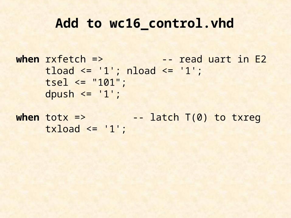
when rxfetch => -- read uart in E2 tload <= '1'; nload <= '1'; tsel <= "101"; dpush <= '1';
when totx => -- latch T(0) to txreg txload <= '1';
Add to wc16_control.vhd
uart_rx
RxD
clrflg rdrf
FE
data_rx(7:0)
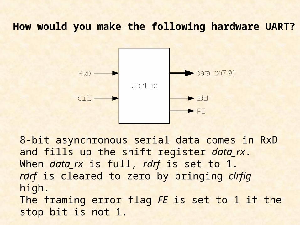
How would you make the following hardware UART?
8-bit asynchronous serial data comes in RxD and fills up the shift register data_rx. When data_rx is full, rdrf is set to 1. rdrf is cleared to zero by bringing clrflg high.The framing error flag FE is set to 1 if the stop bit is not 1.

mark
startstop
delay
shift
RxD
!RxD
baud_count < 0.5 bit time
baud_count < bit time
baud_count >= 0.5 bit time
baud_count < bit timeand
bit_count < 8
baud_count >= bit timeand
bit_count >= 8
UART Receive State Diagram

entity uart_rx is port(
RxD : in STD_LOGIC; clk : in STD_LOGIC; clr : in STD_LOGIC; rdrf_clr : in STD_LOGIC; rdrf : out STD_LOGIC; FE : out STD_LOGIC; rx_data : out STD_LOGIC_VECTOR(7 downto 0)
);end uart_rx;
uart_rxRxD
rdrf_clr
rdrf
FE
rx_data(7:0)
clr
clk

architecture uart_rx of uart_rx istype state_type is (mark, start, delay, shift, stop);signal state: state_type;signal rxbuff: STD_LOGIC_VECTOR (7 downto 0);signal baud_count: STD_LOGIC_VECTOR (11 downto 0);signal bit_count: STD_LOGIC_VECTOR (3 downto 0);signal rdrf_set, fe_set, cclr, cclr8, rxload: STD_LOGIC;constant bit_time: STD_LOGIC_VECTOR (11 downto 0) := X"A28";constant half_bit_time: STD_LOGIC_VECTOR (11 downto 0) := X"514";
begin
9600 baud

uart2: process(clk, clr, rdrf_clr) begin if clr = '1' then
state <= mark;rxbuff <= "00000000";baud_count <= X"000";bit_count <= "0000";FE <= '0';
elsif rdrf_clr = '1' thenrdrf <= '0';
elsif (clk'event and clk = '1') thencase state is
when mark => -- wait for start bit if RxD = '1' then state <= mark; else
baud_count <= X"000"; bit_count <= "0000"; rxbuff <= "00000000"; FE <= '0';
state <= start; -- go to start end if;
mark
startstop
delay
shift
RxD
!RxD
baud_count < 0.5 bit time
baud_count < bit time
baud_count >= 0.5 bit time
baud_count < bit timeand
bit_count < 8
baud_count >= bit timeand
bit_count >= 8

when start => -- check for start bit if baud_count >= half_bit_time then
baud_count <= X"000"; state <= delay;
else baud_count <= baud_count + 1;
state <= start; end if; when delay => if baud_count >= bit_time then
baud_count <= X"000";if bit_count < 8 then state <= shift;else
state <= stop; end if;
else baud_count <= baud_count + 1;
state <= delay; end if;
mark
startstop
delay
shift
RxD
!RxD
baud_count < 0.5 bit time
baud_count < bit time
baud_count >= 0.5 bit time
baud_count < bit timeand
bit_count < 8
baud_count >= bit timeand
bit_count >= 8

when shift => -- get next bit rxbuff(7) <= RxD; rxbuff(6 downto 0) <= rxbuff(7 downto 1); bit_count <= bit_count + 1; state <= delay;
when stop => rdrf <= '1'; if RxD = '0' then
FE <= '1'; else
FE <= '0'; end if;
state <= mark; end case; end if;end process uart2; rx_data <= rxbuff; end uart_rx;
mark
startstop
delay
shift
RxD
!RxD
baud_count < 0.5 bit time
baud_count < bit time
baud_count >= 0.5 bit time
baud_count < bit timeand
bit_count < 8
baud_count >= bit timeand
bit_count >= 8
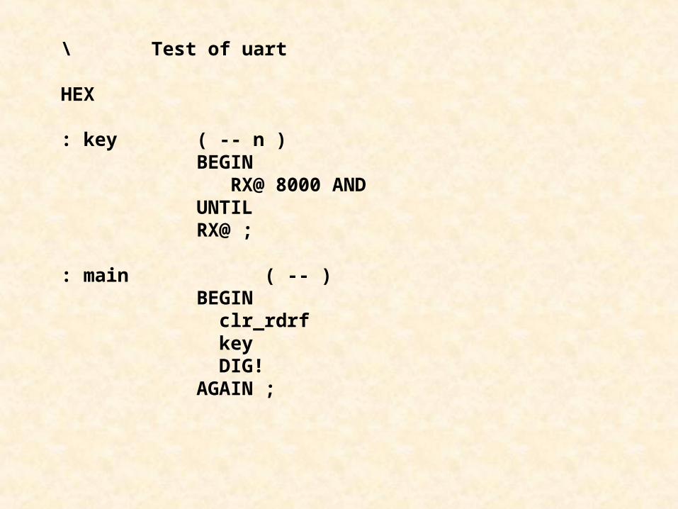
\ Test of uart
HEX
: key ( -- n )BEGIN RX@ 8000 ANDUNTILRX@ ;
: main ( -- )BEGIN clr_rdrf key DIG!AGAIN ;
Related Documents