RPWM Based Four Switch Three Phase Inverter Fed Induction Motor Drive with Model Predictive Controller Abstract: The aim of this paper is to design and analyze Four Switch Three Phase Inverter (FSTPI) for induction motor drive. In this approach, instead of conventional 6-switch, 3- phase (SSTP) PWM inverter, a 4-switch, 3-phase inverter (FSTP) is utilized. This reduces both the cost of the inverter and the computation for real-time implementation. The advantage of this Four Switch Three Phase inverter is lesser switching losses, lower electromagnetic interference (EMI), less complexity of control algorithm and reduced interface circuits. A low cost of motor drive is the more advantageous factor that can be achieved using the proposed drive system. A simulation model of the drive system is developed and analyzed in order to verify the effectiveness of the approach. Further more in this project Sinusoidal Pulse Width Modulation (SPWM) and Random Pulse Width Modulation techniques are being compared. These techniques are used to generate their respective output PWM signals, which are then compared, based on harmonic content and distortion using the THD measure of various output voltages. In the present work, we propose a study of RPWM technique in a drive system based on a Four Switch Three-Phase inverter, feeding an induction motor. RPWM provide better responses when compared with the conventional PWM Techniques. Random Pulse Width Modulation (RPWM) approach can make the harmonic spectrum of inverter output voltage to be continuously distributed without affecting the fundamental frequency component. The control strategy of the proposed drive system of three phase induction motor is based on Model Predictive Control technique. Simulation results are carried out in Matlab/Simulink to analyze and explore the characteristics of the proposed drive system. Keywords: Induction motor, Four Switch Three Phase Inverter, Pulse Width Modulation (PWM), Sinusoidal PWM, Random PWM, Total Harmonic Distortion (THD) and Model Predictive Control technique. Muthunagai. R PG Student, Sri Manakula Vinayagar Engineering College, Madagadipet Raja. D Assistant Professor, EEE Department, Sri Manakula Vinayagar Engineering College, Madagadipet ISSN 2319-9725

Welcome message from author
This document is posted to help you gain knowledge. Please leave a comment to let me know what you think about it! Share it to your friends and learn new things together.
Transcript
RPWM Based Four Switch Three Phase Inverter Fed
Induction Motor Drive with Model Predictive
Controller
Abstract: The aim of this paper is to design and analyze Four Switch Three Phase Inverter (FSTPI)
for induction motor drive. In this approach, instead of conventional 6-switch, 3- phase (SSTP) PWM
inverter, a 4-switch, 3-phase inverter (FSTP) is utilized. This reduces both the cost of the inverter
and the computation for real-time implementation. The advantage of this Four Switch Three Phase
inverter is lesser switching losses, lower electromagnetic interference (EMI), less complexity of
control algorithm and reduced interface circuits. A low cost of motor drive is the more advantageous
factor that can be achieved using the proposed drive system. A simulation model of the drive system
is developed and analyzed in order to verify the effectiveness of the approach. Further more in this
project Sinusoidal Pulse Width Modulation (SPWM) and Random Pulse Width Modulation
techniques are being compared. These techniques are used to generate their respective output PWM
signals, which are then compared, based on harmonic content and distortion using the THD
measure of various output voltages. In the present work, we propose a study of RPWM technique in
a drive system based on a Four Switch Three-Phase inverter, feeding an induction motor. RPWM
provide better responses when compared with the conventional PWM Techniques. Random Pulse
Width Modulation (RPWM) approach can make the harmonic spectrum of inverter output voltage to
be continuously distributed without affecting the fundamental frequency component. The control
strategy of the proposed drive system of three phase induction motor is based on Model Predictive
Control technique. Simulation results are carried out in Matlab/Simulink to analyze and explore the
characteristics of the proposed drive system.
Keywords: Induction motor, Four Switch Three Phase Inverter, Pulse Width Modulation (PWM),
Sinusoidal PWM, Random PWM, Total Harmonic Distortion (THD) and Model Predictive Control
technique.
Muthunagai. R
PG Student, Sri Manakula Vinayagar Engineering College,
Madagadipet
Raja. D
Assistant Professor, EEE Department, Sri Manakula Vinayagar
Engineering College, Madagadipet
ISSN 2319-9725

May, 2014 www.ijirs.com Vol3 Issue 5
International Journal of Innovative Research and Studies Page 440
1. Introduction:
Induction motor has been considered as the work-house of various industries because of its
very wide industrial applications and well known advantages such as simplicity and
robustness. In recent years, the industries are focusing on the low cost ac drives to meet the
need for reducing the cost particularly when power demanded by the target application is
within the low power range. Also in rural electric systems and in remote areas, the cost of
bringing three phase power is often high due to high cost of three phase extension. Moreover
the rate structure of three phase service is higher when compared to single phase service. For
these above mentioned criteria, a cost effective drive has to be designed. The low cost could
be gained by reducing the power switches in the inverter feeding the electric motor.
A variable speed motor with wide speed range offers the designer to get better operating
features. This can be obtained by the using three phase motor, which is readily available.
Therefore, the use single to three phase converter is best suited for these situations where
three phase power is not available. Researchers have investigated different methods including
static phase converter, rotary phase converters, reduced topology power electronic converters
& novel motor designs [1-4]. The components reduction is possible by making alternatives to
the conventional three phase bridge configuration for a voltage fed inverter, since this circuit
utilizes six switching devices and six reactive power diodes. This leads to a bridge circuit
with only four switching devices and four reactive power diodes. It has been demonstrated
that a two-level current control can be implemented to yield quasi sinusoidal currents in the
three phase load [5,6]. The variable speed ac motor drive utilizes three phase (SSTP)
inverters with high speed power semiconductor devices. Traditionally these inverters (SSTPI)
have been widely used for drives but they have some major drawbacks which include the
switching losses, complex control algorithm and on board interfacing circuits to generate six
PWM signals. This can be overcome through the reduction in topology of the inverter in the
armature which has two legs (four switches) instead of three legs (six switches) in
conventional inverters.
In this paper a Four Switch Three Phase Inverter for a cost-effective induction motor drive is
developed. The overall drive system employs only six IGBT transistors for the rectifier and
inverter structure. The Four Switch Three Phase (FSTP) inverter has the following
advantageous factors over the traditional Six Switch Three Phase (SSTP) inverter, they are
i. switching loss minimization,
May, 2014 www.ijirs.com Vol3 Issue 5
International Journal of Innovative Research and Studies Page 441
ii. reduced count of interface circuits to provide logic signals,
iii. ease of control algorithm to generate logic commands,
iv. the chances of destroying the switches because of reduced interaction between
switches get minimized and
v. for real time application, the computational burden are reduced.
The past research works on FSTP inverter for induction motor drive did not paid much
attention for closed loop control using Model Predictive Control (MPC) technique. In this
paper, the proposed approach consists of FSTP inverter fed induction motor drive with MPC
technique. The paper is organized as stated below: In the first section, the Four Switch Three
Phase (FSTP) inverter topology is described. Next the analysis and comparison of different
switching strategies namely SPWM & RPWM for FSTP inverter are presented. Taking into
account the comparison results on THD basis, the control strategy with MPC technique is
being implemented. Finally the paper presents FSTP inverter fed induction motor drive
system incorporating the Model Predictive Control Technique. The simulation results are
carried out using Matlab/ Simulink to explore the performance characteristics of the low cost
drive.
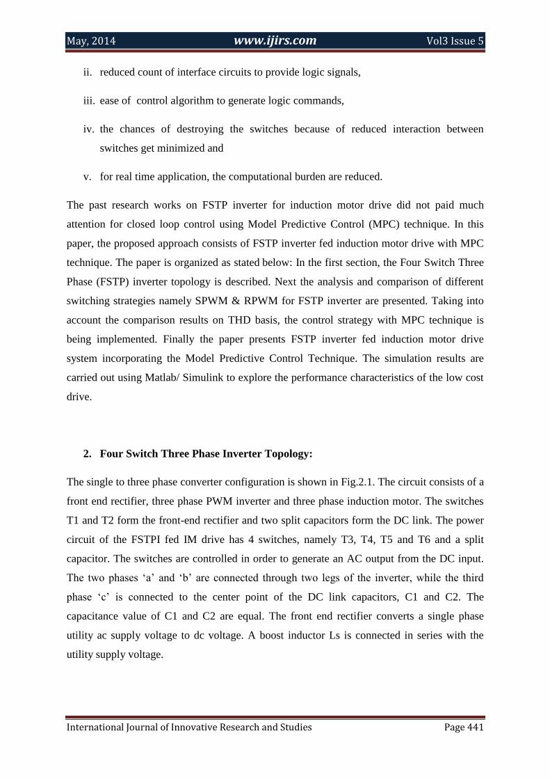
2. Four Switch Three Phase Inverter Topology:
The single to three phase converter configuration is shown in Fig.2.1. The circuit consists of a
front end rectifier, three phase PWM inverter and three phase induction motor. The switches
T1 and T2 form the front-end rectifier and two split capacitors form the DC link. The power
circuit of the FSTPI fed IM drive has 4 switches, namely T3, T4, T5 and T6 and a split
capacitor. The switches are controlled in order to generate an AC output from the DC input.
The two phases ‘a’ and ‘b’ are connected through two legs of the inverter, while the third
phase ‘c’ is connected to the center point of the DC link capacitors, C1 and C2. The
capacitance value of C1 and C2 are equal. The front end rectifier converts a single phase
utility ac supply voltage to dc voltage. A boost inductor Ls is connected in series with the
utility supply voltage.

May, 2014 www.ijirs.com Vol3 Issue 5
International Journal of Innovative Research and Studies Page 442
Figure 1
It is assumed that the 4-power switches are denoted by the binary variables S1 to S4. The
binary ‘1’ corresponds to an ON state and the binary ‘0’ corresponds to an OFF state. The
states of the upper (S1, S2) and lower (S3, S4) switches of a leg are complementary that is S3
= 1 − S1 and S4 = 1 − S2. Considering a 3-phase Y-connected Induction Motor, the terminal
voltages.
Vas, Vbs and Vcs can be expressed as the function of the states of the upper switches as
follows:
Vas = Vc/3 (4S1 − 2S2 − 1) (2.1)
Vbs = Vc/3 (−2S1 + 4S2 − 1) (2.2)
Vcs = Vc/3 (−2S1 − 2S2 + 2) (2.3)
where, Vas, Vbs, Vcs are the inverter output phase voltages. ‘Vc’ is the voltage across the
DC link capacitors. ‘Vdc’ is the voltage across the capacitor C1 and C2 (Vdc = Vc/2). S1, S2
are taken as the switching functions for the 2-switches. In matrix form the above equations
can be written as:
[
]
(
) [ ]
[ ]
May, 2014 www.ijirs.com Vol3 Issue 5
International Journal of Innovative Research and Studies Page 443
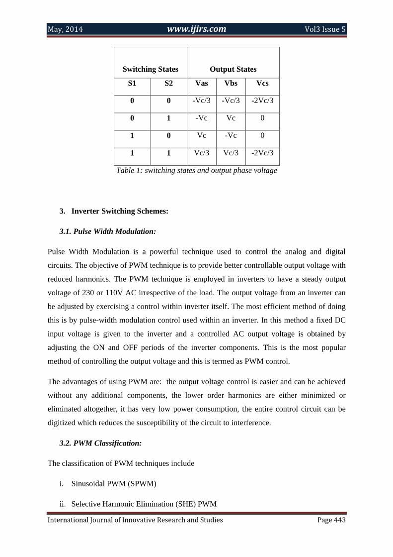
Switching States
Output States
S1 S2 Vas Vbs Vcs
0 0 -Vc/3 -Vc/3 -2Vc/3
0 1 -Vc Vc 0
1 0 Vc -Vc 0
1 1 Vc/3 Vc/3 -2Vc/3
Table 1: switching states and output phase voltage
3. Inverter Switching Schemes:
3.1. Pulse Width Modulation:
Pulse Width Modulation is a powerful technique used to control the analog and digital
circuits. The objective of PWM technique is to provide better controllable output voltage with
reduced harmonics. The PWM technique is employed in inverters to have a steady output
voltage of 230 or 110V AC irrespective of the load. The output voltage from an inverter can
be adjusted by exercising a control within inverter itself. The most efficient method of doing
this is by pulse-width modulation control used within an inverter. In this method a fixed DC
input voltage is given to the inverter and a controlled AC output voltage is obtained by
adjusting the ON and OFF periods of the inverter components. This is the most popular
method of controlling the output voltage and this is termed as PWM control.
The advantages of using PWM are: the output voltage control is easier and can be achieved
without any additional components, the lower order harmonics are either minimized or
eliminated altogether, it has very low power consumption, the entire control circuit can be
digitized which reduces the susceptibility of the circuit to interference.
3.2. PWM Classification:
The classification of PWM techniques include
i. Sinusoidal PWM (SPWM)
ii. Selective Harmonic Elimination (SHE) PWM

May, 2014 www.ijirs.com Vol3 Issue 5
International Journal of Innovative Research and Studies Page 444
iii. Minimum Ripple Current PWM
iv. Space Vector Pulse Width Modulation (SVPWM)
v. Random Pulse Width Modulation (RPWM)
vi. Hysteresis band current control PWM
vii. Sinusoidal PWM with instantaneous current control
There are several techniques to vary the inverter gain. The efficient method of controlling the
gain (and output voltage) is to incorporate pulse width modulation (PWM) control within the
inverters. The commonly used techniques are sinusoidal and space vector pulse width
modulation, but the emerging technique is the Random Pulse Width Modulation. To
overcome the drawbacks of more acoustical noise and more harmonic distortion at higher
modulation indices, this work is focused on the Random Pulse Width Modulation (RPWM)
technique. In this paper a comparative study is performed on SPWM & RPWM based FSTP
inverter feeding an induction motor drive.
3.3. Sinusoidal and Random Pulse Width Modulation (SPWM & RPWM):
The random pulse width modulation (RPWM) has become an established means of mitigation
of undesirable side effects in PWM converters, the voltage source inverters in adjustable
speed ac drives in particular. Randomizing the switching frequency has been found to be the
most effective method of RPWM. Fig 3.1 depicts the randomization procedure in the sine-
triangle PWM where successive triangular waveform period lengths are varied pseudo-
randomly.
Figure 2: Random sine-Triangle PWM
In converters with fixed switching frequency, the power is concentrated in discrete harmonics
of the output voltage. In contrast to that, in converters with randomly varying switching
frequency, the harmonic power is transferred to the continuous spectrum. RPWM is provided
in the following manner. The method begins by determining a switching period randomly for
May, 2014 www.ijirs.com Vol3 Issue 5
International Journal of Innovative Research and Studies Page 445
a switching cycle subsequent to a current sampling cycle. The method then determines a
switching pattern from a reference voltage generated from signals detected and processed in
the current sampling cycle. Switching signals are then generated to make a specific switching
pattern. The switching signals are then transmitted to switches of the converter during the
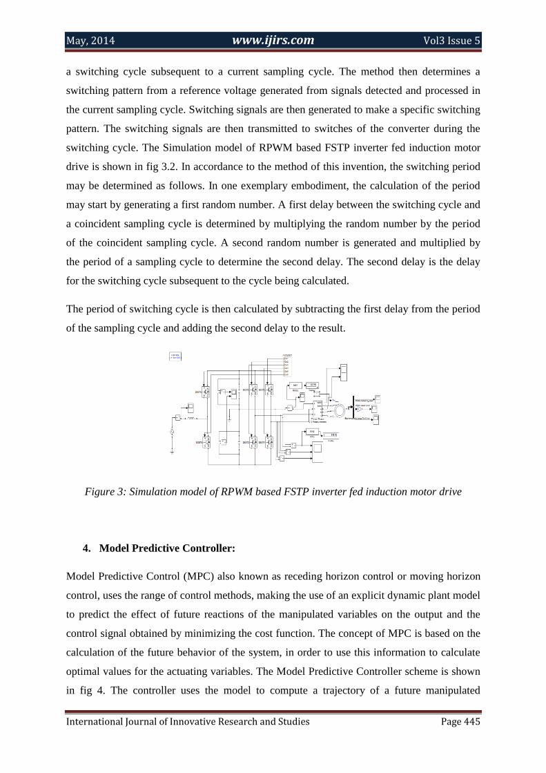
switching cycle. The Simulation model of RPWM based FSTP inverter fed induction motor
drive is shown in fig 3.2. In accordance to the method of this invention, the switching period
may be determined as follows. In one exemplary embodiment, the calculation of the period
may start by generating a first random number. A first delay between the switching cycle and
a coincident sampling cycle is determined by multiplying the random number by the period
of the coincident sampling cycle. A second random number is generated and multiplied by
the period of a sampling cycle to determine the second delay. The second delay is the delay
for the switching cycle subsequent to the cycle being calculated.
The period of switching cycle is then calculated by subtracting the first delay from the period
of the sampling cycle and adding the second delay to the result.
Figure 3: Simulation model of RPWM based FSTP inverter fed induction motor drive
4. Model Predictive Controller:
Model Predictive Control (MPC) also known as receding horizon control or moving horizon
control, uses the range of control methods, making the use of an explicit dynamic plant model
to predict the effect of future reactions of the manipulated variables on the output and the
control signal obtained by minimizing the cost function. The concept of MPC is based on the
calculation of the future behavior of the system, in order to use this information to calculate
optimal values for the actuating variables. The Model Predictive Controller scheme is shown
in fig 4. The controller uses the model to compute a trajectory of a future manipulated
May, 2014 www.ijirs.com Vol3 Issue 5
International Journal of Innovative Research and Studies Page 446
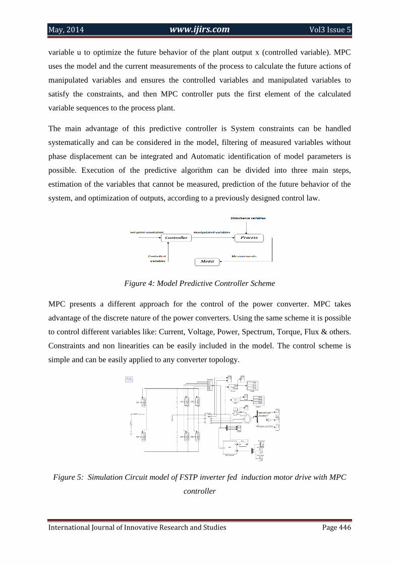
variable u to optimize the future behavior of the plant output x (controlled variable). MPC
uses the model and the current measurements of the process to calculate the future actions of
manipulated variables and ensures the controlled variables and manipulated variables to
satisfy the constraints, and then MPC controller puts the first element of the calculated
variable sequences to the process plant.
The main advantage of this predictive controller is System constraints can be handled
systematically and can be considered in the model, filtering of measured variables without
phase displacement can be integrated and Automatic identification of model parameters is
possible. Execution of the predictive algorithm can be divided into three main steps,
estimation of the variables that cannot be measured, prediction of the future behavior of the
system, and optimization of outputs, according to a previously designed control law.
Figure 4: Model Predictive Controller Scheme
MPC presents a different approach for the control of the power converter. MPC takes
advantage of the discrete nature of the power converters. Using the same scheme it is possible
to control different variables like: Current, Voltage, Power, Spectrum, Torque, Flux & others.
Constraints and non linearities can be easily included in the model. The control scheme is
simple and can be easily applied to any converter topology.
Figure 5: Simulation Circuit model of FSTP inverter fed induction motor drive with MPC
controller

May, 2014 www.ijirs.com Vol3 Issue 5
International Journal of Innovative Research and Studies Page 447
The simulation circuit model of FSTP inverter fed induction motor drive with MPC controller
is shown in Fig 5. For motor drive applications, the measured variables is w, and a
mathematical model of the machine are used to estimate the variables that cannot be
measured such as the rotor & stator flux. Then the same model is used to predict the future
behaviur of the variables for every control action. Finally, the voltage vector that produces
the optimum reference tracking is selected as the switching state for the next sampling step.
The model of the machine is the most important part of the controller, because both
estimations & predictions depend on it.
5. Simulation Results And Discussion:
A computer simulation model has been developed in MATLAB/ Simulink Software to test
the proposed RPWM technique. Weighted Total Harmonic Distortion is used to evaluate the
performance of the FSTPI fed induction motor drive system.
Figure 6: Input Current Waveform of RPWM based FSTPI
Figure 7: Pulse pattern Waveform of RPWM based FSTPI
May, 2014 www.ijirs.com Vol3 Issue 5
International Journal of Innovative Research and Studies Page 448
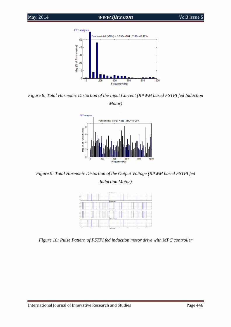
Figure 8: Total Harmonic Distortion of the Input Current (RPWM based FSTPI fed Induction
Motor)
Figure 9: Total Harmonic Distortion of the Output Voltage (RPWM based FSTPI fed
Induction Motor)
Figure 10: Pulse Pattern of FSTPI fed induction motor drive with MPC controller
May, 2014 www.ijirs.com Vol3 Issue 5
International Journal of Innovative Research and Studies Page 449
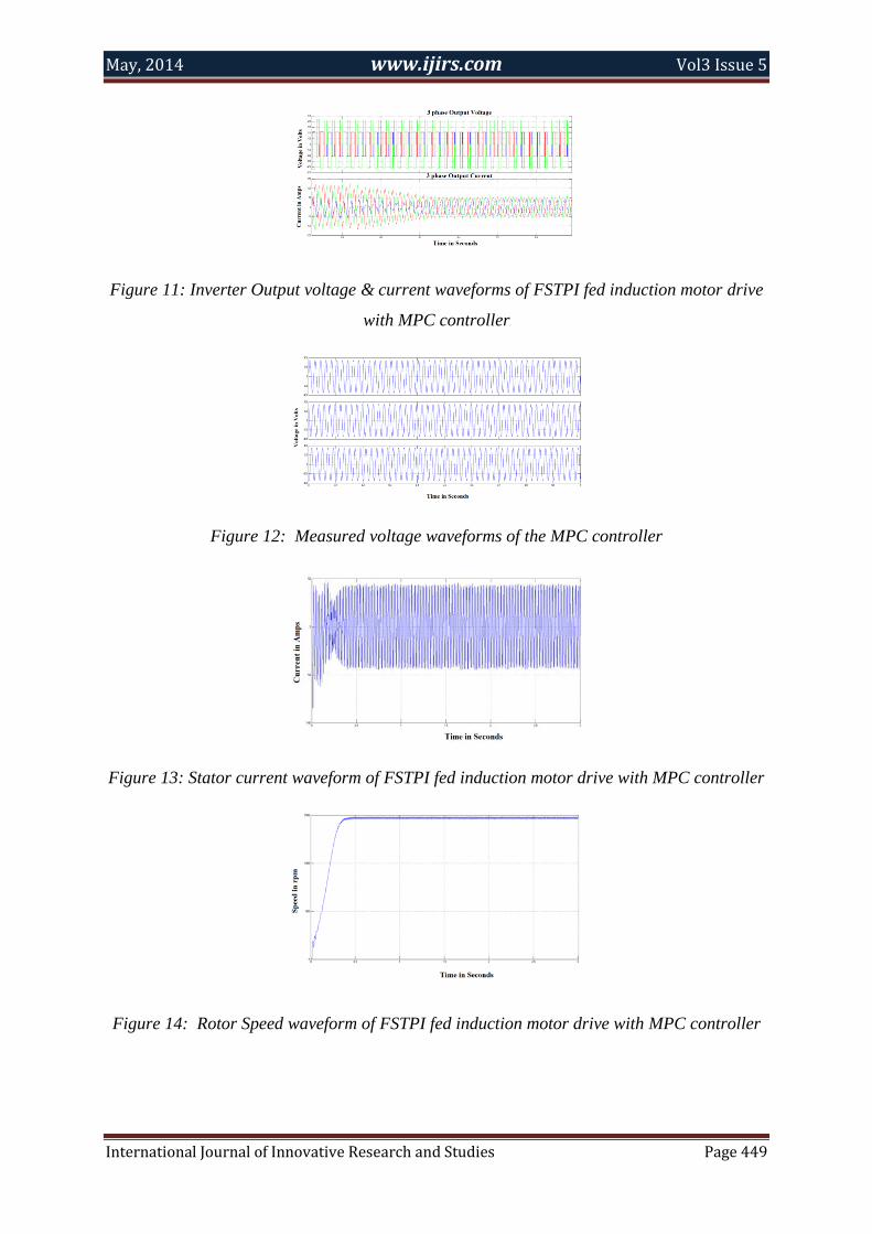
Figure 11: Inverter Output voltage & current waveforms of FSTPI fed induction motor drive
with MPC controller
Figure 12: Measured voltage waveforms of the MPC controller
Figure 13: Stator current waveform of FSTPI fed induction motor drive with MPC controller
Figure 14: Rotor Speed waveform of FSTPI fed induction motor drive with MPC controller
May, 2014 www.ijirs.com Vol3 Issue 5
International Journal of Innovative Research and Studies Page 450
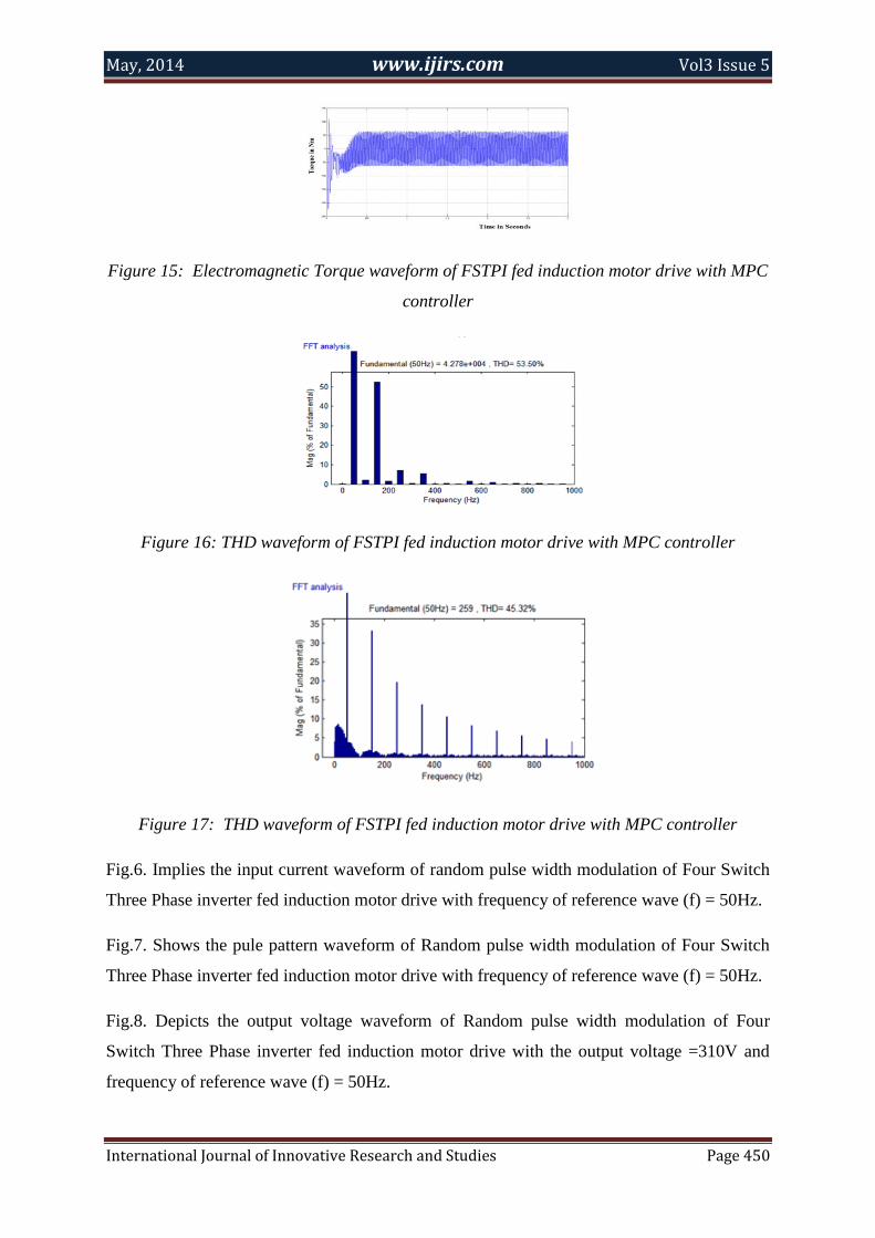
Figure 15: Electromagnetic Torque waveform of FSTPI fed induction motor drive with MPC
controller
Figure 16: THD waveform of FSTPI fed induction motor drive with MPC controller
Figure 17: THD waveform of FSTPI fed induction motor drive with MPC controller
Fig.6. Implies the input current waveform of random pulse width modulation of Four Switch
Three Phase inverter fed induction motor drive with frequency of reference wave (f) = 50Hz.
Fig.7. Shows the pule pattern waveform of Random pulse width modulation of Four Switch
Three Phase inverter fed induction motor drive with frequency of reference wave (f) = 50Hz.
Fig.8. Depicts the output voltage waveform of Random pulse width modulation of Four
Switch Three Phase inverter fed induction motor drive with the output voltage =310V and
frequency of reference wave (f) = 50Hz.

May, 2014 www.ijirs.com Vol3 Issue 5
International Journal of Innovative Research and Studies Page 451
Fig.9. Illustrates the Total Harmonic Distortion response of the input current waveform
obtained by Random Pulse Width Modulation based Four Switch Three Phase Inverter fed
Induction Motor.
Fig.10. Depicts the Total Harmonic Distortion response of the output voltage waveform
obtained by Random Pulse Width Modulation based Four Switch Three Phase Inverter fed
Induction Motor.
Fig.11. Indicates the Pulse Pattern of Four Switch Three Phase Inverter fed induction motor
drive with Model based Predictive Current controller.
Fig.12. Shows the inverter Output voltage & current waveforms of FSTPI fed induction
motor drive with MPC controller.
Fig.13. points the measured voltage waveform obtained from the controller.
Fig.14. Depicts the stator current waveform of Four Switch Three Phase inverter fed
induction motor drive with MPC controller at a rated power of 1.1 KW.
Fig.15. Illustrates the rotor speed waveform of Four Switch Three Phase inverter fed
induction motor drive with MPC controller at a rated power of 1.1 KW
Fig.16. Depicts the simulation result of the electromagnetic torque waveform of four switch
three phase inverter fed induction motor drive with model based predictive controller.
Fig.17. Indicates the Total harmonic distortion response the input current waveform obtained
from Four Switch Three Phase Inverter fed induction motor drive with Model based
Predictive Current controller. The %THD obtained is 53.50
Fig.18. Indicates the Total harmonic distortion response of the output voltage waveform
obtained from Four Switch Three Phase Inverter fed induction motor drive with Model based
Predictive Current controller. The %THD obtained is 45.32
May, 2014 www.ijirs.com Vol3 Issue 5
International Journal of Innovative Research and Studies Page 452
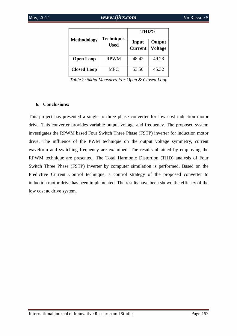
Methodology Techniques
Used
THD%
Input
Current
Output
Voltage
Open Loop RPWM 48.42 49.28
Closed Loop MPC 53.50 45.32
Table 2: %thd Measures For Open & Closed Loop
6. Conclusions:
This project has presented a single to three phase converter for low cost induction motor
drive. This converter provides variable output voltage and frequency. The proposed system
investigates the RPWM based Four Switch Three Phase (FSTP) inverter for induction motor
drive. The influence of the PWM technique on the output voltage symmetry, current
waveform and switching frequency are examined. The results obtained by employing the
RPWM technique are presented. The Total Harmonic Distortion (THD) analysis of Four
Switch Three Phase (FSTP) inverter by computer simulation is performed. Based on the
Predictive Current Control technique, a control strategy of the proposed converter to
induction motor drive has been implemented. The results have been shown the efficacy of the
low cost ac drive system.

May, 2014 www.ijirs.com Vol3 Issue 5
International Journal of Innovative Research and Studies Page 453
References:
1. Jin-Su Jang, Byoung-Gun Park, Tae-Sung Kim, Dong Myung Lee, Dong-Seok Hyun,
Sensorless control of four-switch three phase PMSM drive using extended Kalman
filter, industrial electronics, IECON 2008, in: 34th Annual Conference of IEEE, pp.
1368–1372.
2. M.N. Uddin, T.S. Radwan, M.A. Rahman, Performance analysis of a 4-switch, 3-
phase inverter based cost effective IPM motor drives, in: Canadian Conference on
Electrical and Computer Engineering, 2004, pp. 85–88.
3. C.B. Jacobina, E.R.C. da Silva, A.M.N. Lima, R.L.A. Ribeiro, Vector and scalar
control of a four switch three phase inverter, in: Conference on Rec., IEEE-IAS Annu.
Meeting, 1995, pp. 2422–2429.
4. C.B. Jacobina, M.B. de Rossiter Correa, E.R.C. da Silva, A.M.N. Lima, A general
PWM strategy for four-switch three phase inverters, IEEE Trans. Energy Convers. 21
(4) (Dec. 2006) 832–838.
5. J. Klima, Analytical investigation of an induction motor fed from four-switch VSI
with a new space vector modulation strategy, IEEE Trans. Power Electron 21 (6)
(2006), 1618–1617.
6. J.T. Boys, A.W. Green, Current forced single – phase reversible rectifier, in: IEE
Proceeding, vol. 136, Pt. B. no. 5, September 1989.
7. [8] Nalin Kant Mohanty, Ranganath Muthu, Microcontroller based PWM controlled
four switch three Phase inverter fed induction motor drive Serbian, J. Electric. Eng. 7
(2) (2010) 195– 204.
8. Chul-Woo Park, Woo-Hyen Kwon, Simple and robust speed sensorless vector control
of induction motor using stator current based MRAC, Electric Power Syst. Res. 71
(2004) 257–266.
9. RASHID M.H, ‘Power electronics: circuits, devices and applications’ prentice- Hall,
USA, 1993, 2nd
edn.).
Related Documents