RELM Wireless Corporation Rev. 01-03 RPV599A Owner’s Manual

Welcome message from author
This document is posted to help you gain knowledge. Please leave a comment to let me know what you think about it! Share it to your friends and learn new things together.
Transcript

RELM Wireless Corporation Rev. 01-03
RPV599A Owner’s Manual
THANK YOU
Thank you for your purchase of the RELM two-way portable radio. This
easy-to-use radio adopts the latest advanced technology, providing reliable
communication performance in today’s demanding communications
environment.
Before operating this radio, please read this manual carefully to be
acquainted with its operation and features.
RELM Communications, Inc.
CONTENTS User Safety, Training, and General Information ............................................................................... 4 Compliance with RF Energy Exposure Standards ............................................................................ 4 FCC Compliance................................................................................................................................ 5 Precautions ......................................................................................................................................... 5 Supplied Accessories ......................................................................................................................... 7 Charging The Battery......................................................................................................................... 7
Installing/Removing Accessories .................................................................................... 8
Battery ................................................................................................................................................ 8 Unit with belt clip .............................................................................................................................. 8 Antenna .............................................................................................................................................. 8 External Speaker Microphone ........................................................................................................... 8 Belt Clip ............................................................................................................................................. 9
Radio Controls ........................................................................................................................... 9
LCD Icons ........................................................................................................................................ 11
Features and Operation........................................................................................................12
POWER............................................................................................................................................12 VOLUME.........................................................................................................................................12 MONITOR .......................................................................................................................................12 SELECT CHANNEL.......................................................................................................................12 SELECT SQUELCH LEVEL..........................................................................................................12 RECEIVE.........................................................................................................................................13 TRANSMIT .....................................................................................................................................13 SELECT TRANSMIT POWER ......................................................................................................13 CONNECT ID/DISCONNECT ID .................................................................................................13 CHANNEL SCAN...........................................................................................................................14 FREQUENCY REVERSE/TALK AROUND..............................................................................15 DTMF SELECTIVE CALL ............................................................................................................16 CODE SQUELCH ...........................................................................................................................17 SELECTIVE CALLIING ................................................................................................................18 TWO-TONE SELECTIVE CALL ..................................................................................................18 SELECTABLE CTCSS ...................................................................................................................18 AUTO-RESPONDER......................................................................................................................18 CALL ALERT TONE......................................................................................................................19
Care and Cleaning..................................................................................................................19
Service..........................................................................................................................................19
4 RELM Communications, Inc.
User Safety, Training, and General Information
READ THIS IMPORTANT INFORMATION ON SAFE AND EFFICIENT OPERATION BEFORE USING YOUR RELM HANDHELD PORTABLE TWO-WAY RADIO.
Compliance with RF Energy Exposure Standards
Your RELM two-way radio is designed and tested to comply with a number of national and international standards and guidelines (listed below) regarding human exposure to radio frequency electromagnetic energy. This radio complies with the IEEE (FCC) and ICNIRP exposure limits for occupational/controlled RF exposure environment at duty cycles of up to 50% talk-50% listen and should be used for occupational use only. In terms of measuring RF energy for compliance with the FCC exposure guidelines, your radio radiates measurable RF energy only while it is transmitting (during talking), not when it is receiving (listening) or in standby mode. Note: The approved batteries supplied with this radio are rated for a 5-5-90 duty cycle (5%
talk-5% listen-90% standby), even though this radio complies with the FCC occupational RF exposure limits at duty cycles of up to 50% talk.
Your RELM two-way radio complies with the following RF energy exposure standards and guidelines: • United States Federal Communications Commission, Code of Federal Regulations; 47CFR
part 2 sub-part J
• American National Standards Institute (ANS)/Institute of Electrical and Electronic Engineers (IEEE) C95. 1-1992
• Institute of Electrical and Electronic Engineers (IEEE) C95. 1-1999 Edition • International Commission on Non-Ionizing Radiation Protection (ICNIRP) 1998 • Ministry of Health (Canada) Safety Code 6. Limits of Human Exposure to Radio frequency
Electromagnetic Fields in the Frequency Range from 3kHz to 300GHz, 1999 • Australian Communications Authority Radio communications (Electromagnetic
Radiation-Human Exposure) Standard 1999 (applicable to wireless phones only)
Operational Instructions and Training Guidelines To ensure optimal performance and compliance with the occupational/controlled environment RF energy exposure limits in the above standards and guidelines, users should transmit no more than 50% of the time and always adhere to the following procedures:
Transmit and Receive To transmit (talk), push the Push-To-Talk (PTT) button; to receive, release the PTT button.
Hand-held radio operation Hold the radio in a vertical position with the microphone one to two inches (2.5 to 5 cm) away from the lips.
Body-worn operation • Always place the radio in a RELM approved clip, holder, holster, case, or body harness for
this product. Use of non-RELM-approved accessories may exceed FCC RF exposure

RELM Communications, Inc. 5
guidelines. • If you do not use a RELM approved body-worn accessory and are not using the radio in the
intended use position in front of the face, then ensure the antenna and the radio are kept one inch (2.5 cm) from the body when transmitting.
Antennas & Batteries • Use only RELM approved, supplied antenna or RELM approved replacement antenna.
Unauthorized antennas, modifications, or attachments could damage the radio and may violate FCC regulations.
• Use only RELM approved, supplied batteries or RELM approved replacement batteries. Use of non-RELM-approved batteries may exceed FCC RF exposure guidelines.
Approved Accessories
For a list of RELM approved accessories, see the accessories page of this user manual or visit the following website which lists approved accessories: http://www.RELM.com
FCC Compliance
This equipment has been tested and found to comply with the limits for a Class B digital device, pursuant to part 15 of the FCC Rules. These limits are designed to provide reasonable protection against harmful interference in a residential installation. This equipment generates, uses and can radiate radio frequency energy and, if not installed and used in accordance with the instructions, may cause harmful interference to radio communications. However, there is no guarantee that interference will not occur in a particular installation. If this equipment does cause harmful interference to radio or television reception, which can be determined by turning the equipment off and on, the user is encouraged to try to correct the interference by one or more of the following measures: • Reorient or relocate the receiving antenna. • Increase the separation between the equipment and receiver. • Connect the equipment into an outlet on a circuit different from that to which the receiver is
connected. • Consult the dealer or an experienced radio/TV technician for help.
Industry Canada Compliance This Class B digital apparatus complies with Canadian ICES-003. Cet appareil numerique de la classe B est conforme à la norme NMB-003 Canada.
FCC Requirements Your radio must be properly licensed Federal Communications Commission prior to use. Your RELM Wireless dealer can assist you in meeting these requirements. Your dealer will program each radio with your authorized frequencies, signaling codes, etc., and will be there to meet your communications needs as your system expands.
Precautions
• Only qualified technicians are allowed to maintain this product. • Do not use the transceiver or charge a battery in explosive areas such as coal gas, dust, steam,
etc.

6 RELM Communications, Inc.
• Switch OFF the transceiver while refueling or parking at gas station. • Do not modify or adjust this transceiver without permission. • Do not expose the transceiver to direct sunlight over a long time, nor place it close to heating
source. • Do not place the transceiver in excessively dusty, humid areas, nor on unstable surfaces. Safety: It is important that the operator is aware of and understands hazards common to the operation of any transceiver.

RELM Communications, Inc. 7
Supplied Accessories
Please carefully take the transceiver out of the box. We recommend that you confirm the items listed in the following table before discarding the box. If any items are missing or have been damaged during shipment, file a claim with the carrier immediately.
Item Qty. (pcs)
Antenna 1
Belt clip 1
Screw set 1
External speaker-microphone jack cover 1
Locking bracket for speaker-microphone 1
Battery 1
Charger 1
Warranty card 1
Owner’s Manual 1
Charging The Battery
The factory does not charge the battery before it is shipped It must be charged before being used. Repeat charging and discharging for two or three times to optimize its charging capacity. When the battery voltage becomes low to the point the radio indicates low voltage (flashing led, no display...), the battery should be recharged or replaced with a charged battery.
• Slide the battery pack or transceiver with a battery back into the charger.
• Make sure the battery pack contacts make contact with the charging terminals.
• When the battery begins charging, the status LED is red; and when the battery is fully charged the status LED is green.
8 RELM Communications, Inc.
Installing/Removing Accessories
Battery
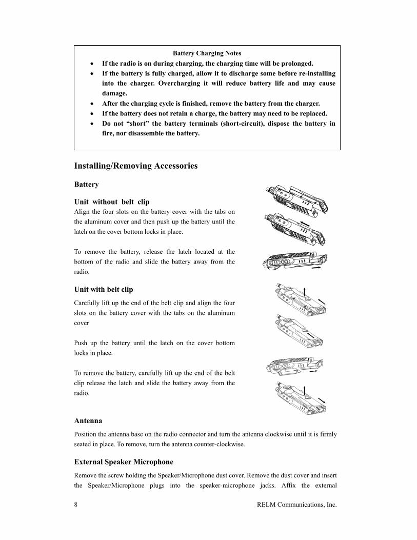
Unit without belt clip Align the four slots on the battery cover with the tabs on the aluminum cover and then push up the battery until the latch on the cover bottom locks in place. To remove the battery, release the latch located at the bottom of the radio and slide the battery away from the radio.
Unit with belt clip
Carefully lift up the end of the belt clip and align the four slots on the battery cover with the tabs on the aluminum cover Push up the battery until the latch on the cover bottom locks in place. To remove the battery, carefully lift up the end of the belt clip release the latch and slide the battery away from the radio.
Antenna
Position the antenna base on the radio connector and turn the antenna clockwise until it is firmly seated in place. To remove, turn the antenna counter-clockwise.
External Speaker Microphone
Remove the screw holding the Speaker/Microphone dust cover. Remove the dust cover and insert the Speaker/Microphone plugs into the speaker-microphone jacks. Affix the external
Battery Charging Notes • If the radio is on during charging, the charging time will be prolonged. • If the battery is fully charged, allow it to discharge some before re-installing
into the charger. Overcharging it will reduce battery life and may cause damage.
• After the charging cycle is finished, remove the battery from the charger. • If the battery does not retain a charge, the battery may need to be replaced. • Do not “short” the battery terminals (short-circuit), dispose the battery in
fire, nor disassemble the battery.
RELM Communications, Inc. 9
speaker-microphone with the retainer clip by using the supplied screw (3mm x 6mm). If the external speaker-microphone is not used, replace the dust cover.
Belt Clip
Using the supplied screws (2 pcs - 3mm x 8mm.), mount the belt clip to mounting holes in the rear case.
Radio Controls
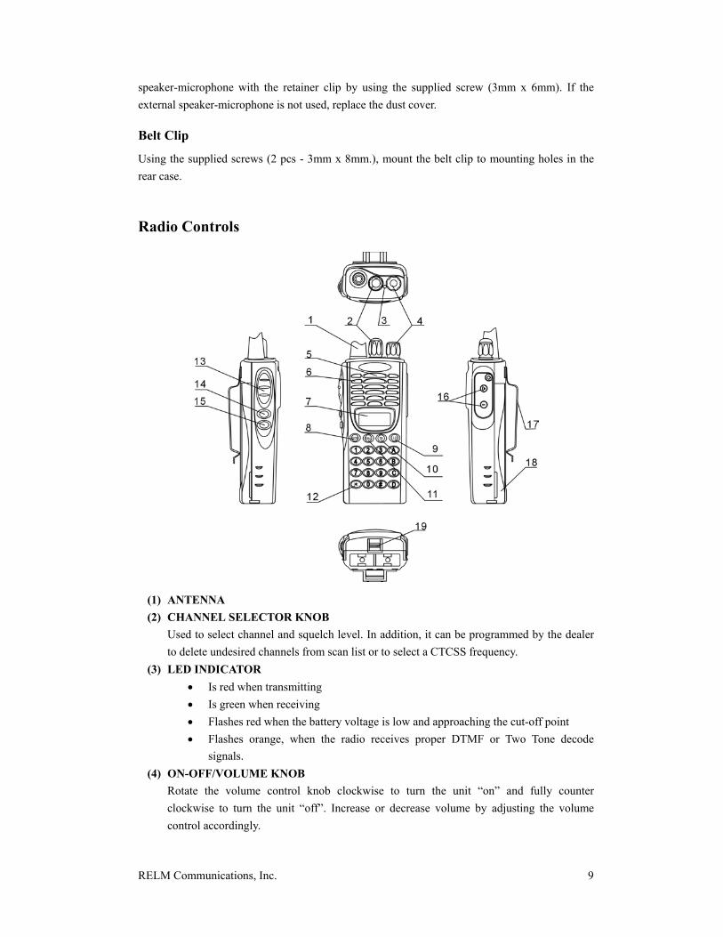
(1) ANTENNA (2) CHANNEL SELECTOR KNOB
Used to select channel and squelch level. In addition, it can be programmed by the dealer to delete undesired channels from scan list or to select a CTCSS frequency.
(3) LED INDICATOR • Is red when transmitting • Is green when receiving • Flashes red when the battery voltage is low and approaching the cut-off point • Flashes orange, when the radio receives proper DTMF or Two Tone decode
signals. (4) ON-OFF/VOLUME KNOB
Rotate the volume control knob clockwise to turn the unit “on” and fully counter clockwise to turn the unit “off”. Increase or decrease volume by adjusting the volume control accordingly.

10 RELM Communications, Inc.
(5) SPEAKER (6) MICROPHONE (7) LCD
Used to display channel and operation status. (8) SCN KEY Used to enable or disable the scan function.
(9) LO (low power) KEY Used to toggle the transmit power mode form “high” to “low” or from “low” to “high”.
(10) TA KEY Used to enable or disable FREQUENCY REVERSE/TALK AROUND feature.
(11) DIAL KEY When the “store and send” feature is enabled, it is used to send codes; and when “auto-dial” feature is enabled, it is used to store, confirm, send or delete codes.
(12) KEYPAD Used to enter, store or send DTMF codes.
(13) PTT BUTTON Used to switch between transmit and receive mode.
(14) LAMP BUTTON Used to turn “on” or “off” the LCD backlight. Press the [LAMP] button, the backlight will illuminate for about 5 seconds and then automatically turn off. During illuminating and pressing any key, except the [LAMP] button, the timer will re-start. To turn “off” the backlight, press the [LAMP] button again. .
(15) MONI BUTTON Used to monitor the selected channels.
(16) EXTERNAL SPEAKER-MICROPHONE JACK Used to connect with external the speaker-microphone, programming cable, or cloning cable.
(17) BELT CLIP (18) BATTERY (19) BATTERY LATCH
RELM Communications, Inc. 11
LCD Icons
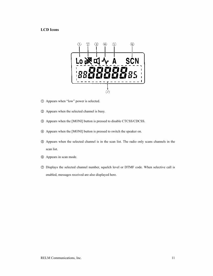
① Appears when “low” power is selected.
② Appears when the selected channel is busy.
③ Appears when the [MONI] button is pressed to disable CTCSS/CDCSS.
④ Appears when the [MONI] button is pressed to switch the speaker on.
⑤ Appears when the selected channel is in the scan list. The radio only scans channels in the
scan list.
⑥ Appears in scan mode.
⑦ Displays the selected channel number, squelch level or DTMF code. When selective call is
enabled, messages received are also displayed here.

12 RELM Communications, Inc.
Features and Operation
POWER
To turn on the power, turn the On-Off/VOL knob clockwise until a “click” is heard (the tone also can be programmed as “beeps”), and characters will be displayed on LCD. To turn off the power, turn the On-Off /VOL knob counterclockwise until a “click” is heard.
VOLUME
Press [MONI] button to monitor background noise, and at the same time turn On-Off/VOL knob to adjust the volume to a comfortable level.
MONITOR
There are four ways the monitor function can be configured. Your dealer can program one of the following four monitor modes:
• OFF – No audio is heard when the momentary monitor key is pressed. • Monitor Momentary – When using any tone mode decode and a receive signal is present
with an incompatible tone or no tone, audio can be heard when the momentary monitor key is pressed.
• Monitor Lock – Same as Monitor Momentary, but the momentary monitor key toggles the audio function “on” or “off”.
• SQ OFF Momentary – Receiver audio is heard when the momentary monitor key is pressed.
SELECT CHANNEL
Turn the channel selector knob to change the channel. The channel number is displayed on LCD. Turn the knob clockwise, channel number will increase; and turn counter clockwise, channel number will decrease. The factory or dealer programs the channel frequencies of each channel.
SELECT SQUELCH LEVEL
Hold down the [MONI] button, and then press the [LO] key. The current squelch level code is displayed on the LCD as shown below. Turn the CHANNEL SELECTOR knob to select the squelch level and press any key, except the [LAMP] button, to store the setting. The LCD returns to the origin display. Note: If the squelch level is set too high, you may not efficiently receive weak signals; if the
level is set too low, you may hear a constant white noise, hear a sputtering noise, or hear unwanted noises.
RELM Communications, Inc. 13
RECEIVE
CTCSS /CDCSS/ DTMF/Two-Tone functions are programmed by the factory or your dealer. When signaling tones have been programmed, only channels with the same frequency and signaling tones can be heard. If tone signaling is not used, then all conversations on your selected channel can be heard.
TRANSMIT
Before transmitting, verify there is no channel activity. Push the PTT button and speak clearly into the microphone (mouth is 1 – 2 inches away from the microphone); or push a key on the keypad to transmit a DTMF tone. When the PTT button is released, the radio returns to receive mode. NOTE:
• If your dealer has enabled Busy Channel Lockout feature and the selected channel is busy, when pressing the [PTT] button, the radio will sound an alert tone and the transmission is prohibited.
• When pressing the [PTT] button, the radio will check its battery voltage. If the battery voltage is lower than the “low battery” threshold value, the red LED flashes. If the voltages drops further, the radio stops transmitting and an alert sounds. In this condition, recharge or replace the battery with a charged battery.
• When continuous transmission time exceeds the preset time of the “Time-Out-Timer” (programmed by the dealer), the radio stops transmission and an alert sounds. The unit then returns to the receive mode. Also, a “Transmit Warning” alert tone can be programmed by the dealer to warn the end user that the transmission time is becoming long.
SELECT TRANSMIT POWER
If transmit power (programmed by the dealer) is set to “high” on any given channel, pressing the [LO] key will toggle the transmit power modes between “high” and “low”. When in low power mode, “Lo”appears on the LCD. Since using low transmit power mode can save battery life and decreases potential interference to others, low transmit power mode should be selected when the communication quality can be guaranteed. NOTE: • If “high” transmit power is prohibited on the current channel and “Lo” is displayed on
LCD, when pressing [LO], an alert tone of wrong operation will be heard and the transmit power will remain “low”.
• The operation of switching a channel from “high” transmit power mode to “low” transmit power mode will switch all channels from “high” transmit power mode to “low“ transmit power mode.
CONNECT ID/DISCONNECT ID
When the radio is connecting or disconnecting to a repeater, a connect ID or disconnect ID (programmed by your dealer) can be sent. One of the following methods can be configured: To transmit a connect ID:

14 RELM Communications, Inc.
• Method 1: Press the [PTT] button, the connect ID is transmitted. • Method 2: While pressing the [PTT] button, press the [DIAL] key and then the [*] key,
the connect ID is transmitted. To transmit a disconnect ID: • Method 1: Release the [PTT] button, the disconnect ID is transmitted. • Method 2: While pressing the [PTT] button, press the [DIAL] key and then the [*] key,
the disconnect ID is transmitted.
CHANNEL SCAN
Press [SCN], the radio begins scanning in ascending order from the current channel and “SCAN” appears on the LCD. To stop scanning, press [SCN] again.
■ SCAN OPERATION
When the radio stops on a busy channel, the scan function can be restarted according to the restart mode, which can be programmed by the dealer as carrier-operated scan or time-operated scan.
• Carrier Operate – Scan stops on a receiving channel until there is no activity;
while inactive, the unit remains on the channel for the predetermined “Dropout Delay Time” (programmed by the dealer) before it resumes scanning.
• Time Operate – Scan stops on the receiving channel for only the predetermined “Dropout Delay Time” (programmed by the dealer) before it resumes scanning. The radio will begin scanning other channels even if the channel is still busy.
■ PRIORITY SCAN
If your dealer has programmed a priority channel, the radio will periodically sample the priority channel when it scans non-priority channels. When it detects any activity on the priority channel, the radio switches to the priority channel. When a priority channel is selected, “P” appears on the LCD.
■ CHANNEL DELETE
This feature allows you to delete undesired channels from the scan list. Select the channels to be deleted by using the channel selector knob in the non-scan mode. Holding down the [MONI] button and pressing the [SCN] key will toggle the selected channel between ADD and DELETE.
When the current channel is in scan list, “A” is displayed on the LCD. DELETE ADD
■ SCAN REVERT CHANNEL
The “Scan Revert Channel” feature (programmed by the dealer) allows you to transmit on a

RELM Communications, Inc. 15
predetermined channel while responding to or initiating a call while in the scan mode. When pressing the [PTT] button, the radio stops scanning and transmits on the “revert” channel.
FREQUENCY REVERSE/TALK AROUND
Your dealer can program the “Frequency Reverse” or “Talk Around” feature. If communications between radios are disrupted because of a long distance from the repeater, frequency reverse feature can be used to re-establish communications to another radio. When the “frequency reverse” feature is enabled, the transmit frequency and receive frequency will be reversed. At the same time, the corresponding CTCSS/CDCSS encode and decode tones will also be reversed. To enable or disable the “Frequency Reverse” feature, press the [TA] key.

16 RELM Communications, Inc.
Enable Disable If “Talk Around” is programmed, the TX frequency can be changed to be the same as the RX frequency. The CTCSS/CDCSS encode and decode tones change respectively. To enable or disable the “Talk Around” feature, press the [TA] key.
Enable Disable
DTMF SELECTIVE CALL
■ MANUAL DIAL
While pressing the [PTT] button, press the DTMF keys to transmit the corresponding DTMF tones. The DTMF tones can be heard when a key is pressed. The radio can be programmed by the dealer to continue transmitting for 2 seconds after the [PTT] button is released. Therefore, in the 2 seconds, a DTMF code can be transmitted without pressing the [PTT] button. The [A], [B], [C] and [D] keys can be programmed as active or inactive DTMF keys.
■ STORE AND DIAL
If the dealer enables this feature, a DTMF code with up to 16 digits can be sent when the [DIAL] key is pushed.
• If [A], [B], [C] and [D] keys have been set as inactive in the manual dial mode, these keys still can be used in this feature.
• The ”[D]” key can be programmed as a null tone (delay) by the dealer. (i.e., the “D” tone is not transmitted, it only represents a pause time.)
■ AUTO-DIAL
This function is enabled or disabled by the dealer. STORING A DTMF CODE One DTMF code with a maximum of 16 digits can be stored in any one of the ten numbered keys, [0]-[9]. Press the [DIAL] key and then press the [#] key. The LCD display is shown below. Enter the code to be stored (16 digits maximum) with the keypad, and press the [DIAL] key. Select a numbered key [0]-[9] to store the code into the memory location.

RELM Communications, Inc. 17
• If [A], [B], [C] and [D] keys have been set as inactive in the manual dial mode, these keys still can be used in this feature.
• If an incorrect digit was entered, press the [MONI] button and re-enter the whole number.
• To exit the tone entry mode, press the [PTT], [SCN], [TA], or [LO] key.
CONFIRM A STORED DTMF CODE Press the [DIAL] key and then press the [*] key. The LCD display is shown below. Select a numbered key [0]-[9], the location where the DTMF code is stored. The stored code scrolls on LCD and corresponding DTMF tone is heard. To return to the original display, press any key.
SENDING A DTMF CODE To transmit a stored DTMF code, press the [DIAL] key and the memory location [0]-[9]. The code is displayed on LCD during the transmission. DELETE A STORED DTMF CODE To delete a code, press the [DIAL] key and press the [D] key. The LCD display is shown below. Select the memory location [0]-[9]. To cancel this operation, press any key other than [0]-[9].
RE-DIAL Pressing the [DIAL] key twice will transmit the last sent DTMF code. The code is displayed on LCD during the transmission. NOTE: The Re-dial memory is deleted when the radio is turned off.
CODE SQUELCH
The dealer can program the “code squelch” signaling feature. If this feature is enabled and the received code is the same as the radio ID code (3-10 digits), squelch opens. If the dealer enables the “Auto-Responder” and “Call Alert Tone” feature, it can be used with Code Squelch signaling; but when Group Call is enabled, the “Auto- Responder” feature is inactive. To send a call, hold down the [PTT] button and enter the ID code or Group Code by the keypad. The “store and send” or “auto-dial” feature can be used to send codes. When transmission ends, the radio returns to normal operation. Note: The “Code Squelch” feature cannot be used with the “selective call” feature on the same channel.
18 RELM Communications, Inc.
SELECTIVE CALLIING
The dealer can program the Selective Calling feature. This feature is similar to code squelch, but it is used to transmit or receive a combination message (maximum with 5 digits). The format is: ID code (3 digits) +1 intermediate code +message code (maximum with 5 digits) When the radio receives a DTMF code, the speaker is switched on and the following respective messages appears on the LCD:
• When the radio receives its ID code, a “C” appears on the LCD • When the radio receives a group code, an “A” appears on the LCD. • When there is no message code, “NO DATA” appears on the LCD.
To send a call, hold down the [PTT] button and enter the DTMF code by the keypad. The “store and send” or “auto-dial” feature can be used to send codes. When transmission ends, the radio returns to normal operation. Note: IF the “Code Squelch” has been enabled on the selected channel, the “Message Call” feature cannot be enabled on the same channel.
TWO-TONE SELECTIVE CALL
The dealer can program the “Two-Tone Selective Call feature. The two-tone is sent when the [PTT] button and [LAMP] button are simultaneously pushed. After the two-tones are heard, release the keys.
SELECTABLE CTCSS
The dealer can program the “Selectable CTCSS” feature to temporarily change the CTCSS frequency on a channel. To enter the “Selectable CTCSS” mode, use the channel selector to select the channel, hold down the [MONI] button, press the [DIAL] key (the LCD display is shown below), and then use the channel selector knob to select a CTCSS frequency. The selected frequency is valid only in the “Selectable CTCSS” mode. To exit from this mode, hold down the [MONI] button and press the [DIAL] key. The LCD will return to the original display.
AUTO-RESPONDER
The dealer can program the “Auto-Responder” feature to work with the “Code Squelch” or the Selective Call” feature. When enabled and the radio receives a call with the correct code, the radio will automatically respond. One of the following respond modes can be programmed by the dealer:
• Alert Tone • Radio ID Code • Code stored in [0] key

RELM Communications, Inc. 19
CALL ALERT TONE
The dealer can program the “Call Alert Tone” feature to sound an alert tone when the correct DTMF tone is received. To stop the alert tone, press any key.
Care and Cleaning • Avoid physical abuse of your radio such as carrying it by the antenna or remote
microphone. • Wipe the battery contacts with a lint-free cloth to remove dirt, grease, or other material
that may prevent good electrical contact. • When not in use, keep the accessory jacks covered with the protective cap. • The case, controls, and keypad can be cleaned with a mild detergent and warm water.
Avoid using strong chemicals.
Service If you need service, contact your RELM Communication, Inc. dealer. If you find it inconvenient to have service performed by your local dealer, you may contact the factory below: RELM Communication, Inc. 7100 Technology Dr. W. Melbourne, FL 32904 Attn: Service Department (800) 422-6281 www.RELM.com

RELM Wireless Corporation 7100 Technology Drive West Melbourne, FL 32904 (800) 422-6281 (321) 953-7986 [email protected]
Related Documents