Tool for Rocket Propulsion Analysis Alexander Ponomarenko [email protected] www.propulsion-analysis.com Cologne, Germany

RPA - Tool for Rocket Propulsion Analysis
Jan 20, 2015
Conference presentation at Space Propulsion 2014 (Cologne, Germany)
Welcome message from author
This document is posted to help you gain knowledge. Please leave a comment to let me know what you think about it! Share it to your friends and learn new things together.
Transcript

Tool for Rocket Propulsion Analysis
Alexander Ponomarenkocontact@propulsion-analysis.comwww.propulsion-analysis.com Cologne, Germany
RPA Overview
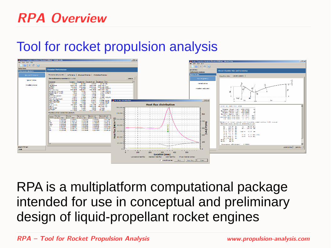
Tool for rocket propulsion analysis
RPA is a multiplatform computational package intended for use in conceptual and preliminary design of liquid-propellant rocket engines
RPA – Tool for Rocket Propulsion Analysis www.propulsion-analysis.com
RPA Overview
The motivation of RPA development was to...● Provide modern tool for prediction of rocket engine
performance at the conceptual and preliminary stages of design
● Capture impacts on engine performance due to variation of design parameters
● Assess the parameters of main engine components to provide better data for detailed analysis/design
● Assist in education of new generation of propulsion engineers
RPA – Tool for Rocket Propulsion Analysis www.propulsion-analysis.com

RPA Overview
Features of the tool:
● Steady-state analysis
● Simplified physical models and wide usage of semi-empirical relations
● Minimum of input parameters
● Rapid execution with accuracy sufficient for conceptual and preliminary design studies
RPA – Tool for Rocket Propulsion Analysis www.propulsion-analysis.com
RPA Overview
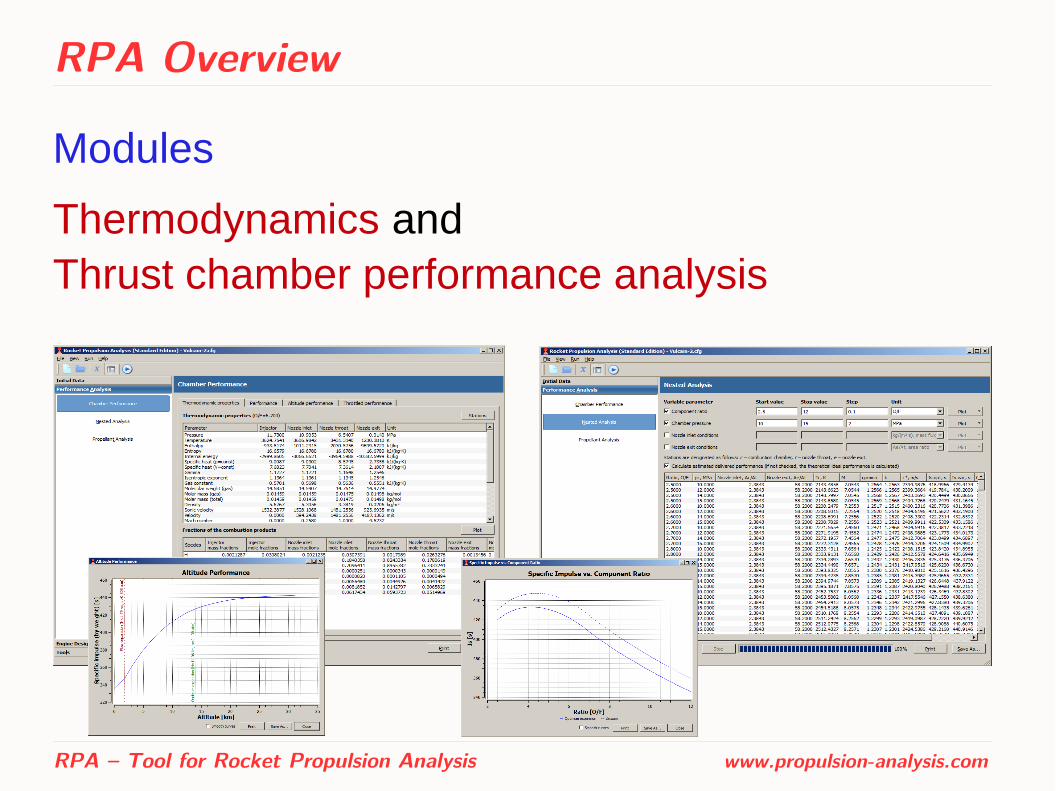
Modules
Thermodynamics and Thrust chamber performance analysis
RPA – Tool for Rocket Propulsion Analysis www.propulsion-analysis.com
RPA Overview
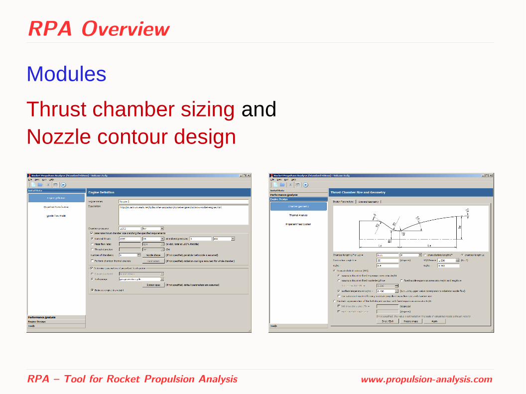
Modules
Thrust chamber sizing and Nozzle contour design
RPA – Tool for Rocket Propulsion Analysis www.propulsion-analysis.com
RPA Overview
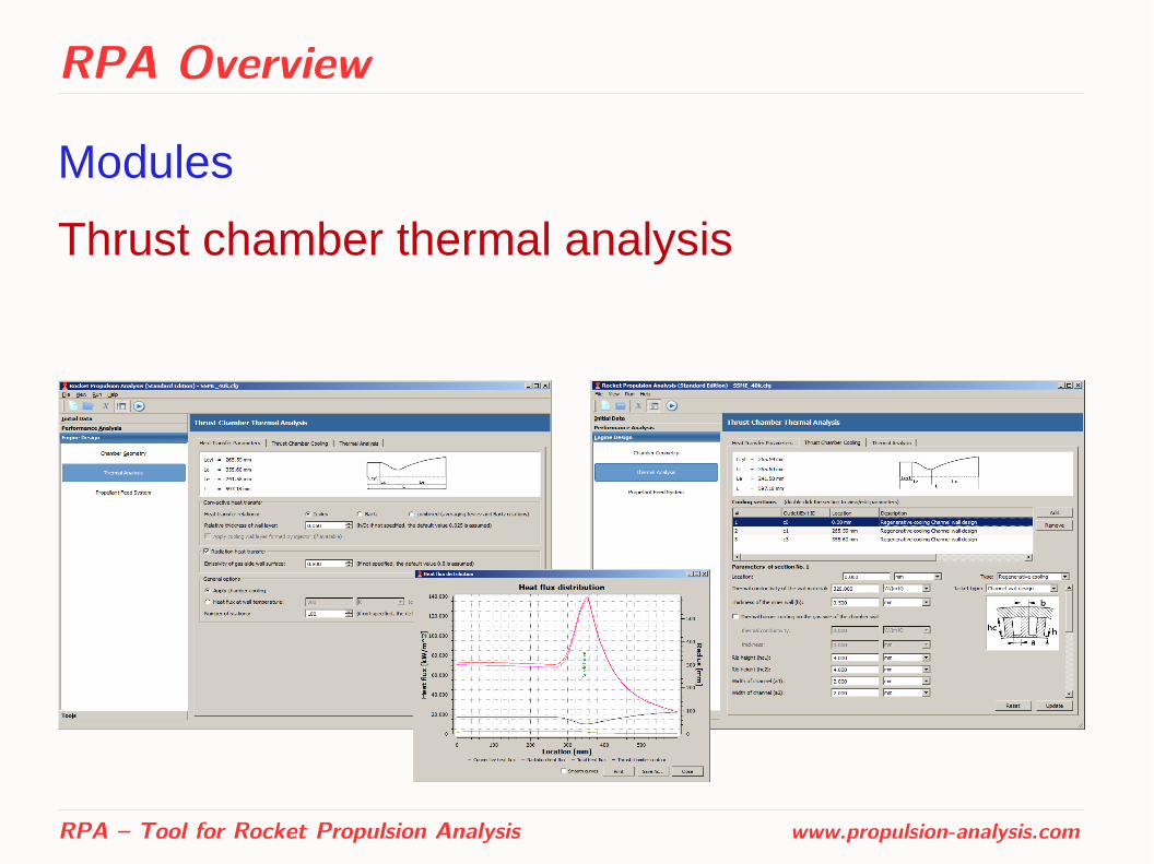
Modules
Thrust chamber thermal analysis
RPA – Tool for Rocket Propulsion Analysis www.propulsion-analysis.com
RPA Overview
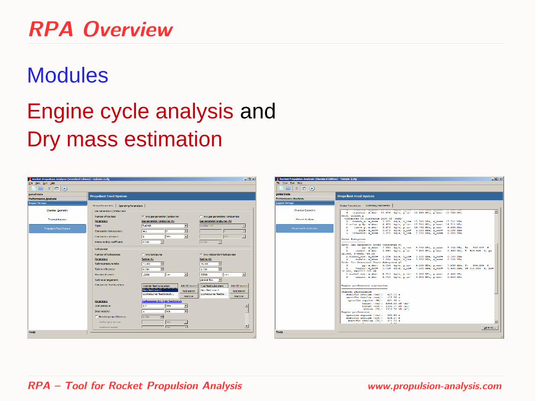
Modules
Engine cycle analysis and Dry mass estimation
RPA – Tool for Rocket Propulsion Analysis www.propulsion-analysis.com

Thermodynamics
Properties of reactants and reaction products ● Expandable thermodynamic data library based on
NASA Glenn thermodynamic database (also used by CEA)
● Includes data for such propellant components as (but not limited to): – liquid hydrogen H2(L), liquid methane CH4(L), RP-1, RG-1,
synthine, MMH, UDMH, methyl alcohol
– liquid oxygen O2(L), nitrogen tetra-oxide N2O4, hydrogen peroxide H2O2
● User may add own propellant components and products of reaction
RPA – Tool for Rocket Propulsion Analysis www.propulsion-analysis.com

Thermodynamics
Used methods
Gibbs free energy minimization for problems p=const
● (p,T) = const
● (p,I) = const
● (p,S) = const
Helmholtz free energy minimization for problems V=const
● (V,T) = const
● (V,U) = const
● (V,S) = const
RPA – Tool for Rocket Propulsion Analysis www.propulsion-analysis.com

Performance Analysis
Assumptions:
● Ideal gas law is applied to all processes
● Adiabatic, isobaric, isenthalpic combustion in combustion chamber at injector face
● Adiabatic, isentropic quasi-one-dimensional nozzle flow for both shifting and frozen equilibrium models
RPA – Tool for Rocket Propulsion Analysis www.propulsion-analysis.com
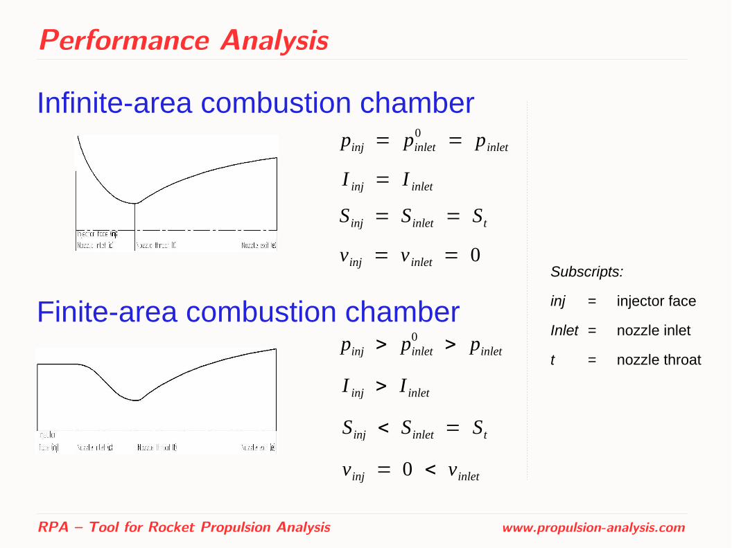
Performance Analysis
Infinite-area combustion chamber
RPA – Tool for Rocket Propulsion Analysis www.propulsion-analysis.com
pinj = pinlet0 = pinlet
I inj = I inlet
S inj = Sinlet = St
vinj = v inlet = 0Subscripts:
inj = injector face
Inlet = nozzle inlet
t = nozzle throat
Finite-area combustion chamberpinj > pinlet
0 > pinlet
I inj > I inlet
Sinj < S inlet = St
vinj = 0 < vinlet
Performance Analysis
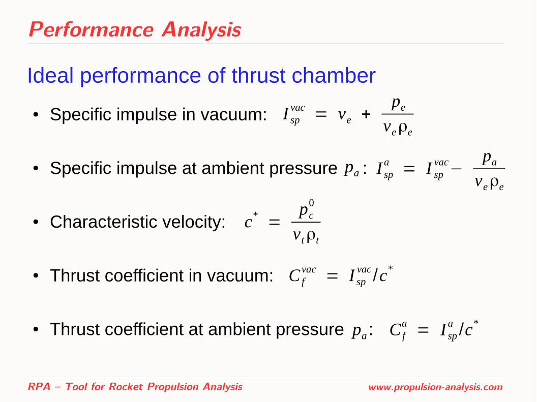
Ideal performance of thrust chamber
● Specific impulse in vacuum:
● Specific impulse at ambient pressure :
● Characteristic velocity:
● Thrust coefficient in vacuum:
● Thrust coefficient at ambient pressure :
RPA – Tool for Rocket Propulsion Analysis www.propulsion-analysis.com
I spvac = ve +
peveρe
I spa = I sp
vac−paveρe
C fvac = I sp
vac /c*
C fa = I sp
a /c*
c* =pc
0
vtρt
pa
pa
Performance Analysis
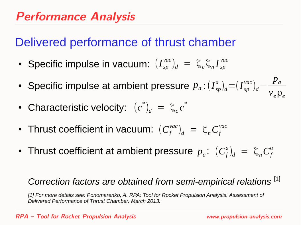
Delivered performance of thrust chamber
● Specific impulse in vacuum:
● Specific impulse at ambient pressure :
● Characteristic velocity:
● Thrust coefficient in vacuum:
● Thrust coefficient at ambient pressure :
Correction factors are obtained from semi-empirical relations [1]
[1] For more details see: Ponomarenko, A. RPA: Tool for Rocket Propulsion Analysis. Assessment of Delivered Performance of Thrust Chamber. March 2013.
RPA – Tool for Rocket Propulsion Analysis www.propulsion-analysis.com
(I spvac)d = ζ cζn I sp
vac
(I spa )d=(I sp
vac)d−paveρe
(C fvac)d = ζnC f
vac
(C fa)d = ζnC f
a
(c*)d = ζc c*
pa
pa
Performance Analysis
Additional options:
● Analysis of nozzle performance with shifting and frozen chemical equilibrium
● Optimization of propellant components mixture ratio for max delivered
● Altitude performance analysis, over-expanded nozzle performance analysis
● Throttled engine performance analysis
RPA – Tool for Rocket Propulsion Analysis www.propulsion-analysis.com
(I spvac)d
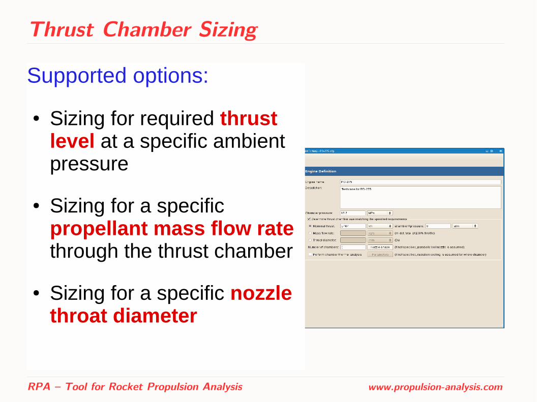
Thrust Chamber Sizing
Supported options:
● Sizing for required thrust level at a specific ambient pressure
● Sizing for a specific propellant mass flow rate through the thrust chamber
● Sizing for a specific nozzle throat diameter
RPA – Tool for Rocket Propulsion Analysis www.propulsion-analysis.com
Thrust Chamber Sizing
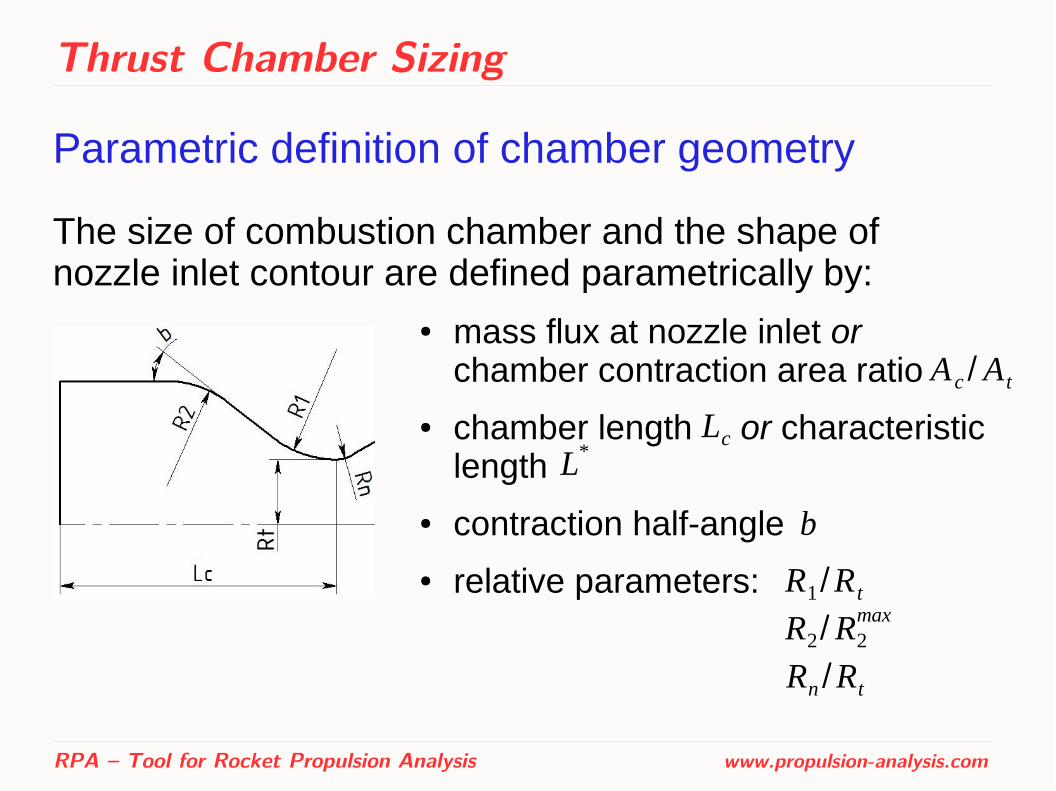
Parametric definition of chamber geometry
The size of combustion chamber and the shape of nozzle inlet contour are defined parametrically by:
RPA – Tool for Rocket Propulsion Analysis www.propulsion-analysis.com
● mass flux at nozzle inlet or chamber contraction area ratio
● chamber length or characteristic length
● contraction half-angle
● relative parameters:
A c / A t
LcL*
R1/R tR2/R2
max
Rn /Rt
b

Nozzle Contour Design
Supported options:
● Cone nozzle with a specified exit half-angle
● Parabolic nozzle contour with specified or automatically assessed initial and/or exit half-angle
● Truncated ideal contour (TIC) with fixed expansion area ratioand nozzle length (design method: axisymmetric MOC)
● TIC with maximum thrust at fixed expansion area ratio (design method: axisymmetric MOC)
● TIC with maximum thrust at fixed nozzle length (design method: axisymmetric MOC)
RPA – Tool for Rocket Propulsion Analysis www.propulsion-analysis.com
Nozzle Contour Design
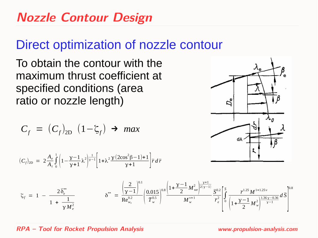
Direct optimization of nozzle contour
RPA – Tool for Rocket Propulsion Analysis www.propulsion-analysis.com
C f = (C f )2D (1−ζ f ) → max
(C f)2D = 2AeA t∫0
1
(1−γ−1γ+1
λ2)
1γ−1 [1+λ2 γ (2cos2
β−1)+1γ+1 ] r d r
To obtain the contour with the maximum thrust coefficient at specified conditions (area ratio or nozzle length)
ζ f = 1 −2 δe
**
1 +1
γM e2
δ** =( 2γ−1 )
0.1
Rew0
0.2 (0.015
T w0.5 )
0.8 (1+ γ−12
M we2 )
γ+12(γ−1)
M wν+1
S0.2
r e2 [∫0
Sr1.25M 1+1.25ν
(1+γ−12
M w2 )
1.36 γ−0.36γ−1
d S ]0.8
Thrust Chamber Thermal Analysis
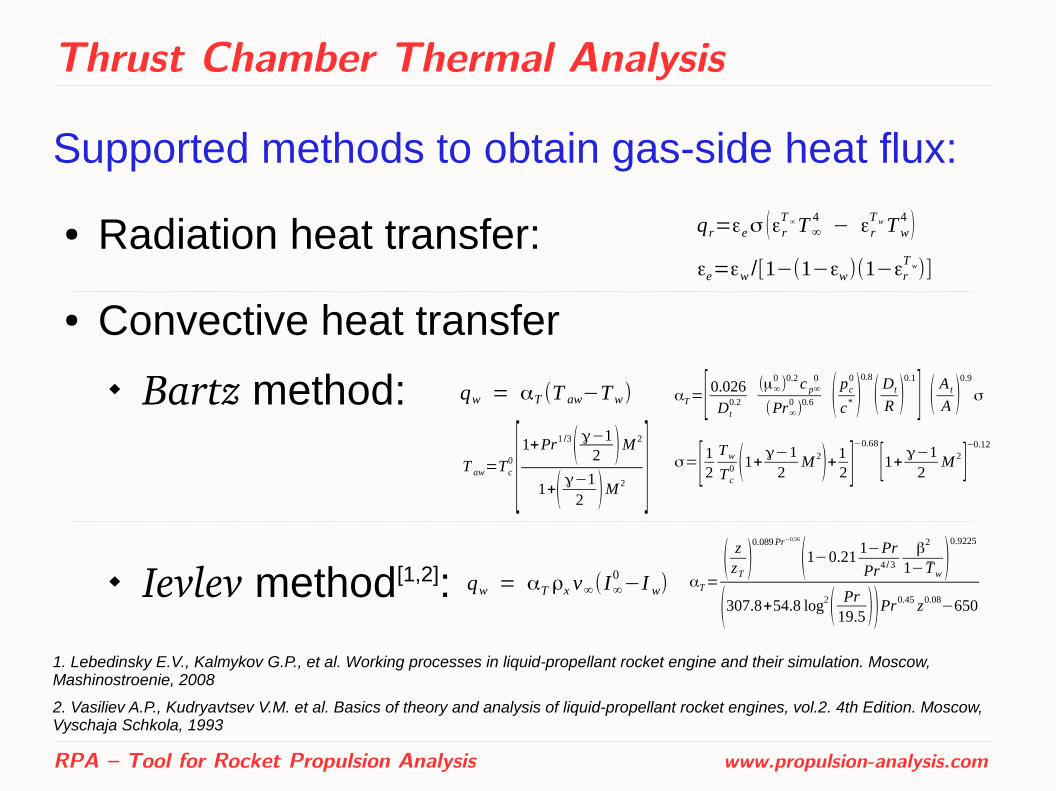
Supported methods to obtain gas-side heat flux:
● Radiation heat transfer:
● Convective heat transfer
Bartz method:
Ievlev method[1,2]:
1. Lebedinsky E.V., Kalmykov G.P., et al. Working processes in liquid-propellant rocket engine and their simulation. Moscow, Mashinostroenie, 2008
2. Vasiliev A.P., Kudryavtsev V.M. et al. Basics of theory and analysis of liquid-propellant rocket engines, vol.2. 4th Edition. Moscow, Vyschaja Schkola, 1993
RPA – Tool for Rocket Propulsion Analysis www.propulsion-analysis.com
qr=εeσ (εrT ∞T∞
4− εr
T wTw4 )
εe=εw /[1−(1−εw)(1−εrT w)]
qw = αT (T aw−Tw) αT=[ 0.026Dt
0.2
(μ∞0 )0.2c p∞
0
(Pr∞0)
0.6 ( pc0
c* )0.8
( Dt
R )0.1
] ( A t
A )0.9
σ
σ=[12 TwTc0 (1+γ−1
2M 2)+1
2 ]−0.68
[1+ γ−12
M 2]−0.12
T aw=Tc0 [1+Pr
1 /3( γ−12 )M 2
1+( γ−12 )M 2 ]
qw = αT ρx v∞(I∞0−I w) αT=
( zzT )0.089Pr−0.56
(1−0.211−Pr
Pr4 /3
β2
1− Tw )0.9225
(307.8+54.8 log2( Pr19.5 ))Pr0.45 z0.08−650

Thrust Chamber Thermal Analysis
Supported cooling methods: Heat transfer equations:
● Radiation cooling
● Regenerative cooling
coaxial shells tubular-wall jacket channel-wall jacket
● Film cooling
● Thermal barrier coating
RPA – Tool for Rocket Propulsion Analysis www.propulsion-analysis.com
qwTwg+qr
T wg =λwtw
(T wg−Twc) = εwcσ Twc4 = qrc
T wc
qwTwg+qr
T wg =λwtw
(T wg−Twc) = αc (Twc−T c)
αc = ηf Nuλcd e
(qwT wg+qr
T wg)2π r dx = mc cc dT c
q (1)
q (2) =S(1)
S(2) S =(I∞
0−I w)T e
0.425μ1000
0.15
R15000.425
(T e+Tw)0.595
(3T e+T w)0.15
qwTwg+qr
T wg =1
t 1
λ1+t2λ2
+...+tNλN
(Twg−T wc)
Thrust Chamber Thermal Analysis
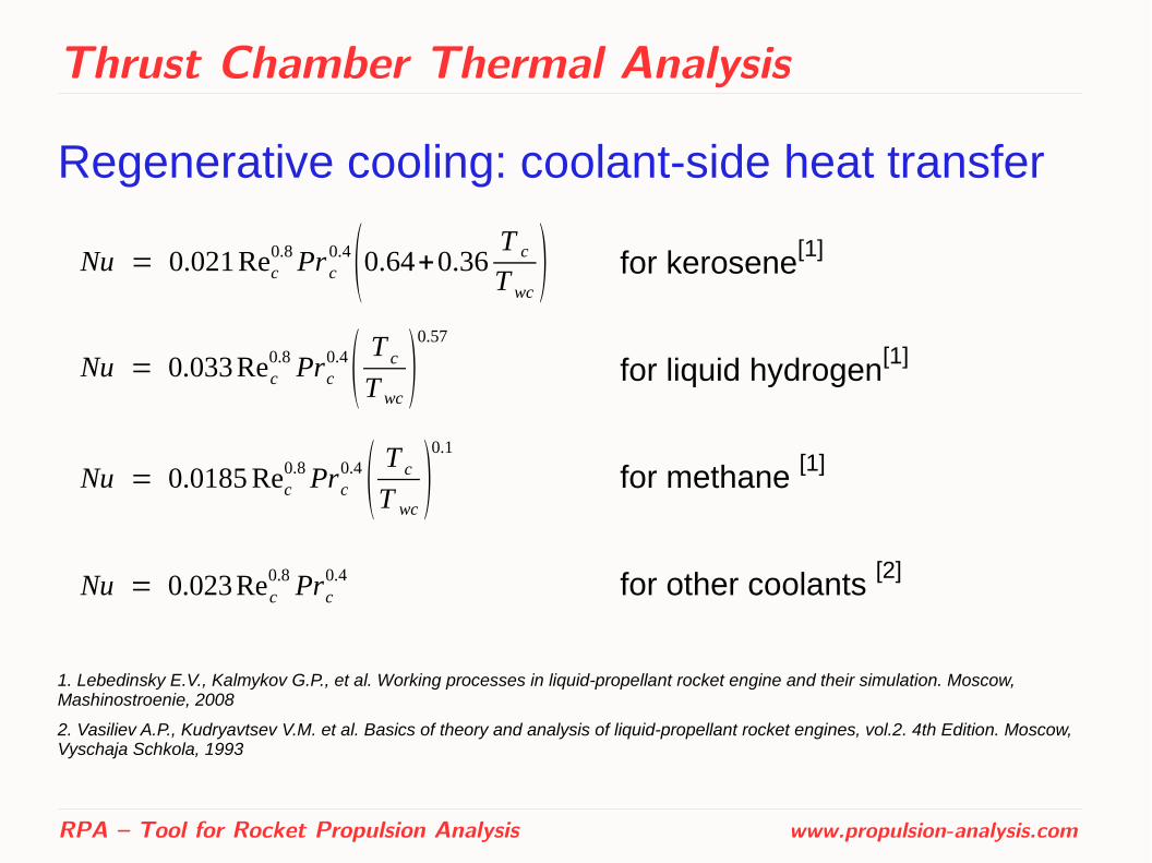
Regenerative cooling: coolant-side heat transfer
RPA – Tool for Rocket Propulsion Analysis www.propulsion-analysis.com
Nu = 0.021Rec0.8Pr c
0.4(0.64+0.36T c
T wc) for kerosene[1]
for liquid hydrogen[1]
for methane [1]
for other coolants [2]
Nu = 0.033 Rec0.8 Prc
0.4( T c
T wc)
0.57
Nu = 0.0185 Rec0.8Prc
0.4 ( T c
T wc)
0.1
Nu = 0.023Rec0.8 Prc
0.4
1. Lebedinsky E.V., Kalmykov G.P., et al. Working processes in liquid-propellant rocket engine and their simulation. Moscow, Mashinostroenie, 2008
2. Vasiliev A.P., Kudryavtsev V.M. et al. Basics of theory and analysis of liquid-propellant rocket engines, vol.2. 4th Edition. Moscow, Vyschaja Schkola, 1993
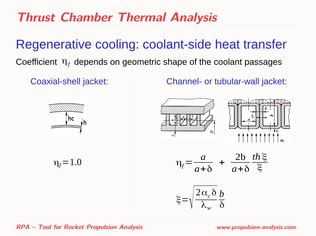
Thrust Chamber Thermal Analysis
Regenerative cooling: coolant-side heat transferCoefficient depends on geometric shape of the coolant passages
RPA – Tool for Rocket Propulsion Analysis www.propulsion-analysis.com
η f
Coaxial-shell jacket: Channel- or tubular-wall jacket:
ηf=1.0 ηf=aa+δ
+2ba+δ
th ξξ
ξ=√ 2αcδ
λw
bδ
Thrust Chamber Thermal Analysis
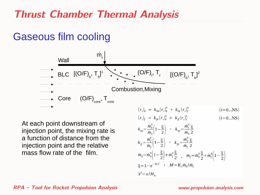
Gaseous film cooling
RPA – Tool for Rocket Propulsion Analysis www.propulsion-analysis.com
BLC
Core (O/F)core
, Tcore
(O/F)f, T
f[(O/F)b, T
b]1
mf
.
[(O/F)b, T
b]2
Wall
Combustion,Mixing
At each point downstream of injection point, the mixing rate is a function of distance from the injection point and the relative mass flow rate of the film.
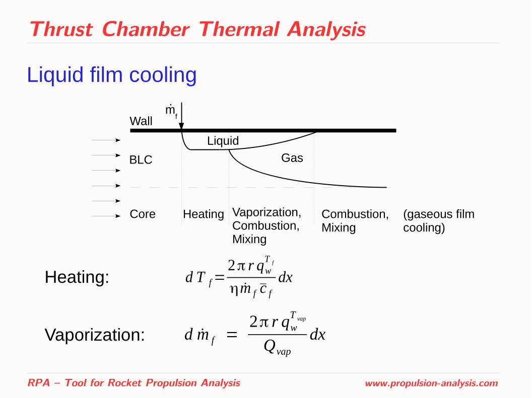
Thrust Chamber Thermal Analysis
Liquid film cooling
RPA – Tool for Rocket Propulsion Analysis www.propulsion-analysis.com
d T f=2π r qw
T f
ηm f c fdx
d m f =2π r qw
T vap
Qvap
dx
Heating:
Vaporization:
.
Core
BLC
mfWall
Heating Vaporization,Combustion,Mixing
Combustion,Mixing
Liquid
Gas
(gaseous film cooling)
Engine Cycle Analysis
Supported options:● Staged combustion cycle (SC)● Full flow staged combustion (FFSC)● Gas generator cycle (GG)
Allowed variations of the flow diagram: ● Number of combustion devices (gas generators or
preburners)● Number of turbopumps ● Arrangement of turbines (serial or parallel)● Availability of booster pumps ● Availability of kick pumps ● Availability of tap-off branches
RPA – Tool for Rocket Propulsion Analysis www.propulsion-analysis.com

Engine Cycle Analysis
Top-level input parameters:● Type of combustion devices:
oxidizer-rich fuel-rich
● Number of independent turbopumps,● Number of gas generators/preburners
Component-specific input parameters:● Efficiency of pumps and turbines● Pressure drop in all components (valves, injectors, etc.) ● Temperature in combustion devices
● Turbines pressure ratios (for GG cycle)
RPA – Tool for Rocket Propulsion Analysis www.propulsion-analysis.com

Engine Cycle Analysis
Flow diagram decomposition (example)
RPA – Tool for Rocket Propulsion Analysis www.propulsion-analysis.com
Flow diagram Fuel feed Oxidizer feed Power Oxidizer-rich SC cycle subsystem subsystem subsystem
Engine Cycle Analysis
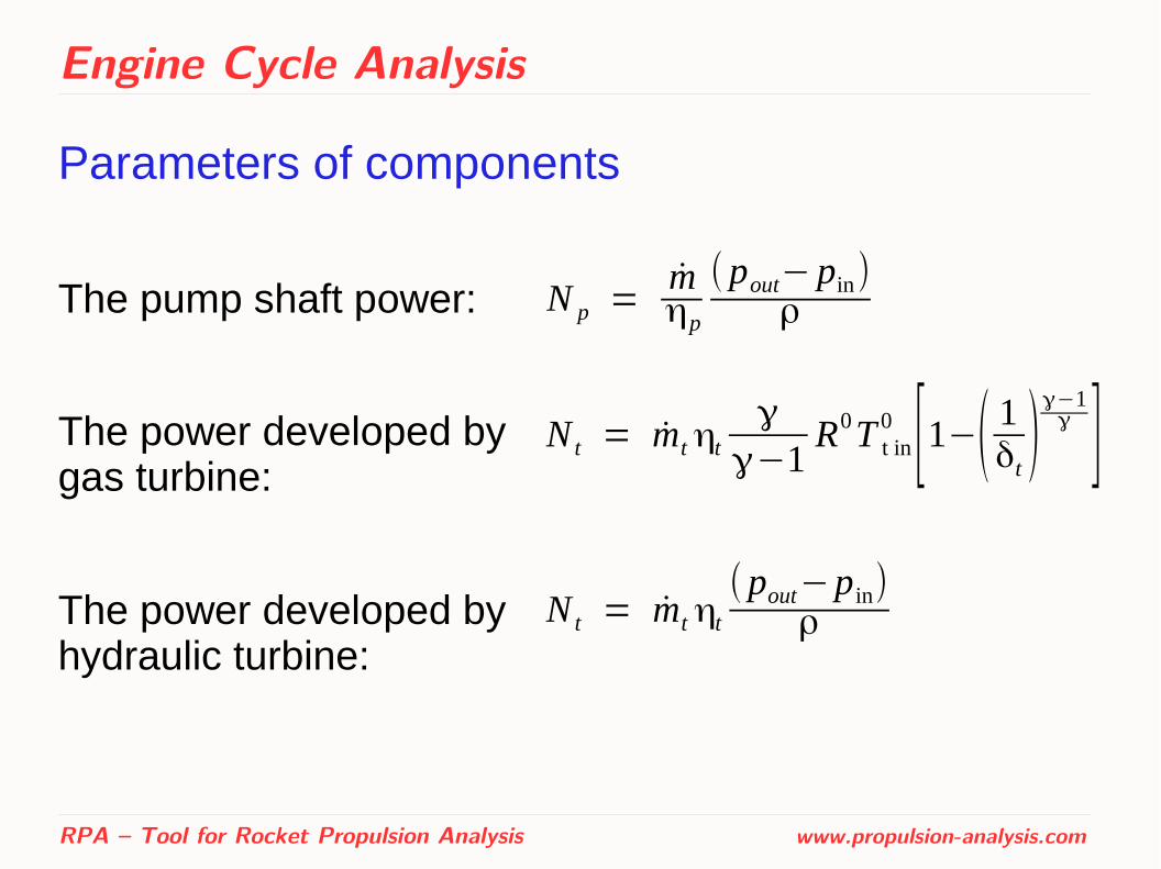
Parameters of components
The pump shaft power:
The power developed by gas turbine:
The power developed by hydraulic turbine:
RPA – Tool for Rocket Propulsion Analysis www.propulsion-analysis.com
N p =mηp
( pout− pin)ρ
N t = mtηtγ
γ−1R0T t in
0 [1−( 1δt )
γ−1γ ]
N t = mt ηt( pout−pin)
ρ
Engine Cycle Analysis
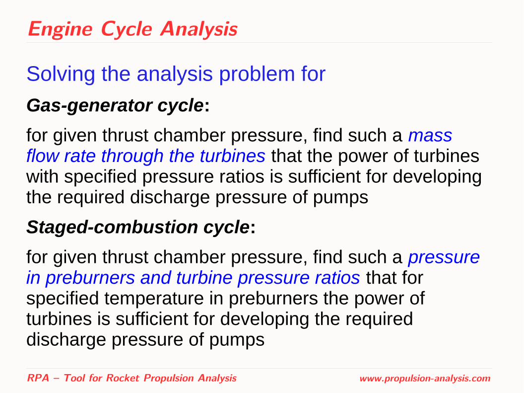
Solving the analysis problem for
Gas-generator cycle:
for given thrust chamber pressure, find such a mass flow rate through the turbines that the power of turbines with specified pressure ratios is sufficient for developing the required discharge pressure of pumps
Staged-combustion cycle:
for given thrust chamber pressure, find such a pressure in preburners and turbine pressure ratios that for specified temperature in preburners the power of turbines is sufficient for developing the required discharge pressure of pumps
RPA – Tool for Rocket Propulsion Analysis www.propulsion-analysis.com
Engine Dry Mass Estimation
● Based on the set of semi-empirical equations for each major type of engines: gas generator, staged combustion and expander cycles
● Initially developed at Moscow Aviation Institute
● RPA utilizes this method with slightly modified coefficients to better fit the available data on historic engines
● Results of chamber sizing and cycle analysis are used as an input parameters of engine weight estimation
RPA – Tool for Rocket Propulsion Analysis www.propulsion-analysis.com

Test cases
Thermodynamics
Comparison with NASA equilibrium code CEA has been performed for a large number of test cases.
Few of them are presented here:
RPA – Tool for Rocket Propulsion Analysis www.propulsion-analysis.com

Test cases
Thermodynamics
RPA – Tool for Rocket Propulsion Analysis www.propulsion-analysis.com
A perfect agreement is obtained between the CEA and PRA programs.
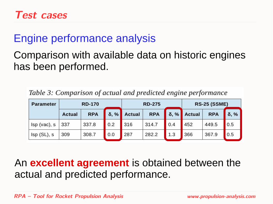
Test cases
Engine performance analysis
Comparison with available data on historic engines has been performed.
RPA – Tool for Rocket Propulsion Analysis www.propulsion-analysis.com
An excellent agreement is obtained between the actual and predicted performance.
Test cases
Thrust chamber thermal analysis
Comparison with available reference data has been performed:
– SSME 40k [1]
– Aestus [2]
RPA – Tool for Rocket Propulsion Analysis www.propulsion-analysis.com
[1] Scaling Techniques for Design, Development, and Test. Carol E. Dexter, Mark F. Fisher, James R. Hulka, Konstantin P. Denisov, Alexander A. Shibanov, and Anatoliy F. Agarkov
[2] Simulation and Analysis of Thrust Chamber Flowfields: Storable Propellant Rockets. Dieter Preclik, Oliver Knab, Denis Estublier, and Dag Wennerberg

Test cases
Thrust chamber thermal analysis
SSME 40k
RPA – Tool for Rocket Propulsion Analysis www.propulsion-analysis.com
Test cases
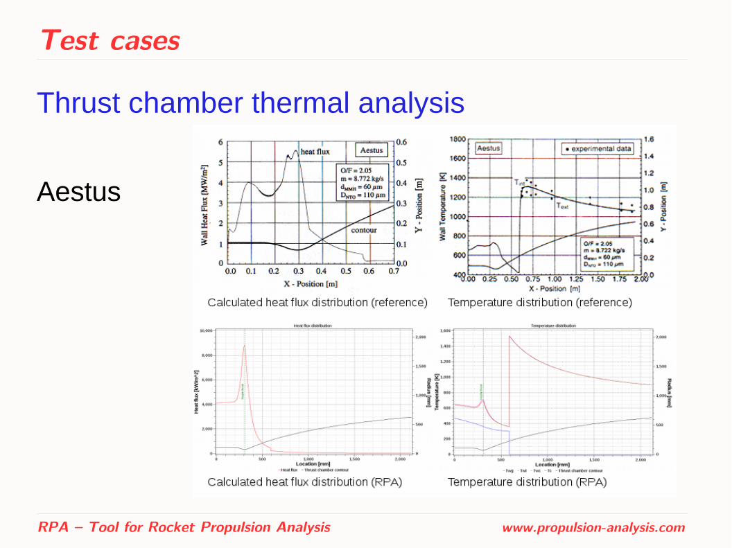
Thrust chamber thermal analysis
Aestus
RPA – Tool for Rocket Propulsion Analysis www.propulsion-analysis.com

Test cases
Thrust chamber thermal analysis ● Obtained good agreement is sufficient for
conceptual and preliminary design studies.
● Quantitative and qualitative differences in results can be explained by the following:
– RPA does not simulate fuel atomization and dispersion, as well as droplets burning
– The hot gas properties for thermal analysis are retrieved from quasi one-dimensional flow model
– The heat transfer is simulated in RPA using semi-empirical relations
RPA – Tool for Rocket Propulsion Analysis www.propulsion-analysis.com
Test cases
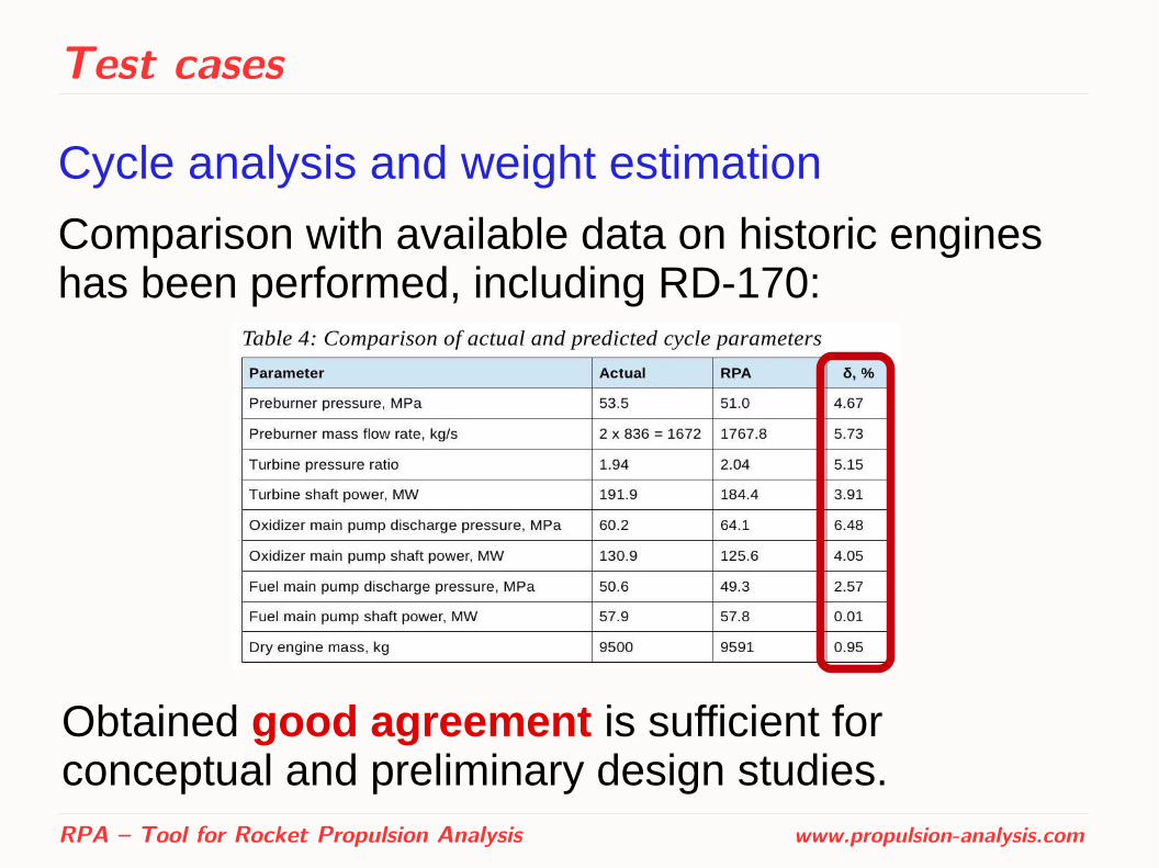
Cycle analysis and weight estimation
Comparison with available data on historic engines has been performed, including RD-170:
RPA – Tool for Rocket Propulsion Analysis www.propulsion-analysis.com
Obtained good agreement is sufficient for conceptual and preliminary design studies.

Future development
Future development of RPA ● Design of thrust optimized nozzle contour (TOC),
● Improved options for thermal analysis (e.g., support of jackets with bi-directional channels, support of BLC formed by injector, designing the cooling jackets, further validation including film cooling model),
● Improved options for modeling feed systems (e.g. estimation of pressure drop in a hydraulic components and efficiencies of the pumps and turbines),
● Support of additional engine cycles (e.g. expander cycle).
RPA – Tool for Rocket Propulsion Analysis www.propulsion-analysis.com
RPA - Tool for Rocket Propulsion Analysis
Thank you for your attention!
RPA – Tool for Rocket Propulsion Analysis www.propulsion-analysis.com
Related Documents