, Haas Automation Inc. 2800 Sturgis Road Oxnard, CA 93030-8933 U.S.A. | HaasCNC.com To get translated versions of this Manual: 1. Go to www.HaasCNC.com 2. See Owner Resources (bottom of page) 3. Select Manuals and Documentation © 2015 Haas Automation, Inc. All Rights Reserved. Copy by Permission Only. Copyright Strictly Enforced. Rotary/Tailstock Operator’s Manual 96-8260 Revision B June 2017 English Original Instructions

Welcome message from author
This document is posted to help you gain knowledge. Please leave a comment to let me know what you think about it! Share it to your friends and learn new things together.
Transcript

,
Haas Automation Inc.2800 Sturgis Road
Oxnard, CA 93030-8933U.S.A. | HaasCNC.com
To get translated versions of this Manual:1. Go to www.HaasCNC.com2. See Owner Resources (bottom of page)3. Select Manuals and Documentation
© 2015 Haas Automation, Inc. All Rights Reserved. Copy by Permission Only. Copyright Strictly Enforced.
Rotary/Tailstock Operator’sManual
96-8260 Revision B
June 2017English
Original Instructions
96-8960A.book Page i Tuesday, July 28, 2015 1:34 PM

96-8960A.book Page ii Tuesday, July 28, 2015 1:34 PM
96-8960A.book Page i Tuesday, July 28, 2015 1:34 PM
© 2015 Haas Automation, Inc.
All rights reserved. No part of this publication may be reproduced, stored in a retrieval system, ortransmitted, in any form, or by any means, mechanical, electronic, photocopying, recording, orotherwise, without the written permission of Haas Automation, Inc. No patent liability is assumed withrespect to the use of the information contained herein. Moreover, because Haas Automation strivesconstantly to improve its high-quality products, the information contained in this manual is subject tochange without notice. We have taken every precaution in the preparation of this manual; nevertheless,Haas Automation assumes no responsibility for errors or omissions, and we assume no liability fordamages resulting from the use of the information contained in this publication.
i

96-8960A.book Page ii Tuesday, July 28, 2015 1:34 PM
ii

96-8960A.book Page iii Tuesday, July 28, 2015 1:34 PM
iii
LIMITED WARRANTY CERTIFICATE
Haas Automation, Inc.
Covering Haas Automation, Inc. CNC Equipment
Effective September 1, 2010
Haas Automation Inc. (“Haas” or “Manufacturer”) provides a limited warranty on all newmills, turning centers, and rotary machines (collectively, “CNC Machines”) and theircomponents (except those listed below under Limits and Exclusions of Warranty)(“Components”) that are manufactured by Haas and sold by Haas or its authorizeddistributors as set forth in this Certificate. The warranty set forth in this Certificate is alimited warranty, it is the only warranty by Manufacturer, and is subject to the terms andconditions of this Certificate.
Limited Warranty Coverage
Each CNC Machine and its Components (collectively, “Haas Products”) are warranted byManufacturer against defects in material and workmanship. This warranty is provided onlyto an end-user of the CNC Machine (a “Customer”). The period of this limited warranty isone (1) year. The warranty period commences on the date the CNC Machine is installed atthe Customer’s facility. Customer may purchase an extension of the warranty period froman authorized Haas distributor (a “Warranty Extension”), any time during the first year ofownership.
Repair or Replacement Only
Manufacturer’s sole liability, and Customer’s exclusive remedy under this warranty, withrespect to any and all Haas products, shall be limited to repairing or replacing, at thediscretion of the Manufacturer, the defective Haas product.
Disclaimer of Warranty
This warranty is Manufacturer’s sole and exclusive warranty, and is in lieu of all otherwarranties of whatever kind or nature, express or implied, written or oral, including, but notlimited to, any implied warranty of merchantability, implied warranty of fitness for aparticular purpose, or other warranty of quality or performance or noninfringement. All suchother warranties of whatever kind are hereby disclaimed by Manufacturer and waived byCustomer.
96-8960A.book Page iv Tuesday, July 28, 2015 1:34 PM
iv
Limits and Exclusions of Warranty
Components subject to wear during normal use and over time, including, but not limited to,paint, window finish and condition, light bulbs, seals, wipers, gaskets, chip removal system(e.g., augers, chip chutes), belts, filters, door rollers, tool changer fingers, etc., are excludedfrom this warranty. Manufacturer’s specified maintenance procedures must be adhered toand recorded in order to maintain this warranty. This warranty is void if Manufacturerdetermines that (i) any Haas Product was subjected to mishandling, misuse, abuse,neglect, accident, improper installation, improper maintenance, improper storage, orimproper operation or application, including the use of improper coolants or other fluids, (ii)any Haas Product was improperly repaired or serviced by Customer, an unauthorizedservice technician, or other unauthorized person, (iii) Customer or any person makes orattempts to make any modification to any Haas Product without the prior writtenauthorization of Manufacturer, and/or (iv) any Haas Product was used for anynon-commercial use (such as personal or household use). This warranty does not coverdamage or defect due to an external influence or matters beyond the reasonable control ofManufacturer, including, but not limited to, theft, vandalism, fire, weather condition (such asrain, flood, wind, lightning, or earthquake), or acts of war or terrorism.
Without limiting the generality of any of the exclusions or limitations described in thisCertificate, this warranty does not include any warranty that any Haas Product will meet anyperson’s production specifications or other requirements, or that operation of any HaasProduct will be uninterrupted or error-free. Manufacturer assumes no responsibility withrespect to the use of any Haas Product by any person, and Manufacturer shall not incurany liability to any person for any failure in design, production, operation, performance, orotherwise of any Haas Product, other than repair or replacement of same as set forth in thewarranty above.
Limitation of Liability and Damages
Manufacturer will not be liable to Customer or any other person for any compensatory,incidental, consequential, punitive, special, or other damage or claim, whether in an actionin contract, tort, or other legal or equitable theory, arising out of or related to any Haasproduct, other products or services provided by Manufacturer or an authorized distributor,service technician, or other authorized representative of Manufacturer (collectively,“authorized representative”), or the failure of parts or products made by using any HaasProduct, even if Manufacturer or any authorized representative has been advised of thepossibility of such damages, which damage or claim includes, but is not limited to, loss ofprofits, lost data, lost products, loss of revenue, loss of use, cost of down time, businessgood will, any damage to equipment, premises, or other property of any person, and anydamage that may be caused by a malfunction of any Haas product. All such damages andclaims are disclaimed by Manufacturer and waived by Customer. Manufacturer’s soleliability, and Customer’s exclusive remedy, for damages and claims for any causewhatsoever shall be limited to repair or replacement, at the discretion of Manufacturer, ofthe defective Haas Product as provided in this warranty.
96-8960A.book Page v Tuesday, July 28, 2015 1:34 PM
v
Customer has accepted the limitations and restrictions set forth in this Certificate, including,but not limited to, the restriction on its right to recover damages, as part of its bargain withManufacturer or its Authorized Representative. Customer realizes and acknowledges thatthe price of the Haas Products would be higher if Manufacturer were required to beresponsible for damages and claims beyond the scope of this warranty.
Entire Agreement
This Certificate supersedes any and all other agreements, promises, representations, orwarranties, either oral or in writing, between the parties or by Manufacturer with respect tosubject matter of this Certificate, and contains all of the covenants and agreementsbetween the parties or by Manufacturer with respect to such subject matter. Manufacturerhereby expressly rejects any other agreements, promises, representations, or warranties,either oral or in writing, that are in addition to or inconsistent with any term or condition ofthis Certificate. No term or condition set forth in this Certificate may be modified oramended, unless by a written agreement signed by both Manufacturer and Customer.Notwithstanding the foregoing, Manufacturer will honor a Warranty Extension only to theextent that it extends the applicable warranty period.
Transferability
This warranty is transferable from the original Customer to another party if the CNCMachine is sold via private sale before the end of the warranty period, provided that writtennotice thereof is provided to Manufacturer and this warranty is not void at the time oftransfer. The transferee of this warranty will be subject to all terms and conditions of thisCertificate.
Miscellaneous
This warranty shall be governed by the laws of the State of California without application ofrules on conflicts of laws. Any and all disputes arising from this warranty shall be resolvedin a court of competent jurisdiction located in Ventura County, Los Angeles County, orOrange County, California. Any term or provision of this Certificate that is invalid orunenforceable in any situation in any jurisdiction shall not affect the validity or enforceabilityof the remaining terms and provisions hereof, or the validity or enforceability of theoffending term or provision in any other situation or in any other jurisdiction.

96-8960A.book Page vi Tuesday, July 28, 2015 1:34 PM
vi
Customer Feedback
If you have concerns or questions regarding this Operator’s Manual, please contact us onour website, www.HaasCNC.com. Use the “Contact Haas” link and send your commentsto the Customer Advocate.
You can find an electronic copy of this manual and other useful information on our websitein the “Resource Center”. Join Haas owners online and be a part of the greater CNCcommunity at these sites:
The Haas Resource Center: Documentation and Proceduresatyourservice.haascnc.com
diy.haascnc.com
At Your Service: The Official Haas Answer and Information Blog
haasparts.comYour Source for Genuine Haas Parts
www.facebook.com/HaasAutomationIncHaas Automation on Facebook
www.twitter.com/Haas_AutomationFollow us on Twitter
www.linkedin.com/company/haas-automationHaas Automation on LinkedIn
www.youtube.com/user/haasautomationProduct videos and information
www.flickr.com/photos/haasautomationProduct photos and information
96-8960A.book Page vii Tuesday, July 28, 2015 1:34 PM
vii
Customer Satisfaction Policy
Dear Haas Customer,
Your complete satisfaction and goodwill are of the utmost importance to both HaasAutomation, Inc. and the Haas distributor (HFO) where you purchased your equipment.Normally, your HFO will rapidly resolve any concerns you have about your salestransaction or the operation of your equipment.
However, if your concerns are not resolved to your complete satisfaction, and you havediscussed your concerns with a member of the HFO’s management, the General Manager,or the HFO’s owner directly, please do the following:
Contact Haas Automation’s Customer Service Advocate at 805-988-6980. So that we mayresolve your concerns as quickly as possible, please have the following informationavailable when you call:
• Your company name, address, and phone number• The machine model and serial number• The HFO name, and the name of your latest contact at the HFO• The nature of your concern
If you wish to write Haas Automation, please use this address:
Haas Automation, Inc. U.S.A.2800 Sturgis RoadOxnard CA 93030Att: Customer Satisfaction Manageremail: [email protected]
Once you contact the Haas Automation Customer Service Center, we will make every effortto work directly with you and your HFO to quickly resolve your concerns. At HaasAutomation, we know that a good Customer-Distributor-Manufacturer relationship will helpensure continued success for all concerned.
International:
Haas Automation, EuropeMercuriusstraat 28, B-1930Zaventem, Belgiumemail: [email protected]
Haas Automation, AsiaNo. 96 Yi Wei Road 67,Waigaoqiao FTZShanghai 200131 P.R.C.email: [email protected]

96-8960A.book Page viii Tuesday, July 28, 2015 1:34 PM
viii

96-8960A.book Page ix Tuesday, July 28, 2015 1:34 PM
Declaration of Conformity
Product: CNC Indexers and Rotary Tables with Control
Manufactured By: Haas Automation, Inc.
2800 Sturgis Road, Oxnard, CA 93030 805-278-1800
We declare, in sole responsibility, that the above-listed products, to which this declarationrefers, comply with the regulations as outlined in the CE directive for Machining Centers:
• Machinery Directive 2006 / 42 / EC
• Electromagnetic Compatibility Directive 2004 / 108 / EC
• Additional Standards:
– EN 60204-1:2006/A1:2009– EN 614-1:2006+A1:2009– EN 894-1:1997+A1:2008– EN 13849-1:2008/AC:2009– EN 14121-1:2007
RoHS: COMPLIANT by Exemption per producer documentation. Exempt by:
a) Monitoring and control systemsb) Lead as an alloying element in steel, aluminum, and copper
Person authorized to compile technical file:
Jens ThingAddress: Haas Automation Europe
Mercuriusstraat 28, B-1930Zaventem, Belgium
ix
96-8960A.book Page x Tuesday, July 28, 2015 1:34 PM
USA: Haas Automation certifies this machine to be in compliance with the OSHA and ANSIdesign and manufacturing standards listed below. Operation of this machine will becompliant with the below-listed standards only as long as the owner and operator continueto follow the operation, maintenance, and training requirements of these standards.
• OSHA 1910.212 - General Requirements for All Machines
• ANSI B11.5-1983 (R1994) Drilling, Milling, and Boring Machines
• ANSI B11.19-2003 Performance Criteria for Safeguarding
• ANSI B11.23-2002 Safety Requirements for Machining Centers and AutomaticNumerically Controlled Milling, Drilling, and Boring Machines
• ANSI B11.TR3-2000 Risk Assessment and Risk Reduction - A Guideline to Estimate,Evaluate, and Reduce Risks Associated with Machine Tools
CANADA: As the original equipment manufacturer, we declare that the listed productscomply with regulations as outlined in the Pre-Start Health and Safety Reviews Section 7of Regulation 851 of the Occupational Health and Safety Act Regulations for IndustrialEstablishments for machine guarding provisions and standards.
Further, this document satisfies the notice-in-writing provision for exemption from Pre-Startinspection for the listed machinery as outlined in the Ontario Health and Safety Guidelines,PSR Guidelines dated April 2001. The PSR Guidelines allow that notice in writing from theoriginal equipment manufacturer declaring conformity to applicable standards is acceptablefor the exemption from Pre-Start Health and Safety Review.
Original Instructions
ETL LISTEDCONFORMS TONFPA STD 79
ANSI/UL STD 508UL SUBJECT 2011
CERTIFIED TO CAN/CSA STD C22.2 N O.73
All Haas CNC machine tools carry the ETL Listed mark, certifying that they conform to the NFPA 79 Electrical Standard for Industrial Machinery and the Canadian equivalent, CAN/CSA C22.2 No. 73. The ETL Listed and cETL Listed marks are awarded to products that have successfully undergone testing by Intertek Testing Services (ITS), an alternative to Underwriters' Laboratories.
x
96-8960A.book Page xi Tuesday, July 28, 2015 1:34 PM
How to Use This Manual
To get the maximum benefit of your new Haas machine, read this manual thoroughly andrefer to it often. The content of this manual is also available on your machine control underthe HELP function.
IMPORTANT: Before you operate the machine, read and understand the Operator’sManual Safety chapter.
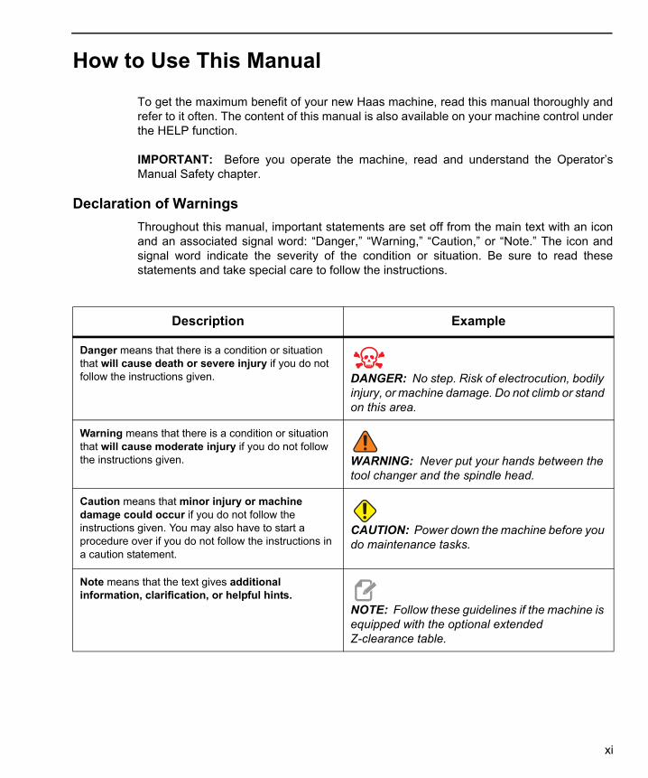
Declaration of Warnings
Throughout this manual, important statements are set off from the main text with an iconand an associated signal word: “Danger,” “Warning,” “Caution,” or “Note.” The icon andsignal word indicate the severity of the condition or situation. Be sure to read thesestatements and take special care to follow the instructions.
Description Example
Danger means that there is a condition or situation that will cause death or severe injury if you do not follow the instructions given. DANGER: No step. Risk of electrocution, bodily
injury, or machine damage. Do not climb or stand on this area.
Warning means that there is a condition or situation that will cause moderate injury if you do not follow the instructions given. WARNING: Never put your hands between the
tool changer and the spindle head.
Caution means that minor injury or machine damage could occur if you do not follow the instructions given. You may also have to start a procedure over if you do not follow the instructions in a caution statement.
CAUTION: Power down the machine before you do maintenance tasks.
Note means that the text gives additional information, clarification, or helpful hints.
NOTE: Follow these guidelines if the machine is equipped with the optional extended Z-clearance table.
xi

96-8960A.book Page xii Tuesday, July 28, 2015 1:34 PM
Text Conventions Used in this Manual
Description Text Example
Code Block text gives program examples. G00 G90 G54 X0. Y0.;
A Control Button Reference gives the name of a control key or button that you are to press.
Press [CYCLE START].
A File Path describes a sequence of file system directories.
Service > Documents and Software >...
A Mode Reference describes a machine mode. MDI
A Screen Element describes an object on the machine’s display that you interact with.
Select the SYSTEM tab.
System Output describes text that the machine control displays in response to your actions.
PROGRAM END
User Input describes text that you should enter into the machine control.
G04 P1.;
Variable n indicates a range of non-negative integers from 0 to 9.
Dnn represents D00 through D99.
xii

96-8960A.book Page xiii Tuesday, July 28, 2015 1:34 PM
Contents
Chapter 1 Rotary Introduction . . . . . . . . . . . . . . . . . . . . . . . . . . . . . 11.1 Introduction . . . . . . . . . . . . . . . . . . . . . . . . . . . . . . . 11.2 Semi 4th and 5th Axes Control . . . . . . . . . . . . . . . . . . . . . 11.3 4th and 5th Axis Control Using the RS-232 Port . . . . . . . . . . . . 11.4 Servo Control . . . . . . . . . . . . . . . . . . . . . . . . . . . . . . 2
1.4.1 Servo Control - Front Panel . . . . . . . . . . . . . . . . 31.4.2 Servo Control- Rear Panel. . . . . . . . . . . . . . . . . 6
Chapter 2 Operation . . . . . . . . . . . . . . . . . . . . . . . . . . . . . . . . . . 72.1 Turning On the Servo Control . . . . . . . . . . . . . . . . . . . . . . 72.2 Run Mode . . . . . . . . . . . . . . . . . . . . . . . . . . . . . . . . 72.3 Initialize Servo Control to Factory Default Parameters . . . . . . . . . 82.4 Jogging . . . . . . . . . . . . . . . . . . . . . . . . . . . . . . . . . 82.5 Emergency Stop . . . . . . . . . . . . . . . . . . . . . . . . . . . . . 92.6 Dual Axes Coordinate System. . . . . . . . . . . . . . . . . . . . . . 92.7 Finding the Zero Position . . . . . . . . . . . . . . . . . . . . . . . . 10
2.7.1 Manually Finding The Zero Position . . . . . . . . . . . . 102.7.2 Offsetting the Zero Position . . . . . . . . . . . . . . . . 11
2.8 Operating Hints . . . . . . . . . . . . . . . . . . . . . . . . . . . . . 112.9 Default Values . . . . . . . . . . . . . . . . . . . . . . . . . . . . . . 112.10 Alarm: Error Codes . . . . . . . . . . . . . . . . . . . . . . . . . . . 122.11 Alarm: Servo Off Codes . . . . . . . . . . . . . . . . . . . . . . . . . 13
Chapter 3 Tailstock Operation . . . . . . . . . . . . . . . . . . . . . . . . . . . . 153.1 Introduction . . . . . . . . . . . . . . . . . . . . . . . . . . . . . . . 153.2 Manual Tailstock Operation . . . . . . . . . . . . . . . . . . . . . . . 153.3 Pneumatic Tailstock Operation . . . . . . . . . . . . . . . . . . . . . 15
Chapter 4 Programming . . . . . . . . . . . . . . . . . . . . . . . . . . . . . . . 174.1 Introduction . . . . . . . . . . . . . . . . . . . . . . . . . . . . . . . 174.2 Putting a Program Into Memory . . . . . . . . . . . . . . . . . . . . . 18
4.2.1 Selecting a Stored Program . . . . . . . . . . . . . . . . 194.2.2 Clearing a Program . . . . . . . . . . . . . . . . . . . . 204.2.3 Entering a Step . . . . . . . . . . . . . . . . . . . . . . 204.2.4 Inserting a Line . . . . . . . . . . . . . . . . . . . . . . 214.2.5 Deleting a Line. . . . . . . . . . . . . . . . . . . . . . . 21
xiii

96-8960A.book Page xiv Tuesday, July 28, 2015 1:34 PM
4.3 The RS-232 Interface . . . . . . . . . . . . . . . . . . . . . . . . . . 214.3.1 Upload and Download . . . . . . . . . . . . . . . . . . . 234.3.2 RS-232 Remote Command Mode . . . . . . . . . . . . . 244.3.3 RS-232 Single Axis Commands . . . . . . . . . . . . . . 244.3.4 RS-232 Responses . . . . . . . . . . . . . . . . . . . . 25
4.4 Program Functions . . . . . . . . . . . . . . . . . . . . . . . . . . . 264.4.1 Absolute / Incremental Motion . . . . . . . . . . . . . . . 264.4.2 Auto Continue Control . . . . . . . . . . . . . . . . . . . 264.4.3 Continuous Motion. . . . . . . . . . . . . . . . . . . . . 274.4.4 Loop Counts . . . . . . . . . . . . . . . . . . . . . . . . 274.4.5 Delay Code (G97) . . . . . . . . . . . . . . . . . . . . . 274.4.6 Circle Division . . . . . . . . . . . . . . . . . . . . . . . 274.4.7 Feedrate Programming . . . . . . . . . . . . . . . . . . 274.4.8 Subroutines (G96) . . . . . . . . . . . . . . . . . . . . . 28
4.5 Simultaneous Rotation and Milling . . . . . . . . . . . . . . . . . . . 294.5.1 Spiral Milling (HRT & HA5C). . . . . . . . . . . . . . . . 294.5.2 Possible Timing Issue . . . . . . . . . . . . . . . . . . . 30
4.6 Programming Examples . . . . . . . . . . . . . . . . . . . . . . . . . 314.6.1 Programming Example 1 . . . . . . . . . . . . . . . . . 314.6.2 Programming Example 2 . . . . . . . . . . . . . . . . . 314.6.3 Programming Example 3 . . . . . . . . . . . . . . . . . 324.6.4 Programming Example 4 . . . . . . . . . . . . . . . . . 334.6.5 Programming Example 5 . . . . . . . . . . . . . . . . . 334.6.6 Programming Example 6 . . . . . . . . . . . . . . . . . 35
Chapter 5 G-codes and Parameters . . . . . . . . . . . . . . . . . . . . . . . . .375.1 Introduction . . . . . . . . . . . . . . . . . . . . . . . . . . . . . . . 375.2 G-Codes . . . . . . . . . . . . . . . . . . . . . . . . . . . . . . . . . 37
5.2.1 G28 Return Home . . . . . . . . . . . . . . . . . . . . . 385.2.2 G33 Continuous Motion . . . . . . . . . . . . . . . . . . 385.2.3 G73 Peck Cycle . . . . . . . . . . . . . . . . . . . . . . 385.2.4 G85 Fractional Circle Division . . . . . . . . . . . . . . . 385.2.5 G86/G87 Turn CNC Relay On/Off . . . . . . . . . . . . . 395.2.6 G88 Return To Home Position. . . . . . . . . . . . . . . 395.2.7 G89 Wait For Remote Input . . . . . . . . . . . . . . . . 395.2.8 G90/G91 Absolute/Incremental Position. . . . . . . . . . 405.2.9 G92 Pulse CNC Relay And Wait For Remote Input . . . . 405.2.10 G93 Pulse CNC Relay . . . . . . . . . . . . . . . . . . . 405.2.11 G94 Pulse CNC Relay And Run Next L Steps Automatically
405.2.12 G95 End Of Program/Return But More Steps Follow . . . 405.2.13 G96 Subroutine Call/Jump. . . . . . . . . . . . . . . . . 405.2.14 G97 Delay By L Count/10 Seconds . . . . . . . . . . . . 40
xiv

96-8960A.book Page xv Tuesday, July 28, 2015 1:34 PM
5.2.15 G98 Circle Division . . . . . . . . . . . . . . . . . . . . 415.2.16 G99 End Of Program/Return And End Of Steps. . . . . . 41
5.3 Parameters . . . . . . . . . . . . . . . . . . . . . . . . . . . . . . . 415.3.1 Gear Compensation . . . . . . . . . . . . . . . . . . . . 415.3.2 Rotary Parameter Summary . . . . . . . . . . . . . . . . 425.3.3 Parameter 1 - CNC Interface Relay Control . . . . . . . . 445.3.4 Parameter 2 - CNC Interface Relay Polarity & Aux. Relay
Enable . . . . . . . . . . . . . . . . . . . . . . . . . . . 455.3.5 Parameter 3 - Servo Loop Proportional Gain . . . . . . . 455.3.6 Parameter 4 - Servo Loop Derivative Gain . . . . . . . . 455.3.7 Parameter 5 - Double Remote Trigger Option . . . . . . . 455.3.8 Parameter 6 - Disable Front Panel Start. . . . . . . . . . 465.3.9 Parameter 7 - Memory Protection . . . . . . . . . . . . . 465.3.10 Parameter 8 - Disable Remote Start. . . . . . . . . . . . 465.3.11 Parameter 9 - Encoder Steps Per Programmed Unit . . . 475.3.12 Parameter 10 - Auto Continue Control. . . . . . . . . . . 475.3.13 Parameter 11 - Reverse Direction Option . . . . . . . . . 485.3.14 Parameter 12 - Display Units and Precision (decimal location)
485.3.15 Parameter 13 - Maximum Positive Travel . . . . . . . . . 495.3.16 Parameter 14 - Maximum Negative Travel . . . . . . . . 495.3.17 Parameter 15 - Backlash Amount . . . . . . . . . . . . . 495.3.18 Parameter 16 - Auto Continue Dwell . . . . . . . . . . . 495.3.19 Parameter 17 - Servo Loop Integral Gain . . . . . . . . . 505.3.20 Parameter 18 - Acceleration . . . . . . . . . . . . . . . . 505.3.21 Parameter 19 - Maximum Speed . . . . . . . . . . . . . 505.3.22 Parameter 20 - Gear Ratio Divider . . . . . . . . . . . . 505.3.23 Parameter 21 - RS-232 Interface Axis Select . . . . . . . 515.3.24 Parameter 22 - Maximum Allowed Servo Loop Error . . . 515.3.25 Parameter 23 - Fuse Level in % . . . . . . . . . . . . . . 515.3.26 Parameter 24 - General Purpose Flags . . . . . . . . . . 525.3.27 Parameter 25 - Brake Release Time . . . . . . . . . . . 535.3.28 Parameter 26 - RS-232 Speed . . . . . . . . . . . . . . 535.3.29 Parameter 27 - Automatic Home Control . . . . . . . . . 535.3.30 Parameter 28 - Encoder Steps Per Motor Revolution . . . 545.3.31 Parameter 29 - Not Used . . . . . . . . . . . . . . . . . 545.3.32 Parameter 30 - Protection . . . . . . . . . . . . . . . . . 555.3.33 Parameter 31 - CNC Relay Hold Time. . . . . . . . . . . 555.3.34 Parameter 32 - Delay Time for Engaging Brake . . . . . . 555.3.35 Parameter 33 - X-On/X-Off Enable . . . . . . . . . . . . 555.3.36 Parameter 34 - Belt Stretch Adjustment . . . . . . . . . . 555.3.37 Parameter 35 - Dead Zone Compensation . . . . . . . . 555.3.38 Parameter 36 - Maximum Speed . . . . . . . . . . . . . 565.3.39 Parameter 37 - Encoder Test Window Size . . . . . . . . 56
xv
96-8960A.book Page xvi Tuesday, July 28, 2015 1:34 PM
5.3.40 Parameter 38 - Loop Second Dif Gain. . . . . . . . . . . 565.3.41 Parameter 39 - Phase Offset . . . . . . . . . . . . . . . 565.3.42 Parameter 40 - Max Current . . . . . . . . . . . . . . . . 565.3.43 Parameter 41 - Unit Selection . . . . . . . . . . . . . . . 575.3.44 Parameter 42 - Mtr Current Coefficnt . . . . . . . . . . . 575.3.45 Parameter 43 - Elct Rev Per Mec Rev. . . . . . . . . . . 575.3.46 Parameter 44 - Exp Accel Time Const . . . . . . . . . . 585.3.47 Parameter 45 - Grid Offset . . . . . . . . . . . . . . . . 585.3.48 Parameter 46 - Beeper Duration. . . . . . . . . . . . . . 585.3.49 Parameter 47 - HRT320FB Zero Offset . . . . . . . . . . 585.3.50 Parameter 48 - HRT320FB Increment. . . . . . . . . . . 585.3.51 Parameter 49 - Scale Steps Per Deg . . . . . . . . . . . 585.3.52 Parameter 50 - Not Used . . . . . . . . . . . . . . . . . 585.3.53 Parameter 51 - Rotary Scale General Purpose Flags . . . 595.3.54 Parameter 52 - Dead Zone (Not used) HRT210SC only . 595.3.55 Parameter 53 - Rotary Multiplier. . . . . . . . . . . . . . 595.3.56 Parameter 54 - Scale Range . . . . . . . . . . . . . . . 595.3.57 Parameter 55 - Scale Steps Per Rev . . . . . . . . . . . 605.3.58 Parameter 56 - Scale Max Compensation. . . . . . . . . 605.3.59 Parameter 57 - Torque Only Command . . . . . . . . . . 605.3.60 Parameter 58 - Low Pass (LP) Filter Cutoff . . . . . . . . 605.3.61 Parameter 59 - Derivative (D) Cutoff . . . . . . . . . . . 605.3.62 Parameter 60 - Motor Encoder Type . . . . . . . . . . . 615.3.63 Parameter 61 - Phase Advance . . . . . . . . . . . . . . 61
Chapter 6 Routine Maintenance. . . . . . . . . . . . . . . . . . . . . . . . . . . .636.1 Introduction . . . . . . . . . . . . . . . . . . . . . . . . . . . . . . . 636.2 Inspection of the Table (HRT & TRT) . . . . . . . . . . . . . . . . . . 63
6.2.1 Platter Face Runout . . . . . . . . . . . . . . . . . . . . 636.2.2 Platter I.D. Runout . . . . . . . . . . . . . . . . . . . . . 63
6.3 Backlash. . . . . . . . . . . . . . . . . . . . . . . . . . . . . . . . . 646.3.1 Mechanical Checks . . . . . . . . . . . . . . . . . . . . 656.3.2 Check Worm Play . . . . . . . . . . . . . . . . . . . . . 656.3.3 Check Worm Wheel Gear and Worm Shaft . . . . . . . . 666.3.4 Check Popout (Face Gear only) . . . . . . . . . . . . . . 66
6.4 Adjustments . . . . . . . . . . . . . . . . . . . . . . . . . . . . . . . 666.5 Coolants . . . . . . . . . . . . . . . . . . . . . . . . . . . . . . . . . 676.6 Lubrication . . . . . . . . . . . . . . . . . . . . . . . . . . . . . . . . 67
6.6.1 HRT Lubrication . . . . . . . . . . . . . . . . . . . . . . 676.6.2 HA5C Lubrication . . . . . . . . . . . . . . . . . . . . . 686.6.3 TRT, T5C, and TR Lubrication. . . . . . . . . . . . . . . 69
6.7 Cleanup . . . . . . . . . . . . . . . . . . . . . . . . . . . . . . . . . 696.8 HA5C Collet Key Replacement . . . . . . . . . . . . . . . . . . . . . 70
xvi
96-8960A.book Page xvii Tuesday, July 28, 2015 1:34 PM
6.9 Tailstock Routine Maintenance . . . . . . . . . . . . . . . . . . . . . 716.9.1 Tailstock Lubrication . . . . . . . . . . . . . . . . . . . . 71
6.10 Lubricants for Rotary Products . . . . . . . . . . . . . . . . . . . . . 726.10.1 Lubricants and Refill Volumes . . . . . . . . . . . . . . . 72
Chapter 7 Troubleshooting. . . . . . . . . . . . . . . . . . . . . . . . . . . . . . 757.1 Troubleshooting a Working Interface on a CNC. . . . . . . . . . . . . 75
7.1.1 Check Servo Control Remote Input Alone. . . . . . . . . 757.1.2 Check The CNC Cable Interface Alone . . . . . . . . . . 757.1.3 Check Servo Control And Mill Together . . . . . . . . . . 76
7.2 Troubleshooting Guide . . . . . . . . . . . . . . . . . . . . . . . . . 777.3 TR/TRT/T5C Troubleshooting Guide . . . . . . . . . . . . . . . . . . 79
Chapter 8 Rotary Setup. . . . . . . . . . . . . . . . . . . . . . . . . . . . . . . . 818.1 General Setup . . . . . . . . . . . . . . . . . . . . . . . . . . . . . . 81
8.1.1 Rotary Table Mounting. . . . . . . . . . . . . . . . . . . 818.2 HA5C Mounting . . . . . . . . . . . . . . . . . . . . . . . . . . . . . 82
8.2.1 HA5C Tooling Points. . . . . . . . . . . . . . . . . . . . 848.3 HA2TS Setup (HA5C) . . . . . . . . . . . . . . . . . . . . . . . . . . 858.4 HRT/TR-110 Brake Booster Installation . . . . . . . . . . . . . . . . . 85
8.4.1 Pressure Adjustment. . . . . . . . . . . . . . . . . . . . 878.4.2 Oil Level . . . . . . . . . . . . . . . . . . . . . . . . . . 87
8.5 Interfacing to Other Equipment . . . . . . . . . . . . . . . . . . . . . 888.5.1 Servo Control Relay . . . . . . . . . . . . . . . . . . . . 888.5.2 The Remote Input . . . . . . . . . . . . . . . . . . . . . 898.5.3 The RS-232 Interface . . . . . . . . . . . . . . . . . . . 96
8.6 Using Collets, Chucks, and Faceplates . . . . . . . . . . . . . . . . . 988.6.1 HA5C . . . . . . . . . . . . . . . . . . . . . . . . . . . 988.6.2 A6AC Air Collet Closer (HRT) . . . . . . . . . . . . . . . 998.6.3 AC25/100/125 Air Collet Closers . . . . . . . . . . . . 1018.6.4 Haas Manual Draw Tube (HMDT) . . . . . . . . . . . . 1068.6.5 Collet Sticking . . . . . . . . . . . . . . . . . . . . . . 107
Chapter 9 Tailstock Setup . . . . . . . . . . . . . . . . . . . . . . . . . . . . . .1099.1 Tailstock Setup . . . . . . . . . . . . . . . . . . . . . . . . . . . . 1099.2 Tailstock Alignment . . . . . . . . . . . . . . . . . . . . . . . . . . 1099.3 Installation/Removal of Morse Taper Accessories . . . . . . . . . . 109
Index . . . . . . . . . . . . . . . . . . . . . . . . . . . . . . . . . .111
xvii

96-8960A.book Page xviii Tuesday, July 28, 2015 1:34 PM
xviii
Rotary Introduction
96-8960A.book Page 1 Tuesday, July 28, 2015 1:34 PM
Chapter 1: Rotary Introduction
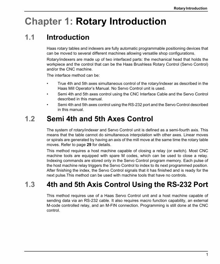
1.1 IntroductionHaas rotary tables and indexers are fully automatic programmable positioning devices thatcan be moved to several different machines allowing versatile shop configurations.
Rotary/indexers are made up of two interfaced parts: the mechanical head that holds theworkpiece and the control that can be the Haas Brushless Rotary Control (Servo Control)and/or the CNC machine.
The interface method can be:
• True 4th and 5th axes simultaneous control of the rotary/indexer as described in theHaas Mill Operator’s Manual. No Servo Control unit is used.
• Semi 4th and 5th axes control using the CNC Interface Cable and the Servo Controldescribed in this manual.
• Semi 4th and 5th axes control using the RS-232 port and the Servo Control describedin this manual.
1.2 Semi 4th and 5th Axes ControlThe system of rotary/indexer and Servo Control unit is defined as a semi-fourth axis. Thismeans that the table cannot do simultaneous interpolation with other axes. Linear movesor spirals are generated by having an axis of the mill move at the same time the rotary tablemoves. Refer to page 29 for details.
This method requires a host machine capable of closing a relay (or switch). Most CNCmachine tools are equipped with spare M codes, which can be used to close a relay.Indexing commands are stored only in the Servo Control program memory. Each pulse ofthe host machine relay triggers the Servo Control to index to its next programmed position.After finishing the index, the Servo Control signals that it has finished and is ready for thenext pulse.This method can be used with machine tools that have no controls.
1.3 4th and 5th Axis Control Using the RS-232 PortThis method requires use of a Haas Servo Control unit and a host machine capable ofsending data via an RS-232 cable. It also requires macro function capability, an externalM-code controlled relay, and an M-FIN connection. Programming is still done at the CNCcontrol.
1

Servo Control
96-8960A.book Page 2 Tuesday, July 28, 2015 1:34 PM
1.4 Servo ControlThe Servo Control unit is specifically designed for rapid positioning of parts in secondaryoperations, such as milling, drilling, and tapping. The Servo Control unit interfaces well withautomatic machines, such as NC mills and automatic production machines. Yourequipment can remotely activate the Servo Control for fully automatic operation.
Workpiece positioning is accomplished by programming angular movement and storingthese positions in the Servo Control. Up to seven programs can be stored and thebattery-powered memory retains the program when the Servo Control is turned off.
The Servo Control is programmed in step (angle) sizes from .001 to 999.999°. There canbe 99 steps for each program, and each step can be repeated (looped) 999 times. Theoptional RS-232 interface is used to upload, download, enter data, read position, start, andstop operation.
2

Rotary Introduction
96-8960A.book Page 3 Tuesday, July 28, 2015 1:34 PM
1.4.1 Servo Control - Front Panel
F1.1: Servo Control - Front Panel
1. Display – 4-lines show current data.2. [0] - [9] - Data entry keys and jog speed selection3. [MODE/RUN PROG] – Switches from Run
mode to Program mode (with blinking display).4. [DISPLAY SCAN] – Scans display to show
either the screen with Position, Step Angle, Feed Rate, Loop Counts, G Code, and status line, or position and status line in RUN mode. It scans left/right in Program mode.
5. [STEP SCAN] – Scans step numbers from 1 through 99 in Run mode. It scans up/down in Program mode.
6. [-] (Minus) - Selects negative step values or Prog/Upload/Download functions. Feed Rate Override (50, 75 or 100%).
7. [CLEAR/ZERO SET] – Clears the entered data, resets program to 0, or defines the present servo position as Home.
8. [ZERO RETURN] – Causes the servo to return to the Home position, search for mechanical Home, delete a step, or move forward to the mechanical offset.9. Load meter – Indicates (%) of spindle load. A high load indicates excessive load or workpiece support misalignment. Hi-Load or Hi Curr alarms occur if not corrected. Damage to the motor or table may result if excessive loads continue. Refer to the "Troubleshooting" section, starting on page 75, for more information.[JOG ]– Causes the servo to move in either the forward [+] or backward [-] direction at a rate defined by the last numeric key pressed.10. [EMERGENCY STOP] – Turns off the servo when on and aborts the step in progress.11. [CYCLE START] – Begins a step, stops a continued operation, inserts a step, or turns the servo on.
1 2
3
4
5
67891011
8888888888888888888888888888888888888888888888888888888888888888
0
3
Servo Control
96-8960A.book Page 4 Tuesday, July 28, 2015 1:34 PM
Servo Control - Display
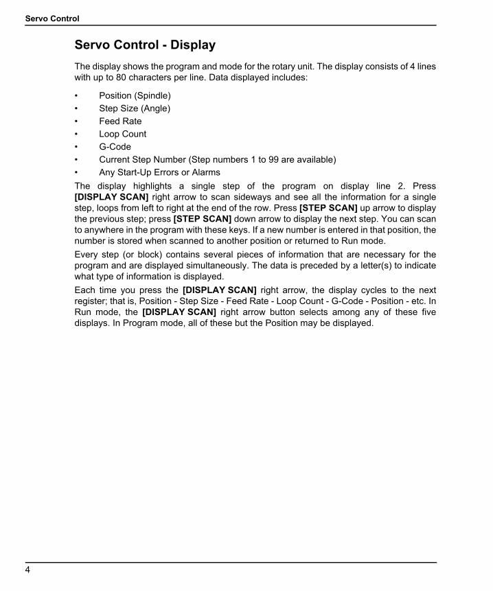
The display shows the program and mode for the rotary unit. The display consists of 4 lineswith up to 80 characters per line. Data displayed includes:
• Position (Spindle)
• Step Size (Angle)
• Feed Rate
• Loop Count
• G-Code
• Current Step Number (Step numbers 1 to 99 are available)
• Any Start-Up Errors or Alarms
The display highlights a single step of the program on display line 2. Press[DISPLAY SCAN] right arrow to scan sideways and see all the information for a singlestep, loops from left to right at the end of the row. Press [STEP SCAN] up arrow to displaythe previous step; press [STEP SCAN] down arrow to display the next step. You can scanto anywhere in the program with these keys. If a new number is entered in that position, thenumber is stored when scanned to another position or returned to Run mode.
Every step (or block) contains several pieces of information that are necessary for theprogram and are displayed simultaneously. The data is preceded by a letter(s) to indicatewhat type of information is displayed.
Each time you press the [DISPLAY SCAN] right arrow, the display cycles to the nextregister; that is, Position - Step Size - Feed Rate - Loop Count - G-Code - Position - etc. InRun mode, the [DISPLAY SCAN] right arrow button selects among any of these fivedisplays. In Program mode, all of these but the Position may be displayed.
4

Rotary Introduction
96-8960A.book Page 5 Tuesday, July 28, 2015 1:34 PM
F1.2: Display
1. The first line displays current spindle position (POS), followed by the G-Code display (G) then the loop count display (L).
2. The second and third lines display the step number (N) followed by the step size, then the feed rate (F).The left three characters on the second or third line contain the step number from 1 to 99. They cannot be changed with the numeric keys and are selected by using the [STEP SCAN] arrow buttons.
3. See item 2.4. The fourth line is the control status line. It provides three control operations: RUN, STOP, ALARM. These
operations are followed by the percentage of load, and the last status of the air brake.
888888888888888888888888888888888888888888888888
1
2
3
4
BRUSHLESS ROTARY CONTROL
5
Servo Control
96-8960A.book Page 6 Tuesday, July 28, 2015 1:34 PM
1.4.2 Servo Control- Rear Panel
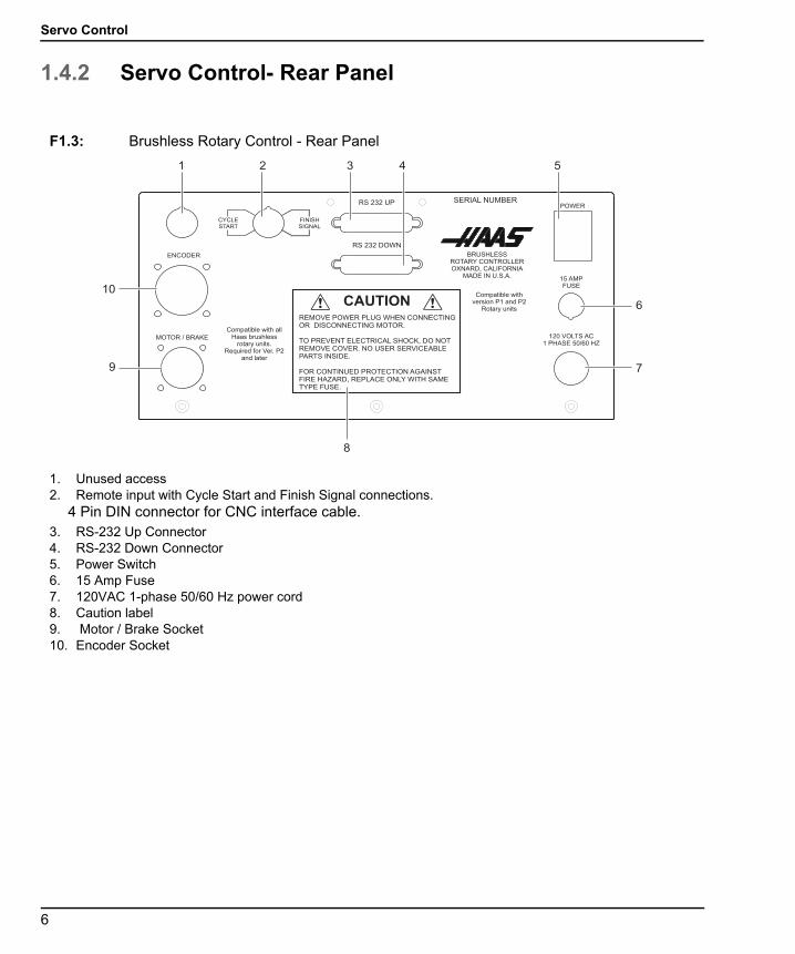
F1.3: Brushless Rotary Control - Rear Panel
1. Unused access2. Remote input with Cycle Start and Finish Signal connections.
4 Pin DIN connector for CNC interface cable.3. RS-232 Up Connector4. RS-232 Down Connector5. Power Switch6. 15 Amp Fuse7. 120VAC 1-phase 50/60 Hz power cord8. Caution label9. Motor / Brake Socket10. Encoder Socket
Compatible withversion P1 and P2
Rotary units
RS 232 DOWN
RS 232 UP
! !REMOVE POWER PLUG WHEN CONNECTINGOR DISCONNECTING MOTOR.
TO PREVENT ELECTRICAL SHOCK, DO NOTREMOVE COVER. NO USER SERVICEABLEPARTS INSIDE.
FOR CONTINUED PROTECTION AGAINSTFIRE HAZARD, REPLACE ONLY WITH SAMETYPE FUSE.
CAUTION
SERIAL NUMBERPOWER
15 AMPFUSE
120 VOLTS AC1 PHASE 50/60 HZ
MOTOR / BRAKE
ENCODER BRUSHLESSROTARY CONTROLLEROXNARD, CALIFORNIA
MADE IN U.S.A.
CYCLESTART
FINISHSIGNAL
Compatible with allHaas brushless
rotary units.Required for Ver. P2
and later
1 2
10
9
3 4 5
6
7
8
6

Operation
96-8960A.book Page 7 Tuesday, July 28, 2015 1:34 PM
Chapter 2: Operation
2.1 Turning On the Servo ControlThe Servo Control requires a single 115V AC supply. To turn on your Servo Control:
1. Press [0] on the rear panel Power switch to make sure that the Servo Control power is off.
2. Connect the control cables (MOTOR/BRAKE and ENCODER) from the table/indexer.
3. Connect the remote input (CNC Interface) cable from the mill (and/or the RS-232 UP cable from the PC or CNC Mill).
4. Connect the Servo Control power cord to a 120VAC, single-phase, 50/60 Hz power supply. Press [1] on the rear panel Power switch to power on the Servo Control.
The Servo Control runs a self-test and then displays: To begin Clear Alarms then Press Cycle Start. If the display gives an alarm message, refer to the Alarm:Error Codes section of this manual, starting on page 12. The numbers remain in the display for only about one second.
5. Pull the [EMERGENCY STOP] to disengage it, if it is set. Press a key to continue operation.
2.2 Run ModeWhen the Servo Control is first turned on, it is in Run mode but the servo motor is turnedoff. This is indicated by: Por On. Pressing [CYCLE START] allows you to continueoperation.
Run mode is used to execute pre-programmed commands. The servo loop can be turnedon in this mode and holds the motor to a commanded position when idle.
When an area of the display is flashing on and off, you are in Program mode. To return toRun mode:
1. Press and release [MODE/RUN PROG] until the display is steady.
7

Initialize Servo Control to Factory Default Parameters
96-8960A.book Page 8 Tuesday, July 28, 2015 1:34 PM
2.3 Initialize Servo Control to Factory Default ParametersAfter turning on the Servo Control, you may need to initialize the control to your rotarymodel. To initialize the servo control:
1. Go to parameter mode. Press [MODE/RUN PROG].
The display flashes.
2. Press and hold [STEP SCAN] up arrow for 5 seconds.
The display is in parameter mode.
3. Press and hold [CLEAR/ZERO SET] for 5 seconds.
The display shows a rotary model.
4. Press [DISPLAY SCAN] to scroll to find model type.
5. Press [CYCLE START].
6. Press [STEP SCAN] to model version.
7. Press [CYCLE START].
The display shows Detecting Motor, and parameters begin loading for your model rotary.
8. When parameter loading stops, press [MODE/RUN PROG].
9. Power off and on the Servo Control.
10. Press the front panel [CYCLE START] switch once.
The display shows 01 no Ho. This means that the motor(s) are now powered but zero position is not defined (there is no home position).
2.4 JoggingTo jog the rotary unit:
1. Select the jog rate as a percent of the maximum feed rate with the front panel number keys. For example, press [5] and then [0] to select 50 percent jog rate.
2. Press [JOG] [+] or [-] to move the table at the jog rate you selected to the position that you want.
3. If the control is set up for linear motion; there are both positive and negative travel limits possible. If a step exceeds the travel limits, the control gives the message 2 FAr and the step is not executed.
4. Parameters 13 and 14 control the maximum travel distances. Information about these parameters starts on page 49.
8

Operation
96-8960A.book Page 9 Tuesday, July 28, 2015 1:34 PM
2.5 Emergency StopTo turn off the servo, cause the spindle to decelerate and stop, and display E-STOP:
1. Press [EMERGENCY STOP] on the Servo Control.
If the last step was not completed, the control remains on that step so the rotary position is not lost.
2. To restart, pull out the [EMERGENCY STOP] button and push [CYCLE START] twice (once to turn the servo on, and again to restart the step).
The remote [CYCLE START] and [FINISH SIGNAL] will not function until you pull out the [EMERGENCY STOP] button and push [CYCLE START].
2.6 Dual Axes Coordinate SystemThe illustrations in this section show the layout of the A and B axes in the Haas five-axiscontrol. The A Axis is rotary motion around the X Axis, while the B Axis is rotary motionabout the Y Axis.
You can use the right-hand rule to determine axis rotation for the A and B axes. Place thethumb of your right hand along the positive X Axis. The fingers of your right hand point inthe direction of tool movement for a positive A-Axis command.
Likewise, with the A Axis at 90°, if you place the thumb of your right hand along the positiveY Axis, the fingers of your hand point in the direction of tool movement for a positive B-Axiscommand.
It is important to remember that the right-hand rule determines direction of tool movement,and not the table movement direction. For the right-hand rule, the fingers point opposite ofthe positive rotary table movement. Refer to these figures.
F2.1: Work Coordinates (Positive Direction)
z+
B+
A+
Y+X+
9
Finding the Zero Position
96-8960A.book Page 10 Tuesday, July 28, 2015 1:34 PM
F2.2: Table Movement (Positive Command)
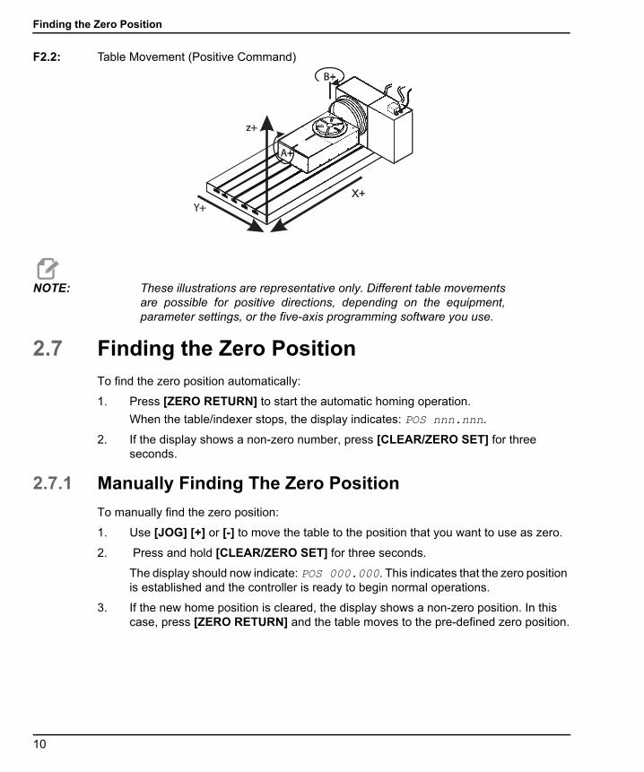
NOTE: These illustrations are representative only. Different table movementsare possible for positive directions, depending on the equipment,parameter settings, or the five-axis programming software you use.
2.7 Finding the Zero PositionTo find the zero position automatically:
1. Press [ZERO RETURN] to start the automatic homing operation.
When the table/indexer stops, the display indicates: POS nnn.nnn.
2. If the display shows a non-zero number, press [CLEAR/ZERO SET] for three seconds.
2.7.1 Manually Finding The Zero Position
To manually find the zero position:
1. Use [JOG] [+] or [-] to move the table to the position that you want to use as zero.
2. Press and hold [CLEAR/ZERO SET] for three seconds.
The display should now indicate: POS 000.000. This indicates that the zero position is established and the controller is ready to begin normal operations.
3. If the new home position is cleared, the display shows a non-zero position. In this case, press [ZERO RETURN] and the table moves to the pre-defined zero position.
z+
B+
A+
Y+X+
.
10

Operation
96-8960A.book Page 11 Tuesday, July 28, 2015 1:34 PM
2.7.2 Offsetting the Zero Position
To offset the Zero Position:
1. Use [JOG] [+] or [-] to move the rotary unit to the position to use as zero and press [CLEAR/ZERO SET] for 3 seconds.
The following is displayed: POS 000.000.
2. If there is a zero offset defined, a non-zero number is displayed. In this case, press [ZERO RETURN] once and the unit moves forward to the predefined zero position.
2.8 Operating HintsHere are a few servo control operating hints:
• To select another display while in the Run mode, press [DISPLAY SCAN].
• A program can be started at any step by pressing [STEP SCAN] up or down.
• Make sure the mill has the same number of M-Codes programmed as steps in therotary control.
• Do not program two consecutive M-Codes in the mill to index the rotary control. Toavoid a timing fault in the mill, use a dwell of 1/4 second between M-Codes.
2.9 Default ValuesFor all rotary units, the default values are:
T2.1: Default Rotary Values
If an entry is cleared or set to 0 by the operator, the value is changed by the control to thedefault value. All entries are stored when selecting the next display function, step number,or returning to Run mode.
Variable Value
step size zero 000.000
F maximum feed rate defined by Parameters
L 001
G-Code G91 (incremental)
11

Alarm: Error Codes
96-8960A.book Page 12 Tuesday, July 28, 2015 1:34 PM
2.10 Alarm: Error CodesA set of self tests are run when the control is turned on and the results may indicate acontrol fault. These are displayed on the Alarm: 4th line.
NOTE: Intermittent low voltage errors or power failures may be the result ofinadequate power to the controller. Use short, heavy-duty extensioncords. Make sure that the supplied power is a minimum of 15 amps atthe plug.
T2.2: Error Codes and Description
Error Code Description
Blank front panel Program CRC failure (bad RAM, or cycle power if bad ROM to RAM program transfer.)
E0 EProm EPROM CRC error
Frt Pnel Short Front panel switch closed or shorted
Remote Short Remote Start switch closed and enabled, or remote CNC input shorted (remove cable to test)
RAM Fault Memory fault
Stored Prg Flt Stored program fault (low battery)
Power Failure Power failure interrupt (low line voltage)
Enc Chip Bad Encoder chip bad
Interrupt Flt Timer/interrupt fault
1khz Missing Clock generation logic failure (1 kHz signal missing)
Scal Cmp Lrge Exceeding maximum allowed rotary scales compensation. (HRT210SC only)
12
Operation
96-8960A.book Page 13 Tuesday, July 28, 2015 1:34 PM
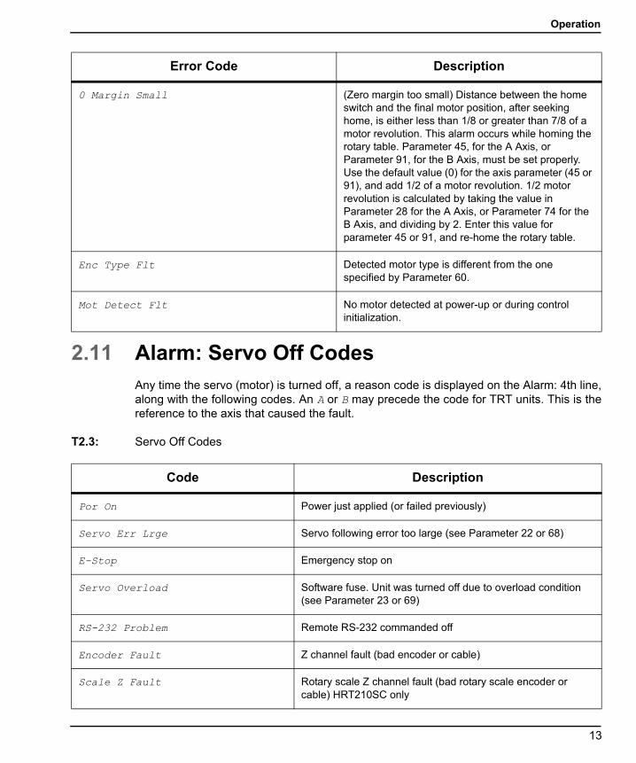
2.11 Alarm: Servo Off CodesAny time the servo (motor) is turned off, a reason code is displayed on the Alarm: 4th line,along with the following codes. An A or B may precede the code for TRT units. This is thereference to the axis that caused the fault.
T2.3: Servo Off Codes
0 Margin Small (Zero margin too small) Distance between the home switch and the final motor position, after seeking home, is either less than 1/8 or greater than 7/8 of a motor revolution. This alarm occurs while homing the rotary table. Parameter 45, for the A Axis, or Parameter 91, for the B Axis, must be set properly. Use the default value (0) for the axis parameter (45 or 91), and add 1/2 of a motor revolution. 1/2 motor revolution is calculated by taking the value in Parameter 28 for the A Axis, or Parameter 74 for the B Axis, and dividing by 2. Enter this value for parameter 45 or 91, and re-home the rotary table.
Enc Type Flt Detected motor type is different from the one specified by Parameter 60.
Mot Detect Flt No motor detected at power-up or during control initialization.
Error Code Description
Code Description
Por On Power just applied (or failed previously)
Servo Err Lrge Servo following error too large (see Parameter 22 or 68)
E-Stop Emergency stop on
Servo Overload Software fuse. Unit was turned off due to overload condition (see Parameter 23 or 69)
RS-232 Problem Remote RS-232 commanded off
Encoder Fault Z channel fault (bad encoder or cable)
Scale Z Fault Rotary scale Z channel fault (bad rotary scale encoder or cable) HRT210SC only
13
Alarm: Servo Off Codes
96-8960A.book Page 14 Tuesday, July 28, 2015 1:34 PM
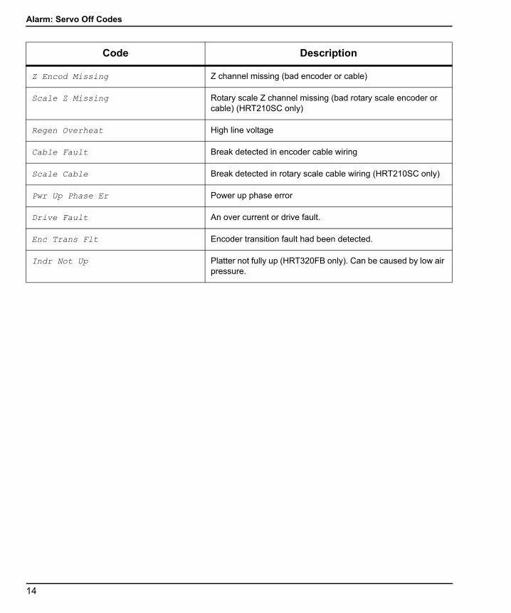
Z Encod Missing Z channel missing (bad encoder or cable)
Scale Z Missing Rotary scale Z channel missing (bad rotary scale encoder or cable) (HRT210SC only)
Regen Overheat High line voltage
Cable Fault Break detected in encoder cable wiring
Scale Cable Break detected in rotary scale cable wiring (HRT210SC only)
Pwr Up Phase Er Power up phase error
Drive Fault An over current or drive fault.
Enc Trans Flt Encoder transition fault had been detected.
Indr Not Up Platter not fully up (HRT320FB only). Can be caused by low air pressure.
Code Description
14
Tailstock Operation
96-8960A.book Page 15 Tuesday, July 28, 2015 1:34 PM
Chapter 3: Tailstock Operation
3.1 IntroductionThe operation of the tailstock is separated into manual and pneumatic types. Be sure thetailstock has been properly installed and aligned before operating.
NOTE: Excessive tailstock force, and misalignment greater than 0.003 TotalIndicator Reading (TIR), causes premature wear on the geartrainand motor.
3.2 Manual Tailstock OperationTo operate the manual tailstock:
1. Position the manual tailstock so that after approximately 1" of tailstock spindle travel, the center comes into contact with the work piece/fixture. If the tailstock needs to be repositioned, repeat Step 4 of “Tailstock Alignment” on page 109.
2. Once in contact, apply only enough force on the handwheel to hold the workpiece/fixture securely.
NOTE: The force required on the handwheel is similar to the force used inclosing a typical garden faucet.
3. Tighten the spindle lock at this time.
3.3 Pneumatic Tailstock OperationTo operate the pneumatic tailstock:
1. Position the pneumatic tailstock so that after approximately 1" of tailstock spindle travel, the center comes into contact with the work piece/fixture. If the tailstock needs to be repositioned, loosen the 1/2-13 hex head bolts (HHB) and repeat Step 4 of “Tailstock Alignment” on page 109.
2. Use of the tailstock spindle lock is optional when using pneumatic tailstock models. Use the following information to determine tailstock air pressure:
15

Pneumatic Tailstock Operation
96-8960A.book Page 16 Tuesday, July 28, 2015 1:34 PM
Maximum Air pressure = 100 psi (7 bar) results in 300 lb (136 kg) tailstock force.
Minimum Air pressure = 5 psi (.3 bar) results in 15 lb (6.8 kg) tailstock force.
ModelNormal Operating
Range Maximum Air Pressure
Rotary Tables 10-60 psi (.7-4.1 bar) 100 psi (7 bar)
Servo 5C indexers 5-40 psi (.3-2.7 bar) 60 psi (4.1 bar) for Live Centers only
16

Programming
96-8960A.book Page 17 Tuesday, July 28, 2015 1:34 PM
Chapter 4: Programming
4.1 IntroductionThis section covers manual input of your program. Unless you up-load a program from acomputer or CNC Mill using the RS-232 serial port (refer to page 21), programming is donethrough the keypad on the front panel. The buttons on the right column of the keypad areused for program control.
NOTE: Always press and immediately release a button. Pushing and holdingdown a button causes the button to repeat; however, this is usefulwhen scrolling through a program. Some buttons have more than onefunction depending on the mode.
Press [MODE/RUN PROG] to select between the Program mode and Run mode. Thedisplay flashes on and off when in Program mode and remains steady when in Run mode.
In Program mode, you enter commands into memory as steps.
T4.1: How Data is Stored in the Servo Control Memory
Pushing [DISPLAY SCAN] moves the window to the right. Pushing [STEP SCAN] up ordown arrow moves the window up or down.
Step Number Step Size Feed Rate Loop Count G Code
1 90.000 80 01 91
2 -30.000 05 01 91
3 0 80 01 99
Through
99 0 80 01 99
17

Putting a Program Into Memory
96-8960A.book Page 18 Tuesday, July 28, 2015 1:34 PM
4.2 Putting a Program Into Memory
NOTE: All data is automatically stored in memory when you press a controlbutton.
Programming begins with making sure that the Servo Control is in Program mode and atstep number 01. To do this:
1. Press [MODE/RUN PROG] while the unit is not in motion.
One of the display fields blinks, indicating you are in Program mode.
2. Push and hold [CLEAR/ZERO SET] for five seconds.
You have cleared the memory. You are at step 01 and ready to begin programming, POS 000.000 is displayed. The memory does not have to be cleared each time data is entered or changed. You can change data in the program simply by writing new data over old.
3. You can store (7) programs in a single-axis control (numbered 0-6). To access a program, press [-] (minus) while showing a G-code.
The display changes to: Prog n.
4. Press a number key to select a new program, and then press [MODE/RUN PROG] to return to Run mode or [CYCLE START] to continue in Program mode.
Each one of the possible 99 steps in a program must contain a G-code and one of these:
a) Step size or position command shown as a number with possible minus sign.
b) Feed rate shown with a preceding F.c) Loop count shown with a preceding L.d) Subroutine destination with a preceding Loc.
5. To display the additional codes associated with a step, press [DISPLAY SCAN].
Example lines of code:
S135.000 G91F0 40.000 L001
6. Some entries are not allowed for particular G-codes, and either cannot be entered or are ignored. Most steps are incremental position commands and this is the default G91.
7. G86, G87, G89, G92, and G93 should be used with the CNC relay function disabled (Parameter 1 = 2). Enter your step size in degrees to three decimal places. You must always enter the decimal places, even if they are zero. Enter a minus sign (-) for opposite rotation. To edit a feedrate or loop count, push [DISPLAY SCAN] to view the entry and input the data.
18
Programming
96-8960A.book Page 19 Tuesday, July 28, 2015 1:34 PM
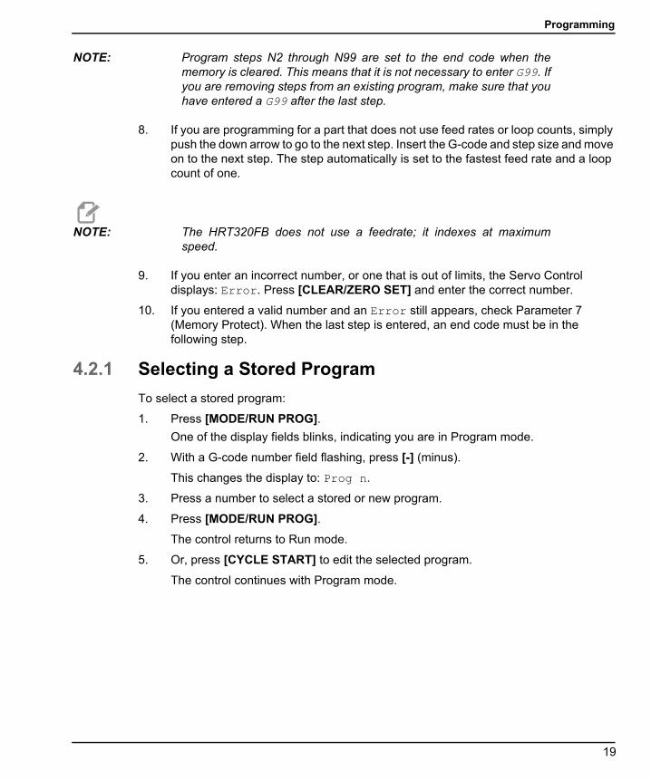
NOTE: Program steps N2 through N99 are set to the end code when thememory is cleared. This means that it is not necessary to enter G99. Ifyou are removing steps from an existing program, make sure that youhave entered a G99 after the last step.
8. If you are programming for a part that does not use feed rates or loop counts, simply push the down arrow to go to the next step. Insert the G-code and step size and move on to the next step. The step automatically is set to the fastest feed rate and a loop count of one.
NOTE: The HRT320FB does not use a feedrate; it indexes at maximumspeed.
9. If you enter an incorrect number, or one that is out of limits, the Servo Control displays: Error. Press [CLEAR/ZERO SET] and enter the correct number.
10. If you entered a valid number and an Error still appears, check Parameter 7 (Memory Protect). When the last step is entered, an end code must be in the following step.
4.2.1 Selecting a Stored Program
To select a stored program:
1. Press [MODE/RUN PROG].
One of the display fields blinks, indicating you are in Program mode.
2. With a G-code number field flashing, press [-] (minus).
This changes the display to: Prog n.
3. Press a number to select a stored or new program.
4. Press [MODE/RUN PROG].
The control returns to Run mode.
5. Or, press [CYCLE START] to edit the selected program.
The control continues with Program mode.
19
Putting a Program Into Memory
96-8960A.book Page 20 Tuesday, July 28, 2015 1:34 PM
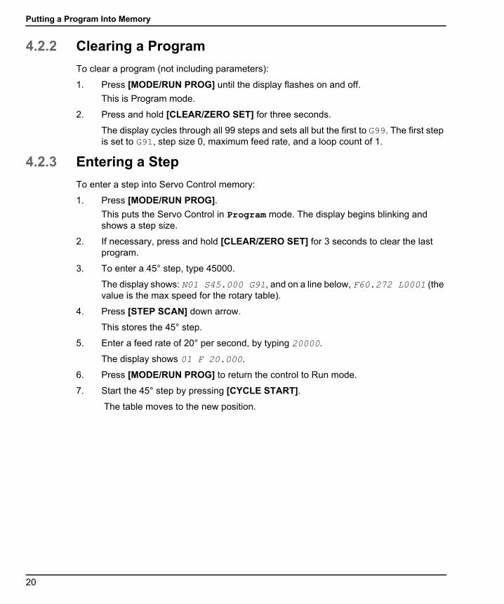
4.2.2 Clearing a Program
To clear a program (not including parameters):
1. Press [MODE/RUN PROG] until the display flashes on and off.
This is Program mode.
2. Press and hold [CLEAR/ZERO SET] for three seconds.
The display cycles through all 99 steps and sets all but the first to G99. The first step is set to G91, step size 0, maximum feed rate, and a loop count of 1.
4.2.3 Entering a Step
To enter a step into Servo Control memory:
1. Press [MODE/RUN PROG].
This puts the Servo Control in Program mode. The display begins blinking and shows a step size.
2. If necessary, press and hold [CLEAR/ZERO SET] for 3 seconds to clear the last program.
3. To enter a 45° step, type 45000.
The display shows: N01 S45.000 G91, and on a line below, F60.272 L0001 (the value is the max speed for the rotary table).
4. Press [STEP SCAN] down arrow.
This stores the 45° step.
5. Enter a feed rate of 20° per second, by typing 20000.
The display shows 01 F 20.000.
6. Press [MODE/RUN PROG] to return the control to Run mode.
7. Start the 45° step by pressing [CYCLE START].
The table moves to the new position.
20

Programming
96-8960A.book Page 21 Tuesday, July 28, 2015 1:34 PM
4.2.4 Inserting a Line
To insert a new step into a program:
1. Press [MODE/RUN PROG] until the display flashes on and off.
This is Program mode.
2. Press and hold [CYCLE START] for three seconds while in Program mode.
This moves the current step and all following steps down, and inserts a new step with default values.
NOTE: Subroutine jumps must be renumbered.
4.2.5 Deleting a Line
To delete a step from a program:
1. Press [MODE/RUN PROG] until display flashes on and off.
This is Program mode.
2. Press and hold [ZERO RETURN] for three seconds.
All the following steps move up by one.
NOTE: Subroutine jumps must be renumbered.
4.3 The RS-232 InterfaceThere are two connectors used for the RS-232 interface; one each of male and femaleDB-25 connectors. To connect multiple Servo Controls, connect the cable from thecomputer to the female connector. Another cable can connect the first Servo Control to thesecond by connecting the male connector of the first box to the female connector of thesecond. You can connect up to nine controls in this way. The RS-232 connector on theServo Control is used to load programs.
The RS-232 connector on the back of most personal computers is a male DB-9, so onlyone type of cable is required for connection to the control, or between controls. This cablemust be a DB-25 male on one end and a DB-9 female on the other. Pins 1, 2, 3, 4, 5, 6, 7,8, and 9 must be wired one-to-one. It cannot be a Null Modem cable, which inverts pins 2and 3. To check cable type, use a cable tester to check that communication lines arecorrect.
21

The RS-232 Interface
96-8960A.book Page 22 Tuesday, July 28, 2015 1:34 PM
The control is DCE (Data Communication Equipment), which means that it transmits on theRXD line (pin 3) and receives on the TXD line (pin 2). The RS-232 connector on most PCsis wired for DTE (Data Terminal Equipment), so no special jumpers should be required.
T4.2: PC RS-232 COM1 Setup
F4.1: RS-232 Daisy Chain Two Servo Controllers for TRT: [1] PC with RS-232 DB-9 Connector, [2] RS-232 Cable DB-9 to DB-25 straight through, [3] Servo Control A-Axis, [4] RS-232 Cable DB-25 to DB-25 straight through, [5] Servo Control B-Axis
The [RS-232 DOWN] (out line) DB-25 connector is used when multiple controls are used.The first control’s [RS-232 DOWN] (out line) connector goes to the second controller’s[RS-232 UP] (in line) connector, etc.
PC Parameter Value
Stop Bits 2
Parity Even
Baud Rate 9600
Data Bits 7
RS 232 DOWN
RS 232 UP SERIAL NUMBERPOWER
15 AMPFUSE
BRUSHLESSROTARY CONTROLLEROXNARD, CALIFORNIA
MADE IN U.S.A.
FINISHSIGNAL
RS 232 DOWN
RS 232 UP SERIAL NUMBERPOWER
15 AMPFUSE
BRUSHLESSROTARY CONTROLLEROXNARD, CALIFORNIA
MADE IN U.S.A.
FINISHSIGNAL
1
2
3
4 5
22

Programming
96-8960A.book Page 23 Tuesday, July 28, 2015 1:34 PM
If Parameter 33 is 0, the CTS line can still be used to synchronize output. When more thanone Haas rotary control is daisy-chained, data sent from the PC goes to all of the controlsat the same time. That is why an axis selection code (Parameter 21) is required. Data sentback to the PC from the controls is programmed together using digital logic OR gates(OR-ed) so that, if more than one box is transmitting, the data will be garbled. Therefore,the axis selection code must be unique for each controller. The serial interface may be usedin either a remote command mode or as an upload/download path.
4.3.1 Upload and Download
The serial interface may be used to upload or download a program. All data is sent andreceived in ASCII code. Lines sent by the Servo Control are terminated by a carriage return(CR) and line feed (LF). Lines sent to the Servo Control may contain a LF, but it is ignoredand the lines are terminated by a CR.
Programs sent or received by the controller have the following format:
%N01 G91 X045.000 F080.000 L002N02 G90 X000.000 Y045.000 F080.000N03 G98 F050.000 L013N04 G96 P02N05 G99%
The Servo Control inserts steps and re-numbers all required data. The P code is thedestination of a subroutine jump for G96.
The % must be found before the Servo Control processes any input and it always beginsoutput with a %. The N-Code and G-code are found on all lines and the remaining codesare present as required by the G-code. The N-Code is the same as the step number displayin the controller. All N-Codes must be continuous starting from 1. The Servo Control alwaysends output with a % and inputs to it is terminated by a %, N99 or G99. Spaces are onlyallowed where shown.
The Servo Control displays SEnding as a program is sent. The Servo Control displaysLoAding as a program is received. In each case, the line number changes as theinformation is sent or received. An error message is displayed if bad information was sent,and the display indicates the last line received. If an error occurs, make sure that the letterO was not inadvertently used in the program instead of a zero. Also refer to“Troubleshooting a Working Interface on a CNC” on page 75.
When an RS-232 interface is used, it is recommended that the programs be written inWindows Notepad, or another ASCII program. Word processing programs, such as Word,are not recommended, as they will insert extra, unnecessary information.
Upload/Download functions do not need an axis select code, as they are manually initiatedby an operator at the front panel. However, if the select code (Parameter 21) is not zero,an attempt to send a program to the control will fail, as the lines do not begin with the correctaxis select code.
23

The RS-232 Interface
96-8960A.book Page 24 Tuesday, July 28, 2015 1:34 PM
Upload or download is started from Program mode with the G-code displayed. To start anupload or download:
1. Press [-] (minus) while the G-code is displayed and blinking.
Prog n is displayed, where n is the currently selected program number.
2. Select a different program by pressing a number key, then press [CYCLE START] to return to Program mode or [MODE/RUN PROG] to return to Run mode, or press [-] (minus) again and the display shows: SEnd n ,where n is the currently selected program number.
3. Select a different program by pressing a number key and then [CYCLE START] to begin sending that selected program, or press [-] (minus) again and the display shows: rEcE n ,where n is the currently selected program number.
4. Select a different program by pressing a number key and then Start to begin receiving that selected program, or press the minus (-) key again to return the display to Program mode.
5. Both uploading and downloading can be terminated by pressing [CLEAR/ZERO SET].
4.3.2 RS-232 Remote Command Mode
Parameter 21 cannot be zero for the remote command mode to operate. The Servo Controllooks for an axis select code defined by this parameter.
The Servo Control must also be in RUN mode to respond to the interface. Since the controlpowers-on in RUN mode, unattended remote operation is possible.Commands are sent tothe Servo Control in ASCII code and terminated by a carriage return (CR).
All commands, except for the B command, must be preceded by the numeric code for anaxis (U, V, W, X, Y, Z). Refer to “Parameter 21 - RS-232 Interface Axis Select” onpage 51.The B command does not require the select code, since it is used to activate allaxes simultaneously. The ASCII codes used to command the control follow:
4.3.3 RS-232 Single Axis Commands
The following are the RS-232 commands, where x is the selected axis designated byParameter 21 (cap U, V, W, X, Y, or Z):
T4.3: RS-232 Commands
ASCII Command Function
xSnn.nn Specify step size nn.nn or absolute position.
xFnn.nn Specify feed rate nn.nn in units/second.
xGnn Specify Gnn code.
24
Programming
96-8960A.book Page 25 Tuesday, July 28, 2015 1:34 PM
Sample Remote Program
The following is a transmitted program for the W-Axis. Set Parameter 21 = 3 (W-Axis). Sendthe following:
WS180.000 (Steps)WF100.000 (Feed)WG91 (Increment)WB (Begin)
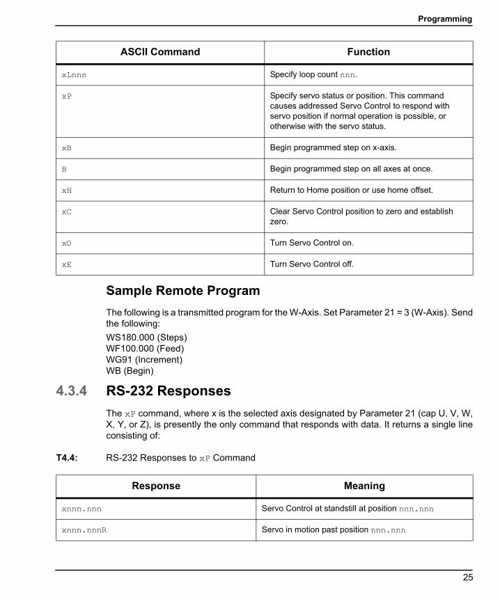
4.3.4 RS-232 Responses
The xP command, where x is the selected axis designated by Parameter 21 (cap U, V, W,X, Y, or Z), is presently the only command that responds with data. It returns a single lineconsisting of:
T4.4: RS-232 Responses to xP Command
xLnnn Specify loop count nnn.
xP Specify servo status or position. This command causes addressed Servo Control to respond with servo position if normal operation is possible, or otherwise with the servo status.
xB Begin programmed step on x-axis.
B Begin programmed step on all axes at once.
xH Return to Home position or use home offset.
xC Clear Servo Control position to zero and establish zero.
xO Turn Servo Control on.
xE Turn Servo Control off.
ASCII Command Function
Response Meaning
xnnn.nnn Servo Control at standstill at position nnn.nnn
xnnn.nnnR Servo in motion past position nnn.nnn
25
Program Functions
96-8960A.book Page 26 Tuesday, July 28, 2015 1:34 PM
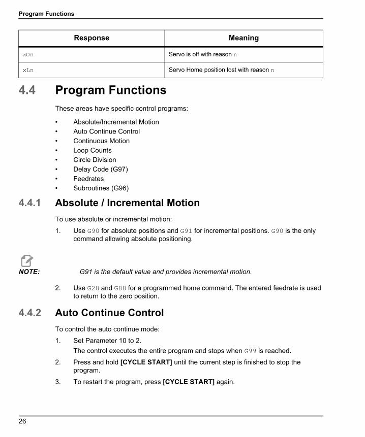
4.4 Program FunctionsThese areas have specific control programs:
• Absolute/Incremental Motion
• Auto Continue Control
• Continuous Motion
• Loop Counts
• Circle Division
• Delay Code (G97)
• Feedrates
• Subroutines (G96)
4.4.1 Absolute / Incremental Motion
To use absolute or incremental motion:
1. Use G90 for absolute positions and G91 for incremental positions. G90 is the only command allowing absolute positioning.
NOTE: G91 is the default value and provides incremental motion.
2. Use G28 and G88 for a programmed home command. The entered feedrate is used to return to the zero position.
4.4.2 Auto Continue Control
To control the auto continue mode:
1. Set Parameter 10 to 2.
The control executes the entire program and stops when G99 is reached.
2. Press and hold [CYCLE START] until the current step is finished to stop the program.
3. To restart the program, press [CYCLE START] again.
xOn Servo is off with reason n
xLn Servo Home position lost with reason n
Response Meaning
26

Programming
96-8960A.book Page 27 Tuesday, July 28, 2015 1:34 PM
4.4.3 Continuous Motion
To start continuous motion:
1. G33 uses remote [CYCLE START] to start continuous motion.
2. When an M-Fin signal from the CNC control is connected to the Remote [CYCLE START], and an arbitrary feed rate is entered in the feed rate field for the G33 step, rotary motion continues until the M-Fin signal is released.
3. Set step size to 1.000 for G33 clockwise motion. Set step size to –1.000 for G33 counter-clockwise motion.
4. The loop count is set to 1.
4.4.4 Loop Counts
Loop Counts allows a step to repeat up to 999 times, before going on to the next step. Theloop count is an L followed by a value between 1 and 999. In Run mode, it displays theremaining loop counts for the selected step. It is also used in conjunction with the CircleDivision function to enter the number of divisions in the circle from 2 to 999. The Loop Countspecifies the number of times to repeat a subroutine, when used with G96.
4.4.5 Delay Code (G97)
G97 is used to program a pause (dwell) in a program. For example, programming a G97and setting L = 10 produces a 1 second dwell. G97 does not pulse the CNC relay at stepcompletion.
4.4.6 Circle Division
Circle division is selected with a G98 (or G85 for TRT units). The L defines how many equalparts a circle is divided into. After the L count steps, the unit is in the same position it startedfrom. Circle division is only available in the circular modes (i.e., Parameter 12 = 0, 5, or 6).
4.4.7 Feedrate Programming
The feedrate display ranges between 00.001 and the maximum for the rotary unit (seetable). The feedrate value is preceded by an F and displays the feedrate used for theselected step. The feedrate corresponds to degrees rotated per second.
For example: A feedrate of 80.000 means the platter rotates 80° in one second.
When the Servo Control is in Stop mode, press [-] to change the feed rate value in theprogram without modifying the program or any parameters. This is the Feed Rate Overridemode.
Press [-] until the desired feed rate value (50, 75 or 100%), e.g., OVR:75%, is indicated inthe lower, right corner of the display.
27
Program Functions
96-8960A.book Page 28 Tuesday, July 28, 2015 1:34 PM
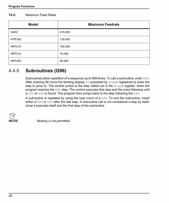
T4.5: Maximum Feed Rates
4.4.8 Subroutines (G96)
Subroutines allow repetition of a sequence up to 999 times. To call a subroutine, enter G96.After entering 96 move the blinking display 00 preceded by Step# registered to enter thestep to jump to. The control jumps to the step called out in the Step# register, when theprogram reaches the G96 step. The control executes that step and the ones following untila G95 or G99 is found. The program then jumps back to the step following the G96.
A subroutine is repeated by using the loop count of a G96. To end the subroutine, inserteither a G95 or G99 after the last step. A subroutine call is not considered a step by itself,since it executes itself and the first step of the subroutine.
NOTE: Nesting is not permitted.
Model Maximum Feedrate
HA5C 410.000
HTR160 130.000
HRT210 100.000
HRT310 75.000
HRT450 50.000
28

Programming
96-8960A.book Page 29 Tuesday, July 28, 2015 1:34 PM
4.5 Simultaneous Rotation and MillingG94 is used to perform simultaneous milling. The relay is pulsed at the beginning of the stepso that the CNC mill goes to the next block. The Servo Control then executes the L stepswithout waiting for start commands. Normally, the L count on the G94 is set to 1 and thatstep is followed by a step that is run simultaneous with a CNC mill.
4.5.1 Spiral Milling (HRT & HA5C)
Spiral milling is coordinated movement of the rotary unit and the mill axis. Simultaneousrotation and milling allows machining of cams, spiral, and angular cuts. Use a G94 in thecontrol and add rotation and feed rate. The control executes G94 (signals mill to proceed)and the following step(s) as one. If more than one step is required, use an L command. Inorder to spiral mill, the mill feed rate must be calculated so the rotary unit and the mill axisstop at the same time.
In order to calculate the mill feed rate, the following information needs to be addressed:
• The angular rotation of the spindle (this is described in the part drawing).
• A feed rate for the spindle (arbitrarily select a reasonable one, for example, fivedegrees (5°) per second).
• The distance you wish to travel on X-axis (see part drawing).
For example, to mill a spiral that is 72° of rotation and move 1.500" on the X-axis at thesame time:
1. Compute the amount of time it takes the rotary unit to rotate through the angle # of degrees / (feed rate of spindle) = time to index 72 degrees / 5° per second = 14.40 seconds for unit to rotate.
2. Compute the mill feed rate that moves the X distance in 14.40 seconds (length to travel in inches/# of seconds of rotation) x 60 seconds = mill feed rate in inches per minute. 1.500 inches/14.4 seconds = 0.1042 inches per second x 60 = 6.25 inches per minute.
Therefore, if the indexer is set to move 72° at a feed rate of 5° per second, program the millto travel 1.500 inches with a feed rate of 6.25 inches per minute for the spiral tobe generated.
The program for the Servo Control is as follows:
29
Simultaneous Rotation and Milling
96-8960A.book Page 30 Tuesday, July 28, 2015 1:34 PM
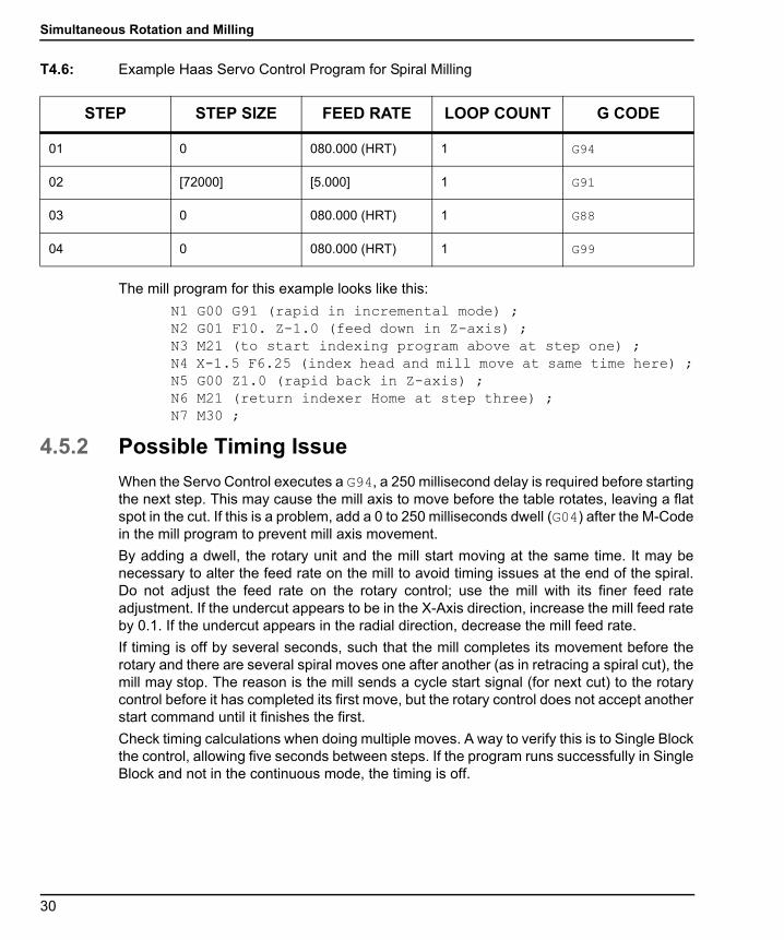
T4.6: Example Haas Servo Control Program for Spiral Milling
The mill program for this example looks like this:
N1 G00 G91 (rapid in incremental mode) ;N2 G01 F10. Z-1.0 (feed down in Z-axis) ;N3 M21 (to start indexing program above at step one) ;N4 X-1.5 F6.25 (index head and mill move at same time here) ;N5 G00 Z1.0 (rapid back in Z-axis) ;N6 M21 (return indexer Home at step three) ;N7 M30 ;
4.5.2 Possible Timing Issue
When the Servo Control executes a G94, a 250 millisecond delay is required before startingthe next step. This may cause the mill axis to move before the table rotates, leaving a flatspot in the cut. If this is a problem, add a 0 to 250 milliseconds dwell (G04) after the M-Codein the mill program to prevent mill axis movement.
By adding a dwell, the rotary unit and the mill start moving at the same time. It may benecessary to alter the feed rate on the mill to avoid timing issues at the end of the spiral.Do not adjust the feed rate on the rotary control; use the mill with its finer feed rateadjustment. If the undercut appears to be in the X-Axis direction, increase the mill feed rateby 0.1. If the undercut appears in the radial direction, decrease the mill feed rate.
If timing is off by several seconds, such that the mill completes its movement before therotary and there are several spiral moves one after another (as in retracing a spiral cut), themill may stop. The reason is the mill sends a cycle start signal (for next cut) to the rotarycontrol before it has completed its first move, but the rotary control does not accept anotherstart command until it finishes the first.
Check timing calculations when doing multiple moves. A way to verify this is to Single Blockthe control, allowing five seconds between steps. If the program runs successfully in SingleBlock and not in the continuous mode, the timing is off.
STEP STEP SIZE FEED RATE LOOP COUNT G CODE
01 0 080.000 (HRT) 1 G94
02 [72000] [5.000] 1 G91
03 0 080.000 (HRT) 1 G88
04 0 080.000 (HRT) 1 G99
30

Programming
96-8960A.book Page 31 Tuesday, July 28, 2015 1:34 PM
4.6 Programming ExamplesThe following sections contain examples of Servo Control programming:
• Example 1 - Index the platter 90°.
• Example 2 - Index the platter 90° (Example 1, Steps 1-8), rotate at 5 °/sec (F5) in theopposite direction for 10.25° and then return home.
• Example 3 - Drill a four-hole pattern and then a five-hole pattern on the same part.
• Example 4 - Index 90.12°, start a seven-hole bolt pattern, and then return to the zeroposition.
• Example 5 - Index 90°, slow feed for 15°, repeat this pattern three times, and returnhome.
• Example 6 - Index 15°, 20°, 25°, and 30° in sequence, four times, and then drill afive-hole bolt pattern.
4.6.1 Programming Example 1
To index the platter 90°:
1. Turn on power by pressing [1] on the rear panel [POWER] switch.
2. Press [CYCLE START].
3. Press [ZERO RETURN].
4. Press [MODE/RUN PROG] and release.
Display blinks.
5. Press and hold [CLEAR/ZERO SET] for five seconds.
The display shows 01 000.000.
6. Type 90000 on the key pad.
7. Press [MODE/RUN PROG].
The display stops blinking.
8. Press [CYCLE START] to index.
4.6.2 Programming Example 2
To index the platter 90° (Example 1, Steps 1-8), rotate at 5 °/sec (F5) in the oppositedirection for 10.25°, and then return home:
1. Run Programming Example 1, on page 31.
2. Press [MODE/RUN PROG] and release.
The display blinks.
3. Press the [STEP SCAN] down arrow twice. You should be on program step 02.
4. Type 91 on the key pad. Use [CLEAR/ZERO SET] to erase mistakes.
31

Programming Examples
96-8960A.book Page 32 Tuesday, July 28, 2015 1:34 PM
5. Press [DISPLAY SCAN].
6. Type -10250 on the keypad.
7. Press the [STEP SCAN] down arrow.
The Servo Control is now on the feed display.
8. Type 5000 on the keypad.
9. Press the [STEP SCAN] down arrow.
a. The control is now on step 03.
10. Type 88 on the keypad.
11. Press the [STEP SCAN] up arrow (4) times. The control is now on step 01.
12. Press [MODE/RUN PROG].
The display stops blinking.
13. Press [CYCLE START] (3) times. The unit indexes 90 degrees (90°), slow feeds in the opposite direction for 10.25 degrees (10.25°), then returns home.
4.6.3 Programming Example 3
This example shows the program as you would enter it into the Servo Control. Be sure toclear out the memory before you enter the program.
To drill a four-hole pattern, and then a five-hole pattern on the same part:
1. Enter these steps into the Servo Control:
T4.7: Example 3 Program
2. To program Example 3 using circle division, enter the following steps into the Servo Control (Set Parameter 12 = 6 for this example):
Step Step Size Feed Rate Loop Count G-code
01 90.000 270.000 (HA5C) 4 G91
02 72.000 270.000 (HA5C) 5 G91
03 0 270.000 (HA5C) 1 G99
32
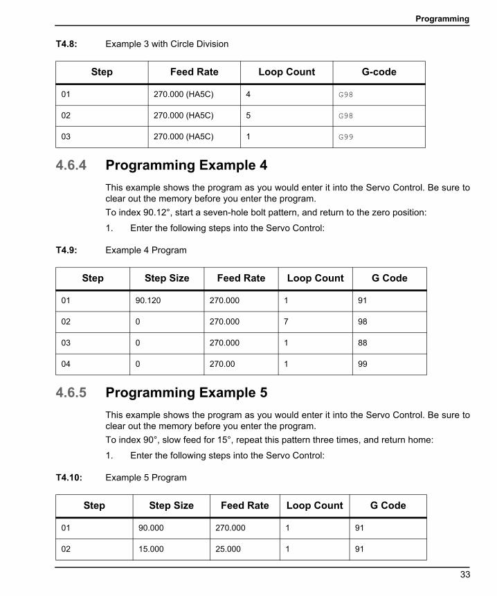
Programming
96-8960A.book Page 33 Tuesday, July 28, 2015 1:34 PM
T4.8: Example 3 with Circle Division
4.6.4 Programming Example 4
This example shows the program as you would enter it into the Servo Control. Be sure toclear out the memory before you enter the program.
To index 90.12°, start a seven-hole bolt pattern, and return to the zero position:
1. Enter the following steps into the Servo Control:
T4.9: Example 4 Program
4.6.5 Programming Example 5
This example shows the program as you would enter it into the Servo Control. Be sure toclear out the memory before you enter the program.
To index 90°, slow feed for 15°, repeat this pattern three times, and return home:
1. Enter the following steps into the Servo Control:
T4.10: Example 5 Program
Step Feed Rate Loop Count G-code
01 270.000 (HA5C) 4 G98
02 270.000 (HA5C) 5 G98
03 270.000 (HA5C) 1 G99
Step Step Size Feed Rate Loop Count G Code
01 90.120 270.000 1 91
02 0 270.000 7 98
03 0 270.000 1 88
04 0 270.00 1 99
Step Step Size Feed Rate Loop Count G Code
01 90.000 270.000 1 91
02 15.000 25.000 1 91
33
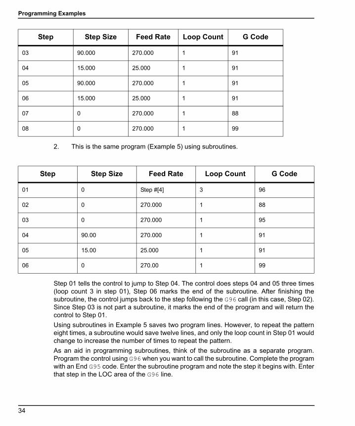
Programming Examples
96-8960A.book Page 34 Tuesday, July 28, 2015 1:34 PM
2. This is the same program (Example 5) using subroutines.
Step 01 tells the control to jump to Step 04. The control does steps 04 and 05 three times(loop count 3 in step 01), Step 06 marks the end of the subroutine. After finishing thesubroutine, the control jumps back to the step following the G96 call (in this case, Step 02).Since Step 03 is not part a subroutine, it marks the end of the program and will return thecontrol to Step 01.
Using subroutines in Example 5 saves two program lines. However, to repeat the patterneight times, a subroutine would save twelve lines, and only the loop count in Step 01 wouldchange to increase the number of times to repeat the pattern.
As an aid in programming subroutines, think of the subroutine as a separate program.Program the control using G96 when you want to call the subroutine. Complete the programwith an End G95 code. Enter the subroutine program and note the step it begins with. Enterthat step in the LOC area of the G96 line.
03 90.000 270.000 1 91
04 15.000 25.000 1 91
05 90.000 270.000 1 91
06 15.000 25.000 1 91
07 0 270.000 1 88
08 0 270.000 1 99
Step Step Size Feed Rate Loop Count G Code
Step Step Size Feed Rate Loop Count G Code
01 0 Step #[4] 3 96
02 0 270.000 1 88
03 0 270.000 1 95
04 90.00 270.000 1 91
05 15.00 25.000 1 91
06 0 270.00 1 99
34

Programming
96-8960A.book Page 35 Tuesday, July 28, 2015 1:34 PM
4.6.6 Programming Example 6
This example shows the program as you would enter it into the Servo Control. Be sure toclear out the memory before entering the program.
To index 15°, 20°, 25°, and 30° in sequence, four times, and then drill a five-hole boltpattern:
1. Enter these steps into the Servo Control:
T4.11: Example 6 Program
Step Step Size Feed Rate Loop Count G-code
01 0 Loc 1 G96
02 0 25.000 (HA5C) 1 G98
03 0 270.000 (HA5C) 1 95
Main program above step 01-03 - Subroutine steps 01-08
04 15.000 25.000 (HA5C) 1 91
05 20.000 270.000 (HAC5) 1 91
06 25.000 25.000 (HAC5) 1 91
07 30.000 270.000 (HAC5) 1 91
08 0 270.000 (HAC5) 1 99
35

Programming Examples
96-8960A.book Page 36 Tuesday, July 28, 2015 1:34 PM
36
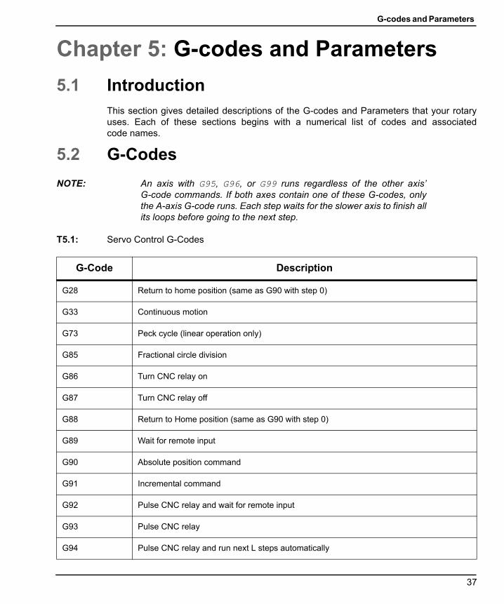
G-codes and Parameters
96-8960A.book Page 37 Tuesday, July 28, 2015 1:34 PM
Chapter 5: G-codes and Parameters
5.1 IntroductionThis section gives detailed descriptions of the G-codes and Parameters that your rotaryuses. Each of these sections begins with a numerical list of codes and associatedcode names.
5.2 G-Codes
NOTE: An axis with G95, G96, or G99 runs regardless of the other axis’G-code commands. If both axes contain one of these G-codes, onlythe A-axis G-code runs. Each step waits for the slower axis to finish allits loops before going to the next step.
T5.1: Servo Control G-Codes
G-Code Description
G28 Return to home position (same as G90 with step 0)
G33 Continuous motion
G73 Peck cycle (linear operation only)
G85 Fractional circle division
G86 Turn CNC relay on
G87 Turn CNC relay off
G88 Return to Home position (same as G90 with step 0)
G89 Wait for remote input
G90 Absolute position command
G91 Incremental command
G92 Pulse CNC relay and wait for remote input
G93 Pulse CNC relay
G94 Pulse CNC relay and run next L steps automatically
37

G-Codes
96-8960A.book Page 38 Tuesday, July 28, 2015 1:34 PM
5.2.1 G28 Return Home
G28 (and G88) provide a programmed return to home command. The feed rate (F) is usedto provide the rate of return to the zero position.
5.2.2 G33 Continuous Motion
When remote [CYCLE START] is manually closed and held or an M-Fin signal from theCNC controller is active at a G33 step, continuous rotary movement is started. Motion stopswhen remote [CYCLE START] is manually opened or the M-Fin signal from the CNCcontroller is removed.
M51 to close and M61 to open.
5.2.3 G73 Peck Cycle
Refer to the Mill Manual G73 High Speed Peck Drilling Canned Cycle description and G91Incremental Command.
5.2.4 G85 Fractional Circle Division
For TRT units, circle division is selected with G85. The L defines how many equal parts acircle is divided into. After the L count steps, the unit is in the same position it started from.Circle division is only available in the circular modes (i.e., Parameter 12 = 0, 5, or 6).
G95 End of program/return but more steps follow
G96 Subroutine call/jump (destination is a step number)
G97 Delay by L count/10 seconds (down to 0.1 second)
G98 Circle division (circular operation only)
G99 End of program/return and end of steps
G-Code Description
38

G-codes and Parameters
96-8960A.book Page 39 Tuesday, July 28, 2015 1:34 PM
5.2.5 G86/G87 Turn CNC Relay On/Off
G86 closes the [FINISH SIGNAL] relay in the Servo Control.
F5.1: CNC Relay On: [1] CNC Mill, [2] Servo Control
NOTE: If the control is used around high-frequency equipment, such aselectric welders or induction heaters, shielded wire must be used toprevent false triggering by radiated EMI (electromagneticinterference). The shield should be attached to earth ground.
If your application is in an automatic machine (CNC mill), the feedback lines([FINISH SIGNAL] pins 1 and 2) are used. Pins 1 and 2 are connected to the contacts of arelay inside the control and have no polarity or power on them.
They are used to synchronize the automatic equipment with the Servo Control.
The feedback cables tell the mill that the rotary unit has finished. The relay can be used to[FEED HOLD] NC machine movements, or can be used to cancel an M-Code function. Ifthe machine is not equipped with this option, an alternative may be to dwell (pause) longerthan it takes to move the rotary unit. The relay triggers for all [CYCLE START] closures,except G97.
G87 opens the [FINISH SIGNAL] relay.
5.2.6 G88 Return To Home Position
G88 Return to Home position is the same as G90 with step 0. Refer to “G28 Return Home”on page 38
5.2.7 G89 Wait For Remote Input
G89 waits for the remote input (mFin). Stops rotary/indexer and waits for mFin signal tocontinue motion.
M FIN
+24 V
680 OHM
SIGNALFINISH
CYCLESTART
1
23
4
1
2
+12 Volt s
39
G-Codes
96-8960A.book Page 40 Tuesday, July 28, 2015 1:34 PM
5.2.8 G90/G91 Absolute/Incremental Position
[G90] is used to indicate absolute positioning and [G91] is used for incremental positioning.[G91] is the default value.
5.2.9 G92 Pulse CNC Relay And Wait For Remote Input
Same as [G94] except Servo Control waits for remote input.
5.2.10 G93 Pulse CNC Relay
Same as [G94], with no loop.
5.2.11 G94 Pulse CNC Relay And Run Next L Steps Automatically
G94 is used to perform simultaneous milling. The relay is pulsed at the beginning of the stepso that the CNC mill goes to the next block. The Servo Control then executes the L stepswithout waiting for start commands. Normally, the L count on the G94 is set to 1 and thatstep is followed by a step that is run simultaneous with a CNC mill.
5.2.12 G95 End Of Program/Return But More Steps Follow
End a G96 subroutine with a G95 after the last step of the subroutine.
5.2.13 G96 Subroutine Call/Jump
Subroutines allow repetition of a sequence up to 999 times. To call a subroutine, enter G96.After entering 96 move the blinking display 00 preceded by Step# registered to enter thestep to jump to. The control jumps to the step called out in the Step# register, when theprogram reaches the G96 step. The control executes that step and the ones following untila G95 or G99 is found. The program then jumps back to the step following the G96.
A subroutine is repeated by using the loop count of a G96. To end the subroutine, inserteither a G95 or G99 after the last step. A subroutine call is not considered a step by itself,since it executes itself and the first step of the subroutine.
NOTE: Nesting is not permitted.
5.2.14 G97 Delay By L Count/10 Seconds
G97 is used to program a pause (dwell) in a program. For example, programming a G97and setting L = 10 produces a 1 second dwell. G97 does not pulse the CNC relay at stepcompletion.
40
G-codes and Parameters
96-8960A.book Page 41 Tuesday, July 28, 2015 1:34 PM
5.2.15 G98 Circle Division
Circle division is selected with a G98 (or G85 for TRT units). The L defines how many equalparts a circle is divided into. After the L count steps, the unit is in the same position it startedfrom. Circle division is only available in the circular modes (i.e., Parameter 12 = 0, 5, or 6).
5.2.16 G99 End Of Program/Return And End Of Steps
A G99 is the end of the program or steps.
5.3 ParametersParameters are used to change the way the servo control and rotary unit operate. A batteryin the servo control keeps the parameters and the stored program saved for up toeight years.
5.3.1 Gear Compensation
The servo control has the ability to store a compensation table to correct for small errors inthe worm gear. The gear compensation tables are part of the parameters.
WARNING: Press [EMERGENCY STOP] before parameter changes are made,otherwise the rotary moves by the adjustment amount.
To view and adjust the gear compensation tables:
1. Press [MODE/RUN PROG] until the display flashes on and off.
This is Program mode.
2. Press [STEP SCAN] up arrow and hold it at step 01 for three seconds.
The display changes to parameter entry mode.
3. Press [DISPLAY SCAN] to select the gear compensation tables.
There is a plus (+) direction table and a minus (-) direction table. The gear compensation data is displayed as:
gP Pnnn cc for plus table
G- Pnnn cc for minus table
The nnn value is the machine position in degrees, and the cc is the compensation value in encoder steps. There is a table entry every two degrees starting at 001 and going to 359. If your control has non-zero values in the gear compensation tables, it is recommended that you do not change them.
41
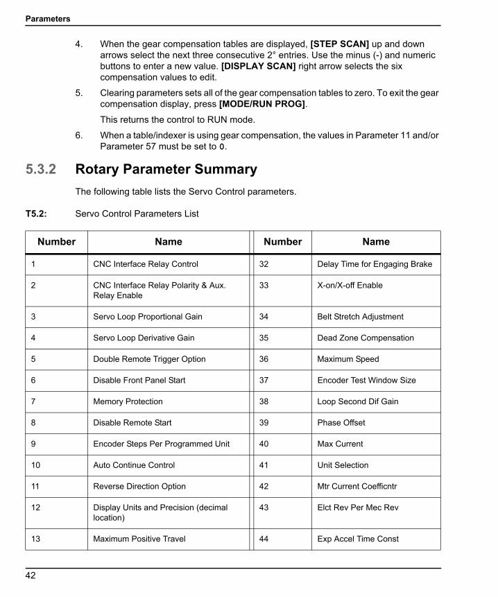
Parameters
96-8960A.book Page 42 Tuesday, July 28, 2015 1:34 PM
4. When the gear compensation tables are displayed, [STEP SCAN] up and down arrows select the next three consecutive 2° entries. Use the minus (-) and numeric buttons to enter a new value. [DISPLAY SCAN] right arrow selects the six compensation values to edit.
5. Clearing parameters sets all of the gear compensation tables to zero. To exit the gear compensation display, press [MODE/RUN PROG].
This returns the control to RUN mode.
6. When a table/indexer is using gear compensation, the values in Parameter 11 and/or Parameter 57 must be set to 0.
5.3.2 Rotary Parameter Summary
The following table lists the Servo Control parameters.
T5.2: Servo Control Parameters List
Number Name Number Name
1 CNC Interface Relay Control 32 Delay Time for Engaging Brake
2 CNC Interface Relay Polarity & Aux. Relay Enable
33 X-on/X-off Enable
3 Servo Loop Proportional Gain 34 Belt Stretch Adjustment
4 Servo Loop Derivative Gain 35 Dead Zone Compensation
5 Double Remote Trigger Option 36 Maximum Speed
6 Disable Front Panel Start 37 Encoder Test Window Size
7 Memory Protection 38 Loop Second Dif Gain
8 Disable Remote Start 39 Phase Offset
9 Encoder Steps Per Programmed Unit 40 Max Current
10 Auto Continue Control 41 Unit Selection
11 Reverse Direction Option 42 Mtr Current Coefficntr
12 Display Units and Precision (decimal location)
43 Elct Rev Per Mec Rev
13 Maximum Positive Travel 44 Exp Accel Time Const
42
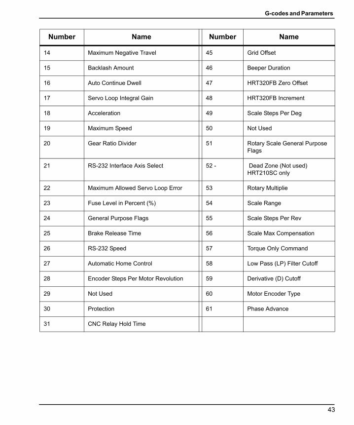
G-codes and Parameters
96-8960A.book Page 43 Tuesday, July 28, 2015 1:34 PM
14 Maximum Negative Travel 45 Grid Offset
15 Backlash Amount 46 Beeper Duration
16 Auto Continue Dwell 47 HRT320FB Zero Offset
17 Servo Loop Integral Gain 48 HRT320FB Increment
18 Acceleration 49 Scale Steps Per Deg
19 Maximum Speed 50 Not Used
20 Gear Ratio Divider 51 Rotary Scale General Purpose Flags
21 RS-232 Interface Axis Select 52 - Dead Zone (Not used) HRT210SC only
22 Maximum Allowed Servo Loop Error 53 Rotary Multiplie
23 Fuse Level in Percent (%) 54 Scale Range
24 General Purpose Flags 55 Scale Steps Per Rev
25 Brake Release Time 56 Scale Max Compensation
26 RS-232 Speed 57 Torque Only Command
27 Automatic Home Control 58 Low Pass (LP) Filter Cutoff
28 Encoder Steps Per Motor Revolution 59 Derivative (D) Cutoff
29 Not Used 60 Motor Encoder Type
30 Protection 61 Phase Advance
31 CNC Relay Hold Time
Number Name Number Name
43

Parameters
96-8960A.book Page 44 Tuesday, July 28, 2015 1:34 PM
Changing Parameters
To change a parameter:
1. Press [MODE/RUN PROG] until display flashes on and off.
This is Program mode.
2. Press [STEP SCAN] up arrow and hold it at step 01 for three seconds.
After three seconds, the display changes to parameter entry mode.
3. Press [STEP SCAN] up and down arrow keys to scroll through the parameters.
4. Pressing the up/down arrow, right arrow, or Mode button will cause an entered parameter to be stored.
Some of the parameters are protected from being changed by the user to avoid unstable or unsafe operation. If one of these parameters needs to be changed, call your dealer.
5. Before a parameter value can be changed, press [EMERGENCY STOP].
6. To exit from parameter entry mode and go to Run mode, press [MODE/RUN PROG].
7. To exit from parameter entry mode and return to step 01, push the [STEP SCAN] down arrow.
5.3.3 Parameter 1 - CNC Interface Relay Control
Parameter 1 - CNC Interface Relay Control has a range from 0 to 2.
T5.3: Parameter 1 Settings
Setting Description
0 relay active during indexer motion
1 relay pulsed for 1/4 second at end of motion
2 no relay action
44
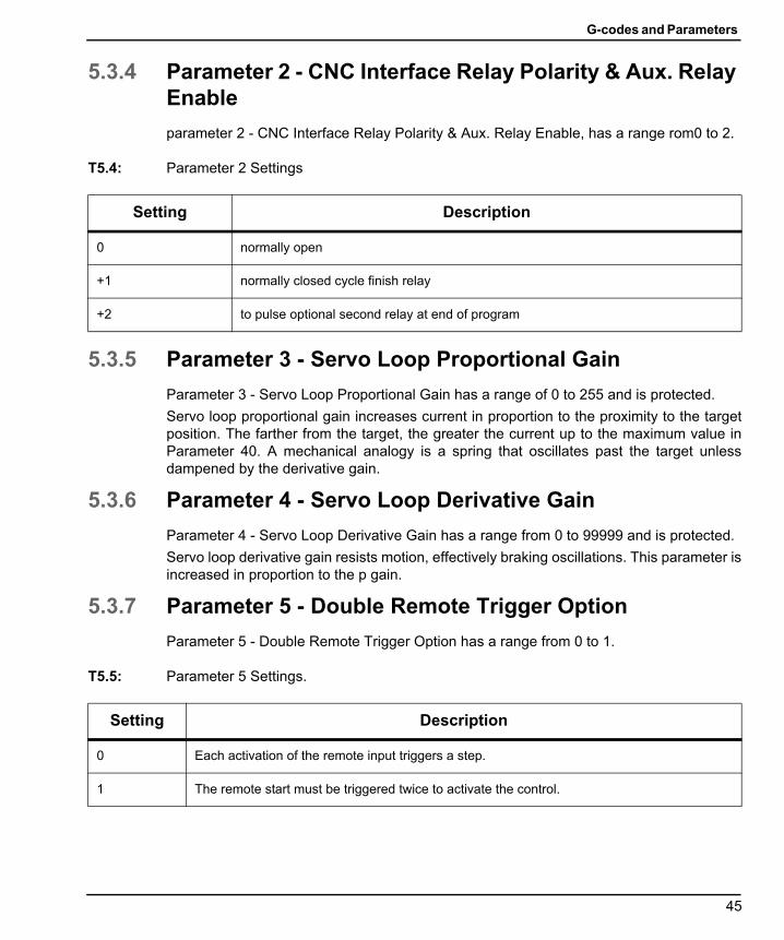
G-codes and Parameters
96-8960A.book Page 45 Tuesday, July 28, 2015 1:34 PM
5.3.4 Parameter 2 - CNC Interface Relay Polarity & Aux. Relay Enable
parameter 2 - CNC Interface Relay Polarity & Aux. Relay Enable, has a range rom0 to 2.
T5.4: Parameter 2 Settings
5.3.5 Parameter 3 - Servo Loop Proportional Gain
Parameter 3 - Servo Loop Proportional Gain has a range of 0 to 255 and is protected.
Servo loop proportional gain increases current in proportion to the proximity to the targetposition. The farther from the target, the greater the current up to the maximum value inParameter 40. A mechanical analogy is a spring that oscillates past the target unlessdampened by the derivative gain.
5.3.6 Parameter 4 - Servo Loop Derivative Gain
Parameter 4 - Servo Loop Derivative Gain has a range from 0 to 99999 and is protected.
Servo loop derivative gain resists motion, effectively braking oscillations. This parameter isincreased in proportion to the p gain.
5.3.7 Parameter 5 - Double Remote Trigger Option
Parameter 5 - Double Remote Trigger Option has a range from 0 to 1.
T5.5: Parameter 5 Settings.
Setting Description
0 normally open
+1 normally closed cycle finish relay
+2 to pulse optional second relay at end of program
Setting Description
0 Each activation of the remote input triggers a step.
1 The remote start must be triggered twice to activate the control.
45

Parameters
96-8960A.book Page 46 Tuesday, July 28, 2015 1:34 PM
5.3.8 Parameter 6 - Disable Front Panel Start
Parameter 6 - Disable Front Panel Start has a range from 0 to 1.
T5.6: Parameter 6 Settings
5.3.9 Parameter 7 - Memory Protection
Parameter 7 - Memory Protection has a range from 0 to 1.
T5.7: Parameter 7 Settings
5.3.10 Parameter 8 - Disable Remote Start
Parameter 8 - Disable Remote Start has a range from 0 to 1.
T5.8: Parameter 8 Settings
Setting Description
0 The front panel [CYCLE START] and [ZERO RETURN] work.
1 The front panel [CYCLE START] and [ZERO RETURN] do not work.
Setting Description
0 Changes can be made to the stored program. Does not prevent changing parameters.
1 No changes can be made to the stored program. Does not prevent changing parameters.
Setting Description
0 The remote start input works
1 The remote start input will not work
46
G-codes and Parameters
96-8960A.book Page 47 Tuesday, July 28, 2015 1:34 PM
5.3.11 Parameter 9 - Encoder Steps Per Programmed Unit
Parameter 9 - Encoder Steps Per Programmed Unit has a range from 0 to 999999.
Defines the number of encoder steps required to complete one full unit (degree, inch,millimeter, etc.).
Example 1: An HA5C with a 2000 pulse per revolution encoder (four pulses per line, orquadrature) and a 60:1 gear ratio produces: (8000 x 60)/360 degrees = 1333.333 encodersteps.Since 1333.333 is not a whole integer, it must be multiplied by some number to clearthe decimal point. Use Parameter 20 to accomplish this in the above case. Set Parameter20 to 3, therefore: 1333.333 x 3 = 4000 (entered in Parameter 9).
Example 2: An HRT with 8192 line encoder (with quadrature), a 90:1 gear ratio and a finaldrive of 3:1 would produce: [32768 x (90 x 3)]/360 = 24576 steps for 1 degree of motion.
5.3.12 Parameter 10 - Auto Continue Control
Parameter 10 - Auto Continue Control has a range from 0 to 3.
T5.9: Parameter 10 Settings
Setting Description
0 Stop after each step
1 Continue all looped steps and stop before next step
2 Continue all programs until end code 99 or 95
3 Repeat all steps until stopped manually
47
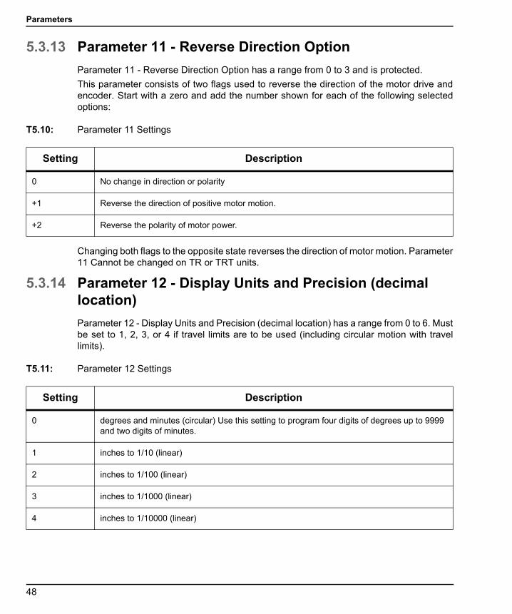
Parameters
96-8960A.book Page 48 Tuesday, July 28, 2015 1:34 PM
5.3.13 Parameter 11 - Reverse Direction Option
Parameter 11 - Reverse Direction Option has a range from 0 to 3 and is protected.
This parameter consists of two flags used to reverse the direction of the motor drive andencoder. Start with a zero and add the number shown for each of the following selectedoptions:
T5.10: Parameter 11 Settings
Changing both flags to the opposite state reverses the direction of motor motion. Parameter11 Cannot be changed on TR or TRT units.
5.3.14 Parameter 12 - Display Units and Precision (decimal location)
Parameter 12 - Display Units and Precision (decimal location) has a range from 0 to 6. Mustbe set to 1, 2, 3, or 4 if travel limits are to be used (including circular motion with travellimits).
T5.11: Parameter 12 Settings
Setting Description
0 No change in direction or polarity
+1 Reverse the direction of positive motor motion.
+2 Reverse the polarity of motor power.
Setting Description
0 degrees and minutes (circular) Use this setting to program four digits of degrees up to 9999 and two digits of minutes.
1 inches to 1/10 (linear)
2 inches to 1/100 (linear)
3 inches to 1/1000 (linear)
4 inches to 1/10000 (linear)
48

G-codes and Parameters
96-8960A.book Page 49 Tuesday, July 28, 2015 1:34 PM
5.3.15 Parameter 13 - Maximum Positive Travel
Parameter 13 - Maximum Positive Travel has a range from 0 to 99999.
This is the positive travel limit in units * 10 (entered value loses last digit). It applies only tolinear motion (i.e., Parameter 12 = 1, 2, 3, or 4). If it is set to 1000, positive travel is limitedto 100 inches. The entered value is affected by the gear ratio divider (Parameter 20).
5.3.16 Parameter 14 - Maximum Negative Travel
Parameter 14 - Maximum Negative Travel has a range from 0 to 99999
This is the negative travel limit in units * 10 (entered value loses last digit). It applies onlyto linear motion (i.e., Parameter 12 = 1, 2, 3, or 4). For examples, see Parameter 13.
5.3.17 Parameter 15 - Backlash Amount
Parameter 15 - Backlash Amount has a range from 0 to 99.
This parameter compensates electronically for mechanical gear backlash. It is in units ofencoder steps.
NOTE: This parameter cannot correct mechanical backlash.
Refer to “Backlash” on page 64 for details on how to check and adjust backlash in the wormwheel gear, between the worm gear and shaft, as well as the worm shaft backbearing housing.
5.3.18 Parameter 16 - Auto Continue Dwell
Parameter 16 - Auto Continue Dwell has a range from 0 to 99
This parameter causes a pause at the end of a step when the automatic continuation optionis used. The delay is in multiples of 1/10 second. Thus, a value of 13 gives 1.3 seconds ofdelay. Used primarily for continuous duty, allowing for motor cool down time and longermotor life.
5 degrees to 1/100 (circular) Use this setting to program four digits of degrees up to 9999 and two digits of fractional degrees to 1/100
6 degrees to 1/1000 (circular) Use this setting to program three digits of degrees up to 999 and three digits of fractional degrees to 1/1000
Setting Description
49
Parameters
96-8960A.book Page 50 Tuesday, July 28, 2015 1:34 PM
5.3.19 Parameter 17 - Servo Loop Integral Gain
Parameter 17 - Servo Loop Integral Gain has a range from 0 to 255 and is protected.
If integral is to be disabled during deceleration (for less overshoot), set Parameter 24accordingly. Integral gain provides larger increases of current to achieve target. Thisparameter often causes a hum when set too high.
5.3.20 Parameter 18 - Acceleration
Parameter 18 - Acceleration has a range from 0 to 9999999 x 100 and is protected.
This parameter defines how fast the motor is accelerated up to the desired speed. Thevalue used is units * 10 in encoder steps/second/second. The highest acceleration is655350 steps per second per second for TRT units. It must be greater than or equal to twiceParameter 19, usually 2X. The entered value = the desired value/Parameter 20, if a gearratio divider is used. A lower value results in gentler acceleration.
5.3.21 Parameter 19 - Maximum Speed
Parameter 19 - Maximum Speed has a range from 0 to 9999999 x 100.
This parameter defines the maximum speed (RPM of motor). The value used is units * 10in encoder steps/second. The highest speed is 250000 steps per second for TRT units. Itmust be less than or equal to Parameter 18. If this parameter exceeds Parameter 36, onlythe smaller number is used. See Parameter 36 also. The entered value = the desiredvalue/Parameter 20, if a gear ratio divider is used. Lowering this value results in reducedmaximum speed (maximum motor RPM).
Standard Formula: degrees (inches) per sec X ratio (Parameter 9)/100 = entered value inParameter 19.
Formula with Gear Ratio Divider: (Parameter 20): degrees (inches) per second X ratio(Parameter 9)/[ratio divider (Parameter 20) x 100] = entered value in Parameter 19.
5.3.22 Parameter 20 - Gear Ratio Divider
Parameter 20 - Gear Ratio Divider has a range from 0 to 100 and is protected.
Parameter 20 selects non-integer gear ratios for Parameter 9. If Parameter 20 is set to 2 ormore, Parameter 9 is divided by Parameter 20 before it is used. If Parameter 20 is set to 0or 1, no change is made to Parameter 9.
Example 1: Parameter 9 = 2000 and Parameter 20 = 3, the number of steps per unit willbe 2000/3 = 666.667, thus compensating for fractional gear ratios.
Example 2 (with a gear ratio divider Parameter 20 needed): 32768 encoder pulses perrevolution X 72:1 gear ratio X 2:1 belt ratio/360 degrees per revolution = 13107.2. Since13107.2 is non-integer we require a ratio divider (Parameter 20) set to 5 then: 13107.2 ratio= 65536 (Parameter 9) encoder steps/5 (Parameter 20) ratio divider.
50
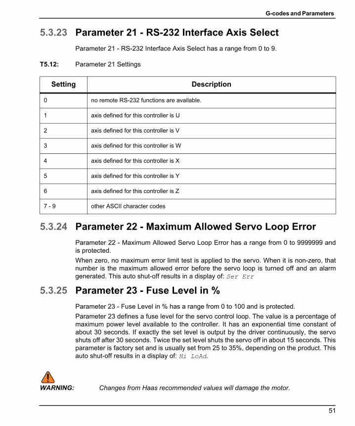
G-codes and Parameters
96-8960A.book Page 51 Tuesday, July 28, 2015 1:34 PM
5.3.23 Parameter 21 - RS-232 Interface Axis Select
Parameter 21 - RS-232 Interface Axis Select has a range from 0 to 9.
T5.12: Parameter 21 Settings
5.3.24 Parameter 22 - Maximum Allowed Servo Loop Error
Parameter 22 - Maximum Allowed Servo Loop Error has a range from 0 to 9999999 andis protected.
When zero, no maximum error limit test is applied to the servo. When it is non-zero, thatnumber is the maximum allowed error before the servo loop is turned off and an alarmgenerated. This auto shut-off results in a display of: Ser Err
5.3.25 Parameter 23 - Fuse Level in %
Parameter 23 - Fuse Level in % has a range from 0 to 100 and is protected.
Parameter 23 defines a fuse level for the servo control loop. The value is a percentage ofmaximum power level available to the controller. It has an exponential time constant ofabout 30 seconds. If exactly the set level is output by the driver continuously, the servoshuts off after 30 seconds. Twice the set level shuts the servo off in about 15 seconds. Thisparameter is factory set and is usually set from 25 to 35%, depending on the product. Thisauto shut-off results in a display of: Hi LoAd.
WARNING: Changes from Haas recommended values will damage the motor.
Setting Description
0 no remote RS-232 functions are available.
1 axis defined for this controller is U
2 axis defined for this controller is V
3 axis defined for this controller is W
4 axis defined for this controller is X
5 axis defined for this controller is Y
6 axis defined for this controller is Z
7 - 9 other ASCII character codes
51

Parameters
96-8960A.book Page 52 Tuesday, July 28, 2015 1:34 PM
5.3.26 Parameter 24 - General Purpose Flags
Parameter 24 - General Purpose Flags has a range from 0 to 65535 (maximum range) andis protected.
Parameter 24 consists of five individual flags for controlling servo functions. Start with zeroand add the number shown for each of the following selected options.
T5.13: Parameter 24 Settings
Setting Description
0 No general purpose flags used
+1 Interpret Parameter 9 as twice entered value.
+2 Not Used.
+4 Disable integral when brake is engaged (see Parameter 17)
+8 Protection of parameters enabled (see Parameter 30)
+16 Serial interface disabled
+32 Start-up Haas message disabled
+64 Not Used.
+128 Disable Z channel encoder test
+256 Normally closed over-temp sensor
+512 Disable cable test
+1024 Disable rotary scale encoder cable test (HRT210SC only)
+2048 Disable rotary scale encoder Z test (HRT210SC only)
+4096 Disable integral while decelerating (see Parameter 17)
+8192 Continuous brake function
+16384 Invert brake output
+32768 Invert platter status input
52

G-codes and Parameters
96-8960A.book Page 53 Tuesday, July 28, 2015 1:34 PM
5.3.27 Parameter 25 - Brake Release Time
Parameter 25 - Brake Release Time has a range from 0 to 19 and is protected.
If Parameter 25 is zero, the brake release is not activated (i.e., always engaged); otherwise,this is the delay time to release the air before the motor is started in motion. It is in units of1/10 second. A value 5 delays for 5/10 second. (Not used in HA5C, and defaults to 0.)
5.3.28 Parameter 26 - RS-232 Speed
Parameter 26 - RS-232 Speed has a range from 0 to 8.
Parameter 26 selects data rates on the RS-232 interface. The HRT & HA5C parametervalues and rates are:
T5.14: Parameter 26 - RS-232 Speed Settings
The TRT always has this parameter set to 5, at a data rate of 4800.
5.3.29 Parameter 27 - Automatic Home Control
Parameter 27 - Automatic Home Control has a range from 0 to 512 and is protected.
All Haas Rotaries use a home switch in conjunction with the Z pulse on the motor encoder(one for each revolution of the motor) for repeatability. The home switch consists of amagnet (Haas P/N 69-18101) and a proximity switch (Haas P/N 36-3002), which is amagnetically sensitive transistor.
When the control is shut down and restarted, it requires the user to press[ZERO RETURN]. The motor then operates slowly in a clockwise direction (as viewed fromthe platter of a rotary table) until the proximity switch is magnetically tripped, then backs upto the first Z pulse.
NOTE: To reverse direction when seeking a home switch (if it currently movesaway from the home switch during the home sequence), add 256 tothe value in Parameter 27.
Setting Data Rate Setting Data Rate
0 110 5 4800
1 300 6 7200
2 600 7 9600
3 1200 8 19200
4 2400
53

Parameters
96-8960A.book Page 54 Tuesday, July 28, 2015 1:34 PM
Parameter 27 is used to customize the home control function of the Servo Control. Startwith a zero and add the number shown for each of the following selected options:
T5.15: Parameter 27 Settings
5.3.30 Parameter 28 - Encoder Steps Per Motor Revolution
Parameter 28 - Encoder Steps Per Motor Revolution has a range from 0 to 9999999 and isprotected.
Parameter 28 is used with the Z channel option to check the encoder accuracy. IfParameter 27 is 2 or 3, it is used to check that the correct number of encoder steps arereceived per revolution.
5.3.31 Parameter 29 - Not Used
Parameter 29 - Not Used.
Setting Description
0 no automatic home functions available (no home switch)
1 only table zero position switch available
2 only Z channel home available
3 home on both Z channel and table zero switch
+4 home if inverted Z (determined by encoder used)
+8 home to zero position in negative direction
+16 home to zero position in positive direction
+24 home to zero position in shortest direction
+32 auto servo on at power on
+64 auto search for home at power on (have "auto servo on at power up" selected)
+128 for inverted Home switch (determined by home switch used)
+256 search for home in positive direction
54
G-codes and Parameters
96-8960A.book Page 55 Tuesday, July 28, 2015 1:34 PM
5.3.32 Parameter 30 - Protection
Parameter 30 - Protection has a range from 0 to 65535.
Parameter 30 protects some of the other parameters. Every time the controller is turned on,this parameter has a new random value. If protection is selected (Parameter 24), theprotected parameters cannot be changed until this parameter is set to a different value thatis a function of the initial random value.
5.3.33 Parameter 31 - CNC Relay Hold Time
Parameter 31 - CNC Relay Hold Time has a range from 0 to 9.
Parameter 31 specifies the amount of time the CNC interface relay is held active at the endof a step. If zero, the relay time is 1/4 second. All other values give the time in multiples of0.1 second.
5.3.34 Parameter 32 - Delay Time for Engaging Brake
Parameter 32 - Delay Time for Engaging Brake has a range from 0 to 19 and is protected.
Parameter 32 sets the amount of time delay between the end of a motion and engaging theair brake. It has units of 1/10 second. A value of 4 delays for 4/10 second.
5.3.35 Parameter 33 - X-On/X-Off Enable
Parameter 33 - X-On/X-Off Enable has a range from 0 to 1.
Parameter 33 enables the sending of the X-On and X-Off codes via the RS-232 interface.If your computer needs these, set this parameter to 1. Otherwise, only the RTS and CTSlines are used to synchronize communication. Refer to “The RS-232 Interface” on page 21.
5.3.36 Parameter 34 - Belt Stretch Adjustment
Parameter 34 - Belt Stretch Adjustment has a range from 0 to 399 and is protected.
Parameter 34 corrects for stretching in a belt if one is used to couple the motor to the loadbeing moved. It is a count of the number of steps of motion that are added to the motorposition while it is moving. It is always applied in the same direction as the motion. Thus,when motion stops, the motor snaps backward to take the load off the belt. This parameteris not used in an HA5C and, in this case, is defaulted to 0.
5.3.37 Parameter 35 - Dead Zone Compensation
Parameter 35 - Dead Zone Compensation has a range from 0 to 19 and is protected.
Parameter 35 compensates for the dead zone in the driver electronics. It is normally set to0 or 1.
55

Parameters
96-8960A.book Page 56 Tuesday, July 28, 2015 1:34 PM
5.3.38 Parameter 36 - Maximum Speed
Parameter 36 - Maximum Speed has a range from 0 to 9999999 x 100 and is protected.
Parameter 36 defines the maximum feed rate. The value used is (Parameter 36)*10 inencoder steps/second. The highest speed is thus 250000 steps per second for TRT unitsand 1,000,000 steps per second for HRT & HA5C units. It must be less than or equal toParameter 18. If this parameter exceeds Parameter 19, only the smaller number is used.See Parameter 19 also.
5.3.39 Parameter 37 - Encoder Test Window Size
Parameter 37 - Encoder Test Window Size has a range from 0 to 999.
Parameter 37 defines the tolerance window for the Z channel encoder test. This much erroris allowed in the difference between the actual encoder position and the ideal value whenthe Z channel is encountered.
5.3.40 Parameter 38 - Loop Second Dif Gain
Parameter 38 - Loop Second Dif Gain has a range from 0 to 9999.
Parameter 38 is the servo loop second differential gain.
5.3.41 Parameter 39 - Phase Offset
Parameter 39 - Phase Offset has a range from 0 to 4095.
Parameter 39 is the offset of encoder Z-pulse to zero degree of phasing.
5.3.42 Parameter 40 - Max Current
Parameter 40 - Max Current has a range from 0 to 2047.
Parameter 40 is the maximum peak current output to the motor. Units DAC bits.
WARNING: Changes from Haas recommended values for this parameter willdamage the motor.
56
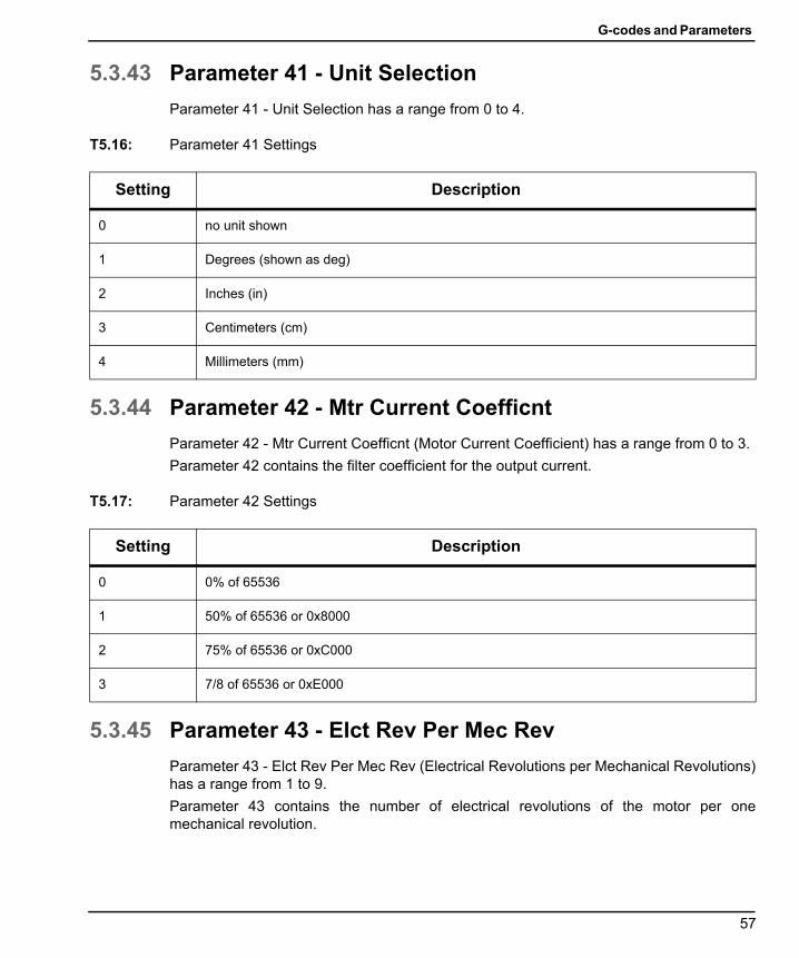
G-codes and Parameters
96-8960A.book Page 57 Tuesday, July 28, 2015 1:34 PM
5.3.43 Parameter 41 - Unit Selection
Parameter 41 - Unit Selection has a range from 0 to 4.
T5.16: Parameter 41 Settings
5.3.44 Parameter 42 - Mtr Current Coefficnt
Parameter 42 - Mtr Current Coefficnt (Motor Current Coefficient) has a range from 0 to 3.
Parameter 42 contains the filter coefficient for the output current.
T5.17: Parameter 42 Settings
5.3.45 Parameter 43 - Elct Rev Per Mec Rev
Parameter 43 - Elct Rev Per Mec Rev (Electrical Revolutions per Mechanical Revolutions)has a range from 1 to 9.
Parameter 43 contains the number of electrical revolutions of the motor per onemechanical revolution.
Setting Description
0 no unit shown
1 Degrees (shown as deg)
2 Inches (in)
3 Centimeters (cm)
4 Millimeters (mm)
Setting Description
0 0% of 65536
1 50% of 65536 or 0x8000
2 75% of 65536 or 0xC000
3 7/8 of 65536 or 0xE000
57

Parameters
96-8960A.book Page 58 Tuesday, July 28, 2015 1:34 PM
5.3.46 Parameter 44 - Exp Accel Time Const
Parameter 44 - Exp Accel Time Const (Exponential Acceleration Time Constant) has arange from 0 to 999
Parameter 44 contains the exponential acceleration time constant. Units are 1/10000second.
5.3.47 Parameter 45 - Grid Offset
Parameter 45 - Grid Offset has a range from 0 to 99999.
The distance between the home switch and the final stopped motor position after homing,is added by this grid offset amount. It is modulus of Parameter 28, which means that ifParameter 45 = 32769 and Parameter 28 = 32768, then it is interpreted as 1.
5.3.48 Parameter 46 - Beeper Duration
Parameter 46 - Beeper Duration has a range from 0 to 999.
Parameter 46 contains the length of beeper tone in milliseconds. Value 0-35 provides notone. Default is 150 milliseconds.
5.3.49 Parameter 47 - HRT320FB Zero Offset
Parameter 47 - HRT320FB Zero Offset has a range from 0 to 9999 for HRT320FB.
Parameter 47 contains the angular value to offset zero position. Units are 1/1000 of adegree.
5.3.50 Parameter 48 - HRT320FB Increment
Parameter 48 - HRT320FB Increment has a range from 0 to 1000 for the HRT320FB only.
Parameter 48 contains the angular value to control indexer increments. Units are 1/1000 ofa degree.
5.3.51 Parameter 49 - Scale Steps Per Deg
Parameter 49 - Scale Steps Per Deg has a range from 0 to 99999 x 100 for HRT210SConly.
Parameter 49 converts the rotary scale steps into degrees to access values in the rotarycompensation table.
5.3.52 Parameter 50 - Not Used
Parameter 50 - Not Used.
58

G-codes and Parameters
96-8960A.book Page 59 Tuesday, July 28, 2015 1:34 PM
5.3.53 Parameter 51 - Rotary Scale General Purpose Flags
Parameter 51 - Rotary Scale General Purpose Flags has a range from 0 to 63 forHRT210SC only.
Parameter 51consists of six individual flags for controlling the rotary encoder functions.Start with a zero and add the number shown for each of the following selected options:
T5.18: Parameter 51 Settings
5.3.54 Parameter 52 - Dead Zone (Not used) HRT210SC only
Parameter 52 - Dead Zone (Not used) for HRT210SC only.
5.3.55 Parameter 53 - Rotary Multiplier
Parameter 53 - Rotary Multiplier has a range from 0 to 9999 for HRT210SC only.
Parameter 53 increases current in proportion to the proximity to the absolute rotary scaleposition. The farther from the absolute rotary scale target, the greater the current up to themaximum compensation value in Parameter 56. Alarm is generated if exceeded, seeParameter 56.
5.3.56 Parameter 54 - Scale Range
Parameter 54 - Scale Range has a range from 0 to 99 for HRT210SC only.
Parameter 54 selects non-integer ratios for Parameter 49. If Parameter 5 is set to 2 ormore, Parameter 49 is divided by Parameter 54 before it is used. If Parameter 54 is set to0 or 1, no change is made to Parameter 49.
Setting Description
+1 enable the use of the rotary scale
+2 invert the direction of the rotary scale
+4 negate the direction of the rotary scale compensation
+8 use motor Z pulse when zeroing
+16 display the rotary scale in steps and in HEX format
+32 disable rotary scale compensation during brake.
59
Parameters
96-8960A.book Page 60 Tuesday, July 28, 2015 1:34 PM
5.3.57 Parameter 55 - Scale Steps Per Rev
Parameter 55 - Scale Steps Per Rev has a range from 0 to 9999999 x 100 for HRT210SConly.
Parameter 55 converts the rotary scale steps into encoder steps. It is also used with the Zoption to check the rotary scale encoder accuracy.
5.3.58 Parameter 56 - Scale Max Compensation
Parameter 56 - Scale Max Compensation has a range from 0 to 999999 for HRT210SConly.
Parameter 56 contains the maximum number of encoder steps that the scale couldcompensate before alarm rLS Err occurs.
5.3.59 Parameter 57 - Torque Only Command
Parameter 57 - Torque Only Command has a range from 0 to 999999999 and is protected.
Parameter 57 provides a command to the servo amplifier. Non-zero value disconnectscontrol loop and makes servo motor move. Used only for troubleshooting.
5.3.60 Parameter 58 - Low Pass (LP) Filter Cutoff
Parameter 58 - Low Pass (LP) Filter Cutoff has a frequency (Hz) range from 0 to 9999 andis protected.
Parameter 58 is applied on torque command. Torque command low pass filter (for quieter,more efficient servo control) removes high frequency noise.
5.3.61 Parameter 59 - Derivative (D) Cutoff
Parameter 59 - Derivative (D) Cutoff has a frequency (Hz) range from 0 to 9999 and isprotected.
Parameter 59 filter applied on derivative component of feedback controller algorithm(relative to torque control).
60

G-codes and Parameters
96-8960A.book Page 61 Tuesday, July 28, 2015 1:34 PM
5.3.62 Parameter 60 - Motor Encoder Type
Parameter 60 - Motor Encoder Type has a range from 0 to 7 and is protected.
T5.19: Parameter 60 Settings
5.3.63 Parameter 61 - Phase Advance
Parameter 61 - Phase Advance has electrical units that range from 0 to 360 and isprotected.
Parameter 61 contributes to the feedback controller algorithm that improves high speedtorque performance of Sigma-5 motor.
Setting Description
0 Sigma-1 Motor
1 not used
2 not used
3 not used
4 not used
5 not used
6 not used
7 Sigma-5 Motor
61

Parameters
96-8960A.book Page 62 Tuesday, July 28, 2015 1:34 PM
62

Routine Maintenance
96-8960A.book Page 63 Tuesday, July 28, 2015 1:34 PM
Chapter 6: Routine Maintenance
6.1 IntroductionHaas rotary units require very little routine servicing. However, it is very important toperform these services to ensure reliability and long operating life.
6.2 Inspection of the Table (HRT & TRT)To ensure that the table performs accurately, occasionally perform the following points ofinspection:
1. Platter face runout
2. Platter I.D. runout.
3. Worm play.
4. Backlash between worm wheel gear and worm shaft.
5. Backlash in the worm gear.
6. Popout (Face Gear units).
6.2.1 Platter Face Runout
To check the platter runout:
1. Mount an indicator to the body of the table.
2. Position the stylus on the face of the platter.
3. Index the table 360°.
The runout should be 0.0005" or less.
6.2.2 Platter I.D. Runout
To check the platter I.D. runout:
1. Mount the indicator to the table body.
2. Position the stylus on the platter through-hole.
3. Index the table 360°.
Runout should be:
63
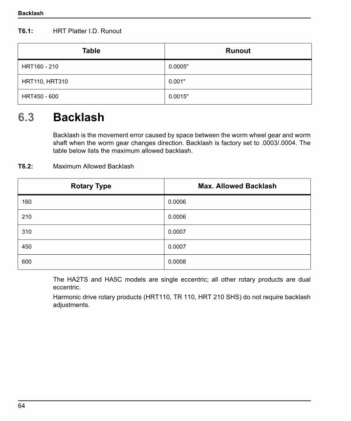
Backlash
96-8960A.book Page 64 Tuesday, July 28, 2015 1:34 PM
T6.1: HRT Platter I.D. Runout
6.3 BacklashBacklash is the movement error caused by space between the worm wheel gear and wormshaft when the worm gear changes direction. Backlash is factory set to .0003/.0004. Thetable below lists the maximum allowed backlash.
T6.2: Maximum Allowed Backlash
The HA2TS and HA5C models are single eccentric; all other rotary products are dualeccentric.
Harmonic drive rotary products (HRT110, TR 110, HRT 210 SHS) do not require backlashadjustments.
Table Runout
HRT160 - 210 0.0005"
HRT110, HRT310 0.001"
HRT450 - 600 0.0015"
Rotary Type Max. Allowed Backlash
160 0.0006
210 0.0006
310 0.0007
450 0.0007
600 0.0008
64
Routine Maintenance
96-8960A.book Page 65 Tuesday, July 28, 2015 1:34 PM
6.3.1 Mechanical Checks
Mechanical checks should be performed to confirm there is no backlash before making anyadjustments (electrical or mechanical) to the worm wheel gear. Measurements of backlashare required to determine whether there is excessive backlash.
If backlash is found after performing the mechanical checks, contact Haas Service forassistance with backlash adjustment procedures (mechanical or electrical). Have thefollowing tools available before contacting Service to make mechanical adjustments:
• Indicator (.0001)
• Aluminum Pry Bar
• Screwdriver
• Allen Wrench (5/16)
• Torque Wrench (capable of 25 lbs. torque)
Assistance from Service for electrical and mechanical adjustments is stronglyrecommended, as adjusting backlash too far results in rapid gear wear. See also theBacklash Adjustments (Electrical) section.
To make minimum mechanical checks in four (4) places at 90° angles:
1. Take measurement at 0°.
2. Take measurement at 90°.
3. Take measurement at 180°.
4. Take measurement at 270°.
6.3.2 Check Worm Play
Worm play shows up as backlash at the platter; therefore, worm play must be measuredbefore meaningful backlash measurements can be made.
To measure worm play:
1. Remove the air supply to the table.
2. Remove the worm housing cover from the side of the table.
3. Mount an indicator to the table body with the sensing arm on the exposed end of the worm.
4. Use an aluminum bar to rock the platter back and forth.
There should be no detectable reading.
65
Adjustments
96-8960A.book Page 66 Tuesday, July 28, 2015 1:34 PM
6.3.3 Check Worm Wheel Gear and Worm Shaft
To check the backlash between the worm gear and shaft:
1. Disconnect the air supply.
2. Place a magnet on the face of the platter at a radius of 1/2" in from the outside diameter of the platter.
3. Mount an indicator on the body of the table.
4. Position the stylus on the magnet.
5. Use an aluminum bar to rock the platter back and forth (apply approximately 10 ft-lb while testing).
Backlash should be between 0.0001" (0.0002" for HRT) and 0.0006".
6.3.4 Check Popout (Face Gear only)
To check popout:
1. Disconnect the air supply from the unit.
2. Index the table 360°.
3. Mount an indicator to the table body.
4. Position the stylus on the platter face and zero the dial.
5. Connect the air supply and read the popout from the indicator dial.
Popout should be between 0.0001" and 0.0005"
6.4 AdjustmentsThe face runout, face I.D. runout, worm play, backlash between worm and gear, and thepopout are set at the factory and are not field serviceable. If any of these specifications areout of tolerance, contact your Haas Factory Outlet.
66
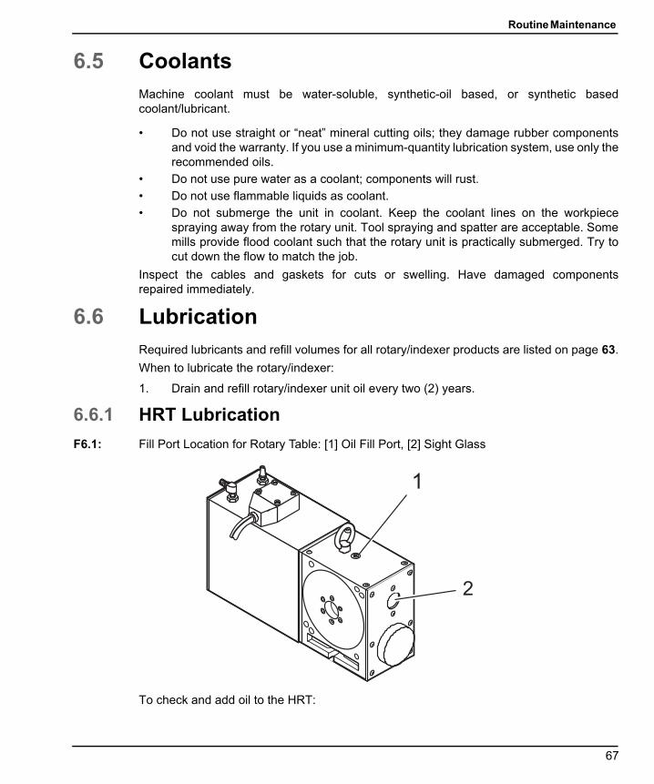
Routine Maintenance
96-8960A.book Page 67 Tuesday, July 28, 2015 1:34 PM
6.5 CoolantsMachine coolant must be water-soluble, synthetic-oil based, or synthetic basedcoolant/lubricant.
• Do not use straight or “neat” mineral cutting oils; they damage rubber componentsand void the warranty. If you use a minimum-quantity lubrication system, use only therecommended oils.
• Do not use pure water as a coolant; components will rust.
• Do not use flammable liquids as coolant.
• Do not submerge the unit in coolant. Keep the coolant lines on the workpiecespraying away from the rotary unit. Tool spraying and spatter are acceptable. Somemills provide flood coolant such that the rotary unit is practically submerged. Try tocut down the flow to match the job.
Inspect the cables and gaskets for cuts or swelling. Have damaged componentsrepaired immediately.
6.6 LubricationRequired lubricants and refill volumes for all rotary/indexer products are listed on page 63.
When to lubricate the rotary/indexer:
1. Drain and refill rotary/indexer unit oil every two (2) years.
6.6.1 HRT Lubrication
F6.1: Fill Port Location for Rotary Table: [1] Oil Fill Port, [2] Sight Glass
To check and add oil to the HRT:
1
2
67
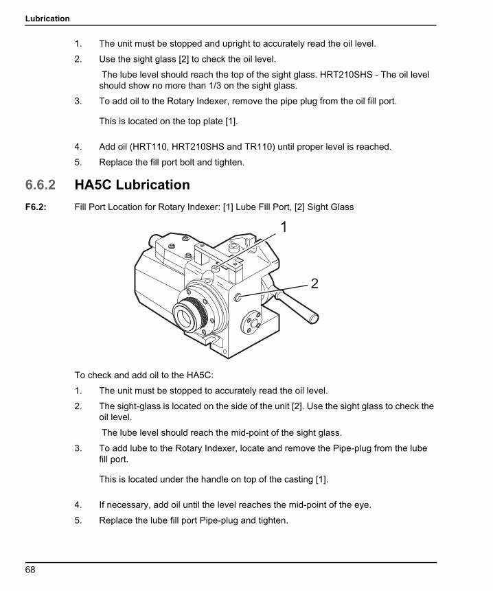
Lubrication
96-8960A.book Page 68 Tuesday, July 28, 2015 1:34 PM
1. The unit must be stopped and upright to accurately read the oil level.
2. Use the sight glass [2] to check the oil level.
The lube level should reach the top of the sight glass. HRT210SHS - The oil level should show no more than 1/3 on the sight glass.
3. To add oil to the Rotary Indexer, remove the pipe plug from the oil fill port.
This is located on the top plate [1].
4. Add oil (HRT110, HRT210SHS and TR110) until proper level is reached.
5. Replace the fill port bolt and tighten.
6.6.2 HA5C Lubrication
F6.2: Fill Port Location for Rotary Indexer: [1] Lube Fill Port, [2] Sight Glass
To check and add oil to the HA5C:
1. The unit must be stopped to accurately read the oil level.
2. The sight-glass is located on the side of the unit [2]. Use the sight glass to check the oil level.
The lube level should reach the mid-point of the sight glass.
3. To add lube to the Rotary Indexer, locate and remove the Pipe-plug from the lube fill port.
This is located under the handle on top of the casting [1].
4. If necessary, add oil until the level reaches the mid-point of the eye.
5. Replace the lube fill port Pipe-plug and tighten.
2
1
68

Routine Maintenance
96-8960A.book Page 69 Tuesday, July 28, 2015 1:34 PM
6.6.3 TRT, T5C, and TR Lubrication
F6.3: Fill Port location for Trunnion Tables: [1] Fill Ports, [2] Sight Glasses
To check and add oil to the TRT, T5C, or TR:
1. The unit must be stopped and upright to accurately read the oil level.
2. Use the sight glasses [2] to check the oil level.
The lube level should reach the top of both sight glasses.
3. If the level is low, fill the table through the pipe plugs [1] in the body.
4. Fill to the top of the sight glass. Do not over fill.
5. If the oil is dirty, drain and refill with clean oil.
6.7 Cleanup
CAUTION: Do not use air gun around front or rear seals. Chips may damage sealif blown in with an air gun.
1
2
69

HA5C Collet Key Replacement
96-8960A.book Page 70 Tuesday, July 28, 2015 1:34 PM
F6.4: Location of the front and rear brake seals: [1] Rear Brake Seal - HRT, [2] Front platter Seal - HRT, [3] Front Seal - HA5C, [4] Rear Seal - HA5C.
To clean your Rotary/Indexer:
1. After use, it is important to clean the rotary table.
2. Remove all metal chips from the unit.
The surfaces of the unit are precisely ground for accurate positioning and metal chips could damage those surfaces.
3. Apply a coat of rust preventative to the collet taper or platter.
6.8 HA5C Collet Key Replacement
WARNING: Never run the indexer with the collet key backed out; this damages thespindle and galls the spindle bore.
1 2
34
70

Routine Maintenance
96-8960A.book Page 71 Tuesday, July 28, 2015 1:34 PM
F6.5: HA5C Collet Key Replacement: [1] Spare Collet Key
To replace the collet key:
1. Remove the pipe plug from the access hole with a 3/16 allen wrench.
2. Align the collet key with the access hole by jogging the spindle.
3. Remove the collet key with a 3/32 allen wrench.
4. Replace the collet key with Haas P/N 22-4052 only.
A spare collet key [1] is located on the front casting face.
5. Screw the collet into the spindle until it begins to protrude into the inside diameter.
6. Place a new collet into the spindle while aligning the keyway with the key.
7. Tighten the key until it hits the bottom of the keyway, then back off 1/4 turn.
8. Pull the collet out to make sure it slides freely.
9. Replace the pipe plug in the access hole. If there is no thread locking compound on the threads, use a medium strength thread locking compound.
6.9 Tailstock Routine MaintenanceFor all tailstocks, perform the following routine maintenance:
1. Daily: Use a shop rag to thoroughly clean the unit free of chips and apply a rust preventative such as WD-40.
6.9.1 Tailstock Lubrication
Required lubricants and refill volumes for all rotary products are listed in “Lubricants andRefill Volumes” on page 72. To lubricate the tailstock:
1
71

Lubricants for Rotary Products
96-8960A.book Page 72 Tuesday, July 28, 2015 1:34 PM
1. Twice Yearly: Use a standard grease gun and apply 1 full stroke to the top mount Zerk fitting, for a pneumatic and manual tailstock.
6.10 Lubricants for Rotary ProductsHaas rotary products contain the lubricants they need to operate when shipped.Instructions for how and when to add lubricants are located on page 63. Lubricants aregenerally available for purchase at most local industrial supply companies.
6.10.1 Lubricants and Refill Volumes
The table below indicates the brand and amount of lubricant required to refill specific rotaryproducts from Haas.
To determine the amount of lubricant needed, add the refill volume per each axis of theconfigured product, e.g., an HRT160 combined with an HRT210 requires 40 ounces of oil.
T6.3: Haas Rotary Solutions - Lubricants and Refill Volumes
Type Model Lubricant Volume, oz.(L)
Rotary Table HRT160/SP/SS1 Mobil SHC 627 14 oz (.5 L)
HRT160-2 (Dual) Mobil SHC 627 28 oz (.9 L)
HRT210/M/SP1 Mobil SHC 627 26 oz (.8 L)
HRT210/SHS1 Mobil SHC 625 26 oz (.8 L)
HRT210-2 (Dual) Mobil SHC 627 52 oz (1.6 L)
HRT310/SP Mobil SHC 627 96 oz (2.9 L)
HRT450 Mobil SHC 627 104 oz (3.1 L)
HRT600 Mobil SHC 627 180 oz (5.4 L)
HRTA5 Mobil SHC 627 14 oz (.5 L)
HRTA6 Mobil SHC 627 26 oz (.8 L)
72

Routine Maintenance
96-8960A.book Page 73 Tuesday, July 28, 2015 1:34 PM
1 Modified (M), Special (SP), Super High Speed (SHS), Super Speed (SS).2 Y-Axis Mount.3 HA2TS is HA5C-2 with Two (2) Pneumatic Tailstocks.
Trunnion TR160/Y 2 Mobil SHC 634 51 oz (1.6 L)
TR160-2 (Dual) Mobil SHC 634 74 oz (2.2 L)
TR210 Mobil SHC 634 71 oz (2.1 L)
TR310 Mobil SHC 634 338 oz (10 L)
TRT160 Mobil SHC 634 40 oz (.1.2 L)
TRT210 Mobil SHC 634 122 oz (3.7 L)
Indexer HA2TS3 Mobil SHC 627 20 oz (.6 L)
HA5C4 Mobil SHC 627 10 oz (.3 L)
HA5CSB5 Mobil SHC 627 10 oz (.3 L)
HA5C2 Mobil SHC 627 20 oz (.6 L)
HA5C3 Mobil SHC 627 30 oz (.9 L)
HA5C4 Mobil SHC 627 40 oz (1.2 L)
T5C 634/T, 627/R6 26 oz /T, 10 oz /R7
T5C2 634/T, 627/R 26 oz /T, 20 oz /R
T5C3 634/T, 627/R 26 oz /T, 30 oz /R
T5C4 634/T, 627/R 26 oz /T, 40 oz /R
Indexing Table
HIT210 Mobilith SHC 4608 7 oz (half cartridge)
HRT320FB9 Mobil SHC 627 58 oz (1.8 L)
Tailstock HPTS4/5/6/9/11.5/14.510 Mobil CM-P 10 Full Strokes12
HTS4/5/6/9/11.5/14.511 Mobil CM-P 10 Full Strokes12
Type Model Lubricant Volume, oz.(L)
73

Lubricants for Rotary Products
96-8960A.book Page 74 Tuesday, July 28, 2015 1:34 PM
4 Collet (C).5 High Speed Indexer (SB).6 Mobil SHC for Tilt (T) and Rotary (R) Axes.7 Refill Vol. for Tilt (T) and Rotary (R) Axes.8 Mobilith SHC-640 oil contains Molybdenum Disulfide (Moly Grease). An equivalent brandof multi-purpose grease may also be used.9 Face Gear Brushless (FB). All Haas rotary products use brushless motors (except legacyproducts).10 Pneumatic Tailstock.11 Manual Tailstock.12 From Grease Gun (Lever-type) Cartridge for Initial Fill.
74

Troubleshooting
96-8960A.book Page 75 Tuesday, July 28, 2015 1:34 PM
Chapter 7: Troubleshooting
7.1 Troubleshooting a Working Interface on a CNCIf there are problems, try to isolate the problem by checking the Servo Control and the millseparately. There are only two signals and each one can be checked separately from theother. If the rotary unit stops indexing because of an interface problem, follow thesesimple checks:
1. Check the Servo Control remote input alone
2. Check the CNC cable interface alone
3. Check the Servo Control and the mill together
7.1.1 Check Servo Control Remote Input Alone
To check the Servo Control remote input:
1. Disconnect the remote cable from the back of the controller.
2. Set the control to index a single step of 90°.
3. Connect a continuity tester or a voltmeter (a digital meter may not be fast enough to sample the brief pulse) set for low ohms across pins 1 and 2; they are marked on the rear of the control as [FINISH SIGNAL].
It must show an open circuit, otherwise check relay Parameter 1 (should be 1) and Parameter 2 (should be 0). The relay must show an open circuit with the control turned off, otherwise the relay is defective.
4. Use a jumper wire to short pins 3 and 4 together, they are marked on the rear of the control as [CYCLE START].
The unit must index, and at the end of the index, the voltmeter should deflect briefly toward low ohms or continuity. If this works as described, the problem is NOT in the rotary control, but may be the interface cable or mill.
7.1.2 Check The CNC Cable Interface Alone
To check the CNC cable interface:
1. Check the signals from the CNC using your voltmeter.
NOTE: The pin orientation is reversed.
2. Execute an M function from the mill to rotate.
The mill beacon light should come on (green) and stay on.
75

Troubleshooting a Working Interface on a CNC
96-8960A.book Page 76 Tuesday, July 28, 2015 1:34 PM
3. Use the meter and check continuity across the [CYCLE START] pins 3 and 4. Try not to short the test leads and pins against the shield of the male plug.
NOTE: Some mills may have a +12 to +24 volt signal on pin 4 to activate arotary unit. Check if there is voltage between pin 4 and the ground, ifthe continuity test fails, this is also a valid [CYCLE START] signal. Ifthere is voltage present on Pin 4, a Haas interface box must be used(Part # IB). Contact your dealer if there are questions on how to usethe interface box.
4. To check the [CYCLE FINISH] signal, use a voltmeter test probe to short together pins 1 and 2 on the mill cable.
The mill beacon light should turn off.
If the above tests pass, there is a valid signals coming from the mill.
7.1.3 Check Servo Control And Mill Together
To check the Servo Control and mill:
1. Reset the mill by pressing [RESET] or turn it off by pressing [POWER OFF].
2. Connect the remote cable, then turn both the Servo Control and mill on.
Once connected, the rotary unit should remain idle. If the rotary unit moves, the [CYCLE START] signal from the mill is shorted.
3. If it remains idle, execute or MDI an M function from the mill to index.
Do not index from the program unless using single-block. If the rotary unit does not move, the mill is not outputting a signal or there is a break in the cable.
If the Servo Control indexes properly, ensure that the mill beacon light goes out at the end of the index. If the light does not go out, the [CYCLE FINISH] signal is not returning to the mill. This could be an open wire in the remote cable, or a problem in cables that connect to the CNC.
4. If the unit works only in single block, but not in the Run mode, there may be a timing problem involving two M functions, or a simultaneous milling problem. Review the section on simultaneous milling. If there are two M functions, separate them with a dwell of ¼ second.
76
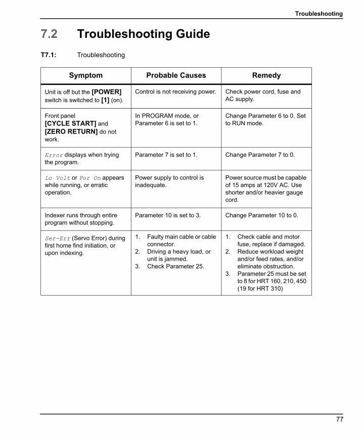
Troubleshooting
96-8960A.book Page 77 Tuesday, July 28, 2015 1:34 PM
7.2 Troubleshooting Guide
T7.1: Troubleshooting
Symptom Probable Causes Remedy
Unit is off but the [POWER] switch is switched to [1] (on).
Control is not receiving power. Check power cord, fuse and AC supply.
Front panel [CYCLE START] and [ZERO RETURN] do not work.
In PROGRAM mode, or Parameter 6 is set to 1.
Change Parameter 6 to 0. Set to RUN mode.
Error displays when trying the program.
Parameter 7 is set to 1. Change Parameter 7 to 0.
Lo Volt or Por On appears while running, or erratic operation.
Power supply to control is inadequate.
Power source must be capable of 15 amps at 120V AC. Use shorter and/or heavier gauge cord.
Indexer runs through entire program without stopping.
Parameter 10 is set to 3. Change Parameter 10 to 0.
Ser-Err (Servo Error) during first home find initiation, or upon indexing.
1. Faulty main cable or cable connector.
2. Driving a heavy load, or unit is jammed.
3. Check Parameter 25.
1. Check cable and motor fuse, replace if damaged.
2. Reduce workload weight and/or feed rates, and/or eliminate obstruction.
3. Parameter 25 must be set to 8 for HRT 160, 210, 450 (19 for HRT 310)
77

Troubleshooting Guide
96-8960A.book Page 78 Tuesday, July 28, 2015 1:34 PM
High load (HI LoAd) Drive Fault (DR FLT)
1. Fixture or workpiece is distorted, or rotary unit is jammed.
2. Tailstock or workpiece support not properly aligned.
3. Heavy workload.4. Break does not released.5. Coolant-damaged conduit
box.6. Shorted motor.
1. Ensure fixture workpiece mounting surface is flat within .001, and/or eliminate obstruction.
2. Align tailstock or support to table within .003 TIR.
3. Reduce feed.4. Examine brake solenoid
valve, and replace if necessary. Air line kinked or exhaust muffler restricted. Clean muffler with solvent or replace.
5. Examine conduit box - replace if necessary.
6. Consult Haas Service Department.
Workpiece chatter during index or continuous cutting operations.
1. Brake nor operative (HRT & TRT)
2. Excessive backlash.3. Excessive wormshaft
play.
Consult Haas Service Department.
HA5C and A6 dead length collets sticking, and/or insufficient clamping force.
Excessive spindle/collet friction.
Lubricate spindle and collet with a Molybdenum disulfide grease.
Air leaking around brake disc-HRT & TRT.
Chips blown in between O-ring and brake disc.
Consult Haas Service Department. (Do not use air gun around brake disc).
Oil leaking out exhaust muffler (TRT).
Brake air line pressure set too low (TRT).
Set air pressure to between 85 and 120 psi (TRT).
HRT320FB only - Display reads Indrdn and platter does not lift.
Insufficient air pressure, or platter face is prevented from lifting.
Check air pressure (60 psi min). Check for platter clearance or excessive weight of workpiece.
HRT (A6) - Dead length collets sticking, and/or insufficient clamping force.
Excessive spindle/collet friction.
Lubricate spindle and collet with a Molybdenum disulfide grease.
Symptom Probable Causes Remedy
78

Troubleshooting
96-8960A.book Page 79 Tuesday, July 28, 2015 1:34 PM
7.3 TR/TRT/T5C Troubleshooting Guide
T7.2: TR/TRT/T5C Troubleshooting for CNC Mills
Symptom Remedy
The tilt (A) axis travels past the horizontal position by more than 20 degrees when homing.
Set Parameter 43:8 (INV HOME SW) from 0 to 1 or from 1 to 0.
The tilt (A) axis of the trunnion does not find home.
Make sure the A HOME SWITCH bit changes (on the Diagnostics INPUT 2 screen) while you jog the tilt axis from the positive travel limit to the negative travel limit. If the bit does not change, replace the home switch. This can be done in the field, except on TR110 units.
The tilt (A) axis does not home to a horizontal position.
Set the rotary platter flatness: Refer to the TR/TRT/T5C Rotary Platter Flatness Adjustment procedure.
Alarm 168 A ZERO RET MARGIN TOO SMALL occurs.
Set the A-Axis grid offset: Refer to the TR/TRT/T5C Rotary A or B Axis Grid Offset Adjustment procedure.
Alarm 194 B ZERO RET MARGIN TOO SMALL occurs.
Set the B- Axis grid offset: Refer to the TR/TRT/T5C Rotary A or B Axis Grid Offset Adjustment procedure.
Alarm 290 A-AXIS SECONDARY ENCODER CABLE FAULT occurs.
Set Parameter 269:0 to 0. Refer to the TR/TRT/T5C Rotary Removal for the proper removal procedure.
Alarm 831 A SERIAL DATA COMMUNICATION FAULT occurs.
Set Parameter 951* (A SECONDARY ENCODER C) to 111 if the machine is equipped with MOCON/MAINCON. Set Parameter 951* to 0 if the machine is equipped with MOTIF. Refer to the VMC MOTIF or Expansion Card Identification procedure to determine which card you have.
Alarm 832 B SERIAL DATA COMMUNICATION FAULT occurs.
Set Parameter 952* (B SECONDARY ENCODER C) to 112 if the machine is equipped with MOCON/MAINCON. Set Parameter 952* to 0 if the machine is equipped with MOTIF. Refer to the VMC MOTIF or Expansion Card Identification procedure to determine which card you have.
79

TR/TRT/T5C Troubleshooting Guide
96-8960A.book Page 80 Tuesday, July 28, 2015 1:34 PM
Alarm 426 A SCALE SCREW MISMATCH occurs after changing Parameter 951/952.
Invert Parameter 269:1 (INVERT LN SCL).
Travel limits in the positive and negative directions are inconsistent.
Check Parameter 48 (A MAX TRAVEL) (negative direction travel limit) and Parameter 623 (A PLUS TRAVEL LIMIT) (positive direction travel limit). These parameters should have the same value.
Simultaneous fourth and fifth axis motion is jerky.
Make sure Parameter 104 (A AXIS IN POSITION LIMIT) and Parameter 165 (B AXIS IN POSITION LIMIT) is set to 64,000. If motion is still jerky, set Parameters 104 and 165 to 128,000. If motion is still jerky, the program needs more data points.
The surface finish created in fourth and fifth axis motion is not as good as linear axis motion.
Check the following parameters for the A and B axes: 789/790 COMMAND FIR ORDER 887/888 NOTCH CENTER FREQ 903/904 NOTCH DEPTH FACTOR. Compare these values to the corresponding values for the linear axes parameters: X (786, 884, 900) Y (787, 885, 901) Z (788, 886, 902)Match the rotary axes values to the linear axis values.
Fourth and fifth axis positioning is not consistent.
Make sure Parameter 282* (SCALE GAIN MULTIPLIER) is set to 5000.
Alarm 831 or 832 continues to occur after checking parameters.
Make sure the scale connector is plugged into the correct card in the control. Refer to the VMC MOTIF or Expansion Card Identification procedure to determine which card you have.In a MOCON/MAINCON equipped control, connect the scale feedback cable to Port A on the expansion card at the bottom of the processor stack. In a MOTIF-equipped control, connect the scale to Port A on the MOTIF card on top of the processor stack.
* Cycle power when this parameter is changed before proceeding to next task.
Symptom Remedy
80

Rotary Setup
96-8960A.book Page 81 Tuesday, July 28, 2015 1:34 PM
Chapter 8: Rotary Setup
8.1 General SetupThere are a number of ways the rotary products can be installed. Use the following picturesas a guide.
8.1.1 Rotary Table Mounting
Rotary tables can be mounted as follows:
1. Mount and secure the HRT 160, 210, 450, and 600 Rotary Tables as shown.
F8.1: Standard HRT Mounting (except HRT 310): [1] Remove Top Cover to Access Toe-Clamp Pockets, [2] 1/2-13 UNC T-Nuts, Studs, Flange nuts and Washers, [3] Toe-Clamp Assembly (2), [4] 1/4-20 UNC SHCS (4), [5] Bottom of Casting, [6] 1/2-13 UNC T-Nuts, Studs, Flange Nuts, and Washers, [7] Clamping Tool Assembly (2), [8] 1/2-13 UNC T-Nuts, Studs, Flange nuts, and Washers, and [9] Toe Clamp Assembly
2. Use standard stud mounting, front and rear. For extra rigidity, use additional Toe-Clamps (*not supplied).
3. Secure the HRT 310 as shown (dimensions are in inches).
F8.2: HRT 310 Mounting: [1] 3/4-10 UNC X 8” SHCS (4), [2] 0.781”Ø through C’ Bore 1.188 Ø X 0.80 DP, [3] 1/2-13 UNC T-Nuts,Studs, Flange nuts and Washers, [4] Fixture Plate, [5] Table Width, [6] Fixture Plate to Mill Table Bolt Hole Pattern as Required by End User, and [7] Minimum Fixture Plate Length
*1
56
78
9
2
34
7.875”
1” Req.
12
3
4
5.000
4.450
5.000
4.450
6.075
7.500
7.75
10.00
13.500
5
6
7
81
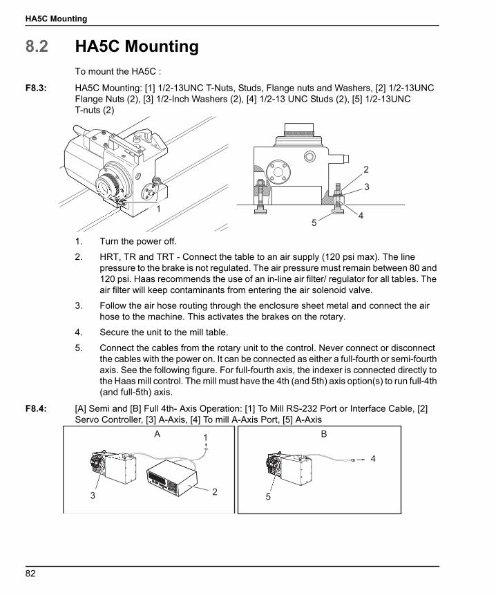
HA5C Mounting
96-8960A.book Page 82 Tuesday, July 28, 2015 1:34 PM
8.2 HA5C MountingTo mount the HA5C :
F8.3: HA5C Mounting: [1] 1/2-13UNC T-Nuts, Studs, Flange nuts and Washers, [2] 1/2-13UNC Flange Nuts (2), [3] 1/2-Inch Washers (2), [4] 1/2-13 UNC Studs (2), [5] 1/2-13UNC T-nuts (2)
1. Turn the power off.
2. HRT, TR and TRT - Connect the table to an air supply (120 psi max). The line pressure to the brake is not regulated. The air pressure must remain between 80 and 120 psi. Haas recommends the use of an in-line air filter/ regulator for all tables. The air filter will keep contaminants from entering the air solenoid valve.
3. Follow the air hose routing through the enclosure sheet metal and connect the air hose to the machine. This activates the brakes on the rotary.
4. Secure the unit to the mill table.
5. Connect the cables from the rotary unit to the control. Never connect or disconnect the cables with the power on. It can be connected as either a full-fourth or semi-fourth axis. See the following figure. For full-fourth axis, the indexer is connected directly to the Haas mill control. The mill must have the 4th (and 5th) axis option(s) to run full-4th (and full-5th) axis.
F8.4: [A] Semi and [B] Full 4th- Axis Operation: [1] To Mill RS-232 Port or Interface Cable, [2] Servo Controller, [3] A-Axis, [4] To mill A-Axis Port, [5] A-Axis
MADEIN
U .S.A .AU TOM
A TION
1
2
3
45
1
23
4
5
A B
-
+
9
0
STE PS C AN
CYCLES TAR TEME R GE NCYS TOP
JOG
ZE R OR ETUR NCL E AR
DIS P LAY
SC ANZE R OSE T
7
4
15
2
0-
6
3
89
RU NPR O G
MODE
82
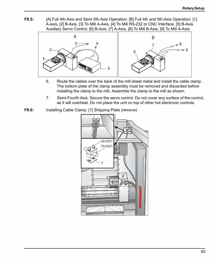
Rotary Setup
96-8960A.book Page 83 Tuesday, July 28, 2015 1:34 PM
F8.5: [A] Full 4th-Axis and Semi 5th-Axis Operation, [B] Full 4th and 5th-Axis Operation: [1] A-axis, [2] B-Axis, [3] To Mill A-Axis, [4] To Mill RS-232 or CNC Interface, [5] B-Axis Auxillary Servo Control, [6] B-Axis, [7] A-Axis, [8] To Mill B-Axis, [9] To Mill A-Axis
6. Route the cables over the back of the mill sheet metal and install the cable clamp. The bottom plate of the clamp assembly must be removed and discarded before installing the clamp to the mill. Assemble the clamp to the mill as shown.
7. Semi-Fourth Axis: Secure the servo control. Do not cover any surface of the control, as it will overheat. Do not place the unit on top of other hot electronic controls.
F8.6: Installing Cable Clamp: [1] Shipping Plate (remove)
-
+
9
0
STE PS C AN
CYCLES TAR TEME R GE NCYS TOP
JOG
ZE R OR ETUR NCL E AR
DIS P LAY
SC ANZE R OSE T
7
4
15
2
0-
6
3
89
RU NPR O G
MODE
1
3 4
5
26
7 8
9
A B
49-0001
79-0001
1
83

HA5C Mounting
96-8960A.book Page 84 Tuesday, July 28, 2015 1:34 PM
8. Semi-Fourth Axis: Connect the AC line cord to a power supply. The cord is a three-wire ground type, and the ground must be connected. The power service must supply a minimum of 15 amps continuously. Conduit wire must be 12-gauge or larger and fused for at least 20 amps. If an extension cord is used, use a three-wire ground type; the ground line must be connected. Avoid outlets that have large electric motors connected to them. Use only heavy-duty 12-gauge extension cords capable of 20 amp load. Do not exceed a length of 30 feet.
9. Semi-Fourth Axis: Connect the remote interface lines. See “Interfacing to Other equipment” section.
10. Turn on the mill (and servo control, if applicable) and home the table/indexer by pressing the Zero Return button. All Haas indexers home in the clockwise direction, as viewed from the platter/spindle. If the table(s) home counter-clockwise, press E-stop and call your dealer.
8.2.1 HA5C Tooling Points
The HA5C is equipped with tooling points in order to speed setups. One of the mosttime-consuming procedures in setup is aligning the head with the table. On the mountingsurfaces are two 0.500" bored holes on 3.000" centers.
The holes on the bottom surface are parallel to the spindle within 0.0005" per 6 inches andon center within ±0.001". By boring matching holes in the tooling plate, setups becomeroutine. Using tooling holes also prevents the head from shifting on the mill table when thepart is subjected to heavy cutting forces.
On CNC mills, a machined stepped plug of 0.500" diameter on one side and 0.625" on theother comes with the Haas head. The 0.625" diameter fits into the T-slot of the mill table,enabling quick parallel alignment.
84
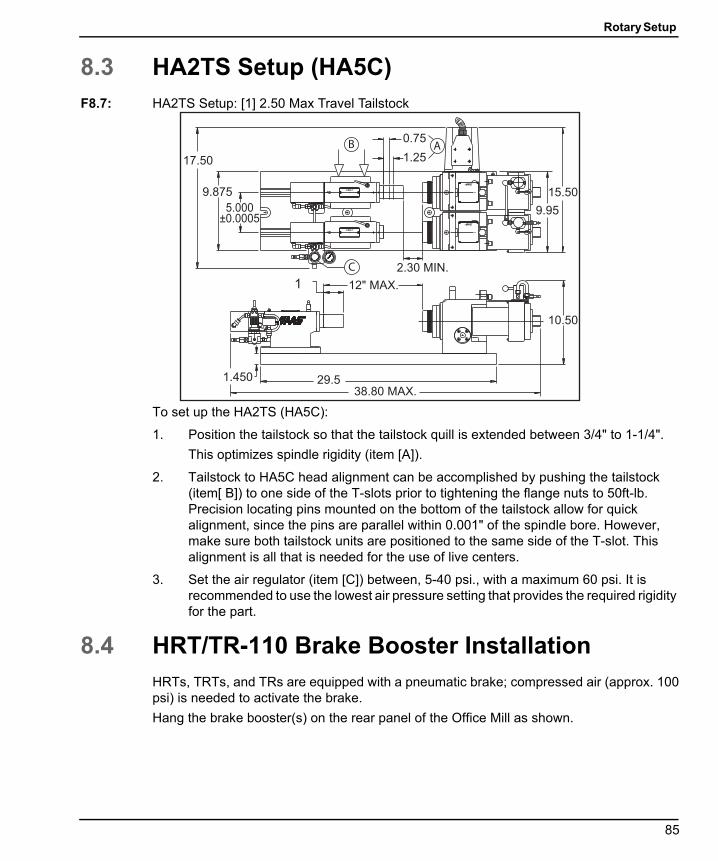
Rotary Setup
96-8960A.book Page 85 Tuesday, July 28, 2015 1:34 PM
8.3 HA2TS Setup (HA5C)F8.7: HA2TS Setup: [1] 2.50 Max Travel Tailstock
To set up the HA2TS (HA5C):
1. Position the tailstock so that the tailstock quill is extended between 3/4" to 1-1/4".
This optimizes spindle rigidity (item [A]).
2. Tailstock to HA5C head alignment can be accomplished by pushing the tailstock (item[ B]) to one side of the T-slots prior to tightening the flange nuts to 50ft-lb. Precision locating pins mounted on the bottom of the tailstock allow for quick alignment, since the pins are parallel within 0.001" of the spindle bore. However, make sure both tailstock units are positioned to the same side of the T-slot. This alignment is all that is needed for the use of live centers.
3. Set the air regulator (item [C]) between, 5-40 psi., with a maximum 60 psi. It is recommended to use the lowest air pressure setting that provides the required rigidity for the part.
8.4 HRT/TR-110 Brake Booster InstallationHRTs, TRTs, and TRs are equipped with a pneumatic brake; compressed air (approx. 100psi) is needed to activate the brake.
Hang the brake booster(s) on the rear panel of the Office Mill as shown.
17.50
5.000±0.0005
9.875
38.80 MAX.29.5
10.50
12" MAX.
15.50
9.95
0.75
2.30 MIN.
1.25AB
C
1.450
1
85

HRT/TR-110 Brake Booster Installation
96-8960A.book Page 86 Tuesday, July 28, 2015 1:34 PM
F8.8: Brake Booster Mounting on the Office Mill Rear Panel
The brake booster is shipped full of oil, including a container of extra oil to top off thereservoir.
The brake booster must be bled before operating, to remove any air that may have enteredthe system during shipping. To bleed the brake booster(s):
1. Close the brake booster air pressure regulator completely (turn the knob counter-clockwise), then connect shop air to the regulator input port. It may be necessary to pull up on the knob before it will turn.
NOTE: Do not connect shop air to the brake booster before closing the valve.
2. Remove the square bolt plug at the top of the reservoir.
86

Rotary Setup
96-8960A.book Page 87 Tuesday, July 28, 2015 1:34 PM
F8.9: Brake Booster Setup: [1] Reservoir, [2] Plug, [3] Oil level 1/4"-1/2" below cap, [4] Bleed Valve, [5] Top of Rear Cabinet Door, [6] Shop Air, [7] Pressure Regulator
3. Turn the brake booster air pressure knob clockwise until the gage reads approximately 5 psi.
4. Press the bleed valve several times to release trapped air in the high-pressure cylinder. This air gets released into the oil reservoir.
5. Bleeding is complete when air bubbles no longer appear in the oil reservoir.
6. Add Mobil SHC 525 until the oil level reaches 1/4" to 1/2" below the reservoir cap.
8.4.1 Pressure Adjustment
CAUTION: Setting regulator pressure above the recommendation will damage thebrake.
To adjust the brake booster pressure:
1. Set the air pressure for the brake booster between 35 and 40 psi.
2. Turn the knob clockwise to increase the pressure; turn it counter-clockwise to decrease the pressure.
3. Once the pressure is set, press the adjusting knob down to lock it.
8.4.2 Oil Level
To check brake booster oil level:
1. Check the brake booster oil level periodically.
2. If necessary, add oil by removing the plug (square bolt) at the top of the reservoir and filling with Mobil SHC 525.
2
1
6
4
3
5
7
87

Interfacing to Other Equipment
96-8960A.book Page 88 Tuesday, July 28, 2015 1:34 PM
8.5 Interfacing to Other EquipmentThe Servo Control can be installed to communicate with your mill in two different ways:
• Remote input using CNC Interface Cable (two signal method), and/or
• RS-232 Interface
These connections are detailed in the following sections.
8.5.1 Servo Control Relay
The relay inside the servo control has a maximum rating of 2 amps (1 amp for HA5C) at 30volts DC. It is programmed as either a normally closed (closed during cycle) or a normallyopen after cycle relay. Refer to the “Parameters” section. It is intended to drive other logicor small relays, it will not drive other motors, magnetic starters, or loads exceeding 100watts. If the feedback relay is used to drive another DC relay (or any inductive load), installa snubber diode across the relay’s coil in the opposite direction of coil current flow Failureto use this diode, or other arc suppression circuitry or inductive loads, damages thecontacts of the relays.
F8.10: Servo Control Relay: [1] CNC Mill Internal, [2] M Function Relay, [3] CNC Interface Cable, [4] Servo Control Internal
1. Use an ohmmeter to measure resistance across pins 1 and 2, to test the relay.
The reading should be infinite (open contacts), with the servo control off.
2. If a low resistance is measured (not infinite), the relay has failed and it must be replaced.
M FIN
+12 Volt s
+24 V
680 OHM
SIGNALFINISH
CYCLESTART
1
23
4
3
1
2
4
88

Rotary Setup
96-8960A.book Page 89 Tuesday, July 28, 2015 1:34 PM
8.5.2 The Remote Input
The Haas servo control has two signals, input and output. The mill tells the rotary controlto index (an input), it indexes, and then sends a signal back to the mill that the index (anoutput) has been completed. This interface requires four wires; two for each signal, andfrom the rotary control remote input and from the mill.
F8.11: CNC Interface Cable: [1] CNC Mill, [2] RS-232 Cables, [3] Haas Servo Control (2 for TRT), [4] Indexer Control Cables, [5] HRT Control Cables, [6] TRT Control Cables (2 sets), [7] Servo Control Internal, [8] CNC Interface Cables, [9] CNC Mill Internal, [10] M Function Relay
The CNC Interface Cable provides these two signals between the mill and the Haas ServoControl. Since most CNC machines are equipped with spare M-codes, semi-fourth axismachining is achieved by connecting one end of the CNC Interface Cable to any of thesespare relays (switches) and the other to the Haas Servo Control.
TRT
M-FIN
+12 Volts
+24 V
680 OHM
SIGNALFINISH
CYCLESTART
1
23
4
HRT
HA5C
MADEINU.S.A.MADEINU.S.A.AUTOMATIONAU TOMA TION
1
2
3
4
5
6
7
8
9
10
--RU
PR
RU
PR
----
RUPRRUPR
89
Interfacing to Other Equipment
96-8960A.book Page 90 Tuesday, July 28, 2015 1:34 PM
The Servo Control stores rotary position programs in memory and each pulse of the millrelay triggers the Servo Control to move to its next programmed position. Once the moveis complete, the Servo Control signals that it has finished and is ready for the next pulse.
A remote input socket (CYCLE START and FINISH SIGNAL) is provided on the servocontrol back panel. Remote input consists of a CYCLE START and a FINISH SIGNALcommand. To connect to the remote, a connector (contact your dealer) is used to triggerthe servo control from any one of several sources. The cable connector is a male four-pinDIN connector. The Haas Automation part number is 74-1510 (Amphenol part number is703-91-T-3300-1). The Haas Automation part number for the panel receptacle on the rearpanel of the Servo Control is 74-1509 (Amphenol part number 703-91-T-3303-9).
For CYCLE START and FINISH SIGNAL operation:
1. When pins 3 and 4 are connected to each other for a minimum of 0.1 seconds, the servo control moves one cycle or step in the program.
When CYCLE START is used, pin 3 supplies a positive 12 volts at 20 milliamps and pin 4 is connected to the diode of an opto-isolator that grounds to chassis. Connecting pin 3 to pin 4 causes a current to flow through the diode of the opto-isolator, triggering the control.
NOTE: If the control is used around high-frequency equipment, such aselectric welders or induction heaters, shielded wire must be used toprevent false triggering by radiated EMI (electromagneticinterference). The shield should be attached to earth ground.
2. To move again, pins 3 and 4 must open for a minimum of 0.1 seconds and then repeat step 1.
CAUTION: Under no circumstances apply power to pins 3 and 4; a relay closureis the safest way to interface the control.
3. If your application is in an automatic machine (CNC mill), the feedback lines (FINISH SIGNAL pins 1 and 2) are used. Pins 1 and 2 are connected to the contacts of a relay inside the control and have no polarity or power on them. They are used to synchronize the automatic equipment with the servo controller.
4. The feedback cables tell the mill that the rotary unit has finished. The relay can be used to FEED HOLD NC machine movements, or can be used to cancel an M function. If the machine is not equipped with this option, an alternative may be to dwell (pause) longer than it takes to move the rotary unit. The relay triggers for all CYCLE START closures, except G97.
90
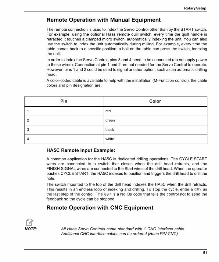
Rotary Setup
96-8960A.book Page 91 Tuesday, July 28, 2015 1:34 PM
Remote Operation with Manual Equipment
The remote connection is used to index the Servo Control other than by the START switch.For example, using the optional Haas remote quill switch, every time the quill handle isretracted it touches a clamped micro switch, automatically indexing the unit. You can alsouse the switch to index the unit automatically during milling. For example, every time thetable comes back to a specific position, a bolt on the table can press the switch, indexingthe unit.
In order to index the Servo Control, pins 3 and 4 need to be connected (do not apply powerto these wires). Connection at pin 1 and 2 are not needed for the Servo Control to operate.However, pins 1 and 2 could be used to signal another option, such as an automatic drillinghead.
A color-coded cable is available to help with the installation (M-Function control); the cablecolors and pin designation are:
HA5C Remote Input Example:
A common application for the HA5C is dedicated drilling operations. The CYCLE STARTwires are connected to a switch that closes when the drill head retracts, and theFINISH SIGNAL wires are connected to the Start wires of the drill head. When the operatorpushes CYCLE START, the HA5C indexes to position and triggers the drill head to drill thehole.
The switch mounted to the top of the drill head indexes the HA5C when the drill retracts.This results in an endless loop of indexing and drilling. To stop the cycle, enter a G97 asthe last step of the control. The G97 is a No Op code that tells the control not to send thefeedback so the cycle can be stopped.
Remote Operation with CNC Equipment
NOTE: All Haas Servo Controls come standard with 1 CNC interface cable.Additional CNC interface cables can be ordered (Haas P/N CNC).
Pin Color
1 red
2 green
3 black
4 white
91
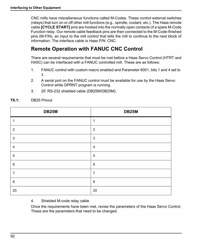
Interfacing to Other Equipment
96-8960A.book Page 92 Tuesday, July 28, 2015 1:34 PM
CNC mills have miscellaneous functions called M-Codes. These control external switches(relays) that turn on or off other mill functions (e.g., spindle, coolant, etc.). The Haas remotecable [CYCLE START] pins are hooked into the normally open contacts of a spare M-CodeFunction relay. Our remote cable feedback pins are then connected to the M-Code-finishedpins (M-FIN), an input to the mill control that tells the mill to continue to the next block ofinformation. The interface cable is Haas P/N: CNC.
Remote Operation with FANUC CNC Control
There are several requirements that must be met before a Haas Servo Control (HTRT andHA5C) can be interfaced with a FANUC controlled mill. These are as follows:
1. FANUC control with custom macro enabled and Parameter 6001, bits 1 and 4 set to 1.
2. A serial port on the FANUC control must be available for use by the Haas Servo Control while DPRNT program is running.
3. 25’ RS-232 shielded cable (DB25M/DB25M).
T8.1: DB25 Pinout
4. Shielded M-code relay cable
Once the requirements have been met, revise the parameters of the Haas Servo Control.These are the parameters that need to be changed.
DB25M DB25M
1 1
2 2
3 3
4 4
5 5
6 6
7 7
8 8
20 20
92
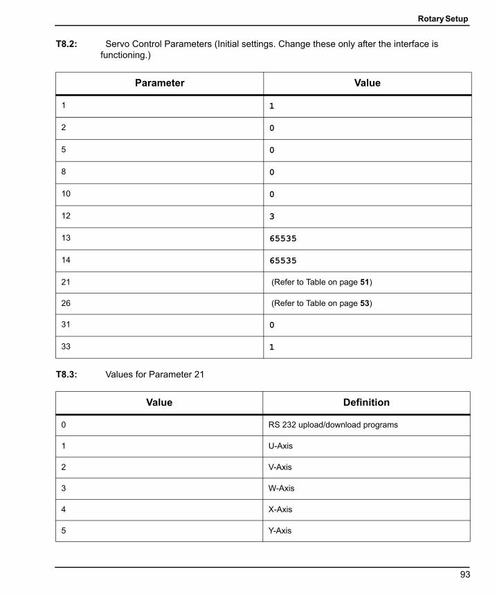
Rotary Setup
96-8960A.book Page 93 Tuesday, July 28, 2015 1:34 PM
T8.2: Servo Control Parameters (Initial settings. Change these only after the interface is functioning.)
T8.3: Values for Parameter 21
Parameter Value
1 1
2 0
5 0
8 0
10 0
12 3
13 65535
14 65535
21 (Refer to Table on page 51)
26 (Refer to Table on page 53)
31 0
33 1
Value Definition
0 RS 232 upload/download programs
1 U-Axis
2 V-Axis
3 W-Axis
4 X-Axis
5 Y-Axis
93
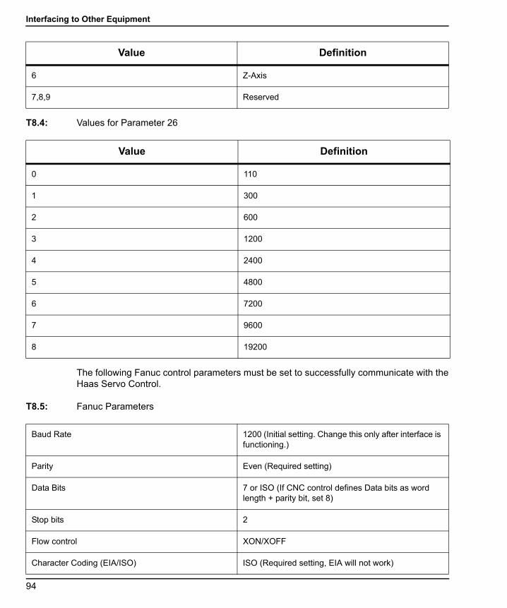
Interfacing to Other Equipment
96-8960A.book Page 94 Tuesday, July 28, 2015 1:34 PM
T8.4: Values for Parameter 26
The following Fanuc control parameters must be set to successfully communicate with theHaas Servo Control.
T8.5: Fanuc Parameters
6 Z-Axis
7,8,9 Reserved
Value Definition
0 110
1 300
2 600
3 1200
4 2400
5 4800
6 7200
7 9600
8 19200
Value Definition
Baud Rate 1200 (Initial setting. Change this only after interface is functioning.)
Parity Even (Required setting)
Data Bits 7 or ISO (If CNC control defines Data bits as word length + parity bit, set 8)
Stop bits 2
Flow control XON/XOFF
Character Coding (EIA/ISO) ISO (Required setting, EIA will not work)
94
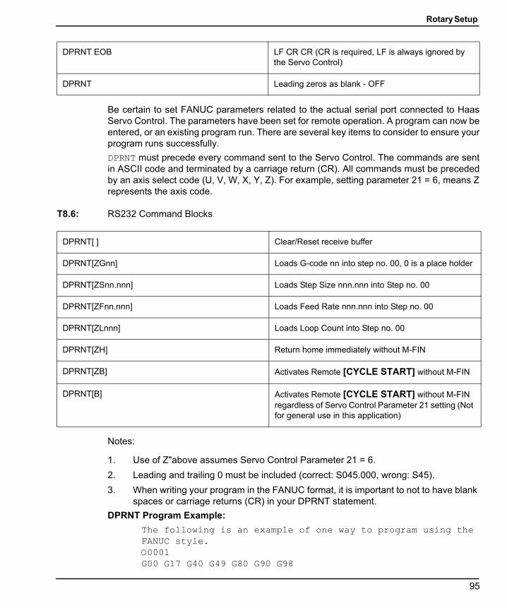
Rotary Setup
96-8960A.book Page 95 Tuesday, July 28, 2015 1:34 PM
Be certain to set FANUC parameters related to the actual serial port connected to HaasServo Control. The parameters have been set for remote operation. A program can now beentered, or an existing program run. There are several key items to consider to ensure yourprogram runs successfully.
DPRNT must precede every command sent to the Servo Control. The commands are sentin ASCII code and terminated by a carriage return (CR). All commands must be precededby an axis select code (U, V, W, X, Y, Z). For example, setting parameter 21 = 6, means Zrepresents the axis code.
T8.6: RS232 Command Blocks
Notes:
1. Use of Z"above assumes Servo Control Parameter 21 = 6.
2. Leading and trailing 0 must be included (correct: S045.000, wrong: S45).
3. When writing your program in the FANUC format, it is important to not to have blank spaces or carriage returns (CR) in your DPRNT statement.
DPRNT Program Example:
The following is an example of one way to program using the FANUC style.O0001G00 G17 G40 G49 G80 G90 G98
DPRNT EOB LF CR CR (CR is required, LF is always ignored by the Servo Control)
DPRNT Leading zeros as blank - OFF
DPRNT[ ] Clear/Reset receive buffer
DPRNT[ZGnn] Loads G-code nn into step no. 00, 0 is a place holder
DPRNT[ZSnn.nnn] Loads Step Size nnn.nnn into Step no. 00
DPRNT[ZFnn.nnn] Loads Feed Rate nnn.nnn into Step no. 00
DPRNT[ZLnnn] Loads Loop Count into Step no. 00
DPRNT[ZH] Return home immediately without M-FIN
DPRNT[ZB] Activates Remote [CYCLE START] without M-FIN
DPRNT[B] Activates Remote [CYCLE START] without M-FIN regardless of Servo Control Parameter 21 setting (Not for general use in this application)
95
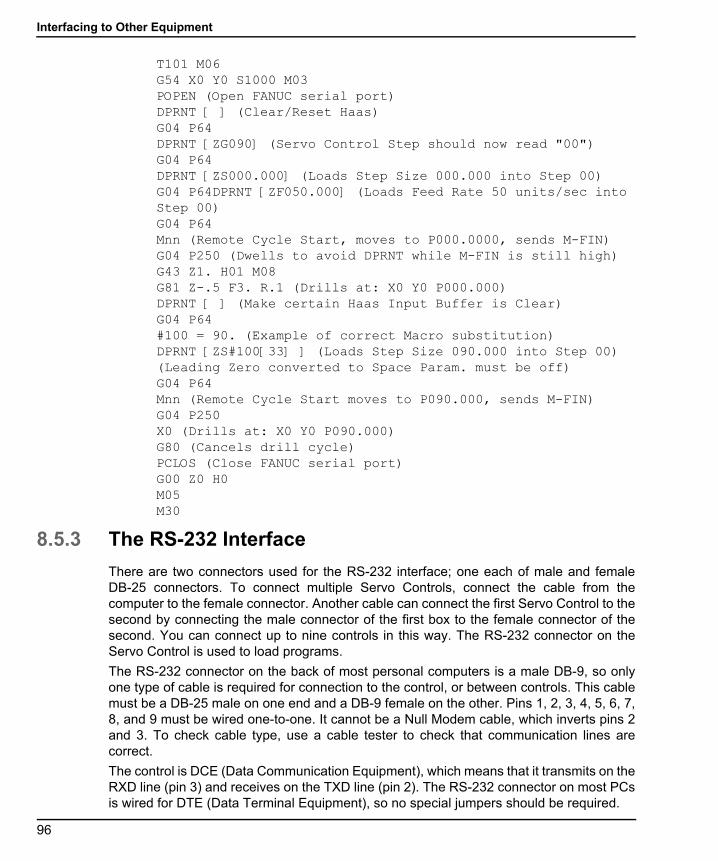
Interfacing to Other Equipment
96-8960A.book Page 96 Tuesday, July 28, 2015 1:34 PM
T101 M06G54 X0 Y0 S1000 M03POPEN (Open FANUC serial port)DPRNT [ ] (Clear/Reset Haas)G04 P64DPRNT [ZG090] (Servo Control Step should now read "00")G04 P64 DPRNT [ZS000.000] (Loads Step Size 000.000 into Step 00)G04 P64DPRNT [ZF050.000] (Loads Feed Rate 50 units/sec into Step 00)G04 P64Mnn (Remote Cycle Start, moves to P000.0000, sends M-FIN)G04 P250 (Dwells to avoid DPRNT while M-FIN is still high)G43 Z1. H01 M08G81 Z-.5 F3. R.1 (Drills at: X0 Y0 P000.000)DPRNT [ ] (Make certain Haas Input Buffer is Clear) G04 P64#100 = 90. (Example of correct Macro substitution)DPRNT [ZS#100[33] ] (Loads Step Size 090.000 into Step 00) (Leading Zero converted to Space Param. must be off)G04 P64Mnn (Remote Cycle Start moves to P090.000, sends M-FIN)G04 P250X0 (Drills at: X0 Y0 P090.000)G80 (Cancels drill cycle)PCLOS (Close FANUC serial port) G00 Z0 H0M05M30
8.5.3 The RS-232 Interface
There are two connectors used for the RS-232 interface; one each of male and femaleDB-25 connectors. To connect multiple Servo Controls, connect the cable from thecomputer to the female connector. Another cable can connect the first Servo Control to thesecond by connecting the male connector of the first box to the female connector of thesecond. You can connect up to nine controls in this way. The RS-232 connector on theServo Control is used to load programs.
The RS-232 connector on the back of most personal computers is a male DB-9, so onlyone type of cable is required for connection to the control, or between controls. This cablemust be a DB-25 male on one end and a DB-9 female on the other. Pins 1, 2, 3, 4, 5, 6, 7,8, and 9 must be wired one-to-one. It cannot be a Null Modem cable, which inverts pins 2and 3. To check cable type, use a cable tester to check that communication lines arecorrect.
The control is DCE (Data Communication Equipment), which means that it transmits on theRXD line (pin 3) and receives on the TXD line (pin 2). The RS-232 connector on most PCsis wired for DTE (Data Terminal Equipment), so no special jumpers should be required.
96

Rotary Setup
96-8960A.book Page 97 Tuesday, July 28, 2015 1:34 PM
T8.7: PC RS-232 COM1 Setup
F8.12: RS-232 Daisy Chain Two Servo Controllers for TRT: [1] PC with RS-232 DB-9 Connector, [2] RS-232 Cable DB-9 to DB-25 straight through, [3] Servo Control A-Axis, [4] RS-232 Cable DB-25 to DB-25 straight through, [5] Servo Control B-Axis
The [RS-232 DOWN] (out line) DB-25 connector is used when multiple controls are used.The first control’s [RS-232 DOWN] (out line) connector goes to the second controller’s[RS-232 UP] (in line) connector, etc.
PC Parameter Value
Stop Bits 2
Parity Even
Baud Rate 9600
Data Bits 7
RS 232 DOWN
RS 232 UP SERIAL NUMBERPOWER
15 AMPFUSE
BRUSHLESSROTARY CONTROLLEROXNARD, CALIFORNIA
MADE IN U.S.A.
FINISHSIGNAL
RS 232 DOWN
RS 232 UP SERIAL NUMBERPOWER
15 AMPFUSE
BRUSHLESSROTARY CONTROLLEROXNARD, CALIFORNIA
MADE IN U.S.A.
FINISHSIGNAL
1
2
3
4 5
97

Using Collets, Chucks, and Faceplates
96-8960A.book Page 98 Tuesday, July 28, 2015 1:34 PM
If Parameter 33 is 0, the CTS line can still be used to synchronize output. When more thanone Haas rotary control is daisy-chained, data sent from the PC goes to all of the controlsat the same time. That is why an axis selection code (Parameter 21) is required. Data sentback to the PC from the controls is programmed together using digital logic OR gates(OR-ed) so that, if more than one box is transmitting, the data will be garbled. Therefore,the axis selection code must be unique for each controller. The serial interface may be usedin either a remote command mode or as an upload/download path.
8.6 Using Collets, Chucks, and FaceplatesThe following sections describe the use and adjustment of the following collets, chucks, andfaceplates:
• HA5C Standard 5C and Step Collets
• A6AC Air Collet Closer (HRT)
8.6.1 HA5C
The HA5C accepts standard 5C collets and step collets.
F8.13: HA5C Chuck Install: [1] SHCS, [2] LC5C-B, [3] HA5C, [4]Face Plate, [5] Chuck, [6] 70 ft-lb
To install collets, chucks, and faceplates in an HA5C:
1. When inserting the collets, align the keyway on the collet with the pin inside the spindle.
2. Push the collet in and turn the collet drawbar clockwise the collet is correctly tightened.
3. Chucks and face plates use the 2-3/16-10 threaded nose on the spindle. You should use chucks with a diameter smaller than 5" and that weigh less than 20 pounds.
4. Pay special attention when installing chucks, always make sure that the thread and the outside diameter of the spindle are free of dirt and chips.
5. Apply a thin coating of oil to the spindle, and screw the chuck on gently until it seats against the rear of the spindle.
6. Tighten the chuck to approximately 70 ft-lb with a strap wrench.
1
2
3
4
5
6
98

Rotary Setup
96-8960A.book Page 99 Tuesday, July 28, 2015 1:34 PM
7. Always use a firm, steady pressure to remove or install chucks or face plates, otherwise damage to the indexing head may result.
WARNING: Never use a hammer or pry bar to tighten the chuck; this will damagethe precision bearings inside your unit.
8.6.2 A6AC Air Collet Closer (HRT)
The A6AC collet closer bolts to the back of the HRT A6 (See the following illustration).
The drawbar and collet adapters are designed to mate with the Haas A6/5C spindle nose.The optional A6/3J and A6/16C can be obtained from a local tooling distributor. Failure tofollow the A6AC installation instructions may result in throughst bearing failure.
NOTE: A special drawtube adapter is required for the 16C and 3J. Be sure tosupply the tooling distributor with spindle/drawbar details as shown.
F8.14: A6AC Collet Closer Mounted To An HRT A6
99

Using Collets, Chucks, and Faceplates
96-8960A.book Page 100 Tuesday, July 28, 2015 1:34 PM
F8.15: Drawtube and Spindle (Extended/retracted)
T8.8: Drawtube To Spindle Dimensions (Extended/retracted) @ 100 psi Line Pressure
A6AC Clamping Force and Air Supply
The A6AC is a 1-3/4" diameter through-hole type closer, adjustable from the rear. It holdsparts using spring force to provide up to 0.125" of longitudinal movement and up to 5000 lbof draw force at 120 psi.
Reference NameValue
(extended/retracted)
[A] MAX. (Tube Extended) .640
[B] MIN. (Tube Retracted) .760
[C] Spindle Type and Size A1-6
[D] Draw Tube Thread Data
1 - Diameter of Thread (internal) 1 7/8 - 16 - UN - 2B
2 - Pitch 1.834/1.841
3 - Thread Length 1.25
[E] Draw Tube I.D. 1.75
[F] Draw Tube O.D. 2.029
[G] Spindle I.D. 2.0300
E F
AB
G
D
C
100

Rotary Setup
96-8960A.book Page 101 Tuesday, July 28, 2015 1:34 PM
A6AC Adjustment
To adjust the collet closer:
1. Align a collet with the keyway, push the collet into the spindle, and turn the draw bar clockwise to pull the collet in.
2. To make final adjustments, place a part in the collet, and turn the air valve to the Unclamped position.
3. Tighten the draw bar until it stops, then loosen it 1/4-1/2 turn, and turn the air valve to the Clamped position (adjusted for maximum clamping force).
4. To reduce clamping force, loosen the draw bar or reduce the air pressure before adjusting.
8.6.3 AC25/100/125 Air Collet Closers
The following sections describe removal and installation of AC25/100/125 air collet closersand collets.
AC25/100/125 for the HA5C and T5C
The AC25 is a non through-hole type closer that holds parts using air pressure, whichprovides up to 3000 pounds of draw force, depending on air pressure supplied. The unitprovides 0.03" of longitudinal movement so diameter variations of up to 0.007" can beclamped securely without readjustment.
F8.16: HA5C Air Collets Draw Force vs. Air Pressure
101

Using Collets, Chucks, and Faceplates
96-8960A.book Page 102 Tuesday, July 28, 2015 1:34 PM
The AC100 is a through-hole type closer that holds parts using spring force, providing upto 10,000 pounds of draw force. The unit provides 0.025" of longitudinal movement sodiameter variations of up to 0.006" can be clamped securely without readjustment. Set airpressure between 85 and 120 psi.
The AC125 air collet closer has a 5/16" through-hole that allows small diameter stock toextend out of the unit. The AC125 also has a large diameter counterbore in the drawtubethat allows stock to pass through a standard 5C collet up to approximately 1.6" out the rearof the collet. This also allows the use of most standard collet stops. The AC125 uses airpressure to provide up to 12,000 lb. of draw force (adjustable through a customer-suppliedair pressure regulator). The drawtube travel of 0.060" allows the unit to securely clampparts with up to 0.015" variation in diameter without readjustment.
Manual Collet Closer Removal (Model AC25/100/125)
F8.17: Collet Closer: [1] AC25, [2] AC125, [3] AC100, [4] Manual Collet Closer
Before installing the air collet closer on the unit, you must first remove the manual colletcloser assembly [4]. To remove this assembly:
1. Remove the top and bottom mounting bolts for the handle [A].
2. Slide the handle off the collet closer assembly.
3. Remove the collet closer and slide the collet closer assembly out the back of the spindle.
4. Remove the flathead screw [C] and locking pawl [B], and unscrew the spindle nut [D].
It may be necessary to use two 1/8" pins and a screwdriver to break the spindle nut loose.
A D
BC
1
2
3
4
102
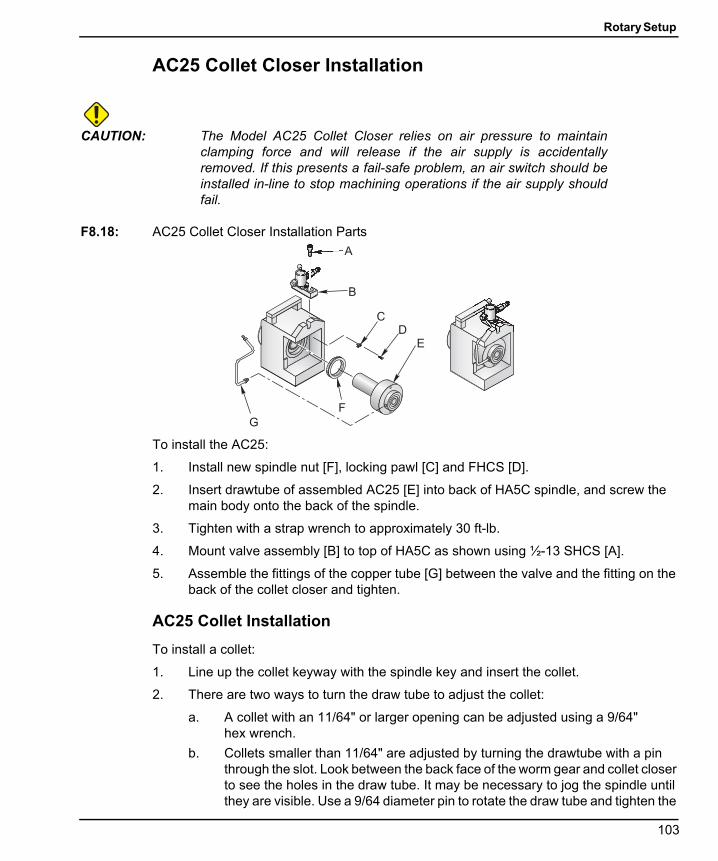
Rotary Setup
96-8960A.book Page 103 Tuesday, July 28, 2015 1:34 PM
AC25 Collet Closer Installation
CAUTION: The Model AC25 Collet Closer relies on air pressure to maintainclamping force and will release if the air supply is accidentallyremoved. If this presents a fail-safe problem, an air switch should beinstalled in-line to stop machining operations if the air supply shouldfail.
F8.18: AC25 Collet Closer Installation Parts
To install the AC25:
1. Install new spindle nut [F], locking pawl [C] and FHCS [D].
2. Insert drawtube of assembled AC25 [E] into back of HA5C spindle, and screw the main body onto the back of the spindle.
3. Tighten with a strap wrench to approximately 30 ft-lb.
4. Mount valve assembly [B] to top of HA5C as shown using ½-13 SHCS [A].
5. Assemble the fittings of the copper tube [G] between the valve and the fitting on the back of the collet closer and tighten.
AC25 Collet Installation
To install a collet:
1. Line up the collet keyway with the spindle key and insert the collet.
2. There are two ways to turn the draw tube to adjust the collet:
a. A collet with an 11/64" or larger opening can be adjusted using a 9/64" hex wrench.
b. Collets smaller than 11/64" are adjusted by turning the drawtube with a pin through the slot. Look between the back face of the worm gear and collet closer to see the holes in the draw tube. It may be necessary to jog the spindle until they are visible. Use a 9/64 diameter pin to rotate the draw tube and tighten the
F
G
B
A
DE
C
103
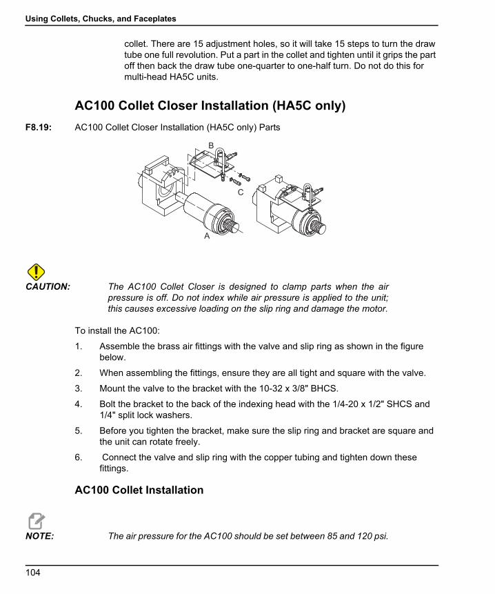
Using Collets, Chucks, and Faceplates
96-8960A.book Page 104 Tuesday, July 28, 2015 1:34 PM
collet. There are 15 adjustment holes, so it will take 15 steps to turn the draw tube one full revolution. Put a part in the collet and tighten until it grips the part off then back the draw tube one-quarter to one-half turn. Do not do this for multi-head HA5C units.
AC100 Collet Closer Installation (HA5C only)
F8.19: AC100 Collet Closer Installation (HA5C only) Parts
CAUTION: The AC100 Collet Closer is designed to clamp parts when the airpressure is off. Do not index while air pressure is applied to the unit;this causes excessive loading on the slip ring and damage the motor.
To install the AC100:
1. Assemble the brass air fittings with the valve and slip ring as shown in the figure below.
2. When assembling the fittings, ensure they are all tight and square with the valve.
3. Mount the valve to the bracket with the 10-32 x 3/8" BHCS.
4. Bolt the bracket to the back of the indexing head with the 1/4-20 x 1/2" SHCS and 1/4" split lock washers.
5. Before you tighten the bracket, make sure the slip ring and bracket are square and the unit can rotate freely.
6. Connect the valve and slip ring with the copper tubing and tighten down these fittings.
AC100 Collet Installation
NOTE: The air pressure for the AC100 should be set between 85 and 120 psi.
A
B
C
104
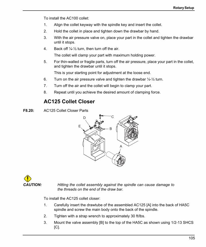
Rotary Setup
96-8960A.book Page 105 Tuesday, July 28, 2015 1:34 PM
To install the AC100 collet:
1. Align the collet keyway with the spindle key and insert the collet.
2. Hold the collet in place and tighten down the drawbar by hand.
3. With the air pressure valve on, place your part in the collet and tighten the drawbar until it stops.
4. Back off ¼-½ turn, then turn off the air.
The collet will clamp your part with maximum holding power.
5. For thin-walled or fragile parts, turn off the air pressure, place your part in the collet, and tighten the drawbar until it stops.
This is your starting point for adjustment at the loose end.
6. Turn on the air pressure valve and tighten the drawbar ¼-½ turn.
7. Turn off the air and the collet will begin to clamp your part.
8. Repeat until you achieve the desired amount of clamping force.
AC125 Collet Closer
F8.20: AC125 Collet Closer Parts
CAUTION: Hitting the collet assembly against the spindle can cause damage tothe threads on the end of the draw bar.
To install the AC125 collet closer:
1. Carefully insert the drawtube of the assembled AC125 [A] into the back of HA5C spindle and screw the main body onto the back of the spindle.
2. Tighten with a strap wrench to approximately 30 ft/lbs.
3. Mount the valve assembly [B] to the top of the HA5C as shown using 1/2-13 SHCS [C].
B
A
CD
E
105
Using Collets, Chucks, and Faceplates
96-8960A.book Page 106 Tuesday, July 28, 2015 1:34 PM
4. Assemble the fitting [D] part number 58-16755 and copper tube [E] part number 58-4059 between the valve and fitting on the back of the collet closure and tighten.
5. Never use a hammer to remove or install these items. The shock will damage the precision bearings and gears inside the unit.
Collet Installation (Model AC125)
All collets used with the AC125 must be clean and in good condition. To install a collet inthe AC125:
1. Align the collet keyway with the spindle key and insert the collet.
2. Insert a 5/16" hex wrench into the hex in the back of the drawtube, and turn the drawtube to engage the collet.
3. Tighten the drawtube until it grips the part, and then back off approximately 1/4 turn.
This is a good starting point for fine-tuning the grip range.
Air Collet Closer Removal (Model AC25/100/125)
Air collet closers fitted at the factory are not intended to be removed. However, if you needto remove the air collet closer:
1. Use a woven strap wrench to remove the collet assembly.
2. Do not use a hammer or impact wrench to remove the closer bodies; damage may occur to the gear and bearing sets.
3. When re-installing the collet closer, use a strap wrench and tighten to approximately 30 ft-lb.
8.6.4 Haas Manual Draw Tube (HMDT)
The HMDT is used for standard and tilt multi-head 5C units in place of pneumatic closers,where a through hole is required or space constraints exist. The HMDT fits within the bodyof the 5C unit and has a 1.12" (28 mm) through hole. The collet is tightened using astandard 1-1/2" (38 mm) socket and a torque wrench for consistency.
106
Rotary Setup
96-8960A.book Page 107 Tuesday, July 28, 2015 1:34 PM
8.6.5 Collet Sticking
NOTE: To prevent excessive wear and collet sticking, make sure collets arein good condition and free from burrs. A light coat of molybdenumgrease (Haas p/n 99-0007 or Mobil p/n CM-P) on the collet wearsurfaces extends the life of the spindle/collet, and helpsprevent sticking.
When using the AC25, releasing a collet is accomplished by removing the air supply. Thecollet is then pushed out by a heavy spring inside the air collet.
The AC100 uses shop air to move the drawbar forward and release the collet. Increasingthe air pressure can help free the collet when it sticks; however, do not exceed 150 psi.
The AC125 uses shop air to pull in the drawtube, and a heavy internal spring to push outthe drawtube and release the collet. If, after repeated use, the spring does not push out thecollet, use one of the following methods to remove the collet and lubricate the outside ofthe collet with a light grease before re-inserting:
1. If the three-way air valve becomes clogged, exhaust airflow may be restricted, causing the collet to stick in the taper. Leave the valve clamped, and connect and disconnect the air supply several times.
2. If the above procedure does not free the collet, switch the valve to the unclamped position, then gently tap the back end of the drawtube with a plastic-faced mallet.
107

Using Collets, Chucks, and Faceplates
96-8960A.book Page 108 Tuesday, July 28, 2015 1:34 PM
108
Tailstock Setup
96-8960A.book Page 109 Tuesday, July 28, 2015 1:34 PM
Chapter 9: Tailstock Setup
9.1 Tailstock Setup
IMPORTANT: The warranty card should be filled out before you use the tailstock.
IMPORTANT: When using Servo 5C Indexers, Haas Automation recommends usinglive center tailstocks only!
NOTE: Tailstocks cannot be used with the HRT320FB table.
Tailstocks must be properly aligned to the rotary table before using. Refer to page 109 forthe alignment procedure.
To prepare the tailstock to mount on the table:
1. Clear the button surface of the tailstock casting before mounting it to the mill table.
2. If there are any noticeable burrs or nicks on the mounting surface, clean them with a deburring stone.
9.2 Tailstock AlignmentTo align your tailstock:
1. Mount the supplied 0.625 dia. locating pins to the bottom of the tailstock using 1/4- 20 x 1/2” socket head cap screw (SHCS).
2. Mount the tailstock to a clean mill table.
3. Fasten lightly to the mill table using 1/2-13 hex head bolt (HHB), hardened tooling washers and 1/2-13 T-nuts.
4. Extend the tailstock spindle from the body. Use the tailstock spindle surface to sweep the tailstock spindle center line to rotary product center line, align to within 0.003 TIR.
5. Once the unit is properly aligned, torque the 1/2-13 nuts to 50 ft-lb.
9.3 Installation/Removal of Morse Taper AccessoriesTo install or remove a Morse taper accessory:
1. Inspect and clean the tailstock taper and the tapered surface of live center.
2. Apply a light coat of oil on the center, before inserting it, into the spindle. This aids in removing the center, and also prevents corrosion buildup.
109
Installation/Removal of Morse Taper Accessories
96-8960A.book Page 110 Tuesday, July 28, 2015 1:34 PM
3. Manual Tailstock - Live or dead centers: Retract the tailstock spindle into the body and the leadscrew forces the center out.
4. Pneumatic Tailstock - Live centers: Wedge an aluminum bar between the face of the tailstock spindle and the rear surface of the live centers flange.
5. Pneumatic Tailstock - Dead Centers: Thread dead centers are recommend (often called N/C Dead Centers). Use a wrench to hold the center in place, and turn the nut until it backs the center out from tailstock spindle.
110

96-8960A.book Page 111 Tuesday, July 28, 2015 1:34 PM
Index
AAC25/100/125
adjustment ..................................... 101air collet closer ..................................... 101
A6AC .............................................. 99adjustment ................................ 101
air supplyA6AC closer ................................... 100
alarmerror codes ....................................... 12servo off codes.................................. 13
Bbacklash................................................ 64
worm gear check ............................... 66worm shaft check............................... 66
brake boosterinstallation ........................................ 85oil level ............................................ 87pressure adjustment ........................... 87
brushless rotary control ............................. 1display.............................................. 4front panel ......................................... 3rear panel.......................................... 6
Cchuck.................................................... 98clamp force
A6AC closer ................................... 100cleanup ................................................. 70collet .................................................... 98
AC100........................................... 105AC25............................................. 103key replacement ................................ 71sticking .......................................... 107
collet closerA6AC .............................................. 99AC100........................................... 104AC125........................................... 105AC25 ............................................ 103manual .......................................... 102removal ......................................... 106
collet closer adjustmentA6AC ............................................ 101
control modesrun .................................................. 7
control programs..................................... 26absolute or incremental motion............. 26auto continue mode ........................... 26circle division .................................... 27continuous motion ............................. 27feedrate........................................... 27loop counts ...................................... 27pause (dwell) .................................... 27subroutine........................................ 28
coolant.................................................. 67coordinate system..................................... 9
right-hand rule ................................... 9
Ddefault control values ............................... 11
Eemergency stop ........................................ 9
Ffaceplate ............................................... 98
GG-codes ................................................ 37gear compensation.................................. 41
111
96-8960A.book Page 112 Tuesday, July 28, 2015 1:34 PM
HHA5C
lubrication ........................................ 68mounting ......................................... 82tooling points .................................... 84
Haas manual draw tube (HDMT) .............. 106HRT
lubrication ........................................ 67
Iinspection
platter face runout.............................. 63platter I.D. runout............................... 63
Jjogging ................................................... 8
Llubricants
requirements .................................... 72lubrication
HA5C.............................................. 68HRT................................................ 67T5C ................................................ 69tailstock ........................................... 71TR.................................................. 69TRT................................................ 69
Mmachine coolant ..................................... 67maintenance .......................................... 63
backlash .......................................... 64cleanup ........................................... 70lubrication ........................................ 67measure worm play............................ 65mechanical checks ............................ 65table inspection ................................. 63tailstock ........................................... 71
manual collet closerremoval ......................................... 102
Morse taper ......................................... 109
Ooffsets
zero position..................................... 11
Pparameters............................................ 41programming ......................................... 17
clear a program ................................ 20delete a step .................................... 21enter a step...................................... 20examples......................................... 31insert a new step............................... 21select a stored program...................... 19store program in memory.................... 18
Rremote input .......................................... 89remote operation
CNC............................................... 92FANUC CNC.................................... 92manual equipment............................. 91
right-hand rule ......................................... 9rotary axis
jogging.............................................. 8rotary setup
AC25/100/125 for HA5C and TSC ....... 101collet in an HA5C .............................. 98general ........................................... 81HA2TS (HA5C)................................. 85install a collet in the AC125 ................ 106interfacing........................................ 88mounting ......................................... 81
routine maintenancelubricants......................................... 72popout check.................................... 66
RS-232 interface ............................... 21, 96remote command mode...................... 24responses........................................ 25single axis commands........................ 24upload or download a program............. 23
run mode ................................................ 7
Ssemi-fourth and fifth axis ............................ 1
RS-232 ............................................. 1
112

96-8960A.book Page 113 Tuesday, July 28, 2015 1:34 PM
servo control ........................................ 1, 2display .............................................. 4front panel.......................................... 3initialize ............................................. 8introduction ........................................ 2operating hints .................................. 11power on ........................................... 7rear panel .......................................... 6relay ............................................... 88
simultaneous milling ................................ 29spiral milling ..................................... 29timing issues .................................... 30
stepsinsert new ........................................ 21
TT5C
lubrication ........................................ 69tailstock
alignment....................................... 109lubrication ........................................ 71manual operation............................... 15operation ......................................... 15pneumatic operation........................... 15setup ............................................ 109
TRlubrication ........................................ 69
troubleshooting....................................... 75collet sticking .................................. 107general guide.................................... 77TR/TRT/T5C guide ............................ 79
TRTlubrication ........................................ 69
Zzero position
automatic......................................... 10manual ............................................ 10offset .............................................. 11
113

96-8960A.book Page 114 Tuesday, July 28, 2015 1:34 PM
114
Related Documents