http://catalog.moeller.net ATEX Rotary switches T, switch-disconnectors P, Small enclosures CI-K The powerful, rugged and compact cam switches and switch-disconnectors are used in industry, workshops and in building services management. The basic switch types of four different construction types and with a wide range of standard contact sequences and rating ranges are available. Switch for ATEX Zone 22 - TT rotary switches - P1 and P3 switch-disconnectors - Degree of protection IP65 Page 7/4 P switch-disconnectors - Up to 110 kW and 315 A - P1 and P3 in IP65 enclosure - 4 different types of construction Page 7/6 CI-K enclosure system - Switch protection in IP65 - Individual laser inscription - Customized cutouts - Cable entry as push-through diaphragm or - knockout Page 7/60 TM/T rotary switches - up to 10/132 kW - Non-standard circuits possible (EK) - Various types of construction Page 7/52 Rotary switches, switch-disconnectors Mini rotary switches Small enclosures, empty enclosures Moeller HPL0211-2007/2008 Contents 7/1 Rotary switches T, switch-disconnectors P, Small enclosures CI-K, empty enclosures CI Page Technical overview 7/2 System overview 7/4 Rotary switches 7/4 Switch-disconnectors 7/6 Description 7/8 Key to part numbers, modular system 7/8 Ordering 7/9 Load current switches, main switches, maintenance/repair switches 7/10 Load current switches, ON/OFF switches 7/21 Load current switches, changeover contacts 7/25 Load-current switch - Safety switch 7/30 Load current switch - reversing switch 7/32 Load current switches, (reversing) star-delta switches 7/33 load-current switch - pole-change switch 7/34 Control switch, step switch 7/35 Control switch: ON/OFF switch, changeover, hand/auto switch 7/37 Control switch - hand/auto switch 7/38 Control switch - ON buttons, universal control switches 7/40 Control switch - instrument selector switches 7/40 Switch with locking mechanism 7/41 Main switch assembly kits, thumb- grip, maintenance key 7/43 Front plates 7/44 Add-on front plates 7/45 key operation, locking interlock 7/46 Neutral conductor, auxiliary contact, central mounting accessories, service distribution board mounting accessories 7/48 Coupling drive, interlock parts, shaft extension 7/49 Shrouds, keys 7/50 Insulated enclosures, accessories 7/51 Technical data 7/67 Switch-disconnectors 7/67 Switch-disconnectors, auxiliary contacts 7/69 Rotary switches 7/70 Dimensions 7/76 Page Technical overview 7/2 Description 7/9 Key to part numbers, modular system 7/9 System overview 7/52 Ordering 7/54 Control circuit isolator, ON/OFF switch 7/54 Changeover switch, hand/automatic switch 7/55 Control switch, step switch 7/56 Control switch - group switch, ON (OFF) button, reversing switch, coding switch 7/58 Locks, front plates 7/59 Technical data 7/74 Dimensions 7/88 Page System overview 7/60 Ordering 7/61 Basic enclosures 7/61 Accessories 7/64 Technical data 7/75 Dimensions 7/88

Welcome message from author
This document is posted to help you gain knowledge. Please leave a comment to let me know what you think about it! Share it to your friends and learn new things together.
Transcript

http://catalog.moeller.net
ATEX
Rotary switches T, switch-disconnectors P, Small enclosures CI-K
The powerful, rugged and compact cam switches and switch-disconnectors are used in industry, workshops and in building services management. The basic switch types of four different construction types and with a wide range of standard contact sequences and rating ranges are available.
Switch for ATEX Zone 22- TT rotary switches- P1 and P3 switch-disconnectors- Degree of protection IP65
Page 7/4
P switch-disconnectors- Up to 110 kW and 315 A- P1 and P3 in IP65 enclosure- 4 different types of construction
Page 7/6
CI-K enclosure system- Switch protection in IP65- Individual laser inscription- Customized cutouts- Cable entry as push-through
diaphragm or- knockout
Page 7/60
TM/T rotary switches- up to 10/132 kW- Non-standard circuits possible (EK)- Various types of construction
Page 7/52
Rotary switches, switch-disconnectors Mini rotary switches Small enclosures, empty enclosures
Moeller HPL0211-2007/2008
Contents 7/1
Ro
tary
sw
itch
es T
, sw
itch
-dis
con
nec
tors
P,
Smal
l en
clo
sure
s C
I-K
, em
pty
en
clo
sure
s C
I
Page
Technical overview 7/2
System overview 7/4
Rotary switches 7/4
Switch-disconnectors 7/6
Description 7/8
Key to part numbers, modular system 7/8
Ordering 7/9
Load current switches, main switches, maintenance/repair switches
7/10
Load current switches, ON/OFF switches
7/21
Load current switches, changeover contacts
7/25
Load-current switch - Safety switch 7/30
Load current switch - reversing switch 7/32
Load current switches, (reversing) star-delta switches
7/33
load-current switch - pole-change switch
7/34
Control switch, step switch 7/35
Control switch: ON/OFF switch, changeover, hand/auto switch
7/37
Control switch - hand/auto switch 7/38
Control switch - ON buttons, universal control switches
7/40
Control switch - instrument selector switches
7/40
Switch with locking mechanism 7/41
Main switch assembly kits, thumb-grip, maintenance key
7/43
Front plates 7/44
Add-on front plates 7/45
key operation, locking interlock 7/46
Neutral conductor, auxiliary contact, central mounting accessories, service distribution board mounting accessories
7/48
Coupling drive, interlock parts, shaft extension
7/49
Shrouds, keys 7/50
Insulated enclosures, accessories 7/51
Technical data 7/67
Switch-disconnectors 7/67
Switch-disconnectors, auxiliary contacts
7/69
Rotary switches 7/70
Dimensions 7/76
Page
Technical overview 7/2
Description 7/9
Key to part numbers, modular system 7/9
System overview 7/52
Ordering 7/54
Control circuit isolator, ON/OFF switch 7/54
Changeover switch, hand/automatic switch
7/55
Control switch, step switch 7/56
Control switch - group switch, ON (OFF) button, reversing switch, coding switch
7/58
Locks, front plates 7/59
Technical data 7/74
Dimensions 7/88
Page
System overview 7/60
Ordering 7/61
Basic enclosures 7/61
Accessories 7/64
Technical data 7/75
Dimensions 7/88
Moeller HPL0211-2007/2008
7/2
Moeller HPL0211-2007/2008http://catalog.moeller.net http://catalog.moeller.net
Rota
ry s
wit
ches
, sw
itch
-dis
conn
ecto
rs
Rota
ry s
wit
ches
, sw
itch
-dis
conn
ecto
rs
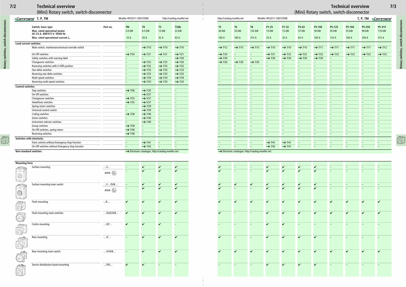
Technical overview Technical overview(Mini) Rotary switch, switch-disconnector (Mini) Rotary switch, switch-disconnector
Switch, basic type Part no. TM T0 T3 T5(B) T5 T6 T8 P1-25 P1-32 P3-63 P3-100 P5-125 P5-160 P5-250 P5-315Max. rated operatioal power AC-23 A, 400/415 V, 50/60 Hz
3.0 kW 6.5 kW 13 kW 22 kW 30 kW 55 kW 132 kW 13 kW 15 kW 37 kW 50 kW 45 kW 55 kW 90 kW 110 kW
Max. rated operational current Iu 10 A 20 A 32 A 63 A 100 A 160 A 315 A 25 A 32 A 63 A 100 A 125 A 160 A 250 A 315 A
Load current switchesMain switch, maintenance/manual override switch – a 7/10 a 7/10 a 7/10 a 7/12 a 7/15 a 7/15 a 7/10 a 7/10 a 7/10 a 7/11 a 7/11 a 7/11 a 7/11 a 7/12
On-Off switches a 7/54 a 7/21 a 7/21 a 7/21 a 7/24 – – a 7/21 a 7/22 a 7/22 a 7/22 a 7/22 a 7/22 a 7/22 a 7/22Safety switches with warning label – – – a 7/30 a 7/30 – – a 7/30 a 7/30 a 7/30 a 7/30 – – – –Changeover switches – a 7/25 a 7/25 a 7/26 a 7/26 a 7/26 a 7/26 – – – – – – – –Reversing switches with 0 (Off) position – a 7/32 a 7/32 a 7/32 – – – – – – – – – – –Star-delta switches – a 7/33 a 7/33 a 7/33 – – – – – – – – – – –
– – – – – – – – –– – – – – – – – –– – – – – – – – –
– – – – – – – – –– – – – – – – – –– – – – – – – – –– – – – – – – – –– – – – – – – – –– – – – – – – – –– – – – – – – – –– – – – – – – – –– – – – – – – – –– – – – – – – – –– – – – – – – – –– – – – – – – – –
– a 7/41 a 7/41 – – – – – –– a 7/42 a 7/41 – – – – – –
gue, http://catalog.moeller.net
– ✔ ✔ ✔ ✔ – – – –– ✔ ✔ ✔ ✔ – – – –
✔ ✔ ✔ ✔ ✔ – – – –– ✔ ✔ ✔ ✔ – – – –
✔ ✔ ✔ ✔ ✔ ✔ ✔ ✔ ✔
– ✔ ✔ ✔ ✔ ✔ ✔ ✔ ✔
– ✔ ✔ – – – – – –
– ✔ ✔ ✔ ✔ – – – –
✔ ✔ ✔ ✔ ✔ ✔ ✔ ✔ ✔
– ✔ ✔ ✔ ✔ – – – –
7/3
T, P, TM T, P, TM
Reversing star-delta switches – a 7/33 a 7/33 a 7/33 – –Multi-speed switches – a 7/34 a 7/34 a 7/34 – –Reversing multi-speed switches – a 7/33 a 7/33 a 7/33 – –
Control switchesStep switches a 7/56 a 7/35 – – –On-Off switches – a 3/37 – – – –Changeover switches a 7/55 a 3/37 – – – –Hand/Auto switches a 7/55 a 3/37 – – – –Spring-return switches – a 7/39 – – – –Universal control switch – a 7/39 – – – –Coding switches a 7/58 a 7/40 – – – –Series switches – a 7/40 – – – –Instrument selector switches – a 7/40 – – – –Group switches a 7/58 – – – – –On-Off switches, spring-return a 7/58 – – – – –Reversing switches a 7/58 – – – – –
Switches with interlocksPanic switchs without Emergency-Stop function – a 7/41 – – – –On-Off switches without Emergency-Stop function – a 7/42 – – – –
Non-standard switches a Electronic catalogue, http://catalog.moeller.net a Electronic catalo
Mounting formSurface mounting …/I… – ✔ ✔ ✔ ✔ –
– ✔ ✔ ✔ ✔ –
Surface mounting main switch …/I…/SVB… – ✔ ✔ ✔ ✔ ✔
– ✔ ✔ ✔ ✔ –
Flush mounting .../E… ✔ ✔ ✔ ✔ ✔ ✔
Flush mounting main switches …/E(A)/SVB… ✔ ✔ ✔ ✔ ✔ –
Centre mounting …/EZ… ✔ ✔ ✔ – – –
Rear mounting …/Z… – ✔ ✔ ✔ ✔ –
Rear mounting main switch …/V/SVB… – ✔ ✔ ✔ ✔ ✔
Service distribution board mounting …/IVS… ✔ ✔ – – – –
ATEX
ATEX

7/4Ro
tary
sw
itch
es, s
wit
ch-d
isco
nnec
tors
Moeller HPL0211-2007/2008 http://catalog.moeller.net
System overviewRotary switches
ON-OFF switch T0, T3, T5B, T5
Control switches T0, T3, T5B, T5
ATEX
10
9
8
7
7
6
5
4
3
2
1
6
8
9
10
10
1
2
3
4
99
10
ATEX
T
7/5
http://catalog.moeller.net Moeller HPL0211-2007/2008
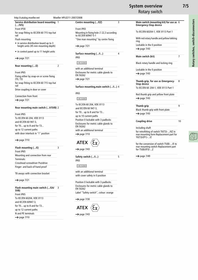
System overviewRotary switch
Rota
ry s
wit
ches
, sw
itch
-dis
conn
ecto
rs
Service distribution board mounting (…/IVS)
1
Front IP30for snap fitting to IEC/EN 60 715 top-hat railFlush mounting• in service distribution board up to 3
height units (45 mm mounting depth)
• in control panel up to 11 height units
a page 7/21
Rear mounting (.../Z) 2
Front IP65Fixing either by snap-on or screw fixing (T0, T3)for snap fitting to IEC/EN 60 715 top-hat railDrive coupling in door or cover
Connection from fronta page 7/21
Rear mounting main switch (...V/SVB) 2
Front IP65To IEC/EN 60 204, VDE 0113and IEC/EN 60 947-3,for T0... up to 8 and for T3...up to 12 current pathswith door interlock in "I" position
a page 7/10
Flush mounting (.../E) 3Front IP65Mounting and connection from rearTerminals:Crosshead screwdriver PozidriveFinger- and back-of-hand proof
T8 aways with connection bracket
a page 7/21
Flush mounting main switch (.../EA/SVB)
3
Front IP65To IEC/EN 60204, VDE 0113and IEC/EN 60947-3,for T0... up to 8 and for T3...up to 12 current pathsN and PE terminalsa page 7/10
Centre mounting (.../EZ) 3
Front IP65Mounting in fixing hole o 22,3 according to IEC/EN 60947-5-1"One man mounting" by centre fixing
a page 7/21
Surface mounting (.../I...) 4IP65
with an additional terminalEnclosures for metric cable glands to EN 50262a page 7/21
Surface mounting,main switch (.../I...) 4
IP65
To IEC/EN 60 204, VDE 0113and IEC/EN 60 947-3,for T0... up to 8 and for T3...up to 10 current pathsPosition 0 lockable with 3 padlocksEnclosures for metric cable glands to EN 50262with an additional terminala page 7/10
a page 7/43
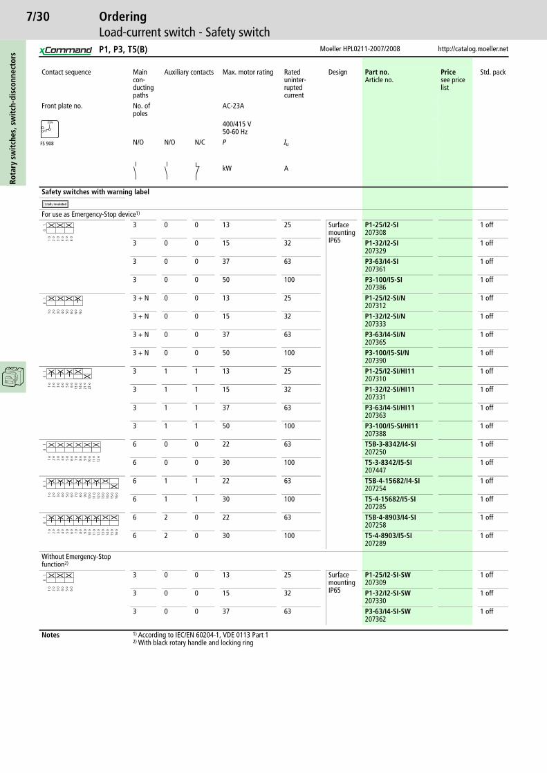
Safety switch (.../I...) 5IP65
with an additional terminalwith cover safety in 0 position
Position 0 lockable with 3 padlocksEnclosures for metric cable glands to EN 50262Label "Safety switch", colour: orange
a page 7/30
a page 7/43
ATEX
ATEX
Main switch (mounting kit) for use as Emergency-Stop device
6
To IEC/EN 60204-1, VDE 0113 Part 1
With red rotary handle and yellow lokking ringLockable in the 0 positiona page 7/43
Main switch (kit) 7
Black rotary handle and locking ring
Lockable in the 0 positiona page 7/43
Thumb-grip, for use as Emergency-Stop device
8
To IEC/EN 60 204-1, VDE 0113 Part 1
Red thumb grip and yellow front platea page 7/43
Thumb-grip 9Black thumb-grip with front platea page 7/43
Coupling drive 10
Including shaft for retrofiiting of switch T0(T3)-.../XZ in rear mounting form Replacement part for T0(T3)/(P1)-.../Z
for the conversion of switch T5(B)-.../E to rear mounting switch Replacement part for T5(B)/(P3)-...Z
a page 7/49
7/6Ro
tary
sw
itch
es, s
wit
ch-d
isco
nnec
tors
Moeller HPL0211-2007/2008 http://catalog.moeller.net
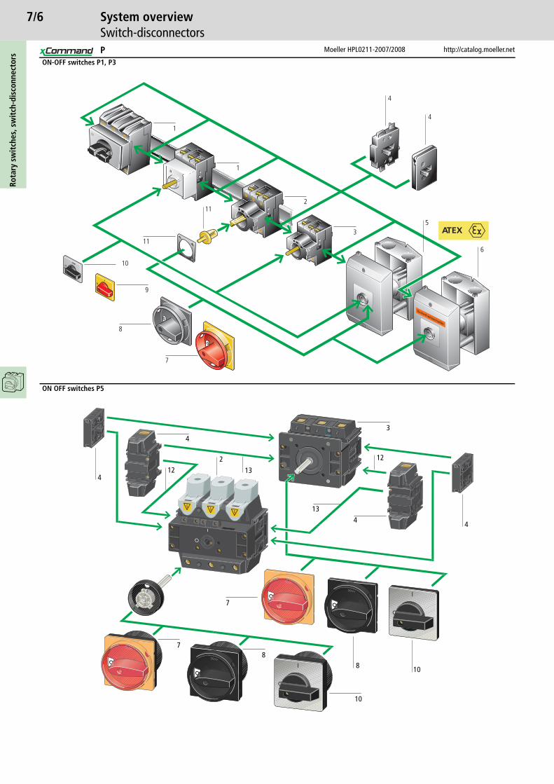
System overviewSwitch-disconnectors
ON-OFF switches P1, P3
ON OFF switches P5
11
9
10
8
7
2
3
1
1
4
4
6
11
5ATEX
43
10
87
2
4
12
1312
108
4
4
13
7
P
7/7
http://catalog.moeller.net Moeller HPL0211-2007/2008
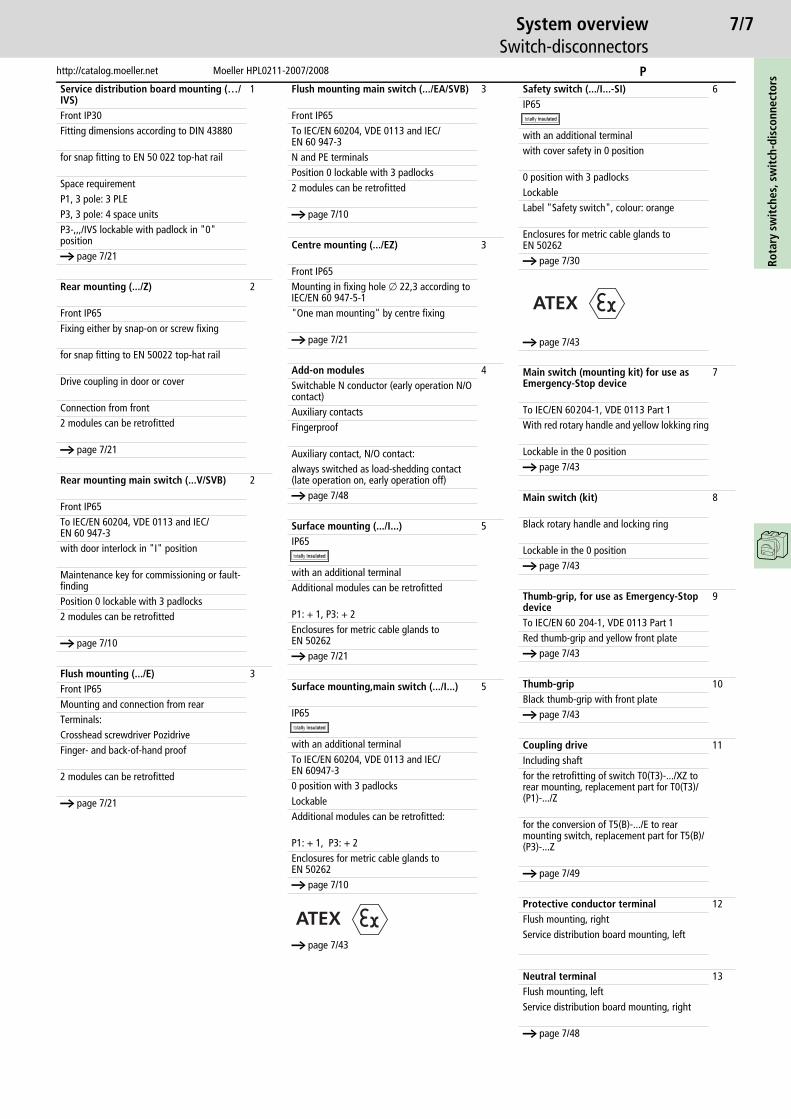
System overviewSwitch-disconnectors
Rota
ry s
wit
ches
, sw
itch
-dis
conn
ecto
rs
Service distribution board mounting (…/IVS)
1
Front IP30Fitting dimensions according to DIN 43880
for snap fitting to EN 50 022 top-hat rail
Space requirementP1, 3 pole: 3 PLEP3, 3 pole: 4 space unitsP3-,,,/IVS lockable with padlock in "0" positiona page 7/21
Rear mounting (.../Z) 2
Front IP65Fixing either by snap-on or screw fixing
for snap fitting to EN 50022 top-hat rail
Drive coupling in door or cover
Connection from front2 modules can be retrofitted
a page 7/21
Rear mounting main switch (...V/SVB) 2
Front IP65To IEC/EN 60204, VDE 0113 and IEC/EN 60 947-3with door interlock in "I" position
Maintenance key for commissioning or fault-finding Position 0 lockable with 3 padlocks 2 modules can be retrofitted
a page 7/10
Flush mounting (.../E) 3Front IP65Mounting and connection from rearTerminals:Crosshead screwdriver PozidriveFinger- and back-of-hand proof
2 modules can be retrofitted
a page 7/21
Flush mounting main switch (.../EA/SVB) 3
Front IP65To IEC/EN 60204, VDE 0113 and IEC/EN 60 947-3N and PE terminalsPosition 0 lockable with 3 padlocks 2 modules can be retrofitted
a page 7/10
Centre mounting (.../EZ) 3
Front IP65Mounting in fixing hole o 22,3 according to IEC/EN 60 947-5-1"One man mounting" by centre fixing
a page 7/21
Add-on modules 4Switchable N conductor (early operation N/O contact)Auxiliary contactsFingerproof
Auxiliary contact, N/O contact:always switched as load-shedding contact (late operation on, early operation off)a page 7/48
Surface mounting (.../I...) 5IP65
with an additional terminalAdditional modules can be retrofitted
P1: + 1, P3: + 2Enclosures for metric cable glands to EN 50262a page 7/21
Surface mounting,main switch (.../I...) 5
IP65
with an additional terminalTo IEC/EN 60204, VDE 0113 and IEC/EN 60947-30 position with 3 padlocksLockableAdditional modules can be retrofitted:
P1: + 1, P3: + 2Enclosures for metric cable glands to EN 50262a page 7/10
a page 7/43
ATEX
Safety switch (.../I...-SI) 6IP65
with an additional terminalwith cover safety in 0 position
0 position with 3 padlocksLockableLabel "Safety switch", colour: orange
Enclosures for metric cable glands to EN 50262a page 7/30
a page 7/43
Main switch (mounting kit) for use as Emergency-Stop device
7
To IEC/EN 60204-1, VDE 0113 Part 1With red rotary handle and yellow lokking ring
Lockable in the 0 positiona page 7/43
Main switch (kit) 8
Black rotary handle and locking ring
Lockable in the 0 positiona page 7/43
Thumb-grip, for use as Emergency-Stop device
9
To IEC/EN 60 204-1, VDE 0113 Part 1Red thumb-grip and yellow front platea page 7/43
Thumb-grip 10Black thumb-grip with front platea page 7/43
Coupling drive 11Including shaft for the retrofitting of switch T0(T3)-.../XZ to rear mounting, replacement part for T0(T3)/(P1)-.../Z
for the conversion of T5(B)-.../E to rear mounting switch, replacement part for T5(B)/(P3)-...Z
a page 7/49
Protective conductor terminal 12Flush mounting, rightService distribution board mounting, left
Neutral terminal 13Flush mounting, leftService distribution board mounting, right
a page 7/48
ATEX
P
7/8Ro
tary
sw
itch
es, s
wit
ch-d
isco
nnec
tors
Moeller HPL0211-2007/2008 http://catalog.moeller.net
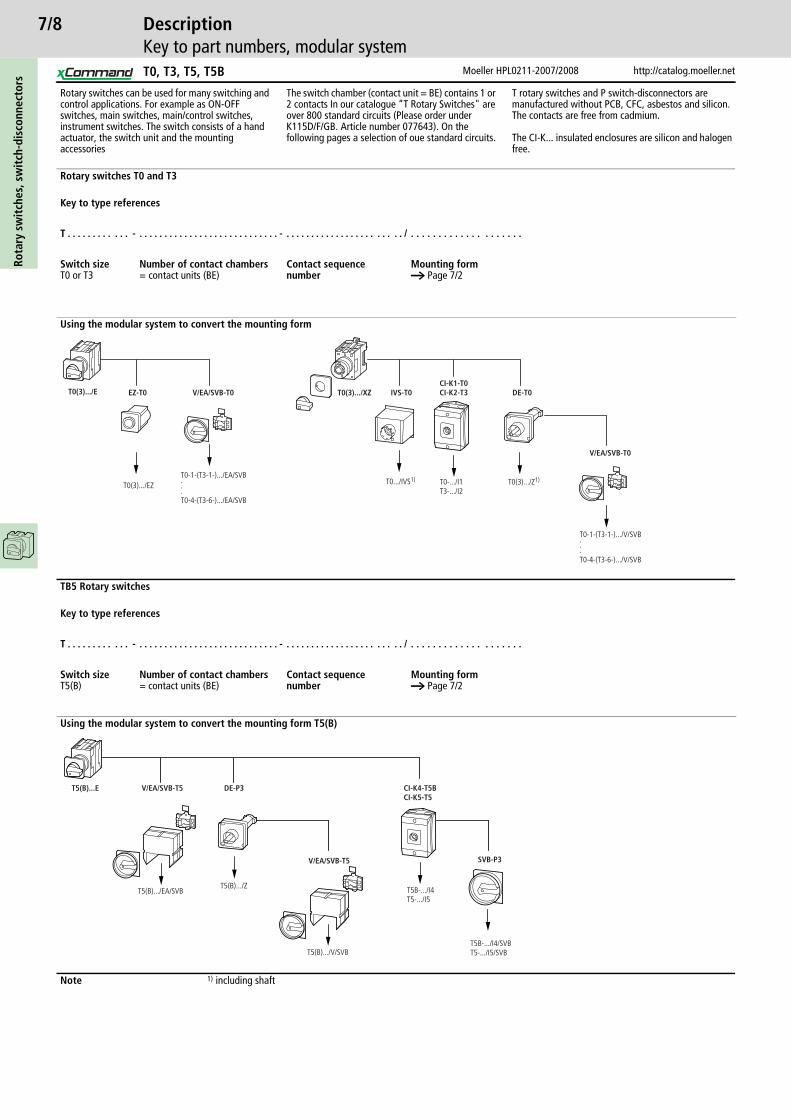
DescriptionKey to part numbers, modular system
Rotary switches can be used for many switching and control applications. For example as ON-OFF switches, main switches, main/control switches, instrument switches. The switch consists of a hand actuator, the switch unit and the mounting accessories
The switch chamber (contact unit = BE) contains 1 or 2 contacts In our catalogue “T Rotary Switches" are over 800 standard circuits (Please order under K115D/F/GB. Article number 077643). On the following pages a selection of oue standard circuits.
T rotary switches and P switch-disconnectors are manufactured without PCB, CFC, asbestos and silicon. The contacts are free from cadmium.
The CI-K... insulated enclosures are silicon and halogen free.
Rotary switches T0 and T3
Key to type references
T . . . . . . . . . . . . - . . . . . . . . . . . . . . . . . . . . . . . . . . . . - . . . . . . . . . . . . . . . . . . . . . . . / . . . . . . . . . . . . . . . . . . . .
Switch sizeT0 or T3
Number of contact chambers= contact units (BE)
Contact sequence number
Mounting forma Page 7/2
Using the modular system to convert the mounting form
CI-K1-T0CI-K2-T3
T0-.../I1T3-.../I2
T0.../IVS1)
T0(3).../E
T0(3).../EZ
EZ-T0 V/EA/SVB-T0 T0(3).../XZ IVS-T0 DE-T0
T0(3).../Z1)
V/EA/SVB-T0
T0-1-(T3-1-).../V/SVB...T0-4-(T3-6-).../V/SVB
T0-1-(T3-1-).../EA/SVB...T0-4-(T3-6-).../EA/SVB
TB5 Rotary switches
Key to type references
T . . . . . . . . . . . . - . . . . . . . . . . . . . . . . . . . . . . . . . . . . - . . . . . . . . . . . . . . . . . . . . . . . / . . . . . . . . . . . . . . . . . . . .
Switch sizeT5(B)
Number of contact chambers= contact units (BE)
Contact sequence number
Mounting forma Page 7/2
Using the modular system to convert the mounting form T5(B)
CI-K4-T5BCI-K5-T5
DE-P3V/EA/SVB-T5T5(B)...E
T5(B).../EA/SVBT5(B).../Z
V/EA/SVB-T5
T5(B).../V/SVB
T5B-.../I4T5-.../I5
SVB-P3
T5B-.../I4/SVBT5-.../I5/SVB
Note 1) including shaft
T0, T3, T5, T5B
7/9
http://catalog.moeller.net Moeller HPL0211-2007/2008
OrderingKey to part numbers, modular system
Rota
ry s
wit
ches
, sw
itch
-dis
conn
ecto
rs
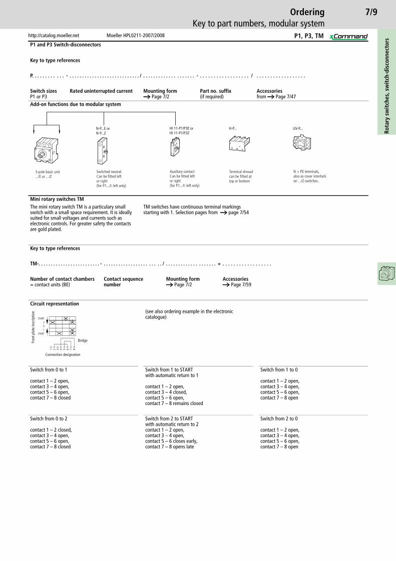
P1 and P3 Switch-disconnectors
Key to type references
P. . . . . . . . . . . . - . . . . . . . . . . . . . . . . . . . . . . . . . . . . / . . . . . . . . . . . . . . . . . . . . - . . . . . . . . . . . . . . . . . . / . . . . . . . . . . . . . . . . . .
Switch sizesP1 or P3
Rated uninterrupted current Mounting forma Page 7/2
Part no. suffix(if required)
Accessoriesfrom a Page 7/47
Add-on functions due to modular system
H-P... UV-P...N-P...Z HI 11-P1/P3ZN-P...E HI 11-P1/P3E
3-pole basic unit.../E or .../Z
Switched neutralCan be fitted left or right(for P1.../I: left only)
Auxiliary contactCan be fitted leftor right(for P1.../I: left only)
Terminal shroudcan be fitted attop or bottom
N + PE terminals,also as cover interlockon .../Z-switches.
or or
Mini rotary switches TMThe mini rotary switch TM is a particulary small switch with a small space requirement. It is ideally suited for small voltages and currents such as electronic controls. For greater safety the contacts are gold plated.
TM switches have continuous terminal markings starting with 1. Selection pages from a page 7/54
Key to type references
TM-. . . . . . . . . . . . . . . . . . . . . . . . . - . . . . . . . . . . . . . . . . . . . . . . . / . . . . . . . . . . . . . . . . . . . . + . . . . . . . . . . . . . . . . . .
Number of contact chambers= contact units (BE)
Contact sequence number
Mounting forma Page 7/2
Accessoriesa Page 7/59
Circuit representation(see also ordering example in the electronic catalogue)
Switch from 0 to 1
contact 1 – 2 open,contact 3 – 4 open,contact 5 – 6 open,contact 7 – 8 closed
Switch from 1 to START with automatic return to 1
contact 1 – 2 open,contact 3 – 4 closed,contact 5 – 6 open,contact 7 – 8 remains closed
Switch from 1 to 0
contact 1 – 2 open,contact 3 – 4 open,contact 5 – 6 open,contact 7 – 8 open
Switch from 0 to 2
contact 1 – 2 closed,contact 3 – 4 open,contact 5 – 6 open,contact 7 – 8 closed
Switch from 2 to START with automatic return to 2contact 1 – 2 open,contact 3 – 4 open,contact 5 – 6 closes early,contact 7 – 8 opens late
Switch from 2 to 0
contact 1 – 2 open,contact 3 – 4 open,contact 5 – 6 open,contact 7 – 8 open
1 2 3 4 5 6 7 8
START102
START
Bridge
Connection designation
Fron
t pla
te in
scrip
tion
P1, P3, TM

7/10Ro
tary
sw
itch
es, s
wit
ch-d
isco
nnec
tors
Moeller HPL0211-2007/2008 http://catalog.moeller.net
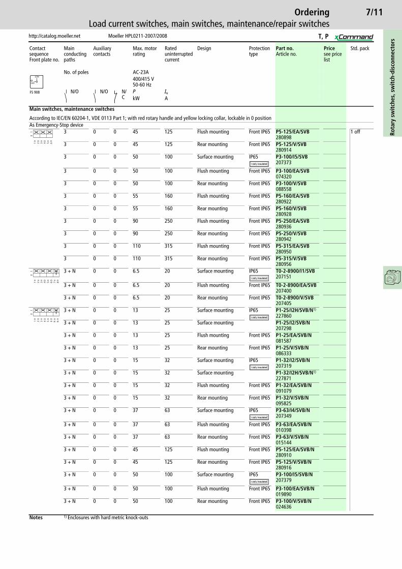
OrderingLoad current switches, main switches, maintenance/repair switches
Contact sequenceFront plate no.
Main con-ducting paths
Auxiliary contacts
Max. motor rating
Rated uninterrupted current
Design Protection type Part no.Article no.
Pricesee price list
Std. pack
No. of poles
AC-23A400/415 V50-60 Hz
N/O N/O N/C
P Iu
kW A
Main switches, maintenance switches
According to IEC/EN 60204-1, VDE 0113 Part 1; with red rotary handle and yellow locking collar, lockable in 0 positionAs Emergency-Stop device
1 0 0 6.5 20 Surface mounting IP65 T0-1-8200/I1/SVB207145
1 off
1 0 0 6.5 20 Flush mounting Front IP65 T0-1-8200/EA/SVB053110
1 0 0 6.5 20 Rear mounting Front IP65 T0-1-8200/V/SVB057856
1 0 0 13 32 Surface mounting IP65 T3-1-8200/I2/SVB207200
1 0 0 13 32 Flush mounting Front IP65 T3-1-8200/EA/SVB066576
1 0 0 22 63 Surface mounting IP65 T5B-1-8200/I4/SVB207240
1 0 0 22 63 Flush mounting Front IP65 T5B-1-8200/EA/SVB094279
2 0 0 6.5 20 Surface mounting IP65 T0-1-102/I1/SVB207143
2 0 0 6.5 20 Flush mounting Front IP65 T0-1-102/EA/SVB091078
2 0 0 6.5 20 Rear mounting Front IP65 T0-1-102/V/SVB095824
2 0 0 13 32 Surface mounting IP65 T3-1-102/I2/SVB207198
2 0 0 13 32 Flush mounting Front IP65 T3-1-102/EA/SVB014374
2 0 0 13 32 Rear mounting Front IP65 T3-1-102/V/SVB019120
2 0 0 22 63 Surface mounting IP65 T5B-1-102/I4/SVB207238
2 0 0 22 63 Flush mounting Front IP65 T5B-1-102/EA/SVB094469
2 0 0 30 100 Surface mounting IP65 T5-1-102/I5/SVB207273
3 0 0 6.5 20 Surface mounting IP65 T0-2-1/I1/SVB207147
3 0 0 6.5 20 Flush mounting Front IP65 T0-2-1/EA/SVB038873
3 0 0 6.5 20 Rear mounting Front IP65 T0-2-1/V/SVB043619
3 0 0 13 25 Surface mounting IP65 P1-25/I2H/SVB1)
2269003 0 0 13 25 Surface mounting P1-25/I2/SVB
2072933 0 0 13 25 Flush mounting Front IP65 P1-25/EA/SVB
0410973 0 0 13 25 Rear mounting Front IP65 P1-25/V/SVB
0553353 0 0 15 32 Surface mounting IP65 P1-32/I2H/SVB1)
2278683 0 0 15 32 Surface mounting P1-32/I2/SVB
2073143 0 0 15 32 Flush mounting Front IP65 P1-32/EA/SVB
0814383 0 0 15 32 Rear mounting Front IP65 P1-32/V/SVB
0956763 0 0 37 63 Surface mounting IP65 P3-63/I4/SVB
207343
3 0 0 37 63 Flush mounting Front IP65 P3-63/EA/SVB031607
3 0 0 37 63 Rear mounting Front IP65 P3-63/V/SVB048218
Notes 1) Enclosures with hard metric knock-outs
FS 908
ON
OFF
1 2
01
1 2 3 4
01
1 2 3 4 5 6
01
T, P
7/11
http://catalog.moeller.net Moeller HPL0211-2007/2008
OrderingLoad current switches, main switches, maintenance/repair switches
Rota
ry s
wit
ches
, sw
itch
-dis
conn
ecto
rs
Contact sequenceFront plate no.
Main conducting paths
Auxiliary contacts
Max. motor rating
Rated uninterrupted current
Design Protection type
Part no.Article no.
Pricesee price list
Std. pack
No. of poles AC-23A400/415 V50-60 Hz
N/O N/O N/C
P Iu
kW A
Main switches, maintenance switches
According to IEC/EN 60204-1, VDE 0113 Part 1; with red rotary handle and yellow locking collar, lockable in 0 positionAs Emergency-Stop device
3 0 0 45 125 Flush mounting Front IP65 P5-125/EA/SVB280898
1 off
3 0 0 45 125 Rear mounting Front IP65 P5-125/V/SVB280914
3 0 0 50 100 Surface mounting IP65 P3-100/I5/SVB207373
3 0 0 50 100 Flush mounting Front IP65 P3-100/EA/SVB074320
3 0 0 50 100 Rear mounting Front IP65 P3-100/V/SVB088558
3 0 0 55 160 Flush mounting Front IP65 P5-160/EA/SVB280922
3 0 0 55 160 Rear mounting Front IP65 P5-160/V/SVB280928
3 0 0 90 250 Flush mounting Front IP65 P5-250/EA/SVB280936
3 0 0 90 250 Rear mounting Front IP65 P5-250/V/SVB280942
3 0 0 110 315 Flush mounting Front IP65 P5-315/EA/SVB280950
3 0 0 110 315 Rear mounting Front IP65 P5-315/V/SVB280956
3 + N 0 0 6.5 20 Surface mounting IP65 T0-2-8900/I1/SVB207151
3 + N 0 0 6.5 20 Flush mounting Front IP65 T0-2-8900/EA/SVB207400
3 + N 0 0 6.5 20 Rear mounting Front IP65 T0-2-8900/V/SVB207405
3 + N 0 0 13 25 Surface mounting IP65 P1-25/I2H/SVB/N1)
2278603 + N 0 0 13 25 Surface mounting P1-25/I2/SVB/N
2072983 + N 0 0 13 25 Flush mounting Front IP65 P1-25/EA/SVB/N
0815873 + N 0 0 13 25 Rear mounting Front IP65 P1-25/V/SVB/N
0863333 + N 0 0 15 32 Surface mounting IP65 P1-32/I2/SVB/N
2073193 + N 0 0 15 32 Surface mounting P1-32/I2H/SVB/N1)
2278713 + N 0 0 15 32 Flush mounting Front IP65 P1-32/EA/SVB/N
0910793 + N 0 0 15 32 Rear mounting Front IP65 P1-32/V/SVB/N
0958253 + N 0 0 37 63 Surface mounting IP65 P3-63/I4/SVB/N
207349
3 + N 0 0 37 63 Flush mounting Front IP65 P3-63/EA/SVB/N010398
3 + N 0 0 37 63 Rear mounting Front IP65 P3-63/V/SVB/N015144
3 + N 0 0 45 125 Flush mounting Front IP65 P5-125/EA/SVB/N280910
3 + N 0 0 45 125 Rear mounting Front IP65 P5-125/V/SVB/N280916
3 + N 0 0 50 100 Surface mounting IP65 P3-100/I5/SVB/N207379
3 + N 0 0 50 100 Flush mounting Front IP65 P3-100/EA/SVB/N019890
3 + N 0 0 50 100 Rear mounting Front IP65 P3-100/V/SVB/N024636
Notes 1) Enclosures with hard metric knock-outs
FS 908
ON
OFF
1 2 3 4 5 6
01
1 2 3 4 5 6 7 8
01
1 2 3 4 5 6 N N
01
T, P

7/12Ro
tary
sw
itch
es, s
wit
ch-d
isco
nnec
tors
Moeller HPL0211-2007/2008 http://catalog.moeller.net
OrderingLoad current switches, main switches, maintenance/repair switches
Contact sequenceFront plate no.
Main conduct-ing paths
Auxiliary contacts
Max. motor rating
Rated uninter-rupted current
Design Protection type
Part no.Article no.
Pricesee price list
Std. pack
No. of poles
AC-23A400/415 V50-60 Hz
N/O N/O
N/C
P Iu
kW A
Main switches, maintenance switches
According to IEC/EN 60204-1, VDE 0113 Part 1; with red rotary handle and yellow locking collar, lockable in 0 positionAs Emergency-Stop device
3 + N 0 0 55 160 Flush mounting Front IP65 P5-160/EA/SVB/N280924
1 off
3 + N 0 0 55 160 Rear mounting Front IP65 P5-160/V/SVB/N280930
3 + N 0 0 90 250 Flush mounting Front IP65 P5-250/EA/SVB/N280938
3 + N 0 0 90 250 Rear mounting Front IP65 P5-250/V/SVB/N280944
3 + N 0 0 110 315 Flush mounting Front IP65 P5-315/EA/SVB/N280952
3 + N 0 0 110 315 Rear mounting Front IP65 P5-315/V/SVB/N280958
6 0 0 6.5 20 Surface mounting IP65 T0-3-8342/I1/SVB207159
6 0 0 6.5 20 Flush mounting Front IP65 T0-3-8342/EA/SVB029382
6 0 0 6.5 20 Rear mounting Front IP65 T0-3-8342/V/SVB034128
6 0 0 13 32 Surface mounting IP65 T3-3-8342/I2/SVB207208
6 0 0 13 32 Flush mounting Front IP65 T3-3-8342/EA/SVB071326
6 0 0 13 32 Rear mounting Front IP65 T3-3-8342/V/SVB076072
6 0 0 22 63 Surface mounting IP65 T5B-3-8342/I4/SVB207242
6 0 0 22 63 Flush mounting Front IP65 T5B-3-8342/EA/SVB092308
6 0 0 22 63 Rear mounting Front IP65 T5B-3-8342/V/SVB092300
6 0 0 30 100 Surface mounting IP65 T5-3-8342/I5/SVB207279
6 0 0 30 100 Flush mounting Front IP65 T5-3-8342/EA/SVB096383
6 0 0 30 100 Rear mounting Front IP65 T5-3-8342/V/SVB096381
8 0 0 6.5 20 Surface mounting IP65 T0-4-8344/I1/SVB207163
8 0 0 6.5 20 Flush mounting Front IP65 T0-4-8344/EA/SVB008267
8 0 0 6.5 20 Rear mounting Front IP65 T0-4-8344/V/SVB014007
8 0 0 13 32 Surface mounting IP65 T3-4-8344/I2/SVB207212
8 0 0 13 32 Flush mounting Front IP65 T3-4-8344/EA/SVB008964
8 0 0 13 32 Rear mounting Front IP65 T3-4-8344/V/SVB020598
8 0 0 22 63 Surface mounting IP65 T5B-4-8344/I4/SVB207248
8 0 0 22 63 Flush mounting Front IP65 T5B-4-8344/EA/SVB092062
8 0 0 22 63 Rear mounting Front IP65 T5B-4-8344/V/SVB092056
8 0 0 30 100 Surface mounting IP65 T5-4-8344/I5/SVB1)
207283
8 0 0 30 100 Flush mounting Front IP65 T5-4-8344/EA/SVB095961
Notes 1) Rated uninterrupted current max. 95 A
FS 908
ON
OFF
1 2 3 4 5 6 N N
01
1 2 3 4 5 6 7 8 9 10
01
11 12
1 2 3 4 5 6 7 8 9 10
01
11 12 13 14 15 16
T, P

7/13
http://catalog.moeller.net Moeller HPL0211-2007/2008
OrderingLoad current switches, main switches, maintenance/repair switches
Rota
ry s
wit
ches
, sw
itch
-dis
conn
ecto
rs
Contact sequenceFront plate no.
Main conducting paths
Auxiliary contacts Max. motor rating
Rated uninter-rupted current
Design Protection type
Part no.Article no.
Pricesee price list
Std. pack
No. of poles
AC-23A400/415 V50-60 Hz
N/O N/O N/C P Iu
kW A
Main switches, maintenance switches
According to IEC/EN 60204-1, VDE 0113 Part 1; with red rotary handle and yellow locking collar, lockable in 0 positionAs Emergency-Stop device
3 1 0 6.5 20 Surface mounting
IP65 T0-2-15679/I1/SVB207149
1 off
3 1 0 6.5 20 Flush mounting Front IP65 T0-2-15679/EA/SVB081588
3 1 0 6.5 20 Rear mounting Front IP65 T0-2-15679/V/SVB086334
3 1 0 45 125 Flush mounting Front IP65 P5-125/EA/SVB/HI10280899
3 1 0 45 125 Rear mounting Front IP65 P5-125/V/SVB/HI10280915
3 1 0 55 160 Flush mounting Front IP65 P5-160/EA/SVB/HI10280923
3 1 0 55 160 Rear mounting Front IP65 P5-160/V/SVB/HI10280929
3 1 0 90 250 Flush mounting Front IP65 P5-250/EA/SVB/HI10280937
3 1 0 90 250 Rear mounting Front IP65 P5-250/V/SVB/HI10280943
3 1 0 110 315 Flush mounting Front IP65 P5-315/EA/SVB/HI10280951
3 1 0 110 315 Rear mounting Front IP65 P5-315/V/SVB/HI10280957
3 1 1 13 25 Surface mounting
IP65 P1-25/I2/SVB/HI11207297
3 1 1 13 25 Surface mounting
IP65 P1-25/I2H/SVB/HI111)
226902
3 1 1 13 25 Flush mounting Front IP65 P1-25/EA/SVB/HI11091080
3 1 1 13 25 Rear mounting Front IP65 P1-25/V/SVB/HI11095826
3 1 1 15 32 Surface mounting
IP65 P1-32/I2/SVB/HI11207318
3 1 1 15 32 Surface mounting
IP65 P1-32/I2H/SVB/HI111)
227870
3 1 1 15 32 Flush mounting Front IP65 P1-32/EA/SVB/HI11072567
3 1 1 15 32 Rear mounting Front IP65 P1-32/V/SVB/HI11015145
3 1 1 37 63 Surface mounting
IP65 P3-63/I4/SVB/HI11207348
3 1 1 37 63 Flush mounting Front IP65 P3-63/EA/SVB/HI11019891
3 1 1 37 63 Rear mounting Front IP65 P3-63/V/SVB/HI11024637
3 1 1 50 100 Surface mounting
IP65 P3-100/I5/SVB/HI11207378
3 1 1 50 100 Flush mounting Front IP65 P3-100/EA/SVB/HI11029383
3 1 1 50 100 Rear mounting Front IP65 P3-100/V/SVB/HI11034129
Notes 1) Enclosures with hard metric knock-outs
FS 908
ON
OFF
1 2 3 4 5 6 7 8
01
1 2 3 4 5 6 13 14
01
1 2 3 4 5 6 13 14
01
21 22
T, P
7/14Ro
tary
sw
itch
es, s
wit
ch-d
isco
nnec
tors
Moeller HPL0211-2007/2008 http://catalog.moeller.net
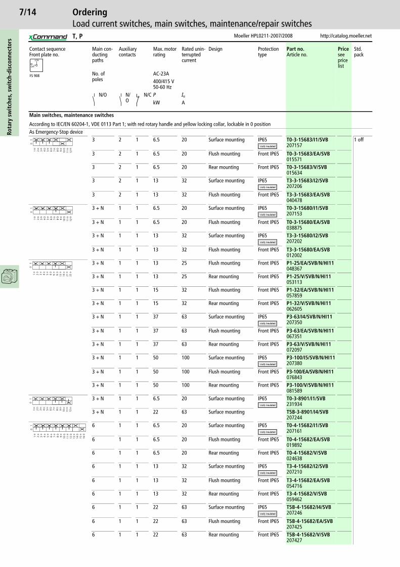
OrderingLoad current switches, main switches, maintenance/repair switches
Contact sequenceFront plate no.
Main con-ducting paths
Auxiliary contacts
Max. motor rating
Rated unin-terrupted current
Design Protection type
Part no.Article no.
Pricesee price list
Std. pack
No. of poles
AC-23A400/415 V50-60 Hz
N/O N/O
N/C P Iu
kW A
Main switches, maintenance switches
According to IEC/EN 60204-1, VDE 0113 Part 1; with red rotary handle and yellow locking collar, lockable in 0 positionAs Emergency-Stop device
3 2 1 6.5 20 Surface mounting IP65 T0-3-15683/I1/SVB207157
1 off
3 2 1 6.5 20 Flush mounting Front IP65 T0-3-15683/EA/SVB015571
3 2 1 6.5 20 Rear mounting Front IP65 T0-3-15683/V/SVB015634
3 2 1 13 32 Surface mounting IP65 T3-3-15683/I2/SVB207206
3 2 1 13 32 Flush mounting Front IP65 T3-3-15683/EA/SVB040478
3 + N 1 1 6.5 20 Surface mounting IP65 T0-3-15680/I1/SVB207153
3 + N 1 1 6.5 20 Flush mounting Front IP65 T0-3-15680/EA/SVB038875
3 + N 1 1 13 32 Surface mounting IP65 T3-3-15680/I2/SVB207202
3 + N 1 1 13 32 Flush mounting Front IP65 T3-3-15680/EA/SVB012002
3 + N 1 1 13 25 Flush mounting Front IP65 P1-25/EA/SVB/N/HI11048367
3 + N 1 1 13 25 Rear mounting Front IP65 P1-25/V/SVB/N/HI11053113
3 + N 1 1 15 32 Flush mounting Front IP65 P1-32/EA/SVB/N/HI11057859
3 + N 1 1 15 32 Rear mounting Front IP65 P1-32/V/SVB/N/HI11062605
3 + N 1 1 37 63 Surface mounting IP65 P3-63/I4/SVB/N/HI11207350
3 + N 1 1 37 63 Flush mounting Front IP65 P3-63/EA/SVB/N/HI11067351
3 + N 1 1 37 63 Rear mounting Front IP65 P3-63/V/SVB/N/HI11072097
3 + N 1 1 50 100 Surface mounting IP65 P3-100/I5/SVB/N/HI11207380
3 + N 1 1 50 100 Flush mounting Front IP65 P3-100/EA/SVB/N/HI11076843
3 + N 1 1 50 100 Rear mounting Front IP65 P3-100/V/SVB/N/HI11081589
3 + N 1 1 6.5 20 Surface mounting IP65 T0-3-8901/I1/SVB231934
3 + N 1 1 22 63 Surface mounting T5B-3-8901/I4/SVB207244
6 1 1 6.5 20 Surface mounting IP65 T0-4-15682/I1/SVB207161
6 1 1 6.5 20 Flush mounting Front IP65 T0-4-15682/EA/SVB019892
6 1 1 6.5 20 Rear mounting Front IP65 T0-4-15682/V/SVB024638
6 1 1 13 32 Surface mounting IP65 T3-4-15682/I2/SVB207210
6 1 1 13 32 Flush mounting Front IP65 T3-4-15682/EA/SVB054716
6 1 1 13 32 Rear mounting Front IP65 T3-4-15682/V/SVB059462
6 1 1 22 63 Surface mounting IP65 T5B-4-15682/I4/SVB207246
6 1 1 22 63 Flush mounting Front IP65 T5B-4-15682/EA/SVB207425
6 1 1 22 63 Rear mounting Front IP65 T5B-4-15682/V/SVB207427
FS 908
ON
OFF
1 2 3 4 5 6 7 8
01
9 10 11 12
1 2 3 4 5 6 7 8
01
9 10 11 12
1 2 3 4 5 6 NN
01
13 14 21 22
1 2 3 4 5 6 7 8
01
9 10 11 12
1 2 3 4 5 6 7 8
01
9 10 11 12 13 14 15 16
T, P
7/15
http://catalog.moeller.net Moeller HPL0211-2007/2008
OrderingLoad current switches, main switches, maintenance/repair switches
Rota
ry s
wit
ches
, sw
itch
-dis
conn
ecto
rs
Contact sequenceFront plate no.
Main con-ducting paths
Auxiliary contacts
Max. motor rating
Rated uninter-rupted current
Design Protection type
Part no.Article no.
Pricesee price list
Std. pack
No. of poles
AC-23A400/415 V50-60 Hz
N/O N/O
N/C
P Iu
kW A
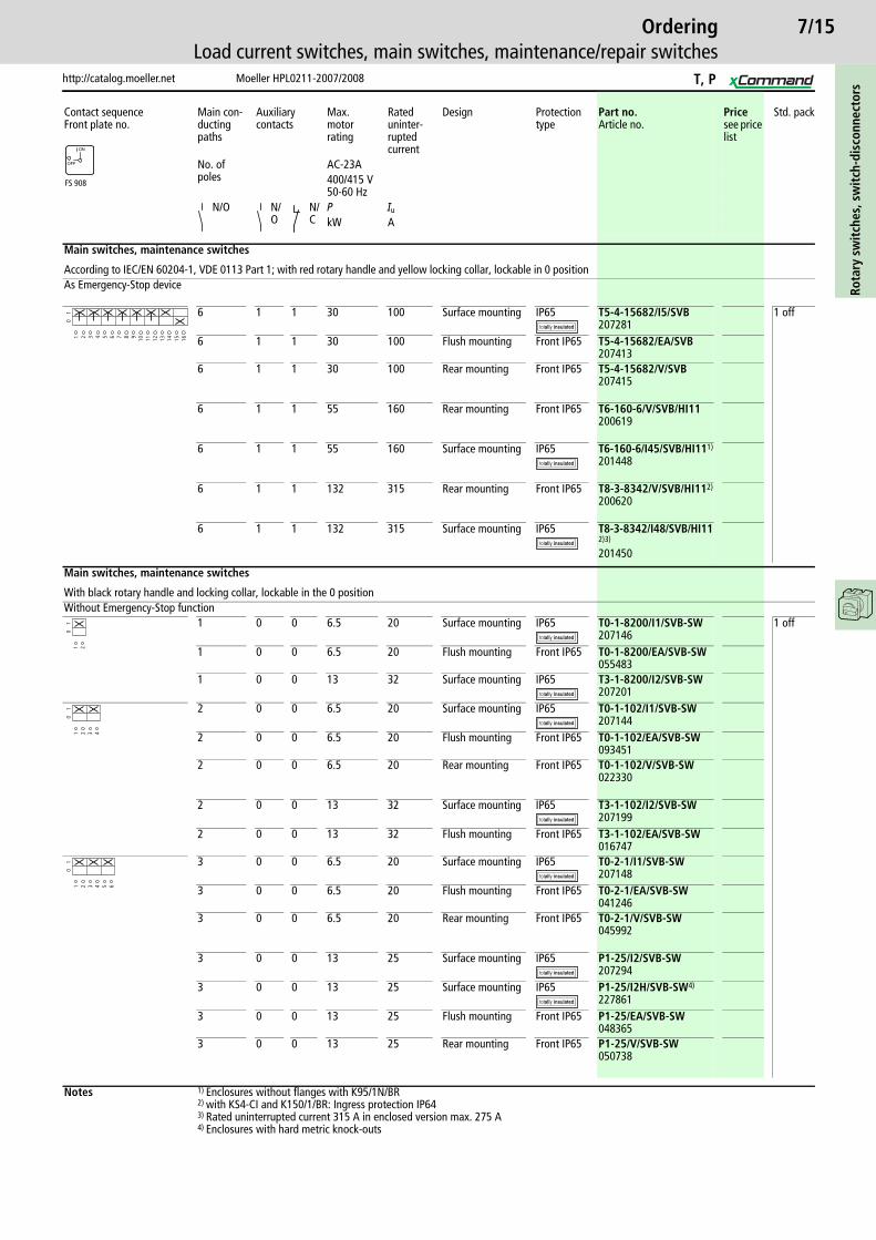
Main switches, maintenance switches
According to IEC/EN 60204-1, VDE 0113 Part 1; with red rotary handle and yellow locking collar, lockable in 0 positionAs Emergency-Stop device
6 1 1 30 100 Surface mounting IP65 T5-4-15682/I5/SVB207281
1 off
6 1 1 30 100 Flush mounting Front IP65 T5-4-15682/EA/SVB207413
6 1 1 30 100 Rear mounting Front IP65 T5-4-15682/V/SVB207415
6 1 1 55 160 Rear mounting Front IP65 T6-160-6/V/SVB/HI11200619
6 1 1 55 160 Surface mounting IP65 T6-160-6/I45/SVB/HI111)
201448
6 1 1 132 315 Rear mounting Front IP65 T8-3-8342/V/SVB/HI112)
200620
6 1 1 132 315 Surface mounting IP65 T8-3-8342/I48/SVB/HI112)3)
201450
Main switches, maintenance switches
With black rotary handle and locking collar, lockable in the 0 positionWithout Emergency-Stop function
1 0 0 6.5 20 Surface mounting IP65 T0-1-8200/I1/SVB-SW207146
1 off
1 0 0 6.5 20 Flush mounting Front IP65 T0-1-8200/EA/SVB-SW055483
1 0 0 13 32 Surface mounting IP65 T3-1-8200/I2/SVB-SW207201
2 0 0 6.5 20 Surface mounting IP65 T0-1-102/I1/SVB-SW207144
2 0 0 6.5 20 Flush mounting Front IP65 T0-1-102/EA/SVB-SW093451
2 0 0 6.5 20 Rear mounting Front IP65 T0-1-102/V/SVB-SW022330
2 0 0 13 32 Surface mounting IP65 T3-1-102/I2/SVB-SW207199
2 0 0 13 32 Flush mounting Front IP65 T3-1-102/EA/SVB-SW016747
3 0 0 6.5 20 Surface mounting IP65 T0-2-1/I1/SVB-SW207148
3 0 0 6.5 20 Flush mounting Front IP65 T0-2-1/EA/SVB-SW041246
3 0 0 6.5 20 Rear mounting Front IP65 T0-2-1/V/SVB-SW045992
3 0 0 13 25 Surface mounting IP65 P1-25/I2/SVB-SW207294
3 0 0 13 25 Surface mounting IP65 P1-25/I2H/SVB-SW4)
2278613 0 0 13 25 Flush mounting Front IP65 P1-25/EA/SVB-SW
0483653 0 0 13 25 Rear mounting Front IP65 P1-25/V/SVB-SW
050738
Notes 1) Enclosures without flanges with K95/1N/BR2) with KS4-CI and K150/1/BR: Ingress protection IP643) Rated uninterrupted current 315 A in enclosed version max. 275 A4) Enclosures with hard metric knock-outs
FS 908
ON
OFF
1 2 3 4 5 6 7 8
01
9 10 11 12 13 14 15 16
1 2
01
1 2 3 4
01
1 2 3 4 5 6
01
T, P
7/16Ro
tary
sw
itch
es, s
wit
ch-d
isco
nnec
tors
Moeller HPL0211-2007/2008 http://catalog.moeller.net
OrderingLoad current switches, main switches, maintenance/repair switches
Contact sequenceFront plate no.
Main conducting paths
Auxiliary contacts
Max. motor rating
Rated uninterrupted current
Design Protection type
Part no.Article no.
Pricesee price list
Std. pack
No. of poles AC-23A400/415 V50-60 Hz
N/O N/O N/C
P Iu
kW A
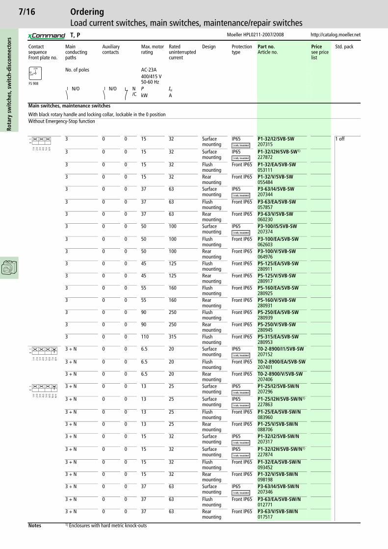
Main switches, maintenance switches
With black rotary handle and locking collar, lockable in the 0 positionWithout Emergency-Stop function
3 0 0 15 32 Surface mounting
IP65 P1-32/I2/SVB-SW207315
1 off
3 0 0 15 32 Surface mounting
IP65 P1-32/I2H/SVB-SW1)
2278723 0 0 15 32 Flush
mountingFront IP65 P1-32/EA/SVB-SW
0531113 0 0 15 32 Rear
mountingFront IP65 P1-32/V/SVB-SW
0554843 0 0 37 63 Surface
mountingIP65 P3-63/I4/SVB-SW
2073443 0 0 37 63 Flush
mountingFront IP65 P3-63/EA/SVB-SW
0578573 0 0 37 63 Rear
mountingFront IP65 P3-63/V/SVB-SW
0602303 0 0 50 100 Surface
mountingIP65 P3-100/I5/SVB-SW
2073743 0 0 50 100 Flush
mountingFront IP65 P3-100/EA/SVB-SW
0626033 0 0 50 100 Rear
mountingFront IP65 P3-100/V/SVB-SW
0649763 0 0 45 125 Flush
mountingFront IP65 P5-125/EA/SVB-SW
2809113 0 0 45 125 Rear
mountingFront IP65 P5-125/V/SVB-SW
2809173 0 0 55 160 Flush
mountingFront IP65 P5-160/EA/SVB-SW
2809253 0 0 55 160 Rear
mountingFront IP65 P5-160/V/SVB-SW
2809313 0 0 90 250 Flush
mountingFront IP65 P5-250/EA/SVB-SW
280939
3 0 0 90 250 Rear mounting
Front IP65 P5-250/V/SVB-SW280945
3 0 0 110 315 Flush mounting
Front IP65 P5-315/EA/SVB-SW280953
3 + N 0 0 6.5 20 Surface mounting
IP65 T0-2-8900/I1/SVB-SW207152
3 + N 0 0 6.5 20 Flush mounting
Front IP65 T0-2-8900/EA/SVB-SW207401
3 + N 0 0 6.5 20 Rear mounting
Front IP65 T0-2-8900/V/SVB-SW207406
3 + N 0 0 13 25 Surface mounting
IP65 P1-25/I2/SVB-SW/N207296
3 + N 0 0 13 25 Surface mounting
IP65 P1-25/I2H/SVB-SW/N1)
227863
3 + N 0 0 13 25 Flush mounting
Front IP65 P1-25/EA/SVB-SW/N083960
3 + N 0 0 13 25 Rear mounting
Front IP65 P1-25/V/SVB-SW/N088706
3 + N 0 0 15 32 Surface mounting
IP65 P1-32/I2/SVB-SW/N207317
3 + N 0 0 15 32 Surface mounting
IP65 P1-32/I2H/SVB-SW/N1)
227874
3 + N 0 0 15 32 Flush mounting
Front IP65 P1-32/EA/SVB-SW/N093452
3 + N 0 0 15 32 Rear mounting
Front IP65 P1-32/V/SVB-SW/N098198
3 + N 0 0 37 63 Surface mounting
IP65 P3-63/I4/SVB-SW/N207346
3 + N 0 0 37 63 Flush mounting
Front IP65 P3-63/EA/SVB-SW/N012771
3 + N 0 0 37 63 Rear mounting
Front IP65 P3-63/V/SVB-SW/N017517
Notes 1) Enclosures with hard metric knock-outs
FS 908
ON
OFF
1 2 3 4 5 6
01
1 2 3 4 5 6 7 8
01
1 2 3 4 5 6 N N
01
T, P
7/17
http://catalog.moeller.net Moeller HPL0211-2007/2008
OrderingLoad current switches, main switches, maintenance/repair switches
Rota
ry s
wit
ches
, sw
itch
-dis
conn
ecto
rs
Contact sequenceFront plate no.
Main conduct-ing paths
Auxiliary contacts
Max. motor rating
Rated uninter-ruptedcurrent
Design Protection type
Part no.Article no.
Pricesee price list
Std. pack
No. of poles
AC-23A400/415 V50-60 Hz
N/O N/O
N/C
P Iu
kW A
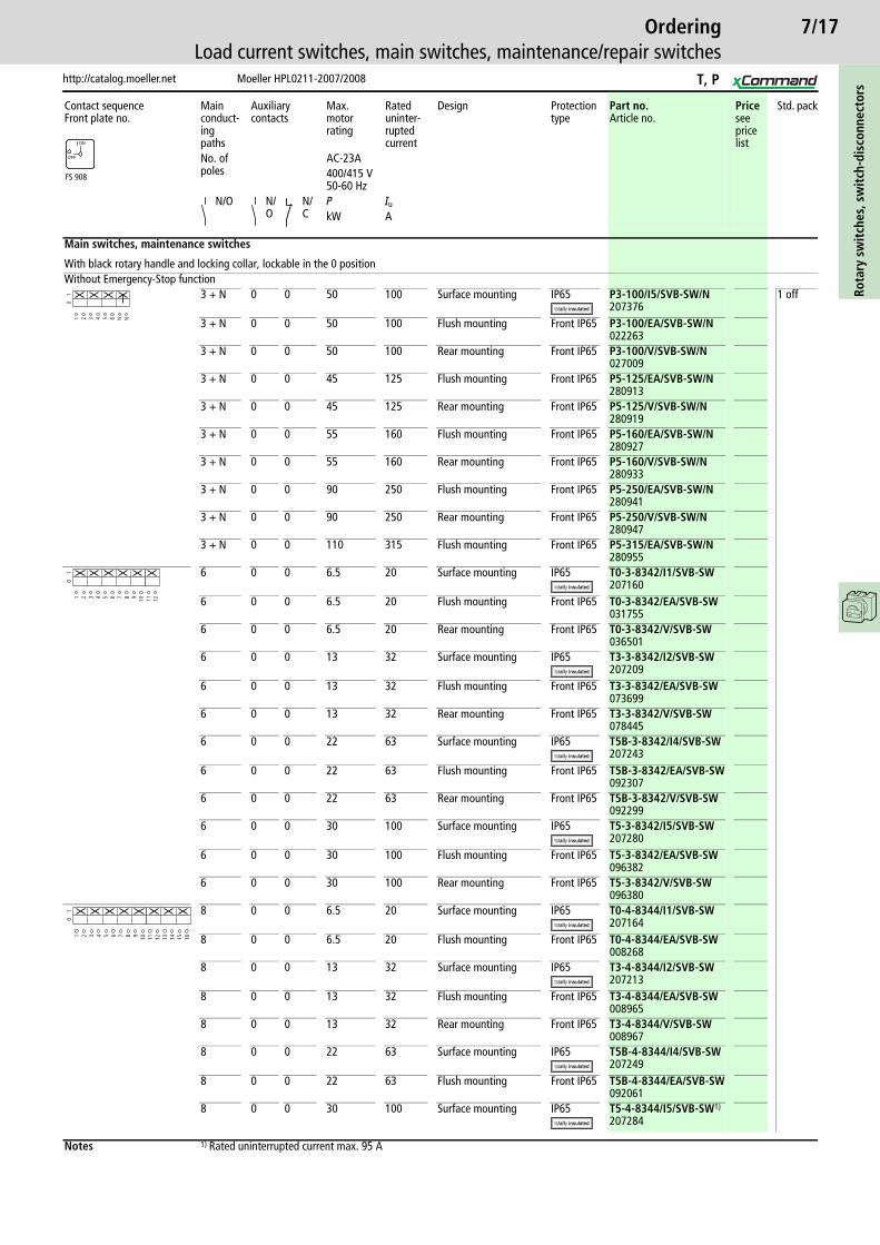
Main switches, maintenance switches
With black rotary handle and locking collar, lockable in the 0 positionWithout Emergency-Stop function
3 + N 0 0 50 100 Surface mounting IP65 P3-100/I5/SVB-SW/N207376
1 off
3 + N 0 0 50 100 Flush mounting Front IP65 P3-100/EA/SVB-SW/N022263
3 + N 0 0 50 100 Rear mounting Front IP65 P3-100/V/SVB-SW/N027009
3 + N 0 0 45 125 Flush mounting Front IP65 P5-125/EA/SVB-SW/N280913
3 + N 0 0 45 125 Rear mounting Front IP65 P5-125/V/SVB-SW/N280919
3 + N 0 0 55 160 Flush mounting Front IP65 P5-160/EA/SVB-SW/N280927
3 + N 0 0 55 160 Rear mounting Front IP65 P5-160/V/SVB-SW/N280933
3 + N 0 0 90 250 Flush mounting Front IP65 P5-250/EA/SVB-SW/N280941
3 + N 0 0 90 250 Rear mounting Front IP65 P5-250/V/SVB-SW/N280947
3 + N 0 0 110 315 Flush mounting Front IP65 P5-315/EA/SVB-SW/N280955
6 0 0 6.5 20 Surface mounting IP65 T0-3-8342/I1/SVB-SW207160
6 0 0 6.5 20 Flush mounting Front IP65 T0-3-8342/EA/SVB-SW031755
6 0 0 6.5 20 Rear mounting Front IP65 T0-3-8342/V/SVB-SW036501
6 0 0 13 32 Surface mounting IP65 T3-3-8342/I2/SVB-SW207209
6 0 0 13 32 Flush mounting Front IP65 T3-3-8342/EA/SVB-SW073699
6 0 0 13 32 Rear mounting Front IP65 T3-3-8342/V/SVB-SW078445
6 0 0 22 63 Surface mounting IP65 T5B-3-8342/I4/SVB-SW207243
6 0 0 22 63 Flush mounting Front IP65 T5B-3-8342/EA/SVB-SW092307
6 0 0 22 63 Rear mounting Front IP65 T5B-3-8342/V/SVB-SW092299
6 0 0 30 100 Surface mounting IP65 T5-3-8342/I5/SVB-SW207280
6 0 0 30 100 Flush mounting Front IP65 T5-3-8342/EA/SVB-SW096382
6 0 0 30 100 Rear mounting Front IP65 T5-3-8342/V/SVB-SW096380
8 0 0 6.5 20 Surface mounting IP65 T0-4-8344/I1/SVB-SW207164
8 0 0 6.5 20 Flush mounting Front IP65 T0-4-8344/EA/SVB-SW008268
8 0 0 13 32 Surface mounting IP65 T3-4-8344/I2/SVB-SW207213
8 0 0 13 32 Flush mounting Front IP65 T3-4-8344/EA/SVB-SW008965
8 0 0 13 32 Rear mounting Front IP65 T3-4-8344/V/SVB-SW008967
8 0 0 22 63 Surface mounting IP65 T5B-4-8344/I4/SVB-SW207249
8 0 0 22 63 Flush mounting Front IP65 T5B-4-8344/EA/SVB-SW092061
8 0 0 30 100 Surface mounting IP65 T5-4-8344/I5/SVB-SW1)
207284
Notes 1) Rated uninterrupted current max. 95 A
FS 908
ON
OFF
1 2 3 4 5 6 N N
01
1 2 3 4 5 6 7 8 9 10
01
11 12
1 2 3 4 5 6 7 8 9 10
01
11 12 13 14 15 16
T, P

7/18Ro
tary
sw
itch
es, s
wit
ch-d
isco
nnec
tors
Moeller HPL0211-2007/2008 http://catalog.moeller.net
OrderingLoad current switches, main switches, maintenance/repair switches
Contact sequenceFront plate no.
Main conduct-ing paths
Auxiliary contacts
Max. motor rating
Rated uninter-rupted current
Design Protection type
Part no.Article no.
Pricesee price list
Std. pack
AC-23ANo. of poles
400/415 V50-60 Hz
N/O N/O
N/C
P Iu
kW A
Main switches, maintenance switches
With black rotary handle and locking collar, lockable in the 0 positionWithout Emergency-Stop function
3 1 0 6.5 20 Surface mounting IP65 T0-2-15679/I1/SVB-SW207150
1 off
3 1 0 6.5 20 Flush mounting Front IP65 T0-2-15679/EA/SVB-SW083961
3 1 0 6.5 20 Rear mounting Front IP65 T0-2-15679/V/SVB-SW088707
3 1 0 45 125 Flush mounting Front IP65 P5-125/EA/SVB-SW/HI10280912
3 1 0 45 125 Rear mounting Front IP65 P5-125/V/SVB-SW/HI10280918
3 1 0 55 160 Flush mounting Front IP65 P5-160/EA/SVB-SW/HI10280926
3 1 0 55 160 Rear mounting Front IP65 P5-160/V/SVB-SW/HI10280932
3 1 0 90 250 Flush mounting Front IP65 P5-250/EA/SVB-SW/HI10280940
3 1 0 90 250 Rear mounting Front IP65 P5-250/V/SVB-SW/HI10280946
3 1 0 110 315 Rear mounting Front IP65 P5-315/V/SVB-SW/HI10280960
3 1 1 13 25 Surface mounting IP65 P1-25/I2/SVB-SW/HI11207295
3 1 1 13 25 Surface mounting IP65 P1-25/I2H/SVB-SW/HI111)
227862
3 1 1 13 25 Flush mounting Front IP65 P1-25/EA/SVB-SW/HI11070194
3 1 1 13 25 Rear mounting Front IP65 P1-25/V/SVB-SW/HI11098199
3 1 1 15 32 Surface mounting IP65 P1-32/I2/SVB-SW/HI11207316
3 1 1 15 32 Surface mounting IP65 P1-32/I2H/SVB-SW/HI111)
227873
3 1 1 15 32 Flush mounting Front IP65 P1-32/EA/SVB-SW/HI11012772
3 1 1 15 32 Rear mounting Front IP65 P1-32/V/SVB-SW/HI11017518
3 1 1 37 63 Surface mounting IP65 P3-63/I4/SVB-SW/HI11207345
3 1 1 37 63 Flush mounting Front IP65 P3-63/EA/SVB-SW/HI11022264
3 1 1 37 63 Rear mounting Front IP65 P3-63/V/SVB-SW/HI11027010
3 1 1 50 100 Surface mounting IP65 P3-100/I5/SVB-SW/HI11207375
3 1 1 50 100 Flush mounting Front IP65 P3-100/EA/SVB-SW/HI11031756
3 1 1 50 100 Rear mounting Front IP65 P3-100/V/SVB-SW/HI11036502
3 2 1 6.5 20 Surface mounting IP65 T0-3-15683/I1/SVB-SW207158
3 2 1 6.5 20 Flush mounting Front IP65 T0-3-15683/EA/SVB-SW015600
3 2 1 13 32 Surface mounting IP65 T3-3-15683/I2/SVB-SW207207
3 2 1 13 32 Flush mounting Front IP65 T3-3-15683/EA/SVB-SW042851
3 + N 1 1 6.5 20 Surface mounting IP65 T0-3-15680/I1/SVB-SW207154
3 + N 1 1 6.5 20 Flush mounting Front IP65 T0-3-15680/EA/SVB-SW041248
3 + N 1 1 13 32 Surface mounting IP65 T3-3-15680/I2/SVB-SW207203
Notes 1) Enclosures with hard metric knock-outs
FS 908
ON
OFF
1 2 3 4 5 6 7 8
01
1 2 3 4 5 6 13 14
01
21 22
1 2 3 4 5 6 7 8
01
9 10 11 12
1 2 3 4 5 6 7 8
01
9 10 11 12
T, P

7/19
http://catalog.moeller.net Moeller HPL0211-2007/2008
OrderingLoad current switches, main switches, maintenance/repair switches
Rota
ry s
wit
ches
, sw
itch
-dis
conn
ecto
rs
Contact sequenceFront plate no.
Main conduct-ing paths
Auxiliary contacts
Max. motor rating
Rated uninter-rupted current
Design Protection type
Part no.Article no.
Pricesee price list
Std. pack
No. of poles
AC-23A400/415 V50-60 Hz
N/O N/O
N/C
P Iu
kW A
Main switches, maintenance switches
With black rotary handle and locking collar, lockable in the 0 positionWithout Emergency-Stop function
3 + N 1 1 13 25 Flush mounting Front IP65 P1-25/EA/SVB-SW/N/HI11050740
1 off
3 + N 1 1 15 32 Flush mounting Front IP65 P1-32/EA/SVB-SW/N/HI11060232
3 + N 1 1 15 32 Rear mounting Front IP65 P1-32/V/SVB-SW/N/HI11064978
3 + N 1 1 37 63 Surface mounting IP65 P3-63/I4/SVB-SW/N/HI11207347
3 + N 1 1 37 63 Flush mounting Front IP65 P3-63/EA/SVB-SW/N/HI11069724
3 + N 1 1 37 63 Rear mounting Front IP65 P3-63/V/SVB-SW/N/HI11074470
3 + N 1 1 50 100 Surface mounting IP65 P3-100/I5/SVB-SW/N/HI11207377
3 + N 1 1 50 100 Flush mounting Front IP65 P3-100/EA/SVB-SW/N/HI11079216
3 + N 1 1 50 100 Rear mounting Front IP65 P3-100/V/SVB-SW/N/HI11083962
3 + N 1 1 6.5 20 Flush mounting Front IP65 T0-3-8901/EA/SVB-SW231933
3 + N 1 1 13 32 Surface mounting IP65 T3-3-8901/I2/SVB-SW218988
3 + N 1 1 22 63 Surface mounting IP65 T5B-3-8901/I4/SVB-SW207245
3 + N 1 1 22 63 Flush mounting Front IP65 T5B-3-8901/EA/SVB-SW207421
3 + N 1 1 30 100 Surface mounting IP65 T5-3-8901/I5/SVB-SW207278
6 1 1 6.5 20 Surface mounting IP65 T0-4-15682/I1/SVB-SW207162
6 1 1 6.5 20 Flush mounting Front IP65 T0-4-15682/EA/SVB-SW022265
6 1 1 6.5 20 Rear mounting Front IP65 T0-4-15682/V/SVB-SW027011
6 1 1 13 32 Surface mounting IP65 T3-4-15682/I2/SVB-SW207211
6 1 1 13 32 Flush mounting Front IP65 T3-4-15682/EA/SVB-SW057089
6 1 1 13 32 Rear mounting Front IP65 T3-4-15682/V/SVB-SW061835
6 1 1 22 63 Surface mounting IP65 T5B-4-15682/I4/SVB-SW207247
6 1 1 22 63 Flush mounting Front IP65 T5B-4-15682/EA/SVB-SW207426
6 1 1 22 63 Rear mounting Front IP65 T5B-4-15682/V/SVB-SW207428
6 1 1 30 100 Surface mounting IP65 T5-4-15682/I5/SVB-SW207282
6 1 1 30 100 Flush mounting Front IP65 T5-4-15682/EA/SVB-SW207414
6 1 1 30 100 Rear mounting Front IP65 T5-4-15682/V/SVB-SW207416
6 1 1 55 160 Surface mounting IP65 T6-160-6/I45/SVB-SW/HI111)
201447
6 1 1 55 160 Rear mounting Front IP65 T6-160-6/V/SVB-SW/HI11200127
6 1 1 132 315 Surface mounting IP65 T8-3-8342/I48/SVB-SW/HI112)3)
201449
6 1 1 132 315 Rear mounting Front IP65 T8-3-8342/V/SVB-SW/HI113)
200128
Notes 1) Enclosures without flanges with K95/1N/BR2) with KS4-CI and K150/1/BR: IP643) Rated uninterrupted current 315 A in enclosed version max. 275 A
FS 908
ON
OFF
1 2 3 4 5 6 7 8
01
9 10 11 12
1 2 3 4 5 6 7 8
01
9 10 11 12
1 2 3 4 5 6 7 8
01
9 10 11 12 13 14 15 16
T, P

7/20Ro
tary
sw
itch
es, s
wit
ch-d
isco
nnec
tors
Moeller HPL0211-2007/2008 http://catalog.moeller.net
OrderingLoad current switches, main switches, maintenance/repair switches
Contact sequenceFront plate no.
Main conducting paths
Auxiliary contacts
Max. motor rating
Rated uninter-rupted current
Design Protection type
Part no.Article no.
Pricesee price list
Std. pack
No. of poles AC-23A Iu
400/415 V50-60 Hz
A
N/O N/O N/C P
kW
On-Off switches
As Emergency-Stop deviceAccording to IEC/EN60204-1, VDE 113 Part 1with red thumb grip and yellow front plate
1 0 0 6.5 20 Flush mounting
Front IP65 T0-1-8200/E-RT009474
1 off
1 0 0 6.5 20 Distribution board mounting
Front IP30 T0-1-8200/IVS-RT081956
2 0 0 6.5 20 Surface mounting
IP65 T0-1-102/I1-RT207062
2 0 0 6.5 20 Flush mounting
Front IP65 T0-1-102/E-RT009046
2 0 0 22 32 Flush mounting
Front IP65 T3-1-102/E-RT016318
3 0 0 6.5 20 Surface mounting
IP65 T0-2-1/I1-RT207082
3 0 0 6.5 20 Flush mounting
Front IP65 T0-2-1/E-RT011082
3 0 0 6.5 20 Distribution board mounting
Front IP30 T0-2-1/IVS-RT084329
3 0 0 13 25 Surface mounting
IP65 P1-25/I2-RT207300
3 0 0 13 25 Flush mounting
Front IP65 P1-25/E-RT002388
3 0 0 13 25 Distribution board mounting
Front IP30 P1-25/IVS-RT013140
3 0 0 15 32 Flush mounting
Front IP65 P1-32/E-RT003197
3 0 0 15 32 Distribution board mounting
Front IP30 P1-32/IVS-RT022632
3 0 0 37 63 Flush mounting
Front IP65 P3-63/E-RT005743
3 0 0 37 63 Distribution board mounting
Front IP30 P3-63/IVS-RT045845
3 0 0 50 100 Surface mounting
IP65 P3-100/I5-RT207382
3 0 0 50 100 Flush mounting
Front IP65 P3-100/E-RT007189
3 0 0 50 100 Distribution board mounting
Front IP30 P3-100/IVS-RT086185
3 + N 0 0 6.5 20 Flush mounting
Front IP65 T0-2-8900/E-RT207399
FS 908
ON
OFF
1 2
01
1 2 3 4
01
1 2 3 4 5 6
01
1 2 3 4 5 6 7 8
01
T, P

7/21
http://catalog.moeller.net Moeller HPL0211-2007/2008
OrderingLoad current switches, ON/OFF switches
Rota
ry s
wit
ches
, sw
itch
-dis
conn
ecto
rs
Contact sequenceFront plate no.
Main conducting paths
Auxiliary contacts
Max. motor rating
Rated uninter-rupted current
Design Protection type
Part no.Article no.
Std. pack
No. of poles AC-23A
N/O N/O
N/C
400/415 V50-60 HzP Iu
kW A
On-Off switcheswith black thumb grip and front plateWithout auxiliary contacts
1 0 0 6.5 20 Surface mounting IP65 T0-1-8200/I1207074
1 off
1 0 0 6.5 20 Flush mounting Front IP65 T0-1-8200/E067352
1 0 0 6.5 20 Distribution board mounting
Front IP30 T0-1-8200/IVS074471
1 0 0 6.5 20 Centre mounting Front IP65 T0-1-8200/EZ069725
1 0 0 6.5 20 Rear mounting Front IP65 T0-1-8200/Z076844
1 0 0 13 32 Flush mounting Front IP65 T3-1-8200/E064208
1 0 0 13 32 Surface mounting IP65 T3-1-8200/I2207167
1 0 0 13 32 Centre mounting Front IP65 T3-1-8200/EZ066581
1 0 0 22 63 Flush mounting Front IP65 T5B-1-8200/E094281
2 0 0 6.5 20 Surface mounting IP65 T0-1-102/I1207061
2 0 0 6.5 20 Flush mounting Front IP65 T0-1-102/E088709
2 0 0 6.5 20 Distribution board mounting
Front IP30 T0-1-102/IVS015147
2 0 0 6.5 20 Centre mounting Front IP65 T0-1-102/EZ091082
2 0 0 6.5 20 Rear mounting Front IP65 T0-1-102/Z095828
2 0 0 22 32 Surface mounting IP65 T3-1-102/I2207165
2 0 0 22 32 Flush mounting Front IP65 T3-1-102/E076073
2 0 0 22 32 Centre mounting Front IP65 T3-1-102/EZ078446
2 0 0 22 32 Rear mounting Front IP65 T3-1-102/Z083192
2 0 0 22 63 Flush mounting Front IP65 T5B-1-102/E094471
3 0 0 6.5 20 Surface mounting IP65 T0-2-1/I1207081
3 0 0 6.5 20 Flush mounting Front IP65 T0-2-1/E024639
3 0 0 6.5 20 Distribution board mounting
Front IP30 T0-2-1/IVS031758
3 0 0 6.5 20 Centre mounting Front IP65 T0-2-1/EZ027012
3 0 0 6.5 20 Rear mounting Front IP65 T0-2-1/Z036504
3 0 0 13 25 Surface mounting IP65 P1-25/I2207299
3 0 0 13 25 Surface mounting IP65 P1-25/I2H1)
226898
3 0 0 13 25 Flush mounting Front IP65 P1-25/E038724
3 0 0 13 25 Distribution board mounting
Front IP30 P1-25/IVS052962
3 0 0 13 25 Centre mounting Front IP65 P1-25/EZ041250
3 0 0 13 25 Rear mounting Front IP65 P1-25/Z057708
Notes 1) Enclosures with hard metric knock-outs
FS 908
ON
OFF
1 2
01
1 2 3 4
01
1 2 3 4 5 6
01
T, P
7/22Ro
tary
sw
itch
es, s
wit
ch-d
isco
nnec
tors
Moeller HPL0211-2007/2008 http://catalog.moeller.net
OrderingLoad current switches, ON/OFF switches
Contact sequenceFront plate no.
Main conducting paths
Auxiliary contacts
Max. motor rating
Rated uninterrupted current
Design Protection type
Part no.Article no.
Std. pack
No. of poles AC-23A
N/O N/O
N/C
400/415 V50-60 HzP Iu
kW A
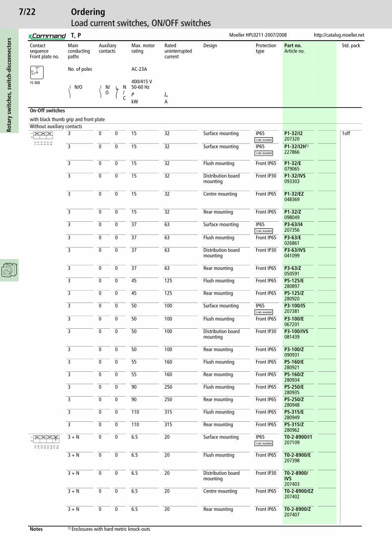
On-Off switches
with black thumb grip and front plateWithout auxiliary contacts
3 0 0 15 32 Surface mounting IP65 P1-32/I2207320
1off
3 0 0 15 32 Surface mounting IP65 P1-32/I2H1)
227866
3 0 0 15 32 Flush mounting Front IP65 P1-32/E079065
3 0 0 15 32 Distribution board mounting
Front IP30 P1-32/IVS093303
3 0 0 15 32 Centre mounting Front IP65 P1-32/EZ048369
3 0 0 15 32 Rear mounting Front IP65 P1-32/Z098049
3 0 0 37 63 Surface mounting IP65 P3-63/I4207356
3 0 0 37 63 Flush mounting Front IP65 P3-63/E026861
3 0 0 37 63 Distribution board mounting
Front IP30 P3-63/IVS041099
3 0 0 37 63 Rear mounting Front IP65 P3-63/Z050591
3 0 0 45 125 Flush mounting Front IP65 P5-125/E280897
3 0 0 45 125 Rear mounting Front IP65 P5-125/Z280920
3 0 0 50 100 Surface mounting IP65 P3-100/I5207381
3 0 0 50 100 Flush mounting Front IP65 P3-100/E067201
3 0 0 50 100 Distribution board mounting
Front IP30 P3-100/IVS081439
3 0 0 50 100 Rear mounting Front IP65 P3-100/Z090931
3 0 0 55 160 Flush mounting Front IP65 P5-160/E280921
3 0 0 55 160 Rear mounting Front IP65 P5-160/Z280934
3 0 0 90 250 Flush mounting Front IP65 P5-250/E280935
3 0 0 90 250 Rear mounting Front IP65 P5-250/Z280948
3 0 0 110 315 Flush mounting Front IP65 P5-315/E280949
3 0 0 110 315 Rear mounting Front IP65 P5-315/Z280962
3 + N 0 0 6.5 20 Surface mounting IP65 T0-2-8900/I1207109
3 + N 0 0 6.5 20 Flush mounting Front IP65 T0-2-8900/E207398
3 + N 0 0 6.5 20 Distribution board mounting
Front IP30 T0-2-8900/IVS207403
3 + N 0 0 6.5 20 Centre mounting Front IP65 T0-2-8900/EZ207402
3 + N 0 0 6.5 20 Rear mounting Front IP65 T0-2-8900/Z207407
Notes 1) Enclosures with hard metric knock-outs
FS 908
ON
OFF
1 2 3 4 5 6
01
1 2 3 4 5 6 7 8
01
T, P
7/23
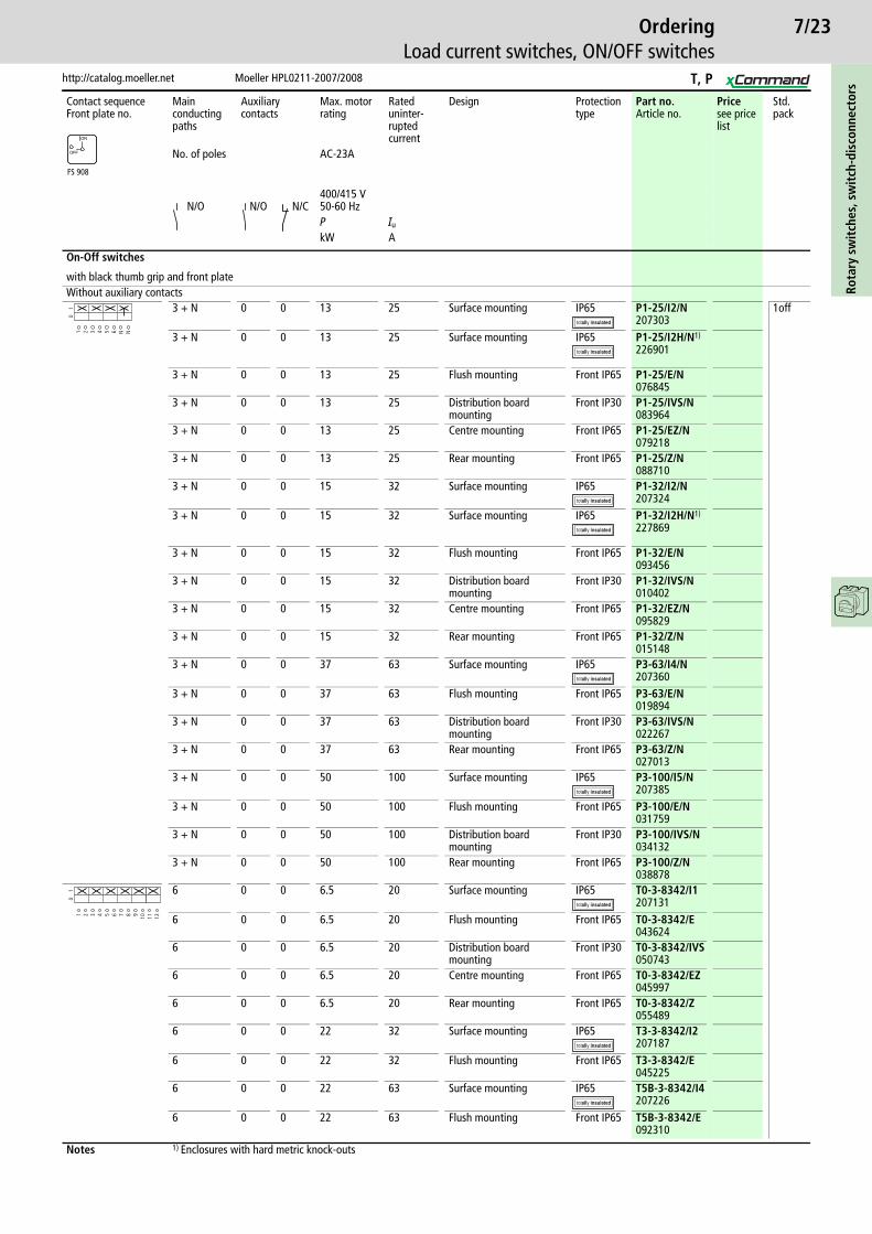
http://catalog.moeller.net Moeller HPL0211-2007/2008
OrderingLoad current switches, ON/OFF switches
Rota
ry s
wit
ches
, sw
itch
-dis
conn
ecto
rs
Contact sequenceFront plate no.
Main conducting paths
Auxiliary contacts
Max. motor rating
Rateduninter-ruptedcurrent
Design Protection type
Part no.Article no.
Pricesee price list
Std. pack
No. of poles AC-23A
N/O N/O N/C400/415 V50-60 HzP Iu
kW A
On-Off switches
with black thumb grip and front plateWithout auxiliary contacts
3 + N 0 0 13 25 Surface mounting IP65 P1-25/I2/N207303
1off
3 + N 0 0 13 25 Surface mounting IP65 P1-25/I2H/N1)
226901
3 + N 0 0 13 25 Flush mounting Front IP65 P1-25/E/N076845
3 + N 0 0 13 25 Distribution board mounting
Front IP30 P1-25/IVS/N083964
3 + N 0 0 13 25 Centre mounting Front IP65 P1-25/EZ/N079218
3 + N 0 0 13 25 Rear mounting Front IP65 P1-25/Z/N088710
3 + N 0 0 15 32 Surface mounting IP65 P1-32/I2/N207324
3 + N 0 0 15 32 Surface mounting IP65 P1-32/I2H/N1)
227869
3 + N 0 0 15 32 Flush mounting Front IP65 P1-32/E/N093456
3 + N 0 0 15 32 Distribution board mounting
Front IP30 P1-32/IVS/N010402
3 + N 0 0 15 32 Centre mounting Front IP65 P1-32/EZ/N095829
3 + N 0 0 15 32 Rear mounting Front IP65 P1-32/Z/N015148
3 + N 0 0 37 63 Surface mounting IP65 P3-63/I4/N207360
3 + N 0 0 37 63 Flush mounting Front IP65 P3-63/E/N019894
3 + N 0 0 37 63 Distribution board mounting
Front IP30 P3-63/IVS/N022267
3 + N 0 0 37 63 Rear mounting Front IP65 P3-63/Z/N027013
3 + N 0 0 50 100 Surface mounting IP65 P3-100/I5/N207385
3 + N 0 0 50 100 Flush mounting Front IP65 P3-100/E/N031759
3 + N 0 0 50 100 Distribution board mounting
Front IP30 P3-100/IVS/N034132
3 + N 0 0 50 100 Rear mounting Front IP65 P3-100/Z/N038878
6 0 0 6.5 20 Surface mounting IP65 T0-3-8342/I1207131
6 0 0 6.5 20 Flush mounting Front IP65 T0-3-8342/E043624
6 0 0 6.5 20 Distribution board mounting
Front IP30 T0-3-8342/IVS050743
6 0 0 6.5 20 Centre mounting Front IP65 T0-3-8342/EZ045997
6 0 0 6.5 20 Rear mounting Front IP65 T0-3-8342/Z055489
6 0 0 22 32 Surface mounting IP65 T3-3-8342/I2207187
6 0 0 22 32 Flush mounting Front IP65 T3-3-8342/E045225
6 0 0 22 63 Surface mounting IP65 T5B-3-8342/I4207226
6 0 0 22 63 Flush mounting Front IP65 T5B-3-8342/E092310
Notes 1) Enclosures with hard metric knock-outs
FS 908
ON
OFF
1 2 3 4 5 6 N N
01
1 2 3 4 5 6 7 8 9 10
01
11 12
T, P
7/24Ro
tary
sw
itch
es, s
wit
ch-d
isco
nnec
tors
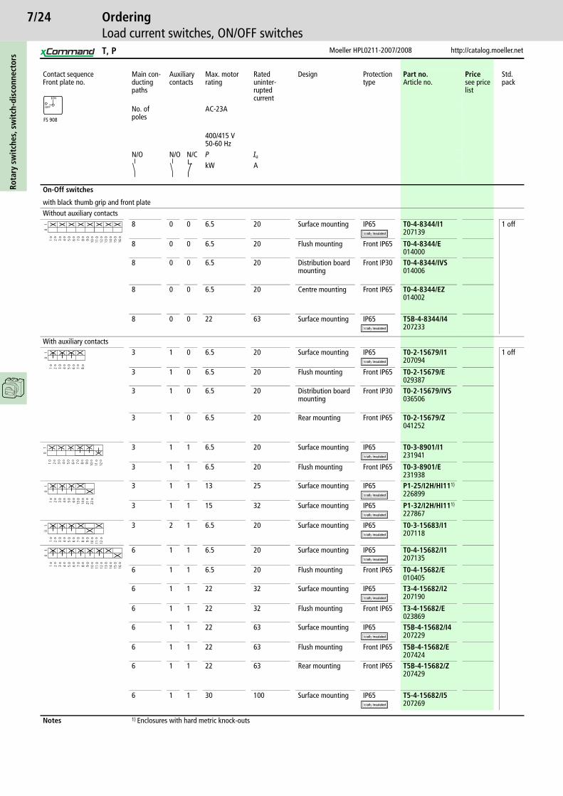
Moeller HPL0211-2007/2008 http://catalog.moeller.net
OrderingLoad current switches, ON/OFF switches
Contact sequenceFront plate no.
Main con-ducting paths
Auxiliary contacts
Max. motor rating
Rateduninter-ruptedcurrent
Design Protection type
Part no.Article no.
Pricesee price list
Std. pack
No. of poles
AC-23A
400/415 V50-60 Hz
N/O N/O N/C P Iu
kW A
On-Off switches
with black thumb grip and front plateWithout auxiliary contacts
8 0 0 6.5 20 Surface mounting IP65 T0-4-8344/I1207139
1 off
8 0 0 6.5 20 Flush mounting Front IP65 T0-4-8344/E014000
8 0 0 6.5 20 Distribution board mounting
Front IP30 T0-4-8344/IVS014006
8 0 0 6.5 20 Centre mounting Front IP65 T0-4-8344/EZ014002
8 0 0 22 63 Surface mounting IP65 T5B-4-8344/I4207233
With auxiliary contacts3 1 0 6.5 20 Surface mounting IP65 T0-2-15679/I1
2070941 off
3 1 0 6.5 20 Flush mounting Front IP65 T0-2-15679/E029387
3 1 0 6.5 20 Distribution board mounting
Front IP30 T0-2-15679/IVS036506
3 1 0 6.5 20 Rear mounting Front IP65 T0-2-15679/Z041252
3 1 1 6.5 20 Surface mounting IP65 T0-3-8901/I1231941
3 1 1 6.5 20 Flush mounting Front IP65 T0-3-8901/E231938
3 1 1 13 25 Surface mounting IP65 P1-25/I2H/HI111)
226899
3 1 1 15 32 Surface mounting IP65 P1-32/I2H/HI111)
227867
3 2 1 6.5 20 Surface mounting IP65 T0-3-15683/I1207118
6 1 1 6.5 20 Surface mounting IP65 T0-4-15682/I1207135
6 1 1 6.5 20 Flush mounting Front IP65 T0-4-15682/E010405
6 1 1 22 32 Surface mounting IP65 T3-4-15682/I2207190
6 1 1 22 32 Flush mounting Front IP65 T3-4-15682/E023869
6 1 1 22 63 Surface mounting IP65 T5B-4-15682/I4207229
6 1 1 22 63 Flush mounting Front IP65 T5B-4-15682/E207424
6 1 1 22 63 Rear mounting Front IP65 T5B-4-15682/Z207429
6 1 1 30 100 Surface mounting IP65 T5-4-15682/I5207269
Notes 1) Enclosures with hard metric knock-outs
FS 908
ON
OFF
1 2 3 4 5 6 7 8 9 10
01
11 12 13 14 15 16
1 2 3 4 5 6 7 8
01
1 2 3 4 5 6 7 8
01
9 10 11 12
1 2 3 4 5 6 13 14
01
21 22
1 2 3 4 5 6 7 8
01
9 10 11 12
1 2 3 4 5 6 7 8
01
9 10 11 12 13 14 15 16
T, P
7/25
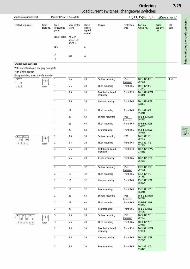
http://catalog.moeller.net Moeller HPL0211-2007/2008
OrderingLoad current switches, changeover switches
Rota
ry s
wit
ches
, sw
itch
-dis
conn
ecto
rs
Contact sequence Front plate no.
Main conducting paths
Max. motor rating
Rateduninter-ruptedcurrent
Design Protection type
Part no.Article no.
Pricesee price list
Std. pack
No. of poles AC-23A400/415 V50-60 Hz
N/O P Iu
kW A
Changeover switches
With black thumb-grip and grey front plateWith 0 (Off) positionGroup switches, mains transfer switches
1 6.5 20 Surface mounting IP65 T0-1-8210/I1207076
1 off
1 6.5 20 Flush mounting Front IP65 T0-1-8210/E012742
1 6.5 20 Distribution board mounting
Front IP30 T0-1-8210/IVS074440
1 6.5 20 Centre mounting Front IP65 T0-1-8210/EZ048337
1 13 32 Flush mounting Front IP65 T3-1-8210/E054718
1 22 63 Surface mounting IP65 T5B-1-8210/I4207432
1 22 63 Flush mounting Front IP65 T5B-1-8210/E094261
1 22 63 Rear mounting Front IP65 T5B-1-8210/Z094258
2 6.5 20 Surface mounting IP65 T0-2-8211/I1207102
2 6.5 20 Flush mounting Front IP65 T0-2-8211/E022234
2 6.5 20 Distribution board mounting
Front IP30 T0-2-8211/IVS076813
2 6.5 20 Centre mounting Front IP65 T0-2-8211/EZ053083
2 13 32 Surface mounting IP65 T3-2-8211/I2207178
2 13 32 Flush mounting Front IP65 T3-2-8211/E061837
2 13 32 Centre mounting Front IP65 T3-2-8211/EZ003075
2 13 32 Rear mounting Front IP65 T3-2-8211/Z064210
2 22 63 Surface mounting IP65 T5B-2-8211/I4207220
2 22 63 Flush mounting Front IP65 T5B-2-8211/E093094
2 22 63 Rear mounting Front IP65 T5B-2-8211/Z093082
3 6.5 20 Surface mounting IP65 T0-3-8212/I1207123
3 6.5 20 Flush mounting Front IP65 T0-3-8212/E029353
3 6.5 20 Distribution board mounting
Front IP30 T0-3-8212/IVS079186
3 6.5 20 Centre mounting Front IP65 T0-3-8212/EZ057829
3 6.5 20 Rear mounting Front IP65 T0-3-8212/Z036473
1 2 3 4
20
1
FS 684
01 2
1 2 3 4 5 6 7 8
20
1
FS 684
01 2
1 2 3 4 5 6 7 8 9 10 11 12
20
1
FS 684
01 2
T0, T3, T5(B), T6, T8
7/26Ro
tary
sw
itch
es, s
wit
ch-d
isco
nnec
tors
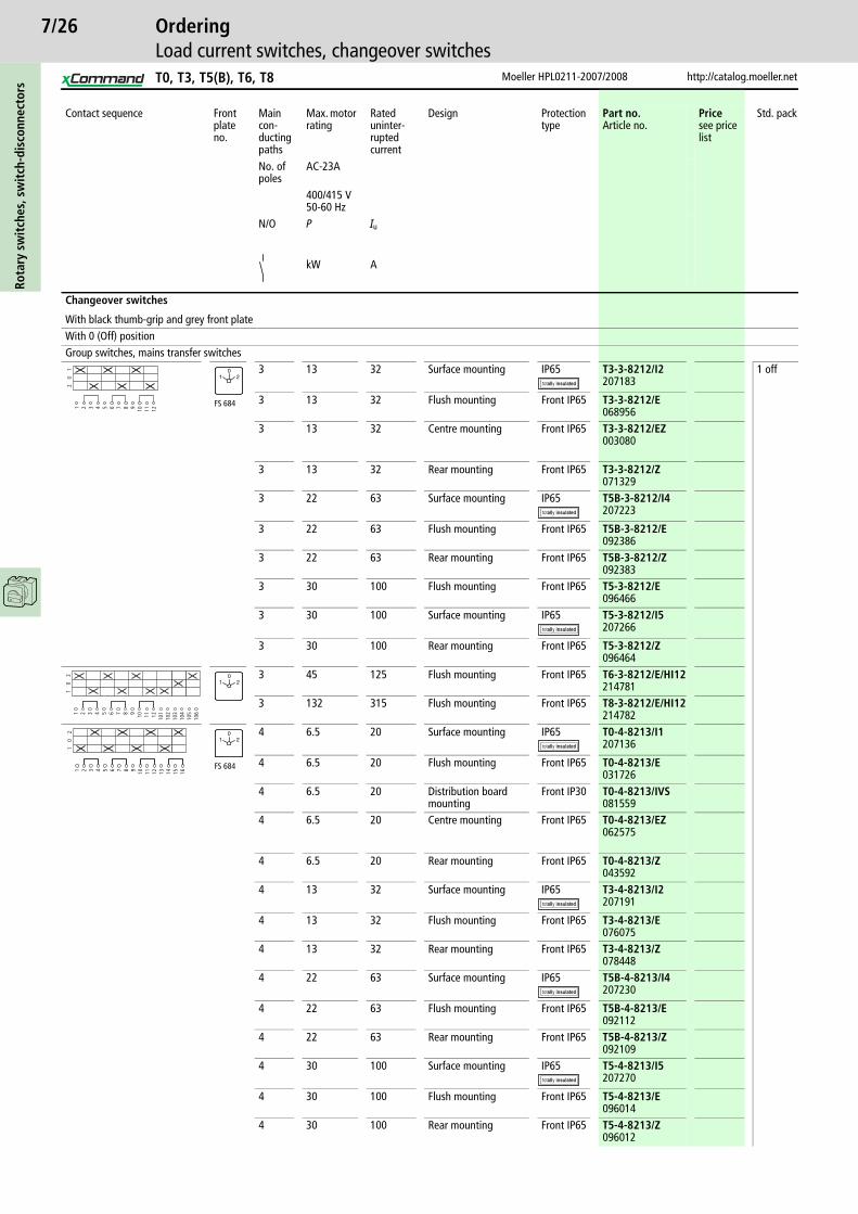
Moeller HPL0211-2007/2008 http://catalog.moeller.net
OrderingLoad current switches, changeover switches
Contact sequence Front plate no.
Main con-ducting paths
Max. motor rating
Rated uninter-rupted current
Design Protection type
Part no.Article no.
Pricesee price list
Std. pack
No. of poles
AC-23A
400/415 V50-60 Hz
N/O P Iu
kW A
Changeover switches
With black thumb-grip and grey front plateWith 0 (Off) positionGroup switches, mains transfer switches
3 13 32 Surface mounting IP65 T3-3-8212/I2207183
1 off
3 13 32 Flush mounting Front IP65 T3-3-8212/E068956
3 13 32 Centre mounting Front IP65 T3-3-8212/EZ003080
3 13 32 Rear mounting Front IP65 T3-3-8212/Z071329
3 22 63 Surface mounting IP65 T5B-3-8212/I4207223
3 22 63 Flush mounting Front IP65 T5B-3-8212/E092386
3 22 63 Rear mounting Front IP65 T5B-3-8212/Z092383
3 30 100 Flush mounting Front IP65 T5-3-8212/E096466
3 30 100 Surface mounting IP65 T5-3-8212/I5207266
3 30 100 Rear mounting Front IP65 T5-3-8212/Z096464
3 45 125 Flush mounting Front IP65 T6-3-8212/E/HI12214781
3 132 315 Flush mounting Front IP65 T8-3-8212/E/HI12214782
4 6.5 20 Surface mounting IP65 T0-4-8213/I1207136
4 6.5 20 Flush mounting Front IP65 T0-4-8213/E031726
4 6.5 20 Distribution board mounting
Front IP30 T0-4-8213/IVS081559
4 6.5 20 Centre mounting Front IP65 T0-4-8213/EZ062575
4 6.5 20 Rear mounting Front IP65 T0-4-8213/Z043592
4 13 32 Surface mounting IP65 T3-4-8213/I2207191
4 13 32 Flush mounting Front IP65 T3-4-8213/E076075
4 13 32 Rear mounting Front IP65 T3-4-8213/Z078448
4 22 63 Surface mounting IP65 T5B-4-8213/I4207230
4 22 63 Flush mounting Front IP65 T5B-4-8213/E092112
4 22 63 Rear mounting Front IP65 T5B-4-8213/Z092109
4 30 100 Surface mounting IP65 T5-4-8213/I5207270
4 30 100 Flush mounting Front IP65 T5-4-8213/E096014
4 30 100 Rear mounting Front IP65 T5-4-8213/Z096012
1 2 3 4 5 6 7 8 9 10 11 12
20
1
FS 684
01 2
1 2 3 4 5 6 7 8 9 10 11 12 101
102
10
2
103
104
105
106
01 2
1 2 3 4 5 6 7 8 9 10 11 12 13 14
10
2
15 16
FS 684
01 2
T0, T3, T5(B), T6, T8

7/27
http://catalog.moeller.net Moeller HPL0211-2007/2008
OrderingLoad current switches, changeover switches
Rota
ry s
wit
ches
, sw
itch
-dis
conn
ecto
rs
Contact sequence Front plate no.
Main con-ducting paths
Max. motor rating
Rated uninter-rupted current
Design Protection type
Part no.Article no.
Pricesee price list
Std. pack
No. of poles
AC-23A
400/415 V50-60 Hz
N/O P Iu
kW A
Changeover switches
With black thumb-grip and grey front plateWith 0 (Off) positionGroup switches, mains transfer switches
4 6.5 20 Surface mounting IP65 T0-4-8294/I1207138
1 off
4 6.5 20 Flush mounting Front IP65 T0-4-8294/E010371
4 6.5 20 Distribution board mounting
Front IP30 T0-4-8294/IVS043594
4 13 32 Surface mounting IP65 T3-4-8294/I2207193
4 13 32 Flush mounting Front IP65 T3-4-8294/E002513
4 13 32 Rear mounting Front IP65 T3-4-8294/Z004886
4 22 63 Surface mounting IP65 T5B-4-8294/I4207232
4 22 63 Flush mounting Front IP65 T5B-4-8294/E092084
4 22 63 Rear mounting Front IP65 T5B-4-8294/Z092081
4 30 100 Surface mounting IP65 T5-4-8294/I5207433
4 30 100 Flush mounting Front IP65 T5-4-8294/E095986
4 30 100 Rear mounting Front IP65 T5-4-8294/Z095984
4 13 32 Flush mounting Front IP65 T3-4-8902/E215222
4 13 32 Flush mounting Front IP65 T3-4-8902/EZ215223
4 13 32 Flush mounting IP65 T3-4-8902/I2215224
4 13 32 Flush mounting Front IP65 T3-4-8902/Z215225
4 22 63 Flush mounting Front IP65 T5B-4-8902/E207430
4 22 63 Surface mounting IP65 T5B-4-8902/I4207237
4 22 63 Rear mounting Front IP65 T5B-4-8902/Z207431
4 30 100 Flush mounting Front IP65 T5-4-8902/E207418
4 30 100 Surface mounting IP65 T5-4-8902/I5207214
4 30 100 Rear mounting Front IP65 T5-4-8902/Z207419
1 2 3 4 5 6 7 8 9 10 11 12 13 14
10
2
15 16
FS 953
0
1 2
1 2 3 4 5 6 7 8 9 10 11 12 13 14
0
15 16
Mains
Stand-by
0
FS 161629
NETZNOT-
STROM
T0, T3, T5(B), T6, T8

7/28Ro
tary
sw
itch
es, s
wit
ch-d
isco
nnec
tors
Moeller HPL0211-2007/2008 http://catalog.moeller.net
OrderingLoad current switches, changeover switches
Contact sequence Front plate no.
Main con-ducting paths
Max. motor rating Rateduninter-ruptedcurrent
Design Protection type
Part no.Article no.
Pricesee price list
Std. pack
No. of poles
AC-23A
400/415 V50-60 Hz
N/O P Iu
kW A
Changeover switches
With black thumb-grip and grey front plateWith 0 (Off) positionWith spring-return from both directions to 0
1 6.5 20 Surface mounting IP65 T0-1-8214/I1207077
1 off
1 6.5 20 Flush mounting Front IP65 T0-1-8214/E019863
1 6.5 20 Distribution board mounting
Front IP30 T0-1-8214/IVS045967
1 6.5 20 Centre mounting Front IP65 T0-1-8214/EZ076815
1 6.5 20 Rear mounting Front IP65 T0-1-8214/Z050720
2 6.5 20 Surface mounting IP65 T0-2-8215/I1207103
2 6.5 20 Flush mounting Front IP65 T0-2-8215/E022236
2 6.5 20 Distribution board mounting
Front IP30 T0-2-8215/IVS048340
2 6.5 20 Centre mounting Front IP65 T0-2-8215/EZ081561
3 6.5 20 Surface mounting IP65 T0-3-8216/I1207434
3 6.5 20 Flush mounting Front IP65 T0-3-8216/E024609
3 6.5 20 Centre mounting Front IP65 T0-3-8216/EZ086307
3 13 32 Surface mounting IP65 T3-3-8216/I2207184
3 13 32 Flush mounting Front IP65 T3-3-8216/E023870
Without 0 (Off) positionChangeover switches
1 6.5 20 Surface mounting IP65 T0-1-8220/I1207078
1 off
1 6.5 20 Flush mounting Front IP65 T0-1-8220/E031728
1 6.5 20 Distribution board mounting
Front IP30 T0-1-8220/IVS055459
1 6.5 20 Centre mounting Front IP65 T0-1-8220/EZ095799
1 6.5 20 Rear mounting Front IP65 T0-1-8220/Z086312
2 6.5 20 Surface mounting IP65 T0-2-8221/I1207104
2 6.5 20 Flush mounting Front IP65 T0-2-8221/E038847
2 6.5 20 Distribution board mounting
Front IP30 T0-2-8221/IVS057832
2 6.5 20 Centre mounting Front IP65 T0-2-8221/EZ010372
2 22 32 Surface mounting IP65 T3-2-8221/I2207180
2 22 32 Flush mounting Front IP65 T3-2-8221/E045227
2 22 63 Surface mounting IP65 T5B-2-8221/I4207221
2 22 63 Flush mounting Front IP65 T5B-2-8221/E093047
1 2 3 4
10
2
FS 4011
01 2
1 2 3 4 5 6 7 8
10
2
1 2 3 4 5 6 7 8 9 10 11 12
10
21 2 3 4
12
FS 943
1 2
1 2 3 4 5 6 7 8
12
T0, T3, T5(B), T6, T8

7/29
http://catalog.moeller.net Moeller HPL0211-2007/2008
OrderingLoad current switches, changeover switches
Rota
ry s
wit
ches
, sw
itch
-dis
conn
ecto
rs
Contact sequenceFront plate no.
Main con-ducting paths
Max. motor rating
Rateduninter-ruptedcurrent
Design Protection type
Part no.Article no.
Pricesee price list
Std. pack
No. of poles
AC-23A
N/O 400/415 V50-60 HzP Iu
kW A
Changeover switches
with black thumb grip and front plateWithout 0 (Off) positionChangeover switches
3 6.5 20 Surface mounting IP65 T0-3-8222/I1207124
1
3 6.5 20 Flush mounting Front IP65 T0-3-8222/E048339
3 6.5 20 Distribution board mounting
Front IP30 T0-3-8222/IVS060205
3 6.5 20 Centre mounting Front IP65 T0-3-8222/EZ015118
3 13 32 Flush mounting Front IP65 T3-3-8222/E052346
3 22 32 Surface mounting IP65 T3-3-8222/I2207185
3 22 63 Surface mounting IP65 T5B-3-8222/I4207224
3 22 63 Flush mounting Front IP65 T5B-3-8222/E092378
3 22 63 Rear mounting Front IP65 T5B-3-8222/Z092375
4 6.5 20 Surface mounting IP65 T0-4-8223/I1207137
4 6.5 20 Flush mounting Front IP65 T0-4-8223/E050712
4 6.5 20 Distribution board mounting
Front IP30 T0-4-8223/IVS062578
4 6.5 20 Centre mounting Front IP65 T0-4-8223/EZ019864
4 6.5 20 Rear mounting Front IP65 T0-4-8223/Z086315
4 13 32 Surface mounting IP65 T3-4-8223/I2207192
4 13 32 Flush mounting Front IP65 T3-4-8223/E059465
4 13 32 Rear mounting Front IP65 T3-4-8223/Z061838
4 22 63 Surface mounting IP65 T5B-4-8223/I4207231
4 22 63 Flush mounting Front IP65 T5B-4-8223/E092108
4 22 63 Rear mounting Front IP65 T5B-4-8223/Z092105
5 6.5 20 Flush mounting Front IP65 T0-5-8369/E060204
5 22 32 Surface mounting IP65 T3-5-8369/I2207536
5 22 32 Flush mounting Front IP65 T3-5-8369/E066584
6 6.5 20 Flush mounting Front IP65 T0-6-8370/E062577
6 6.5 20 Distribution board mounting
Front IP30 T0-6-8370/IVS067324
6 6.5 20 Centre mounting Front IP65 T0-6-8370/EZ029356
6 22 32 Flush mounting Front IP65 T3-6-8370/E073703
8 6.5 20 Flush mounting Front IP65 T0-8-8372/E064950
8 6.5 20 Distribution board mounting
Front IP30 T0-8-8372/IVS069697
8 22 32 Flush mounting Front IP65 T3-8-8372/E080822
1 2
FS 943
1 2 3 4 5 6 7 8 9 10 11 12
12
1 2 3 4 5 6 7 8 9 10 11 12
12
1 2 3 4 5 6 7 8 9 10 11 12 13 14
12
15 16
1 2 3 4 5 6 7 8 9 10 11 12 13 14
12
15 16 17 18 19 20
1 2 3 4 5 6 7 8 9 10 11 12 13 14
12
15 16 17 18 19 20 21 22 23 24
1 2 3 4 5 6 7 8 9 10 11 12 13 14
12
15 16 17 18 19 20 21 22 23 24 25 26 27 28 29 30 31 32
T0, T3, T5(B), T6, T8
7/30Ro
tary
sw
itch
es, s
wit
ch-d
isco
nnec
tors
Moeller HPL0211-2007/2008 http://catalog.moeller.net
OrderingLoad-current switch - Safety switch
Contact sequence Main con-ducting paths
Auxiliary contacts Max. motor rating Rateduninter-ruptedcurrent
Design Part no.Article no.
Pricesee price list
Std. pack
Front plate no. No. of poles
AC-23A
400/415 V50-60 Hz
N/O N/O N/C P Iu
kW A
Safety switches with warning label
For use as Emergency-Stop device1)
3 0 0 13 25 Surface mountingIP65
P1-25/I2-SI207308
1 off
3 0 0 15 32 P1-32/I2-SI207329
1 off
3 0 0 37 63 P3-63/I4-SI207361
1 off
3 0 0 50 100 P3-100/I5-SI207386
1 off
3 + N 0 0 13 25 P1-25/I2-SI/N207312
1 off
3 + N 0 0 15 32 P1-32/I2-SI/N207333
1 off
3 + N 0 0 37 63 P3-63/I4-SI/N207365
1 off
3 + N 0 0 50 100 P3-100/I5-SI/N207390
1 off
3 1 1 13 25 P1-25/I2-SI/HI11207310
1 off
3 1 1 15 32 P1-32/I2-SI/HI11207331
1 off
3 1 1 37 63 P3-63/I4-SI/HI11207363
1 off
3 1 1 50 100 P3-100/I5-SI/HI11207388
1 off
6 0 0 22 63 T5B-3-8342/I4-SI207250
1 off
6 0 0 30 100 T5-3-8342/I5-SI207447
1 off
6 1 1 22 63 T5B-4-15682/I4-SI207254
1 off
6 1 1 30 100 T5-4-15682/I5-SI207285
1 off
6 2 0 22 63 T5B-4-8903/I4-SI207258
1 off
6 2 0 30 100 T5-4-8903/I5-SI207289
1 off
Without Emergency-Stop function2)
3 0 0 13 25 Surface mountingIP65
P1-25/I2-SI-SW207309
1 off
3 0 0 15 32 P1-32/I2-SI-SW207330
1 off
3 0 0 37 63 P3-63/I4-SI-SW207362
1 off
Notes 1) According to IEC/EN 60204-1, VDE 0113 Part 12) With black rotary handle and locking ring
FS 908
ON
OFF
1 2 3 4 5 6
01
1 2 3 4 5 6 N N
01
1 2 3 4 5 6 13 14
01
21 22
1 2 3 4 5 6 7 8 9 10
01
11 12
1 2 3 4 5 6 7 8
01
9 10 11 12 13 14 15 16
1 2 3 4 5 6 7 8
01
9 10 11 12 13 14 15 16
1 2 3 4 5 6
01
P1, P3, T5(B)

7/31
http://catalog.moeller.net Moeller HPL0211-2007/2008
OrderingLoad-current switch - Safety switch
Rota
ry s
wit
ches
, sw
itch
-dis
conn
ecto
rs
EngineeringMaintenance, repair and safety switches all have the same electrical function. They are designed to safely isolate electrical installations (loads) from mains power during maintenance and repair work and to ensure that a hazard does not arise which endangers personnel, machinery and production materials.Safety switches are main switches with an additional enclosure. Installed in the immediate vicinity of the motor or the electrical load they act as switch-disconnectors for that load. It makes possible work without danger according to DIN EN 50110/VDE 0105. This is particularly important if there is any danger of the main switch being inadvertently operated.
ApplicationBy securing the switch in the OFF position with his own padlock (up to 3 can be fitted), the fitter/electrician can protect himself against the possibility of any other person switching the machine on. Maintenance switches are merely additional, enclosed main switches with a padlocking facility.Enclosed main switch with padlock interlocka 7/10a 7/30
Features• Safety switches are housed in insulated enclosures and bear the inscription
“Safety switch” on a bright orange label.• With special red handle and yellow locking ring for Emergency_Stop use
according to STOP category O IEC/EN 60204/VDE 0113.• If the switch is not usable for Emergency_Stop both parts are black (partno. suffix
"SW")• The cover and handle can be interlocked by fitting a padlock.
SelectionSwitches must be selected according to the following criteria:1) according to motor switching capacity, when the switch is fitted in so that the operator may use it for operational ON and OFF switching.2) The rating data always applies for 3 poles. When the motor rating is divided between 6 poles, such as for star-delta starting, a 6-pole switch can be used to control 1.73 times the rated power.3) If the switch has a load-shedding contact (LA), you can select the appropriate switch according to the uninterrupted current. The load-shedding contact is an auxiliary contact, which is closed in the ON position and opens early when switching off, so that a contactor located in the circuit takes over the switching capacity and the maintenance/safety switch operates at zero load. When switching on, the load-shedding contact closes later than or at the same time as the main contacts. With P and T switches this is the N/O auxiliary contact.
4) The "ON" position can be locked using a padlock (after altering the handle) This is not permissable for switches with red/yellow handles.
Example:Safety switch with load shedding and annunciation
Contact sequence Main conducting paths
Auxiliary contacts Max. motor rating
Rateduninter-ruptedcurrent
Design Part no.Article no.
Pricesee price list
Std. pack
Front plate no. No. of poles AC-23A400/415 V50-60 Hz
N/O N/O N/C P Iu
kW A
Without Emergency-Stop function
3 + N 0 0 13 25 Surface mountingIP65
P1-25/I2-SI/N-SW207313
1 off
3 + N 0 0 15 32 P1-32/I2-SI/N-SW207334
1 off
3 + N 0 0 50 100 P3-100/I5-SI/N-SW207391
1 off
3 1 1 13 25 P1-25/I2-SI/HI11-SW207311
1 off
3 1 1 15 32 P1-32/I2-SI/HI11-SW207332
1 off
3 1 1 37 63 P3-63/I4-SI/HI11-SW207364
1 off
3 1 1 50 100 P3-100/I5-SI/HI11-SW207389
1 off
6 0 0 22 63 T5B-3-8342/I4-SI-SW207251
1 off
6 1 1 22 63 T5B-4-15682/I4-SI-SW207255
1 off
6 1 1 30 100 T5-4-15682/I5-SI-SW207286
1 off
6 2 0 30 100 T5-4-8903/I5-SI-SW207290
1 off
FS 908
ON
OFF
1 2 3 4 5 6 N N
01
1 2 3 4 5 6 13 14
01
21 22
1 2 3 4 5 6 7 8 9 10
01
11 12
1 2 3 4 5 6 7 8
01
9 10 11 12 13 14 15 16
Q11
L2
NL3
L1
F1
Q112
1
4
3
6
5
F2
1 3 5
2 4 6
M3
7 9 11
8 10 12
Q1
U V W
A2Q11
A1
A2P1 P2
F0
95
96
21
22
F2
O
13
14
I13
14
FAZ-B4/1-HS
P1, P3, T5(B)
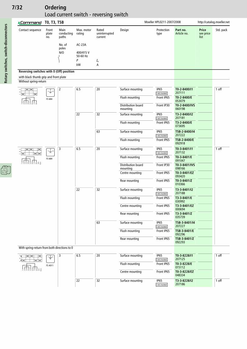
7/32Ro
tary
sw
itch
es, s
wit
ch-d
isco
nnec
tors
Moeller HPL0211-2007/2008 http://catalog.moeller.net
OrderingLoad current switch - reversing switch
Contact sequence Front plate no.
Main conducting paths
Max. motor rating
Rated uninterrupted current
Design Protection type
Part no.Article no.
Pricesee price list
Std. pack
No. of poles
AC-23A
N/O 400/415 V50-60 HzP Iu
kW A
Reversing switches with 0 (Off) position
with black thumb grip and front plateWithout spring-return
2 6.5 20 Surface mounting IP65 T0-2-8400/I1207111
1 off
Flush mounting Front IP65 T0-2-8400/E053079
Distribution board mounting
Front IP30 T0-2-8400/IVS060198
22 32 Surface mounting IP65 T3-2-8400/I2207181
Flush mounting Front IP65 T3-2-8400/E073695
63 Surface mounting IP65 T5B-2-8400/I4207222
Flush mounting Front IP65 T5B-2-8400/E092918
3 6.5 20 Surface mounting IP65 T0-3-8401/I1207132
1 off
Flush mounting Front IP65 T0-3-8401/E091047
Distribution board mounting
Front IP30 T0-3-8401/IVS098166
Centre mounting Front IP65 T0-3-8401/EZ093420
Rear mounting Front IP65 T0-3-8401/Z010366
22 32 Surface mounting IP65 T3-3-8401/I2207188
Flush mounting Front IP65 T3-3-8401/E030992
Centre mounting Front IP65 T3-3-8401/EZ000694
Rear mounting Front IP65 T3-3-8401/Z035739
63 Surface mounting IP65 T5B-3-8401/I4207227
Flush mounting Front IP65 T5B-3-8401/E092296
Rear mounting Front IP65 T5B-3-8401/Z092293
With spring-return from both directions to 0
3 6.5 20 Surface mounting IP65 T0-3-8228/I1207125
1 off
Flush mounting Front IP65 T0-3-8228/E015112
Centre mounting Front IP65 T0-3-8228/EZ048334
22 32 Surface mounting IP65 T3-3-8228/I2207186
1 off
1 2 3 4 5 6 7 8
10
2
FS 684
01 2
1 2 3 4 5 6 7 8 9 10
10
2
FS 684
01 2
1 2 3 4 5 6 7 8 9 10
10
2
FS 4011
01 2
T0, T3, T5B

7/33
http://catalog.moeller.net Moeller HPL0211-2007/2008
OrderingLoad current switches, (reversing) star-delta switches, (reversing) multi-speed switches
Rota
ry s
wit
ches
, sw
itch
-dis
conn
ecto
rs
Contact sequence Front plate no.
Main conducting paths
Max. motor rating
Rated uninter-rupted current
Design Protection type
Part no.Article no.
Pricesee price list
Std. pack
No. of poles
AC-23A
N/O 400/415 V50-60 HzP Iu
kW A
Star-delta switches
with black thumb grip and front plate3 6.5 20 Surface
mountingIP65 T0-4-8410/I1
2071401 off
Flush mounting Front IP65 T0-4-8410/E024604
Distribution board mounting
Front IP30 T0-4-8410/IVS064945
Centre mounting
Front IP65 T0-4-8410/EZ053080
Rear mounting Front IP65 T0-4-8410/Z083929
22 32 Surface mounting
IP65 T3-4-8410/I2207195
Flush mounting Front IP65 T3-4-8410/E009657
Centre mounting
Front IP65 T3-4-8410/EZ000721
Rear mounting Front IP65 T3-4-8410/Z012030
63 Surface mounting
IP65 T5B-4-8410/I4207234
Flush mounting Front IP65 T5B-4-8410/E092052
Reversing Star-delta switches
with black thumb grip and front plateTwo-way switches
3 6.5 20 Flush mounting Front IP65 T0-5-15876/E000893
1 off
22 32 Surface mounting
IP65 T3-5-15876/I2207537
Flush mounting Front IP65 T3-5-15876/E016776
Rear mounting Front IP65 T3-5-15876/Z019149
63 Flush mounting Front IP65 T5B-5-15876/E214785
Flush mounting Front IP65 T5B-5-15876/Z214786
Reversing multi-speed switches
with black thumb grip and front plateTwo-speed, two directions, for one tapped winding
3 6.5 20 Flush mounting Front IP65 T0-6-15866/E055460
1 off
Centre mounting
Front IP65 T0-6-15866/EZ012747
Rear mounting Front IP65 T0-6-15866/Z067326
22 32 Flush mounting Front IP65 T3-6-15866/E054744
3 22 63 Flush mounting Front IP65 T5B-7-15866/E214788
1 off
1 2 3 4 5 6 7 8 9 10 11 12 13 14
0y
d
15 16
FS 635
Y0
1 2 3 4 5 6 7 8 9 10 11 12 13 14
dy
0
15 16 17 18 19 20
yd
FS 638
Y0
Y
1 2 3 4 5 6 7 8 9 10 11 12 13 14
dy
0
15 16 17 18 19 20
yd
FS 4017
Y0
Y
1 2 3 4 5 6 7 8 9 10 11 12 13 14
21
01
2
15 16 17 18 19 20 21 22 23 24
FS 629
10
12 2
1 2 3 4 5 6 7 8 9 10 11 12 13 14
21
01
2
15 16 17 18 19 20 21 22 23 24
FS 441
10
12 2
T0, T3, T5(B)
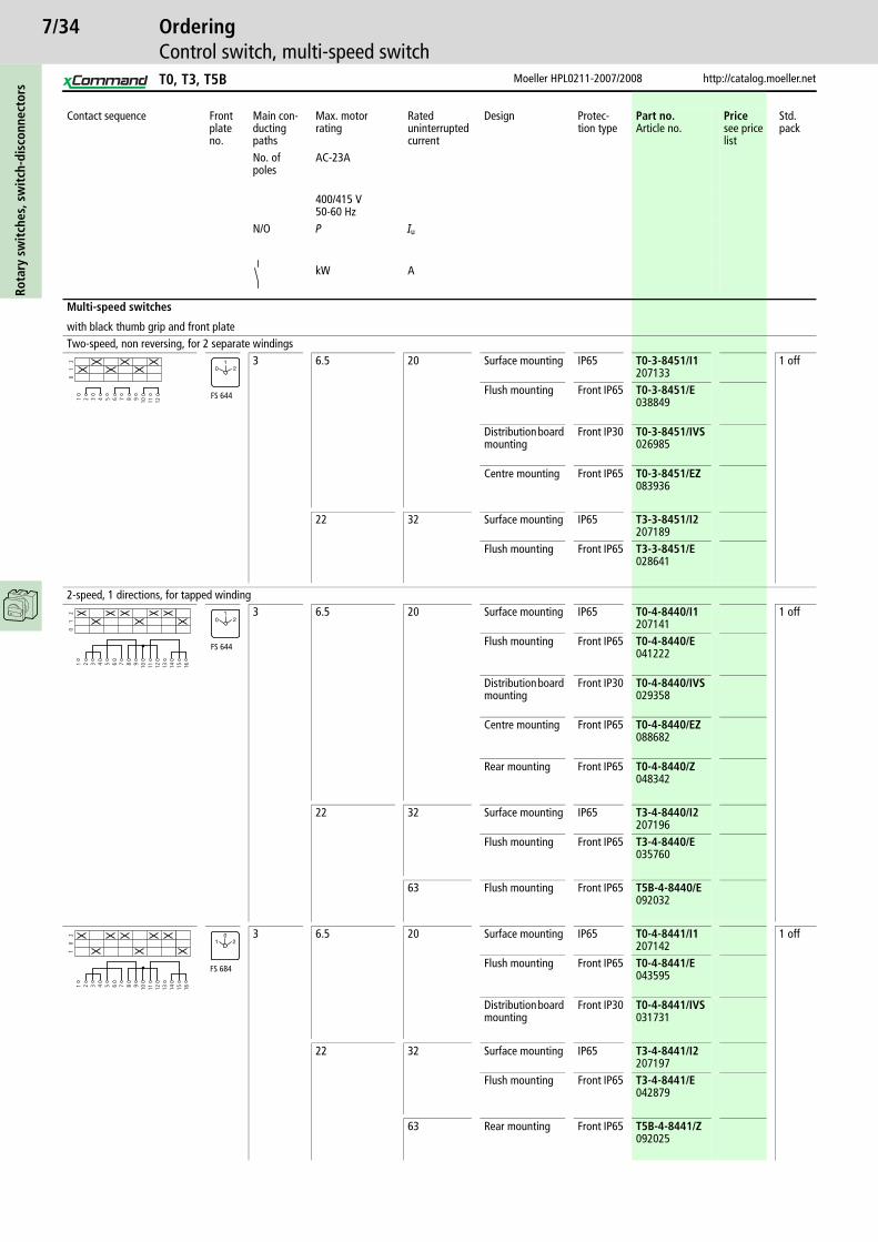
7/34Ro
tary
sw
itch
es, s
wit
ch-d
isco
nnec
tors
Moeller HPL0211-2007/2008 http://catalog.moeller.net
OrderingControl switch, multi-speed switch
Contact sequence Front plate no.
Main con-ducting paths
Max. motor rating
Rated uninterrupted current
Design Protec-tion type
Part no.Article no.
Pricesee price list
Std. pack
No. of poles
AC-23A
400/415 V50-60 Hz
N/O P Iu
kW A
Multi-speed switches
with black thumb grip and front plateTwo-speed, non reversing, for 2 separate windings
3 6.5 20 Surface mounting IP65 T0-3-8451/I1207133
1 off
Flush mounting Front IP65 T0-3-8451/E038849
Distribution board mounting
Front IP30 T0-3-8451/IVS026985
Centre mounting Front IP65 T0-3-8451/EZ083936
22 32 Surface mounting IP65 T3-3-8451/I2207189
Flush mounting Front IP65 T3-3-8451/E028641
2-speed, 1 directions, for tapped winding3 6.5 20 Surface mounting IP65 T0-4-8440/I1
2071411 off
Flush mounting Front IP65 T0-4-8440/E041222
Distribution board mounting
Front IP30 T0-4-8440/IVS029358
Centre mounting Front IP65 T0-4-8440/EZ088682
Rear mounting Front IP65 T0-4-8440/Z048342
22 32 Surface mounting IP65 T3-4-8440/I2207196
Flush mounting Front IP65 T3-4-8440/E035760
63 Flush mounting Front IP65 T5B-4-8440/E092032
3 6.5 20 Surface mounting IP65 T0-4-8441/I1207142
1 off
Flush mounting Front IP65 T0-4-8441/E043595
Distribution board mounting
Front IP30 T0-4-8441/IVS031731
22 32 Surface mounting IP65 T3-4-8441/I2207197
Flush mounting Front IP65 T3-4-8441/E042879
63 Rear mounting Front IP65 T5B-4-8441/Z092025
1 2 3 4 5 6 7 8 9 10 11 12
01
2
FS 644
01
2
1 2 3 4 5 6 7 8 9 10 11 12 13 14
01
2
15 16
FS 644
01
2
1 2 3 4 5 6 7 8 9 10 11 12 13 14
10
2
15 16
FS 684
01 2
T0, T3, T5B

7/35
http://catalog.moeller.net Moeller HPL0211-2007/2008
OrderingControl switch, step switch
Rota
ry s
wit
ches
, sw
itch
-dis
conn
ecto
rs
Contact sequence Front plate no. No. of poles
Design Protection type
Part no.Article no.
Pricesee price list
Std. pack
Step switches
With black thumb-grip and grey front plateOne contact closed per step(without overlap)
With 0 (Off) position1 Surface mounting IP 65 T0-1-8240/I1
207079
Flush mounting Front IP 65 T0-1-8240/E034105
Centre mounting Front IP 65 T0-1-8240/EZ043597
1 Surface mounting IP 65 T0-2-8241/I1207107
Flush mounting Front IP 65 T0-2-8241/E050716
Distribution board mounting
Front IP 30 T0-2-8241/IVS057835
Centre mounting Front IP 65 T0-2-8241/EZ053089
1 Surface mounting IP 65 T0-2-8242/I1207108
Flush mounting Front IP 65 T0-2-8242/E067327
Distribution board mounting
Front IP 30 T0-2-8242/IVS074446
Centre mounting Front IP 65 T0-2-8242/EZ069700
1 Surface mounting IP 65 T0-3-8243/I1207128
Flush mounting Front IP 65 T0-3-8243/E081565
Distribution board mounting
Front IP 30 T0-3-8243/IVS088684
Centre mounting Front IP 65 T0-3-8243/EZ083938
1 Flush mounting Front IP 65 T0-3-8244/E095803
Distribution board mounting
Front IP 30 T0-3-8244/IVS012749
Centre mounting Front IP 65 T0-3-8244/EZ098176
3 Surface mounting IP 65 T0-3-8280/I1207130
Flush mounting Front IP 65 T0-3-8280/E034106
Centre mounting Front IP 65 T0-3-8280/EZ036479
3 Flush mounting Front IP 65 T0-5-8281/E048344
Distribution board mounting
Front IP 30 T0-5-8281/IVS055463
Centre mounting Front IP 65 T0-5-8281/EZ050717
Rear mounting Front IP 65 T0-5-8281/Z057836
3 Flush mounting Front IP 65 T0-6-8282/E062582
Distribution board mounting
Front IP 30 T0-6-8282/IVS069701
Centre mounting Front IP 65 T0-6-8282/EZ064955
1 2 3 4
01
2
FS 418
21
0
1 2 3 4 5 6
01
23
FS 420
21
03
1 2 3 4 5 6 7 8
01
23
4
FS 422
21
034
1 2 3 4 5 6 7 8 9 10
01
23
45
FS 424
21
034
5
1 2 3 4 5 6 7 8 9 10 11 12
01
23
45
6
FS 426
21
034
65
1 2 3 4 5 6 7 8 9 10 11 12
01
2
FS 418
21
0
1 2 3 4 5 6 7 8 9 10 11 12 13 14
01
2
15 16 17 18
3
FS 420
21
03
1 2 3 4 5 6 7 8 9 10 11 12 13 14
01
23
4
15 16 17 18 19 20 21 22 23 24
FS 422
21
034
T0
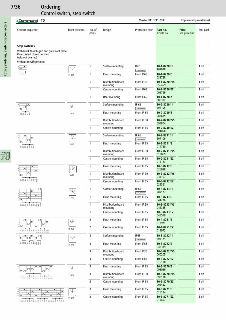
7/36Ro
tary
sw
itch
es, s
wit
ch-d
isco
nnec
tors
Moeller HPL0211-2003 http://catalog.moeller.net
OrderingControl switch, step switch
Contact sequence Front plate no. No. of poles
Design Protection type Part no.Article no.
Pricesee price list
Std. pack
Step switches
With black thumb-grip and grey front plateOne contact closed per step(without overlap)Without 0 (Off) position
1 Surface mounting IP65 T0-1-8220/I1207078
1 off
1 Flush mounting Front IP65 T0-1-8220/E031728
1 off
1 Distribution board mounting
Front IP30 T0-1-8220/IVS055459
1 off
1 Centre mounting Front IP65 T0-1-8220/EZ095799
1 off
1 Rear mounting Front IP65 T0-1-8220/Z086312
1 off
1 Surface mounting IP 65 T0-2-8230/I1207105
1 off
1 Flush mounting Front IP 65 T0-2-8230/E088685
1 off
1 Distribution board mounting
Front IP 30 T0-2-8230/IVS095804
1 off
1 Centre mounting Front IP 65 T0-2-8230/EZ091058
1 off
1 Surface mounting IP 65 T0-2-8231/I1207106
1 off
1 Flush mounting Front IP 65 T0-2-8231/E012750
1 off
1 Distribution board mounting
Front IP 30 T0-2-8231/IVS019869
1 off
1 Centre mounting Front IP 65 T0-2-8231/EZ015123
1 off
1 Flush mounting Front IP 65 T0-3-8232/E026988
1 off
1 Distribution board mounting
Front IP 30 T0-3-8232/IVS034107
1 off
1 Centre mounting Front IP 65 T0-3-8232/EZ029361
1 off
1 Surface mounting IP 65 T0-3-8233/I1207127
1 off
1 Flush mounting Front IP 65 T0-3-8233/E041226
1 off
1 Distribution board mounting
Front IP 30 T0-3-8233/IVS048345
1 off
1 Centre mounting Front IP 65 T0-3-8233/EZ043599
1 off
2 Flush mounting Front IP 65 T0-4-8251/E013971
1 off
2 Centre mounting Front IP 65 T0-4-8251/EZ013972
1 off
3 Surface mounting IP65 T0-3-8222/I1207124
1 off
3 Flush mounting Front IP65 T0-3-8222/E048339
1 off
3 Distribution board mounting
Front IP30 T0-3-8222/IVS060205
1 off
3 Centre mounting Front IP65 T0-3-8222/EZ015118
1 off
3 Flush mounting Front IP 65 T0-5-8270/E091059
1 off
3 Distribution board mounting
Front IP 30 T0-5-8270/IVS098178
1 off
3 Centre mounting Front IP 65 T0-5-8270/EZ093432
1 off
3 Flush mounting Front IP 65 T0-6-8271/E015124
1 off
3 Centre mounting Front IP 65 T0-6-8271/EZ017497
1 off
1 2 3 4
12
FS 943
1 2
1 2 3 4 5 6
12
3
FS 404
32
1
1 2 3 4 5 6 7 8
12
34
FS 606
2
41
3
1 2 3 4 5 6 7 8 9- 10
12
34
5
FS 408
32 4
51
1 2 3 4 5 6 7 8 9 10 11 12
12
34
56
FS 410
32 4
516
1 2 3 4 5 6 7 8 9 10 11 12 13 14
12
15 16
34
FS 406
23
14
1 2 3 4 5 6 7 8 9 10 11 12
12
FS 943
1 2
1 2 3 4 5 6 7 8 9 10 11 12 13 14
12
3
15 16 17 18
FS 404
32
1
1 2 3 4 5 6 7 8 9 10 11 12 13 14
12
3
15 16 17 18 19 20 21 22 23 24
4
FS 406
23
14
T0

7/37
http://catalog.moeller.net Moeller HPL0211-2003
OrderingControl switch, ON-OFF switches, changeover switches, Hand/Auto switches
Rota
ry s
wit
ches
, sw
itch
-dis
conn
ecto
rs
Contact sequence Front plate no. No. of poles
Design Protection type Part no.Article no.
Pricesee price list
Std. pack
On-Off switches
With black thumb-grip and grey front plateOne contact closed per step(without overlap)
1 Flush mounting Front IP 65 T0-1-15401/E038854
1 off
1 Centre mounting Front IP 65 T0-1-15401/EZ041227
1 off
1 Surface mounting IP 65 T0-1-15401/I1207067
1 off
1 Distribution board mounting
Front IP30 T0-1-15401/IVS045973
1 off
2 Flush mounting Front IP 65 T0-1-15402/E053092
1 off
2 Centre mounting Front IP 65 T0-1-15402/EZ055465
1 off
2 Surface mounting IP 65 T0-1-15402/I1207068
1 off
2 Distribution board mounting
Front IP30 T0-1-15402/IVS060211
1 off
3 Flush mounting Front IP 65 T0-2-15403/E067330
1 off
3 Centre mounting Front IP 65 T0-2-15403/EZ069703
1 off
3 Distribution board mounting
Front IP30 T0-2-15403/IVS074449
1 off
4 Flush mounting Front IP 65 T0-2-15404/E081568
1 off
4 Centre mounting Front IP 65 T0-2-15404/EZ083941
1 off
Changeover switches
With black thumb-grip and grey front plateOne contact closed per step(without overlap)
1 Flush mounting Front IP 65 T0-1-15421/E095806
1 off
1 Centre mounting Front IP 65 T0-1-15421/EZ098179
1 off
1 Surface mounting IP 65 T0-1-15421/I1207069
1 off
1 Distribution board mounting
Front IP30 T0-1-15421/IVS012752
1 off
2 Flush mounting Front IP 65 T0-2-15422/E019871
1 off
2 Distribution board mounting
Front IP30 T0-2-15422/IVS026990
1 off
2 Centre mounting Front IP 65 T0-2-15422/EZ022244
1 off
2 Rear mounting Front IP 65 T0-2-15422/Z029363
1 off
3 Surface mounting IP 65 T0-3-15423/I1207114
1 off
3 Flush mounting Front IP 65 T0-3-15423/E034109
1 off
Hand/Auto switches With 0 (Off) positionWithout spring-return
1 Surface mounting IP65 T0-1-15431/I1207070
1 off
Flush mounting Front IP 65 T0-1-15431/E019872
Distribution board mounting
IP65 T0-1-15431/IVS026991
Centre mounting Front IP 65 T0-1-15431/EZ022245
Rear mounting Front IP 65 T0-1-15431/Z029364
1 2
01
FS 415
01
1 2 3 4
01
1 2 3 4 5 6
01
1 2 3 4 5 6 7 8
01
1 2 3 4
20
1
FS 429
02 1
1 2 3 4 5 6 7 8
20
11 2 3 4 5 6 7 8 9 10 11 12
20
1
1 2 3 4
HAND0
AUTO
FS 1401
0HAND AUTO
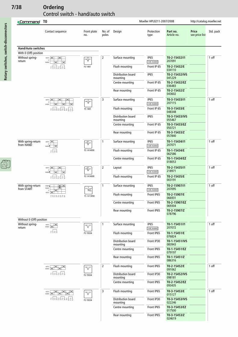
7/38Ro
tary
sw
itch
es, s
wit
ch-d
isco
nnec
tors
Moeller HPL0211-2007/2008 http://catalog.moeller.net
OrderingControl switch - hand/auto switch
Contact sequence Front plate no.
No. of poles
Design Protection type
Part no.Article no.
Pricesee price list
Std. pack
Hand/Auto switches With 0 (Off) positionWithout spring-return
2 Surface mounting IP65 T0-2-15432/I1207091
1 off
Flush mounting Front IP 65 T0-2-15432/E034110
Distribution board mounting
IP65 T0-2-15432/IVS041229
Centre mounting Front IP 65 T0-2-15432/EZ036483
Rear mounting Front IP 65 T0-2-15432/Z043602
3 Surface mounting IP65 T0-3-15433/I1207115
1 off
Flush mounting Front IP 65 T0-3-15433/E048348
Distribution board mounting
IP65 T0-3-15433/IVS055467
Centre mounting Front IP 65 T0-3-15433/EZ050721
Rear mounting Front IP 65 T0-3-15433/Z057840
With spring-return from HAND
1 Surface mounting IP65 T0-1-15434/I1207071
1 off
Flush mounting Front IP 65 T0-1-15434/E062586
Centre mounting Front IP 65 T0-1-15434/EZ018053
2 Layout IP65 T0-2-15435/I1218971
1 off
Flush mounting Front IP 65 T0-2-15435/E003191
With spring-return from START
1 Surface mounting IP65 T0-2-15907/I1207095
1 off
Flush mounting Front IP65 T0-2-15907/E066931
Centre mounting Front IP65 T0-2-15907/EZ069304
Rear mounting Front IP65 T0-2-15907/Z078796
Without 0 (Off) positionWithout spring-return
1 Surface mounting IP65 T0-1-15451/I1207072
1 off
Flush mounting Front IP65 T0-1-15451/E076824
Distribution board mounting
Front IP30 T0-1-15451/IVS083943
Centre mounting Front IP65 T0-1-15451/EZ079197
Rear mounting Front IP65 T0-1-15451/Z086316
2 Flush mounting Front IP65 T0-2-15452/E091062
1 off
Distribution board mounting
Front IP30 T0-2-15452/IVS098181
Centre mounting Front IP65 T0-2-15452/EZ093435
3 Flush mounting Front IP65 T0-3-15453/E015127
1 off
Distribution board mounting
Front IP30 T0-3-15453/IVS022246
Centre mounting Front IP65 T0-3-15453/EZ017500
Rear mounting Front IP65 T0-3-15453/Z024619
1 2 3 4 5 6 7 8HAND
0AUTO
FS 1401
0HAND AUTO
1 2 3 4 5 6 7 8 9 10 11 12
HAND0
AUTO
FS 1401
0HAND AUTO
1 2 3 4
HAND0
AUTO
FS 1414000
0HAND AUTO
1 2 3 4 5 6 7 8
HAND0
AUTO
FS 1414000
0HAND AUTO
1 2 3 4 5 6 7 8
AUTO0
HANDSTART
FS 1413890
0AUTO HAND
START
1 2 3 4
HANDAUTO
FS 19334
HAND AUTO
1 2 3 4 5 6 7 8
HANDAUTO
FS 19334
HAND AUTO
1 2 3 4 5 6 7 8 9 10 11 12
HANDAUTO
FS 19334
HAND AUTO
T0
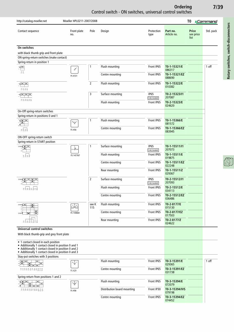
7/39
http://catalog.moeller.net Moeller HPL0211-2007/2008
OrderingControl switch - ON switches, universal control switches
Rota
ry s
wit
ches
, sw
itch
-dis
conn
ecto
rs
Contact sequence Front plate no.
Pole Design Protection type
Part no.Article no.
Pricesee price list
Std. pack
On switches
with black thumb grip and front plateON spring-return switches (make contact)Spring-return in position 1
1 Flush mounting Front IP65 T0-1-15321/E086317
1 off
Centre mounting Front IP65 T0-1-15321/EZ088690
2 Flush mounting Front IP65 T0-1-15322/E010382
3 Surface mounting IP65 T0-2-15323/I1207087
Flush mounting Front IP65 T0-2-15323/E024620
On-Off spring-return switchesSpring-return in positions 0 and 1
1 Flush mounting Front IP65 T0-1-15366/E081572
Centre mounting Front IP65 T0-1-15366/EZ083945
ON-OFF spring-return switchSpring-return in START position
1 Surface mounting IP65 T0-1-15511/I1207073
Flush mounting Front IP65 T0-1-15511/E019875
Centre mounting Front IP65 T0-1-15511/EZ022248
Rear mounting Front IP65 T0-1-15511/Z029367
2 Surface mounting IP65 T0-2-15512/I1207093
Flush mounting Front IP65 T0-2-15512/E034113
Centre mounting Front IP65 T0-2-15512/EZ036486
see K 115
Flush mounting Front IP65 T0-2-8177/E015130
Centre mounting Front IP65 T0-2-8177/EZ017503
Rear mounting Front IP65 T0-2-8177/Z024622
Universal control switches
With black thumb-grip and grey front plate
• 1 contact closed in each position• Additionally 1 contact closed in position 0 and 1• Additionally 1 contact closed in position 0 and 2• Additionally 1 contact closed in position 0 and 3Stay-put switches with 3 positions
Flush mounting Front IP65 T0-3-15391/E029365
1 off
Centre mounting Front IP65 T0-3-15391/EZ031738
Spring-return from positions 1 and 2Flush mounting Front IP65 T0-3-15394/E
072079Distribution board mounting Front IP30 T0-3-15394/IVS
079198
Centre mounting Front IP65 T0-3-15394/EZ074452
1 2
I1
FS 4721
1
1 2 3 4
I1
1 2 3 4 5 6
I1
1 2 3 4
0I
1
FS 456
0 1
01
START
1 2 3 4
FS 147767
START
1
0
01
START
1 2 3 4 5 6 7 8
START102
START
1 2 3 4 5 6 7 8
FS 140660
01 2
START START
1 2 3 4 5 6 7 8 9 10 11 12
20
1
FS 429
02 1
1 2 3 4 5 6 7 8 9 10 11 12
20
1
FS 458
012
T0
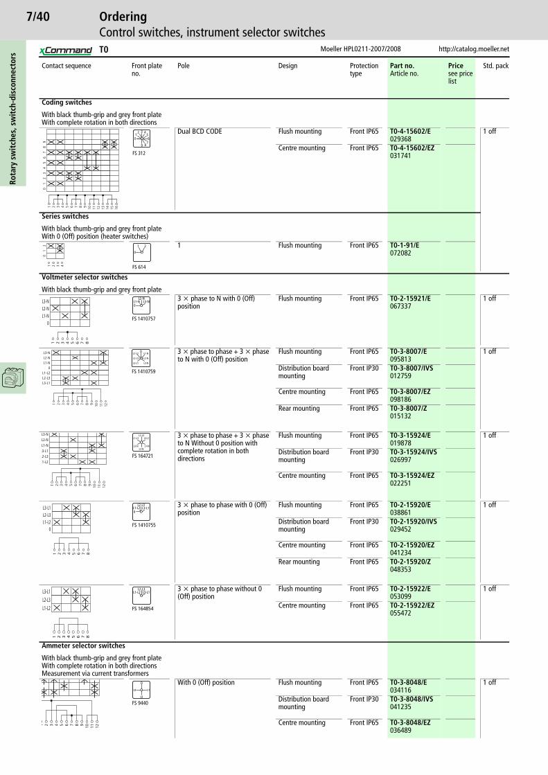
7/40Ro
tary
sw
itch
es, s
wit
ch-d
isco
nnec
tors
Moeller HPL0211-2007/2008 http://catalog.moeller.net
OrderingControl switches, instrument selector switches
Contact sequence Front plate no.
Pole Design Protection type
Part no.Article no.
Pricesee price list
Std. pack
Coding switches
With black thumb-grip and grey front plateWith complete rotation in both directions
Dual BCD CODE Flush mounting Front IP65 T0-4-15602/E029368
1 off
Centre mounting Front IP65 T0-4-15602/EZ031741
Series switches
With black thumb-grip and grey front plateWith 0 (Off) position (heater switches)
1 Flush mounting Front IP65 T0-1-91/E072082
Voltmeter selector switches
With black thumb-grip and grey front plate3 x phase to N with 0 (Off) position
Flush mounting Front IP65 T0-2-15921/E067337
1 off
3 x phase to phase + 3 x phase to N with 0 (Off) position
Flush mounting Front IP65 T0-3-8007/E095813
1 off
Distribution board mounting
Front IP30 T0-3-8007/IVS012759
Centre mounting Front IP65 T0-3-8007/EZ098186
Rear mounting Front IP65 T0-3-8007/Z015132
3 x phase to phase + 3 x phase to N Without 0 position with complete rotation in both directions
Flush mounting Front IP65 T0-3-15924/E019878
1 off
Distribution board mounting
Front IP30 T0-3-15924/IVS026997
Centre mounting Front IP65 T0-3-15924/EZ022251
3 x phase to phase with 0 (Off) position
Flush mounting Front IP65 T0-2-15920/E038861
1 off
Distribution board mounting
Front IP30 T0-2-15920/IVS029452
Centre mounting Front IP65 T0-2-15920/EZ041234
Rear mounting Front IP65 T0-2-15920/Z048353
3 x phase to phase without 0 (Off) position
Flush mounting Front IP65 T0-2-15922/E053099
1 off
Centre mounting Front IP65 T0-2-15922/EZ055472
Ammeter selector switches
With black thumb-grip and grey front plateWith complete rotation in both directionsMeasurement via current transformers
With 0 (Off) position Flush mounting Front IP65 T0-3-8048/E034116
1 off
Distribution board mounting
Front IP30 T0-3-8048/IVS041235
Centre mounting Front IP65 T0-3-8048/EZ036489
1 2 3 4 5 6 7 8 9 10 11 12 13 14
01
23
45
67
89
15 16
42
0
3
9
6
8
1 5
7
FS 312
1 2 3 4
01
2
FS 614
0
21
1 2 3 4 5 6 7 8
0L1-NL2-NL3-N L1-N
L2-NL3-N
FS 1410757
0
1 2 3 4 5 6 7 8 9 10 11 12
L3-L1L2-L3L1-L2
0L1-NL2-NL3-N L1-L2
FS 1410759
0
L2-L3
L3-L1
L1-N
L2-N
L3-N
1 2 3 4 5 6 7 8 9 10 11 12
L1-L2L2-L3L3-L1L1-NL2-NL3-N
L1-L2L2-L3
L3-L1
L1-NL2-N
L3-N
FS 164721
1 2 3 4 5 6 7 8
0L1-L2L2-L3L3-L1 L1-L2
L2-L3L3-L1
0
FS 1410755
1 2 3 4 5 6 7 8
L1-L2L2-L3L3-L1 L1-L2
L2-L3L3-L1
FS 164854
1 2 3 4 5 6 7 8 9 10 11 12
L1
L2
FS 9440
0
L3
T0
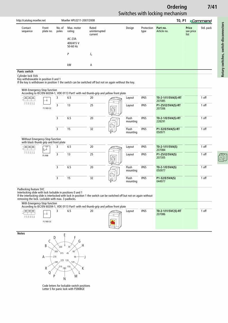
7/41
http://catalog.moeller.net Moeller HPL0211-2007/2008
OrderingSwitches with locking mechanism
Rota
ry s
wit
ches
, sw
itch
-dis
conn
ecto
rs
Contact sequence
Front plate no.
No. of poles
Max. motor rating
Rated uninterrupted current
Design Protection type
Part no.Article no.
Pricesee price list
Std. pack
AC-23A400/415 V50-60 Hz
P Iu
kW A
Panic switchCylinder lock SVAKey withdrawable in position 0 and 1If the key is withdrawn in position 1 the switch can be switched off but not on again without the key.
With Emergency-Stop functionAccording to IEC/EN 60204-1, VDE 0113 Part1 with red thumb-grip and yellow front plate
3 6.5 20 Layout IP65 T0-2-1/I1/SVA(S)-RT207085
1 off
3 13 25 Layout IP65 P1-25/I2/SVA(S)-RT207306
1 off
3 6.5 20 Flush mounting
IP65 T0-2-1/E/SVA(S)-RT228291
1 off
3 15 32 Flush mounting
IP65 P1-32/E/SVA(S)-RT050971
1 off
Without Emergency-Stop functionwith black thumb grip and front plate
3 6.5 20 Layout IP65 T0-2-1/I1/SVA(S)207084
1 off
3 13 25 Layout IP65 P1-25/I2/SVA(S)207305
1 off
3 6.5 20 Flush mounting
IP65 T0-2-1/E/SVA(S)050977
1 off
3 15 32 Flush mounting
IP65 P1-32/E/SVA(S)044977
1 off
Padlocking feature SVCInterlocking slide with lock lockable in positions 0 and 1If the interlocking slide is interlocked with lock in position 1 the switch can be switched off but not on again without removing the lock. Lockable with max. 3 padlocks.
With Emergency-Stop functionAccording to IEC/EN 60204-1, VDE 0113 Part1 with red thumb-grip and yellow front plate
3 6.5 20 Layout IP65 T0-2-1/I1/SVC(S)-RT207086
1 off
Notes
Code letters for lockable switch positionsLetter S for panic lock with FS908GE
1 2 3 4 5 6
01
FS 908 GE
1
0
ON
OFF
1 2 3 4 5 6
01
FS 908
ON
OFF
ON
OFF
1 2 3 4 5 6
01
FS 908 GE
1
0
3300
30
300
240225
210180
150
135120
90
6045
270
F
HG
J
KL
MN
PQ
R
A
BC
DE
315
T0, P1

7/42Ro
tary
sw
itch
es, s
wit
ch-d
isco
nnec
tors
Moeller HPL0211-2007/2008 http://catalog.moeller.net
OrderingSwitches with locking mechanism
Contact sequence
Front plate no.
No. of poles
Max. motor rating
Rated uninterrupted current
Product view
Design Protection type
Part no.Article no.
Pricesee price list
Std. pack
AC-23A400/415 V50-60 Hz
P Iu
kW A
On-Off switchwith black thumb grip and front plateKey can only be withdrawn in position 0 (Pos A)Without Emergency-Stop function
Cylinder lock SVA2 6.5 20 Layout IP65 T0-1-102/I1/S
2070631 off
2 6.5 20 Flush mounting
IP65 T0-1-102/EZ/S014933
1 off
Key operation ST-0, IP533 6.5 20 Layout IP65 T0-2-1/I1/SVA(A)
2070831 off
3 13 25 Layout IP65 P1-25/I2/SVA(A)207304
1 off
3 6.5 20 Flush mounting
IP65 T0-2-1/E/SVA(A)050976
1 off
3 13 25 Flush mounting
IP65 P1-25/E/SVA(A)050965
1 off
3 6.5 20 Rear mounting
IP65 T0-2-1/Z/SVA(A)050978
1 off
Notes
Code letters for lockable switch positionsLetter S for panic lock with FS908GE
1 2 3 4
01
FS 908
ON
OFF
1 2 3 4
01
FS 908
ON
OFF
1 2 3 4 5 6
01
FS 908
ON
OFF
ON
OFF
ON
OFF
3300
30
300
240225
210180
150
135120
90
6045
270
F
HG
J
KL
MN
PQ
R
A
BC
DE
315
T0, P1
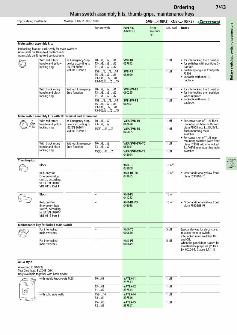
7/43
http://catalog.moeller.net Moeller HPL0211-2007/2008
OrderingMain switch assembly kits, thumb-grips, maintenance keys
Rota
ry s
wit
ches
, sw
itch
-dis
conn
ecto
rs
For use with Part no.Article no.
Pricesee price list
Std. pack Notes
Main switch assembly kits
Padlocking feature, exclusively for main switchesAdmissible on T0 up to 4 contact unitsAdmissible on T3 up to 6 contact units
With red rotary handle and yellow locking ring
as Emergency-Stop device according to IEC/EN 60204-1, VDE 0113 Part 1
T0-.../E, .../Z, .../I1T3-.../E, .../Z, .../I2P1-.../E, .../Z, .../I2
SVB-T0057892
1 off • for interlocking the 0 position• for switches with positions 0 -
I at 90°• Switching angle as front plate
FS908• Lockable with max. 3
padlocks
T5B-.../E, .../Z, .../I4T5-.../E, .../Z, .../I5P3-63/E, .../Z, .../I4P3-100/E, .../Z, .../I5
SVB-P3052999
1 off
With black rotary handle and black locking ring
Without Emergency-Stop function
T0-.../E, .../Z, .../I1T3-.../E, .../Z, .../I2P1-.../E, .../Z, .../I2
SVB-SW-T0060265
1 off • for interlocking the 0 position• for interlocking the I position
when required• Lockable with max. 3
padlocksT5B-.../E, .../Z, .../I4T5-.../E, .../Z, .../I5P3-63/E, .../Z, .../I4P3-100/E, .../Z, .../I5
SVB-SW-P3062491
1 off
Main switch assembly kits with PE terminal and N terminalWith red rotary handle and yellow locking ring
as Emergency-Stop device according to IEC/EN 60204-1, VDE 0113 Part 1
T0-.../E, .../ZT3-.../E, .../Z
V/EA/SVB-T0062638
1 off • For conversion of T.../E flush mounting switches with front plate FS908 into T.../EA/SVB... flush mounting main switches.
• For conversion of T.../Z rear mounting switches (with front plate FS908) into interlocked T.../V/SVB rear mounting main switches
T5(B)-.../E, .../Z V/EA/SVB-T5045065
1 off
With black rotary handle and black locking ring
Without Emergency-Stop function
T0-.../E, .../ZT3-.../E, .../Z
V/EA/SVB-SW-T0065011
1 off
T5(B)-.../E, .../Z V/EA/SVB-SW-T5045064
1 off
Thumb-gripsBlack – KNB-T0
03890910 off
Red, only for Emergency-Stop switch, according to IEC/EN 60204-1, VDE 0113 Part 1
– KNB-RT-T0043655
10 off • Order additional yellow front plate FS908GE-T0
Black – KNB-P3041282
10 off
Red, only for Emergency-Stop switch, according to IEC/EN 60204-1, VDE 0113 Part 1
– KNB-RT-P3046028
10 off • Order additional yellow front plate FS908GE-P3
Maintenance key for locked main switchFor interlocked main switches
– KNK-T0000650
5 off Special devices for electricians, to allow them to switch interlocked main switches On and Off,when the panel door is open for maintenance purposes (to IEC/EN 60204-1, Clause 5.1.1.1)
For interlocked main switches
– KNK-P3000649
5 off
ATEX style
According to 94/9EGTest Certificate BVS04E106XOnly available together with basic device
with metric knock-outs M20 T0-.../I1 +ATEX-I1237513
1 off
T3-.../I2P1-.../I2
+ATEX-I2237514
1 off
with solid side walls T5B-.../I4P3-.../I4
+ATEX-I4237516
1 off
T5-.../I5P3-.../I5
+ATEX-I5237517
1 off
SVB-...-T0(P3), KNB-...-T0(P3)
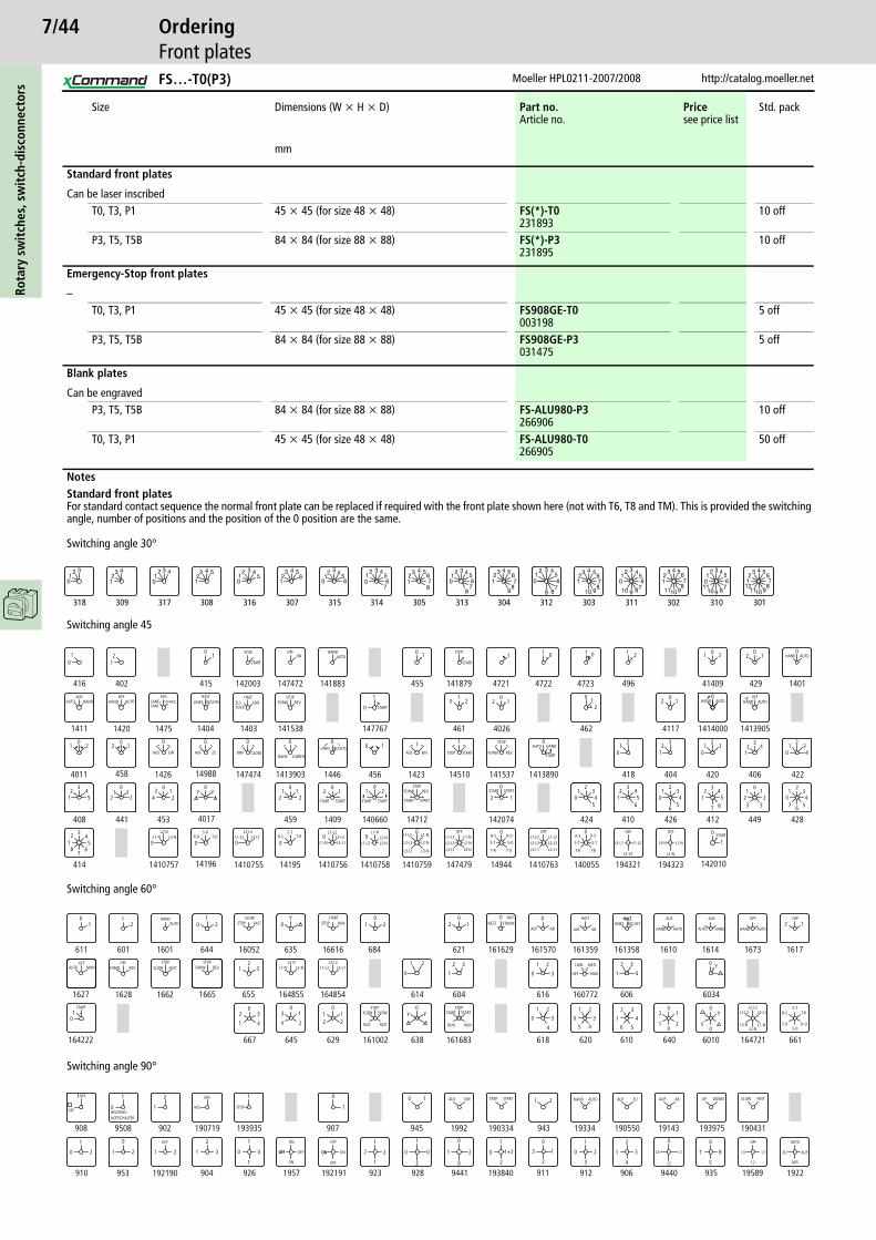
7/44Ro
tary
sw
itch
es, s
wit
ch-d
isco
nnec
tors
Moeller HPL0211-2007/2008 http://catalog.moeller.net
OrderingFront plates
Size Dimensions (W x H x D) Part no.Article no.
Pricesee price list
Std. pack
mm
Standard front plates
Can be laser inscribedT0, T3, P1 45 x 45 (for size 48 x 48) FS(*)-T0
23189310 off
P3, T5, T5B 84 x 84 (for size 88 x 88) FS(*)-P3231895
10 off
Emergency-Stop front plates
–T0, T3, P1 45 x 45 (for size 48 x 48) FS908GE-T0
0031985 off
P3, T5, T5B 84 x 84 (for size 88 x 88) FS908GE-P3031475
5 off
Blank plates
Can be engravedP3, T5, T5B 84 x 84 (for size 88 x 88) FS-ALU980-P3
26690610 off
T0, T3, P1 45 x 45 (for size 48 x 48) FS-ALU980-T0266905
50 off
NotesStandard front platesFor standard contact sequence the normal front plate can be replaced if required with the front plate shown here (not with T6, T8 and TM). This is provided the switching angle, number of positions and the position of the 0 position are the same.
Switching angle 30°
Switching angle 45
Switching angle 60°
Switching angle 90°
318
12 3
0
309
12
3 4
317
12 3 4
0
308
123 4 5
316
12 3 4
50
307
12
3 4 56
315
12 3 4
560
314
12 3 4
56
70
305
12
3 4 5678
313
12 3 4 5
67
8
0
304
12
3 4 567
89
312
42
0
3
9
6
8
1 5
7
303
12
3 4 5678
910
311
12 3 4
56
78910
0
302
12
3 4 567
891011
310
12 3 4
56
78910
110
301
12
3 4 567
891011
12
OFFON
STOP
STARTAUTO
HAND
START
STOPAUTOHAND
HAND AUTO AUTOOFF
AUTOAUS
HAND
416
01
12
402
01
415 142003 147472 141883 455
10
142010
1
0
141879 4721
1
4722
1 0
4723
0
496
1 2
41409
1 20
429
02 1
1401
0
1413905
0
14140004117
20
1
462
21
0
4026
20
1
461
01
2
147767
1
0
14153814031404147514201411
4011
01 2
458
012
1426
0
14988
0
147474
0
1413903
0
1446
0
456
0 1
1423
1
14510
1
141537 1413890
0
418
21
0
404
32
1
420
21
03
406
23
14
422
21
034
408
32 4
51
441
10
12 2
453
23 1
4
0
4017
Y0
Y
459
21
0
21
1409
02 1
140660
01 2
14712 142074
0
2 1
424
21
034
5
410
32 4
516
426
21
034
65
412
32
1
7 65
4
449
0
211
233
428
0
21 3
4567
414
21
345
687
1410757
0
14196
0
1410755
0
14195
0
1410756
0
1410758
0
1410759
0
147479 14944
0
1410763 140055
0
194321 194323
HAND AUTOOFF
LANG-SAM
AUSSCHNELL ZU-
RUCKLINKS RECHTS
HALT HALTVOR.
STOP
STARTFORW. REV. HAND
TRIPEIN CLOSEAUS ZUAUFRAISE LOWER
LINKS RECHTSEINAUS STARTSTOP
STOP
FORW. REV. START
START
AUTO HAND
STARTSTART
START
REV.STOP
START
FORW.
STARTSTARTSTARTSTART
L2-NL3-NL1-N
S-OT-OR-O
L2-L3L3-L1L1-L2
L2-N
L3-N
L1-N
L2-L3
L3-L1
L1-L2S-T
T-RR-S L2-L3L3-L1
L1-L2L2-NL3-NL1-N
L1-N
L1-L2 L2-N
L3-N
L1-NL2-L3
L3-L1
L1-L2OFF OFF
L2-L3
L3-L1
L1-L2
L2-N
L3-N L1-N
OFF OFF
L2-L3
L3-L1
L1-L2
L2-L3
L3-L1 L1-L2S-T
T-R
R-S
S-O
T-O
R-O
S-T
T-R
R-S R-S
S-T
T-R
START
RUN
STOPSTART
RUN
SLOW
FAST
STOPSLOW
FAST
STOPAUTOSLOWHAND
FAST STOPSTART
RUN NETZAUF
HALTNOT-STROM
AB AUF AB
HALTHALTLINKS RECHTS
AUTO
AUS
HAND AUTO
AUS
HAND AUTO
OFF
HAND
OFF
L2-N L2-L3AUTO
OFFMAN REV.
OFFFORW.
STOPSLOW FAST REV.
STOPFORW. L1-N L3-N
01
611
12
601 1601
01
2
644 16052 635
Y0
16616 684
01 2
621
012
161629
0
161570
0
161359 161358 1610 1614 1673 1617
2 1
6034
0 Y
606
2
41
3
160772616
1
0
2
3
604
2
1
3
614
0
21
164854164855655
21 3
1665166216281627
01
164222
2
1
3
4
0
667 645
2
13
4
0
629
10
12 2
161002 638
Y0
Y
161683
1
0
2
3
4
618 620
1
0
2
345
610
2
1
3
4
56
640
2
10
0
2
1
Y0
0Y
6010 164721 661
L1-L2 L3-L1HIGHOFF
MED.LOW
S-TT-R
R-O
R-S
T-OS-O
L2-L3L3-L1L1-L2
L3-N L1-NL2-N
START
HEIZUNG-NOTSCHALTER
AUS
EIN
STOP
ON OFF
EIN START AUTO ZU SLOW
ZU
OFF
AUS STOP HAND AUF ABAUF DOWNUP FAST
AUTO
AUF
AUS
L3
L2
L1
908
0
1
9508
2
1
902 190719
1
193935
0
1
907
0 1
945 1992
1 2
943 19334 190550 19143 193975 190431
192219589
0
T R
S
935
0
9440
2
1 3
4
906
1
0 2
3
912
1+2
1
0
2
1938409441
0
0
1 2
1
2 2
1
923
1
2
0 0
9281921911957
1
0 0
1
926
2
1 3
904
21
192190
0
1 2
953
0 2
1
910
190334
L3
L2
L1
OFF
ONON ONOFFOFF OFF
ON
OFF
ON
OFF
911
13
0
2
FS…-T0(P3)

7/45
http://catalog.moeller.net Moeller HPL0211-2007/2008
OrderingAdd-on front plates
Rota
ry s
wit
ches
, sw
itch
-dis
conn
ecto
rs
Explanation Language For use with Part no.Article no.
Pricesee price list
Std. pack
Add-on front plates, clip-on
for padlocking feature consists of label mount and insert label• Inscribed with standard text "main switch only open in 0 position" in various languages• Blank, can be engraved
Blank, can be engraved None Rotary switches T0, T3, P1 ZFS60-T0019924
25 off
Blank, can be engraved None Switch-disconnectors T5(B), P3 ZFS60-P3022297
Engraved with standard text German/English Rotary switches T0, T3, P1 ZFS61/62-T0030170
Engraved with standard text Spanish Switch-disconnectors T5(B), P3 ZFS77-P3047422
Engraved with standard text French Switch-disconnectors T5(B), P3 ZFS63-P3047423
Engraved with standard text French Rotary switches T0, T3, P1 ZFS63-T0047424
Engraved with standard text German/English Switch-disconnectors T5(B), P3 ZFS61/62-P3065739
Engraved with standard text Italian Rotary switches T0, T3, P1 ZFS68-T0065751
Engraved with standard text Spanish Rotary switches T0, T3, P1 ZFS77-T0065752
Engraved with standard text Hungarian Switch-disconnectors T5(B), P3 ZFS80-P3205565
Engraved with standard text Portuguese Rotary switches T0, T3, P1 ZFS72-T0205541
Engraved with standard text Swedish Rotary switches T0, T3, P1 ZFS75-T0205544
Engraved with standard text Hungarian Rotary switches T0, T3, P1 ZFS80-T0205548
Enter country reference when ordering:D = GermanGB = EnglishF = FrenchI = ItalianE = Spanish
Switch-disconnector P5-.../EA/SVBSwitch-disconnector P5-.../V/SVB
ZFS(*)-P5105225
1 off
Label mounts, black, plug-in type
Rotary switches T0, T3, P1 ZFSX-T0024670
25 off
Switch-disconnectors T5(B), P3 ZFSX-P3027043
25 off
Insert plates
Rotary switches T0, T3, P1 BS45X14-T0029416
25 off
Switch-disconnectors T5(B), P3 BS84X24-P3031789
25 off
ZFS…

Moeller HPL0211-2007/2008
7/46
Moeller HPL0211-2007/2008http://catalog.moeller.net http://catalog.moeller.net
Rota
ry s
wit
ches
, sw
itch
-dis
conn
ecto
rs
Rota
ry s
wit
ches
, sw
itch
-dis
conn
ecto
rs
Ordering OrderingKey operation, locking interlock Key operation, locking interlock
For use with Key withdrawal/locking option
Part no.Article no.
Pricesee price list
Std. pack Notes
S-T0 key operated lock mechanism, Front IP53
Includes two keysKMS 1 lock mechanism Individual lock mechanism, not suitable for master key systems
T0-.../E, .../I1, .../Z up to max. 6 contact unitsT3-.../E, .../Z up to max. 5 contact unitsT3-.../I2 up to max. 4 contact unitsP1-.../E, .../I2, .../Z
Key withdrawal positions can be programmed by the user
S-T0086709
1 off The key replaces the thumb-grip, cannot be switched without key. The switch position indication in on the lock. Normally the key is withdrawable in every position.With the ordering of a rotary switch with front plate FS908 together with key operation the key is only withdrawable in the 0 position.The key removability can be changed (also retro) with the locking cam "VR-T0".With retrofitting of key operation the existing front plate of the rotary switch must be used.Key a page 7/50
KMS 2-10 lock mechanisms, KMS 201-400 lock mechanisms: Individual lock mechanisms, not suitable for master key systems
S-SOND-KMS(*)-T0231957
1 off
1 off
0 1 off
1 off
-T3 1 off
1 off
)-T3 1 off
1 off
1 off
Switched with thumb-grip.Locked by turning the key. The key is removable. Normally all positions can be locked.Individual positions or ranges are lockable (also retro with VR-T3). In positions that are not lockable the key cannot be removed. With lockable ranges only inside the range can be switched without the key.The positions or ranges to be locked must be entered as follows in the form.Example 1: SVA(A)-T3 = only position A withdrawableExample 2: SVA(A, E)-T3 = only position A and E withdrawableExample 3: SVA(A-J)-T3 = range A to J withdrawableExample 4 SVA(S)-T3 = main switch for use as Emergency-Stop according to IEC/EN 60204-1, VDE 0113 Part 1, with red thumb-grip and yellow front plate "Panic lock version" lockable in positions A and E, from E it can still be switched to A but not from A to E.
The front plate of the switch is to be used for retroffitting. With the letter S use for panic lock FS908GE.Ordering example: P1-25/I2-RT+SVA(S)-T3
Ordering example for a master key system:SVA(A-G)-SOND-SA(A6294-1/2)-T3Key a page 7/50
3300
30
300
240225
210180
150
135120
90
6045
270
F
HG
J
KL
MN
PQ
R
A
BC
DE
315
Switched with thumb-grip. Interlocked by pushing a button that is lockable with 1-3 padlocks. Normally all positions can be lokked. By entering SCV(...)-T3 only the entered position is lockable. Locked ranges can only be switched within the range without removing the padlocks.The positions or ranges to be locked must be entered in the form.Form a Notes to SVA(...)-T3The front plate of the switch is to be used for retroffitting. With the letter S use for panic lock FS908GE.
Ordering example:P1-25/I2-RT+SVC(S)-T3
3300
30
300
240225
210180
150
135120
90
6045
270
F
HG
J
KL
MN
PQ
R
A
BC
DE
315
7/47
S…, SVA…, SVC… S…, SVA…, SVC…
Lock KMS1: Switch with FS908 are possible as main switch for T0-1-... to T0-4-.../I1, .../E; T3-1-... to T3-4-.../I2; T3-1-... to T3-6-.../E; P1-.../I2, .../E
T0-.../E, .../I1, .../Z up to max. 6 contact unitsT3-.../E, .../Z up to max. 5 contact unitsT3-.../I2 up to max. 4 contact unitsP1-.../E, .../I2, .../Z
Key withdrawal positions are programmed ex-works as ordered
S(*)-T0231959
SA(...) = Master key system (with master key) supplied with a security certificate. Order must include a lock plan showing the full configuration of the envisaged lock system. For subsequent part orders, simply state the item number within the lock plan, e.g. (A6294-1/2).
S(*)-SOND-SA(*)-T231965
SVA-T3 cylinder lock, Front IP65
Includes two keysKMS 1 lock mechanism Individual lock mechanism, not suitable for master key systems
T0-.../E, .../I1, .../ZT3-.../E, .../I2, .../ZP1-.../E, .../I2, .../Z
Key withdrawal positions can be programmed by the user
SVA-T3050974
KMS 2-10 lock mechanisms, KMS 201-400 lock mechanisms: Individual lock mechanisms, not suitable for master key systems
SVA-SOND-KMS(*)231967
KMS1 lock mechanism: Switches with FS908 are suitable as main switches: T0-1-... to T0-4-.../I1, .../E; T3-1-... to T3-5-.../I2; T3-1-... to T3-6-.../E; P1-.../I2, .../E
T0-.../E, .../I1, .../ZT3-.../E, .../I2, .../ZP1-.../E, .../I2, .../Z
Lockable positions can be programmed by the user
SVA(*)-T3907745
SA(...) = Master key system (with master key) supplied with a security certificate. Order must include a lock plan showing the full configuration of the envisaged lock system. For subsequent part orders, simply state the item number within the lock plan, e.g. (A6294-1/2).
SVA(*)-SOND-SA(*231971
SVC-T3 padlocking feature, Front IP65
In the depressed position, the locking slide is lockable with up to 3 padlocksAll positions are lockable T0-.../E, .../I1, .../Z
T3-.../E, .../I2, .../Z P1-.../E, .../I2, .../Z
Lockable positions can be programmed by the user
SVC-T3050975
Specified positions or ranges are lockable T0-1-... to T0-4-.../I1, .../E T3-1-... to T3-5-.../I2 T3-1-... to T3-6-.../E P1-.../I2, .../EP1-.../I2, .../E
Lockable positions are programmed ex- works as ordered
SVC(*)-T3907748

7/48Ro
tary
sw
itch
es, s
wit
ch-d
isco
nnec
tors
Moeller HPL0211-2007/2008 http://catalog.moeller.net
OrderingNeutral poles, auxiliary switches, central mounting accessories
For use with Part no.Article no.
Pricesee price list
Std. pack
Neutral poles
Early-make, late-breakFor side mounting, left or right P1-.../E, .../EA, .../EZ N-P1E
0006515 off
With P1-.../I2: optional N-P1Z or HI11-P1/P3Z can only be fitted to left
P1-.../Z, .../V, .../I2, .../IVS N-P1Z000652
P3-.../E, .../EA... N-P3E062432
P3-.../Z, .../V, .../IVSP3-63/E,.../Z, /I4P3-100/E, .../Z, .../I5
N-P3Z064805
Neutral terminalFor side mounting P5-250(315)/Z(V) N-P5-250/315Z
280972 1 off
Protective conductor terminalFor side mounting P5-125(160)/E(EA) PE-P5-125/160E
2809731 off
P5-250(315)/Z(V) PE-P5-250/315Z280976
Auxiliary contacts
Late making N/O and early breaking N/C contacts. The N/O is always connected as a load-shedding contact.
For side mounting, left and/or right P1-.../E, .../EA..., .../EZP3-.../E, .../EA
HI11-P1/P3E061813
5 off
With P1-.../I2: HI11-P1/P3Z or N-P1Z can be fitted to left only
P1-.../Z, .../V, .../I2, .../IVSP3-63/Z, .../V, .../I4, .../IVSP3-100/Z, .../V, .../I5, .../IVS
HI11-P1/P3Z062031
Centre mounting accessories
For single-hole fittingMounting diameter 22.3 mm
For rotary switches with existing front plate T0-.../ET3-.../E
EZ-T0081622
1 off
Mounting diameter 22.3 mm and 30.5 mm T0-.../ET3-.../EP1-.../E
EZ-P1091455
1 off
Service distribution board mounting accessories
Includes push-fit shaftFor retrofitting T0-.../XZ basic switches as T0-.../IVS into service distribution boards
T0-.../XZ IVS-T0091114
1 off
N-P1, N-P3, N-P5

7/49
http://catalog.moeller.net Moeller HPL0211-2007/2008
OrderingCoupling drive, interlock parts, shaft extension
Rota
ry s
wit
ches
, sw
itch
-dis
conn
ecto
rs
For use with Type suffix/TypeArticle no., When ordered with basic unit/ ordered separately
Pricesee price list
Std. pack Notes
Coupling drive
Includes push-fit shaftFor retrofitting T0(T3)-.../XZ basic switches in the rear mounting form Spare parts for T0(T3)/(P1)-.../Z
DE-T0093487
1 off
For conversion of T5 (B)-.../E flush mounting switch into a rear mounting switch Spare parts for T5(B)/(P3)-.../Z
DE-P3093972
3 off
Interlock sections
With PE and N conductor connectionFits on the reverse of flush mounting switches, with interlocking function for rear mounting switches.
T0-.../E, ...EZ, ...ZT3-.../E, ...EZ, ...ZP1-.../E, ...EZ, ...Z
UV-T0019925
1 off Fits on the reverse of flush mounting switches
T5(B)-.../E, ...ZP3-.../E, ...Z
UV-P3048289
With interlocking function for rear mounting switches
Interlock extensions
Up to four off, 25 mm each, can be plugged onto interlock section(An equal number of shaft extensions is required for this purpose)
Use ZVV-T0 only with T0/T3-.../Z and P1-.../Z
UV-T0 ZVV-T0022298
10 off Use ZVV-T0 only with construction type T0/T3-.../Z and P1-.../Z
Use ZVV-P3 only with T5(B)-.../Z and P3-.../Z
UV-P3 ZVV-P3024671
Use ZVV-P3 only with construction type T5(B)-.../Z and P3-.../Z
Shaft extensions
Up to four off, 25 mm each, can be plugged onto switch shaftT0-.../Z, T0-.../VT3-.../Z, T3-.../VP1-.../Z, P1-.../V
ZAV-T0027044
10 off
T5(B)-.../Z P3-.../Z
ZAV-P3029417
ShaftAluminium, length: 480 mm P5-.../V...
P5-.../ZZAV-P5280979
1 off
Interlock extensions und shaft extensions, complete
Only available in conjunction with a basic unitExtension up to 25 mm when ordered
with basic unit+ZAV(X1)+ZVV(X1)-T0/P3254546
1 off
Control circuit terminalP5-250/315 ST-P5-250/315
2809781 off Terminal capacity
• solid or stranded: 4 mm2
• Flexible with ferrules to DIN 46228: 4 mm2
DE-T0(P3), ZAV-T0(P3)

7/50Ro
tary
sw
itch
es, s
wit
ch-d
isco
nnec
tors
Moeller HPL0211-2007/2008 http://catalog.moeller.net
OrderingShrouds, Keys
For use with Part no.Article no.
Pricesee price list
Std. pack Notes
ShroudsFor flush-mounting switches with up to 4 contact units
T0-.../E T3-.../E
H3-T0093828
1 off Cable entriesQuantity:2 x o 20 mm+ 2 x o 15 mmCross-section:5 x 6 mm2
5 x 2.5 mm2
Cover for protection of terminals For up to 2 contact units
T5(B)-.../E, .../Z H1-T5045062
Can be used for input and/or output wiring
Extension of H1-T5 cover To protect 3 to 8 contact units
H1-T5 HZ-T5045063
10 off 1 x HZ-T5 required per contact unit
To cover terminals on 3-pole switch-disconnectors
P1-.../E, .../EZ, .../Z, .../EA, .../V
H-P1017253
5 off Can be used for input and/or output wiring
To cover terminals on 4-pole switch-disconnectors
P1-...N, ...HI11, ...N...HI11
H-P14019626
Can be used for input and/or output wiring
To cover terminals on 3-pole open switch-disconnectors with N neutral conductor and/or HI11 auxiliary contact modules fitted
P3-.../E, .../Z, .../EA, .../V P3-...N, ...HI11, ...N...HI11
H-P3021999
The shroud is designed for fitting onto both sides of the switch-disconnector. Parts which are not required can be broken off.
Set of three, to protect the terminals
P5 H-P5-125/160-3P280967
3 off
Cover assembly to protect the 6 terminals
T8-3-8342/... H-T8200184
KeysFor KMS 1 individual lock mechanism
ES-KMS1-T0231972
10 off
For KMS 2 - 10 individual lock mechanism or KMS 201 - 400
ES-KMS(*)-T0231973
Individual key, corrosion-proof, for master key systems and recorded individual lock mechanisms: state lock plan no. and lock
HS-SA(*)-T0256151
Master keys must always be ordered separately.Please send or submit the security certificate with repeat orders.Ordering example:HS-SA(A6294-1/2)-T0
Locking cams (2 cams per set)
For user to select indexing position in which key can be withdrawn
S-T0 for all switching angles
VR-T0089082
1 off
Mounting plate screenTo connect the screeniing CI-K2 MBS-I2
2901912 off
H…

7/51
http://catalog.moeller.net Moeller HPL0211-2007/2008
OrderingInsulated enclosures, accessories
Rota
ry s
wit
ches
, sw
itch
-dis
conn
ecto
rs
For use with Part no.Article no.
Pricesee price list
Std. pack Notes
IP65 insulated enclosures
Enclosures designed for metric cable glands to EN 502621 – 2 contact units With push-
through cable entry diaphragm.
T0-.../XZ CI-K1-T0-2207435
1 off Cable sizes which may be pushed through the diaphragmMain-/control current12 mm/– 16 mm/8 mm1 contact unit = 2 contacts
3 - 4 contact units T0-.../XZ CI-K1-T0-4207436
1 off
1 – 2 contact units T3-.../XZ CI-K2-T3-2207437
1 off
5 contact units T3-.../Z CI-K2-T3-5207438
1 off
3 - 4 contact units T3-.../XZ CI-K2-T3-4225325
1 off
1 – 2 contact units With metric knock-outs
T0-.../XZ CI-K1H-T0-2105854
1 off
3 - 4 contact units T0-.../XZ CI-K1H-T0-4105855
1 off
1 – 2 contact units T3-.../XZ CI-K2H-T3-2269462
1 off
3 - 4 contact units T3-.../XZ CI-K2H-T3-4105859
1 off
5 contact units T3-.../XZ CI-K2H-T3-5105860
1 off
1 – 2 contact units T5B-.../E CI-K4-T5B-2207439
1 off Converts T5-.../Z into T5-.../I5 and T5B-.../E into T5B.../I4:Order AW-T5-... extension terminals in addition1 contact unit = 2 contacts
3 - 4 contact units T5B-.../Z CI-K4-T5B-4207440
1 off
1 – 2 contact units T5-.../Z CI-K5-T5-2207441
1 off
3 - 4 contact units T5-.../Z CI-K5-T5-4207442
1 off
only available together with basic device
T0-.../I1 +I1H105870
1 off
only available together with basic device
T3-.../I2P1-.../I2
+I2H105871
1 off
Neutral terminals
For connection of 5th conductorCI-K2-PKZ0-... K-CI-K1/2
20745120 off
T5B-.../I4,Cl-K4-T5B-...P3-.../I4CI-K4
K-CI-K4206916
20 off
T5-…/I5,CI-K5-T5-…P3-…/I5CI-K, 100 A
K50/1098573
10 off
T5-.../I5,CI-K5-T5-...P3-.../I5CI-K5
K-CI-K5218488
20 off
Set of external fixing bracketsT5B-.../I4,T5-.../I5,P3-63/I4,P3-100/I5,
AB-CI-K4/5206914
1 off For fixing CI-K4 and CI-K5 directly to the wall.One set comprises 4 brackets.
Set of extension terminals
For retrofittingFor cable connection in the enclosure
For the lowest contact unit T5B-.../I4 T5-.../I5
AW-T5-1/2032601
10 off Included with T5B-.../I4 and T5-.../I5 as standard.
For the second contact unit from the bottom
T5-.../I5 AW-T5-3/4032602
1 off Included with T5B-.../I4 and T5-.../I5 as standard.
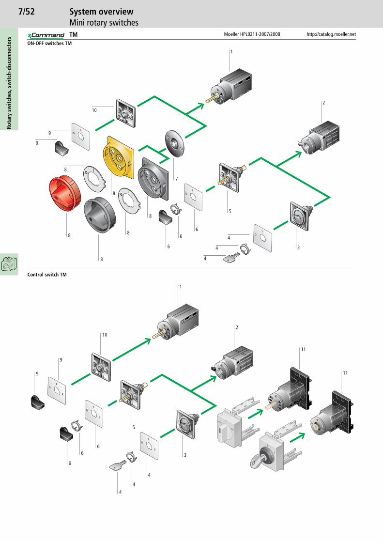
7/52Ro
tary
sw
itch
es, s
wit
ch-d
isco
nnec
tors
Moeller HPL0211-2007/2008 http://catalog.moeller.net
System overviewMini rotary switches
ON-OFF switches TM
1
2
5
3
4
4
4
66
6
7
8
8
8
8
9
8
9
10
8
Control switch TM
AUTO
HANDO
1
0
2
11
3
4
4
4
5
66
6
9
9
10
1
11
TM
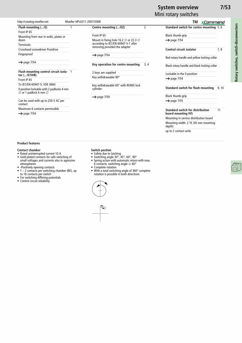
7/53
http://catalog.moeller.net Moeller HPL0211-2007/2008
System overviewMini rotary switches
Rota
ry s
wit
ches
, sw
itch
-dis
conn
ecto
rs
Flush mounting (.../E) 1Front IP 65Mounting from rear in walls, plates or doorsTerminals:Crosshead screwdriver PozidriveFingerproof
a page 7/54
Flush mounting control circuit isola-tor (.../E/SVB)
1
Front IP 65To IEC/EN 60947-5, VDE 06600 position lockable with 2 padlocks 4 mm o or 1 padlock 6 mm o
Can be used with up to 250 V AC per contactMaximum 6 contacts permissiblea page 7/54
Centre mounting (.../EZ) 2
Front IP 65Mount in fixing hole 16.2 o or 22.3 o according to IEC/EN 60947-5-1 after removing provided the adapter
a page 7/54
Key operation for centre mounting 3, 4
2 keys are suppliedKey withdrawable 90°
Key withdrawable 60° with RONIS lock cylinder.
a page 7/59
Standard switch for centre mounting 5, 6
Black thumb-gripa page 7/54
Control circuit isolator 7, 8
Red rotary handle and yellow locking collar
Black rotary handle and black locking collar
Lockable in the 0 positiona page 7/54
Standard switch for flush mounting 9, 10
Black thumb-gripa page 7/55
Standard switch for distribution board mounting IVS
11
Mounting in service distribution boardMounting width: 2 TE (45 mm mounting depth)up to 2 contact units
Product features
Contact chamber• Rated uninterrupted current 10 A• Gold plated contacts for safe switching of
small voltages and currents also in agressive atmospheres
• -Positively opening contacts• 1 – 2 contacts per switching chamber (BE), up
to 16 contacts per switch• For switching differing potentials• Control circuit reliability
Switch postion• Safety due to latching• Switching angle 30°, 45°, 60°, 90°• Spring action with automatic return with max.
6 contacts, switching angle f 60°• Complete rotation• With a total switching angle of 360° complete
rotation is possible in both directions
TM

7/54M
ini r
otar
y sw
itch
es
Moeller HPL0211-2007/2008 http://catalog.moeller.net
OrderingControl circuit isolators, On-Off switches
Contact sequence Front plate no.
No. of poles
Design Protection type
Part no.Article no.
Pricesee price list
Std. pack
Control circuit isolators, 90°
With padlocking facility, lockable in the Off positionUp to 250 V AC per contact
1 Flush mounting Front IP65 TM-1-8290/E/SVB-SW215351
1 off
Flush mounting Front IP65 TM-1-8290/E/SVB045477
2 Flush mounting Front IP65 TM-1-8291/E/SVB-SW215352
Flush mounting Front IP65 TM-1-8291/E/SVB045478
3 Flush mounting Front IP65 TM-2-8292/E/SVB045484
Flush mounting Front IP65 TM-2-8292/E/SVB-SW210955
3 + N Flush mounting Front IP65 TM-2-8293/E/SVB045485
6 Flush mounting Front IP65 TM-3-8326/E/SVB045498
On-Off switches, 90°1 Centre
mountingFront IP65 TM-1-8290/EZ
0006931 off
Flush mounting Front IP65 TM-1-8290/E070131
2 Centre mounting
Front IP65 TM-1-8291/EZ015073
Flush mounting Front IP65 TM-1-8291/E072504
3 Flush mounting Front IP65 TM-2-8292/E074877
Centre mounting
Front IP65 TM-2-8292/EZ015096
3 + N Flush mounting Front IP65 TM-2-8293/E077250
Centre mounting
Front IP65 TM-2-8293/EZ045486
6 Flush mounting Front IP65 TM-3-8326/E079623
1 2
01
1 2 3 4
01
1 2 3 4 5 6
01
1 2 3 4 5 6 7 8
01
1 2 3 4 5 6 7 8 9 10
01
11 12
1 2
01 1
0
F 056
1 2 3 4
01
1 2 3 4 5 6
01
1 2 3 4 5 6 7 8
01
1 2 3 4 5 6 7 8 9 10
01
11 12
TM
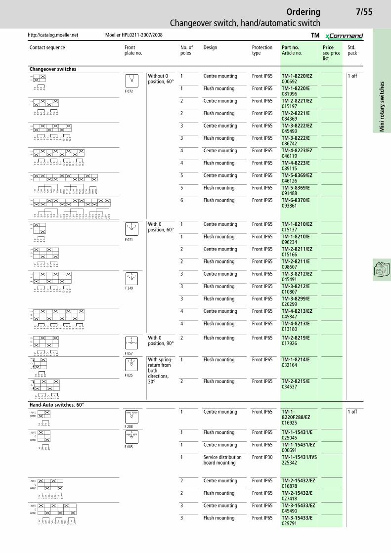
7/55
http://catalog.moeller.net Moeller HPL0211-2007/2008
OrderingChangeover switch, hand/automatic switch
Min
i rot
ary
swit
ches
Contact sequence Front plate no.
No. of poles
Design Protection type
Part no.Article no.
Pricesee price list
Std. pack
Changeover switchesWithout 0 position, 60°
1 Centre mounting Front IP65 TM-1-8220/EZ000692
1 off
1 Flush mounting Front IP65 TM-1-8220/E081996
2 Centre mounting Front IP65 TM-2-8221/EZ015197
2 Flush mounting Front IP65 TM-2-8221/E084369
3 Centre mounting Front IP65 TM-3-8222/EZ045493
3 Flush mounting Front IP65 TM-3-8222/E086742
4 Centre mounting Front IP65 TM-4-8223/EZ046119
4 Flush mounting Front IP65 TM-4-8223/E089115
5 Centre mounting Front IP65 TM-5-8369/EZ046126
5 Flush mounting Front IP65 TM-5-8369/E091488
6 Flush mounting Front IP65 TM-6-8370/E093861
With 0 position, 60°
1 Centre mounting Front IP65 TM-1-8210/EZ015137
1 Flush mounting Front IP65 TM-1-8210/E096234
2 Centre mounting Front IP65 TM-2-8211/EZ015166
2 Flush mounting Front IP65 TM-2-8211/E098607
3 Centre mounting Front IP65 TM-3-8212/EZ045491
3 Flush mounting Front IP65 TM-3-8212/E010807
3 Flush mounting Front IP65 TM-3-8299/E020299
4 Centre mounting Front IP65 TM-4-8213/EZ045847
4 Flush mounting Front IP65 TM-4-8213/E013180
With 0 position, 90°
2 Flush mounting Front IP65 TM-2-8219/E017926
With spring-return from both directions, 30°
1 Flush mounting Front IP65 TM-1-8214/E032164
2 Flush mounting Front IP65 TM-2-8215/E034537
Hand-Auto switches, 60°1 Centre mounting Front IP65 TM-1-
8220F288/EZ016925
1 off
1 Flush mounting Front IP65 TM-1-15431/E025045
1 Centre mounting Front IP65 TM-1-15431/EZ000691
1 Service distribution board mounting
Front IP30 TM-1-15431/IVS225342
2 Centre mounting Front IP65 TM-2-15432/EZ016878
2 Flush mounting Front IP65 TM-2-15432/E027418
3 Centre mounting Front IP65 TM-3-15433/EZ045490
3 Flush mounting Front IP65 TM-3-15433/E029791
1 2 3 4
12
F 072
1 2
1 2 3 4 5 6 7 8
12
1 2 3 4 5 6 7 8 9 10 11 12
12
1 2 3 4 5 6 7 8 9 10 11 12 13 14
12
15 16
1 2 3 4 5 6 7 8 9 10 11 12 13 14
12
15 16 17 18 19 20
1 2 3 4 5 6 7 8 9 10 11 12 13 14
12
15 16 17 18 19 20 21 22 23 24
1 2 3 4
10
2
F 071
1 20
1 2 3 4 5 6 7 8
10
21 2 3 4 5 6 7 8 9 10 11 12
10
2
F 249
102
1 2 3 4 5 6 7 8 9 10 11 12 13 14
10
2
15 16
1 2 3 4 5 6 7 8
10
2
F 057
0
1 2
1 2 3 4
10
2
F 025
01 2
1 2 3 4 5 6 7 8
10
2
1 2 3 4
HANDAUTO
F 288
HAND AUTOM
1 2 3 4
HAND0
AUTO
F 085
0HAND AUTO
1 2 3 4 5 6 7 8
HAND0
AUTO
1 2 3 4 5 6 7 8 9 10 11 12
HAND0
AUTO
TM

7/56M
ini r
otar
y sw
itch
es
Moeller HPL0211-2007/2008 http://catalog.moeller.net
OrderingControl switch, step switch
Contact sequence Front plate no.
No. of poles
Design Protection type
Part no.Article no.
Pricesee price list
Std. pack
Step switches
Without 0 (Off) position3 steps, 60°
1 Flush mounting Front IP65 TM-2-8230/E039283
1 off
1 Centre mounting Front IP65 TM-2-8230/EZ000701
3 Flush mounting Front IP65 TM-5-8270/E041656
3 Centre mounting Front IP65 TM-5-8270/EZ046124
4 steps, 60°1 Flush mounting Front IP65 TM-2-8231/E
044029
1 Centre mounting Front IP65 TM-2-8231/EZ000700
3 Flush mounting Front IP65 TM-6-8271/E046402
3 Centre mounting Front IP65 TM-6-8271/EZ046128
5 steps, 60°1 Flush mounting Front IP65 TM-3-8232/E
039298
1 Centre mounting Front IP65 TM-3-8232/EZ015592
2 Flush mounting Front IP65 TM-5-8252/E041671
2 Centre mounting Front IP65 TM-5-8252/EZ046123
6 steps 60°, no full rotation1 Flush mounting Front IP65 TM-3-8233/E
053521
1 Centre mounting Front IP65 TM-3-8233/EZ015630
2 Flush mounting Front IP65 TM-6-8253/E055894
2 Centre mounting Front IP65 TM-6-8253/EZ046127
10 steps, 30°1 Flush mounting Front IP65 TM-5-8237/E
069150
1 Centre mounting Front IP65 TM-5-8237/EZ015661
1 2 3 4 5 6
12
3
F 076
2
1
3
1 2 3 4 5 6 7 8 9 10 11 12 13 14
12
3
15 16 17 18
1 2 3 4 5 6 7 8
12
34
F 077
2
1
3
4
1 2 3 4 5 6 7 8 9 10 11 12 13 14
12
3
15 16 17 18 19 20 21 22 23 24
41 2 3 4 5 6 7 8 9- 10
12
34
5
F 078
2
1
3
4
5
2 3 4 5 6 7 8 91
01
11
21
31
41
51
61
71
81
92
0
1 2 3 4 5 6 7 8 9 10 11 12
12
34
56
21
34
56
F 079
2 3 4 5 6 7 8 9 10 11 12 13 14 15 16 17 18 19 20 21 22 23 24
2 3 4 5 6 7 8 9 10 11 12 13 14 15 16 17 18 19 20
F 011
12
3 4 567
8910
TM
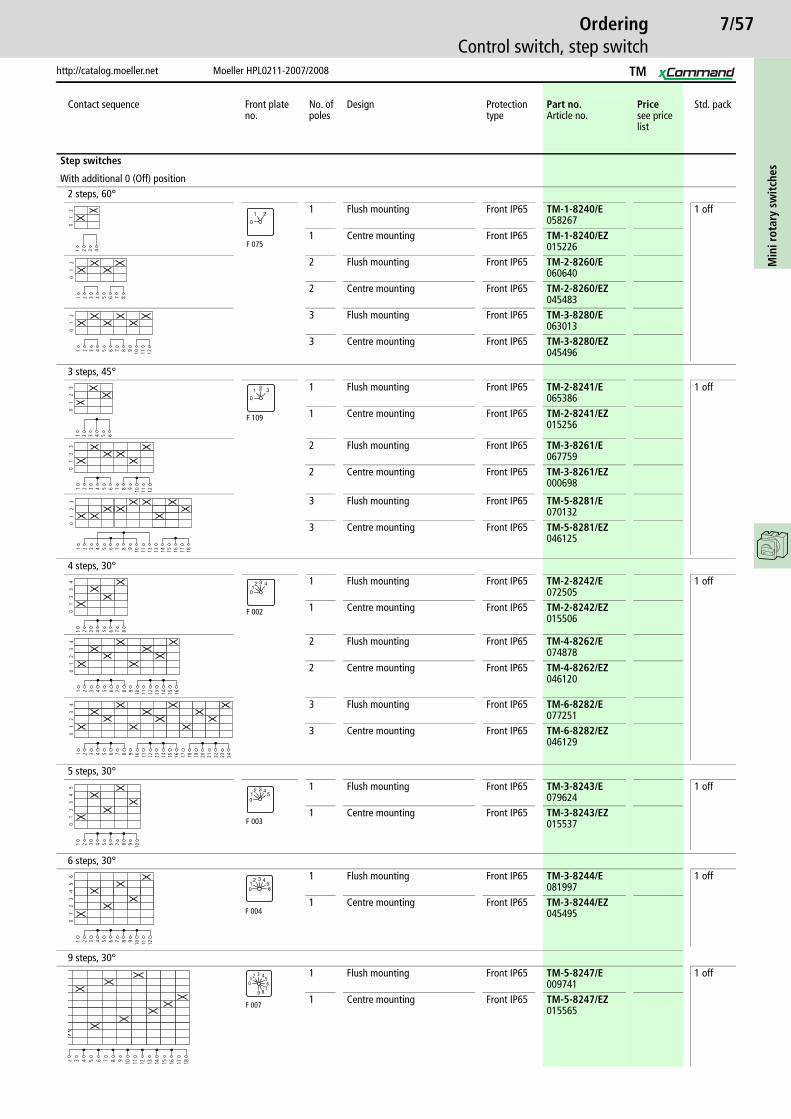
7/57
http://catalog.moeller.net Moeller HPL0211-2007/2008
OrderingControl switch, step switch
Min
i rot
ary
swit
ches
Contact sequence Front plate no.
No. of poles
Design Protection type
Part no.Article no.
Pricesee price list
Std. pack
Step switches
With additional 0 (Off) position2 steps, 60°
1 Flush mounting Front IP65 TM-1-8240/E058267
1 off
1 Centre mounting Front IP65 TM-1-8240/EZ015226
2 Flush mounting Front IP65 TM-2-8260/E060640
2 Centre mounting Front IP65 TM-2-8260/EZ045483
3 Flush mounting Front IP65 TM-3-8280/E063013
3 Centre mounting Front IP65 TM-3-8280/EZ045496
3 steps, 45°1 Flush mounting Front IP65 TM-2-8241/E
065386 1 off
1 Centre mounting Front IP65 TM-2-8241/EZ015256
2 Flush mounting Front IP65 TM-3-8261/E067759
2 Centre mounting Front IP65 TM-3-8261/EZ000698
3 Flush mounting Front IP65 TM-5-8281/E070132
3 Centre mounting Front IP65 TM-5-8281/EZ046125
4 steps, 30°1 Flush mounting Front IP65 TM-2-8242/E
072505 1 off
1 Centre mounting Front IP65 TM-2-8242/EZ015506
2 Flush mounting Front IP65 TM-4-8262/E074878
2 Centre mounting Front IP65 TM-4-8262/EZ046120
3 Flush mounting Front IP65 TM-6-8282/E077251
3 Centre mounting Front IP65 TM-6-8282/EZ046129
5 steps, 30°1 Flush mounting Front IP65 TM-3-8243/E
079624 1 off
1 Centre mounting Front IP65 TM-3-8243/EZ015537
6 steps, 30°1 Flush mounting Front IP65 TM-3-8244/E
081997 1 off
1 Centre mounting Front IP65 TM-3-8244/EZ045495
9 steps, 30°1 Flush mounting Front IP65 TM-5-8247/E
009741 1 off
1 Centre mounting Front IP65 TM-5-8247/EZ015565
1 2 3 4
01
2
F 075
1
0
2
1 2 3 4 5 6 7 8
01
21 2 3 4 5 6 7 8 9 10 11 12
01
21 2 3 4 5 6
01
23
F 109
0
1 2 3
1 2 3 4 5 6 7 8 9 10 11 12
01
23
1 2 3 4 5 6 7 8 9 10 11 12 13 14
01
2
15 16 17 18
31 2 3 4 5 6 7 8
01
23
4
F 002
01
2 3 4
1 2 3 4 5 6 7 8 9 10 11 12 13 14
01
23
4
15 16
1 2 3 4 5 6 7 8 9 10 11 12 13 14
01
23
4
15 16 17 18 19 20 21 22 23 24
1 2 3 4 5 6 7 8 9 10
01
23
45
F 003
12 3 4
50
1 2 3 4 5 6 7 8 9 10 11 12
01
23
45
6
F 004
12 3 4
560
2 3 4 5 6 7 8 9 10 11 12 13 14 15 16 17 18
F 007
01
2 3 456
789
TM
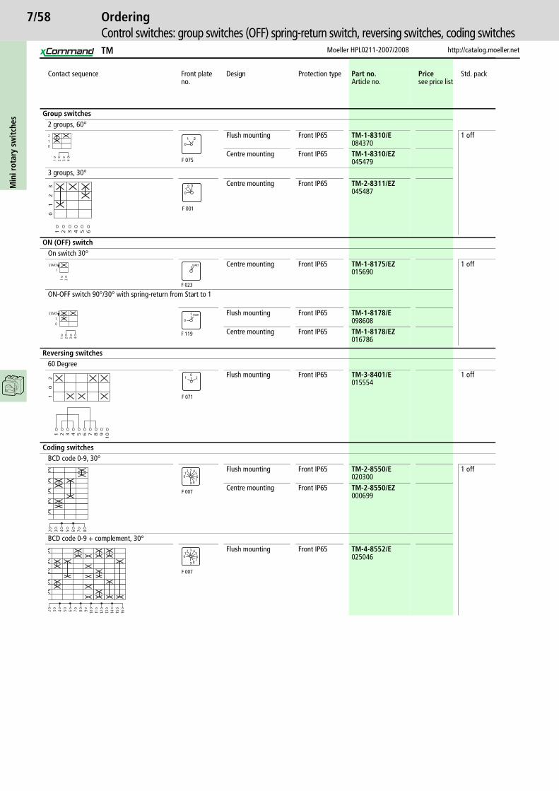
7/58M
ini r
otar
y sw
itch
es
Moeller HPL0211-2007/2008 http://catalog.moeller.net
OrderingControl switches: group switches (OFF) spring-return switch, reversing switches, coding switches
Contact sequence Front plate no.
Design Protection type Part no.Article no.
Pricesee price list
Std. pack
Group switches2 groups, 60°
Flush mounting Front IP65 TM-1-8310/E084370
1 off
Centre mounting Front IP65 TM-1-8310/EZ045479
3 groups, 30°Centre mounting Front IP65 TM-2-8311/EZ
045487
ON (OFF) switchOn switch 30°
Centre mounting Front IP65 TM-1-8175/EZ015690
1 off
ON-OFF switch 90°/30° with spring-return from Start to 1
Flush mounting Front IP65 TM-1-8178/E098608
Centre mounting Front IP65 TM-1-8178/EZ016786
Reversing switches60 Degree
Flush mounting Front IP65 TM-3-8401/E015554
1 off
Coding switchesBCD code 0-9, 30°
Flush mounting Front IP65 TM-2-8550/E020300
1 off
Centre mounting Front IP65 TM-2-8550/EZ000699
BCD code 0-9 + complement, 30°Flush mounting Front IP65 TM-4-8552/E
025046
012
1 2 3 4 F 075
1
0
2
1 2 3 4 5 6
01
23
F 001
12 3
0
ISTART
1 2
F 023
START
01
START
1 2 3 4
0
1
F 119
START
1 2 3 4 5 6 7 8 91
0
10
2
F 071
1 20
2 3 4 5 6 7 8
F 007
01
2 3 456
789
2 3 4 5 6 7 8 9 10 11 12 13 14 15 16
F 007
01
2 3 456
789
TM

7/59
http://catalog.moeller.net Moeller HPL0211-2007/2008
OrderingLocks, front plates
Min
i rot
ary
swit
ches
Protec-tion type
Key withdrawable with
Part no. suffixArticle no.
Pricesee price list
Std. pack Notes
Key operation
Includes two keysFor service distribution board mounting (IVS)when ordered with basic unit
Key operated lock mechanism including two keys.The key can be withdrawn only in specified positions, see diagrams below. However, the KABA lock mechanism for 90 can also be used for other switching angles provided the positions for key withdrawal correspond with those specified for the Type of switch.Example: +EZ/S-B can be used on a step switch having a switching angle of 30°, provided the key is to be withdrawn only in the Off position at 270°.
Options for key withdrawal
Postion marking for the example
KABA lock 90°
IP65 0° +EZ/S-A045458
1 off
IP65 270 + 0° +EZ/S-F045463
IP65 270° +EZ/S-B045459
RONIS lock 60°
IP55 270 + 330 + 30 + 90 + 150 + 210°
+EZ/S-J045466
IP55 270 + 90° +EZ/S-D045461
IP55 270 + 330 + 90 + 150°
+EZ/S-N045468
IP55 300 + 0 + 60 + 120 + 180 + 240°
+EZ/S-H045465
A B FE
R
GC D
H J M N P Q
3300
30
300
270
240 225
210180
150
135 120
90
60315 45
Size Dimensions (W x H x D)
Part no.Article no.
Std. pack Notes
mm
Standard front platesTM.../EZ 29 x 29 (for frame
size 30 x 30)TM/EZ-FRONTSCHILD-NR(*)239022
1 off Standard front platesFor standard contact sequence the normal front plate can be replaced if required with the front plate shown here. This is provided the switching angle, number of positions and the position of the 0 position are the same.
Switching angle 30°
Switching angle 45
Switching angle 60°
Switching angle 90°
TM.../E 29 x 29 (for frame size 30 x 30)
TM/E-FRONTSCHILD-NR(*)239021
1 off
Blank plates
Can be engravedTM 29 x 29 (for frame
size 30 x 30)FS980-TM-E071438
10 off
TM 29 x 29 (for frame size 30 x 30)
FS980-TM-EZ073811
50 off F023
START
F024
STOP START
F025
1 0 2
F039
MAN OFFAUTO
F053
01
2
F258
AUTO 0 HAND AUTO 0 MAN
F259 F708
F004 F007F006F005F003F002 F011F001
AUTO OFFHAND
12 3
01
2 3 4
01
2 3 45
01
2 3 4560
12 3 4
56
70
12 3 4
56
78
01
2 3 456
789
02
3 4 567
8910
1
10
234
576
21
345
687
0
L2-L3
L3-L1
L1-L2
L2-L3
L3-L1
L1-L20
L2-N
L3-N
L1-N
L2-L3
L3-L1
L1-L221
345
67
12
012
33
32
145
21
034
OFF1
212
01
212
32
14
21
OFF
32
10
31 321 200 21
F215 F216 F738 F109 F115 F330 F105 F113
F110 F111F788F785F106F741 F322F293
START START1 2
02
1
3
456
2
1
3
45
1
0
2
3
2
1
3
4AUTO HAND
OFFMAN AUTO
02 1
0
HAND AUTO01
0
20 2
11 2
0AUTO MAN1 2
F072 F234 F288 F071 F073 F075 F076 F085
F077 F079F078F102F732F373 F121F249
AUTO HAND 2
1
3
START0
1NOT-STROM
NETZ
0
31
2
4
ON
OFF
ON
OFF
11
0
0
24
1
3
13
0
2
31
2
MAN
OFF
AUTO21
01 20 1
AUS
EIN
OFF
ON
0
1
F056 F063 F068 F700 F743 F057 F209 F719
F206 F119F437F718F062F060 F990F059
EZ/S-…
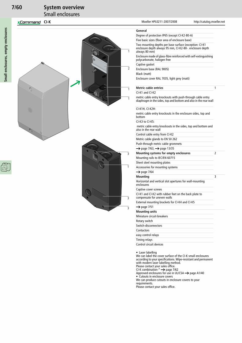
7/60Sm
all e
nclo
sure
s, e
mpt
y en
clos
ures
Moeller HPL0211-2007/2008 http://catalog.moeller.net
System overviewSmall enclosures
GeneralDegree of protection IP65 (except CI-K2-80-A)Five basic sizes (floor area of enclosure base)Two mounting depths per base surface (exception: CI-K1 enclosure depth always 95 mm, CI-K2-80-. enclosure depth always 80 mm)Enclosure made of glass-fibre reinforced with self-extinguishing polycarbonate, halogen freeCaptive gasketEnclosure base (RAL 9005)Black (matt)Enclosure cover RAL 7035, light grey (matt)
Metric cable entries 1CI-K1 and CI-K2metric cable entry knockouts with push-through cable entry diaphragm in the sides, top and bottom and also in the rear wall
CI-K1H, CI-K2H:metric cable entry knockouts in the enclosure sides, top and bottomCI-K3 to CI-K5: metric cable entry knockouts in the sides, top and bottom and also in the rear wallControl cable entry from CI-K2Metric cable glands to EN 50 262Push-through metric cable grommetsa page 7/63, a page 13/35Mounting systems for empty enclosures 2Mounting rails to IEC/EN 60715Sheet steel mounting platesAccessories for mounting systemsa page 7/64Mounting 3Horizontal and vertical slot apertures for wall-mounting enclosuresCaptive cover screwsCI-K1 and CI-K2 with rubber feet on the back plate to compensate for uneven wallsExternal mounting brackets for CI-K4 and CI-K5a page 7/51Mounting unitsMiniature circuit-breakersRotary switchSwitch-disconnectorsContactorseasy control relaysTiming relaysControl circuit devices
• Laser labellingWe can label the cover surface of the CI-K small enclosures according to your specifications. Wipe-resistant and permanent with modern laser labelling method. Please contact your sales office.CI-K combination-* a page 7/62Approved enclosures for use in UL/CSA a page A1/40• Cutouts in enclosure coversWe can produce cutouts in enclosure covers to your requirements. Please contact your sales office.
1
2
1
1
3
1
3
3
CI-K

7/61
http://catalog.moeller.net Moeller HPL0211-2007/2008
OrderingBasic enclosures
Smal
l enc
losu
res,
em
pty
encl
osur
es
Dimensions Enclosure depth: Dimensions from top1. Mounting depth for mounting plate2. Mounting depth for mounting rails,
7.5 mm height3. Enclosure depth
Features Part no.Article no.
Pricesee price list
Std. pack
mm mm
CI-K basic enclosures
• Degree of protection IP65 (Exception: CI-K2-80-A), material glass-fibre reinforced polycarbonate• Enclosure base RAL 9005, black/enclosure top RAL 7035, light grey• Metric cable entry knockouts top, bottom and in the back plate• Push-through cable membrane on CI-K1 and CI-K2• Hard metric knockouts for sizes CI-K1H and CI-K2H• Hard metric knockouts from sizes CI-K3 to CI-K5• Two protective covers to protect the push-through cable membrane with CI-K1 and CI-K2• Control cable entry from CI-K2• Lamp indicator L-. can be mounted in base knock-out M20/M25
With mounting rail CI-K1-95-TS206881
1 off
With mounting rail CI-K1H-95-TS105853
With mounting rail CI-K2-100-TS206882
With mounting rail CI-K2H-100-TS229304
With mounting plate CI-K2-100-M206893
With mounting plate CI-K2H-100-M229306
With mounting rail CI-K2-145-TS206883
With mounting rail CI-K2H-145-TS229305
With mounting plate CI-K2-145-M206894
With mounting plate CI-K2H-145-M229307
With adapter plate Prepared for fitting a DILE contactor with ZE overload relay
CI-K2-145-AD207632
With adapter plate Prepared for fitting a DILE contactor with ZE overload relay
CI-K2H-145-AD229308
With mounting rail CI-K3-125-TS206884
With mounting plate CI-K3-125-M206895
With mounting rail CI-K3-160-TS206885
With mounting plate CI-K3-160-M206896
Notes Number and size of cable entries a page 7/63
120
82
80L
S
L
95
72
160
116
100
T
Q
M
79
73
100
160
116
100
T
Q
M
124
118
145
200
152
120
U
N
R
125
98
93
200
152
120
U
N
R160
133
128
CI-K1, CI-K2, CI-K3
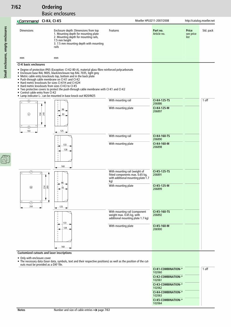
7/62Sm
all e
nclo
sure
s, e
mpt
y en
clos
ures
Moeller HPL0211-2007/2008 http://catalog.moeller.net
OrderingBasic enclosures
Dimensions Enclosure depth: Dimensions from top1. Mounting depth for mounting plate2. Mounting depth for mounting rails, 7.5 mm height3. 7.5 mm mounting depth with mounting rails
Features Part no.Article no.
Pricesee price list
Std. pack
mm mm
CI-K basic enclosures
• Degree of protection IP65 (Exception: CI-K2-80-A), material glass-fibre reinforced polycarbonate• Enclosure base RAL 9005, black/enclosure top RAL 7035, light grey• Metric cable entry knockouts top, bottom and in the back plate• Push-through cable membrane on CI-K1 and CI-K2• Hard metric knockouts for sizes CI-K1H and CI-K2H• Hard metric knockouts from sizes CI-K3 to CI-K5• Two protective covers to protect the push-through cable membrane with CI-K1 and CI-K2• Control cable entry from CI-K2• Lamp indicator L-. can be mounted in base knock-out M20/M25
With mounting rail CI-K4-125-TS206886
1 off
With mounting plate CI-K4-125-M206897
With mounting rail CI-K4-160-TS206890
With mounting plate CI-K4-160-M206898
With mounting rail (weight of fitted components max. 0.65 kg, with additional mounting plate 1.7 kg)
CI-K5-125-TS206891
With mounting plate CI-K5-125-M206899
With mounting rail (component weight max. 0.65 kg, with additional mounting plate 1.7 kg)
CI-K5-160-TS206892
With mounting plate CI-K5-160-M206900
Customized cutouts and laser inscriptions
• Only with enclosure cover• The necessary data (laser data, symbols, text and their respective positions) as well as the position of the cut-
outs must be provided as a DXF file.CI-K1-COMBINATION-*102060
1 off
CI-K2-COMBINATION-*102061
CI-K3-COMBINATION-*102062
CI-K4-COMBINATION-*102063
CI-K5-COMBINATION-*102064
Notes Number and size of cable entries a page 7/63
V
O
O
160
240
194
125
98
93
160
133
128
200
280
234
P
W
P
125
98
93
160
133
128
CI-K4, CI-K5

7/63
http://catalog.moeller.net Moeller HPL0211-2007/2008
OrderingBasic enclosures
Smal
l enc
losu
res,
em
pty
encl
osur
es
Dimensions Enclosure depth: Dimensions from top1. Enclosure depth2. Mounting depth for mounting plate3. Mounting depth for mounting rail, 7.5 mm height
Features Part no.Article no.
Pricesee price list
Std. pack
mm mm
Basic enclosure CI-K2
• Degree of protection IP30, glass-fibre reinforced polycarbonate material• Enclosure base RAL 9005, black/enclosure top RAL 7035, light grey• Metric cable entry knockouts top, bottom and in the back plate• Push-through cable entry diaphragm with CI-K2• Hard metric knockouts on CI-K2H• Two protective covers to protect the push-through cable membrane with CI-K2• Control cable entry• L-... indicator lights can be fitted in M20/M25 knockout in base
with cover cutout Standard cutout dimensions and mounting rail for devices requiring 2 to 4 space units. Push-through cable entry membrane. Close off unused space units (max. 2) using blanking strips VST1, a page 7/65
CI-K2-80-A211107
1 off
with hinged cover
Standard cutout dimensions and mounting rail for devices requiring 2 to 4 space units. Hard metric knockouts. Close off unused space units (max. 2) using blanking strips VST1, a page 7/65
CI-K2H-80-A229309
1 off
with cover cutout Transparent hinged cover for devices requiring 2 to 4 space units. Push-through cable entry diaphragm.
CI-K2-80-K211108
1 off
with hinged cover
Transparent hinged cover for devices requiring 2 to 4 space units. Hard metric cable entry knockouts.
CI-K2H-80-K229310
1 off
Notes Membrane grommets, cable glands a page 13/35
100
160
T
Q
M
46
80
Q
M
T
100
160
80
70
115
L M N O P Q R
Knockouts Knockouts Knockouts Knockouts Knockouts Knockouts Knockouts2 x M20 or push-through membrane up to max. o 12 mm
2 x M25 or push-through membrane up to max. o 16 mmCI-K2H: 2 x M25/20
2 X M25/20 2 X M32/25 2 X M50/40/25 2 x M25 or push-through membrane up to max. o 16 mm and 1 push-through mem-brane up to o 8 mmCI-K2H: 2 x M25/20
2 X M25/201 X M20 1 X M20 1 X M20
S T U V W
Back plate: Back plate: Back plate: Back plate: Back plate: 2 x push-through mem-brane up to max. o 8 mm
2 x push-through mem-brane up to max. o 11 mm
2 X M25/20 2 X M32/25 2 X M50/40/25
(not for CI-K2H)
CI-K2
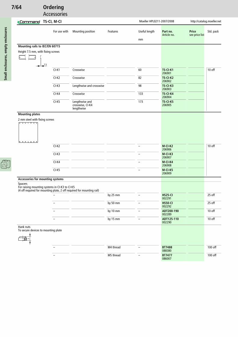
7/64Sm
all e
nclo
sure
s, e
mpt
y en
clos
ures
Moeller HPL0211-2007/2008 http://catalog.moeller.net
OrderingAccessories
For use with Mounting position Features Useful length Part no.Article no.
Pricesee price list
Std. pack
mm
Mounting rails to IEC/EN 60715
Height 7.5 mm, with fixing screws
CI-K1 Crosswise 60 TS-CI-K1206901
10 off
CI-K2 Crosswise 82 TS-CI-K2206902
CI-K3 Lengthwise and crosswise 98 TS-CI-K3206903
CI-K4 Crosswise 133 TS-CI-K4206904
CI-K5 Lengthwise and crosswise, CI-K4 lengthwise
173 TS-CI-K5206905
Mounting plates
2 mm steel with fixing screws
CI-K2 – M-CI-K2206906
10 off
CI-K3 – M-CI-K3206907
CI-K4 – M-CI-K4206908
CI-K5 – M-CI-K5206909
Accessories for mounting systemsSpacers For raising mounting systems in CI-K3 to CI-K5(4 off required for mounting plate, 2 off required for mounting rail)
– by 25 mm – HS25-CI002291
25 off
– by 50 mm – HS50-CI002292
25 off
– by 10 mm – ADT200-190002289
10 off
– by 15 mm – ADT125-110002290
10 off
Hank nutsTo secure devices to mounting plate
– M4 thread – BT7488088380
100 off
– M5 thread – BT7477086007
100 off
7.5
7
TS-CI, M-CI
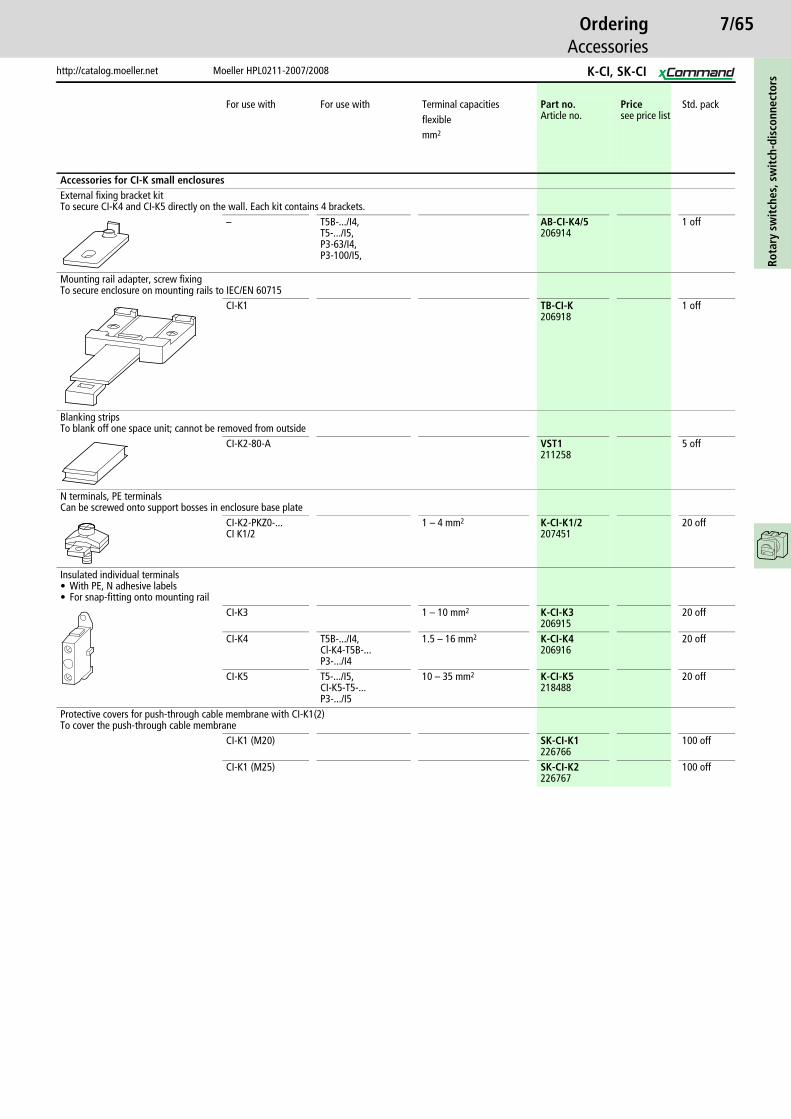
7/65
http://catalog.moeller.net Moeller HPL0211-2007/2008
OrderingAccessories
Rota
ry s
wit
ches
, sw
itch
-dis
conn
ecto
rs
For use with For use with Terminal capacities Part no.Article no.
Pricesee price list
Std. packflexiblemm2
Accessories for CI-K small enclosuresExternal fixing bracket kitTo secure CI-K4 and CI-K5 directly on the wall. Each kit contains 4 brackets.
– T5B-.../I4,T5-.../I5,P3-63/I4,P3-100/I5,
AB-CI-K4/5206914
1 off
Mounting rail adapter, screw fixingTo secure enclosure on mounting rails to IEC/EN 60715
CI-K1 TB-CI-K206918
1 off
Blanking stripsTo blank off one space unit; cannot be removed from outside
CI-K2-80-A VST1211258
5 off
N terminals, PE terminalsCan be screwed onto support bosses in enclosure base plate
CI-K2-PKZ0-...CI K1/2
1 – 4 mm2 K-CI-K1/2207451
20 off
Insulated individual terminals• With PE, N adhesive labels• For snap-fitting onto mounting rail
CI-K3 1 – 10 mm2 K-CI-K3206915
20 off
CI-K4 T5B-.../I4,Cl-K4-T5B-...P3-.../I4
1.5 – 16 mm2 K-CI-K4206916
20 off
CI-K5 T5-.../I5,CI-K5-T5-...P3-.../I5
10 – 35 mm2 K-CI-K5218488
20 off
Protective covers for push-through cable membrane with CI-K1(2)To cover the push-through cable membrane
CI-K1 (M20) SK-CI-K1226766
100 off
CI-K1 (M25) SK-CI-K2226767
100 off
K-CI, SK-CI

7/66Sm
all e
nclo
sure
s, e
mpt
y en
clos
ures
Moeller HPL0211-2007/2008 http://catalog.moeller.net
OrderingAccessories
Dimensions Features For use with Enclosure depth Part no.Article no.
Pricesee price list
Std. pack
mm mm
CI-B, C, D basic enclosures
• Transparent cover• Metric knockouts top, bottom• With PEN terminal• IP55 individual enclosure with pre-drilled mounting plate
DIL00AM CI-B024315
5 off
S27 CI-C031434
2 off
DIL0AMS27
CI-D038553
2 off
Hank nuts
To secure devices to mounting plateM4 thread – BT7488
088380100 off
M5 thread – BT7477086007
100 off
PE terminal (5th conductor)
Rated current 25 AFor o 1.5 – 6 mm2 solid
CI-BCI-CCI-D
K6/1002270
100 off
149
87L
L
128
110
L
Knockouts2 X M20
L
165
110
L
128
110
L
222
110
L
128
110
7
CI

7/67
http://catalog.moeller.net Moeller HPL0211-2007/2008
Technical dataSwitch-disconnectors
Rota
ry s
wit
ches
, sw
itch
-dis
conn
ecto
rs
P1-25 P1-32 P3-63 P3-100
GeneralStandards IEC/EN 60 947, VDE 0660, IEC/EN 60 204, CSA,UL Switch-
disconnectors to IEC/EN 60 947-3Lifespan, mechanical Operations x 106 0.3 0.3 0.1 0.1Maximum operating frequency Operations/h 50 50 50 50Climatic proofing Damp heat, constant, to IEC 60068-2-78; Damp heat, cyclical, to
IEC 60068-2-30Ambient temperature Open °C -25…50 -25…50 -25…50 -25…50
Enclosed °C -25…40 -25…40 -25…40 -25…40Mounting position As required As required As required As requiredMechanical shock resistance (IEC/EN 60068-2-27)
Half-sinusoidal shock, 20 ms g 15 15 15 15
ContactsRated operational voltage Ue V AC 690 690 690 690Rated impulse withstand voltage Uimp V AC 6000 6000 6000 6000Overvoltage category/pollution degree III/3 III/3 III/3 III/3Rated uninterrupted current Iu A 25 32 63 100Load rating with intermittent operation, class 12
AB 60 % DF x Ie 1.3 1.3 1.3 1.3AB 40 % DF x Ie 1.6 1.6 1.6 1.6AB 25 % DF x Ie 2 2 2 2
Short-circuit rating Fuse A gG/gL 25 50 80 100Rated short-time withstand current (1 s current) Icw Arms 640 640 1260 2000Isolating characteristics to IEC/EN 60947 V AC 690 690 690 690Safe isolation to VDE 0106 Part 101 and Part 101/A1
Safe isolation to VDE 0106 Part 101 and Part 101 A1 between auxiliary contacts and main contacts
V AC 440 440 440 440
Switching angles ° 90 90 90 90Contacts Number max. 3 (+N) max. 3 (+N) max. 3 (+N) max. 3 (+N)Current heat loss per contact at Ie W 1.1 1.8 4.5 7.5Terminal capacitiesSolid or stranded mm2 1 x (1.5 – 6)
2 x (1.5 – 6)1 x (1.5 – 6)2 x (1.5 – 6)
1 x (2.5 – 35)2 x (2.5 – 10)
1 x (2.5 – 35)2 x (2.5 – 10)
Flexible with ferrule to DIN 46228 mm2 1 x (1 – 4)2 x (1 – 4)
1 x (1 – 4)2 x (1 – 4)
1 x (1.5 – 25)2 x (1.5 – 6)
1 x (1.5 – 25)2 x (1.5 – 6)
Terminal screw M4 M4 M5 M5Tightening torque Nm 1.6 1.6 3 3Switching capacityAlternating voltage
Rated making capacity cos v = 0.35 A 240 320 800 950Rated breaking capacity, motor load switch cos v = 0.35
230 V A 190 260 640 760400/415 V A 150 300 600 740500 V A 170 290 590 880690 V A 150 250 340 520
Rated operational current 440 V load-break switch AC-21A Ie A 25 32 63 100AC-3 motor load switch motor rating 230 V P kW 5.5 7.5 15 22
400/415 V P kW 7.5 13 30 37500 V P kW 7.5 18.5 30 45690 V P kW 7.5 15 30 37
AC-23A Motor load switches (main switches maintenance switches)
230 V P kW 7 8.5 18.5 30400/415 V P kW 13 15 37 50500 V P kW 11 18.5 37 65690 V P kW 11 18.5 30 45
DCDC-1, Load-break switches L/R = 1 ms Rated operational current Ie A 25 32 63 100
Voltage per contact pair in series V 60 60 60 60DC-23A, motor load switchL/R = 15 ms
24 V Rated operational current Ie A 25 25 50 50Contacts Quantity 1 1 1 1
48 V Rated operational current Ie A 25 25 50 50Contacts Quantity 2 2 2 2
60 V Rated operational current Ie A 25 25 50 50Contacts Quantity 3 3 3 3
120 V Rated operational current Ie A 12 12 25 25Contacts Quantity 3 3 3 3
Notes Main switch characteristics to IEC/EN 60204; positive opening of contacts, operator element positively located on shaftThe rated uninterrupted current Iu is stated at max. connected cross-section.For terminal capacity solid, stranded and flexible:Max. 2 cross-section sizes difference admissible when using 2 conductors.
P1, P3

7/68Ro
tary
sw
itch
es, s
wit
ch-d
isco
nnec
tors
Moeller HPL0211-2007/2008 http://catalog.moeller.net
Technical dataSwitch-disconnectors
P5-125 P5-160 P5-250 P5-315
GeneralStandards IEC/EN 60947, VDE 0660, IEC/EN 60204, CSA,
UL switch disconnector according to IEC/EN 60947-3Lifespan, mechanical Operations x 106 0.1 0.1 0.08 0.08
Maximum operating frequency Operations/h 50 50 50 50Climatic proofing Damp heat, constant, to IEC 60068-2-78; Damp heat, cyclical, to IEC
60068-2-30Ambient temperature Open °C -25…50 -25…50 -25…50 -25…50
Enclosed °C -25…40 -25…40 -25…40 -25…40Mounting position As required As required As required As required
ContactsRated operational voltage Ue V AC 690 690 690 690Rated impulse withstand voltage Uimp V AC 8000 8000 8000 8000Overvoltage category/pollution degree III/3 III/3 III/3 III/3Rated uninterrupted current Iu A 125 160 250 315Load rating with intermittent operation, class 12
AB 60 % DF x Ie 1.3 1.3 1.3 1.3AB 40 % DF x Ie 1.6 1.6 1.6 1.6AB 25 % DF x Ie 2 2 2 2
Short-circuit rating Fuse A gG/gL 125 160 250 315Rated short-time withstand current (1 s current) Icw Arms 2500 3000 4600 5800Isolating characteristics to IEC/EN 60947 V AC 690 690 690 690Safe isolation to VDE 0106 Part 101 and Part 101/A1
Safe isolation to VDE 0106 Part 101 and Part 101 A1 between auxiliary contacts and main contacts
V AC 440 440 440 440
Switching angles ° 90 90 90 90Contacts Number max. 3 (+N) max. 3 (+N) max. 3 (+N) max. 3 (+N)Current heat loss per contact at Ie W 8 10 13 16
Terminal capacitiesSolid or stranded mm2 1 x (10 – 95)
2 x (10 – 35)1 x (10 – 95)2 x (10 – 35)
1 x (16 – 185)2 x (16 – 70)
1 x (16 – 185)2 x (16 – 70)
Copper band, 1 band Number of segments x width x thickness
mm 6 x 9 x 0.8 6 x 20 x 1
Copper band, 2 bands mm 6 x 9 x 0.8 6 x 9 x 0.8Flexible with ferrule to DIN 46228 mm2 1 x (16 – 70)
2 x (16 – 25)1 x (16 – 70)2 x (16 – 25)
1 x (25 – 120)2 x (25 – 50)
1 x (25 – 120)2 x (25 – 50)
Terminal screw Allen screw 5 Allen screw 5 Allen screw 6 Allen screw 6Tightening torque Nm 14 14 16 16
Notes Main switch characteristics to IEC/EN 60204; positive opening of contacts, operator element positively located on shaftThe rated uninterrupted current Iu is stated at max. connected cross-section.For terminal capacity solid, stranded and flexible:Max. 2 cross-section sizes difference admissible when using 2 conductors.
P5
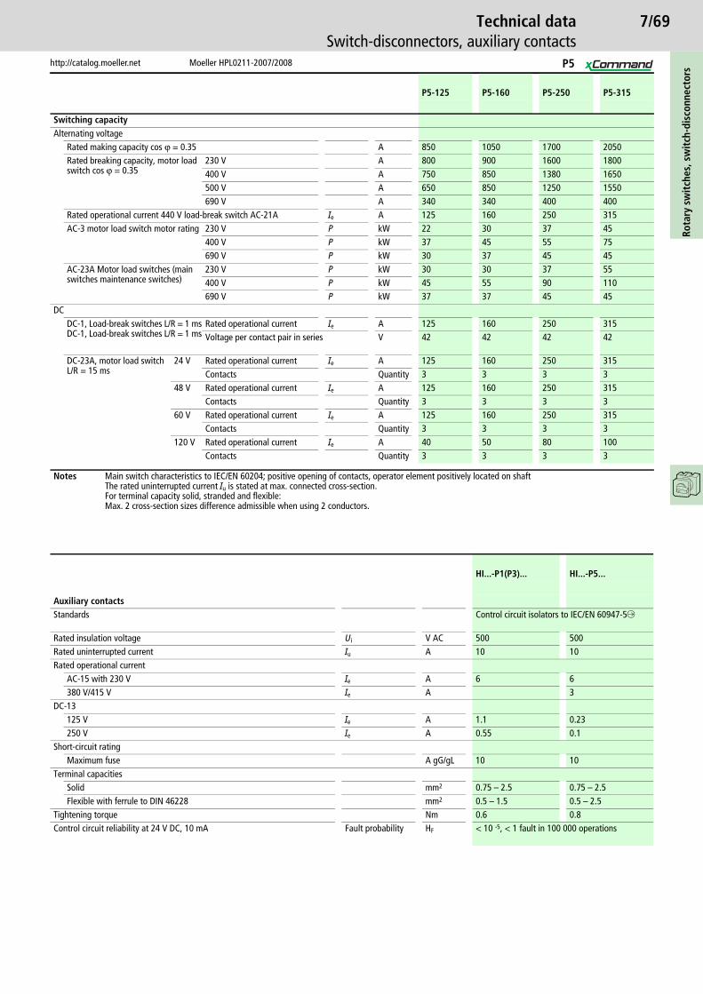
7/69
http://catalog.moeller.net Moeller HPL0211-2007/2008
Technical dataSwitch-disconnectors, auxiliary contacts
Rota
ry s
wit
ches
, sw
itch
-dis
conn
ecto
rs
P5-125 P5-160 P5-250 P5-315
Switching capacityAlternating voltage
Rated making capacity cos v = 0.35 A 850 1050 1700 2050Rated breaking capacity, motor load switch cos v = 0.35
230 V A 800 900 1600 1800400 V A 750 850 1380 1650500 V A 650 850 1250 1550690 V A 340 340 400 400
Rated operational current 440 V load-break switch AC-21A Ie A 125 160 250 315AC-3 motor load switch motor rating 230 V P kW 22 30 37 45
400 V P kW 37 45 55 75690 V P kW 30 37 45 45
AC-23A Motor load switches (main switches maintenance switches)
230 V P kW 30 30 37 55400 V P kW 45 55 90 110690 V P kW 37 37 45 45
DCDC-1, Load-break switches L/R = 1 msDC-1, Load-break switches L/R = 1 ms
Rated operational current Ie A 125 160 250 315Voltage per contact pair in series V 42 42 42 42
DC-23A, motor load switchL/R = 15 ms
24 V Rated operational current Ie A 125 160 250 315Contacts Quantity 3 3 3 3
48 V Rated operational current Ie A 125 160 250 315Contacts Quantity 3 3 3 3
60 V Rated operational current Ie A 125 160 250 315Contacts Quantity 3 3 3 3
120 V Rated operational current Ie A 40 50 80 100Contacts Quantity 3 3 3 3
Notes Main switch characteristics to IEC/EN 60204; positive opening of contacts, operator element positively located on shaftThe rated uninterrupted current Iu is stated at max. connected cross-section.For terminal capacity solid, stranded and flexible:Max. 2 cross-section sizes difference admissible when using 2 conductors.
HI...-P1(P3)... HI...-P5...
Auxiliary contactsStandards Control circuit isolators to IEC/EN 60947-5f
Rated insulation voltage Ui V AC 500 500Rated uninterrupted current Iu A 10 10Rated operational current
AC-15 with 230 V Ie A 6 6380 V/415 V Ie A 3
DC-13 125 V Ie A 1.1 0.23250 V Ie A 0.55 0.1
Short-circuit ratingMaximum fuse A gG/gL 10 10
Terminal capacitiesSolid mm2 0.75 – 2.5 0.75 – 2.5Flexible with ferrule to DIN 46228 mm2 0.5 – 1.5 0.5 – 2.5
Tightening torque Nm 0.6 0.8Control circuit reliability at 24 V DC, 10 mA Fault probability HF < 10 -5, < 1 fault in 100 000 operations
P5
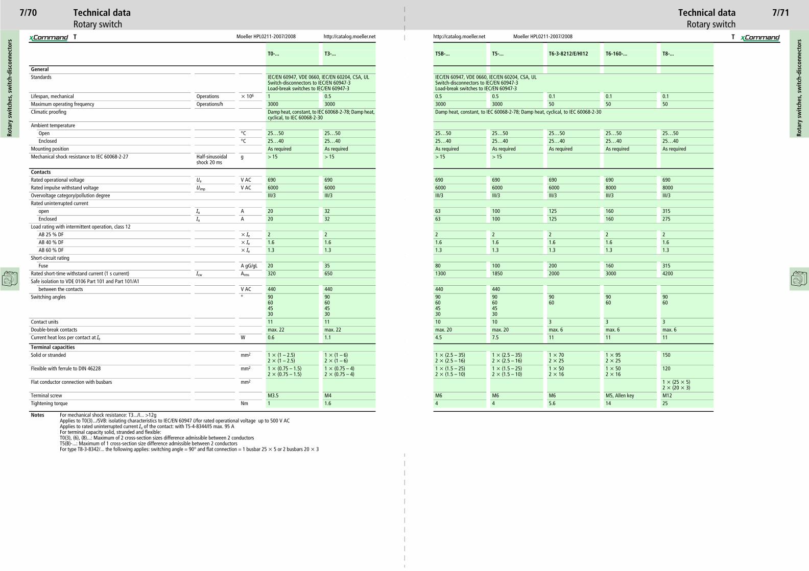
Moeller HPL0211-2007/2008
7/70
Moeller HPL0211-2007/2008http://catalog.moeller.net http://catalog.moeller.net
Rota
ry s
wit
ches
, sw
itch
-dis
conn
ecto
rs
Rota
ry s
wit
ches
, sw
itch
-dis
conn
ecto
rs
Technical data Technical dataRotary switch Rotary switch
T0-... T3-... T5B-... T5-... T6-3-8212/E/HI12 T6-160-... T8-...
GeneralStandards IEC/EN 60947, VDE 0660, IEC/EN 60204, CSA, UL
Switch-disconnectors to IEC/EN 60947-3Load-break switches to IEC/EN 60947-3
IEC/EN 60947, VDE 0660, IEC/EN 60204, CSA, ULSwitch-disconnectors to IEC/EN 60947-3Load-break switches to IEC/EN 60947-3
Lifespan, mechanical Operations x 106 1 0.5 0.5 0.5 0.1 0.1 0.1Maximum operating frequency Operations/h 3000 3000 3000 3000 50 50 50Climatic proofing Damp heat, constant, to IEC 60068-2-78; Damp heat,
cyclical, to IEC 60068-2-30Damp heat, constant, to IEC 60068-2-78; Damp heat, cyclical, to IEC 60068-2-30
Ambient temperatureOpen °C 25…50 25…50 25…50 25…50 25…50 25…50 25…50
25…40 25…40 25…40 25…40As required As required As required As required> 15
690 690 690 6906000 6000 8000 8000III/3 III/3 III/3 III/3
100 125 160 315100 125 160 275
2 2 2 21.6 1.6 1.6 1.61.3 1.3 1.3 1.3
100 200 160 3151850 2000 3000 4200
44090604530
9060
9060
9060
10 3 3 3max. 20 max. 6 max. 6 max. 67.5 11 11 11
1 x (2.5 – 35)2 x (2.5 – 16)
1 x 702 x 25
1 x 952 x 25
150
1 x (1.5 – 25)2 x (1.5 – 10)
1 x 502 x 16
1 x 502 x 16
120
1 x (25 x 5)2 x (20 x 3)
M6 M6 M5, Allen key M124 5.6 14 25
7/71
T T
Enclosed °C 25…40 25…40 25…40Mounting position As required As required As requiredMechanical shock resistance to IEC 60068-2-27 Half-sinusoidal
shock 20 msg > 15 > 15 > 15
ContactsRated operational voltage Ue V AC 690 690 690Rated impulse withstand voltage Uimp V AC 6000 6000 6000Overvoltage category/pollution degree III/3 III/3 III/3Rated uninterrupted current
open Iu A 20 32 63Enclosed Iu A 20 32 63
Load rating with intermittent operation, class 12AB 25 % DF x Ie 2 2 2AB 40 % DF x Ie 1.6 1.6 1.6AB 60 % DF x Ie 1.3 1.3 1.3
Short-circuit ratingFuse A gG/gL 20 35 80
Rated short-time withstand current (1 s current) Icw Arms 320 650 1300Safe isolation to VDE 0106 Part 101 and Part 101/A1
between the contacts V AC 440 440 440Switching angles ° 90
604530
90604530
90604530
Contact units 11 11 10Double-break contacts max. 22 max. 22 max. 20Current heat loss per contact at Ie W 0.6 1.1 4.5
Terminal capacitiesSolid or stranded mm2 1 x (1 – 2.5)
2 x (1 – 2.5)1 x (1 – 6)2 x (1 – 6)
1 x (2.5 – 35)2 x (2.5 – 16)
Flexible with ferrule to DIN 46228 mm2 1 x (0.75 – 1.5)2 x (0.75 – 1.5)
1 x (0.75 – 4)2 x (0.75 – 4)
1 x (1.5 – 25)2 x (1.5 – 10)
Flat conductor connection with busbars mm2
Terminal screw M3.5 M4 M6Tightening torque Nm 1 1.6 4
Notes For mechanical shock resistance: T3.../I... >12gApplies to T0(3).../SVB: isolating characteristics to IEC/EN 60947 Ufor rated operational voltage up to 500 V ACApplies to rated uninterrupted current Iu of the contact: with T5-4-8344/I5 max. 95 AFor terminal capacity solid, stranded and flexible:T0(3), (6), (8)...: Maximum of 2 cross-section sizes difference admissible between 2 conductorsT5(B)-...: Maximum of 1 cross-section size difference admissible between 2 conductorsFor type T8-3-8342/... the following applies: switching angle = 90° and flat connection = 1 busbar 25 x 5 or 2 busbars 20 x 3

Moeller HPL0211-2007/2008
7/72
Moeller HPL0211-2007/2008http://catalog.moeller.net http://catalog.moeller.net
Rota
ry s
wit
ches
, sw
itch
-dis
conn
ecto
rs
Rota
ry s
wit
ches
, sw
itch
-dis
conn
ecto
rs
Technical data Technical dataRotary switch Rotary switch
T0-... T3-... T5B-... T5-... T6-3-8212/E/HI12 T6-160-... T8-...
Switching capacityAlternating voltage
Rated making capacity cos v = 0.35 A 130 320 800 950 1600 1600 2390Rated breaking capacity, motor load switch cos v = 0.35
230 V A 100 260 520 760 1280 1280 1910400 V A 110 260 600 740 900 900 1800500 V A 80 240 480 590 880 880 1200690 V A 60 170 340 420 340 340 420
Rated operational current 440 V load-break switch AC-21A Ie A 20 32 63 100 125 160 315AC-3 motor load switch motor rating 230 V P kW 3 6.5 15 22 22 22 22
30 22 22 3730 37 45 5545 37 45 5537 37 37 3755 37 37 3730 22 22 3745 22 22 3718.5 37 37 7530 45 55 13237 55 55 7530 30 30 3716 – – –6 – – –4 – – –
80 125 125 31560 42 42 42
– 125 125 250– 1 1 1– 125 125 250– 2 2 2– 125 125 125– 3 3 3– 50 50 50– 3 3 3– – – –– – – –– 125 125 250– 24 24
00000 operations
Control circuit isolators to IEC/EN 60947-5f
– 500 500 –– 10 10 –
– 6 6 –– 4 4 –
– 10 10 –
– 0.75 – 2.5 0.75 – 2.5 –
– 0.5 – 1.5 0.5 – 1.5 –
0.35 0.35– < 10-5, < 1 fault in 100 000 operations
7/73
T T
230 V Star-delta P kW 4 11 22400/415 V P kW 4 12 22400 V Star-delta P kW 5.5 18.5 37500 V P kW 5.5 15 22500 V Star-delta P kW 7.5 22 37690 V P kW 4 15 22690 V Star-delta P kW 5.5 22 37
AC-23A Motor load switches (main switches maintenance switches)
230 V P kW 3.5 7.5 15400/415 V P kW 6.5 13 22500 V P kW 13 15 22690 V P kW 22
Rated operational current control switch AC-15
230 V Ie A 6 10 16400/415 V Ie A 4 6 6500 V Ie A 2 4 4
DCDC-1, Load-break switches L/R = 1 ms Rated operational current Ie A 10 25 63
Voltage per contact pair in series V 60 60 60DC-21A Rated operational current 240 V Ie A 1 1
240 V Contacts Quantity 1 1DC-23A, motor load switchL/R = 15 ms
24 V Rated operational current Ie A 10 25 50Contacts Quantity 1 1 1
48 V Rated operational current Ie A 10 25 50Contacts Quantity 2 2 2
60 V Rated operational current Ie A 10 25 50Contacts Quantity 3 3 3
120 V Rated operational current Ie A 5 12 25Contacts Quantity 3 3 3
240 V Rated operational current Ie A 5 5 20Contacts Quantity 5 5 6
DC-13, Control switches L/R = 50 ms Rated operational current Ie A 10 20 25Voltage per contact pair in series V 32 32 24
Control circuit reliability at 24 V DC, 10 mA Fault probability HF < 10 -5, < 1 fault in 100000 operations < 10 -5, < 1 fault in 1
Auxiliary contactsStandardsRated insulation voltage Ui V AC – – –Rated uninterrupted current Iu A – – –Rated operational current
AC-15 with 230 V Ie A – – –380 V/415 V Ie A – – –
Short-circuit ratingMaximum fuse A gG/gL – – –
Terminal capacitiesSolid mm2 – – –
Flexible with ferrule to DIN 46228 mm2 – – –
Tightening torque NmControl circuit reliability at 24 V DC, 10 mA Fault probability HF – – –
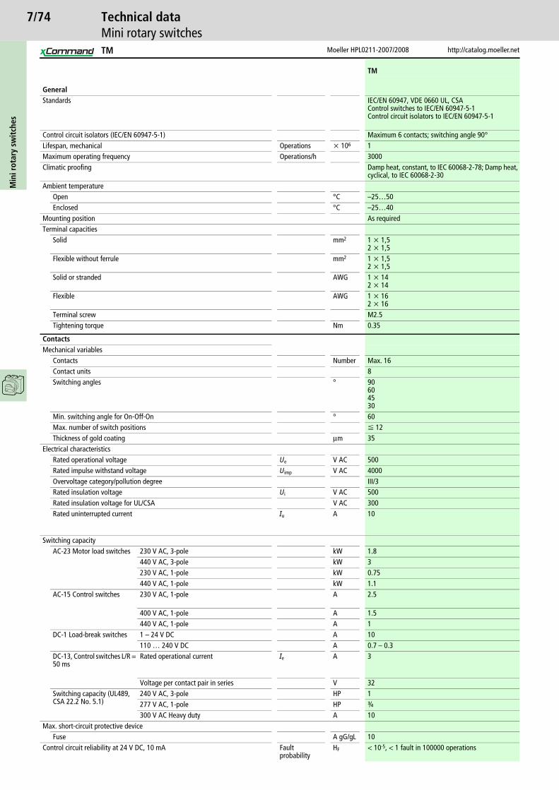
7/74M
ini r
otar
y sw
itch
es
Moeller HPL0211-2007/2008 http://catalog.moeller.net
Technical dataMini rotary switches
TM
GeneralStandards IEC/EN 60947, VDE 0660 UL, CSA
Control switches to IEC/EN 60947-5-1Control circuit isolators to IEC/EN 60947-5-1
Control circuit isolators (IEC/EN 60947-5-1) Maximum 6 contacts; switching angle 90°Lifespan, mechanical Operations x 106 1Maximum operating frequency Operations/h 3000Climatic proofing Damp heat, constant, to IEC 60068-2-78; Damp heat,
cyclical, to IEC 60068-2-30Ambient temperature
Open °C –25…50Enclosed °C –25…40
Mounting position As requiredTerminal capacities
Solid mm2 1 x 1,52 x 1,5
Flexible without ferrule mm2 1 x 1,52 x 1,5
Solid or stranded AWG 1 x 142 x 14
Flexible AWG 1 x 162 x 16
Terminal screw M2.5Tightening torque Nm 0.35
ContactsMechanical variables
Contacts Number Max. 16Contact units 8Switching angles ° 90
604530
Min. switching angle for On-Off-On ° 60Max. number of switch positions F 12Thickness of gold coating mm 35
Electrical characteristicsRated operational voltage Ue V AC 500Rated impulse withstand voltage Uimp V AC 4000Overvoltage category/pollution degree III/3Rated insulation voltage Ui V AC 500Rated insulation voltage for UL/CSA V AC 300Rated uninterrupted current Iu A 10
Switching capacityAC-23 Motor load switches 230 V AC, 3-pole kW 1.8
440 V AC, 3-pole kW 3230 V AC, 1-pole kW 0.75440 V AC, 1-pole kW 1.1
AC-15 Control switches 230 V AC, 1-pole A 2.5
400 V AC, 1-pole A 1.5440 V AC, 1-pole A 1
DC-1 Load-break switches 1 – 24 V DC A 10110 … 240 V DC A 0.7 – 0.3
DC-13, Control switches L/R = 50 ms
Rated operational current Ie A 3
Voltage per contact pair in series V 32Switching capacity (UL489, CSA 22.2 No. 5.1)
240 V AC, 3-pole HP 1277 V AC, 1-pole HP o
300 V AC Heavy duty A 10Max. short-circuit protective device
Fuse A gG/gL 10Control circuit reliability at 24 V DC, 10 mA Fault
probabilityHF < 10-5, < 1 fault in 100000 operations
TM

7/75
http://catalog.moeller.net Moeller HPL0211-2007/2008
Technical dataSmall enclosures
Smal
l enc
losu
res,
em
pty
encl
osur
es
CI-K1 CI-K2 CI-K3 CI-K4 CI-K5
GeneralStandards IEC/EN 60529
DIN 43660EN 50262
Climatic proofing Damp heat, constant, to IEC 60068-2-78Damp heat, cyclic, to IEC 60068-2-30
Ambient temperature °C –25…70Ambient temperature with push-through cable entry °C –25…40Protection type IP 65 IP 65 IP 65 IP 65 IP 65Degree of protection with push-through cable entry IP 65 IP 65 IP 65 IP 65 IP 65Dissipatable heat loss a Chapter 14, Technical data
Material characteristicsMaterial
Base, Cover Glass-fibre reinforced polycarbonateSurface treatment Resistant to corrosionColour
Base RAL 9005, black (matt)Cover Enclosure cover RAL 7035, light grey (matt)
Material propertiesElectrical
Creepage resistance to IEC 60112Base CTI175Cover CTI175
Surface resistance to IEC 60093 O x 1013 1Dielectric strength to IEC 60243-1 kV/mm 30
ThermalContinuous thermal stability
Enclosures °C -40…120Gasket °C -40…80
MechanicalIK code to EN 50102 Please enquireWeight of components fitted
per mounting rail kg 0.2 0.7 0.85 0.75 0.65with mounting plate kg 0.85 0.9 1
Chemical resistanceBase, Cover
Resistant Acids < 10 %, mineral oil, petrol, grease, saline solutionPartially resistant Acids > 10 %, alcoholNot resistant Alkalis, benzol
Push-through membrane (CI-K1/CI-K2) and sealing materialResistant Acids < 10 %, alkalis,
alcohol, saline solutionPartially resistant Acids < 10 %, grease, benzol
Not resistant Mineral oil, petrolAtmospheric
Saline spray IEC 60068-2-11UV resistance Beneath protective shieldWater consumption to DIN EN ISO 62 % 0.29 0.29 0.29 0.29 0.29
Flammability characteristicsGlow wire test
Base, CoverGlow wire to VDE 0471 Part 2 °C Thickness 960/1 mmto UL 94 VO/1.5 mm thick
Push-through membrane (CI-K1/CI-K2) and sealing material
To IEC 2 °C 650/1 mm thickto UL 94 HB
Halogen free Yes
CI-K

7/76Ro
tary
sw
itch
es, s
wit
ch-d
isco
nnec
tors
Moeller HPL0211-2007/2008 http://catalog.moeller.net
DimensionsRotary switch
Flush mounting
T0.../E (+ H3-T0)T3.../E (+ H3-T0)
Drilling dimensions
Centre mounting
T0.../EZT3.../EZ T0 T3
Drilling dimensions
� Not included as standard
Service distribution board mounting
T0.../IVS Drilling dimensionsbase
48
4817
525 101
c20 35
H3-T0
b
75
90
10 –
11
3.1 – 3.5
12.2
30
48
4817
1.5 – 5b
c21 35
4548
48 54
61
3.2
24.1
+0.
4 0
22.3 +0.4 0
Part no. c20 c21T0-1...T0-2...T0-3...T0-4...T0-5...T0-6...T0-7...T0-8...T0-9...T0-10...T0-11...
41506069798898107117126136
6170808999108118127137146156
One contact unit depth 9.5 mm
Part no. c20 c21T3-1...T3-2...T3-3...T3-4...T3-5...T3-6...T3-7...T3-8...T3-9...T3-10...T3-11...
4456677990102113125136148159
64768799110122133145156168179
One contact unit depth 11.5 mm
54
5545 M4 50
48
60 50
� 5
� 528
45
55c22
5
T0, T3
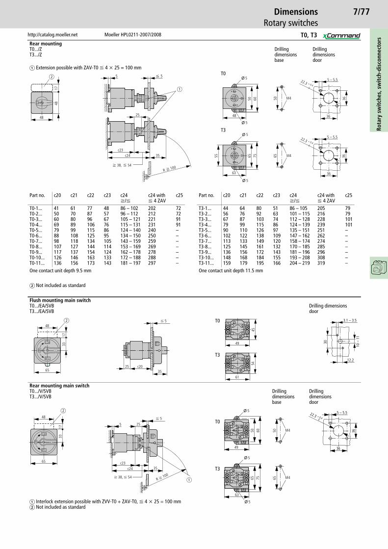
7/77
http://catalog.moeller.net Moeller HPL0211-2007/2008
DimensionsRotary switches
Rota
ry s
wit
ches
, sw
itch
-dis
conn
ecto
rs
Rear mountingT0.../ZT3.../Z
Drilling dimensionsbase
Drilling dimensionsdoor
� Extension possible with ZAV-T0 F 4 x 25 = 100 mm
� Not included as standard
Flush mounting main switchT0.../EA/SVBT3.../EA/SVB
Drilling dimensionsdoor
T0
T3
Rear mounting main switchT0.../V/SVBT3.../V/SVB
Drilling dimensionsbase
Drilling dimensionsdoor
� Interlock extension possible with ZVV-T0 + ZAV-T0, F 4 x 25 = 100 mm� Not included as standard
T0
T3
548
4817
M450
5 – 5.5
36
36
5 – 5.5
36
36M465
48
50 60
63
65 7555
5 5
25
c23c24 35
O 5
O
O
O
5
5
38, 54
22.3 + 0.4 0
22.3 + 0.4 0
100R
a
b
T3
T0
Part no. c20 c21 c22 c23 c24f/F
c24 withF 4 ZAV
c25
T0-1...T0-2...T0-3...T0-4...T0-5...T0-6...T0-7...T0-8...T0-9...T0-10...T0-11...
41506069798898107117126136
6170808999108118127137146156
778796106115125134144154163173
485767768695105114124133143
86 – 10296 – 112105 – 121115 – 131124 – 140134 – 150143 – 159153 – 169162 – 178172 – 188181 – 197
202212221231240250259269278288297
72729191–––––––
One contact unit depth 9.5 mm
Part no. c20 c21 c22 c23 c24f/F
c24 withF 4 ZAV
c25
T3-1...T3-2...T3-3...T3-4...T3-5...T3-6...T3-7...T3-8...T3-9...T3-10...T3-11...
4456677990102113125136148159
64768799110122133145156168179
8092103115126138149161172184195
5163748697109120132143155166
86 – 105101 – 115112 – 128124 – 139135 – 151147 – 162158 – 174170 – 185181 – 196193 – 208204 – 219
205216228239251262274285296308319
7979101101–––––––
One contact unit depth 11.5 mm
65
3317
48
ON
OFF
OFF
I
o
o
25 c2035
b F 5
61
54
49
45
3.1 – 3.530
10 –
11
12.2
I
o
o
65
3317
48
b
5 25
c23c24 35
ON
OFF
OFF
a
F 5
f 38, F 54R f 100
65 75
63
5
5
M465
M450
�
�
50 60
49
� 522.3 + 0.4 0
5 – 5.5
36
36
T0, T3

7/78Ro
tary
sw
itch
es, s
wit
ch-d
isco
nnec
tors
Moeller HPL0211-2007/2008 http://catalog.moeller.net
DimensionsRotary switches
Surface mountingT0.../I1
Drilling dimensionsbase
T3.../I2 Drilling dimensionsbase
Surface mounting main switch
T0.../I1/SVB
Drilling dimensionsbase
T3.../I2/SVB Drilling dimensionsbase
F 3 padlocks
80
120
c25 27
137 M20
127
M4
100
160
c25 c33
180 M20 / M25
∅8
171
M4
80
120
c25 35
M20
137
I
OFFo
ON
oOFF 12
7
M4
100
160
180
35c25
M20 /M25
�8
I
OFFo
ON
oOFF
d b
d = 4 – 8 mmb + d F 47 mm
171
M4
Part no. c25T0-1...T0-2...T0-3...T0-4...
75759595
Part no. c25 c33T3-1...T3-2...T3-3...T3-4...T3-5...
8080100100145
2727353535
T0, T3

7/79
http://catalog.moeller.net Moeller HPL0211-2007/2008
DimensionsRotary switches, switch-disconnectors, accessories
Rota
ry s
wit
ches
, sw
itch
-dis
conn
ecto
rs
Key operation
S-T0S-SOND...-T0
T0.../E(I1) + S-(SOND-)T0T3.../E(I2) + S-(SOND-)T0
T0.../Z + S-(SOND-)T0T3.../Z + S-(SOND-)T0
T0.../EZ � T0../E + EZ-T0 + S-(SOND-)T0T3.../EZ � T3../E + EZ-T0 + S-(SOND-)T0
Cylinder lock
SVA-T3 T0.../I1/SVAT3.../I2/SVAP1.../12/SVA
T0.../E/SVA...T3.../E/SVA...P1.../E/SVA
T0.../Z/SVA...T3.../Z/SVA...P1.../Z/SVA
Padlocking feature
SVC-T3 T0.../I1/SVCT3.../I2/SVCP1.../12/SVC
T0.../E/SVC...T3.../E/SVC...P1.../E/SVC
T0.../Z/SVC...T3.../Z/SVC...P1.../Z/SVC
ModulesSwitched neutral N-P...Auxiliary contact HI 11-P1/P3
F 3 padlocks
� Not included as standard
17
27
48
48
b
1930
5
36
12.2
3.1 – 3.5
30
10...
11
527
44
5 – 5.5
36
36
22.3 + 0.4 0
100R
2 – 5
c20 22:25 – 28 30:23 – 26
3.2
30.5
17
3.2 12.5
��
22.3 + 0.4 0
73
48
b 56
73
46 30
5673
46 30
56
73
46 30
73
48
b 56
73
46
48
56
73
46
48
5673
46
48
L3 L2 L1
T3 T2 T16 4 2
5 3 1 b31
a3
N-P
H-P...
HI 11
N
N
1 3
2 4 6
a32 a31 a32 a32 a31 a32
a33
5
Part no. a3 a31 a32 a33 b31P1-...P3-..
4972
1518
1515
83114
4960
d b
d = 4 – 8 mmb + d F 47 mm
T0, T3, P1, P3
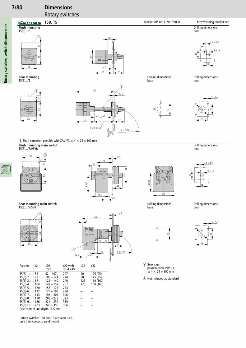
7/80Ro
tary
sw
itch
es, s
wit
ch-d
isco
nnec
tors
Moeller HPL0211-2007/2008 http://catalog.moeller.net
DimensionsRotary switches
Flush mountingT5(B).../E
Drilling dimensionsdoor
Rear mountingT5(B).../Z
Drilling dimensionsbase
Drilling dimensionsdoor
� Shaft extension possible with ZAV-P3 F 4 x 25 = 100 mmFlush mounting main switchT5(B).../EA/SVB
Drilling dimensionsdoor
Rear mounting main switchT5(B).../V/SVB
Drilling dimensionsbase
Drilling dimensionsdoor
�
�
Extension possible with ZVV-P3, F 4 x 25 = 100 mm
Not included as standard
88
8827
ON
OFF
I
o
18
c2
86
37
F 5
b
14
37
4.1 – 4.5
12 – 13
ON
OFFo
I
88
8827
48
5 – 5.5
48
30.5
c20
c2 37
2525
73M6
a
f 38, F 54
F 5
R f 100
b
88
2788
ON
OFF
OFF
I
o
o
25c2
88
80/9
0
40.516.5
44
100
80/9
0
14
37
4.1 – 4.5
12 – 13
F 5b
ON
OFF
OFF
o
I
o
48
5 – 5.5
48
30.5
2788
88
1216.5
c205
25 25
40.5
44
73
a
b
R f 100
F 5
Part no. c2 c20f/F
c20 withF 4 ZAV
c21 c22
T5(B)-1...T5(B)-2...T5(B)-3...T5(B)-4...
547187104
92 – 107109 – 124125 – 140142 – 157
207224240257
9090123123
125 (95)125 (95)160 (160)160 (160)
T5(B)-5...T5(B)-6...T5(B)-7...T5(B)-8...T5(B)-9...T5(B)-10...
120137153170186203
158 – 173175 – 190191 – 206208 – 223224 – 239240 – 356
273290306323339356
––––––
––––––
One contact unit depth 16.5 mm
Rotary switches T5B and T5 are same size,only thier contacts are different
T5B, T5

7/81
http://catalog.moeller.net Moeller HPL0211-2007/2008
DimensionsRotary switches
Rota
ry s
wit
ches
, sw
itch
-dis
conn
ecto
rs
Surface mountingT5B.../I4
T5.../I5
Surface mounting main switches
T5B.../I4/SVB Drilling dimensionsF 3 padlocks
T5.../I5/SVB Drilling dimensions
External fixing bracketAB-CI-K415
160 c22 29
M20240
280
200 c22 37
M20
M25M50M25
M32
160
240
c22 44
193
142
M5
I
OFFo
ON
oOFF
d b
d = 4 – 8 mmb + d F 47 mm
280
200 c22 44
233
182
M5
I
OFFo
ON
oOFF
Part no. c22T5(B)-1...T5(B)-2...T5(B)-3...T5(B)-4...
125125160160
One contact unit depth 16.5 mm
Rotary switches T5B and T5 are same size,only thier contacts are different20 5.
5
6.5
52
36
3.8
M5t = 3
7.8
6
T5B, T5

7/82Ro
tary
sw
itch
es, s
wit
ch-d
isco
nnec
tors
Moeller HPL0211-2007/2008 http://catalog.moeller.net
DimensionsRotary switches
Flush mounting
T6-3-8212/E/HI12T8.../E/HI12
T6-160-6/V/SVB-SW/HI11 T8-3-8342/V/SVB-SW/HI11
Drilling dimensionsdoor
T6: 4 M5 x 20T8: 4 M6 x 20
F 3 padlocks for T.../SVB
150
58
5c2 c30
b2
a2
9
88
73
5.5 1
93 216 200
5
76224
6.4 H-T6-100
118
22
68108
100R
7
130
250
1044.5
172.8
315 218
9.2
86.5
7 1
130
68
H-T8
19
100R
Part no. a2 b2 c2 c30 d1 d2 x1 y1
T6-3-8212/E/HI12T8.../E/HI12T8.../SVB
88130–
88130–
152173
4462–
∅ 26 – 30∅ 22 – 25∅ 26 – 30
∅ 6.0∅ 7.0∅ 7.0
6810468
6810468
d2
d1
x1
y1
d b
d = 4 – 8 mmb + d F 47 mm
T6, T8
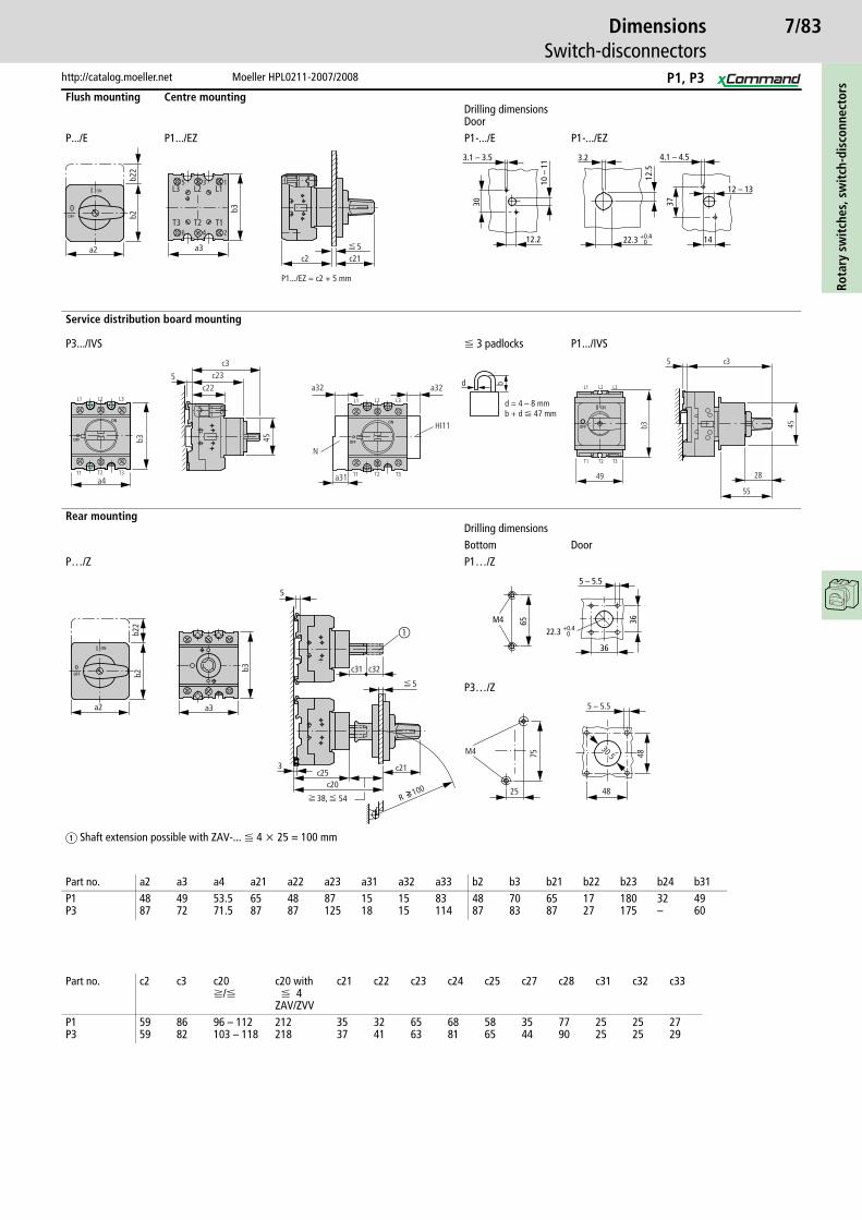
7/83
http://catalog.moeller.net Moeller HPL0211-2007/2008
DimensionsSwitch-disconnectors
Rota
ry s
wit
ches
, sw
itch
-dis
conn
ecto
rs
Flush mounting Centre mountingDrilling dimensionsDoor
P.../E P1.../EZ P1-.../E P1-.../EZ
Service distribution board mounting
P3.../IVS F 3 padlocks P1.../IVS
Rear mountingDrilling dimensionsBottom Door
P…/Z P1…/Z
P3…/Z
� Shaft extension possible with ZAV-... F 4 x 25 = 100 mm
ON
0
I
OFF
a2
b2b2
2
b3
a3
L3 L1
T3 T1
L2
T2
1
2
3
4
5
6
5c2 c21
P1.../EZ = c2 + 5 mm
4.1 – 4.53.2
22.3 +0.40
12.5
10 –
11
12.2
3.1 – 3.5
30
14
37
12 – 13
b3
a4
c22c23
c3
5
45
N
HI11
L3L2L1
T3T2T1
L3L2L1
T3T2T1
a32 a32
a31
d b
d = 4 – 8 mmb + d F 47 mm
49
L1 L2 L3
T1 T2 T3
55
28
b3 45
5 c3
�
38,
3
5
a3
5
b22
b2
a2
c21c25c20
R 100
c31 c32b3
54
5 – 5.5
M4 65 36
36
22.3 +0.40
M4 75
25
5 – 5.5
48
48
30.5
Part no. a2 a3 a4 a21 a22 a23 a31 a32 a33 b2 b3 b21 b22 b23 b24 b31P1P3
4887
4972
53.571.5
6587
4887
87125
1518
1515
83114
4887
7083
6587
1727
180175
32–
4960
Part no. c2 c3 c20f/F
c20 withF 4
ZAV/ZVV
c21 c22 c23 c24 c25 c27 c28 c31 c32 c33
P1P3
5959
8682
96 – 112103 – 118
212218
3537
3241
6563
6881
5865
3544
7790
2525
2525
2729
P1, P3
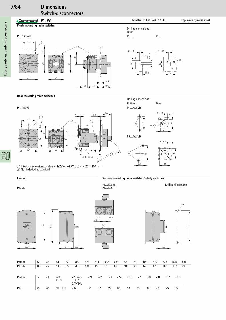
7/84Ro
tary
sw
itch
es, s
wit
ch-d
isco
nnec
tors
Moeller HPL0211-2007/2008 http://catalog.moeller.net
DimensionsSwitch-disconnectors
Flush mounting main switchesDrilling dimensionsDoor
P…/EA/SVB P1… P3…
Rear mounting main switchesDrilling dimensionsBottom Door
P…/V/SVB P1…/V/SVB
P3…/V/SVB
� Interlock extension possible with ZVV-...+ZAV... F 4 x 25 = 100 mm� Not included as standard
Layout
P1.../I2
Surface mounting main switches/safety switches
P1.../I2/SVBP1.../I2/SI
Drilling dimensions
b3
a3
ON
OFF
b22
c27c225
o
o OFF
I 1
2
3
4
5
6
N
N y
y
a22b2
1
a21
b31
H-P...
F 5
b
14
4.1 – 4.5
10 –
11
12.2
3.1 – 3.5
30 37
12 – 13
3
I ON
OFF
OFF
5
o
o
1
2
3
4
5
6
N
N
a22
a21 a3 c25c20
c27
b22
b21
b31
b3
H-P... a
F 5
R f 100
f 38, F 54
b
5 – 5.5
M4 65 36
36
22.3 +0.40
M4 75
25
5 – 5.5
48
48
30.5
a23
160
c28 c33
M25
171
c27
M4
b23
M25M25F 8
Part no. a2 a3 a4 a21 a22 a23 a31 a32 a33 b2 b3 b21 b22 b23 b24 b31P1.../I2 48 49 53.5 65 48 100 15 15 83 48 70 65 17 180 35.5 49
Part no. c2 c3 c20f/F
c20 withF 4
ZAV/ZVV
c21 c22 c23 c24 c25 c27 c28 c31 c32 c33
P1... 59 86 96 – 112 212 35 32 65 68 58 35 80 25 25 27
P1, P3

7/85
http://catalog.moeller.net Moeller HPL0211-2007/2008
DimensionsSwitch-disconnectors
Rota
ry s
wit
ches
, sw
itch
-dis
conn
ecto
rs
Flush mounting
P5.../E Drilling dimensions
Flush mounting main switches
P5-.../EA/SVB(-SW)
Rear mounting
P5.../Z Drilling dimensions
Rear mounting main switches
P5-.../V/SVB(-SW)
b
c
8 35a
M5
68 88
F 5
q 8
8
q 6
8
26 – 30
6
68 88
26
49.388
c21
M5 HI10
a
a1
a2 a2
b2b2
b
F 5
q 8
8
b
c 8 35
b12
2
6.4
a
a1
c1
F 5
q 8
8
q 6
8
26 – 30
6
c
b2b2
b
aa2 a2
88
26
49.3c1
F 5
R f 100
Part no. a a1 a2 b b1 b2 c c1P5-125/160 112 36 38 108 120 76 91 f 130 F 287P5-250/315 145 44 52.5 126 144 88 98 f 140 F 280
q 8
8
P5
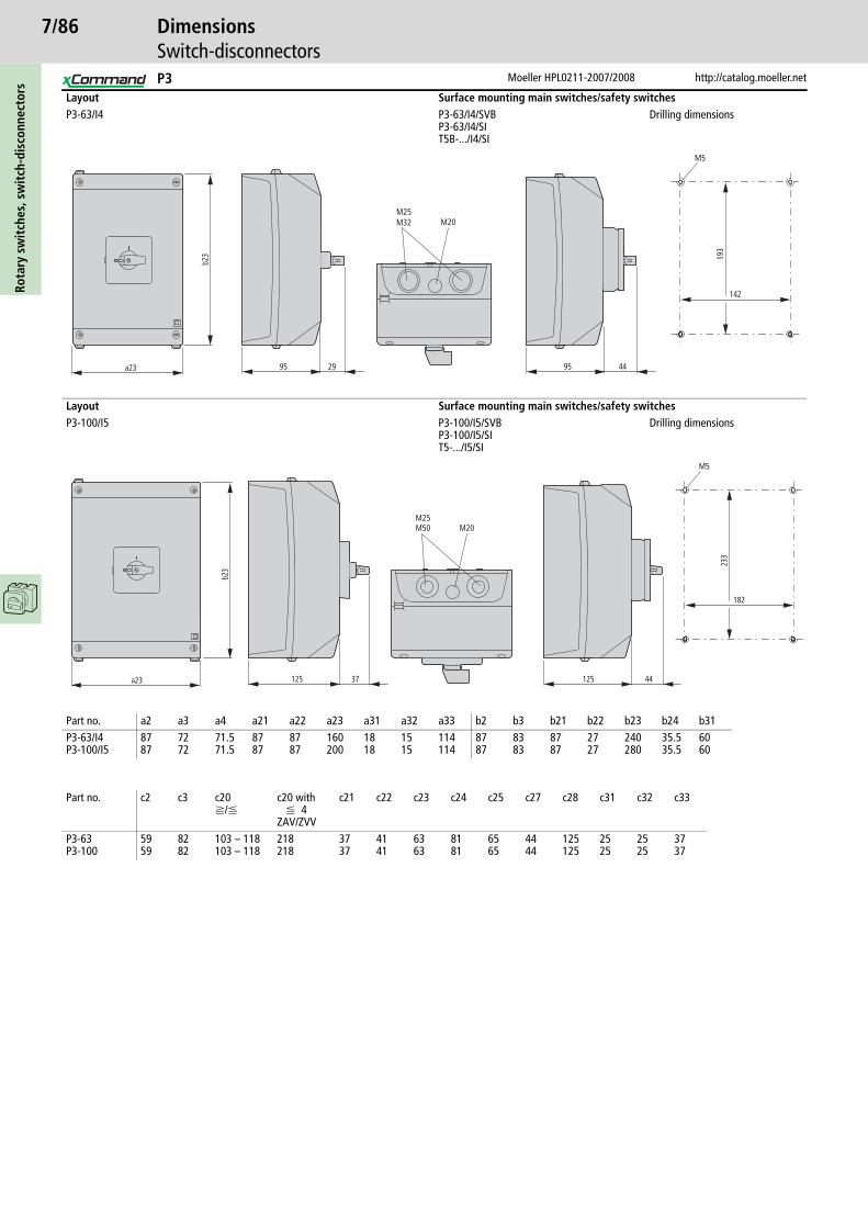
7/86Ro
tary
sw
itch
es, s
wit
ch-d
isco
nnec
tors
Moeller HPL0211-2007/2008 http://catalog.moeller.net
DimensionsSwitch-disconnectors
Layout Surface mounting main switches/safety switchesP3-63/I4 P3-63/I4/SVB
P3-63/I4/SIT5B-.../I4/SI
Drilling dimensions
Layout Surface mounting main switches/safety switchesP3-100/I5 P3-100/I5/SVB
P3-100/I5/SIT5-.../I5/SI
Drilling dimensions
a23 95 29
b23
95 44
193
142
M5
M25M32 M20
a23 125 37 125 44
233
182
M5
M25M50 M20
b23
Part no. a2 a3 a4 a21 a22 a23 a31 a32 a33 b2 b3 b21 b22 b23 b24 b31P3-63/I4P3-100/I5
8787
7272
71.571.5
8787
8787
160200
1818
1515
114114
8787
8383
8787
2727
240280
35.535.5
6060
Part no. c2 c3 c20f/F
c20 with F 4
ZAV/ZVV
c21 c22 c23 c24 c25 c27 c28 c31 c32 c33
P3-63P3-100
5959
8282
103 – 118103 – 118
218218
3737
4141
6363
8181
6565
4444
125125
2525
2525
3737
P3

7/87
http://catalog.moeller.net Moeller HPL0211-2007/2008
DimensionsMini rotary switches
Rota
ry s
wit
ches
, sw
itch
-dis
conn
ecto
rs
Flush mounting
TM.../E Drilling dimensions
Control circuit switchesfor 2 padlocks ∅ 4 mm or 1 padlock ∅ 6 mm
TM-.../E/SVB(-SW) Drilling dimensions
Centre mounting
TM-.../EZ Drilling dimensions1)
Centre mounting with key operation
TM-...+EZ/S-.. Drilling dimensions1)
Service distribution board mounting
TM-.../IVS TM-.../IVS/S
Note 1)) Drilling dimensions either 16.2 mm = without reduction � RMQ16; 22.3 mm = with reduction � RMQ Titan
28
c20
3
� 4
.8
30
30
28
28
M3 M33.2
20
848
48
28
c21
3
35
38
38
M4 M4
104.2
30
F 5.5
28
c20 231230
30
17/19
1.7
17.9
3.2
24.1
+0.
4 0
22.3 +0.4 0
16.2 +0.2 0
30
30
5.5
28
c20 3512
17/19
1.7
17.9
3.2
24.1
+0.
4 0
22.3 +0.4 0
16.2 +0.2 0
Part no. c20 c21TM-1...TM-2...TM-3...TM-4...TM-5...TM-6...TM-7...TM-8...
395163758799111123
425466
One contact unit depth 12 mm
c1 c235.5
60
45
Part no. c1 c2TM-1...TM-2...
4446
2126.5
One contact unit depth 12 mm
42 21.5 2435.5
60
45
TM
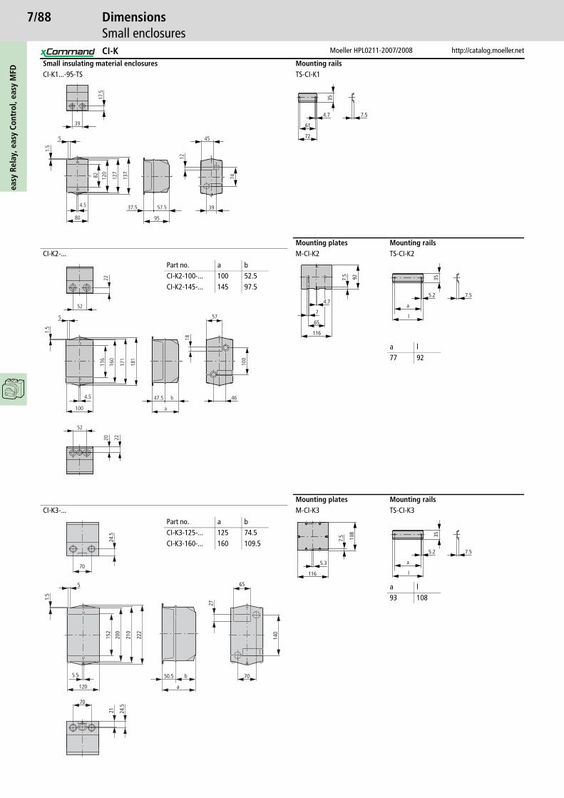
7/88ea
sy R
elay
, eas
y Co
ntro
l, ea
sy M
FD
Moeller HPL0211-2007/2008 http://catalog.moeller.net
DimensionsSmall enclosures
Small insulating material enclosures Mounting railsCI-K1...-95-TS TS-CI-K1
Mounting plates Mounting railsCI-K2-... M-CI-K2 TS-CI-K2
Mounting plates Mounting railsCI-K3-... M-CI-K3 TS-CI-K3
17.5
12
74120
82 127
137
1.5
39
5
37.5 57.5
95
39
45
4.5
80
7.5
35
61
72
4.717
1
181
57
18
100
46
160
52
5
52
100
20 22
47.5 b
a
22
1.5
4.5
116
Part no. a bCI-K2-100-... 100 52.5CI-K2-145-... 145 97.5
7.5 92
7
65
116
4.77.5
35
a
5.2
l
a l77 92
70
5
24.5
1.5
200
152
210
222
120
70
21 24.5
50.5 b
a
70
140
27
65
5.5
Part no. a bCI-K3-125-... 125 74.5CI-K3-160-... 160 109.5 7.
5
116
5.3
108
7.5
35
a
5.2
l
a l93 108
CI-K
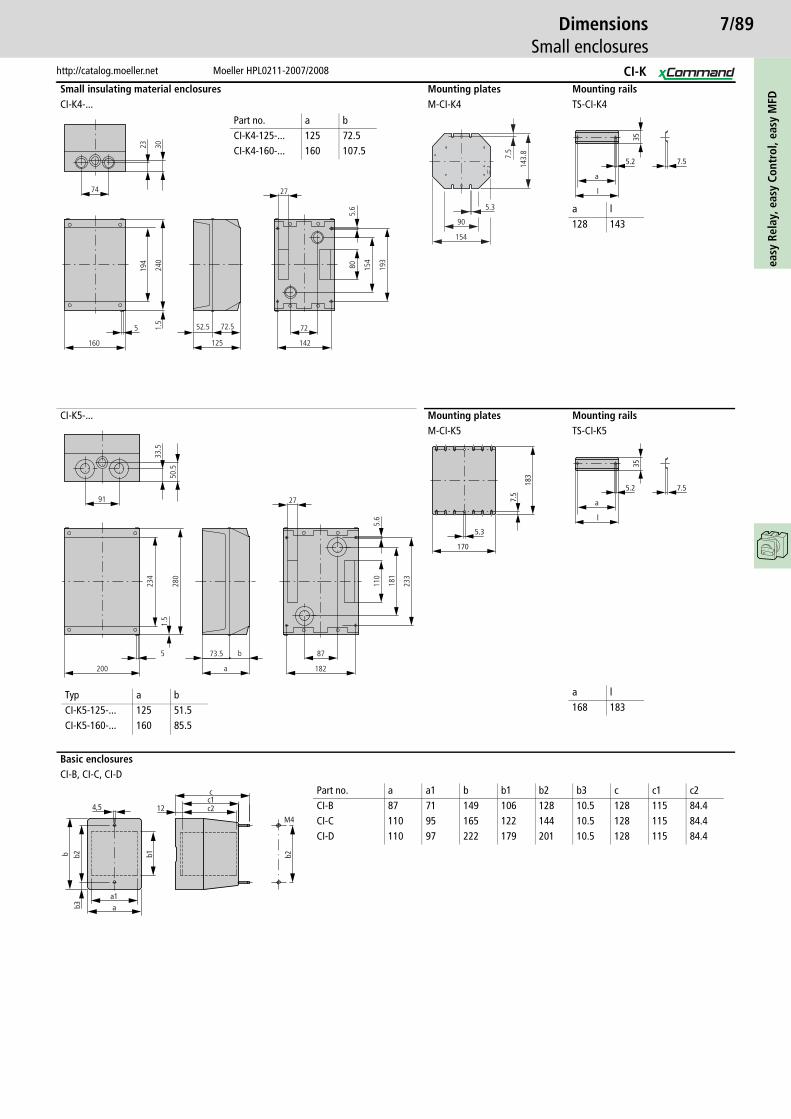
7/89
http://catalog.moeller.net Moeller HPL0211-2007/2008
DimensionsSmall enclosures
easy
Rel
ay, e
asy
Cont
rol,
easy
MFD
Small insulating material enclosures Mounting plates Mounting railsCI-K4-... M-CI-K4 TS-CI-K4
CI-K5-... Mounting plates Mounting railsM-CI-K5 TS-CI-K5
Basic enclosuresCI-B, CI-C, CI-D
1.5
74
160
5
240
194
3023
52.5 72.5
125
72
142
27
80 154
193
5.6
Part no. a bCI-K4-125-... 125 72.5CI-K4-160-... 160 107.5
5.3
90
154
7.5
143.
8
7.5
35
a
5.2
l
a l128 143
110
181
233
50.5
280
234
1.5
91
33.5
200
5
a
b73.5
27
5.6
87
182
7.5
5.318
3
170
7.5
35
a
5.2
l
Typ a bCI-K5-125-... 125 51.5CI-K5-160-... 160 85.5
a l168 183
b2
12
cc1c2
a1a
b2b
b3
4,5
b1
M4
Part no. a a1 b b1 b2 b3 c c1 c2CI-B 87 71 149 106 128 10.5 128 115 84.4CI-C 110 95 165 122 144 10.5 128 115 84.4CI-D 110 97 222 179 201 10.5 128 115 84.4
CI-K
Related Documents


