www.kaeser.com ASD Series With the world-renowned SIGMA PROFILE Flow rate 0.89 to 6.39 m³/min, Pressure 5.5 to 15 bar Rotary Screw Compressors

Welcome message from author
This document is posted to help you gain knowledge. Please leave a comment to let me know what you think about it! Share it to your friends and learn new things together.
Transcript
www.kaeser.com
ASD Series With the world-renowned SIGMA PROFILE Flow rate 0.89 to 6.39 m³/min, Pressure 5.5 to 15 bar
Rotary Screw Compressors
Up to
usable for heating96 %
ASD – Multiple savingsThe newly improved ASD systems save energy in a num-ber of ways: equipped with further-refined SIGMA PRO-FILE rotors, the airends are controlled and monitored by the industrial PC-based SIGMA CONTROL 2 compressor controller. This advanced controller matches compressed air delivery to actual air demand and keeps costly idling time to an absolute minimum, thanks to its Dynamic con-trol mode.
Variable speed control with reluctance motorThe new synchronous reluctance motor combines the advantages of both asynchronous and synchronous mo-tors, all within a single drive system. The motor contains no aluminium, copper or expensive rare earth materials, making the drive system durable and easy to service. Furthermore, the functional principle keeps heat losses in the motor to a minimum, which results in significantly lower bearing temperatures, thereby ensuring extended service life for the motor and bearings. Together with a perfectly matched frequency converter, the synchronous reluctance motor delivers superior performance compared to an asyn-chronous motor when it comes to losses, particularly in the partial load range.
Perfect partnersASD series rotary screw compressors are the perfect partners for high-efficiency industrial compressed air stations. The internal SIGMA CONTROL 2 compressor controller offers various communication channels, allowing seamless integration into master control systems such as KAESER’s SIGMA AIR MANAGER, as well as in-house central control systems. This helps achieve unprecedented levels of efficiency.
Electronic Thermo Management (ETM)Powered by an electric motor and integrated into the cooling circuit, the sensor-controlled temperature control valve is the heart of the innovative Electronic Thermo Management (ETM) system. The new SIGMA CONTROL 2 compressor controller monitors the inlet air and com-pressor temperature in order to prevent the formation of condensate, even at varying air humidity levels. The ETM system dynamically controls fluid temperatures, ensuring they remain as low as possible for greater energy efficien-cy. It also enables the operator to adapt the heat recovery system better to suit the specific requirements.
With its latest generation of ASD (ASD.4) series rotary screw compressors, KAESER KOMPRESSOREN once again pushes the boundaries of compressed air efficiency and availability. Not only do these optimised systems deliver more compressed air for less energy, they also combine simple operation and maintenance-friendliness with exceptional versatility and environ-mentally responsible design.
Why choose heat recovery?In fact, the question should be: Why not? Amazingly, up to 100% of the (electrical) energy supplied to a compressor is converted into heat. Up to 96% of this energy can be recovered and reused for heating purposes. This not only reduces primary energy consumption, but also improves the company’s overall energy balance.
ASD series
ASD – Even more efficient
2
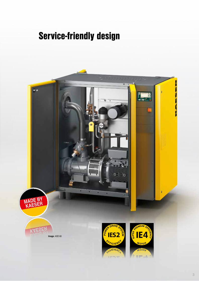
Image: ASD 60
Service-friendly design
3
4
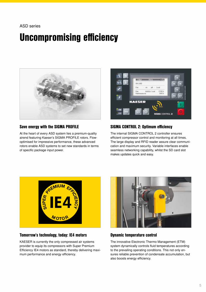
Save energy with the SIGMA PROFILEAt the heart of every ASD system lies a premium-quality airend featuring Kaeser’s SIGMA PROFILE rotors. Flow- optimised for impressive performance, these advanced rotors enable ASD systems to set new standards in terms of specific package input power.
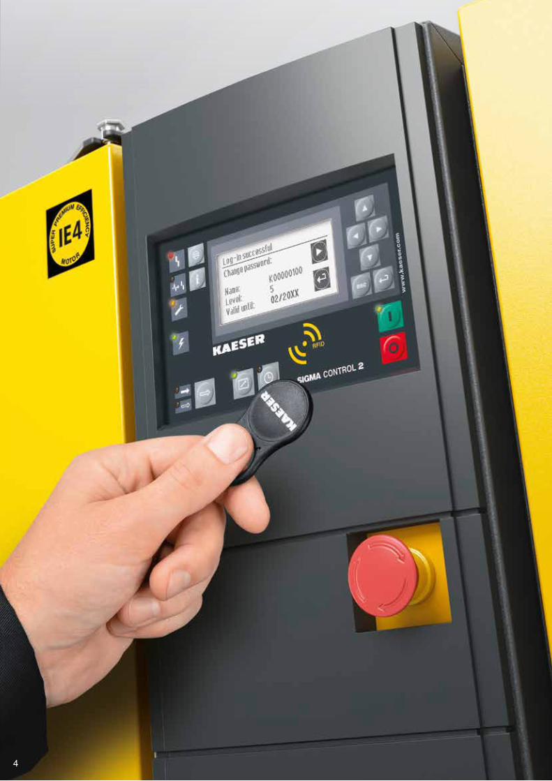
SIGMA CONTROL 2: Optimum efficiencyThe internal SIGMA CONTROL 2 controller ensures efficient compressor control and monitoring at all times. The large display and RFID reader assure clear communi-cation and maximum security. Variable interfaces enable seamless networking capability, whilst the SD card slot makes updates quick and easy.
Tomorrow’s technology, today: IE4 motorsKAESER is currently the only compressed air systems provider to equip its compressors with Super Premium Efficiency IE4 motors as standard, thereby delivering maxi-mum performance and energy efficiency.
Dynamic temperature controlThe innovative Electronic Thermo Management (ETM) system dynamically controls fluid temperatures according to the prevailing operating conditions. This not only en-sures reliable prevention of condensate accumulation, but also boosts energy efficiency.
ASD series
Uncompromising efficiency
5
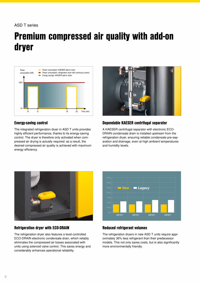
Energy-saving controlThe integrated refrigeration dryer in ASD T units provides highly efficient performance, thanks to its energy-saving control. The dryer is therefore only activated when com-pressed air drying is actually required: as a result, the desired compressed air quality is achieved with maximum energy efficiency.
Dependable KAESER centrifugal separatorA KAESER centrifugal separator with electronic ECO-DRAIN condensate drain is installed upstream from the refrigeration dryer, ensuring reliable condensate pre-sep-aration and drainage, even at high ambient temperatures and humidity levels.
Refrigeration dryer with ECO-DRAIN The refrigeration dryer also features a level-controlled ECO-DRAIN electronic condensate drain, which reliably eliminates the compressed air losses associated with units using solenoid valve control. This saves energy and considerably enhances operational reliability.
Reduced refrigerant volumesThe refrigeration dryers in new ASD T units require appr- oximately 36% less refrigerant than their predecessor models. This not only saves costs, but is also significantly more environmentally friendly.
ASD T series
Premium compressed air quality with add-on dryer
3.5 kg
3.0 kg
2.5 kg
2.0 kg
1.5 kg
1.0 kg
0.5 kg
0 kg
ASD 35 T ASD 40 T ASD 50 T ASD 60 T
▀ New ▀ Legacy
Power consumption (kW)
▀ Power consumption: KAESER add-on dryer ▀ Power consumption: refrigeration dryer with continuous control ▀ Energy savings: KAESER add-on dryer
10 12 18 20
100%
0%Time (min)
6
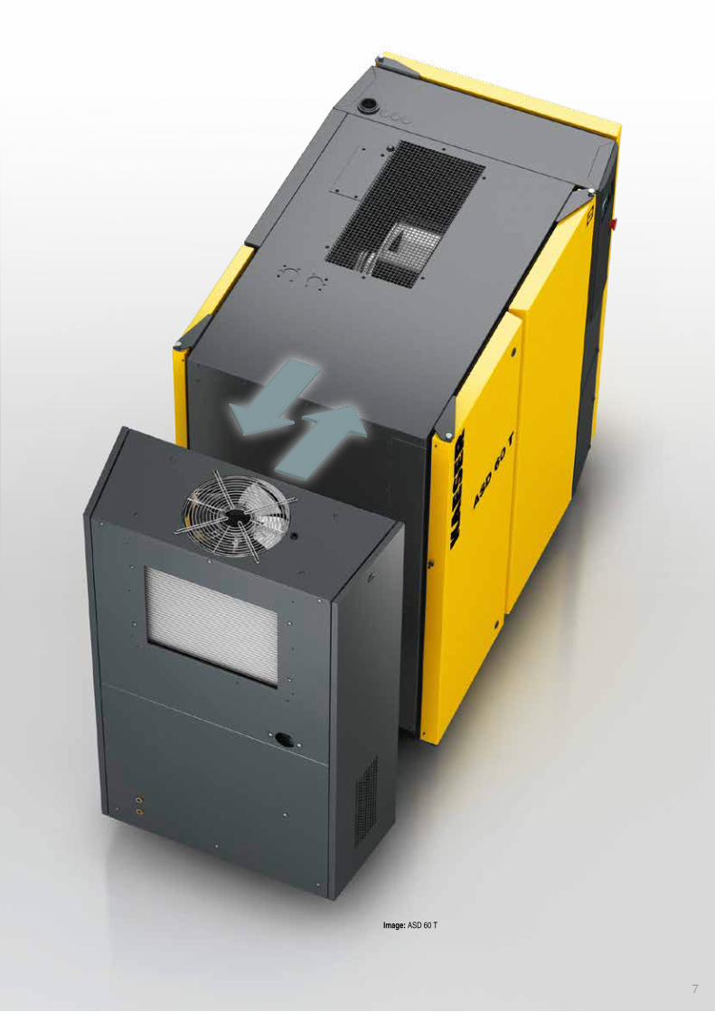
Image: ASD 60 T
7
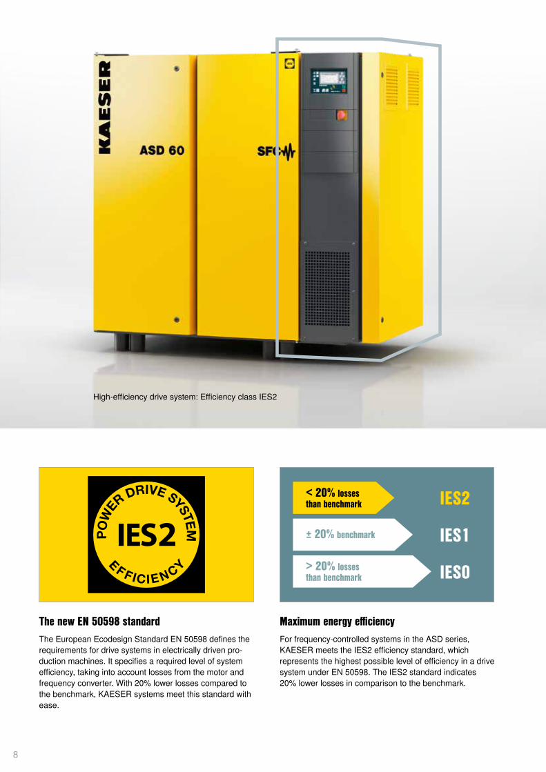
< 20% lossesthan benchmark
± 20% benchmark
> 20% lossesthan benchmark
IES2
IES1
IES0
The new EN 50598 standard The European Ecodesign Standard EN 50598 defines the requirements for drive systems in electrically driven pro-duction machines. It specifies a required level of system efficiency, taking into account losses from the motor and frequency converter. With 20% lower losses compared to the benchmark, KAESER systems meet this standard with ease.
Maximum energy efficiencyFor frequency-controlled systems in the ASD series, KAESER meets the IES2 efficiency standard, which represents the highest possible level of efficiency in a drive system under EN 50598. The IES2 standard indicates 20% lower losses in comparison to the benchmark.
High-efficiency drive system: Efficiency class IES2
8
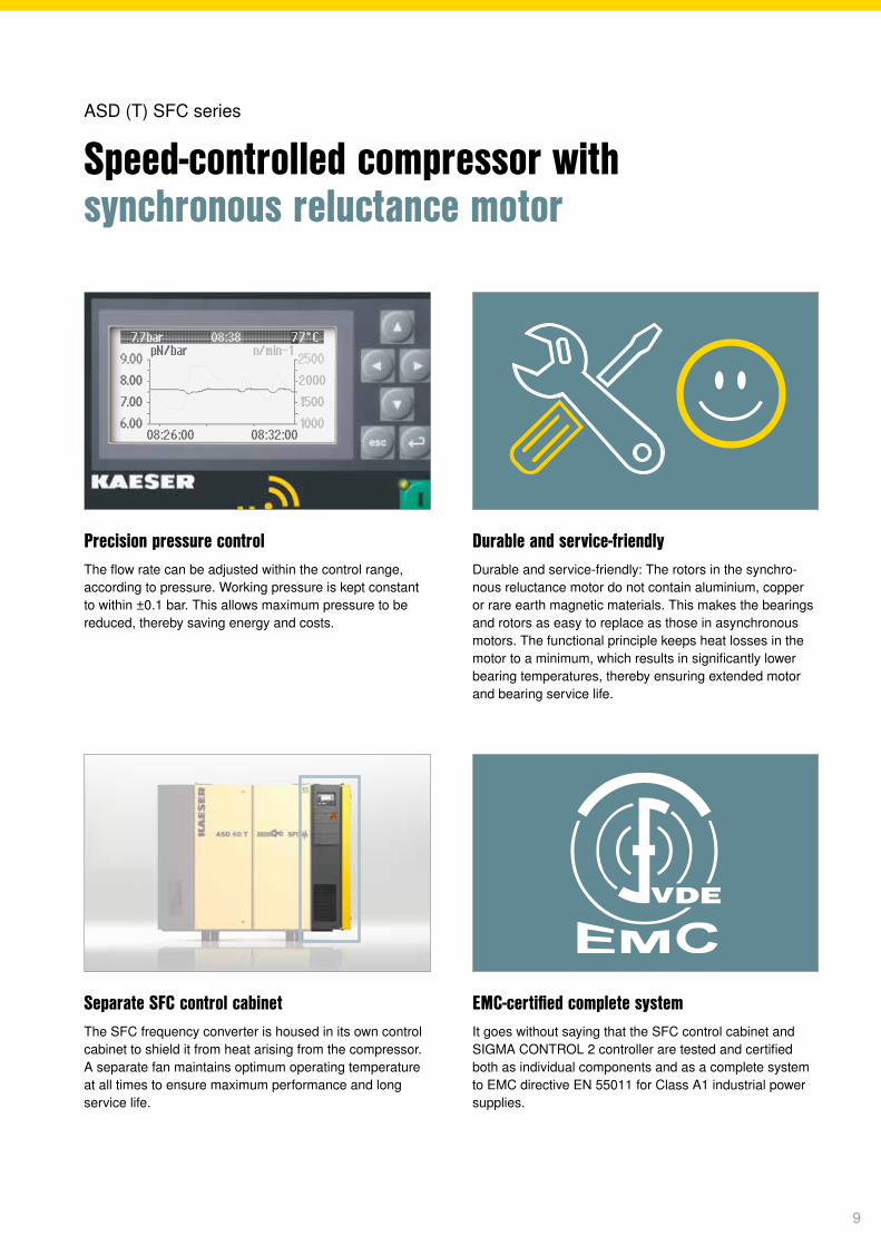
Separate SFC control cabinetThe SFC frequency converter is housed in its own control cabinet to shield it from heat arising from the compressor. A separate fan maintains optimum operating temperature at all times to ensure maximum performance and long service life.
EMC-certified complete systemIt goes without saying that the SFC control cabinet and SIGMA CONTROL 2 controller are tested and certified both as individual components and as a complete system to EMC directive EN 55011 for Class A1 industrial power supplies.
Precision pressure controlThe flow rate can be adjusted within the control range, according to pressure. Working pressure is kept constant to within ±0.1 bar. This allows maximum pressure to be reduced, thereby saving energy and costs.
Durable and service-friendlyDurable and service-friendly: The rotors in the synchro-nous reluctance motor do not contain aluminium, copper or rare earth magnetic materials. This makes the bearings and rotors as easy to replace as those in asynchronous motors. The functional principle keeps heat losses in the motor to a minimum, which results in significantly lower bearing temperatures, thereby ensuring extended motor and bearing service life.
ASD (T) SFC series
Speed-controlled compressor with synchronous reluctance motor
9
Low magnetic resistance
High magnetic resistance
00:00
00:45
01:30
02:15
03:00
03:45
04:30
05:15
06:00
06:45
07:30
08:15
09:00
10:30
11:15
12:00
12:45
13:30
14:15
15:00
15:45
16:30
17:15
18:00
18:45
19:30
21:00
21:45
22:30
23:15
23:30
Time
Flow rate (%)
100
70
30
0
▬ Day 1 ▬ Day 2 ▬ Day 3 ▬ Day 4 ▬ Day 5 ▬ Day 6 ▬ Day 7 ▬ Day 8 ▬ Day 9 ▬ Day 10 ▬ Day 11
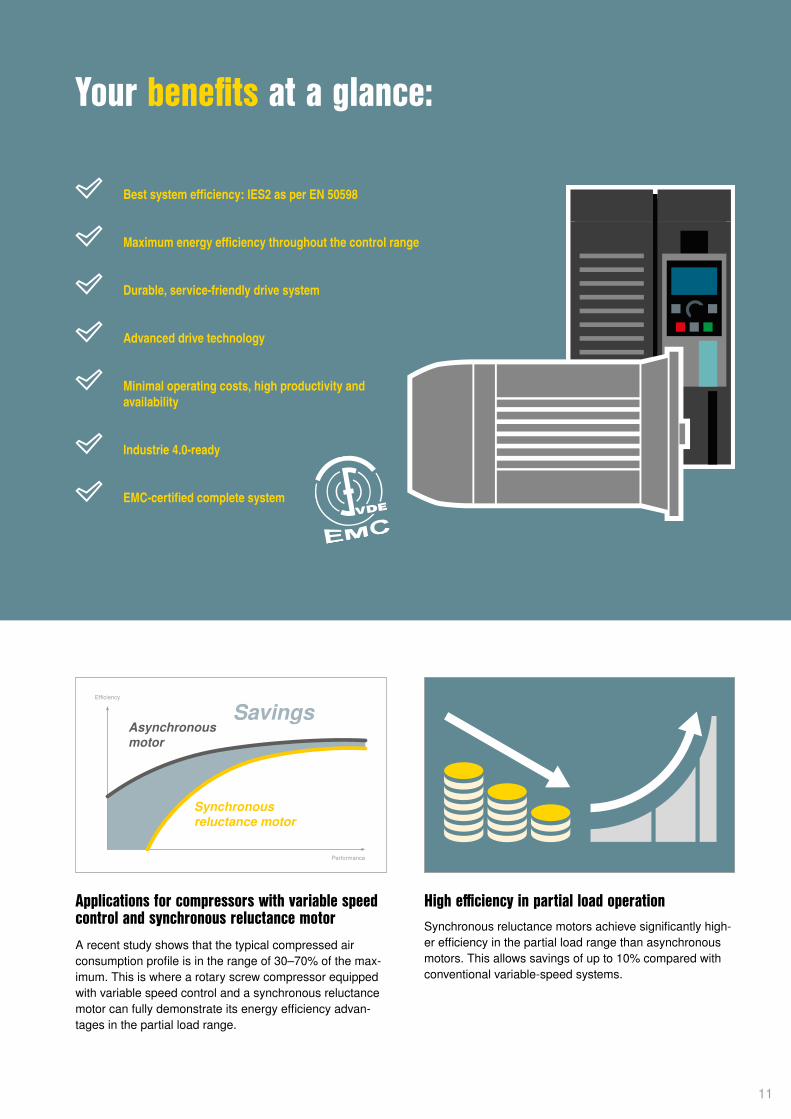
How the reluctance motor worksIn a synchronous reluctance motor, the torque is generat-ed by magnetic reluctance. The rotor features salient poles and is made of a soft magnetic material, such as electrical steel, which is highly permeable to magnetic fields.
Minimal operating costs – exceptional productivity Considerable energy savings are made possible thanks to significantly higher efficiency – especially in the partial load range – compared to systems equipped with asyn-chronous drive motors. The low moment of inertia in syn-chronous reluctance motors allows very short cycle times, thereby boosting the productivity of the machine and the system as a whole.
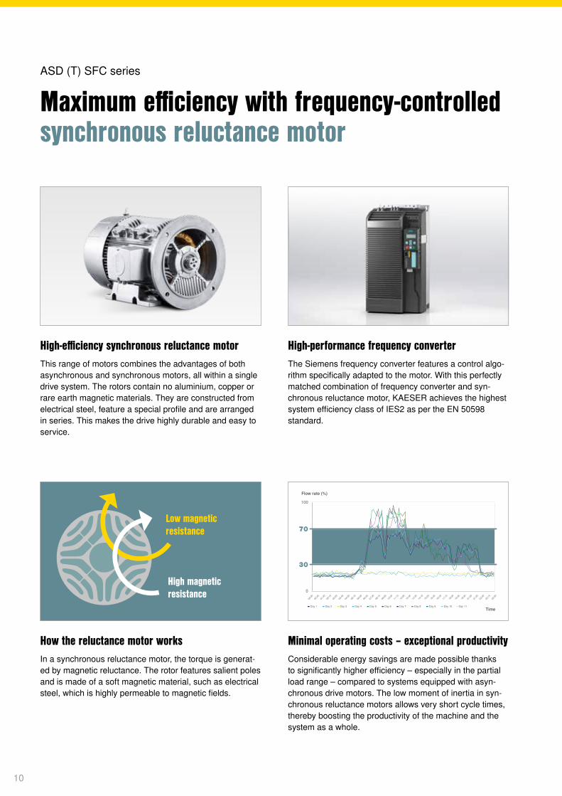
High-efficiency synchronous reluctance motorThis range of motors combines the advantages of both asynchronous and synchronous motors, all within a single drive system. The rotors contain no aluminium, copper or rare earth magnetic materials. They are constructed from electrical steel, feature a special profile and are arranged in series. This makes the drive highly durable and easy to service.
High-performance frequency converter The Siemens frequency converter features a control algo-rithm specifically adapted to the motor. With this perfectly matched combination of frequency converter and syn-chronous reluctance motor, KAESER achieves the highest system efficiency class of IES2 as per the EN 50598 standard.
ASD (T) SFC series
Maximum efficiency with frequency-controlled synchronous reluctance motor
10
Effi ciency
Performance
Asynchronousmotor
Synchronousreluctance motor
Savings
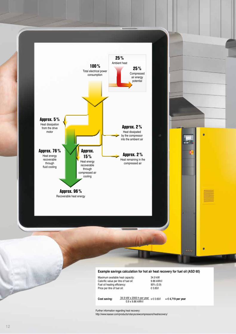
Applications for compressors with variable speed control and synchronous reluctance motorA recent study shows that the typical compressed air consumption profile is in the range of 30–70% of the max-imum. This is where a rotary screw compressor equipped with variable speed control and a synchronous reluctance motor can fully demonstrate its energy efficiency advan-tages in the partial load range.
High efficiency in partial load operationSynchronous reluctance motors achieve significantly high-er efficiency in the partial load range than asynchronous motors. This allows savings of up to 10% compared with conventional variable-speed systems.
Best system efficiency: IES2 as per EN 50598
Maximum energy efficiency throughout the control range
Durable, service-friendly drive system
Advanced drive technology
Minimal operating costs, high productivity and availability
Industrie 4.0-ready
EMC-certified complete system
Your benefits at a glance:
11
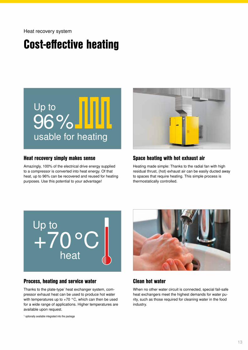
Approx. 5 %Heat dissipationfrom the drive
motor
Approx. 76 %Heat energy recoverable
throughfl uid cooling
Approx. 2 %Heat dissipated
by the compressor into the ambient air
Approx. 2 %Heat remaining in the
compressed air
Approx. 15 %
Heat energy recoverable
through compressed air
cooling
Approx. 96 %Recoverable heat energy
100 %Total electrical power
consumption
25 %Ambient heat
25 %Compressed
air energypotential
Further information regarding heat recovery: http://www.kaeser.com/products/rotaryscrewcompressors/heatrecovery/
Example savings calculation for hot air heat recovery for fuel oil (ASD 60)
Maximum available heat capacity: 34.9 kWCalorific value per litre of fuel oil: 9.86 kWh/lFuel oil heating efficiency: 90% (0.9)Price per litre of fuel oil: € 0.60/l Cost saving: x € 0.60/l = € 4,719 per year34.9 kW x 2000 h per year
0.9 x 9.86 kWh/l
12
Up to
+70°Cheat
Up to
usable for heating96 %
Heat recovery simply makes senseAmazingly, 100% of the electrical drive energy supplied to a compressor is converted into heat energy. Of that heat, up to 96% can be recovered and reused for heating purposes. Use this potential to your advantage!
Clean hot waterWhen no other water circuit is connected, special fail-safe heat exchangers meet the highest demands for water pu-rity, such as those required for cleaning water in the food industry.
Space heating with hot exhaust airHeating made simple: Thanks to the radial fan with high residual thrust, (hot) exhaust air can be easily ducted away to spaces that require heating. This simple process is thermostatically controlled.
Process, heating and service waterThanks to the plate-type* heat exchanger system, com-pressor exhaust heat can be used to produce hot water with temperatures up to +70 °C, which can then be used for a wide range of applications. Higher temperatures are available upon request.*) optionally available integrated into the package
Cost-effective heatingHeat recovery system
13
Jan Mar April May Jun Jul Aug Sep Oct Nov DecFeb
100 %
Required heating energy (%)
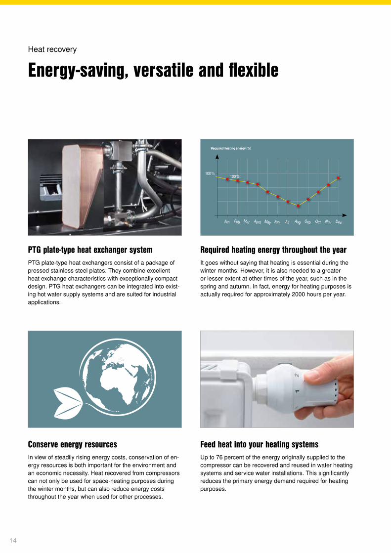
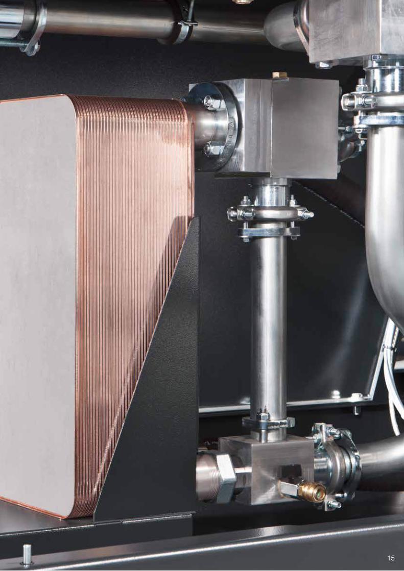
PTG plate-type heat exchanger systemPTG plate-type heat exchangers consist of a package of pressed stainless steel plates. They combine excellent heat exchange characteristics with exceptionally compact design. PTG heat exchangers can be integrated into exist-ing hot water supply systems and are suited for industrial applications.
Feed heat into your heating systemsUp to 76 percent of the energy originally supplied to the compressor can be recovered and reused in water heating systems and service water installations. This significantly reduces the primary energy demand required for heating purposes.
Required heating energy throughout the yearIt goes without saying that heating is essential during the winter months. However, it is also needed to a greater or lesser extent at other times of the year, such as in the spring and autumn. In fact, energy for heating purposes is actually required for approximately 2000 hours per year.
Conserve energy resourcesIn view of steadily rising energy costs, conservation of en-ergy resources is both important for the environment and an economic necessity. Heat recovered from compressors can not only be used for space-heating purposes during the winter months, but can also reduce energy costs throughout the year when used for other processes.
Energy-saving, versatile and flexibleHeat recovery
14
Dez
100 %
15
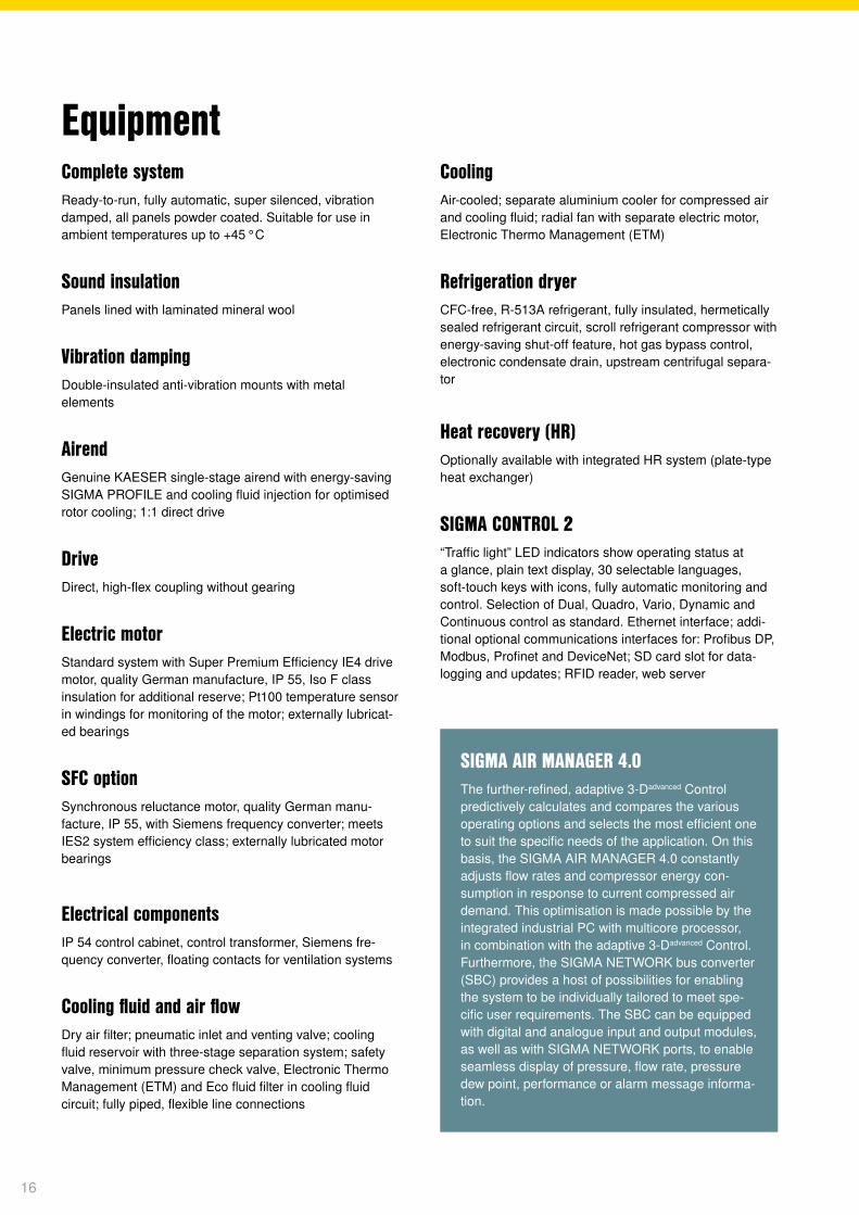
SIGMA AIR MANAGER 4.0The further-refined, adaptive 3-Dadvanced Control predictively calculates and compares the various operating options and selects the most efficient one to suit the specific needs of the application. On this basis, the SIGMA AIR MANAGER 4.0 constantly adjusts flow rates and compressor energy con-sumption in response to current compressed air demand. This optimisation is made possible by the integrated industrial PC with multicore processor, in combination with the adaptive 3-Dadvanced Control. Furthermore, the SIGMA NETWORK bus converter (SBC) provides a host of possibilities for enabling the system to be individually tailored to meet spe-cific user requirements. The SBC can be equipped with digital and analogue input and output modules, as well as with SIGMA NETWORK ports, to enable seamless display of pressure, flow rate, pressure dew point, performance or alarm message informa-tion.
Complete systemReady-to-run, fully automatic, super silenced, vibration damped, all panels powder coated. Suitable for use in ambient temperatures up to +45 °C
Sound insulationPanels lined with laminated mineral wool
Vibration dampingDouble-insulated anti-vibration mounts with metal elements
AirendGenuine KAESER single-stage airend with energy-saving SIGMA PROFILE and cooling fluid injection for optimised rotor cooling; 1:1 direct drive
DriveDirect, high-flex coupling without gearing
Electric motorStandard system with Super Premium Efficiency IE4 drive motor, quality German manufacture, IP 55, Iso F class insulation for additional reserve; Pt100 temperature sensor in windings for monitoring of the motor; externally lubricat-ed bearings
SFC optionSynchronous reluctance motor, quality German manu-facture, IP 55, with Siemens frequency converter; meets IES2 system efficiency class; externally lubricated motor bearings
Electrical componentsIP 54 control cabinet, control transformer, Siemens fre-quency converter, floating contacts for ventilation systems
Cooling fluid and air flowDry air filter; pneumatic inlet and venting valve; cooling fluid reservoir with three-stage separation system; safety valve, minimum pressure check valve, Electronic Thermo Management (ETM) and Eco fluid filter in cooling fluid circuit; fully piped, flexible line connections
EquipmentCoolingAir-cooled; separate aluminium cooler for compressed air and cooling fluid; radial fan with separate electric motor, Electronic Thermo Management (ETM)
Refrigeration dryerCFC-free, R-513A refrigerant, fully insulated, hermetically sealed refrigerant circuit, scroll refrigerant compressor with energy-saving shut-off feature, hot gas bypass control, electronic condensate drain, upstream centrifugal separa-tor
Heat recovery (HR)Optionally available with integrated HR system (plate-type heat exchanger)
SIGMA CONTROL 2“Traffic light” LED indicators show operating status at a glance, plain text display, 30 selectable languages, soft-touch keys with icons, fully automatic monitoring and control. Selection of Dual, Quadro, Vario, Dynamic and Continuous control as standard. Ethernet interface; addi-tional optional communications interfaces for: Profibus DP, Modbus, Profinet and DeviceNet; SD card slot for data- logging and updates; RFID reader, web server
16
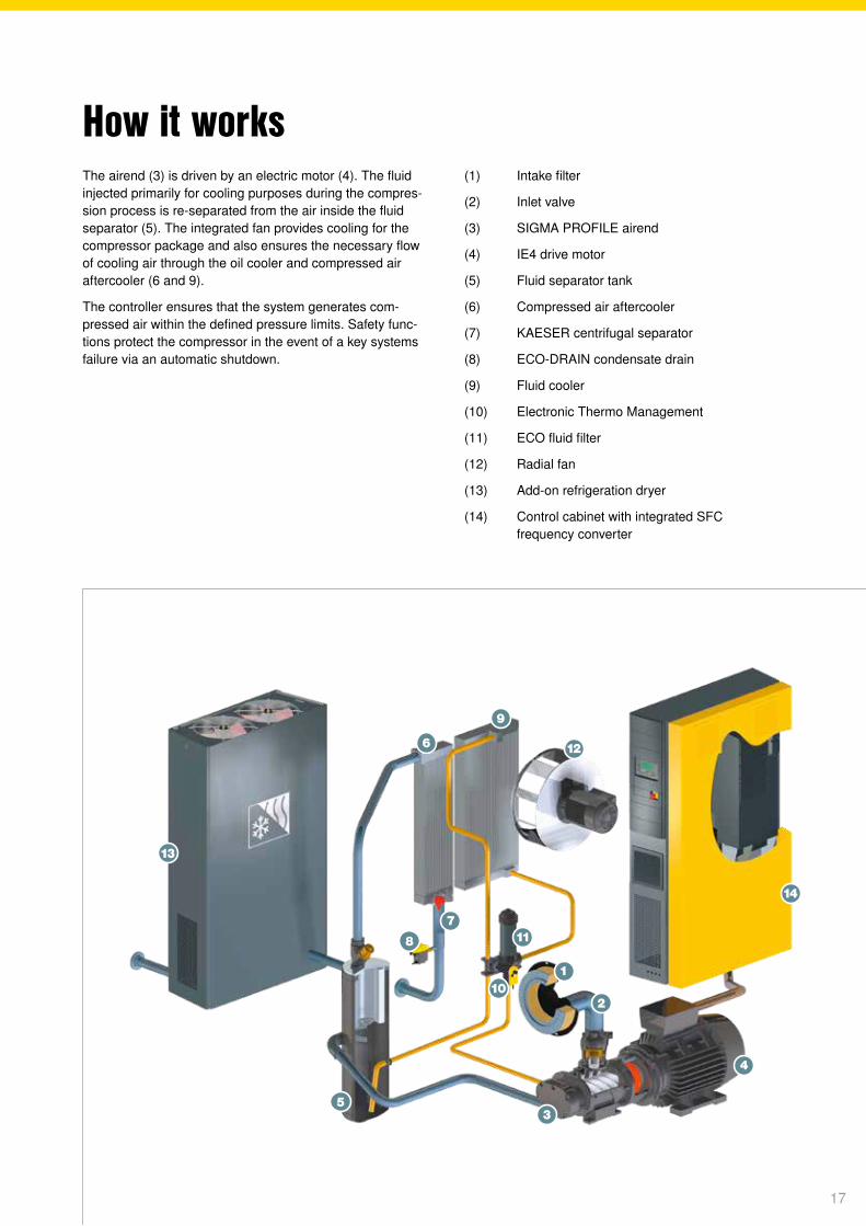
The airend (3) is driven by an electric motor (4). The fluid injected primarily for cooling purposes during the compres-sion process is re-separated from the air inside the fluid separator (5). The integrated fan provides cooling for the compressor package and also ensures the necessary flow of cooling air through the oil cooler and compressed air aftercooler (6 and 9).
The controller ensures that the system generates com-pressed air within the defined pressure limits. Safety func-tions protect the compressor in the event of a key systems failure via an automatic shutdown.
(1) Intake filter
(2) Inlet valve
(3) SIGMA PROFILE airend
(4) IE4 drive motor
(5) Fluid separator tank
(6) Compressed air aftercooler
(7) KAESER centrifugal separator
(8) ECO-DRAIN condensate drain
(9) Fluid cooler
(10) Electronic Thermo Management
(11) ECO fluid filter
(12) Radial fan
(13) Add-on refrigeration dryer
(14) Control cabinet with integrated SFC frequency converter
How it works
17
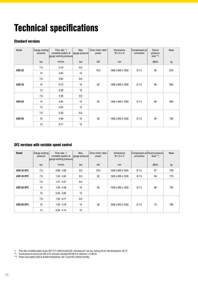
Technical specificationsStandard versions
SFC versions with variable speed control
*) Flow rate, complete system as per ISO 1217: 2009 Annexe C/E: inlet pressure 1 bar (a), cooling and air inlet temperature +20 °C **) Sound pressure level as per ISO 2151 and basic standard ISO 9614-2, tolerance: ± 3 dB (A) ***) Power consumption (kW) at ambient temperature +20° C and 30% relative humidity
Model Gauge working pressure
Flow rate, *) complete system at
gauge working pressure
Max. gauge pressure
Drive motor rated power
DimensionsW x D x H
Compressed air connection
Sound pressure level **)
Mass
bar m³/min bar kW mm dB(A) kg
ASD 35 SFC 7.5 0.88 - 4.00 8.5 18.5 1540 x 900 x 1530 G 1¼ 67 700
ASD 40 SFC 7.5 1.05 - 4.64 8.5 22 1540 x 900 x 1530 G 1¼ 68 710
ASD 50 SFC
7.5 1.07 - 5.27 8.5
25 1540 x 900 x 1530 G 1¼ 68 75510 1.00 - 4.58 13
13 0.93 - 3.82 13
ASD 60 SFC
7.5 1.26 - 6.17 8.5
30 1540 x 900 x 1530 G 1¼ 70 79510 1.00 - 4.76 15
13 0.93 - 4.14 15
Model Gauge working pressure
Flow rate, *) complete system at
gauge working pressure
Max. gauge pressure
Drive motor rated power
DimensionsW x D x H
Compressed air connection
Sound pressure level **)
Mass
bar m³/min bar kW mm dB(A) kg
ASD 357.5 3.16 8.5
18.5 1460 x 900 x 1530 G 1¼ 65 61010 2.63 12
ASD 40
7.5 3.92 8.5
22 1460 x 900 x 1530 G 1¼ 66 65510 3.13 12
13 2.58 15
ASD 50
7.5 4.58 8.5
25 1460 x 900 x 1530 G 1¼ 66 69510 3.85 12
13 3.05 15
ASD 60
7.5 5.53 8.5
30 1460 x 900 x 1530 G 1¼ 69 75010 4.49 12
13 3.71 15
18
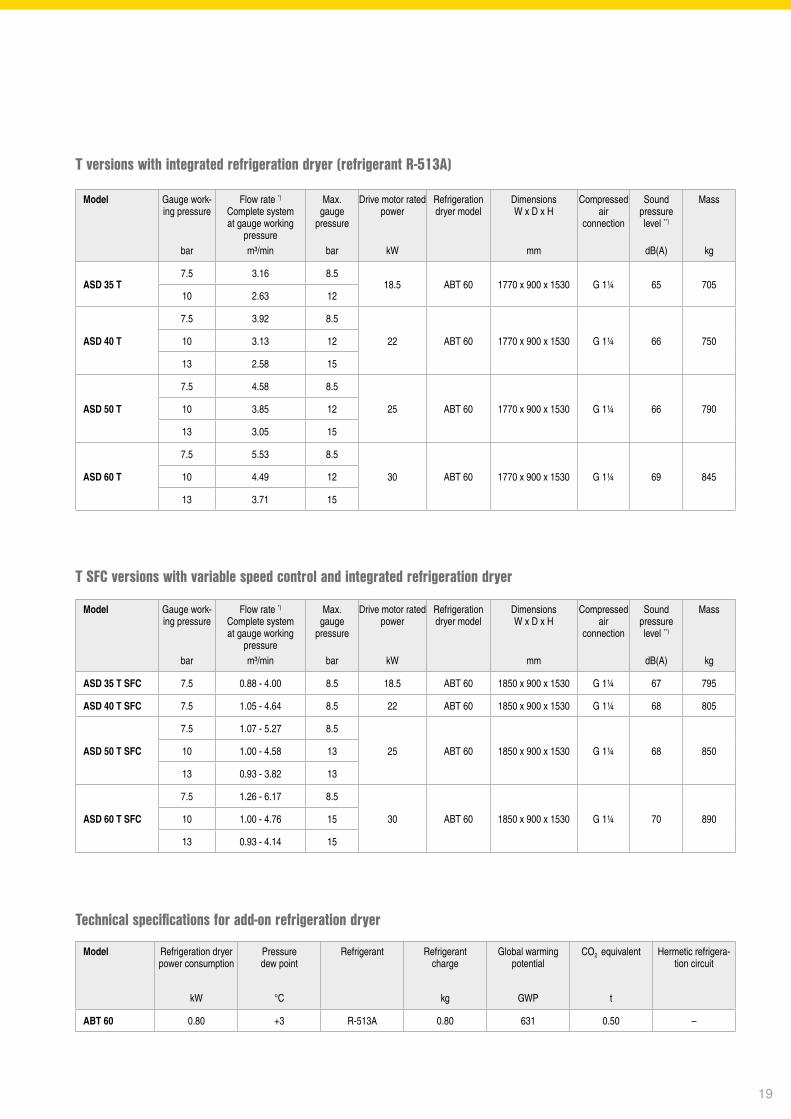
Model Refrigeration dryer power consumption
Pressure dew point
Refrigerant Refrigerantcharge
Global warming potential
CO2 equivalent Hermetic refrigera-tion circuit
kW °C kg GWP t
ABT 60 0.80 +3 R-513A 0.80 631 0.50 –
Technical specifications for add-on refrigeration dryer
T versions with integrated refrigeration dryer (refrigerant R-513A)
T SFC versions with variable speed control and integrated refrigeration dryer
Model Gauge work-ing pressure
Flow rate *) Complete system at gauge working
pressure
Max. gauge
pressure
Drive motor rated power
Refrigeration dryer model
DimensionsW x D x H
Compressed air
connection
Sound pressure level **)
Mass
bar m³/min bar kW mm dB(A) kg
ASD 35 T7.5 3.16 8.5
18.5 ABT 60 1770 x 900 x 1530 G 1¼ 65 70510 2.63 12
ASD 40 T
7.5 3.92 8.5
22 ABT 60 1770 x 900 x 1530 G 1¼ 66 75010 3.13 12
13 2.58 15
ASD 50 T
7.5 4.58 8.5
25 ABT 60 1770 x 900 x 1530 G 1¼ 66 79010 3.85 12
13 3.05 15
ASD 60 T
7.5 5.53 8.5
30 ABT 60 1770 x 900 x 1530 G 1¼ 69 84510 4.49 12
13 3.71 15
Model Gauge work-ing pressure
Flow rate *) Complete system at gauge working
pressure
Max. gauge
pressure
Drive motor rated power
Refrigeration dryer model
DimensionsW x D x H
Compressed air
connection
Sound pressure level **)
Mass
bar m³/min bar kW mm dB(A) kg
ASD 35 T SFC 7.5 0.88 - 4.00 8.5 18.5 ABT 60 1850 x 900 x 1530 G 1¼ 67 795
ASD 40 T SFC 7.5 1.05 - 4.64 8.5 22 ABT 60 1850 x 900 x 1530 G 1¼ 68 805
ASD 50 T SFC
7.5 1.07 - 5.27 8.5
25 ABT 60 1850 x 900 x 1530 G 1¼ 68 85010 1.00 - 4.58 13
13 0.93 - 3.82 13
ASD 60 T SFC
7.5 1.26 - 6.17 8.5
30 ABT 60 1850 x 900 x 1530 G 1¼ 70 89010 1.00 - 4.76 15
13 0.93 - 4.14 15
19
The world is our homeAs one of the world’s largest manufacturers of compressors, blowers and compressed air systems, KAESER KOMPRESSOREN is represented throughout the world by a comprehensive network of branches, subsidiaries and authorised distribution partners in over 140 countries.
By offering innovative, effi cient and reliable products and services, KAESER KOMPRESSOREN’s experienced consultants and engineers work in close partnership with customers to enhance their competitive edge and to develop progressive system concepts that continuously push the boundaries of performance and technology. Moreover, decades of knowledge and expertise from this industry-leading systems provider are made available to each and every customer via the KAESER group’s advanced global IT network.
These advantages, coupled with KAESER’s worldwide service organisation, ensure that every product operates at peak performance at all times, whilst providing maximum availability.
KAESER COMPRESSORS Australia Pty. Ltd.Locked Bag 1406 – Dandenong South – Vic. 316445 Zenith Road – Dandenong – Vic. 3175Phone: +61 39791 5999 – Fax: +61 39791 5733www.kaeser.com – E-mail: [email protected]
KAESER COMPRESSORS NZ LimitedPO BOX 301261 – Albany – Auckland 075218B Tarndale Grove – Albany – Auckland 0632Phone +64 9 941 0499www.kaeser.com – E-mail: [email protected] P-
651/
2AUS
S
pecifi
catio
ns s
ubje
ct to
cha
nge
with
out n
otice
. .5
/21
Related Documents