Avid CNC Rotary Axis Users Guide v2021Q1.1

Welcome message from author
This document is posted to help you gain knowledge. Please leave a comment to let me know what you think about it! Share it to your friends and learn new things together.
Transcript

Avid CNC Rotary Axis Users Guide
v2021Q1.1

Rotary Axis Users Guide
Version 2021Q1.1 © 2021 Avid CNC
All Rights Reserved
1. Mach4 Control Software
If you have not installed and con�gured Mach4, follow the instructions in the Mach4 Software Setup Guide(https://www.avidcnc.com/support/instructions/software/mach4). The con�guration section below is additional steps forsetting up Mach4 with rotary that you may have previously completed in the calibration section.
1.1 Con�guration
1.1.1
Navigate to Avid CNC Machine Con�guration.
Operation Note

Rotary Axis Users Guide
Version 2021Q1.1 © 2021 Avid CNC
All Rights Reserved
1.1.2
Select the Avid CNC Rotary Axis 4th Axis option.
Rotary Axis Users Guide
Version 2021Q1.1 © 2021 Avid CNC
All Rights Reserved
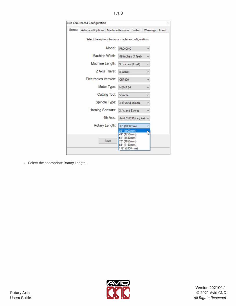
1.1.3
Select the appropriate Rotary Length.

Rotary Axis Users Guide
Version 2021Q1.1 © 2021 Avid CNC
All Rights Reserved
1.1.4
Save your changes.

Rotary Axis Users Guide
Version 2021Q1.1 © 2021 Avid CNC
All Rights Reserved
1.2 Operation
1.2.1
Navigate to the Machine Setup tab.
Select a "Rotary Axis Enabled" Cutting Method.
The Machine Setup Notes section contains information about control box connections that may need to be changed whenswitching cutting methods.
Operation Note

Rotary Axis Users Guide
Version 2021Q1.1 © 2021 Avid CNC
All Rights Reserved
1.2.2
When you enable Mach4, you will now be able to use the Home A Axis and Zero A buttons.

Rotary Axis Users Guide
Version 2021Q1.1 © 2021 Avid CNC
All Rights Reserved
1.2.3
The Diagnostics tab will now contain an A axis homing sensor LED.

Rotary Axis Users Guide
Version 2021Q1.1 © 2021 Avid CNC
All Rights Reserved
1.3 Homing
The homing sensor installed in Section 1.6.2 of the Rotary Assembly Instructions provides the ability to home your rotaryaxis. This is a convenient way to rotationally position your workpiece relative to the spindle (or router).
It may be necessary to adjust the home offset to achieve the desired workpiece orientation. This can be done by enablingCustom Homing Settings (https://www.avidcnc.com/support/instructions/software/mach4Con�guration/#3-advanced-settings) and adjusting the Home Offset(https://www.avidcnc.com/support/instructions/software/mach4UsersGuide/#homing-and-soft-limits) value.

Rotary Axis Users Guide
Version 2021Q1.1 © 2021 Avid CNC
All Rights Reserved
1.4 Touch Plate Use
For proper use of the Auto Z Touch Plate, ensure you have completed the "Touch Plate Offset" section in either theRecessed or Table Top Installation and Calibration Instructions.
1.4.1
Enable Mach4 and click the Auto Z Touch Plate button.

Rotary Axis Users Guide
Version 2021Q1.1 © 2021 Avid CNC
All Rights Reserved
1.4.2
With a rotary cutting method enabled, you will see a Rotary tab.
This contains the touch plate functions to be used speci�cally with your rotary axis.

Rotary Axis Users Guide
Version 2021Q1.1 © 2021 Avid CNC
All Rights Reserved
1.4.3
Ensure you enter the correct tool diameter (not required if only zeroing Z axis).

Rotary Axis Users Guide
Version 2021Q1.1 © 2021 Avid CNC
All Rights Reserved
1.4.4
The Rotary Touch Operations section contains the buttons you will use after your rotary axis is calibrated.
Z Axis Touch: This will zero your Z axis relative to the center of the chuck.
Y Axis Touch: This will zero the Y axis (or X axis if your rotary axis is mounted parallel to the Y axis) relative to thecenter of the chuck.
Multi-Axis Touch: This is a combination of the above two buttons. It will touch off in the Z and Y (or X) direction.
You will need to manually zero the axis parallel to your rotary axis (at the appropriate position based on your workpiece). Ifyour rotary axis is parallel to the X axis, you will need to zero the Y axis. If mounted parallel to the Y axis, you will need tozero the X axis.
Operation Note

Rotary Axis Users Guide
Version 2021Q1.1 © 2021 Avid CNC
All Rights Reserved
2. Post Processors
2.1 Vectric
Avid CNC has created rotary post processors for Vectric software (VCarve Pro and Aspire versions 9.5 and newer). An AvidCNC Posts for Vectric Software (https://www.avidcnc.com/support/instructions/software/downloads/vectric) installer isavailable that will install the new post processors.
After you have installed the post processors, you will see four Avid CNC Wrap options used for rotary wrapping:
1. Avid CNC Wrap X2A G93 (inch): G20 (inch) units, wraps X moves to A moves. Toolpaths will be wrapped around the Yaxis.
2. Avid CNC Wrap X2A G93 (mm): G21 (mm) units, wraps X moves to A moves. Toolpaths will be wrapped around the Yaxis.
3. Avid CNC Wrap Y2A G93 (inch): G20 (inch) units, wraps Y moves to A moves. Toolpaths will be wrapped around the Xaxis.
4. Avid CNC Wrap Y2A G93 (mm): G21 (mm) units, wraps Y moves to A moves. Toolpaths will be wrapped around the Xaxis.

Rotary Axis Users Guide
Version 2021Q1.1 © 2021 Avid CNC
All Rights Reserved
2.2 Autodesk Fusion 360
Avid CNC has created rotary post processors for Autodesk Fusion 360 and are available for download(https://www.avidcnc.com/support/instructions/software/downloads/fusion). This includes two rotary post processors:
1. Avid CNC Warp X to A: Wraps X moves to A moves. Toolpaths will be wrapped around the Y axis. Units (G20 or G21)will be determined from the document units in Fusion.
2. Avid CNC Warp Y to A: Wraps Y moves to A moves. Toolpaths will be wrapped around the X axis. Units (G20 or G21)will be determined from the document units in Fusion.
There are two options for how to install the posts:
1. Install post processor to a Cloud library in Fusion 360 (https://knowledge.autodesk.com/support/fusion-360/learn-explore/caas/sfdcarticles/sfdcarticles/How-to-install-a-cloud-post-in-Fusion-360.html)
2. Install a personal (locally saved) post processor in Fusion 360 CAM (https://knowledge.autodesk.com/support/fusion-360/learn-explore/caas/sfdcarticles/sfdcarticles/How-to-add-a-Post-Processor-to-your-Personal-Posts-in-Fusion-360.html)

Rotary Axis Users Guide
Version 2021Q1.1 © 2021 Avid CNC
All Rights Reserved
3. Rotary Work�ow
This section describes the basic steps necessary to get started using your rotary axis. Links are provided to additionalinformation where possible.
3.1 Create G Code
3.1.1
Many of the common CAM software packages with rotary capabilities have documentation for generating tool paths.
VCarve Pro: Rotary Machining and Wrapping (https://docs.vectric.com/docs/V9.5/VCarvePro/ENU/Help/UserGuide/Process/Rotary/Rotary Machining and Wrapping.html)
Aspire: Rotary Machining and Wrapping (https://docs.vectric.com/docs/V9.0/Aspire/ENU/Help/Toolpaths/RotaryMachining and Wrapping/Rotary Machining and Wrapping.html)
Fusion 360: 4th Axis Wrap Toolpath (https://help.autodesk.com/view/fusion360/ENU/?guid=GUID-7FF25192-AED7-4230-92DC-E22ADF15D498)
If you want to perform indexing operations in Fusion 360, you can setup a different tool orientation for eachoperation within a single setup.
3.1.2
Ensure you have downloaded and installed the rotary post processors (see section 2) for your CAM software.
Select the appropriate post processor to wrap either your X axis or Y axis moves to A axis moves.

Rotary Axis Users Guide
Version 2021Q1.1 © 2021 Avid CNC
All Rights Reserved
3.1.3
If using VCarve Pro or Aspire, in your Material Setup settings, ensure your Z-Zero is set to Center of Cylinder.
Only use Surface of Cylinder if you will be manually setting all work offsets. Using the Auto Z Touch Plate will set workoffsets to the center of the cylinder.
Operation Note

Rotary Axis Users Guide
Version 2021Q1.1 © 2021 Avid CNC
All Rights Reserved
3.1.4
If using Fusion 360, your WCS needs to be located at the center of your part.
Only use a different WCS location if you will be manually setting all work offsets. Using the Auto Z Touch Plate will set workoffsets to the center of your workpiece.
Operation Note

Rotary Axis Users Guide
Version 2021Q1.1 © 2021 Avid CNC
All Rights Reserved
3.2 Workpiece Setup
Depending on the length of your workpiece and material used, it is possible to mount your workpiece in the chuck withoutuse of the tailstock. However, in most cases it is recommended to use the tailstock to support the end of your workpiece.The following instructions include use of the tailstock.
3.2.1
Your rotary kit contains two sets of jaws, inside and outside jaws. These provide options to properly secure variousworkpiece sizes in the chuck. Each jaw is numbered 1, 2, 3, or 4 and correspond to the numbers stamped on the guide slotsof the chuck.
To change jaws, follow the steps below:
1. Use the chuck key to loosen the jaws until you can remove all four from their guide slots.
2. Position the �rst thread of the scroll gear just to the right of slot 1.
3. Insert the jaw marked "1" into the guide slot.
4. While pressing the jaw inward, turn the chuck key to advance the �rst thread of the scroll gear just to the right of slot 2.
5. Insert the jaw marked "2" into the guide slot.

Rotary Axis Users Guide
Version 2021Q1.1 © 2021 Avid CNC
All Rights Reserved
6. Repeat the above steps for jaws 3 and 4.
7. When installed properly, all four jaws will meet at the center of the chuck.

Rotary Axis Users Guide
Version 2021Q1.1 © 2021 Avid CNC
All Rights Reserved
3.2.2
Tailstock end of workpiece
Mark center of workpiece
At the tailstock end of your workpiece, mark the center point.

Rotary Axis Users Guide
Version 2021Q1.1 © 2021 Avid CNC
All Rights Reserved
3.2.3
For square workpieces, draw diagonal lines from each corner to �nd the center.

Rotary Axis Users Guide
Version 2021Q1.1 © 2021 Avid CNC
All Rights Reserved
3.2.4
Insert the workpiece into the chuck and tighten with the chuck key.

Rotary Axis Users Guide
Version 2021Q1.1 © 2021 Avid CNC
All Rights Reserved
3.2.5
Fully retract the tailstock's live center.

Rotary Axis Users Guide
Version 2021Q1.1 © 2021 Avid CNC
All Rights Reserved
3.2.6
Move the tailstock to the closest lock position to the workpiece.
Lock both spring plungers.

Rotary Axis Users Guide
Version 2021Q1.1 © 2021 Avid CNC
All Rights Reserved
3.2.7
Center of workpiece
Tighten the live center at the workpiece center point.

Rotary Axis Users Guide
Version 2021Q1.1 © 2021 Avid CNC
All Rights Reserved
3.2.8
Tighten the tailstock clamp.

Rotary Axis Users Guide
Version 2021Q1.1 © 2021 Avid CNC
All Rights Reserved
3.3 Work Offsets
Before running your program you will need to use the Auto Z Touch Plate to set your work offsets. Review the Touch Platesection for proper usage of the rotary touch plate functions.
3.3.1
MANUALLY setX axis offset
Set Z axis offsetwith touch plate
Set Y axis offsetwith touch plate
Mounted parallel to X axis
When your rotary assembly is mounted parallel to the X axis, use the touch plate to set the Z and Y axis offsets.
You will need to MANUALLY set the X axis offset, explained in step 3.3.3.

Rotary Axis Users Guide
Version 2021Q1.1 © 2021 Avid CNC
All Rights Reserved
3.3.2
MANUALLY setY axis offset
Set Z axis offsetwith touch plate
Set X axis offsetwith touch plate
Mounted parallel to Y axis
When your rotary assembly is mounted parallel to the Y axis, use the touch plate to set the Z and X axis offsets.
You will need to MANUALLY set the Y axis offset, explained in step 3.3.3.

Rotary Axis Users Guide
Version 2021Q1.1 © 2021 Avid CNC
All Rights Reserved
3.3.3
To set manually set the offset for the third axis (either X or Y, depending on orientation), jog the machine to yourdesired start position and click the Zero X or Zero Y button in Mach4.

Rotary Axis Users Guide
Version 2021Q1.1 © 2021 Avid CNC
All Rights Reserved
3.3.4
If your workpiece requires a speci�c A axis zero position, use the Home A Axis button. This will square the jaws to yourspindle which can then be used as a reference to zero the A axis.
Related Documents