Product Data Sheet June 2013 00813-0500-4485, Rev EC Energy savings gained through minimal permanent pressure loss Variety of sensor materials Flexible mounting options Rosemount 485 Annubar Primary Element Technology Innovative T-shape design that increases accuracy to +/-0.75% of flow rate Integral thermowell design saves installation time and cost Higher signal strength enhances measurement at low flows Rosemount 585 Annubar Primary Element Technology Handles applications where conditions exceed the structural limitations of other primary elements Symmetrical sensor design allows bi-directional flow measurement Rosemount Annubar Primary Elements

Welcome message from author
This document is posted to help you gain knowledge. Please leave a comment to let me know what you think about it! Share it to your friends and learn new things together.
Transcript
Product Data SheetJune 2013
00813-0500-4485, Rev EC
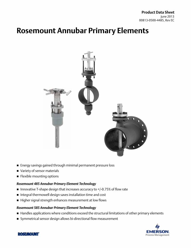
Rosemount Annubar Primary Elements
Energy savings gained through minimal permanent pressure loss
Variety of sensor materials
Flexible mounting options
Rosemount 485 Annubar Primary Element Technology
Innovative T-shape design that increases accuracy to +/-0.75% of flow rate
Integral thermowell design saves installation time and cost
Higher signal strength enhances measurement at low flows
Rosemount 585 Annubar Primary Element Technology
Handles applications where conditions exceed the structural limitations of other primary elements
Symmetrical sensor design allows bi-directional flow measurement
Rosemount DP Flow June 2013
Contents
Rosemount 485 Annubar Primary Element
Rosemount 485 Annubar Primary Ordering Information . . . . . . . . . . . . . . . . . . . . . . . . . . . . . . . . . . . . . . . . . . page 4
Rosemount 485 specifications . . . . . . . . . . . . . . . . . . . . . . . . . . . . . . . . . . . . . . . . . . . . . . . . . . . . . . . . . . . . . . . . . . page 9
Rosemount 585 Annubar Primary Element
Rosemount 585 Annubar Ordering Information . . . . . . . . . . . . . . . . . . . . . . . . . . . . . . . . . . . . . . . . . . . . . . . . .page 12
Rosemount 585 specifications . . . . . . . . . . . . . . . . . . . . . . . . . . . . . . . . . . . . . . . . . . . . . . . . . . . . . . . . . . . . . . . . .page 18
Dimensional Drawings
485 Dimensional Drawings . . . . . . . . . . . . . . . . . . . . . . . . . . . . . . . . . . . . . . . . . . . . . . . . . . . . . . . . . . . . . . . . . . . .page 24
Rosemount 585 dimensional drawings . . . . . . . . . . . . . . . . . . . . . . . . . . . . . . . . . . . . . . . . . . . . . . . . . . . . . . . . .page 32
Installation and Flowmeter Orientation . . . . . . . . . . . . . . . . . . . . . . . . . . . . . . . . . . . . . . . . . . . . . . . . . . . . . . . . . . . . . Click Here
2 www.rosemount.com

Rosemount DP FlowJune 2013
3www.rosemount.com
Rosemount DP Flow June 2013
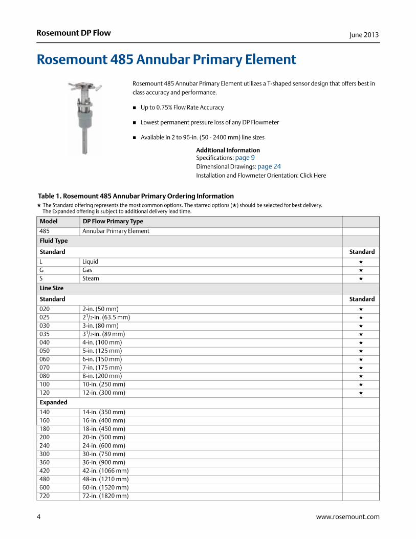
Rosemount 485 Annubar Primary Element
Rosemount 485 Annubar Primary Element utilizes a T-shaped sensor design that offers best in class accuracy and performance.
Up to 0.75% Flow Rate Accuracy
Lowest permanent pressure loss of any DP Flowmeter
Available in 2 to 96-in. (50 - 2400 mm) line sizes
Additional InformationSpecifications: page 9Dimensional Drawings: page 24Installation and Flowmeter Orientation: Click Here
Table 1. Rosemount 485 Annubar Primary Ordering Information★ The Standard offering represents the most common options. The starred options (★) should be selected for best delivery.__The Expanded offering is subject to additional delivery lead time.
Model DP Flow Primary Type
485 Annubar Primary Element
Fluid Type
Standard Standard
L Liquid ★
G Gas ★
S Steam ★
Line Size
Standard Standard
020 2-in. (50 mm) ★
025 21/2-in. (63.5 mm) ★
030 3-in. (80 mm) ★
035 31/2-in. (89 mm) ★
040 4-in. (100 mm) ★
050 5-in. (125 mm) ★
060 6-in. (150 mm) ★
070 7-in. (175 mm) ★
080 8-in. (200 mm) ★
100 10-in. (250 mm) ★
120 12-in. (300 mm) ★
Expanded
140 14-in. (350 mm)160 16-in. (400 mm)180 18-in. (450 mm)200 20-in. (500 mm)240 24-in. (600 mm)300 30-in. (750 mm)360 36-in. (900 mm)420 42-in. (1066 mm)480 48-in. (1210 mm)600 60-in. (1520 mm)720 72-in. (1820 mm)
4 www.rosemount.com
Rosemount DP FlowJune 2013
5www.rosemount.com
780 78-in. (1950 mm)840 84-in. (2100 mm)900 90-in. (2250 mm)960 96-in. (2400 mm)
Pipe I.D. Range (See “Pipe I.D. Range Code” on page 21)
Standard Standard
C Range C from the Pipe I.D. table ★
D Range D from the Pipe I.D. table ★
Expanded
A Range A from the Pipe I.D. tableB Range B from the Pipe I.D. tableE Range E from the Pipe I.D. tableZ Non-standard Pipe I.D. Range or Above 12-in. Line Size
Pipe Material / Assembly Material
Standard Standard
C Carbon steel (A105) ★
S 316 Stainless Steel ★
0(1) No mounting (Customer Supplied) ★
Expanded
G Chrome-Moly Grade F-11N Chrome-Moly Grade F-22J Chrome-Moly Grade F-91
Piping Orientation
Standard Standard
H Horizontal Piping ★
D Vertical Piping with Downwards Flow ★
U Vertical Piping with Upwards Flow ★
Annubar Type
Standard Standard
P Pak-Lok ★
F Flanged with opposite side support ★
Expanded
L Flange-LokG Gear-Drive Flo-TapM Manual Flo-Tap
Sensor Material
Standard Standard
S 316 Stainless Steel ★
Expanded
H Alloy C-276
Sensor Size
Standard Standard
1 Sensor size 1 — Line sizes 2-in. (50 mm) to 8-in. (200 mm) ★
2 Sensor size 2 — Line sizes 6-in. (150 mm) to 96-in. (2400 mm) ★
3 Sensor size 3 — Line sizes greater than 12-in. (300 mm) ★
Table 1. Rosemount 485 Annubar Primary Ordering Information★ The Standard offering represents the most common options. The starred options (★) should be selected for best delivery.__The Expanded offering is subject to additional delivery lead time.
Rosemount DP Flow June 2013
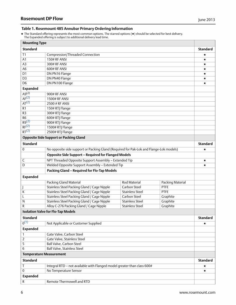
Mounting Type
Standard Standard
T1 Compression/Threaded Connection ★
A1 150# RF ANSI ★
A3 300# RF ANSI ★
A6 600# RF ANSI ★
D1 DN PN16 Flange ★
D3 DN PN40 Flange ★
D6 DN PN100 Flange ★
Expanded
A9(2) 900# RF ANSIAF(2) 1500# RF ANSIAT(2) 2500 # RF ANSIR1 150# RTJ FlangeR3 300# RTJ FlangeR6 600# RTJ FlangeR9(2) 900# RTJ FlangeRF(2) 1500# RTJ FlangeRT(2) 2500# RTJ Flange
Opposite Side Support or Packing Gland
Standard Standard
0 No opposite side support or Packing Gland (Required for Pak-Lok and Flange-Lok models) ★
Opposite Side Support – Required for Flanged Models
C NPT Threaded Opposite Support Assembly – Extended Tip ★
D Welded Opposite Support Assembly – Extended Tip ★
Packing Gland – Required for Flo-Tap Models
Expanded
Packing Gland Material Rod Material Packing MaterialJ Stainless Steel Packing Gland / Cage Nipple Carbon Steel PTFEK Stainless Steel Packing Gland / Cage Nipple Stainless Steel PTFEL Stainless Steel Packing Gland / Cage Nipple Carbon Steel GraphiteN Stainless Steel Packing Gland / Cage Nipple Stainless Steel GraphiteR Alloy C-276 Packing Gland / Cage Nipple Stainless Steel Graphite
Isolation Valve for Flo-Tap Models
Standard Standard
0(1) Not Applicable or Customer Supplied ★
Expanded
1 Gate Valve, Carbon Steel2 Gate Valve, Stainless Steel5 Ball Valve, Carbon Steel6 Ball Valve, Stainless Steel
Temperature Measurement
Standard Standard
T Integral RTD – not available with Flanged model greater than class 600# ★
0 No Temperature Sensor ★
Expanded
R Remote Thermowell and RTD
Table 1. Rosemount 485 Annubar Primary Ordering Information★ The Standard offering represents the most common options. The starred options (★) should be selected for best delivery.__The Expanded offering is subject to additional delivery lead time.
6 www.rosemount.com
Rosemount DP FlowJune 2013
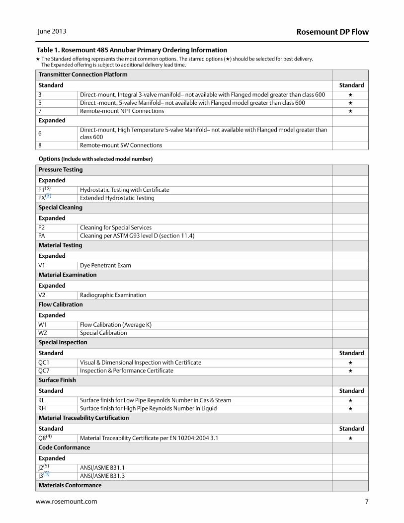
Transmitter Connection Platform
Standard Standard
3 Direct-mount, Integral 3-valve manifold– not available with Flanged model greater than class 600 ★
5 Direct -mount, 5-valve Manifold– not available with Flanged model greater than class 600 ★
7 Remote-mount NPT Connections ★
Expanded
6Direct-mount, High Temperature 5-valve Manifold– not available with Flanged model greater than class 600
8 Remote-mount SW Connections
Options (Include with selected model number)
Pressure Testing
Expanded
P1(3) Hydrostatic Testing with CertificatePX(3) Extended Hydrostatic Testing
Special Cleaning
Expanded
P2 Cleaning for Special ServicesPA Cleaning per ASTM G93 level D (section 11.4)
Material Testing
Expanded
V1 Dye Penetrant Exam
Material Examination
Expanded
V2 Radiographic Examination
Flow Calibration
Expanded
W1 Flow Calibration (Average K)WZ Special Calibration
Special Inspection
Standard Standard
QC1 Visual & Dimensional Inspection with Certificate ★
QC7 Inspection & Performance Certificate ★
Surface Finish
Standard Standard
RL Surface finish for Low Pipe Reynolds Number in Gas & Steam ★
RH Surface finish for High Pipe Reynolds Number in Liquid ★
Material Traceability Certification
Standard Standard
Q8(4) Material Traceability Certificate per EN 10204:2004 3.1 ★
Code Conformance
Expanded
J2(5) ANSI/ASME B31.1J3(5) ANSI/ASME B31.3
Materials Conformance
Table 1. Rosemount 485 Annubar Primary Ordering Information★ The Standard offering represents the most common options. The starred options (★) should be selected for best delivery.__The Expanded offering is subject to additional delivery lead time.
7www.rosemount.com
Rosemount DP Flow June 2013
Expanded
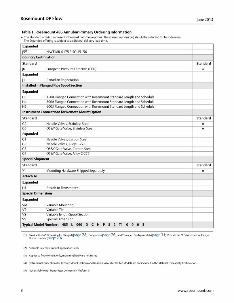
J5(6) NACE MR-0175 / ISO 15156
Country Certification
Standard Standard
J6 European Pressure Directive (PED) ★
Expanded
J1 Canadian Registration
Installed in Flanged Pipe Spool Section
Expanded
H3 150# Flanged Connection with Rosemount Standard Length and ScheduleH4 300# Flanged Connection with Rosemount Standard Length and ScheduleH5 600# Flanged Connection with Rosemount Standard Length and Schedule
Instrument Connections for Remote Mount Option
Standard Standard
G2 Needle Valves, Stainless Steel ★
G6 OS&Y Gate Valve, Stainless Steel ★
Expanded
G1 Needle Valves, Carbon SteelG3 Needle Valves, Alloy C-276G5 OS&Y Gate Valve, Carbon SteelG7 OS&Y Gate Valve, Alloy C-276
Special Shipment
Standard Standard
Y1 Mounting Hardware Shipped Separately ★
Attach To
Expanded
H1 Attach to Transmitter
Special Dimensions
Expanded
VM Variable MountingVT Variable TipVS Variable length Spool SectionV9 Special Dimension
Typical Model Number: 485 L 060 D C H P S 2 T1 0 0 0 3
(1) Provide the “A” dimension for Flanged (page 28), Flange-Lok (page 26), and Threaded Flo-Tap models (page 31). Provide the “B” dimension for Flange Flo-Tap models (page 29).
(2) Available in remote mount applications only.
(3) Applies to flow element only, mounting hardware not tested.
(4) Instrument Connections for Remote Mount Options and Isolation Valves for Flo-tap Models are not included in the Material Traceability Certification.
(5) Not available with Transmitter Connection Platform 6.
Table 1. Rosemount 485 Annubar Primary Ordering Information★ The Standard offering represents the most common options. The starred options (★) should be selected for best delivery.__The Expanded offering is subject to additional delivery lead time.
8 www.rosemount.com
Rosemount DP FlowJune 2013
Rosemount 485 specifications
Rosemount 485 performance specifications
Performance statement assumptionsMeasured pipe I.D. (or Measured pipe cross sectional area)
Discharge coefficient factor±0.75% of flow rate
Repeatability±0.1%
Line Sizes
Sensor Size 1: 2-in. to 8-in. (50 to 200 mm)
Sensor Size 2: 6-in. to 96-in. (150 to 2400 mm)
Sensor Size 3: 12-in. to 96-in. (300 to 2400 mm)
NoteSome mounting types are not available in larger line sizes.
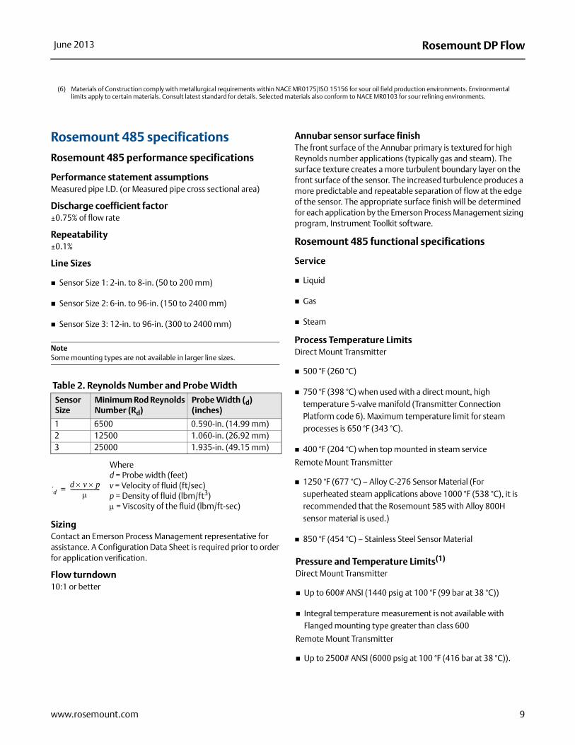
Table 2. Reynolds Number and Probe Width
Sizing Contact an Emerson Process Management representative for assistance. A Configuration Data Sheet is required prior to order for application verification.
Flow turndown10:1 or better
Annubar sensor surface finishThe front surface of the Annubar primary is textured for high Reynolds number applications (typically gas and steam). The surface texture creates a more turbulent boundary layer on the front surface of the sensor. The increased turbulence produces a more predictable and repeatable separation of flow at the edge of the sensor. The appropriate surface finish will be determined for each application by the Emerson Process Management sizing program, Instrument Toolkit software.
Rosemount 485 functional specifications
Service
Liquid
Gas
Steam
Process Temperature LimitsDirect Mount Transmitter
500 °F (260 °C)
750 °F (398 °C) when used with a direct mount, high temperature 5-valve manifold (Transmitter Connection Platform code 6). Maximum temperature limit for steam processes is 650 °F (343 °C).
400 °F (204 °C) when top mounted in steam service
Remote Mount Transmitter
1250 °F (677 °C) – Alloy C-276 Sensor Material (For superheated steam applications above 1000 °F (538 °C), it is recommended that the Rosemount 585 with Alloy 800H sensor material is used.)
850 °F (454 °C) – Stainless Steel Sensor Material
(6) Materials of Construction comply with metallurgical requirements within NACE MR0175/ISO 15156 for sour oil field production environments. Environmental limits apply to certain materials. Consult latest standard for details. Selected materials also conform to NACE MR0103 for sour refining environments.
Sensor Size
Minimum Rod Reynolds Number (Rd)
Probe Width (d) (inches)
1 6500 0.590-in. (14.99 mm)2 12500 1.060-in. (26.92 mm)3 25000 1.935-in. (49.15 mm)
Where d = Probe width (feet)v = Velocity of fluid (ft/sec)p = Density of fluid (lbm/ft3) = Viscosity of the fluid (lbm/ft-sec)
Rdd v p
---------------------=
Pressure and Temperature Limits(1)
Direct Mount Transmitter
Up to 600# ANSI (1440 psig at 100 °F (99 bar at 38 °C))
Integral temperature measurement is not available with Flanged mounting type greater than class 600
Remote Mount Transmitter
Up to 2500# ANSI (6000 psig at 100 °F (416 bar at 38 °C)).
9www.rosemount.com
Rosemount DP Flow June 2013
Rosemount 485 physical specifications
Temperature MeasurementIntegral RTD
100 Ohm platinum RTD
4-wire RTD ( = 0.00385)
Remote RTD
100 Ohm platinum RTD, spring loaded with 1/2-in. NPT nipple and union (078 series with Rosemount 644 housing)
Thermowell
1/2-in. x 1/2-in NPT, 316 Stainless Steel with 1/2-in. weld couplet (same as specified pipe material).
Housing connections1/2–14 NPT, G1/2, and M20 × 1.5 conduit. HART interface connections fixed to terminal block for output code A
Annubar sensor material
316 Stainless Steel
Alloy C-276
Mounting material
Carbon Steel (A105)
316 Stainless Steel
Chrome-Moly Grade F-11
Chrome-Moly Grade F-22
Chrome-Moly Grade F-91
Annubar typeSee “485 Dimensional Drawings” on page 24
Pak-Lok Mode (option P)
Provided with a compression sealing mechanism rated up to 600# ANSI (1440 psig at 100 °F (99 bar at 38 °C))
–150 to 850 °F (–101 to 454 °C)
Not available for steam above 600°F (315 °C)
Flanged with Opposite Side Support Model (option F)
Provided with opposite side support, which is the same material as the pipe and requires a second pipe penetration
Sensor flange is the same material as the Annubar sensor and the mounting flange is the same material as the pipe material
Flanged mounting hardware: nuts, studs and gaskets (DIN units supplied without nuts, studs and gaskets). Standard bolting provided is Carbon Steel (A193 B7/A194 2H). Standard gaskets provided are spiral wound 304SST flexible graphite filled.
SST: (–300 to 850 °F (–184 to 454 °C))
Alloy C-276: (–150 to 1250 °F (-101 to 677 °C))
Flange–Lok Model (option L)
Flange–Lok assembly is supplied in 316 SST material.
Flange-Lok mounting hardware: nuts, studs and gaskets (DIN units supplied without nuts, studs and gaskets). Standard bolting provided is Carbon Steel (A193 B7/A194 2H). Standard gaskets provided are spiral wound 304SST flexible graphite filled.
–150 to 850 °F (-101 to 454 °C)
Not available for steam above 600 °F (315 °C)
Flo-Tap Models (options G and M)
Opposite side support is not available
Threaded connection is not available with Sensor Size 3
Gear Drive is not available with Sensor Size 1
Packing gland required
Packing Gland Material Temperature Limits
PTFE: –40 to 400 °F (–40 to 204 °C)
Graphite: –150 to 850 °F (-101 to 454 °C)
Isolation valve included
The isolation valve will carry the same pressure rating as the sensor flange and mounting flange specified in the mounting type
Isolation vales are not supplied with DIN flanges and must be customer supplied
For threaded flo-tap models, the isolation valve NPT size is 11/4-in. (Sensor Size 1) and 2-in. (Sensor Size 2).
(1) Static pressure selection may effect pressure limitations.
10 www.rosemount.com
Rosemount DP FlowJune 2013
11www.rosemount.com
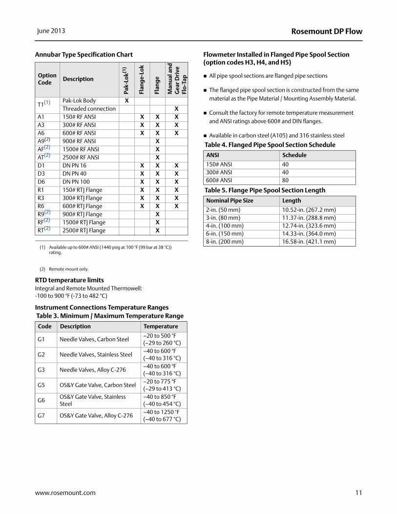
Annubar Type Specification Chart
RTD temperature limitsIntegral and Remote Mounted Thermowell:-100 to 900 °F (-73 to 482 °C)
Instrument Connections Temperature Ranges
Flowmeter Installed in Flanged Pipe Spool Section (option codes H3, H4, and H5)
All pipe spool sections are flanged pipe sections
The flanged pipe spool section is constructed from the same material as the Pipe Material / Mounting Assembly Material.
Consult the factory for remote temperature measurement and ANSI ratings above 600# and DIN flanges.
Available in carbon steel (A105) and 316 stainless steel
Option Code
Description
Pak-
Lok(1
)
(1) Available up to 600# ANSI (1440 psig at 100 °F (99 bar at 38 °C)) rating.
Flan
ge-
Lok
Flan
ge
Man
ual
and
Gea
r D
rive
Flo-
Tap
T1(1) Pak-Lok Body XThreaded connection X
A1 150# RF ANSI X X XA3 300# RF ANSI X X XA6 600# RF ANSI X X XA9(2)
(2) Remote mount only.
900# RF ANSI XAF(2) 1500# RF ANSI XAT(2) 2500# RF ANSI XD1 DN PN 16 X X XD3 DN PN 40 X X XD6 DN PN 100 X X XR1 150# RTJ Flange X X XR3 300# RTJ Flange X X XR6 600# RTJ Flange X X XR9(2) 900# RTJ Flange XRF(2) 1500# RTJ Flange XRT(2) 2500# RTJ Flange X
Table 3. Minimum / Maximum Temperature Range
Code Description Temperature
G1 Needle Valves, Carbon Steel –20 to 500 °F(–29 to 260 °C)
G2 Needle Valves, Stainless Steel –40 to 600 °F(–40 to 316 °C)
G3 Needle Valves, Alloy C-276 –40 to 600 °F(–40 to 316 °C)
G5 OS&Y Gate Valve, Carbon Steel–20 to 775 °F(–29 to 413 °C)
G6OS&Y Gate Valve, Stainless Steel
–40 to 850 °F(–40 to 454 °C)
G7 OS&Y Gate Valve, Alloy C-276–40 to 1250 °F(–40 to 677 °C)
Table 4. Flanged Pipe Spool Section Schedule
ANSI Schedule
150# ANSI 40300# ANSI 40600# ANSI 80
Table 5. Flange Pipe Spool Section Length
Nominal Pipe Size Length
2-in. (50 mm) 10.52-in. (267.2 mm)3-in. (80 mm) 11.37-in. (288.8 mm)4-in. (100 mm) 12.74-in. (323.6 mm)6-in. (150 mm) 14.33-in. (364.0 mm)8-in. (200 mm) 16.58-in. (421.1 mm)
Rosemount DP Flow June 2013
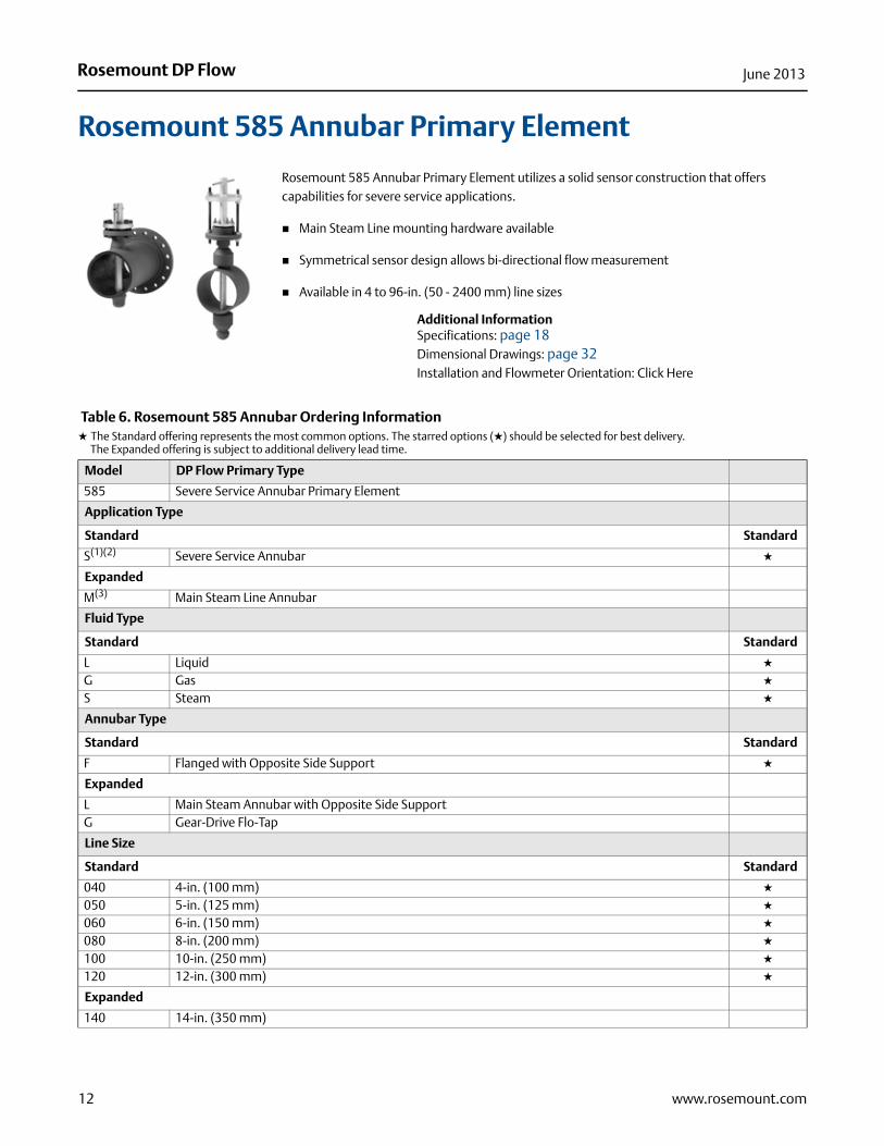
Rosemount 585 Annubar Primary Element
Rosemount 585 Annubar Primary Element utilizes a solid sensor construction that offers capabilities for severe service applications.
Main Steam Line mounting hardware available
Symmetrical sensor design allows bi-directional flow measurement
Available in 4 to 96-in. (50 - 2400 mm) line sizes
Additional InformationSpecifications: page 18Dimensional Drawings: page 32Installation and Flowmeter Orientation: Click Here
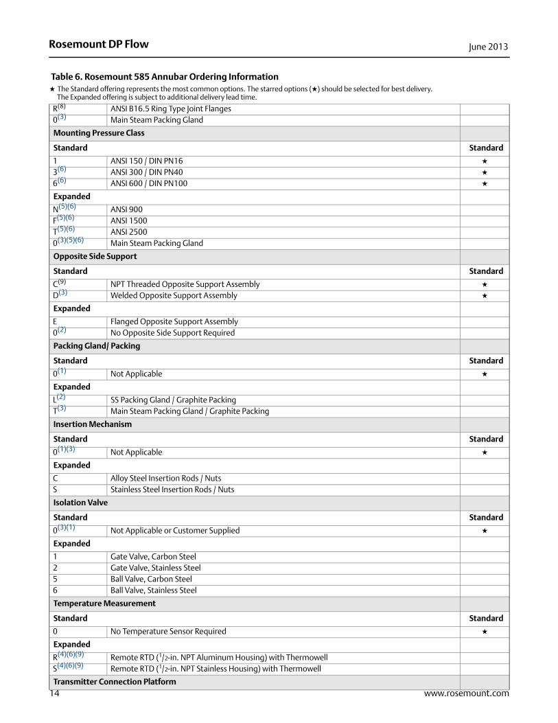
Table 6. Rosemount 585 Annubar Ordering Information★ The Standard offering represents the most common options. The starred options (★) should be selected for best delivery.__The Expanded offering is subject to additional delivery lead time.
Model DP Flow Primary Type
585 Severe Service Annubar Primary Element
Application Type
Standard Standard
S(1)(2) Severe Service Annubar ★
Expanded
M(3) Main Steam Line Annubar
Fluid Type
Standard Standard
L Liquid ★
G Gas ★
S Steam ★
Annubar Type
Standard Standard
F Flanged with Opposite Side Support ★
Expanded
L Main Steam Annubar with Opposite Side SupportG Gear-Drive Flo-Tap
Line Size
Standard Standard
040 4-in. (100 mm) ★
050 5-in. (125 mm) ★
060 6-in. (150 mm) ★
080 8-in. (200 mm) ★
100 10-in. (250 mm) ★
120 12-in. (300 mm) ★
Expanded
140 14-in. (350 mm)
12 www.rosemount.com
Rosemount DP FlowJune 2013
160 16-in. (400 mm)180 18-in. (450 mm)200 20-in. (500 mm)240 24-in. (600 mm)300 30-in. (750 mm)360 36-in. (900 mm)420 42-in. (1066 mm)480 48-in. (1210 mm)600 60-in. (1520 mm)720 72-in. (1820 mm)840 84-in. (2100 mm)960 96-in. (2400 mm)
Mounting Assembly Material
Standard Standard
C Carbon Steel (A105) ★
S 316/316L Stainless Steel ★
Expanded
L Carbon Steel (A350 LF2) G Chrome-Moly Grade F-11N Chrome-Moly Grade F-22J Chrome-Moly Grade F-91 0(4) No Mounting (Customer Supplied)
Piping Orientation
Standard Standard
H Horizontal Piping ★
D Vertical Piping with Downwards Flow ★
U Vertical Piping with Upwards Flow ★
Sensor Material
Standard Standard
S 316/316L Stainless Steel ★
Expanded
H(5) Alloy C-276W(3)(5) Alloy 800HK(5) PVDF (KYNAR)
Sensor Size
Standard Standard
11 Sensor size 11 ★
22(6) Sensor size 22 ★
Expanded
44(2)(3) Sensor size 44
Mounting Type
Standard Standard
A ANSI B16.5 Raised Face Flanges ★
D(7) DIN Raised Face Flanges ★
Expanded
Table 6. Rosemount 585 Annubar Ordering Information★ The Standard offering represents the most common options. The starred options (★) should be selected for best delivery.__The Expanded offering is subject to additional delivery lead time.
13www.rosemount.com
Rosemount DP Flow June 2013
14 www.rosemount.com
R(8) ANSI B16.5 Ring Type Joint Flanges0(3) Main Steam Packing Gland
Mounting Pressure Class
Standard Standard
1 ANSI 150 / DIN PN16 ★
3(6) ANSI 300 / DIN PN40 ★
6(6) ANSI 600 / DIN PN100 ★
Expanded
N(5)(6) ANSI 900 F(5)(6) ANSI 1500 T(5)(6) ANSI 2500 0(3)(5)(6) Main Steam Packing Gland
Opposite Side Support
Standard Standard
C(9) NPT Threaded Opposite Support Assembly ★
D(3) Welded Opposite Support Assembly ★
Expanded
E Flanged Opposite Support Assembly0(2) No Opposite Side Support Required
Packing Gland/ Packing
Standard Standard
0(1) Not Applicable ★
Expanded
L(2) SS Packing Gland / Graphite PackingT(3) Main Steam Packing Gland / Graphite Packing
Insertion Mechanism
Standard Standard
0(1)(3) Not Applicable ★
Expanded
C Alloy Steel Insertion Rods / NutsS Stainless Steel Insertion Rods / Nuts
Isolation Valve
Standard Standard
0(3)(1) Not Applicable or Customer Supplied ★
Expanded
1 Gate Valve, Carbon Steel2 Gate Valve, Stainless Steel5 Ball Valve, Carbon Steel6 Ball Valve, Stainless Steel
Temperature Measurement
Standard Standard
0 No Temperature Sensor Required ★
Expanded
R(4)(6)(9) Remote RTD (1/2-in. NPT Aluminum Housing) with ThermowellS(4)(6)(9) Remote RTD (1/2-in. NPT Stainless Housing) with Thermowell
Transmitter Connection Platform
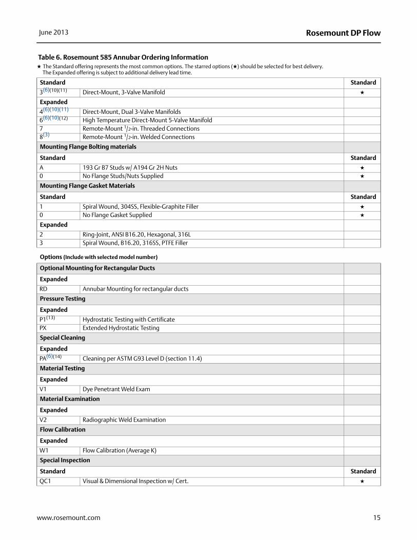
Table 6. Rosemount 585 Annubar Ordering Information★ The Standard offering represents the most common options. The starred options (★) should be selected for best delivery.__The Expanded offering is subject to additional delivery lead time.
Rosemount DP FlowJune 2013
Standard Standard
3(6)(10)(11) Direct-Mount, 3-Valve Manifold ★
Expanded
4(6)(10)(11) Direct-Mount, Dual 3-Valve Manifolds6(6)(10)(12) High Temperature Direct-Mount 5-Valve Manifold7 Remote-Mount 1/2-in. Threaded Connections8(3) Remote-Mount 1/2-in. Welded Connections
Mounting Flange Bolting materials
Standard Standard
A 193 Gr B7 Studs w/ A194 Gr 2H Nuts ★
0 No Flange Studs/Nuts Supplied ★
Mounting Flange Gasket Materials
Standard Standard
1 Spiral Wound, 304SS, Flexible-Graphite Filler ★
0 No Flange Gasket Supplied ★
Expanded
2 Ring-Joint, ANSI B16.20, Hexagonal, 316L 3 Spiral Wound, B16.20, 316SS, PTFE Filler
Options (Include with selected model number)
Optional Mounting for Rectangular Ducts
Expanded
RD Annubar Mounting for rectangular ducts
Pressure Testing
Expanded
P1(13) Hydrostatic Testing with CertificatePX Extended Hydrostatic Testing
Special Cleaning
Expanded
PA(6)(14) Cleaning per ASTM G93 Level D (section 11.4)
Material Testing
Expanded
V1 Dye Penetrant Weld Exam
Material Examination
Expanded
V2 Radiographic Weld Examination
Flow Calibration
Expanded
W1 Flow Calibration (Average K)
Special Inspection
Standard Standard
QC1 Visual & Dimensional Inspection w/ Cert. ★
Table 6. Rosemount 585 Annubar Ordering Information★ The Standard offering represents the most common options. The starred options (★) should be selected for best delivery.__The Expanded offering is subject to additional delivery lead time.
15www.rosemount.com
Rosemount DP Flow June 2013
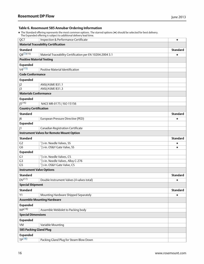
QC7 Inspection & Performance Certificate ★
Material Traceability Certification
Standard Standard
Q8(5)(15) Material Traceability Certification per EN 10204:2004 3.1 ★
Positive Material Testing
Expanded
V4(15) Positive Material Identification
Code Conformance
Expanded
J2 ANSI/ASME B31.1 J3 ANSI/ASME B31.3
Materials Conformance
Expanded
J5(16) NACE MR-0175 / ISO 15156
Country Certification
Standard Standard
J6 European Pressure Directive (PED) ★
Expanded
J1 Canadian Registration Certificate
Instrument Valves for Remote Mount Option
Standard Standard
G2 1/2-in. Needle Valves, SS ★
G6 1/2-in. OS&Y Gate Valve, SS ★
Expanded
G1 1/2-in. Needle Valves, CS G3 1/2-in. Needle Valves, Alloy C-276 G5 1/2-in. OS&Y Gate Valve, CS
Instrument Valve Options
Standard Standard
DV(17) Double Instrument Valves (4 valves total) ★
Special Shipment
Standard Standard
Y1 Mounting Hardware Shipped Separately ★
Assemble Mounting Hardware
Expanded
WP(18) Assemble Weldolet to Packing body
Special Dimensions
Expanded
VM Variable Mounting
585 Packing Gland Plug
Expanded
TP(18) Packing Gland Plug for Steam Blow Down
Table 6. Rosemount 585 Annubar Ordering Information★ The Standard offering represents the most common options. The starred options (★) should be selected for best delivery.__The Expanded offering is subject to additional delivery lead time.
16 www.rosemount.com
Rosemount DP FlowJune 2013
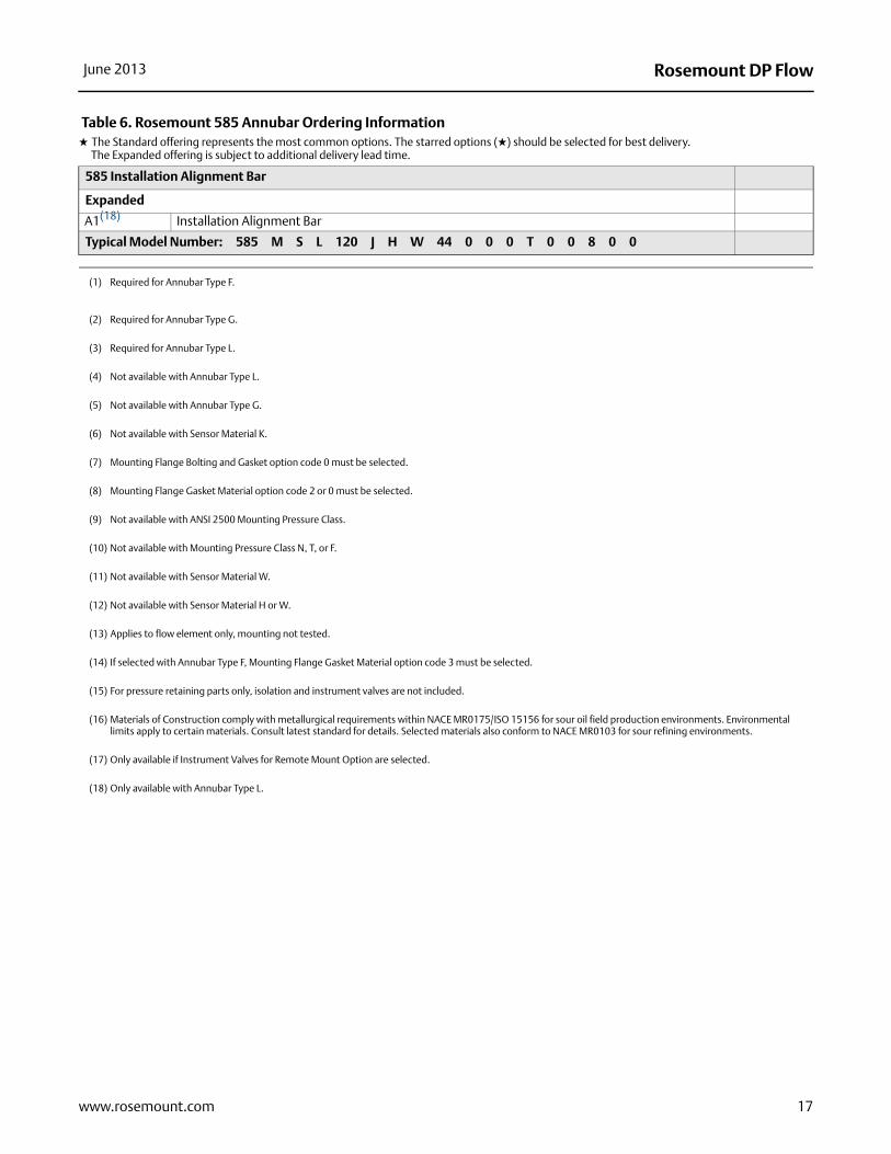
585 Installation Alignment Bar
Expanded
A1(18) Installation Alignment Bar
Typical Model Number: 585 M S L 120 J H W 44 0 0 0 T 0 0 8 0 0
(1) Required for Annubar Type F.
(2) Required for Annubar Type G.
(3) Required for Annubar Type L.
(4) Not available with Annubar Type L.
(5) Not available with Annubar Type G.
(6) Not available with Sensor Material K.
(7) Mounting Flange Bolting and Gasket option code 0 must be selected.
(8) Mounting Flange Gasket Material option code 2 or 0 must be selected.
(9) Not available with ANSI 2500 Mounting Pressure Class.
(10) Not available with Mounting Pressure Class N, T, or F.
(11) Not available with Sensor Material W.
(12) Not available with Sensor Material H or W.
(13) Applies to flow element only, mounting not tested.
(14) If selected with Annubar Type F, Mounting Flange Gasket Material option code 3 must be selected.
(15) For pressure retaining parts only, isolation and instrument valves are not included.
(16) Materials of Construction comply with metallurgical requirements within NACE MR0175/ISO 15156 for sour oil field production environments. Environmental limits apply to certain materials. Consult latest standard for details. Selected materials also conform to NACE MR0103 for sour refining environments.
(17) Only available if Instrument Valves for Remote Mount Option are selected.
(18) Only available with Annubar Type L.
Table 6. Rosemount 585 Annubar Ordering Information★ The Standard offering represents the most common options. The starred options (★) should be selected for best delivery.__The Expanded offering is subject to additional delivery lead time.
17www.rosemount.com
Rosemount DP Flow June 2013
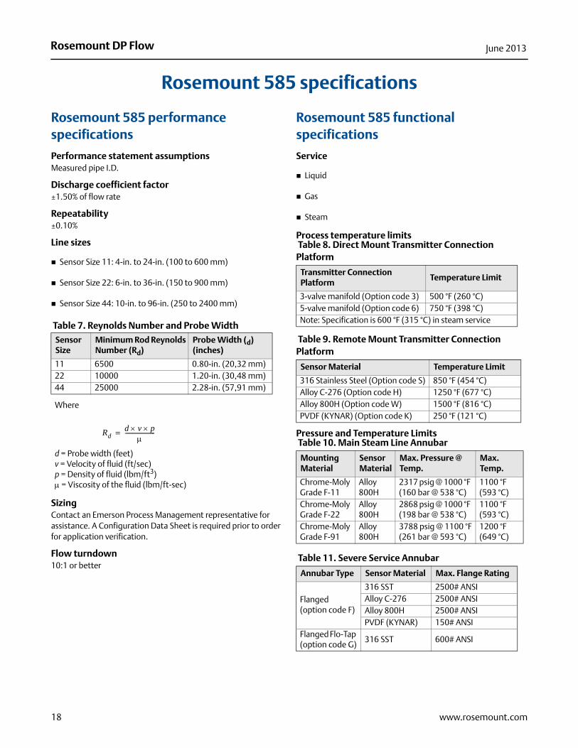
Rosemount 585 specifications
Rosemount 585 performance specifications
Performance statement assumptionsMeasured pipe I.D.
Discharge coefficient factor±1.50% of flow rate
Repeatability±0.10%
Line sizes
Sensor Size 11: 4-in. to 24-in. (100 to 600 mm)
Sensor Size 22: 6-in. to 36-in. (150 to 900 mm)
Sensor Size 44: 10-in. to 96-in. (250 to 2400 mm)
Table 7. Reynolds Number and Probe Width
Sizing Contact an Emerson Process Management representative for assistance. A Configuration Data Sheet is required prior to order for application verification.
Flow turndown10:1 or better
Rosemount 585 functional specifications
Service
Liquid
Gas
Steam
Process temperature limits
Pressure and Temperature Limits
Sensor Size
Minimum Rod Reynolds Number (Rd)
Probe Width (d) (inches)
11 6500 0.80-in. (20,32 mm)22 10000 1.20-in. (30,48 mm)44 25000 2.28-in. (57,91 mm)
Where
d = Probe width (feet)v = Velocity of fluid (ft/sec)p = Density of fluid (lbm/ft3) = Viscosity of the fluid (lbm/ft-sec)
Rdd v p
---------------------=
Table 8. Direct Mount Transmitter Connection Platform
Transmitter Connection Platform
Temperature Limit
3-valve manifold (Option code 3) 500 °F (260 °C) 5-valve manifold (Option code 6) 750 °F (398 °C)Note: Specification is 600 °F (315 °C) in steam service
Table 9. Remote Mount Transmitter Connection Platform
Sensor Material Temperature Limit
316 Stainless Steel (Option code S) 850 °F (454 °C)Alloy C-276 (Option code H) 1250 °F (677 °C)Alloy 800H (Option code W) 1500 °F (816 °C)PVDF (KYNAR) (Option code K) 250 °F (121 °C)
Table 10. Main Steam Line Annubar
Mounting Material
Sensor Material
Max. Pressure @ Temp.
Max. Temp.
Chrome-Moly Grade F-11
Alloy 800H
2317 psig @ 1000 °F (160 bar @ 538 °C)
1100 °F (593 °C)
Chrome-Moly Grade F-22
Alloy 800H
2868 psig @ 1000 °F (198 bar @ 538 °C)
1100 °F (593 °C)
Chrome-Moly Grade F-91
Alloy 800H
3788 psig @ 1100 °F(261 bar @ 593 °C)
1200 °F (649 °C)
Table 11. Severe Service Annubar
Annubar Type Sensor Material Max. Flange Rating
Flanged (option code F)
316 SST 2500# ANSIAlloy C-276 2500# ANSIAlloy 800H 2500# ANSIPVDF (KYNAR) 150# ANSI
Flanged Flo-Tap (option code G)
316 SST 600# ANSI
18 www.rosemount.com
Rosemount DP FlowJune 2013
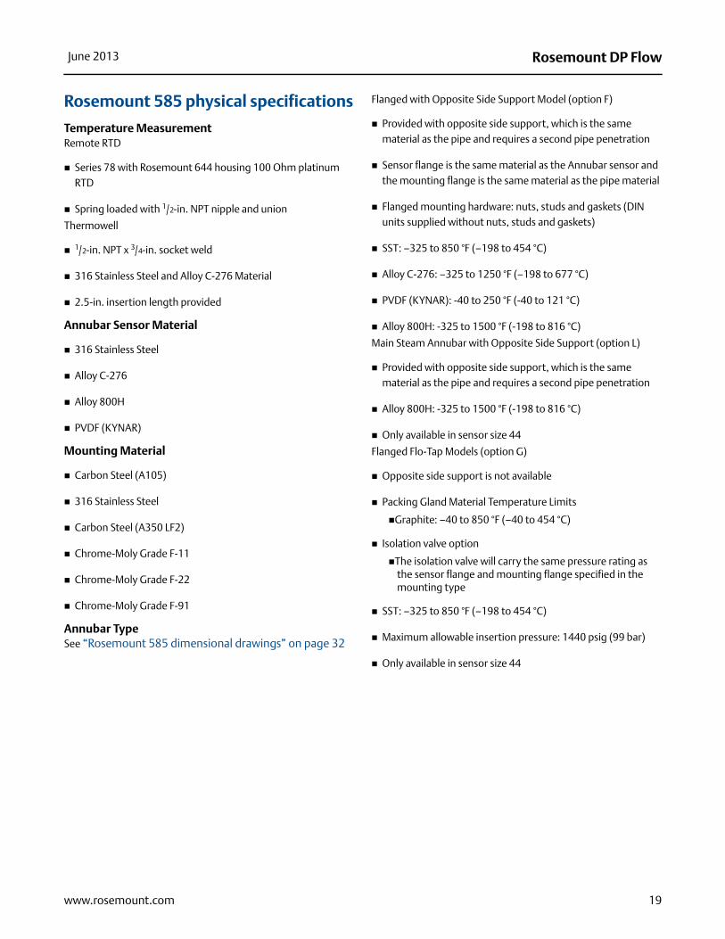
Rosemount 585 physical specifications
Temperature MeasurementRemote RTD
Series 78 with Rosemount 644 housing 100 Ohm platinum RTD
Spring loaded with 1/2-in. NPT nipple and union
Thermowell
1/2-in. NPT x 3/4-in. socket weld
316 Stainless Steel and Alloy C-276 Material
2.5-in. insertion length provided
Annubar Sensor Material
316 Stainless Steel
Alloy C-276
Alloy 800H
PVDF (KYNAR)
Mounting Material
Carbon Steel (A105)
316 Stainless Steel
Carbon Steel (A350 LF2)
Chrome-Moly Grade F-11
Chrome-Moly Grade F-22
Chrome-Moly Grade F-91
Annubar TypeSee “Rosemount 585 dimensional drawings” on page 32
Flanged with Opposite Side Support Model (option F)
Provided with opposite side support, which is the same material as the pipe and requires a second pipe penetration
Sensor flange is the same material as the Annubar sensor and the mounting flange is the same material as the pipe material
Flanged mounting hardware: nuts, studs and gaskets (DIN units supplied without nuts, studs and gaskets)
SST: –325 to 850 °F (–198 to 454 °C)
Alloy C-276: –325 to 1250 °F (–198 to 677 °C)
PVDF (KYNAR): -40 to 250 °F (-40 to 121 °C)
Alloy 800H: -325 to 1500 °F (-198 to 816 °C)
Main Steam Annubar with Opposite Side Support (option L)
Provided with opposite side support, which is the same material as the pipe and requires a second pipe penetration
Alloy 800H: -325 to 1500 °F (-198 to 816 °C)
Only available in sensor size 44
Flanged Flo-Tap Models (option G)
Opposite side support is not available
Packing Gland Material Temperature Limits
Graphite: –40 to 850 °F (–40 to 454 °C)
Isolation valve option
The isolation valve will carry the same pressure rating as the sensor flange and mounting flange specified in the mounting type
SST: –325 to 850 °F (–198 to 454 °C)
Maximum allowable insertion pressure: 1440 psig (99 bar)
Only available in sensor size 44
19www.rosemount.com
Rosemount DP Flow June 2013
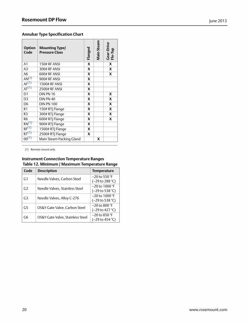
Annubar Type Specification Chart
Instrument Connection Temperature Ranges
Option Code
Mounting Type/Pressure Class
Flan
ged
Mai
n S
team
Gea
r-D
rive
Flo-
Tap
A1 150# RF ANSI X XA3 300# RF ANSI X XA6 600# RF ANSI X XAN(1)
(1) Remote mount only.
900# RF ANSI XAF(1) 1500# RF ANSI XAT(1) 2500# RF ANSI XD1 DIN PN 16 X XD3 DIN PN 40 X XD6 DIN PN 100 X XR1 150# RTJ Flange X XR3 300# RTJ Flange X XR6 600# RTJ Flange X XRN(1) 900# RTJ Flange XRF(1) 1500# RTJ Flange XRT(1) 2500# RTJ Flange X00(1) Main Steam Packing Gland X
Table 12. Minimum / Maximum Temperature Range
Code Description Temperature
G1 Needle Valves, Carbon Steel –20 to 550 °F(–29 to 288 °C)
G2 Needle Valves, Stainless Steel –20 to 1000 °F(–29 to 538 °C)
G3 Needle Valves, Alloy C-276–20 to 1000 °F(–29 to 538 °C)
G5 OS&Y Gate Valve, Carbon Steel–20 to 800 °F(–29 to 427 °C)
G6 OS&Y Gate Valve, Stainless Steel–20 to 850 °F(–29 to 454 °C)
20 www.rosemount.com
Rosemount DP FlowJune 2013
I.D. Range Code
A
B
C
D
B
C
D
E
A
B
C
D
B
C
D
B
C
D
E
A
B
C
D
21www.rosemount.com
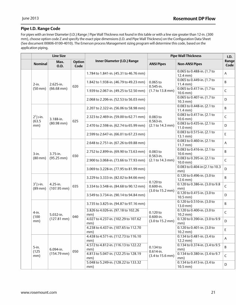
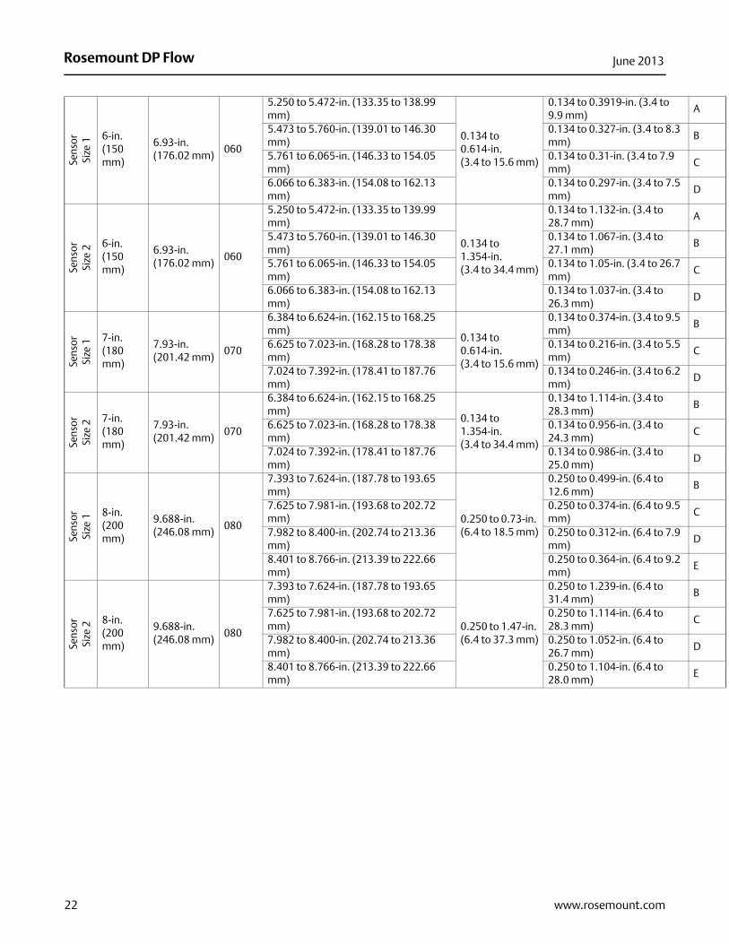
Pipe I.D. Range CodeFor pipes with an Inner Diameter (I.D.) Range / Pipe Wall Thickness not found in this table or with a line size greater than 12-in. (300 mm), choose option code Z and specify the exact pipe dimensions (I.D. and Pipe Wall Thickness) on the Configuration Data Sheet (See document 00806-0100-4010). The Emerson process Management sizing program will determine this code, based on the application piping.
Line Size
Inner Diameter (I.D.) Range
Pipe Wall Thickness
NominalMax. O.D.
Option Code
ANSI Pipes Non-ANSI Pipes
2-in. (50 mm)
2.625-in. (66.68 mm)
020
1.784 to 1.841-in. (45.31 to 46.76 mm)
0.065 to 0.545-in. (1.7 to 13.8 mm)
0.065 to 0.488-in. (1.7 to 12.4 mm)
1.842 to 1.938-in. (46.79 to 49.23 mm)0.065 to 0.449-in. (1.7 to 11.4 mm)
1.939 to 2.067-in. (49.25 to 52.50 mm)0.065 to 0.417-in. (1.7 to 10.6 mm)
2.068 to 2.206-in. (52.53 to 56.03 mm)0.065 to 0.407-in. (1.7 to 10.3 mm)
21/2-in. (63.5 mm)
3.188-in. (80.98 mm)
025
2.207 to 2.322-in. (56.06 to 58.98 mm)
0.083 to 0.563-in. (2.1 to 14.3 mm)
0.083 to 0.448-in. (2.1 to 11.4 mm)
2.323 to 2.469-in. (59.00 to 62.71 mm)0.083 to 0.417-in. (2.1 to 10.6 mm)
2.470 to 2.598-in. (62.74 to 65.99 mm)0.083 to 0.435-in. (2.1 to 11.0 mm)
2.599 to 2.647-in. (66.01 to 67.23 mm)0.083 to 0.515-in. (2.1 to 13.1 mm)
3-in. (80 mm)
3.75-in. (95.25 mm)
030
2.648 to 2.751-in. (67.26 to 69.88 mm)
0.083 to 0.563-in. (2.1 to 14.3 mm)
0.083 to 0.460-in. (2.1 to 11.7 mm)
2.752 to 2.899-in. (69.90 to 73.63 mm)0.083 to 0.416-in. (2.1 to 10.6 mm)
2.900 to 3.068-in. (73.66 to 77.93 mm)0.083 to 0.395-in. (2.1 to 10.0 mm)
3.069 to 3.228-in. (77.95 to 81.99 mm)0.083 to 0.404-in (2.1 to 10.3mm)
31/2-in. (89 mm)
4.25-in. (107.95 mm)
035
3.229 to 3.333-in. (82.02 to 84.66 mm)0.120 to 0.600-in. (3.0 to 15.2 mm)
0.120 to 0.496-in. (3.0 to 12.6 mm)
3.334 to 3.548-in. (84.68 to 90.12 mm)0.120 to 0.386-in. (3.0 to 9.8mm)
3.549 to 3.734-in. (90.14 to 94.84 mm)0.120 to 0.415-in. (3.0 to 10.5 mm)
4-in. (100 mm)
5.032-in. (127.81 mm)
040
3.735 to 3.825-in. (94.87 to 97.16 mm)
0.120 to 0.600-in. (3.0 to 15.2 mm)
0.120 to 0.510-in. (3.0 to 13.0 mm)
3.826 to 4.026-in. (97.18 to 102.26 mm)
0.120 to 0.400-in. (3.0 to 10.2 mm)
4.027 to 4.237-in. (102.29 to 107.62 mm)
0.120 to 0.390-in. (3.0 to 9.9mm)
4.238 to 4.437-in. (107.65 to 112.70 mm)
0.120 to 0.401-in. (3.0 to 10.2 mm)
5-in. (125 mm)
6.094-in. (154.79 mm)
050
4.438 to 4.571-in. (112.73 to 116.10 mm)
0.134 to 0.614-in. (3.4 to 15.6 mm)
0.134 to 0.481-in. (3.4 to 12.2 mm)
4.572 to 4.812-in. (116.13 to 122.22 mm)
0.134 to 0.374-in. (3.4 to 9.5mm)
4.813 to 5.047-in. (122.25 to 128.19 mm)
0.134 to 0.380-in. (3.4 to 9.7mm)
5.048 to 5.249-in. (128.22 to 133.32 mm)
0.134 to 0.413-in. (3.4 to 10.5 mm)
Rosemount DP Flow June 2013
A
B
C
D
A
B
C
D
B
C
D
B
C
D
B
C
D
E
B
C
D
E
Sens
or
Size
1 6-in. (150 mm)
6.93-in. (176.02 mm)
060
5.250 to 5.472-in. (133.35 to 138.99 mm)
0.134 to 0.614-in. (3.4 to 15.6 mm)
0.134 to 0.3919-in. (3.4 to 9.9 mm)
5.473 to 5.760-in. (139.01 to 146.30 mm)
0.134 to 0.327-in. (3.4 to 8.3mm)
5.761 to 6.065-in. (146.33 to 154.05 mm)
0.134 to 0.31-in. (3.4 to 7.9 mm)
6.066 to 6.383-in. (154.08 to 162.13 mm)
0.134 to 0.297-in. (3.4 to 7.5mm)
Sens
or
Size
2 6-in. (150 mm)
6.93-in. (176.02 mm)
060
5.250 to 5.472-in. (133.35 to 139.99 mm)
0.134 to 1.354-in. (3.4 to 34.4 mm)
0.134 to 1.132-in. (3.4 to 28.7 mm)
5.473 to 5.760-in. (139.01 to 146.30 mm)
0.134 to 1.067-in. (3.4 to 27.1 mm)
5.761 to 6.065-in. (146.33 to 154.05 mm)
0.134 to 1.05-in. (3.4 to 26.7mm)
6.066 to 6.383-in. (154.08 to 162.13 mm)
0.134 to 1.037-in. (3.4 to 26.3 mm)
Sens
or
Size
1 7-in. (180 mm)
7.93-in. (201.42 mm)
070
6.384 to 6.624-in. (162.15 to 168.25 mm)
0.134 to 0.614-in. (3.4 to 15.6 mm)
0.134 to 0.374-in. (3.4 to 9.5mm)
6.625 to 7.023-in. (168.28 to 178.38 mm)
0.134 to 0.216-in. (3.4 to 5.5mm)
7.024 to 7.392-in. (178.41 to 187.76 mm)
0.134 to 0.246-in. (3.4 to 6.2mm)
Sens
or
Size
2 7-in. (180 mm)
7.93-in. (201.42 mm)
070
6.384 to 6.624-in. (162.15 to 168.25 mm)
0.134 to 1.354-in. (3.4 to 34.4 mm)
0.134 to 1.114-in. (3.4 to 28.3 mm)
6.625 to 7.023-in. (168.28 to 178.38 mm)
0.134 to 0.956-in. (3.4 to 24.3 mm)
7.024 to 7.392-in. (178.41 to 187.76 mm)
0.134 to 0.986-in. (3.4 to 25.0 mm)
Sens
or
Size
1 8-in. (200 mm)
9.688-in. (246.08 mm)
080
7.393 to 7.624-in. (187.78 to 193.65 mm)
0.250 to 0.73-in. (6.4 to 18.5 mm)
0.250 to 0.499-in. (6.4 to 12.6 mm)
7.625 to 7.981-in. (193.68 to 202.72 mm)
0.250 to 0.374-in. (6.4 to 9.5mm)
7.982 to 8.400-in. (202.74 to 213.36 mm)
0.250 to 0.312-in. (6.4 to 7.9mm)
8.401 to 8.766-in. (213.39 to 222.66 mm)
0.250 to 0.364-in. (6.4 to 9.2mm)
Sens
or
Size
2 8-in. (200 mm)
9.688-in. (246.08 mm)
080
7.393 to 7.624-in. (187.78 to 193.65 mm)
0.250 to 1.47-in. (6.4 to 37.3 mm)
0.250 to 1.239-in. (6.4 to 31.4 mm)
7.625 to 7.981-in. (193.68 to 202.72 mm)
0.250 to 1.114-in. (6.4 to 28.3 mm)
7.982 to 8.400-in. (202.74 to 213.36 mm)
0.250 to 1.052-in. (6.4 to 26.7 mm)
8.401 to 8.766-in. (213.39 to 222.66 mm)
0.250 to 1.104-in. (6.4 to 28.0 mm)
22 www.rosemount.com
Rosemount DP FlowJune 2013
A
B
C
D
E
B
C
D
23www.rosemount.com
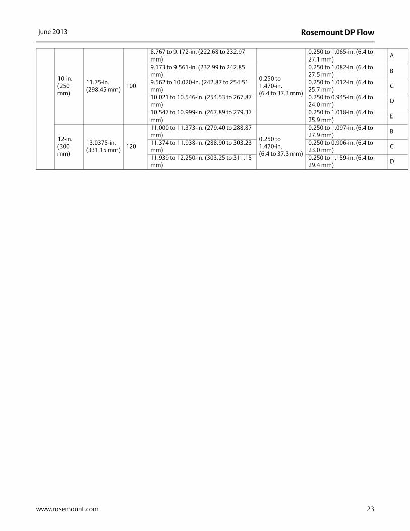
10-in. (250 mm)
11.75-in. (298.45 mm)
100
8.767 to 9.172-in. (222.68 to 232.97 mm)
0.250 to 1.470-in. (6.4 to 37.3 mm)
0.250 to 1.065-in. (6.4 to 27.1 mm)
9.173 to 9.561-in. (232.99 to 242.85 mm)
0.250 to 1.082-in. (6.4 to 27.5 mm)
9.562 to 10.020-in. (242.87 to 254.51 mm)
0.250 to 1.012-in. (6.4 to 25.7 mm)
10.021 to 10.546-in. (254.53 to 267.87 mm)
0.250 to 0.945-in. (6.4 to 24.0 mm)
10.547 to 10.999-in. (267.89 to 279.37 mm)
0.250 to 1.018-in. (6.4 to 25.9 mm)
12-in. (300 mm)
13.0375-in. (331.15 mm)
120
11.000 to 11.373-in. (279.40 to 288.87 mm)
0.250 to 1.470-in. (6.4 to 37.3 mm)
0.250 to 1.097-in. (6.4 to 27.9 mm)
11.374 to 11.938-in. (288.90 to 303.23 mm)
0.250 to 0.906-in. (6.4 to 23.0 mm)
11.939 to 12.250-in. (303.25 to 311.15 mm)
0.250 to 1.159-in. (6.4 to 29.4 mm)
Rosemount DP Flow June 2013
24 www.rosemount.com
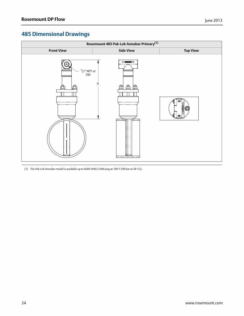
485 Dimensional Drawings
Rosemount 485 Pak-Lok Annubar Primary(1)
Front View Side View Top View
(1) The Pak-Lok Annubar model is available up to 600# ANSI (1440 psig at 100 °F (99 bar at 38 °C)).
A
1/2” NPT or SW
Rosemount DP FlowJune 2013
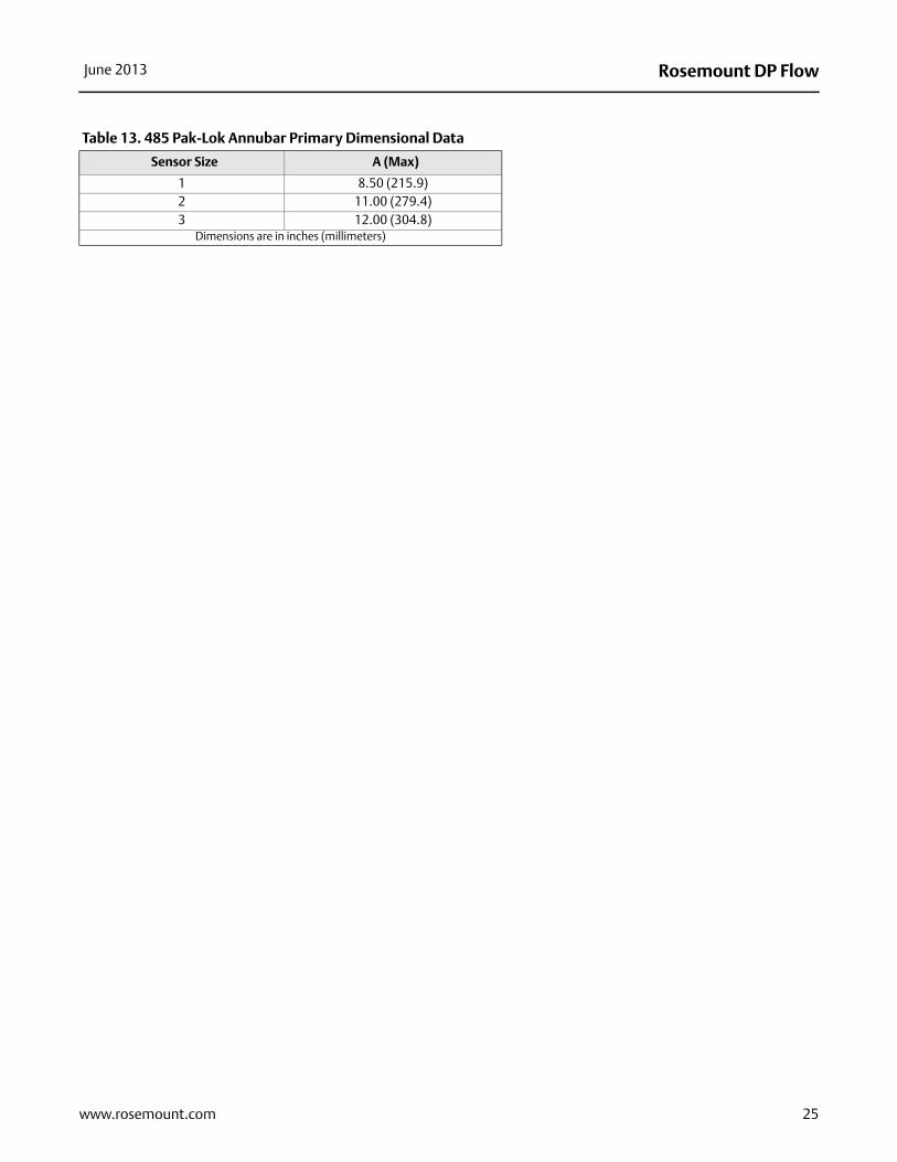
Table 13. 485 Pak-Lok Annubar Primary Dimensional Data
Sensor Size A (Max)
1 8.50 (215.9)2 11.00 (279.4)3 12.00 (304.8)
Dimensions are in inches (millimeters)
25www.rosemount.com
Rosemount DP Flow June 2013
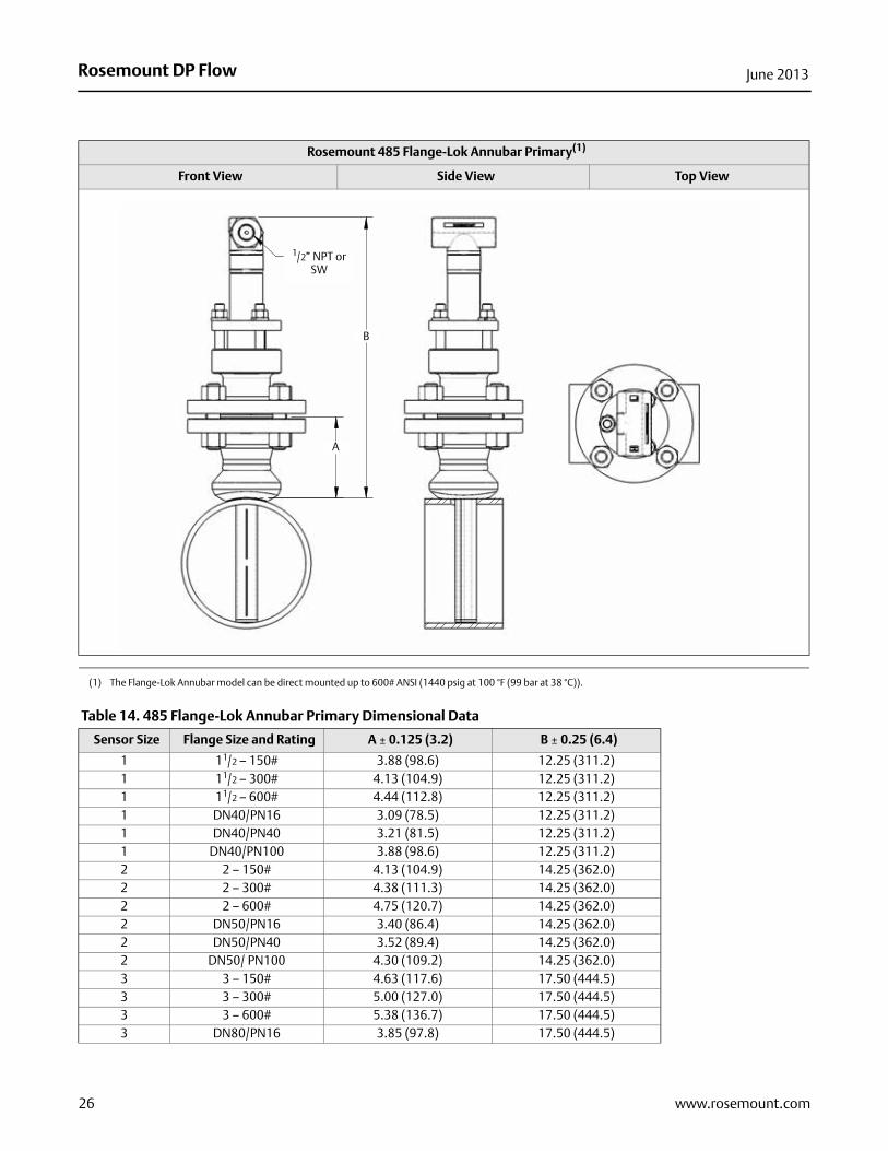
Rosemount 485 Flange-Lok Annubar Primary(1)
Front View Side View Top View
(1) The Flange-Lok Annubar model can be direct mounted up to 600# ANSI (1440 psig at 100 °F (99 bar at 38 °C)).
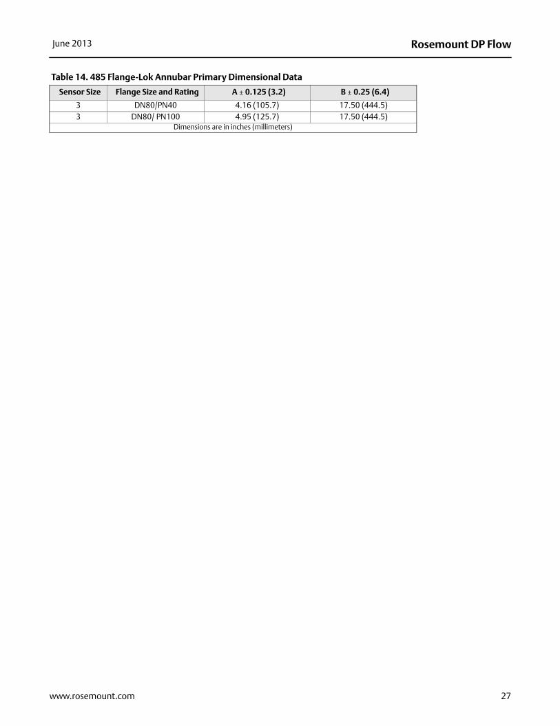
Table 14. 485 Flange-Lok Annubar Primary Dimensional Data
Sensor Size Flange Size and Rating A ± 0.125 (3.2) B ± 0.25 (6.4)
1 11/2 – 150# 3.88 (98.6) 12.25 (311.2)1 11/2 – 300# 4.13 (104.9) 12.25 (311.2)1 11/2 – 600# 4.44 (112.8) 12.25 (311.2)1 DN40/PN16 3.09 (78.5) 12.25 (311.2)1 DN40/PN40 3.21 (81.5) 12.25 (311.2)1 DN40/PN100 3.88 (98.6) 12.25 (311.2)2 2 – 150# 4.13 (104.9) 14.25 (362.0)2 2 – 300# 4.38 (111.3) 14.25 (362.0)2 2 – 600# 4.75 (120.7) 14.25 (362.0)2 DN50/PN16 3.40 (86.4) 14.25 (362.0)2 DN50/PN40 3.52 (89.4) 14.25 (362.0)2 DN50/ PN100 4.30 (109.2) 14.25 (362.0)3 3 – 150# 4.63 (117.6) 17.50 (444.5)3 3 – 300# 5.00 (127.0) 17.50 (444.5)3 3 – 600# 5.38 (136.7) 17.50 (444.5)3 DN80/PN16 3.85 (97.8) 17.50 (444.5)
B
A
1/2” NPT or SW
26 www.rosemount.com
Rosemount DP FlowJune 2013
3 DN80/PN40 4.16 (105.7) 17.50 (444.5)3 DN80/ PN100 4.95 (125.7) 17.50 (444.5)
Dimensions are in inches (millimeters)
Table 14. 485 Flange-Lok Annubar Primary Dimensional Data
Sensor Size Flange Size and Rating A ± 0.125 (3.2) B ± 0.25 (6.4)
27www.rosemount.com
Rosemount DP Flow June 2013
28 www.rosemount.com
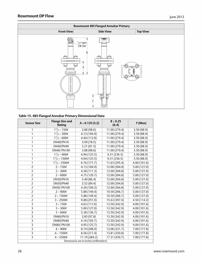
Rosemount 485 Flanged Annubar Primary
Front View Side View Top View
B
A
F
1/2” NPTOR SW
Table 15. 485 Flanged Annubar Primary Dimensional Data
Sensor SizeFlange Size and
RatingA ± 0.125 (3.2)
B ± 0.25 (6.4)
F (Max)
1 11/2 – 150# 3.88 (98.6) 11.00 (279.4) 3.50 (88.9)1 11/2 – 300# 4.13 (104.9) 11.00 (279.4) 3.50 (88.9)1 11/2 – 600# 4.44 (112.8) 11.00 (279.4) 3.50 (88.9)1 DN40/PN16 3.09 (78.5) 11.00 (279.4) 3.50 (88.9)1 DN40/PN40 3.21 (81.5) 11.00 (279.4) 3.50 (88.9)1 DN40/ PN100 3.88 (98.6) 11.00 (279.4) 3.50 (88.9)1 11/2 – 900# 4.94 (125.5) 9.31 (236.5) 3.50 (88.9)1 11/2 – 1500# 4.94 (125.5) 9.31 (236.5) 3.50 (88.9)1 11/2 – 2500# 6.76 (171.7) 11.63 (295.4) 4.00 (101.6)2 2 – 150# 4.13 (104.9) 12.00 (304.8) 5.00 (127.0)2 2 – 300# 4.38 (111.3) 12.00 (304.8) 5.00 (127.0)2 2 – 600# 4.75 (120.7) 12.00 (304.8) 5.00 (127.0)2 DN50/PN16 3.40 (86.4) 12.00 (304.8) 5.00 (127.0)2 DN50/PN40 3.52 (89.4) 12.00 (304.8) 5.00 (127.0)2 DN50/ PN100 4.30 (109.2) 12.00 (304.8) 5.00 (127.0)2 2 – 900# 5.88 (149.4) 10.50 (266.7) 5.00 (127.0)2 2 – 1500# 5.88 (149.4) 10.50 (266.7) 5.00 (127.0)2 3 – 2500# 9.88 (251.0) 15.63 (397.0) 4.50 (114.3)3 3 – 150# 4.63 (117.6) 13.50 (342.9) 4.00 (101.6)3 3 – 300# 5.00 (127.0) 13.50 (342.9) 4.00 (101.6)3 3 – 600# 5.38 (136.7) 13.50 (342.9) 4.00 (101.6)3 DN80/PN16 3.85 (97.8) 13.50 (342.9) 4.00 (101.6)3 DN80/PN40 4.16 (105.7) 13.50 (342.9) 4.00 (101.6)3 DN80/ PN100 4.95 (125.7) 13.50 (342.9) 4.00 (101.6)3 4 – 900# 8.19 (208.0) 13.06 (331.7) 7.00 (177.8)3 4 – 1500# 8.56 (217.4) 13.81 (350.8) 7.00 (177.8)3 4 – 2500# 11.19 (284.2) 17.31 (439.7) 7.00 (177.8)
Dimensions are in inches (millimeters)
Rosemount DP FlowJune 2013
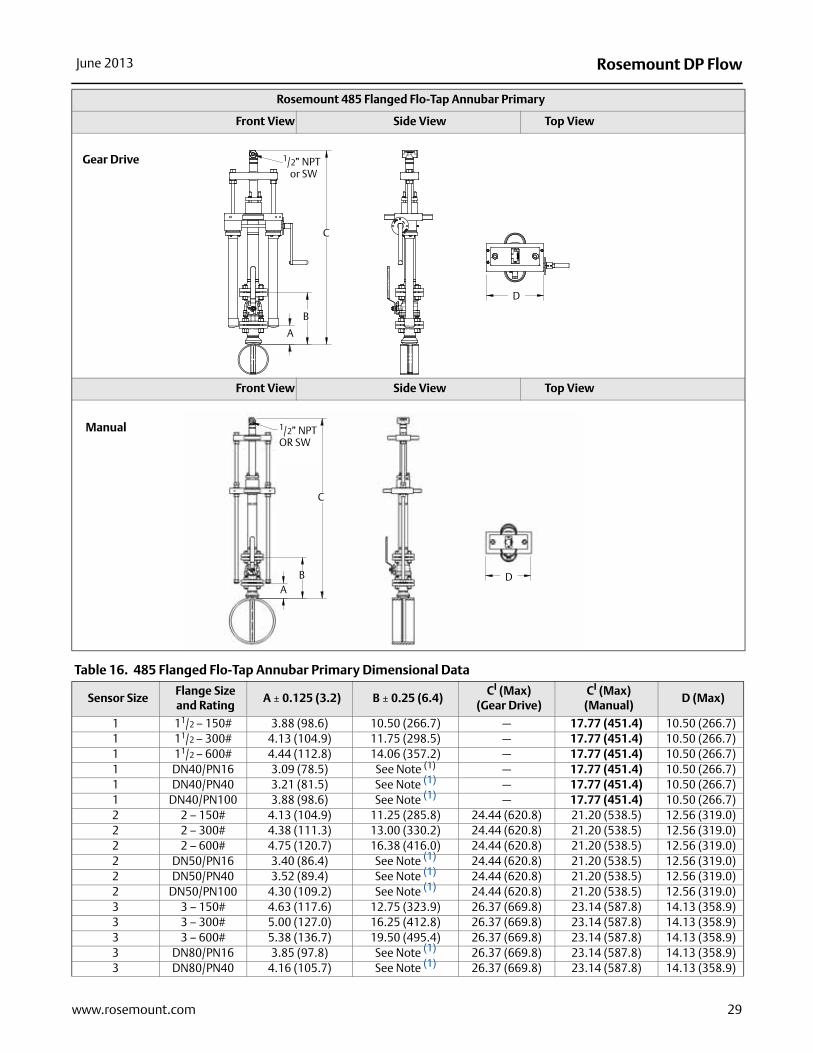
Rosemount 485 Flanged Flo-Tap Annubar Primary
Front View Side View Top View
Front View Side View Top View
Gear Drive
C
B
A
1/2” NPTor SW
D
C
BA
Manual 1/2” NPTOR SW
D
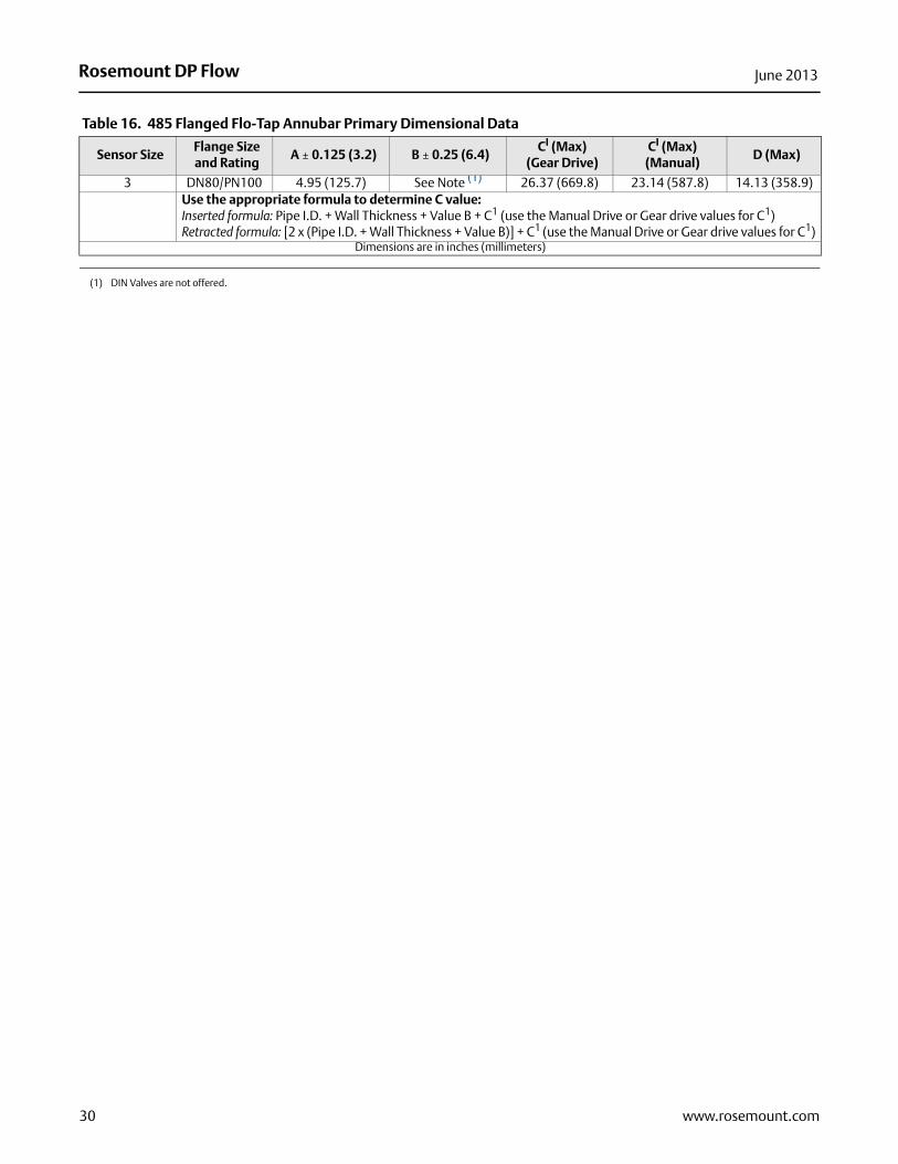
Table 16. 485 Flanged Flo-Tap Annubar Primary Dimensional Data
Sensor SizeFlange Size and Rating
A ± 0.125 (3.2) B ± 0.25 (6.4)CI (Max)
(Gear Drive)CI (Max)
(Manual)D (Max)
1 11/2 – 150# 3.88 (98.6) 10.50 (266.7) — 17.77 (451.4) 10.50 (266.7)1 11/2 – 300# 4.13 (104.9) 11.75 (298.5) — 17.77 (451.4) 10.50 (266.7)1 11/2 – 600# 4.44 (112.8) 14.06 (357.2) — 17.77 (451.4) 10.50 (266.7)1 DN40/PN16 3.09 (78.5) See Note (1) — 17.77 (451.4) 10.50 (266.7)1 DN40/PN40 3.21 (81.5) See Note (1) — 17.77 (451.4) 10.50 (266.7)1 DN40/PN100 3.88 (98.6) See Note (1) — 17.77 (451.4) 10.50 (266.7)2 2 – 150# 4.13 (104.9) 11.25 (285.8) 24.44 (620.8) 21.20 (538.5) 12.56 (319.0)2 2 – 300# 4.38 (111.3) 13.00 (330.2) 24.44 (620.8) 21.20 (538.5) 12.56 (319.0)2 2 – 600# 4.75 (120.7) 16.38 (416.0) 24.44 (620.8) 21.20 (538.5) 12.56 (319.0)2 DN50/PN16 3.40 (86.4) See Note (1) 24.44 (620.8) 21.20 (538.5) 12.56 (319.0)2 DN50/PN40 3.52 (89.4) See Note (1) 24.44 (620.8) 21.20 (538.5) 12.56 (319.0)2 DN50/PN100 4.30 (109.2) See Note (1) 24.44 (620.8) 21.20 (538.5) 12.56 (319.0)3 3 – 150# 4.63 (117.6) 12.75 (323.9) 26.37 (669.8) 23.14 (587.8) 14.13 (358.9)3 3 – 300# 5.00 (127.0) 16.25 (412.8) 26.37 (669.8) 23.14 (587.8) 14.13 (358.9)3 3 – 600# 5.38 (136.7) 19.50 (495.4) 26.37 (669.8) 23.14 (587.8) 14.13 (358.9)3 DN80/PN16 3.85 (97.8) See Note (1) 26.37 (669.8) 23.14 (587.8) 14.13 (358.9)3 DN80/PN40 4.16 (105.7) See Note (1) 26.37 (669.8) 23.14 (587.8) 14.13 (358.9)
29www.rosemount.com
Rosemount DP Flow June 2013
3 DN80/PN100 4.95 (125.7) See Note (1) 26.37 (669.8) 23.14 (587.8) 14.13 (358.9)Use the appropriate formula to determine C value: Inserted formula: Pipe I.D. + Wall Thickness + Value B + C1 (use the Manual Drive or Gear drive values for C1)Retracted formula: [2 x (Pipe I.D. + Wall Thickness + Value B)] + C1 (use the Manual Drive or Gear drive values for C1)
Dimensions are in inches (millimeters)
(1) DIN Valves are not offered.
Table 16. 485 Flanged Flo-Tap Annubar Primary Dimensional Data
Sensor SizeFlange Size and Rating
A ± 0.125 (3.2) B ± 0.25 (6.4)CI (Max)
(Gear Drive)CI (Max)
(Manual)D (Max)
30 www.rosemount.com
Rosemount DP FlowJune 2013
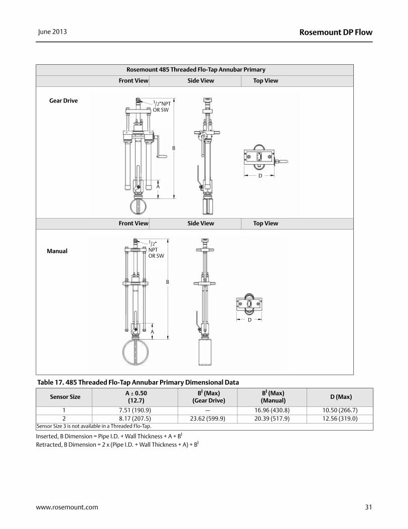
Inserted, B Dimension = Pipe I.D. + Wall Thickness + A + BI
Retracted, B Dimension = 2 x (Pipe I.D. + Wall Thickness + A) + BI
Rosemount 485 Threaded Flo-Tap Annubar Primary
Front View Side View Top View
Front View Side View Top View
Table 17. 485 Threaded Flo-Tap Annubar Primary Dimensional Data
Sensor SizeA ± 0.50
(12.7)BI (Max)
(Gear Drive)BI (Max)
(Manual)D (Max)
1 7.51 (190.9) — 16.96 (430.8) 10.50 (266.7)2 8.17 (207.5) 23.62 (599.9) 20.39 (517.9) 12.56 (319.0)
Sensor Size 3 is not available in a Threaded Flo-Tap.
Gear Drive
B
1/2”NPT OR SW
A
D
B
A
Manual
1/2”NPT OR SW
D
31www.rosemount.com
Rosemount DP Flow00813-0500-4485 Rev EC
Product Data SheetJune 2013
Emerson Process ManagementRosemount Inc.8200 Market BoulevardChanhassen, MN 55317 USAT (U.S.) 1-800-999-9307T (International) (952) 906-8888F (952) 906-8889www.rosemount.com
Emerson Process ManagementBlegistrasse 23P.O. Box 1046CH 6341 BaarSwitzerlandT +41 (0) 41 768 6111F +41 (0) 41 768 6300www.rosemount.com
Emerson Process Management Asia Pacific Pte Ltd1 Pandan CrescentSignapore 128461T +65 6777 8211F +65 6777 0947Service Support Hotline: +65 6770 8711Email: [email protected]
Emerson Process Management Latin America1300 Concord Terrace, Suite 400Sunrise Florida 33323 USAT + 1 954 846 5030www.rosemount.com
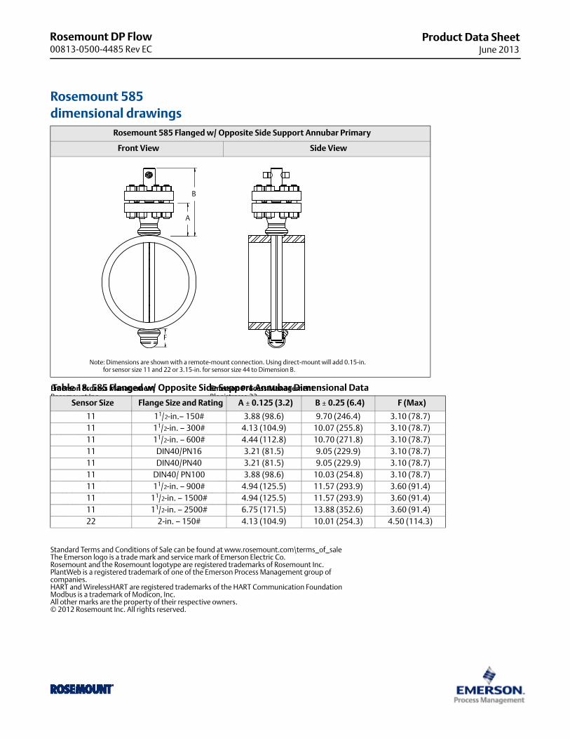
Rosemount 585 dimensional drawings
Rosemount 585 Flanged w/ Opposite Side Support Annubar Primary
Front View Side View
B
A
F
Note: Dimensions are shown with a remote-mount connection. Using direct-mount will add 0.15-in. for sensor size 11 and 22 or 3.15-in. for sensor size 44 to Dimension B.
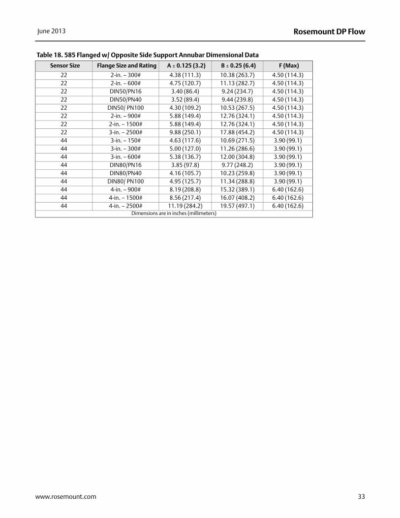
Table 18. 585 Flanged w/ Opposite Side Support Annubar Dimensional Data
Sensor Size Flange Size and Rating A ± 0.125 (3.2) B ± 0.25 (6.4) F (Max)
11 11/2-in.– 150# 3.88 (98.6) 9.70 (246.4) 3.10 (78.7)11 11/2-in. – 300# 4.13 (104.9) 10.07 (255.8) 3.10 (78.7)11 11/2-in. – 600# 4.44 (112.8) 10.70 (271.8) 3.10 (78.7)11 DIN40/PN16 3.21 (81.5) 9.05 (229.9) 3.10 (78.7)11 DIN40/PN40 3.21 (81.5) 9.05 (229.9) 3.10 (78.7)11 DIN40/ PN100 3.88 (98.6) 10.03 (254.8) 3.10 (78.7)11 11/2-in. – 900# 4.94 (125.5) 11.57 (293.9) 3.60 (91.4)11 11/2-in. – 1500# 4.94 (125.5) 11.57 (293.9) 3.60 (91.4)11 11/2-in. – 2500# 6.75 (171.5) 13.88 (352.6) 3.60 (91.4)22 2-in. – 150# 4.13 (104.9) 10.01 (254.3) 4.50 (114.3)
Standard Terms and Conditions of Sale can be found at www.rosemount.com\terms_of_saleThe Emerson logo is a trade mark and service mark of Emerson Electric Co.Rosemount and the Rosemount logotype are registered trademarks of Rosemount Inc.PlantWeb is a registered trademark of one of the Emerson Process Management group of companies.HART and WirelessHART are registered trademarks of the HART Communication FoundationModbus is a trademark of Modicon, Inc.All other marks are the property of their respective owners.© 2012 Rosemount Inc. All rights reserved.
Rosemount DP FlowJune 2013
22 2-in. – 300# 4.38 (111.3) 10.38 (263.7) 4.50 (114.3)22 2-in. – 600# 4.75 (120.7) 11.13 (282.7) 4.50 (114.3)22 DIN50/PN16 3.40 (86.4) 9.24 (234.7) 4.50 (114.3)22 DIN50/PN40 3.52 (89.4) 9.44 (239.8) 4.50 (114.3)22 DIN50/ PN100 4.30 (109.2) 10.53 (267.5) 4.50 (114.3)22 2-in. – 900# 5.88 (149.4) 12.76 (324.1) 4.50 (114.3)22 2-in. – 1500# 5.88 (149.4) 12.76 (324.1) 4.50 (114.3)22 3-in. – 2500# 9.88 (250.1) 17.88 (454.2) 4.50 (114.3)44 3-in. – 150# 4.63 (117.6) 10.69 (271.5) 3.90 (99.1)44 3-in. – 300# 5.00 (127.0) 11.26 (286.6) 3.90 (99.1)44 3-in. – 600# 5.38 (136.7) 12.00 (304.8) 3.90 (99.1)44 DIN80/PN16 3.85 (97.8) 9.77 (248.2) 3.90 (99.1)44 DIN80/PN40 4.16 (105.7) 10.23 (259.8) 3.90 (99.1)44 DIN80/ PN100 4.95 (125.7) 11.34 (288.8) 3.90 (99.1)44 4-in. – 900# 8.19 (208.8) 15.32 (389.1) 6.40 (162.6)44 4-in. – 1500# 8.56 (217.4) 16.07 (408.2) 6.40 (162.6)44 4-in. – 2500# 11.19 (284.2) 19.57 (497.1) 6.40 (162.6)
Dimensions are in inches (millimeters)
Table 18. 585 Flanged w/ Opposite Side Support Annubar Dimensional Data
Sensor Size Flange Size and Rating A ± 0.125 (3.2) B ± 0.25 (6.4) F (Max)
33www.rosemount.com
Rosemount DP Flow June 2013
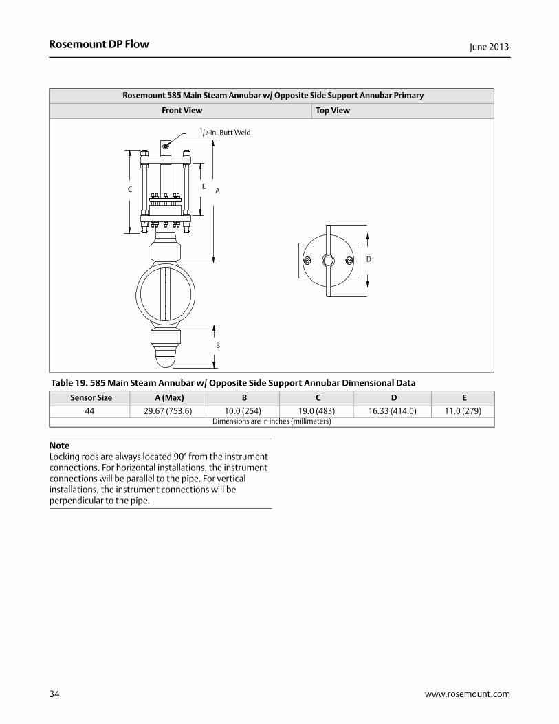
NoteLocking rods are always located 90° from the instrument connections. For horizontal installations, the instrument connections will be parallel to the pipe. For vertical installations, the instrument connections will be perpendicular to the pipe.
Rosemount 585 Main Steam Annubar w/ Opposite Side Support Annubar Primary
Front View Top View
Table 19. 585 Main Steam Annubar w/ Opposite Side Support Annubar Dimensional Data
Sensor Size A (Max) B C D E
44 29.67 (753.6) 10.0 (254) 19.0 (483) 16.33 (414.0) 11.0 (279)Dimensions are in inches (millimeters)
A
1/2-in. Butt Weld
B
C
D
E
34 www.rosemount.com
Rosemount DP FlowJune 2013
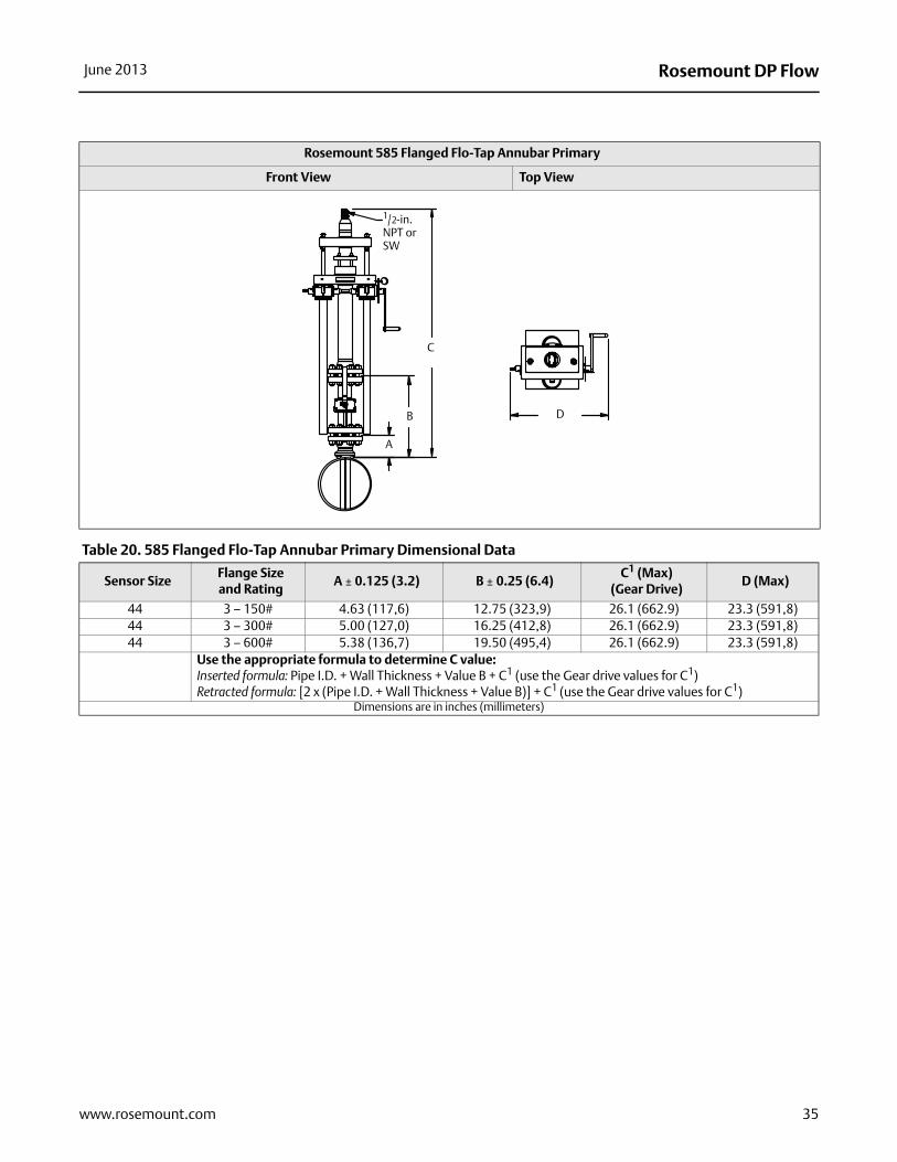
Rosemount 585 Flanged Flo-Tap Annubar Primary
Front View Top View
C
B
A
1/2-in. NPT or SW
D
Table 20. 585 Flanged Flo-Tap Annubar Primary Dimensional Data
Sensor SizeFlange Size and Rating
A ± 0.125 (3.2) B ± 0.25 (6.4)C1 (Max)
(Gear Drive)D (Max)
44 3 – 150# 4.63 (117,6) 12.75 (323,9) 26.1 (662.9) 23.3 (591,8)44 3 – 300# 5.00 (127,0) 16.25 (412,8) 26.1 (662.9) 23.3 (591,8)44 3 – 600# 5.38 (136,7) 19.50 (495,4) 26.1 (662.9) 23.3 (591,8)
Use the appropriate formula to determine C value: Inserted formula: Pipe I.D. + Wall Thickness + Value B + C1 (use the Gear drive values for C1)Retracted formula: [2 x (Pipe I.D. + Wall Thickness + Value B)] + C1 (use the Gear drive values for C1)
Dimensions are in inches (millimeters)
35www.rosemount.com
Rosemount DP Flow00813-0500-4485 Rev EC
Product Data SheetJune 2013
Emerson Process ManagementRosemount Inc.8200 Market BoulevardChanhassen, MN 55317 USAT (U.S.) 1-800-999-9307T (International) (952) 906-8888F (952) 906-8889www.rosemount.com
Emerson Process ManagementBlegistrasse 23P.O. Box 1046CH 6341 BaarSwitzerlandT +41 (0) 41 768 6111F +41 (0) 41 768 6300www.rosemount.com
Emerson Process Management Asia Pacific Pte Ltd1 Pandan CrescentSignapore 128461T +65 6777 8211F +65 6777 0947Service Support Hotline: +65 6770 8711Email: [email protected]
Emerson Process Management Latin America1300 Concord Terrace, Suite 400Sunrise Florida 33323 USAT + 1 954 846 5030www.rosemount.com
Standard Terms and Conditions of Sale can be found at www.rosemount.com\terms_of_saleThe Emerson logo is a trade mark and service mark of Emerson Electric Co.Rosemount and the Rosemount logotype are registered trademarks of Rosemount Inc.PlantWeb is a registered trademark of one of the Emerson Process Management group of companies.HART and WirelessHART are registered trademarks of the HART Communication FoundationModbus is a trademark of Modicon, Inc.All other marks are the property of their respective owners.© 2012 Rosemount Inc. All rights reserved.
Related Documents


