Quick Start Guide 00825-0100-4530, Rev GB June 2017 Rosemount ™ 5300 Level Transmitter Guided Wave Radar

Welcome message from author
This document is posted to help you gain knowledge. Please leave a comment to let me know what you think about it! Share it to your friends and learn new things together.
Transcript

Quick Start Guide00825-0100-4530, Rev GB
June 2017
Rosemount™ 5300 Level Transmitter
Guided Wave Radar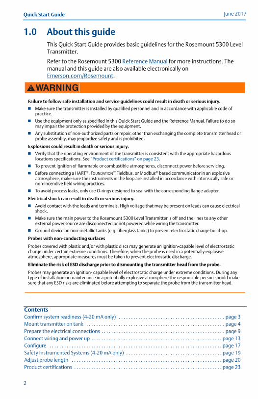
June 2017Quick Start Guide
1.0 About this guideThis Quick Start Guide provides basic guidelines for the Rosemount 5300 Level Transmitter.
Refer to the Rosemount 5300 Reference Manual for more instructions. The manual and this guide are also available electronically on Emerson.com/Rosemount.
Failure to follow safe installation and service guidelines could result in death or serious injury.
Make sure the transmitter is installed by qualified personnel and in accordance with applicable code of practice.
Use the equipment only as specified in this Quick Start Guide and the Reference Manual. Failure to do so may impair the protection provided by the equipment.
Any substitution of non-authorized parts or repair, other than exchanging the complete transmitter head or probe assembly, may jeopardize safety and is prohibited.
Explosions could result in death or serious injury.
Verify that the operating environment of the transmitter is consistent with the appropriate hazardous locations specifications. See “Product certifications” on page 23.
To prevent ignition of flammable or combustible atmospheres, disconnect power before servicing.
Before connecting a HART®, FOUNDATION™ Fieldbus, or Modbus® based communicator in an explosive atmosphere, make sure the instruments in the loop are installed in accordance with intrinsically safe or non-incendive field wiring practices.
To avoid process leaks, only use O-rings designed to seal with the corresponding flange adapter.
Electrical shock can result in death or serious injury.
Avoid contact with the leads and terminals. High voltage that may be present on leads can cause electrical shock.
Make sure the main power to the Rosemount 5300 Level Transmitter is off and the lines to any other external power source are disconnected or not powered while wiring the transmitter.
Ground device on non-metallic tanks (e.g. fiberglass tanks) to prevent electrostatic charge build-up.
Probes with non-conducting surfaces
Probes covered with plastic and/or with plastic discs may generate an ignition-capable level of electrostatic charge under certain extreme conditions. Therefore, when the probe is used in a potentially explosive atmosphere, appropriate measures must be taken to prevent electrostatic discharge.
Eliminate the risk of ESD discharge prior to dismounting the transmitter head from the probe.
Probes may generate an ignition- capable level of electrostatic charge under extreme conditions. During any type of installation or maintenance in a potentially explosive atmosphere the responsible person should make sure that any ESD risks are eliminated before attempting to separate the probe from the transmitter head.
ContentsConfirm system readiness (4-20 mA only) . . . . . . . . . . . . . . . . . . . . . . . . . . . . . . . . . . . . . . . . . . . page 3Mount transmitter on tank . . . . . . . . . . . . . . . . . . . . . . . . . . . . . . . . . . . . . . . . . . . . . . . . . . . . . . . . page 4Prepare the electrical connections . . . . . . . . . . . . . . . . . . . . . . . . . . . . . . . . . . . . . . . . . . . . . . . . . . page 9Connect wiring and power up . . . . . . . . . . . . . . . . . . . . . . . . . . . . . . . . . . . . . . . . . . . . . . . . . . . . . page 13Configure . . . . . . . . . . . . . . . . . . . . . . . . . . . . . . . . . . . . . . . . . . . . . . . . . . . . . . . . . . . . . . . . . . . . . . page 17Safety Instrumented Systems (4-20 mA only) . . . . . . . . . . . . . . . . . . . . . . . . . . . . . . . . . . . . . . . page 19Adjust probe length . . . . . . . . . . . . . . . . . . . . . . . . . . . . . . . . . . . . . . . . . . . . . . . . . . . . . . . . . . . . . page 20Product certifications . . . . . . . . . . . . . . . . . . . . . . . . . . . . . . . . . . . . . . . . . . . . . . . . . . . . . . . . . . . . page 23
2

Quick Start GuideJune 2017
2.0 Confirm system readiness (4-20 mA only)
2.1 Confirm HART revision capabilityIf using HART-based control or asset management systems, confirm the HART 7 capability of such systems prior to commissioning and installation. Not all systems are capable of communicating with the HART Revision 7 protocol. This transmitter can be configured for either HART Revision 5 or 7.
2.2 Confirm correct device driver Verify the latest device driver (DD/DTM™) is loaded on your systems to
ensure proper communication. See Table 1. Download the latest device driver from EmersonProcess.com/DeviceFiles.
2.3 Switch HART revision modeIf the HART configuration tool is not capable of communicating with HART Revision 7, the device will load a generic menu with limited capability.
To switch the HART revision mode from the generic menu:1. Locate the “Message” field.
2. In the Message field, enter HART5 or HART7 and then 27 trailing spaces.
Table 1. Rosemount 5300 Device Revisions and Files
Firmware version(1)
1. Firmware version is printed on the transmitter head label, e.g. SW 2E0.
Find device driver
HART universal revision Device revision(2)
2. Device revision is printed on the transmitter head label, e.g. HART Dev Rev 4.
2F0 and later7 4
5 3
2A2 - 2D2 5 3
3
June 2017Quick Start Guide
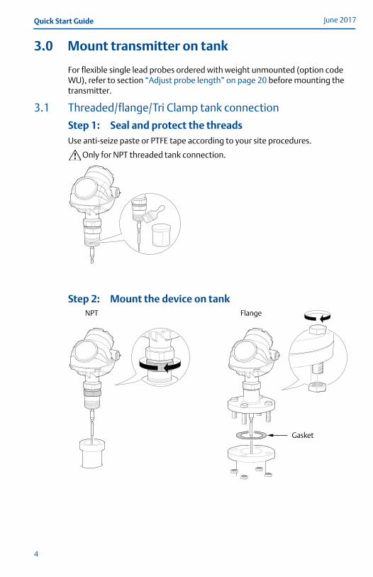
3.0 Mount transmitter on tank
For flexible single lead probes ordered with weight unmounted (option code WU), refer to section “Adjust probe length” on page 20 before mounting the transmitter.
3.1 Threaded/flange/Tri Clamp tank connection
Step 1: Seal and protect the threadsUse anti-seize paste or PTFE tape according to your site procedures.
Only for NPT threaded tank connection.
Step 2: Mount the device on tankNPT Flange
Gasket
4
Quick Start GuideJune 2017
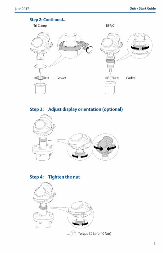
Step 2: Continued...
Step 3: Adjust display orientation (optional)
Step 4: Tighten the nut
Tri Clamp BSP/G
GasketGasket
Torque 30 Lbft (40 Nm)
5

June 2017Quick Start Guide
3.2 Remote housing
Step 1: Carefully remove the transmitter
Step 2: Mount the probe on tank
Step 3: Mount the remote connection on the probe
Gasket
Torque 30 Lbft (40 Nm)
6

Quick Start GuideJune 2017
Step 4: Mount the bracket to the pipe
Step 5: Fasten the housing support
Step 6: Mount the transmitter head
4X
Vertical pipe
Horizontal pipe
3X
Torque 30 Lbft (40 Nm)
7
June 2017Quick Start Guide
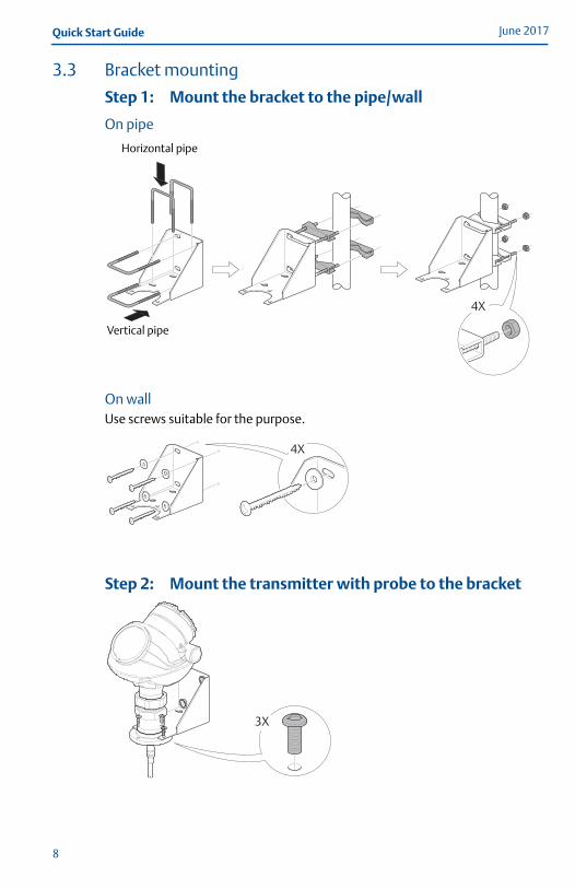
3.3 Bracket mounting
Step 1: Mount the bracket to the pipe/wall
On pipe
On wallUse screws suitable for the purpose.
Step 2: Mount the transmitter with probe to the bracket
4X
Vertical pipe
Horizontal pipe
4X
3X
8

Quick Start GuideJune 2017
4.0 Prepare the electrical connections
4.1 Cable selectionUse shielded twisted pair wiring (18-12 AWG).
For the RS-485 bus, use shielded twisted pair wiring, preferably with an impedance of 120 (typically 24 AWG).
4.2 Cable gland/conduitFor explosion-proof/flameproof installations, only use cable glands or conduit entry devices certified explosion-proof or flameproof.
4.3 Power supply (Vdc)
4.4 4-20 mA/HART communication
Figure 1. Wiring Diagram
NoteRosemount 5300 Level Transmitters with Flameproof/explosion-proof output have a built-in barrier; no external barrier needed.
Approval type HART FOUNDATION Fieldbus RS-485 with Modbus
None 16 - 42.4 9 - 32 8-30 (max. rating)
Non-sparking/energy limited 16 - 42.4 9 - 32 N/A
Intrinsically safe 16 - 30 9 - 30 N/A
FISCO N/A 9 - 17.5 N/A
Explosion-proof/Flameproof 20 - 42.4 16 - 32 8-30 (max. rating)
A.B.
C.
Field CommunicatorApproved IS barrier (for Intrinsically Safe installations only)HART modem
D.E.F.
Current meterLoad resistance (≥250 Power supply
1 2 34 5 67 8
09
+-
+-
+-
A
C
B
FD
E
9

June 2017Quick Start Guide
Load limitations
For HART communication, a minimum loop resistance of 250 is required. Maximum loop resistance is determined by the voltage level of the external power supply, as described by Figure 2.
Figure 2. Load Limitations
Intrinsically safe installations
Non-hazardous and Non-sparking/energy limited installations
Explosion-proof/flameproof (Ex d) installations
R(): Maximum Loop ResistanceUE(V): External Power Supply Voltage
NoteFor the Ex d case, the diagram is only valid if the HART load resistance is at the + side and if the - side is grounded, otherwise the load resistance value is limited to 435 .
847
586
24
1400
200
400
600
800
1000
1200
10 16 20 30 40 50
Operating region
UE(V)
R(
1400
200
10 16
1387
586
24 42.4
20 30 40 50
400
600
800
1000
1200
UE(V)
R(
Operating region
1400
200
400
600
800
1000
1200
10 20
24
348
1148
42.4
30 40 50UE(V)
R(
Operating region
10
Quick Start GuideJune 2017
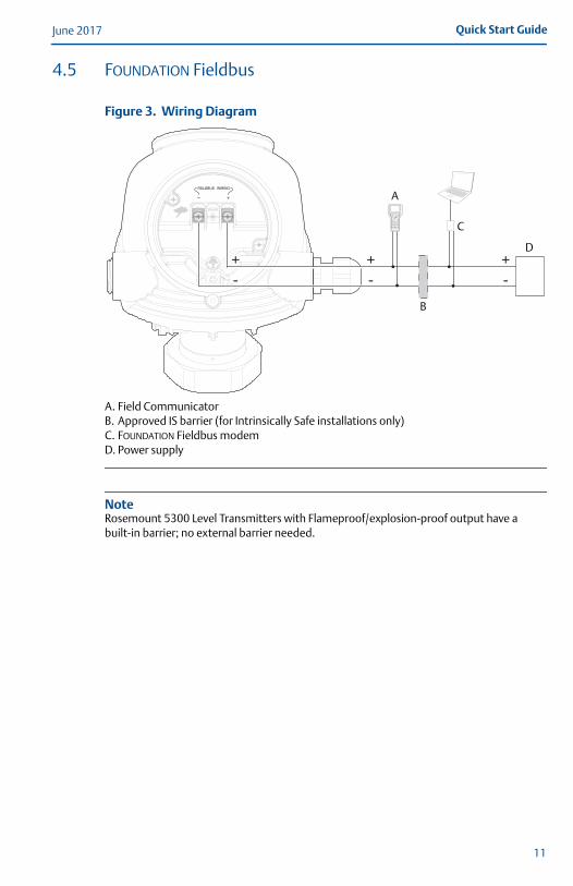
4.5 FOUNDATION Fieldbus
Figure 3. Wiring Diagram
NoteRosemount 5300 Level Transmitters with Flameproof/explosion-proof output have a built-in barrier; no external barrier needed.
A.B.C.D.
Field CommunicatorApproved IS barrier (for Intrinsically Safe installations only)FOUNDATION Fieldbus modemPower supply
1 2 34 5 67 8
09
+-
+-
+-
A
C
B
D
11
June 2017Quick Start Guide
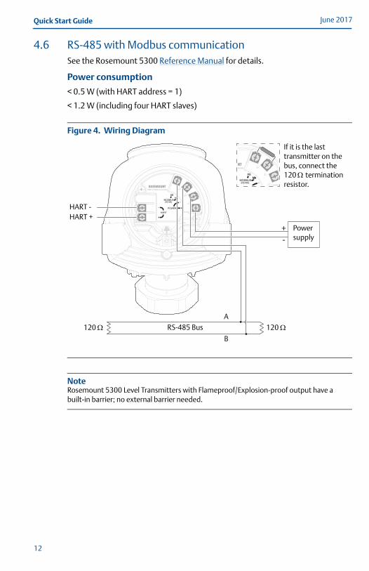
4.6 RS-485 with Modbus communicationSee the Rosemount 5300 Reference Manual for details.
Power consumption
< 0.5 W (with HART address = 1)
< 1.2 W (including four HART slaves)
Figure 4. Wiring Diagram
NoteRosemount 5300 Level Transmitters with Flameproof/Explosion-proof output have a built-in barrier; no external barrier needed.
-+
If it is the last transmitter on the bus, connect the 120 termination resistor.
HART -
120
Power supply
120 RS-485 BusA
B
HART +
12

Quick Start GuideJune 2017
5.0 Connect wiring and power upStep 1: Verify that the power supply is disconnected
Step 2: Remove the cover
Step 3: Remove the plastic plugs
Step 4: Pull the cable through the cable gland/conduit
Adapters are required if M20 glands are used.
Step 5: Connect the cable wiresSee the wiring diagrams on page 9-12.
13

June 2017Quick Start Guide
Step 6: Ensure proper groundingMake sure grounding is done (including IS ground inside Terminal compartment) according to Hazardous Locations Certifications, national and local electrical codes.
Transmitter housing groundingThe most effective transmitter housing grounding method is a direct connection to earth ground with minimal (< 1 ) impedance. There are two grounding screw connections provided (see Figure 5).
Figure 5. Ground Screws
Signal cable shield groundingMake sure the instrument cable shield is: trimmed close and insulated from touching the transmitter housing. continuously connected throughout the segment. connected to a good earth ground at the power supply end.
Figure 6. Cable Shield
A.B.
Internal ground screwExternal ground screw
A.B.
Insulate shieldMinimize distance
C.D.
Trim shield and insulateConnect shield back to the power supply ground
A
B
AB
B
C CC
D
14
Quick Start GuideJune 2017
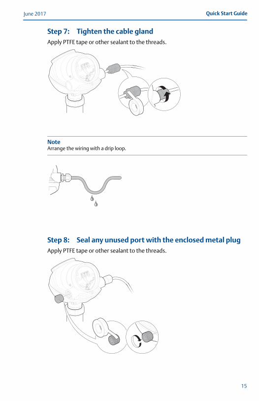
Step 7: Tighten the cable glandApply PTFE tape or other sealant to the threads.
NoteArrange the wiring with a drip loop.
Step 8: Seal any unused port with the enclosed metal plugApply PTFE tape or other sealant to the threads.
15
June 2017Quick Start Guide
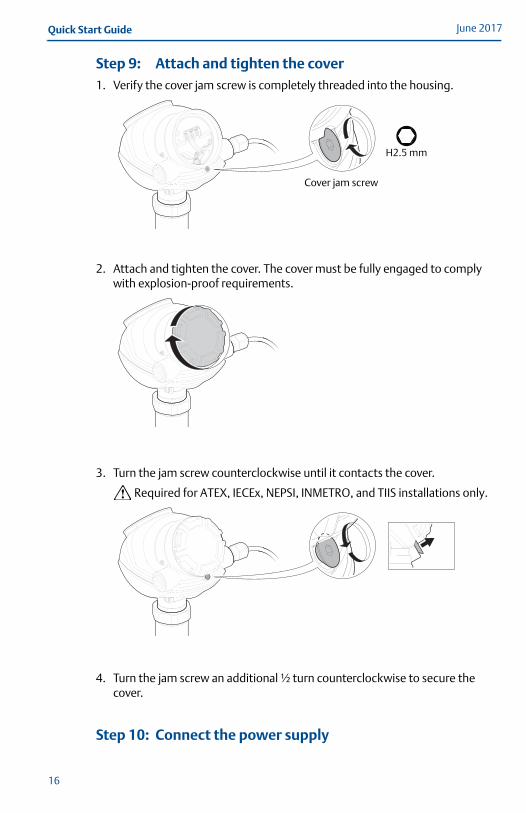
Step 9: Attach and tighten the cover1. Verify the cover jam screw is completely threaded into the housing.
2. Attach and tighten the cover. The cover must be fully engaged to comply with explosion-proof requirements.
3. Turn the jam screw counterclockwise until it contacts the cover.
Required for ATEX, IECEx, NEPSI, INMETRO, and TIIS installations only.
4. Turn the jam screw an additional ½ turn counterclockwise to secure the cover.
Step 10: Connect the power supply
H2.5 mm
Cover jam screw
16
Quick Start GuideJune 2017
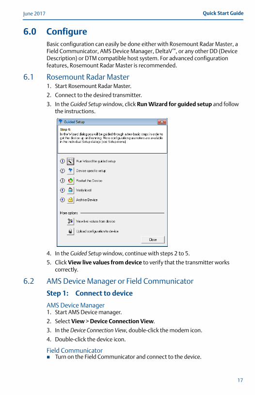
6.0 ConfigureBasic configuration can easily be done either with Rosemount Radar Master, a Field Communicator, AMS Device Manager, DeltaV™, or any other DD (Device Description) or DTM compatible host system. For advanced configuration features, Rosemount Radar Master is recommended.
6.1 Rosemount Radar Master1. Start Rosemount Radar Master.
2. Connect to the desired transmitter.
3. In the Guided Setup window, click Run Wizard for guided setup and follow the instructions.
4. In the Guided Setup window, continue with steps 2 to 5.
5. Click View live values from device to verify that the transmitter works correctly.
6.2 AMS Device Manager or Field Communicator
Step 1: Connect to device
AMS Device Manager1. Start AMS Device manager.
2. Select View > Device Connection View.
3. In the Device Connection View, double-click the modem icon.
4. Double-click the device icon.
Field Communicator Turn on the Field Communicator and connect to the device.
17
June 2017Quick Start Guide
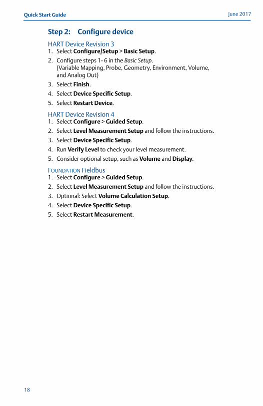
Step 2: Configure device
HART Device Revision 31. Select Configure/Setup > Basic Setup.
2. Configure steps 1- 6 in the Basic Setup. (Variable Mapping, Probe, Geometry, Environment, Volume, and Analog Out)
3. Select Finish.
4. Select Device Specific Setup.
5. Select Restart Device.
HART Device Revision 41. Select Configure > Guided Setup.
2. Select Level Measurement Setup and follow the instructions.
3. Select Device Specific Setup.
4. Run Verify Level to check your level measurement.
5. Consider optional setup, such as Volume and Display.
FOUNDATION Fieldbus1. Select Configure > Guided Setup.
2. Select Level Measurement Setup and follow the instructions.
3. Optional: Select Volume Calculation Setup.
4. Select Device Specific Setup.
5. Select Restart Measurement.
18
Quick Start GuideJune 2017
7.0 Safety Instrumented Systems (4-20 mA only)For Safety Certified installations, refer to the Rosemount 5300 Reference Manual.
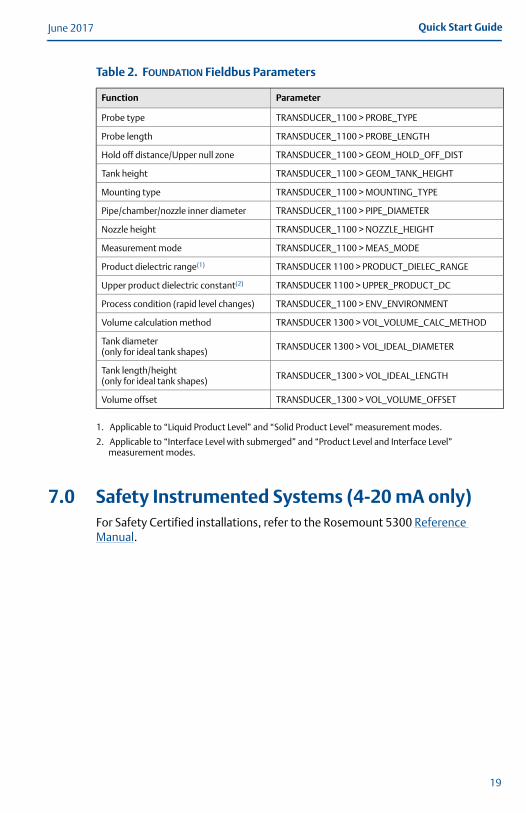
Table 2. FOUNDATION Fieldbus Parameters
Function Parameter
Probe type TRANSDUCER_1100 > PROBE_TYPE
Probe length TRANSDUCER_1100 > PROBE_LENGTH
Hold off distance/Upper null zone TRANSDUCER_1100 > GEOM_HOLD_OFF_DIST
Tank height TRANSDUCER_1100 > GEOM_TANK_HEIGHT
Mounting type TRANSDUCER_1100 > MOUNTING_TYPE
Pipe/chamber/nozzle inner diameter TRANSDUCER_1100 > PIPE_DIAMETER
Nozzle height TRANSDUCER_1100 > NOZZLE_HEIGHT
Measurement mode TRANSDUCER_1100 > MEAS_MODE
Product dielectric range(1)
1. Applicable to “Liquid Product Level” and “Solid Product Level” measurement modes.
TRANSDUCER 1100 > PRODUCT_DIELEC_RANGE
Upper product dielectric constant(2)
2. Applicable to “Interface Level with submerged” and “Product Level and Interface Level” measurement modes.
TRANSDUCER 1100 > UPPER_PRODUCT_DC
Process condition (rapid level changes) TRANSDUCER_1100 > ENV_ENVIRONMENT
Volume calculation method TRANSDUCER 1300 > VOL_VOLUME_CALC_METHOD
Tank diameter (only for ideal tank shapes) TRANSDUCER 1300 > VOL_IDEAL_DIAMETER
Tank length/height (only for ideal tank shapes) TRANSDUCER_1300 > VOL_IDEAL_LENGTH
Volume offset TRANSDUCER_1300 > VOL_VOLUME_OFFSET
19
June 2017Quick Start Guide
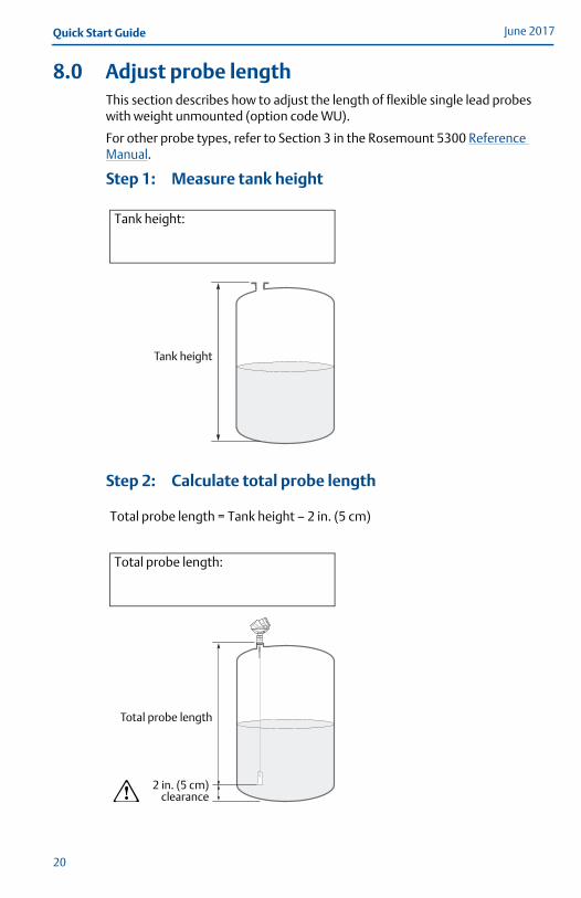
8.0 Adjust probe lengthThis section describes how to adjust the length of flexible single lead probes with weight unmounted (option code WU).
For other probe types, refer to Section 3 in the Rosemount 5300 Reference Manual.
Step 1: Measure tank height
Step 2: Calculate total probe length
Tank height:
Tank height
Total probe length = Tank height – 2 in. (5 cm)
Total probe length:
2 in. (5 cm)clearance
Total probe length
20
Quick Start GuideJune 2017
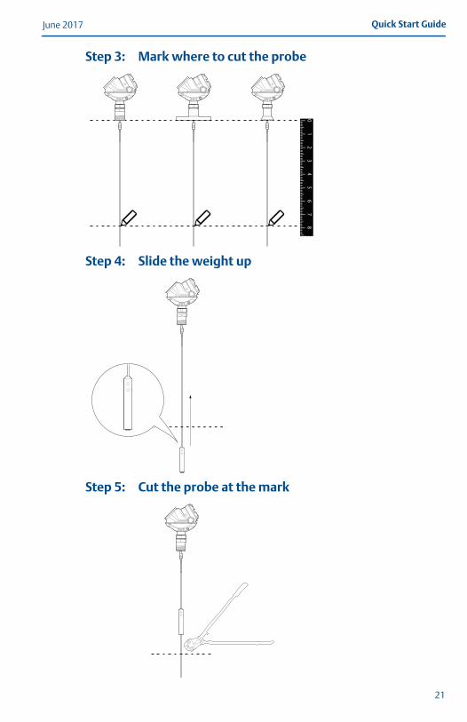
Step 3: Mark where to cut the probe
Step 4: Slide the weight up
Step 5: Cut the probe at the mark
12
34
56
78
0
21

June 2017Quick Start Guide
Step 6: Fasten the weight
Step 7: Update transmitter configuration to the new probe length
Weight material Torque (Nm)
Stainless steel 5
Alloy C-276 2.5
Alloy 400 2.5
Duplex 2205 2.5
Hand tighten, hard(see table for torque value)
Probe length:
Probe length
22
Quick Start GuideJune 2017
9.0 Product certificationsRev 9.1
9.1 European directive informationA copy of the EU Declaration of Conformity can be found at the end of the Quick Start Guide. The most recent revision of the EU declaration of conformity can be found at Emerson.com/Rosemount.
9.2 Ordinary location certificationAs standard, the transmitter has been examined and tested to determine that the design meets the basic electrical, mechanical, and fire protection requirements by a nationally recognized test laboratory (NRTL) as accredited by the Federal Occupational Safety and Health Administration (OSHA).
9.3 Installing equipment in North AmericaThe US National Electrical Code (NEC®) and the Canadian Electrical Code (CEC) permit the use of Division marked equipment in Zones and Zone marked equipment in Divisions. The markings must be suitable for the area classification, gas, and temperature class. This information is clearly defined in the respective codes.
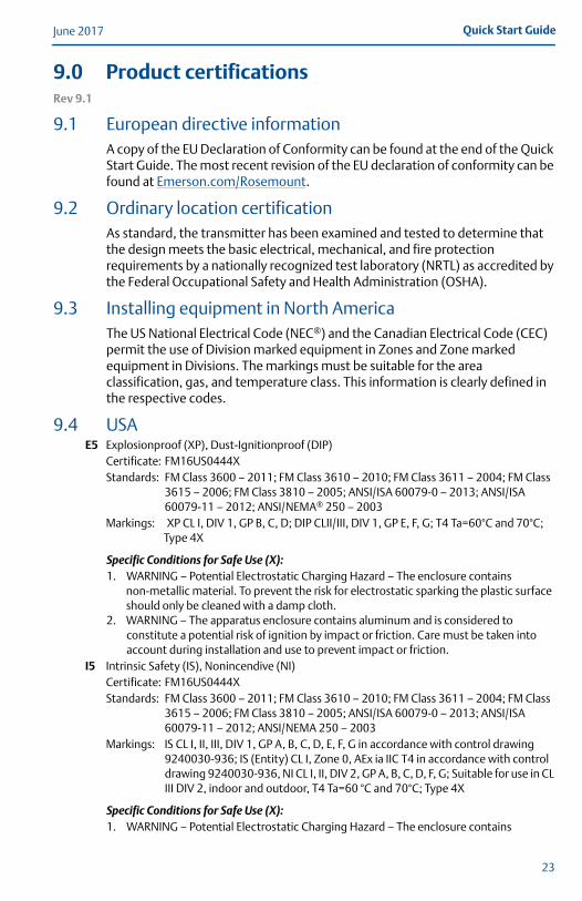
9.4 USAE5 Explosionproof (XP), Dust-Ignitionproof (DIP)
Certificate: FM16US0444XStandards: FM Class 3600 – 2011; FM Class 3610 – 2010; FM Class 3611 – 2004; FM Class
3615 – 2006; FM Class 3810 – 2005; ANSI/ISA 60079-0 – 2013; ANSI/ISA 60079-11 – 2012; ANSI/NEMA® 250 – 2003
Markings: XP CL I, DIV 1, GP B, C, D; DIP CLII/III, DIV 1, GP E, F, G; T4 Ta=60°C and 70°C; Type 4X
Specific Conditions for Safe Use (X):1. WARNING – Potential Electrostatic Charging Hazard – The enclosure contains
non-metallic material. To prevent the risk for electrostatic sparking the plastic surface should only be cleaned with a damp cloth.
2. WARNING – The apparatus enclosure contains aluminum and is considered to constitute a potential risk of ignition by impact or friction. Care must be taken into account during installation and use to prevent impact or friction.
I5 Intrinsic Safety (IS), Nonincendive (NI)Certificate: FM16US0444XStandards: FM Class 3600 – 2011; FM Class 3610 – 2010; FM Class 3611 – 2004; FM Class
3615 – 2006; FM Class 3810 – 2005; ANSI/ISA 60079-0 – 2013; ANSI/ISA 60079-11 – 2012; ANSI/NEMA 250 – 2003
Markings: IS CL I, II, III, DIV 1, GP A, B, C, D, E, F, G in accordance with control drawing 9240030-936; IS (Entity) CL I, Zone 0, AEx ia IIC T4 in accordance with control drawing 9240030-936, NI CL I, II, DIV 2, GP A, B, C, D, F, G; Suitable for use in CL III DIV 2, indoor and outdoor, T4 Ta=60 °C and 70°C; Type 4X
Specific Conditions for Safe Use (X):1. WARNING – Potential Electrostatic Charging Hazard – The enclosure contains
23
June 2017Quick Start Guide
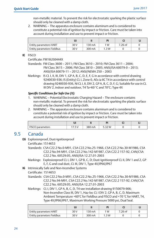
non-metallic material. To prevent the risk for electrostatic sparking the plastic surface should only be cleaned with a damp cloth.
2. WARNING – The apparatus enclosure contains aluminum and is considered to constitute a potential risk of ignition by impact or friction. Care must be taken into account during installation and use to prevent impact or friction.
IE FISCOCertificate: FM16US0444XStandards: FM Class 3600 – 2011; FM Class 3610 – 2010; FM Class 3611 – 2004;
FM Class 3615 – 2006; FM Class 3810 – 2005; ANSI/ISA 60079-0 – 2013;ANSI/ISA 60079-11 – 2012; ANSI/NEMA 250 – 2003
Markings: IS CL I, II, III, DIV 1, GP A, B, C, D, E, F, G in accordance with control drawing 9240030-936; IS (Entity) CL I, Zone 0, AEx ia IIC T4 in accordance with control drawing 9240030-936, NI CL I, II, DIV 2, GP A, B, C, D, F, G; Suitable for use in CL III DIV 2, indoor and outdoor, T4 Ta=60 °C and 70°C; Type 4X
Specific Conditions for Safe Use (X):1. WARNING – Potential Electrostatic Charging Hazard – The enclosure contains
non-metallic material. To prevent the risk for electrostatic sparking the plastic surface should only be cleaned with a damp cloth.
2. WARNING – The apparatus enclosure contains aluminum and is considered to constitute a potential risk of ignition by impact or friction. Care must be taken into account during installation and use to prevent impact or friction.
9.5 CanadaE6 Explosionproof, Dust-Ignitionproof
Certificate: 1514653Standards: CSA C22.2 No.0-M91, CSA C22.2 No.25-1966, CSA C22.2 No.30-M1986, CSA
C22.2 No.94-M91, CSA C22.2 No.142-M1987, CSA C22.2 157-92, CAN/CSA C22.2 No. 60529:05, ANSI/ISA 12.27.01-2003
Markings: Explosionproof CL I, DIV 1, GP B, C, D; Dust-Ignitionproof CL II, DIV 1 and 2, GP E, F, G and coal dust, CL III, DIV 1, Type 4X/IP66/IP67
I6 Intrinsically Safe and Non-Incendive SystemsCertificate: 1514653Standards: CSA C22.2 No.0-M91, CSA C22.2 No.25-1966, CSA C22.2 No.30-M1986, CSA
C22.2 No.94-M91, CSA C22.2 No.142-M1987, CSA C22.2 157-92, CAN/CSA C22.2 No. 60529:05, ANSI/ISA 12.27.01-2003
Markings: CL I, DIV 1, GP A, B, C, D, T4 see installation drawing 9150079-906; Non-Incendive Class III, DIV 1, Haz-loc CL I DIV 2, GP A, B, C, D, Maximum Ambient Temperature +60°C for Fieldbus and FISCO and +70 °C for HART, T4, Type 4X/IP66/IP67, Maximum Working Pressure 5000 psi, Dual Seal.
Ui Ii Pi Ci Li
Entity parameters HART 30 V 130 mA 1 W 7.26 nF 0Entity parameters Fieldbus 30 V 300 mA 1.3 W 0 0
Ui Ii Pi Ci Li
FISCO parameters 17.5 V 380 mA 5.32 W 0 0
Ui Ii Pi Ci Li
Entity parameters HART 30 V 130 mA 1 W 7.26 nF 0Entity parameters Fieldbus 30 V 300 mA 1.3 W 0 0
24
Quick Start GuideJune 2017
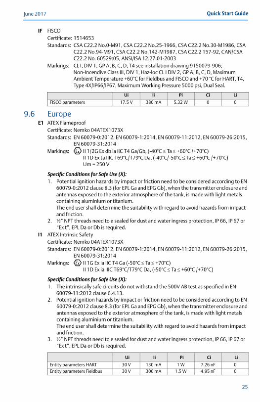
IF FISCOCertificate: 1514653Standards: CSA C22.2 No.0-M91, CSA C22.2 No.25-1966, CSA C22.2 No.30-M1986, CSA
C22.2 No.94-M91, CSA C22.2 No.142-M1987, CSA C22.2 157-92, CAN/CSA C22.2 No. 60529:05, ANSI/ISA 12.27.01-2003
Markings: CL I, DIV 1, GP A, B, C, D, T4 see installation drawing 9150079-906; Non-Incendive Class III, DIV 1, Haz-loc CL I DIV 2, GP A, B, C, D, Maximum Ambient Temperature +60°C for Fieldbus and FISCO and +70 °C for HART, T4, Type 4X/IP66/IP67, Maximum Working Pressure 5000 psi, Dual Seal.
9.6 EuropeE1 ATEX Flameproof
Certificate: Nemko 04ATEX1073XStandards: EN 60079-0:2012, EN 60079-1:2014, EN 60079-11:2012, EN 60079-26:2015,
EN 60079-31:2014Markings: II 1/2G Ex db ia IIC T4 Ga/Gb, (-40°C Ta +60°C /+70°C)
II 1D Ex ta IIIC T69°C/T79°C Da, (-40°C/-50°C Ta +60°C /+70°C)Um = 250 V
Specific Conditions for Safe Use (X):1. Potential ignition hazards by impact or friction need to be considered according to EN
60079-0:2012 clause 8.3 (for EPL Ga and EPG Gb), when the transmitter enclosure and antennas exposed to the exterior atmosphere of the tank, is made with light metals containing aluminium or titanium. The end user shall determine the suitability with regard to avoid hazards from impact and friction.
2. ½” NPT threads need to e sealed for dust and water ingress protection, IP 66, IP 67 or “Ex t”, EPL Da or Db is required.
I1 ATEX Intrinsic SafetyCertificate: Nemko 04ATEX1073XStandards: EN 60079-0:2012, EN 60079-1:2014, EN 60079-11:2012, EN 60079-26:2015,
EN 60079-31:2014Markings: II 1G Ex ia IIC T4 Ga (-50°C Ta +70°C)
II 1D Ex ia IIIC T69°C/T79°C Da, (-50°C Ta +60°C /+70°C)
Specific Conditions for Safe Use (X):1. The intrinsically safe circuits do not withstand the 500V AB test as specified in EN
60079-11:2012 clause 6.4.13.2. Potential ignition hazards by impact or friction need to be considered according to EN
60079-0:2012 clause 8.3 (for EPL Ga and EPG Gb), when the transmitter enclosure and antennas exposed to the exterior atmosphere of the tank, is made with light metals containing aluminium or titanium.The end user shall determine the suitability with regard to avoid hazards from impact and friction.
3. ½” NPT threads need to e sealed for dust and water ingress protection, IP 66, IP 67 or “Ex t”, EPL Da or Db is required.
Ui Ii Pi Ci Li
FISCO parameters 17.5 V 380 mA 5.32 W 0 0
Ui Ii Pi Ci Li
Entity parameters HART 30 V 130 mA 1 W 7.26 nF 0Entity parameters Fieldbus 30 V 300 mA 1.5 W 4.95 nF 0
25
June 2017Quick Start Guide
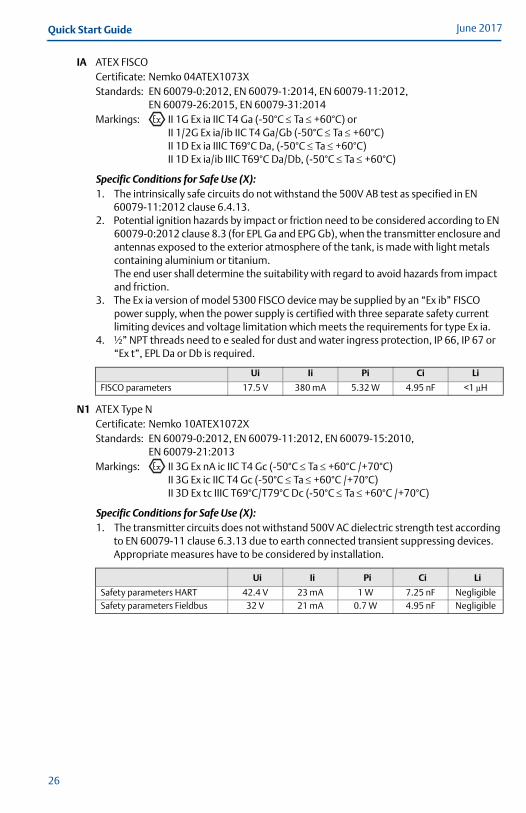
IA ATEX FISCOCertificate: Nemko 04ATEX1073XStandards: EN 60079-0:2012, EN 60079-1:2014, EN 60079-11:2012,
EN 60079-26:2015, EN 60079-31:2014Markings: II 1G Ex ia IIC T4 Ga (-50°C Ta +60°C) or
II 1/2G Ex ia/ib IIC T4 Ga/Gb (-50°C Ta +60°C)II 1D Ex ia IIIC T69°C Da, (-50°C Ta +60°C)II 1D Ex ia/ib IIIC T69°C Da/Db, (-50°C Ta +60°C)
Specific Conditions for Safe Use (X):1. The intrinsically safe circuits do not withstand the 500V AB test as specified in EN
60079-11:2012 clause 6.4.13.2. Potential ignition hazards by impact or friction need to be considered according to EN
60079-0:2012 clause 8.3 (for EPL Ga and EPG Gb), when the transmitter enclosure and antennas exposed to the exterior atmosphere of the tank, is made with light metals containing aluminium or titanium.The end user shall determine the suitability with regard to avoid hazards from impact and friction.
3. The Ex ia version of model 5300 FISCO device may be supplied by an “Ex ib” FISCO power supply, when the power supply is certified with three separate safety current limiting devices and voltage limitation which meets the requirements for type Ex ia.
4. ½” NPT threads need to e sealed for dust and water ingress protection, IP 66, IP 67 or “Ex t”, EPL Da or Db is required.
N1 ATEX Type NCertificate: Nemko 10ATEX1072XStandards: EN 60079-0:2012, EN 60079-11:2012, EN 60079-15:2010,
EN 60079-21:2013Markings: II 3G Ex nA ic IIC T4 Gc (-50°C Ta +60°C /+70°C)
II 3G Ex ic IIC T4 Gc (-50°C Ta +60°C /+70°C)II 3D Ex tc IIIC T69°C/T79°C Dc (-50°C Ta +60°C /+70°C)
Specific Conditions for Safe Use (X):1. The transmitter circuits does not withstand 500V AC dielectric strength test according
to EN 60079-11 clause 6.3.13 due to earth connected transient suppressing devices. Appropriate measures have to be considered by installation.
Ui Ii Pi Ci Li
FISCO parameters 17.5 V 380 mA 5.32 W 4.95 nF <1 μH
Ui Ii Pi Ci Li
Safety parameters HART 42.4 V 23 mA 1 W 7.25 nF NegligibleSafety parameters Fieldbus 32 V 21 mA 0.7 W 4.95 nF Negligible
26

Quick Start GuideJune 2017
9.7 InternationalE7 IECEx Flameproof
Certificate: IECEx NEM 06.0001X Standards: IEC 60079-0:2011, IEC 60079-1:2014-06, IEC 60079-11:2011;
IEC 60079-26:2014, IEC 60079-31:2013Markings: Ex db ia IIC T4 Ga/Gb (-40°C Ta +60°C /+70°C)
Ex ta IIIC T69 °C/T79 °C Da (-40°C Ta +60°C /+70°C)Um=250 VAC, IP66/IP67
Specific Conditions for Safe Use (X):1. Potential ignition hazards by impact or friction need to be considered according to IEC
60079-0:2011 clause 8.3 (for EPL Ga and EPL Gb), when the transmitter enclosure and antenna exposed to the exterior atmosphere of the tank, is made with light metals containing aluminum or titanium.The end used shall determine the suitability with regard to avoid hazards from impact and friction.
2. ½” NPT threads need to be sealed for dust and water ingress protection, IP 66, IP 67 or “Ex t”, EPL Da or Db is required.
I7 IECEx Intrinsic SafetyCertificate: IECEx NEM 06.0001XStandards:IEC 60079-0:2011, IEC 60079-1:2014-06, IEC 60079-11:2011;
IEC 60079-26:2014, IEC 60079-31:2013Markings: Ex ia IIC T4 Ga (-50°C Ta +70°C)
Ex ib IIC T4 Ga/GbEx ia IIIC T69°C/T79°C Da (-50°C Ta +60°C/+70°C)Ex ib IIIC T69°C/T79°C Da (-50°C Ta +60°C/+70°C)
Specific Conditions for Safe Use (X):1. The Intrinsically safe circuits do not withstand the 500 V AC test as specified in IEC
60079-11 clause 6.4.13.2. Potential ignition hazards by impact or friction need to be considered according to IEC
60079-0:2011 clause 8.3 (for EPL Ga and EPL Gb), when the transmitter enclosure and antenna exposed to the exterior atmosphere of the tank, is made with light metals containing aluminum or titanium.The end used shall determine the suitability with regard to avoid hazards from impact and friction.
3. ½” NPT threads need to be sealed for dust and water ingress protection, IP 66, IP 67 or “Ex t”, EPL Da or Db is required.
Ui Ii Pi Ci Li
Entity parameters HART 30 V 130 mA 1 W 0 μF NegligibleEntity parameters Fieldbus 30 V 300 mA 1.5 W 4.95 nF Negligible
27
June 2017Quick Start Guide
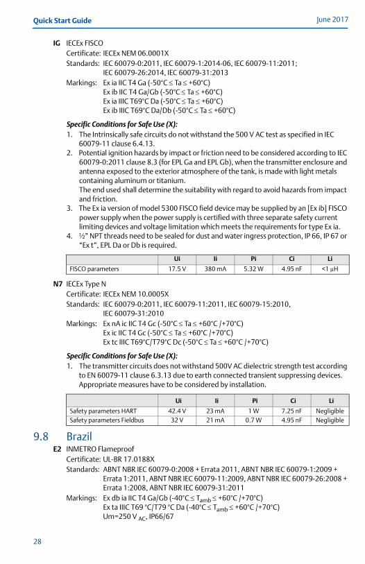
IG IECEx FISCOCertificate: IECEx NEM 06.0001XStandards: IEC 60079-0:2011, IEC 60079-1:2014-06, IEC 60079-11:2011;
IEC 60079-26:2014, IEC 60079-31:2013Markings: Ex ia IIC T4 Ga (-50°C Ta +60°C)
Ex ib IIC T4 Ga/Gb (-50°C Ta +60°C)Ex ia IIIC T69°C Da (-50°C Ta +60°C)Ex ib IIIC T69°C Da/Db (-50°C Ta +60°C)
Specific Conditions for Safe Use (X):1. The Intrinsically safe circuits do not withstand the 500 V AC test as specified in IEC
60079-11 clause 6.4.13.2. Potential ignition hazards by impact or friction need to be considered according to IEC
60079-0:2011 clause 8.3 (for EPL Ga and EPL Gb), when the transmitter enclosure and antenna exposed to the exterior atmosphere of the tank, is made with light metals containing aluminum or titanium.The end used shall determine the suitability with regard to avoid hazards from impact and friction.
3. The Ex ia version of model 5300 FISCO field device may be supplied by an [Ex ib] FISCO power supply when the power supply is certified with three separate safety current limiting devices and voltage limitation which meets the requirements for type Ex ia.
4. ½” NPT threads need to be sealed for dust and water ingress protection, IP 66, IP 67 or “Ex t”, EPL Da or Db is required.
N7 IECEx Type NCertificate: IECEx NEM 10.0005XStandards: IEC 60079-0:2011, IEC 60079-11:2011, IEC 60079-15:2010,
IEC 60079-31:2010Markings: Ex nA ic IIC T4 Gc (-50°C Ta +60°C /+70°C)
Ex ic IIC T4 Gc (-50°C Ta +60°C /+70°C)Ex tc IIIC T69°C/T79°C Dc (-50°C Ta +60°C /+70°C)
Specific Conditions for Safe Use (X):1. The transmitter circuits does not withstand 500V AC dielectric strength test according
to EN 60079-11 clause 6.3.13 due to earth connected transient suppressing devices. Appropriate measures have to be considered by installation.
9.8 BrazilE2 INMETRO Flameproof
Certificate: UL-BR 17.0188XStandards: ABNT NBR IEC 60079-0:2008 + Errata 2011, ABNT NBR IEC 60079-1:2009 +
Errata 1:2011, ABNT NBR IEC 60079-11:2009, ABNT NBR IEC 60079-26:2008 + Errata 1:2008, ABNT NBR IEC 60079-31:2011
Markings: Ex db ia IIC T4 Ga/Gb (-40°C Tamb +60°C /+70°C)Ex ta IIIC T69 °C/T79 °C Da (-40°C Tamb +60°C /+70°C)Um=250 V AC, IP66/67
Ui Ii Pi Ci Li
FISCO parameters 17.5 V 380 mA 5.32 W 4.95 nF <1 μH
Ui Ii Pi Ci Li
Safety parameters HART 42.4 V 23 mA 1 W 7.25 nF NegligibleSafety parameters Fieldbus 32 V 21 mA 0.7 W 4.95 nF Negligible
28

Quick Start GuideJune 2017
Specific Conditions for Safe Use (X):1. See certificate for Specific Conditions.
I2 INMETRO Intrinsic SafetyCertificate: UL-BR 17.0188XStandards: ABNT NBR IEC 60079-0:2008 + Errata 2011, ABNT NBR IEC 60079-11:2009,
ABNT NBR IEC 60079-26:2008 + Errata 1:2008, ABNT NBR IEC 60079-31:2011Markings: Ex ia IIC T4 Ga (- 50°C Tamb +60°C /+70°C)
Ex ia IIIC T69°C/T79°C Da (- 50°C Tamb +60°C /+70°C)
Specific Conditions for Safe Use (X):1. See certificate for Specific Conditions.
IB INMETRO FISCOCertificate: UL-BR 17.0188XStandards: ABNT NBR IEC 60079-0:2008 + Errata 2011, ABNT NBR IEC 60079-11:2009,
ABNT NBR IEC 60079-26:2008 + Errata 1:2008, ABNT NBR IEC 60079-31:2011Markings: Ex ia IIC T4 Ga
Ex ia/ib IIC T4 Ga/GbEx ia IIIC T69°C DaEx ia/ib IIIC T69°C Da/Db(- 50°C Tamb +60°C)
Specific Conditions for Safe Use (X):1. See certificate for Specific Conditions.
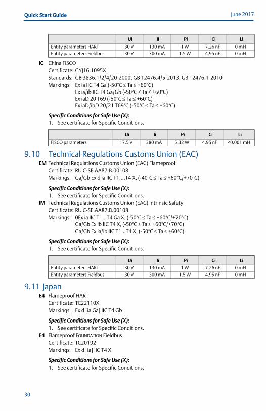
9.9 ChinaE3 China Flameproof
Certificate: GYJ16.1095XStandards: GB 3836.1/2/4/20-2010, GB 12476.1/5-2013, GB 12476.4-2010Markings: Ex d ia IIC T4 Ga/Gb (-40°C Ta +60°C/+70°C)
Ex tD A20 IP 66/67 T69°C /T79°C (-40°C Ta +60°C/+70°C)
Specific Conditions for Safe Use (X):1. See certificate for Specific Conditions.
I3 China Intrinsic SafetyCertificate: GYJ16.1095XStandards: GB 3836.1/2/4/20-2010, GB 12476.1/5-2013, GB 12476.4-2010 Markings: Ex ia IIC T4 Ga (-50°C Ta +60°C/+70°C)
Ex iaD 20 T69°C /T79°CEx iaD/ibD 20/21 T69°C (-50°C Ta +60°C)
Specific Conditions for Safe Use (X):1. See certificate for Specific Conditions.
Ui Ii Pi Ci Li
Entity parameters HART 30 VCC 130 mA 1.0 W 7.26 nF NegligibleEntity parameters Fieldbus 30 VCC 300 mA 1.5 W 4.95 nF Negligible
Ui Ii Pi Ci Li
FISCO parameters 17.5 VCC 380 mA 5.32 W 4.95 nF <1 μH
29
June 2017Quick Start Guide
IC China FISCOCertificate: GYJ16.1095XStandards: GB 3836.1/2/4/20-2000, GB 12476.4/5-2013, GB 12476.1-2010Markings: Ex ia IIC T4 Ga (-50°C Ta +60°C)
Ex ia/ib IIC T4 Ga/Gb (-50°C Ta +60°C)Ex iaD 20 T69 (-50°C Ta +60°C)Ex iaD/ibD 20/21 T69°C (-50°C Ta +60°C)
Specific Conditions for Safe Use (X):1. See certificate for Specific Conditions.
9.10 Technical Regulations Customs Union (EAC)EM Technical Regulations Customs Union (EAC) Flameproof
Certificate: RU C-SE.AA87.B.00108Markings: Ga/Gb Ex d ia IIC T1….T4 X, (-40°C Ta +60°C/+70°C)
Specific Conditions for Safe Use (X):1. See certificate for Specific Conditions.
IM Technical Regulations Customs Union (EAC) Intrinsic SafetyCertificate: RU C-SE.AA87.B.00108Markings: 0Ex ia IIC T1...T4 Ga X, (-50°C Ta +60°C/+70°C)
Ga/Gb Ex ib IIC T4 X, (-50°C Ta +60°C/+70°C)Ga/Gb Ex ia/ib IIC T1…T4 X, (-50°C Ta +60°C)
Specific Conditions for Safe Use (X):1. See certificate for Specific Conditions.
9.11 JapanE4 Flameproof HART
Certificate: TC22110XMarkings: Ex d [ia Ga] IIC T4 Gb
Specific Conditions for Safe Use (X):1. See certificate for Specific Conditions.
E4 Flameproof FOUNDATION FieldbusCertificate: TC20192Markings: Ex d [ia] IIC T4 X
Specific Conditions for Safe Use (X):1. See certificate for Specific Conditions.
Ui Ii Pi Ci Li
Entity parameters HART 30 V 130 mA 1 W 7.26 nF 0 mHEntity parameters Fieldbus 30 V 300 mA 1.5 W 4.95 nF 0 mH
Ui Ii Pi Ci Li
FISCO parameters 17.5 V 380 mA 5.32 W 4.95 nF <0.001 mH
Ui Ii Pi Ci Li
Entity parameters HART 30 V 130 mA 1 W 7.26 nF 0 mHEntity parameters Fieldbus 30 V 300 mA 1.5 W 4.95 nF 0 mH
30

Quick Start GuideJune 2017
9.12 IndiaFlameproof, Intrinsically safeCertificate: P392482/1Markings: Ex db ia IIC T4 Ga /Gb
Ex ia IIC T4 Ga
Specific Conditions for Safe Use (X):1. See certificate for Specific Conditions.
9.13 UkraineFlameproof, Intrinsically SafeCertificate: UA.TR.047.C.0352-13Markings: 0 Ex ia IIC T4X,
1 Ex d ia IIC T4 X
Specific Conditions for Safe Use (X):1. See certificate for Specific Conditions.
9.14 UzbekistanSafety (import)Certificate: UZ.SMT.01.342.2017121
9.15 CombinationsKA Combination of E1, E5 and E6KB Combination of E1, E5 and E7KC Combination of E1, E6 and E7KD Combination of E5, E6 and E7KE Combination of I1, I5 and I6KF Combination of I1, I5 and I7KG Combination of I1, I6 and I7KH Combination of I5, I6 and I7KI Combination of IA, IE and IFKJ Combination of IA, IE and IGKK Combination of IA, IF and IGKL Combination of IE, IF and IG
9.16 Additional certificationsSBS American Bureau of Shipping (ABS) Type Approval
Certificate: 15-LD1340199Intended Use: For use on ABS Classed Vessels and Offshore Facilities in accordance with ABS rules and International Standards.
SBV Bureau Veritas (BV) Type ApprovalCertificate: 22378_B0 BVRequirements: Bureau Veritas rules for classification of steel ships.Application: Class Notations: AUT-UMS, AUT-CCS, AUT-PORT and AUT-IMS.
SDN Det Norske Veritas (DNV) Type ApprovalCertificate: A-14107Intended Use: Det Norske Veritas´ Rules for Classification of Steel Ships, High Speed & Light Craft and Det Norske Veritas´ Offshore Standards.
31
June 2017Quick Start Guide
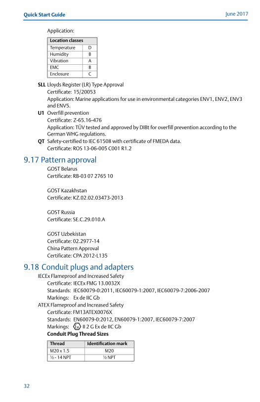
Application:
SLL Lloyds Register (LR) Type ApprovalCertificate: 15/20053Application: Marine applications for use in environmental categories ENV1, ENV2, ENV3 and ENV5.
U1 Overfill preventionCertificate: Z-65.16-476Application: TÜV tested and approved by DIBt for overfill prevention according to the German WHG regulations.
QT Safety-certified to IEC 61508 with certificate of FMEDA data.Certificate: ROS 13-06-005 C001 R1.2
9.17 Pattern approvalGOST BelarusCertificate: RB-03 07 2765 10
GOST KazakhstanCertificate: KZ.02.02.03473-2013
GOST RussiaCertificate: SE.C.29.010.A
GOST UzbekistanCertificate: 02.2977-14China Pattern ApprovalCertificate: CPA 2012-L135
9.18 Conduit plugs and adaptersIECEx Flameproof and Increased Safety
Certificate: IECEx FMG 13.0032XStandards: IEC60079-0:2011, IEC60079-1:2007, IEC60079-7:2006-2007Markings: Ex de IIC Gb
ATEX Flameproof and Increased SafetyCertificate: FM13ATEX0076XStandards: EN60079-0:2012, EN60079-1:2007, IEC60079-7:2007Markings: II 2 G Ex de IIC GbConduit Plug Thread Sizes
Location classes
Temperature DHumidity BVibration AEMC B Enclosure C
Thread Identification mark
M20 x 1.5 M20½ - 14 NPT ½ NPT
32

Quick Start GuideJune 2017
Thread Adapter Thread Sizes
Specific Conditions for Safe Use (X):1. When the thread adapter or blanking plug is used with an enclosure in type of
protection increased safety “e” the entry thread shall be suitably sealed in order to maintain the ingress protection rating (IP) of the enclosure.See certificate for Specific Conditions.
2. The blanking plug shall not be used with an adapter.3. Blanking Plug and Threaded Adapter shall be either NPT or Metric thread forms. G½
thread forms are only acceptable for existing (legacy) equipment installations.
Male thread Identification mark
M20 x 1.5 – 6g M20½- 14 NPT ½ - 14 NPT¾ - 14 NPT ¾- 14 NPT
Female thread Identification mark
M20 x 1.5 – 6H M20½ - 14 NPT ½ - 14 NPT
G1/2 G1/2
33
June 2017Quick Start Guide
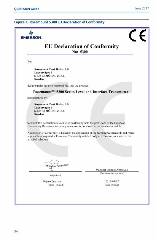
Figure 7. Rosemount 5300 EU Declaration of Conformity
EU Declaration of Conformity No: 5300
Manager Product Approvals (function name - printed)
Dajana Prastalo (name - printed)
(signature)
2017-05-17 (date of issue)
We,
Rosemount Tank Radar AB Layoutvägen 1 S-435 33 MÖLNLYCKE Sweden
declare under our sole responsibility that the product,
Rosemount™ 5300 Series Level and Interface Transmitter manufactured by,
Rosemount Tank Radar AB Layoutvägen 1 S-435 33 MÖLNLYCKE Sweden
to which this declaration relates, is in conformity with the provisions of the European Community Directives, including amendments, as shown in the attached schedule.
Assumption of conformity is based on the application of the harmonized standards and, when applicable or required, a European Community notified body certification, as shown in the attached schedule.
34

Quick Start GuideJune 2017
Schedule No: 5300
Page 2 of 4
EMC Directive (2014/30/EU)
EN 61326-1:2013
ATEX Directive (2014/34/EU)
Nemko 04ATEX1073X
Intrinsic Safety (Hart@ 4-20mA): Equipment Group II, Category 1G, Ex ia IIC T4 Ga Equipment Group II, Category 1D, Ex ia IIIC T79° Da
Intrinsic Safety (Foundation ® Fieldbus): Equipment Group II, Category 1G, Ex ia IIC T4 Ga Equipment Group II, Category 1D, Ex ia IIIC T69° Da
Intrinsic Safety (Foundation ® Fieldbus FISCO): Equipment Group II, Category 1G, Ex ia IIC T4 Ga Equipment Group II, Category 1/2G, Ex ia/ib IIC T4 Ga/Gb
Equipment Group II, Category 1D, Ex ia IIIC T69° Da Equipment Group II, Category 1/2D, Ex ia/ib IIIC T69° Da/Db
Flameproof (Hart@ 4-20mA, Modbus RS-485): Equipment Group II, Category 1/2G, Ex db ia IIC T4 Ga/Gb
Equipment Group II, Category 1D, Ex ta IIIC T79° Da
Flameproof (Foundation ® Fieldbus): Equipment Group II, Category 1/2G, Ex db ia IIC T4 Ga/Gb
Equipment Group II, Category 1D, Ex ta IIIC T69° Da
EN 60079-0:2012; EN 60079-1:2014; EN 60079-11:2012; EN 60079-26:2015; EN 60079-31:2014
35
June 2017Quick Start Guide
Schedule No: 5300
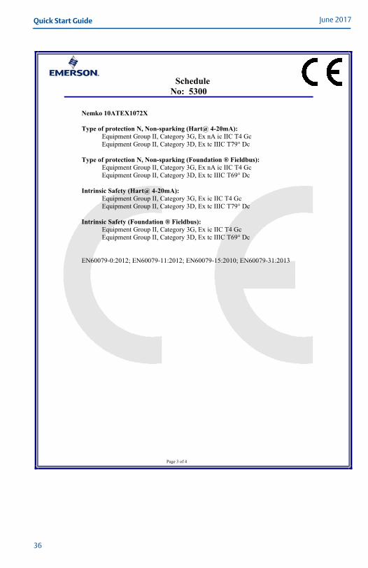
Page 3 of 4
Nemko 10ATEX1072X
Type of protection N, Non-sparking (Hart@ 4-20mA):Equipment Group II, Category 3G, Ex nA ic IIC T4 Gc Equipment Group II, Category 3D, Ex tc IIIC T79° Dc
Type of protection N, Non-sparking (Foundation ® Fieldbus): Equipment Group II, Category 3G, Ex nA ic IIC T4 Gc Equipment Group II, Category 3D, Ex tc IIIC T69° Dc
Intrinsic Safety (Hart@ 4-20mA):Equipment Group II, Category 3G, Ex ic IIC T4 Gc Equipment Group II, Category 3D, Ex tc IIIC T79° Dc
Intrinsic Safety (Foundation ® Fieldbus): Equipment Group II, Category 3G, Ex ic IIC T4 Gc Equipment Group II, Category 3D, Ex tc IIIC T69° Dc
EN60079-0:2012; EN60079-11:2012; EN60079-15:2010; EN60079-31:2013
36

Quick Start GuideJune 2017
Schedule No: 5300
Page 4 of 4
ATEX Notified Body for EU Type Examination Certificates and Type Examination Certificates
Nemko AS [Notified Body Number: 0470] P.O.Box 73 Blindern 0314 OSLO Norway
ATEX Notified Body for Quality Assurance
DNV Nemko Presafe AS [Notified Body Number: 2460] Veritasveien 1 1322 HØVIK Norway
37

June 2017Quick Start Guide
Figure 8. 9240030-936 - System Control Drawing for Hazardous Location Installation of Intrinsically Safe FM Approved Apparatus
FM A
ppro
ved
Prod
uct
No
re
vis
ion
s t
o t
his
dra
win
g
with
ou
t p
rio
r F
acto
ry M
utu
al
Ap
pro
va
l.
A3
OR
IGIN
AL S
IZE
GU
-LN
06
44
53
00
GU
-PO
6P
DF
9240 030-936
9240
030-
936
06
44
SYST
EM C
ON
TRO
L D
RA
WIN
Gfo
r h
aza
rdo
us lo
ca
tio
n in
sta
llatio
n o
f In
trin
sic
ally
Sa
fe F
M a
pp
rove
d a
pp
ara
tus
51 / 1
ISS
UE
D B
Y
AP
PR
OV
ED
BY
WE
EK
WE
EK
PR
OD
UC
T C
OD
E
DO
C. T
YP
EF
ILE
TIT
LE
DW
G N
O.
ISS
UE
SH
EE
T
SC
ALE
1:1
1 S
T A
NG
LE
FIN
ISH
, U
NLE
SS
OT
HE
RW
ISE
ST
AT
ED
:
ALL D
IME
NS
ION
S A
RE
IN
MIL
LIM
ET
RE
S.
Th
e c
op
yright/ow
ners
hip
of th
is d
ocum
ent is
and w
ill r
em
ain
ours
.
Th
e d
oc
um
ent m
ust
not be u
sed w
ithout our auth
oriza
tion o
r bro
ught
to t
he
kn
ow
ledge o
f a third p
arty.
Contrave
ntio
n w
ill b
e p
rose
cute
d.
Ro
sem
ou
nt
Tan
k R
ad
ar
AB
, S
wed
en
ASSO
CIAT
ED A
PPAR
ATU
S
BARR
IER
POW
ERSU
PPLY
HAZ
ARD
OU
S LO
CATI
ON
NO
N-H
AZAR
DO
US
LOCA
TIO
NEN
TITY
CO
NC
EPT
APP
RO
VAL
The
Enti
ty c
on
cep
t al
low
s in
terc
on
nec
tio
n o
f in
trin
sica
lly s
afe
app
arat
us
to a
sso
ciat
ed a
pp
arat
us
no
t sp
ecifi
cally
exa
min
ed in
co
mb
inat
ion
as
a sy
stem
. Th
e ap
pro
ved
val
ues
of m
ax. o
pen
cir
cuit
vo
ltag
e (V
oc
or V
t) a
nd
max
. sh
ort
cir
cuit
cu
rren
t (Is
c o
r It)
an
d m
ax. p
ow
er (
Voc
x Is
c /
4) o
r (V
t x
It /
4),
for t
he
asso
ciat
ed a
pp
arat
us
mu
st b
e le
ss t
han
or e
qu
al to
th
e m
axim
um
saf
e in
pu
t vo
ltag
e (V
max
), m
axim
um
saf
e in
pu
t cu
rren
t (Im
ax),
and
max
imu
m s
afe
inp
ut
po
wer
(Pm
ax) o
f th
e in
trin
sica
lly s
afe
app
arat
us.
In a
dd
itio
n, t
he
app
rove
d m
ax. a
llow
able
co
nn
ecte
d c
apac
itan
ce (C
a o
r Co
) of t
he
asso
ciat
ed
app
arat
us
mu
st b
e g
reat
er t
han
th
e su
m o
f th
e in
terc
on
nec
tin
g c
able
cap
acit
ance
an
d t
he
un
pro
tect
ed
inte
rnal
cap
acit
ance
(Ci)
of t
he
intr
insi
cally
saf
e ap
par
atu
s, an
d t
he
the
app
rove
d m
ax. a
llow
able
co
nn
ecte
d in
du
ctan
ce (L
a o
r Lo
) of t
he
asso
ciat
ed a
pp
arat
us
mu
st b
e g
reat
er t
han
th
e su
m o
f th
e in
terc
on
nec
tin
g c
able
ind
uct
ance
an
d t
he
un
pro
tect
ed in
tern
al in
du
ctan
ce (L
i) o
f th
e in
trin
sica
llysa
fe a
pp
arat
us.
No
tes:
1.
No
revi
sio
n to
th
is d
raw
ing
wit
ho
ut
pri
or F
acto
ry M
utu
al a
pp
rova
l.
2.
Ass
oci
ated
ap
par
atu
s m
anu
fact
ure
r's in
stal
lati
on
dra
win
g m
ust
be
follo
wed
wh
en
in
stal
ling
th
is p
rod
uct
.
3.
Du
st-T
igh
t se
al m
ust
be
use
d w
hen
inst
alle
d in
Cla
ss II
an
d C
lass
III e
nvir
on
men
ts.
4.
Co
ntr
ol e
qu
ipm
ent
con
nec
ted
to t
he
bar
rier
mu
st n
ot
use
or g
ener
ate
mo
re t
han
250
Vrm
s o
r Vd
c.
5.
Resi
stan
ce b
etw
een
Intr
insi
cally
Saf
e G
rou
nd
an
d E
arth
Gro
un
d m
ust
be
less
th
an 1
.0 o
hm
.
6.
Inst
alla
tio
ns
sho
uld
be
in a
cco
rdan
ce w
ith
AN
SI/I
SA-R
P12.
6 "I
nst
alla
tio
n o
f In
trin
sica
lly S
afe
Sy
stem
s fo
r Haz
ard
ou
s Lo
cati
on
s" a
nd
th
e N
atio
nal
Ele
ctri
c C
od
e (A
NSI
/NFP
A 7
0).
7.
The
asso
ciat
ed a
pp
arat
us
mu
st b
e Fa
cto
ry M
utu
al A
pp
rove
d.
8.
Co
nn
ect
sup
ply
wir
es to
th
e ap
pro
pri
ate
term
inal
s as
ind
icat
ed o
n t
he
term
inal
blo
ck a
nd
in t
he
inst
alla
tio
n d
ocu
men
ts.
RO
SE
MO
UN
T 5
300 S
ER
IES
Intr
insic
ally
Safe
App
ara
tus
for
use
inC
lass
I,II,I
II,
Div
isio
n1,
Gro
ups
A,B
,C,D
,E,F
,G,
Cla
ss
I,Z
one
0,A
Ex
iaIIC
T4,T
em
pera
ture
Cla
ss
T4
:
Mod
elEn
tity
Para
met
ers
Am
bien
tTem
pera
ture
Lim
its4-2
0m
A/H
AR
TIS
Mod
el
Vm
ax(U
i)<
=3
0V
,Im
ax(I
i)<
=13
0m
AP
i<
=1W
,C
i=
7.2
6 n
F,
Li=
0 u
H
-50
<=
Ta
<=
70
deg
C
Fie
ldbus
ISM
od
el
Vm
ax(U
i)<
=3
0V
,Im
ax(I
i)<
=30
0m
AP
i<
=1.3
W,C
i=
0,L
i=
0u
H-5
0<
=T
a<
=6
0d
eg
C
Fie
ldbus
FIS
CO
ISM
ode
lV
max(U
i)<
=17.5
V, Im
ax(I
i) <
= 3
80 m
AP
i<
=5.3
2W
,C
i=
0,
Li=
0uH
-50
<=
Ta
<=
60
deg
C
SM
E-5
513
0644
1
ISS
UE
CH
. O
RD
ER
No
WE
EK
ISS
UE
CH
. O
RD
ER
No
WE
EK
ISS
UE
CH
. O
RD
ER
No
WE
EK
ISS
UE
CH
. O
RD
ER
No
WE
EK
2S
ME
-5879
0751
3S
ME
-7117
1143
4S
ME
-7469
1242
5S
ME
-7655
1409
WA
RNIN
G :
To
pre
ven
t ig
nit
ion
of f
lam
mab
le o
r co
mb
ust
ible
atm
osp
her
es, r
ead
, u
nd
erst
and
an
d a
dh
ere
to t
he
man
ufa
ctu
rer's
live
mai
nte
nan
ce p
roce
du
res.
WA
RNIN
G:
Sub
stit
uti
on
of c
om
po
nen
ts m
ay im
pai
r In
trin
sic
Safe
ty.
WA
RNIN
G:
Pote
nti
al E
lect
rost
atic
Ch
arg
ing
Haz
ard
– T
he
encl
osu
re is
a n
on
-met
allic
co
nst
ruct
ion
. To
pre
ven
t
th
e ri
sk o
f ele
ctro
stat
ic s
par
kin
g t
he
pla
stic
su
rfac
e sh
ou
ld o
nly
be
clea
ned
wit
h a
dam
p c
loth
.
WA
RNIN
G:
The
app
arat
us
encl
osu
re c
on
tain
s al
um
inu
m a
nd
is c
on
sid
ered
to c
on
stit
ute
a p
ote
nti
al ri
sk o
f
ig
nit
ion
by
imp
act
or f
rict
ion
. Car
e m
ust
be
take
n in
to a
cco
un
t d
uri
ng
inst
alla
tio
n a
nd
use
to
pre
ven
t im
pac
t o
r fri
ctio
n.
38
Quick Start GuideJune 2017
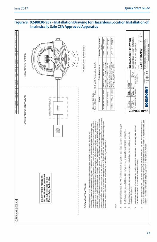
Figure 9. 9240030-937 - Installation Drawing for Hazardous Location Installation of Intrinsically Safe CSA Approved Apparatus
SM
E-5
514
0644
1
ISS
UE
CH
. O
RD
ER
No
WE
EK
ISS
UE
CH
. O
RD
ER
No
WE
EK
ISS
UE
CH
. O
RD
ER
No
WE
EK
ISS
UE
CH
. O
RD
ER
No
WE
EK
A3
OR
IGIN
AL S
IZE
GU
-LN
06
44
53
00
GU
-PO
6P
DF
9240 030-937
9240
030
-937
06
44
INST
ALL
ATI
ON
DR
AW
ING
for
ha
za
rdo
us lo
ca
tio
n in
sta
llatio
n
of C
SA
ap
pro
ve
d a
pp
ara
tus
31 / 1
ISS
UE
D B
Y
AP
PR
OV
ED
BY
WE
EK
WE
EK
PR
OD
UC
T C
OD
E
DO
C. T
YP
EF
ILE
TIT
LE
DW
G N
O.
ISS
UE
SH
EE
T
SC
ALE
1:1
1 S
T A
NG
LE
FIN
ISH
, U
NLE
SS
OT
HE
RW
ISE
ST
AT
ED
:
ALL D
IME
NS
ION
S A
RE
IN
MIL
LIM
ET
RE
S.
Th
e c
op
yright/ow
ners
hip
of th
is d
ocum
ent is
and w
ill r
em
ain
ours
.
Th
e d
oc
um
ent m
ust
not be u
sed w
ithout our auth
oriza
tion o
r bro
ught
to t
he
kn
ow
ledge o
f a third p
arty.
Contrave
ntio
n w
ill b
e p
rose
cute
d.
Ro
sem
ou
nt
Tan
k R
ad
ar
AB
, S
wed
en
AC
CO
CIA
TED
APP
ARA
TUS
BARR
IER
POW
ERSU
PPLY
HA
ZA
RDO
US
LOC
ATIO
NN
ON
-HA
ZA
RDO
US
LOC
ATIO
N
RO
SE
MO
UN
T 5
30
0 S
ER
IES
EX-C
ERTI
FIED
PRO
DU
CT.
No
mod
ifica
tions
perm
itted
with
outr
efer
ence
toth
eEx
-cer
tifyi
ngAu
thor
ities
.
Intr
insic
ally
Safe
Ex
iaC
lass
I,D
ivis
ion
1,
Gro
ups
A,B
,Ca
nd
D,
Tem
pera
ture
Code T
4:
Mod
elEn
tity
Para
met
ers
Am
bien
tTem
pera
ture
Lim
its4-2
0m
A/H
AR
TIS
Mod
el
Vm
ax
<=
30V
,Im
ax
<=
13
0m
AP
i<
=1W
,C
i=
7.3
nF
, Li =
0 u
H-5
0<
=T
a<
=7
0d
eg
C
Fie
ldbus
ISM
od
el
Vm
ax
<=
30V
,Im
ax
<=
30
0m
AP
i<
=1.3
W,C
i=
0,L
i=
0u
H-5
0<
=T
a<
=6
0d
eg
C
Fie
ldbus
FIS
CO
ISM
ode
lV
max
<=
17.5
V, Im
ax <
= 3
80 m
AP
i<
=5.3
2W
,C
i=
0,
Li=
0uH
-50
<=
Ta
<=
60
deg
C
SM
E-5
983
0840
2S
ME
-7063
31123
ENTI
TYC
ON
CEP
TA
PPR
OVA
L
The
Entity
co
ncept
allo
ws
inte
rconn
ectio
nof
intr
insic
ally
safe
appara
tus
toassocia
ted
app
ara
tus
not
specific
ally
exam
ined
inco
mbin
ation
as
asyste
m.T
he
appro
ve
dvalu
es
of
maxim
um
open
circu
itvo
ltag
e(V
oc)
and m
axim
um
short
circuit
curr
ent(I
sc)
and
maxim
um
outp
ut pow
er
(or
Voc x
Isc / 4
), for
the a
ssocia
ted a
ppara
tus
must be less than o
req
ua
lto
the
maxim
um
safe
input
vo
ltage
(Ui),
maxim
um
safe
inp
utcurr
en
t(I
i),an
dm
axim
um
safe
inp
utp
ow
er
(Pi)
of
the
intr
insic
ally
safe
ap
para
tus.In
additio
n,th
ea
ppro
ved
maxim
um
allo
wa
ble
connecte
dcapacita
nce
(Ca)
of
the
associa
ted
appara
tus
mustbe
gre
ate
rth
an
the
sum
of
the
inte
rconnecting
cable
capacitance
and
the
unpro
tecte
din
tern
alcapacitance
(Ci)
of
the
intr
insic
ally
safe
appara
tus,an
dth
e a
ppro
ved m
axim
um
allo
wable
connecte
d ind
ucta
nce
(La)
of
the
associa
ted
appara
tus
mustbe
gre
ate
rth
an the s
um
of th
e inte
rconnecting c
able
inducta
nce
and
the
un
pro
tecte
din
tern
alin
du
cta
nce
(Li)
of
the intr
insic
ally
safe
appara
tus.
Note
s:
1.
Entity
para
mete
rs lis
ted (
for
HA
RT
/Fie
ldbus M
odel) a
pply
only
to a
ssocia
ted a
ppara
tus w
ith lin
ear
outp
ut.
2.
Contr
ol equip
ment connecte
d to the b
arr
ier
must not use o
r genera
te m
ore
than 2
50 V
rms o
r V
dc.
3.
Connect supply
wires to the a
ppro
priate
term
inals
as indic
ate
d o
n the term
inal blo
ck a
nd in the
insta
llation d
ocum
ents
.
4.
Insta
llations s
hould
be in a
ccord
ance w
ith A
NS
I/IS
A-R
P12.6
"In
sta
llations o
f In
trin
sic
ally
Safe
Syste
ms
for
Hazard
ous L
ocations"
and the C
anadia
n E
lectr
ic C
ode.
5.
Pro
duct options b
earing the D
UA
L S
EA
L m
ark
ing o
n the label m
eets
the D
ual S
eal re
quirem
ents
of A
NS
I/IS
A
12.2
7.0
1. N
o a
dditio
nal pro
cess s
ealin
g is r
equired. F
or
the in-s
erv
ice lim
its a
pplic
able
to a
specific
model, s
ee
Pro
cess P
ressure
/Tem
pera
ture
range in A
ppendix
A o
f th
e R
efe
rence m
anual.
39

June 2017Quick Start Guide
Figure 10. 9240030-938 - Installation Drawing for Hazardous Location Installation of Intrinsically Safe ATEX and IECEx Approved Apparatus
SM
E-5
515
0644
1
ISS
UE
CH
. O
RD
ER
No
WE
EK
ISS
UE
CH
. O
RD
ER
No
WE
EK
ISS
UE
CH
. O
RD
ER
No
WE
EK
ISS
UE
CH
. O
RD
ER
No
WE
EK
A3
OR
IGIN
AL S
IZE
GU
-LN
06
44
5300
GU
-PO
6P
DF
D9240030-938
D92
4003
0-93
8
06
44
INST
ALL
ATI
ON
DR
AW
ING
for
ha
za
rdo
us lo
ca
tio
n in
sta
llatio
n
of A
TE
X a
nd
IE
CE
x a
pp
rove
d a
pp
ara
tus
51 / 1
ISS
UE
D B
Y
AP
PR
OV
ED
BY
WE
EK
WE
EK
PR
OD
UC
T C
OD
E
DO
C. T
YP
EF
ILE
TIT
LE
DW
G N
O.
ISS
UE
SH
EE
T
SC
ALE
1:1
1 S
T A
NG
LE
FIN
ISH
, U
NLE
SS
OT
HE
RW
ISE
ST
AT
ED
:
ALL D
IME
NS
ION
S A
RE
IN
MIL
LIM
ET
RE
S.
Th
e c
op
yright/ow
ners
hip
of th
is d
ocum
ent is
and w
ill r
em
ain
ours
.
Th
e d
oc
um
ent m
ust
not be u
sed w
ithout our auth
oriza
tion o
r bro
ught
to t
he
kn
ow
ledge o
f a third p
arty.
Contrave
ntio
n w
ill b
e p
rose
cute
d.
Ro
sem
ou
nt
Tan
k R
ad
ar
AB
, S
wed
en
AC
CO
CIA
TED
APP
ARA
TUS
BA
RRIE
RPO
WER
SUPP
LY
HA
ZA
RDO
US
LOC
ATIO
N
NO
N-H
AZ
ARD
OU
S LO
CAT
ION
RO
SE
MO
UN
T 5
30
0 S
ER
IES
EX-C
ERTI
FIED
PR
OD
UC
T.N
o m
odifi
catio
ns p
erm
itted
with
out r
efer
ence
to th
eEx
-cer
tifyi
ng A
utho
ritie
s.
Intr
insi
c Sa
fety
Par
amet
ers:
II 1G
Ex
ia II
C T
4 G
a;II
1/2G
Ex
ia/ib
IIC
T4
Ga/
Gb
II 1D
Ex
ia II
IC T
69°/T
79° D
a;II
1/2D
Ex
ia/ib
IIIC
T69
°/T79
° Da/
Db
Mod
elPa
ram
eter
sA
mbi
ent T
empe
ratu
re
Lim
its
4-2
0 m
A/H
AR
T IS
Mod
el
Ui <
= 3
0V
, Ii <
= 1
30 m
A
Pi <
= 1
W, C
i =
7.2
6 n
F, L
i =
0
-5
0 <
= T
a <
= 7
0 d
eg C
Fie
ldbus I
S M
od
el
P
i <
= 1
.5W
, C
i =
4.9
5nF
, L
i =
0
-5
0 <
= T
a <
= 6
0 d
eg C
Fie
ldbus F
ISC
O I
S M
ode
l P
i <
= 5
.32W
, C
i =
4.9
5nF
, Li =
0
-5
0 <
= T
a <
= 6
0 d
eg C
Ui <
= 3
0V
, Ii <
= 3
00
mA
Ui <
= 1
7.5
V,
Ii <
= 3
80
mA
2S
ME
-6440
1048
3S
ME
-7230
1217
4S
ME
-7653
1409
5S
ME
-8477
1549
INTR
INSI
CA
LLY
SAFE
INST
ALL
ATI
ON
S T
he a
ppro
ve
d v
alu
es o
f m
axim
um
open c
ircu
it v
oltag
e (
Uo
) a
nd
ma
xim
um
sh
ort
circu
it c
urr
en
t (I
o)
an
d
maxim
um
outp
ut pow
er
(or
Uo x
Io / 4
), for
the a
ssocia
ted a
ppara
tus m
ust be less than o
r eq
ua
l to
the
maxim
um
safe
input
vo
ltage (
Ui),
maxim
um
safe
inp
ut curr
en
t (I
i), an
d m
axim
um
safe
inp
ut p
ow
er
(Pi)
of
the intr
insic
ally
safe
ap
para
tus. In
additio
n, th
e a
ppro
ved
maxim
um
allo
wa
ble
connecte
d c
apacita
nce
(C
o)
of
the a
ssocia
ted a
ppara
tus m
ust be g
reate
r th
an
the
sum
of
the inte
rconnecting
cable
capacitance
a
nd t
he u
npro
tecte
d inte
rnal capacitance (
Ci) o
f th
e intr
insic
ally
safe
appara
tus, an
d th
e a
ppro
ved
ma
xim
um
allo
wa
ble
co
nn
ecte
d ind
ucta
nce (
Lo)
of
the a
ssocia
ted a
ppara
tus m
ust be g
rea
ter
than the
sum
of th
e inte
rconnecting c
able
in
ducta
nce a
nd t
he u
npro
tecte
d inte
rnal in
du
cta
nce (
Li) o
f th
e
intr
insic
ally
sa
fe a
pp
ara
tus.
No
tes :
1
.S
afe
ty p
ara
me
ters
lis
ted
(fo
r H
AR
T/F
ield
bu
s M
od
el) a
pp
ly o
nly
to
asso
cia
ted
ap
pa
ratu
s w
ith
lin
ea
r o
utp
ut.
2.
Co
ntr
ol e
qu
ipm
en
t co
nn
ecte
d t
o t
he
ba
rrie
r m
ust
no
t u
se
or
ge
ne
rate
mo
re t
ha
n 2
50
Vrm
s o
r V
dc.
3.
Co
nn
ect
su
pp
ly w
ire
s t
o t
he
ap
pro
pria
te t
erm
ina
ls a
s in
dic
ate
d o
n t
he
te
rmin
al
blo
ck t
ab
le a
nd
in
th
e in
sta
llatio
n d
ocu
me
nts
4.
Wh
en
mo
de
l 5
30
0 is s
up
plie
d b
y a
n E
x ib
ce
rtifie
d s
afe
ty b
arr
ier,
fo
llow
ing
EP
L c
lassific
atio
n a
pp
lies f
or
diffe
ren
t p
art
s o
f th
e t
ran
sm
itte
r.
-T
he
an
ten
na
pa
rt,
loca
ted
in
th
e p
roce
ss v
esse
l, is c
lassifie
d E
PL
Ga
.
-T
ran
sm
itte
r h
ea
d,
is c
lassifie
d E
PL
Gb
.
SPEC
IFIC
CO
ND
ITIO
NS
FOR
SA
FE U
SE (X
) :
1.
Th
e in
trin
sic
ally
sa
fe c
ircu
its d
o n
ot
with
sta
nd
th
e 5
00
V A
C t
est
as s
pe
cifie
d in
IEC
60
07
9-1
1 c
lau
se
6.4
.13
.
2.
“Po
ten
tia
l ig
nitio
n h
aza
rds b
y im
pa
ct
or
fric
tio
n n
ee
d t
o b
e c
on
sid
ere
d a
cco
rdin
g
to I
EC
60
07
9-0
:20
11
cla
use
8.3
(fo
r E
PL
Ga
an
d E
PL
Gb
) a
nd
cla
use
8.4
(fo
r E
PL
Da
an
d E
PL
Db
) ,
wh
en
th
e t
ran
sm
itte
r e
nclo
su
re a
nd
an
ten
na
s e
xp
ose
d t
o t
he
exte
rio
r
atm
osp
he
re o
f th
e t
an
k,
is m
ad
e w
ith
lig
ht
me
tals
co
nta
inin
g a
lum
iniu
m o
r tita
niu
m.
Th
e e
nd
use
d s
ha
ll d
ete
rmin
e t
he
su
ita
bili
ty w
ith
re
ga
rd t
o a
vo
id h
aza
rds f
rom
im
pa
ct
an
d f
rictio
n.”
3.
Pa
rts o
f th
e r
od
-an
ten
na
s,
for
typ
e 5
30
0 a
re n
on
-co
nd
uctin
g m
ate
ria
l co
ve
rin
g m
eta
l su
rfa
ce
s
an
d t
he
are
a o
f th
e n
on
-co
nd
uctin
g p
art
exce
ed
s t
he
ma
xim
um
pe
rmis
sib
le a
rea
s f
or
Gro
up
III
acco
rdin
g t
o I
EC
60
07
9-0
.2
01
1 c
lau
se
7.4
:3
Th
ere
fore
, w
he
n t
he
an
ten
na
is u
se
d in
a p
ote
ntia
lly
exp
losiv
e a
tmo
sp
he
re g
rou
p I
II,
EP
L D
a,
ap
pro
pria
te m
ea
su
res m
ust
be
ta
ke
n t
o p
reve
nt
ele
ctr
osta
tic d
isch
arg
e.
4.
Th
e E
x ia
ve
rsio
n o
f m
od
el 5
30
0 F
ISC
O f
ield
de
vic
e m
ay b
e s
up
plie
d b
y a
n [
Ex ib
] F
ISC
O
po
we
r su
pp
ly w
he
n t
he
po
we
r su
pp
ly is c
ert
ifie
d w
ith
th
ree
se
pa
rate
sa
fety
cu
rre
nt
limitin
g
de
vic
es a
nd
vo
lta
ge
lim
ita
tio
n w
hic
h m
ee
ts t
he
re
qu
ire
me
nts
fo
r ty
pe
Ex ia
.
5.
½”
NP
T t
hre
ad
s n
ee
d t
o b
e s
ea
led
fo
r d
ust
an
d w
ate
r in
gre
ss p
rote
ctio
n,
IP 6
6,
IP 6
7 o
r ‘E
x t
’,
EP
L D
a o
r D
b is r
eq
uire
d.
40
Quick Start GuideJune 2017
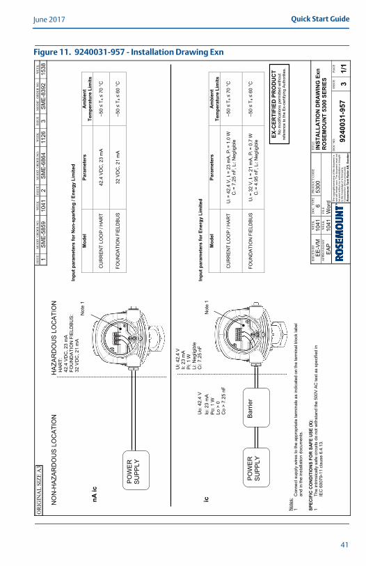
Figure 11. 9240031-957 - Installation Drawing Exn
–≤
≤
–≤
≤
–≤
≤
–≤
≤
41

June 2017Quick Start Guide
List of Model Parts with China RoHS Concentration above MCVs 含含有China RoHS管控物 超 的部件型号列表
Part Name 部件名称
Hazardous Substances / 有害物
Lead
(Pb)
Mercury 汞
(Hg)
Cadmium
(Cd)
Hexavalent Chromium
(Cr +6)
Polybrominated biphenyls
(PBB)
Polybrominated diphenyl ethers
(PBDE)
Electronics Assembly X O O O O O
Housing Assembly 体
O O O X O O
This table is proposed in accordance with the provision of SJ/T11364 本表格系依据SJ/T11364的O: Indicate that said hazardous substance in all of the homogeneous materials for this part is below the limit requirement of GB/T 26572. O:意 GB/T 26572所X: Indicate that said hazardous substance contained in at least one of the homogeneous materials used for this part is above the limit requirement of GB/T 26572. X:意 GB/T 26572所
42

Quick Start GuideJune 2017
43

*00825-0100-4530*
Global HeadquartersEmerson Automation Solutions6021 Innovation Blvd.Shakopee, MN 55379, USA
+1 800 999 9307 or +1 952 906 8888+1 952 949 7001 [email protected]
North America Regional OfficeEmerson Automation Solutions8200 Market Blvd.Chanhassen, MN 55317, USA
+1 800 999 9307 or +1 952 906 8888
+1 952 949 7001
Latin America Regional OfficeEmerson Automation Solutions1300 Concord Terrace, Suite 400Sunrise, FL 33323, USA
+1 954 846 5030
+1 954 846 5121
Linkedin.com/company/Emerson-Automation-Solutions
Twitter.com/Rosemount_News
Facebook.com/Rosemount
Youtube.com/user/RosemountMeasurement
Google.com/+RosemountMeasurement
Standard Terms and Conditions of Sale can be found on the Terms and Conditions of Sale page.The Emerson logo is a trademark and service mark of Emerson Electric Co.DeltaV, Rosemount, and Rosemount logotype are trademarks of Emerson.HART is a registered trademark of the FieldComm Group.FOUNDATION Fieldbus is a trademark of the FieldComm Group.Modbus is a registered trademark of Gould Inc.NEMA is a registered trademark and service mark of the National Electrical Manufacturers Association.National Electrical Code is a registered trademark of National Fire Protection Association, Inc.DTM is a trademark of the FDT Group.All other marks are the property of their respective owners.© 2017 Emerson. All rights reserved.
Europe Regional OfficeEmerson Automation SolutionsNeuhofstrasse 19a P.O. Box 1046CH 6340 BaarSwitzerland
+41 (0) 41 768 6111
+41 (0) 41 768 6300
Asia Pacific Regional OfficeEmerson Automation Solutions1 Pandan CrescentSingapore 128461
+65 6777 8211
+65 6777 0947 [email protected]
Middle East and Africa Regional OfficeEmerson Automation SolutionsEmerson FZE P.O. Box 17033Jebel Ali Free Zone - South 2Dubai, United Arab Emirates
+971 4 8118100
+971 4 [email protected]
Quick Start Guide00825-0100-4530, Rev GB
June 2017
Related Documents