Product Data Sheet 00813-0201-4016, Rev HA October 2005 Rosemount 1199 www.rosemount.com FOR ROSEMOUNT 3051, 1151, AND 2088 TRANSMITTERS EXPANDED TRANSMITTER USE • Extreme hot and cold temperatures • Corrosive applications • Clogging • Sanitary requirements APPLICATIONS • Level, Flow, Pressure, Interface, Density Contents Specifications . . . . . . . . . . . . . . . . . . . . . . . . . . . . . . . . . . . . . . . . . . . . . . . . . . . . . . page 2 General Purpose Seals Selection Overview . . . . . . . . . . . . . . . . . . . . . . . . . . . . . . . page 5 Ordering Information . . . . . . . . . . . . . . . . . . . . . . . . . . . . . . . . . . . . . . . . . . . . . . . . page 10 Diaphragm Seal Connections . . . . . . . . . . . . . . . . . . . . . . . . . . . . . . . . . . . . . . . . . page 11 General Purpose Seal Assemblies . . . . . . . . . . . . . . . . . . . . . . . . . . . . . . . . . . . . . page 13 Sanitary Diaphragm Seal Systems . . . . . . . . . . . . . . . . . . . . . . . . . . . . . . . . . . . . . page 25 General Information. . . . . . . . . . . . . . . . . . . . . . . . . . . . . . . . . . . . . . . . . . . . . . . . . page 36 Rosemount 1199 Diaphragm Seal Systems (European Offering)

Welcome message from author
This document is posted to help you gain knowledge. Please leave a comment to let me know what you think about it! Share it to your friends and learn new things together.
Transcript

Product Data Sheet00813-0201-4016, Rev HA
October 2005 Rosemount 1199
Rosemount 1199 Diaphragm Seal Systems(European Offering)
FOR ROSEMOUNT 3051, 1151, AND 2088 TRANSMITTERS
EXPANDED TRANSMITTER USE
• Extreme hot and cold temperatures
• Corrosive applications
• Clogging
• Sanitary requirements
APPLICATIONS
• Level, Flow, Pressure, Interface, Density
www.ro
Contents
Specifications . . . . . . . . . . . . . . . . . . . . . . . . . . . . . . . . . . . . . . . . . . . . . . . . . . . . . . page 2
General Purpose Seals Selection Overview . . . . . . . . . . . . . . . . . . . . . . . . . . . . . . . page 5
Ordering Information . . . . . . . . . . . . . . . . . . . . . . . . . . . . . . . . . . . . . . . . . . . . . . . . page 10
Diaphragm Seal Connections . . . . . . . . . . . . . . . . . . . . . . . . . . . . . . . . . . . . . . . . . page 11
General Purpose Seal Assemblies . . . . . . . . . . . . . . . . . . . . . . . . . . . . . . . . . . . . . page 13
Sanitary Diaphragm Seal Systems . . . . . . . . . . . . . . . . . . . . . . . . . . . . . . . . . . . . . page 25
General Information. . . . . . . . . . . . . . . . . . . . . . . . . . . . . . . . . . . . . . . . . . . . . . . . . page 36
semount.com
Product Data Sheet00813-0201-4016, Rev HA
October 2005Rosemount 1199
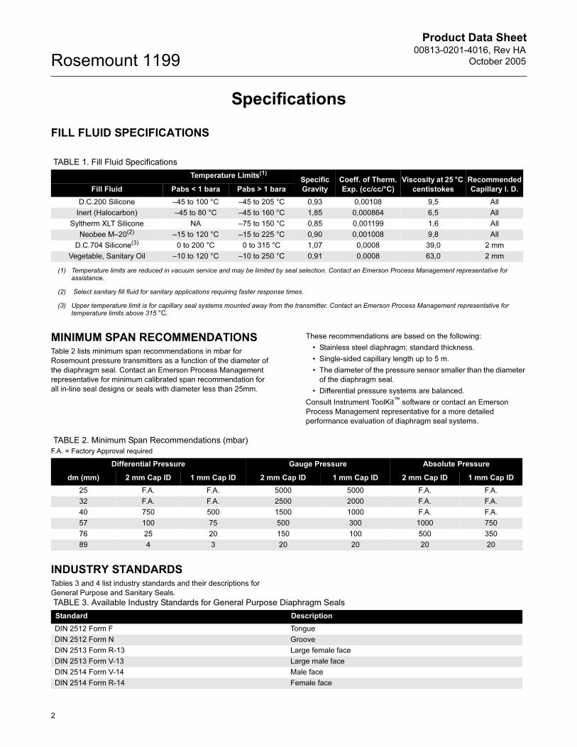
Specifications
FILL FLUID SPECIFICATIONS
MINIMUM SPAN RECOMMENDATIONSTable 2 lists minimum span recommendations in mbar for
Rosemount pressure transmitters as a function of the diameter of
the diaphragm seal. Contact an Emerson Process Management
representative for minimum calibrated span recommendation for
all in-line seal designs or seals with diameter less than 25mm.
These recommendations are based on the following:
• Stainless steel diaphragm; standard thickness.
• Single-sided capillary length up to 5 m.
• The diameter of the pressure sensor smaller than the diameter
of the diaphragm seal.
• Differential pressure systems are balanced.
Consult Instrument ToolKit™ software or contact an Emerson
Process Management representative for a more detailed
performance evaluation of diaphragm seal systems.
INDUSTRY STANDARDSTables 3 and 4 list industry standards and their descriptions for
General Purpose and Sanitary Seals.
TABLE 1. Fill Fluid Specifications
Temperature Limits(1)
Specific
Gravity
Coeff. of Therm.
Exp. (cc/cc/°C)
Viscosity at 25 °C
centistokes
Recommended
Capillary I. D.Fill Fluid Pabs < 1 bara Pabs > 1 bara
D.C.200 Silicone –45 to 100 °C –45 to 205 °C 0,93 0,00108 9,5 All
Inert (Halocarbon) –45 to 80 °C –45 to 160 °C 1,85 0,000864 6,5 All
Syltherm XLT Silicone NA –75 to 150 °C 0,85 0,001199 1,6 All
Neobee M–20(2) –15 to 120 °C –15 to 225 °C 0,90 0,001008 9,8 All
D.C.704 Silicone(3) 0 to 200 °C 0 to 315 °C 1,07 0,0008 39,0 2 mm
Vegetable, Sanitary Oil –10 to 120 °C –10 to 250 °C 0,91 0,0008 63,0 2 mm
(1) Temperature limits are reduced in vacuum service and may be limited by seal selection. Contact an Emerson Process Management representative for assistance.
(2) Select sanitary fill fluid for sanitary applications requiring faster response times.
(3) Upper temperature limit is for capillary seal systems mounted away from the transmitter. Contact an Emerson Process Management representative for temperature limits above 315 °C.
TABLE 2. Minimum Span Recommendations (mbar)
F.A. = Factory Approval required
Differential Pressure Gauge Pressure Absolute Pressure
dm (mm) 2 mm Cap ID 1 mm Cap ID 2 mm Cap ID 1 mm Cap ID 2 mm Cap ID 1 mm Cap ID
25 F.A. F.A. 5000 5000 F.A. F.A.
32 F.A. F.A. 2500 2000 F.A. F.A.
40 750 500 1500 1000 F.A. F.A.
57 100 75 500 300 1000 750
76 25 20 150 100 500 350
89 4 3 20 20 20 20
TABLE 3. Available Industry Standards for General Purpose Diaphragm Seals
Standard Description
DIN 2512 Form F Tongue
DIN 2512 Form N Groove
DIN 2513 Form R-13 Large female face
DIN 2513 Form V-13 Large male face
DIN 2514 Form V-14 Male face
DIN 2514 Form R-14 Female face
2

Product Data Sheet00813-0201-4016, Rev HA
October 2005 Rosemount 1199
GASKET SPECIFICATIONSTable 5 refers to the gaskets supplied with the diaphragm seal.
TRANSMITTER SPECIFICATIONS
Functional Specifications
For complete functional, performance, and physical specifications
for the Rosemount 3051S, 3051C, Rosemount 3051T, Rosemount
1151, and Rosemount 2088 transmitters, refer to the respective
product data sheets listed in this section.
The transmitter pressure ranges and ordering codes for use with
diaphragm seals are located in Section 4 of this document.
Hazardous Locations Certifications
Adding seals to the transmitter does not change the approval
ratings of the individual transmitters. For complete approval
listings, see the respective product data sheet for the pressure
transmitter.
Maximum Working Pressure of
Transmitter–Seal System
The maximum working pressure (MWP) of the transmitter–seal
system is a function of the MWP of the transmitter and the remote
seal. To determine the MWP of the transmitter–seal system,
simply select the lesser value of the two. For safe operation, the
MWP of the transmitter–seal system must not be exceeded.
DIN 2526 Form C, D or E Raised face
DIN 2696 Form L 'Linsen” gasket face
ANSI /ASME B16.5 Raised face
ANSI /ASME B16.5 Ring type joint
TABLE 3. Available Industry Standards for General Purpose Diaphragm Seals
Standard Description
TABLE 4. Available for Sanitary Diaphragm Seals Industry Standards(1)
Standard Description
SMS: Swedish Milk Standard Female or male thread
IDF: International Dairy Federation Female or male thread
RJT: Ring Joint Type Female or male thread
DIN 11851 Female or male thread
Tri-Clamp® Sanitary
Tuchenhagen Varivent® Sanitary
Homogenizer Clamping Flange Sanitary
(1) Other standards are available upon request.
TABLE 5. Gasket Specifications
Gasket Temperature Limit (°C)
PTFE(1)
(1) Temperature limits are in standard circumstances.
–160 to 230 °C
98% Graphite(1) –200 to 500 °C
Viton®(2)
(2) Temperature limit in oxidizing atmosphere.
–20 to 200 °C
Ethylene Propylene –55 to 150 °C
TABLE 6. Transmitter Temperature Limits Summary.
Rosemount
3051S,
3051C, 3051T
Rosemount
1151
Rosemount
2088
Ambient –40 to 85 °C S Electronics
–40 to 85 °C
–40 to 85 °C
E,G Electronics
–30 to 95 °C
Storage –45 to 110 °C S Electronics
–50 to 85 °C
–45 to 85 °C
E,G Electronics
–50 to 120 °C
Process
Silicone
Sensor
–40 to 120 °C –40 to 105 °C –40 to 120 °C
3
Product Data Sheet00813-0201-4016, Rev HA
October 2005Rosemount 1199
NACE Standard
NACE (National Association of Corrosion Engineers) standard
MR–01–75 defines metallic material requirements for resistance to
sulfide stress cracking when exposed to sour environments.
Contact an Emerson Process Management representative to aid
in selecting the proper materials in order for Rosemount
diaphragm seals to meet the
NACE standard.
Zero Elevation and Suppression
Zero elevation and suppression must be such that the lower range
value is greater than or equal to the (–URL) and the upper range
value is less than or equal to the (+URL). The calibrated span
must be greater than or equal to the minimum span.
PHYSICAL SPECIFICATIONS
Materials of Construction
Isolating Diaphragm
Rosemount 3051S/C: 316L SST
Rosemount 3051T: 316L SST
Rosemount 1151: 316L SST
Rosemount 2088: 316L SST
Process Flange or Connector
Rosemount 3051S/C: 316 SST
Rosemount 3051T: 316L SST
Rosemount 1151: CF-8M (Cast Version of 316 SST, material per
ASTM-A743)
Rosemount 2088: 316L SST
O-ring
Rosemount 3051S/C: Glass-filled TFE
Rosemount 3051T: None
Rosemount 1151: Viton® or Buna N
Rosemount 2088: None
Sensor Module Fill Fluid
Silicone Oil
Bolts (Rosemount 3051S/C and 1151 only)
Plated Carbon Steel or 316 SST
Electronics Housing
Low-copper aluminum or CF-8M (cast version of 316 SST,
material per ASTM-A743), NEMA 4X, IP66
Paint
Polyurethane
Cover O-rings
Buna-N
Electrical Connection
Rosemount 3051S, 3051C, 3051T, and Rosemount 20881/2–14 NPT, PG 13.5, G1/2 Female (PF1/2 Female, or M20 3
1.5 Female (CM20) conduit entry
Rosemount 1151
• 1/2–14 NPT conduit with screw terminals and integral test
jacks compatible with miniature banana plugs (Pomona 2944,
3690, or equivalent)
Rosemount 3051S, 3051C, 3051T, and Rosemount 1151 Smart
• The HART®-based communicator connections are fixed to the
terminal block.
Transmitter Weight
The transmitter/seal system weight depends on the type of
capillary and seal:
Rosemount 3051S_C
3,3 kg without options
Rosemount 3051C
2,5 kg without options
Rosemount 3051T
1,4 kg without options
Rosemount 1151
5,5 kg without options
Rosemount 2088
1,0 kg without options
Tagging
The pressure transmitter will be tagged, at no charge, in
accordance with customer requirements. All tags are stainless
steel. The standard tag is wired to the transmitter. Tag is 0,5 mm
thick with 3,2 mm high letters. A permanently attached tag is
available upon request. The remote seal model number is
identified on the transmitter nameplate
Calibration
Transmitters are factory calibrated to customer’s specified range.
If calibration is not specified, then the transmitters are calibrated at
maximum range. Calibration is performed at ambient temperature
and pressure. Four and 20 mA points must be the same unit of
measure. Available units of measure:
Custom Configurations
Rosemount 3051S/3051C (Option Code C1)
If code C1 is ordered, the customer may specify the following
data in addition to the standard configuration parameters.
Refer to Configuration Data Sheet 00806-0100-4001.
Rosemount 1151 (Option Code C9)
If Options Code C9 is ordered, the customer may specify the
following data in addition to the standard configuration
parameters. Refer to Configuration Data Sheet
00806-0100-4593.
Descriptor: 16 alphanumeric characters
Message: 32 alphanumeric characters
Date: Day, month, year
Damping: Sec.
• inH2O
• mmH2O
• ftH2O
• bar
• mbar
• Pa
• kg/cm2
• g/cm2
• torr
• atm
• psi
• mmHg
• kPa
• inHg
4
Product Data Sheet00813-0201-4016, Rev HA
October 2005 Rosemount 1199
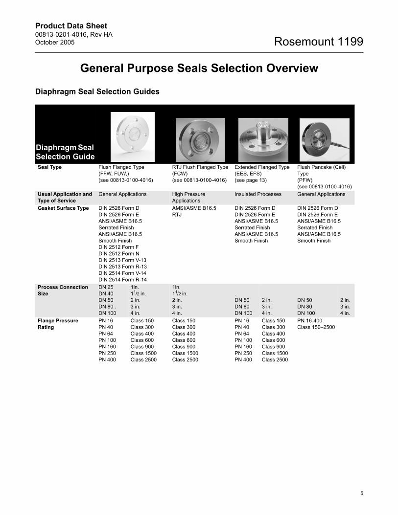
General Purpose Seals Selection Overview
Diaphragm Seal Selection Guides
Diaphragm Seal Selection Guide
Seal Type Flush Flanged Type
(FFW, FUW,)
(see 00813-0100-4016)
RTJ Flush Flanged Type
(FCW)
(see 00813-0100-4016)
Extended Flanged Type
(EES, EFS)
(see page 13)
Flush Pancake (Cell)
Type
(PFW)
(see 00813-0100-4016)
Usual Application and
Type of Service
General Applications High Pressure
Applications
Insulated Processes General Applications
Gasket Surface Type DIN 2526 Form D
DIN 2526 Form E
ANSI/ASME B16.5
Serrated Finish
ANSI/ASME B16.5
Smooth Finish
DIN 2512 Form F
DIN 2512 Form N
DIN 2513 Form V-13
DIN 2513 Form R-13
DIN 2514 Form V-14
DIN 2514 Form R-14
AMSI/ASME B16.5
RTJ
DIN 2526 Form D
DIN 2526 Form E
ANSI/ASME B16.5
Serrated Finish
ANSI/ASME B16.5
Smooth Finish
DIN 2526 Form D
DIN 2526 Form E
ANSI/ASME B16.5
Serrated Finish
ANSI/ASME B16.5
Smooth Finish
Process Connection
Size
DN 25
DN 40
DN 50
DN 80 .
DN 100
1in.
11/2 in.
2 in.
3 in.
4 in.
1in.
11/2 in.
2 in.
3 in.
4 in.
.
DN 50
DN 80
DN 100
2 in.
3 in.
4 in.
DN 50
DN 80
DN 100
2 in.
3 in.
4 in.
Flange Pressure
Rating
PN 16
PN 40
PN 64
PN 100
PN 160
PN 250
PN 400
Class 150
Class 300
Class 400
Class 600
Class 900
Class 1500
Class 2500
Class 150
Class 300
Class 400
Class 600
Class 900
Class 1500
Class 2500
PN 16
PN 40
PN 64
PN 100
PN 160
PN 250
PN 400
Class 150
Class 300
Class 400
Class 600
Class 900
Class 1500
Class 2500
PN 16-400
Class 150–2500
5

Product Data Sheet00813-0201-4016, Rev HA
October 2005Rosemount 1199
Diaphragm and
Wetted Parts Material/
Upper Housing
Material
316LSST
Monel 400®
316Ti SST (WNr 1.4571)
Titanium Gr2
Hastelloy ® C-276,B,C-22
Zirconium
Inconel 600®
Tantalum
Nickel 201
316LSST
316Ti SST (WNr 1.4571)
Hastelloy C-276
Duplex SST 1.4462
316LSST
Nickel 201
316Ti SST (WNr 1.4571)
Monel 400
Hastelloy C-22, C-276, B
Inconel 600
Tantalum
Titanium Gr2
316LSST
Nickel 201
316Ti SST (WNr
1.4571)
Titanium Gr2
Hastelloy C-276, B,
C-22
Monel 400
Zirconium
Tantalum
Inconel 600
Flushing Ring Material 316L SST
316Ti SST (WNr 1.4571)
Hastelloy C-276
Duplex SST 1.4462
316L SST
316Ti SST (WNr 1.4571)
Hastell oy C-276
Duplex SST 1.4462
Not Applicable 316L SST
316Ti SST (WNr
1.4571)
Hastelloy C-276
Duplex SST 1.4462
Options Direct Mount Connection
Material Traceability
Gold-coated 25 �m
Teflon® -coated Diaphragm
Cold Temperature Fill
50 �m Diaphragm Thickness
150 �m Diaphragm
Thickness
Direct Mount Connection
Material Traceability
Teflon -coated
Diaphragm
Cold Temperature Fill
50 �m Diaphragm
Thickness
150 �m Diaphragm
Thickness
Direct Mount Connection
Material Traceability
Custom Extension
Lengths
Cold Temperature Fill
50 �m Diaphragm
Thickness
150�m Diaphragm
Thickness
Material Traceability
Cold Temperature Fill
Gold-coated 25 �m
Teflon -coated
Diaphragm
50 �m Diaphragm
Thickness
150�m Diaphragm
Thickness
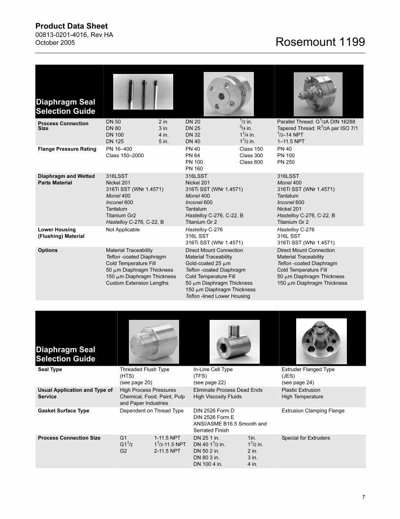
Diaphragm Seal Selection Guide
Diaphragm Seal Selection Guide
Seal Type Extended Pancake (Cell) Type
(DES, DFS)
(see page 17)
Internal Flanged Type
(RFW)
(see 00813-0100-4016)
Internal Threaded Type
(RTW)
(see 00813-0100-4016)
Usual Application and
Type of Service
Insulated Processes Small Process Connections Small Process Connections
High Pressures
Gasket Surface Type DIN 2526 Form D
DIN 2526 Form E
ANSI/ASME B16.5
Serrated Finish
ANSI/ASME B16.5
Smooth Finish
DIN 2512 Form N
DIN 2512 Form F
DIN 2513 Form V-13
DI 2513 Form R-13
DIN 2514 Form V-14
DIN 2514 Form R-14
DIN 2526 Form D
DIN 2526 Form E
ANSI/ASME B16.5 Serrated Finish
ANSI/ASME B16.5 Smooth Finish
Not Applicable
6
Product Data Sheet00813-0201-4016, Rev HA
October 2005 Rosemount 1199
Process ConnectionSize
DN 50
DN 80
DN 100
DN 125
2 in.
3 in.
4 in.
5 in.
DN 20
DN 25
DN 32
DN 40
1/2 in.3/4 in.
11/4 in.
11/2 in.
Parallel Thread: G1/2A DIN 16288
Tapered Thread: R1/2A per ISO 7/11/2–14 NPT
1–11.5 NPT
Flange Pressure Rating PN 16–400
Class 150–2000
PN 40
PN 64
PN 100
PN 160
Class 150
Class 300
Class 600
PN 40
PN 100
PN 250
Diaphragm and Wetted
Parts Material
316LSST
Nickel 201
316Ti SST (WNr 1.4571)
Monel 400
Inconel 600
Tantalum
Titanium Gr2
Hastelloy C-276, C-22, B
316LSST
Nickel 201
316Ti SST (WNr 1.4571)
Monel 400
Inconel 600
Tantalum
Hastelloy C-276, C-22, B
Titanium Gr 2
316LSST
Monel 400
316Ti SST (WNr 1.4571)
Tantalum
Inconel 600
Nickel 201
Hastelloy C-276, C-22, B
Titanium Gr 2
Lower Housing
(Flushing) Material
Not Applicable Hastelloy C-276
316L SST
316Ti SST (WNr 1.4571)
Hastelloy C-276
316L SST
316Ti SST (WNr 1.4571)
Options Material Traceability
Teflon -coated Diaphragm
Cold Temperature Fill
50 �m Diaphragm Thickness
150 �m Diaphragm Thickness
Custom Extension Lengths
Direct Mount Connection
Material Traceability
Gold-coated 25 �m
Teflon -coated Diaphragm
Cold Temperature Fill
50 �m Diaphragm Thickness
150 �m Diaphragm Thickness
Teflon -lined Lower Housing
Direct Mount Connection
Material Traceability
Teflon -coated Diaphragm
Cold Temperature Fill
50 �m Diaphragm Thickness
150 �m Diaphragm Thickness
Diaphragm Seal Selection Guide
Diaphragm Seal Selection Guide
Seal Type Threaded Flush Type
(HTS)
(see page 20)
In-Line Cell Type
(TFS)
(see page 22)
Extruder Flanged Type
(JES)
(see page 24)
Usual Application and Type of
Service
High Process Pressures
Chemical, Food, Paint, Pulp
and Paper Industries
Eliminate Process Dead Ends
High Viscosity Fluids
Plastic Extrusion
High Temperature
Gasket Surface Type Dependent on Thread Type DIN 2526 Form D
DIN 2526 Form E
ANSI/ASME B16.5 Smooth and
Serrated Finish
Extrusion Clamping Flange
Process Connection Size G1
G11/2
G2
1-11.5 NPT
11/2-11.5 NPT
2-11.5 NPT
DN 25 1 in.
DN 40 11/2 in.
DN 50 2 in.
DN 80 3 in.
DN 100 4 in.
1in.
11/2 in.
2 in.
3 in.
4 in.
Special for Extruders
7
Product Data Sheet00813-0201-4016, Rev HA
October 2005Rosemount 1199
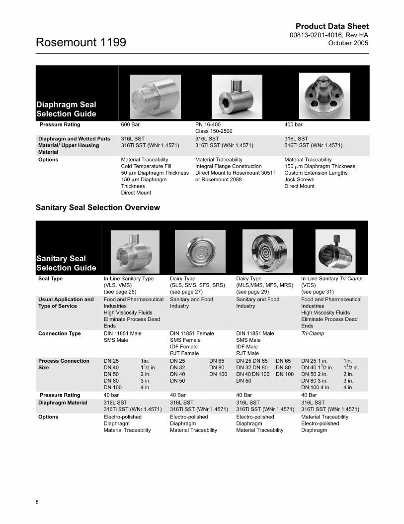
Sanitary Seal Selection Overview
Pressure Rating 600 Bar PN 16-400
Class 150-2500
400 bar
Diaphragm and Wetted Parts
Material/ Upper Housing
Material
316L SST
316Ti SST (WNr 1.4571)
316L SST
316Ti SST (WNr 1.4571)
316L SST
316Ti SST (WNr 1.4571)
Options Material Traceability
Cold Temperature Fill
50 �m Diaphragm Thickness
150 �m Diaphragm
Thickness
Direct Mount
Material Traceability
Integral Flange Construction
Direct Mount to Rosemount 3051T
or Rosemount 2088
Material Traceability
150 �m Diaphragm Thickness
Custom Extension Lengths
Jock Screws
Direct Mount
Diaphragm Seal Selection Guide
Sanitary Seal Selection Guide
Seal Type In-Line Sanitary Type
(VLS, VMS)
(see page 25)
Dairy Type
(SLS, SMS, SFS, SRS)
(see page 27)
Dairy Type
(MLS,MMS, MFS, MRS)
(see page 29)
In-Line Sanitary Tri-Clamp
(VCS)
(see page 31)
Usual Application and
Type of Service
Food and Pharmaceutical
Industries
High Viscosity Fluids
Eliminate Process Dead
Ends
Sanitary and Food
Industry
Sanitary and Food
Industry
Food and Pharmaceutical
Industries
High Viscosity Fluids
Eliminate Process Dead
Ends
Connection Type DIN 11851 Male
SMS Male
DIN 11851 Female
SMS Female
IDF Female
RJT Female
DIN 11851 Male
SMS Male
IDF Male
RJT Male
Tri-Clamp
Process Connection
Size
DN 25
DN 40
DN 50
DN 80
DN 100
1in.
11/2 in.
2 in.
3 in.
4 in.
DN 25
DN 32
DN 40
DN 50
DN 65
DN 80
DN 100
DN 25 DN 65
DN 32 DN 80
DN 40 DN 100
DN 50
DN 65
DN 80
DN 100
DN 25 1 in.
DN 40 11/2 in.
DN 50 2 in.
DN 80 3 in.
DN 100 4 in.
1in.
11/2 in.
2 in.
3 in.
4 in.
Pressure Rating 40 bar 40 Bar 40 Bar 40 Bar
Diaphragm Material 316L SST
316Ti SST (WNr 1.4571)
316L SST
316Ti SST (WNr 1.4571)
316L SST
316Ti SST (WNr 1.4571)
316L SST
316Ti SST (WNr 1.4571)
Options Electro-polished
Diaphragm
Material Traceability
Electro-polished
Diaphragm
Material Traceability
Electro-polished
Diaphragm
Material Traceability
Material Traceability
Electro-polished
Diaphragm
8
Product Data Sheet00813-0201-4016, Rev HA
October 2005 Rosemount 1199
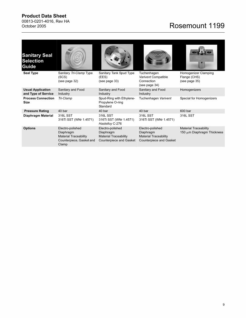
Sanitary Seal Selection Guide
Seal Type Sanitary Tri-Clamp Type
(SCS)
(see page 32)
Sanitary Tank Spud Type
(EES)
(see page 33)
Tuchenhagen
Varivent Compatible
Connection
(see page 34)
Homogenizer Clamping
Flange (CHS)
(see page 35)
Usual Application
and Type of Service
Sanitary and Food
Industry
Sanitary and Food
Industry
Sanitary and Food
Industry
Homogenizers
Process Connection
Size
Tri-Clamp Spud-Ring with Ethylene-
Propylene O-ring
Standard
Tuchenhagen Varivent Special for Homogenizers
Pressure Rating 40 bar 40 bar 40 bar 600 bar
Diaphragm Material 316L SST
316Ti SST (WNr 1.4571)
316L SST
316Ti SST (WNr 1.4571)
Hastelloy C-276
316L SST
316Ti SST (WNr 1.4571)
316L SST
Options Electro-polished
Diaphragm
Material Traceability
Counterpiece, Gasket and
Clamp
Electro-polished
Diaphragm
Material Traceability
Counterpiece and Gasket
Electro-polished
Diaphragm
Material Traceability
Counterpiece and Gasket
Material Traceability
150 �m Diaphragm Thickness
9

Product Data Sheet00813-0201-4016, Rev HA
October 2005Rosemount 1199
Ordering Information
HOW TO ORDER A ROSEMOUNT SEAL/TRANSMITTER SYSTEM
The following steps outline the transmitter/seal
system ordering process. Please review the entire
procedure before specifying a transmitter/seal
system model number.
Step 1. Select a Pressure Transmitter Model
Number
Refer to the Pressure Transmitters product data
sheets below to select a transmitter model number.
For additional transmitter information, see the
following product data sheets:
• Rosemount 3051S Series:(document number 00813-0100-4801)
• Rosemount 3051C and 3051T (document number 00813-0100-4001)
• Rosemount 2088 (document number 00813-0100-4690)
• Rosemount 1151 (document number 00813-0100-4360)
Step 2. Select a Seal Assembly Model Number
1. Use Table 7 on page 11 or Table 8 on page 12
to specify a Capillary or Direct Mount Fill Fluid
code (nine characters).
• Include a code from each section of the table.
Example: Using: “1199MD256...” is typical of the first half of
a seal assembly model number.
2. Use the Seal tables beginning on page 11 to
specify the Diaphragm Seal Configuration.
3. Include a code from each section of the table.
• Include as many options as desired from the Options (Multiple Selections) section.
Example: The customer wants the one piece design and a
150mm diaphragm thickness to add a vacuum resistant to
the model. The model string becomes DFFWJG0A00EC.
4. Combine the two sets of model numbers to
create one model number string. This completes
a valid seal assembly model number.
Example: Combine the model strings in steps A and B
above for a complete seal assembly model number string:
“1199MD256 DFFWJG0A00EC.”
NOTE FOR SPECIAL CONFIGURATIONS
It is possible to order two different seal assemblies
for one transmitter. Use the seal location code to
specify the attachment location for both the high and
low side seals.
For example, suppose a direct mount seal is required
on the high pressure side of the Rosemount 3051
All-Welded System and a seal with a 3 m capillary is
required for the low pressure side. In this example,
the order may look like the following:
CAUTION
While it is possible to combine different types of
seals, fill fluid and capillary lengths, be aware that
performance may be more affected by some
combinations than others. Consult with an Emerson
Process Management representative for assistance
in seal selection.
Quantity Model Number
1 3051CD4A22A1AS9 (From Step 1)
1 1199WDAD6 DFFWJGDA00 (From Step 2)
1 1199MD356 DFFWJGDA00 (From Step 2)
10
Product Data Sheet00813-0201-4016, Rev HA
October 2005 Rosemount 1199
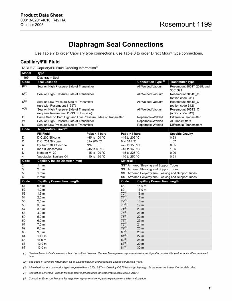
Diaphragm Seal ConnectionsUse Table 7 to order Capillary type connections. use Table 8 to order Direct Mount type connections.
Capillary/Fill Fluid
TABLE 7. Capillary/Fill Fluid Ordering Information(1)
Model Type
1199 Diaphragm Seal
Code Seal Location Connection Type(2) Transmitter Type
P(3) Seal on High Pressure Side of Transmitter All Welded Vacuum Rosemount 3051T, 2088, and
3051S2T
R(3) Seal on High Pressure Side of Transmitter All Welded Vacuum Rosemount 3051S_C
(option code B11)
S(3) Seal on Low Pressure Side of Transmitter
(use with Rosemount 1199T)
All Welded Vacuum Rosemount 3051S_C
(option code B12)
T(3) Seal on High Pressure Side of Transmitter
(requires Rosemount 1199S on low side)
All Welded Vacuum Rosemount 3051S_C
(option code B12)
D Same Seal on Both High and Low Pressure Sides of Transmitter Repairable-Welded Differential Transmitter
W Seal on High Pressure Side of Transmitter Repairable-Welded All Transmitters
M Seal on Low Pressure Side of Transmitter Repairable-Welded Differential Transmitters
Code Temperature Limits(4)
Fill Fluid Pabs < 1 bara Pabs > 1 bara Specific Gravity
D
C
A
H
N
4
D.C.200 Silicone
D.C. 704 Silicone
Syltherm XLT Silicone
Inert (Halocarbon)
Neobee M–20
Vegetable, Sanitary Oil
–45 to 100 °C
0 to 200 °C
N/A
–45 to 80 °C
–15 to 120 °C
–10 to 120 °C
–45 to 205 °C
0 to 315 °C
–75 to 150 °C
–45 to 160 °C
–15 to 225 °C
–10 to 250 °C
0,93
1,07
0,85
1,85
0,90
0,91
Code Capillary Inside Diameter (mm) Material
2 1 mm SST Armored Sleeving and Support Tubes
3 2 mm SST Armored Sleeving and Support Tubes
5 1 mm SST Armored Polyethylene Sleeving and Support Tubes
6 2 mm SST Armored Polyethylene Sleeving and Support Tubes
Code Capillary Connection Length Code Capillary Connection Length
51 0,5 m 68 14,0 m
52 1,0 m 69 15,0 m
53 1,5 m 70(5) 16 m
54 2,0 m 71(5) 17 m
55 2,5 m 72(5) 18 m
56 3,0 m 73(5) 19 m
57 3,5 m 74(5) 20 m
58 4,0 m 75(5) 21 m
59 5,0 m 76(5) 22 m
60 6,0 m 77(5) 23 m
61 7,0 m 78(5) 24 m
62 8,0 m 79(5) 25 m
63 9,0 m 80(5) 26 m
64 10,0 m 81(5) 27 m
65 11,0 m 82(5) 28 m
66 12,0 m 83(5) 29 m
67 13,0 m 84(5) 30 m
(1) Shaded Areas indicate special orders. Consult an Emerson Process Management representative for configuration availability, performance effect, and lead time.
(2) See page 41 for more information on all welded vacuum and repairable-welded connection types.
(3) All welded system connection types require either a 316L SST or Hastelloy C-276 isolating diaphragm in the pressure transmitter model codes.
(4) Contact an Emerson Process Management representative for temperature limits above 315°C.
(5) Consult an Emerson Process Management representative to perform performance effect calculation.
11
Product Data Sheet00813-0201-4016, Rev HA
October 2005Rosemount 1199
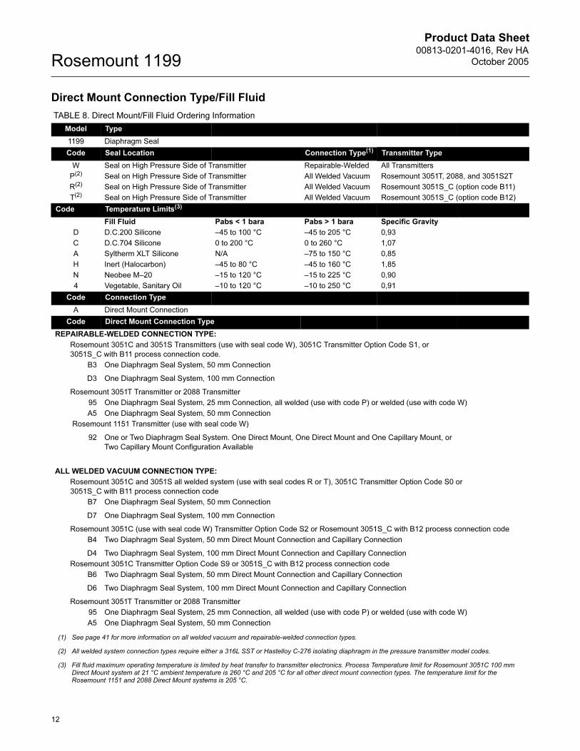
Direct Mount Connection Type/Fill Fluid
TABLE 8. Direct Mount/Fill Fluid Ordering Information
Model Type
1199 Diaphragm Seal
Code Seal Location Connection Type(1) Transmitter Type
W Seal on High Pressure Side of Transmitter Repairable-Welded All Transmitters
P(2) Seal on High Pressure Side of Transmitter All Welded Vacuum Rosemount 3051T, 2088, and 3051S2T
R(2) Seal on High Pressure Side of Transmitter All Welded Vacuum Rosemount 3051S_C (option code B11)
T(2) Seal on High Pressure Side of Transmitter All Welded Vacuum Rosemount 3051S_C (option code B12)
Code Temperature Limits(3)
Fill Fluid Pabs < 1 bara Pabs > 1 bara Specific Gravity
D D.C.200 Silicone –45 to 100 °C –45 to 205 °C 0,93
C D.C.704 Silicone 0 to 200 °C 0 to 260 °C 1,07
A Syltherm XLT Silicone N/A –75 to 150 °C 0,85
H Inert (Halocarbon) –45 to 80 °C –45 to 160 °C 1,85
N Neobee M–20 –15 to 120 °C –15 to 225 °C 0,90
4 Vegetable, Sanitary Oil –10 to 120 °C –10 to 250 °C 0,91
Code Connection Type
A Direct Mount Connection
Code Direct Mount Connection Type
REPAIRABLE-WELDED CONNECTION TYPE:
Rosemount 3051C and 3051S Transmitters (use with seal code W), 3051C Transmitter Option Code S1, or
3051S_C with B11 process connection code.
B3 One Diaphragm Seal System, 50 mm Connection
D3 One Diaphragm Seal System, 100 mm Connection
Rosemount 3051T Transmitter or 2088 Transmitter
95 One Diaphragm Seal System, 25 mm Connection, all welded (use with code P) or welded (use with code W)
A5 One Diaphragm Seal System, 50 mm Connection
Rosemount 1151 Transmitter (use with seal code W)
92 One or Two Diaphragm Seal System. One Direct Mount, One Direct Mount and One Capillary Mount, or
Two Capillary Mount Configuration Available
ALL WELDED VACUUM CONNECTION TYPE:
Rosemount 3051C and 3051S all welded system (use with seal codes R or T), 3051C Transmitter Option Code S0 or
3051S_C with B11 process connection code
B7 One Diaphragm Seal System, 50 mm Connection
D7 One Diaphragm Seal System, 100 mm Connection
Rosemount 3051C (use with seal code W) Transmitter Option Code S2 or Rosemount 3051S_C with B12 process connection code
B4 Two Diaphragm Seal System, 50 mm Direct Mount Connection and Capillary Connection
D4 Two Diaphragm Seal System, 100 mm Direct Mount Connection and Capillary Connection
Rosemount 3051C Transmitter Option Code S9 or 3051S_C with B12 process connection code
B6 Two Diaphragm Seal System, 50 mm Direct Mount Connection and Capillary Connection
D6 Two Diaphragm Seal System, 100 mm Direct Mount Connection and Capillary Connection
Rosemount 3051T Transmitter or 2088 Transmitter
95 One Diaphragm Seal System, 25 mm Connection, all welded (use with code P) or welded (use with code W)
A5 One Diaphragm Seal System, 50 mm Connection
(1) See page 41 for more information on all welded vacuum and repairable-welded connection types.
(2) All welded system connection types require either a 316L SST or Hastelloy C-276 isolating diaphragm in the pressure transmitter model codes.
(3) Fill fluid maximum operating temperature is limited by heat transfer to transmitter electronics. Process Temperature limit for Rosemount 3051C 100 mm Direct Mount system at 21 °C ambient temperature is 260 °C and 205 °C for all other direct mount connection types. The temperature limit for the Rosemount 1151 and 2088 Direct Mount systems is 205 °C.
12

Product Data Sheet00813-0201-4016, Rev HA
October 2005 Rosemount 1199
General Purpose Seal Assemblies
EFS Flanged type: Extended Diaphragm Seals
Dimensional Drawing for EFS Flanged Type: Extended Diaphragm Seal
EFS Process Connection Dimensions
DIN 2501 ANSI/ASME B16.5
DN PN(1)
Dimensions (mm)
DN CL(1)
Dimensions (mm)
dm D b d2 k f d4 d5 dm D b d2 k f d4 d5
50 40 48 165 20 4x18 125 3 102 48 2 in. 150 48 152 19 4x19 121 1,5 92 48
64 48 180 26 4x22 135 3 102 48 300 48 165 22 8x19 127 1,5 92 48
100 48 195 28 4x26 145 3 102 48 600 48 165 32 8x19 127 6,3 92 48
80 40 76 200 24 8x18 160 3 138 76 3 in. 150 76 190 24 4x19 152 1,5 127 76
64 76 215 28 8x22 170 3 138 76 300 76 210 28 8x22 168 1,5 127 76
100 76 230 32 8x26 180 3 138 76 600 76 210 38 8x22 168 6,3 127 76
100 16 89 220 20 8x18 180 3 158 94 4 in. 150 89 229 24 8x19 190 1,5 157 94
40 89 235 24 8x22 190 3 162 94 300 89 254 32 8x22 200 1,5 157 94
64 89 250 30 8x26 200 3 162 94 400 89 254 35 8x25 200 6,3 157 94
(1) Dimensions for other flange ratings are available upon request.
(2) Other extension lengths are available upon request..
b
d2
f
dmd5d4kD 1
199-0
70A
B, 1199-0
000A
02A
x
Standard Extension
Lengths x (2)DIN Standard Extension
Lengths x(2)ANSI/ASME Standard
Extension Lengths x (2)
50 mm 50 mm 2 in
100 mm 100 mm 4 in.
150 mm 150 mm 6 in.
200 mm 200 mm 8 in.
13
Product Data Sheet00813-0201-4016, Rev HA
October 2005Rosemount 1199
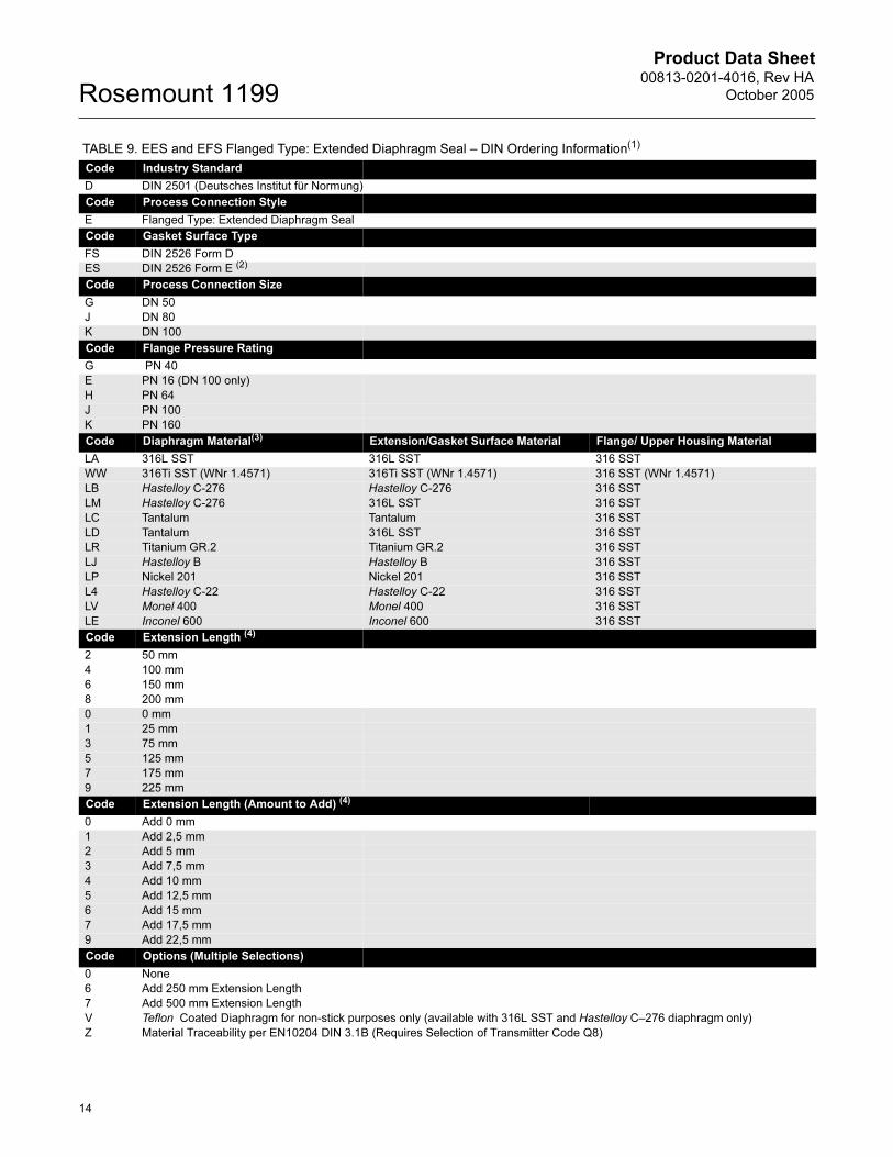
TABLE 9. EES and EFS Flanged Type: Extended Diaphragm Seal – DIN Ordering Information(1)
Code Industry Standard
D DIN 2501 (Deutsches Institut für Normung)
Code Process Connection Style
E Flanged Type: Extended Diaphragm Seal
Code Gasket Surface Type
FS DIN 2526 Form D
ES DIN 2526 Form E (2)
Code Process Connection Size
G DN 50
J DN 80
K DN 100
Code Flange Pressure Rating
G PN 40
E PN 16 (DN 100 only)
H PN 64
J PN 100
K PN 160
Code Diaphragm Material(3) Extension/Gasket Surface Material Flange/ Upper Housing Material
LA 316L SST 316L SST 316 SST
WW 316Ti SST (WNr 1.4571) 316Ti SST (WNr 1.4571) 316 SST (WNr 1.4571)
LB Hastelloy C-276 Hastelloy C-276 316 SST
LM Hastelloy C-276 316L SST 316 SST
LC Tantalum Tantalum 316 SST
LD Tantalum 316L SST 316 SST
LR Titanium GR.2 Titanium GR.2 316 SST
LJ Hastelloy B Hastelloy B 316 SST
LP Nickel 201 Nickel 201 316 SST
L4 Hastelloy C-22 Hastelloy C-22 316 SST
LV Monel 400 Monel 400 316 SST
LE Inconel 600 Inconel 600 316 SST
Code Extension Length (4)
2 50 mm
4 100 mm
6 150 mm
8 200 mm
0 0 mm
1 25 mm
3 75 mm
5 125 mm
7 175 mm
9 225 mm
Code Extension Length (Amount to Add) (4)
0 Add 0 mm
1 Add 2,5 mm
2 Add 5 mm
3 Add 7,5 mm
4 Add 10 mm
5 Add 12,5 mm
6 Add 15 mm
7 Add 17,5 mm
9 Add 22,5 mm
Code Options (Multiple Selections)
0 None
6 Add 250 mm Extension Length
7 Add 500 mm Extension Length
V Teflon Coated Diaphragm for non-stick purposes only (available with 316L SST and Hastelloy C–276 diaphragm only)
Z Material Traceability per EN10204 DIN 3.1B (Requires Selection of Transmitter Code Q8)
14

Product Data Sheet00813-0201-4016, Rev HA
October 2005 Rosemount 1199
2 Radial Capillary Connection - Available with 316L SST or 316Ti SST (WNr 1.4571) Diaphragm Material only
5 50 µm Diaphragm Thickness (available in 316L SST or Hastelloy)
8 150 µm Diaphragm Thickness - 316L SST or Hastelloy C-276 Diaphragm Material only
B Extra Fill for Cold Temperature Applications
T NACE MR–01–75
(1) Shaded areas indicate special orders. Consult an Emerson Process Management representative for availability, performance effects, and lead time
(2) Select for Tantalum and Titanium wetted parts only.
(3) When ordering special diaphragm materials, the standard housing material is 316L SST unless noted otherwise. Consult an Emerson Process Management representative for use with spiral wound gaskets.
(4) DIN extension lengths are specified in millimeters as offered. Additional lengths are available as special orders. Consult factory.
TABLE 10. EES and EFS Flanged Type: Extended Diaphragm Seal –ANSI Ordering Information(1)
Code Industry Standard
A ANSI/ASME B16.5 (American National Standards Institute/American Society of Mechanical Engineers)
Code Process Connection Style
E Flanged Type: Extended Diaphragm Seal
Code Gasket Surface Type
FS Serrated Finish
ES Smooth Finish (2)
Code Process Connection Size
G 2 in.
7 3 in.
9 4 in.
Code Flange Pressure Rating
1 Class 150
2 Class 300
3 Class 400
4 Class 600
5 Class 900
6 Class 1500
7 Class 2500
Code Diaphragm Material(3) Extension/Gasket Surface Material Flange/Upper Housing Material
LA 316L SST 316L SST 316 SST
LB Hastelloy C-276 Hastelloy C-276 316 SST
LM Hastelloy C-276 316L SST 316 SST
LC Tantalum Tantalum 316 SST
LD Tantalum 316L SST 316 SST
LR Titanium GR.2 Titanium GR.2 316 SST
LJ Hastelloy B Hastelloy B 316 SST
LP Nickel 201 Nickel 201 316 SST
L4 Hastelloy C-22 Hastelloy C-22 316 SST
LV Monel 400 Monel 400 316 SST
LE Inconel 600 Inconel 600 316 SST
Code Extension Length(4)
2 2 in.
4 4 in.
6 6 in.
8 8 in.
0 0 in.
1 1 in.
3 3 in.
5 5 in.
7 7 in.
9 9 in.
TABLE 9. EES and EFS Flanged Type: Extended Diaphragm Seal – DIN Ordering Information(1)
15

Product Data Sheet00813-0201-4016, Rev HA
October 2005Rosemount 1199
Code Extension Length (Amount to Add)
0 Add 0 in.
1 Add 1/8 in.
2 Add 1/4 in.
3 Add 3/8 in.
4 Add 1/2 in.
5 Add 5/8 in.
6 Add 3/4 in.
7 Add 7/8 in.
Code Options (Multiple Selections)
0 None
V Teflon Coated Diaphragm for non-stick purposes only (available with 316L SST and Hastelloy C–276 diaphragm only)
Z Material Traceability per EN10204 DIN 3.1B (Requires Selection of Transmitter Code Q8)
2 Radial Capillary Connection - Available with 316L SST or 316Ti SST (WNr 1.4571) Diaphragms only
5 50 µm Diaphragm Thickness (available in 316L SST or Hastelloy)
6 Add 10-in. Extension Length
7 Add 20-in. Extension Length
8 150 µm Diaphragm Thickness - 316L or Hastelloy C-276 Diaphragm Material only
B Extra Fill for Cold Temperature Applications
T NACE MR–01–75
(1) Shaded areas indicate special orders. Consult an Emerson Process Management representative for availability, performance effects, and lead time.
(2) Select for Tantalum and Titanium wetted parts only.
(3) When ordering special diaphragm materials, the standard housing material is 316L SST unless noted otherwise. Consult an Emerson Process Management representative for use with spiral wound gaskets.
(4) ANSI extension lengths are in inches as offered. Additional lengths are available as special orders. Consult factory.
TABLE 10. EES and EFS Flanged Type: Extended Diaphragm Seal –ANSI Ordering Information(1)
16
Product Data Sheet00813-0201-4016, Rev HA
October 2005 Rosemount 1199
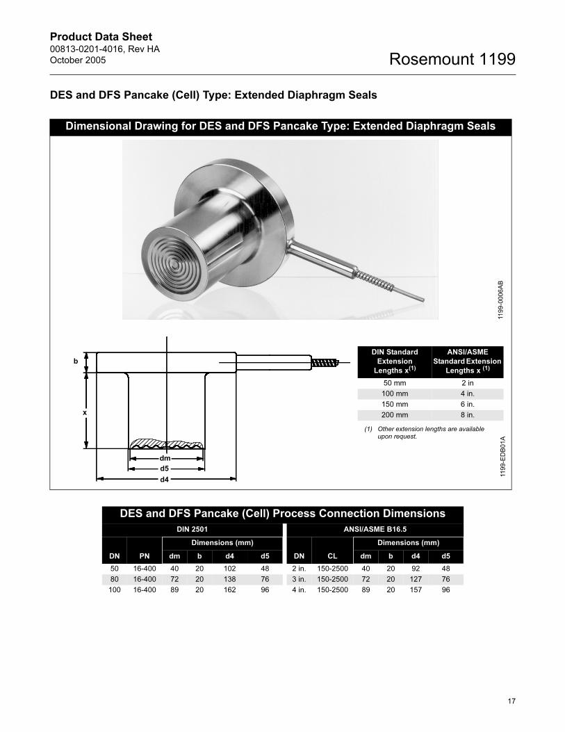
DES and DFS Pancake (Cell) Type: Extended Diaphragm Seals
Dimensional Drawing for DES and DFS Pancake Type: Extended Diaphragm Seals
1199-0
006A
B
DIN Standard
Extension
Lengths x(1)
ANSI/ASME
Standard Extension
Lengths x (1)
(1) Other extension lengths are available upon request.
50 mm 2 in
100 mm 4 in.
150 mm 6 in.
200 mm 8 in.
b
dm
d5
d4
1199-E
DB
01A
x
DES and DFS Pancake (Cell) Process Connection Dimensions
DIN 2501 ANSI/ASME B16.5
DN PN
Dimensions (mm)
DN CL
Dimensions (mm)
dm b d4 d5 dm b d4 d5
50 16-400 40 20 102 48 2 in. 150-2500 40 20 92 48
80 16-400 72 20 138 76 3 in. 150-2500 72 20 127 76
100 16-400 89 20 162 96 4 in. 150-2500 89 20 157 96
17
Product Data Sheet00813-0201-4016, Rev HA
October 2005Rosemount 1199
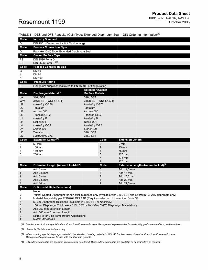
TABLE 11. DES and DFS Pancake (Cell) Type: Extended Diaphragm Seal – DIN Ordering Information(1)
Code Industry Standard
D DIN 2501 (Deutsches Institut für Normung)
Code Process Connection Style
D Pancake (Cell) Type: Extended Diaphragm Seal
Code Gasket Surface Type
FS DIN 2526 Form D
ES DIN 2526 Form E (2)
Code Process Connection Size
G DN 50
J DN 80
K DN 100
Code Pressure Rating
0 Flange not supplied; seal rated to PN 16-400 or flange rating
Code Diaphragm Material(3)Extension/Gasket
Surface Material
LA 316L SST 316L SST
WW 316Ti SST (WNr 1.4571) 316Ti SST (WNr 1.4571)
LB Hastelloy C-276 Hastelloy C-276
LC Tantalum Tantalum
LE Inconel 600 Inconel 600
LR Titanium GR.2 Titanium GR.2
LJ Hastelloy B Hastelloy B
LP Nickel 201 Nickel 201
L4 Hastelloy C-22 Hastelloy C-22
LV Monel 400 Monel 400
LD Tantalum 316L SST
LM Hastelloy C-276 316L SST
Code Extension Length(4) Code Extension Length
2 50 mm 0 0 mm
4 100 mm 1 25 mm
6 150 mm 3 75 mm
8 200 mm 5 125 mm
7 175 mm
9 225 mm
Code Extension Length (Amount to Add)(4) Code Extension Length (Amount to Add)(4)
0 Add 0 mm 5 Add 12,5 mm
1 Add 2,5 mm 6 Add 15 mm
2 Add 5 mm 7 Add 17,5 mm
3 Add 7,5 mm 8 Add 20 mm
4 Add 10 mm 9 Add 22,5 mm
Code Options (Multiple Selections)
0 None
V Teflon Coated Diaphragm for non-stick purposes only (available with 316L SST and Hastelloy C–276 diaphragm only)
Z Material Traceability per EN10204 DIN 3.1B (Requires selection of transmitter Code Q8)
5 50 µm Diaphragm Thickness (available in 316L SST or Hastelloy)
8 150 µm Diaphragm Thickness - 316L SST or Hastelloy C-276 Diaphragm Material only
6 Add 250 mm Extension Length
7 Add 500 mm Extension Length
B Extra Fill for Cold Temperature Applications
T NACE MR–01–75
(1) Shaded areas indicate special orders. Consult an Emerson Process Management representative for availability, performance effects, and lead time.
(2) Select for Tantalum wetted parts only.
(3) When ordering special diaphragm materials, the standard housing material is 316L SST unless noted otherwise. Consult an Emerson Process Management representative for use with spiral wound gaskets.
(4) DIN extension lengths are specified in millimeters, as offered. Other extension lengths are available as special offers on request.
18

Product Data Sheet00813-0201-4016, Rev HA
October 2005 Rosemount 1199
TABLE 12. DES and DFS Pancake (Cell) Type: Extended Diaphragm Seal – ANSI/ASME Ordering Information(1)
Code Industry Standard
A ANSI/ASME B16.5 (American National Standards Institute/American Society of Mechanical Engineers)
Code Process Connection Style
D Pancake (Cell) Type: Extended Diaphragm Seal
Code Gasket Surface Type
FS Serrated Finish
ES Smooth Finish (2)
Code Process Connection Size
G 2 in.
7 3 in.
9 4 in.
B 5 in.
Code Pressure Rating
0 Flange not supplied; seal rated to Class 150–2500 or flange rating
Code Diaphragm Material (3) Extension/Gasket Surface Material
LA 316L SST 316L SST
WW 316Ti SST (WNr 1.4571) 316Ti SST (WNr 1.4571)
LB Hastelloy C-276 Hastelloy C-276
LC Tantalum Tantalum
LE Inconel 600 Inconel 600
LR Titanium GR.2 Titanium GR.2
LJ Hastelloy B Hastelloy B
LP Nickel 201 Nickel 201
L4 Hastelloy C-22 Hastelloy C-22
LV Monel 400 Monel 400
LD Tantalum 316L SST
LM Hastelloy C-276 316L SST
Code Extension Length(4) Extension Length(5)
2 2 in. 0 0 in.
4 4 in. 1 1 in.
6 6 in. 3 3 in.
8 8 in. 5 5 in.
7 7 in.
9 9 in.
Code Extension Length (Amount to Add) Code Extension Length (Amount to Add)
0 Add 0 in 4 Add 1/2 in.
1 Add 1/8 in 5 Add 5/8 in.
2 Add 1/4 in. 6 Add 3/4 in.
3 Add 3/8 in. 7 Add 7/8 in.
Code Options (Multiple Selections)
0 None
V Teflon Coated Diaphragm for non-stick purposes only (available with 316L SST and Hastelloy C–276 diaphragm only)
Z Material Traceability per EN10204 DIN 3.1B (Requires selection of transmitter code Q8)
5 50 µm Diaphragm Thickness (available in 316L SST or Hastelloy)
8 150 µm Diaphragm Thickness - 316L or Hastelloy C-276 Diaphragm Material Only
6 Add 10-in. Extension Length
7 Add 20-in. Extension Length
B Extra Fill for Cold Temperature Applications
T NACE MR–01–75
(1) Shaded areas indicate special orders. Consult an Emerson Process Management representative for availability, performance effects, and lead time.
(2) Select for Tantalum wetted parts only.
(3) When ordering special diaphragm materials, the standard housing material is 316L SST unless noted otherwise.Consult an Emerson Process Management representative for use with spiral wound gaskets.
(4) ANSI extension lengths are specified in inches as offered. Other extension lengths are available as special offers on request.
(5) ANSI extension lengths are specified in inches as offered. Other extension lengths are available as special offers on request.
19
Product Data Sheet00813-0201-4016, Rev HA
October 2005Rosemount 1199
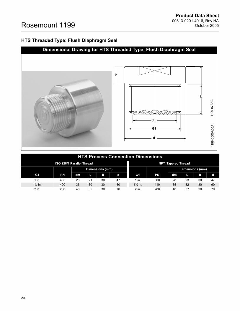
HTS Threaded Type: Flush Diaphragm Seal
Dimensional Drawing for HTS Threaded Type: Flush Diaphragm Seal
HTS Process Connection Dimensions
ISO 228/1 Parallel Thread NPT: Tapered Thread
G1 PN
Dimensions (mm)
G1 PN
Dimensions (mm)
dm L b d dm L b d
1 in. 455 28 21 30 47 1 in. 600 28 23 30 47
1½ in. 400 35 30 30 60 1½ in. 410 35 32 30 60
2 in. 280 48 35 30 70 2 in. 280 48 37 30 70
11
99
-00
00
A0
5A
L
b
dm
G1
d
11
99
-07
3A
B
20
Product Data Sheet00813-0201-4016, Rev HA
October 2005 Rosemount 1199
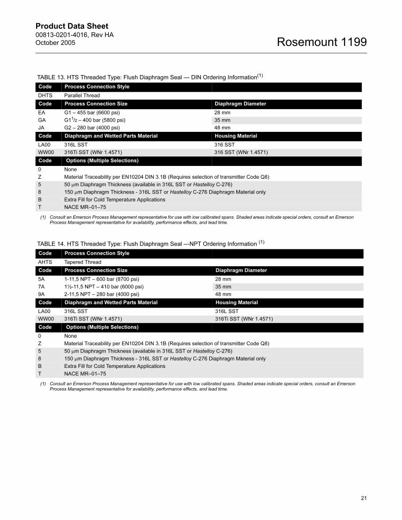
TABLE 13. HTS Threaded Type: Flush Diaphragm Seal — DIN Ordering Information(1)
Code Process Connection Style
DHTS Parallel Thread
Code Process Connection Size Diaphragm Diameter
EA G1 – 455 bar (6600 psi) 28 mm
GA G11/2 – 400 bar (5800 psi) 35 mm
JA G2 – 280 bar (4000 psi) 48 mm
Code Diaphragm and Wetted Parts Material Housing Material
LA00 316L SST 316 SST
WW00 316Ti SST (WNr 1.4571) 316 SST (WNr 1.4571)
Code Options (Multiple Selections)
0 None
Z Material Traceability per EN10204 DIN 3.1B (Requires selection of transmitter Code Q8)
5 50 µm Diaphragm Thickness (available in 316L SST or Hastelloy C-276)
8 150 µm Diaphragm Thickness - 316L SST or Hastelloy C-276 Diaphragm Material only
B Extra Fill for Cold Temperature Applications
T NACE MR–01–75
(1) Consult an Emerson Process Management representative for use with low calibrated spans. Shaded areas indicate special orders, consult an Emerson Process Management representative for availability, performance effects, and lead time.
TABLE 14. HTS Threaded Type: Flush Diaphragm Seal —NPT Ordering Information (1)
Code Process Connection Style
AHTS Tapered Thread
Code Process Connection Size Diaphragm Diameter
5A 1-11,5 NPT – 600 bar (8700 psi) 28 mm
7A 1½-11,5 NPT – 410 bar (6000 psi) 35 mm
9A 2-11,5 NPT – 280 bar (4000 psi) 48 mm
Code Diaphragm and Wetted Parts Material Housing Material
LA00 316L SST 316L SST
WW00 316Ti SST (WNr 1.4571) 316Ti SST (WNr 1.4571)
Code Options (Multiple Selections)
0 None
Z Material Traceability per EN10204 DIN 3.1B (Requires selection of transmitter Code Q8)
5 50 µm Diaphragm Thickness (available in 316L SST or Hastelloy C-276)
8 150 µm Diaphragm Thickness - 316L SST or Hastelloy C-276 Diaphragm Material only
B Extra Fill for Cold Temperature Applications
T NACE MR–01–75
(1) Consult an Emerson Process Management representative for use with low calibrated spans. Shaded areas indicate special orders, consult an Emerson Process Management representative for availability, performance effects, and lead time.
21
Product Data Sheet00813-0201-4016, Rev HA
October 2005Rosemount 1199
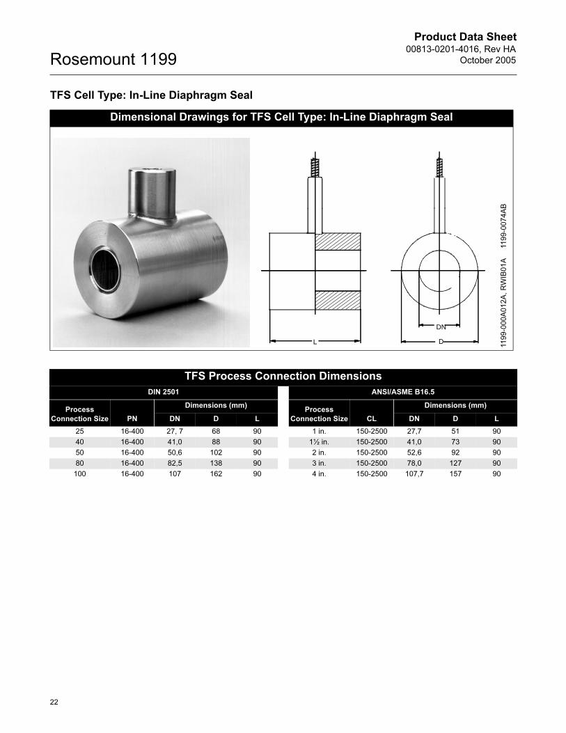
TFS Cell Type: In-Line Diaphragm Seal
Dimensional Drawings for TFS Cell Type: In-Line Diaphragm Seal
L D
DN
11
99
-00
0A
01
2A
, R
WIB
01
A11
99
-00
74
AB
TFS Process Connection Dimensions
DIN 2501 ANSI/ASME B16.5
Process
Connection Size PN
Dimensions (mm)Process
Connection Size CL
Dimensions (mm)
DN D L DN D L
25 16-400 27, 7 68 90 1 in. 150-2500 27,7 51 90
40 16-400 41,0 88 90 1½ in. 150-2500 41,0 73 90
50 16-400 50,6 102 90 2 in. 150-2500 52,6 92 90
80 16-400 82,5 138 90 3 in. 150-2500 78,0 127 90
100 16-400 107 162 90 4 in. 150-2500 107,7 157 90
22
Product Data Sheet00813-0201-4016, Rev HA
October 2005 Rosemount 1199
TABLE 15. TFS Cell Type: In-Line Diaphragm Seal —DIN Ordering Information(1)
Code Industry Standard
D DIN 2501 (Deutsches Institut für Normung)
Code Process Connection Style
T Flanged Type: In-Line Diaphragm Seal
Code Gasket Surface
FS DIN 2526 Form D
Code Process Connection Size
D DN 25
F DN 40
G DN 50
J DN 80
K DN 100
Code Pressure Rating
0 Flange not supplied; seal rated to PN 16-400 or flange rating
Code Diaphragm and Wetted Parts Material(2) Housing Material
LA00 316L SST 316 SST
LB00 Hastelloy C-276 316 SST
WW00 316Ti SST (WNr 1.4571) 316 SST (WNr 1.4571)
Code Options (Multiple Selections)
0 None
Z Material Traceability per EN10204 DIN 3.1B (Requires selection of transmitter Code Q8)
T NACE MR–01–75
(1) Consult an Emerson Process Management representative for use with low calibrated spans. Shaded areas indicate special orders, consult an Emerson Process Management representative for availability, performance effects, and lead time.
(2) When ordering special diaphragm materials, the standard housing material is 316L SST unless noted otherwise.
TABLE 16. TFS Cell Type: In-Line Diaphragm Seal —ANSI/ASME Ordering Information(1)
Code Industry Standard
A ANSI/ASME B16.5 (American National Standards Institute/American Society of Mechanical Engineers)
Code Process Connection Style
T Flanged Type: In-Line Diaphragm Seal
Code Gasket Surface
FS Serrated Finish
Code Process Connection Size
2 1 in.
4 1½ in.
G 2 in.
7 3 in.
9 4 in.
Code Pressure Rating
0 Flange not supplied; seal rated to Class 2500 or flange rating
Code Diaphragm and Wetted Parts Material(2) Housing Material
LA00 316L SST 316L SST
LB00 Hastelloy C-276 316L SST
WW00 316Ti SST (WNr 1.4571) 316Ti SST (WNr 1.4571)
Code Options (Multiple Selections)
0 None
Z Material Traceability per EN10204 DIN 3.1B (Requires selection of transmitter Code Q8)
T NACE MR–01–75
(1) Consult an Emerson Process Management representative for use with low calibrated spans. Shaded areas indicate special orders, consult an Emerson Process Management representative for availability, performance effects, and lead time.
(2) When ordering special diaphragm materials, the standard housing material is 316L SST unless noted otherwise.
23
Product Data Sheet00813-0201-4016, Rev HA
October 2005Rosemount 1199
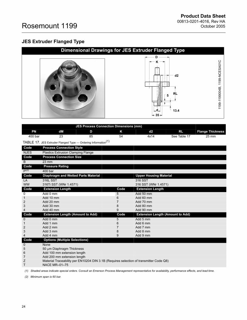
JES Extruder Flanged Type
Dimensional Drawings for JES Extruder Flanged Type
13.4
35
RL
d
5
d2
K
D
11
99
-11
99
00
4B
, 11
99
-NC
ES
A0
1C
JES Process Connection Dimensions (mm)
Flange ThicknessPN dM D K d2 RL
400 bar 23 85 54 4x14 See Table 17 25 mm
TABLE 17. JES Extruder Flanged Type — Ordering Information(1)
Code Process Connection Style
NJES Plastics Extrusion Clamping Flange
Code Process Connection Size
B 23 mm
Code Pressure Rating
P(2) 400 bar
Code Diaphragm and Wetted Parts Material Upper Housing Material
LA 316L SST 316 SST
WW 316Ti SST (WNr 1.4571) 316 SST (WNr 1.4571)
Code Extension Length Code Extension Length
0 Add 0 mm 5 Add 50 mm
1 Add 10 mm 6 Add 60 mm
2 Add 20 mm 7 Add 70 mm
3 Add 30 mm 8 Add 80 mm
4 Add 40 mm 9 Add 90 mm
Code Extension Length (Amount to Add) Code Extension Length (Amount to Add)
0 Add 0 mm 5 Add 5 mm
1 Add 1 mm 6 Add 6 mm
2 Add 2 mm 7 Add 7 mm
3 Add 3 mm 8 Add 8 mm
4 Add 4 mm 9 Add 9 mm
Code Options (Multiple Selections)
0 None
5 50 µm Diaphragm Thickness
6 Add 100 mm extension length
7 Add 200 mm extension length
Z Material Traceability per EN10204 DIN 3.1B (Requires selection of transmitter Code Q8)
T NACE MR–01–75
(1) Shaded areas indicate special orders. Consult an Emerson Process Management representative for availability, performance effects, and lead time.
(2) Minimum span is 60 bar.
24
Product Data Sheet00813-0201-4016, Rev HA
October 2005 Rosemount 1199
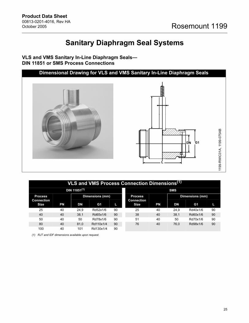
Sanitary Diaphragm Seal Systems
VLS and VMS Sanitary In-Line Diaphragm Seals—DIN 11851 or SMS Process Connections
Dimensional Drawing for VLS and VMS Sanitary In-Line Diaphragm Seals
G1DN
11
99
-RW
IC0
1A
, 11
99
-07
5A
B
L
VLS and VMS Process Connection Dimensions(1)
DIN 11851(1) SMS
Process
Connection
Size PN
Dimensions (mm) Process
Connection
Size PN
Dimensions (mm)
DN G1 L DN G1 L
25 40 24,9 Rd52x1/6 90 25 40 24,9 Rd40x1/6 90
40 40 38,1 Rd65x1/6 90 38 40 38,1 Rd60x1/6 90
50 40 50 Rd78x1/6 90 51 40 50 Rd70x1/6 90
80 40 81,0 Rd110x1/4 90 76 40 76,0 Rd98x1/6 90
100 40 101 Rd130x1/4 90
(1) RJT and IDF dimensions available upon request.
25

Product Data Sheet00813-0201-4016, Rev HA
October 2005Rosemount 1199
TABLE 18. VLS Sanitary In-Line Diaphragm Seal—DIN Ordering Information(1)
Code Industry Standard
S Sanitary
Code Process Connection Style(2)
VLS Sanitary In Line Seal per DIN 11851 (maximum working pressure: 40 bar)
Code Process Connection Size
D0 DN 25
F0 DN 40
G0 DN 50
J0 DN 80
K0 DN 100
Code Diaphragm Material
LA00 316L SST
WW00 316Ti SST (WNr 1.4571)
Code Options (Multiple Selections)
0 None
6 Electrolytical polishing of diaphragm material
Z Material Traceability per EN10204 DIN 3.1B (Requires selection of transmitter code Q8)
(1) Consult an Emerson Process Management representative for use with low calibrated spans. Shaded areas indicate special orders, consult an Emerson Process Management representative for availability, performance effects, and lead time.
(2) Other industry standards such as IDF and RJT available upon request.
TABLE 19. VMS Sanitary In-Line Diaphragm Seal—SMS Ordering Information(1)
Code Industry Standard
S Sanitary
Code Process Connection Style(2)
VMS Sanitary In Line Seal per SMS (maximum working pressure: 40 bar)
Code Process Connection Size
20 DN 25
30 DN 38
50 DN 51
70 DN 76
Code Diaphragm Material
LA00 316L SST
WW00 316Ti SST (WNr 1.4571)
Code Options (Multiple Selections)
0 None
6 Electrolytical polishing of diaphragm material
Z Material Traceability per EN10204 DIN 3.1B (Requires selection of transmitter code Q8)
(1) Consult an Emerson Process Management representative for use with low calibrated spans. Shaded areas indicate special orders, consult an Emerson Process Management representative for availability, performance effects, and lead time.
(2) Other industry standards such as IDF and RJT available upon request.
26
Product Data Sheet00813-0201-4016, Rev HA
October 2005 Rosemount 1199
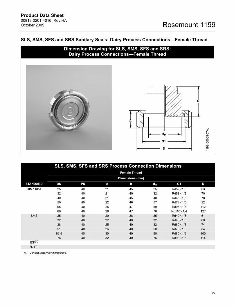
SLS, SMS, SFS and SRS Sanitary Seals: Dairy Process Connections—Female Thread
Dimension Drawing for SLS, SMS, SFS and SRS: Dairy Process Connections—Female Thread
dm
G1
A
D
b
11
99
-00
00
B0
7A
,
SLS, SMS, SFS and SRS Process Connection Dimensions
Female Thread
STANDARD
Dimensions (mm)
DN PN A b dm G1 D
DIN 11851 25 40 21 45 25 Rd52�1/6 63
32 40 21 40 32 Rd58�1/6 70
40 40 21 45 40 Rd65�1/6 78
50 40 22 46 57 Rd78�1/6 92
65 40 25 47 59 Rd95�1/6 112
80 40 29 47 76 Rd110�1/4 127
SMS 25 40 20 38 25 Rd40�1/6 51
32 40 22 40 32 Rd48�1/6 60
38 40 25 40 32 Rd60�1/6 74
51 40 26 40 50 Rd70�1/6 84
63,5 40 30 40 50 Rd85�1/6 100
76 40 32 40 76 Rd98�1/6 114
IDF(1)
RJT(1)
(1) Contact factory for dimensions.
27
Product Data Sheet00813-0201-4016, Rev HA
October 2005Rosemount 1199
TABLE 20. SLS Sanitary Seals: Dairy Process Connection—Female Thread Ordering Information(1)
Code Industry Standard
S Sanitary
Code Process Connection Style
SLS Female Thread per DIN 11851
Code Process Connection Size Pressure Rating(2)
D0 DN 25 40 bar
F0 DN 40 40 bar
G0 DN 50 25 bar
J0 DN 80 25 bar
E0 DN 32 40 bar
H0 DN 65 25 bar
Code Diaphragm Material
LA00 316L SST
WW00 316Ti SST (WNr 1.4571)
Code Options (Multiple Selections)
0 None
6 Electrolytical polishing of diaphragm material
Z Material Traceability per EN10204 DIN 3.1B (Requires selection of transmitter code Q8)
2 Counterpiece (tank/pipe spud) and Gasket (ethylene propylene standard gasket material)
(1) Shaded areas indicate special orders. Consult an Emerson Process Management representative for availability, performance effects, and lea d time.
(2) Maximum working pressure is dependent on the pressure rating of the connection.
TABLE 21. SMS, SFS and SRS Sanitary Seals: Dairy Process Connection—Female Thread Ordering Information(1)
Code Industry Standard
S Sanitary
Code Process Connection Style
SMS Female Thread per SMS Standard
SFS Female Thread per IDF Standard
SRS Female Thread per RJT Standard
Code Process Connection Size Pressure Rating(2)
30 DN 38 (11/2 in.) 40 bar
50 DN 51 (2 in.) 40 bar
20 DN 25 40 bar
60 DN 63.5 40 bar
70 DN 76 40 bar
Code Diaphragm Material
LA00 316L SST
WW00 316Ti SST (WNr 1.4571)
Code Options (Multiple Selections)
0 None
6 Electrolytical polishing of diaphragm material
Z Material Traceability per EN10204 DIN 3.1B (Requires selection of transmitter code Q8)
2 Counterpiece (tank/pipe spud) and Gasket (ethylene propylene standard gasket material)
(1) Shaded areas indicate special orders. Consult an Emerson Process Management representative for availability, performance effects, and lea d time.
(2) Maximum working pressure is dependent on the pressure rating of the connection.
28

Product Data Sheet00813-0201-4016, Rev HA
October 2005 Rosemount 1199
MLS, MMS, MFS and MRS Sanitary Seal: Dairy Process Connections—Male Thread
Dimensional Drawing for MLS, MMS, MFS and MRS:Dairy Process Connections—Male Thread
G1
dm
b
1199-057
11
99
-00
00
A0
7
MLS, MMS, MFS and MRS Process Connection Dimensions
STANDARD
Male Thread
DN PN
DIMENSIONS (mm)
b dm G1
DIN 11851 25 40 46 25 Rd52�1/6
32 40 47 32 Rd58�1/6
40 40 46 32 Rd65�1/6
50 40 46 40 Rd78�1/6
65 40 46 57 Rd95�1/6
80 40 47 72 Rd110�1/4
SMS 25 40 47 25 Rd40�1/6
32 40 47 32 Rd48�1/6
38 40 47 32 Rd60�1/6
51 40 47 40 Rd70�1/6
63,5 40 47 57 Rd85�1/6
76 40 47 72 Rd98�1/6
IDF(1)
RJT(1)
(1) Consult the factory for dimensions.
29
Product Data Sheet00813-0201-4016, Rev HA
October 2005Rosemount 1199
TABLE 22. MLS Sanitary Seal: Dairy Process Connections—Male Thread Ordering Information(1)
Code Industry Standard
S Sanitary
Code Process Connection Style
MLS Male Thread per DIN 11851
Code Process Connection Size Pressure Rating(2)
F0 DN 40 40 bar
G0 DN 50 40 bar
J0 DN 80 40 bar
D0 DN 25 40 bar
E0 DN 32 40 bar
H0 DN 65 40 bar
Code Diaphragm Material
LA00 316L SST
WW00 316 Ti SST (WNr 1.4571)
Code Options (Multiple Selections)
0 None
6 Electrolytical polishing of diaphragm material
Z Material Traceability per EN10204 DIN 3.1B (Requires selection of transmitter code Q8)
2 Counterpiece (tank/pipe spud) and gasket (standard gasket material ethylene propylene)
(1) Shaded areas indicate special orders. Consult an Emerson Process Management representative for availability, performance effects, and lea d time.
(2) Maximum working pressure is dependent on the pressure rating of the connection.
TABLE 23. MMS, MFS, and MRS Sanitary Seals: Dairy Process Connections—Male Thread Ordering Information(1)
Code Industry Standard
S Sanitary
Code Process Connection Style
MMS Male Thread per SMS Standard
MFS Male Thread per IDF Standard
MRS Male Thread per RJT Standard
Code Process Connection Size Pressure Rating(2)
30 DN 38 (11/2 in.) 40 bar
50 DN 51 (2 in.) 40 bar
20 DN 25 40 bar
60 DN 63.5 40 bar
70 DN 76 40 bar
Code Diaphragm Material and Wetted Parts
LA00 316L SST
WW00 316Ti SST (1.4571 WNr)
Code Options (Multiple Selections)
0 None
6 Electrolytical polishing of diaphragm material
Z Material Traceability per EN10204 DIN 3.1B (Requires selection of transmitter code Q8)
2 Counterpiece (tank/pipe spud) and gasket (standard gasket material ethylene propylene)
(1) Shaded areas indicate special orders. Consult an Emerson Process Management representative for availability, performance effects, and lea d time.
(2) Maximum working pressure is dependent upon the pressure rating of the connection.
30
Product Data Sheet00813-0201-4016, Rev HA
October 2005 Rosemount 1199
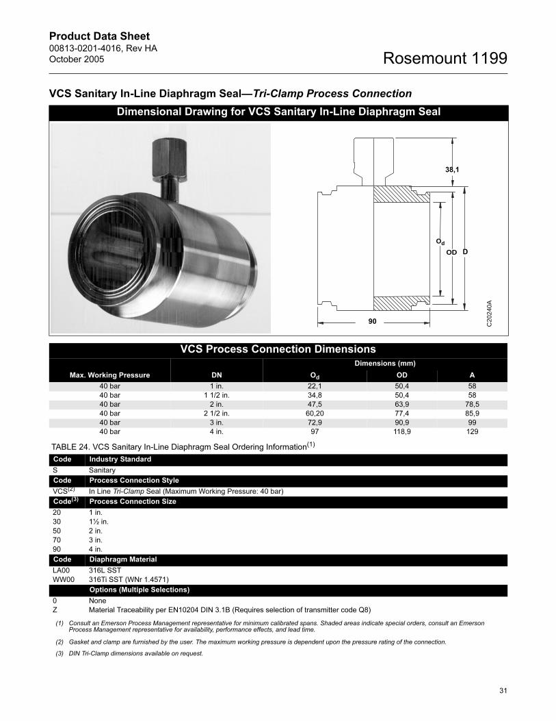
VCS Sanitary In-Line Diaphragm Seal—Tri-Clamp Process Connection
Dimensional Drawing for VCS Sanitary In-Line Diaphragm Seal
VCS Process Connection Dimensions
Max. Working Pressure DN
Dimensions (mm)
Od OD A
40 bar 1 in. 22,1 50,4 58
40 bar 1 1/2 in. 34,8 50,4 58
40 bar 2 in. 47,5 63,9 78,5
40 bar 2 1/2 in. 60,20 77,4 85,9
40 bar 3 in. 72,9 90,9 99
40 bar 4 in. 97 118,9 129
TABLE 24. VCS Sanitary In-Line Diaphragm Seal Ordering Information(1)
(1) Consult an Emerson Process Management representative for minimum calibrated spans. Shaded areas indicate special orders, consult an Emerson Process Management representative for availability, performance effects, and lead time.
Code Industry Standard
S Sanitary
Code Process Connection Style
VCS(2)
(2) Gasket and clamp are furnished by the user. The maximum working pressure is dependent upon the pressure rating of the connection.
In Line Tri-Clamp Seal (Maximum Working Pressure: 40 bar)
Code(3)
(3) DIN Tri-Clamp dimensions available on request.
Process Connection Size
20 1 in.
30 1½ in.
50 2 in.
70 3 in.
90 4 in.
Code Diaphragm Material
LA00 316L SST
WW00 316Ti SST (WNr 1.4571)
Options (Multiple Selections)
0 None
Z Material Traceability per EN10204 DIN 3.1B (Requires selection of transmitter code Q8)
C20
240A
Od
OD
38,1
90
D
31
Product Data Sheet00813-0201-4016, Rev HA
October 2005Rosemount 1199
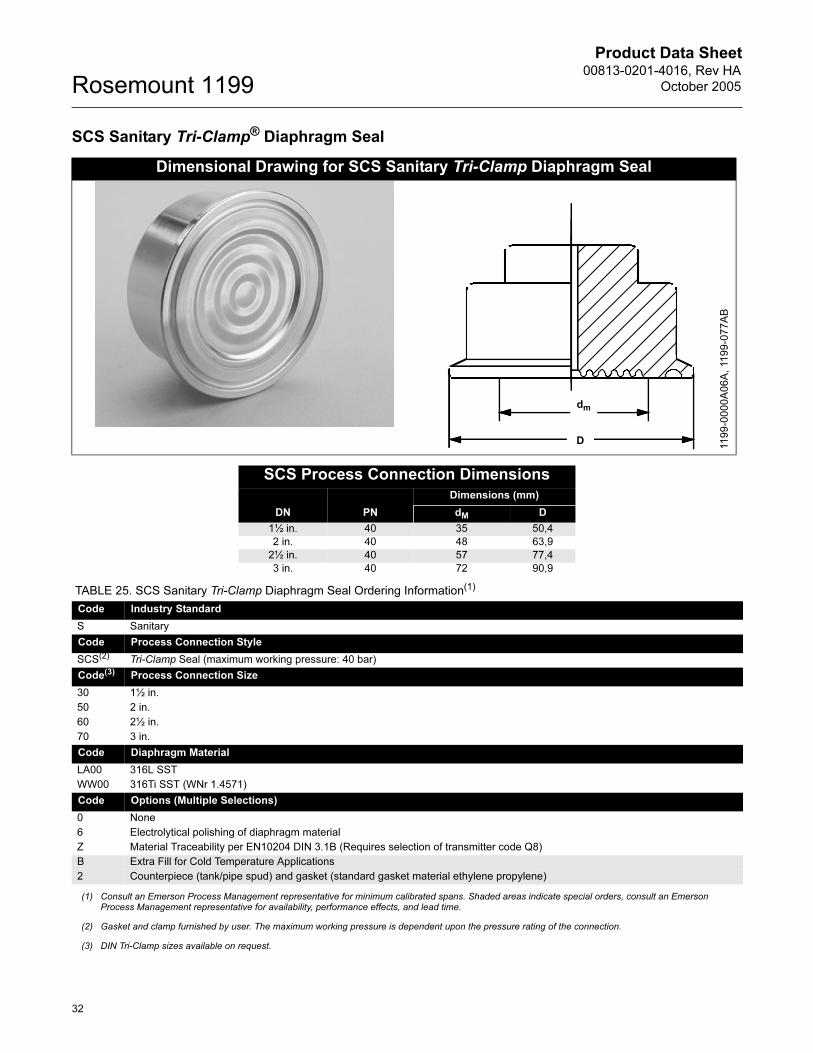
SCS Sanitary Tri-Clamp® Diaphragm Seal
Dimensional Drawing for SCS Sanitary Tri-Clamp Diaphragm Seal
SCS Process Connection Dimensions
DN PN
Dimensions (mm)
dM D
1½ in. 40 35 50,4
2 in. 40 48 63,9
2½ in. 40 57 77,4
3 in. 40 72 90,9
TABLE 25. SCS Sanitary Tri-Clamp Diaphragm Seal Ordering Information(1)
(1) Consult an Emerson Process Management representative for minimum calibrated spans. Shaded areas indicate special orders, consult an Emerson Process Management representative for availability, performance effects, and lead time.
Code Industry Standard
S Sanitary
Code Process Connection Style
SCS(2)
(2) Gasket and clamp furnished by user. The maximum working pressure is dependent upon the pressure rating of the connection.
Tri-Clamp Seal (maximum working pressure: 40 bar)
Code(3)
(3) DIN Tri-Clamp sizes available on request.
Process Connection Size
30 1½ in.
50 2 in.
60 2½ in.
70 3 in.
Code Diaphragm Material
LA00 316L SST
WW00 316Ti SST (WNr 1.4571)
Code Options (Multiple Selections)
0 None
6 Electrolytical polishing of diaphragm material
Z Material Traceability per EN10204 DIN 3.1B (Requires selection of transmitter code Q8)
B Extra Fill for Cold Temperature Applications
2 Counterpiece (tank/pipe spud) and gasket (standard gasket material ethylene propylene)
D
dm
11
99
-00
00
A0
6A
, 11
99
-07
7A
B
32

Product Data Sheet00813-0201-4016, Rev HA
October 2005 Rosemount 1199
EES Sanitary Tank Spud: Extended Diaphragm Seal
Dimensional Drawing for EES Sanitary Tank Spud Type: Extended Diaphragm Seal
DN PN
Dimensions (mm)
A B C D E F G
50 40 72 73 76 82.5 125 165 25
80 40 89 98 102 108 160 200 25
Flanged Type Tank Spud
TABLE 26. EES Sanitary Tank Spud Type: Extended Diaphragm Seal Ordering Information(1)
(1) Shaded areas indicate special orders. Consult an Emerson Process Management representative for availability, performance effects, and lead time.
Code Industry Standard
S Sanitary
Code Process Connection Style
EES Flanged Tank Spud Seal Type: Extended Diaphragm Seal (Supplied with ethylene propylene gasket)
Code Process Connection Size Flange Pressure Rating
JG DN 80 40 bar
GG DN 50 40 bar
Code Diaphragm (2)
(2) When ordering optional diaphragm materials, the standard housing material is 316L SST unless noted otherwise.
WW 316Ti SST (WNr 1.4571)
LA 316L SST
LB Hastelloy C-276
Code Extension Length(3)
(3) Other extension lengths are available upon request.
10 25 mm
Code Options (Multiple Selections)
0 None
1 Viton® O-ring
2 Tank spud counterpiece to be welded on tank: includes Ethylene-Propylene O-ring, stainless steel bolts, and washers
Z Material Traceability per EN10204 DIN 3.1B (Requires selection of transmitter code Q8)
5 50 �m Diaphragm Thickness (available in 316L SST or Hastelloy)
8 150 �m Diaphragm Thickness (316L SST or Hastelloy C-276 Diaphragm Material Only)
B Extra Fill for Cold Temperature Applications
6 Electrolytical Polishing of Diaphragm Material
7 Blind Plug for Tank Spud Counterpiece
G
A
BCDEF 1
19
9-0
00
0A
03
A,
11
99
-05
6A
B
C
D
E
F
GAB
Flanged Type Tank Spud Dimensions
Dimensions (mm)
DN A B C D E F G
50 25 15 76 82.5 125 165 22
80 25 15 103 108 160 200 22
11
99
-00
00
B1
4B
33
Product Data Sheet00813-0201-4016, Rev HA
October 2005Rosemount 1199
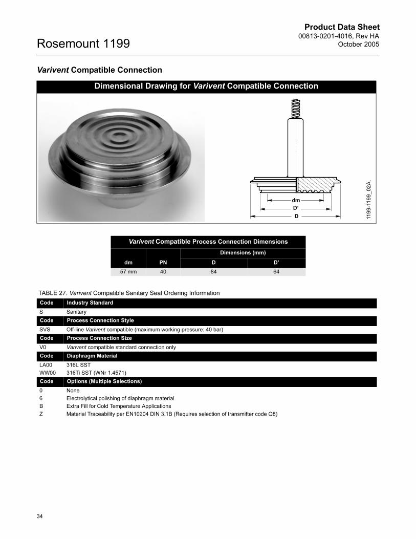
Varivent Compatible Connection
Dimensional Drawing for Varivent Compatible Connection
dm
D
D’
11
99
-11
99
_0
2A
,
Varivent Compatible Process Connection Dimensions
dm PN
Dimensions (mm)
D D’
57 mm 40 84 64
TABLE 27. Varivent Compatible Sanitary Seal Ordering Information
Code Industry Standard
S Sanitary
Code Process Connection Style
SVS Off-line Varivent compatible (maximum working pressure: 40 bar)
Code Process Connection Size
V0 Varivent compatible standard connection only
Code Diaphragm Material
LA00 316L SST
WW00 316Ti SST (WNr 1.4571)
Code Options (Multiple Selections)
0 None
6 Electrolytical polishing of diaphragm material
B Extra Fill for Cold Temperature Applications
Z Material Traceability per EN10204 DIN 3.1B (Requires selection of transmitter code Q8)
34

Product Data Sheet00813-0201-4016, Rev HA
October 2005 Rosemount 1199
CHS Homogenizer Clamping Flange Type
Dimensional Drawings for CHS Homogenizer Clamping Flange Type
33.5
95
60.5
7
23.5
93
30
13.5
11
99
-NC
HS
A0
1A
,
TABLE 28. CHS Homogenizer Clamping Flange Type–Ordering Information(1)
Code Process Connection Style
NCHS Homogenizer Clamping Flange
Code Process Connection Size
C 23,5 mm
Code(2) Pressure Rating
R 600 bar
Code Diaphragm and Wetted Parts Material
LA00 316L SST
WW00 316Ti SST (WNr 1.4571)
Code Options (Multiple Selections)
0 None
5 50 �m Diaphragm Thickness (available in 316L SST or Hastelloy)
V Teflon Coated Diaphragm for nonstick purposes only (available with 316L SST and Hastelloy C–276 diaphragm only)
B Extra Fill for Cold Temperature Applications
Z Material Traceability per EN10204 DIN 3.1B (Requires selection of transmitter code Q8)
(1) Shaded areas indicate special orders. Please consult an Emerson Process Management representative for availability, performance effects, and lead time.
(2) Minimum span is 60 bar.
35
Product Data Sheet00813-0201-4016, Rev HA
October 2005Rosemount 1199
General Information
WHAT IS A DIAPHRAGM SEAL SYSTEM?
A diaphragm seal system consists of a pressure
transmitter, a diaphragm seal, a fill fluid, and either a
direct-mount or capillary-style connection.
During operation, the flexible diaphragm and fill fluid
separate the pressure sensitive element of the
transmitter from the process medium. The capillary
tubing or direct mount flange connects the
diaphragm to the transmitter.
When process pressure is applied, the diaphragm
transfers the measured pressure through the filled
system and capillary tubing to the transmitter
element. This transferred pressure displaces the
sensing diaphragm in the pressure-sensitive element
of the transmitter. The displacement is proportional to
the process pressure and is electronically converted
to an appropriate current, voltage, or digital HART
output signal.
WHY USE DIAPHRAGM SEALS?
Seal systems provide a reliable process pressure
measurement and prevent the process medium from
contacting the transmitter diaphragm.
ADDITIONAL INFORMATION
This product data sheet provides information on
Rosemount transmitter/diaphragm seal systems.
Rosemount 1199 diaphragm seals can be assembled
to Rosemount 3051C, 1151, and 2088 differential,
gage, and absolute pressure transmitters, and liquid
level transmitters. For additional information, refer to
the following product data sheets:
• Rosemount 1151 Alphaline Pressure Transmitters (document number 00813-0100-4360)
• Rosemount 3051 Pressure Transmitter (document number 00813-0100-4001)
• Rosemount 2088 Gage and Absolute Pressure Transmitter (document number 00813-0100-4690)
Transmitter/diaphragm seal systems should be
considered when:
• The process temperature is outside of the normal operating ranges of the transmitter and cannot be brought into those limits with impulse piping.
• The process is corrosive and would require frequent transmitter replacement or unusual materials of construction.
• The process contains suspended solids or is viscous and may plug the impulse piping.
• The application requires the use of sanitary connections.
• There is a need for easier cleaning of the process from the connections to avoid contamination between batches.
• There is a need to replace wet legs to reduce maintenance on applications where the wet leg is not stable or often needs to be refilled.
• There is a need to make density or interface measurements.
• The process medium may freeze or solidify in the transmitter or impulse piping.
SPECIAL ORDERS
Many other special-order transmitter/diaphragm seal
materials, configurations, and fill fluids are available
that are not covered in this document. Contact an
Emerson Process Management representative or
consult the factory for special order information.
PERFORMANCE CONSIDERATIONS
Temperature Effects
Temperature effect errors occur when the fill fluid
expands or contracts with fluctuations in the process
or ambient temperature, thus causing a change in
the internal pressure of the transmitter/seal system.
Two primary factors affect the temperature
performance of a diaphragm seal system: the
diaphragm stiffness and the characteristics of the fill
fluid.
36
Product Data Sheet00813-0201-4016, Rev HA
October 2005 Rosemount 1199
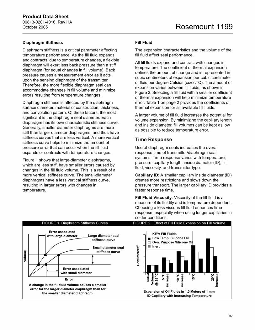
Diaphragm Stiffness
Diaphragm stiffness is a critical parameter affecting
temperature performance. As the fill fluid expands
and contracts, due to temperature changes, a flexible
diaphragm will exert less back pressure than a stiff
diaphragm (for equal changes in fill volume). Back
pressure causes a measurement error as it acts
upon the sensing diaphragm of the transmitter.
Therefore, the more flexible diaphragm seal can
accommodate changes in fill volume and minimize
errors resulting from temperature changes.
Diaphragm stiffness is affected by the diaphragm
surface diameter, material of construction, thickness,
and convolution pattern. Of these factors, the most
significant is the diaphragm seal diameter. Each
diaphragm has its own characteristic stiffness curve.
Generally, smaller diameter diaphragms are more
stiff than larger diameter diaphragms, and thus have
stiffness curves that are less vertical. A more vertical
stiffness curve helps to minimize the amount of
pressure error that can occur when the fill fluid
expands or contracts with temperature changes.
Figure 1 shows that large-diameter diaphragms,
which are less stiff, have smaller errors caused by
changes in the fill fluid volume. This is a result of a
more vertical stiffness curve. The small-diameter
diaphragms have a less vertical stiffness curve,
resulting in larger errors with changes in
temperature.
Fill Fluid
The expansion characteristics and the volume of the
fill fluid affect seal performance.
All fill fluids expand and contract with changes in
temperature. The coefficient of thermal expansion
defines the amount of change and is represented in
cubic centimeters of expansion per cubic centimeter
of fluid per degree Celsius (cc/cc/°C). The amount of
expansion varies between fill fluids, as shown in
Figure 2. Selecting a fill fluid with a smaller coefficient
of thermal expansion will help minimize temperature
error. Table 1 on page 2 provides the coefficients of
thermal expansion for all available fill fluids.
A larger volume of fill fluid increases the potential for
volume expansion. By minimizing the capillary length
and inside diameter, fill volumes can be kept as low
as possible to reduce temperature error.
Time Response
Use of diaphragm seals increases the overall
response time of transmitter/diaphragm seal
systems. Time response varies with temperature,
pressure, capillary length, inside diameter (ID), fill
fluid, viscosity, and transmitter type.
Capillary ID: A smaller capillary inside diameter (ID)
creates more restrictions and slows down the
pressure transport. The larger capillary ID provides a
faster response time.
Fill Fluid Viscosity: Viscosity of the fill fluid is a
measure of its fluidity and is temperature dependent.
Choosing a less viscous fill fluid enhances time
response, especially when using longer capillaries in
colder conditions.
FIGURE 1. Diaphragm Stiffness Curves FIGURE 2. Effect of Fill Fluid Expansion on Fill Volume
Cen
tim
eter
s3
I ni t
ial
Vo
lum
e
@ 2
5 °
C
5 °
C
incre
ase
10 °
C
incr e
ase
15°C
20°C
incr e
ase
Expansion of Oil Fluids in 1.0 Meters of 1 mm
ID Capillary with Increasing Temperature
KEY: Fill Fluids
Low Temp. Silicone Oil
Gen. Purpose Silicone Oil
Inert
A change in the fill fluid volume causes a smaller
error for the larger diameter diaphragm than for
the smaller diameter diaphragm.
Error associated
with large diameter Large diameter seal
stiffness curve
Error associated
with small diameter
Error
Volu
me
Small diameter seal
stiffness curve
37
Product Data Sheet00813-0201-4016, Rev HA
October 2005Rosemount 1199
Capillary Length: A longer capillary provides a
greater distance for the pressure signal to travel, thus
increasing the response time.
Applications with large tanks and slow changes in
level, may not be hindered by a longer response
time. Yet, a small, narrow tank may be subject to
measurement difficulties if the response time is too
slow. Applications that change rather quickly, such as
flow, also require faster response times.
Summary
Adding seals to a transmitter can affect overall
system performance. Selecting the most appropriate
diaphragm seals, capillaries, and fill fluid can
minimize these effects, maximize assembly
performance, and still meet or exceed process
demands.
Consider the following when selecting a diaphragm
seal system:
• Use larger diameter diaphragms to minimize temperature effects.
• Keep capillary length as short as possible to reduce temperature effects and response time.
• Select larger ID capillaries to improve time response or select smaller ID capillaries to improve temperature performance.
• Select fill fluid that is the least viscous and has the smallest coefficient of thermal expansion while satisfying the most extreme process conditions.
Refer to Figure 3 for a summary of temperature effect
and time response properties of various seal
systems. In-line seal designs, diaphragm seal
designs with diameters less than 50 mm and various
other design configurations can result in significant
temperature effect errors. Consult Instrument ToolKit
or contact an Emerson Process Management
representative for a detailed performance evaluation
of a specific diaphragm seal system configuration.
DIRECT MOUNT SEAL CONNECTION TYPES
Rosemount 3051C, 1151, and 2088 transmitters with
the Rosemount 1199 direct mount style seals are
flange mounted directly to the vessel. They provide
precise level and specific gravity measurements and
are available in a wide variety of configurations.
The direct-mount connection is welded at the seal
and the “L” bracket on Rosemount 3051C
transmitters and at the seal and the transmitter
flange for Rosemount 1151 and 2088 transmitters.
Figure 4, 5, and 7 illustrate the various direct mount
seal assembly configurations and weld locations.
38
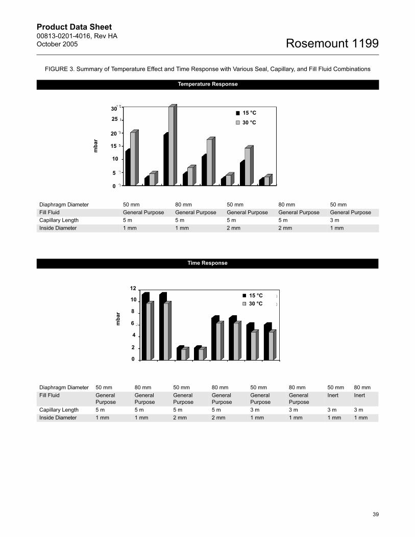
Product Data Sheet00813-0201-4016, Rev HA
October 2005 Rosemount 1199
FIGURE 3. Summary of Temperature Effect and Time Response with Various Seal, Capillary, and Fill Fluid Combinations
Temperature Response
Diaphragm Diameter 50 mm 80 mm 50 mm 80 mm 50 mm
Fill Fluid General Purpose General Purpose General Purpose General Purpose General Purpose
Capillary Length 5 m 5 m 5 m 5 m 3 m
Inside Diameter 1 mm 1 mm 2 mm 2 mm 1 mm
5
15
10
25
30
20
0
mbar
15 °C
30 °C
Time Response
Diaphragm Diameter 50 mm 80 mm 50 mm 80 mm 50 mm 80 mm 50 mm 80 mm
Fill Fluid General
Purpose
General
Purpose
General
Purpose
General
Purpose
General
Purpose
General
Purpose
Inert Inert
Capillary Length 5 m 5 m 5 m 5 m 3 m 3 m 3 m 3 m
Inside Diameter 1 mm 1 mm 2 mm 2 mm 1 mm 1 mm 1 mm 1 mm
2
6
4
10
12
8
0
mbar
15 °C
30 °C
39
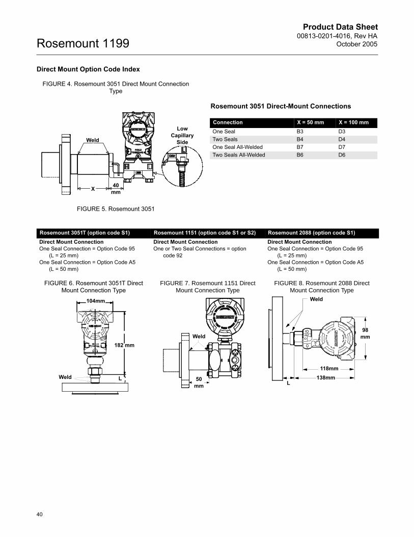
Product Data Sheet00813-0201-4016, Rev HA
October 2005Rosemount 1199
Direct Mount Option Code Index
FIGURE 4. Rosemount 3051 Direct Mount Connection Type
FIGURE 5. Rosemount 3051
Rosemount 3051 Direct-Mount Connections
Connection X = 50 mm X = 100 mm
One Seal B3 D3
Two Seals B4 D4
One Seal All-Welded B7 D7
Two Seals All-Welded B6 D6
Low
Capillary
Side
40
mmX
Weld
Rosemount 3051T (option code S1) Rosemount 1151 (option code S1 or S2) Rosemount 2088 (option code S1)
Direct Mount Connection
One Seal Connection = Option Code 95
(L = 25 mm)
One Seal Connection = Option Code A5
(L = 50 mm)
Direct Mount Connection
One or Two Seal Connections = option
code 92
Direct Mount Connection
One Seal Connection = Option Code 95
(L = 25 mm)
One Seal Connection = Option Code A5
(L = 50 mm)
FIGURE 6. Rosemount 3051T Direct Mount Connection Type
FIGURE 7. Rosemount 1151 Direct Mount Connection Type
FIGURE 8. Rosemount 2088 Direct Mount Connection Type
104mm
182 mm
Weld L
Weld
50
mm
98
mm
118mm
138mm
Weld
L
40

Product Data Sheet00813-0201-4016, Rev HA
October 2005 Rosemount 1199
High Temperature and Vacuum Applications
There are three parameters to consider when
selecting a transmitter/seal system for vacuum
applications: fill fluid selection, system construction,
and installation.
Fill Fluid Selection
The fill fluid must be able to withstand the highest
temperature and lowest process pressure conditions
under which the transmitter will be operating.
Therefore, the fill fluid must have a vapor pressure
that is compatible with the most extreme process
conditions in order to remain in the liquid phase at all
times. (Be sure to consider temperature and
pressure conditions during start-up and system
cleaning operations.)
Temperature limits of fill fluids, as shown in Table 1,
See “Fill Fluid Specifications” on page 2 are stated
for atmospheric pressure conditions; these limits are
reduced under vacuum conditions. “Fill Fluid Vapor
Pressure Curves” on page 42 provides the vapor
pressure curves for D.C. 200, D.C. 704, and Neobee
M-20 fill fluids.
Note that the Instrument Toolkit software program
makes checking fill fluid compatibility simple and
easy by automatically verifying the pressure curve
against the process conditions.
Remote Seal System Construction
1199 remote seal systems are offered in two
construction types: repairable-welded and all welded
(vacuum). The most commonly used construction is
the repairable-welded. In this design all of the
connection points are welded except the sensor
module to transmitter flange, which allows for the
repair of the seal system. In this case, the transmitter
can be re-used with replacement remote seals
attached.
The all welded vacuum construction was designed
specifically for high temperature and vacuum
applications. In this construction, the sensor module
gaskets are removed and a disk is welded over the
sensor isolators. This eliminates the possibility of air
being drawn into the seal system in deep vacuum
conditions. This premium design is strongly
suggested for vacuum pressures below 6 psia (310
mmHga).
Rosemount 3051 All Welded System
3051-W
eldRepairable-AllW
elded
Repairable-Welded Construction All Welded (Vacuum) Construction
All connection points welded except gasket between sensor module and transmitter flange
All connection points welded including welded
disk over sensor module isolators
GasketedWelded Disk
41

Product Data Sheet00813-0201-4016, Rev HA
October 2005Rosemount 1199
Installation
For vacuum applications, to ensure positive pressure at the transmitter, mount the transmitter so that it is level with,
or below the lowest tap.
Under the following conditions, the transmitter fill fluid may start to vaporize, at which point, the transmitter will
cease to make appropriate readings:
• The transmitter is mounted above the lower tap (causing a negative head effect).
• The process pressure is less than the head pressure exerted by the fill fluid in the capillary.
• This puts the transmitter fill fluid under a vacuum, thereby degrading the maximum operating temperature. If the operating temperature and vacuum pressure exceed the vapor pressure point of the transmitter fill fluid, the fill fluid is likely to vaporize.
To order the All-Vacuum construction on the
Rosemount 3051C, specify S7, S8, S9, or S0 in the
3051Cmodel number and the W seal location in the
1199 model number. To order the All Welded Vacuum
system on the Rosemount 3051T, specify S1 in the
3051T model number and the P seal location code in
the 1199 model number.
To order an All Welded Vacuum system on the
Rosemount 3051S, specific B11 or B12 in the 3051S
model number and the P, R, S, or T seal location code
in the 1199 model number.
See Table 29 to confirm how the transmitter assemble
to code and 1199 seal location codes combine to get
Repairable-Welded or All Welded Vacuum
construction.
FILL_VP_CURVE_AA04A
TABLE 29. Remote Seal System Construction Model Codes
Transmitter
Type
Transmitter Assemble To
Code
1199 Seal Location
CodeRepairable
-WeldedAll Welded
Vacuum
3051S_C B11 R — •
3051S_CD B12 S or T — •
3051S_T B11 or B12 P — •
3051S B12 D • —
B11 or B12 W or M • —
3051CD S1 or S2 W, M, or D • —
S7, S8, S9, or
S0
W, M, or D — •
3051CG /
CA
S1 W • —
S7 or S0 W — •
3051T S1 W or P — •
1151 S1 or S2 W, M, or D • —
2088 S1 W or P • —
42

Product Data Sheet00813-0201-4016, Rev HA
October 2005 Rosemount 1199
43
Instrument Toolkit® Software
Rosemount Inc. offers the best tool available for
understanding transmitter /seal system assemblies
and for making seal selection easy.
The Instrument Toolkit® is a Windows®-based
software package. Whether the application is level,
flow, pressure, density, or interface, Instrument
Toolkit will assist in selecting the best
transmitter-diaphragm seal system for the
application. The program will request the application
parameters and will then calculate the correct
calibration range (See Figure 9). Next, the program
will go through transmitter and remote seal model
number selection (See Figure 10). Based on the
models selected and the application data, Instrument
Toolkit will calculate the seal and transmitter/seal
system performance (See Figure 11).
Instrument Toolkit uses exclusionary logic to limit the
selection of transmitter and seal models which meet
the application requirements. The program will not
permit the selection of transmitter ranges which do
not meet the application span; diaphragm seal
models which do not meet the maximum working
pressure; or seal fill fluids which do not meet the
temperature and vapor pressure limitations.
The Instrument Toolkit Help section includes other
tools to assist in Diaphragm Seal selection. seal
dimensional drawings, product data, selection
fundamentals, technical information, and ordering
instructions are included in this section.
Instrument Toolkit also allows the user to generate,
view, and print performance and application reports
including installation drawings and specification
sheets.
Instrument Toolkit considers the following variables
to match the best seal system to the application:
• Seal diaphragm thickness, diameter, material, and rigidity
• Fill fluid volume, quality, thermal expansion and vapor pressure characteristics
• Capillary length and inside diameter
• Ambient and process temperatures
• Working and static pressures
• Vacuum applications
• Transmitter location and performance
FIGURE 9. Seal System Calibration Screen
FIGURE 10. Model Number Selection Screen
FIGURE 11. Results Screen

Product Data Sheet00813-0201-4016, Rev HA
October 2005Rosemount 1199
Emerson Process Management
© 2005 Rosemount Inc. All rights reserved.
¢00813-0201-4016?¤
Rosemount, Tri-Clamp, and the Rosemount logotype are registered trademarks of Rosemount Inc.Inconel, Monel is a registered trademark of International Nickel Co.Hastelloy is a registered trademark of Haynes International.HART is a registered trademark of the HART Communication Foundation.Teflon is a registered trademark of E.I. du Pont de Nemours & Co.Varivent is a registered trademark of Tuchenhagen Nederland B.V.All other marks are the property of their respective owners.
Rosemount Inc.8200 Market BoulevardChanhassen, MN 55317 USAT (U.S) 1-800-999-9307T (International) (952) 906-8888F (952) 949-7001
www.rosemount.com
Emerson Process Management Heath PlaceBognor RegisWest Sussex PO22 9SHEnglandT 44 (0) 1243 863121F 44 (0) 1243 867554
Emerson Process Management Asia Pacific Private Limited1 Pandan CrescentSingapore 128461T (65) 6777 8211F (65) 6777 0947/65 6777 [email protected]
Related Documents