Roof Plan Components Roof Layout Plan

Welcome message from author
This document is posted to help you gain knowledge. Please leave a comment to let me know what you think about it! Share it to your friends and learn new things together.
Transcript
Roof Plan Components Roof Layout Plan

Roof Plan
A roof plan is commonly drawn to a scale of 1/8 inch per foot or 1/16 inch per foot.
A roof plan shows the shape of the roof, as well as roofing materials, underlayment and location of vents.

Roof Plan
A roof framing plan shows size and direction of the construction members that are required to frame a roof.

*Roof slope is a description of the angle that the roof rafter makes with a horizontal reference. It compares the horizontal run to the vertical rise. A 6:12 roof has a pitch of 1/2.

On a flat roof, a slope of ¼ inch per foot is often uses to prevent water from ponding on the roof. (2 percent slope)

*Live Loads: Those fixed or moving weights, which are not a structural part of the house. Examples include furniture, occupants, snow on the roof, etc.
Dead Loads: Those static or fixed weights of the structure itself. Example of dead loads are the weights of roofing, foundation walls, siding, joists, etc.

Define the term parapet as used in reference to a flat roof:
It is a false wall surrounding the perimeter of the roof.

The flat roof is a very common style in areas with little rain or snow. In addition to being used in residential construction, the flat roof is typically used on commercial structures to provide a platform for heating and other mechanical equipment.
When used, it must be shown on the roof plan
Flat Roof
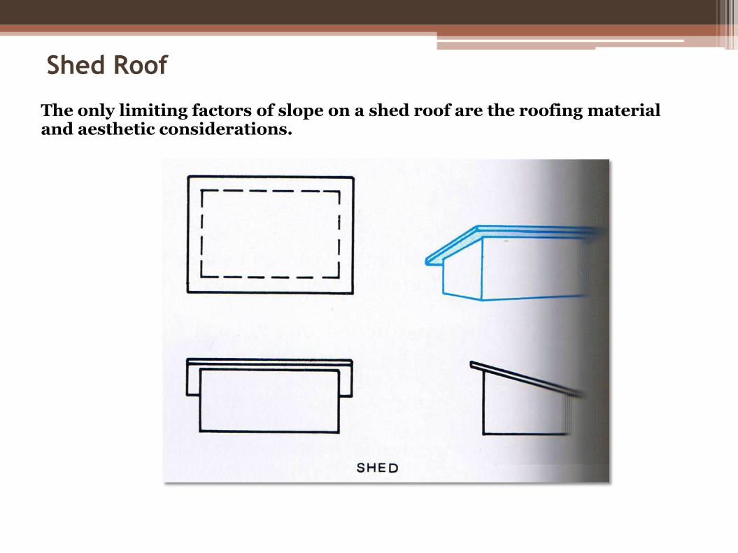
Shed Roof
The only limiting factors of slope on a shed roof are the roofing material and aesthetic considerations.

Gable Roof
*A Gable roof is the most common type of roof used in residential construction. It is the made up of two shed roofs that meet to form a ridge between the support walls.

Roof Plan*A Hip roof has many similarities to a gable roof but has a minimum of four surfaces instead of two.

Roof PlanThe intersections of gable surfaces are called either hips or valleys.

A-Frame RoofAn A-Frame structure uses rafters to form its supporting walls.
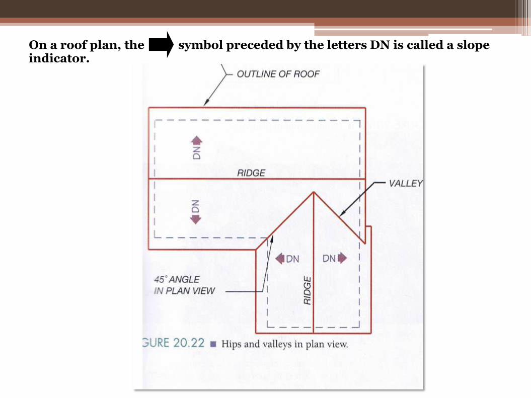
On a roof plan, the symbol preceded by the letters DN is called a slope indicator.
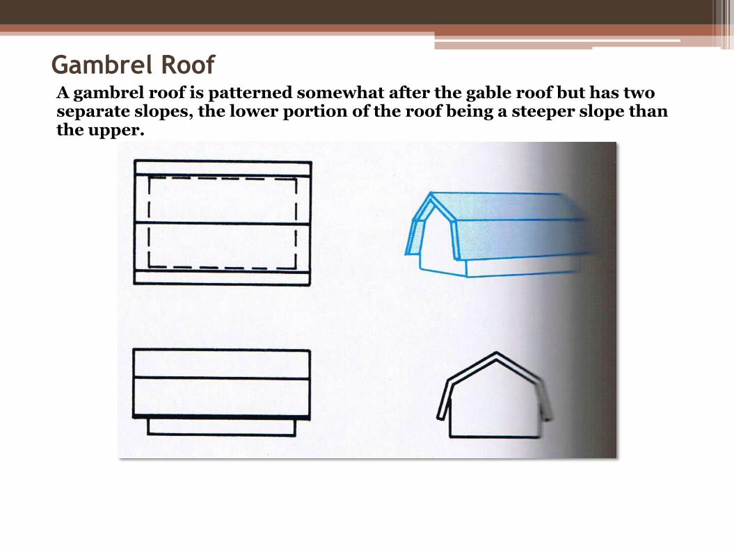
Gambrel RoofA gambrel roof is patterned somewhat after the gable roof but has two separate slopes, the lower portion of the roof being a steeper slope than the upper.

Dutch Hip RoofA Dutch hip roof is a combination of a hip and gable roof.

Dormer Window*Briefly describe a dormer:
A dormer is an opening framed in the roof to allow for window placement.

Match the following roof names with the appropriate figure.

Match the following roof names with the appropriate figure.

The weight of the roofing material will affect the size of framing members all the way down to the foundation level.

A square is used to describe an area of roofing that covers 100 square feet.
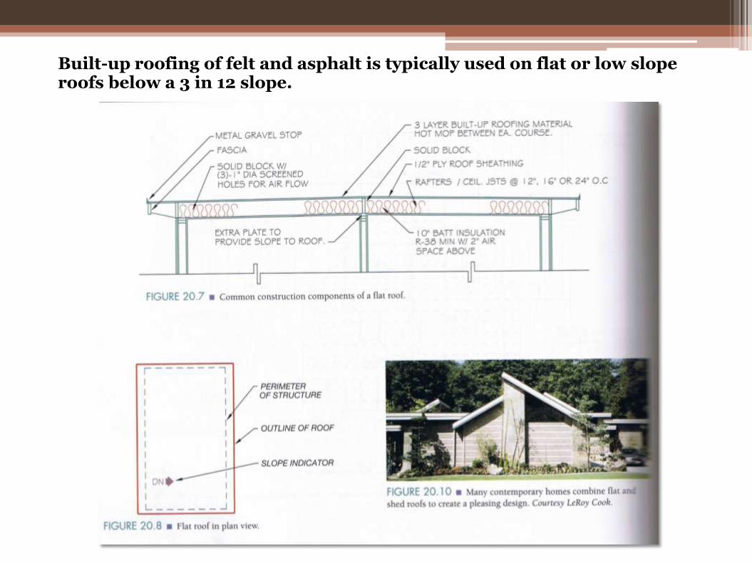
Built-up roofing of felt and asphalt is typically used on flat or low slope roofs below a 3 in 12 slope.

The standard shingle is a three tab rectangular strip weighing 235 pounds per square.

On shingle roofs most building codes require a minimum slope of 4:12 with an underlayment of one layer of 15 pound roofing felt.
As the angle of the roof is increased, the size of the overhang may need to be decreased so that the eave will not extend into the line of sight from the window.

Hips represent the intersection between two roof planes and are represented by a line drawn at an angle that is one-half of the angle formed between the two supporting walls.

The attic access should have an opening that is 22 inches by 30 inches with a minimum headroom clearance above the access door of 30 inches.
Avoid placing the access in areas such as the garage; areas with high moisture content, such as bathrooms and utility rooms, or in bedrooms that will be used by young children.
Code requires that the access be located in a hallway or other accessible location.
The attic area must be provided with vents that are covered with 1/8 inch screen mesh.

When slopes on both sides of the roof are equal, the wider the distance between the support walls the higher the roof ridge will be.

A small gable built on the up-slope side of the chimney to divert water away from the chimney is called a saddle.

A skylight is connected to the ceiling by an enclosed area called a chase or well.

A roof plan requires very few dimensions. Typically only the overhangs and openings are dimensioned. These may even be specified in note form rather than with dimensions.

Trusses are designed so that the weight to be supported is spread to the outer walls. This is done by placing some members in tension and some in compression. A member in compression is indicated by a plus sign, and one in tension is represented by a minus sign.
*Most trusses are spaced 24” O.C.
Trusses

A fascia is a trim board placed at the end of the rafter or truss tails and usually perpendicular to the building wall.
*The fascia can be make from either 1X or 2X material, depending on the need to resist warping.
Fascia Board

Vents*Vents my be placed in the gabled end walls near the ridge.
In some areas, a continuous vent is placed in the eaves, or a vent may be placed in each third rafter space.
Related Documents