Rolling Contact Bearings Lecture #3 Course Name : DESIGN OF MACHINE ELEMENTS Course Number: MET 214

Rolling Contact Bearings Lecture #3 Course Name : DESIGN OF MACHINE ELEMENTS Course Number: MET 214.
Dec 15, 2015
Welcome message from author
This document is posted to help you gain knowledge. Please leave a comment to let me know what you think about it! Share it to your friends and learn new things together.
Transcript

Rolling Contact BearingsLecture #3
Course Name : DESIGN OF MACHINE ELEMENTSCourse Number: MET 214

Power transmission systems involve rotating shafts. As a consequence, the techniques used in power transmission systems to support rotating shafts must be different than the techniques used in construction technology to support beams (non-rotating members), although the same general approach used to categorize beam supports does apply to components used to support rotating shafts. The components used in a power transmission systems to support rotating shafts must supply reaction forces and/or moments. The reaction forces and/or moments are necessary to mount a shaft in a system. In addition, the components that supply the reaction forces and/or moments to a shaft must supply the reaction forces and/or moments to the shaft while permitting the shaft to rotate. Accordingly, the supports used in power transmission systems are fundamentally different that the supports used in construction technology.

In order to proceed with the design of a power transmission system, the designer must befamiliar with the different types of components that can be used to support rotating shafts. Avariety of components are available to support the rotating shafts. To assist in thefamiliarization and/or categorization of the components used to support rotating shafts, abrief review of beam supports used in construction technology will be presented.
As described in strength of material text books, beam supports can be classified according tothe types of reaction the supports provide. Different types of beam supports are shown in thefigure below.

A basic configuration that can satisfy the requirements to support rotating shafts used in power transmission systems consists of a pair of rigid supports with a hole provided in each support as shown below. The supports are separated by an amount that enables the shaft to be supported by the hole of each support. If the diameter of the hole in each support is slightly larger than the shaft diameter, the shaft will be able to rotate as the supports supply reactions forces perpendicular to the axis of rotation of the shaft. The supports illustrated below provide a radial reaction force capability while permitting the shaft to rotate.

If a reaction force must be produced along the axis of rotation of the shaft, a stepped shaft may be used with supports as shown in the side view below.
Figure #2: side view of shaft support configuration with axial reaction capability.
The configuration shown in Figure #2 has the disadvantage that very little margin is provided for the shaft to expand. By relocating one of the supports and using a collar at the other support, the shaft may be located laterally by the supports while permitting the shaft to expand as shown in the figure on the next slide.

Figure #3: side view of shaft support configuration with axial reaction capability and latitude for shaft expansion.
It should be noted that the thickness of the supports can be used to influence the amount of reaction moment the support applies to the shaft . The reaction moment generated by a support can be used to control the angular misalignment existing between the shaft and the axis of the hole in the support when the shaft is experiencing transverse loading as shown in the figures in the next slide.

Increasing the thickness of the supports and/or reducing the hole diameter in the supports enables the supports to control the slope of the shaft at the supports, in essence providing for a moment reaction.

A major drawback of the configurations illustrated previously is that the shaft experiences a large amount of friction as the shaft rotates. This is due to the fact that as the shaft is rotated, the shaft slides on the inside surface of the hole formed in support. To reduce the amount of friction existing between the shaft and the support, a form of rolling friction may be implemented. Rolling friction requires the use of rolling elements between the shaft and the support as shown in the illustrations provided below.


In order to facilitate installation and/or standardization of shaft supports, the components necessary to enable a shaft to rotate via rolling friction are assembled into self contained units, referred to as rolling contact bearings as described in the illustrations provided below.
Although cylindrical rolling elements are shown in the figure above, a variety of rolling elements can be used resulting in a variety of bearing types with different advantages/ disadvantages including different reaction force and/or moment capabilities. Procedures for selecting bearings will be discussed in a subsequent lecture.

Here we will discuss different types of rolling contact bearings and the applications in which each is typically used. Many variations on the designs shown are available. As each is discussed, refer to Table 14 – 1 for a comparison of the performance relative to the others. Radial loads act toward the center of the bearing along a radius. Such loads are typical of those created by power transmission elements on shafts such as spur gears, V-belt drives, and chain drives. Thrust loads are those that act parallel to the axis of the shaft. The axial components of the forces on helical gears, worms and worm gears, and bevel gears are thrust loads. Also, bearings supporting shafts with vertical axes are subjected to thrust loads due to the weight of the shaft and the elements son the shaft as well as from axial operating forces. Misalignment refers to the angular deviation of the axis of the shaft at the bearing from the true axis of the bearing itself. An excellent rating for misalignment in Table 14 -1 indicates that the bearing can accommodate up to 4.00 of angular deviation.

A bearing with a fair rating can withstand up to 0.150 , while a poor rating indicates that rigid shafts with less than 0.050 of misalignment are required. Manufacturers catalogs should be consulted for specific data.
Single-Row, Deep-Groove Ball BearingSometimes called Conrad bearings, the single-row, deep-groove ball bearing is what most people think of when the term ball bearing is used. The inner race is typically pressed on the shaft at the bearing seat with a slight interference fit to ensure that it rotates with the shaft. The spherical rolling elements, or balls, roll in a deep groove in both the inner and the outer races. The spacing of the balls is maintained by retainer or “cages”. While designed primarily for radial load-carrying capacity, the deep groove allows a fairly sizable thrust load to be carried. The thrust load would be applied to one side of the inner race by a shoulder on the shaft. The load would pass across the side of the groove, through the ball, to the opposite side of the outer race, and then to the housing. The radius of the ball is slightly smaller than the radius of the groove to allow free rolling of the balls. The contact between a ball and the race is theoretically at a point, but it is actually a small circular area because of the deformation of the elements. Because the load is carried on a small area, very high local contact stresses occur. To increase the capacity of a single-row bearing, a bearing with a greater number of balls, or larger balls operating in larger-diameter races, should be used.
Double-Row, Deep-Groove Ball BearingAdding a second row of balls (Figure 14-2) increases the radial load-carrying capacity of the deep-groove type of bearing compared with the single-row design because more balls share the load. Thus, a greater load can be carried in the same space, or a given load can be carried in a smaller space. The greater width of double-row bearings often adversely affects the misalignment capability.

Angular Contact Ball BearingOne side of each race in an angular contact bearing is higher to allow the accommodation of greater thrust loads compared with the standard single-row, deep-groove bearing. The sketch in Figure 14-3 shows the preferred angle of the resultant force (radial and thrust loads combined), with commercially available bearings having angles of 150 to 400 .
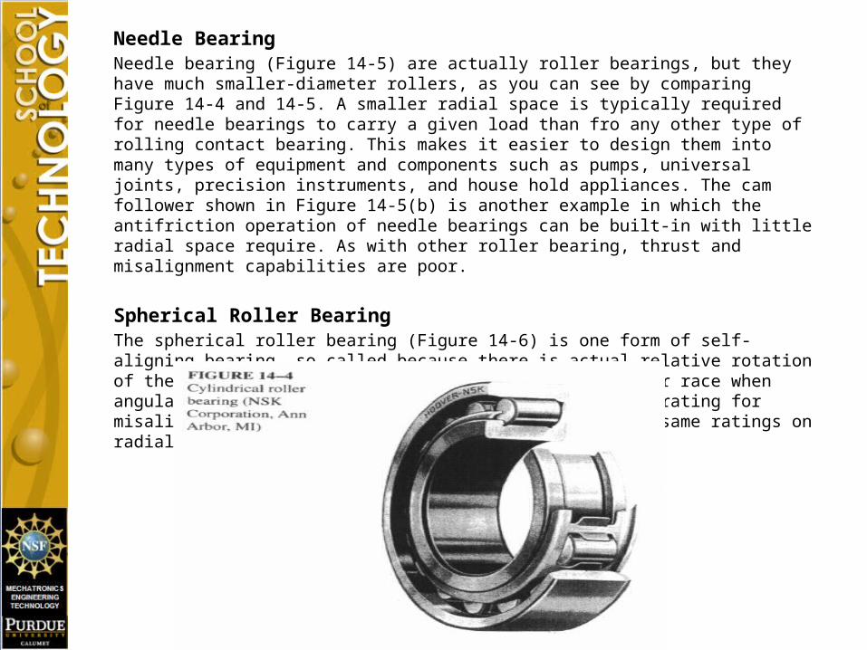
Cylindrical Roller BearingReplacing the spherical balls with cylindrical balls (Figure 14-4), with corresponding changes in the design of the races, gives a greater radial load capacity. The pattern of contact between a roller and its race is theoretically a line, and it becomes a rectangular shape as the members deform under load. The resulting contact stress levels are lower than for equivalent-sized ball bearings, allowing smaller bearings to carry a given load or a given size bearing to carry a higher load. Thrust load capacity is poor because any thrust load would be applied to the side of the rollers, causing rubbing, not true rolling motion. It is recommended that no thrust load be applied. Roller bearings are often fairly wide, giving the only fair ability to accommodate angular misalignment.
Needle BearingNeedle bearing (Figure 14-5) are actually roller bearings, but they have much smaller-diameter rollers, as you can see by comparing Figure 14-4 and 14-5. A smaller radial space is typically required for needle bearings to carry a given load than fro any other type of rolling contact bearing. This makes it easier to design them into many types of equipment and components such as pumps, universal joints, precision instruments, and house hold appliances. The cam follower shown in Figure 14-5(b) is another example in which the antifriction operation of needle bearings can be built-in with little radial space require. As with other roller bearing, thrust and misalignment capabilities are poor.
Spherical Roller BearingThe spherical roller bearing (Figure 14-6) is one form of self-aligning bearing, so called because there is actual relative rotation of the outer race relative to the rollers and the inner race when angular misalignments occur. This gives the excellent rating for misalignment capability while retaining virtually the same ratings on radial load capacity.

Tapered Roller BearingTapered roller bearings (Figure 14-7) are designed to take substantial thrust loads along with high radial loads, resulting in excellent ratings on both. They are often used in wheel bearings for vehicles and mobile equipment and in heavy-duty machinery having inherently high thrust loads. Section 14-12 gives additional information about their application. Figures 8-25, 9-36, 10-1, and 10-2 show tapered roller bearings applied in gear-type speed reducers.

Thrust bearings:The bearings discussed so far in this chapter have been designed to carry radial loads or a combination of radial and thrust loads. Many machine design projects demand a bearing that resists only thrust loads, and several types of standard thrust bearings are commercially available. The same types of rolling elements are used: spherical balls, cylindrical rollers, and tapered rollers.Most thrust bearings can take little or no radial load. Then the design and the selection of such bearings are dependent only on the magnitude of the thrust load and the design life. The data rating and basic static load rating are reported in manufacturers’ catalogs in the same way as they are for radial bearings.
Mounted Bearings:In many types of heavy machines and special machines produced in small quantities, mounted bearings rather than unmounted bearings are selected. The mounted bearings provide a means of attaching the bearing unit directly to the frame of the machine with bolts rather than inserting it into a machined recess in a housing as is required in unmounted bearings.

The figure shows the most common configuration for a mounted bearing: the pillow block. The housing is made from formed steel, cast iron, or cast steel, with holes or slots provided for attachment during assembly of the machine, at which time alignment of the bearing unit is adjusted. The bearings themselves can be of virtually any of the types discuss in the preceding sections; ball, tapered roller, or spherical roller is preferred. Misalignment capability is an important consideration because of the conditions of use of such bearing. This capability is provided is provided either in the bearing construction itself or in the housing.

Because the bearing itself is similar to those already discussed, the selection process is also similar. Most catalogs provide extensive charts of data listing the load-carrying capacity at specified rated life values. Internet site 7 includes an example. Other forms of mounted bearings are shown in the figure. The flange units are designed to be mounted on the vertical side frames of machines, holding horizontal shafts. Again, several bearing types and sizes are available. The term take-up unit refers to a bearing mounted in housing, which in turn is mounted in a frame that allows movement of the bearing with shaft in place. Used on conveyors, chain drives, belt drives, and similar applications, the take-up unit permits adjustment of the center distance of the drive components at the times of installation and during operation to accommodate wear or stretch of parts of the assembly.

Bearing Materials:The load on a rolling contact bearing is exerted on a small area . The resulting contact stresses are quite high, regardless of types of bearing. Contact stresses of approximately 300000 psi are not uncommon in commercially available bearings. To withstand such high stresses, the ball, rollers, and races are made from a very hard, high-strength steel or ceramic. The most widely used bearing material is AISI 52100 steel, which has a very high carbon content, 0.95% to 1.10%, along with 1.30% to 1.60% chromium, 0.25% to 0.45% manganese, 0.20% to 0.35% silicon, and others allowing elements with low but controlled amounts. Impurities are carefully minimized to obtain a very clean steel. The material is through hardened to the range of 58-65 on the Rockwell c scale to give it the ability to resist high contrast stress. Some tool steels, particularly M1 to M50, are also used. Case hardening by carburizing is used with such steels, particularly as AISI 3310, 4620, and 8620 to achieve the high surface hardness required while retaining a tough core. Carefully control the case depth is required because the stress occur in subsurface zones. Some more lightly loaded bearings and those exposed to corrosive environments are AISI 440C stainless steel elements. Rolling elements and other components can be made from ceramic materials such as silicon nitrate(si3n4). Although their cost is higher than that of steel, ceramics offer significant advantages as shown in table. Their light weight, high strength, and high temperature capability make them desirable for aerospace, engine, military and other demanding applications.

In order to proceed with the design of a power transmission system, the designer must understand how power is transferred through the system. In order to develop an understanding of how power is transferred through a system, consider the following situation.A weight w is to be lifted off of the floor using the hoist shown below. Develop an equation that relates the acceleration a of the weight w to the torque Tm that a motor applies to the cylinder of the hoist. In addition, determine the power supplied by the motor to the hoist when the weight w is being hoisted at a constant velocity.

Draw a free body diagram of the weight w to develop the equation of motion.
where tension in cable weight of object being lifted by hoist acceleration of object being lifted by
hoist acceleration due to gravity
maF
ag
wwFT
wag
wFT
TFwa
g

Draw free body diagram of cylinder
Where torques acting on cylinder radius of cylinder
torque produced by motor mass moment of inertia of
cylinder angular acceleration of
cylinder
mJT
mTM JFRT 0
T0R
mTmJ

To develop an expression for the motor torque in terms of the linear acceleration a of theweight w, solve the previous equation for motor torque and substitute the expression for FT
into the equation for motor torque.
Where R0α=a
Rearranging terms results in the following expression for motor torque as a function ofthe acceleration a of the weight w and the load torque generated by the weight w.
Where =
The acceleration a of the weight w may be expressed as a desired velocity divided by the time to reach the desired velocity assuming the weight is hoisted from a rest position with a constant acceleration a.
A generalized plot of the velocity verse time for the hoisting of the weight is shown on thenext slide. A de-acceleration interval has been provided to stop the hoist.
00 R
aJwa
g
wRT MM
WMM
M Tag
wR
R
JwRa
g
wR
R
JT
0
000
0
WT wR0
WTMT

No values are shown for velocity on the graph in order to direct the focus toward the functionalrelationships existing among the two graphs provided below.
A plot of the motor torque versus time for the above defined velocity profile isshown below.

Several important points are to be observed from the information presented above.
1) Initially the weight w is at rest. In order to accelerate the weight w to a desired velocity of V, a motor torque that is larger than the value of the load torque must be applied to the hoist. The amount of torque that must be supplied from the motor in order for the hoist to lift the weight w for the desired acceleration a can be determined from the equations provided above.
2) After the weight has been accelerated to the desired velocity, the value of the motor torque is reduced so that the motor torque will have the same value as the load torque and as a result, the net torque applied to the hoist will be zero. In order for the motor torque to have the same value as the load torque, the acceleration a of the weight w must be zero. When the motor torque is set equal to the load torque, a balance is established between the load torque and the motor torque and according to Newton’s 1st law, since there is no longer any net torque applied to the hoist after the weight has been hoisted to the desired velocity, the hoist will continue to lift the weight at the desired velocity until the hoist is de-accelerated. The amount of power supplied by the motor to the shaft while the weight is being hoisted at a constant rate is equal to Pm = . The amount of power required to lift the weight w is Pw = V w. Note Pm =Pw.
MTMT
MT
WT
MT

3) Since the hoist is rotating in the same direction as the torque applied to the hoist by the motor, the algebraic sign associated with the power the motor is supplying to the shaft is always positive regardless of the sign convention used to define the direction of the motor torque and/or the angular velocity of the hoist. This must be the case since under the steady state conditions described above, the motor torque and the angular velocity of the hoist will have the same orientation (sign), and as a consequence, the product of motor torque with angular velocity will always produce a positive product. This must be the case since the product of two positive terms is positive and the product of two negative terms is also positive. The positive sign associated with indicates that the motor is supplying power to the shaft.
4) Since attaching the weight w to the hoist impedes the motion of the hoist, the torque applied to the hoist by the weight w acts in a direction opposite of the direction of rotation of the hoist and/or the angular velocity of the hoist during the steady state. When the hoist is rotating at a constant rate, the direction of the load torque is opposite the direction of rotation and the algebraic sign associated with the power required to lift the weight w is negative regardless of the sign convention used to define the direction of rotation of the hoist and/or the angular velocity of the hoist. This must be the case since the product of two terms having opposing signs results in a negative product. As a consequence, the sign associated with the power transferred from the weight to the shaft will be negative indicating the shaft is providing power to the weight in order to lift the weight.

5) The algebraic signs associated with and will prove to be very useful in determining the power requirements of a motor based upon the power requirements of the loads that the motor must drive. The algebraic signs associated with and can be used to create a power balance for use in determining the amount of power to be transferred through a power transmission system. Due to the sign convention existing with the power supplied by the motor and the power utilized by the load, the total power supplied to the shaft will sum to zero.
6) + =0. The net power transferred to the shaft is zero. Since the algebraic sign for is negative, the power balance for the shaft can be rewritten as follows: = .
7) In general, when a component supplies or transfers power to a shaft, the torque applied to the shaft by the component will always be in the same direction as the direction of rotation of the shaft. When a component removes power from a shaft or in other words, the shaft transfers power to the component, the torque applied to the shaft by the component will be in a direction opposite to the direction of rotation of the shaft.
8) Since all components affixed to the hoist have the same angular velocity, the power balance equation can be extended to a torque balance equation.
wP

= . Where
Under steady state conditions, the net torque applied to a shaft must be zero. The results of extending the power balance equation to a torque balance equation produces consistency with the laws of statics indicating that the power balance equations are credible. Relating the power balance concept to a torque balance concept will prove useful in determining the direction of torque that a power system component applies to a shaft. As will be evident after discussing torsional shear stresses existing in a shaft, such considerations are fundamental to identifying the appropriate diameter of a shaft used in a power transmission system. When a shaft drives multiple components, the torque each component applies to the shaft must be combined properly in order to identify the appropriate diameter for the shaft.

The equation relating motor torque to the acceleration a of the weight w may berearranged to emphasize the assumptions that typically accompany the analysis of apower transmission system in the steady state.
Recalling where mc = Mass of cylinder
wc = Weight of cylinder
The torque required from a motor to operate a hoist contains two components
steady state component = load torque =
dynamic component involving the acceleration a of the weight w.
wRag
wR
R
JT MM 00
0
20
20 2
1
2
1R
g
wRmJ ccM
w
w
g
awRT c
M 2
1110
wR0
g
aRwwc
0
2
1
wRg
aRwwT cM 0
0
2
1
MT
WT

The Steady state component for load torque can be factored out of the expression for Tm
to obtain an expression for Tm that depends on the steady state component for load torque and an adjustment factor, to be referred to as a Service Factor, that depends on the dynamics associated with a particular application.
Note: Service Factor ≥1 when Service Factor=1 -> a=0Service Factor>1 -> relevance depends upon a/g ratio
][2
111 00 torServiceFacwR
w
w
g
awRT c
M
w
w
g
atorServiceFac c
2
111
WT
][2
111 torServiceFacT
w
w
g
aTT W
cWM

The equation for motor torque can be multiplied on both sides by the angular velocity to develop an expression for power.
During steady State operations the following equation holds for power.
=
The above equation can be obtained from a power balance as noted earlier.
][2
111 torServiceFacp
w
w
g
app w
cwM
][2
111 torServiceFacT
w
w
g
aTT W
cWM
][2
111 torServiceFacT
w
w
g
aTT W
cWM
Mp wp

Accordingly, to establish performance requirements for subsystem components so the mechanical design process can proceed, the power and/or torque propagated through a power transmission system can be assumed to be the steady state power and/or torque, and adjustments to be made for dynamical influences can be incorporated by adjusting the steady state values by a service factor consistent with the expected level of dynamic performance anticipated for the application.
Note: Expression for service factor can be written in terms of final velocity and time to accelerate to final velocity assuming constant acceleration.
where final velocity time to accelerate from zero velocity
w
w
g
atorServiceFac c
2
111
w
w
gttorServiceFac c
f
f
2
111
fft

Recall power can be related to torque and customized to a particular set of units
where “steady state power”; (ft-lbs)/secTorque ft-lbsangular velocity rads/sec
In terms of customized units:
P= (T*n)/ 63,000 where P= horse power T= torque in lbsn= rpm
Using the system configuration associated with a design, it is possible to transfer power requirements from one component to another and repeatedly use to determine the torque associated with each component. After the torque loading is establish for a component, the stress level that must be accommodated by the component can be determined and used to assist in the design of the component.
TP
PT
sec550
1
sec60
min12
min12
1lbsft
HP
rev
radsrev
in
ftlbsinP
000,632
)550)(60)(12()550)(60)(12(
2 TnTnTnP

Accordingly, in essence, there are two different approaches that can be used to analyze the torque that is being transmitted by a power transmission system. If an assumption is made that a system is operating in the steady state, the equations governing the motion behavior of the system are greatly simplified since the acceleration is zero. The results of a steady state analysis can be adjusted by a service factor whose value depends on the application. Alternatively, the mass moment of inertia of a system may be determined and a more complete analysis performed. If the time to accelerate and/or the time to decelerate are important issues to be analyzed for a system, then a complete analysis using the mass moment of inertia would be required. However, if time to start and/or stop are not issues that need to be analyzed, then a system can be analyzed using the steady state assumption as compensated by a service factor. The method of analysis to be used in the initial stages of the design process presented herein will be the steady state approach. As will be found, a considerable amount of data supplied by manufacturers of components, including shaft couplings, belt drive and/or chain drive systems, rely upon this approach to characterize their products. Accordingly, the steady state approach will enable the designer to apply the same basic principles used by component suppliers to assist in the selection of a variety of components to be used in power transmission systems. After analyzing the basic building blocks used in power transmission systems, the focus of the effort will be directed toward conveyor systems and issues involving motor selection predicated on representing the conveyor components undergoing motion in terms of an equivalent mass moment of inertia.
Related Documents