OWNER’S HANDBOOK ROLLER TEAM MOTORHOMES

Welcome message from author
This document is posted to help you gain knowledge. Please leave a comment to let me know what you think about it! Share it to your friends and learn new things together.
Transcript
1
O W N E R ’ S H A N D B O O K
R O L L E R T E A M M O T O R H O M E S

2
Important
Your motorhome makes use of many complexsystems and services. Please ensure that youhave read all instruction manuals carefully, and fully understand all aspects of your vehicle, before driving it on the open road.If you have any queries on the operation ofany part of your motorhome please contactyour supplying dealer.
3
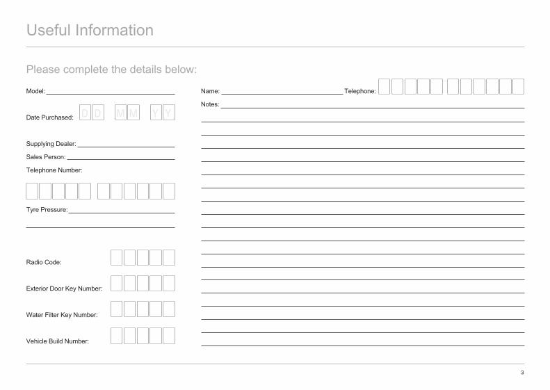
Useful Information
Please complete the details below:
Model:
Date Purchased:
Supplying Dealer:
Sales Person:
Telephone Number:
Tyre Pressure:
Radio Code:
Exterior Door Key Number:
Water Filter Key Number:
Vehicle Build Number:
Name: Telephone:
Notes:D D M M Y Y
4
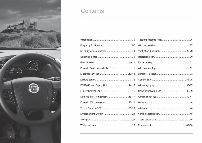
Introduction ...............................................................5
Preparing for the road ............................................6-7
Driving your motorhome............................................8
Selecting a pitch ........................................................9
Gas services ......................................................10/11
Dometic Combination Hob ......................................11
Electrical services ..............................................12-13
Leisure battery ........................................................14
EC176 Power Supply Unit .................................14-15
EC362 Control Panel ..............................................15
Dometic 8401 refrigerator ..................................16-17
Dometic 8501 refrigerator ..................................18-19
Truma Combi 4E/6E ..........................................20-23
Entertainment System ............................................24
Skylights .................................................................24
Water services ........................................................25
Thetford cassette toilet ............................................26
Windows & blinds ...................................................27
Ventilation & security..........................................28-29
Habitation door ........................................................30
Entrance step ..........................................................31
Wind-out awning .....................................................32
Centrav l locking .....................................................33
General care ......................................................34-35
Winter laying up .................................................36-37
Good neighbour guide .......................................38-39
Annual check list ................................................40-43
Warranty ..................................................................44
Aftercare ..................................................................44
Vehicle specification................................................45
Cable colour chart ...................................................46
Power circuits .....................................................47-50
Contents

5
Introduction
This handbook has been designed to enable you to derive the maximum benefit and enjoyment from your motorhome; its information will be beneficial to experienced and new motorhomers alike.Thank you for deciding to buy one of our motorhomes.This handbook has been designed to enable you to derive the maximum benefit from your motorhome; its information will be beneficial to both experienced and new motorhomers alike.The information contained in this handbook is intended to give you a general guide as to the care, use and maintenance of your vehicle. We would advise you to read all of the individual appliance instructions that will be found in the information wallet supplied with your vehicle prior to using them for the first time.Your motorhome is designed to give many years of use as a leisure purpose vehicle and not as a permanent residence. Regular maintenance however will not only ensure trouble free service, but will also enhance your vehicles value. Your supplying dealer is responsible for all aspects of your customer care. We would suggest that you make a note of the dealers name and contact information in the dedicated space in the front of this handbook as this would speed up the process of answering any queries you may have. Should you require assistance, your supplying dealer is fully conversant with the correct procedures that should be followed to get any issues resolved in a timely manner.For total piece of mind all our vehicles are supplied with a comprehensive warranty for vehicles registered in the UK. Please ensure that your supplying dealer has fully explained all aspects of
the terms and conditions of your vehicle warranty and the necessary servicing requirements.Your vehicle should be supplied with two vehicle handbooks, the ‘Quick Start’ guide and the base vehicle handbook. Please refer to the base vehicle handbook for matters relating to the motorhome as a road going vehicle (e.g. lubricant levels, service intervals etc…).
Notes on Private Exporting of VehiclesOur motorhomes are designed and manufactured to operate in a specific country or region and therefore it is imperative that when purchasing a new vehicle, the buyer should be completely aware of the design and operating parameters of the product. Vehicles purchased in the UK are not only built to the necessary European Directives and Standards (e.g. ECWVTA – Type approval), but also are equipped with components that are designed to operate in a typical European temperate climate. Should a customer choose to export a registered vehicle from the UK, or purchase a vehicle from a nonaligned dealership outside the UK, it is their responsibility to ensure that any required modifications have been completed to the correct standard, and that the vehicle complies with all legislation of the country in which the vehicle is to be registered. Any equipment that is operated in a country that it is not designed for will either not perform correctly and could possibly fail. This equipment may also not be covered by the appliance manufacturer’s warranty.
Similarly, our vehicles are designed to be used on normal tarmacadam roads, with occasional off road campsite use. Should a vehicle be used outside of these conditions, the vehicle could suffer undue load, stress and ingress of debris and therefore we will not be held liable for any such failure and as a result any applicable warranty will be void.
Modifications To Your VehiclePlease check with your supplying dealer before carrying out any modifications to your vehicle.Any unauthorised modifications carried out by a third party could effect the terms of your warranty agreement.We would always advise that you consult your dealer before any additional equipment is fitted to your vehicle to ensure the appropriate fixing support is available.Never allow modifications of electrical or LPG systems and appliances except by qualified persons. Care should be taken to ensure that any additional equipment or appliances are installed with the appliance / equipment manufacturer’s instructions.
Appliance MaintenanceIn the interest of safety, replacement parts for an appliance shall conform to the appliance manufacturers specifications, and should be fitted by him or his authorised agent.

6
Preparing for the Road
Loading Your VehicleAll models manufactured by us are of a well balanced design, the most common causes of poor stability include:• Poor weight distribution of the weight inside the vehicle.• Incorrect tyre pressure (always adhere to the tyre pressures stated in the back of this handbook).
Try to load heavy items down near the floor of the vehicle, between the axles and as evenly as possible side to side.We would recommend that the table is stored on the floor between the beds if there is no dedicated storage position.Where a dedicated storage position is available, the table should be retained in this position whilst the vehicle is in motion.
Bicycle Carrier (If Fitted)We recommend that if a bicycle carrier is fitted to your vehicle it should be capable of carrying no more than two cycles.
Tow BarsVarious suppliers manufacture tow bars that can be fitted to your vehicle. Please check with your tow bar supplier that the tow ball fitted to your vehicle fits your requirements exactly and does not contravene any road traffic regulations.
7
Maximum Loading Of Your VehicleThe weights of your vehicle are stated in the back of this handbook and on the secondary weight plate located in the engine bay of your vehicle.The secondary weight plate gives the following information.The serial number of your vehicle which should be quoted in any correspondence with your supplying dealer.• The maximum authorised weight of your vehicle which must never be exceeded when the vehicle is loaded and in use.• The gross train weight of your vehicle. This is the maximum combined weight of the actual motorhome fully loaded to its maximum authorised weight, plus the allowance for a trailer. The weight of the loaded motorhome and trailer must never exceed the gross train weight quoted on the weight plate.• ‘1’ is the maximum authorised weight for the individual front axle.• ‘2’ is the maximum authorised weight for the individual rear axle.• ‘3’ is the maximum authorised weight of the individual third axle (only used on twin rear axle models).
Please note that if you add both maximum authorised axle weights together it will normally give you a larger figure than the maximum authorised weight – please be aware that the Maximum Authorised Weight must never be exceeded.
Please take care to ensure that you have allowed for the masses of all items you intend to carry in the motorhome. e.g. passengers, optional equipment, essential habitation equipment and personal effects such as clothing, food, pets, bicycles, sailboards, sports equipment, etc.
Before You Set Off In Your Motorhome• Ensure all articles are stowed securely. Do not store tins, bottles or heavy items in overhead lockers. • Close and secure all lockers and cupboard doors.• Secure all bunks.• Close and secure all roof lights.• Store main table in transit position.• Ensure fridge is on 12V operation and set door lock.• Close and latch all windows (never drive with windows on night settings).• Leave all curtains and blinds open to aide visibility.• Ensure leisure battery is secure.• Ensure all gas appliances are turned off, that the gas bottles are correctly positioned, secured and turned off.• Ensure that seat swivels (if fitted) are locked in the forward facing position.• Ensure entrance step is retracted.
Preparing for the Road
8
Driving Your Motorhome
Driving Your MotorhomePulling AwayWhen pulling away in your motorhome always operate the clutch smoothly, change gears smoothly and try not to jerk the clutch.
Motorhome HandlingPlease remember that your motorhome is much larger than a standard motor car when carrying out any manoeuvres.• Allow longer to speed up when overtaking.• Do not swing out suddenly.• Carry out all manoeuvres as smoothly as possible.• Use the nearside wing mirror to check motorhome has cleared obstacle when overtaking.• Do not bump the kerbs with the motorhome wheels.• Reduce speed accordingly in strong winds, going downhill or in poor visibility.• Large high speed vehicles cause air buffeting, extra care must be taken when passing or being passed by a high sided vehicle.
ReversingProficiency at reversing can only be achieved with practice and we would recommend that you should first practice in a large open area. As well as this courses are run by many organisations.
Reversing AidYour vehicle may be fitted with a visual reversing aid. This aid is designed to assist a drivers attention only during reversing of the vehicle, they are not intended to replace a drivers self judgement. We will not accept any responsibility for any accident caused by a drivers negligence.
Navigation AidYour vehicle may be fitted with an audio/visual navigation aid. This navigation aid is designed to assist the driver whilst travelling, it is not meant to replace a driver’s self-judgement as to the suitability of a specific route for their vehicle. We will not accept any responsibility for any accident caused by a driver’s negligence.

9
Changing a Wheel• Ensure handbrake is fully applied and use wheel
chocks if necessary to ensure the vehicle cannot move.
• Remove the wheel trims (if fitted). Use the wheel-brace to slacken off wheel nuts on the wheel to be changed.• Position the jack under the axle or at the appropriate jacking point.• Jack up the vehicle until the wheel to be changed is just off the ground.• Remove the wheel nuts and wheel.• Fit the spare wheel and reverse the above procedure.• Tighten all nuts equally.
Driving AbroadPlease ensure that you are familiar with the relevant laws and regulations that apply in the countries in which you choose to travel.Different mainland European countries have different laws and regulations and it is your responsibility to ensure that your vehicle complies with these regulations and that you drive within the law.
Vehicles Fitted with Comfort - Matic GearboxIf the vehicle is at a standstill and a gear is engaged, keep the brake pedal pressed until you decide to set off. Then release the brake and accelerate gradually.To safeguard clutch efficiency, do not use the accelerator to keep the vehicle at a standstill (e.g: parking on a hill); the clutch could be damaged by overheating. Use the brake pedal instead and operate the accelerator only when you are ready to set off.During hill starts, accelerate gradually but fully after releasing the handbrake or brake pedal to allow the engine to increase its rpm to greater extent and overcome the higher gradients with more torque. For more information on the Comfort – Matic gearbox please refer to the handbook supplied with your base vehicle.
Selecting a PitchDo not pitch in a position in which your vehicle will obstruct others coming in.Try to choose an area that is dry, reasonably level and preferably with a hard base. If you have no alternative but to pitch on a slope, ensure that when you leave you are driving down the slope.It is always good practice to chock the wheels of the Motorhome when parked on a slope or a slippery surface even when the brakes are applied.In poor site conditions you are advised to try to keep engine revs as low as possible to try to avoid wheel spin and try to steer as straight as possible.
Levelling the MotorhomeLevelling of the motorhome on your chosen pitch must be carried out in both directions for the refrigerator and other equipment to function correctly. Levelling the motorhome should be carried out using proprietary levelling ramps, or boards.
Selecting a Pitch
10
Gas Services
The gas appliances in your vehicle are fed from an underslung fixed LPG tank.Gas flows from the LPG tank via a gas regulator. This regulator provides a working gas pressure of 30 m bar (1.5kg of gas per hour).All appliances installed by us are designed to work within this pressure range.Please ensure that any additional appliances, not fitted by us, are capable of working within this pressure.
Fixed LPG TankYour vehicle has been fitted with a fixed LPG tank that is mounted underneath your vehicle (model specific). This tank allows your vehicle to be filled via a proprietary LPG pump at a suitable filling station.
The level of the gas tank is shown on the level indicator on the vehicle dashboard. NOTEIt is important to ensure that when sighting your vehicle it is levelled both side to side and front to back. This will ensure that no liquid gas can enter the on board pipework. Gas Safety ValvesGas flows from the gas tank via a regulator to a set of safety shut off valves that supply each individual appliance in the vehicle.
The valves allow isolation of a single appliance without affecting the operation of other equipment.Each valve has a symbol fixed to it that indicates which appliance it is supplying.The location of the isolation valves varies from model to model, and depending on the layout some vehicles may have two individual sets of valves.Please familiarise yourself with the location of these valves before using your vehicle for the first time.
Precautions - If a gas leak is suspected• Turn off the gas supply at the cylinder using the isolation valve on top of the gas bottle.• Never search using a match.• Open all doors and windows to allow any gas to escape.• LPG has been given a smell by the manufacturers to help with the detection of leaks – check that the gas is not escaping from an unlit appliance.• Do not operate any electrical apparatus, especially light switches.• If the leak is not obvious the motorhome should be evacuated and qualified personnel consulted.• Remember that gas is heavier than air and therefore sinks to the lowest point.• Keep bottled gas containers outside and protect against frost. If storage inside is the only option then keep away from heat sources.

11
Externally Sited CylindersYou are advised that gas cylinders should not be sited outside the vehicle and that gas hoses should never be extended to accommodate this. Hose lengths should be no more than 400mm (+ 50mm/-100mm).If gas bottles are to be removed for a long period of time then care should be taken to ensure that debris cannot enter the gas system via the open pipe work.
WarningPlease ensure that the gas system is only modified and maintained by competent persons.
Dometic Combination Hob The Dometic combination hob comprises of two burners and a recessed sink bowl which are hidden from view when not in use by two hinged glass lids.
Controls and Symbols
This symbol is placed next to the hob burner knobs. The full dot refers to the corresponding hob burner.
A large flame on the control knob indicates a high flame
A small flame on the control knob indicates a low flame
A push button igniter is used to ignite the
burners
Lighting the burnersLift up both hinged glass lids covering the hob and bowl before lighting the burners.To ignite the burner gently push in and turn the control knob to the high flame position and maintaining the pressure also press the igniter button. When the burner lights maintain pressure on the knob for a few seconds for the flame failure device to deactivate.
Adjust the size of the flame as required.To switch the burner off rotate the knob until the dot on the knob is in line with the indicator on the hob.Warning – never close the hinged glass lids until the flame has been fully extinguished and the burners have cooled.
Gas Services/ Dometic Combination Hob
12
Electrical Services
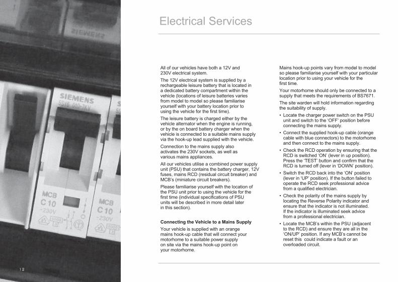
All of our vehicles have both a 12V and 230V electrical system.The 12V electrical system is supplied by a rechargeable leisure battery that is located in a dedicated battery compartment within the vehicle (locations of leisure batteries varies from model to model so please familiarise yourself with your battery location prior to using the vehicle for the first time).The leisure battery is charged either by the vehicle alternator when the engine is running, or by the on board battery charger when the vehicle is connected to a suitable mains supply via the hook-up lead supplied with the vehicle.Connection to the mains supply also activates the 230V sockets, as well as various mains appliances.All our vehicles utilise a combined power supply unit (PSU) that contains the battery charger, 12V fuses, mains RCD (residual circuit breaker) and MCB’s (miniature circuit breakers).Please familiarise yourself with the location of the PSU unit prior to using the vehicle for the first time (individual specifications of PSU units will be described in more detail later in this section).
Connecting the Vehicle to a Mains SupplyYour vehicle is supplied with an orange mains hook-up cable that will connect your motorhome to a suitable power supply on site via the mains hook-up point on your motorhome.
Mains hook-up points vary from model to model so please familiarise yourself with your particular location prior to using your vehicle for the first time.Your motorhome should only be connected to a supply that meets the requirements of BS7671.The site warden will hold information regarding the suitability of supply.• Locate the charger power switch on the PSU unit and switch to the ‘OFF’ position before connecting the mains supply.• Connect the supplied hook-up cable (orange cable with blue connectors) to the motorhome and then connect to the mains supply.• Check the RCD operation by ensuring that the RCD is switched ‘ON’ (lever in up position). Press the ‘TEST’ button and confirm that the RCD is turned off (lever in ‘DOWN’ position). • Switch the RCD back into the ‘ON’ position (lever in ‘UP’ position). If the button failed to operate the RCD seek professional advice from a qualified electrician.• Check the polarity of the mains supply by locating the Reverse Polarity indicator and ensure that the indicator is not illuminated. If the indicator is illuminated seek advice from a professional electrician.• Locate the MCB’s within the PSU (adjacent to the RCD) and ensure they are all in the ‘ON/UP’ position. If any MCB’s cannot be reset this could indicate a fault or an overloaded circuit.

13
• Locate the power switch on the PSU and turn to the ‘ON’ position. The switch will illuminate when turned on.It is now safe to check the operation of the 12V and 230V equipment.
Overseas ConnectionsConnection to mains voltage overseas requires particular attention. Electricity supplies abroad may be of reverse polarity. The significance of this is that when an appliance is switched off, it may not be electrically isolated.It is useful to check the polarity of the supply so that the connection can be made neutral to neutral and live to live as recommended. Your vehicle, however, is fitted with a double pole circuit breaker. Check that all motorhome equipment is set to accept the site supply prior to switching it on.
Please note that if too many appliances are in operation at one time, the MCB may trip. This is a safety measure. On some sites, the power is not sufficient to power all appliances. If in doubt, consult the site manager or warden. When replacing 12V fuses always with a fuse of the correct value. NEVER replace with a higher value / rating as this could damage the wiring harness.
Wiring of connecting cable and motorhome mains inlet:Pitch outlet supply Cable plug
Cable coupler Motorhome mains inlet
The cable plug is connected to the cable coupler by a 2.5mm flexible 3-core cable.
Warning:It is essential that connections are made exactly as shown. If the terminal markings are not in accordance with the diagram, they must be ignored. If in doubt, consult a qualified electrician.
GeneratorsIf a generator is fitted, the vehicle must be regularly serviced to achieve the optimum performance. Engine speed is used to govern the output and frequency of the unit in kW and Hz, and if this is allowed to vary beyond a safe level, permanent damage could be caused to certain electronic equipment such as 12V chargers etc.
IMPORTANTPeriodically, preferably not less than once a year, the motorhome electrical installation should be inspected and tested. A report on the condition should be obtained as described in the Regulations for Electrical Installations, published by the Institute of Electrical Engineers. It is important that the main switch at the site point should be switched off, the supply flexible cable disconnected and any cover replaced on the socket outlet at the site supply point. It is dangerous to leave the supply flexible cable connected.If a fault should develop with your electrical system that is not described in the ‘fault table’ and your supplying dealer cannot resolve the problem, Sargent Electrical Systems operate a telephone help line that is available during normal office hours.Tel: 01482 678981
Flexible Wiring Fixed WiringBrown Live RedBlue Neutral Black
Green/Yellow Earth Green/Yellow
Electrical Services
14
Leisure Battery / EC176 Power Supply Unit
Leisure BatteryYour vehicle is equipped with a rechargeable leisure battery that is located in a dedicated battery compartment within your vehicle.Locations of leisure batteries vary from model to model, so please familiarise yourself with your battery location before using your vehicle for the first time. The battery is charged via the on board charging unit when the vehicle is plugged into a mains supply, or via the vehicle alternator whilst your motorhome is being driven.
Connecting and Disconnecting the BatteryPlease ensure that all cigarettes are extinguished before working in the auxiliary battery compartment.Switch off all appliances and lamps before disconnecting the leisure battery.• Release the battery securing bolts or securing straps from the leisure battery.• Carefully remove the battery from the battery compartment (please take care – the leisure battery is extremely heavy).• Release the battery terminals using a suitably sized spanner.To refit the battery, simply reverse the above procedure. Please ensure the battery is located safely and securely before driving your motorhome.Any replacement auxiliary battery shall be of the same type and specification as that originally fitted by the manufacturer.
EC176 (Power Supply Unit)OverviewThe EC176 Power Supply Unit incorporates a battery charger that supplies 12V DC power to run the leisure equipment and supplies the leisure battery. It also houses the 12V DC fuses that protect the various 12V circuits, and the 230V RCD and MCB’s that protect the various mains circuits.
Features of the PSURESIDUAL CURRENT DEVICE (R.C.D.) & MINIATURE CIRCUIT BREAKERS (M.C.B.)The Residual Current Device is provided to protect the user from a potentially lethal electric shock. The RCD will turn off (trip) if a fault occurs on the system. To ensure the RCD is working correctly, the test button should be operated each time the vehicle is connected to the mains supply.The Miniature circuit breakers (MCB’s) operate in a similar way to traditional fuses and are provided to protect the wiring from an overload or short circuit. If an overload occurs the MCB will switch off the supply. If this occurs the cause of the fault should be investigated before switching the MCB back on. Details of the MCB ratings and the circuits they protect are detailed in your Tribute handbook and information wallet supplied with your vehicle.
15
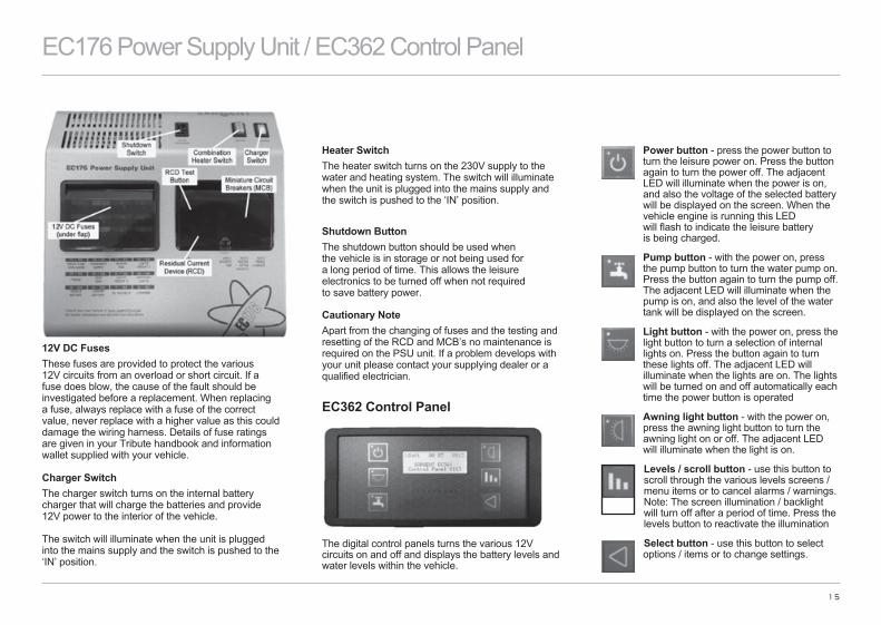
12V DC FusesThese fuses are provided to protect the various 12V circuits from an overload or short circuit. If a fuse does blow, the cause of the fault should be investigated before a replacement. When replacing a fuse, always replace with a fuse of the correct value, never replace with a higher value as this could damage the wiring harness. Details of fuse ratings are given in your Tribute handbook and information wallet supplied with your vehicle.
Charger SwitchThe charger switch turns on the internal battery charger that will charge the batteries and provide 12V power to the interior of the vehicle. The switch will illuminate when the unit is plugged into the mains supply and the switch is pushed to the ‘IN’ position.
Heater SwitchThe heater switch turns on the 230V supply to the water and heating system. The switch will illuminate when the unit is plugged into the mains supply and the switch is pushed to the ‘IN’ position.
Shutdown ButtonThe shutdown button should be used when the vehicle is in storage or not being used for a long period of time. This allows the leisure electronics to be turned off when not required to save battery power.
Cautionary NoteApart from the changing of fuses and the testing and resetting of the RCD and MCB’s no maintenance is required on the PSU unit. If a problem develops with your unit please contact your supplying dealer or a qualified electrician.
EC362 Control Panel
The digital control panels turns the various 12V circuits on and off and displays the battery levels and water levels within the vehicle.
Power button - press the power button to turn the leisure power on. Press the button again to turn the power off. The adjacent LED will illuminate when the power is on, and also the voltage of the selected battery will be displayed on the screen. When the vehicle engine is running this LED will flash to indicate the leisure battery is being charged.
Pump button - with the power on, press the pump button to turn the water pump on. Press the button again to turn the pump off. The adjacent LED will illuminate when the pump is on, and also the level of the water tank will be displayed on the screen.
Light button - with the power on, press the light button to turn a selection of internal lights on. Press the button again to turn these lights off. The adjacent LED will illuminate when the lights are on. The lights will be turned on and off automatically each time the power button is operated
Awning light button - with the power on, press the awning light button to turn the awning light on or off. The adjacent LED will illuminate when the light is on.
Levels / scroll button - use this button to scroll through the various levels screens / menu items or to cancel alarms / warnings. Note: The screen illumination / backlight will turn off after a period of time. Press the levels button to reactivate the illumination
Select button - use this button to select options / items or to change settings.
EC176 Power Supply Unit / EC362 Control Panel

Dometic RM8401 Refrigerator
(1) Power ON/OFF switch(2) Energy selector switch button 230V AC(3) Energy selector switch button GAS(4) Energy selector switch button 12V DC(6) Temperature level selection(7) Temperature level display(8) Indicator LED failure/reset button GAS FAILURE
Switching ON/OFFSwitch ON by pressing button (1) for 2 seconds
Switch OFF by pressing button (1) for 2 seconds
230V AC OperationSelect ‘mains voltage’ by pressing button (2)
Set temperature set by pressing button (6)
12V DC Operation (vehicle battery)Select ‘battery voltage’ by pressing button (4)
Set temperature step by pressing button (6)
Gas Operation
Select GAS by pressing button (3)
Set temperature step by pressing button (6)
Electrical OperationTo start the refrigerator press button (1) for 2 seconds. The refrigerator will start with the last selected power source.
12V operation press button (4)
230V operation press button (2)
16
Dometic RM8401 Refrigerator
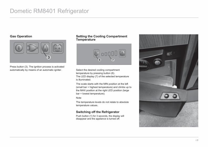
Gas Operation
Press button (3). The ignition process is activated automatically by means of an automatic igniter.
Setting the Cooling Compartment Temperature
Select the desired cooling compartment temperature by pressing button (6). The LED display (7) of the selected temperature is illuminated.
The scale starts with the MIN position at the left (small bar = highest temperature) and climbs up to the MAX position at the right LED position (large bar = lowest temperature).
Note
The temperature levels do not relate to absolute temperature values.
Switching off the RefrigeratorPush button (1) for 3 seconds, the display will disappear and the appliance is turned off.
17
Dometic RM8401 Refrigerator

Dometic RM8501 Refrigerator
18
Dometic 8501 Refrigerator
1) Manual energy selector2) Temperature controller3) Battery igniter (gas)4) Flame indicator (galvanometer)
Electrical Operation
Switch on the appliance by turning the energy selection switch (1) to:
230V operation12V operation
Gas Operation
Dometic RM8501 Refrigerator
19
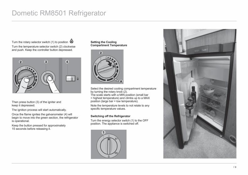
Turn the rotary selector switch (1) to position Turn the temperature selector switch (2) clockwise and push. Keep the controller button depressed.
Then press button (3) of the igniter and keep it depressed. The ignition process will start automatically. Once the flame ignites the galvanometer (4) will begin to move into the green section, the refrigerator is operational. Keep the button pressed for approximately 15 seconds before releasing it.
Setting the Cooling Compartment Temperature
Select the desired cooling compartment temperature by turning the rotary knob (2). The scale starts with a MIN position (small bar = highest temperature) and climbs up to a MAX position (large bar = low temperature).Note the temperature levels to not relate to any specific temperature values. Switching off the RefrigeratorTurn the energy selector switch (1) to the OFF position. The appliance is switched off.

Truma Combi 4E / Truma Combi 6EThe Combi E Gas Heater is a warm air heater with an integrated hot water boiler. The unit can operate on liquid gas (LPG) or 230V mains electricity. The heater can be used in ‘winter’ mode that will produce warm air heating and hot water, and ‘summer’ mode that will produce hot water only.Before operating the heater for the first time ensure that the 12V system is turned ‘ON’ on the control panel over the doorway, and that the gas cylinder, and isolation valve are turned on. To use the heater on 230V the motorhome must be plugged into the mains supply, with the isolation switch in the ‘ON’ position.
TRUMA CP PLUS CONTROL PANEL1 = Display2 = Status line3 = Menu line (above)4 = Menu line (below)5 = Display of mains voltage 230 V (shore power)6 = Display timer7 = Settings / values8 = Control knob / pushThe control knob / push button (8) is used to select menus in the lines (3 + 4) and configure the settings. These are shown via a display (1) with a lighted background. Pressing the back button (9) takes the user back out of the menu again.Control Knob/Push ButtonThe control knob / push button (8) is used to select and change set values and parameters; these can be saved by clicking the control knob / push button. Selected menu items will flash.
20
Truma Combi 4E / 6E
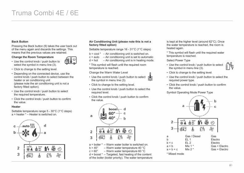
Back ButtonPressing the Back button (9) takes the user back out of the menu again and discards the settings. This means that the previous values are retained.Change the Room Temperature• Use the control knob / push button to
select the symbol in menu line (3).• Click to change to the setting level.• Depending on the connected device, use the
control knob / push button to select between the heater or air conditioning unit (please note the air conditioning unit is not a factory fitted option).
• Use the control knob / push button to select the required temperature.
• Click the control knob / push button to confirm the value.
HeaterSettable temperature range 5 - 30°C (1°C steps) a = heater * – Heater is switched on.
Air Conditioning Unit (please note this is not a factory fitted option)Settable temperature range 16 - 31°C (1°C steps)b = cool * – Air conditioning unit is switched on. c = auto – Air conditioning unit is set to automatic d = hot – Air conditioning unit is in heating mode.* This symbol will flash until the required room temperature is reached.Change the Warm Water Level• Use the control knob / push button to select
the symbol in menu line (3).• Click to change to the setting level.• Use the control knob / push button to select the
required level.• Click the control knob / push button to confirm
the value.
a = boiler * – Warm water boiler is switched on. b = 40° – Warm water temperature 40 °C c = 60° – Warm water temperature 60 °C d = boost * – Targeted, fast heating of the content of the boiler (boiler priority). The water temperature
is kept at the higher level (around 62°C). Once the water temperature is reached, the room is heated again.* This symbol will flash until the required water temperature is reached.Select Power Type• Use the control knob / push button to select
the symbol in menu line (3).• Click to change to the setting level.• Use the control knob / push button to select the
required power type.• Click the control knob / push button to confirm
the value.Symbol Operating Mode Power Type
a Gas / Diesel Gas b EL 1 Electro b + c EL 2 Electro a + b Mix 1 * Gas + Electro a + b + c Mix 2 * Gas + Electro* Mixed mode
21
Truma Combi 4E / 6E
22
Truma Combi 4E / 6E
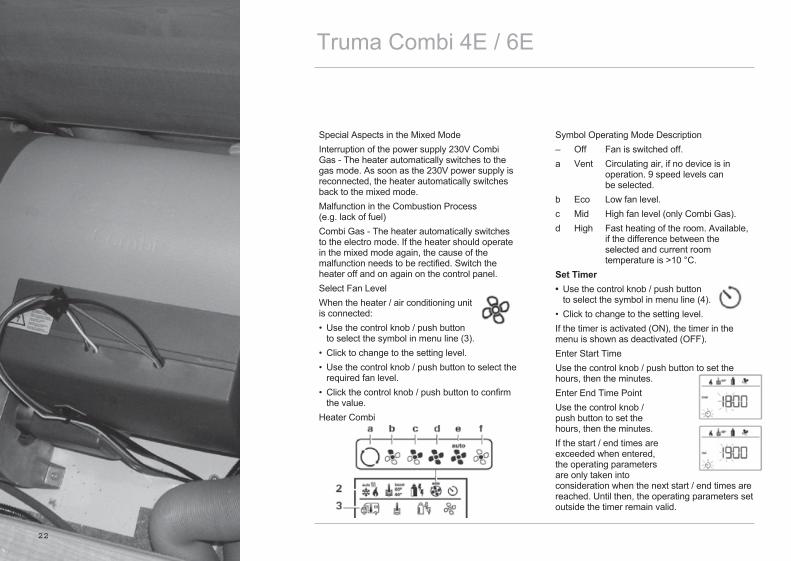
Special Aspects in the Mixed ModeInterruption of the power supply 230V Combi Gas - The heater automatically switches to the gas mode. As soon as the 230V power supply is reconnected, the heater automatically switches back to the mixed mode.Malfunction in the Combustion Process (e.g. lack of fuel)Combi Gas - The heater automatically switches to the electro mode. If the heater should operate in the mixed mode again, the cause of the malfunction needs to be rectified. Switch the heater off and on again on the control panel.Select Fan LevelWhen the heater / air conditioning unit is connected:• Use the control knob / push button
to select the symbol in menu line (3).• Click to change to the setting level.• Use the control knob / push button to select the
required fan level.• Click the control knob / push button to confirm
the value.Heater Combi
Symbol Operating Mode Description– Off Fan is switched off.a Vent Circulating air, if no device is in operation. 9 speed levels can be selected.b Eco Low fan level.c Mid High fan level (only Combi Gas).d High Fast heating of the room. Available, if the difference between the selected and current room temperature is >10 °C.Set Timer• Use the control knob / push button
to select the symbol in menu line (4).• Click to change to the setting level.If the timer is activated (ON), the timer in the menu is shown as deactivated (OFF).Enter Start TimeUse the control knob / push button to set the hours, then the minutes.Enter End Time PointUse the control knob / push button to set the hours, then the minutes.If the start / end times are exceeded when entered, the operating parameters are only taken into consideration when the next start / end times are reached. Until then, the operating parameters set outside the timer remain valid.
23
Truma Combi 4E / 6E
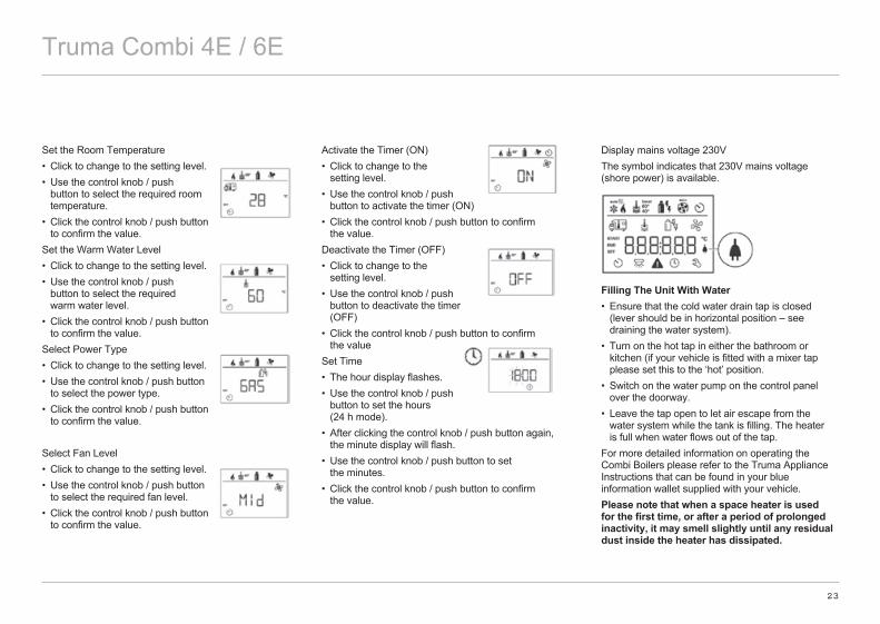
Set the Room Temperature• Click to change to the setting level.• Use the control knob / push
button to select the required room temperature.
• Click the control knob / push button to confirm the value.
Set the Warm Water Level• Click to change to the setting level.• Use the control knob / push
button to select the required warm water level.
• Click the control knob / push button to confirm the value.
Select Power Type• Click to change to the setting level.• Use the control knob / push button
to select the power type.• Click the control knob / push button
to confirm the value.
Select Fan Level• Click to change to the setting level.• Use the control knob / push button
to select the required fan level.• Click the control knob / push button
to confirm the value.
Activate the Timer (ON)• Click to change to the
setting level.• Use the control knob / push
button to activate the timer (ON)• Click the control knob / push button to confirm
the value.Deactivate the Timer (OFF)• Click to change to the
setting level.• Use the control knob / push
button to deactivate the timer (OFF)
• Click the control knob / push button to confirm the value
Set Time• The hour display flashes.• Use the control knob / push
button to set the hours (24 h mode).
• After clicking the control knob / push button again, the minute display will flash.
• Use the control knob / push button to set the minutes.
• Click the control knob / push button to confirm the value.
Display mains voltage 230VThe symbol indicates that 230V mains voltage (shore power) is available.
Filling The Unit With Water• Ensure that the cold water drain tap is closed
(lever should be in horizontal position – see draining the water system).
• Turn on the hot tap in either the bathroom or kitchen (if your vehicle is fitted with a mixer tap please set this to the ‘hot’ position.
• Switch on the water pump on the control panel over the doorway.
• Leave the tap open to let air escape from the water system while the tank is filling. The heater is full when water flows out of the tap.
For more detailed information on operating the Combi Boilers please refer to the Truma Appliance Instructions that can be found in your blue information wallet supplied with your vehicle.Please note that when a space heater is used for the first time, or after a period of prolonged inactivity, it may smell slightly until any residual dust inside the heater has dissipated.
Entertainment System / Skylights
24
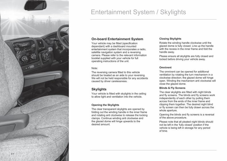
On-board Entertainment SystemYour vehicle may be fitted (specification dependant) with a dashboard mounted entertainment system that incorporates a radio, satellite navigation system and a reversing camera. Please refer to the relevant information booklet supplied with your vehicle for full operating instructions of the unit.
Note:The reversing camera fitted to this vehicle should be treated as an aide to your reversing. We will not be held responsible for any accidents caused by driver carelessness.
SkylightsYour vehicle is fitted with skylights in the ceiling to allow light and ventilation into the vehicle.
Opening the SkylightsThe clear transparent skylights are opened by folding out the winding handle in the inner frame and rotating anti clockwise to release the locking clamps. Continue winding anti clockwise and the glazed dome will hinge upwards to the desired amount.
Closing SkylightsRotate the winding handle clockwise until the glazed dome is fully closed. Line up the handle with the recess in the inner frame and fold the handle away.Please ensure all skylights are fully closed and locked before driving your vehicle away.
OmniventThe omnivent can be opened for additional ventilation by rotating the turn mechanism in a clockwise direction; the glazed dome will hinge open. Winding the mechanism anti clockwise will close the glazed dome.Blinds & Fly ScreensThe clear skylights are fitted with night blinds and fly screens. The blinds and fly screens work independently of each other by pulling them across from the ends of the inner frame and clipping them together. The desired night blind or fly screen can then be fully drawn across the whole aperture.Opening the blinds and fly screens is a reversal of the above procedure.Please note that all pleated night blinds should not be left in the ‘fully closed’ position if the vehicle is being left in storage for any period of time.
25
Water ServicesFresh Water TankYour vehicle has an on board fresh water tank that allows you to carry fresh water with you on your journey. This tank supplies all of the water systems inside your vehicle. The volume of the fresh water tank will vary depending on which model you have chosen. Water is pumped from the on board tank by a self priming and cancelling automatic pump throughout the vehicle.The pump is fitted with an in-line filter to ensure trouble free running. This must be cleaned periodically to ensure that there is no reduction in flow.The pump automatically pressurises the water system to a pre-determined water pressure, when a tap is opened water flows from it and the pump switches on to maintain the pre-determined pressure.When the tap is switched off the pump will continue running until the correct pressure in the system is reached, it will then shut down.The pump circuit is controlled by the isolation switch on the control panel. Always switch off the pump at the control panel when leaving the vehicle.
Please note that if the pump runs on for more than 5-10 seconds after you have closed all the taps, it is possible that there could be a leak in the system. This should be checked immediately.
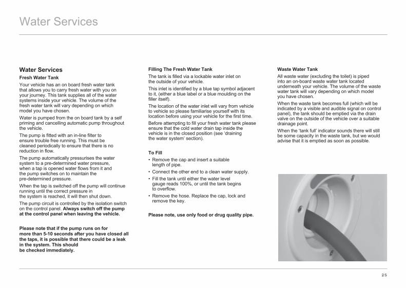
Filling The Fresh Water TankThe tank is filled via a lockable water inlet on the outside of your vehicle.This inlet is identified by a blue tap symbol adjacent to it, (either a blue label or a blue moulding on the filler itself).The location of the water inlet will vary from vehicle to vehicle so please familiarise yourself with its location before using your vehicle for the first time.Before attempting to fill your fresh water tank please ensure that the cold water drain tap inside the vehicle is in the closed position (see ‘draining the water system’ section).
To Fill• Remove the cap and insert a suitable
length of pipe.• Connect the other end to a clean water supply.• Fill the tank until either the water level gauge reads 100%, or until the tank begins to overflow.• Remove the hose. Replace the cap, lock and remove the key.
Please note, use only food or drug quality pipe.
Waste Water TankAll waste water (excluding the toilet) is piped into an on-board waste water tank located underneath your vehicle. The volume of the waste water tank will vary depending on which model you have chosen.When the waste tank becomes full (which will be indicated by a visible and audible signal on control panel), the tank should be emptied via the drain valve on the outside of the vehicle over a suitable drainage point.When the ‘tank full’ indicator sounds there will still be some capacity in the waste tank, but we would advise that it is emptied as soon as possible.
Water Services
26
Thetford Cassette Toilet
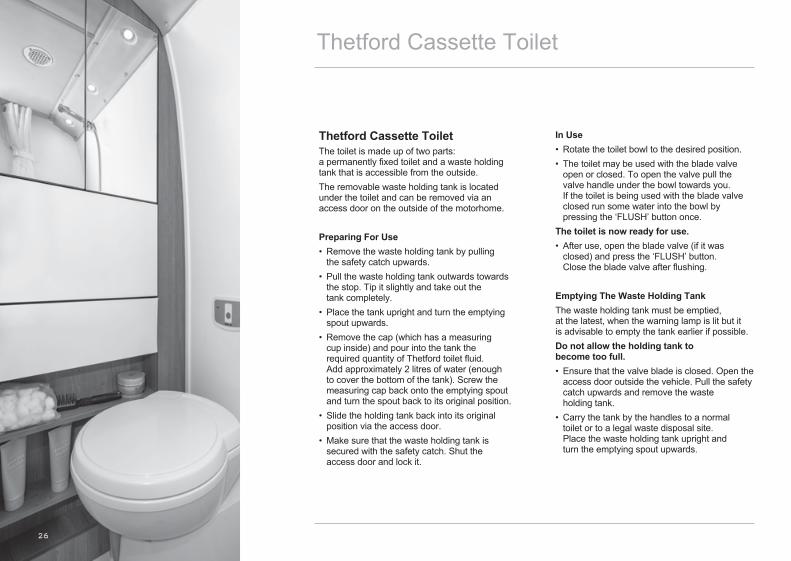
Thetford Cassette ToiletThe toilet is made up of two parts: a permanently fixed toilet and a waste holding tank that is accessible from the outside.The removable waste holding tank is located under the toilet and can be removed via an access door on the outside of the motorhome.
Preparing For Use• Remove the waste holding tank by pulling the safety catch upwards.• Pull the waste holding tank outwards towards the stop. Tip it slightly and take out the tank completely.• Place the tank upright and turn the emptying spout upwards.• Remove the cap (which has a measuring cup inside) and pour into the tank the required quantity of Thetford toilet fluid. Add approximately 2 litres of water (enough to cover the bottom of the tank). Screw the measuring cap back onto the emptying spout and turn the spout back to its original position.• Slide the holding tank back into its original position via the access door.• Make sure that the waste holding tank is secured with the safety catch. Shut the access door and lock it.
In Use• Rotate the toilet bowl to the desired position.• The toilet may be used with the blade valve open or closed. To open the valve pull the valve handle under the bowl towards you. If the toilet is being used with the blade valve closed run some water into the bowl by pressing the ‘FLUSH’ button once.The toilet is now ready for use.• After use, open the blade valve (if it was closed) and press the ‘FLUSH’ button. Close the blade valve after flushing.
Emptying The Waste Holding TankThe waste holding tank must be emptied, at the latest, when the warning lamp is lit but it is advisable to empty the tank earlier if possible.Do not allow the holding tank to become too full.• Ensure that the valve blade is closed. Open the access door outside the vehicle. Pull the safety catch upwards and remove the waste holding tank.• Carry the tank by the handles to a normal toilet or to a legal waste disposal site. Place the waste holding tank upright and turn the emptying spout upwards.

27
• Remove the emptying spout cap. Hold the waste holding tank by the upper handle nearest to the emptying spout. Hold the rear handle with your other hand so that you can operate the vent plunger with your thumb. Keep the vent plunger pressed to ensure that the tank is emptied without splashing.
Please note that the vent plunger should only be pressed when the emptying spout is pointing downwards.After emptying, flush the tank and clean the blade valve thoroughly with water. Replace the spout cap and slide the waste holding tank back into the toilet and close the door.
Windows & BlindsYour vehicle is fitted with side windows to provide light and ventilation to your vehicle. The number of windows fitted will depend on the particular model that you have chosen.
All windows fitted to the habitation area of your motorhome are of acrylic construction and open either by means of a top hinge or a slide, depending on the location in the vehicle.Top hung windows are opened by rotating the two catches 90o to release from the locking plate, the window will then hinge outwards on the top hinge. The window can be held in the open position by means of the locking collar on the telescopic arm. Sliding windows are opened by releasing the retaining catch and sliding the window in its track.Please ensure all windows are fully closed and locked before driving your vehicle away.
Window BlindsThe habitation widows are fitted with spring loaded night blinds and fly screens. The fly screens pull down from the top of the blind, the night blinds pull up from the bottom. Always ensure that the blinds are in the fully open position before driving your vehicle.
Windows & Blinds
28
Ventilation & Security
Awning Space LPG Appliance ExhaustNo danger is caused if the LPG exhaust from the refrigerator vents into an enclosed awning.If totally enclosed, space heaters may produce enough exhaust fumes to pollute an enclosed awning to levels of discomfort.In extreme cases carbon monoxide could build up to reach dangerous levels. You are advised to allow some additional ventilation when such appliances are in use.
VentilationLow level ventilation is provided via cut out in the furniture. High level ventilation is provided by sky lights located in the roof of your vehicle.All ventilation complies with European Standards and vents should not be obstructed in any way as this could lead to insufficient fresh air.If this occurs then the confined atmosphere can become deficient in oxygen which can lead to a build up of the highly dangerous gas carbon monoxide (Co). Carbon monoxide is colourless, odourless and tasteless and if allowed to build up will rapidly cause unconsciousness, and even death.There is no danger providing all ventilation is not blocked in any way and all meshes are regularly cleaned using a vacuum cleaner.
Roof Mounted Flue InstallationsAll flue installations should be inspected for corrosion once a year throughout their length. If any sign of perforation is detected, the flue should be replaced. Ensure the replacement flue is of the correct type and that it is installed by an approved engineer.
Combustible MaterialsCare should be taken when storing any combustible materials near any source of heat (e.g. space heater) as these surfaces can become very hot during use and any guards or grills may not give full protection, particularly to the young or elderly.
Portable HeatersNever use portable cooking or heating appliances other than electric heaters that are not of the direct radiant type, to heat your vehicle as it can be a fire and asphyxiation hazard.Under no circumstances should a cooking appliance be used for heating the vehicle.
Warning Notice: Portable or open flame heating equipment should not be used. If you have such equipment on board, consider very carefully whether the risks are worth it.Please note that internal socket outlets should only be used with dedicated appliances.No appliance should be used outside the motorhome whilst connected to an internal socket.
29
Ventilation & Security
Fire And Safety PrecautionsIn Case Of FirePlease read all warning notices inside your motorhome advising you on fire prevention, ventilation and what to do in the event of a fire.If a fire should develop in your vehicle please observe the following;• Get everybody out of the motorhome as quickly as possible.• Call the fire brigade.• Turn off the gas bottle isolation valve if safe
to do so. • If possible and safe to do so, remove the gas cylinders and place some distance away from the vehicle.• If it is an electrical fire, always turn off the supply as quickly as possible.• Only tackle the fire only if you deem it safe to do so.
Fire ExtinguisherYour vehicle is fitted with a fire extinguisher for use in the event of an emergency.The location of the fire extinguisher will vary from model to model so it is important that you familiarise yourself with its location before using your vehicle for the first time.Please refer to the instructions printed on the actual extinguisher for guidance as to the correct use of the unit, and the maintenance schedule that should be adhered to.Please ensure that you are confident as to the location and operation of the fire extinguisher before using the vehicle for the first time.
Smoke DetectorsYour vehicle is fitted with a battery operated smoke alarm that will emit a loud pulsating tone should smoke be detected in your vehicle.
Operating The Smoke AlarmOnce the battery is connected a small indicator light (LED) positioned near the test button should flash approximately once every minute. This indicates that the alarm is operating normally.
Testing Your Smoke AlarmIt is recommended that you test your smoke alarm once a week to ensure the detector is working correctly.• Push and hold the ‘TEST’ button for approximately 3 seconds.• A loud pulsating alarm should sound to indicate the detector is functioning correctly. • During the alarm test the LED indicator will flash quickly.
Maintaining Your Smoke AlarmIf the smoke alarm emits a short beep once a minute the battery is at the end of its life and should be replaced immediately, this low voltage warning will sound for approximately 7 days. We would always recommend that the battery is replaced at least every 12 months to ensure correct operation. If the LED indicator does not flash every minute then the battery should be replaced immediately as this will indicate that the battery is completely flat.
Clean your smoke alarm regularly to prevent dust build up. This can be done using a vacuum cleaner with a brush attachment.
Carbon Monoxide AlarmIf your vehicle is fitted with a battery operated carbon monoxide detector it will detect carbon monoxide in your motorhome if it should rise to dangerous levels and sound the alarm.
Operating the Carbon Monoxide AlarmOnce the batteries are connected small power indicator light will flash green once a minute to indicate that the unit is receiving power from the batteries and is operational.
Testing the Sounder, Batteries and CircuitryTest the sounder, batteries and circuitry by pressing and holding the test / rest button for 1 second to confirm that the detector is operating properly. The sounder should sound as soon as the button is pressed, and the alarm LED will illuminate red, indicating that the sounder is working and the batteries are providing power to the unit. This test for the sounder, and batteries should be performed weekly.
30
Habitation Door
Maintaining your Detector• Test the sounder, batteries and circuitry of
your detector once per week by pressing and holding the test / reset button for one second.
• Keep the detector free from dust by gently vacuuming with a soft brush
• We would recommend that you change the batteries in your detector at least every 12 months to ensure correct operation. The unit continually checks the settings of its sensor and circuitry. If any of these settings are found to be incorrect or if the batteries have become low then the detector will emit a single audible chirp once per minute for up to 30 days. Important: This does not mean that the detector has detected carbon monoxide.
Note: The sensor used in the detector has a lifetime of seven years after activation. After this seven year period the entire unit should be replaced with a similar model.
Escape PathsIt is important that you do not block any escape paths or emergency exits with any obstructions that could hinder your escape in an emergency. Please familiarise yourself with the designated emergency exits in your vehicle before using it for the first time.
Children & PetsDo not leave children or pets in an unattended motorhome as they could be exposed to hazards that could cause an accident.
SecurityWe have tried to go further than any other motorhome manufacturer to protect your investment. make it difficult for the thieves by protecting your motorhome and its contents. Always lock all doors and windows when leaving your vehicle, even if it is left for a short period of time.
Motorhome TheftThe theft of a motorhome can occur in the most unlikely circumstances; from a motorway service area, or even from an owners’ drive.
Make sure all windows and doors are secured even if only leaving the vehicle for a short time and we would advise that you do not leave valuables in easily visible positions inside the vehicle.
31
Entrance Step
Locking / Unlocking With Either The Cab Key Or Habitation KeyLocking or unlocking the drivers’ door will only lock or unlock the driver and passenger door, it will not lock or unlock the sliding door. This must be locked or unlocked independently using either the key or key fob.Locking or unlocking the habitation door with the key will only lock or unlock the sliding door, the cab doors must be unlocked independently with either they key or key fob.
Sliding Door StopThe sliding door may be fitted with a halfway stop that allows this door to be half closed when the habitation area is in use. Releasing the sliding door handle in the normal way will release the door from this ‘half closed’ position.Please note that if you slam the door from the fully ‘open’ position is will automatically stop at the ‘halfway’ position until the handle is released again.
Entrance StepYour vehicle may be fitted with an electric entrance step that is designed to assist you when entering and exiting your motorhome.The step can be operated automatically with the central locking system, or manually via a button located next to the habitation entrance door.The step will automatically fold away when the engine starts to minimise the risk of injury when the vehicle is in motion.
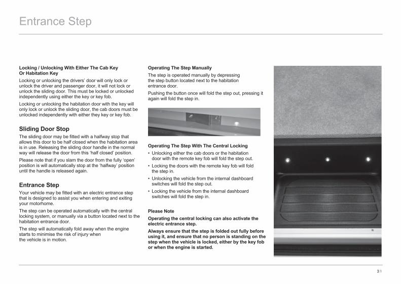
Operating The Step ManuallyThe step is operated manually by depressing the step button located next to the habitation entrance door.Pushing the button once will fold the step out, pressing it again will fold the step in.
Operating The Step With The Central Locking• Unlocking either the cab doors or the habitation door with the remote key fob will fold the step out.• Locking the doors with the remote key fob will fold the step in.• Unlocking the vehicle from the internal dashboard switches will fold the step out.• Locking the vehicle from the internal dashboard switches will fold the step in.
Please NoteOperating the central locking can also activate the electric entrance step.Always ensure that the step is folded out fully before using it, and ensure that no person is standing on the step when the vehicle is locked, either by the key fob or when the engine is started.

32
Wind Out Awning
Wind Out Awning (if fitted)Your vehicle may be fitted with a wind out awning which, when extended, will provide a shaded area next to your motorhome.
OperationWinding Out The Awning• Locate the winding handle into the socket on the left hand side of the awning.• Turn the winding handle clockwise – the awning will start to open after approximately two turns.• Continue winding. When the awning has extended to approximately 1 metre stop winding and lower the supporting legs from the awning and adjust the length of the legs until they come into contact with the ground.• Continue unrolling the blind until it is fully extended.• Adjust the height / position of the supporting legs to ensure that the blind fabric is taught and allowing water to run off in the event of rain – remove the winding handle.• We would recommend that the support legs are pegged into the ground.
Winding In The Awning• Remove the central support rafter if fitted.• Insert the winding handle into the socket and turn anti clockwise – the awning will start to retract (the legs, if pegged into the ground, should be released).• When the awing is retracted to within 1 metre of the vehicle the supporting legs can be folded back into the awning facia.• Continue winding anti clockwise until the awning snaps back fully into the awning box – continue winding slowly until the handle stops as this engages the locking mechanism of the awning.• Remove the winding handle.
Please note that the awning is designed to be a sun shade and not as rain protection. The awning should be closed in the likelihood of high winds, storm, snow or heavy rain

33
Central Locking
A
AB C
Central LockingYour vehicle is fitted with a central locking system that links the locking of the rear habitation door to the base vehicle cab doors.The central locking can be activated by either the remote key fob, the locking switches on the dashboard (base vehicle dependant) or manually by the key.
Locking / Unlocking With The Remote Key-FobThe Fiat key has three buttons that lock and unlock the various entrance doors on the vehicle.
• Pressing button ‘A’ will unlock the base vehicle cab doors only.• Pressing button ‘B’ will lock both the base vehicle cab doors and the rear habitation door.• Pressing button ‘C’ will unlock the rear sliding doors only. Please note that the base vehicle cab doors will give an audible click, but will not unlock.
Locking / Unlocking With The Dashboard SwitchesWhen inside the vehicle the entrance doors can be locked or unlocked via the two switches on the Fiat dashboard.• Pressing button ‘A’ will lock all entrance doors (and the
LED will illuminate).• Pressing button ‘A’ again will unlock all entrance doors
(LED will go out).

General Care
Motorhome ExteriorTo maintain this showroom finish, wash the motorhome regularly with a mild detergent, rinse off with cold water and leather off. A good quality car wax may be applied which will make washing even easier in the future.Abrasive cleaning agents must never be used to clean the exterior of your motorhome.Within the first twelve months cracks and blisters may appear in the surface of the moulded GRP components. These are cosmetic only and have no effect on the vehicle structure. These components can be readily repaired using the correct procedure (please refer this to your supplying dealer).Please note that it is not safe to walk on the roof of your motorhome.Please refer to the relevant section of your base vehicle handbook for advice on preserving the painted metal panels of your motorhome.
Care Of Windows• Day to Day Cleaning – please wash windows carefully, as you would with paintwork on your car. Do not scrub windows prior to removing surface dirt and film with a hose – any trapped dirt could cause scratching. When all the excess dirt has been removed, wash with a solution of warm water and a small amount of washing up liquid, windows can then be dried off with a window leather.• Small Scratches – can be removed using a liquid metal polish or a commercial acrylic polish, available from most good accessory shops. The type of polish used should depend on the severity of the scratch; a more abrasive substance is needed for deeper scratches, for example.
Any process of scratch removal should be finished with the finest grade of polish to ‘buff’ the area(s) concerned.
• Catches and Stays – all the Polyplastic ranges of window fittings do not require any special attention or lubrication.
On a day to day level, please be careful not to over-tighten the thumbscrews on window stays.
34
35
Care Of Windows cont.It is a popular misconception that acrylic motorhome windows are vacuum sealed, this is not so. The windows in a motorhome can, as with domestic glazing, be susceptible to temporary condensation if the temperature difference between inside and outside changes quickly and / or dramatically i.e. if a cold motorhome is heated quickly using the heater or by the sun.These drastic changes of temperature and the moisture in the air both contribute towards the temporary condensation that will normally disappear as quickly as it appears.This whole phenomenon is purely related to ambient temperature changes of the motorhome compared to the window cavities. Notes on Internal CondensationCondensation occurs when warm moist air meets a cold surface. The risk of condensation therefore depends upon how moist the air is and how cold the internal surfaces of the vehicle are.
Condensation is normally more noticeable during the winter months as the motorhome is cold and because skylights, windows and doors are opened less meaning that the moist internal air cannot escape.
How to try to minimise the likelihood of condensation occurringTo try to minimise the risk of condensation occurring it is important to try to maintain some level of ventilation. Your vehicle complies with EN721: 1988 which states the minimum requirements for high and low level
ventilation, it is very important that these are not blocked or reduced in any way.
Try to provide reasonable heating.If possible use the electric element of the space heater when washing, cooking or drying damp clothes, particularly if the windows show signs of misting up.
Try to make sure all areas are at least partially heated, condensation most often occurs in unheated areas. To prevent condensation the heat has to keep the room surfaces reasonably warm.
It can take a long time for a cold motorhome to warm up so it is better to have a small amount of heat for a long period rather than a lot of heat for a short time. A motorhome that have been left unoccupied of long periods of time can become very cold. Whenever possible it is best to put the heating on at a low level before setting off on a journey in the winter to pre heat the vehicle.
Even in a well insulated motorhome with correct ventilation it is likely during cold weather if the temperature is less than 10oC that condensation will occur. Ideally the temperature should be kept at about 20oC although this is not always possible.
Motorhome Interior Side Walls, Roof Lining and FurnitureA simple wash with a damp cloth and a mild detergent is all that is necessary.
Soft FurnishingsCarpets should be vacuumed occasionally to remove grit and sand. This helps maintain good appearance and ensure long life.
The upholstery can be cleaned with a mild reputable upholstery cleaner.
It is recommended that curtains be dry cleaned.
Cupboard CatchesIt is advisable to lightly oil cupboard catches, sliding bolts and hinges from time to time.
Vanity Unit / Shower CubicleYour vehicle is fitted with a plastic vanity bowl. Do not pour very hot water into it as it is made from a moulded polymer that may deform, always put cold water in first.
Care Of Plastic ComponentsThe cleaning of any plastic components in the vehicle, e.g shower tray, should only be undertaken with mild soapy water. General household cleaning products should not be used as they may cause the plastic to go brittle and crack.
We will not be held responsible for any replacement if it is suspected that this was the case.
Plated FittingsThese should never be cleaned using abrasive cleaners. Clean with a damp cloth and polish with a dry cloth only.
Natural Wood Worktop EdgesShould your vehicle worktop edges show signs of the lacquer breaking down, they should be re-sealed using a proprietary yacht varnish, (or equivalent).
General Care

36
Winter Laying Up
Care should always be taken to ensure your investment is receiving the best attention, particularly prior to going into winter storage. The following tips will be helpful for the periods when your motorhome is not regularly used.It applies if you store in a compound away from home, or in your own drive.
TyresCare should be taken to ensure that your vehicle is not stored with slightly deflated tyres as this could cause damage to the side walls that could lead to an accident when driving at speed.Ideally you should rotate your wheels every couple of weeks to try to eliminate flat spots developing.
Water SystemIt is important that the water system is fully drained off during the winter months to avoid freezing when the motorhome is not in use or after the last trip of the season. Failure to do this could result in serious damage to components.
To Drain Off• Open the drain valve on the fresh water tank to ensure it is fully empty.• Open the drain valve on the waste tank to ensure it is fully empty, (only drain into a suitable container).• Open all taps inside the vehicle and leave open.• Open the drain valve inside the vehicle to empty the water heater and empty the pipe work inside the vehicle.• Allow the vehicle to drain in this way for five minutes, then run the pump to ensure it is free of water.• Empty cassette toilet, (see manufacturers instructions).

37
Soft Furnishings / FurnitureLeave all cupboard doors open to allow the maximum amount of air to circulate around the vehicle.
Window BlindsWindow night blinds should not be left in the ‘closed’ position for long periods as this may affect their folding back into the ‘open’ position.
Bringing Your Vehicle Out Of StorageBefore starting to use your motorhome after a long storage period we would recommend that you have all gas and 230V electrical services checked by a competent person.We would recommend that the water system is flushed through with a sterilising solution prior to the first use of the motorhome.
Winter Laying Up

38
Good Neighbour Guide
Motorhome Owners’ Good Neighbour CodeAt A Camp Site On ArrivalPark as close to the reception area as possible and report your arrival. Do not drive to a pitch and park unless directed by reception staff.
Vehicle Movement Around The SiteAlways keep to the site roads unless directed otherwise. Obey the speed limits, these are generally 10 mph.
Please note that stopping distances on grass are greater than on a normal road. You must have a current valid driving licence to drive a vehicle on site roads. Park where directed on your pitch. Where possible you should leave approximately 6m of free space around your vehicle.
Using Site Appliances• Connect all mains hook-ups correctly and carefully.• Turn off all fresh water taps completely.• Use facilities such as toilets and showers with care and consideration, leaving them in a tidy condition.• Young children should be escorted and supervised.
Disposing Of WasteIf your vehicle is not fitted with a waste water tank, place a suitable container under all waste water outlets.• Do not allow these to overflow.• Make sure you empty the containers at appropriate waste water points. • Empty chemical toilets only where directed.• Avoid damage to sewerage treatment works by using only approved chemicals. Phenols, coal tar or caustic based fluids must never be used under any circumstances.• Solid bulky items such as disposable nappies etc. must not be put into the chemical closet emptying point or site rubbish bins. Wrap them in a polythene bag and place in designated containers.• Household rubbish should be put into the private rubbish collection bins.
Noise PollutionPlease show consideration by thinking how the noise you create will affect those around you.Open and close doors quietly.Control noise made by your children: do not allow them to play with kites, model aircraft, catapults or airguns close to vehicles.Do not allow them to play loud, boisterous ballgames.Keep volume turned down on CD players, personal stereos radios and TVs. Do not play musical instruments so loudly that they will upset your neighbours.

39
If you have a power generator, make sure it is adequately silenced and use it with consideration, especially after dark.
PetsMost site operators do not object to well behaved pets but they should be kept well under control.• No animal should be allowed to run loose on the site.• Leads must be no longer than 3m.• Animals are not allowed in the shower or toilet blocks.• Dogs must not be allowed to foul sites, roads or green areas.• Carry a small spade and a supply of plastic bags in your motorhome in order to clean up any mess made by your dog. It is then possible to dispose of it in an appropriate manner.
Fire PrecautionsRead all fire precaution notices and make sure that you and your family are familiar with the locations of hoses, extinguishers and assembly points.A fire blanket is a good idea for the kitchen.Barbecues should not be used unless permission has been given. If you are allowed to use a barbecue, use it with care and consideration for those around you.Open fires are not allowed on campsites.
Tents and AwningsIt is polite to ask permission before erecting a tent or awning. Permission will normally be granted if the tent is of a recognised standard make and in good condition.If the stay is longer than a day or two the groundsheet and/or side flaps of the awning should be lifted to avoid unsightly patches or damage to the grass.
Leaving the SiteAlways tidy your pitch and make sure you do not leave bags of rubbish lying about. Check out at reception, pay your site fees and thank them for an enjoyable stay.
Wild CampingCamping on a non-licensed site without the permission of the landowner is illegal in the UK.If you do have permission to camp on an unlicensed site, always follow the advice in the code.Pay particular attention to the following points:• Dispose of litter only in receptacles provided for the
purpose. If there are none, put litter in plastic bags and take it away with you to dispose of in an appropriate manner.
• Control the water waste from your motorhome, do not let it run onto the ground.
• Chemical toilets must only be emptied in an appropriate waste point.
• Do not hang washing or similar items outside your vehicle.
• Do not allow children to climb on fences or walls. Damage to these may allow farm animals to stray into the wrong field.
ParkingYou should only park your vehicle in an approved place and during the permitted times. Do not use any of your facilities such as cooking or washing in a way that may cause annoyance or inconvenience to those around you.
User ManualsBefore using your motorhome for the first time, and at the beginning of each season, read and follow the advice given by the manufacturer and appliance manufacturers in their user handbooks.
Protecting the EnvironmentAlways behave and, encourage children to behave, in a manner that protects the environment and other people’s property.Please read and follow the advice contained in the country code and the coastal code.After many years of use you may decide that your vehicle has reached the end of its useful life and should be disposed of.Please ensure that you comply with the end of life vehicle legislation and take it to an authorised treatment facility who will deal with it properly to minimise any environmental impact.
Good Neighbour Guide
40
Annual Check List
Motorhome Annual ChecklistIntroductionIt makes good sense to check over your motorhome at least every year.If you tend not to use it much during the winter months, check it over before storing it. Any defect, repairs or adjustments can then be made without rushing. At the start of the new season, check and clean the motorhome inside and out, lubricate and top up any systems that may have been missed in the autumn and get ready to enjoy another year of fantastic holidays and weekends away.
1. Body MountingBody to ChassisExamine all fixings holding the body to the chassis. These may be direct connections or via sub frame. Check that all fixings are present and tight.
Body to CabExamine the joint between the body and the cab for any signs of movement. Check that the sealing media are sound.
Body Retention (de-mountables)Check that the body retaining gear is serviceable and tight. Check that the body support struts are serviceable and tight.
2. WindowsWindow Fitments and OperationCheck that the window glazing rubber or seal is in good condition and that there is no sign of deterioration or cracking. Check that the windows open and close easily and smoothly. On top hung windows ensure that the fixing of the top hinge rail is satisfactory. Check that there is a good weather seal when the window is closed and latched. Ensure all catches and stays operate satisfactorily. Repair or replace any defective parts.
3. External DoorsSecurityCheck hinges and catches for satisfactory operation and ensure that the doors are held securely shut when latched. Check that keys and internal latches lock the doors properly. Check that any device designed to hold the door in an open position is fitted correctly and operates positively.
SealsEnsure that the door seals are in good general condition and are free from cracking and other signs of deterioration. Check that when the door is closed it provides a weather tight seal.

41
4. Internal DoorsSecurityCheck that the hinges and catches are in good condition and operate properly. Ensure that the doors are securely shut when latched.
SafetyCheck that any device to hold door closed can be operated from both sides of the door to enable it to be opened in an emergency.
5. Chassis or Under-Body Attachments
Folding StepCheck the step pivots for satisfactory operation or signs of wear. Check that the retaining mechanisms holds the step securely when closed. If a warning light is fitted, check that the switch is working.
Under-Floor Water Tank MountingsCheck that the mounting frames are fixed securely to the body. Check that any tank release fastenings are free from rust and corrosion and they operate smoothly. If necessary, remove rust with a wire brush, treat with a rust inhibiting solution and lubricate joints.
Spare WheelRemove spare wheel and check for damage. Check tyre pressure. Check that the mounting is securely attached to the body. Check for satisfactory spare wheel retention.
WheelboxesCheck for damage, corrosion, water seepage, or signs of tyre rubbing.
6. Attachments to Body ExteriorSkylightsCheck the general condition, security and that the sealing has not deteriorated.
Mouldings and TrimsCheck the security of fixings. Check the seals have not deteriorated.
Flue Terminals and Air VentsMake sure that these are not blocked. Check the security of the fixings. Check the seals have not deteriorated.
7. InternalBody SeepageExamine for signs of moisture staining in areas under windows, sides of roof and in corners which might indicate water seepage. Use a moisture meter if unsure.
FurnitureCheck that all furniture is securely fixed. Make sure that the door hinges, catches and stays operate smoothly.
Dinette Seat and BedsCheck seat bases for signs of damage and ensure fixings are secure. Make up the beds according to the manufacturer’s instructions and check for rigidity and safety.
Curtains, Blinds and NetsCheck that the tracks are secure and without movement. Check that the curtains draw freely without snagging. Check the operation of the blinds and/or nets. Check the fly screens in the skylights and air vents.
Annual Check List
42
Annual Check List
Cab SeatsWhere cab seats form part of the living area and/or bed layout, check that they are attached securely. Make sure that the seat slides, swivels and seat backs operate smoothly and easily.
Fire ExtinguisherCheck the condition and the expiry date. If the date has expired or the extinguisher is partly exhausted, replace.
8. Gas SystemsCylinders and RegulatorsCheck the compatibility of cylinders and regulators.Ensure that your regulator controls the gas to the correct pressure for the type of cylinder in use. Check that the air vents and gas drain hole in the floor of the cylinder compartment are free from obstruction. Check that the seals on all the internal doors are in good condition and fit properly.
Hosing and PipingCheck flexible hoses for cracking and condition. Check the date stamped on them has not passed. If the expiry date is close or passed, have the hoses replaced. Check all rigid piping for adequate support and any damage.
AppliancesAs a guide checking the gas appliances can be summarised as follows:• Cleaning: Where appropriate, remove cover(s) to gain access to exchanger. Remove any build up of fluff or other foreign matter. Re-assemble and test operation. Clean flame-viewing window.• Operation of controls: Check all knobs etc are secure on their spindles and that they work smoothly. Check that the appliance works properly by using normal controls without forcing. If the gas taps are stiff to operate, ease them open with an approved LPG grease.
Flame Structure• Pilot flames should burn quietly and cleanly.• Refrigerator: When the fridge gas control is turned to maximum the flame colour should be predominantly blue.• Water heater: The main burner should burn blue and of even height.• Ovens: Flames should be of even height and burn quietly. The colour should be mainly blue/green but there will be yellow tips to the flames as the burner heats up.• Grill burners: Flames may develop yellow tips as they heat up, especially when using butane.

43
• General comments: A flame lifting away from the burner indicates that the pressure is too high. A yellow flame causes sooting and indicates the pressure is too low. If these faults occur, recheck the regulator, cylinders and pipes, adjust as necessary.• Flues: Check security of fixings, attachments to appliances and flue terminals. Check for damage and corrosion. Check for gas leakage into the vehicle.• Flame failure device (FFD): Check for satisfactory operation by the following method: after the appliance has been checked, allow time for the thermocouple to cool. Try to relight the appliance by turning it on without pushing the gas control knob in. If the appliance does not light the FFD is working.• Security: Check that all appliances are securely fixed to the vehicle/ furniture and that no ‘play’ is present. Where applicable check that the water pipes are properly attached and there are no signs of leaks.
9. Water SystemBefore operating the water system, check the following items visually for signs of leakage.Fresh Water Tank/ContainerCheck condition. Fill tank and check for leaks. Check external filler and filler pipe to tank. Check venting. Check presence and condition of filler cap.
Waste Water TankCheck that the drain tap is clear and working properly. Make sure that the drain hose is present and in good condition.
Pump FilterWhen applicable, remove filter, clean and replace. Check the in-line pump for security of fixing and condition. Check that the pump inlets and outlets are clear and not obstructed. Check security of fixing and condition of delivery hose and electric cable.
System CheckOperate the pump and check all piping for leaks. Operate all taps and shower. If a hot water system is fitted, it can be checked for leaks using cold water.
Please note aerated water from a tap could be caused by a leak on the suction side of the pump. Waste Water SystemAllow water to run through drain pipes: check for leaks and satisfactory draining from sinks etc. • Couplings and fluids: Avoid confusion by making sure proper markings are used: Blue for fresh water and red for waste water. Check that the filler positions are correctly designated: ‘Petrol’, ‘Diesel’ and ‘Water’ as appropriate.
10. Electrical SystemExtra Low Voltage 12V (Excluding vehicle electrics).• Batteries: Check the condition of any battery including connections, wire, fuses and relays connected with domestic electric’s.• Wiring: Examine all visible wiring for damage or wear. Check that all connections are safe.• Fuses and Holders: Check that all fuses and fuse holders protecting the domestic electrics are satisfactory. Check that fuse ratings are compatible with the appliances being protected.• Appliances: Inspect all appliances for signs of damage, overheating or wear. Check the security of the fixings. Test the operation of each appliance.• Mains System 230V: Inspection and certification of the 230V system should only be carried out by a suitably qualified electrician.
Annual Check List
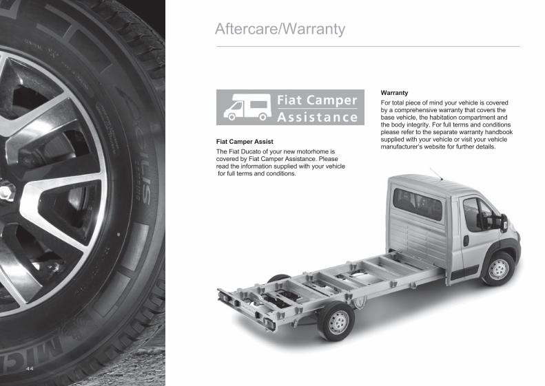
44
Aftercare/Warranty
Fiat Camper AssistThe Fiat Ducato of your new motorhome is covered by Fiat Camper Assistance. Please read the information supplied with your vehicle for full terms and conditions.
WarrantyFor total piece of mind your vehicle is covered by a comprehensive warranty that covers the base vehicle, the habitation compartment and the body integrity. For full terms and conditions please refer to the separate warranty handbook supplied with your vehicle or visit your vehicle manufacturer’s website for further details.
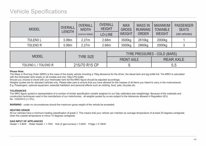
45
Vehicle Specifications
MODEL OVERALL LENGTH
OVERALL WIDTH
(mirrors folded)
OVERALL HEIGHT
MAX GROSS WEIGHT
MASS IN RUNNING ORDER
MAXIMUM TOWABLE WEIGHT
PASSENGER SEATS
(std vehicles)LO-LINETOLENO L 5.99m 2.27m 2.68m 3500kg 2810kg 2000kg 1
TOLENO R 5.99m 2.27m 2.68m 3500kg 2860kg 2000kg 3
MODEL TYRE SIZETYRE PRESSURES - COLD (BARS)
FRONT AXLE REAR AXLETOLENO L / TOLENO R 215/70 R15 CP 5 5.5
Please Note: The Mass in Running Order (MRO) is the mass of the empty vehicle including a 75kg allowance for the driver, the diesel tank and lpg bottle full. The MRO is calculated with the freshwater tank empty on all models and one 13kg LPG bottle.Should you choose to travel with your freshwater tank full the MRO figure should be adjusted accordingly.Weights quoted are for standard vehicles only. Please take care to ensure that you have allowed for the masses of all items you intend to carry in the motorcaravan. E.g. Passengers, optional equipment, essential habitation and personal effects such as clothing, food, pets, bicycles etc.
TOLERANCES The MRO figure quoted is representative of a number of similar specification models weighed on our fully calibrated axle weighbridge. Because of the materials and construction techniques used in the manufacture of our motorhomes, all weights quoted by us are subject to the tolerances allowed in Regulation (EU) No. 1230/2012 (+/-3%).
WARNING - under no circumstances should the maximum gross weight of the vehicle be exceeded.
HEATING GRADE All our vehicles have a minimum heating classification of grade 3. This means that your vehicle can maintain an average temperature of at least 20 degrees centigrade when the outside temperature is minus 15 degrees centigrade.
GAS INPUT OF APPLIANCES Heater = 3.9kW. Water Heater = 1.7kW. Hob (2 gas burners) = 3.0kW. Fridge = 0.19kW.
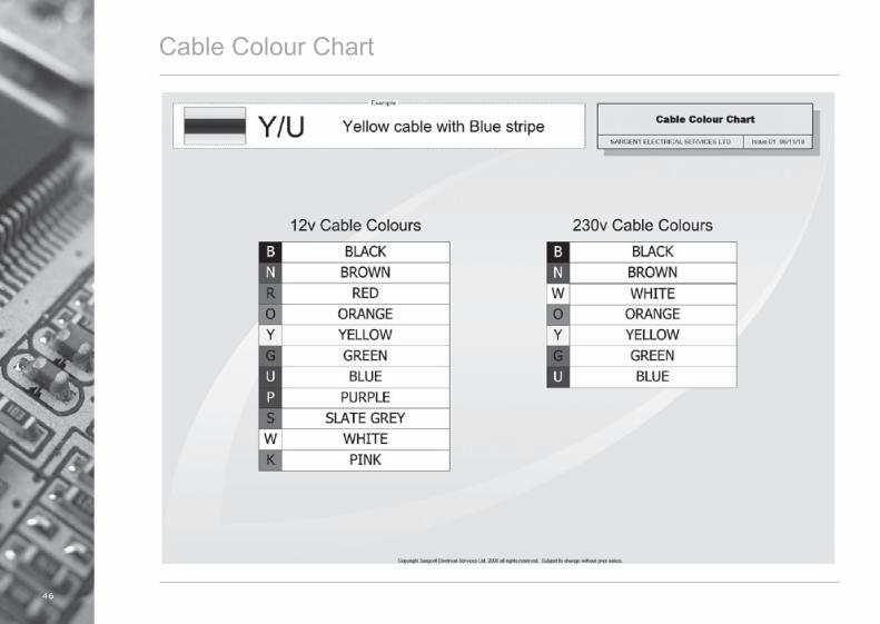
46
Cable Colour Chart
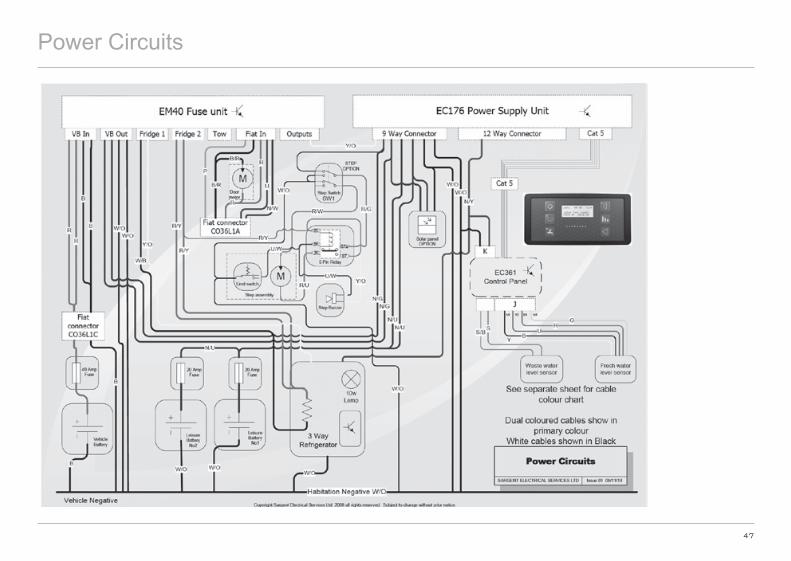
47
Power Circuits
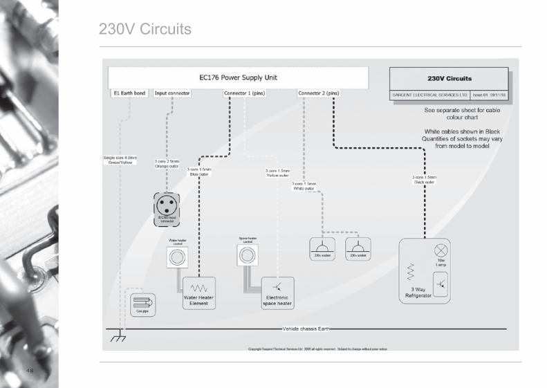
48
230V Circuits

49
Consumer Circuits Floor

50
Consumer Circuits Roof

51
Notes
Notes
52
Related Documents