LEADING THE MOVEMENT ROLLER CHAIN & POWER TRANSMISSION COMPONENTS GENERAL PRODUCT CATALOG TTsueAKI"

Welcome message from author
This document is posted to help you gain knowledge. Please leave a comment to let me know what you think about it! Share it to your friends and learn new things together.
Transcript

LEADING THE MOVEMENT
ROLLER CHAIN & POWER TRANSMISSION COMPONENTS
GENERAL PRODUCT CATALOG
TTsueAKI"

Engineering Class Chains With experienced engineers who understand the changing demands of the market, Tsubaki proudly features heavy-duty engineered chain, designed to withstand rigorous operating conditions across a range of applications. Tsubaki offers a full lineup of engineering class chain, from Drive, Roller Conveyor, Steel Bushed, Welded Steel, Drop Forged, Bar to Pin and service programs such as the ProService® Life Cycle Field Service Package.
Sprockets It has to be precise and strong.Extensive design, engineering,and manufacturing capability allows us to produce a wide variety of Made-To-Order (MTO) sprocket products for a multitude of applications. From one-off custom to high volume OEM sprocket requirements, Tsubaki has you covered.
Power Transmission Components and BackstopsQuality designs and features are key when it comes to clutches and backstops. From preventing reverse rotations to overheating, Tsubaki clutches and backstops are designed to outperform the competition. With a variety of innovative power transmission solutions from overload protection to keyless shaft mounting devices to custom zip chain lifters, Tsubaki has your solution.
Cable & Hose Carriers It is not a one-size-fits all solution. Not all applications can be solved by one type of carrier. Tsubaki KabelSchlepp’s cable & hose carriers can come in nylon, steel and hybrid materials. Whether you have an extremely heavy cable package or an ultra long travel length, we have got the perfect carrier for you.
Powering Your Every NeedTsubaki’s wide range of power transmission and motion control products are here for your various operational needs. From the simplest to the most complicated applications, we have the right product for you. Quality is guaranteed. Expect to get maximum performance from any of our products.
l

Don't see what you need? Call us at 800-323-7790 and we will make it!
®
100+ YEARS.
70+ LOCATIONS.
1 MISSION.
For more than 100 years, Tsubaki has developed and manufactured the highest quality products for power transmission, material handling and motion control. An intense focus on innovation and an unwavering commitment to quality has helped us consistently meet the evolving needs of our customers since 1917.
Today, we have more than 26 manufacturing sites globally and our products are sold in more than 70 countries. Our international presence affords us access to the brightest minds in engineering, many of whom have contributed to the development of our industry leading products and services.
TTsuBAKI
TABLE OF CONTENTSIntroduction Why Tsubaki Chain? .........................................................................................1 Basics of Roller Chain ......................................................................................3 Common Roller Chain Applications .................................................................6
ANSI Chains 25 Roller Chain – ¼” Pitch ...............................................................................8 35 Roller Chain – 3/8” Pitch ............................................................................9 37, 38, 41 Roller Chains – ½” Pitch ...............................................................10 40 Roller Chain – ½” Pitch .............................................................................11 50 Roller Chain – 5/8” Pitch ..........................................................................12 60 Roller Chain – ¾” Pitch .............................................................................13 80 Roller Chain – 1” Pitch ..............................................................................14 100 Roller Chain – 1-1/4” Pitch .....................................................................15 120 Roller Chain – 1-1/2” Pitch .....................................................................16 140 Roller Chain – 1-3/4” Pitch .....................................................................17 160 Roller chain – 2” Pitch ............................................................................18 180 Roller Chain – 2-1/4” Pitch .....................................................................19 200 Roller Chain – 2-1/2” Pitch .....................................................................20 240 Roller Chain – 3” Pitch ............................................................................21
Conveyor Series Single Pitch Conveyor Series Chains .............................................................22 Double Pitch Conveyor Series Chains ............................................................23 Double PItch Conveyor Series Chains (Delrin Roller) .....................................24
Heavy Duty Chains Introduction ....................................................................................................26 Heavy Series ...................................................................................................27 T Series ..........................................................................................................28 HT Series ........................................................................................................29 Super Series ...................................................................................................30 Super H Series ...............................................................................................31 Ultra Super Series ..........................................................................................32
Attachment Chains Introduction ....................................................................................................34 How to Order Attachment Chains ....................................................................35 Single Pitch Attachment Chains .....................................................................37 Double Pitch Attachment Chains ....................................................................39 Double Pitch Attachment Chains (Delrin Roller) .............................................40 Single and Double Pitch Hollow Pin Chains ...................................................41 Curved Chains ................................................................................................42
British Standard Roller Chains Introduction ....................................................................................................45 British Standard Chains .................................................................................46 British Standard Lube-Free (Lambda®) ...........................................................47 British Standard Corrosion & Heat Resistant ..................................................48 British Standard Attachment Chains ...............................................................49
Lube-Free Chains Introduction – Lambda® Chains .....................................................................51 Specialty Lambda® Chain Options ..................................................................52 Drive Lambda® Roller Chains .........................................................................53 Conveyor Lambda® Chains and Attachments .................................................54 Double Pitch Lambda® Chains .......................................................................55 Corrosion Resistant Lambda® Chains ............................................................56 Drive Xceeder® Roller Chain ...........................................................................57 Conveyor Xceeder® Chains and Attachments .................................................58 Double Pitch Xceeder® Chains and Attachments ............................................59 High-Temp Lambda® Chains ..........................................................................60 Hollow Pin Lambda® Chains ..........................................................................61 Outboard Roller Lambda® Chains ...................................................................62 Top Plate Lambda® Chains .............................................................................64
Corrosion & Heat Resistant Chains Corrosion Resistant Guide ..............................................................................66 Single Pitch & Hollow Pin Neptune® Chains ..................................................69 Double Pitch & Hollow Pin Neptune® Chains .................................................70 Single Pitch & Hollow Pin Nickel Plated Chains ............................................71 Double Pitch & Hollow Pin Nickel Plated Chains ...........................................72 Single Pitch & Hollow Pin Stainless Steel Chains ..........................................73 Double Pitch Stainless Steel Chains ...............................................................74 Super Stainless™ Steel Roller Chains ............................................................75 Poly-Steel Chains ...........................................................................................76 Corrosion Resistant Attachments ....................................................................77
Harsh Environment Chain Titan® Series Roller Chains ............................................................................79
Oilfield (Energy Series®) Chains Introduction ....................................................................................................83 Single Strand Oilfield Chains .........................................................................84 Multi-Strand Oilfield Chains ...........................................................................85
Leaf Chains Introduction and Technical Information ...........................................................87 AL Series Leaf Chains ....................................................................................89 BL Series Leaf Chains ....................................................................................90 Ultra-Life Series Leaf Chains ..........................................................................91
Free Flow & Top Chains Introduction ....................................................................................................93 Double Plus® Chains ......................................................................................94 Double Plus® Guide Rails ...............................................................................95 Pallet Guide Rails ...........................................................................................96 Plastic Return Guides & Brackets ...................................................................97 Poly-Steel & Guide Attachments ....................................................................98 Outboard Roller Chains - Technical Details ....................................................99 Single & Double Pitch Outboard Roller Chains ............................................100 Single & Double Pitch Outboard Roller Chains with Brake Roller .................101 Single Pitch Top Roller Chains .....................................................................102 Double Pitch Top Roller Chains ....................................................................104 Roller Table Chains .......................................................................................105 ST Series Roller Table Chains .......................................................................106 RT Series Roller Table Chains .......................................................................107
Top Chains TS Series Top Chains ...................................................................................108 TT & TP Series Top Chains ...........................................................................109 TTU & TPU Top Series Chains ......................................................................110 TTP & TN Top Series Chains ........................................................................111 TRU & TKU Series Top Chains .....................................................................112 TNU & TO Top Series Chains .......................................................................113 TU Series Top Chains ...................................................................................114 Single & Double Pitch Plastic Chains ..........................................................115 Plastic Chain Corrosion Resistant Guide ......................................................116
Specialty Chains Laser-Express™ ...........................................................................................118 Made-To-Order Specials ...............................................................................119 Thermoforming Chains .................................................................................121 Miniature Chains ..........................................................................................122 Bindery Chains .............................................................................................123 Vacuum Wrapping Chains ............................................................................124 Gripper Chains™ ..........................................................................................125 Pin Oven Chains ...........................................................................................126 Crossrod Chains ..........................................................................................127 Live Tubular Roller Chains ............................................................................128 Bucket Elevator Chains .................................................................................129 Bearing Bushed Chains ................................................................................130
.TSllBAKI"
Sprockets Sprockets 101 ...............................................................................................132 No. 25 Sprockets: 1/4˝ Pitch ........................................................................138 No. 35 Sprockets: 3/8˝ Pitch ........................................................................139 No. 41 Sprockets: 1/2˝ Pitch ........................................................................143 No. 40 Sprockets: 1/2˝ Pitch ........................................................................145 No. 50 Sprockets: 5/8˝ Pitch ........................................................................151 No. 60 Sprockets: 3/4˝ Pitch ........................................................................158 No. 80 Sprockets: 1˝ Pitch ...........................................................................165 No. 100 Sprockets: 1-1/4˝ Pitch ...................................................................171 No. 120 Sprockets: 1-1/2˝ Pitch ...................................................................176 No. 140 Sprockets: 1-3/4˝ Pitch ...................................................................179 No. 160 Sprockets: 2˝ Pitch .........................................................................182 No. 180 Sprockets: 2-1/4˝ Pitch ...................................................................184 No. 200 Sprockets: 2-1/2˝ Pitch ...................................................................184 No. 240 Sprockets: 3˝ Pitch .........................................................................185 C2040 Sprockets: 1˝ Pitch ...........................................................................185 C2042 Sprockets: 1˝ Pitch ...........................................................................186 C2050 Sprockets: 1-1/4˝ Pitch .....................................................................186 C2052 Sprockets: 1-1/4˝ Pitch .....................................................................187 C2060 Sprockets: 1-1/2˝ Pitch .....................................................................187 C2062 Sprockets: 1-1/2˝ Pitch .....................................................................188 C2080 Sprockets: 2˝ Pitch ...........................................................................188 C2082 Sprockets: 2˝ Pitch ...........................................................................189 RS06B Sprockets – 3/8” Pitch .......................................................................190 RS08B Sprockets – ½” Pitch .........................................................................190 RS10B Sprockets – 5/8” Pitch .......................................................................191 RS12B Sprockets – ¾” Pitch .........................................................................191 RS16B Sprockets – 1” Pitch ..........................................................................192 Double Plus® Spockets .................................................................................193 TAPER-LOCK® Bushings ...............................................................................194 TAPER-LOCK® Weld-On Hubs ......................................................................197 QD® Bushings ..............................................................................................199 QD® Weld-On Hubs .......................................................................................203 No. 35 Split Taper Sprockets .........................................................................204 No. 41 Split Taper Sprockets .........................................................................205 No. 40 Split Taper Sprockets .........................................................................206 No. 50 Split Taper Sprockets .........................................................................207 No. 60 Split Taper Sprockets .........................................................................208 No. 80 Split Taper Sprockets .........................................................................209 No. 100 Split Taper Sprockets .......................................................................211 No. 120 Split Taper Sprockets .......................................................................213 No. 140 Split Taper Sprockets .......................................................................215 No. 160 Split Taper Sprockets .......................................................................216 Split Taper Bushings .....................................................................................217 Split Taper Hubs ............................................................................................219 Smart Tooth® Sprockets ...............................................................................220
Power Transmission Units & Components Introduction ..................................................................................................222 Clutches & Backstops Information ...............................................................223 MGUS & BB Series Clutches & Backstops ...................................................225 TSS & TFS Series Clutches & Backstops .....................................................226 BUS200 & PBUS Series Clutches & Backstops ............................................227 MZ & MIUS Series Clutches & Backstops ....................................................228 MZEU & BREU Series Clutches & Backstops ...............................................229 BR-HT & BRUS Series Clutches & Backstops ..............................................230 BSEU & CA Series Clutches & Backstops ....................................................231 BS Series & BS/BS-F Series Clutches & Backstops .....................................232 BS-F Series Backstops .................................................................................233 POWER-LOCK® Introduction ........................................................................234 AS & AD Series POWER-LOCKS® ................................................................237 AE & FL Series POWER-LOCKS® .................................................................238 RE & KE Series POWER-LOCKS® .................................................................239 TF & SL Series POWER-LOCKS® .................................................................240 EL & EF Series POWER-LOCKS® .................................................................241 Shock Relays - Introduction .........................................................................242 TSBSB/TSBED Series Shock Relays .............................................................244 TSBSC Shock Relays ....................................................................................245 Overload Protection Devices ........................................................................246
Chain Tools & Technical Resources Chain Management System™ (CMS) ...........................................................248 Wear Indicator Kits .......................................................................................249 Chain Tools ..................................................................................................250
Technical Resources Roller Chain Drive Selection Process ...........................................................251 Heavy-Duty Series Chain Selection ..............................................................254 British Standard Drive Selection ..................................................................254 Roller Chain Installation & Arrangement .....................................................256 Roller Chain Lubrication Guide ....................................................................257 Troubleshooting Guide .................................................................................259 Attachment Chain Selection Guide ...............................................................260 Double Plus® & Outboard Roller Selection Procedure ..................................263 Top Chain Selection & Engineering Information ...........................................269 Roller Table Selection Procedure ..................................................................275 Pitch Conversion Table .................................................................................278 Lambda® Horsepower Tables ........................................................................279 Xceeder® Horsepower Tables ........................................................................283
US Tsubaki Terms & Conditions of Sale .......................................................286
TABLE OF CONTENTS.TSllBAKI"
INTR
OD
UC
TIO
N
1
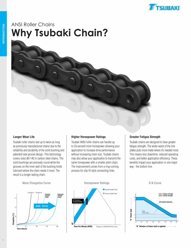
Longer Wear Life
Tsubaki roller chains last up to twice as long as previously manufactured chains due to the reliability and durability of the solid bushing and patented lube groove design. This technology covers sizes 80-140 in carbon steel chains. The solid bushings are precisely round while the grooves on the inner wall of the bushing holds lubricant where the chain needs it most. The result is a longer lasting chain.
Higher Horsepower Ratings
Tsubaki ANSI roller chains can handle up to 33-percent more horsepower allowing your application to increase drive performance without increasing chain size. Tsubaki chains may also allow your applicaiton to transmit the same horsepower with a smaller pitch chain. The improvement comes from a ring-coining process for slip-fit style connecting links.
Greater Fatigue Strength
Tsubaki chains are designed to have greater fatigue strength. The wider-waist of the link plates puts more metal where it’s needed most. This means less downtime, reduced operating costs, and better application efficiency. These benefits impact your application in one major way - the bottom line.
ANSI Roller Chains
Why Tsubaki Chain?
Time (Hours)
Elon
gatio
n (%
)
RS80 - RS140
0 50 100 150 200
1.5
1.0
.05
Competitor A Competitor BPreviousTsubakiChain
ImprovedTsubakiChain
“N” Number of times load is applied
“S”
Chai
n lo
ad
A & a: Fatigue strengthB & b: Tensile strength
US Tsubaki Improved
Other roller chain
0 10 102 103 104 105 106 107
B
b
A
a
Revs Per Minute (RPM)
HP
*Ratings are for RS80-RS240 Roller Chains
33% Increase inHorsepower Ratings
Improved Tsubaki Chain
Previous Tsubaki Chain
Horsepower Ratings S-N CurveWear Elongation Curve
.TSllBAKI"
INTR
OD
UC
TIO
N
2
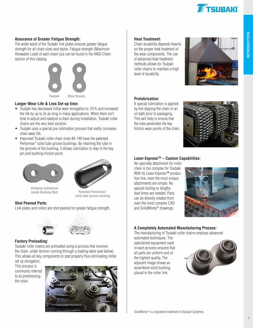
Assurance of Greater Fatigue Strength: The wider waist of the Tsubaki link plates ensures greater fatiguestrength for all chain sizes and styles. Fatigue strength (MaximumAllowable Load) of each chain size can be found in the ANSI Chainsection of this catalog.
Longer Wear Life & Less Set-up time: • Tsubaki has decreased initial wear elongation to .01% and increased
the life by up to 2x as long in many applications. When there isn’t time to adjust and readjust a chain during installation, Tsubaki roller chains are the very best solution.
• Tsubaki uses a special pre-lubrication process that vastly increases chain wear life.
• Improved Tsubaki roller chain sizes 80-140 have the patented Performax™ solid lube groove bushings. By retaining the lube in the grooves of the bushing, it allows lubrication to stay in the key pin and bushing friction point.
Shot Peened Parts: Link plates and rollers are shot peened for greater fatigue strength.
Factory Preloading: Tsubaki roller chains are preloaded using a process that involvesthe chain, under tension running through a loading table (see below).This allows all key components to seat properly thus eliminating initial set up elongation. This process is commonly referred to as prestressing the chain.
Tsubaki Other Brands
Heat Treatment: Chain durability depends heavily on the proper heat treatment of the wear components. The use of advanced heat-treatment methods allows for Tsubaki roller chains to maintain a high level of durability.
Prelubrication: A special lubrication is applied by hot-dipping the chain in an oil bath prior to packaging. This will help to ensure that the lube penetrates the key friction wear points of the chain.
Laser-Express™ – Custom Capabilities: No specialty attachment for roller chain is too complex for Tsubaki.With its Laser-Express™ produc-tion line, even the most unique attachments are simple. No special tooling or lengthy lead times are needed. Parts can be directly created from even the most complex CAD and SolidWorks® drawings.
A Completely Automated Manufacturing Process: The manufacturing of Tsubaki roller chains employs advanced automated techniques. The specialized equipment used in each process ensures that all parts are uniform and of the highest quality. The adjacent image shows an assembled solid bushing placed in the roller link.
SolidWorks® is a registered trademark of Dassault Systémes.
Perfectly Cylindrical Inside Bushing Wall Patented Performax™
solid lube groove bushing
.TSllBAKI"
RO
LLER
CH
AIN
S 10
1
3
Pin
Bushing Roller
Pin LinkPin LinkPlate
RollerRoller LInkPlate
Roller LInkPlate
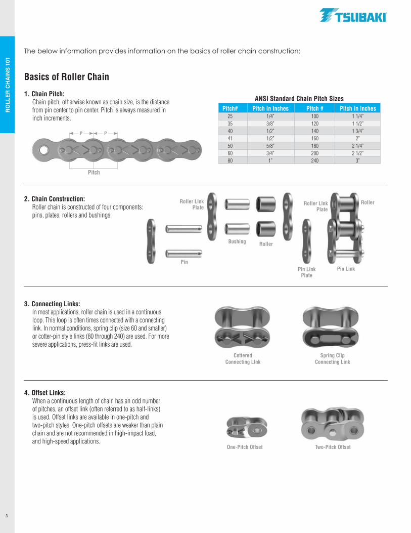
Basics of Roller Chain
1. Chain Pitch: Chain pitch, otherwise known as chain size, is the distance
from pin center to pin center. Pitch is always measured in inch increments.
2. Chain Construction: Roller chain is constructed of four components:
pins, plates, rollers and bushings.
3. Connecting Links: In most applications, roller chain is used in a continuous
loop. This loop is often times connected with a connecting link. In normal conditions, spring clip (size 60 and smaller) or cotter-pin style links (80 through 240) are used. For more severe applications, press-fit links are used.
4. Offset Links: When a continuous length of chain has an odd number
of pitches, an offset link (often referred to as half-links) is used. Offset links are available in one-pitch and two-pitch styles. One-pitch offsets are weaker than plain chain and are not recommended in high-impact load, and high-speed applications.
Pitch
ANSI Standard Chain Pitch Sizes Pitch# Pitch in Inches Pitch # Pitch in Inches 25 1/4” 100 1 1/4” 35 3/8” 120 1 1/2” 40 1/2” 140 1 3/4” 41 1/2” 160 2” 50 5/8” 180 2 1/4” 60 3/4” 200 2 1/2” 80 1” 240 3”
Spring ClipConnecting Link
CotteredConnecting LInk
One-Pitch Offset Two-Pitch Offset
The below information provides information on the basics of roller chain construction:
P P
.TSUBAKI"
RO
LLER
CH
AIN
S 10
1
4
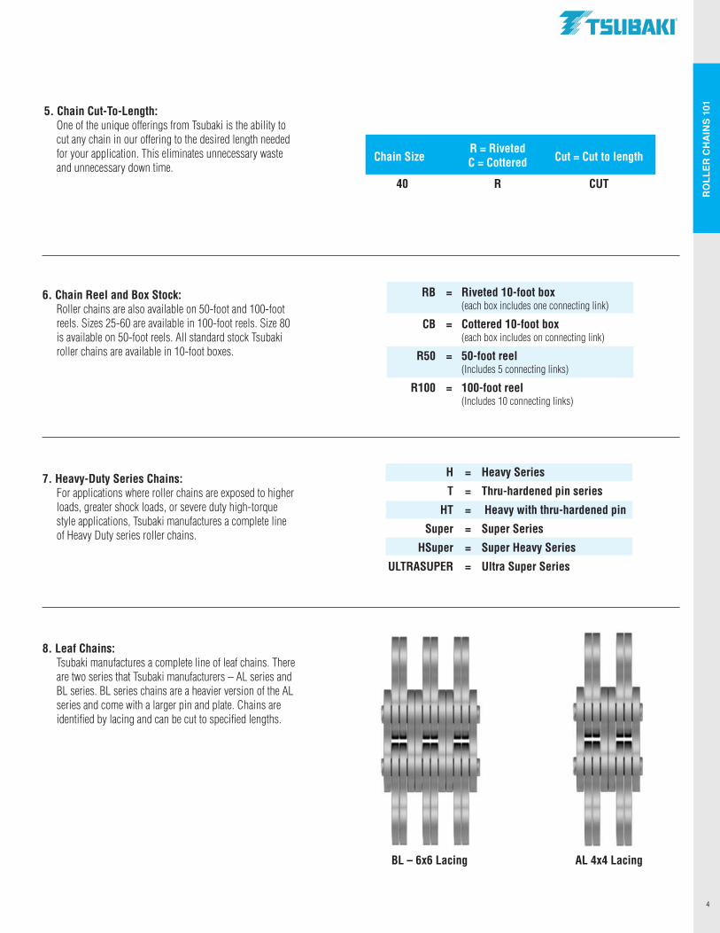
5. Chain Cut-To-Length: One of the unique offerings from Tsubaki is the ability to
cut any chain in our offering to the desired length needed for your application. This eliminates unnecessary waste and unnecessary down time.
6. Chain Reel and Box Stock: Roller chains are also available on 50-foot and 100-foot
reels. Sizes 25-60 are available in 100-foot reels. Size 80 is available on 50-foot reels. All standard stock Tsubaki roller chains are available in 10-foot boxes.
7. Heavy-Duty Series Chains: For applications where roller chains are exposed to higher
loads, greater shock loads, or severe duty high-torque style applications, Tsubaki manufactures a complete line of Heavy Duty series roller chains.
8. Leaf Chains: Tsubaki manufactures a complete line of leaf chains. There
are two series that Tsubaki manufacturers – AL series and BL series. BL series chains are a heavier version of the AL series and come with a larger pin and plate. Chains are identified by lacing and can be cut to specified lengths.
RB = Riveted 10-foot box (each box includes one connecting link)
CB = Cottered 10-foot box (each box includes on connecting link)
R50 = 50-foot reel (Includes 5 connecting links)
R100 = 100-foot reel (Includes 10 connecting links)
R = Riveted Chain Size C = Cottered Cut = Cut to length
40 R CUT
H = Heavy Series
T = Thru-hardened pin series
HT = Heavy with thru-hardened pin
Super = Super Series
HSuper = Super Heavy Series
ULTRASUPER = Ultra Super Series
BL – 6x6 Lacing AL 4x4 Lacing
.TSUBAKI"
RO
LLER
CH
AIN
S 10
1
5
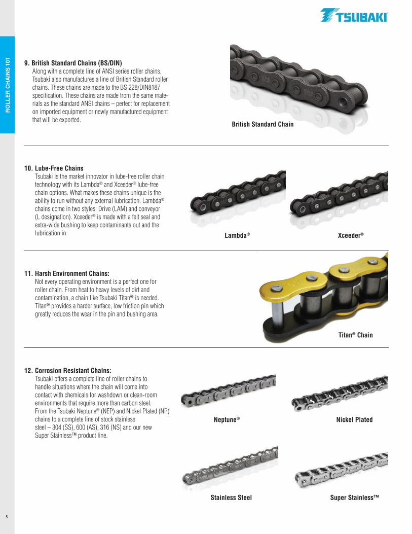
9. British Standard Chains (BS/DIN) Along with a complete line of ANSI series roller chains,
Tsubaki also manufactures a line of British Standard roller chains. These chains are made to the BS 228/DIN8187 specification. These chains are made from the same mate-rials as the standard ANSI chains – perfect for replacement on imported equipment or newly manufactured equipment that will be exported.
10. Lube-Free Chains Tsubaki is the market innovator in lube-free roller chain
technology with its Lambda® and Xceeder® lube-free chain options. What makes these chains unique is the ability to run without any external lubrication. Lambda® chains come in two styles: Drive (LAM) and conveyor (L designation). Xceeder® is made with a felt seal and extra-wide bushing to keep contaminants out and the lubrication in.
11. Harsh Environment Chains: Not every operating environment is a perfect one for
roller chain. From heat to heavy levels of dirt and contamination, a chain like Tsubaki Titan® is needed. Titan® provides a harder surface, low friction pin which greatly reduces the wear in the pin and bushing area.
12. Corrosion Resistant Chains: Tsubaki offers a complete line of roller chains to
handle situations where the chain will come into contact with chemicals for washdown or clean-room environments that require more than carbon steel. From the Tsubaki Neptune® (NEP) and Nickel Plated (NP) chains to a complete line of stock stainless steel – 304 (SS), 600 (AS), 316 (NS) and our new Super Stainless™ product line.
British Standard Chain
Lambda® Xceeder®
Titan® Chain
Stainless Steel Super Stainless™
Neptune® Nickel Plated
.TSUBAKI"
RO
LLER
CH
AIN
S 10
1
6
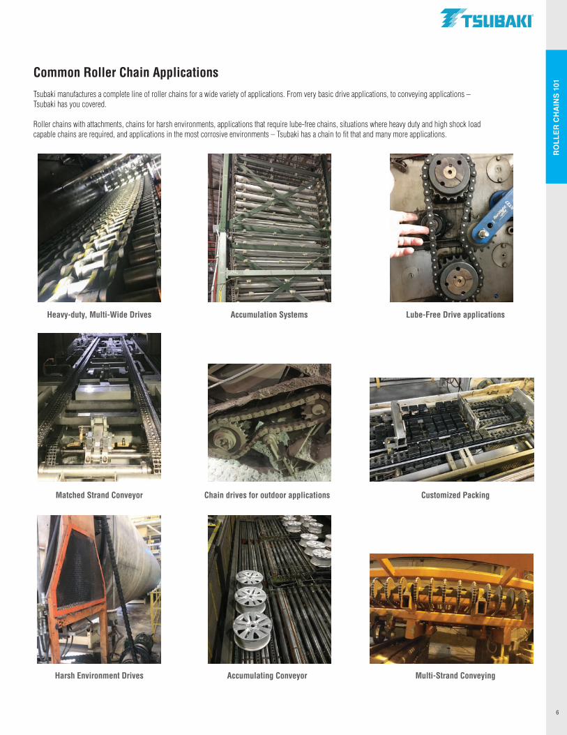
Common Roller Chain ApplicationsTsubaki manufactures a complete line of roller chains for a wide variety of applications. From very basic drive applications, to conveying applications – Tsubaki has you covered.
Roller chains with attachments, chains for harsh environments, applications that require lube-free chains, situations where heavy duty and high shock load capable chains are required, and applications in the most corrosive environments – Tsubaki has a chain to fit that and many more applications.
Img 9576Image 8128 Image 8660
Heavy-duty, Multi-Wide Drives Accumulation Systems Lube-Free Drive applications
Img 0666 Image 8408 Img7457
Matched Strand Conveyor Chain drives for outdoor applications Customized Packing
Img 7966 Img 9649 Img 8654
Harsh Environment Drives Accumulating Conveyor Multi-Strand Conveying
.TSUBAKI"
ANSI chains from Tsubaki provide the strength, reliability and
durability that is required in the toughest environments. With
the Tsubaki Performax™ Bushing in sizes 80-140 – single and
multi-wide strands. Tsubaki ANSI chains help reduce downtime
and improve reliability while decreasing equipment repair costs.
ANSI CHAINS
AN
SI C
HA
INS
8
ANSI CHAINS P P
hH
No. 25 1/4” PITCH
L1
L1
L2
L1
C
L2
L1
W
DB
T
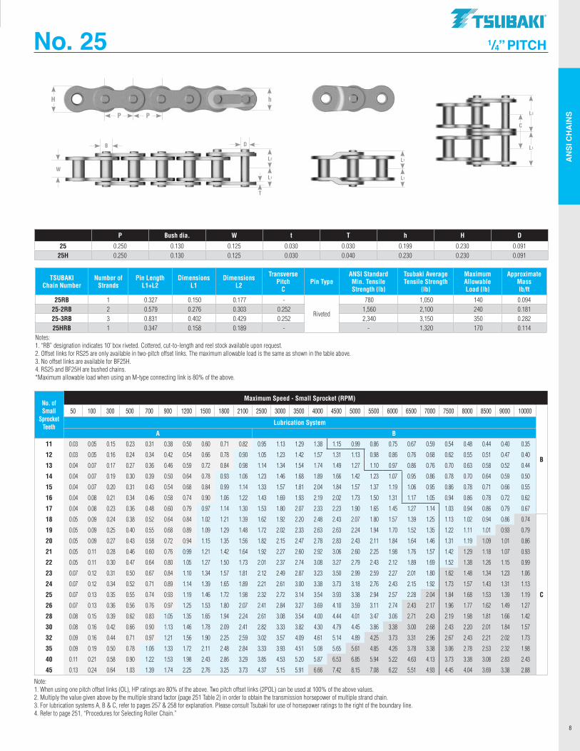
P Bush dia. W t T h H D
25 0.250 0.130 0.125 0.030 0.030 0.199 0.230 0.09125H 0.250 0.130 0.125 0.030 0.040 0.230 0.230 0.091
No. of Small
Sprocket Teeth
Maximum Speed - Small Sprocket (RPM)
50 100 300 500 700 900 1200 1500 1800 2100 2500 3000 3500 4000 4500 5000 5500 6000 6500 7000 7500 8000 8500 9000 10000
B
Lubrication System
A B
11 0.03 0.05 0.15 0.23 0.31 0.38 0.50 0.60 0.71 0.82 0.95 1.13 1.29 1.38 1.15 0.99 0.86 0.75 0.67 0.59 0.54 0.48 0.44 0.40 0.35
12 0.03 0.05 0.16 0.24 0.34 0.42 0.54 0.66 0.78 0.90 1.05 1.23 1.42 1.57 1.31 1.13 0.98 0.86 0.76 0.68 0.62 0.55 0.51 0.47 0.40
13 0.04 0.07 0.17 0.27 0.36 0.46 0.59 0.72 0.84 0.98 1.14 1.34 1.54 1.74 1.49 1.27 1.10 0.97 0.86 0.76 0.70 0.63 0.58 0.52 0.44
14 0.04 0.07 0.19 0.30 0.39 0.50 0.64 0.78 0.93 1.06 1.23 1.46 1.68 1.89 1.66 1.42 1.23 1.07 0.95 0.86 0.78 0.70 0.64 0.59 0.50
15 0.04 0.07 0.20 0.31 0.43 0.54 0.68 0.84 0.99 1.14 1.33 1.57 1.81 2.04 1.84 1.57 1.37 1.19 1.06 0.95 0.86 0.78 0.71 0.66 0.55
16 0.04 0.08 0.21 0.34 0.46 0.58 0.74 0.90 1.06 1.22 1.43 1.69 1.93 2.19 2.02 1.73 1.50 1.31 1.17 1.05 0.94 0.86 0.78 0.72 0.62
17 0.04 0.08 0.23 0.36 0.48 0.60 0.79 0.97 1.14 1.30 1.53 1.80 2.07 2.33 2.23 1.90 1.65 1.45 1.27 1.14 1.03 0.94 0.86 0.79 0.67
18 0.05 0.09 0.24 0.38 0.52 0.64 0.84 1.02 1.21 1.39 1.62 1.92 2.20 2.48 2.43 2.07 1.80 1.57 1.39 1.25 1.13 1.02 0.94 0.86 0.74
C
19 0.05 0.09 0.25 0.40 0.55 0.68 0.89 1.09 1.29 1.48 1.72 2.02 2.33 2.63 2.63 2.24 1.94 1.70 1.52 1.35 1.22 1.11 1.01 0.93 0.79
20 0.05 0.09 0.27 0.43 0.58 0.72 0.94 1.15 1.35 1.56 1.82 2.15 2.47 2.78 2.83 2.43 2.11 1.84 1.64 1.46 1.31 1.19 1.09 1.01 0.86
21 0.05 0.11 0.28 0.46 0.60 0.76 0.99 1.21 1.42 1.64 1.92 2.27 2.60 2.92 3.06 2.60 2.25 1.98 1.76 1.57 1.42 1.29 1.18 1.07 0.93
22 0.05 0.11 0.30 0.47 0.64 0.80 1.05 1.27 1.50 1.73 2.01 2.37 2.74 3.08 3.27 2.79 2.43 2.12 1.89 1.69 1.52 1.38 1.26 1.15 0.99
23 0.07 0.12 0.31 0.50 0.67 0.84 1.10 1.34 1.57 1.81 2.12 2.49 2.87 3.23 3.50 2.99 2.59 2.27 2.01 1.80 1.62 1.48 1.34 1.23 1.06
24 0.07 0.12 0.34 0.52 0.71 0.89 1.14 1.39 1.65 1.89 2.21 2.61 3.00 3.38 3.73 3.18 2.76 2.43 2.15 1.92 1.73 1.57 1.43 1.31 1.13
25 0.07 0.13 0.35 0.55 0.74 0.93 1.19 1.46 1.72 1.98 2.32 2.72 3.14 3.54 3.93 3.38 2.94 2.57 2.28 2.04 1.84 1.68 1.53 1.39 1.19
26 0.07 0.13 0.36 0.56 0.76 0.97 1.25 1.53 1.80 2.07 2.41 2.84 3.27 3.69 4.10 3.59 3.11 2.74 2.43 2.17 1.96 1.77 1.62 1.49 1.27
28 0.08 0.15 0.39 0.62 0.83 1.05 1.35 1.65 1.94 2.24 2.61 3.08 3.54 4.00 4.44 4.01 3.47 3.06 2.71 2.43 2.19 1.98 1.81 1.66 1.42
30 0.08 0.16 0.42 0.66 0.90 1.13 1.46 1.78 2.09 2.41 2.82 3.33 3.82 4.30 4.79 4.45 3.86 3.38 3.00 2.68 2.43 2.20 2.01 1.84 1.57
32 0.09 0.16 0.44 0.71 0.97 1.21 1.56 1.90 2.25 2.59 3.02 3.57 4.09 4.61 5.14 4.89 4.25 3.73 3.31 2.96 2.67 2.43 2.21 2.02 1.73
35 0.09 0.19 0.50 0.78 1.06 1.33 1.72 2.11 2.48 2.84 3.33 3.93 4.51 5.08 5.65 5.61 4.85 4.26 3.78 3.38 3.06 2.78 2.53 2.32 1.98
40 0.11 0.21 0.58 0.90 1.22 1.53 1.98 2.43 2.86 3.29 3.85 4.53 5.20 5.87 6.53 6.85 5.94 5.22 4.63 4.13 3.73 3.38 3.08 2.83 2.43
45 0.13 0.24 0.64 1.03 1.39 1.74 2.25 2.76 3.25 3.73 4.37 5.15 5.91 6.66 7.42 8.15 7.08 6.22 5.51 4.93 4.45 4.04 3.69 3.38 2.88
Note: 1. When using one pitch offset links (OL), HP ratings are 80% of the above. Two pitch offset links (2POL) can be used at 100% of the above values. 2. Multiply the value given above by the multiple strand factor (page 251 Table 2) in order to obtain the transmission horsepower of multiple strand chain. 3. For lubrication systems A, B & C, refer to pages 257 & 258 for explanation. Please consult Tsubaki for use of horsepower ratings to the right of the boundary line. 4. Refer to page 251, “Procedures for Selecting Roller Chain.”
TSUBAKI Chain Number
Number of Strands
Pin Length L1+L2
Dimensions L1
Dimensions L2
Transverse Pitch
CPin Type
ANSI Standard Min. Tensile Strength lb
Tsubaki Average Tensile Strength
lb
Maximum Allowable Load lb
Approximate Mass lb/ft
25RB 1 0.327 0.150 0.177 -
Riveted
780 1,050 140 0.09425-2RB 2 0.579 0.276 0.303 0.252 1,560 2,100 240 0.18125-3RB 3 0.831 0.402 0.429 0.252 2,340 3,150 350 0.28225HRB 1 0.347 0.158 0.189 - - 1,320 170 0.114
Notes:1. “RB” designation indicates 10’ box riveted. Cottered, cut-to-length and reel stock available upon request.2. Offset links for RS25 are only available in two-pitch offset links. The maximum allowable load is the same as shown in the table above.3. No offset links are available for BF25H.4. RS25 and BF25H are bushed chains.*Maximum allowable load when using an M-type connecting link is 80% of the above.
t_ ~~~~~c;3~~~-=--r-i-/-----------r T~~~~~~~~~
.TSllBAKI"
AN
SI C
HA
INS
9
P P
hH
TSUBAKI Chain Number
Number of
StrandsL1+L2 L1 L2 L
Transverse Pitch
CPin Type
ANSI Standard Min. Tensile Strength lb
Tsubaki AverageTensile Strength
Maximum Allowable
Load
Approximate Masslb/ft
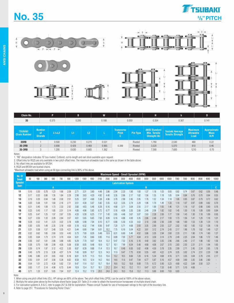
35RB 1 0.500 0.230 0.270 0.531 0.399
Riveted 1,760 2,530 480 0.2235-2RB 2 0.898 0.429 0.469 0.965 Riveted 3,520 5,070 810 0.4635-3RB 3 1.295 0.630 0.665 1.362 Riveted 7,590 7,600 1210 0.70
Notes:1. “RB” designation indicates 10’ box riveted. Cottered, cut-to-length and reel stock available upon request.2. Offset links for RS25 are only available in two-pitch offset links. The maximum allowable load is the same as shown in the table above.3. No offset links are available for BF25H.4. RS25 and BF25H are bushed chains.*Maximum allowable load when using an M-type connecting link is 80% of the above.
Chain No. P B W T H h D
35 0.375 0.200 0.188 0.050 0.354 0.307 0.141
No. 35 3/8” PITCH
L1
L1
L2
L1
C
L2
L1
C
C
L2
L1
W
DB
T
No. Of Small
Sprocket Teeth
Maximum Speed - Small Sprocket (RPM)
50 100 300 500 700 900 1200 1500 1800 2100 2500 3000 3500 4000 4500 5000 5500 6000 6500 7000 7500 8000 8500 9000 10000
Lubrication System
A B C11 0.16 0.30 0.78 1.23 1.66 2.09 2.71 3.31 3.90 4.48 3.86 2.94 2.33 1.90 1.60 1.37 1.18 1.03 0.93 0.82 0.74 0.67 0.62 0.56 0.48 12 0.17 0.32 0.86 1.35 1.84 2.29 2.98 3.63 4.29 4.92 4.40 3.35 2.66 2.17 1.82 1.56 1.35 1.18 1.05 0.94 0.84 0.76 0.70 0.64 0.55 13 0.19 0.35 0.94 1.48 2.00 2.51 3.25 3.97 4.68 5.38 4.96 3.78 2.99 2.45 2.05 1.76 1.52 1.34 1.18 1.06 0.95 0.87 0.79 0.72 0.62 14 0.20 0.38 1.01 1.60 2.16 2.71 3.51 4.30 5.07 5.82 5.55 4.22 3.35 2.74 2.29 1.96 1.70 1.49 1.33 1.18 1.07 0.97 0.89 0.82 0.70 15 0.21 0.40 1.09 1.73 2.33 2.92 3.80 4.63 5.46 6.28 6.16 4.68 3.71 3.04 2.55 2.17 1.89 1.65 1.46 1.31 1.18 1.07 0.98 0.90 0.76 16 0.23 0.43 1.17 1.85 2.51 3.14 4.06 4.96 5.85 6.72 6.77 5.16 4.09 3.35 2.80 2.40 2.08 1.82 1.62 1.45 1.30 1.18 1.09 0.99 0.84 17 0.25 0.47 1.25 1.97 2.67 3.35 4.33 5.30 6.25 7.17 7.43 5.65 4.48 3.67 3.07 2.63 2.28 2.00 1.77 1.58 1.43 1.30 1.18 1.09 0.93 18 0.27 0.50 1.33 2.09 2.84 3.57 4.61 5.65 6.65 7.63 8.09 6.16 4.88 4.00 3.35 2.86 2.48 2.17 1.93 1.73 1.56 1.41 1.29 1.18 1.01 19 0.28 0.52 1.41 2.23 3.02 3.78 4.89 5.98 7.04 8.10 8.77 6.68 5.30 4.33 3.63 3.10 2.68 2.36 2.09 1.88 1.69 1.53 1.39 1.29 1.10 20 0.30 0.55 1.49 2.35 3.18 4.00 5.18 6.32 7.44 8.56 9.47 7.20 5.71 4.68 3.93 3.35 2.90 2.55 2.27 2.02 1.82 1.65 1.52 1.38 1.18 21 0.31 0.58 1.57 2.48 3.35 4.21 5.44 6.66 7.84 9.01 10.2 7.75 6.16 5.04 4.22 3.61 3.12 2.74 2.43 2.17 1.96 1.78 1.62 1.49 1.27 22 0.32 0.62 1.65 2.60 3.53 4.43 5.73 7.00 8.26 9.48 10.9 8.31 6.60 5.40 4.52 3.86 3.35 2.94 2.60 2.33 2.11 1.90 1.74 1.60 1.37 23 0.35 0.64 1.73 2.74 3.70 4.64 6.01 7.35 8.66 9.95 11.6 8.89 7.05 5.77 4.84 4.13 3.58 3.14 2.79 2.49 2.25 2.04 1.86 1.72 1.46 24 0.36 0.67 1.81 2.86 3.88 4.85 6.29 7.70 9.07 10.4 12.2 9.47 7.52 6.16 5.16 4.40 3.82 3.35 2.96 2.66 2.40 2.17 1.98 1.82 1.56 25 0.38 0.70 1.89 2.99 4.05 5.08 6.58 8.05 9.48 10.9 12.7 10.1 7.99 6.54 5.48 4.68 4.06 3.57 3.15 2.83 2.55 2.31 2.11 1.94 1.65 26 0.39 0.74 1.97 3.12 4.22 5.30 6.87 8.39 9.88 11.4 13.3 10.7 8.48 6.93 5.82 4.96 4.30 3.78 3.35 2.99 2.71 2.45 2.24 2.05 1.76 28 0.43 0.79 2.13 3.38 4.57 5.74 7.43 9.09 10.7 12.3 14.3 11.9 9.47 7.75 6.50 5.55 4.81 4.22 3.74 3.35 3.02 2.74 2.51 2.29 1.96 30 0.46 0.86 2.31 3.65 4.93 6.18 8.01 9.79 11.5 13.3 15.6 13.2 10.5 8.60 7.20 6.16 5.34 4.68 4.16 3.71 3.35 3.04 2.78 2.55 2.17 32 0.50 0.91 2.47 3.90 5.28 6.62 8.58 10.5 12.4 14.2 16.6 14.6 11.6 9.47 7.94 6.77 5.87 5.16 4.57 4.09 3.69 3.35 3.06 2.80 - 35 0.54 1.01 2.72 4.30 5.82 7.31 9.47 11.6 13.7 15.7 18.4 16.6 13.2 10.8 9.08 7.75 6.72 5.90 5.23 4.68 4.22 3.84 3.50 3.21 - 40 0.63 1.17 3.14 4.98 6.73 8.44 10.9 13.4 15.7 18.1 21.2 20.4 16.2 13.2 11.1 9.47 8.21 7.20 6.40 5.71 5.16 4.68 - - - 45 0.71 1.33 3.57 5.65 7.64 9.57 12.4 15.2 17.8 20.5 24.0 24.3 19.3 15.8 13.2 11.3 9.80 8.60 7.63 6.83 - - - - -
Note: 1. When using one pitch offset links (OL), HP ratings are 80% of the above. Two pitch offset links (2POL) can be used at 100% of the above values. 2. Multiply the value given above by the multiple strand factor (page 251 Table 2) in order to obtain the transmission horsepower of multiple strand chain. 3. For lubrication systems A, B & C, refer to pages 257 & 258 for explanation. Please consult Tsubaki for use of horsepower ratings to the right of the boundary line. 4. Refer to page 251, “Procedures for Selecting Roller Chain.”
L
.TSllBAKI"
AN
SI C
HA
INS
10
P P
hH
L2
L1
W
DR
T
L
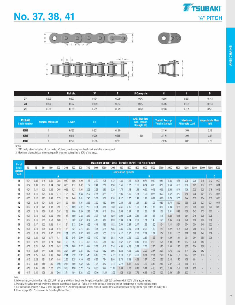
P Roll dia. W T t1 Conn plate H h D
37 0.500 0.307 0.134 0.039 0.047 0.386 0.331 0.143
38 0.500 0.307 0.189 0.043 0.047 0.386 0.331 0.143
41 0.500 0.306 0.251 0.049 0.049 0.386 0.331 0.141
TSUBAKI Chain Number Number of Strands L1+L2 L1 L
ANSI Standard Min. Tensile Strength lb
Tsubaki Average Tensile Strength
Maximum Allowable Load
Approximate Mass lb/ft
43RB 1 0.433 0.201 0.490
1,508
2,116 309 0.19
42RB 1 0.516 0.236 0.555 2,116 309 0.24
41RB 1 0.579 0.266 0.594 2,646 507 0.28
Notes:1. “RB” designation indicates 10’ box riveted. Cottered, cut-to-length and reel stock available upon request.2. Maximum allowable load when using an M-type connecting link is 80% of the above.
No. 37, 38, 41 1/2” PITCH
No. of Small
Sprocket Teeth
Maximum Speed - Small Sprocket (RPM) - 41 Roller Chain
10 25 50 100 200 300 400 500 700 900 1000 1200 1400 1600 1800 2100 2400 2700 3000 3500 4000 5000 6000 7000 8000
Lubrication System
A B C
11 0.04 0.09 0.16 0.31 0.56 0.82 1.06 1.29 1.76 2.20 2.25 1.72 1.35 1.11 0.94 0.74 0.60 0.51 0.43 0.35 0.28 0.20 0.15 0.12 0.09
12 0.04 0.09 0.17 0.34 0.62 0.90 1.17 1.42 1.92 2.41 2.56 1.96 1.56 1.27 1.06 0.84 0.70 0.58 0.50 0.39 0.32 0.23 0.17 0.13 0.11
13 0.04 0.11 0.20 0.36 0.68 0.98 1.27 1.56 2.09 2.63 2.90 2.20 1.74 1.43 1.19 0.95 0.78 0.66 0.56 0.44 0.36 0.25 0.20 0.16 0.13
14 0.05 0.11 0.21 0.39 0.74 1.06 1.37 1.68 2.27 2.84 3.14 2.47 1.96 1.60 1.34 1.06 0.87 0.72 0.62 0.50 0.40 0.30 0.21 0.17 0.15
15 0.05 0.12 0.23 0.43 0.79 1.14 1.48 1.81 2.45 3.07 3.38 2.74 2.17 1.77 1.49 1.18 0.97 0.80 0.70 0.55 0.44 0.32 0.24 0.19 0.16
16 0.05 0.13 0.24 0.46 0.84 1.22 1.58 1.94 2.63 3.29 3.62 3.00 2.39 1.96 1.64 1.30 1.06 0.89 0.76 0.60 0.50 0.35 0.27 0.21 0.17
17 0.07 0.13 0.25 0.48 0.91 1.30 1.69 2.07 2.80 3.51 3.86 3.30 2.61 2.15 1.80 1.42 1.17 0.98 0.83 0.66 0.54 0.39 0.30 0.23 0.19
18 0.07 0.15 0.28 0.52 0.97 1.39 1.80 2.20 2.98 3.74 4.10 3.59 2.84 2.33 1.96 1.56 1.27 1.06 0.91 0.72 0.59 0.42 0.32 0.25 -
19 0.07 0.16 0.30 0.55 1.02 1.48 1.90 2.33 3.16 3.96 4.36 3.89 3.08 2.53 2.12 1.68 1.38 1.15 0.98 0.78 0.64 0.46 0.35 0.28 -
20 0.07 0.16 0.31 0.58 1.09 1.56 2.02 2.47 3.34 4.18 4.60 4.20 3.34 2.74 2.29 1.81 1.49 1.25 1.06 0.84 0.70 0.50 0.38 0.30 -
21 0.08 0.17 0.32 0.62 1.14 1.64 2.13 2.60 3.53 4.41 4.85 4.52 3.59 2.94 2.47 1.96 1.60 1.34 1.14 0.91 0.74 0.54 0.40 0.32 -
22 0.08 0.19 0.35 0.64 1.19 1.73 2.24 2.74 3.70 4.64 5.11 4.85 3.85 3.15 2.64 2.09 1.72 1.43 1.22 0.98 0.79 0.58 0.43 0.35 -
23 0.08 0.19 0.36 0.67 1.26 1.81 2.35 2.87 3.89 4.87 5.35 5.19 4.12 3.37 2.82 2.24 1.84 1.54 1.31 1.05 0.86 0.60 0.47 0.36 -
24 0.09 0.20 0.38 0.71 1.31 1.89 2.45 3.00 4.06 5.10 5.61 5.53 4.39 3.59 3.00 2.39 1.96 1.64 1.39 1.11 0.91 0.64 0.50 0.39 -
25 0.09 0.21 0.39 0.74 1.38 1.98 2.57 3.14 4.25 5.32 5.86 5.87 4.67 3.82 3.19 2.53 2.08 1.74 1.49 1.18 0.97 0.70 0.52 - -
26 0.09 0.21 0.42 0.76 1.43 2.07 2.68 3.27 4.44 5.57 6.12 6.24 4.95 4.05 3.39 2.70 2.20 1.85 1.58 1.25 1.02 0.74 0.56 - -
28 0.11 0.24 0.44 0.83 1.56 2.24 2.90 3.55 4.80 6.02 6.62 6.96 5.53 4.52 3.80 3.00 2.47 2.07 1.76 1.39 1.14 0.82 0.62 - -
30 0.11 0.25 0.48 0.90 1.68 2.41 3.12 3.82 5.18 6.49 7.13 7.72 6.13 5.02 4.20 3.34 2.74 2.29 1.96 1.56 1.27 0.91 0.70 - -
32 0.12 0.28 0.51 0.97 1.80 2.59 3.35 4.10 5.55 6.96 7.64 8.50 6.75 5.53 4.63 3.67 3.00 2.52 2.15 1.70 1.39 1.01 - - -
35 0.13 0.31 0.56 1.06 1.98 2.86 3.69 4.52 6.12 7.67 8.42 9.74 7.72 6.32 5.30 4.20 3.45 2.88 2.47 1.96 1.60 1.14 - - -
40 0.16 0.35 0.66 1.22 2.29 3.30 4.26 5.22 7.07 8.85 9.74 11.47 9.44 7.72 6.48 5.14 4.20 3.53 3.00 2.39 1.96 1.39 - - -
45 0.17 0.40 0.75 1.39 2.60 3.74 4.84 5.93 8.02 10.06 11.05 13.02 11.25 9.21 7.72 6.13 5.02 4.20 3.59 2.84 2.33 - - - -
Note: 1. When using one pitch offset links (OL), HP ratings are 80% of the above. Two pitch offset links (2POL) can be used at 100% of the above values. 2. Multiply the value given above by the multiple strand factor (page 251 Table 2) in order to obtain the transmission horsepower of multiple strand chain. 3. For lubrication systems A, B & C, refer to pages 257 & 258 for explanation. Please consult Tsubaki for use of horsepower ratings to the right of the boundary line. 4. Refer to page 251, “Procedures for Selecting Roller Chain.”
.TSllBAKI"
--------1 1 1 1
AN
SI C
HA
INS
11
P P
hHL2
L1
W
DR
T
L
L1
L1
L2
L1
C
L2
L1
C
C
No. 40 1/2” PITCH
TSUBAKI Chain Number
Number of Strands L1+L2 L1 L2 L
Transverse Pitch
C Pin Type
ANSI Standard Min. Tensile Strength lb
Tsubaki Aver-age Tensile
Strength
Maximum Allowable
Load
Approxi-mate Mass
lb/ft
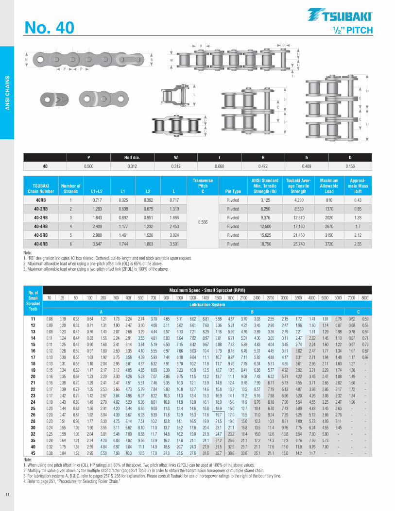
40RB 1 0.717 0.325 0.392 0.717
0.566
Riveted 3,125 4,290 810 0.43
40-2RB 2 1.283 0.608 0.675 1.319 Riveted 6,250 8,580 1370 0.85
40-3RB 3 1.843 0.892 0.951 1.886 Riveted 9,376 12,870 2020 1.28
40-4RB 4 2.409 1.177 1.232 2.453 Riveted 12,500 17,160 2670 1.7
40-5RB 5 2.980 1.461 1.520 3.024 Riveted 15,625 21,450 3150 2.12
40-6RB 6 3.547 1.744 1.803 3.591 Riveted 18,750 25,740 3720 2.55
Note: 1. “RB” designation indicates 10’ box riveted. Cottered, cut-to-length and reel stock available upon request. 2. Maximum allowable load when using a one-pitch offset link (OL) is 65% of the above. 3. Maximum allowable load when using a two-pitch offset link (2POL) is 100% of the above.
P Roll dia. W T H h D
40 0.500 0.312 0.312 0.060 0.472 0.409 0.156
No. of Small
Sprocket Teeth
Maximum Speed - Small Sprocket (RPM)
10 25 50 100 200 300 400 500 700 900 1000 1200 1400 1600 1800 2100 2400 2700 3000 3500 4000 5000 6000 7000 8000Lubrication System
A B C11 0.08 0.19 0.35 0.64 1.21 1.73 2.24 2.74 3.70 4.65 5.11 6.02 6.81 5.58 4.67 3.70 3.03 2.55 2.15 1.72 1.41 1.01 0.76 0.62 0.50 12 0.09 0.20 0.38 0.71 1.31 1.90 2.47 3.00 4.08 5.11 5.62 6.61 7.60 6.36 5.31 4.22 3.45 2.90 2.47 1.96 1.60 1.14 0.87 0.68 0.58 13 0.09 0.23 0.42 0.76 1.43 2.07 2.68 3.29 4.44 5.57 6.13 7.21 8.29 7.16 5.99 4.76 3.89 3.26 2.79 2.21 1.81 1.29 0.98 0.78 0.64 14 0.11 0.24 0.44 0.83 1.56 2.24 2.91 3.55 4.81 6.03 6.64 7.82 8.97 8.01 6.71 5.31 4.36 3.65 3.11 2.47 2.02 1.45 1.10 0.87 0.71 15 0.11 0.25 0.48 0.90 1.68 2.41 3.14 3.84 5.19 6.50 7.15 8.42 9.67 8.88 7.43 5.89 4.83 4.04 3.45 2.74 2.24 1.60 1.22 0.97 0.79 16 0.12 0.28 0.52 0.97 1.80 2.59 3.35 4.10 5.55 6.97 7.66 9.03 10.4 9.79 8.18 6.49 5.31 4.45 3.81 3.02 2.47 1.77 1.34 1.07 0.87 17 0.13 0.30 0.55 1.03 1.92 2.76 3.58 4.39 5.93 7.44 8.18 9.64 11.1 10.7 8.97 7.11 5.82 4.88 4.17 3.31 2.71 1.94 1.48 1.17 0.97 18 0.13 0.31 0.59 1.10 2.04 2.95 3.81 4.67 6.32 7.91 8.70 10.2 11.8 11.7 9.76 7.75 6.34 5.31 4.55 3.61 2.96 2.11 1.60 1.27 - 19 0.15 0.34 0.62 1.17 2.17 3.12 4.05 4.95 6.69 8.39 9.23 10.9 12.5 12.7 10.5 8.41 6.88 5.77 4.92 3.92 3.21 2.29 1.74 1.38 - 20 0.16 0.35 0.66 1.23 2.29 3.30 4.28 5.23 7.07 8.86 9.75 11.5 13.2 13.7 11.1 9.08 7.43 6.22 5.31 4.22 3.45 2.47 1.88 1.49 - 21 0.16 0.38 0.70 1.29 2.41 3.47 4.51 5.51 7.46 9.35 10.3 12.1 13.9 14.8 12.4 9.76 7.99 6.71 5.73 4.55 3.71 2.66 2.02 1.60 - 22 0.17 0.39 0.72 1.35 2.53 3.66 4.73 5.79 7.84 9.83 10.8 12.7 14.6 15.8 13.2 10.5 8.57 7.19 6.13 4.87 3.98 2.86 2.17 1.72 - 23 0.17 0.42 0.76 1.42 2.67 3.84 4.98 6.07 8.22 10.3 11.3 13.4 15.3 16.9 14.1 11.2 9.16 7.68 6.56 5.20 4.26 3.06 2.32 1.84 - 24 0.19 0.43 0.80 1.49 2.79 4.02 5.20 6.36 8.61 10.8 11.9 13.9 16.1 18.0 15.0 11.9 9.76 8.18 7.00 5.54 4.55 3.25 2.47 1.96 - 25 0.20 0.44 0.83 1.56 2.91 4.20 5.44 6.65 9.00 11.3 12.4 14.6 16.8 18.9 16.0 12.7 10.4 8.70 7.43 5.89 4.83 3.45 2.63 - - 26 0.20 0.47 0.87 1.62 3.04 4.39 5.67 6.93 9.39 11.8 12.9 15.3 17.6 19.7 17.0 13.5 11.0 9.24 7.89 6.25 5.12 3.66 2.76 - - 28 0.23 0.51 0.95 1.77 3.30 4.75 6.14 7.51 10.2 12.8 14.1 16.5 19.0 21.5 19.0 15.0 12.3 10.3 8.81 7.00 5.73 4.09 3.11 - - 30 0.24 0.55 1.02 1.90 3.55 5.11 6.62 8.10 11.0 13.7 15.2 17.8 20.4 23.1 21.1 16.8 13.5 11.4 9.76 7.75 6.34 4.55 3.45 - - 32 0.25 0.59 1.09 2.04 3.81 5.48 7.09 8.68 11.7 14.8 16.2 19.0 21.9 24.7 23.2 18.4 15.0 12.6 10.8 8.54 7.00 5.00 - - - 35 0.28 0.64 1.21 2.24 4.20 6.03 7.82 9.56 12.9 16.2 17.8 21.1 24.1 27.2 26.6 21.1 17.2 14.3 12.3 9.76 7.99 5.73 - - - 40 0.32 0.75 1.39 2.59 4.84 6.97 9.04 11.1 14.9 18.8 20.7 24.3 27.9 31.5 32.5 25.7 21.1 17.6 15.0 11.9 9.76 7.00 - - - 45 0.38 0.84 1.58 2.95 5.50 7.93 10.3 12.5 17.0 21.3 23.5 27.6 31.6 35.7 38.6 30.6 25.1 21.1 18.0 14.2 11.7 - - - -
Note: 1. When using one pitch offset links (OL), HP ratings are 80% of the above. Two pitch offset links (2POL) can be used at 100% of the above values. 2. Multiply the value given above by the multiple strand factor (page 251 Table 2) in order to obtain the transmission horsepower of multiple strand chain. 3. For lubrication systems A, B & C, refer to pages 257 & 258 for explanation. Please consult Tsubaki for use of horsepower ratings to the right of the boundary line. 4. Refer to page 251, “Procedures for Selecting Roller Chain.”
.TSllBAKI"
AN
SI C
HA
INS
12
P P
hH
No. 50 5/8” PITCH
TSUBAKI Chain Number
Number of Strands L1+L2 L1 L2 L
Transverse Pitch
C Pin Type
ANSI Standard Min. Tensile Strength lb
Tsubaki Average Tensile
Strength
Maximum Allowable
Load
Approximate Mass lb/ft
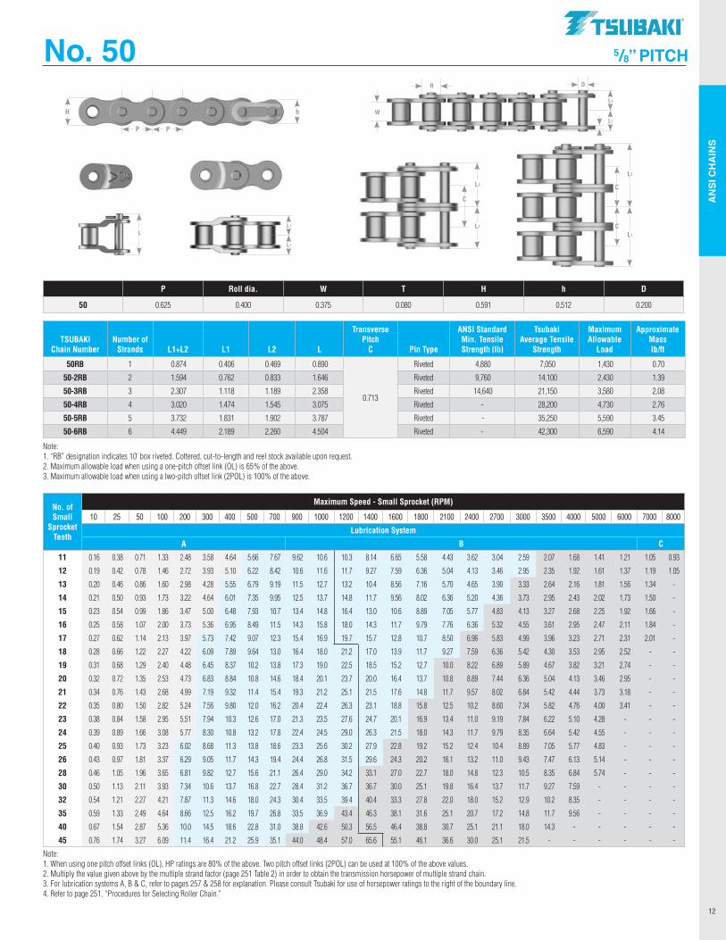
50RB 1 0.874 0.406 0.469 0.890
0.713
Riveted 4,880 7,050 1,430 0.70
50-2RB 2 1.594 0.762 0.833 1.646 Riveted 9,760 14,100 2,430 1.39
50-3RB 3 2.307 1.118 1.189 2.358 Riveted 14,640 21,150 3,580 2.08
50-4RB 4 3.020 1.474 1.545 3.075 Riveted - 28,200 4,730 2.76
50-5RB 5 3.732 1.831 1.902 3.787 Riveted - 35,250 5,590 3.45
50-6RB 6 4.449 2.189 2.260 4.504 Riveted - 42,300 6,590 4.14
Note: 1. “RB” designation indicates 10’ box riveted. Cottered, cut-to-length and reel stock available upon request. 2. Maximum allowable load when using a one-pitch offset link (OL) is 65% of the above. 3. Maximum allowable load when using a two-pitch offset link (2POL) is 100% of the above.
P Roll dia. W T H h D
50 0.625 0.400 0.375 0.080 0.591 0.512 0.200
L2
L1
W
DR
T
LL1
L1
L2
L1
C
L2
L1
C
C
No. of Small
Sprocket Teeth
Maximum Speed - Small Sprocket (RPM)
10 25 50 100 200 300 400 500 700 900 1000 1200 1400 1600 1800 2100 2400 2700 3000 3500 4000 5000 6000 7000 8000
Lubrication System
A B C
11 0.16 0.38 0.71 1.33 2.48 3.58 4.64 5.66 7.67 9.62 10.6 10.3 8.14 6.65 5.58 4.43 3.62 3.04 2.59 2.07 1.68 1.41 1.21 1.05 0.93
12 0.19 0.42 0.78 1.46 2.72 3.93 5.10 6.22 8.42 10.6 11.6 11.7 9.27 7.59 6.36 5.04 4.13 3.46 2.95 2.35 1.92 1.61 1.37 1.19 1.05
13 0.20 0.46 0.86 1.60 2.98 4.28 5.55 6.79 9.19 11.5 12.7 13.2 10.4 8.56 7.16 5.70 4.65 3.90 3.33 2.64 2.16 1.81 1.56 1.34 -
14 0.21 0.50 0.93 1.73 3.22 4.64 6.01 7.35 9.95 12.5 13.7 14.8 11.7 9.56 8.02 6.36 5.20 4.36 3.73 2.95 2.43 2.02 1.73 1.50 -
15 0.23 0.54 0.99 1.86 3.47 5.00 6.48 7.93 10.7 13.4 14.8 16.4 13.0 10.6 8.89 7.05 5.77 4.83 4.13 3.27 2.68 2.25 1.92 1.66 -
16 0.25 0.58 1.07 2.00 3.73 5.36 6.95 8.49 11.5 14.3 15.8 18.0 14.3 11.7 9.79 7.76 6.36 5.32 4.55 3.61 2.95 2.47 2.11 1.84 -
17 0.27 0.62 1.14 2.13 3.97 5.73 7.42 9.07 12.3 15.4 16.9 19.7 15.7 12.8 10.7 8.50 6.96 5.83 4.99 3.96 3.23 2.71 2.31 2.01 -
18 0.28 0.66 1.22 2.27 4.22 6.09 7.89 9.64 13.0 16.4 18.0 21.2 17.0 13.9 11.7 9.27 7.59 6.36 5.42 4.30 3.53 2.95 2.52 - -
19 0.31 0.68 1.29 2.40 4.48 6.45 8.37 10.2 13.8 17.3 19.0 22.5 18.5 15.2 12.7 10.0 8.22 6.89 5.89 4.67 3.82 3.21 2.74 - -
20 0.32 0.72 1.35 2.53 4.73 6.83 8.84 10.8 14.6 18.4 20.1 23.7 20.0 16.4 13.7 10.8 8.89 7.44 6.36 5.04 4.13 3.46 2.95 - -
21 0.34 0.76 1.43 2.68 4.99 7.19 9.32 11.4 15.4 19.3 21.2 25.1 21.5 17.6 14.8 11.7 9.57 8.02 6.84 5.42 4.44 3.73 3.18 - -
22 0.35 0.80 1.50 2.82 5.24 7.56 9.80 12.0 16.2 20.4 22.4 26.3 23.1 18.8 15.8 12.5 10.2 8.60 7.34 5.82 4.76 4.00 3.41 - -
23 0.38 0.84 1.58 2.95 5.51 7.94 10.3 12.6 17.0 21.3 23.5 27.6 24.7 20.1 16.9 13.4 11.0 9.19 7.84 6.22 5.10 4.28 - - -
24 0.39 0.89 1.66 3.08 5.77 8.30 10.8 13.2 17.8 22.4 24.5 29.0 26.3 21.5 18.0 14.3 11.7 9.79 8.35 6.64 5.42 4.55 - - -
25 0.40 0.93 1.73 3.23 6.02 8.68 11.3 13.8 18.6 23.3 25.6 30.2 27.9 22.8 19.2 15.2 12.4 10.4 8.89 7.05 5.77 4.83 - - -
26 0.43 0.97 1.81 3.37 6.29 9.05 11.7 14.3 19.4 24.4 26.8 31.5 29.6 24.3 20.2 16.1 13.2 11.0 9.43 7.47 6.13 5.14 - - -
28 0.46 1.05 1.96 3.65 6.81 9.82 12.7 15.6 21.1 26.4 29.0 34.2 33.1 27.0 22.7 18.0 14.8 12.3 10.5 8.35 6.84 5.74 - - -
30 0.50 1.13 2.11 3.93 7.34 10.6 13.7 16.8 22.7 28.4 31.2 36.7 36.7 30.0 25.1 19.8 16.4 13.7 11.7 9.27 7.59 - - - -
32 0.54 1.21 2.27 4.21 7.87 11.3 14.6 18.0 24.3 30.4 33.5 39.4 40.4 33.3 27.8 22.0 18.0 15.2 12.9 10.2 8.35 - - - -
35 0.59 1.33 2.49 4.64 8.66 12.5 16.2 19.7 26.8 33.5 36.9 43.4 46.3 38.1 31.6 25.1 20.7 17.2 14.8 11.7 9.56 - - - -
40 0.67 1.54 2.87 5.36 10.0 14.5 18.6 22.8 31.0 38.8 42.6 50.3 56.5 46.4 38.8 30.7 25.1 21.1 18.0 14.3 - - - - -
45 0.76 1.74 3.27 6.09 11.4 16.4 21.2 25.9 35.1 44.0 48.4 57.0 65.6 55.1 46.1 36.6 30.0 25.1 21.5 - - - - - -
Note: 1. When using one pitch offset links (OL), HP ratings are 80% of the above. Two pitch offset links (2POL) can be used at 100% of the above values. 2. Multiply the value given above by the multiple strand factor (page 251 Table 2) in order to obtain the transmission horsepower of multiple strand chain. 3. For lubrication systems A, B & C, refer to pages 257 & 258 for explanation. Please consult Tsubaki for use of horsepower ratings to the right of the boundary line. 4. Refer to page 251, “Procedures for Selecting Roller Chain.”
.TSllBAKI"
AN
SI C
HA
INS
13
No. 60 3/4” PITCH
TSUBAKI Chain Number
Number of Strands L1+L2 L1 L2 L
Transverse Pitch
C Pin Type
ANSI Standard Min. Tensile Strength lb
Tsubaki Average Tensile
Strength
Maximum Allowable
Load
Approximate Mass lb/ft
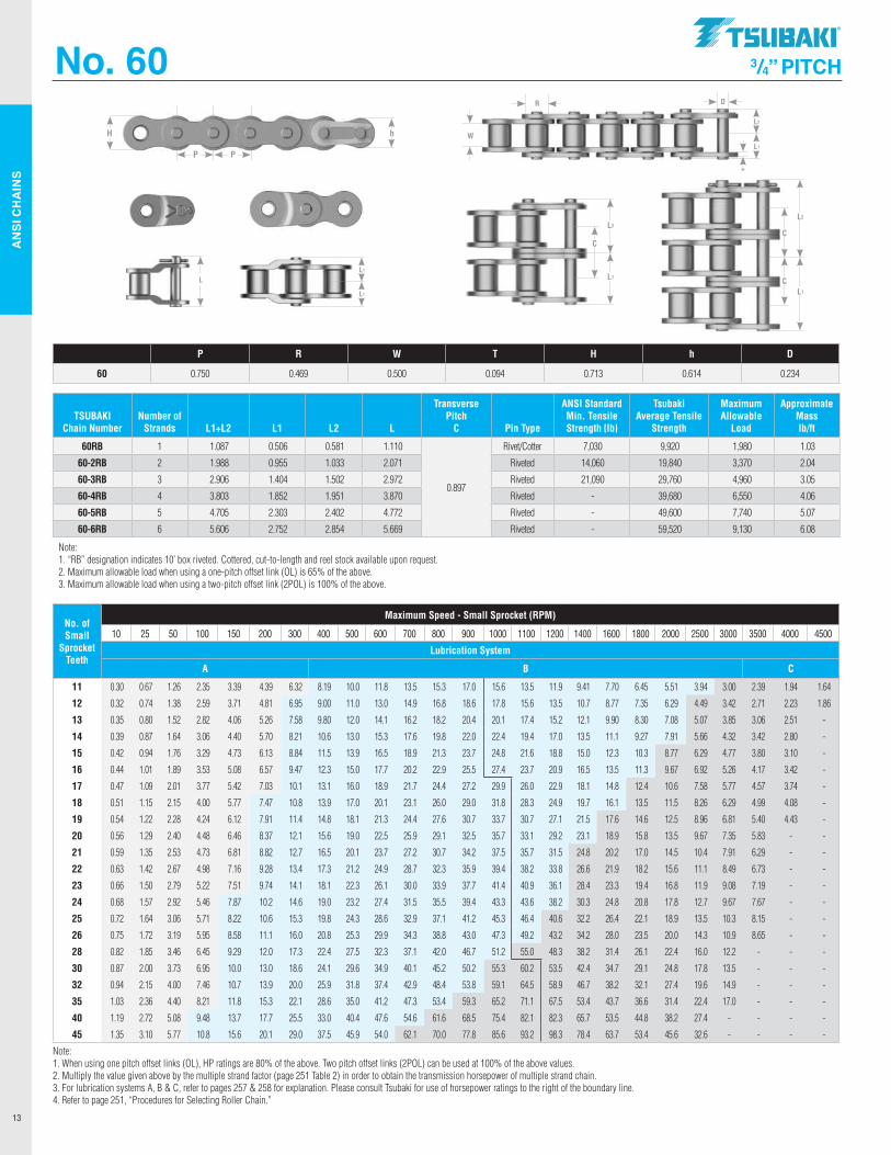
60RB 1 1.087 0.506 0.581 1.110
0.897
Rivet/Cotter 7,030 9,920 1,980 1.03
60-2RB 2 1.988 0.955 1.033 2.071 Riveted 14,060 19,840 3,370 2.04
60-3RB 3 2.906 1.404 1.502 2.972 Riveted 21,090 29,760 4,960 3.05
60-4RB 4 3.803 1.852 1.951 3.870 Riveted - 39,680 6,550 4.06
60-5RB 5 4.705 2.303 2.402 4.772 Riveted - 49,600 7,740 5.07
60-6RB 6 5.606 2.752 2.854 5.669 Riveted - 59,520 9,130 6.08
Note: 1. “RB” designation indicates 10’ box riveted. Cottered, cut-to-length and reel stock available upon request. 2. Maximum allowable load when using a one-pitch offset link (OL) is 65% of the above. 3. Maximum allowable load when using a two-pitch offset link (2POL) is 100% of the above.
P R W T H h D
60 0.750 0.469 0.500 0.094 0.713 0.614 0.234
L2
L1
W
DR
T
LL1
L1
L2
L1
C
L2
L1
C
C
No. of Small
Sprocket Teeth
Maximum Speed - Small Sprocket (RPM)
10 25 50 100 150 200 300 400 500 600 700 800 900 1000 1100 1200 1400 1600 1800 2000 2500 3000 3500 4000 4500
Lubrication System
A B C
11 0.30 0.67 1.26 2.35 3.39 4.39 6.32 8.19 10.0 11.8 13.5 15.3 17.0 15.6 13.5 11.9 9.41 7.70 6.45 5.51 3.94 3.00 2.39 1.94 1.64
12 0.32 0.74 1.38 2.59 3.71 4.81 6.95 9.00 11.0 13.0 14.9 16.8 18.6 17.8 15.6 13.5 10.7 8.77 7.35 6.29 4.49 3.42 2.71 2.23 1.86
13 0.35 0.80 1.52 2.82 4.06 5.26 7.58 9.80 12.0 14.1 16.2 18.2 20.4 20.1 17.4 15.2 12.1 9.90 8.30 7.08 5.07 3.85 3.06 2.51 -
14 0.39 0.87 1.64 3.06 4.40 5.70 8.21 10.6 13.0 15.3 17.6 19.8 22.0 22.4 19.4 17.0 13.5 11.1 9.27 7.91 5.66 4.32 3.42 2.80 -
15 0.42 0.94 1.76 3.29 4.73 6.13 8.84 11.5 13.9 16.5 18.9 21.3 23.7 24.8 21.6 18.8 15.0 12.3 10.3 8.77 6.29 4.77 3.80 3.10 -
16 0.44 1.01 1.89 3.53 5.08 6.57 9.47 12.3 15.0 17.7 20.2 22.9 25.5 27.4 23.7 20.9 16.5 13.5 11.3 9.67 6.92 5.26 4.17 3.42 -
17 0.47 1.09 2.01 3.77 5.42 7.03 10.1 13.1 16.0 18.9 21.7 24.4 27.2 29.9 26.0 22.9 18.1 14.8 12.4 10.6 7.58 5.77 4.57 3.74 -
18 0.51 1.15 2.15 4.00 5.77 7.47 10.8 13.9 17.0 20.1 23.1 26.0 29.0 31.8 28.3 24.9 19.7 16.1 13.5 11.5 8.26 6.29 4.99 4.08 -
19 0.54 1.22 2.28 4.24 6.12 7.91 11.4 14.8 18.1 21.3 24.4 27.6 30.7 33.7 30.7 27.1 21.5 17.6 14.6 12.5 8.96 6.81 5.40 4.43 -
20 0.56 1.29 2.40 4.48 6.46 8.37 12.1 15.6 19.0 22.5 25.9 29.1 32.5 35.7 33.1 29.2 23.1 18.9 15.8 13.5 9.67 7.35 5.83 - -
21 0.59 1.35 2.53 4.73 6.81 8.82 12.7 16.5 20.1 23.7 27.2 30.7 34.2 37.5 35.7 31.5 24.8 20.2 17.0 14.5 10.4 7.91 6.29 - -
22 0.63 1.42 2.67 4.98 7.16 9.28 13.4 17.3 21.2 24.9 28.7 32.3 35.9 39.4 38.2 33.8 26.6 21.9 18.2 15.6 11.1 8.49 6.73 - -
23 0.66 1.50 2.79 5.22 7.51 9.74 14.1 18.1 22.3 26.1 30.0 33.9 37.7 41.4 40.9 36.1 28.4 23.3 19.4 16.8 11.9 9.08 7.19 - -
24 0.68 1.57 2.92 5.46 7.87 10.2 14.6 19.0 23.2 27.4 31.5 35.5 39.4 43.3 43.6 38.2 30.3 24.8 20.8 17.8 12.7 9.67 7.67 - -
25 0.72 1.64 3.06 5.71 8.22 10.6 15.3 19.8 24.3 28.6 32.9 37.1 41.2 45.3 46.4 40.6 32.2 26.4 22.1 18.9 13.5 10.3 8.15 - -
26 0.75 1.72 3.19 5.95 8.58 11.1 16.0 20.8 25.3 29.9 34.3 38.8 43.0 47.3 49.2 43.2 34.2 28.0 23.5 20.0 14.3 10.9 8.65 - -
28 0.82 1.85 3.46 6.45 9.29 12.0 17.3 22.4 27.5 32.3 37.1 42.0 46.7 51.2 55.0 48.3 38.2 31.4 26.1 22.4 16.0 12.2 - - -
30 0.87 2.00 3.73 6.95 10.0 13.0 18.6 24.1 29.6 34.9 40.1 45.2 50.2 55.3 60.2 53.5 42.4 34.7 29.1 24.8 17.8 13.5 - - -
32 0.94 2.15 4.00 7.46 10.7 13.9 20.0 25.9 31.8 37.4 42.9 48.4 53.8 59.1 64.5 58.9 46.7 38.2 32.1 27.4 19.6 14.9 - - -
35 1.03 2.36 4.40 8.21 11.8 15.3 22.1 28.6 35.0 41.2 47.3 53.4 59.3 65.2 71.1 67.5 53.4 43.7 36.6 31.4 22.4 17.0 - - -
40 1.19 2.72 5.08 9.48 13.7 17.7 25.5 33.0 40.4 47.6 54.6 61.6 68.5 75.4 82.1 82.3 65.7 53.5 44.8 38.2 27.4 - - - -
45 1.35 3.10 5.77 10.8 15.6 20.1 29.0 37.5 45.9 54.0 62.1 70.0 77.8 85.6 93.2 98.3 78.4 63.7 53.4 45.6 32.6 - - - -
Note: 1. When using one pitch offset links (OL), HP ratings are 80% of the above. Two pitch offset links (2POL) can be used at 100% of the above values. 2. Multiply the value given above by the multiple strand factor (page 251 Table 2) in order to obtain the transmission horsepower of multiple strand chain. 3. For lubrication systems A, B & C, refer to pages 257 & 258 for explanation. Please consult Tsubaki for use of horsepower ratings to the right of the boundary line. 4. Refer to page 251, “Procedures for Selecting Roller Chain.”
P P
hH
.TSllBAKI"
AN
SI C
HA
INS
14
P P
hH
No. 80 1” PITCH
TSUBAKI Chain Number
Number of Strands L1+L2 L1 L2 L
Transverse Pitch
C Pin Type
ANSI Standard Min. Tensile Strength lb
Tsubaki Ave. Tensile
Strength
Maximum Allowable
Load
Approximate Mass lb/ft
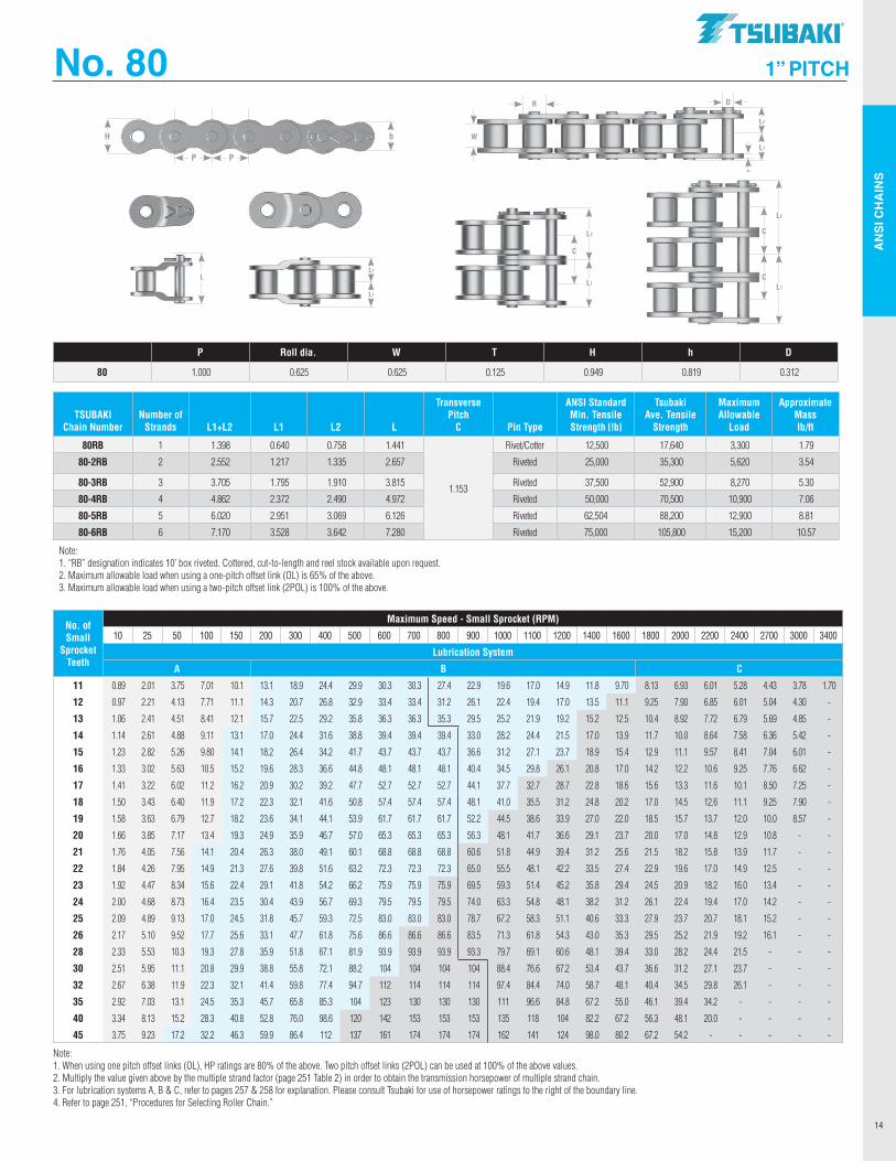
80RB 1 1.398 0.640 0.758 1.441
1.153
Rivet/Cotter 12,500 17,640 3,300 1.79
80-2RB 2 2.552 1.217 1.335 2.657 Riveted 25,000 35,300 5,620 3.54
80-3RB 3 3.705 1.795 1.910 3.815 Riveted 37,500 52,900 8,270 5.30
80-4RB 4 4.862 2.372 2.490 4.972 Riveted 50,000 70,500 10,900 7.06
80-5RB 5 6.020 2.951 3.069 6.126 Riveted 62,504 88,200 12,900 8.81
80-6RB 6 7.170 3.528 3.642 7.280 Riveted 75,000 105,800 15,200 10.57
Note: 1. “RB” designation indicates 10’ box riveted. Cottered, cut-to-length and reel stock available upon request. 2. Maximum allowable load when using a one-pitch offset link (OL) is 65% of the above. 3. Maximum allowable load when using a two-pitch offset link (2POL) is 100% of the above.
P Roll dia. W T H h D
80 1.000 0.625 0.625 0.125 0.949 0.819 0.312
L2
L1
W
DR
T
LL1
L1
L2
L1
C
L2
L1
C
C
No. of Small
Sprocket Teeth
Maximum Speed - Small Sprocket (RPM)
10 25 50 100 150 200 300 400 500 600 700 800 900 1000 1100 1200 1400 1600 1800 2000 2200 2400 2700 3000 3400
Lubrication System
A B C
11 0.89 2.01 3.75 7.01 10.1 13.1 18.9 24.4 29.9 30.3 30.3 27.4 22.9 19.6 17.0 14.9 11.8 9.70 8.13 6.93 6.01 5.28 4.43 3.78 1.70
12 0.97 2.21 4.13 7.71 11.1 14.3 20.7 26.8 32.9 33.4 33.4 31.2 26.1 22.4 19.4 17.0 13.5 11.1 9.25 7.90 6.85 6.01 5.04 4.30 -
13 1.06 2.41 4.51 8.41 12.1 15.7 22.5 29.2 35.8 36.3 36.3 35.3 29.5 25.2 21.9 19.2 15.2 12.5 10.4 8.92 7.72 6.79 5.69 4.85 -
14 1.14 2.61 4.88 9.11 13.1 17.0 24.4 31.6 38.8 39.4 39.4 39.4 33.0 28.2 24.4 21.5 17.0 13.9 11.7 10.0 8.64 7.58 6.36 5.42 -
15 1.23 2.82 5.26 9.80 14.1 18.2 26.4 34.2 41.7 43.7 43.7 43.7 36.6 31.2 27.1 23.7 18.9 15.4 12.9 11.1 9.57 8.41 7.04 6.01 -
16 1.33 3.02 5.63 10.5 15.2 19.6 28.3 36.6 44.8 48.1 48.1 48.1 40.4 34.5 29.8 26.1 20.8 17.0 14.2 12.2 10.6 9.25 7.76 6.62 -
17 1.41 3.22 6.02 11.2 16.2 20.9 30.2 39.2 47.7 52.7 52.7 52.7 44.1 37.7 32.7 28.7 22.8 18.6 15.6 13.3 11.6 10.1 8.50 7.25 -
18 1.50 3.43 6.40 11.9 17.2 22.3 32.1 41.6 50.8 57.4 57.4 57.4 48.1 41.0 35.5 31.2 24.8 20.2 17.0 14.5 12.6 11.1 9.25 7.90 -
19 1.58 3.63 6.79 12.7 18.2 23.6 34.1 44.1 53.9 61.7 61.7 61.7 52.2 44.5 38.6 33.9 27.0 22.0 18.5 15.7 13.7 12.0 10.0 8.57 -
20 1.66 3.85 7.17 13.4 19.3 24.9 35.9 46.7 57.0 65.3 65.3 65.3 56.3 48.1 41.7 36.6 29.1 23.7 20.0 17.0 14.8 12.9 10.8 - -
21 1.76 4.05 7.56 14.1 20.4 26.3 38.0 49.1 60.1 68.8 68.8 68.8 60.6 51.8 44.9 39.4 31.2 25.6 21.5 18.2 15.8 13.9 11.7 - -
22 1.84 4.26 7.95 14.9 21.3 27.6 39.8 51.6 63.2 72.3 72.3 72.3 65.0 55.5 48.1 42.2 33.5 27.4 22.9 19.6 17.0 14.9 12.5 - -
23 1.92 4.47 8.34 15.6 22.4 29.1 41.8 54.2 66.2 75.9 75.9 75.9 69.5 59.3 51.4 45.2 35.8 29.4 24.5 20.9 18.2 16.0 13.4 - -
24 2.00 4.68 8.73 16.4 23.5 30.4 43.9 56.7 69.3 79.5 79.5 79.5 74.0 63.3 54.8 48.1 38.2 31.2 26.1 22.4 19.4 17.0 14.2 - -
25 2.09 4.89 9.13 17.0 24.5 31.8 45.7 59.3 72.5 83.0 83.0 83.0 78.7 67.2 58.3 51.1 40.6 33.3 27.9 23.7 20.7 18.1 15.2 - -
26 2.17 5.10 9.52 17.7 25.6 33.1 47.7 61.8 75.6 86.6 86.6 86.6 83.5 71.3 61.8 54.3 43.0 35.3 29.5 25.2 21.9 19.2 16.1 - -
28 2.33 5.53 10.3 19.3 27.8 35.9 51.8 67.1 81.9 93.9 93.9 93.9 93.3 79.7 69.1 60.6 48.1 39.4 33.0 28.2 24.4 21.5 - - -
30 2.51 5.95 11.1 20.8 29.9 38.8 55.8 72.1 88.2 104 104 104 104 88.4 76.6 67.2 53.4 43.7 36.6 31.2 27.1 23.7 - - -
32 2.67 6.38 11.9 22.3 32.1 41.4 59.8 77.4 94.7 112 114 114 114 97.4 84.4 74.0 58.7 48.1 40.4 34.5 29.8 26.1 - - -
35 2.92 7.03 13.1 24.5 35.3 45.7 65.8 85.3 104 123 130 130 130 111 96.6 84.8 67.2 55.0 46.1 39.4 34.2 - - - -
40 3.34 8.13 15.2 28.3 40.8 52.8 76.0 98.6 120 142 153 153 153 135 118 104 82.2 67.2 56.3 48.1 20.0 - - - -
45 3.75 9.23 17.2 32.2 46.3 59.9 86.4 112 137 161 174 174 174 162 141 124 98.0 80.2 67.2 54.2 - - - - -
Note: 1. When using one pitch offset links (OL), HP ratings are 80% of the above. Two pitch offset links (2POL) can be used at 100% of the above values. 2. Multiply the value given above by the multiple strand factor (page 251 Table 2) in order to obtain the transmission horsepower of multiple strand chain. 3. For lubrication systems A, B & C, refer to pages 257 & 258 for explanation. Please consult Tsubaki for use of horsepower ratings to the right of the boundary line. 4. Refer to page 251, “Procedures for Selecting Roller Chain.”
.TSllBAKI"
AN
SI C
HA
INS
15
No. 100 1 1/4” PITCH
TSUBAKI Chain Number
Number of Strands L1+L2 L1 L2 L
Transverse Pitch
C Pin Type
ANSI Standard Min. Tensile Strength lb
Tsubaki Average Tensile
Strength
Maximum Allowable
Load
Approximate Mass lb/ft
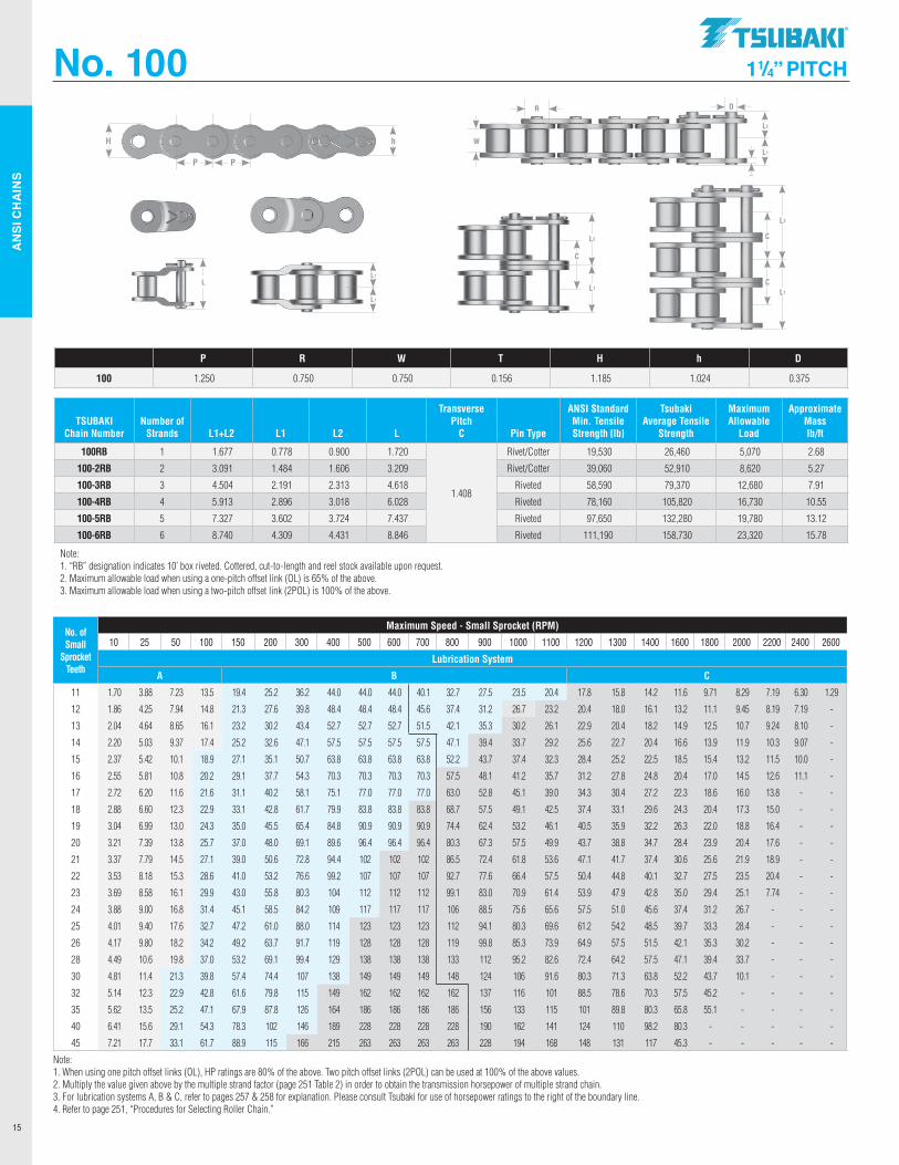
100RB 1 1.677 0.778 0.900 1.720
1.408
Rivet/Cotter 19,530 26,460 5,070 2.68
100-2RB 2 3.091 1.484 1.606 3.209 Rivet/Cotter 39,060 52,910 8,620 5.27
100-3RB 3 4.504 2.191 2.313 4.618 Riveted 58,590 79,370 12,680 7.91
100-4RB 4 5.913 2.896 3.018 6.028 Riveted 78,160 105,820 16,730 10.55
100-5RB 5 7.327 3.602 3.724 7.437 Riveted 97,650 132,280 19,780 13.12
100-6RB 6 8.740 4.309 4.431 8.846 Riveted 111,190 158,730 23,320 15.78
Note: 1. “RB” designation indicates 10’ box riveted. Cottered, cut-to-length and reel stock available upon request. 2. Maximum allowable load when using a one-pitch offset link (OL) is 65% of the above. 3. Maximum allowable load when using a two-pitch offset link (2POL) is 100% of the above.
P R W T H h D
100 1.250 0.750 0.750 0.156 1.185 1.024 0.375
No. of Small
Sprocket Teeth
Maximum Speed - Small Sprocket (RPM)
10 25 50 100 150 200 300 400 500 600 700 800 900 1000 1100 1200 1300 1400 1600 1800 2000 2200 2400 2600
Lubrication System
A B C
11 1.70 3.88 7.23 13.5 19.4 25.2 36.2 44.0 44.0 44.0 40.1 32.7 27.5 23.5 20.4 17.8 15.8 14.2 11.6 9.71 8.29 7.19 6.30 1.29
12 1.86 4.25 7.94 14.8 21.3 27.6 39.8 48.4 48.4 48.4 45.6 37.4 31.2 26.7 23.2 20.4 18.0 16.1 13.2 11.1 9.45 8.19 7.19 -
13 2.04 4.64 8.65 16.1 23.2 30.2 43.4 52.7 52.7 52.7 51.5 42.1 35.3 30.2 26.1 22.9 20.4 18.2 14.9 12.5 10.7 9.24 8.10 -
14 2.20 5.03 9.37 17.4 25.2 32.6 47.1 57.5 57.5 57.5 57.5 47.1 39.4 33.7 29.2 25.6 22.7 20.4 16.6 13.9 11.9 10.3 9.07 -
15 2.37 5.42 10.1 18.9 27.1 35.1 50.7 63.8 63.8 63.8 63.8 52.2 43.7 37.4 32.3 28.4 25.2 22.5 18.5 15.4 13.2 11.5 10.0 -
16 2.55 5.81 10.8 20.2 29.1 37.7 54.3 70.3 70.3 70.3 70.3 57.5 48.1 41.2 35.7 31.2 27.8 24.8 20.4 17.0 14.5 12.6 11.1 -
17 2.72 6.20 11.6 21.6 31.1 40.2 58.1 75.1 77.0 77.0 77.0 63.0 52.8 45.1 39.0 34.3 30.4 27.2 22.3 18.6 16.0 13.8 - -
18 2.88 6.60 12.3 22.9 33.1 42.8 61.7 79.9 83.8 83.8 83.8 68.7 57.5 49.1 42.5 37.4 33.1 29.6 24.3 20.4 17.3 15.0 - -
19 3.04 6.99 13.0 24.3 35.0 45.5 65.4 84.8 90.9 90.9 90.9 74.4 62.4 53.2 46.1 40.5 35.9 32.2 26.3 22.0 18.8 16.4 - -
20 3.21 7.39 13.8 25.7 37.0 48.0 69.1 89.6 96.4 96.4 96.4 80.3 67.3 57.5 49.9 43.7 38.8 34.7 28.4 23.9 20.4 17.6 - -
21 3.37 7.79 14.5 27.1 39.0 50.6 72.8 94.4 102 102 102 86.5 72.4 61.8 53.6 47.1 41.7 37.4 30.6 25.6 21.9 18.9 - -
22 3.53 8.18 15.3 28.6 41.0 53.2 76.6 99.2 107 107 107 92.7 77.6 66.4 57.5 50.4 44.8 40.1 32.7 27.5 23.5 20.4 - -
23 3.69 8.58 16.1 29.9 43.0 55.8 80.3 104 112 112 112 99.1 83.0 70.9 61.4 53.9 47.9 42.8 35.0 29.4 25.1 7.74 - -
24 3.88 9.00 16.8 31.4 45.1 58.5 84.2 109 117 117 117 106 88.5 75.6 65.6 57.5 51.0 45.6 37.4 31.2 26.7 - - -
25 4.01 9.40 17.6 32.7 47.2 61.0 88.0 114 123 123 123 112 94.1 80.3 69.6 61.2 54.2 48.5 39.7 33.3 28.4 - - -
26 4.17 9.80 18.2 34.2 49.2 63.7 91.7 119 128 128 128 119 99.8 85.3 73.9 64.9 57.5 51.5 42.1 35.3 30.2 - - -
28 4.49 10.6 19.8 37.0 53.2 69.1 99.4 129 138 138 138 133 112 95.2 82.6 72.4 64.2 57.5 47.1 39.4 33.7 - - -
30 4.81 11.4 21.3 39.8 57.4 74.4 107 138 149 149 149 148 124 106 91.6 80.3 71.3 63.8 52.2 43.7 10.1 - - -
32 5.14 12.3 22.9 42.8 61.6 79.8 115 149 162 162 162 162 137 116 101 88.5 78.6 70.3 57.5 45.2 - - - -
35 5.62 13.5 25.2 47.1 67.9 87.8 126 164 186 186 186 186 156 133 115 101 89.8 80.3 65.8 55.1 - - - -
40 6.41 15.6 29.1 54.3 78.3 102 146 189 228 228 228 228 190 162 141 124 110 98.2 80.3 - - - - -
45 7.21 17.7 33.1 61.7 88.9 115 166 215 263 263 263 263 228 194 168 148 131 117 45.3 - - - - -
Note: 1. When using one pitch offset links (OL), HP ratings are 80% of the above. Two pitch offset links (2POL) can be used at 100% of the above values. 2. Multiply the value given above by the multiple strand factor (page 251 Table 2) in order to obtain the transmission horsepower of multiple strand chain. 3. For lubrication systems A, B & C, refer to pages 257 & 258 for explanation. Please consult Tsubaki for use of horsepower ratings to the right of the boundary line. 4. Refer to page 251, “Procedures for Selecting Roller Chain.”
P P
hH
L2
L1
W
DR
T
LL1
L1
L2
L1
C
L2
L1
C
C
.TSllBAKI"
AN
SI C
HA
INS
16
No. 120 1 1/2” PITCH
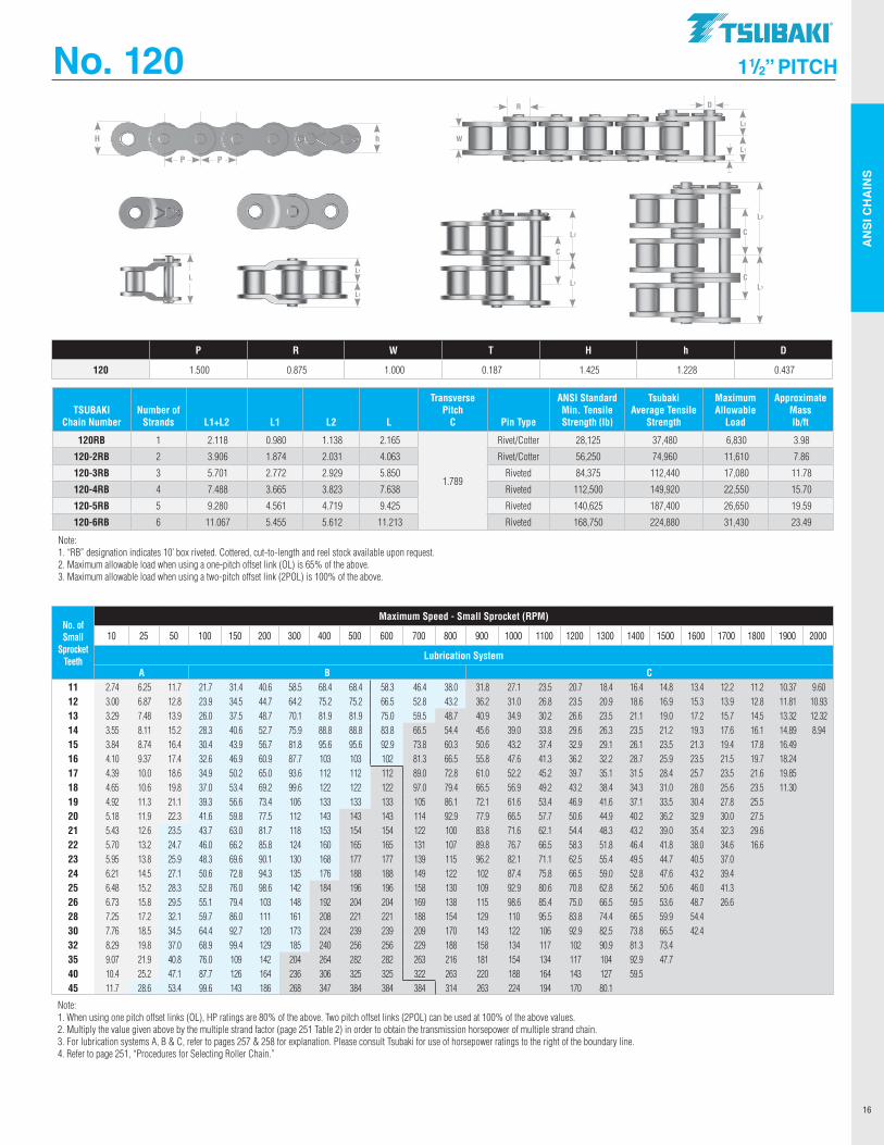
P R W T H h D
120 1.500 0.875 1.000 0.187 1.425 1.228 0.437
TSUBAKI Chain Number
Number of Strands L1+L2 L1 L2 L
Transverse Pitch
C Pin Type
ANSI Standard Min. Tensile Strength lb
Tsubaki Average Tensile
Strength
Maximum Allowable
Load
Approximate Mass lb/ft
120RB 1 2.118 0.980 1.138 2.165
1.789
Rivet/Cotter 28,125 37,480 6,830 3.98
120-2RB 2 3.906 1.874 2.031 4.063 Rivet/Cotter 56,250 74,960 11,610 7.86
120-3RB 3 5.701 2.772 2.929 5.850 Riveted 84,375 112,440 17,080 11.78
120-4RB 4 7.488 3.665 3.823 7.638 Riveted 112,500 149,920 22,550 15.70
120-5RB 5 9.280 4.561 4.719 9.425 Riveted 140,625 187,400 26,650 19.59
120-6RB 6 11.067 5.455 5.612 11.213 Riveted 168,750 224,880 31,430 23.49
Note: 1. “RB” designation indicates 10’ box riveted. Cottered, cut-to-length and reel stock available upon request. 2. Maximum allowable load when using a one-pitch offset link (OL) is 65% of the above. 3. Maximum allowable load when using a two-pitch offset link (2POL) is 100% of the above.
No. of Small
Sprocket Teeth
Maximum Speed - Small Sprocket (RPM)
10 25 50 100 150 200 300 400 500 600 700 800 900 1000 1100 1200 1300 1400 1500 1600 1700 1800 1900 2000
Lubrication System
A B C11 2.74 6.25 11.7 21.7 31.4 40.6 58.5 68.4 68.4 58.3 46.4 38.0 31.8 27.1 23.5 20.7 18.4 16.4 14.8 13.4 12.2 11.2 10.37 9.60 12 3.00 6.87 12.8 23.9 34.5 44.7 64.2 75.2 75.2 66.5 52.8 43.2 36.2 31.0 26.8 23.5 20.9 18.6 16.9 15.3 13.9 12.8 11.81 10.93 13 3.29 7.48 13.9 26.0 37.5 48.7 70.1 81.9 81.9 75.0 59.5 48.7 40.9 34.9 30.2 26.6 23.5 21.1 19.0 17.2 15.7 14.5 13.32 12.32 14 3.55 8.11 15.2 28.3 40.6 52.7 75.9 88.8 88.8 83.8 66.5 54.4 45.6 39.0 33.8 29.6 26.3 23.5 21.2 19.3 17.6 16.1 14.89 8.94 15 3.84 8.74 16.4 30.4 43.9 56.7 81.8 95.6 95.6 92.9 73.8 60.3 50.6 43.2 37.4 32.9 29.1 26.1 23.5 21.3 19.4 17.8 16.49 16 4.10 9.37 17.4 32.6 46.9 60.9 87.7 103 103 102 81.3 66.5 55.8 47.6 41.3 36.2 32.2 28.7 25.9 23.5 21.5 19.7 18.24 17 4.39 10.0 18.6 34.9 50.2 65.0 93.6 112 112 112 89.0 72.8 61.0 52.2 45.2 39.7 35.1 31.5 28.4 25.7 23.5 21.6 19.85 18 4.65 10.6 19.8 37.0 53.4 69.2 99.6 122 122 122 97.0 79.4 66.5 56.9 49.2 43.2 38.4 34.3 31.0 28.0 25.6 23.5 11.30 19 4.92 11.3 21.1 39.3 56.6 73.4 106 133 133 133 105 86.1 72.1 61.6 53.4 46.9 41.6 37.1 33.5 30.4 27.8 25.5 20 5.18 11.9 22.3 41.6 59.8 77.5 112 143 143 143 114 92.9 77.9 66.5 57.7 50.6 44.9 40.2 36.2 32.9 30.0 27.5 21 5.43 12.6 23.5 43.7 63.0 81.7 118 153 154 154 122 100 83.8 71.6 62.1 54.4 48.3 43.2 39.0 35.4 32.3 29.6 22 5.70 13.2 24.7 46.0 66.2 85.8 124 160 165 165 131 107 89.8 76.7 66.5 58.3 51.8 46.4 41.8 38.0 34.6 16.6 23 5.95 13.8 25.9 48.3 69.6 90.1 130 168 177 177 139 115 96.2 82.1 71.1 62.5 55.4 49.5 44.7 40.5 37.0 24 6.21 14.5 27.1 50.6 72.8 94.3 135 176 188 188 149 122 102 87.4 75.8 66.5 59.0 52.8 47.6 43.2 39.4 25 6.48 15.2 28.3 52.8 76.0 98.6 142 184 196 196 158 130 109 92.9 80.6 70.8 62.8 56.2 50.6 46.0 41.3 26 6.73 15.8 29.5 55.1 79.4 103 148 192 204 204 169 138 115 98.6 85.4 75.0 66.5 59.5 53.6 48.7 26.6 28 7.25 17.2 32.1 59.7 86.0 111 161 208 221 221 188 154 129 110 95.5 83.8 74.4 66.5 59.9 54.4 30 7.76 18.5 34.5 64.4 92.7 120 173 224 239 239 209 170 143 122 106 92.9 82.5 73.8 66.5 42.4 32 8.29 19.8 37.0 68.9 99.4 129 185 240 256 256 229 188 158 134 117 102 90.9 81.3 73.4 35 9.07 21.9 40.8 76.0 109 142 204 264 282 282 263 216 181 154 134 117 104 92.9 47.7 40 10.4 25.2 47.1 87.7 126 164 236 306 325 325 322 263 220 188 164 143 127 59.5 45 11.7 28.6 53.4 99.6 143 186 268 347 384 384 384 314 263 224 194 170 80.1
Note: 1. When using one pitch offset links (OL), HP ratings are 80% of the above. Two pitch offset links (2POL) can be used at 100% of the above values. 2. Multiply the value given above by the multiple strand factor (page 251 Table 2) in order to obtain the transmission horsepower of multiple strand chain. 3. For lubrication systems A, B & C, refer to pages 257 & 258 for explanation. Please consult Tsubaki for use of horsepower ratings to the right of the boundary line. 4. Refer to page 251, “Procedures for Selecting Roller Chain.”
P P
hH
L2
L1
W
DR
T
LL1
L1
L2
L1
C
L2
L1
C
C
.TSllBAKI"
AN
SI C
HA
INS
17
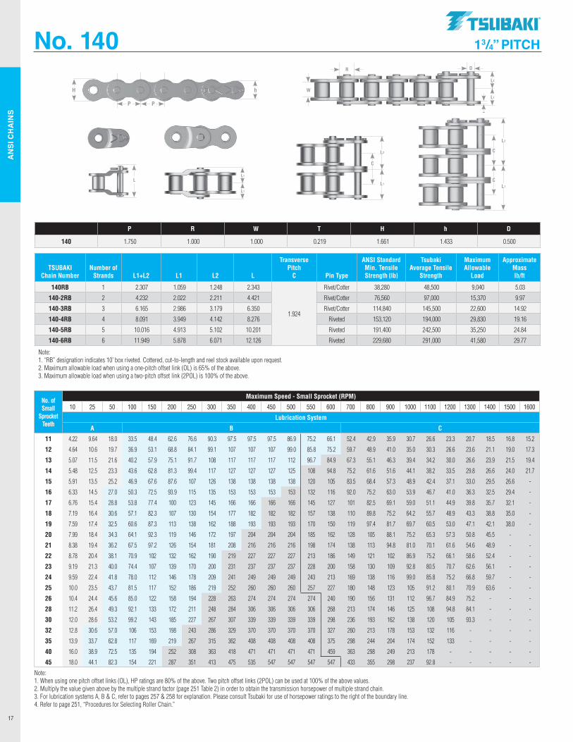
No. 140 1 3/4” PITCH
TSUBAKI Chain Number
Number of Strands L1+L2 L1 L2 L
Transverse Pitch
C Pin Type
ANSI Standard Min. Tensile Strength lb
Tsubaki Average Tensile
Strength
Maximum Allowable
Load
Approximate Mass lb/ft
140RB 1 2.307 1.059 1.248 2.343
1.924
Rivet/Cotter 38,280 48,500 9,040 5.03
140-2RB 2 4.232 2.022 2.211 4.421 Rivet/Cotter 76,560 97,000 15,370 9.97
140-3RB 3 6.165 2.986 3.179 6.350 Rivet/Cotter 114,840 145,500 22,600 14.92
140-4RB 4 8.091 3.949 4.142 8.276 Riveted 153,120 194,000 29,830 19.16
140-5RB 5 10.016 4.913 5.102 10.201 Riveted 191,400 242,500 35,250 24.84
140-6RB 6 11.949 5.878 6.071 12.126 Riveted 229,680 291,000 41,580 29.77
Note: 1. “RB” designation indicates 10’ box riveted. Cottered, cut-to-length and reel stock available upon request. 2. Maximum allowable load when using a one-pitch offset link (OL) is 65% of the above. 3. Maximum allowable load when using a two-pitch offset link (2POL) is 100% of the above.
P R W T H h D
140 1.750 1.000 1.000 0.219 1.661 1.433 0.500
No. of Small
Sprocket Teeth
Maximum Speed - Small Sprocket (RPM)
10 25 50 100 150 200 250 300 350 400 450 500 550 600 700 800 900 1000 1100 1200 1300 1400 1500 1600
Lubrication System
A B C
11 4.22 9.64 18.0 33.5 48.4 62.6 76.6 90.3 97.5 97.5 97.5 86.9 75.2 66.1 52.4 42.9 35.9 30.7 26.6 23.3 20.7 18.5 16.8 15.2
12 4.64 10.6 19.7 36.9 53.1 68.8 84.1 99.1 107 107 107 99.0 85.8 75.2 59.7 48.9 41.0 35.0 30.3 26.6 23.6 21.1 19.0 17.3
13 5.07 11.5 21.6 40.2 57.9 75.1 91.7 108 117 117 117 112 96.7 84.9 67.3 55.1 46.3 39.4 34.2 30.0 26.6 23.9 21.5 19.4
14 5.48 12.5 23.3 43.6 62.8 81.3 99.4 117 127 127 127 125 108 94.8 75.2 61.6 51.6 44.1 38.2 33.5 29.8 26.6 24.0 21.7
15 5.91 13.5 25.2 46.9 67.6 87.6 107 126 138 138 138 138 120 105 83.5 68.4 57.3 48.9 42.4 37.1 33.0 29.5 26.6 -
16 6.33 14.5 27.0 50.3 72.5 93.9 115 135 153 153 153 153 132 116 92.0 75.2 63.0 53.9 46.7 41.0 36.3 32.5 29.4 -
17 6.76 15.4 28.8 53.8 77.4 100 123 145 166 166 166 166 145 127 101 82.5 69.1 59.0 51.1 44.9 39.8 35.7 32.1 -
18 7.19 16.4 30.6 57.1 82.3 107 130 154 177 182 182 182 157 138 110 89.8 75.2 64.2 55.7 48.9 43.3 38.8 35.0 -
19 7.59 17.4 32.5 60.6 87.3 113 138 162 188 193 193 193 170 150 119 97.4 81.7 69.7 60.5 53.0 47.1 42.1 38.0 -
20 7.99 18.4 34.3 64.1 92.3 119 146 172 197 204 204 204 185 162 128 105 88.1 75.2 65.3 57.3 50.8 45.5 - -
21 8.38 19.4 36.2 67.5 97.2 126 154 181 208 216 216 216 198 174 138 113 94.8 81.0 70.1 61.6 54.6 48.9 - -
22 8.78 20.4 38.1 70.9 102 132 162 190 219 227 227 227 213 186 149 121 102 86.9 75.2 66.1 58.6 52.4 - -
23 9.19 21.3 40.0 74.4 107 139 170 200 231 237 237 237 228 200 158 130 109 92.8 80.5 70.7 62.6 56.1 - -
24 9.59 22.4 41.8 78.0 112 146 178 209 241 249 249 249 243 213 169 138 116 99.0 85.8 75.2 66.8 59.7 - -
25 10.0 23.5 43.7 81.5 117 152 186 219 252 260 260 260 257 227 180 148 123 105 91.2 80.1 70.9 63.6 - -
26 10.4 24.4 45.6 85.0 122 158 194 228 263 274 274 274 274 240 190 156 131 112 96.7 84.9 75.2 - - -
28 11.2 26.4 49.3 92.1 133 172 211 248 284 306 306 306 306 268 213 174 146 125 108 94.8 84.1 - - -
30 12.0 28.6 53.2 99.2 143 185 227 267 307 339 339 339 339 298 236 193 162 138 120 105 93.3 - - -
32 12.8 30.6 57.0 106 153 198 243 286 329 370 370 370 370 327 260 213 178 153 132 116 - - - -
35 13.9 33.7 62.8 117 169 219 267 315 362 408 408 408 408 375 298 244 204 174 152 133 - - - -
40 16.0 38.9 72.5 135 194 252 308 363 418 471 471 471 471 459 363 298 249 213 178 - - - - -
45 18.0 44.1 82.3 154 221 287 351 413 475 535 547 547 547 547 433 355 298 237 92.8 - - - - -
Note: 1. When using one pitch offset links (OL), HP ratings are 80% of the above. Two pitch offset links (2POL) can be used at 100% of the above values. 2. Multiply the value given above by the multiple strand factor (page 251 Table 2) in order to obtain the transmission horsepower of multiple strand chain. 3. For lubrication systems A, B & C, refer to pages 257 & 258 for explanation. Please consult Tsubaki for use of horsepower ratings to the right of the boundary line. 4. Refer to page 251, “Procedures for Selecting Roller Chain.”
P P
hH
L2
L1
W
DR
T
LL1
L1
L2
L1
C
L2
L1
C
C
.TSllBAKI"
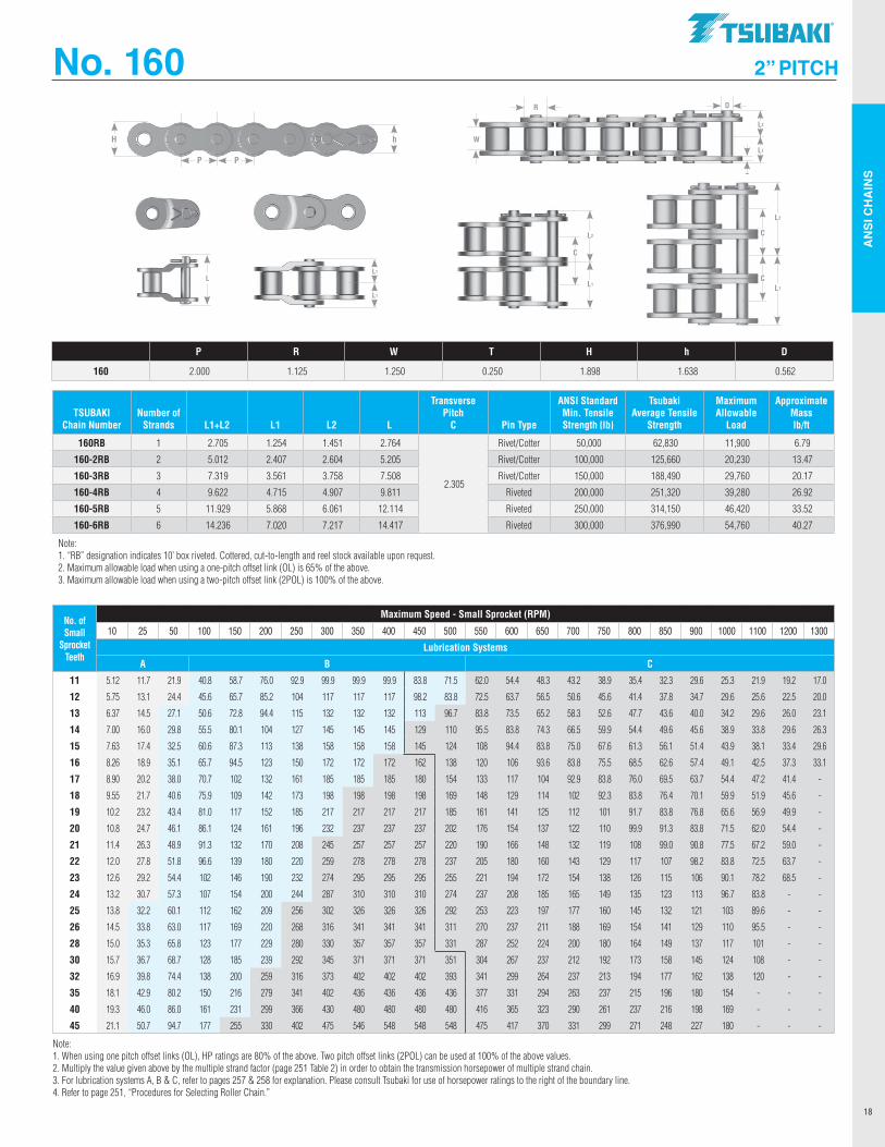
AN
SI C
HA
INS
18
No. 160 2 ” PITCH
P R W T H h D
160 2.000 1.125 1.250 0.250 1.898 1.638 0.562
TSUBAKI Chain Number
Number of Strands L1+L2 L1 L2 L
Transverse Pitch
C Pin Type
ANSI Standard Min. Tensile Strength lb
Tsubaki Average Tensile
Strength
Maximum Allowable
Load
Approximate Mass lb/ft
160RB 1 2.705 1.254 1.451 2.764
2.305
Rivet/Cotter 50,000 62,830 11,900 6.79
160-2RB 2 5.012 2.407 2.604 5.205 Rivet/Cotter 100,000 125,660 20,230 13.47
160-3RB 3 7.319 3.561 3.758 7.508 Rivet/Cotter 150,000 188,490 29,760 20.17
160-4RB 4 9.622 4.715 4.907 9.811 Riveted 200,000 251,320 39,280 26.92
160-5RB 5 11.929 5.868 6.061 12.114 Riveted 250,000 314,150 46,420 33.52
160-6RB 6 14.236 7.020 7.217 14.417 Riveted 300,000 376,990 54,760 40.27
Note: 1. “RB” designation indicates 10’ box riveted. Cottered, cut-to-length and reel stock available upon request. 2. Maximum allowable load when using a one-pitch offset link (OL) is 65% of the above. 3. Maximum allowable load when using a two-pitch offset link (2POL) is 100% of the above.
No. of Small
Sprocket Teeth
Maximum Speed - Small Sprocket (RPM)
10 25 50 100 150 200 250 300 350 400 450 500 550 600 650 700 750 800 850 900 1000 1100 1200 1300
Lubrication Systems
A B C
11 5.12 11.7 21.9 40.8 58.7 76.0 92.9 99.9 99.9 99.9 83.8 71.5 62.0 54.4 48.3 43.2 38.9 35.4 32.3 29.6 25.3 21.9 19.2 17.0
12 5.75 13.1 24.4 45.6 65.7 85.2 104 117 117 117 98.2 83.8 72.5 63.7 56.5 50.6 45.6 41.4 37.8 34.7 29.6 25.6 22.5 20.0
13 6.37 14.5 27.1 50.6 72.8 94.4 115 132 132 132 113 96.7 83.8 73.5 65.2 58.3 52.6 47.7 43.6 40.0 34.2 29.6 26.0 23.1
14 7.00 16.0 29.8 55.5 80.1 104 127 145 145 145 129 110 95.5 83.8 74.3 66.5 59.9 54.4 49.6 45.6 38.9 33.8 29.6 26.3
15 7.63 17.4 32.5 60.6 87.3 113 138 158 158 158 145 124 108 94.4 83.8 75.0 67.6 61.3 56.1 51.4 43.9 38.1 33.4 29.6
16 8.26 18.9 35.1 65.7 94.5 123 150 172 172 172 162 138 120 106 93.6 83.8 75.5 68.5 62.6 57.4 49.1 42.5 37.3 33.1
17 8.90 20.2 38.0 70.7 102 132 161 185 185 185 180 154 133 117 104 92.9 83.8 76.0 69.5 63.7 54.4 47.2 41.4 -
18 9.55 21.7 40.6 75.9 109 142 173 198 198 198 198 169 148 129 114 102 92.3 83.8 76.4 70.1 59.9 51.9 45.6 -
19 10.2 23.2 43.4 81.0 117 152 185 217 217 217 217 185 161 141 125 112 101 91.7 83.8 76.8 65.6 56.9 49.9 -
20 10.8 24.7 46.1 86.1 124 161 196 232 237 237 237 202 176 154 137 122 110 99.9 91.3 83.8 71.5 62.0 54.4 -
21 11.4 26.3 48.9 91.3 132 170 208 245 257 257 257 220 190 166 148 132 119 108 99.0 90.8 77.5 67.2 59.0 -
22 12.0 27.8 51.8 96.6 139 180 220 259 278 278 278 237 205 180 160 143 129 117 107 98.2 83.8 72.5 63.7 -
23 12.6 29.2 54.4 102 146 190 232 274 295 295 295 255 221 194 172 154 138 126 115 106 90.1 78.2 68.5 -
24 13.2 30.7 57.3 107 154 200 244 287 310 310 310 274 237 208 185 165 149 135 123 113 96.7 83.8 - -
25 13.8 32.2 60.1 112 162 209 256 302 326 326 326 292 253 223 197 177 160 145 132 121 103 89.6 - -
26 14.5 33.8 63.0 117 169 220 268 316 341 341 341 311 270 237 211 188 169 154 141 129 110 95.5 - -
28 15.0 35.3 65.8 123 177 229 280 330 357 357 357 331 287 252 224 200 180 164 149 137 117 101 - -
30 15.7 36.7 68.7 128 185 239 292 345 371 371 371 351 304 267 237 212 192 173 158 145 124 108 - -
32 16.9 39.8 74.4 138 200 259 316 373 402 402 402 393 341 299 264 237 213 194 177 162 138 120 - -
35 18.1 42.9 80.2 150 216 279 341 402 436 436 436 436 377 331 294 263 237 215 196 180 154 - - -
40 19.3 46.0 86.0 161 231 299 366 430 480 480 480 480 416 365 323 290 261 237 216 198 169 - - -
45 21.1 50.7 94.7 177 255 330 402 475 546 548 548 548 475 417 370 331 299 271 248 227 180 - - -
Note: 1. When using one pitch offset links (OL), HP ratings are 80% of the above. Two pitch offset links (2POL) can be used at 100% of the above values. 2. Multiply the value given above by the multiple strand factor (page 251 Table 2) in order to obtain the transmission horsepower of multiple strand chain. 3. For lubrication systems A, B & C, refer to pages 257 & 258 for explanation. Please consult Tsubaki for use of horsepower ratings to the right of the boundary line. 4. Refer to page 251, “Procedures for Selecting Roller Chain.”
P P
hH
L2
L1
W
DR
T
LL1
L1
L2
L1
C
L2
L1
C
C
.TSllBAKI"
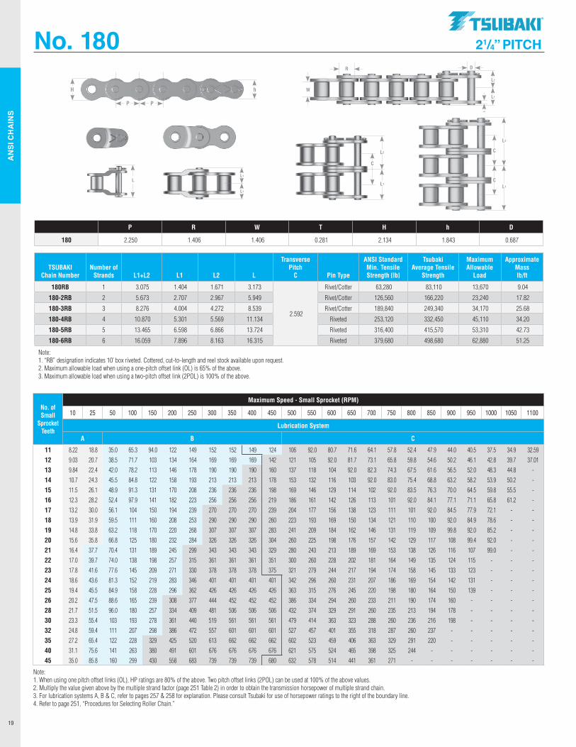
AN
SI C
HA
INS
19
No. 180 2 1/4” PITCH
TSUBAKI Chain Number
Number of Strands L1+L2 L1 L2 L
Transverse Pitch
C Pin Type
ANSI Standard Min. Tensile Strength lb
Tsubaki Average Tensile
Strength
Maximum Allowable
Load
Approximate Mass lb/ft
180RB 1 3.075 1.404 1.671 3.173
2.592
Rivet/Cotter 63,280 83,110 13,670 9.04
180-2RB 2 5.673 2.707 2.967 5.949 Rivet/Cotter 126,560 166,220 23,240 17.82
180-3RB 3 8.276 4.004 4.272 8.539 Rivet/Cotter 189,840 249,340 34,170 25.68
180-4RB 4 10.870 5.301 5.569 11.134 Riveted 253,120 332,450 45,110 34.20
180-5RB 5 13.465 6.598 6.866 13.724 Riveted 316,400 415,570 53,310 42.73
180-6RB 6 16.059 7.896 8.163 16.315 Riveted 379,680 498,680 62,880 51.25
Note: 1. “RB” designation indicates 10’ box riveted. Cottered, cut-to-length and reel stock available upon request. 2. Maximum allowable load when using a one-pitch offset link (OL) is 65% of the above. 3. Maximum allowable load when using a two-pitch offset link (2POL) is 100% of the above.
P R W T H h D
180 2.250 1.406 1.406 0.281 2.134 1.843 0.687
No. of Small
Sprocket Teeth
Maximum Speed - Small Sprocket (RPM)
10 25 50 100 150 200 250 300 350 400 450 500 550 600 650 700 750 800 850 900 950 1000 1050 1100
Lubrication System
A B C
11 8.22 18.8 35.0 65.3 94.0 122 149 152 152 149 124 106 92.0 80.7 71.6 64.1 57.8 52.4 47.9 44.0 40.5 37.5 34.9 32.59 12 9.03 20.7 38.5 71.7 103 134 164 169 169 169 142 121 105 92.0 81.7 73.1 65.8 59.8 54.6 50.2 46.1 42.8 39.7 37.01 13 9.84 22.4 42.0 78.2 113 146 178 190 190 190 160 137 118 104 92.0 82.3 74.3 67.5 61.6 56.5 52.0 48.3 44.8 - 14 10.7 24.3 45.5 84.8 122 158 193 213 213 213 178 153 132 116 103 92.0 83.0 75.4 68.8 63.2 58.2 53.9 50.2 - 15 11.5 26.1 48.9 91.3 131 170 208 236 236 236 198 169 146 129 114 102 92.0 83.5 76.3 70.0 64.5 59.8 55.5 - 16 12.3 28.2 52.4 97.9 141 182 223 256 256 256 219 186 161 142 126 113 101 92.0 84.1 77.1 71.1 65.8 61.2 - 17 13.2 30.0 56.1 104 150 194 239 270 270 270 239 204 177 156 138 123 111 101 92.0 84.5 77.9 72.1 - - 18 13.9 31.9 59.5 111 160 208 253 290 290 290 260 223 193 169 150 134 121 110 100 92.0 84.9 78.6 - - 19 14.8 33.8 63.2 118 170 220 268 307 307 307 283 241 209 184 162 146 131 119 109 99.8 92.0 85.2 - - 20 15.6 35.8 66.8 125 180 232 284 326 326 326 304 260 225 198 176 157 142 129 117 108 99.4 92.0 - - 21 16.4 37.7 70.4 131 189 245 299 343 343 343 329 280 243 213 189 169 153 138 126 116 107 99.0 - - 22 17.0 39.7 74.0 138 198 257 315 361 361 361 351 300 260 228 202 181 164 149 135 124 115 - - - 23 17.8 41.6 77.6 145 209 271 330 378 378 378 375 321 279 244 217 194 174 158 145 133 123 - - - 24 18.6 43.6 81.3 152 219 283 346 401 401 401 401 342 296 260 231 207 186 169 154 142 131 - - - 25 19.4 45.5 84.9 158 228 296 362 426 426 426 426 363 315 276 245 220 198 180 164 150 139 - - - 26 20.2 47.5 88.6 165 239 308 377 444 452 452 452 386 334 294 260 233 211 190 174 160 - - - - 28 21.7 51.5 96.0 180 257 334 409 481 506 506 506 432 374 329 291 260 235 213 194 178 - - - - 30 23.3 55.4 103 193 278 361 440 519 561 561 561 479 414 363 323 288 260 236 216 198 - - - - 32 24.8 59.4 111 207 298 386 472 557 601 601 601 527 457 401 355 318 287 260 237 - - - - - 35 27.2 65.4 122 228 329 425 520 613 662 662 662 602 523 459 406 363 329 291 220 - - - - - 40 31.1 75.6 141 263 380 491 601 676 676 676 676 621 575 524 465 398 325 244 - - - - - - 45 35.0 85.8 160 299 430 558 683 739 739 739 680 632 578 514 441 361 271 - - - - - - -
Note: 1. When using one pitch offset links (OL), HP ratings are 80% of the above. Two pitch offset links (2POL) can be used at 100% of the above values. 2. Multiply the value given above by the multiple strand factor (page 251 Table 2) in order to obtain the transmission horsepower of multiple strand chain. 3. For lubrication systems A, B & C, refer to pages 257 & 258 for explanation. Please consult Tsubaki for use of horsepower ratings to the right of the boundary line. 4. Refer to page 251, “Procedures for Selecting Roller Chain.”
P P
hH
L2
L1
W
DR
T
LL1
L1
L2
L1
C
L2
L1
C
C
.TSllBAKI"
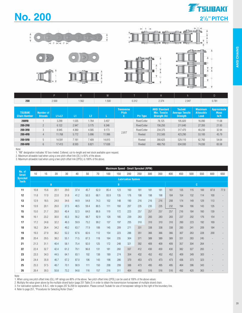
AN
SI C
HA
INS
20
No. 200 2 1/2 ” PITCH
P R W T H h D
200 2.500 1.562 1.500 0.312 2.374 2.047 0.781
TSUBAKI Chain Number
Number of Strands L1+L2 L1 L2 L
Transverse Pitch
C Pin Type
ANSI Standard Min. Tensile Strength lb
Tsubaki Average Tensile
Strength
Maximum Allowable
Load
Approximate Mass lb/ft
200RB 1 3.299 1.535 1.764 3.437
2.817
Rivet/Cotter 78,125 105,820 16,090 11.08
200-2RB 2 6.122 2.947 3.175 6.346 Rivet/Cotter 156,250 211,640 27,350 21.93
200-3RB 3 8.945 4.360 4.585 9.173 Rivet/Cotter 234,375 317,470 40,230 32.94
200-4RB 4 11.768 5.772 5.996 11.996 Riveted 312,500 423,290 53,100 43.79
200-5RB 5 14.591 7.181 7.409 14.815 Riveted 390,625 529,110 62,760 54.64
200-6RB 6 17.413 8.593 8.821 17.638 Riveted 468,750 634,930 74,030 65.58
Note: 1. “RB” designation indicates 10’ box riveted. Cottered, cut-to-length and reel stock available upon request. 2. Maximum allowable load when using a one-pitch offset link (OL) is 65% of the above. 3. Maximum allowable load when using a two-pitch offset link (2POL) is 100% of the above.
No. of Small
Sprocket Teeth
Maximum Speed - Small Sprocket (RPM)
10 15 20 30 40 50 70 100 150 200 250 300 350 400 450 500 550 600 650
Lubrication System
A B C
11 10.8 15.6 20.1 29.0 37.4 45.7 62.0 85.4 123 160 181 181 181 161 135 115 100 87.8 77.9
12 11.8 17.0 22.0 31.8 41.2 50.3 68.1 93.9 135 176 198 198 198 184 154 132 114 100 -
13 12.9 18.5 24.0 34.6 44.9 54.8 74.3 102 148 190 216 216 216 208 174 149 129 113 -
14 13.9 20.1 26.0 37.5 48.5 59.4 80.5 111 160 207 235 235 235 232 194 166 143 126 -
15 15.0 21.7 28.0 40.4 52.3 64.0 86.6 119 172 223 257 257 257 257 216 184 160 139 -
16 16.1 23.2 30.0 43.3 56.2 68.7 92.9 128 185 239 283 283 283 283 237 202 176 154 -
17 17.2 24.8 32.2 46.3 59.9 73.2 99.2 137 197 255 310 310 310 310 260 223 192 169 -
18 18.2 26.4 34.2 49.2 63.7 77.9 106 145 209 271 331 338 338 338 283 241 209 184 -
19 19.3 27.9 36.2 52.2 67.6 82.6 112 154 223 288 351 366 366 366 307 263 228 200 -
20 20.4 29.5 38.2 55.1 71.5 87.3 118 164 235 304 371 389 389 389 331 283 245 - -
21 21.3 31.1 40.4 58.1 75.4 92.0 125 172 248 321 392 409 409 409 357 304 264 - -
22 22.4 32.7 42.4 61.2 79.1 96.8 131 181 260 337 412 430 430 430 382 327 283 - -
23 23.3 34.3 44.5 64.1 83.1 102 138 189 274 354 432 452 452 452 409 349 303 - -
24 24.4 35.9 46.7 67.2 87.0 106 143 198 286 370 453 473 473 473 436 373 323 - -
25 25.3 37.5 48.7 70.1 90.9 111 150 208 299 388 473 495 495 495 464 396 343 - -
26 26.4 39.3 50.8 73.2 94.8 116 157 216 311 404 493 516 516 516 492 420 363 - -
Note: 1. When using one pitch offset links (OL), HP ratings are 80% of the above. Two pitch offset links (2POL) can be used at 100% of the above values. 2. Multiply the value given above by the multiple strand factor (page 251 Table 2) in order to obtain the transmission horsepower of multiple strand chain. 3. For lubrication systems A, B & C, refer to pages 257 & 258 for explanation. Please consult Tsubaki for use of horsepower ratings to the right of the boundary line. 4. Refer to page 251, “Procedures for Selecting Roller Chain.”
P P
hH
L2
L1
W
DR
T
LL1
L1
L2
L1
C
L2
L1
C
C
.TSllBAKI"
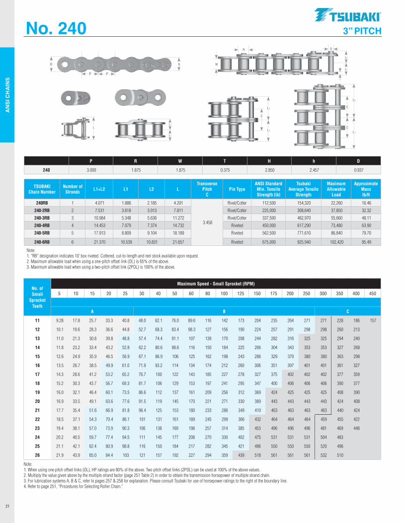
AN
SI C
HA
INS
21
No. 240 3” PITCH
TSUBAKI Chain Number
Number of Strands L1+L2 L1 L2 L
Transverse Pitch
CPin Type
ANSI Standard Min. Tensile Strength lb
Tsubaki Average Tensile
Strength
Maximum Allowable
Load
Approximate Mass lb/ft
240RB 1 4.071 1.886 2.185 4.201
3.458
Rivet/Cotter 112,500 154,320 22,260 16.46
240-2RB 2 7.531 3.618 3.913 7.811 Rivet/Cotter 225,000 308,640 37,850 32.32
240-3RB 3 10.984 5.348 5.636 11.272 Rivet/Cotter 337,500 462,970 55,660 48.11
240-4RB 4 14.453 7.079 7.374 14.732 Riveted 450,000 617,290 73,480 63.90
240-5RB 5 17.913 8.809 9.104 18.189 Riveted 562,500 771,610 86,840 79.70
240-6RB 6 21.370 10.539 10.831 21.657 Riveted 675,000 925,940 102,420 95.49
Note: 1. “RB” designation indicates 10’ box riveted. Cottered, cut-to-length and reel stock available upon request. 2. Maximum allowable load when using a one-pitch offset link (OL) is 65% of the above. 3. Maximum allowable load when using a two-pitch offset link (2POL) is 100% of the above.
P R W T H h D
240 3.000 1.875 1.875 0.375 2.850 2.457 0.937
No. of Small
Sprocket Teeth
Maximum Speed - Small Sprocket (RPM)
5 10 15 20 25 30 40 50 60 80 100 125 150 175 200 250 300 350 400 450
A B C
11 9.28 17.8 25.7 33.3 40.8 48.0 62.1 76.0 89.6 116 142 173 204 235 264 271 271 228 186 157
12 10.1 19.6 28.3 36.6 44.8 52.7 68.3 83.4 98.3 127 156 190 224 257 291 298 298 260 213
13 11.0 21.3 30.8 39.8 48.8 57.4 74.4 91.1 107 139 170 208 244 282 316 325 325 294 240
14 11.8 23.2 33.4 43.2 52.8 62.2 80.6 98.6 116 150 184 225 266 304 343 353 353 327 268
15 12.6 24.9 35.9 46.5 56.9 67.1 86.9 106 125 162 198 243 286 329 370 380 380 363 298
16 13.5 26.7 38.5 49.9 61.0 71.9 93.2 114 134 174 212 260 306 351 397 401 401 361 327
17 14.3 28.6 41.2 53.2 65.2 76.7 100 122 143 185 227 278 327 375 402 402 402 377 359
18 15.2 30.3 43.7 56.7 69.3 81.7 106 129 153 197 241 295 347 400 406 406 406 390 377
19 16.0 32.1 46.4 60.1 73.5 86.6 112 137 161 209 256 312 369 424 425 425 425 408 390
20 16.9 33.5 49.1 63.6 77.6 91.5 119 145 170 221 271 330 389 443 443 443 443 424 408
21 17.7 35.4 51.6 66.9 81.8 96.4 125 153 180 233 286 349 410 463 463 463 463 440 424
22 18.5 37.1 54.3 70.4 86.1 101 131 161 189 245 299 366 432 464 464 464 459 455 422
23 19.4 38.1 57.0 73.9 90.3 106 138 169 198 257 314 385 453 496 496 496 481 469 448
24 20.2 40.5 59.7 77.4 94.5 111 145 177 208 270 330 402 475 531 531 531 504 483
25 21.1 42.1 62.4 80.9 98.8 116 150 184 217 282 345 421 496 550 550 550 520 496
26 21.9 43.9 65.0 84.4 103 121 157 192 227 294 359 439 518 561 561 561 532 510
Note: 1. When using one pitch offset links (OL), HP ratings are 80% of the above. Two pitch offset links (2POL) can be used at 100% of the above values. 2. Multiply the value given above by the multiple strand factor (page 251 Table 2) in order to obtain the transmission horsepower of multiple strand chain. 3. For lubrication systems A, B & C, refer to pages 257 & 258 for explanation. Please consult Tsubaki for use of horsepower ratings to the right of the boundary line. 4. Refer to page 251, “Procedures for Selecting Roller Chain.”
P P
hH
L2
L1
W
DR
T
LL1
L1
L2
L1
C
L2
L1
C
C
.TSllBAKI"
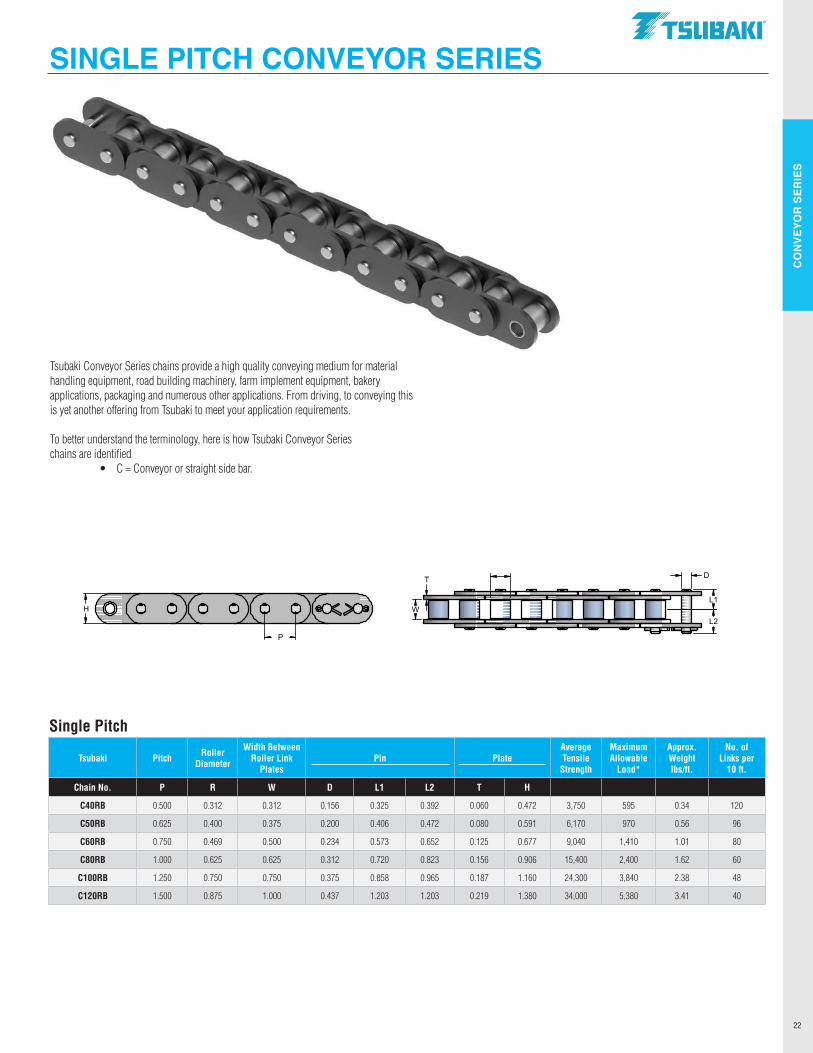
CO
NVE
YOR
SER
IES
22
Tsubaki Pitch Roller Diameter
Width Between Roller Link
PlatesPin Plate
Average Tensile
Strength
Maximum Allowable
Load*
Approx. Weight lbs/ft.
No. of Links per
10 ft.
Chain No. P R W D L1 L2 T H
C40RB 0.500 0.312 0.312 0.156 0.325 0.392 0.060 0.472 3,750 595 0.34 120
C50RB 0.625 0.400 0.375 0.200 0.406 0.472 0.080 0.591 6,170 970 0.56 96
C60RB 0.750 0.469 0.500 0.234 0.573 0.652 0.125 0.677 9,040 1,410 1.01 80
C80RB 1.000 0.625 0.625 0.312 0.720 0.823 0.156 0.906 15,400 2,400 1.62 60
C100RB 1.250 0.750 0.750 0.375 0.858 0.965 0.187 1.160 24,300 3,840 2.38 48
C120RB 1.500 0.875 1.000 0.437 1.203 1.203 0.219 1.380 34,000 5,380 3.41 40
SINGLE PITCH CONVEYOR SERIES
Single Pitch
Tsubaki Conveyor Series chains provide a high quality conveying medium for material handling equipment, road building machinery, farm implement equipment, bakery applications, packaging and numerous other applications. From driving, to conveying this is yet another offering from Tsubaki to meet your application requirements. To better understand the terminology, here is how Tsubaki Conveyor Series chains are identified • C = Conveyor or straight side bar.
L2
L1
P
H W
DT
.TSllBAKI"
------------
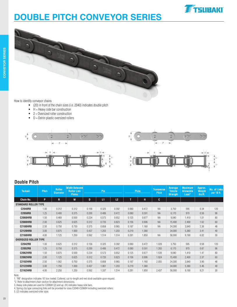
CO
NVE
YOR
SER
IES
23
L1
L2
W
DR
T
P
H
L1
L2
W
DR
T
P
H
Double Pitch
DOUBLE PITCH CONVEYOR SERIES
How to identify conveyor chains • (20) in front of the chain sizes (i.e. 2040) indicates double pitch • H = Heavy side bar construction • 2 = Oversized roller construction • D = Delrin plastic oversized rollers
Tsubaki Pitch Roller Diameter
Width Between Roller Link
PlatesPin Plate Transverse
Pitch
Average Tensile
Strength
Maximum Allowable
Load*
Approx. Weight lbs/ft.
No. of Links per 10 ft.
Chain No. P R W D L1 L2 T H C
STANDARD ROLLER TYPE
C2040RB 1.00 0.312 0.312 0.156 0.325 0.392 0.060 0.472 NA 3,750 595 0.34 120
C2050RB 1.25 0.400 0.375 0.200 0.406 0.472 0.080 0.591 NA 6,170 970 0.56 96
C2060HRB 1.50 0.469 0.500 0.234 0.573 0.652 0.125 0.677 NA 9,040 1,410 1.01 80
C2080HRB 2.00 0.625 0.625 0.312 0.720 0.823 0.156 0.906 NA 15,400 2,400 1.62 60
C2100HRB 2.50 0.750 0.750 0.375 0.858 0.965 0.187 1.160 NA 24,300 3,840 2.38 48
C2120HRB 3.00 0.875 1.000 0.437 1.203 1.203 0.219 1.380 34,000 5,380 3.41 40
C2160HRB 4.00 1.125 1.250 0.562 1.514 1.514 0.281 1.850 NA 58,000 9,190 6.02 30
OVERSIZED ROLLER TYPE
C2042RB 1.00 0.625 0.312 0.156 0.325 0.392 0.060 0.472 1.028 3,750 595 0.58 120
C2052RB 1.25 0.750 0.375 0.200 0.406 0.472 0.080 0.591 1.283 6,170 970 0.87 96
C2062HRB 1.50 0.875 0.500 0.234 0.573 0.652 0.125 0.677 1.539 9,040 1,410 1.47 80
C2082HRB 2.00 1.125 0.625 0.312 0.720 0.823 0.156 0.906 1.924 15,400 2,400 2.37 60
C2102HRB 2.50 1.562 0.750 0.375 0.858 0.965 0.187 1.160 2.055 24,300 3,840 3.90 48
C2122HRB 3.00 1.750 1.000 0.437 1.061 1.203 0.219 1.380 34,000 5,380 5.46 40
C2162HRB 4.00 2.250 1.250 0.562 1.337 1.514 0.281 1.850 2.437 58,000 9,190 9.21 30
Note: 1. “RB” designation indicates 10’ box riveted. Cottered, cut-to-length and reel stock available upon request.*2. Refer to attachment chain section for attachment dimensions.3. Heavy side plates are used for C2060H (2) and up. (H) indicates heavy side bars.4. Spring clip type connecting links will be provided for sizes C2040-C2060H including oversized rollers.5. (2) indicates oversized roller style.
.TSllBAKI"
--------------I I T
I I T T
I I T
I I T
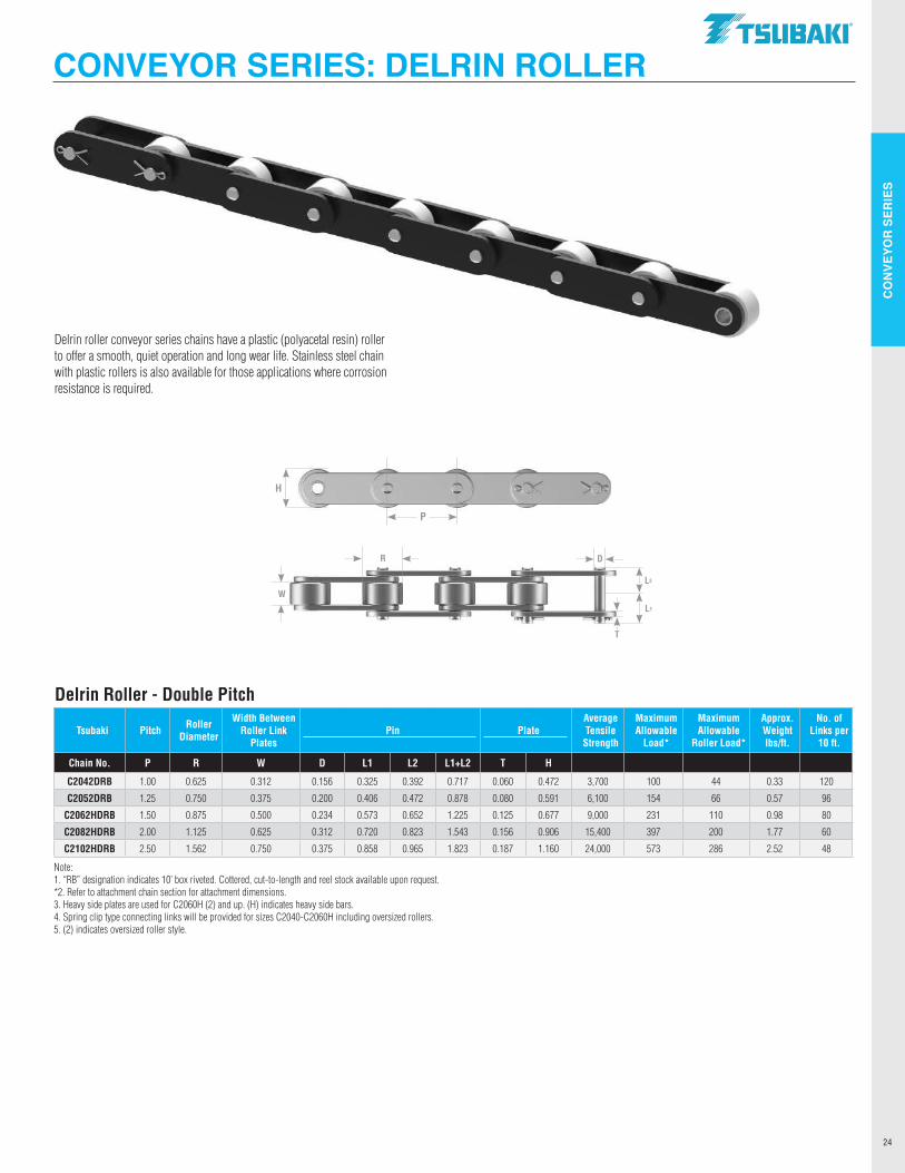
CO
NVE
YOR
SER
IES
24
CONVEYOR SERIES: DELRIN ROLLER
Delrin Roller - Double Pitch
Delrin roller conveyor series chains have a plastic (polyacetal resin) roller to offer a smooth, quiet operation and long wear life. Stainless steel chain with plastic rollers is also available for those applications where corrosion resistance is required.
L2
L1
W
DR
T
P
H
Tsubaki Pitch Roller Diameter
Width Between Roller Link
PlatesPin Plate
Average Tensile
Strength
Maximum Allowable
Load*
Maximum Allowable
Roller Load*
Approx. Weight lbs/ft.
No. of Links per
10 ft.
Chain No. P R W D L1 L2 L1+L2 T H
C2042DRB 1.00 0.625 0.312 0.156 0.325 0.392 0.717 0.060 0.472 3,700 100 44 0.33 120
C2052DRB 1.25 0.750 0.375 0.200 0.406 0.472 0.878 0.080 0.591 6,100 154 66 0.57 96
C2062HDRB 1.50 0.875 0.500 0.234 0.573 0.652 1.225 0.125 0.677 9,000 231 110 0.98 80
C2082HDRB 2.00 1.125 0.625 0.312 0.720 0.823 1.543 0.156 0.906 15,400 397 200 1.77 60
C2102HDRB 2.50 1.562 0.750 0.375 0.858 0.965 1.823 0.187 1.160 24,000 573 286 2.52 48
Note: 1. “RB” designation indicates 10’ box riveted. Cottered, cut-to-length and reel stock available upon request.*2. Refer to attachment chain section for attachment dimensions.3. Heavy side plates are used for C2060H (2) and up. (H) indicates heavy side bars.4. Spring clip type connecting links will be provided for sizes C2040-C2060H including oversized rollers.5. (2) indicates oversized roller style.
.TSllBAKI"
---------------
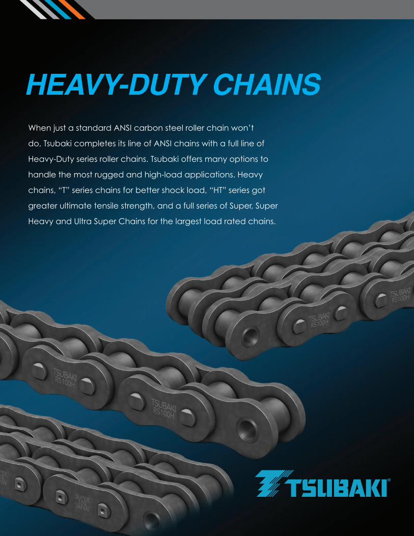
When just a standard ANSI carbon steel roller chain won’t
do, Tsubaki completes its line of ANSI chains with a full line of
Heavy-Duty series roller chains. Tsubaki offers many options to
handle the most rugged and high-load applications. Heavy
chains, “T” series chains for better shock load, “HT” series got
greater ultimate tensile strength, and a full series of Super, Super
Heavy and Ultra Super Chains for the largest load rated chains.
HEAVY-DUTY CHAINS
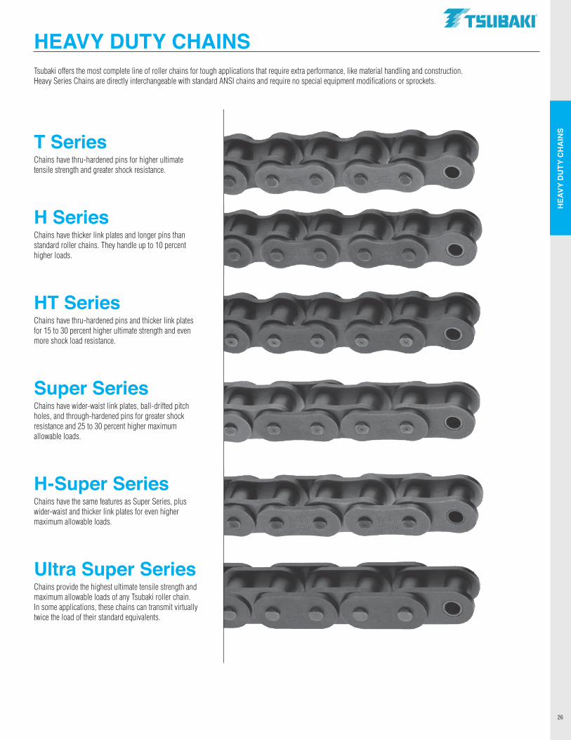
HEA
VY D
UTY
CH
AIN
S
26
HEAVY-DUTY CHAINS
HEAVY DUTY CHAINS Tsubaki offers the most complete line of roller chains for tough applications that require extra performance, like material handling and construction. Heavy Series Chains are directly interchangeable with standard ANSI chains and require no special equipment modifications or sprockets.
T Series Chains have thru-hardened pins for higher ultimate tensile strength and greater shock resistance.
H Series Chains have thicker link plates and longer pins than standard roller chains. They handle up to 10 percent higher loads.
HT Series Chains have thru-hardened pins and thicker link plates for 15 to 30 percent higher ultimate strength and even more shock load resistance.
Super Series Chains have wider-waist link plates, ball-drifted pitch holes, and through-hardened pins for greater shock resistance and 25 to 30 percent higher maximum allowable loads.
H-Super Series Chains have the same features as Super Series, plus wider-waist and thicker link plates for even higher maximum allowable loads.
Ultra Super Series Chains provide the highest ultimate tensile strength and maximum allowable loads of any Tsubaki roller chain. In some applications, these chains can transmit virtually twice the load of their standard equivalents.
.TSUBAKI"
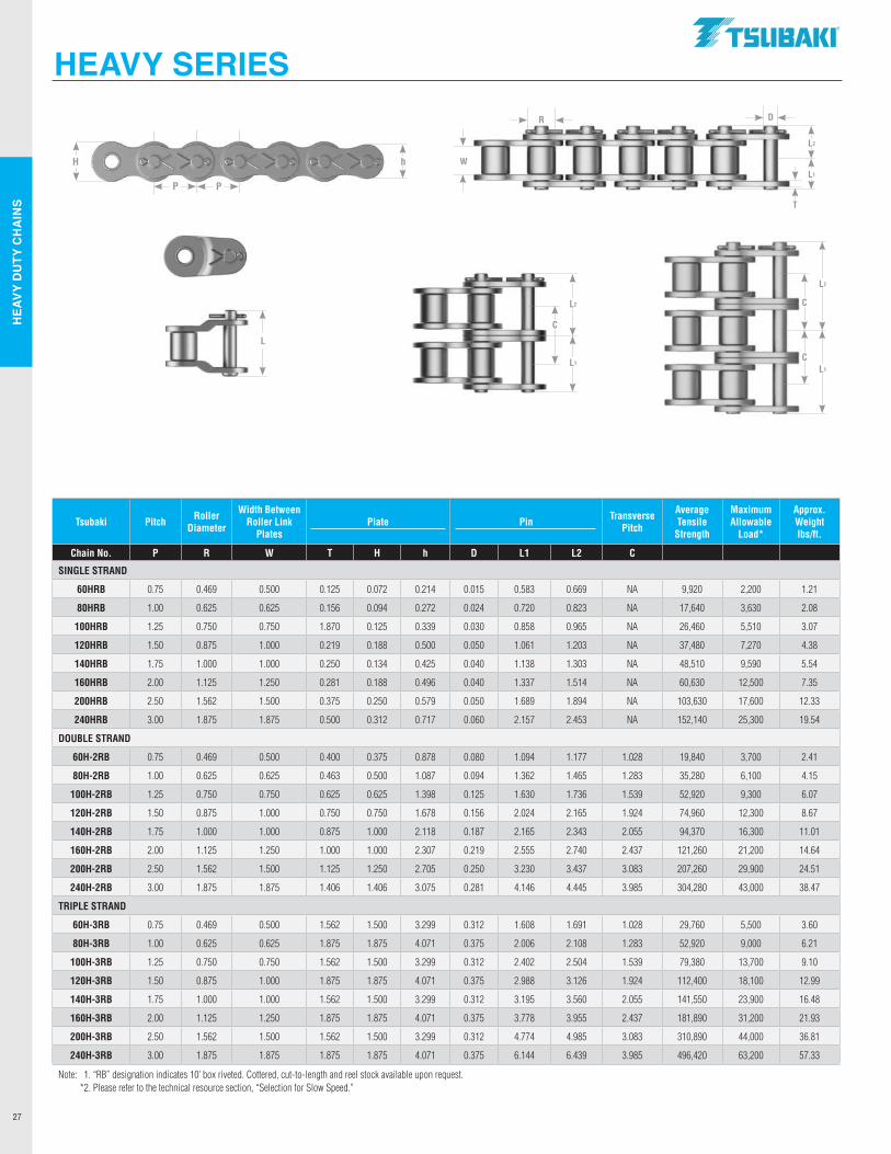
HEA
VY D
UTY
CH
AIN
S
27
HEAVY SERIES
Tsubaki Pitch Roller Diameter
Width Between Roller Link
PlatesPlate Pin Transverse
Pitch
Average Tensile
Strength
Maximum Allowable
Load*
Approx. Weight lbs/ft.
Chain No. P R W T H h D L1 L2 C
SINGLE STRAND
60HRB 0.75 0.469 0.500 0.125 0.072 0.214 0.015 0.583 0.669 NA 9,920 2,200 1.21
80HRB 1.00 0.625 0.625 0.156 0.094 0.272 0.024 0.720 0.823 NA 17,640 3,630 2.08
100HRB 1.25 0.750 0.750 1.870 0.125 0.339 0.030 0.858 0.965 NA 26,460 5,510 3.07
120HRB 1.50 0.875 1.000 0.219 0.188 0.500 0.050 1.061 1.203 NA 37,480 7,270 4.38
140HRB 1.75 1.000 1.000 0.250 0.134 0.425 0.040 1.138 1.303 NA 48,510 9,590 5.54
160HRB 2.00 1.125 1.250 0.281 0.188 0.496 0.040 1.337 1.514 NA 60,630 12,500 7.35
200HRB 2.50 1.562 1.500 0.375 0.250 0.579 0.050 1.689 1.894 NA 103,630 17,600 12.33
240HRB 3.00 1.875 1.875 0.500 0.312 0.717 0.060 2.157 2.453 NA 152,140 25,300 19.54
DOUBLE STRAND
60H-2RB 0.75 0.469 0.500 0.400 0.375 0.878 0.080 1.094 1.177 1.028 19,840 3,700 2.41
80H-2RB 1.00 0.625 0.625 0.463 0.500 1.087 0.094 1.362 1.465 1.283 35,280 6,100 4.15
100H-2RB 1.25 0.750 0.750 0.625 0.625 1.398 0.125 1.630 1.736 1.539 52,920 9,300 6.07
120H-2RB 1.50 0.875 1.000 0.750 0.750 1.678 0.156 2.024 2.165 1.924 74,960 12,300 8.67
140H-2RB 1.75 1.000 1.000 0.875 1.000 2.118 0.187 2.165 2.343 2.055 94,370 16,300 11.01
160H-2RB 2.00 1.125 1.250 1.000 1.000 2.307 0.219 2.555 2.740 2.437 121,260 21,200 14.64
200H-2RB 2.50 1.562 1.500 1.125 1.250 2.705 0.250 3.230 3.437 3.083 207,260 29,900 24.51
240H-2RB 3.00 1.875 1.875 1.406 1.406 3.075 0.281 4.146 4.445 3.985 304,280 43,000 38.47
TRIPLE STRAND
60H-3RB 0.75 0.469 0.500 1.562 1.500 3.299 0.312 1.608 1.691 1.028 29,760 5,500 3.60
80H-3RB 1.00 0.625 0.625 1.875 1.875 4.071 0.375 2.006 2.108 1.283 52,920 9,000 6.21
100H-3RB 1.25 0.750 0.750 1.562 1.500 3.299 0.312 2.402 2.504 1.539 79,380 13,700 9.10
120H-3RB 1.50 0.875 1.000 1.875 1.875 4.071 0.375 2.988 3.126 1.924 112,400 18,100 12.99
140H-3RB 1.75 1.000 1.000 1.562 1.500 3.299 0.312 3.195 3.560 2.055 141,550 23,900 16.48
160H-3RB 2.00 1.125 1.250 1.875 1.875 4.071 0.375 3.778 3.955 2.437 181,890 31,200 21.93
200H-3RB 2.50 1.562 1.500 1.562 1.500 3.299 0.312 4.774 4.985 3.083 310,890 44,000 36.81
240H-3RB 3.00 1.875 1.875 1.875 1.875 4.071 0.375 6.144 6.439 3.985 496,420 63,200 57.33
Note: 1. “RB” designation indicates 10’ box riveted. Cottered, cut-to-length and reel stock available upon request. *2. Please refer to the technical resource section, “Selection for Slow Speed.”
P P
hH
L2
L1
C
L2
L1
C
C
L
L2
L1
W
DR
T
.TSUBAKI"
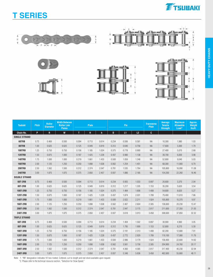
HEA
VY D
UTY
CH
AIN
S
28
Tsubaki Pitch Roller Diameter
Width Between Roller Link
PlatesPlate Pin Transverse
Pitch
Average Tensile
Strength
Maximum Allowable
Load*
Approx. Weight lbs/ft.
Chain No. P R W T H h D L1 L2 C
SINGLE STRAND
60TRB 0.75 0.469 0.500 0.094 0.713 0.614 0.234 0.506 0.581 NA 10,300 1,980 1.03
80TRB 1.00 0.625 0.625 0.125 0.949 0.819 0.312 0.640 0.758 NA 17,600 3,300 1.79
100TRB 1.25 0.750 0.750 0.156 1.185 1.024 0.375 0.778 0.900 NA 27,400 5,070 2.68
120TRB 1.50 0.875 1.000 0.187 1.425 1.228 0.437 0.980 1.138 NA 39,700 6,830 3.98
140TRB 1.75 1.000 1.000 0.219 1.661 1.433 0.500 1.059 1.248 NA 52,800 9,040 5.03
160TRB 2.00 1.125 1.250 0.250 1.898 1.638 0.562 1.254 1.451 NA 68,300 11,900 6.79
200TRB 2.50 1.562 1.500 0.312 2.374 2.047 0.781 1.535 1.764 NA 105,800 16,090 11.08
240TRB 3.00 1.875 1.875 0.375 2.850 2.457 0.937 1.886 2.185 NA 154,200 22,260 16.46
DOUBLE STRAND
60T-2RB 0.75 0.469 0.500 0.094 0.713 0.614 0.234 0.955 1.033 0.897 20,600 3,370 2.04
80T-2RB 1.00 0.625 0.625 0.125 0.949 0.819 0.312 1.217 1.335 1.153 35,200 5,620 3.54
100T-2RB 1.25 0.750 0.750 0.156 1.185 1.024 0.375 1.484 1.606 1.408 54,600 8,620 5.27
120T-2RB 1.50 0.875 1.000 0.187 1.425 1.228 0.437 1.874 2.031 1.789 79,400 11,610 7.86
140T-2RB 1.75 1.000 1.000 0.219 1.661 1.433 0.500 2.022 2.211 1.924 105,800 15,370 9.97
160T-2RB 2.00 1.125 1.250 0.250 1.898 1.638 0.562 2.407 2.604 2.305 136,600 20,230 13.47
200T-2RB 2.50 1.562 1.500 0.312 2.374 2.047 0.781 2.947 3.175 2.817 211,600 27,350 21.93
240T-2RB 3.00 1.875 1.875 0.375 2.850 2.457 0.937 3.618 3.913 3.458 308,600 37,850 32.32
TRIPLE STRAND
60T-3RB 0.75 0.469 0.500 0.094 0.713 0.614 0.234 1.404 1.502 0.897 30,900 4,960 3.05
80T-3RB 1.00 0.625 0.625 0.125 0.949 0.819 0.312 1.795 1.909 1.153 52,800 8,270 5.30
100T-3RB 1.25 0.750 0.750 0.156 1.185 1.024 0.375 2.191 2.313 1.408 82,200 12,680 7.91
120T-3RB 1.50 0.875 1.000 0.187 1.425 1.228 0.437 2.772 2.929 1.789 119,100 17,080 11.76
140T-3RB 1.75 1.000 1.000 0.219 1.661 1.433 0.500 2.986 3.179 1.924 158,400 22,600 14.92
160T-3RB 2.00 1.125 1.250 0.250 1.898 1.638 0.562 3.561 3.758 2.305 204,900 24,760 20.17
200T-3RB 2.50 1.562 1.500 0.312 2.374 2.047 0.781 4.360 4.585 2.817 317,400 40,230 32.94
240T-3RB 3.00 1.875 1.875 0.375 2.850 2.457 0.937 5.348 5.636 3.458 462,600 55,660 48.11
Note: 1. “RB” designation indicates 10’ box riveted. Cottered, cut-to-length and reel stock available upon request. *2. Please refer to the technical resource section, “Selection for Slow Speed.”
T SERIES
P P
hH
L2
L1
C
L2
L1
C
CL
L2
L1
W
DR
T
.TSUBAKI"
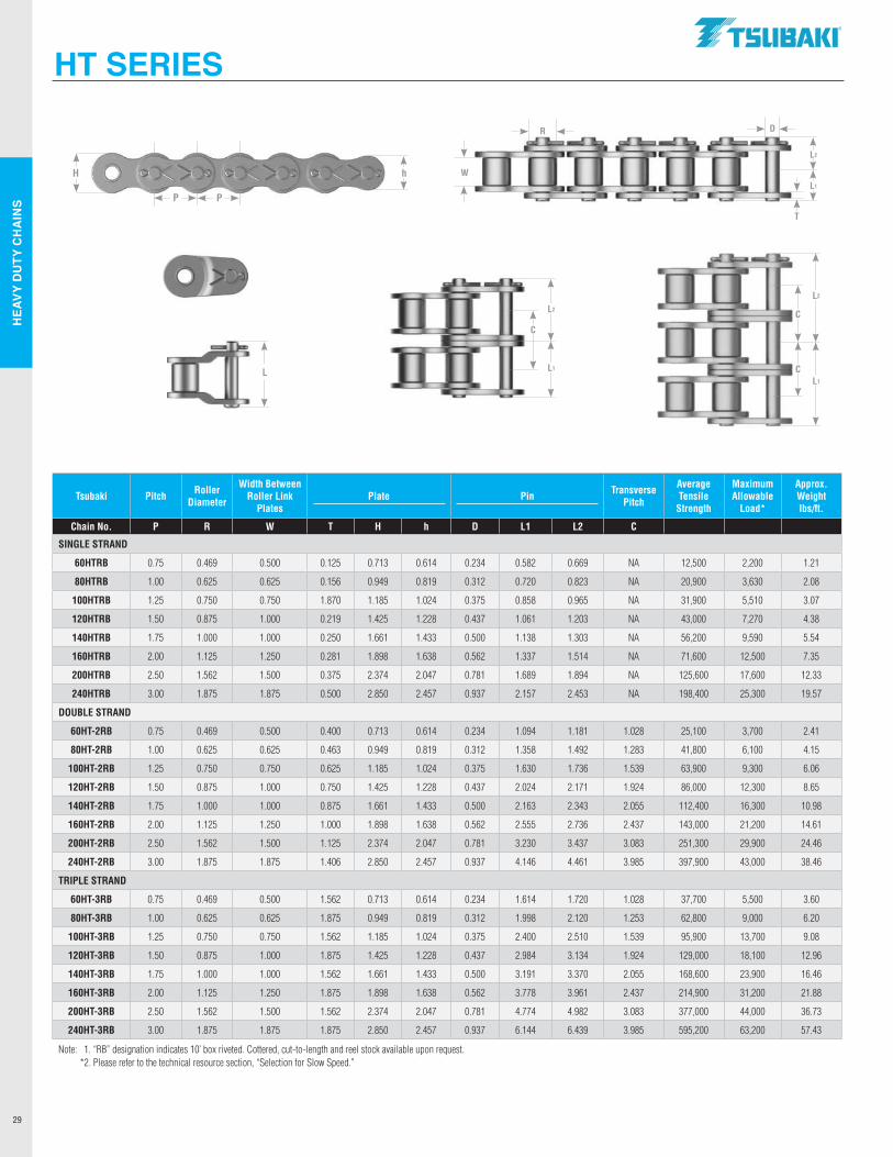
HEA
VY D
UTY
CH
AIN
S
29
Tsubaki Pitch Roller Diameter
Width Between Roller Link
PlatesPlate Pin Transverse
Pitch
Average Tensile
Strength
Maximum Allowable
Load*
Approx. Weight lbs/ft.
Chain No. P R W T H h D L1 L2 C
SINGLE STRAND
60HTRB 0.75 0.469 0.500 0.125 0.713 0.614 0.234 0.582 0.669 NA 12,500 2,200 1.21
80HTRB 1.00 0.625 0.625 0.156 0.949 0.819 0.312 0.720 0.823 NA 20,900 3,630 2.08
100HTRB 1.25 0.750 0.750 1.870 1.185 1.024 0.375 0.858 0.965 NA 31,900 5,510 3.07
120HTRB 1.50 0.875 1.000 0.219 1.425 1.228 0.437 1.061 1.203 NA 43,000 7,270 4.38
140HTRB 1.75 1.000 1.000 0.250 1.661 1.433 0.500 1.138 1.303 NA 56,200 9,590 5.54
160HTRB 2.00 1.125 1.250 0.281 1.898 1.638 0.562 1.337 1.514 NA 71,600 12,500 7.35
200HTRB 2.50 1.562 1.500 0.375 2.374 2.047 0.781 1.689 1.894 NA 125,600 17,600 12.33
240HTRB 3.00 1.875 1.875 0.500 2.850 2.457 0.937 2.157 2.453 NA 198,400 25,300 19.57
DOUBLE STRAND
60HT-2RB 0.75 0.469 0.500 0.400 0.713 0.614 0.234 1.094 1.181 1.028 25,100 3,700 2.41
80HT-2RB 1.00 0.625 0.625 0.463 0.949 0.819 0.312 1.358 1.492 1.283 41,800 6,100 4.15
100HT-2RB 1.25 0.750 0.750 0.625 1.185 1.024 0.375 1.630 1.736 1.539 63,900 9,300 6.06
120HT-2RB 1.50 0.875 1.000 0.750 1.425 1.228 0.437 2.024 2.171 1.924 86,000 12,300 8.65
140HT-2RB 1.75 1.000 1.000 0.875 1.661 1.433 0.500 2.163 2.343 2.055 112,400 16,300 10.98
160HT-2RB 2.00 1.125 1.250 1.000 1.898 1.638 0.562 2.555 2.736 2.437 143,000 21,200 14.61
200HT-2RB 2.50 1.562 1.500 1.125 2.374 2.047 0.781 3.230 3.437 3.083 251,300 29,900 24.46
240HT-2RB 3.00 1.875 1.875 1.406 2.850 2.457 0.937 4.146 4.461 3.985 397,900 43,000 38.46
TRIPLE STRAND
60HT-3RB 0.75 0.469 0.500 1.562 0.713 0.614 0.234 1.614 1.720 1.028 37,700 5,500 3.60
80HT-3RB 1.00 0.625 0.625 1.875 0.949 0.819 0.312 1.998 2.120 1.253 62,800 9,000 6.20
100HT-3RB 1.25 0.750 0.750 1.562 1.185 1.024 0.375 2.400 2.510 1.539 95,900 13,700 9.08
120HT-3RB 1.50 0.875 1.000 1.875 1.425 1.228 0.437 2.984 3.134 1.924 129,000 18,100 12.96
140HT-3RB 1.75 1.000 1.000 1.562 1.661 1.433 0.500 3.191 3.370 2.055 168,600 23,900 16.46
160HT-3RB 2.00 1.125 1.250 1.875 1.898 1.638 0.562 3.778 3.961 2.437 214,900 31,200 21.88
200HT-3RB 2.50 1.562 1.500 1.562 2.374 2.047 0.781 4.774 4.982 3.083 377,000 44,000 36.73
240HT-3RB 3.00 1.875 1.875 1.875 2.850 2.457 0.937 6.144 6.439 3.985 595,200 63,200 57.43
Note: 1. “RB” designation indicates 10’ box riveted. Cottered, cut-to-length and reel stock available upon request. *2. Please refer to the technical resource section, “Selection for Slow Speed.”
HT SERIES
P P
hH
L2
L1
C
L2
L1
C
CL
L2
L1
W
DR
T
.TSUBAKI"
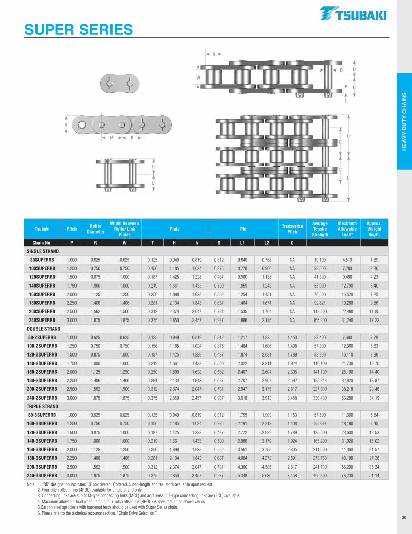
HEA
VY D
UTY
CH
AIN
S
30
SUPER SERIES
P P
H
L2
L1
W
R
T
D
L1
L1
L2
L1
C
C
Tsubaki Pitch Roller Diameter
Width Between Roller Link
PlatesPlate Pin Transverse
Pitch
Average Tensile
Strength
Maximum Allowable
Load*
Approx. Weight lbs/ft.
Chain No. P R W T H h D L1 L2 C
SINGLE STRAND
80SUPERRB 1.000 0.625 0.625 0.125 0.949 0.819 0.312 0.640 0.758 NA 19,100 4,510 1.89
100SUPERRB 1.250 0.750 0.750 0.156 1.185 1.024 0.375 0.778 0.900 NA 28,500 7,280 2.86
120SUPERRB 1.500 0.875 1.000 0.187 1.425 1.228 0.437 0.980 1.138 NA 41,800 9,480 4.23
140SUPERRB 1.750 1.000 1.000 0.219 1.661 1.433 0.500 1.059 1.248 NA 55,000 12,790 5.40
160SUPERRB 2.000 1.125 1.250 0.250 1.898 1.638 0.562 1.254 1.451 NA 70,500 16,520 7.25
180SUPERRB 2.250 1.406 1.406 0.281 2.134 1.843 0.687 1.404 1.671 NA 92,621 19,260 9.56
200SUPERRB 2.500 1.562 1.500 0.312 2.374 2.047 0.781 1.535 1.764 NA 113,500 22,480 11.85
240SUPERRB 3.000 1.875 1.875 0.375 2.850 2.457 0.937 1.886 2.185 NA 165,200 31,240 17.22
DOUBLE STRAND
80-2SUPERRB 1.000 0.625 0.625 0.125 0.949 0.819 0.312 1.217 1.335 1.153 38,400 7,680 3.78
100-2SUPERRB 1.250 0.750 0.750 0.156 1.185 1.024 0.375 1.484 1.606 1.408 57,300 12,360 5.63
120-2SUPERRB 1.500 0.875 1.000 0.187 1.425 1.228 0.437 1.874 2.031 1.789 83,800 16,110 8.36
140-2SUPERRB 1.750 1.000 1.000 0.219 1.661 1.433 0.500 2.022 2.211 1.924 110,100 21,730 10.70
160-2SUPERRB 2.000 1.125 1.250 0.250 1.898 1.638 0.562 2.407 2.604 2.305 141,100 28,100 14.40
180-2SUPERRB 2.250 1.406 1.406 0.281 2.134 1.843 0.687 2.707 2.967 2.592 185,243 32,820 18.87
200-2SUPERRB 2.500 1.562 1.500 0.312 2.374 2.047 0.781 2.947 3.175 2.817 227,000 38,210 23.46
240-2SUPERRB 3.000 1.875 1.875 0.375 2.850 2.457 0.937 3.618 3.913 3.458 330,400 53,280 34.19
TRIPLE STRAND
80-3SUPERRB 1.000 0.625 0.625 0.125 0.949 0.819 0.312 1.795 1.909 1.153 57,500 11,300 5.64
100-3SUPERRB 1.250 0.750 0.750 0.156 1.185 1.024 0.375 2.191 2.313 1.408 85,800 18,180 8.45
120-3SUPERRB 1.500 0.875 1.000 0.187 1.425 1.228 0.437 2.772 2.929 1.789 125,600 23,600 12.53
140-3SUPERRB 1.750 1.000 1.000 0.219 1.661 1.433 0.500 2.986 3.179 1.924 165,200 31,920 16.02
160-3SUPERRB 2.000 1.125 1.250 0.250 1.898 1.638 0.562 3.561 3.758 2.305 211,500 41,360 21.57
180-3SUPERRB 2.250 1.406 1.406 0.281 2.134 1.843 0.687 4.004 4.272 2.591 278,763 48,100 27.26
200-3SUPERRB 2.500 1.562 1.500 0.312 2.374 2.047 0.781 4.360 4.585 2.817 241,700 56,200 35.24
240-3SUPERRB 3.000 1.875 1.875 0.375 2.850 2.457 0.937 5.348 5.636 3.458 496,800 78,230 51.14
Note: 1. “RB” designation indicates 10’ box riveted. Cottered, cut-to-length and reel stock available upon request. 2. Four-pitch offset links (4POL) available for single strand only. 3. Connecting links are slip fit M-type connecting links (MCL) and and press fit F-type connecting links are (FCL) available. 4. Maximum allowable load when using a four-pitch offset link (4POL) is 85% that of the above values. 5.Carbon steel sprockets with hardened teeth should be used with Super Series chain. 6. Please refer to the technical resource section, “Chain Drive Selection.”
.TSUBAKI"
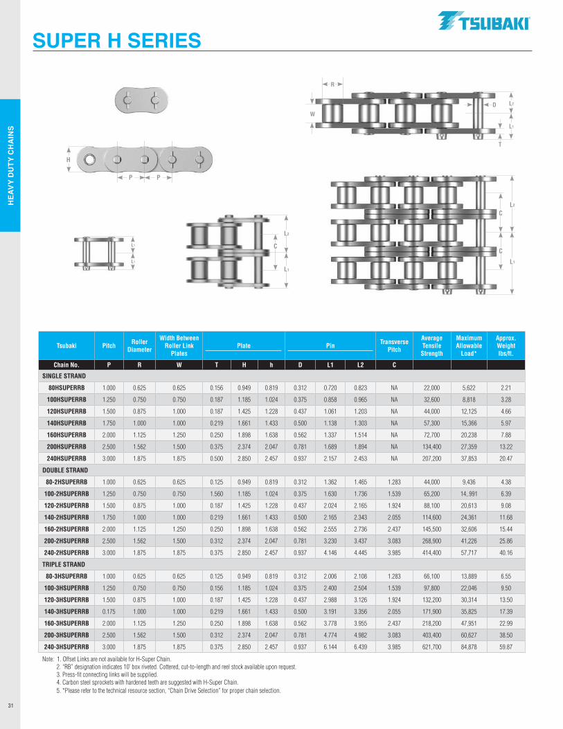
HEA
VY D
UTY
CH
AIN
S
31
P P
H
RollerDia.
SUPER H SERIES
L2
L1
W
R
T
D
L1
L1
L2
L1
C
C
L2
L1
C
Tsubaki Pitch Roller Diameter
Width Between Roller Link
PlatesPlate Pin Transverse
Pitch
Average Tensile
Strength
Maximum Allowable
Load*
Approx. Weight lbs/ft.
Chain No. P R W T H h D L1 L2 C
SINGLE STRAND
80HSUPERRB 1.000 0.625 0.625 0.156 0.949 0.819 0.312 0.720 0.823 NA 22,000 5,622 2.21
100HSUPERRB 1.250 0.750 0.750 0.187 1.185 1.024 0.375 0.858 0.965 NA 32,600 8,818 3.28
120HSUPERRB 1.500 0.875 1.000 0.187 1.425 1.228 0.437 1.061 1.203 NA 44,000 12,125 4.66
140HSUPERRB 1.750 1.000 1.000 0.219 1.661 1.433 0.500 1.138 1.303 NA 57,300 15,366 5.97
160HSUPERRB 2.000 1.125 1.250 0.250 1.898 1.638 0.562 1.337 1.514 NA 72,700 20,238 7.88
200HSUPERRB 2.500 1.562 1.500 0.375 2.374 2.047 0.781 1.689 1.894 NA 134,400 27,359 13.22
240HSUPERRB 3.000 1.875 1.875 0.500 2.850 2.457 0.937 2.157 2.453 NA 207,200 37,853 20.47
DOUBLE STRAND
80-2HSUPERRB 1.000 0.625 0.625 0.125 0.949 0.819 0.312 1.362 1.465 1.283 44,000 9,436 4.38
100-2HSUPERRB 1.250 0.750 0.750 1.560 1.185 1.024 0.375 1.630 1.736 1.539 65,200 14,.991 6.39
120-2HSUPERRB 1.500 0.875 1.000 0.187 1.425 1.228 0.437 2.024 2.165 1.924 88,100 20,613 9.08
140-2HSUPERRB 1.750 1.000 1.000 0.219 1.661 1.433 0.500 2.165 2.343 2.055 114,600 24,361 11.68
160-2HSUPERRB 2.000 1.125 1.250 0.250 1.898 1.638 0.562 2.555 2.736 2.437 145,500 32,606 15.44
200-2HSUPERRB 2.500 1.562 1.500 0.312 2.374 2.047 0.781 3.230 3.437 3.083 268,900 41,226 25.86
240-2HSUPERRB 3.000 1.875 1.875 0.375 2.850 2.457 0.937 4.146 4.445 3.985 414,400 57,717 40.16
TRIPLE STRAND
80-3HSUPERRB 1.000 0.625 0.625 0.125 0.949 0.819 0.312 2.006 2.108 1.283 66,100 13,889 6.55
100-3HSUPERRB 1.250 0.750 0.750 0.156 1.185 1.024 0.375 2.400 2.504 1.539 97,800 22,046 9.50
120-3HSUPERRB 1.500 0.875 1.000 0.187 1.425 1.228 0.437 2.988 3.126 1.924 132,200 30,314 13.50
140-3HSUPERRB 0.175 1.000 1.000 0.219 1.661 1.433 0.500 3.191 3.356 2.055 171,900 35,825 17.39
160-3HSUPERRB 2.000 1.125 1.250 0.250 1.898 1.638 0.562 3.778 3.955 2.437 218,200 47,951 22.99
200-3HSUPERRB 2.500 1.562 1.500 0.312 2.374 2.047 0.781 4.774 4.982 3.083 403,400 60,627 38.50
240-3HSUPERRB 3.000 1.875 1.875 0.375 2.850 2.457 0.937 6.144 6.439 3.985 621,700 84,878 59.87
Note: 1. Offset Links are not available for H-Super Chain. 2. “RB” designation indicates 10’ box riveted. Cottered, cut-to-length and reel stock available upon request. 3. Press-fit connecting links will be supplied. 4. Carbon steel sprockets with hardened teeth are suggested with H-Super Chain. 5. *Please refer to the technical resource section, “Chain Drive Selection” for proper chain selection.
.TSUBAKI"
DE
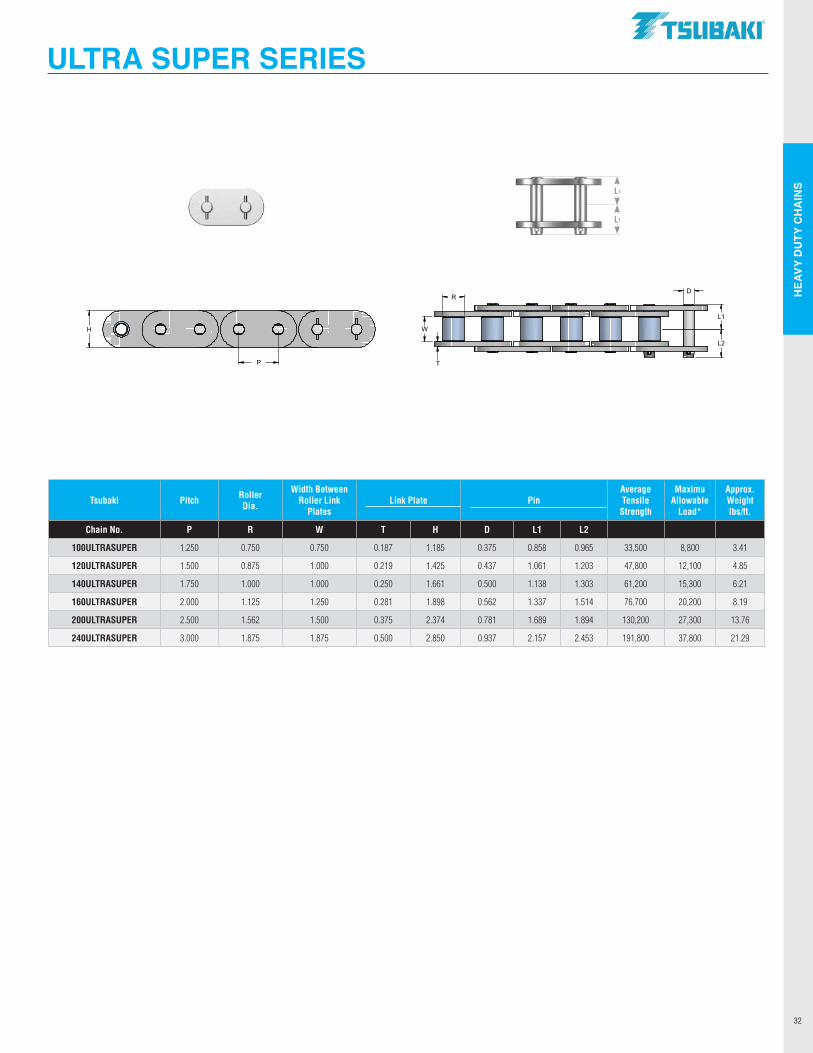
HEA
VY D
UTY
CH
AIN
S
32
ULTRA SUPER SERIES
L1
L1
Tsubaki Pitch Roller Dia.
Width Between Roller Link
PlatesLink Plate Pin
Average Tensile
Strength
Maximu Allowable
Load*
Approx. Weight lbs/ft.
Chain No. P R W T H D L1 L2
100ULTRASUPER 1.250 0.750 0.750 0.187 1.185 0.375 0.858 0.965 33,500 8,800 3.41
120ULTRASUPER 1.500 0.875 1.000 0.219 1.425 0.437 1.061 1.203 47,800 12,100 4.85
140ULTRASUPER 1.750 1.000 1.000 0.250 1.661 0.500 1.138 1.303 61,200 15,300 6.21
160ULTRASUPER 2.000 1.125 1.250 0.281 1.898 0.562 1.337 1.514 76,700 20,200 8.19
200ULTRASUPER 2.500 1.562 1.500 0.375 2.374 0.781 1.689 1.894 130,200 27,300 13.76
240ULTRASUPER 3.000 1.875 1.875 0.500 2.850 0.937 2.157 2.453 191,800 37,800 21.29
L2
L1
WH
P
DR
T
.TSUBAKI"
GLi)
: (o (o oJCf pc◊ ◊) :;[] :,:1::,:i::,:1::1):1;1:t
--------
The core to what has made Tsubaki an industry leader in roller
chain manufacturing continues to be attachment chains.
Tsubaki stocks a complete offering of standard roller chain
attachments in single and double pitch chains. Additional
offerings include attachments for lube-free, anti-corrosion,
British Standard, hollow pin, and curved chains.
ATTACHMENT CHAINS
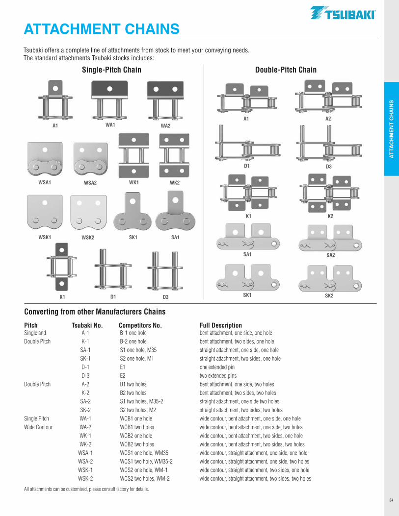
ATTA
CH
MEN
T C
HA
INS
34
Tsubaki offers a complete line of attachments from stock to meet your conveying needs. The standard attachments Tsubaki stocks includes:
Pitch Tsubaki No. Competitors No. Full DescriptionSingle and A-1 B-1 one hole bent attachment, one side, one holeDouble Pitch K-1 B-2 one hole bent attachment, two sides, one hole SA-1 S1 one hole, M35 straight attachment, one side, one hole SK-1 S2 one hole, M1 straight attachment, two sides, one hole D-1 E1 one extended pin D-3 E2 two extended pinsDouble Pitch A-2 B1 two holes bent attachment, one side, two holes K-2 B2 two holes bent attachment, two sides, two holes SA-2 S1 two holes, M35-2 straight attachment, one side two holes SK-2 S2 two holes, M2 straight attachment, two sides, two holesSingle Pitch WA-1 WCB1 one hole wide contour, bent attachment, one side, one holeWide Contour WA-2 WCB1 two holes wide contour, bent attachment, one side, two holes WK-1 WCB2 one hole wide contour, bent attachment, two sides, one hole WK-2 WCB2 two holes wide contour, bent attachment, two sides, two holes WSA-1 WCS1 one hole, WM35 wide contour, straight attachment, one side, one hole WSA-2 WCS1 two hole, WM35-2 wide contour, straight attachment, one side, two holes WSK-1 WCS2 one hole, WM-1 wide contour, straight attachment, two sides, one hole WSK-2 WCS2 two holes, WM-2 wide contour, straight attachment, two sides, two holes
All attachments can be customized, please consult factory for details.
Converting from other Manufacturers Chains
ATTACHMENT CHAINS
WSA2
A1
K1 D1 D3
SA1
WA1 WA2
SK1
WK2
WSK2
WK1WSA1
WSK1
A1 A2
D1 D3
Single-Pitch Chain Double-Pitch Chain
K1 K2
SA1 SA2
SK1 SK2
.TSllBAKI"
I I I
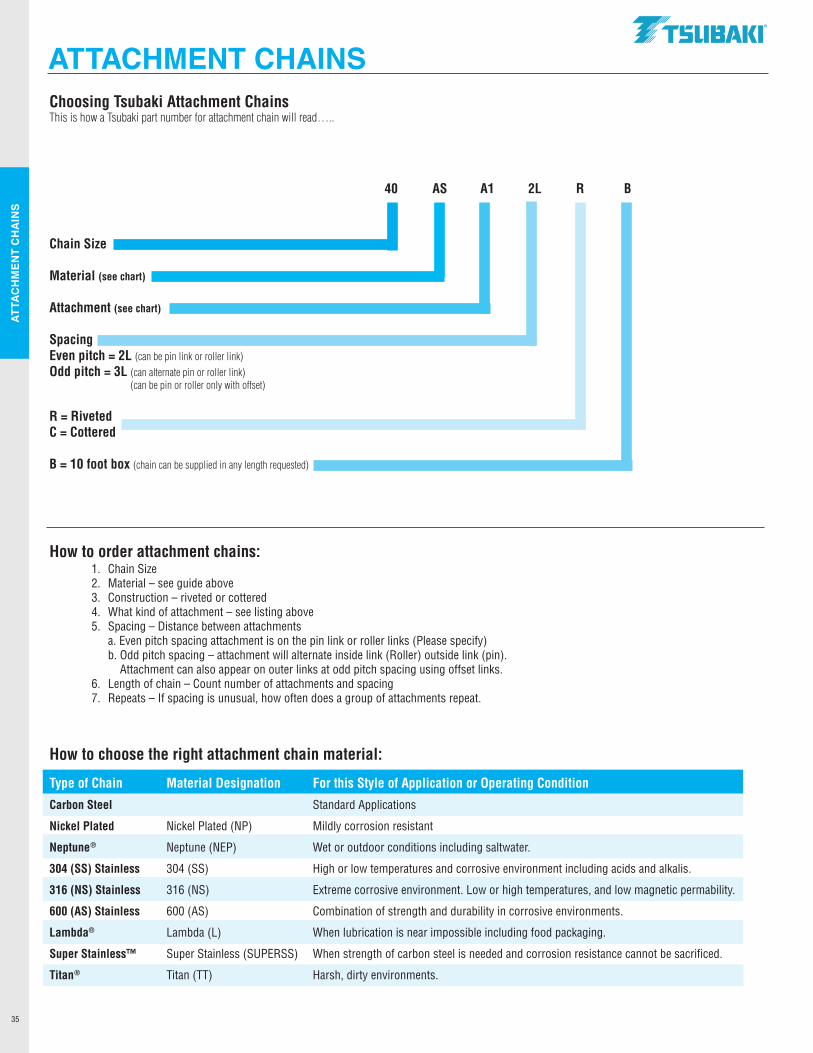
ATTA
CH
MEN
T C
HA
INS
35
Choosing Tsubaki Attachment ChainsThis is how a Tsubaki part number for attachment chain will read…..
40 AS A1 2L R B
Chain Size
Material (see chart)
Attachment (see chart)
SpacingEven pitch = 2L (can be pin link or roller link)Odd pitch = 3L (can alternate pin or roller link) (can be pin or roller only with offset)
R = RivetedC = Cottered
B = 10 foot box (chain can be supplied in any length requested)
How to order attachment chains: 1. Chain Size 2. Material – see guide above 3. Construction – riveted or cottered 4. What kind of attachment – see listing above 5. Spacing – Distance between attachments a. Even pitch spacing attachment is on the pin link or roller links (Please specify) b. Odd pitch spacing – attachment will alternate inside link (Roller) outside link (pin). Attachment can also appear on outer links at odd pitch spacing using offset links. 6. Length of chain – Count number of attachments and spacing 7. Repeats – If spacing is unusual, how often does a group of attachments repeat.
How to choose the right attachment chain material:
Type of Chain Material Designation For this Style of Application or Operating Condition
Carbon Steel Standard Applications
Nickel Plated Nickel Plated (NP) Mildly corrosion resistant
Neptune ® Neptune (NEP) Wet or outdoor conditions including saltwater.
304 (SS) Stainless 304 (SS) High or low temperatures and corrosive environment including acids and alkalis.
316 (NS) Stainless 316 (NS) Extreme corrosive environment. Low or high temperatures, and low magnetic permability.
600 (AS) Stainless 600 (AS) Combination of strength and durability in corrosive environments.
Lambda® Lambda (L) When lubrication is near impossible including food packaging.
Super Stainless™ Super Stainless (SUPERSS) When strength of carbon steel is needed and corrosion resistance cannot be sacrificed.
Titan ® Titan (TT) Harsh, dirty environments.
ATTACHMENT CHAINS.TSllBAKI"
----------' I

NOTES
36
.TSllBAKI"
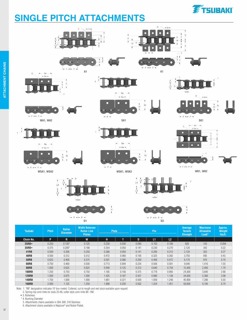
ATTA
CH
MEN
T C
HA
INS
37
SINGLE PITCH ATTACHMENTS
Approx. Weight lbs/ft.
SA1 SK1
D1 D3
WSA1, WSA2 WSK1, WSK2
WA1, WA2
WK1, WK2
Tsubaki Pitch Roller Diameter
Width Between Roller Link
PlatesPlate Pin
Average Tensile
Strength
Maximum Allowable
Load*
Approx. Weight lbs/ft.
Chain No. P R W H T D L1 L2 25RBw 0.250 0.130* 0.125 0.230 0.030 0.090 0.150 0.189 926 143 0.09435RBw 0.375 0.200* 0.188 0.354 0.050 0.141 0.230 0.270 2,120 342 0.2241RB 0.500 0.306 0.250 0.386 0.050 0.141 0.266 0.313 2,120 353 0.2740RB 0.500 0.312 0.312 0.472 0.060 0.156 0.325 0.392 3,750 595 0.4350RB 0.625 0.400 0.375 0.591 0.080 0.200 0.406 0.472 6,170 970 0.7060RB 0.750 0.469 0.500 0.713 0.094 0.234 0.506 0.581 9,040 1,410 1.0380RB 1.000 0.625 0.625 0.949 0.125 0.312 0.640 0.758 15,400 2,400 1.79
100RB 1.250 0.750 0.750 1.185 0.156 0.375 0.778 0.900 24,300 3,840 2.68120RB 1.500 0.875 1.000 1.425 0.187 0.437 0.980 1.138 34,000 5,380 3.98140RB 1.750 1.000 1.000 1.661 0.221 0.500 1.059 1.248 45,900 7,280 5.03160RB 2.000 1.125 1.250 1.898 0.250 0.562 1.254 1.451 58,000 9,190 6.79
Note: 1. “RB” designation indicates 10’ box riveted. Cottered, cut-to-length and reel stock available upon request 2. Spring clip conn links for sizes 25-60, cotter style conn links 80 -160 w 3. Rollerless * 4. Bushing Diameter 5. Attachments chains available in 304, 600, 316 Stainless 6. Attachment chains available in Neptune® and Nickel Plated.
A1 K10 ...
- Kw -
--------
• • • • • - p - p -
- Kw --
I Xs Cl
I L3
L4 I I
L2
'
11
,. II
- p -
- p -
w I
'-
Nw
- Kw -
- Kw -
11 ..
[" N-' ----r
w I
I X
I _J_ X
l IT
-'-'-r
.TSllBAKI"
• • • • •
Cl
Cl
I L3
L4 I
L2
'
Xs
Xs
I LI
I L2 D
'
... - Kw-
Xs Cl
' '
~ • • • • •
II , .
- p - p -
I 11 w I
11 ..
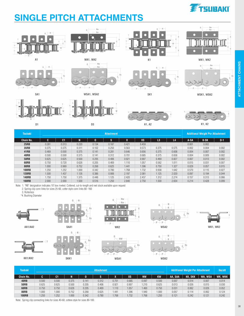
ATTA
CH
MEN
T C
HA
INS
38
Tsubaki Attachment Additional Weight Per Attachment
Chain No. C C1 N O S X XS L3 L4 A-SA K-SKD D-125RB 0.281 0.313 0.220 0.134 0.187 0.421 0.459 0.001 0.002 35RB 0.375 0.375 0.311 0.102 0.250 0.563 0.573 0.375 0.575 0.002 0.004 0.00241RB 0.469 0.500 0.375 0.141 0.281 0.646 0.656 0.375 0.608 0.004 0.007 0.00240RB 0.500 0.500 0.375 0.141 0.312 0.701 0.685 0.375 0.658 0.004 0.009 0.00250RB 0.625 0.625 0.500 0.205 0.406 0.921 0.907 0.469 0.827 0.007 0.013 0.00260RB 0.750 0.720 0.626 0.205 0.469 1.110 1.057 0.562 1.011 0.015 0.031 0.00780RB 1.000 0.969 0.752 0.268 0.625 1.441 1.396 0.750 1.327 0.029 0.057 0.015100RB 1.250 1.252 1.000 0.342 0.780 1.768 1.732 0.938 1.642 0.570 0.115 0.027120RB 1.500 1.437 1.126 0.386 0.906 2.197 2.081 1.125 2.020 0.097 0.194 0.044140RB 1.750 1.750 1.375 0.448 1.125 2.420 2.437 1.312 2.274 0.157 0.313 0.066160RB 2.000 2.000 1.500 0.516 1.250 2.840 2.750 1.500 2.654 0.214 0.428 0.099
Note: 1. “RB” designation indicates 10’ box riveted. Cottered, cut-to-length and reel stock available upon request 2. Spring clip conn links for sizes 25-60, cotter style conn links 80 -160 3. Rollerless *4. Bushing Diameter
SINGLE PITCH ATTACHMENTS
WSA1SKK1
WSA2WK2
WSK2
SAA1
P
C1Xs
NO
P
K
P
C1Xs
NO
P
K
C X
NwO
P
Kw
C X
AA1/AA2
T
KK1/KK2
T
NO
C1Xs
XsC1
NO
C1Xs
XsC1
K1
L2
L1
T
DW
CX
N
T
CX
O
SK1
P P
C1
Xs
NO
A1
L2
L1
T
D W
CX
N
T
R
O
SA1
P P
H
C1
Xs
NO
P
C1Xs
NWO
P
WSA1, WSA2
P P
C1
Xs
NwOKw
WSK1, WSK2
C1
Xs
NwOKw
P P
WA1, WA2
CX
NwOKw
WK1, WK2
CX
NwOKw
CX
D1
W
T
R
D3
L4
L2D
W
T
R
L3
T
L4
L2 D
L3
T
A1, A2 K1, K2
TTS S
TS
WK1, WK2
Tsubaki Attachment Additional Weight Per Attachment lbs/att
Chain No. C C1 N O S X XS NW KW AA, SAA KK, SKK WA, WSA WK, WKK40RB 0.500 0.500 0.375 0.141 0.312 0.701 0.685 0.097 0.500 0.007 0.014 0.007 0.01450RB 0.625 0.625 0.500 0.205 0.406 0.921 0.907 1.210 0.625 0.013 0.026 0.015 0.03060RB 0.750 0.750 0.626 0.205 0.469 1.110 1.057 1.460 0.750 0.031 0.062 0.026 0.05280RB 1.000 1.000 0.752 0.268 0.625 1.441 1.396 1.940 1.000 0.057 0.114 0.062 0.124
100RB 1.250 1.252 1.000 0.342 0.780 1.768 1.732 1.768 1.250 0.121 0.242 0.121 0.242
Note: Spring clip connecting links for sizes 40-60, cottere style for sizes 80-100.
.TSllBAKI"
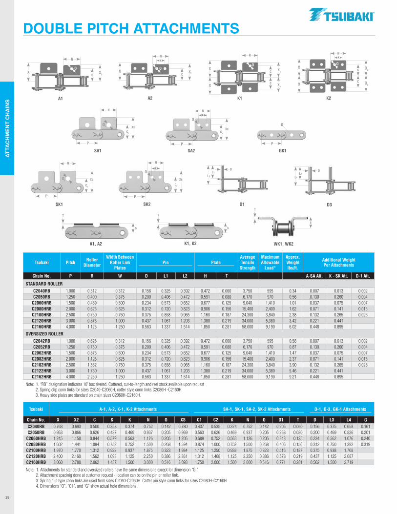
ATTA
CH
MEN
T C
HA
INS
39
DOUBLE PITCH ATTACHMENTS
A1 A2 K1 K2
SA1 SA2
SK1 SK2 D1 D3
GK1
CX2
N
XC
X2X C X2
X
XC X2
P
O1
P
O
P
G
P P
C2
Xs
N
K D
L4
DL3
WK1, WK2A1, A2 K1, K2
S
Tsubaki Pitch Roller Diameter
Width Between Roller Link
PlatesPin Plate
Average Tensile
Strength
Maximum Allowable
Load*
Approx. Weight lbs/ft.
Additional Weight Per Attachments
Chain No. P R W D L1 L2 H T A-SA Att. K - SK Att. D-1 Att.
STANDARD ROLLER
C2040RB 1.000 0.312 0.312 0.156 0.325 0.392 0.472 0.060 3,750 595 0.34 0.007 0.013 0.002C2050RB 1.250 0.400 0.375 0.200 0.406 0.472 0.591 0.080 6,170 970 0.56 0.130 0.260 0.004
C2060HRB 1.500 0.469 0.500 0.234 0.573 0.652 0.677 0.125 9,040 1,410 1.01 0.037 0.075 0.007C2080HRB 2.000 0.625 0.625 0.312 0.720 0.823 0.906 0.156 15,400 2,400 1.62 0.071 0.141 0.015C2100HRB 2.500 0.750 0.750 0.375 0.858 0.965 1.160 0.187 24,300 3,840 2.38 0.132 0.265 0.026C2120HRB 3.000 0.875 1.000 0.437 1.061 1.203 1.380 0.219 34,000 5,380 3.42 0.221 0.441 C2160HRB 4.000 1.125 1.250 0.563 1.337 1.514 1.850 0.281 58,000 9,190 6.02 0.448 0.895
OVERSIZED ROLLER
C2042RB 1.000 0.625 0.312 0.156 0.325 0.392 0.472 0.060 3,750 595 0.58 0.007 0.013 0.002C2052RB 1.250 0.750 0.375 0.200 0.406 0.472 0.591 0.080 6,170 970 0.87 0.130 0.260 0.004
C2062HRB 1.500 0.875 0.500 0.234 0.573 0.652 0.677 0.125 9,040 1,410 1.47 0.037 0.075 0.007C2082HRB 2.000 1.125 0.625 0.312 0.720 0.823 0.906 0.156 15,400 2,400 2.37 0.071 0.141 0.015C2102HRB 2.500 1.562 0.750 0.375 0.858 0.965 1.160 0.187 24,300 3,840 3.90 0.132 0.265 0.026C2122HRB 3.000 1.750 1.000 0.437 1.061 1.203 1.380 0.219 34,000 5,380 5.46 0.221 0.441 C2162HRB 4.000 2.250 1.250 0.563 1.337 1.514 1.850 0.281 58,000 9,190 9.21 0.448 0.895
Note: 1. “RB” designation indicates 10’ box riveted. Cottered, cut-to-length and reel stock available upon request 2. Spring clip conn links for sizes C2040-C2060H, cotter style conn links C2080H -C2160H. 3. Heavy side plates are standard on chain sizes C2060H-C2160H.
Tsubaki A-1, A-2, K-1, K-2 Attachments SA-1, SK-1, SA-2, SK-2 Attachments D-1, D-3, GK-1 Attachments
Chain No. X X2 C S K N O XS C1 C2 K N O O1 T D L3 L4 GC2040RB 0.763 0.693 0.500 0.358 0.374 0.752 0.142 0.780 0.437 0.535 0.374 0.752 0.142 0.205 0.060 0.156 0.375 0.658 0.161C2050RB 0.953 0.866 0.626 0.437 0.469 0.937 0.205 0.969 0.563 0.626 0.469 0.937 0.205 0.268 0.080 0.200 0.469 0.826 0.201
C2060HRB 1.245 1.150 0.844 0.579 0.563 1.126 0.205 1.205 0.689 0.752 0.563 1.126 0.205 0.343 0.125 0.234 0.562 1.076 0.240C2080HRB 1.602 1.441 1.094 0.752 0.752 1.500 0.268 1.594 0.874 1.000 0.752 1.500 0.268 0.406 0.156 0.312 0.750 1.392 0.319C2100HRB 1.970 1.770 1.312 0.922 0.937 1.875 0.323 1.984 1.125 1.250 0.938 1.875 0.323 0.516 0.187 0.375 0.938 1.708C2120HRB 2.400 2.160 1.562 1.093 1.125 2.250 0.386 2.361 1.312 1.468 1.125 2.250 0.386 0.578 0.219 0.437 1.125 2.087C2160HRB 3.060 2.780 2.062 1.437 1.500 3.000 0.516 3.093 1.750 2.000 1.500 3.000 0.516 0.771 0.281 0.562 1.500 2.719
Note: 1. Attachments for standard and oversized rollers have the same dimensions except for dimension “G.” 2. Attachment spacinig done at customer request - location can be on the pin or roller link. 3. Spring clip type conn links are used from sizes C2040-C2060H. Cotter pin style conn links for sizes C2080H-C2160H. 4. Dimensions “O”, “O1”, and “G” show actual hole dimensions.
T
TT
S
L4
L3
C1
Xs
N
C1
Xs
N
C2
Xs
NK
NK
NNK
C X2
C X2
X
X
S
O1
O
OOOO
.TSllBAKI"
x,o
-----------------' I I I I I I I I I I I I I I I I I I I I I I I I I I I I I I I I
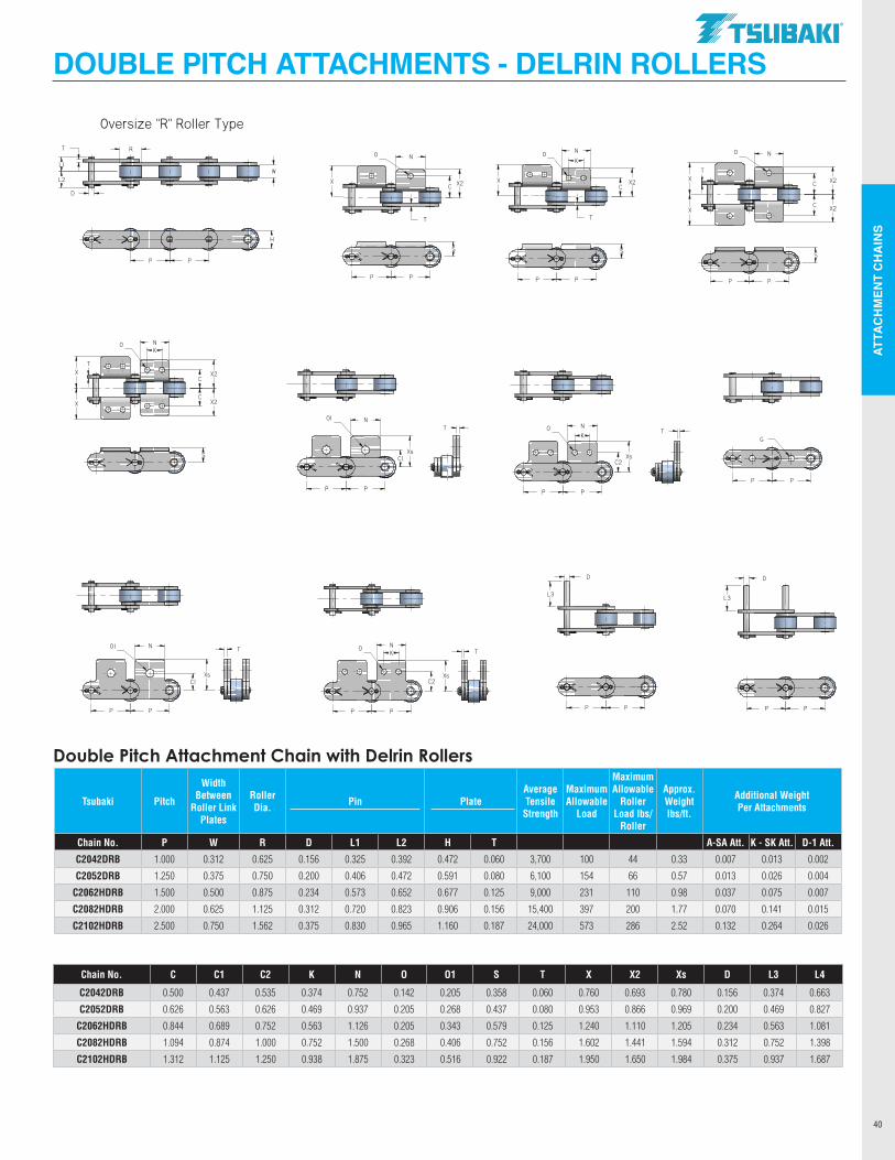
ATTA
CH
MEN
T C
HA
INS
40
Tsubaki Pitch
Width Between
Roller Link Plates
Roller Dia. Pin Plate
Average Tensile
Strength
Maximum Allowable
Load
Maximum Allowable
Roller Load lbs/
Roller
Approx. Weight lbs/ft.
Additional Weight Per Attachments
Chain No. P W R D L1 L2 H T A-SA Att. K - SK Att. D-1 Att.
C2042DRB 1.000 0.312 0.625 0.156 0.325 0.392 0.472 0.060 3,700 100 44 0.33 0.007 0.013 0.002
C2052DRB 1.250 0.375 0.750 0.200 0.406 0.472 0.591 0.080 6,100 154 66 0.57 0.013 0.026 0.004
C2062HDRB 1.500 0.500 0.875 0.234 0.573 0.652 0.677 0.125 9,000 231 110 0.98 0.037 0.075 0.007
C2082HDRB 2.000 0.625 1.125 0.312 0.720 0.823 0.906 0.156 15,400 397 200 1.77 0.070 0.141 0.015
C2102HDRB 2.500 0.750 1.562 0.375 0.830 0.965 1.160 0.187 24,000 573 286 2.52 0.132 0.264 0.026
DOUBLE PITCH ATTACHMENTS - DELRIN ROLLERS
Double Pitch Attachment Chain with Delrin Rollers
Chain No. C C1 C2 K N O O1 S T X X2 Xs D L3 L4
C2042DRB 0.500 0.437 0.535 0.374 0.752 0.142 0.205 0.358 0.060 0.760 0.693 0.780 0.156 0.374 0.663
C2052DRB 0.626 0.563 0.626 0.469 0.937 0.205 0.268 0.437 0.080 0.953 0.866 0.969 0.200 0.469 0.827
C2062HDRB 0.844 0.689 0.752 0.563 1.126 0.205 0.343 0.579 0.125 1.240 1.110 1.205 0.234 0.563 1.081
C2082HDRB 1.094 0.874 1.000 0.752 1.500 0.268 0.406 0.752 0.156 1.602 1.441 1.594 0.312 0.752 1.398
C2102HDRB 1.312 1.125 1.250 0.938 1.875 0.323 0.516 0.922 0.187 1.950 1.650 1.984 0.375 0.937 1.687
2080H A-1
P P
S
T
X2CX
NO
2080H A-2O
K
N
CX2X
S
T
P P
2080H K-1
P P
S
T
O N
C
C
X2
X2
X
X
2080H K-2
X
X
X2
X2C
C
NK
O
T
S
2080H SA-1 2080H SA-2 2080H GK-1
G
P P
2080H SK-1 2080H SK-2 2080H D-1 2080H D-3
O1 N
XsC1
P P
T TO N
K
XsC2
P P
O1 N
XsC1
T
P P
TO NK
C2Xs
P P
L3
D
P P P P
D
L3
Oversize "R" Roller Type
P P
H
W
D
RT
L1
L2
.TSllBAKI"
:1··@5~ m~
1-- ----I-- _____j
t~iJ@-~1¥3
J··i~:u ~ -----i-- ~
---------------
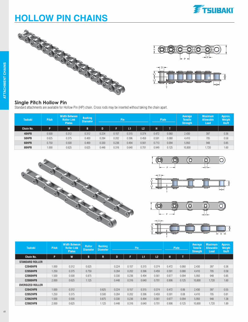
ATTA
CH
MEN
T C
HA
INS
41
Tsubaki PitchWidth Between
Roller Link Plates
Roller Diameter
Bushing Diameter Pin Plate
Average Tensile
Strength
Maximum Allowable
Load
Approx. Weight lbs/ft
Chain No. P W B R D F L1 L2 H T
STANDARD ROLLER
C2040HPB 1.000 0.312 0.625 0.224 0.157 0.315 0.374 0.472 0.060 2,430 397 0.36
C2050HPB 1.250 0.375 0.750 0.284 0.202 0.396 0.459 0.591 0.080 4,410 705 0.58
C2060HPB 1.500 0.500 0.875 0.330 0.236 0.494 0.561 0.677 0.094 5,950 948 0.85
C2080HPB 2.000 0.625 1.125 0.448 0.316 0.640 0.701 0.906 0.125 10,800 1,720 1.60
OVERSIZED ROLLER
C2042HPB 1.000 0.312 0.625 0.224 0.157 0.315 0.374 0.472 0.06 2,430 397 0.55
C2052HPB 1.250 0.375 0.500 0.284 0.202 0.396 0.459 0.591 0.08 4,410 705 0.81
C2062HPB 1.500 0.500 0.875 0.330 0.236 0.494 0.561 0.677 0.094 5,950 948 1.38
C2082HPB 2.000 0.625 1.125 0.448 0.316 0.640 0.701 0.906 0.125 10,800 1,720 1.89
Tsubaki PitchWidth Between
Roller Link Plates
Bushing Diamater Pin Plate
Average Tensile
Strength
Maximum Allowable
Load
Approx. Weight lbs/ft
Chain No. P W B D F L1 L2 H T
40HPB 0.500 0.312 0.312 0.224 0.157 0.315 0.374 0.472 0.060 2,430 397 0.36
50HPB 0.625 0.375 0.400 0.284 0.202 0.396 0.459 0.591 0.080 4,410 705 0.58
60HPB 0.750 0.500 0.469 0.330 0.236 0.494 0.561 0.713 0.094 5,950 948 0.85
80HPB 1.000 0.625 0.625 0.448 0.316 0.640 0.701 0.949 0.125 10,800 1,720 1.60
Single Pitch Hollow PinStandard attachments are available for Hollow Pin (HP) chain. Cross rods may be inserted without taking the chain apart.
HOLLOW PIN CHAINS
P
h
F
P F
P F
L2
L1
L2
L1
L2
L1
D
D
D
W
B
W
R
W
B
T
T
T
P
h
F
P F
P F
L2
L1
L2
L1
L2
L1
D
D
D
W
B
W
R
W
B
T
T
T
.TSllBAKI"
-----1 J (o 12 o)
7 i
I:D (1: [1: (1: I 1:~ I I. -l
I t J @ j 9)
7 i
I:D I CZ'.1 lZ:i c:;1 ~ I : ~
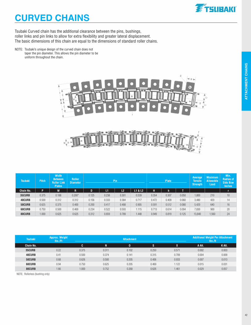
ATTA
CH
MEN
T C
HA
INS
42
CURVED CHAINS
L2
L1
T
D
RW
L1
L2
D
NO
x
x
C
C
Tsubaki Approx. Weight lbs./Ft Attachment Additional Weight Per Attachment
lbs./ft
Chain No. C N O S X A Att. K Att.
35CURB 0.22 0.375 0.311 0.102 0.250 0.571 0.002 0.003
40CURB 0.41 0.500 0.374 0.141 0.315 0.709 0.004 0.009
50CURB 0.68 0.626 0.500 0.205 0.406 0.933 0.007 0.013
60CURB 0.94 0.750 0.625 0.205 0.469 1.122 0.015 0.031
80CURB 1.66 1.000 0.752 0.268 0.626 1.461 0.029 0.057
NOTE: Rollerless (bushing only)
Tsubaki Pitch
Width Between
Roller Link Plates
Roller Diameter Pin Plate
Average Tensile
Strength
Maximum Allowable
Load
Min. Radius of Side Bow
Inches
Chain No. P W R D L1 L2 L1 & L2 H h T r
35CURB 0.375 0.188 0.200* 0.125 0.238 0.301 0.539 0.354 0.307 0.050 1,800 210 10
40CURB 0.500 0.312 0.312 0.156 0.333 0.384 0.717 0.472 0.409 0.060 3,480 420 14
50CURB 0.625 0.375 0.400 0.200 0.417 0.488 0.905 0.591 0.512 0.080 5,420 640 16
60CURB 0.750 0.500 0.469 0.234 0.522 0.593 1.115 0.713 0.614 0.094 7,830 900 20
80CURB 1.000 0.625 0.625 0.312 0.659 0.789 1.448 0.949 0.819 0.125 13,840 1,560 24
Tsubaki Curved chain has the additional clearance between the pins, bushings, roller links and pin links to allow for extra flexibility and greater lateral displacement.The basic dimensions of this chain are equal to the dimensions of standard roller chains.
NOTE: Tsubaki’s unique design of the curved chain does not taper the pin diameter. This allows the pin diameter to be uniform throughout the chain.
W
r
.TSllBAKI"

NOTES
43
.TSllBAKI"
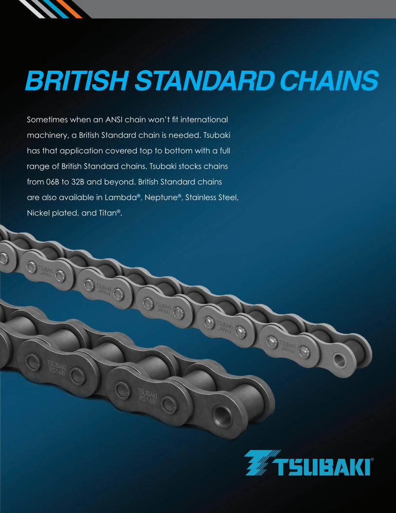
Sometimes when an ANSI chain won’t fit international
machinery, a British Standard chain is needed. Tsubaki
has that application covered top to bottom with a full
range of British Standard chains. Tsubaki stocks chains
from 06B to 32B and beyond. British Standard chains
are also available in Lambda®, Neptune®, Stainless Steel,
Nickel plated, and Titan®.
BRITISH STANDARD CHAINS
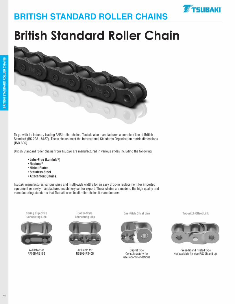
BRIT
ISH
STAN
DARD
RO
LLER
CHA
INS
45
BRITISH STANDARD ROLLER CHAINS
To go with its industry leading ANSI roller chains, Tsubaki also manufactures a complete line of British Standard (BS 228 - 8187). These chains meet the International Standards Organization metric dimensions (ISO 606).
British Standard roller chains from Tsubaki are manufactured in various styles including the following:
• Lube-Free (Lambda®) • Neptune®
• Nickel Plated • Stainless Steel • Attachment Chains
Tsubaki manufactures various sizes and multi-wide widths for an easy drop-in replacement for imported equipment or newly manufactured machinery set for export. These chains are made to the high quality and manufacturing standards that Tsubaki uses in all roller chains it manufactures.
Spring Clip-Style Cotter-Style Connecting Link Connecting Link
Available for Available for RF06B-RS16B RS20B-RS40B
One-Pitch Offset Link Two-pitch Offset Link
Slip-fit type Press-fit and riveted type Consult factory for Not available for size RS20B and up. use recommendations
British Standard Roller Chain
.TSUBAKI"
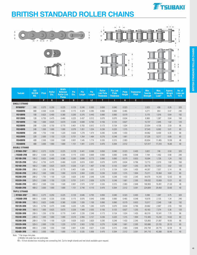
BRIT
ISH
STAN
DARD
RO
LLER
CHA
INS
46
BRITISH STANDARD ROLLER CHAINS
P P
hHL2
L1
W
DR
t
L
L2
L1
C
L2
L1
C
C
TsubakiISO
BS/DIN NO.
Pitch Roller Dia.
Width Between
Roller Link Plates
Pin Dia.
Pin Length
Pin Length
Roller Link Plate Thickness
Pin Link Plate
Thickness
Plate Height
Transverse Pitch
Min. Tensile
Strength
Max.Allowable
Load*
Approx. Weight lbs/ft.
No. of Links per
10 ft.
P R W D L1 L2 T t H C SINGLE STRAND
RF06BRB* 06B 0.375 0.250 0.225 0.129 0.240 0.303 0.050 0.040 0.323 - 2,023 438 0.26 320
RS08BRB 08B 0.500 0.335 0.305 0.175 0.329 0.395 0.060 0.060 0.465 - 4,271 854 0.47 240
RS10BRB 10B 0.625 0.400 0.380 0.200 0.376 0.443 0.060 0.060 0.579 - 5,170 1,016 0.64 192
RS12BRB 12B 0.750 0.475 0.460 0.225 0.437 0.512 0.070 0.070 0.634 - 6,969 1,387 0.84 160
RS16BRB 16B 1.000 0.625 0.670 0.326 0.699 0.783 0.156 0.125 0.827 - 15,737 2,945 1.82 120
RS20BRB 20B 1.250 0.750 0.770 0.401 0.783 0.912 0.173 0.134 1.024 - 22,054 4,136 2.59 96
RS24BRB 24B 1.500 1.000 1.000 0.576 1.051 1.254 0.236 0.220 1.315 - 37,543 6,092 5.01 80
RS28BRB 28B 1.750 1.100 1.220 0.626 1.278 1.474 0.295 0.248 1.433 - 44,962 8,430 6.35 68
RS32BRB 32B 2.000 1.150 1.220 0.701 1.264 1.484 0.276 0.248 1.661 - 57,326 9,217 6.89 60
RS40BRB 40B 2.500 1.550 1.500 0.901 1.545 1.774 0.335 0.315 2.083 - 83,854 11,465 10.99 48
RS48BRB 48B 3.000 1.900 1.800 1.151 1.941 2.315 0.476 0.394 2.512 - 127,017 17,310 16.80 40
DOUBLE STRAND
◊ RF06B-2RB* 06B-2 0.375 0.250 0.225 0.129 0.441 0.506 0.050 0.040 0.323 0.403 3,822 746 0.50 320
◊ RS08B-2RB 08B-2 0.500 0.335 0.305 0.175 0.603 0.669 0.060 0.060 0.465 0.548 7,194 1,452 0.90 240
RS10B-2RB 10B-2 0.625 0.400 0.380 0.200 0.699 0.773 0.060 0.060 0.579 0.653 10,004 1,726 1.24 192
RS12B-2RB 12B-2 0.750 0.475 0.460 0.225 0.819 0.901 0.070 0.070 0.634 0.766 13,713 2,019 1.68 160
RS16B-2RB 16B-2 1.000 0.625 0.670 0.326 1.321 1.407 0.156 0.125 0.827 1.255 28,776 5,013 3.62 120
RS20B-2RB 20B-2 1.250 0.750 0.770 0.401 1.509 1.631 0.173 0.134 1.024 1.435 44,287 7,037 5.14 96
RS24B-2RB 24B-2 1.500 1.000 1.000 0.576 2.004 2.205 0.236 0.220 1.315 1.904 75,311 10,364 9.84 80
RS28B-2RB 28B-2 1.750 1.100 1.220 0.626 2.450 2.646 0.295 0.248 1.433 2.345 84,078 14,343 12.63 68
RS32B-2RB 32B-2 2.000 1.150 1.220 0.701 2.411 2.636 0.276 0.248 1.661 2.305 109,032 15,669 13.51 60
RS40B-2RB 40B-2 2.500 1.550 1.500 0.901 2.970 3.197 0.335 0.315 2.083 2.846 160,963 19,491 21.50 48
RS48B-2RB 48B-2 3.000 1.900 1.800 1.151 3.740 4.110 0.476 0.394 2.512 3.591 224,809 29,450 33.60 40
TRIPLE STRAND
◊ RF06B-3RB* 06B-3 0.375 0.250 0.225 0.129 0.646 0.705 0.050 0.040 0.323 0.403 5,598 1,097 0.75 320
◊ RS08B-3RB 08B-3 0.500 0.335 0.305 0.175 0.876 0.943 0.060 0.060 0.465 0.548 10,678 2,135 1.34 240
RS10B-3RB 10B-3 0.625 0.400 0.380 0.200 1.026 1.100 0.060 0.060 0.579 0.653 15,017 2,540 1.88 192
RS12B-3RB 12B-3 0.750 0.475 0.460 0.225 1.205 1.283 0.070 0.070 0.634 0.766 20,682 2,967 2.55 160
RS16B-3RB 16B-3 1.000 0.625 0.670 0.326 1.949 2.035 0.156 0.125 0.827 1.255 43,163 7,374 5.36 120
RS20B-3RB 20B-3 1.250 0.750 0.770 0.401 2.226 2.349 0.173 0.134 1.024 1.435 66,319 10,341 7.70 96
RS24B-3RB 24B-3 1.500 1.000 1.000 0.576 2.956 3.157 0.236 0.220 1.315 1.904 112,405 15,242 14.62 80
RS28B-3RB 28B-3 1.750 1.100 1.220 0.626 3.623 3.820 0.295 0.248 1.433 2.345 125,893 21,087 18.95 68
RS32B-3RB 32B-3 2.000 1.150 1.220 0.701 3.563 3.783 0.276 0.248 1.661 2.305 163,886 23,155 20.10 60
RS40B-3RB 40B-3 2.500 1.550 1.500 0.901 4.393 4.621 0.335 0.315 2.083 2.846 242,794 28,776 32.09 48
RS48B-3RB 48B-3 3.000 1.900 1.800 1.151 5.535 5.906 0.476 0.394 2.512 3.591 341,710 43,388 50.40 40
Note: * Flat shape link plate. ◊ Middle link plate has one solid plate. RB = 10 foot stocked box including one connecting link. Cut-to-length strands and reel stock available upon request.
T
.TSUBAKI"
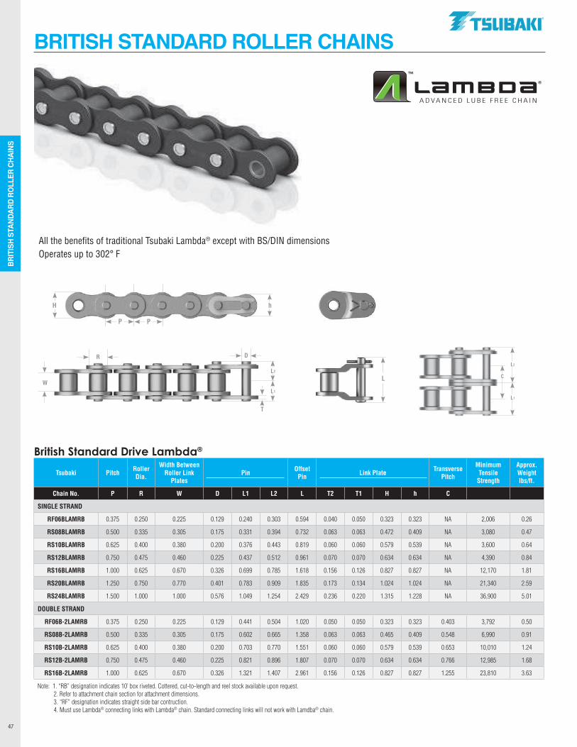
BRIT
ISH
STAN
DARD
RO
LLER
CHA
INS
47
BRITISH STANDARD ROLLER CHAINS
Tsubaki Pitch RollerDia.
Width Between Roller Link
PlatesPin Offset
Pin Link Plate TransversePitch
Minimum Tensile
Strength
Approx. Weight lbs/ft.
Chain No. P R W D L1 L2 L T2 T1 H h C
SINGLE STRAND
RF06BLAMRB 0.375 0.250 0.225 0.129 0.240 0.303 0.594 0.040 0.050 0.323 0.323 NA 2,006 0.26
RS08BLAMRB 0.500 0.335 0.305 0.175 0.331 0.394 0.732 0.063 0.063 0.472 0.409 NA 3,080 0.47
RS10BLAMRB 0.625 0.400 0.380 0.200 0.376 0.443 0.819 0.060 0.060 0.579 0.539 NA 3,600 0.64
RS12BLAMRB 0.750 0.475 0.460 0.225 0.437 0.512 0.961 0.070 0.070 0.634 0.634 NA 4,390 0.84
RS16BLAMRB 1.000 0.625 0.670 0.326 0.699 0.785 1.618 0.156 0.126 0.827 0.827 NA 12,170 1.81
RS20BLAMRB 1.250 0.750 0.770 0.401 0.783 0.909 1.835 0.173 0.134 1.024 1.024 NA 21,340 2.59
RS24BLAMRB 1.500 1.000 1.000 0.576 1.049 1.254 2.429 0.236 0.220 1.315 1.228 NA 36,900 5.01
DOUBLE STRAND
RF06B-2LAMRB 0.375 0.250 0.225 0.129 0.441 0.504 1.020 0.050 0.050 0.323 0.323 0.403 3,792 0.50
RS08B-2LAMRB 0.500 0.335 0.305 0.175 0.602 0.665 1.358 0.063 0.063 0.465 0.409 0.548 6,990 0.91
RS10B-2LAMRB 0.625 0.400 0.380 0.200 0.703 0.770 1.551 0.060 0.060 0.579 0.539 0.653 10,010 1.24
RS12B-2LAMRB 0.750 0.475 0.460 0.225 0.821 0.896 1.807 0.070 0.070 0.634 0.634 0.766 12,985 1.68
RS16B-2LAMRB 1.000 0.625 0.670 0.326 1.321 1.407 2.961 0.156 0.126 0.827 0.827 1.255 23,810 3.63
Note: 1. “RB” designation indicates 10’ box riveted. Cottered, cut-to-length and reel stock available upon request. 2. Refer to attachment chain section for attachment dimensions. 3. “RF” designation indicates straight side bar contruction. 4. Must use Lambda® connecting links with Lambda® chain. Standard connecting links will not work with Lamdba® chain.
British Standard Drive Lambda®
L
P P
hH
All the benefits of traditional Tsubaki Lambda® except with BS/DIN dimensionsOperates up to 302° F
L2
L1
CL2
L1
W
DR
T
.TSUBAKI"
ADVANCED LUBE FREE CHAIN
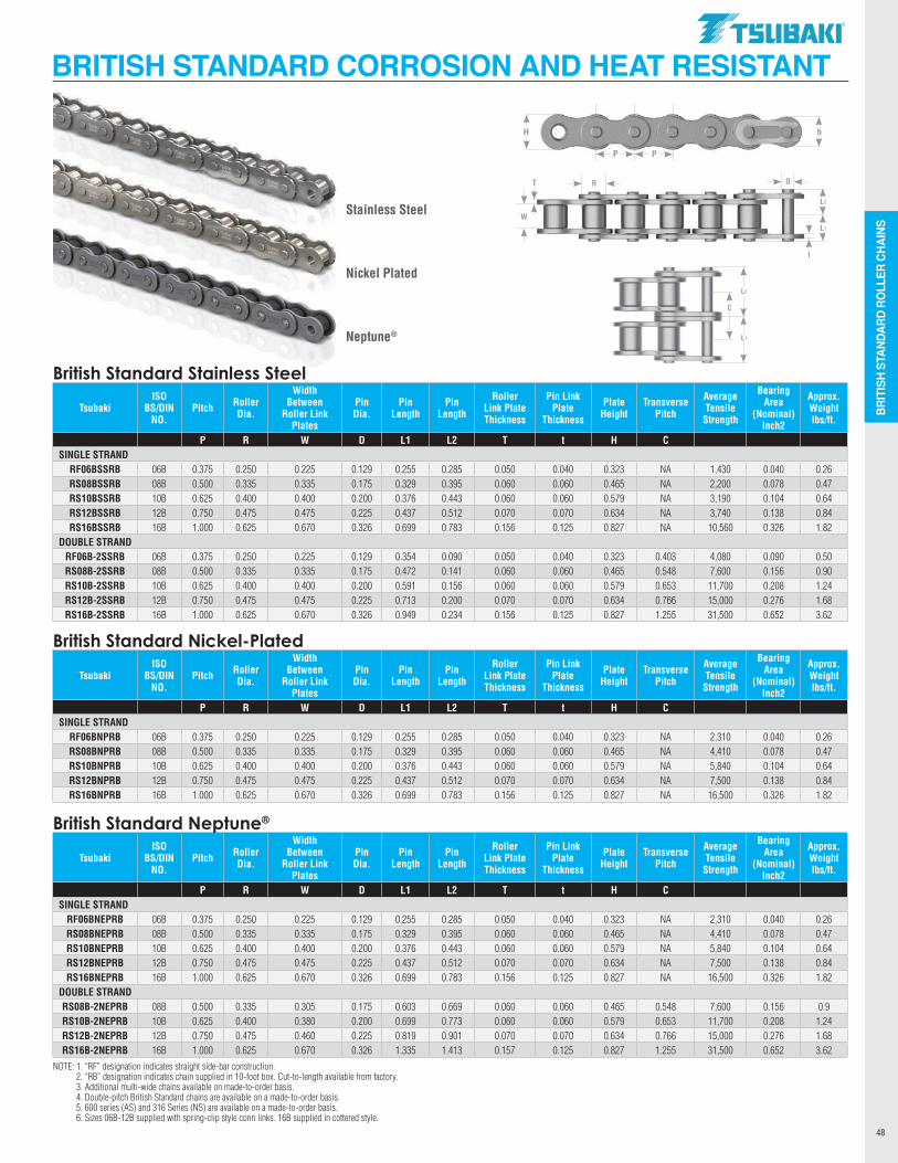
BRIT
ISH
STAN
DARD
RO
LLER
CHA
INS
48
BRITISH STANDARD CORROSION AND HEAT RESISTANT
P P
hH
L2
L1
W
DR
t
Stainless Steel
Nickel Plated
Neptune®
L2
L1
C
British Standard Stainless Steel
TsubakiISO
BS/DIN NO.
Pitch Roller Dia.
Width Between
Roller Link Plates
Pin Dia.
Pin Length
Pin Length
Roller Link Plate Thickness
Pin Link Plate
Thickness
Plate Height
Transverse Pitch
Average Tensile
Strength
Bearing Area
(Nominal) Inch2
Approx. Weight lbs/ft.
P R W D L1 L2 T t H C SINGLE STRAND
RF06BSSRB 06B 0.375 0.250 0.225 0.129 0.255 0.285 0.050 0.040 0.323 NA 1,430 0.040 0.26RS08BSSRB 08B 0.500 0.335 0.335 0.175 0.329 0.395 0.060 0.060 0.465 NA 2,200 0.078 0.47RS10BSSRB 10B 0.625 0.400 0.400 0.200 0.376 0.443 0.060 0.060 0.579 NA 3,190 0.104 0.64RS12BSSRB 12B 0.750 0.475 0.475 0.225 0.437 0.512 0.070 0.070 0.634 NA 3,740 0.138 0.84RS16BSSRB 16B 1.000 0.625 0.670 0.326 0.699 0.783 0.156 0.125 0.827 NA 10,560 0.326 1.82
DOUBLE STRANDRF06B-2SSRB 06B 0.375 0.250 0.225 0.129 0.354 0.090 0.050 0.040 0.323 0.403 4,080 0.090 0.50RS08B-2SSRB 08B 0.500 0.335 0.335 0.175 0.472 0.141 0.060 0.060 0.465 0.548 7,600 0.156 0.90RS10B-2SSRB 10B 0.625 0.400 0.400 0.200 0.591 0.156 0.060 0.060 0.579 0.653 11,700 0.208 1.24RS12B-2SSRB 12B 0.750 0.475 0.475 0.225 0.713 0.200 0.070 0.070 0.634 0.766 15,000 0.276 1.68RS16B-2SSRB 16B 1.000 0.625 0.670 0.326 0.949 0.234 0.156 0.125 0.827 1.255 31,500 0.652 3.62
British Standard Nickel-Plated
TsubakiISO
BS/DIN NO.
Pitch Roller Dia.
Width Between
Roller Link Plates
Pin Dia.
Pin Length
Pin Length
Roller Link Plate Thickness
Pin Link Plate
Thickness
Plate Height
Transverse Pitch
Average Tensile
Strength
Bearing Area
(Nominal) Inch2
Approx. Weight lbs/ft.
P R W D L1 L2 T t H C SINGLE STRAND
RF06BNPRB 06B 0.375 0.250 0.225 0.129 0.255 0.285 0.050 0.040 0.323 NA 2,310 0.040 0.26RS08BNPRB 08B 0.500 0.335 0.335 0.175 0.329 0.395 0.060 0.060 0.465 NA 4,410 0.078 0.47RS10BNPRB 10B 0.625 0.400 0.400 0.200 0.376 0.443 0.060 0.060 0.579 NA 5,840 0.104 0.64RS12BNPRB 12B 0.750 0.475 0.475 0.225 0.437 0.512 0.070 0.070 0.634 NA 7,500 0.138 0.84RS16BNPRB 16B 1.000 0.625 0.670 0.326 0.699 0.783 0.156 0.125 0.827 NA 16,500 0.326 1.82
British Standard Neptune®
TsubakiISO
BS/DIN NO.
Pitch Roller Dia.
Width Between
Roller Link Plates
Pin Dia.
Pin Length
Pin Length
Roller Link Plate Thickness
Pin Link Plate
Thickness
Plate Height
Transverse Pitch
Average Tensile
Strength
Bearing Area
(Nominal) Inch2
Approx. Weight lbs/ft.
P R W D L1 L2 T t H C SINGLE STRAND
RF06BNEPRB 06B 0.375 0.250 0.225 0.129 0.255 0.285 0.050 0.040 0.323 NA 2,310 0.040 0.26RS08BNEPRB 08B 0.500 0.335 0.335 0.175 0.329 0.395 0.060 0.060 0.465 NA 4,410 0.078 0.47RS10BNEPRB 10B 0.625 0.400 0.400 0.200 0.376 0.443 0.060 0.060 0.579 NA 5,840 0.104 0.64RS12BNEPRB 12B 0.750 0.475 0.475 0.225 0.437 0.512 0.070 0.070 0.634 NA 7,500 0.138 0.84RS16BNEPRB 16B 1.000 0.625 0.670 0.326 0.699 0.783 0.156 0.125 0.827 NA 16,500 0.326 1.82
DOUBLE STRANDRS08B-2NEPRB 08B 0.500 0.335 0.305 0.175 0.603 0.669 0.060 0.060 0.465 0.548 7,600 0.156 0.9RS10B-2NEPRB 10B 0.625 0.400 0.380 0.200 0.699 0.773 0.060 0.060 0.579 0.653 11,700 0.208 1.24RS12B-2NEPRB 12B 0.750 0.475 0.460 0.225 0.819 0.901 0.070 0.070 0.634 0.766 15,000 0.276 1.68RS16B-2NEPRB 16B 1.000 0.625 0.670 0.326 1.335 1.413 0.157 0.125 0.827 1.255 31,500 0.652 3.62
NOTE: 1. “RF” designation indicates straight side-bar construction. 2. “RB” designation indicates chain supplied in 10-foot box. Cut-to-length available from factory. 3. Additional multi-wide chains available on made-to-order basis. 4. Double-pitch British Standard chains are available on a made-to-order basis. 5. 600 series (AS) and 316 Series (NS) are available on a made-to-order basis. 6. Sizes 06B-12B supplied with spring-clip style conn links. 16B supplied in cottered style.
T
.TSUBAKI"
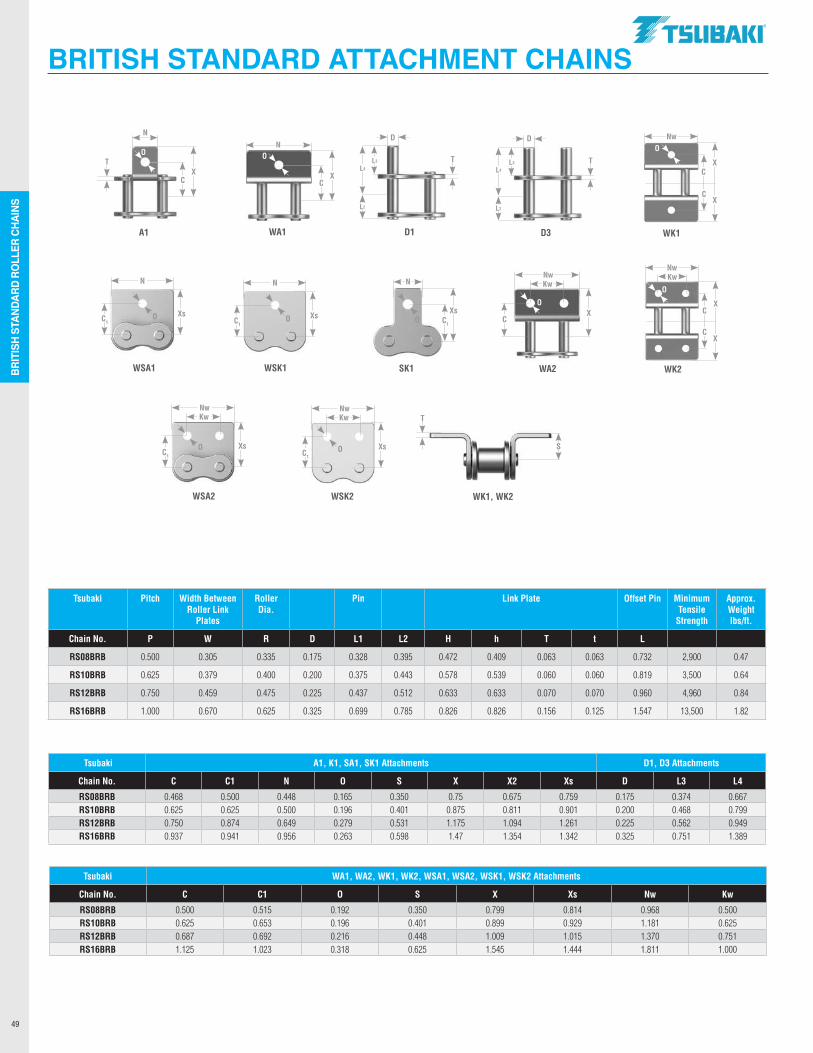
BRIT
ISH
STAN
DARD
RO
LLER
CHA
INS
49
BRITISH STANDARD ATTACHMENT CHAINS
Tsubaki Pitch Width Between Roller Link
Plates
Roller Dia.
Pin Link Plate Offset Pin Minimum Tensile
Strength
Approx. Weight lbs/ft.
Chain No. P W R D L1 L2 H h T t L
RS08BRB 0.500 0.305 0.335 0.175 0.328 0.395 0.472 0.409 0.063 0.063 0.732 2,900 0.47
RS10BRB 0.625 0.379 0.400 0.200 0.375 0.443 0.578 0.539 0.060 0.060 0.819 3,500 0.64
RS12BRB 0.750 0.459 0.475 0.225 0.437 0.512 0.633 0.633 0.070 0.070 0.960 4,960 0.84
RS16BRB 1.000 0.670 0.625 0.325 0.699 0.785 0.826 0.826 0.156 0.125 1.547 13,500 1.82
Tsubaki A1, K1, SA1, SK1 Attachments D1, D3 Attachments
Chain No. C C1 N O S X X2 Xs D L3 L4
RS08BRB 0.468 0.500 0.448 0.165 0.350 0.75 0.675 0.759 0.175 0.374 0.667RS10BRB 0.625 0.625 0.500 0.196 0.401 0.875 0.811 0.901 0.200 0.468 0.799RS12BRB 0.750 0.874 0.649 0.279 0.531 1.175 1.094 1.261 0.225 0.562 0.949RS16BRB 0.937 0.941 0.956 0.263 0.598 1.47 1.354 1.342 0.325 0.751 1.389
Tsubaki WA1, WA2, WK1, WK2, WSA1, WSA2, WSK1, WSK2 Attachments
Chain No. C C1 O S X Xs Nw Kw
RS08BRB 0.500 0.515 0.192 0.350 0.799 0.814 0.968 0.500RS10BRB 0.625 0.653 0.196 0.401 0.899 0.929 1.181 0.625RS12BRB 0.687 0.692 0.216 0.448 1.009 1.015 1.370 0.751RS16BRB 1.125 1.023 0.318 0.625 1.545 1.444 1.811 1.000
A1
CX
O
N
T
D1
D
L3
D3
D
L3
L4
L2
WA1
CX
N
WK1
Nw
CX
CX
WA2
Nw
CX
Kw
WSK2
Nw
C1
Xs
Kw
WSA2
Nw
C1
XsO
Kw
WSA1
N
C1
XsO
WK2
Nw
CX
O
CX
Kw
SK1
N
C1
XsO
S
WK1, WK2
WSK1
N
C1
XsO
O
O
T T
T
O
O
L4
L2
.TSUBAKI"
---------
----------
Tsubaki Lube-Free Lambda® chains are ideal for applications
where lubrication is difficult or not possible, from drive and
conveyor styles to corrosion resistant and British Standard,
Tsubaki has a complete product offering to maximize
performance in lube-free applications.
LUBE-FREE CHAINS
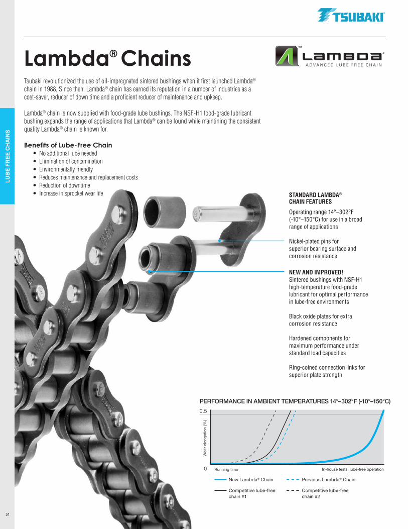
LUB
E FR
EE C
HA
INS
51
Lambda® ChainsTsubaki revolutionized the use of oil-impregnated sintered bushings when it first launched Lambda®
chain in 1988, Since then, Lambda® chain has earned its reputation in a number of industries as a cost-saver, reducer of down time and a proficient reducer of maintenance and upkeep.
Lambda® chain is now supplied with food-grade lube bushings. The NSF-H1 food-grade lubricant bushing expands the range of applications that Lambda® can be found while maintining the consistent quality Lambda® chain is known for.
Benefits of Lube-Free Chain • No additional lube needed • Elimination of contamination • Environmentally friendly • Reduces maintenance and replacement costs • Reduction of downtime • Increase in sprocket wear life
Wea
r elo
ngat
ion
(%)
0.5
0 Running time In-house tests, lube-free operation
STANDARD LAMBDA® CHAIN FEATURES
Operating range 14°–302°F (-10°–150°C) for use in a broad range of applications
Nickel-plated pins for superior bearing surface and corrosion resistance
NEW AND IMPROVED!Sintered bushings with NSF-H1 high-temperature food-grade lubricant for optimal performance in lube-free environments
Black oxide plates for extra corrosion resistance
Hardened components for maximum performance under standard load capacities
Ring-coined connection links for superior plate strength
PERFORMANCE IN AMBIENT TEMPERATURES 14°–302°F (-10°–150°C)
New Lambda® Chain
Competitive lube-free chain #1
Previous Lambda® Chain
Competitive lube-free chain #2
.TSllBAKI"
Lameca" ADVANCED LUBE FREE CHAIN
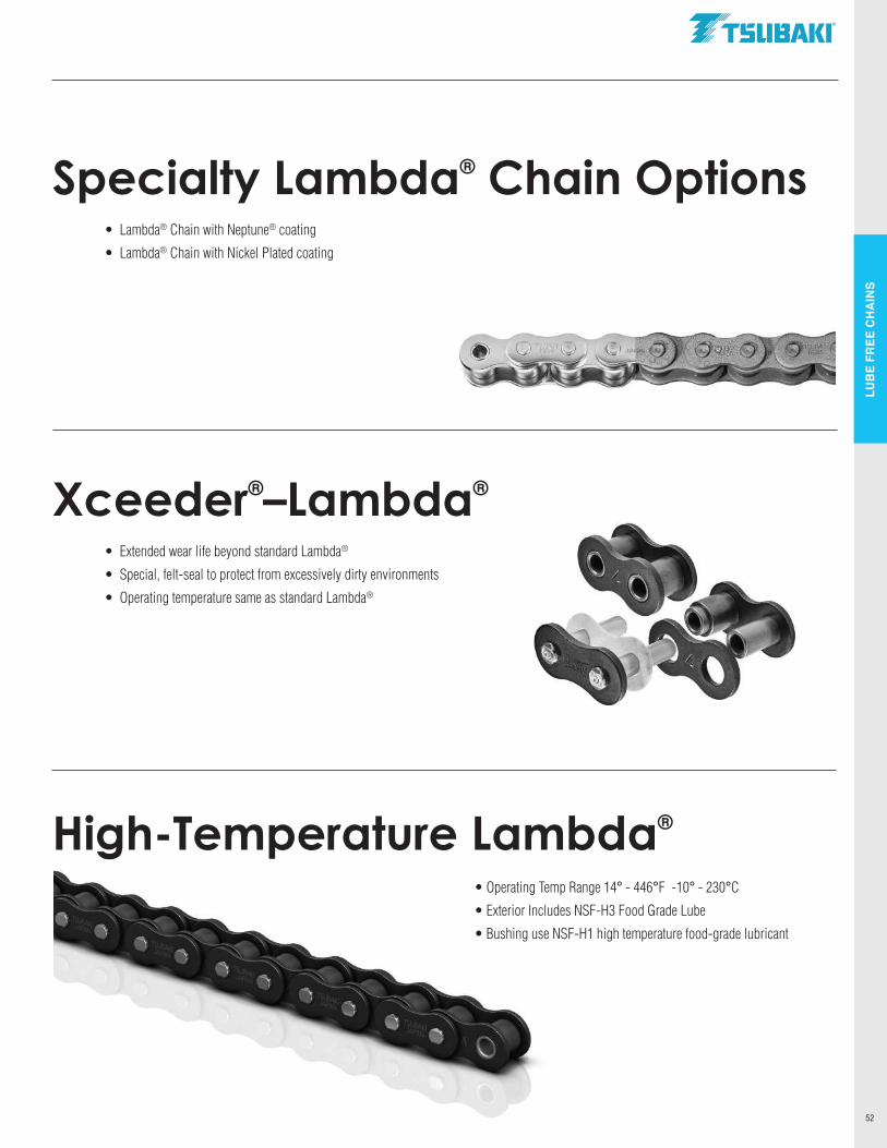
LUB
E FR
EE C
HA
INS
52
Xceeder®–Lambda®
• Extended wear life beyond standard Lambda®
• Special, felt-seal to protect from excessively dirty environments
• Operating temperature same as standard Lambda®
High-Temperature Lambda®
Specialty Lambda® Chain Options• Lambda® Chain with Neptune® coating
• Lambda® Chain with Nickel Plated coating
• Operating Temp Range 14° - 446°F -10° - 230°C
• Exterior Includes NSF-H3 Food Grade Lube
• Bushing use NSF-H1 high temperature food-grade lubricant
.TSllBAKI"
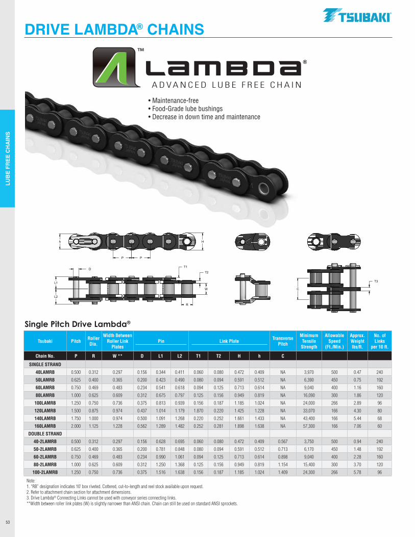
LUB
E FR
EE C
HA
INS
53
Tsubaki Pitch Roller Dia.
Width Between Roller Link
PlatesPin Link Plate Transverse
Pitch
Minimum Tensile
Strength
Allowable Speed
(Ft./Min.)
Approx. Weight lbs/ft.
No. of Links
per 10 ft.
Chain No. P R W ** D L1 L2 T1 T2 H h C
SINGLE STRAND
40LAMRB 0.500 0.312 0.297 0.156 0.344 0.411 0.060 0.080 0.472 0.409 NA 3,970 500 0.47 240
50LAMRB 0.625 0.400 0.365 0.200 0.423 0.490 0.080 0.094 0.591 0.512 NA 6,390 450 0.75 192
60LAMRB 0.750 0.469 0.483 0.234 0.541 0.618 0.094 0.125 0.713 0.614 NA 9,040 400 1.16 160
80LAMRB 1.000 0.625 0.609 0.312 0.675 0.797 0.125 0.156 0.949 0.819 NA 16,090 300 1.86 120
100LAMRB 1.250 0.750 0.736 0.375 0.813 0.939 0.156 0.187 1.185 1.024 NA 24,000 266 2.89 96
120LAMRB 1.500 0.875 0.974 0.437 1.014 1.179 1.870 0.220 1.425 1.228 NA 33,070 166 4.30 80
140LAMRB 1.750 1.000 0.974 0.500 1.091 1.268 0.220 0.252 1.661 1.433 NA 43,400 166 5.44 68
160LAMRB 2.000 1.125 1.228 0.562 1.289 1.482 0.252 0.281 1.898 1.638 NA 57,300 166 7.06 60
DOUBLE STRAND
40-2LAMRB 0.500 0.312 0.297 0.156 0.628 0.695 0.060 0.080 0.472 0.409 0.567 3,750 500 0.94 240
50-2LAMRB 0.625 0.400 0.365 0.200 0.781 0.848 0.080 0.094 0.591 0.512 0.713 6,170 450 1.48 192
60-2LAMRB 0.750 0.469 0.483 0.234 0.990 1.061 0.094 0.125 0.713 0.614 0.898 9,040 400 2.28 160
80-2LAMRB 1.000 0.625 0.609 0.312 1.250 1.368 0.125 0.156 0.949 0.819 1.154 15,400 300 3.70 120
100-2LAMRB 1.250 0.750 0.736 0.375 1.516 1.638 0.156 0.187 1.185 1.024 1.409 24,300 266 5.78 96
Note: 1. “RB” designation indicates 10’ box riveted. Cottered, cut-to-length and reel stock available upon request.2. Refer to attachment chain section for attachment dimensions.3. Drive Lambda® Connecting Links cannot be used with conveyor series connecting links.**Width between roller link plates (W) is slightly narrower than ANSI chain. Chain can still be used on standard ANSI sprockets.
DRIVE LAMBDA® CHAINS
Single Pitch Drive Lambda®
• Maintenance-free• Food-Grade lube bushings• Decrease in down time and maintenance
T3
C
T2
R
D
L2
L1
Hh
P P
T1
W
.TSllBAKI"
Lame ca® ADVANCED LUBE FREE CHAIN
11 II II II II II II 1111111_1111_111111111 ________
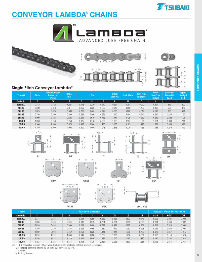
LUB
E FR
EE C
HA
INS
54
Single Pitch Conveyor Lambda®
Tsubaki PitchWidth Between
Roller Link Plates
Roller Dia.
Pin
Offset Link Pin Link Plate Link Plate
Thickness
Roller Link Plate
Height
Maximum Allowable
Load
Approx. Weight lbs/ft.
Chain No. P W R D L1 L2 L H T h35LRBp 0.375 0.188 0.200* 0.118 0.230 0.270 0.531 0.354 0.050 0.307 342 0.22
40LRB 0.500 0.313 0.311 0.156 0.325 0.392 0.717 0.060 0.409 0.409 595 0.4350LRB 0.625 0.375 0.400 0.200 0.405 0.472 0.890 0.080 0.512 0.512 970 0.7060LRB 0.750 0.500 0.469 0.234 0.506 0.581 1.110 0.094 0.614 0.614 1,410 1.0380LRB 1.000 0.625 0.625 0.312 0.640 0.758 1.441 0.125 0.819 0.819 2,400 1.79
100LRB 1.250 0.750 0.750 0.375 0.778 0.900 1.720 0.157 1.024 1.024 3,840 2.68120LRB 1.500 1.000 0.875 0.437 0.980 1.138 2.165 0.187 1.228 1.225 5,380 3.98140LRB 1.750 1.000 1.000 0.500 1.059 1.248 2.343 0.220 1.433 1.433 7,275 5.03
CONVEYOR LAMBDA® CHAINS
P P
hH
L2
L1
C
Tsubaki Attachment Dimension Additional Weight Per Attachment
Chain No. C C1 N O S X Xs L3 L4 A-SA K-SK D-135LRBp 0.374 0.374 0.311 0.134 0.250 0.563 0.563 0.573 0.375 0.002 0.004 0.002
40LRB 0.500 0.500 0.374 0.141 0.315 0.701 0.701 0.685 0.375 0.004 0.008 0.00250LRB 0.626 0.626 0.500 0.205 0.406 0.922 0.922 0.907 0.469 0.006 0.013 0.00460LRB 0.750 0.720 0.626 0.205 0.469 1.110 1.110 1.057 0.563 0.015 0.030 0.00680LRB 1.000 0.969 0.752 0.268 0.626 1.441 1.441 1.396 0.752 0.028 0.057 0.015
100LRB 1.250 1.252 1.000 0.343 0.780 1.768 1.768 1.732 0.937 0.057 0.114 0.026120LRB 1.500 1.437 1.126 0.406 0.906 2.197 2.000 2.083 1.126 0.097 0.194 0.044140LRB 1.752 1.752 1.374 0.469 1.126 2.484 2.252 2.500 1.311 0.156 0.313 0.066
Note: 1. “RB” designation indicates 10’ box riveted. Cottered, cut-to-length and reel stock available upon request. 2. Spring clip conn links for sizes 25-60, cotter style conn links 80 -140. 3. Rollerless. *4. Bushing Diameter.
L2
L1
W
DR
T
A1
CX
O
N
T
D1
D
L3
D3
D
L3
L4
L2
WA1
CX
N
WK1
Nw
CX
CX
WA2
Nw
CX
Kw
WSK2
Nw
C1
Xs
Kw
WSA2
Nw
C1
XsO
Kw
WSA1
N
C1
XsO
SK1
N
C1
XsO
S
WK1, WK2
WSK1
N
C1
XsO
O
O
T T
T
O
O
L4
L2
.TSllBAKI"
Lameca® ADVANCED LUBE FREE CHAIN
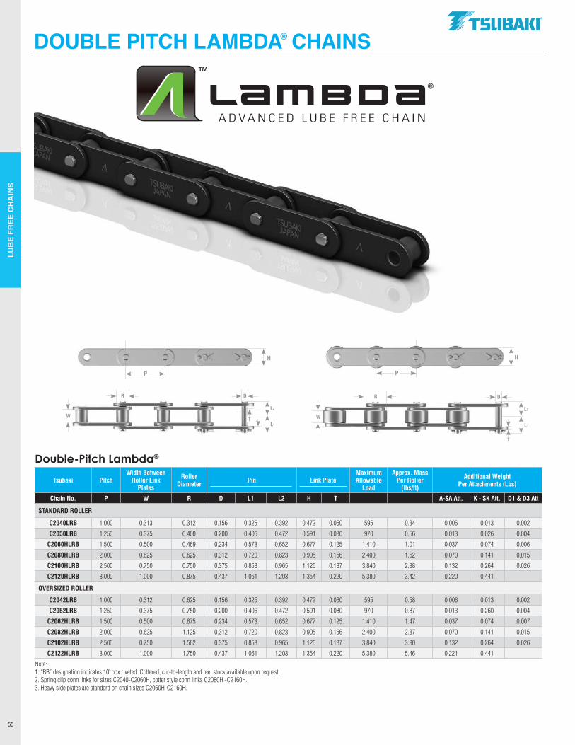
LUB
E FR
EE C
HA
INS
55
DOUBLE PITCH LAMBDA® CHAINS
L2
L1
W
DR
T
P
H
L2
L1
W
DR
T
P
H
Double-Pitch Lambda®
Tsubaki PitchWidth Between
Roller Link Plates
Roller Diameter Pin Link Plate
Maximum Allowable
Load
Approx. Mass Per Roller
(lbs/ft)
Additional Weight Per Attachments (Lbs)
Chain No. P W R D L1 L2 H T A-SA Att. K - SK Att. D1 & D3 Att
STANDARD ROLLER
C2040LRB 1.000 0.313 0.312 0.156 0.325 0.392 0.472 0.060 595 0.34 0.006 0.013 0.002
C2050LRB 1.250 0.375 0.400 0.200 0.406 0.472 0.591 0.080 970 0.56 0.013 0.026 0.004
C2060HLRB 1.500 0.500 0.469 0.234 0.573 0.652 0.677 0.125 1,410 1.01 0.037 0.074 0.006
C2080HLRB 2.000 0.625 0.625 0.312 0.720 0.823 0.905 0.156 2,400 1.62 0.070 0.141 0.015
C2100HLRB 2.500 0.750 0.750 0.375 0.858 0.965 1.126 0.187 3,840 2.38 0.132 0.264 0.026
C2120HLRB 3.000 1.000 0.875 0.437 1.061 1.203 1.354 0.220 5,380 3.42 0.220 0.441
OVERSIZED ROLLER
C2042LRB 1.000 0.312 0.625 0.156 0.325 0.392 0.472 0.060 595 0.58 0.006 0.013 0.002
C2052LRB 1.250 0.375 0.750 0.200 0.406 0.472 0.591 0.080 970 0.87 0.013 0.260 0.004
C2062HLRB 1.500 0.500 0.875 0.234 0.573 0.652 0.677 0.125 1,410 1.47 0.037 0.074 0.007
C2082HLRB 2.000 0.625 1.125 0.312 0.720 0.823 0.905 0.156 2,400 2.37 0.070 0.141 0.015
C2102HLRB 2.500 0.750 1.562 0.375 0.858 0.965 1.126 0.187 3,840 3.90 0.132 0.264 0.026
C2122HLRB 3.000 1.000 1.750 0.437 1.061 1.203 1.354 0.220 5,380 5.46 0.221 0.441
Note: 1. “RB” designation indicates 10’ box riveted. Cottered, cut-to-length and reel stock available upon request.2. Spring clip conn links for sizes C2040-C2060H, cotter style conn links C2080H -C2160H.3. Heavy side plates are standard on chain sizes C2060H-C2160H.
.TSllBAKI"
TM
Lame ca® ADVANCED LUBE FREE CHAIN
11 11 II ll==1 11t========!! ---1---1-I- --1•••-••-••1-•
I I I I I I I I I
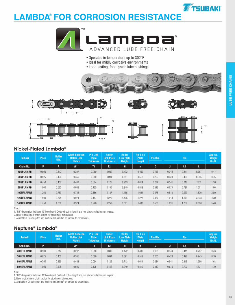
LUB
E FR
EE C
HA
INS
56
LAMBDA® FOR CORROSION RESISTANCE
• Operates in temperature up to 302°F• Ideal for mildly corrosive environments• Long-lasting, food-grade lube bushings
Nickel-Plated Lambda®
Tsubaki Pitch Roller Dia.
Width Between Roller Link
Plates
Pin Link Plate
Thickness
Roller Link Plate Thickness
Roller Link Plate
Height
Pin Link Plate
HeightPin Dia. Pin
Approx. Weight lbs/ft.
Chain No. P R W** T1 T2 H h D L1 L2 L
40NPLAMRB 0.500 0.312 0.297 0.060 0.080 0.472 0.409 0.156 0.344 0.411 0.787 0.47
50NPLAMRB 0.625 0.400 0.365 0.080 0.094 0.591 0.512 0.200 0.423 0.490 0.945 0.75
60NPLAMRB 0.750 0.469 0.483 0.094 0.125 0.713 0.614 0.234 0.541 0.618 1260 1.16
80NPLAMRB 1.000 0.625 0.609 0.125 0.156 0.949 0.819 0.312 0.675 0.797 1.571 1.86
100NPLAMRB 1.250 0.750 0.736 0.156 0.187 1.185 1.024 0.375 0.813 0.939 1.870 2.89
120NPLAMRB 1.500 0.875 0.974 0.187 0.220 1.425 1.228 0.437 1.014 1.179 2.323 4.30
140NPLAMRB 1.750 1.000 0.974 0.220 0.252 1.661 1.433 0.500 1.091 1.268 2.508 5.40
Note: 1. “RB” designation indicates 10’ box riveted. Cottered, cut-to-length and reel stock available upon request.2. Refer to attachment chain section for attachment dimensions.3. Available in Double-pitch and multi-wide Lambda® on a made-to-order basis.
Neptune® Lambda®
Tsubaki Pitch Roller Dia.
Width Between Roller Link
Plates
Pin Link Plate
Thickness
Roller Link Plate Thickness
Roller Link Plate
Height
Pin Link Plate
HeightPin Dia. Pin
Approx. Weight lbs/ft.
Chain No. P R W** T1 T2 H h D L1 L2 L
40NEPLAMRB 0.500 0.312 0.297 0.060 0.080 0.472 0.409 0.156 0.344 0.411 0.787 0.43
50NEPLAMRB 0.625 0.400 0.365 0.080 0.094 0.591 0.512 0.200 0.423 0.490 0.945 0.70
60NEPLAMRB 0.750 0.469 0.483 0.094 0.125 0.713 0.614 0.234 0.541 0.618 1.260 1.03
80NEPLAMRB 1.000 0.625 0.609 0.125 0.156 0.949 0.819 0.312 0.675 0.797 1.571 1.79
Note: 1. “RB” designation indicates 10’ box riveted. Cottered, cut-to-length and reel stock available upon request.2. Refer to attachment chain section for attachment dimensions.3. Available in Double-pitch and multi-wide Lambda® on a made-to-order basis.
T3
C
T2
R
D
L2
L1
Hh
P P
T1
W
.TSllBAKI"
Lame ca® ADVANCED LUBE FREE CHAIN
-------------
-------------
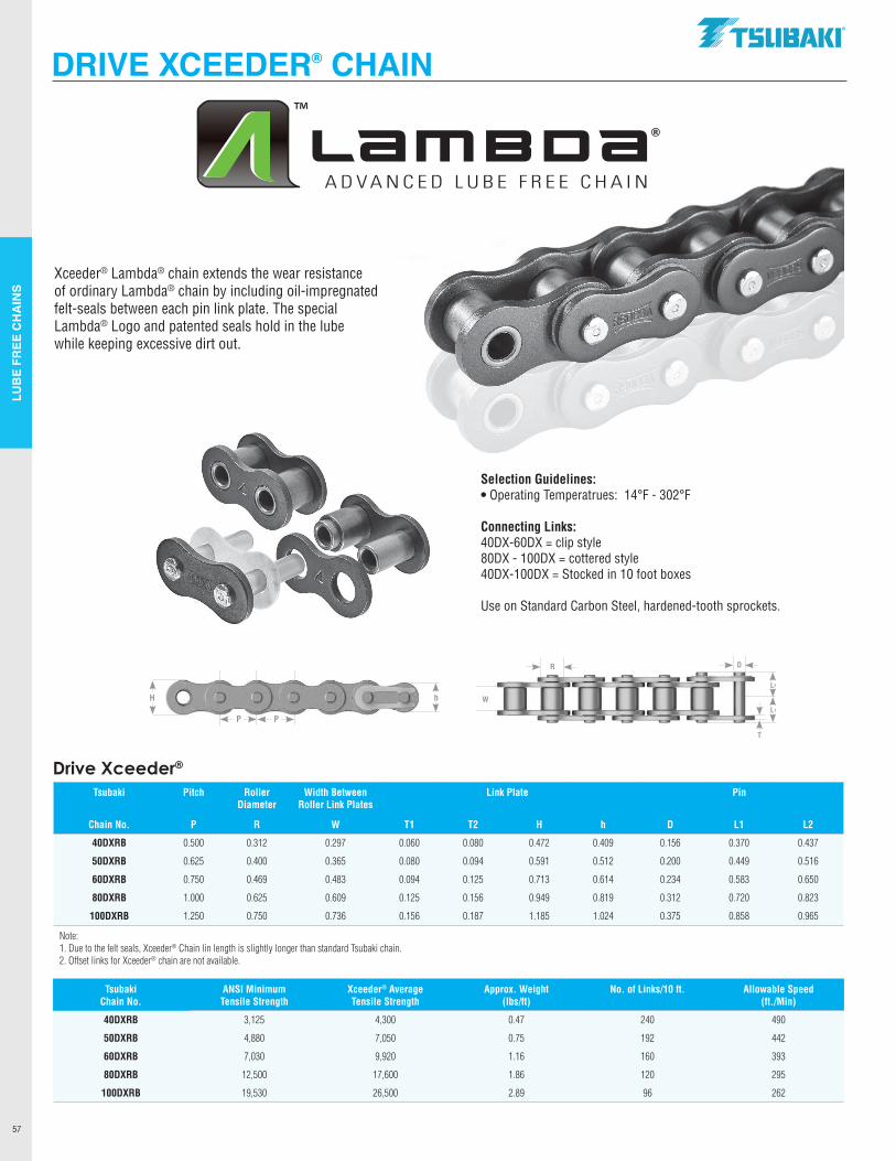
LUB
E FR
EE C
HA
INS
57
DRIVE XCEEDER® CHAIN
Selection Guidelines:• Operating Temperatrues: 14°F - 302°F
Connecting Links:40DX-60DX = clip style 80DX - 100DX = cottered style 40DX-100DX = Stocked in 10 foot boxes Use on Standard Carbon Steel, hardened-tooth sprockets.
Xceeder® Lambda® chain extends the wear resistance of ordinary Lambda® chain by including oil-impregnated felt-seals between each pin link plate. The specialLambda® Logo and patented seals hold in the lube while keeping excessive dirt out.
P P
hHL2
L1
W
DR
T
Drive Xceeder®
Tsubaki Pitch Roller Diameter
Width Between Roller Link Plates
Link Plate Pin
Chain No. P R W T1 T2 H h D L1 L2
40DXRB 0.500 0.312 0.297 0.060 0.080 0.472 0.409 0.156 0.370 0.437
50DXRB 0.625 0.400 0.365 0.080 0.094 0.591 0.512 0.200 0.449 0.516
60DXRB 0.750 0.469 0.483 0.094 0.125 0.713 0.614 0.234 0.583 0.650
80DXRB 1.000 0.625 0.609 0.125 0.156 0.949 0.819 0.312 0.720 0.823
100DXRB 1.250 0.750 0.736 0.156 0.187 1.185 1.024 0.375 0.858 0.965
Note:1. Due to the felt seals, Xceeder® Chain lin length is slightly longer than standard Tsubaki chain.2. Offset links for Xceeder® chain are not available.
TsubakiChain No.
ANSI Minimum Tensile Strength
Xceeder® Average Tensile Strength
Approx. Weight (lbs/ft)
No. of Links/10 ft. Allowable Speed (ft./Min)
40DXRB 3,125 4,300 0.47 240 490
50DXRB 4,880 7,050 0.75 192 442
60DXRB 7,030 9,920 1.16 160 393
80DXRB 12,500 17,600 1.86 120 295
100DXRB 19,530 26,500 2.89 96 262
.TSllBAKI"
Lame ca® ADVANCED LUBE FREE CHAIN
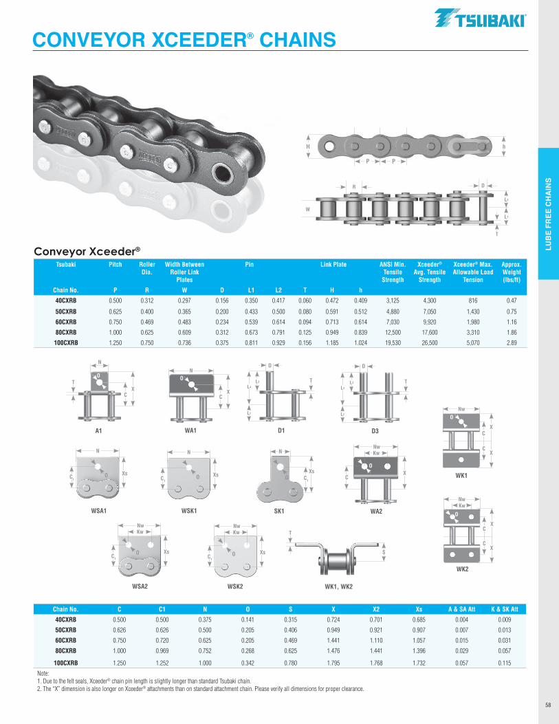
LUB
E FR
EE C
HA
INS
58
Selection Guidelines:• Operating Temperatrues: 14°F - 302°F
Connecting Links:40DX-60DX = clip style 80DX - 100DX = cottered style 40DX-100DX = Stocked in 10 foot boxes Use on Standard Carbon Steel, hardened-tooth sprockets.
Conveyor Xceeder®
Tsubaki Pitch Roller Dia.
Width Between Roller Link
Plates
Pin Link Plate ANSI Min. Tensile
Strength
Xceeder® Avg. Tensile
Strength
Xceeder® Max. Allowable Load
Tension
Approx. Weight (lbs/ft)
Chain No. P R W D L1 L2 T H h
40CXRB 0.500 0.312 0.297 0.156 0.350 0.417 0.060 0.472 0.409 3,125 4,300 816 0.47
50CXRB 0.625 0.400 0.365 0.200 0.433 0.500 0.080 0.591 0.512 4,880 7,050 1,430 0.75
60CXRB 0.750 0.469 0.483 0.234 0.539 0.614 0.094 0.713 0.614 7,030 9,920 1,980 1.16
80CXRB 1.000 0.625 0.609 0.312 0.673 0.791 0.125 0.949 0.839 12,500 17,600 3,310 1.86
100CXRB 1.250 0.750 0.736 0.375 0.811 0.929 0.156 1.185 1.024 19,530 26,500 5,070 2.89
Chain No. C C1 N O S X X2 Xs A & SA Att K & SK Att
40CXRB 0.500 0.500 0.375 0.141 0.315 0.724 0.701 0.685 0.004 0.009
50CXRB 0.626 0.626 0.500 0.205 0.406 0.949 0.921 0.907 0.007 0.013
60CXRB 0.750 0.720 0.625 0.205 0.469 1.441 1.110 1.057 0.015 0.031
80CXRB 1.000 0.969 0.752 0.268 0.625 1.476 1.441 1.396 0.029 0.057
100CXRB 1.250 1.252 1.000 0.342 0.780 1.795 1.768 1.732 0.057 0.115
Note:1. Due to the felt seals, Xceeder® chain pin length is slightly longer than standard Tsubaki chain.2. The “X” dimension is also longer on Xceeder® attachments than on standard attachment chain. Please verify all dimensions for proper clearance.
CONVEYOR XCEEDER® CHAINS
P P
hH
L2
L1
W
DR
T
A1
CX
O
N
T
D1
D
L3
D3
D
L3
L4
L2
WA1
CX
N
WK1
Nw
CX
CX
WA2
Nw
CX
Kw
WSK2
Nw
C1
Xs
Kw
WSA2
Nw
C1
XsO
Kw
WSA1
N
C1
XsO
WK2
Nw
CX
O
CX
KwSK1
N
C1
XsO
S
WK1, WK2
WSK1
N
C1
XsO
O
O
T T
T
O
O
L4
L2
.TSllBAKI"
i
L --------..-- ~-.-- ..... ..---~--=-,,,~
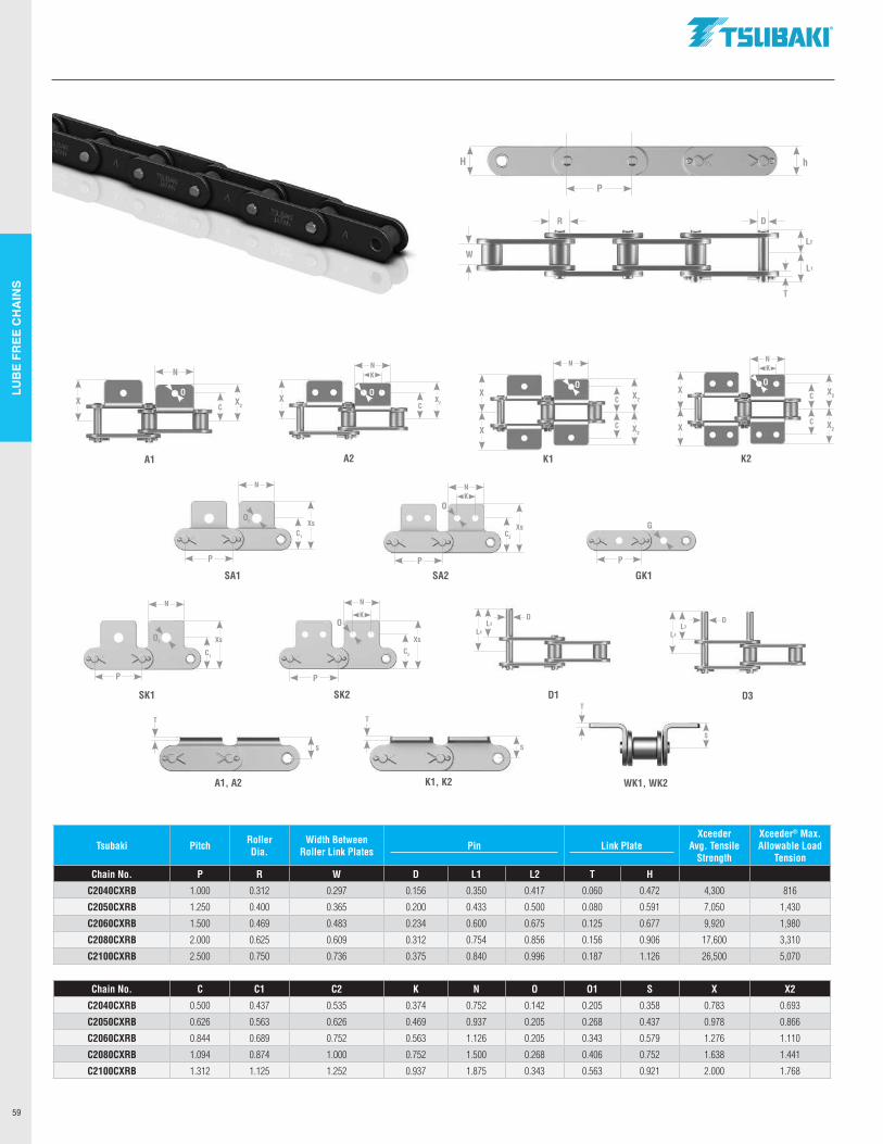
LUB
E FR
EE C
HA
INS
59
Tsubaki Pitch Roller Dia.
Width Between Roller Link Plates Pin Link Plate
Xceeder Avg. Tensile
Strength
Xceeder® Max.Allowable Load
Tension
Chain No. P R W D L1 L2 T H
C2040CXRB 1.000 0.312 0.297 0.156 0.350 0.417 0.060 0.472 4,300 816
C2050CXRB 1.250 0.400 0.365 0.200 0.433 0.500 0.080 0.591 7,050 1,430
C2060CXRB 1.500 0.469 0.483 0.234 0.600 0.675 0.125 0.677 9,920 1,980
C2080CXRB 2.000 0.625 0.609 0.312 0.754 0.856 0.156 0.906 17,600 3,310
C2100CXRB 2.500 0.750 0.736 0.375 0.840 0.996 0.187 1.126 26,500 5,070
Chain No. C C1 C2 K N O O1 S X X2
C2040CXRB 0.500 0.437 0.535 0.374 0.752 0.142 0.205 0.358 0.783 0.693
C2050CXRB 0.626 0.563 0.626 0.469 0.937 0.205 0.268 0.437 0.978 0.866
C2060CXRB 0.844 0.689 0.752 0.563 1.126 0.205 0.343 0.579 1.276 1.110
C2080CXRB 1.094 0.874 1.000 0.752 1.500 0.268 0.406 0.752 1.638 1.441
C2100CXRB 1.312 1.125 1.252 0.937 1.875 0.343 0.563 0.921 2.000 1.768
L2
L1
W
DR
T
P
hH
A1 A2 K1 K2
SA1 SA2
SK1 SK2 D1 D3
GK1
CX2
N
XC
X2X C X2
X
XC X2
P
O1
P
O
P
G
P P
C2
Xs
N
K D
L4
DL3
WK1, WK2A1, A2 K1, K2
S
T
TT
S
L4
L3
C1
Xs
N
C1
Xs
N
C2
Xs
NK
NK
NNK
C X2
C X2
X
X
S
O1
O
OOOO
.TSllBAKI"
j_
X,o
II
I I I I I I I I I I I I I I I I I I I I I I
1 1
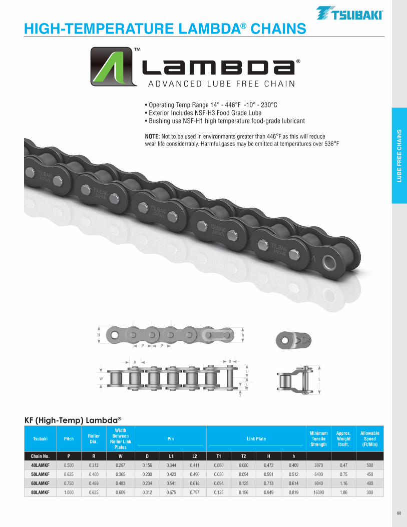
LUB
E FR
EE C
HA
INS
60
HIGH-TEMPERATURE LAMBDA® CHAINS
KF (High-Temp) Lambda®
Tsubaki Pitch Roller Dia.
Width Between
Roller Link Plates
Pin Link PlateMinimum Tensile
Strength
Approx. Weight lbs/ft.
Allowable Speed
(Ft/Min)
Chain No. P R W D L1 L2 T1 T2 H h
40LAMKF 0.500 0.312 0.297 0.156 0.344 0.411 0.060 0.080 0.472 0.409 3970 0.47 500
50LAMKF 0.625 0.400 0.365 0.200 0.423 0.490 0.080 0.094 0.591 0.512 6400 0.75 450
60LAMKF 0.750 0.469 0.483 0.234 0.541 0.618 0.094 0.125 0.713 0.614 9040 1.16 400
80LAMKF 1.000 0.625 0.609 0.312 0.675 0.797 0.125 0.156 0.949 0.819 16090 1.86 300
• Operating Temp Range 14° - 446°F -10° - 230°C• Exterior Includes NSF-H3 Food Grade Lube• Bushing use NSF-H1 high temperature food-grade lubricant
NOTE: Not to be used in environments greater than 446°F as this will reduce wear life considerrably. Harmful gases may be emitted at temperatures over 536°F
T
P P
hH
L2
L1
W
DR
T
L
.TSllBAKI"
Lame ca® ADVANCED LUBE FREE CHAIN
-------------
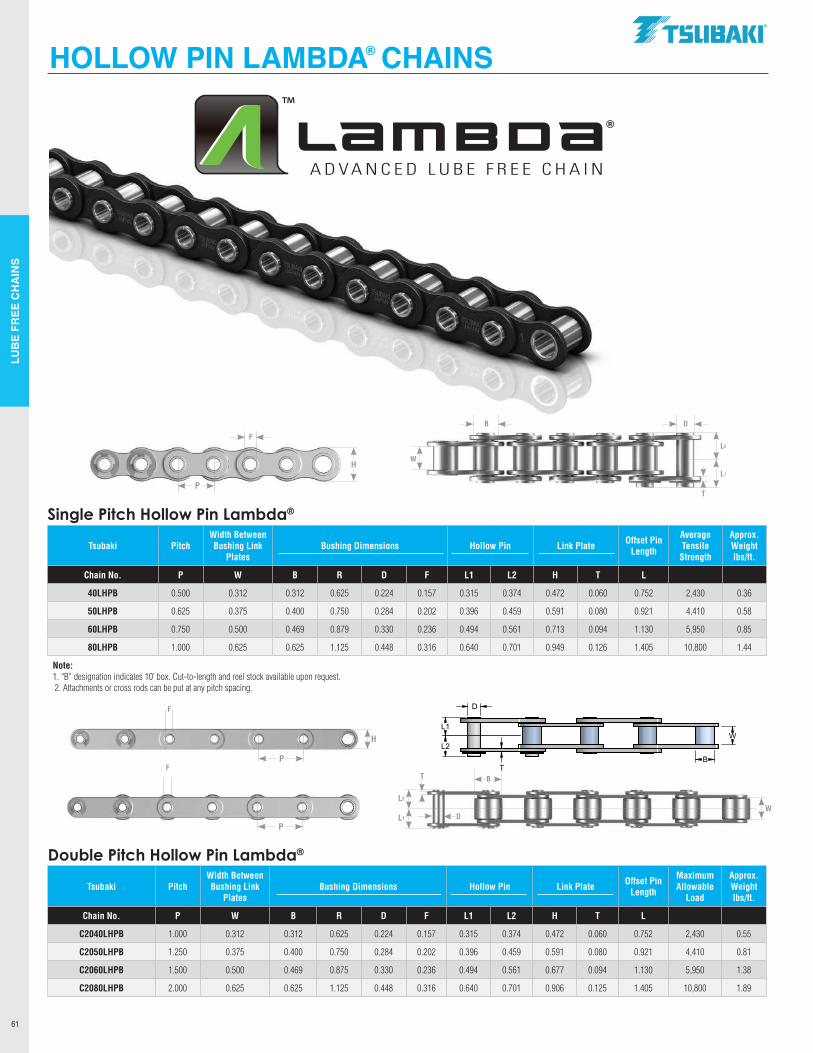
LUB
E FR
EE C
HA
INS
61
Single Pitch Hollow Pin Lambda®
Tsubaki PitchWidth Between Bushing Link
PlatesBushing Dimensions Hollow Pin Link Plate Offset Pin
Length
Average Tensile
Strength
Approx. Weight lbs/ft.
Chain No. P W B R D F L1 L2 H T L
40LHPB 0.500 0.312 0.312 0.625 0.224 0.157 0.315 0.374 0.472 0.060 0.752 2,430 0.36
50LHPB 0.625 0.375 0.400 0.750 0.284 0.202 0.396 0.459 0.591 0.080 0.921 4,410 0.58
60LHPB 0.750 0.500 0.469 0.879 0.330 0.236 0.494 0.561 0.713 0.094 1.130 5,950 0.85
80LHPB 1.000 0.625 0.625 1.125 0.448 0.316 0.640 0.701 0.949 0.126 1.405 10,800 1.44
Note: 1. “B” designation indicates 10’ box. Cut-to-length and reel stock available upon request. 2. Attachments or cross rods can be put at any pitch spacing.
Double Pitch Hollow Pin Lambda®
Tsubaki PitchWidth Between Bushing Link
PlatesBushing Dimensions Hollow Pin Link Plate Offset Pin
Length
Maximum Allowable
Load
Approx. Weight lbs/ft.
Chain No. P W B R D F L1 L2 H T L
C2040LHPB 1.000 0.312 0.312 0.625 0.224 0.157 0.315 0.374 0.472 0.060 0.752 2,430 0.55
C2050LHPB 1.250 0.375 0.400 0.750 0.284 0.202 0.396 0.459 0.591 0.080 0.921 4,410 0.81
C2060LHPB 1.500 0.500 0.469 0.875 0.330 0.236 0.494 0.561 0.677 0.094 1.130 5,950 1.38
C2080LHPB 2.000 0.625 0.625 1.125 0.448 0.316 0.640 0.701 0.906 0.125 1.405 10,800 1.89
HOLLOW PIN LAMBDA® CHAINS
P
H
F
P
F
WL2
L1
T B
D
L2
L1
W
DB
TP
H
F
P
h
F
P F
P F
L2
L1
L2
L1
L2
L1
D
D
D
W
B
W
R
W
B
T
T
T
.TSllBAKI"
TM
Lame ca® ADVANCED LUBE FREE CHAIN
------------7 i-
-------------
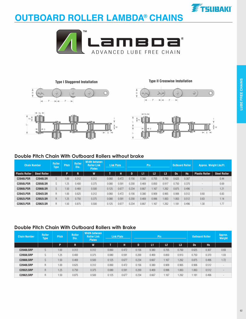
LUB
E FR
EE C
HA
INS
62
OUTBOARD ROLLER LAMBDA® CHAINS
Double Pitch Chain With Outboard Rollers with Brake
Chain Number Roller Type Pitch Roller
Dia.
Width between Roller Link
PlatesLink Plate Pin Outboard Roller Approx.
Weight
P R W T H D L1 L2 L3 Ds Hs
C2040LSRP S 1.00 0.312 0.312 0.060 0.472 0.156 0.380 0.705 0.760 0.625 0.307 0.69
C2050LSRP S 1.25 0.400 0.375 0.080 0.591 0.200 0.469 0.850 0.913 0.750 0.370 1.03
C2060LSRP S 1.50 0.469 0.500 0.125 0.677 0.234 0.667 1.167 1.262 0.875 0.496 1.72
C2040LSRP R 1.00 0.625 0.312 0.060 0.472 0.156 0.380 0.909 0.965 0.906 0.512 -
C2052LSRP R 1.25 0.750 0.375 0.080 0.591 0.200 0.469 0.996 1.063 1.063 0.512 -
C2062LSRP R 1.50 0.875 0.500 0.125 0.677 0.234 0.667 1.167 1.262 1.181 0.496 -
Double Pitch Chain With Outboard Rollers without brake
Chain Number Roller Type Pitch Roller
Dia.
Width between Roller Link
PlatesLink Plate Pin Outboard Roller Approx. Weight Lbs/Ft.
Plastic Roller Steel Roller P R W T H D L1 L2 L3 Ds Hs Plastic Roller Steel Roller
C2040LPSR C2040LSR S 1.00 0.312 0.312 0.060 0.472 0.156 0.380 0.705 0.760 0.625 0.307 - 0.44
C2050LPSR C2050LSR S 1.25 0.400 0.375 0.080 0.591 0.200 0.469 0.850 0.917 0.750 0.370 - 0.69
C2060LPSR C2060LSR S 1.50 0.469 0.500 0.125 0.677 0.234 0.667 1.167 1.262 0.875 0.496 - 1.21
C2042LPSR C2042LSR R 1.00 0.625 0.312 0.060 0.472 0.156 0.380 0.909 0.965 0.906 0.512 0.60 0.83
C2052LPSR C2052LSR R 1.25 0.750 0.375 0.080 0.591 0.200 0.469 0.996 1.063 1.063 0.512 0.83 1.14
C2062LPSR C2062LSR R 1.50 0.875 0.500 0.125 0.677 0.234 0.667 1.167 1.262 1.181 0.496 1.30 1.77
Type I Staggered Installation Type II Crosswise Installation
P P
H
P P
H
L2
L3
DW
Ds
T
R
Hs
L1
DW
Ds
T
R
Hs
.TSllBAKI"
Lame ca® ADVANCED LUBE FREE CHAIN
0 0
l l
' -a;n-----~~~f§-~g..-~
'
----------------
----
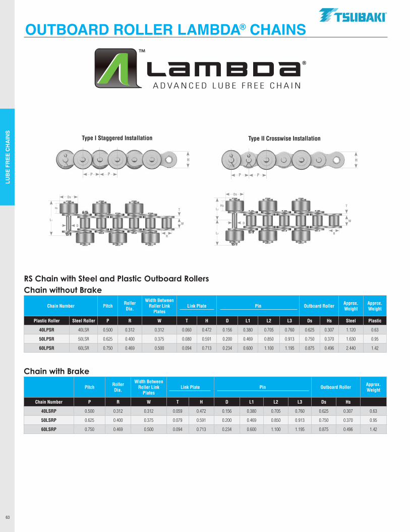
LUB
E FR
EE C
HA
INS
63
L1
DW
Ds
THs
RS Chain with Steel and Plastic Outboard RollersChain without Brake
Chain Number Pitch Roller Dia.
Width Between Roller Link
PlatesLink Plate Pin Outboard Roller Approx.
WeightApprox. Weight
Plastic Roller Steel Roller P R W T H D L1 L2 L3 Ds Hs Steel Plastic
40LPSR 40LSR 0.500 0.312 0.312 0.060 0.472 0.156 0.380 0.705 0.760 0.625 0.307 1.120 0.63
50LPSR 50LSR 0.625 0.400 0.375 0.080 0.591 0.200 0.469 0.850 0.913 0.750 0.370 1.630 0.95
60LPSR 60LSR 0.750 0.469 0.500 0.094 0.713 0.234 0.600 1.100 1.195 0.875 0.496 2.440 1.42
Chain with Brake
Pitch Roller Dia.
Width Between Roller Link
PlatesLink Plate Pin Outboard Roller Approx.
Weight
Chain Number P R W T H D L1 L2 L3 Ds Hs
40LSRP 0.500 0.312 0.312 0.059 0.472 0.156 0.380 0.705 0.760 0.625 0.307 0.63
50LSRP 0.625 0.400 0.375 0.079 0.591 0.200 0.469 0.850 0.913 0.750 0.370 0.95
60LSRP 0.750 0.469 0.500 0.094 0.713 0.234 0.600 1.100 1.195 0.875 0.496 1.42
OUTBOARD ROLLER LAMBDA® CHAINS
Type I Staggered Installation Type II Crosswise Installation
P P
H
P P
H
L2
L3
D
Ds
THs
R
W
R
.TSllBAKI"
Lame ca® ADVANCED LUBE FREE CHAIN
A
' ' A I A
' ' '
'
--------------
-----------
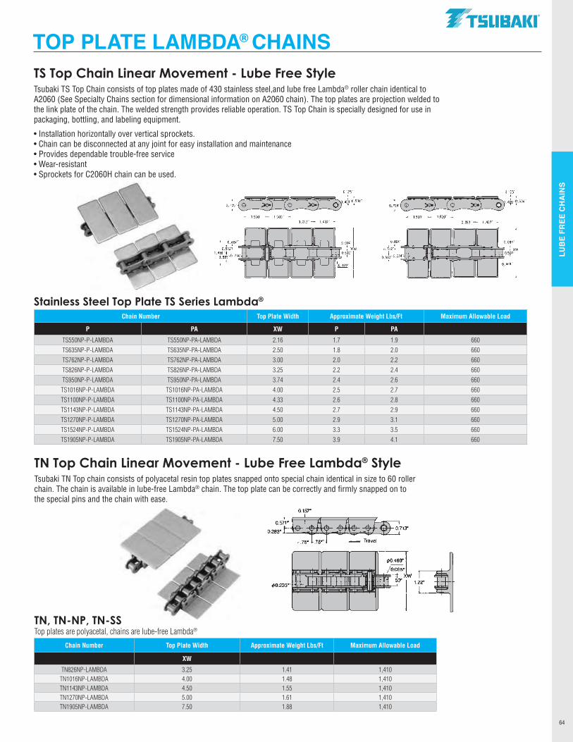
LUB
E FR
EE C
HA
INS
64
Chain Number Top Plate Width Approximate Weight Lbs/Ft Maximum Allowable Load
P PA XW P PA
TS550NP-P-LAMBDA TS550NP-PA-LAMBDA 2.16 1.7 1.9 660TS635NP-P-LAMBDA TS635NP-PA-LAMBDA 2.50 1.8 2.0 660TS762NP-P-LAMBDA TS762NP-PA-LAMBDA 3.00 2.0 2.2 660TS826NP-P-LAMBDA TS826NP-PA-LAMBDA 3.25 2.2 2.4 660TS950NP-P-LAMBDA TS950NP-PA-LAMBDA 3.74 2.4 2.6 660
TS1016NP-P-LAMBDA TS1016NP-PA-LAMBDA 4.00 2.5 2.7 660TS1100NP-P-LAMBDA TS1100NP-PA-LAMBDA 4.33 2.6 2.8 660TS1143NP-P-LAMBDA TS1143NP-PA-LAMBDA 4.50 2.7 2.9 660TS1270NP-P-LAMBDA TS1270NP-PA-LAMBDA 5.00 2.9 3.1 660TS1524NP-P-LAMBDA TS1524NP-PA-LAMBDA 6.00 3.3 3.5 660TS1905NP-P-LAMBDA TS1905NP-PA-LAMBDA 7.50 3.9 4.1 660
TS Top Chain Linear Movement - Lube Free StyleTsubaki TS Top Chain consists of top plates made of 430 stainless steel,and lube free Lambda® roller chain identical to A2060 (See Specialty Chains section for dimensional information on A2060 chain). The top plates are projection welded to the link plate of the chain. The welded strength provides reliable operation. TS Top Chain is specially designed for use in packaging, bottling, and labeling equipment.
• Installation horizontally over vertical sprockets.•Chain can be disconnected at any joint for easy installation and maintenance•Provides dependable trouble-free service•Wear-resistant•Sprockets for C2060H chain can be used.
Stainless Steel Top Plate TS Series Lambda®
Chain Number Top Plate Width Approximate Weight Lbs/Ft Maximum Allowable Load
XW
TN826NP-LAMBDA 3.25 1.41 1,410TN1016NP-LAMBDA 4.00 1.48 1,410TN1143NP-LAMBDA 4.50 1.55 1,410TN1270NP-LAMBDA 5.00 1.61 1,410TN1905NP-LAMBDA 7.50 1.88 1,410
TOP PLATE LAMBDA® CHAINS
TN Top Chain Linear Movement - Lube Free Lambda® StyleTsubaki TN Top chain consists of polyacetal resin top plates snapped onto special chain identical in size to 60 roller chain. The chain is available in lube-free Lambda® chain. The top plate can be correctly and firmly snapped on to the special pins and the chain with ease.
TN, TN-NP, TN-SSTop plates are polyacetal, chains are lube-free Lambda®
.TSllBAKI"
0.125~
0.7fg7
~1.soa~~-1.soo~-J

For the best defense against corrosion, Tsubaki offers a full
line of options for the toughest, harshest and most-corrosive
applications. Nickel Plated and Neptune® along with a full
line of Stainless chains that include 304, 316, 600 and Super
Stainless™. In harsh environments where lubrication is a
challenge, Tsubaki Titan® chain for improved wear life.
CORROSION &HEAT RESISTANT CHAINS
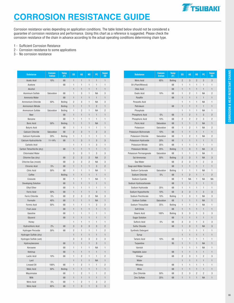
CO
RRO
SIO
N &
HEA
T R
ESIS
TAN
T CH
AIN
S
66
CORROSION &HEAT RESISTANT CHAINS
Substance Concen-tration
Temp (F) SS AS NS PC Super
SS Substance Concen-tration
Temp (F) SS AS NS PC Super
SS
Acetic Acid 10% 68 1 1 1 1 1 Nitric Acid 65% Boiling 2 3 2 3 3
Acetone 68 1 1 1 1 1 Oil (Plant/Mineral) 68 1 1 1 1 1
Alcohol 1 1 1 1 1 Oleic Acid 68 1 1 1 1 1
Aluminum Sulfate Saturation 68 1 3 1 NA 3 Oxalic Acid 10% 68 1 2 1 NA 2
Ammonia Water 68 1 1 1 1 1 Paraffin 68 1 1 1 1 1
Ammonium Chloride 50% Boiling 2 3 1 NA 3 Peracetic Acid 1 1 1 NA 1
Ammonium Nitrate Boiling 1 1 1 2 1 Petroleum 68 1 1 1 1 1
Ammonium Sulfate Saturation Boiling 1 2 1 NA 2 Phosphate 1 1 1 NA 1
Beer 68 1 1 1 1 1 Phosphoric Acid 5% 68 1 2 1 3 2
Benzene 68 1 1 1 1 1 Phosphoric Acid 10% 68 2 2 2 3 2
Boric Acid 50% Boiling 1 1 1 NA 1 Picric Acid Saturation 68 1 1 1 NA 1
Butyric Acid 68 1 1 1 1 1 Potassium Saturation 68 1 2 1 NA 2
Calcium Chloride Saturation 68 2 3 1 2 3 Potassium Bichromate 10% 68 1 1 1 1 1
Calcium Hydroxide 20% Boiling 1 1 1 1 1 Potassium Chloride Saturation 68 1 2 1 NA 2
Calcium Hydrochlorite 11-14% 68 1 3 1 3 3 Potassium Hydroxide 20% 68 1 1 1 1 1
Carbolic Acid 1 1 1 3 1 Potassium Nitrate 25% 68 1 1 1 1 1
Carbon Tetrachlorite (dry) 68 1 1 1 1 1 Potassium Nitrate 25% Boiling 1 3 1 NA 3
Chlorinated Water 3 3 1 3 3 Potassium Permanganate Saturation 68 1 1 1 NA 1
Chlorine Gas (dry) 68 2 2 2 NA 2 Sal Ammoniac 50% Boiling 2 3 1 NA 3
Chlorine Gas (moist) 68 3 3 2 NA 3 Sea-Water 68 2 3 1 2 3
Chromic Acid 5% 68 1 1 1 3 2 Soap-and-Water Solution 68 1 1 1 1 1
Citric Acid 50% 68 1 1 1 NA 1 Sodium Carbonate Saturation Boiling 1 1 1 NA 1
Coffee Boiling 1 1 1 1 1 Sodium Chloride 5% 68 1 2 1 1 2
Creosote 68 1 1 1 NA 1 Sodium Cyanide 68 1 NA 1 NA NA
Developing Solution 68 1 1 1 1 1 Sodium Hydrocarbonate 68 1 1 1 1 1
Ethyl Ether 68 1 1 1 1 1 Sodium Hydroxide 25% 68 1 1 1 1 1
Ferric Acid 50% 68 1 1 1 3 1 Sodium Hypochlorite 10% 68 3 3 1 3 3
Ferric Chloride 5% 68 2 3 2 NA 3 Sodium Perchlorate 10% Boiling 1 3 1 NA 3
Formalin 40% 68 1 1 1 NA 1 Sodium Sulfate Saturation 68 1 1 1 NA 1
Formic Acid 50% 68 1 1 1 3 2 Sodium Thiosulfate 25% Boiling 1 1 1 NA 1
Fruit Juice 68 1 1 1 1 1 Soft Drink 68 1 1 1 1 1
Gasoline 68 1 1 1 1 1 Stearic Acid 100% Boiling 3 3 1 3 3
Glycerol 68 1 1 1 1 1 Sugar Solution 68 1 1 1 1 1
Honey 1 1 1 1 1 Sulfuric Acid 5% 68 3 3 1 3 3
Hydrochloric Acid 2% 68 3 3 3 3 2 Sulfur Dioxide 68 1 3 1 NA 3
Hydrogen Peroxide 30% 68 2 1 1 1 2 Synthetic Detergent 1 1 1 1 1
Hydrogen Sulfide (dry) 1 1 1 1 1 Syrup 1 1 1 1 1
Hydrogen Sulfide (wet) 3 3 3 3 3 Tartaric Acid 10% 68 1 1 1 1 1
Hydroxybenzene 68 1 1 1 3 1 Turpentine 95 1 1 1 NA 1
Kerosene 68 1 1 1 NA 1 Varnish 1 1 1 NA 1
Ketchup 68 1 1 1 1 1 Vegetable Juice 68 1 1 1 1 1
Lactic Acid 10% 68 1 2 1 1 2 Vinegar 68 2 3 1 2 3
Lard 1 1 1 NA 1 Water 1 1 1 1 1
Linseed Oil 100% 68 1 2 1 1 2 Whiskey 68 1 1 1 1 1
Malic Acid 50% Boiling 1 1 1 1 1 Wine 68 1 1 1 1 1
Mayonnaise 68 1 2 1 1 2 Zinc Chloride 50% 68 2 3 2 2 3
Milk 68 1 1 1 1 1 Zinc Sulfate 25% 68 1 1 1 NA 1
Nitric Acid 5% 68 1 2 1 3 2
Nitric Acid 65% 68 1 3 1 3 3
Corrosion resistance varies depending on application conditions. The table listed below should not be considered a guarantee of corrosion resistance and performance. Using this chart as a reference is suggested. Please check the corrosion resistance of the chain in advance according to the actual operating conditions determining chain type.
1 - Sufficient Corrosion Reistance2 - Corrosion resistance to some applications3 - No corrosion resistance
CORROSION RESISTANCE GUIDE.TSllBAKI"
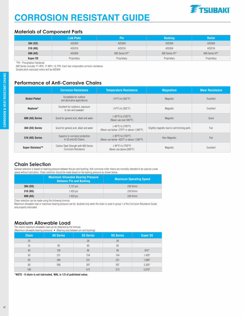
CO
RRO
SIO
N &
HEA
T R
ESIS
TAN
T CH
AIN
S
67
Materials of Component PartsLink Plate Pin Bushing Roller
304 (SS) AISI304 AISI304 AISI304 AISI304
316 (NS) AISI316 AISI316 AISI304 AISI316
600 (AS) AISI304 600 Series HT* 600 Series HT* 600 Series HT*
Super SS Proprietary Proprietary Proprietary Proprietary
*PH - Precipitation Hardened600 Series includes 17-4PH, 17-8PH, 13-7PH. Each has comporable corrision resistanceDouble pitch oversized rollers will be AISI304
Performance of Anti-Corrosive ChainsCorrosion Resistance Temperature Resistance Magnetism Wear Resistance
Nickel Plated Acceptable for outdoor and decorative applciations (14°F) to (302°F) Magnetic Excellent
Neptune® Excellent for outdoors, exposure to rain and seawater (14°F) to (302°F) Magnetic Excellent
600 (AS) Series Good for general acid, alkali and water(-40°F) to (750°F)
(Never use over 930°F)Magnetic Good
304 (SS) Series Good for general acid, alkali and water(-40°F) to (750°F)
(Never use below -270°F or above 1,300°F)Slightly magnetic due to cold forming parts Fair
316 (NS) Series Superior in corrosion protection to SS and AS Chains
(-40°F) to (750°F) (Never use below -420°F or above 1,500°F)
Non-Magnetic Fair
Super Stainless™ Carbon Steel Strength with 600 Series Corrosion Resistance
(-40°F) to (750°F)(Never use above (930°F)
Magnetic Excellent
Chain SelectionGeneral selection is based on bearing pressure between the pin and bushing. Anti-corrosive roller chains are normally intended to be used at a slow speed without lubrication. Chain selection should be made based on the bearing pressure as shown below.
Maximum Allowable Bearing Pressure Between Pin and Bushing Maximum Operating Speed
304 (SS) 2,131 psi 230 ft/min
316 (NS) 1,420 psi 230 ft/min
600 (AS) 1,420 psi 230 ft/min
Chain selection can be made using the following formulaMaximum allowable load or maximum bearing pressure can be doubled only when the chain is used in group 1 of the Corrosion Resistance Guide and properly lubricated
Maxium Allowable LoadThe chains maximum allowable load can be obtained by the formula:(Maximum allowable bearing pressure) • (Bearing area between pin and bushing)
Chain AS Series SS Series NS Series Super SS
25 26 26
35 90 60 60
40 150 99 99 810*
50 231 154 154 1,430*
60 346 231 231 1,980*
80 596 397 397 3,300*
100 573 573 5,070*
CORROSION RESISTANT GUIDE
*NOTE - If chain is not lubricated, MAL is 1/3 of published value.
.TSllBAKI"
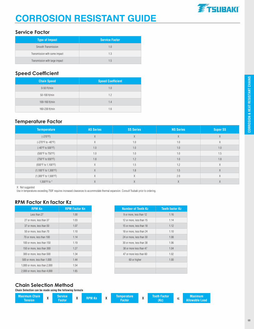
CO
RRO
SIO
N &
HEA
T R
ESIS
TAN
T CH
AIN
S
68
Service FactorType of Impact Service Factor
Smooth Transmission 1.0
Transmission with some impact 1.3
Transmission with large impact 1.5
Speed CoefficientChain Speed Speed Coefficient
0-50 Ft/min 1.0
50-100 ft/min 1.2
100-160 ft/min 1.4
160-230 ft/min 1.6
Temperature FactorTermperature AS Series SS Series NS Series Super SS
(-270°F) X X X X
(-270°F to -40°F) X 1.0 1.0 X
(-40°F to 500°F) 1.0 1.0 1.0 1.0
(500°F to 750°F) 1.0 1.0 1.0 1.5
(750°F to 930°F) 1.8 1.2 1.0 1.8
(930°F to 1,100°F) X 1.5 1.2 X
(1,100°F to 1,300°F) X 1.8 1.5 X
(1,300°F to 1,500°F) X X 2.0 X
1,500°F to * X X X X
X: Not suggestedUse in temperatures exceeding 750F requires increased clearances to accommodate thermal expansion. Consult Tsubaki prior to ordering.
CORROSION RESISTANT GUIDE
RPM Factor Kn factor KzRPM Kn RPM Factor Kn Number of Teeth Kz Teeth factor Kz
Less than 27 1.00 9 or more, less than 12 1.16
27 or more, less than 37 1.03 12 or more, less than 15 1.14
37 or more, less than 50 1.07 15 or more, less than 18 1.12
50 or more, less than 70 1.10 18 or more, less than 24 1.10
70 or more, less than 100 1.14 24 or more, less than 30 1.08
100 or more, less than 150 1.19 30 or more, less than 38 1.06
150 or more, less than 300 1.27 38 or more less than 47 1.04
300 or more, less than 500 1.34 47 or more less than 60 1.02
500 or more, less than 1,000 1.44 60 or higher 1.00
1,000 or more, less than 2,000 1.54
2,000 or more, less than 4,000 1.65
Chain Selection MethodChain Selection can be made using the following formula
Maximum Chain Tension X Service
Factor X RPM Kn X Temperature Factor X Tooth Factor
(Kz) ≤ Maximum Allowable Load
.TSllBAKI"
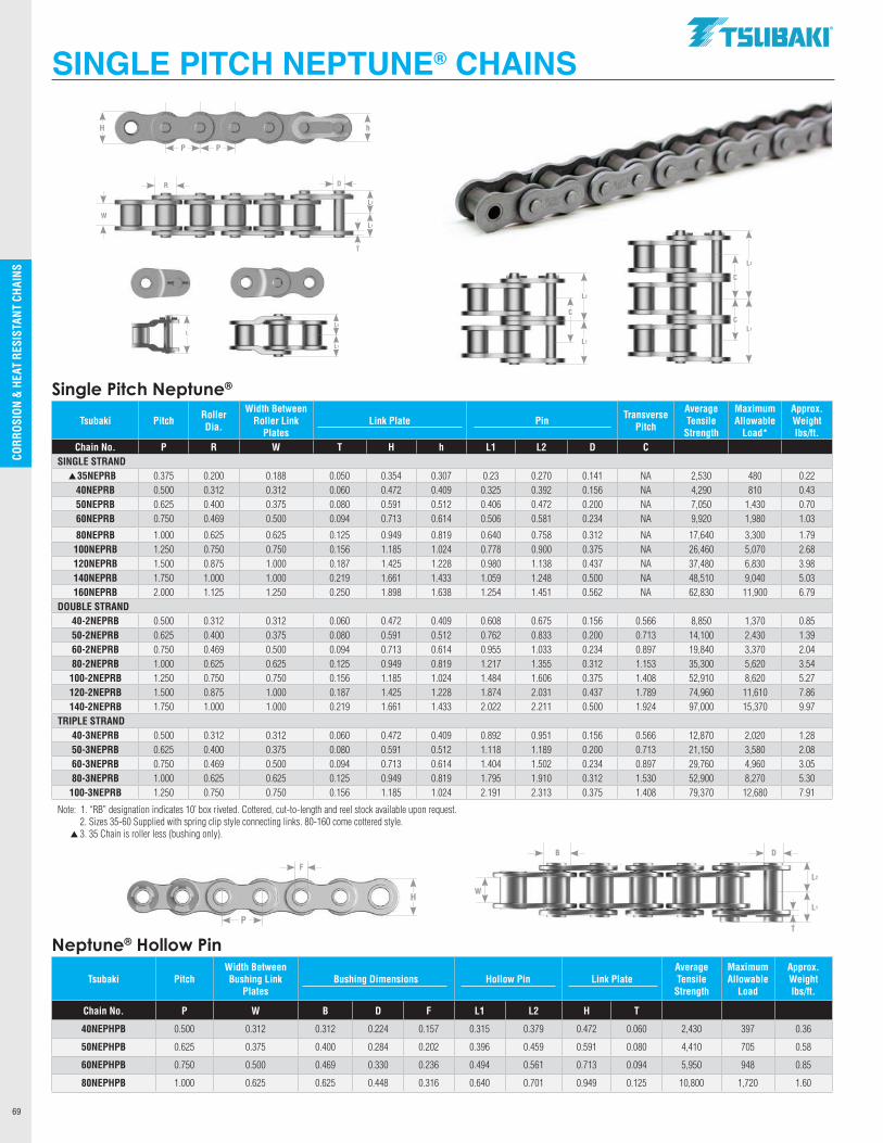
CO
RRO
SIO
N &
HEA
T R
ESIS
TAN
T CH
AIN
S
69
Single Pitch Neptune®
Tsubaki Pitch Roller Dia.
Width Between Roller Link
PlatesLink Plate
Pin
Transverse Pitch
Average Tensile
Strength
Maximum Allowable
Load*
Approx. Weight lbs/ft.
Chain No. P R W T H h L1 L2 D C SINGLE STRAND
35NEPRB 0.375 0.200 0.188 0.050 0.354 0.307 0.23 0.270 0.141 NA 2,530 480 0.2240NEPRB 0.500 0.312 0.312 0.060 0.472 0.409 0.325 0.392 0.156 NA 4,290 810 0.4350NEPRB 0.625 0.400 0.375 0.080 0.591 0.512 0.406 0.472 0.200 NA 7,050 1,430 0.7060NEPRB 0.750 0.469 0.500 0.094 0.713 0.614 0.506 0.581 0.234 NA 9,920 1,980 1.03
80NEPRB 1.000 0.625 0.625 0.125 0.949 0.819 0.640 0.758 0.312 NA 17,640 3,300 1.79100NEPRB 1.250 0.750 0.750 0.156 1.185 1.024 0.778 0.900 0.375 NA 26,460 5,070 2.68120NEPRB 1.500 0.875 1.000 0.187 1.425 1.228 0.980 1.138 0.437 NA 37,480 6,830 3.98140NEPRB 1.750 1.000 1.000 0.219 1.661 1.433 1.059 1.248 0.500 NA 48,510 9,040 5.03160NEPRB 2.000 1.125 1.250 0.250 1.898 1.638 1.254 1.451 0.562 NA 62,830 11,900 6.79
DOUBLE STRAND40-2NEPRB 0.500 0.312 0.312 0.060 0.472 0.409 0.608 0.675 0.156 0.566 8,850 1,370 0.8550-2NEPRB 0.625 0.400 0.375 0.080 0.591 0.512 0.762 0.833 0.200 0.713 14,100 2,430 1.3960-2NEPRB 0.750 0.469 0.500 0.094 0.713 0.614 0.955 1.033 0.234 0.897 19,840 3,370 2.0480-2NEPRB 1.000 0.625 0.625 0.125 0.949 0.819 1.217 1.355 0.312 1.153 35,300 5,620 3.54100-2NEPRB 1.250 0.750 0.750 0.156 1.185 1.024 1.484 1.606 0.375 1.408 52,910 8,620 5.27120-2NEPRB 1.500 0.875 1.000 0.187 1.425 1.228 1.874 2.031 0.437 1.789 74,960 11,610 7.86140-2NEPRB 1.750 1.000 1.000 0.219 1.661 1.433 2.022 2.211 0.500 1.924 97,000 15,370 9.97
TRIPLE STRAND40-3NEPRB 0.500 0.312 0.312 0.060 0.472 0.409 0.892 0.951 0.156 0.566 12,870 2,020 1.2850-3NEPRB 0.625 0.400 0.375 0.080 0.591 0.512 1.118 1.189 0.200 0.713 21,150 3,580 2.0860-3NEPRB 0.750 0.469 0.500 0.094 0.713 0.614 1.404 1.502 0.234 0.897 29,760 4,960 3.0580-3NEPRB 1.000 0.625 0.625 0.125 0.949 0.819 1.795 1.910 0.312 1.530 52,900 8,270 5.30100-3NEPRB 1.250 0.750 0.750 0.156 1.185 1.024 2.191 2.313 0.375 1.408 79,370 12,680 7.91
Note: 1. “RB” designation indicates 10’ box riveted. Cottered, cut-to-length and reel stock available upon request. 2. Sizes 35-60 Supplied with spring clip style connecting links. 80-160 come cottered style. 3. 35 Chain is roller less (bushing only).
Neptune® Hollow Pin
Tsubaki PitchWidth Between Bushing Link
PlatesBushing Dimensions Hollow Pin Link Plate
Average Tensile
Strength
Maximum Allowable
Load
Approx. Weight lbs/ft.
Chain No. P W B D F L1 L2 H T
40NEPHPB 0.500 0.312 0.312 0.224 0.157 0.315 0.379 0.472 0.060 2,430 397 0.36
50NEPHPB 0.625 0.375 0.400 0.284 0.202 0.396 0.459 0.591 0.080 4,410 705 0.58
60NEPHPB 0.750 0.500 0.469 0.330 0.236 0.494 0.561 0.713 0.094 5,950 948 0.85
80NEPHPB 1.000 0.625 0.625 0.448 0.316 0.640 0.701 0.949 0.125 10,800 1,720 1.60
SINGLE PITCH NEPTUNE® CHAINS
L2
L1
C
L2
L1
C
C
LL2
L1
L2
L1
W
DB
T
p
p
P
H
F
P P
hH
L2
L1
W
DR
T
.TSllBAKI"
' ;.
I ;. ' y ;.
;. ;.
;. I I ;. l I
I ' ' ' ' ' ' II 11
r r r r T T
------------
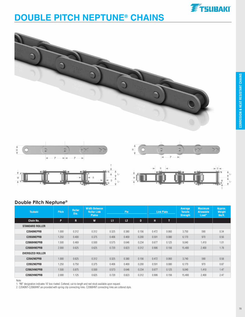
CO
RRO
SIO
N &
HEA
T R
ESIS
TAN
T CH
AIN
S
70
Double Pitch Neptune®
Tsubaki Pitch Roller Dia.
Width Between Roller Link
PlatesPin Link Plate
Average Tensile
Strength
Maximum Allowable
Load*
Approx. Weight lbs/ft.
Chain No. P R W L1 L2 D H T
STANDARD ROLLER
C2040NEPRB 1.000 0.312 0.312 0.325 0.380 0.156 0.472 0.060 3,750 590 0.34
C2050NEPRB 1.250 0.400 0.375 0.406 0.469 0.200 0.591 0.080 6,170 970 0.56
C2060HNEPRB 1.500 0.469 0.500 0.575 0.646 0.234 0.677 0.125 9,040 1,410 1.01
C2080HNEPRB 2.000 0.625 0.625 0.720 0.823 0.312 0.906 0.156 15,400 2,400 1.78
OVERSIZED ROLLER
C2042NEPRB 1.000 0.625 0.312 0.325 0.380 0.156 0.472 0.060 3,740 590 0.58
C2052NEPRB 1.250 0.750 0.375 0.406 0.469 0.200 0.591 0.080 6,170 970 0.87
C2062HNEPRB 1.500 0.875 0.500 0.573 0.646 0.234 0.677 0.125 9,040 1,410 1.47
C2082HNEPRB 2.000 1.125 0.625 0.720 0.823 0.312 0.906 0.156 15,400 2,400 2.47
Note: 1. “RB” designation indicates 10’ box riveted. Cottered, cut-to-length and reel stock available upon request.2. C2040NT-C2060HNT are provided with spring clip connecting links. C2080HNT connecting links are cottered style.
DOUBLE PITCH NEPTUNE® CHAINS
P P
H
L2
L1
W
T
DR
L2
L1
W
DR
T
P
H
.TSllBAKI"
-----------
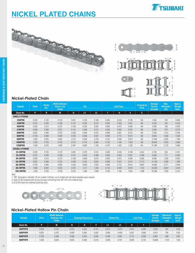
CO
RRO
SIO
N &
HEA
T R
ESIS
TAN
T CH
AIN
S
71
NICKEL PLATED CHAINS
Width Between
Roller Link Plates
L2
L1
C
L2
L1
W
DR
T
L
P P
hH
Nickel-Plated Chain
Tsubaki Pitch Roller Dia.
Width Between Roller Link
PlatesPin
Link Plate
Transverse Pitch
Average Tensile
Strength
Max. Allowable
LBS.
Approx. Weight lbs/ft.
Chain No. P R W D L1 L2 T H h C
SINGLE STRAND
25NPRB 0.250 0.130 0.125 0.091 0.150 0.189 0.030 0.230 0.199 NA 1,050 140 0.09435NPRB 0.375 0.200 0.188 0.141 0.230 0.270 0.050 0.354 0.307 NA 2,530 418 0.22040NPRB 0.500 0.312 0.312 0.156 0.325 0.392 0.060 0.472 0.409 NA 4,290 706 0.43041NPRB 0.500 0.306 0.251 0.141 0.266 0.312 0.050 0.382 0.331 NA 2,640 370 0.27050NPRB 0.625 0.400 0.375 0.200 0.406 0.472 0.080 0.591 0.512 NA 7,050 1,212 0.70060NPRB 0.750 0.469 0.500 0.234 0.506 0.581 0.094 0.713 0.614 NA 9,920 1,630 1.03080NPRB 1.000 0.625 0.625 0.312 0.640 0.758 0.125 0.949 0.819 NA 17,640 2,855 1.790100NPRB 1.250 0.750 0.750 0.375 0.778 0.900 0.156 1.185 1.024 NA 26,640 4,294 2.680120NPRB 1.500 0.875 1.000 0.437 0.980 1.138 0.187 1.425 1.228 NA 37,480 5,733 3.980
DOUBLE STRAND25-2NPRB 0.250 0.130 0.125 0.091 0.276 0.315 0.030 0.230 0.199 0.252 2,100 238 0.18135-2NPRB 0.375 0.200 0.188 0.141 0.429 0.469 0.050 0.354 0.307 0.399 5,060 711 0.46040-2NPRB 0.500 0.312 0.312 0.156 0.608 0.675 0.060 0.472 0.409 0.566 8,580 1,200 0.85050-2NPRB 0.625 0.400 0.375 0.200 0.762 0.833 0.080 0.591 0.512 0.713 14,100 2,000 1.39060-2NPRB 0.750 0.469 0.500 0.234 0.955 1.033 0.094 0.713 0.614 0.897 19,840 2,771 2.04080-2NPRB 1.000 0.625 0.625 0.312 1.217 1.335 0.125 0.949 0.819 1.153 35,280 4,854 3.540100-2NPRB 1.250 0.750 0.750 0.375 1.484 1.606 0.156 1.185 1.024 1.408 53,280 7,300 5.270
Note: 1. “RB” designation indicates 10’ box riveted. Cottered, cut-to-length and reel stock available upon request.2. Sizes 25-60 Supplied with spring clip style connecting links. 80-120 come cottered style.3. 25 & 35 Chain are rollerless (bushing only).
Tsubaki PitchWidth Between Bushing Link
PlatesBushing Dimensions Hollow Pin Link Plate
Average Tensile
Strength
Maximum Allowable
Load
Approx. Weight lbs/ft.
Chain No. P W B D F L1 L2 H T
40NPHPB 0.500 0.312 0.312 0.224 0.157 0.315 0.374 0.472 0.060 2,430 397 0.36
50NPHPB 0.625 0.375 0.400 0.284 0.202 0.396 0.459 0.591 0.080 4,410 705 0.58
60NPHPB 0.750 0.500 0.469 0.330 0.236 0.494 0.561 0.713 0.094 5,950 948 0.85
80NPHPB 1.000 0.625 0.625 0.448 0.316 0.640 0.701 0.949 0.125 10,800 1,720 1.60
Nickel-Plated Hollow Pin Chain
L2
L1
W
DB
TP
H
F
.TSllBAKI"
y ..
I .. y' .. ..
.. .. I
y
y y
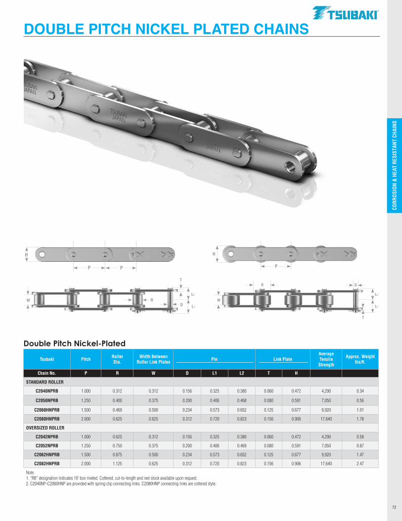
CO
RRO
SIO
N &
HEA
T R
ESIS
TAN
T CH
AIN
S
72
P P
H
L2
L1
W
T
DR
L2
L1
W
DR
T
P
H
DOUBLE PITCH NICKEL PLATED CHAINS
Double Pitch Nickel-Plated
Tsubaki Pitch Roller Dia.
Width Between Roller Link Plates Pin Link Plate
Average Tensile
Strength
Approx. Weight lbs/ft.
Chain No. P R W D L1 L2 T H
STANDARD ROLLER
C2040NPRB 1.000 0.312 0.312 0.156 0.325 0.380 0.060 0.472 4,290 0.34
C2050NPRB 1.250 0.400 0.375 0.200 0.406 0.468 0.080 0.591 7,050 0.56
C2060HNPRB 1.500 0.469 0.500 0.234 0.573 0.652 0.125 0.677 9,920 1.01
C2080HNPRB 2.000 0.625 0.625 0.312 0.720 0.823 0.156 0.906 17,640 1.78
OVERSIZED ROLLER
C2042NPRB 1.000 0.625 0.312 0.156 0.325 0.380 0.060 0.472 4,290 0.58
C2052NPRB 1.250 0.750 0.375 0.200 0.406 0.469 0.080 0.591 7,050 0.87
C2062HNPRB 1.500 0.875 0.500 0.234 0.573 0.652 0.125 0.677 9,920 1.47
C2082HNPRB 2.000 1.125 0.625 0.312 0.720 0.823 0.156 0.906 17,640 2.47
Note: 1. “RB” designation indicates 10’ box riveted. Cottered, cut-to-length and reel stock available upon request.2. C2040NP-C2060HNP are provided with spring clip connecting links. C2080HNP connecting links are cottered style.
.TSllBAKI"
c'X
----------
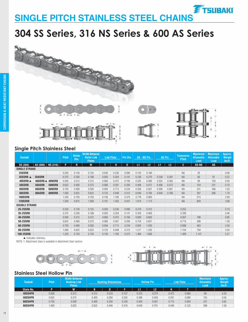
CO
RRO
SIO
N &
HEA
T R
ESIS
TAN
T CH
AIN
S
73
Stainless Steel Hollow Pin
Tsubaki PitchWidth Between Bushing Link
PlatesBushing Dimensions Hollow Pin Link Plate
Maximum Allowable
Load
Approx. Weight lbs/ft.
Chain No. P W B D F L1 L2 H T 40SSHPB 0.500 0.312 0.312 0.224 0.157 0.315 0.374 0.472 0.060 99 0.3550SSHPB 0.625 0.375 0.400 0.284 0.202 0.396 0.459 0.591 0.080 155 0.5660SSHPB 0.750 0.500 0.469 0.330 0.236 0.494 0.561 0.713 0.094 231 0.8280SSHPB 1.000 0.625 0.625 0.448 0.316 0.640 0.701 0.949 0.125 398 1.58
SINGLE PITCH STAINLESS STEEL CHAINS
P P
hH
L2
L1
W
DR
T
L2
L1
C
304 SS Series, 316 NS Series & 600 AS Series
L
Tsubaki Pitch Roller Dia.
Width Between Roller Link
PlatesLink Plate Pin Dia. SS - NS Pin AS Pin Transverse
Pitch
Maximum Allowable
Load
Maximum Allowable
Load
Approx. Weight lbs/ft.
SS (304) AS (600) NS (316) P R W T H D L1 L2 L1 L2 C SS-NS ASSINGLE STRAND
25SSRB 0.250 0.130 0.125 0.030 0.230 0.090 0.150 0.189 NA 26 0.0935SSRB 35ASRB 0.375 0.200 0.188 0.050 0.354 0.141 0.238 0.270 0.238 0.281 NA 60 91 0.2240SSRB 40ASRB 40NSRB 0.500 0.312 0.312 0.060 0.472 0.156 0.325 0.380 0.325 0.392 NA 99 150 0.4350SSRB 50ASRB 50NSRB 0.625 0.400 0.375 0.080 0.591 0.200 0.406 0.472 0.406 0.472 NA 154 231 0.7060SSRB 60ASRB 60NSRB 0.750 0.469 0.500 0.094 0.713 0.234 0.506 0.581 0.506 0.581 NA 231 346 1.0380SSRB 80ASRB 80NSRB 1.000 0.625 0.625 0.125 0.949 0.312 0.640 0.766 0.640 0.766 NA 397 596 1.79100SSRB 1.250 0.750 0.750 0.156 1.185 0.375 0.778 0.900 NA 573 2.69120SSRB 1.500 0.875 1.000 0.197 1.425 0.437 1.014 1.173 NA 859 3.98
DOUBLE STRAND25-2SSRB 0.250 0.130 0.125 0.030 0.230 0.090 0.276 0.315 0.252 0.1935-2SSRB 0.375 0.200 0.188 0.050 0.354 0.141 0.429 0.469 0.399 0.4640-2SSRB 0.500 0.312 0.312 0.060 0.472 0.156 0.600 0.683 0.567 198 0.8550-2SSRB 0.625 0.400 0.375 0.080 0.591 0.200 0.754 0.837 0.713 308 1.3960-2SSRB 0.750 0.469 0.500 0.094 0.713 0.234 0.955 1.030 0.898 463 2.0480-2SSRB 1.000 0.625 0.625 0.125 0.949 0.312 1.217 1.335 1.154 794 3.54100-2SSRB 1.250 0.750 0.750 0.156 1.185 0.375 1.484 1.606 1.409 1,147 5.27
Indicates rollerless.NOTE: 1. Attachment chain is available in attachment chain section.
Single Pitch Stainless Steel
p
p
p
p
L2
L1
W
DB
TP
H
F
.TSllBAKI"
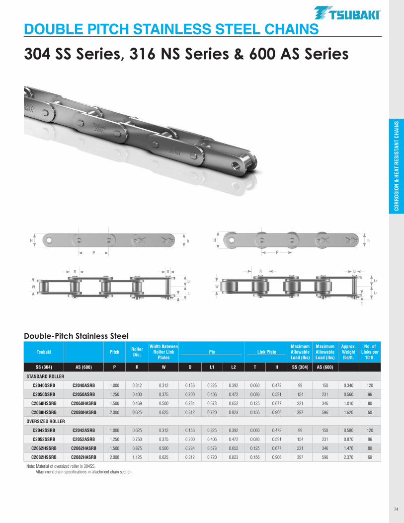
CO
RRO
SIO
N &
HEA
T R
ESIS
TAN
T CH
AIN
S
74
DOUBLE PITCH STAINLESS STEEL CHAINS
L2
L1
W
DR
T
P
hH
L2
L1
W
DR
T
P
hH
304 SS Series, 316 NS Series & 600 AS Series
Double-Pitch Stainless Steel
Tsubaki Pitch Roller Dia.
Width Between Roller Link
Plates Pin Link Plate
Maximum Allowable Load (lbs)
Maximum Allowable Load (lbs)
Approx. Weight lbs/ft.
No. of Links per
10 ft.
SS (304) AS (600) P R W D L1 L2 T H SS (304) AS (600)
STANDARD ROLLER
C2040SSRB C2040ASRB 1.000 0.312 0.312 0.156 0.325 0.392 0.060 0.472 99 150 0.340 120
C2050SSRB C2050ASRB 1.250 0.400 0.375 0.200 0.406 0.472 0.080 0.591 154 231 0.560 96
C2060HSSRB C2060HASRB 1.500 0.469 0.500 0.234 0.573 0.652 0.125 0.677 231 346 1.010 80
C2080HSSRB C2080HASRB 2.000 0.625 0.625 0.312 0.720 0.823 0.156 0.906 397 596 1.620 60
OVERSIZED ROLLER
C2042SSRB C2042ASRB 1.000 0.625 0.312 0.156 0.325 0.392 0.060 0.472 99 150 0.580 120
C2052SSRB C2052ASRB 1.250 0.750 0.375 0.200 0.406 0.472 0.080 0.591 154 231 0.870 96
C2062HSSRB C2062HASRB 1.500 0.875 0.500 0.234 0.573 0.652 0.125 0.677 231 346 1.470 80
C2082HSSRB C2082HASRB 2.000 1.125 0.625 0.312 0.720 0.823 0.156 0.906 397 596 2.370 60
Note: Material of oversized roller is 304SS. Attachment chain specifications in attachment chain section.
.TSllBAKI"
---------- --
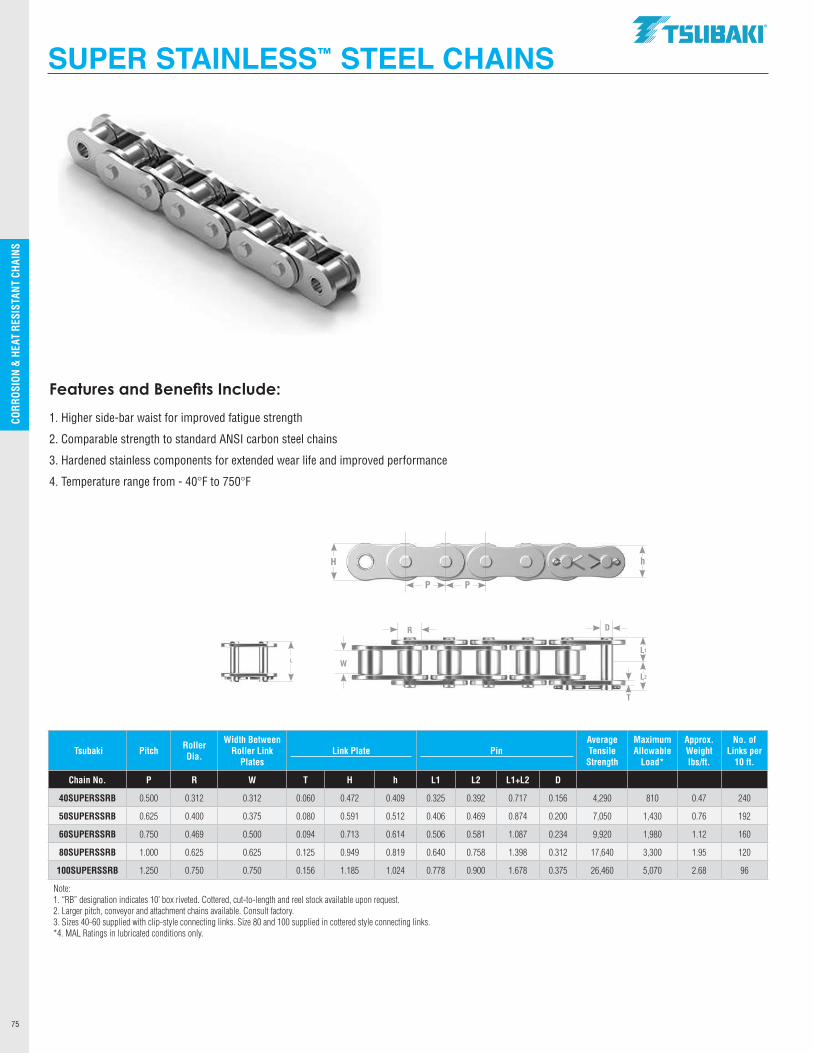
CO
RRO
SIO
N &
HEA
T R
ESIS
TAN
T CH
AIN
S
75
SUPER STAINLESS™ STEEL CHAINS
Features and Benefits Include:
1. Higher side-bar waist for improved fatigue strength
2. Comparable strength to standard ANSI carbon steel chains
3. Hardened stainless components for extended wear life and improved performance
4. Temperature range from - 40°F to 750°F
L1
L2
W
DR
T
P P
hH
L
Tsubaki Pitch Roller Dia.
Width Between Roller Link
PlatesLink Plate
Pin
Average Tensile
Strength
Maximum Allowable
Load*
Approx. Weight lbs/ft.
No. of Links per
10 ft.
Chain No. P R W T H h L1 L2 L1+L2 D
40SUPERSSRB 0.500 0.312 0.312 0.060 0.472 0.409 0.325 0.392 0.717 0.156 4,290 810 0.47 240
50SUPERSSRB 0.625 0.400 0.375 0.080 0.591 0.512 0.406 0.469 0.874 0.200 7,050 1,430 0.76 192
60SUPERSSRB 0.750 0.469 0.500 0.094 0.713 0.614 0.506 0.581 1.087 0.234 9,920 1,980 1.12 160
80SUPERSSRB 1.000 0.625 0.625 0.125 0.949 0.819 0.640 0.758 1.398 0.312 17,640 3,300 1.95 120
100SUPERSSRB 1.250 0.750 0.750 0.156 1.185 1.024 0.778 0.900 1.678 0.375 26,460 5,070 2.68 96
Note: 1. “RB” designation indicates 10’ box riveted. Cottered, cut-to-length and reel stock available upon request.2. Larger pitch, conveyor and attachment chains available. Consult factory.3. Sizes 40-60 supplied with clip-style connecting links. Size 80 and 100 supplied in cottered style connecting links.*4. MAL Ratings in lubricated conditions only.
.TSllBAKI"
-------------
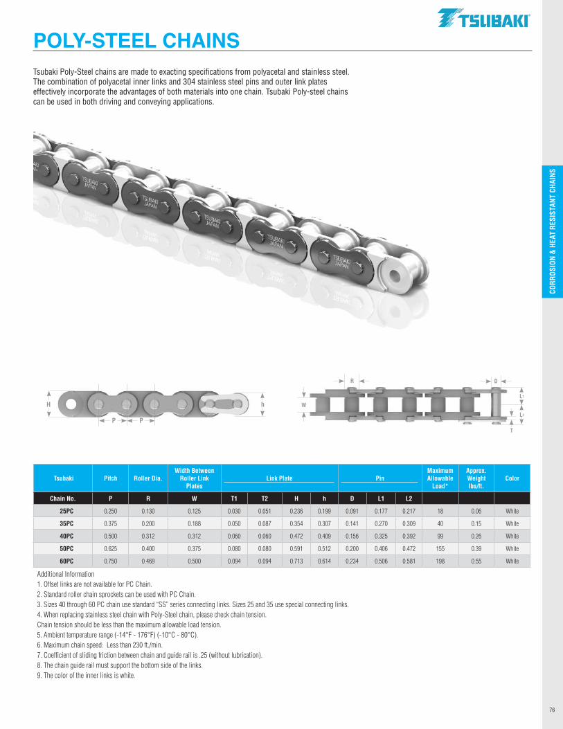
CO
RRO
SIO
N &
HEA
T R
ESIS
TAN
T CH
AIN
S
76
Tsubaki Poly-Steel chains are made to exacting specifications from polyacetal and stainless steel. The combination of polyacetal inner links and 304 stainless steel pins and outer link plates effectively incorporate the advantages of both materials into one chain. Tsubaki Poly-steel chains can be used in both driving and conveying applications.
POLY-STEEL CHAINS
L1
L2
W
DR
T
P P
hH
Tsubaki Pitch Roller Dia.Width Between
Roller Link Plates
Link Plate PinMaximum Allowable
Load*
Approx. Weight lbs/ft.
Color
Chain No. P R W T1 T2 H h D L1 L2
25PC 0.250 0.130 0.125 0.030 0.051 0.236 0.199 0.091 0.177 0.217 18 0.06 White
35PC 0.375 0.200 0.188 0.050 0.087 0.354 0.307 0.141 0.270 0.309 40 0.15 White
40PC 0.500 0.312 0.312 0.060 0.060 0.472 0.409 0.156 0.325 0.392 99 0.26 White
50PC 0.625 0.400 0.375 0.080 0.080 0.591 0.512 0.200 0.406 0.472 155 0.39 White
60PC 0.750 0.469 0.500 0.094 0.094 0.713 0.614 0.234 0.506 0.581 198 0.55 White
Additional Information1. Offset links are not available for PC Chain.2. Standard roller chain sprockets can be used with PC Chain.3. Sizes 40 through 60 PC chain use standard “SS” series connecting links. Sizes 25 and 35 use special connecting links.4. When replacing stainless steel chain with Poly-Steel chain, please check chain tension. Chain tension should be less than the maximum allowable load tension.5. Ambient temperature range (-14°F - 176°F) (-10°C - 80°C).6. Maximum chain speed: Less than 230 ft./min.7. Coefficient of sliding friction between chain and guide rail is .25 (without lubrication).8. The chain guide rail must support the bottom side of the links.9. The color of the inner links is white.
.TSllBAKI"
_________ .. __
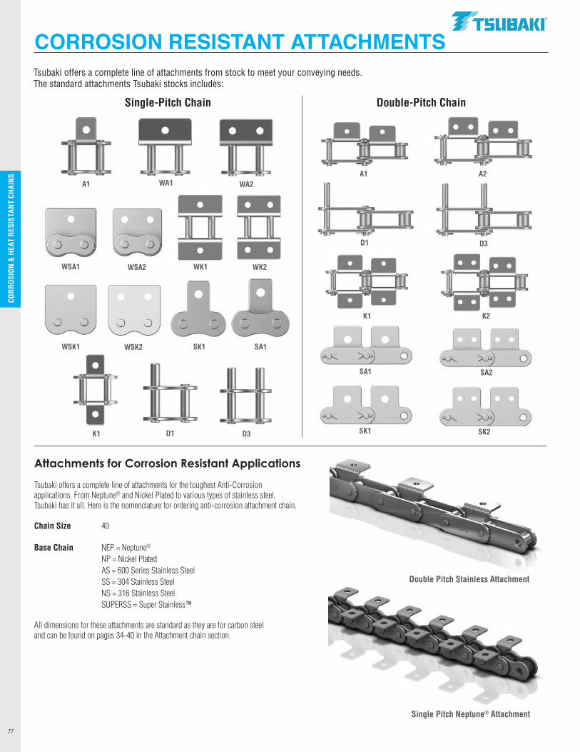
CO
RRO
SIO
N &
HEA
T R
ESIS
TAN
T CH
AIN
S
77
Tsubaki offers a complete line of attachments from stock to meet your conveying needs. The standard attachments Tsubaki stocks includes:
CORROSION RESISTANT ATTACHMENTS
Attachments for Corrosion Resistant Applications Tsubaki offers a complete line of attachments for the toughest Anti-Corrosionapplications. From Neptune® and Nickel Plated to various types of stainless steel,Tsubaki has it all. Here is the nomenclature for ordering anti-corrosion attachment chain. Chain Size 40 Base Chain NEP = Neptune®
NP = Nickel Plated AS = 600 Series Stainless Steel SS = 304 Stainless Steel NS = 316 Stainless Steel SUPERSS = Super Stainless™ All dimensions for these attachments are standard as they are for carbon steel and can be found on pages 34-40 in the Attachment chain section.
Single Pitch Neptune® Attachment
Double Pitch Stainless Attachment
WSA2
A1
K1 D1 D3
SA1
WA1 WA2
SK1
WK2
WSK2
WK1WSA1
WSK1
A1 A2
D1 D3
Single-Pitch Chain Double-Pitch Chain
K1 K2
SA1 SA2
SK1 SK2
.TSllBAKI"
I I I
The toughest and harshest operating conditions
demand a roller chain that is built as tough as
the environment it operates in. Titan® chain
combines the best of Tsubaki’s ANSI roller
chain design with a hard-chrome plated pin
and coated side plates. This combination
makes Titan® chain ideal in the dirtiest and
toughest applications where lubrication is
difficult. Another extended-life chain
solution from Tsubaki.
HARSH ENVIRONMENT CHAINS
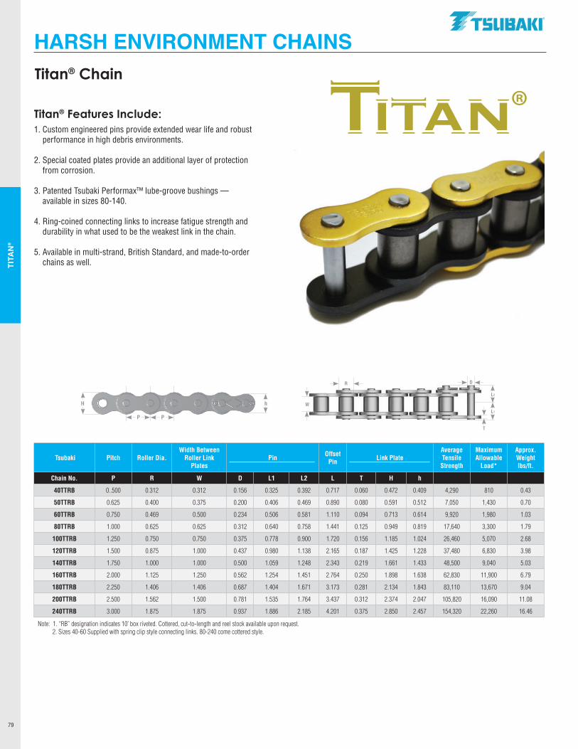
TITA
N®
79
HARSH ENVIRONMENT CHAINS
Titan® Features Include: 1. Custom engineered pins provide extended wear life and robust
performance in high debris environments.
2. Special coated plates provide an additional layer of protection from corrosion.
3. Patented Tsubaki Performax™ lube-groove bushings — available in sizes 80-140.
4. Ring-coined connecting links to increase fatigue strength and durability in what used to be the weakest link in the chain.
5. Available in multi-strand, British Standard, and made-to-order chains as well.
Titan® Chain
®
P P
hH
L2
L1
W
DR
T
Tsubaki Pitch Roller Dia.Width Between
Roller Link Plates
Pin Offset Pin Link Plate
Average Tensile
Strength
Maximum Allowable
Load*
Approx. Weight lbs/ft.
Chain No. P R W D L1 L2 L T H h
40TTRB 0..500 0.312 0.312 0.156 0.325 0.392 0.717 0.060 0.472 0.409 4,290 810 0.43
50TTRB 0.625 0.400 0.375 0.200 0.406 0.469 0.890 0.080 0.591 0.512 7,050 1,430 0.70
60TTRB 0.750 0.469 0.500 0.234 0.506 0.581 1.110 0.094 0.713 0.614 9,920 1,980 1.03
80TTRB 1.000 0.625 0.625 0.312 0.640 0.758 1.441 0.125 0.949 0.819 17,640 3,300 1.79
100TTRB 1.250 0.750 0.750 0.375 0.778 0.900 1.720 0.156 1.185 1.024 26,460 5,070 2.68
120TTRB 1.500 0.875 1.000 0.437 0.980 1.138 2.165 0.187 1.425 1.228 37,480 6,830 3.98
140TTRB 1.750 1.000 1.000 0.500 1.059 1.248 2.343 0.219 1.661 1.433 48,500 9,040 5.03
160TTRB 2.000 1.125 1.250 0.562 1.254 1.451 2.764 0.250 1.898 1.638 62,830 11,900 6.79
180TTRB 2.250 1.406 1.406 0.687 1.404 1.671 3.173 0.281 2.134 1.843 83,110 13,670 9.04
200TTRB 2.500 1.562 1.500 0.781 1.535 1.764 3.437 0.312 2.374 2.047 105,820 16,090 11.08
240TTRB 3.000 1.875 1.875 0.937 1.886 2.185 4.201 0.375 2.850 2.457 154,320 22,260 16.46
Note: 1. “RB” designation indicates 10’ box riveted. Cottered, cut-to-length and reel stock available upon request. 2. Sizes 40-60 Supplied with spring clip style connecting links. 80-240 come cottered style.
.TSUBAKI"
TITAN
-------------
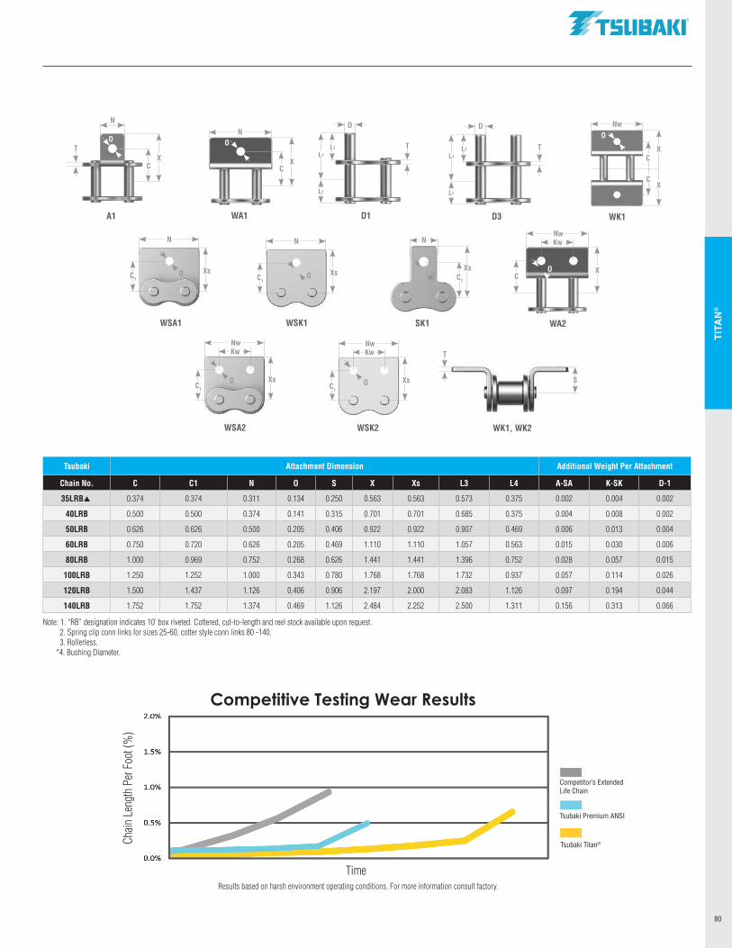
TITA
N®
80
Competitive Testing Wear Results
Time
Chain
Len
gth
Per F
oot (
%)
Competitor’s ExtendedLife Chain
Tsubaki Premium ANSI
Tsubaki Titan®
Results based on harsh environment operating conditions. For more information consult factory.
Tsubaki Attachment Dimension Additional Weight Per Attachment
Chain No. C C1 N O S X Xs L3 L4 A-SA K-SK D-1
35LRBp 0.374 0.374 0.311 0.134 0.250 0.563 0.563 0.573 0.375 0.002 0.004 0.002
40LRB 0.500 0.500 0.374 0.141 0.315 0.701 0.701 0.685 0.375 0.004 0.008 0.002
50LRB 0.626 0.626 0.500 0.205 0.406 0.922 0.922 0.907 0.469 0.006 0.013 0.004
60LRB 0.750 0.720 0.626 0.205 0.469 1.110 1.110 1.057 0.563 0.015 0.030 0.006
80LRB 1.000 0.969 0.752 0.268 0.626 1.441 1.441 1.396 0.752 0.028 0.057 0.015
100LRB 1.250 1.252 1.000 0.343 0.780 1.768 1.768 1.732 0.937 0.057 0.114 0.026
120LRB 1.500 1.437 1.126 0.406 0.906 2.197 2.000 2.083 1.126 0.097 0.194 0.044
140LRB 1.752 1.752 1.374 0.469 1.126 2.484 2.252 2.500 1.311 0.156 0.313 0.066
Note: 1. “RB” designation indicates 10’ box riveted. Cottered, cut-to-length and reel stock available upon request. 2. Spring clip conn links for sizes 25-60, cotter style conn links 80 -140. 3. Rollerless. *4. Bushing Diameter.
A1
CX
O
N
T
D1
D
L3
D3
D
L3
L4
L2
WA1
CX
N
WK1
Nw
CX
CX
WA2
Nw
CX
Kw
WSK2
Nw
C1
Xs
Kw
WSA2
Nw
C1
XsO
Kw
WSA1
N
C1
XsO
SK1
N
C1
XsO
S
WK1, WK2
WSK1
N
C1
XsO
O
O
T T
T
O
O
L4
L2
.TSUBAKI"
~
-------------
2.0%
1.5% -1.0% -0.5% -0.0%

NOTES
81
.TSllBAKI"

Oilfield chains from Tsubaki are designed for high speed and
high shock load applications. Oilfield chains are built to deliver
reliable power and performance in the most demanding
environments. Common applications include, mining, oil
and gas exploration, logging, fracking and digging and
drilling. Tsubaki Oilfield chains come with the Performax™
bushings for sizes 80-120 chains and are API Certified.
OILFIELD CHAINS (ENERGY SERIES®)
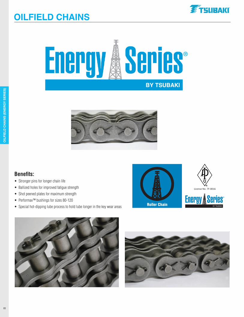
OIL
FIEL
D CH
AIN
S (E
NER
GY
SER
IES)
83
Benefits:• Stronger pins for longer chain life
• Ballized holes for improved fatigue strength
• Shot peened plates for maximum strength
• Performax™ bushings for sizes 80-120
• Special hot-dipping lube process to hold lube longer in the key wear areas
OILFIELD CHAINS
ProcessBlue C
Black
Specialty Packaging 02/14/20SPACK165
2 4 0.125
Energy Series - Roller ChainLabels per roll: 1000Rolls per case: 3
4.0000"
2.0000"
R 0.1250"
License No. 7F-0016
Lice
nse
No.
7F-
0016
®
.TSUBAKI"
ner er1es
Energy Series~
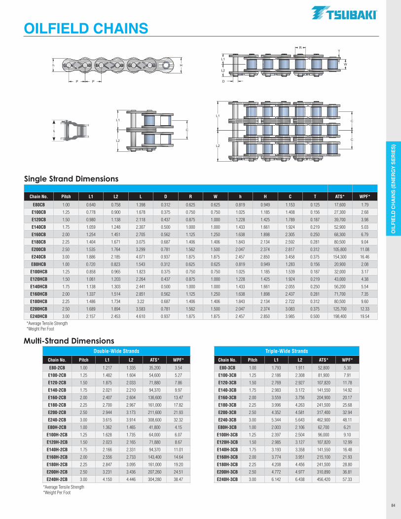
OIL
FIEL
D CH
AIN
S (E
NER
GY
SER
IES)
84
Multi-Strand Dimensions
OILFIELD CHAINS
Single Strand Dimensions
Chain No. Pitch L1 L2 L D R W h H C T ATS* WPF*
E80CB 1.00 0.640 0.758 1.398 0.312 0.625 0.625 0.819 0.949 1.153 0.125 17,600 1.79
E100CB 1.25 0.778 0.900 1.678 0.375 0.750 0.750 1.025 1.185 1.408 0.156 27,300 2.68
E120CB 1.50 0.980 1.138 2.118 0.437 0.875 1.000 1.228 1.425 1.789 0.187 39,700 3.98
E140CB 1.75 1.059 1.248 2.307 0.500 1.000 1.000 1.433 1.661 1.924 0.219 52,900 5.03
E160CB 2.00 1.254 1.451 2.705 0.562 1.125 1.250 1.638 1.898 2.305 0.250 68,300 6.79
E180CB 2.25 1.404 1.671 3.075 0.687 1.406 1.406 1.843 2.134 2.592 0.281 80,500 9.04
E200CB 2.50 1.535 1.764 3.299 0.781 1.562 1.500 2.047 2.374 2.817 0.312 105,800 11.08
E240CB 3.00 1.886 2.185 4.071 0.937 1.875 1.875 2.457 2.850 3.458 0.375 154,300 16.46
E80HCB 1.00 0.720 0.823 1.543 0.312 0.625 0.625 0.819 0.949 1.283 0.156 20,900 2.08
E100HCB 1.25 0.858 0.965 1.823 0.375 0.750 0.750 1.025 1.185 1.539 0.187 32,000 3.17
E120HCB 1.50 1.061 1.203 2.264 0.437 0.875 1.000 1.228 1.425 1.924 0.219 43,000 4.38
E140HCB 1.75 1.138 1.303 2.441 0.500 1.000 1.000 1.433 1.661 2.055 0.250 56,200 5.54
E160HCB 2.00 1.337 1.514 2.851 0.562 1.125 1.250 1.638 1.898 2.437 0.281 71,700 7.35
E180HCB 2.25 1.486 1.734 3.22 0.687 1.406 1.406 1.843 2.134 2.722 0.312 80,500 9.60
E200HCB 2.50 1.689 1.894 3.583 0.781 1.562 1.500 2.047 2.374 3.083 0.375 125,700 12.33
E240HCB 3.00 2.157 2.453 4.610 0.937 1.875 1.875 2.457 2.850 3.985 0.500 198,400 19.54*Average Tensile Strength*Weight Per Foot
Double-Wide Strands Triple-Wide Strands
Chain No. Pitch L1 L2 ATS* WPF* Chain No. Pitch L1 L2 ATS* WPF*
E80-2CB 1.00 1.217 1.335 35,200 3.54 E80-3CB 1.00 1.793 1.911 52,800 5.30
E100-2CB 1.25 1.482 1.604 54,600 5.27 E100-3CB 1.25 2.186 2.308 81,900 7.91
E120-2CB 1.50 1.875 2.033 71,880 7.86 E120-3CB 1.50 2.769 2.927 107,820 11.78
E140-2CB 1.75 2.021 2.210 94,370 9.97 E140-3CB 1.75 2.983 3.172 141,550 14.92
E160-2CB 2.00 2.407 2.604 136,600 13.47 E160-3CB 2.00 3.559 3.756 204,900 20.17
E180-2CB 2.25 2.700 2.967 161,000 17.82 E180-3CB 2.25 3.996 4.263 241,500 25.68
E200-2CB 2.50 2.944 3.173 211,600 21.93 E200-3CB 2.50 4.352 4.581 317,400 32.94
E240-2CB 3.00 3.615 3.914 308,600 32.32 E240-3CB 3.00 5.344 5.643 462,900 48.11
E80H-2CB 1.00 1.362 1.465 41,800 4.15 E80H-3CB 1.00 2.003 2.106 62,700 6.21
E100H-2CB 1.25 1.628 1.735 64,000 6.07 E100H-3CB 1.25 2.397 2.504 96,000 9.10
E120H-2CB 1.50 2.023 2.165 71,880 8.67 E120H-3CB 1.50 2.985 3.127 107,820 12.99
E140H-2CB 1.75 2.166 2.331 94,370 11.01 E140H-3CB 1.75 3.193 3.358 141,550 16.48
E160H-2CB 2.00 2.556 2.733 143,400 14.64 E160H-3CB 2.00 3.774 3.951 215,100 21.93
E180H-2CB 2.25 2.847 3.095 161,000 19.20 E180H-3CB 2.25 4.208 4.456 241,500 28.80
E200H-2CB 2.50 3.231 3.436 207,260 24.51 E200H-3CB 2.50 4.772 4.977 310,890 36.81
E240H-2CB 3.00 4.150 4.446 304,280 38.47 E240H-3CB 3.00 6.142 6.438 456,420 57.33
*Average Tensile Strength*Weight Per Foot
C
C
D
L2
L1
L2
L1W
T
C
L1
L2
R
h H
P P
L
.TSUBAKI"
n===.;~~~::$s;~~. ~~~~~~==::i_i
~~~~~~~ ~~~~~c
-----
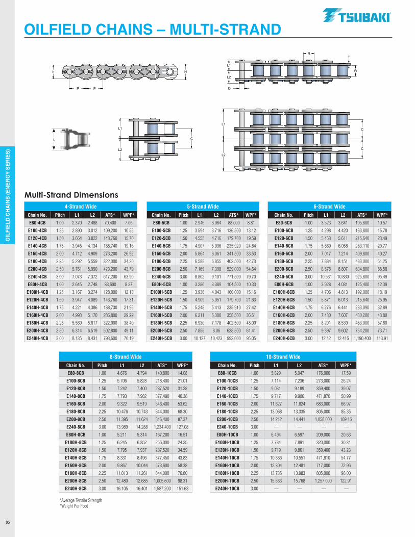
OIL
FIEL
D CH
AIN
S (E
NER
GY
SER
IES)
85
OILFIELD CHAINS – MULTI-STRAND
8-Strand Wide 10-Strand WideChain No. Pitch L1 L2 ATS* WPF* Chain No. Pitch L1 L2 ATS* WPF*
E80-8CB 1.00 4.676 4.794 140,800 14.08 E80-10CB 1.00 5.829 5.947 176,000 17.59
E100-8CB 1.25 5.706 5.828 218,400 21.01 E100-10CB 1.25 7.114 7.236 273,000 26.24
E120-8CB 1.50 7.242 7.400 287,520 31.28 E120-10CB 1.50 9.031 9.189 359,400 39.07
E140-8CB 1.75 7.793 7.982 377,490 40.38 E140-10CB 1.75 9.717 9.906 471,870 50.99
E160-8CB 2.00 9.322 9.519 546,400 53.62 E160-10CB 2.00 11.627 11.824 683,000 66.97
E180-8CB 2.25 10.476 10.743 644,000 68.30 E180-10CB 2.25 13.068 13.335 805,000 85.35
E200-8CB 2.50 11.395 11.624 846,400 87.37 E200-10CB 2.50 14.212 14.441 1,058,000 109.16
E240-8CB 3.00 13.989 14.288 1,234,400 127.08 E240-10CB 3.00 — — — —
E80H-8CB 1.00 5.211 5.314 167,200 16.51 E80H-10CB 1.00 6.494 6.597 209,000 20.63
E100H-8CB 1.25 6.245 6.352 256,000 24.25 E100H-10CB 1.25 7.784 7.891 320,000 30.31
E120H-8CB 1.50 7.795 7.937 287,520 34.59 E120H-10CB 1.50 9.719 9.861 359,400 43.23
E140H-8CB 1.75 8.331 8.496 377,450 43.83 E140H-10CB 1.75 10.386 10.551 471,810 54.77
E160H-8CB 2.00 9.867 10.044 573,600 58.38 E160H-10CB 2.00 12.304 12.481 717,000 72.96
E180H-8CB 2.25 11.013 11.261 644,000 76.80 E180H-10CB 2.25 13.735 13.983 805,000 96.00
E200H-8CB 2.50 12.480 12.685 1,005,600 98.31 E200H-10CB 2.50 15.563 15.768 1,257,000 122.91
E240H-8CB 3.00 16.105 16.401 1,587,200 151.63 E240H-10CB 3.00 — — — —
C
C
D
L2
L1
L2
L1W
T
C
L1
L2
R
h H
P P
L
4-Strand Wide 5-Strand Wide 6-Strand WideChain No. Pitch L1 L2 ATS* WPF* Chain No. Pitch L1 L2 ATS* WPF* Chain No. Pitch L1 L2 ATS* WPF*
E80-4CB 1.00 2.370 2.488 70,400 7.06 E80-5CB 1.00 2.946 3.064 88,000 8.81 E80-6CB 1.00 3.523 3.641 105,600 10.57
E100-4CB 1.25 2.890 3.012 109,200 10.55 E100-5CB 1.25 3.594 3.716 136,500 13.12 E100-6CB 1.25 4.298 4.420 163,800 15.78
E120-4CB 1.50 3.664 3.822 143,760 15.70 E120-5CB 1.50 4.558 4.716 179,700 19.59 E120-6CB 1.50 5.453 5.611 215,640 23.49
E140-4CB 1.75 3.945 4.134 188,740 19.16 E140-5CB 1.75 4.907 5.096 235,920 24.84 E140-6CB 1.75 5.869 6.058 283,110 29.77
E160-4CB 2.00 4.712 4.909 273,200 26.92 E160-5CB 2.00 5.864 6.061 341,500 33.53 E160-6CB 2.00 7.017 7.214 409,800 40.27
E180-4CB 2.25 5.292 5.559 322,000 34.20 E180-5CB 2.25 6.588 6.855 402,500 42.73 E180-6CB 2.25 7.884 8.151 483,000 51.25
E200-4CB 2.50 5.761 5.990 423,200 43.79 E200-5CB 2.50 7.169 7.398 529,000 54.64 E200-6CB 2.50 8.578 8.807 634,800 65.58
E240-4CB 3.00 7.073 7.372 617,200 63.90 E240-5CB 3.00 8.802 9.101 771,500 79.70 E240-6CB 3.00 10.531 10.830 925,800 95.49
E80H-4CB 1.00 2.645 2.748 83,600 8.27 E80H-5CB 1.00 3.286 3.389 104,500 10.33 E80H-6CB 1.00 3.928 4.031 125,400 12.39
E100H-4CB 1.25 3.167 3.274 128,000 12.13 E100H-5CB 1.25 3.936 4.043 160,000 15.16 E100H-6CB 1.25 4.706 4.813 192,000 18.19
E120H-4CB 1.50 3.947 4.089 143,760 17.31 E120H-5CB 1.50 4.909 5.051 179,700 21.63 E120H-6CB 1.50 5.871 6.013 215,640 25.95
E140H-4CB 1.75 4.221 4.386 188,730 21.95 E140H-5CB 1.75 5.248 5.413 235,910 27.42 E140H-6CB 1.75 6.276 6.441 283,090 32.89
E160H-4CB 2.00 4.993 5.170 286,800 29.22 E160H-5CB 2.00 6.211 6.388 358,500 36.51 E160H-6CB 2.00 7.430 7.607 430,200 43.80
E180H-4CB 2.25 5.569 5.817 322,000 38.40 E180H-5CB 2.25 6.930 7.178 402,500 48.00 E180H-6CB 2.25 8.291 8.539 483,000 57.60
E200H-4CB 2.50 6.314 6.519 502,800 49.11 E200H-5CB 2.50 7.855 8.06 628,500 61.41 E200H-6CB 2.50 9.397 9.602 754,200 73.71
E240H-4CB 3.00 8.135 8.431 793,600 76.19 E240H-5CB 3.00 10.127 10.423 992,000 95.05 E240H-6CB 3.00 12.12 12.416 1,190,400 113.91
Multi-Strand Dimensions
*Average Tensile Strength*Weight Per Foot
.TSUBAKI"
r~~~~~
~§@~@~~7
~§@~~~c L~~~~==:i
----- ----- --- -I I I I I I I I I
------- - ..I

Another segment of the Tsubaki chain product line is
the full line of AL and BL Series leaf chains. When lifting
applications require chains without rollers to carry to load,
Tsubaki is there with the BL Series leaf chains. Tsubaki
manufactures leaf chains from ½” pitch to 2-1/2” pitch
in numerous lacing combinations. Please consult Tsubaki for
the right Leaf Chain design needed to fit your application.
LEAF CHAINS
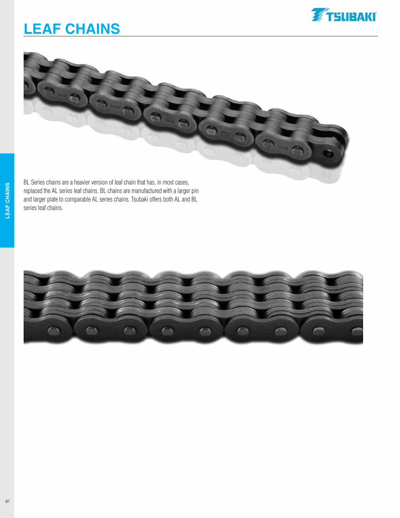
LEA
F C
HA
INS
87
BL Series chains are a heavier version of leaf chain that has, in most cases, replaced the AL series leaf chains. BL chains are manufactured with a larger pin and larger plate to comparable AL series chains. Tsubaki offers both AL and BL series leaf chains.
LEAF CHAINS.TSUBAKI"
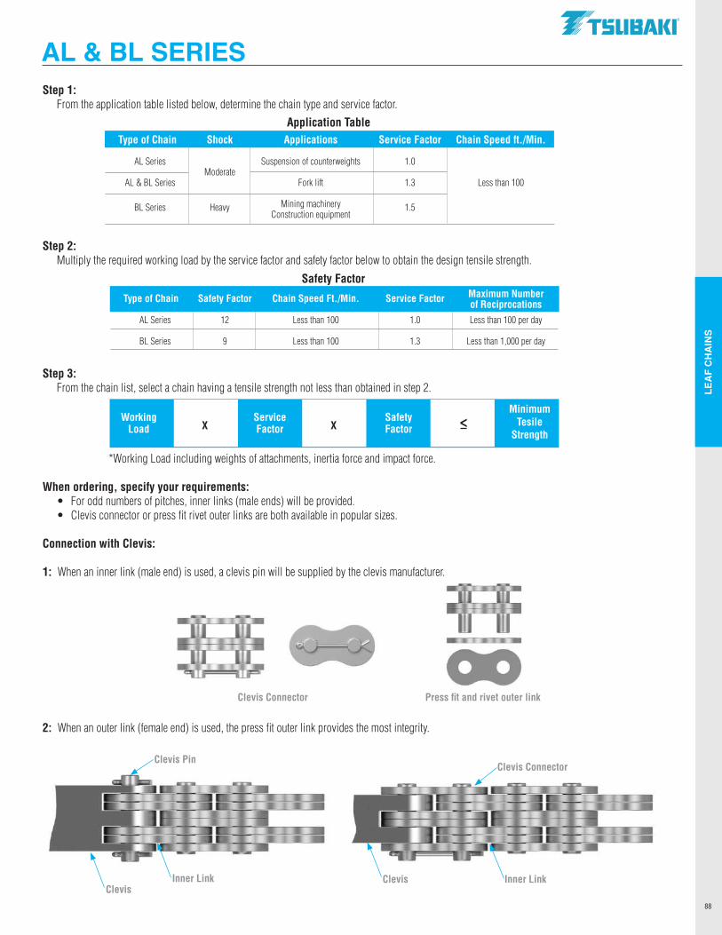
LEA
F C
HA
INS
88
Step 1: From the application table listed below, determine the chain type and service factor.
Step 2: Multiply the required working load by the service factor and safety factor below to obtain the design tensile strength.
Step 3: From the chain list, select a chain having a tensile strength not less than obtained in step 2.
*Working Load including weights of attachments, inertia force and impact force.
When ordering, specify your requirements: • For odd numbers of pitches, inner links (male ends) will be provided. • Clevis connector or press fit rivet outer links are both available in popular sizes.
Connection with Clevis:
1: When an inner link (male end) is used, a clevis pin will be supplied by the clevis manufacturer.
2: When an outer link (female end) is used, the press fit outer link provides the most integrity.
Application TableType of Chain Shock Applications Service Factor Chain Speed ft./Min.
AL Series Moderate
Suspension of counterweights 1.0
AL & BL Series Fork lift 1.3 Less than 100
BL Series Heavy Mining machinery 1.5 Construction equipment
Safety Factor
Working Service e Safety
Minimum
Load X Factor X Factor < Tesile Strength
Press fit and rivet outer linkClevis Connector
Clevis Pin
ClevisInner Link
Clevis Connector
Clevis Inner Link
AL & BL SERIES
Type of Chain Safety Factor Chain Speed Ft./Min. Service Factor Maximum Number of Reciprocations AL Series 12 Less than 100 1.0 Less than 100 per day
BL Series 9 Less than 100 1.3 Less than 1,000 per day
.TSUBAKI"
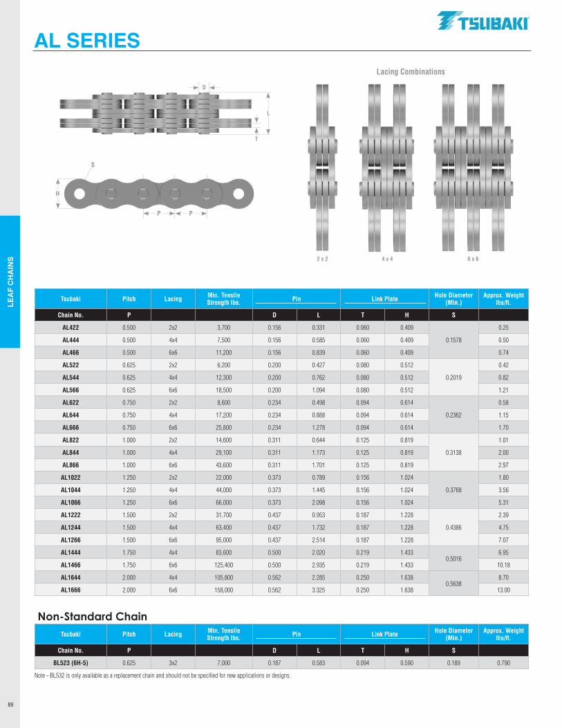
LEA
F C
HA
INS
89
AL SERIES
L
D
T
2 x 2 4 x 4 6 x 6
P P
H
S
Lacing Combinations
Tsubaki Pitch Lacing Min. Tensile Strength lbs. Pin Link Plate Hole Diameter
(Min.)Approx. Weight
lbs/ft.
Chain No. P D L T H S
AL422 0.500 2x2 3,700 0.156 0.331 0.060 0.409
0.1578
0.25
AL444 0.500 4x4 7,500 0.156 0.585 0.060 0.409 0.50
AL466 0.500 6x6 11,200 0.156 0.839 0.060 0.409 0.74
AL522 0.625 2x2 6,200 0.200 0.427 0.080 0.512
0.2019
0.42
AL544 0.625 4x4 12,300 0.200 0.762 0.080 0.512 0.82
AL566 0.625 6x6 18,500 0.200 1.094 0.080 0.512 1.21
AL622 0.750 2x2 8,600 0.234 0.498 0.094 0.614
0.2362
0.58
AL644 0.750 4x4 17,200 0.234 0.888 0.094 0.614 1.15
AL666 0.750 6x6 25,800 0.234 1.278 0.094 0.614 1.70
AL822 1.000 2x2 14,600 0.311 0.644 0.125 0.819
0.3138
1.01
AL844 1.000 4x4 29,100 0.311 1.173 0.125 0.819 2.00
AL866 1.000 6x6 43,600 0.311 1.701 0.125 0.819 2.97
AL1022 1.250 2x2 22,000 0.373 0.789 0.156 1.024
0.3768
1.80
AL1044 1.250 4x4 44,000 0.373 1.445 0.156 1.024 3.56
AL1066 1.250 6x6 66,000 0.373 2.098 0.156 1.024 5.31
AL1222 1.500 2x2 31,700 0.437 0.953 0.187 1.228
0.4386
2.39
AL1244 1.500 4x4 63,400 0.437 1.732 0.187 1.228 4.75
AL1266 1.500 6x6 95,000 0.437 2.514 0.187 1.228 7.07
AL1444 1.750 4x4 83,600 0.500 2.020 0.219 1.4330.5016
6.95
AL1466 1.750 6x6 125,400 0.500 2.935 0.219 1.433 10.18
AL1644 2.000 4x4 105,800 0.562 2.285 0.250 1.6380.5638
8.70
AL1666 2.000 6x6 158,000 0.562 3.325 0.250 1.638 13.00
Non-Standard ChainTsubaki Pitch Lacing Min. Tensile
Strength lbs. Pin Link Plate Hole Diameter (Min.)
Approx. Weight lbs/ft.
Chain No. P D L T H S
BL523 (6H-5) 0.625 3x2 7,000 0.187 0.583 0.094 0.590 0.189 0.790
Note - BL532 is only available as a replacement chain and should not be specified for new applications or designs.
.TSUBAKI"
------
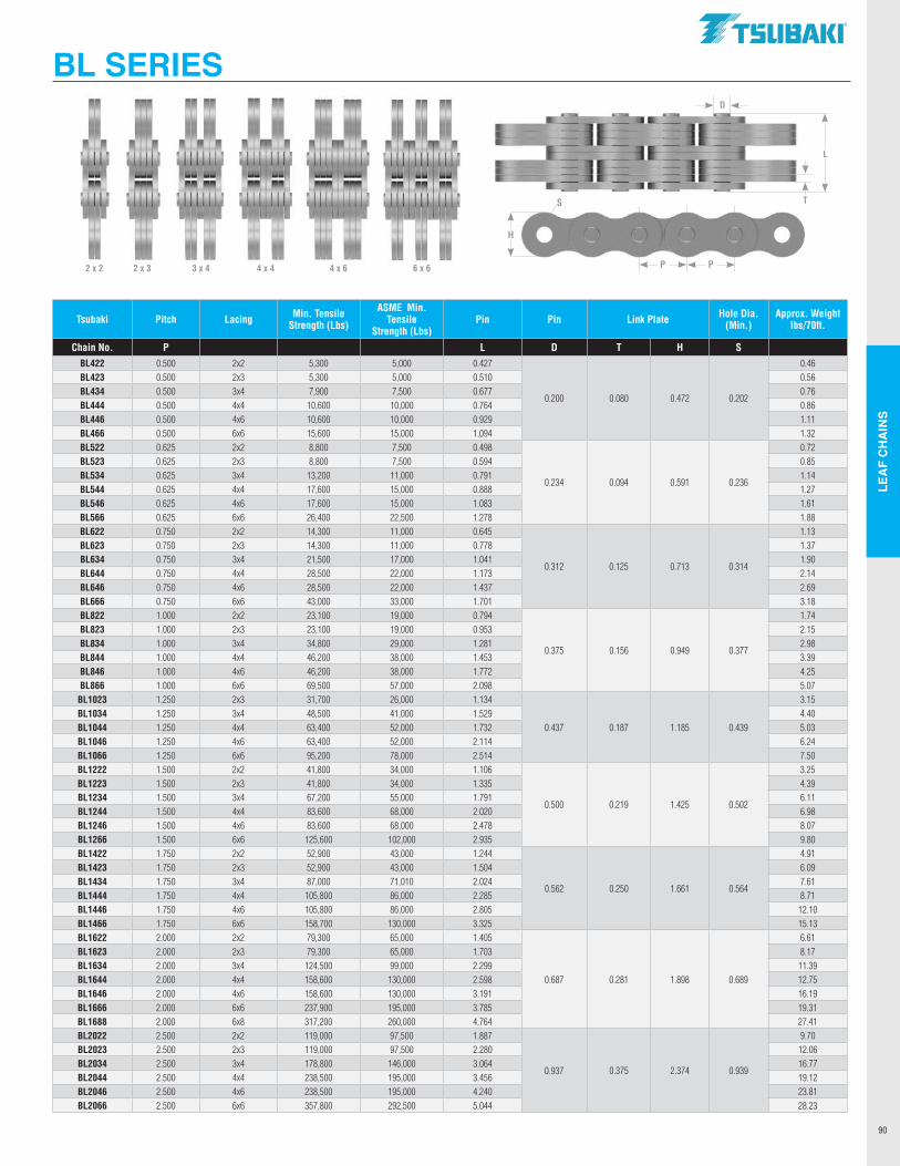
LEA
F C
HA
INS
90
BL SERIES
2 x 2 2 x 3 3 x 4 4 x 4 4 x 6 6 x 6
L
D
T
P P
H
S
Tsubaki Pitch Lacing Min. Tensile Strength (Lbs)
ASME Min.Tensile
Strength (Lbs)Pin Pin Link Plate Hole Dia.
(Min.)Approx. Weight
lbs/70ft.
Chain No. P L D T H SBL422 0.500 2x2 5,300 5,000 0.427
0.200 0.080 0.472 0.202
0.46BL423 0.500 2x3 5,300 5,000 0.510 0.56BL434 0.500 3x4 7,900 7,500 0.677 0.76BL444 0.500 4x4 10,600 10,000 0.764 0.86BL446 0.500 4x6 10,600 10,000 0.929 1.11BL466 0.500 6x6 15,600 15,000 1.094 1.32BL522 0.625 2x2 8,800 7,500 0.498
0.234 0.094 0.591 0.236
0.72BL523 0.625 2x3 8,800 7,500 0.594 0.85BL534 0.625 3x4 13,200 11,000 0.791 1.14BL544 0.625 4x4 17,600 15,000 0.888 1.27BL546 0.625 4x6 17,600 15,000 1.083 1.61BL566 0.625 6x6 26,400 22,500 1.278 1.88BL622 0.750 2x2 14,300 11,000 0.645
0.312 0.125 0.713 0.314
1.13BL623 0.750 2x3 14,300 11,000 0.778 1.37BL634 0.750 3x4 21,500 17,000 1.041 1.90BL644 0.750 4x4 28,500 22,000 1.173 2.14BL646 0.750 4x6 28,500 22,000 1.437 2.69BL666 0.750 6x6 43,000 33,000 1.701 3.18BL822 1.000 2x2 23,100 19,000 0.794
0.375 0.156 0.949 0.377
1.74BL823 1.000 2x3 23,100 19,000 0.953 2.15BL834 1.000 3x4 34,800 29,000 1.281 2.98BL844 1.000 4x4 46,200 38,000 1.453 3.39BL846 1.000 4x6 46,200 38,000 1.772 4.25BL866 1.000 6x6 69,500 57,000 2.098 5.07
BL1023 1.250 2x3 31,700 26,000 1.134
0.437 0.187 1.185 0.439
3.15BL1034 1.250 3x4 48,500 41,000 1.529 4.40BL1044 1.250 4x4 63,400 52,000 1.732 5.03BL1046 1.250 4x6 63,400 52,000 2.114 6.24BL1066 1.250 6x6 95,200 78,000 2.514 7.50BL1222 1.500 2x2 41,800 34,000 1.106
0.500 0.219 1.425 0.502
3.25BL1223 1.500 2x3 41,800 34,000 1.335 4.39BL1234 1.500 3x4 67,200 55,000 1.791 6.11BL1244 1.500 4x4 83,600 68,000 2.020 6.98BL1246 1.500 4x6 83,600 68,000 2.478 8.07BL1266 1.500 6x6 125,600 102,000 2.935 9.80BL1422 1.750 2x2 52,900 43,000 1.244
0.562 0.250 1.661 0.564
4.91BL1423 1.750 2x3 52,900 43,000 1.504 6.09BL1434 1.750 3x4 87,000 71,010 2.024 7.61BL1444 1.750 4x4 105,800 86,000 2.285 8.71BL1446 1.750 4x6 105,800 86,000 2.805 12.10BL1466 1.750 6x6 158,700 130,000 3.325 15.13BL1622 2.000 2x2 79,300 65,000 1.405
0.687 0.281 1.898 0.689
6.61BL1623 2.000 2x3 79,300 65,000 1.703 8.17BL1634 2.000 3x4 124,500 99,000 2.299 11.39BL1644 2.000 4x4 158,600 130,000 2.598 12.75BL1646 2.000 4x6 158,600 130,000 3.191 16.19BL1666 2.000 6x6 237,900 195,000 3.785 19.31BL1688 2.000 6x8 317,200 260,000 4.764 27.41BL2022 2.500 2x2 119,000 97,500 1.887
0.937 0.375 2.374 0.939
9.70BL2023 2.500 2x3 119,000 97,500 2.280 12.06BL2034 2.500 3x4 178,800 146,000 3.064 16.77BL2044 2.500 4x4 238,500 195,000 3.456 19.12BL2046 2.500 4x6 238,500 195,000 4.240 23.81BL2066 2.500 6x6 357,800 292,500 5.044 28.23
.TSUBAKI"
I I I
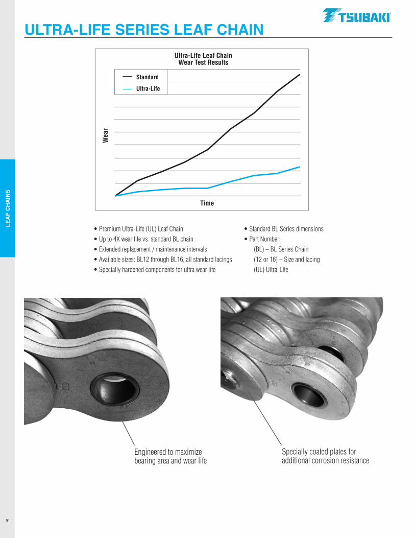
LEA
F C
HA
INS
91
• Premium Ultra-Life (UL) Leaf Chain • Up to 4X wear life vs. standard BL chain• Extended replacement / maintenance intervals• Available sizes: BL12 through BL16, all standard lacings• Specially hardened components for ultra wear life
• Standard BL Series dimensions• Part Number: (BL) – BL Series Chain (12 or 16) – Size and lacing (UL) Ultra-LIfe
ULTRA-LIFE SERIES LEAF CHAIN
Engineered to maximize bearing area and wear life
Specially coated plates for additional corrosion resistance
Ultra-Life Leaf ChainWear Test Results
Time
Wea
r
Standard
Ultra-Life
.TSUBAKI"
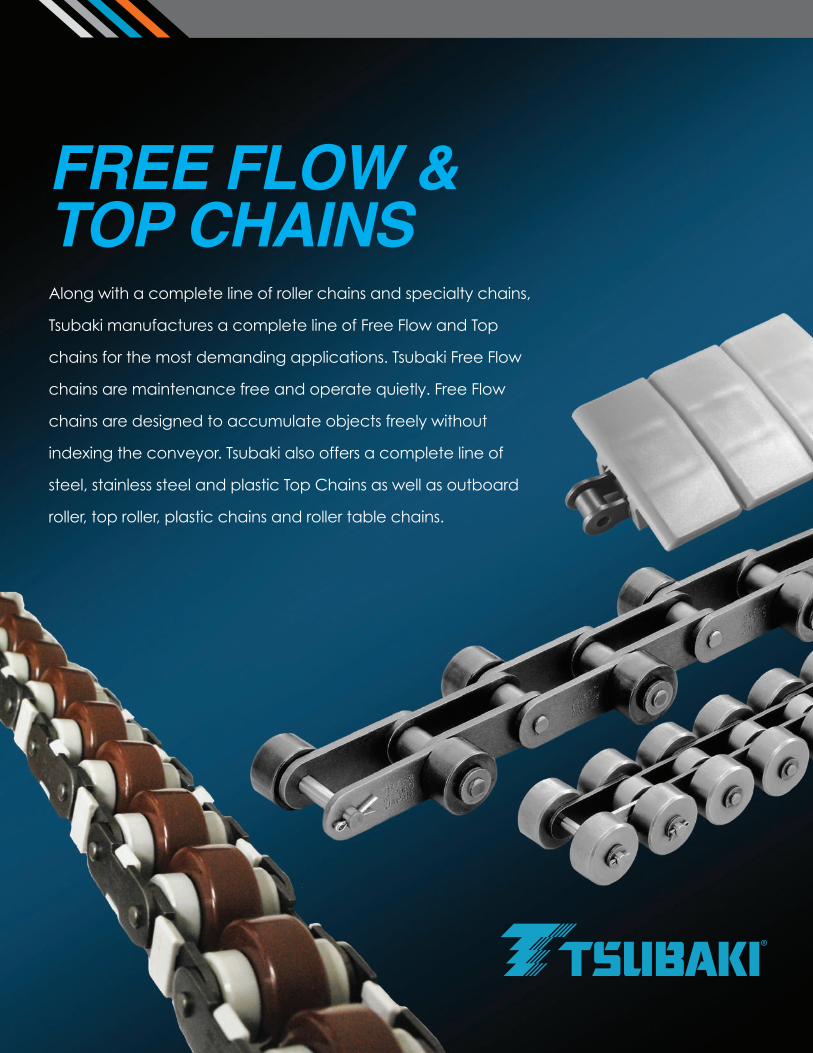
Along with a complete line of roller chains and specialty chains,
Tsubaki manufactures a complete line of Free Flow and Top
chains for the most demanding applications. Tsubaki Free Flow
chains are maintenance free and operate quietly. Free Flow
chains are designed to accumulate objects freely without
indexing the conveyor. Tsubaki also offers a complete line of
steel, stainless steel and plastic Top Chains as well as outboard
roller, top roller, plastic chains and roller table chains.
FREE FLOW &TOP CHAINS
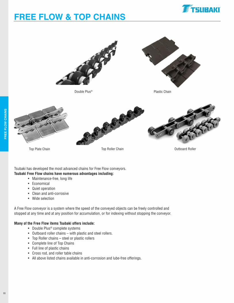
FREE
FLO
W C
HA
INS
93
FREE FLOW & TOP CHAINS
Tsubaki has developed the most advanced chains for Free Flow conveyors. Tsubaki Free Flow chains have numerous advantages including: • Maintenance-free, long life • Economical • Quiet operation • Clean and anti-corrosive • Wide selection
A Free Flow conveyor is a system where the speed of the conveyed objects can be freely controlled and stopped at any time and at any position for accumulation, or for indexing without stopping the conveyor.
Many of the Free Flow items Tsubaki offers include: • Double Plus® complete systems • Outboard roller chains – with plastic and steel rollers. • Top Roller chains – steel or plastic rollers • Complete line of Top Chains • Full line of plastic chains • Cross rod, and roller table chains • All above listed chains available in anti-corrosion and lube-free offerings.
Top Plate Chain
Plastic Chain
Top Roller Chain
Double Plus®
Outboard Roller
.TSUBAKI"
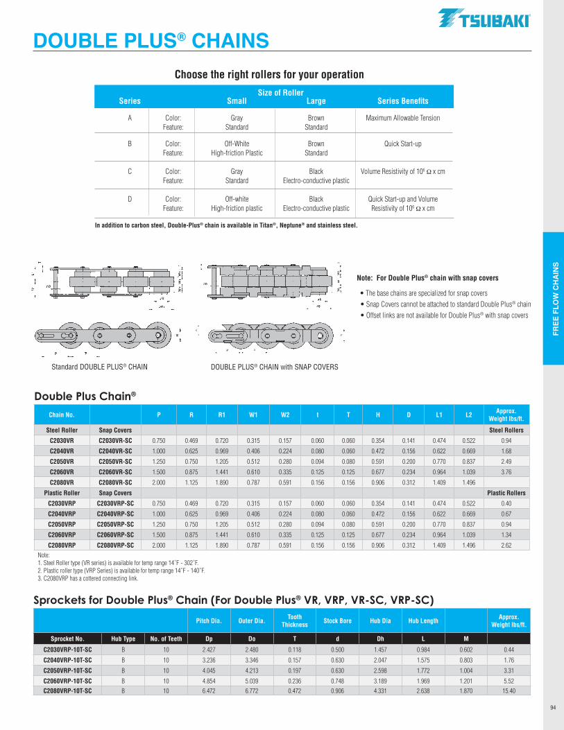
FREE
FLO
W C
HA
INS
94
Size of Roller Series Small Large Series Benefits
A Color: Gray Brown Maximum Allowable Tension Feature: Standard Standard
B Color: Off-White Brown Quick Start-up Feature: High-friction Plastic Standard
C Color: Gray Black Volume Resistivity of 106 Ω x cm Feature: Standard Electro-conductive plastic
D Color: Off-white Black Quick Start-up and Volume Feature: High-friction plastic Electro-conductive plastic Resistivity of 106 Ω x cm
DOUBLE PLUS® CHAINS
Sprockets for Double Plus® Chain (For Double Plus® VR, VRP, VR-SC, VRP-SC)
Pitch Dia. Outer Dia. Tooth Thickness Stock Bore Hub Dia Hub Length Approx.
Weight lbs/ft.
Sprocket No. Hub Type No. of Teeth Dp Do T d Dh L M
C2030VRP-10T-SC B 10 2.427 2.480 0.118 0.500 1.457 0.984 0.602 0.44
C2040VRP-10T-SC B 10 3.236 3.346 0.157 0.630 2.047 1.575 0.803 1.76
C2050VRP-10T-SC B 10 4.045 4.213 0.197 0.630 2.598 1.772 1.004 3.31
C2060VRP-10T-SC B 10 4.854 5.039 0.236 0.748 3.189 1.969 1.201 5.52C2080VRP-10T-SC B 10 6.472 6.772 0.472 0.906 4.331 2.638 1.870 15.40
Double Plus Chain®
Chain No. P R R1 W1 W2 t T H D L1 L2 Approx. Weight lbs/ft.
Steel Roller Snap Covers Steel Rollers
C2030VR C2030VR-SC 0.750 0.469 0.720 0.315 0.157 0.060 0.060 0.354 0.141 0.474 0.522 0.94
C2040VR C2040VR-SC 1.000 0.625 0.969 0.406 0.224 0.080 0.060 0.472 0.156 0.622 0.669 1.68
C2050VR C2050VR-SC 1.250 0.750 1.205 0.512 0.280 0.094 0.080 0.591 0.200 0.770 0.837 2.49
C2060VR C2060VR-SC 1.500 0.875 1.441 0.610 0.335 0.125 0.125 0.677 0.234 0.964 1.039 3.76
C2080VR C2080VR-SC 2.000 1.125 1.890 0.787 0.591 0.156 0.156 0.906 0.312 1.409 1.496
Plastic Roller Snap Covers Plastic Rollers
C2030VRP C2030VRP-SC 0.750 0.469 0.720 0.315 0.157 0.060 0.060 0.354 0.141 0.474 0.522 0.40
C2040VRP C2040VRP-SC 1.000 0.625 0.969 0.406 0.224 0.080 0.060 0.472 0.156 0.622 0.669 0.67
C2050VRP C2050VRP-SC 1.250 0.750 1.205 0.512 0.280 0.094 0.080 0.591 0.200 0.770 0.837 0.94
C2060VRP C2060VRP-SC 1.500 0.875 1.441 0.610 0.335 0.125 0.125 0.677 0.234 0.964 1.039 1.34
C2080VRP C2080VRP-SC 2.000 1.125 1.890 0.787 0.591 0.156 0.156 0.906 0.312 1.409 1.496 2.62Note: 1. Steel Roller type (VR series) is available for temp range 14˚F - 302˚F.2. Plastic roller type (VRP Series) is available for temp range 14˚F - 140˚F.3. C2080VRP has a cottered connecting link.
Note: For Double Plus® chain with snap covers
• The base chains are specialized for snap covers • Snap Covers cannot be attached to standard Double Plus® chain • Offset links are not available for Double Plus® with snap covers
Choose the right rollers for your operation
In addition to carbon steel, Double-Plus® chain is available in Titan®, Neptune® and stainless steel.
Standard DOUBLE PLUS® CHAIN DOUBLE PLUS® CHAIN with SNAP COVERS
.TSUBAKI"
----------
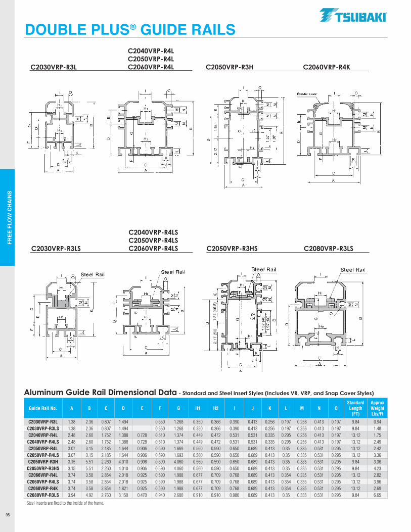
FREE
FLO
W C
HA
INS
95
DOUBLE PLUS® GUIDE RAILS
Aluminum Guide Rail Dimensional Data - Standard and Steel Insert Styles (Includes VR, VRP, and Snap Cover Styles)
Guide Rail No. A B C D E F G H1 H2 I J K L M N OStandard Length
(FT)
Approx Weight Lbs/Ft
C2030VRP-R3L 1.38 2.36 0.807 1.494 0.550 1.268 0.350 0.366 0.390 0.413 0.256 0.197 0.256 0.413 0.197 9.84 0.94C2030VRP-R3LS 1.38 2.36 0.807 1.494 0.550 1.268 0.350 0.366 0.390 0.413 0.256 0.197 0.256 0.413 0.197 9.84 1.48C2040VRP-R4L 2.48 2.60 1.752 1.388 0.728 0.510 1.374 0.449 0.472 0.531 0.531 0.335 0.295 0.256 0.413 0.197 13.12 1.75
C2040VRP-R4LS 2.48 2.60 1.752 1.388 0.728 0.510 1.374 0.449 0.472 0.531 0.531 0.335 0.295 0.256 0.413 0.197 13.12 2.49C2050VRP-R4L 3.07 3.15 2.185 1.644 0.906 0.590 1.669 0.560 0.590 0.650 0.689 0.413 0.35 0.335 0.531 0.295 13.12 2.42
C2050VRP-R4LS 3.07 3.15 2.185 1.644 0.906 0.590 1.693 0.560 0.590 0.650 0.689 0.413 0.35 0.335 0.531 0.295 13.12 3.36C2050VRP-R3H 3.15 5.51 2.260 4.010 0.906 0.590 4.060 0.560 0.590 0.650 0.689 0.413 0.35 0.335 0.531 0.295 9.84 3.36
C2050VRP-R3HS 3.15 5.51 2.260 4.010 0.906 0.590 4.060 0.560 0.590 0.650 0.689 0.413 0.35 0.335 0.531 0.295 9.84 4.23C2066VRP-R4L 3.74 3.58 2.854 2.018 0.925 0.590 1.988 0.677 0.709 0.768 0.689 0.413 0.354 0.335 0.531 0.295 13.12 2.82
C2060VRP-R4LS 3.74 3.58 2.854 2.018 0.925 0.590 1.988 0.677 0.709 0.768 0.689 0.413 0.354 0.335 0.531 0.295 13.12 3.96C2060VRP-R4K 3.74 3.58 2.854 1.821 0.925 0.590 1.988 0.677 0.709 0.768 0.689 0.413 0.354 0.335 0.531 0.295 13.12 2.69
C2080VRP-R3LS 3.94 4.92 2.760 3.150 0.470 0.940 2.680 0.910 0.910 0.980 0.689 0.413 0.35 0.335 0.531 0.295 9.84 6.65
Steel inserts are fixed to the inside of the frame.
C2030VRP-R3L
C2040VRP-R4LC2050VRP-R4LC2060VRP-R4L C2050VRP-R3H C2060VRP-R4K
C2030VRP-R3LS
C2040VRP-R4LSC2050VRP-R4LSC2060VRP-R4LS C2050VRP-R3HS C2080VRP-R3LS
w
(!J m
0
LL ...J
J C
A
K
I
u..
J
C
A
z m
0
cc '"
I
C A
C
I A
I J
J
]~ m
:::;r
.TSUBAKI"
Steel Rail
m
0
_J
J C
A
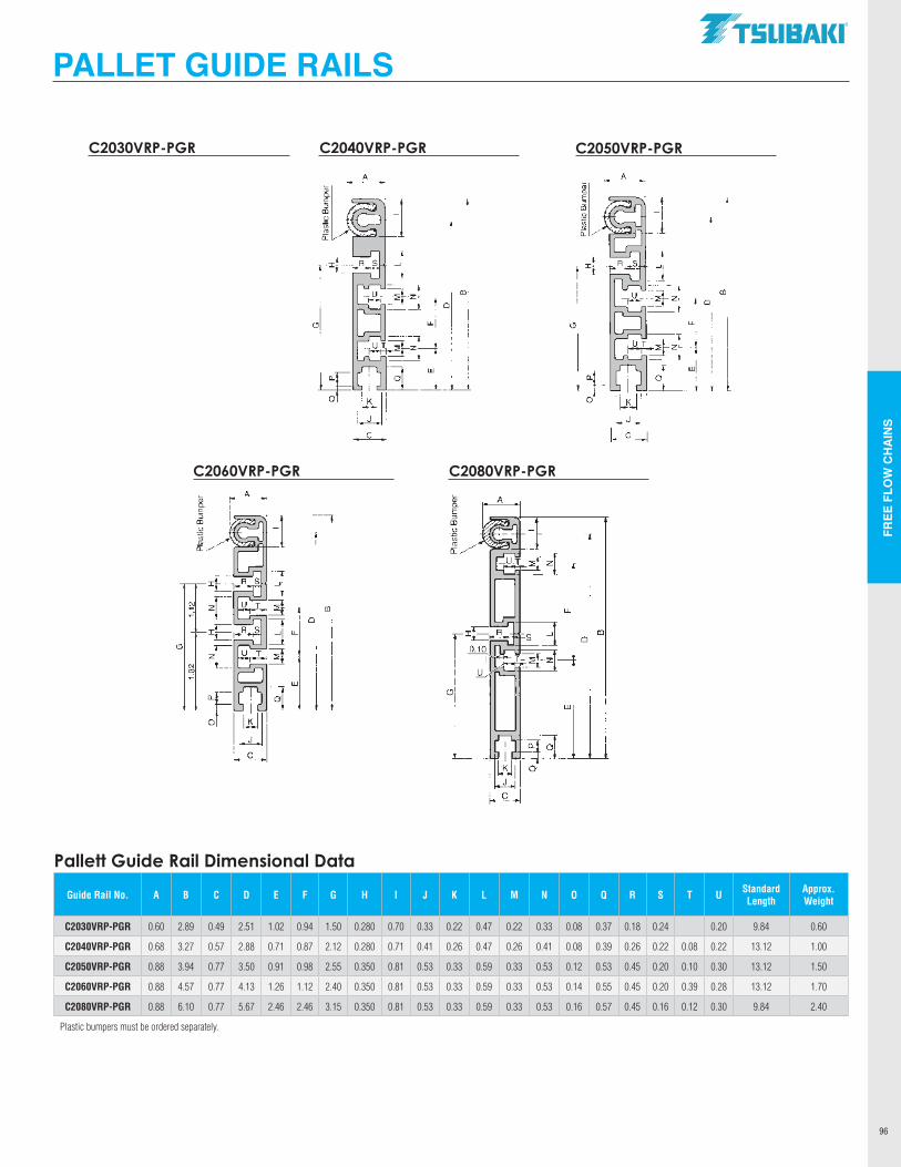
FREE
FLO
W C
HA
INS
96
PALLET GUIDE RAILS
Pallett Guide Rail Dimensional Data
Guide Rail No. A B C D E F G H I J K L M N O Q R S T U Standard Length
Approx. Weight
C2030VRP-PGR 0.60 2.89 0.49 2.51 1.02 0.94 1.50 0.280 0.70 0.33 0.22 0.47 0.22 0.33 0.08 0.37 0.18 0.24 0.20 9.84 0.60
C2040VRP-PGR 0.68 3.27 0.57 2.88 0.71 0.87 2.12 0.280 0.71 0.41 0.26 0.47 0.26 0.41 0.08 0.39 0.26 0.22 0.08 0.22 13.12 1.00
C2050VRP-PGR 0.88 3.94 0.77 3.50 0.91 0.98 2.55 0.350 0.81 0.53 0.33 0.59 0.33 0.53 0.12 0.53 0.45 0.20 0.10 0.30 13.12 1.50
C2060VRP-PGR 0.88 4.57 0.77 4.13 1.26 1.12 2.40 0.350 0.81 0.53 0.33 0.59 0.33 0.53 0.14 0.55 0.45 0.20 0.39 0.28 13.12 1.70
C2080VRP-PGR 0.88 6.10 0.77 5.67 2.46 2.46 3.15 0.350 0.81 0.53 0.33 0.59 0.33 0.53 0.16 0.57 0.45 0.16 0.12 0.30 9.84 2.40
Plastic bumpers must be ordered separately.
C2030VRP-PGR C2040VRP-PGR C2050VRP-PGR
C2060VRP-PGR C2080VRP-PGR
A a; C. E :,
"' " ~ "' 1i:
~ E :,
"' " ·-55
"' 1i:
.TSUBAKI"
"'
LL
w
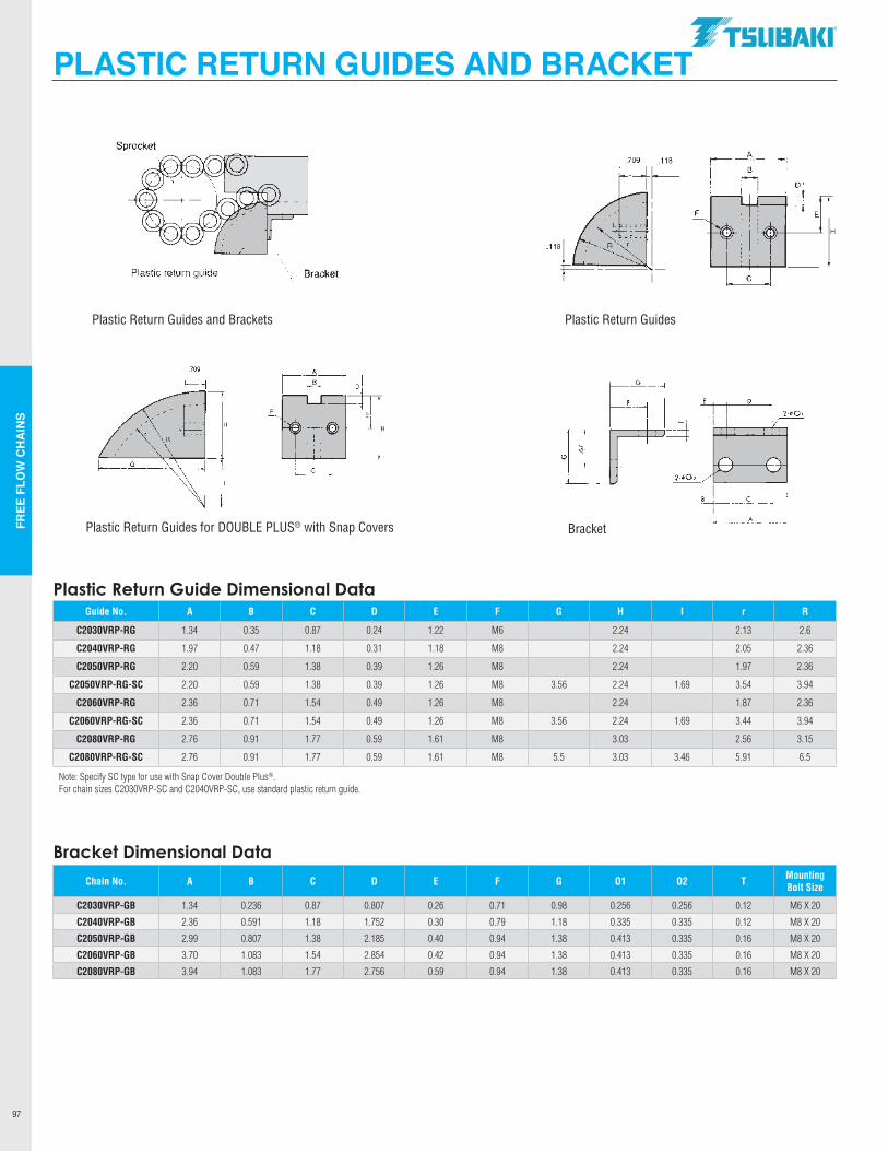
FREE
FLO
W C
HA
INS
97
PLASTIC RETURN GUIDES AND BRACKET
Plastic Return Guide Dimensional DataGuide No. A B C D E F G H I r R
C2030VRP-RG 1.34 0.35 0.87 0.24 1.22 M6 2.24 2.13 2.6
C2040VRP-RG 1.97 0.47 1.18 0.31 1.18 M8 2.24 2.05 2.36
C2050VRP-RG 2.20 0.59 1.38 0.39 1.26 M8 2.24 1.97 2.36
C2050VRP-RG-SC 2.20 0.59 1.38 0.39 1.26 M8 3.56 2.24 1.69 3.54 3.94
C2060VRP-RG 2.36 0.71 1.54 0.49 1.26 M8 2.24 1.87 2.36
C2060VRP-RG-SC 2.36 0.71 1.54 0.49 1.26 M8 3.56 2.24 1.69 3.44 3.94
C2080VRP-RG 2.76 0.91 1.77 0.59 1.61 M8 3.03 2.56 3.15
C2080VRP-RG-SC 2.76 0.91 1.77 0.59 1.61 M8 5.5 3.03 3.46 5.91 6.5
Note: Specify SC type for use with Snap Cover Double Plus®.For chain sizes C2030VRP-SC and C2040VRP-SC, use standard plastic return guide.
Bracket Dimensional Data
Chain No. A B C D E F G O1 O2 T Mounting Bolt Size
C2030VRP-GB 1.34 0.236 0.87 0.807 0.26 0.71 0.98 0.256 0.256 0.12 M6 X 20
C2040VRP-GB 2.36 0.591 1.18 1.752 0.30 0.79 1.18 0.335 0.335 0.12 M8 X 20
C2050VRP-GB 2.99 0.807 1.38 2.185 0.40 0.94 1.38 0.413 0.335 0.16 M8 X 20
C2060VRP-GB 3.70 1.083 1.54 2.854 0.42 0.94 1.38 0.413 0.335 0.16 M8 X 20
C2080VRP-GB 3.94 1.083 1.77 2.756 0.59 0.94 1.38 0.413 0.335 0.16 M8 X 20
.
Plastic Return Guides
BracketPlastic Return Guides for DOUBLE PLUS® with Snap Covers
Plastic Return Guides and Brackets
.TSUBAKI"
Sprocket A
.709 .118
I D
F
.118
Plastic return guide Bracket ----I C
.709 A
G
D
2·¢01
H
~ r---A
:;; ()
G C
C
A
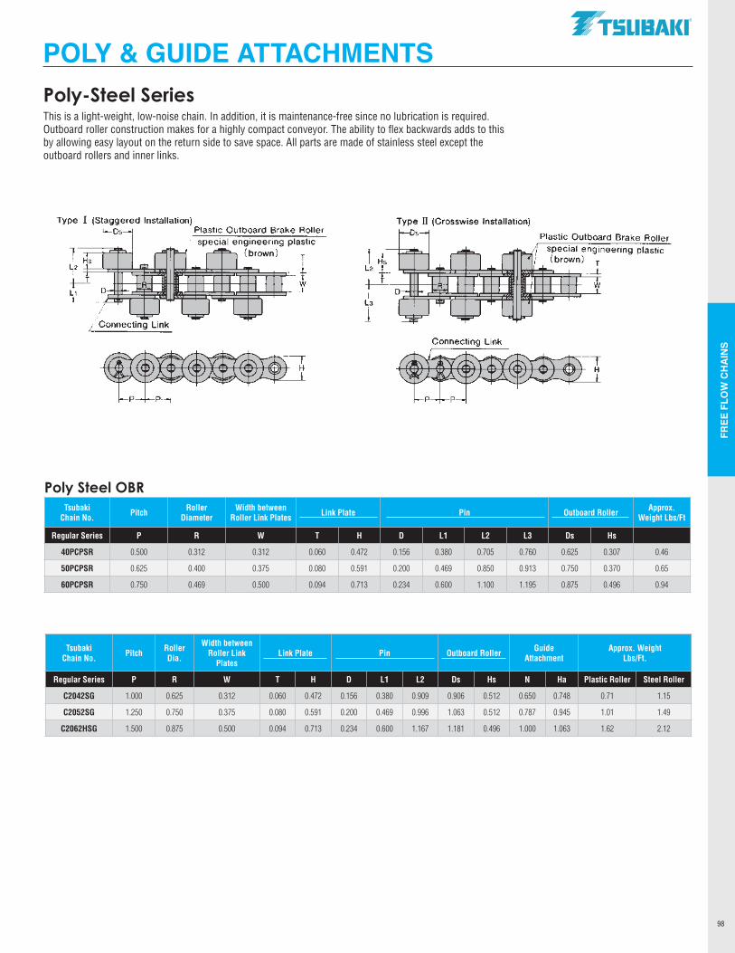
FREE
FLO
W C
HA
INS
98
POLY & GUIDE ATTACHMENTSPoly-Steel SeriesThis is a light-weight, low-noise chain. In addition, it is maintenance-free since no lubrication is required. Outboard roller construction makes for a highly compact conveyor. The ability to flex backwards adds to this by allowing easy layout on the return side to save space. All parts are made of stainless steel except the outboard rollers and inner links.
Poly Steel OBR Tsubaki
Chain No. Pitch Roller Diameter
Width between Roller Link Plates Link Plate Pin Outboard Roller Approx.
Weight Lbs/Ft
Regular Series P R W T H D L1 L2 L3 Ds Hs
40PCPSR 0.500 0.312 0.312 0.060 0.472 0.156 0.380 0.705 0.760 0.625 0.307 0.46
50PCPSR 0.625 0.400 0.375 0.080 0.591 0.200 0.469 0.850 0.913 0.750 0.370 0.65
60PCPSR 0.750 0.469 0.500 0.094 0.713 0.234 0.600 1.100 1.195 0.875 0.496 0.94
Tsubaki Chain No. Pitch Roller
Dia.
Width between Roller Link
PlatesLink Plate Pin Outboard Roller Guide
AttachmentApprox. Weight
Lbs/Ft.
Regular Series P R W T H D L1 L2 Ds Hs N Ha Plastic Roller Steel Roller
C2042SG 1.000 0.625 0.312 0.060 0.472 0.156 0.380 0.909 0.906 0.512 0.650 0.748 0.71 1.15
C2052SG 1.250 0.750 0.375 0.080 0.591 0.200 0.469 0.996 1.063 0.512 0.787 0.945 1.01 1.49
C2062HSG 1.500 0.875 0.500 0.094 0.713 0.234 0.600 1.167 1.181 0.496 1.000 1.063 1.62 2.12
.TSUBAKI"
Type I (Staggered Installation) Type II (Crosswise Installation) Os Plastic Outboard Brake Roller Os
Hs T
T w w L,
Connecting Link
Connecting Link
~
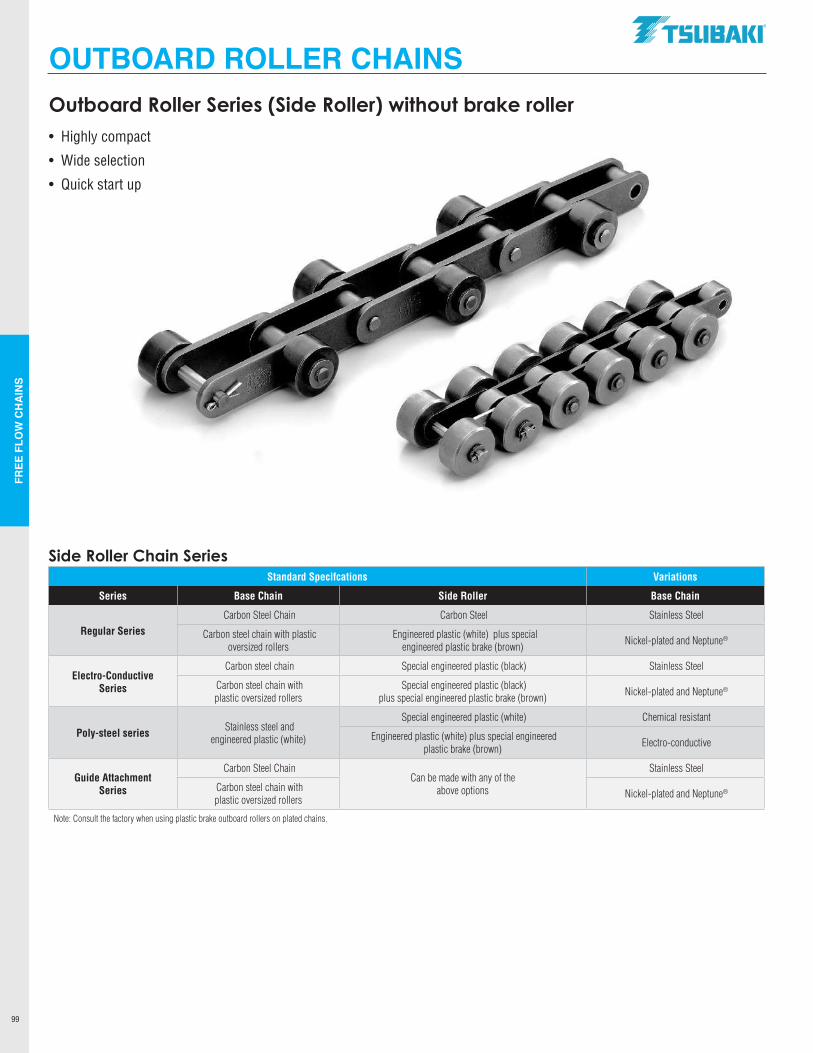
FREE
FLO
W C
HA
INS
99
OUTBOARD ROLLER CHAINSOutboard Roller Series (Side Roller) without brake roller• Highly compact
• Wide selection
• Quick start up
Side Roller Chain SeriesStandard Specifcations Variations
Series Base Chain Side Roller Base Chain
Regular SeriesCarbon Steel Chain Carbon Steel Stainless Steel
Carbon steel chain with plastic oversized rollers
Engineered plastic (white) plus special engineered plastic brake (brown) Nickel-plated and Neptune®
Electro-Conductive Series
Carbon steel chain Special engineered plastic (black) Stainless Steel
Carbon steel chain with plastic oversized rollers
Special engineered plastic (black)plus special engineered plastic brake (brown) Nickel-plated and Neptune®
Poly-steel series Stainless steel andengineered plastic (white)
Special engineered plastic (white) Chemical resistant
Engineered plastic (white) plus special engineered plastic brake (brown) Electro-conductive
Guide AttachmentSeries
Carbon Steel ChainCan be made with any of the
above options
Stainless Steel
Carbon steel chain withplastic oversized rollers Nickel-plated and Neptune®
Note: Consult the factory when using plastic brake outboard rollers on plated chains.
.TSUBAKI"
..
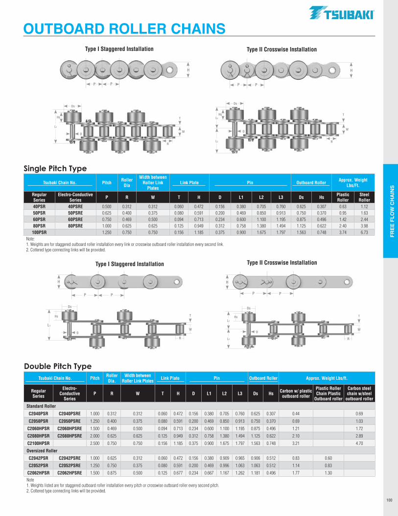
FREE
FLO
W C
HA
INS
100
Hs
Double Pitch TypeTsubaki Chain No. Pitch Roller
Dia.Width between
Roller Link Plates Link Plate Pin Outboard Roller Approx. Weight Lbs/ft.
Regular Series
Electro- Conductive
SeriesP R W T H D L1 L2 L3 Ds Hs Carbon w/ plastic
outboard roller
Plastic Roller Chain Plastic
Outboard roller
Carbon steel chain w/steel
outboard roller
Standard Roller
C2040PSR C2040PSRE 1.000 0.312 0.312 0.060 0.472 0.156 0.380 0.705 0.760 0.625 0.307 0.44 0.69
C2050PSR C2050PSRE 1.250 0.400 0.375 0.080 0.591 0.200 0.469 0.850 0.913 0.750 0.370 0.69 1.03
C2060HPSR C2060HPSRE 1.500 0.469 0.500 0.094 0.713 0.234 0.600 1.100 1.195 0.875 0.496 1.21 1.72
C2080HPSR C2080HPSRE 2.000 0.625 0.625 0.125 0.949 0.312 0.758 1.380 1.494 1.125 0.622 2.10 2.89
C2100HPSR 2.500 0.750 0.750 0.156 1.185 0.375 0.900 1.675 1.797 1.563 0.748 3.21 4.70
Oversized Roller
C2042PSR C2042PSRE 1.000 0.625 0.312 0.060 0.472 0.156 0.380 0.909 0.965 0.906 0.512 0.83 0.60
C2052PSR C2052PSRE 1.250 0.750 0.375 0.080 0.591 0.200 0.469 0.996 1.063 1.063 0.512 1.14 0.83
C2062HPSR C2062HPSRE 1.500 0.875 0.500 0.125 0.677 0.234 0.667 1.167 1.262 1.181 0.496 1.77 1.30Note 1. Weights listed are for staggered outboard roller installation every pitch or crosswise outboard roller every second pitch.2. Cottered type connecting links will be provided.
Single Pitch Type
Tsubaki Chain No. Pitch Roller Dia
Width between Roller Link
PlatesLink Plate Pin Outboard Roller Approx. Weight
Lbs/Ft.
Regular Series
Electro-Conductive Series P R W T H D L1 L2 L3 Ds Hs Plastic
RollerSteel Roller
40PSR 40PSRE 0.500 0.312 0.312 0.060 0.472 0.156 0.380 0.705 0.760 0.625 0.307 0.63 1.1250PSR 50PSRE 0.625 0.400 0.375 0.080 0.591 0.200 0.469 0.850 0.913 0.750 0.370 0.95 1.6360PSR 60PSRE 0.750 0.469 0.500 0.094 0.713 0.234 0.600 1.100 1.195 0.875 0.496 1.42 2.4480PSR 80PSRE 1.000 0.625 0.625 0.125 0.949 0.312 0.758 1.380 1.494 1.125 0.622 2.40 3.98100PSR 1.250 0.750 0.750 0.156 1.185 0.375 0.900 1.675 1.797 1.563 0.748 3.74 6.73
Note:1. Weights are for staggered outboard roller installation every link or crosswise outboard roller installation every second link.2. Cottered type connecting links will be provided.
OUTBOARD ROLLER CHAINS
Type I Staggered Installation Type II Crosswise Installation
P P
H
P P
H
L2
L3
DW
Ds
T
R
Hs
L1
DW
Ds
T
R
Hs
Type I Staggered Installation Type II Crosswise Installation
P P
H
L1
DW
Ds
T
R
P P
H
L2
L3
D
Ds
T
W
R
Hs
.TSUBAKI"
.... .. . .. y y y y
.. I .. '
y
' '
0
' I y
'
------ --- ----- ---
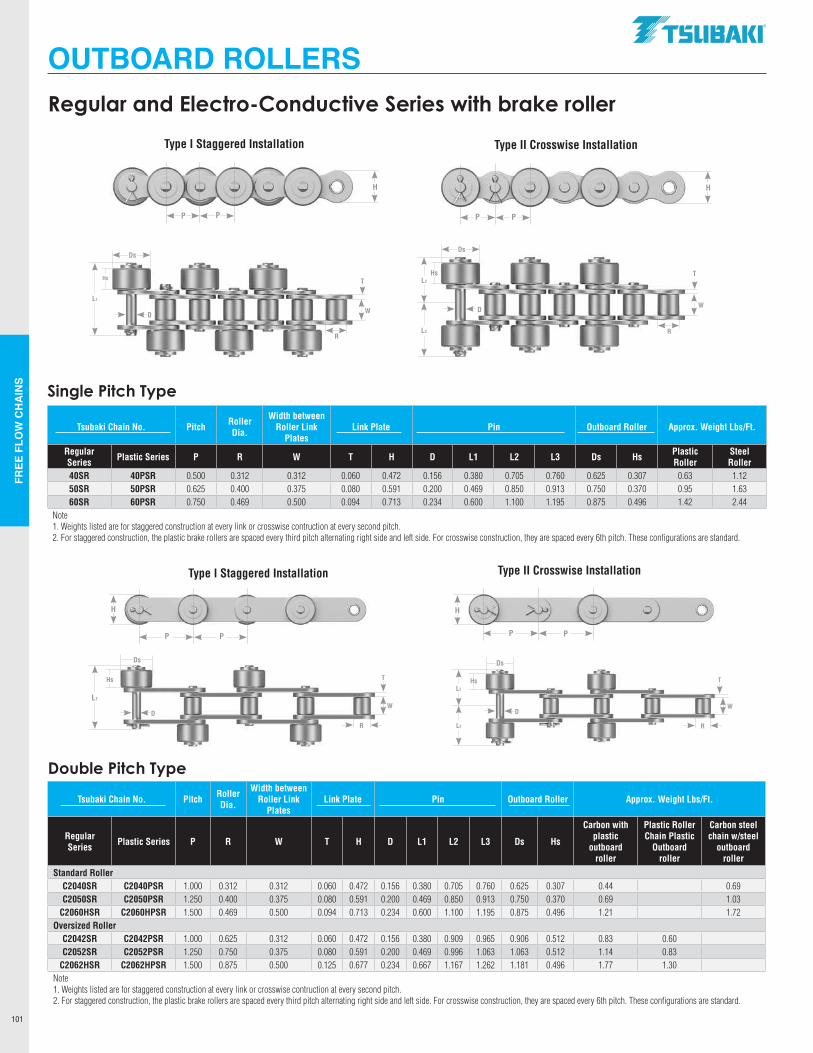
FREE
FLO
W C
HA
INS
101
Single Pitch Type
Tsubaki Chain No. Pitch Roller Dia.
Width between Roller Link
PlatesLink Plate Pin Outboard Roller Approx. Weight Lbs/Ft.
Regular Series Plastic Series P R W T H D L1 L2 L3 Ds Hs Plastic
RollerSteel Roller
40SR 40PSR 0.500 0.312 0.312 0.060 0.472 0.156 0.380 0.705 0.760 0.625 0.307 0.63 1.1250SR 50PSR 0.625 0.400 0.375 0.080 0.591 0.200 0.469 0.850 0.913 0.750 0.370 0.95 1.6360SR 60PSR 0.750 0.469 0.500 0.094 0.713 0.234 0.600 1.100 1.195 0.875 0.496 1.42 2.44
Note1. Weights listed are for staggered construction at every link or crosswise contruction at every second pitch.2. For staggered construction, the plastic brake rollers are spaced every third pitch alternating right side and left side. For crosswise construction, they are spaced every 6th pitch. These configurations are standard.
Double Pitch Type
Tsubaki Chain No. Pitch Roller Dia.
Width between Roller Link
PlatesLink Plate Pin Outboard Roller Approx. Weight Lbs/Ft.
Regular Series Plastic Series P R W T H D L1 L2 L3 Ds Hs
Carbon with plastic
outboard roller
Plastic Roller Chain Plastic
Outboard roller
Carbon steel chain w/steel
outboard roller
Standard RollerC2040SR C2040PSR 1.000 0.312 0.312 0.060 0.472 0.156 0.380 0.705 0.760 0.625 0.307 0.44 0.69C2050SR C2050PSR 1.250 0.400 0.375 0.080 0.591 0.200 0.469 0.850 0.913 0.750 0.370 0.69 1.03
C2060HSR C2060HPSR 1.500 0.469 0.500 0.094 0.713 0.234 0.600 1.100 1.195 0.875 0.496 1.21 1.72Oversized Roller
C2042SR C2042PSR 1.000 0.625 0.312 0.060 0.472 0.156 0.380 0.909 0.965 0.906 0.512 0.83 0.60C2052SR C2052PSR 1.250 0.750 0.375 0.080 0.591 0.200 0.469 0.996 1.063 1.063 0.512 1.14 0.83
C2062HSR C2062HPSR 1.500 0.875 0.500 0.125 0.677 0.234 0.667 1.167 1.262 1.181 0.496 1.77 1.30Note1. Weights listed are for staggered construction at every link or crosswise contruction at every second pitch.2. For staggered construction, the plastic brake rollers are spaced every third pitch alternating right side and left side. For crosswise construction, they are spaced every 6th pitch. These configurations are standard.
OUTBOARD ROLLERSRegular and Electro-Conductive Series with brake roller
Type I Staggered Installation Type II Crosswise Installation
P P
H
P P
H
L2
L3
D
Ds
THs
L1
D
Ds
THs
Type I Staggered Installation Type II Crosswise Installation
P P
H
L1
D
Ds
THs
P P
H
L2
L3
D
Ds
THs
W
RR
W
R
W
R
W
.TSUBAKI"
~~~~~~~~~~y A
~~~w~~~=S~~' I ~M~~~~~~~~Q" y A
s'l~~~~~~~~~~'
- - - - -
----- --- ------- ------ ------0 0
A
I
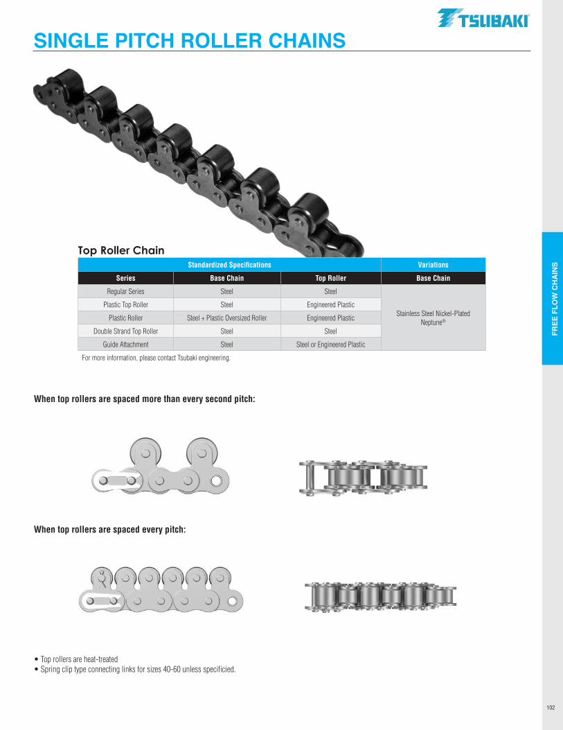
FREE
FLO
W C
HA
INS
102
SINGLE PITCH ROLLER CHAINS
When top rollers are spaced more than every second pitch:
When top rollers are spaced every pitch:
• Top rollers are heat-treated•Spring clip type connecting links for sizes 40-60 unless specificied.
Top Roller ChainStandardized Specifications Variations
Series Base Chain Top Roller Base Chain
Regular Series Steel Steel
Stainless Steel Nickel-Plated Neptune®
Plastic Top Roller Steel Engineered Plastic
Plastic Roller Steel + Plastic Oversized Roller Engineered Plastic
Double Strand Top Roller Steel Steel
Guide Attachment Steel Steel or Engineered Plastic
For more information, please contact Tsubaki engineering.
.TSUBAKI"
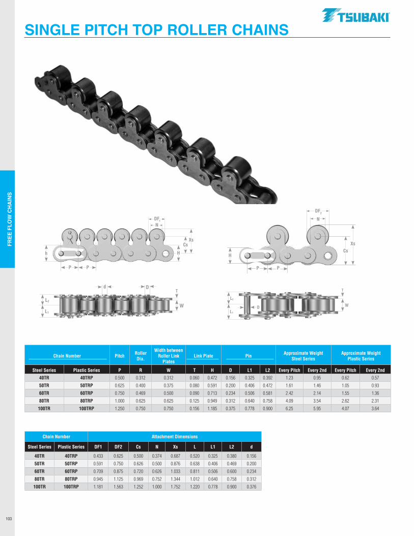
FREE
FLO
W C
HA
INS
103
SINGLE PITCH TOP ROLLER CHAINS
Chain Number Pitch Roller Dia.
Width between Roller Link
PlatesLink Plate Pin Approximate Weight
Steel SeriesApproximate Weight
Plastic Series
Steel Series Plastic Series P R W T H D L1 L2 Every Pitch Every 2nd Every Pitch Every 2nd
40TR 40TRP 0.500 0.312 0.312 0.060 0.472 0.156 0.325 0.392 1.23 0.95 0.62 0.57
50TR 50TRP 0.625 0.400 0.375 0.080 0.591 0.200 0.406 0.472 1.61 1.46 1.05 0.93
60TR 60TRP 0.750 0.469 0.500 0.090 0.713 0.234 0.506 0.581 2.42 2.14 1.55 1.36
80TR 80TRP 1.000 0.625 0.625 0.125 0.949 0.312 0.640 0.758 4.09 3.54 2.62 2.31
100TR 100TRP 1.250 0.750 0.750 0.156 1.185 0.375 0.778 0.900 6.25 5.95 4.07 3.64
Chain Number Attachment Dimensions
Steel Series Plastic Series DF1 DF2 Cs N Xs L L1 L2 d
40TR 40TRP 0.433 0.625 0.500 0.374 0.687 0.520 0.325 0.380 0.156
50TR 50TRP 0.591 0.750 0.626 0.500 0.876 0.638 0.406 0.469 0.200
60TR 60TRP 0.709 0.875 0.720 0.626 1.033 0.811 0.506 0.600 0.234
80TR 80TRP 0.945 1.125 0.969 0.752 1.344 1.012 0.640 0.758 0.312
100TR 100TRP 1.181 1.563 1.252 1.000 1.752 1.220 0.778 0.900 0.376
P P
h
NDF1
H
CsXs
L2
L1
W
dT
D
P P
HCs
Xs
L2
L1
W
T
D
N
DF2
.TSUBAKI"
- --111111111111 ____ _
--------
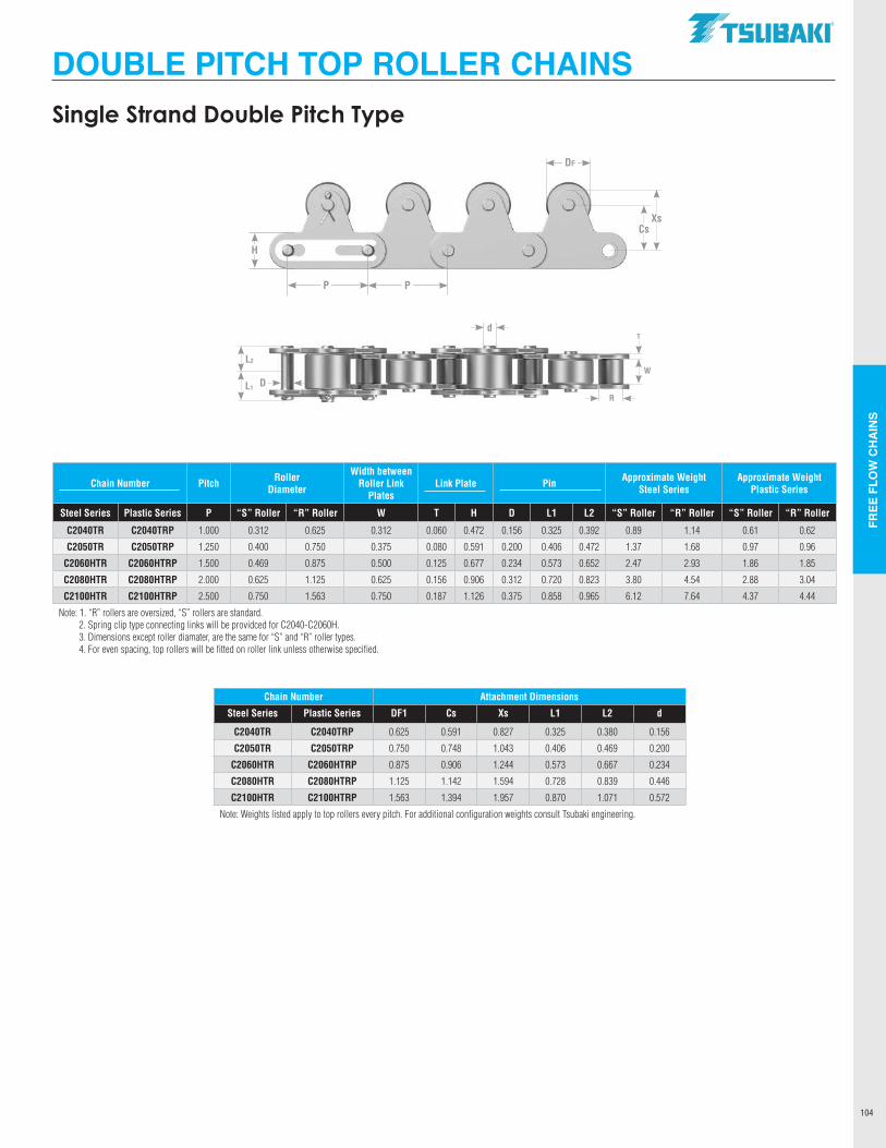
FREE
FLO
W C
HA
INS
104
Chain Number Pitch Roller Diameter
Width between Roller Link
PlatesLink Plate Pin Approximate Weight
Steel SeriesApproximate Weight
Plastic Series
Steel Series Plastic Series P “S” Roller “R” Roller W T H D L1 L2 “S” Roller “R” Roller “S” Roller “R” Roller
C2040TR C2040TRP 1.000 0.312 0.625 0.312 0.060 0.472 0.156 0.325 0.392 0.89 1.14 0.61 0.62
C2050TR C2050TRP 1.250 0.400 0.750 0.375 0.080 0.591 0.200 0.406 0.472 1.37 1.68 0.97 0.96
C2060HTR C2060HTRP 1.500 0.469 0.875 0.500 0.125 0.677 0.234 0.573 0.652 2.47 2.93 1.86 1.85
C2080HTR C2080HTRP 2.000 0.625 1.125 0.625 0.156 0.906 0.312 0.720 0.823 3.80 4.54 2.88 3.04
C2100HTR C2100HTRP 2.500 0.750 1.563 0.750 0.187 1.126 0.375 0.858 0.965 6.12 7.64 4.37 4.44
Note: 1. “R” rollers are oversized, “S” rollers are standard. 2. Spring clip type connecting links will be providced for C2040-C2060H. 3. Dimensions except roller diamater, are the same for “S” and “R” roller types. 4. For even spacing, top rollers will be fitted on roller link unless otherwise specified.
Chain Number Attachment Dimensions
Steel Series Plastic Series DF1 Cs Xs L1 L2 d
C2040TR C2040TRP 0.625 0.591 0.827 0.325 0.380 0.156
C2050TR C2050TRP 0.750 0.748 1.043 0.406 0.469 0.200
C2060HTR C2060HTRP 0.875 0.906 1.244 0.573 0.667 0.234
C2080HTR C2080HTRP 1.125 1.142 1.594 0.728 0.839 0.446
C2100HTR C2100HTRP 1.563 1.394 1.957 0.870 1.071 0.572
Note: Weights listed apply to top rollers every pitch. For additional configuration weights consult Tsubaki engineering.
L2
L1 DW
dT
R
DOUBLE PITCH TOP ROLLER CHAINSSingle Strand Double Pitch Type
P P
H
DF
CsXs
.TSUBAKI"
I
______ .. _ .. _____ _
-------
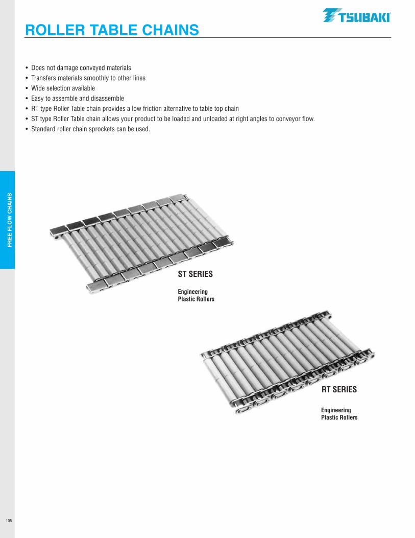
FREE
FLO
W C
HA
INS
105
ROLLER TABLE CHAINS
• Does not damage conveyed materials• Transfers materials smoothly to other lines• Wide selection available• Easy to assemble and disassemble• RT type Roller Table chain provides a low friction alternative to table top chain• ST type Roller Table chain allows your product to be loaded and unloaded at right angles to conveyor flow.• Standard roller chain sprockets can be used.
Engineering Plastic Rollers
ST SERIES
RT SERIES
Engineering Plastic Rollers
.TSUBAKI"
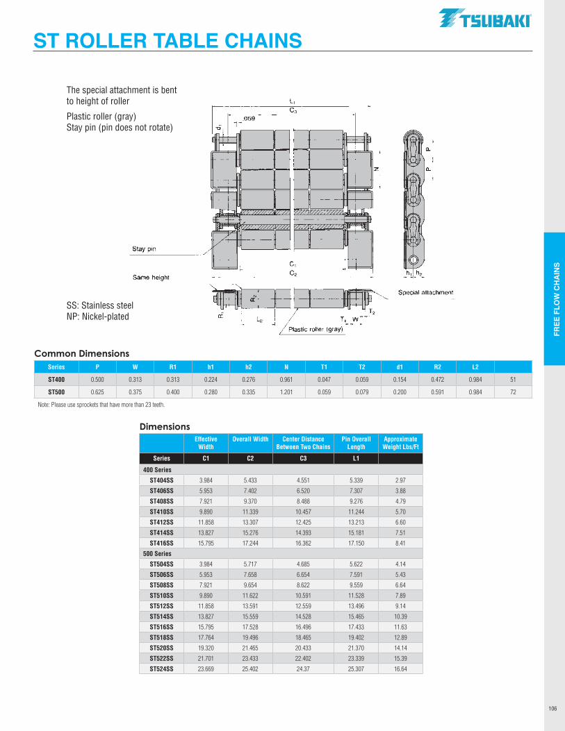
FREE
FLO
W C
HA
INS
106
ST ROLLER TABLE CHAINS
DimensionsEffective
WidthOverall Width Center Distance
Between Two ChainsPin Overall
LengthApproximate Weight Lbs/Ft
Series C1 C2 C3 L1
400 Series
ST404SS 3.984 5.433 4.551 5.339 2.97
ST406SS 5.953 7.402 6.520 7.307 3.88
ST408SS 7.921 9.370 8.488 9.276 4.79
ST410SS 9.890 11.339 10.457 11.244 5.70
ST412SS 11.858 13.307 12.425 13.213 6.60
ST414SS 13.827 15.276 14.393 15.181 7.51
ST416SS 15.795 17.244 16.362 17.150 8.41
500 Series
ST504SS 3.984 5.717 4.685 5.622 4.14
ST506SS 5.953 7.658 6.654 7.591 5.43
ST508SS 7.921 9.654 8.622 9.559 6.64
ST510SS 9.890 11.622 10.591 11.528 7.89
ST512SS 11.858 13.591 12.559 13.496 9.14
ST514SS 13.827 15.559 14.528 15.465 10.39
ST516SS 15.795 17.528 16.496 17.433 11.63
ST518SS 17.764 19.496 18.465 19.402 12.89
ST520SS 19.320 21.465 20.433 21.370 14.14
ST522SS 21.701 23.433 22.402 23.339 15.39
ST524SS 23.669 25.402 24.37 25.307 16.64
Common DimensionsSeries P W R1 h1 h2 N T1 T2 d1 R2 L2
ST400 0.500 0.313 0.313 0.224 0.276 0.961 0.047 0.059 0.154 0.472 0.984 51
ST500 0.625 0.375 0.400 0.280 0.335 1.201 0.059 0.079 0.200 0.591 0.984 72
Note: Please use sprockets that have more than 23 teeth.
SS: Stainless steelNP: Nickel-plated
The special attachment is bent to height of roller
Plastic roller (gray)Stay pin (pin does not rotate)
.059
~ --
ill! -= -
r ~ ~ ~
, Ill"
/
Stay pin / ti Same hei ht g
a: I
---I I I
L, C3
~ f--fll >-- M
-F7 ~~
... .... ,
~ c, C2
T, W
Plastic roller (gray)
.TSUBAKI"
z
Special attachment
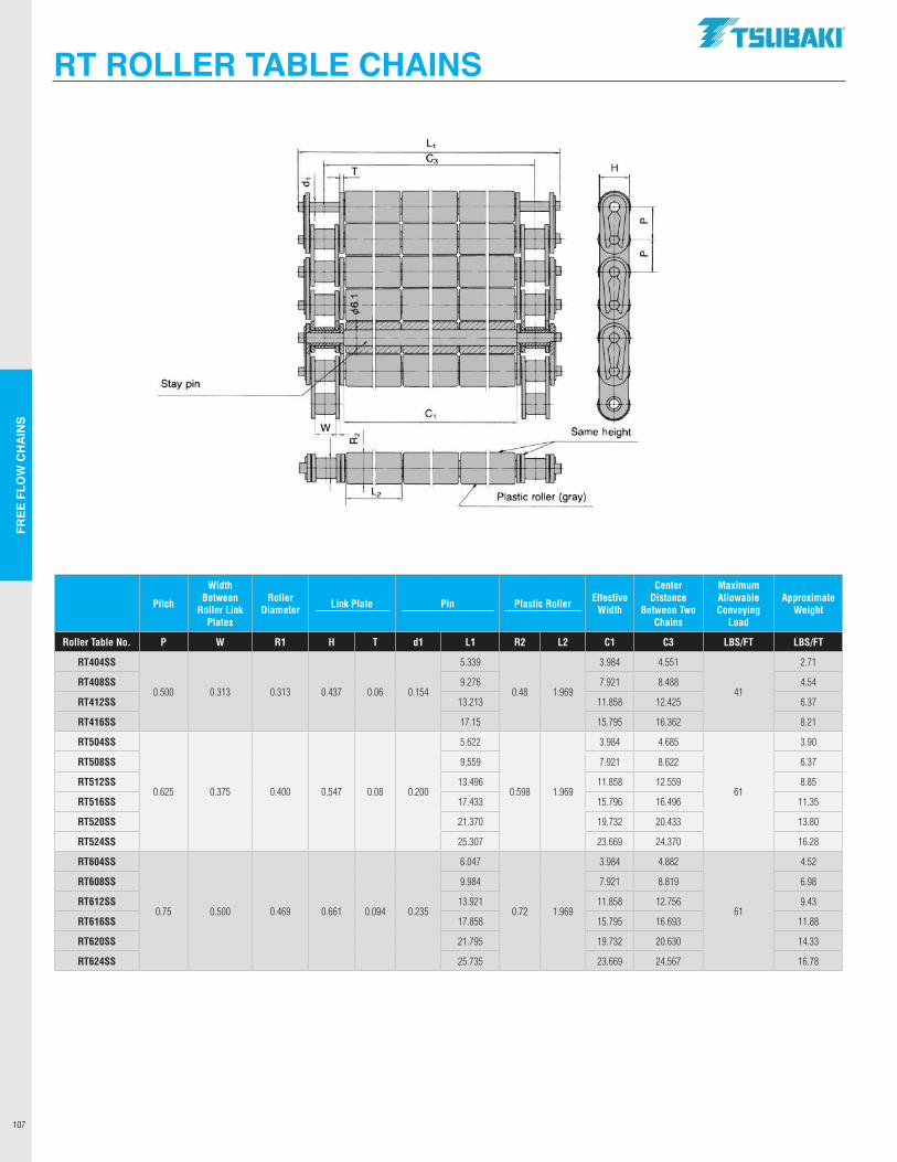
FREE
FLO
W C
HA
INS
107
RT ROLLER TABLE CHAINS
Pitch
Width Between
Roller Link Plates
Roller Diameter Link Plate Pin Plastic Roller Effective
Width
Center Distance
Between Two Chains
Maximum Allowable Conveying
Load
Approximate Weight
Roller Table No. P W R1 H T d1 L1 R2 L2 C1 C3 LBS/FT LBS/FT
RT404SS
0.500 0.313 0.313 0.437 0.06 0.154
5.339
0.48 1.969
3.984 4.551
41
2.71
RT408SS 9.276 7.921 8.488 4.54
RT412SS 13.213 11.858 12.425 6.37
RT416SS 17.15 15.795 16.362 8.21
RT504SS
0.625 0.375 0.400 0.547 0.08 0.200
5.622
0.598 1.969
3.984 4.685
61
3.90
RT508SS 9.559 7.921 8.622 6.37
RT512SS 13.496 11.858 12.559 8.85
RT516SS 17.433 15.796 16.496 11.35
RT520SS 21.370 19.732 20.433 13.80
RT524SS 25.307 23.669 24.370 16.28
RT604SS
0.75 0.500 0.469 0.661 0.094 0.235
6.047
0.72 1.969
3.984 4.882
61
4.52
RT608SS 9.984 7.921 8.819 6.98
RT612SS 13.921 11.858 12.756 9.43
RT616SS 17.858 15.795 16.693 11.88
RT620SS 21.795 19.732 20.630 14.33
RT624SS 25.735 23.669 24.567 16.78
.TSUBAKI"
T H
a.
a.
Stay pin
Same height
_ .. __ .. ____ _
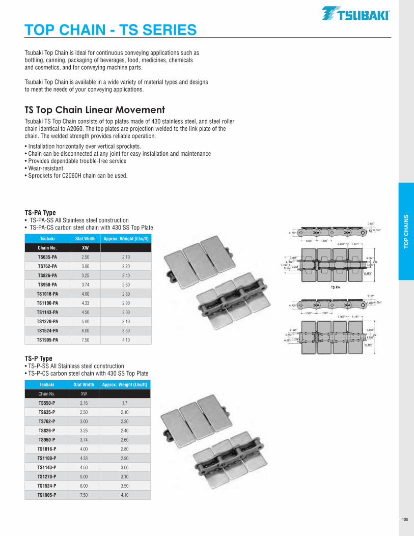
TOP
CH
AIN
S
108
Tsubaki Top Chain is ideal for continuous conveying applications such as bottling, canning, packaging of beverages, food, medicines, chemicalsand cosmetics, and for conveying machine parts.
Tsubaki Top Chain is available in a wide variety of material types and designsto meet the needs of your conveying applications.
TS Top Chain Linear MovementTsubaki TS Top Chain consists of top plates made of 430 stainless steel, and steel roller chain identical to A2060. The top plates are projection welded to the link plate of the chain. The welded strength provides reliable operation.
•Installation horizontally over vertical sprockets.•Chain can be disconnected at any joint for easy installation and maintenance•Provides dependable trouble-free service•Wear-resistant•Sprockets for C2060H chain can be used.
TS-PA Type• TS-PA-SS All Stainless steel construction• TS-PA-CS carbon steel chain with 430 SS Top Plate
TS-P Type• TS-P-SS All Stainless steel construction• TS-P-CS carbon steel chain with 430 SS Top Plate
Tsubaki Slat Width Approx. Weight (Lbs/ft)
Chain No. XW
TS635-PA 2.50 2.10
TS762-PA 3.00 2.20
TS826-PA 3.25 2.40
TS950-PA 3.74 2.60
TS1016-PA 4.00 2.80
TS1100-PA 4.33 2.90
TS1143-PA 4.50 3.00
TS1270-PA 5.00 3.10
TS1524-PA 6.00 3.50
TS1905-PA 7.50 4.10
Tsubaki Slat Width Approx. Weight (Lbs/ft)
Chain No. XW
TS550-P 2.16 1.7
TS635-P 2.50 2.10
TS762-P 3.00 2.20
TS826-P 3.25 2.40
TS950-P 3.74 2.60
TS1016-P 4.00 2.80
TS1100-P 4.33 2.90
TS1143-P 4.50 3.00
TS1270-P 5.00 3.10
TS1524-P 6.00 3.50
TS1905-P 7.50 4.10
TOP CHAIN - TS SERIES.TSllBAKI"
. ~. _534•
0.~ I
1.500 1.500 o.06r -1.437
TS-PA
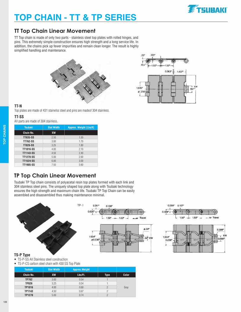
TOP
CH
AIN
S
109
Tsubaki Slat Width Approx.Weight
Chain No. XW Lbs/Ft. Type Color
TP762 3.00 0.54 1
GrayTP826 3.25 0.54 1
TP1016 4.00 0.60 2TP1143 4.50 0.67 2TP1270 5.00 0.74 2
TT Top Chain Linear MovementTT Top chain is made of only two parts - stainless steel top plates with rolled hinges, and pins. This extremely simple construction ensures high strength and a long service life. In addition, the chains pick up fewer impurities and remain clean longer. The result is highly simplified handling and maintenance.
TT-NTop plates are made of 431 stainelss steel and pins are madeof 304 stainless.
TT-SSAll parts are made of 304 stainless.
Tsubaki Slat Width Approx. Weight (Lbs/ft)
Chain No. XW
TT635-SS 2.50 1.50TT762-SS 3.00 1.70TT826-SS 3.25 1.80TT1016-SS 4.00 2.10TT1143-SS 4.50 2.40TT1270-SS 5.00 2.60TT1524-SS 6.00 3.00TT1905-SS 7.50 3.60
TP Top Chain Linear Movement Tsubaki TP Top chain consists of polyacetal resin top plates formed with each link and 304 stainless steel pins. The uniquely shaped top plate along with Tsubaki technologyensures the high strength and maximum chain life. Tsubaki TP Top Chain can be easily assembled and disassembled thus making maintenance minimal.
TS-P Type• TS-P-SS All Stainless steel construction• TS-P-CS carbon steel chain with 430 SS Top Plate
TOP CHAIN - TT & TP SERIES.TSllBAKI"
TP- I 0.311' 0.126" 0.299' 0.157"
06~J~lf11: 1@1 -=wt--9)-·---·°1. 1.50'___,__1.50'~-...- Travel
o5fi-t:t¥ 1 (! 1 '½) 1.50" 1.50' -' ---= Travel
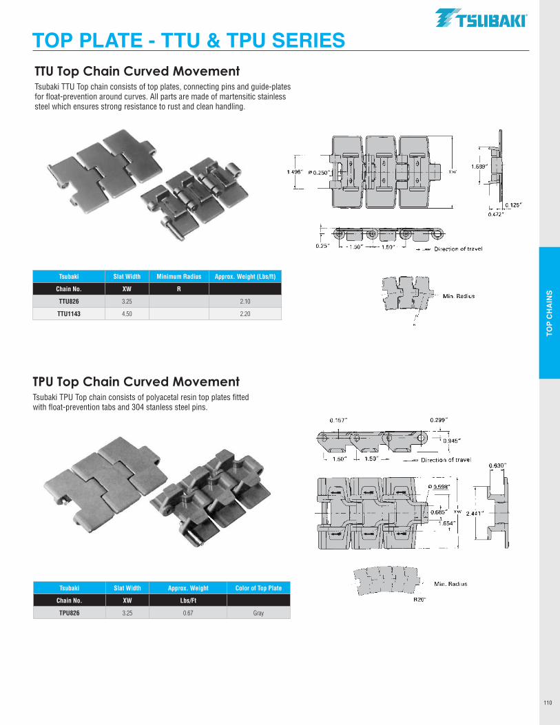
TOP
CH
AIN
S
110
Tsubaki Slat Width Approx. Weight Color of Top Plate
Chain No. XW Lbs/Ft
TPU826 3.25 0.67 Gray
TTU Top Chain Curved Movement Tsubaki TTU Top chain consists of top plates, connecting pins and guide-plates for float-prevention around curves. All parts are made of martensitic stainless steel which ensures strong resistance to rust and clean handling.
Tsubaki Slat Width Minimum Radius Approx. Weight (Lbs/ft)
Chain No. XW R
TTU826 3.25 2.10
TTU1143 4.50 2.20
TPU Top Chain Curved Movement Tsubaki TPU Top chain consists of polyacetal resin top plates fitted with float-prevention tabs and 304 stanless steel pins.
TOP PLATE - TTU & TPU SERIES.TSllBAKI"
xw
T Min. Radius
R20"
0.472"
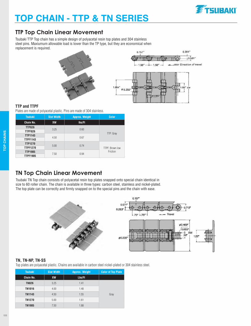
TOP
CH
AIN
S
111
Tsubaki Slat Width Approx. Weight Color of Top Plate
Chain No. XW Lbs/Ft
TN826 3.25 1.41
Gray
TN1016 4.00 1.48
TN1143 4.50 1.55
TN1270 5.00 1.61
TN1905 7.50 1.88
TTP Top Chain Linear MovementTsubaki TTP Top chain has a simple design of polyacetal resin top plates and 304 stainless steel pins. Maxiumum allowable load is lower than the TP type, but they are economical when replacement is required.
TTP and TTPFPlates are made of polyacetal plastic. Pins are made of 304 stainless.
Tsubaki Slat Width Approx. Weight Color
Chain No. XW lbs/Ft
TTP8263.25 0.60
TTP: GrayTTPF826TTP1143
4.50 0.67TTPF1143TTP1270
5.00 0.74TTPF: Brown low
FrictionTTPF1270TTP1905
7.50 0.94TTPF1905
TN Top Chain Linear MovementTsubaki TN Top chain consists of polyacetal resin top plates snapped onto special chain identical in size to 60 roller chain. The chain is available in three types: carbon steel, stainless and nickel-plated. The top plate can be correctly and firmly snapped on to the special pins and the chain with ease.
TN, TN-NP, TN-SSTop plates are polyacetal plastic. Chains are available in carbon steel nickel-plated or 304 stainless steel.
TOP CHAIN - TTP & TN SERIES.TSllBAKI"
0.157" 0.281"
4t±+1~_k31" 1.50" ==:==:lion of travel
1.654" 00.250"
~0.46~1 jo.095·
¢0.235"
X - I I I I I I I I
~ .50" I ,_· I I I 1·1 I I . I
w 1.22"
L
I
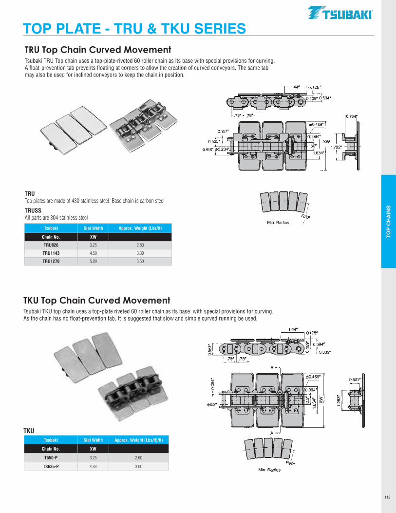
TOP
CH
AIN
S
112
Tsubaki Slat Width Approx. Weight (Lbs/ft)
Chain No. XW
TRU826 3.25 2.80
TRU1143 4.50 3.30
TRU1270 5.00 3.50
TRU Top Chain Curved MovementTsubaki TRU Top chain uses a top-plate-riveted 60 roller chain as its base with special provisions for curving. A float-prevention tab prevents floating at corners to allow the creation of curved conveyors. The same tab may also be used for inclined conveyors to keep the chain in position.
TRUTop plates are made of 430 stainless steel. Base chain is carbon steel
TRUSSAll parts are 304 stainless steel
Tsubaki Slat Width Approx. Weight (Lbs/ft)/ft)
Chain No. XW
T550-P 3.25 2.60
TS635-P 4.33 3.00
TKU Top Chain Curved MovementTsubaki TKU top chain uses a top-plate riveted 60 roller chain as its base with special provisions for curving. As the chain has no float-prevention tab, It is suggested that slow and simple curved running be used.
TKU
TOP PLATE - TRU & TKU SERIES.TSllBAKI"
~-~---- @25" _ 0.409" q.534"
.75" _75• 0.764"
0.157"
0.535" L--,--tt+--t+++ ++-11-++-1----++-1---ill~
0.516" ¢0.234"
ffiffi A:ea,,
Min. Radius /
0.551"
¢0.2"
A ::J
ffiffi A:ea,,
Min. Radius I
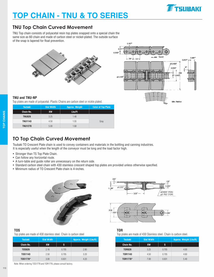
TOP
CH
AIN
S
113
TOS Top plates are made of 430 stainless steel. Chain is carbon steel
TORTop plates are made of 430 Stainless steel. Chain is carbon steel.
Tsubaki Slat Width Approx. Weight (Lbs/ft) Tsubaki Slat Width Approx. Weight (Lbs/ft)
Chain No. XW S Chain No. XW S
TOS826 2.16 0.705 2.80 TOR826 3.25 0.705 4.00
TOS1143 2.50 0.705 3.20 TOR1143 4.50 0.705 4.60
TOS1778* 3.00 0.831 4.20 TOR1778* 7.00 0.831 5.40
Note: When ordering TOS1778 and TOR1778, please consult factory.
TNU Top Chain Curved MovementTNU Top chain consists of polyacetal resin top plates snapped onto a special chain the same size as 60 chain and made of carbon steel or nickel-plated. The outside surface of the snap is tapered for float prevention.
TNU and TNU-NPTop plates are made of polyacetal. Plastic Chains are carbon steel or nickle plated.
Tsubaki Slat Width Approx. Weight Color of Top Plate
Chain No. XW Lbs/Ft
TNU826 3.25 1.48
GrayTNU1143 4.50 1.55
TNU1270 5.00 1.68
TO Top Chain Curved MovementTsubaki TO Crescent Plate chain is used to convey containers and materials in the bottling and canning industries. It is especially useful when the length of the conveyor must be long and the load factor high.
• Stronger than TS Top Plate Chain.• Can follow any horizontal route.• A turn-table and guide roller are unnecessary on the return side.• Standard carbon steel chain with 430 stainless crescent shaped top plates are provided unless otherwise specified.• Minimum radius of TO Crescent Plate chain is 4-inches.
TOP CHAIN - TNU & TO SERIES.TSllBAKI"
0.157"
0.571"
0.283". ~~-i------,,..---.c;--==---.'="'"-.J../
</>0.469"
0.095"
q>0.235"
xw .5" 1.343"1 rti=-~-~c.sr~-1 1
.125"
T. s
0t;--·,10.313" ..I..
l Min. Radius
0.461" 0.237"
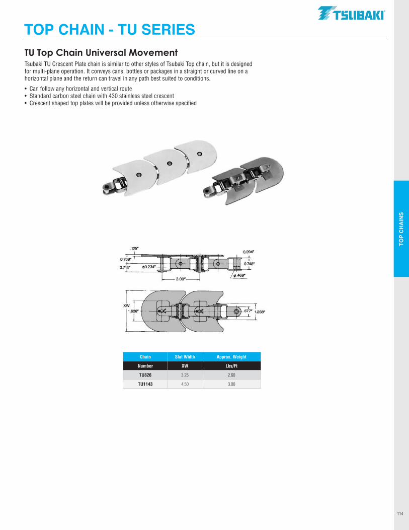
TOP
CH
AIN
S
114
Chain Slat Width Approx. Weight
Number XW Lbs/Ft
TU826 3.25 2.60
TU1143 4.50 3.00
TU Top Chain Universal MovementTsubaki TU Crescent Plate chain is similar to other styles of Tsubaki Top chain, but it is designed for multi-plane operation. It conveys cans, bottles or packages in a straight or curved line on a horizontal plane and the return can travel in any path best suited to conditions.
• Can follow any horizontal and vertical route• Standard carbon steel chain with 430 stainless steel crescent• Crescent shaped top plates will be provided unless otherwise specified
TOP CHAIN - TU SERIES.TSllBAKI"
1.626" ·· ---!EC-Hll-il& ~ISE- .677" 1.2611"
l ~i7"=~t:::::::t'::==---1
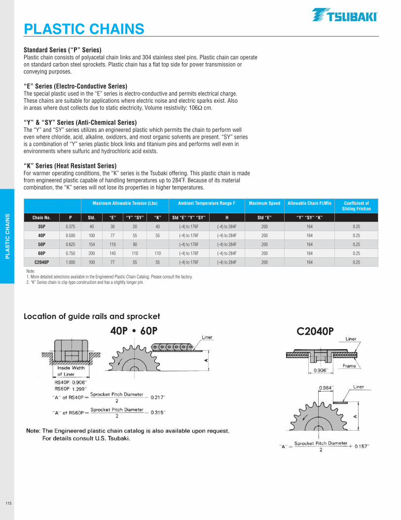
PLA
STIC
CH
AIN
S
115
Standard Series (“P” Series)Plastic chain consists of polyacetal chain links and 304 stainless steel pins. Plastic chain can operate on standard carbon steel sprockets. Plastic chain has a flat top side for power transmission or conveying purposes.
“E” Series (Electro-Conductive Series)The special plastic used in the “E” series is electro-conductive and permits electrical charge.These chains are suitable for applications where electric noise and electric sparks exist. Alsoin areas where dust collects due to static electricity, Volume resistivity: 106Ωcm.
“Y” & “SY” Series (Anti-Chemical Series)The “Y” and “SY” series utilizes an engineered plastic which permits the chain to perform welleven where chloride, acid, alkaline, oxidizers, and most organic solvents are present. “SY” series is a combination of “Y” series plastic block links and titanium pins and performs well even in environments where sulfuric and hydrochloric acid exists.
“K” Series (Heat Resistant Series)For warmer operating conditions, the “K” series is the Tsubaki offering. This plastic chain is madefrom engineered plastic capable of handling temperatures up to 284˚F. Because of its material combination, the “K” series will not lose its properties in higher temperatures.
Maximum Allowable Tension (Lbs) Ambient Temperature Range F Maximum Speed Allowable Chain Ft/Min Coefficient of Sliding Friction
Chain No. P Std. “E” “Y” “SY” “K” Std “E” “Y” “SY” H Std “E” “Y” “SY” “K”
35P 0.375 40 30 20 40 (-4) to 176F (-4) to 284F 200 164 0.25
40P 0.500 100 77 55 55 (-4) to 176F (-4) to 284F 200 164 0.25
50P 0.625 154 110 90 (-4) to 176F (-4) to 284F 200 164 0.25
60P 0.750 200 143 110 110 (-4) to 176F (-4) to 284F 200 164 0.25
C2040P 1.000 100 77 55 55 (-4) to 176F (-4) to 284F 200 164 0.25
Note: 1. More detailed selections available in the Engineered Plastic Chain Catalog. Please consult the factory.2. “K” Series chain is clip-type construction and has a slightly longer pin.
PLASTIC CHAINS
Location of guide rails and sprocket
40P • 60P C2040P
RS40P: 0.906" RS60P 1 .299"
"A" of RS40P = Sprocke~ Pitch Diameter 0_21 T 2
'"A'" of RS60P = Sprocket Pitch Diameter 0_315 .. 2
Note: The Engineered plastic chain catalog is also available upon request. For details consult U.S. Tsubaki.
.TSUBAKI"
Liner
eflm,~<mt«( Frame\
0.906"
Liner
"A"= Sprocket Pitch Diameter+ 015 T 2 .
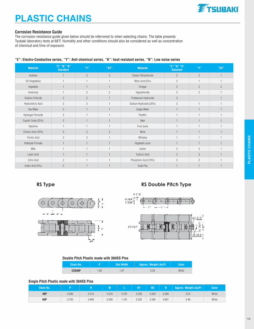
PLA
STIC
CH
AIN
S
116
Material “E” “N” “K” Standard “Y” “SY” Material “E” “N” “K”
Standard “Y” “SY”
Acetone 1 3 3 Carbon Tetrachloride 2 2 1
Oil (Vegetable) 1 1 1 Nitric Acid (5%) 3 1 1
Vegetable 1 1 1 Vinegar 2 2 2
Ammonia 1 2 2 Hypochloride 3 2 1
Sodium Chloride 2 2 1 Postassium Hydroxide 3 1
Hydrochloric Acid 3 3 1 Sodium Hydroxide (20%) 3 1 1
Sea Water 2 1 1 Soapy Water 1 1 1
Hydrogen Peroxide 3 1 1 Paraffin 1 1 1
Caustic Soda (25%) 3 1 1 Beer 1 1 1
Gasoline 1 1 1 Fruit Juice 1 1 1
Chloric Acid (10%) 3 2 2 Wine 1 1 1
Formic Acid 3 3 1 Whiskey 1 1 1
Aldehyde Formate 1 1 1 Vegetable Juice 1 1 1
Milk 1 1 1 Iodine 3 3 1
Lactic Acid 1 1 1 Sulfuric Acid 3 3 1
Citric Acid 2 1 1 Phosphoric Acid (10%) 3 2 1
Acetic Acid (5%) 3 1 1 Soda Pop 1 1 1
Corrosion Resistance GuideThe corrosion resistance guide given below should be referrered to when selecting chains. The table presents Tsubaki laboratory tests at 68˚F. Humidity and other conditions should also be considered as well as concentration of chemical and time of exposure.
“E”: Electro-Conductive series, “Y”: Anti-chemical series, “K”: heat resistant series, “N”: Low noise series
Double Pitch Plastic made with 304SS Pins
Chain No. P Slat Width Approx. Weight Lbs/Ft Color
C2040P 1.00 1.97 0.28 White
Single Pitch Plastic made with 304SS Pins
Chain No. P R W L H1 H2 H Approx. Weight Lbs/Ft Color
40P 0.500 0.313 0.310 0.787 0.236 0.264 0.500 0.24 White
60P 0.750 0.469 0.500 1.181 0.335 0.346 0.681 0.48 White
PLASTIC CHAINS
RS Type RS Double Pitch Type
t.~~ Gittfil:!
JW1$q1! ¢R
.TSUBAKI"
~0.157"
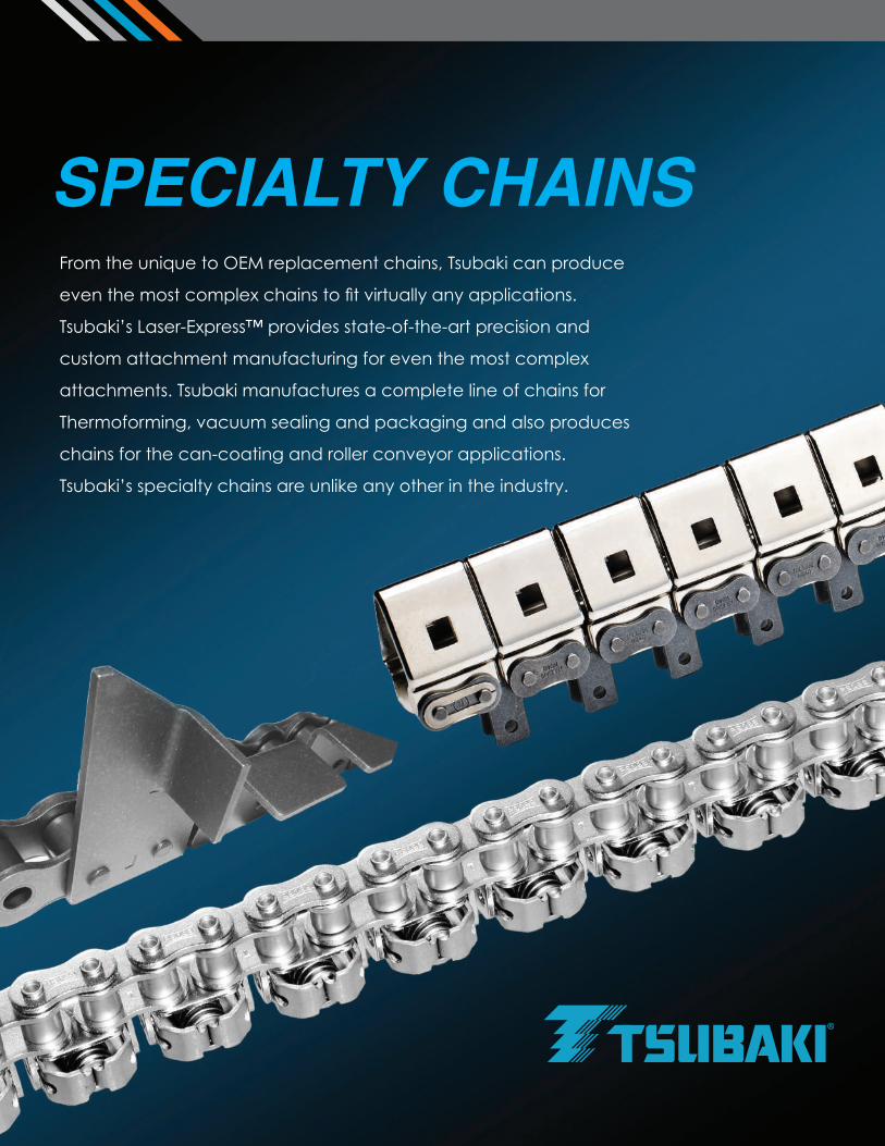
From the unique to OEM replacement chains, Tsubaki can produce
even the most complex chains to fit virtually any applications.
Tsubaki’s Laser-Express™ provides state-of-the-art precision and
custom attachment manufacturing for even the most complex
attachments. Tsubaki manufactures a complete line of chains for
Thermoforming, vacuum sealing and packaging and also produces
chains for the can-coating and roller conveyor applications.
Tsubaki’s specialty chains are unlike any other in the industry.
SPECIALTY CHAINS
•
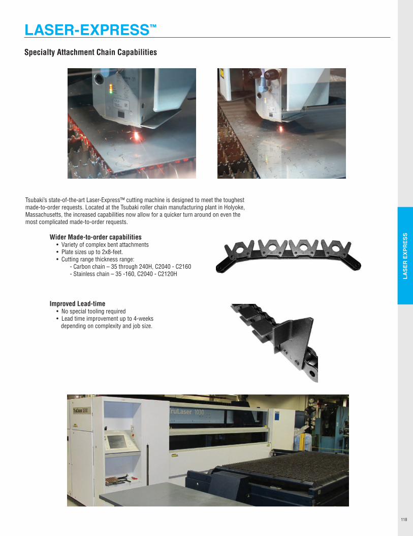
LASE
R E
XPR
ESS
118
Specialty Attachment Chain Capabilities
Tsubaki’s state-of-the-art Laser-Express™ cutting machine is designed to meet the toughest made-to-order requests. Located at the Tsubaki roller chain manufacturing plant in Holyoke, Massachusetts, the increased capabilities now allow for a quicker turn around on even the most complicated made-to-order requests.
Wider Made-to-order capabilities • Variety of complex bent attachments • Plate sizes up to 2x8-feet. • Cutting range thickness range: - Carbon chain – 35 through 240H, C2040 - C2160 - Stainless chain – 35 -160, C2040 - C2120H
Improved Lead-time • No special tooling required • Lead time improvement up to 4-weeks depending on complexity and job size.
LASER-EXPRESS™
,th
-:----i
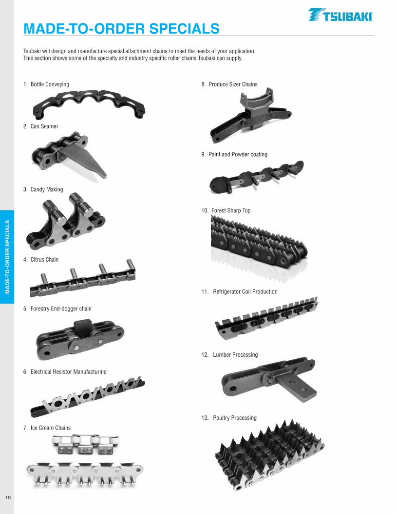
MA
DE-
TO-O
RD
ER S
PEC
IALS
119
1. Bottle Conveying
2. Can Seamer
3. Candy Making
4. Citrus Chain
5. Forestry End-dogger chain
6. Electrical Resistor Manufacturing
7. Ice Cream Chains
8. Produce Sizer Chains
9. Paint and Powder coating
10. Forest Sharp Top
11. Refrigerator Coil Production
12. Lumber Processing
13. Poultry Processing
Tsubaki will design and manufacture special attachment chains to meet the needs of your application. This section shows some of the specialty and industry specific roller chains Tsubaki can supply.
MADE-TO-ORDER SPECIALS.TSUBAKI"
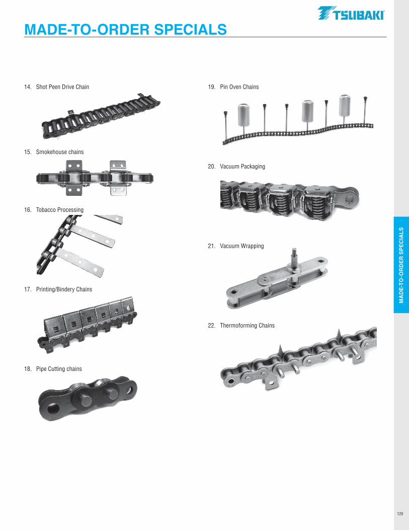
MA
DE-
TO-O
RD
ER S
PEC
IALS
120
14. Shot Peen Drive Chain
15. Smokehouse chains
16. Tobacco Processing
17. Printing/Bindery Chains
18. Pipe Cutting chains
19. Pin Oven Chains
20. Vacuum Packaging
21. Vacuum Wrapping
22. Thermoforming Chains
MADE-TO-ORDER SPECIALS.TSUBAKI"
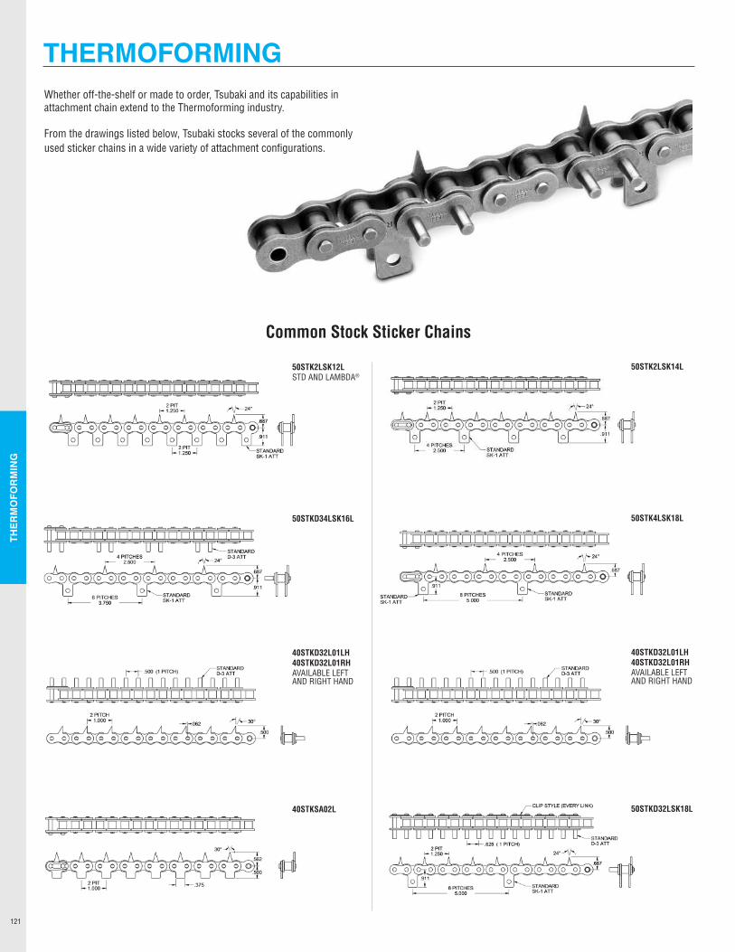
THER
MO
FOR
MIN
G
121
Whether off-the-shelf or made to order, Tsubaki and its capabilities in attachment chain extend to the Thermoforming industry.
From the drawings listed below, Tsubaki stocks several of the commonly used sticker chains in a wide variety of attachment configurations.
50STK2LSK12LSTD AND LAMBDA®
50STKD34LSK16L
40STKD32L01LH40STKD32L01RHAVAILABLE LEFT AND RIGHT HAND
40STKSA02L
50STK2LSK14L
50STK4LSK18L
40STKD32L01LH40STKD32L01RHAVAILABLE LEFT AND RIGHT HAND
50STKD32LSK18L
Common Stock Sticker Chains
THERMOFORMING
ff
~ IOI i) i) ILJI IOI i) 1) fr fr i) i) ILJI 12Q 1) 1 1 STANDARD
4Pt~ES !"\f- 24• D·3ATT
'4l 0 0 0 .911
6 PITCHES STANDARD ~ 3.750 ~ SK-1 ATT
~CLIP STYLE (EVERY LINK)
STANDARD SK-1 ATT
ff
ff
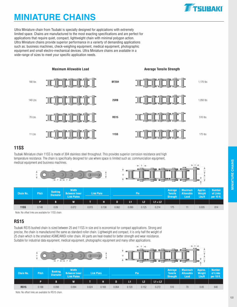
MIN
IATU
RE
CH
AIN
S
122
180 lbs Rendering BF25H Rendering 1,170 lbs
140 Lbs Rendering 25RB Rendering 1,050 lbs
70 Lbs Rendering RS15 Rendering 510 lbs
11 Lbs Rendering 11SS Rendering 175 lbs
Ultra Miniature chain from Tsubaki is specially designed for applciations with extremelylimited space. Chains are manufactured to the most exacting specifications and are perfect for applications that require quiet, compact, lightweight chain with minimal polygon action.Ultra Miniature chains provide superior performance in a varierty of demanding applicationssuch as: business machines, check-weighing equipment, medical equipment, photographic equipment and small electro-mechanical devices. Ultra Miniature chains are available in a wide-range of sizes to meet your specific application needs.
P P
hH
L2
L1
W
DR
T
Chain No. Pitch Bushing Diamater
Width Between Inner
Link PlatesLink Plate Pin
Average Tensile
Strength
Maximum Allowable
Load
Approx. Weight Lbs/ft
Number of Links
per 10 ft.
P B W T H D L1 L2 L1 + L2
RS15 0.188 0.098 0.094 0.024 0.169 0.064 0.120 0.152 0.272 510 70 0.05 640
Note: No offset links are available for RS15 chain.
11SSTsubaki Miniature chain 11SS is made of 304 stainless steel throughout. This provides superior corrosion resistance and high temperature resistance. The chain is specifically designed for use where space is limited such as: communciation equipment, medical equipment and business machines.
RS15Tsubaki RS15 bushed chain is sized between 25 and 11SS in size and is economical for compact applications. Strong and precise, the chain is manufactured the same as standard roller chain. Lightweight and compact, it is only half the weight of 25 chain which is the smallest ASME/ANSI roller chain. All parts are heat-treated for better strength and wear resistance. Suitable for industrial data equipment, medical equipment, photographic equipment and many other applications.
P P
hH
L2
L1
W
DR
T
Chain No. Pitch Bushing Diamater
Width Between Inner
Link PlatesLink Plate Pin
Average Tensile
Strength
Maximum Allowable
Load
Approx. Weight Lbs/ft
Number of Links
per 10 ft.
P B W T H D L1 L2 L1 + L2
11SS 0.148 0.09 0.072 0.015 0.138 0.062 0.090 0.125 0.214 175 11 0.035 814
Note: No offset links are available for 11SS chain.
Maximum Allowable Load Average Tensile Strength
MINIATURE CHAINS.TSUBAKI"
--------------
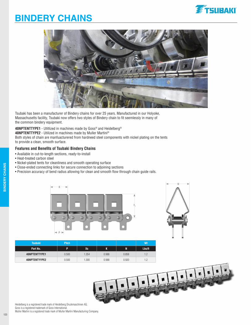
BIN
DER
Y C
HA
INS
123
Tsubaki has been a manufacturer of Bindery chains for over 25 years. Manufactured in our Holyoke, Massachusetts facility, Tsubaki now offers two styles of Bindery chain to fit seemlessly in many of the common bindery equipment.
40NPTENTTYPE1 - Utitlized in machines made by Goss® and Heidelberg®
40NPTENTTYPE2 - Utilized in machines made by Muller Martini®Both styles of chain are manfuacturered from hardneed steel components with nickel plating on the tents to provide a clean, smooth surface.
Features and Benefits of Tsubaki Bindery Chains• Available in cut-to-length sections, ready-to-install• Heat-treated carbon steel• Nickel-plated tents for cleanliness and smooth operating surface• Close-ended connecting links for secure connection to adjoining sections• Precision accuracy of bend radius allowing for clean and smooth flow through chain guide rails.
Tsubaki Pitch Wt
Part No. P Xs K N Lbs/ft
40NPTENTTYPE1 0.500 1.354 0.988 0.858 1.2
40NPTENTYYPE2 0.500 1.300 0.988 0.920 1.2
P
KN
X5
BINDERY CHAINS
Heidelberg is a registered trade mark of Heidelberg Druckmaschinen AG.Goss is a registered trademark of Goss International.Muller Martini is a registered trade mark of Muller Martini Manufacturing Company.
.TSUBAKI"
~
•
-----
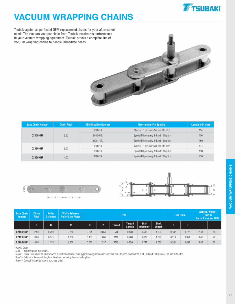
VAC
UU
M W
RA
PPIN
G C
HA
INS
124
Base Chain Number
Chain Pitch
Roller Diamater
Width Between Roller Link Plates Pin Link Plate
Approx. Weight (lbs/Ft)
No. of Links per 10 ft.
P R W D L1 Thread Thread Length
Shaft Diameter
Shaft Length T H
C2100HNP 2.50 0.750 0.750 0.375 0.858 M8 0.630 0.506 1.000 0.187 1.126 2.38 48
C2120HNP 3.00 0.875 1.000 0.437 1.061 M10 0.700 0.629 1.090 0.219 1.354 3.41 40
C2160HNP 4.00 1.125 1.250 0.562 1.337 M10 0.750 0.787 1.060 0.281 1.898 6.02 30
How to Order:Step 1 - Indentify chain size (pitch).Step 2 - Count the number of links between the extended carrier pins. Typical configurations are every 3rd and 8th pitch, 3rd and 9th pitch, 3rd and 10th pitch or 3rd and 12th pitch.Step 3 - Determine the overall length of the chain, including the connecting link.Step 4 - Contact Tsubaki to place a purchase order.
Tsubaki again has perfected OEM replacement chains for your aftermarket needs.The vacuum wrapper chain from Tsubaki maximizes performance in your vacuum wrapping equipment. Tsubaki stocks a complete line of vacuum wrapping chains to handle immediate needs.
Base Chain Number Chain Pitch OEM Machine Number Description (Pin Spacing) Length in Pitches
C2100HNP 2.50
8600-14 Special D1 pin every 3rd and 8th pitch 154
8600-14E Special D1 pin every 3rd and 10th pitch 156
8600-14EL Special D1 pin every 3rd and 12th pitch 150
C2120HNP 3.008300-18 Special D1 pin every 3rd and 9th pitch 144
8600-18 Special D1 pin every 3rd and 10th pitch 130
C2160HNP 4.00 8300-24 Special D1 pin every 3rd and 10th pitch 130
P P
HL2
L1
W
T
DR
VACUUM WRAPPING CHAINSVACUUM WRAPPING CHAINS.TSUBAKI"
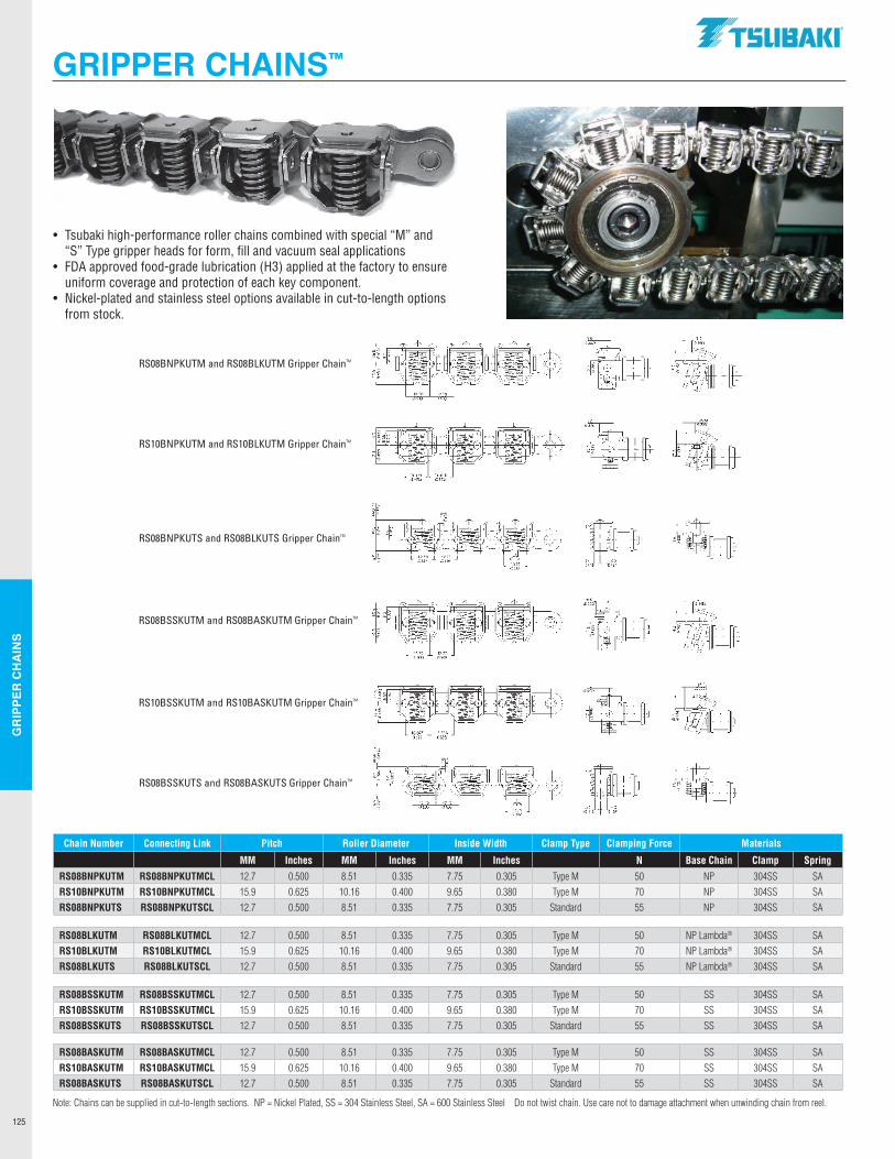
GR
IPPE
R C
HA
INS
125
Chain Number Connecting Link Pitch Roller Diameter Inside Width Clamp Type Clamping Force Materials
MM Inches MM Inches MM Inches N Base Chain Clamp Spring
RS08BNPKUTM RS08BNPKUTMCL 12.7 0.500 8.51 0.335 7.75 0.305 Type M 50 NP 304SS SARS10BNPKUTM RS10BNPKUTMCL 15.9 0.625 10.16 0.400 9.65 0.380 Type M 70 NP 304SS SARS08BNPKUTS RS08BNPKUTSCL 12.7 0.500 8.51 0.335 7.75 0.305 Standard 55 NP 304SS SA
RS08BLKUTM RS08BLKUTMCL 12.7 0.500 8.51 0.335 7.75 0.305 Type M 50 NP Lambda® 304SS SARS10BLKUTM RS10BLKUTMCL 15.9 0.625 10.16 0.400 9.65 0.380 Type M 70 NP Lambda® 304SS SARS08BLKUTS RS08BLKUTSCL 12.7 0.500 8.51 0.335 7.75 0.305 Standard 55 NP Lambda® 304SS SA
• Tsubaki high-performance roller chains combined with special “M” and “S” Type gripper heads for form, fill and vacuum seal applications
• FDA approved food-grade lubrication (H3) applied at the factory to ensure uniform coverage and protection of each key component.• Nickel-plated and stainless steel options available in cut-to-length options
from stock.
GRIPPER CHAINS™
RS08BSSKUTM RS08BSSKUTMCL 12.7 0.500 8.51 0.335 7.75 0.305 Type M 50 SS 304SS SARS10BSSKUTM RS10BSSKUTMCL 15.9 0.625 10.16 0.400 9.65 0.380 Type M 70 SS 304SS SARS08BSSKUTS RS08BSSKUTSCL 12.7 0.500 8.51 0.335 7.75 0.305 Standard 55 SS 304SS SA
Note: Chains can be supplied in cut-to-length sections. NP = Nickel Plated, SS = 304 Stainless Steel, SA = 600 Stainless Steel Do not twist chain. Use care not to damage attachment when unwinding chain from reel.
RS08BASKUTM RS08BASKUTMCL 12.7 0.500 8.51 0.335 7.75 0.305 Type M 50 SS 304SS SARS10BASKUTM RS10BASKUTMCL 15.9 0.625 10.16 0.400 9.65 0.380 Type M 70 SS 304SS SARS08BASKUTS RS08BASKUTSCL 12.7 0.500 8.51 0.335 7.75 0.305 Standard 55 SS 304SS SA
RS08BNPKUTM and RS08BLKUTM Gripper ChainTM
RS10BNPKUTM and RS10BLKUTM Gripper ChainTM
RS08BNPKUTS and RS08BLKUTS Gripper ChainTM
RS08BSSKUTM and RS08BASKUTM Gripper ChainTM
RS10BSSKUTM and RS10BASKUTM Gripper ChainTM
RS08BSSKUTS and RS08BASKUTS Gripper ChainTM
.TSUBAKI"
~~ ,;,.ii•~."''" ~'! - ~? I-
C'
".~., ~.,•:, s - ,.
- e +-
p ~
------------------
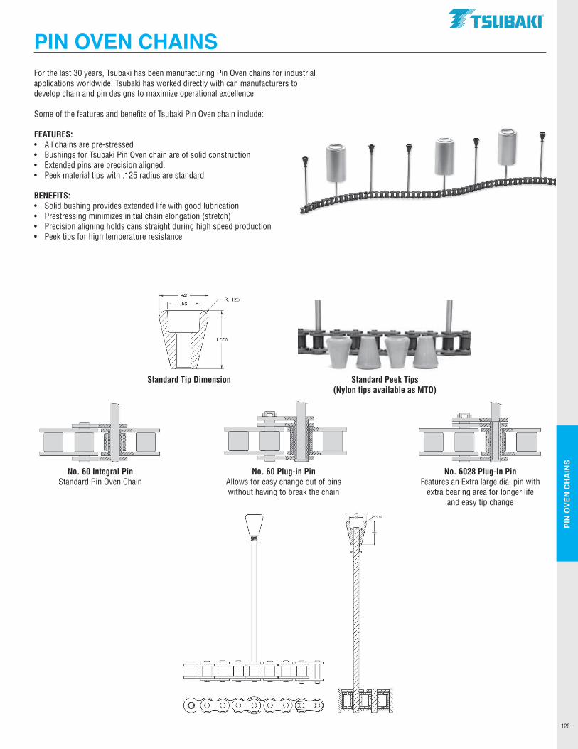
PIN
OVE
N C
HA
INS
126
PIN OVEN CHAINSFor the last 30 years, Tsubaki has been manufacturing Pin Oven chains for industrial applications worldwide. Tsubaki has worked directly with can manufacturers to develop chain and pin designs to maximize operational excellence.
Some of the features and benefits of Tsubaki Pin Oven chain include:
FEATURES:• All chains are pre-stressed • Bushings for Tsubaki Pin Oven chain are of solid construction• Extended pins are precision aligned.• Peek material tips with .125 radius are standard
BENEFITS:• Solid bushing provides extended life with good lubrication• Prestressing minimizes initial chain elongation (stretch)• Precision aligning holds cans straight during high speed production• Peek tips for high temperature resistance
Standard Tip Dimension Standard Peek Tips (Nylon tips available as MTO)
No. 60 Integral Pin No. 60 Plug-in Pin No. 6028 Plug-In Pin Standard Pin Oven Chain Allows for easy change out of pins Features an Extra large dia. pin with without having to break the chain extra bearing area for longer life and easy tip change
PIN OVEN CHAINS.TSUBAKI"
-
.840 R. 125
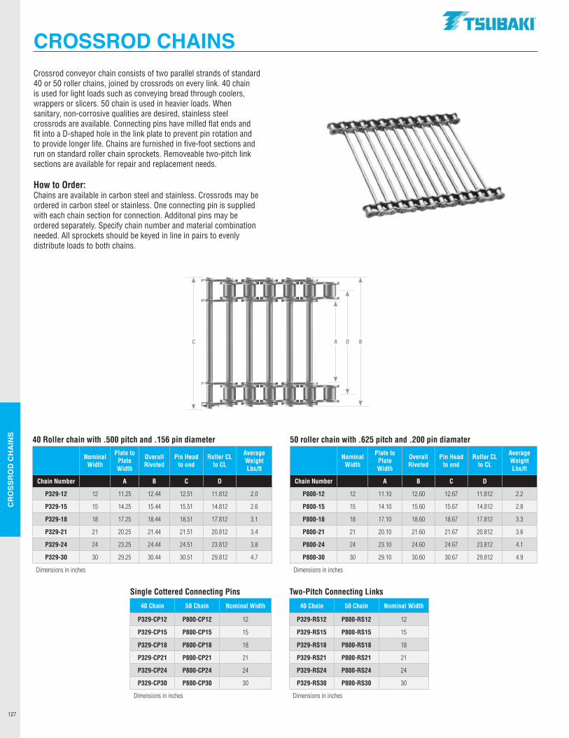
CR
OSS
RO
D C
HA
INS
127
CROSS ROD CHAINS
40 Roller chain with .500 pitch and .156 pin diameter 50 roller chain with .625 pitch and .200 pin diamater
Nominal Width
Plate to Plate Width
Overall Riveted
Pin Head to end
Roller CL to CL
Average Weight Lbs/ft
Nominal Width
Plate to Plate Width
Overall Riveted
Pin Head to end
Roller CL to CL
Average Weight Lbs/ft
Chain Number A B C D Chain Number A B C D
P329-12 12 11.25 12.44 12.51 11.812 2.0 P800-12 12 11.10 12.60 12.67 11.812 2.2
P329-15 15 14.25 15.44 15.51 14.812 2.6 P800-15 15 14.10 15.60 15.67 14.812 2.8
P329-18 18 17.25 18.44 18.51 17.812 3.1 P800-18 18 17.10 18.60 18.67 17.812 3.3
P329-21 21 20.25 21.44 21.51 20.812 3.4 P800-21 21 20.10 21.60 21.67 20.812 3.6
P329-24 24 23.25 24.44 24.51 23.812 3.8 P800-24 24 23.10 24.60 24.67 23.812 4.1
P329-30 30 29.25 30.44 30.51 29.812 4.7 P800-30 30 29.10 30.60 30.67 29.812 4.9
Dimensions in inches Dimensions in inches
Crossrod conveyor chain consists of two parallel strands of standard 40 or 50 roller chains, joined by crossrods on every link. 40 chain is used for light loads such as conveying bread through coolers, wrappers or slicers. 50 chain is used in heavier loads. When sanitary, non-corrosive qualities are desired, stainless steel crossrods are available. Connecting pins have milled flat ends and fit into a D-shaped hole in the link plate to prevent pin rotation and to provide longer life. Chains are furnished in five-foot sections and run on standard roller chain sprockets. Removeable two-pitch link sections are available for repair and replacement needs.
How to Order: Chains are available in carbon steel and stainless. Crossrods may be ordered in carbon steel or stainless. One connecting pin is supplied with each chain section for connection. Additonal pins may be ordered separately. Specify chain number and material combination needed. All sprockets should be keyed in line in pairs to evenly distribute loads to both chains.
Single Cottered Connecting Pins Two-Pitch Connecting Links
40 Chain 50 Chain Nominal Width 40 Chain 50 Chain Nominal Width
P329-CP12 P800-CP12 12 P329-RS12 P800-RS12 12
P329-CP15 P800-CP15 15 P329-RS15 P800-RS15 15
P329-CP18 P800-CP18 18 P329-RS18 P800-RS18 18
P329-CP21 P800-CP21 21 P329-RS21 P800-RS21 21
P329-CP24 P800-CP24 24 P329-RS24 P800-RS24 24
P329-CP30 P800-CP30 30 P329-RS30 P800-RS30 30
Dimensions in inches Dimensions in inches
A D BC
CROSSROD CHAINS.TSUBAKI"
. . ·~ . ,
I I I I I I I I I I lllT
I I I I I I I I I I 11~1 ' ~..., " -,
------- -------
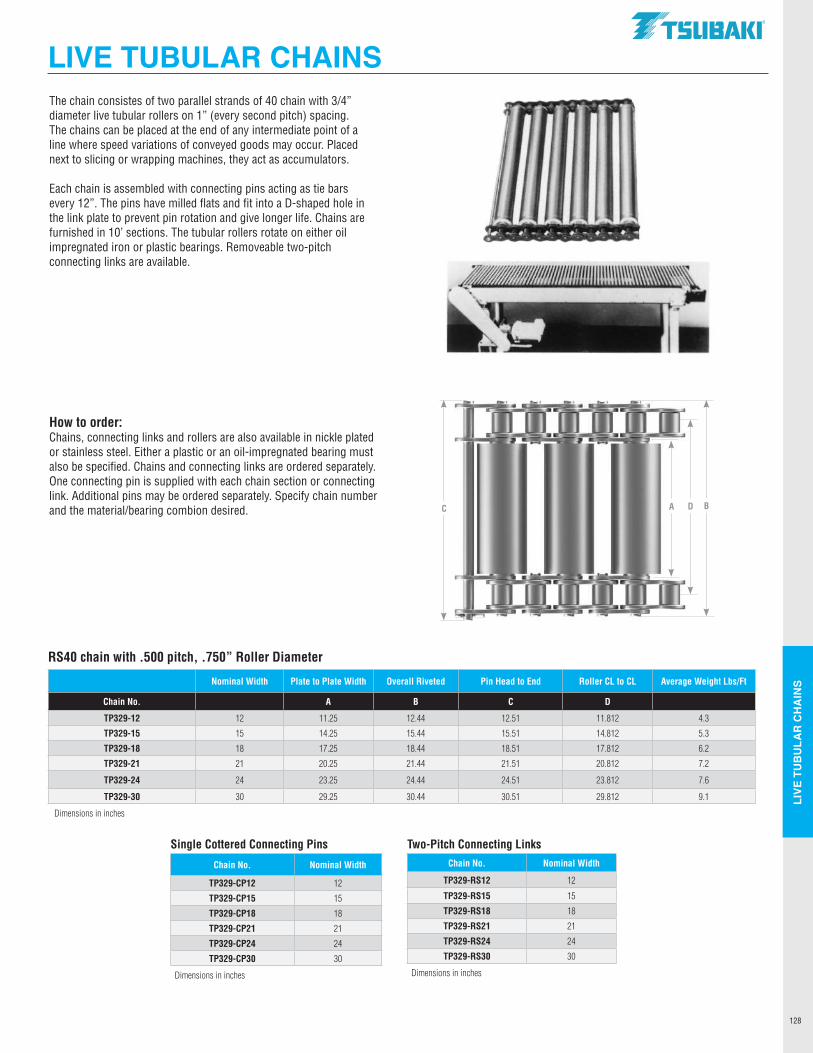
LIVE
TU
BU
LAR
CH
AIN
S
128
RS40 chain with .500 pitch, .750” Roller Diameter
Nominal Width Plate to Plate Width Overall Riveted Pin Head to End Roller CL to CL Average Weight Lbs/Ft
Chain No. A B C D
TP329-12 12 11.25 12.44 12.51 11.812 4.3
TP329-15 15 14.25 15.44 15.51 14.812 5.3
TP329-18 18 17.25 18.44 18.51 17.812 6.2
TP329-21 21 20.25 21.44 21.51 20.812 7.2
TP329-24 24 23.25 24.44 24.51 23.812 7.6
TP329-30 30 29.25 30.44 30.51 29.812 9.1
Dimensions in inches
The chain consistes of two parallel strands of 40 chain with 3/4” diameter live tubular rollers on 1” (every second pitch) spacing. The chains can be placed at the end of any intermediate point of a line where speed variations of conveyed goods may occur. Placed next to slicing or wrapping machines, they act as accumulators.
Each chain is assembled with connecting pins acting as tie bars every 12”. The pins have milled flats and fit into a D-shaped hole in the link plate to prevent pin rotation and give longer life. Chains are furnished in 10’ sections. The tubular rollers rotate on either oil impregnated iron or plastic bearings. Removeable two-pitch connecting links are available.
How to order: Chains, connecting links and rollers are also available in nickle plated or stainless steel. Either a plastic or an oil-impregnated bearing must also be specified. Chains and connecting links are ordered separately. One connecting pin is supplied with each chain section or connecting link. Additional pins may be ordered separately. Specify chain number and the material/bearing combion desired.
Two-Pitch Connecting LinksChain No. Nominal Width
TP329-RS12 12
TP329-RS15 15
TP329-RS18 18
TP329-RS21 21
TP329-RS24 24
TP329-RS30 30
Dimensions in inches
Single Cottered Connecting Pins
Chain No. Nominal Width
TP329-CP12 12
TP329-CP15 15
TP329-CP18 18
TP329-CP21 21
TP329-CP24 24
TP329-CP30 30
Dimensions in inches
A D BC
LIVE TUBULAR CHAINS.TSUBAKI"
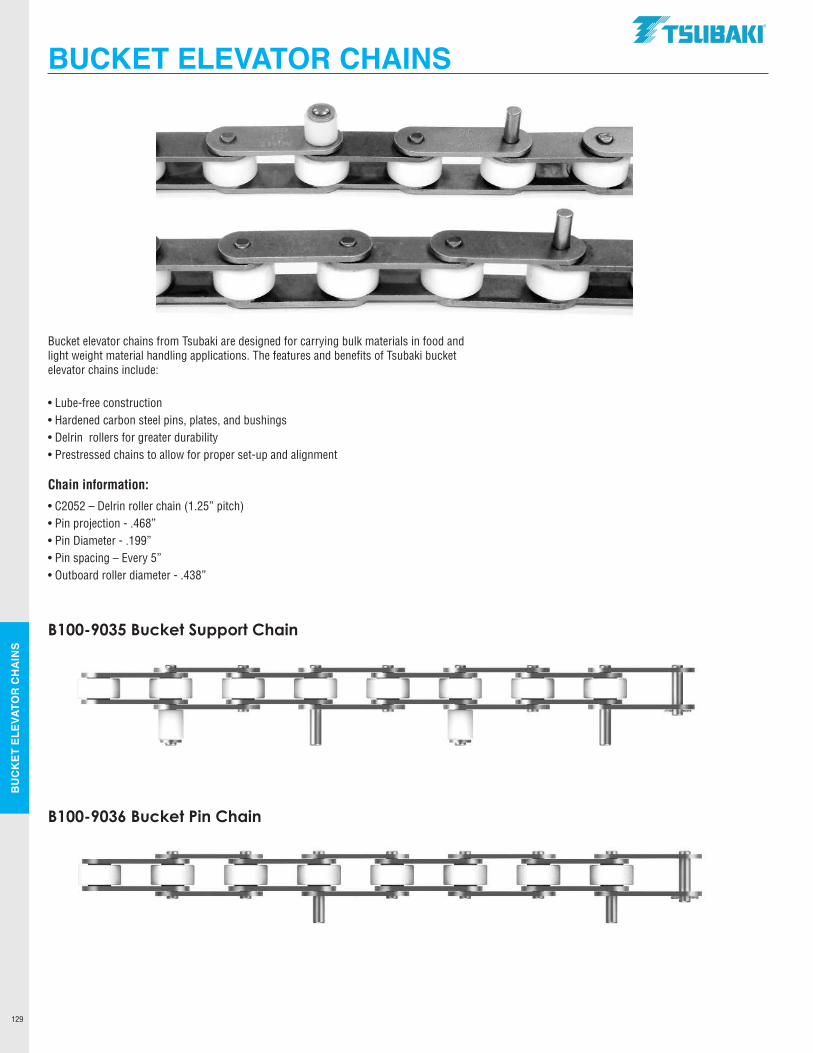
BU
CK
ET E
LEVA
TOR
CH
AIN
S
129
BUCKET ELEVATOR CHAINS
Bucket elevator chains from Tsubaki are designed for carrying bulk materials in food and light weight material handling applications. The features and benefits of Tsubaki bucket elevator chains include:
• Lube-free construction • Hardened carbon steel pins, plates, and bushings• Delrin rollers for greater durability• Prestressed chains to allow for proper set-up and alignment
Chain information:
• C2052 – Delrin roller chain (1.25” pitch)• Pin projection - .468”• Pin Diameter - .199”• Pin spacing – Every 5”• Outboard roller diameter - .438”
B100-9035 Bucket Support Chain
B100-9036 Bucket Pin Chain
.TSUBAKI"
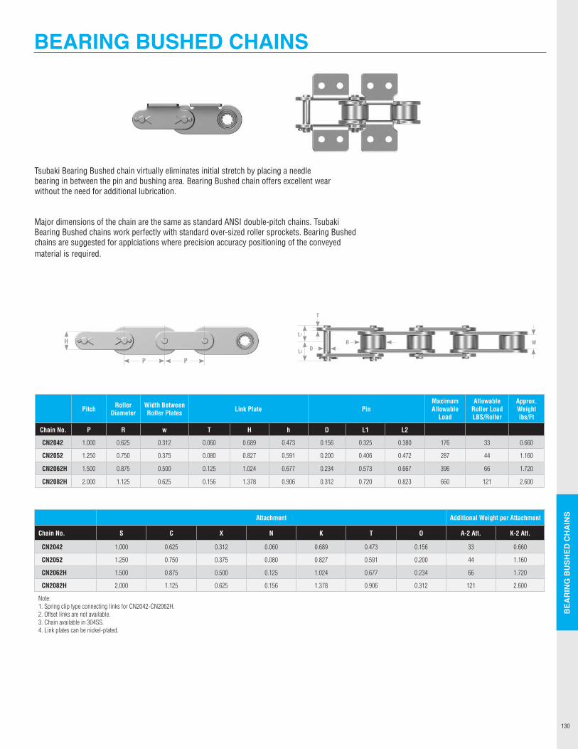
BEA
RIN
G B
USH
ED C
HA
INS
130
BEARING BUSHED CHAINS
Tsubaki Bearing Bushed chain virtually eliminates initial stretch by placing a needle bearing in between the pin and bushing area. Bearing Bushed chain offers excellent wear without the need for additional lubrication. Major dimensions of the chain are the same as standard ANSI double-pitch chains. Tsubaki Bearing Bushed chains work perfectly with standard over-sized roller sprockets. Bearing Bushed chains are suggested for applciations where precision accuracy positioning of the conveyed material is required.
Pitch Roller Diameter
Width Between Roller Plates Link Plate Pin
Maximum Allowable
Load
Allowable Roller Load LBS/Roller
Approx. Weight lbs/Ft
Chain No. P R w T H h D L1 L2
CN2042 1.000 0.625 0.312 0.060 0.689 0.473 0.156 0.325 0.380 176 33 0.660
CN2052 1.250 0.750 0.375 0.080 0.827 0.591 0.200 0.406 0.472 287 44 1.160
CN2062H 1.500 0.875 0.500 0.125 1.024 0.677 0.234 0.573 0.667 396 66 1.720
CN2082H 2.000 1.125 0.625 0.156 1.378 0.906 0.312 0.720 0.823 660 121 2.600
Attachment Additional Weight per Attachment
Chain No. S C X N K T O A-2 Att. K-2 Att.
CN2042 1.000 0.625 0.312 0.060 0.689 0.473 0.156 33 0.660
CN2052 1.250 0.750 0.375 0.080 0.827 0.591 0.200 44 1.160
CN2062H 1.500 0.875 0.500 0.125 1.024 0.677 0.234 66 1.720
CN2082H 2.000 1.125 0.625 0.156 1.378 0.906 0.312 121 2.600
Note:1. Spring clip type connecting links for CN2042-CN2062H.2. Offset links are not available.3. Chain available in 304SS.4. Link plates can be nickel-plated.
P P
HL1
L2
W
T
DR
BEARING BUSHED CHAINS
0
--------
SPROCKETSTsubaki produces a broad range of sprockets to satisfy all your
application requirements. Stock product offerings are readily
available and can be supplied in a multitude of pitch ranges and
configurations. Extensive design, engineering and manufacturing
capabilities allow Tsubaki to produce a wide variety of made-
to-order sprocket products for a miltitude of applications. From
one-off customer designs to high volume OEM and Smart Tooth®
sprocket requirements, Tsubaki has you covered.
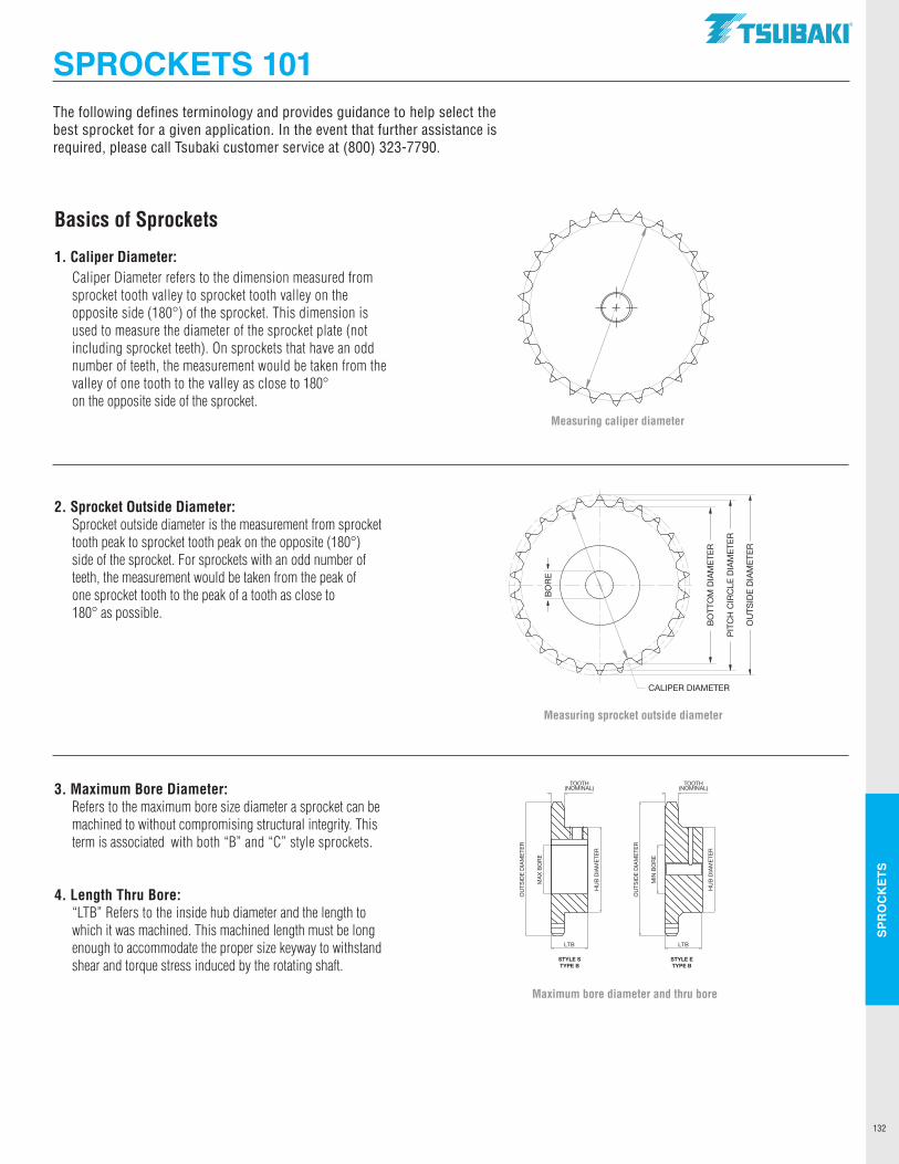
SPR
OC
KET
S
132
Basics of Sprockets
1. Caliper Diameter: Caliper Diameter refers to the dimension measured from
sprocket tooth valley to sprocket tooth valley on the opposite side (180°) of the sprocket. This dimension is used to measure the diameter of the sprocket plate (not including sprocket teeth). On sprockets that have an odd number of teeth, the measurement would be taken from the valley of one tooth to the valley as close to 180° on the opposite side of the sprocket.
2. Sprocket Outside Diameter: Sprocket outside diameter is the measurement from sprocket
tooth peak to sprocket tooth peak on the opposite (180°) side of the sprocket. For sprockets with an odd number of teeth, the measurement would be taken from the peak of one sprocket tooth to the peak of a tooth as close to 180° as possible.
3. Maximum Bore Diameter: Refers to the maximum bore size diameter a sprocket can be machined to without compromising structural integrity. This term is associated with both “B” and “C” style sprockets.
4. Length Thru Bore: “LTB” Refers to the inside hub diameter and the length to which it was machined. This machined length must be long enough to accommodate the proper size keyway to withstand shear and torque stress induced by the rotating shaft.
The following defines terminology and provides guidance to help select the best sprocket for a given application. In the event that further assistance is required, please call Tsubaki customer service at (800) 323-7790.
Measuring caliper diameter
Measuring sprocket outside diameter
BO
BO
RREE
BO
RE
BO
TTO
M D
IAM
ETE
R
CALIPER DIAMETER
PIT
CH
CIR
CLE
DIA
ME
TER
OU
TSID
E D
IAM
ETE
R
Maximum bore diameter and thru bore
TOOTH(NOMINAL)
OU
TSID
ED
IAM
ETE
R
HU
B D
IAM
ETE
R
MIN
BO
RE
LTB
STYLE STYPE B
STYLE ETYPE B
TOOTH(NOMINAL)
OU
TSID
ED
IAM
ETE
R
HU
B D
IAM
ETE
R
MA
X B
OR
E
LTB
SPROCKETS 101TSUBAKI"
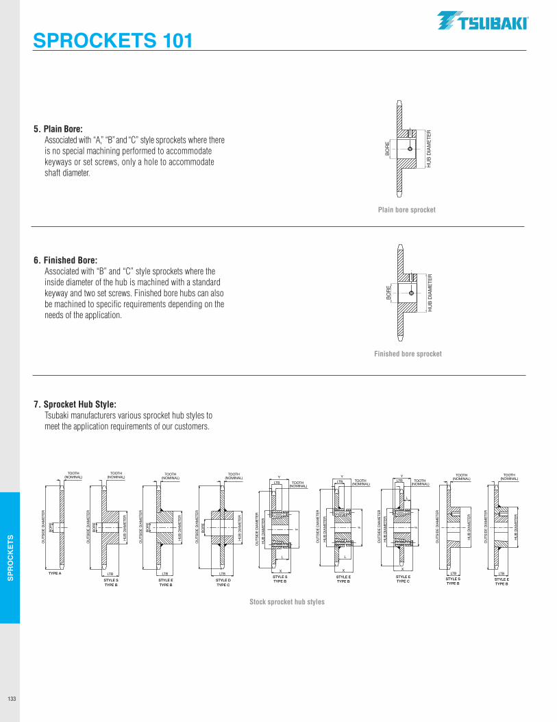
SPR
OC
KET
S
133
Finished bore sprocket
Stock sprocket hub styles
BO
RE
HU
BD
IAM
ETE
R
BO
RE
HU
BD
IAM
ETE
R
OU
TSID
ED
IAM
ETE
R
OU
TSID
ED
IAM
ETE
R
OU
TSID
ED
IAM
ETE
R
OU
TSID
ED
IAM
ETE
R
OU
TSID
ED
IAM
ETE
RB
OR
E
HU
BD
IAM
ETE
R
STYLE DTYPE B
LTB
TOOTH (NOMINAL)
BO
RE
BO
RE
BO
RE
BO
RE
HU
BD
IAM
ETE
R
HU
BD
IAM
ETE
R
HU
BD
IAM
ETE
R
LTB
STYLE DTYPE C
LTB
STYLE ETYPE B
LTB
STYLE STYPE B
TYPE A
TOOTH(NOMINAL)
TOOTH(NOMINAL)
TOOTH(NOMINAL)
TOOTH(NOMINAL)
STYLE STYPE B
LTB
TOOTH (NOMINAL)
OU
TSID
ED
IAM
ETE
RB
OR
E
BO
RE
OU
TSID
ED
IAM
ETE
R
TYPE A
TOOTH (NOMINAL)
HU
BD
IAM
ETE
R
OU
TSID
ED
IAM
ETE
R
BO
RE
HU
BD
IAM
ETE
R
STYLE ETYPE B
LTB
TOOTH (NOMINAL)
STYLE STYPE B
LTB
TOOTH (NOMINAL)
OU
TSID
ED
IAM
ETE
R
BO
RE
HU
BD
IAM
ETE
R
HU
BD
IAM
ETE
R
Y
OU
TSID
ED
IAM
ETE
R
F
X
STYLE ETYPE C
LTB
L
STYLE STYPE B
X
L
Y
LTB
OU
TSID
ED
IAM
ETE
R
HU
BD
IAM
ETE
R
Y
HU
BD
IAM
ETE
R
OU
TSID
ED
IAM
ETE
R
F F
STYLE ETYPE B
X
L
LTBTOOTH(NOMINAL)
TOOTH(NOMINAL)
TOOTH(NOMINAL)
STYLE STYPE B
LTB
TOOTH(NOMINAL)
OU
TSID
ED
IAM
ETE
R
OU
TSID
ED
IAM
ETE
R
HU
BD
IAM
ETE
R
HU
BD
IAM
ETE
R
STYLE ETYPE B
LTB
TOOTH(NOMINAL)
5. Plain Bore: Associated with “A,” “B” and “C” style sprockets where there is no special machining performed to accommodate keyways or set screws, only a hole to accommodate shaft diameter.
6. Finished Bore: Associated with “B” and “C” style sprockets where the inside diameter of the hub is machined with a standard keyway and two set screws. Finished bore hubs can also be machined to specific requirements depending on the needs of the application.
7. Sprocket Hub Style: Tsubaki manufacturers various sprocket hub styles to meet the application requirements of our customers.
SPROCKETS 101
Plain bore sprocket
BO
RE
HU
BD
IAM
ETE
R
BO
RE
HU
BD
IAM
ETE
R
.TSUBAKI"
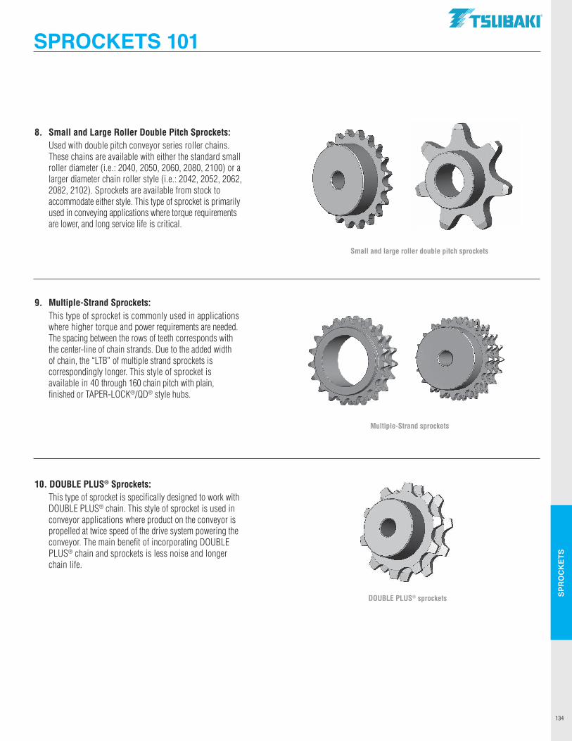
SPR
OC
KET
S
134
8. Small and Large Roller Double Pitch Sprockets: Used with double pitch conveyor series roller chains.
These chains are available with either the standard small roller diameter (i.e.: 2040, 2050, 2060, 2080, 2100) or a larger diameter chain roller style (i.e.: 2042, 2052, 2062, 2082, 2102). Sprockets are available from stock to accommodate either style. This type of sprocket is primarily used in conveying applications where torque requirements are lower, and long service life is critical.
9. Multiple-Strand Sprockets: This type of sprocket is commonly used in applications
where higher torque and power requirements are needed. The spacing between the rows of teeth corresponds with the center-line of chain strands. Due to the added width of chain, the “LTB” of multiple strand sprockets is correspondingly longer. This style of sprocket is available in 40 through 160 chain pitch with plain, finished or TAPER-LOCK®/QD® style hubs.
10. DOUBLE PLUS® Sprockets: This type of sprocket is specifically designed to work with DOUBLE PLUS® chain. This style of sprocket is used in conveyor applications where product on the conveyor is propelled at twice speed of the drive system powering the conveyor. The main benefit of incorporating DOUBLE PLUS® chain and sprockets is less noise and longer chain life.
Multiple-Strand sprockets
Small and large roller double pitch sprockets
DOUBLE PLUS® sprockets
SPROCKETS 101TSUBAKI"
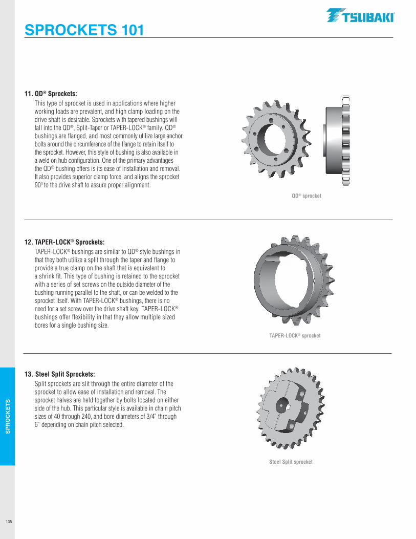
SPR
OC
KET
S
135
11. QD® Sprockets: This type of sprocket is used in applications where higher working loads are prevalent, and high clamp loading on the drive shaft is desirable. Sprockets with tapered bushings will fall into the QD®, Split-Taper or TAPER-LOCK® family. QD® bushings are flanged, and most commonly utilize large anchor bolts around the circumference of the flange to retain itself to the sprocket. However, this style of bushing is also available in a weld on hub configuration. One of the primary advantages the QD® bushing offers is its ease of installation and removal. It also provides superior clamp force, and aligns the sprocket 900 to the drive shaft to assure proper alignment.
12. TAPER-LOCK® Sprockets: TAPER-LOCK® bushings are similar to QD® style bushings in that they both utilize a split through the taper and flange to provide a true clamp on the shaft that is equivalent to a shrink fit. This type of bushing is retained to the sprocket with a series of set screws on the outside diameter of the bushing running parallel to the shaft, or can be welded to the sprocket itself. With TAPER-LOCK® bushings, there is no need for a set screw over the drive shaft key. TAPER-LOCK® bushings offer flexibility in that they allow multiple sized bores for a single bushing size.
13. Steel Split Sprockets: Split sprockets are slit through the entire diameter of the sprocket to allow ease of installation and removal. The sprocket halves are held together by bolts located on either side of the hub. This particular style is available in chain pitch sizes of 40 through 240, and bore diameters of 3/4” through 6” depending on chain pitch selected.
TAPER-LOCK® sprocket
QD® sprocket
Steel Split sprocket
SPROCKETS 101.TSUBAKI"
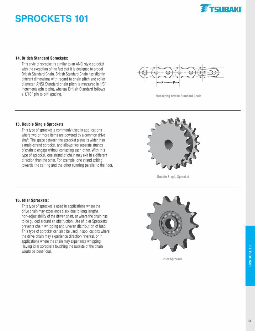
SPR
OC
KET
S
136
14. British Standard Sprockets: This style of sprocket is similar to an ANSI style sprocket with the exception of the fact that it is designed to propel British Standard Chain. British Standard Chain has slightly different dimensions with regard to chain pitch and roller diameter. ANSI Standard chain pitch is measured in 1/8” increments (pin to pin), whereas British Standard follows a 1/16” pin to pin spacing.
.
15. Double Single Sprockets: This type of sprocket is commonly used in applications where two or more items are powered by a common drive shaft. The space between the sprocket plates is wider than a multi-strand sprocket, and allows two separate strands of chain to engage without contacting each other. With this type of sprocket, one strand of chain may exit in a different direction than the other. For example, one strand exiting towards the ceiling and the other running parallel to the floor.
16. Idler Sprockets: This type of sprocket is used in applications where the drive chain may experience slack due to long lengths, non-adjustability of the driven shaft, or where the chain has to be guided around an obstruction. Use of Idler Sprockets prevents chain whipping and uneven distribution of load. This type of sprocket can also be used in applications where the drive chain may experience direction reversal, or in applications where the chain may experience whipping. Having idler sprockets touching the outside of the chain would be beneficial.
Double Single Sprocket
Measuring British Standard Chain
P P
Idler Sprocket
SPROCKETS 101TSUBAKI"
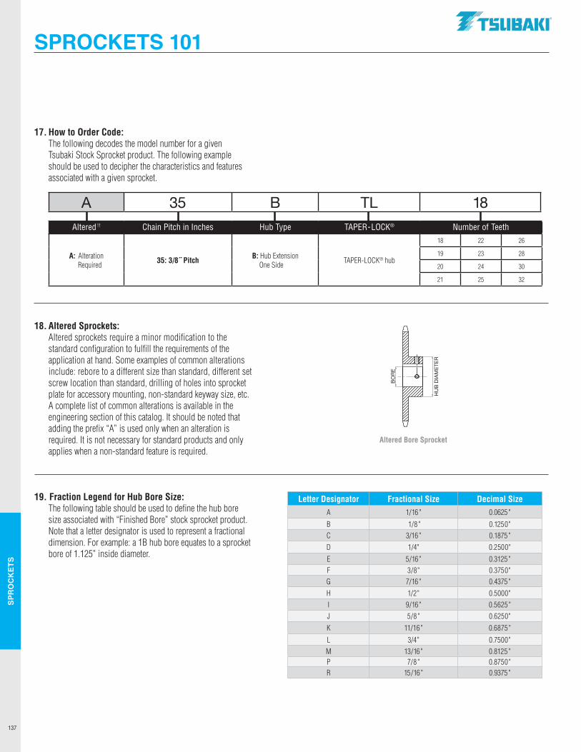
SPR
OC
KET
S
137
17. How to Order Code: The following decodes the model number for a given Tsubaki Stock Sprocket product. The following example should be used to decipher the characteristics and features associated with a given sprocket.
18. Altered Sprockets: Altered sprockets require a minor modification to the standard configuration to fulfill the requirements of the application at hand. Some examples of common alterations include: rebore to a different size than standard, different set screw location than standard, drilling of holes into sprocket plate for accessory mounting, non-standard keyway size, etc. A complete list of common alterations is available in the engineering section of this catalog. It should be noted that adding the prefix “A” is used only when an alteration is required. It is not necessary for standard products and only applies when a non-standard feature is required.
19. Fraction Legend for Hub Bore Size: The following table should be used to define the hub bore size associated with “Finished Bore” stock sprocket product. Note that a letter designator is used to represent a fractional dimension. For example: a 1B hub bore equates to a sprocket bore of 1.125” inside diameter.
Letter Designator Fractional Size Decimal SizeA 1/16" 0.0625"
B 1/8" 0.1250"C 3/16" 0.1875"D 1/4" 0.2500"
E 5/16" 0.3125"F 3/8" 0.3750"G 7/16" 0.4375"H 1/2" 0.5000"I 9/16" 0.5625"J 5/8" 0.6250"
K 11/16" 0.6875"
L 3/4" 0.7500"M 13/16" 0.8125 "P 7/8" 0.8750"R 15/16" 0.9375"
A 35 B TL 18
Altered !! Chain Pitch in Inches Hub Type TAPER-LOCK® Number of Teeth
A: Alteration Required 35: 3/8˝ Pitch B: Hub Extension
One Side TAPER-LOCK® hub
18 22 26
19 23 28
20 24 30
21 25 32
SPROCKETS 101
Altered Bore Sprocket
BO
RE
HU
BD
IAM
ETE
R
BO
RE
HU
BD
IAM
ETE
R
.TSUBAKI"
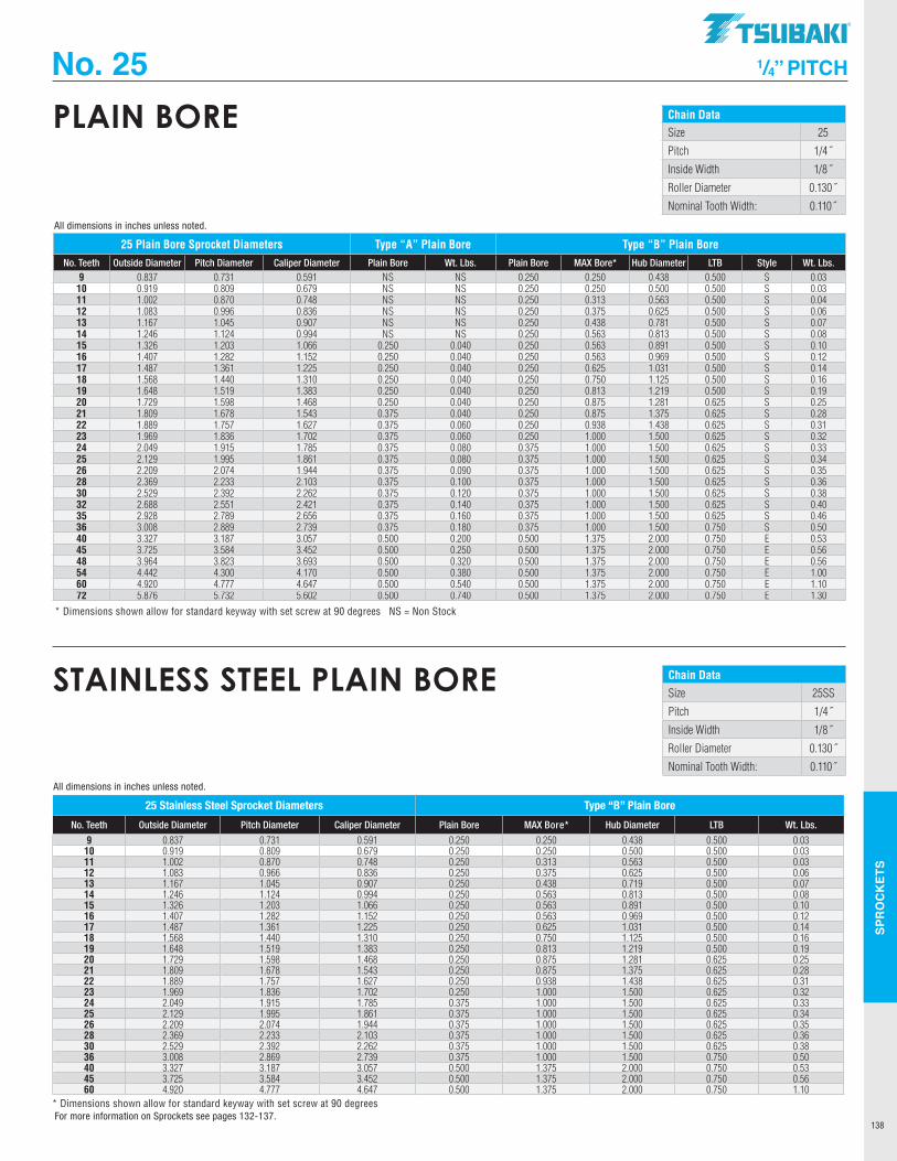
SPR
OC
KET
S
138
Chain DataSize 25
Pitch 1/4˝
Inside Width 1/8˝
Roller Diameter 0.130˝
Nominal Tooth Width: 0.110˝
PLAIN BORE
25 Plain Bore Sprocket Diameters Type “A” Plain Bore Type “B” Plain BoreNo. Teeth Outside Diameter Pitch Diameter Caliper Diameter Plain Bore Wt. Lbs. Plain Bore MAX Bore* Hub Diameter LTB Style Wt. Lbs.
9 0.837 0.731 0.591 NS NS 0.250 0.250 0.438 0.500 S 0.0310 0.919 0.809 0.679 NS NS 0.250 0.250 0.500 0.500 S 0.0311 1.002 0.870 0.748 NS NS 0.250 0.313 0.563 0.500 S 0.0412 1.083 0.996 0.836 NS NS 0.250 0.375 0.625 0.500 S 0.0613 1.167 1.045 0.907 NS NS 0.250 0.438 0.781 0.500 S 0.0714 1.246 1.124 0.994 NS NS 0.250 0.563 0.813 0.500 S 0.0815 1.326 1.203 1.066 0.250 0.040 0.250 0.563 0.891 0.500 S 0.1016 1.407 1.282 1.152 0.250 0.040 0.250 0.563 0.969 0.500 S 0.1217 1.487 1.361 1.225 0.250 0.040 0.250 0.625 1.031 0.500 S 0.1418 1.568 1.440 1.310 0.250 0.040 0.250 0.750 1.125 0.500 S 0.1619 1.648 1.519 1.383 0.250 0.040 0.250 0.813 1.219 0.500 S 0.1920 1.729 1.598 1.468 0.250 0.040 0.250 0.875 1.281 0.625 S 0.2521 1.809 1.678 1.543 0.375 0.040 0.250 0.875 1.375 0.625 S 0.2822 1.889 1.757 1.627 0.375 0.060 0.250 0.938 1.438 0.625 S 0.3123 1.969 1.836 1.702 0.375 0.060 0.250 1.000 1.500 0.625 S 0.3224 2.049 1.915 1.785 0.375 0.080 0.375 1.000 1.500 0.625 S 0.3325 2.129 1.995 1.861 0.375 0.080 0.375 1.000 1.500 0.625 S 0.3426 2.209 2.074 1.944 0.375 0.090 0.375 1.000 1.500 0.625 S 0.3528 2.369 2.233 2.103 0.375 0.100 0.375 1.000 1.500 0.625 S 0.3630 2.529 2.392 2.262 0.375 0.120 0.375 1.000 1.500 0.625 S 0.3832 2.688 2.551 2.421 0.375 0.140 0.375 1.000 1.500 0.625 S 0.4035 2.928 2.789 2.656 0.375 0.160 0.375 1.000 1.500 0.625 S 0.4636 3.008 2.889 2.739 0.375 0.180 0.375 1.000 1.500 0.750 S 0.5040 3.327 3.187 3.057 0.500 0.200 0.500 1.375 2.000 0.750 E 0.5345 3.725 3.584 3.452 0.500 0.250 0.500 1.375 2.000 0.750 E 0.5648 3.964 3.823 3.693 0.500 0.320 0.500 1.375 2.000 0.750 E 0.5654 4.442 4.300 4.170 0.500 0.380 0.500 1.375 2.000 0.750 E 1.0060 4.920 4.777 4.647 0.500 0.540 0.500 1.375 2.000 0.750 E 1.1072 5.876 5.732 5.602 0.500 0.740 0.500 1.375 2.000 0.750 E 1.30
* Dimensions shown allow for standard keyway with set screw at 90 degrees NS = Non Stock
All dimensions in inches unless noted.
No. 25 1/4” PITCH
Chain DataSize 25SS
Pitch 1/4˝
Inside Width 1/8˝
Roller Diameter 0.130˝
Nominal Tooth Width: 0.110˝
STAINLESS STEEL PLAIN BORE
25 Stainless Steel Sprocket Diameters Type “B” Plain Bore
No. Teeth Outside Diameter Pitch Diameter Caliper Diameter Plain Bore MAX Bore* Hub Diameter LTB Wt. Lbs.
9 0.837 0.731 0.591 0.250 0.250 0.438 0.500 0.0310 0.919 0.809 0.679 0.250 0.250 0.500 0.500 0.0311 1.002 0.870 0.748 0.250 0.313 0.563 0.500 0.0312 1.083 0.966 0.836 0.250 0.375 0.625 0.500 0.0613 1.167 1.045 0.907 0.250 0.438 0.719 0.500 0.0714 1.246 1.124 0.994 0.250 0.563 0.813 0.500 0.0815 1.326 1.203 1.066 0.250 0.563 0.891 0.500 0.1016 1.407 1.282 1.152 0.250 0.563 0.969 0.500 0.1217 1.487 1.361 1.225 0.250 0.625 1.031 0.500 0.1418 1.568 1.440 1.310 0.250 0.750 1.125 0.500 0.1619 1.648 1.519 1.383 0.250 0.813 1.219 0.500 0.1920 1.729 1.598 1.468 0.250 0.875 1.281 0.625 0.2521 1.809 1.678 1.543 0.250 0.875 1.375 0.625 0.2822 1.889 1.757 1.627 0.250 0.938 1.438 0.625 0.3123 1.969 1.836 1.702 0.250 1.000 1.500 0.625 0.3224 2.049 1.915 1.785 0.375 1.000 1.500 0.625 0.3325 2.129 1.995 1.861 0.375 1.000 1.500 0.625 0.3426 2.209 2.074 1.944 0.375 1.000 1.500 0.625 0.3528 2.369 2.233 2.103 0.375 1.000 1.500 0.625 0.3630 2.529 2.392 2.262 0.375 1.000 1.500 0.625 0.3836 3.008 2.869 2.739 0.375 1.000 1.500 0.750 0.5040 3.327 3.187 3.057 0.500 1.375 2.000 0.750 0.5345 3.725 3.584 3.452 0.500 1.375 2.000 0.750 0.5660 4.920 4.777 4.647 0.500 1.375 2.000 0.750 1.10
* Dimensions shown allow for standard keyway with set screw at 90 degrees
All dimensions in inches unless noted.
For more information on Sprockets see pages 132-137.
TSUBAKI"
---------------
----
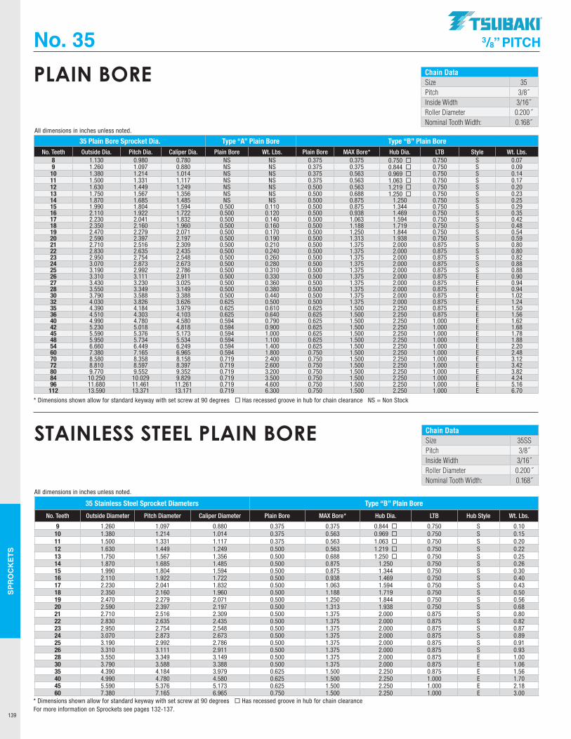
SPR
OC
KET
S
139
Chain DataSize 35Pitch 3/8˝Inside Width 3/16˝Roller Diameter 0.200˝Nominal Tooth Width: 0.168˝
PLAIN BORE
No. 35 3/8” PITCH
35 Plain Bore Sprocket Dia. Type “A” Plain Bore Type “B” Plain BoreNo. Teeth Outside Dia. Pitch Dia. Caliper Dia. Plain Bore Wt. Lbs. Plain Bore MAX Bore* Hub Dia. LTB Style Wt. Lbs.
8 1.130 0.980 0.780 NS NS 0.375 0.375 0.750 ¨ 0.750 S 0.079 1.260 1.097 0.880 NS NS 0.375 0.375 0.844 ¨ 0.750 S 0.09
10 1.380 1.214 1.014 NS NS 0.375 0.563 0.969 ¨ 0.750 S 0.1411 1.500 1.331 1.117 NS NS 0.375 0.563 1.063 ¨ 0.750 S 0.1712 1.630 1.449 1.249 NS NS 0.500 0.563 1.219 ¨ 0.750 S 0.2013 1.750 1.567 1.356 NS NS 0.500 0.688 1.250 ¨ 0.750 S 0.2314 1.870 1.685 1.485 NS NS 0.500 0.875 1.250 0.750 S 0.2515 1.990 1.804 1.594 0.500 0.110 0.500 0.875 1.344 0.750 S 0.2916 2.110 1.922 1.722 0.500 0.120 0.500 0.938 1.469 0.750 S 0.3517 2.230 2.041 1.832 0.500 0.140 0.500 1.063 1.594 0.750 S 0.4218 2.350 2.160 1.960 0.500 0.160 0.500 1.188 1.719 0.750 S 0.4819 2.470 2.279 2.071 0.500 0.170 0.500 1.250 1.844 0.750 S 0.5420 2.590 2.397 2.197 0.500 0.190 0.500 1.313 1.938 0.750 S 0.5921 2.710 2.516 2.309 0.500 0.210 0.500 1.375 2.000 0.875 S 0.8022 2.830 2.635 2.435 0.500 0.240 0.500 1.375 2.000 0.875 S 0.8023 2.950 2.754 2.548 0.500 0.260 0.500 1.375 2.000 0.875 S 0.8224 3.070 2.873 2.673 0.500 0.280 0.500 1.375 2.000 0.875 S 0.8825 3.190 2.992 2.786 0.500 0.310 0.500 1.375 2.000 0.875 S 0.8826 3.310 3.111 2.911 0.500 0.330 0.500 1.375 2.000 0.875 E 0.9027 3.430 3.230 3.025 0.500 0.360 0.500 1.375 2.000 0.875 E 0.9428 3.550 3.349 3.149 0.500 0.380 0.500 1.375 2.000 0.875 E 0.9430 3.790 3.588 3.388 0.500 0.440 0.500 1.375 2.000 0.875 E 1.0232 4.030 3.826 3.626 0.625 0.500 0.500 1.375 2.000 0.875 E 1.2435 4.390 4.184 3.979 0.625 0.610 0.625 1.500 2.250 0.875 E 1.5036 4.510 4.303 4.103 0.625 0.640 0.625 1.500 2.250 0.875 E 1.5640 4.990 4.780 4.580 0.594 0.790 0.625 1.500 2.250 1.000 E 1.6242 5.230 5.018 4.818 0.594 0.900 0.625 1.500 2.250 1.000 E 1.6845 5.590 5.376 5.173 0.594 1.000 0.625 1.500 2.250 1.000 E 1.7848 5.950 5.734 5.534 0.594 1.100 0.625 1.500 2.250 1.000 E 1.8854 6.660 6.449 6.249 0.594 1.400 0.625 1.500 2.250 1.000 E 2.2060 7.380 7.165 6.965 0.594 1.800 0.750 1.500 2.250 1.000 E 2.4870 8.580 8.358 8.158 0.719 2.400 0.750 1.500 2.250 1.000 E 3.1272 8.810 8.597 8.397 0.719 2.600 0.750 1.500 2.250 1.000 E 3.4280 9.770 9.552 9.352 0.719 3.200 0.750 1.500 2.250 1.000 E 3.8284 10.250 10.029 9.829 0.719 3.500 0.750 1.500 2.250 1.000 E 4.2496 11.680 11.461 11.261 0.719 4.600 0.750 1.500 2.250 1.000 E 5.16112 13.590 13.371 13.171 0.719 6.300 0.750 1.500 2.250 1.000 E 6.70
* Dimensions shown allow for standard keyway with set screw at 90 degrees ¨ Has recessed groove in hub for chain clearance NS = Non Stock
All dimensions in inches unless noted.
Chain DataSize 35SSPitch 3/8˝Inside Width 3/16˝Roller Diameter 0.200˝Nominal Tooth Width: 0.168˝
STAINLESS STEEL PLAIN BORE
35 Stainless Steel Sprocket Diameters Type “B” Plain Bore
No. Teeth Outside Diameter Pitch Diameter Caliper Diameter Plain Bore MAX Bore* Hub Dia. LTB Hub Style Wt. Lbs.
9 1.260 1.097 0.880 0.375 0.375 0.844 ¨ 0.750 S 0.1010 1.380 1.214 1.014 0.375 0.563 0.969 ¨ 0.750 S 0.1511 1.500 1.331 1.117 0.375 0.563 1.063 ¨ 0.750 S 0.2012 1.630 1.449 1.249 0.500 0.563 1.219 ¨ 0.750 S 0.2213 1.750 1.567 1.356 0.500 0.688 1.250 ¨ 0.750 S 0.2514 1.870 1.685 1.485 0.500 0.875 1.250 0.750 S 0.2615 1.990 1.804 1.594 0.500 0.875 1.344 0.750 S 0.3016 2.110 1.922 1.722 0.500 0.938 1.469 0.750 S 0.4017 2.230 2.041 1.832 0.500 1.063 1.594 0.750 S 0.4318 2.350 2.160 1.960 0.500 1.188 1.719 0.750 S 0.5019 2.470 2.279 2.071 0.500 1.250 1.844 0.750 S 0.5620 2.590 2.397 2.197 0.500 1.313 1.938 0.750 S 0.6821 2.710 2.516 2.309 0.500 1.375 2.000 0.875 S 0.8022 2.830 2.635 2.435 0.500 1.375 2.000 0.875 S 0.8223 2.950 2.754 2.548 0.500 1.375 2.000 0.875 S 0.8724 3.070 2.873 2.673 0.500 1.375 2.000 0.875 S 0.8925 3.190 2.992 2.786 0.500 1.375 2.000 0.875 S 0.9126 3.310 3.111 2.911 0.500 1.375 2.000 0.875 S 0.9328 3.550 3.349 3.149 0.500 1.375 2.000 0.875 E 1.0030 3.790 3.588 3.388 0.500 1.375 2.000 0.875 E 1.0635 4.390 4.184 3.979 0.625 1.500 2.250 0.875 E 1.5640 4.990 4.780 4.580 0.625 1.500 2.250 1.000 E 1.7045 5.590 5.376 5.173 0.625 1.500 2.250 1.000 E 2.1860 7.380 7.165 6.965 0.750 1.500 2.250 1.000 E 3.00
* Dimensions shown allow for standard keyway with set screw at 90 degrees ¨ Has recessed groove in hub for chain clearance
All dimensions in inches unless noted.
For more information on Sprockets see pages 132-137.
.TSUBAKI"
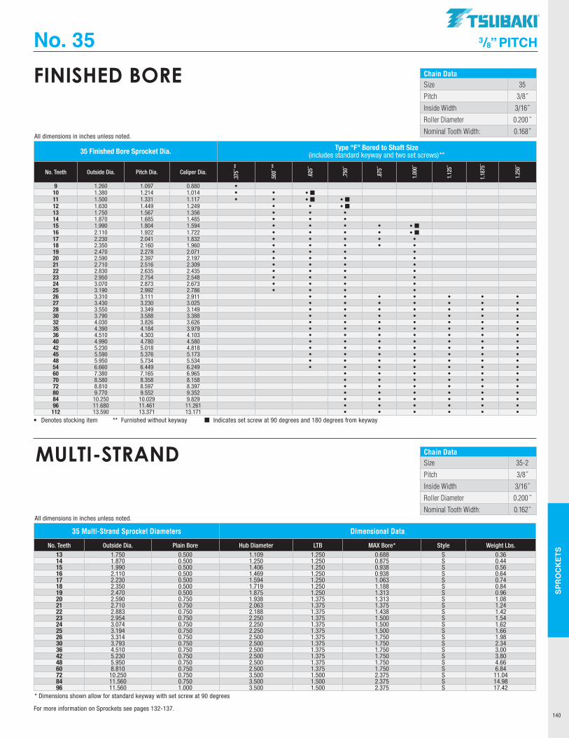
SPR
OC
KET
S
140
Chain DataSize 35
Pitch 3/8˝
Inside Width 3/16˝
Roller Diameter 0.200˝
Nominal Tooth Width: 0.168˝
FINISHED BORE
No. 35 3/8” PITCH
35 Finished Bore Sprocket Dia. Type “F” Bored to Shaft Size (includes standard keyway and two set screws)**
No. Teeth Outside Dia. Pitch Dia. Caliper Dia.
.375
˝ **
.500
˝ **
.625
˝
.750
˝
.875
˝
1.00
0˝
1.12
5˝
1.18
75˝
1.25
0˝
9 1.260 1.097 0.880 •10 1.380 1.214 1.014 • • • ¢11 1.500 1.331 1.117 • • • ¢ • ¢12 1.630 1.449 1.249 • • • ¢13 1.750 1.567 1.356 • • •14 1.870 1.685 1.485 • • •15 1.990 1.804 1.594 • • • • • ¢16 2.110 1.922 1.722 • • • • • ¢17 2.230 2.041 1.832 • • • • •18 2.350 2.160 1.960 • • • • •19 2.470 2.278 2.071 • • • •20 2.590 2.397 2.197 • • • •21 2.710 2.516 2.309 • • • •22 2.830 2.635 2.435 • • • •23 2.950 2.754 2.548 • • • •24 3.070 2.873 2.673 • • • •25 3.190 2.992 2.786 • • • •26 3.310 3.111 2.911 • • • • • • •27 3.430 3.230 3.025 • • • • • • •28 3.550 3.349 3.149 • • • • • • •30 3.790 3.588 3.388 • • • • • • •32 4.030 3.826 3.626 • • • • • • •35 4.390 4.184 3.979 • • • • • • •36 4.510 4.303 4.103 • • • • • • •40 4.990 4.780 4.580 • • • • • • •42 5.230 5.018 4.818 • • • • • • •45 5.590 5.376 5.173 • • • • • • •48 5.950 5.734 5.534 • • • • • • •54 6.660 6.449 6.249 • • • • • • •60 7.380 7.165 6.965 • • • • • •70 8.580 8.358 8.158 • • • • • •72 8.810 8.597 8.397 • • • • • •80 9.770 9.552 9.352 • • • • • •84 10.250 10.029 9.829 • • • • • •96 11.680 11.461 11.261 • • • • • •112 13.590 13.371 13.171 • • • • • •
• Denotes stocking item ** Furnished without keyway ¢ Indicates set screw at 90 degrees and 180 degrees from keyway
All dimensions in inches unless noted.
Chain DataSize 35-2
Pitch 3/8˝
Inside Width 3/16˝
Roller Diameter 0.200˝
Nominal Tooth Width: 0.162˝
MULTI-STRAND
35 Multi-Strand Sprocket Diameters Dimensional Data
No. Teeth Outside Dia. Plain Bore Hub Diameter LTB MAX Bore* Style Weight Lbs. 13 1.750 0.500 1.109 1.250 0.688 S 0.3614 1.870 0.500 1.250 1.250 0.875 S 0.4415 1.990 0.500 1.406 1.250 0.938 S 0.5616 2.110 0.500 1.469 1.250 0.938 S 0.6417 2.230 0.500 1.594 1.250 1.063 S 0.7418 2.350 0.500 1.719 1.250 1.188 S 0.8419 2.470 0.500 1.875 1.250 1.313 S 0.9620 2.590 0.750 1.938 1.375 1.313 S 1.0821 2.710 0.750 2.063 1.375 1.375 S 1.2422 2.883 0.750 2.188 1.375 1.438 S 1.4223 2.954 0.750 2.250 1.375 1.500 S 1.5424 3.074 0.750 2.250 1.375 1.500 S 1.6225 3.194 0.750 2.250 1.375 1.500 S 1.6626 3.314 0.750 2.500 1.375 1.750 S 1.9830 3.793 0.750 2.500 1.375 1.750 S 2.3436 4.510 0.750 2.500 1.375 1.750 S 3.0042 5.230 0.750 2.500 1.375 1.750 S 3.8048 5.950 0.750 2.500 1.375 1.750 S 4.6660 8.810 0.750 2.500 1.375 1.750 S 6.8472 10.250 0.750 3.500 1.500 2.375 S 11.0484 11.560 0.750 3.500 1.500 2.375 S 14.9896 11.560 1.000 3.500 1.500 2.375 S 17.42
* Dimensions shown allow for standard keyway with set screw at 90 degrees
All dimensions in inches unless noted.
For more information on Sprockets see pages 132-137.
TSUBAKI"
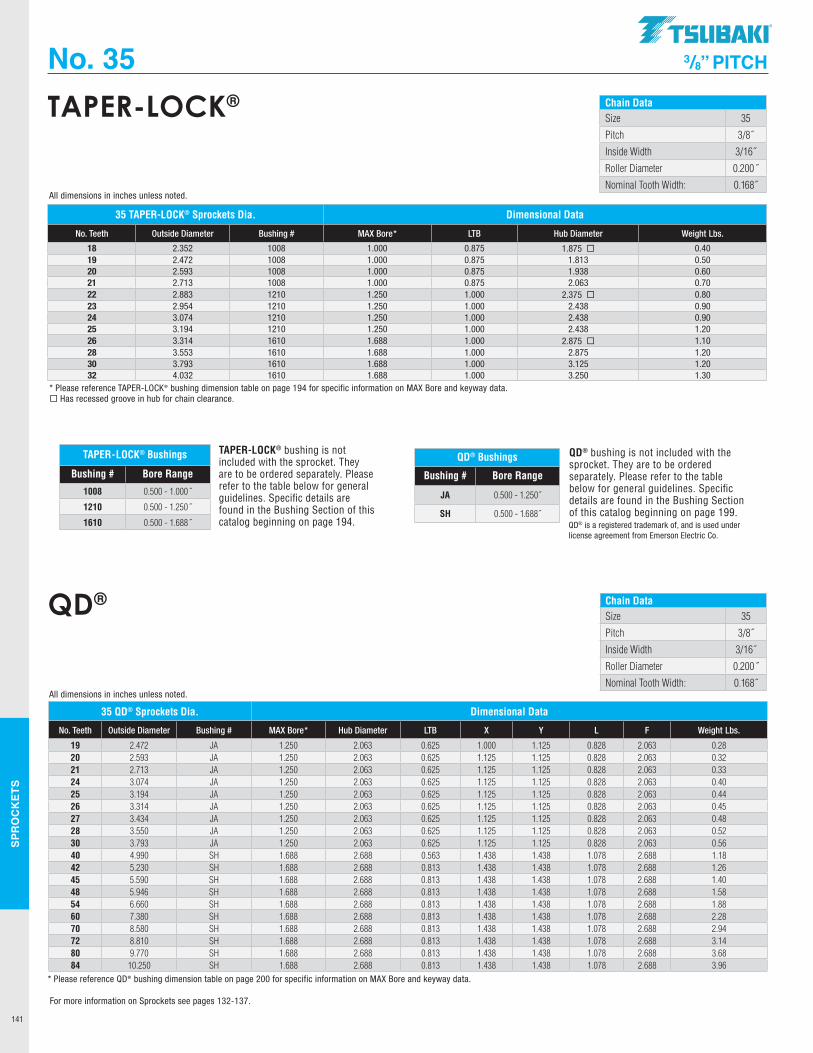
SPR
OC
KET
S
141
Chain DataSize 35
Pitch 3/8˝
Inside Width 3/16˝
Roller Diameter 0.200˝
Nominal Tooth Width: 0.168˝
TAPER-LOCK®
No. 35 3/8” PITCH
TAPER-LOCK® bushing is not included with the sprocket. They are to be ordered separately. Please refer to the table below for general guidelines. Specific details are found in the Bushing Section of this catalog beginning on page 194.
TAPER-LOCK® Bushings
Bushing # Bore Range
1008 0.500 - 1.000˝
1210 0.500 - 1.250˝
1610 0.500 - 1.688˝
35 TAPER-LOCK® Sprockets Dia. Dimensional Data
No. Teeth Outside Diameter Bushing # MAX Bore* LTB Hub Diameter Weight Lbs.
18 2.352 1008 1.000 0.875 1.875 ¨ 0.4019 2.472 1008 1.000 0.875 1.813 0.5020 2.593 1008 1.000 0.875 1.938 0.6021 2.713 1008 1.000 0.875 2.063 0.7022 2.883 1210 1.250 1.000 2.375 ¨ 0.8023 2.954 1210 1.250 1.000 2.438 0.9024 3.074 1210 1.250 1.000 2.438 0.9025 3.194 1210 1.250 1.000 2.438 1.2026 3.314 1610 1.688 1.000 2.875 ¨ 1.1028 3.553 1610 1.688 1.000 2.875 1.2030 3.793 1610 1.688 1.000 3.125 1.2032 4.032 1610 1.688 1.000 3.250 1.30
* Please reference TAPER-LOCK® bushing dimension table on page 194 for specific information on MAX Bore and keyway data.¨ Has recessed groove in hub for chain clearance.
All dimensions in inches unless noted.
Chain DataSize 35
Pitch 3/8˝
Inside Width 3/16˝
Roller Diameter 0.200˝
Nominal Tooth Width: 0.168˝
QD®
QD® bushing is not included with the sprocket. They are to be ordered separately. Please refer to the table below for general guidelines. Specific details are found in the Bushing Section of this catalog beginning on page 199.
35 QD® Sprockets Dia. Dimensional Data
No. Teeth Outside Diameter Bushing # MAX Bore* Hub Diameter LTB X Y L F Weight Lbs.
19 2.472 JA 1.250 2.063 0.625 1.000 1.125 0.828 2.063 0.2820 2.593 JA 1.250 2.063 0.625 1.125 1.125 0.828 2.063 0.3221 2.713 JA 1.250 2.063 0.625 1.125 1.125 0.828 2.063 0.3324 3.074 JA 1.250 2.063 0.625 1.125 1.125 0.828 2.063 0.4025 3.194 JA 1.250 2.063 0.625 1.125 1.125 0.828 2.063 0.4426 3.314 JA 1.250 2.063 0.625 1.125 1.125 0.828 2.063 0.4527 3.434 JA 1.250 2.063 0.625 1.125 1.125 0.828 2.063 0.4828 3.550 JA 1.250 2.063 0.625 1.125 1.125 0.828 2.063 0.5230 3.793 JA 1.250 2.063 0.625 1.125 1.125 0.828 2.063 0.5640 4.990 SH 1.688 2.688 0.563 1.438 1.438 1.078 2.688 1.1842 5.230 SH 1.688 2.688 0.813 1.438 1.438 1.078 2.688 1.2645 5.590 SH 1.688 2.688 0.813 1.438 1.438 1.078 2.688 1.4048 5.946 SH 1.688 2.688 0.813 1.438 1.438 1.078 2.688 1.5854 6.660 SH 1.688 2.688 0.813 1.438 1.438 1.078 2.688 1.8860 7.380 SH 1.688 2.688 0.813 1.438 1.438 1.078 2.688 2.2870 8.580 SH 1.688 2.688 0.813 1.438 1.438 1.078 2.688 2.9472 8.810 SH 1.688 2.688 0.813 1.438 1.438 1.078 2.688 3.1480 9.770 SH 1.688 2.688 0.813 1.438 1.438 1.078 2.688 3.6884 10.250 SH 1.688 2.688 0.813 1.438 1.438 1.078 2.688 3.96
* Please reference QD® bushing dimension table on page 200 for specific information on MAX Bore and keyway data.
All dimensions in inches unless noted.
QD® Bushings
Bushing # Bore Range
JA 0.500 - 1.250˝
SH 0.500 - 1.688˝QD® is a registered trademark of, and is used under license agreement from Emerson Electric Co.
For more information on Sprockets see pages 132-137.
.TSUBAKI"
----------
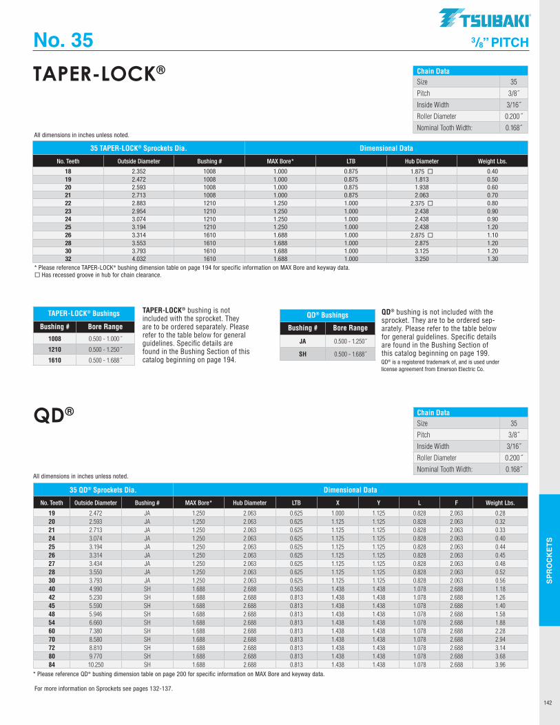
SPR
OC
KET
S
142
Chain DataSize 35
Pitch 3/8˝
Inside Width 3/16˝
Roller Diameter 0.200˝
Nominal Tooth Width: 0.168˝
TAPER-LOCK®
No. 35 3/8” PITCH
TAPER-LOCK® bushing is not included with the sprocket. They are to be ordered separately. Please refer to the table below for general guidelines. Specific details are found in the Bushing Section of this catalog beginning on page 194.
TAPER-LOCK® Bushings
Bushing # Bore Range
1008 0.500 - 1.000˝
1210 0.500 - 1.250˝
1610 0.500 - 1.688˝
35 TAPER-LOCK® Sprockets Dia. Dimensional Data
No. Teeth Outside Diameter Bushing # MAX Bore* LTB Hub Diameter Weight Lbs.
18 2.352 1008 1.000 0.875 1.875 ¨ 0.4019 2.472 1008 1.000 0.875 1.813 0.5020 2.593 1008 1.000 0.875 1.938 0.6021 2.713 1008 1.000 0.875 2.063 0.7022 2.883 1210 1.250 1.000 2.375 ¨ 0.8023 2.954 1210 1.250 1.000 2.438 0.9024 3.074 1210 1.250 1.000 2.438 0.9025 3.194 1210 1.250 1.000 2.438 1.2026 3.314 1610 1.688 1.000 2.875 ¨ 1.1028 3.553 1610 1.688 1.000 2.875 1.2030 3.793 1610 1.688 1.000 3.125 1.2032 4.032 1610 1.688 1.000 3.250 1.30
* Please reference TAPER-LOCK® bushing dimension table on page 194 for specific information on MAX Bore and keyway data.¨ Has recessed groove in hub for chain clearance.
All dimensions in inches unless noted.
Chain DataSize 35
Pitch 3/8˝
Inside Width 3/16˝
Roller Diameter 0.200˝
Nominal Tooth Width: 0.168˝
QD®
QD® bushing is not included with the sprocket. They are to be ordered sep-arately. Please refer to the table below for general guidelines. Specific details are found in the Bushing Section of this catalog beginning on page 199.
35 QD® Sprockets Dia. Dimensional Data
No. Teeth Outside Diameter Bushing # MAX Bore* Hub Diameter LTB X Y L F Weight Lbs.
19 2.472 JA 1.250 2.063 0.625 1.000 1.125 0.828 2.063 0.2820 2.593 JA 1.250 2.063 0.625 1.125 1.125 0.828 2.063 0.3221 2.713 JA 1.250 2.063 0.625 1.125 1.125 0.828 2.063 0.3324 3.074 JA 1.250 2.063 0.625 1.125 1.125 0.828 2.063 0.4025 3.194 JA 1.250 2.063 0.625 1.125 1.125 0.828 2.063 0.4426 3.314 JA 1.250 2.063 0.625 1.125 1.125 0.828 2.063 0.4527 3.434 JA 1.250 2.063 0.625 1.125 1.125 0.828 2.063 0.4828 3.550 JA 1.250 2.063 0.625 1.125 1.125 0.828 2.063 0.5230 3.793 JA 1.250 2.063 0.625 1.125 1.125 0.828 2.063 0.5640 4.990 SH 1.688 2.688 0.563 1.438 1.438 1.078 2.688 1.1842 5.230 SH 1.688 2.688 0.813 1.438 1.438 1.078 2.688 1.2645 5.590 SH 1.688 2.688 0.813 1.438 1.438 1.078 2.688 1.4048 5.946 SH 1.688 2.688 0.813 1.438 1.438 1.078 2.688 1.5854 6.660 SH 1.688 2.688 0.813 1.438 1.438 1.078 2.688 1.8860 7.380 SH 1.688 2.688 0.813 1.438 1.438 1.078 2.688 2.2870 8.580 SH 1.688 2.688 0.813 1.438 1.438 1.078 2.688 2.9472 8.810 SH 1.688 2.688 0.813 1.438 1.438 1.078 2.688 3.1480 9.770 SH 1.688 2.688 0.813 1.438 1.438 1.078 2.688 3.6884 10.250 SH 1.688 2.688 0.813 1.438 1.438 1.078 2.688 3.96
* Please reference QD® bushing dimension table on page 200 for specific information on MAX Bore and keyway data.
All dimensions in inches unless noted.
QD® Bushings
Bushing # Bore Range
JA 0.500 - 1.250˝
SH 0.500 - 1.688˝QD® is a registered trademark of, and is used under license agreement from Emerson Electric Co.
For more information on Sprockets see pages 132-137.
TSUBAKI"
-----------
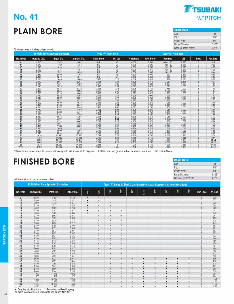
SPR
OC
KET
S
143
Chain DataSize 41Pitch 1/2˝Inside Width 1/4˝Roller Diameter 0.306˝Nominal Tooth Width: 0.227˝
PLAIN BORE
No. 41 1/2” PITCH
41 Plain Bore Sprocket Diameters Type “A” Plain Bore Type “B” Plain Bore
No. Teeth Outside Dia. Pitch Dia. Caliper Dia. Plain Bore Wt. Lbs. Plain Bore MAX Bore* Hub Dia. LTB Style Wt. Lbs. 8 1.510 1.307 1.002 NS NS 0.500 0.500 0.984 ¨ 0.875 S 0.199 1.670 1.462 1.134 NS NS 0.500 0.625 1.125 ¨ 0.875 S 0.2010 1.840 1.618 1.312 NS NS 0.500 0.750 1.250 ¨ 0.875 S 0.2711 2.000 1.775 1.451 NS NS 0.500 0.875 1.438 ¨ 0.875 S 0.3512 2.170 1.932 1.626 NS NS 0.500 0.938 1.563 ¨ 0.875 S 0.4413 2.330 2.089 1.768 NS NS 0.500 1.000 1.563 0.875 S 0.5014 2.490 2.247 1.941 NS NS 0.500 1.250 1.750 0.875 S 0.5715 2.650 2.405 2.086 0.625 0.28 0.500 1.313 1.906 0.875 S 0.7216 2.810 2.563 2.257 0.625 0.34 0.625 1.375 2.063 0.875 S 0.9117 2.980 2.721 2.403 0.625 0.36 0.625 1.500 2.234 1.000 S 1.0918 3.140 2.879 2.573 0.625 0.44 0.625 1.625 2.375 1.000 S 1.2519 3.300 3.038 2.722 0.625 0.46 0.625 1.750 2.469 1.000 S 1.4920 3.460 3.355 2.890 0.625 0.52 0.625 1.875 2.750 1.000 S 1.6421 3.620 3.513 3.040 0.625 0.60 0.625 1.875 2.875 1.000 E 1.8122 3.780 3.672 3.207 0.625 0.66 0.625 2.000 3.000 1.000 E 1.9323 3.940 3.672 3.357 0.625 0.72 0.625 2.250 3.188 1.000 E 2.2524 4.100 3.831 3.525 0.625 0.82 0.625 2.250 3.250 1.000 E 2.3325 4.200 3.989 3.675 0.625 0.88 0.625 2.250 3.250 1.000 E 2.4626 4.418 4.148 3.842 0.625 0.94 0.625 2.250 3.250 1.000 E 2.5027 4.580 4.307 3.994 0.625 1.00 0.625 2.250 3.250 1.000 E 2.5628 4.740 4.465 4.159 0.625 1.08 0.625 2.250 3.250 1.000 E 2.6430 5.060 4.783 4.477 0.594 1.20 0.625 2.250 3.250 1.000 E 2.8032 5.380 5.101 4.794 0.594 1.44 0.625 2.250 3.250 1.000 E 2.9635 5.860 5.578 5.266 0.594 1.70 0.625 2.375 3.250 1.000 E 3.1236 6.020 5.737 5.431 0.594 1.84 0.625 2.375 3 .250 1.000 E 3.3240 6.650 6.373 6.067 0.719 2.22 0.750 2.375 3.250 1.063 E 4.0642 6.970 6.691 6.385 0.719 2.50 0.750 2.375 3.500 1.063 E 4.1045 7.450 7.168 6.858 0.719 2.52 0.750 2.375 3.500 1.063 E 4.1848 7.930 7.645 7.339 0.719 2.92 0.750 2.375 3.500 1.063 E 4.9254 8.880 8.599 8.294 0.719 3.54 0.750 2.375 3.500 1.063 E 5.6860 9.840 9.544 9.246 0.719 4.60 0.750 2.375 3.500 1.063 E 6.7870 11.430 11.145 10.840 0.719 6.22 0.750 2.750 4.000 1.188 E 9.5472 11.750 11.463 11.156 0.719 6.32 0.750 2.750 4.000 1.188 E 9.6480 13.030 12.736 12.430 0.719 8.46 0.750 2.750 4.000 1.188 E 11.5484 13.660 13.372 13.067 0.719 9.12 0.750 2.750 4.000 1.188 E 12.2096 15.570 15.282 14.976 0.938 11.84 1.000 2.750 4.000 1.188 E 14.86
112 18.120 17.827 17.522 0.938 15.84 1.000 2.750 4.000 1.188 E 19.16
* Dimensions shown allow for standard keyway with set screw at 90 degrees. ¨ Has recessed groove in hub for chain clearance. NS = Non Stock
All dimensions in inches unless noted.
Chain DataSize 41Pitch 1/2˝Inside Width 1/4˝Roller Diameter 0.306˝Nominal Tooth Width: 0.227˝
FINISHED BORE
41 Finished Bore Sprocket Diameters Type “F” Bored to Shaft Size (includes standard keyway and two set screws)
No.Teeth Outside Dia. Pitch Dia. Caliper Dia.
.500
˝ **
.625
˝
.750
˝
1.00
0˝
1.12
5˝
1.18
88˝
1.25
0˝
1.37
5˝
1.43
8˝
1.50
0˝Hub Style Wt. Lbs.
9 1.670 1.462 1.134 • • S 0.2010 1.840 1.618 1.312 • • S 0.2711 2.000 1.775 1.451 • • • S 0.3512 2.170 1.932 1.626 • • • S 0.4413 2.330 2.089 1.768 • • • • S 0.5014 2.490 2.247 1.941 • • • • S 0.5715 2.650 2.405 2.086 • • • • S 0.7216 2.810 2.563 2.257 • • • S 0.9117 2.980 2.721 2.403 • • • S 1.0918 3.140 2.879 2.573 • • • S 1.2519 3.300 3.038 2.722 • • • S 1.4920 3.460 3.196 2.890 • • • S 1.6421 3.620 3.355 3.040 • • • E 1.8122 3.780 3.513 3.207 • • • E 1.9323 3.940 3.672 3.357 • • • E 2.2524 4.100 3.831 3.525 • • • E 2.3325 4.200 3.989 3.675 • • • E 2.4626 4.418 4.148 3.842 • • • E 2.5027 4.580 4.307 3.994 • • • E 2.5628 4.740 4.465 4.159 • • • E 2.6430 5.060 4.783 4.477 • • • E 2.8032 5.380 5.101 4.794 • • • E 2.9635 5.860 5.578 5.266 • • • E 3.1236 6.020 5.737 5.431 • • • E 3.3240 6.650 6.373 6.067 • • • • • • • • E 4.0642 6.970 6.691 6.385 • • • • • • • • E 4.1045 7.450 7.168 6.858 • • • • • • • • E 4.1848 7.930 7.645 7.339 • • • • • • • • E 4.9254 8.880 8.599 8.294 • • • • • • • • E 5.6860 9.840 9.544 9.246 • • • • • • • • E 6.7870 11.430 11.145 10.840 • • • • • • • • E 9.5472 11.750 11.463 11.156 • • • • • • • • E 9.6480 13.030 12.736 12.430 • • • • • • • • E 11.5484 13.660 13.372 13.067 • • • • • • • • E 12.2096 15.570 15.282 14.976 • • • • • • • E 14.86112 18.120 17.827 17.522 • • • • • • • E 19.16
• Denotes stocking item ** Furnished without keyway
All dimensions in inches unless noted.
For more information on Sprockets see pages 132-137.
.TSUBAKI"
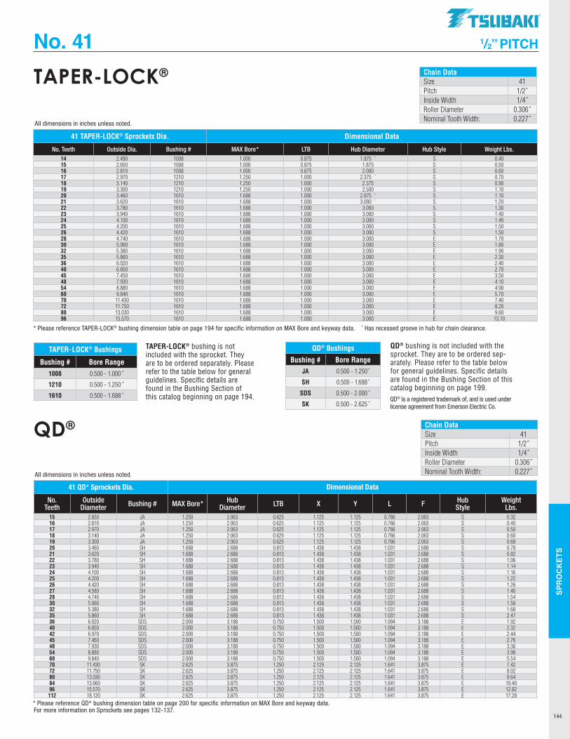
SPR
OC
KET
S
144
Chain DataSize 41Pitch 1/2˝Inside Width 1/4˝Roller Diameter 0.306˝Nominal Tooth Width: 0.227˝
TAPER-LOCK®
No. 41 1/2” PITCH
TAPER-LOCK® bushing is not included with the sprocket. They are to be ordered separately. Please refer to the table below for general guidelines. Specific details are found in the Bushing Section of this catalog beginning on page 194.
TAPER-LOCK® Bushings
Bushing # Bore Range1008 0.500 - 1.000˝
1210 0.500 - 1.250˝
1610 0.500 - 1.688˝
41 TAPER-LOCK® Sprockets Dia. Dimensional Data
No. Teeth Outside Dia. Bushing # MAX Bore* LTB Hub Diameter Hub Style Weight Lbs. 14 2.490 1008 1.000 0.875 1.875 ¨ S 0.4015 2.650 1008 1.000 0.875 1.875 S 0.5016 2.810 1008 1.000 0.875 2.000 S 0.6017 2.970 1210 1.250 1.000 2.375 ¨ S 0.7018 3.140 1210 1.250 1.000 2.375 S 0.9019 3.300 1210 1.250 1.000 2.500 S 1.1020 3.460 1610 1.688 1.000 2.875 ¨ S 1.1021 3.620 1610 1.688 1.000 3.000 ¨ S 1.2022 3.780 1610 1.688 1.000 3.000 S 1.3023 3.940 1610 1.688 1.000 3.000 S 1.4024 4.100 1610 1.688 1.000 3.000 S 1.4025 4.200 1610 1.688 1.000 3.000 S 1.5026 4.420 1610 1.688 1.000 3.000 S 1.5028 4.740 1610 1.688 1.000 3.000 E 1.7030 5.060 1610 1.688 1.000 3.000 E 1.8032 5.380 1610 1.688 1.000 3.000 E 1.9035 5.860 1610 1.688 1.000 3.000 E 2.3036 6.020 1610 1.688 1.000 3.000 E 2.4040 6.650 1610 1.688 1.000 3.000 E 2.7045 7.450 1610 1.688 1.000 3.000 E 3.5048 7.930 1610 1.688 1.000 3.000 E 4.1054 8.880 1610 1.688 1.000 3.000 E 4.9060 9.840 1610 1.688 1.000 3.000 E 5.7070 11.430 1610 1.688 1.000 3.000 E 7.4072 11.750 1610 1.688 1.000 3.000 E 8.2080 13.030 1610 1.688 1.000 3.000 E 9.6096 15.570 1610 1.688 1.000 3.000 E 13.10
* Please reference TAPER-LOCK® bushing dimension table on page 194 for specific information on MAX Bore and keyway data. ¨ Has recessed groove in hub for chain clearance.
All dimensions in inches unless noted.
Chain DataSize 41Pitch 1/2˝Inside Width 1/4˝Roller Diameter 0.306˝Nominal Tooth Width: 0.227˝
QD®
QD® Bushings
Bushing # Bore RangeJA 0.500 - 1.250˝
SH 0.500 - 1.688˝
SDS 0.500 - 2.000˝
SK 0.500 - 2.625˝
41 QD® Sprockets Dia. Dimensional Data
No. Teeth
Outside Diameter Bushing # MAX Bore* Hub
Diameter LTB X Y L F Hub Style
Weight Lbs.
15 2.650 JA 1.250 2.063 0.625 1.125 1.125 0.766 2.063 S 0.3216 2.810 JA 1.250 2.063 0.625 1.125 1.125 0.766 2.063 S 0.4017 2.970 JA 1.250 2.063 0.625 1.125 1.125 0.766 2.063 S 0.5018 3.140 JA 1.250 2.063 0.625 1.125 1.125 0.766 2.063 S 0.6019 3.300 JA 1.250 2.063 0.625 1.125 1.125 0.766 2.063 S 0.6820 3.460 SH 1.688 2.688 0.813 1.438 1.438 1.031 2.688 S 0.7821 3.620 SH 1.688 2.688 0.813 1.438 1.438 1.031 2.688 S 0.8222 3.780 SH 1.688 2.688 0.813 1.438 1.438 1.031 2.688 S 1.0623 3.940 SH 1.688 2.688 0.813 1.438 1.438 1.031 2.688 S 1.1424 4.100 SH 1.688 2.688 0.813 1.438 1.438 1.031 2.688 S 1.1625 4.200 SH 1.688 2.688 0.813 1.438 1.438 1.031 2.688 S 1.2226 4.420 SH 1.688 2.688 0.813 1.438 1.438 1.031 2.688 S 1.2627 4.580 SH 1.688 2.688 0.813 1.438 1.438 1.031 2.688 S 1.4028 4.740 SH 1.688 2.688 0.813 1.438 1.438 1.031 2.688 S 1.5430 5.060 SH 1.688 2.688 0.813 1.438 1.438 1.031 2.688 S 1.5832 5.380 SH 1.688 2.688 0.813 1.438 1.438 1.031 2.688 S 1.6835 5.860 SH 1.688 2.688 0.813 1.438 1.438 1.031 2.688 S 2.4736 6.020 SDS 2.000 3.188 0.750 1.500 1.500 1.094 3.188 E 1.9240 6.650 SDS 2.000 3.188 0.750 1.500 1.500 1.094 3.188 E 2.3242 6.970 SDS 2.000 3.188 0.750 1.500 1.500 1.094 3.188 E 2.4445 7.450 SDS 2.000 3.188 0.750 1.500 1.500 1.094 3.188 E 2.7648 7.930 SDS 2.000 3.188 0.750 1.500 1.500 1.094 3.188 E 3.3654 8.880 SDS 2.000 3.188 0.750 1.500 1.500 1.094 3.188 E 3.9860 9.840 SDS 2.000 3.188 0.750 1.500 1.500 1.094 3.188 E 5.5470 11.430 SK 2.625 3.875 1.250 2.125 2.125 1.641 3.875 E 7.4272 11.750 SK 2.625 3.875 1.250 2.125 2.125 1.641 3.875 E 8.0280 13.030 SK 2.625 3.875 1.250 2.125 2.125 1.641 3.875 E 9.6484 13.660 SK 2.625 3.875 1.250 2.125 2.125 1.641 3.875 E 10.4096 15.570 SK 2.625 3.875 1.250 2.125 2.125 1.641 3.875 E 12.82112 18.120 SK 2.625 3.875 1.250 2.125 2.125 1.641 3.875 E 17.28
* Please reference QD® bushing dimension table on page 200 for specific information on MAX Bore and keyway data.
All dimensions in inches unless noted.
QD® bushing is not included with the sprocket. They are to be ordered sep-arately. Please refer to the table below for general guidelines. Specific details are found in the Bushing Section of this catalog beginning on page 199. QD® is a registered trademark of, and is used under license agreement from Emerson Electric Co.
For more information on Sprockets see pages 132-137.
TSUBAKI"
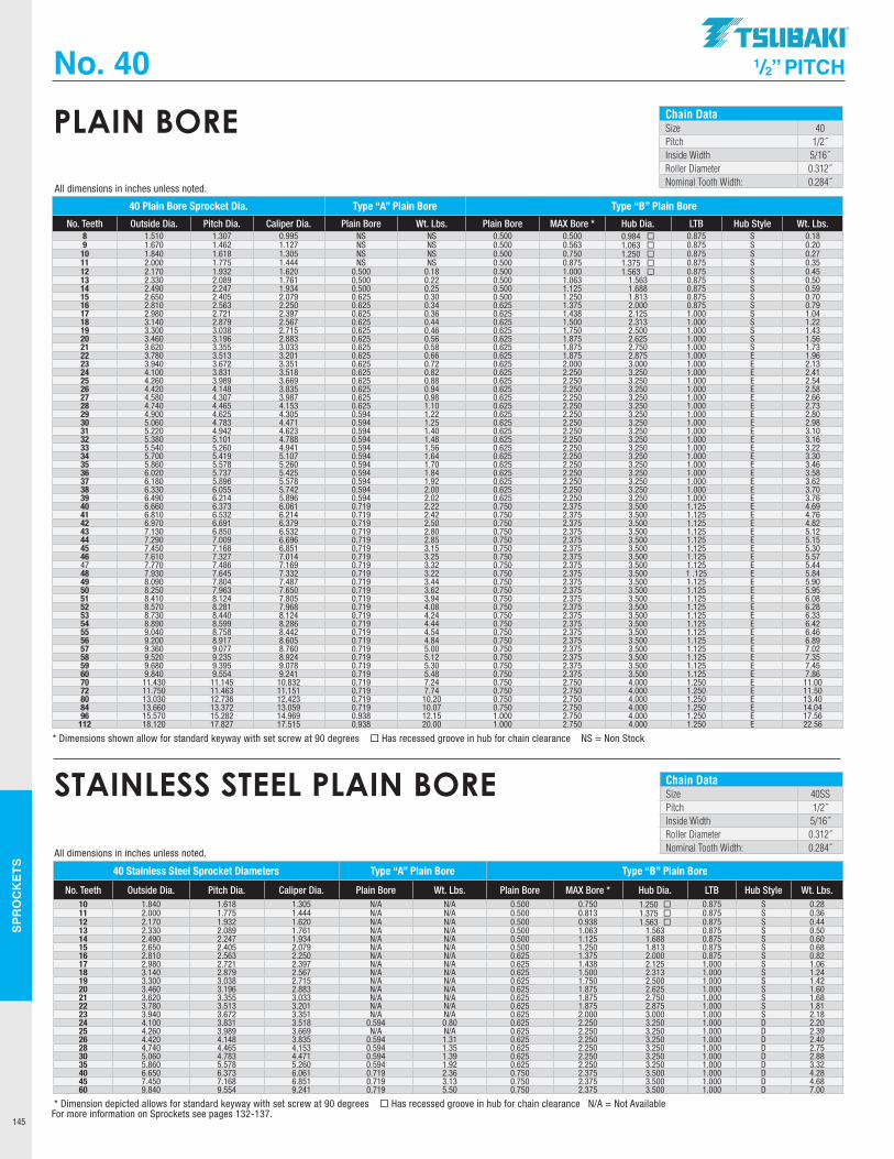
SPR
OC
KET
S
145
Chain DataSize 40Pitch 1/2˝Inside Width 5/16˝Roller Diameter 0.312˝Nominal Tooth Width: 0.284˝
PLAIN BORE
No. 40 1/2” PITCH
40 Plain Bore Sprocket Dia. Type “A” Plain Bore Type “B” Plain Bore
No. Teeth Outside Dia. Pitch Dia. Caliper Dia. Plain Bore Wt. Lbs. Plain Bore MAX Bore * Hub Dia. LTB Hub Style Wt. Lbs. 8 1.510 1.307 0.995 NS NS 0.500 0.500 0.984 ¨ 0.875 S 0.189 1.670 1.462 1.127 NS NS 0.500 0.563 1.063 ¨ 0.875 S 0.2010 1.840 1.618 1.305 NS NS 0.500 0.750 1.250 ¨ 0.875 S 0.2711 2.000 1.775 1.444 NS NS 0.500 0.875 1.375 ¨ 0.875 S 0.3512 2.170 1.932 1.620 0.500 0.18 0.500 1.000 1.563 ¨ 0.875 S 0.4513 2.330 2.089 1.761 0.500 0.22 0.500 1.063 1.563 0.875 S 0.5014 2.490 2.247 1.934 0.500 0.25 0.500 1.125 1.688 0.875 S 0.5915 2.650 2.405 2.079 0.625 0.30 0.500 1.250 1.813 0.875 S 0.7016 2.810 2.563 2.250 0.625 0.34 0.625 1.375 2.000 0.875 S 0.7917 2.980 2.721 2.397 0.625 0.36 0.625 1.438 2.125 1.000 S 1.0418 3.140 2.879 2.567 0.625 0.44 0.625 1.500 2.313 1.000 S 1.2219 3.300 3.038 2.715 0.625 0.46 0.625 1.750 2.500 1.000 S 1.4320 3.460 3.196 2.883 0.625 0.56 0.625 1.875 2.625 1.000 S 1.5621 3.620 3.355 3.033 0.625 0.58 0.625 1.875 2.750 1.000 S 1.7322 3.780 3.513 3.201 0.625 0.66 0.625 1.875 2.875 1.000 E 1.9623 3.940 3.672 3.351 0.625 0.72 0.625 2.000 3.000 1.000 E 2.1324 4.100 3.831 3.518 0.625 0.82 0.625 2.250 3.250 1.000 E 2.4125 4.260 3.989 3.669 0.625 0.88 0.625 2.250 3.250 1.000 E 2.5426 4.420 4.148 3.835 0.625 0.94 0.625 2.250 3.250 1.000 E 2.5827 4.580 4.307 3.987 0.625 0.98 0.625 2.250 3.250 1.000 E 2.6628 4.740 4.465 4.153 0.625 1.10 0.625 2.250 3.250 1.000 E 2.7329 4.900 4.625 4.305 0.594 1.22 0.625 2.250 3.250 1.000 E 2.8030 5.060 4.783 4.471 0.594 1.25 0.625 2.250 3.250 1.000 E 2.9831 5.220 4.942 4.623 0.594 1.40 0.625 2.250 3.250 1.000 E 3.1032 5.380 5.101 4.788 0.594 1.48 0.625 2.250 3.250 1.000 E 3.1633 5.540 5.260 4.941 0.594 1.56 0.625 2.250 3.250 1.000 E 3.2234 5.700 5.419 5.107 0.594 1.64 0.625 2.250 3.250 1.000 E 3.3035 5.860 5.578 5.260 0.594 1.70 0.625 2.250 3.250 1.000 E 3.4636 6.020 5.737 5.425 0.594 1.84 0.625 2.250 3.250 1.000 E 3.5837 6.180 5.896 5.578 0.594 1.92 0.625 2.250 3.250 1.000 E 3.6238 6.330 6.055 5.742 0.594 2.00 0.625 2.250 3.250 1.000 E 3.7039 6.490 6.214 5.896 0.594 2.02 0.625 2.250 3.250 1.000 E 3.7640 6.660 6.373 6.061 0.719 2.22 0.750 2.375 3.500 1.125 E 4.6941 6.810 6.532 6.214 0.719 2.42 0.750 2.375 3.500 1.125 E 4.7642 6.970 6.691 6.379 0.719 2.50 0.750 2.375 3.500 1.125 E 4.8243 7.130 6.850 6.532 0.719 2.80 0.750 2.375 3.500 1.125 E 5.1244 7.290 7.009 6.696 0.719 2.85 0.750 2.375 3.500 1.125 E 5.1545 7.450 7.168 6.851 0.719 3.15 0.750 2.375 3.500 1.125 E 5.3046 7.610 7.327 7.014 0.719 3.25 0.750 2.375 3.500 1.125 E 5.5747 7.770 7.486 7.169 0.719 3.32 0.750 2.375 3.500 1.125 E 5.4448 7.930 7.645 7.332 0.719 3.22 0.750 2.375 3.500 1 .125 E 5.8449 8.090 7.804 7.487 0.719 3.44 0.750 2.375 3.500 1.125 E 5.9050 8.250 7.963 7.650 0.719 3.62 0.750 2.375 3.500 1.125 E 5.9551 8.410 8.124 7.805 0.719 3.94 0.750 2.375 3.500 1.125 E 6.0852 8.570 8.281 7.968 0.719 4.08 0.750 2.375 3.500 1.125 E 6.2853 8.730 8.440 8.124 0.719 4.24 0.750 2.375 3.500 1.125 E 6.3354 8.890 8.599 8.286 0.719 4.44 0.750 2.375 3.500 1.125 E 6.4255 9.040 8.758 8.442 0.719 4.54 0.750 2.375 3.500 1.125 E 6.4656 9.200 8.917 8.605 0.719 4.84 0.750 2.375 3.500 1.125 E 6.8957 9.360 9.077 8.760 0.719 5.00 0.750 2.375 3.500 1.125 E 7.0258 9.520 9.235 8.924 0.719 5.12 0.750 2.375 3.500 1.125 E 7.3559 9.680 9.395 9.078 0.719 5.30 0.750 2.375 3.500 1.125 E 7.4560 9.840 9.554 9.241 0.719 5.48 0.750 2.375 3.500 1.125 E 7.8670 11.430 11.145 10.832 0.719 7.24 0.750 2.750 4.000 1.250 E 11.0072 11.750 11.463 11.151 0.719 7.74 0.750 2.750 4.000 1.250 E 11.5080 13.030 12.736 12.423 0.719 10.20 0.750 2.750 4.000 1.250 E 13.4084 13.660 13.372 13.059 0.719 10.07 0.750 2.750 4.000 1.250 E 14.0496 15.570 15.282 14.969 0.938 12.15 1.000 2.750 4.000 1.250 E 17.56112 18.120 17.827 17.515 0.938 20.00 1.000 2.750 4.000 1.250 E 22.56
* Dimensions shown allow for standard keyway with set screw at 90 degrees ¨ Has recessed groove in hub for chain clearance NS = Non Stock
All dimensions in inches unless noted.
Chain DataSize 40SSPitch 1/2˝Inside Width 5/16˝Roller Diameter 0.312˝Nominal Tooth Width: 0.284˝
STAINLESS STEEL PLAIN BORE
40 Stainless Steel Sprocket Diameters Type “A” Plain Bore Type “B” Plain Bore
No. Teeth Outside Dia. Pitch Dia. Caliper Dia. Plain Bore Wt. Lbs. Plain Bore MAX Bore * Hub Dia. LTB Hub Style Wt. Lbs.10 1.840 1.618 1.305 N/A N/A 0.500 0.750 1.250 0.875 S 0.2811 2.000 1.775 1.444 N/A N/A 0.500 0.813 1.375 0.875 S 0.3612 2.170 1.932 1.620 N/A N/A 0.500 0.938 1.563 0.875 S 0.4413 2.330 2.089 1.761 N/A N/A 0.500 1.063 1.563 0.875 S 0.5014 2.490 2.247 1.934 N/A N/A 0.500 1.125 1.688 0.875 S 0.6015 2.650 2.405 2.079 N/A N/A 0.500 1.250 1.813 0.875 S 0.6816 2.810 2.563 2.250 N/A N/A 0.625 1.375 2.000 0.875 S 0.8217 2.980 2.721 2.397 N/A N/A 0.625 1.438 2.125 1.000 S 1.0618 3.140 2.879 2.567 N/A N/A 0.625 1.500 2.313 1.000 S 1.2419 3.300 3.038 2.715 N/A N/A 0.625 1.750 2.500 1.000 S 1.4220 3.460 3.196 2.883 N/A N/A 0.625 1.875 2.625 1.000 S 1.6021 3.620 3.355 3.033 N/A N/A 0.625 1.875 2.750 1.000 S 1.6822 3.780 3.513 3.201 N/A N/A 0.625 1.875 2.875 1.000 S 1.8123 3.940 3.672 3.351 N/A N/A 0.625 2.000 3.000 1.000 S 2.1824 4.100 3.831 3.518 0.594 0.80 0.625 2.250 3.250 1.000 D 2.2025 4.260 3.989 3.669 N/A N/A 0.625 2.250 3.250 1.000 D 2.3926 4.420 4.148 3.835 0.594 1.31 0.625 2.250 3.250 1.000 D 2.4028 4.740 4.465 4.153 0.594 1.35 0.625 2.250 3.250 1.000 D 2.7530 5.060 4.783 4.471 0.594 1.39 0.625 2.250 3.250 1.000 D 2.8835 5.860 5.578 5.260 0.594 1.92 0.625 2.250 3.250 1.000 D 3.3240 6.650 6.373 6.061 0.719 2.36 0.750 2.375 3.500 1.000 D 4.2845 7.450 7.168 6.851 0.719 3.13 0.750 2.375 3.500 1.000 D 4.6860 9.840 9.554 9.241 0.719 5.50 0.750 2.375 3.500 1.000 D 7.00
* Dimension depicted allows for standard keyway with set screw at 90 degrees ¨ Has recessed groove in hub for chain clearance N/A = Not Available
All dimensions in inches unless noted.
For more information on Sprockets see pages 132-137.
.TSUBAKI"
-----------
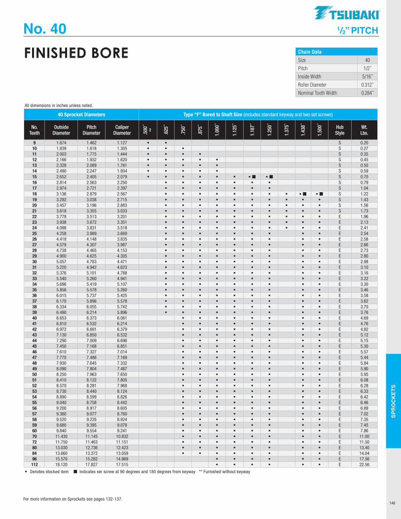
SPR
OC
KET
S
146
Chain Data
Size 40
Pitch 1/2˝
Inside Width 5/16˝
Roller Diameter 0.312˝
Nominal Tooth Width: 0.284˝
FINISHED BORE
No. 40 1/2” PITCH
40 Sprocket Diameters Type “F” Bored to Shaft Size (includes standard keyway and two set screws)
No. Teeth
Outside Diameter
Pitch Diameter
Caliper Diameter .5
00˝
**
.625
˝
.750
˝
.875
˝
1.00
0˝
1.12
5˝
1.18
7˝
1.25
0˝
1.37
5˝
1.43
8˝
1.50
0˝ Hub Style
Wt. Lbs.
9 1.674 1.462 1.127 • • S 0.2010 1.839 1.618 1.305 • • • S 0.2711 2.003 1.775 1.444 • • • • S 0.3512 2.166 1.932 1.620 • • • • • S 0.4513 2.328 2.089 1.761 • • • • • S 0.5014 2.490 2.247 1.934 • • • • • S 0.5915 2.652 2.405 2.079 • • • • • • • ¢ • ¢ S 0.7016 2.814 2.563 2.250 • • • • • • • S 0.7917 2.974 2.721 2.397 • • • • • • • S 1.0418 3.136 2.879 2.567 • • • • • • • • • ¢ • ¢ S 1.2219 3.292 3.038 2.715 • • • • • • • • • • S 1.4320 3.457 3.196 2.883 • • • • • • • • • • S 1.5621 3.618 3.355 3.033 • • • • • • • • • • S 1.7322 3.778 3.513 3.201 • • • • • • • • • • E 1.9623 3.938 3.672 3.351 • • • • • • • • • • E 2.1324 4.098 3.831 3.518 • • • • • • • • • • E 2.4125 4.258 3.989 3.669 • • • • • • • • • E 2.5426 4.418 4.148 3.835 • • • • • • • • • E 2.5827 4.578 4.307 3.987 • • • • • • • • • E 2.6628 4.738 4.465 4.153 • • • • • • • • • E 2.7329 4.900 4.625 4.305 • • • • • • • • • E 2.8030 5.057 4.783 4.471 • • • • • • • • • E 2.9831 5.220 4.942 4.623 • • • • • • • • • E 3.1032 5.376 5.101 4.788 • • • • • • • • • E 3.1633 5.540 5.260 4.941 • • • • • • • • • E 3.2234 5.696 5.419 5.107 • • • • • • • • • E 3.3035 5.856 5.578 5.260 • • • • • • • • • E 3.4636 6.015 5.737 5.425 • • • • • • • • • E 3.5837 6.170 5.896 5.578 • • • • • • • • • E 3.6238 6.334 6.055 5.742 • • • • • • • • • E 3.7039 6.490 6.214 5.896 • • • • • • • • • E 3.7640 6.653 6.373 6.061 • • • • • • • • E 4.6941 6.810 6.532 6.214 • • • • • • • • E 4.7642 6.972 6.691 6.379 • • • • • • • • E 4.8243 7.130 6.850 6.532 • • • • • • • • E 5.1244 7.290 7.009 6.696 • • • • • • • • E 5.1545 7.450 7.168 6.851 • • • • • • • • E 5.3046 7.610 7.327 7.014 • • • • • • • • E 5.5747 7.770 7.486 7.169 • • • • • • • • E 5.4448 7.930 7.645 7.332 • • • • • • • • E 5.8449 8.090 7.804 7.487 • • • • • • • • E 5.9050 8.250 7.963 7.650 • • • • • • • • E 5.9551 8.410 8.122 7.805 • • • • • • • • E 6.0852 8.570 8.281 7.968 • • • • • • • • E 6.2853 8.730 8.440 8.124 • • • • • • • • E 6.3354 8.890 8.599 8.826 • • • • • • • • E 6.4255 9.040 8.758 8.442 • • • • • • • • E 6.4656 9.200 8.917 8.605 • • • • • • • • E 6.8957 9.360 9.077 8.760 • • • • • • • • E 7.0258 9.520 9.235 8.924 • • • • • • • • E 7.3559 9.680 9.395 9.078 • • • • • • • • E 7.4560 9.840 9.554 9.241 • • • • • • • • E 7.8670 11.430 11.145 10.832 • • • • • • • • E 11.0072 11.750 11.463 11.151 • • • • • • • • E 11.5080 13.030 12.736 12.423 • • • • • • • • E 13.4084 13.660 13.372 13.059 • • • • • • • • E 14.0496 15.570 15.282 14.969 • • • • • • E 17.56112 18.120 17.827 17.515 • • • • • • E 22.56
• Denotes stocked item ¢ Indicates ser screw at 90 degrees and 180 degrees from keyway ** Furnished without keyway
All dimensions in inches unless noted.
For more information on Sprockets see pages 132-137.
TSUBAKI"
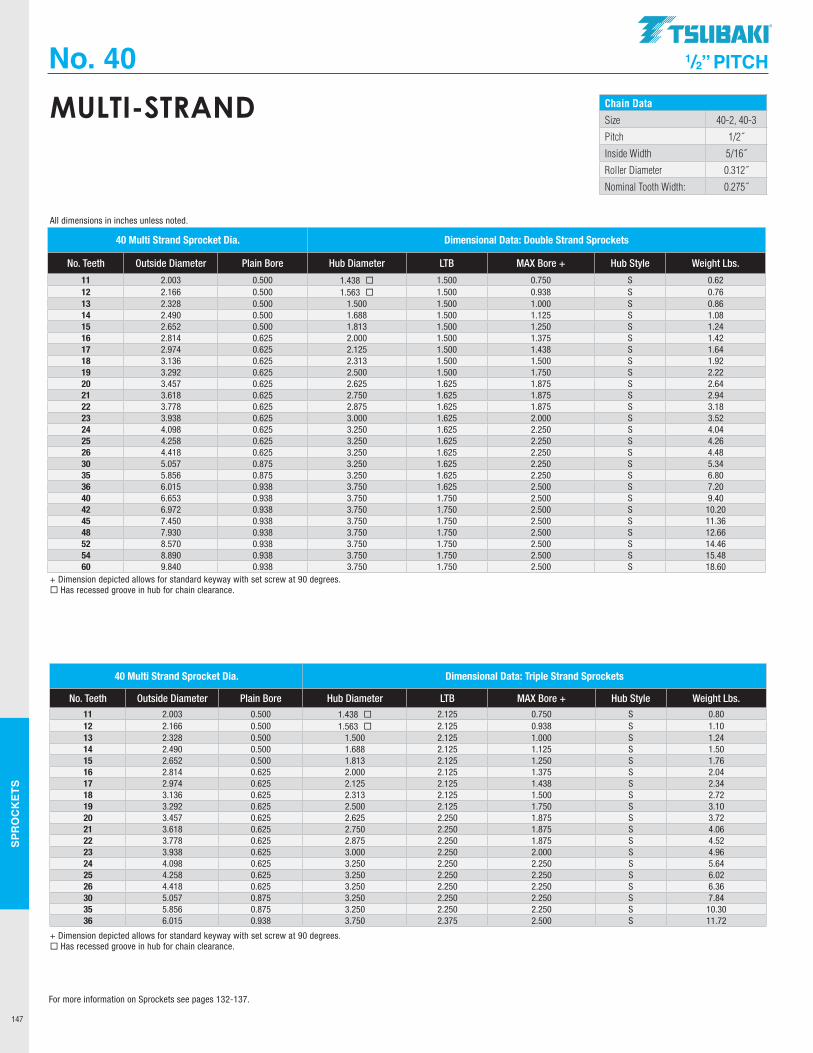
SPR
OC
KET
S
147
Chain Data
Size 40-2, 40-3
Pitch 1/2˝
Inside Width 5/16˝
Roller Diameter 0.312˝
Nominal Tooth Width: 0.275˝
MULTI-STRAND
No. 40 1/2” PITCH
40 Multi Strand Sprocket Dia. Dimensional Data: Double Strand Sprockets
No. Teeth Outside Diameter Plain Bore Hub Diameter LTB MAX Bore + Hub Style Weight Lbs.
11 2.003 0.500 1.438 1.500 0.750 S 0.6212 2.166 0.500 1.563 1.500 0.938 S 0.7613 2.328 0.500 1.500 1.500 1.000 S 0.8614 2.490 0.500 1.688 1.500 1.125 S 1.0815 2.652 0.500 1.813 1.500 1.250 S 1.2416 2.814 0.625 2.000 1.500 1.375 S 1.4217 2.974 0.625 2.125 1.500 1.438 S 1.6418 3.136 0.625 2.313 1.500 1.500 S 1.9219 3.292 0.625 2.500 1.500 1.750 S 2.2220 3.457 0.625 2.625 1.625 1.875 S 2.6421 3.618 0.625 2.750 1.625 1.875 S 2.9422 3.778 0.625 2.875 1.625 1.875 S 3.1823 3.938 0.625 3.000 1.625 2.000 S 3.5224 4.098 0.625 3.250 1.625 2.250 S 4.0425 4.258 0.625 3.250 1.625 2.250 S 4.2626 4.418 0.625 3.250 1.625 2.250 S 4.4830 5.057 0.875 3.250 1.625 2.250 S 5.3435 5.856 0.875 3.250 1.625 2.250 S 6.8036 6.015 0.938 3.750 1.625 2.500 S 7.2040 6.653 0.938 3.750 1.750 2.500 S 9.4042 6.972 0.938 3.750 1.750 2.500 S 10.2045 7.450 0.938 3.750 1.750 2.500 S 11.3648 7.930 0.938 3.750 1.750 2.500 S 12.6652 8.570 0.938 3.750 1.750 2.500 S 14.4654 8.890 0.938 3.750 1.750 2.500 S 15.4860 9.840 0.938 3.750 1.750 2.500 S 18.60
40 Multi Strand Sprocket Dia. Dimensional Data: Triple Strand Sprockets
No. Teeth Outside Diameter Plain Bore Hub Diameter LTB MAX Bore + Hub Style Weight Lbs. 11 2.003 0.500 1.438 2.125 0.750 S 0.8012 2.166 0.500 1.563 2.125 0.938 S 1.1013 2.328 0.500 1.500 2.125 1.000 S 1.2414 2.490 0.500 1.688 2.125 1.125 S 1.5015 2.652 0.500 1.813 2.125 1.250 S 1.7616 2.814 0.625 2.000 2.125 1.375 S 2.0417 2.974 0.625 2.125 2.125 1.438 S 2.3418 3.136 0.625 2.313 2.125 1.500 S 2.7219 3.292 0.625 2.500 2.125 1.750 S 3.1020 3.457 0.625 2.625 2.250 1.875 S 3.7221 3.618 0.625 2.750 2.250 1.875 S 4.0622 3.778 0.625 2.875 2.250 1.875 S 4.5223 3.938 0.625 3.000 2.250 2.000 S 4.9624 4.098 0.625 3.250 2.250 2.250 S 5.6425 4.258 0.625 3.250 2.250 2.250 S 6.0226 4.418 0.625 3.250 2.250 2.250 S 6.3630 5.057 0.875 3.250 2.250 2.250 S 7.8435 5.856 0.875 3.250 2.250 2.250 S 10.3036 6.015 0.938 3.750 2.375 2.500 S 11.72
+ Dimension depicted allows for standard keyway with set screw at 90 degrees.¨ Has recessed groove in hub for chain clearance.
+ Dimension depicted allows for standard keyway with set screw at 90 degrees.¨ Has recessed groove in hub for chain clearance.
All dimensions in inches unless noted.
For more information on Sprockets see pages 132-137.
.TSUBAKI"
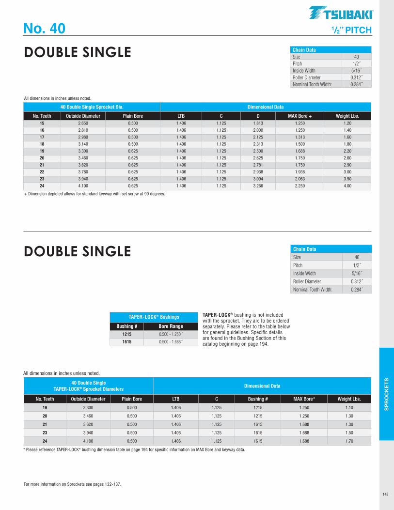
SPR
OC
KET
S
148
Chain DataSize 40Pitch 1/2˝Inside Width 5/16˝Roller Diameter 0.312˝Nominal Tooth Width: 0.284˝
DOUBLE SINGLE
No. 40 1/2” PITCH
40 Double Single Sprocket Dia. Dimensional Data
No. Teeth Outside Diameter Plain Bore LTB C D MAX Bore + Weight Lbs. 15 2.650 0.500 1.406 1.125 1.813 1.250 1.20
16 2.810 0.500 1.406 1.125 2.000 1.250 1.40
17 2.980 0.500 1.406 1.125 2.125 1.313 1.60
18 3.140 0.500 1.406 1.125 2.313 1.500 1.80
19 3.300 0.625 1.406 1.125 2.500 1.688 2.20
20 3.460 0.625 1.406 1.125 2.625 1.750 2.60
21 3.620 0.625 1.406 1.125 2.781 1.750 2.90
22 3.780 0.625 1.406 1.125 2.938 1.938 3.00
23 3.940 0.625 1.406 1.125 3.094 2.063 3.50
24 4.100 0.625 1.406 1.125 3.266 2.250 4.00
+ Dimension depicted allows for standard keyway with set screw at 90 degrees.
All dimensions in inches unless noted.
TAPER-LOCK® bushing is not included with the sprocket. They are to be ordered separately. Please refer to the table below for general guidelines. Specific details are found in the Bushing Section of this catalog beginning on page 194.
TAPER-LOCK® Bushings
Bushing # Bore Range1215 0.500 - 1.250˝
1615 0.500 - 1.688˝
40 Double Single TAPER-LOCK® Sprocket Diameters
Dimensional Data
No. Teeth Outside Diameter Plain Bore LTB C Bushing # MAX Bore* Weight Lbs.
19 3.300 0.500 1.406 1.125 1215 1.250 1.10
20 3.460 0.500 1.406 1.125 1215 1.250 1.30
21 3.620 0.500 1.406 1.125 1615 1.688 1.30
23 3.940 0.500 1.406 1.125 1615 1.688 1.50
24 4.100 0.500 1.406 1.125 1615 1.688 1.70
* Please reference TAPER-LOCK® bushing dimension table on page 194 for specific information on MAX Bore and keyway data.
All dimensions in inches unless noted.
Chain Data
Size 40
Pitch 1/2˝
Inside Width 5/16˝
Roller Diameter 0.312˝
Nominal Tooth Width: 0.284˝
DOUBLE SINGLE
For more information on Sprockets see pages 132-137.
TSUBAKI"
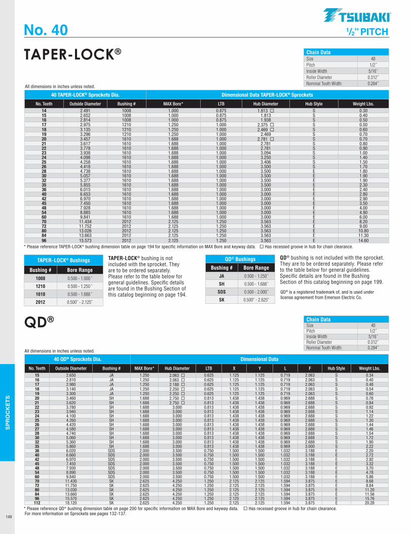
SPR
OC
KET
S
149
No. 40 1/2” PITCH
Chain DataSize 40Pitch 1/2˝Inside Width 5/16˝Roller Diameter 0.312˝Nominal Tooth Width: 0.284˝
TAPER-LOCK®
TAPER-LOCK® bushing is not included with the sprocket. They are to be ordered separately. Please refer to the table below for general guidelines. Specific details are found in the Bushing Section of this catalog beginning on page 194.
TAPER-LOCK® Bushings
Bushing # Bore Range1008 0.500 - 1.000˝
1210 0.500 - 1.250˝
1610 0.500 - 1.688˝
2012 0.500” - 2.125”
40 TAPER-LOCK® Sprockets Dia. Dimensional Data TAPER-LOCK® Sprockets
No. Teeth Outside Diameter Bushing # MAX Bore* LTB Hub Diameter Hub Style Weight Lbs. 14 2.491 1008 1.000 0.875 1.813 ¨ S 0.3015 2.652 1008 1.000 0.875 1.813 S 0.4016 2.814 1008 1.000 0.875 1.938 S 0.5017 2.975 1210 1.250 1.000 2.375 ¨ S 0.5018 3.135 1210 1.250 1.000 2.469 ¨ S 0.6019 3.296 1210 1.250 1.000 2.469 S 0.7020 3.457 1610 1.688 1.000 2.781 ¨ S 0.7021 3.617 1610 1.688 1.000 2.781 S 0.8022 3.778 1610 1.688 1.000 2.781 S 0.9023 3.938 1610 1.688 1.000 3.094 S 1.0024 4.098 1610 1.688 1.000 3.250 S 1.4025 4.258 1610 1.688 1.000 3.406 S 1.5026 4.418 1610 1.688 1.000 3.500 S 1.7028 4.738 1610 1.688 1.000 3.500 E 1.8030 5.057 1610 1.688 1.000 3.500 E 1.9032 5.377 1610 1.688 1.000 3.500 E 1.9035 5.855 1610 1.688 1.000 3.500 E 2.3036 6.015 1610 1.688 1.000 3.000 E 2.4040 6.653 1610 1.688 1.000 3.000 E 2.8042 6.970 1610 1.688 1.000 3.000 E 2.9045 7.450 1610 1.688 1.000 3.000 E 3.5048 7.928 1610 1.688 1.000 3.000 E 4.0054 8.885 1610 1.688 1.000 3.000 E 4.9060 9.841 1610 1.688 1.000 3.000 E 6.0070 11.434 2012 2.125 1.250 3.563 E 8.2072 11.752 2012 2.125 1.250 3.563 E 9.0080 13.026 2012 2.125 1.250 3.563 E 10.8084 13.663 2012 2.125 1.250 3.563 E 11.3096 15.573 2012 2.125 1.250 3.563 E 14.60
* Please reference TAPER-LOCK® bushing dimension table on page 194 for specific information on MAX Bore and keyway data. ¨ Has recessed groove in hub for chain clearance.
All dimensions in inches unless noted.
Chain DataSize 40Pitch 1/2˝Inside Width 5/16˝Roller Diameter 0.312˝Nominal Tooth Width: 0.284˝
QD®
QD® Bushings
Bushing # Bore RangeJA 0.500 - 1.250˝
SH 0.500 - 1.688˝
SDS 0.500 - 2.000˝
SK 0.500” - 2.625”
40 QD® Sprockets Dia. Dimensional Data
No. Teeth Outside Diameter Bushing # MAX Bore* Hub Diameter LTB X Y L F Hub Style Weight Lbs. 15 2.650 JA 1.250 2.063 ¨ 0.625 1.125 1.125 0.719 2.063 S 0.3416 2.810 JA 1.250 2.063 ¨ 0.625 1.125 1.125 0.719 2.063 S 0.4017 2.980 JA 1.250 2.188 ¨ 0.625 1.125 1.125 0.719 2.063 S 0.4818 3.140 JA 1.250 2.250 ¨ 0.625 1.125 1.125 0.719 2.063 S 0.5419 3.300 JA 1.250 2.250 ¨ 0.625 1.125 1.125 0.719 2.063 S 0.6020 3.460 SH 1.688 2.750 ¨ 0.813 1.438 1.438 0.969 2.688 S 0.7621 3.620 SH 1.688 2.750 ¨ 0.813 1.438 1.438 0.969 2.688 S 0.8422 3.780 SH 1.688 3.000 0.813 1.438 1.438 0.969 2.688 S 0.9223 3.940 SH 1.688 3.000 0.813 1.438 1.438 0.969 2.688 S 1.1424 4.100 SH 1.688 3.000 0.813 1.438 1.438 0.969 2.688 S 1.2225 4.260 SH 1.688 3.000 0.813 1.438 1.438 0.969 2.688 S 1.3026 4.420 SH 1.688 3.000 0.813 1.438 1.438 0.969 2.688 S 1.4427 4.580 SH 1.688 3.000 0.813 1.438 1.438 0.969 2.688 S 1.4628 4.740 SH 1.688 3.000 0.813 1.438 1.438 0.969 2.688 S 1.5430 5.060 SH 1.688 3.000 0.813 1.438 1.438 0.969 2.688 S 1.7232 5.360 SH 1.688 3.000 0.813 1.438 1.438 0.969 2.688 S 1.9035 5.860 SH 1.688 3.000 0.813 1.438 1.438 0.969 3.000 S 2.2236 6.020 SDS 2.000 3.500 0.750 1.500 1.500 1.032 3.188 E 2.2040 6.660 SDS 2.000 3.500 0.750 1.500 1.500 1.032 3.188 E 2.7242 6.970 SDS 2.000 3.500 0.750 1.500 1.500 1.032 3.188 E 2.9245 7.450 SDS 2.000 3.500 0.750 1.500 1.500 1.032 3.188 E 3.3248 7.930 SDS 2.000 3.500 0.750 1.500 1.500 1.032 3.188 E 3.7054 8.890 SDS 2.000 3.500 0.750 1.500 1.500 1.032 3.188 E 4.7860 9.840 SDS 2.000 3.500 0.750 1.500 1.500 1.032 3.188 E 5.8670 11.430 SK 2.625 4.250 1.250 2.125 2.125 1.594 3.875 E 8.6872 11.750 SK 2.625 4.250 1.250 2.125 2.125 1.594 3.875 E 8.8480 13.030 SK 2.625 4.250 1.250 2.125 2.125 1.594 3.875 E 11.2084 13.660 SK 2.625 4.250 1.250 2.125 2.125 1.594 3.875 E 11.5696 15.570 SK 2.625 4.250 1.250 2.125 2.125 1.594 3.875 E 15.76112 18.120 SK 2.625 4.250 1.250 2.125 2.125 1.594 3.875 E 20.28
* Please reference QD® bushing dimension table on page 200 for specific information on MAX Bore and keyway data. ¨ Has recessed groove in hub for chain clearance.
All dimensions in inches unless noted.
QD® bushing is not included with the sprocket. They are to be ordered separately. Please refer to the table below for general guidelines. Specific details are found in the Bushing Section of this catalog beginning on page 199.
QD® is a registered trademark of, and is used under license agreement from Emerson Electric Co.
For more information on Sprockets see pages 132-137.
.TSUBAKI"
I I
I I
----------
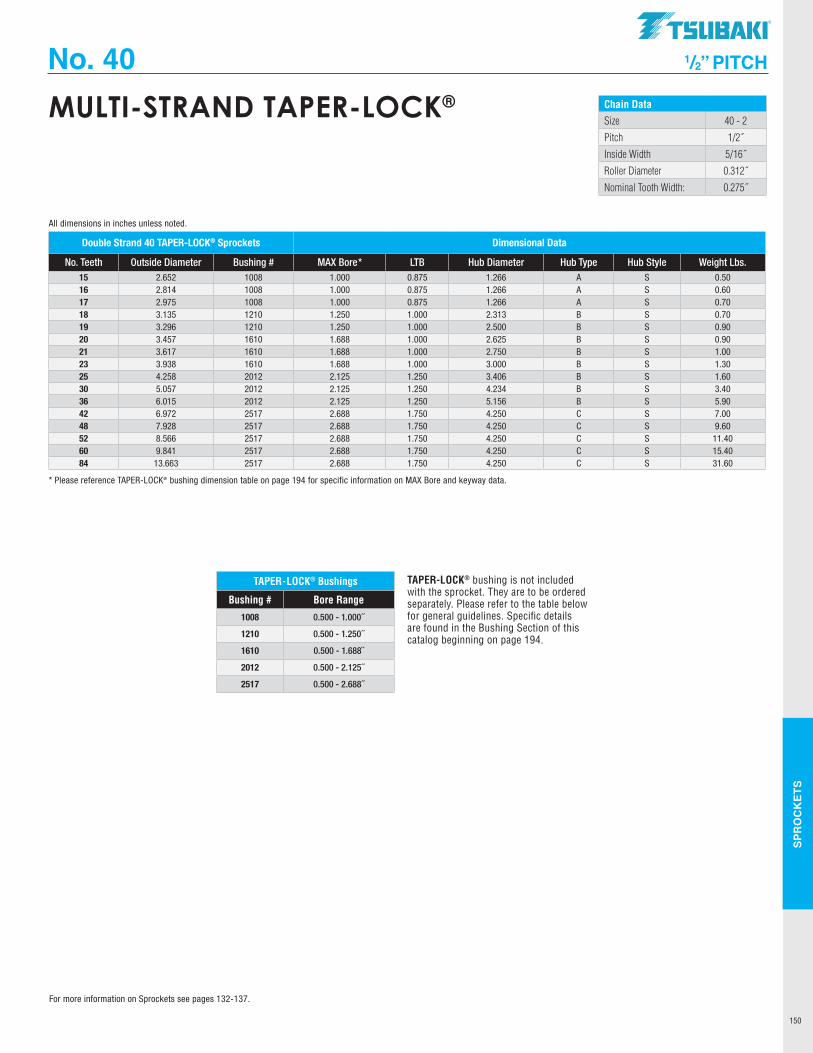
SPR
OC
KET
S
150
No. 40 1/2” PITCH
Chain DataSize 40 - 2
Pitch 1/2˝
Inside Width 5/16˝
Roller Diameter 0.312˝
Nominal Tooth Width: 0.275˝
MULTI-STRAND TAPER-LOCK®
TAPER-LOCK® Bushings
Bushing # Bore Range
1008 0.500 - 1.000˝
1210 0.500 - 1.250˝
1610 0.500 - 1.688˝
2012 0.500 - 2.125˝
2517 0.500 - 2.688˝
Double Strand 40 TAPER-LOCK® Sprockets Dimensional Data
No. Teeth Outside Diameter Bushing # MAX Bore* LTB Hub Diameter Hub Type Hub Style Weight Lbs. 15 2.652 1008 1.000 0.875 1.266 A S 0.5016 2.814 1008 1.000 0.875 1.266 A S 0.6017 2.975 1008 1.000 0.875 1.266 A S 0.7018 3.135 1210 1.250 1.000 2.313 B S 0.7019 3.296 1210 1.250 1.000 2.500 B S 0.9020 3.457 1610 1.688 1.000 2.625 B S 0.9021 3.617 1610 1.688 1.000 2.750 B S 1.0023 3.938 1610 1.688 1.000 3.000 B S 1.3025 4.258 2012 2.125 1.250 3.406 B S 1.6030 5.057 2012 2.125 1.250 4.234 B S 3.4036 6.015 2012 2.125 1.250 5.156 B S 5.9042 6.972 2517 2.688 1.750 4.250 C S 7.0048 7.928 2517 2.688 1.750 4.250 C S 9.6052 8.566 2517 2.688 1.750 4.250 C S 11.4060 9.841 2517 2.688 1.750 4.250 C S 15.4084 13.663 2517 2.688 1.750 4.250 C S 31.60
* Please reference TAPER-LOCK® bushing dimension table on page 194 for specific information on MAX Bore and keyway data.
All dimensions in inches unless noted.
TAPER-LOCK® bushing is not included with the sprocket. They are to be ordered separately. Please refer to the table below for general guidelines. Specific details are found in the Bushing Section of this catalog beginning on page 194.
For more information on Sprockets see pages 132-137.
TSUBAKI"
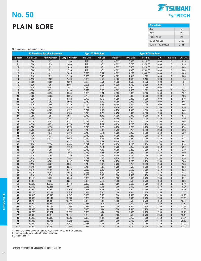
SPR
OC
KET
S
151
No. 50 5/8” PITCH
Chain DataSize 50Pitch 5/8˝Inside Width 3/8˝Roller Diameter 0.400˝Nominal Tooth Width: 0.343˝
PLAIN BORE
50 Plain Bore Sprocket Diameters Type “A” Plain Bore Type “B” Plain Bore
No. Teeth Outside Dia. Pitch Diameter Caliper Diameter Plain Bore Wt. Lbs. Plain Bore MAX Bore * Hub Dia. LTB Hub Style Wt. Lbs.
8 1.880 1.633 1.233 NS NS 0.625 0.625 1.125 ¨ 1.000 S 0.259 2.090 1.828 1.400 NS NS 0.625 0.750 1.375 ¨ 1.000 S 0.36
10 2.300 2.023 1.623 NS NS 0.625 0.875 1.313 ¨ 1.000 S 0.4811 2.500 2.219 1.796 NS NS 0.625 1.000 1.750 ¨ 1.000 S 0.6412 2.710 2.415 2.015 0.625 0.34 0.625 1.250 1.984 ¨ 1.000 S 0.8313 2.910 2.612 2.193 0.625 0.42 0.625 1.313 1.875 1.000 S 0.8814 3.110 2.809 2.409 0.625 0.50 0.625 1.438 2.125 1.000 S 1.1315 3.320 3.006 2.590 0.625 0.54 0.625 1.500 2.375 1.000 S 1.3416 3.520 3.204 2.804 0.625 0.68 0.625 1.750 2.500 1.000 S 1.5117 3.720 3.401 2.987 0.625 0.76 0.625 1.875 2.688 1.000 S 1.7418 3.920 3.599 3.199 0.625 0.86 0.625 1.875 2.875 1.000 S 2.0019 4.120 3.798 3.384 0.625 0.94 0.625 2.000 3.000 1.000 S 2.2220 4.320 3.995 3.595 0.750 1.06 0.750 2.000 3.000 1.000 S 2.2321 4.520 4.194 3.782 0.750 1.12 0.750 2.000 3.000 1.000 E 2.4022 4.720 4.392 3.992 0.750 1.30 0.750 2.000 3.000 1.000 E 2.5623 4.920 4.590 4.179 0.750 1.44 0.750 2.000 3.000 1.000 E 2.6624 5.120 4.788 4.388 0.719 1.50 0.750 2.000 3.000 1.250 E 3.3025 5.320 4.987 4.577 0.719 1.62 0.750 2.000 3.000 1.250 E 3.4026 5.520 5.185 4.785 0.719 1.72 0.750 2.000 3.000 1.250 E 3.4427 5.720 5.384 4.975 0.719 1.96 0.750 2.000 3.000 1.250 E 3.7428 5.920 5.582 5.182 0.719 2.04 0.750 2.000 3.000 1.250 E 3.8029 6.120 5.781 5.371 0.719 2.36 0.750 2.000 3.000 1.250 E 4.0630 6.320 5.979 5.579 0.719 2.54 0.750 2.250 3.250 1.250 E 4.5631 6.520 6.178 5.770 0.719 2.72 0.750 2.250 3.250 1.250 E 4.7432 6.720 6.376 5.976 0.719 2.80 0.750 2.250 3.250 1.250 E 4.9633 6.920 6.575 6.168 0.719 3.14 0.750 2.250 3.250 1.250 E 5.2034 7.120 6.774 6.374 0.719 3.20 0.750 2.250 3.250 1.250 E 5.1435 7.320 6.973 6.565 0.719 3.34 0.750 2.250 3.250 1.250 E 5.4436 7.520 7.171 6.771 0.719 3.82 0.750 2.250 3.250 1.250 E 5.6437 7.720 7.370 6.963 0.719 3.98 0.750 2.250 3.250 1.250 E 5.9038 7.920 7.569 7.169 0.719 4.14 0.750 2.250 3.250 1.250 E 6.0839 8.120 7.768 7.361 0.719 4.42 0.750 2.250 3.250 1.250 E 6.3040 8.320 7.966 7.566 0.719 4.46 0.750 2.250 3.250 1.250 E 6.5041 8.520 8.165 7.759 0.719 4.86 0.750 2.250 3.250 1.250 E 6.6442 8.720 8.364 7.964 0.719 4.98 0.750 2.250 3.250 1.250 E 6.9643 8.910 8.563 8.157 0.719 5.24 0.750 2.250 3.250 1.250 E 7.0644 9.110 8.761 8.361 0.719 5.42 0.750 2.250 3.250 1.250 E 7.5845 9.310 8.960 8.554 0.719 5.92 0.750 2.500 3.750 1.250 E 8.5846 9.510 9.159 8.759 0.938 6.42 1.000 2.500 3.750 1.250 E 8.2247 9.710 9.358 8.952 0.938 6.50 1.000 2.500 3.750 1.250 E 8.4848 9.910 9.556 9.156 0.938 6.58 1.000 2.500 3.750 1.250 E 9.2849 10.110 9.755 9.350 0.938 7.06 1.000 2.500 3.750 1.250 E 9.2250 10.310 9.954 9.554 0.938 7.10 1.000 2.500 3.750 1.250 E 9.8851 10.510 10.153 9.748 0.938 7.32 1.000 2.500 3.750 1.250 E 9.7052 10.710 10.351 9.951 0.938 7.98 1.000 2.500 3.750 1.250 E 10.2453 10.910 10.550 10.146 0.938 8.08 1.000 2.500 3.750 1.250 E 10.4854 11.110 10.749 10.349 0.938 8.30 1.000 2.500 3.750 1.250 E 11.0055 11.310 10.948 10.543 0.938 8.56 1.000 2.500 3.750 1.250 E 10.9356 11.500 11.147 10.747 0.938 8.90 1.000 2.500 3.750 1.250 E 11.5057 11.700 11.346 10.941 0.938 9.38 1.000 2.500 3.750 1.250 E 12.0058 11.900 11.544 11.144 0.938 10.30 1.000 2.500 3.750 1.250 E 11.8259 12.100 11.743 11.339 0.938 10.50 1.000 2.500 3.750 1.250 E 12.3260 12.300 11.942 11.542 0.938 10.80 1.000 2.500 3.750 1.250 E 13.0070 14.290 13.931 13.531 0.938 14.00 1.000 2.500 3.750 1.750 E 18.1672 14.690 14.329 13.929 0.938 15.24 1.000 2.500 3.750 1.750 E 19.4880 16.280 15.919 15.519 0.938 21.00 1.000 2.750 4.250 1.750 E 24.7484 17.080 16.715 16.315 0.938 22.08 1.000 2.750 4.250 1.750 E 25.5096 19.470 19.102 18.702 0.938 27.40 1.000 2.750 4.250 1.750 E 32.92
112 22.650 22.284 21.884 0.938 37.70 1.000 2.750 4.250 1.750 E 42.00
* Dimensions shown allow for standard keyway with set screw at 90 degrees.¨ Has recessed groove in hub for chain clearance.NS = Non Stock
All dimensions in inches unless noted.
For more information on Sprockets see pages 132-137.
.TSUBAKI"
-----------
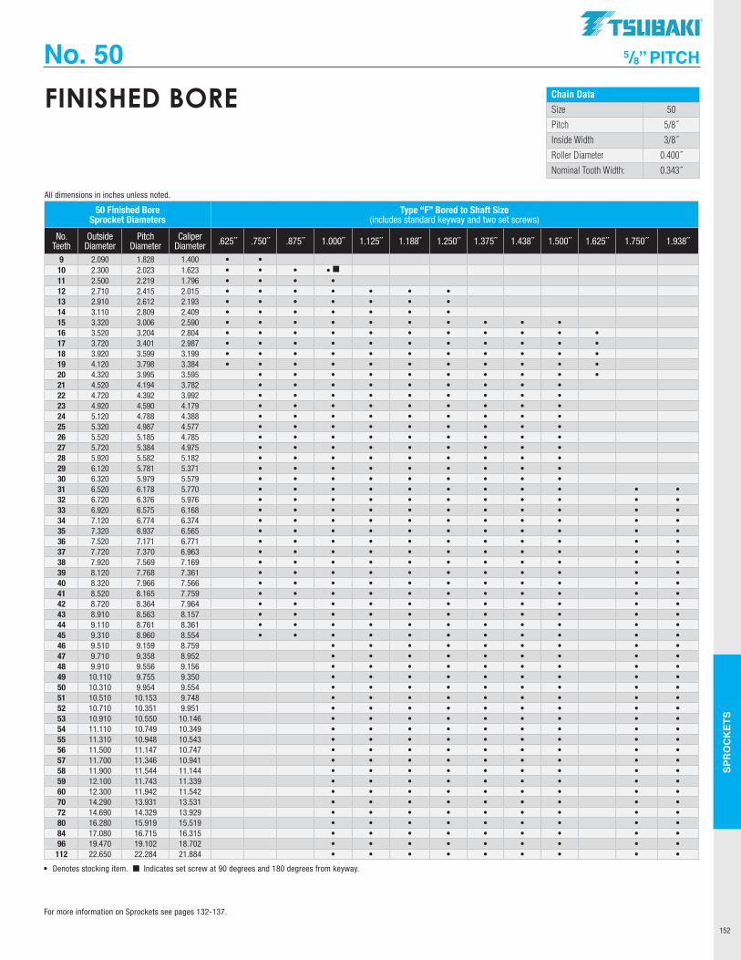
SPR
OC
KET
S
152
No. 50 5/8” PITCH
Chain Data
Size 50
Pitch 5/8˝
Inside Width 3/8˝
Roller Diameter 0.400˝
Nominal Tooth Width: 0.343˝
FINISHED BORE
50 Finished Bore Sprocket Diameters
Type “F” Bored to Shaft Size (includes standard keyway and two set screws)
No. Teeth
Outside Diameter
Pitch Diameter
Caliper Diameter .625 ˝ .750 ˝ .875 ˝ 1.000 ˝ 1.125 ˝ 1.188˝ 1.250 ˝ 1.375 ˝ 1.438 ˝ 1.500 ˝ 1.625 ˝ 1.750 ˝ 1.938 ˝
9 2.090 1.828 1.400 • •10 2.300 2.023 1.623 • • • • ¢11 2.500 2.219 1.796 • • • •12 2.710 2.415 2.015 • • • • • • •13 2.910 2.612 2.193 • • • • • • •14 3.110 2.809 2.409 • • • • • • •15 3.320 3.006 2.590 • • • • • • • • • •16 3.520 3.204 2.804 • • • • • • • • • • •17 3.720 3.401 2.987 • • • • • • • • • • •18 3.920 3.599 3.199 • • • • • • • • • • •19 4.120 3.798 3.384 • • • • • • • • • • •20 4.320 3.995 3.595 • • • • • • • • • •21 4.520 4.194 3.782 • • • • • • • • •22 4.720 4.392 3.992 • • • • • • • • •23 4.920 4.590 4.179 • • • • • • • • •24 5.120 4.788 4.388 • • • • • • • • •25 5.320 4.987 4.577 • • • • • • • • •26 5.520 5.185 4.785 • • • • • • • • •27 5.720 5.384 4.975 • • • • • • • • •28 5.920 5.582 5.182 • • • • • • • • •29 6.120 5.781 5.371 • • • • • • • • •30 6.320 5.979 5.579 • • • • • • • • •31 6.520 6.178 5.770 • • • • • • • • • • •32 6.720 6.376 5.976 • • • • • • • • • • •33 6.920 6.575 6.168 • • • • • • • • • • •34 7.120 6.774 6.374 • • • • • • • • • • •35 7.320 6.937 6.565 • • • • • • • • • • •36 7.520 7.171 6.771 • • • • • • • • • • •37 7.720 7.370 6.963 • • • • • • • • • • •38 7.920 7.569 7.169 • • • • • • • • • • •39 8.120 7.768 7.361 • • • • • • • • • • •40 8.320 7.966 7.566 • • • • • • • • • • •41 8.520 8.165 7.759 • • • • • • • • • • •42 8.720 8.364 7.964 • • • • • • • • • • •43 8.910 8.563 8.157 • • • • • • • • • • •44 9.110 8.761 8.361 • • • • • • • • • • •45 9.310 8.960 8.554 • • • • • • • • • • •46 9.510 9.159 8.759 • • • • • • • • •47 9.710 9.358 8.952 • • • • • • • • •48 9.910 9.556 9.156 • • • • • • • • •49 10.110 9.755 9.350 • • • • • • • • •50 10.310 9.954 9.554 • • • • • • • • •51 10.510 10.153 9.748 • • • • • • • • •52 10.710 10.351 9.951 • • • • • • • • •53 10.910 10.550 10.146 • • • • • • • • •54 11.110 10.749 10.349 • • • • • • • • •55 11.310 10.948 10.543 • • • • • • • • •56 11.500 11.147 10.747 • • • • • • • • •57 11.700 11.346 10.941 • • • • • • • • •58 11.900 11.544 11.144 • • • • • • • • •59 12.100 11.743 11.339 • • • • • • • • •60 12.300 11.942 11.542 • • • • • • • • •70 14.290 13.931 13.531 • • • • • • • • •72 14.690 14.329 13.929 • • • • • • • • •80 16.280 15.919 15.519 • • • • • • • • •84 17.080 16.715 16.315 • • • • • • • • •96 19.470 19.102 18.702 • • • • • • • • •
112 22.650 22.284 21.884 • • • • • • • • •
• Denotes stocking item. ¢ Indicates set screw at 90 degrees and 180 degrees from keyway.
All dimensions in inches unless noted.
For more information on Sprockets see pages 132-137.
TSUBAKI"
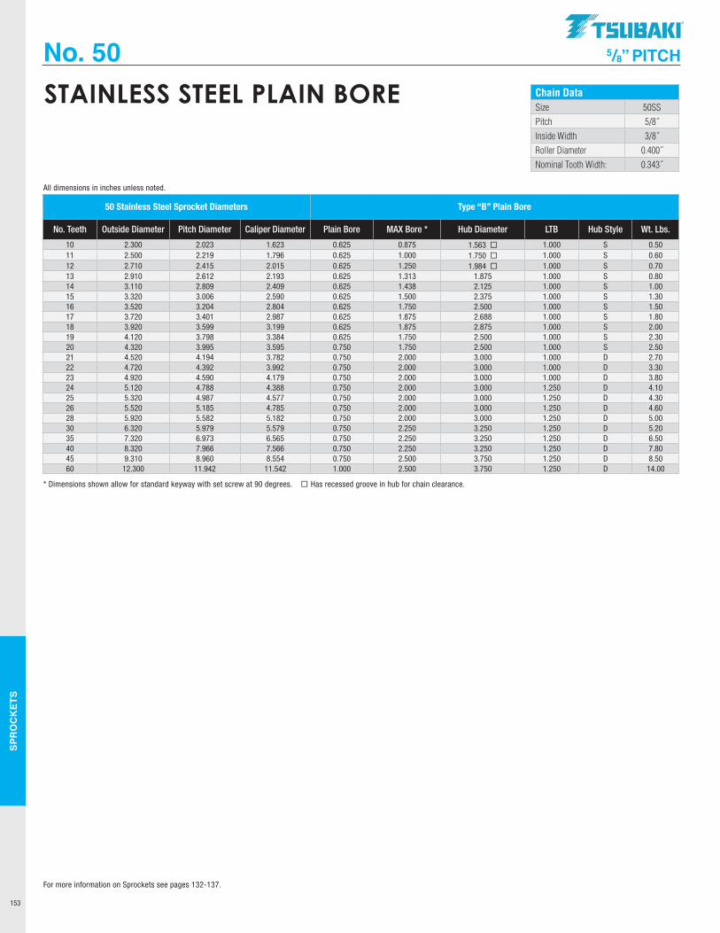
SPR
OC
KET
S
153
No. 50 5/8” PITCH
Chain DataSize 50SSPitch 5/8˝Inside Width 3/8˝Roller Diameter 0.400˝Nominal Tooth Width: 0.343˝
STAINLESS STEEL PLAIN BORE
50 Stainless Steel Sprocket Diameters Type “B” Plain Bore
No. Teeth Outside Diameter Pitch Diameter Caliper Diameter Plain Bore MAX Bore * Hub Diameter LTB Hub Style Wt. Lbs.
10 2.300 2.023 1.623 0.625 0.875 1.563 ¨ 1.000 S 0.5011 2.500 2.219 1.796 0.625 1.000 1.750 ¨ 1.000 S 0.6012 2.710 2.415 2.015 0.625 1.250 1.984 ¨ 1.000 S 0.7013 2.910 2.612 2.193 0.625 1.313 1.875 1.000 S 0.8014 3.110 2.809 2.409 0.625 1.438 2.125 1.000 S 1.0015 3.320 3.006 2.590 0.625 1.500 2.375 1.000 S 1.3016 3.520 3.204 2.804 0.625 1.750 2.500 1.000 S 1.5017 3.720 3.401 2.987 0.625 1.875 2.688 1.000 S 1.8018 3.920 3.599 3.199 0.625 1.875 2.875 1.000 S 2.0019 4.120 3.798 3.384 0.625 1.750 2.500 1.000 S 2.3020 4.320 3.995 3.595 0.750 1.750 2.500 1.000 S 2.5021 4.520 4.194 3.782 0.750 2.000 3.000 1.000 D 2.7022 4.720 4.392 3.992 0.750 2.000 3.000 1.000 D 3.3023 4.920 4.590 4.179 0.750 2.000 3.000 1.000 D 3.8024 5.120 4.788 4.388 0.750 2.000 3.000 1.250 D 4.1025 5.320 4.987 4.577 0.750 2.000 3.000 1.250 D 4.3026 5.520 5.185 4.785 0.750 2.000 3.000 1.250 D 4.6028 5.920 5.582 5.182 0.750 2.000 3.000 1.250 D 5.0030 6.320 5.979 5.579 0.750 2.250 3.250 1.250 D 5.2035 7.320 6.973 6.565 0.750 2.250 3.250 1.250 D 6.5040 8.320 7.966 7.566 0.750 2.250 3.250 1.250 D 7.8045 9.310 8.960 8.554 0.750 2.500 3.750 1.250 D 8.5060 12.300 11.942 11.542 1.000 2.500 3.750 1.250 D 14.00
* Dimensions shown allow for standard keyway with set screw at 90 degrees. ¨ Has recessed groove in hub for chain clearance.
All dimensions in inches unless noted.
For more information on Sprockets see pages 132-137.
.TSUBAKI"
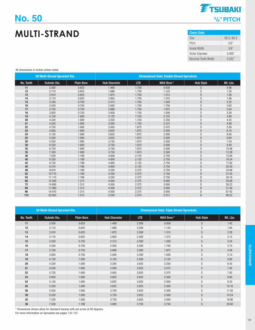
SPR
OC
KET
S
154
No. 50 5/8” PITCH
Chain Data
Size 50-2, 50-3
Pitch 5/8˝
Inside Width 3/8˝
Roller Diameter 0.400˝
Nominal Tooth Width: 0.332˝
MULTI-STRAND
50 Multi-Strand Sprocket Dia. Dimensional Data: Triple Strand Sprockets
No. Teeth Outside Dia. Plain Bore Hub Diameter LTB MAX Bore * Hub Style Wt. Lbs.
11 2.500 0.625 1.469 2.500 0.938 S 1.42
12 2.710 0.625 1.688 2.500 1.125 S 1.84
13 2.910 0.625 1.875 2.500 1.313 S 2.28
14 3.110 0.625 2.063 2.500 1.375 S 2.72
15 3.320 0.750 2.313 2.500 1.500 S 3.24
16 3.520 0.750 2.500 2.500 1.750 S 3.75
17 3.720 0.750 2.688 2.500 1.875 S 4.38
18 3.920 0.750 2.938 2.500 1.938 S 5.10
19 4.120 1.000 3.125 2.500 2.125 S 5.60
20 4.320 1.000 3.250 2.625 2.250 S 6.42
21 4.520 1.000 3.500 2.625 2.375 S 7.42
22 4.720 1.000 3.563 2.625 2.375 S 7.92
23 4.920 1.000 3.625 2.625 2.500 S 8.80
24 5.120 1.000 3.625 2.625 2.500 S 9.42
25 5.320 1.000 3.625 2.625 2.500 S 10.16
26 5.520 1.000 3.750 2.625 2.500 S 11.02
30 6.320 1.000 3.750 2.625 2.500 S 14.24
35 7.320 1.000 3.750 2.625 2.500 S 18.96
36 7.520 1.188 4.000 2.750 2.750 S 20.60
50 Multi-Strand Sprocket Dia. Dimensional Data: Double Strand Sprockets
No. Teeth Outside Dia. Plain Bore Hub Diameter LTB MAX Bore * Hub Style Wt. Lbs.11 2.500 0.625 1.469 1.750 0.938 S 0.9612 2.710 0.625 1.688 1.750 1.125 S 1.2513 2.910 0.625 1.875 1.750 1.313 S 1.5614 3.110 0.625 2.063 1.750 1.375 S 1.8615 3.320 0.750 2.313 1.750 1.500 S 2.2216 3.520 0.750 2.500 1.750 1.750 S 2.6217 3.720 0.750 2.688 1.750 1.875 S 3.0418 3.920 0.750 2.938 1.750 1.938 S 3.5819 4.120 1.000 3.125 1.750 2.125 S 3.9020 4.320 1.000 3.250 1.750 2.250 S 4.2521 4.520 1.000 3.500 1.750 2.375 S 4.9022 4.720 1.000 3.563 1.875 2.375 S 5.5823 4.920 1.000 3.625 1.875 2.500 S 6.1024 5.120 1.000 3.625 1.875 2.500 S 6.5025 5.320 1.000 3.625 1.875 2.500 S 6.9426 5.520 1.000 3.750 1.875 2.500 S 7.5430 6.320 1.000 3.750 1.875 2.500 S 9.4032 6.720 1.000 3.750 1.875 2.500 S 10.4635 7.320 1.000 3.750 1.875 2.500 S 12.2836 7.520 1.188 4.000 2.125 2.750 S 13.9440 8.320 1.188 4.000 2.125 2.750 S 16.5442 8.720 1.188 4.000 2.125 2.750 S 17.9245 9.310 1.188 4.000 2.125 2.750 S 20.3048 9.910 1.188 4.250 2.375 2.750 S 24.0852 10.710 1.188 4.250 2.375 2.750 D 27.4254 11.110 1.188 4.250 2.375 2.750 D 29.1660 12.300 1.313 4.500 2.375 3.000 D 35.8872 14.690 1.313 4.500 2.375 3.000 D 50.2284 17.080 1.313 4.500 2.375 3.000 D 51.6496 19.470 1.313 4.500 2.375 3.000 D 67.42
112 22.650 1.313 5.250 2.375 3.313 D 90.22
* Dimensions shown allow for standard keyway with set screw at 90 degrees.
All dimensions in inches unless noted.
For more information on Sprockets see pages 132-137.
TSUBAKI"
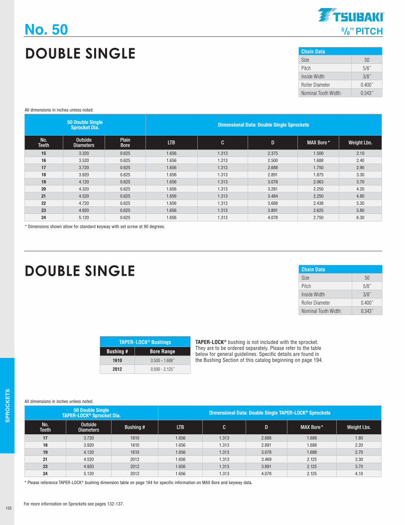
SPR
OC
KET
S
155
No. 50 5/8” PITCH
Chain Data
Size 50
Pitch 5/8˝
Inside Width 3/8˝
Roller Diameter 0.400˝
Nominal Tooth Width: 0.343˝
DOUBLE SINGLE
50 Double Single Sprocket Dia. Dimensional Data: Double Single Sprockets
No. Teeth
Outside Diameters
Plain Bore LTB C D MAX Bore * Weight Lbs.
15 3.320 0.625 1.656 1.313 2.375 1.500 2.10
16 3.520 0.625 1.656 1.313 2.500 1.688 2.40
17 3.720 0.625 1.656 1.313 2.688 1.750 2.90
18 3.920 0.625 1.656 1.313 2.891 1.875 3.30
19 4.120 0.625 1.656 1.313 3.078 2.063 3.70
20 4.320 0.625 1.656 1.313 3.281 2.250 4.20
21 4.520 0.625 1.656 1.313 3.484 2.250 4.80
22 4.720 0.625 1.656 1.313 3.688 2.438 5.30
23 4.920 0.625 1.656 1.313 3.891 2.625 5.80
24 5.120 0.625 1.656 1.313 4.078 2.750 6.30
* Dimensions shown allow for standard keyway with set screw at 90 degrees.
All dimensions in inches unless noted.
Chain Data
Size 50
Pitch 5/8˝
Inside Width 3/8˝
Roller Diameter 0.400˝
Nominal Tooth Width: 0.343˝
DOUBLE SINGLE
TAPER-LOCK® bushing is not included with the sprocket. They are to be ordered separately. Please refer to the table below for general guidelines. Specific details are found in the Bushing Section of this catalog beginning on page 194.
TAPER-LOCK® Bushings
Bushing # Bore Range
1610 0.500 - 1.688˝
2012 0.500 - 2.125˝
50 Double Single TAPER-LOCK® Sprocket Dia. Dimensional Data: Double Single TAPER-LOCK® Sprockets
No. Teeth
Outside Diameters Bushing # LTB C D MAX Bore * Weight Lbs.
17 3.720 1610 1.656 1.313 2.688 1.688 1.80
18 3.920 1610 1.656 1.313 2.891 1.688 2.20
19 4.120 1610 1.656 1.313 3.078 1.688 2.70
21 4.520 2012 1.656 1.313 3.469 2.125 3.30
23 4.920 2012 1.656 1.313 3.891 2.125 3.70
24 5.120 2012 1.656 1.313 4.078 2.125 4.10
* Please reference TAPER-LOCK® bushing dimension table on page 194 for specific information on MAX Bore and keyway data.
All dimensions in inches unless noted.
For more information on Sprockets see pages 132-137.
.TSUBAKI"
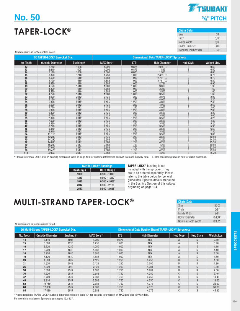
SPR
OC
KET
S
156
No. 50 5/8” PITCH
Chain DataSize 50Pitch 5/8˝Inside Width 3/8˝Roller Diameter 0.400˝Nominal Tooth Width: 0.343˝
TAPER-LOCK®
50 TAPER-LOCK® Sprocket Dia. Dimensional Data TAPER-LOCK® Sprockets
No. Teeth Outside Diameter Bushing # MAX Bore * LTB Hub Diameter Hub Style Weight Lbs. 12 2.710 1008 1.000 0.875 1.938 ¨ S 0.5013 2.910 1008 1.000 0.875 1.813 S 0.5014 3.110 1008 1.000 0.875 1.938 S 0.6015 3.320 1210 1.250 1.000 2.469 ¨ S 0.7016 3.520 1610 1.688 1.000 2.781 ¨ S 0.7017 3.720 1610 1.688 1.000 2.781 ¨ S 0.8018 3.920 1610 1.688 1.000 2.781 S 0.9019 4.120 1610 1.688 1.000 3.000 S 1.3020 4.320 1610 1.688 1.000 3.250 S 1.6021 4.520 1610 1.688 1.000 3.500 S 1.6022 4.720 1610 1.688 1.000 3.500 S 1.6023 4.920 2012 2.125 1.250 3.875 S 2.0024 5.120 2012 2.125 1.250 4.000 S 2.2025 5.320 2012 2.125 1.250 4.000 S 2.4026 5.520 2012 2.125 1.250 4.000 E 2.5027 5.720 2012 2.125 1.250 4.000 E 2.6028 5.920 2012 2.125 1.250 4.000 E 2.8030 6.320 2012 2.125 1.250 3.563 E 3.2032 6.720 2012 2.125 1.250 3.563 E 3.6035 7.320 2012 2.125 1.250 3.563 E 4.2036 7.520 2012 2.125 1.250 3.563 E 4.3040 8.320 2012 2.125 1.250 3.563 E 5.2042 8.720 2012 2.125 1.250 3.563 E 5.9045 9.310 2012 2.125 1.250 3.563 E 6.5048 9.910 2012 2.125 1.250 3.563 E 7.3054 11.110 2012 2.125 1.250 3.563 E 9.0060 12.300 2012 2.125 1.250 3.563 E 10.8070 14.290 2517 2.688 1.750 4.250 E 14.0072 14.690 2517 2.688 1.750 4.250 E 15.5080 16.280 2517 2.688 1.750 4.250 E 19.5084 17.080 2517 2.688 1.750 4.250 E 22.5096 19.470 2517 2.688 1.750 4.250 E 29.00112 22.650 2517 2.688 1.750 4.250 E 38.70
* Please reference TAPER-LOCK® bushing dimension table on page 194 for specific information on MAX Bore and keyway data. ¨ Has recessed groove in hub for chain clearance.
All dimensions in inches unless noted.
Chain DataSize 50-2Pitch 5/8˝Inside Width 3/8˝Roller Diameter 0.400˝Nominal Tooth Width: 0.332˝
MULTI-STRAND TAPER-LOCK®
TAPER-LOCK® BushingsBushing # Bore Range
1008 0.500 - 1.000˝1210 0.500 - 1.250˝1610 0.500 - 1.688˝2012 0.500 - 2.125˝2517 0.500 - 2.688˝
TAPER-LOCK® bushing is not included with the sprocket. They are to be ordered separately. Please refer to the table below for general guidelines. Specific details are found in the Bushing Section of this catalog beginning on page 194.
50 Multi-Strand TAPER-LOCK® Sprocket Dia. Dimensional Data Double Strand TAPER-LOCK® Sprockets
No. Teeth Outside Diameter Bushing # MAX Bore * LTB Hub Diameter Hub Type Hub Style Weight Lbs. 14 3.110 1008 1.000 0.875 N/A A S 0.8015 3.320 1210 1.250 1.000 N/A A S 0.9016 3.520 1210 1.250 1.000 N/A A S 1.1017 3.720 1610 1.688 1.000 N/A A S 1.1018 3.920 1610 1.688 1.000 N/A A S 1.3019 4.120 1610 1.688 1.000 N/A A S 1.6020 4.320 2012 2.125 1.250 3.250 B S 1.5021 4.520 2012 2.125 1.250 3.500 B S 1.9025 5.320 2012 2.125 1.250 4.281 B S 3.8030 6.320 2517 2.688 1.750 5.281 B S 7.5036 7.520 2517 2.688 1.750 4.250 C S 9.4042 8.720 2517 2.688 1.750 4.250 C S 13.4048 9.910 2517 2.688 1.750 4.250 C S 18.6052 10.710 2517 2.688 1.750 4.375 C S 22.2060 12.300 2517 2.688 1.750 4.375 C S 30.3084 17.080 2517 2.688 1.750 4.375 C S 45.30
* Please reference TAPER-LOCK® bushing dimension table on page 194 for specific information on MAX Bore and keyway data.
All dimensions in inches unless noted.
For more information on Sprockets see pages 132-137.
TSUBAKI"
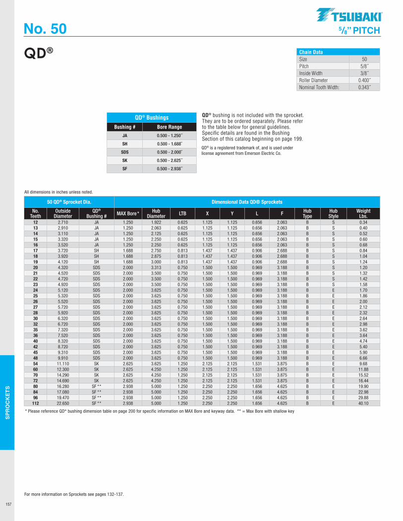
SPR
OC
KET
S
157
No. 50 5/8” PITCH
Chain DataSize 50Pitch 5/8˝Inside Width 3/8˝Roller Diameter 0.400˝Nominal Tooth Width: 0.343˝
QD®
QD® Bushings
Bushing # Bore Range
JA 0.500 - 1.250˝
SH 0.500 - 1.688˝
SDS 0.500 - 2.000˝
SK 0.500 - 2.625˝
SF 0.500 - 2.938˝
QD® bushing is not included with the sprocket. They are to be ordered separately. Please refer to the table below for general guidelines. Specific details are found in the Bushing Section of this catalog beginning on page 199.
QD® is a registered trademark of, and is used under license agreement from Emerson Electric Co.
50 QD® Sprocket Dia. Dimensional Data QD® Sprockets
No. Teeth
Outside Diameter
QD® Bushing # MAX Bore * Hub
Diameter LTB X Y L F Hub Type
Hub Style
Weight Lbs.
12 2.710 JA 1.250 1.922 0.625 1.125 1.125 0.656 2.063 B S 0.3413 2.910 JA 1.250 2.063 0.625 1.125 1.125 0.656 2.063 B S 0.4014 3.110 JA 1.250 2.125 0.625 1.125 1.125 0.656 2.063 B S 0.5215 3.320 JA 1.250 2.250 0.625 1.125 1.125 0.656 2.063 B S 0.6016 3.520 JA 1.250 2.250 0.625 1.125 1.125 0.656 2.063 B S 0.6817 3.720 SH 1.688 2.750 0.813 1.437 1.437 0.906 2.688 B S 0.8418 3.920 SH 1.688 2.875 0.813 1.437 1.437 0.906 2.688 B S 1.0419 4.120 SH 1.688 3.000 0.813 1.437 1.437 0.906 2.688 B S 1.2420 4.320 SDS 2.000 3.313 0.750 1.500 1.500 0.969 3.188 B S 1.2021 4.520 SDS 2.000 3.500 0.750 1.500 1.500 0.969 3.188 B S 1.3222 4.720 SDS 2.000 3.500 0.750 1.500 1.500 0.969 3.188 B S 1.4223 4.920 SDS 2.000 3.500 0.750 1.500 1.500 0.969 3.188 B S 1.5824 5.120 SDS 2.000 3.625 0.750 1.500 1.500 0.969 3.188 B E 1.7025 5.320 SDS 2.000 3.625 0.750 1.500 1.500 0.969 3.188 B E 1.8626 5.520 SDS 2.000 3.625 0.750 1.500 1.500 0.969 3.188 B E 2.0027 5.720 SDS 2.000 3.625 0.750 1.500 1.500 0.969 3.188 B E 2.1228 5.920 SDS 2.000 3.625 0.750 1.500 1.500 0.969 3.188 B E 2.3230 6.320 SDS 2.000 3.625 0.750 1.500 1.500 0.969 3.188 B E 2.6432 6.720 SDS 2.000 3.625 0.750 1.500 1.500 0.969 3.188 B E 2.9835 7.320 SDS 2.000 3.625 0.750 1.500 1.500 0.969 3.188 B E 3.6236 7.520 SDS 2.000 3.625 0.750 1.500 1.500 0.969 3.188 B E 3.6440 8.320 SDS 2.000 3.625 0.750 1.500 1.500 0.969 3.188 B E 4.7442 8.720 SDS 2.000 3.625 0.750 1.500 1.500 0.969 3.188 B E 5.4045 9.310 SDS 2.000 3.625 0.750 1.500 1.500 0.969 3.188 B E 5.9048 9.910 SDS 2.000 3.625 0.750 1.500 1.500 0.969 3.188 B E 6.6654 11.110 SK 2.625 3.625 1.250 2.125 2.125 1.531 3.875 B E 9.6860 12.300 SK 2.625 4.250 1.250 2.125 2.125 1.531 3.875 B E 11.8870 14.290 SK 2.625 4.250 1.250 2.125 2.125 1.531 3.875 B E 15.5272 14.690 SK 2.625 4.250 1.250 2.125 2.125 1.531 3.875 B E 16.4480 16.280 SF ** 2.938 5.000 1.250 2.250 2.250 1.656 4.625 B E 19.9084 17.080 SF ** 2.938 5.000 1.250 2.250 2.250 1.656 4.625 B E 22.9896 19.470 SF ** 2.938 5.000 1.250 2.250 2.250 1.656 4.625 B E 29.88
112 22.650 SF ** 2.938 5.000 1.250 2.250 2.250 1.656 4.625 B E 40.10
* Please reference QD® bushing dimension table on page 200 for specific information on MAX Bore and keyway data. ** = Max Bore with shallow key
All dimensions in inches unless noted.
For more information on Sprockets see pages 132-137.
.TSUBAKI"
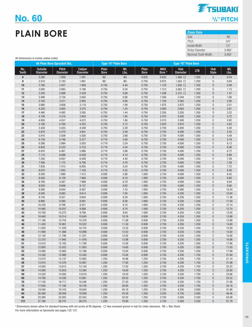
SPR
OC
KET
S
158
No. 60 3/4” PITCH
Chain DataSize 60Pitch 3/4˝Inside Width 1/2˝Roller Diameter 0.469˝Nominal Tooth Width: 0.459˝
PLAIN BORE
60 Plain Bore Sprocket Dia. Type “A” Plain Bore Type “B” Plain Bore
No. Teeth
Outside Diameter
Pitch Diameter
Caliper Diameter
Plain Bore
Wt. Lbs.
Plain Bore
MAX Bore *
Hub Diameter LTB Hub
StyleWt. Lbs.
8 2.260 1.959 1.491 NS NS 0.625 0.625 1.469 ¨ 1.250 S 0.549 2.510 2.193 1.691 NS NS 0.750 0.875 1.563 ¨ 1.250 S 0.64
10 2.760 2.427 1.958 0.750 0.44 0.750 1.125 1.938 ¨ 1.250 S 0.9911 3.000 2.663 2.166 0.750 0.54 0.750 1.313 2.063 ¨ 1.250 S 1.1512 3.250 2.898 2.429 0.750 0.68 0.750 1.438 2.375 ¨ 1.250 S 1.4713 3.490 3.134 2.642 0.750 0.80 0.750 1.500 2.344 1.250 S 1.6614 3.740 3.371 2.902 0.750 0.94 0.750 1.750 2.563 1.250 S 2.0015 3.980 3.608 3.119 0.750 1.08 0.750 1.875 2.875 1.250 S 2.5116 4.220 3.845 3.375 0.750 1.24 0.750 2.000 3.063 1.250 S 2.8117 4.460 4.082 3.595 0.750 1.44 0.750 2.250 3.250 1.250 S 3.2218 4.700 4.319 3.850 0.750 1.62 0.750 2.375 3.500 1.250 E 3.7219 4.950 4.557 4.072 0.750 1.84 0.750 2.375 3.500 1.250 E 3.9220 5.190 4.794 4.325 0.750 2.12 0.750 2.625 3.875 1.250 E 4.6321 5.430 5.033 4.549 0.750 2.28 0.750 2.750 4.000 1.250 E 5.0022 5.670 5.270 4.801 0.750 2.48 0.750 2.750 4.000 1.250 E 5.2523 5.910 5.508 5.026 0.750 2.68 0.750 2.750 4.000 1.250 E 5.4824 6.150 5.746 5.277 0.719 3.00 0.750 2.750 4.000 1.250 E 5.7825 6.390 5.984 5.503 0.719 3.34 0.750 2.750 4.000 1.250 E 6.1326 6.630 6.222 5.753 0.719 3.54 0.750 2.750 4.000 1.250 E 6.3827 6.870 6.461 5.980 0.719 3.96 0.750 2.750 4.000 1.250 E 6.7228 7.110 6.698 6.229 0.719 4.14 0.750 2.750 4.000 1.250 E 6.8829 7.350 6.937 6.458 0.719 4.40 0.750 2.750 4.000 1.250 E 7.2830 7.590 7.175 6.706 0.719 4.78 0.750 2.750 4.000 1.250 E 7.5831 7.830 7.413 6.935 0.719 5.24 0.750 2.750 4.000 1.250 E 7.7232 8.070 7.652 7.183 0.719 5.52 0.750 2.750 4.000 1.250 E 8.2633 8.300 7.890 7.412 0.938 5.86 1.000 2.750 4.000 1.250 E 8.4234 8.540 8.129 7.660 0.938 6.16 1.000 2.750 4.000 1.250 E 8.8035 8.780 8.367 7.889 0.938 6.78 1.000 2.750 4.000 1.250 E 9.0436 9.020 8.606 8.137 0.938 6.82 1.000 2.750 4.000 1.250 E 9.6037 9.260 8.844 8.367 0.938 7.52 1.000 2.750 4.000 1.250 E 10.2438 9.500 9.083 8.614 0.938 7.84 1.000 2.750 4.250 1.250 E 10.8439 9.740 9.321 8.844 0.938 8.28 1.000 2.750 4.250 1.250 E 11.3640 9.980 9.560 9.091 0.938 8.56 1.000 2.750 4.250 1.250 E 11.5041 10.220 9.798 9.321 0.938 9.10 1.000 2.750 4.250 1.250 E 12.1442 10.460 10.037 9.568 0.938 9.74 1.000 2.750 4.250 1.250 E 12.7443 10.700 10.275 9.799 0.938 9.84 1.000 2.750 4.250 1.250 E 13.0044 10.940 10.514 10.045 0.938 10.76 0.938 2.750 4.250 1.250 E 13.8845 11.180 10.752 10.276 0.938 11.08 0.938 2.750 4.250 1.250 E 13.9846 11.420 10.991 10.522 0.938 11.50 0.938 2.750 4.250 1.250 E 14.6047 11.650 11.229 10.754 0.938 12.32 0.938 2.750 4.250 1.250 E 15.0048 11.890 11.468 10.999 0.938 12.42 0.938 2.750 4.250 1.250 E 15.8249 12.130 11.706 11.231 0.938 12.92 0.938 2.750 4.250 1.250 E 15.9050 12.370 11.945 11.476 0.938 13.98 0.938 2.750 4.250 1.250 E 16.9851 12.610 12.183 11.708 0.938 14.58 0.938 2.750 4.250 1.250 E 17.6652 12.850 12.422 11.953 0.938 14.60 0.938 2.750 4.250 1.250 E 17.9353 13.090 12.660 12.186 0.938 15.84 0.938 2.750 4.250 1.250 E 17.9954 13.330 12.889 12.430 0.938 15.92 0.938 2.750 4.250 1.750 E 21.6055 13.570 13.137 12.663 1.250 16.96 1.250 2.750 4.250 1.750 E 21.1456 13.810 13.376 12.907 1.250 17.60 1.250 2.750 4.250 1.750 E 21.8857 14.040 13.615 13.140 1.250 17.62 1.250 2.750 4.250 1.750 E 22.2558 14.280 13.853 13.384 1.250 19.00 1.250 2.750 4.250 1.750 E 22.8059 14.520 14.092 13.618 1.250 19.20 1.250 2.750 4.250 1.750 E 23.8660 14.760 14.330 13.861 1.250 20.02 1.250 2.750 4.250 1.750 E 25.2270 17.150 16.717 16.248 1.250 27.20 1.250 2.750 4.250 1.750 E 31.9872 17.630 17.195 16.726 1.250 28.90 1.250 2.750 4.250 1.750 E 34.1880 19.540 19.103 18.634 1.250 40.18 1.250 2.750 4.250 2.000 E 41.8884 20.490 20.058 19.589 1.250 45.50 1.250 3.250 4.750 2.000 E 46.4696 23.360 22.922 22.453 1.250 52.02 1.250 3.750 5.500 2.250 E 63.08112 27.180 26.741 26.272 1.250 70.80 1.250 3.750 5.500 2.250 E 81.78
* Dimensions shown allow for standard keyway with set screw at 90 degrees. ¨ Has recessed groove in hub for chain clearance. NS = Non Stock
All dimensions in inches unless noted.
For more information on Sprockets see pages 132-137.
TSUBAKI"
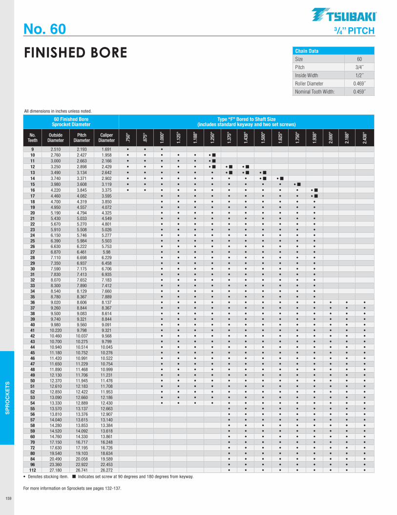
SPR
OC
KET
S
159
No. 60 3/4” PITCH
Chain DataSize 60
Pitch 3/4˝
Inside Width 1/2˝
Roller Diameter 0.469˝
Nominal Tooth Width: 0.459˝
FINISHED BORE
60 Finished Bore Sprocket Diameter
Type “F” Bored to Shaft Size (includes standard keyway and two set screws)
No. Teeth
Outside Diameter
Pitch Diameter
Caliper Diameter .7
50"
.875
"
1.00
0"
1.12
5"
1.18
8"
1.25
0"
1.37
5"
1.43
8"
1.50
0"
1.62
5"
1.75
0"
1.93
8"
2.00
0"
2.18
8"
2.43
8"
9 2.510 2.193 1.691 • • •10 2.760 2.427 1.958 • • • • • • ¢11 3.000 2.663 2.166 • • • • • • ¢12 3.250 2.898 2.429 • • • • • • ¢ • ¢ • ¢13 3.490 3.134 2.642 • • • • • • • ¢ • ¢ • ¢14 3.740 3.371 2.902 • • • • • • • • • ¢ • ¢15 3.980 3.608 3.119 • • • • • • • • • • • ¢16 4.220 3.845 3.375 • • • • • • • • • • • • ¢17 4.460 4.082 3.595 • • • • • • • • • • ¢18 4.700 4.319 3.850 • • • • • • • • • •19 4.950 4.557 4.072 • • • • • • • • • •20 5.190 4.794 4.325 • • • • • • • • • •21 5.430 5.033 4.549 • • • • • • • • • •22 5.670 5.270 4.801 • • • • • • • • • •23 5.910 5.508 5.026 • • • • • • • • • •24 6.150 5.746 5.277 • • • • • • • • • •25 6.390 5.984 5.503 • • • • • • • • • •26 6.630 6.222 5.753 • • • • • • • • • •27 6.870 6.461 5.98 • • • • • • • • • •28 7.110 6.698 6.229 • • • • • • • • • •29 7.350 6.937 6.458 • • • • • • • • • •30 7.590 7.175 6.706 • • • • • • • • • •31 7.830 7.413 6.935 • • • • • • • • • •32 8.070 7.652 7.183 • • • • • • • • • •33 8.300 7.890 7.412 • • • • • • • • • •34 8.540 8.129 7.660 • • • • • • • • • •35 8.780 8.367 7.889 • • • • • • • • • •36 9.020 8.606 8.137 • • • • • • • • • • • • •37 9.260 8.844 8.367 • • • • • • • • • • • • •38 9.500 9.083 8.614 • • • • • • • • • • • • •39 9.740 9.321 8.844 • • • • • • • • • • • • •40 9.980 9.560 9.091 • • • • • • • • • • • • •41 10.220 9.798 9.321 • • • • • • • • • • • • •42 10.460 10.037 9.568 • • • • • • • • • • • • •43 10.700 10.275 9.799 • • • • • • • • • • • • •44 10.940 10.514 10.045 • • • • • • • • • • • • •45 11.180 10.752 10.276 • • • • • • • • • • • • •46 11.420 10.991 10.522 • • • • • • • • • • • • •47 11.650 11.229 10.754 • • • • • • • • • • • • •48 11.890 11.468 10.999 • • • • • • • • • • • • •49 12.130 11.706 11.231 • • • • • • • • • • • • •50 12.370 11.945 11.476 • • • • • • • • • • • • •51 12.610 12.183 11.708 • • • • • • • • • • • • •52 12.850 12.422 11.953 • • • • • • • • • • • • •53 13.090 12.660 12.186 • • • • • • • • • • • • •54 13.330 12.889 12.430 • • • • • • • • • • • • •55 13.570 13.137 12.663 • • • • • • • • •56 13.810 13.376 12.907 • • • • • • • • •57 14.040 13.615 13.140 • • • • • • • • •58 14.280 13.853 13.384 • • • • • • • • •59 14.520 14.092 13.618 • • • • • • • • •60 14.760 14.330 13.861 • • • • • • • • •70 17.150 16.717 16.248 • • • • • • • • •72 17.630 17.195 16.726 • • • • • • • • •80 19.540 19.103 18.634 • • • • • • • • •84 20.490 20.058 19.589 • • • • • • • • •96 23.360 22.922 22.453 • • • • • • • • •112 27.180 26.741 26.272 • • • • • • • • •
• Denotes stocking item. ¢ Indicates set screw at 90 degrees and 180 degrees from keyway.
All dimensions in inches unless noted.
For more information on Sprockets see pages 132-137.
.TSUBAKI"
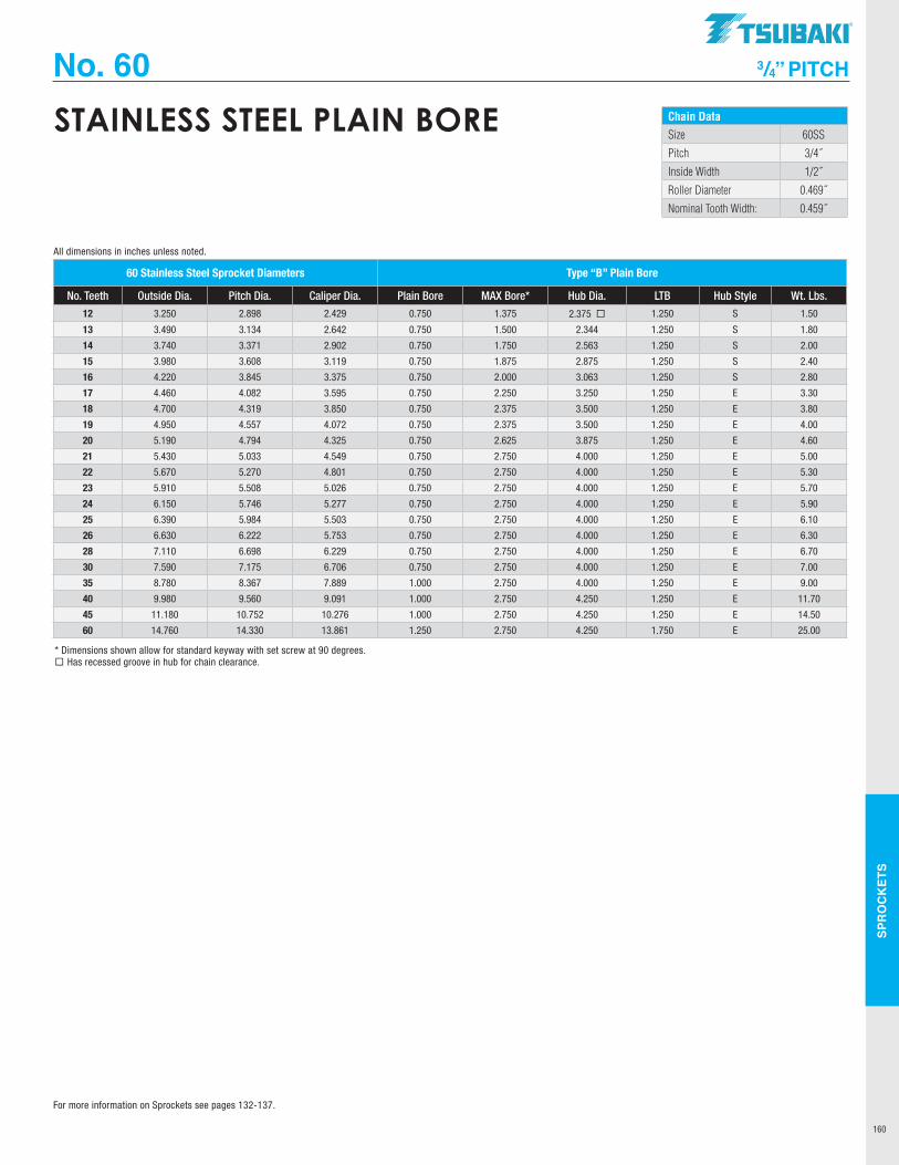
SPR
OC
KET
S
160
No. 60 3/4” PITCH
Chain DataSize 60SS
Pitch 3/4˝
Inside Width 1/2˝
Roller Diameter 0.469˝
Nominal Tooth Width: 0.459˝
STAINLESS STEEL PLAIN BORE
60 Stainless Steel Sprocket Diameters Type “B” Plain Bore
No. Teeth Outside Dia. Pitch Dia. Caliper Dia. Plain Bore MAX Bore* Hub Dia. LTB Hub Style Wt. Lbs.
12 3.250 2.898 2.429 0.750 1.375 2.375 ¨ 1.250 S 1.50
13 3.490 3.134 2.642 0.750 1.500 2.344 1.250 S 1.80
14 3.740 3.371 2.902 0.750 1.750 2.563 1.250 S 2.00
15 3.980 3.608 3.119 0.750 1.875 2.875 1.250 S 2.40
16 4.220 3.845 3.375 0.750 2.000 3.063 1.250 S 2.80
17 4.460 4.082 3.595 0.750 2.250 3.250 1.250 E 3.30
18 4.700 4.319 3.850 0.750 2.375 3.500 1.250 E 3.80
19 4.950 4.557 4.072 0.750 2.375 3.500 1.250 E 4.00
20 5.190 4.794 4.325 0.750 2.625 3.875 1.250 E 4.60
21 5.430 5.033 4.549 0.750 2.750 4.000 1.250 E 5.00
22 5.670 5.270 4.801 0.750 2.750 4.000 1.250 E 5.30
23 5.910 5.508 5.026 0.750 2.750 4.000 1.250 E 5.70
24 6.150 5.746 5.277 0.750 2.750 4.000 1.250 E 5.90
25 6.390 5.984 5.503 0.750 2.750 4.000 1.250 E 6.10
26 6.630 6.222 5.753 0.750 2.750 4.000 1.250 E 6.30
28 7.110 6.698 6.229 0.750 2.750 4.000 1.250 E 6.70
30 7.590 7.175 6.706 0.750 2.750 4.000 1.250 E 7.00
35 8.780 8.367 7.889 1.000 2.750 4.000 1.250 E 9.00
40 9.980 9.560 9.091 1.000 2.750 4.250 1.250 E 11.70
45 11.180 10.752 10.276 1.000 2.750 4.250 1.250 E 14.50
60 14.760 14.330 13.861 1.250 2.750 4.250 1.750 E 25.00
* Dimensions shown allow for standard keyway with set screw at 90 degrees.¨ Has recessed groove in hub for chain clearance.
All dimensions in inches unless noted.
For more information on Sprockets see pages 132-137.
TSUBAKI"
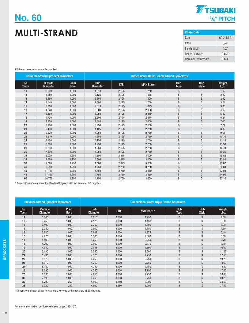
SPR
OC
KET
S
161
No. 60 3/4” PITCH
Chain Data
Size 60-2, 60-3
Pitch 3/4˝
Inside Width 1/2˝
Roller Diameter 0.469˝
Nominal Tooth Width: 0.444˝
MULTI-STRAND
60 Multi-Strand Sprocket Diameters Dimensional Data: Double Strand Sprockets
No. Teeth
Outside Diameter
Plain Bore
Hub Diameter LTB MAX Bore * Hub
TypeHub Style
Weight Lbs.
11 3.000 1.000 1.813 2.125 1.250 B S 1.6212 3.250 1.000 2.125 2.125 1.438 B S 2.2013 3.490 1.000 2.250 2.125 1.500 B S 2.6014 3.740 1.000 2.500 2.125 1.750 B S 3.2415 3.980 1.000 2.813 2.125 1.875 B S 3.9616 4.220 1.000 3.000 2.125 2.000 B S 4.6217 4.460 1.000 3.250 2.125 2.250 B S 5.4018 4.700 1.000 3.500 2.125 2.375 B S 6.2419 4.950 1.000 3.688 2.125 2.500 B S 7.0020 5.190 1.000 3.750 2.125 2.500 B S 7.7221 5.430 1.000 4.125 2.125 2.750 B S 8.8222 5.670 1.000 4.250 2.125 2.750 B S 9.6823 5.910 1.000 4.250 2.125 2.750 B S 10.3024 6.150 1.000 4.250 2.125 2.750 B S 11.1425 6.390 1.000 4.250 2.125 2.750 B S 11.9626 6.630 1.000 4.250 2.125 2.750 B S 12.7030 7.590 1.000 4.250 2.125 2.750 B S 16.3632 8.070 1.250 4.500 2.375 3.000 B S 19.5235 8.780 1.250 4.500 2.375 3.000 B S 22.8036 9.020 1.250 4.500 2.375 3.000 B S 23.8240 9.980 1.250 4.750 2.750 3.250 B S 30.8445 11.180 1.250 4.750 2.750 3.250 B S 37.0848 11.890 1.250 4.750 2.750 3.250 B D 44.9060 14.760 1.250 4.750 2.750 3.250 B D 63.10
60 Multi-Strand Sprocket Diameters Dimensional Data: Triple Strand Sprockets
No. Teeth
Outside Diameter
Plain Bore
Hub Diameter LTB MAX Bore * Hub
TypeHub Style
Weight Lbs.
11 3.000 1.000 1.813 3.000 1.250 B S 2.5012 3.250 1.000 2.125 3.000 1.438 B S 3.3013 3.490 1.000 2.250 3.000 1.500 B S 3.9014 3.740 1.000 2.500 3.000 1.750 B S 4.5015 3.980 1.000 2.688 3.000 1.875 B S 5.4016 4.220 1.000 3.000 3.000 2.000 B S 6.5017 4.460 1.000 3.250 3.000 2.250 B S 7.7018 4.700 1.000 3.500 3.000 2.375 B S 8.5019 4.950 1.000 3.688 3.000 2.500 B S 10.0020 5.190 1.000 3.750 3.000 2.500 B S 11.2021 5.430 1.000 4.125 3.000 2.750 B S 12.5022 5.670 1.000 4.250 3.000 2.750 B S 13.2023 5.910 1.000 4.250 3.000 2.750 B S 14.6024 6.150 1.000 4.250 3.000 2.750 B S 15.8025 6.390 1.000 4.250 3.000 2.750 B S 17.0026 6.630 1.000 4.250 3.000 2.750 B S 18.6030 7.590 1.000 4.250 3.000 2.750 B S 23.2035 8.780 1.250 4.500 3.250 3.000 B S 34.5036 9.020 1.250 4.500 3.250 3.000 B S 37.00
* Dimensions shown allow for standard keyway with set screw at 90 degrees.
* Dimensions shown allow for standard keyway with set screw at 90 degrees.
All dimensions in inches unless noted.
For more information on Sprockets see pages 132-137.
.TSUBAKI"
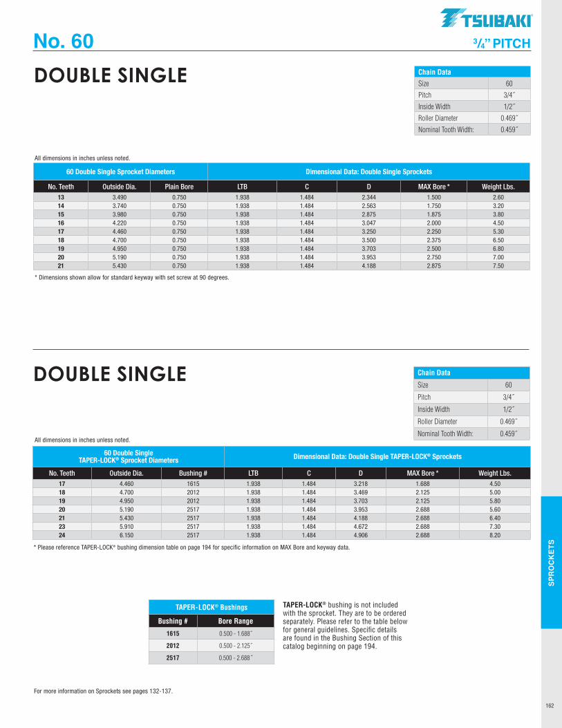
SPR
OC
KET
S
162
No. 60 3/4” PITCH
Chain DataSize 60
Pitch 3/4˝
Inside Width 1/2˝
Roller Diameter 0.469˝
Nominal Tooth Width: 0.459˝
DOUBLE SINGLE
All dimensions in inches unless noted.
Chain Data
Size 60
Pitch 3/4˝
Inside Width 1/2˝
Roller Diameter 0.469˝
Nominal Tooth Width: 0.459˝
DOUBLE SINGLE
TAPER-LOCK® bushing is not included with the sprocket. They are to be ordered separately. Please refer to the table below for general guidelines. Specific details are found in the Bushing Section of this catalog beginning on page 194.
TAPER-LOCK® Bushings
Bushing # Bore Range
1615 0.500 - 1.688˝
2012 0.500 - 2.125˝
2517 0.500 - 2.688˝
60 Double Single TAPER-LOCK® Sprocket Diameters Dimensional Data: Double Single TAPER-LOCK® Sprockets
No. Teeth Outside Dia. Bushing # LTB C D MAX Bore * Weight Lbs. 17 4.460 1615 1.938 1.484 3.218 1.688 4.5018 4.700 2012 1.938 1.484 3.469 2.125 5.0019 4.950 2012 1.938 1.484 3.703 2.125 5.8020 5.190 2517 1.938 1.484 3.953 2.688 5.6021 5.430 2517 1.938 1.484 4.188 2.688 6.4023 5.910 2517 1.938 1.484 4.672 2.688 7.3024 6.150 2517 1.938 1.484 4.906 2.688 8.20
* Please reference TAPER-LOCK® bushing dimension table on page 194 for specific information on MAX Bore and keyway data.
All dimensions in inches unless noted.
60 Double Single Sprocket Diameters Dimensional Data: Double Single Sprockets
No. Teeth Outside Dia. Plain Bore LTB C D MAX Bore * Weight Lbs. 13 3.490 0.750 1.938 1.484 2.344 1.500 2.6014 3.740 0.750 1.938 1.484 2.563 1.750 3.2015 3.980 0.750 1.938 1.484 2.875 1.875 3.8016 4.220 0.750 1.938 1.484 3.047 2.000 4.5017 4.460 0.750 1.938 1.484 3.250 2.250 5.3018 4.700 0.750 1.938 1.484 3.500 2.375 6.5019 4.950 0.750 1.938 1.484 3.703 2.500 6.8020 5.190 0.750 1.938 1.484 3.953 2.750 7.0021 5.430 0.750 1.938 1.484 4.188 2.875 7.50
* Dimensions shown allow for standard keyway with set screw at 90 degrees.
For more information on Sprockets see pages 132-137.
TSUBAKI"
I I I
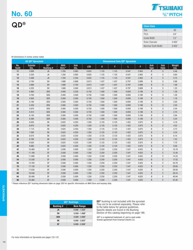
SPR
OC
KET
S
163
No. 60 3/4” PITCH
Chain Data
Size 60
Pitch 3/4˝
Inside Width 1/2˝
Roller Diameter 0.469˝
Nominal Tooth Width: 0.459˝
QD®
QD® Bushings
Bushing # Bore RangeJA 0.500 - 1.250˝
SH 0.500 - 1.688˝
SDS 0.500 - 2.000˝
SK 0.500 - 2.625˝
SF 0.500 - 2.938˝
QD® bushing is not included with the sprocket. They are to be ordered separately. Please refer to the table below for general guidelines. Specific details are found in the Bushing Section of this catalog beginning on page 199.
QD® is a registered trademark of, and is used under license agreement from Emerson Electric Co.
60 QD® Sprockets Dimensional Data QD® Sprockets
No. Teeth
Outside Dia.
QD® Bushing #
MAX Bore *
Hub Dia. LTB X Y L F Hub
TypeHub Style
Weight Lbs.
11 3.000 JA 1.250 2.063 0.625 1.125 1.125 0.547 2.063 B S 0.46
12 3.250 JA 1.250 2.063 0.625 1.125 1.125 0.547 2.063 B S 0.60
13 3.490 JA 1.250 2.250 0.625 1.125 1.125 0.547 2.063 B S 0.75
14 3.740 SH 1.688 2.688 0.813 1.437 1.437 0.797 2.688 B S 0.88
15 3.980 SH 1.688 2.750 0.813 1.437 1.437 0.797 2.688 B S 1.08
16 4.220 SH 1.688 3.000 0.813 1.437 1.437 0.797 2.688 B S 1.25
17 4.460 SDS 2.000 3.250 0.750 1.500 1.500 0.859 3.188 B S 1.38
18 4.700 SDS 2.000 3.500 0.750 1.500 1.500 0.859 3.188 B S 1.56
19 4.950 SDS 2.000 3.500 0.750 1.500 1.500 0.859 3.188 B S 1.76
20 5.190 SDS 2.000 3.500 0.750 1.500 1.500 0.859 3.188 B S 2.00
21 5.430 SDS 2.000 3.500 0.750 1.500 1.500 0.859 3.188 B S 2.20
22 5.670 SDS 2.000 3.500 0.750 1.500 1.500 0.859 3.188 B S 2.44
23 5.910 SDS 2.000 3.500 0.750 1.500 1.500 0.859 3.188 B E 2.70
24 6.150 SDS 2.000 3.500 0.750 1.500 1.500 0.859 3.188 B E 2.94
25 6.390 SDS 2.000 3.500 0.750 1.500 1.500 0.859 3.188 B E 3.24
26 6.630 SK 2.625 4.250 1.250 2.125 2.125 1.422 3.875 B E 4.18
27 6.870 SK 2.625 4.250 1.250 2.125 2.125 1.422 3.875 B E 4.52
28 7.110 SK 2.625 4.250 1.250 2.125 2.125 1.422 3.875 B E 4.72
30 7.590 SK 2.625 4.250 1.250 2.125 2.125 1.422 3.875 B E 5.34
32 8.070 SK 2.625 4.250 1.250 2.125 2.125 1.422 3.875 B E 6.10
35 8.780 SK 2.625 4.250 1.250 2.125 2.125 1.422 3.875 B E 7.42
36 9.020 SK 2.625 4.250 1.250 2.125 2.125 1.422 3.875 B E 7.70
40 9.980 SK 2.625 4.250 1.250 2.125 2.125 1.422 3.875 B E 9.56
42 10.460 SF 2.938 5.000 1.250 2.250 2.250 1.547 4.625 B E 10.78
45 11.180 SF 2.938 5.000 1.250 2.250 2.250 1.547 4.625 B E 12.40
48 11.890 SF 2.938 5.000 1.250 2.250 2.250 1.547 4.625 B E 14.25
54 13.330 SF 2.938 5.000 1.250 2.250 2.250 1.547 4.625 B E 17.02
60 14.760 SF 2.938 5.000 1.250 2.250 2.250 1.547 4.625 B E 20.76
70 17.150 SF 2.938 5.000 1.250 2.250 2.250 1.547 4.625 B E 28.60
72 17.630 SF 2.938 5.000 1.250 2.250 2.250 1.547 4.625 B E 29.58
80 19.540 SF 2.938 5.000 1.250 2.250 2.250 1.547 4.625 B E 38.24
84 20.490 SF 2.938 5.000 1.250 2.250 2.250 1.547 4.625 B E 40.94
96 23.360 SF 2.938 5.000 1.250 2.250 2.250 1.547 4.625 B E 52.40
* Please reference QD® bushing dimension table on page 200 for specific information on MAX Bore and keyway data.
All dimensions in inches unless noted.
For more information on Sprockets see pages 132-137.
.TSUBAKI"
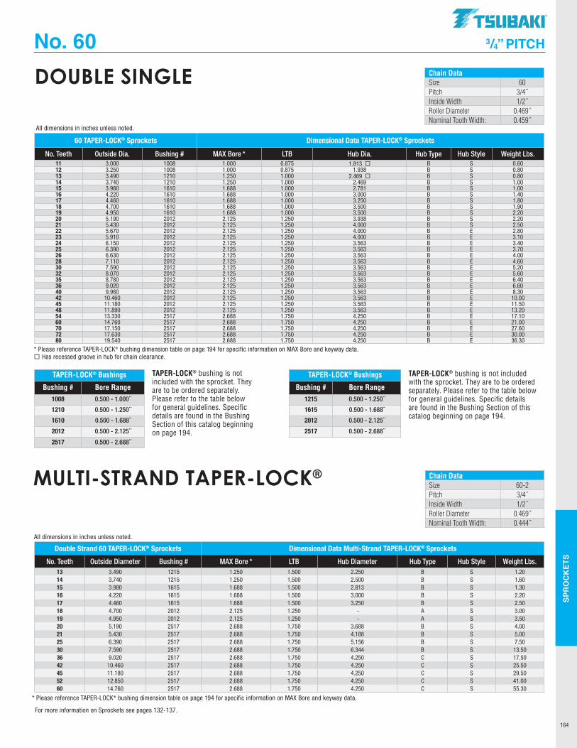
SPR
OC
KET
S
164
No. 60 3/4” PITCH
Chain DataSize 60Pitch 3/4˝Inside Width 1/2˝Roller Diameter 0.469˝Nominal Tooth Width: 0.459˝
DOUBLE SINGLE
60 TAPER-LOCK® Sprockets Dimensional Data TAPER-LOCK® Sprockets
No. Teeth Outside Dia. Bushing # MAX Bore * LTB Hub Dia. Hub Type Hub Style Weight Lbs. 11 3.000 1008 1.000 0.875 1.813 ¨ B S 0.6012 3.250 1008 1.000 0.875 1.938 B S 0.8013 3.490 1210 1.250 1.000 2.469 ¨ B S 0.8014 3.740 1210 1.250 1.000 2.469 B S 1.0015 3.980 1610 1.688 1.000 2.781 B S 1.0016 4.220 1610 1.688 1.000 3.000 B S 1.4017 4.460 1610 1.688 1.000 3.250 B S 1.8018 4.700 1610 1.688 1.000 3.500 B S 1.9019 4.950 1610 1.688 1.000 3.500 B S 2.2020 5.190 2012 2.125 1.250 3.938 B S 2.2021 5.430 2012 2.125 1.250 4.000 B S 2.5022 5.670 2012 2.125 1.250 4.000 B E 2.8023 5.910 2012 2.125 1.250 4.000 B E 3.1024 6.150 2012 2.125 1.250 3.563 B E 3.4025 6.390 2012 2.125 1.250 3.563 B E 3.7026 6.630 2012 2.125 1.250 3.563 B E 4.0028 7.110 2012 2.125 1.250 3.563 B E 4.6030 7.590 2012 2.125 1.250 3.563 B E 5.2032 8.070 2012 2.125 1.250 3.563 B E 5.6035 8.780 2012 2.125 1.250 3.563 B E 6.4036 9.020 2012 2.125 1.250 3.563 B E 6.6040 9.980 2012 2.125 1.250 3.563 B E 8.3042 10.460 2012 2.125 1.250 3.563 B E 10.0045 11.180 2012 2.125 1.250 3.563 B E 11.5048 11.890 2012 2.125 1.250 3.563 B E 13.2054 13.330 2517 2.688 1.750 4.250 B E 17.1060 14.760 2517 2.688 1.750 4.250 B E 21.0070 17.150 2517 2.688 1.750 4.250 B E 27.6072 17.630 2517 2.688 1.750 4.250 B E 30.0080 19.540 2517 2.688 1.750 4.250 B E 36.30
* Please reference TAPER-LOCK® bushing dimension table on page 194 for specific information on MAX Bore and keyway data. ¨ Has recessed groove in hub for chain clearance.
All dimensions in inches unless noted.
TAPER-LOCK® Bushings
Bushing # Bore Range1008 0.500 - 1.000˝
1210 0.500 - 1.250˝
1610 0.500 - 1.688˝
2012 0.500 - 2.125˝
2517 0.500 - 2.688˝
TAPER-LOCK® bushing is not included with the sprocket. They are to be ordered separately. Please refer to the table below for general guidelines. Specific details are found in the Bushing Section of this catalog beginning on page 194.
Chain DataSize 60-2Pitch 3/4˝Inside Width 1/2˝Roller Diameter 0.469˝Nominal Tooth Width: 0.444˝
MULTI-STRAND TAPER-LOCK®
Double Strand 60 TAPER-LOCK® Sprockets Dimensional Data Multi-Strand TAPER-LOCK® Sprockets
No. Teeth Outside Diameter Bushing # MAX Bore * LTB Hub Diameter Hub Type Hub Style Weight Lbs. 13 3.490 1215 1.250 1.500 2.250 B S 1.2014 3.740 1215 1.250 1.500 2.500 B S 1.6015 3.980 1615 1.688 1.500 2.813 B S 1.3016 4.220 1615 1.688 1.500 3.000 B S 2.2017 4.460 1615 1.688 1.500 3.250 B S 2.5018 4.700 2012 2.125 1.250 - A S 3.0019 4.950 2012 2.125 1.250 - A S 3.5020 5.190 2517 2.688 1.750 3.688 B S 4.0021 5.430 2517 2.688 1.750 4.188 B S 5.0025 6.390 2517 2.688 1.750 5.156 B S 7.5030 7.590 2517 2.688 1.750 6.344 B S 13.5036 9.020 2517 2.688 1.750 4.250 C S 17.5042 10.460 2517 2.688 1.750 4.250 C S 25.5045 11.180 2517 2.688 1.750 4.250 C S 29.5052 12.850 2517 2.688 1.750 4.250 C S 41.0060 14.760 2517 2.688 1.750 4.250 C S 55.30
* Please reference TAPER-LOCK® bushing dimension table on page 194 for specific information on MAX Bore and keyway data.
All dimensions in inches unless noted.
TAPER-LOCK® bushing is not included with the sprocket. They are to be ordered separately. Please refer to the table below for general guidelines. Specific details are found in the Bushing Section of this catalog beginning on page 194.
TAPER-LOCK® Bushings
Bushing # Bore Range1215 0.500 - 1.250˝
1615 0.500 - 1.688˝
2012 0.500 - 2.125˝
2517 0.500 - 2.688˝
For more information on Sprockets see pages 132-137.
TSUBAKI"
---

SPR
OC
KET
S
165
No. 80 1” PITCH
Chain Data
Size 80
Pitch 1˝
Inside Width 5/8˝
Roller Diameter 0.625˝
Nominal Tooth Width: 0.575˝
PLAIN BORE
80 Plain Bore Sprocket Dia. Type “A” Plain Bore Type “B” & “C” Plain Bore
No. Teeth
Outside Diameter
Pitch Diameter
Caliper Diameter
Plain Bore
Wt. Lbs.
Plain Bore
MAX Bore *
Hub Diameter LTB Hub
TypeHub Style
Wt. Lbs.
8 3.010 2.613 1.988 N/A N/A 1.000 1.000 1.938 ¨ 1.625 B S 1.409 3.350 2.924 2.254 0.938 0.80 1.000 1.313 2.250 ¨ 1.625 B S 1.6010 3.680 3.236 2.611 0.938 1.00 1.000 1.500 2.563 ¨ 1.625 B S 2.2011 4.010 3.549 2.888 0.938 1.30 1.000 1.625 2.813 ¨ 1.625 B S 3.2012 4.330 3.864 3.239 0.938 1.50 1.000 1.875 3.125 ¨ 1.625 B S 3.4013 4.660 4.179 3.523 0.938 1.80 1.000 2.000 3.000 1.500 B S 3.5014 4.980 4.494 3.869 0.938 2.20 1.000 2.250 3.250 1.500 B S 4.1015 5.300 4.810 4.158 0.938 2.50 1.000 2.500 3.813 1.500 B S 5.3016 5.630 5.126 4.501 0.938 2.90 1.000 2.750 4.000 1.500 B S 5.9017 5.950 5.442 4.794 0.938 3.30 1.000 2.750 4.000 1.500 B S 6.6018 6.270 5.759 5.134 0.938 3.70 1.000 2.750 4.250 1.500 B S 7.3019 6.590 6.076 5.430 0.938 4.10 1.000 2.750 4.250 1.500 B S 7.8020 6.910 6.392 5.767 0.938 4.70 1.000 2.750 4.250 1.500 B S 8.4021 7.240 6.710 6.066 0.938 4.900 1.000 2.750 4.250 1.750 B S 9.4022 7.560 7.027 6.402 0.938 5.500 1.000 2.750 4.250 1.750 B S 10.0023 7.880 7.344 6.702 0.938 6.300 1.000 2.750 4.250 1.750 B S 10.7024 8.200 7.661 7.036 0.938 6.700 1.000 2.750 4.250 1.750 B S 11.3025 8.520 7.979 7.338 0.938 7.200 1.000 2.750 4.250 1.750 B S 11.9026 8.840 8.296 7.671 1.188 7.800 1.250 3.250 4.750 2.000 B D 14.3027 9.160 8.614 7.974 1.188 8.600 1.250 3.250 4.750 2.000 B D 15.4028 9.480 8.931 8.306 1.188 9.300 1.250 3.250 4.750 2.000 B D 16.0029 9.800 9.249 8.611 1.188 9.800 1.188 3.250 4.750 2.000 B D 17.1030 10.110 9.567 8.942 1.188 10.70 1.188 3.250 4.750 2.000 B D 17.4031 10.430 9.884 9.247 1.188 11.30 1.188 3.250 4.750 2.000 B D 18.7032 10.750 10.202 9.577 1.188 12.10 1.188 3.250 4.750 2.000 B D 19.5033 11.070 10.520 9.883 1.188 13.60 1.188 3.250 4.750 2.000 B D 19.6034 11.390 10.838 10.213 1.188 14.30 1.188 3.250 4.750 2.000 B D 21.3035 11.710 11.156 10.520 1.188 14.80 1.188 3.250 4.750 2.000 B D 22.1036 12.030 11.474 10.849 1.188 16.10 1.188 3.250 4.750 2.000 B D 23.1037 12.350 11.792 11.156 1.188 16.80 1.188 3.250 4.750 2.000 B D 23.8038 12.670 12.110 11.485 1.188 17.20 1.188 3.250 4.750 2.000 B D 24.7039 12.990 12.428 11.792 1.188 17.90 1.188 3.250 4.750 2.000 B D 25.6040 13.310 12.746 12.121 1.188 18.90 1.188 3.250 4.750 2.000 B D 26.7041 13.630 13.064 12.429 1.250 21.00 1.250 3.250 4.750 2.000 B D 27.8042 13.940 13.382 12.757 1.250 21.80 1.250 3.250 4.750 2.000 B D 28.7043 14.260 13.700 13.065 1.250 23.60 1.250 3.250 4.750 2.000 B D 29.4044 14.580 14.018 13.393 1.250 24.30 1.250 3.250 4.750 2.000 B D 29.9045 14.900 14.336 13.702 1.250 25.20 1.250 3.250 4.750 2.000 B D 31.4046 15.220 14.654 14.029 1.250 26.60 1.250 3.250 4.750 2.000 B D 33.1047 15.540 14.972 14.338 1.250 26.40 1.250 3.250 4.750 2.000 B D 34.0048 15.860 15.290 14.665 1.250 27.80 1.250 3.250 4.750 2.000 B D 35.5049 16.180 15.608 14.975 1.250 28.90 1.250 3.250 4.750 2.000 B D 35.8050 16.500 15.926 15.301 1.250 30.90 1.250 3.250 4.750 2.000 B D 37.3051 16.810 16.244 15.611 1.250 32.20 1.250 3.250 4.750 2.000 B D 38.5052 17.130 16.562 15.937 1.250 33.00 1.250 3.250 4.750 2.000 B D 39.4053 17.450 16.880 16.248 1.250 34.90 1.250 3.250 4.750 2.000 B D 41.3054 17.770 17.198 16.573 1.250 36.60 1.250 3.500 5.250 2.000 B D 44.7055 18.090 17.516 16.884 1.250 37.50 1.250 3.500 5.250 2.000 B D 45.6056 18.410 17.835 17.210 1.250 39.40 1.250 3.500 5.250 2.000 B D 47.5057 18.730 18.153 17.521 1.250 40.40 1.250 3.500 5.250 2.000 B D 48.5058 19.040 18.471 17.846 1.250 41.30 1.250 3.500 5.250 2.000 B D 50.5059 19.360 18.789 18.157 1.250 42.90 1.250 3.500 5.250 2.000 B D 52.1060 19.680 19.107 18.482 1.250 45.30 1.250 3.500 5.250 2.000 B D 54.5065 21.270 20.698 20.067 1.250 52.20 1.250 3.500 5.250 2.000 B D 61.8070 22.870 22.289 21.644 1.500 59.80 1.500 4.250 6.250 3.500 C D 75.7072 23.500 22.926 22.301 1.500 65.70 1.500 4.250 6.250 3.500 C D 81.4080 26.050 25.471 24.846 1.500 79.60 1.500 4.250 6.250 3.500 C D 89.9084 27.330 26.744 26.119 1.500 86.10 1.500 4.250 6.250 3.500 C D 99.2096 31.150 30.563 29.938 1.500 120.00 1.500 4.250 6.250 3.500 C D 117.00112 36.240 35.655 35.030 1.500 166.00 1.500 4.250 6.250 3.500 C D 154.00
* Dimensions shown allow for standard keyway with set screw at 90 degrees. ¨ Has recessed groove in hub for chain clearance.
All dimensions in inches unless noted.
For more information on Sprockets see pages 132-137.
.TSUBAKI"
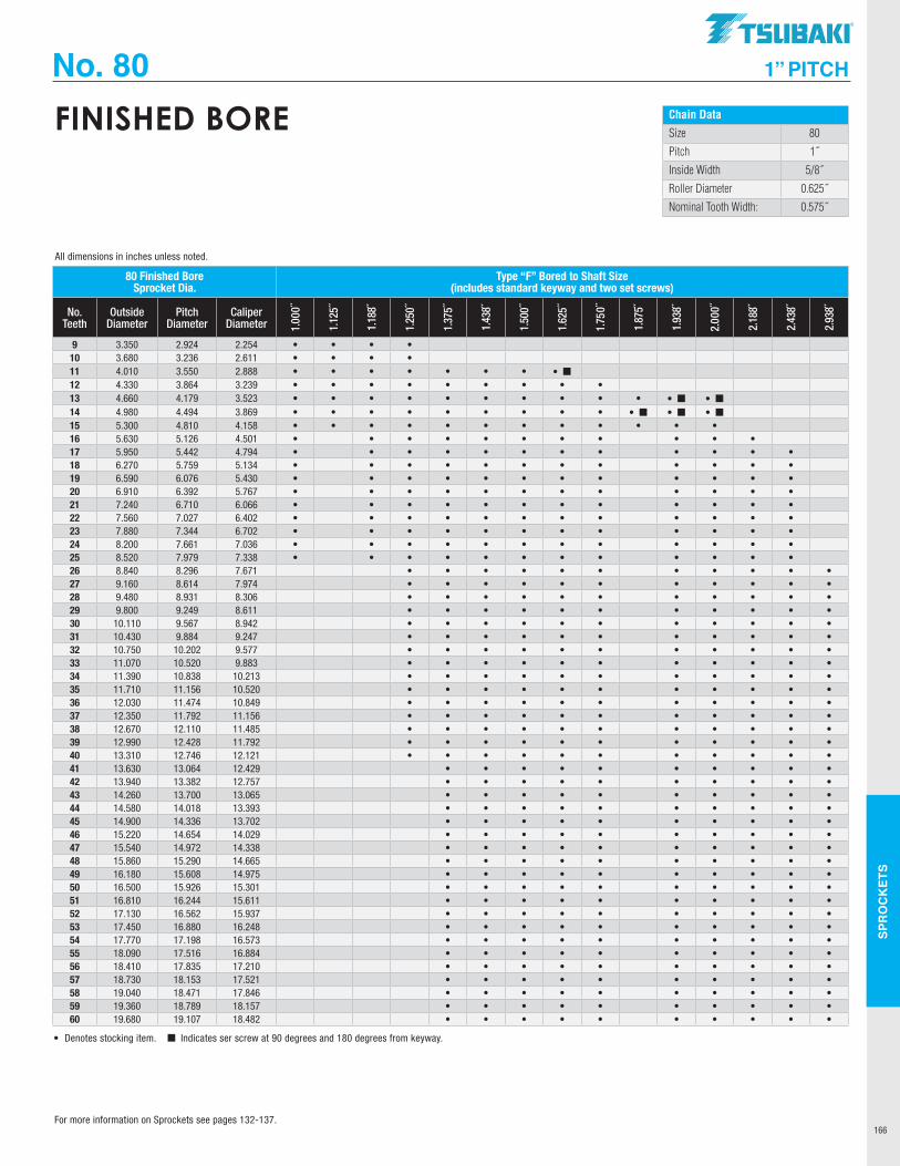
SPR
OC
KET
S
166
No. 80 1” PITCH
Chain Data
Size 80
Pitch 1˝
Inside Width 5/8˝
Roller Diameter 0.625˝
Nominal Tooth Width: 0.575˝
FINISHED BORE
80 Finished Bore Sprocket Dia.
Type “F” Bored to Shaft Size (includes standard keyway and two set screws)
No. Teeth
Outside Diameter
Pitch Diameter
Caliper Diameter 1.
000˝
1.12
5˝
1.18
8˝
1.25
0˝
1.37
5˝
1.43
8˝
1.50
0˝
1.62
5˝
1.75
0˝
1.87
5˝
1.93
8˝
2.00
0˝
2.18
8˝
2.43
8˝
2.93
8˝
9 3.350 2.924 2.254 • • • •10 3.680 3.236 2.611 • • • •11 4.010 3.550 2.888 • • • • • • • • ¢12 4.330 3.864 3.239 • • • • • • • • •13 4.660 4.179 3.523 • • • • • • • • • • • ¢ • ¢14 4.980 4.494 3.869 • • • • • • • • • • ¢ • ¢ • ¢15 5.300 4.810 4.158 • • • • • • • • • • • •16 5.630 5.126 4.501 • • • • • • • • • • •17 5.950 5.442 4.794 • • • • • • • • • • • •18 6.270 5.759 5.134 • • • • • • • • • • • •19 6.590 6.076 5.430 • • • • • • • • • • • •20 6.910 6.392 5.767 • • • • • • • • • • • •21 7.240 6.710 6.066 • • • • • • • • • • • •22 7.560 7.027 6.402 • • • • • • • • • • • •23 7.880 7.344 6.702 • • • • • • • • • • • •24 8.200 7.661 7.036 • • • • • • • • • • • •25 8.520 7.979 7.338 • • • • • • • • • • • •26 8.840 8.296 7.671 • • • • • • • • • • •27 9.160 8.614 7.974 • • • • • • • • • • •28 9.480 8.931 8.306 • • • • • • • • • • •29 9.800 9.249 8.611 • • • • • • • • • • •30 10.110 9.567 8.942 • • • • • • • • • • •31 10.430 9.884 9.247 • • • • • • • • • • •32 10.750 10.202 9.577 • • • • • • • • • • •33 11.070 10.520 9.883 • • • • • • • • • • •34 11.390 10.838 10.213 • • • • • • • • • • •35 11.710 11.156 10.520 • • • • • • • • • • •36 12.030 11.474 10.849 • • • • • • • • • • •37 12.350 11.792 11.156 • • • • • • • • • • •38 12.670 12.110 11.485 • • • • • • • • • • •39 12.990 12.428 11.792 • • • • • • • • • • •40 13.310 12.746 12.121 • • • • • • • • • • •41 13.630 13.064 12.429 • • • • • • • • • •42 13.940 13.382 12.757 • • • • • • • • • •43 14.260 13.700 13.065 • • • • • • • • • •44 14.580 14.018 13.393 • • • • • • • • • •45 14.900 14.336 13.702 • • • • • • • • • •46 15.220 14.654 14.029 • • • • • • • • • •47 15.540 14.972 14.338 • • • • • • • • • •48 15.860 15.290 14.665 • • • • • • • • • •49 16.180 15.608 14.975 • • • • • • • • • •50 16.500 15.926 15.301 • • • • • • • • • •51 16.810 16.244 15.611 • • • • • • • • • •52 17.130 16.562 15.937 • • • • • • • • • •53 17.450 16.880 16.248 • • • • • • • • • •54 17.770 17.198 16.573 • • • • • • • • • •55 18.090 17.516 16.884 • • • • • • • • • •56 18.410 17.835 17.210 • • • • • • • • • •57 18.730 18.153 17.521 • • • • • • • • • •58 19.040 18.471 17.846 • • • • • • • • • •59 19.360 18.789 18.157 • • • • • • • • • •60 19.680 19.107 18.482 • • • • • • • • • •
• Denotes stocking item. ¢ Indicates ser screw at 90 degrees and 180 degrees from keyway.
All dimensions in inches unless noted.
For more information on Sprockets see pages 132-137.
TSUBAKI"
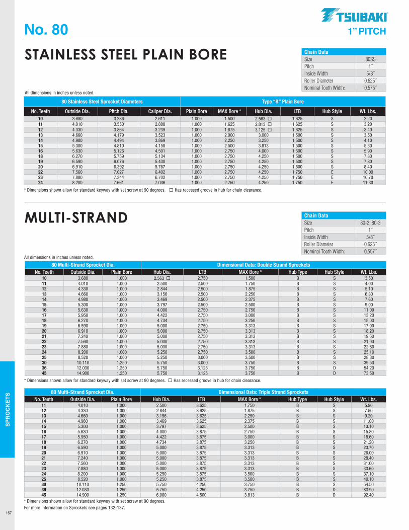
SPR
OC
KET
S
167
No. 80 1” PITCH
Chain DataSize 80SSPitch 1˝Inside Width 5/8˝Roller Diameter 0.625˝Nominal Tooth Width: 0.575˝
STAINLESS STEEL PLAIN BORE
80 Stainless Steel Sprocket Diameters Type “B” Plain Bore
No. Teeth Outside Dia. Pitch Dia. Caliper Dia. Plain Bore MAX Bore * Hub Dia. LTB Hub Style Wt. Lbs.10 3.680 3.236 2.611 1.000 1.500 2.563 ¨ 1.625 S 2.2011 4.010 3.550 2.888 1.000 1.625 2.813 ¨ 1.625 S 3.2012 4.330 3.864 3.239 1.000 1.875 3.125 ¨ 1.625 S 3.4013 4.660 4.179 3.523 1.000 2.000 3.000 1.500 S 3.5014 4.980 4.494 3.869 1.000 2.250 3.250 1.500 S 4.1015 5.300 4.810 4.158 1.000 2.500 3.813 1.500 S 5.3016 5.630 5.126 4.501 1.000 2.750 4.000 1.500 S 5.9018 6.270 5.759 5.134 1.000 2.750 4.250 1.500 S 7.3019 6.590 6.076 5.430 1.000 2.750 4.250 1.500 S 7.8020 6.910 6.392 5.767 1.000 2.750 4.250 1.500 S 8.4022 7.560 7.027 6.402 1.000 2.750 4.250 1.750 E 10.0023 7.880 7.344 6.702 1.000 2.750 4.250 1.750 E 10.7024 8.200 7.661 7.036 1.000 2.750 4.250 1.750 E 11.30
* Dimensions shown allow for standard keyway with set screw at 90 degrees. ¨ Has recessed groove in hub for chain clearance.
All dimensions in inches unless noted.
Chain DataSize 80-2, 80-3Pitch 1˝Inside Width 5/8˝Roller Diameter 0.625˝Nominal Tooth Width: 0.557˝
MULTI-STRAND
80 Multi-Strand Sprocket Dia. Dimensional Data: Double Strand SprocketsNo. Teeth Outside Dia. Plain Bore Hub Dia. LTB MAX Bore * Hub Type Hub Style Wt. Lbs.
10 3.680 1.000 2.563 ¨ 2.750 1.500 B S 3.5011 4.010 1.000 2.500 2.500 1.750 B S 4.0012 4.330 1.000 2.844 2.500 1.875 B S 5.1013 4.660 1.000 3.156 2.500 2.250 B S 6.3014 4.980 1.000 3.469 2.500 2.375 B S 7.6015 5.300 1.000 3.797 2.500 2.500 B S 9.0016 5.630 1.000 4.000 2.750 2.750 B S 11.0017 5.950 1.000 4.422 2.750 3.000 B S 13.2018 6.270 1.000 4.734 2.750 3.250 B S 15.0019 6.590 1.000 5.000 2.750 3.313 B S 17.0020 6.910 1.000 5.000 2.750 3.313 B S 18.2021 7.240 1.000 5.000 2.750 3.313 B S 19.5022 7.560 1.000 5.000 2.750 3.313 B S 21.0023 7.880 1.000 5.000 2.750 3.313 B S 22.8024 8.200 1.000 5.250 2.750 3.500 B S 25.1025 8.520 1.000 5.250 3.000 3.500 B S 28.3030 10.110 1.250 5.750 3.000 3.750 B S 39.5036 12.030 1.250 5.750 3.125 3.750 B D 54.2045 14.900 1.250 5.750 3.125 3.750 B D 73.50
80 Multi-Strand Sprocket Dia. Dimensional Data: Triple Strand SprocketsNo. Teeth Outside Dia. Plain Bore Hub Dia. LTB MAX Bore * Hub Type Hub Style Wt. Lbs.
11 4.010 1.000 2.500 3.625 1.750 B S 5.9012 4.330 1.000 2.844 3.625 1.875 B S 7.5013 4.660 1.000 3.156 3.625 2.250 B S 9.2014 4.980 1.000 3.469 3.625 2.375 B S 11.0015 5.300 1.000 3.797 3.625 2.500 B S 13.1016 5.630 1.000 4.000 3.875 2.750 B S 15.8017 5.950 1.000 4.422 3.875 3.000 B S 18.6018 6.270 1.000 4.734 3.875 3.250 B S 21.2019 6.590 1.000 5.000 3.875 3.313 B S 23.7020 6.910 1.000 5.000 3.875 3.313 B S 26.0021 7.240 1.000 5.000 3.875 3.313 B S 28.4022 7.560 1.000 5.000 3.875 3.313 B S 31.0023 7.880 1.000 5.000 3.875 3.313 B S 33.6024 8.200 1.000 5.250 3.875 3.500 B S 37.1025 8.520 1.000 5.250 3.875 3.500 B S 40.1030 10.110 1.250 5.750 4.250 3.750 B S 54.5036 12.030 1.250 5.750 4.250 3.750 B D 83.9045 14.900 1.250 6.000 4.500 3.813 B D 92.40
* Dimensions shown allow for standard keyway with set screw at 90 degrees.
* Dimensions shown allow for standard keyway with set screw at 90 degrees. ¨ Has recessed groove in hub for chain clearance.
All dimensions in inches unless noted.
For more information on Sprockets see pages 132-137.
.TSUBAKI"
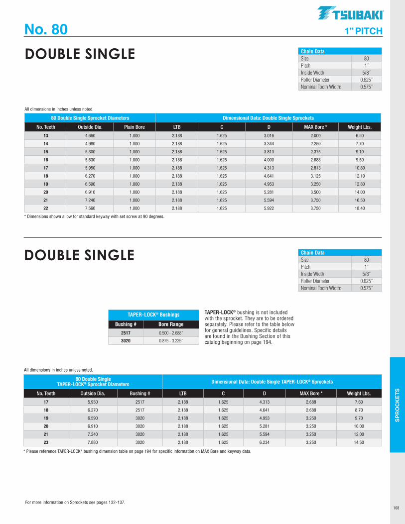
SPR
OC
KET
S
168
No. 80 1” PITCH
Chain DataSize 80Pitch 1˝Inside Width 5/8˝Roller Diameter 0.625˝Nominal Tooth Width: 0.575˝
DOUBLE SINGLE
80 Double Single Sprocket Diameters Dimensional Data: Double Single Sprockets
No. Teeth Outside Dia. Plain Bore LTB C D MAX Bore * Weight Lbs.
13 4.660 1.000 2.188 1.625 3.016 2.000 6.50
14 4.980 1.000 2.188 1.625 3.344 2.250 7.70
15 5.300 1.000 2.188 1.625 3.813 2.375 9.10
16 5.630 1.000 2.188 1.625 4.000 2.688 9.50
17 5.950 1.000 2.188 1.625 4.313 2.813 10.80
18 6.270 1.000 2.188 1.625 4.641 3.125 12.10
19 6.590 1.000 2.188 1.625 4.953 3.250 12.80
20 6.910 1.000 2.188 1.625 5.281 3.500 14.00
21 7.240 1.000 2.188 1.625 5.594 3.750 16.50
22 7.560 1.000 2.188 1.625 5.922 3.750 18.40
* Dimensions shown allow for standard keyway with set screw at 90 degrees.
All dimensions in inches unless noted.
Chain DataSize 80Pitch 1˝Inside Width 5/8˝Roller Diameter 0.625˝Nominal Tooth Width: 0.575˝
DOUBLE SINGLE
TAPER-LOCK® bushing is not included with the sprocket. They are to be ordered separately. Please refer to the table below for general guidelines. Specific details are found in the Bushing Section of this catalog beginning on page 194.
TAPER-LOCK® Bushings
Bushing # Bore Range
2517 0.500 - 2.688˝
3020 0.875 - 3.225˝
80 Double Single TAPER-LOCK® Sprocket Diameters Dimensional Data: Double Single TAPER-LOCK® Sprockets
No. Teeth Outside Dia. Bushing # LTB C D MAX Bore * Weight Lbs.
17 5.950 2517 2.188 1.625 4.313 2.688 7.60
18 6.270 2517 2.188 1.625 4.641 2.688 8.70
19 6.590 3020 2.188 1.625 4.953 3.250 9.70
20 6.910 3020 2.188 1.625 5.281 3.250 10.00
21 7.240 3020 2.188 1.625 5.594 3.250 12.00
23 7.880 3020 2.188 1.625 6.234 3.250 14.50
* Please reference TAPER-LOCK® bushing dimension table on page 194 for specific information on MAX Bore and keyway data.
All dimensions in inches unless noted.
For more information on Sprockets see pages 132-137.
TSUBAKI"
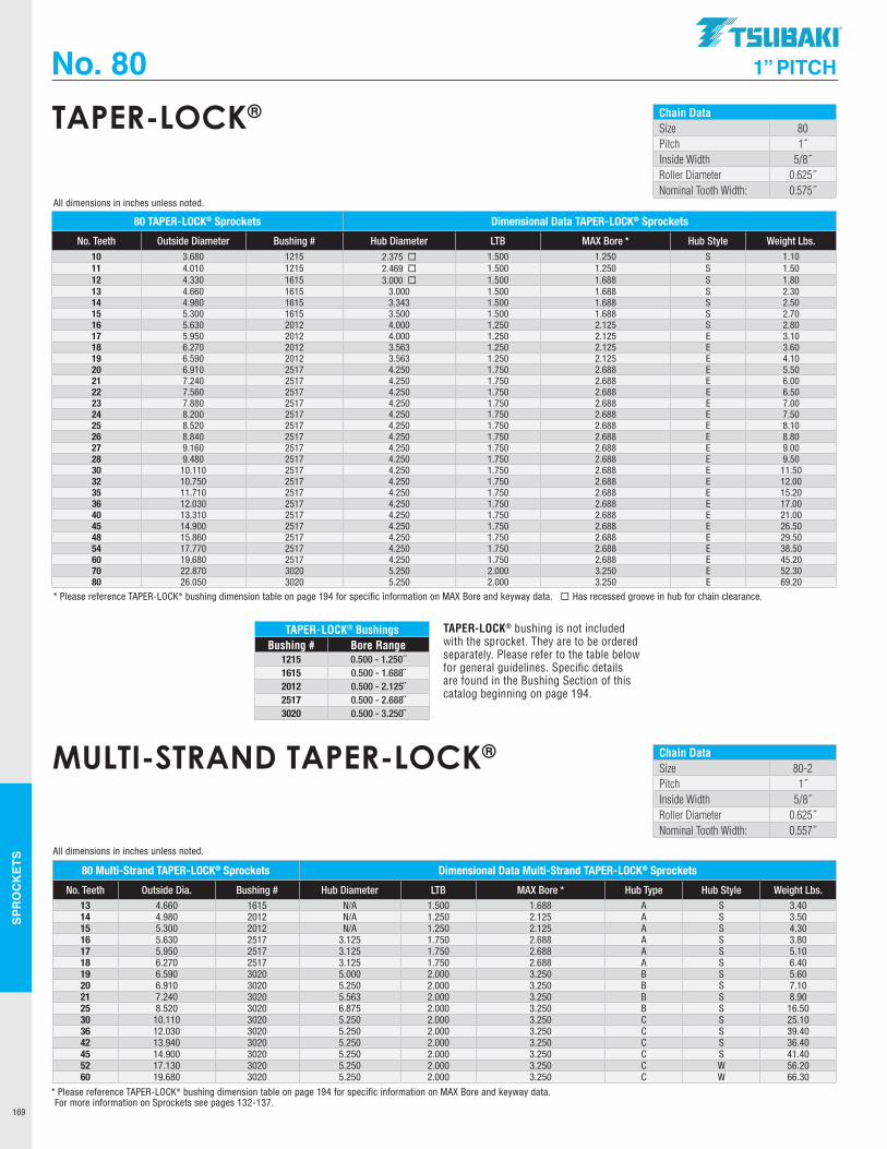
SPR
OC
KET
S
169
No. 80 1” PITCH
Chain DataSize 80Pitch 1˝Inside Width 5/8˝Roller Diameter 0.625˝Nominal Tooth Width: 0.575˝
TAPER-LOCK®
80 TAPER-LOCK® Sprockets Dimensional Data TAPER-LOCK® Sprockets
No. Teeth Outside Diameter Bushing # Hub Diameter LTB MAX Bore * Hub Style Weight Lbs. 10 3.680 1215 2.375 ¨ 1.500 1.250 S 1.1011 4.010 1215 2.469 ¨ 1.500 1.250 S 1.5012 4.330 1615 3.000 ¨ 1.500 1.688 S 1.8013 4.660 1615 3.000 1.500 1.688 S 2.3014 4.980 1615 3.343 1.500 1.688 S 2.5015 5.300 1615 3.500 1.500 1.688 S 2.7016 5.630 2012 4.000 1.250 2.125 S 2.8017 5.950 2012 4.000 1.250 2.125 E 3.1018 6.270 2012 3.563 1.250 2.125 E 3.6019 6.590 2012 3.563 1.250 2.125 E 4.1020 6.910 2517 4.250 1.750 2.688 E 5.5021 7.240 2517 4.250 1.750 2.688 E 6.0022 7.560 2517 4.250 1.750 2.688 E 6.5023 7.880 2517 4.250 1.750 2.688 E 7.0024 8.200 2517 4.250 1.750 2.688 E 7.5025 8.520 2517 4.250 1.750 2.688 E 8.1026 8.840 2517 4.250 1.750 2.688 E 8.8027 9.160 2517 4.250 1.750 2.688 E 9.0028 9.480 2517 4.250 1.750 2.688 E 9.5030 10.110 2517 4.250 1.750 2.688 E 11.5032 10.750 2517 4.250 1.750 2.688 E 12.0035 11.710 2517 4.250 1.750 2.688 E 15.2036 12.030 2517 4.250 1.750 2.688 E 17.0040 13.310 2517 4.250 1.750 2.688 E 21.0045 14.900 2517 4.250 1.750 2.688 E 26.5048 15.860 2517 4.250 1.750 2.688 E 29.5054 17.770 2517 4.250 1.750 2.688 E 38.5060 19.680 2517 4.250 1.750 2.688 E 45.2070 22.870 3020 5.250 2.000 3.250 E 52.3080 26.050 3020 5.250 2.000 3.250 E 69.20
* Please reference TAPER-LOCK® bushing dimension table on page 194 for specific information on MAX Bore and keyway data. ¨ Has recessed groove in hub for chain clearance.
All dimensions in inches unless noted.
TAPER-LOCK® BushingsBushing # Bore Range
1215 0.500 - 1.250˝1615 0.500 - 1.688˝2012 0.500 - 2.125˝2517 0.500 - 2.688˝3020 0.500 - 3.250˝
TAPER-LOCK® bushing is not included with the sprocket. They are to be ordered separately. Please refer to the table below for general guidelines. Specific details are found in the Bushing Section of this catalog beginning on page 194.
Chain DataSize 80-2Pitch 1˝Inside Width 5/8˝Roller Diameter 0.625˝Nominal Tooth Width: 0.557˝
MULTI-STRAND TAPER-LOCK®
80 Multi-Strand TAPER-LOCK® Sprockets Dimensional Data Multi-Strand TAPER-LOCK® Sprockets
No. Teeth Outside Dia. Bushing # Hub Diameter LTB MAX Bore * Hub Type Hub Style Weight Lbs. 13 4.660 1615 N/A 1.500 1.688 A S 3.4014 4.980 2012 N/A 1.250 2.125 A S 3.5015 5.300 2012 N/A 1.250 2.125 A S 4.3016 5.630 2517 3.125 1.750 2.688 A S 3.8017 5.950 2517 3.125 1.750 2.688 A S 5.1018 6.270 2517 3.125 1.750 2.688 A S 6.4019 6.590 3020 5.000 2.000 3.250 B S 5.6020 6.910 3020 5.250 2.000 3.250 B S 7.1021 7.240 3020 5.563 2.000 3.250 B S 8.9025 8.520 3020 6.875 2.000 3.250 B S 16.5030 10.110 3020 5.250 2.000 3.250 C S 25.1036 12.030 3020 5.250 2.000 3.250 C S 39.4042 13.940 3020 5.250 2.000 3.250 C S 36.4045 14.900 3020 5.250 2.000 3.250 C S 41.4052 17.130 3020 5.250 2.000 3.250 C W 56.2060 19.680 3020 5.250 2.000 3.250 C W 66.30
* Please reference TAPER-LOCK® bushing dimension table on page 194 for specific information on MAX Bore and keyway data.
All dimensions in inches unless noted.
For more information on Sprockets see pages 132-137.
.TSUBAKI"
---
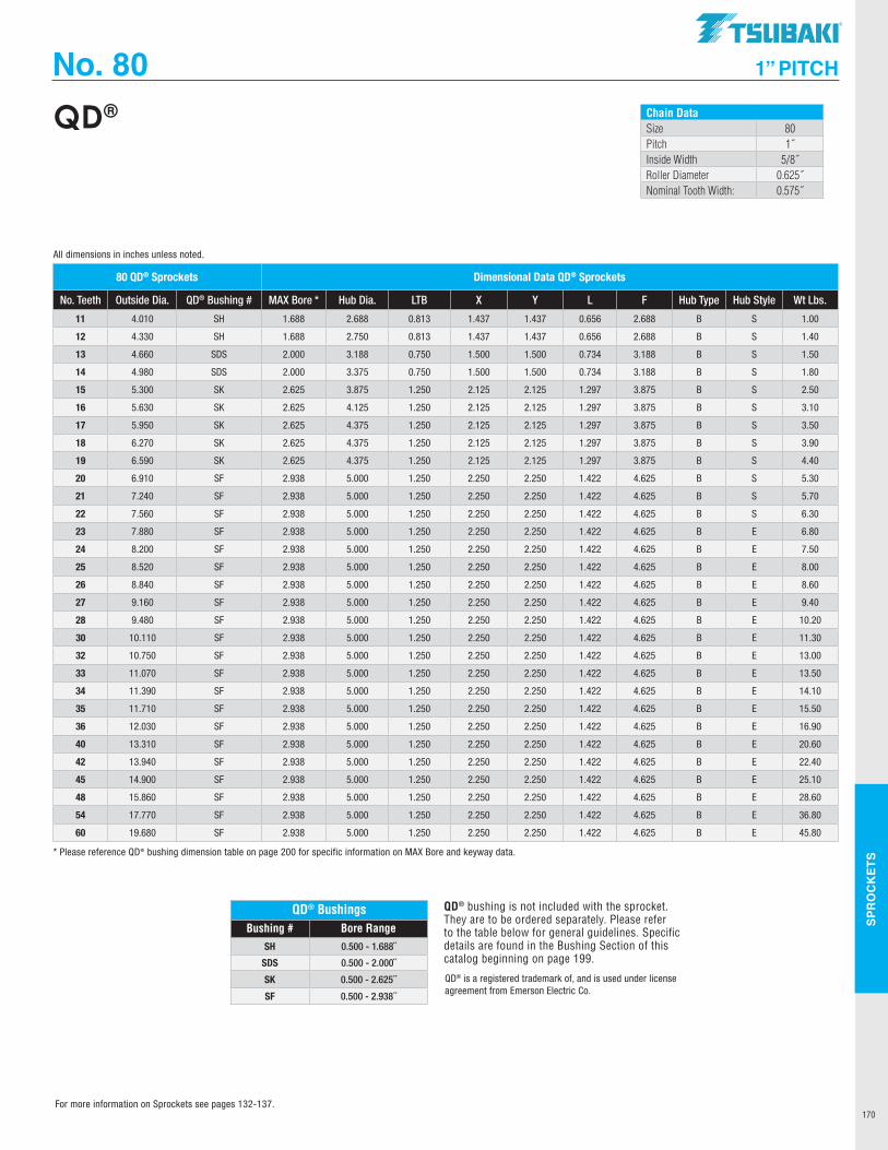
SPR
OC
KET
S
170
No. 80 1” PITCH
Chain DataSize 80Pitch 1˝Inside Width 5/8˝Roller Diameter 0.625˝Nominal Tooth Width: 0.575˝
QD®
QD® BushingsBushing # Bore Range
SH 0.500 - 1.688˝
SDS 0.500 - 2.000˝
SK 0.500 - 2.625˝
SF 0.500 - 2.938˝
QD® bushing is not included with the sprocket. They are to be ordered separately. Please refer to the table below for general guidelines. Specific details are found in the Bushing Section of this catalog beginning on page 199.
QD® is a registered trademark of, and is used under license agreement from Emerson Electric Co.
80 QD® Sprockets Dimensional Data QD® Sprockets
No. Teeth Outside Dia. QD® Bushing # MAX Bore * Hub Dia. LTB X Y L F Hub Type Hub Style Wt Lbs.
11 4.010 SH 1.688 2.688 0.813 1.437 1.437 0.656 2.688 B S 1.00
12 4.330 SH 1.688 2.750 0.813 1.437 1.437 0.656 2.688 B S 1.40
13 4.660 SDS 2.000 3.188 0.750 1.500 1.500 0.734 3.188 B S 1.50
14 4.980 SDS 2.000 3.375 0.750 1.500 1.500 0.734 3.188 B S 1.80
15 5.300 SK 2.625 3.875 1.250 2.125 2.125 1.297 3.875 B S 2.50
16 5.630 SK 2.625 4.125 1.250 2.125 2.125 1.297 3.875 B S 3.10
17 5.950 SK 2.625 4.375 1.250 2.125 2.125 1.297 3.875 B S 3.50
18 6.270 SK 2.625 4.375 1.250 2.125 2.125 1.297 3.875 B S 3.90
19 6.590 SK 2.625 4.375 1.250 2.125 2.125 1.297 3.875 B S 4.40
20 6.910 SF 2.938 5.000 1.250 2.250 2.250 1.422 4.625 B S 5.30
21 7.240 SF 2.938 5.000 1.250 2.250 2.250 1.422 4.625 B S 5.70
22 7.560 SF 2.938 5.000 1.250 2.250 2.250 1.422 4.625 B S 6.30
23 7.880 SF 2.938 5.000 1.250 2.250 2.250 1.422 4.625 B E 6.80
24 8.200 SF 2.938 5.000 1.250 2.250 2.250 1.422 4.625 B E 7.50
25 8.520 SF 2.938 5.000 1.250 2.250 2.250 1.422 4.625 B E 8.00
26 8.840 SF 2.938 5.000 1.250 2.250 2.250 1.422 4.625 B E 8.60
27 9.160 SF 2.938 5.000 1.250 2.250 2.250 1.422 4.625 B E 9.40
28 9.480 SF 2.938 5.000 1.250 2.250 2.250 1.422 4.625 B E 10.20
30 10.110 SF 2.938 5.000 1.250 2.250 2.250 1.422 4.625 B E 11.30
32 10.750 SF 2.938 5.000 1.250 2.250 2.250 1.422 4.625 B E 13.00
33 11.070 SF 2.938 5.000 1.250 2.250 2.250 1.422 4.625 B E 13.50
34 11.390 SF 2.938 5.000 1.250 2.250 2.250 1.422 4.625 B E 14.10
35 11.710 SF 2.938 5.000 1.250 2.250 2.250 1.422 4.625 B E 15.50
36 12.030 SF 2.938 5.000 1.250 2.250 2.250 1.422 4.625 B E 16.90
40 13.310 SF 2.938 5.000 1.250 2.250 2.250 1.422 4.625 B E 20.60
42 13.940 SF 2.938 5.000 1.250 2.250 2.250 1.422 4.625 B E 22.40
45 14.900 SF 2.938 5.000 1.250 2.250 2.250 1.422 4.625 B E 25.10
48 15.860 SF 2.938 5.000 1.250 2.250 2.250 1.422 4.625 B E 28.60
54 17.770 SF 2.938 5.000 1.250 2.250 2.250 1.422 4.625 B E 36.80
60 19.680 SF 2.938 5.000 1.250 2.250 2.250 1.422 4.625 B E 45.80
* Please reference QD® bushing dimension table on page 200 for specific information on MAX Bore and keyway data.
All dimensions in inches unless noted.
For more information on Sprockets see pages 132-137.
TSUBAKI"
-------------
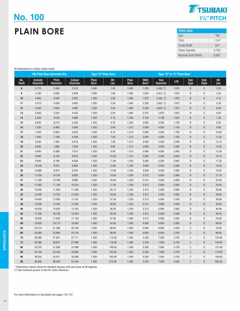
SPR
OC
KET
S
171
No. 100 11/4” PITCH
Chain Data
Size 100
Pitch 1 1/4˝
Inside Width 3/4˝
Roller Diameter 0.750˝
Nominal Tooth Width: 0.692˝
PLAIN BORE
100 Plain Bore Sprocket Dia. Type “A” Plain Bore Type “B” & “C” Plain Bore
No. Teeth
Outside Diameter
Pitch Diameter
Caliper Diameter
Plain Bore
Wt. Lbs.
Plain Bore
MAX Bore *
Hub Diameter LTB Hub
TypeHub Style
Wt. Lbs.
8 3.770 3.266 2.516 1.000 1.40 1.000 1.250 2.438 ¨ 1.875 B S 2.30
9 4.180 3.655 2.849 1.000 1.60 1.000 1.625 2.813 ¨ 1.875 B S 3.20
10 4.600 4.045 3.295 1.000 2.00 1.000 1.875 3.250 ¨ 1.875 B S 4.10
11 5.010 4.438 3.642 1.250 2.50 1.000 2.250 3.563 ¨ 1.875 B S 5.30
12 5.420 4.830 4.080 1.250 3.00 1.000 2.250 4.000 ¨ 1.875 B S 6.40
13 5.820 5.224 4.435 1.250 3.50 1.000 2.375 3.875 1.625 B S 6.50
14 6.230 5.618 4.868 1.250 4.10 1.250 2.750 4.188 1.625 B S 7.40
15 6.630 6.013 5.229 1.250 4.70 1.250 3.000 4.500 1.750 B D 9.20
16 7.030 6.408 5.658 1.250 5.40 1.313 3.000 4.500 1.750 B D 9.90
17 7.440 6.803 6.024 1.250 6.10 1.313 3.000 4.500 1.750 B D 10.80
18 7.840 7.199 6.449 1.250 7.00 1.313 3.000 4.500 1.750 B D 11.50
19 8.240 7.595 6.819 1.250 7.80 1.313 3.000 4.500 2.000 B D 13.10
20 8.640 7.990 7.240 1.250 8.80 1.313 3.000 4.500 2.000 B D 14.20
21 9.040 8.388 7.613 1.250 9.80 1.313 3.000 4.500 2.000 B D 15.30
22 9.440 8.784 8.034 1.250 10.50 1.313 3.000 4.500 2.000 B D 16.10
23 9.840 9.180 8.409 1.250 11.80 1.250 3.000 4.500 2.000 B D 17.20
24 10.250 9.576 8.826 1.250 12.80 1.250 3.000 4.500 2.000 B D 19.20
25 10.660 9.974 9.204 1.250 13.90 1.250 3.000 4.500 2.000 B D 19.50
26 11.050 10.370 9.620 1.250 15.00 1.250 3.313 5.000 2.000 B D 21.70
27 11.440 10.768 9.999 1.250 16.00 1.250 3.313 5.000 2.000 B D 23.00
28 11.840 11.164 10.414 1.250 17.40 1.250 3.313 5.000 2.000 B D 24.40
30 12.640 11.959 11.209 1.250 20.10 1.250 3.313 5.000 2.000 B D 26.90
32 13.440 12.753 12.003 1.250 22.60 1.250 3.313 5.000 2.000 B D 29.80
35 14.640 13.945 13.181 1.250 27.20 1.250 3.313 5.000 2.500 B D 36.90
36 15.040 14.343 13.593 1.250 30.00 1.250 3.313 5.000 2.500 B D 38.60
40 16.630 15.933 15.183 1.250 36.00 1.250 3.313 5.000 2.500 B D 46.90
42 17.430 16.728 15.978 1.250 40.00 1.250 3.313 5.000 2.500 B D 50.40
45 18.630 17.920 17.159 1.500 47.00 1.500 3.313 5.000 2.500 B D 54.00
48 19.820 19.113 18.363 1.500 54.00 1.500 4.000 6.000 2.500 B D 66.00
54 22.210 21.498 20.748 1.500 68.00 1.500 4.000 6.000 3.250 C D 78.00
60 24.600 23.884 23.134 1.500 80.00 1.500 4.000 6.000 3.250 C D 89.00
70 28.580 27.861 27.111 1.500 113.00 1.500 5.250 7.000 3.750 C D 125.00
72 29.380 28.657 27.908 1.500 119.00 1.500 5.250 7.000 3.750 C D 134.00
80 32.570 31.839 31.089 1.500 146.00 1.500 5.250 7.000 3.750 C D 151.00
84 34.160 33.430 32.680 1.500 162.00 1.500 5.250 7.000 3.750 C D 170.00
90 36.550 35.817 35.068 1.500 193.00 1.500 5.250 7.000 3.750 C D 184.00
96 38.930 38.204 37.454 1.500 215.00 1.500 5.250 7.000 4.500 C D 203.00
* Dimensions shown allow for standard keyway with set screw at 90 degrees.¨ Has recessed groove in hub for chain clearance.
All dimensions in inches unless noted.
For more information on Sprockets see pages 132-137.
.TSUBAKI"
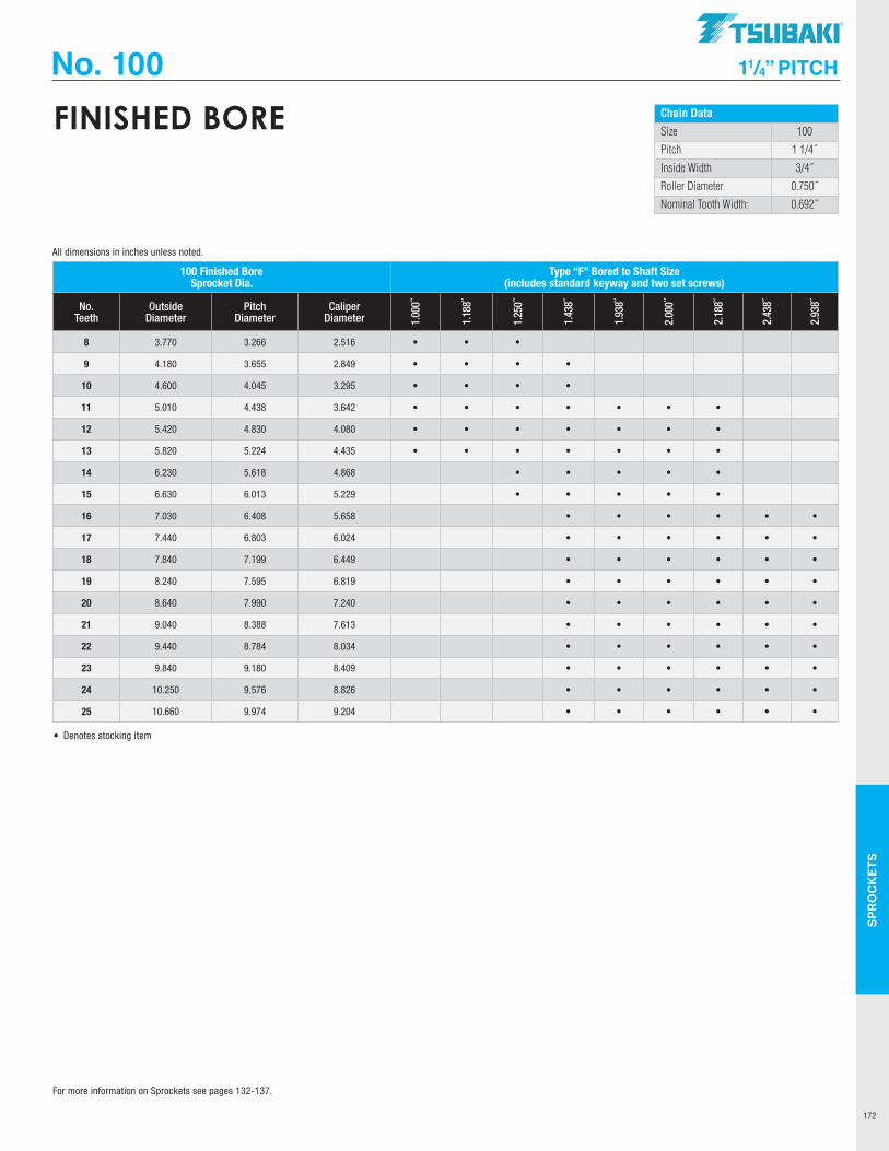
SPR
OC
KET
S
172
No. 100 11/4” PITCH
Chain Data
Size 100
Pitch 1 1/4˝
Inside Width 3/4˝
Roller Diameter 0.750˝
Nominal Tooth Width: 0.692˝
FINISHED BORE
100 Finished Bore Sprocket Dia.
Type “F” Bored to Shaft Size (includes standard keyway and two set screws)
No. Teeth
Outside Diameter
Pitch Diameter
Caliper Diameter 1.
000˝
1.18
8˝
1.25
0˝
1.43
8˝
1.93
8˝
2.00
0˝
2.18
8˝
2.43
8˝
2.93
8˝
8 3.770 3.266 2.516 • • •
9 4.180 3.655 2.849 • • • •
10 4.600 4.045 3.295 • • • •
11 5.010 4.438 3.642 • • • • • • •
12 5.420 4.830 4.080 • • • • • • •
13 5.820 5.224 4.435 • • • • • • •
14 6.230 5.618 4.868 • • • • •
15 6.630 6.013 5.229 • • • • •
16 7.030 6.408 5.658 • • • • • •
17 7.440 6.803 6.024 • • • • • •
18 7.840 7.199 6.449 • • • • • •
19 8.240 7.595 6.819 • • • • • •
20 8.640 7.990 7.240 • • • • • •
21 9.040 8.388 7.613 • • • • • •
22 9.440 8.784 8.034 • • • • • •
23 9.840 9.180 8.409 • • • • • •
24 10.250 9.576 8.826 • • • • • •
25 10.660 9.974 9.204 • • • • • •
• Denotes stocking item
All dimensions in inches unless noted.
For more information on Sprockets see pages 132-137.
TSUBAKI"

SPR
OC
KET
S
173
No. 100 11/4” PITCH
Chain DataSize 100-2, 100-3
Pitch 1 1/4˝
Inside Width 3/4˝
Roller Diameter 0.750˝
Nominal Tooth Width: 0.669˝
MULTI-STRAND
100 Multi-Strand Sprocket Dia. Dimensional Data: Double Strand Sprockets
No. Teeth Outside Dia. Plain Bore Hub Dia. LTB MAX Bore * Hub Type Hub Style Weight Lbs.9 4.180 1.000 2.375 2.875 1.625 B S 4.60
10 4.600 1.000 2.375 2.875 1.875 B S 6.20
11 5.010 1.000 3.125 2.875 2.125 B S 7.90
12 5.420 1.125 3.375 2.875 2.250 B S 9.30
13 5.820 1.125 3.813 2.875 2.500 B S 11.40
14 6.230 1.125 4.188 2.875 2.750 B S 13.60
15 6.630 1.250 4.625 3.125 3.125 B S 17.10
16 7.030 1.250 5.000 3.125 3.313 B S 20.10
17 7.440 1.250 5.250 3.125 3.500 B S 23.10
18 7.840 1.250 5.250 3.125 3.500 B S 25.40
19 8.240 1.250 5.500 3.375 3.750 B S 29.60
20 8.640 1.250 5.500 3.375 3.750 B S 32.40
21 9.040 1.250 5.500 3.375 3.750 B S 35.30
22 9.440 1.250 5.500 3.375 3.750 B D 38.40
23 9.840 1.250 5.500 3.375 3.750 B D 41.30
24 10.250 1.250 5.750 3.375 3.750 B D 45.10
25 10.660 1.250 5.750 3.375 3.750 B D 48.50
26 11.050 1.500 5.750 3.375 3.750 B D 51.50
30 12.640 1.500 5.750 3.375 3.750 B D 65.00
32 13.440 1.500 5.750 3.375 3.750 B D 69.00
35 14.640 1.500 6.000 4.250 3.813 B D 75.00
36 15.038 1.500 6.000 4.500 4.000 B D 90.80
100 Multi-Strand Sprocket Dia. Dimensional Data: Triple Strand Sprockets
No. Teeth Outside Dia. Plain Bore Hub Dia. LTB MAX Bore * Hub Type Hub Style Weight Lbs.
12 5.420 1.125 3.375 4.250 2.250 B S 13.70
13 5.820 1.125 3.813 4.250 2.500 B S 16.90
14 6.230 1.125 4.188 4.250 2.750 B S 20.20
15 6.630 1.250 4.625 4.500 3.125 B S 25.00
16 7.030 1.250 5.000 4.500 3.313 B S 29.30
17 7.440 1.250 5.250 4.500 3.500 B S 33.80
18 7.840 1.250 5.250 4.750 3.500 B S 38.60
19 8.240 1.250 5.500 4.750 3.750 B D 43.30
20 8.640 1.250 5.500 4.750 3.750 B D 47.90
21 9.040 1.250 5.500 4.750 3.750 B D 52.30
22 9.440 1.250 5.500 4.750 3.750 B D 57.50
23 9.840 1.250 5.500 4.750 3.750 B D 62.50
24 10.250 1.250 5.750 4.750 3.750 B D 69.00
25 10.660 1.250 5.750 4.750 3.750 B D 73.00
26 11.050 1.500 5.750 4.750 3.813 B D 79.00
30 12.640 1.500 5.750 4.750 3.813 B D 103.00
* Dimensions shown allow for standard keyway with set screw at 90 degrees.
All dimensions in inches unless noted.
* Dimensions shown allow for standard keyway with set screw at 90 degrees.
For more information on Sprockets see pages 132-137.
.TSUBAKI"
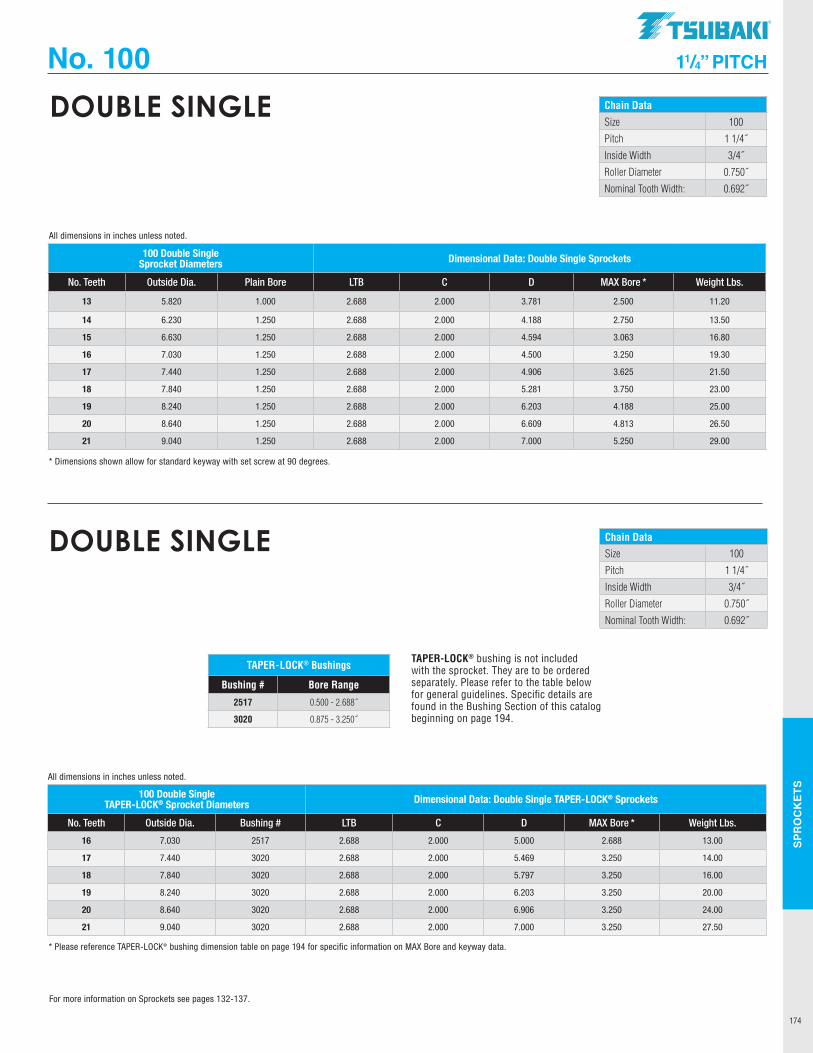
SPR
OC
KET
S
174
No. 100 11/4” PITCH
Chain Data
Size 100
Pitch 1 1/4˝
Inside Width 3/4˝
Roller Diameter 0.750˝
Nominal Tooth Width: 0.692˝
DOUBLE SINGLE
100 Double Single Sprocket Diameters Dimensional Data: Double Single Sprockets
No. Teeth Outside Dia. Plain Bore LTB C D MAX Bore * Weight Lbs.
13 5.820 1.000 2.688 2.000 3.781 2.500 11.20
14 6.230 1.250 2.688 2.000 4.188 2.750 13.50
15 6.630 1.250 2.688 2.000 4.594 3.063 16.80
16 7.030 1.250 2.688 2.000 4.500 3.250 19.30
17 7.440 1.250 2.688 2.000 4.906 3.625 21.50
18 7.840 1.250 2.688 2.000 5.281 3.750 23.00
19 8.240 1.250 2.688 2.000 6.203 4.188 25.00
20 8.640 1.250 2.688 2.000 6.609 4.813 26.50
21 9.040 1.250 2.688 2.000 7.000 5.250 29.00
* Dimensions shown allow for standard keyway with set screw at 90 degrees.
All dimensions in inches unless noted.
Chain DataSize 100
Pitch 1 1/4˝
Inside Width 3/4˝
Roller Diameter 0.750˝
Nominal Tooth Width: 0.692˝
DOUBLE SINGLE
TAPER-LOCK® bushing is not included with the sprocket. They are to be ordered separately. Please refer to the table below for general guidelines. Specific details are found in the Bushing Section of this catalog beginning on page 194.
TAPER-LOCK® Bushings
Bushing # Bore Range
2517 0.500 - 2.688˝
3020 0.875 - 3.250˝
100 Double Single TAPER-LOCK® Sprocket Diameters Dimensional Data: Double Single TAPER-LOCK® Sprockets
No. Teeth Outside Dia. Bushing # LTB C D MAX Bore * Weight Lbs.
16 7.030 2517 2.688 2.000 5.000 2.688 13.00
17 7.440 3020 2.688 2.000 5.469 3.250 14.00
18 7.840 3020 2.688 2.000 5.797 3.250 16.00
19 8.240 3020 2.688 2.000 6.203 3.250 20.00
20 8.640 3020 2.688 2.000 6.906 3.250 24.00
21 9.040 3020 2.688 2.000 7.000 3.250 27.50
* Please reference TAPER-LOCK® bushing dimension table on page 194 for specific information on MAX Bore and keyway data.
All dimensions in inches unless noted.
For more information on Sprockets see pages 132-137.
TSUBAKI"
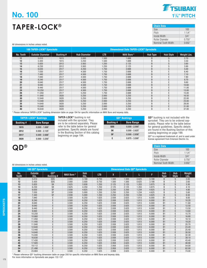
SPR
OC
KET
S
175
100 TAPER-LOCK® Sprockets Dimensional Data TAPER-LOCK® Sprockets
No. Teeth Outside Diameter Bushing # Hub Diameter LTB MAX Bore * Hub Type Hub Style Weight Lbs. 11 5.010 1615 3.000 1.500 1.688 B S 2.7012 5.420 1615 3.250 1.500 1.688 B S 3.5013 5.820 2012 3.563 1.250 2.125 B S 3.6014 6.230 2012 3.563 1.250 2.125 B S 3.9015 6.630 2517 4.250 1.750 2.688 B S 5.0016 7.030 2517 4.500 1.750 2.688 B E 6.4017 7.440 2517 4.500 1.750 2.688 B E 7.1018 7.840 2517 4.500 1.750 2.688 B E 7.8019 8.240 2517 4.500 1.750 2.688 B E 8.7020 8.640 2517 4.500 1.750 2.688 B E 9.6021 9.040 2517 4.500 1.750 2.688 B E 10.6022 9.440 2517 4.500 1.750 2.688 B E 11.0024 10.250 2517 4.500 1.750 2.688 B E 13.0026 11.050 2517 5.250 1.750 2.688 B E 15.0028 11.840 3020 5.250 2.000 3.250 B E 16.5030 12.640 3020 5.250 2.000 3.250 B E 22.0032 13.440 3020 5.250 2.000 3.250 B E 23.0035 14.640 3020 5.250 2.000 3.250 B E 28.0036 15.040 3020 5.250 2.000 3.250 B E 31.0040 16.630 3020 5.250 2.000 3.250 B E 37.00
* Please reference TAPER-LOCK® bushing dimension table on page 194 for specific information on MAX Bore and keyway data.
All dimensions in inches unless noted.
No. 100 11/4” PITCH
Chain DataSize 100Pitch 1 1/4˝Inside Width 3/4˝Roller Diameter 0.750˝Nominal Tooth Width: 0.692˝
TAPER-LOCK®
TAPER-LOCK® Bushings
Bushing # Bore Range
1615 0.500 - 1.688˝
2012 0.500 - 2.125˝
2517 0.500 - 2.688˝
3020 0.500 - 3.250˝
TAPER-LOCK® bushing is not included with the sprocket. They are to be ordered separately. Please refer to the table below for general guidelines. Specific details are found in the Bushing Section of this catalog beginning on page 194.
Chain DataSize 100Pitch 1 1/4˝Inside Width 3/4˝Roller Diameter 0.750˝Nominal Tooth Width: 0.692˝
QD®
QD® is a registered trademark of, and is used under license agreement from Emerson Electric Co.
QD® bushing is not included with the sprocket. They are to be ordered sep-arately. Please refer to the table below for general guidelines. Specific details are found in the Bushing Section of this catalog beginning on page 199.
QD® Bushings
Bushing # Bore RangeSDS 0.500 - 2.000˝
SK 0.500 - 2.625˝
SF 0.500 - 2.938˝
E 0.875 - 3.500˝
100 QD® Sprockets Dimensional Data QD® Sprockets
No. Teeth
Outside Dia.
QD® Bushing # MAX Bore * Hub
Dia. LTB X Y L F Hub Type
Hub Style
Weight Lbs.
11 5.010 SDS 2.000 3.188 0.750 1.500 1.500 0.625 3.188 B S 2.0012 5.420 SDS 2.000 3.500 0.750 1.500 1.500 0.625 3.188 B S 2.6013 5.820 SK 2.625 3.938 1.250 2.125 2.125 1.203 3.875 B S 3.3014 6.230 SK 2.625 4.250 1.250 2.125 2.125 1.203 3.875 B S 4.1015 6.630 SF 2.938 4.625 1.250 2.250 2.250 1.234 4.625 B S 4.8016 7.030 SF 2.938 5.000 1.250 2.250 2.250 1.234 4.625 B S 5.6017 7.440 SF 2.938 5.000 1.250 2.250 2.250 1.234 4.625 B S 6.5018 7.840 E 3.500 6.250 1.625 2.938 2.625 1.813 6.000 B1 S 9.0019 8.240 E 3.500 6.250 1.625 2.938 2.625 1.813 6.000 B1 S 10.2020 8.640 E 3.500 6.250 1.625 2.938 2.625 1.813 6.000 B1 S 11.6021 9.040 E 3.500 6.250 1.625 2.938 2.625 1.813 6.000 B1 S 12.5022 9.440 E 3.500 6.250 1.625 2.938 2.625 1.813 6.000 B1 E 13.5023 9.840 E 3.500 6.250 1.625 2.938 2.625 1.813 6.000 B1 E 14.6024 10.250 E 3.500 6.250 1.625 2.938 2.625 1.813 6.000 B1 E 15.7025 10.660 E 3.500 6.250 1.625 2.938 2.625 1.813 6.000 B1 E 16.8026 11.050 E 3.500 6.250 1.625 2.938 2.625 1.813 6.000 B1 E 18.1027 11.440 E 3.500 6.250 1.625 2.938 2.625 1.813 6.000 B1 E 19.2028 11.840 E 3.500 6.250 1.625 2.938 2.625 1.813 6.000 B1 E 20.7030 12.640 E 3.500 6.250 1.625 2.938 2.625 1.813 6.000 B1 E 23.2032 13.440 E 3.500 6.250 1.625 2.938 2.625 1.813 6.000 B1 E 25.4035 14.640 E 3.500 6.250 1.625 2.938 2.625 1.813 6.000 B1 E 30.5036 15.040 E 3.500 6.250 1.625 2.938 2.625 1.813 6.000 B1 E 32.3040 16.630 E 3.500 6.250 1.625 2.938 2.625 1.813 6.000 B1 E 39.1042 17.430 E 3.500 6.250 1.625 2.938 2.625 1.813 6.000 B1 E 43.4045 17.920 E 3.500 6.250 1.625 2.958 2.625 1.813 6.000 B1 E 48.9048 19.112 E 3.500 6.250 1.625 2.958 2.625 1.813 6.000 B1 E 54.0054 21.498 E 3.500 6.250 1.625 2.958 2.625 1.813 6.000 B1 E 62.0060 23.884 E 3.500 6.250 1.625 2.958 2.625 1.813 6.000 B1 E 74.00
* Please reference QD® bushing dimension table on page 200 for specific information on MAX Bore and keyway data.
All dimensions in inches unless noted.
For more information on Sprockets see pages 132-137.
.TSUBAKI"
---
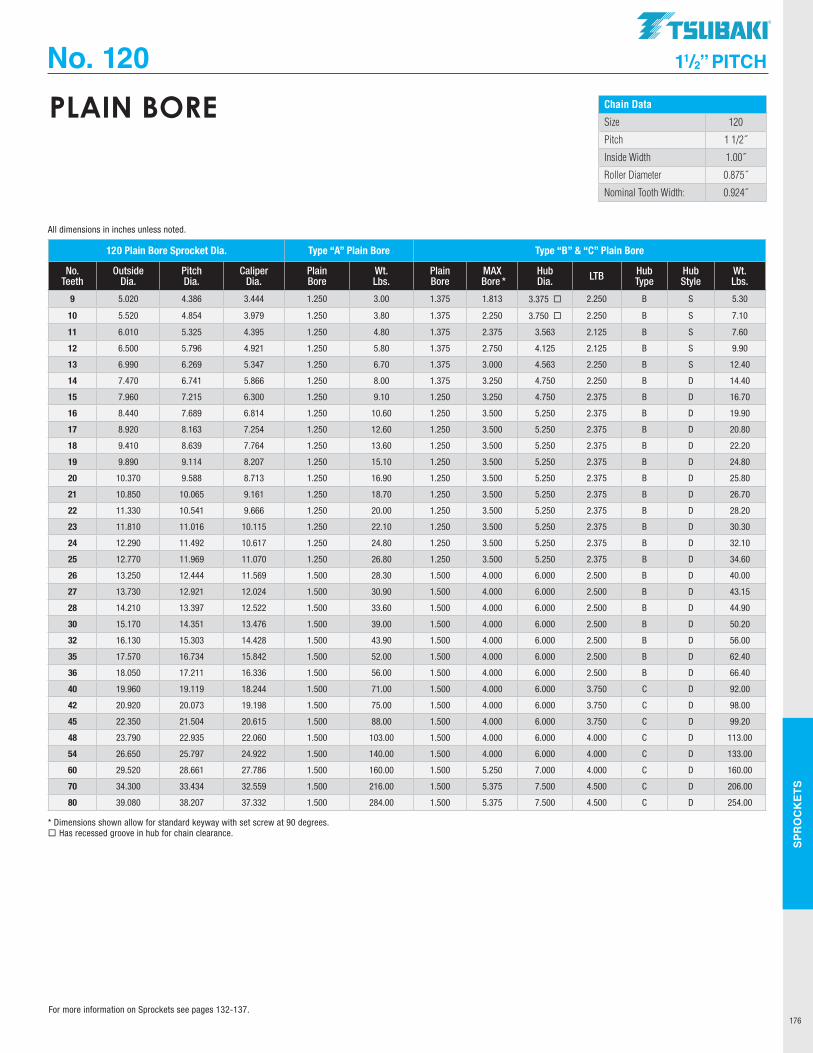
SPR
OC
KET
S
176
No. 120 11/2” PITCH
Chain Data
Size 120
Pitch 1 1/2˝
Inside Width 1.00˝
Roller Diameter 0.875˝
Nominal Tooth Width: 0.924˝
PLAIN BORE
120 Plain Bore Sprocket Dia. Type “A” Plain Bore Type “B” & “C” Plain Bore
No. Teeth
Outside Dia.
Pitch Dia.
Caliper Dia.
Plain Bore
Wt. Lbs.
Plain Bore
MAX Bore *
Hub Dia. LTB Hub
TypeHub Style
Wt. Lbs.
9 5.020 4.386 3.444 1.250 3.00 1.375 1.813 3.375 ¨ 2.250 B S 5.30
10 5.520 4.854 3.979 1.250 3.80 1.375 2.250 3.750 ¨ 2.250 B S 7.10
11 6.010 5.325 4.395 1.250 4.80 1.375 2.375 3.563 2.125 B S 7.60
12 6.500 5.796 4.921 1.250 5.80 1.375 2.750 4.125 2.125 B S 9.90
13 6.990 6.269 5.347 1.250 6.70 1.375 3.000 4.563 2.250 B S 12.40
14 7.470 6.741 5.866 1.250 8.00 1.375 3.250 4.750 2.250 B D 14.40
15 7.960 7.215 6.300 1.250 9.10 1.250 3.250 4.750 2.375 B D 16.70
16 8.440 7.689 6.814 1.250 10.60 1.250 3.500 5.250 2.375 B D 19.90
17 8.920 8.163 7.254 1.250 12.60 1.250 3.500 5.250 2.375 B D 20.80
18 9.410 8.639 7.764 1.250 13.60 1.250 3.500 5.250 2.375 B D 22.20
19 9.890 9.114 8.207 1.250 15.10 1.250 3.500 5.250 2.375 B D 24.80
20 10.370 9.588 8.713 1.250 16.90 1.250 3.500 5.250 2.375 B D 25.80
21 10.850 10.065 9.161 1.250 18.70 1.250 3.500 5.250 2.375 B D 26.70
22 11.330 10.541 9.666 1.250 20.00 1.250 3.500 5.250 2.375 B D 28.20
23 11.810 11.016 10.115 1.250 22.10 1.250 3.500 5.250 2.375 B D 30.30
24 12.290 11.492 10.617 1.250 24.80 1.250 3.500 5.250 2.375 B D 32.10
25 12.770 11.969 11.070 1.250 26.80 1.250 3.500 5.250 2.375 B D 34.60
26 13.250 12.444 11.569 1.500 28.30 1.500 4.000 6.000 2.500 B D 40.00
27 13.730 12.921 12.024 1.500 30.90 1.500 4.000 6.000 2.500 B D 43.15
28 14.210 13.397 12.522 1.500 33.60 1.500 4.000 6.000 2.500 B D 44.90
30 15.170 14.351 13.476 1.500 39.00 1.500 4.000 6.000 2.500 B D 50.20
32 16.130 15.303 14.428 1.500 43.90 1.500 4.000 6.000 2.500 B D 56.00
35 17.570 16.734 15.842 1.500 52.00 1.500 4.000 6.000 2.500 B D 62.40
36 18.050 17.211 16.336 1.500 56.00 1.500 4.000 6.000 2.500 B D 66.40
40 19.960 19.119 18.244 1.500 71.00 1.500 4.000 6.000 3.750 C D 92.00
42 20.920 20.073 19.198 1.500 75.00 1.500 4.000 6.000 3.750 C D 98.00
45 22.350 21.504 20.615 1.500 88.00 1.500 4.000 6.000 3.750 C D 99.20
48 23.790 22.935 22.060 1.500 103.00 1.500 4.000 6.000 4.000 C D 113.00
54 26.650 25.797 24.922 1.500 140.00 1.500 4.000 6.000 4.000 C D 133.00
60 29.520 28.661 27.786 1.500 160.00 1.500 5.250 7.000 4.000 C D 160.00
70 34.300 33.434 32.559 1.500 216.00 1.500 5.375 7.500 4.500 C D 206.00
80 39.080 38.207 37.332 1.500 284.00 1.500 5.375 7.500 4.500 C D 254.00
* Dimensions shown allow for standard keyway with set screw at 90 degrees.¨ Has recessed groove in hub for chain clearance.
All dimensions in inches unless noted.
For more information on Sprockets see pages 132-137.
TSUBAKI"
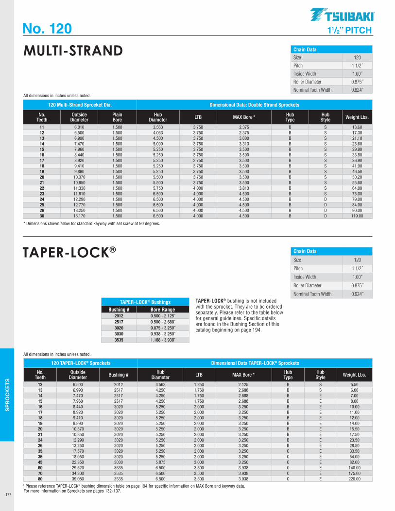
SPR
OC
KET
S
177
No. 120 11/2” PITCH
Chain DataSize 120
Pitch 1 1/2˝
Inside Width 1.00˝
Roller Diameter 0.875˝
Nominal Tooth Width: 0.824˝
MULTI-STRAND
120 Multi-Strand Sprocket Dia. Dimensional Data: Double Strand Sprockets
No. Teeth
Outside Diameter
Plain Bore
Hub Diameter LTB MAX Bore * Hub
TypeHub Style Weight Lbs.
11 6.010 1.500 3.563 3.750 2.375 B S 13.6012 6.500 1.500 4.063 3.750 2.375 B S 17.3013 6.990 1.500 4.500 3.750 3.000 B S 21.1014 7.470 1.500 5.000 3.750 3.313 B S 25.6015 7.960 1.500 5.250 3.750 3.500 B S 29.9016 8.440 1.500 5.250 3.750 3.500 B S 33.8017 8.920 1.500 5.250 3.750 3.500 B S 36.9018 9.410 1.500 5.250 3.750 3.500 B S 41.9019 9.890 1.500 5.250 3.750 3.500 B S 46.5020 10.370 1.500 5.500 3.750 3.500 B S 50.2021 10.850 1.500 5.500 3.750 3.500 B S 55.6022 11.330 1.500 5.750 4.000 3.813 B S 64.0023 11.810 1.500 6.500 4.000 4.500 B S 75.0024 12.290 1.500 6.500 4.000 4.500 B D 79.0025 12.770 1.500 6.500 4.000 4.500 B D 84.0026 13.250 1.500 6.500 4.000 4.500 B D 90.0030 15.170 1.500 6.500 4.000 4.500 B D 119.00
* Dimensions shown allow for standard keyway with set screw at 90 degrees.
All dimensions in inches unless noted.
Chain Data
Size 120
Pitch 1 1/2˝
Inside Width 1.00˝
Roller Diameter 0.875˝
Nominal Tooth Width: 0.924˝
TAPER-LOCK®
120 TAPER-LOCK® Sprockets Dimensional Data TAPER-LOCK® Sprockets
No. Teeth
Outside Diameter Bushing # Hub
Diameter LTB MAX Bore * Hub Type
Hub Style Weight Lbs.
12 6.500 2012 3.563 1.250 2.125 B S 5.5013 6.990 2517 4.250 1.750 2.688 B S 6.0014 7.470 2517 4.250 1.750 2.688 B E 7.0015 7.960 2517 4.250 1.750 2.688 B E 8.0016 8.440 3020 5.250 2.000 3.250 B E 10.0017 8.920 3020 5.250 2.000 3.250 B E 11.0018 9.410 3020 5.250 2.000 3.250 B E 12.0019 9.890 3020 5.250 2.000 3.250 B E 14.0020 10.370 3020 5.250 2.000 3.250 B E 15.5021 10.850 3020 5.250 2.000 3.250 B E 17.5024 12.290 3020 5.250 2.000 3.250 B E 23.5026 13.250 3020 5.250 2.000 3.250 B E 28.5035 17.570 3020 5.250 2.000 3.250 C E 33.5036 18.050 3020 5.250 2.000 3.250 C E 54.0045 22.350 3030 5.875 3.000 3.250 C E 82.0060 29.520 3535 6.500 3.500 3.938 C E 140.0070 34.300 3535 6.500 3.500 3.938 C E 175.0080 39.080 3535 6.500 3.500 3.938 C E 220.00
* Please reference TAPER-LOCK® bushing dimension table on page 194 for specific information on MAX Bore and keyway data.
All dimensions in inches unless noted.
TAPER-LOCK® BushingsBushing # Bore Range
2012 0.500 - 2.125˝2517 0.500 - 2.688˝3020 0.875 - 3.250˝3030 0.938 - 3.250˝3535 1.188 - 3.938˝
TAPER-LOCK® bushing is not included with the sprocket. They are to be ordered separately. Please refer to the table below for general guidelines. Specific details are found in the Bushing Section of this catalog beginning on page 194.
For more information on Sprockets see pages 132-137.
.TSUBAKI"
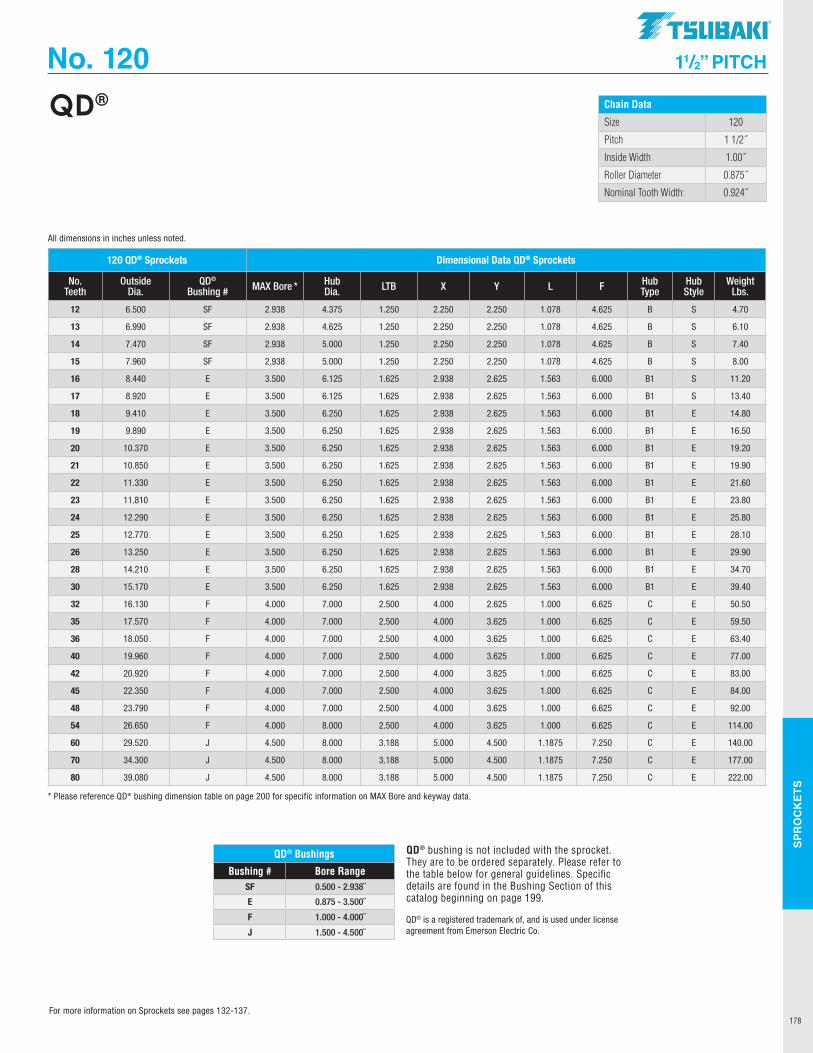
SPR
OC
KET
S
178
No. 120 11/2” PITCH
Chain Data
Size 120
Pitch 1 1/2˝
Inside Width 1.00˝
Roller Diameter 0.875˝
Nominal Tooth Width: 0.924˝
QD®
QD® is a registered trademark of, and is used under license agreement from Emerson Electric Co.
QD® bushing is not included with the sprocket. They are to be ordered separately. Please refer to the table below for general guidelines. Specific details are found in the Bushing Section of this catalog beginning on page 199.
QD® Bushings
Bushing # Bore RangeSF 0.500 - 2.938˝
E 0.875 - 3.500˝
F 1.000 - 4.000˝
J 1.500 - 4.500˝
120 QD® Sprockets Dimensional Data QD® Sprockets
No. Teeth
Outside Dia.
QD® Bushing # MAX Bore * Hub
Dia. LTB X Y L F Hub Type
Hub Style
Weight Lbs.
12 6.500 SF 2.938 4.375 1.250 2.250 2.250 1.078 4.625 B S 4.70
13 6.990 SF 2.938 4.625 1.250 2.250 2.250 1.078 4.625 B S 6.10
14 7.470 SF 2.938 5.000 1.250 2.250 2.250 1.078 4.625 B S 7.40
15 7.960 SF 2.938 5.000 1.250 2.250 2.250 1.078 4.625 B S 8.00
16 8.440 E 3.500 6.125 1.625 2.938 2.625 1.563 6.000 B1 S 11.20
17 8.920 E 3.500 6.125 1.625 2.938 2.625 1.563 6.000 B1 S 13.40
18 9.410 E 3.500 6.250 1.625 2.938 2.625 1.563 6.000 B1 E 14.80
19 9.890 E 3.500 6.250 1.625 2.938 2.625 1.563 6.000 B1 E 16.50
20 10.370 E 3.500 6.250 1.625 2.938 2.625 1.563 6.000 B1 E 19.20
21 10.850 E 3.500 6.250 1.625 2.938 2.625 1.563 6.000 B1 E 19.90
22 11.330 E 3.500 6.250 1.625 2.938 2.625 1.563 6.000 B1 E 21.60
23 11.810 E 3.500 6.250 1.625 2.938 2.625 1.563 6.000 B1 E 23.80
24 12.290 E 3.500 6.250 1.625 2.938 2.625 1.563 6.000 B1 E 25.80
25 12.770 E 3.500 6.250 1.625 2.938 2.625 1.563 6.000 B1 E 28.10
26 13.250 E 3.500 6.250 1.625 2.938 2.625 1.563 6.000 B1 E 29.90
28 14.210 E 3.500 6.250 1.625 2.938 2.625 1.563 6.000 B1 E 34.70
30 15.170 E 3.500 6.250 1.625 2.938 2.625 1.563 6.000 B1 E 39.40
32 16.130 F 4.000 7.000 2.500 4.000 2.625 1.000 6.625 C E 50.50
35 17.570 F 4.000 7.000 2.500 4.000 3.625 1.000 6.625 C E 59.50
36 18.050 F 4.000 7.000 2.500 4.000 3.625 1.000 6.625 C E 63.40
40 19.960 F 4.000 7.000 2.500 4.000 3.625 1.000 6.625 C E 77.00
42 20.920 F 4.000 7.000 2.500 4.000 3.625 1.000 6.625 C E 83.00
45 22.350 F 4.000 7.000 2.500 4.000 3.625 1.000 6.625 C E 84.00
48 23.790 F 4.000 7.000 2.500 4.000 3.625 1.000 6.625 C E 92.00
54 26.650 F 4.000 8.000 2.500 4.000 3.625 1.000 6.625 C E 114.00
60 29.520 J 4.500 8.000 3.188 5.000 4.500 1.1875 7.250 C E 140.00
70 34.300 J 4.500 8.000 3.188 5.000 4.500 1.1875 7.250 C E 177.00
80 39.080 J 4.500 8.000 3.188 5.000 4.500 1.1875 7.250 C E 222.00
* Please reference QD® bushing dimension table on page 200 for specific information on MAX Bore and keyway data.
All dimensions in inches unless noted.
For more information on Sprockets see pages 132-137.
TSUBAKI"
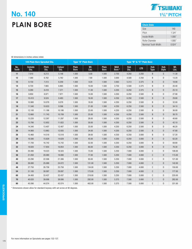
SPR
OC
KET
S
179
No. 140 13/4” PITCH
Chain DataSize 140
Pitch 1 3/4˝
Inside Width 1.000˝
Roller Diameter 1.000˝
Nominal Tooth Width: 0.924˝
PLAIN BORE
140 Plain Bore Sprocket Dia. Type “A” Plain Bore Type “B” & “C” Plain Bore
No. Teeth
Outside Dia.
Pitch Dia.
Caliper Dia.
Plain Bore
Wt. Lbs.
Plain Bore
MAX Bore *
Hub Dia. LTB Hub
TypeHub Style
Wt. Lbs.
11 7.010 6.213 5.148 1.500 5.00 1.500 2.750 4.250 2.250 B S 11.30
12 7.580 6.762 5.762 1.500 7.80 1.500 3.000 4.500 2.250 B D 13.20
13 8.150 7.313 6.259 1.500 8.20 1.500 3.563 5.313 2.375 B D 18.90
14 8.720 7.865 6.865 1.500 10.00 1.500 3.750 5.500 2.375 B D 20.40
15 9.280 8.418 7.371 1.500 11.00 1.500 4.250 6.250 2.375 B D 25.10
16 9.850 8.971 7.971 1.500 14.00 1.500 4.250 6.250 2.500 B D 27.90
17 10.410 9.524 8.483 1.500 16.00 1.500 4.250 6.250 2.500 B D 29.80
18 10.980 10.078 9.078 1.500 18.00 1.500 4.250 6.250 2.500 B D 32.00
19 11.540 10.633 9.596 1.500 21.00 1.500 4.250 6.250 2.500 B D 34.10
20 12.100 11.186 10.186 1.500 23.00 1.500 4.250 6.250 2.500 B D 36.00
21 12.660 11.743 10.709 1.500 25.00 1.500 4.250 6.250 2.500 B D 38.70
22 13.220 12.297 11.297 1.500 28.00 1.500 4.250 6.250 2.500 B D 40.60
23 13.780 12.852 11.822 1.500 30.00 1.500 4.250 6.250 2.500 B D 42.10
24 14.340 13.407 12.407 1.500 33.00 1.500 4.250 6.250 2.500 B D 46.20
25 14.900 13.963 12.935 1.500 34.00 1.500 4.250 6.250 2.500 B D 47.80
26 15.460 14.518 13.518 1.500 39.00 1.500 4.250 6.250 3.000 B D 57.20
28 16.580 15.629 14.629 1.500 45.00 1.500 4.250 6.250 3.000 B D 62.20
30 17.700 16.742 15.742 1.500 52.00 1.500 4.250 6.250 3.000 B D 69.80
32 18.820 17.854 16.854 1.500 60.00 1.500 4.250 6.250 3.000 B D 76.30
35 20.490 19.523 18.503 1.500 73.00 1.500 5.250 7.000 4.000 C D 108.00
36 21.050 20.080 19.080 1.500 77.00 1.500 5.250 7.000 4.000 C D 115.00
40 23.290 22.306 21.306 1.500 93.00 1.500 5.250 7.000 4.000 C D 121.00
45 26.080 25.088 24.072 1.500 131.00 1.500 5.250 7.000 4.000 C D 142.00
48 27.750 26.758 25.758 1.500 134.00 1.500 5.250 7.000 4.000 C D 150.00
54 31.100 30.097 29.097 1.500 173.00 1.500 5.250 7.000 4.000 C D 177.00
60 34.400 33.437 32.437 1.500 219.00 1.500 5.250 7.000 5.000 C D 220.00
70 40.020 39.006 38.006 1.500 292.00 1.500 5.375 7.500 5.000 C D 282.00
80 45.590 44.574 43.574 1.500 402.00 1.500 5.375 7.500 5.000 C D 331.00
* Dimensions shown allow for standard keyway with set screw at 90 degrees.
All dimensions in inches unless noted.
For more information on Sprockets see pages 132-137.
.TSUBAKI"
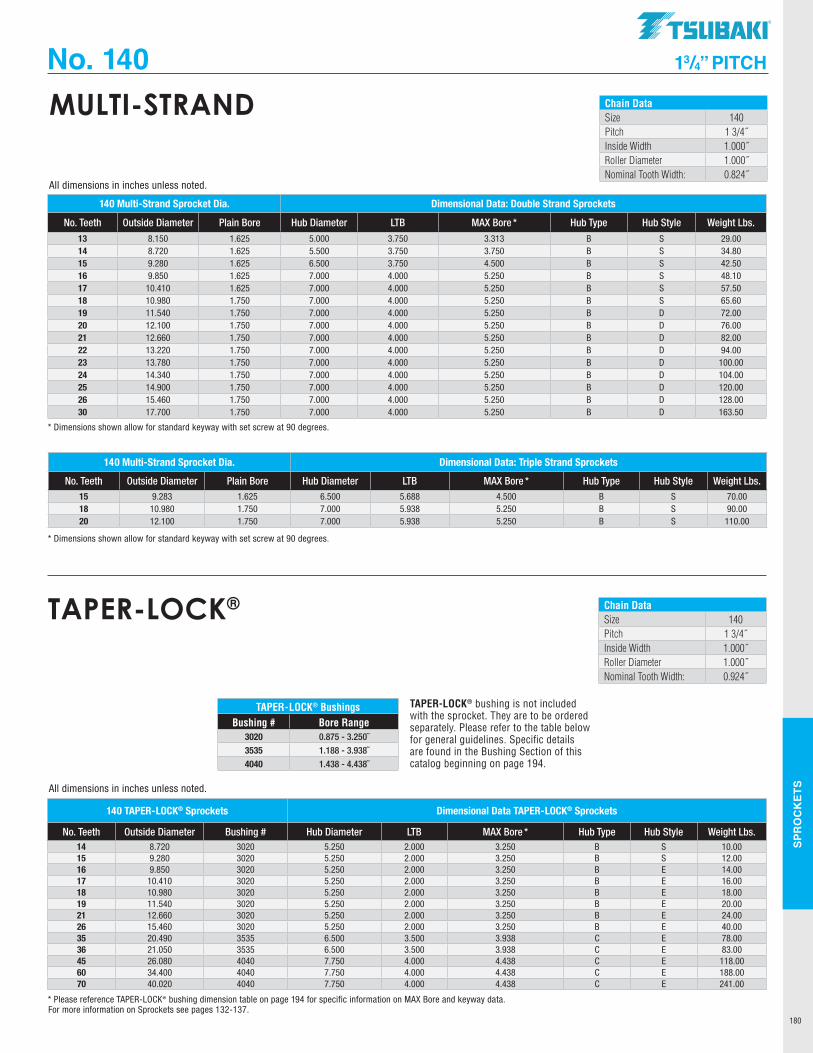
SPR
OC
KET
S
180
No. 140 13/4” PITCH
Chain DataSize 140Pitch 1 3/4˝Inside Width 1.000˝Roller Diameter 1.000˝Nominal Tooth Width: 0.824˝
MULTI-STRAND
140 Multi-Strand Sprocket Dia. Dimensional Data: Double Strand Sprockets
No. Teeth Outside Diameter Plain Bore Hub Diameter LTB MAX Bore * Hub Type Hub Style Weight Lbs.
13 8.150 1.625 5.000 3.750 3.313 B S 29.0014 8.720 1.625 5.500 3.750 3.750 B S 34.8015 9.280 1.625 6.500 3.750 4.500 B S 42.5016 9.850 1.625 7.000 4.000 5.250 B S 48.1017 10.410 1.625 7.000 4.000 5.250 B S 57.5018 10.980 1.750 7.000 4.000 5.250 B S 65.6019 11.540 1.750 7.000 4.000 5.250 B D 72.0020 12.100 1.750 7.000 4.000 5.250 B D 76.0021 12.660 1.750 7.000 4.000 5.250 B D 82.0022 13.220 1.750 7.000 4.000 5.250 B D 94.0023 13.780 1.750 7.000 4.000 5.250 B D 100.0024 14.340 1.750 7.000 4.000 5.250 B D 104.0025 14.900 1.750 7.000 4.000 5.250 B D 120.0026 15.460 1.750 7.000 4.000 5.250 B D 128.0030 17.700 1.750 7.000 4.000 5.250 B D 163.50
140 Multi-Strand Sprocket Dia. Dimensional Data: Triple Strand Sprockets
No. Teeth Outside Diameter Plain Bore Hub Diameter LTB MAX Bore * Hub Type Hub Style Weight Lbs. 15 9.283 1.625 6.500 5.688 4.500 B S 70.0018 10.980 1.750 7.000 5.938 5.250 B S 90.0020 12.100 1.750 7.000 5.938 5.250 B S 110.00
* Dimensions shown allow for standard keyway with set screw at 90 degrees.
* Dimensions shown allow for standard keyway with set screw at 90 degrees.
All dimensions in inches unless noted.
Chain DataSize 140Pitch 1 3/4˝Inside Width 1.000˝Roller Diameter 1.000˝Nominal Tooth Width: 0.924˝
TAPER-LOCK®
140 TAPER-LOCK® Sprockets Dimensional Data TAPER-LOCK® Sprockets
No. Teeth Outside Diameter Bushing # Hub Diameter LTB MAX Bore * Hub Type Hub Style Weight Lbs. 14 8.720 3020 5.250 2.000 3.250 B S 10.0015 9.280 3020 5.250 2.000 3.250 B S 12.0016 9.850 3020 5.250 2.000 3.250 B E 14.0017 10.410 3020 5.250 2.000 3.250 B E 16.0018 10.980 3020 5.250 2.000 3.250 B E 18.0019 11.540 3020 5.250 2.000 3.250 B E 20.0021 12.660 3020 5.250 2.000 3.250 B E 24.0026 15.460 3020 5.250 2.000 3.250 B E 40.0035 20.490 3535 6.500 3.500 3.938 C E 78.0036 21.050 3535 6.500 3.500 3.938 C E 83.0045 26.080 4040 7.750 4.000 4.438 C E 118.0060 34.400 4040 7.750 4.000 4.438 C E 188.0070 40.020 4040 7.750 4.000 4.438 C E 241.00
* Please reference TAPER-LOCK® bushing dimension table on page 194 for specific information on MAX Bore and keyway data.
All dimensions in inches unless noted.
TAPER-LOCK® BushingsBushing # Bore Range
3020 0.875 - 3.250˝
3535 1.188 - 3.938˝
4040 1.438 - 4.438˝
TAPER-LOCK® bushing is not included with the sprocket. They are to be ordered separately. Please refer to the table below for general guidelines. Specific details are found in the Bushing Section of this catalog beginning on page 194.
For more information on Sprockets see pages 132-137.
TSUBAKI"
I
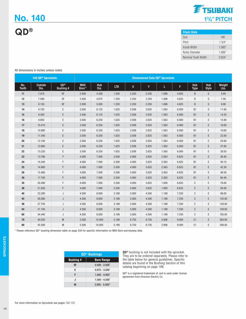
SPR
OC
KET
S
181
No. 140 13/4” PITCH
Chain DataSize 140
Pitch 1 3/4˝
Inside Width 1.000˝
Roller Diameter 1.000˝
Nominal Tooth Width: 0.924˝
QD®
QD® BushingsBushing # Bore Range
SF 0.500 - 2.938˝
E 0.875 - 3.500˝
F 1.000 - 4.000˝
J 1.500 - 4.500˝
M 2.000 - 5.500”
QD® is a registered trademark of, and is used under license agreement from Emerson Electric Co.
QD® bushing is not included with the sprocket. They are to be ordered separately. Please refer to the table below for general guidelines. Specific details are found in the Bushing Section of this catalog beginning on page 199.
140 QD® Sprockets Dimensional Data QD® Sprockets
No. Teeth
Outside Dia.
QD® Bushing #
MAX Bore *
Hub Dia. LTB X Y L F Hub
TypeHub Style
Weight Lbs.
11 7.010 SF 2.938 4.438 1.250 2.250 2.250 1.098 4.625 B S 5.60
12 7.580 SF 2.938 4.875 1.250 2.250 2.250 1.098 4.625 B S 7.40
13 8.150 SF 2.938 5.000 1.250 2.250 2.250 1.098 4.625 B S 8.90
14 8.720 E 3.500 6.125 1.625 2.938 2.625 1.563 6.000 B1 S 11.60
15 9.280 E 3.500 6.125 1.625 2.938 2.625 1.563 6.000 B1 S 14.20
16 9.850 E 3.500 6.250 1.625 2.938 2.625 1.563 6.000 B1 E 15.90
17 10.410 E 3.500 6.250 1.625 2.938 2.625 1.563 6.000 B1 E 18.00
18 10.980 E 3.500 6.250 1.625 2.938 2.625 1.563 6.000 B1 E 19.60
19 11.540 E 3.500 6.250 1.625 2.938 2.625 1.563 6.000 B1 E 22.00
20 12.100 E 3.500 6.250 1.625 2.938 2.625 1.563 6.000 B1 E 24.60
21 12.660 E 3.500 6.250 1.625 2.938 2.625 1.563 6.000 B1 E 27.60
22 13.220 E 3.500 6.250 1.625 2.938 2.625 1.563 6.000 B1 E 29.50
23 13.780 F 4.000 7.000 2.500 4.000 3.625 2.563 6.625 B1 E 36.40
24 14.340 F 4.000 7.000 2.500 4.000 3.625 2.563 6.625 B1 E 40.10
25 14.900 F 4.000 7.000 2.500 4.000 3.625 2.563 6.625 B1 E 42.30
26 15.460 F 4.000 7.000 2.500 4.000 3.625 2.563 6.625 B1 E 46.50
30 17.700 F 4.000 7.000 2.500 4.000 3.625 2.563 6.625 B1 E 60.40
35 20.490 F 4.000 7.000 2.500 4.000 3.625 1.000 6.625 C E 78.00
36 21.050 F 4.000 7.000 2.500 4.000 3.625 1.000 6.625 C E 84.00
40 23.290 J 4.500 8.000 3.188 5.000 4.500 1.188 7.250 C E 98.00
45 26.080 J 4.500 8.000 3.188 5.000 4.500 1.188 7.250 C E 120.00
48 27.750 J 4.500 8.000 3.188 5.000 4.500 1.188 7.250 C E 129.00
54 31.100 J 4.500 8.000 3.188 5.000 4.500 1.188 7.250 C E 149.00
60 34.440 J 4.500 8.000 3.188 5.000 4.500 1.188 7.250 C E 185.00
70 40.020 M 5.500 10.000 5.188 6.750 6.750 2.906 9.000 C1 E 264.00
80 45.590 M 5.500 10.000 5.188 6.750 6.750 2.906 9.000 C1 E 348.00
* Please reference QD® bushing dimension table on page 200 for specific information on MAX Bore and keyway data.
All dimensions in inches unless noted.
For more information on Sprockets see pages 132-137.
.TSUBAKI"
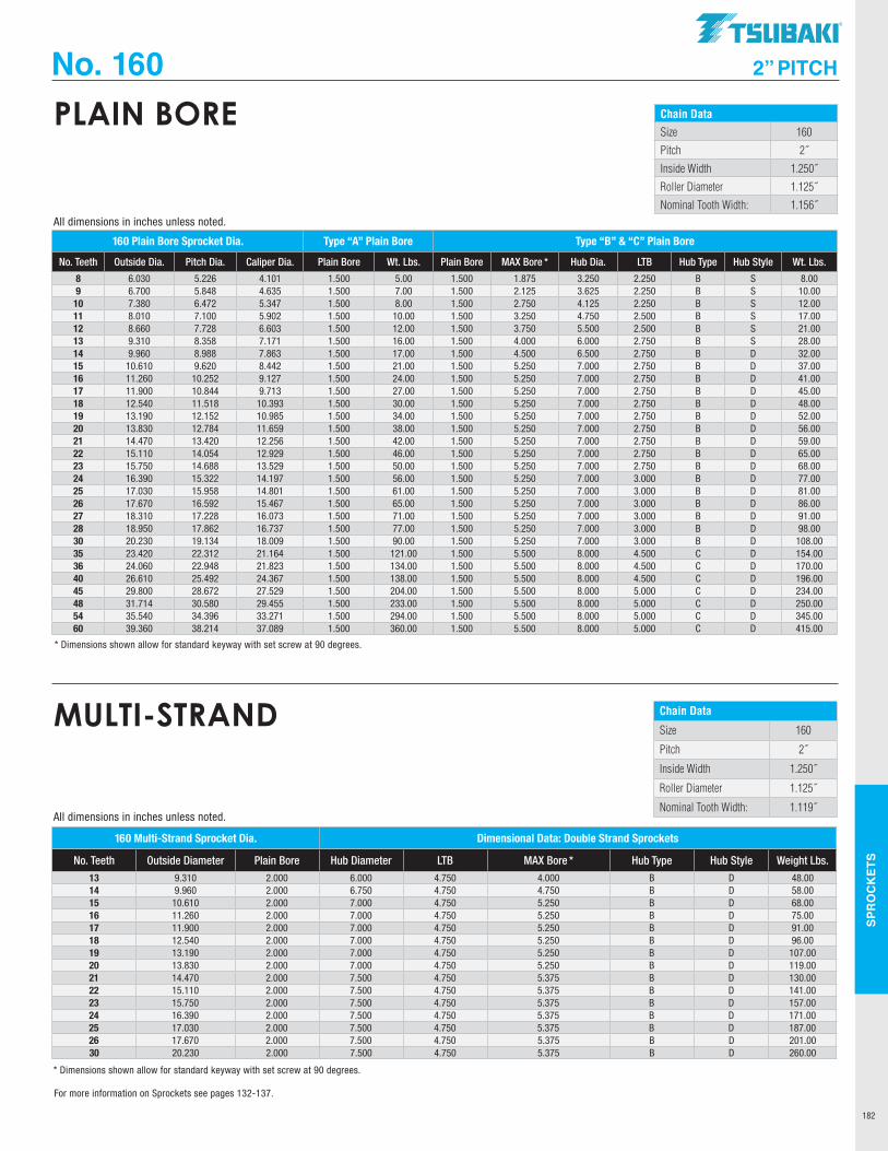
SPR
OC
KET
S
182
No. 160 2” PITCH
Chain DataSize 160
Pitch 2˝
Inside Width 1.250˝
Roller Diameter 1.125˝
Nominal Tooth Width: 1.156˝
PLAIN BORE
160 Plain Bore Sprocket Dia. Type “A” Plain Bore Type “B” & “C” Plain Bore
No. Teeth Outside Dia. Pitch Dia. Caliper Dia. Plain Bore Wt. Lbs. Plain Bore MAX Bore * Hub Dia. LTB Hub Type Hub Style Wt. Lbs.
8 6.030 5.226 4.101 1.500 5.00 1.500 1.875 3.250 2.250 B S 8.009 6.700 5.848 4.635 1.500 7.00 1.500 2.125 3.625 2.250 B S 10.00
10 7.380 6.472 5.347 1.500 8.00 1.500 2.750 4.125 2.250 B S 12.0011 8.010 7.100 5.902 1.500 10.00 1.500 3.250 4.750 2.500 B S 17.0012 8.660 7.728 6.603 1.500 12.00 1.500 3.750 5.500 2.500 B S 21.0013 9.310 8.358 7.171 1.500 16.00 1.500 4.000 6.000 2.750 B S 28.0014 9.960 8.988 7.863 1.500 17.00 1.500 4.500 6.500 2.750 B D 32.0015 10.610 9.620 8.442 1.500 21.00 1.500 5.250 7.000 2.750 B D 37.0016 11.260 10.252 9.127 1.500 24.00 1.500 5.250 7.000 2.750 B D 41.0017 11.900 10.844 9.713 1.500 27.00 1.500 5.250 7.000 2.750 B D 45.0018 12.540 11.518 10.393 1.500 30.00 1.500 5.250 7.000 2.750 B D 48.0019 13.190 12.152 10.985 1.500 34.00 1.500 5.250 7.000 2.750 B D 52.0020 13.830 12.784 11.659 1.500 38.00 1.500 5.250 7.000 2.750 B D 56.0021 14.470 13.420 12.256 1.500 42.00 1.500 5.250 7.000 2.750 B D 59.0022 15.110 14.054 12.929 1.500 46.00 1.500 5.250 7.000 2.750 B D 65.0023 15.750 14.688 13.529 1.500 50.00 1.500 5.250 7.000 2.750 B D 68.0024 16.390 15.322 14.197 1.500 56.00 1.500 5.250 7.000 3.000 B D 77.0025 17.030 15.958 14.801 1.500 61.00 1.500 5.250 7.000 3.000 B D 81.0026 17.670 16.592 15.467 1.500 65.00 1.500 5.250 7.000 3.000 B D 86.0027 18.310 17.228 16.073 1.500 71.00 1.500 5.250 7.000 3.000 B D 91.0028 18.950 17.862 16.737 1.500 77.00 1.500 5.250 7.000 3.000 B D 98.0030 20.230 19.134 18.009 1.500 90.00 1.500 5.250 7.000 3.000 B D 108.0035 23.420 22.312 21.164 1.500 121.00 1.500 5.500 8.000 4.500 C D 154.0036 24.060 22.948 21.823 1.500 134.00 1.500 5.500 8.000 4.500 C D 170.0040 26.610 25.492 24.367 1.500 138.00 1.500 5.500 8.000 4.500 C D 196.0045 29.800 28.672 27.529 1.500 204.00 1.500 5.500 8.000 5.000 C D 234.0048 31.714 30.580 29.455 1.500 233.00 1.500 5.500 8.000 5.000 C D 250.0054 35.540 34.396 33.271 1.500 294.00 1.500 5.500 8.000 5.000 C D 345.0060 39.360 38.214 37.089 1.500 360.00 1.500 5.500 8.000 5.000 C D 415.00
* Dimensions shown allow for standard keyway with set screw at 90 degrees.
All dimensions in inches unless noted.
Chain Data
Size 160
Pitch 2˝
Inside Width 1.250˝
Roller Diameter 1.125˝
Nominal Tooth Width: 1.119˝
MULTI-STRAND
160 Multi-Strand Sprocket Dia. Dimensional Data: Double Strand Sprockets
No. Teeth Outside Diameter Plain Bore Hub Diameter LTB MAX Bore * Hub Type Hub Style Weight Lbs.13 9.310 2.000 6.000 4.750 4.000 B D 48.0014 9.960 2.000 6.750 4.750 4.750 B D 58.0015 10.610 2.000 7.000 4.750 5.250 B D 68.0016 11.260 2.000 7.000 4.750 5.250 B D 75.0017 11.900 2.000 7.000 4.750 5.250 B D 91.0018 12.540 2.000 7.000 4.750 5.250 B D 96.0019 13.190 2.000 7.000 4.750 5.250 B D 107.0020 13.830 2.000 7.000 4.750 5.250 B D 119.0021 14.470 2.000 7.500 4.750 5.375 B D 130.0022 15.110 2.000 7.500 4.750 5.375 B D 141.0023 15.750 2.000 7.500 4.750 5.375 B D 157.0024 16.390 2.000 7.500 4.750 5.375 B D 171.0025 17.030 2.000 7.500 4.750 5.375 B D 187.0026 17.670 2.000 7.500 4.750 5.375 B D 201.0030 20.230 2.000 7.500 4.750 5.375 B D 260.00
* Dimensions shown allow for standard keyway with set screw at 90 degrees.
All dimensions in inches unless noted.
For more information on Sprockets see pages 132-137.
TSUBAKI"
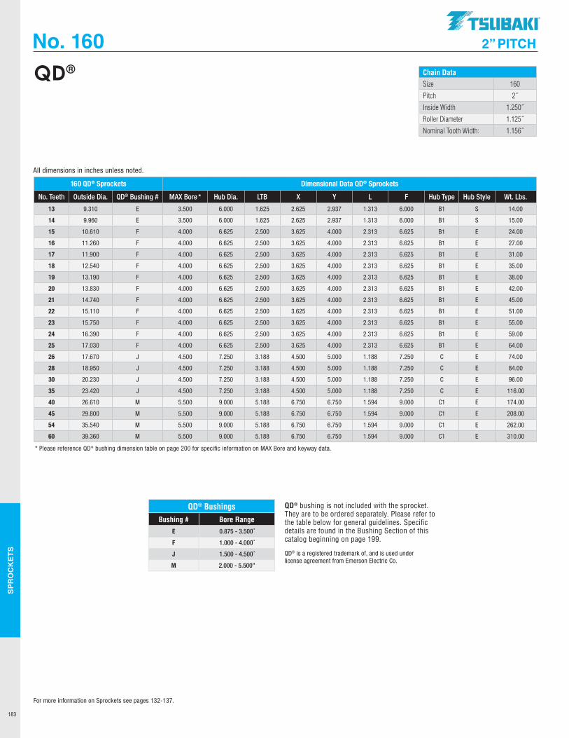
SPR
OC
KET
S
183
No. 160 2” PITCH
Chain DataSize 160
Pitch 2˝
Inside Width 1.250˝
Roller Diameter 1.125˝
Nominal Tooth Width: 1.156˝
QD®
QD® BushingsBushing # Bore Range
E 0.875 - 3.500˝
F 1.000 - 4.000˝
J 1.500 - 4.500˝
M 2.000 - 5.500”
QD® is a registered trademark of, and is used under license agreement from Emerson Electric Co.
QD® bushing is not included with the sprocket. They are to be ordered separately. Please refer to the table below for general guidelines. Specific details are found in the Bushing Section of this catalog beginning on page 199.
160 QD® Sprockets Dimensional Data QD® Sprockets
No. Teeth Outside Dia. QD® Bushing # MAX Bore * Hub Dia. LTB X Y L F Hub Type Hub Style Wt. Lbs.
13 9.310 E 3.500 6.000 1.625 2.625 2.937 1.313 6.000 B1 S 14.00
14 9.960 E 3.500 6.000 1.625 2.625 2.937 1.313 6.000 B1 S 15.00
15 10.610 F 4.000 6.625 2.500 3.625 4.000 2.313 6.625 B1 E 24.00
16 11.260 F 4.000 6.625 2.500 3.625 4.000 2.313 6.625 B1 E 27.00
17 11.900 F 4.000 6.625 2.500 3.625 4.000 2.313 6.625 B1 E 31.00
18 12.540 F 4.000 6.625 2.500 3.625 4.000 2.313 6.625 B1 E 35.00
19 13.190 F 4.000 6.625 2.500 3.625 4.000 2.313 6.625 B1 E 38.00
20 13.830 F 4.000 6.625 2.500 3.625 4.000 2.313 6.625 B1 E 42.00
21 14.740 F 4.000 6.625 2.500 3.625 4.000 2.313 6.625 B1 E 45.00
22 15.110 F 4.000 6.625 2.500 3.625 4.000 2.313 6.625 B1 E 51.00
23 15.750 F 4.000 6.625 2.500 3.625 4.000 2.313 6.625 B1 E 55.00
24 16.390 F 4.000 6.625 2.500 3.625 4.000 2.313 6.625 B1 E 59.00
25 17.030 F 4.000 6.625 2.500 3.625 4.000 2.313 6.625 B1 E 64.00
26 17.670 J 4.500 7.250 3.188 4.500 5.000 1.188 7.250 C E 74.00
28 18.950 J 4.500 7.250 3.188 4.500 5.000 1.188 7.250 C E 84.00
30 20.230 J 4.500 7.250 3.188 4.500 5.000 1.188 7.250 C E 96.00
35 23.420 J 4.500 7.250 3.188 4.500 5.000 1.188 7.250 C E 116.00
40 26.610 M 5.500 9.000 5.188 6.750 6.750 1.594 9.000 C1 E 174.00
45 29.800 M 5.500 9.000 5.188 6.750 6.750 1.594 9.000 C1 E 208.00
54 35.540 M 5.500 9.000 5.188 6.750 6.750 1.594 9.000 C1 E 262.00
60 39.360 M 5.500 9.000 5.188 6.750 6.750 1.594 9.000 C1 E 310.00
* Please reference QD® bushing dimension table on page 200 for specific information on MAX Bore and keyway data.
All dimensions in inches unless noted.
For more information on Sprockets see pages 132-137.
.TSUBAKI"
I I I I ~ ~ I I I I I
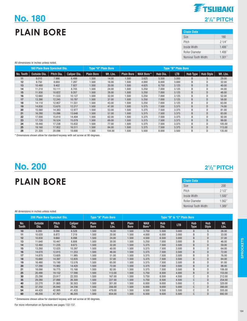
SPR
OC
KET
S
184
No. 180 21/4” PITCH
Chain DataSize 180
Pitch 2 1/4˝
Inside Width 1.406˝
Roller Diameter 1.406˝
Nominal Tooth Width: 1.301˝
PLAIN BORE
180 Plain Bore Sprocket Dia. Type “A” Plain Bore Type “B” Plain Bore
No. Teeth Outside Dia. Pitch Dia. Caliper Dia. Plain Bore Wt. Lbs. Plain Bore MAX Bore * Hub Dia. LTB Hub Type Hub Style Wt. Lbs. 11 9.010 7.986 6.499 1.500 14.00 1.500 3.625 5.500 3.000 B S 29.0012 9.750 8.693 7.287 1.500 16.00 1.500 4.000 6.000 3.000 B D 32.0013 10.480 9.402 7.927 1.500 20.00 1.500 4.625 6.750 3.125 B D 40.0014 11.210 10.111 8.705 1.500 24.00 1.500 5.250 7.000 3.125 B D 44.0015 11.930 10.822 9.357 1.500 28.00 1.500 5.250 7.000 3.125 B D 48.0016 12.660 11.533 10.127 1.500 32.00 1.500 5.250 7.000 3.125 B D 52.0017 13.390 12.245 10.787 1.500 37.00 1.500 5.250 7.000 3.125 B D 58.0018 14.110 12.957 11.551 1.500 43.00 1.500 5.250 7.000 3.125 B D 63.0019 14.830 13.670 12.217 1.500 47.00 1.500 5.375 7.500 3.375 B D 74.0020 15.560 14.383 12.977 1.500 53.00 1.500 5.375 7.500 3.375 B D 81.0021 16.280 15.096 13.648 1.500 57.00 1.500 5.375 7.500 3.375 B D 83.0022 17.000 15.810 14.404 1.500 62.00 1.500 5.375 7.500 3.375 B D 92.0023 17.720 16.524 15.079 1.500 69.00 1.500 5.375 7.500 3.375 B D 99.0024 18.440 17.238 15.832 1.500 77.00 1.500 5.375 7.500 3.375 B D 105.0025 19.160 17.952 16.511 1.500 84.00 1.500 5.375 7.500 3.375 B D 113.0028 21.320 20.096 18.690 1.500 104.00 1.500 5.500 8.000 3.500 B D 135.00
* Dimensions shown allow for standard keyway with set screw at 90 degrees.
All dimensions in inches unless noted.
Chain DataSize 200
Pitch 2 1/2˝
Inside Width 1.500˝
Roller Diameter 1.562˝
Nominal Tooth Width: 1.389˝
PLAIN BORE
200 Plain Bore Sprocket Dia. Type “A” Plain Bore Type “B” & “C” Plain Bore
No. Teeth
Outside Dia.
Pitch Dia.
Caliper Dia.
Plain Bore
Wt. Lbs.
Plain Bore
MAX Bore *
Hub Dia. LTB Hub
TypeHub Style
Wt. Lbs.
10 9.200 8.090 6.528 1.500 16.00 1.500 3.750 5.500 3.000 B S 26.0011 10.020 8.872 7.219 1.500 20.00 1.500 4.000 6.000 3.000 B D 33.0012 10.830 9.660 8.098 1.500 24.00 1.500 4.500 6.500 3.000 B D 37.0013 11.640 10.447 8.808 1.500 30.00 1.500 5.250 7.000 3.000 B D 46.0014 12.460 11.235 9.673 1.500 32.00 1.500 5.375 7.500 3.500 B D 59.0015 13.260 12.025 10.397 1.500 40.00 1.500 5.375 7.500 3.500 B D 64.0016 14.070 12.815 11.253 1.500 46.00 1.500 5.375 7.500 3.500 B D 72.0017 14.870 13.605 11.985 1.500 51.00 1.500 5.375 7.500 3.500 B D 76.0018 15.680 14.397 12.835 1.500 57.00 1.500 5.375 7.500 3.500 B D 84.0019 16.480 15.190 13.576 1.500 65.00 1.500 5.375 7.500 3.500 B D 91.0020 17.290 15.982 14.420 1.500 72.00 1.500 5.375 7.500 3.500 B D 98.0021 18.090 16.775 15.166 1.500 82.00 1.500 5.375 7.500 3.500 B D 106.0025 20.490 19.152 17.590 1.500 113.00 1.500 5.750 8.500 4.000 B D 153.0030 25.290 23.917 22.355 1.500 167.00 1.500 5.750 8.500 4.500 C D 212.0035 29.280 27.890 26.300 1.500 227.00 1.500 5.750 8.500 4.500 C D 254.0040 33.270 31.865 30.303 1.500 301.00 1.500 6.000 9.000 5.000 C D 320.0045 37.250 35.840 34.256 1.500 356.00 1.500 6.000 9.000 5.000 C D 390.0054 44.420 42.995 41.433 1.500 479.00 1.500 6.500 9.500 5.500 C D 555.0060 49.200 47.767 46.205 1.500 654.00 1.500 6.500 9.500 5.500 C D 692.00
* Dimensions shown allow for standard keyway with set screw at 90 degrees.
All dimensions in inches unless noted.
No. 200 21/2” PITCH
For more information on Sprockets see pages 132-137.
TSUBAKI"
-------------
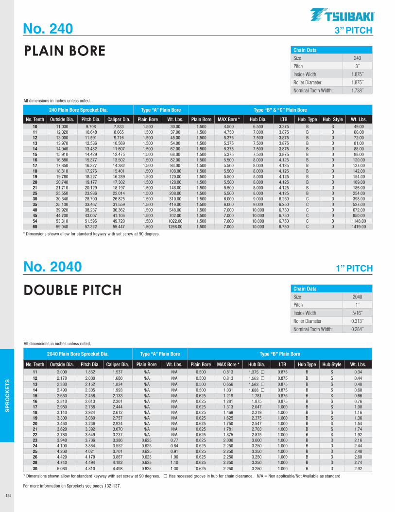
SPR
OC
KET
S
185
No. 240 3” PITCH
Chain DataSize 240
Pitch 3˝
Inside Width 1.875˝
Roller Diameter 1.875˝
Nominal Tooth Width: 1.738˝
PLAIN BORE
240 Plain Bore Sprocket Dia. Type “A” Plain Bore Type “B” & “C” Plain Bore
No. Teeth Outside Dia. Pitch Dia. Caliper Dia. Plain Bore Wt. Lbs. Plain Bore MAX Bore * Hub Dia. LTB Hub Type Hub Style Wt. Lbs. 10 11.030 9.708 7.833 1.500 30.00 1.500 4.500 6.500 3.375 B S 49.0011 12.020 10.648 8.665 1.500 37.00 1.500 4.750 7.000 3.875 B D 66.0012 13.000 11.591 9.716 1.500 45.00 1.500 5.375 7.500 3.875 B D 72.0013 13.970 12.536 10.569 1.500 54.00 1.500 5.375 7.500 3.875 B D 81.0014 14.940 13.482 11.607 1.500 62.00 1.500 5.375 7.500 3.875 B D 88.0015 15.910 14.429 12.475 1.500 68.00 1.500 5.375 7.500 3.875 B D 98.0016 16.880 15.377 13.502 1.500 82.00 1.500 5.500 8.000 4.125 B D 120.0017 17.850 16.327 14.382 1.500 93.00 1.500 5.500 8.000 4.125 B D 137.0018 18.810 17.276 15.401 1.500 108.00 1.500 5.500 8.000 4.125 B D 142.0019 19.780 18.227 16.289 1.500 120.00 1.500 5.500 8.000 4.125 B D 154.0020 20.740 19.177 17.302 1.500 128.00 1.500 5.500 8.000 4.125 B D 169.0021 21.710 20.129 18.197 1.500 148.00 1.500 5.500 8.000 4.125 B D 186.0025 25.550 23.936 22.014 1.500 208.00 1.500 5.500 8.000 4.125 B D 254.0030 30.340 28.700 26.825 1.500 310.00 1.500 6.000 9.000 6.250 C D 398.0035 35.130 33.467 31.559 1.500 416.00 1.500 6.000 9.000 6.250 C D 527.0040 39.920 38.237 36.362 1.500 548.00 1.500 7.000 10.000 6.750 C D 672.0045 44.700 43.007 41.106 1.500 702.00 1.500 7.000 10.000 6.750 C D 850.0054 53.310 51.595 49.720 1.500 1022.00 1.500 7.000 10.000 6.750 C D 1148.0060 59.040 57.322 55.447 1.500 1268.00 1.500 7.000 10.000 6.750 C D 1419.00
* Dimensions shown allow for standard keyway with set screw at 90 degrees.
All dimensions in inches unless noted.
Chain DataSize 2040
Pitch 1˝
Inside Width 5/16˝
Roller Diameter 0.313˝
Nominal Tooth Width: 0.284˝
DOUBLE PITCH
2040 Plain Bore Sprocket Dia. Type “A” Plain Bore Type “B” Plain Bore
No. Teeth Outside Dia. Pitch Dia. Caliper Dia. Plain Bore Wt. Lbs. Plain Bore MAX Bore * Hub Dia. LTB Hub Type Hub Style Wt. Lbs. 11 2.000 1.852 1.537 N/A N/A 0.500 0.813 1.375 ¨ 0.875 B S 0.3412 2.170 2.000 1.688 N/A N/A 0.500 0.813 1.563 ¨ 0.875 B S 0.4413 2.330 2.152 1.824 N/A N/A 0.500 0.656 1.563 ¨ 0.875 B S 0.4814 2.490 2.305 1.993 N/A N/A 0.500 1.031 1.688 ¨ 0.875 B S 0.6015 2.650 2.458 2.133 N/A N/A 0.625 1.219 1.781 0.875 B S 0.6616 2.810 2.613 2.301 N/A N/A 0.625 1.281 1.875 0.875 B S 0.7617 2.980 2.768 2.444 N/A N/A 0.625 1.313 2.047 1.000 B S 1.0018 3.140 2.924 2.612 N/A N/A 0.625 1.469 2.219 1.000 B S 1.1619 3.300 3.080 2.757 N/A N/A 0.625 1.625 2.375 1.000 B S 1.3620 3.460 3.236 2.924 N/A N/A 0.625 1.750 2.547 1.000 B S 1.5421 3.620 3.392 3.070 N/A N/A 0.625 1.781 2.703 1.000 B S 1.7422 3.780 3.549 3.237 N/A N/A 0.625 1.875 2.875 1.000 B S 1.9223 3.940 3.706 3.386 0.625 0.77 0.625 2.000 3.000 1.000 B D 2.1624 4.100 3.864 3.552 0.625 0.84 0.625 2.250 3.250 1.000 B D 2.4425 4.260 4.021 3.701 0.625 0.91 0.625 2.250 3.250 1.000 B D 2.4826 4.420 4.179 3.867 0.625 1.00 0.625 2.250 3.250 1.000 B D 2.6028 4.740 4.494 4.182 0.625 1.10 0.625 2.250 3.250 1.000 B D 2.7430 5.060 4.810 4.498 0.625 1.30 0.625 2.250 3.250 1.000 B D 2.92
* Dimensions shown allow for standard keyway with set screw at 90 degrees. ¨ Has recessed groove in hub for chain clearance. N/A = Non applicable/Not Available as standard
All dimensions in inches unless noted.
No. 2040 1” PITCH
For more information on Sprockets see pages 132-137.
.TSUBAKI"
-------------
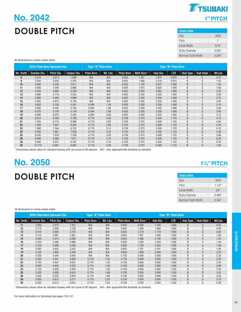
SPR
OC
KET
S
186
No. 2042 1” PITCH
Chain DataSize 2042
Pitch 1˝
Inside Width 5/16˝
Roller Diameter 0.625˝
Nominal Tooth Width: 0.284˝
DOUBLE PITCH
2042 Plain Bore Sprocket Dia. Type “A” Plain Bore Type “B” Plain Bore
No. Teeth Outside Dia. Pitch Dia. Caliper Dia. Plain Bore Wt. Lbs. Plain Bore MAX Bore * Hub Dia. LTB Hub Type Hub Style Wt.Lbs. 8 3.010 2.613 1.988 N/A N/A 0.625 1.281 1.875 0.875 B S 0.729 3.350 2.924 2.255 N/A N/A 0.625 1.469 2.219 0.875 B S 1.0210 3.680 3.236 2.611 N/A N/A 0.625 1.750 2.547 1.000 B S 1.5011 4.000 3.549 2.888 N/A N/A 0.625 1.875 2.625 1.000 B S 1.6812 4.330 3.864 3.239 N/A N/A 0.625 2.250 3.063 1.000 B S 2.2213 4.660 4.179 3.523 N/A N/A 0.625 2.250 3.250 1.000 B S 2.5614 4.980 4.494 3.869 N/A N/A 0.625 2.250 3.250 1.000 B S 2.7215 5.300 4.810 4.158 N/A N/A 0.625 2.250 3.250 1.000 B S 2.9016 5.630 5.126 4.501 0.594 1.38 0.625 2.250 3.250 1.000 B D 3.1017 5.950 5.442 4.794 0.594 1.66 0.625 2.250 3.250 1.000 B D 3.4018 6.270 5.759 5.134 0.594 1.88 0.625 2.250 3.250 1.000 B D 3.5619 6.590 6.076 5.430 0.594 2.06 0.625 2.250 3.250 1.000 B D 3.7220 6.910 6.392 5.768 0.719 2.40 0.750 2.375 3.500 1.125 B D 4.7221 7.240 6.710 6.066 0.719 2.62 0.750 2.375 3.500 1.125 B D 4.8422 7.560 7.027 6.402 0.719 2.88 0.750 2.375 3.500 1.125 B D 5.0423 7.880 7.344 6.702 0.719 3.14 0.750 2.375 3.500 1.125 B D 5.1824 8.200 7.661 7.036 0.719 3.22 0.750 2.375 3.500 1.125 B D 5.5825 8.520 7.979 7.338 0.719 3.50 0.750 2.375 3.500 1.125 B D 5.9626 8.840 8.296 7.671 0.719 3.74 0.750 2.375 3.500 1.125 B D 6.2228 9.480 8.931 8.307 0.719 4.76 0.750 2.375 3.500 1.125 B D 6.7830 10.110 9.567 8.942 0.719 5.08 0.750 2.375 3.500 1.125 B D 7.56
* Dimensions shown allow for standard keyway with set screw at 90 degrees. N/A = Non applicable/Not Available as standard
All dimensions in inches unless noted.
Chain DataSize 2050
Pitch 1 1/4˝
Inside Width 3/8˝
Roller Diameter 0.400˝
Nominal Tooth Width: 0.343˝
DOUBLE PITCH
2050 Plain Bore Sprocket Dia. Type “A” Plain Bore Type “B” Plain Bore
No. Teeth Outside Dia. Pitch Dia. Caliper Dia. Plain Bore Wt. Lbs. Plain Bore MAX Bore * Hub Dia. LTB Hub Type Hub Style Wt.Lbs. 11 2.500 2.315 1.912 N/A N/A 0.625 0.938 1.750 1.000 B S 0.6212 2.710 2.500 2.100 N/A N/A 0.625 1.000 1.984 1.000 B S 0.8013 2.910 2.690 2.270 N/A N/A 0.625 1.219 1.719 1.000 B S 0.8214 3.110 2.881 2.481 N/A N/A 0.625 1.281 1.938 1.000 B S 1.0015 3.320 3.073 2.656 N/A N/A 0.625 1.406 2.156 1.000 B S 1.2216 3.520 3.266 2.866 N/A N/A 0.625 1.594 2.359 1.000 B S 1.4417 3.720 3.460 3.046 N/A N/A 0.625 1.750 2.563 1.000 B S 1.6818 3.920 3.655 3.255 N/A N/A 0.625 1.781 2.781 1.000 B S 1.9419 4.120 3.850 3.436 N/A N/A 0.625 1.969 2.984 1.000 B S 2.2420 4.320 4.045 3.645 N/A N/A 0.750 2.000 3.000 1.000 B D 2.3021 4.520 4.241 3.829 0.719 1.20 0.750 2.000 3.000 1.000 B D 2.4022 4.720 4.437 4.037 0.719 1.30 0.750 2.000 3.000 1.000 B S 2.5423 4.920 4.633 4.222 0.719 1.40 0.750 2.000 3.000 1.000 B D 2.6624 5.120 4.830 4.430 0.719 1.58 0.750 2.000 3.000 1.250 B D 3.3025 5.320 5.026 4.616 0.719 1.68 0.750 2.000 3.000 1.250 B D 3.4226 5.520 5.223 4.823 0.719 1.88 0.750 2.000 3.000 1.250 B D 3.6228 5.920 5.617 5.217 0.719 2.20 0.750 2.000 3.000 1.250 B D 3.7830 6.320 6.012 5.612 0.719 2.54 0.750 2.250 3.250 1.250 B D 4.58
* Dimensions shown allow for standard keyway with set screw at 90 degrees. N/A = Non applicable/Not Available as standard
All dimensions in inches unless noted.
No. 2050 11/4” PITCH
For more information on Sprockets see pages 132-137.
TSUBAKI"
----
-----
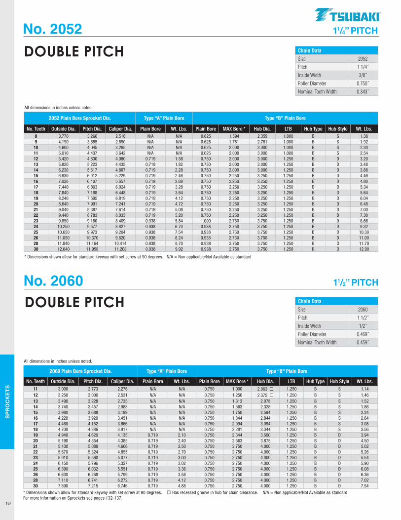
SPR
OC
KET
S
187
No. 2052 11/4” PITCH
Chain DataSize 2052
Pitch 1 1/4˝
Inside Width 3/8˝
Roller Diameter 0.750˝
Nominal Tooth Width: 0.343˝
DOUBLE PITCH
2052 Plain Bore Sprocket Dia. Type “A” Plain Bore Type “B” Plain Bore
No. Teeth Outside Dia. Pitch Dia. Caliper Dia. Plain Bore Wt. Lbs. Plain Bore MAX Bore * Hub Dia. LTB Hub Type Hub Style Wt. Lbs. 8 3.770 3.266 2.516 N/A N/A 0.625 1.594 2.359 1.000 B S 1.389 4.190 3.655 2.850 N/A N/A 0.625 1.781 2.781 1.000 B S 1.92
10 4.600 4.045 3.295 N/A N/A 0.625 2.000 3.000 1.000 B S 2.3011 5.010 4.437 3.642 N/A N/A 0.625 2.000 3.000 1.000 B S 2.5412 5.420 4.830 4.080 0.719 1.58 0.750 2.000 3.000 1.250 B D 3.2013 5.820 5.223 4.435 0.719 1.82 0.750 2.000 3.000 1.250 B D 3.4814 6.230 5.617 4.867 0.719 2.28 0.750 2.000 3.000 1.250 B D 3.8815 6.630 6.012 5.229 0.719 2.46 0.750 2.250 3.250 1.250 B D 4.4616 7.030 6.407 5.657 0.719 2.88 0.750 2.250 3.250 1.250 B D 4.8017 7.440 6.803 6.024 0.719 3.28 0.750 2.250 3.250 1.250 B D 5.3418 7.840 7.198 6.448 0.719 3.64 0.750 2.250 3.250 1.250 B D 5.6419 8.240 7.595 6.819 0.719 4.12 0.750 2.250 3.250 1.250 B D 6.0420 8.640 7.991 7.241 0.719 4.72 0.750 2.250 3.250 1.250 B D 6.4821 9.040 8.387 7.614 0.719 5.08 0.750 2.250 3.250 1.250 B D 7.0022 9.440 8.783 8.033 0.719 5.20 0.750 2.250 3.250 1.250 B D 7.3023 9.850 9.180 8.409 0.938 5.84 1.000 2.750 3.750 1.250 B D 8.6624 10.250 9.577 8.827 0.938 6.70 0.938 2.750 3.750 1.250 B D 9.3225 10.650 9.973 9.204 0.938 7.54 0.938 2.750 3.750 1.250 B D 10.3026 11.050 10.370 9.620 0.938 8.24 0.938 2.750 3.750 1.250 B D 11.0028 11.840 11.164 10.414 0.938 8.70 0.938 2.750 3.750 1.250 B D 11.7030 12.640 11.958 11.208 0.938 9.92 0.938 2.750 3.750 1.250 B D 12.90
* Dimensions shown allow for standard keyway with set screw at 90 degrees. N/A = Non applicable/Not Available as standard
All dimensions in inches unless noted.
Chain DataSize 2060
Pitch 1 1/2˝
Inside Width 1/2˝
Roller Diameter 0.469˝
Nominal Tooth Width: 0.459˝
DOUBLE PITCH
2060 Plain Bore Sprocket Dia. Type “A” Plain Bore Type “B” Plain Bore
No. Teeth Outside Dia. Pitch Dia. Caliper Dia. Plain Bore Wt. Lbs. Plain Bore MAX Bore * Hub Dia. LTB Hub Type Hub Style Wt. Lbs. 11 3.000 2.773 2.276 N/A N/A 0.750 1.000 2.063 ¨ 1.250 B S 1.1412 3.250 3.000 2.531 N/A N/A 0.750 1.250 2.375 ¨ 1.250 B S 1.4613 3.490 3.228 2.735 N/A N/A 0.750 1.313 2.078 1.250 B S 1.5214 3.740 3.457 2.988 N/A N/A 0.750 1.563 2.328 1.250 B S 1.8615 3.980 3.688 3.199 N/A N/A 0.750 1.750 2.594 1.250 B S 2.2416 4.220 3.920 3.451 N/A N/A 0.750 1.844 2.844 1.250 B S 2.6417 4.460 4.152 3.666 N/A N/A 0.750 2.094 3.094 1.250 B S 3.0818 4.700 4.386 3.917 N/A N/A 0.750 2.281 3.344 1.250 B S 3.5619 4.940 4.620 4.135 0.719 2.10 0.750 2.344 3.500 1.250 B D 3.9420 5.190 4.854 4.385 0.719 2.40 0.750 2.563 3.875 1.250 B D 4.5021 5.430 5.089 4.606 0.719 2.50 0.750 2.750 4.000 1.250 B D 5.0222 5.670 5.324 4.855 0.719 2.70 0.750 2.750 4.000 1.250 B D 5.2623 5.910 5.560 5.077 0.719 3.00 0.750 2.750 4.000 1.250 B D 5.5424 6.150 5.796 5.327 0.719 3.02 0.750 2.750 4.000 1.250 B D 5.9025 6.390 6.032 5.551 0.719 3.36 0.750 2.750 4.000 1.250 B D 6.0826 6.630 6.268 5.799 0.719 3.58 0.750 2.750 4.000 1.250 B D 6.3628 7.110 6.741 6.272 0.719 4.12 0.750 2.750 4.000 1.250 B D 7.0230 7.590 7.215 6.746 0.719 4.88 0.750 2.750 4.000 1.250 B D 7.54
All dimensions in inches unless noted.
* Dimensions shown allow for standard keyway with set screw at 90 degrees. ¨ Has recessed groove in hub for chain clearance. N/A = Non applicable/Not Available as standardFor more information on Sprockets see pages 132-137.
No. 2060 11/2” PITCH
.TSUBAKI"
-------------
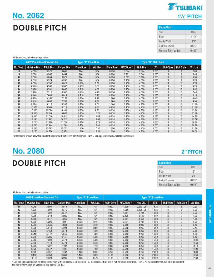
SPR
OC
KET
S
188
No. 2062 11/2” PITCH
Chain Data
Size 2062
Pitch 1 1/2˝
Inside Width 3/8˝
Roller Diameter 0.875˝
Nominal Tooth Width: 0.459˝
DOUBLE PITCH
2062 Plain Bore Sprocket Dia. Type “A” Plain Bore Type “B” Plain Bore
No. Teeth Outside Dia. Pitch Dia. Caliper Dia. Plain Bore Wt. Lbs. Plain Bore MAX Bore * Hub Dia. LTB Hub Type Hub Style Wt. Lbs. 8 4.520 3.920 3.045 N/A N/A 0.750 1.844 2.844 1.250 B S 2.609 5.020 4.386 3.444 N/A N/A 0.750 2.281 3.344 1.250 B S 3.4810 5.520 4.854 3.979 N/A N/A 0.750 2.563 3.828 1.250 B S 4.5411 6.010 5.324 4.395 N/A N/A 0.750 2.750 4.000 1.250 B S 5.2012 6.500 5.796 4.921 0.719 2.98 0.750 2.750 4.000 1.250 B D 5.7013 6.990 6.268 5.347 0.719 3.60 0.750 2.750 4.000 1.250 B D 6.2814 7.470 6.741 5.866 0.719 4.02 0.750 2.750 4.000 1.250 B D 6.8215 7.960 7.215 6.300 0.719 4.76 0.750 2.750 4.000 1.250 B D 7.4816 8.440 7.689 6.814 0.719 5.70 0.750 2.750 4.000 1.250 B D 8.1817 8.920 8.163 7.253 0.938 6.16 1.000 2.750 4.000 1.250 B D 8.8218 9.410 8.638 7.763 0.938 6.96 1.000 2.750 4.000 1.250 B D 9.3619 9.890 9.113 8.207 0.938 8.00 1.000 2.750 4.250 1.250 B D 11.1020 10.370 9.589 8.714 0.938 8.46 0.938 2.750 4.250 1.250 B D 11.6621 10.850 10.064 9.161 0.938 8.93 0.938 2.750 4.250 1.250 B D 13.2422 11.330 10.540 9.665 0.938 10.74 0.938 2.750 4.250 1.250 B D 13.7823 11.810 11.016 10.115 0.938 11.64 0.938 2.750 4.250 1.250 B D 14.9024 12.290 11.492 10.617 0.938 12.64 0.938 2.750 4.250 1.250 B D 15.5625 12.770 11.968 11.070 0.938 13.78 0.938 2.750 4.250 1.250 B D 16.8026 13.250 12.444 11.569 0.938 15.00 0.938 2.750 4.250 1.750 B D 20.2028 14.210 13.397 12.522 1.250 17.32 1.250 2.750 4.250 1.750 B D 21.8630 15.170 14.350 13.475 1.250 19.50 1.250 2.750 4.250 1.750 B D 26.00
* Dimensions shown allow for standard keyway with set screw at 90 degrees. N/A = Non applicable/Not Available as standard
All dimensions in inches unless noted.
Chain DataSize 2080
Pitch 2˝
Inside Width 5/8˝
Roller Diameter 0.625˝
Nominal Tooth Width: 0.575˝
DOUBLE PITCH
2080 Plain Bore Sprocket Dia. Type “A” Plain Bore Type “B” Plain Bore
No. Teeth Outside Dia. Pitch Dia. Caliper Dia. Plain Bore Wt. Lbs. Plain Bore MAX Bore * Hub Dia. LTB Hub Type Hub Style Wt. Lbs. 11 4.010 3.694 3.074 N/A N/A 1.000 1.500 2.813 ¨ 1.625 B S 2.5012 4.330 4.000 3.375 N/A N/A 1.000 1.688 3.125 ¨ 1.625 B S 3.2013 4.660 4.304 3.647 N/A N/A 1.000 1.781 2.781 1.500 B S 3.2014 4.980 4.610 3.985 N/A N/A 1.000 2.125 3.125 1.500 B S 4.0015 5.300 4.917 4.265 N/A N/A 1.000 2.281 3.453 1.500 B S 4.8016 5.630 5.226 4.601 0.938 3.10 1.000 2.531 3.797 1.500 B D 5.7017 5.960 5.536 4.888 0.938 3.40 1.000 2.750 4.000 1.500 B D 6.4018 6.270 5.848 5.223 0.938 3.80 1.000 2.750 4.250 1.500 B D 7.4019 6.590 6.160 5.513 0.938 4.30 1.000 2.750 4.250 1.500 B D 7.7020 6.910 6.472 5.845 0.938 4.80 1.000 2.750 4.250 1.500 B D 8.3021 7.230 6.785 6.141 0.938 5.30 1.000 2.750 4.250 1.750 B D 9.4022 7.560 7.099 6.474 0.938 5.80 1.000 2.750 4.250 1.750 B D 10.0023 7.880 7.413 6.770 0.938 6.40 1.000 2.750 4.250 1.750 B D 10.5024 8.200 7.727 7.102 0.938 7.10 1.000 2.750 4.250 1.750 B D 11.1025 8.520 8.042 7.401 0.938 7.50 1.000 2.750 4.250 1.750 B D 12.0026 8.840 8.357 7.732 1.188 8.30 1.250 3.250 4.750 2.000 B D 14.8028 9.480 8.988 8.363 1.188 9.20 1.188 3.250 4.750 2.000 B D 16.6030 10.110 9.620 8.995 1.188 10.70 1.188 3.250 4.750 2.000 B D 17.80
* Dimensions shown allow for standard keyway with set screw at 90 degrees. ¨ Has recessed groove in hub for chain clearance. N/A = Non applicable/Not Available as standardFor more information on Sprockets see pages 132-137.
All dimensions in inches unless noted.
No. 2080 2” PITCH
TSUBAKI"
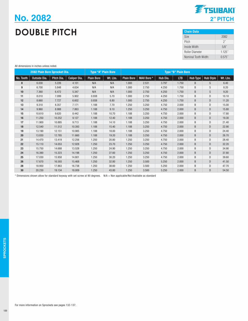
SPR
OC
KET
S
189
No. 2082 2” PITCH
Chain Data
Size 2082
Pitch 2˝
Inside Width 5/8˝
Roller Diameter 1.125˝
Nominal Tooth Width: 0.575˝
DOUBLE PITCH
2082 Plain Bore Sprocket Dia. Type “A” Plain Bore Type “B” Plain Bore
No. Teeth Outside Dia. Pitch Dia. Caliper Dia. Plain Bore Wt. Lbs. Plain Bore MAX Bore * Hub Dia. LTB Hub Type Hub Style Wt. Lbs.
8 6.030 5.226 4.101 N/A N/A 1.000 2.531 3.797 1.750 B S 6.40
9 6.700 5.848 4.634 N/A N/A 1.000 2.750 4.250 1.750 B S 8.20
10 7.360 6.472 5.347 N/A N/A 1.000 2.750 4.250 1.750 B S 9.20
11 8.010 7.099 5.902 0.938 5.70 1.000 2.750 4.250 1.750 B D 10.10
12 8.660 7.727 6.602 0.938 6.80 1.000 2.750 4.250 1.750 B D 11.20
13 9.310 8.357 7.171 1.188 7.70 1.250 3.250 4.750 2.000 B D 15.00
14 9.960 8.988 7.863 1.188 9.10 1.250 3.250 4.750 2.000 B D 15.80
15 10.610 9.620 8.442 1.188 10.70 1.188 3.250 4.750 2.000 B D 17.80
16 11.250 10.252 9.127 1.188 12.40 1.188 3.250 4.750 2.000 B D 19.30
17 11.900 10.885 9.713 1.188 14.10 1.188 3.250 4.750 2.000 B D 21.40
18 12.540 11.512 10.393 1.188 15.40 1.188 3.250 4.750 2.000 B D 22.90
19 13.190 12.151 10.985 1.188 18.00 1.188 3.250 4.750 2.000 B D 24.40
20 13.830 12.785 11.660 1.188 19.20 1.188 3.250 4.750 2.000 B D 26.70
21 14.470 13.419 12.256 1.250 20.80 1.250 3.250 4.750 2.000 B D 28.40
22 15.110 14.053 12.928 1.250 23.70 1.250 3.250 4.750 2.000 B D 32.20
23 15.750 14.688 13.528 1.250 24.90 1.250 3.250 4.750 2.000 B D 34.90
24 16.390 15.323 14.198 1.250 27.60 1.250 3.250 4.750 2.000 B D 37.80
25 17.030 15.958 14.801 1.250 30.20 1.250 3.250 4.750 2.000 B D 39.60
26 17.670 16.593 15.468 1.250 32.80 1.250 3.500 5.250 2.000 B D 41.50
28 18.950 17.863 16.738 1.250 38.60 1.250 3.500 5.250 2.000 B D 47.70
30 20.230 19.134 18.009 1.250 43.80 1.250 3.500 5.250 2.000 B D 54.50
* Dimensions shown allow for standard keyway with set screw at 90 degrees. N/A = Non applicable/Not Available as standard
All dimensions in inches unless noted.
For more information on Sprockets see pages 132-137.
.TSUBAKI"
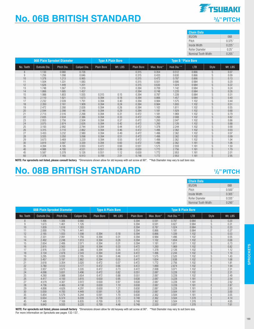
SPR
OC
KET
S
190
No. 08B BRITISH STANDARD 1/2” PITCH
No. 06B BRITISH STANDARD 3/8” PITCH
Chain DataBS/DIN 06BPitch 0.375˝Inside Width 0.225˝Roller Diameter 0.25˝Nominal Tooth Width: 0.205˝
Chain DataBS/DIN 08BPitch 0.500˝Inside Width 0.305˝Roller Diameter 0.335˝Nominal Tooth Width: 0.290˝
06B Plain Sprocket Diameter Type A Plain Bore Type B “Plain Bore
No. Teeth Outside Dia. Pitch Dia. Caliper Dia. Plain Bore Wt. LBS Plain Bore Max. Bore* Hub Dia.** LTB Style Wt. LBS
8 1.130 0.980 0.728 0.315 0.354 0.512 0.866 S 0.079 1.256 1.098 0.846 0.315 0.433 0.630 0.866 S 0.0910 1.378 1.213 0.965 0.315 0.472 0.787 0.866 S 0.1311 1.504 1.331 1.083 0.315 0.551 0.906 0.984 S 0.2012 1.626 1.449 1.201 0.315 0.630 1.024 0.984 S 0.2213 1.748 1.567 1.319 0.394 0.709 1.142 0.984 S 0.2414 1.866 1.685 1.437 0.394 0.748 1.220 0.984 S 0.2615 1.988 1.803 1.555 0.315 0.15 0.394 0.787 1.339 0.984 S 0.3116 2.110 1.921 1.673 0.394 0.18 0.394 0.866 1.457 0.984 S 0.4017 2.232 2.039 1.791 0.394 0.40 0.394 0.984 1.575 1.102 S 0.4418 2.350 2.161 1.909 0.394 0.24 0.394 0.984 1.693 1.102 S 0.5119 2.472 2.280 2.028 0.394 0.26 0.394 1.102 1.811 1.102 S 0.5520 2.594 2.398 2.146 0.394 0.29 0.394 1.181 1.929 1.102 S 0.6821 2.713 2.516 2.268 0.394 0.31 0.472 1.181 1.969 1.102 S 0.7922 2.835 2.634 2.386 0.394 0.33 0.472 1.260 2.008 1.102 S 0.8223 2.953 2.756 2.504 0.394 0.37 0.472 1.260 2.047 1.102 S 0.8624 3.075 2.874 2.626 0.394 0.42 0.472 1.260 2.126 1.102 S 0.8825 3.193 2.992 2.744 0.394 0.44 0.472 1.378 2.244 1.102 S 0.9026 3.315 3.110 2.862 0.394 0.46 0.472 1.496 2.362 1.102 S 0.9327 3.433 3.232 2.980 0.394 0.49 0.472 1.496 2.362 1.102 S 0.9728 3.555 3.350 3.098 0.394 0.51 0.472 1.496 2.362 1.102 S 0.9929 3.673 3.469 3.220 0.394 0.55 0.472 1.496 2.362 1.102 S 1.0430 3.819 3.587 3.339 0.394 0.60 0.472 1.496 2.362 1.181 S 1.0635 4.394 4.185 3.933 0.472 0.60 0.551 1.575 2.559 1.181 S 1.5040 4.988 4.780 4.531 0.551 0.99 0.630 1.772 2.756 1.181 S 1.7945 5.587 5.378 5.126 0.551 1.12 0.630 1.772 2.953 1.181 S 2.0160 7.378 7.165 6.913 0.709 2.01 0.748 1.772 2.953 1.181 E 2.95
NOTE: For sprockets not listed, please consult factory *Dimensions shown allow for std keyway with set screw at 90°. **Hub Diamater may vary to suit bore size.
08B Plain Sprocket Diameter Type A Plain Bore Type B Plain Bore
No. Teeth Outside Dia. Pitch Dia. Caliper Dia. Plain Bore Wt. LBS Plain Bore Max. Bore* Hub Dia.** LTB Style Wt. LBS
8 1.496 1.306 0.980 0.394 0.591 0.787 0.984 S 0.209 1.673 1.461 1.126 0.394 0.591 0.827 0.984 S 0.3110 1.839 1.618 1.283 0.394 0.787 1.024 0.984 S 0.3311 2.000 1.776 1.441 0.394 0.866 1.181 0.984 S 0.3712 2.165 1.933 1.598 0.394 0.18 0.394 0.866 1.339 1.102 S 0.5313 2.331 2.091 1.756 0.394 0.31 0.394 0.984 1.496 1.102 S 0.5514 2.492 2.248 1.913 0.394 0.26 0.394 1.102 1.654 1.102 S 0.6815 2.654 2.406 2.071 0.394 0.31 0.394 1.181 1.811 1.102 S 0.7316 2.815 2.563 2.228 0.394 0.33 0.472 1.260 1.969 1.102 S 0.8217 2.976 2.720 2.386 0.394 0.35 0.472 1.378 2.126 1.102 S 1.1218 3.134 2.878 2.543 0.394 0.44 0.472 1.496 2.244 1.102 S 1.1919 3.295 3.039 2.705 0.394 0.46 0.472 1.575 2.520 1.102 S 1.4320 3.457 3.197 2.862 0.394 0.55 0.472 1.654 2.638 1.102 S 1.6821 3.618 3.354 3.020 0.472 0.57 0.472 1.772 2.756 1.102 E 1.8122 3.780 3.512 3.177 0.472 0.66 0.472 1.890 2.874 1.102 E 1.9423 3.937 3.673 3.335 0.472 0.73 0.472 2.008 3.071 1.102 E 2.3124 4.098 3.831 3.496 0.472 0.82 0.551 2.087 3.228 1.102 E 2.3125 4.260 3.988 3.654 0.472 0.88 0.551 2.087 3.228 1.102 E 2.4926 4.417 4.150 3.815 0.630 0.95 0.630 2.087 3.228 1.181 E 2.5427 4.579 4.307 3.972 0.630 0.97 0.630 2.087 3.228 1.181 E 2.6228 4.736 4.465 4.130 0.630 1.10 0.630 2.087 3.228 1.181 E 2.8729 4.898 4.626 4.291 0.630 1.21 0.630 2.087 3.228 1.181 E 2.9330 5.059 4.783 4.449 0.591 1.26 0.630 2.087 3.504 1.181 E 3.0035 5.854 5.579 5.244 0.591 1.70 0.630 2.362 3.504 1.181 E 3.5540 6.654 6.374 6.039 0.709 2.23 0.748 2.362 3.504 1.378 E 4.1445 7.449 7.169 6.835 0.709 3.15 0.748 2.362 3.504 1.378 E 4.6560 9.843 9.555 9.220 0.709 4.48 0.748 2.520 3.937 1.378 E 7.61
NOTE: For sprockets not listed, please consult factory *Dimensions shown allow for std keyway with set screw at 90°. **Hub Diamater may vary to suit bore size.For more information on Sprockets see pages 132-137.
TSUBAKI"
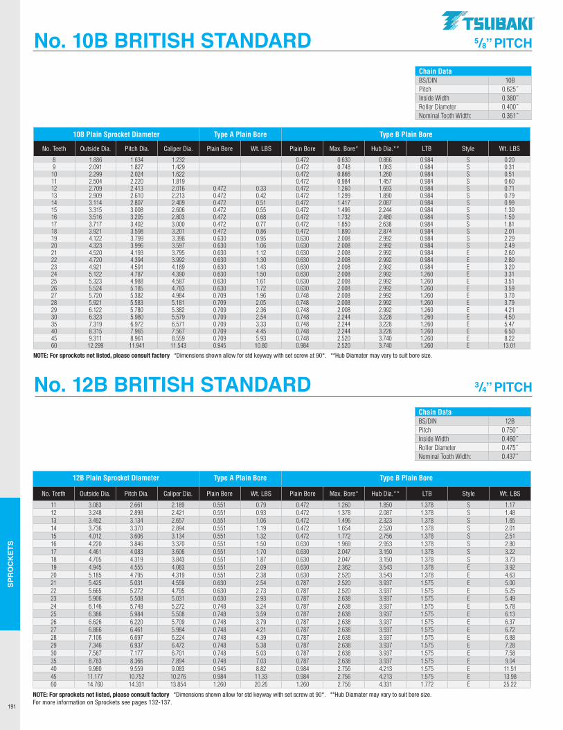
SPR
OC
KET
S
191
No. 10B BRITISH STANDARD 5/8” PITCH
Chain DataBS/DIN 10BPitch 0.625˝Inside Width 0.380˝Roller Diameter 0.400˝Nominal Tooth Width: 0.361˝
Chain DataBS/DIN 12BPitch 0.750˝Inside Width 0.460˝Roller Diameter 0.475˝Nominal Tooth Width: 0.437˝
12B Plain Sprocket Diameter Type A Plain Bore Type B Plain Bore
No. Teeth Outside Dia. Pitch Dia. Caliper Dia. Plain Bore Wt. LBS Plain Bore Max. Bore* Hub Dia.** LTB Style Wt. LBS
11 3.083 2.661 2.189 0.551 0.79 0.472 1.260 1.850 1.378 S 1.1712 3.248 2.898 2.421 0.551 0.93 0.472 1.378 2.087 1.378 S 1.4813 3.492 3.134 2.657 0.551 1.06 0.472 1.496 2.323 1.378 S 1.6514 3.736 3.370 2.894 0.551 1.19 0.472 1.654 2.520 1.378 S 2.0115 4.012 3.606 3.134 0.551 1.32 0.472 1.772 2.756 1.378 S 2.5116 4.220 3.846 3.370 0.551 1.50 0.630 1.969 2.953 1.378 S 2.8017 4.461 4.083 3.606 0.551 1.70 0.630 2.047 3.150 1.378 S 3.2218 4.705 4.319 3.843 0.551 1.87 0.630 2.047 3.150 1.378 S 3.7319 4.945 4.555 4.083 0.551 2.09 0.630 2.362 3.543 1.378 E 3.9220 5.185 4.795 4.319 0.551 2.38 0.630 2.520 3.543 1.378 E 4.6321 5.425 5.031 4.559 0.630 2.54 0.787 2.520 3.937 1.575 E 5.0022 5.665 5.272 4.795 0.630 2.73 0.787 2.520 3.937 1.575 E 5.2523 5.906 5.508 5.031 0.630 2.93 0.787 2.638 3.937 1.575 E 5.4924 6.146 5.748 5.272 0.748 3.24 0.787 2.638 3.937 1.575 E 5.7825 6.386 5.984 5.508 0.748 3.59 0.787 2.638 3.937 1.575 E 6.1326 6.626 6.220 5.709 0.748 3.79 0.787 2.638 3.937 1.575 E 6.3727 6.866 6.461 5.984 0.748 4.21 0.787 2.638 3.937 1.575 E 6.7228 7.106 6.697 6.224 0.748 4.39 0.787 2.638 3.937 1.575 E 6.8829 7.346 6.937 6.472 0.748 5.38 0.787 2.638 3.937 1.575 E 7.2830 7.587 7.177 6.701 0.748 5.03 0.787 2.638 3.937 1.575 E 7.5835 8.783 8.366 7.894 0.748 7.03 0.787 2.638 3.937 1.575 E 9.0440 9.980 9.559 9.083 0.945 8.82 0.984 2.756 4.213 1.575 E 11.5145 11.177 10.752 10.276 0.984 11.33 0.984 2.756 4.213 1.575 E 13.9860 14.760 14.331 13.854 1.260 20.26 1.260 2.756 4.331 1.772 E 25.22
NOTE: For sprockets not listed, please consult factory *Dimensions shown allow for std keyway with set screw at 90°. **Hub Diamater may vary to suit bore size.For more information on Sprockets see pages 132-137.
No. 12B BRITISH STANDARD 3/4” PITCH
10B Plain Sprocket Diameter Type A Plain Bore Type B Plain Bore
No. Teeth Outside Dia. Pitch Dia. Caliper Dia. Plain Bore Wt. LBS Plain Bore Max. Bore* Hub Dia.** LTB Style Wt. LBS
8 1.886 1.634 1.232 0.472 0.630 0.866 0.984 S 0.209 2.091 1.827 1.429 0.472 0.748 1.063 0.984 S 0.31
10 2.299 2.024 1.622 0.472 0.866 1.260 0.984 S 0.5111 2.504 2.220 1.819 0.472 0.984 1.457 0.984 S 0.6012 2.709 2.413 2.016 0.472 0.33 0.472 1.260 1.693 0.984 S 0.7113 2.909 2.610 2.213 0.472 0.42 0.472 1.299 1.890 0.984 S 0.7914 3.114 2.807 2.409 0.472 0.51 0.472 1.417 2.087 0.984 S 0.9915 3.315 3.008 2.606 0.472 0.55 0.472 1.496 2.244 0.984 S 1.3016 3.516 3.205 2.803 0.472 0.68 0.472 1.732 2.480 0.984 S 1.5017 3.717 3.402 3.000 0.472 0.77 0.472 1.850 2.638 0.984 S 1.8118 3.921 3.598 3.201 0.472 0.86 0.472 1.890 2.874 0.984 S 2.0119 4.122 3.799 3.398 0.630 0.95 0.630 2.008 2.992 0.984 S 2.2920 4.323 3.996 3.597 0.630 1.06 0.630 2.008 2.992 0.984 S 2.4921 4.520 4.193 3.795 0.630 1.12 0.630 2.008 2.992 0.984 E 2.6022 4.720 4.394 3.992 0.630 1.30 0.630 2.008 2.992 0.984 E 2.8023 4.921 4.591 4.189 0.630 1.43 0.630 2.008 2.992 0.984 E 3.2024 5.122 4.787 4.390 0.630 1.50 0.630 2.008 2.992 1.260 E 3.3125 5.323 4.988 4.587 0.630 1.61 0.630 2.008 2.992 1.260 E 3.5126 5.524 5.185 4.783 0.630 1.72 0.630 2.008 2.992 1.260 E 3.5927 5.720 5.382 4.984 0.709 1.96 0.748 2.008 2.992 1.260 E 3.7028 5.921 5.583 5.181 0.709 2.05 0.748 2.008 2.992 1.260 E 3.7929 6.122 5.780 5.382 0.709 2.36 0.748 2.008 2.992 1.260 E 4.2130 6.323 5.980 5.579 0.709 2.54 0.748 2.244 3.228 1.260 E 4.5035 7.319 6.972 6.571 0.709 3.33 0.748 2.244 3.228 1.260 E 5.4740 8.315 7.965 7.567 0.709 4.45 0.748 2.244 3.228 1.260 E 6.5045 9.311 8.961 8.559 0.709 5.93 0.748 2.520 3.740 1.260 E 8.2260 12.299 11.941 11.543 0.945 10.80 0.984 2.520 3.740 1.260 E 13.01
NOTE: For sprockets not listed, please consult factory *Dimensions shown allow for std keyway with set screw at 90°. **Hub Diamater may vary to suit bore size.
.TSUBAKI"
I I I
------
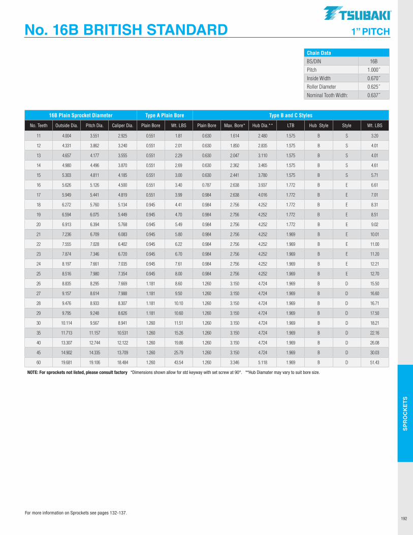
SPR
OC
KET
S
192
No. 16B BRITISH STANDARD 1” PITCH
Chain DataBS/DIN 16B
Pitch 1.000˝
Inside Width 0.670˝
Roller Diameter 0.625˝
Nominal Tooth Width: 0.637˝
16B Plain Sprocket Diameter Type A Plain Bore Type B and C Styles
No. Teeth Outside Dia. Pitch Dia. Caliper Dia. Plain Bore Wt. LBS Plain Bore Max. Bore* Hub Dia.** LTB Hub Style Style Wt. LBS
11 4.004 3.551 2.925 0.551 1.81 0.630 1.614 2.480 1.575 B S 3.20
12 4.331 3.862 3.240 0.551 2.01 0.630 1.850 2.835 1.575 B S 4.01
13 4.657 4.177 3.555 0.551 2.29 0.630 2.047 3.110 1.575 B S 4.01
14 4.980 4.496 3.870 0.551 2.69 0.630 2.362 3.465 1.575 B S 4.61
15 5.303 4.811 4.185 0.551 3.00 0.630 2.441 3.780 1.575 B S 5.71
16 5.626 5.126 4.500 0.551 3.40 0.787 2.638 3.937 1.772 B E 6.61
17 5.949 5.441 4.819 0.551 3.99 0.984 2.638 4.016 1.772 B E 7.01
18 6.272 5.760 5.134 0.945 4.41 0.984 2.756 4.252 1.772 B E 8.31
19 6.594 6.075 5.449 0.945 4.70 0.984 2.756 4.252 1.772 B E 8.51
20 6.913 6.394 5.768 0.945 5.49 0.984 2.756 4.252 1.772 B E 9.02
21 7.236 6.709 6.083 0.945 5.80 0.984 2.756 4.252 1.969 B E 10.01
22 7.555 7.028 6.402 0.945 6.22 0.984 2.756 4.252 1.969 B E 11.00
23 7.874 7.346 6.720 0.945 6.70 0.984 2.756 4.252 1.969 B E 11.20
24 8.197 7.661 7.035 0.945 7.61 0.984 2.756 4.252 1.969 B E 12.21
25 8.516 7.980 7.354 0.945 8.00 0.984 2.756 4.252 1.969 B E 12.70
26 8.835 8.295 7.669 1.181 8.60 1.260 3.150 4.724 1.969 B D 15.50
27 9.157 8.614 7.988 1.181 9.50 1.260 3.150 4.724 1.969 B D 16.60
28 9.476 8.933 8.307 1.181 10.10 1.260 3.150 4.724 1.969 B D 16.71
29 9.795 9.248 8.626 1.181 10.60 1.260 3.150 4.724 1.969 B D 17.50
30 10.114 9.567 8.941 1.260 11.51 1.260 3.150 4.724 1.969 B D 18.21
35 11.713 11.157 10.531 1.260 15.26 1.260 3.150 4.724 1.969 B D 22.16
40 13.307 12.744 12.122 1.260 19.86 1.260 3.150 4.724 1.969 B D 26.08
45 14.902 14.335 13.709 1.260 25.79 1.260 3.150 4.724 1.969 B D 30.03
60 19.681 19.106 18.484 1.260 43.54 1.260 3.346 5.118 1.969 B D 51.43
NOTE: For sprockets not listed, please consult factory *Dimensions shown allow for std keyway with set screw at 90°. **Hub Diamater may vary to suit bore size.
For more information on Sprockets see pages 132-137.
TSUBAKI"
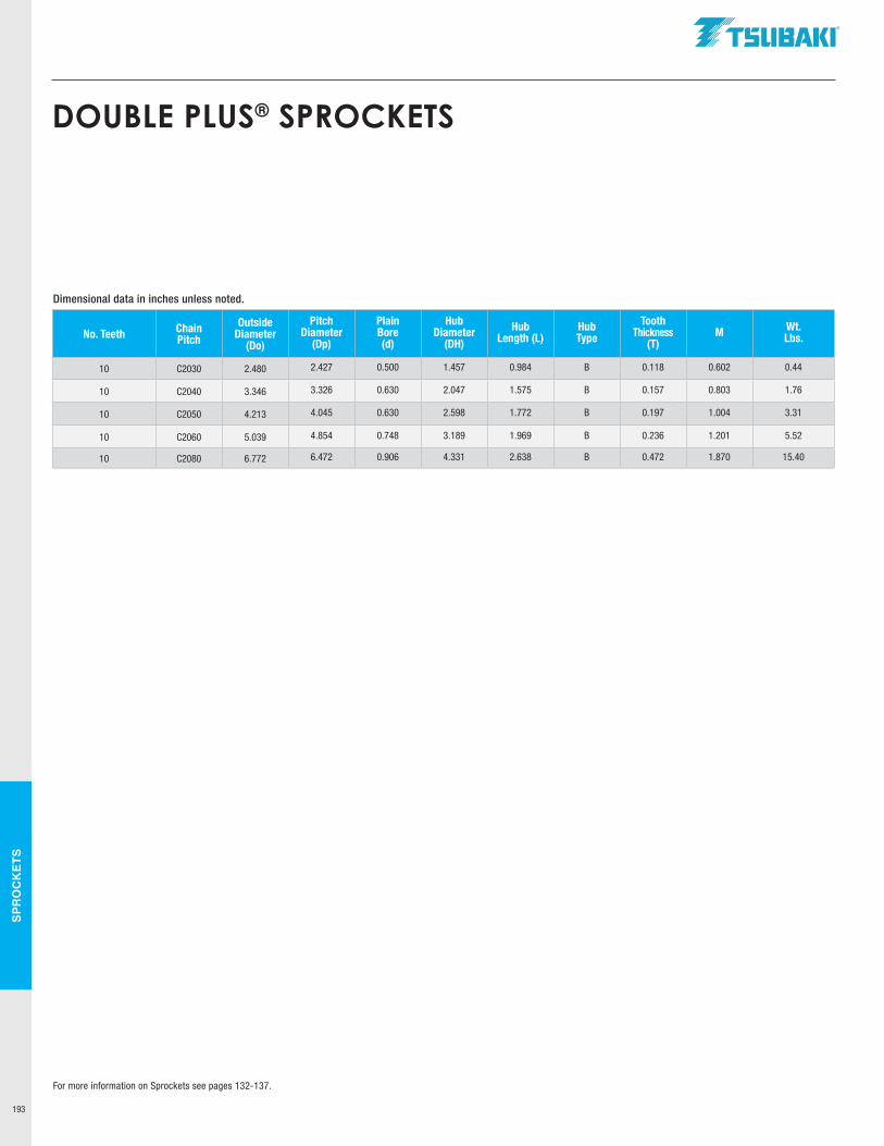
SPR
OC
KET
S
193
DOUBLE PLUS® SPROCKETS
No. Teeth Chain Pitch
OutsideDiameter
(Do)
Pitch Diameter
(Dp)
Plain Bore (d)
Hub Diameter
(DH)
Hub Length (L)
Hub Type
Tooth Thickness
(T)M Wt.
Lbs.
10 C2030 2.480 2.427 0.500 1.457 0.984 B 0.118 0.602 0.44
10 C2040 3.346 3.326 0.630 2.047 1.575 B 0.157 0.803 1.76
10 C2050 4.213 4.045 0.630 2.598 1.772 B 0.197 1.004 3.31
10 C2060 5.039 4.854 0.748 3.189 1.969 B 0.236 1.201 5.52
10 C2080 6.772 6.472 0.906 4.331 2.638 B 0.472 1.870 15.40
Dimensional data in inches unless noted.
For more information on Sprockets see pages 132-137.
.TSUBAKI"
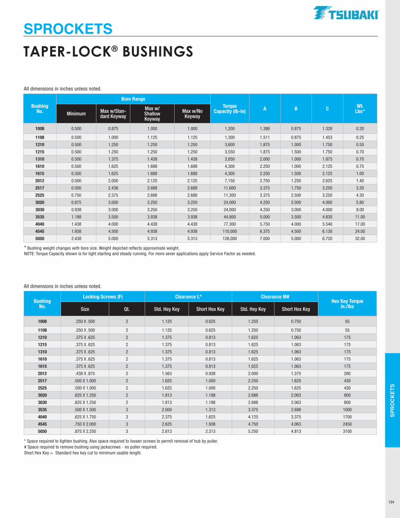
SPR
OC
KET
S
194
TAPER-LOCK® BUSHINGS
SPROCKETS
Bushing No.
Bore RangeTorque
Capacity (lb-in) A B C Wt. Lbs*Minimum Max w/Stan-
dard Keyway
Max w/ Shallow Keyway
Max w/No Keyway
1008 0.500 0.875 1.000 1.000 1,200 1.386 0.875 1.328 0.20
1108 0.500 1.000 1.125 1.125 1,300 1.511 0.875 1.453 0.25
1210 0.500 1.250 1.250 1.250 3,600 1.875 1.000 1.750 0.55
1215 0.500 1.250 1.250 1.250 3,550 1.875 1.500 1.750 0.70
1310 0.500 1.375 1.438 1.438 3,850 2.000 1.000 1.875 0.70
1610 0.500 1.625 1.688 1.688 4,300 2.250 1.000 2.125 0.75
1615 0.500 1.625 1.688 1.688 4,300 2.250 1.500 2.125 1.00
2012 0.500 2.000 2.125 2.125 7,150 2.750 1.250 2.625 1.40
2517 0.500 2.438 2.688 2.688 11,600 3.375 1.750 3.250 3.20
2525 0.750 2.375 2.688 2.688 11,300 3.375 2.500 3.250 4.30
3020 0.875 3.000 3.250 3.250 24,000 4.250 2.000 4.000 5.80
3030 0.938 3.000 3.250 3.250 24,000 4.250 3.000 4.000 8.00
3535 1.188 3.500 3.938 3.938 44,800 5.000 3.500 4.830 11.00
4040 1.438 4.000 4.438 4.438 77,300 5.750 4.000 5.540 17.00
4545 1.938 4.500 4.938 4.938 110,000 6.375 4.500 6.130 24.00
5050 2.438 5.000 5.313 5.313 126,000 7.000 5.000 6.720 32.00
Bushing No.
Locking Screws (F) Clearance L* Clearance M#Hex Key Torque
in./lbsSize Qt. Std. Hey Key Short Hex Key Std. Hey Key Short Hex Key
1008 .250 X .500 2 1.125 0.625 1.250 0.750 55
1108 .250 X .500 2 1.125 0.625 1.250 0.750 55
1210 .375 X .625 2 1.375 0.813 1.625 1.063 175
1215 .375 X .625 2 1.375 0.813 1.625 1.063 175
1310 .375 X .625 2 1.375 0.813 1.625 1.063 175
1610 .375 X .625 2 1.375 0.813 1.625 1.063 175
1615 .375 X .625 2 1.375 0.813 1.625 1.063 175
2012 .438 X .875 2 1.563 0.938 2.000 1.375 280
2517 .500 X 1.000 2 1.625 1.000 2.250 1.625 430
2525 .500 X 1.000 2 1.625 1.000 2.250 1.625 430
3020 .625 X 1.250 2 1.813 1.188 2.688 2.063 800
3030 .625 X 1.250 2 1.813 1.188 2.688 2.063 800
3535 .500 X 1.500 3 2.000 1.313 3.375 2.688 1000
4040 .625 X 1.750 3 2.375 1.625 4.125 3.375 1700
4545 .750 X 2.000 3 2.625 1.938 4.750 4.063 2450
5050 .875 X 2.250 3 2.813 2.313 5.250 4.813 3100
* Bushing weight changes with bore size. Weight depicted reflects approximate weight.NOTE: Torque Capacity shown is for light starting and steady running. For more sever applications apply Service Factor as needed.
* Space required to tighten bushing. Also space required to loosen screws to permit removal of hub by puller. # Space required to remove bushing using jackscrews - no puller required. Short Hex Key = Standard hex key cut to minimum usable length.
All dimensions in inches unless noted.
All dimensions in inches unless noted.
TSUBAKI"
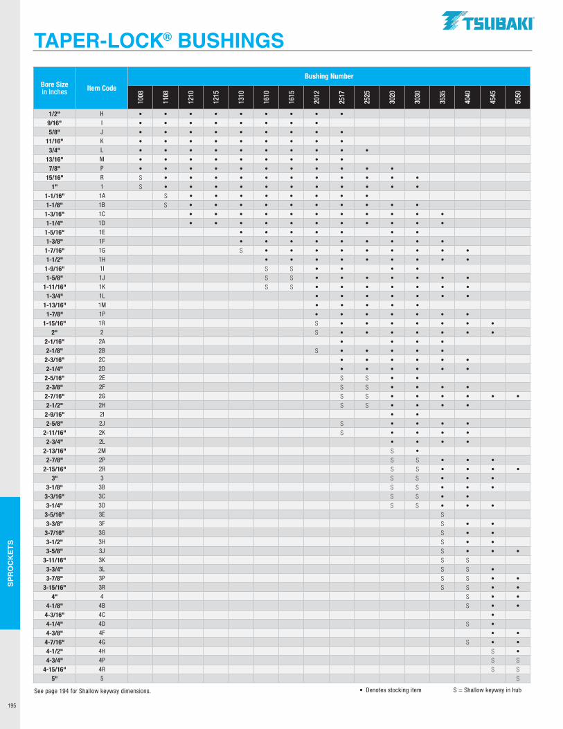
SPR
OC
KET
S
195
TAPER-LOCK® BUSHINGS
Bore Sizein Inches Item Code
Bushing Number
1008
1108
1210
1215
1310
1610
1615
2012
2517
2525
3020
3030
3535
4040
4545
5050
1/2" H • • • • • • • • •9/16" I • • • • • • • •5/8" J • • • • • • • • •
11/16" K • • • • • • • • •3/4" L • • • • • • • • • •
13/16" M • • • • • • • • •7/8" P • • • • • • • • • • •
15/16" R S • • • • • • • • • • •1" 1 S • • • • • • • • • • •
1-1/16" 1A S • • • • • • • •1-1/8" 1B S • • • • • • • • • •1-3/16" 1C • • • • • • • • • • •1-1/4" 1D • • • • • • • • • • •1-5/16" 1E • • • • • • •1-3/8" 1F • • • • • • • • •1-7/16" 1G S • • • • • • • • •1-1/2" 1H • • • • • • • • •1-9/16" 1I S S • • • •1-5/8" 1J S S • • • • • • •
1-11/16" 1K S S • • • • • • •1-3/4" 1L • • • • • • •
1-13/16" 1M • • • • •1-7/8" 1P • • • • • • •
1-15/16" 1R S • • • • • • •2" 2 S • • • • • • •
2-1/16" 2A • • • •2-1/8" 2B S • • • • •2-3/16" 2C • • • • • •2-1/4" 2D • • • • • •2-5/16" 2E S S • •2-3/8" 2F S S • • • •2-7/16" 2G S S • • • • • •2-1/2" 2H S S • • • •2-9/16" 2I • •2-5/8" 2J S • • • •
2-11/16" 2K S • • • •2-3/4" 2L • • • •
2-13/16" 2M S •2-7/8" 2P S S • • •
2-15/16" 2R S S • • • •3" 3 S S • • •
3-1/8" 3B S S • • •3-3/16" 3C S S • •3-1/4" 3D S S • • •3-5/16" 3E S3-3/8" 3F S • •3-7/16" 3G S • •3-1/2" 3H S • •3-5/8" 3J S • • •
3-11/16" 3K S S3-3/4" 3L S S •3-7/8" 3P S S • •
3-15/16" 3R S S • •4" 4 S • •
4-1/8" 4B S • •4-3/16" 4C •4-1/4" 4D S •4-3/8" 4F • •4-7/16" 4G S • •4-1/2" 4H S •4-3/4" 4P S S
4-15/16" 4R S S5" 5 S
• Denotes stocking item S = Shallow keyway in hubSee page 194 for Shallow keyway dimensions.
.TSUBAKI"
SPR
OC
KET
S
196
TAPER-LOCK®
BUSHING INSTALLATION AND REMOVALTAPER-LOCK® Bushing Installation
TAPER-LOCK® Bushing Removal
1 Clean and degrease the bore and tapered surface of the bushing and the tapered bore of the pulley/hub/sprocket.
2 Insert the bushing into the pulley/hub/sprocket bore and line up the holes (Half threaded holes must line up the half straight non-threaded holes).
3 Lightly oil the locking screws and insert but do not tighten yet.
4 When using a key, it should be fitted to the shaft keyway. There should be a top clearance between the key and the keyway in the mating bushing.
5 Clean and degrease the shaft. Fit pulley/hub/sprocket onto the shaft and locate in the desired position.
6 Using a hexagon socket wrench, gradually tighten the locking screws in accordance with the required tightening torque.
7 When the drive has been operating under load for a short period, approximately 30 to 60 minutes, stop the equipment and check that the screws remain at the required tightening torque. Adjust if necessary.
8 To avoid the ingress of dirt, fill all empty holes with grease.
A Remove any loading to the equipment to enable a safe removal of components.
B Slacken and remove all locking screws.
C Add lubricant to the previously removed screws and insert into jack-out hole/holes in the bushing.
D Tighten the screws uniformly and alternately until the bushing is loose and the pulley/hub/sprocket can be moved freely on the shaft.
E Remove the bushing/pulley/hub/sprocket assembly from the shaft.
TAPER-LOCK® is a registered trademark of Rockwell Automation.
TSUBAKI"
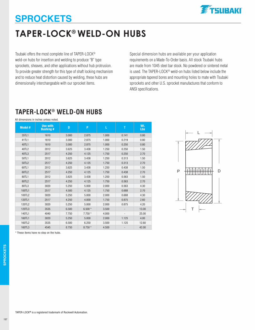
SPR
OC
KET
S
197
Model # Use with Bushing # D P L T Wt.
Lbs
35TL1 1610 3.000 2.875 1.000 0.141 0.80
41TL1 1610 3.000 2.875 1.000 0.219 0.80
40TL1 1610 3.000 2.875 1.000 0.250 0.80
40TL2 2012 3.625 3.438 1.250 0.250 1.50
40TL3 2517 4.250 4.125 1.750 0.250 2.70
50TL1 2012 3.625 3.438 1.250 0.313 1.50
50TL2 2517 4.250 4.125 1.750 0.313 2.70
60TL1 2012 3.625 3.438 1.250 0.438 1.50
60TL2 2517 4.250 4.125 1.750 0.438 2.70
80TL1 2012 3.625 3.438 1.250 0.563 1.50
80TL2 2517 4.250 4.125 1.750 0.563 2.70
80TL3 3020 5.250 5.000 2.000 0.563 4.30
100TL1 2517 4.500 4.125 1.750 0.688 2.70
100TL2 3020 5.250 5.000 2.000 0.688 4.30
120TL1 2517 4.250 4.000 1.750 0.875 2.60
120TL2 3020 5.250 5.000 2.000 0.875 4.20
120TL3 3535 6.500 6.500 * 3.500 - 13.00
140TL1 4040 7.750 7.750 * 4.000 - 25.00
160TL1 3020 5.250 5.000 2.000 1.125 4.00
160TL2 3535 6.500 6.250 3.500 1.125 12.60
160TL3 4545 8.750 8.750 * 4.500 - 42.00
Tsubaki offers the most complete line of TAPER-LOCK® weld-on hubs for insertion and welding to produce “B” type sprockets, sheaves, and other applications without hub protrusion. To provide greater strength for this type of shaft locking mechanism and to reduce heat distortion caused by welding, these hubs are dimensionally interchangeable with our sprocket items.
Special dimension hubs are available per your application requirements on a Made-To-Order basis. All stock Tsubaki hubs are made from 1045 steel bar stock. No powdered or sintered metal is used. The TAPER-LOCK® weld-on hubs listed below include the appropriate tapered bores and mounting holes to mate with Tsubaki sprockets and other U.S. sprocket manufactures that conform to ANSI specifications.
TAPER-LOCK® WELD-ON HUBS
T
DP
L
All dimensions in inches unless noted.
* These items have no step on the hubs.
TAPER-LOCK® is a registered trademark of Rockwell Automation.
TAPER-LOCK® WELD-ON HUBS
SPROCKETS.TSUBAKI"
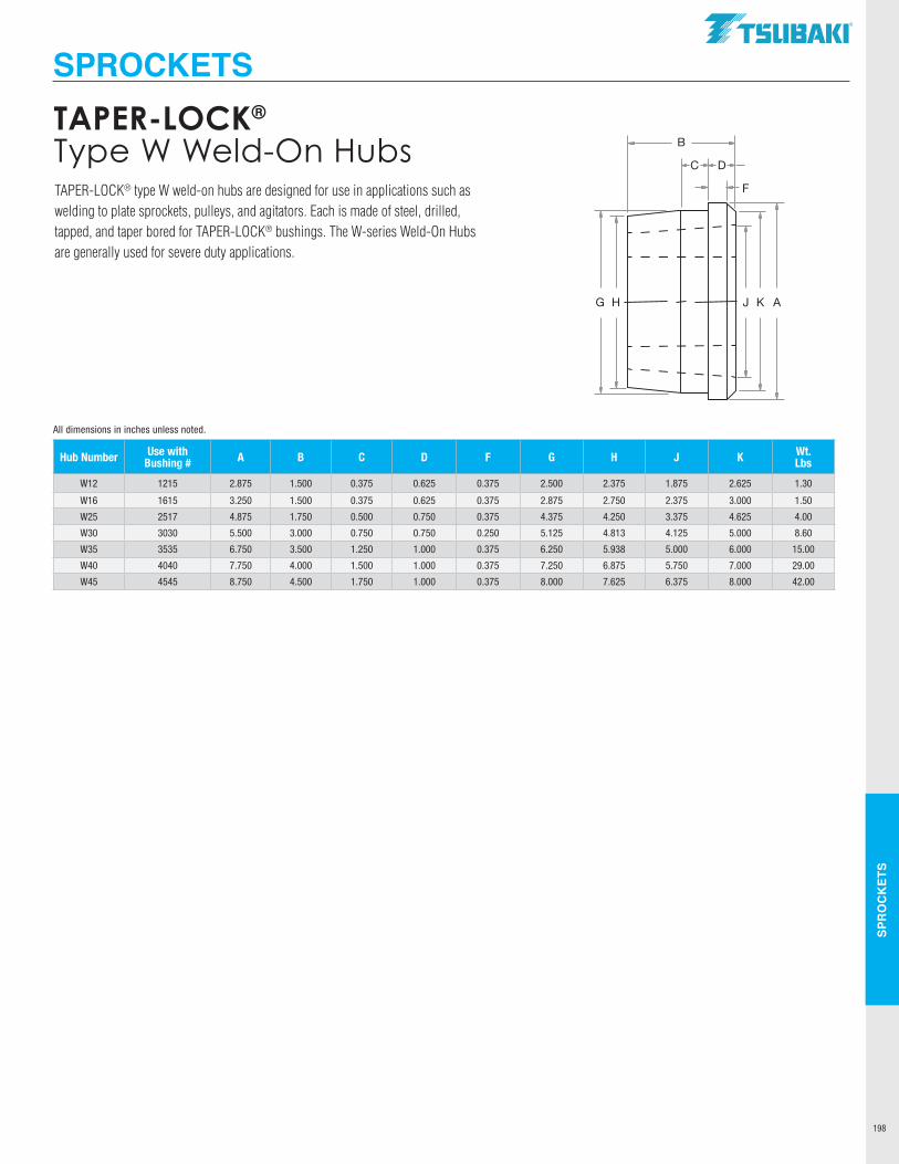
SPR
OC
KET
S
198
TAPER-LOCK® Type W Weld-On Hubs
Hub Number Use with Bushing # A B C D F G H J K Wt.
Lbs
W12 1215 2.875 1.500 0.375 0.625 0.375 2.500 2.375 1.875 2.625 1.30
W16 1615 3.250 1.500 0.375 0.625 0.375 2.875 2.750 2.375 3.000 1.50
W25 2517 4.875 1.750 0.500 0.750 0.375 4.375 4.250 3.375 4.625 4.00
W30 3030 5.500 3.000 0.750 0.750 0.250 5.125 4.813 4.125 5.000 8.60
W35 3535 6.750 3.500 1.250 1.000 0.375 6.250 5.938 5.000 6.000 15.00
W40 4040 7.750 4.000 1.500 1.000 0.375 7.250 6.875 5.750 7.000 29.00
W45 4545 8.750 4.500 1.750 1.000 0.375 8.000 7.625 6.375 8.000 42.00
TAPER-LOCK® type W weld-on hubs are designed for use in applications such as welding to plate sprockets, pulleys, and agitators. Each is made of steel, drilled, tapped, and taper bored for TAPER-LOCK® bushings. The W-series Weld-On Hubs are generally used for severe duty applications.
G H AKJ
B
C D
F
All dimensions in inches unless noted.
SPROCKETSTSUBAKI"
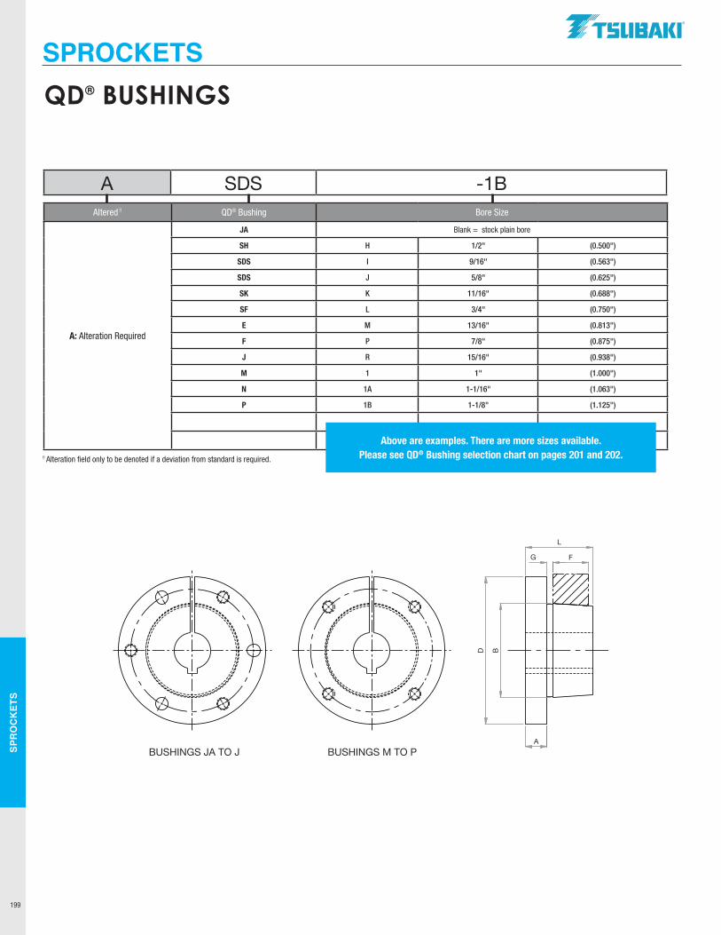
SPR
OC
KET
S
199
BUSHINGS M TO PBUSHINGS JA TO JBUSHINGS M TO N
D
A
B
L
FG
A SDS -1BAltered !! QD® Bushing Bore Size
A: Alteration Required
JA Blank = stock plain bore
SH H 1/2" (0.500")
SDS I 9/16" (0.563")
SDS J 5/8" (0.625")
SK K 11/16" (0.688")
SF L 3/4" (0.750")
E M 13/16" (0.813")
F P 7/8" (0.875")
J R 15/16" (0.938")
M 1 1" (1.000")
N 1A 1-1/16" (1.063")
P 1B 1-1/8" (1.125")
Above are examples. There are more sizes available. Please see QD® Bushing selection chart on pages 201 and 202.!! Alteration field only to be denoted if a deviation from standard is required.
QD® BUSHINGS
SPROCKETSTTSUBAKI"
LJ
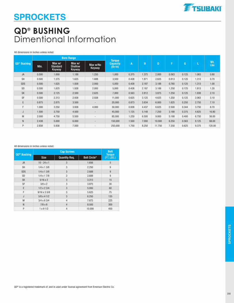
SPR
OC
KET
S
200
QD® Bushing
Bore RangeTorque
Capacity (lb-in)
A B D F G L Wt. LbsMin.
Max w/Standard Keyway
Max w/ Shallow Keyway
Max w/No Keyway
JA 0.500 1.000 1.188 1.250 1,000 0.375 1.375 2.000 0.563 0.125 1.063 0.80
SH 0.500 1.375 1.625 1.688 3,500 0.438 1.871 2.625 0.813 0.125 1.313 0.70
SDS 0.500 1.625 1.938 2.000 5,000 0.438 2.187 3.188 0.760 0.125 1.313 1.00
SD 0.500 1.625 1.938 2.000 5,000 0.438 2.187 3.188 1.250 0.125 1.813 1.20
SK 0.500 2.125 2.500 2.625 7,000 0.563 2.812 3.875 1.250 0.125 1.938 2.10
SF 0.500 2.313 2.938 2.938 11,000 0.625 3.125 4.625 1.250 0.125 2.063 3.10
E 0.875 2.875 3.500 - 20,000 0.873 3.834 6.000 1.625 0.250 2.750 7.10
F 1.000 3.250 3.938 4.000 30,000 0.938 4.437 6.625 2.500 0.344 3.750 8.70
J 1.500 3.750 4.500 - 45,000 1.125 5.148 7.250 3.188 0.375 4.625 16.80
M 2.000 4.750 5.500 - 85,000 1.250 6.500 9.000 5.188 0.400 6.750 56.00
N 2.438 5.000 6.000 - 150,000 1.500 7.000 10.000 6.250 0.563 8.125 68.00
P 2.938 5.938 7.000 - 250,000 1.750 8.250 11.750 7.250 0.625 9.375 120.00
QD® BushingCap Screws Bolt
Torque (FT. LBS.)Size Quantity Req. Bolt Circle*
JA 10 - 24 x 1 3 1.656 5
SH 1/4 x 1 3/8 3 2.250 9
SDS 1/4 x 1 3/8 3 2.688 9
SD 1/4 x 1 7/8 3 2.688 9
SK 5/16 x 2 3 3.313 15
SF 3/8 x 2 3 3.875 30
E 1/2 x 2 3/4 3 5.000 60
F 9/16 x 3 5/8 3 5.625 75
J 5/8 x 4 1/2 3 6.250 135
M 3/4 x 6 3/4 4 7.875 225
N 7/8 x 8 4 8.500 300
P 1 x 9 1/2 4 10.000 450
All dimensions in inches unless noted.
All dimensions in inches unless noted.
QD® BUSHING Dimentional Information
QD® is a registered trademark of, and is used under license agreement from Emerson Electric Co.
SPROCKETSTSUBAKI"
I I I I I I I
I I I
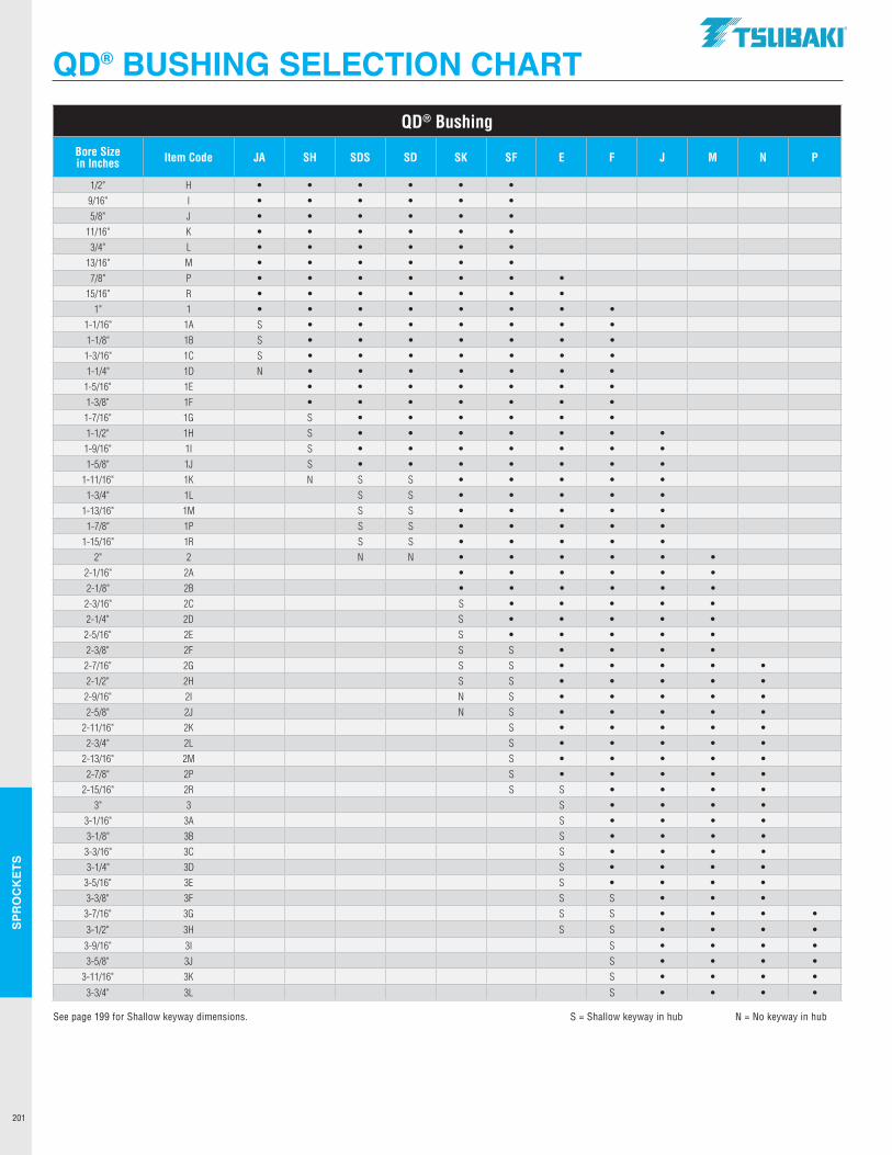
SPR
OC
KET
S
201
QD® Bushing
Bore Size in Inches Item Code JA SH SDS SD SK SF E F J M N P
1/2" H • • • • • •9/16" I • • • • • •5/8" J • • • • • •
11/16" K • • • • • •3/4" L • • • • • •
13/16" M • • • • • •7/8" P • • • • • • •
15/16" R • • • • • • •1" 1 • • • • • • • •
1-1/16" 1A S • • • • • • •1-1/8" 1B S • • • • • • •1-3/16" 1C S • • • • • • •1-1/4" 1D N • • • • • • •
1-5/16" 1E • • • • • • •1-3/8" 1F • • • • • • •1-7/16" 1G S • • • • • •1-1/2" 1H S • • • • • • •1-9/16" 1I S • • • • • • •1-5/8" 1J S • • • • • • •
1-11/16" 1K N S S • • • • •1-3/4" 1L S S • • • • •
1-13/16" 1M S S • • • • •1-7/8" 1P S S • • • • •
1-15/16" 1R S S • • • • •2" 2 N N • • • • • •
2-1/16" 2A • • • • • •2-1/8" 2B • • • • • •2-3/16" 2C S • • • • •2-1/4" 2D S • • • • •2-5/16" 2E S • • • • •2-3/8" 2F S S • • • •2-7/16" 2G S S • • • • •2-1/2" 2H S S • • • • •2-9/16" 2I N S • • • • •2-5/8" 2J N S • • • • •
2-11/16" 2K S • • • • •2-3/4" 2L S • • • • •
2-13/16" 2M S • • • • •2-7/8" 2P S • • • • •
2-15/16" 2R S S • • • •3" 3 S • • • •
3-1/16" 3A S • • • •3-1/8" 3B S • • • •3-3/16" 3C S • • • •3-1/4" 3D S • • • •
3-5/16" 3E S • • • •3-3/8" 3F S S • • •3-7/16" 3G S S • • • •
3-1/2" 3H S S • • • •
3-9/16" 3I S • • • •3-5/8" 3J S • • • •
3-11/16" 3K S • • • •
3-3/4" 3L S • • • •
See page 199 for Shallow keyway dimensions. S = Shallow keyway in hub N = No keyway in hub
QD® BUSHING SELECTION CHART.TSUBAKI"
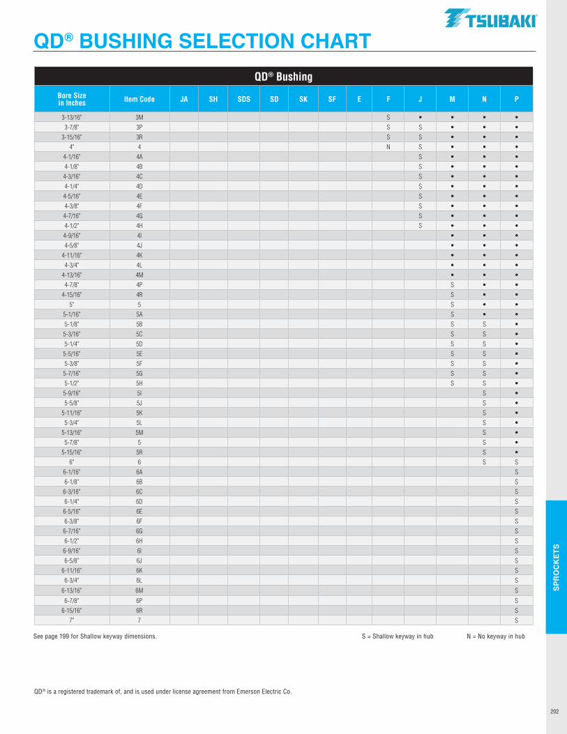
SPR
OC
KET
S
202
QD® Bushing
Bore Sizein Inches Item Code JA SH SDS SD SK SF E F J M N P
3-13/16" 3M S • • • •3-7/8" 3P S S • • •
3-15/16" 3R S S • • •4" 4 N S • • •
4-1/16" 4A S • • •4-1/8" 4B S • • •4-3/16" 4C S • • •4-1/4" 4D S • • •4-5/16" 4E S • • •4-3/8" 4F S • • •4-7/16" 4G S • • •4-1/2" 4H S • • •4-9/16" 4I • • •4-5/8" 4J • • •
4-11/16" 4K • • •4-3/4" 4L • • •
4-13/16" 4M • • • 4-7/8" 4P S • •
4-15/16" 4R S • •5" 5 S • •
5-1/16" 5A S • •5-1/8" 5B S S •
5-3/16" 5C S S •5-1/4" 5D S S •
5-5/16" 5E S S •5-3/8" 5F S S •5-7/16" 5G S S •5-1/2" 5H S S •
5-9/16" 5I S •5-5/8" 5J S •
5-11/16" 5K S •5-3/4" 5L S •
5-13/16" 5M S •5-7/8" 5 S •
5-15/16" 5R S •6" 6 S S
6-1/16" 6A S6-1/8" 6B S
6-3/16" 6C S6-1/4" 6D S
6-5/16" 6E S6-3/8" 6F S6-7/16" 6G S6-1/2" 6H S
6-9/16" 6I S6-5/8" 6J S
6-11/16" 6K S6-3/4" 6L S
6-13/16" 6M S
6-7/8" 6P S6-15/16" 6R S
7" 7 S
QD® is a registered trademark of, and is used under license agreement from Emerson Electric Co.
See page 199 for Shallow keyway dimensions. S = Shallow keyway in hub N = No keyway in hub
QD® BUSHING SELECTION CHARTTSUBAKI"
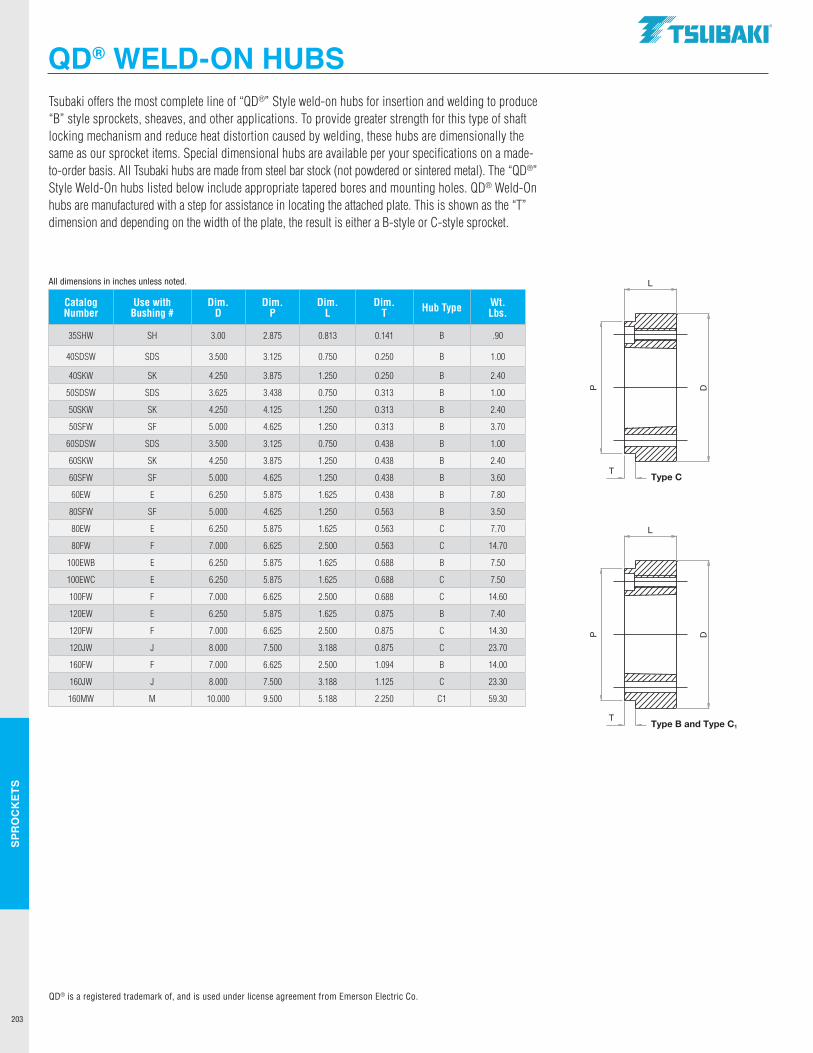
SPR
OC
KET
S
203
Catalog Number
Use with Bushing #
Dim.D
Dim.P
Dim.L
Dim.T Hub Type Wt.
Lbs.
35SHW SH 3.00 2.875 0.813 0.141 B .90
40SDSW SDS 3.500 3.125 0.750 0.250 B 1.00
40SKW SK 4.250 3.875 1.250 0.250 B 2.40
50SDSW SDS 3.625 3.438 0.750 0.313 B 1.00
50SKW SK 4.250 4.125 1.250 0.313 B 2.40
50SFW SF 5.000 4.625 1.250 0.313 B 3.70
60SDSW SDS 3.500 3.125 0.750 0.438 B 1.00
60SKW SK 4.250 3.875 1.250 0.438 B 2.40
60SFW SF 5.000 4.625 1.250 0.438 B 3.60
60EW E 6.250 5.875 1.625 0.438 B 7.80
80SFW SF 5.000 4.625 1.250 0.563 B 3.50
80EW E 6.250 5.875 1.625 0.563 C 7.70
80FW F 7.000 6.625 2.500 0.563 C 14.70
100EWB E 6.250 5.875 1.625 0.688 B 7.50
100EWC E 6.250 5.875 1.625 0.688 C 7.50
100FW F 7.000 6.625 2.500 0.688 C 14.60
120EW E 6.250 5.875 1.625 0.875 B 7.40
120FW F 7.000 6.625 2.500 0.875 C 14.30
120JW J 8.000 7.500 3.188 0.875 C 23.70
160FW F 7.000 6.625 2.500 1.094 B 14.00
160JW J 8.000 7.500 3.188 1.125 C 23.30
160MW M 10.000 9.500 5.188 2.250 C1 59.30
Tsubaki offers the most complete line of “QD®” Style weld-on hubs for insertion and welding to produce “B” style sprockets, sheaves, and other applications. To provide greater strength for this type of shaft locking mechanism and reduce heat distortion caused by welding, these hubs are dimensionally the same as our sprocket items. Special dimensional hubs are available per your specifications on a made- to-order basis. All Tsubaki hubs are made from steel bar stock (not powdered or sintered metal). The “QD®” Style Weld-On hubs listed below include appropriate tapered bores and mounting holes. QD® Weld-On hubs are manufactured with a step for assistance in locating the attached plate. This is shown as the “T” dimension and depending on the width of the plate, the result is either a B-style or C-style sprocket.
L
D
T
P
L
D
T
Type C
Type B and Type C1
P
All dimensions in inches unless noted.
QD® is a registered trademark of, and is used under license agreement from Emerson Electric Co.
QD® WELD-ON HUBS.TSUBAKI"
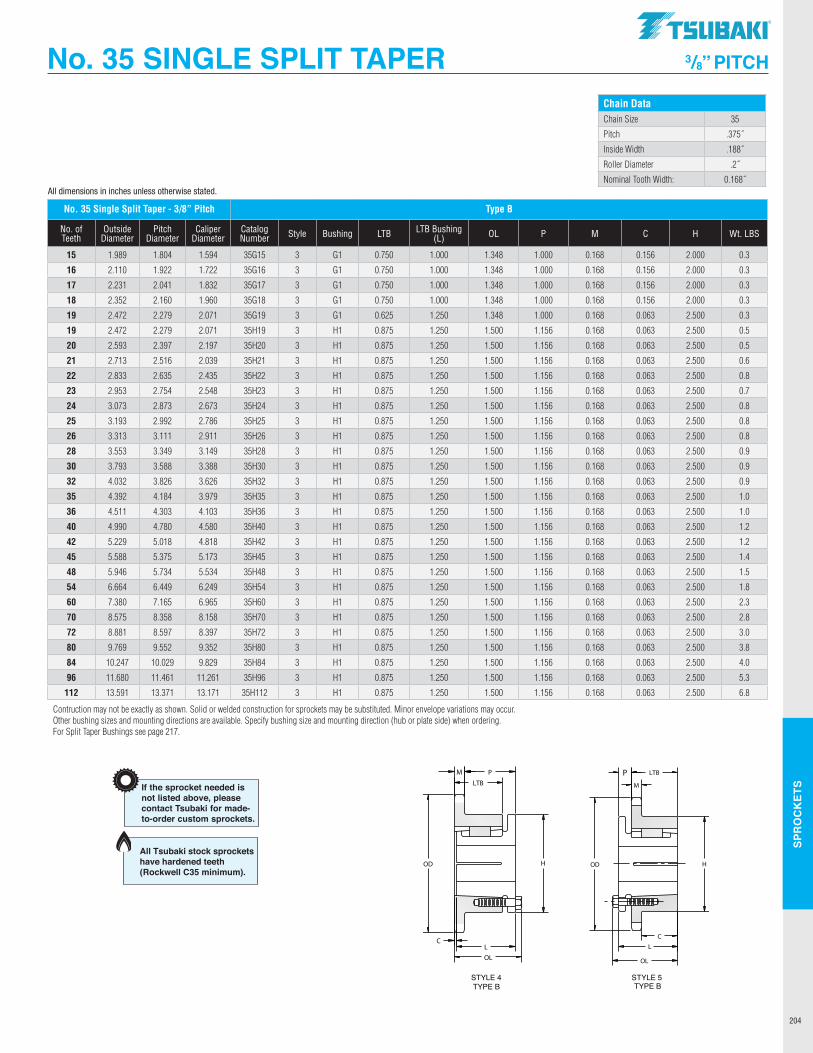
SPR
OC
KET
S
204
All dimensions in inches unless otherwise stated.
No. 35 SINGLE SPLIT TAPER 3/8” PITCH
Construction may not be exactly as shown. Solid or welded construction for sprockets may be substituted. Minor envelope variations may occur. Other bushing sizes andmounting directions available. Specify bushing size and mounting direction (hub or plate side) when ordering.
LTBNo. of Outside Pitch Caliper Catalogue Bushing WeightTeeth Diameter Diameter Diameter Number Style Hub LTB (L) OL P M C H (Ibs.)
Sprocket Diameters1" Pitch
Type B
80H1080H1180P1180P1280P1380P1480Q1480P1580Q1580P1680Q1680P1780Q1780P1880Q1880P1980Q1980Q2080Q2180Q2280Q2380Q2480Q2580Q2680Q2780Q2880Q2980Q3080Q3180Q3280Q33
H1H1P1P1P1P1Q1P1Q1P1Q1P1Q1P1Q1P1Q1Q1Q1Q1Q1Q1Q1Q1Q1Q1Q1Q1Q1Q1Q1
3344444444444444444444444444444
1 1/41 1/4
1 15/16
1 15/16
1 15/16
1 15/16
2 1/21 15/16
2 1/21 15/16
2 1/21 15/16
2 1/21 15/16
2 1/21 15/16
2 1/22 1/22 1/22 1/22 1/22 1/22 1/22 1/22 1/22 1/22 1/22 1/22 1/22 1/22 1/2
1 1/21 1/21 1/21 5/16
1 5/16
1 5/16
1 3/41 5/16
1 3/41 5/16
1 3/41 5/16
1 3/41 5/16
1 3/41 5/16
1 3/41 3/41 3/41 3/41 3/41 3/41 3/41 3/41 3/41 3/41 3/41 3/41 3/41 3/41 3/4
1 21/64
3/41 17/32
1 3/81 3/81 3/8
1 15/16
1 3/81 15/16
1 3/81 15/16
1 3/81 15/16
1 3/81 15/16
1 3/81 15/16
1 15/16
1 15/16
1 15/16
1 15/16
1 15/16
1 15/16
1 15/16
1 15/16
1 15/16
1 15/16
1 15/16
1 15/16
1 15/16
1 15/16
2 3/32
1 1/22 11/32
2 3/16
2 3/16
2 3/16
2 25/32
2 3/16
2 25/32
2 3/16
2 25/32
2 3/16
2 25/32
2 3/16
2 25/32
2 3/16
2 25/32
2 25/32
2 25/32
2 25/32
2 25/32
2 25/32
2 25/32
2 25/32
2 25/32
2 25/32
2 25/32
2 25/32
2 25/32
2 25/32
2 25/32
0.5750.5750.5750.5750.5750.5750.5750.5750.5750.5750.5750.5750.5750.5750.5750.5750.5750.5750.5750.5750.5750.5750.5750.5750.5750.5750.5750.5750.5750.5750.575
2 1/22 1/2
3333
3 7/83
3 7/83
3 7/83
3 7/83
4 1/23
4 1/24 1/24 1/24 1/24 1/24 1/24 1/24 1/24 1/24 1/24 1/24 1/24 1/24 1/24 1/2
1.21.31.62.02.42.62.93.03.43.54.63.85.34.46.04.96.57.07.38.28.89.19.6
10.610.912.412.613.413.914.815.5
21/32
1/16
5/32
----------------------------
10111112131414151516161717181819192021222324252627282930313233
3.2363.5503.5503.8644.1794.4944.4944.8104.8105.1265.1265.4425.4425.7595.7596.0766.0766.3926.7107.0277.3447.6617.9798.2968.6148.9319.2499.5679.884
10.20210.520
TYPE BSTYLE 4
TYPE BSTYLE 3
3.678 4.006 4.006 4.332 4.657 4.981 4.981 5.305 5.305 5.627 5.627 5.950 5.950 6.271 6.271 6.593 6.593 6.914 7.235 7.555 7.876 8.196 8.516 8.836 9.156 9.475 9.795 10.114 10.434 10.753 11.072
If the sprocket needed isnot listed above, pleasecontact Tsubaki for made-to-order custom sprockets.
Dimensional DataSingle Strand Chain 80Size 80Pitch 1.000"Chain Inside Width 0.625"Roller Diameter 0.625"Nom. Tooth Width 0.575"
2.6112.8882.8883.2393.5233.8693.8694.1584.1584.5014.5014.7944.7945.1345.1345.4305.4305.7676.0666.4026.7027.0367.3387.6717.9748.3068.6118.9429.2479.5779.883
All Tsubaki stock sprockets have hardened teeth (Rockwell C35 minimum).
No. 35 Single Split Taper - 3/8” Pitch Type B
No. of Teeth
Outside Diameter
Pitch Diameter
Caliper Diameter
Catalog Number Style Bushing LTB LTB Bushing
(L) OL P M C H Wt. LBS
15 1.989 1.804 1.594 35G15 3 G1 0.750 1.000 1.348 1.000 0.168 0.156 2.000 0.3
16 2.110 1.922 1.722 35G16 3 G1 0.750 1.000 1.348 1.000 0.168 0.156 2.000 0.3
17 2.231 2.041 1.832 35G17 3 G1 0.750 1.000 1.348 1.000 0.168 0.156 2.000 0.3
18 2.352 2.160 1.960 35G18 3 G1 0.750 1.000 1.348 1.000 0.168 0.156 2.000 0.3
19 2.472 2.279 2.071 35G19 3 G1 0.625 1.250 1.348 1.000 0.168 0.063 2.500 0.3
19 2.472 2.279 2.071 35H19 3 H1 0.875 1.250 1.500 1.156 0.168 0.063 2.500 0.5
20 2.593 2.397 2.197 35H20 3 H1 0.875 1.250 1.500 1.156 0.168 0.063 2.500 0.5
21 2.713 2.516 2.039 35H21 3 H1 0.875 1.250 1.500 1.156 0.168 0.063 2.500 0.6
22 2.833 2.635 2.435 35H22 3 H1 0.875 1.250 1.500 1.156 0.168 0.063 2.500 0.8
23 2.953 2.754 2.548 35H23 3 H1 0.875 1.250 1.500 1.156 0.168 0.063 2.500 0.7
24 3.073 2.873 2.673 35H24 3 H1 0.875 1.250 1.500 1.156 0.168 0.063 2.500 0.8
25 3.193 2.992 2.786 35H25 3 H1 0.875 1.250 1.500 1.156 0.168 0.063 2.500 0.8
26 3.313 3.111 2.911 35H26 3 H1 0.875 1.250 1.500 1.156 0.168 0.063 2.500 0.8
28 3.553 3.349 3.149 35H28 3 H1 0.875 1.250 1.500 1.156 0.168 0.063 2.500 0.9
30 3.793 3.588 3.388 35H30 3 H1 0.875 1.250 1.500 1.156 0.168 0.063 2.500 0.9
32 4.032 3.826 3.626 35H32 3 H1 0.875 1.250 1.500 1.156 0.168 0.063 2.500 0.9
35 4.392 4.184 3.979 35H35 3 H1 0.875 1.250 1.500 1.156 0.168 0.063 2.500 1.0
36 4.511 4.303 4.103 35H36 3 H1 0.875 1.250 1.500 1.156 0.168 0.063 2.500 1.0
40 4.990 4.780 4.580 35H40 3 H1 0.875 1.250 1.500 1.156 0.168 0.063 2.500 1.2
42 5.229 5.018 4.818 35H42 3 H1 0.875 1.250 1.500 1.156 0.168 0.063 2.500 1.2
45 5.588 5.375 5.173 35H45 3 H1 0.875 1.250 1.500 1.156 0.168 0.063 2.500 1.4
48 5.946 5.734 5.534 35H48 3 H1 0.875 1.250 1.500 1.156 0.168 0.063 2.500 1.5
54 6.664 6.449 6.249 35H54 3 H1 0.875 1.250 1.500 1.156 0.168 0.063 2.500 1.8
60 7.380 7.165 6.965 35H60 3 H1 0.875 1.250 1.500 1.156 0.168 0.063 2.500 2.3
70 8.575 8.358 8.158 35H70 3 H1 0.875 1.250 1.500 1.156 0.168 0.063 2.500 2.8
72 8.881 8.597 8.397 35H72 3 H1 0.875 1.250 1.500 1.156 0.168 0.063 2.500 3.0
80 9.769 9.552 9.352 35H80 3 H1 0.875 1.250 1.500 1.156 0.168 0.063 2.500 3.8
84 10.247 10.029 9.829 35H84 3 H1 0.875 1.250 1.500 1.156 0.168 0.063 2.500 4.0
96 11.680 11.461 11.261 35H96 3 H1 0.875 1.250 1.500 1.156 0.168 0.063 2.500 5.3
112 13.591 13.371 13.171 35H112 3 H1 0.875 1.250 1.500 1.156 0.168 0.063 2.500 6.8
Contruction may not be exactly as shown. Solid or welded construction for sprockets may be substituted. Minor envelope variations may occur.Other bushing sizes and mounting directions are available. Specify bushing size and mounting direction (hub or plate side) when ordering. For Split Taper Bushings see page 217.
Chain DataChain Size 35
Pitch .375˝
Inside Width .188˝
Roller Diameter .2˝
Nominal Tooth Width: 0.168˝
100P11100Q12100Q13100Q14100Q15100Q16100Q17100Q18100Q19100Q20100Q21100R21100Q22100Q23100Q24100R24100Q25100R25100Q26100R26100Q27100R27100Q28100R28100Q30100R30100Q32100R32100R35100R40100R42100R45100R48100R54100R60100R70100R72100R80100R84
P1Q1Q1Q1Q1Q1Q1Q1Q1Q1Q1R1Q1Q1Q1R1Q1R1Q1R1Q1R1Q1R1Q1R1Q1R1R1R1R1R1R1R1R1R1R1R1R1
444444444444444444444444444444444555555
5.007 5.415 5.821 6.227 6.631 7.034 7.437 7.839 8.241 8.642 9.043 9.043 9.444 9.844 10.245 10.245 10.645 10.645 11.045 11.045 11.444 11.444 11.844 11.844 12.643 12.643 13.441 13.441 14.639 16.633 17.430 18.626 19.821 22.212 24.601 28.583 29.380 32.565 34.157
2.83.54.35.66.67.48.29.09.810.911.812.112.613.815.415.616.016.517.317.918.018.519.620.122.422.925.326.530.240.944.350.557.569.084.0104.0106.0135.0138.0
1 5/16
1 3/41 3/41 3/41 3/41 3/41 3/41 3/41 3/41 3/41 3/4
2 1 3/41 3/41 3/4
2 1 3/4
2 1 3/4
2 1 3/4
2 1 3/4
2 1 3/4
2 1 3/4
2 2 2 2 2 2 2 2 2 2 2 2
1 1/41 7/81 7/8
1 13/16
1 13/16
1 13/16
1 13/16
1 13/16
1 13/16
1 13/16
1 13/16
2 3/16
1 13/16
1 13/16
1 13/16
2 3/16
1 13/16
2 3/16
1 13/16
2 3/16
1 13/16
2 3/16
1 13/16
2 3/16
1 13/16
2 3/16
1 13/16
2 3/16
2 3/16
2 3/16
2 3/16
2 3/16
2 3/16
7/87/87/87/87/87/8
2 3/16
2 27/32
2 27/32
2 25/32
2 25/32
2 25/32
2 25/32
2 25/32
2 25/32
2 25/32
2 25/32
3 5/32
2 25/32
2 25/32
2 25/32
3 5/32
2 25/32
3 5/32
2 25/32
3 5/32
2 25/32
3 5/32
2 25/32
3 5/32
2 25/32
3 5/32
2 25/32
3 5/32
3 5/32
3 5/32
3 5/32
3 5/32
3 5/32
3 5/32
3 5/32
3 5/32
3 5/32
3 5/32
3 5/32
0.6920.6920.6920.6920.6920.6920.6920.6920.6920.6920.6920.6920.6920.6920.6920.6920.6920.6920.6920.6920.6920.6920.6920.6920.6920.6920.6920.6920.6920.6920.6920.6920.6920.6920.6920.6920.6920.6920.692
33 7/83 7/83 7/84 1/24 1/24 1/24 1/24 1/24 1/24 1/25 3/44 1/24 1/24 1/25 3/44 1/25 3/44 1/25 3/44 1/25 3/44 1/25 3/44 1/25 3/44 1/25 3/45 3/45 3/45 3/45 3/45 3/45 3/45 3/45 3/45 3/45 3/45 3/4
TYPE BSTYLE 4 STYLE 5
TYPE B
-1/16
1/16
------------------------------
1 5/16
1 5/16
1 5/16
1 5/16
1 5/16
1 5/16
Dimensional DataSingle Strand Chain 100Size 100Pitch 1.250"Chain Inside Width 0.750"Roller Diameter 0.750"Nominal Tooth Width 0.692"
If the sprocket needed is not listedabove, please contact Tsubaki formade-to-order custom sprockets.
LTBNo. of Outside Pitch Caliper Catalogue Bushing WeightTeeth Diameter Diameter Diameter Number Style Hub LTB (L) OL P M C H (Ibs.)
4.4384.8305.2245.6186.0136.4086.8037.1997.5957.9908.3888.3888.7849.1809.5769.5769.9749.974
10.37010.37010.76810.76811.16411.16411.95911.95912.75312.75313.94515.93316.72817.92019.11321.49823.88427.86128.65731.83933.430
3.6424.0804.4354.8685.2295.6586.0246.4496.8197.2407.6137.6138.0348.4098.8268.8269.2049.2049.6209.6209.9999.999
10.41410.41411.20911.20912.00312.00313.18115.18315.97817.15918.36320.74823.13427.11127.90831.08932.680
Sprocket Diameters1¹⁄₄" Pitch
Type B
Construction may not be exactly as shown. Solid or welded construction for sprockets may be substituted. Minor envelope variations may occur. Other bushing sizes andmounting directions available. Specify bushing size and mounting direction (hub or plate side) when ordering.
111213141516171819202121222324242525262627272828303032323540424548546070728084
1 3/16
2 1/22 1/22 1/22 1/22 1/22 1/22 1/22 1/22 1/22 1/22 7/82 1/22 1/22 1/22 7/82 1/22 7/82 1/22 7/82 1/22 7/82 1/22 7/82 1/22 7/82 1/22 7/82 7/82 7/82 7/82 7/82 7/82 7/82 7/82 7/82 7/82 7/82 7/8
All Tsubaki stock sprockets have hardened teeth (Rockwell C35 minimum).
TSUBAKI"
---------------
H OD
OL
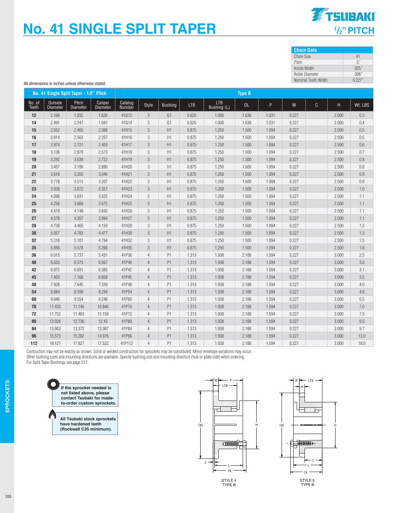
SPR
OC
KET
S
205
No. 41 SINGLE SPLIT TAPER 1/2” PITCH
Chain DataChain Size 41Pitch .5˝Inside Width .025˝Roller Diameter .306˝Nominal Tooth Width: 0.227˝
No. 41 Single Split Taper - 1/2” Pitch Type B
No. of Teeth
Outside Diameter
Pitch Diameter
Caliper Diameter
Catalog Number Style Bushing LTB LTB
Bushing (L) OL P M C H Wt. LBS
12 2.166 1.932 1.626 41G12 3 G1 0.625 1.000 1.638 1.031 0.227 2.000 0.3
14 2.491 2.247 1.941 41G14 3 G1 0.625 1.000 1.638 1.031 0.227 2.000 0.4
15 2.652 2.405 2.086 41H15 3 H1 0.875 1.250 1.500 1.094 0.227 2.500 0.5
16 2.814 2.563 2.257 41H16 3 H1 0.875 1.250 1.500 1.094 0.227 2.500 0.5
17 2.974 2.721 2.403 41H17 3 H1 0.875 1.250 1.500 1.094 0.227 2.500 0.6
18 3.136 2.879 2.573 41H18 3 H1 0.875 1.250 1.500 1.094 0.227 2.500 0.7
19 3.292 3.038 2.722 41H19 3 H1 0.875 1.250 1.500 1.094 0.227 2.500 0.8
20 3.457 3.196 2.890 41H20 3 H1 0.875 1.250 1.500 1.094 0.227 2.500 0.8
21 3.618 3.355 3.040 41H21 3 H1 0.875 1.250 1.500 1.094 0.227 2.500 0.9
22 3.778 3.513 3.207 41H22 3 H1 0.875 1.250 1.500 1.094 0.227 2.500 0.9
23 3.938 3.672 3.357 41H23 3 H1 0.875 1.250 1.500 1.094 0.227 2.500 1.0
24 4.098 3.831 3.525 41H24 3 H1 0.875 1.250 1.500 1.094 0.227 2.500 1.1
25 4.258 3.989 3.675 41H25 3 H1 0.875 1.250 1.500 1.094 0.227 2.500 1.1
26 4.418 4.148 3.842 41H26 3 H1 0.875 1.250 1.500 1.094 0.227 2.500 1.1
27 4.578 4.307 3.994 41H27 3 H1 0.875 1.250 1.500 1.094 0.227 2.500 1.1
28 4.738 4.465 4.159 41H28 3 H1 0.875 1.250 1.500 1.094 0.227 2.500 1.2
30 5.057 4.783 4.477 41H30 3 H1 0.875 1.250 1.500 1.094 0.227 2.500 1.3
32 5.316 5.101 4.794 41H32 3 H1 0.875 1.250 1.500 1.094 0.227 2.500 1.5
35 5.856 5.578 5.266 41H35 3 H1 0.875 1.250 1.500 1.094 0.227 2.500 1.8
36 6.015 5.737 5.431 41P36 4 P1 1.313 1.938 2.188 1.594 0.227 3.000 2.5
40 6.653 6.373 6.067 41P40 4 P1 1.313 1.938 2.188 1.594 0.227 3.000 3.0
42 6.972 6.691 6.385 41P42 4 P1 1.313 1.938 2.188 1.594 0.227 3.000 3.1
45 7.450 7.168 6.858 41P45 4 P1 1.313 1.938 2.188 1.594 0.227 3.000 3.5
48 7.928 7.645 7.339 41P48 4 P1 1.313 1.938 2.188 1.594 0.227 3.000 4.0
54 8.884 8.599 8.294 41P54 4 P1 1.313 1.938 2.188 1.594 0.227 3.000 4.6
60 9.840 9.554 9.246 41P60 4 P1 1.313 1.938 2.188 1.594 0.227 3.000 5.5
70 11.433 11.145 10.840 41P70 4 P1 1.313 1.938 2.188 1.594 0.227 3.000 7.0
72 11.752 11.463 11.156 41P72 4 P1 1.313 1.938 2.188 1.594 0.227 3.000 7.9
80 13.026 12.736 12.43 41P80 4 P1 1.313 1.938 2.188 1.594 0.227 3.000 9.3
84 13.663 13.372 13.067 41P84 4 P1 1.313 1.938 2.188 1.594 0.227 3.000 9.7
96 15.573 15.282 14.976 41P96 4 P1 1.313 1.938 2.188 1.594 0.227 3.000 13.0
112 18.121 17.827 17.522 41P112 4 P1 1.313 1.938 2.188 1.594 0.227 3.000 18.0
Contruction may not be exactly as shown. Solid or welded construction for sprockets may be substituted. Minor envelope variations may occur.Other bushing sizes and mounting directions are available. Specify bushing size and mounting direction (hub or plate side) when ordering. For Split Taper Bushings see page 217.
All dimensions in inches unless otherwise stated.
Construction may not be exactly as shown. Solid or welded construction for sprockets may be substituted. Minor envelope variations may occur. Other bushing sizes andmounting directions available. Specify bushing size and mounting direction (hub or plate side) when ordering.
LTBNo. of Outside Pitch Caliper Catalogue Bushing WeightTeeth Diameter Diameter Diameter Number Style Hub LTB (L) OL P M C H (Ibs.)
Sprocket Diameters1" Pitch
Type B
80H1080H1180P1180P1280P1380P1480Q1480P1580Q1580P1680Q1680P1780Q1780P1880Q1880P1980Q1980Q2080Q2180Q2280Q2380Q2480Q2580Q2680Q2780Q2880Q2980Q3080Q3180Q3280Q33
H1H1P1P1P1P1Q1P1Q1P1Q1P1Q1P1Q1P1Q1Q1Q1Q1Q1Q1Q1Q1Q1Q1Q1Q1Q1Q1Q1
3344444444444444444444444444444
1 1/41 1/4
1 15/16
1 15/16
1 15/16
1 15/16
2 1/21 15/16
2 1/21 15/16
2 1/21 15/16
2 1/21 15/16
2 1/21 15/16
2 1/22 1/22 1/22 1/22 1/22 1/22 1/22 1/22 1/22 1/22 1/22 1/22 1/22 1/22 1/2
1 1/21 1/21 1/21 5/16
1 5/16
1 5/16
1 3/41 5/16
1 3/41 5/16
1 3/41 5/16
1 3/41 5/16
1 3/41 5/16
1 3/41 3/41 3/41 3/41 3/41 3/41 3/41 3/41 3/41 3/41 3/41 3/41 3/41 3/41 3/4
1 21/64
3/41 17/32
1 3/81 3/81 3/8
1 15/16
1 3/81 15/16
1 3/81 15/16
1 3/81 15/16
1 3/81 15/16
1 3/81 15/16
1 15/16
1 15/16
1 15/16
1 15/16
1 15/16
1 15/16
1 15/16
1 15/16
1 15/16
1 15/16
1 15/16
1 15/16
1 15/16
1 15/16
2 3/32
1 1/22 11/32
2 3/16
2 3/16
2 3/16
2 25/32
2 3/16
2 25/32
2 3/16
2 25/32
2 3/16
2 25/32
2 3/16
2 25/32
2 3/16
2 25/32
2 25/32
2 25/32
2 25/32
2 25/32
2 25/32
2 25/32
2 25/32
2 25/32
2 25/32
2 25/32
2 25/32
2 25/32
2 25/32
2 25/32
0.5750.5750.5750.5750.5750.5750.5750.5750.5750.5750.5750.5750.5750.5750.5750.5750.5750.5750.5750.5750.5750.5750.5750.5750.5750.5750.5750.5750.5750.5750.575
2 1/22 1/2
3333
3 7/83
3 7/83
3 7/83
3 7/83
4 1/23
4 1/24 1/24 1/24 1/24 1/24 1/24 1/24 1/24 1/24 1/24 1/24 1/24 1/24 1/24 1/2
1.21.31.62.02.42.62.93.03.43.54.63.85.34.46.04.96.57.07.38.28.89.19.6
10.610.912.412.613.413.914.815.5
21/32
1/16
5/32
----------------------------
10111112131414151516161717181819192021222324252627282930313233
3.2363.5503.5503.8644.1794.4944.4944.8104.8105.1265.1265.4425.4425.7595.7596.0766.0766.3926.7107.0277.3447.6617.9798.2968.6148.9319.2499.5679.884
10.20210.520
TYPE BSTYLE 4
TYPE BSTYLE 3
3.678 4.006 4.006 4.332 4.657 4.981 4.981 5.305 5.305 5.627 5.627 5.950 5.950 6.271 6.271 6.593 6.593 6.914 7.235 7.555 7.876 8.196 8.516 8.836 9.156 9.475 9.795 10.114 10.434 10.753 11.072
If the sprocket needed isnot listed above, pleasecontact Tsubaki for made-to-order custom sprockets.
Dimensional DataSingle Strand Chain 80Size 80Pitch 1.000"Chain Inside Width 0.625"Roller Diameter 0.625"Nom. Tooth Width 0.575"
2.6112.8882.8883.2393.5233.8693.8694.1584.1584.5014.5014.7944.7945.1345.1345.4305.4305.7676.0666.4026.7027.0367.3387.6717.9748.3068.6118.9429.2479.5779.883
All Tsubaki stock sprockets have hardened teeth (Rockwell C35 minimum).
100P11100Q12100Q13100Q14100Q15100Q16100Q17100Q18100Q19100Q20100Q21100R21100Q22100Q23100Q24100R24100Q25100R25100Q26100R26100Q27100R27100Q28100R28100Q30100R30100Q32100R32100R35100R40100R42100R45100R48100R54100R60100R70100R72100R80100R84
P1Q1Q1Q1Q1Q1Q1Q1Q1Q1Q1R1Q1Q1Q1R1Q1R1Q1R1Q1R1Q1R1Q1R1Q1R1R1R1R1R1R1R1R1R1R1R1R1
444444444444444444444444444444444555555
5.007 5.415 5.821 6.227 6.631 7.034 7.437 7.839 8.241 8.642 9.043 9.043 9.444 9.844 10.245 10.245 10.645 10.645 11.045 11.045 11.444 11.444 11.844 11.844 12.643 12.643 13.441 13.441 14.639 16.633 17.430 18.626 19.821 22.212 24.601 28.583 29.380 32.565 34.157
2.83.54.35.66.67.48.29.09.810.911.812.112.613.815.415.616.016.517.317.918.018.519.620.122.422.925.326.530.240.944.350.557.569.084.0104.0106.0135.0138.0
1 5/16
1 3/41 3/41 3/41 3/41 3/41 3/41 3/41 3/41 3/41 3/4
2 1 3/41 3/41 3/4
2 1 3/4
2 1 3/4
2 1 3/4
2 1 3/4
2 1 3/4
2 1 3/4
2 2 2 2 2 2 2 2 2 2 2 2
1 1/41 7/81 7/8
1 13/16
1 13/16
1 13/16
1 13/16
1 13/16
1 13/16
1 13/16
1 13/16
2 3/16
1 13/16
1 13/16
1 13/16
2 3/16
1 13/16
2 3/16
1 13/16
2 3/16
1 13/16
2 3/16
1 13/16
2 3/16
1 13/16
2 3/16
1 13/16
2 3/16
2 3/16
2 3/16
2 3/16
2 3/16
2 3/16
7/87/87/87/87/87/8
2 3/16
2 27/32
2 27/32
2 25/32
2 25/32
2 25/32
2 25/32
2 25/32
2 25/32
2 25/32
2 25/32
3 5/32
2 25/32
2 25/32
2 25/32
3 5/32
2 25/32
3 5/32
2 25/32
3 5/32
2 25/32
3 5/32
2 25/32
3 5/32
2 25/32
3 5/32
2 25/32
3 5/32
3 5/32
3 5/32
3 5/32
3 5/32
3 5/32
3 5/32
3 5/32
3 5/32
3 5/32
3 5/32
3 5/32
0.6920.6920.6920.6920.6920.6920.6920.6920.6920.6920.6920.6920.6920.6920.6920.6920.6920.6920.6920.6920.6920.6920.6920.6920.6920.6920.6920.6920.6920.6920.6920.6920.6920.6920.6920.6920.6920.6920.692
33 7/83 7/83 7/84 1/24 1/24 1/24 1/24 1/24 1/24 1/25 3/44 1/24 1/24 1/25 3/44 1/25 3/44 1/25 3/44 1/25 3/44 1/25 3/44 1/25 3/44 1/25 3/45 3/45 3/45 3/45 3/45 3/45 3/45 3/45 3/45 3/45 3/45 3/4
TYPE BSTYLE 4 STYLE 5
TYPE B
-1/16
1/16
------------------------------
1 5/16
1 5/16
1 5/16
1 5/16
1 5/16
1 5/16
Dimensional DataSingle Strand Chain 100Size 100Pitch 1.250"Chain Inside Width 0.750"Roller Diameter 0.750"Nominal Tooth Width 0.692"
If the sprocket needed is not listedabove, please contact Tsubaki formade-to-order custom sprockets.
LTBNo. of Outside Pitch Caliper Catalogue Bushing WeightTeeth Diameter Diameter Diameter Number Style Hub LTB (L) OL P M C H (Ibs.)
4.4384.8305.2245.6186.0136.4086.8037.1997.5957.9908.3888.3888.7849.1809.5769.5769.9749.974
10.37010.37010.76810.76811.16411.16411.95911.95912.75312.75313.94515.93316.72817.92019.11321.49823.88427.86128.65731.83933.430
3.6424.0804.4354.8685.2295.6586.0246.4496.8197.2407.6137.6138.0348.4098.8268.8269.2049.2049.6209.6209.9999.999
10.41410.41411.20911.20912.00312.00313.18115.18315.97817.15918.36320.74823.13427.11127.90831.08932.680
Sprocket Diameters1¹⁄₄" Pitch
Type B
Construction may not be exactly as shown. Solid or welded construction for sprockets may be substituted. Minor envelope variations may occur. Other bushing sizes andmounting directions available. Specify bushing size and mounting direction (hub or plate side) when ordering.
111213141516171819202121222324242525262627272828303032323540424548546070728084
1 3/16
2 1/22 1/22 1/22 1/22 1/22 1/22 1/22 1/22 1/22 1/22 7/82 1/22 1/22 1/22 7/82 1/22 7/82 1/22 7/82 1/22 7/82 1/22 7/82 1/22 7/82 1/22 7/82 7/82 7/82 7/82 7/82 7/82 7/82 7/82 7/82 7/82 7/82 7/8
All Tsubaki stock sprockets have hardened teeth (Rockwell C35 minimum).
.TSUBAKI"
---------------
OD I:==== H OD
C
OL
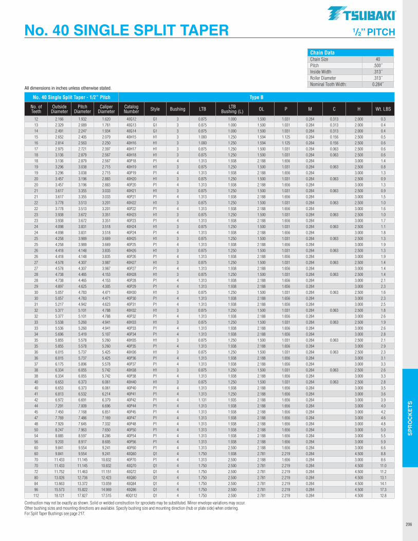
SPR
OC
KET
S
206
No. 40 SINGLE SPLIT TAPER 1/2” PITCH
Chain DataChain Size 40Pitch .500˝Inside Width .313˝Roller Diameter .313˝Nominal Tooth Width: 0.284˝
No. 40 Single Split Taper - 1/2” Pitch Type B
No. of Teeth
Outside Diameter
Pitch Diameter
Caliper Diameter
Catalog Number Style Bushing LTB LTB
Bushing (L) OL P M C H Wt. LBS
12 2.166 1.932 1.620 40G12 G1 3 0.875 1.000 1.500 1.031 0.284 0.313 2.000 0.313 2.329 2.089 1.761 40G13 G1 3 0.875 1.000 1.500 1.031 0.284 0.313 2.000 0.414 2.491 2.247 1.934 40G14 G1 3 0.875 1.000 1.500 1.031 0.284 0.313 2.000 0.415 2.652 2.405 2.079 40H15 H1 3 1.000 1.250 1.594 1.125 0.284 0.156 2.500 0.516 2.814 2.563 2.250 40H16 H1 3 1.000 1.250 1.594 1.125 0.284 0.156 2.500 0.617 2.975 2.721 2.397 40H17 H1 3 0.875 1.250 1.500 1.031 0.284 0.063 2.500 0.618 3.136 2.879 2.567 40H18 H1 3 0.875 1.250 1.500 1.031 0.284 0.063 2.500 0.618 3.136 2.879 2.567 40P18 P1 4 1.313 1.938 2.188 1.656 0.284 3.000 1.419 3.296 3.038 2.715 40H19 H1 3 0.875 1.250 1.500 1.031 0.284 0.063 2.500 0.819 3.296 3.038 2.715 40P19 P1 4 1.313 1.938 2.188 1.656 0.284 3.000 1.320 3.457 3.196 2.883 40H20 H1 3 0.875 1.250 1.500 1.031 0.284 0.063 2.500 0.920 3.457 3.196 2.883 40P20 P1 4 1.313 1.938 2.188 1.656 0.284 3.000 1.321 3.617 3.355 3.033 40H21 H1 3 0.875 1.250 1.500 1.031 0.284 0.063 2.500 0.921 3.617 3.355 3.033 40P21 P1 4 1.313 1.938 2.188 1.656 0.284 3.000 1.522 3.778 3.513 3.201 40H22 H1 3 0.875 1.250 1.500 1.031 0.284 0.063 2.500 1.022 3.778 3.513 3.201 40P22 P1 4 1.313 1.938 2.188 1.656 0.284 3.000 1.623 3.938 3.672 3.351 40H23 H1 3 0.875 1.250 1.500 1.031 0.284 0.063 2.500 1.023 3.938 3.672 3.351 40P23 P1 4 1.313 1.938 2.188 1.656 0.284 3.000 1.724 4.098 3.831 3.518 40H24 H1 3 0.875 1.250 1.500 1.031 0.284 0.063 2.500 1.124 4.098 3.831 3.518 40P24 P1 4 1.313 1.938 2.188 1.656 0.284 3.000 1.825 4.258 3.989 3.669 40H25 H1 3 0.875 1.250 1.500 1.031 0.284 0.063 2.500 1.325 4.258 3.989 3.669 40P25 P1 4 1.313 1.938 2.188 1.656 0.284 3.000 1.926 4.418 4.148 3.835 40H26 H1 3 0.875 1.250 1.500 1.031 0.284 0.063 2.500 1.326 4.418 4.148 3.835 40P26 P1 4 1.313 1.938 2.188 1.656 0.284 3.000 1.927 4.578 4.307 3.987 40H27 H1 3 0.875 1.250 1.500 1.031 0.284 0.063 2.500 1.427 4.578 4.307 3.987 40P27 P1 4 1.313 1.938 2.188 1.656 0.284 3.000 1.428 4.738 4.465 4.153 40H28 H1 3 0.875 1.250 1.500 1.031 0.284 0.063 2.500 1.428 4.738 4.465 4.153 40P28 P1 4 1.313 1.938 2.188 1.656 0.284 3.000 2.129 4.897 4.625 4.305 40P29 P1 4 1.313 1.938 2.188 1.656 0.284 3.000 2.330 5.057 4.783 4.471 40H30 H1 3 0.875 1.250 1.500 1.031 0.284 0.063 2.500 1.630 5.057 4.783 4.471 40P30 P1 4 1.313 1.938 2.188 1.656 0.284 3.000 2.331 5.217 4.942 4.623 40P31 P1 4 1.313 1.938 2.188 1.656 0.284 3.000 2.532 5.377 5.101 4.788 40H32 H1 3 0.875 1.250 1.500 1.031 0.284 0.063 2.500 1.832 5.377 5.101 4.788 40P32 P1 4 1.313 1.938 2.188 1.656 0.284 3.000 2.633 5.538 5.260 4.941 40H33 H1 3 0.875 1.250 1.500 1.031 0.284 0.063 2.500 1.933 5.536 5.260 4.941 40P33 P1 4 1.313 1.938 2.188 1.656 0.284 3.000 2.634 5.696 5.419 5.107 40P34 P1 4 1.313 1.938 2.188 1.656 0.284 3.000 2.835 5.855 5.578 5.260 40H35 H1 3 0.875 1.250 1.500 1.031 0.284 0.063 2.500 2.135 5.855 5.578 5.260 40P35 P1 4 1.313 1.938 2.188 1.656 0.284 3.000 2.936 6.015 5.737 5.425 40H36 H1 3 0.875 1.250 1.500 1.031 0.284 0.063 2.500 2.336 6.015 5.737 5.425 40P36 P1 4 1.313 1.938 2.188 1.656 0.284 3.000 3.137 6.175 5.896 5.578 40P37 P1 4 1.313 1.938 2.188 1.656 0.284 3.000 3.338 6.334 6.055 5.742 40H38 H1 3 0.875 1.250 1.500 1.031 0.284 0.063 2.500 2.638 6.334 6.055 5.742 40P38 P1 4 1.313 1.938 2.188 1.656 0.284 3.000 3.340 6.653 6.373 6.061 40H40 H1 3 0.875 1.250 1.500 1.031 0.284 0.063 2.500 2.840 6.653 6.373 6.061 40P40 P1 4 1.313 1.938 2.188 1.656 0.284 3.000 3.541 6.813 6.532 6.214 40P41 P1 4 1.313 1.250 2.188 1.656 0.284 3.000 3.642 6.972 6.691 6.379 40P42 P1 4 1.131 1.935 2.188 1.656 0.284 3.000 3.944 7.291 7.009 6.696 40P44 P1 4 1.313 1.938 2.188 1.656 0.284 3.000 4.045 7.450 7.168 6.851 40P45 P1 4 1.313 1.938 2.188 1.656 0.284 3.000 4.247 7.769 7.486 7.169 40P47 P1 4 1.313 1.938 2.188 1.656 0.284 3.000 4.648 7.929 7.645 7.332 40P48 P1 4 1.313 1.938 2.188 1.656 0.284 3.000 4.850 8.247 7.963 7.650 40P50 P1 4 1.313 1.938 2.188 1.656 0.284 3.000 5.054 8.885 8.597 8.286 40P54 P1 4 1.313 1.938 2.188 1.656 0.284 3.000 5.556 9.203 8.917 8.605 40P56 P1 4 1.313 1.938 2.188 1.656 0.284 3.000 5.960 9.841 9.554 9.241 40P60 P1 4 1.313 2.500 2.188 1.656 0.284 3.000 6.660 9.841 9.554 9.241 40Q60 Q1 4 1.750 1.938 2.781 2.219 0.284 4.500 8.870 11.433 11.145 10.832 40P70 P1 4 1.313 2.500 2.188 1.656 0.284 3.000 8.670 11.433 11.145 10.832 40Q70 Q1 4 1.750 2.500 2.781 2.219 0.284 4.500 11.072 11.752 11.463 11.151 40Q72 Q1 4 1.750 2.500 2.781 2.219 0.284 4.500 11.280 13.026 12.736 12.423 40Q80 Q1 4 1.750 2.500 2.781 2.219 0.284 4.500 13.184 13.663 13.372 13.059 40Q84 Q1 4 1.750 2.500 2.781 2.219 0.284 4.500 14.196 15.573 15.822 14.969 40Q96 Q1 4 1.750 2.500 2.781 2.219 0.284 4.500 17.3
112 18.121 17.827 17.515 40Q112 Q1 4 1.750 2.500 2.781 2.219 0.284 4.500 12.8
Contruction may not be exactly as shown. Solid or welded construction for sprockets may be substituted. Minor envelope variations may occur.Other bushing sizes and mounting directions are available. Specify bushing size and mounting direction (hub or plate side) when ordering. For Split Taper Bushings see page 217.
All dimensions in inches unless otherwise stated.
TSUBAKI"
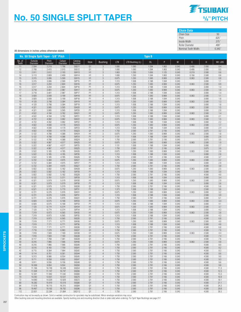
SPR
OC
KET
S
207
No. 50 SINGLE SPLIT TAPER 5/8” PITCH
Chain DataChain Size 50Pitch .625˝Inside Width .375˝Roller Diameter .400˝Nominal Tooth Width: 0.343˝
No. 50 Single Split Taper - 5/8” Pitch Type BNo. of Teeth
Outside Diameter
Pitch Diameter
Caliper Diameter
Catalog Number Style Bushing LTB LTB Bushing (L) OL P M C H Wt. LBS
11 2.504 2.219 1.796 50G11 G1 3 1.000 1.000 1.594 1.063 0.343 0.406 2.000 0.412 2.708 2.415 2.015 50G12 G1 3 1.000 1.000 1.594 1.063 0.343 0.406 2.000 0.513 2.911 2.612 2.193 50H13 H1 3 1.063 1.250 1.656 1.125 0.343 0.219 2.500 0.614 3.113 2.809 2.409 50H14 H1 3 1.000 1.250 1.594 1.063 0.343 0.156 2.500 0.615 3.315 3.006 5.590 50H15 H1 3 0.875 1.250 1.500 0.969 0.343 0.063 2.500 0.815 3.315 3.006 2.590 50P15 P1 4 1.313 1.938 2.188 1.594 0.343 3.000 1.116 3.517 3.204 2.804 50H16 H1 3 0.875 1.250 1.500 0.969 0.343 0.063 2.500 0.916 3.517 3.204 2.804 50P16 P1 4 1.313 1.938 2.188 1.594 0.343 3.000 1.417 3.718 3.401 2.987 50H17 H1 3 0.875 1.250 1.500 0.969 0.343 0.063 2.500 1.017 3.718 3.401 2.987 50P17 P1 4 1.313 1.938 2.188 1.594 0.343 3.000 1.418 3.920 3.599 3.199 50H18 H1 3 0.875 1.250 1.500 0.969 0.343 0.063 2.500 1.118 3.920 3.599 3.199 50P18 P1 4 1.313 1.938 2.188 1.594 0.343 3.000 1.819 4.120 3.798 3.384 50H19 H1 3 0.875 1.250 1.500 0.969 0.343 0.063 2.500 1.319 4.120 3.798 3.384 50P19 P1 4 1.313 1.938 2.188 1.594 0.343 3.000 1.820 4.321 3.995 3.595 50H20 H1 3 0.875 1.250 1.500 0.969 0.343 0.063 2.500 1.520 4.321 3.995 3.595 50P20 P1 4 1.313 1.938 2.188 1.594 0.343 3.000 2.021 4.522 4.194 3.782 50H21 H1 3 0.875 1.250 1.500 0.969 0.343 0.063 2.500 1.421 4.522 4.194 3.782 50P21 P1 4 1.313 1.938 2.188 1.594 0.343 3.000 2.122 4.722 4.392 3.992 50H22 H1 3 0.875 1.250 1.500 0.969 0.343 0.063 2.500 1.522 4.722 4.392 3.992 50P22 P1 4 1.313 1.938 2.188 1.594 0.343 3.000 2.223 4.922 4.590 4.179 50H23 H1 3 0.875 1.250 1.500 0.969 0.343 0.063 2.500 1.723 4.922 4.590 4.179 50P23 P1 4 1.313 1.938 2.188 1.594 0.343 3.000 2.423 4.922 4.590 4.179 50Q23 Q1 4 1.750 2.500 2.781 2.156 0.343 3.875 3.224 5.122 4.788 4.388 50H24 H1 3 0.875 1.250 1.500 0.969 0.343 0.063 2.500 1.824 5.122 4.788 4.388 50P24 P1 4 1.131 1.938 1.188 1.594 0.343 3.000 2.624 5.122 4.788 4.388 50Q24 Q1 4 1.750 2.500 2.781 2.156 0.343 3.875 3.525 5.322 4.987 4.577 50H25 H1 3 0.875 1.250 1.500 0.969 0.343 0.063 2.500 1.925 5.322 4.987 4.577 50P25 P1 4 1.131 1.938 1.188 1.594 0.343 3.000 2.725 5.322 4.987 4.577 50Q25 Q1 4 1.750 2.500 2.781 2.166 0.343 3.875 3.626 5.522 5.185 4.785 50H26 H1 3 0.875 1.250 1.500 0.969 0.343 0.063 2.500 2.026 5.522 5.185 4.785 50P26 P1 4 1.313 1.938 1.188 1.594 0.343 3.000 2.826 5.522 5.185 4.785 50Q26 Q1 4 1.750 2.500 2.781 2.166 0.343 4.500 3.727 5.722 5.384 4.975 50H27 H1 3 0.875 1.250 1.500 0.969 0.343 0.063 2.500 2.227 5.722 5.384 4.975 50P27 P1 4 1.313 1.938 1.880 1.594 0.343 3.000 2.927 5.722 5.384 4.975 50Q27 Q1 4 1.750 2.500 2.781 2.166 0.343 4.500 3.828 5.922 5.582 5.182 50H28 H1 3 0.875 1.250 1.500 0.969 0.343 0.063 2.500 2.528 5.922 5.582 5.182 50P28 P1 4 1.313 1.938 1.188 1.594 0.343 3.000 3.028 5.922 5.582 5.182 50Q28 Q1 4 1.750 2.500 2.781 2.166 0.343 4.500 4.029 6.122 5.781 5.371 50P29 P1 4 1.313 1.938 2.188 1.594 0.343 3.000 3.430 6.321 5.979 5.579 50H30 H1 3 0.875 1.250 1.500 0.969 0.343 0.063 2.500 2.930 6.321 5.979 5.579 50P30 P1 4 1.313 1.938 2.188 1.594 0.343 3.000 3.630 6.321 5.979 5.579 50Q30 Q1 4 1.750 2.500 2.781 2.166 0.343 4.500 5.631 6.521 6.178 5.770 50P31 P1 4 1.373 1.938 2.188 1.594 0.343 2.500 3.632 6.721 6.376 5.976 50H31 H1 3 0.875 1.250 1.500 0.969 0.343 0.063 3.000 3.232 6.721 6.376 5.976 50P31 P1 4 1.313 1.938 2.188 1.594 0.343 2.500 3.932 6.721 6.376 5.976 50Q31 Q1 4 1.750 2.500 2.781 2.166 0.343 3.000 6.133 6.920 6.575 6.168 50H33 H1 3 0.875 1.250 1.500 0.969 0.343 0.063 2.500 3.433 6.920 6.575 6.168 50P33 P1 4 1.313 1.938 2.188 1.594 0.343 3.000 4.134 7.120 6.774 6.374 50H34 H1 3 0.875 1.250 1.500 0.969 0.343 0.063 2.500 3.734 7.120 6.774 6.374 50P34 P1 4 1.313 1.938 2.188 1.594 0.343 3.000 4.335 7.319 6.973 6.565 50H35 H1 3 0.875 1.250 1.500 0.969 0.343 0.063 2.500 3.835 7.319 6.973 6.565 50P35 P1 4 1.313 1.938 2.188 1.594 0.343 3.000 4.335 7.319 6.973 6.565 50Q35 Q1 4 1.750 2.500 2.781 2.166 0.343 4.500 6.836 7.519 7.171 6.771 50H36 H1 3 0.875 1.250 1.500 0.969 0.343 0.063 2.500 4.036 7.519 7.171 6.771 50P36 P1 4 1.313 1.938 2.188 1.594 0.343 3.000 4.836 7.519 7.171 6.771 50Q36 Q1 4 1.750 2.500 2.781 2.166 0.343 4.500 6.837 7.718 7.370 6.963 50Q37 Q1 4 1.750 2.500 2.781 2.166 0.343 4.500 7.038 7.918 7.569 7.169 50H38 H1 3 0.875 1.250 1.500 0.969 0.343 0.063 2.500 4.438 7.918 7.569 7.169 50Q38 Q1 4 1.750 2.500 2.781 2.166 0.343 4.500 7.439 8.117 7.768 7.361 50Q39 Q1 4 1.750 2.500 2.781 2.166 0.343 4.500 7.640 8.316 7.966 7.566 50H40 Q1 3 0.875 1.250 1.500 0.969 0.343 0.063 2.500 4.840 8.316 7.966 7.566 50Q40 Q1 4 1.750 2.500 2.781 2.166 0.343 4.500 8.041 8.516 8.165 7.759 50Q41 Q1 4 1.750 2.500 2.781 2.166 0.343 4.500 8.242 8.715 8.364 7.964 50Q42 Q1 4 1.750 2.500 2.781 2.166 0.343 4.500 8.344 9.114 8.761 8.361 50Q44 Q1 4 1.750 2.500 2.781 2.166 0.343 4.500 8.645 9.313 8.986 8.554 50Q45 Q1 4 1.750 2.500 2.781 2.166 0.343 4.500 9.047 9.711 9.358 8.952 50Q47 Q1 4 1.750 2.500 2.781 2.166 0.343 4.500 9.348 9.911 9.556 9.156 50Q48 Q1 4 1.750 2.500 2.781 2.166 0.343 4.500 9.650 10.309 9.954 9.554 50Q50 Q1 4 1.750 2.500 2.781 2.166 0.343 4.500 9.854 11.106 10.749 10.349 50Q54 Q1 4 1.750 2.500 2.781 2.166 0.343 4.500 11.356 11.504 11.147 10.747 50Q56 Q1 4 1.750 2.500 2.781 2.166 0.343 4.500 12.360 12.301 11.942 11.542 50Q60 Q1 4 1.750 2.500 2.781 2.166 0.343 4.500 13.370 14.292 13.931 13.531 50Q70 Q1 4 1.750 2.500 2.781 2.166 0.343 4.500 16.972 14.690 14.329 13.929 50Q72 Q1 4 1.750 2.500 2.781 2.166 0.343 4.500 18.180 16.282 15.919 15.519 50Q80 Q1 4 1.750 2.500 2.781 2.166 0.343 4.500 21.184 17.078 16.715 16.315 50Q84 Q1 4 1.750 2.500 2.781 2.166 0.343 4.500 24.396 19.467 19.102 18.702 50Q96 Q1 4 1.750 2.500 2.781 2.166 0.343 4.500 29.8
112 22.651 22.284 21.884 50Q112 Q1 4 1.750 2.500 2.781 2.166 0.343 4.500 39.3
Contruction may not be exactly as shown. Solid or welded construction for sprockets may be substituted. Minor envelope variations may occur.Other bushing sizes and mounting directions are available. Specify bushing size and mounting direction (hub or plate side) when ordering. For Split Taper Bushings see page 217.
All dimensions in inches unless otherwise stated.
.TSUBAKI"
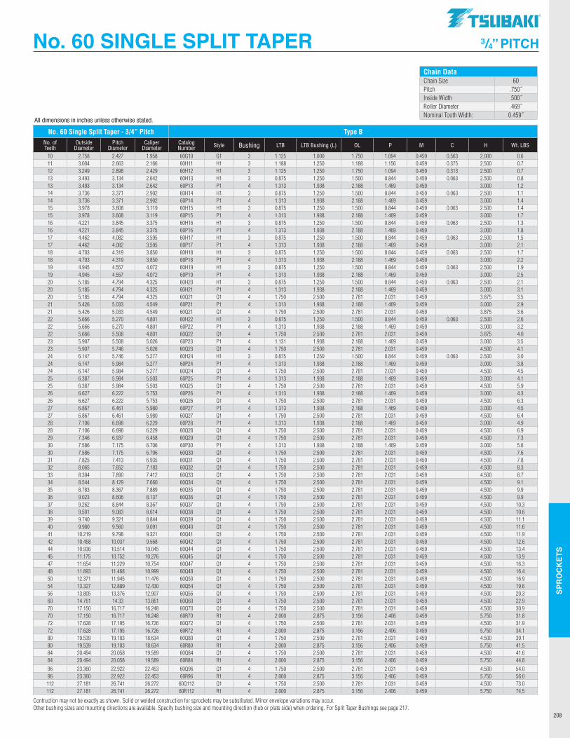
SPR
OC
KET
S
208
No. 60 SINGLE SPLIT TAPER 3/4” PITCH
No. 60 Single Split Taper - 3/4” Pitch Type BNo. of Teeth
Outside Diameter
Pitch Diameter
Caliper Diameter
Catalog Number Style Bushing LTB LTB Bushing (L) OL P M C H Wt. LBS
10 2.758 2.427 1.958 60G10 G1 3 1.125 1.000 1.750 1.094 0.459 0.563 2.000 0.611 3.004 2.663 2.166 60H11 H1 3 1.188 1.250 1.188 1.156 0.459 0.375 2.500 0.712 3.249 2.898 2.429 60H12 H1 3 1.125 1.250 1.750 1.094 0.459 0.313 2.500 0.713 3.493 3.134 2.642 60H13 H1 3 0.875 1.250 1.500 0.844 0.459 0.063 2.500 0.813 3.493 3.134 2.642 60P13 P1 4 1.313 1.938 2.188 1.469 0.459 3.000 1.214 3.736 3.371 2.902 60H14 H1 3 0.875 1.250 1.500 0.844 0.459 0.063 2.500 1.114 3.736 3.371 2.902 60P14 P1 4 1.313 1.938 2.188 1.469 0.459 3.000 1.415 3.978 3.608 3.119 60H15 H1 3 0.875 1.250 1.500 0.844 0.459 0.063 2.500 1.415 3.978 3.608 3.119 60P15 P1 4 1.313 1.938 2.188 1.469 0.459 3.000 1.716 4.221 3.845 3.375 60H16 H1 3 0.875 1.250 1.500 0.844 0.459 0.063 2.500 1.316 4.221 3.845 3.375 60P16 P1 4 1.313 1.938 2.188 1.469 0.459 3.000 1.817 4.462 4.082 3.595 60H17 H1 3 0.875 1.250 1.500 0.844 0.459 0.063 2.500 1.517 4.462 4.082 3.595 60P17 P1 4 1.313 1.938 2.188 1.469 0.459 3.000 2.118 4.703 4.319 3.850 60H18 H1 3 0.875 1.250 1.500 0.844 0.459 0.063 2.500 1.718 4.703 4.319 3.850 60P18 P1 4 1.313 1.938 2.188 1.469 0.459 3.000 2.219 4.945 4.557 4.072 60H19 H1 3 0.875 1.250 1.500 0.844 0.459 0.063 2.500 1.919 4.945 4.557 4.072 60P19 P1 4 1.313 1.938 2.188 1.469 0.459 3.000 2.520 5.185 4.794 4.325 60H20 H1 3 0.875 1.250 1.500 0.844 0.459 0.063 2.500 2.120 5.185 4.794 4.325 60H21 P1 4 1.313 1.938 2.188 1.469 0.459 3.000 3.120 5.185 4.794 4.325 60Q21 Q1 4 1.750 2.500 2.781 2.031 0.459 3.875 3.521 5.426 5.033 4.549 60P21 P1 4 1.313 1.938 2.188 1.469 0.459 3.000 2.921 5.426 5.033 4.549 60Q21 Q1 4 1.750 2.500 2.781 2.031 0.459 3.875 3.622 5.666 5.270 4.801 60H22 H1 3 0.875 1.250 1.500 0.844 0.459 0.063 2.500 2.622 5.666 5.270 4.801 60P22 P1 4 1.313 1.938 2.188 1.469 0.459 3.000 3.222 5.666 5.508 4.801 60Q22 Q1 4 1.750 2.500 2.781 2.031 0.459 3.875 4.023 5.907 5.508 5.026 60P23 P1 4 1.131 1.938 2.188 1.469 0.459 3.000 3.523 5.907 5.746 5.026 60Q23 Q1 4 1.750 2.500 2.781 2.031 0.459 4.500 4.124 6.147 5.746 5.277 60H24 H1 3 0.875 1.250 1.500 0.844 0.459 0.063 2.500 3.024 6.147 5.984 5.277 60P24 P1 4 1.313 1.938 2.188 1.469 0.459 3.000 3.824 6.147 5.984 5.277 60Q24 Q1 4 1.750 2.500 2.781 2.031 0.459 4.500 4.525 6.387 5.984 5.503 60P25 P1 4 1.313 1.938 2.188 1.469 0.459 3.000 4.125 6.387 5.984 5.503 60Q25 Q1 4 1.750 2.500 2.781 2.031 0.459 4.500 5.926 6.627 6.222 5.753 60P26 P1 4 1.313 1.938 2.188 1.469 0.459 3.000 4.326 6.627 6.222 5.753 60Q26 Q1 4 1.750 2.500 2.781 2.031 0.459 4.500 6.327 6.867 6.461 5.980 60P27 P1 4 1.313 1.938 2.188 1.469 0.459 3.000 4.527 6.867 6.461 5.980 60Q27 Q1 4 1.750 2.500 2.781 2.031 0.459 4.500 6.428 7.106 6.698 6.229 60P28 P1 4 1.313 1.938 2.188 1.469 0.459 3.000 4.928 7.106 6.698 6.229 60Q28 Q1 4 1.750 2.500 2.781 2.031 0.459 4.500 6.929 7.346 6.937 6.458 60Q29 Q1 4 1.750 2.500 2.781 2.031 0.459 4.500 7.330 7.586 7.175 6.706 60P30 P1 4 1.313 1.938 2.188 1.469 0.459 3.000 5.630 7.586 7.175 6.706 60Q30 Q1 4 1.750 2.500 2.781 2.031 0.459 4.500 7.631 7.825 7.413 6.935 60Q31 Q1 4 1.750 2.500 2.781 2.031 0.459 4.500 7.832 8.065 7.652 7.183 60Q32 Q1 4 1.750 2.500 2.781 2.031 0.459 4.500 8.333 8.304 7.890 7.412 60Q33 Q1 4 1.750 2.500 2.781 2.031 0.459 4.500 8.734 8.544 8.129 7.660 60Q34 Q1 4 1.750 2.500 2.781 2.031 0.459 4.500 9.135 8.783 8.367 7.889 60Q35 Q1 4 1.750 2.500 2.781 2.031 0.459 4.500 9.936 9.023 8.606 8.137 60Q36 Q1 4 1.750 2.500 2.781 2.031 0.459 4.500 9.937 9.262 8.844 8.367 60Q37 Q1 4 1.750 2.500 2.781 2.031 0.459 4.500 10.338 9.501 9.083 8.614 60Q38 Q1 4 1.750 2.500 2.781 2.031 0.459 4.500 10.639 9.740 9.321 8.844 60Q39 Q1 4 1.750 2.500 2.781 2.031 0.459 4.500 11.140 9.980 9.560 9.091 60Q40 Q1 4 1.750 2.500 2.781 2.031 0.459 4.500 11.641 10.219 9.798 9.321 60Q41 Q1 4 1.750 2.500 2.781 2.031 0.459 4.500 11.942 10.458 10.037 9.568 60Q42 Q1 4 1.750 2.500 2.781 2.031 0.459 4.500 12.644 10.936 10.514 10.045 60Q44 Q1 4 1.750 2.500 2.781 2.031 0.459 4.500 13.445 11.175 10.752 10.276 60Q45 Q1 4 1.750 2.500 2.781 2.031 0.459 4.500 13.947 11.654 11.229 10.754 60Q47 Q1 4 1.750 2.500 2.781 2.031 0.459 4.500 16.348 11.893 11.468 10.999 60Q48 Q1 4 1.750 2.500 2.781 2.031 0.459 4.500 16.450 12.371 11.945 11.476 60Q50 Q1 4 1.750 2.500 2.781 2.031 0.459 4.500 16.954 13.327 12.889 12.430 60Q54 Q1 4 1.750 2.500 2.781 2.031 0.459 4.500 19.656 13.805 13.376 12.907 60Q56 Q1 4 1.750 2.500 2.781 2.031 0.459 4.500 20.360 14.761 14.33 13.861 60Q60 Q1 4 1.750 2.500 2.781 2.031 0.459 4.500 22.970 17.150 16.717 16.248 60Q70 Q1 4 1.750 2.500 2.781 2.031 0.459 4.500 30.970 17.150 16.717 16.248 60R70 R1 4 2.000 2.875 3.156 2.406 0.459 5.750 31.872 17.628 17.195 16.726 60Q72 Q1 4 1.750 2.500 2.781 2.031 0.459 4.500 31.972 17.628 17.195 16.726 60R72 R1 4 2.000 2.875 3.156 2.406 0.459 5.750 34.180 19.539 19.103 18.634 60Q80 Q1 4 1.750 2.500 2.781 2.031 0.459 4.500 39.180 19.539 19.103 18.634 60R80 R1 4 2.000 2.875 3.156 2.406 0.459 5.750 41.584 20.494 20.058 19.589 60Q84 Q1 4 1.750 2.500 2.781 2.031 0.459 4.500 41.684 20.494 20.058 19.589 60R84 R1 4 2.000 2.875 3.156 2.406 0.459 5.750 44.896 23.360 22.922 22.453 60Q96 Q1 4 1.750 2.500 2.781 2.031 0.459 4.500 54.096 23.360 22.922 22.453 60R96 R1 4 2.000 2.875 3.156 2.406 0.459 5.750 56.0112 27.181 26.741 26.272 60Q112 Q1 4 1.750 2.500 2.781 2.031 0.459 4.500 73.0112 27.181 26.741 26.272 60R112 R1 4 2.000 2.875 3.156 2.406 0.459 5.750 74.5
Contruction may not be exactly as shown. Solid or welded construction for sprockets may be substituted. Minor envelope variations may occur.Other bushing sizes and mounting directions are available. Specify bushing size and mounting direction (hub or plate side) when ordering. For Split Taper Bushings see page 217.
All dimensions in inches unless otherwise stated.
Chain DataChain Size 60Pitch .750˝Inside Width .500˝Roller Diameter .469˝Nominal Tooth Width: 0.459˝
TSUBAKI"
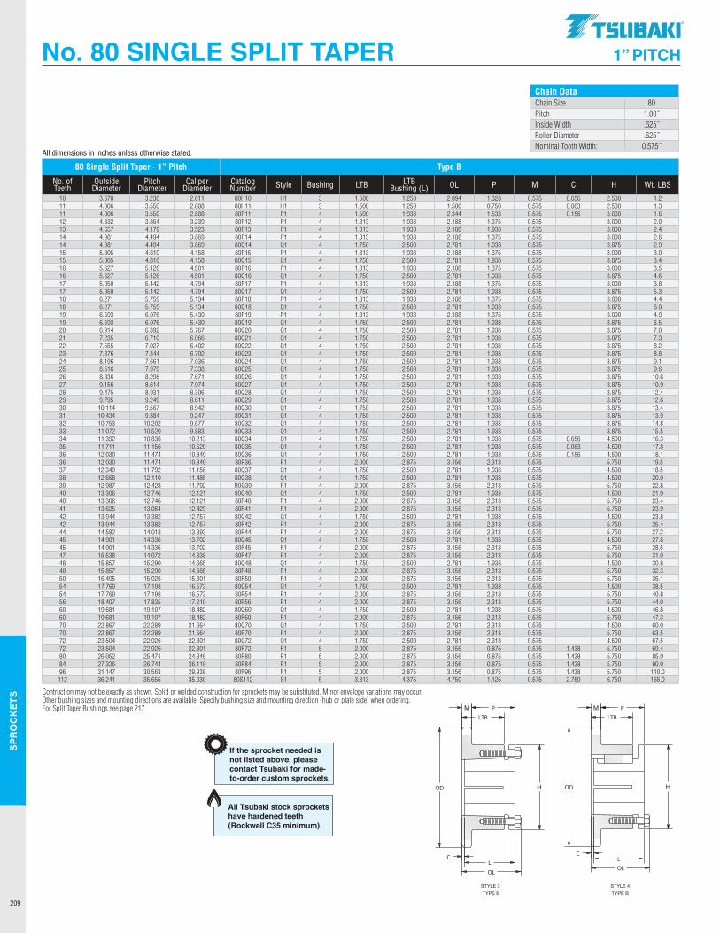
SPR
OC
KET
S
209
All dimensions in inches unless otherwise stated.
No. 80 SINGLE SPLIT TAPER 1” PITCH
80 Single Split Taper - 1” Pitch Type B
No. of Teeth
Outside Diameter
Pitch Diameter
Caliper Diameter
Catalog Number Style Bushing LTB LTB
Bushing (L) OL P M C H Wt. LBS
10 3.678 3.236 2.611 80H10 H1 3 1.500 1.250 2.094 1.328 0.575 0.656 2.500 1.211 4.006 3.550 2.888 80H11 H1 3 1.500 1.250 1.500 0.750 0.575 0.063 2.500 1.311 4.006 3.550 2.888 80P11 P1 4 1.500 1.938 2.344 1.533 0.575 0.156 3.000 1.612 4.332 3.864 3.239 80P12 P1 4 1.313 1.938 2.188 1.375 0.575 3.000 2.013 4.657 4.179 3.523 80P13 P1 4 1.313 1.938 2.188 1.938 0.575 3.000 2.414 4.981 4.494 3.869 80P14 P1 4 1.313 1.938 2.188 1.375 0.575 3.000 2.614 4.981 4.494 3.869 80Q14 Q1 4 1.750 2.500 2.781 1.938 0.575 3.875 2.915 5.305 4.810 4.158 80P15 P1 4 1.313 1.938 2.188 1.375 0.575 3.000 3.015 5.305 4.810 4.158 80Q15 Q1 4 1.750 2.500 2.781 1.938 0.575 3.875 3.416 5.627 5.126 4.501 80P16 P1 4 1.313 1.938 2.188 1.375 0.575 3.000 3.516 5.627 5.126 4.501 80Q16 Q1 4 1.750 2.500 2.781 1.938 0.575 3.875 4.617 5.950 5.442 4.794 80P17 P1 4 1.313 1.938 2.188 1.375 0.575 3.000 3.817 5.950 5.442 4.794 80Q17 Q1 4 1.750 2.500 2.781 1.938 0.575 3.875 5.318 6.271 5.759 5.134 80P18 P1 4 1.313 1.938 2.188 1.375 0.575 3.000 4.418 6.271 5.759 5.134 80Q18 Q1 4 1.750 2.500 2.781 1.938 0.575 3.875 6.019 6.593 6.076 5.430 80P19 P1 4 1.313 1.938 2.188 1.375 0.575 3.000 4.919 6.593 6.076 5.430 80Q19 Q1 4 1.750 2.500 2.781 1.938 0.575 3.875 6.520 6.914 6.392 5.767 80Q20 Q1 4 1.750 2.500 2.781 1.938 0.575 3.875 7.021 7.235 6.710 6.066 80Q21 Q1 4 1.750 2.500 2.781 1.938 0.575 3.875 7.322 7.555 7.027 6.402 80Q22 Q1 4 1.750 2.500 2.781 1.938 0.575 3.875 8.223 7.876 7.344 6.702 80Q23 Q1 4 1.750 2.500 2.781 1.938 0.575 3.875 8.824 8.196 7.661 7.036 80Q24 Q1 4 1.750 2.500 2.781 1.938 0.575 3.875 9.125 8.516 7.979 7.338 80Q25 Q1 4 1.750 2.500 2.781 1.938 0.575 3.875 9.626 8.836 8.296 7.671 80Q26 Q1 4 1.750 2.500 2.781 1.938 0.575 3.875 10.627 9.156 8.614 7.974 80Q27 Q1 4 1.750 2.500 2.781 1.938 0.575 3.875 10.928 9.475 8.931 8.306 80Q28 Q1 4 1.750 2.500 2.781 1.938 0.575 3.875 12.429 9.795 9.249 8.611 80Q29 Q1 4 1.750 2.500 2.781 1.938 0.575 3.875 12.630 10.114 9.567 8.942 80Q30 Q1 4 1.750 2.500 2.781 1.938 0.575 3.875 13.431 10.434 9.884 9.247 80Q31 Q1 4 1.750 2.500 2.781 1.938 0.575 3.875 13.932 10.753 10.202 9.577 80Q32 Q1 4 1.750 2.500 2.781 1.938 0.575 3.875 14.833 11.072 10.520 9.883 80Q33 Q1 4 1.750 2.500 2.781 1.938 0.575 3.875 15.534 11.392 10.838 10.213 80Q34 Q1 4 1.750 2.500 2.781 1.938 0.575 0.656 4.500 16.335 11.711 11.156 10.520 80Q35 Q1 4 1.750 2.500 2.781 1.938 0.575 0.063 4.500 17.836 12.030 11.474 10.849 80Q36 Q1 4 1.750 2.500 2.781 1.938 0.575 0.156 4.500 18.136 12.030 11.474 10.849 80R36 R1 4 2.000 2.875 3.156 2.313 0.575 5.750 19.537 12.349 11.792 11.156 80Q37 Q1 4 1.750 2.500 2.781 1.938 0.575 4.500 18.538 12.668 12.110 11.485 80Q38 Q1 4 1.750 2.500 2.781 1.938 0.575 4.500 20.039 12.987 12.428 11.792 R0Q39 R1 4 2.000 2.875 3.156 2.313 0.575 5.750 22.840 13.306 12.746 12.121 80Q40 Q1 4 1.750 2.500 2.781 1.938 0.575 4.500 21.940 13.306 12.746 12.121 80R40 R1 4 2.000 2.875 3.156 2.313 0.575 5.750 23.441 13.625 13.064 12.429 80R41 R1 4 2.000 2.875 3.156 2.313 0.575 5.750 23.942 13.944 13.382 12.757 80Q42 Q1 4 1.750 2.500 2.781 1.938 0.575 4.500 23.842 13.944 13.382 12.757 80R42 R1 4 2.000 2.875 3.156 2.313 0.575 5.750 25.444 14.582 14.018 13.393 80R44 R1 4 2.000 2.875 3.156 2.313 0.575 5.750 27.245 14.901 14.336 13.702 80Q45 Q1 4 1.750 2.500 2.781 1.938 0.575 4.500 27.845 14.901 14.336 13.702 80R45 R1 4 2.000 2.875 3.156 2.313 0.575 5.750 28.547 15.538 14.972 14.338 80R47 R1 4 2.000 2.875 3.156 2.313 0.575 5.750 31.048 15.857 15.290 14.665 80Q48 Q1 4 1.750 2.500 2.781 1.938 0.575 4.500 30.848 15.857 15.290 14.665 80R48 R1 4 2.000 2.875 3.156 2.313 0.575 5.750 32.350 16.495 15.926 15.301 80R50 R1 4 2.000 2.875 3.156 2.313 0.575 5.750 35.154 17.769 17.198 16.573 80Q54 Q1 4 1.750 2.500 2.781 1.938 0.575 4.500 38.554 17.769 17.198 16.573 80R54 R1 4 2.000 2.875 3.156 2.313 0.575 5.750 40.856 18.407 17.835 17.210 80R56 R1 4 2.000 2.875 3.156 2.313 0.575 5.750 44.060 19.681 19.107 18.482 80Q60 Q1 4 1.750 2.500 2.781 1.938 0.575 4.500 46.860 19.681 19.107 18.482 80R60 R1 4 2.000 2.875 3.156 2.313 0.575 5.750 47.370 22.867 22.289 21.664 80Q70 Q1 4 1.750 2.500 2.781 2.313 0.575 4.500 60.070 22.867 22.289 21.664 80R70 R1 4 2.000 2.875 3.156 2.313 0.575 5.750 63.572 23.504 22.926 22.301 80Q72 Q1 4 1.750 2.500 2.781 2.313 0.575 4.500 67.572 23.504 22.926 22.301 80R72 R1 5 2.000 2.875 3.156 0.875 0.575 1.438 5.750 69.480 26.052 25.471 24.846 80R80 R1 5 2.000 2.875 3.156 0.875 0.575 1.438 5.750 85.084 27.326 26.744 26.119 80R84 R1 5 2.000 2.875 3.156 0.875 0.575 1.438 5.750 90.096 31.147 30.563 29.938 80R96 R1 5 2.000 2.875 3.156 0.875 0.575 1.438 5.750 110.0
112 36.241 35.655 35.030 80S112 S1 5 3.313 4.375 4.750 1.125 0.575 2.750 6.750 165.0
Contruction may not be exactly as shown. Solid or welded construction for sprockets may be substituted. Minor envelope variations may occur.Other bushing sizes and mounting directions are available. Specify bushing size and mounting direction (hub or plate side) when ordering.For Split Taper Bushings see page 217
Chain DataChain Size 80Pitch 1.00˝Inside Width .625˝Roller Diameter .625˝Nominal Tooth Width: 0.575˝
Construction may not be exactly as shown. Solid or welded construction for sprockets may be substituted. Minor envelope variations may occur. Other bushing sizes andmounting directions available. Specify bushing size and mounting direction (hub or plate side) when ordering.
LTBNo. of Outside Pitch Caliper Catalogue Bushing WeightTeeth Diameter Diameter Diameter Number Style Hub LTB (L) OL P M C H (Ibs.)
Sprocket Diameters1" Pitch
Type B
80H1080H1180P1180P1280P1380P1480Q1480P1580Q1580P1680Q1680P1780Q1780P1880Q1880P1980Q1980Q2080Q2180Q2280Q2380Q2480Q2580Q2680Q2780Q2880Q2980Q3080Q3180Q3280Q33
H1H1P1P1P1P1Q1P1Q1P1Q1P1Q1P1Q1P1Q1Q1Q1Q1Q1Q1Q1Q1Q1Q1Q1Q1Q1Q1Q1
3344444444444444444444444444444
1 1/41 1/4
1 15/16
1 15/16
1 15/16
1 15/16
2 1/21 15/16
2 1/21 15/16
2 1/21 15/16
2 1/21 15/16
2 1/21 15/16
2 1/22 1/22 1/22 1/22 1/22 1/22 1/22 1/22 1/22 1/22 1/22 1/22 1/22 1/22 1/2
1 1/21 1/21 1/21 5/16
1 5/16
1 5/16
1 3/41 5/16
1 3/41 5/16
1 3/41 5/16
1 3/41 5/16
1 3/41 5/16
1 3/41 3/41 3/41 3/41 3/41 3/41 3/41 3/41 3/41 3/41 3/41 3/41 3/41 3/41 3/4
1 21/64
3/41 17/32
1 3/81 3/81 3/8
1 15/16
1 3/81 15/16
1 3/81 15/16
1 3/81 15/16
1 3/81 15/16
1 3/81 15/16
1 15/16
1 15/16
1 15/16
1 15/16
1 15/16
1 15/16
1 15/16
1 15/16
1 15/16
1 15/16
1 15/16
1 15/16
1 15/16
1 15/16
2 3/32
1 1/22 11/32
2 3/16
2 3/16
2 3/16
2 25/32
2 3/16
2 25/32
2 3/16
2 25/32
2 3/16
2 25/32
2 3/16
2 25/32
2 3/16
2 25/32
2 25/32
2 25/32
2 25/32
2 25/32
2 25/32
2 25/32
2 25/32
2 25/32
2 25/32
2 25/32
2 25/32
2 25/32
2 25/32
2 25/32
0.5750.5750.5750.5750.5750.5750.5750.5750.5750.5750.5750.5750.5750.5750.5750.5750.5750.5750.5750.5750.5750.5750.5750.5750.5750.5750.5750.5750.5750.5750.575
2 1/22 1/2
3333
3 7/83
3 7/83
3 7/83
3 7/83
4 1/23
4 1/24 1/24 1/24 1/24 1/24 1/24 1/24 1/24 1/24 1/24 1/24 1/24 1/24 1/24 1/2
1.21.31.62.02.42.62.93.03.43.54.63.85.34.46.04.96.57.07.38.28.89.19.6
10.610.912.412.613.413.914.815.5
21/32
1/16
5/32
----------------------------
10111112131414151516161717181819192021222324252627282930313233
3.2363.5503.5503.8644.1794.4944.4944.8104.8105.1265.1265.4425.4425.7595.7596.0766.0766.3926.7107.0277.3447.6617.9798.2968.6148.9319.2499.5679.884
10.20210.520
TYPE BSTYLE 4
TYPE BSTYLE 3
3.678 4.006 4.006 4.332 4.657 4.981 4.981 5.305 5.305 5.627 5.627 5.950 5.950 6.271 6.271 6.593 6.593 6.914 7.235 7.555 7.876 8.196 8.516 8.836 9.156 9.475 9.795 10.114 10.434 10.753 11.072
If the sprocket needed isnot listed above, pleasecontact Tsubaki for made-to-order custom sprockets.
Dimensional DataSingle Strand Chain 80Size 80Pitch 1.000"Chain Inside Width 0.625"Roller Diameter 0.625"Nom. Tooth Width 0.575"
2.6112.8882.8883.2393.5233.8693.8694.1584.1584.5014.5014.7944.7945.1345.1345.4305.4305.7676.0666.4026.7027.0367.3387.6717.9748.3068.6118.9429.2479.5779.883
All Tsubaki stock sprockets have hardened teeth (Rockwell C35 minimum).
.TSUBAKI"
OD H OD I:==== H
C
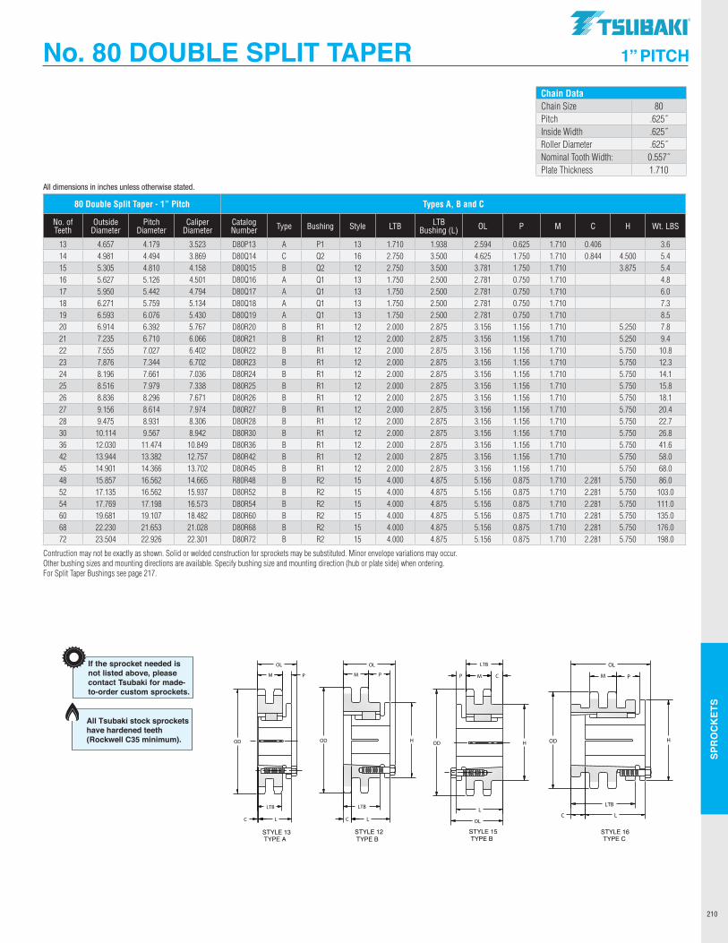
SPR
OC
KET
S
210
No. 80 DOUBLE SPLIT TAPER 1” PITCH
All dimensions in inches unless otherwise stated. 13141516171819202122232425262728303642454852546068727695
D80P13D80Q14D80Q15D80Q16D80Q17D80Q18D80Q19D80R20D80R21D80R22D80R23D80R24D80R25D80R26D80R27D80R28D80R30D80R36D80R42D80R45D80R48D80R52D80R54D80R60D80R68D80R72D80U76D80U95
ACBAAAABBBBBBBBBBBBBBBBBBBBB
P1Q2Q2Q1Q1Q1Q1R1R1R1R1R1R1R1R1R1R1R1R1R1R2R2R2R2R2R2U0U0
13161213131313121212121212121212121212121515151515151515
4.657 4.981 5.3055.627 5.950 6.271 6.593 6.914 7.235 7.555 7.876 8.196 8.516 8.836 9.156 9.475 10.114 12.030 13.944 14.901 15.857 17.132 17.769 19.681 22.230 23.504 24.778 30.828
1 15/16
3 1/23 1/22 1/22 1/22 1/22 1/22 7/82 7/82 7/82 7/82 7/82 7/82 7/82 7/82 7/82 7/82 7/82 7/82 7/84 7/84 7/84 7/84 7/84 7/84 7/85 1/45 1/4
3.65.45.44.86.07.38.57.89.410.812.314.115.818.120.422.726.841.658.068.086.0103.0111.0135.0176.0198.0219.0342.0
1.712 3/42 3/41 3/41 3/41 3/41 3/4
2 2 2 2 2 2 2 2 2 2 2 2 2 4 4 4 4 4 4
3 3/43 3/4
5/81 3/41 3/4
3/43/43/43/4
1 5/32
1 5/32
1 5/32
1 5/32
1 5/32
1 5/32
1 5/32
1 5/32
1 5/32
1 5/32
1 5/32
1 5/32
1 5/32
7/87/87/87/87/87/8
1 1/21 1/2
2 19/32
4 5/83 25/32
2 25/32
2 25/32
2 25/32
2 25/32
3 5/32
3 5/32
3 5/32
3 5/32
3 5/32
3 5/32
3 5/32
3 5/32
3 5/32
3 5/32
3 5/32
3 5/32
3 5/32
5 5/32
5 5/32
5 5/32
5 5/32
5 5/32
5 5/32
5 23/32
5 23/32
1.7101.7101.7101.7101.7101.7101.7101.7101.7101.7101.7101.7101.7101.7101.7101.7101.7101.7101.7101.7101.7101.7101.7101.7101.7101.7101.7101.710
-4 1/23 7/8
----
5 1/45 1/45 3/45 3/45 3/45 3/45 3/45 3/45 3/45 3/45 3/45 3/45 3/45 3/45 3/45 3/45 3/45 3/45 3/48 1/28 1/2
Construction may not be exactly as shown. Solid or welded construction for sprockets may be substituted. Minor envelope variations may occur. Other bushing sizes andmounting directions available. Specify bushing size and mounting direction (hub or plate side) when ordering.
13/32
27/32
-------------- ----
2 9/32
2 9/32
2 9/32
2 9/32
2 9/32
2 9/32
2 1/32
2 1/32
If the sprocket needed isnot listed above, pleasecontact Tsubaki for made-to-order custom sprockets.
Dimensional DataDouble Strand Chain 80Size 80-2Pitch 1.000"Chain Inside Width 0.625"Roller Diameter 0.625"Nominal Tooth Width 0.557"Plate Thickness 1.710"
LTBNo. of Outside Pitch Caliper Catalogue Bushing WeightTeeth Diameter Diameter Diameter Number Type Style Hub LTB (L) OL P M C H (Ibs.)
Sprocket Diameters1" Pitch
Type A, B and C
4.1794.4944.8105.1265.4425.7596.0766.3926.7107.0277.3447.6617.9798.2968.6148.9319.567
11.47113.38214.36615.29016.56217.19819.10721.65322.92624.19830.245
STYLE 13TYPE A
STYLE 12TYPE B
STYLE 15TYPE B
STYLE 16TYPE C
3.5233.8694.1584.5014.7945.1345.4305.7676.0666.4026.7027.0367.3387.6717.9748.3068.942
10.84912.75713.70214.66515.93716.57318.48221.02822.30123.57329.616
All Tsubaki stock sprockets have hardened teeth (Rockwell C35 minimum).
80 Double Split Taper - 1” Pitch Types A, B and C
No. of Teeth
Outside Diameter
Pitch Diameter
Caliper Diameter
Catalog Number Type Bushing Style LTB LTB
Bushing (L) OL P M C H Wt. LBS
13 4.657 4.179 3.523 D80P13 A P1 13 1.710 1.938 2.594 0.625 1.710 0.406 3.614 4.981 4.494 3.869 D80Q14 C Q2 16 2.750 3.500 4.625 1.750 1.710 0.844 4.500 5.415 5.305 4.810 4.158 D80Q15 B Q2 12 2.750 3.500 3.781 1.750 1.710 3.875 5.416 5.627 5.126 4.501 D80Q16 A Q1 13 1.750 2.500 2.781 0.750 1.710 4.817 5.950 5.442 4.794 D80Q17 A Q1 13 1.750 2.500 2.781 0.750 1.710 6.018 6.271 5.759 5.134 D80Q18 A Q1 13 1.750 2.500 2.781 0.750 1.710 7.319 6.593 6.076 5.430 D80Q19 A Q1 13 1.750 2.500 2.781 0.750 1.710 8.520 6.914 6.392 5.767 D80R20 B R1 12 2.000 2.875 3.156 1.156 1.710 5.250 7.821 7.235 6.710 6.066 D80R21 B R1 12 2.000 2.875 3.156 1.156 1.710 5.250 9.422 7.555 7.027 6.402 D80R22 B R1 12 2.000 2.875 3.156 1.156 1.710 5.750 10.823 7.876 7.344 6.702 D80R23 B R1 12 2.000 2.875 3.156 1.156 1.710 5.750 12.324 8.196 7.661 7.036 D80R24 B R1 12 2.000 2.875 3.156 1.156 1.710 5.750 14.125 8.516 7.979 7.338 D80R25 B R1 12 2.000 2.875 3.156 1.156 1.710 5.750 15.826 8.836 8.296 7.671 D80R26 B R1 12 2.000 2.875 3.156 1.156 1.710 5.750 18.127 9.156 8.614 7.974 D80R27 B R1 12 2.000 2.875 3.156 1.156 1.710 5.750 20.428 9.475 8.931 8.306 D80R28 B R1 12 2.000 2.875 3.156 1.156 1.710 5.750 22.730 10.114 9.567 8.942 D80R30 B R1 12 2.000 2.875 3.156 1.156 1.710 5.750 26.836 12.030 11.474 10.849 D80R36 B R1 12 2.000 2.875 3.156 1.156 1.710 5.750 41.642 13.944 13.382 12.757 D80R42 B R1 12 2.000 2.875 3.156 1.156 1.710 5.750 58.045 14.901 14.366 13.702 D80R45 B R1 12 2.000 2.875 3.156 1.156 1.710 5.750 68.048 15.857 16.562 14.665 R80R48 B R2 15 4.000 4.875 5.156 0.875 1.710 2.281 5.750 86.052 17.135 16.562 15.937 D80R52 B R2 15 4.000 4.875 5.156 0.875 1.710 2.281 5.750 103.054 17.769 17.198 16.573 D80R54 B R2 15 4.000 4.875 5.156 0.875 1.710 2.281 5.750 111.060 19.681 19.107 18.482 D80R60 B R2 15 4.000 4.875 5.156 0.875 1.710 2.281 5.750 135.068 22.230 21.653 21.028 D80R68 B R2 15 4.000 4.875 5.156 0.875 1.710 2.281 5.750 176.072 23.504 22.926 22.301 D80R72 B R2 15 4.000 4.875 5.156 0.875 1.710 2.281 5.750 198.0
Contruction may not be exactly as shown. Solid or welded construction for sprockets may be substituted. Minor envelope variations may occur.Other bushing sizes and mounting directions are available. Specify bushing size and mounting direction (hub or plate side) when ordering. For Split Taper Bushings see page 217.
Chain DataChain Size 80Pitch .625˝Inside Width .625˝Roller Diameter .625˝Nominal Tooth Width: 0.557˝Plate Thickness 1.710
Construction may not be exactly as shown. Solid or welded construction for sprockets may be substituted. Minor envelope variations may occur. Other bushing sizes andmounting directions available. Specify bushing size and mounting direction (hub or plate side) when ordering.
LTBNo. of Outside Pitch Caliper Catalogue Bushing WeightTeeth Diameter Diameter Diameter Number Style Hub LTB (L) OL P M C H (Ibs.)
Sprocket Diameters1" Pitch
Type B
80H1080H1180P1180P1280P1380P1480Q1480P1580Q1580P1680Q1680P1780Q1780P1880Q1880P1980Q1980Q2080Q2180Q2280Q2380Q2480Q2580Q2680Q2780Q2880Q2980Q3080Q3180Q3280Q33
H1H1P1P1P1P1Q1P1Q1P1Q1P1Q1P1Q1P1Q1Q1Q1Q1Q1Q1Q1Q1Q1Q1Q1Q1Q1Q1Q1
3344444444444444444444444444444
1 1/41 1/4
1 15/16
1 15/16
1 15/16
1 15/16
2 1/21 15/16
2 1/21 15/16
2 1/21 15/16
2 1/21 15/16
2 1/21 15/16
2 1/22 1/22 1/22 1/22 1/22 1/22 1/22 1/22 1/22 1/22 1/22 1/22 1/22 1/22 1/2
1 1/21 1/21 1/21 5/16
1 5/16
1 5/16
1 3/41 5/16
1 3/41 5/16
1 3/41 5/16
1 3/41 5/16
1 3/41 5/16
1 3/41 3/41 3/41 3/41 3/41 3/41 3/41 3/41 3/41 3/41 3/41 3/41 3/41 3/41 3/4
1 21/64
3/41 17/32
1 3/81 3/81 3/8
1 15/16
1 3/81 15/16
1 3/81 15/16
1 3/81 15/16
1 3/81 15/16
1 3/81 15/16
1 15/16
1 15/16
1 15/16
1 15/16
1 15/16
1 15/16
1 15/16
1 15/16
1 15/16
1 15/16
1 15/16
1 15/16
1 15/16
1 15/16
2 3/32
1 1/22 11/32
2 3/16
2 3/16
2 3/16
2 25/32
2 3/16
2 25/32
2 3/16
2 25/32
2 3/16
2 25/32
2 3/16
2 25/32
2 3/16
2 25/32
2 25/32
2 25/32
2 25/32
2 25/32
2 25/32
2 25/32
2 25/32
2 25/32
2 25/32
2 25/32
2 25/32
2 25/32
2 25/32
2 25/32
0.5750.5750.5750.5750.5750.5750.5750.5750.5750.5750.5750.5750.5750.5750.5750.5750.5750.5750.5750.5750.5750.5750.5750.5750.5750.5750.5750.5750.5750.5750.575
2 1/22 1/2
3333
3 7/83
3 7/83
3 7/83
3 7/83
4 1/23
4 1/24 1/24 1/24 1/24 1/24 1/24 1/24 1/24 1/24 1/24 1/24 1/24 1/24 1/24 1/2
1.21.31.62.02.42.62.93.03.43.54.63.85.34.46.04.96.57.07.38.28.89.19.6
10.610.912.412.613.413.914.815.5
21/32
1/16
5/32
----------------------------
10111112131414151516161717181819192021222324252627282930313233
3.2363.5503.5503.8644.1794.4944.4944.8104.8105.1265.1265.4425.4425.7595.7596.0766.0766.3926.7107.0277.3447.6617.9798.2968.6148.9319.2499.5679.884
10.20210.520
TYPE BSTYLE 4
TYPE BSTYLE 3
3.678 4.006 4.006 4.332 4.657 4.981 4.981 5.305 5.305 5.627 5.627 5.950 5.950 6.271 6.271 6.593 6.593 6.914 7.235 7.555 7.876 8.196 8.516 8.836 9.156 9.475 9.795 10.114 10.434 10.753 11.072
If the sprocket needed isnot listed above, pleasecontact Tsubaki for made-to-order custom sprockets.
Dimensional DataSingle Strand Chain 80Size 80Pitch 1.000"Chain Inside Width 0.625"Roller Diameter 0.625"Nom. Tooth Width 0.575"
2.6112.8882.8883.2393.5233.8693.8694.1584.1584.5014.5014.7944.7945.1345.1345.4305.4305.7676.0666.4026.7027.0367.3387.6717.9748.3068.6118.9429.2479.5779.883
All Tsubaki stock sprockets have hardened teeth (Rockwell C35 minimum).
TSUBAKI"
---------------
LTB LTB
C L C L
L
OL
OD
DL
M p
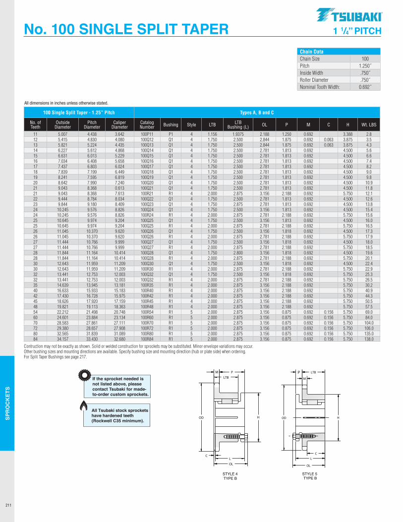
SPR
OC
KET
S
211
No. 100 SINGLE SPLIT TAPER 1 1/4” PITCH
All dimensions in inches unless otherwise stated.
Chain DataChain Size 100Pitch 1.250˝Inside Width .750˝Roller Diameter .750˝Nominal Tooth Width: 0.692˝
100 Single Split Taper - 1.25” Pitch Types A, B and C
No. of Teeth
Outside Diameter
Pitch Diameter
Caliper Diameter
Catalog Number Bushing Style LTB LTB
Bushing (L) OL P M C H Wt. LBS
11 5.007 4.438 3.642 100P11 P1 4 1.156 1.9375 2.188 1.250 0.692 3.388 2.812 5.415 4.830 4.080 100Q12 Q1 4 1.750 2.500 2.844 1.875 0.692 0.063 3.875 3.513 5.821 5.224 4.435 100Q13 Q1 4 1.750 2.500 2.844 1.875 0.692 0.063 3.875 4.314 6.227 5.612 4.868 100Q14 Q1 4 1.750 2.500 2.781 1.813 0.692 4.500 5.615 6.631 6.013 5.229 100Q15 Q1 4 1.750 2.500 2.781 1.813 0.692 4.500 6.616 7.034 6.408 5.658 100Q16 Q1 4 1.750 2.500 2.781 1.813 0.692 4.500 7.417 7.437 6.803 6.024 100Q17 Q1 4 1.750 2.500 2.781 1.813 0.692 4.500 8.218 7.839 7.199 6.449 100Q18 Q1 4 1.750 2.500 2.781 1.813 0.692 4.500 9.019 8.241 7.595 6.819 100Q19 Q1 4 1.750 2.500 2.781 1.813 0.692 4.500 9.820 8.642 7.990 7.240 100Q20 Q1 4 1.750 2.500 2.781 1.813 0.692 4.500 10.921 9.043 8.368 0.613 100Q21 Q1 4 1.750 2.500 2.781 1.813 0.692 4.500 11.821 9.043 8.368 7.613 100R21 R1 4 2.000 2.875 3.156 2.188 0.692 5.750 12.122 9.444 8.784 8.034 100Q22 Q1 4 1.750 2.500 2.781 1.813 0.692 4.500 12.623 9.844 9.180 8.409 100Q23 Q1 4 1.750 2.875 2.781 1.813 0.692 4.500 13.824 10.245 9.576 8.826 100Q24 Q1 4 1.750 2.500 3.156 1.813 0.692 4.500 15.424 10.245 9.576 8.826 100R24 R1 4 2.000 2.875 2.781 2.188 0.692 5.750 15.625 10.645 9.974 9.204 100Q25 Q1 4 1.750 2.500 3.156 1.813 0.692 4.500 16.025 10.645 9.974 9.204 100Q25 R1 4 2.000 2.875 2.781 2.188 0.692 5.750 16.526 11.045 10.370 9.620 100Q26 Q1 4 1.750 2.500 3.156 1.818 0.692 4.500 17.326 11.045 10.370 9.620 100Q26 R1 4 2.000 2.875 2.781 2.188 0.692 5.750 17.927 11.444 10.766 9.999 100Q27 Q1 4 1.750 2.500 3.156 1.818 0.692 4.500 18.027 11.444 10.766 9.999 100Q27 R1 4 2.000 2.875 2.781 2.188 0.692 5.750 18.528 11.844 11.164 10.414 100Q28 Q1 4 1.750 2.800 3.156 1.818 0.692 4.500 19.628 11.844 11.164 10.414 100Q28 R1 4 2.000 2.875 2.781 2.188 0.692 5.750 20.130 12.643 11.959 11.209 100Q30 Q1 4 1.750 2.500 3.156 1.818 0.692 4.500 22.430 12.643 11.959 11.209 100R30 R1 4 2.000 2.875 2.781 2.188 0.692 5.750 22.932 13.441 12.753 12.003 100Q32 Q1 4 1.750 2.500 3.156 1.818 0.692 5.750 25.332 13.441 12.753 12.003 100Q32 R1 4 2.000 2.875 2.781 2.188 0.692 5.750 26.535 14.639 13.945 13.181 100R35 R1 4 2.000 2.875 3.156 2.188 0.692 5.750 30.240 16.633 15.933 15.183 100R40 R1 4 2.000 2.875 3.156 2.188 0.692 5.750 40.942 17.430 16.728 15.975 100R42 R1 4 2.000 2.875 3.156 2.188 0.692 5.750 44.345 18.626 17.920 17.159 100R45 R1 4 2.000 2.875 3.156 2.188 0.692 5.750 50.548 19.821 19.113 18.363 100R48 R1 4 2.000 2.875 3.156 2.188 0.692 5.750 57.554 22.212 21.498 20.748 100R54 R1 5 2.000 2.875 3.156 0.875 0.692 0.156 5.750 69.060 24.601 23.884 23.134 100R60 R1 5 2.000 2.875 3.156 0.875 0.692 0.156 5.750 84.070 28.583 27.861 27.111 100R70 R1 5 2.000 2.875 3.156 0.875 0.692 0.156 5.750 104.072 29.380 28.657 27.908 100R72 R1 5 2.000 2.875 3.156 0.875 0.692 0.156 5.750 106.080 32.565 31.839 31.089 100R80 R1 5 2.000 2.875 3.156 0.875 0.692 0.156 5.750 135.084 34.157 33.430 32.680 100R84 R1 5 2.000 2.875 3.156 0.875 0.692 0.156 5.750 138.0
Contruction may not be exactly as shown. Solid or welded construction for sprockets may be substituted. Minor envelope variations may occur.Other bushing sizes and mounting directions are available. Specify bushing size and mounting direction (hub or plate side) when ordering.For Split Taper Bushings see page 217.
100P11100Q12100Q13100Q14100Q15100Q16100Q17100Q18100Q19100Q20100Q21100R21100Q22100Q23100Q24100R24100Q25100R25100Q26100R26100Q27100R27100Q28100R28100Q30100R30100Q32100R32100R35100R40100R42100R45100R48100R54100R60100R70100R72100R80100R84
P1Q1Q1Q1Q1Q1Q1Q1Q1Q1Q1R1Q1Q1Q1R1Q1R1Q1R1Q1R1Q1R1Q1R1Q1R1R1R1R1R1R1R1R1R1R1R1R1
444444444444444444444444444444444555555
5.007 5.415 5.821 6.227 6.631 7.034 7.437 7.839 8.241 8.642 9.043 9.043 9.444 9.844 10.245 10.245 10.645 10.645 11.045 11.045 11.444 11.444 11.844 11.844 12.643 12.643 13.441 13.441 14.639 16.633 17.430 18.626 19.821 22.212 24.601 28.583 29.380 32.565 34.157
2.83.54.35.66.67.48.29.09.810.911.812.112.613.815.415.616.016.517.317.918.018.519.620.122.422.925.326.530.240.944.350.557.569.084.0104.0106.0135.0138.0
1 5/16
1 3/41 3/41 3/41 3/41 3/41 3/41 3/41 3/41 3/41 3/4
2 1 3/41 3/41 3/4
2 1 3/4
2 1 3/4
2 1 3/4
2 1 3/4
2 1 3/4
2 1 3/4
2 2 2 2 2 2 2 2 2 2 2 2
1 1/41 7/81 7/8
1 13/16
1 13/16
1 13/16
1 13/16
1 13/16
1 13/16
1 13/16
1 13/16
2 3/16
1 13/16
1 13/16
1 13/16
2 3/16
1 13/16
2 3/16
1 13/16
2 3/16
1 13/16
2 3/16
1 13/16
2 3/16
1 13/16
2 3/16
1 13/16
2 3/16
2 3/16
2 3/16
2 3/16
2 3/16
2 3/16
7/87/87/87/87/87/8
2 3/16
2 27/32
2 27/32
2 25/32
2 25/32
2 25/32
2 25/32
2 25/32
2 25/32
2 25/32
2 25/32
3 5/32
2 25/32
2 25/32
2 25/32
3 5/32
2 25/32
3 5/32
2 25/32
3 5/32
2 25/32
3 5/32
2 25/32
3 5/32
2 25/32
3 5/32
2 25/32
3 5/32
3 5/32
3 5/32
3 5/32
3 5/32
3 5/32
3 5/32
3 5/32
3 5/32
3 5/32
3 5/32
3 5/32
0.6920.6920.6920.6920.6920.6920.6920.6920.6920.6920.6920.6920.6920.6920.6920.6920.6920.6920.6920.6920.6920.6920.6920.6920.6920.6920.6920.6920.6920.6920.6920.6920.6920.6920.6920.6920.6920.6920.692
33 7/83 7/83 7/84 1/24 1/24 1/24 1/24 1/24 1/24 1/25 3/44 1/24 1/24 1/25 3/44 1/25 3/44 1/25 3/44 1/25 3/44 1/25 3/44 1/25 3/44 1/25 3/45 3/45 3/45 3/45 3/45 3/45 3/45 3/45 3/45 3/45 3/45 3/4
TYPE BSTYLE 4 STYLE 5
TYPE B
-1/16
1/16
------------------------------
1 5/16
1 5/16
1 5/16
1 5/16
1 5/16
1 5/16
Dimensional DataSingle Strand Chain 100Size 100Pitch 1.250"Chain Inside Width 0.750"Roller Diameter 0.750"Nominal Tooth Width 0.692"
If the sprocket needed is not listedabove, please contact Tsubaki formade-to-order custom sprockets.
LTBNo. of Outside Pitch Caliper Catalogue Bushing WeightTeeth Diameter Diameter Diameter Number Style Hub LTB (L) OL P M C H (Ibs.)
4.4384.8305.2245.6186.0136.4086.8037.1997.5957.9908.3888.3888.7849.1809.5769.5769.9749.974
10.37010.37010.76810.76811.16411.16411.95911.95912.75312.75313.94515.93316.72817.92019.11321.49823.88427.86128.65731.83933.430
3.6424.0804.4354.8685.2295.6586.0246.4496.8197.2407.6137.6138.0348.4098.8268.8269.2049.2049.6209.6209.9999.999
10.41410.41411.20911.20912.00312.00313.18115.18315.97817.15918.36320.74823.13427.11127.90831.08932.680
Sprocket Diameters1¹⁄₄" Pitch
Type B
Construction may not be exactly as shown. Solid or welded construction for sprockets may be substituted. Minor envelope variations may occur. Other bushing sizes andmounting directions available. Specify bushing size and mounting direction (hub or plate side) when ordering.
111213141516171819202121222324242525262627272828303032323540424548546070728084
1 3/16
2 1/22 1/22 1/22 1/22 1/22 1/22 1/22 1/22 1/22 1/22 7/82 1/22 1/22 1/22 7/82 1/22 7/82 1/22 7/82 1/22 7/82 1/22 7/82 1/22 7/82 1/22 7/82 7/82 7/82 7/82 7/82 7/82 7/82 7/82 7/82 7/82 7/82 7/8
All Tsubaki stock sprockets have hardened teeth (Rockwell C35 minimum).
Construction may not be exactly as shown. Solid or welded construction for sprockets may be substituted. Minor envelope variations may occur. Other bushing sizes andmounting directions available. Specify bushing size and mounting direction (hub or plate side) when ordering.
LTBNo. of Outside Pitch Caliper Catalogue Bushing WeightTeeth Diameter Diameter Diameter Number Style Hub LTB (L) OL P M C H (Ibs.)
Sprocket Diameters1" Pitch
Type B
80H1080H1180P1180P1280P1380P1480Q1480P1580Q1580P1680Q1680P1780Q1780P1880Q1880P1980Q1980Q2080Q2180Q2280Q2380Q2480Q2580Q2680Q2780Q2880Q2980Q3080Q3180Q3280Q33
H1H1P1P1P1P1Q1P1Q1P1Q1P1Q1P1Q1P1Q1Q1Q1Q1Q1Q1Q1Q1Q1Q1Q1Q1Q1Q1Q1
3344444444444444444444444444444
1 1/41 1/4
1 15/16
1 15/16
1 15/16
1 15/16
2 1/21 15/16
2 1/21 15/16
2 1/21 15/16
2 1/21 15/16
2 1/21 15/16
2 1/22 1/22 1/22 1/22 1/22 1/22 1/22 1/22 1/22 1/22 1/22 1/22 1/22 1/22 1/2
1 1/21 1/21 1/21 5/16
1 5/16
1 5/16
1 3/41 5/16
1 3/41 5/16
1 3/41 5/16
1 3/41 5/16
1 3/41 5/16
1 3/41 3/41 3/41 3/41 3/41 3/41 3/41 3/41 3/41 3/41 3/41 3/41 3/41 3/41 3/4
1 21/64
3/41 17/32
1 3/81 3/81 3/8
1 15/16
1 3/81 15/16
1 3/81 15/16
1 3/81 15/16
1 3/81 15/16
1 3/81 15/16
1 15/16
1 15/16
1 15/16
1 15/16
1 15/16
1 15/16
1 15/16
1 15/16
1 15/16
1 15/16
1 15/16
1 15/16
1 15/16
1 15/16
2 3/32
1 1/22 11/32
2 3/16
2 3/16
2 3/16
2 25/32
2 3/16
2 25/32
2 3/16
2 25/32
2 3/16
2 25/32
2 3/16
2 25/32
2 3/16
2 25/32
2 25/32
2 25/32
2 25/32
2 25/32
2 25/32
2 25/32
2 25/32
2 25/32
2 25/32
2 25/32
2 25/32
2 25/32
2 25/32
2 25/32
0.5750.5750.5750.5750.5750.5750.5750.5750.5750.5750.5750.5750.5750.5750.5750.5750.5750.5750.5750.5750.5750.5750.5750.5750.5750.5750.5750.5750.5750.5750.575
2 1/22 1/2
3333
3 7/83
3 7/83
3 7/83
3 7/83
4 1/23
4 1/24 1/24 1/24 1/24 1/24 1/24 1/24 1/24 1/24 1/24 1/24 1/24 1/24 1/24 1/2
1.21.31.62.02.42.62.93.03.43.54.63.85.34.46.04.96.57.07.38.28.89.19.6
10.610.912.412.613.413.914.815.5
21/32
1/16
5/32
----------------------------
10111112131414151516161717181819192021222324252627282930313233
3.2363.5503.5503.8644.1794.4944.4944.8104.8105.1265.1265.4425.4425.7595.7596.0766.0766.3926.7107.0277.3447.6617.9798.2968.6148.9319.2499.5679.884
10.20210.520
TYPE BSTYLE 4
TYPE BSTYLE 3
3.678 4.006 4.006 4.332 4.657 4.981 4.981 5.305 5.305 5.627 5.627 5.950 5.950 6.271 6.271 6.593 6.593 6.914 7.235 7.555 7.876 8.196 8.516 8.836 9.156 9.475 9.795 10.114 10.434 10.753 11.072
If the sprocket needed isnot listed above, pleasecontact Tsubaki for made-to-order custom sprockets.
Dimensional DataSingle Strand Chain 80Size 80Pitch 1.000"Chain Inside Width 0.625"Roller Diameter 0.625"Nom. Tooth Width 0.575"
2.6112.8882.8883.2393.5233.8693.8694.1584.1584.5014.5014.7944.7945.1345.1345.4305.4305.7676.0666.4026.7027.0367.3387.6717.9748.3068.6118.9429.2479.5779.883
All Tsubaki stock sprockets have hardened teeth (Rockwell C35 minimum).
.TSUBAKI"
-------------
OD :=====,
C
OL
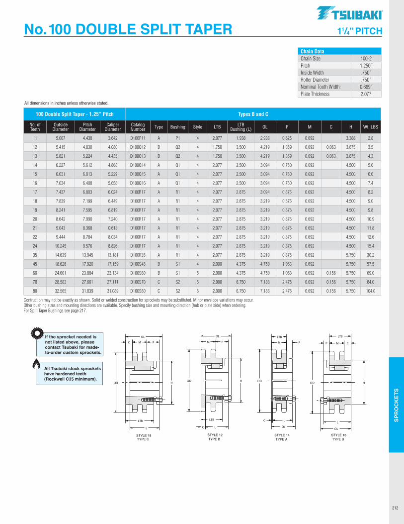
SPR
OC
KET
S
212
All dimensions in inches unless otherwise stated.
No. 100 DOUBLE SPLIT TAPER 11/4” PITCH
D100P11D100Q12D100Q13D100Q14D100Q15D100Q16D100R17D100R18D100R19D100R20D100R21D100R22D100R24D100R35D100S45D100S60D100S70D100S80
ABBAAAAAAAAAAABBCC
P1Q2Q2Q1Q1Q1R1R1R1R1R1R1R1R1S1S1S2S2
141212141414141414141414141415151818
5.007 5.415 5.821 6.227 6.631 7.034 7.437 7.839 8.241 8.642 9.043 9.444 10.245 14.639 18.626 24.601 28.583 32.565
5/81 55/64
1 55/64
3/43/43/47/87/87/87/87/87/87/87/8
1 1/16
1 1/16
2 3/16
2 3/16
2 15/16
4 7/32
4 7/32
3 3/32
3 3/32
3 3/32
3 7/32
3 7/32
3 7/32
3 7/32
3 7/32
3 7/32
3 7/32
3 7/32
4 3/44 3/47 1/87 1/8
-44-----------
6 3/46 3/46 3/46 3/4
Construction may not be exactly as shown. Solid or welded construction for sprockets may be substituted. Minor envelope variations may occur. Other bushing sizes andmounting directions available. Specify bushing size and mounting direction (hub or plate side) when ordering.
3/47/16
7/16
5/16
5/16
5/16
1/16
1/16
1/16
1/16
1/16
1/16
1/16
1/16
1 15/64
1 15/64
2 1/42 1/4
If the sprocket needed isnot listed above, pleasecontact Tsubaki for made-to-order custom sprockets.
2.0772 17/32
2 17/32
2.0772.0772.0772.0772.0772.0772.0772.0772.0772.0772.0773 5/16
3 5/16
5 11/16
5 11/16
1 15/16
3 1/23 1/22 1/22 1/22 1/22 7/82 7/82 7/82 7/82 7/82 7/82 7/82 7/84 3/44 3/46 3/46 3/4
2.0772.0772.0772.0772.0772.0772.0772.0772.0772.0772.0772.0772.0772.0772.0772.0772.0772.077
Dimensional DataDouble Strand Chain 100Size 100-2Pitch 1.250"Chain Inside Width 0.750"Roller Diameter 0.750"Nominal Tooth Width 0.669"Plate Thickness 2.077"
LTBNo. of Outside Pitch Caliper Catalogue Bushing WeightTeeth Diameter Diameter Diameter Number Type Style Hub LTB (L) OL P M C H (Ibs.)
Sprocket Diameters11/4" Pitch
Type B and C
111213141516171819202122243545607080
4.4384.8305.2245.6186.0136.4086.8037.1997.5957.9908.3888.7849.576
13.94517.92023.88427.86131.839
3.6424.0804.4354.8685.2295.6586.0246.4496.8197.2407.6138.0348.826
13.18117.15923.13427.11131.089
STYLE 18TYPE C
STYLE 12TYPE B
STYLE 14TYPE A
STYLE 15TYPE B
4.75.97.97.49.110.910.012.314.917.420.322.829.576.8
138.0251.0358.0431.0
All Tsubaki stock sprockets have hardened teeth (Rockwell C35 minimum).
100 Double Split Taper - 1.25” Pitch Types B and C
No. of Teeth
Outside Diameter
Pitch Diameter
Caliper Diameter
Catalog Number Type Bushing Style LTB LTB
Bushing (L) OL P M C H Wt. LBS
11 5.007 4.438 3.642 D100P11 A P1 4 2.077 1.938 2.938 0.625 0.692 3.388 2.8
12 5.415 4.830 4.080 D100Q12 B Q2 4 1.750 3.500 4.219 1.859 0.692 0.063 3.875 3.5
13 5.821 5.224 4.435 D100Q13 B Q2 4 1.750 3.500 4.219 1.859 0.692 0.063 3.875 4.3
14 6.227 5.612 4.868 D100Q14 A Q1 4 2.077 2.500 3.094 0.750 0.692 4.500 5.6
15 6.631 6.013 5.229 D100Q15 A Q1 4 2.077 2.500 3.094 0.750 0.692 4.500 6.6
16 7.034 6.408 5.658 D100Q16 A Q1 4 2.077 2.500 3.094 0.750 0.692 4.500 7.4
17 7.437 6.803 6.024 D100R17 A R1 4 2.077 2.875 3.094 0.875 0.692 4.500 8.2
18 7.839 7.199 6.449 D100R17 A R1 4 2.077 2.875 3.219 0.875 0.692 4.500 9.0
19 8.241 7.595 6.819 D100R17 A R1 4 2.077 2.875 3.219 0.875 0.692 4.500 9.8
20 8.642 7.990 7.240 D100R17 A R1 4 2.077 2.875 3.219 0.875 0.692 4.500 10.9
21 9.043 8.368 0.613 D100R17 A R1 4 2.077 2.875 3.219 0.875 0.692 4.500 11.8
22 9.444 8.784 8.034 D100R17 A R1 4 2.077 2.875 3.219 0.875 0.692 4.500 12.6
24 10.245 9.576 8.826 D100R17 A R1 4 2.077 2.875 3.219 0.875 0.692 4.500 15.4
35 14.639 13.945 13.181 D100R35 A R1 4 2.077 2.875 3.219 0.875 0.692 5.750 30.2
45 18.626 17.920 17.159 D100S48 B S1 4 2.000 4.375 4.750 1.063 0.692 5.750 57.5
60 24.601 23.884 23.134 D100S60 B S1 5 2.000 4.375 4.750 1.063 0.692 0.156 5.750 69.0
70 28.583 27.661 27.111 D100S70 C S2 5 2.000 6.750 7.188 2.475 0.692 0.156 5.750 84.0
80 32.565 31.839 31.089 D100S80 C S2 5 2.000 6.750 7.188 2.475 0.692 0.156 5.750 104.0
Contruction may not be exactly as shown. Solid or welded construction for sprockets may be substituted. Minor envelope variations may occur.Other bushing sizes and mounting directions are available. Specify bushing size and mounting direction (hub or plate side) when ordering.For Split Taper Bushings see page 217.
Chain DataChain Size 100-2Pitch 1.250˝Inside Width .750˝Roller Diameter .750˝Nominal Tooth Width: 0.669˝Plate Thickness 2.077
Construction may not be exactly as shown. Solid or welded construction for sprockets may be substituted. Minor envelope variations may occur. Other bushing sizes andmounting directions available. Specify bushing size and mounting direction (hub or plate side) when ordering.
LTBNo. of Outside Pitch Caliper Catalogue Bushing WeightTeeth Diameter Diameter Diameter Number Style Hub LTB (L) OL P M C H (Ibs.)
Sprocket Diameters1" Pitch
Type B
80H1080H1180P1180P1280P1380P1480Q1480P1580Q1580P1680Q1680P1780Q1780P1880Q1880P1980Q1980Q2080Q2180Q2280Q2380Q2480Q2580Q2680Q2780Q2880Q2980Q3080Q3180Q3280Q33
H1H1P1P1P1P1Q1P1Q1P1Q1P1Q1P1Q1P1Q1Q1Q1Q1Q1Q1Q1Q1Q1Q1Q1Q1Q1Q1Q1
3344444444444444444444444444444
1 1/41 1/4
1 15/16
1 15/16
1 15/16
1 15/16
2 1/21 15/16
2 1/21 15/16
2 1/21 15/16
2 1/21 15/16
2 1/21 15/16
2 1/22 1/22 1/22 1/22 1/22 1/22 1/22 1/22 1/22 1/22 1/22 1/22 1/22 1/22 1/2
1 1/21 1/21 1/21 5/16
1 5/16
1 5/16
1 3/41 5/16
1 3/41 5/16
1 3/41 5/16
1 3/41 5/16
1 3/41 5/16
1 3/41 3/41 3/41 3/41 3/41 3/41 3/41 3/41 3/41 3/41 3/41 3/41 3/41 3/41 3/4
1 21/64
3/41 17/32
1 3/81 3/81 3/8
1 15/16
1 3/81 15/16
1 3/81 15/16
1 3/81 15/16
1 3/81 15/16
1 3/81 15/16
1 15/16
1 15/16
1 15/16
1 15/16
1 15/16
1 15/16
1 15/16
1 15/16
1 15/16
1 15/16
1 15/16
1 15/16
1 15/16
1 15/16
2 3/32
1 1/22 11/32
2 3/16
2 3/16
2 3/16
2 25/32
2 3/16
2 25/32
2 3/16
2 25/32
2 3/16
2 25/32
2 3/16
2 25/32
2 3/16
2 25/32
2 25/32
2 25/32
2 25/32
2 25/32
2 25/32
2 25/32
2 25/32
2 25/32
2 25/32
2 25/32
2 25/32
2 25/32
2 25/32
2 25/32
0.5750.5750.5750.5750.5750.5750.5750.5750.5750.5750.5750.5750.5750.5750.5750.5750.5750.5750.5750.5750.5750.5750.5750.5750.5750.5750.5750.5750.5750.5750.575
2 1/22 1/2
3333
3 7/83
3 7/83
3 7/83
3 7/83
4 1/23
4 1/24 1/24 1/24 1/24 1/24 1/24 1/24 1/24 1/24 1/24 1/24 1/24 1/24 1/24 1/2
1.21.31.62.02.42.62.93.03.43.54.63.85.34.46.04.96.57.07.38.28.89.19.6
10.610.912.412.613.413.914.815.5
21/32
1/16
5/32
----------------------------
10111112131414151516161717181819192021222324252627282930313233
3.2363.5503.5503.8644.1794.4944.4944.8104.8105.1265.1265.4425.4425.7595.7596.0766.0766.3926.7107.0277.3447.6617.9798.2968.6148.9319.2499.5679.884
10.20210.520
TYPE BSTYLE 4
TYPE BSTYLE 3
3.678 4.006 4.006 4.332 4.657 4.981 4.981 5.305 5.305 5.627 5.627 5.950 5.950 6.271 6.271 6.593 6.593 6.914 7.235 7.555 7.876 8.196 8.516 8.836 9.156 9.475 9.795 10.114 10.434 10.753 11.072
If the sprocket needed isnot listed above, pleasecontact Tsubaki for made-to-order custom sprockets.
Dimensional DataSingle Strand Chain 80Size 80Pitch 1.000"Chain Inside Width 0.625"Roller Diameter 0.625"Nom. Tooth Width 0.575"
2.6112.8882.8883.2393.5233.8693.8694.1584.1584.5014.5014.7944.7945.1345.1345.4305.4305.7676.0666.4026.7027.0367.3387.6717.9748.3068.6118.9429.2479.5779.883
All Tsubaki stock sprockets have hardened teeth (Rockwell C35 minimum).
TSUBAKI"
----------------
f I
t I
" / 1/ "/
OD -
LTB
OD
LTB C L
C L OL
OD
L
OL
H
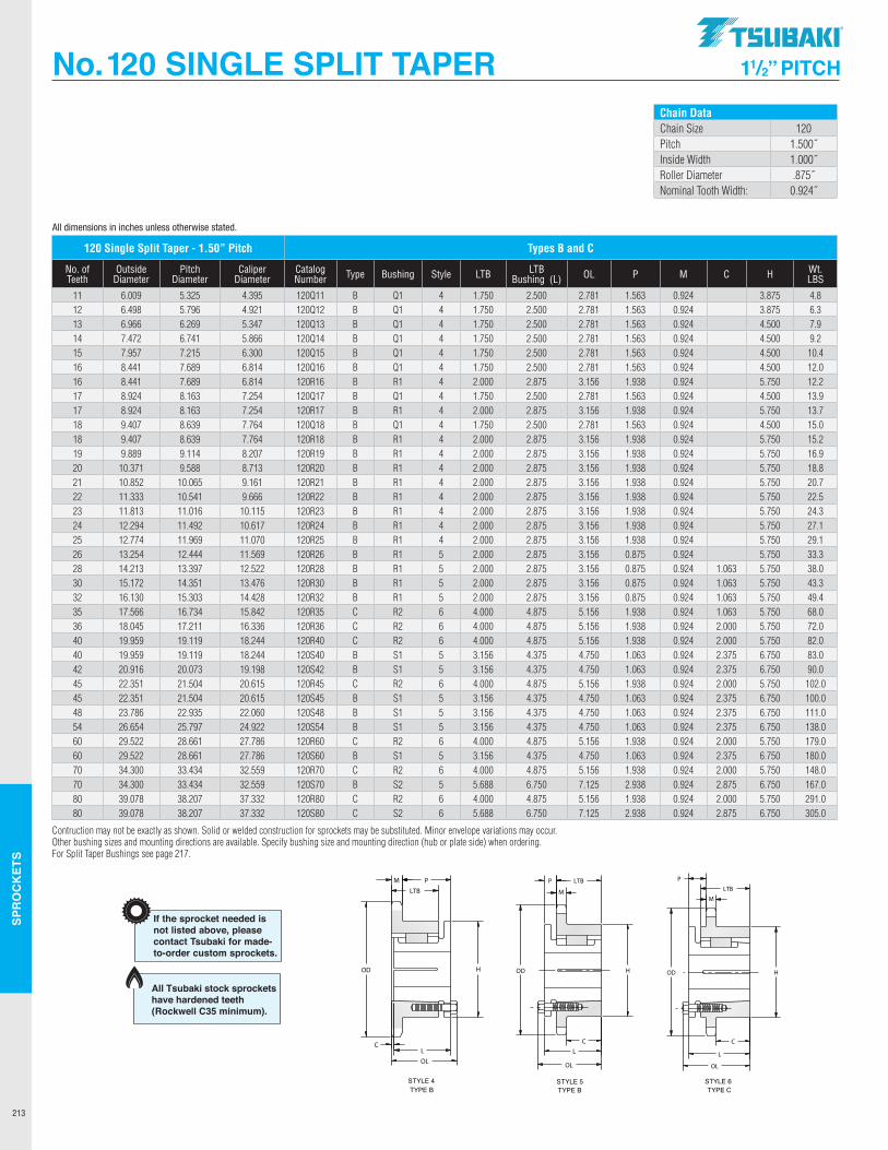
SPR
OC
KET
S
213
No. 120 SINGLE SPLIT TAPER 11/2” PITCH
All dimensions in inches unless otherwise stated.
120Q11120Q12120Q13120Q14120Q15120Q16120R16120Q17120R17120Q18120R18120R19120R20120R21120R22120R23120R24120R25120R26120R28120R30120R32120R35120R36120R40120S40120S42120R45120S45120S48120S54120R60120S60120R70120S70120R80120S80
BBBBBBBBBBBBBBBBBBBBBBCCCBBCBBBCBCBCC
Q1Q1Q1Q1Q1Q1R1Q1R1Q1R1R1R1R1R1R1R1R1R1R1R1R1R2R2R2S1S1R2S1S1S1R2S1R2S2R2S2
4444444444444444445555666556555656566
6.009 6.498 6.986 7.472 7.957 8.441 8.441 8.924 8.924 9.407 9.407 9.889 10.371 10.852 11.333 11.813 12.294 12.774 13.254 14.213 15.172 16.130 17.566 18.045 19.959 19.959 20.916 22.351 22.351 23.786 26.654 29.522 29.522 34.300 34.300 39.078 39.078
2 1/22 1/22 1/22 1/22 1/22 1/22 7/82 1/22 7/82 1/22 7/82 7/82 7/82 7/82 7/82 7/82 7/82 7/82 7/82 7/82 7/82 7/84 7/84 7/84 7/84 3/84 3/84 7/84 3/84 3/84 3/84 7/84 3/84 7/86 3/44 7/86 3/4
4.86.37.99.210.412.012.213.913.715.015.216.918.820.722.524.327.129.133.338.043.349.468.072.082.083.090.0102.0100.0111.0138.0179.0180.0148.0167.0291.0305.0
1 3/41 3/41 3/41 3/41 3/41 3/4
2 1 3/4
2 1 3/4
2 2 2 2 2 2 2 2 2 2 2 2 4 4 4
3 5/16
3 5/16
4 3 5/16
3 5/16
3 5/16
4 3 5/16
4 5 11/16
4 5 11/16
1 9/16
1 9/16
1 9/16
1 9/16
1 9/16
1 9/16
1 15/16
1 9/16
1 15/16
1 9/16
1 15/16
1 15/16
1 15/16
1 15/16
1 15/16
1 15/16
1 15/16
1 15/16
7/87/87/87/8
1 15/16
1 15/16
1 15/16
1 1/16
1 1/16
1 15/16
1 1/16
1 1/16
1 1/16
1 15/16
1 1/16
1 15/16
2 15/16
1 15/16
2 15/16
2 25/32
2 25/32
2 25/32
2 25/32
2 25/32
2 25/32
3 5/32
2 25/32
3 5/32
2 25/32
3 5/32
3 5/32
3 5/32
3 5/32
3 5/32
3 5/32
3 5/32
3 5/32
3 5/32
3 5/32
3 5/32
3 5/32
5 5/32
5 5/32
5 5/32
4 3/44 3/45 5/32
4 3/44 3/44 3/45 5/32
4 3/45 5/32
7 1/85 5/32
7 1/8
0.9240.9240.9240.9240.9240.9240.9240.9240.9240.9240.9240.9240.9240.9240.9240.9240.9240.9240.9240.9240.9240.9240.9240.9240.9240.9240.9240.9240.9240.9240.9240.9240.9240.9240.9240.9240.924
3 7/83 7/84 1/24 1/24 1/24 1/25 3/44 1/25 3/44 1/25 3/45 3/45 3/45 3/45 3/45 3/45 3/45 3/45 3/45 3/45 3/45 3/45 3/45 3/45 3/46 3/46 3/45 3/46 3/46 3/46 3/45 3/46 3/45 3/46 3/45 3/46 3/4
TYPE BSTYLE 4 STYLE 5
TYPE BSTYLE 6TYPE C
Construction may not be exactly as shown. Solid or welded construction for sprockets may be substituted. Minor envelope variations may occur. Other bushing sizes andmounting directions available. Specify bushing size and mounting direction (hub or plate side) when ordering.
------------------
1 1/16
1 1/16
1 1/16
1 1/16
2 2 2
2 3/82 3/8
2 2 3/82 3/82 3/8
2 2 3/8
2 2 7/8
2 2 7/8
If the sprocket needed isnot listed above, pleasecontact Tsubaki for made-to-order custom sprockets.
Dimensional DataSingle Strand Chain 120Size 120Pitch 1.500"Chain Inside Width 1.000"Roller Diameter 0.875"Nominal Tooth Width 0.924"
LTBNo. of Outside Pitch Caliper Catalogue Bushing WeightTeeth Diameter Diameter Diameter Number Type Style Hub LTB (L) OL P M C H (Ibs.)
Sprocket Diameters11/2" Pitch
Type B and C
5.3255.7966.2696.7417.2157.6897.6898.1638.1638.6398.6399.1149.588
10.06510.54111.01611.49211.96912.44413.39714.35115.30316.73417.21119.11919.11920.07321.50421.50422.93525.79728.66128.66133.43433.43438.20738.207
4.3954.9215.3475.8666.3006.8146.8147.2547.2547.7647.7648.2078.7139.1619.666
10.11510.61711.07011.56912.52213.47614.42815.84216.33618.24418.24419.19820.61520.61522.06024.92227.78627.78632.55932.55937.33237.332
11121314151616171718181920212223242526283032353640404245454854606070708080
All Tsubaki stock sprockets have hardened teeth (Rockwell C35 minimum).
120 Single Split Taper - 1.50” Pitch Types B and C
No. of Teeth
Outside Diameter
Pitch Diameter
Caliper Diameter
Catalog Number Type Bushing Style LTB LTB
Bushing (L) OL P M C H Wt. LBS
11 6.009 5.325 4.395 120Q11 B Q1 4 1.750 2.500 2.781 1.563 0.924 3.875 4.812 6.498 5.796 4.921 120Q12 B Q1 4 1.750 2.500 2.781 1.563 0.924 3.875 6.313 6.966 6.269 5.347 120Q13 B Q1 4 1.750 2.500 2.781 1.563 0.924 4.500 7.914 7.472 6.741 5.866 120Q14 B Q1 4 1.750 2.500 2.781 1.563 0.924 4.500 9.215 7.957 7.215 6.300 120Q15 B Q1 4 1.750 2.500 2.781 1.563 0.924 4.500 10.416 8.441 7.689 6.814 120Q16 B Q1 4 1.750 2.500 2.781 1.563 0.924 4.500 12.016 8.441 7.689 6.814 120R16 B R1 4 2.000 2.875 3.156 1.938 0.924 5.750 12.217 8.924 8.163 7.254 120Q17 B Q1 4 1.750 2.500 2.781 1.563 0.924 4.500 13.917 8.924 8.163 7.254 120R17 B R1 4 2.000 2.875 3.156 1.938 0.924 5.750 13.718 9.407 8.639 7.764 120Q18 B Q1 4 1.750 2.500 2.781 1.563 0.924 4.500 15.018 9.407 8.639 7.764 120R18 B R1 4 2.000 2.875 3.156 1.938 0.924 5.750 15.219 9.889 9.114 8.207 120R19 B R1 4 2.000 2.875 3.156 1.938 0.924 5.750 16.920 10.371 9.588 8.713 120R20 B R1 4 2.000 2.875 3.156 1.938 0.924 5.750 18.821 10.852 10.065 9.161 120R21 B R1 4 2.000 2.875 3.156 1.938 0.924 5.750 20.722 11.333 10.541 9.666 120R22 B R1 4 2.000 2.875 3.156 1.938 0.924 5.750 22.523 11.813 11.016 10.115 120R23 B R1 4 2.000 2.875 3.156 1.938 0.924 5.750 24.324 12.294 11.492 10.617 120R24 B R1 4 2.000 2.875 3.156 1.938 0.924 5.750 27.125 12.774 11.969 11.070 120R25 B R1 4 2.000 2.875 3.156 1.938 0.924 5.750 29.126 13.254 12.444 11.569 120R26 B R1 5 2.000 2.875 3.156 0.875 0.924 5.750 33.328 14.213 13.397 12.522 120R28 B R1 5 2.000 2.875 3.156 0.875 0.924 1.063 5.750 38.030 15.172 14.351 13.476 120R30 B R1 5 2.000 2.875 3.156 0.875 0.924 1.063 5.750 43.332 16.130 15.303 14.428 120R32 B R1 5 2.000 2.875 3.156 0.875 0.924 1.063 5.750 49.435 17.566 16.734 15.842 120R35 C R2 6 4.000 4.875 5.156 1.938 0.924 1.063 5.750 68.036 18.045 17.211 16.336 120R36 C R2 6 4.000 4.875 5.156 1.938 0.924 2.000 5.750 72.040 19.959 19.119 18.244 120R40 C R2 6 4.000 4.875 5.156 1.938 0.924 2.000 5.750 82.040 19.959 19.119 18.244 120S40 B S1 5 3.156 4.375 4.750 1.063 0.924 2.375 6.750 83.042 20.916 20.073 19.198 120S42 B S1 5 3.156 4.375 4.750 1.063 0.924 2.375 6.750 90.045 22.351 21.504 20.615 120R45 C R2 6 4.000 4.875 5.156 1.938 0.924 2.000 5.750 102.045 22.351 21.504 20.615 120S45 B S1 5 3.156 4.375 4.750 1.063 0.924 2.375 6.750 100.048 23.786 22.935 22.060 120S48 B S1 5 3.156 4.375 4.750 1.063 0.924 2.375 6.750 111.054 26.654 25.797 24.922 120S54 B S1 5 3.156 4.375 4.750 1.063 0.924 2.375 6.750 138.060 29.522 28.661 27.786 120R60 C R2 6 4.000 4.875 5.156 1.938 0.924 2.000 5.750 179.060 29.522 28.661 27.786 120S60 B S1 5 3.156 4.375 4.750 1.063 0.924 2.375 6.750 180.070 34.300 33.434 32.559 120R70 C R2 6 4.000 4.875 5.156 1.938 0.924 2.000 5.750 148.070 34.300 33.434 32.559 120S70 B S2 5 5.688 6.750 7.125 2.938 0.924 2.875 6.750 167.080 39.078 38.207 37.332 120R80 C R2 6 4.000 4.875 5.156 1.938 0.924 2.000 5.750 291.080 39.078 38.207 37.332 120S80 C S2 6 5.688 6.750 7.125 2.938 0.924 2.875 6.750 305.0
Contruction may not be exactly as shown. Solid or welded construction for sprockets may be substituted. Minor envelope variations may occur.Other bushing sizes and mounting directions are available. Specify bushing size and mounting direction (hub or plate side) when ordering.For Split Taper Bushings see page 217.
Chain DataChain Size 120Pitch 1.500˝Inside Width 1.000˝Roller Diameter .875˝Nominal Tooth Width: 0.924˝
Construction may not be exactly as shown. Solid or welded construction for sprockets may be substituted. Minor envelope variations may occur. Other bushing sizes andmounting directions available. Specify bushing size and mounting direction (hub or plate side) when ordering.
LTBNo. of Outside Pitch Caliper Catalogue Bushing WeightTeeth Diameter Diameter Diameter Number Style Hub LTB (L) OL P M C H (Ibs.)
Sprocket Diameters1" Pitch
Type B
80H1080H1180P1180P1280P1380P1480Q1480P1580Q1580P1680Q1680P1780Q1780P1880Q1880P1980Q1980Q2080Q2180Q2280Q2380Q2480Q2580Q2680Q2780Q2880Q2980Q3080Q3180Q3280Q33
H1H1P1P1P1P1Q1P1Q1P1Q1P1Q1P1Q1P1Q1Q1Q1Q1Q1Q1Q1Q1Q1Q1Q1Q1Q1Q1Q1
3344444444444444444444444444444
1 1/41 1/4
1 15/16
1 15/16
1 15/16
1 15/16
2 1/21 15/16
2 1/21 15/16
2 1/21 15/16
2 1/21 15/16
2 1/21 15/16
2 1/22 1/22 1/22 1/22 1/22 1/22 1/22 1/22 1/22 1/22 1/22 1/22 1/22 1/22 1/2
1 1/21 1/21 1/21 5/16
1 5/16
1 5/16
1 3/41 5/16
1 3/41 5/16
1 3/41 5/16
1 3/41 5/16
1 3/41 5/16
1 3/41 3/41 3/41 3/41 3/41 3/41 3/41 3/41 3/41 3/41 3/41 3/41 3/41 3/41 3/4
1 21/64
3/41 17/32
1 3/81 3/81 3/8
1 15/16
1 3/81 15/16
1 3/81 15/16
1 3/81 15/16
1 3/81 15/16
1 3/81 15/16
1 15/16
1 15/16
1 15/16
1 15/16
1 15/16
1 15/16
1 15/16
1 15/16
1 15/16
1 15/16
1 15/16
1 15/16
1 15/16
1 15/16
2 3/32
1 1/22 11/32
2 3/16
2 3/16
2 3/16
2 25/32
2 3/16
2 25/32
2 3/16
2 25/32
2 3/16
2 25/32
2 3/16
2 25/32
2 3/16
2 25/32
2 25/32
2 25/32
2 25/32
2 25/32
2 25/32
2 25/32
2 25/32
2 25/32
2 25/32
2 25/32
2 25/32
2 25/32
2 25/32
2 25/32
0.5750.5750.5750.5750.5750.5750.5750.5750.5750.5750.5750.5750.5750.5750.5750.5750.5750.5750.5750.5750.5750.5750.5750.5750.5750.5750.5750.5750.5750.5750.575
2 1/22 1/2
3333
3 7/83
3 7/83
3 7/83
3 7/83
4 1/23
4 1/24 1/24 1/24 1/24 1/24 1/24 1/24 1/24 1/24 1/24 1/24 1/24 1/24 1/24 1/2
1.21.31.62.02.42.62.93.03.43.54.63.85.34.46.04.96.57.07.38.28.89.19.6
10.610.912.412.613.413.914.815.5
21/32
1/16
5/32
----------------------------
10111112131414151516161717181819192021222324252627282930313233
3.2363.5503.5503.8644.1794.4944.4944.8104.8105.1265.1265.4425.4425.7595.7596.0766.0766.3926.7107.0277.3447.6617.9798.2968.6148.9319.2499.5679.884
10.20210.520
TYPE BSTYLE 4
TYPE BSTYLE 3
3.678 4.006 4.006 4.332 4.657 4.981 4.981 5.305 5.305 5.627 5.627 5.950 5.950 6.271 6.271 6.593 6.593 6.914 7.235 7.555 7.876 8.196 8.516 8.836 9.156 9.475 9.795 10.114 10.434 10.753 11.072
If the sprocket needed isnot listed above, pleasecontact Tsubaki for made-to-order custom sprockets.
Dimensional DataSingle Strand Chain 80Size 80Pitch 1.000"Chain Inside Width 0.625"Roller Diameter 0.625"Nom. Tooth Width 0.575"
2.6112.8882.8883.2393.5233.8693.8694.1584.1584.5014.5014.7944.7945.1345.1345.4305.4305.7676.0666.4026.7027.0367.3387.6717.9748.3068.6118.9429.2479.5779.883
All Tsubaki stock sprockets have hardened teeth (Rockwell C35 minimum).
.TSUBAKI"
--------------
Ol
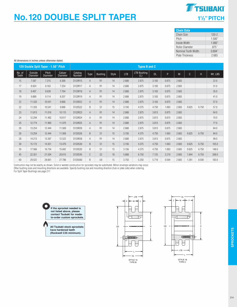
SPR
OC
KET
S
214
No. 120 DOUBLE SPLIT TAPER 11/2” PITCH
All dimensions in inches unless otherwise stated.
Chain DataChain Size 120-2Pitch 1.500˝Inside Width 1.000˝Roller Diameter .875˝Nominal Tooth Width: 0.894˝Plate Thickness 2.683
120 Double Split Taper - 1.50” Pitch Types B and C
No. of Teeth
Outside Diameter
Pitch Diameter
Caliper Diameter
Catalog Number Type Bushing Style LTB LTB Bushing
(L) OL P M C H Wt. LBS
15 7.597 7.215 6.300 D120R15 A R1 14 2.688 2.875 3.183 0.875 2.683 22.0
17 8.924 8.163 7.254 D120R17 A R1 14 2.688 2.875 3.183 0.875 2.683 31.0
18 9.407 8.639 7.764 D120R18 A R1 14 2.688 2.875 3.183 0.875 2.683 35.0
19 9.889 9.114 8.207 D120R19 A R1 14 2.688 2.875 3.183 0.875 2.683 41.0
22 11.333 10.541 9.666 D120R22 A R1 14 2.688 2.875 3.183 0.875 2.683 57.0
22 11.333 10.541 9.666 D120S22 B S1 15 3.156 4.375 4.750 1.063 2.683 0.625 6.750 57.0
23 11.813 11.016 10.115 D120R23 A R1 14 2.688 2.875 3.813 0.875 2.683 64.0
24 12.294 11.492 10.617 D120R24 A R1 14 2.688 2.875 3.813 0.875 2.683 70.0
25 12.774 11.969 11.070 D120R25 A R1 14 2.688 2.875 3.813 0.875 2.683 77.0
26 13.254 12.444 11.569 D120R26 A R1 14 2.688 2.875 3.813 0.875 2.683 84.0
26 13.254 12.444 11.569 D120S26 B S1 15 3.156 4.375 4.750 1.063 2.683 0.625 6.750 84.0
28 14.213 13.397 12.522 D120R28 A R1 14 2.688 2.875 3.813 0.875 2.683 99.0
30 15.172 14.351 13.476 D120S30 B S1 15 3.156 4.375 4.750 1.063 2.683 0.625 6.750 105.0
35 17.566 16.734 15.842 D120S35 B S1 15 3.156 4.375 4.750 1.063 2.683 0.625 6.750 148.0
45 22.351 21.504 20.615 D120S45 C S2 18 5.688 6.750 7.125 2.219 2.683 1.844 6.750 268.0
60 29.522 28.661 27.786 D120U60 B U0 15 3.750 5.250 5.719 0.594 2.683 1.281 8.500 183.0
Contruction may not be exactly as shown. Solid or welded construction for sprockets may be substituted. Minor envelope variations may occur.Other bushing sizes and mounting directions are available. Specify bushing size and mounting direction (hub or plate side) when ordering.For Split Taper Bushings see page 217.
30354560
HD120S30D120S35D120S45D120U60
BBCB
S1S1S2U0
15151815
15.172 17.566 22.351 29.522
4 3/84 3/86 3/45 1/4
105148268183
3 5/16
3 5/16
5 11/16
3 3/4
1 1/16
1 1/16
2 7/3219/32
4 3/44 3/47 1/8
5 23/32
2.6832.6832.6832.683
6 3/46 3/46 3/48 1/2
STYLE 15TYPE B
STYLE 18TYPE C
Construction may not be exactly as shown. Solid or welded construction for sprockets may be substituted. Minor envelope variations may occur. Other bushing sizes andmounting directions available. Specify bushing size and mounting direction (hub or plate side) when ordering.
5/85/8
1 27/32
1 9/32
14.35116.73421.50428.661
13.47615.84220.61527.786
LTBNo. of Outside Pitch Caliper Catalogue Bushing WeightTeeth Diameter Diameter Diameter Number Type Style Hub LTB (L) OL P M C H (Ibs.)
Sprocket Diameters11/2" Pitch
Type B and C
If the sprocket needed isnot listed above, pleasecontact Tsubaki for made-to-order custom sprockets.
Dimensional DataDouble Strand Chain 120Size 120-2Pitch 1.500"Chain Inside Width 1.000"Roller Diameter 0.875"Nominal Tooth Width 0.894"Plate Thickness 2.683"
Construction may not be exactly as shown. Solid or welded construction for sprockets may be substituted. Minor envelope variations may occur. Other bushing sizes andmounting directions available. Specify bushing size and mounting direction (hub or plate side) when ordering.
LTBNo. of Outside Pitch Caliper Catalogue Bushing WeightTeeth Diameter Diameter Diameter Number Style Hub LTB (L) OL P M C H (Ibs.)
Sprocket Diameters1" Pitch
Type B
80H1080H1180P1180P1280P1380P1480Q1480P1580Q1580P1680Q1680P1780Q1780P1880Q1880P1980Q1980Q2080Q2180Q2280Q2380Q2480Q2580Q2680Q2780Q2880Q2980Q3080Q3180Q3280Q33
H1H1P1P1P1P1Q1P1Q1P1Q1P1Q1P1Q1P1Q1Q1Q1Q1Q1Q1Q1Q1Q1Q1Q1Q1Q1Q1Q1
3344444444444444444444444444444
1 1/41 1/4
1 15/16
1 15/16
1 15/16
1 15/16
2 1/21 15/16
2 1/21 15/16
2 1/21 15/16
2 1/21 15/16
2 1/21 15/16
2 1/22 1/22 1/22 1/22 1/22 1/22 1/22 1/22 1/22 1/22 1/22 1/22 1/22 1/22 1/2
1 1/21 1/21 1/21 5/16
1 5/16
1 5/16
1 3/41 5/16
1 3/41 5/16
1 3/41 5/16
1 3/41 5/16
1 3/41 5/16
1 3/41 3/41 3/41 3/41 3/41 3/41 3/41 3/41 3/41 3/41 3/41 3/41 3/41 3/41 3/4
1 21/64
3/41 17/32
1 3/81 3/81 3/8
1 15/16
1 3/81 15/16
1 3/81 15/16
1 3/81 15/16
1 3/81 15/16
1 3/81 15/16
1 15/16
1 15/16
1 15/16
1 15/16
1 15/16
1 15/16
1 15/16
1 15/16
1 15/16
1 15/16
1 15/16
1 15/16
1 15/16
1 15/16
2 3/32
1 1/22 11/32
2 3/16
2 3/16
2 3/16
2 25/32
2 3/16
2 25/32
2 3/16
2 25/32
2 3/16
2 25/32
2 3/16
2 25/32
2 3/16
2 25/32
2 25/32
2 25/32
2 25/32
2 25/32
2 25/32
2 25/32
2 25/32
2 25/32
2 25/32
2 25/32
2 25/32
2 25/32
2 25/32
2 25/32
0.5750.5750.5750.5750.5750.5750.5750.5750.5750.5750.5750.5750.5750.5750.5750.5750.5750.5750.5750.5750.5750.5750.5750.5750.5750.5750.5750.5750.5750.5750.575
2 1/22 1/2
3333
3 7/83
3 7/83
3 7/83
3 7/83
4 1/23
4 1/24 1/24 1/24 1/24 1/24 1/24 1/24 1/24 1/24 1/24 1/24 1/24 1/24 1/24 1/2
1.21.31.62.02.42.62.93.03.43.54.63.85.34.46.04.96.57.07.38.28.89.19.6
10.610.912.412.613.413.914.815.5
21/32
1/16
5/32
----------------------------
10111112131414151516161717181819192021222324252627282930313233
3.2363.5503.5503.8644.1794.4944.4944.8104.8105.1265.1265.4425.4425.7595.7596.0766.0766.3926.7107.0277.3447.6617.9798.2968.6148.9319.2499.5679.884
10.20210.520
TYPE BSTYLE 4
TYPE BSTYLE 3
3.678 4.006 4.006 4.332 4.657 4.981 4.981 5.305 5.305 5.627 5.627 5.950 5.950 6.271 6.271 6.593 6.593 6.914 7.235 7.555 7.876 8.196 8.516 8.836 9.156 9.475 9.795 10.114 10.434 10.753 11.072
If the sprocket needed isnot listed above, pleasecontact Tsubaki for made-to-order custom sprockets.
Dimensional DataSingle Strand Chain 80Size 80Pitch 1.000"Chain Inside Width 0.625"Roller Diameter 0.625"Nom. Tooth Width 0.575"
2.6112.8882.8883.2393.5233.8693.8694.1584.1584.5014.5014.7944.7945.1345.1345.4305.4305.7676.0666.4026.7027.0367.3387.6717.9748.3068.6118.9429.2479.5779.883
All Tsubaki stock sprockets have hardened teeth (Rockwell C35 minimum).
TSUBAKI"
--------------
OD
L
OL
~-+I H
LTB
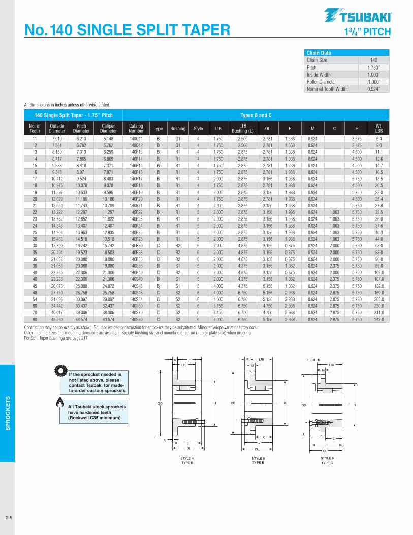
SPR
OC
KET
S
215
No. 140 SINGLE SPLIT TAPER 13/4” PITCH
All dimensions in inches unless otherwise stated. 11121314151617181920212223242526303536364040454854607080
140Q11140Q12140R13140R14140R15140R16140R17140R18140R19140R20140R21140R22140R23140R24140R25140R26140R30140R35140R36140S36140R40140S40140S45140S48140S54140S60140S70140S80
BBBBBBBBBBBBBBBBCCCBCBBCCCCC
Q1Q1R1R1R1R1R1R1R1R1R1R1R1R1R1R1R2R2R2S1R2S1S1S2S2S2S2S2
4444444444455555566565566666
7.010 7.581 8.150 8.717 9.283 9.848 10.412 10.975 11.537 12.099 12.660 13.222 13.782 14.343 14.903 15.463 17.700 20.494 21.053 21.053 23.286 23.286 26.076 27.750 31.096 34.442 40.017 45.590
2 1/22 1/22 7/82 7/82 7/82 7/82 7/82 7/82 7/82 7/82 7/82 7/82 7/82 7/82 7/82 7/84 7/84 7/84 7/84 3/84 7/84 3/84 3/86 3/46 3/46 3/46 3/46 3/4
1 3/41 3/4
2 2 2 2 2 2 2 2 2 2 2 2 2 2 4 4 4
3 5/16
4 3 5/16
3 5/16
5 11/16
5 11/16
5 11/16
5 11/16
5 11/16
1 9/16
1 9/16
1 15/16
1 15/16
1 15/16
1 15/16
1 15/16
1 15/16
1 15/16
1 15/16
1 15/167/87/87/87/87/87/87/87/8
1 1/167/8
1 1/16
1 1/16
2 15/16
2 15/16
2 15/16
2 15/16
2 15/16
2 25/32
2 25/32
3 5/32
3 5/32
3 5/32
3 5/32
3 5/32
3 5/32
3 5/32
3 5/32
3 5/32
3 5/32
3 5/32
3 5/32
3 5/32
3 5/32
5 5/32
5 5/32
5 5/32
4 3/45 5/32
4 3/44 3/47 1/27 1/27 1/27 1/27 1/2
0.9240.9240.9240.9240.9240.9240.9240.9240.9240.9240.9240.9240.9240.9240.9240.9240.9240.9240.9240.9240.9240.9240.9240.9240.9240.9240.9240.924
3 7/84 1/2
5 13/16
5 3/45 3/45 3/45 3/45 3/45 3/45 3/45 3/45 3/45 3/45 3/45 3/45 3/45 3/45 3/45 3/46 3/45 3/46 3/46 3/46 3/46 3/46 3/46 3/46 3/4
TYPE BSTYLE 4 STYLE 5
TYPE BSTYLE 6TYPE C
Construction may not be exactly as shown. Solid or welded construction for sprockets may be substituted. Minor envelope variations may occur. Other bushing sizes andmounting directions available. Specify bushing size and mounting direction (hub or plate side) when ordering.
-----------
1 1/16
1 1/16
1 1/16
1 1/16
1 1/16
2 2 2
2 3/82
2 3/82 3/82 7/82 7/82 7/82 7/82 7/8
If the sprocket needed isnot listed above, pleasecontact Tsubaki for made-to-order custom sprockets.
Dimensional DataSingle Strand Chain 140Size 140Pitch 1.750"Chain Inside Width 1.000"Roller Diameter 1.000"Nominal Tooth Width 0.924"
6.2136.7627.3137.8658.4188.9719.524
10.07810.63311.18611.74312.29712.85213.40713.96314.51816.74219.52320.08020.08022.30622.30625.08826.75830.09733.43739.00644.574
5.1485.7626.2596.8657.3717.9718.4839.0789.596
10.18610.70911.29711.82212.40712.93513.51815.74218.50319.08019.08021.30621.30624.07225.75829.09732.43738.00643.574
LTBNo. of Outside Pitch Caliper Catalogue Bushing WeightTeeth Diameter Diameter Diameter Number Type Style Hub LTB (L) OL P M C H (Ibs.)
Sprocket Diameters13/4" Pitch
Type B and C
6.49.011.112.614.716.518.520.523.025.427.832.536.037.640.344.068.088.090.089.0109.0107.0132.0169.0208.0230.0311.0242.0
All Tsubaki stock sprockets have hardened teeth (Rockwell C35 minimum).
Chain DataChain Size 140Pitch 1.750˝Inside Width 1.000˝Roller Diameter .1.000˝Nominal Tooth Width: 0.924˝
Construction may not be exactly as shown. Solid or welded construction for sprockets may be substituted. Minor envelope variations may occur. Other bushing sizes andmounting directions available. Specify bushing size and mounting direction (hub or plate side) when ordering.
LTBNo. of Outside Pitch Caliper Catalogue Bushing WeightTeeth Diameter Diameter Diameter Number Style Hub LTB (L) OL P M C H (Ibs.)
Sprocket Diameters1" Pitch
Type B
80H1080H1180P1180P1280P1380P1480Q1480P1580Q1580P1680Q1680P1780Q1780P1880Q1880P1980Q1980Q2080Q2180Q2280Q2380Q2480Q2580Q2680Q2780Q2880Q2980Q3080Q3180Q3280Q33
H1H1P1P1P1P1Q1P1Q1P1Q1P1Q1P1Q1P1Q1Q1Q1Q1Q1Q1Q1Q1Q1Q1Q1Q1Q1Q1Q1
3344444444444444444444444444444
1 1/41 1/4
1 15/16
1 15/16
1 15/16
1 15/16
2 1/21 15/16
2 1/21 15/16
2 1/21 15/16
2 1/21 15/16
2 1/21 15/16
2 1/22 1/22 1/22 1/22 1/22 1/22 1/22 1/22 1/22 1/22 1/22 1/22 1/22 1/22 1/2
1 1/21 1/21 1/21 5/16
1 5/16
1 5/16
1 3/41 5/16
1 3/41 5/16
1 3/41 5/16
1 3/41 5/16
1 3/41 5/16
1 3/41 3/41 3/41 3/41 3/41 3/41 3/41 3/41 3/41 3/41 3/41 3/41 3/41 3/41 3/4
1 21/64
3/41 17/32
1 3/81 3/81 3/8
1 15/16
1 3/81 15/16
1 3/81 15/16
1 3/81 15/16
1 3/81 15/16
1 3/81 15/16
1 15/16
1 15/16
1 15/16
1 15/16
1 15/16
1 15/16
1 15/16
1 15/16
1 15/16
1 15/16
1 15/16
1 15/16
1 15/16
1 15/16
2 3/32
1 1/22 11/32
2 3/16
2 3/16
2 3/16
2 25/32
2 3/16
2 25/32
2 3/16
2 25/32
2 3/16
2 25/32
2 3/16
2 25/32
2 3/16
2 25/32
2 25/32
2 25/32
2 25/32
2 25/32
2 25/32
2 25/32
2 25/32
2 25/32
2 25/32
2 25/32
2 25/32
2 25/32
2 25/32
2 25/32
0.5750.5750.5750.5750.5750.5750.5750.5750.5750.5750.5750.5750.5750.5750.5750.5750.5750.5750.5750.5750.5750.5750.5750.5750.5750.5750.5750.5750.5750.5750.575
2 1/22 1/2
3333
3 7/83
3 7/83
3 7/83
3 7/83
4 1/23
4 1/24 1/24 1/24 1/24 1/24 1/24 1/24 1/24 1/24 1/24 1/24 1/24 1/24 1/24 1/2
1.21.31.62.02.42.62.93.03.43.54.63.85.34.46.04.96.57.07.38.28.89.19.6
10.610.912.412.613.413.914.815.5
21/32
1/16
5/32
----------------------------
10111112131414151516161717181819192021222324252627282930313233
3.2363.5503.5503.8644.1794.4944.4944.8104.8105.1265.1265.4425.4425.7595.7596.0766.0766.3926.7107.0277.3447.6617.9798.2968.6148.9319.2499.5679.884
10.20210.520
TYPE BSTYLE 4
TYPE BSTYLE 3
3.678 4.006 4.006 4.332 4.657 4.981 4.981 5.305 5.305 5.627 5.627 5.950 5.950 6.271 6.271 6.593 6.593 6.914 7.235 7.555 7.876 8.196 8.516 8.836 9.156 9.475 9.795 10.114 10.434 10.753 11.072
If the sprocket needed isnot listed above, pleasecontact Tsubaki for made-to-order custom sprockets.
Dimensional DataSingle Strand Chain 80Size 80Pitch 1.000"Chain Inside Width 0.625"Roller Diameter 0.625"Nom. Tooth Width 0.575"
2.6112.8882.8883.2393.5233.8693.8694.1584.1584.5014.5014.7944.7945.1345.1345.4305.4305.7676.0666.4026.7027.0367.3387.6717.9748.3068.6118.9429.2479.5779.883
All Tsubaki stock sprockets have hardened teeth (Rockwell C35 minimum).
140 Single Split Taper - 1.75” Pitch Types B and C
No. of Teeth
Outside Diameter
Pitch Diameter
Caliper Diameter
Catalog Number Type Bushing Style LTB LTB
Bushing (L) OL P M C H Wt. LBS
11 7.010 6.213 5.148 140Q11 B Q1 4 1.750 2.500 2.781 1.563 0.924 3.875 6.412 7.581 6.762 5.762 140Q12 B Q1 4 1.750 2.500 2.781 1.563 0.924 3.875 9.013 8.150 7.313 6.259 140R13 B R1 4 1.750 2.875 2.781 1.938 0.924 4.500 11.114 8.717 7.865 6.865 140R14 B R1 4 1.750 2.875 2.781 1.938 0.924 4.500 12.615 9.283 8.418 7.371 140R15 B R1 4 1.750 2.875 2.781 1.938 0.924 4.500 14.716 9.848 8.971 7.971 140R16 B R1 4 1.750 2.875 2.781 1.938 0.924 4.500 16.517 10.412 9.524 8.483 140R17 B R1 4 2.000 2.875 3.156 1.938 0.924 5.750 18.518 10.975 10.078 9.078 140R18 B R1 4 1.750 2.875 2.781 1.938 0.924 4.500 20.519 11.537 10.633 9.596 140R19 B R1 4 2.000 2.875 3.156 1.938 0.924 5.750 23.020 12.099 11.186 10.186 140R20 B R1 4 1.750 2.875 2.781 1.938 0.924 4.500 25.421 12.660 11.743 10.709 140R21 B R1 4 2.000 2.875 3.156 1.938 0.924 5.750 27.822 13.222 12.297 11.297 140R22 B R1 5 2.000 2.875 3.156 1.938 0.924 1.063 5.750 32.523 13.782 12.852 11.822 140R23 B R1 5 2.000 2.875 3.156 1.938 0.924 1.063 5.750 36.024 14.343 13.407 12.407 140R24 B R1 5 2.000 2.875 3.156 1.938 0.924 1.063 5.750 37.625 14.903 13.963 12.935 140R25 B R1 5 2.000 2.875 3.156 1.938 0.924 1.063 5.750 40.326 15.463 14.518 13.518 140R26 B R1 5 2.000 2.875 3.156 1.938 0.924 1.063 5.750 44.030 17.700 16.742 15.742 140R30 C R2 6 2.000 4.875 3.156 0.875 0.924 2.000 5.750 68.035 20.494 19.523 18.503 140R35 C R2 6 2.000 4.875 3.156 0.875 0.924 2.000 5.750 88.036 21.053 20.080 19.080 140R36 C R2 6 2.000 4.875 3.156 0.875 0.924 2.000 5.750 90.036 21.053 20.080 19.080 140S36 B S1 5 2.000 4.375 3.156 1.062 0.924 2.375 5.750 89.040 23.286 22.306 21.306 140R40 C R2 6 2.000 4.875 3.156 0.875 0.924 2.000 5.750 109.040 23.286 22.306 21.306 140S40 B S1 5 2.000 4.375 3.156 1.062 0.924 2.375 5.750 107.045 26.076 25.088 24.072 140S45 B S1 5 4.000 4.375 5.156 1.062 0.924 2.375 5.750 132.048 27.750 26.758 25.758 140S48 C S2 6 4.000 6.750 5.156 2.938 0.924 2.875 5.750 169.054 31.096 30.097 29.097 140S54 C S2 6 4.000 6.750 5.156 2.938 0.924 2.875 5.750 208.060 34.442 33.437 32.437 140S60 C S2 6 3.156 6.750 4.750 2.938 0.924 2.875 6.750 230.070 40.017 39.006 38.006 140S70 C S2 6 3.156 6.750 4.750 2.938 0.924 2.875 6.750 311.080 45.590 44.574 43.574 140S80 C S2 6 4.000 6.750 5.156 2.938 0.924 2.875 5.750 242.0
Contruction may not be exactly as shown. Solid or welded construction for sprockets may be substituted. Minor envelope variations may occur.Other bushing sizes and mounting directions are available. Specify bushing size and mounting direction (hub or plate side) when ordering.For Split Taper Bushings see page 217.
.TSUBAKI"
r t OD H OD H
H
OL
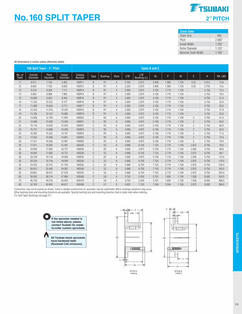
SPR
OC
KET
S
216
No. 160 SPLIT TAPER 2” PITCH
All dimensions in inches unless otherwise stated.
Chain DataChain Size 160Pitch 2.000˝Inside Width 1.250˝Roller Diameter 1.125˝Nominal Tooth Width: 1.156˝
Construction may not be exactly as shown. Solid or welded construction for sprockets may be substituted. Minor envelope variations may occur. Other bushing sizes andmounting directions available. Specify bushing size and mounting direction (hub or plate side) when ordering.
LTBNo. of Outside Pitch Caliper Catalogue Bushing WeightTeeth Diameter Diameter Diameter Number Style Hub LTB (L) OL P M C H (Ibs.)
Sprocket Diameters1" Pitch
Type B
80H1080H1180P1180P1280P1380P1480Q1480P1580Q1580P1680Q1680P1780Q1780P1880Q1880P1980Q1980Q2080Q2180Q2280Q2380Q2480Q2580Q2680Q2780Q2880Q2980Q3080Q3180Q3280Q33
H1H1P1P1P1P1Q1P1Q1P1Q1P1Q1P1Q1P1Q1Q1Q1Q1Q1Q1Q1Q1Q1Q1Q1Q1Q1Q1Q1
3344444444444444444444444444444
1 1/41 1/4
1 15/16
1 15/16
1 15/16
1 15/16
2 1/21 15/16
2 1/21 15/16
2 1/21 15/16
2 1/21 15/16
2 1/21 15/16
2 1/22 1/22 1/22 1/22 1/22 1/22 1/22 1/22 1/22 1/22 1/22 1/22 1/22 1/22 1/2
1 1/21 1/21 1/21 5/16
1 5/16
1 5/16
1 3/41 5/16
1 3/41 5/16
1 3/41 5/16
1 3/41 5/16
1 3/41 5/16
1 3/41 3/41 3/41 3/41 3/41 3/41 3/41 3/41 3/41 3/41 3/41 3/41 3/41 3/41 3/4
1 21/64
3/41 17/32
1 3/81 3/81 3/8
1 15/16
1 3/81 15/16
1 3/81 15/16
1 3/81 15/16
1 3/81 15/16
1 3/81 15/16
1 15/16
1 15/16
1 15/16
1 15/16
1 15/16
1 15/16
1 15/16
1 15/16
1 15/16
1 15/16
1 15/16
1 15/16
1 15/16
1 15/16
2 3/32
1 1/22 11/32
2 3/16
2 3/16
2 3/16
2 25/32
2 3/16
2 25/32
2 3/16
2 25/32
2 3/16
2 25/32
2 3/16
2 25/32
2 3/16
2 25/32
2 25/32
2 25/32
2 25/32
2 25/32
2 25/32
2 25/32
2 25/32
2 25/32
2 25/32
2 25/32
2 25/32
2 25/32
2 25/32
2 25/32
0.5750.5750.5750.5750.5750.5750.5750.5750.5750.5750.5750.5750.5750.5750.5750.5750.5750.5750.5750.5750.5750.5750.5750.5750.5750.5750.5750.5750.5750.5750.575
2 1/22 1/2
3333
3 7/83
3 7/83
3 7/83
3 7/83
4 1/23
4 1/24 1/24 1/24 1/24 1/24 1/24 1/24 1/24 1/24 1/24 1/24 1/24 1/24 1/24 1/2
1.21.31.62.02.42.62.93.03.43.54.63.85.34.46.04.96.57.07.38.28.89.19.6
10.610.912.412.613.413.914.815.5
21/32
1/16
5/32
----------------------------
10111112131414151516161717181819192021222324252627282930313233
3.2363.5503.5503.8644.1794.4944.4944.8104.8105.1265.1265.4425.4425.7595.7596.0766.0766.3926.7107.0277.3447.6617.9798.2968.6148.9319.2499.5679.884
10.20210.520
TYPE BSTYLE 4
TYPE BSTYLE 3
3.678 4.006 4.006 4.332 4.657 4.981 4.981 5.305 5.305 5.627 5.627 5.950 5.950 6.271 6.271 6.593 6.593 6.914 7.235 7.555 7.876 8.196 8.516 8.836 9.156 9.475 9.795 10.114 10.434 10.753 11.072
If the sprocket needed isnot listed above, pleasecontact Tsubaki for made-to-order custom sprockets.
Dimensional DataSingle Strand Chain 80Size 80Pitch 1.000"Chain Inside Width 0.625"Roller Diameter 0.625"Nom. Tooth Width 0.575"
2.6112.8882.8883.2393.5233.8693.8694.1584.1584.5014.5014.7944.7945.1345.1345.4305.4305.7676.0666.4026.7027.0367.3387.6717.9748.3068.6118.9429.2479.5779.883
All Tsubaki stock sprockets have hardened teeth (Rockwell C35 minimum).
160 Split Taper - 2” Pitch Types B and C
No. of Teeth
Outside Diameter
Pitch Diameter
Caliper Diameter
Catalog Number Type Bushing Style LTB LTB
Bushing (L) OL P M C H Wt. LBS
11 8.011 7.100 5.902 160R11 B R1 4 2.250 2.875 3.406 1.969 1.156 0.25 5.813 10.812 8.664 7.728 6.603 160R12 B R1 4 2.250 2.875 3.406 1.969 1.156 0.25 5.750 14.213 9.314 8.358 7.171 160R13 B R1 4 2.000 2.875 3.156 1.719 1.156 5.750 15.514 9.963 8.988 7.863 160R14 B R1 4 2.000 2.875 3.156 1.719 1.156 5.750 18.515 10.609 9.620 8.442 160R15 B R1 4 2.000 2.875 3.156 1.719 1.156 5.750 21.616 11.255 10.252 9.127 160R16 B R1 4 2.000 2.875 3.156 1.719 1.156 5.750 25.017 11.899 10.844 9.713 160R17 B R1 4 2.000 2.875 3.156 1.719 1.156 5.750 28.018 12.543 11.518 10.393 160R18 B R1 4 2.000 2.875 3.156 1.719 1.156 5.750 31.919 13.185 12.152 10.985 160R19 B R1 4 2.000 2.875 3.156 1.719 1.156 5.750 35.920 13.828 12.784 11.659 160R20 C R2 6 4.000 4.875 5.156 1.719 1.156 2 5.750 51.021 14.469 13.420 12.256 160R21 C R2 6 4.000 4.875 5.156 1.719 1.156 2 5.750 56.022 15.110 14.054 12.929 160R22 C R2 6 4.000 4.875 5.156 1.719 1.156 2 5.750 60.023 15.751 14.688 13.529 160R23 C R2 6 4.000 4.875 5.156 1.719 1.156 2 5.750 65.024 16.392 15.322 14.197 160R24 C R2 6 4.000 4.875 5.156 1.719 1.156 2 5.750 71.525 17.032 15.958 14.801 160R25 C R2 6 4.000 4.875 5.156 1.719 1.156 2 5.750 74.026 17.671 16.592 15.467 160R26 C R2 6 4.000 4.875 5.156 1.719 1.156 2 5.750 79.026 17.671 19.592 15.467 160S26 C S2 6 5.688 6.750 7.125 2.719 1.156 2.875 6.750 78.028 18.950 17.862 16.737 160R28 C R2 6 4.000 4.875 5.156 1.719 1.156 2.000 5.750 99.828 18.950 17.862 16.737 160S28 C S2 6 5.688 6.750 7.125 2.719 1.156 2.875 6.750 98.730 20.229 19.134 18.009 160R30 C R2 6 4.000 4.875 5.156 1.719 1.156 2.000 5.750 115.030 20.229 19.134 18.009 160S30 C S2 6 5.688 6.750 7.125 2.719 1.156 2.875 6.750 114.035 23.422 22.312 21.164 160S35 C S2 6 5.688 6.750 7.125 2.719 1.156 2.875 6.750 150.040 26.612 25.492 24.367 160S40 C S2 6 5.688 6.750 7.125 2.719 1.156 2.875 6.750 165.045 29.801 28.672 27.529 160S45 C S2 6 5.688 6.750 7.125 2.719 1.156 2.875 6.750 204.060 39.362 38.214 37.089 160U60 C U0 6 3.750 5.250 5.781 1.656 1.156 1.938 8.500 354.070 45.733 44.578 43.453 160U70 C U0 6 3.750 5.250 5.781 1.656 1.156 1.938 8.500 308.080 52.103 50.942 49.817 160U80 C U1 6 5.625 7.125 7.594 2.594 1.156 2.875 8.500 394.0
Contruction may not be exactly as shown. Solid or welded construction for sprockets may be substituted. Minor envelope variations may occur.Other bushing sizes and mounting directions are available. Specify bushing size and mounting direction (hub or plate side) when ordering.For Split Taper Bushings see page 217.
160R11160R12160R13160R14160R15160R16160R17160R18160R19160R20160R21160R22160R23160R24160R25160R26160S26160R28160S28160R30160S30160S35160S40160S45160U60160U70160U80
BBBBBBBBBCCCCCCCCCCCCCCCCCC
R1R1R1R1R1R1R1R1R1R2R2R2R2R2R2R2S2R2S2R2S2S2S2S2U0U0U1
444444444666666666666666666
8.011 8.664 9.314 9.963 10.609 11.255 11.899 12.543 13.185 13.828 14.469 15.110 15.751 16.392 17.032 17.671 17.671 18.950 18.950 20.229 20.229 23.422 26.612 29.801 39.362 45.733 52.103
2 7/82 7/82 7/82 7/82 7/82 7/82 7/82 7/82 7/84 7/84 7/84 7/84 7/84 7/84 7/84 7/86 3/44 7/86 3/44 7/86 3/46 3/46 3/46 3/45 1/45 1/47 1/8
10.814.215.518.521.625.028.031.935.951.056.060.065.071.574.079.078.099.898.7115.0114.0150.0165.0204.0354.0308.0394.0
2 1/42 1/4
2 2 2 2 2 2 2 4 4 4 4 4 4 4
5 11/16
4 5 11/16
4 5 11/16
5 11/16
5 11/16
5 11/16
3 3/43 3/45 5/8
1 31/32
1 31/32
1 23/32
1 23/32
1 23/32
1 23/32
1 23/32
1 23/32
1 23/32
1 23/32
1 23/32
1 23/32
1 23/32
1 23/32
1 23/32
1 23/32
2 23/32
1 23/32
2 23/32
1 23/32
2 23/32
2 23/32
2 23/32
2 23/32
1 21/32
1 21/32
2 19/32
3 13/32
3 13/32
3 5/32
3 5/32
3 5/32
3 5/32
3 5/32
3 5/32
3 5/32
5 5/32
5 5/32
5 5/32
5 5/32
5 5/32
5 5/32
5 5/32
7 1/85 5/32
7 1/85 5/32
7 1/87 1/87 1/87 1/8
5 25/32
5 25/32
7 19/32
1.1561.1561.1561.1561.1561.1561.1561.1561.1561.1561.1561.1561.1561.1561.1561.1561.1561.1561.1561.1561.1561.1561.1561.1561.1561.1561.156
5 13/16
5 3/45 3/45 3/45 3/45 3/45 3/45 3/45 3/45 3/45 3/45 3/45 3/45 3/45 3/45 3/46 3/45 3/46 3/45 3/46 3/46 3/46 3/46 3/48 1/28 1/28 1/2
TYPE BSTYLE 4 STYLE 6
TYPE C
1/41/4-------2 2 2 2 2 2 2
2 7/82
2 7/82
2 7/82 7/82 7/82 7/8
1 15/16
1 15/16
2 7/8
If the sprocket needed isnot listed above, pleasecontact Tsubaki for made-to-order custom sprockets.
Dimensional DataSingle Strand Chain 160Size 160Pitch 2.000"Chain Inside Width 1.250"Roller Diameter 1.125"Nominal Tooth Width 1.156"
Construction may not be exactly as shown. Solid or welded construction for sprockets may be substituted. Minor envelope variations may occur. Other bushing sizes andmounting directions available. Specify bushing size and mounting direction (hub or plate side) when ordering.
7.1007.7288.3588.9889.620
10.25210.84411.51812.15212.78413.42014.05414.68815.32215.95816.59216.59217.86217.86219.13419.13422.31225.49228.67238.21444.57850.942
5.9026.6037.1717.8638.4429.1279.713
10.39310.98511.65912.25612.92913.52914.19714.80115.46715.46716.73716.73718.00918.00921.16424.36727.52937.08943.45349.817
LTBNo. of Outside Pitch Caliper Catalogue Bushing WeightTeeth Diameter Diameter Diameter Number Type Style Hub LTB (L) OL P M C H (Ibs.)
Sprocket Diameters2" Pitch
Type B and C
111213141516171819202122232425262628283030354045607080
All Tsubaki stock sprockets have hardened teeth (Rockwell C35 minimum).
TSUBAKI"
----------------
OD :==== H
C
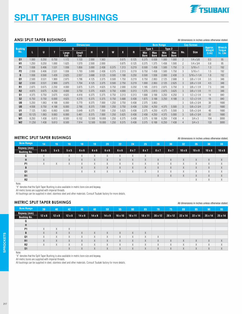
SPR
OC
KET
S
217
SPLIT TAPER BUSHINGS
All dimensions in inches unless otherwise stated.
Bushing No.
Dimensions Bore Range Cap ScrewsApprox. Weight (Lbs)
Wrench Torque In. LbsL U T
DH V W X R
Type 1 Type 2No. SizeLarge
EndSmall End
Min Bore
Max Bore
Min Bore
Max Bore
G1 1.000 0.250 0.750 1.172 1.133 2.000 1.563 0.675 0.125 0.375 0.938 1.000 1.000 2 1/4 x 5/8 0.5 95H1 1.250 0.250 1.000 1.625 1.570 2.500 2.000 0.875 0.125 0.375 1.375 1.438 1.500 2 1/4 x 3/4 0.8 95P1 1.938 0.406 1.531 1.938 1.856 3.000 2.438 0.375 1.313 0.219 0.500 1.438 1.500 1.750 3 5/16 x 1 1.3 192P2 2.938 0.406 2.531 1.938 1.793 3.000 2.438 0.375 2.313 0.219 0.750 1.438 1.500 1.750 3 5/16 x 1 1.5 192B 1.938 0.500 1.439 2.625 2.557 3.688 3.125 0.500 1.188 0.250 0.500 1.938 2.000 2.438 3 5/16 x 1-1/4 1.8 192
Q1 2.500 0.531 1.969 2.875 1.796 4.125 3.375 0.500 1.750 0.219 0.750 2.063 2.125 2.688 3 3/8 x 1-1/4 3.5 348Q2 3.500 0.531 2.969 2.875 1.704 4.125 3.375 0.500 2.750 0.219 1.000 2.063 2.125 2.625 3 3/8 x 1-1/4 4.5 348R1 2.875 0.675 2.250 4.000 3.875 5.375 4.625 0.750 2.000 0.250 1.185 2.813 2.875 3.750 3 3/8 x 1-1/4 7.5 348R2 4.875 0.675 4.250 4.000 3.750 5.375 4.625 0.750 4.000 0.313 1.375 2.813 2.875 3.625 3 3/8 x 1-1/4 11 348S1 4.375 0.750 3.675 4.625 4.418 6.375 5.375 0.750 3.313 0.313 1.688 3.188 3.250 4.250 3 1/2 x 2-1/4 14 840S2 6.750 0.750 6.000 4.625 4.270 6.375 5.375 0.750 5.688 0.438 1.875 3.188 3.250 4.188 3 1/2 x 2-1/4 19 840U0 5.250 1.063 4.188 6.000 5.770 8.375 7.000 1.250 3.750 0.438 2.375 3.063 3 5/8 x 2-3/4 30 1680U0 4.938 0.750 4.188 6.000 2.766 8.375 7.000 1.250 3.750 0.438 3.250 4.250 4.375 5.500 3 5/8 x 2-3/4 27 1680U1 7.125 1.063 6.063 6.000 5.649 8.375 7.000 1.250 5.625 0.438 2.375 4.250 4.375 5.500 3 5/8 x 2-3/4 40 1680U2 10.125 1.063 9.063 6.000 5.461 8.375 7.000 1.250 5.625 0.438 2.438 4.250 4.375 5.000 3 5/8 x 2-3/4 50 1680W1 8.250 1.438 6.813 8.500 6.102 12.500 10.000 1.250 6.375 0.438 3.375 6.188 6.250 7.438 4 3/4 x 3 104 3000W2 11.250 1.438 9.813 8.500 7.914 12.500 10.000 1.250 9.375 0.438 3.375 6.188 6.250 7.438 4 3/4 x 3 133 3000
Bore Range 14 15 16 18 19 20 22 24 25 28 30 32 35 36 38Keyway (mm)
5 x 5 5 x 5 5 x 5 6 x 6 6 x 6 6 x 6 6 x 6 8 x 7 8 x 7 8 x 7 8 x 7 10 x 8 10 x 8 10 x 8 10 x 8Bushing No.G X X X X X X X XH X X X X X X X X X X X X X XP1 X X X X X X X X X X X X X X XB X X X X X X X X X X X X
Q1 X X X X X X X X X X X XR1 X X X X X XR2 X X X
Note:“X” denotes that the Split Taper Bushing is also available in metric bore size and keyway.All metric bores are supplied with imperial threads.All bushings can be supplied in steel, stainless steel and other materials. Consult Tsubaki factory for more details.
Bore Range 39 40 42 45 48 50 55 60 65 70 75 80 85 90 95Keyway (mm)
12 x 8 12 x 8 12 x 8 14 x 9 14 x 9 14 x 9 16 x 10 18 x 11 18 x 11 20 x 12 20 x 12 22 x 14 22 x 14 25 x 14 25 x 14Bushing No.G H P1 X X X B X X X X X X X X X
Q1 X X X X X X X X X X R1 X X X X X X X X X X X X X X XR2 X X X X X X X X X X X X X X XS1 X X X X X X X X X X X X X
Note:“X” denotes that the Split Taper Bushing is also available in metric bore size and keyway.All metric bores are supplied with imperial threads.All bushings can be supplied in steel, stainless steel and other materials. Consult Tsubaki factory for more details.
ANSI SPLIT TAPER BUSHINGS
METRIC SPLIT TAPER BUSHINGS All dimensions in inches unless otherwise stated.
All dimensions in inches unless otherwise stated. METRIC SPLIT TAPER BUSHINGS
.TSUBAKI"
--------------1 L L L LL l LL
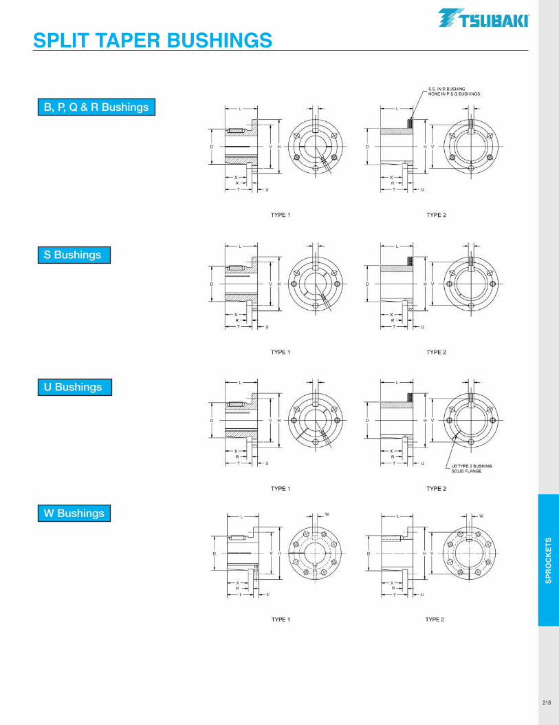
SPR
OC
KET
S
218
SPLIT TAPER BUSHINGS
B, P, Q & R Bushings
S Bushings
U Bushings
W Bushings
TSUBAKI"
S.S. IN R BUSHING NONE IN P & Q BUSHINGS
i D
TYPE 1 TYPE 2
D
u
TYPE 1 TYPE 2
IL 1 i
D V H D
l u
UO TYPE 2 BUSHING SOLID FLANGE
TYPE 1 TYPE2
TYPE 1 TYPE2
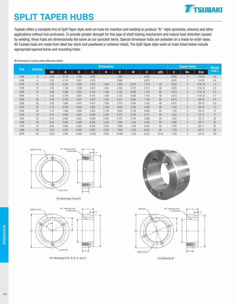
SPR
OC
KET
S
219
SPLIT TAPER HUBS
XA
C
d
B
K
OD
a
3/4" Taper per Footon Diameter
Bolt Size
φ (Bolt Circle)
For Bushing W
XA
C
d
B
K
OD
a
3/4" Taper per Footon Diameter
Bolt Size
For Bushings P, B, Q, R, S, and U
φ (Bolt Circle)XA
C
d
BOD
3/4" Taper per Footon Diameter
Bolt Size
For Bushings G and H
φ (Bolt Circle)
XA
C
d
B
K
OD
a
3/4" Taper per Footon Diameter
Bolt Size
φ (Bolt Circle)
For Bushing W
XA
C
d
B
K
OD
a
3/4" Taper per Footon Diameter
Bolt Size
For Bushings P, B, Q, R, S, and U
φ (Bolt Circle)XA
C
d
BOD
3/4" Taper per Footon Diameter
Bolt Size
For Bushings G and H
φ (Bolt Circle) XA
C
d
B
K
OD
a
3/4" Taper per Footon Diameter
Bolt Size
φ (Bolt Circle)
For Bushing W
XA
C
d
B
K
OD
a
3/4" Taper per Footon Diameter
Bolt Size
For Bushings P, B, Q, R, S, and U
φ (Bolt Circle)XA
C
d
BOD
3/4" Taper per Footon Diameter
Bolt Size
For Bushings G and H
φ (Bolt Circle)
Tsubaki offers a complete line of Split Taper style weld-on hubs for insertion and welding to produce “B:” style sprockets, sheaves and other applications without hub protrusion. To provide greater strength for this type of shaft locking mechanism and reduce heat distortion caused by welding, these hubs are dimensionally the same as our sprocket items. Special dimension hubs are available on a made-to-order basis. All Tsubaki hubs are made from steel bar stock (not powdered or sintered metal). The Split Taper style weld-on hubs listed below include appropriate tapered bores and mounting holes.
All dimensions in inches unless otherwise stated.
Hub BushingDimensions Tapped Holes Weight
(Lbs.)OD A B C K V W X a(0) d No. SizeG1W G 2.00 0.174 1.168 1.875 1.563 0.625 0.625 2 1/4 20 0.4H1W H 2.50 0.174 1.621 2.375 2.000 0.875 0.875 2 1/4 20 0.6P1W P1 3.00 0.292 1.938 2.875 1.094 2.438 0.375 1.313 60 0.625 3 5/16 18 1.4P2W P2 3.00 1.100 1.938 2.875 1.094 2.438 0.375 2.313 60 0.625 3 5/16 18 2.5B1W B 3.88 0.292 2.623 3.750 1.438 3.125 0.500 1.313 60 0.813 3 5/16 18 2.3B2W B 4.50 0.709 2.623 4.375 1.438 3.125 0.500 1.750 60 0.813 3 5/16 18 4.7Q1W Q1 4.50 0.709 2.875 4.375 1.563 3.375 0.500 1.750 60 0.875 3 3/8 16 4.4Q2W Q2 4.50 1.606 2.875 4.375 1.563 3.375 0.500 2.750 60 0.875 3 3/8 16 6.9R1W R1 5.75 0.709 4.000 5.625 2.188 4.625 0.750 2.000 60 1.125 3 3/8 16 7.3R2W R2 5.75 1.606 4.000 5.625 2.188 4.625 0.750 4.000 60 1.125 3 3/8 16 15S1W S1 6.75 0.946 4.625 6.500 2.563 5.375 0.750 3.313 60 1.625 3 1/2 13 17S2W S2 6.75 2.963 4.625 6.500 2.563 5.375 0.750 5.688 60 1.625 3 1/2 13 30U0W U0 8.50 2.000 6.000 8.250 3.250 7.000 1.250 3.750 60 2.000 3 5/8 11 32U1W U1 8.50 2.963 6.000 8.250 3.250 7.000 1.250 5.625 60 1.750 3 5/8 11 45U2W U2 8.50 6.016 6.000 8.250 3.250 7.000 1.250 8.625 60 1.750 3 5/8 11 69W1W W1 12.50 2.963 8.500 12.250 4.563 10.000 1.250 6.375 22.50 1.750 4 3/4 10 130
.TSUBAKI"
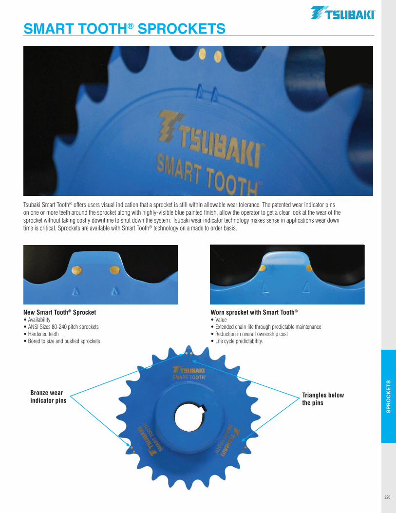
SPR
OC
KET
S
220
Tsubaki Smart Tooth® offers users visual indication that a sprocket is still within allowable wear tolerance. The patented wear indicator pins on one or more teeth around the sprocket along with highly-visible blue painted finish, allow the operator to get a clear look at the wear of the sprocket without taking costly downtime to shut down the system. Tsubaki wear indicator technology makes sense in applications wear down time is critical. Sprockets are available with Smart Tooth® technology on a made to order basis.
New Smart Tooth® Sprocket Worn sprocket with Smart Tooth®
• Availability • Value• ANSI Sizes 80-240 pitch sprockets • Extended chain life through predictable maintenance• Hardened teeth • Reduction in overall ownership cost• Bored to size and bushed sprockets • Life cycle predictability.
Triangles below the pins
Bronze wearindicator pins
SMART TOOTH® SPROCKETSTSUBAKI"
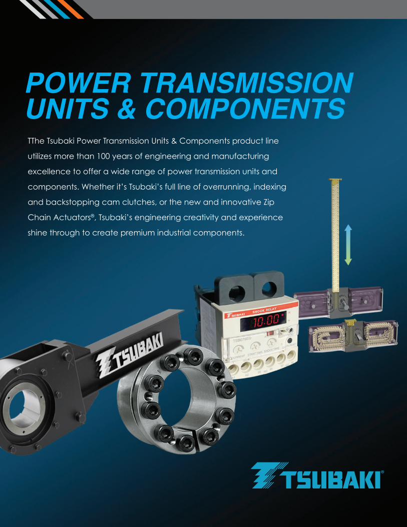
TThe Tsubaki Power Transmission Units & Components product line
utilizes more than 100 years of engineering and manufacturing
excellence to offer a wide range of power transmission units and
components. Whether it’s Tsubaki’s full line of overrunning, indexing
and backstopping cam clutches, or the new and innovative Zip
Chain Actuators®, Tsubaki’s engineering creativity and experience
shine through to create premium industrial components.
POWER TRANSMISSIONUNITS & COMPONENTS
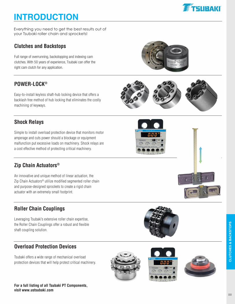
222
CLU
TCH
ES &
BAC
KSTO
PS
POWER TRANSMISSIONUNITS & COMPONENTS
Clutches and Backstops Full range of overrunning, backstopping and indexing cam clutches. With 50 years of experience, Tsubaki can offer the right cam clutch for any application.
POWER-LOCK®
Easy-to-install keyless shaft-hub locking device that offers a backlash free method of hub locking that eliminates the costly machining of keyways.
Shock Relays Simple to install overload protection device that monitors motor amperage and cuts power should a blockage or equipment malfunction put excessive loads on machinery. Shock relays are a cost effective method of protecting critical machinery.
Zip Chain Actuators®
An innovative and unique method of linear actuation, the Zip Chain Actuators® utilize modified segmented roller chain and purpose-designed sprockets to create a rigid chain actuator with an extremely small footprint.
Roller Chain Couplings Leveraging Tsubaki’s extensive roller chain expertise, the Roller Chain Couplings offer a robust and flexible shaft coupling solution.
Overload Protection Devices Tsubaki offers a wide range of mechanical overload protection devices that will help protect critical machinery.
For a full listing of all Tsubaki PT Components, visit www.ustsubaki.com
Everything you need to get the best results out of your Tsubaki roller chain and sprockets!
INTRODUCTIONIN
TRO
DU
CTI
ON
.TSUBAKI"
l ~ I - -
-~ \. - . • w • . ~ .
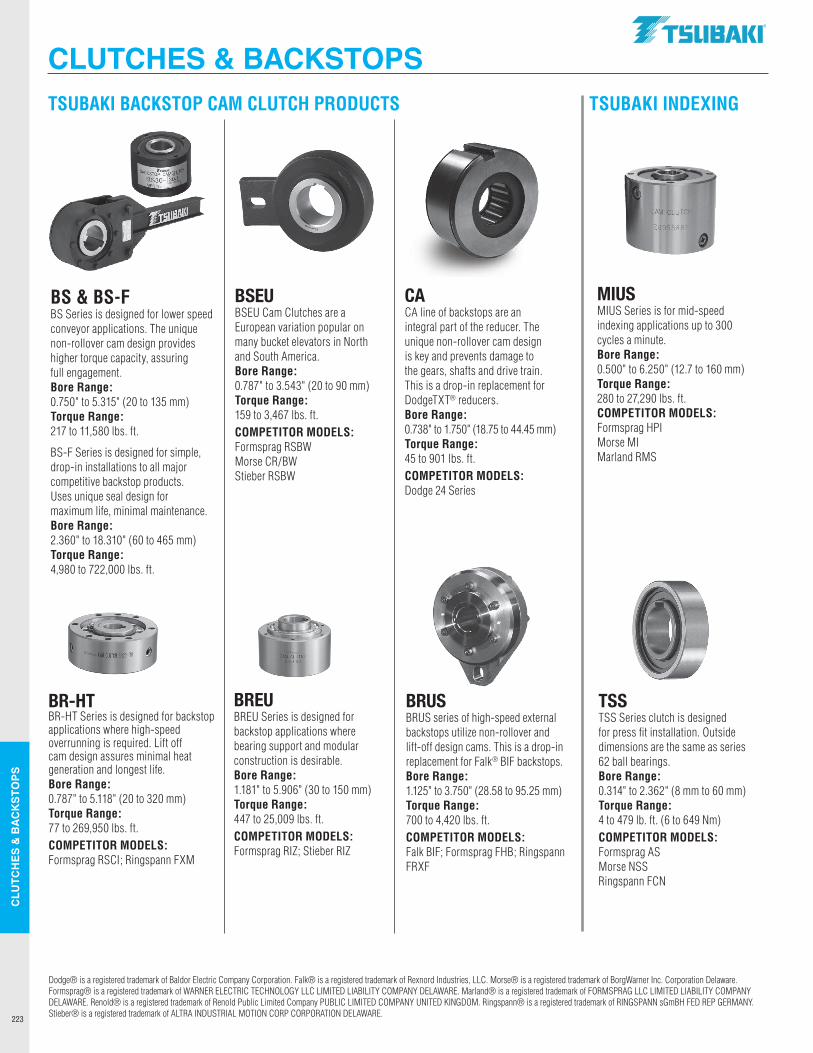
223
CLU
TCH
ES &
BAC
KSTO
PS
TSUBAKI BACKSTOP CAM CLUTCH PRODUCTS TSUBAKI INDEXING
TSSTSS Series clutch is designed for press fit installation. Outside dimensions are the same as series 62 ball bearings. Bore Range: 0.314" to 2.362" (8 mm to 60 mm)Torque Range: 4 to 479 lb. ft. (6 to 649 Nm)COMPETITOR MODELS:Formsprag ASMorse NSSRingspann FCN
BS & BS-FBS Series is designed for lower speed conveyor applications. The unique non-rollover cam design provides higher torque capacity, assuring full engagement.Bore Range: 0.750" to 5.315" (20 to 135 mm)Torque Range: 217 to 11,580 lbs. ft.
BS-F Series is designed for simple, drop-in installations to all major competitive backstop products. Uses unique seal design for maximum life, minimal maintenance.Bore Range: 2.360" to 18.310" (60 to 465 mm)Torque Range: 4,980 to 722,000 lbs. ft.
BSEUBSEU Cam Clutches are a European variation popular on many bucket elevators in North and South America.Bore Range: 0.787" to 3.543" (20 to 90 mm)Torque Range: 159 to 3,467 lbs. ft.COMPETITOR MODELS:Formsprag RSBWMorse CR/BWStieber RSBW
CACA line of backstops are an integral part of the reducer. The unique non-rollover cam design is key and prevents damage to the gears, shafts and drive train. This is a drop-in replacement for DodgeTXT® reducers.Bore Range: 0.738" to 1.750" (18.75 to 44.45 mm)Torque Range: 45 to 901 lbs. ft.COMPETITOR MODELS:Dodge 24 Series
BR-HTBR-HT Series is designed for backstop applications where high-speed overrunning is required. Lift off cam design assures minimal heat generation and longest life.Bore Range: 0.787" to 5.118" (20 to 320 mm)Torque Range: 77 to 269,950 lbs. ft.COMPETITOR MODELS:Formsprag RSCI; Ringspann FXM
BREUBREU Series is designed for backstop applications where bearing support and modular construction is desirable.Bore Range: 1.181" to 5.906" (30 to 150 mm)Torque Range: 447 to 25,009 lbs. ft.COMPETITOR MODELS:Formsprag RIZ; Stieber RIZ
BRUSBRUS series of high-speed external backstops utilize non-rollover and lift-off design cams. This is a drop-in replacement for Falk® BIF backstops.Bore Range: 1.125" to 3.750" (28.58 to 95.25 mm)Torque Range: 700 to 4,420 lbs. ft.COMPETITOR MODELS:Falk BIF; Formsprag FHB; Ringspann FRXF
MIUSMIUS Series is for mid-speed indexing applications up to 300 cycles a minute.Bore Range: 0.500" to 6.250" (12.7 to 160 mm)Torque Range: 280 to 27,290 lbs. ft.COMPETITOR MODELS:Formsprag HPIMorse MIMarland RMS
Dodge® is a registered trademark of Baldor Electric Company Corporation. Falk® is a registered trademark of Rexnord Industries, LLC. Morse® is a registered trademark of BorgWarner Inc. Corporation Delaware. Formsprag® is a registered trademark of WARNER ELECTRIC TECHNOLOGY LLC LIMITED LIABILITY COMPANY DELAWARE. Marland® is a registered trademark of FORMSPRAG LLC LIMITED LIABILITY COMPANY DELAWARE. Renold® is a registered trademark of Renold Public Limited Company PUBLIC LIMITED COMPANY UNITED KINGDOM. Ringspann® is a registered trademark of RINGSPANN sGmBH FED REP GERMANY. Stieber® is a registered trademark of ALTRA INDUSTRIAL MOTION CORP CORPORATION DELAWARE.
CLUTCHES & BACKSTOPS.TSUBAKI"
224
CLU
TCH
ES &
BAC
KSTO
PS
MGUS/MGUS-RMGUS Series is suitable for applications which require low to high speed inner race. MGUS-R Series contains a built-in oil reservoir and can be used for backstopping applications. Bore Range: 0.500" to 6.250" (12.7 to 160 mm)Torque Range: 280 to 27,290 lb. ft. (380 to 37,000 Nm)COMPETITOR MODELS:Formsprag FSO; Morse MG; Ringspann FB
BBBB Series Cam Clutch has the bearing dimensions and characteristics of a 62 Series type ball bearing. This design provides easy installation and is ideal for general overrunning applicationsBore Range: 0.590" to 1.575" (15 to 40 mm) Torque Range: 21 to 192 lb. ft.. (29 to 260 Nm) COMPETITOR MODELS:Formsprag CSK; Morse KK; Ringspann ZZ; Stieber KK
MZMZ Series is designed for low speed indexing applications that require inner or outer race overrunning. These units come pre-lubricated for easy installation and long service life. Bore Range: 0.591" to 2.756" (15 to 70 mm)Torque Range: 137 to 2,242 lb. ft..(186 Nm-m to 3,040 Nm)COMPETITOR MODELS:Stieber SMZ
PBUSPBUS Series clutch is packed with a special grease for general applications. The outer race has provision for mounting gears, pulleys, and sprockets. Bore Range: 0 .375" to 1.750" (10 to 45 mm)Torque Range: 41 to 1,623 lb. ft. (56 to 2,200 Nm)COMPETITOR MODELS:Formsprag FSR; Morse PB-A; Renold SB
TFSTFS Series has two vertical keyways on the outer race to assist with positioning. Outside dimensions are the same as series 63 ball bearings. Ideal for general overrunning applications.Bore Range: 0.472" to 3.150" (12 to 80 mm)Torque Range: 13 to 2,894 lbs. ft. Competitor Models:Formsprag ASNU; Morse NFS; Ringspann FC/FDN
BUS200BUS Series is specifically designed for shaft mounting applications that require high speed inner race overrunning or low to mid speed outer race overrunning. Bore Range: 0.650" to 3.122" (16.5 to 79.3 mm)Torque Range: 39 to 1,025 lbs. ft. Competitor Models:Formsprag FS50; Morse B200; Renold SD
OB-ON/OF & OB-SFOB-ON/OF Series is an enclosed unit housing cam clutch units and a common shaft. These units are used for high speed overrunning applications.Torque Range: 2,318 to 59,270 lbs. ft.
OB-SF Series is an enclosed unit housing cam clutch units that allow for continuous high speed overrunning and engagement and high torque capacities.Torque Range:231 to 4,337 lbs. ft.
MZEUMZEU Series is designed for overruning applications. These units come pre-lubricated, and can be adapted with flanges and torque arms to suit a wide variety of applications.Bore Range: 0.472" to 5.906" (12 to 150 mm)Torque Range: 44 to 24,930 lbs. ft.COMPETITOR MODELS:Formsprag GFR/GFRNStieber GFR
OVERRUNNING AND GENERAL CAM CLUTCH PRODUCTS
For a complete listing of all Tsubaki Cam Clutches, please download the Tsubaki Cam Clutch catalog at: www.ustsubaki.com
CLUTCHES & BACKSTOPS.TSUBAKI"
225
CLU
TCH
ES &
BAC
KSTO
PS
MGUS SERIES MGUS Series Cam Clutch products are designed to satisfy inner or outer race overrunning/general application requirements. Depending on application requirements, the MGUS Series can be used in overrunning, indexing, or backstopping applications. This series is offered in both metric and inch based inner race configurations. MGUS Series units can easily be mated to pulleys, gears, or sprockets.
Available Bore Range
MGUS Series Cam Clutches are stocked in many bore sizes. Requested bore size and keyway combination are possible on a made-to-order basis. Chart below provides the available range of bore sizes per a given model.
Model Inner Diameter Range (in) Torque Capacity (lbs-ft)
MGUS300 0.500 - 0.750 280
MGUS400 0.437 - 0.866 398MGUS500 0.750 - 1.312 1195MGUS600 0.937 - 2.000 2316
MGUS700 1.875 - 2.938 5163
MGUS750 2.250 - 3.437 7007
MGUS800 2.625 - 4.438 13276
MGUS900 3.625 - 5.438 18070
MGUS1000 4.938 - 7.000 27290
BB Series Cam Clutches are a combination of a 62 Series ball bearing and a cam style clutch. These units are designed for press fit applications and are available in five variations, combinations of metal shield or dust protective sealed type and with or without keyways on the inner and/or outer race to allow design and application flexibility. BB Series units come grease lubricated but metal shielded style can be adapted for oil bath lubrication.
BB SERIES
Specifications
ModelInner Diameter
(mm)Bearing Series
Torque Capacity (lbs-ft)
BB15 15 6202 21
BB17 17 6203 32
BB20 20 6204 45
BB25 25 6205 58
BB30 30 6206 103
BB35 35 6207 128
BB40 40 6208 192
BB Series BB-K Series BB-KK Series
MGUS Installation Example
CLUTCHES & BACKSTOPS.TSUBAKI"
226
CLU
TCH
ES &
BAC
KSTO
PS
TSS Series Cam Clutch is designed for press fit installation with outside dimensions the same as the 62 Series ball bearing. As a sprag clutch, torque capacities are often higher than a similar ramp & roller design. This design provides easy handling and installation, most often with a Series 62 ball bearing located next to the TSS Cam Clutch. The TSS Series is ideal for applications that require high speed inner race overrunning in a very compact package. This series ships pre-lubricated with oil.
TSS SERIES
Specifications
Model Inner Diameter (mm)
Bearing Series
Torque Capacity (lbs-ft)
TSS8 8 628 5
TSS10 10 6200 9
TSS12 12 6201 13
TSS15 15 6202 16
TSS20 20 6204 30
TSS25 25 6205 41
TSS30 30 6206 77
TSS35 35 6207 100
TSS40 40 6208 218
TSS45 45 6209 256
TSS50 50 6210 297
TSS60 60 6212 479
TSS Series Cam Clutch
q
yi
o
eu
wrt
TSS installation example
e - Shafti - Snap ring shafto - Keyq - TSS Cam Clutchr - Housingt - Coveru - Snap ringw - Bearingy - Oil seal
TFS Series Cam Clutch is a sprag type clutch designed for press fit installation. Sprag type designs typically have a higher torque capacity than a similarly sized ramp & roller type clutch. TFS has two vertical keyways on the outer race to assist with locating. Outside dimensions are the same as Series 63 ball bearings. This design is ideal for general inner or outer race overrunning applications. Since the TFS Series does not include an integral bearing, installing the TFS Cam Clutch next to a bearing which handles both the axial and radial loads is the typical application. TFS Series ships pre-lubricated with oil.
TFS SERIES
TFS Series Cam Clutch
TFS installation example
e - Shaft i - Key q - TFS Cam Clutch r - Housingt - Coveru - Snap ring shaftw - Bearingy - Snap ring
tu
i
q r w y e
Specifications
Model Inner Diameter (mm)
Bearing Series
Torque Capacity (lbs-ft)
TFS12 12 6301 13.3TFS15 15 6302 20.7TFS17 17 6303 36.9TFS20 20 6304 62TFS25 25 6305 94.4TFS30 30 6306 148TFS35 35 6307 350TFS40 40 6308 448TFS45 45 6309 558TFS50 50 6310 829TFS60 60 6312 1457TFS70 80 6314 1854TFS80 80 6316 2894
CLUTCHES & BACKSTOPS.TSUBAKI"
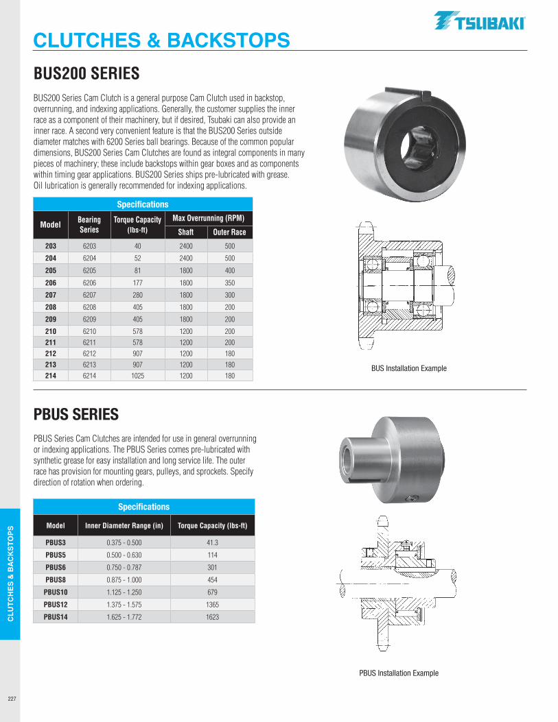
227
CLU
TCH
ES &
BAC
KSTO
PS
Specifications
Model Bearing Series
Torque Capacity(lbs-ft)
Max Overrunning (RPM)
Shaft Outer Race
203 6203 40 2400 500
204 6204 52 2400 500
205 6205 81 1800 400
206 6206 177 1800 350
207 6207 280 1800 300
208 6208 405 1800 200
209 6209 405 1800 200
210 6210 578 1200 200211 6211 578 1200 200212 6212 907 1200 180213 6213 907 1200 180214 6214 1025 1200 180
BUS Installation Example
BUS200 SERIES BUS200 Series Cam Clutch is a general purpose Cam Clutch used in backstop, overrunning, and indexing applications. Generally, the customer supplies the inner race as a component of their machinery, but if desired, Tsubaki can also provide an inner race. A second very convenient feature is that the BUS200 Series outside diameter matches with 6200 Series ball bearings. Because of the common popular dimensions, BUS200 Series Cam Clutches are found as integral components in many pieces of machinery; these include backstops within gear boxes and as components within timing gear applications. BUS200 Series ships pre-lubricated with grease. Oil lubrication is generally recommended for indexing applications.
PBUS Series Cam Clutches are intended for use in general overrunning or indexing applications. The PBUS Series comes pre-lubricated with synthetic grease for easy installation and long service life. The outer race has provision for mounting gears, pulleys, and sprockets. Specify direction of rotation when ordering.
PBUS SERIES
PBUS Installation Example
Specifications
Model Inner Diameter Range (in) Torque Capacity (lbs-ft)
PBUS3 0.375 - 0.500 41.3
PBUS5 0.500 - 0.630 114
PBUS6 0.750 - 0.787 301
PBUS8 0.875 - 1.000 454
PBUS10 1.125 - 1.250 679
PBUS12 1.375 - 1.575 1365
PBUS14 1.625 - 1.772 1623
CLUTCHES & BACKSTOPS.TSUBAKI"
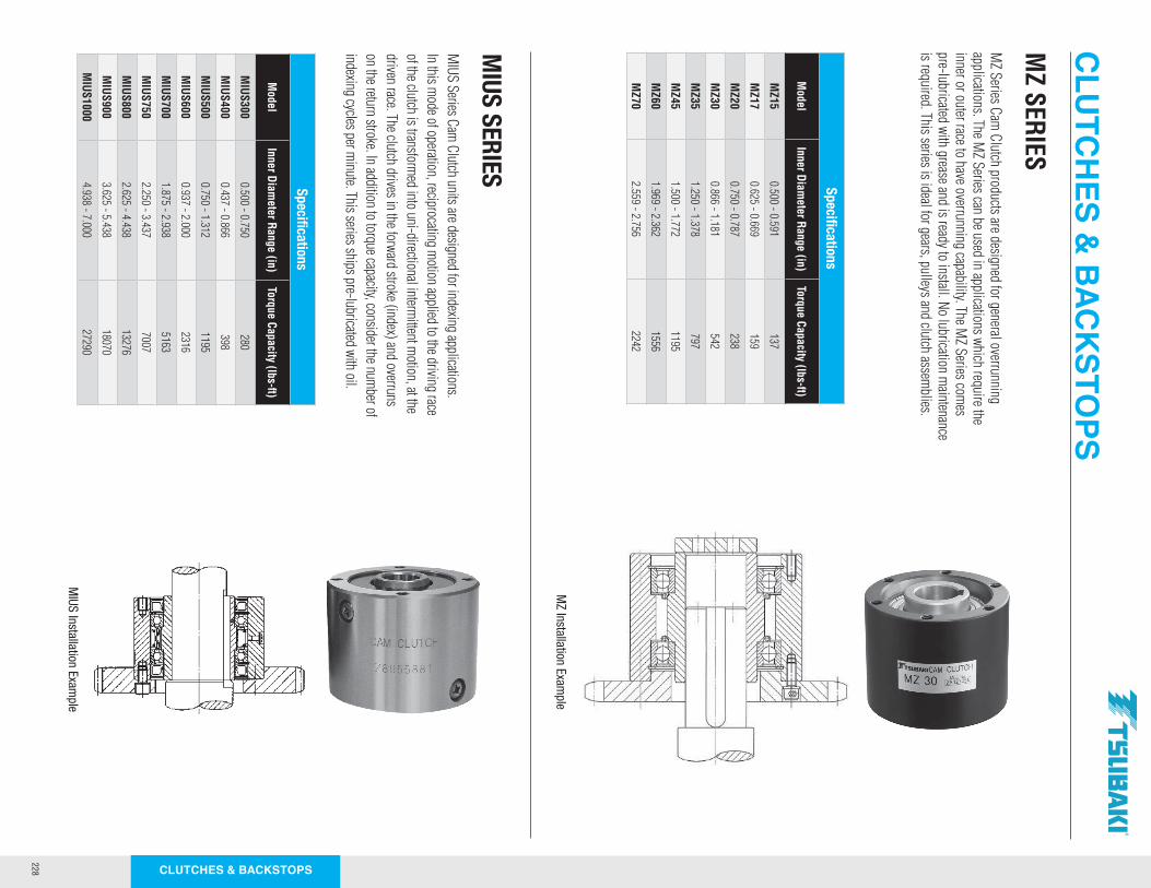
228 CLUTCHES & BACKSTOPS
MZ SERIES
MZ Series Cam
Clutch products are designed for general overrunning applications. The M
Z Series can be used in applications which require the inner or outer race to have overrunning capability. The M
Z Series comes
pre-lubricated with grease and is ready to install. No lubrication maintenance
is required. This series is ideal for gears, pulleys and clutch assemblies.
MIUS Series Cam
Clutch units are designed for indexing applications. In this m
ode of operation, reciprocating motion applied to the driving race
of the clutch is transformed into uni-directional interm
ittent motion, at the
driven race. The clutch drives in the forward stroke (index) and overruns on the return stroke. In addition to torque capacity, consider the num
ber of indexing cycles per m
inute. This series ships pre-lubricated with oil.
MIUS SERIES
Specifications
Model
Inner Diameter Range (in)
Torque Capacity (lbs-ft)
MZ15
0.500 - 0.591137
MZ17
0.625 - 0.669159
MZ20
0.750 - 0.787238
MZ30
0.866 - 1.181542
MZ35
1.250 - 1.378797
MZ45
1.500 - 1.7721195
MZ60
1.969 - 2.3621556
MZ70
2.559 - 2.7562242
Specifications
Model
Inner Diameter Range (in)
Torque Capacity (lbs-ft)
MIUS300
0.500 - 0.750280
MIUS400
0.437 - 0.866398
MIUS500
0.750 - 1.3121195
MIUS600
0.937 - 2.0002316
MIUS700
1.875 - 2.9385163
MIUS750
2.250 - 3.4377007
MIUS800
2.625 - 4.43813276
MIUS900
3.625 - 5.43818070
MIUS1000
4.938 - 7.00027290
MZ Installation Exam
ple
MIUS Installation Exam
ple
CLUTCHES &
BACKSTOPS
~ :.~ 1ft C
= -= -,.
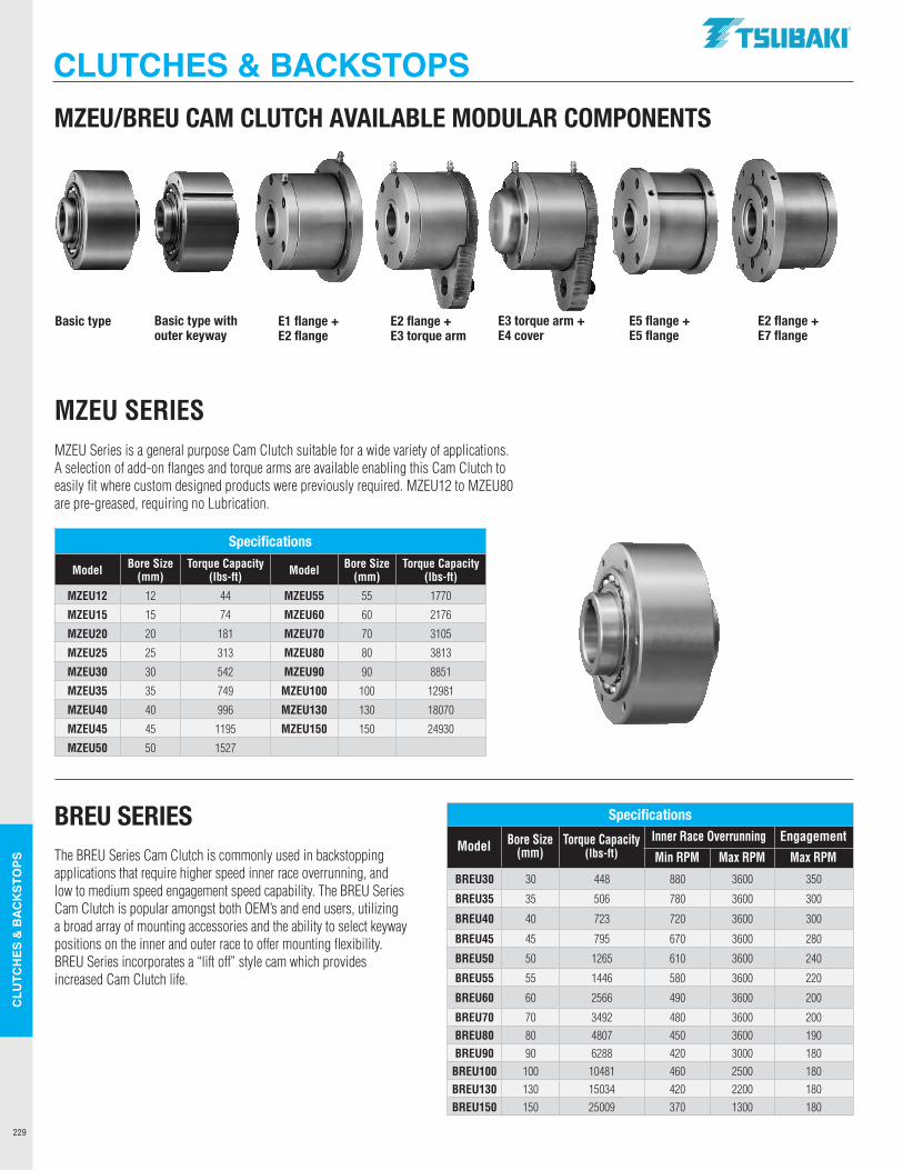
229
CLU
TCH
ES &
BAC
KSTO
PS
Specifications
Model Bore Size (mm)
Torque Capacity(lbs-ft)
Inner Race Overrunning Engagement
Min RPM Max RPM Max RPM
BREU30 30 448 880 3600 350
BREU35 35 506 780 3600 300
BREU40 40 723 720 3600 300
BREU45 45 795 670 3600 280
BREU50 50 1265 610 3600 240
BREU55 55 1446 580 3600 220
BREU60 60 2566 490 3600 200
BREU70 70 3492 480 3600 200BREU80 80 4807 450 3600 190BREU90 90 6288 420 3000 180
BREU100 100 10481 460 2500 180BREU130 130 15034 420 2200 180BREU150 150 25009 370 1300 180
MZEU SERIES MZEU Series is a general purpose Cam Clutch suitable for a wide variety of applications. A selection of add-on flanges and torque arms are available enabling this Cam Clutch to easily fit where custom designed products were previously required. MZEU12 to MZEU80 are pre-greased, requiring no Lubrication.
The BREU Series Cam Clutch is commonly used in backstopping applications that require higher speed inner race overrunning, and low to medium speed engagement speed capability. The BREU Series Cam Clutch is popular amongst both OEM’s and end users, utilizing a broad array of mounting accessories and the ability to select keyway positions on the inner and outer race to offer mounting flexibility. BREU Series incorporates a “lift off” style cam which provides increased Cam Clutch life.
BREU SERIES
Specifications
Model Bore Size (mm)
Torque Capacity (lbs-ft) Model Bore Size
(mm)Torque Capacity
(lbs-ft)
MZEU12 12 44 MZEU55 55 1770
MZEU15 15 74 MZEU60 60 2176
MZEU20 20 181 MZEU70 70 3105
MZEU25 25 313 MZEU80 80 3813
MZEU30 30 542 MZEU90 90 8851
MZEU35 35 749 MZEU100 100 12981
MZEU40 40 996 MZEU130 130 18070
MZEU45 45 1195 MZEU150 150 24930
MZEU50 50 1527
Basic type E1 flange + E2 flange
E2 flange + E3 torque arm
E3 torque arm + E4 cover
E5 flange + E5 flange
E2 flange + E7 flange
Basic type with outer keyway
MZEU/BREU CAM CLUTCH AVAILABLE MODULAR COMPONENTS
CLUTCHES & BACKSTOPS.TSUBAKI"
I I I
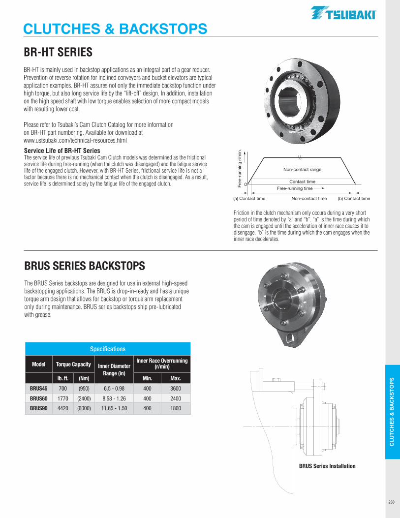
230
CLU
TCH
ES &
BAC
KSTO
PS
BR-HT SERIES BR-HT is mainly used in backstop applications as an integral part of a gear reducer. Prevention of reverse rotation for inclined conveyors and bucket elevators are typical application examples. BR-HT assures not only the immediate backstop function under high torque, but also long service life by the “lift-off” design. In addition, installation on the high speed shaft with low torque enables selection of more compact models with resulting lower cost.
Please refer to Tsubaki’s Cam Clutch Catalog for more information on BR-HT part numbering. Available for download at www.ustsubaki.com/technical-resources.html
The BRUS Series backstops are designed for use in external high-speed backstopping applications. The BRUS is drop-in-ready and has a unique torque arm design that allows for backstop or torque arm replacement only during maintenance. BRUS series backstops ship pre-lubricated with grease.
BRUS SERIES BACKSTOPS
Service Life of BR-HT SeriesThe service life of previous Tsubaki Cam Clutch models was determined as the frictional service life during free-running (when the clutch was disengaged) and the fatigue service life of the engaged clutch. However, with BR-HT Series, frictional service life is not a factor because there is no mechanical contact when the clutch is disengaged. As a result, service life is determined solely by the fatigue life of the engaged clutch.
Friction in the clutch mechanism only occurs during a very short period of time denoted by “a” and “b”. “a” is the time during which the cam is engaged until the acceleration of inner race causes it to disengage. “b” is the time during which the cam engages when the inner race decelerates.
Free
-run
ning
r/m
in.
Non-contact range
Contact time
Free-running time
(a) Contact time (b) Contact timeNon-contact time
0
BRUS Series Installation
Specifications
Model Torque Capacity Inner DiameterRange (in)
Inner Race Overrunning (r/min)
lb. ft. (Nm) Min. Max.
BRUS45 700 (950) 6.5 - 0.98 400 3600
BRUS60 1770 (2400) 8.58 - 1.26 400 2400
BRUS90 4420 (6000) 11.65 - 1.50 400 1800
CLUTCHES & BACKSTOPS.TSUBAKI"
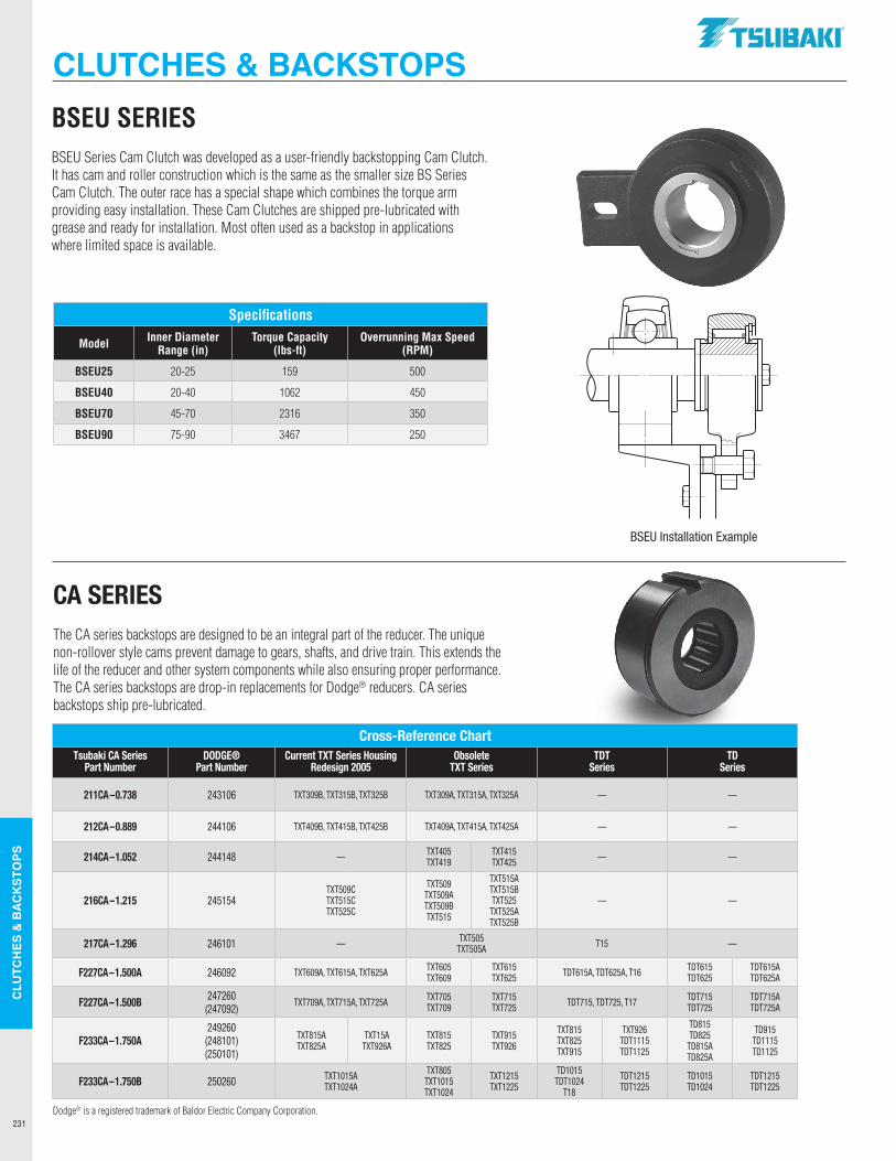
231
CLU
TCH
ES &
BAC
KSTO
PS
BSEU SERIES BSEU Series Cam Clutch was developed as a user-friendly backstopping Cam Clutch. It has cam and roller construction which is the same as the smaller size BS Series Cam Clutch. The outer race has a special shape which combines the torque arm providing easy installation. These Cam Clutches are shipped pre-lubricated with grease and ready for installation. Most often used as a backstop in applications where limited space is available.
The CA series backstops are designed to be an integral part of the reducer. The unique non-rollover style cams prevent damage to gears, shafts, and drive train. This extends the life of the reducer and other system components while also ensuring proper performance. The CA series backstops are drop-in replacements for Dodge® reducers. CA series backstops ship pre-lubricated.
CA SERIES
BSEU Installation Example
Cross-Reference ChartTsubaki CA Series
Part NumberDODGE®
Part NumberCurrent TXT Series Housing
Redesign 2005Obsolete
TXT SeriesTDT
SeriesTD
Series
211CA–0.738 243106 TXT309B, TXT315B, TXT325B TXT309A, TXT315A, TXT325A — —
212CA–0.889 244106 TXT409B, TXT415B, TXT425B TXT409A, TXT415A, TXT425A — —
214CA–1.052 244148 — TXT405 TXT419
TXT415TXT425 — —
216CA–1.215 245154TXT509C TXT515C TXT525C
TXT509 TXT509A TXT509B TXT515
TXT515A TXT515B TXT525
TXT525A TXT525B
— —
217CA–1.296 246101 — TXT505 TXT505A T15 —
F227CA–1.500A 246092 TXT609A, TXT615A, TXT625A TXT605 TXT609
TXT615 TXT625 TDT615A, TDT625A, T16 TDT615
TDT625TDT615A TDT625A
F227CA–1.500B 247260(247092)
TXT709A, TXT715A, TXT725A TXT705 TXT709
TXT715 TXT725 TDT715, TDT725, T17 TDT715
TDT725TDT715A TDT725A
F233CA–1.750A249260 (248101) (250101)
TXT815A TXT825A
TXT15A TXT926A
TXT815 TXT825
TXT915 TXT926
TXT815 TXT825 TXT915
TXT926 TDT1115 TDT1125
TD815TD825
TD815A TD825A
TD915 TD1115 TD1125
F233CA–1.750B 250260 TXT1015A TXT1024A
TXT805 TXT1015 TXT1024
TXT1215 TXT1225
TD1015 TDT1024
T18
TDT1215 TDT1225
TD1015 TD1024
TDT1215 TDT1225
Dodge® is a registered trademark of Baldor Electric Company Corporation.
Specifications
Model Inner Diameter Range (in)
Torque Capacity (lbs-ft)
Overrunning Max Speed (RPM)
BSEU25 20-25 159 500
BSEU40 20-40 1062 450
BSEU70 45-70 2316 350
BSEU90 75-90 3467 250
CLUTCHES & BACKSTOPS.TSUBAKI"
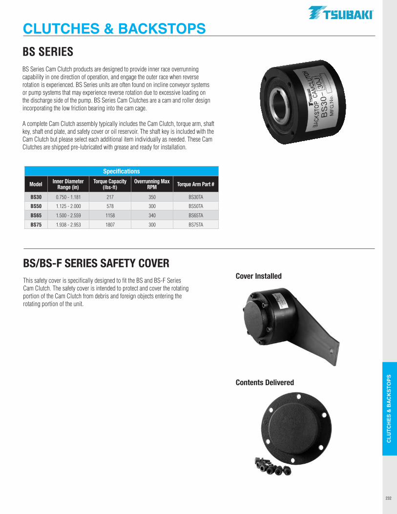
232
CLU
TCH
ES &
BAC
KSTO
PS
BS SERIES BS Series Cam Clutch products are designed to provide inner race overrunning capability in one direction of operation, and engage the outer race when reverse rotation is experienced. BS Series units are often found on incline conveyor systems or pump systems that may experience reverse rotation due to excessive loading on the discharge side of the pump. BS Series Cam Clutches are a cam and roller design incorporating the low friction bearing into the cam cage.
A complete Cam Clutch assembly typically includes the Cam Clutch, torque arm, shaft key, shaft end plate, and safety cover or oil reservoir. The shaft key is included with the Cam Clutch but please select each additional item individually as needed. These Cam Clutches are shipped pre-lubricated with grease and ready for installation.
This safety cover is specifically designed to fit the BS and BS-F Series Cam Clutch. The safety cover is intended to protect and cover the rotating portion of the Cam Clutch from debris and foreign objects entering the rotating portion of the unit.
BS/BS-F SERIES SAFETY COVERCover Installed
Contents Delivered
Specifications
Model Inner DiameterRange (in)
Torque Capacity (lbs-ft)
Overrunning Max RPM Torque Arm Part #
BS30 0.750 - 1.181 217 350 BS30TA
BS50 1.125 - 2.000 578 300 BS50TA
BS65 1.500 - 2.559 1158 340 BS65TA
BS75 1.938 - 2.953 1807 300 BS75TA
CLUTCHES & BACKSTOPS.TSUBAKI"
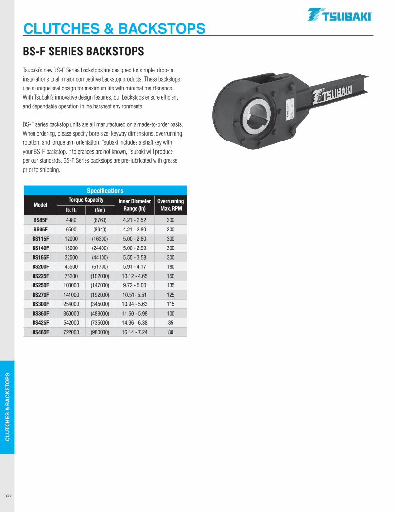
233
CLU
TCH
ES &
BAC
KSTO
PS
BS-F SERIES BACKSTOPS Tsubaki’s new BS-F Series backstops are designed for simple, drop-in installations to all major competitive backstop products. These backstops use a unique seal design for maximum life with minimal maintenance. With Tsubaki’s innovative design features, our backstops ensure efficient and dependable operation in the harshest environments.
BS-F series backstop units are all manufactured on a made-to-order basis. When ordering, please specify bore size, keyway dimensions, overrunning rotation, and torque arm orientation. Tsubaki includes a shaft key with your BS-F backstop. If tolerances are not known, Tsubaki will produce per our standards. BS-F Series backstops are pre-lubricated with grease prior to shipping.
Specifications
ModelTorque Capacity Inner Diameter
Range (in)Overrunning Max. RPMlb. ft. (Nm)
BS85F 4980 (6760) 4.21 - 2.52 300
BS95F 6590 (8940) 4.21 - 2.80 300
BS115F 12000 (16300) 5.00 - 2.80 300
BS140F 18000 (24400) 5.00 - 2.99 300
BS165F 32500 (44100) 5.55 - 3.58 300
BS200F 45500 (61700) 5.91 - 4.17 180
BS225F 75200 (102000) 10.12 - 4.65 150
BS250F 108000 (147000) 9.72 - 5.00 135
BS270F 141000 (192000) 10.51- 5.51 125
BS300F 254000 (345000) 10.94 - 5.63 115
BS360F 360000 (489000) 11.50 - 5.98 100
BS425F 542000 (735000) 14.96 - 6.38 85
BS465F 722000 (980000) 16.14 - 7.24 80
CLUTCHES & BACKSTOPS.TSUBAKI"
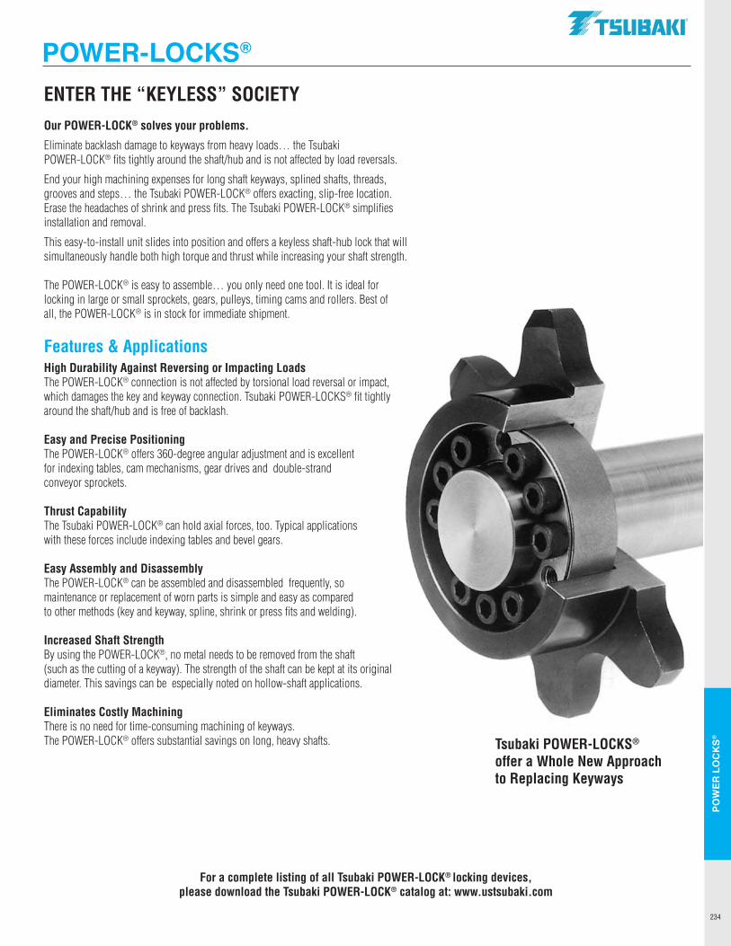
234
POW
ER L
OC
KS®
ENTER THE “KEYLESS” SOCIETYOur POWER-LOCK® solves your problems.
Eliminate backlash damage to keyways from heavy loads… the Tsubaki POWER-LOCK® fits tightly around the shaft/hub and is not affected by load reversals.
End your high machining expenses for long shaft keyways, splined shafts, threads, grooves and steps… the Tsubaki POWER-LOCK® offers exacting, slip-free location.Erase the headaches of shrink and press fits. The Tsubaki POWER-LOCK® simplifies installation and removal.
This easy-to-install unit slides into position and offers a keyless shaft-hub lock that will simultaneously handle both high torque and thrust while increasing your shaft strength.
The POWER-LOCK® is easy to assemble… you only need one tool. It is ideal for locking in large or small sprockets, gears, pulleys, timing cams and rollers. Best of all, the POWER-LOCK® is in stock for immediate shipment.
Features & ApplicationsHigh Durability Against Reversing or Impacting LoadsThe POWER-LOCK® connection is not affected by torsional load reversal or impact, which damages the key and keyway connection. Tsubaki POWER-LOCKS® fit tightly around the shaft/hub and is free of backlash.
Easy and Precise PositioningThe POWER-LOCK® offers 360-degree angular adjustment and is excellent for indexing tables, cam mechanisms, gear drives and double-strand conveyor sprockets.
Thrust CapabilityThe Tsubaki POWER-LOCK® can hold axial forces, too. Typical applications with these forces include indexing tables and bevel gears.
Easy Assembly and DisassemblyThe POWER-LOCK® can be assembled and disassembled frequently, so maintenance or replacement of worn parts is simple and easy as compared to other methods (key and keyway, spline, shrink or press fits and welding).
Increased Shaft StrengthBy using the POWER-LOCK®, no metal needs to be removed from the shaft (such as the cutting of a keyway). The strength of the shaft can be kept at its original diameter. This savings can be especially noted on hollow-shaft applications.
Eliminates Costly MachiningThere is no need for time-consuming machining of keyways. The POWER-LOCK® offers substantial savings on long, heavy shafts. Tsubaki POWER-LOCKS®
offer a Whole New Approach to Replacing Keyways
For a complete listing of all Tsubaki POWER-LOCK® locking devices, please download the Tsubaki POWER-LOCK® catalog at: www.ustsubaki.com
POWER-LOCKS®.TSUBAKI"
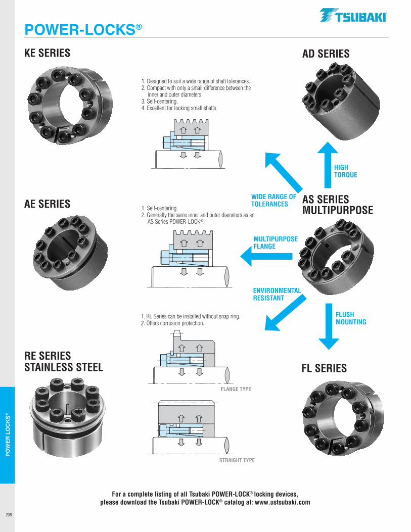
235
POW
ER L
OC
KS®
KE SERIES
1. Designed to suit a wide range of shaft tolerances.2. Compact with only a small difference between the
inner and outer diameters.3. Self-centering.4. Excellent for locking small shafts.
AE SERIES
RE SERIES STAINLESS STEEL FL SERIES
AD SERIES
AS SERIES MULTIPURPOSE1. Self-centering.
2. Generally the same inner and outer diameters as an AS Series POWER-LOCK®.
1. RE Series can be installed without snap ring.2. Offers corrosion protection.
FLANGE TYPE
STRAIGHT TYPE
HIGHTORQUE
FLUSHMOUNTING
MULTIPURPOSE FLANGE
WIDE RANGE OF TOLERANCES
ENVIRONMENTAL RESISTANT
For a complete listing of all Tsubaki POWER-LOCK® locking devices, please download the Tsubaki POWER-LOCK® catalog at: www.ustsubaki.com
POWER-LOCKS®.TSUBAKI"
DD
DD
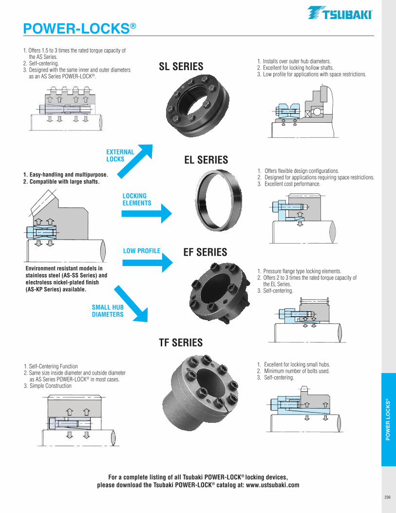
236
POW
ER L
OC
KS®
SL SERIES
1. Offers flexible design configurations.2. Designed for applications requiring space restrictions.3. Excellent cost performance.
EF SERIES
TF SERIES
1. Offers 1.5 to 3 times the rated torque capacity of the AS Series.
2. Self-centering.3. Designed with the same inner and outer diameters
as an AS Series POWER-LOCK®.
1. Pressure flange type locking elements.2. Offers 2 to 3 times the rated torque capacity of
the EL Series.3. Self-centering.
LOCKINGELEMENTS
LOW PROFILE
EXTERNALLOCKS
SMALL HUB DIAMETERS
EL SERIES
1. Installs over outer hub diameters.2. Excellent for locking hollow shafts.3. Low profile for applications with space restrictions.
1. Self-Centering Function2. Same size inside diameter and outside diameter
as AS Series POWER-LOCK® in most cases.3. Simple Construction
Environment resistant models in stainless steel (AS-SS Series) and electroless nickel-plated finish (AS-KP Series) available.
1. Easy-handling and multipurpose.2. Compatible with large shafts.
For a complete listing of all Tsubaki POWER-LOCK® locking devices, please download the Tsubaki POWER-LOCK® catalog at: www.ustsubaki.com
1. Excellent for locking small hubs.2. Minimum number of bolts used.3. Self-centering.
POWER-LOCKS®.TSUBAKI"
.[].. .[].. .[].. .[]..
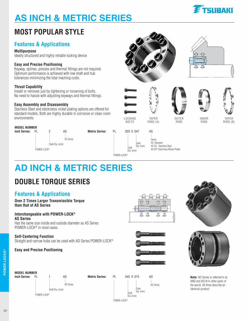
237
POW
ER L
OC
KS®
MOST POPULAR STYLE
Features & ApplicationsMultipurposeIdeally structured and highly reliable locking device
Easy and Precise PositioningKeyway, splines, presses and thermal fittings are not required. Optimum performance is achieved with low shaft and hub tolerances minimizing the total maching costs.
Thrust CapabilityInstall or removes just by tightening or loosening of bolts. No need to hassle with adjusting keyways and thermal fittings.
Easy Assembly and DisassemblyStainless Steel and electroless nickel plating options are offered for standard models. Both are highly durable in corrosive or clean room environments. LOCKING
BOLTSTAPER
RING (A)OUTER RING
INNER RING
TAPER RING (B)
MODEL NUMBERInch Series: PL 2 AS Metric Series: PL 020 X 047 AS
POWER-LOCK®
AS Series
Shaft Dia. (inch)
POWER-LOCK®
SeriesAS: StandardAS-SS : Stainless SteelAS-KP: Electroless Nickel-Plated
OuterDia. (mm)Shaft
Dia. (mm)
AD INCH & METRIC SERIES
AS INCH & METRIC SERIES
DOUBLE TORQUE SERIES
Features & ApplicationsOver 2 Times Larger Transmissible Torque than that of AS Series
Interchangeable with POWER-LOCK® AS SeriesHas the same size inside and outside diameter as AS Series POWER-LOCK® in most cases.
Self-Centering FunctionStraight and narrow hubs can be used with AD Series POWER-LOCK®
Easy and Precise Positioning
MODEL NUMBERInch Series: PL 1 AD Metric Series: PL 045 X 075 AD
POWER-LOCK®
AD Series
Shaft Dia. (inch)
POWER-LOCK®
AD SeriesOuterDia. (mm)Shaft
Dia. (mm)
Note: AD Series is referred to as AND and AD-N in other parts of the world. All three describe an identical product.
.TSUBAKI"
- ,,,, I I I I - I I
' I - I I I
I I - '111!
Li Li Li Li
I] :::a,um
D , ... G C:l'Rllf
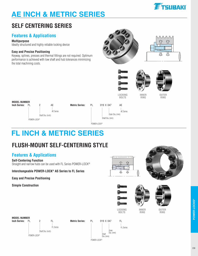
238
POW
ER L
OC
KS®
FL INCH & METRIC SERIES
AE INCH & METRIC SERIESSELF CENTERING SERIES
Features & ApplicationsMultipurposeIdeally structured and highly reliable locking device
Easy and Precise PositioningKeyway, splines, presses and thermal fittings are not required. Optimum performance is achieved with low shaft and hub tolerances minimizing the total machining costs.
LOCKING BOLTS
INNER RING
OUTER RING
MODEL NUMBERInch Series: PL 2 AE Metric Series: PL 019 X 047 AE
POWER-LOCK®
AE Series
Shaft Dia. (inch)
POWER-LOCK®
AE SeriesOuter Dia. (mm)
Shaft Dia. (mm)
FLUSH-MOUNT SELF-CENTERING STYLE
Features & ApplicationsSelf-Centering FunctionStraight and narrow hubs can be used with FL Series POWER-LOCK®
Interchangeable POWER-LOCK® AS Series to FL Series
Easy and Precise Positioning
Simple Construction
MODEL NUMBERInch Series: PL 2 FL Metric Series: PL 019 X 047 FL
POWER-LOCK®
FL Series
Shaft Dia. (inch)
POWER-LOCK®
FL SeriesOuterDia. (mm)Shaft
Dia. (mm)
LOCKING BOLTS
INNER RING
OUTER RING
.TSUBAKI"
---
fr D
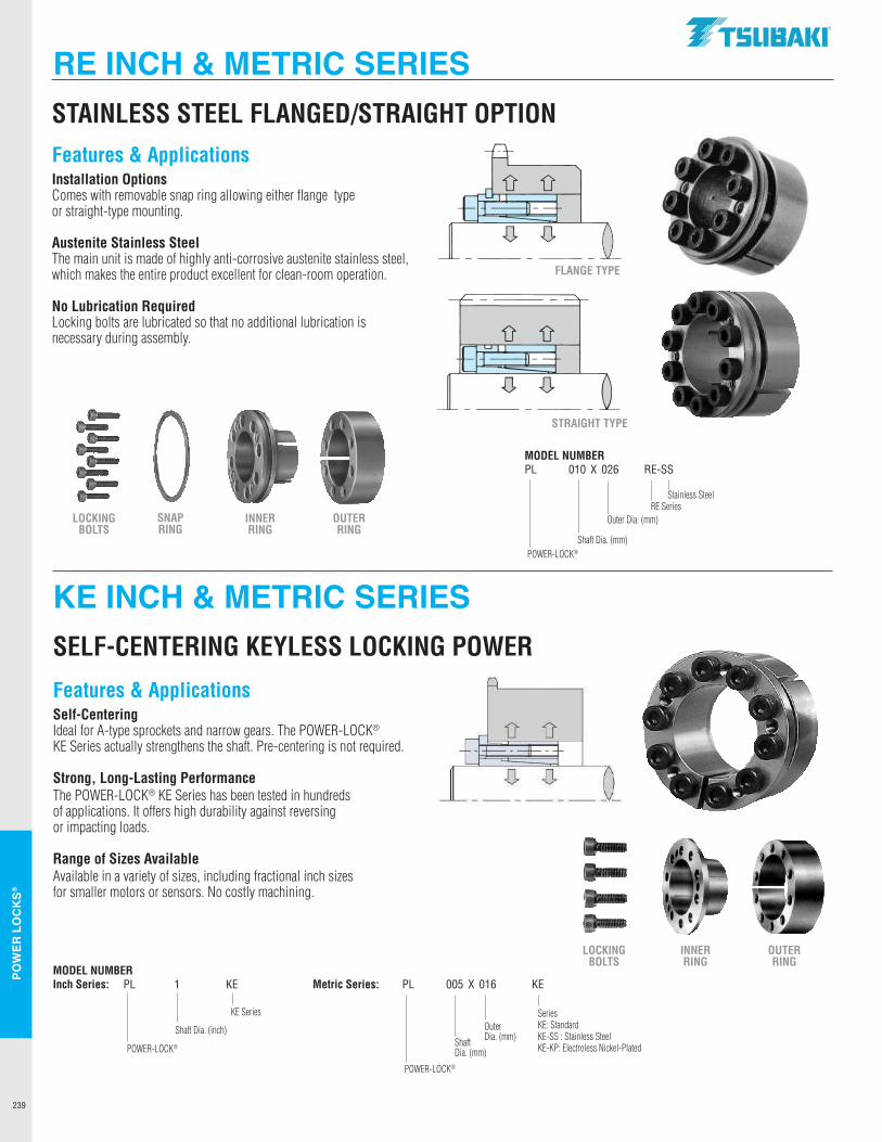
239
POW
ER L
OC
KS®
STAINLESS STEEL FLANGED/STRAIGHT OPTION
MODEL NUMBERPL 010 X 026 RE-SS
POWER-LOCK®
Stainless Steel
Outer Dia. (mm)
Shaft Dia. (mm)
KE INCH & METRIC SERIES
RE INCH & METRIC SERIES
SELF-CENTERING KEYLESS LOCKING POWER
Features & ApplicationsSelf-CenteringIdeal for A-type sprockets and narrow gears. The POWER-LOCK® KE Series actually strengthens the shaft. Pre-centering is not required.
Strong, Long-Lasting PerformanceThe POWER-LOCK® KE Series has been tested in hundreds of applications. It offers high durability against reversing or impacting loads.
Range of Sizes AvailableAvailable in a variety of sizes, including fractional inch sizes for smaller motors or sensors. No costly machining.
MODEL NUMBERInch Series: PL 1 KE Metric Series: PL 005 X 016 KE
POWER-LOCK®
KE Series
Shaft Dia. (inch)
POWER-LOCK®
SeriesKE: StandardKE-SS : Stainless SteelKE-KP: Electroless Nickel-Plated
OuterDia. (mm)Shaft
Dia. (mm)
Features & ApplicationsInstallation OptionsComes with removable snap ring allowing either flange type or straight-type mounting.
Austenite Stainless SteelThe main unit is made of highly anti-corrosive austenite stainless steel, which makes the entire product excellent for clean-room operation.
No Lubrication RequiredLocking bolts are lubricated so that no additional lubrication is necessary during assembly.
FLANGE TYPE
STRAIGHT TYPE
LOCKING BOLTS
INNER RING
OUTER RING
SNAP RING
RE Series
LOCKING BOLTS
INNER RING
OUTER RING
.TSUBAKI"
D D
I I
I I
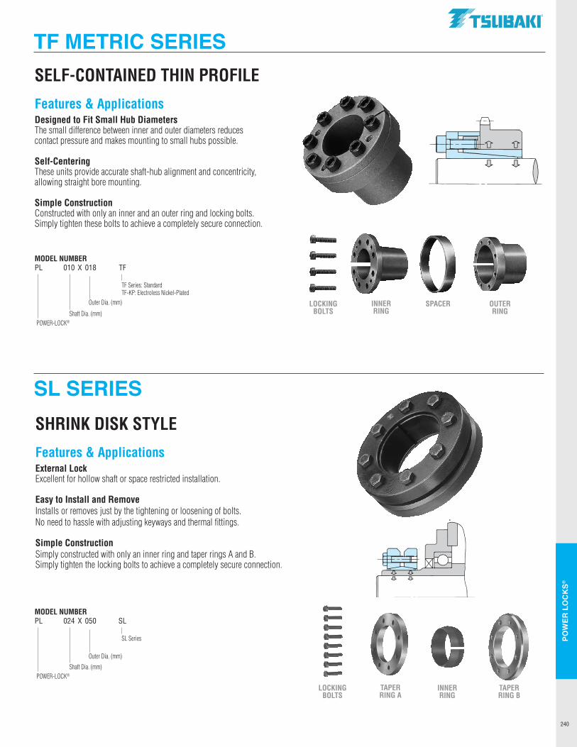
240
POW
ER L
OC
KS®
SL SERIES
TF METRIC SERIESSELF-CONTAINED THIN PROFILE
Features & ApplicationsDesigned to Fit Small Hub DiametersThe small difference between inner and outer diameters reduces contact pressure and makes mounting to small hubs possible.
Self-CenteringThese units provide accurate shaft-hub alignment and concentricity, allowing straight bore mounting.
Simple ConstructionConstructed with only an inner and an outer ring and locking bolts. Simply tighten these bolts to achieve a completely secure connection.
SHRINK DISK STYLE
Features & ApplicationsExternal LockExcellent for hollow shaft or space restricted installation.
Easy to Install and RemoveInstalls or removes just by the tightening or loosening of bolts. No need to hassle with adjusting keyways and thermal fittings.
Simple ConstructionSimply constructed with only an inner ring and taper rings A and B. Simply tighten the locking bolts to achieve a completely secure connection.
LOCKING BOLTS
SPACER OUTER RING
INNER RING
MODEL NUMBERPL 010 X 018 TF
POWER-LOCK®
TF Series: StandardTF-KP: Electroless Nickel-Plated
Outer Dia. (mm)
Shaft Dia. (mm)
MODEL NUMBERPL 024 X 050 SL
POWER-LOCK®
SL Series
Outer Dia. (mm)
Shaft Dia. (mm)
LOCKING BOLTS
INNER RING
TAPER RING B
TAPER RING A
.TSUBAKI"
"iS
JJ,
----
C
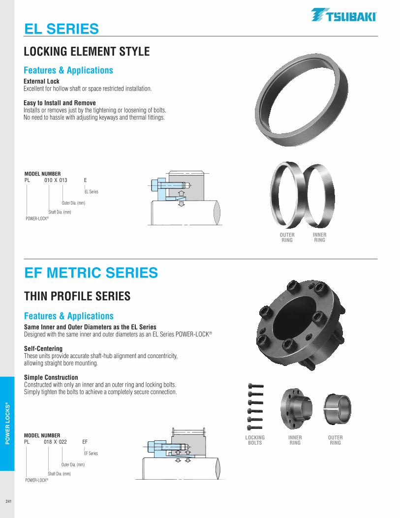
241
POW
ER L
OC
KS®
LOCKING ELEMENT STYLE
MODEL NUMBERPL 010 X 013 E
POWER-LOCK®
EL Series
Outer Dia. (mm)
Shaft Dia. (mm)
EF METRIC SERIES
EL SERIES
THIN PROFILE SERIES
Features & ApplicationsSame Inner and Outer Diameters as the EL SeriesDesigned with the same inner and outer diameters as an EL Series POWER-LOCK®
Self-CenteringThese units provide accurate shaft-hub alignment and concentricity, allowing straight bore mounting.
Simple ConstructionConstructed with only an inner and an outer ring and locking bolts. Simply tighten the bolts to achieve a completely secure connection.
Features & ApplicationsExternal LockExcellent for hollow shaft or space restricted installation.
Easy to Install and RemoveInstalls or removes just by the tightening or loosening of bolts. No need to hassle with adjusting keyways and thermal fittings.
LOCKING BOLTS
INNER RING
OUTER RING
OUTER RING
INNER RING
MODEL NUMBERPL 018 X 022 EF
POWER-LOCK®
EF Series
Outer Dia. (mm)
Shaft Dia. (mm)
... ... ... ... .... ....
.TSUBAKI"
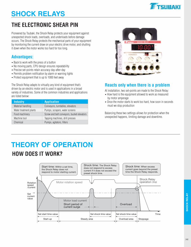
242
SHO
CK
REL
AY
THEORY OF OPERATION
SHOCK RELAYSTHE ELECTRONIC SHEAR PIN Pioneered by Tsubaki, the Shock Relay protects your equipment against unexpected shock loads, overloads, and underloads before damage occurs. The Shock Relay protects the mechanical parts of your equipment by monitoring the current draw on your electric drive motor, and shutting it down when the motor works too hard for too long.
Advantages:• Back to work with the press of a button • No moving parts, CPU design ensures repeatability• Precise set-points retain accuracy day-after-day• Permits problem notification by alarm or warning lights• Protect equipment that is up to 1000 feet away
The Shock Relay adapts to virtually any kind of equipment that’s driven by an electric motor and is used in applications in a broad variety of industries. Some of the common industries and applications are listed below:
HOW DOES IT WORK?
Start time: Within a set time, the Shock Relay does not respond to motor starting current.
Shock time: The Shock Relay does not respond to excess current if it does not exceed the preset shock time.
Shock time: When excess current goes beyond the preset time the Shock Relay responds.
Motor rotation speed
Motor load current
Shock Relayoperation (trip)
Short period ofcurrent surge
Overload
Rotationspeed/current
Set current value
Set start time value Set shock time value Set shock time value Time
Start-up Steady area Overload area Stoppage
Reacts only when there is a problemAt installation, two set-points are made to the Shock Relay:• How hard is the equipment allowed to work as measured
by motor amperage• Once the motor starts to work too hard, how soon in seconds
must we stop production
Balancing these two settings allows for protection when the unexpected happens, limiting damage and downtime.
Industry ApplicationMaterial handling Conveyors, turntables, elevatorsWater treatment plants Pumps, scrapers, water screensFood machinery Screw and belt conveyors, bucket elevatorsMachine tool Tapping machines, drill pressesChemical Pumps, agitators, filters
TSUBAKI"
r........ S-11 lllU.Y
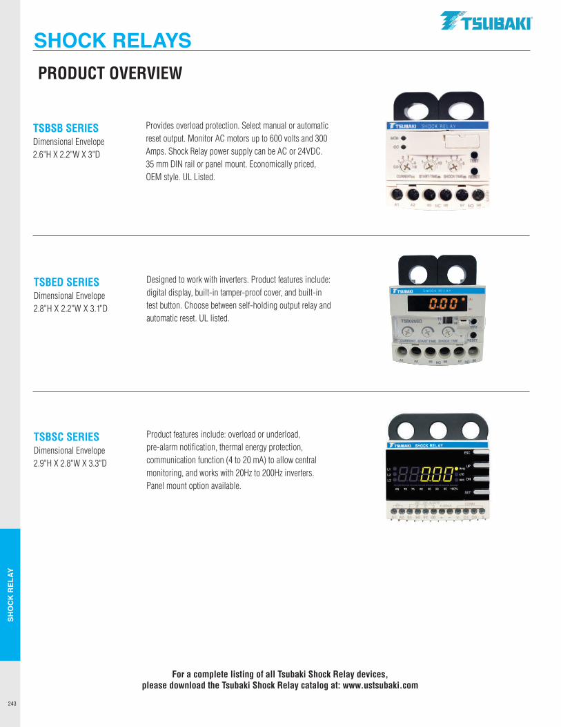
243
SHO
CK
REL
AY
SHOCK RELAYSTable of Contents
TSBED SERIES Dimensional Envelope 2.8"H X 2.2"W X 3.1"D
TSBSB SERIES Dimensional Envelope 2.6"H X 2.2"W X 3"D
TSBSC SERIES Dimensional Envelope 2.9"H X 2.8"W X 3.3"D
PRODUCT OVERVIEW
Designed to work with inverters. Product features include: digital display, built-in tamper-proof cover, and built-in test button. Choose between self-holding output relay and automatic reset. UL listed.
Provides overload protection. Select manual or automatic reset output. Monitor AC motors up to 600 volts and 300 Amps. Shock Relay power supply can be AC or 24VDC. 35 mm DIN rail or panel mount. Economically priced, OEM style. UL Listed.
Product features include: overload or underload, pre-alarm notification, thermal energy protection, communication function (4 to 20 mA) to allow central monitoring, and works with 20Hz to 200Hz inverters. Panel mount option available.
For a complete listing of all Tsubaki Shock Relay devices, please download the Tsubaki Shock Relay catalog at: www.ustsubaki.com
.TSUBAKI"
TTSUBAKI SHOCK AE LA y
..,. . oce
' ',..1,. , .. (t. -~
A.1 A2 95 NC 96 '81 NO 98
,-, ,-, ,-, . ,_,.,_, ,_, w
mm I Atdll,M!lW4!1,i4J;l41\
ESC
" l71717•'m,ue ~ LI.LI LI :: DN
65 70 75 8() 85 90 95 100". SET
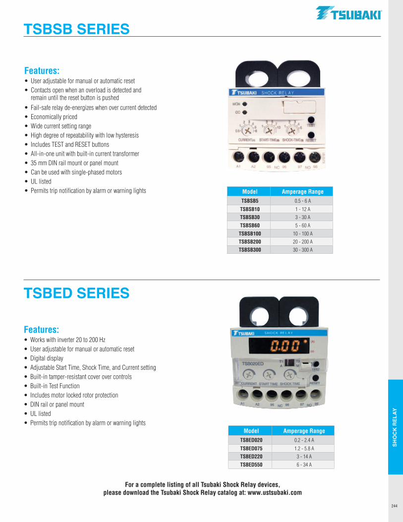
244
SHO
CK
REL
AY
TSBED SERIES
TSBSB SERIES
Features:• User adjustable for manual or automatic reset• Contacts open when an overload is detected and
remain until the reset button is pushed• Fail-safe relay de-energizes when over current detected• Economically priced• Wide current setting range• High degree of repeatability with low hysteresis• Includes TEST and RESET buttons• All-in-one unit with built-in current transformer• 35 mm DIN rail mount or panel mount• Can be used with single-phased motors• UL listed• Permits trip notification by alarm or warning lights Model Amperage Range
TSBSB5 0.5 - 6 A
TSBSB10 1 - 12 ATSBSB30 3 - 30 A
TSBSB60 5 - 60 A
TSBSB100 10 - 100 ATSBSB200 20 - 200 ATSBSB300 30 - 300 A
Features:• Works with inverter 20 to 200 Hz• User adjustable for manual or automatic reset• Digital display• Adjustable Start Time, Shock Time, and Current setting• Built-in tamper-resistant cover over controls• Built-in Test Function• Includes motor locked rotor protection• DIN rail or panel mount• UL listed• Permits trip notification by alarm or warning lights
Model Amperage RangeTSBED020 0.2 - 2.4 A
TSBED075 1.2 - 5.8 ATSBED220 3 - 14 A
TSBED550 6 - 34 A
For a complete listing of all Tsubaki Shock Relay devices, please download the Tsubaki Shock Relay catalog at: www.ustsubaki.com
TSUBAKI"
J"TSUBAKI SHOCK RELAY
A1 A2 95 NC 97 NO 98
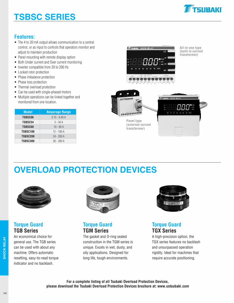
245
SHO
CK
REL
AY
OVERLOAD PROTECTION DEVICES
TSBSC SERIES
Features:• The 4 to 20 mA output allows communication to a central
control, or as input to controls that operators monitor and adjust to maintain production
• Panel mounting with remote display option• Both Under current and Over current monitoring• Inverter compatible from 20 to 200 Hz• Locked rotor protection• Phase imbalance protection• Phase loss protection• Thermal overload protection• Can be used with single-phased motors• Multiple operations can be linked together and
monitored from one location.
Model Amperage RangeTSBSC06 0.15 - 6.40 A
TSBSC34 3 - 34 ATSBSC60 10 - 60 A
TSBSC100 12 - 100 A
TSBSC200 24 - 200 ATSBSC300 36 - 300 A
All-in-one type(built-in current transformer)
Panel type (external current transformer)
Torque GuardTGB SeriesAn economical choice forgeneral use. The TGB seriescan be used with about anymachine. Offers automaticresetting, easy-to-read torqueindicator and no backlash.
Torque GuardTGM SeriesThe gasket and O-ring sealedconstruction in the TGM series isunique. Excels in wet, dusty, andoily applications. Designed forlong life, tough environments.
Torque GuardTGX SeriesA high-precision option, the TGX series features no backlashand unsurpassed operationrigidity. Ideal for machines thatrequire accurate positioning.
For a complete listing of all Tsubaki Overload Protection Devices, please download the Tsubaki Overload Protection Devices brochure at: www.ustsubaki.com
.TSUBAKI"
J"'TSUBAKI SHOCK RELAY
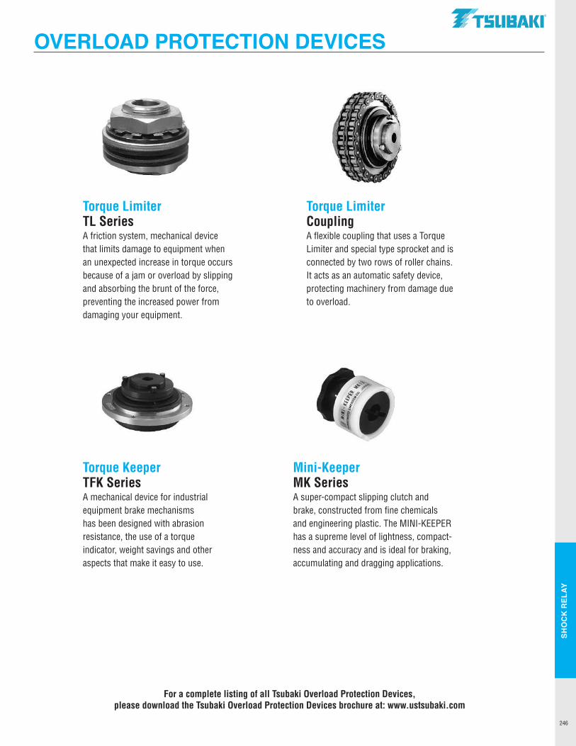
246
SHO
CK
REL
AY
OVERLOAD PROTECTION DEVICES
Torque LimiterTL SeriesA friction system, mechanical device that limits damage to equipment when an unexpected increase in torque occurs because of a jam or overload by slipping and absorbing the brunt of the force, preventing the increased power from damaging your equipment.
Torque LimiterCouplingA flexible coupling that uses a Torque Limiter and special type sprocket and is connected by two rows of roller chains. It acts as an automatic safety device, protecting machinery from damage due to overload.
Torque KeeperTFK SeriesA mechanical device for industrial equipment brake mechanisms has been designed with abrasion resistance, the use of a torque indicator, weight savings and other aspects that make it easy to use.
Mini-KeeperMK SeriesA super-compact slipping clutch and brake, constructed from fine chemicals and engineering plastic. The MINI-KEEPER has a supreme level of lightness, compact-ness and accuracy and is ideal for braking, accumulating and dragging applications.
For a complete listing of all Tsubaki Overload Protection Devices, please download the Tsubaki Overload Protection Devices brochure at: www.ustsubaki.com
TSUBAKI"

Tsubaki has the path to the right roller chain in the Technical
Resource section. In this section you will find details on how
to size a roller chain, select a chain for even the most difficult
applcations, and sizing up the right roller chain. All the details
for designing and selecting the right Double Plus® and Top
Chain for your accumulating applications is right here. Need
the right chain tool for breaking or measuring your chain?
Get it all here.
CHAIN TOOLS &TECHNICAL RESOURCES
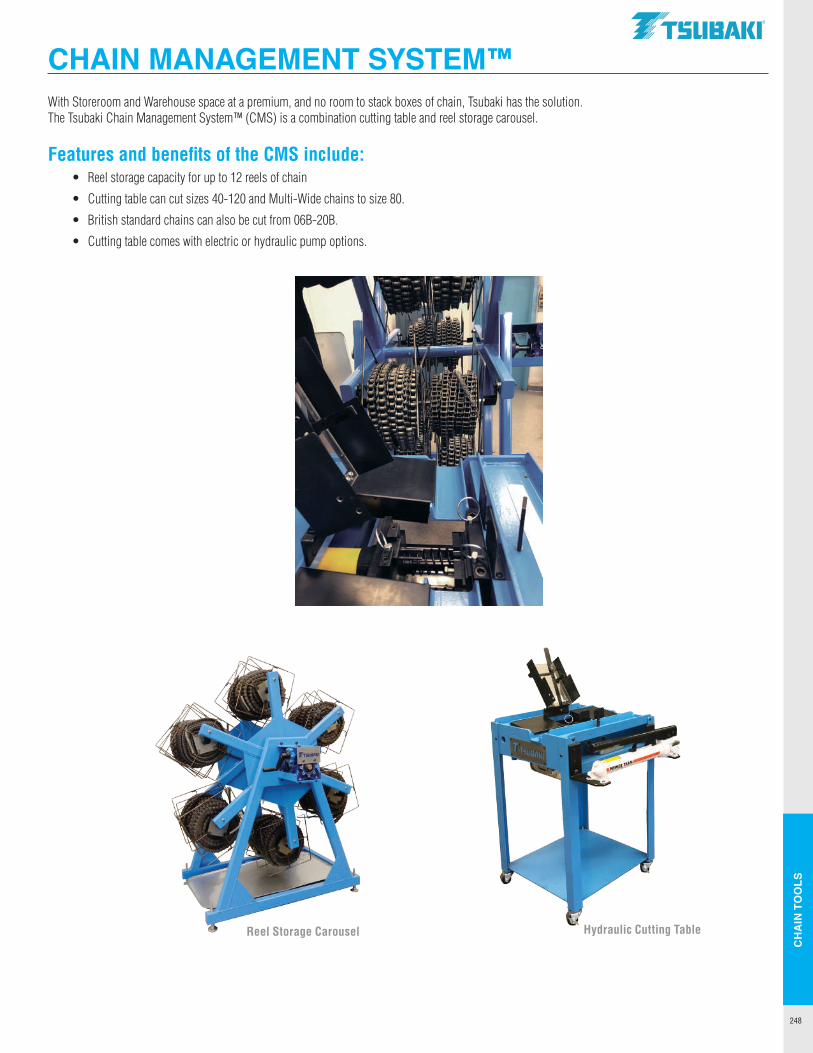
CH
AIN
TO
OLS
248
With Storeroom and Warehouse space at a premium, and no room to stack boxes of chain, Tsubaki has the solution. The Tsubaki Chain Management System™ (CMS) is a combination cutting table and reel storage carousel.
Features and benefits of the CMS include: • Reel storage capacity for up to 12 reels of chain
• Cutting table can cut sizes 40-120 and Multi-Wide chains to size 80.
• British standard chains can also be cut from 06B-20B.
• Cutting table comes with electric or hydraulic pump options.
CHAIN MANAGEMENT SYSTEM™
Reel Storage Carousel Hydraulic Cutting Table
.TSUBAKI"
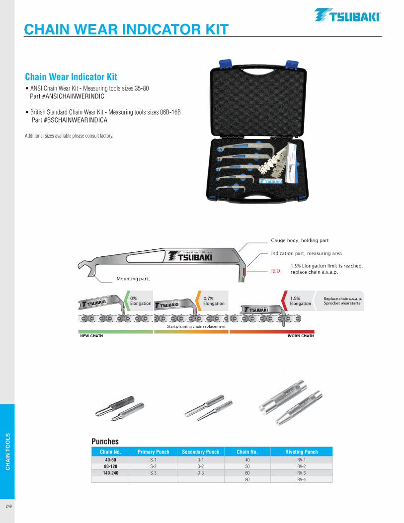
CH
AIN
TO
OLS
249
PunchesChain No. Primary Punch Secondary Punch Chain No. Riveting Punch
40-60 S-1 D-1 40 RV-180-120 S-2 D-2 50 RV-2140-240 S-3 D-3 60 RV-3
80 RV-4
Chain Wear Indicator Kit• ANSI Chain Wear Kit - Measuring tools sizes 35-80 Part #ANSICHAINWERINDIC
• British Standard Chain Wear Kit - Measuring tools sizes 06B-16B Part #BSCHAINWEARINDICA
Additional sizes available please consult factory.
CHAIN WEAR INDICATOR KIT
Mounting part,
0
Start planning chain replacement
NEW CHAIN
.TSUBAKI"
Gauge body, holding part
Indication part, measuring area
1.5% Elongation limit is reached, RED: replace chain a.s.a.p.
Replace chain a.s.a.p. Sprocket wear starts
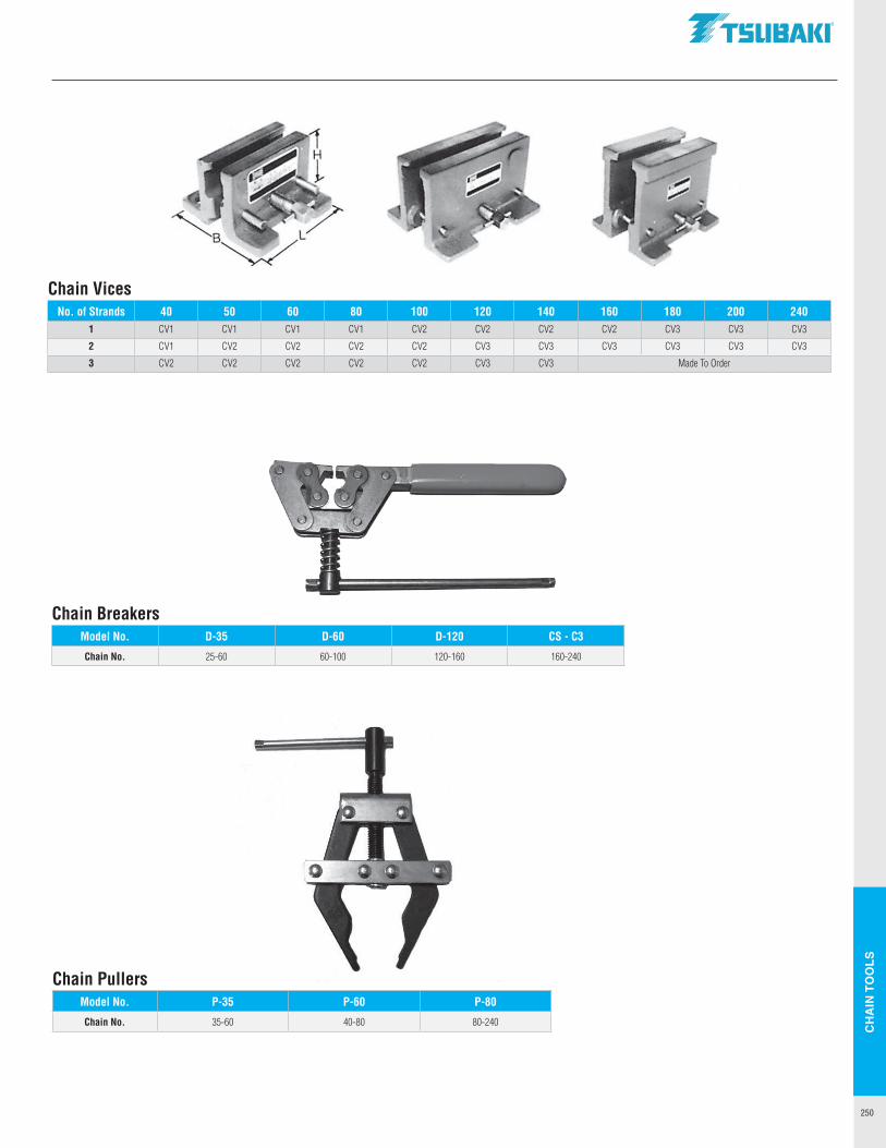
CH
AIN
TO
OLS
250
Chain PullersModel No. P-35 P-60 P-80
Chain No. 35-60 40-80 80-240
Chain VicesNo. of Strands 40 50 60 80 100 120 140 160 180 200 240
1 CV1 CV1 CV1 CV1 CV2 CV2 CV2 CV2 CV3 CV3 CV3
2 CV1 CV2 CV2 CV2 CV2 CV3 CV3 CV3 CV3 CV3 CV3
3 CV2 CV2 CV2 CV2 CV2 CV3 CV3 Made To Order
Chain BreakersModel No. D-35 D-60 D-120 CS - C3
Chain No. 25-60 60-100 120-160 160-240
.TSUBAKI"

TEC
HN
ICA
L SE
CTI
ON
251
Type of Impact
MachinesSource of Power
Internal Combustion Engine
Electric Motor or Turbine
With Hydraulic Drive
Without Hydraulic Drive
Smooth Belt conveyors with small load fluctuation, chain conveyors, centrifugal blowers, general textile machines, machines with small load fluctuation. 1.0 1.0 1.2
Some ImpactCentrifugal compressors, marine engines, conveyors with some load fluctuation,
automatic furnaces, dryers, pulverizers, general machine tools, compressors, general work machines, general paper mills.
1.3 1.2 1.4
Large Impact Press, contruction or mining machines, vibration machines, oil well rigs, rubber mixers, rolls, general machines with reverse or large impact loads. 1.5 1.4 1.7
Tsubaki Roller Chain Drive Selection Process
33,000 x HPS
P x N x n12
"
L =N1 + N2
2+ 2C +
( N2 − N16.28 )
2
C
C =18 2L − N1 − N2 + (2L − N1 − N2)2 −
89.86 (N2 − N1)2
Horsepower RatingThe horsepower rating in Table 4 on page 253 is based on the following conditions:1. The chains are operated under ordinary conditions. The ambient temperature
range must be between 15°F and 140°F. They should not be used in an atmosphere in which abrasive dust or corrosive gas is present or where high humidity is present.
2. The two transmission shafts are in a horizontal position, and the chains are properly installed.
3. The suggested lubrication system and oil are used.4. The load does not change significantly during transmission. The service factor
given in Table 1 should be taken into account when the chains are used under various operating conditions. The load conditions will affect the life of the chain.
5. The increase in horsepower rating of multiple strand roller chain cannot be calculated simply by multiplying the horsepower rating of one strand by the number of strands, since the load on each strand is not exactly the same. In order to estimate the service life of the multiple strand chain, the multiple strand service factor given in Table 2 must be used. When the chain length is 100 pitches and the above conditions are met, a service life of approximately 15,000 hours can be expected.
Procedures for Selecting Roller Chain1. The following must be considered when selecting roller chain: a. Source of Power b. Driven machine c. HP to be transmitted d. RPM of drive and driven shafts e. Diameter of shafts f. Center distance of shafts2. Use Table 1 to obtain the service factor.3. Multiply the horsepower value by the service factor to obtain the design
horsepower value.4. Use Table 4 on page 253 and the HP ratings tables on pages 8-21 to obtain the
chain number and the number of teeth for small sprockets. Refer to the number of revolutions of the high speed shaft (the driving shaft when the speed is reduced; the driven shaft when the speed is increased) and the design horsepower value. For smoother chain drive, a smaller pitch chain is suggested. If a single strand chain does not satisfy the requirements, use a multi-strand chain. If space is limited, a smaller pitch, multi-strand roller chain can be used.
5. After determining the number of teeth for the small sprocket, refer to the sprocket dimension table on page …..to check if the sprocket diameter satisfies the space limitations.
6. The number of teeth for the large sprocket is determined by multiplying the number of teeth for the small sprocket by the speed ratio. More than 15 teeth on the small sprocket is suggested. The number of teeth for the small sprocket should be less than 120. By reducing the number of teeth for the small sprocket, the number of teeth for the large sprocket can be reduced.
7. For temperatures below 15°F, see the environmental temperatures and points of concern table on page 262.
Table 1 – Service Factor
Basic Formula for Chain Drives1. Chain Speed: S
S = = (Ft/min)
P = Chain Pitch N = Sprocket tooth count n = RPM
2. Chain tension: T
T = = (lbs)
S = Chain Speed (ft/min) HP = Horsepower transmitted
3. Number of chain pitches: L
N1 = Small sprocket teeth N2 = Large sprocket teeth C = Center distance in pitches *Any fraction of L is counted as one pitch
4. Center distance in Pitches: C
Table 2 – Multi-Strand Factor
Number of Chain Strands Multi-Strand Factor
2 1.7 3 2.5 4 3.3 5 3.9 6 4.6
.TSUBAKI"
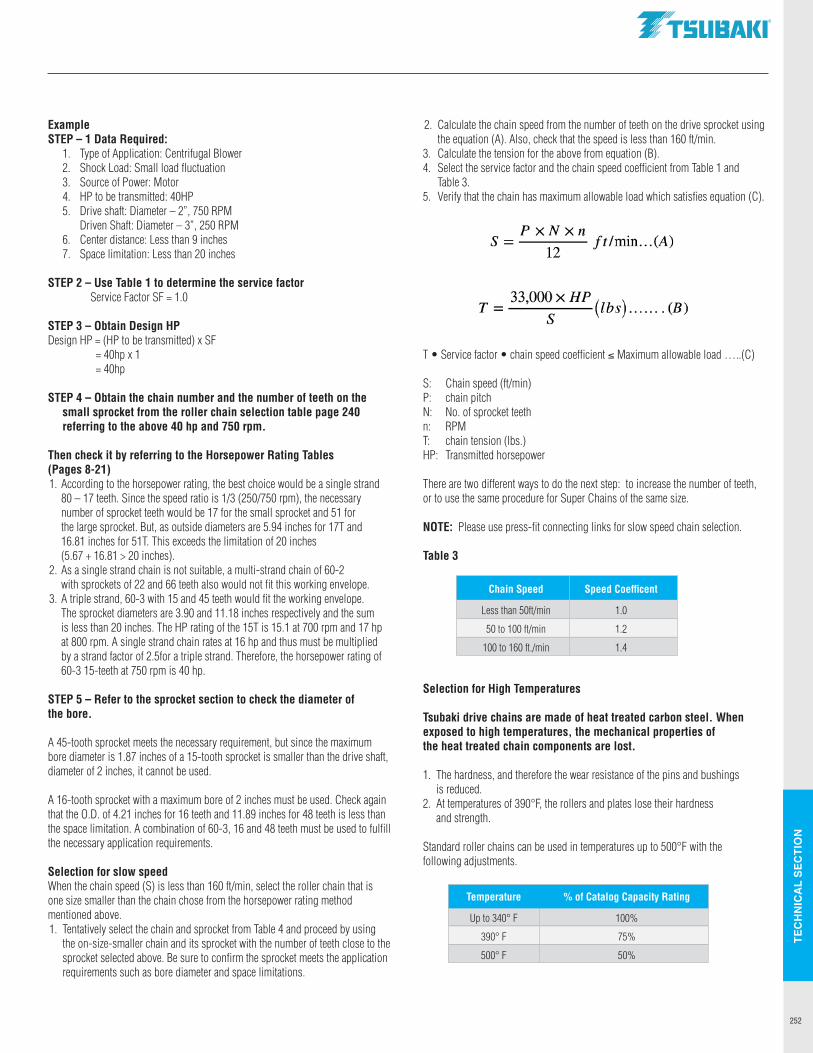
TEC
HN
ICA
L SE
CTI
ON
252
ExampleSTEP – 1 Data Required: 1. Type of Application: Centrifugal Blower 2. Shock Load: Small load fluctuation 3. Source of Power: Motor 4. HP to be transmitted: 40HP 5. Drive shaft: Diameter – 2”, 750 RPM Driven Shaft: Diameter – 3”, 250 RPM 6. Center distance: Less than 9 inches 7. Space limitation: Less than 20 inches
STEP 2 – Use Table 1 to determine the service factor Service Factor SF = 1.0
STEP 3 – Obtain Design HPDesign HP = (HP to be transmitted) x SF = 40hp x 1 = 40hp
STEP 4 – Obtain the chain number and the number of teeth on the small sprocket from the roller chain selection table page 240 referring to the above 40 hp and 750 rpm.
Then check it by referring to the Horsepower Rating Tables (Pages 8-21)1. According to the horsepower rating, the best choice would be a single strand
80 – 17 teeth. Since the speed ratio is 1/3 (250/750 rpm), the necessary number of sprocket teeth would be 17 for the small sprocket and 51 for the large sprocket. But, as outside diameters are 5.94 inches for 17T and 16.81 inches for 51T. This exceeds the limitation of 20 inches (5.67 + 16.81 > 20 inches).
2. As a single strand chain is not suitable, a multi-strand chain of 60-2 with sprockets of 22 and 66 teeth also would not fit this working envelope.
3. A triple strand, 60-3 with 15 and 45 teeth would fit the working envelope. The sprocket diameters are 3.90 and 11.18 inches respectively and the sum is less than 20 inches. The HP rating of the 15T is 15.1 at 700 rpm and 17 hp at 800 rpm. A single strand chain rates at 16 hp and thus must be multiplied by a strand factor of 2.5for a triple strand. Therefore, the horsepower rating of 60-3 15-teeth at 750 rpm is 40 hp.
STEP 5 – Refer to the sprocket section to check the diameter of the bore.
A 45-tooth sprocket meets the necessary requirement, but since the maximum bore diameter is 1.87 inches of a 15-tooth sprocket is smaller than the drive shaft, diameter of 2 inches, it cannot be used.
A 16-tooth sprocket with a maximum bore of 2 inches must be used. Check again that the O.D. of 4.21 inches for 16 teeth and 11.89 inches for 48 teeth is less than the space limitation. A combination of 60-3, 16 and 48 teeth must be used to fulfill the necessary application requirements.
Selection for slow speedWhen the chain speed (S) is less than 160 ft/min, select the roller chain that is one size smaller than the chain chose from the horsepower rating method mentioned above.1. Tentatively select the chain and sprocket from Table 4 and proceed by using
the on-size-smaller chain and its sprocket with the number of teeth close to the sprocket selected above. Be sure to confirm the sprocket meets the application requirements such as bore diameter and space limitations.
2. Calculate the chain speed from the number of teeth on the drive sprocket using the equation (A). Also, check that the speed is less than 160 ft/min.
3. Calculate the tension for the above from equation (B). 4. Select the service factor and the chain speed coefficient from Table 1 and Table 3. 5. Verify that the chain has maximum allowable load which satisfies equation (C).
T • Service factor • chain speed coefficient ≤ Maximum allowable load …..(C)
S: Chain speed (ft/min)P: chain pitchN: No. of sprocket teethn: RPMT: chain tension (lbs.)HP: Transmitted horsepower
There are two different ways to do the next step: to increase the number of teeth, or to use the same procedure for Super Chains of the same size.
NOTE: Please use press-fit connecting links for slow speed chain selection.
Table 3
Chain Speed Speed Coefficent
Less than 50ft/min 1.0
50 to 100 ft/min 1.2
100 to 160 ft./min 1.4
Selection for High Temperatures
Tsubaki drive chains are made of heat treated carbon steel. When exposed to high temperatures, the mechanical properties of the heat treated chain components are lost.
1. The hardness, and therefore the wear resistance of the pins and bushings is reduced.
2. At temperatures of 390°F, the rollers and plates lose their hardness and strength.
Standard roller chains can be used in temperatures up to 500°F with the following adjustments.
Temperature % of Catalog Capacity Rating
Up to 340° F 100%
390° F 75%
500° F 50%
.TSUBAKI"
P xNxn S = 12 ft/min ... (A)
33,000 X HP T=---(lbs) ....... (B) s
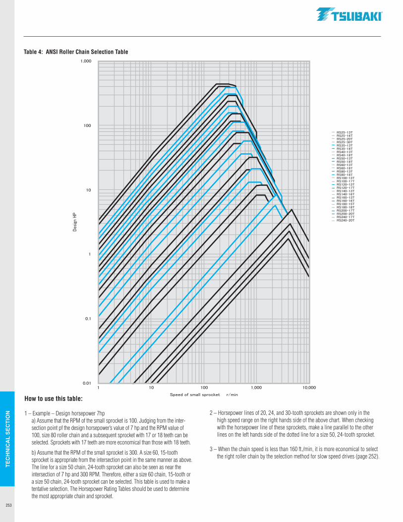
TEC
HN
ICA
L SE
CTI
ON
253
Table 4: ANSI Roller Chain Selection Table
How to use this table:
1 – Example – Design horsepower 7hp a) Assume that the RPM of the small sprocket is 100. Judging from the inter-
section point pf the design horsepower’s value of 7 hp and the RPM value of 100, size 80 roller chain and a subsequent sprocket with 17 or 18 teeth can be selected. Sprockets with 17 teeth are more economical than those with 18 teeth.
b) Assume that the RPM of the small sprocket is 300. A size 60, 15-tooth sprocket is appropriate from the intersection point in the same manner as above. The line for a size 50 chain, 24-tooth sprocket can also be seen as near the intersection of 7 hp and 300 RPM. Therefore, either a size 60 chain, 15-tooth or a size 50 chain, 24-tooth sprocket can be selected. This table is used to make a tentative selection. The Horsepower Rating Tables should be used to determine the most appropriate chain and sprocket.
2 – Horsepower lines of 20, 24, and 30-tooth sprockets are shown only in the high speed range on the right hands side of the above chart. When checking with the horsepower line of these sprockets, make a line parallel to the other lines on the left hands side of the dotted line for a size 50, 24-tooth sprocket.
3 – When the chain speed is less than 160 ft./min, it is more economical to select the right roller chain by the selection method for slow speed drives (page 252).
a. :r: Qi
·.; ., Cl
1,000
100
10
0.1
0.01 10
.TSUBAKI"
- RS25-13T - RS25-16T - RS25-20T - RS25-30T - RS35-13T - RS35-18T - R$40-13T - RS40-18T - RS50-13T - RS50-18T - RS60-13T - RS60-18T - RS80-13T - RS80-18T - RS100-13T - RS100--17T - RS120-13T - RS120-17T - RS140-13T - RS140-16T - RS160-13T - RS160-16T - RS180-15T - RS180-18T - RS200-17T - RS200-20T - RS240-17T - RS240-20T
11 ti I 100 1,000 10,000
Speed of small sprocket r/min
TEC
HN
ICA
L SE
CTI
ON
254
CHAIN DRIVE SELECTION
Heavy Series Chains
Generally Super Series chains are suggested when the chain speed is less than 160 ft./min and where the roller chain or the ASME/ANSI Heavy Series chains are not strong enough to meet application requirements. 1) Tentatively select the chain and sprocket with the same size and number of teeth as used in the “Selection for Slow Speed. ” 2) Calculate the chain speed from the number of teeth of the driving sprocket using equation (A) and check whether the speed is less than 160 ft./min. 3) Calculate the chain tension necessary for the above drive from equation (B). 4) Select the same service factor and the chain speed coefficient from Tables 1 and 2. 5) Select the suitable chain and verify that the chain satisfies equation (C).
T x Service Factor x Chain Speed Coefficient ≤ or = to MAL ………..(C)
S: Chain speed (ft/min)P: Chain pitch (inches)N: Drive sprocket teeth No.n: RPM of drive sprocketT: Chain tensions (lbs)
Table 1: Service Factor
Type of Impact Service Factor
Smooth 1.0
Some Impact 1.3
Large Impact 1.5
Table 2: Service Factor
Chain Speed Speed Coefficient
Less than 50 ft/min 1.0
50-100 ft/min 1.2
100-160 ft/min 1.4
! (Ft/min)
!
S =P × N × n
12
T =33,000 × HP
S= (L BS )
BRITISH STANDARD CHAIN DRIVE SELECTION
1. The following must be considered when selecting roller chain: a. Source of Power b. Driven machine c. HP to be transmitted d. RPM of drive and driven shafts e. Diameter of shafts f. Center distance of shafts
2. Use Table 1 to obtain the service factor.
3. Multiply the horsepower value by the service factor to obtain the design horsepower value.
4. Use Table 4 on page 255 to obtain the chain number and the number of teeth for small sprockets. Refer to the number of revolutions of the high speed shaft (the driving shaft when the speed is reduced; the driven shaft when the speed is increased) and the design horsepower value. For smoother chain drive, a smaller pitch chain is suggested. If a single strand chain does not satisfy the requirements, use a multi-strand chain. If space is limited, a smaller pitch, multi-strand roller chain can be used.
5. After determining the number of teeth for the small sprocket, refer to the sprocket section to check if the sprocket diameter satisfies the space limitations.
6. The number of teeth for the large sprocket is determined by multiplying the number of teeth for the small sprocket by the speed ratio. More than 15 teeth on the small sprocket is suggested. The number of teeth for the small sprocket should be less than 120. By reducing the number of teeth for the small sprocket, the number of teeth for the large sprocket can be reduced.
7. For temperatures below 15°F, see the environmental temperatures and points of concern table on page 262.
Type of Impact Machines
Source of Power
Internal Combustion Engine
Electric Motor
or Turbine
With Hydraulic
Drive
Without Hydraulic
Drive
Smooth
Belt conveyors with small load fluctuation, chain conveyors, centrifugal
blowers, general textile machines, machines with small load fluctuation.
1.0 1.0 1.2
Some Impact
Centrifugal compressors, marine engines, conveyors with some load
fluctuation, automatic furnaces, dryers, pulverizers, general machine tools,
compressors, general work machines, general paper mills.
1.3 1.2 1.4
Large Impact
Press, contruction or mining machines, vibration machines, oil well rigs,
rubber mixers, rolls, general machines with reverse or large impact loads.
1.5 1.4 1.7
Table 1: Service Factor
.TSUBAKI"
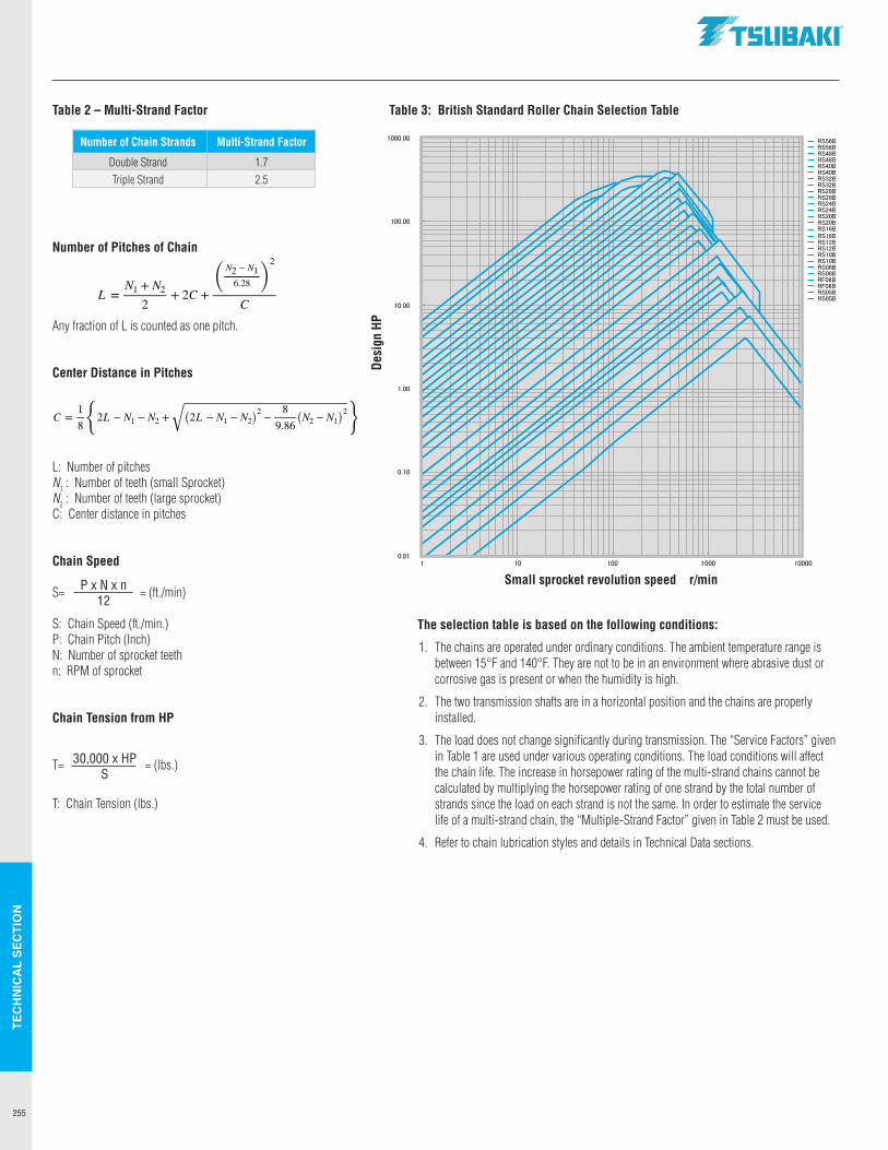
TEC
HN
ICA
L SE
CTI
ON
255
"
L =N1 + N2
2+ 2C +
( N2 − N16.28 )
2
C
C =18 2L − N1 − N2 + (2L − N1 − N2)2 −
89.86 (N2 − N1)2
2
Small sprocket revolution speed r/min
Table 3: British Standard Roller Chain Selection Table
Desi
gn H
P
The selection table is based on the following conditions:
1. The chains are operated under ordinary conditions. The ambient temperature range is between 15°F and 140°F. They are not to be in an environment where abrasive dust or corrosive gas is present or when the humidity is high.
2. The two transmission shafts are in a horizontal position and the chains are properly installed.
3. The load does not change significantly during transmission. The “Service Factors” given in Table 1 are used under various operating conditions. The load conditions will affect the chain life. The increase in horsepower rating of the multi-strand chains cannot be calculated by multiplying the horsepower rating of one strand by the total number of strands since the load on each strand is not the same. In order to estimate the service life of a multi-strand chain, the “Multiple-Strand Factor” given in Table 2 must be used.
4. Refer to chain lubrication styles and details in Technical Data sections.
30,000 x HPS
P x N x n12
Table 2 – Multi-Strand Factor
Number of Chain Strands Multi-Strand Factor
Double Strand 1.7 Triple Strand 2.5
Number of Pitches of Chain
Any fraction of L is counted as one pitch.
Center Distance in Pitches
L: Number of pitchesN1 : Number of teeth (small Sprocket)N2 : Number of teeth (large sprocket)C: Center distance in pitches
Chain Speed
S= = (ft./min)
S: Chain Speed (ft./min.)P: Chain Pitch (Inch)N: Number of sprocket teethn: RPM of sprocket
Chain Tension from HP
T= = (lbs.)
T: Chain Tension (lbs.)
"
L =N1 + N2
2+ 2C +
( N2 − N16.28 )
2
C
C =18 2L − N1 − N2 + (2L − N1 − N2)2 −
89.86 (N2 − N1)2
.TSUBAKI"
...... ~ r/'? %: ~I,' \
-
I/ ~~--; ,, ; ~~~ ~~ 'l ~ ~ / I""~ t::;I' ~
--- , __ -,_ ,,, ,,_ , - .; ., -' -, ., ,, --, " - ; / ,_,; i,";' '.// / , ;" V'!. -,;'; --~ ,., ./2 1//., ~; ~ //,. ,......,....,
I,'; ...,, \.. -
~ ~ t:::~--; ~~~ V
~ :i' ~ ,;';
----~ / I;';;'
~ ,;' ,, ;' .... ;' I/ I,' ;
--- ,_ - - - - - - - - -- I -- --,_ - - ' , ,, , ,, - , , , ,, , , , !'Iii.. // ;'_,; """" '// 1/V ;' ~// /,i; I,' V , " ~~ //4; z ·,i;,, ..... 1// V,.,; _.; ~~ //2 V Li;; 1/ \ -,;;;
~ ~ ~;' ...... ~ ~ t:: ~;--; ~~
,., V I;'; [ "' ~ ,i;,;' ----~ V ;; ~~ / I/ ; \ --
j_~~
- I
_,_ ,_ I ,_ - -_,,, , , ,., I , ,, ,., , , , , , , ... ./ / , ; .// , ,i; ./
1// ,i;, ,;' ;' ~ V .; , ; /
~ /: ...... ~
~ V ~, ;~ ,· ...
l-'.:: ;_.~ ,i; ;'
- - - + - I ~ ,,/ .; ,i;
"// ,i; , /_
'/ / ,,
, ,i;"' ,i;
1/ , / ...... l / ,,
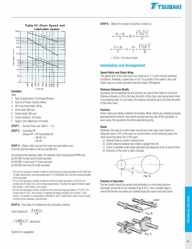
TEC
HN
ICA
L SE
CTI
ON
256
Table 3: British Standard Roller Chain Selection Table
Example:Data:1. Type of application: Centrifugal Blowers2. Source of Power: Electric Motor3. HP to be transmitted: 40 hp4. Drive shaft: 600 rpm5. Driven shaft: 200 rpm6. Center distance: 19 inches7. Space Limit: Maximum 24 inches
STEP 1 – Service Factor per Table 1 – 1.0
STEP 2 – Calculate HP Design HP = HP transmittedSF = 40 HP1.0 = 40 HP
STEP 3 – Obtain chain size and the small sprocket teeth count from the selection table for 40 hp and 600 rpm.
According to the selection table, the selected chain and sprocket RPM’s are:(a) RS12B-3 chain and 25 tooth sprocket (b) RS16B-2 chain and 17-tooth sprocket(c) RS16B chain and 25-tooth sprocket
* For (a), the necessary number of teeth for both small and large sprockets are 25 teeth and 75 teeth respectively, since the speed ratio is 1/3 (200/600 rpm). But the outside diameter of the sprockets
* For (c), the necessary number of teeth for small and large sprockets is 25 (O.D. 8.4 inches) and 75 teeth (O.D. 24.4 inches) respectively. It exceeds the space limitation again (8.4 inches + 24.4 inches > 24 inches).
* For (b), the necessary number of teeth for the small and large sprockets is 17 (O.D. 5.9 inches) and 51 (O.D. 16.8 inches). It satisfies the space limitation (5.9 inches + 16.8 inches < 24 inches). A combination of RS16B-2, and 17 teeth and 51 teeth must be used to fulfill all the necessary requirements.
STEP 4 – Use Table IV to determine the lubrication method
Chain Speed (S):
= = 850 ft/min
System B is suggested
STEP 5 – Obtain the number of pitches of chain (L).
= 73.35 = 74 Links of chain
Installation and Arrangement
Speed Ratio and Chain WrapThe speed ratio of the roller chain can range up to 7:1 under normal operating conditions. However, a speed ratio of 10:1 is possible if the speed is very low. Chain wrap on a small sprocket must be at least 120 degrees.
Distance Between ShaftsSprockets can be separated by any distance as long as their teeth do not touch. Optimum distance is 30 to 50 times the pitch of the chain used except when there is a pulsating load. In such cases, the distance should be up to 20 times the pitch of the chain used.
PositionRoller chains are ideally installed horizontally. When chains are installed at angles approaching the vertical, they stretch quickly and may slip off the sprockets. In such cases, the sprockets should be adjusted properly.
SlackGenerally, the slack of a roller chain should be on the lower side (Figure A). Adequate slack is 4% of the span for normal drives. In the following cases, the slack should be about 2% of the span: a) Vertical Drive or close to vertical drive. b) Center distance between two shafts is greater than 3ft. c) Chain is operated under heavy load and high frequency of an on and off drive. d) Direction of the drive is often changed.
Position of SprocketThe two shafts should be parallel and preferably in a horizontal position. Sprockets should be firmly installed (Figs B & C). Use a straight edge to check that the two sprockets are installed along the same horizontal plane.
1 x 600 x 1712
P x N x n12
2000
1000 800 600
400
200
I <f) 100
80 60
40
20
10
Table IV: Chain Speed and Lubrication System --r--. s I I r-----.!'.:_te,,, C
-...._shl
--....::._0 S. ........
'r--.r-....
i--. I'--.. SYS/ ...._ em 4
(, ''Pp "'9)
SYste I -04 ~
CO CD ffilll en CO OlCDCD al <0 COON <0 0 -=:f'OON 0 0 0 N NNCI? "'1"
Chain No.
( N2-N1)2
= N 1 + N2 + 2C + 6.28
2 C
19 6.28
.TSUBAKI"
( 51-17) 2
•-+----1 19
--..... __ -_-:_-::__ s·
I
Fig. A
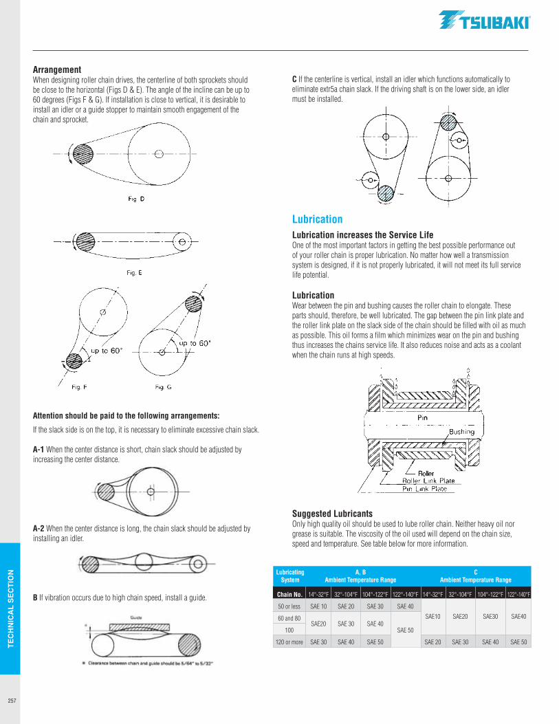
TEC
HN
ICA
L SE
CTI
ON
257
ArrangementWhen designing roller chain drives, the centerline of both sprockets should be close to the horizontal (Figs D & E). The angle of the incline can be up to 60 degrees (Figs F & G). If installation is close to vertical, it is desirable to install an idler or a guide stopper to maintain smooth engagement of the chain and sprocket.
Attention should be paid to the following arrangements:
If the slack side is on the top, it is necessary to eliminate excessive chain slack.
A-1 When the center distance is short, chain slack should be adjusted by increasing the center distance.
A-2 When the center distance is long, the chain slack should be adjusted by installing an idler.
B If vibration occurs due to high chain speed, install a guide.
C If the centerline is vertical, install an idler which functions automatically to eliminate extr5a chain slack. If the driving shaft is on the lower side, an idler must be installed.
LubricationLubrication increases the Service LifeOne of the most important factors in getting the best possible performance out of your roller chain is proper lubrication. No matter how well a transmission system is designed, if it is not properly lubricated, it will not meet its full service life potential.
LubricationWear between the pin and bushing causes the roller chain to elongate. These parts should, therefore, be well lubricated. The gap between the pin link plate and the roller link plate on the slack side of the chain should be filled with oil as much as possible. This oil forms a film which minimizes wear on the pin and bushing thus increases the chains service life. It also reduces noise and acts as a coolant when the chain runs at high speeds.
Suggested LubricantsOnly high quality oil should be used to lube roller chain. Neither heavy oil nor grease is suitable. The viscosity of the oil used will depend on the chain size, speed and temperature. See table below for more information.
Lubricating A, B C System Ambient Temperature Range Ambient Temperature Range
Chain No. 14°-32°F 32°-104°F 104°-122°F 122°-140°F 14°-32°F 32°-104°F 104°-122°F 122°-140°F
50 or less SAE 10 SAE 20 SAE 30 SAE 40
SAE10 SAE20 SAE30 SAE40 60 and 80 SAE20 SAE 30 SAE 40
SAE 50 100
120 or more SAE 30 SAE 40 SAE 50 SAE 20 SAE 30 SAE 40 SAE 50
.TSUBAKI"
Fig D
Fig. E
/ Fig. F Fig. G
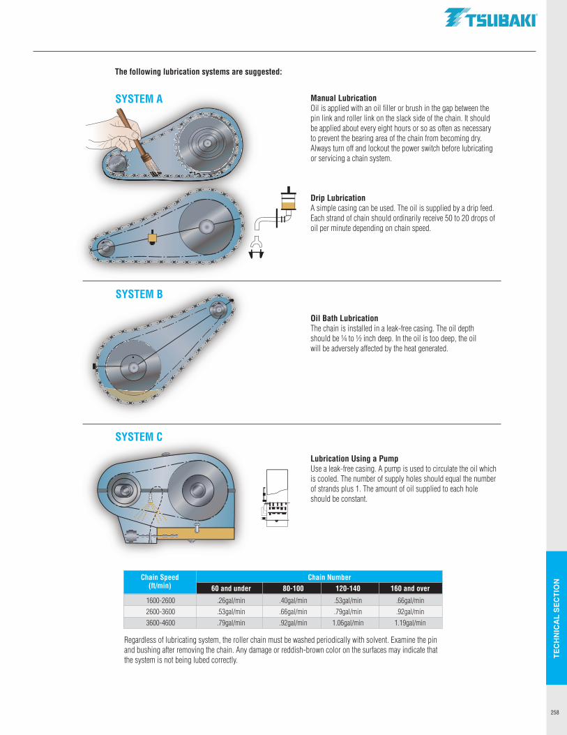
TEC
HN
ICA
L SE
CTI
ON
258
Chain Number 60 and under 80-100 120-140 160 and over
1600-2600 .26gal/min .40gal/min .53gal/min .66gal/min 2600-3600 .53gal/min .66gal/min .79gal/min .92gal/min 3600-4600 .79gal/min .92gal/min 1.06gal/min 1.19gal/min
Regardless of lubricating system, the roller chain must be washed periodically with solvent. Examine the pin and bushing after removing the chain. Any damage or reddish-brown color on the surfaces may indicate that the system is not being lubed correctly.
Manual LubricationOil is applied with an oil filler or brush in the gap between the pin link and roller link on the slack side of the chain. It should be applied about every eight hours or so as often as necessary to prevent the bearing area of the chain from becoming dry. Always turn off and lockout the power switch before lubricating or servicing a chain system.
Drip LubricationA simple casing can be used. The oil is supplied by a drip feed. Each strand of chain should ordinarily receive 50 to 20 drops of oil per minute depending on chain speed.
Oil Bath LubricationThe chain is installed in a leak-free casing. The oil depth should be ¼ to ½ inch deep. In the oil is too deep, the oil will be adversely affected by the heat generated.
Lubrication Using a PumpUse a leak-free casing. A pump is used to circulate the oil which is cooled. The number of supply holes should equal the number of strands plus 1. The amount of oil supplied to each hole should be constant.
The following lubrication systems are suggested:
SYSTEM A
SYSTEM B
SYSTEM C
Chain Speed (ft/min)
~ A tt
.TSUBAKI"
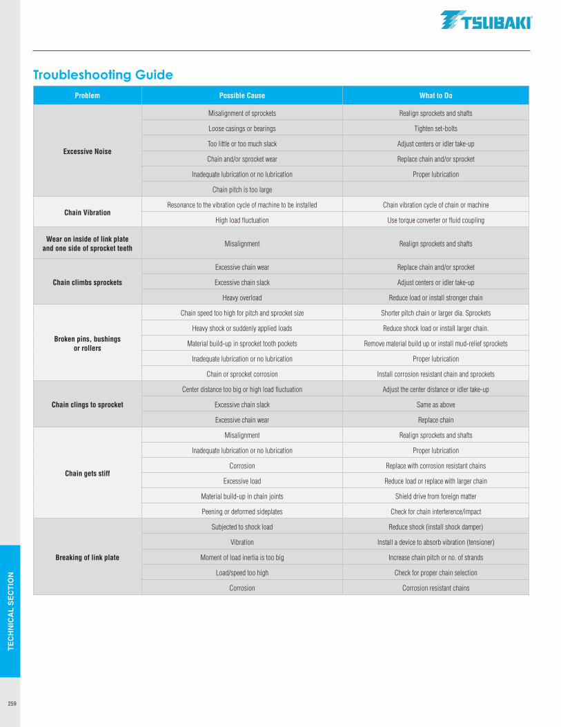
TEC
HN
ICA
L SE
CTI
ON
259
Troubleshooting GuideProblem Possible Cause What to Do
Excessive Noise
Misalignment of sprockets Realign sprockets and shafts
Loose casings or bearings Tighten set-bolts
Too little or too much slack Adjust centers or idler take-up
Chain and/or sprocket wear Replace chain and/or sprocket
Inadequate lubrication or no lubrication Proper lubrication
Chain pitch is too large
Chain VibrationResonance to the vibration cycle of machine to be installed Chain vibration cycle of chain or machine
High load fluctuation Use torque converter or fluid coupling
Wear on inside of link plate and one side of sprocket teeth
Misalignment Realign sprockets and shafts
Chain climbs sprockets
Excessive chain wear Replace chain and/or sprocket
Excessive chain slack Adjust centers or idler take-up
Heavy overload Reduce load or install stronger chain
Broken pins, bushings or rollers
Chain speed too high for pitch and sprocket size Shorter pitch chain or larger dia. Sprockets
Heavy shock or suddenly applied loads Reduce shock load or install larger chain.
Material build-up in sprocket tooth pockets Remove material build up or install mud-relief sprockets
Inadequate lubrication or no lubrication Proper lubrication
Chain or sprocket corrosion Install corrosion resistant chain and sprockets
Chain clings to sprocket
Center distance too big or high load fluctuation Adjust the center distance or idler take-up
Excessive chain slack Same as above
Excessive chain wear Replace chain
Chain gets stiff
Misalignment Realign sprockets and shafts
Inadequate lubrication or no lubrication Proper lubrication
Corrosion Replace with corrosion resistant chains
Excessive load Reduce load or replace with larger chain
Material build-up in chain joints Shield drive from foreign matter
Peening or deformed sideplates Check for chain interference/impact
Breaking of link plate
Subjected to shock load Reduce shock (install shock damper)
Vibration Install a device to absorb vibration (tensioner)
Moment of load inertia is too big Increase chain pitch or no. of strands
Load/speed too high Check for proper chain selection
Corrosion Corrosion resistant chains
.TSUBAKI"
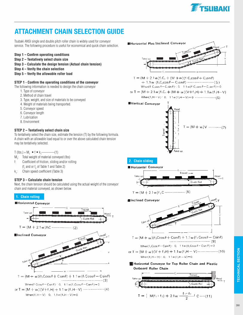
TEC
HN
ICA
L SE
CTI
ON
260
ATTACHMENT CHAIN SELECTION GUIDE
Tsubaki ANSI single and double pitch roller chain is widely used for conveyor service. The following procedure is useful for economical and quick chain selection.
Step 1 – Confirm operating conditionsStep 2 – Tentatively select chain sizeStep 3 – Calculate the design tension (Actual chain tension)Step 4 – Verify the chain selectionStep 5 – Verify the allowable roller load
STEP 1 - Confirm the operating conditions of the conveyorThe following information is needed to design the chain conveyor 1. Type of conveyor 2. Method of chain travel 3. Type, weight, and size of materials to be conveyed 4. Weight of materials being transported. 5. Conveyor speed 6. Conveyor length 7. Lubrication 8. Environment
STEP 2 – Tentatively select chain sizeTo tentatively select the chain size, estimate the tension (T) by the following formula. A chain with an allowable load equal to or over the above calculated chain tension may be tentatively selected.
T (lbs.) = MT • f • k1-----------(1)MT: Total weight of material conveyed (lbs)f: Coefficient of friction, sliding and/or rolling (f1 and or f2 of Table 1 and Table 2)k1: Chain speed coefficient (Table 3)
STEP 3 – Calculate chain tensionNext, the chain tension should be calculated using the actual weight of the conveyor chain and material conveyed, as shown below.
1. Chain rolling
2. Chain sliding
Horizontal Conveyor
Take·up 1• c::J c::J c----caT~ra-ve-1----i
I · I c:::J c:::J le/P;~~~~~~~~~,;::;.;::~~
Guide Rail I~~~~~~~~~~~
T = (M + 2.1 w)f,C ·················· (2)
Inclined Conveyor
r-------H-----------<
T = (M + w)(f,Ccos0+ Csin0) + 1.1 w(f,Ccos0- Csin0) ····································(3)
When(f,Ccos0-Csin0)< 0. 1.1 w(f 1Ccosll-Csin0)=0
or T = (M + w) (V+f ,H) + 1.1 w (f ,H-V) ·················· (4)
When(f, H-V)< 0. 1.1 w(f ,H-V)=O
.TSUBAKI"
Horizontal Plus Inclined Conveyor ~ c~ --Cl H1ead------ T
V
C,----4------ H-----<
T = (M + 2.1 w)f,C, + (M +w)(f,C 2cos0+ C2sin0) + 1.1w (f,C 2cos0-C 2sin0)·············· .......... (5) When(f ,C 1cos 0-C,sin 0)< 0, 1 1w(f ,C 1cos 0-C 1sin 0)= 0
or T = (M + 21 w)f,C, + (M + w)(V+f ,H) + 1.1w(f ,H-V)
When(f,H-V)<O. 11w(f,H-V)=O ·········· ........ (6)
Vertical Conveyor
I Q)
T=(M+w)V ···········(7) > "' ~
Horizontal Conveyor
T = (M + 2.1 w)f 2 C ·················· (8)
Inclined Conveyor
V
~------H--------1
T = (M + w )(f 2Ccos0+ Csin0) + 1 1 w(fi Ccos0- Csin0) ···································· (9)
When(f 1Ccos 0-Csin 0)< 0, 1.1 w (f ,Ccos 0-Csin 0)= 0
or T = (M + w )(V + f 2H) + 1 1 w(f 2H - V) ·················· (1O)
When(f 2 H-V)<O. 1.1w(f 1 H-V)=O
Horizontal Conveyor for Top Roller Chain and Plastic
Outboard Roller Chain
T = I M(f,+f2) + 2.1 w f,+t,
2 I C ·····(11)
Head -r
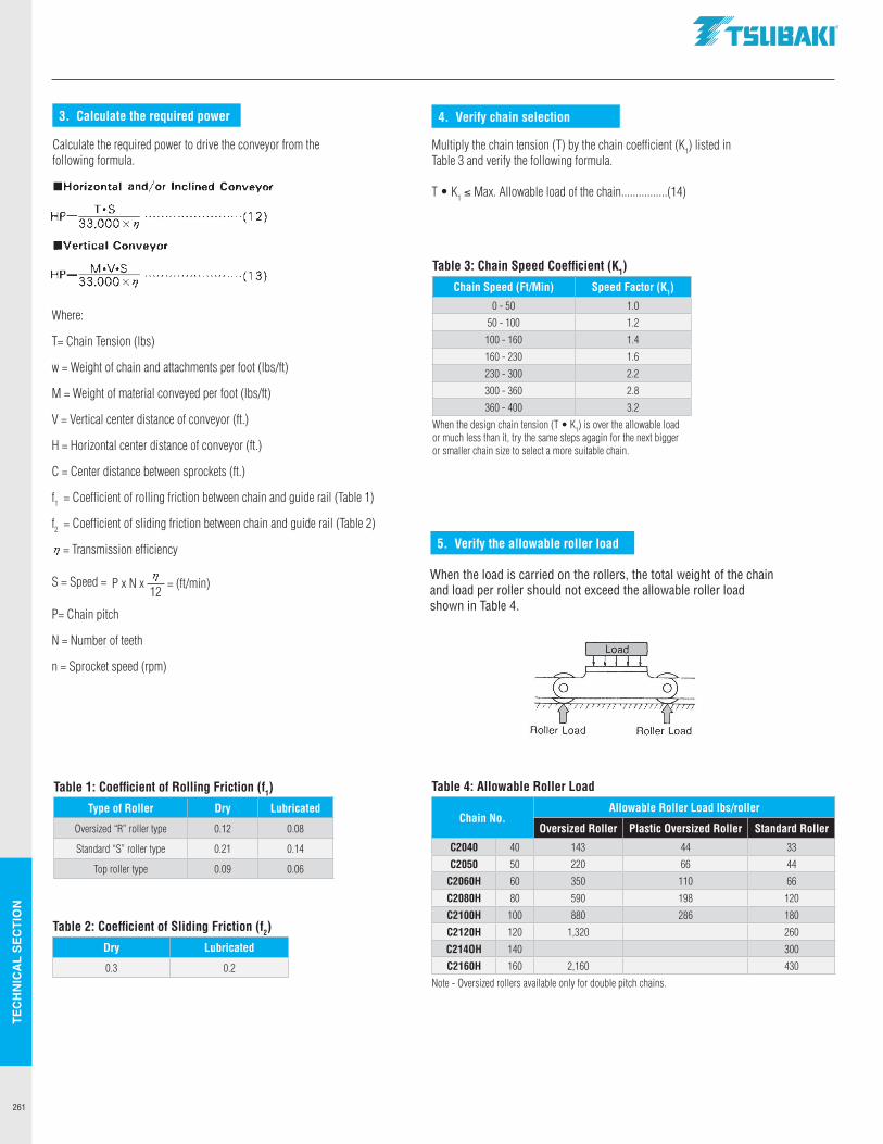
TEC
HN
ICA
L SE
CTI
ON
261
Where:
T= Chain Tension (lbs)
w = Weight of chain and attachments per foot (lbs/ft)
M = Weight of material conveyed per foot (lbs/ft)
V = Vertical center distance of conveyor (ft.)
H = Horizontal center distance of conveyor (ft.)
C = Center distance between sprockets (ft.)
f1 = Coefficient of rolling friction between chain and guide rail (Table 1)
f2 = Coefficient of sliding friction between chain and guide rail (Table 2)
= Transmission efficiency
S = Speed =
P= Chain pitch
N = Number of teeth
n = Sprocket speed (rpm)
3. Calculate the required power
Calculate the required power to drive the conveyor from the following formula.
Table 1: Coefficient of Rolling Friction (f1)
Type of Roller Dry Lubricated
Oversized “R” roller type 0.12 0.08
Standard “S” roller type 0.21 0.14
Top roller type 0.09 0.06
Multiply the chain tension (T) by the chain coefficient (K1) listed in Table 3 and verify the following formula.
T• K1 ≤ Max. Allowable load of the chain................(14)
Table 2: Coefficient of Sliding Friction (f2)
Dry Lubricated
0.3 0.2
Table 3: Chain Speed Coefficient (K1)
Chain Speed (Ft/Min) Speed Factor (K1)
0 - 50 1.0
50 - 100 1.2
100 - 160 1.4
160 - 230 1.6
230 - 300 2.2
300 - 360 2.8
360 - 400 3.2
When the design chain tension (T •K1) is over the allowable load or much less than it, try the same steps agagin for the next bigger or smaller chain size to select a more suitable chain.
Table 4: Allowable Roller Load
Chain No.Allowable Roller Load lbs/roller
Oversized Roller Plastic Oversized Roller Standard Roller
C2040 40 143 44 33
C2050 50 220 66 44
C2060H 60 350 110 66
C2080H 80 590 198 120
C2100H 100 880 286 180
C2120H 120 1,320 260
C214OH 140 300
C2160H 160 2,160 430
Note - Oversized rollers available only for double pitch chains.
When the load is carried on the rollers, the total weight of the chain and load per roller should not exceed the allowable roller load shown in Table 4.
4. Verify chain selection
5. Verify the allowable roller load
P x N x = (ft/min)12
Horizontal and/or Inclined Conveyor
T•S HP 33,000 X r,i ........................ ( 12 )
Vertical Conveyor
M•V•S HP •---'-"-'-'--"'----........................ (13) 33.000 xr,i
r,i
r,i
.TSUBAKI"
Roller Load Roller Load
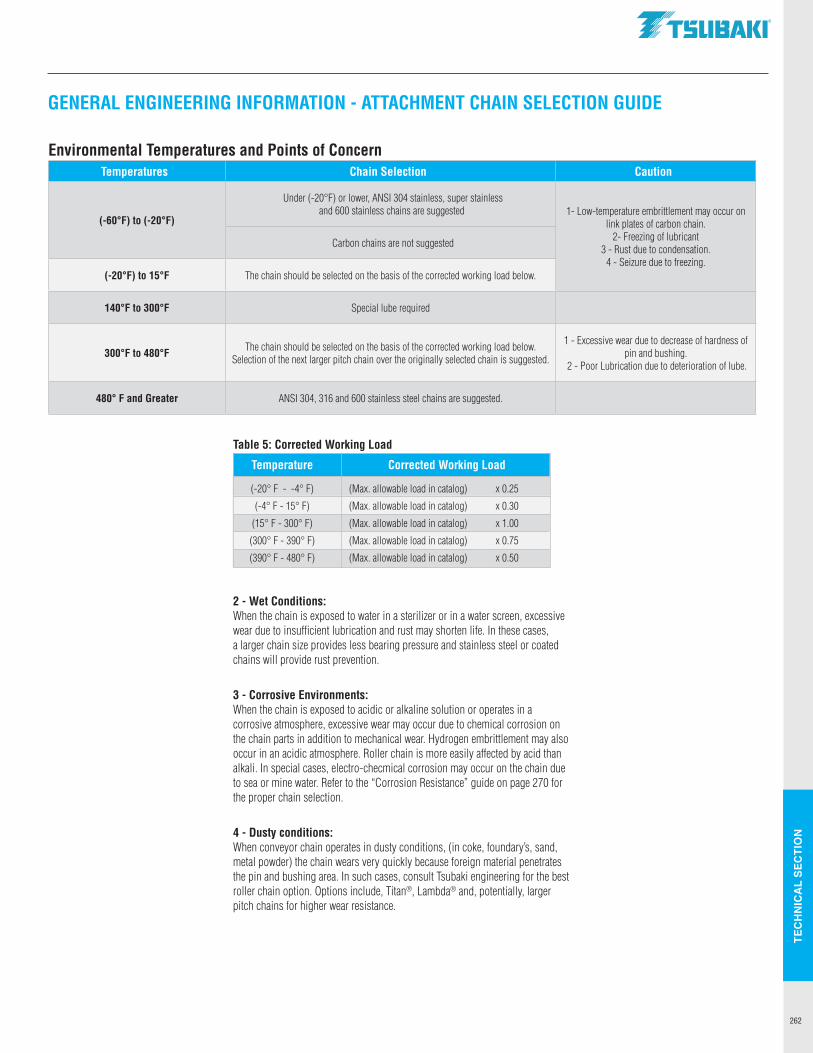
TEC
HN
ICA
L SE
CTI
ON
262
Environmental Temperatures and Points of ConcernTemperatures Chain Selection Caution
(-60°F) to (-20°F)
Under (-20°F) or lower, ANSI 304 stainless, super stainless and 600 stainless chains are suggested 1- Low-temperature embrittlement may occur on
link plates of carbon chain. 2- Freezing of lubricant
3 - Rust due to condensation. 4 - Seizure due to freezing.
Carbon chains are not suggested
(-20°F) to 15°F The chain should be selected on the basis of the corrected working load below.
140°F to 300°F Special lube required
300°F to 480°F The chain should be selected on the basis of the corrected working load below. Selection of the next larger pitch chain over the originally selected chain is suggested.
1 - Excessive wear due to decrease of hardness of pin and bushing.
2 - Poor Lubrication due to deterioration of lube.
480° F and Greater ANSI 304, 316 and 600 stainless steel chains are suggested.
2 - Wet Conditions:When the chain is exposed to water in a sterilizer or in a water screen, excessive wear due to insufficient lubrication and rust may shorten life. In these cases, a larger chain size provides less bearing pressure and stainless steel or coated chains will provide rust prevention.
3 - Corrosive Environments:When the chain is exposed to acidic or alkaline solution or operates in a corrosive atmosphere, excessive wear may occur due to chemical corrosion on the chain parts in addition to mechanical wear. Hydrogen embrittlement may also occur in an acidic atmosphere. Roller chain is more easily affected by acid than alkali. In special cases, electro-checmical corrosion may occur on the chain due to sea or mine water. Refer to the “Corrosion Resistance” guide on page 270 for the proper chain selection.
4 - Dusty conditions:When conveyor chain operates in dusty conditions, (in coke, foundary’s, sand, metal powder) the chain wears very quickly because foreign material penetrates the pin and bushing area. In such cases, consult Tsubaki engineering for the best roller chain option. Options include, Titan®, Lambda® and, potentially, larger pitch chains for higher wear resistance.
Table 5: Corrected Working Load
Temperature Corrected Working Load
(-20° F - -4° F) (Max. allowable load in catalog) x 0.25
(-4° F - 15° F) (Max. allowable load in catalog) x 0.30
(15° F - 300° F) (Max. allowable load in catalog) x 1.00
(300° F - 390° F) (Max. allowable load in catalog) x 0.75
(390° F - 480° F) (Max. allowable load in catalog) x 0.50
GENERAL ENGINEERING INFORMATION - ATTACHMENT CHAIN SELECTION GUIDE
.TSUBAKI"
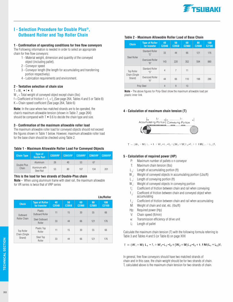
TEC
HN
ICA
L SE
CTI
ON
263
I - Selection Procedure for Double Plus®, Outboard Roller and Top Roller Chain
1 - Confirmation of operating conditions for free flow conveyorsThe Following information is needed in order to select an appropriatechain for free flow conveyors: 1 - Material weight, dimension and quantity of the conveyed object (including pallet). 2 - Conveyor speed 3 - Conveyor length (the length for accumulating and transferring portion respectively). 4 - Lubrication requirements and environment.
2 - Tentative selection of chain sizeT = WT • f • KW T = Total weight of conveyed object except chain (lbs)f = Coefficient of friction f = f2 + f3 (See page 264, Tables 4 and 5 or Table 8)K = Chain speed coefficient (See page 264, Table 6)
Note: In the case where two matched strands are to be operated, thechain’s maximum allowable tension (shown in Table 7, page 264)should be compared with T • 0.6 to decide the chain type and size.
3 - Confirmation of the maximum allowable roller loadThe maximum allowable roller load for conveyed objects should not exceedthe figures shown in Table 1 below. However, maximum allowable roller loadfor the base chain should be checked using Table 2.
Table 1 - Maximum Allowable Roller Load For Conveyed Objects
Chain Type Type of Guide Rail C2030VRP C2040VRP C2050VRP C2060VRP C2080VRP
Double Plus Chain
Aluminum 26 40 53 67
Aluminum with Steel Rail 53 80 107 134 201
This is the load for two strands of Double-Plus chainNote - When using aluminum frame with steel rail, the maximum allowable for VR series is twice that of VRP series
Table 2 - Maximum Allowable Roller Load of Base Chain
Chain Type of Roller for transfer
40 C2040
50 C2050
60 C2060
80 C2080
100 C2100
Steel Roller
Standard Roller “S”
33 44 66 121 176
Oversized Roller “R”
143 220 352 594 880
Top Roller Chain (Single
Strand)
Standard Roller “S”
4 7 11
Oversized Roller “R”
44 66 110 198 286
Poly Steel 4 9 13
Note - The above figures for Poly-Steel show the maximum allowable load per plastic inner link.
Lbs/Roller
Chain Type of Roller for transfer
40 C2040
50 C2050
60 C2060
80 C2080
100 C2100
Outboard Roller Chain
Plastic Outboard Roller
11 15 30 55 66
Steel Outboard Roller
33 44 66 121 176
Top Roller Chain (Single
Strand)
Plastic Top Roller
11 15 30 55 66
Steel TopRoller
33 44 66 121 176
4 - Calculation of maximum chain tension (T)
5 - Calculation of required power (HP) P: Maximum number of pallets o n conveyor T: Maximum chain tension (lbs) L 2: Length of accumulating portion (ft) W 2: Weight of conveyed objects in accumulating portion (Lbs/ft) L 1: Length of conveying portion (ft) W 1: Weight of conveyed objects in conveying portion f1: Coefficient of friction between chain and rail when conveying f 2: Coefficent of friction between chain and conveyed object when accumulating f 3: Coefficient of friction between chain and rail when accumulating M: Weight of chain and slat, etc. (lbs/ft) Hp: Required power (Hp) V: Chain speed (ft/min) : Transmission efficiency of drive unit L: Length of pallet
Calculate the maximum chain tension (T) with the following formula referring to Table 3 and Tables 4 and 5 (or Table 8) on page XXX
In general, free flow conveyors should have two matched strands ofchain and in this case, the chain weight should be for two strands of chain.T, calculated above is the maximum chain tension for two strands of chain.
.TSUBAKI"
Accumulating Portion L, I
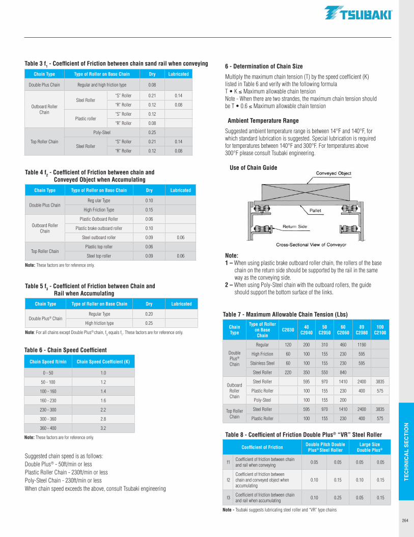
TEC
HN
ICA
L SE
CTI
ON
264
Chain Type Type of Roller on Base Chain Dry Lubricated
Double Plus Chain Regular and high friction type 0.08
Outboard Roller Chain
Steel Roller“S” Roller 0.21 0.14
“R” Roller 0.12 0.08
Plastic roller“S” Roller 0.12
“R” Roller 0.08
Top Roller Chain
Poly-Steel 0.25
Steel Roller“S” Roller 0.21 0.14
“R” Roller 0.12 0.08
Table 3 f1 - Coefficient of Friction between chain sand rail when conveying 6 - Determination of Chain Size
Multiply the maximum chain tension (T) by the speed coefficient (K)listed in Table 6 and verify with the following formulaT • K ≤ Maximum allowable chain tensionNote - When there are two strandes, the maximum chain tension should be T • 0.6 ≤ Maximum allowable chain tension
Ambient Temperature Range
Suggested ambient temperature range is between 14°F and 140°F, forwhich standard lubrication is suggested. Special lubrication is requiredfor temperatures between 140°F and 300°F. For temperatures above 300°F please consult Tsubaki engineering.
Use of Chain Guide
Note:1 – When using plastic brake outboard roller chain, the rollers of the base chain on the return side should be supported by the rail in the same way as the conveying side.2 – When using Poly-Steel chain with the outboard rollers, the guide should support the bottom surface of the links.
Table 4 f2 - Coefficient of Friction between chain and Conveyed Object when Accumulating
Chain Type Type of Roller on Base Chain Dry Lubricated
Double Plus ChainReg ular Type 0.10
High Friction Type 0.15
Outboard Roller Chain
Plastic Outboard Roller 0.06
Plastic brake outboard roller 0.10
Steel outboard roller 0.09 0.06
Top Roller ChainPlastic top roller 0.06
Steel top roller 0.09 0.06
Note: These factors are for reference only.
Table 5 f3 - Coefficient of Friction between Chain and Rail when Accumulating
Chain Type Type of Roller on Base Chain Dry Lubricated
Double Plus® ChainRegular Type 0.20
High friction type 0.25
Note: For all chains except Double Plus® chain, f3 equals f1. These factors are for reference only.
Table 6 - Chain Speed Coefficient
Chain Speed ft/min Chain Speed Coefficient (K)
0 - 50 1.0
50 - 100 1.2
100 - 160 1.4
160 - 230 1.6
230 - 300 2.2
300 - 360 2.8
360 - 400 3.2
Note: These factors are for reference only.
Suggested chain speed is as follows:Double Plus® - 50ft/min or lessPlastic Roller Chain - 230ft/min or lessPoly-Steel Chain - 230ft/min or lessWhen chain speed exceeds the above, consult Tsubaki engineering
Table 8 - Coefficient of Friction Double Plus® “VR” Steel Roller
Coefficient of Friction Double Pitch Double Plus® Steel Roller
Large Size Double Plus®
f1 Coefficient of friction between chain and rail when conveying 0.05 0.05 0.05 0.05
f2Coefficient of friction between chain and conveyed object when accumulating
0.10 0.15 0.10 0.15
f3 Coefficient of friction between chain and rail when accumulating 0.10 0.25 0.05 0.15
Note - Tsubaki suggests lubricating steel roller and “VR” type chains
Table 7 - Maximum Allowable Chain Tension (Lbs)
Chain Type
Type of Roller on Base Chain
C2030 40 C2040
50C2050
60 C2060
80 C2080
100 C2100
Double Plus® Chain
Regular 120 200 310 460 1190
High Friction 60 100 155 230 595
Stainless Steel 60 100 155 230 595
Steel Roller 220 350 550 840
Outboard Roller Chain
Steel Roller 595 970 1410 2400 3835
Plastic Roller 100 155 230 400 575
Poly-Steel 100 155 200
Top Roller Chain
Steel Roller 595 970 1410 2400 3835
Plastic Roller 100 155 230 400 575
.TSUBAKI"
Conveyed Object
Cross-Sectional View of Conveyor
... .. ..
... ... ...
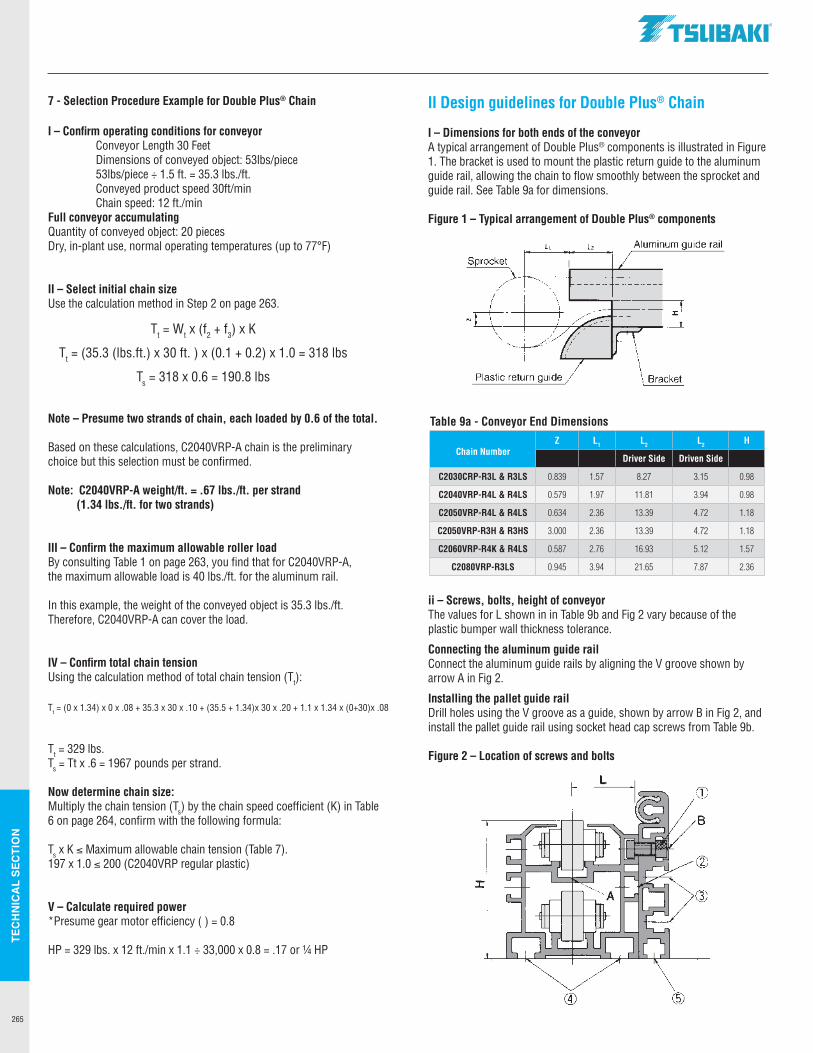
TEC
HN
ICA
L SE
CTI
ON
265
7 - Selection Procedure Example for Double Plus® Chain
I – Confirm operating conditions for conveyor Conveyor Length 30 Feet Dimensions of conveyed object: 53lbs/piece 53lbs/piece ÷ 1.5 ft. = 35.3 lbs./ft. Conveyed product speed 30ft/min Chain speed: 12 ft./minFull conveyor accumulatingQuantity of conveyed object: 20 piecesDry, in-plant use, normal operating temperatures (up to 77°F)
II – Select initial chain sizeUse the calculation method in Step 2 on page 263.
Note – Presume two strands of chain, each loaded by 0.6 of the total.
Based on these calculations, C2040VRP-A chain is the preliminary choice but this selection must be confirmed.
Note: C2040VRP-A weight/ft. = .67 lbs./ft. per strand (1.34 lbs./ft. for two strands)
III – Confirm the maximum allowable roller loadBy consulting Table 1 on page 263, you find that for C2040VRP-A, the maximum allowable load is 40 lbs./ft. for the aluminum rail.
In this example, the weight of the conveyed object is 35.3 lbs./ft.Therefore, C2040VRP-A can cover the load.
IV – Confirm total chain tensionUsing the calculation method of total chain tension (Tt):
Tt = 329 lbs.Ts = Tt x .6 = 1967 pounds per strand.
Now determine chain size:Multiply the chain tension (Ts) by the chain speed coefficient (K) in Table 6 on page 264, confirm with the following formula:
Ts x K ≤ Maximum allowable chain tension (Table 7).197 x 1.0 ≤ 200 (C2040VRP regular plastic)
V – Calculate required power*Presume gear motor efficiency () = 0.8
HP = 329 lbs. x 12 ft./min x 1.1 ÷ 33,000 x 0.8 = .17 or ¼ HP
II Design guidelines for Double Plus® Chain
I – Dimensions for both ends of the conveyorA typical arrangement of Double Plus® components is illustrated in Figure 1. The bracket is used to mount the plastic return guide to the aluminum guide rail, allowing the chain to flow smoothly between the sprocket and guide rail. See Table 9a for dimensions.
Figure 1 – Typical arrangement of Double Plus® components
ii – Screws, bolts, height of conveyorThe values for L shown in in Table 9b and Fig 2 vary because of the plastic bumper wall thickness tolerance.
Connecting the aluminum guide railConnect the aluminum guide rails by aligning the V groove shown by arrow A in Fig 2.
Installing the pallet guide railDrill holes using the V groove as a guide, shown by arrow B in Fig 2, and install the pallet guide rail using socket head cap screws from Table 9b.
Figure 2 – Location of screws and bolts
Table 9a - Conveyor End Dimensions
Chain NumberZ L1 L2 L2 H
Driver Side Driven Side
C2030CRP-R3L & R3LS 0.839 1.57 8.27 3.15 0.98
C2040VRP-R4L & R4LS 0.579 1.97 11.81 3.94 0.98
C2050VRP-R4L & R4LS 0.634 2.36 13.39 4.72 1.18
C2050VRP-R3H & R3HS 3.000 2.36 13.39 4.72 1.18
C2060VRP-R4K & R4LS 0.587 2.76 16.93 5.12 1.57
C2080VRP-R3LS 0.945 3.94 21.65 7.87 2.36
Tt = Wt x (f2 + f3) x K
Tt = (35.3 (lbs.ft.) x 30 ft. ) x (0.1 + 0.2) x 1.0 = 318 lbs
Ts = 318 x 0.6 = 190.8 lbs
Tt = (0 x 1.34) x 0 x .08 + 35.3 x 30 x .10 + (35.5 + 1.34)x 30 x .20 + 1.1 x 1.34 x (0+30)x .08
.TSUBAKI"
L, L, Aluminum guide rail
Bracket
-1111--1111
CD
B
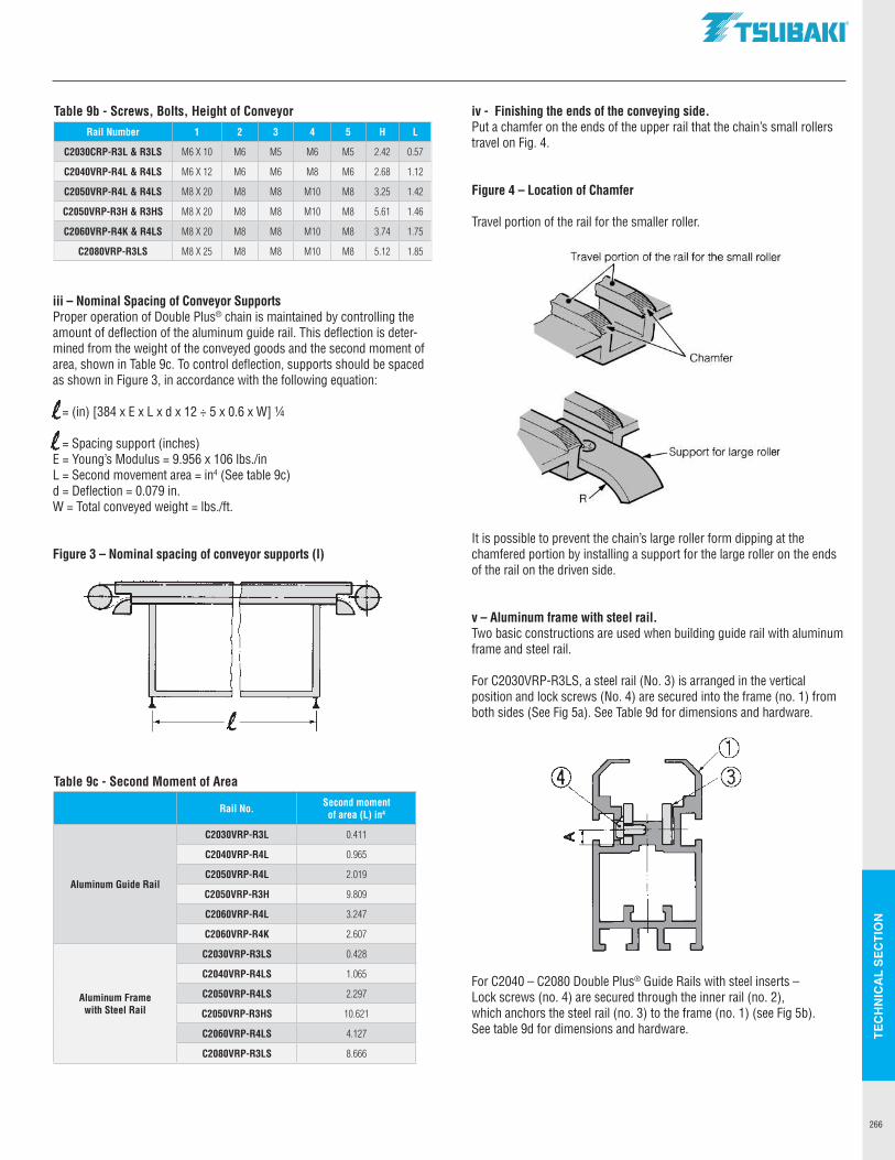
TEC
HN
ICA
L SE
CTI
ON
266
iii – Nominal Spacing of Conveyor SupportsProper operation of Double Plus® chain is maintained by controlling the amount of deflection of the aluminum guide rail. This deflection is deter-mined from the weight of the conveyed goods and the second moment of area, shown in Table 9c. To control deflection, supports should be spaced as shown in Figure 3, in accordance with the following equation:
= (in) [384 x E x L x d x 12 ÷ 5 x 0.6 x W] ¼
= Spacing support (inches)E = Young’s Modulus = 9.956 x 10⁶ lbs./inL = Second movement area = in4 (See table 9c)d = Deflection = 0.079 in.W = Total conveyed weight = lbs./ft.
Figure 3 – Nominal spacing of conveyor supports (l)
iv - Finishing the ends of the conveying side.Put a chamfer on the ends of the upper rail that the chain’s small rollers travel on Fig. 4.
Figure 4 – Location of Chamfer
Travel portion of the rail for the smaller roller.
It is possible to prevent the chain’s large roller form dipping at the chamfered portion by installing a support for the large roller on the ends of the rail on the driven side.
v – Aluminum frame with steel rail.Two basic constructions are used when building guide rail with aluminum frame and steel rail.
For C2030VRP-R3LS, a steel rail (No. 3) is arranged in the vertical position and lock screws (No. 4) are secured into the frame (no. 1) from both sides (See Fig 5a). See Table 9d for dimensions and hardware.
For C2040 – C2080 Double Plus® Guide Rails with steel inserts – Lock screws (no. 4) are secured through the inner rail (no. 2), which anchors the steel rail (no. 3) to the frame (no. 1) (see Fig 5b). See table 9d for dimensions and hardware.
Table 9c - Second Moment of Area
Rail No. Second momentof area (L) in4
Aluminum Guide Rail
C2030VRP-R3L 0.411
C2040VRP-R4L 0.965
C2050VRP-R4L 2.019
C2050VRP-R3H 9.809
C2060VRP-R4L 3.247
C2060VRP-R4K 2.607
Aluminum Frame with Steel Rail
C2030VRP-R3LS 0.428
C2040VRP-R4LS 1.065
C2050VRP-R4LS 2.297
C2050VRP-R3HS 10.621
C2060VRP-R4LS 4.127
C2080VRP-R3LS 8.666
Table 9b - Screws, Bolts, Height of ConveyorRail Number 1 2 3 4 5 H L
C2030CRP-R3L & R3LS M6 X 10 M6 M5 M6 M5 2.42 0.57
C2040VRP-R4L & R4LS M6 X 12 M6 M6 M8 M6 2.68 1.12
C2050VRP-R4L & R4LS M8 X 20 M8 M8 M10 M8 3.25 1.42
C2050VRP-R3H & R3HS M8 X 20 M8 M8 M10 M8 5.61 1.46
C2060VRP-R4K & R4LS M8 X 20 M8 M8 M10 M8 3.74 1.75
C2080VRP-R3LS M8 X 25 M8 M8 M10 M8 5.12 1.85
l l
.TSUBAKI"
Travel portion of the rail for the small roller
Chamfer
Support for large roller
CD @
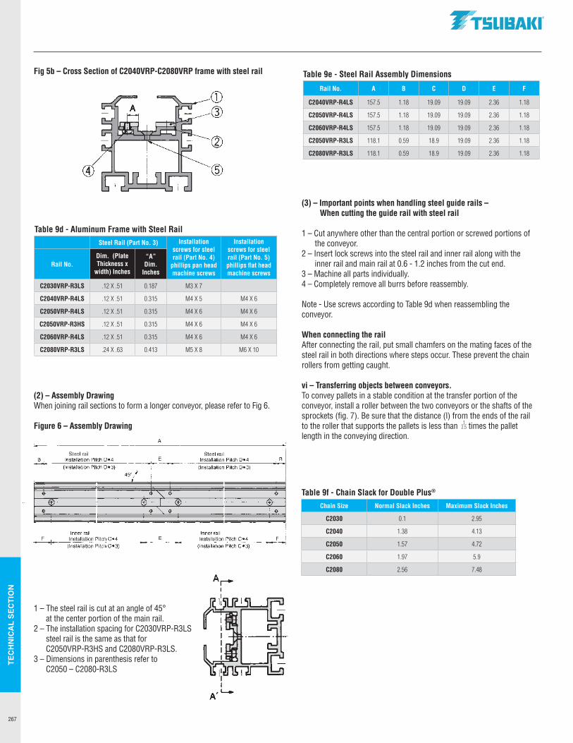
TEC
HN
ICA
L SE
CTI
ON
267
Fig 5b – Cross Section of C2040VRP-C2080VRP frame with steel rail
(2) – Assembly DrawingWhen joining rail sections to form a longer conveyor, please refer to Fig 6.
Figure 6 – Assembly Drawing
1 – The steel rail is cut at an angle of 45° at the center portion of the main rail.
2 – The installation spacing for C2030VRP-R3LS steel rail is the same as that for C2050VRP-R3HS and C2080VRP-R3LS.
3 – Dimensions in parenthesis refer to C2050 – C2080-R3LS
(3) – Important points when handling steel guide rails – When cutting the guide rail with steel rail
1 – Cut anywhere other than the central portion or screwed portions of the conveyor.
2 – Insert lock screws into the steel rail and inner rail along with the inner rail and main rail at 0.6 - 1.2 inches from the cut end.
3 – Machine all parts individually.4 – Completely remove all burrs before reassembly.
Note - Use screws according to Table 9d when reassembling the conveyor.
When connecting the railAfter connecting the rail, put small chamfers on the mating faces of the steel rail in both directions where steps occur. These prevent the chain rollers from getting caught.
vi – Transferring objects between conveyors.To convey pallets in a stable condition at the transfer portion of the conveyor, install a roller between the two conveyors or the shafts of the sprockets (fig. 7). Be sure that the distance (l) from the ends of the rail to the roller that supports the pallets is less than times the pallet length in the conveying direction.
Table 9d - Aluminum Frame with Steel RailSteel Rail (Part No. 3) Installation
screws for steel rail (Part No. 4)
phillips pan head machine screws
Installation screws for steel rail (Part No. 5) phillips flat head machine screws
Rail No.Dim. (Plate Thickness x
width) Inches
“A” Dim.
Inches
C2030VRP-R3LS .12 X .51 0.187 M3 X 7
C2040VRP-R4LS .12 X .51 0.315 M4 X 5 M4 X 6
C2050VRP-R4LS .12 X .51 0.315 M4 X 6 M4 X 6
C2050VRP-R3HS .12 X .51 0.315 M4 X 6 M4 X 6
C2060VRP-R4LS .12 X .51 0.315 M4 X 6 M4 X 6
C2080VRP-R3LS .24 X .63 0.413 M5 X 8 M6 X 10
Table 9e - Steel Rail Assembly Dimensions
Rail No. A B C D E F
C2040VRP-R4LS 157.5 1.18 19.09 19.09 2.36 1.18
C2050VRP-R4LS 157.5 1.18 19.09 19.09 2.36 1.18
C2060VRP-R4LS 157.5 1.18 19.09 19.09 2.36 1.18
C2050VRP-R3LS 118.1 0.59 18.9 19.09 2.36 1.18
C2080VRP-R3LS 118.1 0.59 18.9 19.09 2.36 1.18
12.5
Table 9f - Chain Slack for Double Plus®
Chain Size Normal Slack Inches Maximum Slack Inches
C2030 0.1 2.95
C2040 1.38 4.13
C2050 1.57 4.72
C2060 1.97 5.9
C2080 2.56 7.48
Steel rail B Installation Pitch 0•4
(Installation Pitch D•3)
II
~ II --(+)-- ---it-- ---
+ II
I II
Inner rail I F Installation Pitch C•4 . (Installation Pitch C 3)
A
E '
450A
"
CD @
Steel rail Installation Pitch 0•4
(Installation Pitch D•3)
II
II
B I I i
-f---1 +)- 1-----(+)---- __ ,, ______ -(+)--
4"..+ II -e-
ii Inner rail
E Installation Pitch C•4 F . (Installation Pitch C 3)
.TSUBAKI"
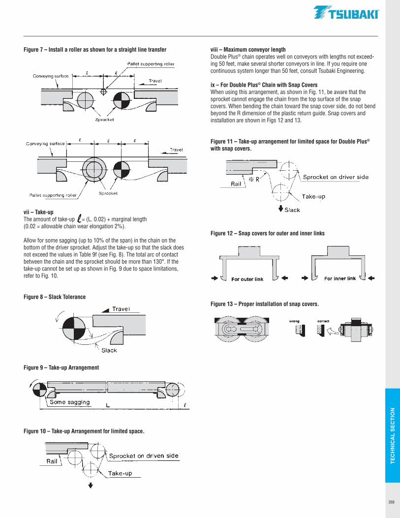
TEC
HN
ICA
L SE
CTI
ON
268
Figure 7 – Install a roller as shown for a straight line transfer
vii – Take-upThe amount of take-up = (L. 0.02) + marginal length (0.02 = allowable chain wear elongation 2%).
Allow for some sagging (up to 10% of the span) in the chain on the bottom of the driver sprocket. Adjust the take-up so that the slack does not exceed the values in Table 9f (see Fig. 8). The total arc of contact between the chain and the sprocket should be more than 130°. If the take-up cannot be set up as shown in Fig. 9 due to space limitations, refer to Fig. 10.
Figure 8 – Slack Tolerance
Figure 9 – Take-up Arrangement
Figure 10 – Take-up Arrangement for limited space.
viii – Maximum conveyor lengthDouble Plus® chain operates well on conveyors with lengths not exceed-ing 50 feet, make several shorter conveyors in line. If you require one continuous system longer than 50 feet, consult Tsubaki Engineering.
ix – For Double Plus® Chain with Snap CoversWhen using this arrangement, as shown in Fig. 11, be aware that the sprocket cannot engage the chain from the top surface of the snap covers. When bending the chain toward the snap cover side, do not bend beyond the R dimension of the plastic return guide. Snap covers and installation are shown in Figs 12 and 13.
Figure 11 – Take-up arrangement for limited space for Double Plus® with snap covers.
Figure 12 – Snap covers for outer and inner links
Figure 13 – Proper installation of snap covers.
Sprocket
Pallet supporting roller
Travel ---
Conveying surface i---~------.-----i
Pallet supporting roller Sprocket
Travel --
~--el-
~ Slack
~· ~esaggi"g
r L
Rail Sprocket on driven side
+
.TSUBAKI"
Take-up
♦ slack
For outer link • For Inner link
Mt wrong
ml
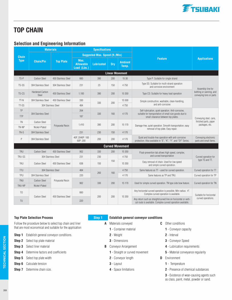
TEC
HN
ICA
L SE
CTI
ON
269
Selection and Engineering Information
Chain Type
Materials Specifications
Feature ApplicationsChain/Pin Top Plate
Suggested Max. Speed (ft./Min)
Max. Allowable
Load (Lbs.)Lubricated Dry Ambient
Temp.
Linear Movement
TS-P Carbon Steel 430 Stainless Steel 660 390 200 15 30 Type P: Suitable for single strand
Assembly line for bottling or canning, and conveying tons or parts
TS-SS 304 Stainless Steel 304 Stainless Steel 231 23 150 4 750 Type SS: Suitable for multi-strand operation and corrosive environment
TS-CS Hardened Carbon Steel 430 Stainless Steel 1,100 390 200 15 350 Type CS: Suitable for heavy load operation
TT-N 304 Stainless Steel 430 Stainless Steel 330330 200
15 500 Simple construction, washable, clean-handling, and anti-corrosiveTT-SS 304 Stainless Steel 484 4 750
TP304 Stainless Steel
Polyacetal Resin
264330 160 4 170
Self-lubrication, quiet operation. Anti-corrosive, suitable for transportation of small size goods due to
small clearance between top plates. Conveying steel, cans, finished parts, paper
packages, etc.
TTP 187
TN Carbon Steel1,410 390 200 15 170 Damage-free, quiet operation. Smooth transportation, easy
removal of top plate. Easy repair.TN-NP Nickel-Plated
TN-S 304 Stainless Steel 231 230 150 4 170
P 304 Stainless Steel 40P, 2040P: 100 60P: 200 200 200 4 170 Quiet and trouble-free operation with anti-corrosive
protection. Also available in “E”, “K”, “Y”, and “SY” Series.Conveying electronic parts and small items.
Curved MovementTRU Carbon Steel 430 Stainless Steel 902 330 200 15 350 Float-prevention tab allows high speed, complex,
and curved transportation Curved operation for type TS and TT.
TRU-SS 304 Stainless Steel 231 230
150
4 750
TKU Carbon Steel 430 Stainless Steel 638 150 15 350 Easy removal of chain. Used for low speed and simple curved operation.
TTU 304 Stainless Steel 484260 160
4 750 Same features as TT - used for curved operation. Curved operation for TT
TPU 304 Stainless Steel
Polyacetal Resin
220 4 170 Same features as TP and TRU. Curved operation for TP
TNU Carbon Steel902 330 200 15 170 Used for simple curved operation. TN type side bow feature. Curved operation for TN
TNU-NP Nickel-Plated
TO
Carbon Steel 430 Stainless Steel
660
200 200 15 350
Any horizontal curved operation is possible. Min radius: 4”. Complex curved operation is available. Suitable for horizontal
curved operations.TU 220 Any return such as straight/curved line on horizontal or verti-
cal route is available. Complex curved operation available.
Top Plate Selection Process Step 1 Establish general conveyor conditions
Follow the procedure below to select top chain and linerthat are most economical and suitable for the application
A Materials conveyed C Other conditions
1 - Container material 1 - Conveyor capacity
Step 1 Establish general conveyor conditions. 2 - Weight 2 - Interval
Step 2 Select top plate material 3 - Dimensions 3 - Conveyor Speed
Step 3 Select liner material B Conveyor Arrangement 4 - Lubrication requirements
Step 4 Determine factors and coefficients 1 - Straight or curved movement 5 - Material conveyance regularity
Step 5 Select top plate width 2 - Conveyor length D Environment
Step 6 Calculate tension 3 - Layout 1 - Temperature
Step 7 Determine chain size. 4 - Space limitations 2 - Presence of chemical substances
3 - Existence of wear-causing agents such as class, paint, metal, powder or sand.
TOP CHAIN
.TSUBAKI"
+
+
I I-
-
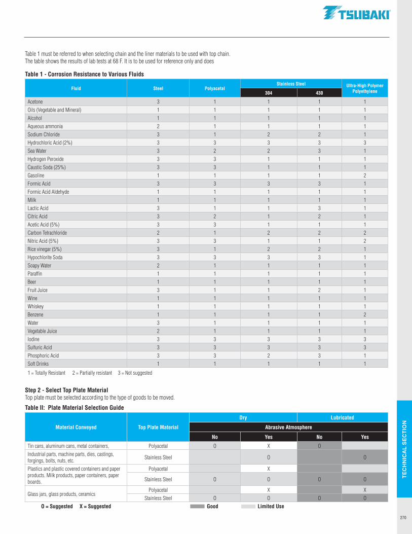
TEC
HN
ICA
L SE
CTI
ON
270
Table 1 must be referred to when selecting chain and the liner materials to be used with top chain. The table shows the results of lab tests at 68 F. It is to be used for reference only and does
Table 1 - Corrosion Resistance to Various Fluids
Fluid Steel PolyacetalStainless Steel Ultra-High Polymer
Polyethylene304 430
Acetone 3 1 1 1 1Oils (Vegetable and Mineral) 1 1 1 1 1Alcohol 1 1 1 1 1Aqueous ammonia 2 1 1 1 1Sodium Chloride 3 1 2 2 1Hydrochloric Acid (2%) 3 3 3 3 3Sea Water 3 2 2 3 1Hydrogen Peroxide 3 3 1 1 1Caustic Soda (25%) 3 3 1 1 1Gasoline 1 1 1 1 2Formic Acid 3 3 3 3 1Formic Acid Aldehyde 1 1 1 1 1Milk 1 1 1 1 1Lactic Acid 3 1 1 3 1Citric Acid 3 2 1 2 1Acetic Acid (5%) 3 3 1 1 1Carbon Tetrachloride 2 1 2 2 2Nitric Acid (5%) 3 3 1 1 2Rice vinegar (5%) 3 1 2 2 1Hypochlorite Soda 3 3 3 3 1Soapy Water 2 1 1 1 1Paraffin 1 1 1 1 1Beer 1 1 1 1 1Fruit Juice 3 1 1 2 1Wine 1 1 1 1 1Whiskey 1 1 1 1 1Benzene 1 1 1 1 2Water 3 1 1 1 1Vegetable Juice 2 1 1 1 1Iodine 3 3 3 3 3Sulfuric Acid 3 3 3 3 3Phosphoric Acid 3 3 2 3 1Soft Drinks 1 1 1 1 1
1 = Totally Resistant 2 = Partially resistant 3 = Not suggested
Step 2 - Select Top Plate MaterialTop plate must be selected according to the type of goods to be moved.
Table II: Plate Material Selection Guide
Material Conveyed Top Plate Material
Dry Lubricated
Abrasive Atmosphere
No Yes No Yes
Tin cans, aluminum cans, metal containers, Polyacetal O X OIndustrial parts, machine parts, dies, castings, forgings, bolts, nuts, etc. Stainless Steel O O
Plastics and plastic covered containers and paper products. Milk products, paper containers, paper boards.
Polyacetal X
Stainless Steel O O O O
Glass jars, glass products, ceramicsPolyacetal X X
Stainless Steel O O O OO = Suggested X = Suggested Good Limited Use
.TSUBAKI"
- -
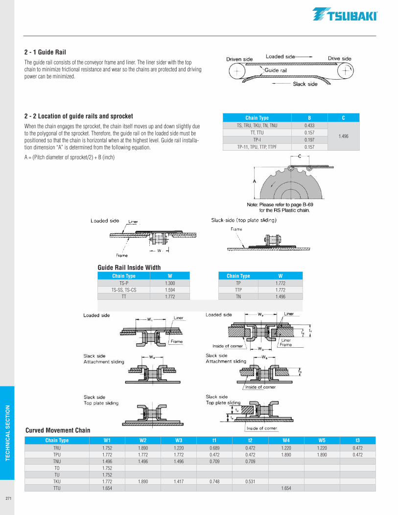
TEC
HN
ICA
L SE
CTI
ON
271
Guide Rail Inside WidthChain Type W Chain Type W
TS-P 1.300 TP 1.772TS-SS, TS-CS 1.594 TTP 1.772
TT 1.772 TN 1.496
2 - 1 Guide RailThe guide rail consists of the conveyor frame and liner. The liner sider with the top chain to minimize frictional resistance and wear so the chains are protected and driving power can be minimized.
2 - 2 Location of guide rails and sprocketWhen the chain engages the sprocket, the chain itself moves up and down slightly due to the polygonal of the sprocket. Therefore, the guide rail on the loaded side must be positioned so that the chain is horizontal when at the highest level. Guide rail installa-tion dimension “A” is determined from the following equation.
A = (Pitch diameter of sprocket/2) + B (inch)
Chain Type B CTS, TRU, TKU, TN, TNU 0.433
1.496TT, TTU 0.157
TP-I 0.197TP-11, TPU, TTP, TTPF 0.157
Chain Type W1 W2 W3 t1 t2 W4 W5 t3TRU 1.752 1.890 1.220 0.689 0.472 1.220 1.220 0.472TPU 1.772 1.772 1.772 0.472 0.472 1.890 1.890 0.472TNU 1.496 1.496 1.496 0.709 0.709TO 1.752TU 1.752
TKU 1.772 1.890 1.417 0.748 0.531TTU 1.654 1.654
Curved Movement Chain
Loaded side Liner
,(S?''o/®<i~'<<F!((ml
, w Frame
Loaded side
~ Slack side Attachment sliding
Slack side Top plate sliding
.TSUBAKI"
Driven side Loaded side--- Drive side
G!:'.~~~q~;:,::,, ::,::::::;::;m --- Slack side
Note: Please refer to page B-69 for the RS Plastic chain.
Slack-side (top plate sliding)
Frame
2<773
Slack side
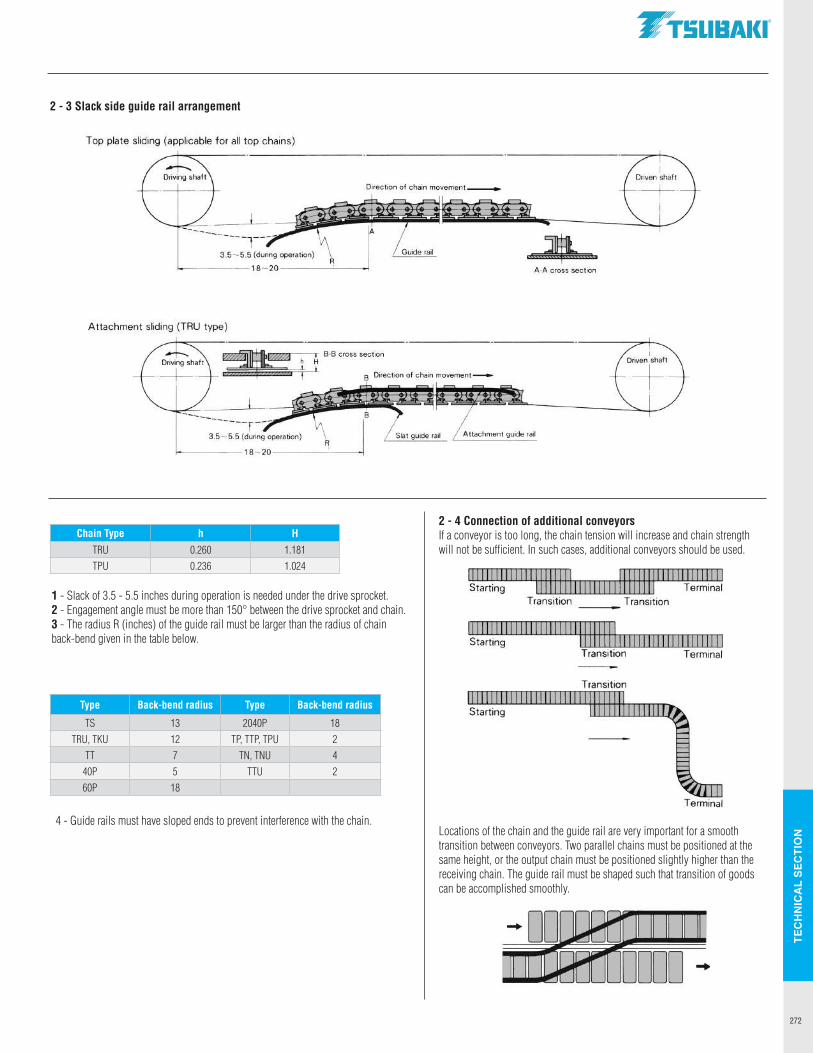
TEC
HN
ICA
L SE
CTI
ON
272
1 - Slack of 3.5 - 5.5 inches during operation is needed under the drive sprocket.2 - Engagement angle must be more than 150° between the drive sprocket and chain.3 - The radius R (inches) of the guide rail must be larger than the radius of chain back-bend given in the table below.
2 - 3 Slack side guide rail arrangement
Chain Type h H
TRU 0.260 1.181TPU 0.236 1.024
Type Back-bend radius Type Back-bend radius
TS 13 2040P 18TRU, TKU 12 TP, TTP, TPU 2
TT 7 TN, TNU 440P 5 TTU 260P 18
4 - Guide rails must have sloped ends to prevent interference with the chain.
2 - 4 Connection of additional conveyorsIf a conveyor is too long, the chain tension will increase and chain strength will not be sufficient. In such cases, additional conveyors should be used.
Locations of the chain and the guide rail are very important for a smooth transition between conveyors. Two parallel chains must be positioned at the same height, or the output chain must be positioned slightly higher than the receiving chain. The guide rail must be shaped such that transition of goods can be accomplished smoothly.
.TSUBAKI"
Top plate sliding (applicable for all top chains)
Direction of chain movement____.,
A-A cross section
Attachment sliding (TRU type)
~m=~--.♦ - B·B cross section
~fhhwm 11 B Direction of chain movement-
>----------18-20------------<
1111111111111111111111 1111111111111111111,111 Starting 111111111 Terminal
Transition ___ Transition
1111111111111111111111111111111 Starting I I I 1111111111 I 11111 I I 1
Transition Terminal
Transition
Terminal
-0~1111111111 111 11 1 DODD ..
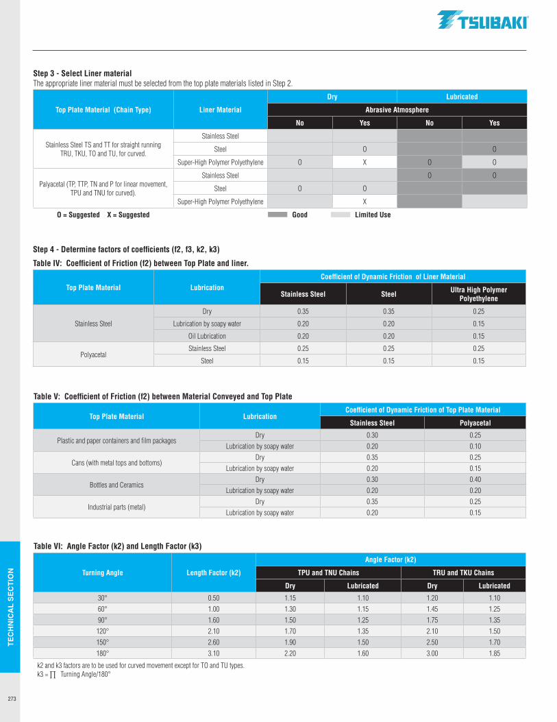
TEC
HN
ICA
L SE
CTI
ON
273
Step 4 - Determine factors of coefficients (f2, f3, k2, k3)
Table IV: Coefficient of Friction (f2) between Top Plate and liner.
Top Plate Material LubricationCoefficient of Dynamic Friction of Liner Material
Stainless Steel Steel Ultra High Polymer Polyethylene
Stainless Steel
Dry 0.35 0.35 0.25
Lubrication by soapy water 0.20 0.20 0.15
Oil Lubrication 0.20 0.20 0.15
PolyacetalStainless Steel 0.25 0.25 0.25
Steel 0.15 0.15 0.15
Step 3 - Select Liner materialThe appropriate liner material must be selected from the top plate materials listed in Step 2.
Top Plate Material (Chain Type) Liner Material
Dry Lubricated
Abrasive Atmosphere
No Yes No Yes
Stainless Steel TS and TT for straight running TRU, TKU, TO and TU, for curved.
Stainless Steel
Steel O O
Super-High Polymer Polyethylene O X O O
Palyacetal (TP, TTP, TN and P for linear movement, TPU and TNU for curved).
Stainless Steel O O
Steel O O
Super-High Polymer Polyethylene X
O = Suggested X = Suggested Good Limited Use
Table VI: Angle Factor (k2) and Length Factor (k3)
Turning Angle Length Factor (k2)
Angle Factor (k2)
TPU and TNU Chains TRU and TKU Chains
Dry Lubricated Dry Lubricated
30° 0.50 1.15 1.10 1.20 1.1060° 1.00 1.30 1.15 1.45 1.2590° 1.60 1.50 1.25 1.75 1.35
120° 2.10 1.70 1.35 2.10 1.50150° 2.60 1.90 1.50 2.50 1.70180° 3.10 2.20 1.60 3.00 1.85
k2 and k3 factors are to be used for curved movement except for TO and TU types.k3 = ∏ Turning Angle/180°
Table V: Coefficient of Friction (f2) between Material Conveyed and Top Plate
Top Plate Material LubricationCoefficient of Dynamic Friction of Top Plate Material
Stainless Steel Polyacetal
Plastic and paper containers and film packagesDry 0.30 0.25
Lubrication by soapy water 0.20 0.10
Cans (with metal tops and bottoms)Dry 0.35 0.25
Lubrication by soapy water 0.20 0.15
Bottles and CeramicsDry 0.30 0.40
Lubrication by soapy water 0.20 0.20
Industrial parts (metal)Dry 0.35 0.25
Lubrication by soapy water 0.20 0.15
.TSUBAKI"
- -
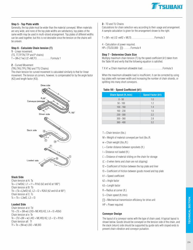
TEC
HN
ICA
L SE
CTI
ON
274
Table VII - Speed Coefficient (k1)
Chain Speed (ft./min) Speed Factor (k1)
0 - 50 1.050 - 100 1.2
100 - 160 1.4160 - 230 1.6230 - 300 2.2300 - 360 2.8360 - 400 3.2
Slack SideChain tension at A: TaTa = L1wf2k2, L1 = l1 + R1k3 (k2 and k3 at 180°)Chain tension at B: TbTb = (Ta +L2wf2) k2, L2 = l2 + R2k3 (k2 and k3 at 90°)Chain tension at C: TcTc = Tb + L3wf2, L3 + l3
Loaded SideChain tension at d: TdTd = (Tc + (M+w) L5f2+ ML’4f3) K2, L4 = l3 +R2k3Chain tension at e: TeTe = (Td +(M + w) L4f2 + ML’4f3) K2, L5 = l2 + R1k3Chain tension atf: TfTf = Te + (M+w) L5f2 + ML’6f3
Step 5 - Top Plate widthGenerally, the top plate must be wider than the material conveyed. When materials are very wide, and none of the top plate widths are satisfactory, top plates of the same width may be used in multi-strand arrangement. Top plates of different widths can be used together, but this is not desirable since the tension on the chains will be uneven.
Step 6 - Calculate Chain tension (T)1 - Linear movement.(TS, TT,TP,TN,TTP and P chains)T = (M+2.1w) Lf2 +ML’F3……………Formula 1
2 - Curved Movement(TRU,TKU,TPU,TNU and TTU Chains)The chain tension for curved movement is calculated similarly to that for linear movement. The tension at corners, however, is compensated for by the angle factor (K2) and length factor (K3).
3 - TO and TU ChainsCalculations for chain selection vary according to their usage and arrangement. A sample calculation is given for the arrangement shown to the right.
T = (M + w) Lf2 +wlf2 + ML’f3…………………….Formula 3
4 - Calculation of power required.HP= (TS/33,000 ∏) ……..Formula 4
Step 7 - Determine Chain SizeMultiply maximum chain tension (T) by the speed coefficient (k1) taken from the Table VII and verify that the following equation is satisfied.
T X k1 ≤ Chain maximum allowable load………………….Formula 5
When the maximum allowable load is insufficient, it can be corrected by using top plates with narrower width and increasing the number of chain strands, or splitting into many short conveyors.
T = Chain tension (lbs.)
M = Weight of material conveyed per foot (lbs./ft.
w = Chain weight (lbs./ft.)
L = Center distance between sprockets (ft.)
l = Distance not loaded (ft.)
L’ = Distance of material sliding on the chain for storage
(L’ = 0 when items and chain are not slipping)
f2 = Coefficient of friction between the top plate and liner
f3 = Coefficient of friction between goods moved and top plate
k1 = Speed coefficient
k2 = Angle factor
k3 = Length factor
R = Radius at corner (ft.)
S = Chain speed (ft./min)
∏ = Mechanical transmission efficiency for drive unit
HP = Power required
Conveyor Design
The layout of a conveyor varies with the type of chain used. A typical layout is shown below. Goods should be conveyed on the tension side of the chain, and the slack (return) side should be supported by guide rails with sloped ends to prevent chain vibration and conveyor pulsation.
.TSUBAKI"
Drive side
Slack side
Loaded side
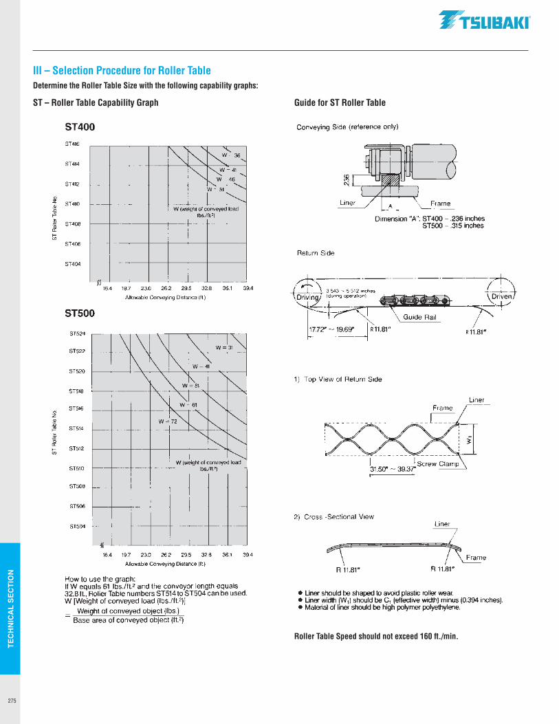
TEC
HN
ICA
L SE
CTI
ON
275
ST – Roller Table Capability Graph Guide for ST Roller Table
Roller Table Speed should not exceed 160 ft./min.
III – Selection Procedure for Roller TableDetermine the Roller Table Size with the following capability graphs:
d z .91 D
t!!1 li;
~ ~ <fl
d z .91 D t!!1 ~ ~ ~ <fl
ST400
ST416
ST414 I~ ~ 'I-... N=36,
ST412 i~ ~~41,
'-. W=46_
W=51 '
ST410 I I"--W !weight of conveyed load
lbs./ft.')
ST408
ST406
ST404
,, JI
16.4 19.7 23.0 26.2 29.5 32.8 36.1 39.4
Allowable Conveying Distance 1ft)
ST500
ST524
ST522 \ \ \ ~ WJ31~
ST520
ST518
ST516
ST514
ST512
I\ I\ ~ W=~~ -\ \
I\_ W~51 ' i'-- ""-
"" "'-.I ~ W=61
W=7~ "' ~ '- "'-"- ' ~ "" ~
W !weight of conveyed load ST510 lbs./ft2)
ST508
ST506
ST504
" " 16.4 19.7 23.0 26.2 29.5 32.8 36.1 39.4
Allowable Conveying Distance (ft.)
How to use the graph: If W equals 61 lbs./ft.2 and the conveyor length equals 32.8 ft., Roller Table numbers ST514 to ST504 can be used. W [Weight of conveyed load (lbs./ft. 2)]
_ Weight of conveyed object (lbs.) - Base area of conveyed object (ft.2)
.TSUBAKI"
Conveying Side (reference only)
Dimension "A": ST400 - .236 inches ST500 - .315 inches
Return Side
17.7':!' - 19.69" R 11.81"
1) Top View of Return Side
Liner Frame
2) Cross -Sectional View Liner
R 11.81" R 11.81"
• Liner should be shaped to avoid plastic roller wear. • Liner width W1) should be C1 (effective width) minus (0.394 inches). • Material of liner should be high polymer polyethylene.
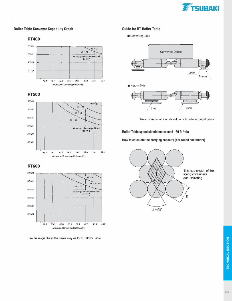
TEC
HN
ICA
L SE
CTI
ON
276
Roller Table Conveyor Capability Graph Guide for RT Roller Table
Roller Table speed should not exceed 160 ft./min
How to calculate the carrying capacity (For round containers)
RT400 RT416
RT412
RT408
RT404
RT500 RT524
RT520
RT516
RT512
RT508
RT504
RT600 RT624
RT620
RT616
RT612
RT608
RT604
.,
w ~ W (weight of conveyed load
lbs.lit.')
16.4 19.7 23.0 26.2 29.5 32.8 36.1 39.4
Allowable Conveying Distance (ft)
W (weight of conveyed load lbs./ft 2)
16.4 19.7 23.0 26.2 29.5 32.8 36.1 39.4
Allowable Conveying Distance (ft.)
~ ....,
~~~ .......______
~-W= I
W (weight of conveyed load lbs./ft')
26,2 29,5 32.8 36.1 39.4 42.6 45.9 49.2
Allowable Conveying Distance (ft)
Use these graphs in the same way as for ST Roller Table.
.TSUBAKI"
Conveying Side
Conveyed Object
Liner Frame
Return Side
Note: Material of liner should be high polymer polyethylene.
This is a sketch of the
8=60°
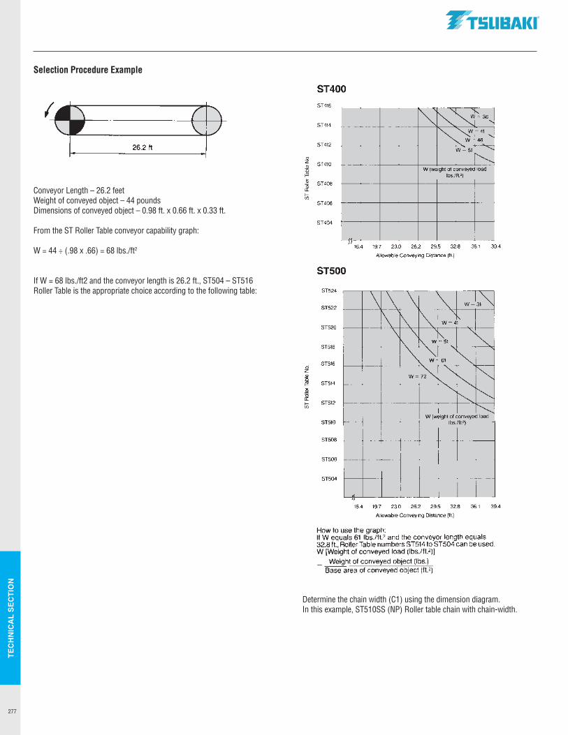
TEC
HN
ICA
L SE
CTI
ON
277
Selection Procedure Example
Conveyor Length – 26.2 feetWeight of conveyed object – 44 poundsDimensions of conveyed object – 0.98 ft. x 0.66 ft. x 0.33 ft.
From the ST Roller Table conveyor capability graph:
W = 44 ÷ (.98 x .66) = 68 lbs./ft2
If W = 68 lbs./ft2 and the conveyor length is 26.2 ft., ST504 – ST516 Roller Table is the appropriate choice according to the following table:
Determine the chain width (C1) using the dimension diagram. In this example, ST510SS (NP) Roller table chain with chain-width.
26.2 ft
ci z ., J5 i!1! i;;
~ f-(/)
ci z ~ i!1! i;;
~ f-(/)
.TSUBAKI"
ST400 ST416
ST414
ST412
~ ~ 'is..
~=36,
"" ~=41
I -.._
'- W=46
W=51 "-
ST410 I f"-..__._
W (weight of conveyed load lbs./tt.2)
ST408
ST406
ST404
,, JI
16.4 19.7 23.0 26.2 29.5 32.8 36.1 39.4
Allowable Conveying Distance (ft.)
ST500
ST524
ST522
ST520
ST518
ST516
ST514
ST512
\ \ \ ""
WJ31~
\ ~ ~ W=~~
\ \ ['__ " \. r'\. W=51 ""-~ "\T ~ W=61
W=7~ "' ~ ' "-~ ' ~ "' "---... W (weight of conveyed load
ST510 lbs./ft.2)
ST508
ST506
ST504
,, " 16.4 19.7 23.0 26.2 29.5 32.8 36.1 39.4
Allowable Conveying Distance (ft.)
How to use the graph: If W equals 61 lbs./ft.2 and the conveyor length equals 32.8 ft., Roller Table numbers ST514 to ST504 can be used. W [Weight of conveyed load (lbs./ft. 2)1 _ Weight of conveyed object (lbs.) - Base area of conveyed object (ft.2)
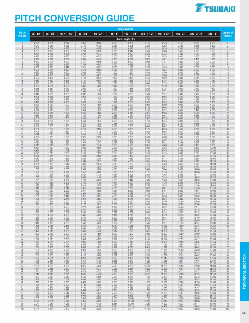
TEC
HN
ICA
L SE
CTI
ON
278
No. of Pitches
Chain NumberLength of Pitches
25 - 1/4” 35 - 3/8” 40/ 41 - 1/2” 50 - 5/8” 60 - 3/4” 80 - 1” 100 - 1-1/4” 120 - 1-1/2” 140 - 1-3/4” 160 - 2” 200 - 2-1/2” 240 - 3”
Chain Length (ft.)1 0.021 0.031 0.042 0.052 0.063 0.083 0.104 0.125 0.146 0.167 0.208 0.250 12 0.042 0.063 0.083 0.104 0.125 0.167 0.208 0.250 0.292 0.333 0.415 0.500 23 0.063 0.094 0.125 0.156 0.188 0.250 0.313 0.375 0.438 0.500 0.625 0.750 34 0.083 0.125 0.167 0.208 0.250 0.333 0.417 0.500 0.588 0.667 0.833 1.000 45 0.104 0.156 0.208 0.260 0.313 0.417 0.521 0.625 0.722 0.833 1.042 1.250 56 0.125 0.188 0.250 0.313 0.375 0.500 0.625 0.750 0.875 1.000 1.250 1.500 67 0.146 0.219 0.292 0.365 0.438 0.583 0.799 0.875 1.021 1.167 1.458 1.750 78 0.167 0.205 0.333 0.417 0.500 0.667 0.833 1.000 1.167 1.333 1.667 2.000 89 0.188 0.281 0.375 0.469 0.563 0.750 0.938 1.126 1.313 1.500 1.875 2.250 910 0.208 0.313 0.417 0.521 0.625 0.833 1.042 1.250 1.458 1.667 2.083 2.500 1011 0.229 0.344 0.459 0.573 0.688 0.917 1.146 1.375 1.604 1.833 2.292 2.750 1112 0.250 0.375 0.500 0.625 0.750 1.000 1.250 1.500 1.750 2.000 2.500 3.000 1213 0.271 0.406 0.542 0.677 0.813 1.083 1.354 1.625 1.896 2.167 2.708 3.250 1314 0.292 0.438 0.583 0.729 0.875 1.167 1.458 1.750 2.042 2.333 2.917 3.500 1415 0.313 0.469 0.625 0.781 0.938 1.250 1.563 1.875 2.188 2.500 3.125 3.750 1516 0.333 0.500 0.667 0.833 1.000 1.333 1.667 2.000 2.333 2.667 3.333 4.000 1617 0.354 0.531 0.708 0.885 1.063 1.417 1.771 2.125 2.479 2.833 3.542 4.250 1718 0.375 0.563 0.750 0.938 1.125 1.500 1.875 2.250 2.725 3.000 3.750 4.500 1819 0.396 0.594 0.792 0.990 1.188 1.583 1.979 2.375 2.771 3.167 3.958 4.750 1920 0.417 0.625 0.833 1.042 1.250 1.667 2.083 2.500 2.917 3.333 4.167 5.000 2021 0.438 0.656 0.875 1.094 1.313 1.750 2.188 2.625 3.063 3.500 4.375 5.250 2122 0.458 0.688 0.917 1.146 1.375 1.833 2.292 2.750 3.208 3.667 4.583 5.500 2223 0.479 0.719 0.958 1.979 1.438 1.917 2.396 2.875 3.354 3.833 4.792 5.750 2324 0.500 0.750 1.000 1.250 1.500 2.000 2.500 3.000 3.500 4.000 5.000 6.000 2425 0.521 0.781 1.042 1.302 1.563 2.083 2.064 3.125 3.646 4.167 5.208 6.250 2526 0.542 0.813 1.083 1.354 1.625 2.167 2.708 3.250 3.792 4.333 5.417 6.500 2627 0.563 0.844 1.125 1.406 1.688 2.250 2.813 3.375 3.938 4.500 5.625 6.750 2728 0.583 0.875 1.667 1.458 1.760 2.333 2.917 3.500 4.083 4.667 5.833 7.000 2829 0.602 0.906 1.208 1.510 1.813 2.417 3.021 3.625 4.229 4.833 6.042 7.250 2930 0.625 0.938 1.250 1.563 1.875 2.500 3.125 3.750 4.375 5.000 6.250 7.500 3031 0.646 0.969 1.292 1.616 1.938 2.588 3.229 3.875 4.521 5.167 6.458 7.750 3132 0.667 1.000 1.333 1.667 2.000 2.667 3.333 4.000 4.667 5.333 6.667 8.000 3233 0.688 1.031 1.375 1.719 2.063 2.750 3.438 4.125 4.813 5.500 6.879 8.250 3334 0.708 1.063 1.417 1.771 2.125 2.833 3.542 4.250 4.958 5.667 7.083 8.500 3435 0.729 1.094 1.458 1.823 2.188 2.917 3.646 4.375 5.104 5.833 7.292 8.750 3536 0.750 1.125 1.500 1.875 2.250 3.000 3.750 4.500 5.250 6.000 7.500 9.000 3637 0.771 1.156 1.542 1.927 2.313 3.083 3.854 4.625 5.396 6.167 7.708 9.250 3738 0.792 1.188 1.583 1.979 2.375 3.167 3.958 4.750 5.542 6.333 7.917 9.500 3839 0.813 1.219 1.625 2.031 2.438 3.250 4.063 4.875 5.688 6.500 8.125 9.750 3940 0.833 1.250 1.667 2.083 2.500 3.333 4.167 5.000 5.833 6.667 8.333 10.000 4041 0.854 1.281 1.708 2.135 2.563 3.417 4.271 5.125 5.979 6.833 8.542 10.250 4142 0.875 1.313 1.750 2.188 2.625 3.500 3.475 5.250 6.125 7.000 8.750 10.500 4243 0.896 1.344 1.792 2.240 2.688 3.583 4.479 5.375 6.271 7.167 8.958 10.750 4344 0.917 1.375 1.833 2.292 2.750 3.667 4.583 5.500 6.417 7.333 9.167 11.000 4445 0.938 1.406 1.875 2.344 2.813 3.750 4.688 5.625 6.563 7.500 9.375 11.250 4546 0.958 1.438 1.917 2.396 2.875 3.833 4.792 5.750 6.708 7.667 9.583 11.500 4647 0.979 1.469 1.958 2.448 2.938 3.917 4.896 5.875 6.854 7.833 9.792 11.750 4748 1.000 1.500 2.000 2.500 3.000 4.000 5.000 6.000 7.000 8.000 10.000 12.000 4849 1.021 1.531 2.042 2.552 3.063 4.083 5.104 6.125 7.146 8.167 10.208 12.250 4950 1.042 1.563 2.083 2.604 3.125 4.167 5.208 6.250 7.292 8.333 10.417 12.500 5051 1.063 1.594 2.125 2.656 3.188 4.250 5.313 6.375 7.438 8.500 10.625 12.750 5152 1.083 1.625 2.167 2.708 3.250 4.333 5.417 6.500 7.583 8.667 10.833 13.000 5253 1.104 1.656 2.208 2.760 3.125 4.417 5.521 6.625 7.729 8.833 11.042 13.250 5354 1.125 1.688 2.250 2.813 3.375 4.500 5.625 6.750 7.875 9.000 11.250 13.500 5455 1.146 1.719 2.917 2.865 3.438 4.583 5.729 6.875 8.021 9.167 11.458 13.750 5556 1.167 1.750 2.333 2.917 3.500 4.667 5.833 7.000 8.167 8.333 11.667 14.000 5657 1.138 1.781 2.375 2.969 3.563 4.750 5.938 7.125 8.313 9.500 11.875 14.250 5758 1.208 1.813 2.417 3.021 3.625 4.833 6.042 7.250 8.458 9.667 12.083 14.500 5859 1.228 1.844 2.458 3.073 3.687 4.917 6.146 7.375 8.604 9.833 12.192 14.750 5960 1.250 1.875 2.500 3.125 3.750 5.000 6.250 7.500 8.750 10.000 12.500 15.000 6061 1.271 1.906 2.542 3.177 3.813 5.083 6.354 7.625 8.896 10.167 12.708 15.250 6162 1.292 1.938 2.583 3.229 3.875 5.167 6.558 7.750 9.042 10.333 12.917 15.500 6263 1.313 1.969 2.625 3.281 3.938 5.250 6.663 7.875 9.188 10.500 13.135 15.750 6364 1.333 2.000 2.667 3.333 4.000 5.333 6.767 8.000 9.333 10.667 13.333 16.000 6465 1.354 2.031 2.708 3.385 4.063 5.417 6.871 8.125 9.479 10.833 13.542 16.250 6566 1.375 2.063 2.750 3.438 4.125 5.500 6.975 8.250 9.625 11.000 13.750 16.500 6667 1.396 2.094 2.792 3.490 4.188 5.883 7.079 8.375 9.771 11.167 13.958 16.750 6768 1.417 2.125 2.833 3.542 4.250 5.667 7.183 8.500 9.917 11.333 14.167 17.000 6869 1.438 2.156 2.875 3.594 4.313 5.750 7.288 8.625 10.063 11.500 14.375 17.250 6970 1.458 2.188 2.917 3.646 4.375 5.833 7.392 8.750 10.208 11.667 14.583 17.500 7071 1.479 2.219 2.958 3.698 4.438 5.917 7.395 8.875 10.354 11.833 14.792 17.750 7172 1.500 2.250 3.000 3.750 4.500 6.000 7.500 9.000 10.500 12.000 15.000 18.000 7273 1.521 2.281 3.042 3.802 4.563 6.083 7.604 9.125 10.646 12.167 15.208 18.250 7374 1.542 2.313 3.083 3.854 4.625 6.167 7.708 9.250 10.792 12.333 15.417 18.500 7475 1.553 2.344 3.125 3.906 4.688 6.250 7.813 9.375 10.938 12.500 15.625 18.750 7576 1.583 2.375 3.167 3.958 4.750 6.333 7.917 9.500 11.083 12.667 15.833 19.000 7677 1.604 3.406 3.208 4.010 4.813 6.417 8.021 9.625 11.229 12.833 16.042 19.250 7778 1.625 2.438 3.250 4.063 4.875 6.500 8.125 9.750 11.375 13.000 16.250 19.500 7879 1.646 2.469 3.292 4.115 4.938 6.583 8.228 9.875 11.521 13.167 16.458 19.750 7980 1.666 2.500 3.333 4.167 5.000 6.667 8.333 10.000 11.667 13.333 16.667 20.000 8081 1.687 2.531 3.375 4.219 5.063 6.750 8.438 10.125 11.813 13.500 16.875 20.250 8182 1.708 2.563 3.417 4.270 5.125 6.833 8.542 10.250 11.958 13.667 17.083 20.500 8283 1.729 2.594 3.458 4.323 5.188 9.917 8.646 10.375 12.104 13.833 17.292 20.750 8384 1.750 2.625 3.500 4.375 5.250 7.000 8.750 10.500 12.250 14.000 17.500 21.000 8485 1.771 2.656 3.542 4.427 5.313 7.083 8.854 10.625 12.396 14.167 17.708 21.250 8586 1.791 2.688 3.583 4.479 5.375 7.167 8.958 10.750 12.542 14.333 17.917 21.500 8687 1.812 2.719 3.625 4.531 5.438 7.250 9.063 10.875 12.688 14.500 18.125 21.750 8788 1.833 2.750 3.667 4.583 5.500 7.333 9.167 11.000 12.833 14.667 18.333 22.000 8889 1.854 2.781 3.708 4.636 5.563 7.417 9.271 11.125 12.979 14.833 18.542 22.250 8990 1.875 2.813 3.750 4.688 5.625 7.500 9.375 11.250 13.125 15.000 18.750 22.500 9091 1.896 2.844 3.792 4.740 5.688 7.583 9.479 11.375 13.271 15.167 18.958 22.750 9192 1.916 2.875 3.833 4.792 5.750 7.667 9.583 11.500 13.417 15.333 19.167 23.000 9293 1.937 2.906 3.875 4.844 5.813 7.750 9.688 11.625 13.563 15.500 19.375 23.250 9394 1.958 2.938 3.917 4.896 5.875 7.833 9.792 11.750 13.708 15.667 19.583 23.500 9495 1.979 2.969 3.958 4.948 2.938 7.917 9.896 11.875 13.854 15.833 19.792 23.750 9596 2.000 3.000 4.000 5.000 6.000 8.000 10.000 12.000 14.000 16.000 20.000 24.000 9697 2.021 3.031 4.042 5.052 6.063 8.083 10.104 12.125 14.146 16.167 20.208 24.250 9798 2.041 3.063 4.083 5.104 6.125 8.167 10.208 12.250 14.292 16.333 20.417 24.500 9899 2.062 3.094 4.125 5.156 6.188 8.250 10.313 12.375 14.438 16.500 20.625 24.750 99
100 2.083 3.125 4.167 5.208 6.250 8.333 10.417 12.500 14.583 16.667 20.833 25.000 100
PITCH CONVERSION GUIDE.TSUBAKI"
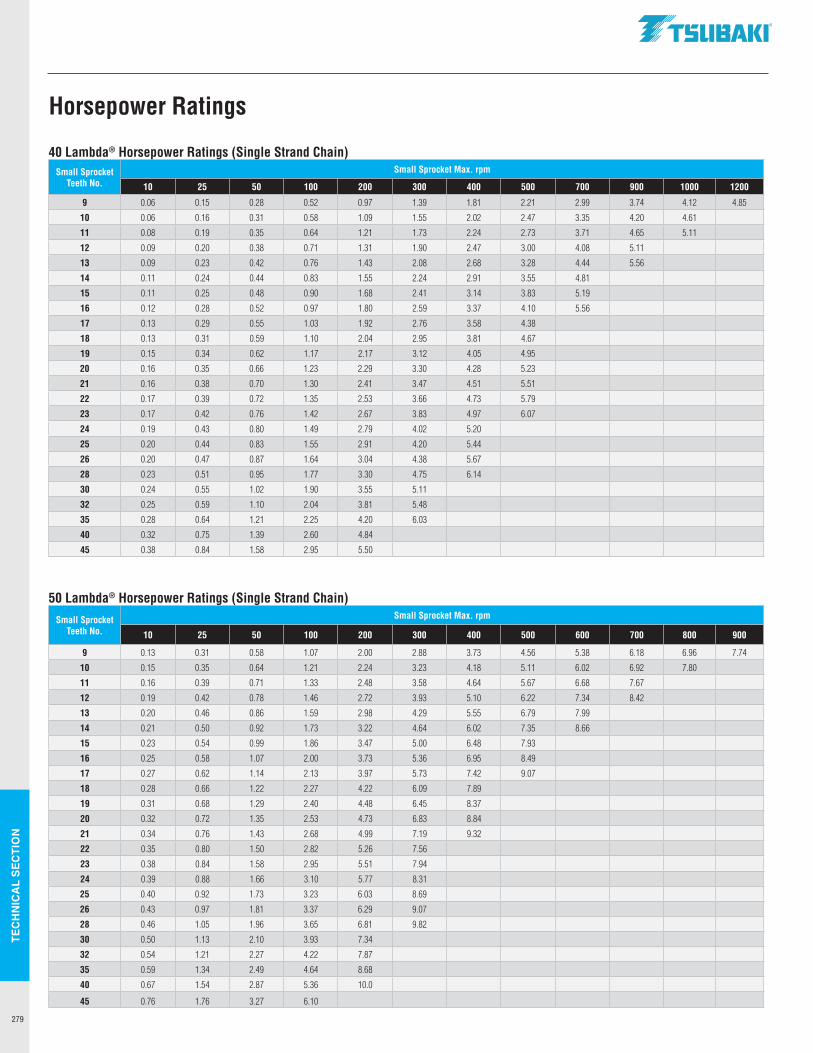
TEC
HN
ICA
L SE
CTI
ON
279
40 Lambda® Horsepower Ratings (Single Strand Chain)Small Sprocket
Teeth No.Small Sprocket Max. rpm
10 25 50 100 200 300 400 500 700 900 1000 1200
9 0.06 0.15 0.28 0.52 0.97 1.39 1.81 2.21 2.99 3.74 4.12 4.85
10 0.06 0.16 0.31 0.58 1.09 1.55 2.02 2.47 3.35 4.20 4.61
11 0.08 0.19 0.35 0.64 1.21 1.73 2.24 2.73 3.71 4.65 5.11
12 0.09 0.20 0.38 0.71 1.31 1.90 2.47 3.00 4.08 5.11
13 0.09 0.23 0.42 0.76 1.43 2.08 2.68 3.28 4.44 5.56
14 0.11 0.24 0.44 0.83 1.55 2.24 2.91 3.55 4.81
15 0.11 0.25 0.48 0.90 1.68 2.41 3.14 3.83 5.19
16 0.12 0.28 0.52 0.97 1.80 2.59 3.37 4.10 5.56
17 0.13 0.29 0.55 1.03 1.92 2.76 3.58 4.38
18 0.13 0.31 0.59 1.10 2.04 2.95 3.81 4.67
19 0.15 0.34 0.62 1.17 2.17 3.12 4.05 4.95
20 0.16 0.35 0.66 1.23 2.29 3.30 4.28 5.23
21 0.16 0.38 0.70 1.30 2.41 3.47 4.51 5.51
22 0.17 0.39 0.72 1.35 2.53 3.66 4.73 5.79
23 0.17 0.42 0.76 1.42 2.67 3.83 4.97 6.07
24 0.19 0.43 0.80 1.49 2.79 4.02 5.20
25 0.20 0.44 0.83 1.55 2.91 4.20 5.44
26 0.20 0.47 0.87 1.64 3.04 4.38 5.67
28 0.23 0.51 0.95 1.77 3.30 4.75 6.14
30 0.24 0.55 1.02 1.90 3.55 5.11
32 0.25 0.59 1.10 2.04 3.81 5.48
35 0.28 0.64 1.21 2.25 4.20 6.03
40 0.32 0.75 1.39 2.60 4.84
45 0.38 0.84 1.58 2.95 5.50
50 Lambda® Horsepower Ratings (Single Strand Chain)Small Sprocket
Teeth No.
Small Sprocket Max. rpm
10 25 50 100 200 300 400 500 600 700 800 900
9 0.13 0.31 0.58 1.07 2.00 2.88 3.73 4.56 5.38 6.18 6.96 7.74
10 0.15 0.35 0.64 1.21 2.24 3.23 4.18 5.11 6.02 6.92 7.80
11 0.16 0.39 0.71 1.33 2.48 3.58 4.64 5.67 6.68 7.67
12 0.19 0.42 0.78 1.46 2.72 3.93 5.10 6.22 7.34 8.42
13 0.20 0.46 0.86 1.59 2.98 4.29 5.55 6.79 7.99
14 0.21 0.50 0.92 1.73 3.22 4.64 6.02 7.35 8.66
15 0.23 0.54 0.99 1.86 3.47 5.00 6.48 7.93
16 0.25 0.58 1.07 2.00 3.73 5.36 6.95 8.49
17 0.27 0.62 1.14 2.13 3.97 5.73 7.42 9.07
18 0.28 0.66 1.22 2.27 4.22 6.09 7.89
19 0.31 0.68 1.29 2.40 4.48 6.45 8.37
20 0.32 0.72 1.35 2.53 4.73 6.83 8.84
21 0.34 0.76 1.43 2.68 4.99 7.19 9.32
22 0.35 0.80 1.50 2.82 5.26 7.56
23 0.38 0.84 1.58 2.95 5.51 7.94
24 0.39 0.88 1.66 3.10 5.77 8.31
25 0.40 0.92 1.73 3.23 6.03 8.69
26 0.43 0.97 1.81 3.37 6.29 9.07
28 0.46 1.05 1.96 3.65 6.81 9.82
30 0.50 1.13 2.10 3.93 7.34
32 0.54 1.21 2.27 4.22 7.87
35 0.59 1.34 2.49 4.64 8.68
40 0.67 1.54 2.87 5.36 10.0
45 0.76 1.76 3.27 6.10
Horsepower Ratings
.TSUBAKI"
------------
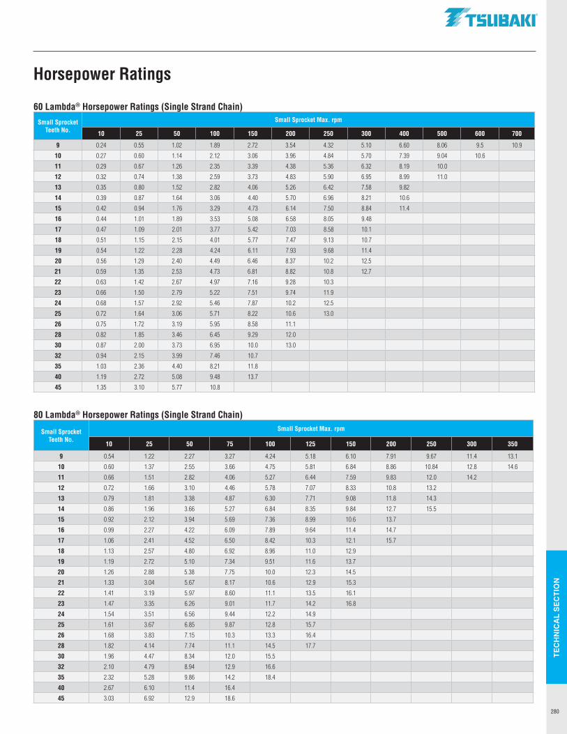
TEC
HN
ICA
L SE
CTI
ON
280
60 Lambda® Horsepower Ratings (Single Strand Chain)
Small Sprocket Teeth No.
Small Sprocket Max. rpm
10 25 50 100 150 200 250 300 400 500 600 700
9 0.24 0.55 1.02 1.89 2.72 3.54 4.32 5.10 6.60 8.06 9.5 10.9
10 0.27 0.60 1.14 2.12 3.06 3.96 4.84 5.70 7.39 9.04 10.6
11 0.29 0.67 1.26 2.35 3.39 4.38 5.36 6.32 8.19 10.0
12 0.32 0.74 1.38 2.59 3.73 4.83 5.90 6.95 8.99 11.0
13 0.35 0.80 1.52 2.82 4.06 5.26 6.42 7.58 9.82
14 0.39 0.87 1.64 3.06 4.40 5.70 6.96 8.21 10.6
15 0.42 0.94 1.76 3.29 4.73 6.14 7.50 8.84 11.4
16 0.44 1.01 1.89 3.53 5.08 6.58 8.05 9.48
17 0.47 1.09 2.01 3.77 5.42 7.03 8.58 10.1
18 0.51 1.15 2.15 4.01 5.77 7.47 9.13 10.7
19 0.54 1.22 2.28 4.24 6.11 7.93 9.68 11.4
20 0.56 1.29 2.40 4.49 6.46 8.37 10.2 12.5
21 0.59 1.35 2.53 4.73 6.81 8.82 10.8 12.7
22 0.63 1.42 2.67 4.97 7.16 9.28 10.3
23 0.66 1.50 2.79 5.22 7.51 9.74 11.9
24 0.68 1.57 2.92 5.46 7.87 10.2 12.5
25 0.72 1.64 3.06 5.71 8.22 10.6 13.0
26 0.75 1.72 3.19 5.95 8.58 11.1
28 0.82 1.85 3.46 6.45 9.29 12.0
30 0.87 2.00 3.73 6.95 10.0 13.0
32 0.94 2.15 3.99 7.46 10.7
35 1.03 2.36 4.40 8.21 11.8
40 1.19 2.72 5.08 9.48 13.7
45 1.35 3.10 5.77 10.8
80 Lambda® Horsepower Ratings (Single Strand Chain)
Small Sprocket Teeth No.
Small Sprocket Max. rpm
10 25 50 75 100 125 150 200 250 300 350
9 0.54 1.22 2.27 3.27 4.24 5.18 6.10 7.91 9.67 11.4 13.1
10 0.60 1.37 2.55 3.66 4.75 5.81 6.84 8.86 10.84 12.8 14.6
11 0.66 1.51 2.82 4.06 5.27 6.44 7.59 9.83 12.0 14.2
12 0.72 1.66 3.10 4.46 5.78 7.07 8.33 10.8 13.2
13 0.79 1.81 3.38 4.87 6.30 7.71 9.08 11.8 14.3
14 0.86 1.96 3.66 5.27 6.84 8.35 9.84 12.7 15.5
15 0.92 2.12 3.94 5.69 7.36 8.99 10.6 13.7
16 0.99 2.27 4.22 6.09 7.89 9.64 11.4 14.7
17 1.06 2.41 4.52 6.50 8.42 10.3 12.1 15.7
18 1.13 2.57 4.80 6.92 8.96 11.0 12.9
19 1.19 2.72 5.10 7.34 9.51 11.6 13.7
20 1.26 2.88 5.38 7.75 10.0 12.3 14.5
21 1.33 3.04 5.67 8.17 10.6 12.9 15.3
22 1.41 3.19 5.97 8.60 11.1 13.5 16.1
23 1.47 3.35 6.26 9.01 11.7 14.2 16.8
24 1.54 3.51 6.56 9.44 12.2 14.9
25 1.61 3.67 6.85 9.87 12.8 15.7
26 1.68 3.83 7.15 10.3 13.3 16.4
28 1.82 4.14 7.74 11.1 14.5 17.7
30 1.96 4.47 8.34 12.0 15.5
32 2.10 4.79 8.94 12.9 16.6
35 2.32 5.28 9.86 14.2 18.4
40 2.67 6.10 11.4 16.4
45 3.03 6.92 12.9 18.6
Horsepower Ratings
.TSUBAKI"
------------
-----------
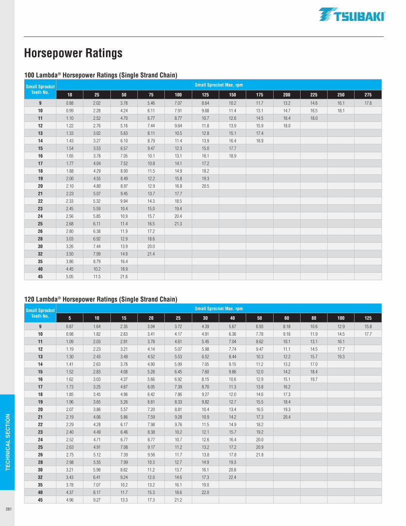
TEC
HN
ICA
L SE
CTI
ON
281
100 Lambda® Horsepower Ratings (Single Strand Chain)
Small Sprocket Teeth No.
Small Sprocket Max. rpm
10 25 50 75 100 125 150 175 200 225 250 275
9 0.88 2.02 3.78 5.46 7.07 8.64 10.2 11.7 13.2 14.6 16.1 17.6
10 0.99 2.28 4.24 6.11 7.91 9.68 11.4 13.1 14.7 16.5 18.1
11 1.10 2.52 4.70 6.77 8.77 10.7 12.6 14.5 16.4 18.0
12 1.22 2.76 5.16 7.44 9.64 11.8 13.9 15.9 18.0
13 1.33 3.02 5.63 8.11 10.5 12.8 15.1 17.4
14 1.43 3.27 6.10 8.79 11.4 13.9 16.4 18.9
15 1.54 3.53 6.57 9.47 12.3 15.0 17.7
16 1.65 3.78 7.05 10.1 13.1 16.1 18.9
17 1.77 4.04 7.52 10.8 14.1 17.2
18 1.88 4.29 8.00 11.5 14.9 18.2
19 2.00 4.55 8.49 12.2 15.8 19.3
20 2.10 4.80 8.97 12.9 16.8 20.5
21 2.23 5.07 9.45 13.7 17.7
22 2.33 5.32 9.94 14.3 18.5
23 2.45 5.59 10.4 15.0 19.4
24 2.56 5.85 10.9 15.7 20.4
25 2.68 6.11 11.4 16.5 21.3
26 2.80 6.38 11.9 17.2
28 3.03 6.92 12.9 18.6
30 3.26 7.44 13.9 20.0
32 3.50 7.99 14.9 21.4
35 3.86 8.79 16.4
40 4.45 10.2 18.9
45 5.05 11.5 21.6
120 Lambda® Horsepower Ratings (Single Strand Chain)
Small Sprocket Teeth No.
Small Sprocket Max. rpm
5 10 15 20 25 30 40 50 60 80 100 125
9 0.87 1.64 2.35 3.04 3.72 4.39 5.67 6.93 8.18 10.6 12.9 15.8
10 0.98 1.82 2.63 3.41 4.17 4.91 6.36 7.78 9.16 11.9 14.5 17.7
11 1.09 2.03 2.91 3.78 4.61 5.45 7.04 8.62 10.1 13.1 16.1
12 1.19 2.23 3.21 4.14 5.07 5.98 7.74 9.47 11.1 14.5 17.7
13 1.30 2.43 3.49 4.52 5.53 6.52 8.44 10.3 12.2 15.7 19.3
14 1.41 2.63 3.78 4.90 5.99 7.05 9.15 11.2 13.2 17.0
15 1.52 2.83 4.08 5.28 6.45 7.60 9.86 12.0 14.2 18.4
16 1.62 3.03 4.37 5.66 6.92 8.15 10.6 12.9 15.1 19.7
17 1.73 3.25 4.67 6.05 7.39 8.70 11.3 13.8 16.2
18 1.85 3.45 4.96 6.42 7.86 9.27 12.0 14.6 17.3
19 1.96 3.65 5.26 6.81 8.33 9.82 12.7 15.5 18.4
20 2.07 3.86 5.57 7.20 8.81 10.4 13.4 16.5 19.3
21 2.19 4.06 5.86 7.59 9.28 10.9 14.2 17.3 20.4
22 2.29 4.28 6.17 7.98 9.76 11.5 14.9 18.2
23 2.40 4.49 6.46 8.38 10.2 12.1 15.7 19.2
24 2.52 4.71 6.77 8.77 10.7 12.6 16.4 20.0
25 2.63 4.91 7.08 9.17 11.2 13.2 17.2 20.9
26 2.75 5.12 7.39 9.56 11.7 13.8 17.8 21.8
28 2.98 5.55 7.99 10.3 12.7 14.9 19.3
30 3.21 5.98 8.62 11.2 13.7 16.1 20.8
32 3.43 6.41 9.24 12.0 14.6 17.3 22.4
35 3.78 7.07 10.2 13.2 16.1 19.0
40 4.37 8.17 11.7 15.3 18.6 22.0
45 4.96 9.27 13.3 17.3 21.2
Horsepower Ratings
.TSUBAKI"
------------
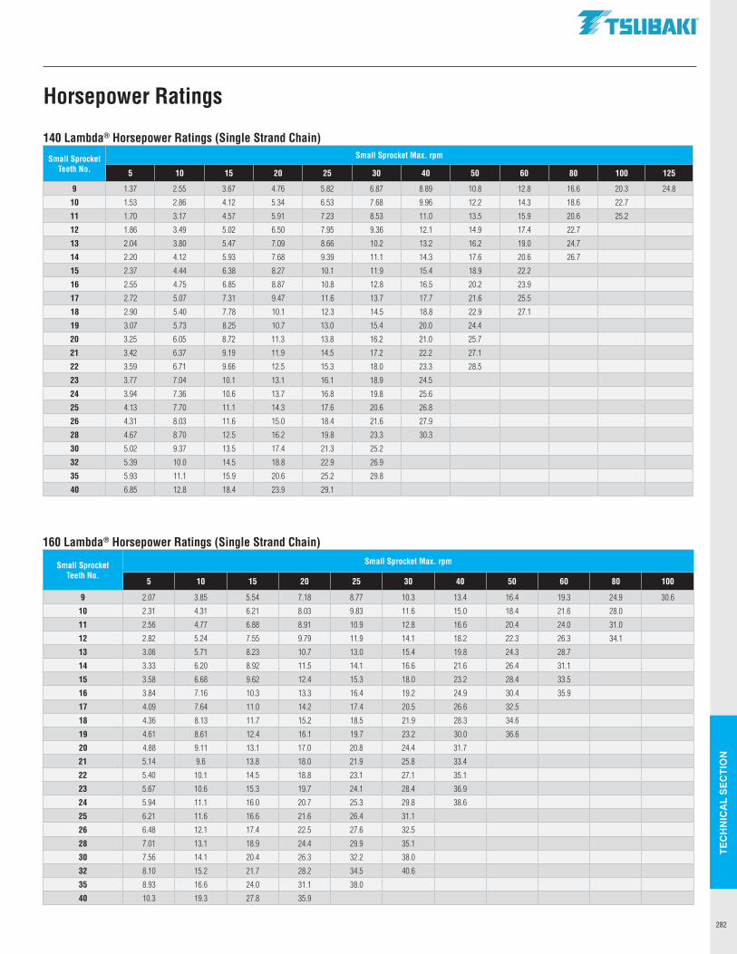
TEC
HN
ICA
L SE
CTI
ON
282
140 Lambda® Horsepower Ratings (Single Strand Chain)
Small Sprocket Teeth No.
Small Sprocket Max. rpm
5 10 15 20 25 30 40 50 60 80 100 125
9 1.37 2.55 3.67 4.76 5.82 6.87 8.89 10.8 12.8 16.6 20.3 24.8
10 1.53 2.86 4.12 5.34 6.53 7.68 9.96 12.2 14.3 18.6 22.7
11 1.70 3.17 4.57 5.91 7.23 8.53 11.0 13.5 15.9 20.6 25.2
12 1.86 3.49 5.02 6.50 7.95 9.36 12.1 14.9 17.4 22.7
13 2.04 3.80 5.47 7.09 8.66 10.2 13.2 16.2 19.0 24.7
14 2.20 4.12 5.93 7.68 9.39 11.1 14.3 17.6 20.6 26.7
15 2.37 4.44 6.38 8.27 10.1 11.9 15.4 18.9 22.2
16 2.55 4.75 6.85 8.87 10.8 12.8 16.5 20.2 23.9
17 2.72 5.07 7.31 9.47 11.6 13.7 17.7 21.6 25.5
18 2.90 5.40 7.78 10.1 12.3 14.5 18.8 22.9 27.1
19 3.07 5.73 8.25 10.7 13.0 15.4 20.0 24.4
20 3.25 6.05 8.72 11.3 13.8 16.2 21.0 25.7
21 3.42 6.37 9.19 11.9 14.5 17.2 22.2 27.1
22 3.59 6.71 9.66 12.5 15.3 18.0 23.3 28.5
23 3.77 7.04 10.1 13.1 16.1 18.9 24.5
24 3.94 7.36 10.6 13.7 16.8 19.8 25.6
25 4.13 7.70 11.1 14.3 17.6 20.6 26.8
26 4.31 8.03 11.6 15.0 18.4 21.6 27.9
28 4.67 8.70 12.5 16.2 19.8 23.3 30.3
30 5.02 9.37 13.5 17.4 21.3 25.2
32 5.39 10.0 14.5 18.8 22.9 26.9
35 5.93 11.1 15.9 20.6 25.2 29.8
40 6.85 12.8 18.4 23.9 29.1
160 Lambda® Horsepower Ratings (Single Strand Chain)
Small Sprocket Teeth No.
Small Sprocket Max. rpm
5 10 15 20 25 30 40 50 60 80 100
9 2.07 3.85 5.54 7.18 8.77 10.3 13.4 16.4 19.3 24.9 30.6
10 2.31 4.31 6.21 8.03 9.83 11.6 15.0 18.4 21.6 28.0
11 2.56 4.77 6.88 8.91 10.9 12.8 16.6 20.4 24.0 31.0
12 2.82 5.24 7.55 9.79 11.9 14.1 18.2 22.3 26.3 34.1
13 3.06 5.71 8.23 10.7 13.0 15.4 19.8 24.3 28.7
14 3.33 6.20 8.92 11.5 14.1 16.6 21.6 26.4 31.1
15 3.58 6.68 9.62 12.4 15.3 18.0 23.2 28.4 33.5
16 3.84 7.16 10.3 13.3 16.4 19.2 24.9 30.4 35.9
17 4.09 7.64 11.0 14.2 17.4 20.5 26.6 32.5
18 4.36 8.13 11.7 15.2 18.5 21.9 28.3 34.6
19 4.61 8.61 12.4 16.1 19.7 23.2 30.0 36.6
20 4.88 9.11 13.1 17.0 20.8 24.4 31.7
21 5.14 9.6 13.8 18.0 21.9 25.8 33.4
22 5.40 10.1 14.5 18.8 23.1 27.1 35.1
23 5.67 10.6 15.3 19.7 24.1 28.4 36.9
24 5.94 11.1 16.0 20.7 25.3 29.8 38.6
25 6.21 11.6 16.6 21.6 26.4 31.1
26 6.48 12.1 17.4 22.5 27.6 32.5
28 7.01 13.1 18.9 24.4 29.9 35.1
30 7.56 14.1 20.4 26.3 32.2 38.0
32 8.10 15.2 21.7 28.2 34.5 40.6
35 8.93 16.6 24.0 31.1 38.0
40 10.3 19.3 27.8 35.9
Horsepower Ratings
.TSUBAKI"
------------
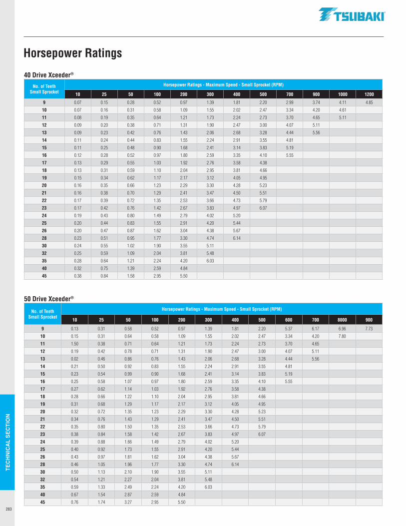
TEC
HN
ICA
L SE
CTI
ON
283
40 Drive Xceeder®
No. of Teeth Small Sprocket
Horsepower Ratings - Maximum Speed - Small Sprocket (RPM)
10 25 50 100 200 300 400 500 700 900 1000 1200
9 0.07 0.15 0.28 0.52 0.97 1.39 1.81 2.20 2.99 3.74 4.11 4.85
10 0.07 0.16 0.31 0.58 1.09 1.55 2.02 2.47 3.34 4.20 4.61
11 0.08 0.19 0.35 0.64 1.21 1.73 2.24 2.73 3.70 4.65 5.11
12 0.09 0.20 0.38 0.71 1.31 1.90 2.47 3.00 4.07 5.11
13 0.09 0.23 0.42 0.76 1.43 2.06 2.68 3.28 4.44 5.56
14 0.11 0.24 0.44 0.83 1.55 2.24 2.91 3.55 4.81
15 0.11 0.25 0.48 0.90 1.68 2.41 3.14 3.83 5.19
16 0.12 0.28 0.52 0.97 1.80 2.59 3.35 4.10 5.55
17 0.13 0.29 0.55 1.03 1.92 2.76 3.58 4.38
18 0.13 0.31 0.59 1.10 2.04 2.95 3.81 4.66
19 0.15 0.34 0.62 1.17 2.17 3.12 4.05 4.95
20 0.16 0.35 0.66 1.23 2.29 3.30 4.28 5.23
21 0.16 0.38 0.70 1.29 2.41 3.47 4.50 5.51
22 0.17 0.39 0.72 1.35 2.53 3.66 4.73 5.79
23 0.17 0.42 0.76 1.42 2.67 3.83 4.97 6.07
24 0.19 0.43 0.80 1.49 2.79 4.02 5.20
25 0.20 0.44 0.83 1.55 2.91 4.20 5.44
26 0.20 0.47 0.87 1.62 3.04 4.38 5.67
28 0.23 0.51 0.95 1.77 3.30 4.74 6.14
30 0.24 0.55 1.02 1.90 3.55 5.11
32 0.25 0.59 1.09 2.04 3.81 5.48
35 0.28 0.64 1.21 2.24 4.20 6.03
40 0.32 0.75 1.39 2.59 4.84
45 0.38 0.84 1.58 2.95 5.50
50 Drive Xceeder®
No. of Teeth Small Sprocket
Horsepower Ratings - Maximum Speed - Small Sprocket (RPM)
10 25 50 100 200 300 400 500 600 700 8000 900
9 0.13 0.31 0.58 0.52 0.97 1.39 1.81 2.20 5.37 6.17 6.96 7.73
10 0.15 0.31 0.64 0.58 1.09 1.55 2.02 2.47 3.34 4.20 7.80
11 1.50 0.38 0.71 0.64 1.21 1.73 2.24 2.73 3.70 4.65
12 0.19 0.42 0.78 0.71 1.31 1.90 2.47 3.00 4.07 5.11
13 0.02 0.46 0.86 0.76 1.43 2.06 2.68 3.28 4.44 5.56
14 0.21 0.50 0.92 0.83 1.55 2.24 2.91 3.55 4.81
15 0.23 0.54 0.99 0.90 1.68 2.41 3.14 3.83 5.19
16 0.25 0.58 1.07 0.97 1.80 2.59 3.35 4.10 5.55
17 0.27 0.62 1.14 1.03 1.92 2.76 3.58 4.38
18 0.28 0.66 1.22 1.10 2.04 2.95 3.81 4.66
19 0.31 0.68 1.29 1.17 2.17 3.12 4.05 4.95
20 0.32 0.72 1.35 1.23 2.29 3.30 4.28 5.23
21 0.34 0.76 1.43 1.29 2.41 3.47 4.50 5.51
22 0.35 0.80 1.50 1.35 2.53 3.66 4.73 5.79
23 0.38 0.84 1.58 1.42 2.67 3.83 4.97 6.07
24 0.39 0.88 1.66 1.49 2.79 4.02 5.20
25 0.40 0.92 1.73 1.55 2.91 4.20 5.44
26 0.43 0.97 1.81 1.62 3.04 4.38 5.67
28 0.46 1.05 1.96 1.77 3.30 4.74 6.14
30 0.50 1.13 2.10 1.90 3.55 5.11
32 0.54 1.21 2.27 2.04 3.81 5.48
35 0.59 1.33 2.49 2.24 4.20 6.03
40 0.67 1.54 2.87 2.59 4.84
45 0.76 1.74 3.27 2.95 5.50
Horsepower Ratings
.TSUBAKI"
------------
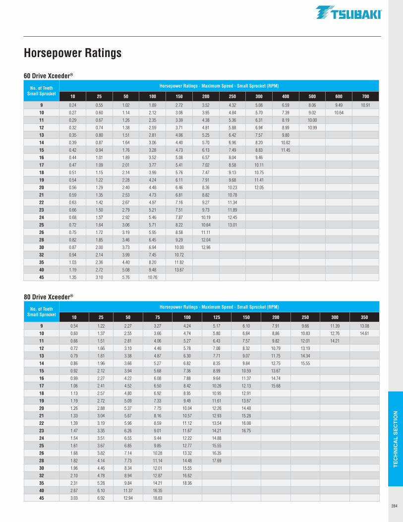
TEC
HN
ICA
L SE
CTI
ON
284
60 Drive Xceeder®
No. of Teeth Small Sprocket
Horsepower Ratings - Maximum Speed - Small Sprocket (RPM)
10 25 50 100 150 200 250 300 400 500 600 700
9 0.24 0.55 1.02 1.89 2.72 3.52 4.32 5.08 6.59 8.06 9.49 10.91
10 0.27 0.60 1.14 2.12 3.06 3.95 4.84 5.70 7.39 9.02 10.64
11 0.29 0.67 1.26 2.35 3.39 4.38 5.36 6.31 8.19 10.00
12 0.32 0.74 1.38 2.59 3.71 4.81 5.88 6.94 8.99 10.99
13 0.35 0.80 1.51 2.81 4.06 5.25 6.42 7.57 9.80
14 0.39 0.87 1.64 3.06 4.40 5.70 6.96 8.20 10.62
15 0.42 0.94 1.76 3.28 4.73 6.13 7.49 8.83 11.45
16 0.44 1.01 1.89 3.52 5.08 6.57 8.04 9.46
17 0.47 1.09 2.01 3.77 5.41 7.02 8.58 10.11
18 0.51 1.15 2.14 3.99 5.76 7.47 9.13 10.75
19 0.54 1.22 2.28 4.24 6.11 7.91 9.68 11.41
20 0.56 1.29 2.40 4.48 6.46 8.36 10.23 12.05
21 0.59 1.35 2.53 4.73 6.81 8.82 10.78
22 0.63 1.42 2.67 4.97 7.16 9.27 11.34
23 0.66 1.50 2.79 5.21 7.51 9.73 11.89
24 0.68 1.57 2.92 5.46 7.87 10.19 12.45
25 0.72 1.64 3.06 5.71 8.22 10.64 13.01
26 0.75 1.72 3.19 5.95 8.58 11.11
28 0.82 1.85 3.46 6.45 9.29 12.04
30 0.87 2.00 3.73 6.94 10.00 12.96
32 0.94 2.14 3.99 7.45 10.72
35 1.03 2.36 4.40 8.20 11.82
40 1.19 2.72 5.08 9.48 13.67
45 1.35 3.10 5.76 10.76
80 Drive Xceeder®
No. of Teeth Small Sprocket
Horsepower Ratings - Maximum Speed - Small Sprocket (RPM)
10 25 50 75 100 125 150 200 250 300 350
9 0.54 1.22 2.27 3.27 4.24 5.17 6.10 7.91 9.66 11.39 13.08
10 0.60 1.37 2.55 3.66 4.74 5.80 6.84 8.86 10.83 12.76 14.61
11 0.66 1.51 2.81 4.06 5.27 6.43 7.57 9.82 12.01 14.21
12 0.72 1.66 3.10 4.46 5.78 7.06 8.32 10.79 13.19
13 0.79 1.81 3.38 4.87 6.30 7.71 9.07 11.75 14.34
14 0.86 1.96 3.66 5.27 6.82 8.35 9.84 12.75 15.55
15 0.92 2.12 3.94 5.68 7.36 8.99 10.59 13.67
16 0.99 2.27 4.22 6.08 7.88 9.64 11.37 14.74
17 1.06 2.41 4.52 6.50 8.42 10.26 12.13 15.68
18 1.13 2.57 4.80 6.92 8.95 10.95 12.91
19 1.19 2.72 5.09 7.33 9.49 11.61 13.67
20 1.26 2.88 5.37 7.75 10.04 12.26 14.48
21 1.33 3.04 5.67 8.16 10.57 12.93 15.28
22 1.39 3.19 5.96 8.59 11.12 13.54 16.08
23 1.47 3.35 6.26 9.01 11.67 14.21 16.75
24 1.54 3.51 6.55 9.44 12.22 14.88
25 1.61 3.67 6.85 9.85 12.77 15.55
26 1.68 3.82 7.14 10.28 13.32 16.35
28 1.82 4.14 7.73 11.14 14.48 17.69
30 1.96 4.46 8.34 12.01 15.55
32 2.10 4.78 8.94 12.87 16.62
35 2.31 5.28 9.84 14.21 18.36
40 2.67 6.10 11.37 16.35
45 3.03 6.92 12.94 18.63
Horsepower Ratings
.TSUBAKI"
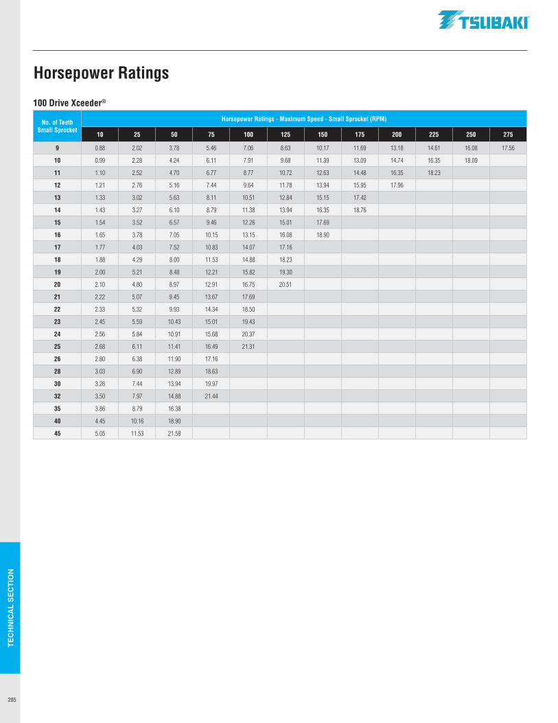
TEC
HN
ICA
L SE
CTI
ON
285
100 Drive Xceeder®
No. of Teeth Small Sprocket
Horsepower Ratings - Maximum Speed - Small Sprocket (RPM)
10 25 50 75 100 125 150 175 200 225 250 275
9 0.88 2.02 3.78 5.46 7.06 8.63 10.17 11.69 13.18 14.61 16.08 17.56
10 0.99 2.28 4.24 6.11 7.91 9.68 11.39 13.09 14.74 16.35 18.09
11 1.10 2.52 4.70 6.77 8.77 10.72 12.63 14.48 16.35 18.23
12 1.21 2.76 5.16 7.44 9.64 11.78 13.94 15.95 17.96
13 1.33 3.02 5.63 8.11 10.51 12.84 15.15 17.42
14 1.43 3.27 6.10 8.79 11.38 13.94 16.35 18.76
15 1.54 3.52 6.57 9.46 12.26 15.01 17.69
16 1.65 3.78 7.05 10.15 13.15 16.08 18.90
17 1.77 4.03 7.52 10.83 14.07 17.16
18 1.88 4.29 8.00 11.53 14.88 18.23
19 2.00 5.21 8.48 12.21 15.82 19.30
20 2.10 4.80 8.97 12.91 16.75 20.51
21 2.22 5.07 9.45 13.67 17.69
22 2.33 5.32 9.93 14.34 18.50
23 2.45 5.59 10.43 15.01 19.43
24 2.56 5.84 10.91 15.68 20.37
25 2.68 6.11 11.41 16.49 21.31
26 2.80 6.38 11.90 17.16
28 3.03 6.90 12.89 18.63
30 3.26 7.44 13.94 19.97
32 3.50 7.97 14.88 21.44
35 3.86 8.79 16.38
40 4.45 10.16 18.90
45 5.05 11.53 21.58
Horsepower Ratings
.TSUBAKI"
PRICE-PAYMENTThe prices stated are those in effect on the date hereof and are subject to change based on prices in effect on the date of shipment. Interest at the rate of 18% per annum shall be charged on overdue payments. Prices are for Seller’s standard packaging only, and F.O.B. Seller’s plant or warehouse. All orders are subject to credit approval. Terms of payment are net, 30 days. In the event of non-payment by Buyer, Buyer shall pay all of Seller’s costs of collection, including reasonable attorneys’ fees. Up to 5% over or under the specified quantity for made-to-order products may be shipped at Seller’s option.
PERFORMANCE-CHANGES-DELAYS(a) Any time for delivery stated herein is approximate. Delivery
shall be deemed complete by tender of the products to a common carrier. Partial shipments are permitted.
(b) Orders are not subject to cancellation or revision, in whole or in part, without written approval of Seller.
(c) Should Buyer cause changes to be made in the design or construction of said products, or otherwise delay or interrupt the progress of the work hereunder, Buyer will reimburse Seller for any additional expenses arising therefrom.
(d) Seller shall not be liable for any delay caused by acts of God, riot or civil commotion, government orders, rules, regulations, suspensions or requisitions of any kind, strikes or other stoppages of labor or shortage in the supply of labor or material, fire casualties or accidents, or any cause, whether of the same or a different character, beyond Seller’s control. Any such delay shall extend the time for delivery of the products. Delay in delivery of any installment shall not relieve Buyer of its obligation to accept remaining deliveries.
(e) If delays due to Buyer’s fault exceed 60 days in the aggregate, the entire purchase price shall be due and payable to Seller on demand.
RISK OF LOSSAfter delivery to the carrier, Buyer assumes the risk of all loss or damage to the products resulting from any cause whatever.
LIMITED WARRANTYProducts manufactured by Seller: (a) conform to the design and specifications, If any, expressly agreed to in writing by Seller; and (b) are free of defects in workmanship and materials at the time of shipment. The warranties set forth in the preceding sentence are exclusive of all other warranties, express or implied, and extend only to Buyer and to no other person. ALL WARRANTIES OF MERCHANTABILITY OR FITNESS FOR A PARTICULAR PURPOSE ARE HEREBY EXCLUDED.
NON-RELIANCEBuyer is not relying upon any advice, representations or warranties (except the warranties expressly set forth above) of Seller, or upon Seller’s skill or judgment regarding the Seller’s products. Buyer is solely responsible for the design and specifications of the products, including without limitation, the determination of suitability for Buyer’s application of the products.
CLAIMS(a) Any claim relating to quantity or type shall be made to
Seller in writing within 7 days after receipt of the products; any such claim made thereafter shall be barred.
(b) Any claim under the above-stated Limited Warranty shall be made to Seller in writing within three (3) months after receipt of the products; any such claim made thereafter shall be barred.
(c) Seller’s liability for breach of warranty or otherwise is limited to repair or replacement, at Seller’s option, of non-conforming or defective products. Buyer waives all other remedies, including, but not limited to, all rights to consequential, special or incidental damages, including, but not limited to, damages resulting from personal injury, death or damage to or loss of use of property.
(d) Repair, alteration, neglect or misuse of the products shall void all applicable warranties.
INDEMNIFICATIONBuyer will indemnify, defend and hold Seller harmless from all loss, liability, damage and expense, including attorneys’ fees, arising out of any claim (a) for infringement of any patent, trademark, copyright, misappropriation of trade secrets, unfair competition or similar charge by any products supplied by Seller in accordance with the design or specifications furnished by Buyer, or (b) arising out of or connected with the products or any items into which the products are incorporated, including, but not limited to, any claim for product liability (whether or not based on negligence or strict liability of Seller), breach of warranty, breach of contract or otherwise.
DUTIES AND TAXESIn addition to the specified purchase price, Buyer will pay any and all federal, state or local taxes, duties, excises, license fees and other charges leveled, assessed or imposed upon Seller due to the manufacture, sale, purchase or delivery of the products. Buyer shall also pay the cost by which such manufacture is increased by reason of any law, ordinance or regulation adopted or promulgated by any government or governmental subdivision, department or agency, or other source, after the date hereof, but prior to the completion and delivery hereunder.
SPECIFICATIONS, DRAWINGS, PATTERNS AND TOOLSSeller’s specifications, drawings, patterns and tooling shall be the sole and exclusive property of Seller unless otherwise agreed in writing.
ENTIRE AGREEMENTThese terms and conditions constitute the entire agreement between Buyer and Seller and supersede any inconsistent terms and conditions, whether contained in Buyer’s purchase order or otherwise, and whether made heretofore or hereafter. No statement or writing subsequent to the date hereof which purports to modify or add to the terms and onditions hereof shall be binding unless consented to in writing, which makes specific reference hereto, and which has been signed by the party against which enforcement thereof is sought. Seller reserves the right to change these terms and conditions without prior notice.
RETURNED GOODSNo goods will be accepted for return without prior written authorization by Seller. Freight must be prepaid on all such returns, and each return is subject to inspection and acceptance by Seller to assure the goods are in a “resalable” condition. A minimum 10% handling and restocking charge will be applied to all authorized returns. Special or made-to-order goods are NOT returnable. Attachment chains returned are at the manufacturer’s discretion.
U.S. Tsubaki Power Transmission, LLC. © All rights reserved. 05/21
TERMS AND CONDITIONS OF SALE
©2019 U.S. Tsubaki Power Transmission, LLC.All Rights Reserved. Printed in U.S.A.
07/19 Rev. 0 L10950
Corporate HeadquartersU.S. Tsubak Power Transmission, LLC301 E. Marquardt DriveWheeling, IL 60090Tel: (800) 323-7790www.ustsubaki.com
Roller Chain Division821 Main StreetHolyoke, MA 01040Tel: (800) 323-7790
Sprocket ManufacturingMississauga, OntarioTel: (800) 323-7790
Cable & Hose Carrier Division7100 W. Marcia RoadMilwaukee, WI 53223Tel: (800) 443-4216
Conveyor and ConstructionChain Division1010 Edgewater DriveSandusky, OH 44870Tel: (800) 537-6140
DRIVE CHAINS
SMART TOOTH® SPROCKETS
BACKSTOPS & OVERRUNNING CLUTCHES
ATTACHMENT CHAINS
LAMBDA®
LUBE-FREE CHAINSSPECIALTY CHAINS
LEADING THE MOVEMENT
©2021 U.S. Tsubaki Power Transmission, LLC.All Rights Reserved. Printed in U.S.A.
05/21 Rev. 0 L10940
Note: In accordance with the policy of U.S. Tsubaki Power Transmission, LLC to consistently improve its products, the specifications in this brochure are subject to change without notice. The logos, brand names or product names in this brochure are trademarks or registered trademarks of Tsubakimoto Chain Co. and its subsidiaries in Japan, the U.S. and other countries.
TTsueAK1·
Related Documents


